Fusion of Visual and Infrared Signals in Visual Sensor Network
6
20th Iranian Conferance on Electrical Engineering, (ICEE2012),May 15-17,2012, Tehran,Iran Fusion of Visual and Infrared Signals in Visual Sensor Network for Night Vision Sajjad Ghaeminejad 1 ,Ali Aghagolzadeh 2 ,and Hadi Seyedarabi l I-Faculty of Electrical and Computer Eng., University of Tabriz, Tabriz, Iran. 2-Faculty of Electrical and Computer Eng., Babol Nooshirvani University of Technology, Babol, Iran. [email protected], [email protected], [email protected] Abstract: Multisensory fusion has become an area of intense research activi in the past few years. The goal of this paper is to present a technique for fusing infrared and visible videos. In this technique we propose a sion method that quickly ses infrared and visible frames and gives a better performance. This is done by first decomposing the inputs using D and extracting two maps (resulted from Choose M rule) from approximation sub frames and then fusing detail subframes according to these maps. After being compared to some of the popular fusion methods, the experimental results demonstrate that not only does this proposed method have a superior fusion performance, it can also be easily implemented in visual sensor networks in which speed and simplici are of critical importance. Keywords: Fusion, Visual Sensor Networks, Night- Vision, Multi-scale Transformation, Visual awareness 1. Introduction Visual sensor networks (VSN) are networks of smart cameras capable of local image processing and data communication. Cameras in VSNs form a distributed system performing infoation extraction and collaborating on application-specific tasks. The network generally consists of the cameras themselves, which have some local image processing, communication and storage capabilities, and possibly one or more central computers where visual data om multiple cameras is further processed and sed. Visual sensor networks are most useful in applications involving area surveillance, tracking, medicine and environmental monitoring. Video sion is one branch of multi-sensor data sion. It is a technique to integrate information om multiple videos. These videos may come om one sensor or multiple sensors. Moreover, the sensors can be of different kinds or the same. In recent years, it has been widely applied in machine vision, remote sensing, medical imaging, military applications, and etc. Inared sensors are sensitive to the differences of temperature in the scene and that is why IR videos have low definition and most of the context in their data will be hard to be recognized by human eye. On the contrary, the visual sensor is sensitive to the reflecting properties of targets in the scene. Unfortunately if a target is behind an obstacle that does not allow reflecting light come through and reach the sensor (e.g. a person in the smoke) or when there is not enough light in the environment (e.g. a pedestrian walking in a dark street), the visible sensor does not give any information about these targets since it is not getting any. If IR and visible videos are fused, all advantages of both sensors (IR and visible) will be remained in the fused image. Visual data sion algorithms can be categorized into low, mid, and high levels. In some literature, this is referred to as pixel, feature, and symbolic levels. Pixel- level algorithms work either in the spatial domain or in the transform domain. By changing a single coefficient in the transformed fused image, all (or a whole neighborhood o pixel values in the spatial domain will change. As a result, in the process of enhancing features in some image areas, undesirable artifacts may be introduced to some other image areas. Algorithms that work in the spatial domain, however, have the ability to focus on the desired image areas, limiting unwanted changes in other areas. This paper is primarily conceed with the discussion of pixel level sion. There are a number of pixel-based fusion schemes ranging om simply averaging the pixel values of inputs to more complex multi-resolution (MR) methods such as pyramid methods [3 and 9], wavelet methods [1, 5, 6, 10, 17 and 18] or Principal Component Analysis (PCA). A usel review of MR sion schemes is given in [11]. MR pixel-based fusion methods, shown in Eq. (1), generally involve transforming each of the registered input ames , h,om normal image space into some other domain by applying an MR transform, w. The transformed ames are sed using some sion rule, , and the fused image Pis reconstructed by performing the inverse transform, w-1• (1) 978-1-4673-1148-9112/$3l.00 ©2012 IEEE 1232
-
Upload
independent -
Category
Documents
-
view
0 -
download
0
Transcript of Fusion of Visual and Infrared Signals in Visual Sensor Network

20th Iranian Conferance on Electrical Engineering, (ICEE2012), May 15-17,2012, Tehran, Iran
Fusion of Visual and Infrared Signals in Visual Sensor Network for
Night Vision
Sajjad Ghaeminejad1, Ali Aghagolzadeh2, and Hadi Seyedarabil
I-Faculty of Electrical and Computer Eng., University of Tabriz, Tabriz, Iran. 2-Faculty of Electrical and Computer Eng., Babol Nooshirvani University of Technology, Babol, Iran.
[email protected], [email protected], [email protected]
Abstract: Multisensory fusion has become an area of intense research activity in the past few years. The goal of this paper is
to present a technique for fusing infrared and visible videos. In this technique we propose a filsion method that quickly filses infrared and visible frames and gives a better performance. This is done by first decomposing the inputs using DWT and
extracting two maps (resulted from Choose Max rule) from approximation sub frames and then fusing detail subframes according to these maps. After being compared to some of the popular fusion methods, the experimental results demonstrate
that not only does this proposed method have a superior fusion performance, it can also be easily implemented in visual sensor
networks in which speed and simplicity are of critical importance.
Keywords: Fusion, Visual Sensor Networks, Night
Vision, Multi-scale Transformation, Visual awareness
1. Introduction
Visual sensor networks (VSN) are networks of smart cameras capable of local image processing and data communication. Cameras in VSNs form a distributed system performing information extraction and collaborating on application-specific tasks. The network generally consists of the cameras themselves, which have some local image processing, communication and storage capabilities, and possibly one or more central computers where visual data from multiple cameras is further processed and fused. Visual sensor networks are most useful in applications involving area surveillance, tracking, medicine and environmental monitoring.
Video fusion is one branch of multi-sensor data fusion. It is a technique to integrate information from multiple videos. These videos may come from one sensor or multiple sensors. Moreover, the sensors can be of different kinds or the same.
In recent years, it has been widely applied in machine vision, remote sensing, medical imaging, military applications, and etc.
Infrared sensors are sensitive to the differences of temperature in the scene and that is why IR videos have low definition and most of the context in their data will
be hard to be recognized by human eye. On the contrary, the visual sensor is sensitive to the reflecting properties of targets in the scene. Unfortunately if a target is behind an obstacle that does not allow reflecting light come through and reach the sensor (e.g. a person in the smoke) or when there is not enough light in the environment (e.g. a pedestrian walking in a dark street), the visible sensor does not give any information about these targets since it is not getting any. If IR and visible videos are fused, all advantages of both sensors (IR and visible) will be remained in the fused image.
Visual data fusion algorithms can be categorized into low, mid, and high levels. In some literature, this is referred to as pixel, feature, and symbolic levels. Pixellevel algorithms work either in the spatial domain or in the transform domain. By changing a single coefficient in the transformed fused image, all (or a whole neighborhood of) pixel values in the spatial domain will change. As a result, in the process of enhancing features in some image areas, undesirable artifacts may be introduced to some other image areas. Algorithms that work in the spatial domain, however, have the ability to focus on the desired image areas, limiting unwanted changes in other areas.
This paper is primarily concerned with the discussion of pixel level fusion. There are a number of pixel-based fusion schemes ranging from simply averaging the pixel values of inputs to more complex multi-resolution (MR) methods such as pyramid methods [3 and 9], wavelet methods [1, 5, 6, 10, 17 and 18] or Principal Component Analysis (PCA). A useful review of MR fusion schemes is given in [11]. MR pixel-based fusion methods, shown in Eq. (1), generally involve transforming each of the registered input frames ii, h,71Nfrom normal image space into some other domain by applying an MR transform, w. The transformed frames are fused using
some fusion rule, rjJ , and the fused image Pis
reconstructed by performing the inverse transform, w-1•
(1)
978-1-4673-1148-9112/$3l.00 ©2012 IEEE 1232

A common wavelet family used for fusion is the discrete wavelet transform (DWT). The 2-dimensional discrete wavelet transform and the Laplacian pyramid decompose an image into its multi-scale edge representation. They are based on this fact that the human visual system is primarily sensitive to the local contrast changes, i.e. edges.
Visual data fusion in the spatial domain can be also classified into three categories based on the type of chosen neighborhood. These are pixel-based, windowbased, and region based [12 and 13]. The pixel-based fusion is characterized by simplicity and the highest popularity. Because pixel based and window-based methods fail to take into account the relationship between points, the fused image with either of them might lose some gray level and feature information. The regionbased fusion, on the contrary, can obtain the best fusion results by considering the nature of points in each region altogether. Therefore, region-based fusion has advantages over the other two counterparts. This of course does not come without a cost. Increased complexity is the first drawback that can be mentioned. While region-based methods usually outperform the other methods, their complexity and the computation load for systems is a drawback. For our video fusion applications in a VSN network, this is even worse since bandwidth and power constraints should also be taken into consideration. More complex methods require more power and more time. The fusion method proposed in this paper tries to take advantage of good characteristics of region based method in a faster manner. Therefore, a simple, yet efficient, fusion scheme is introduced in which fusion rule for detail sub-frames of a DWT of a frame is replaced by a logic coefficient choosing map. This means the whole segmentation phase is bypassed, resulting in reduction of complexity and computational load. We used Daubechies Spline (DBSS) as DWT in our work. In this paper we will use image and frame interchangeably. In the case of video fusion these terms are technically the same.
3. Proposed fusion Technique for Videos
Block diagram of the proposed fusion technique is
shown in figure 1. Infrared and visual videos are considered to be spatially and temporally registered. The
steps of the proposed technique are as follows:
I. Get IR and Visual frames
II. Extract moving objects and still background from
IR frame
III. Calculate the difference between extracted
background from the current IR frame and
the background extracted from the previous frame.
IV. Calculate the difference between the current visual
frame and the previous one.
V. If any of two differences calculated in steps III
and IV are more than certain thresholds, fuse
the IR background and visual frames using
the proposed method in section (3.2) and
save it for the future use.
VI. If none of these differences are more than the pre
defined thresholds, just put new object map
on the previous fusion of IR background and
visual frame and save it for the future use.
3. 1 Background Subtraction
Since our main targets are usually warmer than their
environment (like a person walking in a street), first
moving objects and background are extracted from the
current infrared frame. There are different ways for
doing this ranging from simple frame differencing to
more complicated ones like mixture of Gaussians. In
visual Sensor Networks power and memory are two
critical factors that must be taken into account. Therefore,
more complicated methods are less desired for our application
3.2 Change Detection
At this stage, we see how different the current frames
in infrared and visible videos are from their previous counterparts. There is a wide variety of methods here. A
simple one is pixel by pixel differencing and adding
absolute values of these differences as in equation (2),
where A and B are two frames, A(i,j) and B(i,j) are the
grey values in pixel (i,j) and frames are of size m Xn. n 111
d(A, B) = I II AU,}) - BO,})I i=1 j=1
(2)
Histogram differencing is another simple method for
measuring similarity between two frames. If h;(A) is
value of histogram of frame A in grey value of i , the
similarity measure based on histogram differencing will
be: k
Hd(a, b) = II h;(A)-h;(B) I (3) ;=1
where k is the number of grey levels in input frames.
4. Proposed fusion method
If any of two differences calculated in steps III and IV
in section 3 are more than certain thresholds (meaning
there are some important change), the IR background and
visual frames are fused using proposed method shown in
Fig. 2. First, IR extracted background and visual frame
are decomposed by DWT. Here we will treat their
approximation and detail sub-frames differently. To
afford some insight into our method, we apply each step
on a pair of frames from Dune dataset [14] shown in
figure 3. Decomposing each frame using DWT (DBSS)
approximation and detail sub-frames are as shown in
figures 4 and 5.
For approximation sub-frames, we use "choose max"
(CM) rule which simply chooses pixels with larger grey
value from two approximation sub-frames.
1233

Object Map
\ IR
H Background
frame
� Just put new map on
Suhtraction IR Change previous background
background Detection:
Visual Important
r--change Frame , detected?
� Fuse the frames according to
the proposed method
FIg. I. The proposed techmque for vIdeo fustOn
IR background map Approximation CM
Visual frame
Object map
Detail Proposed
method
Fig. 2: The proposed method for fusion of frames
a b
Fig. 3: Frames no. 7406 from Dune dataset; a) infrared frame, b)
visible frame
a b c
d e f
Fig. 4: Detail sub-frames of frames in figure 3; a-c) detail sub-frames
of figure 3a, d-f) detail sub-frames of figure 3b.
a b
Fig. 5: Approximation sub-frames of frames in figure 3; a) for the
infrared frame, b) for the visible frame.
To do so, simply, a logical map is formed for each
sub-frame from applying eM rule in approximation parts.
Let A and B be two input frames, their approximation
sub-frames are LLA and LLB and their detail sub-frames
are HLA, HHA, LHA, HLB, HHB, LHB. For frame A,
'fusion choosing maps' will be:
(4)
and for frame B:
(5)
Now, considering F, LLF, HLF, HHF and LHF as the
fused image and its sub-frames, approximation band of
fused frame is produced according to equation (6):
LLF =LLA x map_A + LLR xmap_B (6)
Therefore, if we use eM rule for approximation
subframes, it will give us two partial approximations and
two maps for fusion detail subframes. These are shown in
figure 6. In maps given in figures 6c and 6d, the white
parts represent the pixels which were chosen by eM rule.
In the other word, the white parts of each map indicate
the pixels that contribute to the approximation subframe
of the combined frame. Fused approximation sub-frame,
built using figures 6a and 6b is also shown in figure 6e.
For detail sub-frames, as mentioned earlier, we do not
use conventional methods like eM or averaging or
weighted averaging as used by researchers so far. The
resulting maps of fusing approximation sub-frames are used as fusion choosing maps for detail sub-frames.
Using two maps 'map_A' and 'map_B' we form details of fused frame:
1234
HL F = HL A X map _A + HL R X map_B
LHF =LHA x map_A + LHRxmap_B
HH} = HH A x map_A + HHB xmap_B
(7)
(8)
(9)
a b
c d
e
Fig. 6: Approximation sub-frames and CM maps for frames of figure 3.
a) approximation sub-frame of figure 3a after applying CM rule, b)
approximation sub-frame of figure 3b after applying CM rule, c) CM
map for infrared approximation sub-frame of figure 3a, d) CM map for
visible approximation sub-frame of figure 3b, e) fused approximation
sub-frame resulted from combining figures 6a and 6b
As it can be clearly seen from equations (7)-(9), a
pixel in details is chosen from an input only if its grey
value outweighs the ones of other inputs in
approximation sub-frames. Figures 7a and 7b show detail
sub-frames of figure 4 after applying choosing maps of
figure 6c and 6d, and figure 7c shows the fused detail
sub-frame. Finally, to get the fusion result of frames
given in figure 3, inverse DWT (IDWT) is applied on
figures 6e and 7c. The result is shown in figure 8.
Fig. 7: Detail sub-frames of frames in figure 3. a) detail sub-frames
of the visible frame of figure 3 after applying the map of figure 6d,
b) detail sub-frames of the infrared frame of figure 3 after applying
the map of figure 6c, c) fused detail sub-frames
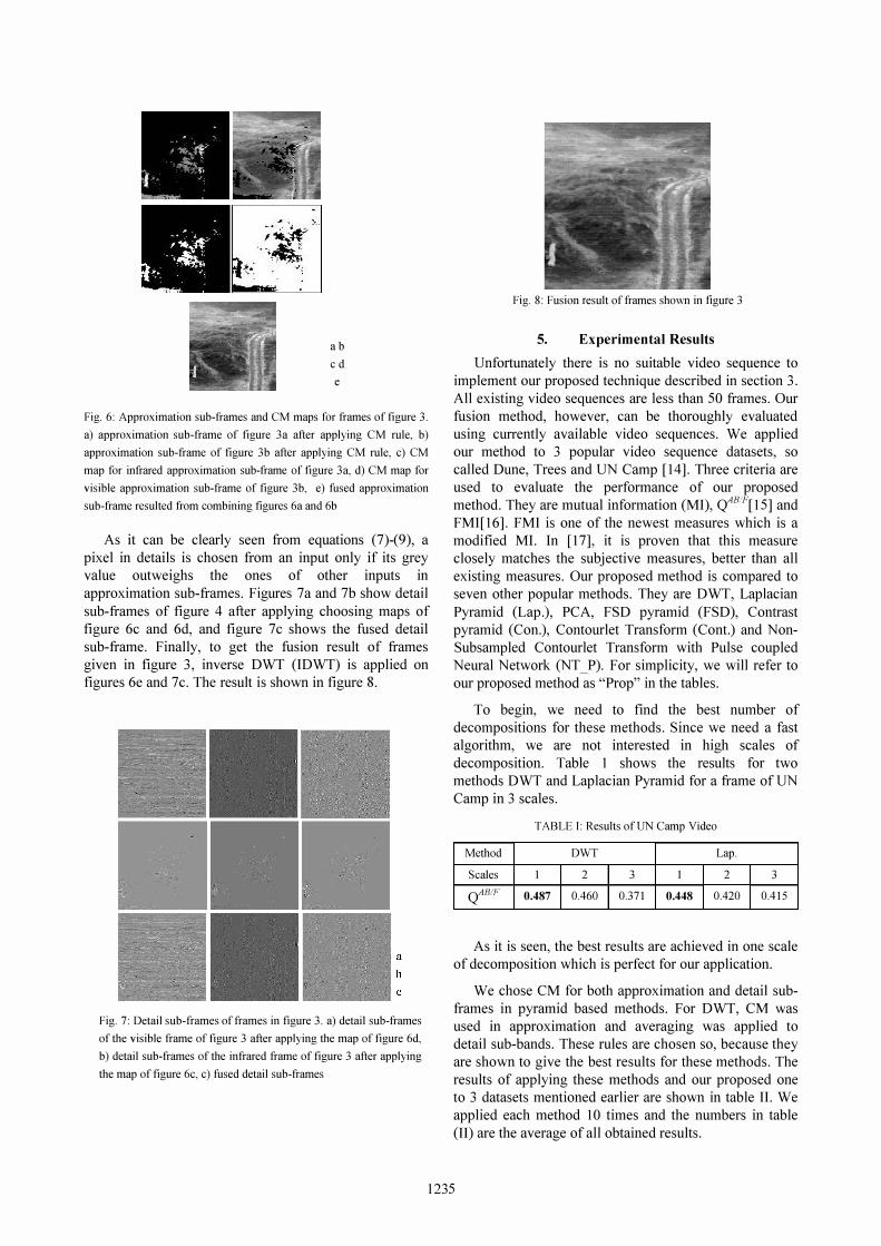
Fig. 8: Fusion result of frames shown in figure 3
5. Experimental Results
Unfortunately there is no suitable video sequence to
implement our proposed technique described in section 3.
All existing video sequences are less than 50 frames. Our
fusion method, however, can be thoroughly evaluated
using currently available video sequences. We applied
our method to 3 popular video sequence datasets, so
called Dune, Trees and UN Camp [14]. Three criteria are
used to evaluate the performance of our proposed
method. They are mutual information (MI), <tBF[ 15] and
FMI[ 16]. FMI is one of the newest measures which is a
modified MI. In [17], it is proven that this measure
closely matches the subjective measures, better than all
existing measures. Our proposed method is compared to seven other popular methods. They are DWT, Laplacian
Pyramid (Lap.), PCA, FSD pyramid (FSD), Contrast
pyramid (Con.), Contourlet Transform (Cont.) and Non
Subsampled Contourlet Transform with Pulse coupled
Neural Network (NT_P). For simplicity, we will refer to
our proposed method as "Prop" in the tables.
To begin, we need to fmd the best number of
decompositions for these methods. Since we need a fast
algorithm, we are not interested in high scales of
decomposition. Table 1 shows the results for two
methods DWT and Laplacian Pyramid for a frame of UN
Camp in 3 scales.
TABLE I: Results of UN Camp Video
Method DWT Lap.
Scales 1 2 3 1 2 3
<tB!F 0.487 0.460 0.371 0.448 0.420 0.415
As it is seen, the best results are achieved in one scale
of decomposition which is perfect for our application.
We chose CM for both approximation and detail sub
frames in pyramid based methods. For DWT, CM was
used in approximation and averaging was applied to
detail sub-bands. These rules are chosen so, because they
are shown to give the best results for these methods. The
results of applying these methods and our proposed one
to 3 datasets mentioned earlier are shown in table II. We
applied each method 10 times and the numbers in table
(II) are the average of all obtained results.
1235
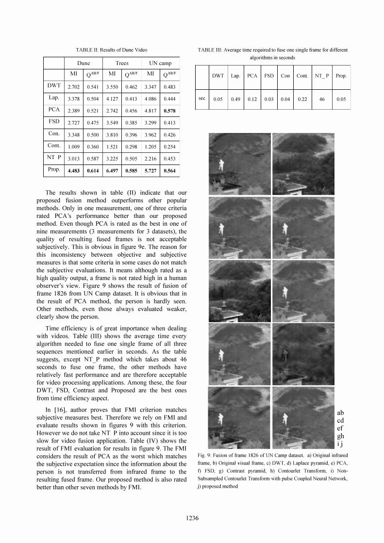
TABLE II: Results of Dune Video
Dune Trees UN camp
MI QAB/F MI Q
AB/F MI QAB/F
DWT 2.702 0.541 3.550 0.462 3.347 0.483
Lap. 3.378 0.504 4.127 0.413 4.086 0.444
PCA 2.389 0.521 2.742 0.456 4.817 0.578
FSD 2.727 0.475 3.549 0.385 3.299 0.413
Can. 3.348 0.500 3.810 0.396 3.962 0.426
Cant. 1.009 0.360 1.521 0.298 1.205 0.254
NT P 3.013 0.587 3.225 0.505 2.216 0.453
Prop. 4.483 0.614 6.497 0.585 5.727 0.564
The results shown in table (II) indicate that our
proposed fusion method outperforms other popular
methods. Only in one measurement, one of three criteria
rated PCA's performance better than our proposed
method. Even though PCA is rated as the best in one of
nine measurements (3 measurements for 3 datasets), the
quality of resulting fused frames is not acceptable
subjectively. This is obvious in figure ge. The reason for
this inconsistency between objective and subjective
measures is that some criteria in some cases do not match
the subjective evaluations. It means although rated as a
high quality output, a frame is not rated high in a human
observer's view. Figure 9 shows the result of fusion of
frame 1826 from UN Camp dataset. It is obvious that in
the result of PCA method, the person is hardly seen.
Other methods, even those always evaluated weaker,
clearly show the person.
Time efficiency is of great importance when dealing
with videos. Table (III) shows the average time every
algorithm needed to fuse one single frame of all three
sequences mentioned earlier in seconds. As the table
suggests, except NT_P method which takes about 46
seconds to fuse one frame, the other methods have
relatively fast performance and are therefore acceptable
for video processing applications. Among these, the four
DWT, FSD, Contrast and Proposed are the best ones
from time efficiency aspect.
In [16], author proves that FMI criterion matches
subjective measures best. Therefore we rely on FMI and
evaluate results shown in figures 9 with this criterion.
However we do not take NT P into account since it is too
slow for video fusion application. Table (IV) shows the
result of FMI evaluation for results in figure 9. The FMI
considers the result of PCA as the worst which matches
the subjective expectation since the information about the
person is not transferred from infrared frame to the
resulting fused frame. Our proposed method is also rated better than other seven methods by FMI.
TABLE III: Average time required to fuse one single frame for diflerent
algorithms in seconds
DWT Lap. PCA FSD Con
sec 0.05 0.49 0.l2 0.03 0.04
Cont. NT -
0.22 46
P Prop.
0.05
ab cd ef gh IJ
Fig. 9: Fusion of frame 1826 of UN Camp dataset. a) Original infrared
frame, b) Original visual frame, c) DWT, d) Laplace pyramid, e) PCA,
t) FSD, g) Contrast pyramid, h) Contourlet Transform, i) Non
Subsampled Contourlet Transform with pulse Coupled Neural Network,
j) proposed method
1236

TABLE IV: Objective Evaluations of frame 1826 from UN Camp
dataset using FMI
DWT Lap. PCA FSD Con. Cont. Prop.
FMI 0.5023 0.4991 0.4573 0.4952 0.4912 0.3581 0.5024
Now in the last part of our experimental results, we
evaluate these six methods using FMI for our three
datasets. The results are shown in table (V). Again
proposed method outperforms all six methods.
TABLE V: FMI Evaluations on three datasets
DWT Lap. PCA FSD Con. Cont. Prop.
Dune 0.537 0.537 0.526 0.536 0.536 0.392 0.539
Trees 0.502 0.490 0.430 0.488 0.479 0.385 0.503
UN
Camp 0.577 0.577 0.575 0.576 0.575 0.344 0.598
From figure 9 and tables (II-V), it is clearly seen that
our method delivers a better performance than other
methods. The reason for this improved performance is
that when in previous methods a CM rule is applied
separately to detail sub-frames, sometimes some
inconsistencies occur. By inconsistency, we mean
sometimes a pixel's approximation is chosen from one
frame by CM rule, while not in all its three detail sub
frames that pixel is chosen from the same frame. In our
method, we believe, due to the nature of the night-vision
application, we choose detail pixels come from the same
frame that this pixel in the approximation sub-frame
came from. This means even if in approximation sub
frame a pixel wins the CM test, we pick detail
coefficients of the MR transform for the fused result from
the same frame, no matter what their values are. In fact,
the proposed method is a kind of fast region-based fusion
method since the grey value in grey images can be used as a measure of affiliation between pixels of the image. In
our case all pixels with high grey value can be clustered
into target regions and therefore treated likewise.
Although some may argue that this is not true in all cases,
it is the case in night vision applications. The numerical
results also support this idea.
5. Conclusion
In this paper, we have described a video fusion technique that utilizes similarity between consecutive frames in a video sequence. Also a method for fusing video frames is proposed. The comparative analysis between the proposed method and seven existing methods has shown the merit of our approach.
6. ACKNOWLAGEMEN
This research is partially supported by Iranian Telecommunication Research Center (lTRC) which is appreciated.
7. References
S. Li, 1. T. Kwok, Y. Wang, "Using the discrete wavelet frame transform to merge Landsat TM and SPOT panchromatic images," Information Fusion, Vol. 3, Pages 17-23,2002.
[1] A. Goshtasby, "2-D and 3-D Image Registration for Medical, Remote Sensing and Industrial Applications," Wiley Press, 2005.
[2] A. Toet, "Hierarchical image fusion," Machine Vision and Applications, Vol.3, Pages 1-11, 1990.
[3] S. K. Rogers, C. W. Tong, M. Kabrisky, J. P. Mills, "Multisensor fusion of ladar and passive infrared imagery for target segmentation," Optical Engineering, Vol. 28, Issue 8, Pages 881-886, 1989.
[4] J. J. Lewis, R. J. O'Callaghan, S. G. Nikolov, D. R. Bull and N. Canagarajah, "Pixel- and Region-Based Image Fusion with Complex Wavelets," Information Fusion, Elsevier, Vol. 8, Issue 2, Pages 119-130,2007.
[5] A. Petrosian, F. Meyer, "Wavelets in Signal and Image Analysis," Kluwer Academic Publishers, the Netherlands, Pages 213-244, 2001.
[6] D. L. Hall, 1. Linas, "An introduction to multisensor data fusion," Proceedings of the IEEE, Vol. 85, Issue I, Pages 6-23, 1997.
[7] G. Piella, "A general framework for multiresolution image fusion," Information Fusion, Journal of Elsevier on, Vol. 4, Issue 4, Pages 259-280, 2003.
[8] A. Toet, L. V. Ruyven, 1. Velaton, "Merging thermal and visual images by a contrast pyramid," Optical Engineering, .vol. 28, Issue 7, Pages 789-792, 1989.
[9] H. Li, B. Manjunath, S. Mitra, "Multisensor Image Fusion Using the Wavelet Transform," Graphical Models Image Processing, Journal of Elsevier on, Vol. 57, Issue 3, Pages 235 - 245, May 1995.
[10] Z. Zhang, R. S. Blum, "A Categorization of MultiscaleDecomposition-Based Image Fusion Schemes with a Performance Study for a Digital Camera Application," Proceedings of the IEEE, Vol. 87, Issue 8, Pages 1315-1326,2002.
[II] N. Cvejic, J. Lewis, D. Bull, et al. "Region-based multimodal image fusion using ICA bases," IEEE Sensors Journal, Vol. 7, Issue 5, Pages 743-751, 2007.
[12] G. Piella, "A region-based multiresolution image fusion Algorithm," Proceedings of the Fifth International Conference on Information Fusion, Pages 1557-1564,2002.
[13] http: //www.imagefusion.org/images/toet2/toet2.html (Last accessed on 11111/11)
[14] C. Xydeas, and V. Petrovic, "Objective pixel-level image fusion performance measure," Proceedings of SPIE, Pages 88 - 99, 2000.
[15] M. B. A. Haghighat, A. Aghagolzadeh, H. Seyedarabi, "A NonReference Image Fusion Metric Based on Mutual Information of Image Features," Computers and Electrical Engineering, Elsevier, Vol. 37, Issue 5, Pages 744-756,2011.
[16] W. Cai, M. Li, X. Y. Li, "Infrared and Visible Image Fusion Based On Contourlet Transform," Image and Graphics, Fifth International Conference on, 2009.
[17] Q. X. Bo, Y. 1. Wen, X. H. Zhi, Z. Z.QQian, "Image Fusion Algorithm Based on Spatial Frequency-Motivated Pulse Coupled Neural Networks in Nonsubsampled Contourlet Transform Domain," ACT A AUTOMA TlCA SINICA, Vol. 34, Pages 1508-1514,2008.
1237