Lasing Without Population Inversion and Quantum Interference
Upload
independentCategory
view
2download
0
Full Spectrum Inversion of radio occultation signals
Arne Skov Jensen, Martin S. Lohmann, Hans-Henrik Benzon, and Alan SteenNielsenResearch and Development Department, Danish Meteorological Institute, Copenhagen, Denmark
Received 16 August 2002; revised 1 January 2003; accepted 3 February 2003; published 21 May 2003.
[1] Temperature, pressure, and humidity profiles of the Earth�s atmosphere can bederived through the radio occultation technique. This technique is based on the Dopplershift imposed, by the atmosphere, on a signal emitted from a GNSS satellite and receivedby a low orbiting satellite. The method is very accurate with a temperature accuracy of1�K, when both frequencies in the GPS system are used. However, difficulties arise whenthe signal consists of multiple frequencies generated by multipath phenomena in theatmosphere. We demonstrate that, in general, it is possible to determine the arrival timesof the different frequency components in a radio occultation signal simply as thederivatives of the phases of the conjugated Fourier spectrum of the entire occultationsignal. Based on this property, a novel Full Spectrum Inversion technique for radiooccultation sounding capable of disentangling multiple rays in multipath regions ispresented. As the entire signal is used in the Fourier transform, a high spatial resolutionin the Doppler frequency, and hence in the retrieved temperature, pressure, and humidityprofiles, can be achieved. The method is conceptual and computational simple and thuseasy to implement. The performance of the Full Spectrum Inversion is demonstrated byapplying the technique to simulated signals generated by solving Helmholtz equation withuse of the multiple phase-screen technique. Excellent agreement is found betweencomputed bending angle profiles and corresponding solutions to the Abel integral.INDEX TERMS: 6974 Radio Science: Signal processing; 6904 Radio Science: Atmospheric propagation;6964 Radio Science: Radio wave propagation; 6969 Radio Science: Remote sensing; KEYWORDS: inversion,multipath, radio occultations
Citation: Jensen, A. S., M. S. Lohmann, H.-H. Benzon, and A. S. Nielsen, Full Spectrum Inversion of radio occultationsignals, Radio Sci., 38(3), 1040, doi:10.1029/2002RS002763, 2003.
1. Introduction[2] In general terms, the radio occultation technique
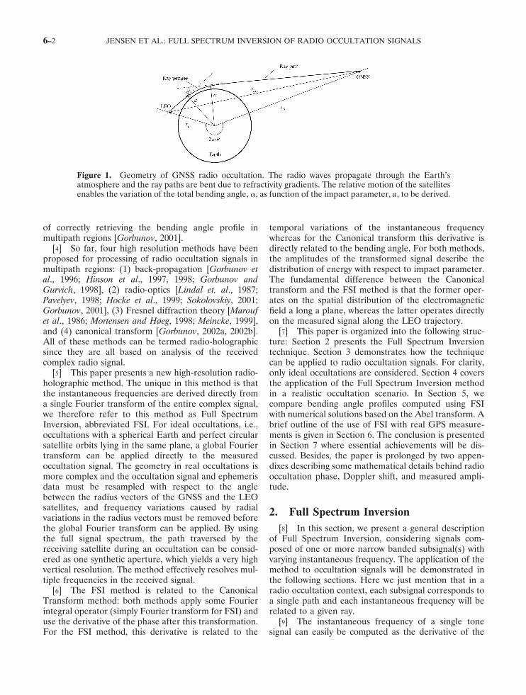
is based on the bending of radio waves caused byrefractive index gradients in a planetary atmosphere[e.g., Kursinski et al., 1997, 2000]. In Global NavigationSatellite System (GNSS) radio occultations, the bendingis measured as radio waves traverse the Earth�s atmo-sphere from a GNSS satellite to a Low Earth Orbit(LEO) satellite (see Figure 1). The atmospheric bendingcan be retrieved as function of impact parameter fromthe measured Doppler shifts of the radio signal and thepositions and velocities of the satellites. Assuming localspherical symmetry, the measured pairs of bending angleand impact parameter can be inverted through the Abeltransform to yield the index of refractivity as function ofheight [Fjeldbo et al., 1971].
[3] In single ray regions, the computation of bendingangles is straightforward as they are unambiguouslyrelated to the instantaneous frequency of the receivedsignal. Therefore, radio occultation measurements havetraditionally been based on the instantaneous frequency.However, radio signals propagating through the lowertroposphere may have a very complex structure due tomultipath effects caused mainly by water vapor struc-tures [Gorbunov et al., 1996; Gorbunov and Gurvich,1998; Gorbunov et al., 2000; Sokolovskiy, 2001]. In re-gions that exhibit multipath, the bending angles cannotbe derived directly from the instantaneous frequency ofthe measured signal because the instantaneous fre-quency will be related, not to a single pair of bendingangle and impact parameter, but to two or more pairs.Another drawback of retrieving the bending angle di-rectly from the instantaneous frequency is that thevertical resolution is limited by the size of the Fresnelzone. Thus, there has been much effort in developingtechniques with high vertical resolution that are capable
Copyright 2003 by the American Geophysical Union.0048-6604/03/2002RS002763
RADIO SCIENCE, VOL. 38, NO. 3, 1040, doi:10.1029/2002RS002763, 2003
6–1
of correctly retrieving the bending angle profile inmultipath regions [Gorbunov, 2001].
[4] So far, four high resolution methods have beenproposed for processing of radio occultation signals inmultipath regions: (1) back-propagation [Gorbunov etal., 1996; Hinson et al., 1997, 1998; Gorbunov andGurvich, 1998], (2) radio-optics [Lindal et. al., 1987;Pavelyev, 1998; Hocke et al., 1999; Sokolovskiy, 2001;Gorbunov, 2001], (3) Fresnel diffraction theory [Maroufet al., 1986; Mortensen and Høeg, 1998; Meincke, 1999],and (4) canonical transform [Gorbunov, 2002a, 2002b].All of these methods can be termed radio-holographicsince they are all based on analysis of the receivedcomplex radio signal.
[5] This paper presents a new high-resolution radio-holographic method. The unique in this method is thatthe instantaneous frequencies are derived directly froma single Fourier transform of the entire complex signal,we therefore refer to this method as Full SpectrumInversion, abbreviated FSI. For ideal occultations, i.e.,occultations with a spherical Earth and perfect circularsatellite orbits lying in the same plane, a global Fouriertransform can be applied directly to the measuredoccultation signal. The geometry in real occultations ismore complex and the occultation signal and ephemerisdata must be resampled with respect to the anglebetween the radius vectors of the GNSS and the LEOsatellites, and frequency variations caused by radialvariations in the radius vectors must be removed beforethe global Fourier transform can be applied. By usingthe full signal spectrum, the path traversed by thereceiving satellite during an occultation can be consid-ered as one synthetic aperture, which yields a very highvertical resolution. The method effectively resolves mul-tiple frequencies in the received signal.
[6] The FSI method is related to the CanonicalTransform method: both methods apply some Fourierintegral operator (simply Fourier transform for FSI) anduse the derivative of the phase after this transformation.For the FSI method, this derivative is related to the
temporal variations of the instantaneous frequencywhereas for the Canonical transform this derivative isdirectly related to the bending angle. For both methods,the amplitudes of the transformed signal describe thedistribution of energy with respect to impact parameter.The fundamental difference between the Canonicaltransform and the FSI method is that the former oper-ates on the spatial distribution of the electromagneticfield a long a plane, whereas the latter operates directlyon the measured signal along the LEO trajectory.
[7] This paper is organized into the following struc-ture: Section 2 presents the Full Spectrum Inversiontechnique. Section 3 demonstrates how the techniquecan be applied to radio occultation signals. For clarity,only ideal occultations are considered. Section 4 coversthe application of the Full Spectrum Inversion methodin a realistic occultation scenario. In Section 5, wecompare bending angle profiles computed using FSIwith numerical solutions based on the Abel transform. Abrief outline of the use of FSI with real GPS measure-ments is given in Section 6. The conclusion is presentedin Section 7 where essential achievements will be dis-cussed. Besides, the paper is prolonged by two appen-dixes describing some mathematical details behind radiooccultation phase, Doppler shift, and measured ampli-tude.
2. Full Spectrum Inversion[8] In this section, we present a general description
of Full Spectrum Inversion, considering signals com-posed of one or more narrow banded subsignal(s) withvarying instantaneous frequency. The application of themethod to occultation signals will be demonstrated inthe following sections. Here we just mention that in aradio occultation context, each subsignal corresponds toa single path and each instantaneous frequency will berelated to a given ray.
[9] The instantaneous frequency of a single tonesignal can easily be computed as the derivative of the
Figure 1. Geometry of GNSS radio occultation. The radio waves propagate through the Earth�satmosphere and the ray paths are bent due to refractivity gradients. The relative motion of the satellitesenables the variation of the total bending angle, �, as function of the impact parameter, a, to be derived.
JENSEN ET AL.: FULL SPECTRUM INVERSION OF RADIO OCCULTATION SIGNALS6–2

phase. For signals composed of more than one tone,computation of the instantaneous frequency of eachtone is far more complicated. For time-varying signals, acommon approach is to use the Short Term FourierTransform (STFT), which forms the basis for the RadioOptics Method. This transformation splits the signal intosmaller blocks and performs the Fourier transform oneach block. The length of the signal blocks is chosen asa trade-off between frequency resolution and time res-olution. For a detailed discussion of STFT for ROsignals, see, for example, Pavelyev [1998], Gorbunov et al.[2000], and Sokolovskiy [2001].
[10] Full Spectrum Inversion provides a simple andefficient tool for deriving the instantaneous frequenciesof a signal composed of several narrow banded subsig-nals. When certain criteria are fulfilled, FSI is capable ofresolving the frequency variation of each signal compo-nent. Since the FSI is based on the Fourier transform ofthe entire signal a very high frequency resolution can beachieved compared to the STFT method.
[11] FSI relies on the assumption that the Fouriertransform of an entire signal can be computed using theMethod of Stationary Phase (MSP) [Born and Wolf,1999]. The MSP method can be applied to a Fourierintegral when the following two criteria are fulfilled: (1)For each subsignal, the signal amplitude term is slowlyvarying compared to the phase term. (2) The secondorder derivatives of the subsignal phases are largecompared to the higher order derivatives. As will beshown below, the use of the FSI method also requiresthat the representation of the signal in the time-frequency domain yields an unambiguous relation oftime as a function of frequency. Consequently, anyinstantaneous frequency can only occur once, meaningthat there is either one or zero stationary phase points inthe Fourier integral.
[12] Now, consider a signal composed of severalnarrow banded subsignals:
V�t� � �p
Qp �t�exp�i�p �t��, (1)
where �p is the phase and Qp the amplitude of the p th
subsignal and i is the imaginary unit. The Fouriertransform of V(t) yields:
V̂��� � �p�
0
TQp �t��exp�i��p �t�� � �t���dt�, (2)
where T is the measurement time.[13] Consider a given angular frequency for which
� � d�q/dt(t�t1) where q refers to the subsignal con-taining the angular frequency �, and t1 corresponds tothe time where the instantaneous frequency of thissubsignal is �. If the requirements listed above are valid,(2) can be evaluated using the MSP method. Assuming
that there is only one stationary phase point, the Fourierintegral is dominated by the contribution from thesubsignal q that satisfy the relation � � d�q/dt(t�t1). Byusing the MSP method, (2) can be approximated as[Born and Wolf, 1999]:
V̂��� � � 2�i
d 2�q
dt 2 �t1 �
Qq �t1 �exp�i��q �t1 ���t1 ��.
(3)
Due to the square root term, the phase of the Fourierspectrum will experience a phase shift of �/2 whend2�q/dt2 changes sign.
[14] Equation (3) reveals that we can interpret thedifferent frequency components in the Fourier spectrumas the instantaneous frequencies contained in the signal.Similar results with respect to Fourier spectra and localspatial frequencies can be found in [Goodman, 1996].
[15] The arrival times corresponding to the differentfrequencies in the signal can now be found simply bydifferentiating the phase, u, of the Fourier transformgiven by (3):
du
d��
d
d���q �t1 ���t1 � �
d�q
dt1
dt1
d�� �
dt1
d�� t1 � �t1 ,
or on parametric form:
���t�, t� � ��, �du
d�� . (4)
which shows that the pairs of instantaneous frequenciesand the times where these frequencies occurred aresimply given as the Fourier frequencies and the deriva-tives of the phases of the corresponding conjugatedFourier components.
3. Inversion of Ideal Occultation Data[16] The Full Spectrum Inversion technique is based
on the assumption that the Fourier integral of the entiresignal can be evaluated using the MSP method and thatany instantaneous frequency can only occur once duringan occultation. In this section, we assess the validity ofthese assumptions. We will assume that the satellites aremoving in circular orbits within the occultation plane,that the atmosphere is spherical symmetric, and thatgeometrical optics gives an adequate description of thesignal propagation. The subsignals introduced in theprevious section now correspond to different singlepathsand we interpret the radio occultation signal as a sum ofseveral subsignals when multipath occurs.
[17] As shown in Appendix A, the time derivative ofthe phase of each subsignal (the total Doppler angularfrequency) may be expressed as:
JENSEN ET AL.: FULL SPECTRUM INVERSION OF RADIO OCCULTATION SIGNALS 6–3

�q �t� �d�q
dt�t� � k�drG
dt �1 � � a
rG� 2
�drL
dt �1 � � a
rL� 2
� ad�
dt � (5)
in which �q is the ray signal phase, k is the wave number,rL is distance from center of the Earth to the LEOsatellite, rG is distance from center of the Earth to theGNSS satellite, a is the ray impact parameter, and �denotes the angle between the two radius vectors.
[18] Note that the angular frequency given by (5)is the total Doppler, i.e., the sum of the excessDoppler and geometric Doppler. The latter is definedas the frequency variations caused by the relativemovements of the satellites. Under the assumptionsdescribed above, the two radial velocity components arezero and the angular velocity, d�/dt, is constant, implyingthat:
�q �t� �d�q
dt�t� � ka
d�
dt. (6)
That is, the total frequency of each ray is proportional tothe ray impact parameter, ensuring a unique relationbetween ray impact parameter and the ray Dopplerfrequency. In agreement with Gorbunov [2001], it isassumed that rays are uniquely identified by their impactparameter. Therefore, we conclude that, under the givenassumptions, any instantaneous frequency will occuronly once during an occultation.
[19] From geometrical optics, it can be shown thatthe amplitude Q of a radio occultation (sub)-signal maybe expressed as (see Appendix B):
Q � P
2�
a
�rGrL � 2sin����1 � � a
rG� 2 ��
a
rL� 2 d�
da1/ 2
,
(7)
in agreement with S. S. Leroy (Amplitude of anoccultation signal in three dimensions, submitted toRadio Science, 2001), where P is the transmittedsignal power. In single path regions (7) represents thetotal signal amplitude, whereas in multipath regions (7)yields the amplitude of each subsignal. It follows from(6) that:
d�
da� k�d�
dt � 2�d 2�q
dt 2 � �1
. (8)
Inserting (6) and (8) into (7) yields:
Qq �
P
d 2�q
dt 2 ��q
k �2�ksin����q ���d�
dtrL� �d�
dtrG�
1/ 2
���d�
dtrL� 2
� ��q
k � 2���d�
dtrG� 2
� ��q
k � 2�� 1/4.
(9)
Since the relative variations in �q, rL, and rG aregenerally small compared to the variations in d2�q/dt2,we can assume that Qq is proportional to (d2�q/dt2)1/2.
[20] If the higher order phase terms are small com-pared to the second order phase term, the phase varia-tions near a stationary phase point are dominated by thesecond order derivative of the phase, whereas the am-plitude variations are dominated by the first orderderivative of the amplitude. Now, if we require that therelative variations in the amplitude shall be small duringa time interval where the phase is increased or decreasedwith a factor of � then the following must be true:
�d 3�q
dt 3 ��2��d 2�q
dt 2 � 3/ 2
, (10)
where it has been assumed that the subsignal amplitudeis proportional to (d2�q/dt2)1/2 as implied by (9). Equa-tion (10) reveals that the relative amplitude variationsare always small when the higher order phase derivativesare negligible compared to the second order derivative.Hence, for the assumptions stated in the beginning ofthis section, the only requirement for the validity ofthe FSI method is that the higher order phase terms ofeach subsignal must be small compared to the secondorder or higher order phase terms. There are twoobvious cases where this requirement may be violated;when d2�q/dt2 � 0, and when the instantaneous fre-quency varies rapidly. General assessment of the impacton the FSI resolution caused by higher order phasederivatives is difficult. Instead, the validity of the methodshould be demonstrated through simulations using real-istic refractivity fields. However, this is a subject of afuture study and in the following it will be assumed thatthe contribution from higher order phase terms can beneglected.
[21] Now, inserting (9) into (3) yields the Fouriertransform of the occultation signal:
V̂��� � �2�i�d 2 �q
dt 2 �−1/ 2
Qq �t1 �exp�i ��q �t1 � � �t1 ��
� Uexp�iu����,
in which
JENSEN ET AL.: FULL SPECTRUM INVERSION OF RADIO OCCULTATION SIGNALS6–4

U
� �P��
k��d�
dtrL��1�d�
dtrG��1
ksin��������d�
dtrL�2
� ��
k�2��d�
dtrG�2
� ��
k�2 1/ 2
(11)
and
u��� � exp� i��q �t1 � � �t1 ��
4 �� , (12)
where all derivatives are evaluated for t � t1.[22] From (12) it follows that the relative variations
in the magnitude of U(�) is small and the powerspectrum of an entire radio occultation signal will there-fore have an approximately rectangular shape if theassumptions stated in beginning of this section arefulfilled. This is an important property because it allowsus to use the shape of the signal spectrum to checkwhether our assumptions about the occultation signalare valid.
4. Inversion of Realistic Occultation Data[23] The preceding section demonstrated the appli-
cation of FSI to radio occultation signals under theassumption that the satellites were orbiting a sphericalEarth in the same plane following perfect circular orbits.In this section, we show how FSI can be applied in asimilar manner for realistic occultations. In this context,we define realistic occultations as occultations where theEarth is oblate and the satellite orbits are only nearlycircular (like those used by the GPS satellites, theGPS/MET mission, and the CHAMP satellite) includingalso occultations where the GNSS and the LEO orbitsare not in the same plane.
[24] When the oblateness of the Earth is taken intoaccount, inversion of the occultation data should beperformed assuming local spherical symmetry tangentialto the Earth ellipsoid [Syndergaard, 1998]. Generally, thecenter of local curvature does not coincide with thecenter of the satellite orbits. Consequently, we cannotassume that the satellite orbits are circular when invert-ing the occultation data, as radial velocities and acceler-ations are introduced when the satellite positions aredescribed relative to the center of local curvature.Furthermore, when the angle between the two satelliteorbits are not zero, there is no longer a linear relationbetween time and �.
[25] The presence of higher order derivatives of �and the presence of radial accelerations may ruin theunambiguous relation of time as function frequency. Inthese cases, FSI will give very noisy results in the
affected frequency band. The noise/oscillations in theretrieved arrival times represent an interference prob-lem, as more arrival times correspond to the sameinstantaneous frequency. These oscillations have thesame nature as the oscillation in the instantaneousfrequency observed in multipath regions. Hence, aunique relationship between ray frequency and rayimpact parameter cannot be assumed in general, as inthe previous section. When interference occurs, directapplication of (5) results in a noisy bending angle profilefor the affected impact parameters. Consequently, wemust eliminate the interference caused by the presenceof higher derivatives in both radius vectors and � prior tothe application of FSI.
[26] One way to eliminate this kind of interference isto use a modified version of the back-propagationtechnique where we instead of back-propagating thefield to a plane propagates the field to a circular LEOorbit approximating the real LEO orbit. However, herewe will introduce another approach, which offers a simplerimplementation and requires far less computer power. Theidea is to remove the influence from radial accelerationsand higher order derivatives of � in two simple steps.
[27] First, it is straightforward to account for theinfluence of the higher order derivatives of �. If weinstead of differentiating the signal phase with respect totime differentiate with respect to � then (5) can berewritten as:
d�q
d�� ka � k
drL
d��1 � � a
rL� 2
� kdrG
d��1 � � a
rG� 2
,
(13)
where d�q/d� is a pseudo angular frequency, which isapproximately proportional to d�q/dt. Equation (13)shows that the contributions from higher order deriva-tives in � can be eliminated if we instead of time use � asthe independent variable.
[28] Second, interference caused by radial variationscan be removed by correcting the signal phase by a phasefactor representing the frequency variation introducedby the last two terms in (13). This, of course, requires apriori knowledge of a or a sufficient accurate model ofa(�). An obvious choice of model is the impact param-eter profile derived from the smoothed signal phase.Assuming that the maximum difference between thedifferent impact parameters in a multipath zone is of theorder of 10 km, this model yields a relative model impactparameter accuracy of the order of O(10�3) or better inmultipath regions, whereas the model is nearly perfect insingle path regions.
[29] From the previous discussions, we conclude thatFSI is suitable for inverting real occultation signals if weinstead of time use � as the independent variable andremove the effects of radial variations in the satellite
JENSEN ET AL.: FULL SPECTRUM INVERSION OF RADIO OCCULTATION SIGNALS 6–5

position vectors. In practice, the variable transformationis most easily performed by resampling the originalsignal and ephemeris data with respect to �. Radialvariations can be removed by imposing an appropriatefrequency shift through the following operation:
Vs ��� � V���exp��im ����, (14)
where
�m ��� � k��0
� drL
d��1 � �am
rL� 2
�drG
d��1 � �am
rG� 2
d��,
(15)
in which �0 is the initial angle between the radiusvectors, V(�) represents the measured signal resampledwith respect to �, Vs(�) represents the measured signalafter removal of the frequency shift caused by radialvariations, and am represents a model of the true impactparameter variation.
[30] The pseudo frequency variation d�s/dt of Vs canbe retrieved using FSI, subsequently the impact param-eter variation can be derived from (13) using:
d�q
d��
d� s
d��
d�m
d�. (16)
Finally, the corresponding bending angles, �, can bederived from the geometrical relations [e.g., Kursinski etal., 2000]:
� � � � G � L � �, (17)
and
a � rLsin�L � � rGsin�G �, (18)
where G and L are the angles between the ray pathand the satellite radius vector at the GNSS and the LEOsatellites, respectively.
5. FSI of Simulated Occultation Signals[31] In this section, we validate the Full Spectrum
Inversion technique. We have chosen to validate themethod using an atmosphere without horizontal varia-tions described by known model refractivity profiles. Wecompare model bending angle profiles, which have beencomputed from the refractivity profiles (via Abel trans-formation), with bending angle profiles computed by FSIfrom simulated radio occultation signals. These signalsare generated by applying a wave propagator to atmo-spheres with refractivity distributions described by themodel refractive profiles. Two different test cases havebeen investigated. In the first case, we consider idealoccultations and an atmosphere with multipath. In thesecond case, we consider realistic occultations and anatmosphere with strong multipath.
[32] Our simulations are based on solutions to theparabolic approximation of the Helmholtz wave equa-tion computed using the split-step algorithm, also knownas the multiple phase-screen technique [Gorbunov andGurvich, 1998; Sokolovskiy, 2001]. This approach offers aforward propagating model, capable of simulating thepropagation of radio waves for most realistic atmo-spheric conditions. There are two primary limitations tothis technique: (1) The backscattered field is neglected.(2) Accurate calculations are restricted to near-horizon-tal propagation. The propagation from the last screen tothe LEO orbit is calculated using the Fresnel diffractionintegral.
[33] All the simulations have been performed using awave optics propagator developed by M. E. Gorbunov.In the simulations, the number of phase screens was setto 1200 and a sampling frequency of 70 Hz was used.
[34] In the first test case, the model refractivityprofile N is given as function of height, h, and can bedescribed by the following equation:
N�h� � 315 exp� �h
7.35km� � Bexp���h � BH� 2
0.05km 2 � .
(19)
[35] This refractivity profile represents an exponen-tial with a Gaussian shaped bump. In (19) BH is theheight of the bump, and B determines the size of thisbump. The first part of the equation is the refractivity ofthe reference atmosphere defined by the InternationalTelecommunications Union (ITU) [1981]. The secondpart of the equation determines the strength and heightof the refractivity bump. This bump in the refractivityprofile can be used to simulate multipath effects. Theduration of a possible multipath situation is determinedby the magnitude of the parameter B. In the simulations,B and BH have been set to 20 and 3 km, respectively,which yields an atmosphere with significant gradientsleading to multipath propagation. At this point, thesatellites are moving in circular orbits within the occul-tation plane.
[36] In Figure 2 the amplitude of the occultationsignal is depicted. Signs of strong multipath interferenceare noticed from 21 to 33 s as significant fluctuations inthe signal amplitude. The simulated signal is amplitudeand excess phase sampled like real radio occultationssignals. Before a signal can be processed using the FSImethod, the total signal phase has to be reconstructed inorder to restore the �original� signal. This is done byadding the phase corresponding to the geometricalDoppler, followed by up-sampling of the signal throughinterpolation of the amplitude and the new phase. Whenthe signal is interpolated, the sampling rate must corre-spond to at least twice the new signal bandwidth in orderto satisfy the sampling theorem.
JENSEN ET AL.: FULL SPECTRUM INVERSION OF RADIO OCCULTATION SIGNALS6–6

[37] For the current simulation, the center frequencywas removed and the signal was up-sampled by a factorof 11. After retrieval of the instantaneous frequencyvariation, the center frequency was added to the re-trieved Doppler frequencies before the bending angleprofile was computed.
[38] The results from a FFT of the restored signal areshown in Figure 3. Within the bandwidth of the signal,the FFT spectrum is flat as predicted by (9). Yet, a dipin the spectrum is observed at a frequency of -60 Hzcaused by the multipath. The phase of the conjugatedsignal spectrum can be differentiated with respect tofrequency to derive the frequency variation (see (4)). Bydoing this, the frequency variation depicted in Figure 4is obtained. The figure shows that FSI is capable of
resolving the frequency variations of all the three sub-signals in the occultation signal showing the expectedS-signature of a multipath zone. For comparison, Figure4 also depicts the instantaneous frequency computed asthe time derivative of the signal phase. It is seen that thetwo curves are overlapping except in the area withmultipath effects, which is on the abscissa from 21 to33 s. In this interval, the instantaneous frequency fails toresolve the different subsignals; instead, a very irregularDoppler variation is erroneously predicted. This is to beexpected, since pure phase detection cannot revealmultipath.
[39] In Figure 5 we compare the bending angleprofile computed from the frequency variation predictedby FSI, with the corresponding bending angle profile
Figure 2. Signal amplitude variations corresponding to simulation with ideal satellite orbits. Theamplitude fluctuations in the interval from 21 to 33 s are caused by multipath.
JENSEN ET AL.: FULL SPECTRUM INVERSION OF RADIO OCCULTATION SIGNALS 6–7

obtained as the Abel transform of the model refractivityprofile. We see an excellent agreement between the twocurves demonstrating FSI�s ability to retrieve bendingangle profiles in regions with strong multipath. We alsonotice that the small deviations from the flat powerspectrum observed in Figure 3 do not seem to have anyappreciable effect on the retrieval of the bending angleprofile.
[40] We will now apply the FSI method to a simula-tion with realistic orbits, an oblate Earth, and an atmo-sphere with strong multipath. The model refractivityprofile, NB, is at this point given as function of height, h,by the following equations:
NA �h� � 400exp��h/8km�, (20a)
NB �h� � NA �h��1 � 0.05� 2
�� tan�1�h � 7km
0.05km �� , (20b)
which are similar to the refractivity model used bySokolovskiy [2001]. Equation (20) describes an exponentialprofile that is displaced at a height of 7 km. In thesimulated occultation, the LEO orbit corresponds to theGPS/MET orbit and the GNSS orbit corresponds to atypical GPS orbit. The average antenna azimuth angle was27 degrees for the occultation. The amplitude variation ofthe simulated radio occultation signal is plotted in Figure 6.Between 27 and 35 s, the signal amplitude shows significantoscillations due to multipath interference.
[41] Following the description in Section 4, the sim-ulated signal and the corresponding ephemeris data are
Figure 3. Power spectrum of up-sampled occultation signal corresponding to simulation with idealsatellite orbits. The small dip at -60 Hz is due to multipath.
JENSEN ET AL.: FULL SPECTRUM INVERSION OF RADIO OCCULTATION SIGNALS6–8

resampled with respect to the angle between the tworadius vectors and frequency variation caused by radialvariations in the satellite positions are removed. Subse-quently, we apply the same processing scheme as the oneused above. The power spectrum of the complex up-sampled signal is depicted in Figure 7. We notice thatthe spectrum, as in the previous ideal case, is quite flat.A comparison between the bending angle profile com-puted using FSI and a corresponding bending angleprofile computed by means of an Abel transformation ofthe refractivity profile given by (20) is presented inFigure 8. We observe a very fine agreement between theFSI profile and the corresponding solution to the Abeltransform even in the multipath region.
[42] Close inspection of Figures 4, 5, and 7 revealssmall oscillations in the frequency variation and in thebending angle profiles. These oscillations are not relatedto variations in the refractivity index, but are results ofthe finite window used in the Fourier transform.
6. Application to Real Data[43] The optimal application of the FSI method to
real radio occultation data is a subject of a future study.In this section, we just briefly discuss two importantissues related to processing of measured occultationdata; ionospheric calibration and retrieval in the mul-tipath free upper atmosphere.
Figure 4. Frequency versus time reconstructed by FSI (curve of small crosses) and by differentiationof the signal phase (solid curve) for ideal orbits. It is readily noticed that the FSI method is capable ofresolving multipath.
JENSEN ET AL.: FULL SPECTRUM INVERSION OF RADIO OCCULTATION SIGNALS 6–9

[44] When applying FSI to real GPS occultations, theionospheric calibration can be done by either correctingthe phase or the bending angle [Syndergaard, 2000].However, it is desirable to apply the ionospheric calibra-tion on the bending angle, since calibration on the phasemay introduce phase accelerations that can introduceinterference phenomena in the derived arrival times asdescribed in Section 4.
[45] Above the tropopause, the occurrence of mul-tipath is rare and it might therefore be desirable to usetraditional processing technique and derive the instan-taneous frequency directly from the measured phase.The advantage of doing this is that the small oscillationsin the bending angle profiles caused by the final length ofthe Fourier transform, described earlier, can be avoided.However, it must be noted that it is always advantageousto perform Fourier transformation on the entire signalin order to use the largest possible window even if FSI isused only in the lower atmosphere.
7. Summary and Conclusion[46] A new radio holographic inversion method for
GNSS-LEO radio occultations has been presented,which we refer to as the Full Spectrum Inversionmethod. This technique yields sub-Fresnel vertical reso-lution and is capable of disentangling multiple rays inmultipath regions, which are known to appear quiteoften in the lower troposphere.
[47] Full Spectrum Inversion is based on the fact thatwhen a signal is composed of several narrow-bandedsubsignals the arrival time of the frequency componentsin the Fourier spectrum is simply given as the derivativeof the phases with respect to the frequency of theconjugated Fourier components. The method is valid, ifthe following three criteria are fulfilled: (1) Any instan-taneous frequency can occur only once. (2) For eachsubsignal, the signal amplitude term must be slowlyvarying compared to the phase term. (3) The second
Figure 5. Bending angle versus impact parameter reconstructed by FSI (curve of small circles) andderived directly from the Abel transform (solid line) for ideal orbits.
JENSEN ET AL.: FULL SPECTRUM INVERSION OF RADIO OCCULTATION SIGNALS6–10

order derivatives of the subsignal phases must be largecompared to the higher order derivatives.
[48] When using Full Spectrum Inversion to invertradio occultation data, a distinction between ideal oc-cultations and realistic occultations must be made. Hereideal occultations are defined as occultations with aspherical Earth and perfect circular obits lying in thesame plane. On the other hand, realistic occultations aredefined as occultations with an oblate Earth and approx-imately circular orbits lying in two different planes. Inthe former case, a global Fourier transform can beapplied directly to the measured signal. Realistic occul-tations require that the occultation signal and ephemerisdata are resampled with respect to the angle between theradius vectors of the GNSS and the LEO satellites, andthat frequency variations caused by radial variations inthe radius vectors are removed before a global Fourier
transform can be applied. Removal of those unwantedfrequency variations requires a priory knowledge of thevariations in impact parameter during an occultation,which can be estimated, e.g., from the smoothed signalphase.
[49] The performance of Full Spectrum Inversionhas been verified by applying the technique to simu-lated signals generated by solving Helmholtz equationwith the multiple phase-screen technique. Two differ-ent test cases were considered. In the first case, idealsatellite orbits and a perfect spherical atmospherewith multipath was considered, while in the secondcase, realistic orbits and an oblate atmosphere withstrong multipath was investigated. From the simulatedoccultation signals, the corresponding bending angleprofiles were reconstructed using Full Spectrum In-version. Comparison between the reconstructed bend-
Figure 6. Amplitude variations corresponding to simulation with realistic satellite orbits.
JENSEN ET AL.: FULL SPECTRUM INVERSION OF RADIO OCCULTATION SIGNALS 6–11

ing angle profiles and bending angle profiles obtaineddirectly from the refractivity profiles through the Abeltransformation shows excellent agreement demon-strating the ability of the Full Spectrum Inversionmethod to retrieve the correct bending angle profile inmultipath regions.
Appendix A: The Geometrical OpticsRadio Occultation Phase and Doppler
[50] The phase �, of a ray propagating along a pathS, from SG to SL is given by
� � k�SG
SL
nds, (A1)
where n is the index of refraction along the path and k isthe wave number. The path is determined by the condi-tion that the integral (A1) is stationary along the path;this is due to the principle of Fermat. If the index ofrefraction in the atmosphere can be assumed to varyonly in the radial direction of the Earth, (A1) can beexpressed in explicit terms. With a spherical symmetricatmosphere the Bouger�s formula for the media can beused, which yields:
nrsin � a, (A2)
where r is the radial distance from the Earth, is theangle between the tangent to the propagation path andthe radius vector from the center of the Earth, and a isthe impact parameter. The impact parameter is constantalong the ray path, i.e., da/ds � 0. From the geometry of
Figure 7. Signal power spectrum corresponding to simulations with realistic satellite orbits
JENSEN ET AL.: FULL SPECTRUM INVERSION OF RADIO OCCULTATION SIGNALS6–12

the occultation it can be shown that
sin�� �
r�d�
dr ��1 � r 2�d�
dr � 2ds � �1 � r 2�d�
dr � 2
dr. (A3)
Here (r,�) is the polar coordinates of a point on the ray.Using the kinematic relations stated in (A3) and Boug-er�s formula, the optical path between the transmitterand the receiver becomes:
� � k�sG
sL
nds
� k�ro
rL
nnrdr
�n 2r 2 � a 2� k�
rO
rG
nnrdr
�n 2r 2 � a 2, (A4)
where rG and rL are the distances from the GNSS andLEO satellites to the center of the Earth, respectively. r0is the distance to the tangent point (i.e., � �/2) fromthe Earth center. In the tangent point r0 is given by n(r0)r0 � a. Equation (A4) can be rewritten in several forms.The one used here yields:
� � k�rO
rL 1
r�n 2r 2 � a 2dr
� k�rO
rG 1
r�n 2r 2 � a 2dr � ka�. (A5)
[51] The instantaneous Doppler frequency can bedefined as the time derivative of the phase. In (A5) thequantities rL, rG, r0, a, and � are all functions of time.Differentiating (A5) with respect to time gives the rayDoppler frequency �(t):
Figure 8. Bending angle versus impact parameter reconstructed by FSI (curve of small circles) andderived directly from the Abel transform (solid line) for realistic satellite orbits.
JENSEN ET AL.: FULL SPECTRUM INVERSION OF RADIO OCCULTATION SIGNALS 6–13

��t� �d�
dt
� k�rG
2 � a 2
rG
drG
dt� k
�rL2 � a 2
rL
drL
dt� ka
d�
dt. (A6)
This expression for the Doppler frequency is only oneamong many others found in the literature. It has a verysimple physical meaning especially when the radialvelocities are zero or very small. In this case, theDoppler frequency is simply proportional to the impactparameter.
Appendix B: Radio OccultationAmplitude
[52] In order to determine the amplitude of a radiosignal, the intensity of each ray must be known. Born andWolf [1999, chapter 3.1.2] express the ratio between theintensities, I1 and I2, in two points of a ray as:
I2
I1�
n2
n1e ��s1
s2� 2S
n , (B1)
where S�S(r, t) is the eikonal that describes the opticalwave surfaces or the geometrical wave fronts and n�n(r)is the index of refraction of the medium. Initial and finalquantities are denoted by subindexes 1 and 2, respec-tively. The integration in (B1) is performed along theoptical path of the ray.
[53] Evaluation of (B1) is not straightforward anddemands extensive derivations, which is beyond thescope of this article. The result is given by the equationbelow:
I2 �n2
n1I1e ��s 1
s 2� 2S
n ds �
r12sin��1 �cos�1 ��d�
da� 1
r22sin��2 �cos�2 ��d�
da� 2
I1 . (B2)
It should be noted that the derivatives are performed atthe endpoints.
[54] At the starting point, i.e., the GPS position,d�/da and sin(�) are both zero but the intensity isinfinite. This means that we must find the limit ofI1sin(�1)(d�/da)1 when the point S1 approaches theGNSS position. First, the incremental angle yields:
� �1
r1sin�1 � s, (B3)
where S is the distance between the GNSS point andthe endpoint r1 on the ray path. Since the endpointcontains information about the impact parameter, the
derivative d�/da at the GNSS point must be found fromthe integral expression for � integrated in the r-space:
� � �r1
rG 1
r
a
�n 2r 2 � a 2dr, (B4)
which yields:
�d�
da� 1
� s
n1 r12cos 2�1 �
. (B5)
If we take the limit of ( S)2I1�PG/2� for r1� rG wherePG is the power transmitted by the GPS satellite, thefinal expression for the intensity at the LEO receiverbecomes:
IL �PG
2�
aG
rGrLsin��L ��nG2 rG
2 � aG2 �nL
2rL2 � aL
2�d�
da�L
nL
nG.
(B6)
In the calculation of the intensity in (B6) it has not beenassumed that the index of refraction is spherical sym-metric and it is therefore allowed to have differentimpact parameters for the two satellites.
[55] When the index of refraction is constant and theray path is a straight line, (B6) reduces to
I2 �PG
2�rLG2 , (B7)
where rLG is the distance between the transmitter andreceiver. This is well known and purely a justification ofthe calculation.
[56] By setting aG�aL�a and nG�nL�1, the ampli-tude of the ray at the LEO-receiver can be written as:
AL � �PG
2� � a
rGrLsin��L ��rG2 � a 2�rL
2 � a 2�d�
da�L
.
(B8)
In (B8) the absolute value symbol has been removed; itintroduces a phase shift of ��/2 depending on the signof d�/da. Physically, it resembles the phase anomalyaround a focus in an optical system.
[57] Acknowledgments. This work was supported bythe European Space Agency, ESTEC contract 14809/00/NL/MM. We wish to thank Mikhail E. Gorbunov forproviding us with his wave optics propagator simulationtool. Thanks to Sergey Sokolovskiy for useful commentsand suggestions, which have improved this paper.
JENSEN ET AL.: FULL SPECTRUM INVERSION OF RADIO OCCULTATION SIGNALS6–14

ReferencesBorn, M., and E. Wolf, Principles of Optics, Cambridge
Univ. Press, New York, 1999.Fjeldbo, G., A. J. Kliore, and R. Eshlermann, The neutral
atmosphere of Venus studied with the Mariner V radiooccultation experiments, Astron. J., 76(2), 123–140, 1971.
Goodman, J. W., Introduction to Fourier Optics, McGraw-Hill, New York, 1996.
Gorbunov, M. E., Radioholographic methods for process-ing radio occultation data in multipath regions, Sci. Rep.01-02, Dan. Meteorol. Inst., Copenhagen, 2001.
Gorbunov, M. E., Radioholographic analysis of Microlab-1radio occultation data in the lower troposphere, J. Geo-phys. Res., 107(D12), doi:10.1029/2001JD000889, 2002a.
Gorbunov, M. E., Canonical transform method for process-ing GPS radio occultation data in lower troposphere,Radio Sci., 37(5), 1076, doi:10.1029/2000RS002592,2002b.
Gorbunov, M. E., and A. S. Gurvich, Microlab-1 experi-ment: Multipath effects in the lower troposphere, J.Geophys. Res., 103(D12), 13,819–13,826, 1998.
Gorbunov, M. E., S. V. Sokolovskiy, and L. Bengtson,Advanced algorithms of inversion of GPS/MET satellitedata and their application to reconstruction of tempera-ture and humidity, Tech. Rep. 211, Max Planck Inst. forMeteorol., Hamburg, Germany, 1996.
Gorbunov, M. E., A. S. Gurvich, and L. Kornblueh, Com-parative analysis of radioholographic methods of process-ing radio occultation data, Radio Sci., 35(4), 1025–1034,2000.
Hinson, D. P., F. M. Flasar, A. J. K. P. J. Schinder, J. D.Twicken, and R. G. Herrera, Jupiter�s ionsphere: Resultsfrom the first Galileo radio occultation experiment, Geo-phys., Res. Lett., 24(17), 2107–2110, 1997.
Hinson, D. P., J. D. Twicken, and E. T. Karayel, Jupiter�sionsphere: New results from the first Voyager 2 radiooccultation measurements, J. Geophys. Res., 103(A5),9505–9520, 1998.
Hocke, K. A., A. G. Pavelyev, O. I. Yakovlev, L. Barthes,and N. Jakowski, Radio occultation data analysis by theradioholographic method, J. Atmos. Sol. Terr. Phys.,61(15) 1169–1179, 1999.
International Telecommunication Union (ITU), Propaga-tion in non-ionized media, J. Comput. Phys., 41, 115–131,1981.
Kursinski, E. R., G. A. Hajj, J. T. Schofield, and R. P.Linfield, Observing Earth�s atmosphere with radio occul-tation measurements using Global Positioning System. J.Geophys. Res., 102(D19), 23,429–23,465, 1997.
Kursinski, E. R., G. A. Hajj, S. S. Leroy, and B. Herman,The GPS radio occultation technique, TAO, 11(1), 53–114, 2000.
Lindal, G. F., J. R. Lyons, D. N. Sweetnam, V. R. Eshle-man, D. P. Hinson, and G. L. Tyler, The atmosphere ofUranus: Results of radio occultation measurements withVoyager 2, J. Geophys. Res., 92(A13), 14,987–15,001,1987.
Marouf, E. A., G. L. Tyler, and P. A. Rosen, Profilng Saturnrings by radio occultation, Icarus, 68, 120–166, 1986.
Meincke, M. D., Inversion methods for atmospheric profil-ing with GPS occultations, Sci. Rep. 99-11, Dan. Meteo-rol. Inst., Copenhagen, 1999.
Mortensen, M. D., and P. Høoeg, Inversion of GPS occul-tation measurements using Fresnel diffraction theory,Geophys Res. Lett., 25(13), 2446–2449, 1998.
Pavelyev, A. G., On the feasibility of radioholographicinvestigations of wave fields near the Earth�s radio-shadow zone on the satellite-to-satellite path, J. Commun.Technol. Electron., 43(8), 875–879, 1998.
Sokolovskiy, S. V., Modeling and inverting radio occulta-tion signals in the moist troposphere, Radio Sci., 36(3),441–458, 2001.
Syndergaard, S., Modeling the impact of the Earth�s oblate-ness on the retrieval of temperature and pressure profilesfrom limp sounding, J. Atmos. Sol. Terr. Phys., 60(2),171–180, 1998.
Syndergaard, S., On the ionospheric calibration in GPSradio occultations, Radio Sci., 35(3), 865–884, 2000.
H.-H. Benzon, A. S. Jensen, M. S. Lohmann, and A. S.Nielsen, Research and Development Department, Danish Me-teorological Institute, Lyngbyvej 100, DK–2100 Copenhagen,Denmark. ([email protected]; [email protected]; [email protected];[email protected])
JENSEN ET AL.: FULL SPECTRUM INVERSION OF RADIO OCCULTATION SIGNALS 6–15
Copyright © 2022 FDOKUMEN