Fronius IG-TL 3.0 / 3.6 / 4.0 / 4.6 / 5.0 Fronius IG-TL Dummy
144
/ Perfect Charging / Perfect Welding / Solar Energy 42,0426,0074,EA 008-31072015 Fronius IG-TL 3.0 / 3.6 / 4.0 / 4.6 / 5.0 Fronius IG-TL Dummy Operating Instructions Inverter for grid-connected photo- voltaic systems EN-US
-
Upload
khangminh22 -
Category
Documents
-
view
4 -
download
0
Transcript of Fronius IG-TL 3.0 / 3.6 / 4.0 / 4.6 / 5.0 Fronius IG-TL Dummy
/ Perfect Charging / Perfect Welding / Solar Energy
42,0426,0074,EA 008-31072015
Fronius IG-TL 3.0 / 3.6 / 4.0 / 4.6 / 5.0Fronius IG-TL Dummy
Operating Instructions
Inverter for grid-connected photo-voltaic systemsE
N-U
S

0

EN-U
S
Dear reader,
Introduction Thank you for the trust you have placed in our company and congratulations on buying this high-quality Fronius product. These instructions will help you familiarize yourself with the product. Reading the instructions carefully will enable you to learn about the many different features it has to offer. This will allow you to make full use of its advantages.
Please also note the safety rules to ensure greater safety when using the product. Careful handling of the product will repay you with years of safe and reliable operation. These are essential prerequisites for excellent results.
1

2

EN-U
S
Contents
Safety Instructions ..................................................................................................................................... 7
General Information 11
Protection of Persons and Equipment ....................................................................................................... 13Safety.................................................................................................................................................... 13Protection of Persons and Equipment .................................................................................................. 13RCMU ................................................................................................................................................... 13Monitoring the Grid ............................................................................................................................... 13Warning notices affixed to the device ................................................................................................... 14Information on Dummy Devices............................................................................................................ 16
Utilization in accordance with "intended purpose" ..................................................................................... 17Utilization in Conformity with "Intended Purpose"................................................................................. 17Field of application ............................................................................................................................... 17Photovoltaic system stipulations ........................................................................................................... 17
The Fronius IG TL Unit in the PV System.................................................................................................. 18General ................................................................................................................................................. 18Tasks .................................................................................................................................................... 18Converting DC into AC current ............................................................................................................. 18Fully automatic operation management................................................................................................ 18Display function and data communication ............................................................................................ 18Solar Module String Monitoring............................................................................................................. 18System upgrades .................................................................................................................................. 18Active inverter cooling........................................................................................................................... 19Power derating...................................................................................................................................... 19
Installation and Startup 21
Fronius IG TL Installation and Connection................................................................................................. 23Fronius IG TL construction.................................................................................................................... 23Overview............................................................................................................................................... 23
Choosing the Location ............................................................................................................................... 24Choosing the Location (General) .......................................................................................................... 24Choosing a Location for Inside Installation ........................................................................................... 25Choosing a Location for Outdoor Installation........................................................................................ 25
Connection Options and Knockouts on the Fronius IG TL......................................................................... 26Connection options on the Fronius IG TL ............................................................................................. 26Knockouts on the Fronius IG TL ........................................................................................................... 26
Attaching the Wall Bracket......................................................................................................................... 28Selecting dowels and screws................................................................................................................ 28Screw recommendation ........................................................................................................................ 28Separating the wall bracket and power stage set ................................................................................. 28Installation position ............................................................................................................................... 28Attaching the wall bracket - Wall installation......................................................................................... 29Attaching the wall bracket - Column installation ................................................................................... 30
Connecting Fronius IG TL Dummy to the Public Grid Using a Separate Power Supply Unit..................... 31General ................................................................................................................................................. 31Connecting Fronius IG TL Dummy to the Public Grid Using a Separate Power Supply Unit (AC) ....... 31
Connecting the Fronius IG TL to the public grid (AC) ................................................................................ 32Monitoring the Grid ............................................................................................................................... 32AC terminals ......................................................................................................................................... 32Connecting Aluminum Cables............................................................................................................... 32AC cable cross section ......................................................................................................................... 33Safety.................................................................................................................................................... 33Connecting the Fronius IG TL to the public grid (AC) ........................................................................... 33Maximum AC-side Overcurrent Protection ........................................................................................... 34
Connecting Solar Module Strings to the Fronius IG TL (DC)..................................................................... 35Fronius IG TL field of application .......................................................................................................... 35General information about solar modules ............................................................................................. 35Safety.................................................................................................................................................... 35
3
DC terminals ......................................................................................................................................... 36Connecting aluminum cables................................................................................................................ 36Cable cross section of solar module strings ......................................................................................... 36Polarity reversal of solar module strings ............................................................................................... 37Information on Dummy Devices............................................................................................................ 37Connecting Solar Module Strings to the Fronius IG TL (DC)................................................................ 37
Inserting String Fuses into the Fronius IG TL ............................................................................................ 40General ................................................................................................................................................. 40Selecting string fuses............................................................................................................................ 40Safety.................................................................................................................................................... 40Inserting string fuses into the Fronius IG TL ......................................................................................... 41
Criteria for the Proper Selection of String Fuses ....................................................................................... 43General ................................................................................................................................................. 43Criteria for the Proper Selection of String Fuses .................................................................................. 43Effects of Using Underrated Fuses ....................................................................................................... 43Fuse recommendations ........................................................................................................................ 43Application example.............................................................................................................................. 43Fuses .................................................................................................................................................... 44
Clipping Power Stage Sets onto the Wall Bracket ..................................................................................... 45Clipping power stage sets onto the wall bracket................................................................................... 45
Data Communication and Solar Net .......................................................................................................... 46Fronius Solar Net and Data Interface ................................................................................................... 46Data communication rack ..................................................................................................................... 46Overcurrent and under-voltage shutdown............................................................................................. 46Data communication connections ......................................................................................................... 47'Solar Net' LED description ................................................................................................................... 48Example ................................................................................................................................................ 48Maximum output current for data communication and the 12 V signaling output ................................. 49Connecting data communication cables to inverters ............................................................................ 49
USB Stick as a Data Logger and for Updating Inverter Software .............................................................. 50USB stick as a data logger.................................................................................................................... 50Data on the USB stick........................................................................................................................... 50Data amount and memory capacity ...................................................................................................... 51Buffer memory ...................................................................................................................................... 52Suitable USB sticks............................................................................................................................... 52USB stick for updating inverter software............................................................................................... 53Removing the USB stick ....................................................................................................................... 53
First startup ................................................................................................................................................ 54Factory pre-set configuration ................................................................................................................ 54First startup ........................................................................................................................................... 54
Operation 57
Keys and symbols...................................................................................................................................... 59Keys and Symbols ................................................................................................................................ 59Display .................................................................................................................................................. 60Symbols for function key functions ....................................................................................................... 60Control and Status LEDs ...................................................................................................................... 61
Startup Phase and Grid Feed-in Mode ...................................................................................................... 62Startup phase........................................................................................................................................ 62The operation of feeding energy into the grid ....................................................................................... 62
Navigation in the Menu Level..................................................................................................................... 63Activating display illumination ............................................................................................................... 63Automatic Deactivation of Display Illumination / Switching to the "NOW" Display Mode...................... 63Accessing the menu level ..................................................................................................................... 63
The Display Modes .................................................................................................................................... 64Display modes ...................................................................................................................................... 64Selecting a display mode ...................................................................................................................... 64Overview of display values ................................................................................................................... 65
Display Values in the ‘NOW’ Display Mode ............................................................................................... 66Selecting a display mode ...................................................................................................................... 66Display values in the ‘NOW’ display mode ........................................................................................... 66
Display Values in the ‘TODAY’ / ‘YEAR’ / ‘TOTAL’ Display Modes ........................................................... 68Selecting the ‘TODAY’ / ‘YEAR’ / ‘TOTAL’ display mode ..................................................................... 68
4
EN-U
S
Display values in the ‘TODAY’ / ‘YEAR’ / ‘TOTAL’ display modes ....................................................... 69The Setup Menu ........................................................................................................................................ 71
Presetting.............................................................................................................................................. 71Accessing the Setup menu ................................................................................................................... 71Scrolling through menu items ............................................................................................................... 71
Menu Items in the Setup Menu .................................................................................................................. 72Standby................................................................................................................................................. 72Contrast ................................................................................................................................................ 72Backlight ............................................................................................................................................... 73Language ............................................................................................................................................. 73Currency .............................................................................................................................................. 73CO2 Factor ........................................................................................................................................... 73Yield ...................................................................................................................................................... 74DATCOM .............................................................................................................................................. 74Signal relay ........................................................................................................................................... 75Energy manager ................................................................................................................................... 76Energy manager: Notes on configuring the switch-on and switch-off points ........................................ 77Energy manager: Example ................................................................................................................... 77USB....................................................................................................................................................... 77String Control ........................................................................................................................................ 78Device Info ............................................................................................................................................ 79Clock .................................................................................................................................................... 81PS Status .............................................................................................................................................. 81Grid Status ............................................................................................................................................ 81Version.................................................................................................................................................. 81
Setting and Displaying Menu Items ........................................................................................................... 82General menu item settings .................................................................................................................. 82Exiting a menu item .............................................................................................................................. 83Examples of Setting and Displaying Menu Items.................................................................................. 83Setting the display illumination.............................................................................................................. 83Setting the currency and feed-in tariff ................................................................................................... 84Updating inverter software using a USB stick....................................................................................... 85Safely removing USB sticks.................................................................................................................. 88Activating solar module string monitoring ............................................................................................. 89Setting the time and date ...................................................................................................................... 92
Switching the key lock on and off............................................................................................................... 94General ................................................................................................................................................. 94Switching the Key Lock On and Off ...................................................................................................... 94
Troubleshooting and Maintenance 97
Status Diagnosis and Troubleshooting ...................................................................................................... 99Displaying Status Codes....................................................................................................................... 99Total failure of the display ..................................................................................................................... 99Class 1 status codes............................................................................................................................. 99Class 3 status codes............................................................................................................................. 101Class 4 status codes............................................................................................................................. 103Class 5 status codes............................................................................................................................. 108Class 7 status codes............................................................................................................................. 110Class 10–12 Status Codes ................................................................................................................... 116Customer Service ................................................................................................................................. 116
Maintenance .............................................................................................................................................. 117Safety.................................................................................................................................................... 117General ................................................................................................................................................. 117Opening Fronius IG TL for service/maintenance .................................................................................. 117Operation in dusty environments .......................................................................................................... 118
Replacing String Fuses.............................................................................................................................. 120Safety.................................................................................................................................................... 120Preparation ........................................................................................................................................... 120Replacing fuses .................................................................................................................................... 122Finally.................................................................................................................................................... 123
Appendix 125
5
Technical Data ........................................................................................................................................... 127Fronius IG TL 3.0 .................................................................................................................................. 127Fronius IG TL 3.6 .................................................................................................................................. 128Fronius IG TL 4.0 .................................................................................................................................. 129Fronius IG TL 4.6 .................................................................................................................................. 130Fronius IG TL 5.0 .................................................................................................................................. 131Fronius IG TL Dummy........................................................................................................................... 132Protection devices for all inverters ........................................................................................................ 132Explanation of footnotes ....................................................................................................................... 132
Relevant Standards and Directives............................................................................................................ 133CE Conformity Marking......................................................................................................................... 133Relevant standards and directives........................................................................................................ 133Grid interface ........................................................................................................................................ 133Parallel Operation of In-Plant Power Generation Systems ................................................................... 133Circuit to Prevent Islanding ................................................................................................................... 133Grid Failure ........................................................................................................................................... 133
Terms and conditions of warranty and disposal......................................................................................... 134Fronius Manufacturer's Warranty.......................................................................................................... 134Disposal ................................................................................................................................................ 134.............................................................................................................................................................. 136
6

EN-U
S
Safety Instructions
Explanation of Safety Instruc-tions
If you see any of the symbols depicted in the "Safety Rules," special care is required.
General
DANGER! Indicates an immediate danger. Death or serious injury may result if appropriate precautions are not taken.
WARNING! Indicates a possibly dangerous situation. Death or serious injury may result if appropriate precautions are not taken.
CAUTION! Indicates a situation where damage or injury could occur. Minor injury or damage to property may result if appropriate precautions are not taken.
NOTE! Indicates the possibility of flawed results and damage to the equipment.
IMPORTANT! Indicates tips for correct operation and other particularly useful information. It does not indicate a potentially damaging or dangerous situation.
The device is manufactured using state-of-the-art technology and according to recognized safety standards. If used incorrectly or misused, however, it can cause- injury or death to the operator or a third party,- damage to the device and other material assets belonging to the operator,- inefficient operation of the deviceAll persons involved in commissioning, maintaining and servicing the device must- be suitably qualified,- have knowledge of and experience in dealing with electrical installations
and- read and follow these operating instructions carefully
The operating instructions must always be at hand wherever the device is be-ing used. In addition to the operating instructions, attention must also be paid to any generally applicable and local regulations regarding accident preven-tion and environmental protection.All safety and danger notices on the device - must be kept in a legible state - must not be damaged/marked - must not be removed- must not be covered, pasted or painted overFor the location of the safety and danger notices on the device, refer to the section headed "General" in the operating instructions for the device.Before switching on the device, remove any faults that could compromise safety.Your personal safety is at stake!
7
Utilization in Ac-cordance with "Intended Pur-pose"
Environmental Conditions
Qualified Service Engineers
Safety Measures at the Installation Location
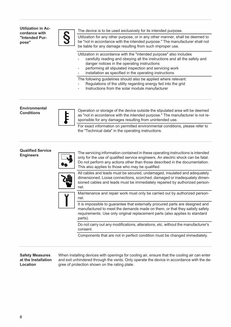
When installing devices with openings for cooling air, ensure that the cooling air can enter and exit unhindered through the vents. Only operate the device in accordance with the de-gree of protection shown on the rating plate.
The device is to be used exclusively for its intended purpose. Utilization for any other purpose, or in any other manner, shall be deemed to be "not in accordance with the intended purpose." The manufacturer shall not be liable for any damage resulting from such improper use.
Utilization in accordance with the "intended purpose" also includes - carefully reading and obeying all the instructions and all the safety and
danger notices in the operating instructions- performing all stipulated inspection and servicing work- installation as specified in the operating instructionsThe following guidelines should also be applied where relevant:- Regulations of the utility regarding energy fed into the grid- Instructions from the solar module manufacturer
Operation or storage of the device outside the stipulated area will be deemed as "not in accordance with the intended purpose." The manufacturer is not re-sponsible for any damages resulting from unintended use.For exact information on permitted environmental conditions, please refer to the "Technical data" in the operating instructions.
The servicing information contained in these operating instructions is intended only for the use of qualified service engineers. An electric shock can be fatal. Do not perform any actions other than those described in the documentation. This also applies to those who may be qualified.All cables and leads must be secured, undamaged, insulated and adequately dimensioned. Loose connections, scorched, damaged or inadequately dimen-sioned cables and leads must be immediately repaired by authorized person-nel.Maintenance and repair work must only be carried out by authorized person-nel.It is impossible to guarantee that externally procured parts are designed and manufactured to meet the demands made on them, or that they satisfy safety requirements. Use only original replacement parts (also applies to standard parts).Do not carry out any modifications, alterations, etc. without the manufacturer's consent.Components that are not in perfect condition must be changed immediately.
8
EN-U
S
Data Regarding Noise Emission ValuesEMC Device Clas-sifications
EMC Measures
Grid Connection
Electrical Installa-tions
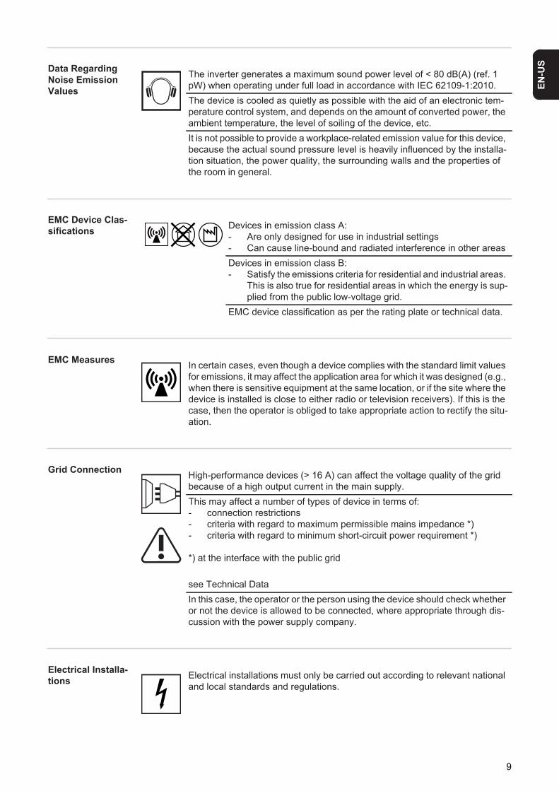
The inverter generates a maximum sound power level of < 80 dB(A) (ref. 1 pW) when operating under full load in accordance with IEC 62109-1:2010.The device is cooled as quietly as possible with the aid of an electronic tem-perature control system, and depends on the amount of converted power, the ambient temperature, the level of soiling of the device, etc.It is not possible to provide a workplace-related emission value for this device, because the actual sound pressure level is heavily influenced by the installa-tion situation, the power quality, the surrounding walls and the properties of the room in general.
Devices in emission class A:- Are only designed for use in industrial settings- Can cause line-bound and radiated interference in other areasDevices in emission class B:- Satisfy the emissions criteria for residential and industrial areas.
This is also true for residential areas in which the energy is sup-plied from the public low-voltage grid.
EMC device classification as per the rating plate or technical data.
In certain cases, even though a device complies with the standard limit values for emissions, it may affect the application area for which it was designed (e.g., when there is sensitive equipment at the same location, or if the site where the device is installed is close to either radio or television receivers). If this is the case, then the operator is obliged to take appropriate action to rectify the situ-ation.
High-performance devices (> 16 A) can affect the voltage quality of the grid because of a high output current in the main supply.This may affect a number of types of device in terms of:- connection restrictions- criteria with regard to maximum permissible mains impedance *)- criteria with regard to minimum short-circuit power requirement *)
*) at the interface with the public grid
see Technical DataIn this case, the operator or the person using the device should check whether or not the device is allowed to be connected, where appropriate through dis-cussion with the power supply company.
Electrical installations must only be carried out according to relevant national and local standards and regulations.
9
Protective Mea-sures against ESD
Safety measures in normal opera-tion
Safety Symbols
Disposal
Backup
Copyright
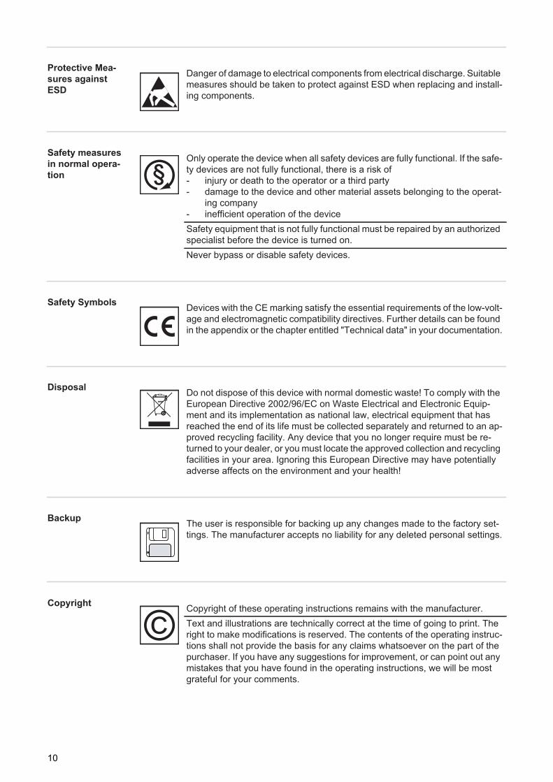
Danger of damage to electrical components from electrical discharge. Suitable measures should be taken to protect against ESD when replacing and install-ing components.
Only operate the device when all safety devices are fully functional. If the safe-ty devices are not fully functional, there is a risk of- injury or death to the operator or a third party- damage to the device and other material assets belonging to the operat-
ing company- inefficient operation of the deviceSafety equipment that is not fully functional must be repaired by an authorized specialist before the device is turned on.Never bypass or disable safety devices.
Devices with the CE marking satisfy the essential requirements of the low-volt-age and electromagnetic compatibility directives. Further details can be found in the appendix or the chapter entitled "Technical data" in your documentation.
Do not dispose of this device with normal domestic waste! To comply with the European Directive 2002/96/EC on Waste Electrical and Electronic Equip-ment and its implementation as national law, electrical equipment that has reached the end of its life must be collected separately and returned to an ap-proved recycling facility. Any device that you no longer require must be re-turned to your dealer, or you must locate the approved collection and recycling facilities in your area. Ignoring this European Directive may have potentially adverse affects on the environment and your health!
The user is responsible for backing up any changes made to the factory set-tings. The manufacturer accepts no liability for any deleted personal settings.
Copyright of these operating instructions remains with the manufacturer.Text and illustrations are technically correct at the time of going to print. The right to make modifications is reserved. The contents of the operating instruc-tions shall not provide the basis for any claims whatsoever on the part of the purchaser. If you have any suggestions for improvement, or can point out any mistakes that you have found in the operating instructions, we will be most grateful for your comments.
10

General Information


EN-U
S
Protection of Persons and Equipment
Safety
Protection of Per-sons and Equip-ment
The design and function of the inverter provide a maximum level of safety during both in-stallation and operation.
The inverter provides operator and equipment protection through:a) RCMUb) monitoring the grid
RCMU RCMU = Residual Current Monitoring Unit
The inverter is equipped with an RCMU according to DIN VDE 0126-1-1.It monitors residual currents from the solar module to the inverter grid connection and dis-connects the inverter from the grid when an improper residual current is detected.Additional residual current protection may be needed depending on the installation's pro-tection system or the requirements of the utility company. In this case, use a type A residual current circuit breaker with a release current of at least 100 mA.
Monitoring the Grid
Whenever conditions in the electric grid are inconsistent with standard conditions (for ex-ample, grid switch-off, interruption), the inverter will immediately stop operating and inter-rupt the supply of power into the grid.
Grid monitoring is carried out using:- Voltage monitoring- Frequency monitoring- Monitoring islanding conditions
WARNING! If the equipment is used or tasks are carried out incorrectly, serious injury or damage may result. Only qualified personnel are authorized to install your inverter and only within the scope of the respective technical regulations. It is essential that you read the "Safety regulations" chapter before commissioning the equipment or carrying out maintenance work.
13
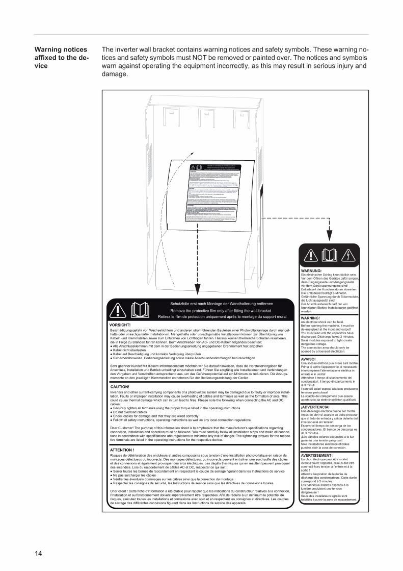
Warning notices affixed to the de-vice
The inverter wall bracket contains warning notices and safety symbols. These warning no-tices and safety symbols must NOT be removed or painted over. The notices and symbols warn against operating the equipment incorrectly, as this may result in serious injury and damage.
14

EN-U
S
Safety Symbols:
Warning Notice Texts:
WARNING!An electric shock can be fatal. Before opening the machine, it must be de-energized at the input and output.You must wait until the capacitors have discharged. Discharge takes 3 minutes.Solar modules exposed to light create dangerous voltage.The service area should only be opened by a licensed electrician.
CAUTION!Inverters and other current-carrying components of a photovoltaic system may be dam-aged through faulty or improper installation. Faulty or improper installation may cause overheating of cables and terminals as well as the formation of arcs. This could cause ther-mal damage, which in turn may lead to fires. Please note the following when connecting the AC and DC cables:- Securely tighten all terminals using the proper torque listed in the operating instruc-
tions- Do not overload cables- Check cables for damage and that they are wired correctly- Follow all safety instructions, operating instructions as well as any local connection
regulations
Dear Customer, The purpose of this information sheet is to emphasize that the manufac-turer's specifications regarding connection, installation and operation must be followed. You must carefully follow all installation steps and make all connections in accordance with specifications and regulations to minimize any risk of danger. The tightening torques for the respective terminals are listed in the operating instructions for each respective device.
Risk of serious injury or damage due to incorrect operation
Do not use the functions described until you have thoroughly read and under-stood the following documents:- These operating instructions- All operating instructions for the system components of the photovoltaic
system, especially the safety rules
Dangerous electrical voltages
15

Information on Dummy Devices
A dummy device should not be connected to a photovoltaic system for real operation and may only be used for demonstration purposes.
IMPORTANT! When using a dummy device:- you should never connect a live DC cable to the DC connection sockets- you should never connect the public grid to the AC connection sockets.
You may connect live cables or cable pieces for demonstration purposes.
Dummy devices receive their power supply from a separate power unit.
Dummy devices can be recognized by their device rating plate:
Dummy device rating plate
16
EN-U
S
Utilization in accordance with "intended purpose"
Utilization in Con-formity with "In-tended Purpose"
The Fronius IG TL solar inverter is designed exclusively to convert direct current from solar modules into alternating current and feed this power into the pubic grid.The following are deemed to be not in conformity with its intented purpose:- Utilization for any other purpose, or in any other manner- Alterations to the Fronius IG TL that are not expressly recommended by Fronius- Installation of components that are not expressly recommended or sold by Fronius
The manufacturer is not responsible for any damages resulting from unintended use.All warranty claims are voided.
Utilization in conformity with the "intended purpose" also includes- Following all the instructions in these operating instructions- Carrying out all the specified inspection and servicing work
Field of applica-tion
The inverter has been designed exclusively for use in grid-connected photovoltaic sys-tems. It cannot generate electric power independently of the grid.
Photovoltaic sys-tem stipulations
When configuring the photovoltaic system, make sure that all photovoltaic system compo-nents are operating completely within their permitted operating range.
All measures recommended by the solar module manufacturer for maintaining solar mod-ule properties must be followed.
NOTE! The inverter is designed exclusively to be connected and used with non-grounded solar modules in protection class II. The solar modules cannot be grounded at either the positive or negative pole.
Use with other DC generators (e.g., wind generators) is not permitted.
17

The Fronius IG TL Unit in the PV System
General The solar inverter is the highly complex link between the solar modules and the public grid.
Tasks The main tasks of the inverter include:- Converting DC to AC current- Fully automatic operational management- Display function and data communication
Converting DC into AC current
The inverter transforms the direct current generated by the solar modules into alternating current. This alternating current is fed into your home system or into the public grid and synchronized with the voltage that is used there.
Fully automatic operation man-agement
The inverter is fully automatic. Starting at sunrise, as soon as the solar modules generate enough energy, the automatic control unit starts monitoring grid voltage and frequency. As soon as there is a sufficient level of irradiance, your solar inverter starts feeding energy into the grid.
The control system of the inverter ensures that the maximum possible power output is drawn from the solar modules at all times. This function is called MPPT (Maximum Power Point Tracking).
As dusk starts and there is no longer sufficient energy available to feed power into the grid, the inverter shuts down the grid connection completely and stops operating. All settings and recorded data are saved.
Display function and data commu-nication
The display on the inverter is the interface between the inverter and the operator. The de-sign of the display is geared toward simple operation and making system data available at all times.
The inverter is equipped with basic logging functions for recording minimum and maximum data on a daily, yearly, and cumulative basis. These values are shown on the display.
A wide range of data communication products allows many possibilities for recording and viewing data.
Solar Module String Monitoring
The inverter has a function that can monitor incoming solar module strings to detect errors in the solar module field.
System upgrades The inverter is designed for various system upgrades, e.g.:- Data logger (when using a PC to record and manage data from your photovoltaic sys-
tem), includes a data logger and a modem interface.- Various large-format displays- Actuators (e.g.: relays, alarms) - Fronius Sensor Box (sensors for temperature, irradiance, energy measurement, etc.)- Fronius DC Box 60/12 (general mailbox)
18
EN-U
S
Active inverter coolingThe inverter's temperature-controlled, variable-speed fan with ball-bearing support pro-vides:- Optimal inverter cooling- Higher efficiency- Cooler parts, thus extending the service life- The least possible energy consumption and lowest possible noise level- Weight reduction due to the reduction of the cooling element surface
Power derating Should there be insufficient heat dissipation in spite of the fan operating at maximum speed (for example, inadequate heat transfer away from the heat sinks), the power will be derated to protect the inverter when the ambient temperature reaches approx. 40 °C and above.
Derating the power reduces the output of the inverter for a short period sufficient to ensure that the temperature will not exceed the permissible limit.Your inverter will remain ready for operation as long as possible without any interruption.
19

20

Installation and Startup

EN-U
S
Fronius IG TL Installation and Connection
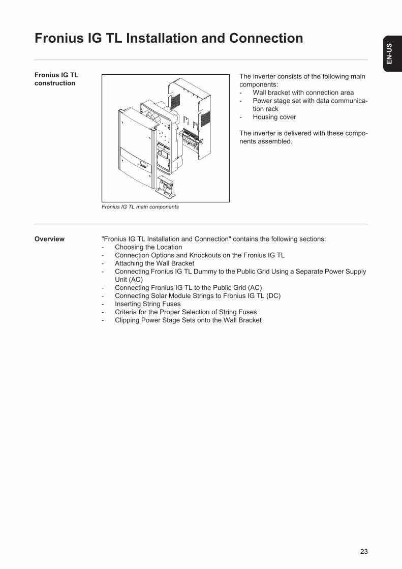
Fronius IG TL construction
Fronius IG TL main components
The inverter consists of the following main components:- Wall bracket with connection area- Power stage set with data communica-
tion rack- Housing cover
The inverter is delivered with these compo-nents assembled.
Overview "Fronius IG TL Installation and Connection" contains the following sections:- Choosing the Location- Connection Options and Knockouts on the Fronius IG TL- Attaching the Wall Bracket- Connecting Fronius IG TL Dummy to the Public Grid Using a Separate Power Supply
Unit (AC)- Connecting Fronius IG TL to the Public Grid (AC)- Connecting Solar Module Strings to Fronius IG TL (DC)- Inserting String Fuses- Criteria for the Proper Selection of String Fuses- Clipping Power Stage Sets onto the Wall Bracket
23
Choosing the Location
Choosing the Lo-cation (General)
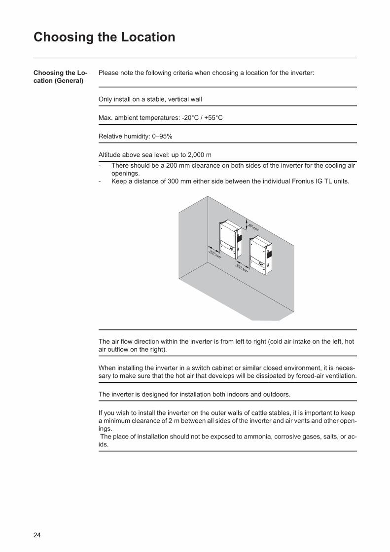
Please note the following criteria when choosing a location for the inverter:
Only install on a stable, vertical wall
Max. ambient temperatures: -20°C / +55°C
Relative humidity: 0–95%
Altitude above sea level: up to 2,000 m- There should be a 200 mm clearance on both sides of the inverter for the cooling air
openings.- Keep a distance of 300 mm either side between the individual Fronius IG TL units.
The air flow direction within the inverter is from left to right (cold air intake on the left, hot air outflow on the right).
When installing the inverter in a switch cabinet or similar closed environment, it is neces-sary to make sure that the hot air that develops will be dissipated by forced-air ventilation.
The inverter is designed for installation both indoors and outdoors.
If you wish to install the inverter on the outer walls of cattle stables, it is important to keep a minimum clearance of 2 m between all sides of the inverter and air vents and other open-ings. The place of installation should not be exposed to ammonia, corrosive gases, salts, or ac-ids.
200 mm
300 mm
50 mm
24
EN-U
S
Choosing a Loca-tion for Inside In-stallationChoosing a Loca-tion for Outdoor Installation
During certain operation phases the inverter may produce a slight noise. For this reason it should not be installed in an occupied living area.Do not install the inverter in:- areas with large amounts of dust- areas with large amounts of conducting dust particles (e.g., iron filings)- areas with corrosive gases, acids or salts- areas where there is an increased risk of accidents, e.g., from farm animals (horses,
cattle, sheep, pigs, etc.)- stables or adjoining areas- storage areas for hay, straw, chaff, animal feed, fertilizers, etc.- storage or processing areas for fruit, vegetables or winegrowing products- areas used in the preparation of grain, green fodder or animal feeds- greenhouses
Because of its IP 44 protection class, the inverter is not susceptible to hose water on any side and can also be operated in moist environments.In order to keep inverter heating as low as possible, the inverter should not be exposed to direct sunlight. Ideally, the inverter should be installed in a protected location, e.g., near the solar modules or under an overhanging roof.Do not install the inverter:- where it may be exposed to ammonia, corrosive gases, acids or salts (e.g., fertilizer
storage areas, vent openings for livestock stables, chemical plants, tanneries, etc.).
25
Connection Options and Knockouts on the Fronius IG TL
Connection op-tions on the Fro-nius IG TL
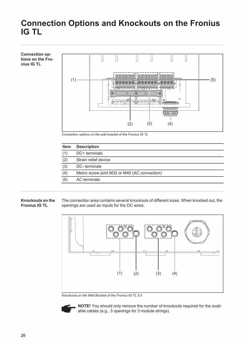
Connection options on the wall bracket of the Fronius IG TL
Knockouts on the Fronius IG TL
The connection area contains several knockouts of different sizes. When knocked out, the openings are used as inputs for the DC wires.
Knockouts on the Wall Bracket of the Fronius IG TL 5.0
Item Description(1) DC+ terminals(2) Strain relief device(3) DC- terminals(4) Metric screw joint M32 or M40 (AC connection)(5) AC terminals
(1)
(2) (3) (4)
(5)
NOTE! You should only remove the number of knockouts required for the avail-able cables (e.g., 3 openings for 3 module strings).
(1) (2) (3) (4)
26
EN-U
S
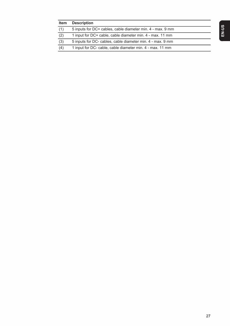
Item Description(1) 5 inputs for DC+ cables, cable diameter min. 4 - max. 9 mm(2) 1 input for DC+ cable, cable diameter min. 4 - max. 11 mm(3) 5 inputs for DC- cables, cable diameter min. 4 - max. 9 mm(4) 1 input for DC- cable, cable diameter min. 4 - max. 11 mm
27
Attaching the Wall Bracket
Selecting dowels and screws
The head height of the screws used may be a maximum of 6 mm.When using washers, the maximum head height of th screws is reduced by the thickness of the washers.
Screw recom-mendation
The manufacturer recommends using screws with a min. diameter of 6 mm for inverter in-stallation.
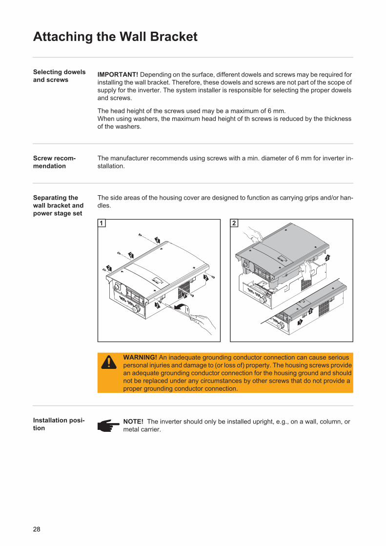
Separating the wall bracket and power stage set
The side areas of the housing cover are designed to function as carrying grips and/or han-dles.
1 2
Installation posi-tion
IMPORTANT! Depending on the surface, different dowels and screws may be required for installing the wall bracket. Therefore, these dowels and screws are not part of the scope of supply for the inverter. The system installer is responsible for selecting the proper dowels and screws.
2
2
2
2
2
2
1
1
1
2
2
2
WARNING! An inadequate grounding conductor connection can cause serious personal injuries and damage to (or loss of) property. The housing screws provide an adequate grounding conductor connection for the housing ground and should not be replaced under any circumstances by other screws that do not provide a proper grounding conductor connection.
NOTE! The inverter should only be installed upright, e.g., on a wall, column, or metal carrier.
28

EN-U
S
Attaching the wall bracket - Wall in-stallation1 2
1
2
CAUTION! The inverter can be damaged by soiling or water on the terminals and contacts of the connection area.- When drilling, make sure that terminals and contacts in the connection area
do not become soiled or wet. Leave the dust cover in position. - The wall bracket apart from the power stage set does not possess the degree
of protection of the complete inverter and, therefore, should not be attached without a power stage set.Protect the wall bracket against soiling and moisture during installation.
min. 50 mmmin. 2 in.
1 1
2
3
4
(*)
1
1
2
3
2
IMPORTANT! Attach the wall bracket so that the display marking (*) on the wall bracket is at eye level.
NOTE! When attaching the wall bracket to the wall, make sure that the wall brack-et is not warped or deformed.
3
3
4
1 2
4
1
4
29
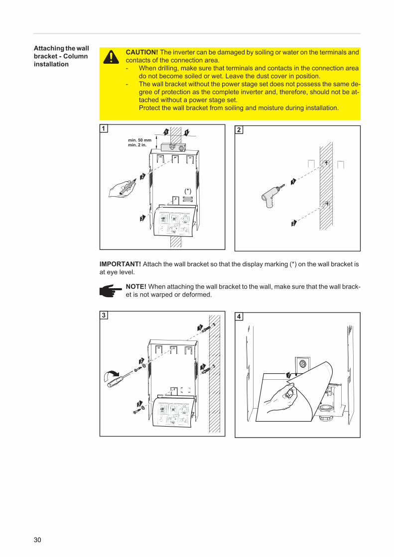
Attaching the wall bracket - Column installation
1
2
1
2
CAUTION! The inverter can be damaged by soiling or water on the terminals and contacts of the connection area.- When drilling, make sure that terminals and contacts in the connection area
do not become soiled or wet. Leave the dust cover in position.- The wall bracket without the power stage set does not possess the same de-
gree of protection as the complete inverter and, therefore, should not be at-tached without a power stage set.Protect the wall bracket from soiling and moisture during installation.
min. 50 mmmin. 2 in.
1 1
2
3
(*)
1
1
2
2
IMPORTANT! Attach the wall bracket so that the display marking (*) on the wall bracket is at eye level.
NOTE! When attaching the wall bracket to the wall, make sure that the wall brack-et is not warped or deformed.
2
3
1
1
3
3
4
1 2
4
1
4
30
EN-U
S
Connecting Fronius IG TL Dummy to the Public Grid Using a Separate Power Supply Unit
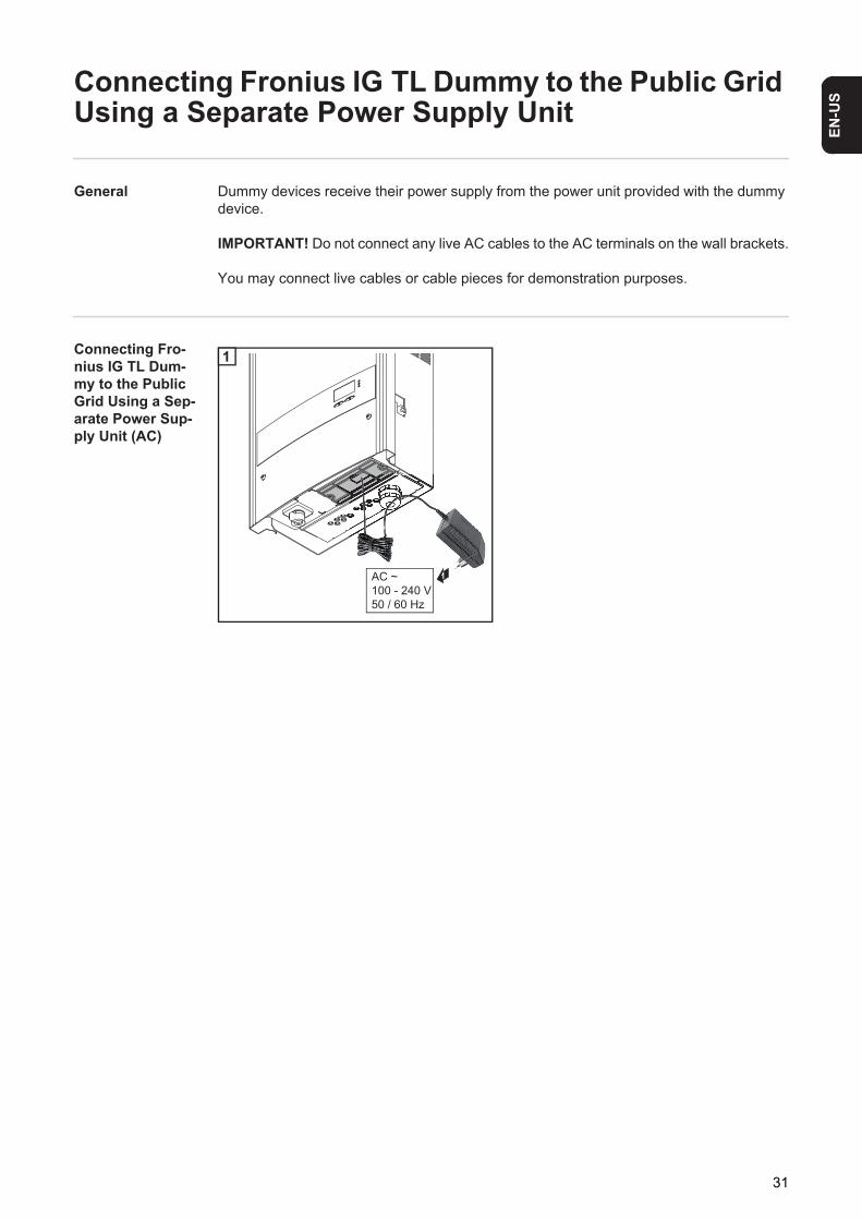
General Dummy devices receive their power supply from the power unit provided with the dummy device.
IMPORTANT! Do not connect any live AC cables to the AC terminals on the wall brackets.
You may connect live cables or cable pieces for demonstration purposes.
Connecting Fro-nius IG TL Dum-my to the Public Grid Using a Sep-arate Power Sup-ply Unit (AC)
1
1AC ~100 - 240 V50 / 60 Hz
1
31

Connecting the Fronius IG TL to the public grid (AC)
Monitoring the Grid
AC terminals Legend:
L Phase conductorN Neutral conductorPE Grounding conductor / GroundPE (a) Connection option for additional
ground
Max. cable cross section per conductor ca-ble:16 mm²
Min. cable cross section per conductor ca-ble:corresponds to the AC-side overcurrent-protected value, but at least 2.5 mm²
Connecting Alu-minum Cables
The AC-side terminals are designed for connecting single-wire, round aluminum cables. The following points must be taken into account when connecting aluminum cables due to the non-conducting oxide layer of aluminum:- reduced rated currents for aluminum cables - the connection requirements listed below.
Connection Requirements:
Carefully clean off the oxide layer of the stripped end of the cable, e.g., using a knife.
IMPORTANT! Do not use brushes, files, or sandpaper; aluminum particles may get stuck and can transfer to other cables.
After removing the oxide layer of the cable end, rub in a neutral grease, e.g., acid-free and alkali-free Vaseline.Then immediately connect it to the terminal.
Repeat the steps above whenever the cable is disconnected and then reconnected.
IMPORTANT! The resistance in the leads to the AC-side connection terminals must be as low as possible for optimal functioning of grid monitoring.
AC
PE N LPE
PE(a)
NOTE! Connect the phase (L), neutral conductor (N), and grounding conductor (PE) cables correctly!
NOTE! Take into account local specifications when configuring cable cross sec-tions.
1
2
3
32
EN-U
S
AC cable cross sectionFor a standard M32 metric screw joint with a reducer:Cable diameter 7 - 15 mm
For an M32 metric screw joint (reducer removed): Cable diameter 11 - 21 mm(a cable diameter of 11 mm reduces the strain relief force from 100 N to a max. of 80 N)
For an M40 metric screw joint (option): Cable diameter 19 - 28 mm
If required, use reducers for smaller cable diameters.
Safety
Connecting the Fronius IG TL to the public grid (AC)
WARNING! An electric shock can be fatal. Danger from grid voltage and DC volt-age from solar modules.- Never work with live wires! Prior to all connection work, make sure that the
AC and DC wires are not charged.- Only an authorized electrician is permitted to connect this inverter to the pub-
lic grid.
CAUTION! Danger of damaging the inverter from improperly connected termi-nals. Improperly connected terminals can cause thermal damage to the inverter and may cause a fire. When connecting the AC and DC cables, make sure that all terminals are tightened securely using the proper torque.
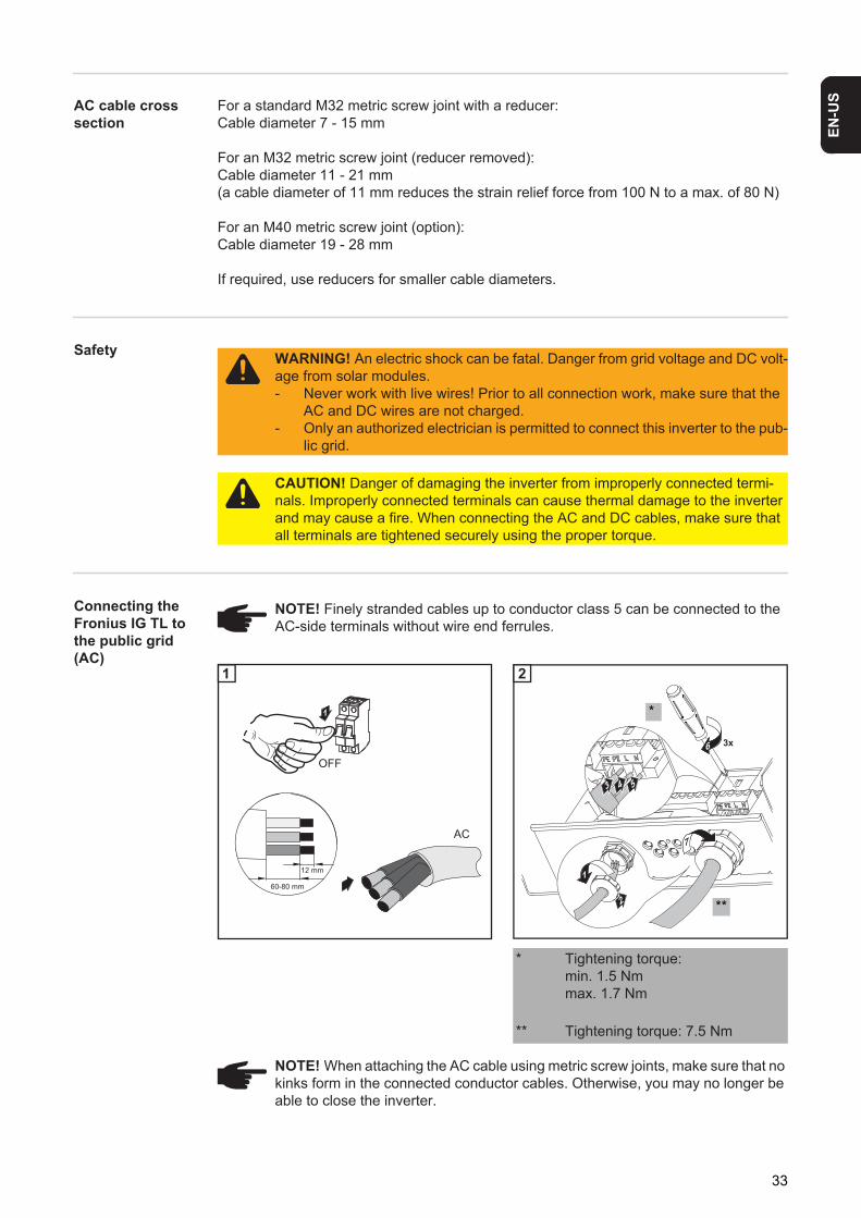
NOTE! Finely stranded cables up to conductor class 5 can be connected to the AC-side terminals without wire end ferrules.
1 1
* Tightening torque:min. 1.5 Nmmax. 1.7 Nm
** Tightening torque: 7.5 Nm
NOTE! When attaching the AC cable using metric screw joints, make sure that no kinks form in the connected conductor cables. Otherwise, you may no longer be able to close the inverter.
1
60-80 mm
12 mm
AC
OFF
1
3 54
2
1
7
6 3x
*
**
2
33
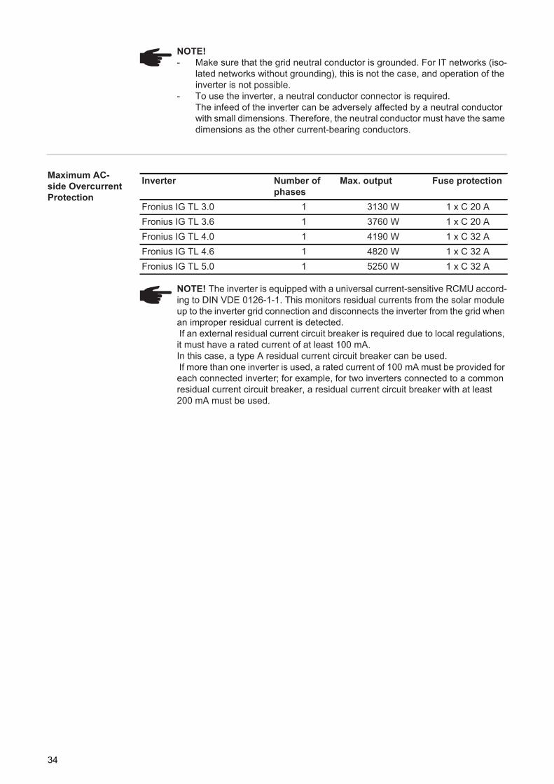
Maximum AC-side Overcurrent Protection
NOTE! - Make sure that the grid neutral conductor is grounded. For IT networks (iso-
lated networks without grounding), this is not the case, and operation of the inverter is not possible.
- To use the inverter, a neutral conductor connector is required.The infeed of the inverter can be adversely affected by a neutral conductor with small dimensions. Therefore, the neutral conductor must have the same dimensions as the other current-bearing conductors.
Inverter Number of phases
Max. output Fuse protection
Fronius IG TL 3.0 1 3130 W 1 x C 20 AFronius IG TL 3.6 1 3760 W 1 x C 20 AFronius IG TL 4.0 1 4190 W 1 x C 32 AFronius IG TL 4.6 1 4820 W 1 x C 32 AFronius IG TL 5.0 1 5250 W 1 x C 32 A
NOTE! The inverter is equipped with a universal current-sensitive RCMU accord-ing to DIN VDE 0126-1-1. This monitors residual currents from the solar module up to the inverter grid connection and disconnects the inverter from the grid when an improper residual current is detected. If an external residual current circuit breaker is required due to local regulations, it must have a rated current of at least 100 mA. In this case, a type A residual current circuit breaker can be used. If more than one inverter is used, a rated current of 100 mA must be provided for each connected inverter; for example, for two inverters connected to a common residual current circuit breaker, a residual current circuit breaker with at least 200 mA must be used.
34
EN-U
S
Connecting Solar Module Strings to the Fronius IG TL (DC)
Fronius IG TL field of applica-tion
General informa-tion about solar modules
In order to select suitable solar modules and get the most efficient use out of the inverter, please note the following points:- The open circuit voltage of the solar modules increases as the temperature decreases
(assuming constant irradiance). Open circuit voltage may not exceed 850 V.If the open circuit voltage exceeds 850 volts, the inverter may be damaged, and all warranty rights will become null and void.
- Note the temperature coefficients in the solar module data sheet- More exact data for sizing the solar array for the particular location can be obtained
using calculations tools such as the Fronius Solar.configurator (available at http://www.fronius.com).
Safety
NOTE! The inverter is designed exclusively to be connected and used with non-grounded solar modules. The solar modules must correspond to protection class II and class A according to IEC 61730, and they cannot be grounded at either the positive or negative pole. Use with other DC generators (e.g., wind generators) is not permitted.
NOTE! Before connecting solar modules, make sure that the voltage specified by the manufacturer corresponds to the actual measured voltage. Note the safety instructions and specifications of the solar module manufacturer regarding solar module grounding. Solar modules that require a ground at the positive or negative pole cannot be used with the Fronius IG TL.
WARNING! An electric shock can be fatal. Danger from grid voltage and DC volt-age from solar modules.- Never work with live wires! Prior to all connection work, make sure that the
AC and DC wires are not charged.- Only an authorized electrician is permitted to connect this inverter to the pub-
lic grid.
CAUTION! Danger of injury from hazardous electrical voltage. Transformerless systems can transfer leakage currents to solar module frames and mounts due to their topology. Connect and ground all solar module frames and mounts and other conductive surfaces. To ground solar module frames or mounts, please refer to the specifications pro-vided by the solar module manufacturer and national guidelines.
CAUTION! Danger of damaging the inverter from improperly connected termi-nals. Improperly connected terminals can cause thermal damage to the inverter and may cause a fire. When connecting the AC and DC cables, make sure that all terminals are tightened securely using the proper torque.
CAUTION! Overloading the inverter may damage it. Only connect a maximum of 20 A to each DC terminal.
35
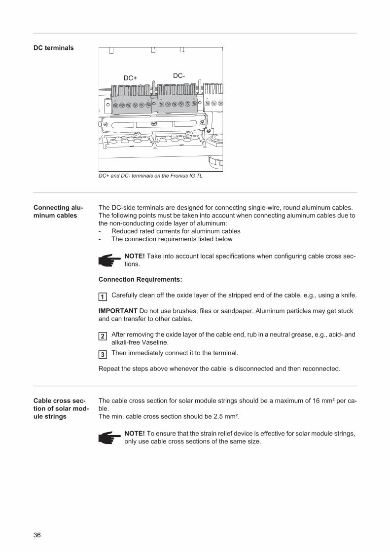
DC terminals
DC+ and DC- terminals on the Fronius IG TL
Connecting alu-minum cables
The DC-side terminals are designed for connecting single-wire, round aluminum cables. The following points must be taken into account when connecting aluminum cables due to the non-conducting oxide layer of aluminum:- Reduced rated currents for aluminum cables- The connection requirements listed below
Connection Requirements:
Carefully clean off the oxide layer of the stripped end of the cable, e.g., using a knife.
IMPORTANT Do not use brushes, files or sandpaper. Aluminum particles may get stuck and can transfer to other cables.
After removing the oxide layer of the cable end, rub in a neutral grease, e.g., acid- and alkali-free Vaseline.Then immediately connect it to the terminal.
Repeat the steps above whenever the cable is disconnected and then reconnected.
Cable cross sec-tion of solar mod-ule strings
The cable cross section for solar module strings should be a maximum of 16 mm² per ca-ble.The min. cable cross section should be 2.5 mm².
DC+ DC-
NOTE! Take into account local specifications when configuring cable cross sec-tions.
1
2
3
NOTE! To ensure that the strain relief device is effective for solar module strings, only use cable cross sections of the same size.
36
EN-U
S
Polarity reversal of solar module stringsThe inverter comes standard with 6 metal bolts in fuse holders in the power stage set. These metal bolts ensure that the inverter is protected against reversed polarity. Reverse polarity in the solar module strings will not cause any damage to the inverter.
If string fuses are used instead of metal bolts, reverse polarity in an individual solar module string can cause damage to the inverter and may cause an inverter fire.
Information on Dummy Devices
A dummy device (which is labeled as such on its rating plate) should not be connected to a photovoltaic system for real operation and may only be used for demonstration purposes.
IMPORTANT! When using a dummy device, you should never connect a live DC cable to the DC connection sockets.
You may connect live cables or cable pieces for demonstration purposes.
The following section "Connecting Solar Module Strings to the Fronius IG TL (DC)" only applies to genuine inverters.
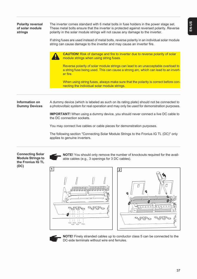
Connecting Solar Module Strings to the Fronius IG TL (DC)
1
2
CAUTION! Risk of damage and fire to inverter due to reverse polarity of solar module strings when using string fuses.
Reverse polarity of solar module strings can lead to an unacceptable overload to a string fuse being used. This can cause a strong arc, which can lead to an invert-er fire.
When using string fuses, always make sure that the polarity is correct before con-necting the individual solar module strings.
NOTE! You should only remove the number of knockouts required for the avail-able cables (e.g., 3 openings for 3 DC cables).
1
11
24
3
2
NOTE! Finely stranded cables up to conductor class 5 can be connected to the DC-side terminals without wire end ferrules.
37
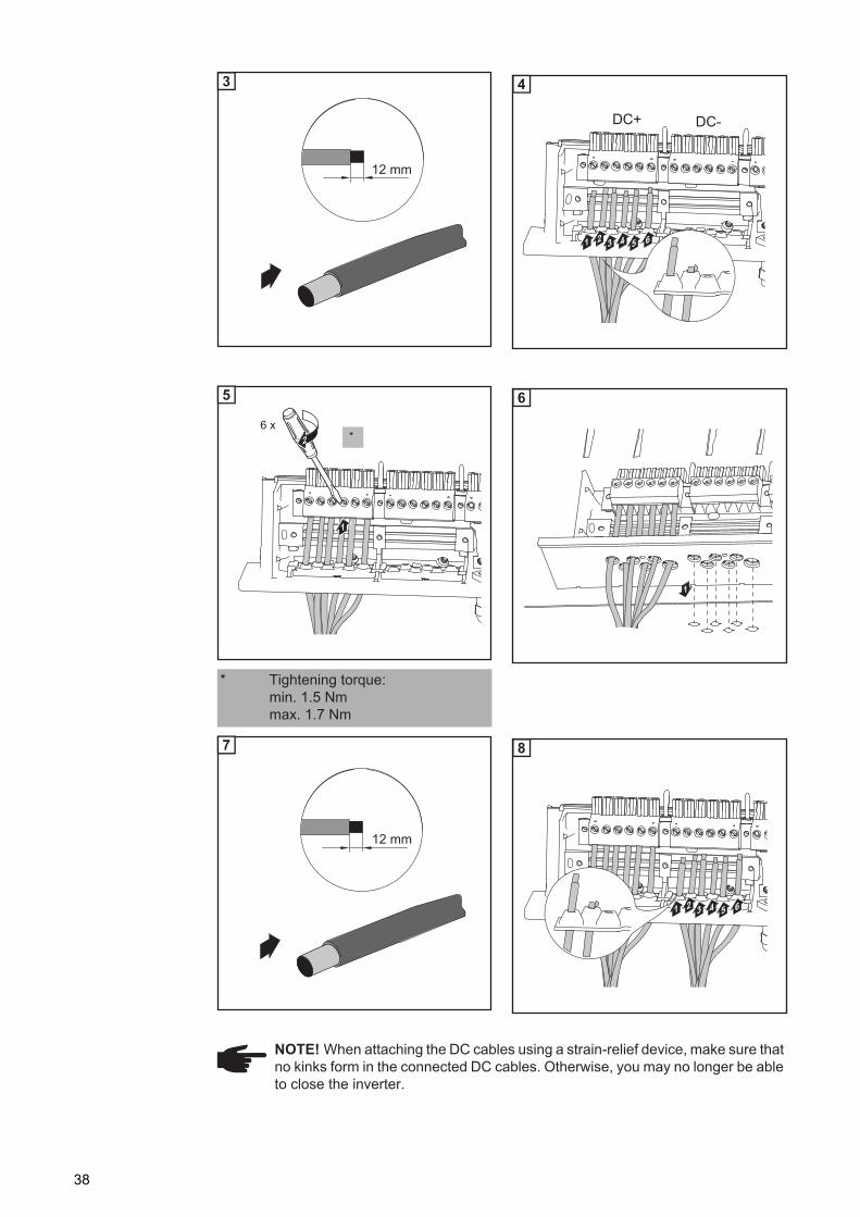
1
2
1
2
12 mm
3
1 65432
DC-DC+
4
1
1
* Tightening torque:min. 1.5 Nmmax. 1.7 Nm
2
1
*6 x
5
1
6
12 mm
7
1 65432
8
NOTE! When attaching the DC cables using a strain-relief device, make sure that no kinks form in the connected DC cables. Otherwise, you may no longer be able to close the inverter.
38
EN-U
S
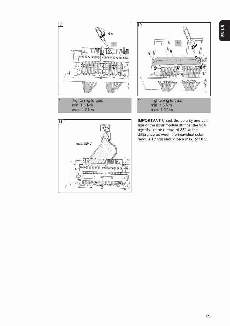
1
1
* Tightening torque:min. 1.5 Nmmax. 1.7 Nm
** Tightening torque:min. 1.5 Nmmax. 1.9 Nm
1
IMPORTANT Check the polarity and volt-age of the solar module strings: the volt-age should be a max. of 850 V; the difference between the individual solar module strings should be a max. of 10 V.
2
1
*
6 x
9
13 2
4**
10
max. 850 V
11
39
Inserting String Fuses into the Fronius IG TL
General The steps described in the ‘Inserting String Fuses into the Fronius IG TL’ section should only be carried out if the solar module manufacturer requires the use of string fuses for op-eration.
Selecting string fuses
If the solar module manufacturer requires the use of string fuses for operation, select string fuses according to the information from the solar module manufacturer or according to the ‘Criteria for the Proper Selection of String Fuses’ section:- max. 20 A per fuse holder- max. 6 DC inputs- max. 11 A per measuring channel if solar module string monitoring is activated and
being used- max. 20 A of total input current- Fuse dimensions: Diameter 10.3 x 35 - 38 mm
Safety
IMPORTANT! - Follow all solar module safety instructions- Follow all solar module manufacturer requirements
WARNING! An electric shock can be fatal. Danger from grid voltage and DC volt-age from solar modules.- The DC main switch is used only to switch off power to the power stage set.
When the DC main switch is turned off, the connection area is still energized.- Only licensed electricians should access the connection area.- All maintenance and service work should only be carried out when the power
stage set has been disconnected from the connection area.- Maintenance and service work on the inverter power stage set should only
be carried out by Fronius-trained personnel.
WARNING! An electric shock can be fatal. Danger from residual voltage from ca-pacitors.
You must wait until the capacitors have discharged. Discharge takes 3 minutes.
40
EN-U
S
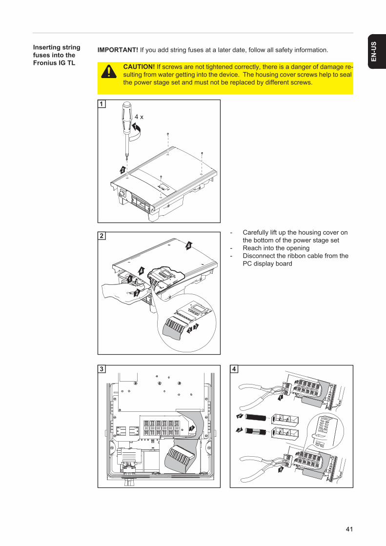
Inserting string fuses into the Fronius IG TL1
2 - Carefully lift up the housing cover on the bottom of the power stage set
- Reach into the opening- Disconnect the ribbon cable from the
PC display board
3 4
IMPORTANT! If you add string fuses at a later date, follow all safety information.
CAUTION! If screws are not tightened correctly, there is a danger of damage re-sulting from water getting into the device. The housing cover screws help to seal the power stage set and must not be replaced by different screws.
2
14 x
1
2
1
4
4
33
2
1
3
1
4
2
3
4
41
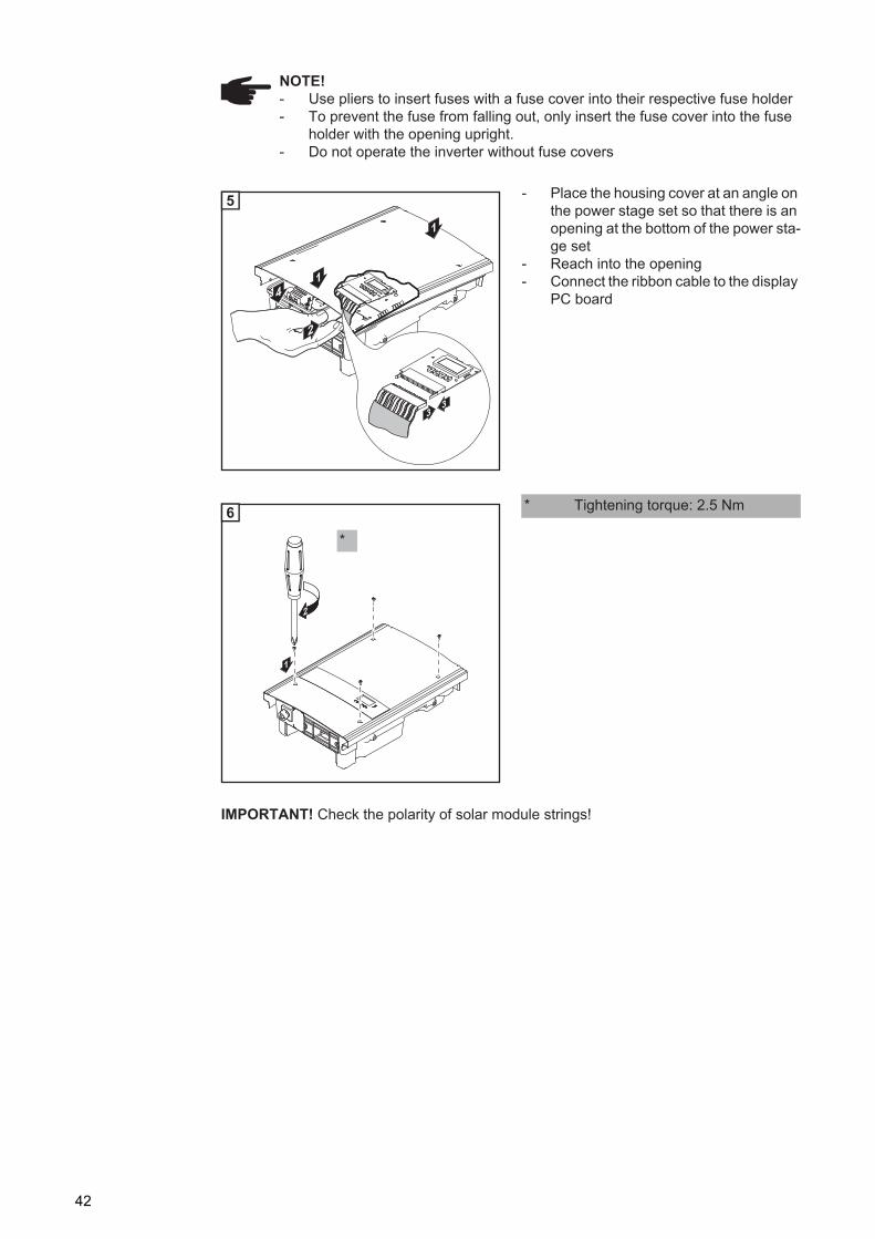
1 - Place the housing cover at an angle on the power stage set so that there is an opening at the bottom of the power sta-ge set
- Reach into the opening- Connect the ribbon cable to the display
PC board
NOTE! - Use pliers to insert fuses with a fuse cover into their respective fuse holder- To prevent the fuse from falling out, only insert the fuse cover into the fuse
holder with the opening upright.- Do not operate the inverter without fuse covers
2
1
14
33
5
1 * Tightening torque: 2.5 Nm
IMPORTANT! Check the polarity of solar module strings!
1
2
*
6
42
EN-U
S
Criteria for the Proper Selection of String Fuses
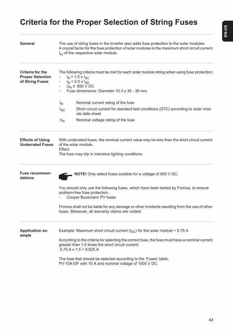
General The use of string fuses in the inverter also adds fuse protection to the solar modules.A crucial factor for the fuse protection of solar modules is the maximum short circuit current Isc of the respective solar module.
Criteria for the Proper Selection of String Fuses
The following criteria must be met for each solar module string when using fuse protection:- IN > 1.5 x ISC- IN < 2.0 x ISC- UN ≥ 850 V DC- Fuse dimensions: Diameter 10.3 x 35 - 38 mm
Effects of Using Underrated Fuses
With underrated fuses, the nominal current value may be less than the short circuit current of the solar module.Effect:The fuse may trip in intensive lighting conditions.
Fuse recommen-dations
You should only use the following fuses, which have been tested by Fronius, to ensure problem-free fuse protection:- Cooper Bussmann PV fuses
Fronius shall not be liable for any damage or other incidents resulting from the use of other fuses. Moreover, all warranty claims are voided.
Application ex-ample
Example: Maximum short circuit current (ISC) for the solar module = 5.75 A
According to the criteria for selecting the correct fuse, the fuse must have a nominal current greater than 1.5 times the short circuit current: 5.75 A x 1.5 = 8.625 A
The fuse that should be selected according to the ‘Fuses’ table: PV-10A10F with 10 A and nominal voltage of 1000 V DC.
IN Nominal current rating of the fuseISC Short circuit current for standard test conditions (STC) according to solar mod-
ule data sheetVN Nominal voltage rating of the fuse
NOTE! Only select fuses suitable for a voltage of 850 V DC.
43

Fuses
‘Fuses’ Table: Selection of suitable fuses, e.g., Cooper Bussmann fuses
Nominal current value
Fuse Nominal current value
Fuse
1.0 A PV-1A10F 6.0 A PV-6A10F2.0 A PV-2A10F 8.0 A PV-8A10F3.0 A PV-3A10F 10.0 A PV-10A10F4.0 A PV-4A10F 12.0 A PV-12A10F5.0 A PV-5A10F 15.0 A PV-15A10F
44
EN-U
S
Clipping Power Stage Sets onto the Wall Bracket
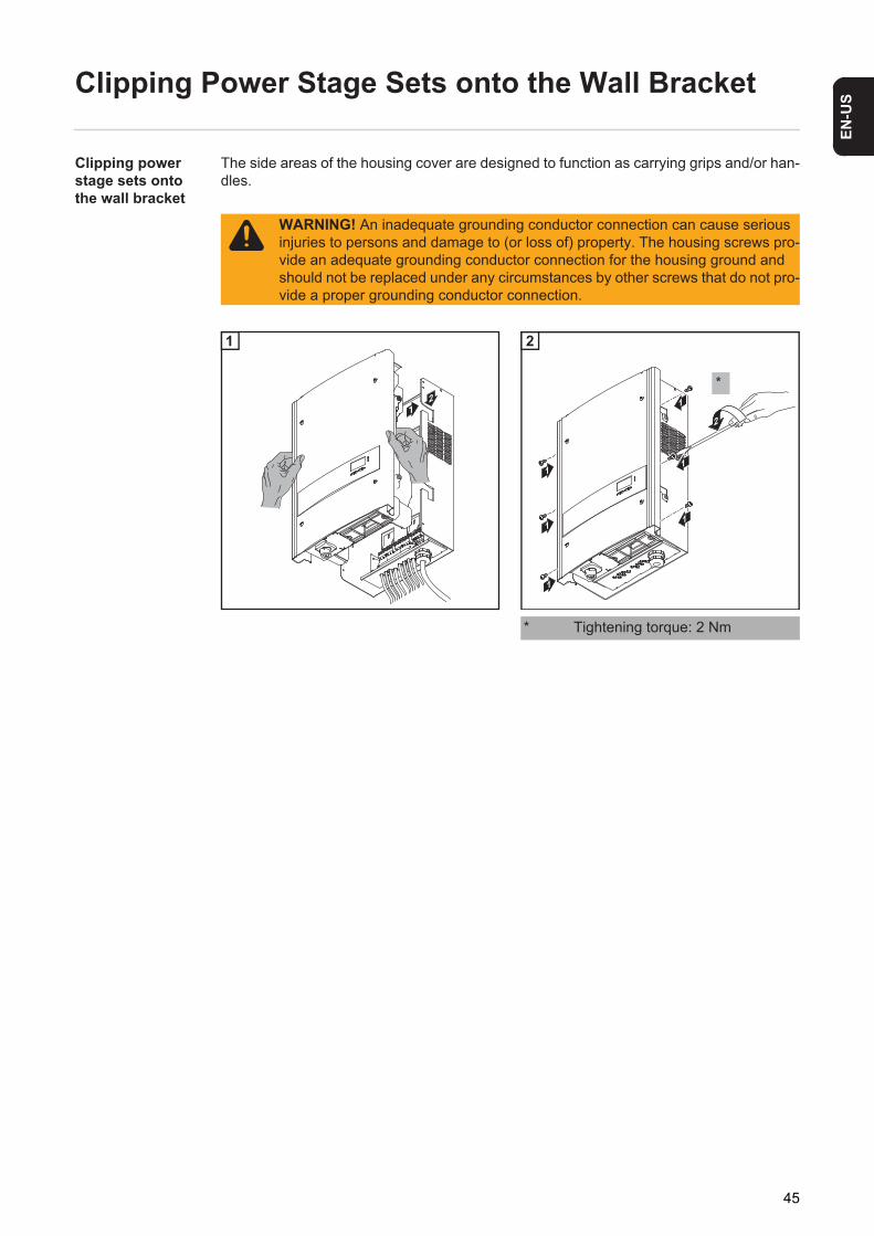
Clipping power stage sets onto the wall bracket
The side areas of the housing cover are designed to function as carrying grips and/or han-dles.
WARNING! An inadequate grounding conductor connection can cause serious injuries to persons and damage to (or loss of) property. The housing screws pro-vide an adequate grounding conductor connection for the housing ground and should not be replaced under any circumstances by other screws that do not pro-vide a proper grounding conductor connection.
1 1
* Tightening torque: 2 Nm
21
1
11
1
1
2
1
1
*
2
45
Data Communication and Solar Net
Fronius Solar Net and Data Inter-face
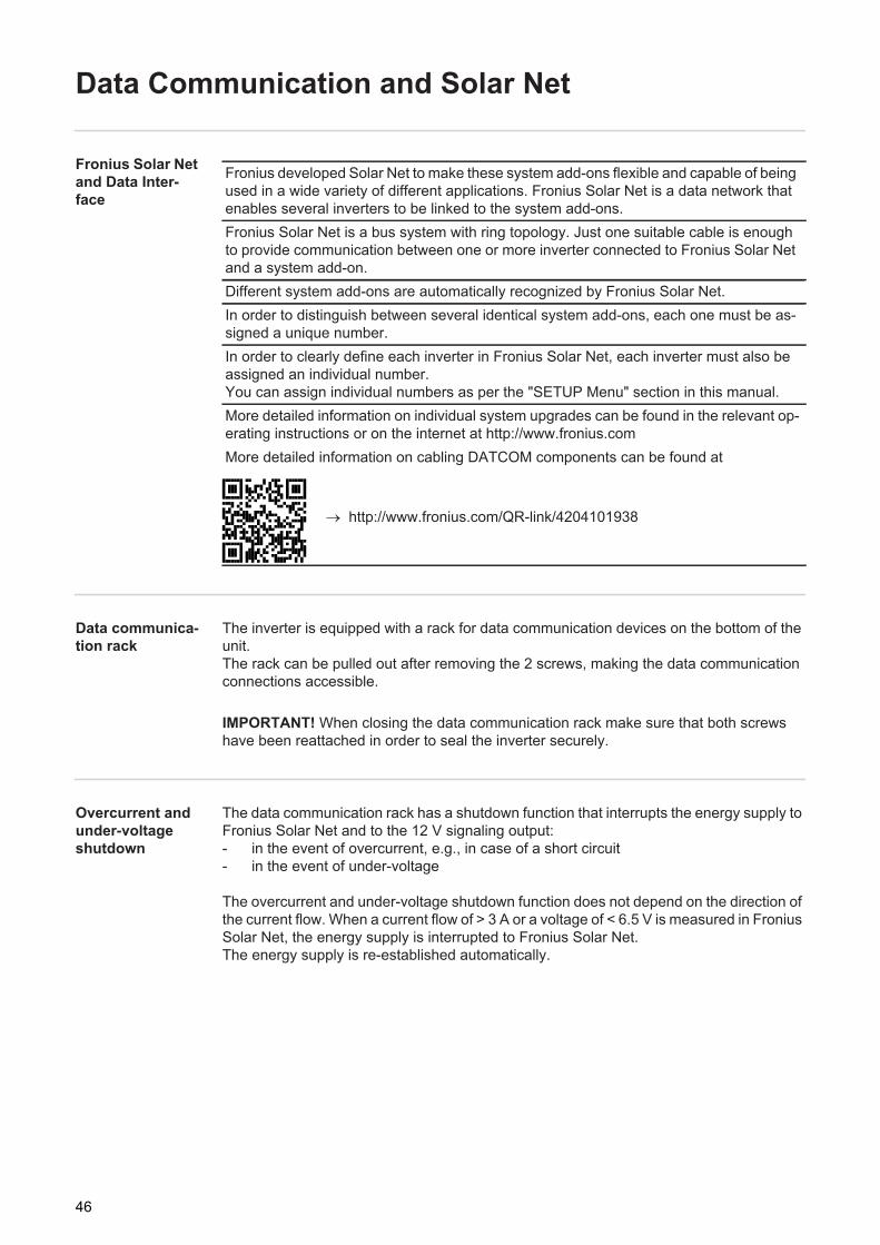
Data communica-tion rack
The inverter is equipped with a rack for data communication devices on the bottom of the unit.The rack can be pulled out after removing the 2 screws, making the data communication connections accessible.
Overcurrent and under-voltage shutdown
The data communication rack has a shutdown function that interrupts the energy supply to Fronius Solar Net and to the 12 V signaling output:- in the event of overcurrent, e.g., in case of a short circuit- in the event of under-voltage
The overcurrent and under-voltage shutdown function does not depend on the direction of the current flow. When a current flow of > 3 A or a voltage of < 6.5 V is measured in Fronius Solar Net, the energy supply is interrupted to Fronius Solar Net.The energy supply is re-established automatically.
Fronius developed Solar Net to make these system add-ons flexible and capable of being used in a wide variety of different applications. Fronius Solar Net is a data network that enables several inverters to be linked to the system add-ons.Fronius Solar Net is a bus system with ring topology. Just one suitable cable is enough to provide communication between one or more inverter connected to Fronius Solar Net and a system add-on.Different system add-ons are automatically recognized by Fronius Solar Net.In order to distinguish between several identical system add-ons, each one must be as-signed a unique number.In order to clearly define each inverter in Fronius Solar Net, each inverter must also be assigned an individual number.You can assign individual numbers as per the "SETUP Menu" section in this manual.More detailed information on individual system upgrades can be found in the relevant op-erating instructions or on the internet at http://www.fronius.comMore detailed information on cabling DATCOM components can be found at
http://www.fronius.com/QR-link/4204101938
IMPORTANT! When closing the data communication rack make sure that both screws have been reattached in order to seal the inverter securely.
46
EN-U
S
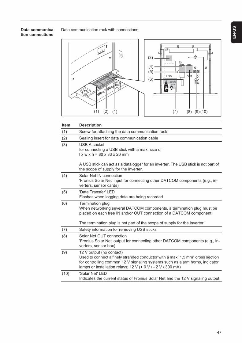
Data communica-tion connectionsData communication rack with connections:
Item Description(1) Screw for attaching the data communication rack(2) Sealing insert for data communication cable(3) USB A socket
for connecting a USB stick with a max. size of l x w x h = 80 x 33 x 20 mm
A USB stick can act as a datalogger for an inverter. The USB stick is not part of the scope of supply for the inverter.
(4) Solar Net IN connection'Fronius Solar Net' input for connecting other DATCOM components (e.g., in-verters, sensor cards)
(5) 'Data Transfer' LEDFlashes when logging data are being recorded
(6) Termination plugWhen networking several DATCOM components, a termination plug must be placed on each free IN and/or OUT connection of a DATCOM component.
The termination plug is not part of the scope of supply for the inverter.(7) Safety information for removing USB sticks(8) Solar Net OUT connection
'Fronius Solar Net' output for connecting other DATCOM components (e.g., in-verters, sensor box)
(9) 12 V output (no contact)Used to connect a finely stranded conductor with a max. 1.5 mm² cross section for controlling common 12 V signaling systems such as alarm horns, indicator lamps or installation relays; 12 V (+ 0 V / - 2 V / 300 mA)
(10) 'Solar Net' LEDIndicates the current status of Fronius Solar Net and the 12 V signaling output
USB OUTDo not
disconnectwhile LED is
flashing. GN
D12
V D
C
(1) (2)
(3)
(4)(5)
(6)
(7) (9) (10)(8)(1)
47
'Solar Net' LED description
The 'Solar Net' LED lights up:Power supply for data communication within Fronius Solar Net and the 12 V signaling out-put are OK
The 'Solar Net' LED flashes continually 3x per second:Overcurrent or short circuit at the 12 V signaling output (e.g. connected consumer load is too high or faulty), data communication in Fronius Solar Net is OK
The 'Solar Net' LED is off:Error in data communication in Fronius Solar Net; the 12 V signaling output is deactivated- Overcurrent (current flow > 3 A, e.g. due to a short circuit in Fronius Solar Net)- Under-voltage (no short circuit, voltage in Fronius Solar Net < 6.5 V, e.g. if too many
DATCOM components are in Fronius Solar Net and the electrical supply is insufficient)
In this case, the DATCOM components require an external energy supply via an ex-ternal power supply unit.
Check other DATCOM components to detect any under-voltage present.
The 'Solar Net' flashes briefly every 5 seconds:After a shutdown due to over-current or under-voltage, the inverter tries to restore the en-ergy supply in the Fronius Solar Net every 5 seconds so long as there is an error, for ex-ample.
Once the error has been corrected, power is restored to Fronius Solar Net within 5 seconds and then to the 12 V signaling output 1 second later.
During this time the 'Solar Net' LED flashes 3x per second. Once there is no longer an error at the signaling output, the 'Solar Net' LED lights up again.
Example Logging and archiving data from the inverter and sensor using a Fronius Datalogger Box and Fronius Sensor Box:
Explanation of illustration: Data network with 3 inverters, one Data Logger Box and one Sensor Box
= terminating plug
1 2 3
FroniusIG-TL
FroniusIG-TL
FroniusIG-TL
IN OUT
Sensor Box
IN OUT
Datalogger Box
IN OUT
°C
W/m²
m/s
IN OUT IN OUT
48
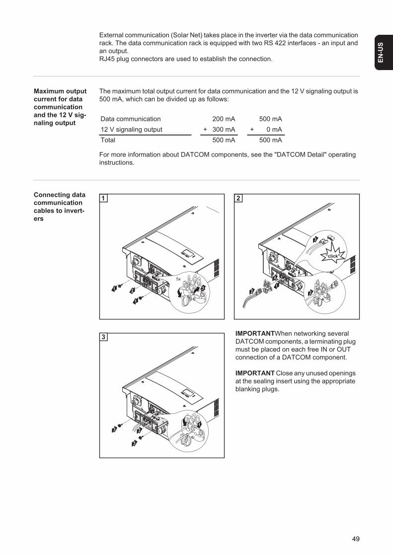
EN-U
S
External communication (Solar Net) takes place in the inverter via the data communication rack. The data communication rack is equipped with two RS 422 interfaces - an input and an output.RJ45 plug connectors are used to establish the connection.
Maximum output current for data communication and the 12 V sig-naling output
The maximum total output current for data communication and the 12 V signaling output is 500 mA, which can be divided up as follows:
For more information about DATCOM components, see the "DATCOM Detail" operating instructions.
Connecting data communication cables to invert-ers
1 2
Data communication 200 mA 500 mA12 V signaling output + 300 mA + 0 mATotal 500 mA 500 mA
1
1
2 3
5x
1
1
3
2 2
"click"
4
2
1 IMPORTANTWhen networking several DATCOM components, a terminating plug must be placed on each free IN or OUT connection of a DATCOM component.
IMPORTANT Close any unused openings at the sealing insert using the appropriate blanking plugs.
3
3
12
3
49
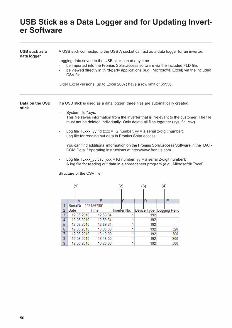
USB Stick as a Data Logger and for Updating Invert-er Software
USB stick as a data logger
A USB stick connected to the USB A socket can act as a data logger for an inverter.
Logging data saved to the USB stick can at any time- be imported into the Fronius Solar.access software via the included FLD file,- be viewed directly in third-party applications (e.g., Microsoft® Excel) via the included
CSV file.
Older Excel versions (up to Excel 2007) have a row limit of 65536.
Data on the USB stick
If a USB stick is used as a data logger, three files are automatically created:
- System file *.sys: This file saves information from the inverter that is irrelevant to the customer. The file must not be deleted individually. Only delete all files together (sys, fld, csv).
- Log file TLxxx_yy.fld (xxx = IG number, yy = a serial 2-digit number): Log file for reading out data in Fronius Solar.access.
You can find additional information on the Fronius Solar.access Software in the "DAT-COM Detail" operating instructions at http://www.fronius.com
- Log file TLxxx_yy.csv (xxx = IG number, yy = a serial 2-digit number): A log file for reading out data in a spreadsheet program (e.g., Microsoft® Excel)
Structure of the CSV file:
(1) (2) (3) (4)
50
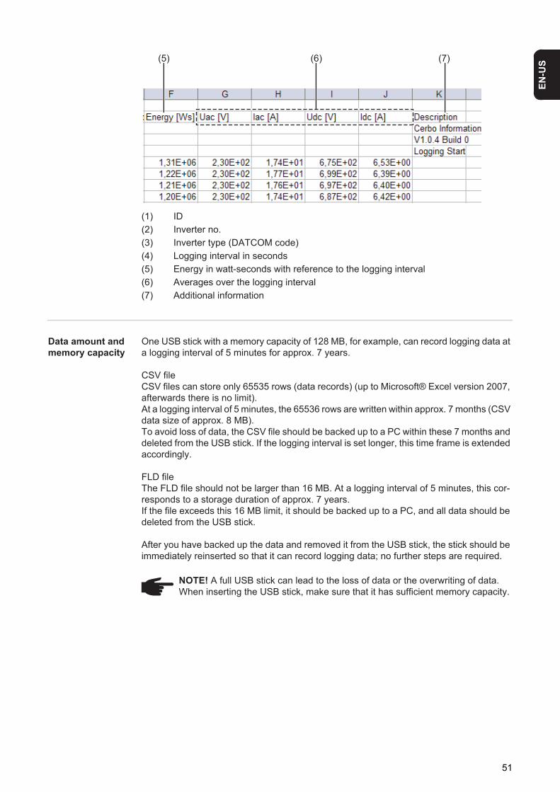
EN-U
S
(1) ID(2) Inverter no.(3) Inverter type (DATCOM code)(4) Logging interval in seconds(5) Energy in watt-seconds with reference to the logging interval (6) Averages over the logging interval(7) Additional information
Data amount and memory capacity
One USB stick with a memory capacity of 128 MB, for example, can record logging data at a logging interval of 5 minutes for approx. 7 years.
CSV fileCSV files can store only 65535 rows (data records) (up to Microsoft® Excel version 2007, afterwards there is no limit). At a logging interval of 5 minutes, the 65536 rows are written within approx. 7 months (CSV data size of approx. 8 MB). To avoid loss of data, the CSV file should be backed up to a PC within these 7 months and deleted from the USB stick. If the logging interval is set longer, this time frame is extended accordingly.
FLD fileThe FLD file should not be larger than 16 MB. At a logging interval of 5 minutes, this cor-responds to a storage duration of approx. 7 years.If the file exceeds this 16 MB limit, it should be backed up to a PC, and all data should be deleted from the USB stick.
After you have backed up the data and removed it from the USB stick, the stick should be immediately reinserted so that it can record logging data; no further steps are required.
(5) (6) (7)
NOTE! A full USB stick can lead to the loss of data or the overwriting of data. When inserting the USB stick, make sure that it has sufficient memory capacity.
51
Buffer memory If the USB stick is removed (e.g., to back up data), the logging data are written to a buffer memory in the inverter.As soon as the USB stick is reinserted, the data are automatically transferred from the buf-fer memory to the USB stick.
The buffer memory can store a maximum of 24 logging points. Data are logged only during inverter operation (power greater than 0 W). The following time spans for storing data re-sult from the different logging intervals:
When the buffer memory is full, the oldest data in the buffer memory are written over with the new data.
IMPORTANT The buffer memory requires a constant power supply.If there is an AC power outage during operation, all data in the buffer memory are lost. The automatic night switch-off must be deactivated so that the data are not lost at night (set 'Night Mode' to ON - see chapter "Setting and Displaying Menu Items," section "Displaying and setting parameters in the 'DATCOM' menu item").
Suitable USB sticks
Due to the number of USB sticks on the market, we cannot guarantee that every USB stick will be recognized by the inverter.
Fronius recommends using only certified, industrial USB sticks (look for the USB-IF logo).
The inverter supports USB sticks using the following file systems:- FAT12- FAT16- FAT32
Fronius recommends that the USB stick only be used for recording logging data or for up-dating the inverter software. USB sticks should not contain any other data.
Logging interval [min] Time span [min]5 12010 24015 36020 48030 720
52
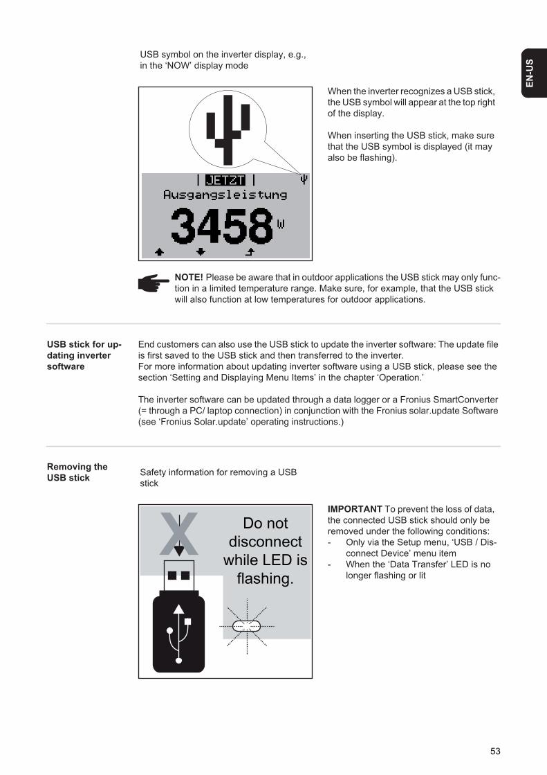
EN-U
S
USB stick for up-dating inverter software
End customers can also use the USB stick to update the inverter software: The update file is first saved to the USB stick and then transferred to the inverter.For more information about updating inverter software using a USB stick, please see the section ‘Setting and Displaying Menu Items’ in the chapter ‘Operation.’
The inverter software can be updated through a data logger or a Fronius SmartConverter (= through a PC/ laptop connection) in conjunction with the Fronius solar.update Software (see ‘Fronius Solar.update’ operating instructions.)
Removing the USB stick
USB symbol on the inverter display, e.g., in the ‘NOW’ display mode
When the inverter recognizes a USB stick, the USB symbol will appear at the top right of the display.
When inserting the USB stick, make sure that the USB symbol is displayed (it may also be flashing).
NOTE! Please be aware that in outdoor applications the USB stick may only func-tion in a limited temperature range. Make sure, for example, that the USB stick will also function at low temperatures for outdoor applications.
Safety information for removing a USB stick
IMPORTANT To prevent the loss of data, the connected USB stick should only be removed under the following conditions:- Only via the Setup menu, ‘USB / Dis-
connect Device’ menu item- When the ‘Data Transfer’ LED is no
longer flashing or lit
Do notdisconnect
while LED isflashing.
53
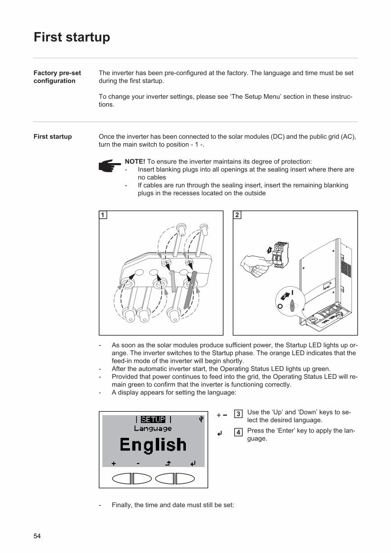
First startup
Factory pre-set configuration
The inverter has been pre-configured at the factory. The language and time must be set during the first startup.
To change your inverter settings, please see ‘The Setup Menu’ section in these instruc-tions.
First startup Once the inverter has been connected to the solar modules (DC) and the public grid (AC), turn the main switch to position - 1 -.
1 2
- As soon as the solar modules produce sufficient power, the Startup LED lights up or-ange. The inverter switches to the Startup phase. The orange LED indicates that the feed-in mode of the inverter will begin shortly.
- After the automatic inverter start, the Operating Status LED lights up green.- Provided that power continues to feed into the grid, the Operating Status LED will re-
main green to confirm that the inverter is functioning correctly.- A display appears for setting the language:
- Finally, the time and date must still be set:
NOTE! To ensure the inverter maintains its degree of protection:- Insert blanking plugs into all openings at the sealing insert where there are
no cables- If cables are run through the sealing insert, insert the remaining blanking
plugs in the recesses located on the outside
1
1
32
2
Use the ‘Up’ and ‘Down’ keys to se-lect the desired language.Press the ‘Enter’ key to apply the lan-guage.
3
4
54
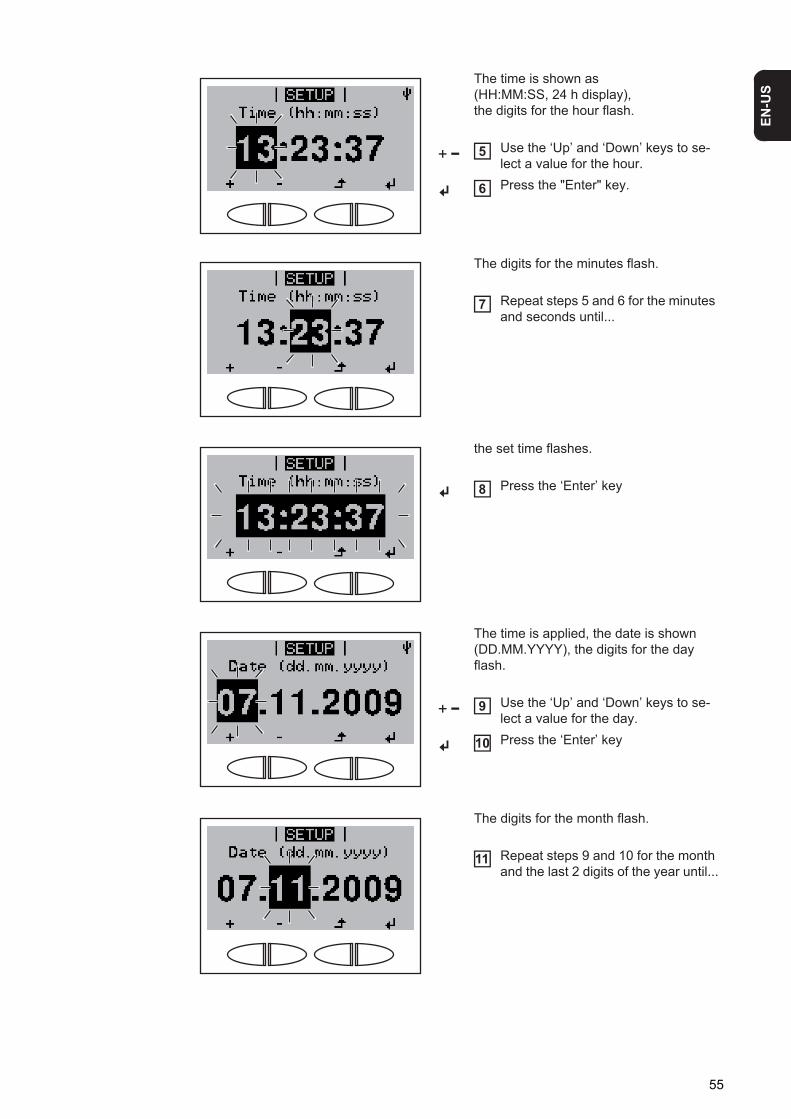
EN-U
S
The time is shown as (HH:MM:SS, 24 h display), the digits for the hour flash.
Use the ‘Up’ and ‘Down’ keys to se-lect a value for the hour.Press the "Enter" key.
The digits for the minutes flash.
Repeat steps 5 and 6 for the minutes and seconds until...
the set time flashes.
Press the ‘Enter’ key
The time is applied, the date is shown (DD.MM.YYYY), the digits for the day flash.
Use the ‘Up’ and ‘Down’ keys to se-lect a value for the day.Press the ‘Enter’ key
The digits for the month flash.
Repeat steps 9 and 10 for the month and the last 2 digits of the year until...
5
6
7
8
9
10
11
55
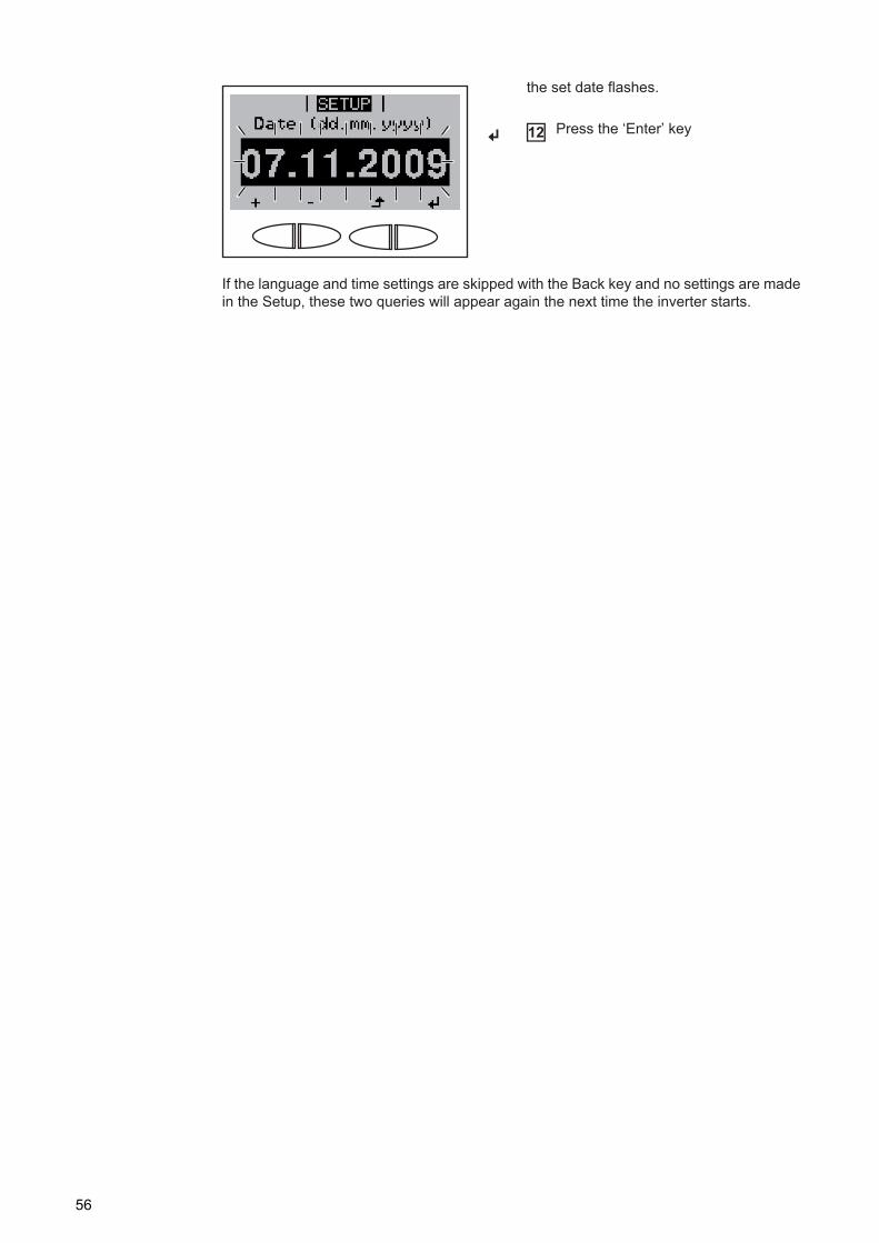
If the language and time settings are skipped with the Back key and no settings are made in the Setup, these two queries will appear again the next time the inverter starts.
the set date flashes.
Press the ‘Enter’ key12
56
Operation

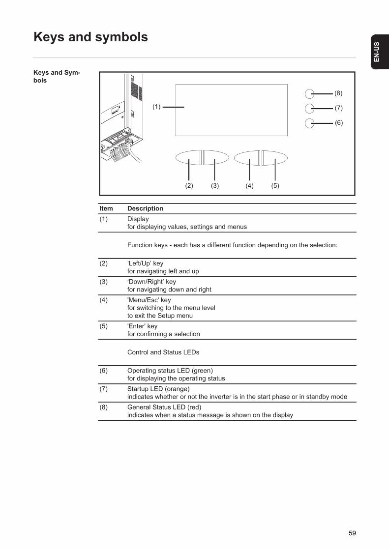
EN-U
S
Keys and symbols
Keys and Sym-bols
Item Description(1) Display
for displaying values, settings and menus
Function keys - each has a different function depending on the selection:
(2) ‘Left/Up’ keyfor navigating left and up
(3) ‘Down/Right’ keyfor navigating down and right
(4) 'Menu/Esc' keyfor switching to the menu levelto exit the Setup menu
(5) 'Enter' keyfor confirming a selection
Control and Status LEDs
(6) Operating status LED (green)for displaying the operating status
(7) Startup LED (orange)indicates whether or not the inverter is in the start phase or in standby mode
(8) General Status LED (red)indicates when a status message is shown on the display
(1)
(2) (3) (4) (5)
(6)
(7)
(8)
59
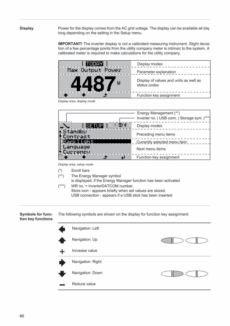
Display Power for the display comes from the AC grid voltage. The display can be available all day long depending on the setting in the Setup menu.
Display area, display mode
Display area, setup mode
(*) Scroll bars(**) The Energy Manager symbol
is displayed, if the Energy Manager function has been activated(***) WR no. = InverterDATCOM number,
Store icon - appears briefly when set values are stored,USB connection - appears if a USB stick has been inserted
Symbols for func-tion key functions
The following symbols are shown on the display for function key assignment:
IMPORTANT! The inverter display is not a calibrated measuring instrument. Slight devia-tion of a few percentage points from the utility company meter is intrinsic to the system. A calibrated meter is required to make calculations for the utility company.
Function key assignment
Display modes
Parameter explanation
Display of values and units as well asstatus codes
Function key assignment
Next menu items
Currently selected menu item
Preceding menu items
Display modes
Inverter no. | USB conn. | Storage sym. (***)
(*)
1
Energy Management (**)
Navigation: Left
Navigation: Up
Increase value
Navigation: Right
Navigation: Down
Reduce value
60
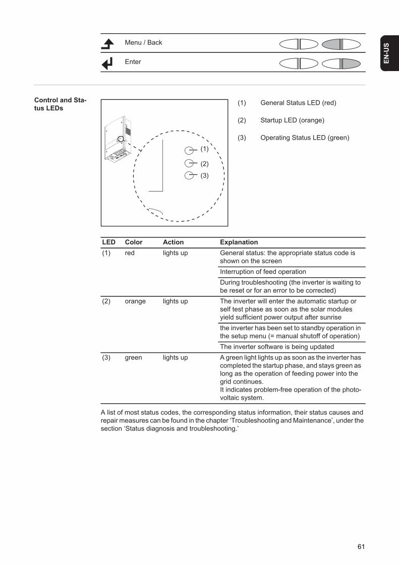
EN-U
S
Control and Sta-tus LEDs
(1) General Status LED (red)
(2) Startup LED (orange)
(3) Operating Status LED (green)
A list of most status codes, the corresponding status information, their status causes and repair measures can be found in the chapter ‘Troubleshooting and Maintenance’, under the section ‘Status diagnosis and troubleshooting.’
Menu / Back
Enter
(3)
(2)
(1)
LED Color Action Explanation(1) red lights up General status: the appropriate status code is
shown on the screenInterruption of feed operationDuring troubleshooting (the inverter is waiting to be reset or for an error to be corrected)
(2) orange lights up The inverter will enter the automatic startup or self test phase as soon as the solar modules yield sufficient power output after sunrisethe inverter has been set to standby operation in the setup menu (= manual shutoff of operation)The inverter software is being updated
(3) green lights up A green light lights up as soon as the inverter has completed the startup phase, and stays green as long as the operation of feeding power into the grid continues.It indicates problem-free operation of the photo-voltaic system.
61
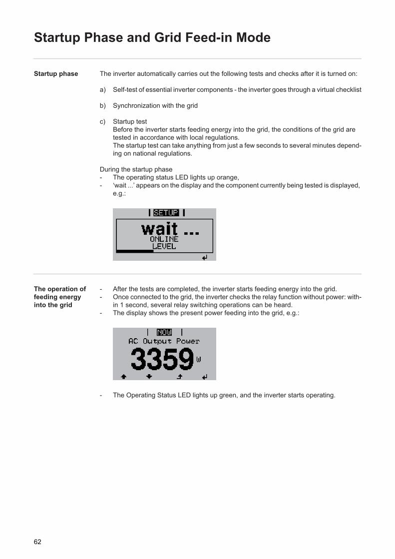
Startup Phase and Grid Feed-in Mode
Startup phase The inverter automatically carries out the following tests and checks after it is turned on:
a) Self-test of essential inverter components - the inverter goes through a virtual checklist
b) Synchronization with the grid
c) Startup testBefore the inverter starts feeding energy into the grid, the conditions of the grid are tested in accordance with local regulations.The startup test can take anything from just a few seconds to several minutes depend-ing on national regulations.
During the startup phase- The operating status LED lights up orange,- ‘wait ...’ appears on the display and the component currently being tested is displayed,
e.g.:
The operation of feeding energy into the grid
- After the tests are completed, the inverter starts feeding energy into the grid.- Once connected to the grid, the inverter checks the relay function without power: with-
in 1 second, several relay switching operations can be heard.- The display shows the present power feeding into the grid, e.g.:
- The Operating Status LED lights up green, and the inverter starts operating.
62

EN-U
S
Navigation in the Menu Level
Activating display illumination
Press any key.
The display illumination is activated.
The Setup menu also offers a choice between a permanently lit or permanently dark display.
Automatic Deacti-vation of Display Illumination / Switching to the "NOW" Display Mode
If no key is pressed for 2 minutes:- the display illumination turns off automatically and the inverter switches to the "NOW"
display mode (if the display illumination is set to automatic)- the inverter can be switched to the "NOW" display mode from any menu level, except
for the "Standby" menu item- the current output power is displayed.
Accessing the menu level
1
Press the ‘Menu’ key.
‘Menu’ appears on the display.
The inverter is now at the menu level.
From the menu level you can- Set the desired display mode- Access the Setup menu
1
63
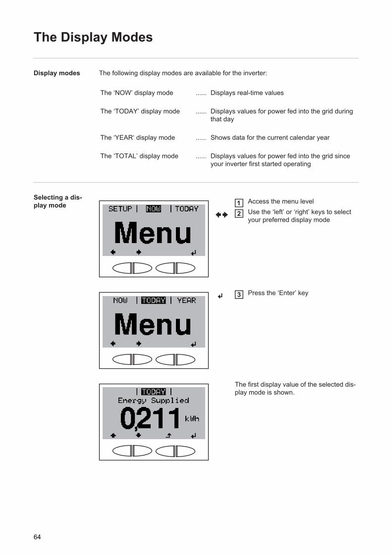
The Display Modes
Display modes The following display modes are available for the inverter:
Selecting a dis-play mode
The ‘NOW’ display mode ...... Displays real-time values
The ‘TODAY’ display mode ...... Displays values for power fed into the grid during that day
The ‘YEAR‘ display mode ...... Shows data for the current calendar year
The ‘TOTAL’ display mode ...... Displays values for power fed into the grid since your inverter first started operating
Access the menu levelUse the ‘left’ or ‘right’ keys to select your preferred display mode
Press the ‘Enter’ key
The first display value of the selected dis-play mode is shown.
12
3
64
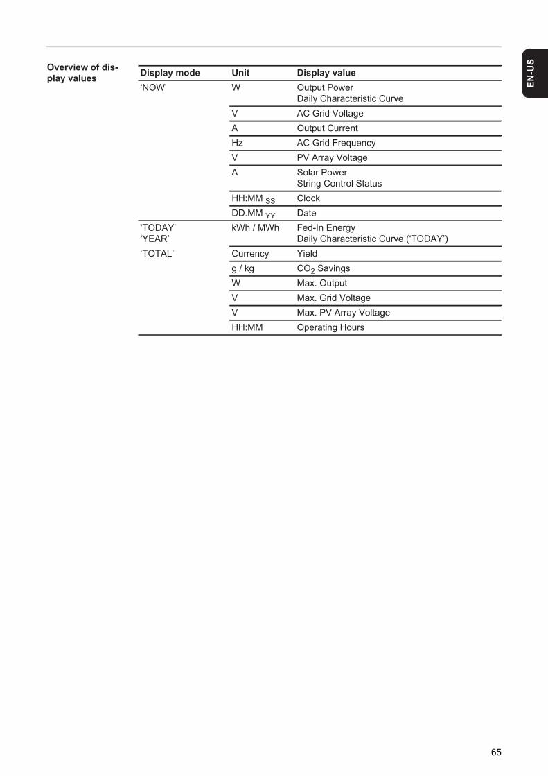
EN-U
S
Overview of dis-play values Display mode Unit Display value‘NOW’ W Output PowerDaily Characteristic Curve
V AC Grid VoltageA Output CurrentHz AC Grid FrequencyV PV Array VoltageA Solar Power
String Control StatusHH:MM SS ClockDD.MM YY Date
‘TODAY’‘YEAR’
kWh / MWh Fed-In EnergyDaily Characteristic Curve (‘TODAY’)
‘TOTAL’ Currency Yieldg / kg CO2 SavingsW Max. OutputV Max. Grid VoltageV Max. PV Array VoltageHH:MM Operating Hours
65
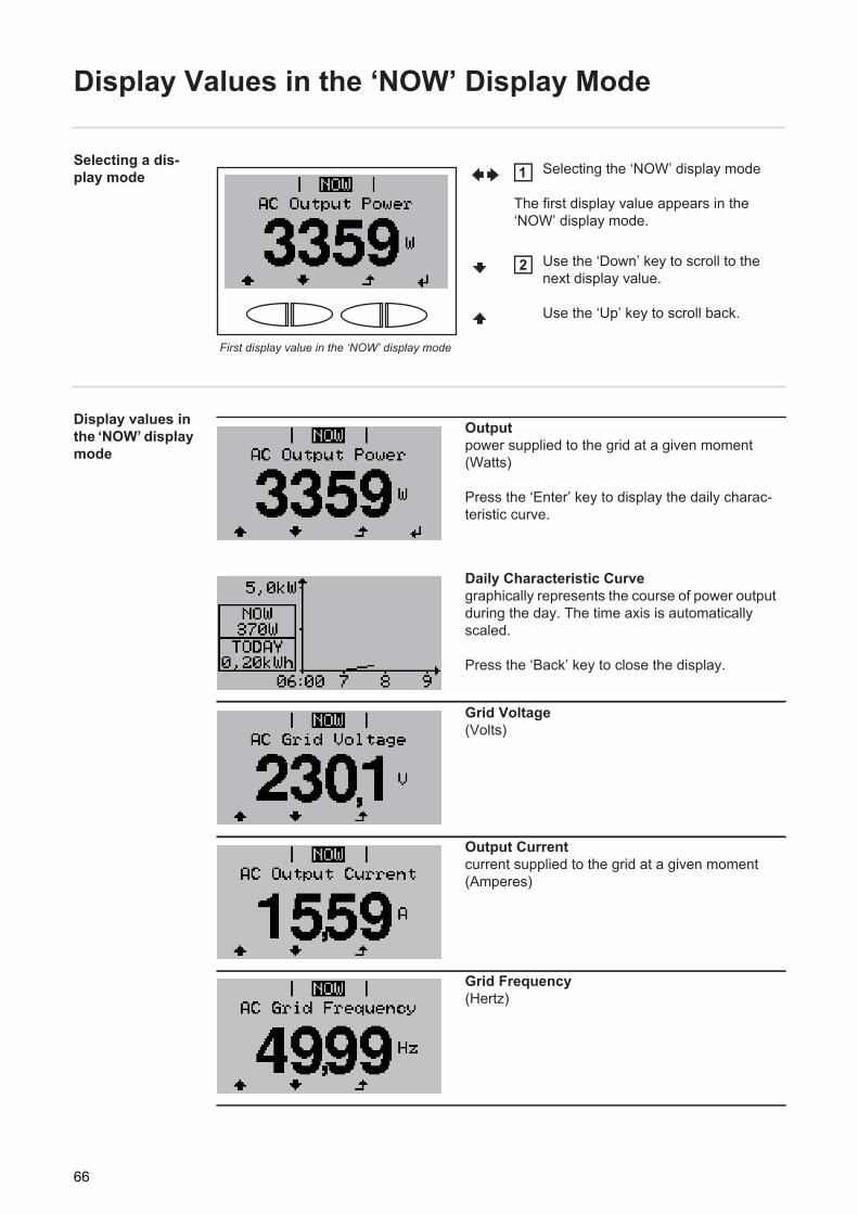
Display Values in the ‘NOW’ Display Mode
Selecting a dis-play mode
Display values in the ‘NOW’ display mode
First display value in the ‘NOW’ display mode
Selecting the ‘NOW’ display mode
The first display value appears in the ‘NOW’ display mode.
Use the ‘Down’ key to scroll to the next display value.
Use the ‘Up’ key to scroll back.
1
2
Outputpower supplied to the grid at a given moment (Watts)
Press the ‘Enter’ key to display the daily charac-teristic curve.
Daily Characteristic Curvegraphically represents the course of power output during the day. The time axis is automatically scaled.
Press the ‘Back’ key to close the display.
Grid Voltage(Volts)
Output Currentcurrent supplied to the grid at a given moment (Amperes)
Grid Frequency(Hertz)
66
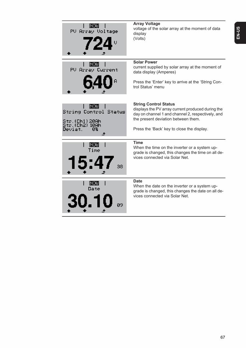
EN-U
S
Array Voltagevoltage of the solar array at the moment of data display (Volts)
Solar Powercurrent supplied by solar array at the moment of data display (Amperes)
Press the ‘Enter’ key to arrive at the ‘String Con-trol Status’ menu
String Control Statusdisplays the PV array current produced during the day on channel 1 and channel 2, respectively, and the present deviation between them.
Press the ‘Back’ key to close the display.
TimeWhen the time on the inverter or a system up-grade is changed, this changes the time on all de-vices connected via Solar Net.
DateWhen the date on the inverter or a system up-grade is changed, this changes the date on all de-vices connected via Solar Net.
67
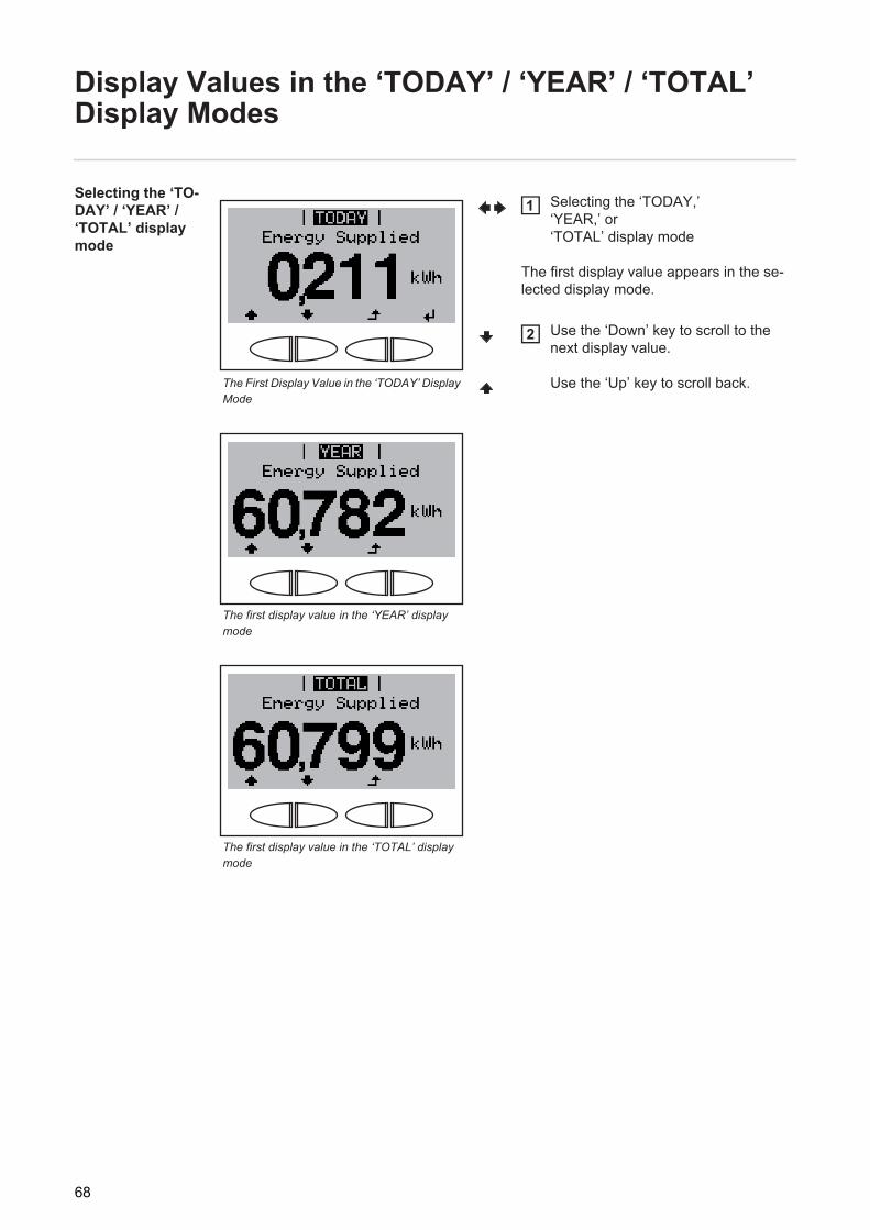
Display Values in the ‘TODAY’ / ‘YEAR’ / ‘TOTAL’ Display Modes
Selecting the ‘TO-DAY’ / ‘YEAR’ / ‘TOTAL’ display mode
The First Display Value in the ‘TODAY’ Display Mode
The first display value in the ‘YEAR’ display mode
The first display value in the ‘TOTAL’ display mode
Selecting the ‘TODAY,’ ‘YEAR,’ or ‘TOTAL’ display mode
The first display value appears in the se-lected display mode.
Use the ‘Down’ key to scroll to the next display value.
Use the ‘Up’ key to scroll back.
1
2
68
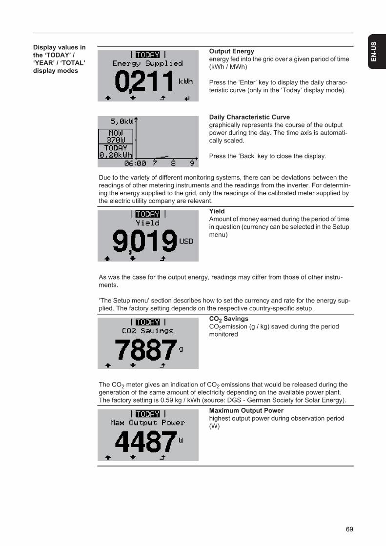
EN-U
S
Display values in the ‘TODAY’ / ‘YEAR’ / ‘TOTAL’ display modesOutput Energyenergy fed into the grid over a given period of time (kWh / MWh)
Press the ‘Enter’ key to display the daily charac-teristic curve (only in the ‘Today’ display mode).
Daily Characteristic Curvegraphically represents the course of the output power during the day. The time axis is automati-cally scaled.
Press the ‘Back’ key to close the display.
Due to the variety of different monitoring systems, there can be deviations between the readings of other metering instruments and the readings from the inverter. For determin-ing the energy supplied to the grid, only the readings of the calibrated meter supplied by the electric utility company are relevant.
YieldAmount of money earned during the period of time in question (currency can be selected in the Setup menu)
As was the case for the output energy, readings may differ from those of other instru-ments.
‘The Setup menu’ section describes how to set the currency and rate for the energy sup-plied. The factory setting depends on the respective country-specific setup.
CO2 SavingsCO2emission (g / kg) saved during the period monitored
The CO2 meter gives an indication of CO2 emissions that would be released during the generation of the same amount of electricity depending on the available power plant.The factory setting is 0.59 kg / kWh (source: DGS - German Society for Solar Energy).
Maximum Output Powerhighest output power during observation period (W)
69
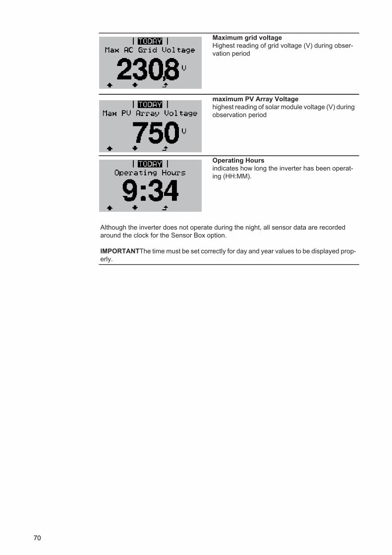
Maximum grid voltageHighest reading of grid voltage (V) during obser-vation period
maximum PV Array Voltagehighest reading of solar module voltage (V) during observation period
Operating Hoursindicates how long the inverter has been operat-ing (HH:MM).
Although the inverter does not operate during the night, all sensor data are recorded around the clock for the Sensor Box option.
IMPORTANTThe time must be set correctly for day and year values to be displayed prop-erly.
70
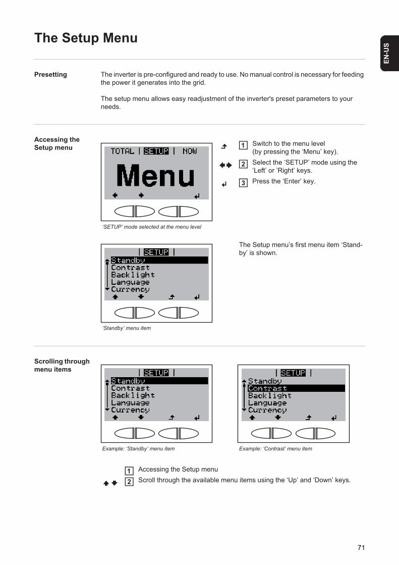
EN-U
S
The Setup Menu
Presetting The inverter is pre-configured and ready to use. No manual control is necessary for feeding the power it generates into the grid.
The setup menu allows easy readjustment of the inverter's preset parameters to your needs.
Accessing the Setup menu
Scrolling through menu items
‘SETUP’ mode selected at the menu level
Switch to the menu level (by pressing the ‘Menu’ key).Select the ‘SETUP’ mode using the ‘Left’ or ’Right’ keys.Press the ‘Enter’ key.
‘Standby’ menu item
The Setup menu’s first menu item ‘Stand-by’ is shown.
1
2
3
Example: ‘Standby’ menu item Example: ‘Contrast’ menu item
Accessing the Setup menuScroll through the available menu items using the ‘Up’ and ‘Down’ keys.
12
71
Menu Items in the Setup Menu
Standby Manual activation/deactivation of the standby mode
- The power electronics are switched off in standby mode. No power is fed into the grid.- The Startup LED lights up orange.- In standby mode, no other menu item can be accessed or set in the Setup menu.- Automatic switching to the ‘NOW’ display mode after 2 minutes if no key is pressed is
not activated.- The standby mode can only be deactivated manually by pressing the ‘Enter’ key.- Grid supply operation can be resumed at any time (deactivate ‘Standby’).
Setting standby mode (manual shutoff for feeding energy into the grid):
Select the ‘Standby’ menu item.Press the ‘Enter’ key.
The display alternates between ‘STANDBY’ and ‘ENTER.’The Standby mode is now activated.The Startup LED lights up orange.
Restoring the grid feed:
In Standby mode, the display alternates between ‘STANDBY’ and ‘ENTER.’
Press ‘Enter’ to restore the grid feed.
The menu item ‘Standby’ is shown.The inverter also switches to the Startup phase.After the grid feed is restored, the Operation Status LED lights up green.
Contrast Contrast setting on LCD display
Since contrast depends on temperature, it may be necessary to adjust the ‘Contrast’ menu item when ambient conditions change.
Unit -Setting range EnterFactory setting ‘Standby’ deactivated
12
1
Unit -Setting range 0 - 10Factory setting 5
72
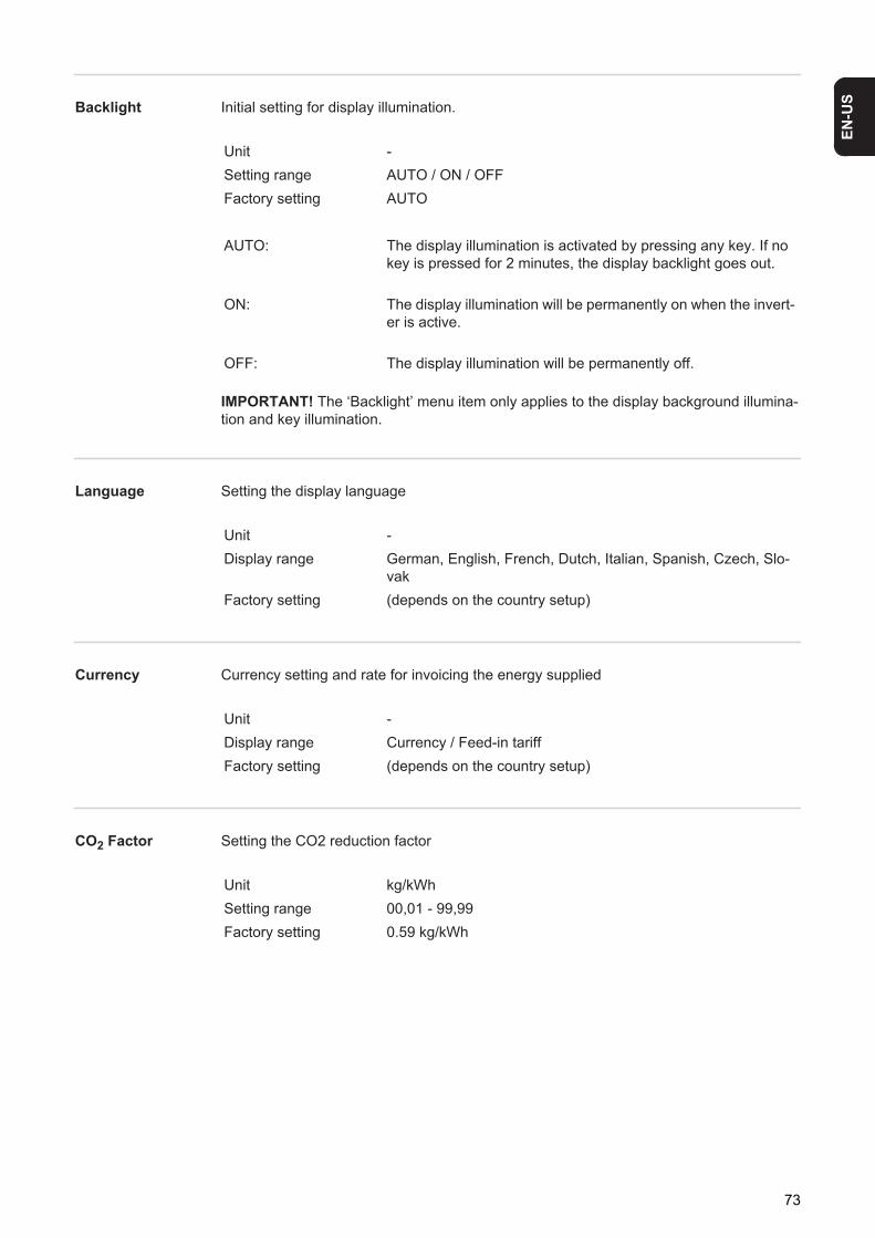
EN-U
S
Backlight Initial setting for display illumination.Language Setting the display language
Currency Currency setting and rate for invoicing the energy supplied
CO2 Factor Setting the CO2 reduction factor
Unit -Setting range AUTO / ON / OFFFactory setting AUTO
AUTO: The display illumination is activated by pressing any key. If no key is pressed for 2 minutes, the display backlight goes out.
ON: The display illumination will be permanently on when the invert-er is active.
OFF: The display illumination will be permanently off.
IMPORTANT! The ‘Backlight’ menu item only applies to the display background illumina-tion and key illumination.
Unit -Display range German, English, French, Dutch, Italian, Spanish, Czech, Slo-
vakFactory setting (depends on the country setup)
Unit -Display range Currency / Feed-in tariffFactory setting (depends on the country setup)
Unit kg/kWhSetting range 00,01 - 99,99Factory setting 0.59 kg/kWh
73
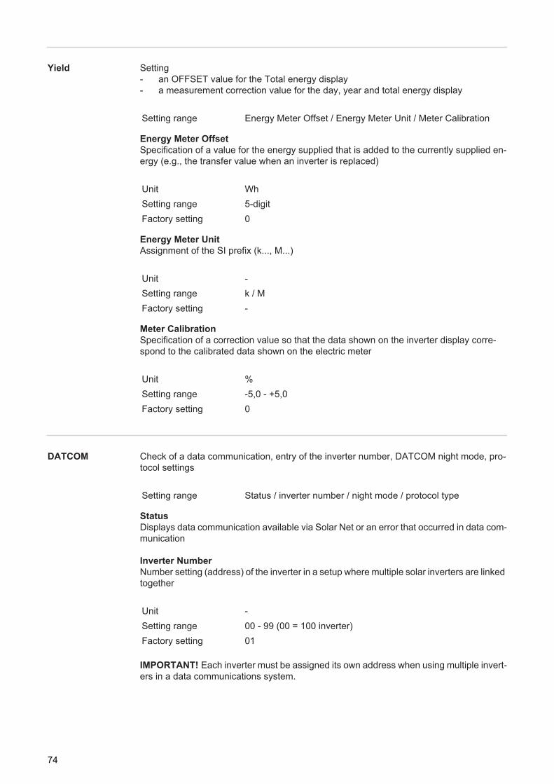
Yield Setting- an OFFSET value for the Total energy display - a measurement correction value for the day, year and total energy display
Energy Meter OffsetSpecification of a value for the energy supplied that is added to the currently supplied en-ergy (e.g., the transfer value when an inverter is replaced)
Energy Meter UnitAssignment of the SI prefix (k..., M...)
Meter CalibrationSpecification of a correction value so that the data shown on the inverter display corre-spond to the calibrated data shown on the electric meter
DATCOM Check of a data communication, entry of the inverter number, DATCOM night mode, pro-tocol settings
StatusDisplays data communication available via Solar Net or an error that occurred in data com-munication
Inverter NumberNumber setting (address) of the inverter in a setup where multiple solar inverters are linked together
Setting range Energy Meter Offset / Energy Meter Unit / Meter Calibration
Unit WhSetting range 5-digitFactory setting 0
Unit -Setting range k / MFactory setting -
Unit %Setting range -5,0 - +5,0Factory setting 0
Setting range Status / inverter number / night mode / protocol type
Unit -Setting range 00 - 99 (00 = 100 inverter)Factory setting 01
IMPORTANT! Each inverter must be assigned its own address when using multiple invert-ers in a data communications system.
74
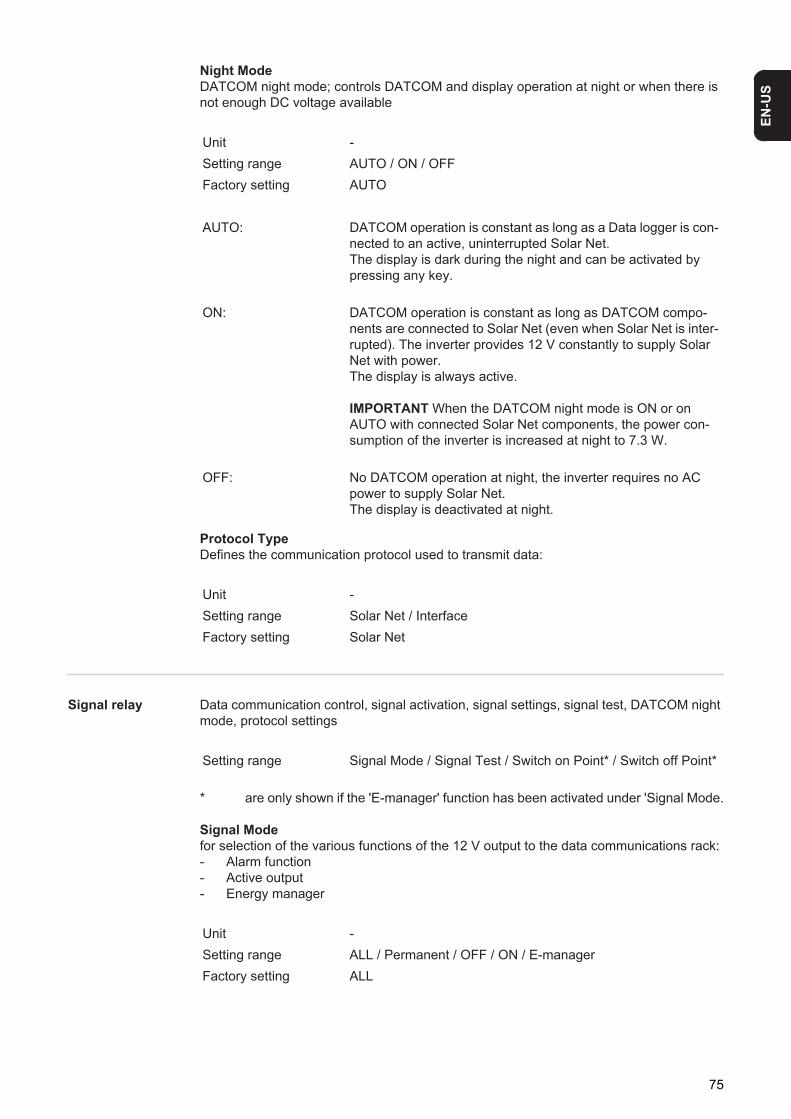
EN-U
S
Night ModeDATCOM night mode; controls DATCOM and display operation at night or when there is not enough DC voltage available
Protocol TypeDefines the communication protocol used to transmit data:
Signal relay Data communication control, signal activation, signal settings, signal test, DATCOM night mode, protocol settings
* are only shown if the 'E-manager' function has been activated under 'Signal Mode.
Signal Modefor selection of the various functions of the 12 V output to the data communications rack:- Alarm function- Active output- Energy manager
Unit -Setting range AUTO / ON / OFFFactory setting AUTO
AUTO: DATCOM operation is constant as long as a Data logger is con-nected to an active, uninterrupted Solar Net.The display is dark during the night and can be activated by pressing any key.
ON: DATCOM operation is constant as long as DATCOM compo-nents are connected to Solar Net (even when Solar Net is inter-rupted). The inverter provides 12 V constantly to supply Solar Net with power.The display is always active.
IMPORTANT When the DATCOM night mode is ON or on AUTO with connected Solar Net components, the power con-sumption of the inverter is increased at night to 7.3 W.
OFF: No DATCOM operation at night, the inverter requires no AC power to supply Solar Net.The display is deactivated at night.
Unit -Setting range Solar Net / InterfaceFactory setting Solar Net
Setting range Signal Mode / Signal Test / Switch on Point* / Switch off Point*
Unit -Setting range ALL / Permanent / OFF / ON / E-managerFactory setting ALL
75
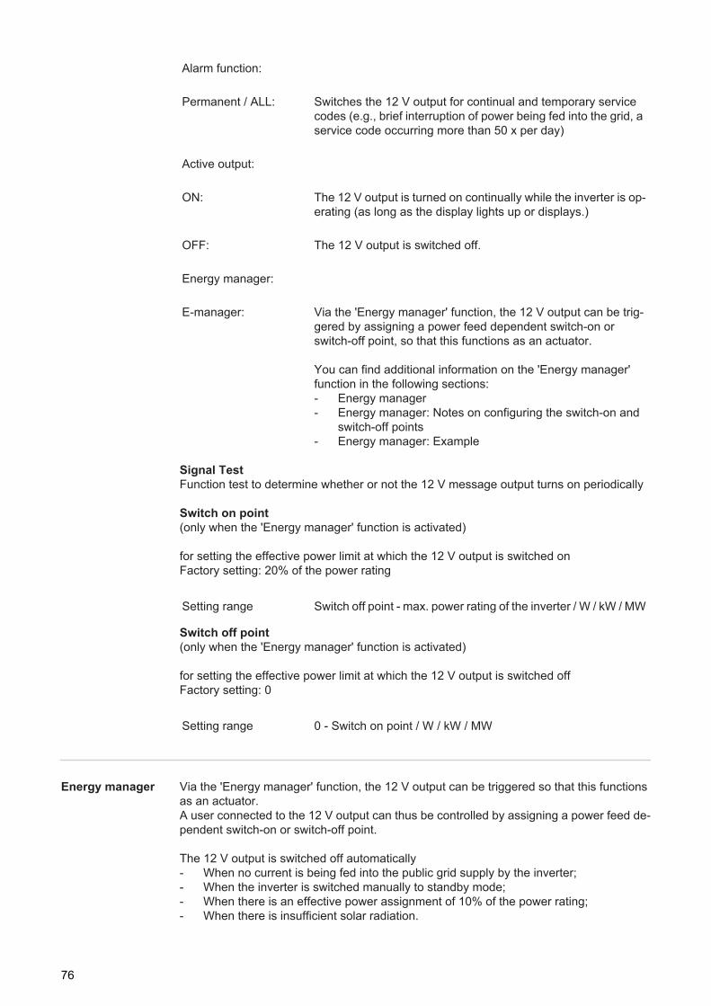
Signal TestFunction test to determine whether or not the 12 V message output turns on periodically
Switch on point(only when the 'Energy manager' function is activated)
for setting the effective power limit at which the 12 V output is switched onFactory setting: 20% of the power rating
Switch off point(only when the 'Energy manager' function is activated)
for setting the effective power limit at which the 12 V output is switched offFactory setting: 0
Energy manager Via the 'Energy manager' function, the 12 V output can be triggered so that this functions as an actuator.A user connected to the 12 V output can thus be controlled by assigning a power feed de-pendent switch-on or switch-off point.
The 12 V output is switched off automatically- When no current is being fed into the public grid supply by the inverter;- When the inverter is switched manually to standby mode;- When there is an effective power assignment of 10% of the power rating;- When there is insufficient solar radiation.
Alarm function:
Permanent / ALL: Switches the 12 V output for continual and temporary service codes (e.g., brief interruption of power being fed into the grid, a service code occurring more than 50 x per day)
Active output:
ON: The 12 V output is turned on continually while the inverter is op-erating (as long as the display lights up or displays.)
OFF: The 12 V output is switched off.
Energy manager:
E-manager: Via the 'Energy manager' function, the 12 V output can be trig-gered by assigning a power feed dependent switch-on or switch-off point, so that this functions as an actuator.
You can find additional information on the 'Energy manager' function in the following sections:- Energy manager- Energy manager: Notes on configuring the switch-on and
switch-off points- Energy manager: Example
Setting range Switch off point - max. power rating of the inverter / W / kW / MW
Setting range 0 - Switch on point / W / kW / MW
76
EN-U
S
To deactivate the 'Energy manager' function, select another function and press the 'Enter' key.
Energy manager: Notes on config-uring the switch-on and switch-off points
Pay attention to the following when configuring the switch-on and switch-off points:
Insufficient difference between the switch-on point and the switch-off point or power fluc-tuations can cause frequent switching cycles.To avoid excessive switching on and off, the difference between the switch-on and switch-off points should be at least 100 - 200 W.
When selecting the switch-off point, consider the power consumption of the connected us-er.
When selecting the switch-on point also bear in mind the weather conditions and the ex-pected solar radiation.
Energy manager: Example
Switch on point = 2000 WSwitch off point = 1800 W
If the inverter supplies 2000 W or more, the 12 V output of the inverter is switched on.If the inverter output sinks below 1800 W, the 12 V output is switched off.
Possible applications:Operation of a heat pump or an air-conditioning system, using as much self-produced pow-er as possible.
IMPORTANT Do not connect any 230 V user directly to the 12 V output. To control a 230 V user via the 12 V output extra relays or protection is required.
USB Value settings when using a USB stick
Disconnect DeviceTo remove a USB stick from the USB A socket on the data communication rack without losing data.The USB stick can be removed:- When OK is displayed- When the ‘Data Transfer’ LED is no longer flashing or lit
Update SoftwareUpdating the inverter software using a USB stick.For more information about updating inverter software using a USB stick, please see the section ‘Setting and Displaying Menu Items.’
To activate the 'Energy manager' function, select 'E-manager' and press the 'Enter' key.When the 'Energy manager' function is activated, the 'Energy manager' icon is displayed at the top left of the display:
When the 12 V output is switched off (open contact)
When the 12 V output is switched on (closed contact)
Setting range Disconnect Device / Update Software / Logging Interval
77
Logging IntervalActivating / Deactivating the logging function, as well as setting the logging interval
IMPORTANT The time must be set correctly in order for the logging function to work cor-rectly.
String Control For monitoring incoming solar modules strings
Functional principle:- The incoming solar module strings are combined at 2 measuring channels.- The 2 measuring channels record the total current of the respective connected solar
module strings over the entire charging day.- The average solar module string current is used for an effective comparison of the two
measuring channel values.- The average solar module string current is calculated from the channel measurement
value divided by the number of solar module strings connected per channel.- The difference of the two average values is calculated and displayed as a % with the
smaller average value being deducted from the larger average value.- A warning is shown on the display when
IMPORTANTThe time must be set correctly in order for the solar module string monitoring function to work properly.
Status An actual value display of the average solar module string current from measuring channel 1, measuring channel 2, and their present deviation.
Unit MinutesSetting range 30 Min. / 20 Min. / 15 Min. / 10 Min. / 5 Min. / No LogFactory setting No Log
30 Min. The logging interval is 30 minutes; new logging data are saved to the USB stick every 30 minutes.
20 Min.15 Min.10 Min.5 Min. The logging interval is 5 minutes; new logging data are saved to
the USB stick every 5 minutes.
No Log No data are saved
a) The difference of the two average values is larger than the defined maximum deviation
and
b) The threshold value defined for the average solar module string current of a measuring channel is exceeded.
Setting range Display: Status / Config. Channel ONE / Config. Channel TWO / max. Deviation / Threshold
78
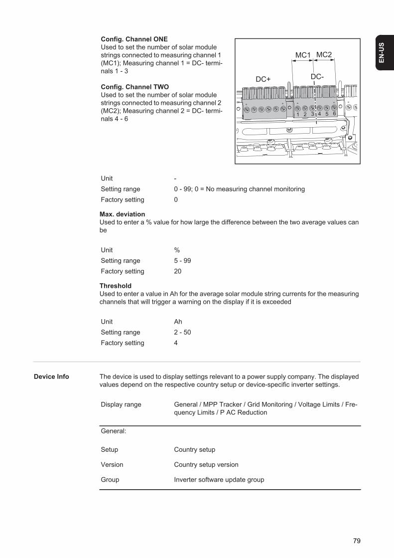
EN-U
S
Max. deviationUsed to enter a % value for how large the difference between the two average values can be
ThresholdUsed to enter a value in Ah for the average solar module string currents for the measuring channels that will trigger a warning on the display if it is exceeded
Device Info The device is used to display settings relevant to a power supply company. The displayed values depend on the respective country setup or device-specific inverter settings.
Config. Channel ONEUsed to set the number of solar module strings connected to measuring channel 1 (MC1); Measuring channel 1 = DC- termi-nals 1 - 3
Config. Channel TWOUsed to set the number of solar module strings connected to measuring channel 2 (MC2); Measuring channel 2 = DC- termi-nals 4 - 6
Unit -Setting range 0 - 99; 0 = No measuring channel monitoringFactory setting 0
Unit %Setting range 5 - 99Factory setting 20
Unit AhSetting range 2 - 50Factory setting 4
DC+ DC-
1 2 3 4 5 6
MC1 MC2
Display range General / MPP Tracker / Grid Monitoring / Voltage Limits / Fre-quency Limits / P AC Reduction
General:
Setup Country setup
Version Country setup version
Group Inverter software update group
79
MPP Tracker:
DC mode DC operating mode
FIX Voltage value in V for fixed voltage operation
User Voltage value in V for MPP user operation
Grid Monitoring:
GMTi Startup time of the inverter in s
GMTr Restart time in s after a grid error
ULL Grid voltage average value over 10 minutes in V.
LL Trip Detection time for long-term voltage monitoring
Voltage Limits:
UIL max Upper inner grid voltage value in V
UIL min Lower inner grid voltage value in V
UOL max Upper outer grid voltage limit value in V
UOL min Lower outer grid voltage limit value in V
Frequency Limits:
FIL max Upper inner grid frequency value in Hz
FIL min Lower inner grid frequency value in Hz
FOL max Upper outer grid frequency limit value in Hz
FOL min Lower outer grid frequency limit value in Hz
P AC Reduction:
Max. P AC Manual power reduction
GPIS SoftStart function
GFDPRv Power reduction depending on grid frequency in %/Hz
GFDPRr Back to nominal power in %/s (after a power reduction caused by the grid frequency)
80
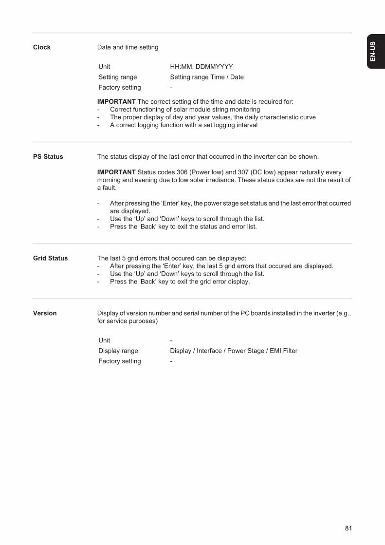
EN-U
S
Clock Date and time settingIMPORTANT The correct setting of the time and date is required for:- Correct functioning of solar module string monitoring- The proper display of day and year values, the daily characteristic curve- A correct logging function with a set logging interval
PS Status The status display of the last error that occurred in the inverter can be shown.
IMPORTANT Status codes 306 (Power low) and 307 (DC low) appear naturally every morning and evening due to low solar irradiance. These status codes are not the result of a fault.
- After pressing the ‘Enter’ key, the power stage set status and the last error that ocurred are displayed.
- Use the ‘Up’ and ‘Down’ keys to scroll through the list.- Press the ‘Back’ key to exit the status and error list.
Grid Status The last 5 grid errors that occured can be displayed:- After pressing the ‘Enter’ key, the last 5 grid errors that occured are displayed.- Use the ‘Up’ and ‘Down’ keys to scroll through the list.- Press the ‘Back’ key to exit the grid error display.
Version Display of version number and serial number of the PC boards installed in the inverter (e.g., for service purposes)
Unit HH:MM, DDMMYYYYSetting range Setting range Time / DateFactory setting -
Unit -Display range Display / Interface / Power Stage / EMI FilterFactory setting -
81
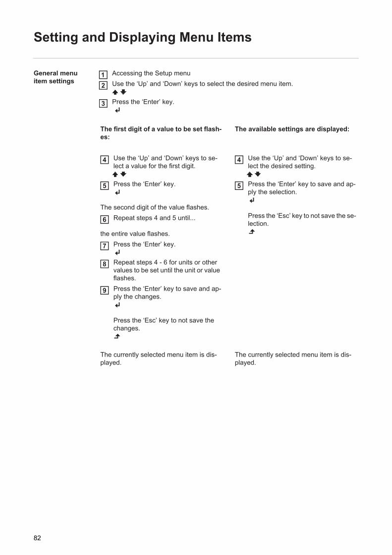
Setting and Displaying Menu Items
General menu item settings
Accessing the Setup menuUse the ‘Up’ and ‘Down’ keys to select the desired menu item.
Press the ‘Enter’ key.
The first digit of a value to be set flash-es:
The available settings are displayed:
Use the ‘Up’ and ‘Down’ keys to se-lect a value for the first digit.
Press the ‘Enter’ key.
The second digit of the value flashes.Repeat steps 4 and 5 until...
the entire value flashes.Press the ‘Enter’ key.
Repeat steps 4 - 6 for units or other values to be set until the unit or value flashes.Press the ‘Enter’ key to save and ap-ply the changes.
Press the ‘Esc’ key to not save the changes.
Use the ‘Up’ and ‘Down’ keys to se-lect the desired setting.
Press the ‘Enter’ key to save and ap-ply the selection.
Press the ‘Esc’ key to not save the se-lection.
The currently selected menu item is dis-played.
The currently selected menu item is dis-played.
12
3
4
5
6
7
8
9
4
5
82
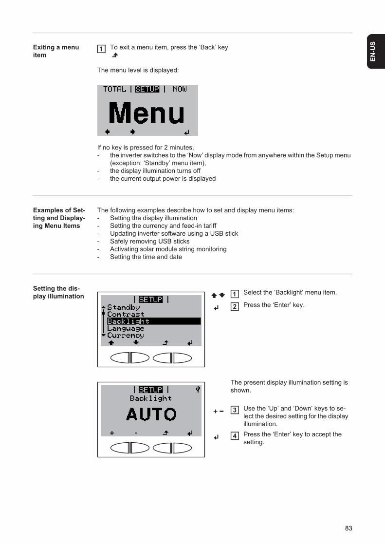
EN-U
S
Exiting a menu itemTo exit a menu item, press the ‘Back’ key.
The menu level is displayed:
If no key is pressed for 2 minutes, - the inverter switches to the ‘Now’ display mode from anywhere within the Setup menu
(exception: ‘Standby’ menu item),- the display illumination turns off- the current output power is displayed
Examples of Set-ting and Display-ing Menu Items
The following examples describe how to set and display menu items:- Setting the display illumination- Setting the currency and feed-in tariff- Updating inverter software using a USB stick- Safely removing USB sticks- Activating solar module string monitoring- Setting the time and date
Setting the dis-play illumination
1
Select the ‘Backlight’ menu item.
Press the ‘Enter’ key.
The present display illumination setting is shown.
Use the ‘Up’ and ‘Down’ keys to se-lect the desired setting for the display illumination.Press the ‘Enter’ key to accept the setting.
1
2
3
4
83
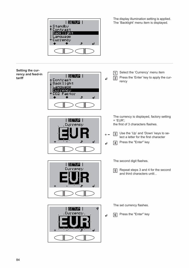
Setting the cur-rency and feed-in tariff
The display illumination setting is applied. The ‘Backlight’ menu item is displayed.
Select the ‘Currency’ menu itemPress the ‘Enter’ key to apply the cur-rency
The currency is displayed, factory setting = ‘EUR’;the first of 3 characters flashes.
Use the ‘Up’ and ‘Down’ keys to se-lect a letter for the first characterPress the "Enter" key
The second digit flashes.
Repeat steps 3 and 4 for the second and third characters until...
The set currency flashes.
Press the "Enter" key
12
3
4
5
6
84
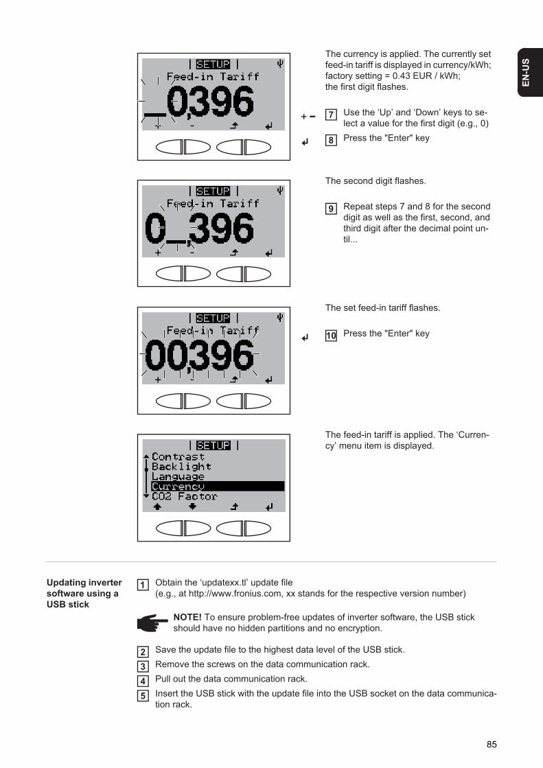
EN-U
S
Updating inverter software using a USB stick
Obtain the ‘updatexx.tl’ update file(e.g., at http://www.fronius.com, xx stands for the respective version number)
Save the update file to the highest data level of the USB stick.Remove the screws on the data communication rack.Pull out the data communication rack.Insert the USB stick with the update file into the USB socket on the data communica-tion rack.
The currency is applied. The currently set feed-in tariff is displayed in currency/kWh; factory setting = 0.43 EUR / kWh;the first digit flashes.
Use the ‘Up’ and ‘Down’ keys to se-lect a value for the first digit (e.g., 0)Press the "Enter" key
The second digit flashes.
Repeat steps 7 and 8 for the second digit as well as the first, second, and third digit after the decimal point un-til...
The set feed-in tariff flashes.
Press the "Enter" key
The feed-in tariff is applied. The ‘Curren-cy’ menu item is displayed.
7
8
9
10
NOTE! To ensure problem-free updates of inverter software, the USB stick should have no hidden partitions and no encryption.
1
2345
85
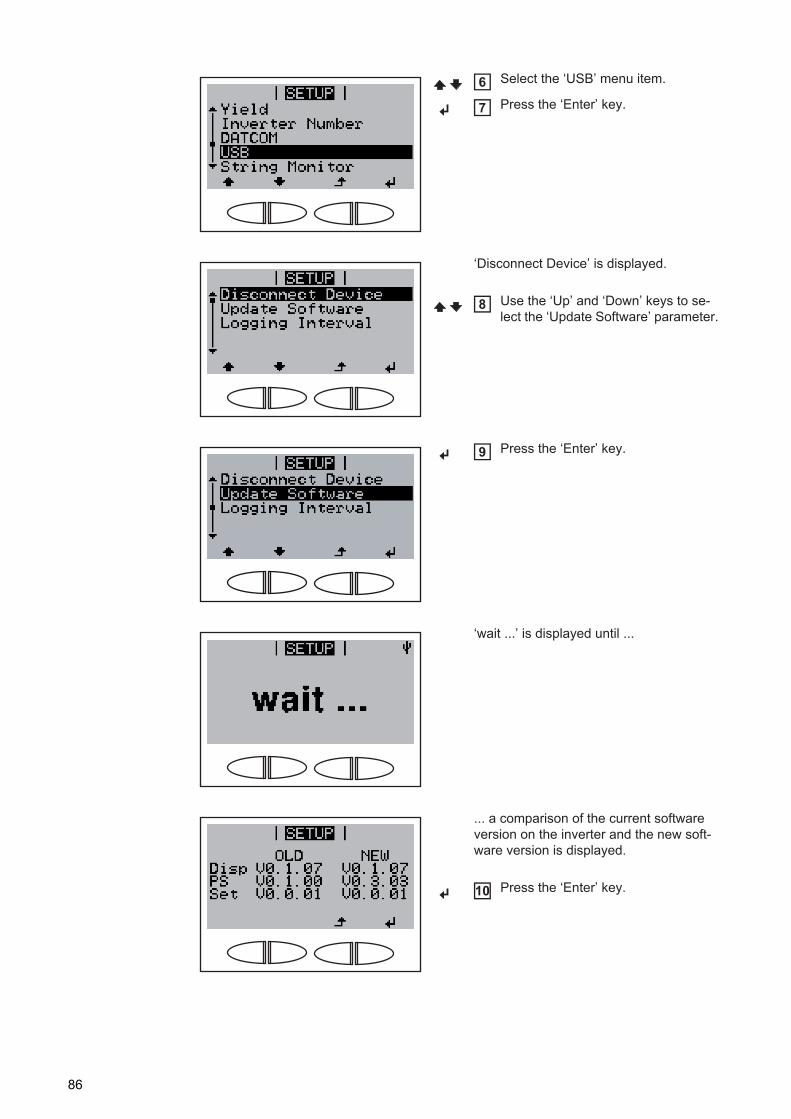
Select the ‘USB’ menu item.
Press the ‘Enter’ key.
‘Disconnect Device’ is displayed.
Use the ‘Up’ and ‘Down’ keys to se-lect the ‘Update Software’ parameter.
Press the ‘Enter’ key.
‘wait ...’ is displayed until ...
... a comparison of the current software version on the inverter and the new soft-ware version is displayed.
Press the ‘Enter’ key.
6
7
8
9
10
86
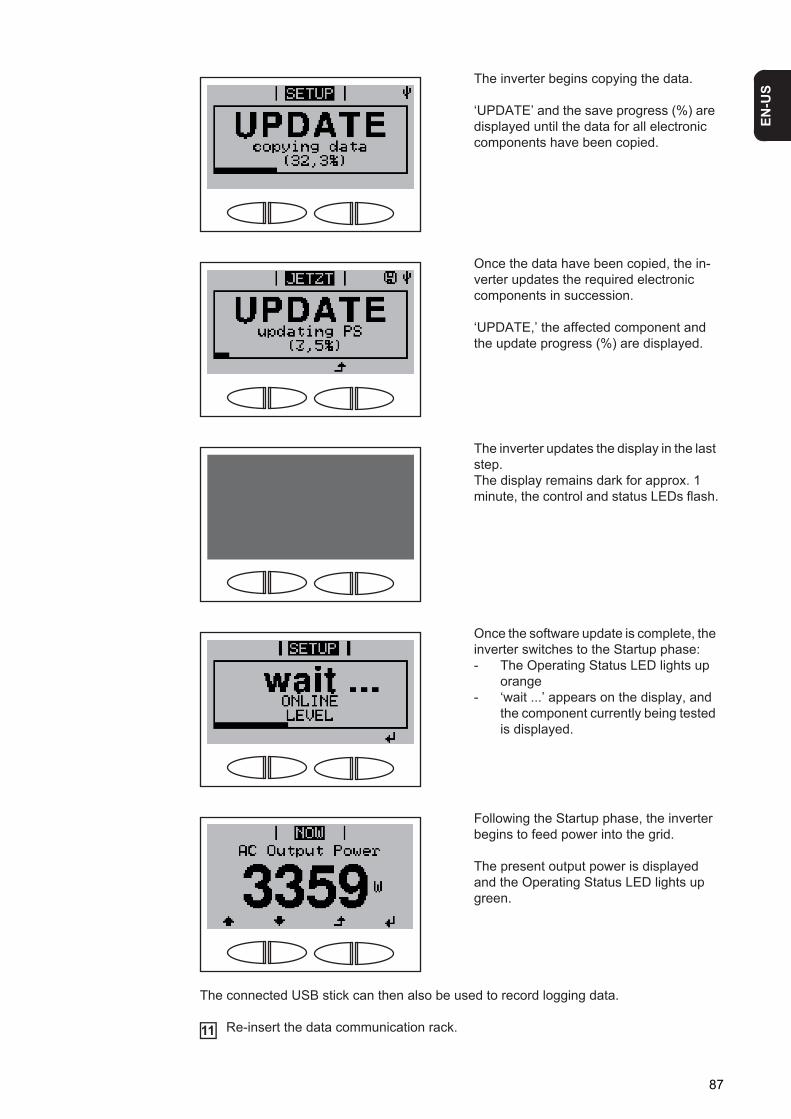
EN-U
S
The connected USB stick can then also be used to record logging data.
Re-insert the data communication rack.
The inverter begins copying the data.
‘UPDATE’ and the save progress (%) are displayed until the data for all electronic components have been copied.
Once the data have been copied, the in-verter updates the required electronic components in succession.
‘UPDATE,’ the affected component and the update progress (%) are displayed.
The inverter updates the display in the last step.The display remains dark for approx. 1 minute, the control and status LEDs flash.
Once the software update is complete, the inverter switches to the Startup phase:- The Operating Status LED lights up
orange- ‘wait ...’ appears on the display, and
the component currently being tested is displayed.
Following the Startup phase, the inverter begins to feed power into the grid.
The present output power is displayed and the Operating Status LED lights up green.
11
87
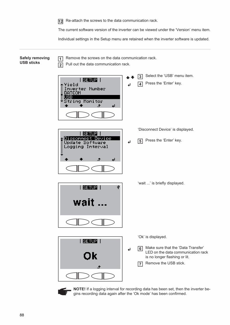
Re-attach the screws to the data communication rack.
The current software version of the inverter can be viewed under the ‘Version’ menu item.
Individual settings in the Setup menu are retained when the inverter software is updated.
Safely removing USB sticks
Remove the screws on the data communication rack.Pull out the data communication rack.
12
Select the ‘USB’ menu item.
Press the ‘Enter’ key.
‘Disconnect Device’ is displayed.
Press the ‘Enter’ key.
‘wait ...’ is briefly displayed.
‘Ok’ is displayed.
Make sure that the ‘Data Transfer’ LED on the data communication rack is no longer flashing or lit.Remove the USB stick.
NOTE! If a logging interval for recording data has been set, then the inverter be-gins recording data again after the ‘Ok mode’ has been confirmed.
12
3
4
5
6
7
88
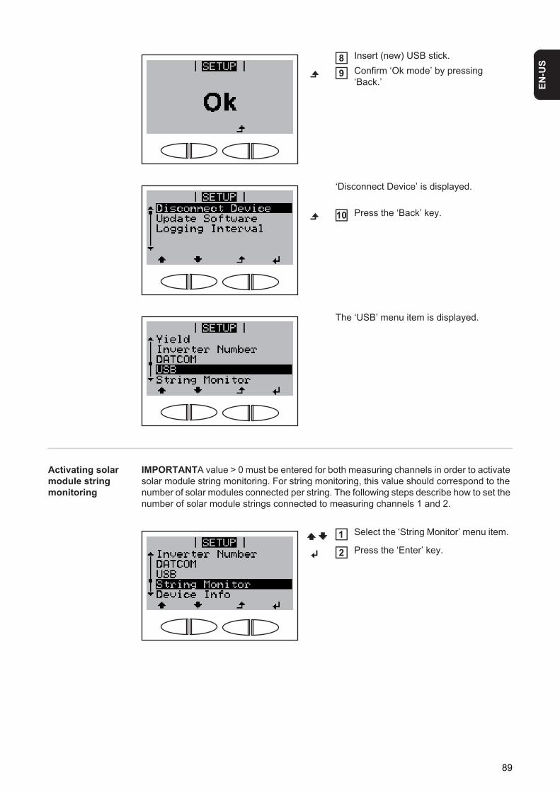
EN-U
S
Activating solar module string monitoring
IMPORTANTA value > 0 must be entered for both measuring channels in order to activate solar module string monitoring. For string monitoring, this value should correspond to the number of solar modules connected per string. The following steps describe how to set the number of solar module strings connected to measuring channels 1 and 2.
Insert (new) USB stick.Confirm ‘Ok mode’ by pressing ‘Back.’
‘Disconnect Device’ is displayed.
Press the ‘Back’ key.
The ‘USB’ menu item is displayed.
89
10
Select the ‘String Monitor’ menu item.
Press the ‘Enter’ key.1
2
89
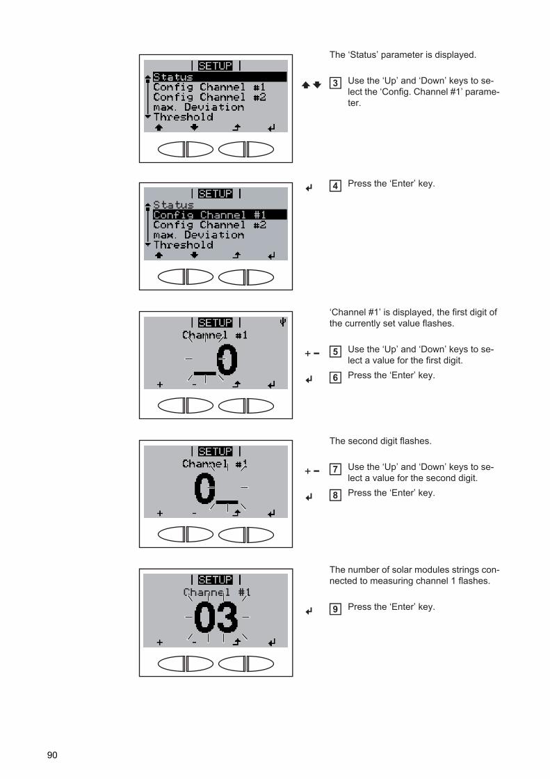
The ‘Status’ parameter is displayed.
Use the ‘Up’ and ‘Down’ keys to se-lect the ‘Config. Channel #1’ parame-ter.
Press the ‘Enter’ key.
‘Channel #1’ is displayed, the first digit of the currently set value flashes.
Use the ‘Up’ and ‘Down’ keys to se-lect a value for the first digit.Press the ‘Enter’ key.
The second digit flashes.
Use the ‘Up’ and ‘Down’ keys to se-lect a value for the second digit.Press the ‘Enter’ key.
The number of solar modules strings con-nected to measuring channel 1 flashes.
Press the ‘Enter’ key.
3
StatusConfig Channel #1
4
5
6
7
8
Channel #1
9
90
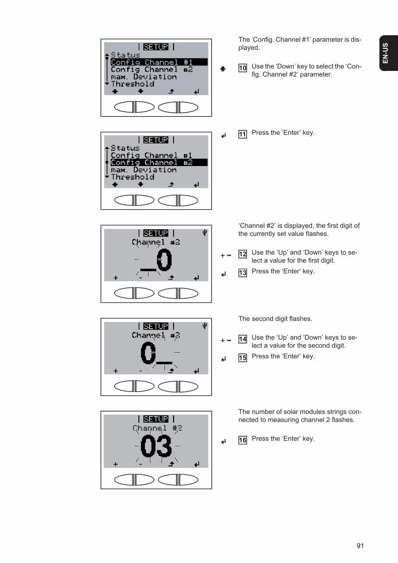
EN-U
S
The ‘Config. Channel #1’ parameter is dis-played.
Use the ‘Down’ key to select the ‘Con-fig. Channel #2’ parameter.
Press the ‘Enter’ key.
‘Channel #2’ is displayed, the first digit of the currently set value flashes.
Use the ‘Up’ and ‘Down’ keys to se-lect a value for the first digit.Press the ‘Enter’ key.
The second digit flashes.
Use the ‘Up’ and ‘Down’ keys to se-lect a value for the second digit.Press the ‘Enter’ key.
The number of solar modules strings con-nected to measuring channel 2 flashes.
Press the ‘Enter’ key.
StatusConfig Channel #1
10
11
12
13
14
15
Channel #2
16
91
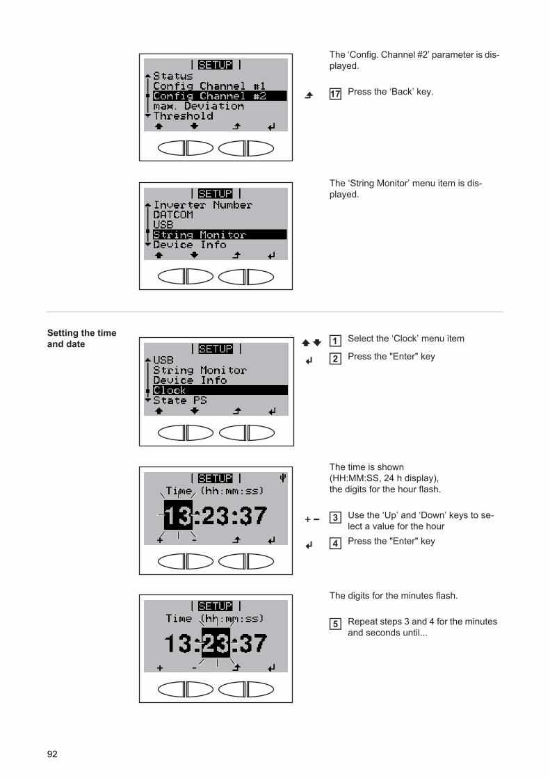
Setting the time and date
The ‘Config. Channel #2’ parameter is dis-played.
Press the ‘Back’ key.
The ‘String Monitor’ menu item is dis-played.
17
Select the ‘Clock’ menu item
Press the "Enter" key
The time is shown (HH:MM:SS, 24 h display), the digits for the hour flash.
Use the ‘Up’ and ‘Down’ keys to se-lect a value for the hourPress the "Enter" key
The digits for the minutes flash.
Repeat steps 3 and 4 for the minutes and seconds until...
1
2
3
4
5
92
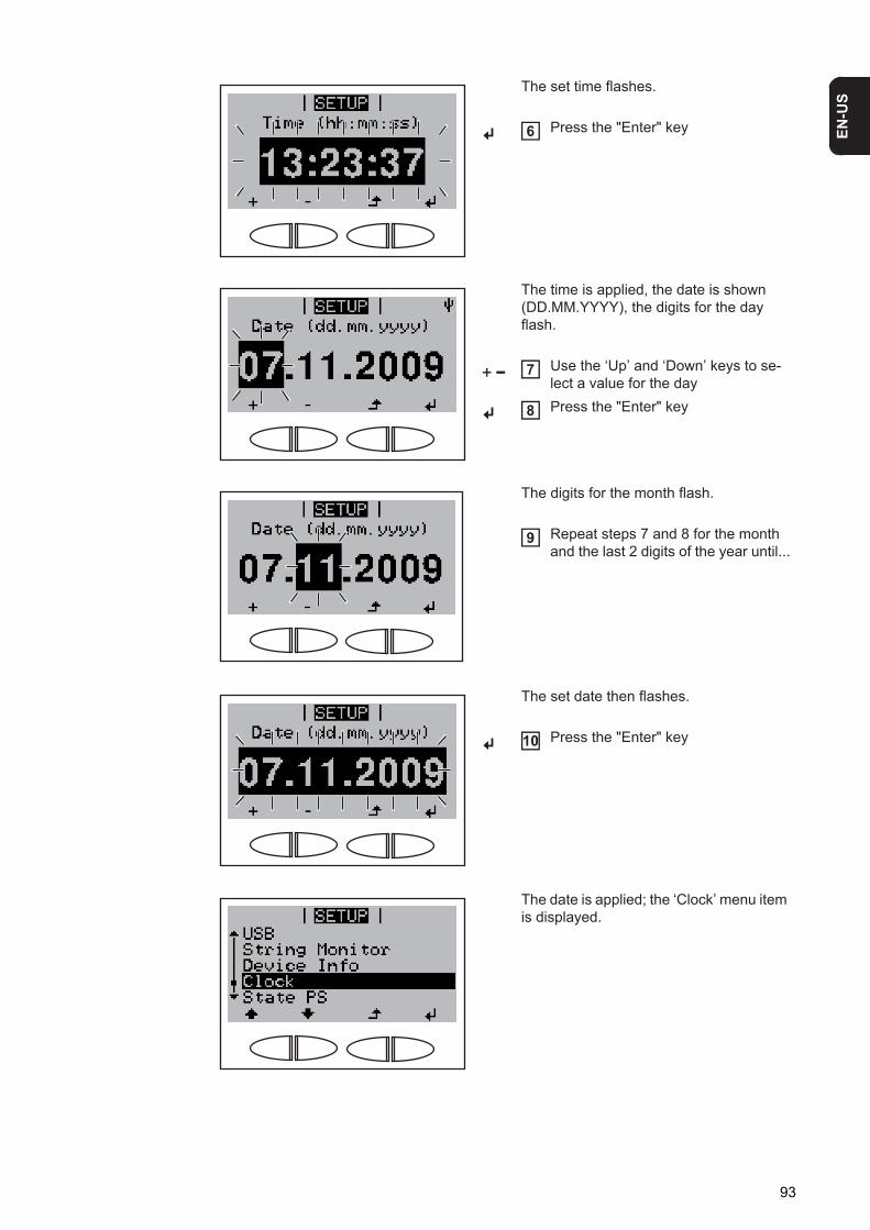
EN-U
S
The set time flashes.
Press the "Enter" key
The time is applied, the date is shown (DD.MM.YYYY), the digits for the day flash.
Use the ‘Up’ and ‘Down’ keys to se-lect a value for the dayPress the "Enter" key
The digits for the month flash.
Repeat steps 7 and 8 for the month and the last 2 digits of the year until...
The set date then flashes.
Press the "Enter" key
The date is applied; the ‘Clock’ menu item is displayed.
6
7
8
9
10
93
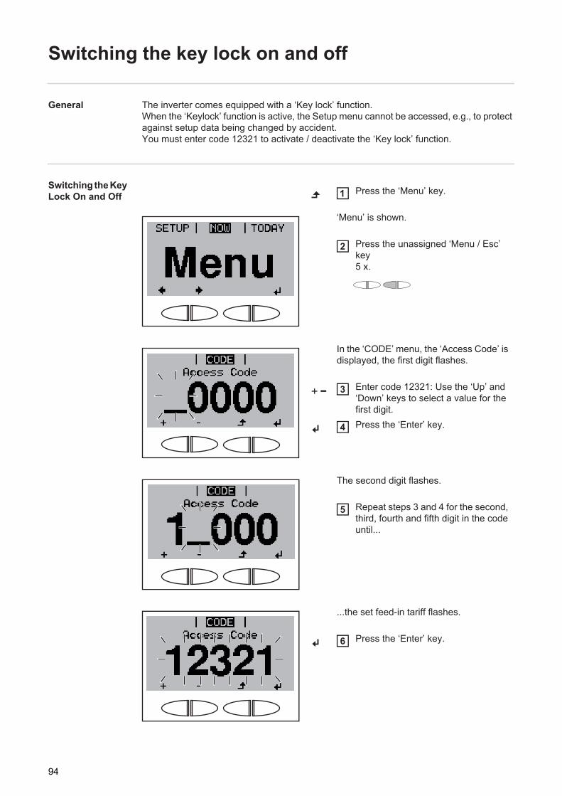
Switching the key lock on and off
General The inverter comes equipped with a ‘Key lock’ function.When the ‘Keylock’ function is active, the Setup menu cannot be accessed, e.g., to protect against setup data being changed by accident.You must enter code 12321 to activate / deactivate the ‘Key lock’ function.
Switching the Key Lock On and Off Press the ‘Menu’ key.
‘Menu’ is shown.
Press the unassigned ‘Menu / Esc’ key 5 x.
In the ‘CODE’ menu, the ‘Access Code’ is displayed, the first digit flashes.
Enter code 12321: Use the ‘Up’ and ‘Down’ keys to select a value for the first digit.Press the ‘Enter’ key.
The second digit flashes.
Repeat steps 3 and 4 for the second, third, fourth and fifth digit in the code until...
...the set feed-in tariff flashes.
Press the ‘Enter’ key.
1
2
3
4
5
6
94
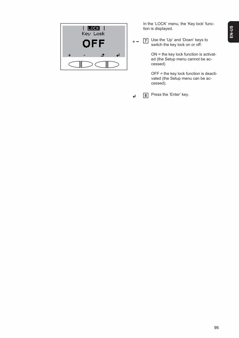
EN-U
S
In the ‘LOCK’ menu, the ‘Key lock‘ func-tion is displayed.
Use the ‘Up’ and ‘Down’ keys to switch the key lock on or off:
ON = the key lock function is activat-ed (the Setup menu cannot be ac-cessed)
OFF = the key lock function is deacti-vated (the Setup menu can be ac-cessed).
Press the ‘Enter’ key.
7
8
95

96
Troubleshooting and Maintenance

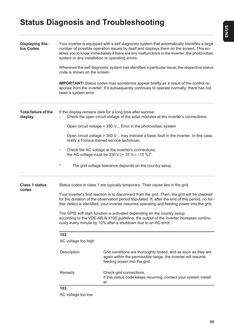
EN-U
S
Status Diagnosis and Troubleshooting
Displaying Sta-tus Codes
Your inverter is equipped with a self diagnostic system that automatically identifies a large number of possible operation issues by itself and displays them on the screen. This en-ables you to know immediately if there are any malfunctions in the inverter, the photovoltaic system or any installation or operating errors.
Whenever the self diagnostic system has identified a particular issue, the respective status code is shown on the screen.
Total failure of the display
If the display remains dark for a long time after sunrise:- Check the open circuit voltage of the solar modules at the inverter's connections:
Open circuit voltage < 350 V... Error in the photovoltaic system
Open circuit voltage > 350 V... may indicate a basic fault in the inverter. In this case, notify a Fronius-trained service technician.
- Check the AC voltage at the inverter's connections:the AC voltage must be 230 V (+ 10 % / - 15 %)*.
* The grid voltage tolerance depends on the country setup.
Class 1 status codes
Status codes in class 1 are typically temporary. Their cause lies in the grid.
Your inverter's first reaction is to disconnect from the grid. Then, the grid will be checked for the duration of the observation period stipulated. If, after the end of this period, no fur-ther defect is identified, your inverter resumes operating and feeding power into the grid.
The GPIS soft start function is activated depending on the country setup:according to the VDE-AR-N 4105 guideline, the output of the inverter increases continu-ously every minute by 10% after a shutdown due to an AC error.
IMPORTANT! Status codes may sometimes appear briefly as a result of the control re-sponse from the inverter. If it subsequently continues to operate normally, there has not been a system error.
102AC voltage too high
Description Grid conditions are thoroughly tested, and as soon as they are again within the permissible range, the inverter will resume feeding power into the grid.
Remedy Check grid connections.If this status code keeps recurring, contact your system install-er.
103AC voltage too low
99
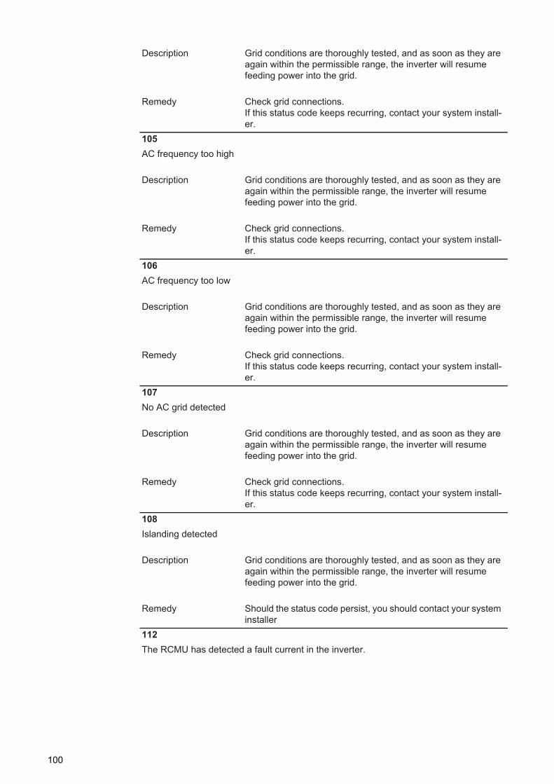
Description Grid conditions are thoroughly tested, and as soon as they are again within the permissible range, the inverter will resume feeding power into the grid.
Remedy Check grid connections.If this status code keeps recurring, contact your system install-er.
105AC frequency too high
Description Grid conditions are thoroughly tested, and as soon as they are again within the permissible range, the inverter will resume feeding power into the grid.
Remedy Check grid connections.If this status code keeps recurring, contact your system install-er.
106AC frequency too low
Description Grid conditions are thoroughly tested, and as soon as they are again within the permissible range, the inverter will resume feeding power into the grid.
Remedy Check grid connections.If this status code keeps recurring, contact your system install-er.
107No AC grid detected
Description Grid conditions are thoroughly tested, and as soon as they are again within the permissible range, the inverter will resume feeding power into the grid.
Remedy Check grid connections.If this status code keeps recurring, contact your system install-er.
108Islanding detected
Description Grid conditions are thoroughly tested, and as soon as they are again within the permissible range, the inverter will resume feeding power into the grid.
Remedy Should the status code persist, you should contact your system installer
112The RCMU has detected a fault current in the inverter.
100

EN-U
S
Class 3 status codes
Class 3 comprises status codes that may appear during feed-in operation and that do not cause a permanent interruption of the operation of feeding power into the grid.
After automatic disconnection from the grid and waiting for its conditions to return to those stipulated, your inverter will try to resume feed-in operation.
Description Grid conditions are thoroughly tested, and as soon as they are again within the permissible range, the inverter will resume feeding power into the grid.
Remedy Check grid connections or fuses.If this status code keeps recurring, contact your system install-er.
301Overcurrent (AC)
Description A short interruption of power feeding into the grid due to over-current in the inverter circuit.The inverter returns to the startup phase.
Remedy The fault is rectified automatically.If this status code keeps recurring, contact your system install-er.
302Overcurrent (DC)
Description Description A short interruption of power feeding into the grid due to overcurrent in the inverter DC circuit.The inverter returns to the startup phase.
Remedy The fault is rectified automatically.If this status code keeps recurring, contact your system install-er.
303Over-temperature cooling element
Description Short interruption of power feeding into the grid due to over-temperature.The inverter returns to the startup phase.
Remedy The fault is rectified automatically.If this status code keeps recurring, contact your system install-er.
304Interior temperature too high
Description Short interruption of power feeding into the grid due to over-temperature.The inverter returns to the startup phase.
101
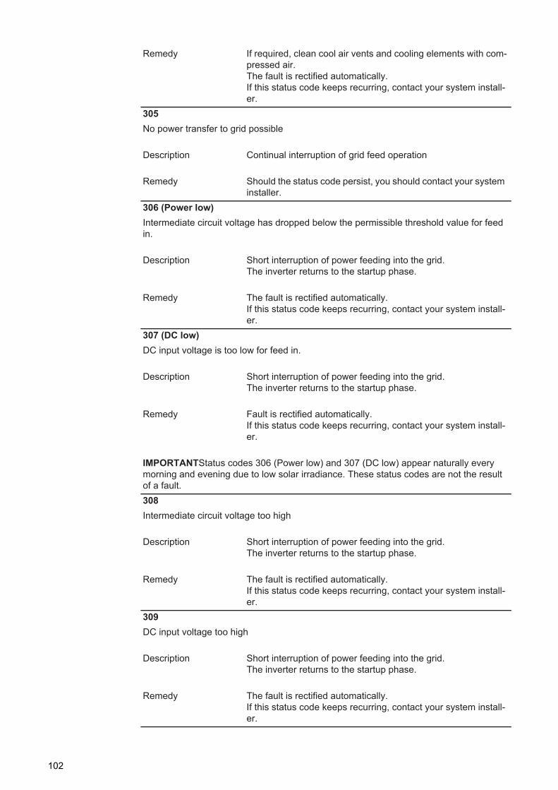
Remedy If required, clean cool air vents and cooling elements with com-pressed air.The fault is rectified automatically.If this status code keeps recurring, contact your system install-er.
305No power transfer to grid possible
Description Continual interruption of grid feed operation
Remedy Should the status code persist, you should contact your system installer.
306 (Power low)Intermediate circuit voltage has dropped below the permissible threshold value for feed in.
Description Short interruption of power feeding into the grid.The inverter returns to the startup phase.
Remedy The fault is rectified automatically.If this status code keeps recurring, contact your system install-er.
307 (DC low)DC input voltage is too low for feed in.
Description Short interruption of power feeding into the grid.The inverter returns to the startup phase.
Remedy Fault is rectified automatically.If this status code keeps recurring, contact your system install-er.
IMPORTANTStatus codes 306 (Power low) and 307 (DC low) appear naturally every morning and evening due to low solar irradiance. These status codes are not the result of a fault.308Intermediate circuit voltage too high
Description Short interruption of power feeding into the grid.The inverter returns to the startup phase.
Remedy The fault is rectified automatically.If this status code keeps recurring, contact your system install-er.
309DC input voltage too high
Description Short interruption of power feeding into the grid.The inverter returns to the startup phase.
Remedy The fault is rectified automatically.If this status code keeps recurring, contact your system install-er.
102
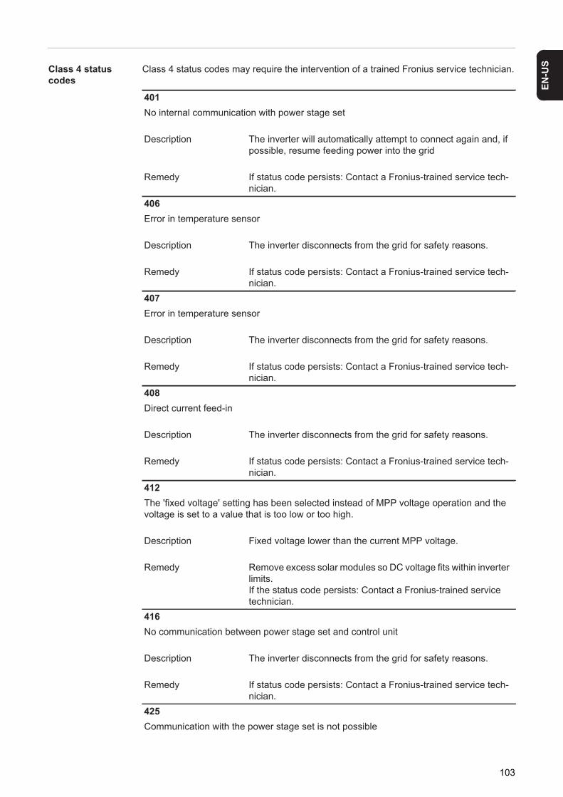
EN-U
S
Class 4 status codesClass 4 status codes may require the intervention of a trained Fronius service technician.
401No internal communication with power stage set
Description The inverter will automatically attempt to connect again and, if possible, resume feeding power into the grid
Remedy If status code persists: Contact a Fronius-trained service tech-nician.
406Error in temperature sensor
Description The inverter disconnects from the grid for safety reasons.
Remedy If status code persists: Contact a Fronius-trained service tech-nician.
407Error in temperature sensor
Description The inverter disconnects from the grid for safety reasons.
Remedy If status code persists: Contact a Fronius-trained service tech-nician.
408Direct current feed-in
Description The inverter disconnects from the grid for safety reasons.
Remedy If status code persists: Contact a Fronius-trained service tech-nician.
412The 'fixed voltage' setting has been selected instead of MPP voltage operation and the voltage is set to a value that is too low or too high.
Description Fixed voltage lower than the current MPP voltage.
Remedy Remove excess solar modules so DC voltage fits within inverter limits.If the status code persists: Contact a Fronius-trained service technician.
416No communication between power stage set and control unit
Description The inverter disconnects from the grid for safety reasons.
Remedy If status code persists: Contact a Fronius-trained service tech-nician.
425Communication with the power stage set is not possible
103

Description The inverter disconnects from the grid for safety reasons and then attempts a restart.
Remedy If status code persists: Contact a Fronius-trained service tech-nician.
426The intermediate circuit charging takes too long
Description Short interruption of grid feed-in mode.The inverter returns to the Startup phase.
Remedy The fault is rectified automatically.If this status code keeps recurring, contact your system install-er.
427Power stage set inoperative for too long (timeout)
Description Short interruption of grid feed-in mode.The inverter returns to the Startup phase.
Remedy The fault is rectified automatically.If this status code keeps recurring, contact your system install-er.
428Timeout error during connection
Description Short interruption of grid feed-in mode.The inverter returns to the Startup phase.
Remedy If this status code keeps recurring, contact your system install-er.
429Timeout error when disconnecting
Description Short interruption of grid feed-in mode.The inverter returns to the Startup phase.
Remedy If this status code keeps recurring, contact your system install-er.
431Power stage set software being updated
Description Inverter does not feed energy into the grid.
Remedy Update firmware using Fronius Solar.update or a USB stick432Internal database error during power stage set allocation
Description The inverter disconnects from the grid for safety reasons and then attempts a restart.
104
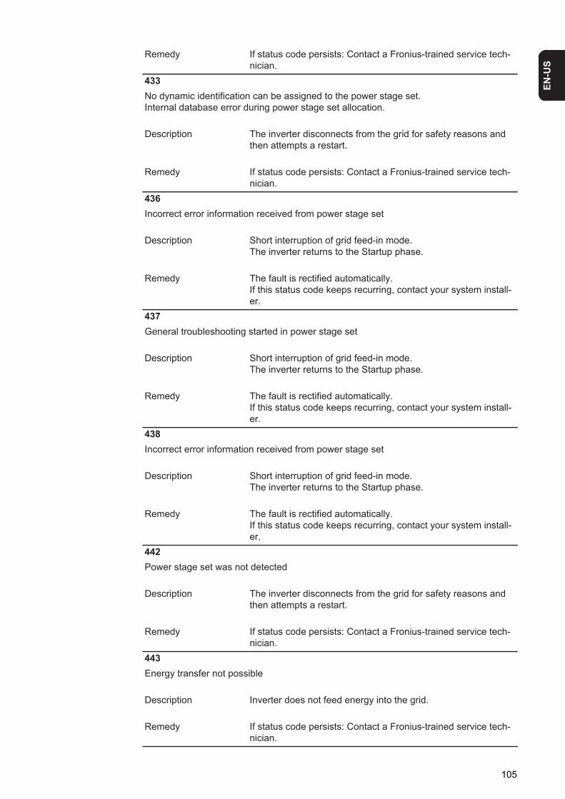
EN-U
S
Remedy If status code persists: Contact a Fronius-trained service tech-nician.
433No dynamic identification can be assigned to the power stage set.Internal database error during power stage set allocation.
Description The inverter disconnects from the grid for safety reasons and then attempts a restart.
Remedy If status code persists: Contact a Fronius-trained service tech-nician.
436Incorrect error information received from power stage set
Description Short interruption of grid feed-in mode.The inverter returns to the Startup phase.
Remedy The fault is rectified automatically.If this status code keeps recurring, contact your system install-er.
437General troubleshooting started in power stage set
Description Short interruption of grid feed-in mode.The inverter returns to the Startup phase.
Remedy The fault is rectified automatically.If this status code keeps recurring, contact your system install-er.
438Incorrect error information received from power stage set
Description Short interruption of grid feed-in mode.The inverter returns to the Startup phase.
Remedy The fault is rectified automatically.If this status code keeps recurring, contact your system install-er.
442Power stage set was not detected
Description The inverter disconnects from the grid for safety reasons and then attempts a restart.
Remedy If status code persists: Contact a Fronius-trained service tech-nician.
443Energy transfer not possible
Description Inverter does not feed energy into the grid.
Remedy If status code persists: Contact a Fronius-trained service tech-nician.
105
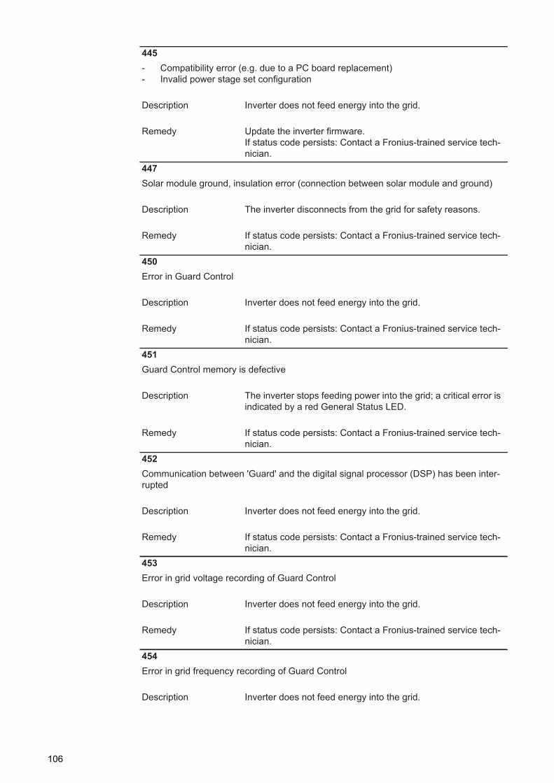
445- Compatibility error (e.g. due to a PC board replacement)- Invalid power stage set configuration
Description Inverter does not feed energy into the grid.
Remedy Update the inverter firmware.If status code persists: Contact a Fronius-trained service tech-nician.
447Solar module ground, insulation error (connection between solar module and ground)
Description The inverter disconnects from the grid for safety reasons.
Remedy If status code persists: Contact a Fronius-trained service tech-nician.
450Error in Guard Control
Description Inverter does not feed energy into the grid.
Remedy If status code persists: Contact a Fronius-trained service tech-nician.
451Guard Control memory is defective
Description The inverter stops feeding power into the grid; a critical error is indicated by a red General Status LED.
Remedy If status code persists: Contact a Fronius-trained service tech-nician.
452Communication between 'Guard' and the digital signal processor (DSP) has been inter-rupted
Description Inverter does not feed energy into the grid.
Remedy If status code persists: Contact a Fronius-trained service tech-nician.
453Error in grid voltage recording of Guard Control
Description Inverter does not feed energy into the grid.
Remedy If status code persists: Contact a Fronius-trained service tech-nician.
454Error in grid frequency recording of Guard Control
Description Inverter does not feed energy into the grid.
106
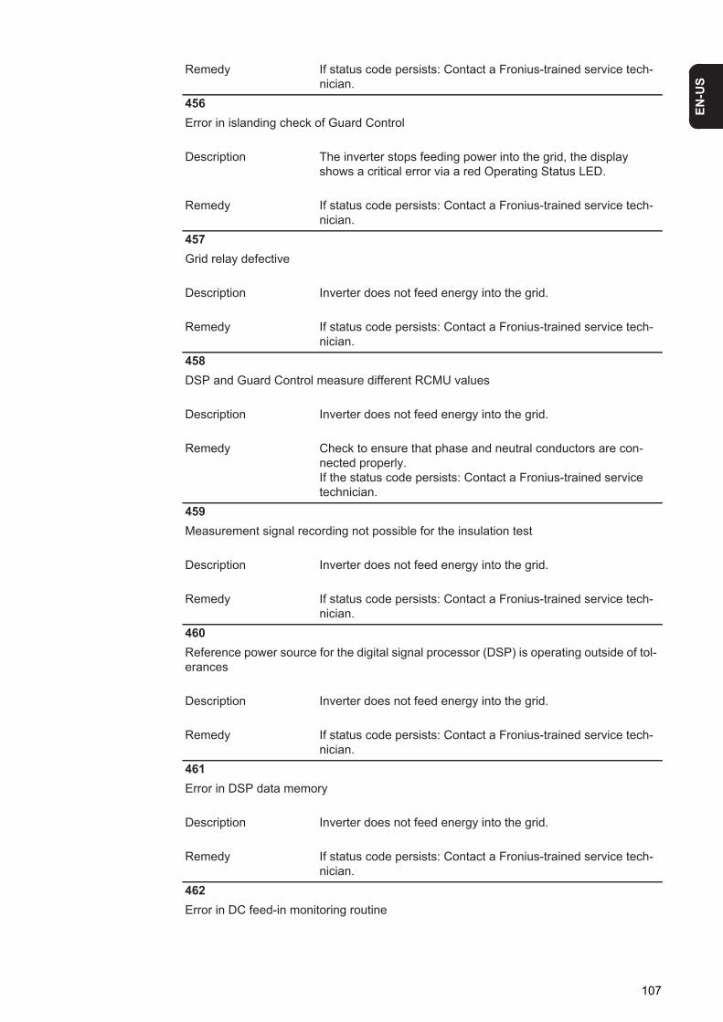
EN-U
S
Remedy If status code persists: Contact a Fronius-trained service tech-nician.
456Error in islanding check of Guard Control
Description The inverter stops feeding power into the grid, the display shows a critical error via a red Operating Status LED.
Remedy If status code persists: Contact a Fronius-trained service tech-nician.
457Grid relay defective
Description Inverter does not feed energy into the grid.
Remedy If status code persists: Contact a Fronius-trained service tech-nician.
458DSP and Guard Control measure different RCMU values
Description Inverter does not feed energy into the grid.
Remedy Check to ensure that phase and neutral conductors are con-nected properly.If the status code persists: Contact a Fronius-trained service technician.
459Measurement signal recording not possible for the insulation test
Description Inverter does not feed energy into the grid.
Remedy If status code persists: Contact a Fronius-trained service tech-nician.
460Reference power source for the digital signal processor (DSP) is operating outside of tol-erances
Description Inverter does not feed energy into the grid.
Remedy If status code persists: Contact a Fronius-trained service tech-nician.
461Error in DSP data memory
Description Inverter does not feed energy into the grid.
Remedy If status code persists: Contact a Fronius-trained service tech-nician.
462Error in DC feed-in monitoring routine
107
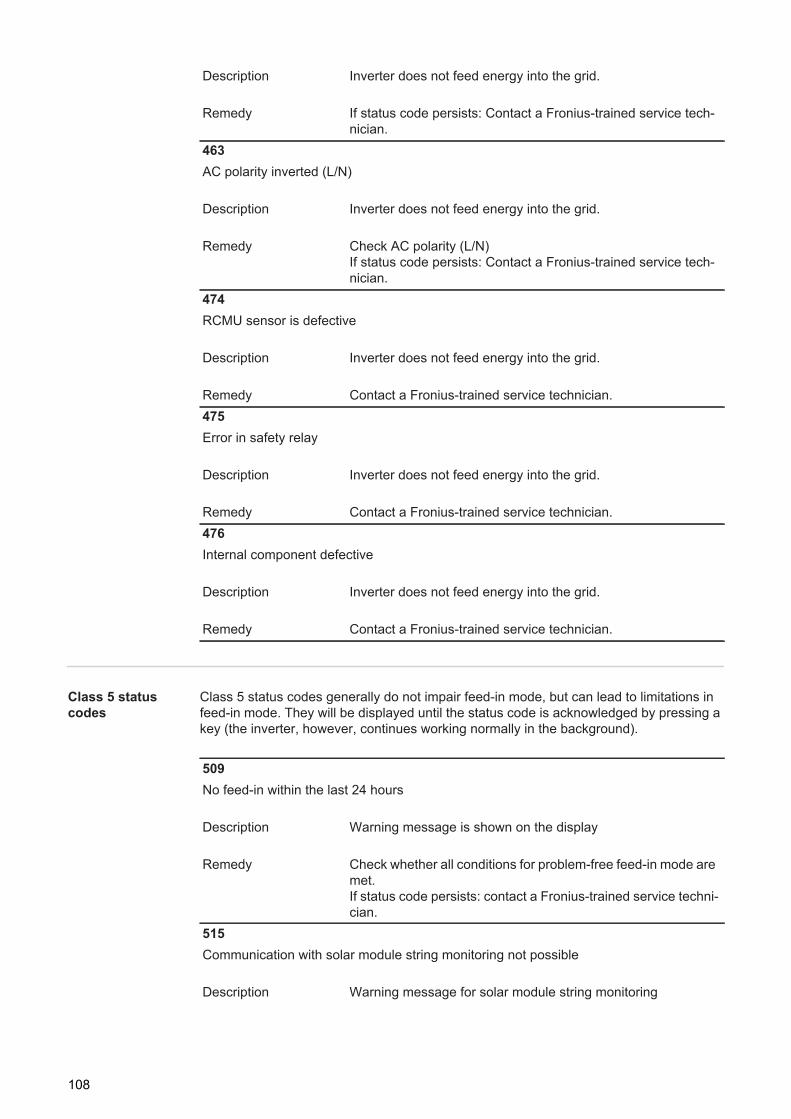
Class 5 status codes
Class 5 status codes generally do not impair feed-in mode, but can lead to limitations in feed-in mode. They will be displayed until the status code is acknowledged by pressing a key (the inverter, however, continues working normally in the background).
Description Inverter does not feed energy into the grid.
Remedy If status code persists: Contact a Fronius-trained service tech-nician.
463AC polarity inverted (L/N)
Description Inverter does not feed energy into the grid.
Remedy Check AC polarity (L/N)If status code persists: Contact a Fronius-trained service tech-nician.
474RCMU sensor is defective
Description Inverter does not feed energy into the grid.
Remedy Contact a Fronius-trained service technician.475Error in safety relay
Description Inverter does not feed energy into the grid.
Remedy Contact a Fronius-trained service technician.476Internal component defective
Description Inverter does not feed energy into the grid.
Remedy Contact a Fronius-trained service technician.
509No feed-in within the last 24 hours
Description Warning message is shown on the display
Remedy Check whether all conditions for problem-free feed-in mode are met.If status code persists: contact a Fronius-trained service techni-cian.
515Communication with solar module string monitoring not possible
Description Warning message for solar module string monitoring
108
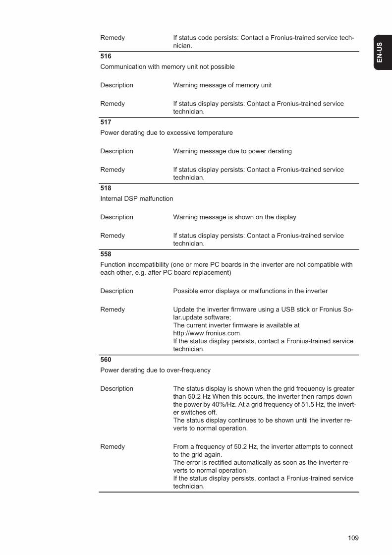
EN-U
S
Remedy If status code persists: Contact a Fronius-trained service tech-nician.
516Communication with memory unit not possible
Description Warning message of memory unit
Remedy If status display persists: Contact a Fronius-trained service technician.
517Power derating due to excessive temperature
Description Warning message due to power derating
Remedy If status display persists: Contact a Fronius-trained service technician.
518Internal DSP malfunction
Description Warning message is shown on the display
Remedy If status display persists: Contact a Fronius-trained service technician.
558Function incompatibility (one or more PC boards in the inverter are not compatible with each other, e.g. after PC board replacement)
Description Possible error displays or malfunctions in the inverter
Remedy Update the inverter firmware using a USB stick or Fronius So-lar.update software;The current inverter firmware is available at http://www.fronius.com.If the status display persists, contact a Fronius-trained service technician.
560Power derating due to over-frequency
Description The status display is shown when the grid frequency is greater than 50.2 Hz When this occurs, the inverter then ramps down the power by 40%/Hz. At a grid frequency of 51.5 Hz, the invert-er switches off.The status display continues to be shown until the inverter re-verts to normal operation.
Remedy From a frequency of 50.2 Hz, the inverter attempts to connect to the grid again.The error is rectified automatically as soon as the inverter re-verts to normal operation.If the status display persists, contact a Fronius-trained service technician.
109
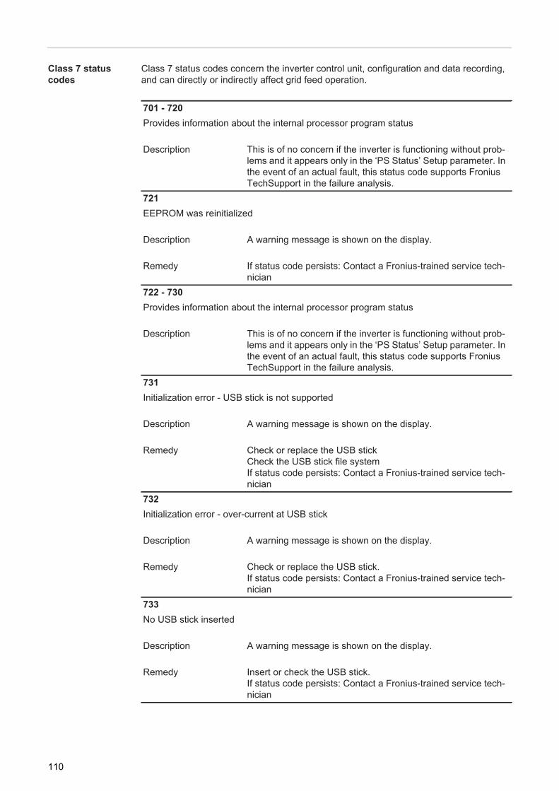
Class 7 status codes
Class 7 status codes concern the inverter control unit, configuration and data recording, and can directly or indirectly affect grid feed operation.
701 - 720Provides information about the internal processor program status
Description This is of no concern if the inverter is functioning without prob-lems and it appears only in the ‘PS Status’ Setup parameter. In the event of an actual fault, this status code supports Fronius TechSupport in the failure analysis.
721EEPROM was reinitialized
Description A warning message is shown on the display.
Remedy If status code persists: Contact a Fronius-trained service tech-nician
722 - 730Provides information about the internal processor program status
Description This is of no concern if the inverter is functioning without prob-lems and it appears only in the ‘PS Status’ Setup parameter. In the event of an actual fault, this status code supports Fronius TechSupport in the failure analysis.
731Initialization error - USB stick is not supported
Description A warning message is shown on the display.
Remedy Check or replace the USB stickCheck the USB stick file systemIf status code persists: Contact a Fronius-trained service tech-nician
732Initialization error - over-current at USB stick
Description A warning message is shown on the display.
Remedy Check or replace the USB stick.If status code persists: Contact a Fronius-trained service tech-nician
733No USB stick inserted
Description A warning message is shown on the display.
Remedy Insert or check the USB stick.If status code persists: Contact a Fronius-trained service tech-nician
110
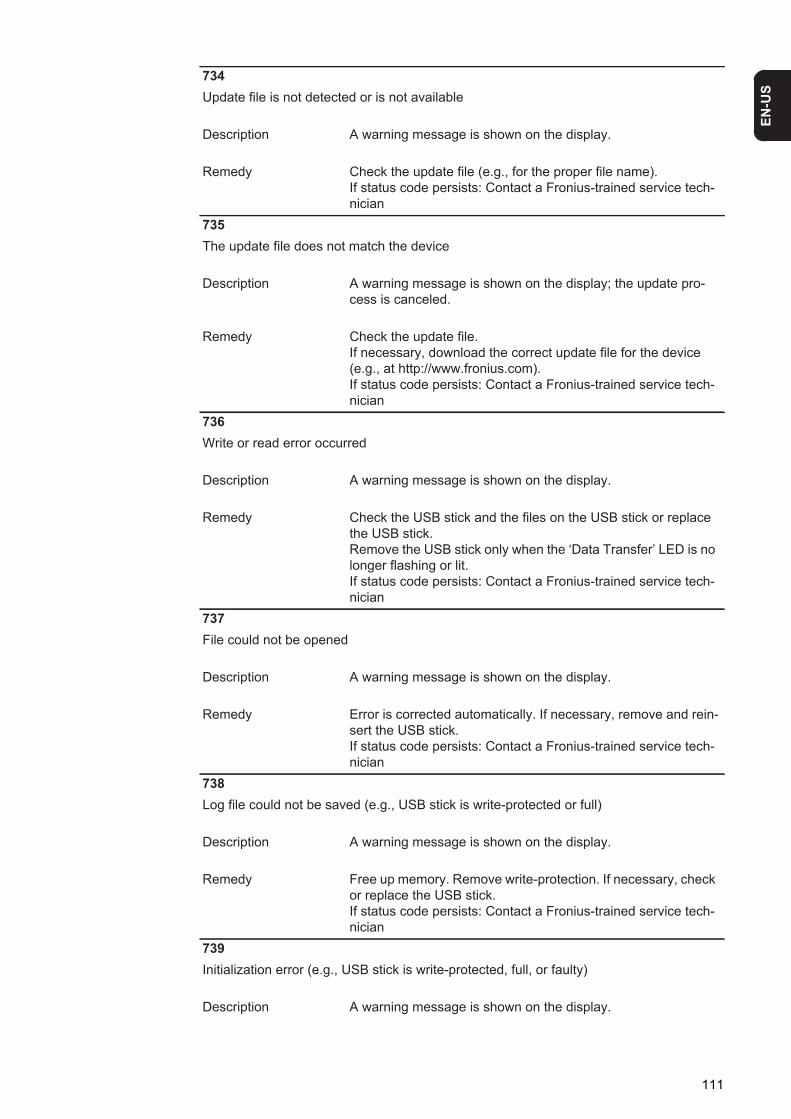
EN-U
S
734Update file is not detected or is not available
Description A warning message is shown on the display.
Remedy Check the update file (e.g., for the proper file name).If status code persists: Contact a Fronius-trained service tech-nician
735The update file does not match the device
Description A warning message is shown on the display; the update pro-cess is canceled.
Remedy Check the update file. If necessary, download the correct update file for the device (e.g., at http://www.fronius.com).If status code persists: Contact a Fronius-trained service tech-nician
736Write or read error occurred
Description A warning message is shown on the display.
Remedy Check the USB stick and the files on the USB stick or replace the USB stick.Remove the USB stick only when the ‘Data Transfer’ LED is no longer flashing or lit.If status code persists: Contact a Fronius-trained service tech-nician
737File could not be opened
Description A warning message is shown on the display.
Remedy Error is corrected automatically. If necessary, remove and rein-sert the USB stick.If status code persists: Contact a Fronius-trained service tech-nician
738Log file could not be saved (e.g., USB stick is write-protected or full)
Description A warning message is shown on the display.
Remedy Free up memory. Remove write-protection. If necessary, check or replace the USB stick.If status code persists: Contact a Fronius-trained service tech-nician
739Initialization error (e.g., USB stick is write-protected, full, or faulty)
Description A warning message is shown on the display.
111
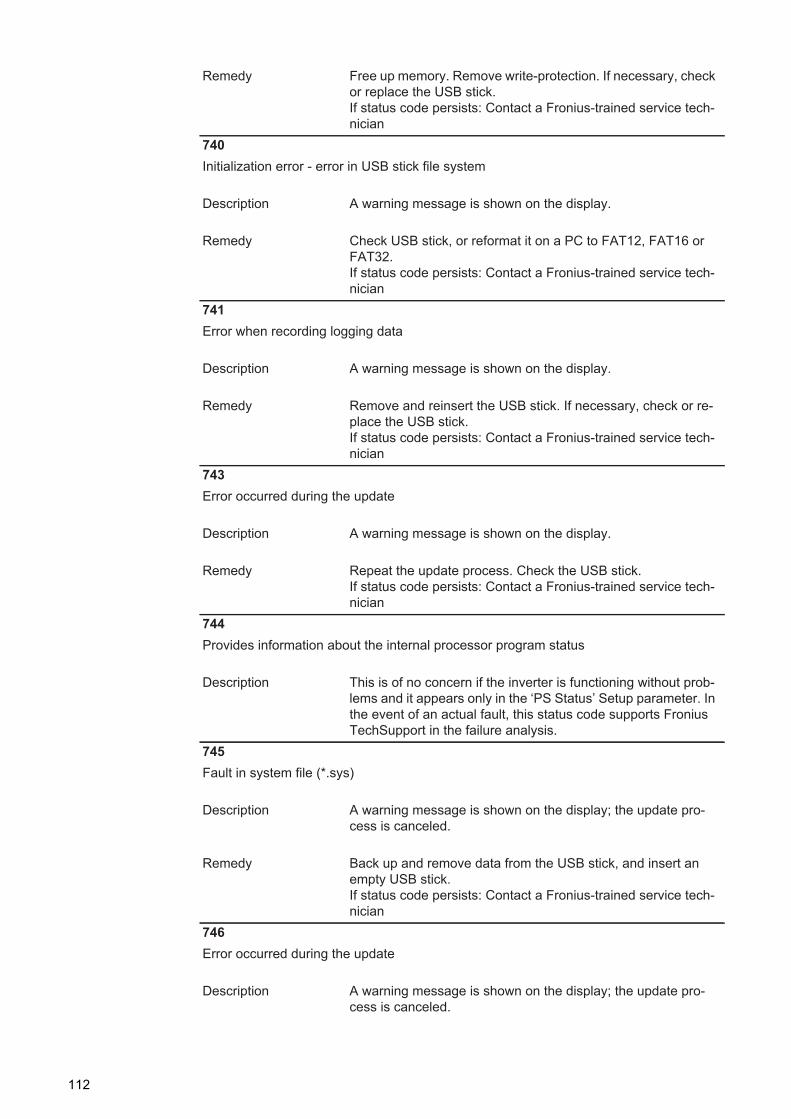
Remedy Free up memory. Remove write-protection. If necessary, check or replace the USB stick.If status code persists: Contact a Fronius-trained service tech-nician
740Initialization error - error in USB stick file system
Description A warning message is shown on the display.
Remedy Check USB stick, or reformat it on a PC to FAT12, FAT16 or FAT32.If status code persists: Contact a Fronius-trained service tech-nician
741Error when recording logging data
Description A warning message is shown on the display.
Remedy Remove and reinsert the USB stick. If necessary, check or re-place the USB stick.If status code persists: Contact a Fronius-trained service tech-nician
743Error occurred during the update
Description A warning message is shown on the display.
Remedy Repeat the update process. Check the USB stick.If status code persists: Contact a Fronius-trained service tech-nician
744Provides information about the internal processor program status
Description This is of no concern if the inverter is functioning without prob-lems and it appears only in the ‘PS Status’ Setup parameter. In the event of an actual fault, this status code supports Fronius TechSupport in the failure analysis.
745Fault in system file (*.sys)
Description A warning message is shown on the display; the update pro-cess is canceled.
Remedy Back up and remove data from the USB stick, and insert an empty USB stick.If status code persists: Contact a Fronius-trained service tech-nician
746Error occurred during the update
Description A warning message is shown on the display; the update pro-cess is canceled.
112
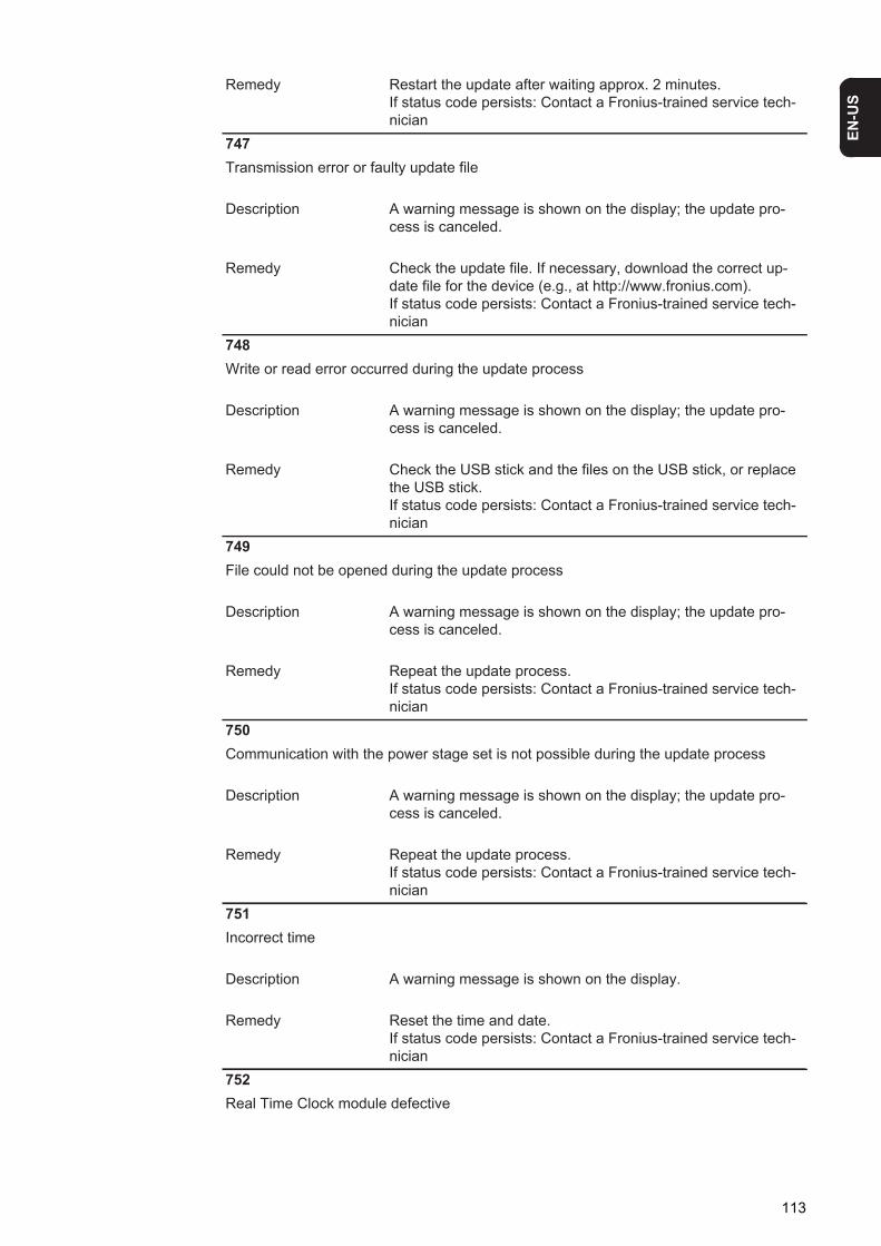
EN-U
S
Remedy Restart the update after waiting approx. 2 minutes.If status code persists: Contact a Fronius-trained service tech-nician
747Transmission error or faulty update file
Description A warning message is shown on the display; the update pro-cess is canceled.
Remedy Check the update file. If necessary, download the correct up-date file for the device (e.g., at http://www.fronius.com).If status code persists: Contact a Fronius-trained service tech-nician
748Write or read error occurred during the update process
Description A warning message is shown on the display; the update pro-cess is canceled.
Remedy Check the USB stick and the files on the USB stick, or replace the USB stick.If status code persists: Contact a Fronius-trained service tech-nician
749File could not be opened during the update process
Description A warning message is shown on the display; the update pro-cess is canceled.
Remedy Repeat the update process.If status code persists: Contact a Fronius-trained service tech-nician
750Communication with the power stage set is not possible during the update process
Description A warning message is shown on the display; the update pro-cess is canceled.
Remedy Repeat the update process.If status code persists: Contact a Fronius-trained service tech-nician
751Incorrect time
Description A warning message is shown on the display.
Remedy Reset the time and date.If status code persists: Contact a Fronius-trained service tech-nician
752Real Time Clock module defective
113
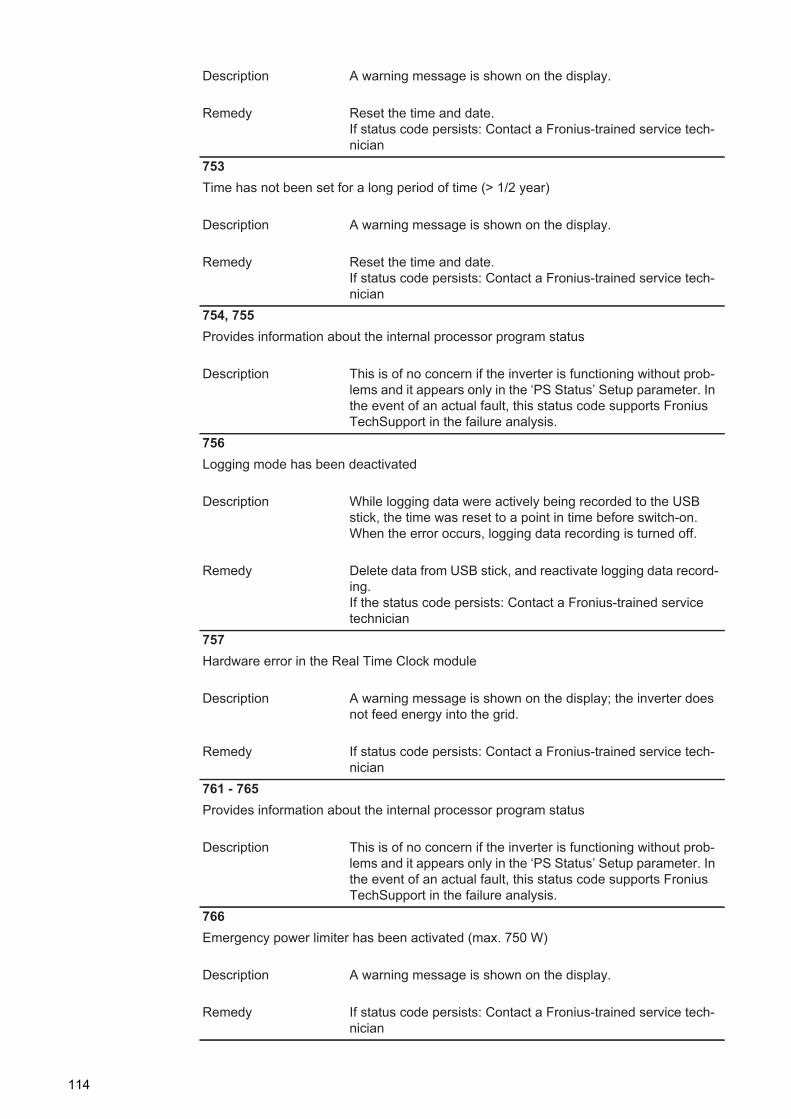
Description A warning message is shown on the display.
Remedy Reset the time and date.If status code persists: Contact a Fronius-trained service tech-nician
753Time has not been set for a long period of time (> 1/2 year)
Description A warning message is shown on the display.
Remedy Reset the time and date.If status code persists: Contact a Fronius-trained service tech-nician
754, 755Provides information about the internal processor program status
Description This is of no concern if the inverter is functioning without prob-lems and it appears only in the ‘PS Status’ Setup parameter. In the event of an actual fault, this status code supports Fronius TechSupport in the failure analysis.
756Logging mode has been deactivated
Description While logging data were actively being recorded to the USB stick, the time was reset to a point in time before switch-on. When the error occurs, logging data recording is turned off.
Remedy Delete data from USB stick, and reactivate logging data record-ing.If the status code persists: Contact a Fronius-trained service technician
757Hardware error in the Real Time Clock module
Description A warning message is shown on the display; the inverter does not feed energy into the grid.
Remedy If status code persists: Contact a Fronius-trained service tech-nician
761 - 765Provides information about the internal processor program status
Description This is of no concern if the inverter is functioning without prob-lems and it appears only in the ‘PS Status’ Setup parameter. In the event of an actual fault, this status code supports Fronius TechSupport in the failure analysis.
766Emergency power limiter has been activated (max. 750 W)
Description A warning message is shown on the display.
Remedy If status code persists: Contact a Fronius-trained service tech-nician
114
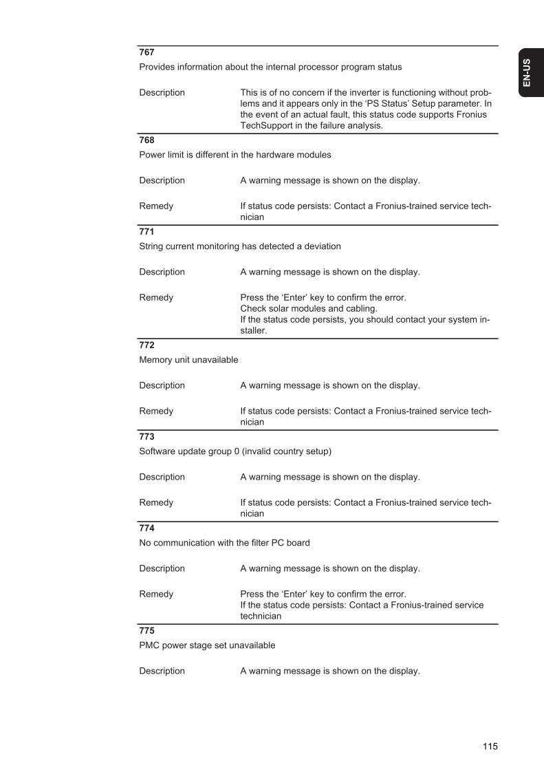
EN-U
S
767Provides information about the internal processor program status
Description This is of no concern if the inverter is functioning without prob-lems and it appears only in the ‘PS Status’ Setup parameter. In the event of an actual fault, this status code supports Fronius TechSupport in the failure analysis.
768Power limit is different in the hardware modules
Description A warning message is shown on the display.
Remedy If status code persists: Contact a Fronius-trained service tech-nician
771String current monitoring has detected a deviation
Description A warning message is shown on the display.
Remedy Press the ‘Enter’ key to confirm the error.Check solar modules and cabling.If the status code persists, you should contact your system in-staller.
772Memory unit unavailable
Description A warning message is shown on the display.
Remedy If status code persists: Contact a Fronius-trained service tech-nician
773Software update group 0 (invalid country setup)
Description A warning message is shown on the display.
Remedy If status code persists: Contact a Fronius-trained service tech-nician
774No communication with the filter PC board
Description A warning message is shown on the display.
Remedy Press the ‘Enter’ key to confirm the error.If the status code persists: Contact a Fronius-trained service technician
775PMC power stage set unavailable
Description A warning message is shown on the display.
115
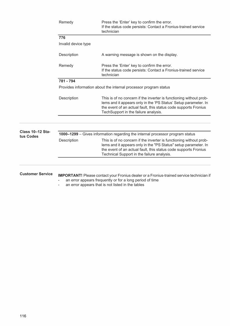
Class 10–12 Sta-tus Codes
Customer Service
Remedy Press the ‘Enter’ key to confirm the error.If the status code persists: Contact a Fronius-trained service technician
776Invalid device type
Description A warning message is shown on the display.
Remedy Press the ‘Enter’ key to confirm the error.If the status code persists: Contact a Fronius-trained service technician
781 - 794Provides information about the internal processor program status
Description This is of no concern if the inverter is functioning without prob-lems and it appears only in the ‘PS Status’ Setup parameter. In the event of an actual fault, this status code supports Fronius TechSupport in the failure analysis.
1000–1299 – Gives information regarding the internal processor program statusDescription This is of no concern if the inverter is functioning without prob-
lems and it appears only in the "PS Status" setup parameter. In the event of an actual fault, this status code supports Fronius Technical Support in the failure analysis.
IMPORTANT! Please contact your Fronius dealer or a Fronius-trained service technician if- an error appears frequently or for a long period of time- an error appears that is not listed in the tables
116

EN-U
S
Maintenance
Safety
General The inverter is designed so that it does not require additional maintenance. However, there are a few points to keep in mind during operation to ensure that the inverter functions op-timally.
Opening Fronius IG TL for service/maintenance
Procedure for opening the inverter for service or maintenance:
Disconnect the AC supply from the inverter.Turn off the main DC switch.Allow the capacitors to discharge (3 minutes).Remove the 6 side screws.Remove the power stage set from the wall bracket.Protect the wall bracket from soiling and moisture.Remove the 4 cover screws.Carefully lift up the housing cover on the bottom of the power stage set.Reach into the opening.Disconnect the ribbon cable from the PC display board.Remove the cover.
WARNING! An electric shock can be fatal. Danger from grid voltage and DC volt-age from solar modules.- The DC main switch is used only to switch off power to the power stage set.
When the DC main switch is turned off, the connection area is still energized.- Only licensed electricians should access the connection area.- All maintenance and service work should only be carried out when the power
stage set has been disconnected from the connection area.- Maintenance and service work on the inverter power stage set should only
be carried out by Fronius-trained personnel.
WARNING! An electric shock can be fatal. Danger from residual voltage from ca-pacitors.You must wait until the capacitors have discharged. Discharge takes 3 minutes.
WARNING! An inadequate grounding conductor connection can cause serious injuries to persons and damage to (or loss of) property.The housing screws provide an adequate grounding conductor connection for the housing ground and should not, under any circumstances, be replaced by differ-ent screws that do not provide a proper grounding conductor connection.
1234567891011
117
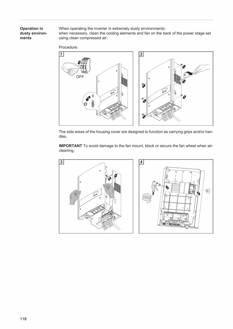
Operation in dusty environ-ments
When operating the inverter in extremely dusty environments:when necessary, clean the cooling elements and fan on the back of the power stage set using clean compressed air.
Procedure:1 1
The side areas of the housing cover are designed to function as carrying grips and/or han-dles.
IMPORTANT To avoid damage to the fan mount, block or secure the fan wheel when air-cleaning.
1 1
1
32
OFF
1
1
1
1
1
2
1
1
2
12
3
1
2
4
118
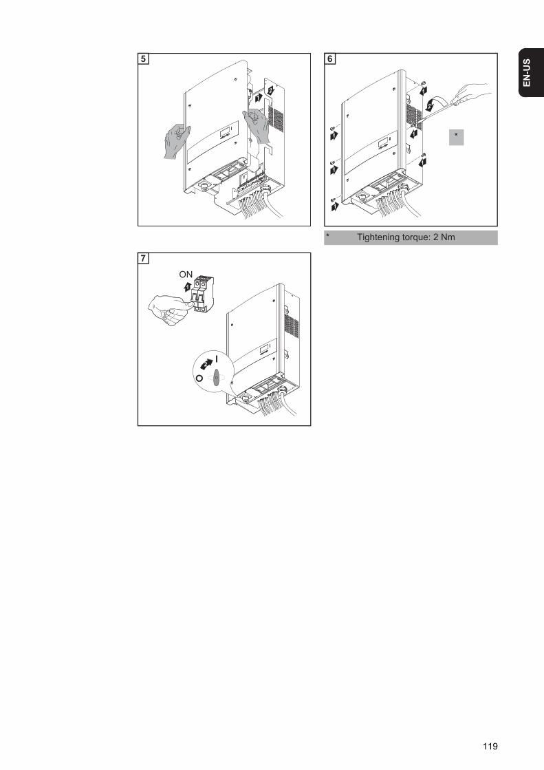
EN-U
S
1
1 1
* Tightening torque: 2 Nm
21
5
1 1
1
1
1
1
2
*
6
1
32
ON
7
119

Replacing String Fuses
Safety
Preparation
1 1
The side areas of the housing cover are designed to function as carrying grips and/or han-dles.
WARNING! An electric shock can be fatal. Danger from grid voltage and DC volt-age from solar modules.- The DC main switch is used only to switch off power to the power stage set.
When the DC main switch is turned off, the connection area is still energized.- Only licensed electricians should access the connection area.- All maintenance and service work should only be carried out when the power
stage set has been disconnected from the connection area.- Maintenance and service work on the inverter power stage set should only
be carried out by Fronius-trained personnel.
WARNING! An electric shock can be fatal. Danger from residual voltage from ca-pacitors.You must wait until the capacitors have discharged. Discharge takes 3 minutes.
WARNING! An inadequate grounding conductor connection can cause serious injuries to persons and damage to (or loss of) property.The housing screws provide an adequate grounding conductor connection for the housing ground and should not, under any circumstances, be replaced by differ-ent screws that do not provide a proper grounding conductor connection.
1
32
OFF
1
1
1
1
1
2
1
1
2
120
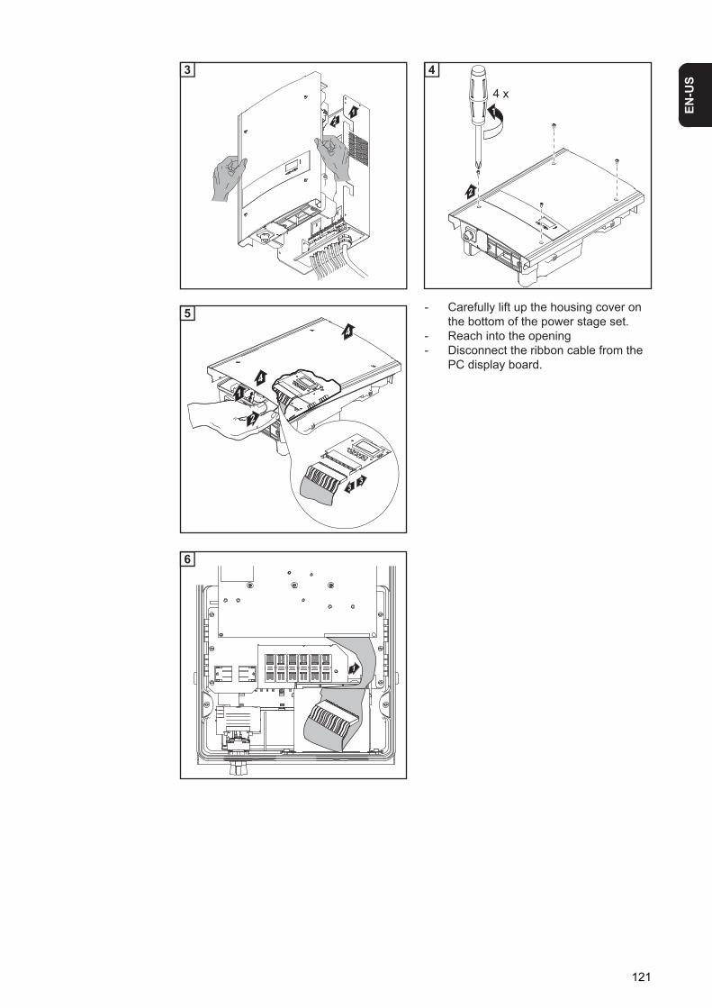
EN-U
S
1 1
1 - Carefully lift up the housing cover on the bottom of the power stage set.
- Reach into the opening- Disconnect the ribbon cable from the
PC display board.
1
12
3
2
14 x
4
2
1
4
4
33
5
1
6
121
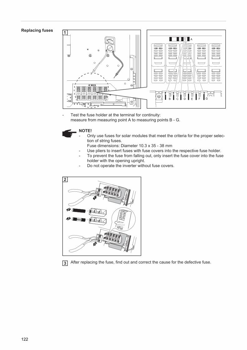
Replacing fuses 1
- Test the fuse holder at the terminal for continuity:measure from measuring point A to measuring points B - G.
1
After replacing the fuse, find out and correct the cause for the defective fuse.
NOTE! - Only use fuses for solar modules that meet the criteria for the proper selec-
tion of string fuses.Fuse dimensions: Diameter 10.3 x 35 - 38 mm
- Use pliers to insert fuses with fuse covers into the respective fuse holder.- To prevent the fuse from falling out, only insert the fuse cover into the fuse
holder with the opening upright.- Do not operate the inverter without fuse covers.
A
B FEDC G
1
1
4
2
3
2
3
122
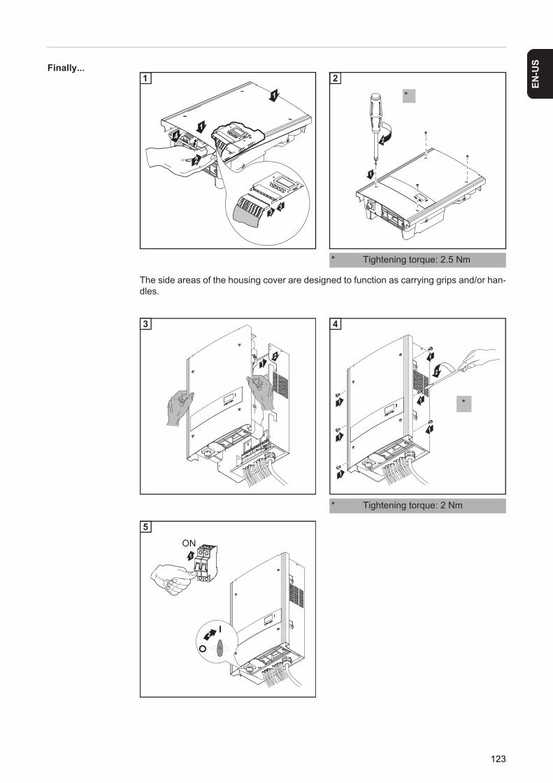
EN-U
S
Finally...The side areas of the housing cover are designed to function as carrying grips and/or han-dles.
1
1 1
* Tightening torque: 2.5 Nm
1 1
* Tightening torque: 2 Nm
2
1
14
33
1
1
2
*
2
21
3
1 1
1
1
1
1
2
*
4
1
32
ON
5
123

124

Appendix

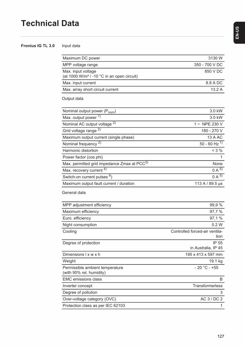
EN-U
S
Technical Data
Fronius IG TL 3.0 Input data
Output data
General data
Maximum DC power 3130 WMPP voltage range 350 - 700 V DCMax. input voltage(at 1000 W/m² / -10 °C in an open circuit)
850 V DC
Max. input current 8.8 A DCMax. array short circuit current 13.2 A
Nominal output power (Pnom) 3.0 kWMax. output power 1) 3.0 kWNominal AC output voltage 2) 1 ~ NPE 230 VGrid voltage range 2) 180 - 270 VMaximum output current (single phase) 13 A ACNominal frequency 2) 50 - 60 Hz 1)
Harmonic distortion < 3 %Power factor (cos phi) 1Max. permitted grid impedance Zmax at PCC3) NoneMax. recovery current 4) 0 A 5)
Switch-on current pulses 6) 0 A 5)
Maximum output fault current / duration 113 A / 89.5 μs
MPP adjustment efficiency 99,9 %Maximum efficiency 97,7 %Euro. efficiency 97,1 %Night consumption 0.2 WCooling Controlled forced-air ventila-
tionDegree of protection IP 55
in Australia, IP 45Dimensions l x w x h 195 x 413 x 597 mmWeight 19.1 kgPermissible ambient temperature (with 95% rel. humidity)
- 20 °C - +55 �
EMC emissions class BInverter concept TransformerlessDegree of pollution 3Over-voltage category (OVC) AC 3 / DC 2Protection class as per IEC 62103 1
127

Fronius IG TL 3.6 Input data
Output data
General data
Maximum DC power 3850 WMPP voltage range 350 - 700 V DCMax. input voltage(at 1000 W/m² / -10 °C in an open circuit)
850 V DC
Max. input current 10.8 A DCMax. array short circuit current 16.2 A
Nominal output power (Pnom) 3.68 kWMax. output power 1) 3.68 kWNominal AC output voltage 2) 1 ~ NPE 230 VGrid voltage range 2) 180 - 270 VMaximum output current (single phase) 16 A ACNominal frequency 2) 50 - 60 Hz 1)
Harmonic distortion < 3 %Power factor (cos phi) 1Max. permitted grid impedance Zmax at PCC3) NoneMax. recovery current 4) 0 A 5)
Switch-on current pulses 6) 0 A 5)
Maximum output fault current / duration 113 A / 89.5 μs
MPP adjustment efficiency 99,9 %Maximum efficiency 97,7 %Euro. efficiency 97,2 %Night consumption 0.2 WCooling Controlled forced-air ventila-
tionDegree of protection IP 55
in Australia, IP 45Dimensions l x w x h 195 x 413 x 597 mmWeight 19.1 kgPermissible ambient temperature (with 95% rel. humidity)
- 20 °C - +55 �
EMC emissions class BInverter concept TransformerlessDegree of pollution 3Over-voltage category (OVC) AC 3 / DC 2Protection class as per IEC 62103 1
128

EN-U
S
Fronius IG TL 4.0 Input dataOutput data
General data
Maximum DC power 4190 WMPP voltage range 350 - 700 V DCMax. input voltage(at 1000 W/m² / -10 °C in an open circuit)
850 V DC
Max. input current 11.8 A DCMax. array short circuit current 17.7 A
Nominal output power (Pnom) 4.0 kWMax. output power 1) 4.0 kWNominal AC output voltage 2) 1 ~ NPE 230 VGrid voltage range 2) 180 - 270 VMaximum output current (single phase) 17.4 A ACNominal frequency 2) 50 - 60 Hz 1)
Harmonic distortion < 3 %Power factor (cos phi) 1Max. permitted grid impedance Zmax at PCC3) 262 milliohmsMax. recovery current 4) 0 A 5)
Switch-on current pulses 6) 0 A 5)
Maximum output fault current / duration 113 A / 89.5 μs
MPP adjustment efficiency 99,9 %Maximum efficiency 97,7 %Euro. efficiency 97,3 %Night consumption 0.2 WCooling Controlled forced-air ventila-
tionDegree of protection IP 55
in Australia, IP 45Dimensions l x w x h 195 x 413 x 597 mmWeight 19.1 kgPermissible ambient temperature (with 95% rel. humidity)
- 20 °C - +55 �
EMC emissions class BInverter concept TransformerlessDegree of pollution 3Over-voltage category (OVC) AC 3 / DC 2Protection class as per IEC 62103 1
129
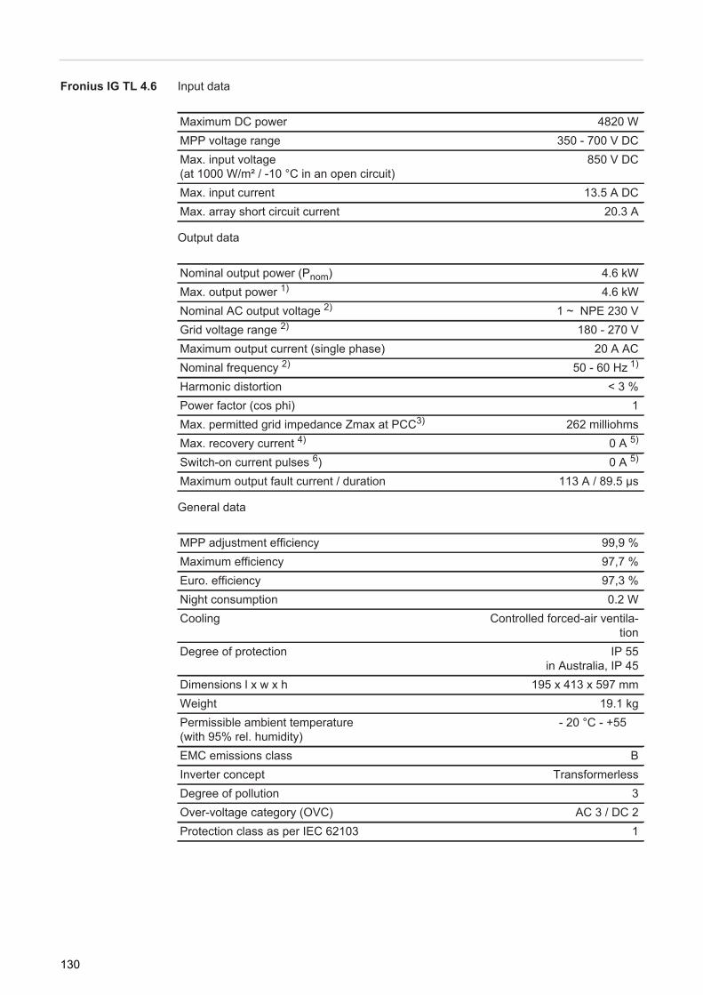
Fronius IG TL 4.6 Input data
Output data
General data
Maximum DC power 4820 WMPP voltage range 350 - 700 V DCMax. input voltage(at 1000 W/m² / -10 °C in an open circuit)
850 V DC
Max. input current 13.5 A DCMax. array short circuit current 20.3 A
Nominal output power (Pnom) 4.6 kWMax. output power 1) 4.6 kWNominal AC output voltage 2) 1 ~ NPE 230 VGrid voltage range 2) 180 - 270 VMaximum output current (single phase) 20 A ACNominal frequency 2) 50 - 60 Hz 1)
Harmonic distortion < 3 %Power factor (cos phi) 1Max. permitted grid impedance Zmax at PCC3) 262 milliohmsMax. recovery current 4) 0 A 5)
Switch-on current pulses 6) 0 A 5)
Maximum output fault current / duration 113 A / 89.5 μs
MPP adjustment efficiency 99,9 %Maximum efficiency 97,7 %Euro. efficiency 97,3 %Night consumption 0.2 WCooling Controlled forced-air ventila-
tionDegree of protection IP 55
in Australia, IP 45Dimensions l x w x h 195 x 413 x 597 mmWeight 19.1 kgPermissible ambient temperature (with 95% rel. humidity)
- 20 °C - +55 �
EMC emissions class BInverter concept TransformerlessDegree of pollution 3Over-voltage category (OVC) AC 3 / DC 2Protection class as per IEC 62103 1
130
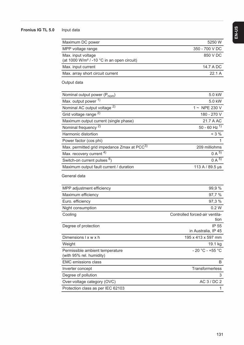
EN-U
S
Fronius IG TL 5.0 Input dataOutput data
General data
Maximum DC power 5250 WMPP voltage range 350 - 700 V DCMax. input voltage(at 1000 W/m² / -10 °C in an open circuit)
850 V DC
Max. input current 14.7 A DCMax. array short circuit current 22.1 A
Nominal output power (Pnom) 5.0 kWMax. output power 1) 5.0 kWNominal AC output voltage 2) 1 ~ NPE 230 VGrid voltage range 2) 180 - 270 VMaximum output current (single phase) 21.7 A ACNominal frequency 2) 50 - 60 Hz 1)
Harmonic distortion < 3 %Power factor (cos phi) 1Max. permitted grid impedance Zmax at PCC3) 209 milliohmsMax. recovery current 4) 0 A 5)
Switch-on current pulses 6) 0 A 5)
Maximum output fault current / duration 113 A / 89.5 μs
MPP adjustment efficiency 99,9 %Maximum efficiency 97,7 %Euro. efficiency 97,3 %Night consumption 0.2 WCooling Controlled forced-air ventila-
tionDegree of protection IP 55
in Australia, IP 45Dimensions l x w x h 195 x 413 x 597 mmWeight 19.1 kgPermissible ambient temperature (with 95% rel. humidity)
- 20 °C - +55 °C
EMC emissions class BInverter concept TransformerlessDegree of pollution 3Over-voltage category (OVC) AC 3 / DC 2Protection class as per IEC 62103 1
131
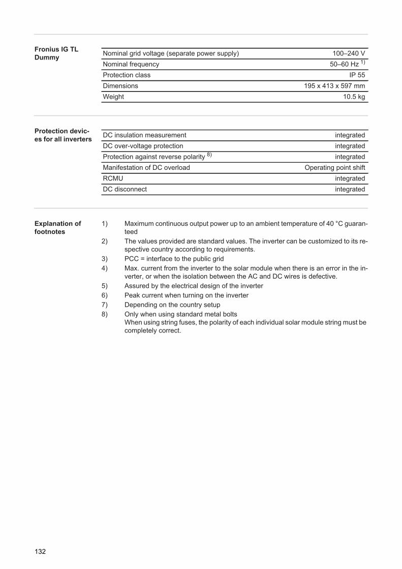
Fronius IG TL Dummy
Protection devic-es for all inverters
Explanation of footnotes
1) Maximum continuous output power up to an ambient temperature of 40 °C guaran-teed
2) The values provided are standard values. The inverter can be customized to its re-spective country according to requirements.
3) PCC = interface to the public grid4) Max. current from the inverter to the solar module when there is an error in the in-
verter, or when the isolation between the AC and DC wires is defective.5) Assured by the electrical design of the inverter6) Peak current when turning on the inverter7) Depending on the country setup8) Only when using standard metal bolts
When using string fuses, the polarity of each individual solar module string must be completely correct.
Nominal grid voltage (separate power supply) 100–240 VNominal frequency 50–60 Hz 1)
Protection class IP 55Dimensions 195 x 413 x 597 mmWeight 10.5 kg
DC insulation measurement integratedDC over-voltage protection integratedProtection against reverse polarity 8) integratedManifestation of DC overload Operating point shiftRCMU integratedDC disconnect integrated
132

EN-U
S
Relevant Standards and Directives
CE Conformity Marking
The equipment complies with all the requisite and relevant standards and directives that form part of the relevant EU directive, and therefore is permitted to display the CE mark.
Relevant stan-dards and direc-tives
- EN 50178Electronic equipment for use in power installations
- EN 61000-3-2:2006, 3-3:1995, 3-11:2000, 3-12:2005, 6-2:2005, 6-3:2007- EN 50366:2003
Grid interface - VDE V 0126-1-1- ÖVE/ÖNORM E 8001-4-712
Parallel Operation of In-Plant Power Generation Sys-tems
The inverter complies with the- "Guidelines for connection and parallel operation of in-plant generation systems with
the low-voltage grid" published by the German Electricity Industry Association (VDEW)
- "Technical guidelines for parallel operation of in-plant generation systems with distri-bution networks" published by the Association of Austrian Electricity Companies.
Circuit to Prevent Islanding
The inverter has a circuit for preventing islanding which is approved by the Professional Association for Precision Mechanics and Electronic Engineering in accordance with DIN VDE 0126-1-1.
Grid Failure The standard measurement and safety procedures integrated into the inverter ensure that the power feed is immediately interrupted in the event of a grid failure (shut-off by the utility or damage to lines).
133
Terms and conditions of warranty and disposal
Fronius Manufac-turer's Warranty
Detailed warranty terms and conditions specific to your country can be found online: www.fronius.com/solar/warranty
To take advantage of the full warranty duration for your newly installed Fronius inverter or accumulator, register your product at: www.solarweb.com.
Disposal Should your inverter be replaced at some future date, Fronius will accept the obsolete equipment back and provide for its proper recycling.
134
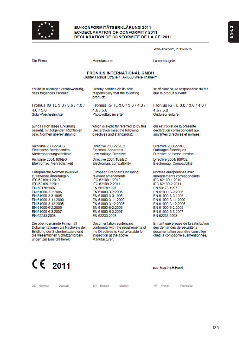
EN-U
S
135
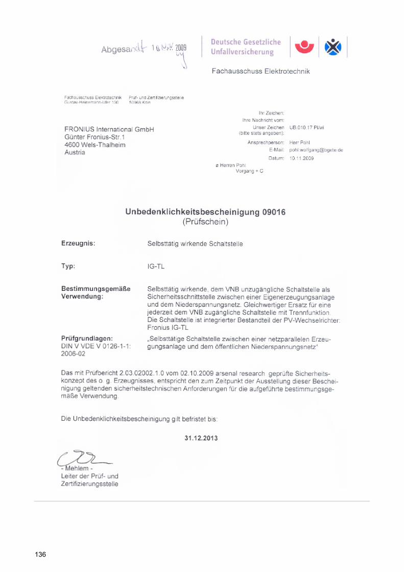
136
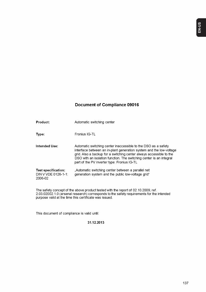
EN-U
S
137


Fronius Worldwide - www.fronius.com/addresses
Under http://www.fronius.com/addresses you will find all addresses of our sales branches and partner firms!
Fronius International GmbH4600 Wels, Froniusplatz 1, AustriaE-Mail: [email protected]://www.fronius.com
Fronius USA LLC Solar Electronics Division6797 Fronius Drive, Portage, IN 46368E-Mail: [email protected]://www.fronius-usa.com


![TP-Link TL-MR3020 [OpenWrt Wiki] - emoc](https://static.fdokumen.com/doc/165x107/63377625e8797a6c4909364b/tp-link-tl-mr3020-openwrt-wiki-emoc.jpg)