Fronius Symo 10 - 20 kW Explanation of symbols and choice ...
28
/ Battery Charging Systems / Welding Technology / Solar Electronics 42,0426,0175,EN 004-05112013 Fronius Symo 10 - 20 kW Explanation of symbols and choice of location Notes regarding installation and connection Operating Instructions Grid-connected inverter EN
-
Upload
khangminh22 -
Category
Documents
-
view
3 -
download
0
Transcript of Fronius Symo 10 - 20 kW Explanation of symbols and choice ...

/ Battery Charging Systems / Welding Technology / Solar Electronics
42,0426,0175,EN 004-05112013
Fronius Symo 10 - 20 kWExplanation of symbols and choice of location Notes regarding installation and connection
Operating Instructions
Grid-connected inverterEN

0

EN
Contents
Explanation of symbols .............................................................................................................................. 3Explanation of safety symbols .............................................................................................................. 3Explanation of symbols - choice of location .......................................................................................... 3Explanation of symbols - installation position ....................................................................................... 4
Choice of location ...................................................................................................................................... 7Proper use ............................................................................................................................................ 7General comments regarding choice of location................................................................................... 7
Installation notes ........................................................................................................................................ 8Selecting dowels and screws................................................................................................................ 8Recommended screws ......................................................................................................................... 8Fitting the wall bracket .......................................................................................................................... 8Installing the inverter on a mast ............................................................................................................ 8
Notes regarding grid connection ................................................................................................................ 9Monitoring the Grid ............................................................................................................................... 9AC terminals ......................................................................................................................................... 9Type of AC cable .................................................................................................................................. 9Connecting aluminum cables................................................................................................................ 9Cross-section of the AC cable .............................................................................................................. 10Connecting the inverter to the public grid (AC) ..................................................................................... 10Maximum fuse rating on alternating current side .................................................................................. 11
Notes regarding DC connection................................................................................................................. 12General comments regarding solar modules ........................................................................................ 12DC terminals ......................................................................................................................................... 12Connecting aluminum cables................................................................................................................ 13Inverter DC connection ......................................................................................................................... 13
Notes regarding inverters with multiple MPP trackers ............................................................................... 15Inverter with multiple MPP trackers ...................................................................................................... 15
Notes regarding the laying of data communication cables ........................................................................ 16Laying data communication cables....................................................................................................... 16
Notes regarding attaching the inverter to the wall bracket......................................................................... 17Attaching the inverter to the wall bracket .............................................................................................. 17
Notes regarding starting up for the first time.............................................................................................. 18Notes regarding starting up for the first time......................................................................................... 18
Notes regarding software updates ............................................................................................................. 19Notes regarding software updates ........................................................................................................ 19
USB Stick as a Data Logger and for Updating Inverter Software .............................................................. 20USB stick as a data logger.................................................................................................................... 20Data on the USB stick........................................................................................................................... 20Data volume and storage capacity........................................................................................................ 21Buffer memory ...................................................................................................................................... 21Suitable USB sticks............................................................................................................................... 22USB stick for updating the inverter software......................................................................................... 22Remove USB stick ................................................................................................................................ 23
Notes regarding maintenance.................................................................................................................... 24Maintenance ......................................................................................................................................... 24Cleaning................................................................................................................................................ 24
1

2

EN
Explanation of symbols
Explanation of safety symbols
If you see any of the symbols depicted in the "Safety rules", special care is required.
Explanation of symbols - choice of location
DANGER! indicates immediate and real danger. If it is not avoided, death or se-rious injury will result.
WARNING! indicates a potentially dangerous situation. Death or serious injury may result if appropriate precautions are not taken.
CAUTION! indicates a situation where damage or injury could occur. If it is not avoided, minor injury and/or damage to property may result.
NOTE! indicates a risk of flawed results and possible damage to the equipment.
IMPORTANT! indicates tips for correct operation and other particularly useful information. It does not indicate a potentially damaging or dangerous situation.
The inverter is suitable for installation indoors.
The inverter is suitable for installation outdoors.
Its IP 55 degree of protection means that the inverter is resistant to water jets from any direction and can also be used in damp environments.
In order to minimise the heating up of the inverter, do not expose it to di-rect insolation. The inverter should ideally be mounted in a protected po-sition, e.g. in the vicinity of the solar modules or beneath the eaves.
=L1N
+-
~
=L1N
+-
~IP 55
=L1N
+-
~
=L1N
+-
~
3

Explanation of symbols - instal-lation position
UDCmax at an altitude of:0 to 2000 m = 1000 V2001 to 2500 m = 950 V2501 to 3000 m = 900 V3001 to 3400 m = 850 V
IMPORTANT! The inverter must not be installed or used at altitudes above 3400 m.
Do not install the inverter: - in areas where ammonia, corrosive vapours, acids or salts are
present(e.g. fertiliser stores, ventilation openings from cattle sheds, chemi-cal plants, tanneries, etc.)
As the inverter generates low levels of noise at certain times, it should not be installed close to living areas.
Do not install the inverter:- in places where there is an increased risk of damage from farm ani-
mals (horses, cattle, sheep, pigs, etc.) - in stables or adjoining areas - in storage areas for hay, straw, chaff, animal feed, fertilisers, etc.
Do not install the inverter:- in places and environments subject to heavy build-up of dust- in places and environments in which a heavy build-up of dust con-
taining conductive particles (e.g. iron chips) is likely
Do not install the inverter:- in greenhouses- in storage or processing areas for fruit, vegetables or winegrowing
products - in places used to prepare grain, green fodder or animal feeds
2000 m2000 m
2500 m
=L1N
+-
~
UDCmax =
1000 V
UDCmax =
900 V
3000 m
2500 m
3000 m
3400 m
UDCmax =
815 V
UDCmax =
750 V
> 3400 m
=L1N
+-
~
NH3
=L1N
+-
~
=L1N
+-
~
=L1N
+-
~
=L1N
+-
~
The inverter is designed to be installed vertically on a vertical wall or pil-lar.
4

EN
The inverter is suitable for horizontal installation.The inverter is suitable for installation on a sloping surface.
Do not install the inverter on a sloping surface with its connection sockets facing upwards.
Do not install the inverter at an angle on a vertical wall or pillar.
Do not install the inverter horizontally on a vertical wall or pillar.
Do not install the inverter on a vertical wall or pillar with its connection sockets facing upwards.
Do not install the inverter such that it overhangs with its connection sock-ets facing upwards.
Do not install the inverter such that it overhangs with its connection sock-ets facing downwards.
5

Do not install the inverter on the ceiling.
6
EN
Choice of location
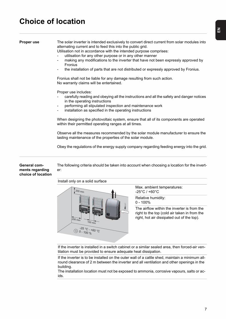
Proper use The solar inverter is intended exclusively to convert direct current from solar modules into alternating current and to feed this into the public grid.Utilisation not in accordance with the intended purpose comprises:- utilisation for any other purpose or in any other manner- making any modifications to the inverter that have not been expressly approved by
Fronius- the installation of parts that are not distributed or expressly approved by Fronius.
Fronius shall not be liable for any damage resulting from such action.No warranty claims will be entertained.
Proper use includes:- carefully reading and obeying all the instructions and all the safety and danger notices
in the operating instructions- performing all stipulated inspection and maintenance work- installation as specified in the operating instructions
When designing the photovoltaic system, ensure that all of its components are operated within their permitted operating ranges at all times.
Observe all the measures recommended by the solar module manufacturer to ensure the lasting maintenance of the properties of the solar module.
Obey the regulations of the energy supply company regarding feeding energy into the grid.
General com-ments regarding choice of location
The following criteria should be taken into account when choosing a location for the invert-er:
Install only on a solid surface
Max. ambient temperatures: -25°C / +60°C
Relative humidity: 0 - 100%
The airflow within the inverter is from the right to the top (cold air taken in from the right, hot air dissipated out of the top).
If the inverter is installed in a switch cabinet or a similar sealed area, then forced-air ven-tilation must be provided to ensure adequate heat dissipation.
If the inverter is to be installed on the outer wall of a cattle shed, maintain a minimum all-round clearance of 2 m between the inverter and all ventilation and other openings in the building.The installation location must not be exposed to ammonia, corrosive vapours, salts or ac-ids.
200 mm100 mm
200 mm
-25 °C - +60 °C0 - 100 %
7

Installation notes
Selecting dowels and screws
IMPORTANT! Depending on the surface, different dowels and screws may be required for installing the wall bracket. Therefore, these dowels and screws are not part of the scope of supply for the inverter. The system installer is responsible for selecting the proper dowels and screws.
Recommended screws
To install the inverter, the manufacturer recommends the use of steel or aluminium screws with a diameter of 6 - 8 mm.
Fitting the wall bracket
Installing the in-verter on a mast
When installing the inverter on a mast or support, Fronius recommends the “Pole clamp” mast fixing set from Rittal GmbH (order no. SZ 2584.000). This set enables the inverter to be installed on round or rectangular masts with the follow-ing diameters: ∅ between 40 and 190 mm, between 50 and 150 mm
NOTE! When fitting the wall bracket to the wall or a pillar, ensure that the wall bracket does not become warped or deformed.
8

EN
Notes regarding grid connection
Monitoring the Grid
AC terminals PE Ground conductor / grounding
L1-L3 Phase conductor
N Neutral conductor
Max. cross-section of each conductor ca-ble:16 mm²
Min. cross-section of each conductor cable:in accordance with the fuse rating on the AC side, but at least 2.5 mm²
The AC cables can be connected to the AC terminals without ferrules.
Type of AC cable The following types of AC cable can be connected to the AC terminals of the inverter:
Connecting alu-minum cables
The AC-side terminals are designed for connecting single-wire, round, aluminum cables. The following points must be taken into account when connecting aluminum cables due to the non-conducting oxide layer of aluminum:- Reduced rated currents for aluminum cables - The connection requirements listed below
Connection Requirements:
Carefully clean off the oxide layer of the stripped end of the cable, e.g., using a knife.
IMPORTANTDo not use brushes, files or sandpaper. Aluminum particles may get stuck and can transfer to other cables.
After removing the oxide layer of the cable end, rub in a neutral grease, e.g., acid- and alkali-free Vaseline.
Then immediately connect it to the terminal.
Repeat the steps above whenever the cable is disconnected and then reconnected.
IMPORTANT! The resistance in the leads to the AC-side connection terminals must be as low as possible for optimal functioning of grid monitoring.
AC
PEPEPEPE N
M32
L1L1 L3L3L2L2
- copper or aluminium: round, single wire- Copper: round, finely stranded up to conductor category 4
Cu / Al Cu
max. Class 4
NOTE! Take into account local specifications when configuring cable cross sec-tions.
1
2
3
9

Cross-section of the AC cable
When using an M32 metric screw joint (reducer removed): cable diameter 11 - 21 mm(with a cable diameter of 11 mm the strain-relief force is reduced from 100 N to a maximum of 80 N)
With cable diameters greater than 21 mm, the M32 screw joint must be replaced by an M32 screw joint with a larger clamping area - item number: 42,0407,0780 - strain-relief device M32x15 KB 18-25.
Connecting the inverter to the public grid (AC)
IMPORTANT! The PE ground conductor of the AC cable must be laid in such a way that it is the last to be disconnected in the event that the strain-relief device should fail.This can be ensured, for example, by making it somewhat longer and by laying it in a loop.
If AC cables are laid over the shaft of the DC main switch or across the connection block of the DC main switch, they may be damaged when the inverter is swung in, or they may even prevent the inverter from being swung in.
IMPORTANT! Do not lay AC cables over the shaft of the DC main switch or across the connection block of the DC main switch!
NOTE! Form loops with the AC cables when connecting them to the AC termi-nals. When securing the AC cables using a metric screw joint, ensure that the loops do not protrude beyond the connection area. Under certain circumstances it may oth-erwise no longer be possible to close the inverter.
NOTE!- Ensure that the grid neutral conductor is grounded. In the case of IT networks
(insulated networks with no grounding) this may not be the case; it will then not be possible to use the inverter.
- In order to use the inverter, the neutral conductor must be connected.A neutral conductor that is too small may adversely affect the ability of the inverter to feed energy into the grid. The neutral conductor must therefore be the same size as the other live conductors.
10

EN
Example: AC cable
If overlength AC or DC cables are to be laid in loops in the connection area, attach the cables with cable ties to the eyelets provi-ded on the top and bottom of the connec-tion block.
Maximum fuse rating on alternat-ing current side
Inverter Phases AC power Maximum fuse rating
Recommended fuse rating
Fronius Symo 10.0-3-M 3 10000 W 1 x C 63 A 1 x C 25 A
Fronius Symo 12.5-3-M 3 12500 W 1 x C 63 A 1 x C 32 A
Fronius Symo 15.0-3-M 3 15000 W 1 x C 63 A 1 x C 32 A
Fronius Symo 17.5-3-M 3 17500 W 1 x C 63 A 1 x C 40 A
Fronius Symo 20.0-3-M 3 20000 W 1 x C 63 A 1 x C 50 A
NOTE! Local regulations, the energy supply company or other factors may re-quire an earth-leakage circuit breaker in the grid line. For this situation, a type A earth-leakage circuit breaker with a tripping current of at least 100 mA is generally adequate. In particular cases, and depending on local factors, however, the type A earth-leakage circuit breaker may trip at the wrong time. For this reason, Fron-ius recommends that an earth-leakage circuit breaker that is suitable for frequen-cy converters should be used.
max. C 63 A
AC ~
RCD
National Standards
?
Type A
YES
IΔN ≥ 100 mA
§
11

Notes regarding DC connection
General com-ments regarding solar modules
To enable suitable solar modules to be chosen and to use the inverter as efficiently as pos-sible, it is important to bear the following points in mind:- If insolation is constant and the temperature is falling, the open circuit voltage of the
solar modules will increase. The open circuit voltage must not exceed 1000 V. If the open circuit voltage exceeds the specified values, the inverter will be destroyed and no warranty claims will be entertained.
- The temperature coefficients on the solar modules data sheet must be observed- More exact values for dimensioning the solar modules can be provided by suitable cal-
culation programs, like the Fronius Solar.configurator (which can be downloaded from www.fronius.com).
DC terminals Max. cross-section of each DC cable:16 mm²
Min. cross-section of each DC cable:2.5 mm²
The DC cables can be connected to the DC terminals without ferrules.
For double insulated DC connection leads with a cable diameter greater than 6 mm², 15 mm of the outer jacket must be removed in order to connect the cable to the DC ter-minal.
NOTE! Before you connect up the solar modules you should check that the volt-age specified by the manufacturer corresponds to the actual measured voltage.
DC =
min. 2,5 mm² - max. 16 mm²min. 1,5 Nm - max. 1,8 Nm
*
DC1+ DC2+ DC- *
D1
D2D3
D1
D1
D1
15 mm
15 mm
D > 6 mm²
NOTE! To ensure effective strain relief of the solar module strings, only use cables with identical cross-sections.
12

EN
Connecting alu-minum cablesThe DC-side terminals are designed for connecting single-wire, round aluminum cables. The following points must be taken into account when connecting aluminum cables due to the non-conducting oxide layer of aluminum:- Reduced rated currents for aluminum cables- The connection requirements listed below
Connection Requirements:
Carefully clean off the oxide layer of the stripped end of the cable, e.g., using a knife.
IMPORTANT Do not use brushes, files or sandpaper. Aluminum particles may get stuck and can transfer to other cables.
After removing the oxide layer of the cable end, rub in a neutral grease, e.g., acid- and alkali-free Vaseline.
Then immediately connect it to the terminal.
Repeat the steps above whenever the cable is disconnected and then reconnected.
Inverter DC con-nection
The difference between the individual solar module strings must not exceed 10 V.
NOTE! Take into account local specifications when configuring cable cross sec-tions.
1
2
3
0 - 2000 m: UDCmax 1000 V2001 - 2500 m: UDCmax 950 V2501 - 3000 m: UDCmax 900 V3001 - 3400 m: UDCmax 850 V> 3400 m
+ / -
CAUTION! Risk of possible dam-age to the inverter! Check the po-larity and voltage of the solar module strings before making the connection. The voltage must not exceed the following values:- when installed between 0 and
2000 m above sea level: 1000 V
- when installed between 2001 and 2500 m above sea level: 950 V
- when installed between 2501 and 3000 m above sea level: 900 V
- when installed between 3001 and 3400 m above sea level: 850 V
NOTE! Only break out as many target break points as the number of cables that are provided (e.g. if there are 2 DC cables, then break out 2 recesses).
13

If DC cables are laid over the shaft of the DC main switch or across the connection block of the DC main switch, they may be damaged when the inverter is swung in, or they may even prevent the inverter from being swung in.
IMPORTANT! Do not lay DC cables over the shaft of the DC main switch or across the connection block of the DC main switch!
DC+ DC-
14

EN
Notes regarding inverters with multiple MPP track-ers
Inverter with mul-tiple MPP track-ers
Connecting two solar module fields to an inverter with multiple MPP trackers
In the case of inverters with multiple MPP trackers, there are 2 independent DC inputs (MPP trackers) available. These can be connected to an unequal number of solar modules.There are 3 terminals for DC+ available per MPP tracker. In total there are 6 terminals for DC-.
Connecting 2-6 strings in multiple MPP tra-cker mode:divide the strings between the two MPP tra-cker inputs (DC+1/DC+2). The DC- termi-nals can be used however you wish, as they are internally connected. When starting up for the first time, set MPP TRACKER 2 to "ON" (this will also later be possible from the Basic menu)
Connecting multiple interconnected solar module fields to an inverter with multiple MPP trackers using one lead
Single MPP tracker mode on an inverter with multiple MPP trackers:
If the strings are connected using a string collection box and only one bus is used for connection to the inverter, the connection DC+1 (pin 2) and DC+2 (pin 1) must be jumpered.The wire diameter of the DC connection lead and the jumpering must be the same. Jumpering of the DC terminal is not neces-sary, as these terminals are jumpered inter-nally.
When starting up for the first time, set MPP TRACKER 2 to "OFF" (this will also later be possible from the Basic menu)
If the inverter with multiple MPP trackers is operated in single MPP tracker mode, the currents from the DC leads connected are divided evenly across both inputs.
1DC+1
DC-1
PV 1PV 1PV 2
DC+1
DC-2
DC+2
DC+2 DC-2 1 2 33 4 5 61 2 3
DC-1 DC+1
PV 1PV 2
D1 D1=*
*
1DC+1 DC+2 DC-
2 1 2 33 4 5 61 2 3
max. 33 A
15
Notes regarding the laying of data communication cables
Laying data com-munication ca-bles
IMPORTANT! Operating the inverter with an option card and 2 broken-out option card di-visions is not permitted.To cater for this eventuality, a relevant blanking cover (42,0405,2020) is available from Fronius as an option.
IMPORTANT! Note the following if data communication cables are being introduced into the inverter:- depending on the number and cross-section of the data communication cables that
are being introduced, take the relevant blanking plugs out of the sealing insert and in-sert the data communication cable.
- insert without fail the relevant blanking plugs into the free openings on the sealing in-sert.
16

EN
Notes regarding attaching the inverter to the wall bracket
Attaching the in-verter to the wall bracket
Two people are required to attach the inverter to the wall bracket, as it is extremely heavy.
The fastening screws in the data communication area of the inverter are used for securing the inverter to the wall bracket. Correctly tightened fastening screws are a prerequisite if proper contact is to be established between inverter and wall bracket.
NOTE! For safety reasons, the inverter is fitted with a latch that prevents the in-verter from being swung into the wall bracket unless the DC main switch is switched off.- Never attach the inverter to the wall bracket or swing it in unless the DC main
switch is switched off,- Never use force to attach the inverter or swing it in.
CAUTION! If the fastening screws are not tightened correctly, then the inverter is at risk of being damaged.Fastening screws that are not correctly tightened can result in arcs occurring when the inverter is in operation, which in turn can cause fires. Always use the specified torque when tightening the fastening screws.
17

Notes regarding starting up for the first time
Notes regarding starting up for the first time
When starting up the inverter for the first time, it is necessary to select various setup set-tings.
If setup is interrupted before it is complete, it can be restarted by means of an AC reset. An AC reset is performed by switching the automatic circuit breaker off and then on again.
The country setup can only be set when starting up the inverter for the first time. If it be-comes necessary to modify the country setup at a later date, please contact your Technical Support team.
18

EN
Notes regarding software updates
Notes regarding software updates
If the inverter is supplied with a USB stick, the inverter software must be updated as soon as the inverter has been commissi-oned:
Plug the USB stick into the data com-munication area of the inverter
Open the Setup menu
Select the "USB" menu item
Select "Update Software"
Update the software
USB+
3
54 4
1
2 2
1
2345
19

USB Stick as a Data Logger and for Updating Invert-er Software
USB stick as a data logger
A USB stick connected to the USB A socket can act as a data logger for an inverter.
Logging data saved to the USB stick can at any time- be imported into the Fronius Solar.access software via the included FLD file,- be viewed directly in third-party applications (e.g., Microsoft® Excel) via the included
CSV file.
Older Excel versions (up to Excel 2007) have a row limit of 65536.
Data on the USB stick
If the USB stick is being used as a data logger, three files will be created automatically:
- FRONIUS.sys system file: This file stores information from the inverter that is irrelevant to the customer. The file must not be deleted separately; only ever delete all of the files (sys, fld, csv) in one go.
- DALO.fld log file: A log file for reading the data in the Fronius Solar.access software.
Further details on the Fronius Solar.access software can be found in the "DATCOM Details" operating instructions at http://www.fronius.com
- DATA.csv log file: A log file for reading the data in a spreadsheet program (e.g. Microsoft® Excel)
Data structure on the USB stick
(1) USB root directory
(2) Fronius inverter (Fronius Galvo or Fronius Symo)
(3) Inverter number - can be set in the Setup menu under DATCOM
If there are several inverters with the same inverter number, the three files will be sa-ved in the same folder. A digit is added to the file name as a suffix (e.g.: DALO_02.fld)
Structure of the CSV file:
USB_Drive (1)
GALVO / SYMO (2)
01 (3)
02
FRONIUS.sysDALO.fldDATA.csv
FRONIUS.sysDALO.fldDATA.csv
(1) (2) (3) (4) (5) (6) (7)
20
EN
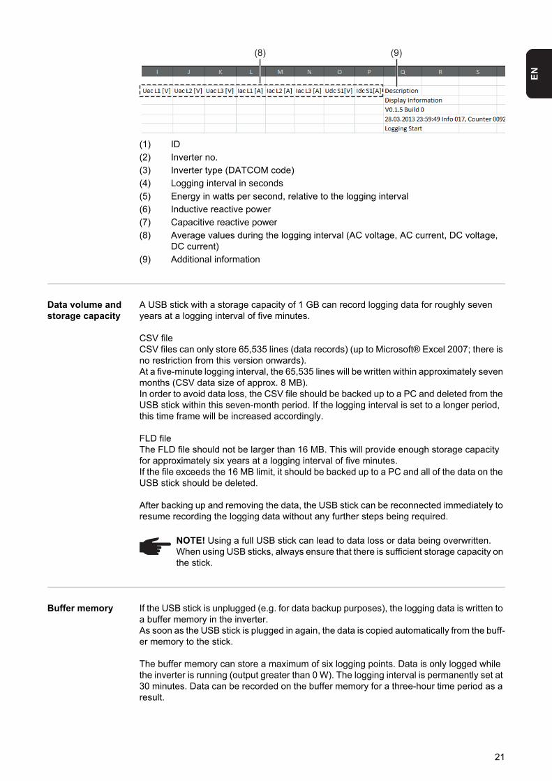
(1) ID
(2) Inverter no.
(3) Inverter type (DATCOM code)
(4) Logging interval in seconds
(5) Energy in watts per second, relative to the logging interval
(6) Inductive reactive power
(7) Capacitive reactive power
(8) Average values during the logging interval (AC voltage, AC current, DC voltage, DC current)
(9) Additional information
Data volume and storage capacity
A USB stick with a storage capacity of 1 GB can record logging data for roughly seven years at a logging interval of five minutes.
CSV fileCSV files can only store 65,535 lines (data records) (up to Microsoft® Excel 2007; there is no restriction from this version onwards). At a five-minute logging interval, the 65,535 lines will be written within approximately seven months (CSV data size of approx. 8 MB). In order to avoid data loss, the CSV file should be backed up to a PC and deleted from the USB stick within this seven-month period. If the logging interval is set to a longer period, this time frame will be increased accordingly.
FLD fileThe FLD file should not be larger than 16 MB. This will provide enough storage capacity for approximately six years at a logging interval of five minutes.If the file exceeds the 16 MB limit, it should be backed up to a PC and all of the data on the USB stick should be deleted.
After backing up and removing the data, the USB stick can be reconnected immediately to resume recording the logging data without any further steps being required.
Buffer memory If the USB stick is unplugged (e.g. for data backup purposes), the logging data is written to a buffer memory in the inverter.As soon as the USB stick is plugged in again, the data is copied automatically from the buff-er memory to the stick.
The buffer memory can store a maximum of six logging points. Data is only logged while the inverter is running (output greater than 0 W). The logging interval is permanently set at 30 minutes. Data can be recorded on the buffer memory for a three-hour time period as a result.
(8) (9)
NOTE! Using a full USB stick can lead to data loss or data being overwritten. When using USB sticks, always ensure that there is sufficient storage capacity on the stick.
21

When the buffer memory is full, the oldest data in the memory will be overwritten by the next batch of data.
IMPORTANT! The buffer memory requires a permanent power supply.If there is a power failure while the inverter is in operation, all the data in the buffer memory will be lost. To avoid losing data during the night, the automatic night switch-off facility must be deactivated (switch the 'Night Mode' setup parameter to ON - see the section 'Setting and displaying the menu items', 'Viewing and adjusting parameters in the DATCOM menu item').
Suitable USB sticks
Due to the variety of USB sticks available on the market, it cannot be guaranteed that every USB stick will be detected by the inverter.
Fronius recommends that only certified, industry-grade USB sticks are used (look out for the USB-IF logo).
The inverter supports USB sticks with the following file systems:- FAT12- FAT16- FAT32
Fronius recommends that the USB sticks employed should only be used for recording log-ging data or updating the inverter software. The USB sticks should not contain any other data.
USB stick for up-dating the invert-er software
With the help of the USB stick, end customers can also update the inverter software via the USB item on the SETUP menu: the update file is first saved to the USB stick, from where it is then transferred to the inverter. The update file must be saved in the root directory on the USB stick.
USB symbol on the inverter display, e.g. in display mode ‘NOW’:
If the inverter detects a USB stick, the USB symbol will appear in the top right corner of the display.
When inserting a USB stick, check wheth-er the USB symbol is displayed (it may also flash).
NOTE! Please note for outdoor applications that conventional USB sticks are of-ten only guaranteed to work within a restricted temperature range. For outdoor applications ensure that the USB stick also functions, for example, at low temper-atures.
AC Output Power
NOW
22

EN
Remove USBstickSecurity note concerning the removal of a USB stick:
IMPORTANT! To avoid any loss of data, a USB stick may only be removed if the fol-lowing conditions are met:- only remove a USB stick via the
'Safely remove USB / HW' item on the SETUP menu
- the 'Data transmission' LED has stopped flashing or comes on steady.
Do not disconnect USB-Stick
while LED is flashing!
X
23

Notes regarding maintenance
Maintenance
Cleaning Clean the inverter and the display as required with a damp cloth.Do not use cleaning agents, abrasives or solvents to clean the inverter.
NOTE! When installed outdoors in a horizontal position:once a year, check that all screw joints are tight!
24

EN
25

Fronius Worldwide - www.fronius.com/addresses
Under http://www.fronius.com/addresses you will find all addresses of our sales branches and partner firms!
Fronius International GmbH4600 Wels, Froniusplatz 1, AustriaE-Mail: [email protected]://www.fronius.com
Fronius USA LLC Solar Electronics Division6797 Fronius Drive, Portage, IN 46368E-Mail: [email protected]://www.fronius-usa.com