
1571291670012-ESTC TL REFRESHER COURSE BOOK.pdf
125
TRAIN LIGHTING EQUIPMENTS TRAIN LIGHTING EQUIPMENTS Presstec ERRU RRU 4.5kw V Belts C122 Alternator Tensioning Device Emergency Light Alternator 4.5KW 130V 300mm DC Fan Axle Pulley for TL Coarch RJB Battery Fise cum BCT X X X X DFB BCT Tube Light 2Feet 110V DC Cell Phone Charger 100VA
-
Upload
khangminh22 -
Category
Documents
-
view
1 -
download
0
Transcript of 1571291670012-ESTC TL REFRESHER COURSE BOOK.pdf
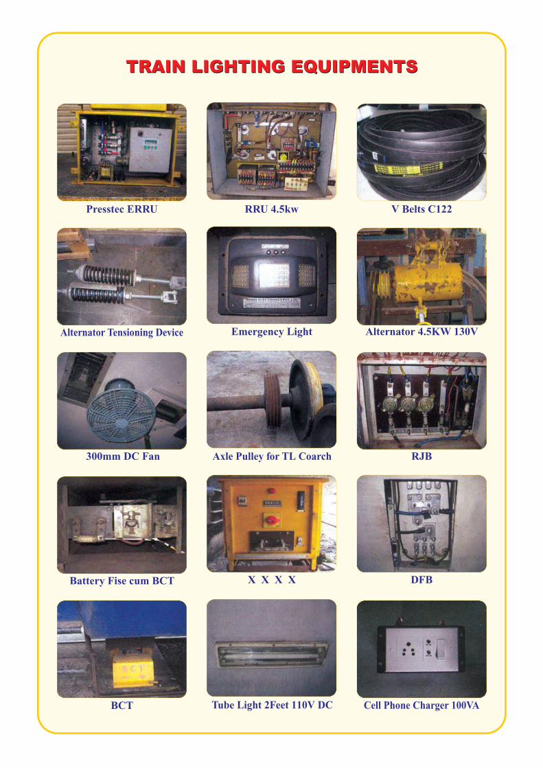
TRAIN LIGHTING EQUIPMENTSTRAIN LIGHTING EQUIPMENTS
Presstec ERRU RRU 4.5kw V Belts C122
Alternator Tensioning Device Emergency Light Alternator 4.5KW 130V
300mm DC Fan Axle Pulley for TL Coarch RJB
Battery Fise cum BCT X X X X DFB
BCT Tube Light 2Feet 110V DC Cell Phone Charger 100VA
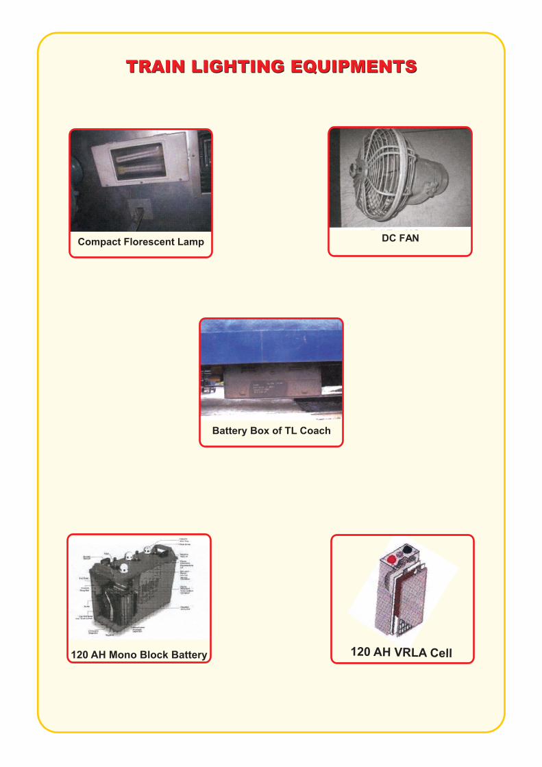
TRAIN LIGHTING EQUIPMENTSTRAIN LIGHTING EQUIPMENTS
Compact Florescent Lamp DC FAN
Battery Box of TL Coach
120 AH Mono Block Battery 120 A VRLA Ce lH l
REFRESHERCOURSE
MATERIALFOR
TRAIN LIGHTING(Based on Railway Board Module)
Issued by E.S.T.C. South Lalaguda, Secunderabad.

REFRESHER COURSE FOR SKILLED ARTISANS(TECHNICIAN TL)
Module No. Module Description
Elec-1.1 Basic knowledge about tools, safety, First aid, material handling & storage, proper up keep of work area.
Elec-1.2 General Electrical Technology & definitions of electrical terms.
Elec-1.3 Reading of drawing, circuit diagrams.
Elec-1.4 Basic properties of Electrical Materials.
Elec-1.11 Names, Size, Location of generating equipments, belts, batteries, electrical fittings. &
Elec-1.13 Testing, erection and commissioning of TL Equipment
Elec-1.12 Maintenance schedules, critical points, settings and tolerance of TL equipments.
Elec-1.18 Codes/Manuals/SMIs/MS on TL Maintenance.
Elec-1.19 Case studies on failure on TL.


ELEC - 1.1BASIC KNOWLEDGE ABOUT TOOLS,
FIRST AID, MATERIAL HANDLING & STORAGE, PROPER
UP KEEP OF WORK AREA
SAFETY,
Refresher Course Material For Train Lighting 1
Refresher Course Material For Train Lighting 2
Module Description: Basic knowledge about tools, safety, First aid, Material handlingand storage, proper up keep of work area.
1. KNOWLEDGE ABOUT TOOLS:
Combination plier, Nose plier, side cutter, screw driver, Electrician’s knife, test lamp, soldering iron, spanner, standard wire guage, crimping tools.
MODULE No. ELEC-1.1
2. CARE AND MAINTENANCE OF TOOLS:
1. Do not use a plier as a hammer. 2. A screw driver with a loose handle should not be used. 3. Do not hammer the wooden handle of the screw driver. 4. For test lamp, give a knot of wires under the cap of the holder. 5. Electric iron must be properly connected to earth. 6. Flexible wire should be used in electric iron. 7. Spanner should not be loose on the nut and bolt. 8. Spanner should not be used as hammer. 9. Do not throw wire gauge with other tools in the tool kit. Protect from rust and dust.
3. FIRST AID BOX: Items contained in First aid box are:
SAFETY PRECAUTIONS:
Do not forget that electric shocks are generally received by the worker and can be avoided. Put off main switch immediately incase of a person in contact with a live conductor. Apply artificial respiration quickly and call the doctor at once. Connect a switch on live (+ve or phase) conductor only. Do not use wires and tools having poor insulation. Do not renew a blown fuse until it is satisfied as to its cause and have rectified the fault Do not add water to acid while preparing an electrolyte always add acid to water. Do not bring a naked flame near an accumulator. Do not throw water on a live conductor or equipment in case of fire. Use only carbon tetrachloride. Use fire extinguishers on electrical fire.
lSet of splints. :One Set lRoller Bandage : 10 lTriangular bandages : 4 lTourniquet bandages :2 lCotton Wool:4 lSafety Pins :10 lAdhesive Dressing : 20 lParacetamol Tab :20 lAntiseptic Cream :1 lDiazepam Tab :10 lInjury Card:1
Refresher Course Material For Train Lighting 3
The safety precautions to be taken while working on coaches: 1. Never work underneath the coach without obtaining line block from guard or ASM. 2. Always keep Danger board/Red light when working on the rake. Danger board shall be removed after completion of work by authorized person only. 3. Do not place or drop metal objects on top of the battery. 4. Disconnect the supply immediately in case of coach firing. 5. Use box spanners to attend battery connections. 6. Remove rings, wrist watches etc that might come in contact with battery terminals. 7. Never bring a naked flame near a battery, as it may burn. 8. Always obey safety instructions given by person incharge. 9. Do not toss tools and materials from one person to another but transfer from hand to hand.10. Don’t handle heavy TL equipment carelessly.11. Don’t remove/replace connections in regulators box when supply is on.12. Do not try to remove or replace V belts, when it is full tension.13. Be caution about 120 V DC supply.14. Use ladder while replacing sidelights, junction boxes.15. Do not adopt short cut methods.16. Hasty makes the man prone to danger.17. Complete your work before few minutes, of starting of a train.18. Do not try to catch or get down from moving train.
1. Alternator suspension gear assembly are thoroughly checked for all the parts i.e. bracket ‘U’ clamp split pins, cotter pins, hanger pins, safety chains. 2. Suspension bracket to be checked thoroughly for cracks and for correct dia meter i.e. 32.5 + 0.2 mm. 3. Rectifier regulator box fixing bolts and nuts to be checked for its tightness. 4. The clearances of the alternator and battery boxes from the rail level are to be checked and confirmed to the prescribed figures of code of practice. 5. Battery box suspension bracket bolts, with nuts and split pins checked for tightness. 6. Battery box bottom sheet is checked for any damage/ corrosion and weakness. 7. Battery box bottom half doors are checked for track welding. 8. Battery box door latches are checked for proper locking. 9. Check MS safety rods in the boxes with necessary nuts check nuts, and split pins.10. Cell packing is checked for its proper fitment.11. Check axle pulley for tightness by tapping with 1 kg hammer.12. Check axle pulley for breakage of any post, or flange etc and any cracks or other abnormalities.13. Check for any sign or shifting or losing of axle pulley on the axle by absorbing white band mark.14. Ensure that all the terminal connections are tight and there are no temporary and loose connections.15. See that the portable emergency lighting equipment box with the guard is in working condition and possess with all accessories.16. See that all the fans, junction boxes are fitted with bolts, nuts, check nuts etc.17. No electrical equipment shall project outside, more than the footboard.18. Check for under frame casing for corrosion, damage, droppage.19. Add always acid to sufficient quantity of distilled water and never distilled water to acid.20. While handling acid jars rubber gloves, apron, gum boots and gaggles to be used.21. Precautions against dangerous fumes, such as provision of exhaust fans, adequate ventilation to be provided.22. Hydrochloric acid and sulphuric acid should be separately stocked to avoid misusage- causing accidents.23. Before working with electrolyte make sure that the water for washing is easily available. If electrolyte is splashed on the skin or clothing wash immediately with water for 10 to 15 minutes. If eyes are affected flood with water and obtain immediate medical attention.24. Smoking is prohibited in the battery room.25. Ensure that through feeding given is with correct polarity.26. Ensure that the clearances 50 mm and 35 mm ( 75 mm and 35 mm as per RDSO is maintained between free end nut of tension rod and bracket of trans mounted alternator for AC coaches and non AC coaches respectively.27. Avoid shorting of through leads to know the polarity. Use voltmeter for this purpose.28. Ensure that the coach is free from earth leakage.29. Support the wiring with proper cleats.30. Check for the correct polarity of charger and battery before connecting charging.
The safety items to be checked on train lighting coaches during maintenance in yards:

Refresher Course Material For Train Lighting 4
HANDLING AND STORAGE OF T.L EQUIPMENT AND PROPER UP KEEP OF WORK AREA:
While removing and fittiment of T.L equipment, care must be taken not to drop the equipment.
Store the T.L equipment systematically in proper place in cleaned area under the roof.
Coach numbers are to be marked on removal equipment with piece of chalk.
Safety Rules of Electricity
1. Beware of live conductors, bare or insulated.
2. Never tamper with any electrical gear.
3. Never disconnect a plug point by pulling the flexible cable.
4. Never touch a conductor unless you have made sure it is dead and earthed.
5. Never energies a conductor unless you are sure all are clear and there is no one likely to be working on it.
6. Always switch off before replacing a blown fuse.
7. Do not lift or move portable electrical appliances with power 'ON'. Switch 'OFF'.
power and earth the frame before shifting position.
8. Check leakage, if any, with a neon tester after switching on but before touching the metallic frame of the apparatus.
9. Cut off supply and earth the point on which you want to work. If you have to work
with power 'ON' keep your self insulated and see that you are on firm support.
Dry wood, paper, cloth and rubber are good insulators for 250 volts.
10. Do not handle electric switches of appliances with wet hands. Be more careful in
handling electric gear inside bathrooms and during monsoon weather.
11. Do not lean against electrical poles or stay wire there to.
12. Do not play with electricity.
13. Use 5- pin plugs and check up earth connections carefully. Each plug socket to be protected and controlled by a proper fuse and a switch on the live side. Use interlock switch plug or keep the plugs located at a high level not less than 4'-6' above floor level i.e. beyond the reach of children.

Refresher Course Material For Train Lighting 5
ELEC - 1.2GENERAL ELECTRICAL
TECHNOLOGY ANDDEFINITIONS OF
ELECTRICAL TERMS
Refresher Course Material For Train Lighting 6
MODULE No.ELEC-1.2
Module Description: General Electrical Technology and definitions of electrical Terms.
1. Electricity:Electricity is a sort of energy, which can neither be seen nor touched, but its presence can be experiences in its applications.
Electricity is of two kinds: 1. Static Electricity 2. Dynamic Electricity.
Static electricity is produced by friction and can not be taken from one place to another.
Dynamic electricity is also known as current electricity and can easily be taken from generating stations to far off places by means of wires and cables.
1. Matter Molecule, Atom and Atomic Structure:
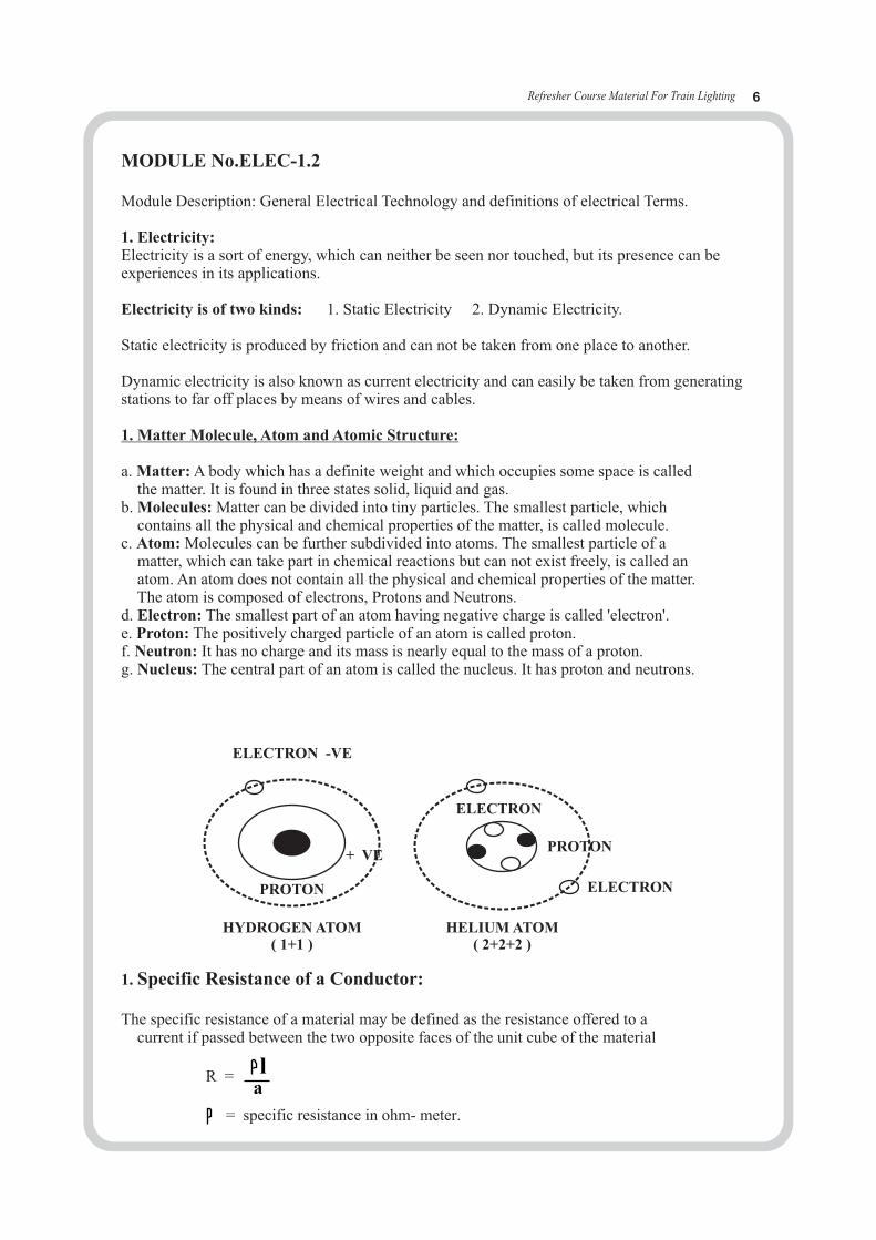
a. Matter: A body which has a definite weight and which occupies some space is called the matter. It is found in three states solid, liquid and gas.b. Molecules: Matter can be divided into tiny particles. The smallest particle, which contains all the physical and chemical properties of the matter, is called molecule.c. Atom: Molecules can be further subdivided into atoms. The smallest particle of a matter, which can take part in chemical reactions but can not exist freely, is called an atom. An atom does not contain all the physical and chemical properties of the matter. The atom is composed of electrons, Protons and Neutrons.d. Electron: The smallest part of an atom having negative charge is called 'electron'.e. Proton: The positively charged particle of an atom is called proton.f. Neutron: It has no charge and its mass is nearly equal to the mass of a proton.g. Nucleus: The central part of an atom is called the nucleus. It has proton and neutrons.
1. Specific Resistance of a Conductor:
The specific resistance of a material may be defined as the resistance offered to a current if passed between the two opposite faces of the unit cube of the material
R =
= specific resistance in ohm- meter.
ELECTRON -VE
ELECTRON
ELECTRON
PROTON
PROTON
+ VE
HYDROGEN ATOM( 1+1 )
HELIUM ATOM( 2+2+2 )
la
Refresher Course Material For Train Lighting 7
Current passing through each resistance in a series circuit remains the same as there is only one path for the current flow. When the current passes through a series circuit there is a drop of voltage in each resistance which is proportional to their individual resistances.
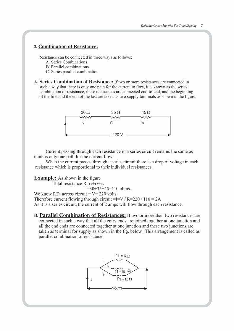
Example: As shown in the figure Total resistance R=r1+r2+r3
=30+35+45=110 ohms.We know P.D. across circuit = V= 220 volts.Therefore current flowing through circuit =I=V / R=220 / 110 = 2AAs it is a series circuit, the current of 2 amps will flow through each resistance.
B. Parallel Combination of Resistances: If two or more than two resistances are connected in such a way that all the entry ends are joined together at one junction and all the end ends are connected together at one junction and these two junctions are taken as terminal for supply as shown in the fig. below. This arrangement is called as parallel combination of resistance.
220 V
30 45 35
2. Combination of Resistance:
Resistance can be connected in three ways as follows: A. Series Combinations B. Parallel combinations C. Series parallel combination.
A. Series Combination of Resistance: If two or more resistances are connected in such a way that there is only one path for the current to flow, it is known as the series combination of resistance, these resistances are connected end-to-end, and the beginning of the first and the end of the last are taken as two supply terminals as shown in the figure.
r1 = 6
r1 =10
r3 =15
VOLTS
I
i1i2
i3
r1 r2 r3

Refresher Course Material For Train Lighting 8
VOLTS
A B C D2.5
64
I = 5A 64
20
15
60
In a parallel circuit, the voltage across each resistance is the same as each resistance is connected across the supply mains.
The current flowing through each resistance in a circuit is inversely proportional to the value of the individual resistances as the voltage applied at each resistance is same.Hence the greater the resistance, the less will be the current flowing through it.
Example: Total resistance (R) =
Therefore 1/R = 1/r + 1/r + 1/r1 2 3
R= (r1 x r x r /(r x r + r x r + r x r 2 3 3 1 1 2
In the fig: We know : 1/R = 1/r + 1/r +1/ r1 2 3
1/R = 1/6 +1/10 +1/15 1/R = (5+3+2) / 30=10/30 R=3 ohms
C. Series-Parallel Combination of Resistances: In this circuit the current divides itself into two branches as shown in figure.
2 3
( (
Product of total resistancesSum of total resistances
Solution: Equivalent Resistances of section B.C =
Equivalent Resistance of section C. D = (r1 x r x r / (r x r + r x r + r x r ) 2 3 2 3 3 1 1 2
i.e.Rcd = (15x20x60) / (300+1200+900) = 7.5 ohms.
Equivalent resistance of A. D = 2.5 + 32 + 7.5 = 42 ohms.
Voltage across the circuit = I x R = 5 x 42 = 210 volts.
3. Electric current: The flow of electrons in one direction along any path or any circuit is called electric current. Its symbol is I and its unit is ampere. (a). The instrument by which the current is measured is called an ampere meter, which is always connected in series with the circuit.
4. Voltage: It is the electrical potential (i.e., pressure) between any two live wires or between one live wire and earth. Its symbol is 'V'. The unit of measurement is volt. It is measured by voltmeter, which is always connected in parallel with the supply.
(
(
i.e. R = 42 ohms
64 * 6464 + 64
i.e. Rbc = 32 ohms
Refresher Course Material For Train Lighting 9
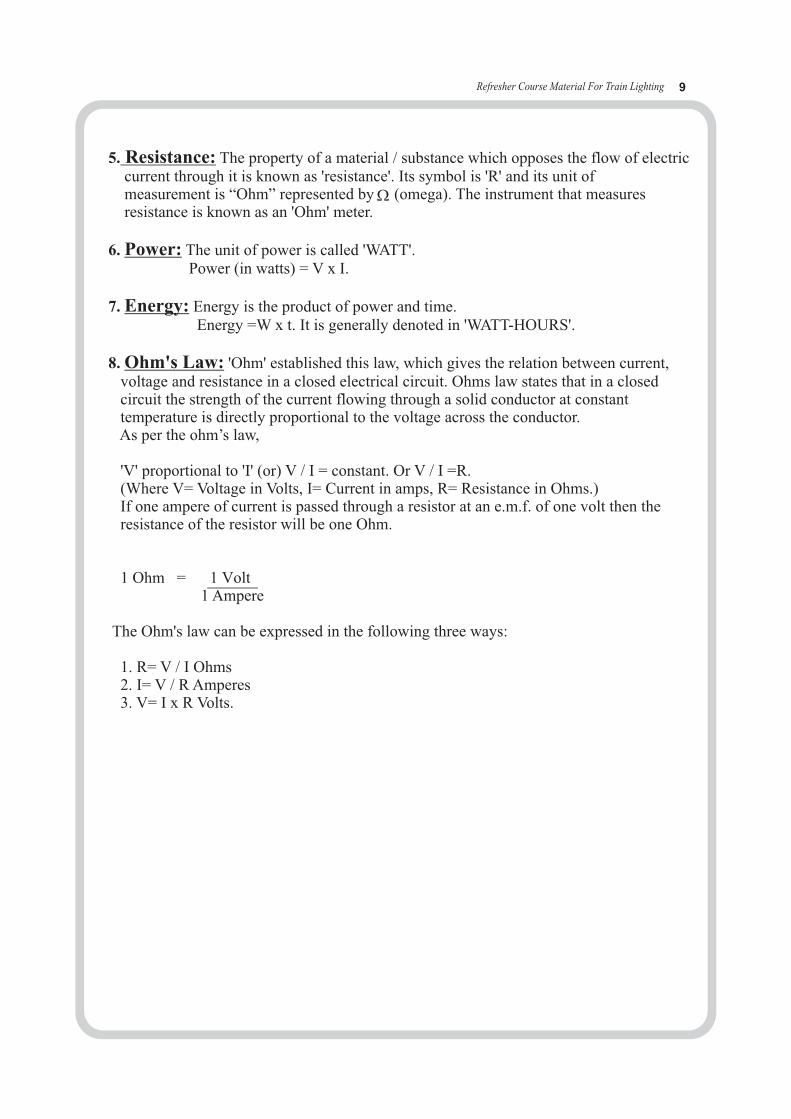
5. Resistance: The property of a material / substance which opposes the flow of electric current through it is known as 'resistance'. Its symbol is 'R' and its unit of measurement is “Ohm” represented by (omega). The instrument that measures resistance is known as an 'Ohm' meter.
6. Power: The unit of power is called 'WATT'. Power (in watts) = V x I.
7. Energy: Energy is the product of power and time. Energy =W x t. It is generally denoted in 'WATT-HOURS'.
8. Ohm's Law: 'Ohm' established this law, which gives the relation between current, voltage and resistance in a closed electrical circuit. Ohms law states that in a closed circuit the strength of the current flowing through a solid conductor at constant temperature is directly proportional to the voltage across the conductor. As per the ohm’s law,
'V' proportional to 'I' (or) V / I = constant. Or V / I =R. (Where V= Voltage in Volts, I= Current in amps, R= Resistance in Ohms.) If one ampere of current is passed through a resistor at an e.m.f. of one volt then the resistance of the resistor will be one Ohm.
1 Ohm = 1 Volt 1 Ampere The Ohm's law can be expressed in the following three ways:
1. R= V / I Ohms 2. I= V / R Amperes 3. V= I x R Volts.
Refresher Course Material For Train Lighting 10
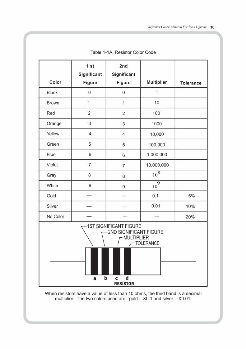
Table 1-1A, Resistor Color Code
When resistors have a value of less than 10 ohms, the third band is a decimalmultiplier. The two colors used are : gold = X0.1 and silver = X0.01.
a b c dRESISTOR
1ST SIGNIFICANT FIGURE2ND SIGNIFICANT FIGURE
MULTIPLIERTOLERANCE
Black 0
Brown 1
Red 2
Orange 3
Yellow 4
Green 5
Blue 6
Violet 7
Gray 8
White 9
Gold
Silver
No Color
Color
1 st
Significant
Figure
2nd
Significant
Figure Multiplier Tolerance
0
1
2
3
4
5
6
7
8
9
1
10
100
1000
10,000
100,000
1,000,000
10,000,000
5%
10%
20%
0.1
0.01
108
109
----- -----

TERMINOLOGY IN BATTERIES
1. AMPERE (Amp): The unit of measure of current flow through a conductor or circuit.
2. AMPERE-HOUR (AH): A unit of measure for battery capacity, obtained by multiplying the current flow (in Amperes), by the time (in Hours) of discharge. A battery which delivery 5 amperes for 20 hours, delivers 5 amperes times 20 hours, OR 100 Ampere-Hours.
3. CAPACITY: The ability of a fully charged battery to deliver a specified quantity of electricity at a given rate (Ampere) over a definite period of time. Capacity is normally measured in Ampere- hours (Ah).
4. CIRCUIT: An electric circuit is the path of an electric current. A closed circuit has a complete path. An open circuit has a broken or disconnected path.
4.1 CIRCUIT (SERIES): A circuit which has only one path for the current to flow. Batteries arranged in series are connected with the negative of the first to positive of the second; negative of the second to positve of the third & so on. If two 12-volt batteries are connected in series the circuit voltage is equal to the sum of the two battery voltages or 24 V.
4.2 CIRCUIT (PARALLEL): A circuit which provides more than one path for current to flow. A parallel arrangement of batteries (usually of like voltage and capacity) would have all positive terminals connected to a conductor and all negative terminals connected to another conductor.
4.3 SHORT CIRCUIT: A shortening of electrical path, usually within a battery/cell, which results in a greater than normal rate of discharge and/or a reduction in cell voltage under load.
5. CURRENT: The rate of flow of electricity. The movement of electrons along a conductor. It is comparable to the flow of stream of water. A unit of measurement is the Ampere.
6. VOLT: The unit of measure for electrical pressure.
6.1 OPEN CIRCUIT VOLTAGE OF BATTERY: The voltage of battery when it is not delivering or receiving power. It is 2.02 or 2.05 Volts for a fully charged cell.
6.2 VOLTAGE DROP: The net difference in electrical pressure (Voltage) when measured across a resistance or impedance.
7. RESISTENCE: The opposite force offered by a wire or substance to the free flow of an electric current.
8. CORROSION: An accumulation of solid sulphates of iron, copper or other metals, usually in the terminal area, contributing to poor electrical contact between cables and battery terminals.
9. SECONDARY BATTERY: Battery which can be recharged by passing direct current through it in a direction opposite to that of discharge.
10. CYCLE: In a battery, a discharge and a recharge is called one cycle.
10.1 DISCHARGE: When a battery is delivering power, it is said to be discharging.
10.2 ELECTROLYTE: In a lead acid battery the Electrolyte is Sulphuric Acid diluted with water. the chemical reaction of cell is as follows: PbO + Pb + 2 H SO -------------- 2PbSO + 2H O2 2 4 4 2
10.3 SPECIFIC GRAVITY : The strength or percentage of the Sulphuric Acid in the electrolyte is measured by the specific gravity of the electrolyte., i.e. the weight of the electrolyte as compared to the weight of an equal volume of pure water.
Refresher Course Material For Train Lighting 11

Refresher Course Material For Train Lighting 12
ELEC - 1.3READING OF DRAWINGS &
CIRCUIT DIAGRAMS
Refresher Course Material For Train Lighting 13
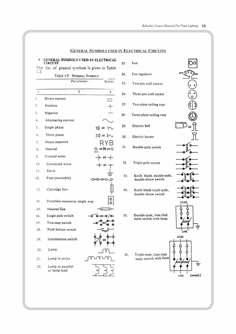
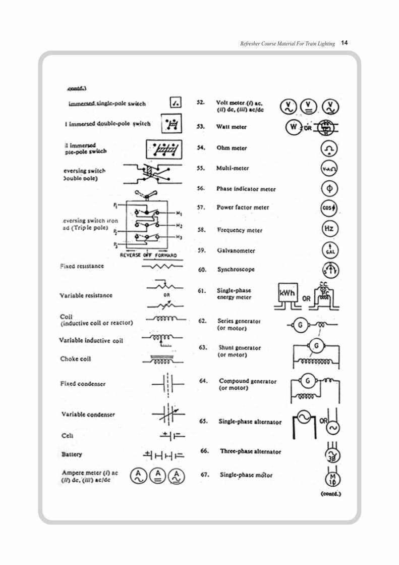
GENERAL SYMBOLS USED IN ELECTRICAL CIRCUITS
Refresher Course Material For Train Lighting 14

Refresher Course Material For Train Lighting 15
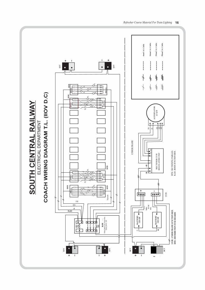
Refresher Course Material For Train Lighting 16
EF
T
BC
T
EF
T
BC
T
HR
C35A
RJ
B
SPM
DF
B
RW
6AR
W6A
RW
6AR
W6A
DF
BD
FB
F
L2
L1
L
L
L
L
L
L
LF
F
LH
RC
16A
HR
C6A
HR
C6A
L
L
LF
F
BF
DD
FB
HR
C6A
HR
C6A
L
L
L
LL
EF
T
EF
T
..
..
..
..
..
..
..
..
..
..
..
..
..
..
..
..
-
-+
+B
AT
TE
RY
120
AH
BA
TT
ER
Y12
0A
H
HR
C US
EF
40A
UF
JB
-B+
B
RE
CT
IFIE
RC
UM
RE
GU
LA
TO
RU
NITU
ND
ER
FR
AM
E
AL
TE
RN
AT
OR
4.5
KW
SPM
:SE
CT
ION
ING
PAR
LL
EL
R.J
.B:R
OO
FJU
NC
TIO
NB
OX
UF
JB:U
ND
ER
FR
AM
EJU
NC
TIO
NB
OX
DF
B:D
IST
RIB
UT
ION
FU
SEB
OA
RD
S
+F
-FA
1A
2A
3
////
//
////
////
F+
F-
A1
A2
A3
----
-
----
-
----
-
----
-
4m
mA
1.C
ab
le2
16
mm
A1.C
ab
le2
35
mm
A1.C
ab
le2 2
50
mm
A1.C
ab
le
SO
UT
HC
EN
TR
AL
RA
ILW
AY
EL
EC
TR
ICA
LD
EP
AR
TM
EN
T
CO
AC
HW
IRIN
GD
IAG
RA
MT.L
.(I
IOV
D.C
)
Rot
ary
Sw
itch
cum
Junc
tion
Box
Rot
ary
Sw
itch
-40
AR
ewira
ble
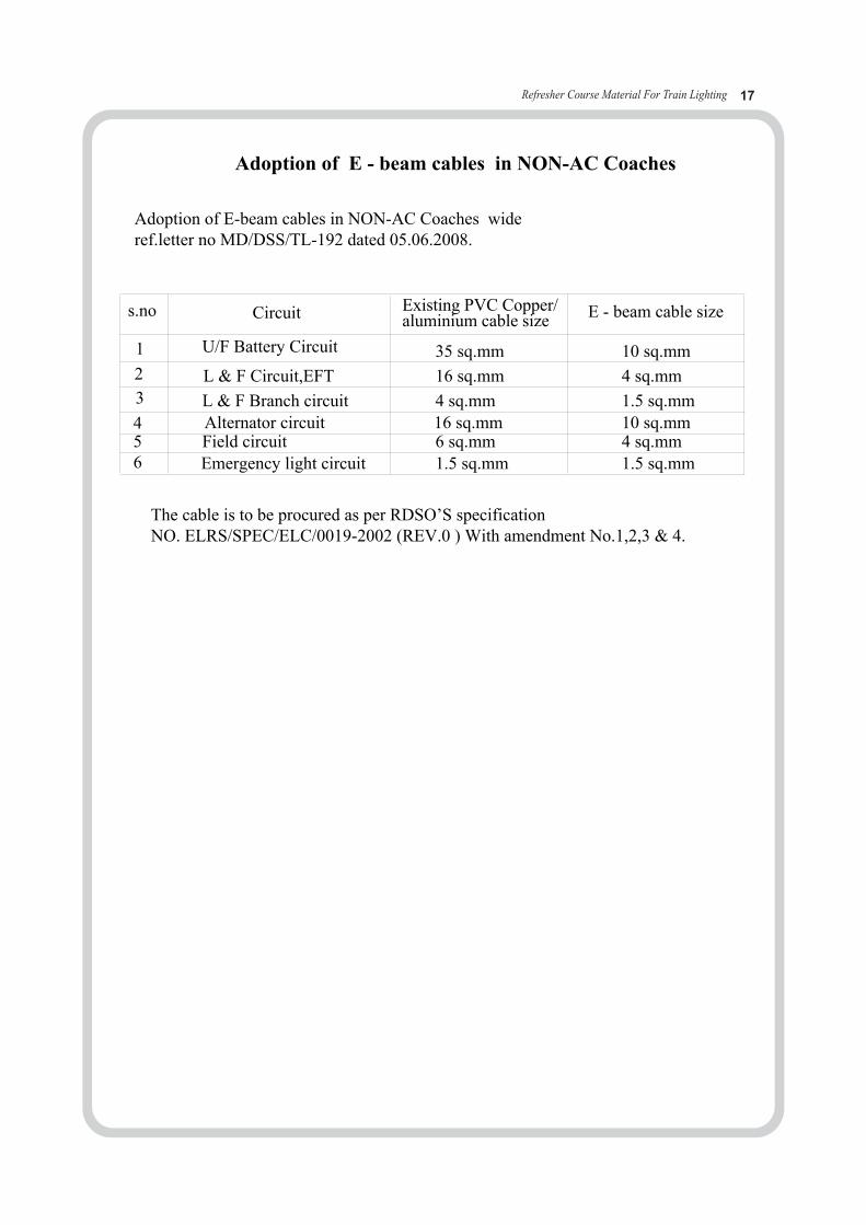
Adoption of E - beam cables in NON-AC Coaches
Adoption of E-beam cables in NON-AC Coaches wide ref.letter no MD/DSS/TL-192 dated 05.06.2008.
s.no Circuit Existing PVC Copper/aluminium cable size E - beam cable size
1
2
3
456
U/F Battery Circuit
Emergency light circuit
L & F Circuit,EFT
L & F Branch circuitAlternator circuitField circuit
35 sq.mm
16 sq.mm
4 sq.mm16 sq.mm
6 sq.mm 1.5 sq.mm
10 sq.mm
1.5 sq.mm
4 sq.mm
10 sq.mm 4 sq.mm 1.5 sq.mm
The cable is to be procured as per RDSO’S specification NO. ELRS/SPEC/ELC/0019-2002 (REV.0 ) With amendment No.1,2,3 & 4.
Refresher Course Material For Train Lighting 17

Refresher Course Material For Train Lighting 18
DIM
EN
SIO
ND
RA
WIN
GO
FA
LT
ER
NA
TO
R(
TR
AN
SO
ME
UN
TO
MD
)
1.A
LTE
RN
AT
OR
PU
LL
EY
2.A
LTE
RN
AT
OR
3.A
LTE
RN
AT
OR
SU
SP
EN
SIO
NN
YL
ON
BU
SH
4.A
LTE
RN
AT
OR
SU
SP
EN
SIO
NB
RA
CK
ET
5.S
AF
ET
YC
HA
IN6
.B
ELT
TE
NS
ION
ING
DE
VIC
E7
.'V
'BE
LT8
.A
XL
EP
UL
LE
Y
75
64
32
18
26
8
400
∅70
225
95
55
55
221.5
310
55
20
20
100
117.5
115
37
470
136.5
650
210
25
35
0
2842 _
+
ALT
ER
NA
TO
RP
UL
LE
Y
ALT
ER
NA
TO
RA
LTE
RN
AT
OR
SU
SP
EN
SIO
NN
YL
ON
BU
SH
ALT
ER
NA
TO
RS
US
PE
NS
ION
BR
AC
KE
T
SA
FE
TY
CH
AIN
BE
LTT
EN
SIO
NIN
GD
EV
ICE
'V'B
ELT
AX
LE
PU
LL
EY

Refresher Course Material For Train Lighting 19
AX
LE
PU
LL
EY
TU
RN
TH
ISN
UT
FO
RA
DJS
DT
ING
TH
EB
ELT
TE
NS
ION
AL
RT
ER
NA
TO
R
MO
UN
TIN
GA
RR
AN
GE
ME
NT
OF
4.5
KW
ALT
ER
NA
TO
RO
NT
HE
BO
GIE
572.
6PC
D
185
PCD

Refresher Course Material For Train Lighting 20
III.
Bel
tT
ensi
onin
gD
evic
e
CO
AC
HB
RA
CK
ET
FOR
TEN
SIO
NIN
GD
EV
ICE
SP
LIT
PIN
(DIA
5x
45
)T
OB
ED
ED
VI
PR
OA
SP
ER
IS.5
49
-1
97
4N
.M
I7
5m
m.
CL
EA
RA
NC
E
FO
RA
C&
50
mm
FO
R4
.5k
w
- - - - -
- - - - -
- - - - -
- - - - -- - - - -
- - - - -- - - - -
- - - - -
- - - - -
- - - - -
- - - - -
- - - - -
14
107
84
111
53
69
212
1013
15
14
15F
OR
KE
YE
01
14S
PLI
TP
IN∅
5x
4504
13P
IND
IA26
x85
01
12P
LAIN
WA
SH
ER
6∅ 5
6x
∅36
01
11PA
CK
ING
PIE
CE
5x
10x
105
01
10H
EX
.LO
CK
NU
T(D
OU
BLE
EF
MC
HA
R)∅
33x
3.5
03
09IN
DIC
ATO
R3.
2x
110/
270/
290/
310
01
08P
LAIN
WA
SH
ER
10x
∅10
0/∅
6001
07H
EX
.NU
T(S
ING
LEE
FM
CH
AR
)M33
x3.
502
06S
PR
ING
01
05S
PE
CIA
LN
UT
∅48
x42
01
04P
IPE
∅40
BO
RE
x13
001
03T
EN
SIO
NIN
GR
OD
M.3
3x
7.8C
Dx
3DP
01
02S
PR
ING
SE
AT∅
84x
2501
01R
OTA
TIN
GS
PR
ING
SE
AT∅
125
x55
01
ITE
MD
ES
CR
IPT
ION
NO
’S
TE
NSI
ON
ING
DE
VIC
EA
SSE
MB
LYF
OR
25K
W/2
2.5
KW
/18K
W/4
.5K
WT
RA
NSO
MM
OU
NT
ED
ALT
ER
NA
TO
R
Refresher Course Material For Train Lighting 21
12
22
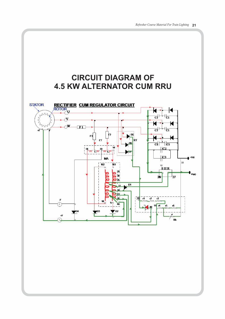
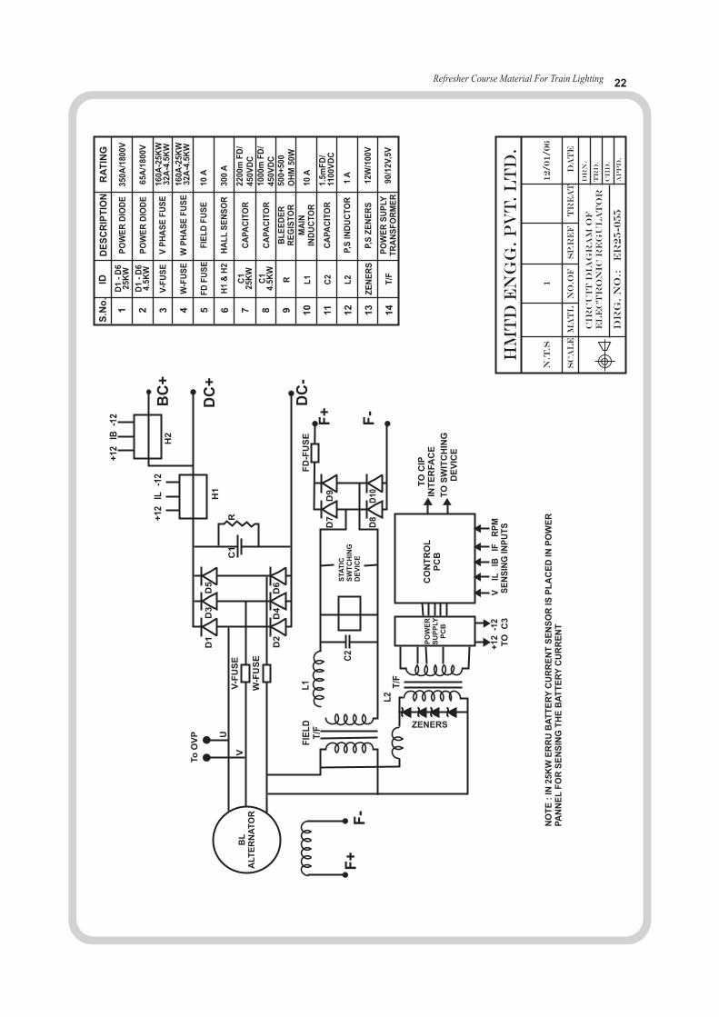
CIRCUIT DIAGRAM OF 4.5 KW ALTERNATOR CUM RRU
Refresher Course Material For Train Lighting 22
NO
TE
:IN
25
KW
ER
RU
BA
TT
ER
YC
UR
RE
NT
SE
NS
OR
ISP
LA
CE
DIN
PO
WE
RP
AN
NE
LF
OR
SE
NS
ING
TH
EB
AT
TE
RY
CU
RR
EN
T
BL
ALT
ER
NA
TO
R
+12
+12
-12
-12
IB
ILH
2B
C+
DC
+
DC
-
F+
F+
F-
F-
H1
FD
-FU
SE
TO
CIP
INT
ER
FA
CE
TO
SW
ITC
HIN
GD
EV
ICE
CO
NT
RO
LP
CB
ZENERS
RE
WO
P SU
PP
LY
PC
B
STA
TIC
SW
TC
HIN
GD
EV
ICE
RC
1U
D1
D2
D7
+1
2-1
2V
ILIB
IFR
PM
SE
NS
ING
INP
UT
ST
OC
3
D8
D10D9
L1
L2
C2
FIE
LD
T/F
T/F
D4
D6
D3
D5
VV
-FU
SE
W-F
US
E
To
OV
P
S.N
o.
1 2 3 4 5 6 7 8 9 10
11
12
13
14
IDD
ES
CR
IPT
ION
RA
TIN
G
D1
-D
62
5K
W
D1
-D
64
.5K
W
V-F
US
E
W-F
US
E
FD
FU
SE
PO
WE
RD
IOD
E3
50
A/1
80
0V
65
A/1
80
0V
16
0A
-25
KW
32
A-4
.5K
W
16
0A
-25
KW
32
A-4
.5K
W
220
0m
FD
/4
50
VD
C1
00
0m
FD
/4
50
VD
C5
00
+5
00
OH
M50W
PO
WE
RD
IOD
E
VP
HA
SE
FU
SE
WP
HA
SE
FU
SE
FIE
LD
FU
SE
10
A
10
A
1A
12
W/1
00
V
90/1
2V
,5V
D/
5m
F1
.11
00
VD
C
30
0A
HA
LL
SE
NS
OR
CA
PA
CIT
OR
CA
PA
CIT
OR
CA
PA
CIT
OR
P,S
IND
UC
TO
R
P,S
ZE
NE
RS
DE
RE
EB
LR
EG
IST
OR
PO
WE
RYL
SU
PT
RA
NS
FO
RM
ER
MA
ININ
DU
CT
OR
H1
&H
2
C1
25
KW
C1
4.5
KW
R L1
C2
L2
ZE
NE
RS
T/F
HM
TD
EN
GG
.P
vt
.L
td
.
N.T
.S
CIR
CU
IT
DIA
GR
AM
OF
EL
EC
TR
ON
IC
RE
GU
LA
TO
R
Dr
g.
No
.:E
R2
5-0
55
SC
AL
EM
AT
LN
O.O
FS
P.R
EF
TR
EA
TD
AT
E
1
DR
N.
TR
D.
IC
ID
.
AP
PD
.
12/01
/06
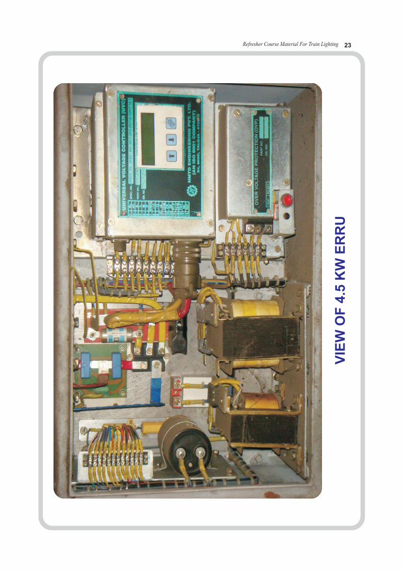
Refresher Course Material For Train Lighting 23
VIE
WO
F4.5
KW
ER
RU

Refresher Course Material For Train Lighting 24
HYDRO METER
6 Rubber Tube
5 Nozzle
4 Lead Bulb
3 Glass Bulb
2 Glass Tube
1 Rubber Bulb
1300
1280
1260
1240
1220
1200
1180
1160
1140
1120
1100

Refresher Course Material For Train Lighting 25
41
42
51
00
12
12
7050 mm DIA UNPAINTED
PO
SIT
IVE
EA
RT
HE
D
NE
GA
TIV
EE
AR
TH
ED
WHITE PAINTED GLASSGREEN
BLUE PVC INSULATED WIRE
RED PVC INSULATED WIRE
BLUE PAINTED
PRONGEARTH
GLASS
25 W, 1100
HANDLE
PM NEG
RED PAINTED
SOLDERED
SOLDERED
10 mm DIA BRASS ROD
M.S. CLAMP
2 mm DIA HOLE
110 x 10 x 1.5 mm LEATHER STRIP
BATTENHOLDER
LAMPS (INDENTICAL)
ABBEXURE - III (SHEET - IV)
SECTION X - X
PHEARTH
2.55
17
17
171
17114
2
12
NAGATIVE
INSTRUCTIONS FOR USE
1. FOR EQUIPPED COACH
2. FOR UNEQUIPPED COACHESCONNECT A HEALTHY EQUIPPED COACH TO THE UNEQUIPPEDCOACH UNDER CHECK THROUGH EMERGENCYFEED TERMINAL BOARD & TEST AS INDICATED ABOVE
a) ISOLATE THE COACHb) SWITCH ON ALL LIGHTS & FANSc) CONNECT THE RED CONNECTOR TO THE P.M.
& THE BLUE CONNECTOR TO THE NEGATIVEOF THE COACH E.F.T.B.
d) PRESS HOME THE POINTED END OF THE EARTH PRONG(GREEN LEAD) ON THE COACH BODY ENSURING APROPER ELECTRICAL CONTACT
e) PROCEED AS DESCRIBED IN ANNEXTURE IIISHEET I, II, III AND IV
EARTH INDICATOR LAMP
Refresher Course Material For Train Lighting 26
ELEC - 1.4BASIC PROPERTIES
OF ELECTRICAL MATERIALS
Refresher Course Material For Train Lighting 27
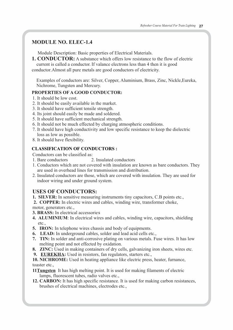
MODULE NO. ELEC-1.4
Module Description: Basic properties of Electrical Materials.
1. CONDUCTOR: A substance which offers low resistance to the flow of electric current is called a conductor. If valance electrons less than 4 then it is good conductor.Almost all pure metals are good conductors of electricity.
Examples of conductors are: Silver, Copper, Aluminium, Brass, Zinc, Nickle,Eureka, Nichrome, Tungsten and Mercury.
PROPERTIES OF A GOOD CONDUCTOR:1. It should be low cost.2. It should be easily available in the market.3. It should have sufficient tensile strength.4. Its joint should easily be made and soldered.5. It should have sufficient mechanical strength.6. It should not be much effected by charging atmospheric conditions.7. It should have high conductivity and low specific resistance to keep the dielectric loss as low as possible.8. It should have flexibility.
Conductors can be classified as:1. Bare conductors 2. Insulated conductors1. Conductors which are not covered with insulation are known as bare conductors. They are used in overhead lines for transmission and distribution.2. Insulated conductors are those, which are covered with insulation. They are used for indoor wiring and under ground system.
USES OF CONDUCTORS:1. SILVER: In sensitive measuring instruments tiny capacitors, C.B points etc.,2. COPPER: In electric wires and cables, winding wire, transformer choke, motor, generators etc.,3. BRASS: In electrical accessorie4. ALUMINIUM: In electrical wires and cables, winding wire, capacitors, shielding
etc.,5. IRON: In telephone wires chassis and body of equipments.6. LEAD: In underground cables, solder and lead acid cells etc.,7. TIN: In solder and anti-corrosive plating on various metals. Fuse wires. It has low melting point and not effected by oxidation.8. ZINC: Used in making containers of dry cells, galvanizing iron sheets, wires etc.9. EUREKHA: Used in resistors, fan regulators, starters etc.,10. NICHROME: Used in heating appliance like electric press, heater, furnance, toaster etc.,11Tungsten It has high melting point. It is used for making filaments of electric lamps, fluorescent tubes, radio valves etc.,12. CARBON: It has high specific resistance. It is used for making carbon resistances, brushes of electrical machines, electrodes etc.,
CLASSIFICATION OF CONDUCTORS :
s
13. MERCURY: It is a liquid conductor. It is used in mercury vapour lamps, mercury floating switches, mercury arc rectifiers and Ferranti-ampere hour meters etc.,14. ELECTROLYTE: It is also a liquid conductor. They are used in primary and secondary cells etc.,
II. INSULATORS : The substances that cannot pass current through them under normal conditions are termed as insulators.If valance electrons more than 4 then it is good insulator. The resistance of an insulator is usually high.
COMMON INSULATORS: Dry air, Asbestos, Bakelite, glass, mica, paper, slate, porcelain, cotton, rubber, plastic, varnish, and mineral oil, dry wood, ebonite etc.
PROPERTIES OF GOOD INSULATORS: a. It should have high specific resistance.b. It should have high dielectric strength.c. It should have an ability to bear high temperature.d. It should be moisture and waterproof.e. It should have permanent nature.
COMMON INSULATORS AND THEIR USES:1. BAKELITE: Used in switches, holders, sockets etc.2. PORCELAIN: Used in pipes, fuse cut-outs, neutral links etc.3. MICA: Used in heating elements, windings.4. RUBBER: Used in hand gloves, rubber mating etc.5. FIBER: Used in Formers of Transformer windings.6. VARNISH: Used to insulate a winding.7. GLASS: Used in insulators of over head wiring.8. WOOD: Used in boards, round blocks, casing-caping, battens etc.9. LEATHEROID PAPER: Used in motor winding.10. COTTON TAPE: Used for covering a winding.11. PVC: Used for covering of wires.12. OIL: Used in Oil circuit breakers and transformers.
III.SEMICONDUCTORS: A semiconductor is a substance whose conductivity lies inbetween conductors and insulators.If valance elctrons are are equal to 4 then it is called semiconductor.
* Examples of semiconductors are Germanium and Silicon.*These two elements are essentially required for the manufacture of transistors, diodes, IC’s and Chips etc.
Refresher Course Material For Train Lighting 28

Refresher Course Material For Train Lighting 29
ELEC - 1.11 &
Names, Size, Location of generating equipments, belts,
Batteries and Electrical fittings.
1.13
Testing, erection and commissioning of TL Equipments
Refresher Course Material For Train LightingRefresher Course Material For Train Lighting 30
MODULE No. ELEC-1.11
Train lighting system
Train lighting is one of the important passenger amenities which influence the image of st th
Railways. Although 1 train ran on 16 Apr-1853 from Bori Bandar (present CSTM) to Thane, train lighting system came to Indian Railway in 1930 through Axle driven Dynamo pioneered by M/s J. Stone & Co.
Power supply system for trains are designed and developed to suit the requirement of AC and non-AC working in the train. Few factors considered for development of such systems are as under:
• Coach load
• Speed of the train
• Weight of the equipments
• Available technology for reliable equipments etc.
Indian Railways have been using following systems for power supply in mail/exp trains:
• Self-generating
• Mid-on-generation
• End-on-generation
• Head-on-generation
1. Self-generating
• Axle driven system working on 24 V DC
• Axle driven system working on 110 V DC
2. Mid-on-generation
• MOG with 415 V , 3 phase generation and 110 V AC utilization3. End-on-generation
• EOG with 415 V, 3 phase generation and 110 V AC utilization
• EOG with 750 V, 3 phase generation and 415 & 110 V AC utilization4. Head-on-generation (HOG) Power feeding from OHE for lighting loads (EMUs):
• 750 V DC – light & fan works on 110 V AC
• 1500 V DC – light & fan works on 110 V AC
• 25 KV – light & fan works on 141 AC. Power feeding from HOG for Hotel Loads (Loco):
• Hotel load power taken from Electric/ Diesel Locomotive.
• Hotel load power supply taken directly from OHE through a separate pantograph mounted on the power car.

Refresher Course Material For Train Lighting 31
Self Generation system:
The power supply arrangement of SG coach has under slung alternator, which is driven by the running axles of the coach with the belt of the coach. The voltage of the alternator which varies with the speed of the train is regulated with the help of RRU and converted to 110 v DC and is used for charging the battery. The electrical load of the coach is supplied through the 110 v DC battery when train is at halt.
EOG (End-on-generation)
The EOG system is used in Rajdhani and Shatabdi type trains which have only Ac coaches and have large power requirement. Each EOG train has 2 power cars with 2x500 KVA alternator each. The power is fed by any two DG sets through IVC. The power is supplied at 3 phase 750 V, which is stepped down in individual coach to 3 phase 415 v for supplyingvarious loads like RMPU, WRA etc. The 110 v AC supply for lights and fans is obtained by further stepping down the 415 v supply. A 24 v battery is used for supplying a few emergency lights provided in the coach.
MOG (Mid-on-generation)
The MOG system was adopted by IR for slow moving passenger trains which have very low generation to non-generation ratio. These trains had one power car in the middle of the train, which fed power supply to the coaches at either side of power car. The power car coach had two DG set of 30 KVA each out of which one was used as standby. The power car coach also had one 3 phase, 30 KVA step down transformer of 415/110 v. The 110 v AC is supplied to the coaches through couplers.
The system has discontinued after introduction of EMU and DMU service.
HOG (Head- on- generation)
The HOG scheme can be considered with the following two options:
• Hotel load power taken from Electric/Diesel Locomotive.
• Hotel load power supply taken directly from OHE through a separate pantograph mounted on the power car.
• The system is considered to provide cost effective, reliable and energy efficient supply system for coaches.

Refresher Course Material For Train Lighting 32
Train lighting in coaching stock on Indian Railways is working on 110 V DC. This is used for working
of lights and fans which is the basic amenity for Passengers.
WORKING PRINCIPLE OF ALTERNATOR AND REGULATOR
The alternator consists of three main coils connected in star and two field coils connected
in series. The rotor is made of stamping resembling a cogged wheel. Due to residual magnetism
In the field coils and when the rotor rotates (by movement of train) ac voltage is induced in the
main coils. Till the desired output is reached the field coils are excited by positive feed back system
from regulator.
WORKING OF ALTERNATOR :
Among the above the most important equipment is alternator with regulator. The alternator
generates 97V, three phase AC and regulator controls the output at preset values(120, 122, 123,124
and 127 v) at 37.5 A. The alternator cut-in speed is 19 kmph and maximum output can be achieved
from a minimum train speed of 29 kmph to maximum speed of 160 kmph. The output of the RRU
is used for
THE MAJOR EQUIPMENTS IN TL SYSTEM ARE
(a) Alternator and Rectifier Cum Regulator Unit, 4.5kW
(b) Set Of Battery 120 Ah, 110 V
(c) Amenity Fittings With Junction Boxes, Isolators and
Protective devices viz, HRC Fuses and MCBs.
(a) Charging The Battery
(b) For Operation Of Lights And Fans
Refresher Course Material For Train Lighting 33
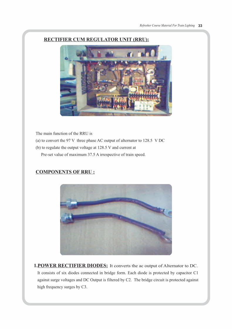
The main function of the RRU is
(a) to convert the 97 V three phase AC output of alternator to 128.5 V DC
(b) to regulate the output voltage at 128.5 V and current at
Pre-set value of maximum 37.5 A irrespective of train speed.
COMPONENTS OF RRU :
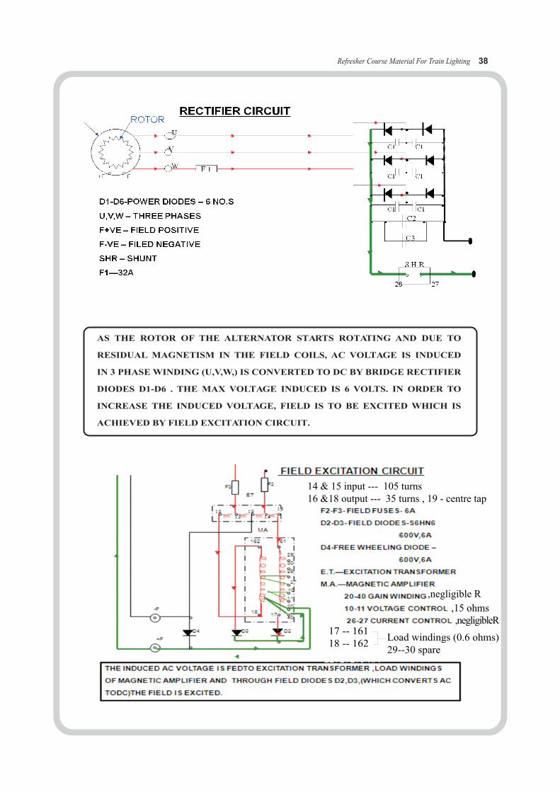
It converts the ac output of Alternator to DC. 1.POWER RECTIFIER DIODES:
It consists of six diodes connected in bridge form. Each diode is protected by capacitor C1
against surge voltages and DC Output is filtered by C2. The bridge circuit is protected against
high frequency surges by C3.
RECTIFIER CUM REGULATOR UNIT (RRU):

Refresher Course Material For Train Lighting 34
2. EXCITATION TRANSFORMER
It steps down the AC output from alternator to desired voltage (45 v) for field excitation.
3. MAGNETIC AMPLIFIER :
It is the heart of regulator which has six sets of windings. Two sets for load winding
connected to field circuit and four sets of control Winding. When the desired output is
reached, a command is sent to the control winding from voltage sensing circuit and current
sensing Circuit. Where in the load winding offers variable resistance (resistance increases)
reducing the excitation current, by which the output current and voltage is maintained at
pre set values.
Refresher Course Material For Train Lighting 35
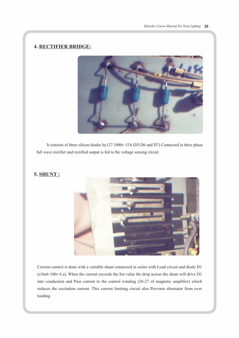
4. RECTIFIER BRIDGE:
It consists of three silicon diodes by127 1000v 15A (D5,D6 and D7) Connected in three phase
full wave rectifier and rectified output is fed to the voltage sensing circuit.
Current control is done with a variable shunt connected in series with Load circuit and diode D1
(s1hn6 100v 6 a). When the current exceeds the Set value the drop across the shunt will drive D1
into conduction and Pass current to the control winding (26-27 of magnetic amplifier) which
reduces the excitation current. This current limiting circuit also Prevents alternator from over
loading.
5. SHUNT :
Refresher Course Material For Train Lighting 36
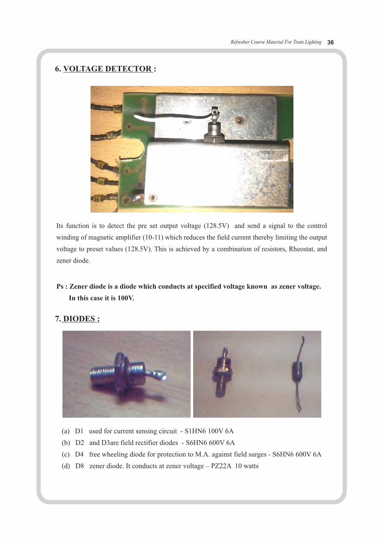
Its function is to detect the pre set output voltage (128.5V) and send a signal to the control
winding of magnetic amplifier (10-11) which reduces the field current thereby limiting the output
voltage to preset values (128.5V). This is achieved by a combination of resistors, Rheostat, and
zener diode.
6. VOLTAGE DETECTOR :
7. DIODES :
Ps : Zener diode is a diode which conducts at specified voltage known as zener voltage.
In this case it is 100V.
(a) D1 used for current sensing circuit - S1HN6 100V 6A
(b) D2 and D3are field rectifier diodes - S6HN6 600V 6A
(c) D4 free wheeling diode for protection to M.A. against field surges - S6HN6 600V 6A
(d) D8 zener diode. It conducts at zener voltage – PZ22A 10 watts

Refresher Course Material For Train Lighting 37
WORKING OF REGULATOR :
The voltage induced in the AC windings of alternator is dependent on the speed of
the rotor, excitation current and load current. Without a voltage regulator the output voltage
increases abnormally due to Positive feed back to the field.
Similarly current control is achieved by a variable Shunt connected in series with load.
When the output current reaches the Preset value 37.5A . A drop in voltage across the shunt
will conduct diode D1 (S1HN6 100V 6A) and a signal is sent to the control winding of the
Magnetic amplifier (26-27) which increases the impedance of load Winding thereby limiting
the output current to preset value of Maximum 37.5A.
Excitation transformer steps down the AC output of alternator to 45V for field supply.
This supply is fed to the load windings of Magnetic amplifier (17-161 and 18-162) and is
converted to dc by field diodes D2 and D3 (S6HN6 600V 6A) and fed to the field windings
through control winding Of magnetic amplifier (20-40). When the output voltage reaches
the preset (120-127 v)value the zener diode D8 (PZ22A 10watts) starts conducting and a
Command signal is sent to the control winding (10-11) of magnetic Amplifier which increases
the impedance of load winding there by Reducing the field excitation, which in turn limits the
out put voltage To the preset value128.5 V
1.FOR COACHES WITH FLOODED CELLS 120 AH 6V.
A) MAIL & EXPRESS TRAINS 128.5 + 0.5 V.
B) PASSENGER TRAINS 128.5 + 0.5 V.
2.FOR COAHES WITH VRLA CELLS 120 AH 2 V .
A) SUPER FAST TRAINS 128.5 + 0.5 V.128.5 + 0.5 V.. B) MAIL & EXPRESS TRAINS
C) PASSENGER TRAINS 128.5 + 0.5 V.
OUTPUT SETTINGS OF ALTERNATOR-REGULATOR
ERRU/RRU Voltage setting for 120AH VRLA Battery : (Ref . wide lr NO.EL/6.7.50 dated on 18.01.2010) in existing system 18 monoblock of 6V, 120ah LMLA Batteries used in two battery box with charging setting at 126 + 0.5 V . In case of VRLA Batteries (for 18 monoblock) this setting i.e.2.33V per cell was stated on higher side by VRLA Battery manufacturers.As per VRLA Battery manufacturers,the VRLA cell charging voltage should not be more than 2.25V per celli.e.121.5 for 18 monoblock set , but this will not be suitable for LMLA Batteries.To overcome this problem and have common voltage setting for LMLA & VRLA ,it is decided that 19 monoblock cell for VRLA batteries with the ERRU/RRU Voltage setting at 128.5 + 0.5 V .shall be used.This voltage setting corresponds to 2.38 V per cell for LMLA (18 monoblock) and 2.25V per cell for VRLA (19 monoblock) .
Refresher Course Material For Train Lighting 38
AS THE ROTOR OF THE ALTERNATOR STARTS ROTATING AND DUE TO
RESIDUAL MAGNETISM IN THE FIELD COILS, AC VOLTAGE IS INDUCED
IN 3 PHASE WINDING (U,V,W,) IS CONVERTED TO DC BY BRIDGE RECTIFIER
DIODES D1-D6 . THE MAX VOLTAGE INDUCED IS 6 VOLTS. IN ORDER TO
INCREASE THE INDUCED VOLTAGE, FIELD IS TO BE EXCITED WHICH IS
ACHIEVED BY FIELD EXCITATION CIRCUIT.
,negligible R,15 ohms,negligibleR
14 & 15 input --- 105 turns16 &18 output --- 35 turns , 19 - centre tap
17.25 1717777 1 17777 1544645454 22929295464
174455
17777
1756417
17 -- 16118 -- 162
Load windings (0.6 ohms) 29--30 spare
Refresher Course Material For Train Lighting 39
29
30
26
10
11
20
40
D2D3
1718
162 161
-F
+F
F3F2
ET
D4
27
1815
1914
16
MA-ve
26
F 1
C1C1
C1 C1
U
V
W
C1 C1
C2
C3
S H R
+F -F
27
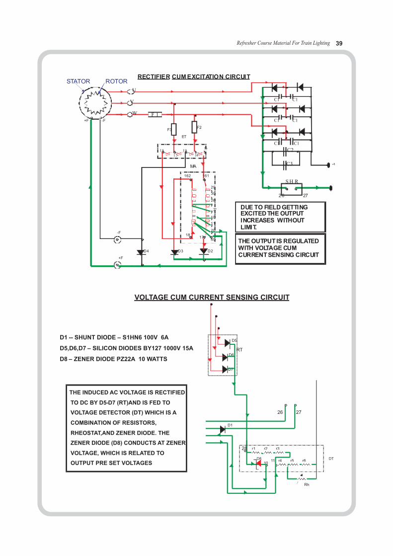
STATOR ROTORRECTIFIER CUM EXCITATION CIRCUIT
DUE TO FIELD GETTING EXCITED THE OUTPUT INCREASES WITHOUT LIMIT.
THE OUTPUT IS REGULATED WITH VOLTAGE CUM CURRENT SENSING CIRCUIT
VOLTAGE CUM CURRENT SENSING CIRCUIT
D1 -- SHUNT DIODE – S1HN6 100V 6A
D5,D6,D7 – SILICON DIODES BY127 1000V 15A
D8 – ZENER DIODE PZ22A 10 WATTS
26 27
RT
D5
D6
D7
D1
1011 r4 r5 r6
r1 r2 r3
Rh
28
THE INDUCED AC VOLTAGE IS RECTIFIED
TO DC BY D5-D7 (RT)AND IS FED TO
VOLTAGE DETECTOR (DT) WHICH IS A
COMBINATION OF RESISTORS,
RHEOSTAT,AND ZENER DIODE. THE
ZENER DIODE (D8) CONDUCTS AT ZENER
VOLTAGE, WHICH IS RELATED TO
OUTPUT PRE SET VOLTAGESD8 DT
Refresher Course Material For Train Lighting 40
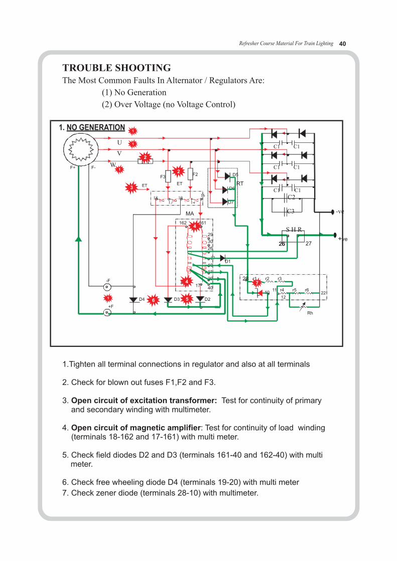
1.Tighten all terminal connections in regulator and also at all terminals
2. Check for blown out fuses F1,F2 and F3.
3. Open circuit of excitation transformer: Test for continuity of primary and secondary winding with multimeter.
4. Open circuit of magnetic amplifier: Test for continuity of load winding with multi meter.
5. Check field diodes with multi meter.
6. Check free wheeling diode D4 with multi meter
7. Check zener diode (terminals 28-10) with multimeter.
(terminals 18-162 and 17-161)
D2 and D3 (terminals 161-40 and 162-40)
(terminals 19-20)
AL
-ve
26
F 1
C1C1
C1 C1
U
V
W
C1 C1
C2
C3
S H R
F+ F-
27+ve
29
30
26
10
11
20
40
D2D3
1718
162 161
-F
+F
F3F2
ET
D4
27
1815
1914
16
MA
26
RT
D5
D6
D7
D1
1011 r4 r5 r6
r1 r2 r3
Rh
28
1. NO GENERATION
ET
1
1
1
1
2
3
6 5
7
2
4
4
1222
TROUBLE SHOOTINGThe Most Common Faults In Alternator / Regulators Are:
(1) No Generation
(2) Over Voltage (no Voltage Control)
Refresher Course Material For Train Lighting 41
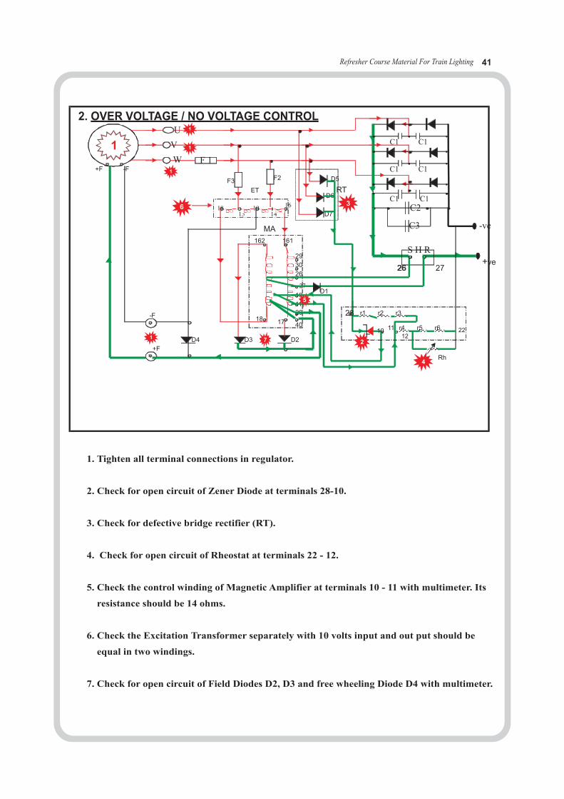
1. Tighten all terminal connections in regulator.
2. Check for open circuit of Zener Diode at terminals 28-10.
3. Check for defective bridge rectifier (RT).
4. Check for open circuit of Rheostat at terminals 22 - 12.
5. Check the control winding of Magnetic Amplifier at terminals 10 - 11 with multimeter. Its
resistance should be 14 ohms.
6. Check the Excitation Transformer separately with 10 volts input and out put should be
equal in two windings.
7. Check for open circuit of Field Diodes D2, D3 and free wheeling Diode D4 with multimeter.
1
1
1
1AL
-ve
26
F 1
C1C1
C1 C1
U
V
W
C1 C1C2
C3
S H R
+F -F
27+ve
29
30
26
10
11
20
40
D2D3
1718
162 161
-F
+F
F3 F2
ET
D4
27
1815
1914
16
MA
26
RT
D5
D6
D7
D1
10 11 r4 r5 r6
r1 r2 r3
Rh
28
2. OVER VOLTAGE / NO VOLTAGE CONTROL
6
1
3
5
2
4
712
22
Refresher Course Material For Train Lighting 42
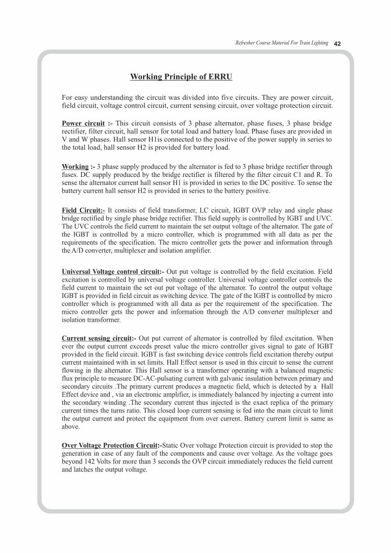
Working Principle of ERRU
For easy understanding the circuit was divided into five circuits. They are power circuit, field circuit, voltage control circuit, current sensing circuit, over voltage protection circuit.
Over Voltage Protection Circuit:-Static Over voltage Protection circuit is provided to stop the generation in case of any fault of the components and cause over voltage. As the voltage goes beyond 142 Volts for more than 3 seconds the OVP circuit immediately reduces the field current and latches the output voltage.
Current sensing circuit:- Out put current of alternator is controlled by filed excitation. When ever the output current exceeds preset value the micro controller gives signal to gate of IGBT provided in the field circuit. IGBT is fast switching device controls field excitation thereby output current maintained with in set limits. Hall Effect sensor is used in this circuit to sense the current flowing in the alternator. This Hall sensor is a transformer operating with a balanced magnetic flux principle to measure DC-AC-pulsating current with galvanic insulation between primary and secondary circuits .The primary current produces a magnetic field, which is detected by a Hall Effect device and , via an electronic amplifier, is immediately balanced by injecting a current into the secondary winding .The secondary current thus injected is the exact replica of the primary current times the turns ratio. This closed loop current sensing is fed into the main circuit to limit the output current and protect the equipment from over current. Battery current limit is same as above.
Universal Voltage control circuit:- Out put voltage is controlled by the field excitation. Field excitation is controlled by universal voltage controller. Universal voltage controller controls the field current to maintain the set out put voltage of the alternator. To control the output voltage IGBT is provided in field circuit as switching device. The gate of the IGBT is controlled by micro controller which is programmed with all data as per the requirement of the specification. The micro controller gets the power and information through the A/D converter multiplexer and isolation transformer.
Field Circuit:- It consists of field transformer, LC circuit, IGBT OVP relay and single phase bridge rectified by single phase bridge rectifier. This field supply is controlled by IGBT and UVC.The UVC controls the field current to maintain the set output voltage of the alternator. The gate of the IGBT is controlled by a micro controller, which is programmed with all data as per the requirements of the specification. The micro controller gets the power and information through the A/D converter, multiplexer and isolation amplifier.
Working :- 3 phase supply produced by the alternator is fed to 3 phase bridge rectifier through fuses. DC supply produced by the bridge rectifier is filtered by the filter circuit C1 and R. Tosense the alternator current hall sensor H1 is provided in series to the DC positive. To sense the battery current hall sensor H2 is provided in series to the battery positive.
Power circuit :- This circuit consists of 3 phase alternator, phase fuses, 3 phase bridge rectifier, filter circuit, hall sensor for total load and battery load. Phase fuses are provided in V and W phases. Hall sensor H1is connected to the positive of the power supply in series to the total load, hall sensor H2 is provided for battery load.
Refresher Course Material For Train Lighting 43
THE OPERATING INSTRUCTIONS FOR INTERFACE UNIT FOR ERRU
Interface unit has two functions i.e. emergency operation and data monitoring system. The instruction to operate the emergency system is:
1. If one of the regulator stops the operation then we can use this emergency unit to maintain the powering the output. 2. Check the generation of the alternator using the Green LED in the interface unit. 3. If any one of the regulator stops working, then turn the “ Switch-1” from “Normal to Emergency”. 4. And turn the “Switch-2” to in working alternator side ( if alternator-1 is not working change to alternator-2 and vice versa) 5. This normal to emergency operation changing should be done in “Train stopped condition only”. To see all the parameters of regulator, LCD system is used in data monitoring unit. This LCD system used to display this data by scrolling arrangement. Instructions for opera-tion of this system are: a. Press “Select” button to stop the scrolling the parameters. b. Press “Up” to see the parameters in ascending order. Press “Down” to see the parameters in descending order. c. To see the fault channel first stop the scrolling using “Select” and press “Up” or “Down”. d. For come out from the fault channel press “Select” again then the system starts scrolling.
Note :- If “Up” and “Down” both buttons are pressed at a time more than 10 seconds the data stored in the interface will be “Reset”.
The interface box is provided to monitor the set parameters. These parameters are displayed using LCD by a scrolling arrangement. The parameters are:
1. DC output current of both the alternators. 2. DC output voltage of both the alternators. 3. Battery current. 4. Battery charging current. 5. Battery discharging current. 6. Amp hour in. 7. Amp hour out. 8. Total Amp hour in / out. 9. Total KW hr charging and discharging. 10. Speed of the alternator. 11. MFO of the alternator. 12. Total distance travelled by the alternator. 13. Total generation and non-generation time of both regulators. 14. Last 32 faults and storing. 15. Acquisition time.
FACILITIES PROVIDED IN INTERFACE UNIT
Refresher Course Material For Train Lighting 44
Data logger with Interface:Terminals are provided for data logger for storing the parameters of output voltage, current,
battery current charging and discharging and speed of the alternator for both regulators.
Each regulator can be connected to data logger and the above mentioned data can be read at
any time. This can read the total amp hour in and out up to 99000 AH which amounts the data
can be stored for 5 years before resetting.
OVP indication and Reset:OVP indication and reset is also provided in the same box. The operator can reset in case the
OVP operates of disconnects the regulator. All this can be done when the train is in movement.
Setting of parameters:This interface unit has provision to connect the keyboard and having facilities to change the
parameter of DC output voltage incase of improper load sharing. This can also be done in
running time.
Buzzer Arrangement:This interface unit has an arrangement for buzzer sound for alternator failure. The buzzer will
work only when one alternator working and another is not working. The buzzer will not work
when both alternators working or not working.
Emergency field extension:The same data logger box contains the emergency field extension incase of the failure of the
control circuit of one regulator. This helps the operator to understand the healthy conditions
of both the alternator and to provide field extension in case of the control circuit of one
regulator is defective.
Note: Emergency field extension switches are to be operated only when the train is in the
halt condition. Setting of DC output voltage should be done with presence of companies
service engineers. Buzzer arrangement is only for cordon shaft alternator only.
Refresher Course Material For Train Lighting 45
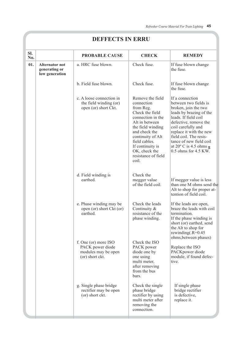
DEFFECTS IN ERRU
Sl.No.
01. Alternator not generating or low generation
If fuse blown change the fuse.
If fuse blown change the fuse.
If a connection between two fields is broken, join the two leads by brazing of the leads. If field coil defective, remove the coil carefully and replace it with the new field coil. The resis-tance of new field coil at 20º C is 4.5 ohms0.5 ohms for 4.5 KW.
If megger value is less than one M ohms send the Alt to shop for proper at-tention of field coil.
If the leads are open,braze the leads with coil termination. If the phase winding is short (or) earthed, send the Alt to shop for rewinding(.R=0.45 ohms,between phases)
Replace the ISO PACKpower diode module, if found defec-tive.
If single phase bridge rectifieris defective, replace it.
Check fuse.
Check fuse.
Remove the fieldconnectionfrom Reg. Check the fieldconnection in theAlt in betweenthe field windingand check the continuity of Altfield cables. If continuity isOK, check the resistance of fieldcoil.
Check themegger valueof the field coil.
Check the leads Continuity & resistance of thephase winding.
Check the ISOPACK powerdiode one by one using multi meter,after removing from the busbars.
Check the single phase bridge rectifier by usingmulti meter afterremoving the connection.
a. HRC fuse blown.
b. Field fuse blown.
c. A loose connection in the field winding (or) open (or) short Ckt.
d. Field winding is earthed.
e. Phase winding may be open (or) short Ckt (or) earthed.
f. One (or) more ISO PACK power diode modules may be open (or) short ckt.
g. Single phase bridge rectifier may be open (or) short ckt.
PROBABLE CAUSE CHECK REMEDY
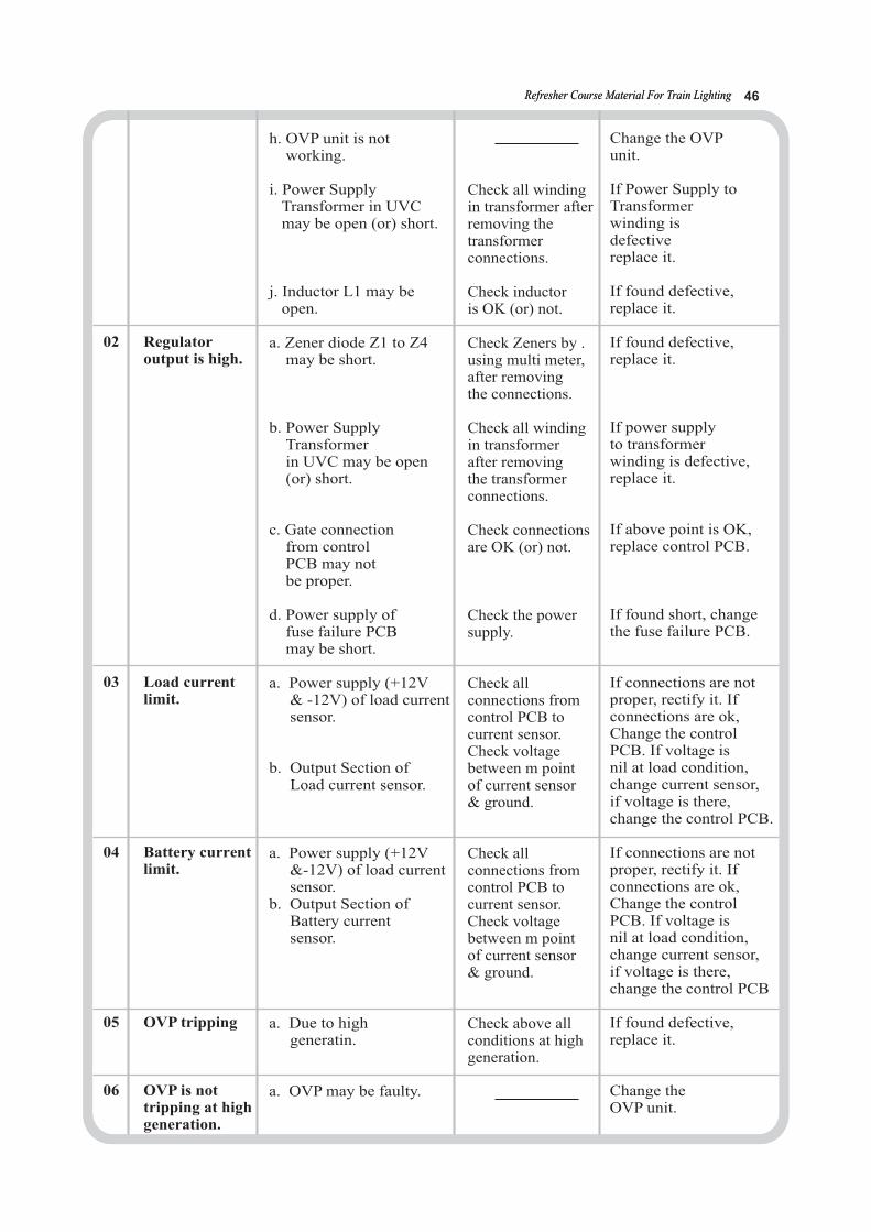
Refresher Course Material For Train LightingRefresher Course Material For Train Lighting 46
Change the OVP unit.
If Power Supply toTransformer winding is defective replace it.
If found defective,replace it.
If found defective,replace it.
If power supply to transformer winding is defective,replace it.
If above point is OK, replace control PCB.
If found short, change the fuse failure PCB.
If connections are not proper, rectify it. If connections are ok,Change the controlPCB. If voltage is nil at load condition,change current sensor,if voltage is there, change the control PCB.
If connections are not proper, rectify it. If connections are ok,Change the controlPCB. If voltage is nil at load condition,change current sensor,if voltage is there, change the control PCB
If found defective, replace it.
Change the OVP unit.
h. OVP unit is not working.
i. Power Supply Transformer in UVCmay be open (or) short.
j. Inductor L1 may be open.
a. Zener diode Z1 to Z4may be short.
b. Power Supply Transformer in UVC may be open (or) short.
c. Gate connection from controlPCB may notbe proper.
d. Power supply of fuse failure PCB may be short.
a. Power supply (+12V & -12V) of load current sensor.
b. Output Section of Load current sensor.
a. Power supply (+12V&-12V) of load currentsensor.
b. Output Section of Battery current sensor.
a. Due to high generatin.
a. OVP may be faulty.
Check all windingin transformer afterremoving the transformer connections.
Check inductor is OK (or) not.
Check Zeners by .using multi meter, after removing the connections.
Check all winding in transformer after removingthe transformerconnections.
Check connectionsare OK (or) not.
Check the power supply.
Check all connections fromcontrol PCB to current sensor.Check voltage between m pointof current sensor& ground.
Check all connections fromcontrol PCB to current sensor.Check voltage between m pointof current sensor& ground.
Check above all conditions at high generation.
02 Regulator output is high.
03 Load current limit.
04 Battery currentlimit.
05 OVP tripping
06 OVP is nottripping at highgeneration.

Characteristics of 4.5 kw alternator:
Output Capacity : 4.5 KWVoltage : 124 Volts DCCurrent : 37.5ACut in Speed : 350 RPM (19 kmph approx)MFO : 600 RPM (31 kmph approx)Max. Speed : 2500 RPM (130 kmph approx)Mounting : Bogie mountingBelts : V-belts (C-122)Insulation : F-class (armature & field winding)Bearing : DE - NU-311 (roller bearing) NDE - 6309 (Ball bearing)
Alternator is equipped with one no. of 185 mm PCD of four groove pulley and is driven throughan axle pulley with 572.6mm PCD (bogie mounted).
Resistance between phases (KEL) - 0.39 ohms at 20 CResistance of field winding (KEL) - 4.5 ohms at 20 C
The free length of spring of 4.5 KW, 110V tensioning mechanism is 345mmThe working length of spring of 4.5 KW, 110V tensioning mechanism is 310mmThe weight of the 4.5 KW TL Alternator is 290 Kg approx.
Cut in speed of Alternator:The minimum train speed in KMPH at which the Alternator develops the rectified DC output of 110 V at no load. and is 19 Kmph.
Minimum speed of for full output (MFO) of Alternator: The minimum train speed in KM / hour at which the Alternator is capable of developing its full rated output is called minimum speed for full output briefly MFO and is 29Kmph.
Residual magnetism of Alternator:A small amount of magnetism remaining in the stator core of an Alternator after the coil current is removed is called residual magnetism.
Reasons for loss of Residual Magnetism:
The reasons for loss of residual magnetism are keeping the Alternator in idle condition forlong time and connecting field wires in wrong polarity. To regain the residual magnetismflash the field terminals for correct polarity of DC supply. The permissible DC voltage isto be applied to regain the residual magnetism is 6 to 12V, DC. Maximum voltage is 24V DC.
Refresher Course Material For Train Lighting 47
0
0
Action to be taken to avoid phase / field wires cut / burnt on TL alternators:
a. Use of FRP cleats on the terminal box of 4.5 KW alternators.b. Use of Nylon / Rubber grommets in place of cable glands.c. Proper clamping / cleaning of cable to the junction box on the coach bodyd. Use of U type washer & spring washer to prevent level movement of sockets as well as losing of sockets.e. Use of proper crimping tool and sockets by the staff.f. Provision of Terminal box cover in all the alternators.g. Setting the current controlling shunt to rated value of current to avoid overloading.h. Avoid running the alternators in service with separately exciting the field as it will generate uncontrolled voltage and current.i. Avoid running of alternators with defective regulator , as it will cause heavy overloading on phase / field winding of alternator.j. Using proper rating of HRC fuse instead of thick wire in phase / field.
EFFECT OF IMPROPER WORKING OF ALTERNATOR:
Excess voltage generation by Alternator leads to-a. Over charging of the batteryb. Frequent reduction in electrolyte levelc. Excessive gassing of cells
Low voltage generation by Alternator leads to-a. Insufficient Charging of batteryb. Low Specific gravityC. Battery getting deep discharged
The safety points to be inspected on Alternator:
Safety items to be checked on alternator are proper existence of safety chains with Original bolts and split pins, suspension hanger pin with cotter pin, suspension arrangement with nylonbushes, alternator pulley with nut and split pin, proper alignment of axle pulley and alternatorpulley, full compliment of V belts with out twisting, proper fitment of tensioning mechanismby maintaining 35mm gap between bracket and free end bush collar, proper tightness of termi-nal connections with cleat and clamp , proper securement of wiring etc.
Precautions to be taken while loading and unloading of Alternator:
1. While unloading and loading Alternator, see that the terminal box and pulley should not be broken.2. The Alternator to be loaded in correct way that bushes to be provided in proper place.3. While loading and unloading proper precautions to be taken not to fall on ground otherwise men/material will be injured/damaged.4. See that the anti rotating clamp provided on trolley coincides with Alternator suspension pin.5. Replace the worn out Alternator and Alternator bracket bushes.6. See that the Alternator should not have play with proper washers in improper place to align the axle pulley.7. Safety chains and cotter pins to be provided with out fail.
The safety points to be inspected on TL axle pulley:
Safety items to be checked on axle pulley are existence of eight bolts with flat and spring washers,full tightness of bolts, proper fitment of axle pulley with a gap 145mm between wheel hub andpulley strap, observation of shifting of axle pulley from its original place, proper alignment ofaxle pulley and alternator pulley, observation of correct belts tension with out twist maintaininggap 3 mm between two flanges, observation of with out worn out grooves and breakage etc.
Refresher Course Material For Train Lighting 48

Refresher Course Material For Train Lighting 49
II. BATTERIES
Working Principle of Cells:
PbO2 + Pb + 2H
Discharging:PbO2 on (+) plate and Pb on (-)ve plates are converted into lead sulphate. In thisprocess, H2SO4 is converted and water is formed. Consequently SPG of electrolyte falls andextents of fall is proportional to AH taken out.
Charging:The chemical process is reversed. PbSO4 on positive plate is converted into PbO2
(lead peroxide) and PbSO4 on negative plate into Pb ( spongy lead ).H2SO4 is formed and water isconsumed. SPG of electrolyte rose.
Types of batteries used in Indian railwaysn Indian Railway: A . Lead acid 1.Conventional type
B . Alkaline batteries
Constructional features:
Accessories: Float. Float guide
Vent Plug
SO
2 4 Pbso + Pbso + 2 H O
E = 2.041 V
(+Ve plate) (- Ve plate)
0
Discharge e- PbSO
4 + 2 H
2O E° = 1.685V
Charge
Discharge
Charge4 4 2
2.VRLA Type3.Low maintenance batteries
1.Nickel cadmuim2.Silver zinc
1.Positive plates2.Negative plates3.Separators4.Container5.Cell cover
Capacities of Batteries In train lighting
* 120 Ah - 110 V DC,BG,TL Coach.* 120 Ah (VRLA) - 110 V DC,BG,TL coach.
Pb + H2 SO4
Discharge
Charge
At negetive electrode :Pbso4 + 2H
+ + 2e- E0 = 0.356 V
At positive electrode : Discharge
ChargePbso4 + 2 H2O E0 = 1.685 VPbo2 + 2H+ + H2SO4 + 2e-
Refresher Course Material For Train Lighting 50
Initial Charging to a new commissioned battery:Lead Acid Batteries are supplied in uncharged condition without electrolyte. Before usingLead Acid battery, it has to be initially filled with recommended quality and quantity ofelectrolyte and make ready for initial charging. The whole phenomenon is associated with the following activities:
Preparation of Electrolyte: • The cells are supplied in dry uncharged condition. • These cells are required dilute Sulphuric acid of SPG ( 1.180-1.220), corrected up to 27° C as electrolyte for initial charging. • Electrolyte = Conc. H2SO4 ( as per IS:266) of SPG concentrated 1.835 + Water ( as per IS:1069) To get 100 litres (approx) of electrolyte:
For SPG Water (litres) Acid (litres) 1.180 86 17 1.220 82 21Concentrated acid should always be poured slowly into the water and never the water in the acid in Ebonite box.
Initial filling:• Filling the electrolyte up to the lower marking on the float indicator• Allow the cell to rest for a period of around 16-24 hrs.• Level of electrolyte may fall. Restore this with some electrolyte.• Now the cells are ready for 1st charging.
Initial Charging:
• Charge the cells for 80/100 hrs at specified rate as per manufacture’s data (6 A for 120 Ah).• During charging, temperature should be less than 50° C After 45° C, reduce the charging rate to ½ value & increase the time accordingly.• Total charge input should be equal to Time X current ( specified Charging current )• While charging, level of electrolyte may fall due to water loss. Restore for 24 hrs by adding water. • Adjust the SPG to 1.215 + 0.005 corrected to 27° C.• Adjust the SPG, the cells must be gassing freely for a minimum 2 hrs of charging. This helps in proper mixing of electrolyte.• Now cells should be discharged through a suitable resistance at constant current (I)=0.10XC10 amps up to 1.80 VPC.• The battery shall be charged at normal charging
Trickle Charging:
When a battery is kept as an emergency reserve, it is very essential that it should be found fully charged when an emergency arises. Due to local action and open circuit losses, the batteries deteriorate .Hence to keep it fresh, batteries are kept on a small charging. For example: A standby battery for station bas-bar of 400 Ah at 10 hr rating, a continuous trickle charge of 1 Amp will keep the cells fully charged and keep in perfect condition.
* Preparation of electrolyte* Initial filling* Initial charging

Factors affecting the life of Lead Acid Battery:
1. Necessity of frequent topping of cells. 2. Leakage of electrolyte on lid and on container body. 3. Failure of one cell on a mono-block unit. 4. Undercharging / overcharging. 5. Always use distilled water for toping of cells. 6. Keeping the discharged cells for long time will result in formation of sulphation.
Details of flooded cells in TL coach
1. There are eighteen flooded mono block batteries; each mono block consists of three cells. 2. The voltage of fully charged cell is 2.2 volts. 3. The specific gravity of fully charged cell is 1.220. 4. The specific gravity of half charged cell is 1.175. 5. The lead acid cell can be discharged up to 1.75 volts.
To know the performance of battery identifying two cells, for measuring specific gravity during one month are called pilot cells. Again two more cells will be identified as pilot cellsafter every one month. Pilot cells should be average cells.
SELECTION OF PILOT CELLS
Month Pilot cells 1st month 1, 12, 132nd month 2, 11, 143rd month 3, 10, 154th month 4, 9, 165th month 5, 8, 176th month 6, 7, 18
TYPES OF DEFECTS IN LEAD ACID BATTERIES
The defects are :-1.Sulphation2.Bucking and cracked plates3.Loss of capacity4.Low specific gravity and low voltage of cell5.Reversed cells6.Dead cells7.Loss of active material8.Sludge9.Internal short circuit of one or more cells.
PILOT CELLS
Refresher Course Material For Train Lighting 51
SULPHATION
Sulphation means the formation of lead sulphate on the surface and in the pores of the active materials of the plates. Sulphate is finely crystalline and easily reduced by the charging current.Sulphation in this sense is a necessary part of the operation of battery and is not a source oftrouble. Lead sulphate is also formed as result of local action or self discharge of the plate.

Refresher Course Material For Train Lighting 52
TREATMENT FOR SULPHATED CELLS
Light Sulphation:- If it is taken in time, charging at low rate approximately 1/3 rd of the normal charging rate will reduce sulphation. The charge should be continued till cells gasfreely. Repeat charge and discharge two to three times till specific gravity of 1.220 is reached.
Bad Sulphation:- Empty the container and fill with distilled water, charge at 1/10th of normalrate and test specific gravity at intervals and it is above 1.150. Stop charging and empty outthe electrolyte. Refill with pure distilled water and continue charge. Ensure that the temperatureof the electrolyte does not rise above 120 degrees F (49 degrees C). The charge of the sulphatewill be indicated by the colour of the plates. After all Sulphation is reduced empty the jar andrefill with electrolyte of 1.220 Specific gravity. It is not advisable to use any de Sulphationagents since Sulpahtion is the natural result of battery action.
CAUSES OF SULPHATION
1. Due to over charging2. Over discharging3. Impurities in acid, plates, or electrolyte4. Due to plates are not covered by the electrolyte5. Due to neglect of battery, Sulphation is caused6. Kept under discharged condition for long time
The following important points should be kept in mind for keeping the battery in goodcondition:
1. Discharging should not be prolonged after the minimum value of the voltage for the particular rate of discharge is reached.2. It should not be left in discharged condition for long.3. The level of the electrolyte should always be 10 to 15 mm above the top of the plates which must not be left exposed to air. Evaporation of electrolyte should be made up by adding distilled water occasionally.4. Since acid does not vaporize, none should be added.5. Vent openings in the filling plug should be kept open to prevent gases formed within from building a high pressure.6. The acid and corrosion on the battery top should be washed off with a cloth moiste- -ned with baking soda or ammonia and water.7. The battery terminals and metal supports should be cleaned down to bare metal and covered with Vaseline or petroleum jelly.
Maintenance of Lead – Acid Cells
This is brought about by the action of the acid solution on the concentration and temperatureof the electrolyte. Lead sulphate formed as a result of local action is easily reduced by thecharging current unless it is neglected. Sulphation applies to the large crystals of lead sulphatethat may form on the plates as a result of neglect or misuse. Excessive sulphation of this typeis difficult to reduce and may injure the plates. The effect is usually noticed by a whitish colouron plates and is caused by over charging, over discharging or keeping the discharged batteryfor a long time. Carbonate of soda added to the electrolyte has a beneficial effect in preventingsulpahtion defect, or the best way is trickling charge i.e., charging the battery at a low ratefor long time.

Requirements for DM Water as per IS1069 Method of test reference * PH Value ---- 6.5 to 7.5 IS3025 ( PART 11 ) 1983
* Specific electrical conductivity at 250 c 5 IS3025 ( PART 14 ) 1984 ( micro ohms cm ) * TDS (mg / l) --- 2 IS 3025 ( PART 16 ) 1984
Refresher Course Material For Train Lighting 53

Refresher Course Material For Train Lighting 54
The lead acid battery, used in the Indian Railways, consists of a spongy lead as negative plate and
lead peroxide as positive plate with dilute sulphuric acid as electrolyte. It has a nominal voltage of 2V and
requires periodic maintenance, depending on its use.
HYDRO METER
This meter is used to measure SPGR of liquids. It consists of glass tube with a glass bulb.
The glass bulb is fitted with lead balls and is fitted with scale, on which SPGR is marked.
This glass bulb is kept in a glass tube. One side of glass tube is fitted with rubber bulb and
on the other side a nozzle. The rubber bulb is pressed to suck electrolyte from the battery.
The electrolyte enters in the outer glass tube in which hydro meter bulb floats and gives
reading. With the dilute sulphuric acid the bulb sinks more in the electrolyte, while with
strong sulphuric acid the bulb less. In this way it gives reading to know the performance
of battery.
CELL TESTER OR HIGH RATE TESTER
This is a tester which gives the correct terminal voltage on full load of the cell. In the tester
there is one resistance of low value which works as load on the cell of the battery. One
voltmeter is connected to give voltage. On the same voltmeter dial, charged to discharge
conditions are also indicated by the words full charged, half charged and dead. One small
lamp is connected in parallel with the voltmeter to indicate light. This tester gives the reading
to one cell only at a time. Following precautions are to be taken while using this cell tester.
VRLA BATTERIES
VRLA / SMF Batteries:
1. It should not be connected with cell terminals for a long time because it gives heavy load
on the cell, so that cell will be discharged quickly.
2. Clean the two terminals of testers and cell before using.
The conventional lead acid battery is improved by developing valve regulated sealed lead-acid
battery ( VRSLAB) with absorbent glass mat or gel technology. These batteries need no addition
of water during their normal life time. There is no spillage of electrolyte or release of gas. The
batteries are charged by constant potential mode. Calcium alloys are used as grid material due
to their lower self-discharges and increase conductivity. Oxygen and hydrogen evolve from
positive and negative respectively during recharge. Oxygen evolved at the anode reacts with
the hydrogen through the separator to produce water. A valve releases the excess gas, preventing
accident during overcharging. VRSLAB finds usage in electronic equipment, standby systems
and remote area power supplies where solar power is used to charge batteries.

Construction of VRLA Cell
1. Terminal Post -ve.
2. Jar & Cover - Polypropylene.
3. Jar to Cover - Hermetic Sealing.
4. Bus bar
5. Separator: Spun Glass microporous matrix (Totally absorbed electrolyte)
6. Positive Plate - Hybrid Grid Alloy
7. Negative Plate - High surface area to enhance oxygen recombination.
8. Vent Plug
9. Terminal Post +ve.
4
9
6
7
8
5
3
1 2
OXYGEN RECOMBINATION PRINCIPLE
Oxygen Combined Indirectly with Hydrogen
Oxygen Formed during charge
Refresher Course Material For Train Lighting 55
Parts of VRLA Batteries:
1. Positive plates: Flat pasted type with lead-calcium High Tin alloy or lead cadmium alloy
to resist corrosion & for longer life.
2. Negative plates: Flat pasted type with lead-calcium alloy grid for maintenance free characteristics.
3. Separator: Low resistance, high porosity and highly absorbent glass mat separator (AGM)
4. Electrolyte: High purity Sulphuric acid to maximize shelf life
5. Terminals: High conductivity lead plated inserts.
6. Safety Valve: Self resealing, pressure regulated and explosion proof.
7. Container and Cover Sealing: Heat Sealing Method (Fusion bond) for better joint strength.
8. Container: High impact Polypropylene co-polymer.
Refresher Course Material For Train Lighting 56
Working principle of VRLA batteries
Valve Regulated Lead Acid (VRLA) batteries can be of either the gelled electrolyte type or the absorbed electrolyte type, While the basic electrode reactions remain the same as in conventionalflooded cells, VRLA batteries operate on the oxygen recombination principle. Due to the special grid alloys used, the actual gas evolution is 97% less than in conventional batteries. The conventional flooded batteries, oxygen evolved at the positive plate bubbles upwards through the electrolyte and is released through the vent plugs. In VRLA batteries, however, the small amount of oxygen that is evolved, is transported through the separator to the negative plate via the gas phase, and is consumed at the negative plate.
Special features of VRLA batteries
FEATURES:VRLA batteries using absorbed electrolyte have the following special features..
The electrolyte is immobilized by using highly absorbent glass mat separators which are designed to hold sufficient electrolyte to meet all performance requirements.
Oxygen Recombination
The battery works on the oxygen recombination principle. Recombination efficiencies are in excess of 99%.
Starved electrolyte
Explosion resistant safety vents
VRLA batteries operate at a slight positive pressure within the cell. Cells are fitted with a unique low pressure self resealing safety vent plug which releases the gasses when the internal pressure within a cell exceeds 6 PSI and reseals again at low pressures. The constant positive pressure in
the cells prevents accidental ingress of external air which would otherwise result in self dischargeat the negative plate. The vent plugs are also fitted with a porous plastic disc, which prevent
external sparks from entering the cell. This makes the vent plug explosion proof.
Hermetic Heat Seal
The battery jar & cover are hermetically sealed on automatic machines. Additionally, the total absorption of electrolyte in the separators and the use of pressure regulated vents make it spill proof and leak proof.
Superior alloys
VRLA batteries use highly corrosion resistant alloys such as Lead cadmium resistant lead alloys.
Copper insert terminals
VRLA batteries have highly conductive copper inserts in terminals resulting in very good power characteristics. Inter cell connections are done by using high purity lead coated copper strip connectors and heavy duty stainless steel bolts which are resistant to sulphuric acid.
Modular Steel Trays
VRLA batteries are assembled in modular steel trays normally in the horizontal configuration. This lends flexibility in assembling the system one module above the other.
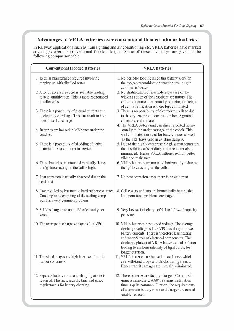
Refresher Course Material For Train Lighting 57
Conventional Flooded Batteries VRLA Batteries
1. Regular maintenance required involving topping up with distilled water.
2. A lot of excess free acid is available leadingto acid stratification. This is more pronounced in taller cells.
3. There is a possibility of ground currents dueto electrolyte spillage. This can result in high rates of self discharge.
4. Batteries are housed in MS boxes under the coaches.
5. There is a possibility of shedding of active material due to vibration in service.
6. These batteries are mounted vertically hencethe ‘g’ force acting on the cell is high.
7. Post corrosion is usually observed due to the acid mist.
8. Cover sealed by bitumen to hard rubber container.Cracking and debonding of the sealing comp-
-ound is a very common problem.
9. Self discharge rate up to 4% of capacity per week.
10. The average discharge voltage is 1.90VPC.
11. Transits damages are high because of brittle rubber containers.
12. Separate battery room and charging at site is required. This increases the time and space requirements for battery charging.
1. No periodic topping since this battery work on the oxygen recombination reaction resulting in zero loss of water.
2. No stratification of electrolyte because of the wicking action of the absorbent separators. Thecells are mounted horizontally reducing the heightof cell. Stratification is there fore eliminated.
3. There is no possibility of electrolyte spillage dueto the dry leak proof construction hence ground currents are eliminated.
4. The VRLA battery unit can directly bolted horiz--ontally to the under carriage of the coach. This will eliminates the need for battery boxes as wellas the FRP trays used in existing designs.
5. Due to the highly compressible glass mat separators,the possibility of shedding of active materials is minimized. Hence VRLA batteries exhibit bettervibration resistance.
6. VRLA batteries are mounted horizontally reducingthe ‘g’ force acting on the cells.
7. No post corrosion since there is no acid mist.
8. Cell covers and jars are hermetically heat sealed.No operational problems envisaged.
9. Very low self discharge of 0.5 to 1.0 % of capacityper week.
10. VRLA batteries have good voltage. The average discharge voltage is 1.95 VPC resulting in lower battery currents. There is therefore less heating and wear & tear of electrical components. The discharge plateau of VRLA batteries is also flatter leading to uniform intensity of light bulbs, for longer duration.
11. VRLA batteries are housed in steel trays whichcan withstand drops and shocks during transit. Hence transit damages are virtually eliminated.
12. These batteries are factory charged. Commissio--ning is immediate. A 80% savings installation time is quite common. Further , the requirements of a separate battery room and charger are consid--erably reduced.
In Railway applications such as train lighting and air conditioning etc. VRLA batteries have markedadvantages over the conventional flooded designs. Some of these advantages are given in the following comparison table:
Advantages of VRLA batteries over conventional flooded tubular batteries

Refresher Course Material For Train Lighting 58
The purpose of belt tensioning device is to keep V belts in tight condition.Its parts are: 1. Tension device 2. Tension spring 3. Belt tension indicator with spring seat 4. Fork eye 5. Fork eye side spring seat 6. Belt tightening nut 7. Free end pipe and nut.
The gap to be maintained between coach bracket and free end bush caller of tensioning device for 4.5 KW TL alternators is 35 mm and for 18 / 25 KW alternator is 50 mm.
Procedure to tighten and loosen the V belts of AC/ TL coach alternator with the help of tensioning device:
Tensioning gears consists of tensioning rod, ‘U’ clamp, nut and check nut of ‘U’ clamp side, springtighten collar spring tension indicator free ends side nut, check nut and split pin. Tensioning rodplays a vital role for tightening or loosening the ‘V’ belt. If the rod moves towards the alternator from the bracket, alternator moves away from the axle pulley and belts are tightened. If the tension rod moves towards the bracket from the alternator the belt is loosened. The moving of tension rod due to tightening or loosening of spring tightening collar nut. If the spring is tightened the tension rod moves away from the bracket. If the spring tensions collar nut is loosened the tension rod moves towards the bracket from the alternator and ‘V’ Belt are loosened.
How to tighten and loosen of V belts of AC / TL coach alternator with the helpof tensioning device:
Tightening and loosening of belts will be done with the nut provided near the fork eye of alternator only. Never use bush nut provided at free end of tension device for tightening and loosening of belts.
III. BELT TENSIONING DEVICE
In the normal course of run, the belts will be stretched and the belt tension of the alternator will be reduced. In addition to the above the gap between free end side bush collar and bracket will be reduced. For maintaining the constant belt tension through out the service, the following operations have to be done. a)Gauge plate shall be cut to 250mm+/-5mm irrespective of of the kw. b)Belt should be tightened to maximum extent possible.c)Aweight of 4 kgs should be hanged at the centre of belt span between axle pulley and alter-
nator pulley and see that top surface of this belt does not go below bottom surface of remaining belts (As per RDSO letter no. EL/7.1.38/1, dt:20.01.11) After the completion of above work, the gap between bracket and free end nut is to be main-tained 50 mm for AC coaches and 35 mm for non AC coaches for free movement of alternator, when train is running in curves. Free end nut and check nut is only to hold the tension rod in position without failing down. Whenever the belts are over stretched and it is not possible to adjust the belt tension by adjusting the tension rod the belts are to be replaced by new. In this way, when ever the belts are loose, the above procedure to be adopted for maintaining constant tension of belts.
Procedure to maintain constant V belt tension (Z) and gap between free end side bush collar and bracket throughout service:
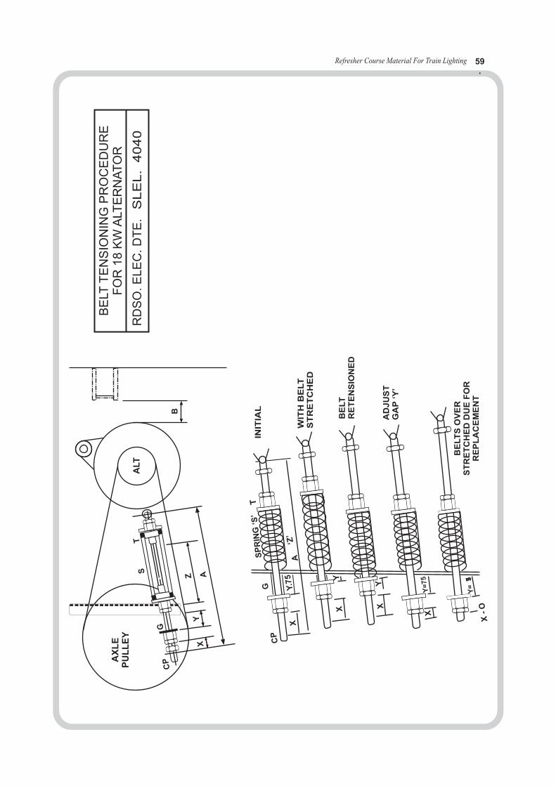
Refresher Course Material For Train Lighting 59.
CP
XY
Z A
B
G
ST
ALT
LA
XE
UL
YP
LE
T
XY
X
PC
G
’Z‘
ASP
RIN
SG
‘’
X
X
X-
O
Y.7
5
Y
Y=
75
Y=357
INIT
IAL
WIT
HB
ELT
ST
RE
TC
HE
D
BE
LT
RE
TE
NS
ION
ED
AD
JU
ST
GA
P‘Y
’
BE
LT
SO
VE
RS
TR
ET
CH
ED
DU
EF
OR
RE
PL
AC
EM
EN
T
BE
LTT
EN
SIO
NIN
GP
RO
CE
DU
RE
FO
R1
8K
WA
LTE
RN
AT
OR
RD
SO
.LE
EC
.D
TE
.LE
SL.
4040
Refresher Course Material For Train Lighting 60
‘V’ belt tension test 1. Tension should be felt by hand by striking it slightly. 2. Belt in correct tension will respond alive and spring. 3. Low tension belt will respond as dead and very tight belt will have no give attitude. 4. Feel the pulleys soon after a run. 5. Warm pulleys indicate slippage, which may be due to very low or very high tension.
How to provide and maintain correct tension of new ‘V’ belts on bogie : 1. Provide alternator on the bogie. 2. Provide axle pulley on the wheel. 3. Provide ‘V’ belt of matching set between grade 48 & 52 on wheel axle, on which , the axle pulley is provided. 4. After lowering and completion of buffer head adjustments of bogie, provide ‘V’ belts over alternator and the axle pulley. 5. After completion of provision of V belt, remove the split pin check nut and bush (pipe) of free end side tension device. 6. Free the check nut and fixing nut of U clamp side of tension rod. 7. Now insert the tension device assembly between the bogie supporting bracket and eye ( leg ) of the alternator . 8. Provide bolt for ‘U’ clamp of tension rod and eye of the alternator. 9. Provide bush ( pipe) and check nut at free end to hold the tension device firmly. 10. Then slowly tighten the fixing unit ( U clamp side ) until the tension indicator coincide with the spring tightening caller This will gives the correct tension of the V belt. 11. Then adjust the gap between coach bracket bush (pipe) collar leaving a gap of 50 mm for AC coaches and 35mm for non AC coaches. Now lock the bush with check nut and provide split pin. 12. Then observe the tension of belts remember that always tightening and loosening of belts will be done with of nut provided near the fork eye of alternator only. Never use bush nut provided at free end of tension device for tightening and loosening of belts.
Refresher Course Material For Train Lighting 61
1. The endless V Belts C 122 are used for TL / AC is of Isosceles trapezoidal cross section.2. Nominal inside length of the ‘V’ Belt C 122 is 3099mm or 122 inches.
Matched set of v belts
In order to avoid unequal distribution of load of belts running on a multiple ‘V’ Belt drive shallbe in matched sets. The belts of the same nominal pitch length matching to the same grading onlyshall be used for a particular set. The belts are to be supplied in a matched set tied together consistsof 6 or 5 or 4 belts as required by the indenters with the grades 48 to 52 only.
The points to be checked during visual inspecting of V belts
Visual inspection of ‘V’ belts, belting shall be checked for any.
1. Deformity
2. Bulging
3. Waviness
4. Cracks Blemishes
5. Unevenness and
6. Marking as specified
The V belt failure modes are :
1. Belt slippage
2. Belt turns over and face twisting
3. Rapid wear
4. Excessive stretch
5. Belt bottom crack
6. Belt top crack
7. Few belts drop in en route
8. Belts riding uneven
9. Defective cord construction
IV. ‘V’ BELTS
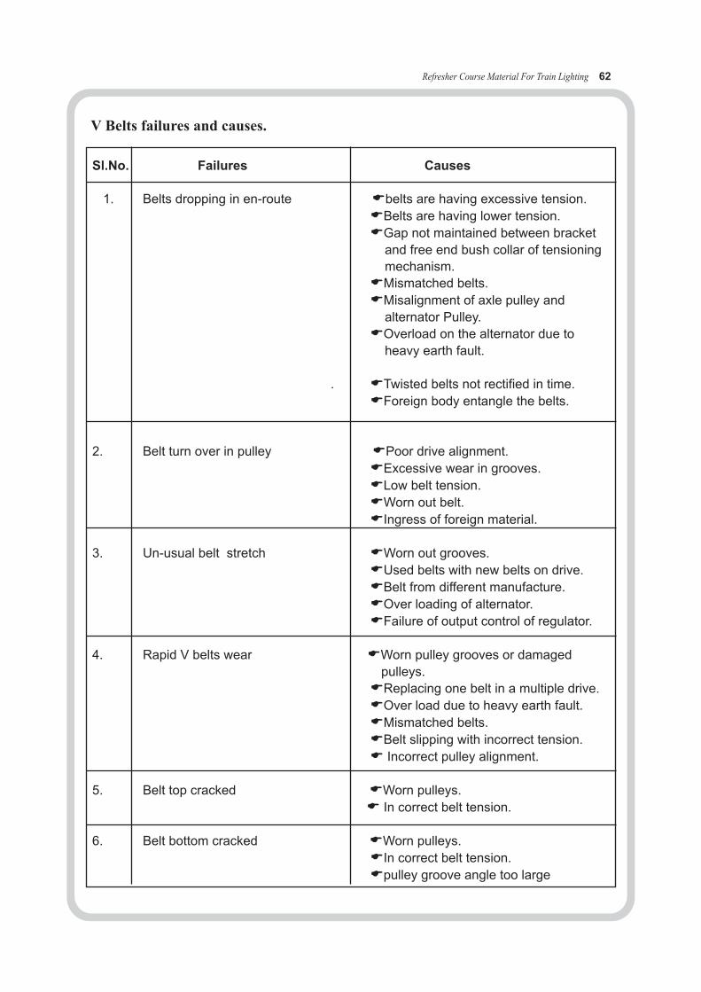
Refresher Course Material For Train Lighting 62
Sl.No. Failures Causes
1. Belts dropping in en-route Ebelts are having excessive tension.
EBelts are having lower tension.
EGap not maintained between bracket
and free end bush collar of tensioning
mechanism.
EMismatched belts.
EMisalignment of axle pulley and
alternator Pulley.
EOverload on the alternator due to
heavy earth fault.
. ETwisted belts not rectified in time.
EForeign body entangle the belts.
2. Belt turn over in pulley EPoor drive alignment.
EExcessive wear in grooves.
ELow belt tension.
EWorn out belt.
EIngress of foreign material.
3. Un-usual belt stretch EWorn out grooves.
EUsed belts with new belts on drive.
EBelt from different manufacture.
EOver loading of alternator.
EFailure of output control of regulator.
4. Rapid V belts wear EWorn pulley grooves or damaged
pulleys.
EReplacing one belt in a multiple drive.
EOver load due to heavy earth fault.
EMismatched belts.
EBelt slipping with incorrect tension.
E Incorrect pulley alignment.
5. Belt top cracked EWorn pulleys.
E In correct belt tension.
6. Belt bottom cracked EWorn pulleys.
EIn correct belt tension.
Epulley groove angle too large
V Belts failures and causes.

Refresher Course Material For Train Lighting 63
7. Belt riding un even EBelts not matched.EIncorrect tension.
8. Belt slipping EIncorrect belt tension.EWorn out grooves.EMismatched belts.
9. Cuts in the base of the belts EAbnormal belt slip.EContamination by oil or chemical.
Common problems in V-Belt drive and their corrective actions:
Sl.No. Problem Cause Remedy
1. Belt slip & noise on the drive. ELack of tension. EIncrease tension.EOil / grease on EDecrease.
pulley grooves.
2. Belt bottom cracking. EHigh belt slippage. EIncrease tension.EImprove storage. EImprove storage.
3. Belt stretching. EExcessive drive EMaintain propertension. tension.
4. Belt snap. EBelt ride over ECheck tension.pulley.
5. Belt turnover. EMismatched belts. EUse belts of EMisaligned drive. matched set.EWorn out pulley ERealign shaft and
grooves. pulley.EShock load. EReplace the pulley.
apply proper tension.
6. Belt whip. EMismatched belt. EReplace belts.ENew belt installed ENever mix old and
along with old belt. new belts.EImproper groove EReplace the pulley.
angle.
Enot enough drive EApply proper tension tension.
Emisaligned shaft. EAlign the drive
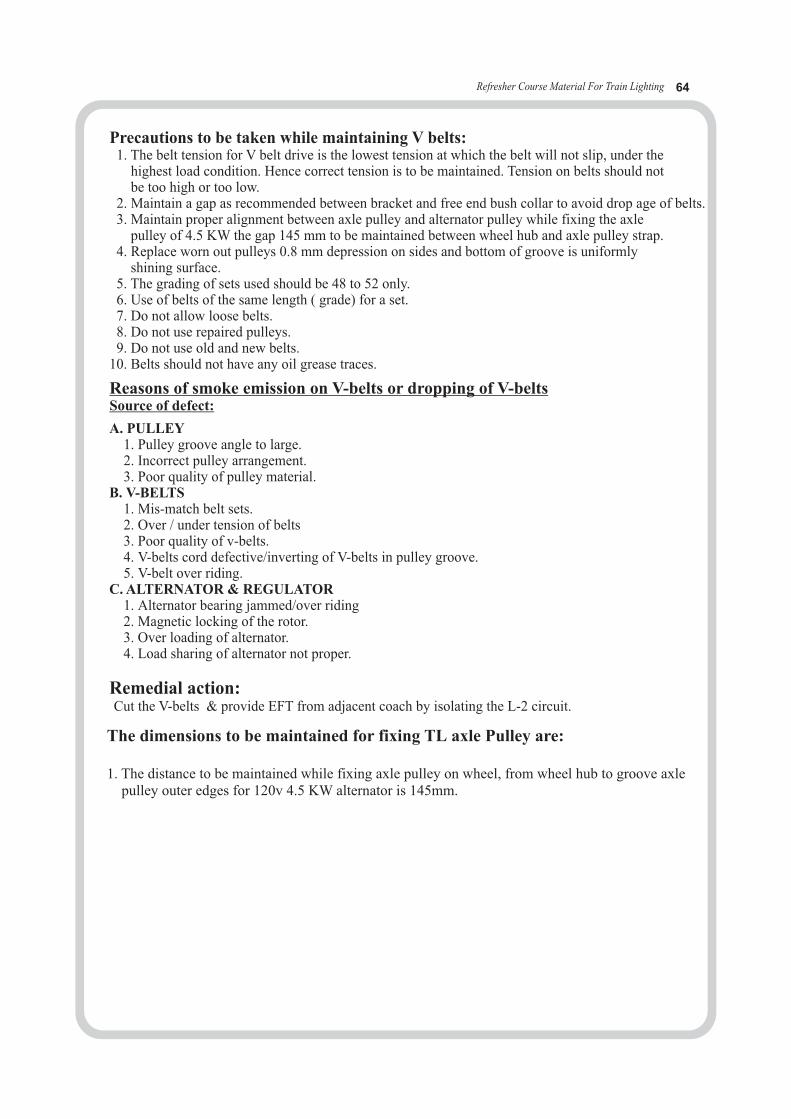
Refresher Course Material For Train Lighting 64
Precautions to be taken while maintaining V belts: 1. The belt tension for V belt drive is the lowest tension at which the belt will not slip, under the highest load condition. Hence correct tension is to be maintained. Tension on belts should not be too high or too low. 2. Maintain a gap as recommended between bracket and free end bush collar to avoid drop age of belts. 3. Maintain proper alignment between axle pulley and alternator pulley while fixing the axle pulley of 4.5 KW the gap 145 mm to be maintained between wheel hub and axle pulley strap. 4. Replace worn out pulleys 0.8 mm depression on sides and bottom of groove is uniformly shining surface. 5. The grading of sets used should be 48 to 52 only. 6. Use of belts of the same length ( grade) for a set. 7. Do not allow loose belts. 8. Do not use repaired pulleys. 9. Do not use old and new belts.10. Belts should not have any oil grease traces.
A. PULLEY 1. Pulley groove angle to large. 2. Incorrect pulley arrangement. 3. Poor quality of pulley material.B. V-BELTS 1. Mis-match belt sets. 2. Over / under tension of belts 3. Poor quality of v-belts. 4. V-belts cord defective/inverting of V-belts in pulley groove. 5. V-belt over riding.C. ALTERNATOR & REGULATOR 1. Alternator bearing jammed/over riding 2. Magnetic locking of the rotor. 3. Over loading of alternator. 4. Load sharing of alternator not proper.
Remedial action:Cut the V-belts & provide EFT from adjacent coach by isolating the L-2 circuit.
Reasons of smoke emission on V-belts or dropping of V-belts Source of defect:
The dimensions to be maintained for fixing TL axle Pulley are:
1. The distance to be maintained while fixing axle pulley on wheel, from wheel hub to groove axle pulley outer edges for 120v 4.5 KW alternator is 145mm.
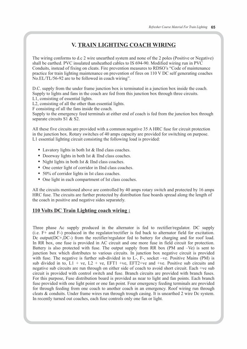
Refresher Course Material For Train Lighting 65
V. TRAIN LIGHTING COACH WIRING
The wiring conforms to d.c 2 wire unearthed system and none of the 2 poles (Positive or Negative)shall be earthed. PVC insulated unsheathed cables to IS 694-90. Modified wiring run in PVCConduits, instead of fixing on cleats. Fire prevention measures to RDSO’s “Code of maintenancepractice for train lighting maintenance on prevention of fires on 110 V DC self generating coachesNo.EL/TL/56-92 are to be followed in coach wiring”.
D.C. supply from the under frame junction box is terminated in a junction box inside the coach.Supply to lights and fans in the coach are fed from this junction box through three circuits.L1, consisting of essential lights.L2, consisting of all the other than essential lights.F consisting of all the fans inside the coach.Supply to the emergency feed terminals at either end of coach is fed from the junction box throughseparate circuits S1 & S2.
All these five circuits are provided with a common negative 35 A HRC fuse for circuit protectionin the junction box. Rotary switches of 40 amps capacity are provided for switching on purpose.L1 essential lighting circuit consisting the following load is provided:
• Lavatory lights in both Ist & IInd class coaches.
• Doorway lights in both Ist & IInd class coaches.
• Night lights in both Ist & IInd class coaches.
• One center light of corridor in IInd class coaches.
• 50% of corridor lights in Ist class coaches.
• One light in each compartment of Ist class coaches.
All the circuits mentioned above are controlled by 40 amps rotary switch and protected by 16 ampsHRC fuse. The circuits are further protected by distribution fuse boards spread along the length of the coach in positive and negative sides separately.
110 Volts DC Train Lighting coach wiring :
Three phase Ac supply produced in the alternator is fed to rectifier/regulator. DC supply (i.e. F+ and F-) produced in the regulator/rectifier is fed back to alternator field for excitation.Dc output(DC+,DC-) from the rectifier/regulator fed to battery for charging and for roof load. In RR box, one fuse is provided in AC circuit and one more fuse in field circuit for protection. Battery is also protected with fuse. The output supply from RR box (PM and –Ve) is sent to junction box which distributes to various circuits. In junction box negative circuit is provided with fuse. The negative is further sub-divided in to L-, F-, socket –ve. Positive Mains (PM) is sub divided in to, L1 + ve, L2 + ve, EFT1 +ve, EFT2+ve and +ve. Positive sub circuits and negative sub circuits are run through on either side of coach to avoid short circuit. Each +ve subcircuit is provided with control switch and fuse. Branch circuits are provided with branch fuses. For this purpose, Fuse distribution board is provided as near to light and fan points. Each branchfuse provided with one light point or one fan point. Four emergency feeding terminals are providedfor through feeding from one coach to another coach in an emergency. Roof wiring run through cleats & conduits. Under frame wires run through trough casing. It is unearthed 2 wire Dc system.In recently turned out coaches, each fuse controls only one fan or light.

* MAJOR EQUIPMENTS IN TL COACH:
• Alternator – 4.5 kw, 110V, 3phase, brush less type, totally enclosed, reversible shunt wound
• Regulator Board-4.5 kw
• Battery-6 V,120 Ah, lead acid 18 nos/VRLA type 19 no’s each 6 V,120 Ah monoblock
• Light -15 w / 20w.110V DC
• Fans-32W dc & bldc, 60W ac fans with 2.5 kva 110Vdc/110 Vac Inverter.
• V-belts, axle pulley, alternator pulley
* PELE : Portable emergency lighting equipment
it consists 1) Tripod stand 2) Holder 3) Flexible wire -- 25mtrs
These are used in emergency condition train service and it is kept in the guard compartment.It should be checked once in 6 months.
Refresher Course Material For Train Lighting 66
DIAGRAM OF 110 VOLTS DC TL SYSTEM INCLUDING CAPACITIES OF EQUIPMENT AND PROTECTION DEVICES
SPM1&SPM2
+
-
+
-
4.5KW
4) Crocodile clips 5) Bulbs 6) Hand lamps
7) Lamp fittings 8) Log book .
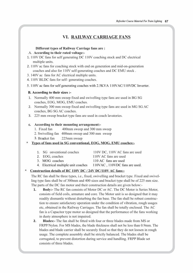
Refresher Course Material For Train LightingRefresher Course Material For Train Lighting 67
VI. RAILWAY CARRIAGE FANS
Different types of Railway Carriage fans are :
A. According to their rated voltage:- 1. 110V DC fans for self generating DC 110V coaching stock and DC electrical
multiple units.
2. 110V ac fans for coaching stock with end on generation and mid-on-generation
coaches and also for 110V self-generating coaches and DC EMU stock .
3. 140V ac fans for AC electrical multiple units.
4. 110V BLDC fans for self- generating coaches.
1. Normally 400 mm sweep fixed and swivelling type fans are used in BG SG
coaches, EOG, MOG, EMU coaches.
2. Normally 300 mm sweep fixed and swivelling type fans are used in MG SG AC
coaches, BG SG AC coaches.
3. 225 mm sweep bracket type fans are used in coach lavatories.
c. According to their mounting arrangement:-
1. Fixed fan 400mm sweep and 300 mm sweep 2. Swivelling fan 400mm sweep and 300 mm sweep 3. Bracccket fan 225mm sweep
* Types of fans used in SG conventional, EOG, MOG, EMU coaches:-
1. SG onventional coaches 110V DC, 110V AC fans are used 2. EOG, coaches 110V AC fans are used
* Construction details of RC 110V DC / 24V DC/110V AC fans:-
The RC fan shall be three types, i.e., fixed, swivelling and bracket type. Fixed and swivel-
ling type fans shall be of 300mm and 400 sizes and bracket type shall be of 225 mm size.
The parts of the DC fan motor and their construction details are given below:-
1. Body:- The RC fan consists of Motor DC or AC. The DC Motor is Series Motor,
consists of field coils, armature and core. The Motor unit is so designed that it may
readily dismantle without disturbing the fan base. The fan shall be robust construc-
tion to ensure satisfactory operation under the condition of vibration, rough usages
etc, obtained in the Railway Carriages. The fan shall be totally enclosed. The AC
fan is a Capacitor type motor so designed that the performance of the fans working
in dusty atmosphere is not impaired.
2. Blades:- The fan shall be fitted with four or three blades made from MS or
FRPP/Nylon. For MS blades, the blade thickness shall not be less than 0.9mm. The
blades and blade carrier shall be securely fixed so that they do not loosen in rough
usage. The complete assembly shall be strictly balanced. The blades shall be
corrugated, to prevent distortion during service and handling. FRPP Blade set
consists of three blades.
5. 110V ac fans for self generating coaches with 2.5KVA 110VAC/110VDC Inverter.
B. According to their sizes :-
3. MOG coaches 110 AC fans are used4. Electrical multiple unit coaches 110VAC , 110VDC fans are used.

3. Bearings:- The Bearing used for RC Fan are SKF 6200, and bush bearing. Nor-mally, ball bearings are used for commutator side; their dimensions are 10mm (ID), 300mm (OD), 9mm (Width). The bearing used at blade end is bush bearing or ball bearing. The size of the bush bearing is 9.589mm (ID), 15.68mm (OD), 20.6mm (Length) and ball bearing used at blade end is SKF 6200.
4. Guard: The fan guards are of closed mesh type for adequate protection against personal injury. The sixes of 400mm fan guards are 425mm x 70mm, whereas 300mm sweep fan is 325 x 70mm. For Cage Guard, spring steel wires are used. Fan Guard rib ends to outer and inner rings are spot welded. The wires of the guard shall be not less than 1.6mm in dia, and central distance between two wires shall not exceed 10mm. Crash worthy mesh guard are also in service.
5. Brushes: The Grade of the Carbon brushes used in RC Fans are EG3 of Assam Carbon, L16 (I) and E55 (I) of electron Carbonium. Carbon brush used may be square of rectangular, but not round. The total length of Carbon brush is 23+/-1.5mm. Useful length is 10mm. Condemned length is 8mm. Spring seat length is 5+/-0.5mm.
6. Spring: Carbon brush springs are made up of spring steel wire Grade 3 or Grade 2. Diameter of the spring wire is 0.5mm (25 SWG). Number of active turns are12+- 1mm. Total turns of the spring are 16+/-1. When 350 gm of load is provided on the spring, the compression length is 14.5mm. The total length of the spring is 38+-2mm. The spring is copper plated with a thickness of 0.015mm.
7. Carbon Brush Holder: The size of the Carbon brush bolder is 44 x 44mm, with Phenolic Base. All the leads shall terminate on Carbon brush holder in crimped manner with lugs, which shall be fixed in position by means of screws. It consists of a Brush Box, size 10mm x 15mm and made up of Zinc Alloy.
8. Armature & Field coils: Two Field coils are connected in series to the Armature on either side. Aluminium field coils are provided in 24 volt DC Fans, whereas Copper field coils are provided in 110 Volts DC fans. All the insulating materials used in RC fans belong to Class E. The 110V armature consists of copper coils. Core used for yoke and armature is made up of electrical steel laminations. Armature consists of twelve coils arranged in 12 slots. The size of copper wire used for 110v armature coils is 33 SWG and numbers of turns are about 750 turns. Resistance of 110V field coils is about 40 ohms.
9. Commutator: Commutator consists of 24 segments, made up of hard drawn copper. The diameter of the Commutator is 40mm. Condemned diameter of commutator is 32mm.
Disadvantages of DC railway carriage fans:Presently 110V DC fixed and swivelling type fans in different sweeps having commutation with the help of carbon brushes are being used in the self generating coaches and DC EMUs. Due to the above the following are the disadvantages
1. Maintenance cost is very high 2. Weight of the fan is high3. Poor efficiency 4. Poor reliability5. Excess noise 6. Operational cost is high7. Short service life 8. Requires frequent maintenance9. Service valve is less 10. Low air deliveries11. High input power
Refresher Course Material For Train LightingRefresher Course Material For Train Lighting 68
Brushless DC Fans:Principle of operation:
An electronically commutated BLDC motor consists of a permanent magnet rotor, a stator
with a poly phase winding and an electronic switching device. The device consists of a ro-
tor position sensor, fixed on the motor shaft, and an electronic switching, module, which
can supply stator winding. Operation of BLDC motor is very similar in concept to that of
DC motors. The stator will be wound for three phase and the winding will be similar to
three-phase induction motor or synchronous motor. The rotor position sensor continuously
senses the axes of the rotor permanent magnet and gives out logical signals. The logical
signals are coded and will be sent to the control module.
The control module decodes the signals and approximately selects the stator windings
whose magnetic field will be perpendicular to the rotor magnetic field and supplies current
to it, a torque is generated and the rotor moves.
Following the resulting rotation the rotor position logic signal changes after certain rotation
(60 electrical degrees). Then the module switches the current to the successive windings so
as to keep the resultant winding field perpendicular to the rotor magnetic field thus ensur-
ing smooth rotation and torque.
Points to be checked on fans during trip schedule:Switch on each fan individually. Check starting of fan when switched on. In upper class
coaches, check fan for starting in the lowest position of regulator and also for variation of
speed in the other regulator positions. If the fan does not start, short the switch terminals
with a small piece of wire temporarily. If the fan starts, this will indicate that the
controlling tumbler switch / regulator is defective. Replace, proceed as follows:
•If the fan does not start when the toggle switch terminals are shorted proceed as
follows:
•Test for supply at the 2-way connector terminals near the fan with the tumbler
switch on. If there is no supply, the wiring is defective and has to be attended.
•Open dome cover in case of swivelling fans and remove fan body fixing screws in
case if fixed fans.
•Remove carbon brushes, check brushes for condemning size, proper bedding,
correct spring tension and correct grade of brush.
•Check for free movement of brush in the brush holder. Replace defective
brushes/springs.
If the commutator is dirty, clean the surface with sand paper of 0 size.
•If the commutator is grooved or the segments are found pitted in one or more
locations, replace the fan by an overhauled fan. The defective fan can thereafter be
rectified by replacing the defective armature by a good one. If spare armature is
not available send defective fan to shop for attention.
•If the fan is noisy, check for loose blades/fan guards and tighten them. If the noise
is due to bearings, replace the fan and send defective fan to shop for replacing.
•Check the fuse for fans and ensure that it is of correct size (35 SWG) tinned
copped.
•Clean fan body and its guard.
Refresher Course Material For Train LightingRefresher Course Material For Train Lighting 69
In swivelling and bracket fans ensure that the fan dust cover is promptly replaced
after attention and also that the nylon cord provided to prevent loss of fan dust
cover, is available in position.
The MCB/ fuse controlling the fan circuit shall be checked for corrected rating (16
A for non AC SG coaches and 6 A for SG AC coaches) and proper functioning and
replace if found defective.
•Note down the total number of fans in each coach and the number of fans found
defective. Defective fans shall include fans, which required push start. The aim is
to achieve cent percent working of fans. The records mentioned above will help in
working out the extent of problem in any particular service to take quick remedial
action.
The fans shall be available as per lay out for the coaches. In case it is necessary to
remove any fan for attending to major defects and no spare fan is available a
Deficiency label shall be affixed near the fan point. In case no deficiency label is
available. Theft memo shall be issued to the security branch.
Deficiency of fans shall be promptly made good when noted by any depot
irrespective of whether the train is primarily maintained or not except in case of
repeated large scale deficiencies of foreign Railway coaches. The Depot/Railways
entrusted with primary maintenance shall be advised by message whenever the
deficiency is made good or when large scale deficiencies are noted.
Points to be checked on RC fans during monthly schedule:
In addition to the items listed under trip examination the following works shall be carried
out.
•The fan body, guards and blade shall be thoroughly cleaned with cloth.
•All fans shall be opened and condition of commutator, brushes and brush gear
shall be thoroughly checked. Action should be taken where necessary as given
under trip attention.
•Studs used for fixing the fan to coach body, shall be checked and tightened,
wherever necessary. Availability of all the three fixing studs should be ensured.
•All the switches controlling the fans shall be checked for its smooth operation and
correct working and replaced where necessary.
•Fan regulators in upper class coaches shall be checked for smooth operation from
one position to the other. In case the regulators are not regulating the fan speed,
the resistance box shall be checked and replaced where necessary.
•Fan blades shall be replaced if found bent, or if there is no proper air discharge.
Refresher Course Material For Train LightingRefresher Course Material For Train Lighting 70
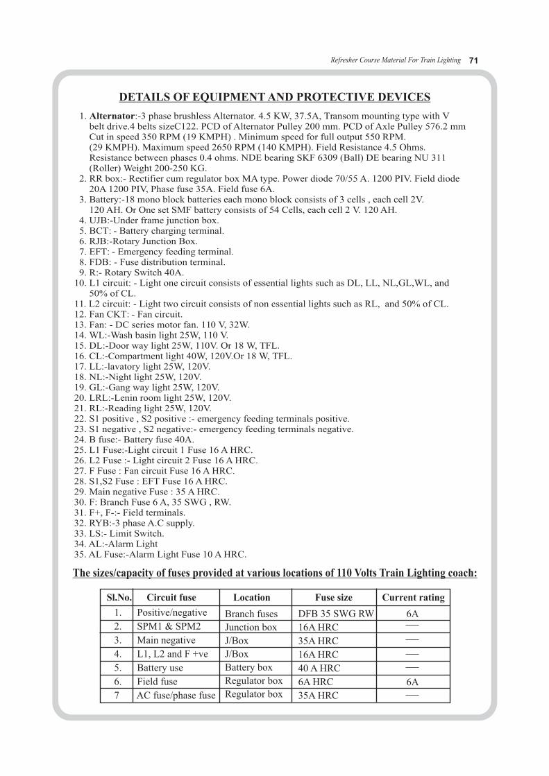
Refresher Course Material For Train Lighting 71
The sizes/capacity of fuses provided at various locations of 110 Volts Train Lighting coach:
1. Positive/negative
2. SPM1 & SPM2
3. Main negative
4. L1, L2 and F +ve
5. Battery use
6. Field fuse
7 AC fuse/phase fuse
Branch fuses
Junction box
J/Box
J/Box
Battery box
Regulator box
Regulator box
DFB 35 SWG RW
16A HRC
35A HRC
16A HRC
40 A HRC
6A HRC
35A HRC
6A
6A
Sl.No. Circuit fuse Location Fuse size Current rating
DETAILS OF EQUIPMENT AND PROTECTIVE DEVICES
1. Alternator:-3 phase brushless Alternator. 4.5 KW, 37.5A, Transom mounting type with Vbelt drive.4 belts sizeC122. PCD of Alternator Pulley 200 mm. PCD of Axle Pulley 576.2 mmCut in speed 350 RPM (19 KMPH) . Minimum speed for full output 550 RPM.(29 KMPH). Maximum speed 2650 RPM (140 KMPH). Field Resistance 4.5 Ohms.Resistance between phases 0.4 ohms. NDE bearing SKF 6309 (Ball) DE bearing NU 311(Roller) Weight 200-250 KG.
2. RR box:- Rectifier cum regulator box MA type. Power diode 70/55 A. 1200 PIV. Field diode20A 1200 PIV, Phase fuse 35A. Field fuse 6A.
3. Battery:-18 mono block batteries each mono block consists of 3 cells , each cell 2V.120 AH. Or One set SMF battery consists of 54 Cells, each cell 2 V. 120 AH.
4. UJB:-Under frame junction box.5. BCT: - Battery charging terminal.6. RJB:-Rotary Junction Box.7. EFT: - Emergency feeding terminal.8. FDB: - Fuse distribution terminal.9. R:- Rotary Switch 40A.
10. L1 circuit: - Light one circuit consists of essential lights such as DL, LL, NL,GL,WL, and50% of CL.
11. L2 circuit: - Light two circuit consists of non essential lights such as RL, and 50% of CL.12. Fan CKT: - Fan circuit.13. Fan: - DC series motor fan. 110 V, 32W.14. WL:-Wash basin light 25W, 110 V.15. DL:-Door way light 25W, 110V. Or 18 W, TFL.16. CL:-Compartment light 40W, 120V.Or 18 W, TFL.17. LL:-lavatory light 25W, 120V.18. NL:-Night light 25W, 120V.19. GL:-Gang way light 25W, 120V.20. LRL:-Lenin room light 25W, 120V.21. RL:-Reading light 25W, 120V.22. S1 positive , S2 positive :- emergency feeding terminals positive.23. S1 negative , S2 negative:- emergency feeding terminals negative.24. B fuse:- Battery fuse 40A.25. L1 Fuse:-Light circuit 1 Fuse 16 A HRC.26. L2 Fuse :- Light circuit 2 Fuse 16 A HRC.27. F Fuse : Fan circuit Fuse 16 A HRC.28. S1,S2 Fuse : EFT Fuse 16 A HRC.29. Main negative Fuse : 35 A HRC.30. F: Branch Fuse 6 A, 35 SWG , RW.31. F+, F-:- Field terminals.32. RYB:-3 phase A.C supply.33. LS:- Limit Switch.34. AL:-Alarm Light 35. AL Fuse:-Alarm Light Fuse 10 A HRC.

Refresher Course Material For Train Lighting 72
POSITIVE EARTH NEGATIVE EARTH (See sheet No-II) (See sheet No-II)
ANNEXURE –III(SHEET-1)
TROUBLE SHOOTING INSTRUCTIONS FOR EARTH ON COACH WIRING
Connect the earth indicating device to the EFTB as shown in sheet IV
Lamps do not Lamps glow Both lamps glow One lamp burns brightly glow at all unequally equally while the other is not glowing at all
(1) (2) (3) (4)
I. Either one or both I. Battery box leaky Coach wiring is healthy Earth fault is either inthe lamps defective positive or negative wiring,Replace the defective the polarity given by the glassLamp/lamps and re-test II. Partial earth on window of the device thus:
Positive or negative “POSITIVE EARTHED” orwiring. (not serious “NEGATIVE EARTHED” bybut should be attended the brightly burning lamp. to as early as possible as per sequence shown in (4)
Examine junction box, distribution fuse board and emergency feed terminal boards at both the endsand check for physical contact of any terminal/lead wires with Earth. Insulate the terminals/leads
properly and repeat the test.
Only one lamp burns Both lamps glow
Only one lamp Both lamps glowBurns
Fault in under frame Fault in body wiringWiring (see sheet III)
Separate the body wiring Coach wiring healthyFrom junction box and re-test

Refresher Course Material For Train Lighting
68
If fault is in underframe wiring, connect the earth indicating device at the battery terminals and test.
ANNEXURE –III(SHEET-3)
NOTE : 1. A coach may have multiple earth faults which is a rare occurrence. By the procedure given above, second fault, if any, can be detected only after the first one has been put right. Hence it is necessary to test the entire wiring every time has been put right.
2. If the fault/faults are not located, the coach should be sent to workshop.
ANNEXURE –III(SHEET-2)
Trouble shooting for earth on
POSITION EARTH NEGATIVE EARTH (*)
POSITIVE EARTHLocate defective section of the under frame positive cables by disconnecting each cable from
the underframe terminal board.
Locate defective section of the underframe negative cables by disconnecting each from the underframe terminal board.
NEGATIVE EARTH
Both lamps glow F- defective.Locate defect.
Disconnect F- cable in the junction box & re-test
One lamp burns IsolateSI_& SII_and re-test
(*) NEGATIVE EARTH
Isolate each other and detect defective section.Both lamps glow.SI or SII defective. One lamp burns L-defective
Locate defect.
Both lamps glow F+ defective. Reconnect F+and isolate each fan individually at DFB. Repeat test till defective section is defected.
Both lamps burn SI+ or SII defective Isolate SI+ & re-test.
Disconnect F+ cable in the junction box and re-test
One lamp burns.LI+ defective.Isolate each light point of LI circuit individually at DFB.Repeat test till defective sectionis detected.
One lamp burns Isolate SI+SII+ and re-test
One lamp burns Roof LI+ or LII Defective.
Both lamps burn, LII+defective Isolate each lightpoint of the LII circuit at DFB.Repeat test till defectivesection is detected.
Both lamps burnSI+ defective. Checkthe defective section(as indicated by the lampmarking) till the defect is detected.
One lamp burns SII* defective. Check the defective section (as indicated by the lamp marking)till the defect is detected.
Refresher Course Material For Train Lighting
If fault is in underframe wiring, connect the earth indicating device at the battery terminals and test.
ANNEXURE –III(SHEET-3)
NOTE : 1. A coach may have multiple earth faults which is a rare occurrence. By the procedure given above, second fault, if any, can be detected only after the first one has been put right. Hence it is necessary to test the entire wiring every time has been put right.
2. If the fault/faults are not located, the coach should be sent to workshop.
ANNEXURE –III(SHEET-2)
Trouble shooting for earth on
POSITION EARTH NEGATIVE EARTH (*)
POSITIVE EARTHLocate defective section of the under frame positive cables by disconnecting each cable from
the underframe terminal board.
Locate defective section of the underframe negative cables by disconnecting each from the underframe terminal board.
NEGATIVE EARTH
Both lamps glow F- defective.Locate defect.
Disconnect F- cable in the junction box & re-test
One lamp burns IsolateSI_& SII_and re-test
(*) NEGATIVE EARTH
Isolate each other and detect defective section.Both lamps glow.SI or SII defective. One lamp burns L-defective
Locate defect.
Both lamps glow F+ defective. Reconnect F+and isolate each fan individually at DFB. Repeat test till defective section is defected.
Both lamps burn SI+ or SII defective Isolate SI+ & re-test.
Disconnect F+ cable in the junction box and re-test
One lamp burns.LI+ defective.Isolate each light point of LI circuit individually at DFB.Repeat test till defective sectionis detected.
One lamp burns Isolate SI+SII+ and re-test
One lamp burns Roof LI+ or LII Defective.
Both lamps burn, LII+defective Isolate each lightpoint of the LII circuit at DFB.Repeat test till defectivesection is detected.
Both lamps burnSI+ defective. Checkthe defective section(as indicated by the lampmarking) till the defect is detected.
One lamp burns SII* defective. Check the defective section (as indicated by the lamp marking)till the defect is detected.
Refresher Course Material For Train Lighting 73
If fault is in underframe wiring, connect the earth indicating device at the battery terminals and test.
ANNEXURE –III(SHEET-3)
NOTE : 1. A coach may have multiple earth faults which is a rare occurrence. By the procedure given above, second fault, if any, can be detected only after the first one has been put right. Hence it is necessary to test the entire wiring every time has been put right.
2. If the fault/faults are not located, the coach should be sent to workshop.
ANNEXURE –III(SHEET-2)
Trouble shooting for earth on
POSITION EARTH NEGATIVE EARTH (*)
POSITIVE EARTHLocate defective section of the under frame positive cables by disconnecting each cable from
the underframe terminal board.
Locate defective section of the underframe negative cables by disconnecting each from the underframe terminal board.
NEGATIVE EARTH
Both lamps glow F- defective.Locate defect.
Disconnect F- cable in the junction box & re-test
One lamp burns IsolateSI_& SII_and re-test
(*) NEGATIVE EARTH
Isolate each other and detect defective section.Both lamps glow.SI or SII defective. One lamp burns L-defective
Locate defect.
Both lamps glow F+ defective. Reconnect F+and isolate each fan individually at DFB. Repeat test till defective section is defected.
Both lamps burn SI+ or SII defective Isolate SI+ & re-test.
Disconnect F+ cable in the junction box and re-test
One lamp burns.LI+ defective.Isolate each light point of LI circuit individually at DFB.Repeat test till defective sectionis detected.
One lamp burns Isolate SI+SII+ and re-test
One lamp burns Roof LI+ or LII Defective.
Both lamps burn, LII+defective Isolate each lightpoint of the LII circuit at DFB.Repeat test till defectivesection is detected.
Both lamps burnSI+ defective. Checkthe defective section(as indicated by the lampmarking) till the defect is detected.
One lamp burns SII* defective. Check the defective section (as indicated by the lamp marking)till the defect is detected.

Refresher Course Material For Train Lighting 74
ELEC - 1.12Maintenance Schedules,
Critical Points, Settings and Tolerances of
TL equipments

Refresher Course Material For Train Lighting 75
MAINTENANCE SCHEDULES OF TRAIN LIGHTING COACHES
1. TRIP SCHEDULE (PRIMARY & SECONDARY MAINTENANCE)
(a) ATTENTION ON MAINTENANCE LINES
As soon as the rake is berthed in the maintenance lines and before commencing the work, a caution board shall be clamped to the rail on either side of the rake by TXR or his representative. Rail locks shall be used on either side of the rake for the safety of maintenance staff attending under gear equipment. TXR should ensure clearance from electrical Chargemen/staff in-charge for the maintenance of rack before removing the caution board and rail locks.
To avoid any malfunctioning of the above system printed forms for permit to work on pit lines issued by the traffic department and after completion of the work, completed/men withdrawn form can be used.
Check the plate-form attention report and concentrate first on attending the defects in these coaches by adapting systematic trouble shooting procedures. Proceed as follows in respect of other equipment.
(b) ALTERNATOR
First attend alternators in coaches for generation, which have arrived “cold” and coach dark condition as per platform report. Proceed as follows: -
ØCheck field fuse, replace if found blown, with approved makes i.e., S&S or English Electric make.
ØCheck the continuity of field and phase winding with the help of test lamp/multi-meter to ensure that windings are not open circuited.
ØCheck for loss of residual magnetism with the help of voltmeter across the field terminals. In case of loss of magnetism, give 12V DC flashing to the field terminals for few second to regain lost residual magnetism.
ØCheck that the regulator feedback loop is O.K.
ØCheck connections for tightness in alternator and rectifier regulator. If this is all right, remove belt from alternator.
ØUse testing machine for testing alternator in situation. Couple the portable motor drive with Alternator.
ØCheck the DC output voltage at the rectifier and regulator terminals. Identify the defects if any and rectify them. The battery should be isolated while doing this test.
ØProvide new split pin for pulley castle nut after completion of work.
ØCheck up the condition of safety chain and availability of split pins in safety chain bolts.
ØCheck up alternator suspension bracket and tension gear for any damage and replace, if necessary.
ØCheck up and tighten loose bolts in terminals box covers.
ØCheck availability of split pin for alternator castle nut.
ØCheck the belt tension after every round trip of the coach.
ØFor new 'V' belt fitted, the belt should be retightened, after completing the first trip.
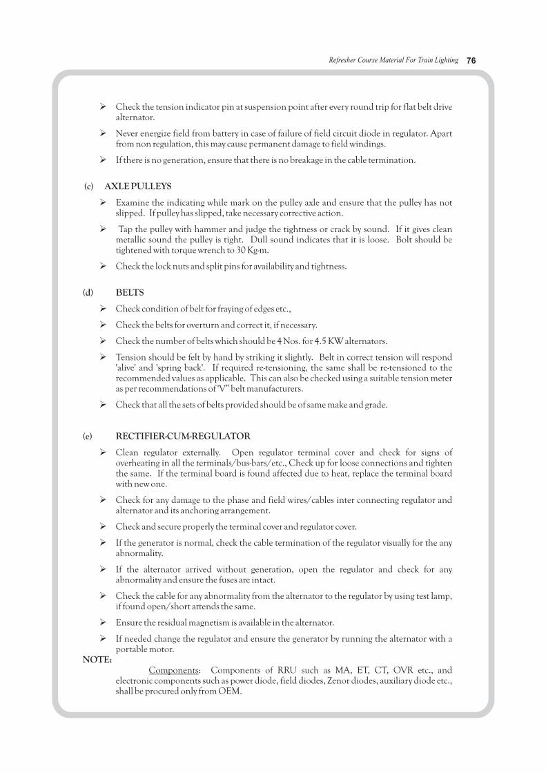
Refresher Course Material For Train Lighting 76
ØCheck the tension indicator pin at suspension point after every round trip for flat belt drive alternator.
ØNever energize field from battery in case of failure of field circuit diode in regulator. Apart from non regulation, this may cause permanent damage to field windings.
ØIf there is no generation, ensure that there is no breakage in the cable termination.
(c) AXLE PULLEYS
ØExamine the indicating while mark on the pulley axle and ensure that the pulley has not slipped. If pulley has slipped, take necessary corrective action.
ØTap the pulley with hammer and judge the tightness or crack by sound. If it gives clean metallic sound the pulley is tight. Dull sound indicates that it is loose. Bolt should be tightened with torque wrench to 30 Kg-m.
ØCheck the lock nuts and split pins for availability and tightness.
(d) BELTS
ØCheck condition of belt for fraying of edges etc.,
ØCheck the belts for overturn and correct it, if necessary.
ØCheck the number of belts which should be 4 Nos. for 4.5 KW alternators.
ØTension should be felt by hand by striking it slightly. Belt in correct tension will respond 'alive' and 'spring back'. If required re-tensioning, the same shall be re-tensioned to the recommended values as applicable. This can also be checked using a suitable tension meter as per recommendations of 'V” belt manufacturers.
ØCheck that all the sets of belts provided should be of same make and grade.
(e) RECTIFIER-CUM-REGULATOR
ØClean regulator externally. Open regulator terminal cover and check for signs of overheating in all the terminals/bus-bars/etc., Check up for loose connections and tighten the same. If the terminal board is found affected due to heat, replace the terminal board with new one.
ØCheck for any damage to the phase and field wires/cables inter connecting regulator and alternator and its anchoring arrangement.
ØCheck and secure properly the terminal cover and regulator cover.
ØIf the generator is normal, check the cable termination of the regulator visually for the any abnormality.
ØIf the alternator arrived without generation, open the regulator and check for any abnormality and ensure the fuses are intact.
ØCheck the cable for any abnormality from the alternator to the regulator by using test lamp, if found open/short attends the same.
ØEnsure the residual magnetism is available in the alternator.
ØIf needed change the regulator and ensure the generator by running the alternator with a portable motor.
NOTE:Components: Components of RRU such as MA, ET, CT, OVR etc., and
electronic components such as power diode, field diodes, Zenor diodes, auxiliary diode etc., shall be procured only from OEM.

Refresher Course Material For Train Lighting 77
Maintenance of alternator/RRU has to be done line with SMIs issued by RDSO as well asManufacturer’s recommendations.
(f) BATTERIES/BATTERY BOX
i) Conventional lead acid batteries
ØTo know the condition of cells during ‘Trip Examination’ some cells in a battery are treated as ‘pilot’cells. On arrival of train in the maintenance line, disconnect all inter vehicle connections. Record thespecific gravity of ‘pilot’ cells in each battery. Different cells should be identified as pilot cells everymonth. The idea of identifying different cells as pilot cells every month is to ensure that true conditionof the battery is reflected.
In case of conventional coaches working on 110 volt DC system there are two cr ates with 9mono block batteries in each battery box. Marking of these cells to indicate pilot cells shall be done asfollows: -
1 2 3 4 5 6 7 8 9
10 11 12 13 14 15 16 17 18
Month Pilot Cells1st Month 1, 12, 132nd Month 2, 11, 14
3rd Month 3, 10, 154th Month 4, 9, 165th Month 5, 8, 176th Month 6, 7, 18
Repeat cycle further.Check the floats of each cells and check for correct electrolyte level as indicated in the float
stem. Replace missing/defective floats. In case of low level, replenish with distill water. If any cellneeds too much water for replenishing, watch for crack in the cells and also check the voltage on loadwhich should not be less than 1.80V. In case of any defect, remove the cell and replace by a spare onepreferably of the same make and lug date or a lug date as close to the one already in the coach.
ØCoaches with discharged batteries which shows less than 100 V on load should be put on charge atdouble the normal rate of charge and the charging reduced to half the rate of charge as soon as thegassing starts and continued till the specific gravity rises to the fully charged value which should bebetween 1210 and 1220. Use the battery charging terminals provided in coaches for charging purpose.Check up correct polarity and connect the charging cables. Use a clip on D.C. ammeter of 0-25A rangeto check up the battery charging current. Note down the rate of charging and the number of hours ofcharge.
ØCheck specific gravity of pilot cells and the total voltage of battery on load at the end of charge andrecord.
ØKeep micro porous vent plug tight. Ensure that washer is available in micro porous vent plugs.
ØCheck all the battery box members for any cracks in the fabricated battery box/cradle and takecorrective action.
ØCheck for proper fitment of mono bloc in the battery box ensuring wooden packing pieces.

Refresher Course Material For Train Lighting 78
ØThe person in charge of battery maintenance should record all the readings mentioned above in hisdiary and this information should be transferred to the register maintained for various trains.
ØCheck anti-theft rods and provision of nuts both inside and outside the battery box on either side.Provide if found missing. Secure battery box cover finally after all works are completed.
ØEnsure that the fitment of the battery box is in order with all the bolts, nuts, lock nuts, split pins etc.,are in order.
ØEnsure the welding are proper and the bottom plate of the box is well secured.
ØEnsure the cells are properly cleaned.
ØEnsure the water level in all the cells/mono bloc is up to the mark and top-up the cells with distilledwater wherever required.
ØEnsure all micro porous vent plugs and sealed floats guide are properly closed.
ØCheck the specific gravity of the cells if it is less than 1200, the battery shall be connected on charge.
ØMeasure the load voltage of the cells/mono block if its less than 100 volts, identify the low voltage celland replace if needed.
ØCheck the terminations in the fuse and the condition of the fuse.
ØCheck the termination of cable in the under frame link box, for proper condition and attend, if needed.
ii. VRLA batteries
SMI No.RDSO/PE/TL/SMI/0001-98 (Rev.0), dated 01.06.1998 to be followed.
(g) EARTH CHECKING
Before checking the earth in the coach in the coach, it should ensure that coach is notconnected to the adjacent coach through EFT (Emergency Feed Terminal). After isolating the coach theearth shall be tested by using a double test lamp as explained in the RDSO code of practice of 110 Vcoaches. If any earth is noticed the required corrective measures should be taken to remove the earthbefore inducting the coach in the service. No coach shall be allowed for service with +ve earth. Howeverincase of – ve earth this can be allowed for maximum one trip that too with properly marking as – veearthed.
Record all the attention given in the under frame and roof, the specific gravity, the condition ofgeneration, lamps, fans and fuses, availability of belts etc., with coach and other details.
(h) FANS
Following scheme is prescribed for all trains during primary or secondary maintenance at a depot.
ØSwitch on each fan individually. Check starting of fan when switched on. In upper class coaches, checkfan for starting in the lowest position of regulator and also for variation of speed in the other regulatorpositions. If the fan does not start, short the switch terminals with a small piece of wire temporarily. Ifthe fan starts, this will indicate that the controlled tumbler switch/regulator is defective. Replacedefective switch/regulator.
ØIf the fan does not start when the toggle switch terminals are shorted, proceed as follows: -
• Test for supply at the two -ways connector terminals near the fan with the tumbler switch on. Ifthere is no supply, the wiring is defective and has to be attended.
Refresher Course Material For Train Lighting 79
• Open dome cover in case of swiveling fans and remove fan body fixing screws in case of fixed fans.
• Remove carbon brushes. Check brushes for condemning size, proper bedding, correct springtension and correct grade of brush.
• Check for free movement of brush in the brush holder. Replace defective brushes/springs.
• If the commutator is dirty, clean the surface with sand paper of 0/0 size.
• If the commutator surface is grooved or the segments are found pitted in one or more locations,replace the fan by an overhauled fan. The defective fan can thereafter be rectified by replacing thedefective armature by a good one. If spare armature is not available send defective fan to shop forattention.
• If the fan is noisy, check for loose blades/fan guards and tighten them. If the noise is due tobearings, replace the fan and send defective fan to shop for replacing.
ØCheck the fuse for fans and ensure that it is of correct size (35 SWG) tinned copper.
ØClean fan body and its guard.
ØIn swiveling and bracket fans ensure that the fan dust cover is promptly replaced after attention and alsothat the nylon cord provided to prevent loss of fan dust cover, is available in position.
ØThe MCB/fuse controlling the fan circuit shall be checked for correct rating (16A for Non-AC SGcoaches and 6 A for SG AC coaches and proper functioning and replace if found defective.
ØNote down the total number of fans in each coach and the number of fans found defective. Defectivefans shall include fans, which required push start. The air is to achieve cent percent working of fans.The records mentioned above will help in working out the extent of the problem in any particularsservice to take quick remedial action.
ØThe fans shall be available as per lay out for the coaches. In case it is necessary to remove any fan forattending to major defects and no spare fan is available a ‘Deficiency Label’ shall be affixed near the fanpoint. In case no deficiency Label is available. Theft Memo shall be issued to the security branch.
ØDeficiency of fans shall be promptly made good when noted by any depot irrespective of whether thetrain is primarily maintained or not except in case of repeated large scale deficiencies of foreignRailway’s coaches. The Depot/Railway entrusted with primary maintenance shall be advised by messagewhenever the deficiency is made good or when large scale deficiencies are noted on arrival
(I) LIGHTING
ØSwitch on each lamp/tube light. If the lamp/tube light does not glow, check lamp/tube light andreplace, if fused. If the lamp is all right, check control fuse and replace, if found blown.
ØIf the fuse is all right, check control switch and replace, if necessary. If the switch is all right, check uplamp holder for stuck up plunger or loose connection and rectify defect. If there is no defect in thelamp holder, check up for supply at the holder terminals and if the wiring is found defective, mark thecoach “Sick” and arrange for attention in maintenance lines.
ØNote down the coach number, total number of lights in each coach and the number ofdefective/missing lights on arrival.
ØProvide switch covers and fuse covers promptly, if they are missing.
ØIf any dome cover is open or not secured properly, rectify defect, if any and secured.
ØReplace broken glass domes/acrylic covers of tube lights.
Refresher Course Material For Train Lighting 80
ØIn case of berth lights in first class and AC coaches, check up for free movement of shutters. Replace offound defective.
ØClean side lamp glasses and red shield inside the lamp in SLRs. Check up for free movement ofoperating handle and drop same lubricating oil, if necessary. Clean tail lamp glass and the reflectingsurface inside.
ØIn case of fluorescent light check holder, switches electronic ballast and wiring and rectify defect/replacecomponent.
ØCheck MCBs/fuses for light circuits in junction box for proper operation and replace defective MCBs.Watch for loose connections between MCB and bus bars and rectify. Ensure that MCBs/fuses areintact for protection of each circuit.
ØCheck fuses/fuse wires of recommended size in junction box as a stop gap measure in place of MCBsand HRC fuses. Ensure that fuse wire provided in junction box as a temporary measures en -routeshould be replaced with MCBs & HRC fuses of the correct sizes at the primary maintenance depot.
ØRemember that fuses & MCBs are safety switch gear provided for isolating the supply in case of faults.Never bypass or use incorrect fuses as this may result in serious failures.
(j) WIRING AND ACCESSORIES
ØEarthing of wiring in the coach shall be checked both on the positive and negative wire separately ineach coach by the earth testing device. A coach with negative earth fault in case of 110 Volt DCsystems, which could not be attended in time, can be given in service in case of emergency. The coachshall be taken for attention by the primary maintenance station during the next trip.
ØCable insulation on coaches get damaged in various ways resulting in earthing. Damaged insulationwhenever noticed shall be promptly taped with PVC tape.
ØThe chipping of insulation is a dangerous practice this leaves permanent scratch on the cable. Thetaped conductor will not be quite satisfactory and so chipping should never be done. Testing shall bedone only at cable termination.
ØPoor chipping of cable, poor crimping of cable lugs and loose connections in terminals will result inexcessive heating and discoloration of lugs, tapes and cables. Watch for this during inspection and takeprompt action to locate and rectify the defects. Replace overheated tape and re-tape the overheatedportion of cable insulation at terminals using PVC tape after ensuring proper cable connection andcause of overheating.
ØReplace blown fuses, incorrect size fuses and discolored fuses by fuses of proper rating. Replace blownor incorrect size of HRC fuses by correct rating. Check all fuses and ensure that they are secured tightlyto their terminals. Replace defective MCBs/fuses in junction box by MCBs/fuses of correct rating.
ØNever replace a blown fuse by a higher gauge fuse. Remember that fuses are provided for protectingcircuits in case of faults. Try to find-out the cause of fault.
ØLoose and exposed/hanging wires should be secured and properly covered. In case wiring is foundmechanically damaged or tampered with or needs replacement, the coach should be marked electricallysick. If the work is of a minor nature, this may be done in maintenance lines.
ØIf the repairs are heavy the coach may be booked to Shops for attention. Coaches which are suspectedto have wiring defect either in the under-frame or roof shall be subjected to insulation test with 500Volt megger.
Refresher Course Material For Train Lighting 81
(a) BATTERY
In addition to the instructions contained under “Trip Examination” the following works shallbe carried out.
ØClean the interior of battery box.
ØClean the cell tops and deposit of sulphate, if any, in inter cell and end cell connections.
ØRemove sulphated inter cell connections, clean the connecting surface with a piece of cloth. Use freshfasteners, sulphated internal connections and fasteners should be soaked in kerosene oil, cleaned withwarm water and kept ready for use. Inter cell connections should be provided with both small and largestrips and four fasteners each with one hexagonal nut, one spring washer to IS: 3063 and two steelpunched washers to IS: 2016.
ØRemove end cell connectors, clean the connecting surface both in cell and connector thoroughly andprovide back. Check for proper crimping of terminal. In case strands of connecting cable are found cutat the crimping end, cut wire at the crimping end and re-crimp with a new inter cell connector. End cellconnector confirming to IS: 6848 should only be provided. Tinned copper crimping sockets with asingle hole, if any provided as a stop gap measure should be replaced by standard end cell connector.Provide end cell connectors with both the fasteners each with one spring washer to IS: 3063 and onepunched steel washer to IS: 2016.
ØTap sealed float guides and check for free movement. Look for elon gated holes in sealed float guidesand replace such guides. Replace deficient floats promptly.
ØCheck whether vent plugs are or the anti-splash type and replace if required.
ØCheck the “make of cells and the lug date. Different “makes” of cells mono-block if found mixedtogether should be replaced by a single “make” of cells. If it is not possible to do this during oneFortnightly Examination this should be noted down and attempts made to replace the same during thenext Fortnightly Examination.
ØCheck whether cell/mono-block packing is tight and provide additional packing, if necessary. Use onlyhard wood coated with acid resistant paint for cell packing. Never use untreated wood or plywood forpacking of cells/mono-block. If any cell/mono-block is found cracked, replace it promptly.
ØCheck for provision of anti-theft rods and provision of nuts, both inside and outside the battery box oneither side. Replace deficient rod and nuts.
ØApply petroleum jelly on inter cell connection and end cell connections. Do not use grease.
ØCheck battery fuses and replace overheated/incorrect size fuses by correct size.
ØCheck battery box fixing nuts for tightness.
ØVRLA Batteries: SMI No.RDSO/PE/TL/SMI/0001-98 (Rev.0), dated 01.06.1998 to be followed.
3 MONTHLY SCHEDULE
In addition to the works mentioned in Trip & Fortnightly Examination, carryout the following:
(a) ALTERNATORS, RECTIFIER AND REGULATOR
i) Check for tightness of terminal connections of alternators and rectifier regulators.
2 FORTNIGHTLY SCHEDULE

Refresher Course Material For Train Lighting 82
ii) Thoroughly clean externally the alternator and regulator.iii) Open inspection cover of regulator. Blow dust with a portable blower. Secure covers tightly after
inspection.iv) Check locking of current setting of regulators, if disturbed it should be reset/locked as prescribed.v) Check the alternator pulley for proper fixture and the availability of castle nut and split pin.
(b) AXLE PULLEY
ØWatch for shifting of axle pulley by observing the white band on either side of pulley. Reset the correctposition of pulley, if found shifted and tighten the loose nuts with torque wrench with recommendedtorque.
ØCheck tightness of nuts and also availability of chuck nuts and split pins in all fixing bolts.
( c ) BATTERIES
i) Conventional Lead Acid Batteries
ØRecord specific gravity of individual cells/mono-block. “Switch on” full load of the coach and recordindividual voltage of cells and total voltage. “Switch off” load. If the specific gravity is less than thatpainted on the battery box, charge the cells as specified under “Trip Examination” after topping up withDM water, if required.
ØUse battery charging terminals provided on coaches for charging purposes. Charging should becontinued till the specific gravity rises to the value of mentioned in battery box, on “Pilot” cells. In casepilot cells show no appreciable improvement, check specific gravity of adjacent cells, if the specificgravity does not improve in spite of charging, replace the battery by another set and send the defectivebattery to Depot/Shop for treatment at the earliest. Cells should be handled with due care whileunloading and in transit to avoid breakage. Adequate facilities should be created in Depot fortreatment of cells which do not pick up charge. Sulphation will be the main cause for this andSulphated cells should be treated for their recovery as specified.
ØOn completion of charging, record the specific gravity of individual cells. If there is any wide variationin the specific gravity/voltage of cells, disconnect and replace those cells showing low specificgravity/voltage by spare ones. In case there are more than 1/3 of total cells with low specific gravity, theentire set should be replaced. Cells showing reverse voltage, zero volts should be withdrawn andreplaced by charged cells immediately.
ØRecord individual voltage of cells and the total voltage on full load of the coach.
ØChange the marking of the pilot cells as given in table 7.2.
ii) VRLA Batteries
SMI No.IRCAMTECH/PE/TL/SMI/0001 -98 (Rev.0) dated 01.06.1998 &RDSO/PE/TL/SMI/0002-98 (Rev.0) dated 19.12.1998.
(d) JUNCTION BOX
ØOpen the front door. Check al connections in MCB-cum-fuse panel for tightness any for heating sign,fuses etc., Check availability of terminal lugs for all cables in junction box and replace if necessary byterminal lugs of correct size.
ØCheck Rotary Switch/MCBs provided for lights, fans circuits for correct condition and Rotary Switchand EFTs for proper operation. Replace/repair defective MCBs. If MCBs are not readily availableprovide rewirable fuses of appropriate ratings, purely as a stop gap measure. Check up negative fuse andreplace if necessary by different ratings of HRC fuse for AC and Non -AC coaches. If rotary switches are

Refresher Course Material For Train Lighting 83
provided instead of MCBs, check for proper operation. Check up HRC fuses provided with rotaryswitches for correct rating and replace, if necessary.
ØClose front door and secure properly by the locking key. If found defective, the same may beattended/replaced.
(e) WIRING AND ACCESSORIES
In addition to the items listed under trip inspection, the following items shall be inspected:-
Superstructure wiring and under-frame wiring shall be tested separately for which the mainnegative fuse in shall be opened and controlling MCBs for all circuits kept off. All other fuses shal lremain in circuit. Insulation resistance shall be measured with all fittings and equipment connectedboth on under-frame and superstructure. The under-frame wiring shall be tested with battery fuse open.The IR value should be minimum 2 Mega Ohm in fair weather condition and minimum 1 Mega-Ohmunder adverse weather condition. Availability of inspection cover of DFBs should ensure.
(f) FANS
In addition to the items listed under “trip examination”, the following works shall be carried out: -
ØThe fan body, guards and blade shall be thoroughly cleaned with cloth.
ØAll fans shall be opened and condition of commutator, brushes and brush gear shall be thoroughlychecked. Action should be taken where necessary as given under “Trip Attention”.
ØStuds used for fixing the fan to coach body, shall be checked and tightened, wherever necessary.Availability of all the three fixing studs should be ensured.
ØAll the switches controlling the fans shall be checked for its smooth operation and correct working andreplaced, where necessary.
ØFan regulators in Upper Class coaches shall be checked for smooth operation from one position to theother. In case the regulators are not regulating the fan speed, the resistance box shall be checked andreplaced, where necessary.
ØFan blades shall be replaced if found bent, or if there is no proper air discharge.
(g) CARRIAGE LIGHTING
In addition to the items listed out under “Trip Examination” proceed as follows: -
ØOpen each fitting with the dome key and remove the dust of the fitting both from inside and outside.Ensure free operation of locking mechanism and replace defective fitting. Clean glasses domes first withwet cloth and then with a clean dry cloth.
ØReplace rusted fittings and fittings with damaged surface.
ØCheck up wattage of lamps and replace with that of correct wattage.
ØCheck up whether toggle switches are marked to indicate lighting control “L”, night light control“NL”, side lamps in guard’s compartment as “SL”, tail lamps as “TL -Rear”, “TL-front” and luggage roomas “LRL”. If not, stencil legends with fluorescent paint.
ØCheck up all lighting circuit fuses in each coach for correct sizes and replace if necessary. Stencil the sizeof fuses near the locations, if not already done.
ØMark inspection covers of Distribution fuse boards as “DFB”, if not done already.
ØThoroughly clean metal guards for roof light fittings in luggage rooms and paint, if necessary.

Refresher Course Material For Train Lighting 84
Check each toggle switch of lights and fans for proper fixing and operation. Replace defectivetoggle switches. Toggle switches should be provided in the locations intended for them and providedwith covers with their knobs exposed for operation by passengers.
(I) DISTRIBUTION FUSE BOARDS AND FUSE CUT-OUTS
Check distribution fuse boards and fuse cut-outs of light and fan circuits, for tightnessof connections and provisions of correct size of fuses in the fuse terminals. Replace missing distributionfuse board covers.
(j) EMERGENCY FEED TERMINALS (EFTs)
ØCheck up supply and marking of polarity of EFTs.
ØReplace missing EFTs and those without wiring nuts.
3 QUARTERLY SCHEDULE
(a) BATTERIES
In addition to the instructions contained under “Monthly Examination” following activities
should be done:
i) Conventional Lead Acid Batteries
Ø‘Switch off’ load. Charge the cells at 50% of normal rate of charge, i.e., at 1/10th of the rated capacity ofcells. Record hourly cell voltage and specific gravity reading of every cell.
ØTerminate charging when 3 successive readings are constant. Record specific gravity and no load voltageof each cell 10 minutes after terminating charge. Specific gravity should be between 1.210 and 1.220 forcells up to 120 Ah capacity. The voltage should not be less than 2.1 volts.
ØIf there is a wide variation in the specific gravity and voltage readings, such cells should be replaced andsent to shops for treatment.
ØCheck the cell voltage on full load. Cells showing reverse and low voltage are to be replaced withhealthy cells of the same make/type.
ii) VRLA Batteries SMI No.RDSO/PE/TL/SMI-0001-98
RDSO/PE/TL/SMI/0002-98 (Rev.0) dated 09.12.1998 to be followed.
(Rev.0) dated 01.06.1998 and
4 HALF YEARLY SCHEDULE
Measure insulation values as follows: -
(a) SUPER STRUCTURE
Short all the outgoing positive terminals from MCB-cum-fuse panel.
Measure and record the following insulation values: -
ØBetween the bunched outgoing terminals and earth.
ØBetween the bunched outgoing positive terminal and main negative outgoing terminal.
ØBetween the main negative outgoing terminals and earth.
(b) UNDER-FRAME
Short the incoming terminals PM and L+ in MCB-cum-fuse panel. Measure and record thefollowing insulation values.
ØBetween the bunched terminals PM & L+ and earth.
(h) TUMBER / TOGGLE SWITCHS

Refresher Course Material For Train Lighting 85
ØBetween the bunched terminals PM and L+ and main negative incoming terminal.
ØBetween the main incoming negative terminal and earth.
Note: Insulation resistance under fair weather conditions shall be minimum 2 mega-ohms. Howeverunder adverse (highly humid/wet) weather conditions, the minimum insulation resistance up to 1 mega -ohm will be acceptable.
In case the insulation resistance is found less than the values mentioned above, individual sub-circuits at junction box for super structure wiring and different feeders for under-frame wiring shall bemeggered separately. The sub-circuit having an insulation value lower than that prescribed above shall betaken up for rewiring. If the nature of repairs is heavy, the coach shall be booked to shops for attention.Do not resort to patchwork in wiring with temporary joints.
Proceed further as follows: -
ØStands of aluminum wire cannot serve as tinned copper fuses to protect circuits. Never resort to thishabit.
ØUse crimpted socket of appropriate size in all cable ends to avoid loose connections and consequentoverheating.
ØUse corroision inhibiting conducting grease while crimping cables or while connecting wires to preventoxidation.
ØStencil the correct size of fuses near the locations, if not already done.
ØCheck all fuses and MCBs for correct rating and MCBs for proper functioning. Replace if necessary.
ØProvide spare fuse wires of correct rating for use in branch circuits on the bobbins located ondistribution fuse boards.
ØCheck voltage drop between battery and the farthest light or fan point with full coach load “ON”. Thevoltage drop should not exceed 3.0 volts.
ØProvide deficient switch and fuse covers promptly.
ØCoach wiring should be terminated in two way connectors which shall be of tough non-ignitablemoulding materials of rigid PVC from which connection to the fitting shall be provided by flexiblesingle core cables for the following: -
• Fans• Reading light fittings• Side light fittings• Tail light fittings• Step light fittings
ØProvide missing connectors.
ØAll cable ends shall be properly socketed. Provide crimping type sockets wherever this is not inexistence. Use sockets of appropriate size. Corrosion inhibiting conducting grease shall be applied tothe conductor as well as inside the socket before crimping. Soldered joints should ordinarily beavoided, where this is absolutely necessary, only approved grade of solder and flux shall be used.
ØElectrical connections provided with bolts and nuts shall be checked and provided with a set of mildsteel plain washer and spring washers, protected against corrosion by Zinc or Cadmium plating andpassivation. Use correct tools for tightening cable connections.
ØSurface of aluminum sockets and bus bards, whenever removed for attentio n shall be cleaned to removethe oxide film from the jointing surface before making a bolted joint and shall be coated with corrosioninhibiting conducting grease to prevent reformation of oxide film.
Refresher Course Material For Train Lighting 86
ØV-Belt: The existing V-Belts shall be replaced with the new 'V' belt. 4 Nos. having same make/grade. The old 'V' belts removed from service to be destroyed.
4 POH SCHEDULE
(a) BRUSHLESS ALTERNATOR
The procedure to be followed shall be as per guidelines given below: -
i) Visual Inspection
ØSerial number and name place particulars of the machine.
ØCheck that rotor rotates freely.
ØCheck the suspension bushes.
ØCheck insulation resistance.
ØCheck continuity of the field and stator.
ØCheck alternator tension rod.
ØCheck the bearing noise with shock-pulse meter.
ii) Electrical Checks
Carry out the following electrical checks and record the following: -
ØOpen the cover of the terminal box and check whether the internal termination and terminal board are intact.
ØTighten all the connections on the terminal board.
ØUsing a multi-meter, check continuity between•Field terminal F+ & F-
•Stator terminal U&V, V to W and W to U
ØCheck the insulation resistance by 500 volts megger between•Stator terminal and frame of machine.
•Field terminals and frame.
•Field terminal and stator terminals.
(Note: Minimum insulation resistance should not be less than 1 mega-ohm for 4.5 KW under worst weather conditions and 20 mega-ohms for 18/22.75 KW respectively.)
iii) Overhauling
ØThe machine received for overhauling should be externally cleaned with wire brush and wiped before dismantling.
ØClean and re-grease the bearing after removing the bearing form the bearing housing. Only Servo Gem (RR-3) grease shall be used.
ØClean the mating surface of the end shield.
ØWhile removing and placing the rotor, care should be taken that the rotor does not rub over the field coils.
ØIf any grease has crept into the stator surface, clean it before assembling.
ØIf stator and rotor parts are found rusty, clean. Apply the insulating varnish (air drying) of recommended grade. Impregnation of the varnish shall be done in an air circulated oven.P

Refresher Course Material For Train Lighting 87
ØChange the alternator suspension nylon bushes 100% and change the suspension pin on conditionbasis.
ØApply the insulating varnish (air drying) of recommended grade. Impregnation of the varnish shall bedone in an air circulated oven.
ØAfter complete fitment and greasing, the bearing noise shall be recorded using shock pulse meter.
ØOnly bearing of SKF/FAG shall be provided as per recommended of RDSO.
iv) Testing of Alternator
Insulation Resistance Test
Check the insulation resistance.
ALTERNATOR
Place of Check Required value for Conventional Coaches
Between stator winding and earth Above 1 M-?
Between field winding and earth Above 1 M-?
Between field winding and stator Above 1 M-?
REGULATOR
Place of Check Required value for Conventional Coaches
Short all terminal (live parts) together and checkthe insulation resistance between the live partsand earth
Above 1 M-?
Note: The insulation resistance of all the above should be measured by 500 volts megger.
v) No-Load Test
Connect the alternator and regulator with a resistance/battery load. Run the Alternator at baseload (1 A) at various speed from 357 r.p.m. to 2500 r.p.m. )
This voltage should not exceed + 5% of set the voltage. The cut in speed should also bechecked. It should not be more than 357 r.p.m. at 108 volts at zero load.
vi) Load Test
Connect the alternator and regulator with resistance/battery load. Run the alternator at half-load i.e., 19 Amps and full load 37.5 Amps respectively at various speed from 600 r.p.m. to 2400 r.p.m.Setting shall be done at 1500 r.p.m. and half load 19A before starting the test.
The voltage should not exceed + 5% of the set voltage at a speed from 600 r.p.m. to 2400r.p.m. The set voltage is 128.5 + 5% volts, 122 volts, 124 volts at 19 Amps 1500 r.p.m. Check theMFO (Minimum speed for Full Output) i.e., 37.5 Amps for 4.5 KW alternator, it should not be morethan 600 r.p.m.
vii) Temperature rise Test
For 4.5 KW Alternator

Refresher Course Material For Train Lighting 88
Run the alternator at 600 r.p.m. and apply the load. The alternator should be capable of giving37.5 Amps at 120 volts. Run the alternator at 2500 r.p.m. with full load for five hours with a fancooling the body. Check the temperature at difference part of the alternator and should be as follows: -
a) Power diode - Should not exceed 1000C at ambient of 500C.
b) Alternator terminal - Should not exceed 1000C at ambient of 500C.
c) Bearing temperature - Should not exceed 850C at ambient of 500C.
d) Stator and Field - Should not exceed 900C at winding load of 37.5 Amps
(b) RECTIFIER-CUM-REGULATOR UNIT
The procedure to be followed shall be as per guidelines given below: -
ØCheck the terminals and inside wires for heating signs and looseness. Blow out the dust.
ØReplace the damaged wiring/terminals. The wiring of the regulator shall be done systematically.
ØCheck the PCB circuit with PCB testing kit or multi-meter to identify defective components. Replacethe defective components.
ØCheck field transformer for correct voltage. Replace, if found defective.
( c ) ‘V’ BELTS/TENSIONING GEAR
ØThe existing ‘V’ belts shall be replaced with the new ‘V’ belts 4 Nos. having same grade/make. The old‘V’ belts removed from service to be destroyed.
ØTensioning gear shall be removed and its spring shall be checked for proper functioning. If requiredmoving parts of tensioning device including spring shall be replaced.
(d) ‘V’ GROOVED AXLE PULL EY
The procedure to be followed shall be as per guidelines given below: -
ØCheck the axle pulley for slippage, tightness and physical damage to grooves. Ensure availability oflocking nuts and split pins in position. Check the alignment of axle pulley with the alternator pulleyand adjust. Change the rubber packing.
ØReplace the pulley if any groove is damaged/broken/worn -out.
ØThe pulley shall be replaced after four year period of earlier on condition basis.
(e) Battery and battery box
The procedure to be followed shall be as per guidelines given below: -
ØRemove the cells from the battery boxes on arrival of the coach in workshop and bring them in thebattery shops for maintenance.
ØRecord voltage and specific gravity of each cell.
ØClean exterior of the cell/mono-block thoroughly. Wash top of the battery with a 10% solution of sodaand a wire brush. During such cleaning, it is necessary to ensure that the micro porous vent plugs aremounted on the cells so that the water does not enter into the cells.
ØBattery boxes shall be cleaned/repaired and repainted with after removing the battery. Check theopening of welds and cracks thoroughly especially on load bearing members vicinity of mounting boltsetc., Detection of minor hair line crack shall be done with ultrasonic testers.
ØTop up cells wherever necessary with distilled water. The level should be corrected as indicated on thefloat.
ØIf there is corrosion/sulphation on the inter-cell-connectors etc., clean them thoroughly and protectfrom further corrosion by applying petroleum jelly or Vaseline. Cell connectors and fasteners should bechanged on condition basis.
Refresher Course Material For Train Lighting 89
ØReplace defective sealed float guide and micro porous vent plugs, if any.
ØClean micro porous vent plug s and sealed float guides and ensure that vent holes are in order.
ØRecord lug date to determine the life of the battery.
ØCharge the battery fully till 3 constant half hourly readings of voltage and specific gravity are obtained.This will indicate that battery is fully charged.
ØDischarge the battery at 10 hrs. discharge rate. While discharging record the voltage and specific gravity.
ØRecord the capacity of the battery during discharge. It should not be less than 80% of the ratedcapacity.
ØIn case while discharging, any of the cells fall below 1.8 vo lts, disconnect the cell from the circuit fortreatment with one or two cycles of slow charge and discharge.
ØAfter two cycles of charge and discharge, recharge the cells fully.
ØBattery box vertical/horizontal member shall be checked for any minor/hair line cracks, its mountingarrangement ensuring proper securing through nut bolts/washers etc.,
ØIn case of VRLA Batteries, SMI No.RDSO/PE/TL/SMI/0001-98 (Rev.0) dated 01.06.1998 andRDSO/PE/TL/SMI/0002-98 (Rev.0) dated to be followed.
(f) WIRING (AFTER 2 YEARS FOR NEW COACHES A ND 1 YEAR FOR OLD COACHES)
The wiring shall be completely inspected for damaged by opening side panels, end wallnear EFTs and also near fittings after stripping. The re-wiring shall be done on condition basis orplanned on the basis of life of 20 years for cables.
The cables used for re-wiring shall be as per IS: 694-1990 (Third Revision). The cables taken upfor re-wiring shall be done through PVC conduits in super structure conforming to IS: 2509.Bushes/Grommets used shall be of Hard PVC as per BS: 1767 -1951 or to grade 6 of IS -5831 latest.Flexible conduits used, if any, under water tank shall be as per IS: 6946.
i) Coach Insulation
Insulation resistance of the coach shall be measured with 500 volts megger. IR value should beminimum 2 M-? but it should not be less than 1 M-? under highly humid/ wet weather.
ii) Cable termination joint
ØAll cable joints shall be checked for its looseness or heating signs. Loose joints and cables havingdamaged insulation shall be replaced/repaired. All cable ends shall be properly socketed with crimpingtype sockets.
ØSurface of crimping sockets and bus-bars shall be cleaned to remove the oxide film from the jointingsurface before making a bolted joint and shall be coated with corrosion resistant conducting grease ofapproved make to prevent reformation of oxide film.
ØFire retarding PVC grommets to IS: 1767 or grade 6 of IS: 5831 shall be provided at all cable entrypoints in metallic members.
ØThe under-frame wiring if running loose shall be provided in flexible steel conduit.
ØAll inspection covers shall be opened to check the distribution boards and condition of wiring.
iii) General Precautions
ØDo not peel insulation for testing. If wires are found with peeled insulation replaced them with freshwires. If peeling is of short length apply proper PVC adhesive tape.

Refresher Course Material For Train Lighting 90
ØDo not use twisted joints of aluminum cables to avoid oxidation and improper contacts and overheating/earth fault due to loose strands.
ØRemove earth fault by isolation method instead of hit and trials and short circuiting of opposite polarityof earth.
ØUse proper rating of fuses both in branch circuits, rotary panels and regulator boxes for field and mainfuse.
ØUse HRC fuse to the extent possible except for branch which may be done with re-wirable tinnedcopper fuse use correct size equivalent re-wirable fuse. Do not use under rated or over rated rewirable toavoid faulty tripping of defective circuits.
ØUse connectors for lights & fans.
ØEnsure extra length of cables near termination’s for future maintenance and replacement, if foundinadequate at the earliest opportunity.
ØCheck for earth fault on every maintenance and rectify those detected.
ØDo not tamper with regulator potentiometer setting unless tested in a proper alternator drive havingvariable speeds.
(g) SWITCHES, LIGHT FITTINGS, ETC.,
i) Light fittings
The light fittings, reflectors, clear acrylic sheet cover, glass globe, holders, etc., shall be checkedand cleaned. Any defective part shall be replaced. Anti-theft arrangement for fluorescent light fittingsshall be checked as per ICF Drg.No.ICF/SK-7-6-079.
ii) Rotary Switch-cum-Junction Box
Strip the housing from the coach and clean thoroughly and remove oxidation from terminalpoints and check the function of rotary switches. Fit back the same and do the connections usingcorrosion inhibiting compound for better conductivity and to avoid oxidation of all contacts.
(h) FANS
ØDismantle the lower guard, upper guard, blade and fan motor.
ØCheck the guard assembly and repair/replace if necessary.
ØCheck the blade angle with a measuring gauge. Correct the same, if necessary.
ØCheck the insulation resistance of the fan motor. The IR value should not be less than 2 M-? as specified in IS: 6680-1992.
ØCheck the fan leads and change it if necessary.
ØCheck the armature winding and field coil, repair/replace if necessary.
ØCheck the commutator for grooving pitting marks, ovality, blackness etc., Polish the commutator ifrequired.
ØCheck the carbon brush and brush spring. Replace by correct grade of carbon brush as recommendedby RDSO. The fan spring should meet the requirements given in IS: 6680. Replace the same ifnecessary.
ØApply air drying insulating varnish if IR value of the armature and field coils is low, give impregnationtreatment in an air circulated oven.
ØClean the ball bearing, check for noise, replace if necessary or grease it with recommended grade grease.
Refresher Course Material For Train Lighting 91
Testing :
i) Check the load current at rated voltage. The wattage of the fan should not exceed the valuespecified in IS: 6680.
ii) Check the air delivery of one or two fans from a batch to ascertain the correctness of the blade angle.The value of the air delivery shall not be less than that specified in IS: 6680.
NOTE:
ØSKF/FAG (imported) make bearings for alternator procured directly from manufacturers as specified inthe RDSO specification shall be used. Use of other makes of bearing is not permitted.
ØShock pulse meter shall be procured by Railways and workshops to monitor condition of the bearingregularly during maintenance service and after replacement of defective bearings.
ØInduction heater/oil bath shall be used for heating the bearing to the required recommendedtemperature.
ØThe pulley condition such as wear on ‘V’ group, pulley key -way, shaft-way, groove angle etc., shall bemonitored during POH. Proper gauges shall be used for checking “V” groove of the pulley.
5 DO’S AND DON’TS FOR MAJOR EQUIPMENT
(a) ALTERNATOR
i) DO’S
ØDo ensure the correct polarity of field winding i.e., positive connected to F+ while measuring thecontinuity of the field winding, otherwise the alternator will not self excite.
ØDo check the proper compression force on the tensioning spring with indicator plate by tightening thespecial nut.
ØDo keep the terminal box tightly closed.
ØDo open the terminal box once in a week and clean the accumulated dust, if any.
ØDo check tightness of the connection regularly, at least once in a week.
ØDo use the cable grommets or cable gland of correct size for reducing the vibration of terminalconnections. It is preferable to anchor the cables externally to avoid shocks and vibrations on theterminals.
ii) DON’TS
ØDon’t use improper tools to handle the alternator it may damage parts of the alternator.
ØDon’t re-grease the bearing frequently. Re-greasing should be done after thoroughly cleaning thebearing with white spirit. It is preferable to re-grease the bearing only during POH.
ØDon’t over-grease the bearing.
ØDon’t keep the belts in over tension as this may reduce life of the belt.
(b) REGULATOR
i) DO’S
ØDo check the regulator terminal box once in a month for loose connections and for cleaning the dust.
ØDo short all seven terminals of the terminal box before measuring the insulation resistance.
ØDo ensure that DC ‘ + ’ and DC ‘ - ’ are connected to battery positive and battery negative respectively.Wrong connection will damage main diodes.
ii) DON’TS
ØDon’t disturb the settings of the regulator shunt and potentiometer.
ØIf any circumstances the burden resistance setting should not be disturbed.
ØDon’t open the regulator box unless there is a defect.
Refresher Course Material For Train Lighting 92
ØDon’t use a megger to test the components. Use multi-meter.
ØDon’t reverse the field terminals on regulator and alternator.
ØNever use a fuse wire for field fuse. Always use HRC fuse of specified value.
© ‘V’ BELTS
i) DO’s
ØUse belt of the same length for a test.
ØBlets should be stocked in lots as per date of receipt and use in the principle of first in first out basis.The belts shall be stored in a well ventilated room free from direct sunlight and moisture.
ØEnsure correct belt tension i.e., 330 Kg for 18 KW, 22.75 KW and 25 KW and 105 KG for 4.5 KWalternators. The tolerance of tension shall be + 5 Kg in both cases.
ØRe-tension newly fitted belts after first trip.
ØMaintain a gap of approximately 75 mm between supporting plate and fixing nut on the free end oftension rod or up to the split pin for the 17 KW, 22.75 KW, 25 KW Alternators and 55 mm for 4.5KW alternators.
ØMaintain proper alignment between axle pulley and alternator pulley.
ØReplace pulley with burnout grooves i.e., 0.8 mm depression on sides and bottom of grooves withuniformly shining surface.
ØForm grades of the belts received from the stores/suppliers after checking on belt measurement gadgets.The grading of belts should be between 48 and 52 only of matched sets.
ii) DON’TS
ØDo not allow loose belts.
ØDo not disturb the nut and check-nut on free end of tension rod if proper gap is available betweensupporting place and fixing nut i.e., 75 mm for AC coach alternators and 55 mm for TL alternators.
ØDo not use repaired pulleys.
ØDo not use old and new mixed belts in sets.
ØBelt should not have any oil or grease traces, if persist clean it by soap and water.
ØThe matched be should have belts of one manufacturer only. Do not use belt of same grade of differentmanufacturer in a set.
(d) VRLA Batteries
Do’s and Don’ts from SMI No.RDSO/PE/TL/SMI/0001-98 (Rev.0) Dt: 01.06.98 to be followed.
Refresher Course Material For Train Lighting 93
ELEC - 1.18CODES / MANUALS / SMI’s / MS
ON TL MAINTENANCE

Refresher Course Material For Train Lighting 94
GOVERNMENT OF INDIA: MINISTRY OF RAILWAYSRESEARCH DESIGNS AND STANDARDS ORGANISATION
MANAK NAGAR : LUCKNOW 226 011
No. EL/6.9.9 Dated: 5 .03.2004
Special Maintenance Instruction No. RDSO/PE/SMI/TL/0027-2004 (Rev. O)
SPECIAL MAINTENANCE INSTRUCTIONS FOR ‘V’ BELTS FITTED ONTL & AC COACHES
1. TITLE:
Checking of V belts in depots / workshops
2. APPLICATION :
All Train lighting and AC Coaches
3. OBJECT:
(a) It has been observed that ‘V’ belts are not giving satisfactory performance and notlasting POH to POH. It is very difficult to replace the belts frequently, if belts fail.
(b) The proper working of TL & AC alternators V- belts drive is essential to ensurereliable generation and proper load sharing between two alternators in AC coaches.
(c) In order to ensure proper fitment of V belts this SMI is being issued.
4. INSTRUCTION
(A) In order to check the new V-belts for proper fitment, following gadgets should beavailable at each depot/workshop for checking :-
a) Pitch length of V belt (as per appendix ‘A’)b) Angle of V belt ( a s per appendix ‘B’)c) Section of V belt ( a s per appendix ‘C’)
Few sets in each lot received should be checked.
(B) To get optimum performance following precautions should be exercised.
a) The belts of same nominal length i.e. same grading should be used as a set.b) Two or more makes of belts should not be used in a set.c) Check tension of V belt after fitment by tension gauge.
Refresher Course Material For Train Lighting 95
d) Re-tension newly fitted belts after 1st trip or 500 km run, whichever isconvenient.
e) Check alignment or pulleys whenever alternator is replaced.f) Replace pulleys if grooves are worn out. Check by GO/NO-GO gauges.g) Measurement gadgets/gauges can be procured from OEMs
5. AGENCY FOR IMPLEMENTATION:
All C & W Workshops, TL & AC Depots and Production Units.
6. PERIODICITY:
Before commissioning of new belts on AC & TL coaches at PUs, workshops andwhenever belts are replaced during normal maintenance at depots.
7. REFERENCE:
RDSO Specification No. ELPS/SPEC/TL/04 – June 1994
8. DISTRIBUTION:
As per enclosed list.
(H. Malhotra)for Director General (PS & EMU)
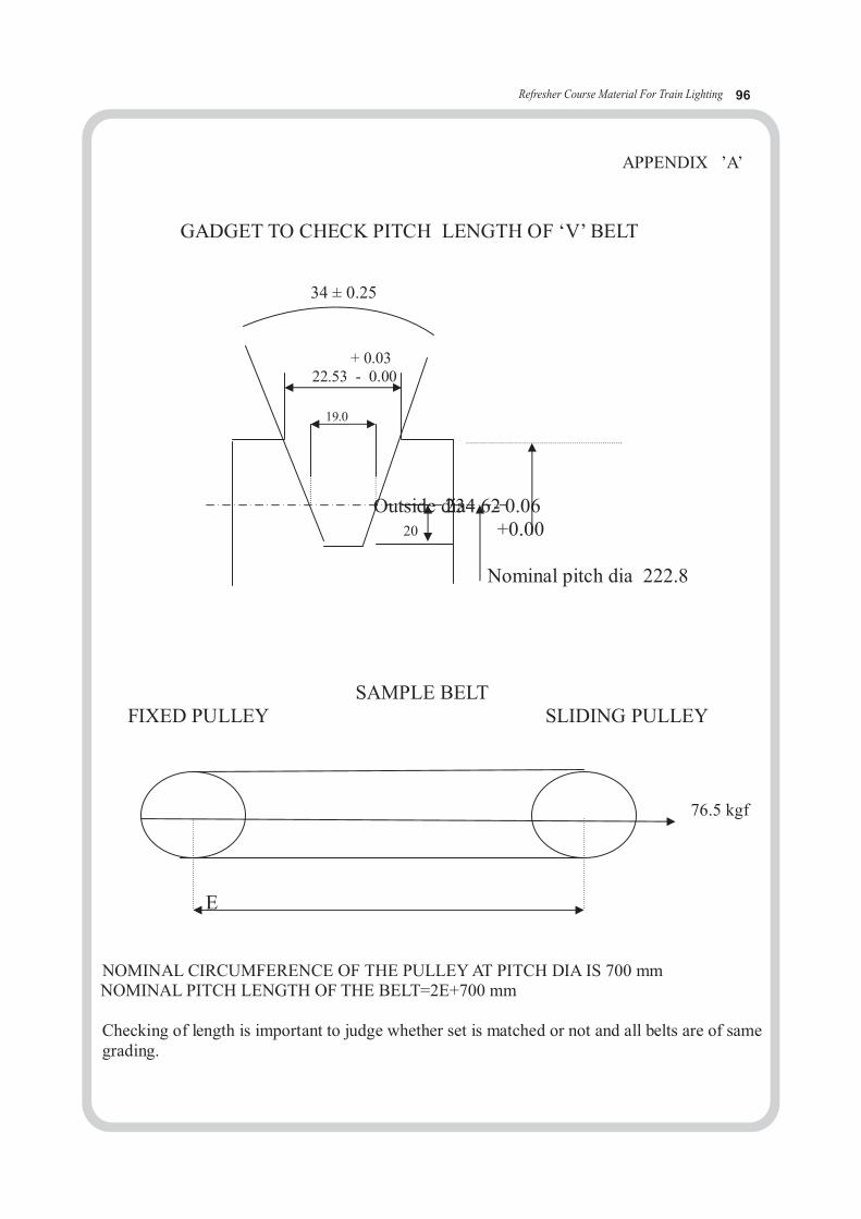
Refresher Course Material For Train Lighting 96
APPENDIX ’A’
GADGET TO CHECK PITCH LENGTH OF ‘V’ BELT
34 ± 0.25
+ 0.03 22.53 - 0.00
19.0
Outside d2 i3a4 . 62- 0.0620 +0.00
Nominal pitch dia 222.8
SAMPLE BELT FIXED PULLEY SLIDING PULLEY
F 76.5 kgf
E
NOMINAL CIRCUMFERENCE OF THE PULLEY AT PITCH DIA IS 700 mm NOMINAL PITCH LENGTH OF THE BELT=2E+700 mm
Checking of length is important to judge whether set is matched or not and all belts are of samegrading.
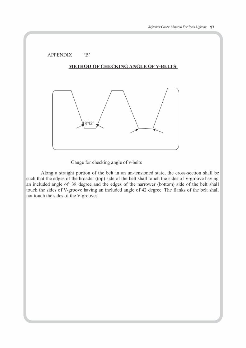
Refresher Course Material For Train Lighting 97
APPENDIX ‘B’
METHOD OF CHECKING ANGLE OF V-BELTS
38º4 2 º
Gauge for checking angle of v-belts
Along a straight portion of the belt in an un-tensioned state, the cross-section shall besuch that the edges of the broader (top) side of the belt shall touch the sides of V-groove havingan included angle of 38 degree and the edges of the narrower (bottom) side of the belt shalltouch the sides of V-groove having an included angle of 42 degree. The flanks of the belt shallnot touch the sides of the V-grooves.

Refresher Course Material For Train Lighting 98
APPENDIX ‘C’
SECTION CHECKING OF V-BELTS
GUAGE FOR CHECKING THE SECTION
Refer specification
Along a straight portion of the belt in an un-tensioned state, the cross-section of the belt shall besuch that when placed in a guage as shown in above figure , it shall not touch the bottom of theguage, the edges of the top width ‘s’ and ‘t’ shall not be higher than the points ‘u’ and ‘v’ at thetop of the template and the guiding mark ‘mn’ on the template shall cut the whole width of thebelt in its upper half.
Note: The pitch width of the belt 19 mm, is the width of the guage at the level of this guidingmark mn, drawn on the gauge.
Refresher Course Material For Train Lighting 99
GOVERNMENT OF INDIAMINISTRY OF RAILWAYS
RESEARCH DESIGNS AND STANDARDS ORGANISATIONMANAK NAGAR, LUCKNOW 226 011
No. EL/ 6.9.9 Dated 1: 2.08.2005
Special Maintenance Instruction No. RDSO/PE/SMI/TL/0030-2005 (Rev. O)
1. TITLE :
Checking of pulleys in V belt drive.
2. OBJECT :
For effective power transmission from axle to alternator, health of pulleys shouldbe good. Maintenance people should know when pulley requires change.
3. INSTRUCTIONS:
WORKSHOP
a) If bottom of the groove is observed shining throughout uniformly, the pulleyshould be replaced.
b) The pulley groove walls should be examined for ovality with the help of asteel scale. If the walls are worn out by more than 0.5 mm the pulley shouldbe replaced.
c) Surface matching between pulley bore and shaft should be not less than 80%.The key in shaft should be fitted properly. Worn key must be replaced byspare EN8 key. If matching of 80% is done, key will not fail.
d) The angle of grooves should be checked by gauges. If angle has increased,the pulley should be replaced. There are different gauges for axle pulley andalternator pulley (See RDSO Drg. No.RDSO/PE/SK/TL/0087-2005 rev.0).
e) Replace rubber pads of axle pulley 100%. Check rubber quality in each lotfrom M&C lab.
f) Ensure gap between two halves of axle pulley to 3.0 ± 0.5 mm and tightening torque should be upto 30 kg - mtr (maximum)g) Life of pulleys is approximately 4 years. Date of replacement should bepunched o n it as well as the alternator number on alternator pulley, as they arematched.h) After removal of alternator for POH, gap between bogie suspension brackets
should b e checked. Excess gap between bogie bracket and alternator suspensionbracket will lead to misalignment of alternator.
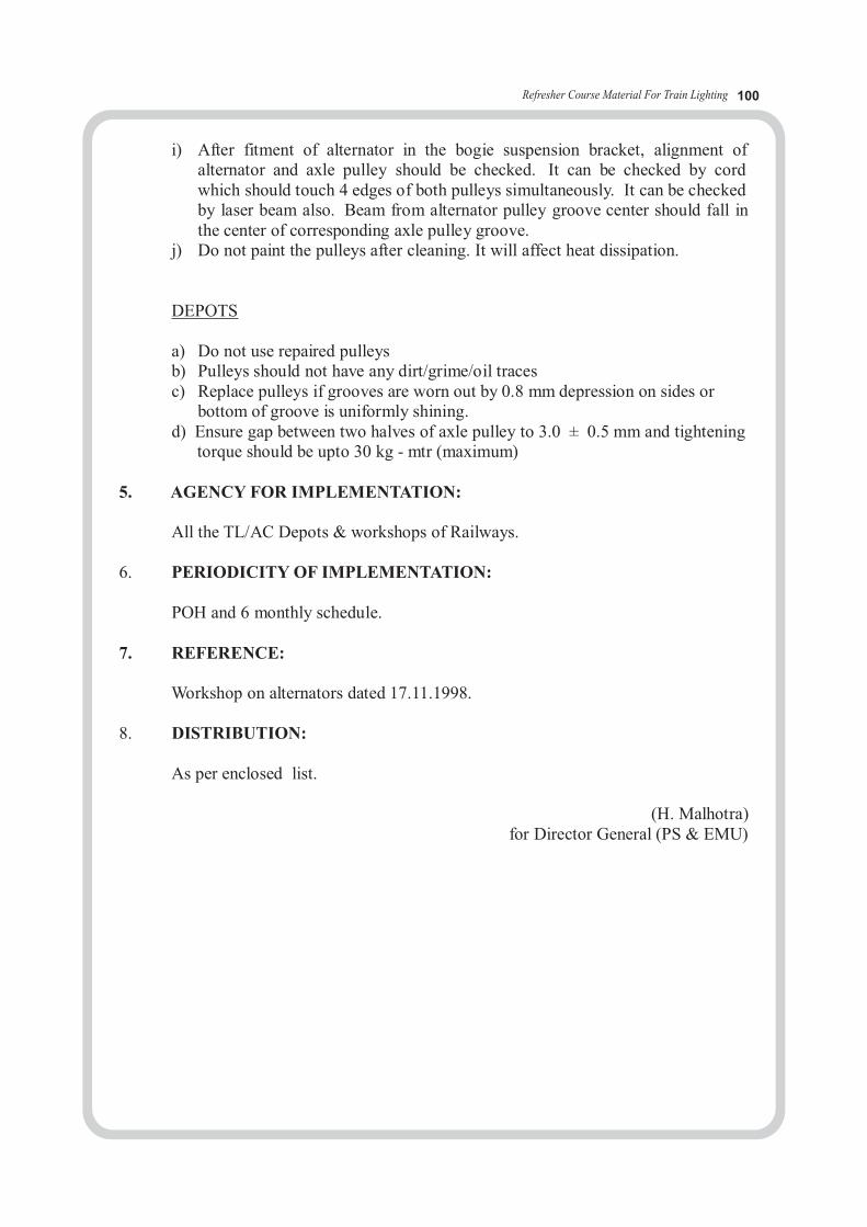
Refresher Course Material For Train Lighting 100
i) After fitment of alternator in the bogie suspension bracket, alignment ofalternator and axle pulley should be checked. It can be checked by cordwhich should touch 4 edges of both pulleys simultaneously. It can be checkedby laser beam also. Beam from alternator pulley groove center should fall inthe center of corresponding axle pulley groove.
j) Do not paint the pulleys after cleaning. It will affect heat dissipation.
DEPOTS
a) Do not use repaired pulleysb) Pulleys should not have any dirt/grime/oil tracesc) Replace pulleys if grooves are worn out by 0.8 mm depression on sides or
bottom of groove is uniformly shining.d) Ensure gap between two halves of axle pulley to 3.0 ± 0.5 mm and tightening torque should be upto 30 kg - mtr (maximum)
5. AGENCY FOR IMPLEMENTATION:
All the TL/AC Depots & workshops of Railways.
6. PERIODICITY OF IMPLEMENTATION:
POH and 6 monthly schedule.
7. REFERENCE:
Workshop on alternators dated 17.11.1998.
8. DISTRIBUTION:
As per enclosed list.
(H. Malhotra)for Director General (PS & EMU)
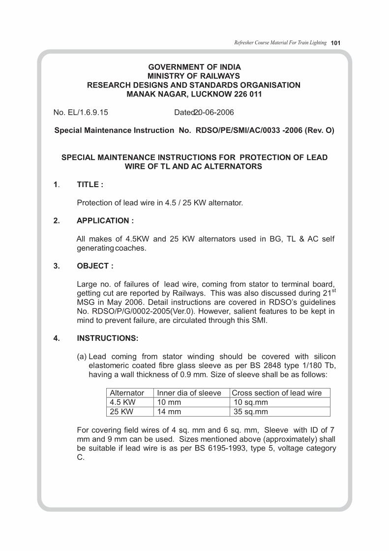
Refresher Course Material For Train Lighting 101
GOVERNMENT OF INDIAMINISTRY OF RAILWAYS
RESEARCH DESIGNS AND STANDARDS ORGANISATIONMANAK NAGAR, LUCKNOW 226 011
No. EL/1.6.9.15 Dated2:0 - 06-2006
Special Maintenance Instruction No. RDSO/PE/SMI/AC/0033 -2006 (Rev. O)
SPECIAL MAINTENANCE INSTRUCTIONS FOR PROTECTION OF LEADWIRE OF TL AND AC ALTERNATORS
1. TITLE :
Protection of lead wire in 4.5 / 25 KW alternator.
2. APPLICATION :
All makes of 4.5KW and 25 KW alternators used in BG, TL & AC selfgenerating coaches.
3. OBJECT :
Large no. of failures of lead wire, coming from stator to terminal board,getting cut are reported by Railways. This was also discussed during 21st
MSG in May 2006. Detail instructions are covered in RDSO’s guidelinesNo. RDSO/P/G/0002-2005(Ver.0). However, salient features to be kept inmind to prevent failure, are circulated through this SMI.
4. INSTRUCTIONS:
(a) Lead coming from stator winding should be covered with siliconelastomeric coated fibre glass sleeve as per BS 2848 type 1/180 Tb,having a wall thickness of 0.9 mm. Size of sleeve shall be as follows:
Alternator Inner dia of sleeve Cross section of lead wire4.5 KW 10 mm 10 sq.mm25 KW 14 mm 35 sq.mm
For covering field wires of 4 sq. mm and 6 sq. mm, Sleeve with ID of 7mm and 9 mm can be used. Sizes mentioned above (approximately) shallbe suitable if lead wire is as per BS 6195-1993, type 5, voltage categoryC.
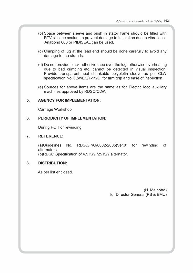
Refresher Course Material For Train Lighting 102
(b) Space between sleeve and bush in stator frame should be filled withRTV silicone sealant to prevent damage to insulation due to vibrations.
Anabond 666 or PIDISEAL can be used.
(c) Crimping of lug at the lead end should be done carefully to avoid anydamage to the strands.
(d) Do not provide black adhesive tape over the lug, otherwise overheatingdue to bad crimping etc. cannot be detected in visual inspection.Provide transparent heat shrinkable polyolefin sleeve as per CLWspecification No.CLW/ES/1-15/G for firm grip and ease of inspection.
(e) Sources for above items are the same as for Electric loco auxiliarymachines approved by RDSO/CLW.
5. AGENCY FOR IMPLEMENTATION:
Carriage Workshop
6. PERIODICITY OF IMPLEMENTATION:
During POH or rewinding
7. REFERENCE:
(a)Guidelines No. RDSO/P/G/0002-2005(Ver.0) for rewinding ofalternators.(b)RDSO Specification of 4.5 KW /25 KW alternator.
8. DISTRIBUTION:
As per list enclosed.
(H. Malhotra)for Director General (PS & EMU)
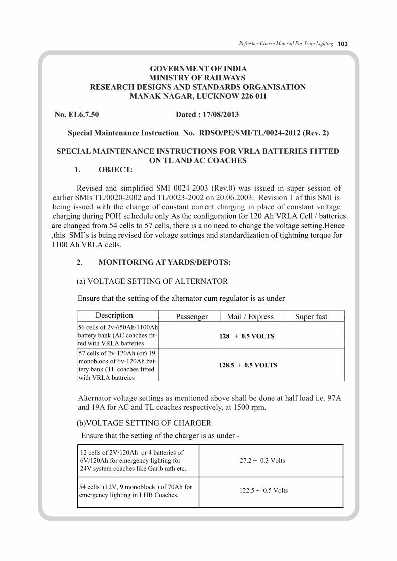
Refresher Course Material For Train Lighting 103
GOVERNMENT OF INDIAMINISTRY OF RAILWAYS
RESEARCH DESIGNS AND STANDARDS ORGANISATIONMANAK NAGAR, LUCKNOW 226 011
No. EL6.7.50 Dated : 17/08/2013
Special Maintenance Instruction No. RDSO/PE/SMI/TL/0024-2012 (Rev. 2)
SPECIAL MAINTENANCE INSTRUCTIONS FOR VRLA BATTERIES FITTEDON TL AND AC COACHES
1. OBJECT:
Revised and simplified SMI 0024-2003 (Rev.0) was issued in super session ofearlier SMIs TL/0020-2002 and TL/0023-2002 on 20.06.2003. Revision 1 of this SMI isbeing issued with the change of constant current charging in place of constant voltagecharging during POH sc .
2. MONITORING AT YARDS/DEPOTS:
Alternator voltage settings as mentioned above shall be done at half load i.e. 97Aand 19A for AC and TL coaches respectively, at 1500 rpm.
hedule only.As the configuration for 120 Ah VRLA Cell / batteries are changed from 54 cells to 57 cells, there is a no need to change the voltage setting.Hence ,this SMI’s is being revised for voltage settings and standardization of tightning torque for 1100 Ah VRLA cells.
(a) VOLTAGE SETTING OF ALTERNATOR
Ensure that the setting of the alternator cum regulator is as under
Description Passenger Mail / Express Super fast56 cells of 2v-650Ah/1100Ah battery bank (AC coaches fit-ted with VRLA batteries
128.5 + 0.5 VOLTS
57 cells of 2v-120Ah (or) 19 monoblock of 6v-120Ah bat-tery bank (TL coaches fitted with VRLA battreies
128 + 0.5 VOLTS
(b)VOLTAGE SETTING OF CHARGER
Ensure that the setting of the charger is as under -
12 cells of 2V/120Ah or 4 batteries of 6V/120Ah for emergency lighting for 24V system coaches like Garib rath etc.
27.2 + 0.3 Volts
54 cells (12V, 9 monoblock ) of 70Ah for emergency lighting in LHB Coaches.
122.5 + 0.5 Volts
Refresher Course Material For Train Lighting 104
( c ) CHECKS DURING TRIP INSPECTION
(i) Check for bypassing of the failed cells.If the cells are found by-passed replace these failed cells immediately with the healthy ones.
(ii) Dust accumilation - if observed , clean with dry cotton cloth. (iii) cell cover or container cracked or bursts , if noted ,replace the cell
with a healthy cell immediately.(iv) In case of battery terminal / cable over heating sign, check for loose
connection at the cell terminal post / cable end. If required replace thecable immediately.
(viii) Do not boost charge the cells for more than 12 hours.
3. QUARTERLY INSPECTION AT YARDS / DEPOTS :
(A) T h e following physical checks shall be made:
(i) Confirm the the 13 Nm ,tightning torque of terminal bolt with torque wrench for four terminal design cell (all makes except exide ) and 22Nm torque with two terminal design cell. (exide).Do not over tight.
(ii) Terminal post corrosion – if observed remove the cable and clean theterminal post and cable lug with brass brush or fine emery paper and applypetroleum jelly.
(B) C h eck open circuit voltage
(a) If the total battery bank open circuit voltage for AC and TL coaches is as under:
AC Coaches : 115.0 Volts or above 57 cells TL Coaches : 117.0 Volts or above 12 cells (24V EL) : 24.5 Volts or above LHB Coaches : 111.0 Volts or above
The following steps shall be followed:
(i) Discharge the battery bank with full coach load for 15 minutes (ii) Note down the individual cell readings after15 minutes while the coach is still connected during the discharge.
(v) Protective lid on safety valve if missing provide new one immediately.(vi) Charge the batteries , preferably for 6-8 hours ,after arrival as per annexure-1 as cells may be partially discharged.(vii) Check for arrival time of the train.If train has arrived late due to heavy detention endroute due to some reasons , charge the coach battery bank as per Annexure-1 to bring up the state of charge of the battery bank before putting the AC coaches again in service.
Refresher Course Material For Train Lighting 105
(iii) If all the cell voltages are 1.98 Volts and above then the cells are in healthycondition – Charge the cells as per the Annexure and the same to be put back into service.
(iv) If some of the cell voltages are less than 1.98 Volts then give boost charging with 2.30 VPC for 12 hrs. by charging them separately with current limited to 20% of rated capacity
(v) The weak cells, which are charged separately must be checked through a discharge at C-10 rate for 30 minutes, the end of discharge voltage should be above 2.0 V. If such a re-charged cell fails to qualify the above test, it should not be replaced back in the coach.
(vi) After performing the discharge test on revived cells, the cells need to be charged at least for 4 hours, prior to fitment in the coach.
(b) If the total battery bank open circuit voltage is as under for AC and TL coaches:
Charge the cells for 12hrs. with 2.30 VPC and then carry out the discharge test as per item No. 3 (a) above.
4. MAINTENANCE AT WORKSHOPS DURING POH:
The below given instructions are to be followed when the coach comes forperiodic overhaul (POH) to the workshop.
(i) Remove all the cell terminal bolts, flat washers, spring washers, inter cellcables, connectors etc. (used insulated tools only)
(ii) Care should be taken to avoid any shorting of cell terminals whileremoving inter cell cable connectors.
(iii) Remove the stacking bolts used for fixing battery modules to battery box /cradle and between the trays.
(iv) Remove the modules with batteries from battery box / cradle by usingsuitable tool.
(v) Clean all the cell terminal posts and inter cell connectors / cable lugs witha brass wire brush to remove any sulphation layer.
(vi) Refix the inter cell connectors /cables and tighten the bolts along with flatand spring washers to specified torque. Replace old spring washers 100%.Quality of new spring washers should be checked as per IS 3063especially permanent set test.
AC coaches : less than 115.0 Volts57 cells TL coaches : less than 117.0 Volts12 cells (24V EL) : less than 24.5 VoltsLHB coaches : less than 111.0Volts
Refresher Course Material For Train Lighting 106
(vii) Discharge the battery bank @ 0.1C and by pass each cell whenever it reach-es end cell voltage of 1.75V.
(viii) Charge the cells at 5% constant current for 24 hours as per table given as under.
(ix) Again give rest to the cells for 6-8 hours.
(x) Discharge the cells as per the table given below at C10 capacity and grad-ually by passing each cell whenever any cell reaches to 1.75V. Duration ofdischarge shall be recorded. If the discharge duration of the cells is foundto be more than 8.5 hrs these can be put back in service after charging.
(xi) If the cells do not give more than 8 hrs of discharge duration beforereaching end cell voltage of 1.75 V, repeat this charging anddischarging cycle once more Cells should not be discharged below1.75 V.
(xii) Even then, if the cells do not give more than 8 hrs. then the cells shall not be put in service.
(xiii) Clean and repaint the modules / cell trays. These may be numbered with the help of stenciling to identify the modules consisting of a battery set for a coach (say Module No./ Set No.e.g.08/01 means 8th module of Set. No.1). The other details like cell number, date of manufacture as indicated on the cell lid and date of fitment shall also be recorded to monitor age-wise performance of the cells.
System rating Application Charge current (CC@ 5% of Ah) in amps
Duration in hours
1100 AH (56 cells)
650AH (56 cells)120AH (57 cells/6V19 monoblock120AH (12 cells/6V 4 monoblock70AH ,12V,9monoblock (54 cells)
AC & TL
AC & TL
TL Application
Emergency lighting
Emergency lighting of LHB Coaches
55
32.5
6
6
3.5
24
24
24
24
24
ApplicationSystem ratingDischarge current@ C10 Capacity
Duration in hours
1100AH 650AH 120AH 70AH
AC & TLAC & TL
TL & Emergency lighting
Emergency lighting LHB
12
65
7
110 10 10 10
10

Refresher Course Material For Train Lighting
Note : All the new VRLA cells shall be given a boost charging if the cells have been lying in depot / workshop for more than 6 months period from the date of manufacture
5. LOADING ON TO THE COACH : (i) After recharge , remove all the inter connectors / cables etc.To avoid shorting of the cells / modules during loading on to the battery box/cradle with care to avoid the physical damages.
(ii) Petroleum jelly is applied over the inter module connectors ,wherever necessary.
(iii) Do not mix ordinary conventional / low maintenance cells with VRLA cells / batteries.
(iv) Put back the trays into the battery box/cradle as per the codition diagram and fix the stacking bolts between the steel tray to battery box/cradle and tray to tray.
(v) Do not mix the cells of different capacities and makes.
6. STORAGE OF CELLS :
The cells shall be stored only at the places,which are not exposed to direct sun light,rain,dust etc.The stored area should be clean ,dry and preferably indoor ambient temperature should be between 15 degrees to 350 c.Preferably,the battery modules shall be stacked in not more than 5 tiers to avoid damage to the modules / modules at the bottom layer. 7. MAINTENANCE PERIODICITY : Trip,Quarterly and POH.
8. APPLICATION :
(i) All types of TL & AC Coaches fitted with VRLA Batteries. (ii) LHB Coaches fitted with VRLS Batteries. (iii) EOG Coaches fitted with VRLA Batteries.
9. AGENCY OF IMPLEMENTATION :
(I) All the zonal railways / production units.
107
VOLTAGE,CURRENT/SETTINGS FOR TERMINAL CHARGING & PRE COOLING OF TL & AC COACHES
a) for 2v,56 cells (AC-1100Ah/650Ah) : Voltage setting 128.8 V, 20 % of the rated charging current (max) capacity i.e. 130 Amp. for 650AH and 220 amps for 1100AH. b) for 2V,57 cells (TL-120Ah) charging : Voltage setting 131 current (max) 20 % of the rated capacity .i.e. 24 Ampsc) for 2V,12 cells (EL-120Ah) charging : Voltage setting 27.6V. 20% of the battery current (max) rated capacity .i.e. 24 Ampsd) for 12V,9 monoblock charging : Voltage setting of 124.2V. 20 % of the rated current (max). capacity.i.e. 14 Amps for 70Ah.
REQUIREMENT OF CHARGING SYSTEM FOR VRLA CELLS
(I) Voltage regulation : Set voltage + 2% (ii) Charging current (max limit ) : 20 % of rated AH capacity. (iii) Voltage / current ripple a) voltage ripple factor : less than 2% b) current ripple factor : less than 2% (iv) Over voltage protection for boost / normal charging. : Trip at 2.35 V/ cell
MINIMUM FACILITY REQUIREMENT AT YARDS / DEPOTS AND WORKSHOPS
At Yards / Depots :i) Constant voltage charger with 20% current limit for full bank of 56/57/54/12 cells.ii) Constant voltage charger with 20% current limit for 1 to 6 cells in step of one.iii)Drive to test alternator / RRU / ERRU.iv) Infrared temperature sensor.v) Torque wrenches with suitable sockets.vi)Adequate charging / pre-cooling points with 70sq.mm copper cable (necessary precautions to be taken to avoid voltage drop during terminal charging. vii)Clamp on meters , multimeters.viii)Trolleys for carrying batteries.ix) Puller for lifting individual cells.
At Work shops :in addition to abovei) Fork liftii) Puller for lifting individual cell.iii) Integrated charge/discharge unit regenarative type,suitable for constant current and constant voltage charging/discharging 220 amp (max).Charging and 110 amp discharging for 1100Ah battery and with suitable current and voltage setting for 120Ah battery.iv) CVCC charger with 20% current limit for 6 to 12 cells in step of one.
Refresher Course Material For Train Lighting 108
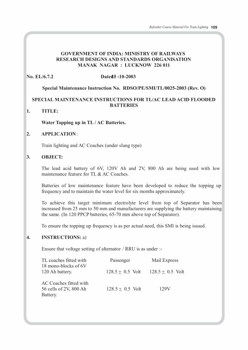
Refresher Course Material For Train Lighting 109
GOVERNMENT OF INDIA: MINISTRY OF RAILWAYSRESEARCH DESIGNS AND STANDARDS ORGANISATION
MANAK NAGAR : LUCKNOW 226 011
No. EL/6.7.2 Dated1:3 - 10-2003
Special Maintenance Instruction No. RDSO/PE/SMI/TL/0025-2003 (Rev. O)
SPECIAL MAINTENANCE INSTRUCTIONS FOR TL/AC LEAD ACID FLOODEDBATTERIES
1. TITLE:
Water Topping up in TL / AC Batteries.
2. APPLICATION :
Train lighting and AC Coaches (under slung type)
3. OBJECT:
The lead acid battery of 6V, 120V Ah and 2V, 800 Ah are being used with lowmaintenance feature for TL & AC Coaches.
Batteries of low maintenance feature have been developed to reduce the topping upfrequency and to maintain the water level for six months approximately.
To achieve this target minimum electrolyte level from top of Separator has beenincreased from 25 mm to 50 mm and manufacturers are supplying the battery maintainingthe same. (In 120 PPCP batteries, 65-70 mm above top of Separator).
To ensure the topping up frequency is as per actual need, this SMI is being issued.
4. INSTRUCTIONS: a)
Ensure that voltage setting of alternator / RRU is as under :-
TL coaches fitted with Passenger Mail Express18 mono-blocks of 6V120 Ah battery. 128.5 + 0.5 Volt 128.5 + 0.5 Volt
AC Coaches fitted with56 cells of 2V, 800 Ah 128.5 + 0.5 Volt 129VBattery.

Refresher Course Material For Train Lighting 110
b) As per theoretical calculations of water loss in hard rubber container battery interval of water topping up should be between 4 to 5 months. For PPCP battery it should be 6-7 months.
c) Initially battery should be topped up to green/ maximum mark on the float guide. Dur-ing monthly inspections position of float should be watched. Water should again be topped up when the float reaches red / minimum mark. Time interval for float to reach red mark from green mark should be noted. Frequent topping up in between simply increases the maintenance workload.
d) If water consumption in a particular cell is more check the follow-
ing: i) Over heating of cellii) Any crack on lid or container.iii) Leakage from vent plug or float guide iv)
Crack in sealing or pinholes.v) If water consumption is more in all the cells, then charging voltage should
be checked and adjusted as per 2 (a).
e) Frequency of topping up should be recorded by the depot. If interval between successivetopping up of water in batteries is less than the interval given in Clause (b) above, then matter should be reported to the manufacturer and RDSO, after satisfying that there is no other reason of excessive water loss as explained in Clause (d).
5. AGENCY FOR IMPLEMENTATION:
All the TL/AC Depots of Railways.
6. PERIODICITY OF IMPLEMENTATION:
During normal maintenanceofCoaches.
7. REFERENCE: RDSO Specification No. ELPS/SPEC/TL09
8. DISTRIBUTION:
As per enclosed list.

Refresher Course Material For Train Lighting 111
GOVERNMENT OF INDIA: MINISTRY OF RAILWAYSRESEARCH DESIGNS AND STANDARDS ORGANISATION
MANAK NAGAR : LUCKNOW 226 011
No. EL/6.7.2 Dated1:0 . 0 6 .2004
Special Maintenance Instruction No. RDSO/PE/SMI/TL/0028 -2004 (Rev. O)
SPECIAL MAINTENANCE INSTRUCTIONS FOR REVIVAL OF LEAD ACIDBATTERIES
1. TITLE:Procedure of Revival of defective cells.
2. APPLICATION :Flooded type Lead acid battery, which is used for TL / AC application.
3. OBJECT:Failure analysis of TL/AC batteries shows that majority of failures of battery areon account of low voltage / low specific gravity of few cells in the set. If this isnot rectified timely then it leads to the dead cells or cell reversal. Many of thefailed cells can be revived and put back into service. Therefore, this SMI is beingissued to guide the Railways for revival of those cells.
4. INSTRUCTIONS (A) FOR LOW VOLTAGE AND LOW
SPECIFIC GRAVITY
(a) In order to avoid this condition of cells, initial charging is ofparamount importance. User must follow the instructions given bysupplier for initial filling with electrolyte and charging. Even aftercomplete duration of charge, if any cell voltage is showing lessthan 2.55 volts, such cells should not be put into service. Supplierto be informed to rectify the cells.
( b) During service if cell open circuit voltage is found less than 1.98 V.then discharge the cell at C10 rate till end cell voltage of 1.8 Vand then charge at C 10 rate.
(c ) In C10 rate discharge, if the cell does not give desired capacity,cycle shall be repeated once. (If cells are sulphated slow ratecharge i.e 50% of C10 rate is recommended to get the desiredcapacity)
(d) If gravity after charging is more than desired value adjust withD.M.water and charge for two hours for proper mixing

(e) If some cells are found lagging (1.98 – 2.00 V) then the cell requiresboost charge at C10 rate for 2-3 hrs.
(f) If cells are stored for more than one month in fully chargecondition then equalizing charge at 2.25V per cell or at the currentof 50% of C10 rate should be given for 5 to 6 hours every month.
(B) FOR DEAD CELL
This happens when plates are highly sulphated. It may be due tocontinuous undercharging or storing the cells in dischargedcondition.
(a) Pour out the electrolyte from the cell.(b) Fill the cell with D.M. Water and allow 2 to 4 hour rest(c) Charge the cell with 50% of C10 rate until voltage reaches to 2.3 to
2.4 V per cell. Voltage will not increase further due to weakelectrolyte.
(d) Dump the originally filled distilled water and fill with final gravityacid recommended at the end of full charge. Charge the batterywith normal charging rate until the voltage reaches to 2.6 to 2.7 Vper cell.Check the gravity if it is less then final specified valueadjust with 1.400 specific gravity, if it is more adjust with D.Mwater and charge for two hour for proper mixing
(e) Conduct C10 discharge, if cell does not give desired capacity(serviced battery capacity shall be above 80%) Cell should not beput in to service.
(C) CELL REVERSAL
This term is normally described as a reverse polarity and occurs when thebattery is discharged deeply below the zero voltage and would not charge fully. Ifdeep discharge occurs no. of times without reaching fully charged conditionbattery shows reverse polarity. These batteries should be taken for revival actionimmediately. Any delay shall reduce the possibility of revival. The followingremedial action is recommended
a. Pour out the electrolyte from the cell.b. Rinse the battery with D.M. water several times and dry.c. Take action as given in ( B )– b, c, d, e.d. If cells are not revived inform the manufacturer, who can take
further remedial action.
5. AGENCY FOR IMPLEMENTATION:All Workshops & Depots.
6. PERIODICITY:On condition basis
Refresher Course Material For Train Lighting 112

Refresher Course Material For Train Lighting 113
Prevention of fire on 110 V DC SG Coaches (SUMMARY)(Ref: RDSO’s LN- EL / TL / 56-1992)
A. Sources and prevention:1. Excessive current: This is the only probable cause of electrical fires on coaches due to inadequate size of cables or any short circuit. Size of cables on different circuit has been standardized as per specification-EL/TL/48.2. Cable size: Aluminum conductor PVC insulated un-sheathed cable to IS: 694 should be used. Flammability test under clause 15.2 of IS: 694-1990(Rev: 3rd).3. Earth checking: Two wire unearthed system –so at least 2 earths one on (+)ve side and one on (-)ve side are necessary to cause short circuit. “Earth testing” should be done by “Earth indicating lamps”.4. Air clearance: Ref:EL/TL/48, clause – 3.9.4) 10 mm - any live part & coach body. 4 mm – opposite polarities5. Damages insulation: 6. Coach insulation test: (By megger with 500 V in J/B).7. Rewiring: Codel life of wiring is 20 yrs. After 15 yrs of service, the coach wire
shall be subjected to simple tests during POH, if required rewiring should be done. Even after 20 yrs, coach is not taken up for wiring; the rewiring will be deferred
only if cable passes the test.8. Battery Box : ICF drawing no: ICF/SK-7-1-306
RDSO’s drawing no- EL / TL-38 (Rev-B) with amendment-1.9. Protective devices: Short circuit is only cause of Electrical fire. So, HRC
fuse / re- wirable fuse have been standardized and HRC / re-wirable fuse shall be procured
from RDSO approved source only. 10. Segregation of (+) & (-) cables: All wires shall be segregated by running them in 2
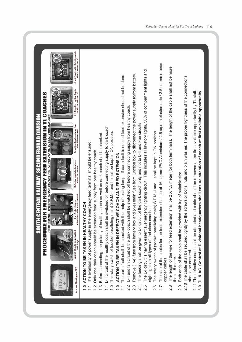
PR
OC
ED
UR
EF
OR
EM
ER
GE
NC
YF
EE
DE
XT
EN
SIO
NIN
TL
CO
AC
HE
S
SO
UT
HC
ENT
RA
LR
AIL
WA
YS
ECU
ND
ERA
BA
DD
IVIS
ION
(As
pe
rTe
ch
nic
al
cir
cu
lar
No
.R
DS
O/P
E/T
L/0
002
(Re
v-
O)
RD
SO
Lr.
No
./
LE
6.9
.12
,D
ate
d2
5.0
6.2
00
9)
+v
e,-v
eM
ark
ing
on
EF
T2
x1.
5m
ts16
mm
sqA
llum
iniu
mca
ble
sho
uld
be
use
dD
efe
cti
ve
co
ach
batt
ery
fus
es
ho
uld
be
rem
ov
ed
Defe
cti
ve
Co
ach
ma
in-v
efu
se
sh
ou
ldb
ere
mo
ved
LII
Cir
cu
itin
He
alt
hy
Co
ach
sh
ou
ldb
esw
itch
ed
off
LII
and
Fan
circ
uit
inD
efec
tive
coac
hsh
ou
ldb
esw
itch
edo
ffC
ab
les
sh
ou
ldb
ee
dd
vi
rop
wit
hL
ug
s
1.0
AC
TIO
NT
OB
ETA
KE
NIN
HE
ALT
HY
CO
AC
H1.1
Th
eava
ilabili
tyo
fpow
er
supply
inth
eem
erg
en
cyfe
ed
term
ina
lshould
be
en
sure
d.
1.2
Only
one
dark
coa
chsh
ould
be
ext
ended
feed
supply
from
on
ehealth
yoac
ch.
1.3
Befo
reco
nnect
ing,
the
pola
rity
ofhealth
yco
ach
as
well
as
dark
coa
chsh
all
be
check
ed.
1.4
L-I
Ici
rcuit
ofth
ehealth
yco
ach
shall
be
switc
he
do
ffbefo
reco
nnect
ing
supply
todark
oac
ch
.
1.5
Th
ero
tary
switc
hof(s
ock
etpara
llelin
gm
ain
)S
.P.M
.-Iand
IIsh
all
be
keptin
ON
posi
tion.
2.0
AC
TIO
NT
OB
ETA
KE
NIN
DE
FE
CT
IVE
CO
AC
HA
ND
FE
ED
OIN
SE
TX
EN
.2.1
Th
eeart
hfa
ult
shall
be
che
cked
with
the
help
ofte
stin
gla
mp.
Ifeart
hfa
ult
isnotic
ed
feed
ext
en
sion
should
notb
edone.
2.2
L-I
Ia
nd
fan
circ
uit
ofth
edark
coa
chsh
all
be
switc
hed
off
befo
reco
nnect
ing
supply
fro
mhealth
yoac
ch.
2.3
Re
mo
vev
+(e)
fuse
fro
mbattery
box
and
v-(e
)m
ain
fuse
from
junct
ion
bo
xto
dis
connect
the
pow
er
supply
to/fro
mbattery
.
2.4
Th
efe
edin
gsh
all
be
giv
en
toL
-Ici
rcu
ito
fth
ed
ark
coach
only
and
notto
L-I
Iand
Fa
nci
rcu
its
2.5
Th
eL-I
circ
uit
ish
avi
ng
ess
entia
l/em
erg
ency
lightin
gci
rcuit.
This
incl
udes
all
lava
tory
lights
,5
0%
ofco
mpart
mentlig
hts
an
dnig
ht
lights
inall
types
ofIIn
dcl
ass
coach
es.
2.6
Th
ero
tary
switc
ho
f(s
ock
etp
ara
llelin
gm
ain
)S
.P.M
.-Iand
IIsh
all
be
keptin
ON
posi
tion.
2.7
Th
esi
zeo
fth
eca
ble
sfo
rth
efe
ed
ext
ensi
on
shall
be
of16
sq.m
mP
VC
Alu
min
ium
/2
.5sq
.mm
ela
stom
etr
ic/2.5
sq.m
me-b
eam
copper
cable
s.
2.8
Th
ele
ngth
ofth
ew
ire
for
fee
de
xte
nsi
on
shall
be
2X
1.5
me
ter
(for
bo
thte
rmin
als
).T
he
length
ofth
eca
ble
shall
no
tbe
more
than
1.5
mete
r.
2.9
Bo
thends
ofth
eca
ble
shall
be
pro
vided
with
lug
ofsu
itable
size
.
2.1
0T
he
cable
shall
be
secu
red
tightly
by
the
scre
ws
or
bolts
,nuts
an
dpla
inw
ash
er.
The
pro
per
tightn
ess
ofth
eco
nnect
ions
should
be
ensu
red.
2.1
1T
he
defe
ctiv
eco
ach
shall
be
attended
and
cable
should
be
rem
ove
datth
efir
sta
vaila
ble
opport
unity
by
TL
sta
ff.
3.0
TL
&A
CC
on
tro
la
tD
ivis
ion
alh
ea
dq
uart
ers
sh
all
en
su
rea
tte
nti
on
of
co
ac
ha
tfi
rst
avail
ab
leo
pp
ort
un
ity.
Refresher Course Material For Train Lighting 114
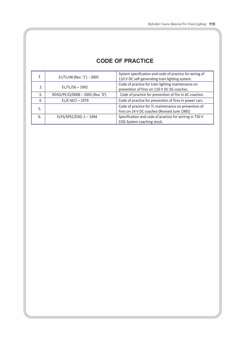
Refresher Course Material For Train Lighting 115
CODE OF PRACTICE
EL/TL/48 (Rev. ‘1’) - 2005 System specification and code of practice for wiring of 110 V DC self-generating train lighting system.
2. EL/TL/56 – 1992 Code of practice for train lighting maintenance on prevention of fires on 110 V DC SG coaches.
3. RDSO/PE/O/0008 – 2005 (Rev. ‘0’) Code of practice for prevention of fire in AC coaches.
4. EL/E-M/1 – 1979 Code of practice for prevention of fires in power cars.
5. Code of practice for TL maintenance on prevention of fires on 24 V DC coaches (Revised June 1985)
6. ELPS/SPEC/EOG-1 – 1994 Specification and code of practice for wirirng in 750 V EOG System coaching stock.
1
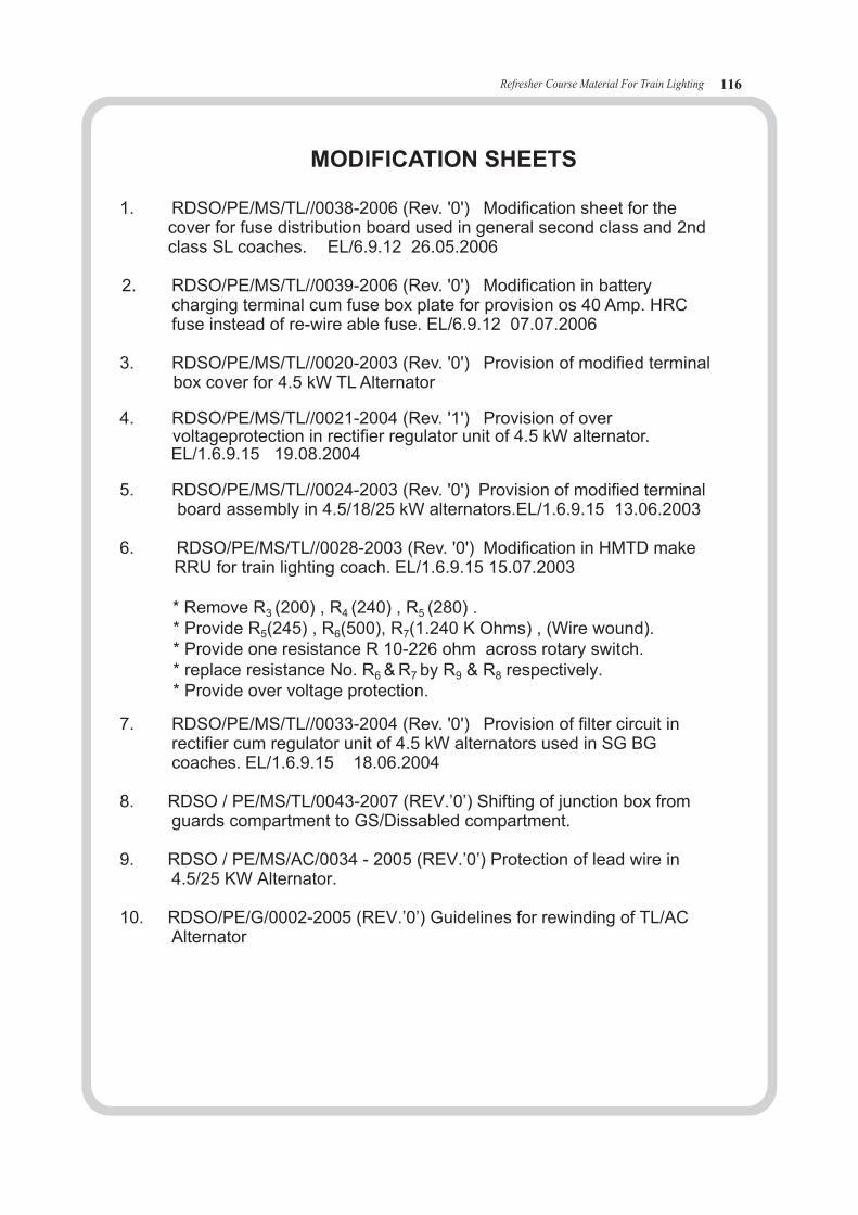
MODIFICATION SHEETS
1. RDSO/PE/MS/TL//0038-2006 (Rev. '0') Modification sheet for the cover for fuse distribution board used in general second class and 2nd class SL coaches. EL/6.9.12 26.05.2006
2. RDSO/PE/MS/TL//0039-2006 (Rev. '0') Modification in battery charging terminal cum fuse box plate for provision os 40 Amp. HRCfuse instead of re-wire able fuse. EL/6.9.12 07.07.2006
3. RDSO/PE/MS/TL//0020-2003 (Rev. '0') Provision of modified terminal box cover for 4.5 kW TL Alternator
4. RDSO/PE/MS/TL//0021-2004 (Rev. '1') Provision of over voltageprotection in rectifier regulator unit of 4.5 kW alternator. EL/1.6.9.15 19.08.2004
5. RDSO/PE/MS/TL//0024-2003 (Rev. '0') Provision of modified terminal board assembly in 4.5/18/25 kW alternators.EL/1.6.9.15 13.06.2003
6. RDSO/PE/MS/TL//0028-2003 (Rev. '0') Modification in HMTD make RRU for train lighting coach. EL/1.6.9.15 15.07.2003
* Remove R3 (200) , R4 (240) , R5 (280) . * Provide R5(245) , R6(500), R7(1.240 K Ohms) , (Wire wound). * Provide one resistance R 10-226 ohm across rotary switch. * replace resistance No. R6 & R7 by R9 & R8 respectively. * Provide over voltage protection.
7. RDSO/PE/MS/TL//0033-2004 (Rev. '0') Provision of filter circuit in rectifier cum regulator unit of 4.5 kW alternators used in SG BG coaches. EL/1.6.9.15 18.06.2004
8. RDSO / PE/MS/TL/0043-2007 (REV.’0’) Shifting of junction box from guards compartment to GS/Dissabled compartment.
9. RDSO / PE/MS/AC/0034 - 2005 (REV.’0’) Protection of lead wire in 4.5/25 KW Alternator.
10. RDSO/PE/G/0002-2005 (REV.’0’) Guidelines for rewinding of TL/AC Alternator
Refresher Course Material For Train Lighting 116

Refresher Course Material For Train Lighting 117
ELEC - 1.19
CASE STUDIES ON FAILURE

Refresher Course Material For Train Lighting 118
The Case studies are enumerated based on the failures generally encountered en-route and action to be taken are detailed below:
Failures Causes Action to be taken
1. Lights and fans not working
2. All lamps are fused in a coach.
3. All fans are not working.
4. Partial fans and lights are not working.
5. Individual fan is not working.
6. Individual light is not working.
7. Lights are found dim during halts and bright during run.
8. Lights flicker during run.
9. Complete coach is in dark at halt.
10. A few coaches in a row are dim or dark in the train.
Negative fuse might have blown off. Battery fuse might have blown off.
Over voltage developed by the Alternator.
Fan- circuit rotary switch maybe in OFF position or defective.Fan circuit fuse may be blown off.
Commutator may be dirty. Brush may be small in size. Fan carbon and spring tension may be inadequate or carbon spring may be defective.
Lamp may be fused. Holder may be defective.
Batteries might have got discharged.
Loose connection in Battery Box or in RJB.
Batteries might have discharged or battery fuse might have blown off
Negative fuse might have blownoff.
Fan sub- circuit and light sub-circuit fuses may have blown off in DFB.
Replace battery fuse and
negative fuse with correct
size fuses.
Operate fan rotary switch in
Junction box, if defective by pass the
switch. Replace the fan circuit
fuse.
Replace fuses if blown.
Replace the fused lamps
Replace the fused lamp.Replace the defective holder.
Clean the commutator with 'O' grade stand paper. Replace the brush and spring.Check the connecting leads.
Check the generation of Alternator
during run.
Tight the loose connections.
Replace the battery fuse if blown off.
Provide through feeding if batteries are
deeply discharged by removing the
negative fuse in RJB of defective coach.
Replace the negative fuse in the
dim or dark coaches.
Remove the main negative fuse in RJB and provide through feeding from adjacent coach. If time permits check the voltage setting in RRU.

Refresher Course Material For Train Lighting 11911911
11. Fan is noisy.
12. Sparking at the fan.
13. Fan is giving inadequate air.
14. Fan is slow during halts but is fast on run.
15. Coach lights and fans in Burnt/Smoke Condition & Coach is in dark condition.
Blade or cage guard may be loose or defective bearing.
Fan commutator may be pitted. Carbon brush may be loose. Spring tension may be inadequate. Brush may not be properly bedded. Fan commutator – cover may be miss-ing.
Carbon brush may be small.Spring tension may be inadequate due to damaged spring.Fan blade may be improper.
Batteries might have deeplydischarged
Tighten fan blade or cage guard.
If bearing is defective isolate the defective fan.
Clean the commutator. Adjust the spring tension, do proper bedding of brush. Adjust the blade angle.Provide fan commutator cover if missing.
Replace the carbon if worn out.Replace springs, if damaged.Adjust the blade angle.
Charge the battery at terminal
maintenance depot and station
en-route having a halt more than
15 minutes.
Over generation (Due to defective regulator)
16. Smoke emission from Coach lights / fans.
Over generation (Due to defective regulator)
Cut the regulator field +VE & -VE wires, which are coming from Alternator or remove Negative main fuse link and battery fuse and then connect through feeding from adjacent coach.
17. Smoke in Individual Fans /Lights.
Burning of fans winding or short circuit in Inverter of FTL.
Isolate the Fan/light.
18. Spark in Junction Boxes Loose fitment of HRC/ Rewirable fuses in Main/Distribution Junc-tion boxes.
Tighten or replace the fuses.
19. Smoke from battery box Loose connections.Low water level.Cell Container Breakage.
First Extinguish smoke/fire if
found. Then remove battery
+ve or –ve fuses and connect
through feedingfrom
adjacent coach.
20. Smoke emission from belts. Alternator Pulley Jam Cut the belts and connect through feeding from Adjacent coach.


![$Tl]DH - E-Journal UIN Jakarta](https://static.fdokumen.com/doc/165x107/63260c1d051fac18490d904c/tldh-e-journal-uin-jakarta.jpg)

