BACHELOR'S THESIS Obstacle alert and collision avoidance ...

*Corresponding author. Tel.: #39-06-44585297; fax: #39-06-4884852.E-mail address: [email protected] (Paolo Casini).
International Journal of Non-Linear Mechanics 37 (2002) 117}133
Friction oscillator excited by moving base and colliding witha rigid or deformable obstacle
Ugo Andreaus*, Paolo Casini
Dipartimento di Ingegneria Strutturale e Geotecnica, Facolta% di Ingegneria, Universita% degli Studi di Roma **La Sapienza++,via Eudossiana 18, 00184 Roma, Italy
Abstract
The dynamics of non-smooth oscillators has not yet su$ciently been investigated, when damping is simultaneouslydue to friction and impact. Because of the theoretical and practical interest of this type of systems, an e!ort is made in thispaper to lighten the behaviour of a single-degree-of-freedomoscillator colliding with an obstacle and excited by a movingbase, which transfers energy to the system via friction. The di!erent nature of discontinuities arising in the combinedproblem of friction and impact has been recognized and discussed. Closed-form solutions are presented for both transientand steady-state response, assuming Coulomb's friction law and a rigid stop-limiting motion. Furthermore, a deformable(hysteretic) obstacle has been considered, and its in#uence on the response has been investigated. � 2001 ElsevierScience Ltd. All rights reserved.
Keywords: SDOF oscillator; Impact; Contact; Coulomb friction; Switch-model
1. Introduction
Friction and impact oscillators are popular sub-jects of analysis. Such interest can be explained intwo ways. First of all, they appear in everyday lifeas well as in engineering systems, thus their study isof considerable practical value. In the second place,the complex dynamics exhibited by these simplenon-smooth systems is a good testing bench fornon-linear theories [1]: one of the most importanttopic is the qualitative study of these systems, in-cluding the stability and bifurcation analysis andthe explanation of chaotic regimes.
Friction-induced vibration, chatter and squealcause serious problems in many industrial applica-
tions, including turbine blade joints, robot joints,electric motor drives, water-lubricated bearings inships and submarines, wheel/rail contact of masstransit systems, machine tool/work piece systemsand brake systems [2}6]. These forms of vibrationare undesirable because of their detrimental e!ectson the operation and performance of mechanicalsystems. They can cause excessive wear of compo-nents, surface damage, fatigue failure and noise[2,3].
Impact oscillators arise naturally in many applica-tions such as impact print hammers [7], gear boxes,heat exchangers, aeroplane wings, o!shore struc-tures, impact dampers of turbine buckets, springhammers and other vibro-impact systems [8}12].
The combined in#uence of friction and impacton damping is exhibited by various kind of struc-tures, namely, bolted connections vibrating perpen-dicularly to the bolt axis [13], pin-jointed trusses
0020-7462/01/$ - see front matter � 2001 Elsevier Science Ltd. All rights reserved.PII: S 0 0 2 0 - 7 4 6 2 ( 0 0 ) 0 0 1 0 1 - 3

Fig. 1. Mechanical system: (a) Friction}impact SDOF oscil-lator; (b) non-smooth Coulomb friction law; (c) switch model.
[14], measuring devices, hydro-mechanicaland pneumatic servomechanisms [8]. The dead-band and friction characteristics in this typeof devices can diminish the precision of motionand introduce non-linearities; thus the dynamicbehaviour of these structures can be dramaticallyaltered.
However, the combined e!ect of dry friction andimpact for the simple oscillator has received littleattention [13,15] to the authors' knowledge, eventhough many practical systems in engineering andscience include a combination of these two phe-nomena. This de"ciency is probably caused by thecomplexity of these systems, which results from thesingularities in the motion. These singularities inmotion result in intermittent sticking, which iscaused by dry friction and by the discontinuities inthe velocity and acceleration due to impacting;thus, the discontinuities due to combined frictionand collision will be classi"ed and discussed inSection 2.5, because these circumstances have notyet su$ciently been investigated.
On the other hand, the single-degree-of-freedom(SDOF) system is very important for the under-standing of simple systems in which there are justtwo impacting components (the body and the ob-stacle) and it is to be hoped that much of thebehaviour will also be seen in more complex sys-tems. In any case, the analysis of large complicatedsystems is not likely to proceed very far without theconceptual insights that simpler systems can pro-vide.
The aim of this paper is to study the motion ofa SDOF oscillator subjected to dry friction impact-ing on a unilateral motion limiting stop, rigid ordeformable (Fig. 1a), where friction is governed bythe Coulomb's law, including static and kineticcoe$cients of friction �
�and �
�(Fig. 1b). The
oscillator is excited by a moving base with constantvelocity. The motion-limiting stop has been "rstassumed to be rigid (Section 4), because sucha model is simultaneously simple and su$cientlyaccurate. However, it does not allow to simulatethe actual dissipative character of the mass}ob-stacle interaction, but via a priori "xed coe$cientof restitution. Thus, in order to have a deeperinsight into the real interaction phenomena, adeformable (hysteretic) stop has been adopted
(Section 5), and the results are compared with thoseof the rigid stop model in Section 5.
Closed-form solutions are found for the rigidstop of both transient and steady motion, withattention to the in#uence of the base velocity on themotion. Furthermore a comparison is performedwith the response obtained via the hysteretic stopmodel; to this end the switch-model procedure isfollowed, which has been proposed in [16] (Fig. 1c).
2. Model of a SDOF &friction-impact' oscillator
2.1. Generalities
The mechanical model of the friction-impactoscillator excited by a moving base and limited bya stop is shown in Fig. 1a. A mass m is connectedvia a linear spring of sti!ness k to a "xed support,and its position at the time � with respect to theunstressed position is denoted by x(�). The masscan slip on a rough belt which moves with constantvelocity �
�and can collide with an obstacle;
moreover, the mass is subjected to a constant com-pressive force F
�*0 normal to the surface. Energy
is transferred from the moving base (the belt) to thediscrete spring-mass oscillator via the friction force,and it is dissipated by possible impact. For the sakeof simplicity the impactless model will be presented"rst; then the combined friction-impact model will
118 U. Andreaus, P. Casini / International Journal of Non-Linear Mechanics 37 (2002) 117}133

Stick: Stick to slip transition: Slip:
�x��(�
�
F�
kand �u�
��)u� H
�, �x
��*�
�
F�
kand �u�
��)u� H
�, �u�
��'u� H
�,
x��"
���
, x��"x
�, x�
�"x
�,
x��"
uR�
�, x�
�"!x
�#
��F�
ksign(x
�), x�
�"!x
�#
��F
�k
sign(u��).
(7)
be formulated in order to characterize the threemodes of motion: stick, slip, and impact.
2.2. Friction-impactless model
The interaction between the mass and the slidingsurface is described by a Coulomb's friction law��(u�
�) (Fig. 1b); u�
�is the relative velocity between
mass and base, i.e. u��"�
�!x�(�). In the following
� and t denote, respectively, the actual and thenon-dimensional time, whereas the prime and theoverdot indicate di!erentiation with respect to� and t, respectively. During the slip mode theequation of motion reads
mx(�)#kx(�)!��(u�
�)"0 (1)
and it can be normalised using
t"��, �"�k
m,
�(�) "
d(�)dt
"
(�)��
,
u��"�
�!�x� . (2)
From (1) and (2) it follows
xK (t)#x(t)!��(u�
�)
k"0. (3)
During the slip mode (u��O0),
��(u�
�)"�
�F�sign(u�
�) (4)
holds, whereas for the stick mode (u��"0) the fric-
tion force balances the elastic restoring force
��(0)"kx(t) (5)
and is bounded by
���(0)�)�
�F
�. (6)
The equation of motion (Eq. (3)), based on theCoulomb's friction law (4)}(6), will be solved inclosed form in order to characterize the impactlessmotion (Section 3): the same equations will be thecore for studying the friction oscillator collidingwith a rigid obstacle (Sections 2.3 and 4).
Aiming to compare closed-form solutions of therigid stop friction oscillator with the deformablestop (Sections 2.4 and 5) required a numerical pro-cedure to be cast; thus the Coulomb's friction lawhas to be reformulated in a manner suitable fornumerical integration: this purpose can be "tted bythe so-called switch model [16] which will be out-lined below, under the assumption of x(x� , i.e.impactless motion; the existence of a deformableobstacle will be introduced in the equation ofmotion in Section 2.4.
As usual, a state vector (x�, x
�) gathering the
state variables of displacement and velocity can bede"ned so that the non-autonomous second ordersystem, Eq. (3), is equivalent to a "rst-order auton-omous system. After the switch model [16], inorder to writing down the equation of motion wehave to distinguish whether the mass sticks or slips.Thus, a region of small velocity is de"ned as�u�
��)u� H
�with u� H
�;�
�(Fig. 1c): the system is con-
sidered to be in the slip mode if the relative velocitylies outside this narrow stick band; if the relativevelocity lies within the stick band and if the staticfriction force, needed to make equilibrium with theapplied force, exceeds the breakway frictionforce �
�F
�, the system is considered to be in
transition from stick to slip. If the mass sticksthen �u�
��)u� H
�, and its position x
�grows linearly
in time until the external force �!kx�� exceeds
the static friction ��F
�. At this stage, i.e. if �u�
��)u� H
�and �!kx
��*�
�F
�, stick to slip transition
takes place; thus the governing equations read asfollows:
U. Andreaus, P. Casini / International Journal of Non-Linear Mechanics 37 (2002) 117}133 119

2.3. Friction model with rigid stop
The mass may come into contact with theobstacle. This process is called an impact andinvolves unsteady changes in the velocities. Theobstacle undergoes a deformation at the impactwith the mass. The assumption of rigid stop consti-tutes an oxymoron (alliance of two incompatiblethings) [12], because one should admit an obstacledeformation to take place due to the in"nitelystrong impact forces in an in"nitely small time.Therefore, during the impact the assumption ofrigid constraint must be locally dropped.
Newton recognized that any collision involvesa loss of mechanical energy due to either an irre-versible deformation, internal viscous or frictionaldissipation, and/or propagation of waves in theparticipating bodies. He attempted to account forthis loss by inclusion of an empirical coe$cient ofrestitution, 0)r)1, that is de"ned as the absolutevalue of the ratio between the velocities immediate-ly after the detachment and immediately before thecontact between the mass and the stop: the valuer"1 de"nes the &elastic' impact oscillator wherethere is no dissipation in the system.
The complete Coulomb friction}impact model isgoverned by Eq. (3), when x(x� (impactlessmotion), whereas the condition
x� �"!rx� � if x"x� and x� '0 (8)
should be added in order to account for the velocitydiscontinuity at the impact instant, i.e. when thedisplacement x attains the clearance x� . In Eq. (8)x� � represents the velocity immediately after thedetachment and x� � the velocity immediately beforethe contact between the mass and the stop.
2.4. Friction model with hysteretic stop
A deformable obstacle requires a more complexrepresentation, in order to characterize the contactforces arising during the mass}stop interaction.The adopted model of hysteretic stop [17] allowsto represent the contact force in terms of closure byusing the concept of envelope and loading curves,on the basis of physical experimentation.
The (lower and upper) envelope curves represent-ing the force-closure contact laws under repeated
loadings are [17}19]
�(u
�)"k
��;
�
u�
u�!;
�
, (9)
x'x� , u�"x�!x,
x)x� , u�"0, (10)
where u�()0) is the contact closure (i.e. the overlap
between the impacting mass and the obstacle), �is
the compressive force, k��
the initial sti!ness (i.e. foru�"0) and ;
�(;
�(0) the limit overlap, with
0'u�*;
�. The values of k
��and ;
�uniquely
de"ne the hyperbolic normal force vs. closure curvecharacterising the behaviour of the deformablestop. Under increasing compressive force (compres-sion phase, upper solid line in Fig. 2a) the curvesbecome gradually steeper. There is also a limitingcompressive strength, �
�, for the stop. If the com-
pressive strength is exceeded, then local failureoccurs.
On decompression (expansion phase, lower solidline in Fig. 2a), the motion-limiting stop showsmarkedly hysteretic behaviour. The unloading con-tact force envelope curves for the stop are alsohyperbolic. The behaviour for the decompressionphase is governed by Eq. (9) as for the compressionphase, assuming an initial sti!ness (i.e. for u
�"0)
smaller than that one in compression; thus, thecompression and expansion envelope curves can berepresented by the following equations (see Eq. (9)):
��(u
�)"k�
��;
�
u�
u�!;
�
,
��(u
�)"k�
��;
�
u�
u�!;
�
,
k���
)k���. (11)
The quantities k���
and k���
are the initial sti!nessesof the compression and expansion envelope curvesrespectively; for x)x� separation occurs andhence contact force drops to zero. The compressionand expansion envelope curves are limit curves,whose analytical form is to be determined by im-posing to cross the origin with given sti!ness and totend asymptotically to the limiting overlap.
120 U. Andreaus, P. Casini / International Journal of Non-Linear Mechanics 37 (2002) 117}133
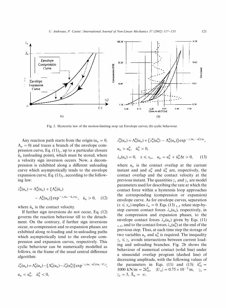
Fig. 2. Hysteretic law of the motion-limiting stop: (a) Envelope curves; (b) cyclic behaviour.
Any reaction path starts from the origin (u�"0,
�"0) and traces a branch of the envelope com-
pression curve, Eq. (11)�, up to a particular closure
u��(unloading point), which must be stored, where
a velocity sign inversion occurs. Now, a decom-pression is exhibited along a di!erent unloadingcurve which asymptotically tends to the envelopeexpansion curve, Eq. (11)
�, according to the follow-
ing law:
���(u
�)"�
�(u
�)#[�
�(u�
�)
!��(u
�)] exp��� ������ � �� , u�
�'0, (12)
where u��is the contact velocity.
If further sign inversions do not occur, Eq. (12)governs the reaction behaviour till to the detach-ment. On the contrary, if further sign inversionsoccur, re-compression and re-expansion phases areexhibited along re-loading and re-unloading pathswhich asymptotically tend to the envelope com-pression and expansion curves, respectively. Thiscyclic behaviour can be numerically modelled asfollows, in the frame of the usual central di!erencealgorithm:
���(u
�)"�
�(u
�)![�
�(u
�)!��
�(u�
�)] exp��������
�� ������ ,
u�(u�
�, u� �
�(0,
���(u
�)"�
�(u
�)#[��
�(u�
�)!�
�(u
�)] exp��� �����
�� �� ,
u�'u�
�, u� �
�'0,
��(u
�)"0, x)x� , u
�"u�
�#u� �
� t'0, (13)
where u�
is the contact overlap at the currentinstant and and u�
�and u� �
�are, respectively, the
contact overlap and the contact velocity at theprevious instant. The quantities �
�and �
�are model
parameters used for describing the rate at which thecontact force within a hysteresis loop approachesthe corresponding (compression or expansion)envelope curve. As for envelope curves, separation(x)x� ) implies �
�"0. Eqs. (13)
���relate step-by-
step current contact forces ��(u
�), respectively, in
the compression and expansion phases, to theenvelope contact forces �
�(u
�) given by Eqs. (11)
���, and to the contact forces �
�(u�
�) at the end of the
previous step. Thus, at each time step the storage oftwo variables u
�and u�
�is required. The inequality
��)�
�avoids intersections between current load-
ing and unloading branches. Fig. 2b shows thebehaviour of numerical contact (solid line) undera sinusoidal overlap program (dashed line) ofdecreasing amplitude, with the following values ofthe parameters in Eqs. (11) and (13): k�
��"
1000 kN/m"2k���, �;
��"0.75�10��m, �
�"
��"5, �
�"R.
U. Andreaus, P. Casini / International Journal of Non-Linear Mechanics 37 (2002) 117}133 121
Stick: Stick to slip transition: Slip:
�!x�!
��k �(�
�
F�
kand �u�
��)u� H
� �!x�!
��k �*�
�
F�
kand �u�
��)u� H
�,
�u���'u� H
�
x��"
���
,
x��"
u��
�,
x��"x
�,
x��"!x
�!
��k
#
��F
�k
sign�x�#
��k �,
x��"x
�,
x��"!x
�!
��k
#
��F�
ksign(u�
�),
(14)
The presence of a deformable obstacle will mod-ify the equation of motion as follows:
where ��is given by Eqs. (13). It should be noted
that:
x)x�N��"0,
x'x�N��'0.
(15)
It seems to be reasonable to de"ne a criterion ofequivalence between the oscillator with hystereticstop, and the impact oscillator, as argued in [17].Such an equivalence can be stated by consideringan impact oscillator (see Section 2.3), where therigid stop is characterised by a coe$cient of restitu-tion r equal to the value:
r��k���
k���
.(16)
De"ning equivalent impact oscillator allows to usea model widely studied from the analytical point ofview, on the basis of a coe$cient of restitution notgiven a priori, but obtained via an analytical inter-pretation of physical behaviours.
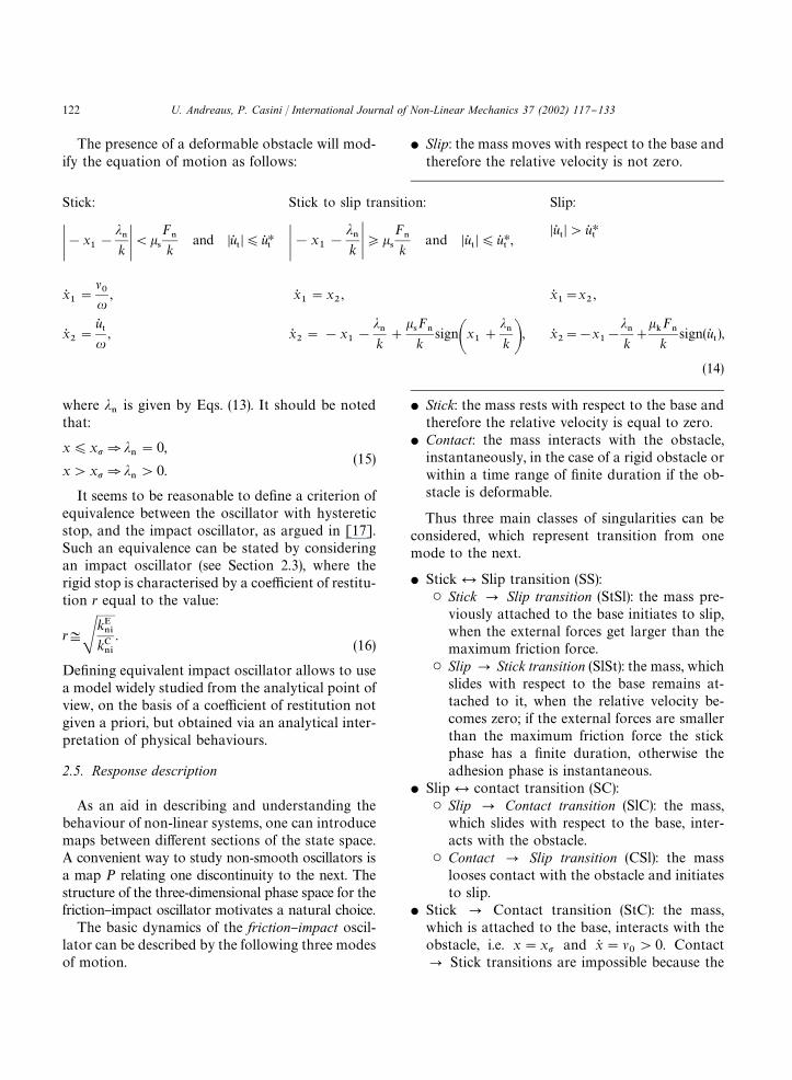
2.5. Response description
As an aid in describing and understanding thebehaviour of non-linear systems, one can introducemaps between di!erent sections of the state space.A convenient way to study non-smooth oscillators isa map P relating one discontinuity to the next. Thestructure of the three-dimensional phase space for thefriction}impact oscillator motivates a natural choice.
The basic dynamics of the friction}impact oscil-lator can be described by the following three modesof motion.
� Slip: the mass moves with respect to the base andtherefore the relative velocity is not zero.
� Stick: the mass rests with respect to the base andtherefore the relative velocity is equal to zero.
� Contact: the mass interacts with the obstacle,instantaneously, in the case of a rigid obstacle orwithin a time range of "nite duration if the ob-stacle is deformable.
Thus three main classes of singularities can beconsidered, which represent transition from onemode to the next.
� Stick � Slip transition (SS):� � Stick P Slip transition (StSl): the mass pre-
viously attached to the base initiates to slip,when the external forces get larger than themaximum friction force.
� � Slip P Stick transition (SlSt): the mass, whichslides with respect to the base remains at-tached to it, when the relative velocity be-comes zero; if the external forces are smallerthan the maximum friction force the stickphase has a "nite duration, otherwise theadhesion phase is instantaneous.
� Slip � contact transition (SC):� � Slip P Contact transition (SlC): the mass,
which slides with respect to the base, inter-acts with the obstacle.
� � Contact P Slip transition (CSl): the masslooses contact with the obstacle and initiatesto slip.
� Stick P Contact transition (StC): the mass,which is attached to the base, interacts with theobstacle, i.e. x"x� and x� "�
�'0. Contact
P Stick transitions are impossible because the
122 U. Andreaus, P. Casini / International Journal of Non-Linear Mechanics 37 (2002) 117}133
mass always leaves the obstacle with negativevelocity and therefore u�
�O0.
The SS transitions characterize the friction oscil-lator, whereas the SC transitions are typical of theimpact oscillator; the peculiarity of friction}impactoscillators is the possibility of exhibiting the StCtransitions, in addiction to all the others.
The authors have observed that the response ofthe friction}impact oscillator can exhibit these "vetransitions, as shown below.
The system response can be described by a suit-able map P
�(x
�,x
�). This map relates the state
P�,(x�
�,x�
�) at a transition point (SS, SC, StC) to
the state P���
of the next transition. In general, themap works on the Poincare section:
� �
"�(x�, x
�)�(SS)x
�"��� ,�
(StSl)�F��"�
���
�(SlSt)�F
��)�
���
�
(SC)x�"x��
(SlC)x�'0
(CSl)x�(0
(StC)x�"x� , x
�"���
� , (17)where:
F�"�
!x�(rigid obstacle),
!x�!��
�(deformable obstacle).
In the case of rigid obstacle, the contact phase isinstantaneous and hence no SS transition can oc-cur; on the contrary, if the obstacle is deformable,any SS transition cannot be excluded during thecontact phase because of its "nite, even small, dura-tion. Furthermore, the possibility that multipletransitions take place at the same time instantcannot be a priori excluded [20]. Thus the&friction}impact' map reads as follows:
P �:�
� �
P� �,
P�PP
���.
(18)
So, by means of the map P �
one can study thesystem dynamics of the investigated non-smoothsystems. Let P
�3�
�be the state of the "rst
transition of the orbit. The map P �
allows us to
determine the countable set of the next transitionstate P
�3�
�:
P�"P�
�(P
�) P�
�"P
��P
��2�P
����������� �����
. (19)
A j-transition periodic motion is simply de"ned bythe equation
P�!P�
�(P
�)"0. (20)
In other terms, a j-transition periodic orbit iscompletely de"ned as the "xed point of the mapP� �. Obviously, the states P
�and P�
�(P
�) in Eq. (20)
have the same transition nature.
2.6. Solution methods
The rigid stop assumption allows an analyticalstudy to be performed. Closed-form solutions canbe formulated for the stick mode and for the slipmode possibly separated or interrupted by impactevents. The exact states of transition from onemode to the other have been explicitly calculatedand implemented as initial values for the closed-form solution of the subsequent modes.
Alternatively, a numerical procedure based onthe switch model (Section 2.2), and on a suitableintegration scheme has been used to analyze theresponse under the assumption of a hysteretic stop.The above-mentioned integration algorithm is anapplication of the Runge}Kutta}Fehlberg scheme[21]. This technique uses one fourth-order and one"fth-order Runge}Kutta method to move to thesolution at the next instant; then the resultsare compared at the current time. In other words,the basis for the Runge}Kutta}Fehlberg scheme isto compute two Runge}Kutta estimates for the newvalue of the solution, but of di!erent orders oferrors. Thus, the two estimates are compared, andthe error is evaluated as the di!erence of the esti-mates at current time. One can increase or decreasethe step-size for the next iteration comparing thevalue of the estimated error with a given tolerance.The numerical results given below have beenachieved by assuming a tolerance 5�10��, whichhas yielded an integration step range from 1�10��
to 2�10��.
U. Andreaus, P. Casini / International Journal of Non-Linear Mechanics 37 (2002) 117}133 123

Fig. 3. Friction-impactless motion: phase portraits of the transient and steady-state motion for general initial conditions: (a) Limitcurves; (b) transient slip modes.
3. Impactless motion
3.1. Steady-state motion
Independent of the initial conditions state pointP�"(x
�, x�
�), a particular region (shaded in
Fig. 3a) in the phase plane has been found by theauthors [22]:
��: (x!u
���)�#x� �(
���
��, (21)
where u�"F
�/k; inequality (21) holds strictly; the
boundary of ��is a circumference having centre
co-ordinates (u���, 0) and radius R��
"��/�.
If P�
3 ��, periodic solutions, with (non-dimen-
sional) period ¹"2�, do exist in a pure slip mode:the trajectory in the phase plane is
��:(x!u
���)�#x� �"(x
�!u
���)�#x� �
�(22)
which represents a circumference having radius
R��"(x
�!u
���)�#x� �
�and centre co-ordina-
tes (u���, 0). It can be noted that the centre of
��
coincides with that of ��, and P
�obviously
belongs to ��. The mass will rest if P
�coincides
with the centre of ��.
If P�
��, the transient motion is attracted by the
following stable limit cycle ���:
���:�
�x� (��
(x!u���)�#x� �"�����#u�
�(�
�!�
�)�,
�x� "��
u�(2�
�!�
�))x)u
���.
(23)
The limit curve is comprised of a circumference archaving centre co-ordinates (u
���, 0) and radius
R���"u��(�
�!�
�)�#��
�/�� and of a straight
segment beginning at P, ending at P
,
P,�u�(2��
!��),��� �, P
,�u��
�,��� � (24)
and hence having length 2u�(�
�!�
�).
3.2. Inyuence of the base speed on steady-stateresponse
For "xed initial conditions, the following criticalvalue for the base speed has been found by theauthors [22]:
�H�"�(x
�!u
���)�#x� �
�(25)
124 U. Andreaus, P. Casini / International Journal of Non-Linear Mechanics 37 (2002) 117}133
���:�
�x� (��, (x!�
�u�)�#x� �)���
��#u��[�
�#(2n!1)�
�]�,
�x� "��
u�[�
�#(2n!1)�
�])x)u
�(�
�#2n�
�), (28)
���:�
�x� '��, (x#�
�u�)�#x� �)���
��#u��[�
�#(2n!1)�
�]�,
�x� "��
!u�(�
�#2n�
�))x)!u
�[�
�#(2n!1)�
�].
(29)
such that
(a) If ��(�H
�(i.e. P
��
�) the maximum displace-
ment depends on ��
according to the mono-tonically increasing relationship x
��"
u���#(��
�/��)#u�
�(�
�!�
�)� which be-
comes linear for ��"�
�.
(b) If ��"�H
�(i.e. P
��
�) transition between pure
sliding and stick-slip motion takes place andthe maximum displacement is x
"u
���#
(�H��
/��)#u��(�
�!�
�)�.
(c) If ��'�H
�(i.e. P
�3�
�) the maximum displace-
ment x�"u
���#(x
�!u
���)�#x� �
�)x
is independent of �
�and the duration of the
steady stick mode is zero (i.e. pure slip mode).
In order to make the presentation more friendly, ifthe base has a velocity larger than the critical value,it will be denoted fast belt (P
�3�
�), whereas slow
belt (P�
��) will indicate the remaining cases.
3.3. Transient motion
If P�
��, transient motion is exhibited which is
comprised of a "nite integer number n*0 of slip-ping modes and a "nal stick mode after whichperiodic motion takes plase, �
��.
A straight segment P�Pcan be found
���:�x� "�
�, !u
���)x)u
���
(26)
such that if P�3�
��no transient slip modes are
exhibited (n"0) and the transient motion is con-stituted uniquely by a stick mode coincident withthe segment P
�P
3�
��.
If P��
��, then n'0; for any &n', two particular
regions can be found (Fig. 3b):
���:"��
����
���,
���:"��
����
���, (27)
where
Starting from either P�3��
�or P
�3��
�, the transi-
ent motion is constituted by &n' subsequent slipmodes and one stick mode: the trajectory will be-long alternatively to the sequence
���
P� ���
P�����
P2P������������&
�' �������� ���� �����
������
�������� ����� ����
Plimit curve ���.
Each slip trajectory is de"ned by a circumferencearc and the transition from one to another occursat the sign inversion of the relative speed. Fornatural initial conditions, P
�,(0, 0), the initial
state point always belongs to ���, and hence the
relative speed maintains its sign so avoiding morethan one initial transient slip mode; in this case, thetransition between the slip and stick transient modeoccurs at the point P
��:
P��
,�u���#�(u
���)�!
���
��,��� �, (30)
Finally, it should be noted that thin lines representimpactless motion trajectories in all the "gures pre-sented below.
4. Friction oscillator with rigid stop
For sake of clarity, a distinction should be madebetween elastic and inelastic impact, and the actualbase speed should be compared with the criticalvalue (Eq. (25)). Without loss of generality, naturalinitial conditions will be assumed, i.e. P
�,(0, 0).
4.1. Elastic impact at a base speed larger than thecritical value
The response is periodic. If the clearance is largerthan the maximum displacement x
�"2u
���of the
impactless motion (Section 3.1), the trajectory in
U. Andreaus, P. Casini / International Journal of Non-Linear Mechanics 37 (2002) 117}133 125

Fig. 4. Elastic impact (r"1) for fast belt (��'�H
�): (a)
x�'u���; (b) x�(u
���.
Fig. 5. Elastic impact (r"1) for slow belt (��)�H
�).
the phase plane is a circumference of centre (u���,0)
and radius 2u���, Eq. (22) (thin line in Fig. 4). On
the contrary, if the clearance gets smaller than x�,
then an impact initiates at P�� and terminates atP�� (Fig. 4, Eqs. (A.1)). Thus, two modes are exhib-ited: an impact phase from P�� to P�� and a slipphase given by the circumference arc P�� P
�P�� ,
which has centre co-ordinates and radius equal tothe impactless circumference. The period is ¹"
arccos(1!x�/(u���)). Figs. 4a and b refer to two
di!erent clearance values.
4.2. Elastic impact at a base speed smaller than thecritical value
Three cases should be considered, because theresponse qualitatively changes as clearance quant-itatively varies, even though the steady-statemotion remains periodic:
(a) clearance larger than the abscissa of the end-point P
of the stick mode and smaller than the
maximum displacement of the impactlessmotion (Fig. 5a), i.e.
u���)x�(u
���#�
���
��#u�
�(�
�!�
�)�,
(31)
(b) clearance larger than the abscissa of the im-pactless circumference centre and smaller thanthe abscissa of the end-point of the stick mode
126 U. Andreaus, P. Casini / International Journal of Non-Linear Mechanics 37 (2002) 117}133
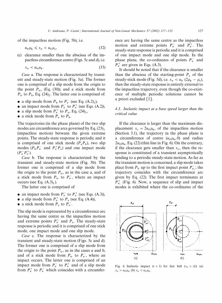
Fig. 6. Inelastic impact (r(1) for fast belt (��'�H
�): (a)
x�'u���; (b) x�(u
���.
of the impactless motion (Fig. 5b), i.e.
u���)x�(u
���, (32)
(c) clearance smaller than the abscissa of the im-pactless circumference centre (Figs. 5c and d), i.e.
x�(u���. (33)
Case a. The response is characterized by transi-ent and steady-state motion (Fig. 5a). The formerone is comprised of a slip mode from the origin tothe point P
��, (Eq. (30)), and a stick mode from
P��to P
, Eq. (24)
�. The latter one is comprised of:
� a slip mode from Pto P�� (see Eq. (A.2)
�),
� an impact mode from P�� to P�� (see Eqs. (A.2)),� a slip mode from P�� to P
, Eq. (24)
�,
� a stick mode from Pto P
.
The trajectories (in the phase plane) of the two slipmodes are circumference arcs governed by Eq. (23)
�(impactless motion) between the given extremepoints. The steady-state response is periodic and itis comprised of one stick mode (P
P
), two slip
modes (PP�� and P�� P
) and one impact mode
(P�� P�� ).Case b. The response is characterized by the
transient and steady-state motion (Fig. 5b). Theformer one is comprised of a slip mode fromthe origin to the point P
��, as in the case a, and of
a stick mode from P��
to P�� , where an impactoccurs (see Eq. (A.3)
�).
The latter one is comprised of
� an impact mode from P�� to P�� (see Eqs. (A.3)),� a slip mode from P�� to P� (see Eq. (A.4)),� a stick mode from P� to P�� .
The slip mode is represented by a circumference archaving the same centre as the impactless motionand extreme points P�� and P� . The steady-stateresponse is periodic and it is comprised of one stickmode, one impact mode and one slip mode.
Case c. The response is characterized by thetransient and steady-state motion (Figs. 5c and d).The former one is comprised of a slip mode fromthe origin to the point P
��, as in the cases a and b,
and of a stick mode from P��
to P�� , where animpact occurs. The latter one is comprised of animpact mode from P�� to P�� and of a slip modefrom P�� to P�� which coincides with a circumfer-
ence arc having the same centre as the impactlessmotion and extreme points P�� and P�� . Thesteady-state response is periodic and it is comprisedof one impact mode and one slip mode. In thephase plane, the co-ordinates of points P�� andP�� are given in Eqs. (A.3).
It should be noted that if the clearance is smallerthan the abscissa of the starting-point P
of the
steady-stick mode (Fig. 5d), i.e. x�(u�
(2��!�
�),
then the steady-state response is entirely external tothe impactless trajectory, even though the co-exist-ence of multiple periodic solutions cannot bea priori excluded [1].
4.3. Inelastic impact at a base speed larger than thecritical value
If the clearance is larger than the maximum dis-placement x
�"2u
���, of the impactless motion
(Section 3.1), the trajectory in the phase plane isa circumference of centre (u
���, 0) and radius
2u���, Eq. (22) (thin line in Fig. 6). On the contrary,
if the clearance gets smaller than x�, then the re-
sponse is constituted of a transient asymptoticallytending to a periodic steady-state motion. As far asthe transient motion is concerned, a slip mode takesplace from P
�up to the "rst impact point P���
; thetrajectory coincides with the circumference arcgiven by Eq. (22). The "rst impact terminates atP���
(Fig. 6). Now, a sequence of slip and impactmodes is exhibited where the co-ordinates of the
U. Andreaus, P. Casini / International Journal of Non-Linear Mechanics 37 (2002) 117}133 127
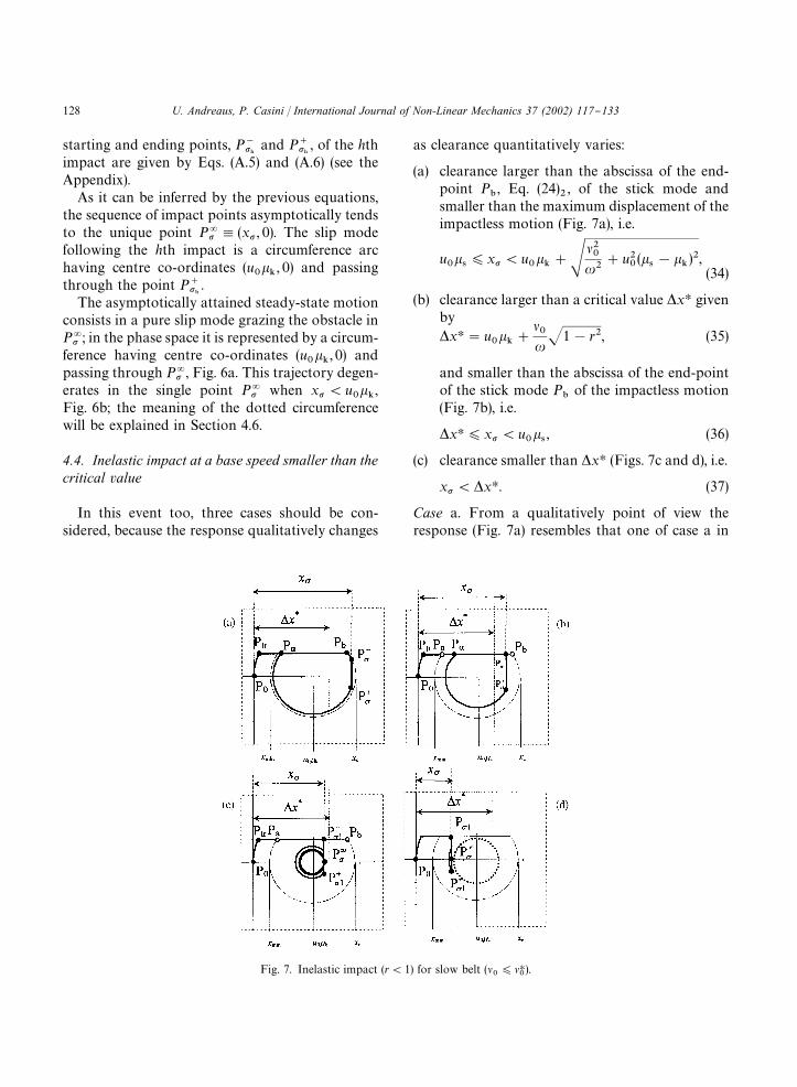
Fig. 7. Inelastic impact (r(1) for slow belt (��)�H
�).
starting and ending points, P���and P���
, of the hthimpact are given by Eqs. (A.5) and (A.6) (see theAppendix).
As it can be inferred by the previous equations,the sequence of impact points asymptotically tendsto the unique point P�� ,(x� , 0). The slip modefollowing the hth impact is a circumference archaving centre co-ordinates (u
���, 0) and passing
through the point P���.
The asymptotically attained steady-state motionconsists in a pure slip mode grazing the obstacle inP�� ; in the phase space it is represented by a circum-ference having centre co-ordinates (u
���, 0) and
passing through P�� , Fig. 6a. This trajectory degen-erates in the single point P�� when x�(u
���,
Fig. 6b; the meaning of the dotted circumferencewill be explained in Section 4.6.
4.4. Inelastic impact at a base speed smaller than thecritical value
In this event too, three cases should be con-sidered, because the response qualitatively changes
as clearance quantitatively varies:
(a) clearance larger than the abscissa of the end-point P
, Eq. (24)
�, of the stick mode and
smaller than the maximum displacement of theimpactless motion (Fig. 7a), i.e.
u���)x�(u
���#�
���
��#u�
�(�
�!�
�)�,
(34)
(b) clearance larger than a critical value xH givenby xH"u
���#
���
1!r�, (35)
and smaller than the abscissa of the end-pointof the stick mode P
of the impactless motion
(Fig. 7b), i.e.
xH)x�(u���, (36)
(c) clearance smaller than xH (Figs. 7c and d), i.e.
x�( xH. (37)
Case a. From a qualitatively point of view theresponse (Fig. 7a) resembles that one of case a in
128 U. Andreaus, P. Casini / International Journal of Non-Linear Mechanics 37 (2002) 117}133
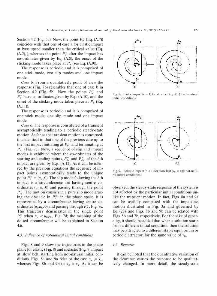
Fig. 8. Elastic impact (r"1) for slow belt (��)�H
�): not-natural
initial conditions.
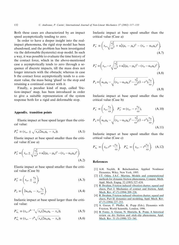
Fig. 9. Inelastic impact (r(1) for slow belt (��)�H
�): not-natu-
ral initial conditions.
Section 4.2 (Fig. 5a). Now, the point P�� (Eq. (A.7))coincides with that one of case a for elastic impactat base speed smaller than the critical value (Eq.(A.2)
�), whereas the point P�� after the impact has
co-ordinates given by Eq. (A.8); the onset of thesticking mode takes place at P� (see Eq. (A.9)).
The response is periodic and it is comprised ofone stick mode, two slip modes and one impactmode.
Case b. From a qualitatively point of view theresponse (Fig. 7b) resembles that one of case b inSection 4.2 (Fig. 5b). Now the points P�� andP�� have co-ordinates given by Eqs. (A.10), and theonset of the sticking mode takes place at P� (Eq.(A.11)).
The response is periodic and it is comprised ofone stick mode, one slip mode and one impactmode.
Case c. The response is constituted of a transientasymptotically tending to a periodic steady-statemotion. As far as the transient motion is concerned,it is identical to that one of the previous case up tothe "rst impact initiating at P���
and terminating atP���
(Fig. 7c). Now, a sequence of slip and impactmodes is exhibited where the co-ordinates of thestarting and ending points, P���
and P���, of the hth
impact are given by Eqs. (A.12). As it can be infer-red by the previous equations the sequence of im-pact points asymptotically tends to the uniquepoint P�� ,(x� , 0). The slip mode following the hthimpact is a circumference arc having centre co-ordinates (u
���, 0) and passing through the point
P���. The motion consists in a pure slip mode graz-
ing the obstacle in P�� ; in the phase space, it isrepresented by a circumference having centre co-ordinates (u
���, 0) and passing through P�� , Fig. 7c.
This trajectory degenerates in the single pointP�� when x�(u
���, Fig. 7d; the meaning of the
dotted circumference will be explained in Section4.6.
4.5. Inyuence of not-natural initial conditions
Figs. 8 and 9 show the trajectories in the phaseplane for elastic (Fig. 8) and inelastic (Fig. 9) impactat &slow' belt, starting from not-natural initial con-ditions. Figs. 8a and 9a refer to the case x�*x
�,
whereas Figs. 8b and 9b to x�(x�. As it can be
observed, the steady-state response of the system isnot a!ected by the particular initial conditions un-like the transient motion. In fact, Figs. 8a and 9acan be usefully compared with the impactlessmotion illustrated in Fig. 3a and governed byEq. (23); and Figs. 8b and 9b can be related withFigs. 5b and 7b, respectively. For the sake of gener-ality, it should be added that when a solution startsfrom a di!erent initial condition, then the solutionmay be attracted to a di!erent stable equilibrium orperiodic attractor, for the same value of �
�.
4.6. Remarks
It can be noted that the quantitative variation ofthe clearance causes the response to be qualitat-ively changed. In more detail, the steady-state
U. Andreaus, P. Casini / International Journal of Non-Linear Mechanics 37 (2002) 117}133 129

Fig. 10. Hysteretic contact for slow belt u���(x�) xH: (a) phase plane trajectory; (b) time-history of the contact force; (c) hysteretic
behaviour of the stop.
response is periodic in the case of Figs. 4, 5 and 7a,bfor natural initial conditions, whereas Figs. 6 and7c,d show that a stationary motion is asymp-totically attained; the qualitative behaviour di!ersbecause in the cases of Figs. 6 and 7c,d the impactvelocity tends asymptotically to zero. For the sakeof completeness, it should be noted that the condi-tion x
(x
��could be exhibited depending on the
values ��,�
�,��, Eq. (30) and (24)
�in each of the
considered cases a}c; however, the presented solu-tions do not lose generality.
As already observed, the response of the systemexhibits di!erent kinds of singularities; in moredetail stickPslip transition (SS) is exhibited inFigs. 5a and 7a (points P
); stickPcontact
transition (StC) occurs at points P�� in Figs. 5b}dand 7b as well as at points P���
in Figs. 7c and d; theslipPcontact transition (SlC) occurs in Figs. 4, 5aand 7a (points P�� ) and in Figs. 6 and 7c,d (pointsP���
). Similar remarks can be done as far as theslipPstick and contactPslip transitions are con-cerned.
Up to now, we dealt with a motion-limiting stopwhich exists from the very beginning, i.e. at t"t
�.
However, the obstacle may be introduced in anytime t't
�, provided that the physical admissibility
condition x(t)(x� does hold; in this case, it shouldbe noted that the system regains the behaviourwhich it should have exhibited, if the stop had beenthere from the very beginning. A dual remark canbe done: whenever a steady-state response exists(Figs. 4, 5 and 7a,b), removing the obstacle in any
time t't�, leads the system to the limit cycle of
the impactless motion. In other words, the responsebecomes the same as the stop had not been therefrom the very beginning. When the solution asymp-totically tends to the steady-state (Figs. 6a,b and7c,d), removing the obstacle leaves the system ina steady-state motion of pure slip represented, inthe phase plane, by a circumference of centre(u
���, 0) and passing through the state-point at the
obstacle removal (dotted circumference in Figs. 6band 7d).
It should be noted that a qualitative resemblancebetween Figs. 5a,b and Figs. 7a,b, and betweenFigs. 6a,b and Figs. 7c,d does exist. In the formercase, the presence in Figs. 7a,b of a steady stickphase constantly supplies the energy lost duringinelastic impact phase, so that a limit cycle doesexist even for dissipative collision; in the latter case,the resemblance is due to the absence of a steadystick phase, even though for di!erent causes, name-ly, a fast belt in Figs. 6a and b, and x�( xH inFigs. 7c and d.
5. Friction oscillator with hysteretic stop
The model of hysteretic contact proposed in Sec-tion 2.4 can be suitably used to account for low-velocity impacts, because it is able to give a realisticdescription of contact phenomena, and, moreover,a quantitatively accurate evaluation of the contactforces during the mass}obstacle interaction.
130 U. Andreaus, P. Casini / International Journal of Non-Linear Mechanics 37 (2002) 117}133

Fig. 11. Hysteretic contact for slow belt x�)u���: (a) phase plane trajectory; (b) time-history of the contact force; (c) hysteretic
behaviour of the stop.
In this paper, impact speeds tending to zerooccur for cases shown in Figs. 6 and 7c,d. Thus, itseems reasonable to investigate these cases by ad-opting the above-mentioned hysteretic stop model,in order to simulate the real behaviour of the ob-stacle (Figs. 10 and 11). Nevertheless, the sameenhanced model can be suitably used to study thehigh-speed impact as well.
Fig. 10a should be compared with Fig. 7c: duringthe transient, the contact force tends to zero viaa sequence of contacts and detachments, Fig. 10b;and grazing is asymptotically attained, where massand obstacle do not longer interact. Fig. 11a shouldbe compared with Fig. 7d: during the transientmotion mass and obstacle get continual contactand the contact force asymptotically tends to thelimit value k(u
���!x�), (Fig. 11b) which obviously
has a repulsive character. Figs. 10c and 11c showthe hysteretic behaviour of the obstacle under re-peated loadings. The ratio k�
��/k�
��has been assigned
such that the equivalent restitution coe$cient(Eq. (16)), coincides with that one used in Section4 (rigid stop model).
6. Concluding remarks
A friction oscillator colliding with an obstaclehas been studied, which is excited by a moving basewith constant velocity; the Coulomb's law has beenassumed with a static coe$cient larger than thekinetic one. Three main classes of singularities have
been recognized and discussed, namely, stick�slip(SS), stickPcontact (StC), and slip�contact (SlC)transitions.
The transient and steady-state impactless motionshave been determined in closed form, and the exist-ence of a critical base velocity has been proved,(Eq. (25)), which is a lower bound of no-stick andbase-velocity-independent motions. A comparisonhas been performed with the closed-form responseexhibited by the oscillator impacting on a rigid stop.Several cases have been distinguished according tothe obstacle nature (elastic or inelastic) and position,and to the belt speed. It has been observed that a limitcycle is attained in a "nite time interval whenever
(i) the impact is not dissipative,(ii) the belt is slow (�
�)�H
�) and the clearance is
large (x�* xH).
Both these cases are characterized by the fact thatthe velocity of each sequential impact equals thatone of the previous collisions. Moreover, abruptlyintroducing (removing) the obstacle let the systemregain the behaviour which it should haveexhibited, as though the stop had (not) been therefrom the very beginning.
In the remaining cases a limit cycle is attainedasymptotically:
(a) it is a pure slip with grazing if the clearance islarger than u
���, whereas
(b) the mass adheres to the obstacle if the clear-ance is smaller than u
���.
U. Andreaus, P. Casini / International Journal of Non-Linear Mechanics 37 (2002) 117}133 131
Both these cases are characterized by an impactspeed asymptotically tending to zero.
In order to have a deeper insight into the real-impact phenomena, the rigid stop model has beenabandoned, and the problem has been investigatedvia the deformable (hysteretic) stop model. In sucha way, it was possible to evaluate the time history ofthe contact force, which in the above-mentionedcase a asymptotically tends to zero through a se-quence of discrete impacts, till the mass does notlonger interacts with the obstacle; whereas in caseb the contact force asymptotically tends to a con-stant value, the mass being &glued' to the stop andretaining a continual contact with it.
Finally, a peculiar kind of map, called &fric-tion}impact' map, has been introduced in orderto give a suitable representation of the systemresponse both for a rigid and deformable stop.
Appendix. transition points
Elastic impact at base speed larger than the criti-cal value:
P � ,(x� ,$x�(2u���!x� )). (A.1)
Elastic impact at base speed smaller than the criti-cal value (Case a):
P �,�x� ,$����
��#u�
�(�
�!�
�)�!(x�!u
���)��.
(A.2)
Elastic impact at base speed smaller than the criti-cal value (Case b):
P � ,�x� ,$��� �, (A.3)
P�,�2u���!x� ,
��� �. (A.4)
Inelastic impact at base speed larger than the criti-cal value:
P���,(x� , r���x� (2u�
��!x�)), (A.5)
P���,(x� ,!r�x�(2u�
��!x� )). (A.6)
Inelastic impact at base speed smaller than thecritical value (Case a):
P�� ,�x� ,����
��#u�
�(�
�!�
�)�!(x�!u
���)��,(A.7)
P��,�x� ,!r����
��#u�
�(�
�!�
�)�!(x�!u
���)��,(A.8)
P�,�u���!�(x�!u
���)�!
���
��(1!r�),
��� �.
(A.9)
Inelastic impact at base speed smaller than thecritical value (Case b):
P�� ,�x� ,��� �, P�� ,(x� ,!r
���
), (A.10)
P�,�u���!�(x�!u
���)�!
���
��(1!r�),
��� �.
(A.11)
Inelastic impact at base speed smaller than thecritical value (Case c):
P���,�x� , r���
��� �, P���
,�x� ,!r���� �. (A.12)
References
[1] A.H. Nayfeh, B. Balachandran, Applied NonlinearDynamics, Wiley, New York, 1995.
[2] J.T. Oden, J.A.C. Martins, Models and computationalmethods for dynamic friction phenomena, Comput. Meth.Appl. Mech. Engng. 52 (1985) 527}634.
[3] R. Ibrahim, Friction induced vibration chatter, squeal andchaos, Part I: Mechanics of contact and friction, Appl.Mech. Rev. 47 (7) (1994) 209}226.
[4] R. Ibrahim, Friction induced vibration chatter, squeal andchaos, Part II: dynamics and modeling, Appl. Mech. Rev.47 (7) (1994) 227}253.
[5] A. Guran, F. Pfei!er, K. Popp (Eds.), Dynamics withFriction, World Scienti"c, London, 1996.
[6] B. Feeny, A. Guran, N. Hinrichs, K. Popp, A historicalreview on dry friction and stick-slip phenomena, Appl.Mech. Rev. 51 (5) (1998) 321}341.
132 U. Andreaus, P. Casini / International Journal of Non-Linear Mechanics 37 (2002) 117}133
[7] J. Jerrelinnd, A. Stensson, Braille printer dynamics,Proceedings of the ASME Design Engineering TechnicalConference, September 12}15 1999, Las Vegas,DETC99/VIB-8032 1999.
[8] A.E. Kobrinskii, Dynamics of Mechanisms with ElasticConnections and Impact Systems, Ili!e Books Ltd.,London, 1969.
[9] J.M.T. Thompson, Complex dynamics of complianto!-shore structures, Proc. Roy. Soc. London A 387 (1983)407}427.
[10] H. Lamba, Impacting oscillators and non-smooth dynam-ical systems, Ph.D. Thesis, School of Mathematics, Uni-versity of Bristol, 1993.
[11] B. Brogliato, Nonsmooth Impact Mechanics, Springer,London, 1996.
[12] W. Goldsmith, Bouncing from one collision to the next,Appl. Mech. Rev. 52 (8) (1999) 27}43.
[13] K.M. Cone, R.I. Zadoks, A numerical study of an impactoscillator with the addition of dry friction, J. Sound Vib.188 (5) (1995) 659}683.
[14] N. Folkman, N. Hinrichs, M. Oestreich, Analysis of a self-excited friction oscillator with external excitation, in: A.Guran, F. Pfei!er, K. Popp (Eds.), Dynamics with Friction,World Scienti"c, London, 1996.
[15] B. Blazejczyk-Okolewska, K. Czolczynski, T. Kapitaniak,J. Wojewoda, Chaotic Mechanics in Systems with Impactsand Friction,World Scienti"c Series on Nonlinear Science,Series A * Vol. 36, London, 1999.
[16] R.I. Leine, D.H. Van Campen, A. De Kraker, L. Van DenSteen, Stick-slip vibration induced by alternate frictionmodels, Nonlinear Dynamics 16 (1998) 41}54.
[17] U. Andreaus, P. Casini, Dynamics of SDOF oscillatorswith hysteretic motion-limiting stop, Nonlinear Dynamics22 (2) (2000) 155}174.
[18] N.R. Barton, S.C. Bandis, K. Bakhtar, Strength,deformation and conductivity coupling of rock joints, Int.J. Rock Mech. Min. Sci. Geomech. Abst. 22 (3) (1985)121}140.
[19] E.S. Hwang, A.S. Nowak, Simulation of dynamic loadfor bridges, J. Struc. Engng. ASCE 117 (5) (1991)1413}1434.
[20] F. GeH nod, B. Brogliato, New results in PainleveH paradoxes,Eur. J. Mech. A/Solids 18 (1999) 653}677.
[21] C.F. Gerald, P.O. Wheatley, Applied Numerical Analysis,Addison-Wesley, Reading, MA, 1994.
[22] U. Andreaus, P. Casini, Dynamics of friction oscillatorsexcited by moving base or/and driving force, J. Sound Vib.(2000), accepted for publication.
U. Andreaus, P. Casini / International Journal of Non-Linear Mechanics 37 (2002) 117}133 133
Copyright © 2022 FDOKUMEN