Obstacle Detecting Autonomous Robot EMILIA HALTORP ...
48
IN DEGREE PROJECT TECHNOLOGY, FIRST CYCLE, 15 CREDITS , STOCKHOLM SWEDEN 2020 ODAR Obstacle Detecting Autonomous Robot EMILIA HALTORP JOHANNA BREDHE KTH ROYAL INSTITUTE OF TECHNOLOGY SCHOOL OF INDUSTRIAL ENGINEERING AND MANAGEMENT
-
Upload
khangminh22 -
Category
Documents
-
view
4 -
download
0
Transcript of Obstacle Detecting Autonomous Robot EMILIA HALTORP ...
IN DEGREE PROJECT TECHNOLOGY,FIRST CYCLE, 15 CREDITS
, STOCKHOLM SWEDEN 2020
ODARObstacle Detecting Autonomous Robot
EMILIA HALTORP
JOHANNA BREDHE
KTH ROYAL INSTITUTE OF TECHNOLOGYSCHOOL OF INDUSTRIAL ENGINEERING AND MANAGEMENT


ODAR
Obstacle Detecting Autonomous Robot
JOHANNA BREDHE, EMILIA HALTORP
Bachelor’s Thesis at ITMSupervisor: Nihad SubasicExaminer: Nihad Subasic
TRITA-ITM-EX 2020:44


AbstractThe industry for autonomous vehicles is growing. Accord-ing to studies nine out of ten traffic accidents are due tothe human factor, if the safety can get good enough in au-tonomous cars they have the potential to save thousands oflives every year. But obstacle detecting autonomous robotscan be used in other situations as well, for example wherethe terrain is inaccessible for humans because of differentreasons.
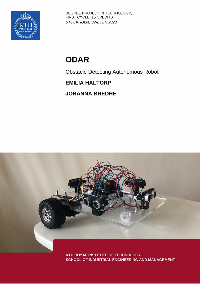
In this project, a self navigating obstacle detecting robotwas made. The robot uses ultrasonic sensors to detect ob-stacles and avoid them. An algorithm of the navigationof the robot was created and implemented to the Arduino.For driving the wheels, two servo motors were used. Therobot consisted of three wheels, two in the back to whichthe servo motors were attached and one caster wheel in thefront. This made it possible to implement differential drivewhich enabled quick and tight turns.
Tests were performed which showed that the robot couldsuccessfully navigate in a room with various obstacles placedout. The placement of the sensors worked good consideringthe amount of sensors that was used. Improvements in de-tection of obstacles could have been made if more sensorshad been used. The tests also confirmed that ultrasonicsensors works good for this kind of task.
Keywords: Mechatronics, Autonomous Robot, UltrasonicSensors, Servo Motors, Arduino

ReferatAutonom hinderupptäckande robot
Industrin for sjalvkorande fordon vaxer. Enligt studier be-ror nio av tio trafikolyckor pa den manskliga faktorn, omsakerheten kan bli tillrackligt bra i sjalvkorande bilar harde potential att radda tusentals liv varje ar. Men hinder-upptackande sjalvkorande robotar kan anvandas i andrasituationer ocksa, till exempel i terrang som ar otillgangligfor manniskor av olika anledningar.
I det har projektet har en sjalvnavigerande hinderupp-tackande robot byggts. Roboten anvander ultraljudssenso-rer for att upptacka hinder och unvika dem. En algoritmfor navigationen av roboten skapades och implementeradesi Arduinon. For drivningen av hjulen anvandes tva servo-motorer. Roboten hade tre hjul, tva i den bakre anden tillvilka servomotorerna var fasta och ett lankhjul fram. Detmojliggjorde differentialstyrning vilket ocksa tillat snabbaoch snava svangar.
Tester genomfordes som visade att roboten kunde na-vigera i ett rum med olika hinder utplacerade utan storreproblem. Placeringen av sensorerna fungerade bra med tan-ke pa det antal sensorer som anvandes. Forbattringar avhinderupptackningen hade kunnat goras om fler sensorerhade anvants. Testerna bekraftade ocksa att ultraljudssen-sorer fungerar bra for denna typ av uppgift.
Nyckelord: Mekatronik, Autonom Robot,Ultraljudssensorer, Servomotorer, Arduino

Acknowledgements
We would like to thank Nihad Subasic for his valuable lectures, and for his alwaysso quick and supportive responses. A special gratitude goes to Seshagopalan Tho-rapalli Muralidharan for all the help and support he provided during this project.It would not have been possible to accomplish this without the enormous helpwith manufacturing and shipping things to us that we got from the department ofmechatronics at KTH, we are very grateful for that.
Johanna Bredhe & Emilia HaltorpStockholm, May 2020

Contents
1 Introduction 31.1 Background . . . . . . . . . . . . . . . . . . . . . . . . . . . . . . . . 31.2 Purpose . . . . . . . . . . . . . . . . . . . . . . . . . . . . . . . . . . 31.3 Scope . . . . . . . . . . . . . . . . . . . . . . . . . . . . . . . . . . . 41.4 Method . . . . . . . . . . . . . . . . . . . . . . . . . . . . . . . . . . 4
2 Theory 52.1 Ultrasonic sensors . . . . . . . . . . . . . . . . . . . . . . . . . . . . 52.2 Servo motors . . . . . . . . . . . . . . . . . . . . . . . . . . . . . . . 62.3 Differential drive . . . . . . . . . . . . . . . . . . . . . . . . . . . . . 62.4 Microcontroller . . . . . . . . . . . . . . . . . . . . . . . . . . . . . . 6
2.4.1 Arduino . . . . . . . . . . . . . . . . . . . . . . . . . . . . . . 7
3 Demonstrator 93.1 Software . . . . . . . . . . . . . . . . . . . . . . . . . . . . . . . . . . 9
3.1.1 Algorithm . . . . . . . . . . . . . . . . . . . . . . . . . . . . . 93.2 Hardware . . . . . . . . . . . . . . . . . . . . . . . . . . . . . . . . . 11
3.2.1 Arduino Uno . . . . . . . . . . . . . . . . . . . . . . . . . . . 113.2.2 Ultrasonic Sensor . . . . . . . . . . . . . . . . . . . . . . . . . 113.2.3 Servo Motor . . . . . . . . . . . . . . . . . . . . . . . . . . . . 12
3.3 Electronics . . . . . . . . . . . . . . . . . . . . . . . . . . . . . . . . 13
4 Tests and results 154.1 Movement . . . . . . . . . . . . . . . . . . . . . . . . . . . . . . . . . 164.2 Navigation . . . . . . . . . . . . . . . . . . . . . . . . . . . . . . . . . 164.3 Sensor tests . . . . . . . . . . . . . . . . . . . . . . . . . . . . . . . . 164.4 Obstacle tests . . . . . . . . . . . . . . . . . . . . . . . . . . . . . . . 17
5 Discussion and conclusions 195.1 Discussion . . . . . . . . . . . . . . . . . . . . . . . . . . . . . . . . . 195.2 Conclusion . . . . . . . . . . . . . . . . . . . . . . . . . . . . . . . . 20
6 Further work 21

Bibliography 23
Appendices
A Arduino Code
B Ultrasonic Sensor Data Sheet

List of Figures
3.1 A flowchart over the algorithm, made with draw.io. . . . . . . . . . . . . 103.2 The construction made in Autodesk Fusion. . . . . . . . . . . . . . . . . 113.3 Ultrasonic Sensor [16] . . . . . . . . . . . . . . . . . . . . . . . . . . . . 123.4 A picture of the servo motors that were used [19] . . . . . . . . . . . . . 123.5 An illustration over the electric circuit, made on Tinkercad.com. . . . . 14
4.1 A picture showing the final construction. . . . . . . . . . . . . . . . . . . 154.2 A picture of how the test was conducted. . . . . . . . . . . . . . . . . . 174.3 A picture of the front sensor during the test. . . . . . . . . . . . . . . . 18

List of Tables
4.1 Results from test with sensor. . . . . . . . . . . . . . . . . . . . . . . . . 17


List of Abbreviations
IDE Integrated Development Environment
PWM Pulse Widht Modulation
CPU Central Processing Unit
ALU Arithmetic Logic Unit
RAM Random Access Memory
ROM Read Only Memory
USB Universal Serial Bus
GPS Global Positioning System
USB Universal Serial Bus
1


Chapter 1
Introduction
Autonomous vehicles can be used for a lot of different purposes and the industryis growing. With autonomous vehicles follows new challenges and safety is onethat is very important. If the safety is good enough autonomous vehicles have thepotential to save thousands of lives every year. Studies show that nine out of tentraffic accidents are due to the human factor [1]. Other benefits of autonomousvehicles could be improved energy efficiency and reduced driving costs [2]. Thisreport presents how an obstacle detecting autonomous robot was developed.
1.1 BackgroundAutonomous robots are freely moving and can operate without direct human super-vision. They are capable of making their own decisions based on what it perceivesand has been programmed to recognize.
An obstacle detecting autonomous robot has many applications. The techniquecan be implemented in cars for example. If the control system is fast enough it candecrease the speed quick and avoid accidents with obstacles that occurs rapidly.With the traffic becoming more complex with new situations the requirements onthe control system and algorithms increases [3].
Autonomous robots can also be used in situations where it is dangerous or inany other way inappropriate for humans to be.
1.2 PurposeThe purpose of this Bachelor’s thesis project was to build a robot that could detectobstacles in its path and avoid them by turning in another direction. Followingresearch questions will be investigated in this thesis:
3

CHAPTER 1. INTRODUCTION
• How should the robot navigate?
• How could the robot detect obstacles in its lane and what should it do when itencounters them?
– What kind of sensors are needed?– Where should the sensors be placed?
1.3 ScopeDue to limited time and a limited budget of 1000 SEK this project had some con-straints. The budget limited the size of the prototype and its components had tobe relatively inexpensive.
Tests were done in ideal conditions, i.e. the robot was driven in an insideenvironment and on a flat surface.
During the time this thesis was written the world suffered a great pandemic.The pandemic struck in the middle of the project and no one was prepared. Thisled to a number of challenges as we were no longer allowed to be on campus andtherefore not in the lab where all of the equipment and tools we needed were. Topartially solve this, things we required was shipped to us and we are very gratefulfor that as it was crucial for our work. However, this led to everything taking alonger amount of time and as we did not have access to all the equipment we neededsome provisional solutions were made.
1.4 MethodThe first step of this project was to formulate the research questions. The nextstep was to gather information about autonomous robots and obstacle detection.This was done by reading articles and investigating projects from previous yearsrelated to the subject. From the literature study, components that were neededfor the prototype could be determined. A prototype was then made. The programAutodesk Fusion was used to create a design. Axles and brackets for the sensorswere 3D-printed. The bottom plate was designed in Adobe Illustrator and cut outwith a laser cutter. When the construction was completed, the Arduino softwareIntegrated Development Environment (IDE) was used to program the algorithm.To avoid collisions, the robot must be able to identify all obstacles in its path. Inorder to achieve this, the robot was equipped with sensors to detect objects. Testswere made where obstacles were placed in front of the robot while it was drivingforward to investigate what the best placement of the sensors were.
4

Chapter 2
Theory
This chapter presents the theory necessary to answer the research questions andbuild an autonomous obstacle avoiding robot.
2.1 Ultrasonic sensorsWhen wanting to measure distance between a moving object and obstacles thatmay appear around it, ultrasonic sensors are a good alternative. They are cheapbut not the most precise. Ultrasonic sensors measures distance by transmittingpulses of ultrasonic sound-waves which propagates through the air and is reflectedand received by the sensor when there is an object in front of them. If there is anobject in front of the sensor, the sound-waves reflects and returns to the receiver[7]. One problem with them is that if the object in front of the sensor is tiltedrelative to the sensors transceiver, only such a small amount of the sound-wave willbe reflected back to the sensor that the object won’t be detected. This can alsocause problems with the measured distance, if the area where the sound-waves hitsthe object is a little bit tilted the distance may be detected as longer or shorterthan it actually is [18].
To calculate the distance between the object on which the sensor is placed andthe obstacle, equation 2.1 can be used [8].
l = tc
2 (2.1)
Where l is the distance, t is the time and c is the speed of sound. It is dividedby two because the time is measured from when the signal is transmitted from thesensor to when it is received and in that time the sound-waves have traveled thedistance twice, back and forth.
What makes the calculations less accurate is the value of the speed of sound.Since the speed of sound depends on temperature it is not ideal to use the samevalue all the time. What could be made to improve this is using a temperaturesensor and constantly update the value [7].
5

CHAPTER 2. THEORY
2.2 Servo motorsServo motors are simple electric motors that offers closed-loop position control [9].They are controlled by a signal, also known as Pulse Width Modulation (PWM).PWM is a technique where digital control is used to create a square wave, whichis a signal that switches between full on and full off. From PWM you get analogresults with digital means. It simulates different voltages between full on and fulloff depending on the portion of time that the signal spends on versus off. If theon-off pattern is repeated fast enough, it will appear as if the signal is a steadyvoltage [10].
The servo motor provides control of linear or angular position, velocity andacceleration. They differ from each other in how many degrees they can rotate andhow much they can torque. Servo motors have many different applications, such asrobotics, printers and automatic door openers.
2.3 Differential driveDifferential drive is a method in which two wheels are driven with one motor each.This enables the robot to move in all directions easily. If both wheels are rotatingwith the same speed in the same direction the robot will either go straight forwardor backwards depending on the direction in which the wheels rotates. To make therobot turn, one wheel will have to have a faster speed while still going in the samedirection as the other one, the robot will then turn away from the faster rotatingwheel. The robot can also spin around the midpoint in between the wheels. To makethat happen, both wheels needs to go at the same speed but in different directions.
The linear velocity of the robot can be calculated as shown by equation 2.2 andthe angular velocity as shown by 2.3,
v = (ωR + ωL)r2 (2.2)
ω = (ωR − ωL)rL
(2.3)
where r is the wheel radius, L the distance between the wheels and ωR, ωL theangular velocity of the right and left wheels [13].
2.4 MicrocontrollerA microcontroller is a small computer with most of the required support chipsavailable. They are often embedded inside other devices and can therefore controlfeatures and actions of the product. The microcontroller controls the device bytaking its input and sending signals to different components in the device [11].
The microcontroller consists of a microprocessor and the primary memory con-nected to a system bus. The microprocessor contains the Central Processing Unit
6

2.4. MICROCONTROLLER
(CPU) with the Arithmetic Logic Unit (ALU), it is the CPU that executes pro-grams. The cache memory can also be found in the microprocessor, this is wherethe next operation is stored. The system bus is the primary pathway between CPUand memory, this is where addresses, data and control signals are transmitted. Theprimary memory is called Random Access Memory (RAM). RAM means that ac-cess to a memory cell is not sequential, which means that it takes just as long toretrieve the information no matter what memory location it is on. It is a very fastcomponent that temporarily stores information that is needed in the moment andnear future. Among the primary memories are also various types of Read OnlyMemory (ROM), these types of memories keep its content regardless of whether ornot it has power. The microcontroller also consists of the external bus, that enablesconnection to external devices and components [12].
2.4.1 ArduinoThe microcontroller used in this project is an Arduino Uno. Arduino is an open-source platform. The Arduino boards are easily programmed on the Arduino Soft-ware (IDE) [14]. Arduino Uno is based on the microcontroller ATmega328P whichhas a flash memory of 32 kB. It has 14 digital input/output pins and six of thesecan be used as PWM outputs. The board can be connected to a computer with aUniversal Serial Bus (USB) cable to power it or to an external power supply, therecommended voltage input is 7-12 V. If it is powered with less than 7 V it maybecome unstable and more than 12 V may cause the voltage regulator to overheatand damage the board [15].
7

Chapter 3
Demonstrator
This chapter will present the hardware and software that was needed in order tobuild the autonomous obstacle detecting robot. It will also include the electricalcircuit that shows how the different components have been connected to the Ar-duino.
3.1 Software
The code for the microcontroller was created in Arduino IDE and can be found inAppendix A.
3.1.1 Algorithm
A flowchart was created to describe the algorithm that the robot uses. The flowchartcan be seen in figure 3.1. The robot started with driving forward. If it encounteredan obstacle in front of its path it checked if there was an obstacle to the right, if notit turned 90° to the right and then continued to drive forward. In the occasion itwas an obstacle to the right as well the robot checked to its left and if there was noobstacle there it would turn 90° left and continue forward. In the case where therewere obstacles both in front and to both sides the robot would check behind and ifthe way was free there it would reverse and then again check its right and left sides.If a situation occurred where there were obstacles all around the robot the motorswould stop and the robot would have to be moved manually.
9

CHAPTER 3. DEMONSTRATOR
Figure 3.1. A flowchart over the algorithm, made with draw.io.
10

3.2. HARDWARE
3.2 HardwareThe final construction is shown in figure 4.1. Everything was created and designedin Autodesk Fusion 360. The bottom plate was made out of 6 mm thick acrylic andlaser cut with Epilog Laser Fusion M2. Wheel axles and sensor mounts were 3Dprinted using Ultimaker2. In the figure, no jumper wires are added.
Figure 3.2. The construction made in Autodesk Fusion.
3.2.1 Arduino Uno
The Arduino Uno controls the two servo motors and also the four ultrasonic sen-sors. Both the sensors and servo motors were connected to the digital input pins.Connecting the two servo motors to separate pins enables control of the motorsseparately which is needed for differential drive.
3.2.2 Ultrasonic Sensor
Four ultrasonic sensors of type HC-SR04 were used in this project, see figure 3.3.These sensors can identify a distance from 2-400 cm. They require a current con-sumption of 2 mA and a 5 V power supply [16]. One sensor was placed in eachdirection of the robot; in the front, to the left, to the right and in the back. Therobot is programmed to stop when an obstacle occurs within 15 cm ahead of it, this
11

CHAPTER 3. DEMONSTRATOR
is due to the problem brought up in chapter 2.1 about measurement problems. Tominimise the risk of the robot hitting an obstacle due to miscalculations it is goodto make it stop when there is still some distance left to the obstacle [18]. The sensorto the right then controls if there is an obstacle to the right, if there is no obstaclethere, the robot turns right. If there is an obstacle to the right, the sensor to theleft controls if there is an obstacle in its way, the robot turns left if no obstacle hasbeen detected there. In the case it occurs to be obstacles both in front of the robotand to the left and right the sensor in the back will check if there is an obstaclebehind. If there is, the robot stops and if it is not it reverses.
Figure 3.3. Ultrasonic Sensor [16]
3.2.3 Servo Motor
Two servo motors of model Tower Pro SG-5010 were used for the two wheels thatwere driven with differential drive, they can be seen in figure 3.4. This servo motoris continuous and can turn 360°. Its dimensions are 40.8 x 20.1 x 38 mm and itsweight 40 g. It requires a 4.8-6 V power supply [17].
Figure 3.4. A picture of the servo motors that were used [19]
.
12

3.3. ELECTRONICS
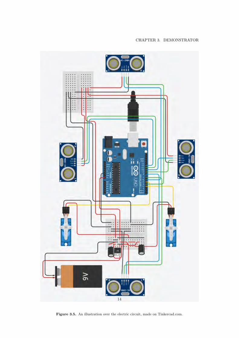
3.3 ElectronicsThe electrical components that the robot consisted of were an Arduino Uno, twoservo motors and four ultrasonic sensors. A 9 V battery was used to power therobot but as some components required 5 V, a voltage regulator and two capacitorswere also needed. The circuit is shown in figure 3.5.
13
CHAPTER 3. DEMONSTRATOR
Figure 3.5. An illustration over the electric circuit, made on Tinkercad.com.
14

Chapter 4
Tests and results
This chapter presents the results of the demonstrator that was built in this projectand the tests which was performed. The final construction can be seen in figure 4.1.
Figure 4.1. A picture showing the final construction.
15

CHAPTER 4. TESTS AND RESULTS
4.1 Movement
The movement of the robot was controlled by the sensors as different values weresent to the servos due to the distance to obstacles around the robot. Therefore,tests to check the movement of the robot were made where obstacles were placed infront of it to make sure it could turn as desired.
4.2 Navigation
The robot was tested in an inside environment where obstacles were placed aroundit. While driving, it was observed to confirm that it worked as intended. First, anobject was placed in front of the robot to make sure it turned right when it discoveredthe object. Then, an object was also placed to the right to ensure it turned left thattime. When the code had been adjusted so that these things worked an obstaclewas placed to the left as well to see if the robot then reversed. Lastly, obstacleswere placed all around the robot to make sure it would stop completely. After all ofthe testing an obstacle course was built. Minor adjustments in the code were madeuntil the robot drove through the obstacle course without difficulties.
4.3 Sensor tests
In order to decide what distance from the obstacles the robot should stop, testswere made with the ultrasonic sensors. Tests were done to find out how accuratethe sensors were. An obstacle was placed at a certain distance from the sensor, thedistance was measured with a ruler and then compared with the distance specifiedby the sensor. This is shown in figure 4.2. The result showed that the sensorsare precise except in the case where the object is placed very close to the sensor.According to the manufacturer’s specifications (which can be seen in Appendix B),the sensors can identify a distance from 2-400 cm. The result is presented in table4.3.
16

4.4. OBSTACLE TESTS
Figure 4.2. A picture of how the test was conducted.
Table 4.1. Results from test with sensor.
Measureddistance
Distancefrom sensor
0 cm 0 cm1 cm 2 cm5 cm 5 cm15 cm 15 cm30 cm 30 cm
4.4 Obstacle testsObstacles of various shapes and sizes were placed in front of the robot to investigatewhich objects the sensors were able to detect. The sensors were attached on top ofthe bottom plate which generated a height difference of 5 cm between the groundand the center of the sensors. This made it interesting to investigate the sensors’ability to detect low obstacles in its path. The test was initiated by placing anobject with a length of 15 cm and a height of 16 cm in front of the robot. Thisobstacle was easily detected by the robot. Another object with the dimensions4,5 cm x 5,5 cm was placed in front of the construction and was once again easily
17

CHAPTER 4. TESTS AND RESULTS
discovered, this is shown in figure 4.3. When an object with the a height of 2,5cm was tested, the robot could not detect it. In order to find the lowest detectableheight, objects with a height of 3,5 cm, 4 cm and lastly 5 cm were tested. Theresult showed that the object with height 5 cm was the lowest obstacle that couldbe identified by the sensors. This test provided useful information about whichobstacles that were suitable to include in the obstacle course that was later builtand what improvements that could have been done to the robot.
Figure 4.3. A picture of the front sensor during the test.
18

Chapter 5
Discussion and conclusions
This chapter aims to discuss the performance and results of the demonstrator. Finalconclusions will be drawn and examples of further work will also be brought up.
5.1 Discussion
The goal of this project was to answer the research questions and to build anautonomous obstacle avoiding robot. Even though some improvements could havebeen made if we have had more time we are happy with the results.
The bottom plate could have been designed in a way that better fits the servomotors. A chassis that fits the bottom plate could have been created to hide thejumper wires and some of the components. This would also give a better overallimpression of the construction.
If the sensors had been attached closer to the ground, at the same height asthe bottom plate or below it, it would have been possible for the robot to identifyobjects with a height less than 5 cm. This would extend the robot’s applications.To change the height of the sensors, it would be necessary to change the design ofthe brackets where the sensors are attached.
We experienced some trouble with a sensor returning only zero as the distanceto an obstacle even though an obstacle was not in front of it. This led to thatour algorithm did not work as expected. After some testing with different codessent to the Arduino and changing the pins on the Arduino to which the sensor wasconnected to we discovered that the problem probably was the pins. Some pinsworked perfectly and some pins did not work at all, while it was also some pins thatsometimes returned the distance to zero and sometimes a very large number like 800cm but sometimes also the correct number. It is not clear if this is a normal problemor if something was wrong with our Arduino. Since we had to use almost all of thedigital pins we could not only choose to use the ones which worked perfectly fine.Our solution to this was to put the worst functioning sensor in the back as this onewas used least. This though, is not a good solution and if we had discovered thisproblem a little bit earlier we could probably have made a better solution. Another
19

CHAPTER 5. DISCUSSION AND CONCLUSIONS
solution to this could have been to change the code slightly so that it would receivemultiple values from this sensor and calculate a mean value from those. It is unclearif this would solve the problem though as the false values most of the time werecompletely wrong.
As mentioned earlier, this project started at the time when Covid-19 beganspreading. In the middle of the project it escalated to a pandemic which causedthe universities in Sweden to close and our remaining work had to be done fromhome. Since the closing of KTH was declared almost halfway in to the projectwe were then in the early constructing phase. At the time we had to leave KTHour construction was not assembled and the parts that we were supposed to 3D-print and laser cut was not done yet. Thanks to the assistants who still had accessto the lab at KTH we could send files to them and get the parts manufacturedanyway and shipped to our homes. This though led to that we did not have theopportunity to adjust and remake the parts to do several prototypes and in thisway develop the robot. With not being able to make a new part we had to come upwith some special solutions which led to that everything was not optimal but stillworked. Even though things did not turn out exactly the way we wanted and thatwe had to face bigger challenges than we thought in the beginning, we think thatthis has developed our problem solving skills more than it should have without thepandemic. The situation really had us thinking outside the box.
5.2 ConclusionFollowing are the research questions that were investigated in this project and theanswers to them:
• How should the robot navigate?
The robot can successfully navigate with the algorithm described in chapter3.1.1.
• How could the robot detect obstacles in its lane and what should it do when itencounters them?
– What kind of sensors are needed?– Where should the sensors be placed?
Ultrasonic sensors was the type of sensors that was chosen. This due to that theyare good at detecting obstacles relative to the price of them. They are placed onein each direction; front, right, left and back. This placement is the most profitablefor the amount of sensors we have got but as it is now, the robot can not detectall obstacles. The sensors has got a measuring angle of 15 degrees according to thedata sheet which can be found in Appendix B. This makes it impossible for onlyfour sensors to detect all obstacles that can occur around the robot.
20

Chapter 6
Further work
A lot of things could be done to improve the performance of this robot. It would alsobe possible to add different functions to develop the robot even more. To improvethe obstacle detection, more ultrasonic sensors could be added. This could makesure that the robot does not have any angles where it can not detect obstacles.Servo motors could also be added to make the sensors turn and detect a biggerangle than if they are fixed, then probably four sensors would be enough. An ideais also to add other types of sensors to detect obstacles that the ultrasonic sensorsmay miss.
To solve the problem with the sensors not detecting obstacles below five cm, theplacement of the sensors could be improved. For example they could be placed onthe bottom plate or even below it. If that would cause a problem with detectingobstacles higher up, a sensor could also be placed above the bottom plate a littlebit higher than the current placement.
To improve the navigation a Global Positioning System (GPS) could be added.This could help with keeping track of the positioning of the robot and also make itpossible for it to return to it’s starting point when the battery is about to run out.With a GPS it would also be possible to set an end point for the robot to travel to.Maybe, both the microcontroller and algorithm would have to be updated then.
Another improvement would be to develop the algorithm so that the robot candrive towards a predetermined goal. Currently, the robot changes direction whenan obstacle arises instead of going around it. If this were to be implemented, therobot could be used in more areas.
Solar panels could be added to help recharge the battery to make the robot moreself sufficient.
21


Bibliography
[1] A. Pernestal, ‘Varning for sjalvkorande bilar’, 2019. [Online]. Available: https://fof.se/tidning/2019/3/artikel/varning-for-sjalvkorande-bilar/[Accessed: 23- Jan- 2020].
[2] W. Zhang, ‘Planning and evaluation of autonomous vehicles in freight and pub-lic transport services’, PhD dissertation, KTH Royal Institute of Technology,Stockholm, 2019. [Online]. Available: http://www.diva-portal.org/smash/get/diva2:1316459/FULLTEXT01.pdf [Accessed: 23- Jan- 2020].
[3] D. Madas et al., ‘On Path Planning Methods for Automotive Collision Avoid-ance’, in 2013 IEEE Intelligent Vehicles Symposium: IV 2013: Gold Coast City,Australia, 23-26 June 2013, 2013, pp. 931–937. [Online]. Available: https://doi-org.focus.lib.kth.se/10.1109/IVS.2013.6629586 [Accessed: 23- Jan-2020].
[4] C. Bondesson and E. Stigenius, ‘Autonom bil med enkapseldator och ul-traljudssensorer: tillampning av en Arduino mikrokontrollerplattform och HC-SR04 sensorer’, Dissertation, 2015. [Online]. Available: http://urn.kb.se/resolve?urn=urn:nbn:se:uu:diva-255762 [Accessed: 28- Jan- 2020].
[5] O. Nordstrom and A. Axelsson, ‘Pathfinder: Autonomous Guided Vehicle us-ing Infrared Light’, Dissertation, 2018. [Online]. Available: http://urn.kb.se/resolve?urn=urn:nbn:se:kth:diva-230241 [Accessed: 28- Jan- 2020].
[6] N. Lorentzon, L. Stromberg, I. Wikander, and M. Bengtson, ‘Konstruktionoch programmering av Arduino-baserad robot for kartlaggning av rum genomultraljud’, Dissertation, 2019. [Online]. Available: http://www.diva-portal.org/smash/get/diva2:1333043/FULLTEXT01.pdf [Accessed: 28- Jan- 2020].
[7] D. Webster, ‘A pulsed ultrasonic distance measurement system based uponphase digitizing,’ in IEEE Transactions on Instrumentation and Measurement,vol. 43, no. 4, pp. 578-582, Aug. 1994. [Online]. Available: https://doi.org/10.1109/19.310171 [Accessed: 12- Feb- 2020]
[8] Ultrasonic Sensor HC-SR04 and Arduino Tutorial [Online]. Avail-able: https://howtomechatronics.com/tutorials/arduino/ultrasonic-sensor-hc-sr04/ [Accessed: 12- Feb -2020]
23

BIBLIOGRAPHY
[9] M. Akar, I. Temiz, ’Motion controller design for the speed control of DC servomotor’, in International journal of applied mathematics and informatics, issue4, vol.1, 2007. [Online]. Available: http://citeseerx.ist.psu.edu/viewdoc/download?doi=10.1.1.548.1319&rep=rep1&type=pdf [Accessed: 14- Feb -2020]
[10] Arduino, ’PWM’ April 2020. [Online]. Available: https://www.arduino.cc/en/tutorial/PWM [Accessed: 28- Apr -2020]
[11] D. Calcutt, F. Cowan, H. Parchizadeh, ”Introduction to Microcontrollers”, in8051 Microcontroller: An Applications Based Introduction. Burlington, MA,USA: Elsevier, 2004. [Online]. Available: https://doi-org.focus.lib.kth.se/10.1016/B978-0-7506-5759-4.X5000-X [Accessed: 14- Feb -2020]
[12] H.Johansson, ’Elektroteknik’, 2013. KTH Institutionen for Maskinkonstruk-tion, Mekatronik.
[13] E. Maulana, M. A. Muslim and A. Zainuri, ”Inverse kinematics of a two-wheeleddifferential drive an autonomous mobile robot,” 2014 Electrical Power, Elec-tronics, Communicatons, Control and Informatics Seminar (EECCIS), Malang,2014, pp. 93-98. [Online]. Available: https://doi.org/10.1109/EECCIS.2014.7003726 [Accessed: 14- Feb- 2020]
[14] Arduino, ’Arduino Introduction’, February 2020. [Online]. Available: https://www.arduino.cc/en/Guide/Introduction [Accessed: 15- Feb- 2020]
[15] Arduino, ’Arduino Uno’, February 2020. [Online]. Available: https://store.arduino.cc/arduino-uno-rev3 [Accessed: 15- Feb- 2020]
[16] Elektrokit, ’Distance sensor ultrasound’. [Online].Available: https://www.electrokit.com/en/product/distance-sensor-ultrasound-hc-sr04-2-400cm/ [Accessed: 23- Mar-2020]
[17] Elektrokit, ’Servo large 360°’. [Online]. Available: https://www.electrokit.com/en/product/servo-large-360/ [Accessed: 23- Mar- 2020]
[18] J. Borenstein and Y. Koren, ”Obstacle avoidance with ultrasonic sensors,” inIEEE Journal on Robotics and Automation, vol. 4, no. 2, pp. 213-218, April1988. [Online]. Available: https://doi-org.focus.lib.kth.se/10.1109/56.2085 [Accessed: 28- Mar -2020]
[19] Electrokit, ’Servo stort 360°’. [Online]. Available: https://www.electrokit.com/produkt/servo-stort-360/ [Accessed: 29- Apr -2020]
24


Appendix A
Arduino Code
/∗ Johanna Bredhe and Emilia Hal torpODAR − Obs tac l e Detec t ing Autonomous RobotMF133X − Bachelor ’ s t h e s i s in MechatronicsTRITA−ITM−EX 2020:44KTH, 04−05−2020 ∗/
#include <NewPing . h>#include <Servo . h>
#define SONAR NUM 4 // Number o f sensors
#define MAX DISTANCE 300
// 0 : f ront , 1 : r i g h t , 2 : l e f t , 3 : backNewPing sonar [SONAR NUM] = { // Sensor o b j e c t array .
NewPing (5 , 13 , MAX DISTANCE) , // Each sensor ’ s t r i g g e r pin , echo pin ,NewPing (6 , 4 , MAX DISTANCE) , // and max d i s t ance to ping .NewPing (12 , 11 , MAX DISTANCE) ,NewPing (8 , 7 , MAX DISTANCE) ,
} ;
Servo l e f t s e r v o ; // Servo o b j e c t f o r each servoServo r i g h t s e r v o ;
int d i s t a n c e f r o n t = 0 ; // I n i t i a l i s i n g v a r i a b l e sint d i s t a n c e r i g h t = 0 ;int d i s t a n c e l e f t = 0 ;int d i s tance back = 0 ;int moving ;int pos ;

void setup ( ) {S e r i a l . begin ( 9 6 0 0 ) ;l e f t s e r v o . attach ( 1 0 ) ; // Attach se rvos to pin 10 and 3r i g h t s e r v o . attach ( 3 ) ;
}
//∗∗Robot movement f u n c t i o n s ∗∗// The f u n c t i o n s r e c e i v e in format ion about how many microseconds// the robo t shou ld d r i v e in t h a t d i r e c t i o n// pwm s i g n a l s are sen t to the se rvos
int forward ( int moving ){l e f t s e r v o . wr i teMicroseconds ( 1 3 0 0 ) ;r i g h t s e r v o . wr i teMicroseconds ( 1 7 0 0 ) ;de lay ( moving ) ;return moving ;
}
int l e f t ( int moving ){l e f t s e r v o . wr i teMicroseconds ( 1 7 0 0 ) ;r i g h t s e r v o . wr i teMicroseconds ( 1 7 0 0 ) ;de lay ( moving ) ;return moving ;
}
int r i g h t ( int moving ){l e f t s e r v o . wr i teMicroseconds ( 1 3 0 0 ) ;r i g h t s e r v o . wr i teMicroseconds ( 1 3 0 0 ) ;de lay ( moving ) ;return moving ;
}
int r e v e r s e ( int moving ){l e f t s e r v o . wr i teMicroseconds ( 1 7 0 0 ) ;r i g h t s e r v o . wr i teMicroseconds ( 1 3 0 0 ) ;de lay ( moving ) ;return moving ;
}
int s tops ( int moving ){l e f t s e r v o . wr i teMicroseconds ( 1 5 0 0 ) ;r i g h t s e r v o . wr i teMicroseconds ( 1 5 0 0 ) ;

delay ( moving ) ;return moving ;
}
void loop ( ) {// C a l c u l a t i n g and p r i n t i n g out the// d i s t ance to any o b s t a c l e in f r o n t o f the robo tS e r i a l . p r i n t ( ” Distance f r o n t : ” ) ;S e r i a l . p r i n t ( sonar [ 0 ] . ping cm ( ) ) ;S e r i a l . p r i n t l n ( ”cm” ) ;d i s t a n c e f r o n t = sonar [ 0 ] . ping cm ( ) ;
// As long as no o b s t a c l e has been d e t e c t e d in f r o n t// o f the robo t i t shou ld keep moving forwardwhile ( d i s t a n c e f r o n t > 15) {
pos = forward ( 5 0 0 ) ;d i s t a n c e f r o n t = sonar [ 0 ] . ping cm ( ) ;
}// I f an o b s t a c l e i s de tec ted , the o ther sensors are checked// The robo t s t op s f o r 300 msi f ( d i s t a n c e f r o n t < 15) {
pos = stops ( 3 0 0 ) ;d i s t a n c e r i g h t = sonar [ 1 ] . ping cm ( ) ;d i s t a n c e l e f t = sonar [ 2 ] . ping cm ( ) ;d i s tance back = sonar [ 3 ] . ping cm ( ) ;
S e r i a l . p r i n t ( ” Distance r i g h t : ” ) ;S e r i a l . p r i n t l n ( sonar [ 1 ] . ping cm ( ) ) ;S e r i a l . p r i n t ( ” Distance l e f t : ” ) ;S e r i a l . p r i n t l n ( sonar [ 2 ] . ping cm ( ) ) ;
// I f t h e r e i s no o b s t a c l e to the r i g h t// The robo t turns r i g h ti f ( d i s t a n c e r i g h t > 15 && d i s t a n c e r i g h t != 0) {
pos = r i g h t ( 1 6 0 0 ) ;d i s t a n c e f r o n t = sonar [ 0 ] . ping cm ( ) ;// I f t h e r e i s no o b s t a c l e in f r o n t o f i t now , i t// d r i v e s forward u n t i l an o b s t a c l e i s d e t e c t e dwhile ( d i s t a n c e f r o n t > 15) {
pos = forward ( 5 0 0 ) ;d i s t a n c e f r o n t = sonar [ 0 ] . ping cm ( ) ;
}

}
// Same th ing happes i f t h e r e i s an// o b s t a c l e to the r i gh t , i t j u s t turns l e f t i n s t eadelse i f ( d i s t a n c e l e f t > 15 && d i s t a n c e l e f t != 0) {
pos = l e f t ( 1 6 0 0 ) ;d i s t a n c e f r o n t = sonar [ 0 ] . ping cm ( ) ;while ( d i s t a n c e f r o n t > 15) {
pos = forward ( 5 0 0 ) ;d i s t a n c e f r o n t = sonar [ 0 ] . ping cm ( ) ;
}}
// I f the on ly f r e e way i s behind the robot , i t w i l l r e v e r s eelse i f ( d i s tance back > 15) {
pos = r e v e r s e ( 2 0 0 0 ) ; // i t r e v e r s e s f o r 2 secondsd i s t a n c e r i g h t = sonar [ 1 ] . ping cm ( ) ;d i s t a n c e l e f t = sonar [ 2 ] . ping cm ( ) ;// then turn r i g h t i f i t ’ s f r e e t he r ei f ( d i s t a n c e r i g h t > 15) {
pos = r i g h t ( 1 6 0 0 ) ;d i s t a n c e f r o n t = sonar [ 0 ] . ping cm ( ) ;while ( d i s t a n c e f r o n t > 15) {
pos = forward ( 5 0 0 ) ;d i s t a n c e f r o n t = sonar [ 0 ] . ping cm ( ) ;
}}// o the rw i s e i t turns l e f telse i f ( d i s t a n c e l e f t > 15) {
pos = l e f t ( 1 6 0 0 ) ;d i s t a n c e f r o n t = sonar [ 0 ] . ping cm ( ) ;while ( d i s t a n c e f r o n t > 15) {
pos = forward ( 5 0 0 ) ;d i s t a n c e f r o n t = sonar [ 0 ] . ping cm ( ) ;
}}else { // I f i t ’ s o b s t a c l e s everywhere i t has to s toppos = stops ( 3 0 0 0 ) ;}
}
else { // I f o b s t a c l e s are d e t e c t e d in every d i r e c t i o npos = stops ( 3 0 0 0 ) ; // around the robot , i t s t op s
}

}}


Appendix B
Ultrasonic Sensor Data Sheet

Tech Support: [email protected]
Ultrasonic Ranging Module HC - SR04
Product features:
Ultrasonic ranging module HC - SR04 provides 2cm - 400cm non-contact measurement function, the ranging accuracy can reach to 3mm. The modules includes ultrasonic transmitters, receiver and control circuit. The basic principle of work: (1) Using IO trigger for at least 10us high level signal, (2) The Module automatically sends eight 40 kHz and detect whether there is a pulse signal back. (3) IF the signal back, through high level , time of high output IO duration is the time from sending ultrasonic to returning. Test distance = (high level time×velocity of sound (340M/S) / 2,
Wire connecting direct as following:
� 5V Supply � Trigger Pulse Input � Echo Pulse Output � 0V Ground
Electric Parameter
Working Voltage DC 5 V
Working Current 15mA
Working Frequency 40Hz
Max Range 4m
Min Range 2cm
MeasuringAngle 15 degree
Trigger Input Signal 10uS TTL pulse
Echo Output Signal Input TTL lever signal and the range in
proportion
Dimension 45*20*15mm

Vcc Trig Echo GND
Timing diagram
The Timing diagram is shown below. You only need to supply a short 10uS pulse to the trigger input to start the ranging, and then the module will send out an 8 cycle burst of ultrasound at 40 kHz and raise its echo. The Echo is a distance object that is pulse width and the range in proportion .You can calculate the range through the time interval between sending trigger signal and receiving echo signal. Formula: uS / 58 = centimeters or uS / 148 =inch; or: the range = high level time * velocity (340M/S) / 2; we suggest to use over 60ms measurement cycle, in order to prevent trigger signal to the echo signal.

Attention:
� The module is not suggested to connect directly to electric, if connected electric, the GND terminal should be connected the module first, otherwise, it will affect the normal work of the module. � When tested objects, the range of area is n ot less than 0.5 square meters and the plane requests as smooth as possible, otherwise ,it will affect the results of measuring.
www.Elecfreaks.com


TRITA -ITM-EX-2020:44
www.kth.se