ObstacleWatch: Acoustic-based Obstacle Collision Detection ...

0
THE UNIVERSITY OF DERBY
EMBEDDED SYSTEMS DESIGN Design and implementation of the obstacle sensing sub-
system of an autonomous guided vehicle BY
Tonbara B. Akpuruku
100272269
Module Leader: Tim Wilmshurst

1
Contents LIST OF FIGURES ...................................................................................................................................... 2
GLOSSARY ............................................................................................................................................... 3
1.0 INTRODUCTION ........................................................................................................................... 4
1.1 OBJECTIVES OF THE OBSTACLE SENSING SUB-SYSTEM .............................................................. 4
2.0 LITERATURE REVIEW (Hardware and communication protocol) .................................................... 5
2.1 SRF05 ....................................................................................................................................... 5
2.2 THE MBED MICROCONTROLLER ............................................................................................... 6
2.3 COMMUNICATION PROTOCOL ................................................................................................. 7
3.0 DEVELOPMENT AND TESTING OF THE OBSTACLE SENSING SUBSYSTEM ....................................... 9
3.10 PHASE 1: USING THE PRINT FUNCTION TO DISPLAY OBSTACLE RANGE ON PC. .......................... 9
3.11 Hardware build .................................................................................................................... 9
3.12 Program description ............................................................................................................. 9
3.20 PHASE 2: TESTING 3 ULTRASOUND SENSORS USING LED AS INDICATORS ............................... 10
3.21 Hardware design ................................................................................................................ 10
3.22 Software description .......................................................................................................... 11
3.30 PHASE 3: I2C COMMUNICATION BETWEEN A MASTER AND A SLAVE. ...................................... 13
3.31 Hardware build .................................................................................................................. 13
3.32 Software description .......................................................................................................... 16
4.0 INTEGRATION OF SUB-SYTEMS................................................................................................... 17
4.1 Hardware description ......................................................................................................... 17
4.2 Software description .......................................................................................................... 20
5.0 AGV TESTING AND EVALUATION ................................................................................................ 20
6.0 CONCLUSION AND RECCOMMENDATION ................................................................................... 21
REFERENCES .......................................................................................................................................... 22
APPENDIX A ........................................................................................................................................... 23
APPENDIX B ........................................................................................................................................... 24
APPENDIX C ........................................................................................................................................... 26
APPENDIX D........................................................................................................................................... 27
APPENDIX E ........................................................................................................................................... 30
APPENDIX F ........................................................................................................................................... 32

2
LIST OF FIGURES
Figure 1.0 Obstacle sensing sub-system overview……………………………………………………….4
Figure 2.0 SRF05 pin out ……………………………………………………………………………………………..5
Figure 2.1 SRF05 timing diagram………………………………………………………………………………….6
Figure 2.2 Mbed pin out ………………………………………………………………………………………………6
Figure 2.3 I2C communication protocol ……………………………………………………………………….7
Figure 2.4 Data transfer on the I2C bus ………………………………………………………………………..8
Figure 3.0 Phase 1 program flow diagram ………………….……………………………………………….9
Figure 3.1 Tera term snap shot ……………………………………………………………………………………10
Figure3.2 Phase 2 hardware interface ………………………………………………………………………..11
Figure 3.3 Phase 2 program flow diagram ……………………………………………………………………12
Figure 3.31 Obstacle sensing sub-system development………………………………………………….14
Figure 3.4a I2C communication interface between two mbeds……………………………………….15
Figure 3.4b Phase 3 program flow diagram …………………………………………………………………….17
Figure 4.0a The AGV ……………………………………………………………………………………………………….18
Figure 4.0b hardware interface between sub-systems …………………………………………………..19

3
GLOSSARY
µS Microseconds
ADC Analogue to digital converter
AGV Autonomous guided vehicle
API Application Programming Interface
cm Centimetres
DAC Digital to Analogue converter
I2C Inter-integrated circuit
LDR Light dependent resistor
LED Light emitting diode
PWM Pulse width modulation
SCL Serial clock
SDA Serial data
SPI Serial peripheral interface
SS Slave select
USB Universal serial bus

4
1.0 INTRODUCTION In the general context, this project involves the implementation of hardware design together with
programming control of an Autonomous Guided Vehicle (AGV). The entire system includes a light
sensing unit (for the purpose of sensing light), an obstacle sensing sub-system (for detecting obstacles),
a deployable solar panel unit and the central control and locomotion unit. All the sub-systems make use
of the mbed microcontroller and communicate with the central control and locomotion unit through the
I2 C communication protocol for effective control of speed and direction.
However, this report is focused on the on the obstacle sensing unit which has a primary aim of detecting
obstacles and sending appropriate messages in form of 8 bit codes to the central control unit. The
obstacle sensing sub-system comprise of 3 SRF05 ultrasonic range finders to detect if there is an
obstacle or not during movement of the AGV.
1.1 OBJECTIVES OF THE OBSTACLE SENSING SUB-SYSTEM
The overall objective of the AGV is to locate and arrive at a point with highest illumination in a particular
hazardous environment. It will avoid all obstacles on its path and deploy its solar panel on arrival at its
destination.
The obstacle sensing sub-system will continuously check for obstacles that will hinder movement of the
AGV towards the light source. The test for obstacles is done very frequently because the central control
unit can request for this information at any time. It is the responsibility of the obstacle sensing unit to
send a word (8 bit binary code) to the master whenever this request is made. The word will be indicating
whether there is an obstacle or not. If there is an obstacle, the word sent should clearly indicate the
location of the obstacle (left, right or centre) as well as the clear path.
SRF2
Fig.1.0 Obstacle sensing sub-system overview
Range in
cm
Yellow led Red led Orange
led

5
2.0 LITERATURE REVIEW (Hardware and communication protocol)
2.1 SRF05
The SRF05 is a low cost ultrasonic range finder with a maximum range of 4 meters which requires 5 volts
DC to power it. It has 5 pins; Supply (Vcc), ground, echo output, trigger input and the mode. For this
project the mode is not required.
Fig.2.0 SRF05 pin out (Source: http://www.robot-electronics.co.uk)
The SRF05 operates by transmitting ultrasonic pulses (trigger function) and measuring the time taken to
receive the reflected pulse (echo). Its output is a variable pulse width which is proportional to the
distance between itself (SRF05) and the obstacle. Dividing this pulse width (in µs) by 58 gives the
distance in centimetres and by 148 gives us distance in inches (Devantech, 2013). There should be a
minimum of 50ms wait time before sending the next pulse to avoid false echo.
The SRF05 sends as 8 cycle burst of ultrasound pulses at a frequency of 40 kHz and raises its echo line. It
then lowers its echo line as soon as it detects an echo pulse.(Devantech, 2013).

6
Fig.2.1 SRF05 timing diagram (Source: http://www.robot-electronics.co.uk)
2.2 THE MBED MICROCONTROLLER
The mbed is based around the LPC1768 microcontroller along with other peripherals. The LPC1768 is a
32 bit ARM cortex M3 based microcontroller for embedded applications featuring a high level of
integration and low power consumption (NPX B.V, 2009). Manufactured by NPX semiconductors, the
LPC1768 is designed to suit rapid prototyping due to its high operating frequency of 96MHz and can
hence perform tasks and execute program codes quickly (Mbed, 2013).
Fig.2.2 Source: Mbed.org
Mbed microcontrollers are supported by the mbed.org developer website, with an online compiler for
easy and instant access to its working environment on windows, Linux or Mac OsX (Mbed, 2013). It has

7
an inbuilt USB programming interface which makes it easy to download program codes from the online
compiler through a USB cable. The online programming environment makes use of C and C++. Working
with the mbed requires no external memory as it has a 64KB Static RAM and a 512KB flash memory.
The mbed is powered either via a USB or 4.5V – 9.0V (VIN pin). It also has a 3.3V regulated output on the
VOUT to peripherals. Its digital I/O pins are 3.3V, 4mA each and 400mA maximum. The LPC1768 has a
10-bit DAC and a 12-bit ADC which allows for flexibility in its abilities. Also in terms of flexibility, the
mbed is compatible with a lot of communication interfaces (I2C, CAN, SPI, Ethernet, etc.) which allows
for easy interfacing with different smart sensors. Its simple Application programming Interface enables
easy programming.
2.3 COMMUNICATION PROTOCOL
The mbed has different protocols for communication with other devices or microcontrollers (including
mbed to mbed). SPI and I2C are well suited for serial communication with on-board peripherals (Leens F,
2009). I2C was developed by Philips to resolve the perceived weaknesses of SPI. Unlike SPI, I2C uses only
2 wires for data transfer; SDA and SCL.
Fig2.3 Example of an I2C communication system (Source: quick2wire.com)
Movement of data is bi-directional but occurs one at a time. Only one node can act as a master at a
time. The master initiates the start and stop conditions as well as generates the clock signal. The start
condition is defined by a high to low transition in SDA when SCL is high while the stop condition is a low
to high transition of SDA when the SCL is high (Toulson and Wilmshurst, 2012). The slave sends an
acknowledgement on receiving data from the master. Nodes on the I2C bus can only pull down the SDA
line to logic 0. Pull-up resistors are used to force the line back to logic 1. All nodes share a common
ground. There also exists an unavoidable capacitance in the semiconductor structure connected to the
bus; it increases with an increase in the number of nodes and vice versa.

8
Fig2.4 Data Transfer on the I2C bus. (Source: http://electronics.stackexchange.com)
Advantages of I2C
1. Requires only 2 wires for data transfer irrespective of number of slaves; SDA and SCL.
2. A slave addressed responds through an acknowledgement
3. It is more reliable than SPI
However, I2C has a few setbacks; limited bandwidth, low data security and requires a longer time to
transfer data due its use of a single line for serial data transfer (Toulson and Wilmshurst, 2012). It is
therefore not suitable for applications that require high reliability.

9
3.0 DEVELOPMENT AND TESTING OF THE OBSTACLE SENSING
SUBSYSTEM Development of this sub-system was in 3 phases which involved different hardware builds and
programming strategies. This is explained in a serial order.
3.10 PHASE 1: USING THE PRINT FUNCTION TO DISPLAY OBSTACLE RANGE ON PC.
The purpose of this phase was to read and display the distance detected by an SRF05 on a computer
making use of the SRF05 library and tera term terminal emulator.
3.11 Hardware build
The trigger and echo pins of the sensor are connected to the digital I/O pins of the mbed. The pin VU on
the mbed powers the sensor with 5V while the mbed is powered by a USB cable connected to a
computer.
3.12 Program description
Yes No

10
Using the mbed header files, echo is declared as DigitalIn while trigger as DIgitalOut, I is declared as a
float. A serial link to print the result on a PC is set up with Serial pc(USBTX, USBRX). The pc.printf
function is used to display the title “Ultrasonic Range”. The timer starts while a continuous loop is
opened using the while 1[ function. Setting the trigger to logic 1 sends ultrasonic pulses for 40µs and
while(!echo) is used to listen for an echo. The timer is reset to measure the echo pulse width which is
proportional to the distance of the obstacle from the sensor. Float I is attached to read the echo pulse
width in µs, that value is printed and divided by 58 to get the distance in cm. This distance is also printed
using the print.f function. (Refer to appendix A for full program listing). Below is a tera term snap shot of
the program.
Fig.3.1 Tera term snap shot of test1
3.20 PHASE 2: TESTING 3 ULTRASOUND SENSORS USING LED AS INDICATORS
This program was developed to flash LEDs when the ultrasonic sensors detect any object in a specified
range of 25cm. Each LED is attached to an ultrasound.
3.21 Hardware design
All echo and trigger pins of the sensors are wired to digital I/O pins (p5 – p30) of the mbed. The anodes
of the LEDs are also connected to digital I/O pins while their cathodes are connected to ground.

11
3.22 Software description
Echo, echo2 and echo3 of the ultrasounds are declared as DigitalIn while trigger, trigger2, trigger3 and
all LEDs are declared as DigitalOut. Three variables i, j and k are declared as floats and are later attached
to the echo pulse with of the 3 sensors. The same procedure as the first test is used. The timer starts
and ultrasound pulses are triggered from the 3 sensors. While(!echo) is used to listen for echo and the
timer is reset to measure the echo pulse width. I, j and k are then divided by 58 to get the distance of
obstacle in cm. the ‘IF’ construct is used to set the range of the sensors in the form ‘if i<25[‘. This opens
a new loop for the condition ‘i>25’ and the red LED is turned on when this condition is satisfied. The
same conditions are also set for j and k accordingly. (Please refer to appendix B for full program listing)
Fig.3.2 Phase 2 hardware diagram

12
Yes
Yes
Yes
No
Yes
No
No
No
13
3.30 PHASE 3: I2C COMMUNICATION BETWEEN A MASTER AND A SLAVE.
This program was developed to ensure effective and efficient communication between 2 mbed
microcontrollers using I2C; one mbed acting as slave and the other acting as master. The slave detects
obstacles in a set range (25cm) and prepares different switch words to send to the master. The master
requests for the status of ultrasounds (checking if there is an obstacle within 25cm of the sensor) and
receives answers as 8-bit codes. The master responds by turning on/off LEDs.
3.31 Hardware build
Three ultrasounds are connected to the slave, 4 LEDs are connected to the master while 2.2K resistors
are introduced to return nodes to logic 0. Both mbeds are connected through the I2C serial port (p9 and
p10 or p29 and p28)
Fig.3.31 obstacle sensing sub-system development

14
5V

15
No
Yes No
No
No Yes
Yes
Yes
16
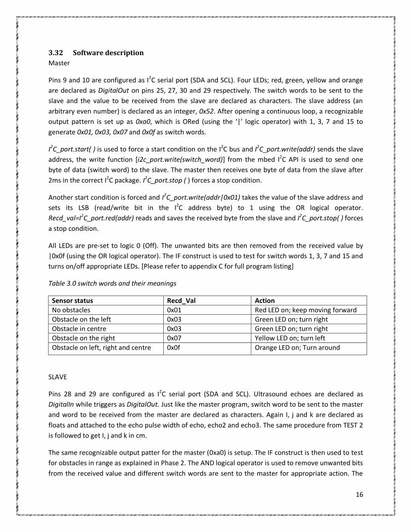
3.32 Software description
Master
Pins 9 and 10 are configured as I2C serial port (SDA and SCL). Four LEDs; red, green, yellow and orange
are declared as DigitalOut on pins 25, 27, 30 and 29 respectively. The switch words to be sent to the
slave and the value to be received from the slave are declared as characters. The slave address (an
arbitrary even number) is declared as an integer, 0x52. After opening a continuous loop, a recognizable
output pattern is set up as 0xa0, which is ORed (using the ‘|’ logic operator) with 1, 3, 7 and 15 to
generate 0x01, 0x03, 0x07 and 0x0f as switch words.
I2C_port.start( ) is used to force a start condition on the I2C bus and I2C_port.write(addr) sends the slave
address, the write function [i2c_port.write(switch_word)] from the mbed I2C API is used to send one
byte of data (switch word) to the slave. The master then receives one byte of data from the slave after
2ms in the correct I2C package. I2C_port.stop ( ) forces a stop condition.
Another start condition is forced and I2C_port.write(addr|0x01) takes the value of the slave address and
sets its LSB (read/write bit in the I2C address byte) to 1 using the OR logical operator.
Recd_val=I2C_port.red(addr) reads and saves the received byte from the slave and I2C_port.stop( ) forces
a stop condition.
All LEDs are pre-set to logic 0 (Off). The unwanted bits are then removed from the received value by
|0x0f (using the OR logical operator). The IF construct is used to test for switch words 1, 3, 7 and 15 and
turns on/off appropriate LEDs. [Please refer to appendix C for full program listing]
Table 3.0 switch words and their meanings
Sensor status Recd_Val Action
No obstacles 0x01 Red LED on; keep moving forward
Obstacle on the left 0x03 Green LED on; turn right
Obstacle in centre 0x03 Green LED on; turn right
Obstacle on the right 0x07 Yellow LED on; turn left
Obstacle on left, right and centre 0x0f Orange LED on; Turn around
SLAVE
Pins 28 and 29 are configured as I2C serial port (SDA and SCL). Ultrasound echoes are declared as
DigitalIn while triggers as DigitalOut. Just like the master program, switch word to be sent to the master
and word to be received from the master are declared as characters. Again I, j and k are declared as
floats and attached to the echo pulse width of echo, echo2 and echo3. The same procedure from TEST 2
is followed to get I, j and k in cm.
The same recognizable output patter for the master (0xa0) is setup. The IF construct is then used to test
for obstacles in range as explained in Phase 2. The AND logical operator is used to remove unwanted bits
from the received value and different switch words are sent to the master for appropriate action. The

17
write function from the mbed I2C slave API is used to write to the I2C master. [Please refer to appendix D
for full program listing]
4.0 INTEGRATION OF SUB-SYTEMS This involves the connection of all the slave subsystems to the central control unit via the I2C bus. As
expected on an I2C bus, slaves monitor the bus pulling the line to logic 0 when addressed while pull up
resistors return the lines back to logic 1.
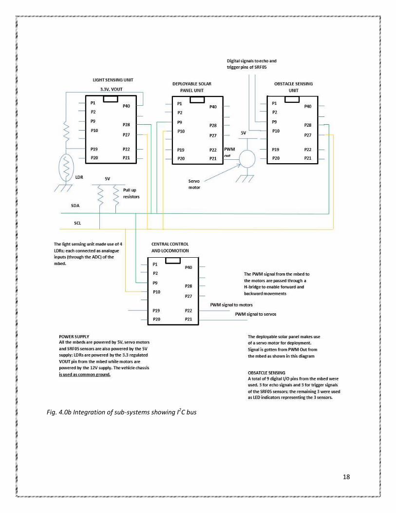
4.1 Hardware description
This AGV comprises four subsystems, each being built around an mbed microcontroller and
communication used between mbeds is I2C. Power supply to the entire system is by a 12V, 1.2amps
battery which is regulated to supply both 12V and 5V to the different units. The vehicle chassis is used as
the common ground and this is to reduce capacitive current drains. All mbeds are powered by 5V.
The obstacle sensing unit as earlier mentioned makes use of the digital I/O pins for connections between
its mbed and the range finders. The light sensing unit makes use of LDRs (light dependent resistor) as
light sensors which are connected through the ADC of the mbed (as analogue inputs). The deployable
solar panel unit makes use of one servo motor which is gets its signal from a PwmOut pin of the mbed.
The vehicles consists of four dc motors which control the speed of the wheels and four servo motors for
steering which are all controlled by the central control and locomotion unit. The servos are powered by
the 5V supply while the motors are powered by the 12V power supply through an H-bridge circuit to
enable both forward and backward movement of the motors. Both servos and motors get their pulse
width signals from the PwmOut pin of the mbed.
Fig. 4.0a: The AGV hardware
18
Fig. 4.0b Integration of sub-systems showing I2C bus

19
Yes
Yes
Yes
Yes
Yes
Yes
Yes
No
Yes
No
Yes
No
Yes
No
Yes
No
Yes

20
4.2 Software description
The same programming strategy as explained in 3.30 (phase 3: i2c communication between a master and
a slave) is applied. The only exception is that the strategy used by the entire team did not require setting
up a required output pattern (switch word) and using the OR logical operator to generate the different
switch words used. All switch words were created and sent accordingly. (Please refer to appendix E for
full program listing. Binary codes and slave addresses are available at appendix F)
5.0 AGV TESTING AND EVALUATION
During the development cycle of this project, all sub-systems performed individual tasks to expectation.
Success of the integration process was marred by excessive time delays on the I2C bus and constant
power outage. The response of the central control unit to the obstacle sensing unit was slow. Also
noticed was the inability of the central controller to respond to the light sensing and obstacle sensing
units sequentially with the limited time available.
Communication issues were due to poor time management skills in C programming. Allocation the
required time to different tasks in programming was key to success. In other the words, the central
control program efficiently and sequentially distributed the right amount of time to the different sub-
units in its program structure. Neat and tidy wiring of signal cables also contributed to fast response of
all the sub-units on the I2C bus.
An initial value of 40cm was used as the range of ultrasonic sensors. It was noticed that there was not
enough time for the AGV to effective avoid obstacles due to time delay on the I2C bus. A better
performance of the obstacle avoidance feature was achieved by increasing the range to 70cm.
Constant steering of the servos required high current and this led to an occurring power outage during
testing as the power supply is only a dc battery. Neat wiring as well as the use of short cables with a
larger diameter was an advantage in power management. In addition, using the chassis of the AGV as a
common ground to all sub-units helped reduce capacitive current drains. Generally, the performance of
the AGV was pretty good as it AGV could navigate to the point of highest light intensity, avoid obstacles
on its way but the solar panel hard a little hardware constraint.

21
6.0 CONCLUSION AND RECCOMMENDATION The issues of time and power management in embedded systems cannot be overemphasized.
Communication success on the I2C bus was achieved by allocating just the right times to sub-units.
Though the vehicle is a light seeking one, more time was allocated to the obstacle sensing unit by the
central controller. This involved giving the obstacle sensing unit a higher priority in the programming
strategy to constantly check for a clear path to its destination.
Programming with the mbed offers flexibility and a wide range of programming strategy due to its
simple API and online compiler readily available. The issue of time justifies the selection of the SRF05
(digital) over the SRF08 (I2C compatible). The use of the SRF08 would have led to a little more time loss
on its I2C bus which will be to a disadvantage. I2C is a reliable but not suitable for high reliability systems
due to time delay and the absence of error checking.
Application of light intensity gradient will be a better option than a pre-set threshold in the
programming strategy for the light sensing sub-system. A battery of higher amperage (about 3amps) is
recommended for future works. Also recommended is the use of two servos for steering; one to steer
both front wheels since they require the same pwm signal and the other to steer the back wheels. This
will reduce the total amount of current consumed by the AGV.
On the issue of communication, I2C may be more reliable than SPI in terms of slave acknowledgement
the two wire data bus (SDA and SCL) communication is half duplex; hence a little amount of time is lost.
CAN is a serial bus system with multi-master capabilities, that is, all CAN nodes are able to transmit data
and several CAN nodes can request the bus simultaneously (Bosch, 2012). CAN which is a highly reliable
communication protocol offers a high degree of real time capabilities (Bosch, 2012), peer to peer
communication, high level of data security and error checking, The CAN serial bus is therefore
recommended for future works to compensate for the limitations of I2C.

22
REFERENCES
Toulson, R and Wilmsurst, T (2012). Fast and effective embedded systems design: Applying the ARM
mbed. Oxford, Elsevier Ltd.
Leens, F (2009). Introduction to I2C and SPI protocols. IEE instrumentation and measurement magazine.
http://www.robot-electronics.co.uk/htm/srf05tech.htm [Assessed 4th December, 2013]
Daventech. (2013) SRF05 data sheet. [Internet]. Available from :
<http://www.robotikhardware.de/download/srf05doku.pdf> [Assessed: 3rd, 4th Decenber, 2013]
Mbed LPC1768 handbook. [Internet] Available from: <http://mbed.org/handbook/mbed-NXP-LPC1768>
[Assessed: 12th December, 2013]>
NPX, B.V (2009) [Internet]. Available from:
<http://www.nxp.com/products/microcontrollers/cortex_m3/> [Assessed 29th November, 2013]
Quick2wire. (2013) [Internet]. Available from: <http://quick2wire.com/articles/i2c-and-spi/> [Assessed
12th December, 2013]
http://electronics.stackexchange.com/ [Assessed 12th December, 2013]
Bosch (2012) Bosch semiconductors and sensors. [Internet]. Available from: <http://www.bosch-
semiconductors.de/en/ubk_semiconductors/safe/ip_modules/what_is_can/what_is_can.html>
[Assessed 11th December, 2013]

23
APPENDIX A
// Simple program to read the distance from an SRF05 using the SRF05 library
#include "mbed.h"
DigitalIn echo(p14); //echo input
DigitalOut trigger(p13); //trigger output
Serial pc(USBTX, USBRX); //declare USB serial link to pc
Timer t; //declare timer, t
float i;
int main() {
t.start(); //start timer
pc.printf("--- UltraSonic Range ---");
while(1) {
trigger=1; //trigger ultrasonic pulse
wait(0.00004); //wait 40ms
trigger=0; //set trigger to logic 0
while(!echo); //listen for echo pulse
t.reset(); //reset timer to measure echo pulse
while(echo);
i=t.read_us(); //attach echo pulse to float i
printf("\n\n\rPulse Length = %6.0f uS", i); //display echo pulse width
i=i/58; //convert pulse width to distance in cm
printf("\n\n\rDistance = %4.1f cm", i); //display distance in cm
wait(2);
}
}

24
APPENDIX B
// program to flash LEDs when ultrasounds detect obstacles within a fixed range of 25cm.
#include "mbed.h"
DigitalIn echo(p14); //SRF1; echo input
DigitalOut trigger(p13); //SRF1; trigger output
DigitalIn echo2(p16); //SRF2; echo2 input
DigitalOut trigger2(p15); //SRF2; trigger2 output
DigitalIn echo3(p18); //SRF3; echo3 input
DigitalOut trigger3(p17); //SRF3; trigger3 output
DigitalOut redled(p25);
DigitalOut yellowled(p27);
DigitalOut orangeled(p29);
Timer t;
float i,j,k; //declare i, j and k as floats
int main() {
t.start(); //start timer
while(1) {
trigger=1; //trigger ultrasonic pulse
wait(0.00004);
trigger=0; //stop sending pulses
while(!echo); //listen for echo pulse
t.reset(); //reset timer to measure echo pulse width
while(echo);
i=t.read_us(); //attach i to echo pulse width of sensor 1 in us
trigger2=1; //trigger ultrasonic pulse for sensor 2
wait(0.00004);
trigger2=0;
while(!echo2);
t.reset();
while(echo2);
j=t.read_us(); //attach j to echo pulse width of sensor 2
trigger3=1; //trigger ultrasonic pulse for sensor 3
wait(0.00004);
trigger3=0;
while(!echo3);

25
t.reset();
while(echo3);
k=t.read_us(); //attach k to echo pulse width of sensor 3
i=i/58; //convert i, j, k to distance in cm
j=j/58;
k=k/58;
redled=0; //pre-set LEDs to 0
yellowled=0;
orangeled=0;
if(i<25) { //set sensor 1 range to 25cm
redled = 1; //on LED 1
}
if(j<25){ //set sensor 2 range to 25cm
yellowled= 1;
}
if(k<25) { //set sensor 3 range to 25cm
orangeled = 1;
}
if(i>25) {
redled = 0;
}
if(j>25){
yellowled= 0;
}
if (k>25){
orangeled=0;
}
wait(0.2);
}
}

26
APPENDIX C
/* Master program to switch on/off different LEDs with respect to words received from the slave
connected to 3 ultrasonic range finders. The slave sends different switch words when it senses obstacles
within a specified range of 25cm*/
#include "mbed.h"
I2C i2c_port(p9, p10); //Configure a serial port, pins 9 and 10 are SDA, SCL
DigitalOut red_led(p25); //red led
DigitalOut green_led(p27); //green led
DigitalOut yellow_led(p30); //yellow led
DigitalOut orange_led(p29); // orange led
char switch_word ; //word we will send
char recd_val; //value received from slave
const int addr = 0x52; //define the I2C slave address, an arbitrary even number
int main() {
while(1) {
switch_word=0xa0; //set up a recognisable output pattern
switch_word=switch_word|0x01; //switch word OR 1
switch_word=switch_word|0x03; //OR 3
switch_word=switch_word|0x07; //OR 7
switch_word=switch_word|0x0f; //OR 15
//send a single byte of data, in correct I2C package
i2c_port.start (); //force a start condition
i2c_port.write (addr); //send the address
i2c_port.write (switch_word); //send one byte of data, i.e. switch_word
i2c_port.stop (); //force a stop condition
wait (0.002);
//receive a single byte of data, in correct I2C package
i2c_port.start();
i2c_port.write(addr|0x01); //send address, with Read/Write bit set to Read
recd_val=i2c_port.read(addr); //Read and save the received byte
i2c_port.stop(); //force a stop condition
//set leds according to word received from slave
red_led=0; //pre-set LEDs to 0
green_led=0;
yellow_led=0;
orange_led=0;

27
//set LEDs according to incoming word from slave
recd_val=recd_val& 0x0f; //AND out unwanted bits
if (recd_val==1){ // indicating no obstacles
red_led=1;
}
if (recd_val==3){ // indicating obstacle at the centre
green_led=1; // switch on green LED
}
if (recd_val==7){ // indicating obstacle ion the left
yellow_led=1; // switch on yellow LED
}
if (recd_val==15){ // obstacles in range of 3 sensors
orange_led=1; // switch on green LED
}
}
}
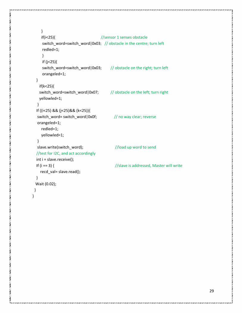
APPENDIX D
/*SLAVE OBSTACLE SENSING SUB-SYSTEM
Program to send 8 bit codes to the master indicating whether obstacles are detected or not within a
specified range of 25cm of the SRF05 sensor. */
#include <mbed.h>
I2CSlave slave(p9, p10); //Configure I2C slave
DigitalIn echo(p14); //Sensor1 echo input
DigitalOut trigger(p13); //sensor1 trigger output
DigitalIn echo2(p16); //Sensor2 echo input
DigitalOut trigger2(p15); //sensor2 trigger output
DigitalIn echo3(p18); //Sensor3 echo input
DigitalOut trigger3(p17); //sensor3 trigger output
DigitalOut orangeled(p25);
DigitalOut redled(p27);
DigitalOut yellowled (p29);
char switch_word ; //word we will send
char recd_val; //value received from master

28
Timer t;
float i,j,k; //declare i, j, k as floats
int main(){
slave.address(0x52); //define slave address
t.start(); // start timer
while(1) {
trigger=1; //trigger is set to logic 1; sends ultrasonic pulses
wait(0.00004); //wait 40us
trigger=0; //trigger is set to logic 0; stops ultrasonic pulses
while(!echo); //wait until the echo line goes high
t.reset(); //measure the pulse width
while(echo);
i=t.read_us(); //attach float i to echo pulse width of sensor1
trigger2=1; // REPEAT FOR SENSOR 2
wait(0.00004);
trigger2=0;
while(!echo2);
t.reset();
while(echo2);
j=t.read_us(); //attach float j to the echo pulse width of sensor2
trigger3=1; //REPEAT THESAME FOR SENSOR 3
wait(0.00004);
trigger3=0;
while(!echo3);
t.reset();
while(echo3);
k=t.read_us(); //attach float k to the echo pulse width of sensor 3
i=i/58; //convert i, j and k from us to cm
j=j/58;
k=k/58;
redled=0; //pre-set LEDs to 0
orangeled=0;
yellowled=0;
switch_word=0xa0; //set up a recognisable output pattern
if((i>25) &&(j>25)&&(k>25)){ // condition for no obstacle
switch_word=switch_word|0x01; //move forward
29
}
if(i<25){ //sensor 1 senses obstacle
switch_word=switch_word|0x03; // obstacle in the centre; turn left
redled=1;
}
if (j<25){
switch_word=switch_word|0x03; // obstacle on the right; turn left
orangeled=1;
}
if(k<25){
switch_word=switch_word|0x07; // obstacle on the left; turn right
yellowled=1;
}
If ((i<25) && (j<25)&& (k<25)){
switch_word= switch_word|0x0f; // no way clear; reverse
orangeled=1;
redled=1;
yellowled=1;
}
slave.write(switch_word); //load up word to send
//test for I2C, and act accordingly
int i = slave.receive();
If (i == 3) { //slave is addressed, Master will write
recd_val= slave.read();
}
Wait (0.02);
}
}

30
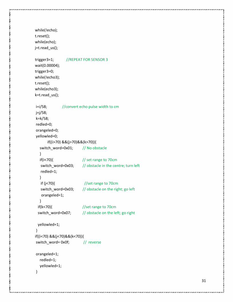
APPENDIX E
/*SLAVE OBSTACLE SENSING SUB-SYSTEM. The range of the 3 ultrasounds is set at 70cm. This unit sends
different switch words to the master stating whether there are obstacles or not. It also indicates the
position of obstacles if detected.
*/
#include <mbed.h>
I2CSlave slave(p9, p10); //Configure I2C slave
DigitalIn echo(p14); //echo input
DigitalOut trigger(p13); //trigger output
DigitalIn echo2(p16);
DigitalOut trigger2(p15);
DigitalIn echo3(p18);
DigitalOut trigger3(p17);
DigitalOut orangeled(p25);
DigitalOut redled(p27);
DigitalOut yellowled (p29);
char switch_word ; //word we will send
char recd_val; //value received from master
Timer t;
float i,j,k;
int main(){
slave.address(0x54); //slave address
t.start(); // start timer
while(1) {
trigger2=1; //send a pulse
wait(0.00004); //wait 40us
trigger2=0;
while(!echo2); //wait until the echo line goes high
t.reset(); //measure the pulse width
while(echo2);
i=t.read_us(); //attach i to echo pulse width
trigger=1; //REPEAT FOR SENSOR 2
wait(0.00004);
trigger=0;
31
while(!echo);
t.reset();
while(echo);
j=t.read_us();
trigger3=1; //REPEAT FOR SENSOR 3
wait(0.00004);
trigger3=0;
while(!echo3);
t.reset();
while(echo3);
k=t.read_us();
i=i/58; //convert echo pulse width to cm
j=j/58;
k=k/58;
redled=0;
orangeled=0;
yellowled=0;
if((i>70) &&(j>70)&&(k>70)){
switch_word=0x01; // No obstacle
}
if(i<70){ // set range to 70cm
switch_word=0x03; // obstacle in the centre; turn left
redled=1;
}
if (j<70){ //set range to 70cm
switch_word=0x03; // obstacle on the right; go left
orangeled=1;
}
if(k<70){ //set range to 70cm
switch_word=0x07; // obstacle on the left; go right
yellowled=1;
}
if((i<70) &&(j<70)&&(k<70)){
switch_word= 0x0f; // reverse
orangeled=1;
redled=1;
yellowled=1;
}

32
slave.write(switch_word); //load up word to send
//test for I2C, and act accordingly
int i = slave.receive();
if (i == 3) { //slave is addressed, Master will write
recd_val= slave.read();
}
}
}
APPENDIX F
LIGHT SENSING TEAM
Action Binary Hex
Left 1000 0000 0x80
Right 1100 0000 0xC0
stop 00000000 0x00
Start condition 1111 0000 0xF0
Defined address 0101 0010 0x52
OBSTACLE SENCING TEAM
Action Binary Hex
No obstacle 0000 0001 0x01
Left 0000 0011 0x03
Right 0000 0111 0x07
Reverse 0000 1111 0x0F
Defined address 0101 0100 0x54
Solar panel
Action Binary Hex
Open the panel 1111 1111 0xFF
Close the panel 1010 0000 0xA0
Defined address 0101 0110 0x56
Copyright © 2022 FDOKUMEN