Deformable Boundary Detection of Stents in Angiographic Images
Upload
independentCategory
view
0download
0
Deformable CT registration using Fourier basis functions in 3D
Amílcar R. Osorio
Fundación Centro Diagnóstico Nuclear
Buenos Aires, Argentina
Roberto A. Isoardi
Fundación Escuela de Medicina Nuclear
Mendoza, Argentina
Germán Mato
Grupo Física Estadística
Centro Atómico Bariloche
Bariloche, Argentina
Abstract— Non-rigid medical image registration is an essential
tool when studying deformable regions such as thorax and
abdomen. In this paper we propose an algorithm based on
Fourier transformations with trigonometric Fourier basis
functions at different orders combined with a subdivision
scheme in order to attain spatial alignment of two
corresponding Computed Tomography (CT) volumes, with
small to moderate deformations. The performance of the
algorithm was analyzed as a function of the transformation
order (n) and the number of volume subdivisions along each
axis (s). The results show that a suitable parameter choice is
n=2, s=3-4. The algorithm was validated by “correcting”
clinical images previously deformed with Thin-Plate Splines
(TPS), and also applied to coregister different scans of a given
subject after repositioning on the scanner bed. This method is
automatic and does not require previous segmentation or
landmark selection. Average registration errors with the
optimal parameters were estimated in approximately 3 mm,
and typical computing time is of the order of a few minutes in a
standard personal computer. We have found that Fourier basis
functions provide an efficient way to implement non-rigid
registration.
Keywords- Non-rigid Registration; Computed Tomography;
Fourier basis functions
I. INTRODUCTION
Image registration has become an extremely important and routine procedure, not only for diagnostic applications, but also as an essential tool to assist in Radiotherapy Planning and adaptive Radiotherapy [1-3]. The search for an automatic, fast and reliable method applicable to different situations remains an open research field. One of the most frequent applications of medical image
registration is the spatial alignment of two or more scans of the same tomographic modality for a given subject. In a general classification scheme, this situation corresponds to intra-subject, intra-modality registration [4-6]. The time elapsed between different scans may range from a few
seconds up to several months, for instance when follow-up studies of a same patient are carried out. If the subject is repositioned between scan sessions, his/her anatomical orientation and distribution will change with respect to the scanner coordinate system. For certain body regions such as the head and limb
portions, the application of a rigid body transformation model is usually satisfactory. When it comes to thorax and abdomen, however, those models only provide a rough approximation. Several organs and tissues of interest may redistribute or deform considerably because of patient repositioning, normal physiological functions or involuntary motion (i.e. respiration). In many cases, it is very important to take into account such variations, for example for fractionated treatment of prostate cancer [7-9]. There are several approaches to this problem in the literature which propose non-rigid registration algorithms [5,10,11], and this remains an active research field given its complexity and variety of situations of interest. Unlike rigid model registration, the validation of deformable methods is particularly challenging, as the outcome after metric optimization may turn out to be non-unique or even meaningless [12]. However, the main difficulty in the application of
deformable methods lies in the many degrees of freedom for the system. In an extreme situation, it would be necessary to propose an independent tri-dimensional transformation for every image voxel. In this case the number of transformations would be three times the number of voxels. Optimization in such a parameter space is computationally expensive. For that reason, a number of approximations are usually implemented, and most non-rigid methods first perform a rigid approach and then apply a non-rigid transformation using a small set of basis functions. For example, spline basis functions are used when fiducial markers are available or algorithms based on physical models can be also applied (e.g. elastic deformations, viscous fluids, etc.)
[13-16].

Figure 1: Flowchart of the whole registration algorithm.
Figure 2: a) Sub-volume assembling method (see Appendix). b) sub-volumes before and c) after assembling. Figures show a 2D
section of the 3D volume.
In this work we offer a systematic analysis of this issue using trigonometric Fourier basis functions [17-19]. With these functions one can easily control the typical size of the deformation field in a simple fashion, ranging from long to short wavelengths. By combining this approach with a volume subdivision scheme, we expect that a very small subset of basis functions should be enough. In addition, since Fourier functions constitute a complete set, we can approximate an arbitrary deformation only by increasing the number of basis functions. The main purpose of this work is to analyze this issue in
a systematic way for intra-modality registration for CT (Computed Tomography). For this modality, we determine the optimal number of coefficients (transformation order) for the basis functions and the number of sub-volumes that produce a satisfactory registration in a reasonable computing time. As the similarity measure, we compute the Normalized
Mutual Information (NMI) at different transformation orders. It has been shown the use of NMI with volume partial interpolation allows fast computation and low noise levels [20-22]. The algorithm is applied on 3D image data sets of deformable parts of the body such as the thorax and abdomen. Each volume was artificially deformed using a known displacement field and then co-registered to its original counterpart, which was taken as the reference image. In order to assess its clinical usefulness, we applied the
method to co-register two CT scans of the same subject on different acquisition dates. This paper is organized as follows: in the next section the
theoretical background of algorithm is described. Then we present the results of applying the algorithm on the data sets as mentioned above, including error estimation. Finally, we analyze the performance of the algorithm in the discussion section.
II. MATERIALS AND METHODS
A. Theoretical Framework and Algorithm
The purpose of a registration method is to find the set of
parameters of the transformation T:r =(x,y,z) → r’= (x’,y’,z’) which maps any point of a floating image F on another reference image R. The transformation has to maximize the similarity measure that will be described below. We adopt the following scheme: 1. Pre-processing: segmentation, resampling, filtering. 2. An initial registration is performed using affine
transformations (rigid+scaling) F → R, optimizing the similarity measure.
3. F is divided into k sub-volumes Fr (k=8 in 3D). 4. An independent transformation is applied to each portion Fr , with a rigid and a non-rigid component.

5. The global transformation Tglobal=S (T1 ∪ T2...∪ Tk ) is obtained after the assembling the transformations Tr .
The above algorithm is depicted in Fig. 1. The affine registration in steps 1 and 3 is parameterized by rotation, translation, shearing and scaling. In 3D, this requires 12 parameters. For the non-rigid transformation we applied a Fourier
expansion up to order n on each dimension:
( ) [ ]∑=
++=n
kji
ijkijkijkijkx baxT1,,
)()( rrr ψϕ (1)
( ) [ ]∑=
++=n
kji
ijkijkijkijky dcyT1,,
)()( rrr ψϕ (2)
( ) [ ]∑=
++=n
kji
ijkijkijkijkz fezT1,,
)()( rrr ψϕ (3)
where:
,sinsinsin)(
=
Z
πkz
Y
πjy
X
πixijk rϕ
and:
.coscoscos)(
=
Z
πkz
Y
πjy
X
πixijk rψ
X, Y, Z being the image dimensions along each spatial
direction and a, b, c, d, e, f the coefficients to be found up to order n. The initial condition is randomly selected with a
Gaussian distribution with 0 mean and variance σ2. In order
to have a smooth initial condition σ is taken to be proportional to n
-1.
In this approach, functions ϕijk represent the subset of transformations that keep the volume boundary invariant,
while functions ψijk represent the transformations with null gradient on that boundary.
B. Assembling and subdivision scheme
Usually, the assembling of independent sub-volumes
after rigid transformations is achieved by the interpolation
of quaternions [23]. To the best of our knowledge, however,
no interpolation method is yet regarded as standard for non-
rigid transformations. In this work, we propose the strategy
shown in Fig. 2. We build for each point a consistent global
transformation from the weighted average transformations
of the corresponding sub-volume and its nearest neighbors.
It is a hierarchical scheme, where each volume is divided
into 8 equal sub-volumes, and this process is repeated s
times. With this method we obtain a smooth continuous and
differentiable global transformation. A full description of
the assembling method is offered in the Appendix.
C. Similarity measure
The Normalized Mutual Information was adopted in this
work [22,24,25]:
∑
∑ ∑+
=
ij
ijij
i j
jjii
pp
pppp
NMI
)log(
)log()log( (4)
where pij is the joint probability distribution of the voxel values of the reference and floating images and pi and pj are the marginal probability distributions. The partial volume method was used as interpolator [26]
and the extended Downhill Simplex [27,28] is chosen as optimizer. We consider that the termination criterion is met when the change in the NMI between two consecutive iterations is < 10-4. The algorithm was implemented in C++ programming language and run on a PC-Linux platform,
Intel Core 2 Duo - 3 GHz.
D. Image data
The CT scans were performed with a HiSpeed scanner
(GE, Milwaukee, USA). (matrix size: 512×512×47, voxel size: 0.7×0.7×7 mm3). Each selected data set was slightly deformed using TPS
(Thin-Plate Splines) [29,30] with a regular grid of 432 control points and a average displacement of 27 mm (maximum displacement: 40 mm), simulating a moderate body expansion (e.g. exhalation-inhalation phase). This artificially deformed volume was selected as the Floating Image to be registered to the original one (Reference Image). After determining the optimum order and number of
subdivisions for each modality, we applied the registration algorithm for co-registering two studies of the same subject, each done on the same scanner but on different days. In this way, we made sure that the patient had been repositioned on the scanner table between scan sessions, causing visible soft tissue displacements in the thoraco-abdominal region.
E. Error estimation
For non-rigid registration, a measure of error can be
provided by the average voxel-to-voxel absolute displacement between the reference and registered images. In case of perfect alignment, such displacements are equal to zero. The average displacement over the whole image is:
∑ −=i
ii qpTN
)(1
ε (5)
where pi and qi are the voxel coordinates of floating and
reference image, respectively and N is the total number of voxels. It is important to keep in mind that both the initial deformation field (after the application of TPS) and the resulting field (after registration) are known.
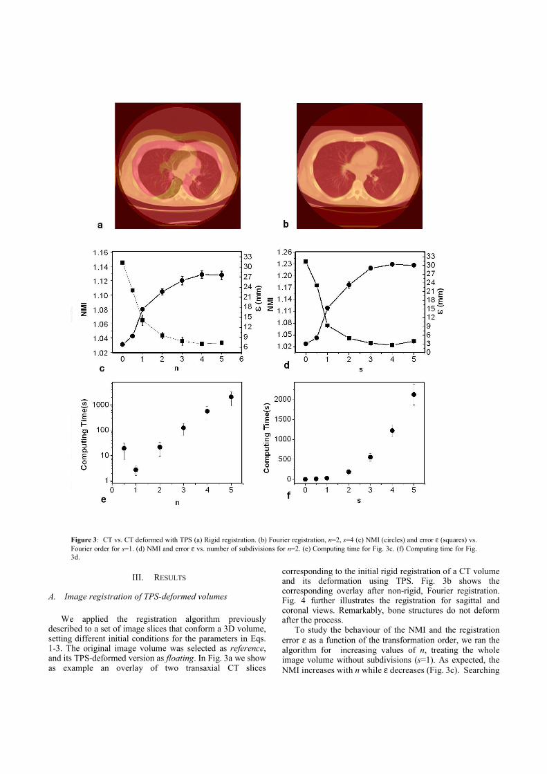
Figure 3: CT vs. CT deformed with TPS (a) Rigid registration. (b) Fourier registration, n=2, s=4 (c) NMI (circles) and error ε (squares) vs.
Fourier order for s=1. (d) NMI and error ε vs. number of subdivisions for n=2. (e) Computing time for Fig. 3c. (f) Computing time for Fig.
3d.
III. RESULTS
A. Image registration of TPS-deformed volumes
We applied the registration algorithm previously
described to a set of image slices that conform a 3D volume, setting different initial conditions for the parameters in Eqs. 1-3. The original image volume was selected as reference, and its TPS-deformed version as floating. In Fig. 3a we show as example an overlay of two transaxial CT slices
corresponding to the initial rigid registration of a CT volume and its deformation using TPS. Fig. 3b shows the corresponding overlay after non-rigid, Fourier registration. Fig. 4 further illustrates the registration for sagittal and coronal views. Remarkably, bone structures do not deform after the process. To study the behaviour of the NMI and the registration
error ε as a function of the transformation order, we ran the algorithm for increasing values of n, treating the whole image volume without subdivisions (s=1). As expected, the
NMI increases with n while ε decreases (Fig. 3c). Searching

Figure 4: Coronal and sagittal views of CT vs. TPS-deformed
CT before (a) and after (b) Fourier registration with order n=2 and subdivision s=4.
for further optimization in the parameter space and reasonable computing time, we then selected n=2 and plotted
NMI and ε as a function of the number of subdivisions (Fig.
3d). The optimum was found for (n=2, s=4), where ε ∼ 3 mm. For all graphs, values at n,s=0 and n,s=0.5 stand for
initial volume alignment and rigid registration, respectively. Let us note that the rigid registration takes longer time than the registration with n=1. This is because for the rigid registration is initialized 3 times in order to avoid local maxima. In contrast, only a rough registration was performed in the rigid stage of the algorithm for n≥1, because its result was just the starting point of the registration with Fourier functions. Every registration cycle was run 12 times each one with a
different initial deformation. The graphs show average values with their corresponding standard deviations (error bars). The computation time for each registration stage is
plotted in Figs. 3e and 3f. The total computation time can be evaluated by adding up the corresponding points. For example, for a second order registration we have to add the rigid part (n=0.5), the first order registration (n=1) and the second order registration (n=2). As the computation time grows exponentially with the order (except between n=0.5 and n=1), the values shown in the graph are already very close to the total computation time. From these figures we choose n=2 as a suitable order,
since for n>2, the computation time increases considerably
even when the error ε is almost constant. Similarly, both the
NMI and ε improve with the number of subdivisions, at the expense of execution time. For this reason, a convenient number of subdivisions was selected as s=3, 4.
B. Intra-subject registration: clinical studies
In addition to the systematic analysis presented above,
we evaluated how the algorithm accounts for real deformations in the thoraco-abdominal region. Two clinical CT scans corresponding to a given subject were selected, each acquired on different dates. The first scan was taken as reference, to which the second one was co-registered, using the optimum n and s as obtained above. Two medical experts examined the reference, floating and registered volumes slice by slice, looking for selected anatomical landmarks. They qualified the results as “fairly acceptable” and encountered only minor misalignments by visual inspection, which were estimated to be 2 mm. Results are shown in Fig. 5.
IV. DISCUSSION AND CONCLUSION
We presented a detailed analysis of a registration method based on the maximization of mutual information. A subset of Fourier functions is used as basis for the transformation. We systematically analyzed the behavior of the algorithm as a function of the order of the transformation and the number of subdivisions of the image. Our systematic analysis shows how the similarity
measure (NMI) behaves with both the order of the transformation n and the number of subdivisions s. For CT-CT registration, we found that maximum NMI is attained for
n ≥ 3 (s=1). For n=2 the NMI is only slightly inferior, however the computing time becomes an order of magnitude longer if calculation is performed up to n = 3 (Fig. 3e), as the number of Fourier parameters to be optimized is 6n3 in 3D (Eqs. 1-3). As expected, the similarity measure increases with the
number of subdivisions s, accompanied by a decrease in
error ε (Fig. 3d). The improvement in registration quality was also confirmed by visual assessment by comparing
Figure 5: Intra-modality registration of two clinical scans
(same subject, different sessions). Left column: rigid registration. Right column: Fourier registration. Top row: image fusion.
Bottom row: image difference.

results using s=3 versus s=4. Only slight improvements in
the NMI and ε were recorded for n>3 and s>3, but at a very high computational cost and providing negligible visual improvements. One issue of concern is that rigid structures such as bone in CT should remain so after registration. Since the characteristic size of the deformation applied is greater than typical bone structures, they do not deform noticeably (Fig. 4). Regarding computing time, setting optimal parameters
(n=2, s=3), and using an ordinary computer, the time for co-registering two CT volumes (matrix dimensions
512×512×47) is ~ 600 secs. (~ 200 secs. if s=2). (Fig. 3f). Such computation times were attained without any specific optimization technique. Let us note that the algorithm leads naturally to parallelization because the sub-volumes can be processed independently. In that way, the computing time can be substantially reduced. In principle, the use of Fourier basis functions allows
arbitrary deformations on any given image volume; the combination of this method with a subdivision scheme allows to accommodate small image portions in a progressive fashion, without affecting the rest of the image data [23,31]. In general, the proposed registration method rendered
acceptable results for small and moderate deformations (~ 25 mm). A preliminary study suggests that it is fairly robust, even in the presence of Gaussian noise. We evaluated its performance using clinical images after deformation with Thin-Plate Splines, as well as image pairs corresponding to different scan sessions for a same subject. The selected studies were thoracic and abdominal scans for three common tomographic modalities. Obviously, not only organ deformations and displacements may come about between scan sessions, but also significant variations in anatomy and function, due to normal or pathological conditions. In these cases, the outcome of any non-rigid registration method offers an approximation whose usefulness must be assessed for each particular situation. We found that near maximum NMI is attained for n=2
and s=3 or 4 in a reasonable computing time for CT-CT registration, with an average error ~ 3mm. We have tested our method with several data sets and the optimal parameters are typically similar (data not shown). These results are of the same order as the ones found in
recent approaches [32,33], using more complex methods such as a combination of cross-correlation and mutual information in the former and local matching of anatomical features in the latter. The computing time is between 400 secs and 1000 secs, which is also of the same order as the time reported in [32]. The applied basis functions involve only “smooth”
transformations, with wavelengths of the order of sub-volume that is being analyzed. Therefore, these transformations cannot deform small structures such as bones. The algorithm was successfully applied to moderately
deformed volumes using Thin-Plate Splines in 3D for co-registering pairs of CT scans of a same subject, each on different dates. The performance was qualified as “fairly
acceptable” by medical experts. Although the current study shows results for intra-modality situations only, the method can be extended and applied to inter-modality cases without substantial change.
ACKNOWLEDGMENT
The authors wish to thank Alvaro Barbeira, Germán Arenas and Andrés Astesiano for their support and assistance. This work was supported by CNEA, CONICET and MINCyT of Argentina.
APPENDIX
After the different sub-volumes are registered it is typically found that the displacement on the borders is not the same for contiguous sub-volumes. This would imply that the transformation is not continuous, which is physically unacceptable. A simple solution for this problem is to use the previous transformations to build a continuous global transformation by linear combination, with weights that depend on the distance from the border of the sub-volume. Let us consider the simple case of two 2D sub-volumes
U1 and U2, with transformations T1 and T2 (see Fig. 2a). We denote the borders of each volume as C1 and C2. We look for a continuous and differentiable global transformation Ts. In order to do that we propose a weighted average with the conditions that on the border itself Ts must be equal to (T1+T2)/2, while well inside of the sub-volumes Ts must converge to T1 or T2. We use the function fh(x)=tanh(x). We define Ts as:
),()(),()(),( 1221 yxTxpyxTxpyxTs
γγ += (A1)
where
Ω∈
+−
Ω∈
+−
=
2
0
1
0
1
),(2
1)(
),(2
1)(
)(
yxif
xxf
yxif
xxf
xp
h
h
γ
γ
γ
Ω∈
+−
Ω∈
+−
=
2
0
1
0
2
),(2
1)(
),(2
1)(
)(
yxif
xxf
yxif
xxf
xp
h
h
γ
γ
γ
The parameter γ controls the distance inside a sub-volume where the transformation is affected by the neighbors and x0 is the coordinate of the border between the two sub-volumes. This parameter is taken as ¼ of the average length of the sub-volume. This means that for the opposite half of the sub-volume the transformation will have almost no effect. These sections, denoted in Fig. 2 by U’1 and U’2 will be connected to the sub-volumes that are to its left and to its right respectively. It is very easy to check that

this transformation satisfies the continuity and differentiability requirements and that has the correct limits. In the more general case of 4 sub-volumes in 2D, Ts has he form:
∑=
=4
1
),(),(),(i
iis yxTyxpyxT γ (A2)
Where now ),( yxpi
γ is given by:
)1)~()(1)~((4
1),(
)1)~()(1)~((4
1),(
)1)~()(1)~((4
1),(
)1)~()(1)~((4
1),(
4
3
2
1
+−+−=
+−+=
++−=
++=
yfxfyxp
yfxfyxp
yfxfyxp
yfxfyxp
hh
hh
hh
hh
γ
γ
γ
γ
with:
γ
γ
yyy
xxx
−=
−=
0
0
~
~
where (x0,y0) is the coordinate where the 4 sub-volumes
intersect. The same procedure can be easily generalized to
3D, where there are 8 transformations piγ(x,y,z):
∑=
=8
1
),,(),,(),(i
iis zyxTzyxpyxTγ (A3)
with:
)1)~)1(((
)1)~)1((()1)~)1(((8
1),,(
14/)1(
12/)1(1
+−×
×+−+−=
+−
+−−
zf
yfxfzyxp
i
h
i
h
i
hi
γ
REFERENCES
[1] M. L. Kessler, “Image registration and data fusion in radiation therapy,” Br. J. Radiol. vol. 79, Special issue 1, Sept. 2006, pp. 99-108.
[2] G. Li, D. Citrin, K. Camphausen, B. Mueller, C. Burman et al, “Advances in 4D medical imaging and 4D radiation therapy,” Technol. Cancer Res. Treat. vol. 7, no. 1, Feb. 2008, pp. 67-81
[3] M. Sharpe and K. K. Brock, “Quality Assurance of Serial 3D Image Registration, Fusion, and Segmentation,” Int. J. Radiat. Oncol. Biol. Phys. vol. 71, no.1, Supplement 1, May 2008, pp. 33-37.
[4] J.B.A. Maintz and M.A. Viergever, “A survey of medical image registration,” Med. Image Anal. vol. 2, no. 1, March 1998, pp. 1–36.
[5] J.V. Hajnal, D.L.G. Hill, and D. J. Hawkes, Medical Image Registration, (CRC Press, Boca Raton, 2001).
[6] B. Zitova and J. Flusser, “Image registration methods: a survey,” Image Vis. Comput. vol. 21, no. 11, Oct. 2003, pp. 977-1000.
[7] D. Yan, D.A. Jaffray, and J.W. Wong, “A model to accumulate fractionated dose in a deforming organ,” Int. J. Radiation Oncol. Biol. Phys. vol. 44, no. 3, June 1999, pp. 665-675.
[8] W. Lu, M.L. Chen, G.H. Olivera, K.J. Ruchala, and T.R. Mackie, “Fast free-form deformable registration via calculus of variations,” Phys. Med. Biol. vol. 49, no. 14, July 2004, pp. 3067-3087.
[9] W. Lu, G. H. Olivera, Q. Chen, K. J. Ruchala, J. Haimerl, S.L. Meeks, K.M. Langen, and P.A. Kupelian, “Deformable registration of the planning image (kVCT) and the daily images (MVCT) for adaptive radiation therapy,” Phys. Med. Biol. vol. 51, no. 17, Sept. 2006, pp. 4357-4374.
[10] H. Lester and S.R. Arridge, “A survey of hierarchical non-linear medical image registration” Pattern Recognit. vol. 32, no. 1, January 1999, pp. 129-149.
[11] W.R. Crum, T. Hartkens, and D.L.G. Hill, “Non-rigid image registration: theory and practice”, Br. J. Radiol. vol. 77, no. 2, Dec. 2004, pp. S140-S153.
[12] W.R. Crum, L.D. Griffin, D.L.G. Hill, and D.J. Hawkes, “Zen and the art of medical image registration: correspondence, homology, and quality,” NeuroImage vol. 20, no. 3, Nov. 2003, pp. 1425-1437.
[13] E. D'Agostino, F. Maes, D. Vandermeulen, and P. Suetens, “A viscous fluid model for multimodal non-rigid registration using mutual information,” Med. Image Anal. vol. 7, no. 4, Dec. 2003, pp. 565-575.
[14] M. Bro-Nielsen and C. Gramkow, “Fast Fluid Registration of Medical Images,” in: Visualization in Biomedical Computing, Lecture Notes in Computer Science (Springer-Verlag, Hamburg, 1996), pp. 267-276.
[15] G.E. Christensen, R.D. Rabitt, and M.I. Miller, “Deformable Templates Using Large Deformation Kinematics,” IEEE Trans. Med. Imaging vol. 5, no. 10, Oct. 1996, pp. 1435-1447.
[16] H. Lester and S.R. Arridge, “Summarising fluid registration by thin-plate spline warps with many landmarks”, Proceedings of Medical Image Understanding and Analysis (MIUA97), (BMVA, Oxford, 1997), pp. 53-56.
[17] Y. Amit, U. Grenander, and M. Piccioni, “Structural image restoration through deformable templates,” J. Am. Statis. Ass. vol. 86, no. 414, June 1991, pp. 376-387.
[18] K.J. Friston, J. Ashburner, C.D. Frith, J.B. Poline, J.D. Heather, and R.S.J. Frackowiak, “Spatial registration and normalisation of images, “ Hum. Brain Mapp. vol. 3, no. 3, 1995, pp. 165.
[19] J. Ashburner and K.J. Friston, “Nonlinear spatial normalization using basis functions,” Hum. Brain Mapp. vol. 7, no. 4, 1999, pp. 254-266.
[20] J.P.W. Pluim, J.B.A. Maintz, and M.A. Viergever, “Mutual information matching and interpolation artefacts,” Proc. SPIE vol. 3661,1999, pp. 56-65.
[21] J.P.W. Pluim, J.B.A. Maintz, and M.A. Viergever, “Interpolation Artefacts in Mutual Information-Based Image Registration,” Comput. Vis. Image. Underst. vol. 77, no. 2, Feb. 2000, pp. 211-232.
[22] J.P.W. Pluim, J.B.A. Maintz, and M.A. Viergever, “Mutual-Information-Based Registration of Medical Images: A Survey,” IEEE Trans. Med. Imaging vol. 22, no. 8, Aug. 2003, pp. 986-1004.
[23] V.S. Walimbe, V. Zagrodsky, S. Raja, B. Bybel, M. Kanvinde, and R. Shekhar, “Elastic registration of three-dimensional whole body CT and PET images by quaternion-based interpolation of multiple piecewise linear rigid-body registrations,” Proc. SPIE, vol. 5370, 2004, pp. 1191-1228.
[24] F. Maes, A. Collignon, D. Vandermeulen, G. Marchal, and P. Suetens, “Multimodality image registration by maximization of mutual information,” IEEE Trans. Med. Imaging vol. 16, no. 2, April 1997, pp. 187-198.
[25] C. Studholme, D.L.G. Hill, and D.J. Hawkes, “An overlap invariant entropy measure of 3D medical image alignment,” Pattern Recognit. vol. 32, no. 1, January 1999, pp. 71-86.
[26] M. Chen and P. K. Varshney, “Mutual Information -based CT-MR brain image registration using generalized partial volume joint

histogram estimation,” IEEE Trans. Med. Imaging vol. 22, no. 9, Sept. 2003, pp. 1111-1119.
[27] W.H. Press, B.P. Flannery, S.A. Teukolsky, and W.T. Vetterling, Numerical Recipes in C: The Art of Scientific Computing, 2nd ed. (Cambridge University Press, Cambridge, 1992).
[28] V. Zagrodsky, R. Shekhar, and J. F. Cornhill, “Multi-function extension of simplex optimisation method for mutual information based registration of ultrasound volumes,” Proc. SPIE vol. 4322, 2001, pp. 508-515.
[29] F.L. Bookstein, “Principal Warps: Thin-Plate Splines and Decomposition of Deformations,” IEEE Trans. Pattern. Anal. Mach. Intell. vol. 11, no. 6, June 1989, pp. 567-585.
[30] K. Rohr, H.S. Stiehl, T.M. Buzug, J. Weese, and M.H. Kuhn, “Landmark-Based Elastic Registration Using Approximating Thin-
Plate Splines,” IEEE Trans. Med. Imaging vol. 20, no. 6, June 2001, pp. 526-534.
[31] B. Likar and F. Pernus, “A Hierarchical Approach to Elastic Registration Based on Mutual Information,” Image Vis. Comput. vol. 19, no. 1-2, January 2001, pp. 33-44.
[32] A. Andronache , M. von Siebenthal ,G. Székely and P. Cattin. “Non-rigid registration of multi-modal images using both mutual information and cross-correlation”. Med Imag Anal, vol. 12, 2008, pp. 3-15.
[33] M. Sohn, M. Birkner , Y. Chi, J. Wang , D. Yan, B. Berger, M. Alber. “Model-independent, multimodality deformable image registration by local matching of anatomical features and minimization of elastic energy”. Med Phys, vol. 35. 2008, pp. 866-878.
Copyright © 2022 FDOKUMEN


![[C. Lemmi] Optica de Fourier](https://static.fdokumen.com/doc/165x107/6315892e511772fe4510654e/c-lemmi-optica-de-fourier.jpg)