Adaptive Image Matching Using Discrimination of Deformable ...
Upload
khangminh22Category
view
4download
0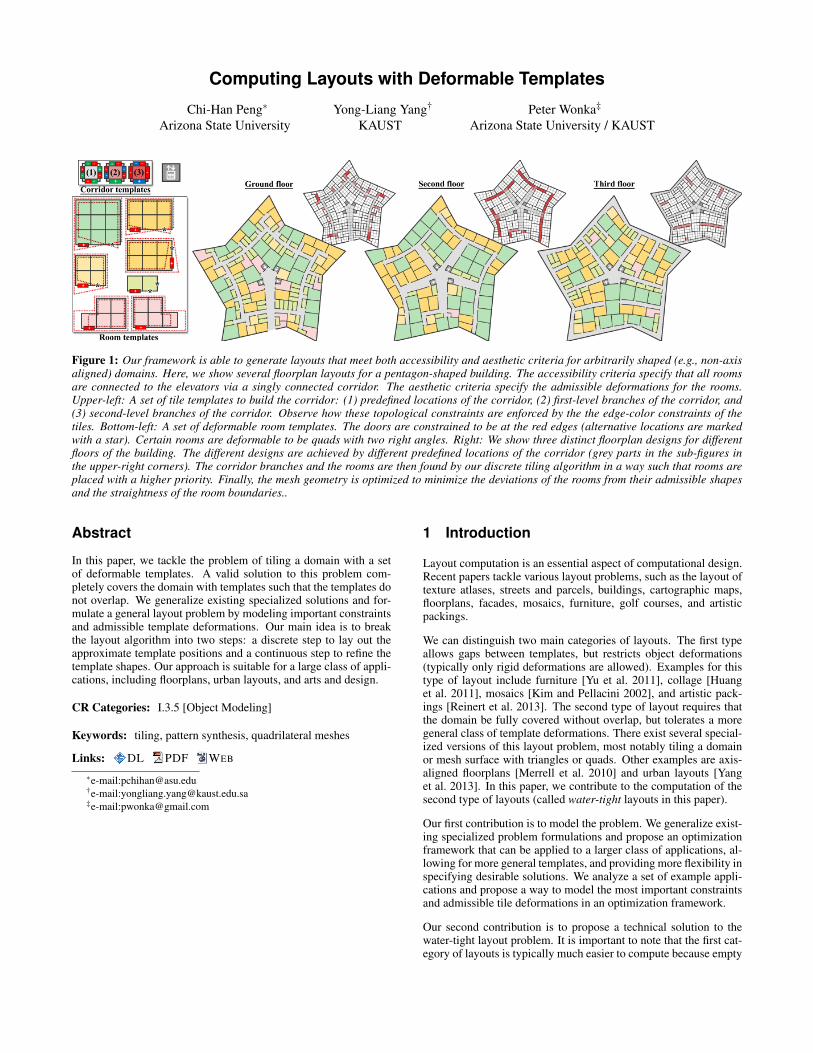
Computing Layouts with Deformable Templates
Chi-Han Peng∗
Arizona State UniversityYong-Liang Yang†
KAUSTPeter Wonka‡
Arizona State University / KAUST
Figure 1: Our framework is able to generate layouts that meet both accessibility and aesthetic criteria for arbitrarily shaped (e.g., non-axisaligned) domains. Here, we show several floorplan layouts for a pentagon-shaped building. The accessibility criteria specify that all roomsare connected to the elevators via a singly connected corridor. The aesthetic criteria specify the admissible deformations for the rooms.Upper-left: A set of tile templates to build the corridor: (1) predefined locations of the corridor, (2) first-level branches of the corridor, and(3) second-level branches of the corridor. Observe how these topological constraints are enforced by the the edge-color constraints of thetiles. Bottom-left: A set of deformable room templates. The doors are constrained to be at the red edges (alternative locations are markedwith a star). Certain rooms are deformable to be quads with two right angles. Right: We show three distinct floorplan designs for differentfloors of the building. The different designs are achieved by different predefined locations of the corridor (grey parts in the sub-figures inthe upper-right corners). The corridor branches and the rooms are then found by our discrete tiling algorithm in a way such that rooms areplaced with a higher priority. Finally, the mesh geometry is optimized to minimize the deviations of the rooms from their admissible shapesand the straightness of the room boundaries..
Abstract
In this paper, we tackle the problem of tiling a domain with a setof deformable templates. A valid solution to this problem com-pletely covers the domain with templates such that the templates donot overlap. We generalize existing specialized solutions and for-mulate a general layout problem by modeling important constraintsand admissible template deformations. Our main idea is to breakthe layout algorithm into two steps: a discrete step to lay out theapproximate template positions and a continuous step to refine thetemplate shapes. Our approach is suitable for a large class of appli-cations, including floorplans, urban layouts, and arts and design.
CR Categories: I.3.5 [Object Modeling]
Keywords: tiling, pattern synthesis, quadrilateral meshes
Links: DL PDF WEB
∗e-mail:[email protected]†e-mail:[email protected]‡e-mail:[email protected]
1 Introduction
Layout computation is an essential aspect of computational design.Recent papers tackle various layout problems, such as the layout oftexture atlases, streets and parcels, buildings, cartographic maps,floorplans, facades, mosaics, furniture, golf courses, and artisticpackings.
We can distinguish two main categories of layouts. The first typeallows gaps between templates, but restricts object deformations(typically only rigid deformations are allowed). Examples for thistype of layout include furniture [Yu et al. 2011], collage [Huanget al. 2011], mosaics [Kim and Pellacini 2002], and artistic pack-ings [Reinert et al. 2013]. The second type of layout requires thatthe domain be fully covered without overlap, but tolerates a moregeneral class of template deformations. There exist several special-ized versions of this layout problem, most notably tiling a domainor mesh surface with triangles or quads. Other examples are axis-aligned floorplans [Merrell et al. 2010] and urban layouts [Yanget al. 2013]. In this paper, we contribute to the computation of thesecond type of layouts (called water-tight layouts in this paper).
Our first contribution is to model the problem. We generalize exist-ing specialized problem formulations and propose an optimizationframework that can be applied to a larger class of applications, al-lowing for more general templates, and providing more flexibility inspecifying desirable solutions. We analyze a set of example appli-cations and propose a way to model the most important constraintsand admissible tile deformations in an optimization framework.
Our second contribution is to propose a technical solution to thewater-tight layout problem. It is important to note that the first cat-egory of layouts is typically much easier to compute because empty

space is allowed. That enables solutions that are built on local mu-tations (adding, deleting, shifting of templates), e.g., simulated an-nealing [Yu et al. 2011] and rjMCMC [Yeh et al. 2013], because onevalid layout can easily be transformed into another valid layout. Bycontrast, water-tight layouts do not admit local transformations thatcan explore the space of valid layouts. Existing approaches usetop-down subdivision [Yang et al. 2013] or greedy placement [Parket al. 2007]. Both approaches can be randomized by backtracking orattempting many randomized layouts from scratch. However, noneof these approaches can be generalized to our problem formulation.Top-down subdivision cannot sufficiently control the shapes in theresulting domain partition and greedy placement often cannot coverthe complete domain. In general, it is actually very difficult to finda single valid solution to a water-tight layout problem. Our idea isto use a two-stage approach. First, we discretize the domain andtile templates into meshes. We can then formulate the approximateplacement and deformation of templates in a global optimizationframework. Second, we refine the shapes of the templates usingcontinuous optimization.
The third contribution of our work is to show how several layoutapplications can be formulated by our framework to achieve novelresults that cannot be computed with existing layout algorithms.
1.1 Related Work
There are multiple ways to characterize layout algorithms. In ourdiscussion, we classify the work based on the allowable deforma-tion of the elements and the allowed gaps between elements.
The first class of layout algorithms we consider includes algorithmsthat do not require the domain to be fully covered, i.e., gaps betweenelements are allowed. For example, in furniture arrangement [Yuet al. 2011; Merrell et al. 2011], shelf filling [Majerowicz et al.2014], or the design of golf courses [Yeh et al. 2012], the amount ofspace can be quite large and the challenge of the layout stems fromthe constraints between different elements. Other layout problems,such as artistic packing layouts [Reinert et al. 2013], decorativemosaics [Hausner 2001], or texture atlas packing [Levy et al. 2002],try to minimize empty space and can therefore be described as pack-ing problems. Most of these problems can be solved by stochasticmethods, such as simulated annealing, MCMC, or rjMCMC.
The second class of layout algorithms allows gaps and deforma-tions. An example of this class is jigsaw image mosaics [Kim andPellacini 2002] because these mosaic elements are allowed to de-form slightly. In the broader sense, probabilistic shape synthesisfrom part collections could also be considered as layout algorithmsin this class. An excellent representative of this type of work is thepaper by Kalogerakis et al. [Kalogerakis et al. 2012].
The third class of layout algorithms neither allows gaps nor tiledeformations. That usually requires a simple, e.g., rectangular,boundary that is cut into rectangular or square tiles. In the sim-plest form, elements are exactly the size of one square. That makesit easy to fill the domain, but tiling is typically restricted by re-lationships between elements, e.g., Wang Tiles. Wang Tiles havebeen nicely applied in computer graphics for texture synthesis [Co-hen et al. 2003] and blue noise generation [Kopf et al. 2006]. Thesolution space can be further restricted by introducing mandatoryneighborhood relationships between tiles. Yeh et al. [Yeh et al.2013] used examples in facade and urban modeling to illustratetheir tiling algorithm that can encode hard and soft constraints. Acomplexity analysis for tiling was presented by Demaine and De-maine [2007]. In [Fasano 2004], the packing of Tetris-like items in3D space is modeled as an MIP problem but solved only heuristi-cally. Prokopyev and Karademir formulate the task of tiling a reg-ular grid using polyominos, i.e., singly connected joints of squares,
into an integer programming problem [Prokopyev and Karademir2012]. An interesting link to the next class is the question of how totransform a set of elements so that they can tile a domain. Escher-ization [Kaplan and Salesin 2000] is a fascinating concept relatedto this question. We refer to the book by Kaplan [Kaplan 2009]for a broader discussion of tiling theory from a computer graphicsperspective.
The fourth class of layout algorithms does not allow gaps, but itdoes allow elements to deform. One class of such layouts fills adomain with rectangles of different size. A good example is res-idential building layouts [Merrell et al. 2010]. While it is easy tofully cover the domain, required neighborhood relationships con-strain the problem and make it difficult to solve. It is not clear howthese building layout algorithms can be extended to non-rectangularrooms, a challenge we want to tackle in this paper. Facade layoutscan also be generated by resizing boxes [Lin et al. 2011; Dai et al.2013; Bao et al. 2013]. Urban layout design [Aliaga et al. 2008b;Aliaga et al. 2008a; Yang et al. 2013] is an example problem inwhich the boundary of the domain is more complex and the ele-ments can be deformed in a more general fashion. Because it isdifficult to find a single valid solution, Yang et al. used hierarchicalsplitting and backtracking. Our method can improve upon this pre-vious work by allowing for better control of the distribution of andneighborhood relationships between tiles. Splitting techniques arealso useful for computing parcel layouts [Vanegas et al. 2012]. Themost popular layout problem with deformable elements is actuallyquad and triangle meshing. Early work, e.g., [Blacker and Stephen-son 1991], tried to fill the domain by incrementally adding quads.These paving-style algorithms illustrate how difficult the problemactually is. The geometric quality usually suffers when two frontscollide with each other and gaps of odd shapes have to be filled.We refer to the survey by Bommes et al. [Bommes et al. 2012] fora broader discussion on quad meshing.
2 Framework Overview
We begin by describing the problem statement as follows. Theproblem domain is given as a 2D polygon with arbitrary numbers ofboundaries defined as closed simple piecewise linear curves. Thegoal of this framework is to completely cover the 2D domain withsmaller polygons that have a disk-like topology, each we call a tile,such that the geometry of each tile is as close to one prescribedtemplate as possible.
The definition of a tile template is important to our paper. In short, atile template is defined as one base polygon (with a disk-like topol-ogy) under certain admissible transformations. For example, a tiletemplate presenting arbitrary rectangles can be defined as a unitsquare under two scalings along the square’s two edge directions.A detailed definition is given in Section 3.
As mentioned previously, finding valid solutions to the water-tightlayout problem in the continuous sense is difficult. Our solution isto break the problem into a discrete part and a continuous part. First,we tessellate both the problem domain and the base polygons of thetile templates into two-manifold polygon meshes. In this way, thecontinuous complete cover problem is transformed into a discretetiling problem, which is formulated as linear integer (Boolean) pro-gramming (Section 4). Second, given a discrete tiling found in theprevious step, we consider the positions of the vertices on the tes-sellated problem domain as continuous variables and solve an op-timization problem to further improve the geometrics of the tiles(Section 5). See Figure 2 for an overview.
Quad Mesh Tessellation: We choose (pure) quad meshes as thetype of meshes for the discretization. This decision is mainly basedon the chosen example applications, e.g., street patterns and floor

Figure 2: Overview of our framework. (a) and (b) The problem domain and its quadrangulation. (c) The given tile templates. Each templateis shown as its base polygon and its admissible transformations (upper left: rectangles with arbitrary ratios of side lengths, upper right:trapezoids with parallel top and bottom sides, middle left: squares, middle right: J-shaped tiles with arbitrary ratios of lengths of the twoends, bottom left and right: these triangle and pentagon tiles can be arbitrarily transformed. Arrows denote the anchors. (d) A completetiling with a small average shape registration error is generated by linear integer (Boolean) programming with shape factors included inthe weighting scheme. Note that the shapes of the triangle and pentagon tiles are irrelevant (zero shape factors). The shape registrationerrors are visualized in the upper-right corners. (e) The mesh geometry is optimized to further reduce the shape registration errors. (f) Acustom tiling design with user-specified tile boundary constraints (red lines) and regular-junction constraints added to reduce the number ofT-junctions.
plans. We consider tiling on other kinds of meshes, such as trian-gle meshes and quad-dominant meshes, as interesting directions forfuture work.
We use the following definitions for a quad mesh. A vertex withvalence 4 is considered as regular; otherwise, it is irregular. Foreach edge, we distinguish two half-edges that are opposite to eachother. A half-edge is a border half-edge if it does not have a face;otherwise, it is a non-border half-edge. We assume that the half-edges circulate around the faces in counter-clockwise order.
3 Tile Templates
A tile template, τx, 0 ≤ x < N, where N is the number of tile tem-plates, defines the admissible shapes for a tile. It is defined as abase polygon with a disk-like topology, Bx, and a specification ofits admissible transformations, defined later in this section. We firstdiscuss the definition of base polygons.
Recall that we quadrangulate the problem domain and the basepolygons into quad meshes prior to the discrete tiling. An essentialtask of the discrete tiling is to recognize identical copies of the basepolygons in the quadrangulated problem domain. This is a graphisomorphism problem, which becomes non-trivial when irregularvertices are considered. For simplicity, we assume that a base poly-gon (a quad mesh) may have up to one irregular vertex in its interiorof which the valence is not a multiple of 4. In this way, the quad-rangulation is unique (if it exists) given a prescribed boundary loopconfiguration. We now define a base polygon as follows:
Definition 3.1 The base polygon of a tile template is a quad meshwith a disk-like topology, i.e., with exactly one boundary and nohandles. The anchor of a tile template is one particular non-borderhalf-edge along the base polygon’s boundary.
In practice, a base polygon is specified by its boundary loop alone(see Figure 4a for an example):
Definition 3.2 The boundary loop of a quad mesh with a disk-liketopology, e.g., a base polygon, is defined as the number of boundaryedges, plus the number of inner edges adjacent to each boundaryvertex in counter-clockwise order, starting at the boundary vertexpointed to by the anchor.
3.1 Admissible Transformations
An admissible transformation is defined by a sequence of k transfor-mation steps. A transformation step is either a similarity or a rigidtransformation, a translation, a rotation, a scaling, or a shearing.The transformation steps only need to be applied to the boundaryvertices of a base polygon. The positions of inner vertices are ir-relevant and can be found by Laplacian smoothing for visualizationpurposes. A unique characteristic of our framework is that trans-formation steps can be specified such that they affect only a subsetof vertices. In this way, we can build many interesting non-lineartransformations, such as bending.
Next, we describe the individual transformation steps. As a basepolygon undergoes a sequence of transformation steps, the nexttransformation is often defined with respect to the base polygon’scurrent position. A translation can be unconstrained or constrainedalong one direction determined by two particular boundary vertices.A rotation is done around a center that is determined by one par-ticular boundary vertex. A scaling or a shearing is done along adirection and a center, determined by two particular boundary ver-tices (for the direction) and one particular boundary vertex (for thecenter).
Since we use a unique transformation model, we show examples inFigure 3 to provide intuition on how this model works in practice.
4 Discrete Tiling
Problem Domain Quadrangulation: Given a collection of tiletemplates (and their base polygons as quad meshes), we quadran-gulate the problem domain such that the edge lengths and the aspectratios of quads roughly match the base polygons. These criteria en-sure that we can find graph-isomorphic copies of the base polygonsin the quadrangulated domain without large shape deviations. Weuse the patch-wise quadrangulation algorithm in [Peng et al. 2014]for its capability to produce semi-regular, i.e., most vertices are reg-ular, quadrangulations for domains of arbitrary boundaries.
We now assume the problem domain has been quadrangulated intoa quad mesh, M. A tile on M is defined as follows.
Definition 4.1 A tile, Ti,x, is a simply connected set of faces on M,

Figure 3: Transformations for tile templates. (a) Two global scal-ings along the two edge directions (red and green arrows). Thecenters for scalings and shearings are at the ends of the arrows. (b)A global shearing along the red edge direction. (c) Two translationsfor two subsets of vertices (red and green), each is constrained tobe along one edge direction. (d) A shearing for a subset of ver-tices (red) along the red edge direction, followed by a translationalong the green edge direction and then a scaling along the blueedge direction for the same subset of vertices. (e) A free translationfor a vertex (red), followed by two global scalings along the redand green edges directions. (f) A global similarity transformation.(g) A counter-clockwise bending that preserves the right angles ofthe corners is approximated by two consecutive counter-clockwiserotations for the red and the green vertices in respective order.
which is enclosed by a closed loop the same as the boundary loopof Bx (τx’s base polygon), starting at a half-edge, ei.
Tile Ti,x can be understood as identifying a graph-isomorphic copyof Bx (τx’s base polygon) on M while aligning τx’s anchor edgewith edge ei. We say that a tile is degenerate if its boundary looptraverses an edge more than once (Figure 4a). We exclude degener-ate tiles unless otherwise specified. We now define a tiling on M inthe following.
Definition 4.2 A tiling on M is a complete or partial cover of M’sfaces into non-overlapping tiles.
Finding a tiling can be understood as finding a non-overlappingsubset of all possible potential tile placements on M. Similar tothe maximal and maximum matchings in graph theory, a tiling ismaximal if any simply connected subsets of uncovered faces can-not be covered by any tiles. A maximal tiling can be easily found byflooding M with tiles in an arbitrary order. A tiling is maximum if ithas the smallest possible number (ideally zero) of uncovered facesamong all possible tilings on M. A maximum tiling is also maxi-mal, but the reverse is not necessarily true. A tiling is complete ifall faces are covered.
Integer Programming: We formulate the tiling problem as a lin-ear integer (Boolean) program. We first enumerate all possible tileplacements on M. This is done by enumerating all possible com-binations of templates and half-edges (as anchors) in the mesh thatlead to valid tiles. Note that the positions of templates with innerirregular vertices are limited by the corresponding irregular verticesin the mesh. Now, for every potential placement of tile Ti,x, we cre-ate a Boolean variable of the same name, indicating the presence ofthe tile in the tiling. For a tiling to be valid, overlapping tiles can-not be present concurrently. This is modeled by adding constraints:∑Ti,x3 fk
Ti,x ≤ 1, for every face, fk, on M. We can replace ≤ withthe = sign if we want to find complete tilings only. The objectivefunction to maximize is modeled as ∑i,x Wi,xTi,x, where Wi,x is the
weight associated with Ti,x. We assume that tile weights are non-negative.
We are now ready to model the tiling problem in linear program-ming form:
Maximize ∑i,x
Wi,xTi,x (1)
Subject to ∑Ti,x3 fk
Ti,x ≤ 1, for every face fk on M.
For a maximum tiling, we set Wi,x to be the number of faces in Bx.In this way, the objective value to maximize amounts to the totalnumber of faces covered by the tiling.
Weighting Scheme: We generalize the weighting scheme as fol-lows:
Wi,x =Wx ∗ f actor0(Ti,x)∗ f actor1(Ti,x)... (2)
Wx denotes the weight of tile template τx, which by default is equalto the number of faces in Bx. Wx can be adjusted to suit user-preferences for each tile template (see Figure 5 for an example).The factors are functions to diverse weights of tiles of the same tiletemplate, to suit application-specific needs, such as:
• A randomization factor, e.g., a random variable ranging fromα to 1, 0 ≤ α ≤ 1 (the lower the number, the stronger therandomization), to randomize the tilings.
• A shape factor based on the shape registration error of Bx toTi,x (Section 5.1) to give tiles with lower registration errorshigher weights and vice versa.
Note that each factor may have different sensitivities to differenttile templates. For example, the shape factor can always return 1for tile templates of which the shapes are irrelevant.
Occurrence Constraints: It is straightforward to impose a lowerbound and/or an upper bound of the number of occurrences for tilesof a particular tile template by adding linear constraints: ∑i Ti,K ≥α , ∑i Ti,K ≤ β , α and β are the lower and upper bounds of thenumber of occurrences for tile template τK .
4.1 Adjacency Constraints
To impose functional criteria on layouts, it is useful to be able toconstrain how tiles are adjacent to each other in a tiling. A com-monly used strategy, e.g., edge color-matching constraints in Wangtiles [Cohen et al. 2003], is to assign colors to boundary half-edgesof all tile templates’ base polygons and require that, in a tiling, ev-ery pair of opposing half-edges on M must have the same color. Inaddition, we allow the color to be signed in the sense that a pairof opposing half-edges must have not only the same color but alsothe opposite signs. Alternatively, the signed color constraints canbe enforced only for the edges with positive-signed colors. Lastly,the edge color-matching constraints can also be soft in the sensethat mis-matchings are less preferred but still admissible. The sameconcepts can be directly applied to vertices.
It is straightforward to model hard constraints in integer program-ming, for example, tiles that cannot be present concurrently due tothe adjacency constraints are constrained to have a joint occurrenceof up to one. However, a direct attempt to model soft constraintswould involve higher-order terms, e.g., adding multiplications ofBoolean variables presenting tiles that we prefer to appear at the

(a) (b)
Figure 4: (a) Potential tile placements of a T-shaped template. Ar-rows denote the anchors. (1), (2), (4), (5), and (7): admissible tileplacements. (3): A degenerate case. (6): Not admissible becausethe boundary loop cannot form at the anchor. (5) and (7): Twotile placements that overlap at the marked face. In a tiling, at mostone of them can be present concurrently. (b) The intuition of usingjoints to model soft constraints. Left: For an edge-based joint to bepresent in a tiling, the two adjacent tiles (top and bottom) must havethe matching color. Right: For a vertex-based joint to be present ina tiling, all adjacent tiles’ boundary vertices (four in this case) musthave matching colors.
same time to the objective function. This approach is especially un-desirable for vertices-based constraints. For example, assuming T0,T1, T2, and T3 are Boolean variables presenting four tiles having ad-jacent boundary vertices of matching color, we would add a quarticterm to the objective function, T0T1T2T3, that equals one only whenall four tiles are present concurrently. Inspired by the joints com-monly used in woodworking, we propose a scheme to model softconstraints using linear terms as follows.
4.1.1 Soft Edge-Based Constraints
We first define imaginary elements called joints as follows. Forevery non-border edge on M, Ei, there exist k joints, Ji, j, where0 ≤ j < k is the color index of the joint and k is the total numberof colors. With the same intuition as for the woodworking joints,the necessary condition for Ji, j to be present in a tiling is that thetwo tiles adjacent to Ei both have the matching color (Figure 4b,left). In other words, Ji, j cannot be present concurrently with everytile that is adjacent to Ei but does not have the matching color. Wethen model the edge joints into the integer programming as Booleanvariables of the same name and extend the objective function as:
Maximize ∑i,x
Wi,xTi,x +∑i, j
WJJi, j, (3)
where 0 < WJ is the weight for edge joints. Now, the integer pro-gramming also optimizes the number of edge joints that appearedin a tiling in a weighted sense (determined by WJ), which is roughlyreversely proportional to the number of mis-matched edge colors.
4.1.2 Soft Vertex-Based Constraints
We can assign a color to every boundary vertex of all tile templates’base polygons and model soft color-matching constraints for ver-tices in a similar fashion (Figure 4b, right). The integer programingnow also optimizes the number of vertices on M such that the colorsof all its adjacent tiles’ boundary vertices match. A useful scenariois described in the following.
Regular Junction-Matching Constraints: A tiling distinguishesa subset of edges on M that are parts of the tile boundaries, whichwe call the boundary network defined by the tiling. Interestingly,based on our assumptions that the problem domain tessellation is
Figure 5: We can improve the regularity of the resulting boundarynetworks of tilings by imposing regular-junction constraints. Herewe show two tilings with the same numbers of tiles, without (left)and with (right) regular-junction constraints. Note that we use ahigher weight for the 2x2 templates to compute tilings of which 2x2templates are placed with a higher priority than other templates.
Figure 6: (a) Left: A tiling generated without shape factors inthe weighting scheme, before (left) and after (right) a shape op-timization. (b) A tiling generated with shape factors included inthe weighting scheme. In summary, by including shape factors intothe discrete tiling calculation, we can compute tilings with smallershape registration errors.
two-manifold and that degenerate-case tiles are excluded, a bound-ary network resembles a coarser polygonal mesh of faces of arbi-trary degrees (i.e., the tiles) imposing on M. From this perspective,the connectivity, i.e., the valence of the vertices on the boundarynetwork, becomes a quality criteria for tilings.
For a tiling, a regular junction is a regular non-border vertex on Mwith the number of adjacent tile boundary edges equal to 4. Notethat the vertex resembles a T-junction on the boundary network ifthe number equals 3 and a degenerated vertex if the number equals2 or 1. Depending on the application, we may prefer tilings withmore regular junctions. Since it is often not possible to have a tilingin which all junctions are regular, we impose this preference in asoft sense. For this goal, for the base polygon of every tile tem-plate, we assign a particular color to every convex corner, i.e., aboundary vertex adjacent to no inner edge on the base polygon. Inthis manner, the number of regular junctions, which are formed byfour adjacent convex corners, is also optimized by integer program-ming. See Figure 5 for an example.
5 Geometric Optimization
Recall that the goal of our framework is to completely tile a domainwith templates, each of which can transform in a specific way de-fined by a sequence of transformation steps (see Section 3.1). Inpractice, a perfect solution may not be feasible. We instead look forsolutions such that the sum of squared distances between verticesof the transformed templates and the corresponding tiles on M isminimized, weighted by each tile’s sensitivity to its shape.

We achieve this goal in two stages. First, we include the shape er-ror of each potential tile placement, found by a method to registerthe shape of a template to the corresponding tile under admissibletransformations (Section 5.1), into the weighting scheme of the dis-crete tiling method. In this way, tilings with lower sums of shapeerrors can be computed. See Figure 6 for a comparison. Second,given a tiling with tiled templates, we further optimize vertex posi-tions of M, such that the boundary of each tile favors the shape ofits corresponding template under the predefined admissible trans-formations in a local/global sense (similar to the projection-basedapproach in [Bouaziz et al. 2012]).
5.1 Shape Registration
Given a template’s base polygon, its sequence of transformationsteps, and a corresponding tile on M with a one-to-one correspon-dence of the boundary vertices, we register the base polygon to thetile under the predefined sequence of transformation steps in such away that the sum of squared distances between corresponding ver-tices is minimized. We register the sequence in the reverse order.Each transformation is registered by solving a least-squares systemof the squared distances between corresponding vertices. This sys-tem has a closed-form solution. Details can be found in AppendixA. We denote the error of a shape registration as the average of thedistances between corresponding vertices in the base polygon andthe corresponding tile.
For transformations consisting of multiple steps, e.g., bending, asingle pass of registration may not achieve the desirable quality.Since all transformation steps are based on relative coordinate sys-tems, i.e., centers and directions, we can register the sequence oftransformation steps repeatedly, in which each pass uses the trans-formed base polygon from the previous pass, until convergence ora time limit is reached. The resulting transformed base polygonstypically have lower registration errors and still approximate theground truths of single-pass transformations nicely, depending onthe specific transformation step sequences. Convergence (in termsof the shape registration error) is guaranteed because the registra-tion of each step either decreases or maintains the error. An analysisis shown in Figure 4 in the additional materials.
In summary, the main gist of our transformation framework is tobuild non-linear transformations, which are generally non-convexand difficult to register, by sequences of transformation steps suchthat each can be registered with a convex, closed-form solution.
Size-preserving constraints: The magnitude of each transforma-tion step, e.g., the distance of a translation, the angle of a rotation,and the factor of a scaling or shearing, can be constrained to liewithin a specified range. An alternative method is to apply an ad-ditional non-uniform scaling to the transformed base polygon toconstrain its bounding box to be within an acceptable range. Allour examples are generated with this method.
5.2 Global Shape Optimization
Given a tiling on M, we find the registered shape of the base poly-gon for each tile by the aforementioned method. We denote theposition of the k-th vertex (beginning at the one pointed to by theanchor) of the tile’s registered base polygon as Vi,x,k. We say thatVi,x,k is a registered position for the k-th vertex of tile Ti,x on M.Each vertex on M, vn, 0≤ n < N, where N is the number of verticeson M, can correspond to multiple registered positions, one for eachadjacent tile of which vn is a boundary vertex. These registeredpositions may not agree. There exist many ways to determine theposition of vn given its registered positions, for example, by movingto the one that is closest to vn’s current position, i.e., snapping. We
choose a weighted average scheme for its robustness and simplicity,formulated as a continuous quadratic optimization problem:
Minimize ∑n,i,x
Wi,x(vn−Rn,i,x)2 (4)
where Wi,x is the weight for tile Ti,x and Rn,i,x is the registered po-sition for vertex vn by tile Ti,x. Note that a tile does not contributemore than one position to a vertex because we exclude degenerate-case tiles. The per-tile weighting is useful in giving tiles differentinfluences on the shape optimization. A typical strategy is to givetiles of flexible shapes smaller weights, e.g., the pentagon and trian-gle tiles in Figure 2 and the flexible single-quad tiles in Figure 10.
After the vertex positions on M are updated by solving equation 4,we perform shape registrations for all tiles again to update the reg-istered positions of the vertices. The procedure is repeated until thesum of the shape registration errors of all tiles is below a thresholdor has reached a local minimum.
Boundary constraints: Additional constraints are added to pre-serve the fidelity of the mesh boundaries. For each border vertex,bm, 0 ≤ m < B, where B is the number of border vertices on M,we identify its two adjacent border vertices, bm0 and bm1. If bm0,bm, and bm1 are co-linear by a threshold, we constrain bm to be onthe straight line with its slope defined by bm0 and bm1 and passingthrough bm. Otherwise, bm is constrained at its current position. Inthis way, border vertices are allowed to move, leading to more de-grees of freedom for the shape optimization, without sacrificing thefidelity of the mesh boundaries.
Straightening constraints: Recall that a tiling also defines aboundary network, i.e., the edges belonging to tile boundaries, ofwhich the aesthetics is largely determined by the shape optimiza-tion. In our applications, we prefer lines in the boundary networkthat are already close to linear to be straightened. For this goal, forevery vertex on M, vn, we identify pairs of its adjacent vertices, vn0and vn1, such that vn0, vn, and vn1 are co-linear by a threshold. Forevery such triple, a quadratic term that measures the deviation of vnfrom the average of vn0 and vn1, Ws(vn− (vn0 +vn1)/2)2, where Wsis the weight for straightening constraints, is added to equation 4.
6 Results and Applications
We use CGAL [cgal 2012] for the half-edge mesh framework andGurobi [Gurobi Optimization 2014], a specialized (mixed) integerprogramming solver, for solving the discrete tiling problems. Alltests are done on a 2.1GHZ quad core CPU, 8GB RAM machine.
Comparison to local methods for the discrete tiling problem: Akey advantage of our approach is to formulate the discrete tilingproblem into an integer programming form, which enables us tosolve it with specialized integer programming solvers. To demon-strate this advantage, we compare our results with those of a typicalstochastic search method that does greedy placement of tiles on anadvancing front, starting at a randomly selected face on the meshborder, with increasing priorities for tiles that are locally preferable,i.e., with more adjacent edges to already tiled faces, over time, i.e.,simulated annealing. We run this method multiple times until a fulltiling is found or a time limit is reached. The results are shownin Figure 7. In summary, by harnessing the power of specializedsolvers, our approach is magnitudes faster than naive stochasticmethods, enabling us to solve problems that are prohibitively ex-pensive for local methods.
Floorplans: Our approach is suitable for generating floorplan lay-outs of large facilities, e.g., offices, hospitals, and parking lots.

Figure 8: Top and bottom rows: two floorplan examples using the corridor and room templates defined in Figure 1.
Figure 9: Parking lot design using a set of templates with edge color constraints to enforce the accessibility criteria: (1) and (2): templatesfor a full-sized and a twin compact-sized parking lot. Edges that must access roads are given the positive red color. (3) Road tiles of whichevery edge is given a negative red color for parking lot access. (4) Green tiles with flexible shapes. (a) and (b): The tiling before and aftera geometric optimization. Road tiles are specified by the user. We allow only similarity transformations for the parking lot and road tiles.However, the concave spaces that were difficult to use are accommodated by the green tiles with flexible shapes. (c) A stylization of the tilingobtained by manually adding trees and replacing tiles by (warped) 2D vector textures.
Compared with floorplans for single-house residential buildings,the problem domains are often much larger and have predefinedbuilding footprints of arbitrary shapes. The task can be summarizedas putting as many copies of a few given room/lot templates as pos-sible into a problem domain in a water-tight manner. Each room/lottemplate comes with a predefined shape and admissible transfor-mations. Moreover, the layouts need to be functional in terms ofaccessibility; for example, all rooms/lots should be connected tothe exits of the building via a singly connected corridor. Overall,all these criteria amount to a global optimization problem with bothdiscrete and continuous components. Our approach is able to findnovel solutions. See Figure 1, 8, and 9 for examples.
Urban pattern layout: In [Yang et al. 2013], urban pattern layoutsare generated in two stages. First, the problem domain is parti-tioned into sub-regions along cross-field streamlines. Second, eachsub-region is turned into parcels by template matching. While theresulting patterns are of high geometric quality, there is a lack of
control over the connectivity of the street network, i.e., boundariesbetween sub-regions. In Figure 10 and 11, we show that our tiling-based approach is an important improvement to streamline-basedsub-region partitioning, enabling users to control the connectivityof the street networks and the occurrences of templates, and tofind non-trivial design solutions with templates of arbitrary, non-rectangular shapes.
Arts and design: Our approach is a powerful solution-finding toolfor tiling-based designs, e.g., using the Tetris tiling set (Figure 12).As future work, we would like to explore more design options thatalso take advantage of the adjacency constraints. One such exampleis shown in Figure 5 in the additional materials.
Performance: The timing statistics of our results are presented inTable 1. Overall, the Gurobi solver delivers amazing performance.The execution time depends more on the characteristics of the prob-lem, e.g., the number of templates and colors for the soft adjacencyconstraints, than on the number of quads in the mesh. Hard con-

Figure 10: Urban layout design. (a) The quadrangulations of two problem domains from [Yang et al. 2013]. (b) We create a set of tiletemplates that includes more general tiles as can be handled by Yang et al.: 1) a set of bendable tiles, 2) L-shaped, J-shaped, and U-shapedtiles of which each end can stretch individually, 3) 2x2 square tiles that can scale non-uniformly, 4) triangle-shaped and pentagon-shapedtiles that can only scale uniformly, and 5) single-quad tiles with lower weights for shape optimization (these tiles are used to model lakeshores and parks with flexible shapes). Each tile may take a further similarity registration. (c) to (e): Three different designs for the firstproblem domain. We can create layouts that favor variety (c) and regularity (d), i.e., fewer numbers of T-junctions, by controlling the weightsfor the regular-junction constraints. (e) We can precisely control the numbers of occurrences for each tile template. (f) to (i): Four differentdesigns for the second problem domain. (f) to (h): Designs with increasing regularity, at the cost of decreasing variety. The second one (g) isa nice example that strikes a balance. (i) A design with user-specified locations of parks.
straints, e.g., hard edge color constraints and boundary constraints,have little impact on the performance. Note that sub-optimal solu-tions are also valid (water-tight and non-overlapping) tilings; there-fore, for difficult problems, we resort to nearly-optimal solutionscomputed under reasonable time limits (Figure 7 in the additionalmaterials). The times to calculate shape factors for all potentialtile placements by shape registrations can be significant. Finally,it takes about 20 to 30 seconds (around 40 to 60 iterations) for thegeometric optimization in most of our results.
Limitations: Scalability is the main limitation of our approach.In general, the execution time increases rapidly when the problemsize, e.g., the numbers of templates, colors for the soft adjacencyconstraints, and quads in the mesh, becomes large. To partially ad-dress this problem, there exist several known heuristics to improvethe execution time of solving tiling problems ([Prokopyev and Ka-rademir 2012]). For example, we can partition the domain into sub-domains and solve them separately. See Figure 6 in the additionalmaterials for an analysis.
Another limitation is the dependence on the initial quadrangula-tions. Indeed, the solution space of possible layouts is limited byhow the domain is quadrangulated in the first place. There exist
several approaches to explore quadrangulations of a given domainin a combinatorial (e.g., [Peng et al. 2014]) or field-based (e.g., [Liuet al. 2011]) sense, effectively enabling users to explore layout re-sults of different quadrangulations. See Figure 13 for examples. Onthe positive side, by starting with an initial quadrangulation suchthat the edge lengths and the aspect ratios of the quads roughlymatch the templates, many “bad” solutions, e.g., of which the ori-entations of tiles and the distributions of templates with inner irreg-ular vertices are incompatible with the problem domain, are filteredout.
7 Conclusion and Future Work
In conclusion, our approach takes a novel tiling-based approachto tackle the problem of generating water-tight layouts with de-formable templates. By formulating the tiling problem as a globaloptimization problem solved by a specialized solver, we are able tofind non-trivial combinatorial solutions that would be prohibitivelyexpensive for local search-based methods. Furthermore, by includ-ing the shape errors of potential tile placements into the optimiza-tion formulation, tilings with overall better shapes can be computed.

Figure 11: Urban layout design in a regular grid setting. (a) The quadrangulated problem domain. User-specified facility areas are markedin grey. (b) Tile templates. (c) A stochastic-looking design generated using zero weight for the regular-junction constraints and a smallrandomization factor to perturb the tile placements. (d) A regular-looking design generated using a large weight for the regular-junctionconstraints; furthermore, each template is constrained to appear at least once (to avoid overly monotonic-looking solutions). (e) A designusing templates of longer (3x1 and 4x1) strips only. (f) A design using templates in the marked sub-group only.
Figure 12: Tetris tiling design with a stochastic distribution by a large randomization factor (a), higher priorities for the 4x1 tiles (b), higherpriorities for the T-shaped tiles (c), and with engraved characters imposed by boundary constraints (d).
Lastly, the geometry can be further improved by a continuous op-timization that improves the shape fidelity of the tiles and the aes-thetic of the boundary network.
As future work, we would like to explore other choices of problemdomain tessellations, for examples, quad-dominant meshes and tri-angles meshes. This leads to more flexibility and interesting appli-cations. One promising venue for applications is mesh processing,e.g., quadrangulation of triangle meshes (by placing quad-shapedtiles on triangle meshes) and requadrangulations (by placing quadsof different shapes on quad meshes). Another interesting directionis to explore layouts on domains other than 2D polygons. In fact,our discrete tiling algorithm is immediately applicable for generalsurface meshes, e.g., a bunny (a sphere-like object) and a torus (seeFigure 14). Beyond tiling on surface meshes, we can tile volumet-ric tiles in volumetric meshes. This may be useful for 3D spatiallayout designs such as floorplans in multi-story buildings.
Appendix A: Transformation Step Registration
Recall that a transformation step applies to a subset of the bound-ary vertices of the template’s base polygon. We denote this sub-set of vertices in the base polygon and the corresponding tile onM as vi and Vi (vi corresponds to Vi), 0 ≤ i < n, where n is thenumber of vertices in the subset. A similarity transformation isregistered by solving a least-squares system of the distances be-
tween corresponding vertices: Vi 7→ Avi +T , 0 ≤ i < n, where A isa 2x2 matrix, A11 = A22, A12 =−A21, and T is a translation vector.A rigid transformation is registered similarity, with the additionalconstraint A2
11 +A222 = 1. A translation is registered trivially. A
rotation along a center is registered by solving a similarity trans-formation without translation and extracting the rotation angle as
arcos(A11/√
A211 +A2
12), using positions of vi and Vi translated bythe negative of the center. A scaling along a direction and a centeris registered by solving a least-squares system: Vi 7→ Avi, 0≤ i < n,where A is a 2x2 matrix, A11 is the scaling factor, A12 = A21 = 0,and A2,2 = 1, i.e., a scaling along the x-axis, using positions of viand Vi translated by the negative of the center and then rotated bythe negative of the angle between the direction and the x-axis. Ashearing is registered similarly. The only difference is that matrixA now resembles a shearing along the x-axis, i.e., A11 = A22 = 1,A12 is the shearing factor, and A21 = 0.
Acknowledgments
We thank the anonymous reviewers for their insightful comments,Yoshihiro Kobayashi and Christopher Grasso for the renderings,and Virginia Unkefer for the proofreading. This research is sup-ported by the NSF #0643822 and the Visual Computing Center atKing Abdullah University of Science and Technology.

Figure 13: (a) to (c): Layout results of alterntative initial quadrangulations of the same problem domain and tile templates in Figure 2. Theinitial quadrangulations are shown in the bottom-right corners and the shape registration errors are shown in the upper-right corners. (a)A regular tiles-only layout based on a fully regular quadrangulation. However, the triangle and pentagon tiles are excluded and now thereis a slight deviation of tile areas between the top and bottom of the domain. (b) A layout based on a quadrangulation that can only be tiledwith at most one triangle or pentagon tile (because the two irregular vertices are too close). Note that there is no pentagon tile around thevalence-5 vertex. (c) A layout based on a quadrangulation with more irregular vertices.
Figure 7: Performance comparison to local methods. We test theTetris tiling on three domains with increasing sizes: 92 faces (a),592 faces (b), and 2628 faces (c). Tilings shown in (a), (b), and(c) are generated by our approach without randomization factors.For (a), it takes 0.14 seconds for our solver to find a full tiling.For the greedy placement method, it takes 35.55 seconds and 6.60seconds without and with simulated annealing. For (b), it takes 0.54seconds for our solver to find a full tiling. For the greedy methodwith simulated annealing, the best result we obtained within a 1000second time limit is shown in (d), which still has 12 missing faces.For (c), it takes 71.46 seconds for our solver to find a full tiling. Thebest result by the greedy placement methods within a 1000 secondtime limit has 72 missing faces.
References
ALIAGA, D., VANEGAS, C., AND BENES, B. 2008. InteractiveExample-Based Urban Layout Synthesis. ACM Trans. Graph.27, 5.
ALIAGA, D. G., BENES, B., VANEGAS, C. A., AND ANDRYSCO,N. 2008. Interactive Reconfiguration of Urban Layouts. IEEEComputer Graphics and Applications 28, 3, 38–47.
BAO, F., SCHWARZ, M., AND WONKA, P. 2013. Procedural fa-cade variations from a single layout. ACM Trans. Graph. 32, 1,8.
Figure 14: Tetris tiling designs on general surface meshes.
BLACKER, T. D., AND STEPHENSON, M. B. 1991. Paving: Anew approach to automated quadrilateral mesh generation. In-ternational Journal for Numerical Methods in Engineering 32,4, 811–847.
BOMMES, D., LVY, B., PIETRONI, N., PUPPO, E., A, C. S.,TARINI, M., AND ZORIN, D. 2012. State of the art in quadmeshing. In Eurographics STARS.
BOUAZIZ, S., DEUSS, M., SCHWARTZBURG, Y., WEISE, T.,AND PAULY, M. 2012. Shape-up: Shaping discrete geometrywith projections. Comp. Graph. Forum 31, 5 (Aug.), 1657–1667.
CGAL, 2012. CGAL, Computational Geometry Algorithms Library.http://www.cgal.org.
COHEN, M. F., SHADE, J., HILLER, S., AND DEUSSEN, O. 2003.Wang tiles for image and texture generation. ACM Trans. Graph.22, 3, 287–294.
DAI, D., RIEMENSCHNEIDER, H., SCHMITT, G., ANDVAN GOOL, L. 2013. Example-based facade texture synthe-sis.
DEMAINE, E. D., AND DEMAINE, M. L. 2007. Jigsaw puzzles,edge matching, and polyomino packing: Connections and com-plexity. Graph. Comb. 23, 1 (Feb.), 195–208.
FASANO, G. 2004. A mip approach for some practical packingproblems: Balancing constraints and tetris-like items. Quarterly

Properties: tile/ shape/ Timing: (seconds)tiling faces/
edgestiles joint
varsrand.weights
shapereg.
firstsol.?
shown sol.
Fig 1,1 605/1265 241 31466/0 0.01/0 59.40 46 100*(0.03%)Fig 1,2 605/1265 211 31358/0 0.01/0 76.78 209 400*(0.09%)Fig 1,3 605/1265 270 31698/0 0.01/0 76.71 27 100*(0.01%)Fig 2,1 71/159 28 505/0 0.5/0.05 1.55 1 0.09Fig 2,2 71/159 28 505/53 0.5/0.05 1.67 1 0.12Fig 5,1 173/373 47 465/0 0/0.01 N/A 1 0.03Fig 5,2 173/373 47 465/145 0/0.01 N/A 1 0.06Fig 8,t1 397/828 131 20740/0 0.01/0 49.62 31 31.78Fig 8,t2 397/828 170 20746/0 0.01/0 64.68 68 200*(0.05%)Fig 8,b1 620/1302 293 31818/0 0.01/0 80.06 70 200*(0.02%)Fig 8,b2 620/1302 265 44268/0 0.01/0 81.80 8 9.56Fig 8,b3 620/1302 254 31872/0 0.01/0 86.34 41 200*(0.01%)Fig 9 1341/2831 941 24987/0 0/0 N/A 2 2.05Fig 10,c 169/368 48 2405/0 0.5/0 8.25 1 1.13Fig 10,d 169/368 66 2405/136 0.5/0 8.10 1 4.03Fig 10,e 169/368 39 2405/136 0.5/0 8.23 2 7.17Fig 10,f 332/721 123 4073/0 0.5/0 12.58 1 0.36Fig 10,g 332/721 147 4073/266 0.5/0 12.55 1 2.01Fig 10,h 332/721 185 4073/266 0.5/0 12.41 1 1.69Fig 10,i 332/721 164 4073/266 0.5/0 12.99 1 2.11Fig 11,c 285/604 106 4770/0 0/0.05 N/A 1 0.25Fig 11,d 285/604 145 4770/252 0/0.05 N/A 1 2.49Fig 11,e 285/604 105 4770/0 0/0.05 N/A 1 0.05Fig 11,f 285/604 96 4770/0 0/0.05 N/A 1 0.38Fig 7,1 92/209 23 1196/0 0/0 N/A 1 0.14Fig 7,2 592/1249 100 9770/0 0/0 N/A 1 0.54Fig 7,3 2628/5396 657 46745/0 0/0 N/A 71 71.46Fig 12,a 592/1249 148 9770/0 0/0.2 N/A 1 10*(0.45%)Fig 12,b 592/1249 148 9770/0 0/0.2 N/A 1 10*(0.64%)Fig 12,c 592/1249 148 9770/0 0/0.2 N/A 1 10*(1.55%)Fig 12,d 592/1249 148 9770/0 0/0.2 N/A 1 10*(1.9%)Fig 14,1 1446/2892 360 25031/0 0/0 N/A N/A† 1000*(0.42%)Fig 14,2 512/1024 128 9728/0 0/0 N/A 0 10*(0.59%)
? Gurobi report times to achieve the first feasible solutions in whole seconds.† The bunny has 1446 faces thus a full Tetris tiling is impossible.
Table 1: Timing statistics. We show the number of faces in themesh, numbers of tiles, numbers of Boolean variables for the poten-tial tile placements and (vertex-based) joint constraints, the weightsfor shape and randomization factors (in a 0 to 1 scale), times (sec-onds) for calculating shape errors for all potential tile placementsby shape registrations, times to find the first feasible solution, i.e.,a full tiling, and times to obtain the shown solutions. Solutions thatwere computed sub-optimally by a time limit are marked and thecloseness to the optimal solution is provided.
Journal of the Belgian, French and Italian Operations ResearchSocieties 2, 2, 161–174.
GUROBI OPTIMIZATION, I., 2014. Gurobi optimizer referencemanual.
HAUSNER, A. 2001. Simulating decorative mosaics. In Proceed-ings of SIGGRAPH 2000, 573–580.
HUANG, H., ZHANG, L., AND ZHANG, H.-C. 2011. Arcimboldo-like collage using internet images. ACM Trans. Graph. 30, 6(Dec.), 155:1–155:8.
KALOGERAKIS, E., CHAUDHURI, S., KOLLER, D., ANDKOLTUN, V. 2012. A probabilistic model for component-basedshape synthesis. ACM Trans. Graph. 31, 4, 55.
KAPLAN, C. S., AND SALESIN, D. H. 2000. Escherization. InProceedings of SIGGRAPH 2000, 499–510.
KAPLAN, C. S. 2009. Introductory Tiling Theory for ComputerGraphics. Morgan-Claypool Publishers.
KIM, J., AND PELLACINI, F. 2002. Jigsaw image mosaics. ACMTrans. Graph. 21, 3 (July), 657–664.
KOPF, J., COHEN-OR, D., DEUSSEN, O., AND LISCHINSKI, D.2006. Recursive wang tiles for real-time blue noise. ACM Trans.Graph., 509–518.
LEVY, B., PETITJEAN, S., RAY, N., AND MAILLOT, J. 2002.Least squares conformal maps for automatic texture atlas gener-ation. ACM Trans. Graph. 21, 3, 362–371.
LIN, J., COHEN-OR, D., ZHANG, H., LIANG, C., SHARF, A.,DEUSSEN, O., AND CHEN, B. 2011. Structure-preserving re-targeting of irregular 3D architecture. ACM Trans. Graph. 30, 6,183:1–183:10.
LIU, Y., XU, W., WANG, J., ZHU, L., GUO, B., CHEN, F., ANDWANG, G. 2011. General planar quadrilateral mesh design us-ing conjugate direction field. ACM Trans. Graph. 30, 6 (Dec.),140:1–140:10.
MAJEROWICZ, L., SHAMIR, A., SHEFFER, A., AND HOOS,H. H. 2014. Filling your shelves: Synthesizing diverse style-preserving artifact arrangements. IEEE Transactions on Visual-ization and Computer Graphics.
MERRELL, P., SCHKUFZA, E., AND KOLTUN, V. 2010.Computer-generated residential building layouts. ACM Trans.Graph. 29, 6 (Dec.), 181:1–181:12.
MERRELL, P., SCHKUFZA, E., LI, Z., AGRAWALA, M., ANDKOLTUN, V. 2011. Interactive furniture layout using interiordesign guidelines. ACM Trans. Graph. 30, 4 (July), 87:1–87:10.
PARK, C., NOH, J.-S., JANG, I.-S., AND KANG, J. M. 2007.A new automated scheme of quadrilateral mesh generation forrandomly distributed line constraints. Computer Aided Design39, 4 (Apr.), 258–267.
PENG, C.-H., BARTON, M., JIANG, C., AND WONKA, P. 2014.Exploring quadrangulations. ACM Trans. Graph. 33, 1 (Feb.),12:1–12:13.
PROKOPYEV, O., AND KARADEMIR, S. 2012. Irregular poly-omino tiling via integer programming with application in phasedarray antenna design.
REINERT, B., RITSCHEL, T., AND SEIDEL, H.-P. 2013. Interac-tive by-example design of artistic packing layouts. ACM Trans.Graph. 32, 6 (Nov.), 218:1–218:7.
VANEGAS, C. A., KELLY, T., WEBER, B., HALATSCH, J.,ALIAGA, D., AND MULLER, P. 2012. Procedural generationof parcels in urban modeling. Comput. Graph. Forum 31, 2.
YANG, Y.-L., WANG, J., VOUGA, E., AND WONKA, P. 2013.Urban pattern: Layout design by hierarchical domain splitting.ACM Trans. Graph. 32, 6 (Nov.), 181:1–181:12.
YEH, Y.-T., YANG, L., WATSON, M., GOODMAN, N. D., ANDHANRAHAN, P. 2012. Synthesizing open worlds with con-straints using locally annealed reversible jump mcmc. ACMTrans. Graph. 31, 4.
YEH, Y.-T., BREEDEN, K., YANG, L., FISHER, M., AND HAN-RAHAN, P. 2013. Synthesis of tiled patterns using factor graphs.ACM Trans. Graph. 32, 1 (Feb.), 3:1–3:13.
YU, L.-F., YEUNG, S.-K., TANG, C.-K., TERZOPOULOS, D.,CHAN, T. F., AND OSHER, S. J. 2011. Make it home: Au-tomatic optimization of furniture arrangement. ACM Trans.Graph. 30, 4 (July), 86:1–86:12.
Copyright © 2022 FDOKUMEN