free energi
67
A Practical Guide to Free-Energy Devices Author: Patrick J. Kelly Chapter 1: Magnet Power Note: If you are not at all familiar with basic electronics, you might find it easier to follow parts of this chapter if you read chapter 12 first. One thing which we are told, is that permanent magnets can’t do any work. Oh yes, magnets can support themselves against the pull of gravity when they stick on your refrigerator, but, we are told, they can’t do any work. Really? What exactly is a permanent magnet? Well, if you take a piece of suitable material like ‘mild’ steel, put it inside a coil of wire and drive a strong electrical current through the coil, then that converts the steel into a permanent magnet. What length of time does the current need to be in the coil to make the magnet? Less than one hundredth of a second. How long can the resulting magnet support its own weight against gravity? Years and years. Does that not strike you as strange? See how long you can support your own body weight against gravity before you get tired. Years and years? No. Months, then? No. Days, even? No. Well if you can’t do it, how come the magnet can? Are you suggesting that a single pulse for a minute fraction of a second can pump enough energy into the piece of steel to power it for years? That doesn’t seem very logical, does it? So, how does the magnet do it? The answer is that the magnet does not actually exert any power at all. In the same way that a solar panel does not put any effort into producing electricity, the power of a magnet flows from the environment and not from the magnet. The electrical pulse which creates the magnet, aligns the atoms inside the steel and creates a magnetic “dipole” which has the same effect that the electrical “dipole” of a battery does. It polarises the quantum environment surrounding it and causes great streams of energy flow around itself. One of the attributes of this energy flow is what we call “magnetism” and that allows the magnet to stick to the door of your refrigerator and defy gravity for years on end. Unlike the battery, we do not put it in a position where it immediately destroys its own dipole, so as a result, energy flows around the magnet, pretty much indefinitely. We are told that permanent magnets can’t be used to do useful work. That is not true. ShenHe Wang’s Permanent Magnet Motor. This is a picture of a Chinese man, ShenHe Wang, who has designed and built an electrical generator of five kilowatt capacity. This generator is powered by permanent magnets and so uses no fuel to run. It uses magnetic particles suspended in a liquid. It should have been on public display at the Shanghai World Expo from 1st May 1 - 1
-
Upload
independent -
Category
Documents
-
view
1 -
download
0
Transcript of free energi

A Practical Guide to Free-Energy Devices Author: Patrick J. Kelly
Chapter 1: Magnet Power
Note: If you are not at all familiar with basic electronics, you might find it easier to follow parts of this chapter if
you read chapter 12 first. One thing which we are told, is that permanent magnets can’t do any work. Oh yes, magnets can support themselves against the pull of gravity when they stick on your refrigerator, but, we are told, they can’t do any work. Really? What exactly is a permanent magnet? Well, if you take a piece of suitable material like ‘mild’ steel, put it inside a coil of wire and drive a strong electrical current through the coil, then that converts the steel into a permanent magnet. What length of time does the current need to be in the coil to make the magnet? Less than one hundredth of a second. How long can the resulting magnet support its own weight against gravity? Years and years. Does that not strike you as strange? See how long you can support your own body weight against gravity before you get tired. Years and years? No. Months, then? No. Days, even? No. Well if you can’t do it, how come the magnet can? Are you suggesting that a single pulse for a minute fraction of a second can pump enough energy into the piece of steel to power it for years? That doesn’t seem very logical, does it? So, how does the magnet do it? The answer is that the magnet does not actually exert any power at all. In the same way that a solar panel does not put any effort into producing electricity, the power of a magnet flows from the environment and not from the magnet. The electrical pulse which creates the magnet, aligns the atoms inside the steel and creates a magnetic “dipole” which has the same effect that the electrical “dipole” of a battery does. It polarises the quantum environment surrounding it and causes great streams of energy flow around itself. One of the attributes of this energy flow is what we call “magnetism” and that allows the magnet to stick to the door of your refrigerator and defy gravity for years on end. Unlike the battery, we do not put it in a position where it immediately destroys its own dipole, so as a result, energy flows around the magnet, pretty much indefinitely. We are told that permanent magnets can’t be used to do useful work. That is not true.
ShenHe Wang’s Permanent Magnet Motor. This is a picture of a Chinese man, ShenHe Wang, who has designed and built an electrical generator of five kilowatt capacity. This generator is powered by permanent magnets and so uses no fuel to run. It uses magnetic particles suspended in a liquid. It should have been on public display at the Shanghai World Expo from 1st May
1 - 1

2010 to 31st October 2010 but the Chinese government stepped in and would not allow it. Instead, they would only allow him show a wristwatch-size version which demonstrated that the design worked but which would be of no practical use in power generation:
Most inventors don’t seem to realise it, but almost every government is opposed to members of the public getting hold of any serious free-energy device (although they are happy to use these devices themselves). Their objective is to dominate and control ordinary people and a major factor in that is to control the supply and cost of power. A second method used everywhere is to control money, and without noticing it, governments manage to take away about 78% of people’s income, mainly by concealed methods, indirect taxes, charges, fees, … If you want to know more about it, then visit www.yourstrawman.com but please understand that the reason why free-energy devices are not for sale in your local shop has to do with political control and vested financial interests and has nothing whatsoever to do with the technology. All technological problems have been solved, literally thousands of times, but the benefits have been suppressed by those in power. Two of Mr Wang’s 5 kilowatt generators successfully completed the Chinese government’s mandatory six-month “Reliability and Safety” testing programme in April 2008. One large Chinese consortium has started buying up coal-fired electricity generating stations in China in order to refurbish them with pollution-free large versions of Wang’s generator. Some information on the construction of the Wang motor is available here: http://www.free-energy-info.tuks.nl//Wang.pdf.
The motor consists of a rotor which has four arms and which sits in a shallow bowl of liquid which has a colloidal suspension of magnetic particles in it:
1 - 2

There is a patent on the motor but it is not in English and what it reveals is not a major amount.
It was Mr Wang's intention to give his motor design to every country in the world and invite them to make it for themselves. This very generous attitude does not take into account the many vested financial interests in each country, not the least of which is the government of that country, which will oppose the introduction of any device which taps into free-energy and which, consequently, would destroy their continuous streams of income. It is even possible that you would not be allowed to go to China, buy one and bring it back with you for use at home. It is not easy to arrange permanent magnets in a pattern which can provide a continuous force in a single direction, as there tends to be a point where the forces of attraction and repulsion balance and produce a position in which the rotor settles down and sticks. There are various ways to avoid this happening. It is possible to modify the magnetic field by diverting it through a soft iron component.
1 - 3

There are many other designs of permanent magnet motor, but before showing some of them, it is probably worth discussing what useful work can be performed by the rotating shaft of a permanent magnet motor. With a home-built permanent magnet motor, where cheap components have been used and the quality of workmanship may not be all that great (though that is most definitely not the case with some home construction), the shaft power may not be very high. Generating electrical power is a common goal, and that can be achieved by causing permanent magnets to pass by coils of wire. The closer to the wire coils, the greater the power generated in those coils. Unfortunately, doing this creates magnetic drag and that drag increases with the amount of electrical current being drawn from the coils. There are ways to reduce this drag on the shaft rotation. One way is to use an Ecklin-Brown style of electrical generator, where the shaft rotation does not move magnets past coils, but instead, moves a magnetic screen which alternatively blocks and restores a magnetic path through the generating coils. A commercially available material called “mu-metal” is particularly good as magnetic shield material and a piece shaped like a plus sign is used in the Ecklin-Brown generator. John Ecklin’s Magnetic-Shielding Generator. John W. Ecklin was granted US Patent Number 3,879,622 on 29th March 1974. The patent is for a magnet/electric motor generator which produces an output greater than the input necessary to run it. There are two styles of operation. The main illustration for the first is:
Here, the (clever) idea is to use a small low-power motor to rotate a magnetic shield to mask the pull of two magnets. This causes a fluctuating magnet field which is used to rotate a generator drive. In the diagram above, the motor at point ‘A’ rotates the shaft and shielding strips at point ‘B”. These rectangular mu-metal strips form a very conductive path for the magnetic lines of force when they are lined up with the ends of the magnets and they effectively shut off the magnet pull in the area of point ‘C’. At point ‘C’, the spring-loaded traveller is pulled to the left when the right-hand magnet is shielded and the left hand magnet is not shielded. When the motor shaft rotates further, the traveller is pulled to the right when the left-hand magnet is shielded and the right hand magnet is not shielded. This oscillation is passed by mechanical linkage to point ‘D’ where it is used to rotate a shaft used to power a generator. As the effort needed to rotate the magnetic shield is relatively low, it is claimed that the output exceeds the input and so can be used to power the motor which rotates the magnetic shield. The second method for exploiting the idea is shown in the patent as:
1 - 4
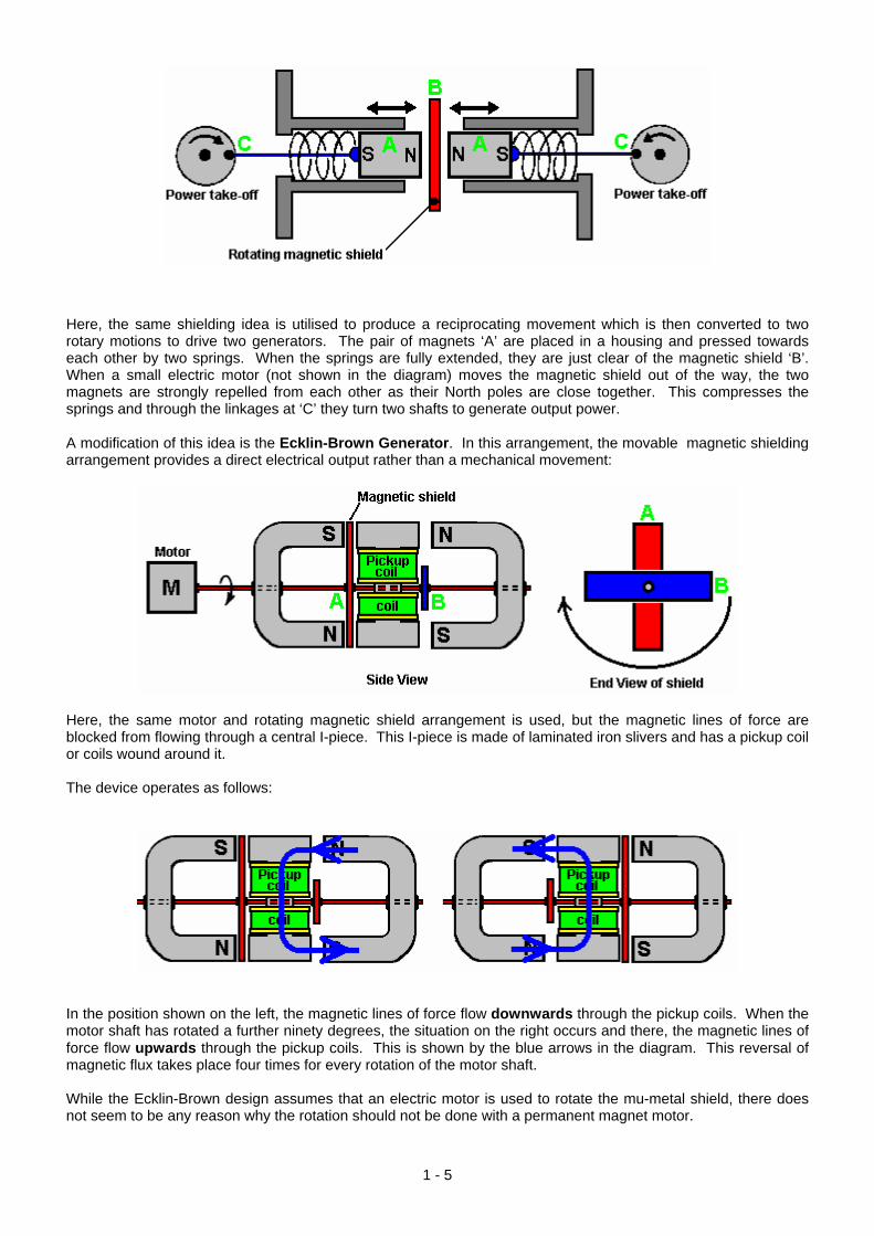
Here, the same shielding idea is utilised to produce a reciprocating movement which is then converted to two rotary motions to drive two generators. The pair of magnets ‘A’ are placed in a housing and pressed towards each other by two springs. When the springs are fully extended, they are just clear of the magnetic shield ‘B’. When a small electric motor (not shown in the diagram) moves the magnetic shield out of the way, the two magnets are strongly repelled from each other as their North poles are close together. This compresses the springs and through the linkages at ‘C’ they turn two shafts to generate output power. A modification of this idea is the Ecklin-Brown Generator. In this arrangement, the movable magnetic shielding arrangement provides a direct electrical output rather than a mechanical movement:
Here, the same motor and rotating magnetic shield arrangement is used, but the magnetic lines of force are blocked from flowing through a central I-piece. This I-piece is made of laminated iron slivers and has a pickup coil or coils wound around it. The device operates as follows:
In the position shown on the left, the magnetic lines of force flow downwards through the pickup coils. When the motor shaft has rotated a further ninety degrees, the situation on the right occurs and there, the magnetic lines of force flow upwards through the pickup coils. This is shown by the blue arrows in the diagram. This reversal of magnetic flux takes place four times for every rotation of the motor shaft. While the Ecklin-Brown design assumes that an electric motor is used to rotate the mu-metal shield, there does not seem to be any reason why the rotation should not be done with a permanent magnet motor.
1 - 5
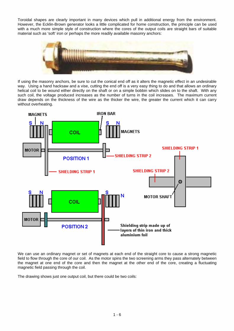
Toroidal shapes are clearly important in many devices which pull in additional energy from the environment. However, the Ecklin-Brown generator looks a little complicated for home construction, the principle can be used with a much more simple style of construction where the cores of the output coils are straight bars of suitable material such as ‘soft’ iron or perhaps the more readily available masonry anchors:
If using the masonry anchors, be sure to cut the conical end off as it alters the magnetic effect in an undesirable way. Using a hand hacksaw and a vise, cutting the end off is a very easy thing to do and that allows an ordinary helical coil to be wound either directly on the shaft or on a simple bobbin which slides on to the shaft. With any such coil, the voltage produced increases as the number of turns in the coil increases. The maximum current draw depends on the thickness of the wire as the thicker the wire, the greater the current which it can carry without overheating.
We can use an ordinary magnet or set of magnets at each end of the straight core to cause a strong magnetic field to flow through the core of our coil. As the motor spins the two screening arms they pass alternately between the magnet at one end of the core and then the magnet at the other end of the core, creating a fluctuating magnetic field passing through the coil. The drawing shows just one output coil, but there could be two coils:
1 - 6

Or there could be four coils:
The coils can be connected in parallel to increase the output current, or they can be connected in series (in a chain configuration) to increase the output voltage. While the drawings show the shields connected directly to the motor drive shaft (a short length of plastic sleeving from a piece of wire would probably be used to help with alignment of the motor shaft and the shielding axle) there is no reason why the shielding should not be on a separate axle mounted in bearings and driven by a belt and pulley wheel arrangement. With a separate shielding axle, allows a long, stiff axle to be used and that allows there to be additional coils and magnets. The result could be like this:
1 - 7

Howard Johnson’s Permanent Magnet Motor. Returning to permanent magnet motors themselves, one of the top names in this field is Howard Johnson. Howard built, demonstrated and gained US patent 4,151,431 on 24th April 1979, from a highly sceptical patent office for, his design of a permanent magnet motor. He used powerful but very expensive Cobalt/Samarium magnets to increase the power output and demonstrated the motor principles for the Spring 1980 edition of Science and Mechanics magazine. His motor configuration is shown here:
The point that he makes is that the magnetic flux of his motor is always unbalanced, thus producing a continuous rotational drive. The rotor magnets are joined in stepped pairs, connected by a non-magnetic yoke. The stator magnets are placed on a mu-metal apron cylinder. Mu-metal is very highly conductive to magnetic flux (and is expensive). The patent states that the armature magnet is 3.125” (79.4 mm) long and the stator magnets are 1” (25.4 mm) wide, 0.25” (6 mm) deep and 4” (100 mm) long. It also states that the rotor magnet pairs are not set at 120 degrees apart but are staggered slightly to smooth out the magnetic forces on the rotor. It also states that the air gap between the magnets of the rotor and the stator are a compromise in that the greater the gap, the smoother the running but the lower the power. So, a gap is chosen to give the greatest power at an acceptable level of vibration. Howard considers permanent magnets to be room-temperature superconductors. Presumably, he sees magnetic material as having electron spin directions in random directions so that their net magnetic field is near zero until the electron spins are aligned by the magnetising process which then creates an overall net permanent magnetic field, maintained by the superconductive electrical flow.
1 - 8

The magnet arrangement is shown here, with the inter-magnet gaps assessed from the drawing in Howard’s patent:
A magazine article on this can be seen at http://newebmasters.com/freeenergy/sm-pg48.html.
1 - 9

The “Carousel” Permanent Magnet Motor/Generator. US Patent 5,625,241, included in the Appendix, presents the specific details of a simple electrical generator powered by permanent magnets alone. This generator can also be used as a motor. The construction is not particularly complicated:
It uses an arrangement where permanent magnets are associated with every second coil set around the rotor. Operation is self-powered and the magnet arrangement is clearly defined:
And the physical arrangement of the device is not particularly complicated:
1 - 10
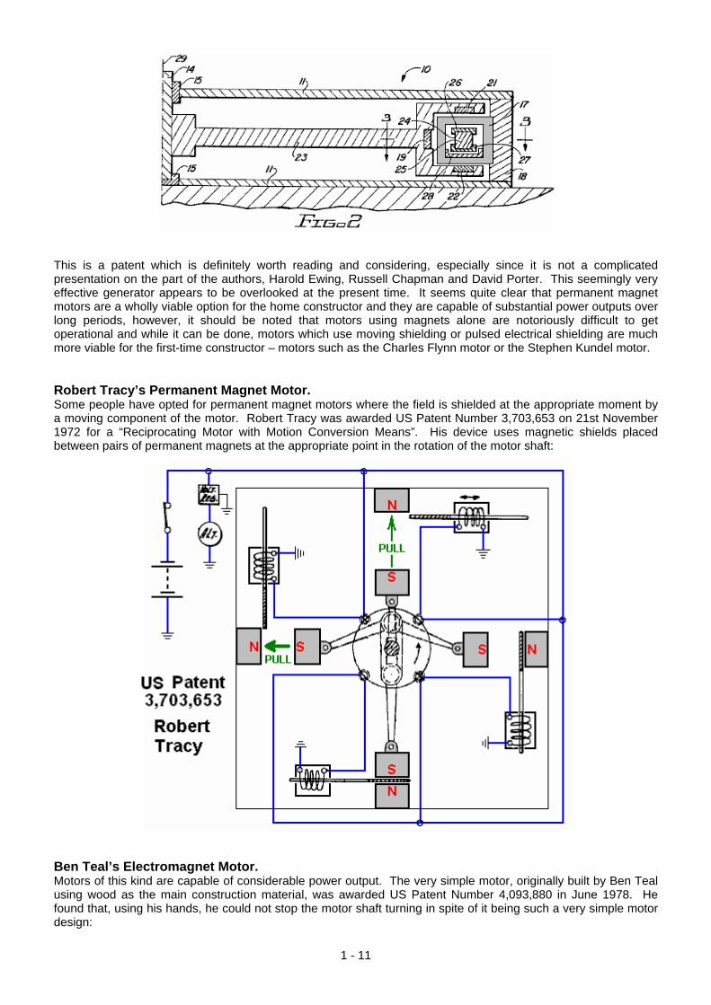
This is a patent which is definitely worth reading and considering, especially since it is not a complicated presentation on the part of the authors, Harold Ewing, Russell Chapman and David Porter. This seemingly very effective generator appears to be overlooked at the present time. It seems quite clear that permanent magnet motors are a wholly viable option for the home constructor and they are capable of substantial power outputs over long periods, however, it should be noted that motors using magnets alone are notoriously difficult to get operational and while it can be done, motors which use moving shielding or pulsed electrical shielding are much more viable for the first-time constructor – motors such as the Charles Flynn motor or the Stephen Kundel motor. Robert Tracy’s Permanent Magnet Motor. Some people have opted for permanent magnet motors where the field is shielded at the appropriate moment by a moving component of the motor. Robert Tracy was awarded US Patent Number 3,703,653 on 21st November 1972 for a “Reciprocating Motor with Motion Conversion Means”. His device uses magnetic shields placed between pairs of permanent magnets at the appropriate point in the rotation of the motor shaft:
Ben Teal’s Electromagnet Motor. Motors of this kind are capable of considerable power output. The very simple motor, originally built by Ben Teal using wood as the main construction material, was awarded US Patent Number 4,093,880 in June 1978. He found that, using his hands, he could not stop the motor shaft turning in spite of it being such a very simple motor design:
1 - 11

The motor operation is as simple as possible with just four switches made from springy metal, pushed by a cam on the rotor shaft. Each switch just powers it’s electromagnet when it needs to pull and disconnects it when the pull is completed. The resulting motor is very powerful and very simple. Additional power can be had by just stacking one or more additional layers on top of each other. The above diagram shows two layers stacked on top of one another. Only one set of four switches and one cam is needed no matter how many layers are used, as the solenoids vertically above each other are wired together in parallel as they pull at the same time. The power delivered by the Teal motor is an indication of the potential power of a permanent magnet motor which operates in a rather similar way by moving magnetic shields to get a reciprocating movement. Placing a resistor and capacitor across each switch contact both suppresses sparks and feeds current back to the battery when the contact opens, and this extends the battery life considerably.
1 - 12

The Jines Permanent Magnet Motor. James E. Jines and James W. Jines were awarded US Patent 3,469,130 on 23rd September 1969 “Means for Shielding and Unshielding Permanent Magnets and Magnetic Motors Utilising the Same” and which is in the Appendix. This magnet motor design uses selective shielding of the drive magnets to produce a continuous force in one direction. It also has a mechanical arrangement to progressively adjust the shielding to adjust the power of the motor.
1 - 13

This is a very interesting design of magnetic motor, especially since it does not call for any materials which are not readily available from many suppliers. It also has the advantage of not needing any form of exact adjustment or balancing of magnetic forces to make it operate. Stephen Kundel’s Permanent Magnet Motor. Stephen Kundel’s motor design is shown in full detail in his patent which is shown on page A - 968 of the Appendix. It uses a simple oscillating motion to position the “stator” magnets so that they provide a continuous rotational force on the output shaft:
Here, the yellow arm marked 38, rocks to the right and left, pushed by a solenoid coil 74. There is no obvious reason why this rocking motion could not be achieved by a mechanical linkage connected to the rotating output shaft 10. The three arms 20, 22 and 24, being pivoted at their upper points, are pushed into a central position by the springs 34 and 35. The magnets 50, 51 and 52, are moved by these arms, causing a continuous rotation of the output drive shaft 10. The movement of these magnets avoids the position where the magnets reach a point of equilibrium and lock into a single position.
1 - 14

Figures 2 and 3 show the position of the magnets, with the Figure 3 position showing a point in the output shaft rotation which is 180 degrees (half a turn) further on than the position shown in Figure 2. Some other, more powerful magnet arrangements which can be used with this design are shown in the full patent in the Appendix. This design does not seem to appeal to many constructors in spite of the fact that it must be one of the easiest magnet motors to set up and make work. The output power level can be as big as you want as additional layers of magnets can be added. The operation is very simple and it can, perhaps, be seen more easily if just one lever arm is considered. The lever arm has just two working positions. In one position it acts on one set of rotor magnets and in the second position it acts on a second set of rotor magnets. So, we will look at each set in turn. If there are two magnets near each other, one fixed in position and the other free to move like this:
The magnets have a strong attraction to each other because of the North and South poles attracting each other. However, as the two South poles repel each other, the movement of the approaching magnet is not directly along the green arrows shown but initially is in the direction shown by the red arrow. This situation continues with the moving magnet approaching he fixed magnet and the pull between them getting stronger all the time. But, the situation changes immediately the moving magnet reaches it’s closest point to the fixed magnet. Momentum starts to carry it past, but at that point the direction of the pull between the magnets starts to oppose the onward movement of the moving magnet:
If the fixed magnet remains in that position, then the moving magnet will oscillate briefly and come to a halt directly opposite the fixed magnet like this:
1 - 15

The attraction forces between the two magnets is now wholly horizontal and there is no force on the movable magnet to cause it to move. This is simple stuff, understood by anyone who has examined permanent magnets in order to see what they do. Stephen Kundel is well aware of this, and so he moves the “fixed” magnet rapidly out of the way before the reverse-direction pull slows the moving magnet down. He moves the magnet sideways and slides another one into position like this:
The new magnet is now much closer to the moving magnet and so has a much greater influence on it. The poles of the new magnet match the poles of the moving magnet which causes them to push apart very strongly, driving the moving magnet onwards in the direction it was moving in. The moving magnet moves very quickly and so gets out of the range of the fixed magnets quite quickly, at which point, the “fixed” magnets of the stator are moved back into their original position where they act in the same way on the next moving magnet attached to the rotor. This very simple operation only requires a small force to move the stator magnets sideways between their two positions, while the force between the stator magnets and the rotor magnets can be high, producing considerable rotational power to the axle on which the rotor discs are attached. The efficiency of the system is further boosted because when the stator magnets are in the first position shown, the second “fixed” magnet is not sitting idle but instead, it acts on the magnet of the next rotor disc:
For this, the magnets attached to Rotor disc 2 have to be positioned so that their poles are the reverse of those attached to Rotor disc 1. Stephen uses a loudspeaker to wobble the horizontal bar on which the stator magnets are mounted, backwards and forwards as a loudspeaker has that mechanism already built into it. Don Kelly’s
1 - 16

permanent magnet motor also uses this very simple idea of moving the stator magnets out of the way at the appropriate moment. Charles “Joe” Flynn’s Permanent Magnet Motor. Patent US 5,455,474 dated 3rd October 1995 and shown in full in the Appendix, gives details of this interesting design. It says: “This invention relates to a method of producing useful energy with magnets as the driving force and represents an important improvement over known constructions and it is one which is simpler to construct, can be made to be self starting, is easier to adjust, and is less likely to get out of adjustment. The present construction is also relatively easy to control, is relatively stable and produces an amazing amount of output energy considering the source of driving energy that is used. The present construction makes use of permanent magnets as the source of driving energy but shows a novel means of controlling the magnetic interaction or coupling between the magnet members and in a manner which is relatively rugged, produces a substantial amount of output energy and torque, and in a device capable of being used to generate substantial amounts of energy.” The patent describes more than one motor. The first one is like this when seen from the side:
An exploded view, shows the different parts clearly:
1 - 17

This construction is relatively simple and yet the operation is powerful. The power is provided by three magnets, shown shaded in blue and yellow. The lower magnet is in the form of a disc with the poles arranged on the large, circular, flat faces. This is the stator magnet which does not move. Positioned above it is a disc made of non-magnetic material (shaded in grey) and which has two magnets embedded in it. This disc is the rotor and is attached to the central vertical shaft. Normally, the rotor would not rotate, but between the two discs there is a ring of seven coils which are used to modify the magnetic fields and produce powerful rotation. The powering up of these coils is very simple and it is arranged by shining a beam of Ultra Violet light from one of the Light-Emitting Diodes through a slot in an optical-timing disc attached to the rotating shaft. The LEDs and the photo-transistors are aligned with the centres of the seven coils. The position and width of the slot controls which photo-transistor gets switched on and for how long it remains powered up. This is a very neat and compact arrangement. The really interesting part of the design is how the coils modify the magnetic fields to produce the output power of the device. The orientation of the magnet poles can be swapped over, provided that this is done for all three magnets.
1 - 18

Shown here is the situation when one of the rotor magnets has rotated to where it is above one of the coils which is not yet powered up. The South pole of the rotor magnet is attracted to the North pole which is the entire upper face of the stator magnet as shown by the three arrows. If a voltage is applied to the coil, then this magnetic coupling is disrupted and altered. If any torque is developed as a result of the coil being powered up, then it will be developed to either side of the energised coil. If the coil is not powered up, then there will be full attraction between the magnets and no rotational force will be produced. You will notice that there are two rotating magnets (an even number) and seven coils (an odd number) so when one of the rotor magnets is above a coil, then the other isn’t. This staggering of the two positions is essential for generating smooth, continuous rotational torque and self-starting without any need to rotate the shaft manually.
The diagram above shows a piece from both sides of the rotor disc, to explain the operation of the coils. On the left, magnet 56 overlaps coil 32 and coil 34. Coil 32 is powered up and this breaks the magnetic link on the left hand side of magnet 56. But, coil 34 is not powered up, so the attraction between magnet 56 and the disc magnet under the coils remains. Even though this attraction is at a downward angle, it creates a push on the rotor, driving it towards the right as shown by the red arrow. While this is happening, the situation around the other side of the rotor disc, is shown on the right. Here, magnet 54 is above coil 36 and that coil is not powered up, so there is no resulting drive in either direction - just a downward pull on the rotor magnet, towards the stator magnet below it. The adjacent coil 38 is also not powered up and so has no effect on the rotation. This method of operation is very close to that of the motor design of Robert Adams described in the next chapter. It is important to understand that this method of operation is nothing like that of the John Bedini pulsers where the rotation of a disc is caused by the electrical pulse applied to a coil creating a repulsion thrust to a rotor magnet. Instead, here, the coil acts as a magnetic shield, being provided with the minimum possible power to do its job. The coil is, in effect, a shield which has no moving parts, and so is a very clever mechanism for overcoming the tendency for the rotor magnets to lock on to the stator magnets and preventing rotation. At any moment, six of the seven coils in this design are inactive, so in effect, just one coil is powered. This is not a major current drain. It is important to understand that the power of this motor is provided by the permanent magnets pulling towards each other. Each of the two magnets applies a horizontal pull on the rotor every seventh of a turn, that is, every 51.1 degrees in the rotation. As the coils are an uneven number, the rotor gets a magnetic pull every 25.5 degrees in the rotation, first from one rotor magnet and then from the other rotor magnet. It follows then, that the power of the motor can be increased by adding more magnets. The first step in this search for additional power is to add a second disc magnet and coils on the other side of the rotor, so that there is a second pull on the magnet. This has the added advantage that it balances the downwards pull of the first disc magnet with an upward pull, giving an enhanced and balanced horizontal thrust as shown here:
1 - 19

The coil switching with the additional layer of coils is shown here:
This produces a larger horizontal thrust. While this design goes for optimum performance, I suggest that a much more simple form of construction with a ring of standard circular neodymium magnets could be used instead of one large disc magnet, and ordinary circular coils placed on top of the circular magnets, and this allows large diameter rotors to be constructed, the larger diameter giving greater output shaft power:
To increase the power of the output shaft further again, additional sets of magnets and coils can be added as shown here:
1 - 20

It should be remembered that the timing section shown above could be replaced by a NE555 timer circuit which generates a steady stream of On / Off pulses. When those pulses are fed to the coils, the motor rotates, slaving itself to the pulse rate. This gives an immediate speed control for the motor as well as avoiding the need for the precise positioning of the slotted disc which allows the LEDs to shine directly on to the phototransistors at the appropriate instant. If that approach is taken, then the timing section shown above would be omitted. The circuitry that Charles specifies for powering the coils to block the magnetic fields of the permanent magnets uses N-channel MOSFETs and is very simple. Here is his circuit for driving one of the coils:
1 - 21
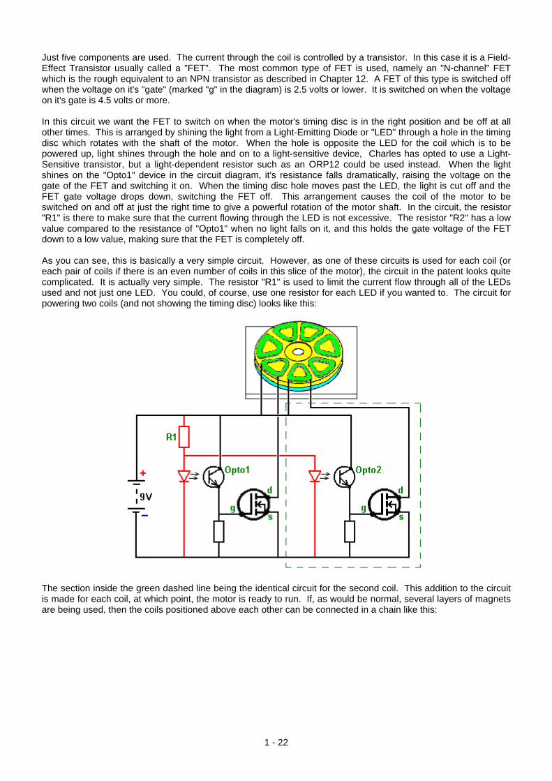
Just five components are used. The current through the coil is controlled by a transistor. In this case it is a Field-Effect Transistor usually called a "FET". The most common type of FET is used, namely an "N-channel" FET which is the rough equivalent to an NPN transistor as described in Chapter 12. A FET of this type is switched off when the voltage on it's "gate" (marked "g" in the diagram) is 2.5 volts or lower. It is switched on when the voltage on it's gate is 4.5 volts or more. In this circuit we want the FET to switch on when the motor's timing disc is in the right position and be off at all other times. This is arranged by shining the light from a Light-Emitting Diode or "LED" through a hole in the timing disc which rotates with the shaft of the motor. When the hole is opposite the LED for the coil which is to be powered up, light shines through the hole and on to a light-sensitive device, Charles has opted to use a Light-Sensitive transistor, but a light-dependent resistor such as an ORP12 could be used instead. When the light shines on the "Opto1" device in the circuit diagram, it's resistance falls dramatically, raising the voltage on the gate of the FET and switching it on. When the timing disc hole moves past the LED, the light is cut off and the FET gate voltage drops down, switching the FET off. This arrangement causes the coil of the motor to be switched on and off at just the right time to give a powerful rotation of the motor shaft. In the circuit, the resistor "R1" is there to make sure that the current flowing through the LED is not excessive. The resistor "R2" has a low value compared to the resistance of "Opto1" when no light falls on it, and this holds the gate voltage of the FET down to a low value, making sure that the FET is completely off. As you can see, this is basically a very simple circuit. However, as one of these circuits is used for each coil (or each pair of coils if there is an even number of coils in this slice of the motor), the circuit in the patent looks quite complicated. It is actually very simple. The resistor "R1" is used to limit the current flow through all of the LEDs used and not just one LED. You could, of course, use one resistor for each LED if you wanted to. The circuit for powering two coils (and not showing the timing disc) looks like this:
The section inside the green dashed line being the identical circuit for the second coil. This addition to the circuit is made for each coil, at which point, the motor is ready to run. If, as would be normal, several layers of magnets are being used, then the coils positioned above each other can be connected in a chain like this:
1 - 22

Connecting several coils "in series" (in a chain) like this, reduces the number of electronic components needed and it makes sure that the pulses to each of these coils is at exactly the same instant. Alternatively, it is possible to wire these coils across each other "in parallel", the choice is generally dictated by the resistance of the coils. The patent drawing shown above seems to indicate that there is a big gap between the LEDs and the optical devices. This is probably not the case as most people would choose to keep the gap between the LED and the light-dependent device as small as possible, mounting them so that they are just clear of the timing disc on each side of it. In this patent, Charles Flynn remarks that this magnet motor can be used for almost any purpose where a motor or engine drive is required and where the amount of energy available or required to produce the driving force may vary little to nil. Charles has produced motors of this type which are capable of rotating at very high speed - 20,000 rpm and with substantial torque. Lesser speeds can also be produced, and the motor can be made to be self-starting. Because of the low power required to operate the device, Charles has been able to operate the motor using just a nine volt, off-the-shelf dry battery. One application which seems most appropriate for this motor design is the Frenette heater shown in Chapter 14. Using this motor to drive the discs inside the heater drum would produce a heater which appears to be driven by just a nine-volt battery. However, while that is the appearance, the reality is that the power of this motor comes from the permanent magnets and not from the battery. The battery current is only used to prevent the backward pull of the magnets and it is not used to drive the motor. While the use of a timing disc is a very satisfactory arrangement, it is also possible to use electronic circuitry instead of the mechanical timing disc, the opto devices and the LEDs. What is needed here is a device which produces a series of voltage pulses which can be used to drive the gate voltage of each FET from below 2.5 volts to over 4.5 volts. It looks as if the well-known 555 timer chip would be suited to this task and it would certainly run off the nine-volt battery. However, we have more than one set of coils which need to be run. For example, if we have say, four sets of coils to drive by powering up four different FET transistors one after the other, then we could use a "Divide-by-Eight" chip, like the 4022 chip. This chip can be set to divide by any number from two to eight. All that is needed to select the number to divide by, is one connection between two of the pins on the chip.
1 - 23
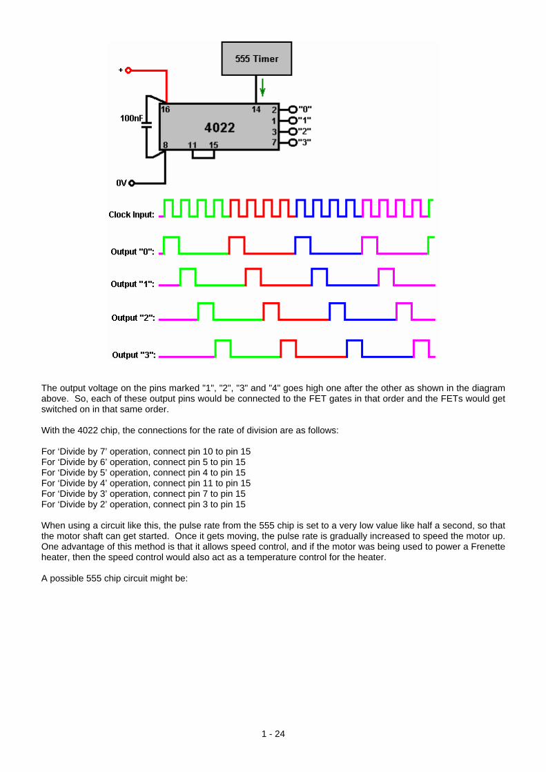
The output voltage on the pins marked "1", "2", "3" and "4" goes high one after the other as shown in the diagram above. So, each of these output pins would be connected to the FET gates in that order and the FETs would get switched on in that same order. With the 4022 chip, the connections for the rate of division are as follows: For ‘Divide by 7’ operation, connect pin 10 to pin 15 For ‘Divide by 6’ operation, connect pin 5 to pin 15 For ‘Divide by 5’ operation, connect pin 4 to pin 15 For ‘Divide by 4’ operation, connect pin 11 to pin 15 For ‘Divide by 3’ operation, connect pin 7 to pin 15 For ‘Divide by 2’ operation, connect pin 3 to pin 15 When using a circuit like this, the pulse rate from the 555 chip is set to a very low value like half a second, so that the motor shaft can get started. Once it gets moving, the pulse rate is gradually increased to speed the motor up. One advantage of this method is that it allows speed control, and if the motor was being used to power a Frenette heater, then the speed control would also act as a temperature control for the heater. A possible 555 chip circuit might be:
1 - 24

As this allows the speed to be controlled and when the required speed is reached, the pulse width can then be adjusted to give the minimum current draw to maintain that speed. There are, of course, many other suitable circuits which could be used instead of this one and Chapter 12 will fill you in on some of them as well as explaining how circuits work and how to build them. If it so happens that it is difficult to find suitable circular magnets with the poles on opposing faces, then I suggest that it should be possible to use standard rectangular magnets throughout and rectangular coils as shown here:
And while this arrangement is not as magnetically efficient as a circular magnet, it does have the convenience of allowing the construction of a rotor of any chosen size. Ideally, unlike the stator shown above, there should be an odd number of magnets, or failing that, an odd number of coils. Alternatively, the rotor could have an odd number of magnets so as to allow self-starting. But, it should be noted that if the motor is to be driven by an electronic pulsing system, then it is very much more simple to have an even number of magnets on the stator and start the motor moving by hand. This is because with an odd number of stator magnets, the opto sensors are not exactly opposite each other and so do not fire together. With an even number of stator magnets, the coils which are 180 degrees apart can be wired together as they fire at exactly the same time. With the slotted optical timing disc, the slots are exactly opposite each other and match the width of the rotor magnets, but the coils (nearly) opposite each other are not powered on and off at exactly the same time, although their powered arcs are likely to overlap for part of their operation. This could be catered for electronically by using a monostable delay for the coil on the opposite side of the disc. The objective of each coil is to just, and only just, cancel out the magnetic field of the permanent magnet underneath it. The magnetic field produced by the coil depends on the current flowing in the coil, the number of turns in the coil and the area of the coil. The current flowing depends on the diameter of the wire and the voltage applied to it. It is probably necessary to mount just one magnet on the stator and experiment with the coil until
1 - 25

your current drive and coil allow the rotor to spin freely. Whatever the coil result is, should be ok for all of the magnets even though they are likely to vary in strength a bit. Steorn’s Magnetic Devices. The Irish company Steorn have produced a system which is almost identical to the Charles Flynn magnet motor just described. They call their device "Orbo" and its operation is pretty much the same. The advance made by Steorn is that they have devised a very clever magnetic masking system using ferrite toroids wound with a copper wire coil. This is a slick method of switching magnetic attraction on and off. When the coil carries a sufficient current it generates a circular magnetic field spiralling around the toroid and not going outside the toroid. This field does not have an attraction for outside magnets. It makes no difference if the direction of the current flow through the coil is reversed as the resulting magnetic field just spins around the toroid in the opposite direction and performs exactly the same magnetic blocking of the ferrite ring which forms the toroid. If no current flows, then the copper wire does not block off the influence of the ferrite ring and the permanent magnets on the rotor are strongly attracted to it, causing the rotor to spin. On their web site www.steorn.com, Steorn illustrate their design like this:
In this implementation, eight ferrite rings are mounted on the stator in four locations ninety degrees apart. These are wound with copper wire coils which can be powered by a battery, via a timing mechanism. The rotor has embedded in it, eight pairs of small permanent magnets, also spaced ninety degrees apart. In exactly the same way as the Adams motor described in chapter 2, the current through the coils is set to the minimum level which allows the rotor to spin freely. The timing mechanism is then switched in and the motor and the rotor given a spin. The rotor magnets are strongly attracted to their corresponding ferrite rings mounted on the stator posts and this accelerates the rotor. If no current is passed through the coils, then the rotor will oscillate backwards and forwards for a short time before coming to rest with the magnets as close to the ferrite rings as possible. To prevent this happening, the timing circuit senses when the magnets reach the ferrite rings, and passes that minimum current through the coils, trapping the rings inside a magnetic field which has no effect on the rotor magnets. The momentum of the rotor causes it to spin on past the stator rings to a position where the magnets are closer to the next rings than they are to the ones which they have just passed, at which point, the current is cut off and the magnetic attraction to the ferrite rings returns. This is identical to one mode of operation of the Adams motor. The next step is also identical to that of the Adams motor, namely, to add on some pick-up coils to convert some of the rotating magnetic energy into electrical energy, either to recharge the driving battery or to power other equipment, or both. Steorn's arrangement for doing this is to add an additional disc, containing permanent magnets, to the rotor and positioning wire coils opposite those magnets as is normal for a generator. Steorn choose to show the resulting energy charging up the battery again:
1 - 26

Video presentations on this style of motor/generator are at: http://www.youtube.com/watch?v=AXamGLyRkt8&NR=1 http://www.youtube.com/watch?v=rg3rLqYMzN4&feature=related and http://jnaudin.free.fr/steorn/indexen.htm We tend to think of this style of magnet-powered motor as being low-power. This is probably because it is often the case that the demonstration proof-of-principle implementations shown are minor devices. These motors can be very powerful and the one shown here, designed and built by Mr Sung of China has an output power of 20 kilowatts or twenty-seven horsepower:
And another design which has a larger diameter and about 144 magnets has a reported output of 225 horsepower:
1 - 27

You will notice that each ring of magnets is positioned further around the rim of the cylinder providing powerful pulses from 64 magnets every 22.5 degrees of rotation, so it is little wonder that the motor has considerable shaft power. Some of the coils can be switched to collect power if the working conditions do not need the full shaft output power, charging the drive battery. The rotating inner cylinder has permanent magnets mounted on it. George Soukup’s Permanent Magnet Motor. There used to be a video on the web, showing a magnet motor built on the “V” style of magnet placement which has two sets of permanent magnets spaced like this:
This style of magnet arrangement (North magnets shown in blue and South in red) has a locking point where the switch from wide spacing to narrow spacing occurs and this causes the rotation to stop there. The implementation shown in this video has the V magnets spaced rather more widely apart as shown here:
1 - 28

The taper is much less pronounced with an inner gap some four times greater than the gap to the outer ring. It also appears that the last inner magnet has a greater gap around the drum than the remaining ring of magnets. The housing is very simple looking, with an evenly spaced ring of twelve holes to take long magnets with alternating North and South magnetised areas along their length. You will notice from the photographs, that George has cavities to take up to twelve stacks of stator magnets, although he only uses any five of them for his demonstrations.
The housing has considerable clearance for the drum and magnets. The rear shaft bearing is just set into the back of the housing:
1 - 29
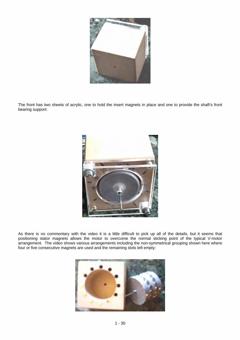
The front has two sheets of acrylic, one to hold the insert magnets in place and one to provide the shaft’s front bearing support:
As there is no commentary with the video it is a little difficult to pick up all of the details, but it seems that positioning stator magnets allows the motor to overcome the normal sticking point of the typical V-motor arrangement. The video shows various arrangements including the non-symmetrical grouping shown here where four or five consecutive magnets are used and the remaining slots left empty:
1 - 30

Dietmar Hohl’s Permanent Magnet Motor If you would like to make a simple motor of this type, then the information provided by Dietmar Hohl, passed to me by Jes Ascanius of Denmark, shows you how. He uses 20 mm diameter round neodymium magnets 10 mm thick, stacked in pairs in the stator of this layout:
This shows a magnetic gate arrangement built on a flat piece of Medium-Density Fibreboard 30 mm thick. The holes drilled in it are 20.1 mm in diameter and positioned so as to take two of the 10 mm thick magnets stacked together. The holes are drilled at an angle of 63 degrees to the horizontal or 27 degrees to the vertical, whichever way you prefer to think of it. On one side of the board, the inserted magnets have their North poles facing upwards, while on the other side of the board, the magnets are inserted with their South poles facing upwards. Dietmar shows six holes to take bolts or screws to fasten the piece of MDF to a larger board or table. Those do not form any part of the magnetic system and can be omitted. A video of one version of it in action can be found at http://www.free-energy-info.tuks.nl//Vtrack.mpg. The gate operates by causing a stack of ten of the magnets to roll along the V-shaped track and pass smoothly across the junction with the next set of V-positioned magnets. There can be as many of these V-sets as you want and the magnet stack will still keep rolling. This is one of the few magnetic gate designs which adapts to drum operation as a motor rotor. The magnets are positioned at an angle in order to use the magnetic fields at the edge of the magnets. They are stacked in pairs in order to increase their power. The power of the motor depends on the strength of the magnets, how close the stator magnet stacks are to the VF-track magnets and the number of stacks of stator magnets. If you decide to construct one of these motors, then it is suggested that you make things easier for yourself by keeping the curvature low, using three or four of the Vs. With Dietmar’s dimensions, a 2-V drum would be 216.5 mm (8.5”) in diameter, a 3-V drum would have a 325 mm (12.8”) diameter and a 4-V drum a diameter of 433 mm (17”) and those dimensions include the 30 mm (1 3/16”) strip which holds the magnets, so the inner drum diameters are 30 mm less in each case. When making the motor drum, it is possible to use a flexible material to hold the magnets. This allows the strip to be laid out flat while the holes are drilled, and then attached to the outside of a rigid drum with a 60 mm lesser diameter than the ones mentioned above. Jes Acanius of Denmark shows how a jig can be made to make drilling the holes easier:
1 - 31

This one has had a length of copper pipe inserted at the correct angle, in order to direct the drill bit at the exact angle required. This motor has been successfully replicated by Jes Ascanius of Denmark who used 10 mm magnets which were to hand, and again with square magnets which were pushed into round holes and not even angled in this proof-of-concept implementation which only took one hour to build using scrap material to hand, and which did work:
With Dietmar’s design using angles magnet pairs, the number of magnets needed is quite high. For a single V, there are 58 magnets. For a 2-V version, 106 magnets. For a 3-V version, 154 magnets and for a 4-V version, 202 magnets if there is only one stack of stator magnets, so ten extra magnets need to be added to the count for each additional ten-magnet stack of stator magnets. The motor power is likely to increase as the diameter increases as the lever arm that the magnet has to turn the drum, increases – double the diameter to (almost) double the power.
Simple Permanent Magnet Motors It is very difficult to use the power of permanent magnets to make a motor powered by them alone. The Dietmar Hohl design shown above is one of the very few which can readily be made and tested at home. The problem is that almost all magnets have a symmetrical magnetic field, while what is needed for a magnet-powered motor is an asymmetrical magnetic field. Consequently, magnets have to be combined in ways which distort their normal field shape. You will notice that in the Hohl motor, the drive magnets are angled and that is an important feature of using magnets in motors.
1 - 32

Schools currently teach that the field surrounding a bar magnet is like this:
This is deduced by scattering iron filings on a sheet of paper held near the magnet. Unfortunately, that is not a correct deduction as the iron filings distort the magnetic field by their presence, each becoming a miniature magnet in it’s own right. More careful measurement shows that the field actually produced by a bar magnet is like this:
There are many lines of force, although these diagrams show only two of them. The important factor is that there is a rotating field at each corner of a typical bar magnet. It follows then that if a row of magnets is placed at a an angle, then there will be a resulting net field in a single direction. For example, if the magnets are rotated forty five degrees clockwise, then the result would be like this:
With this arrangement, the opposing corners of the magnets as shown here, are lower down and so there should be a net magnetic force pushing to the right just above the set of magnets. However, the situation is not as simple and straightforward as you might imagine. The additional lines of magnetic force which have not been shown in the diagram above, act further out from the magnets and they interact, creating a complex composite magnetic field. It is frequently found that after four or five magnets that a short gap needs to be left before the line of magnets is continued on.
1 - 33

Two boys; Anthony and Andreas, have used this magnet arrangement to create a magnetic track and they have a lot of fun, sending a magnet sliding between two of these rows of angled magnets. Initially, they used the cheaper ceramic magnets and got a very satisfactory movement when using a neodymium magnet as the moving component:
You will notice that they have managed a row of 18 ceramic magnets on each side of their track and the results which they are getting are very good. They have three videos on the web at the present time: https://www.youtube.com/watch?v=Vo2-Qb3fUYs https://www.youtube.com/watch?v=VeXrFfw4RSU https://www.youtube.com/watch?v=VTbFfEEE_qU The moving magnet is made up of four 12 mm x 12 mm x 12 mm (or half-inch by half inch by half inch) neodymium magnets attached North - South - North - South - North - South - North - South:
They have not disclosed all of the details of what they are using (accidentally rather than by intention). The ceramic stator magnets are 48 mm x 20 mm x 10 mm with the poles on each of the main faces. They position each magnet with it's North pole facing towards the track and they angle the magnets at 45 degrees. There is a 15 mm gap between the stator magnets and the moving magnets on both sides of the track. Wooden strips direct the moving magnets. Neodymium magnets have very different characteristics to those of ceramic magnets (and that is not just strength of the magnetic field). It is not unusual for experimenters to find that devices will work well with one type of magnet but not with the other type. Here the developers have also tried using two sets of five angled neodymium magnets on each side of their track and the result was a more powerful thrust on their moving magnets.
1 - 34

The magnets are held in place in this picture, by wooden dowels driven into the base plank. They used these in order to avoid any magnet-fastening material which could alter the magnetic field. The next step would be for them to power a motor using their magnetic track technique. However, this has been tried many times and the conclusion is that it is VERY hard to change a straight magnetic track into one which forms a complete circle. Therefore, I would suggest the following arrangement:
Here, a simple disc rotor has four magnets (of the type used to move down the magnetic track) attached to the underside of the disc and positioned so that they move through four short sets of four, or at the outside, five angled stator magnets as the disc spins. It does not matter if the rotor shaft is horizontal or vertical. If the disc spins well, then sets of two air-core pick-up coils can be positioned between each of the stator magnet arrays so that electricity is generated as the rotor magnets pass by overhead. If a constructor decides to attach two rotor discs to the one rotor shaft, then the two rotors should be positioned so that the rotor shaft gets pushed every 45 degrees of rotation rather than every 90 degrees as shown here. This style of motor is definitely within the scope of the average person to build should they be inclined to do so. I have been asked to say how I personally would go about constructing a prototype of this nature. As I have very limited constructional skills, I would do it like this: For the bearing, I would pick a computer cooling fan, as these have very good bearings and if one is not to hand inside an old, obsolete computer, then they can be bought very, very cheaply. The diameter of the fan is not important. These fans generally look something like this:
1 - 35

As the part of the fan which spins round does not normally project above the stationary frame, a spacing disc of wood or plastic is needed to provide the clearance. The disc is glued to the centre of the fan using perhaps, Impact Evostick, epoxy resin or super glue. It would then look like this:
A square of wood can then be screwed to the spacer, like this:
And as I am hopeless at creating good-quality mechanical devices, I would then hold a pencil very steadily against a support and give the wood a spin, so that the pencil draws a perfect circle exactly centred on the bearing of the fan. Then, marking the wood and the spacer so that there is no doubt as to which way round the wood is attached to the spacer, I would unscrew the wood and cut around the pencil line very carefully, smoothing the edges of the disc gently with fine sandpaper. Screwing the disc back in place, a spin should confirm that the edge of the disc stays steadily in place with no wavering of the edge. Actually, if the disc is not perfect, that is not a major problem as it is the rotor magnets which need to be positioned accurately, and for that, another pencil line can be produced by spinning the disc when the desired position has been determined. Permanent magnets vary enormously in size and strength, so when magnets are purchased, it is a matter of testing them using a track of the type used by Anthony and Andreas. The stator magnets are angled at about 45 degrees to the track and with just four on each side, it is a case of finding the spacing between the two sets of angled magnets which pushes the stator magnets furthest along the track.
1 - 36
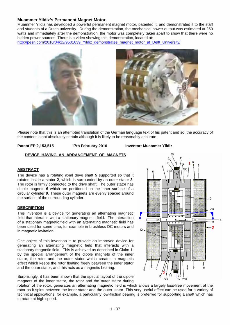
Muammer Yildiz’s Permanent Magnet Motor. Muammer Yildiz has developed a powerful permanent magnet motor, patented it, and demonstrated it to the staff and students of a Dutch university. During the demonstration, the mechanical power output was estimated at 250 watts and immediately after the demonstration, the motor was completely taken apart to show that there were no hidden power sources. There is a video showing this demonstration, located at: http://pesn.com/2010/04/22/9501639_Yildiz_demonstrates_magnet_motor_at_Delft_University/
Please note that this is an attempted translation of the German language text of his patent and so, the accuracy of the content is not absolutely certain although it is likely to be reasonably accurate. Patent EP 2,153,515 17th February 2010 Inventor: Muammer Yildiz
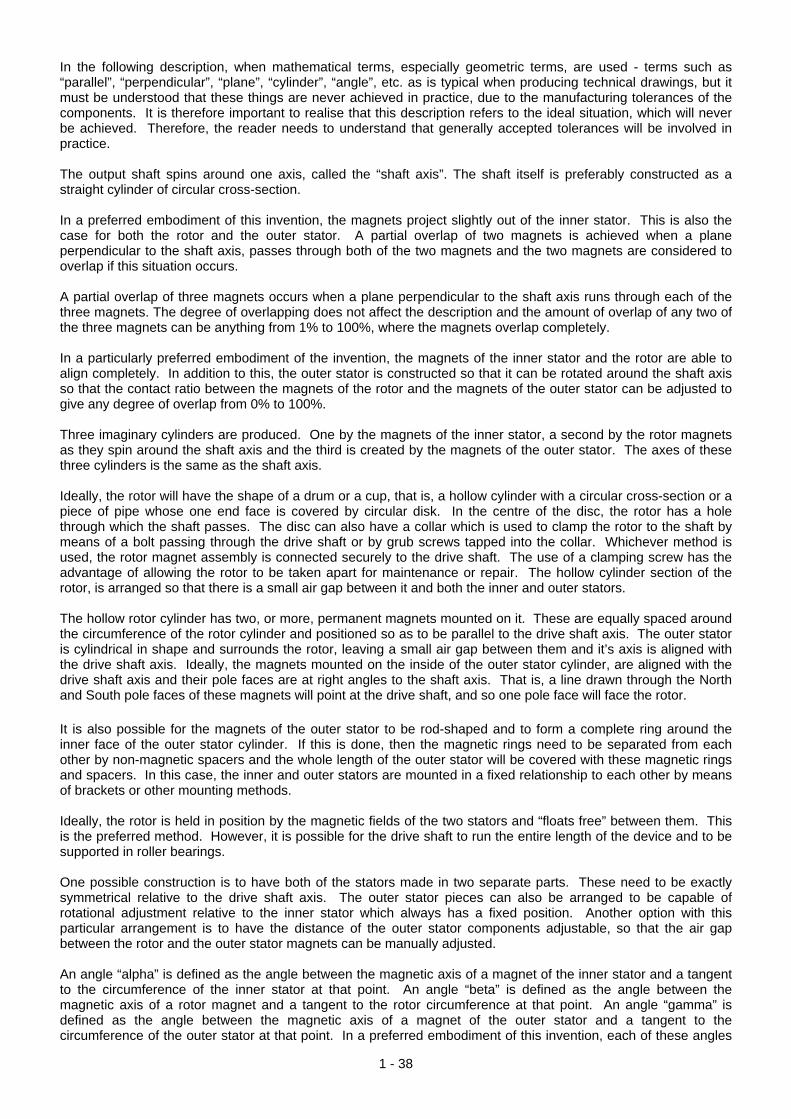
DEVICE HAVING AN ARRANGEMENT OF MAGNETS ABSTRACT The device has a rotating axial drive shaft 5 supported so that it rotates inside a stator 2, which is surrounded by an outer stator 3. The rotor is firmly connected to the drive shaft. The outer stator has dipole magnets 6 which are positioned on the inner surface of a circular cylinder 9. These outer magnets are evenly spaced around the surface of the surrounding cylinder. DESCRIPTION This invention is a device for generating an alternating magnetic field that interacts with a stationary magnetic field. The interaction of a stationary magnetic field with an alternating magnetic field has been used for some time, for example in brushless DC motors and in magnetic levitation. One object of this invention is to provide an improved device for generating an alternating magnetic field that interacts with a stationary magnetic field. This is achieved as described in Claim 1, by the special arrangement of the dipole magnets of the inner stator, the rotor and the outer stator which creates a magnetic effect which keeps the rotor floating freely between the inner stator and the outer stator, and this acts as a magnetic bearing. Surprisingly, it has been shown that the special layout of the dipole magnets of the inner stator, the rotor and the outer stator during rotation of the rotor, generates an alternating magnetic field is which allows a largely loss-free movement of the rotor as it spins between the inner stator and the outer stator. This very useful effect can be used for a variety of technical applications, for example, a particularly low-friction bearing is preferred for supporting a shaft which has to rotate at high speed.
1 - 37
1 - 38
In the following description, when mathematical terms, especially geometric terms, are used - terms such as “parallel”, “perpendicular”, “plane”, “cylinder”, “angle”, etc. as is typical when producing technical drawings, but it must be understood that these things are never achieved in practice, due to the manufacturing tolerances of the components. It is therefore important to realise that this description refers to the ideal situation, which will never be achieved. Therefore, the reader needs to understand that generally accepted tolerances will be involved in practice. The output shaft spins around one axis, called the “shaft axis”. The shaft itself is preferably constructed as a straight cylinder of circular cross-section. In a preferred embodiment of this invention, the magnets project slightly out of the inner stator. This is also the case for both the rotor and the outer stator. A partial overlap of two magnets is achieved when a plane perpendicular to the shaft axis, passes through both of the two magnets and the two magnets are considered to overlap if this situation occurs. A partial overlap of three magnets occurs when a plane perpendicular to the shaft axis runs through each of the three magnets. The degree of overlapping does not affect the description and the amount of overlap of any two of the three magnets can be anything from 1% to 100%, where the magnets overlap completely. In a particularly preferred embodiment of the invention, the magnets of the inner stator and the rotor are able to align completely. In addition to this, the outer stator is constructed so that it can be rotated around the shaft axis so that the contact ratio between the magnets of the rotor and the magnets of the outer stator can be adjusted to give any degree of overlap from 0% to 100%. Three imaginary cylinders are produced. One by the magnets of the inner stator, a second by the rotor magnets as they spin around the shaft axis and the third is created by the magnets of the outer stator. The axes of these three cylinders is the same as the shaft axis. Ideally, the rotor will have the shape of a drum or a cup, that is, a hollow cylinder with a circular cross-section or a piece of pipe whose one end face is covered by circular disk. In the centre of the disc, the rotor has a hole through which the shaft passes. The disc can also have a collar which is used to clamp the rotor to the shaft by means of a bolt passing through the drive shaft or by grub screws tapped into the collar. Whichever method is used, the rotor magnet assembly is connected securely to the drive shaft. The use of a clamping screw has the advantage of allowing the rotor to be taken apart for maintenance or repair. The hollow cylinder section of the rotor, is arranged so that there is a small air gap between it and both the inner and outer stators. The hollow rotor cylinder has two, or more, permanent magnets mounted on it. These are equally spaced around the circumference of the rotor cylinder and positioned so as to be parallel to the drive shaft axis. The outer stator is cylindrical in shape and surrounds the rotor, leaving a small air gap between them and it’s axis is aligned with the drive shaft axis. Ideally, the magnets mounted on the inside of the outer stator cylinder, are aligned with the drive shaft axis and their pole faces are at right angles to the shaft axis. That is, a line drawn through the North and South pole faces of these magnets will point at the drive shaft, and so one pole face will face the rotor. It is also possible for the magnets of the outer stator to be rod-shaped and to form a complete ring around the inner face of the outer stator cylinder. If this is done, then the magnetic rings need to be separated from each other by non-magnetic spacers and the whole length of the outer stator will be covered with these magnetic rings and spacers. In this case, the inner and outer stators are mounted in a fixed relationship to each other by means of brackets or other mounting methods. Ideally, the rotor is held in position by the magnetic fields of the two stators and “floats free” between them. This is the preferred method. However, it is possible for the drive shaft to run the entire length of the device and to be supported in roller bearings. One possible construction is to have both of the stators made in two separate parts. These need to be exactly symmetrical relative to the drive shaft axis. The outer stator pieces can also be arranged to be capable of rotational adjustment relative to the inner stator which always has a fixed position. Another option with this particular arrangement is to have the distance of the outer stator components adjustable, so that the air gap between the rotor and the outer stator magnets can be manually adjusted. An angle “alpha” is defined as the angle between the magnetic axis of a magnet of the inner stator and a tangent to the circumference of the inner stator at that point. An angle “beta” is defined as the angle between the magnetic axis of a rotor magnet and a tangent to the rotor circumference at that point. An angle “gamma” is defined as the angle between the magnetic axis of a magnet of the outer stator and a tangent to the circumference of the outer stator at that point. In a preferred embodiment of this invention, each of these angles
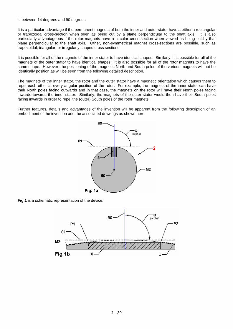
is between 14 degrees and 90 degrees. It is a particular advantage if the permanent magnets of both the inner and outer stator have a either a rectangular or trapezoidal cross-section when seen as being cut by a plane perpendicular to the shaft axis. It is also particularly advantageous if the rotor magnets have a circular cross-section when viewed as being cut by that plane perpendicular to the shaft axis. Other, non-symmetrical magnet cross-sections are possible, such as trapezoidal, triangular, or irregularly shaped cross sections. It is possible for all of the magnets of the inner stator to have identical shapes. Similarly, it is possible for all of the magnets of the outer stator to have identical shapes. It is also possible for all of the rotor magnets to have the same shape. However, the positioning of the magnetic North and South poles of the various magnets will not be identically position as will be seen from the following detailed description. The magnets of the inner stator, the rotor and the outer stator have a magnetic orientation which causes them to repel each other at every angular position of the rotor. For example, the magnets of the inner stator can have their North poles facing outwards and in that case, the magnets on the rotor will have their North poles facing inwards towards the inner stator. Similarly, the magnets of the outer stator would then have their South poles facing inwards in order to repel the (outer) South poles of the rotor magnets. Further features, details and advantages of the invention will be apparent from the following description of an embodiment of the invention and the associated drawings as shown here:
Fig.1 is a schematic representation of the device.
1 - 39

Fig.2a is an oblique view of the inner stator without magnets and Fig.2b is a view of the inner stator at right
angles to the shaft axis.
Fig.3 Shows a magnet arrangement for the inner stator
1 - 40

Fig.4 a section through the inner stator, along the line A--A indicated in Fig.12b
1 - 41

Fig.5a is a view of the fastening device perpendicular to the shaft axis and Fig.5b is a view of the fastening device in the direction of the shaft axis
1 - 42

Fig.6 is a perspective view of the rotor
Fig.7a is a schematic view of the inner stator and rotor. Fig.7b is a diagram of possible angle of the magnetic
axis of the magnets in the rotor;
1 - 43

Fig.8a shows the magnetic arrangement of the rotor, along the direction X--Y indicated in Fig.16. Fig.8b is a
detailed view of the rotor shown in Fig.8a.
Fig.9a to 9h show the angles of sets of magnets installed in the rotor when viewed from the side. These are
shown in greater detail later in this description.
1 - 44

Fig.10 shows the positions of magnet strings embedded in the rotor. These are given in more detail later on.
1 - 45

Fig.11 shows the arrangement of magnets on both stators and the rotor, shown as a section along the shaft axis.
Fig.12a shows the arrangement of cylinder and fins on the rotor before the rotor magnets are installed in the
spaces between the fins.
1 - 46

Fig.12b shows the arrangement of the magnets of the rotor, as seen in a view at right angles to the longitudinal axis of the rotor.
Fig.13 shows the stepped positioning of the magnets of the rotor. This view shows the surface of the rotor and
it’s shaft, opened out and laid flat. That is, the rectangle show here is actually the whole of the cylindrical
1 - 47

surface of the rotor. In this view, the fins between the magnets are not show in order to emphasise the stepping of the magnets relative to each other.
1 - 48
DETAILED DESCRIPTION
Fig.1 shows a schematic representation of the device having an inner stator 2, a rotor 1 and an outer stator 3, which are arranged coaxially around the shaft axis 50 of a pivoting rod-shaped shaft 5. The cylindrical inner stator 2 has at each end, an end cap 13 which is in the form of a circular disc with a ball-race bearing 11 mounted on it. The bearing 11, maintains the position of the inner stator 2 relative to shaft 5. The drive shaft 5 is normally made from a non-magnetic material such as plastic, (not steel) and typically, has a diameter of 10 mm to 40 mm and a length of 100 mm to 400 mm. The inner stator 2 has a core 12 with magnets 8 mounted on it’s outer surface. The inner stator 2 is held stationary by a mounting device 4, which is secured in position in a mechanical housing (not shown), and is held firmly fixed in this way. The rotor 1 consists of two mirror-image rotor drums, each with a pipe section and a circular disc section which is clamped rigidly to drive shaft 5 by means of grub screws 10. Each of the rotor drums has magnets 7 mounted on it. These magnets 7, are positioned in five distinct places and they have one magnetic pole facing towards the shaft and the other pole facing radially outwards. The rotor drums are positioned so that there is a cylindrical air gap between them and the inner stator 2. This air gap is usually of the order of 3mm to 50 mm. Although the two halves of the rotor are separated by the clamping mechanism 4 which prevents the inner stator from rotating, the rotor halves are positioned so that the magnets within them are balanced and so there is no irregular force generated when shaft 5 is spun at high speed. At the ends of the rotor drums there are magnets 700 as the objective of this design is to have the rotor suspended magnetically.

The outer stator 3 is composed of two separate half cylinders 9. Each of these cylinders 9, contains magnets 6 mounted on it’s inner face. Although each section of the outer stator consists of a hollow cylinder, the outer ends of the stator housing form a complete disc which surrounds the drive shaft 5 and forming a complete enclosure rather than leaving the device open at the ends. There is an air gap between the faces of the magnets mounted on the inner surface of the cylindrical frame 9 and the faces of the magnets mounted on the rotor. These sets of magnets face each other and the air gap between them is also typically 3 mm to 50 mm. The magnets on each of the stators are parallel to the shaft axis 50. The outer stators is constructed so that it can be moved relative to the inner stator, thus altering their magnetic overlap. This alteration can be made by moving the outer stator when the motor is actually running. The magnets designated 6, 7, and 8, are dipole magnets and in a preferred embodiment, these are permanent magnets, for example, consisting of SmCo (samarian cobalt) and/or NdFeB (neodymium/iron/boron). It is also possible for one or more of these magnets to be an electromagnet. The magnetic flux density of the magnets 6, 7, and 8 is preferably in a range from 0.4 to 1.4 Tesla. The frame is preferably made from a non-magnetic material such as aluminium with a wall thickness from 2 mm to 10 mm.
Fig.12a shows an inner stator frame made from a non-magnetic material (such as aluminium or copper). The frame 12 has a circular cylinder 120 which has attached to it’s outer surface, radial ribs 121. Each of these ribs extends along the central axis of the cylinder 120 along the full length of the cylinder, that is, from its’ base to the top surface. The ribs are distributed uniformly over the cylinder circumference, forming grooves 122. Cylinder 120 has a central hole along it’s axis for shaft 5 to run through. Both of the end surfaces of cylinder 120 are recessed to accommodate one of the ball bearings 11. The diameter of the stator core 12 is typically 50 mm to 500 mm with a length of 100 mm to 300 mm. The width of the ribs 121 is generally not more than 100 mm and is usually about 20% of the length of the ribs 121.
1 - 49

Fig.12b shows a schematic representation of the inner stator 2. The inner stator 2 is composed of the inner stator frame 12, the magnets 8 and the end caps 13. The magnets 8 are of equal length but their length is less than the length of the stator core 12. These magnets form the outer surface of the stator. They are seated in the grooves 122 and held in position by the ribs 121. The first magnet 8-1 is inserted flush with the end cap 13. The other magnets 8 each have an axial offset V along the shaft axis 50 arranged so that there is an even stepping of the magnets with the final magnet 8-10 butting up against the second end plate 13. The axial offset V is the total overall gap W divided by (n - 1), where n is the number of magnets and so, V varies with the number of magnets used. In a typical arrangement, V is 5% of the length of the magnets 8. The end caps 13 have a diameter of 50 mm to 500 mm and a thickness of 5 mm to 20 mm. A typical length for the magnets 8 is 100 mm. The magnet dimensions are arranged so that when they are positioned in the grooves 122, the inner stator 2 has a substantially uniform outer surface.
Fig.13 shows an opened-out view of the outer surface of the inner stator 2. Here, ten magnets 8 are arranged with even spacing. The under side of the magnets taper in the direction of the shaft axis 50 and so they have a lesser width near the centre of the stator than they do at the outside surface. The first magnet 8-1 is positioned
1 - 50

with its end face aligned with the base 125 of the inner stator core 12. The remaining nine magnets (8-2 to 8-10) are each offset by the amount V with the last magnet 8-10 reaching the top surface of the inner stator core 126.
Fig.14 shows a cross-section through the inner stator 2 along the plane A--A of Fig.12b. The inner stator 2 has a hollow cylinder 120, through which the central axis of the shaft 5 passes. Running along the outer surface of the cylinder are the ribs 121. The hollow cylinder 120 typically has a diameter of 100 mm and a length of 170 mm. In the gaps formed between the ribs 121 the magnets 8 are placed. When seen in the plane A--A these magnets have a trapezoidal cross-section. These magnets have two magnetic poles and the magnets are positioned so that the magnetic axis 80 which runs through the two poles is radial within the section plane A--A. An angle α [alpha] formed at the intersection of the magnetic dipole axis 80 of a magnet 8 and the tangent 81 to the ribs 121 can have a value between 14 degrees and 90 degrees. In the case shown in Fig.14 the angle alpha is 90 degrees.
1 - 51

Fig.15a shows the fastening device 4 in a view perpendicular to the shaft axis 50. The fastening device 4 has an inner hollow cylinder 40 with a smaller radius and an outer fixing ring plate 41 with larger radius. The inner hollow cylinder 40 and the outer ring fastening plate 41 are connected together. The hollow cylinder 40 is used for receiving and fixing the inner stator 2 by means of screws 10. The fastening ring 41 is part of a mechanical housing (not shown) for holding the device firmly positioned.
Fig.15b shows the fastening device 4 in a view in the direction of the shaft axis 50. The mounting ring plate 41 has at it’s periphery, four screws 10 for attachment to the mechanical housing of the hollow cylinder 40 which has on its circumference, a number of screws 10 for fixing the inner stator in place.
Fig.16 is a view of the rotor 1, which is clamped to shaft 5 by means of the screws 10. The rotor 1 consists of two separate drums attached to a central hollow shaft. Mounted in its outer surface are a series of magnets 7 sunk into circular holes. The rotor itself is constructed using a non-magnetic material such as aluminium or copper. The distance between the two rotor drums is 15 mm and they have an outer diameter of 165 mm, a height of 70 mm and a wall thickness of 26 mm. Each rotor drum has a top surface annular disk 102, into which two or more magnets 700 are sunk. These are positioned uniformly around the circumference of the disc as shown in the diagram. The magnetic dipole axis of magnets 700 is parallel to the shaft axis 50.
1 - 52
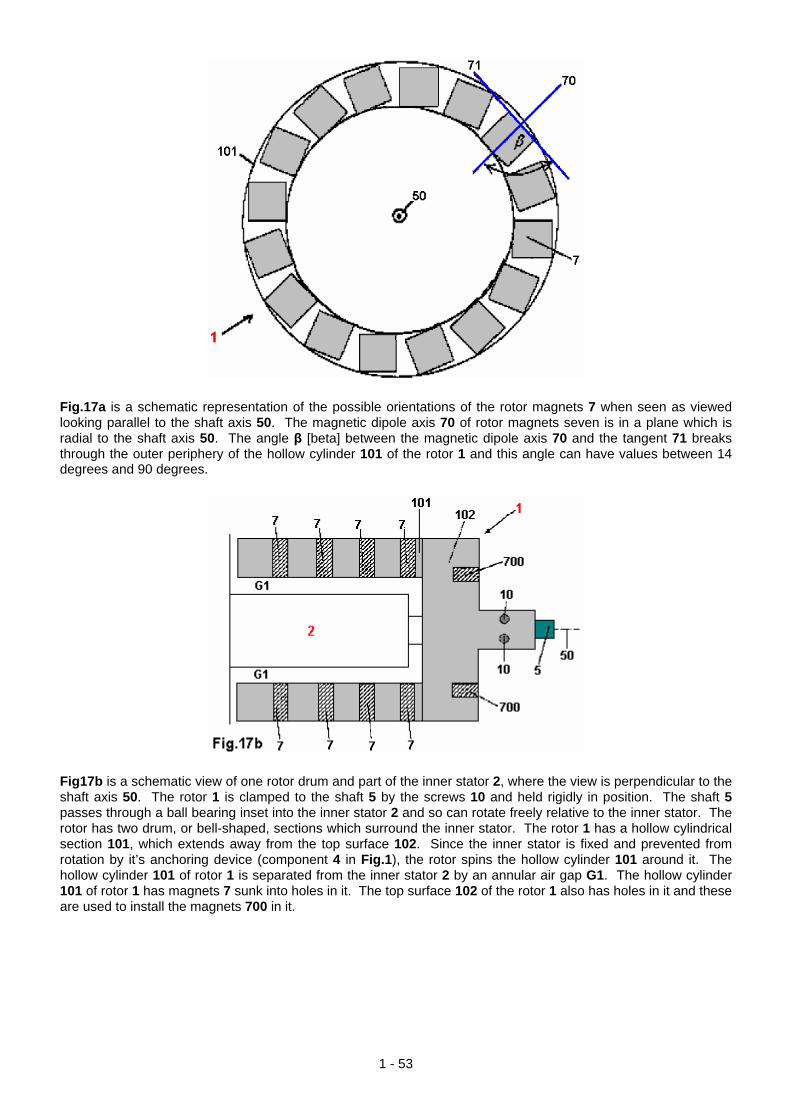
Fig.17a is a schematic representation of the possible orientations of the rotor magnets 7 when seen as viewed looking parallel to the shaft axis 50. The magnetic dipole axis 70 of rotor magnets seven is in a plane which is radial to the shaft axis 50. The angle β [beta] between the magnetic dipole axis 70 and the tangent 71 breaks through the outer periphery of the hollow cylinder 101 of the rotor 1 and this angle can have values between 14 degrees and 90 degrees.
Fig17b is a schematic view of one rotor drum and part of the inner stator 2, where the view is perpendicular to the shaft axis 50. The rotor 1 is clamped to the shaft 5 by the screws 10 and held rigidly in position. The shaft 5 passes through a ball bearing inset into the inner stator 2 and so can rotate freely relative to the inner stator. The rotor has two drum, or bell-shaped, sections which surround the inner stator. The rotor 1 has a hollow cylindrical section 101, which extends away from the top surface 102. Since the inner stator is fixed and prevented from rotation by it’s anchoring device (component 4 in Fig.1), the rotor spins the hollow cylinder 101 around it. The hollow cylinder 101 of rotor 1 is separated from the inner stator 2 by an annular air gap G1. The hollow cylinder 101 of rotor 1 has magnets 7 sunk into holes in it. The top surface 102 of the rotor 1 also has holes in it and these are used to install the magnets 700 in it.
1 - 53

Fig.18a shows the outer surfaces of the two halves of the rotor drum 1 laid out flat instead of curved into a circle in the X--Y plane shown in Fig.16. This surface is perpendicular to the shaft axis 50 and rows of magnets 7 are positioned in rows 701 to 708. Each of these rows is slightly offset in relation to the row beside it, resulting in a zig-zag layout of the magnets 7.
Fig.18b shows, in enlarged detail, the positioning of the magnets 7 shown in Fig.18a. The centres of the magnets 7 in the rows 705 and 706 have a constant separation f between their edges. The distance between any two adjacent rows, say, 705 and 706, is chosen so that the arrangement is as shown in Fig.18b with constant magnetic separation of length d between the edges of the magnets in adjacent rows. For example, the magnets 7051 and 7052 are exactly the same distance apart as magnets 7061 and 7062 the adjacent row 706. Also, the centres of the three magnets 7051, 7052 and 7061 form an isosceles triangle. This relationship holds for all of the
1 - 54

magnets in all seven series 701 to 708. Although the magnets 7 are shown in the diagrams as being circular, they could well be other shapes such as square or hexagonal. The length d ranges from about 3 mm to 50 mm. A distance which is particularly preferred, is 5 mm. The distance f ranges from about 10 mm to 70 mm.
Fig.19a shows a longitudinal section through the mechanical housing for the device, i.e. a section parallel to the shaft axis 50. The mechanical housing includes the support piece 4 for clamping the inner stator 2 to prevent it from rotating, the mount 19 for guiding the movable halves of the outer stator 3, and a rotating threaded rod 14 which can move both halves of the outer stator 3 relative to the rotor and/or the inner stator 2. The gear shaft 14 has two threaded sections with threads which run in opposite directions (right-hand and left-hand threads). The rotation of this shaft causes the two halves of the outer stator housing to move in a symmetrical manner in opposite directions, inwards or outwards. The guide devices 19 are mounted on the gear shaft 14 and so they only move in one plane. The outer cylindrical sections 9 which house the outer stator 3 are firmly attached to the end caps 19. Typically, this mechanical housing has a height of 400 to 600 mm, a width of 400 mm and a depth of 530 mm.
Fig.19b is a section through the outer stator 3, the section plane is perpendicular to the shaft axis 50. The outer stator 3 has arranged in it, a ring of non-magnetic fasteners 18, between which magnets 6 are secured. For reasons of clarity, only some of the magnets 6 are shown although these magnets are mounted on the entire circumference of the outer stator 3. The size of the magnets 6 and the non-magnetic fasteners 18 is chosen so that they form a hollow cylinder whose central axis is in the direction of the shaft axis 50. The magnetic dipole axis 60 of the magnets 6 are perpendicular to the shaft axis 50. An angle γ [gamma] between the magnetic dipole axis 60 and a tangent 61 to the outer periphery of the hollow cylindrical outer stator 3 is between 14 degrees and 90 degrees. The outer stator 3 is connected to the mounting block 4, which includes the mounting columns 20.
1 - 55

Fig.20 is a perspective view of the mechanical housing for the device. Additional practical details are available in the patent. Donald Kelly’s Permanent Magnet Motor. In 1979, Mr Kelly was granted a patent on a permanent magnet motor design. He comments that apart from it being very difficult to generate sufficient power to mechanically move the stator magnets slightly to achieve continuous rotation, the resulting rate of revolutions is very low. For those reasons, he has opted to move the stator magnets slightly using small DC motors. His design is included here as it is a concept which is relatively easy to understand. The overall idea is not unlike that of Stephen Kundel who rocks the stator magnets with a solenoid, as shown earlier in this chapter. The objective here is to use a small electrical current to generate a powerful rotation far greater than would be possible from the electrical current itself, and so, produce what is in effect, a power multiplication through the use of permanent magnets. A slightly reworded copy of his patent is shown in the Appendix.
1 - 56
The operation is a simple strategy. Eight sets of magnets are mounted on rocker arms. These have two main positions. In the first position, the rocker magnets attract the magnets mounted on the rotor. When the rotor moves because of this attraction and reaches a point where there is about to be a backward drag on the rotor, the position of the rocker arms is altered so that the first set of rocker magnets are moved out of the way to a position where they have little effect due to their increased distance from the rotor magnets. This rocker movement also
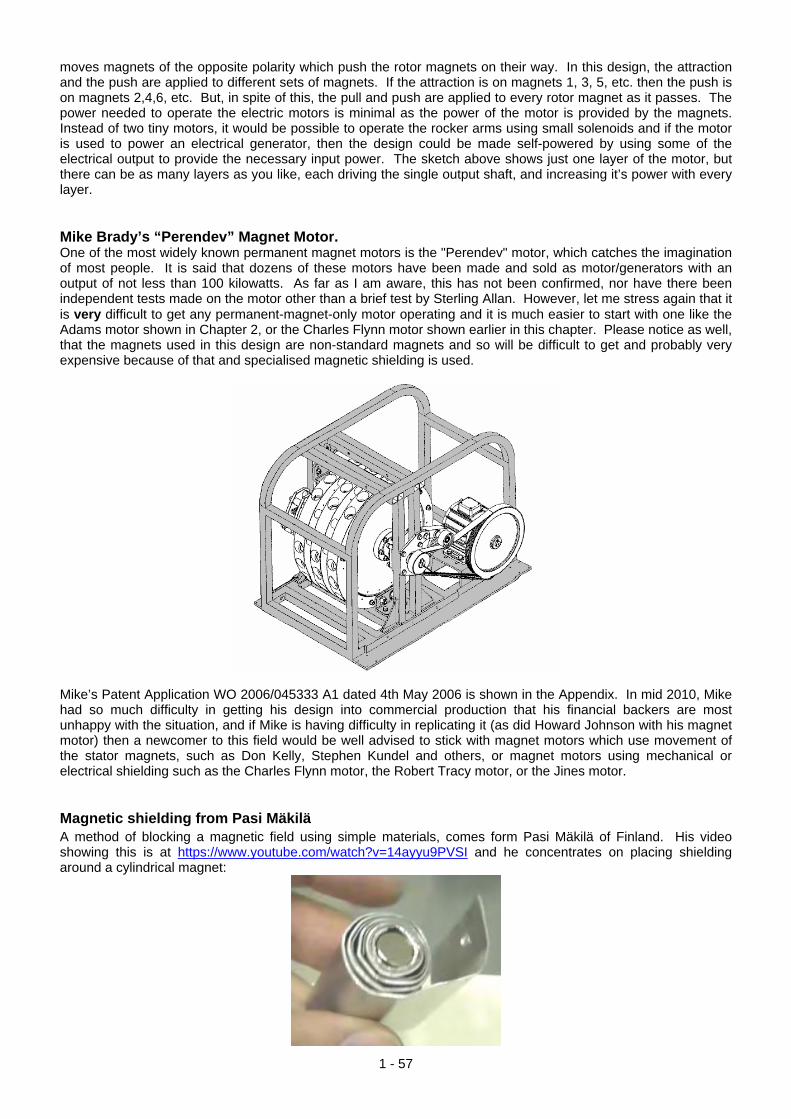
moves magnets of the opposite polarity which push the rotor magnets on their way. In this design, the attraction and the push are applied to different sets of magnets. If the attraction is on magnets 1, 3, 5, etc. then the push is on magnets 2,4,6, etc. But, in spite of this, the pull and push are applied to every rotor magnet as it passes. The power needed to operate the electric motors is minimal as the power of the motor is provided by the magnets. Instead of two tiny motors, it would be possible to operate the rocker arms using small solenoids and if the motor is used to power an electrical generator, then the design could be made self-powered by using some of the electrical output to provide the necessary input power. The sketch above shows just one layer of the motor, but there can be as many layers as you like, each driving the single output shaft, and increasing it’s power with every layer. Mike Brady’s “Perendev” Magnet Motor. One of the most widely known permanent magnet motors is the "Perendev" motor, which catches the imagination of most people. It is said that dozens of these motors have been made and sold as motor/generators with an output of not less than 100 kilowatts. As far as I am aware, this has not been confirmed, nor have there been independent tests made on the motor other than a brief test by Sterling Allan. However, let me stress again that it is very difficult to get any permanent-magnet-only motor operating and it is much easier to start with one like the Adams motor shown in Chapter 2, or the Charles Flynn motor shown earlier in this chapter. Please notice as well, that the magnets used in this design are non-standard magnets and so will be difficult to get and probably very expensive because of that and specialised magnetic shielding is used.
Mike’s Patent Application WO 2006/045333 A1 dated 4th May 2006 is shown in the Appendix. In mid 2010, Mike had so much difficulty in getting his design into commercial production that his financial backers are most unhappy with the situation, and if Mike is having difficulty in replicating it (as did Howard Johnson with his magnet motor) then a newcomer to this field would be well advised to stick with magnet motors which use movement of the stator magnets, such as Don Kelly, Stephen Kundel and others, or magnet motors using mechanical or electrical shielding such as the Charles Flynn motor, the Robert Tracy motor, or the Jines motor. Magnetic shielding from Pasi Mäkilä A method of blocking a magnetic field using simple materials, comes form Pasi Mäkilä of Finland. His video showing this is at https://www.youtube.com/watch?v=14ayyu9PVSI and he concentrates on placing shielding around a cylindrical magnet:
1 - 57

However, when used as general shielding, a series of flat steel and aluminium layers can be used and while Pasi uses aluminium sheet 1.5 mm thick and zinc-plated steel which is 1 mm thick he suggests using thinner sheets. He suggests using four layers of steel with a sheet of aluminium between the steel sheets and perhaps one or more layers of aluminium on the outside. Pasi’s main aim is to share this arrangement to allow people to make permanent magnet motors. One arrangement which may well be worth trying out is to use the shielding to block the backward drag of rotor magnets passing stator magnets, perhaps like this:
With this arrangement, the South poles of the rotor magnets are attracted to the exposed North poles of the stator magnets, causing the rotor to rotate. As soon as a rotor South passes the stator North pole, the stator shielding blocks the reverse pull which would normally slow the rotor down. We then have the repulsion of the North pole of the stator magnet and the North pole of the rotor magnet. To block that, a short length of shielding is placed beside the north pole end of the rotor magnet. It would probably be an advantage to run the stator north pole shielding over the top and underside of the rotor magnet to cause major magnetic blocking. This magnetic motor design is just a suggestion and has not yet been built and tested. The Twin Rotor Suggestion When you are considering shielding magnets using iron or steel, you need to remember that fridge magnets stick to refrigerators because the refrigerators are made of steel. This demonstrates the fact that there is an attraction between magnets and iron or steel. Consequently, if a magnet is shielded with steel so that it blocks the whole of the magnetic field of the magnet, a second magnet will be attracted to that metal shielding material. At http://www.youtube.com/watch?v=vUcWn1x3Tss there is, at the present time, a video by “magneticveil” where he proposes the use of this feature of simple shielding in the construction of a magnet motor. He suggests using two rotors geared together. The rotors have magnets on them, but for the purposes of explanation, just one pair of magnets are shown here:
1 - 58

Each magnet is attracted to the metal shield material between the rotors. This causes the rotors to rotate in the direction shown by the red arrows. The magnets are drawn to the nearest point to the shield which they can reach as shown here:
At this point you would expect the rotors to stop moving and lock into a stationary position. However, the interesting idea is to adjust the shape of the shield like this:
At the end of the shield, its width is reduced and tapered so that the magnetic field from the magnet behind it exactly matches the attraction of the magnet on the near side of the shield. This has the effect of giving a completely neutral zone at the tip of the shield, with neither an attraction or a repulsion in that region. The degree of tapering depends on the strength of the magnets, the thickness and material of the shield and the spacing between the magnets and the shield, and it needs to be discovered by experiment. This neutral zone stops there being a major pull between the magnets and the shield, and so momentum carries the rotors on past the end of the shield. This produces a situation like this:
Here, the magnets have moved past the shield and are repelling each other strongly. They are beyond the axles of the rotors, so the repelling force produces a turning effect on each rotor. This is the situation with just one pair
1 - 59

of magnets, but each rotor will have many magnets on it. This produces an additional turning effect. Consider just one other pair of magnets, in the same position as our first diagram:
The pull between the magnets “A” and the shield, adds to the rotation caused by the push between the unshielded magnets. This arrangement of magnets and shield should allow continuous rotation of both rotors and the motor can be stopped by removing the shield. It should be noted that this arrangement uses magnets in repulsion mode. That is, the outward-facing poles of the magnets on both rotors are the same. There have been reports of permanent magnet motors where the magnets were in repulsion mode, and while these motors ran well, it was found that after about three months, the magnets lost their magnetisation. If at all possible, magnets should be used in their attraction mode. This is not possible in the above twin-rotor arrangement, so if one is being constructed, it might be a good idea to arrange the physical construction in such a way that the rotor magnets can easily be removed. This allows remagnetisation of the magnets, or alternatively, their replacement if very cheap types are used. The Permanent Magnet Motor of Victor Diduck In US patent application number US2007/0296284 of 27th December 2007, there is shown a convincing design for a powerful permanent magnet motor. Here is one of the embodiments from that patent – one which looks reasonably easy to build.
Magnetic Motor Abstract: A magnetic motor having a magnetic drive assembly magnetically coupled to a magnetic slave assembly. The drive assembly has at least one drive magnet. In one embodiment the drive magnet is mounted on a cowling. In another embodiment the drive magnet is mounted on a drive wheel. The slave assembly has at least one slave wheel mounted on a slave shaft. At least one slave magnet is mounted on the slave wheel. In one embodiment slave magnets are mounted in grooves running diagonally across the face of the slave wheel. In another embodiment the slave magnets are mounted in notches cut into the slave wheel. The drive magnet is magnetically coupled to the slave magnet with the poles arranged in a like-faces-like orientation. The gap between the drive magnet and slave magnet can be adjusted in order to optimise the magnetic coupling the between them. The slave wheel and its slave shaft are caused to rotate by the magnetic coupling between the drive magnet and the slave magnet. The slave shaft can be coupled to an output device such as an electric generator. BACKGROUND OF THE INVENTION There have been a number of attempts to perfect magnetic motors; for instance, U.S. Pat. No. 4,151,431 issued to Howard Johnson. However, in most such devices no working models have been achieved. In order to make a permanent magnet motor operate it is necessary to accomplish a switching function equivalent to that accomplished in electric motors by brushes, commutators, alternating current, or other means. In permanent magnet motors magnetic leakage must be shielded so as to reduce energy lost as eddy-current energy. A proper combination of materials, geometry, and magnetic concentration is required in order to be able to construct a magnetic motor that can operate continuously. SUMMARY OF THE INVENTION A magnetic motor is provided comprising a magnetic drive assembly magnetically coupled to a magnetic slave assembly. The magnetic slave assembly includes a rotatable slave shaft upon which is mounted at least one rotatable slave wheel. Upon the slave wheel is mounted at least one slave magnet. The magnetic drive assembly
1 - 60

includes at least one drive magnet which is magnetically coupled to the slave magnet in a like-faces-like orientation. As a result of the magnetic coupling between the drive magnet and the slave magnet, magnetic forces produced between the coupled drive magnet and slave magnet drive the rotatable slave wheel, making it rotate and therefore causing the slave shaft to rotate. The slave shaft is coupled to an output device such as the armature of an electric generator. The slave assembly is coupled to a frame. The slave wheels are fixed to the shaft so that the wheels rotate together. Each slave wheel has embedded in its surface a plurality of slave magnets set in indentations cut into the slave wheel. One pole of each slave magnet is exposed and facing outwards from the surface of the slave wheel, and the other magnet pole faces the slave wheel. Either the north pole or the south pole of the slave magnets may face outward, as long each magnet has the same pole facing outwards. In one embodiment the indentations in the slave wheels for receiving the slave magnets form spaced apart, parallel grooves running from one side of the surface of the slave wheel to the other for receiving the slave magnets. The angle of each groove across the surface of the slave wheel is preferably about 35 degrees with respect to horizontal. The direction of orientation of the grooves of the other of the slave wheels is also about 35 degrees off of the horizontal, but in the opposite direction to that of the first wheel. In another embodiment the indentations in the slave wheels for receiving the slave magnets are notches cut into the slave wheel at measured and equal intervals along the edges of the wheel, intervals of 45 degrees being preferred. In this “cowling” embodiment of the invention, the magnetic drive assembly comprises a pair of non-magnetic cowlings surrounding and substantially enclosing each of the slave wheels. Each pair of cowlings forms a semi-circular surface having a diameter slightly larger than the diameter of its respective slave wheel. The concave curvature of the cowlings faces the slave wheels. Mounted on the convex surface of the cowlings are a plurality of permanent drive magnets. The drive magnets are mounted so that they present to the slave magnets the same pole as the slave magnets present to the drive magnets; i.e., like-faces-like: north-to-north or south-to-south. Neither the cowlings nor their drive magnets rotate. In the various embodiments, the gap between the drive magnets and the slave magnets is adjustable.
BRIEF DESCRIPTION OF THE DRAWINGS Further features and advantages of the invention will be apparent from the following detailed description taken in conjunction with the accompanying drawings, where:
Fig.1 is a perspective view of the cowling embodiment of the magnetic motor with fly wheels attached.
1 - 61

Fig.2 is partially disassembled perspective view of the cowling embodiment of the magnetic motor.
Fig.3 is a diagram of the magnet placement on the cowling.
1 - 62

Fig.4 is a schematic diagram of one slave wheel of the cowlings embodiment showing the position of the permanent magnets.
Fig.5 is a schematic diagram of another slave wheel of the cowlings embodiment showing the position of the permanent magnets.
1 - 63

DETAILED DESCRIPTION OF THE INVENTION In the various embodiments of the invention there is generally provided a magnetic drive assembly and a magnetic slave assembly, with a magnetic field coupling the drive assembly to the slave assembly such that when the drive assembly rotates it causes the slave assembly to rotate. The coupling is entirely magnetic, where no chains, gears, pulleys, worm drives or other physical couplers are required.
Fig.1 and Fig.2 show a first embodiment of the invention, referred to herein as the “cowling” embodiment. In this embodiment the magnetic slave assembly of the magnetic motor 101 comprises two solid non-magnetic slave wheels 102 and 202, most clearly seen in Fig.2. The slave wheels are mounted on a slave shaft 201. Fig.1 shows an embodiment in which optional fly-wheels 301, 401 are mounted on slave shaft 201. The fly-wheels may be conveniently mounted at or near the ends of the slave shaft. A device 1301 for generating electric current is provided that is directly coupled to the slave shaft, or indirectly coupled through a fly-wheel, as shown in Fig.1, or though some other element of the magnetic slave assembly.
Except for elements noted herein, the invention is constructed of a non-magnetic material. Pheotic plastic or ceramic materials are currently preferred for the slave wheels and drive wheels, but a wide variety of non-magnetic materials is acceptable so long as the material does not create or exacerbate eddy currents. The diameter of the slave wheels in currently operating models is approximately 10 inches (250 mm), and the width approximately 5 inches (125 mm). The optimum dimensions of the slave wheels will be determined by the specific application of the invention.
As seen in Fig.2, each slave wheel has a plurality of grooves running from one side to the other. One such groove is designated 701. The grooves in one wheel are oriented at an angle of about 35 degrees to the slave wheel edge, while the grooves of the second wheel are oriented at about 35 degrees to the opposite edge, as can be seen clearly in Fig.2.
1 - 64
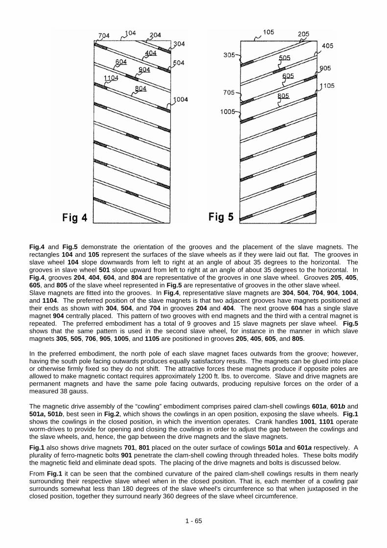
Fig.4 and Fig.5 demonstrate the orientation of the grooves and the placement of the slave magnets. The rectangles 104 and 105 represent the surfaces of the slave wheels as if they were laid out flat. The grooves in slave wheel 104 slope downwards from left to right at an angle of about 35 degrees to the horizontal. The grooves in slave wheel 501 slope upward from left to right at an angle of about 35 degrees to the horizontal. In Fig.4, grooves 204, 404, 604, and 804 are representative of the grooves in one slave wheel. Grooves 205, 405, 605, and 805 of the slave wheel represented in Fig.5 are representative of grooves in the other slave wheel. Slave magnets are fitted into the grooves. In Fig.4, representative slave magnets are 304, 504, 704, 904, 1004, and 1104. The preferred position of the slave magnets is that two adjacent grooves have magnets positioned at their ends as shown with 304, 504, and 704 in grooves 204 and 404. The next groove 604 has a single slave magnet 904 centrally placed. This pattern of two grooves with end magnets and the third with a central magnet is repeated. The preferred embodiment has a total of 9 grooves and 15 slave magnets per slave wheel. Fig.5 shows that the same pattern is used in the second slave wheel, for instance in the manner in which slave magnets 305, 505, 706, 905, 1005, and 1105 are positioned in grooves 205, 405, 605, and 805. In the preferred embodiment, the north pole of each slave magnet faces outwards from the groove; however, having the south pole facing outwards produces equally satisfactory results. The magnets can be glued into place or otherwise firmly fixed so they do not shift. The attractive forces these magnets produce if opposite poles are allowed to make magnetic contact requires approximately 1200 ft. lbs. to overcome. Slave and drive magnets are permanent magnets and have the same pole facing outwards, producing repulsive forces on the order of a measured 38 gauss. The magnetic drive assembly of the “cowling” embodiment comprises paired clam-shell cowlings 601a, 601b and 501a, 501b, best seen in Fig.2, which shows the cowlings in an open position, exposing the slave wheels. Fig.1 shows the cowlings in the closed position, in which the invention operates. Crank handles 1001, 1101 operate worm-drives to provide for opening and closing the cowlings in order to adjust the gap between the cowlings and the slave wheels, and, hence, the gap between the drive magnets and the slave magnets.
Fig.1 also shows drive magnets 701, 801 placed on the outer surface of cowlings 501a and 601a respectively. A plurality of ferro-magnetic bolts 901 penetrate the clam-shell cowling through threaded holes. These bolts modify the magnetic field and eliminate dead spots. The placing of the drive magnets and bolts is discussed below.
From Fig.1 it can be seen that the combined curvature of the paired clam-shell cowlings results in them nearly surrounding their respective slave wheel when in the closed position. That is, each member of a cowling pair surrounds somewhat less than 180 degrees of the slave wheel's circumference so that when juxtaposed in the closed position, together they surround nearly 360 degrees of the slave wheel circumference.
1 - 65

Fig.3A and Fig.3B represent a pattern for mounting the slave magnets on the outside, or convex, surface of one pair of cowlings. The figure represents the cowling-halves 103, 703 as if they were laid flat. Guide lines are provided in the figure to indicate the longitudinal bisecting lines 403 and horizontal lines 503 dividing each cowling into eighths. With respect to the cowling-half shown in Fig.3A, two permanent drive magnets, 203, 303 are glued to the outside surface of the cowling on line 403 bisecting the cowling longitudinally. One drive magnet 203 is placed approximately one eighth of the way from one end. The second drive magnet 303 is placed three eighths of the way from the opposite end. Ferro-magnetic bolts 603 are inserted in the cowling through threaded holes. The purpose of the bolts is to modify the magnetic field to eliminate dead spots. With respect to the cowling-half shown in Fig.3B, drive magnet 803 is placed three eighths of the way from one end, and drive magnet 903 is placed one eighth (one sixteenth ?) of the way from the other end. Again, ferro-magnetic bolts 603 are provided for eliminating dead spots in the magnetic field. The diameter across each slave wheel is approximately 10 inches (250 mm). Measured from the bottom of groove 404 the diameter is 9 inches(225 mm). Consequently, the arc length from the bottom of one groove to the bottom of an adjacent groove is π inches (i.e., 3.14 inches or 80 mm). The drive magnets are glued or otherwise firmly fixed to the outer or concave surfaces of the cowlings. Assuming that the slave magnets have been mounted in the grooves of the slave wheels with the north pole facing outwards, the north pole of each drive magnet is fixed against the cowling surface so that like poles face one another. As the cowlings are moved toward the slave wheels by turning the cranks 1101, 1001 the drive magnets repel the slave magnets, causing the slave wheels to rotate. Adjustment of the spacing between the cowlings and the slave wheels by means of cranks 1101, 1001 adjusts the strength of the interaction of the fields of the drive magnets and slave magnets and, hence, the torque on the slave wheels. As shown in Fig.1, fly-wheels 301, 401 can optionally be mounted on the slave shaft. The preferred position is at or near the end of the shaft. Slave shaft 201 thus turns as a result of the magnetic force from the cowlings being applied to the slave wheels. This shaft can be coupled to an output such as the armature of a generator 1301, either directly or through a flywheel, as shown. Alternatively, the magnetic motor could itself drive a hydraulic pump of a transmission,
1 - 66

1 - 67
thereby reducing the number transmission components and the overall complexity of transmissions. Many different applications for this motor become obvious once it is realised that by using very strong permanent drive magnets useful power can be generated. It is possible to vary the dimensions of the slave wheels. Presently, the preferred diameter is approximately 10 inches and a width of 5 inches. The motor can operate with the slave shaft 201 vertical or horizontal. While aluminium is a suitable material for the motor, the use of a hard plastic or ceramic materials have also been used with success. Pheotic plastic is presently preferred. By using two slave wheels rather than just one, any dead spots in one wheel will be compensated for by the other wheel. The upper limit of the number of slave wheels is not yet known. The lower limit is one. Patrick Kelly www.free-energy-info.tuks.nl www.free-energy-info.com www.free-energy-info.co.uk