FM3 Microcontroller, Electrical Weight on Wash Machine
17
www.cypress.com Document No. 002-05399 Rev. *B 1 AN205339 FM3 Microcontroller, Electrical Weight on Wash Machine This application note describes electrical weight method on wash machine. This solution is either adapted for direct drive wash machine and draft drive machine. Contents 1 INTRODUCTION ...................................................... 1 1.1 Purpose ........................................................... 1 1.2 Definitions, Acronyms and Abbreviations ........ 1 1.3 Document Overview ........................................ 2 2 Electrical Weight Principle ........................................ 2 2.1 Overview ......................................................... 2 2.2 Basic Moving Module ...................................... 2 2.3 Electrical Weight on Wash Machine ................ 5 3 Power Calculation..................................................... 7 3.1 Overview ......................................................... 7 3.2 Power Calculation ........................................... 7 3.3 Software Design .............................................. 9 3.4 Weight Calculation from Power ..................... 10 4 Verification.............................................................. 10 4.1 Overview ....................................................... 10 4.2 Motor Current ................................................ 10 4.3 Power and Load-Weight ................................ 15 5 Document History ................................................... 16 1 INTRODUCTION 1.1 Purpose This application note describes electrical weight method on wash machine. This solution is either adapted for direct drive wash machine and draft drive machine. 1.2 Definitions, Acronyms and Abbreviations Te: Motor Magnetic Torque P: Motor Power Vsq: Voltage on q axis of d/q coordinates in FOC algorithm Vsd: Voltage on d axis of d/q coordinates in FOC algorithm Isq: Current on q axis of d/q coordinates in FOC algorithm Isd: Current on d axis of d/q coordinates in FOC algorithm M: Load weight N: Wash machine’s bucket speed OOB: Wash machine’s PMSM: Permanent Magnet Synchronous Motor BLDC: Brush less DC Motor
-
Upload
khangminh22 -
Category
Documents
-
view
0 -
download
0
Transcript of FM3 Microcontroller, Electrical Weight on Wash Machine
www.cypress.com Document No. 002-05399 Rev. *B 1
AN205339
FM3 Microcontroller, Electrical Weight on Wash Machine
This application note describes electrical weight method on wash machine. This solution is either adapted for direct
drive wash machine and draft drive machine.
Contents
1 INTRODUCTION ...................................................... 1 1.1 Purpose ........................................................... 1 1.2 Definitions, Acronyms and Abbreviations ........ 1 1.3 Document Overview ........................................ 2
2 Electrical Weight Principle ........................................ 2 2.1 Overview ......................................................... 2 2.2 Basic Moving Module ...................................... 2 2.3 Electrical Weight on Wash Machine ................ 5
3 Power Calculation ..................................................... 7 3.1 Overview ......................................................... 7
3.2 Power Calculation ........................................... 7 3.3 Software Design .............................................. 9 3.4 Weight Calculation from Power ..................... 10
4 Verification .............................................................. 10 4.1 Overview ....................................................... 10 4.2 Motor Current ................................................ 10 4.3 Power and Load-Weight ................................ 15
5 Document History ................................................... 16
1 INTRODUCTION
1.1 Purpose
This application note describes electrical weight method on wash machine.
This solution is either adapted for direct drive wash machine and draft drive machine.
1.2 Definitions, Acronyms and Abbreviations
Te: Motor Magnetic Torque
P: Motor Power
Vsq: Voltage on q axis of d/q coordinates in FOC algorithm
Vsd: Voltage on d axis of d/q coordinates in FOC algorithm
Isq: Current on q axis of d/q coordinates in FOC algorithm
Isd: Current on d axis of d/q coordinates in FOC algorithm
M: Load weight
N: Wash machine’s bucket speed
OOB: Wash machine’s
PMSM: Permanent Magnet Synchronous Motor
BLDC: Brush less DC Motor
FM3 Microcontroller, Electrical Weight on Wash Machine
www.cypress.com Document No. 002-05399 Rev. *B 2
1.3 Document Overview
The rest of document is organized as the following:
Chapter 2 explains the principle of electrical weight on wash machine.
Chapter 3 explains how to calculate the power consume in weight process.
Chapter 4 introduce the test weight data on DD wash machine.
2 Electrical Weight Principle
This chapter introduces the algorithm of electrical weight.
2.1 Overview
Body weight can be achieved from electronic weight throwing sensor, but in some case, we can’t have the sensor or the field is very worse that can’t install sensor such as wash machine.
This chapter will talk about it from the connection of input electrical power, body weight and moving. If the load were very weight, the input electrical weight must be very large or small .That is to say, the load’s weight can be obtained from the input electrical power which is easy to be detected. The basic electrical weight principle is on the Law of Energy Conversation. To achieve the body’s weight, first should acknowledge the liner moving module, then can understand rotation moving module easily.
2.2 Basic Moving Module
Electrical machine are usually connect to mechanical system, and it converts the electrical energy to mechanical energy as a motor and converts mechanical energy to electrical energy as a generator. Hence, in these energy conversation processes, understanding of mechanics is essential to learn the energy transform principle.
As we know that the net force on a body is proportional to the time rate of change of its linear momentum as equation (2-1).
(2-1)
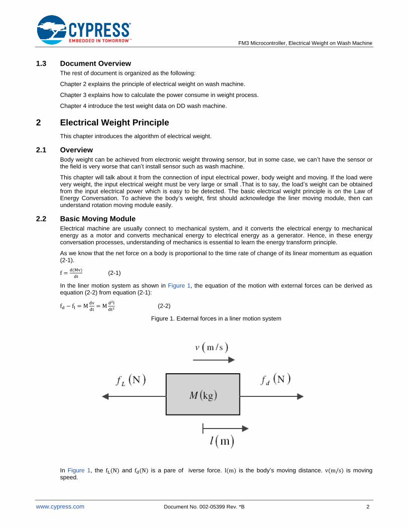
In the liner motion system as shown in Figure 1, the equation of the motion with external forces can be derived as equation (2-2) from equation (2-1):
(2-2)
Figure 1. External forces in a liner motion system
In Figure 1, the and is a pare of iverse force. is the body’s moving distance. is moving speed.
FM3 Microcontroller, Electrical Weight on Wash Machine
www.cypress.com Document No. 002-05399 Rev. *B 3
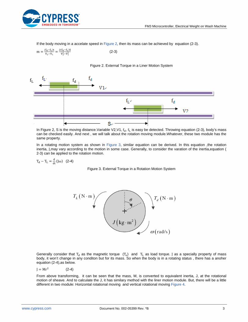
If the body moving in a accelate speed in Figure 2, then its mass can be achieved by equation (2-3).
(2-3)
Figure 2. External Torque in a Liner Motion System
In Figure 2, S is the moving distance.Variable V2,V1, , is easy be detected. Throwing equation (2-3), body’s mass can be checked easily. And next , we will talk about the rotation moving module.Whatever, these two module has the same property.
In a rotating motion system as shown in Figure 3, similar equation can be derived. In this equation ,the rotation inertia, ,may vary according to the motion in some case. Generally, to consider the varation of the inertia,equation ( 2-3) can be applied to the rotation motion.
(2-4)
Figure 3. External Torque in a Rotation Motion System
Generally consider that as the magnetic torque ( ) and as load torque. as a specially property of mass body, it won’t change in any conditon but for its mass. So when the body is in a rotating status , there has a anoher equation (2-4),as below.
(2-4)
From above transforming, it can be seen that the mass, M, is converted to equivalent inertia, J, at the rotational motion of sheave. And to calculate the J, it has similary method with the liner motion module. But, there will be a little different in two module: Horizontal rotational moving and vertical rotational moving Figure 4.

FM3 Microcontroller, Electrical Weight on Wash Machine
www.cypress.com Document No. 002-05399 Rev. *B 4
Figure 4. Horizontal and Vertical Rotation Motion System
These two diferent rotation module has different mothod to calculate body’s mass.
In horizontal rotation system, It is easy to be changed as a liner moving modle. Body’s mass calculate could be predigst as equation (2-5).
(2-5)
Where s is the moving radian. and is the begin testing angle speed and over testing angle speed.
In vertical rotation system, body’s force status has been changed. Besides outside forces, its body gravity also has done power on self. So mass calculation seems to be complex. The moving balcance equation may be constitute from power.
Image that the body is rising up from the bottom to the top around the center throw axis, equation can be expressied as (2-6).
(2-6)
On the other hand, if the body fall down from the top to the bottom and has no force torque but for its gravity and friction, the moving balance equation changed as (2-7).
(2-7)
If the can be known, From equation (2-4), (2-6) and (2-7), the body’s mass can be achieved.At now, body’s moving and body’s mass has been connected throw above equation. Next, we will talk about how to use this math method to calcuate load weight in wash machine.
FM3 Microcontroller, Electrical Weight on Wash Machine
www.cypress.com Document No. 002-05399 Rev. *B 5
2.3 Electrical Weight on Wash Machine
According moving module, wash machine can be defined as two types: Pulsator washing machine and Roller-type washing machine. Pulsator washing machine’s rotation is in horizontal direction. However, Roller-type washing machine’s rotation is in the vertical direction. These two moving modules have been talked in 2.2.
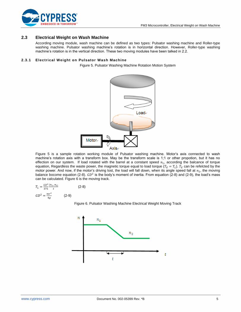
2.3.1 Electr ical Weight on Pulsator Wash Machine
Figure 5. Pulsator Washing Machine Rotation Motion System
Figure 5 is a sample rotation working module of Pulsator washing machine. Motor’s axis connected to wash machine’s rotation axis with a transform box. May be the transform scale is 1;1 or other propotion, but it has no effection on our system. If load rotated with the barrel at a constant speed , according the balcance of torque
equation, Regardless the waste power, the magnetic torque equal to load torque ( ). can be refelcted by the
motor power. And now, if the motor’s driving lost, the load will fall down, when its angle speed fall at , the moving
balance bocome equation (2-8). is the body’s moment of inertia. From equation (2-8) and (2-9), the load’s mass can be calculated. Figure 6 is the moving track.
(2-8)
(2-9)
Figure 6. Pulsator Washing Machine Electrical Weight Moving Track
FM3 Microcontroller, Electrical Weight on Wash Machine
www.cypress.com Document No. 002-05399 Rev. *B 6
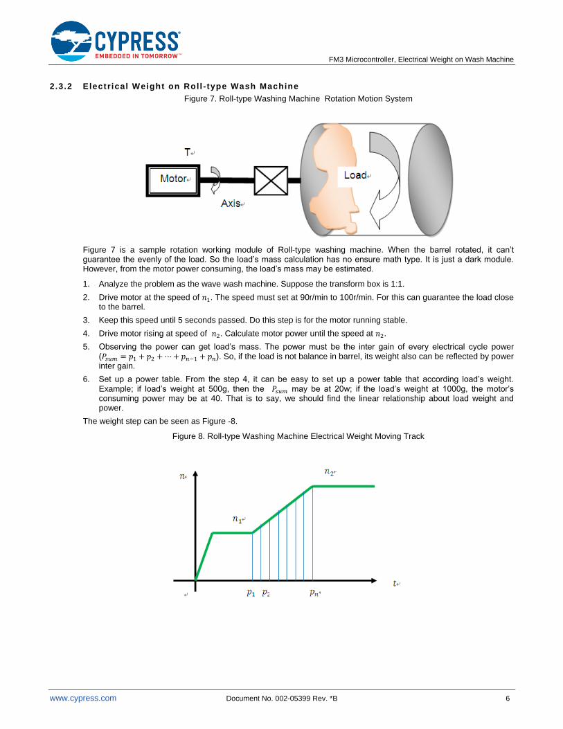
2.3.2 Electr ical Weight on Rol l - type Wash Machine
Figure 7. Roll-type Washing Machine Rotation Motion System
Figure 7 is a sample rotation working module of Roll-type washing machine. When the barrel rotated, it can’t guarantee the evenly of the load. So the load’s mass calculation has no ensure math type. It is just a dark module. However, from the motor power consuming, the load’s mass may be estimated.
1. Analyze the problem as the wave wash machine. Suppose the transform box is 1:1.
2. Drive motor at the speed of . The speed must set at 90r/min to 100r/min. For this can guarantee the load close to the barrel.
3. Keep this speed until 5 seconds passed. Do this step is for the motor running stable.
4. Drive motor rising at speed of . Calculate motor power until the speed at .
5. Observing the power can get load’s mass. The power must be the inter gain of every electrical cycle power ( ). So, if the load is not balance in barrel, its weight also can be reflected by power inter gain.
6. Set up a power table. From the step 4, it can be easy to set up a power table that according load’s weight.
Example; if load’s weight at 500g, then the may be at 20w; if the load’s weight at 1000g, the motor’s consuming power may be at 40. That is to say, we should find the linear relationship about load weight and power.
The weight step can be seen as Figure -8.
Figure 8. Roll-type Washing Machine Electrical Weight Moving Track
FM3 Microcontroller, Electrical Weight on Wash Machine
www.cypress.com Document No. 002-05399 Rev. *B 7
3 Power Calculation
This chapter introduces motor power calculation on FOC control system
3.1 Overview
From chapter 2’s talk, to calculate the load’s weight has been focus on the power calculation. Our control method is based on the FOC system that power calculation seems to be very easy. And this chapter will talk about it detail.
3.2 Power Calculation
3.2.1 FOC Algori thm
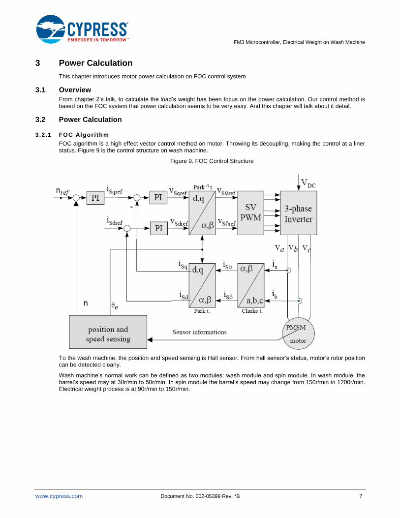
FOC algorithm is a high effect vector control method on motor. Throwing its decoupling, making the control at a liner status. Figure 9 is the control structure on wash machine.
Figure 9. FOC Control Structure
To the wash machine, the position and speed sensing is Hall sensor. From hall sensor’s status, motor’s rotor position can be detected clearly.
Wash machine’s normal work can be defined as two modules: wash module and spin module. In wash module, the barrel’s speed may at 30r/min to 50r/min. In spin module the barrel’s speed may change from 150r/min to 1200r/min. Electrical weight process is at 90r/min to 150r/min.
FM3 Microcontroller, Electrical Weight on Wash Machine
www.cypress.com Document No. 002-05399 Rev. *B 8
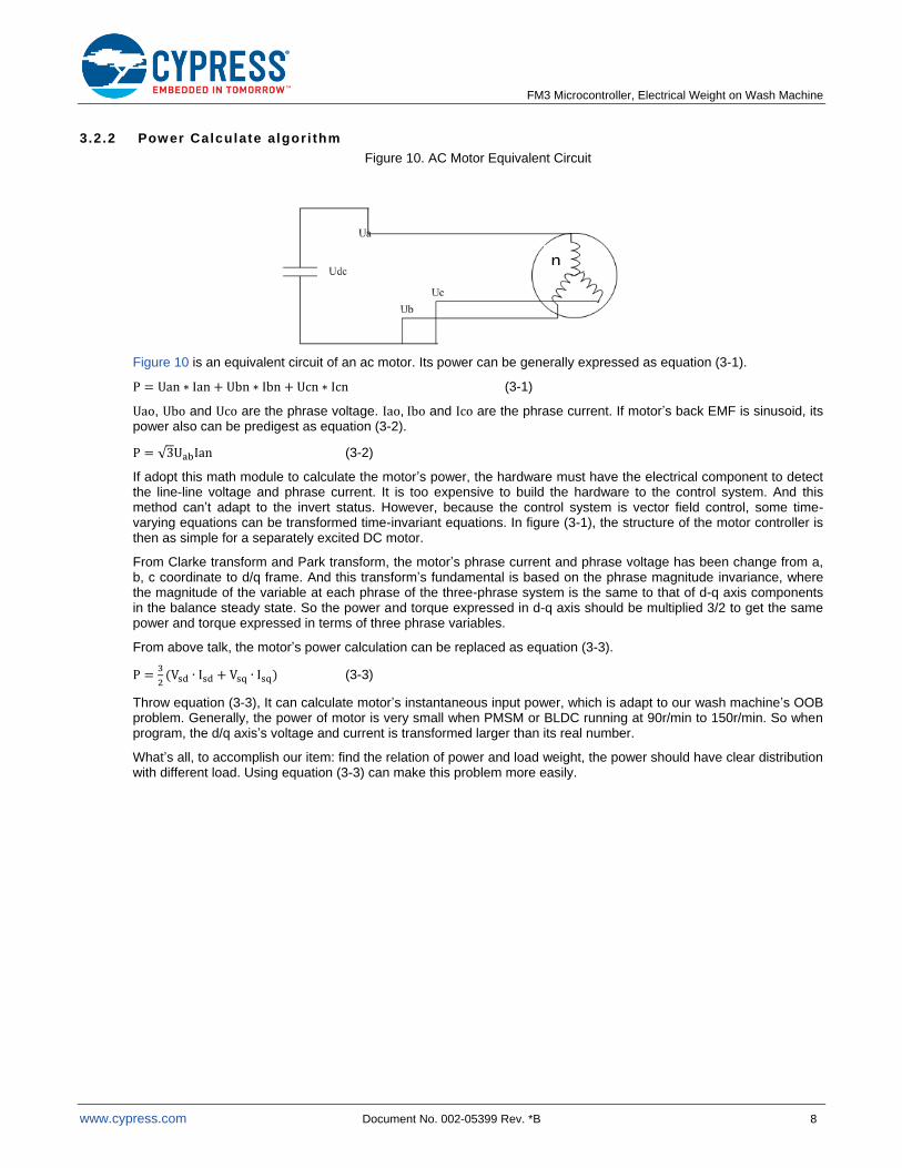
3.2.2 Power Calculate algori thm
Figure 10. AC Motor Equivalent Circuit
Figure 10 is an equivalent circuit of an ac motor. Its power can be generally expressed as equation (3-1).
(3-1)
, and are the phrase voltage. , and are the phrase current. If motor’s back EMF is sinusoid, its power also can be predigest as equation (3-2).
(3-2)
If adopt this math module to calculate the motor’s power, the hardware must have the electrical component to detect the line-line voltage and phrase current. It is too expensive to build the hardware to the control system. And this method can’t adapt to the invert status. However, because the control system is vector field control, some time-varying equations can be transformed time-invariant equations. In figure (3-1), the structure of the motor controller is then as simple for a separately excited DC motor.
From Clarke transform and Park transform, the motor’s phrase current and phrase voltage has been change from a, b, c coordinate to d/q frame. And this transform’s fundamental is based on the phrase magnitude invariance, where the magnitude of the variable at each phrase of the three-phrase system is the same to that of d-q axis components in the balance steady state. So the power and torque expressed in d-q axis should be multiplied 3/2 to get the same power and torque expressed in terms of three phrase variables.
From above talk, the motor’s power calculation can be replaced as equation (3-3).
(3-3)
Throw equation (3-3), It can calculate motor’s instantaneous input power, which is adapt to our wash machine’s OOB problem. Generally, the power of motor is very small when PMSM or BLDC running at 90r/min to 150r/min. So when program, the d/q axis’s voltage and current is transformed larger than its real number.
What’s all, to accomplish our item: find the relation of power and load weight, the power should have clear distribution with different load. Using equation (3-3) can make this problem more easily.
n
FM3 Microcontroller, Electrical Weight on Wash Machine
www.cypress.com Document No. 002-05399 Rev. *B 9
3.3 Software Design
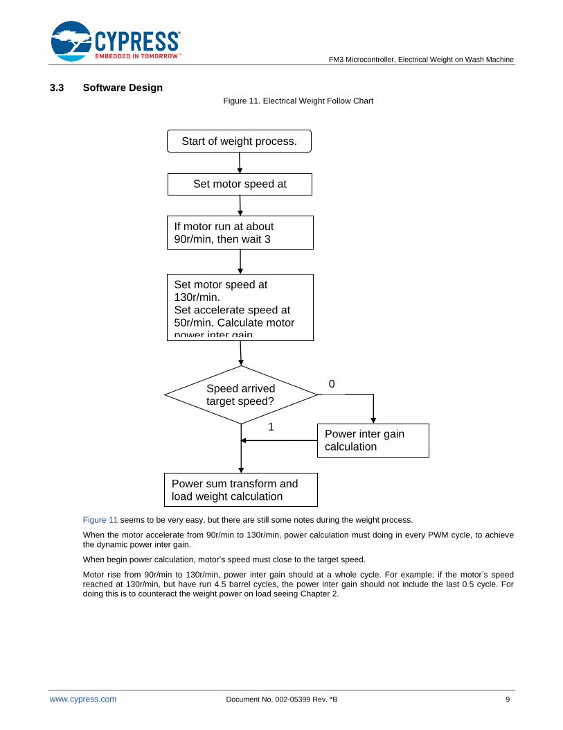
Figure 11. Electrical Weight Follow Chart
Figure 11 seems to be very easy, but there are still some notes during the weight process.
When the motor accelerate from 90r/min to 130r/min, power calculation must doing in every PWM cycle, to achieve the dynamic power inter gain.
When begin power calculation, motor’s speed must close to the target speed.
Motor rise from 90r/min to 130r/min, power inter gain should at a whole cycle. For example; if the motor’s speed reached at 130r/min, but have run 4.5 barrel cycles, the power inter gain should not include the last 0.5 cycle. For doing this is to counteract the weight power on load seeing Chapter 2.
Start of weight process.
Set motor speed at 90r/min.
If motor run at about 90r/min, then wait 3 second.
Set motor speed at 130r/min. Set accelerate speed at 50r/min. Calculate motor power inter gain.
Speed arrived target speed?
Power inter gain calculation
0
1
Power sum transform and load weight calculation
FM3 Microcontroller, Electrical Weight on Wash Machine
www.cypress.com Document No. 002-05399 Rev. *B 10
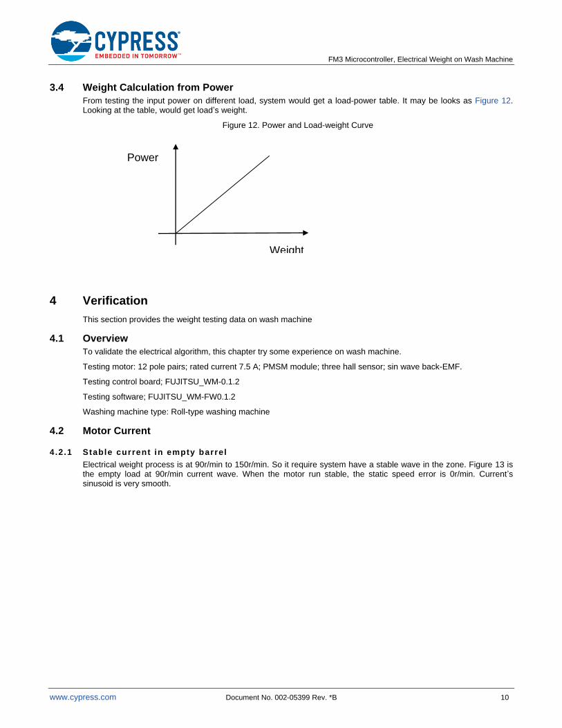
3.4 Weight Calculation from Power
From testing the input power on different load, system would get a load-power table. It may be looks as Figure 12. Looking at the table, would get load’s weight.
Figure 12. Power and Load-weight Curve
4 Verification
This section provides the weight testing data on wash machine
4.1 Overview
To validate the electrical algorithm, this chapter try some experience on wash machine.
Testing motor: 12 pole pairs; rated current 7.5 A; PMSM module; three hall sensor; sin wave back-EMF.
Testing control board; FUJITSU_WM-0.1.2
Testing software; FUJITSU_WM-FW0.1.2
Washing machine type: Roll-type washing machine
4.2 Motor Current
4.2.1 Stable current in empty barrel
Electrical weight process is at 90r/min to 150r/min. So it require system have a stable wave in the zone. Figure 13 is the empty load at 90r/min current wave. When the motor run stable, the static speed error is 0r/min. Current’s sinusoid is very smooth.
Weight
Power
FM3 Microcontroller, Electrical Weight on Wash Machine
www.cypress.com Document No. 002-05399 Rev. *B 11
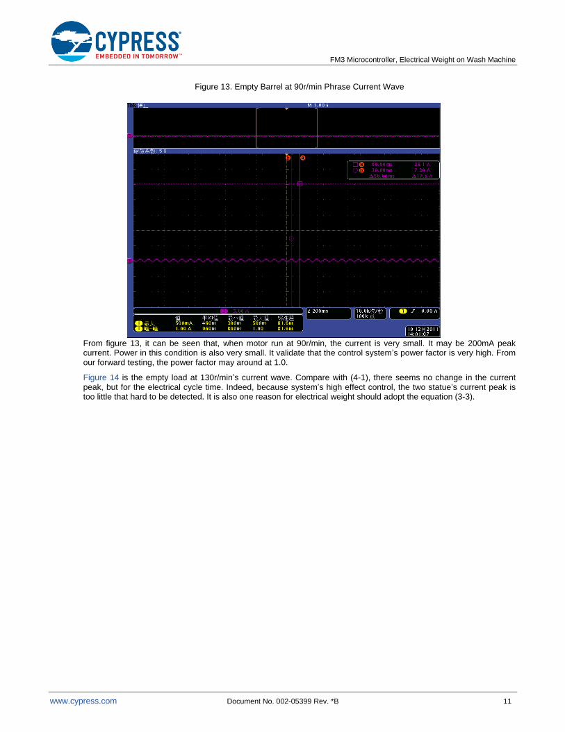
Figure 13. Empty Barrel at 90r/min Phrase Current Wave
From figure 13, it can be seen that, when motor run at 90r/min, the current is very small. It may be 200mA peak current. Power in this condition is also very small. It validate that the control system’s power factor is very high. From our forward testing, the power factor may around at 1.0.
Figure 14 is the empty load at 130r/min’s current wave. Compare with (4-1), there seems no change in the current peak, but for the electrical cycle time. Indeed, because system’s high effect control, the two statue’s current peak is too little that hard to be detected. It is also one reason for electrical weight should adopt the equation (3-3).
FM3 Microcontroller, Electrical Weight on Wash Machine
www.cypress.com Document No. 002-05399 Rev. *B 12
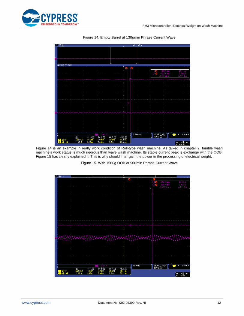
Figure 14. Empty Barrel at 130r/min Phrase Current Wave
Figure 14 is an example in really work condition of Roll-type wash machine. As talked in chapter 2, tumble wash machine’s work status is much rigorous than wave wash machine. Its stable current peak is exchange with the OOB. Figure 15 has clearly explained it. This is why should inter gain the power in the processing of electrical weight.
Figure 15. With 1500g OOB at 90r/min Phrase Current Wave
FM3 Microcontroller, Electrical Weight on Wash Machine
www.cypress.com Document No. 002-05399 Rev. *B 13
4.2.2 Electr ical weight current
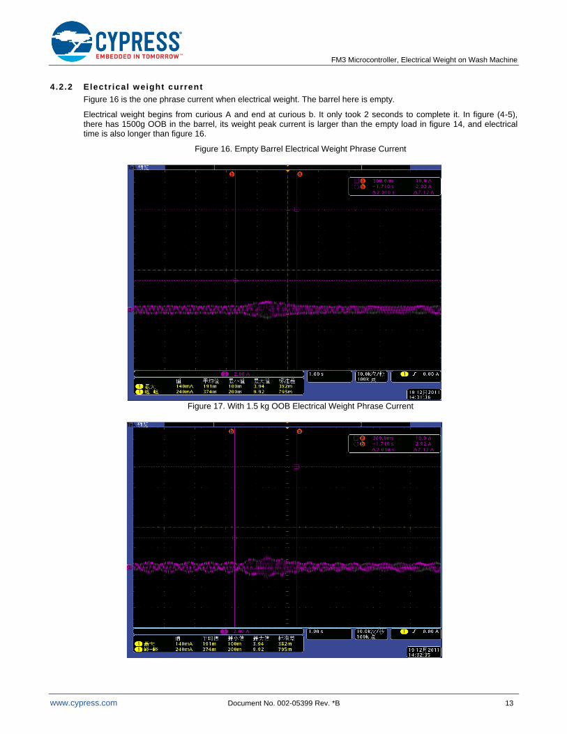
Figure 16 is the one phrase current when electrical weight. The barrel here is empty.
Electrical weight begins from curious A and end at curious b. It only took 2 seconds to complete it. In figure (4-5), there has 1500g OOB in the barrel, its weight peak current is larger than the empty load in figure 14, and electrical time is also longer than figure 16.
Figure 16. Empty Barrel Electrical Weight Phrase Current
Figure 17. With 1.5 kg OOB Electrical Weight Phrase Current
FM3 Microcontroller, Electrical Weight on Wash Machine
www.cypress.com Document No. 002-05399 Rev. *B 14
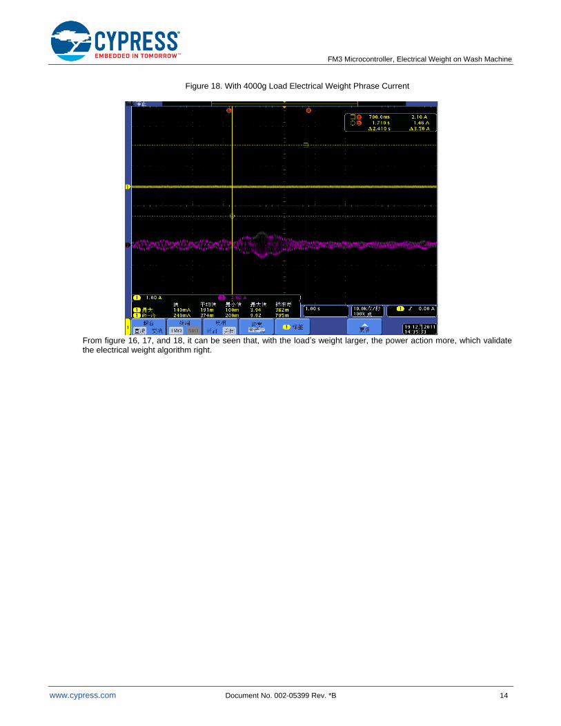
Figure 18. With 4000g Load Electrical Weight Phrase Current
From figure 16, 17, and 18, it can be seen that, with the load’s weight larger, the power action more, which validate the electrical weight algorithm right.
FM3 Microcontroller, Electrical Weight on Wash Machine
www.cypress.com Document No. 002-05399 Rev. *B 15
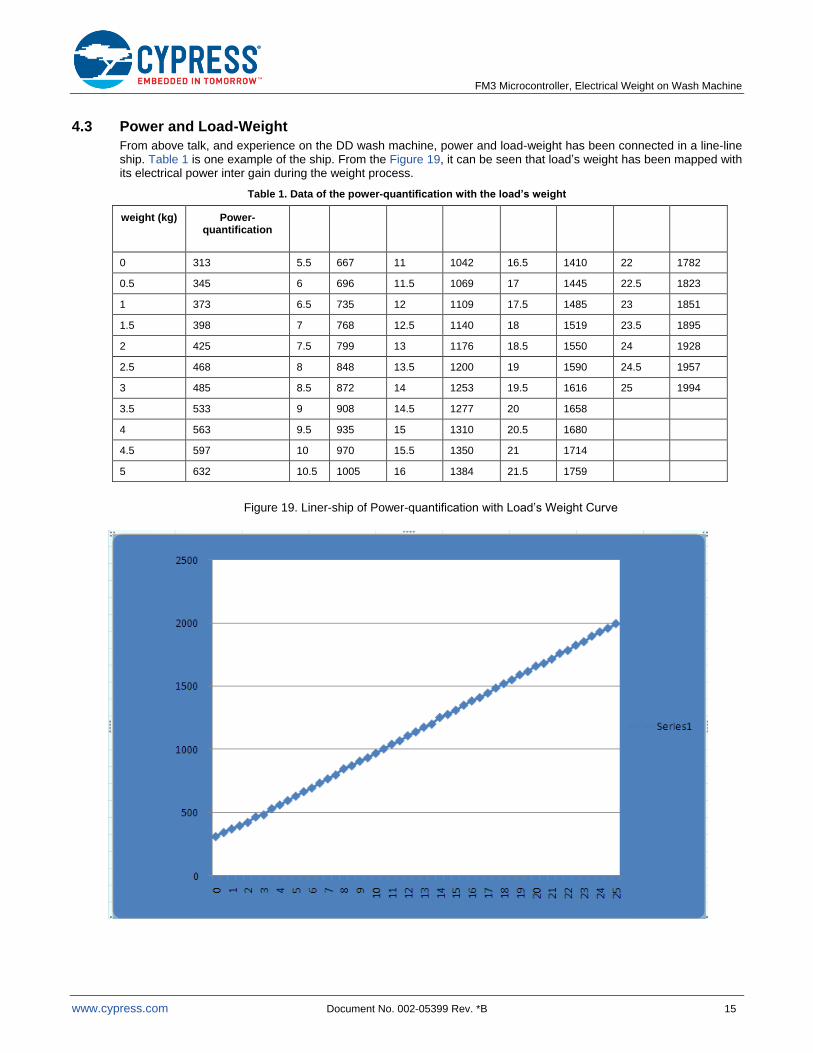
4.3 Power and Load-Weight
From above talk, and experience on the DD wash machine, power and load-weight has been connected in a line-line ship. Table 1 is one example of the ship. From the Figure 19, it can be seen that load’s weight has been mapped with its electrical power inter gain during the weight process.
Table 1. Data of the power-quantification with the load’s weight
weight (kg) Power-quantification
0 313 5.5 667 11 1042 16.5 1410 22 1782
0.5 345 6 696 11.5 1069 17 1445 22.5 1823
1 373 6.5 735 12 1109 17.5 1485 23 1851
1.5 398 7 768 12.5 1140 18 1519 23.5 1895
2 425 7.5 799 13 1176 18.5 1550 24 1928
2.5 468 8 848 13.5 1200 19 1590 24.5 1957
3 485 8.5 872 14 1253 19.5 1616 25 1994
3.5 533 9 908 14.5 1277 20 1658
4 563 9.5 935 15 1310 20.5 1680
4.5 597 10 970 15.5 1350 21 1714
5 632 10.5 1005 16 1384 21.5 1759
Figure 19. Liner-ship of Power-quantification with Load’s Weight Curve
FM3 Microcontroller, Electrical Weight on Wash Machine
www.cypress.com Document No. 002-05399 Rev. *B 16
5 Document History
Document Title: AN205339 - FM3 Microcontroller, Electrical Weight on Wash Machine
Document Number: 002-05399
Revision ECN Orig. of Change
Submission Date
Description of Change
** DOHE 09/31/2011 Initial release
06/07/2012 Changed the document format
*A 5043449 DOHE 12/09/2015 Converted Spansion Application Note “MCU-AN-510115-E-11” to Cypress format
*B 5840678 AESATMP9 08/01/2017 Updated logo and copyright.
FM3 Microcontroller, Electrical Weight on Wash Machine
www.cypress.com Document No. 002-05399 Rev. *B 17
Worldwide Sales and Design Support Cypress maintains a worldwide network of offices, solution centers, manufacturer’s representatives, and distributors. To find the office closest to you, visit us at Cypress Locations.
Products
ARM® Cortex
® Microcontrollers cypress.com/arm
Automotive cypress.com/automotive
Clocks & Buffers cypress.com/clocks
Interface cypress.com/interface
Internet of Things cypress.com/iot
Memory cypress.com/memory
Microcontrollers cypress.com/mcu
PSoC cypress.com/psoc
Power Management ICs cypress.com/pmic
Touch Sensing cypress.com/touch
USB Controllers cypress.com/usb
Wireless Connectivity cypress.com/wireless
PSoC® Solutions
PSoC 1 | PSoC 3 | PSoC 4 | PSoC 5LP | PSoC 6
Cypress Developer Community
Forums | WICED IOT Forums | Projects | Videos | Blogs | Training | Components
Technical Support
cypress.com/support
All other trademarks or registered trademarks referenced herein are the property of their respective owners.
Cypress Semiconductor 198 Champion Court San Jose, CA 95134-1709
© Cypress Semiconductor Corporation, 2011-2017. This document is the property of Cypress Semiconductor Corporation and its subsidiaries, including Spansion LLC (“Cypress”). This document, including any software or firmware included or referenced in this document (“Software”), is owned by Cypress under the intellectual property laws and treaties of the United States and other countries worldwide. Cypress reserves all rights under such laws and treaties and does not, except as specifically stated in this paragraph, grant any license under its patents, copyrights, trademarks, or other intellectual property rights. If the Software is not accompanied by a license agreement and you do not otherwise have a written agreement with Cypress governing the use of the Software, then Cypress hereby grants you a personal, non-exclusive, nontransferable license (without the right to sublicense) (1) under its copyright rights in the Software (a) for Software provided in source code form, to modify and reproduce the Software solely for use with Cypress hardware products, only internally within your organization, and (b) to distribute the Software in binary code form externally to end users (either directly or indirectly through resellers and distributors), solely for use on Cypress hardware product units, and (2) under those claims of Cypress’s patents that are infringed by the Software (as provided by Cypress, unmodified) to make, use, distribute, and import the Software solely for use with Cypress hardware products. Any other use, reproduction, modification, translation, or compilation of the Software is prohibited.
TO THE EXTENT PERMITTED BY APPLICABLE LAW, CYPRESS MAKES NO WARRANTY OF ANY KIND, EXPRESS OR IMPLIED, WITH REGARD TO THIS DOCUMENT OR ANY SOFTWARE OR ACCOMPANYING HARDWARE, INCLUDING, BUT NOT LIMITED TO, THE IMPLIED WARRANTIES OF MERCHANTABILITY AND FITNESS FOR A PARTICULAR PURPOSE. To the extent permitted by applicable law, Cypress reserves the right to make changes to this document without further notice. Cypress does not assume any liability arising out of the application or use of any product or circuit described in this document. Any information provided in this document, including any sample design information or programming code, is provided only for reference purposes. It is the responsibility of the user of this document to properly design, program, and test the functionality and safety of any application made of this information and any resulting product. Cypress products are not designed, intended, or authorized for use as critical components in systems designed or intended for the operation of weapons, weapons systems, nuclear installations, life-support devices or systems, other medical devices or systems (including resuscitation equipment and surgical implants), pollution control or hazardous substances management, or other uses where the failure of the device or system could cause personal injury, death, or property damage (“Unintended Uses”). A critical component is any component of a device or system whose failure to perform can be reasonably expected to cause the failure of the device or system, or to affect its safety or effectiveness. Cypress is not liable, in whole or in part, and you shall and hereby do release Cypress from any claim, damage, or other liability arising from or related to all Unintended Uses of Cypress products. You shall indemnify and hold Cypress harmless from and against all claims, costs, damages, and other liabilities, including claims for personal injury or death, arising from or related to any Unintended Uses of Cypress products.
Cypress, the Cypress logo, Spansion, the Spansion logo, and combinations thereof, WICED, PSoC, CapSense, EZ-USB, F-RAM, and Traveo are trademarks or registered trademarks of Cypress in the United States and other countries. For a more complete list of Cypress trademarks, visit cypress.com. Other names and brands may be claimed as property of their respective owners.