FLX-88 Installation and Operation Guide
36
FLX-88 Installation and Operation Guide Rev 130701 8001 Terrace Ave Phone: 608-831-0880 Suite 201 Toll-Free: 866-462-8649 Middleton, WI 53562 Fax: 608-831-1833
-
Upload
khangminh22 -
Category
Documents
-
view
1 -
download
0
Transcript of FLX-88 Installation and Operation Guide

FLX-88 Installation and Operation Guide
Rev 130701 8001 Terrace Ave Phone: 608-831-0880 Suite 201 Toll-Free: 866-462-8649 Middleton, WI 53562 Fax: 608-831-1833

FLX-88 Installation Guide Important Safety Instructions
Please completely read and verify you understand all instructions in this manual before operating this
equipment.
Keep these instructions in a safe, accessible place for future reference.
Heed all warnings.
Follow all instructions.
Do not use this apparatus near water.
Clean only with a dry cloth.
Do not install near any heat sources such as radiators, heat registers, stoves, or other apparatus (including amplifiers) that produce heat.
Use only accessories specified or recommended by Intelix.
Explanation of graphical symbols:
o Lightning bolt/flash symbol: the lightning bolt/flash and arrowhead within an equilateral triangle symbol is intended to alert the user to the presence of uninsulated “dangerous voltage” within the product enclosure which may be of sufficient magnitude to constitute a risk of shock to a person or persons.
o Exclamation point symbol: the exclamation point within an equilateral triangle symbol is intended to alert the user to the presence of important operating and maintenance (servicing) instructions in the literature accompanying the product.
WARNING: TO REDUCE THE RISK OF FIRE OR ELECTRIC SHOCK, DO NOT EXPOSE THIS APPARATUS TO RAIN OR MOISTURE AND OBJECTS FILLED WITH LIQUIDS, SUCH AS VASES, SHOULD NOT BE PLACED ON THIS APPARATUS.
Use the mains plug to disconnect the apparatus from the mains.
THE MAINS PLUG OF THE POWER CORD MUST REMAIN READILY ACCESSIBLE.
Do not defeat the safety purpose polarized or grounding-type plug. A polarized plug has two blades with one wider than the other. A grounding-type plug has two blades and a third grounding prong. The wide blade or the third prong is provided for your safety. If the provided plug does not fit into your outlet, consult an electrician for replacement of your obsolete outlet. Caution! To reduce the risk of electrical shock, grounding of the center pin of this plug must be maintained.
Protect the power cord from being walked on or pinched particularly at the plugs, convenience receptacles, and the point where they exit from the apparatus.
Do not block the air ventilation openings. Only mount the equipment per Intelix’s instructions.
Use only with the cart, stand, table, or rack specified by Intelix or sold with the equipment. When/if a cart is used, use caution when moving the cart/equipment combination to avoid injury from tip-over.
Unplug this apparatus during lightning storms or when unused for long periods of time.
Caution! Shock Hazard. Do not open the unit.
Refer to qualified service personnel. Servicing is required when the apparatus has been damaged in any way, such as power-supply cord or plug is damaged, liquid has been spilled or objects have fallen into the apparatus, the apparatus has been exposed to rain or moisture, does not operate normally, or has been dropped.
2
FLX-88 Installation Guide
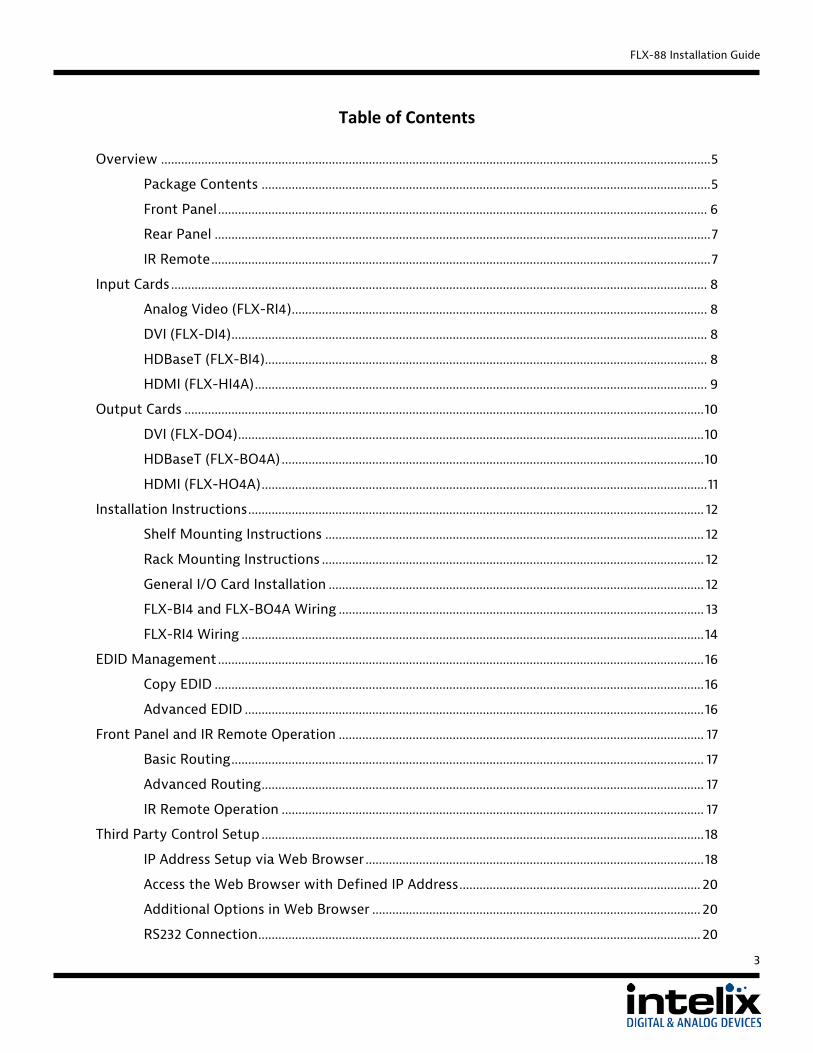
Table of Contents
Overview .................................................................................................................................................................... 5
Package Contents ...................................................................................................................................... 5
Front Panel .................................................................................................................................................. 6
Rear Panel .................................................................................................................................................... 7
IR Remote ..................................................................................................................................................... 7
Input Cards ................................................................................................................................................................ 8
Analog Video (FLX-RI4) ............................................................................................................................ 8
DVI (FLX-DI4) .............................................................................................................................................. 8
HDBaseT (FLX-BI4).................................................................................................................................... 8
HDMI (FLX-HI4A) ....................................................................................................................................... 9
Output Cards ........................................................................................................................................................... 10
DVI (FLX-DO4) ........................................................................................................................................... 10
HDBaseT (FLX-BO4A) .............................................................................................................................. 10
HDMI (FLX-HO4A) ..................................................................................................................................... 11
Installation Instructions ........................................................................................................................................ 12
Shelf Mounting Instructions ................................................................................................................. 12
Rack Mounting Instructions .................................................................................................................. 12
General I/O Card Installation ................................................................................................................ 12
FLX-BI4 and FLX-BO4A Wiring ............................................................................................................. 13
FLX-RI4 Wiring .......................................................................................................................................... 14
EDID Management ................................................................................................................................................. 16
Copy EDID .................................................................................................................................................. 16
Advanced EDID ......................................................................................................................................... 16
Front Panel and IR Remote Operation ............................................................................................................. 17
Basic Routing ............................................................................................................................................. 17
Advanced Routing .................................................................................................................................... 17
IR Remote Operation .............................................................................................................................. 17
Third Party Control Setup .................................................................................................................................... 18
IP Address Setup via Web Browser ..................................................................................................... 18
Access the Web Browser with Defined IP Address ........................................................................ 20
Additional Options in Web Browser .................................................................................................. 20
RS232 Connection .................................................................................................................................... 20
3
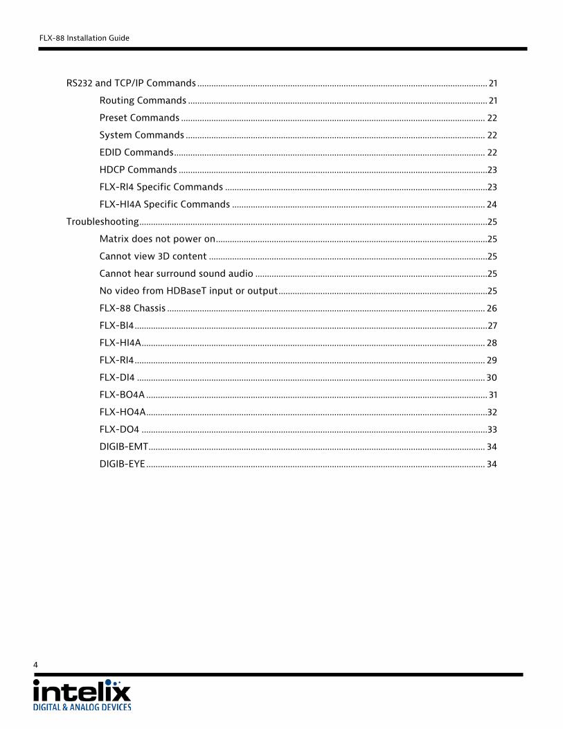
FLX-88 Installation Guide RS232 and TCP/IP Commands ............................................................................................................................. 21
Routing Commands ................................................................................................................................. 21
Preset Commands ................................................................................................................................... 22
System Commands ................................................................................................................................. 22
EDID Commands ...................................................................................................................................... 22
HDCP Commands .....................................................................................................................................23
FLX-RI4 Specific Commands .................................................................................................................23
FLX-HI4A Specific Commands ............................................................................................................. 24
Troubleshooting ......................................................................................................................................................25
Matrix does not power on .....................................................................................................................25
Cannot view 3D content ........................................................................................................................25
Cannot hear surround sound audio ....................................................................................................25
No video from HDBaseT input or output ..........................................................................................25
FLX-88 Chassis ......................................................................................................................................... 26
FLX-BI4 ........................................................................................................................................................ 27
FLX-HI4A .................................................................................................................................................... 28
FLX-RI4 ....................................................................................................................................................... 29
FLX-DI4 ...................................................................................................................................................... 30
FLX-BO4A ................................................................................................................................................... 31
FLX-HO4A ...................................................................................................................................................32
FLX-DO4 ..................................................................................................................................................... 33
DIGIB-EMT ................................................................................................................................................. 34
DIGIB-EYE .................................................................................................................................................. 34
4

FLX-88 Installation Guide
Overview The Intelix FLX-88 is a modular eight input by eight output video matrix switcher. Each modular input or output card supports up to four device connections. In addition to front panel control, the FLX-88 can be controlled via IR, RS232, or TCP/IP connections. The modular input cards include the following connections: HDMI (with stereo audio embedding), DVI, HDBaseT (with RS232 and bi-directional wide-band IR), and analog video with digital scaling via HD15 (VGA-UXGA, RGBHV, RGsB, RsGsBs, component video, S-video and composite video). The modular output cards include the following connections: HDMI (with stereo audio de-embedding, DVI, and HDBaseT (with audio de-embedding). Clear button caps provide legible text on the front panel, which can be customized for each installation. IR, RS232, and TCP/IP provide a wide range of options for third party control systems. Ten programmable presets provide an efficient means of configuring the video and audio distribution for common usage patterns. The FLX-88 was designed with flexibility in mind. There are over 80 possible input card to output card combinations. Since the system is modular, the system integrator can customize their installation per their customer’s needs and not the limitations of available hardware.
Package Contents Please verify the following items are in the shipping box prior to installation of the FLX-88. 1 ea FLX-88 Flexible Matrix Switcher 2 ea Modular Input Metal Blank (installed on FLX-88) 2 ea Modular Output Metal Blank (installed on FLX-88) 4 ea Rubber Feet 1 ea Power Cable 1 ea RS232 Cable 1 ea Infrared Remote Control 1 ea FLX-88 Installation and Operation Guide 1 ea Intelix Pocket Screwdriver
5

FLX-88 Installation Guide
Menu (Top)
Input Buttons
Front Panel
Power LED – Indicates the matrix has proper input power. IR Receiver – For use with the included IR remote. Input Buttons –Buttons labeled “1” through “8”. Menu Buttons (Top Row) –Buttons labeled “AV”, “VIDEO”, and “AUDIO”. AV – Used to route Video and Audio inputs to outputs VIDEO – Used to route Video inputs to outputs
AUDIO – Not used on this model Rack Handle – Eases installation in an equipment rack. LCD Status Display – Displays matrix name and status when changing routes. Output Buttons –Buttons labeled “1” through “8”. Menu Buttons (Bottom Row) –Buttons labeled “ALL”, “THROUGH”, “UNDO”, and “”.
ALL – Used to route one input AV pair to all outputs or to route each AV input to its corresponding output.
THROUGH – Used to route the selected AV input to its corresponding output. UNDO – Used to remove the last button press in a routing sequence – Used to clear the input source select. Explanation of use for the front panel control is located in the section Front Panel Operation (page 14).
Menu (Bottom)
Output Buttons
LCD Status Display
Rack Handle
Power LED/ IR Receiver
6
FLX-88 Installation Guide
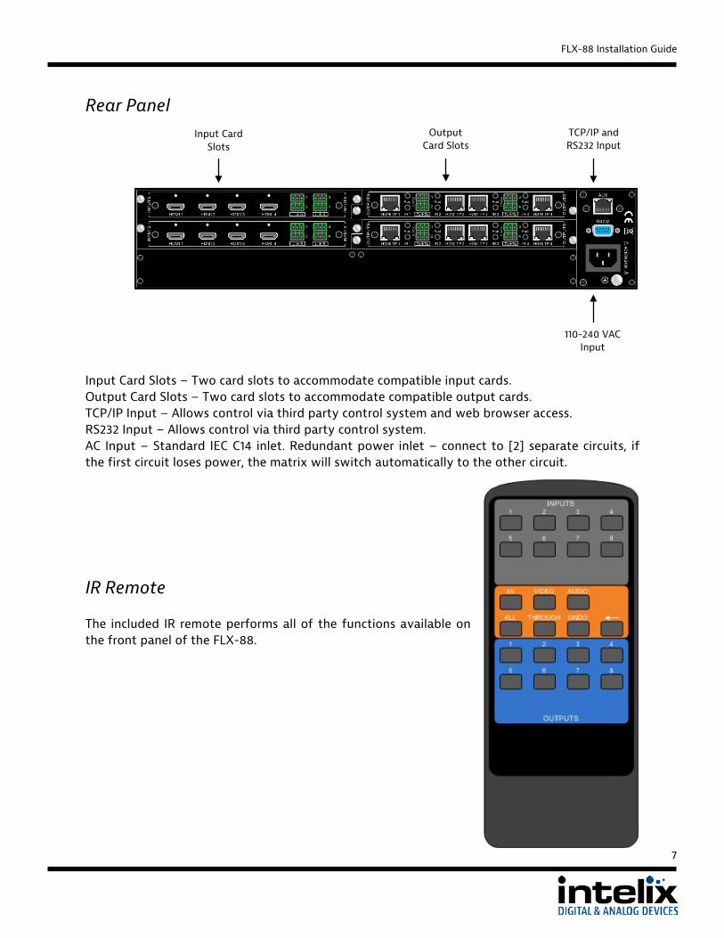
Rear Panel
Input Card Slots – Two card slots to accommodate compatible input cards. Output Card Slots – Two card slots to accommodate compatible output cards. TCP/IP Input – Allows control via third party control system and web browser access. RS232 Input – Allows control via third party control system. AC Input – Standard IEC C14 inlet. Redundant power inlet – connect to [2] separate circuits, if the first circuit loses power, the matrix will switch automatically to the other circuit.
IR Remote The included IR remote performs all of the functions available on the front panel of the FLX-88.
TCP/IP and RS232 Input
Output Card Slots
Input Card Slots
110-240 VAC Input
7

FLX-88 Installation Guide
Input Cards The modular input cards are keyed on the right side to line up with the output cards and ensure they are installed correctly in the matrix.
Analog Video (FLX-RI4)
The HD15 inputs on the FLX-RI4 scale and convert a wide range of analog video signals to HD video resolutions, which can be routed to any available output. The individual scaler engine on each input can accommodate VGA to UXGA, RGBHV, RGsB, RsGsBs, component video, S-video, and composite video signals. Two FLX-RBOCA (component video breakout cable) and two FLX-RBOCB (composite and S-video breakout cable) cables are included with each FLX-RI4.
DVI (FLX-DI4)
The FLX-DI4 DVI-D inputs are HDMI and HDCP compliant and support CEC and DDC standards. Each input is a single link DVI-D connection that can support video resolutions up to 1920x1200.
HDBaseT (FLX-BI4)
The FLX-BI4 takes advantage of HDBaseT inputs to allow sources from remote locations, from up to 70 m away, to be routed to any of the available outputs utilizing standard Cat 5e cable with a TIA-568B crimp. The RS232 and wide-band IR connections for each input allow bi-directional control signals at the equipment rack to interface with source equipment when used with the DIGI-HD70C-S or DIGI-HDE-S HDBaseT transmitters. The optional DIGIB-EMT (IR emitter) and DIGIB-EYE (IR receiver) are required for IR control functionality.
8

FLX-88 Installation Guide
HDMI (FLX-HI4A)
The FLX-HI4 HDMI inputs can be routed to any available outputs. The HDMI inputs can accept video signals up to 1920x1200, including 3D and 48-bit Deep Color at 1080p. Additionally, audio signals from stereo up to 7.1 audio streams will pass through the matrix to supported outputs. Using the euroblock connectors, stereo audio can be embedded with the HDMI video stream. Audio source is selectable (HDMI or analog) by RS232 or TCP/IP command.
9

FLX-88 Installation Guide
Output Cards The modular output cards are keyed on the left side to line up with the input cards and ensure they are installed correctly in the matrix.
DVI (FLX-DO4)
The FLX-DO4 DVI-D outputs are HDMI and HDCP compliant and support CEC and DDC standards. Each output is a single link DVI-D connection that can support video resolutions up to 1920x1200.
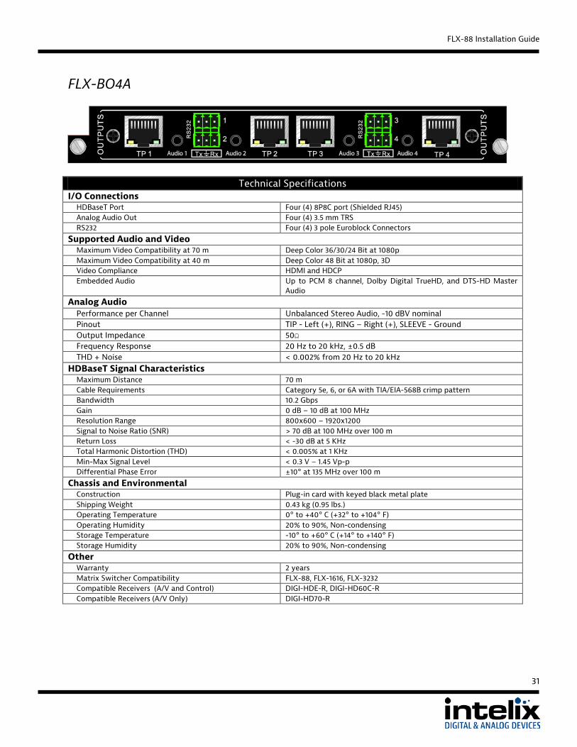
HDBaseT (FLX-BO4A)
The FLX-BO4 takes advantage of HDBaseT outputs connect any source device to a remote display, up to 70m away, utilizing standard Cat 6 cable with a TIA-568B crimp. The RS232 connections for each output allow bi-directional control signals at the equipment rack to interface with display devices when used with the DIGI-HD60C-R or DIGI-HDE-R HDBaseT receivers. Stereo audio can be de-embedded from the HDMI signal and output to the 3.5mm TRS connectors. This unit has advanced EDID copy functions that allow either full or hybrid copy (video with 2ch overwrite) to ensure that the source will emit the correct format.
10

FLX-88 Installation Guide
HDMI (FLX-HO4A)
The FLX-HO4 HDMI outputs can be routed from any input in the matrix. The HDMI outputs can pass video signals up to 1920x1200, including 3D and 48-bit Deep Color at 1080p. Additionally, audio signals from stereo up to 7.1 audio streams will pass to supported HDMI output devices. Stereo audio can be de-embedded from the HDMI signal and output to the euroblock connectors. This unit has advanced EDID copy functions that allow either full or hybrid copy (video with 2ch overwrite) to ensure that the source will emit the correct format.
11

FLX-88 Installation Guide
Installation Instructions Shelf Mounting Instructions Attach the supplied rubber feet to the bottom of the FLX-88 matrix. Follow the instructions in General I/O Card Installation to install the I/O cards.
Rack Mounting Instructions The FLX-88 requires two rack units (2 RU) of space. At least 2 inches of free air space is required on both sides of the FLX-88 for proper side ventilation. Avoid mounting the FLX-88 near a power amplifier or any other source of significant heat. It is recommended that you leave an empty rack space above and below the FLX-88 for additional cooling.
General I/O Card Installation
1. Power off the matrix. 2. Remove the metal blank.
12

FLX-88 Installation Guide
3. Slide the I/O card between the guide rails until it is firmly seated.
4. Secure the I/O card by tightening the thumb screws.
5. Connect the appropriate cabling to the I/O card. 6. Power on the matrix.
FLX-BI4 and FLX-BO4A Wiring A compatible HDBaseT with control transmitter or receiver is required to pass the control signals to the source or display devices. To connect the FLX-BI4 to a compatible transmitter or the FLX-BO4A to a compatible receiver, a Cat 6 or greater cable with a TIA-568B crimp termination on the RJ45 connector must be used. The Cat 6 cable must not exceed 40 meters for 3D content. The Cat 6 cable must not exceed 70 meters for 2D content. To use the IR extension capabilities of the FLX-BI4, the DIGIB-EYE (wideband IR receiver) and DIGIB-EMT (wideband IR emitter) will need to be connected to the appropriate IR ports. These parts are not included with the HDBaseT I/O cards.
13

FLX-88 Installation Guide To use the RS232 extension capabilities of the FLX-BI4 and FLX-BO4A, connect the TX, ground, and RX control signal wires to the removable 3-pole terminal block. Consult the manual of the control device(s) to determine which pins the TX/RX signals are carried on. Be sure to always connect TX to RX and RX to TX.
FLX-RI4 Wiring For VGA signals, use a standard VGA male to VGA male cable.
For RGBHV signals, use a standard VGA to RGBHV cable. Below is a common pinout of this type of cable.
14

FLX-88 Installation Guide
For component video, S-video, and composite video, a VGA to breakout cable is recommended. The FLX-RI4 comes with two FLX-RBOCA (component video breakout cable) and two FLX-RBOCB (composite and S-video breakout cable) cables. See FLX-RI4 Specific Commands on page 20 to define the operation of the inputs.
- Component video, RGsB, and RsGsBs connect to the appropriate red, green, and blue
connections on the FLX-RBOCA cable.
- S-video connects to the purple connector on the FLX-RBOCB cable. - Composite video connects to the yellow connector on the FLX-RBOCB cable.
15

FLX-88 Installation Guide
EDID Management The stock EDID for the inputs of the FLX-88 is 1280x1024 (computer video input) and 1080p with stereo audio (consumer video input). In order to change the EDID information for an input, the EDID copy command will need to be sent to the matrix via RS232 or TCP/IP. EDIDMyyBxx. Copy EDID of output yy to input xx EDIDMInit. Restore factory EDID information The FLX-RI4 input card ignores the EDID settings since there is a scaler engine on each input to output a pre-defined video resolution.
Copy EDID To copy the EDID information from output 3 to input 1, transmit the following command: EDIDM03B01.
Advanced EDID The FLX-HO4A and FLX-BO4A support [2] EDID Copy modes; FULL copy and HYBRID copy. The copy mode can be set by output. On each card, you will find [4] DIP switches near the back of the PCBA (card must be removed from matrix). Each DIP switch corresponds to an output of the card. Set the DIP switches ON for FULL copy mode. Set the DIP switches OFF for HYBRID copy mode. When the output is set to FULL copy mode, the entire EDID table will be copied from the display (sink) to the input. This accomplished via RS232 or TCP/IP command. When the output is set to HYBRID, the EDID table that is copied to the input comes from two locations. The video information, including Preferred Native Timing is retrieved from the display (sink) that is connected to the output. The audio information is overwritten by a 48kHz PCM stereo audio preset. Copying EDID with this HYBRID mode will ensure that all your sources output a format that is compatible with the audio de-embedding circuit.
16

FLX-88 Installation Guide
Front Panel and IR Remote Operation
Basic Routing To set a route using the front panel of the FLX-88:
1. Press the VIDEO button. 2. Press the desired input button (source). 3. Press the desired output button (display).
To route video and audio from input 4 to output 5:
1. Press VIDEO. 2. Press input 4. 3. Press output 5.
Advanced Routing To route video and audio from input 3 to all outputs:
1. Press input 3. 2. Press ALL.
To route video and audio from each input to its corresponding output (1 to 1, 2 to 2, through 8 to 8):
1. Press ALL. 2. Press THROUGH.
IR Remote Operation The buttons on the IR remote are identical to the buttons on the front panel of the FLX-88. The IR routing commands are identical to the front panel commands. See Page 7 for the button layout of the IR remote.
17

FLX-88 Installation Guide
Third Party Control Setup
IP Address Setup via Web Browser Configuring the TCP/IP port is done via a web browser interface. A crossover cable is required for the initial setup. The default IP address is printed on a sticker on the side of the FLX-88.
1. Configure the computer to use the same network prefix as the IP address assigned to the matrix. For example, the IP address of the matrix is 192.168.0.178. Set the computer to use a static IP address within the same network range, such as 192.168.0.42.
2. Connect the crossover cable to the computer and to the TCP/IP port on the FLX-88.
3. Open up Internet Explorer (Firefox, Chrome, and Safari crop the configuration options).
4. Go to the IP address printed on the sticker, which will take you to the Login screen.
18

FLX-88 Installation Guide
5. The Default password is “88888”.
6. Press the LOGIN button. Pressing the Enter key will give a bad password error.
7. Click the System Info button to change the IP address.
8. Changing the dropdown option from Static to DHCP will allow the FLX-88 to automatically obtain an IP address from a DHCP server on the network.
9. For a static IP, enter the IP address, Gateway, and DNS Server information provided by your Network Administrator.
10. Click Apply for the changes to take effect.
19

FLX-88 Installation Guide
Access the Web Browser with Defined IP Address
1. Remove the crossover cable between the computer and the FLX-88.
2. Restore the computer to the previous network settings.
3. Connect the computer and the matrix to the network.
4. Using Internet Explorer, enter the IP address for the matrix to access the browser interface.
Additional Options in Web Browser
1. Serial Info – Adjusts TCP/IP specific settings, including the default port (4001). a. Changing the baud rate settings has no effect on the RS232 port of the FLX-88. b. The baud rate setting must remain at 9600.
2. Change Password – Changes the password of the matrix.
3. Reset Device – Resets all changes to the default settings except for the IP address of the
matrix.
4. Restore Default – Resets all changes to the default settings including the IP address.
RS232 Connection The RS232 control port requires a standard straight-through serial cable for operation. The default settings for the RS232 port are:
- 9600 baud - 8 Data Bits - 1 Stop Bit - Parity = none
20

FLX-88 Installation Guide
RS232 and TCP/IP Commands RS232 Settings: 9600 baud, 8 Data bits, 1 Stop bit, Parity = None TCP/IP Settings: User defined IP address, port 4001 There is either a period (.) or a semicolon (;) at the end of each command. These characters must be present for the command to process correctly. There are no spaces between any of the characters in the command string. xx = Input Number (input 2 would be 02) yy = Output Number (output 3 would be 03) <CR> = Carriage return (Hex 0D) <LF> = Line Feed (Hex 0A)
Routing Commands Description Command Response Route input xx to output yy xxByy. AV: xx->0yy<CR><LF>
Route input xx to all outputs xxAll. xx To All<CR><LF>
Route inputs to corresponding outputs All#. All Through.<CR><LF>
Route input xx to multiple outputs yy Number of outputs is unlimited; each output must be separated by a comma (,)
xxByy,yy. xxVyy,yy<CR><LF>
Turn off all outputs All$. All Closed.<CR><LF>
Turn off specific output yy yy$. AV: yy Closed. <CR><LF>
Output yy routing status Statusyy. V: xx->0yy<CR><LF>
Routing status of all inputs. Status. V: xx->0yy<CR><LF> (Repeating sequence starting with output 1, output 2, etc.)
Examples: 02All. Route Video and Audio from input 2 to all outputs 04$. Turn off Video and Audio for output 4 06B03. Route Video and Audio from input 6 to output 3 03B02,08. Route Video and Audio from input 3 to outputs 2 and 8
21

FLX-88 Installation Guide
Preset Commands Description Command Response Save the current routing as a preset. Values range from 0 through 9
Savex. Save to Fx<CR><LF>
Recall preset x Recallx. Recall From Fx<CR><LF>
Clear preset x Clearx.
Examples: Save4. Save the current routing as preset 4. Recall4. Recall preset 4 Clear4. Clear preset 4
System Commands Description Command Response Power full ON PWON. PWON<CR><LF>
Power off (Standby Mode) PWOFF. PWOFF<CR><LF>
Retrieve matrix model information /*Type; FLX-88<CR><LF>
Lock the front panel keys /%Lock; System Locked!<CR><LF>
Unlock the front panel keys /%Unlock; System Unlock!<CR><LF>
Retrieve matrix firmware version number /^Version; Vz.z<CR><LF>
Turn off matrix command feedback /:MessageOff; Closed the Message Return.<CR><LF>
Turn on matrix command feedback /:MessageOn; Enabled the Message Return.<CR><LF>
EDID Commands Description Command Response Copy EDID of output yy to input xx EDIDMyyBxx. EDIDMyyBxx.<CR><LF>
Restore factory EDID information EDIDMInit. EDIDMInit<CR><LF>
Example: EDIDM05B01. Copy EDID of output 5 to input 1
22

FLX-88 Installation Guide
HDCP Commands Description Command Response Turn HDCP Compliance off for input xx /%I/xx:0. /%I/xx:0.<CR><LF>
Turn HDCP Compliance on for input xx /%I/xx:1. /%I/xx:1.<CR><LF>
Example: /%I/04:0. Turn HDCP Compliance off for input 4
FLX-RI4 Specific Commands The input number values are dependent upon which slot the FLX-RI4 is inserted. If the input card is in the first input card slot, the input number values range from 01 through 04. If the input card is in the second input card slot, the input number values range from 05 through 08. xx is the input number value. Description Command Response Set input xx to VGA input mode PTNIxx0622%. xx0622%.<CR><LF>
When input xx is in VGA mode, auto adjusts the input signal
PTNIxx0606%. xx0606%.<CR><LF>
Set input xx to component video input mode PTNIxx0623%. xx0623%.<CR><LF>
Set input xx to S-video input mode PTNIxx0624%. xx0624%.<CR><LF>
Set input xx to composite video input mode PTNIxx0625%. xx0625%.<CR><LF>
Set input xx to scale to XGA output (1024x768) PTNIxx0626%. xx0626%.<CR><LF>
Set input xx to scale to 720p output (1280x720) PTNIxx0627%. xx0627%.<CR><LF>
Set input xx to scale to WXGA output (1280x800) PTNIxx0628%. xx0628%.<CR><LF>
Set input xx to scale to 1080p output (1920x1080) PTNIxx0629%. xx0629%.<CR><LF>
Set input xx to VGA input mode PTNIxx0622%. xx0622%.<CR><LF>
Examples: PTNI050622%. Set input 5 to VGA input mode PTNI050606%. Auto adjust input 5 VGA source PTNI020623%. Set input 2 to component video input mode
23

FLX-88 Installation Guide
FLX-HI4A Specific Commands The input number values are dependent upon which slot the FLX-HI4A is inserted. If the input card is in the first input card slot, the input number values range from 1 through 4. If the input card is in the second input card slot, the input number values range from 5 through 8. [X] is the input number value. Description Command Response Set input xx to analog audio input embedding AUDIOxx:0. AUDIOxxI0.<CR><LF>
Set input xx to digital audio (use HDMI audio) AUDIOxx:1. AUDIOxxI1.<CR><LF>
Examples: AUDIO07:0. Use analog audio for input 7.
24

FLX-88 Installation Guide
Troubleshooting Matrix does not power on Verify power outlet is active. Verify continuity in power cable.
Cannot view 3D content Copy EDID from output to input. Verify display is 3D compatible. Verify source device can output 3D content. Verify twisted pair cable does not exceed 40 meters if using the FLX-BI4 or FLX-BO4.
Cannot hear surround sound audio Copy EDID from output to input. Verify output can broadcast surround sound audio. Verify source device is configured to output surround sound audio. Change input from analog audio to HDMI audio (FLX-HI4A)
No video from HDBaseT input or output Verify the green link LED on the HDBaseT card is lit solid.
25

FLX-88 Installation Guide
Technical Specifications FLX-88 Chassis
Technical Specifications I/O Connections
Supported Input Cards FLX-BI4, FLX-DI4, FLX-HI4, FLX-RI4, FLX-HI4A Supported Output Cards FLX-BO4, FLX-DO4, FLX-HO4, FLX-BO4A, FLX-HO4A Input and Output Card Securing Mechanism Thumbscrew Control, Rear Panel RS232 via DE-9, TCP/IP via 8P8C Connector Control, Front Panel Push Button, IR
Chassis and Environmental Material Black Painted Aluminum Dimensions 483mm x 356mm x 89mm (19 in. x 14 in. x 3.5 in.) Rack Spacing 2 RU Shipping Weight 5.9 kg (13 lbs.) Operating Temperature 0° to +40° C (+32° to +104° F) Operating Humidity 20% to 90%, Non-condensing Storage Temperature -10° to +60° C (+14° to +140° F) Storage Humidity 20% to 90%, Non-condensing
Power, ESD, and Regulatory Power Supply 100-240VAC 50/60 Hz Power Consumption 60 watts Fully Populated ESD Protection 15kV Regulatory CE, RoHS
Other Warranty 2 years Diagnostic Indicators LCD output status and power LED Included Accessories Installation Guide, IR Remote, RS232 Cable, Power Cable, Modular Metal
Blank (4 ea), Rubber Feet (4 ea) and Intelix Pocket Screwdriver.
26

FLX-88 Installation Guide
FLX-BI4
Technical Specifications I/O Connections
HDBaseT Port Four (4) 8P8C port (Shielded RJ45) IR In Four (4) 3.5 mm TS (Requires DIGIB-EYE) IR Out Four (4) 3.5 mm TRS (Requires DIGIB-EMT) RS232 Four (4) 3 pole Euroblock Connectors
Supported Audio and Video Maximum Video Compatibility at 70 m Deep Color 36/30/24 Bit at 1080p Maximum Video Compatibility at 40 m Deep Color 48 Bit at 1080p, 3D Video Compliance HDMI and HDCP Embedded Audio Up to PCM 8 channel, Dolby Digital TrueHD, and DTS-HD Master
Audio HDBaseT Signal Characteristics
Maximum Distance 70 m Cable Requirements Category 5e, 6, or 6A with TIA/EIA-568B crimp pattern Bandwidth 10.2 Gbps Gain 0 dB – 10 dB at 100 MHz Resolution Range 800x600 – 1920x1200 Signal to Noise Ratio (SNR) > 70 dB at 100 MHz over 100 m Return Loss < -30 dB at 5 KHz Total Harmonic Distortion (THD) < 0.005% at 1 KHz Min-Max Signal Level < 0.3 V – 1.45 Vp-p Differential Phase Error ±10° at 135 MHz over 100 m
Chassis and Environmental Construction Plug-in card with keyed black metal plate Shipping Weight 0.43 kg (0.95 lbs.) Operating Temperature 0° to +40° C (+32° to +104° F) Operating Humidity 20% to 90%, Non-condensing Storage Temperature -10° to +60° C (+14° to +140° F) Storage Humidity 20% to 90%, Non-condensing
Other Warranty 2 years Matrix Switcher Compatibility FLX-8X8A, FLX-88, FLX-1616, FLX-3232 HDBaseT Transmitter (A/V and Control) Compatibility DIGI-HDE-S, DIGI-HD60C-S HDBaseT Transmitter (A/V Only) Compatibility DIGI-HD70-S Infrared (IR) Emitter DIGIB-EMT Infrared (IR) Receiver DIGIB-EYE
27

FLX-88 Installation Guide
FLX-HI4A
Technical Specifications I/O Connections
HDMI Input Four (4) HDMI Type A Receptacle Connector Analog Audio In Four (4) 3 pole Euroblock Connectors
Supported Audio and Video Maximum Video Compatibility Deep Color 48/36/30/24 Bit at 1080p, 3D Video Compliance HDMI and HDCP (Selectable) HDMI Audio Compatibility Up to PCM 8 channel, Dolby Digital TrueHD, and DTS-HD Master
Audio Analog to Digital Conversion Audio Format PCM 2 Channel 48kHz
Analog Audio Performance per Channel Unbalanced Stereo Audio, -10 dBV nominal Pinout (Left to Right) Left (+), Ground, Right (+) Input Impedance >10kΩ Frequency Response 20 Hz to 20 kHz, ±0.5 dB THD + Noise < 0.002% from 20 Hz to 20 kHz
HDMI Signal Characteristics Bandwidth 340 MHz (10.2 Gbps) Gain 0 dB Resolution Range Up to 1920x1200 Crosstalk < -50 dB at 5 KHz Input Level TMDS 2.9V/3.3V
Chassis and Environmental Construction Plug-in card with keyed black metal plate Shipping Weight 0.45 kg (1 lbs.) Operating Temperature 0° to +40° C (+32° to +104° F)
Operating Humidity 20% to 90%, Non-condensing Storage Temperature -10° to +60° C (+14° to +140° F) Storage Humidity 20% to 90%, Non-condensing
Other Warranty 2 years Matrix Switcher Compatibility FLX-88, FLX-1616, FLX-3232
28

FLX-88 Installation Guide
FLX-RI4
Technical Specifications I/O Connections
Analog Video Input Four (4) Female HD15 Supported Video
Input Signal Types VGA-UXGA, RGBHV, RGsB, RsGsBs, Component Video, S-Video, & Composite Video
Output Scaling Resolutions XGA (1024x768), WXGA (1280x800), 720p (1280x720), and 1080p (1920x1080)
Analog Video Input Characteristics Bandwidth 340 MHz (10.2 Gbps) Gain 0 dB Resolution Range 640x480 – 1920x1080 Crosstalk < -50 dB at 5 MHz Input Coupling AC Coupling Only Input Level 0.5V – 2.0Vp-p
Chassis and Environmental Construction Plug-in card with keyed black metal plate Shipping Weight 0.67 kg (1.36 lbs.) Operating Temperature 0° to +40° C (+32° to +104° F) Operating Humidity 20% to 90%, Non-condensing Storage Temperature -10° to +60° C (+14° to +140° F) Storage Humidity 20% to 90%, Non-condensing
Included Accessories FLX-RBOCA (2 ea) 40 mm (15.75 in.) Male HD15 to three (3) Female RCA Connectors (Red,
Green, Blue) FLX-RBOCB (2 ea) 40 mm (15.75 in.) Male HD15 to one (1) Female RCA Connector
(Yellow) and one (1) Female S-Video Connector Other
Warranty 2 years HDMI Matrix Switcher Compatibility FLX-8X8A, FLX-88, FLX-1616, FLX-3232
29

FLX-88 Installation Guide
FLX-DI4
Technical Specifications I/O Connections
Single Link DVI Input Four (4) Female DVI 24+5 Supported Video
Input Signal Types Single Link DVI-D up to 1920x1200 Video Compliance HDMI and HDCP EDID and DDC Actively Buffered; Supports DVI and HDMI standards
DVI Signal Characteristics Bandwidth 340 MHz (10.2 Gbps) Gain 0 dB Resolution Range 640x480 – 1920x1200 Crosstalk < -50 dB at 5 KHz Input Level TMDS 2.9V/3.3V
Chassis and Environmental Construction Plug-in card with keyed black metal plate Shipping Weight 0.37 kg (0.81 lbs.) Operating Temperature 0° to +40° C (+32° to +104° F) Operating Humidity 20% to 90%, Non-condensing Storage Temperature -10° to +60° C (+14° to +140° F) Storage Humidity 20% to 90%, Non-condensing
Other Warranty 2 years Matrix Switcher Compatibility FLX-8X8A, FLX-88, FLX-1616, FLX-3232
30
FLX-88 Installation Guide
FLX-BO4A
Technical Specifications I/O Connections
HDBaseT Port Four (4) 8P8C port (Shielded RJ45) Analog Audio Out Four (4) 3.5 mm TRS RS232 Four (4) 3 pole Euroblock Connectors
Supported Audio and Video Maximum Video Compatibility at 70 m Deep Color 36/30/24 Bit at 1080p Maximum Video Compatibility at 40 m Deep Color 48 Bit at 1080p, 3D Video Compliance HDMI and HDCP Embedded Audio Up to PCM 8 channel, Dolby Digital TrueHD, and DTS-HD Master
Audio Analog Audio
Performance per Channel Unbalanced Stereo Audio, -10 dBV nominal Pinout TIP - Left (+), RING – Right (+), SLEEVE - Ground Output Impedance 50Ω Frequency Response 20 Hz to 20 kHz, ±0.5 dB THD + Noise < 0.002% from 20 Hz to 20 kHz
HDBaseT Signal Characteristics Maximum Distance 70 m Cable Requirements Category 5e, 6, or 6A with TIA/EIA-568B crimp pattern Bandwidth 10.2 Gbps Gain 0 dB – 10 dB at 100 MHz Resolution Range 800x600 – 1920x1200 Signal to Noise Ratio (SNR) > 70 dB at 100 MHz over 100 m Return Loss < -30 dB at 5 KHz Total Harmonic Distortion (THD) < 0.005% at 1 KHz Min-Max Signal Level < 0.3 V – 1.45 Vp-p Differential Phase Error ±10° at 135 MHz over 100 m
Chassis and Environmental Construction Plug-in card with keyed black metal plate Shipping Weight 0.43 kg (0.95 lbs.) Operating Temperature 0° to +40° C (+32° to +104° F) Operating Humidity 20% to 90%, Non-condensing Storage Temperature -10° to +60° C (+14° to +140° F) Storage Humidity 20% to 90%, Non-condensing
Other Warranty 2 years Matrix Switcher Compatibility FLX-88, FLX-1616, FLX-3232 Compatible Receivers (A/V and Control) DIGI-HDE-R, DIGI-HD60C-R Compatible Receivers (A/V Only) DIGI-HD70-R
31

FLX-88 Installation Guide
FLX-HO4A
Technical Specifications I/O Connections
HDMI Input Four (4) HDMI Type A Receptacle Connector Analog Audio Out Four (4) 3 pole Euroblock Connectors
Supported Video Maximum Video Compatibility Deep Color 48/36/30/24 Bit at 1080p, 3D Video Compliance HDMI and HDCP
Analog Audio Performance per Channel Unbalanced Stereo Audio, -10 dBV nominal Pinout (Left to Right) Left (+), Ground, Right (+) Output Impedance 50Ω Frequency Response 20 Hz to 20 kHz, ±0.5 dB THD + Noise < 0.002% from 20 Hz to 20 kHz
HDMI Signal Characteristics Bandwidth 340 MHz (10.2 Gbps) Gain 0 dB Resolution Range Up to 1920x1200 Crosstalk < -50 dB at 5 KHz Input Level TMDS 2.9V/3.3V
Chassis and Environmental Construction Plug-in card with keyed black metal plate Shipping Weight 0.45 kg (1 lbs.) Operating Temperature 0° to +40° C (+32° to +104° F) Operating Humidity 20% to 90%, Non-condensing Storage Temperature -10° to +60° C (+14° to +140° F) Storage Humidity 20% to 90%, Non-condensing
Other EDID Copy Mode Selection Four (4) 2 position DIP switch (one per output) Warranty 2 years Matrix Switcher Compatibility FLX-88, FLX-1616, FLX-3232
32

FLX-88 Installation Guide
FLX-DO4
Technical Specifications I/O Connections
Single Link DVI Output Four (4) Female DVI 24+5 Supported Video
Output Signal Types Single Link DVI-D up to 1920x1200 Video Compliance HDMI and HDCP EDID and DDC Actively Buffered; Supports DVI and HDMI standards
DVI Signal Characteristics Bandwidth 340 MHz (10.2 Gbps) Gain 0 dB Resolution Range 640x480 – 1920x1200 Crosstalk < -50 dB at 5 KHz Input Level TMDS 2.9V/3.3V
Chassis and Environmental Construction Plug-in card with keyed black metal plate Shipping Weight 0.37 kg (0.81 lbs.) Operating Temperature 0° to +40° C (+32° to +104° F) Operating Humidity 20% to 90%, Non-condensing Storage Temperature -10° to +60° C (+14° to +140° F) Storage Humidity 20% to 90%, Non-condensing
Other Warranty 2 years Matrix Switcher Compatibility FLX-8X8A, FLX-88, FLX-1616, FLX-3232
33

FLX-88 Installation Guide
DIGIB-EMT
Technical Specifications
Signal Characteristics Wide-Band Infrared (IR) 30 KHz to 56 KHz at 5V DC reference
Physical Characteristics Material, Emitter Housing Deep red translucent plastic Dimensions, Emitter Housing 6 mm x 9.5 mm x 15 mm (0.24 in. x 0.37 in. x 0.59 in.) Cable Length 2 m (6.56 ft) Cable Connector 3.5 mm (1/8 in.) mono (TS) plug Shipping Weight 0.5 lbs. (0.23kg)
Other Warranty 2 years What’s in the Box (4) DIGIB-EMT Compatible Devices FLX-BI4, FLX-BO4, DIGI-HDE-S, DIGI-HDE-R, DIGI-HD60C-S, DIGI-HD60C-R,
DIGI-HD-IR3-S, DIGI-HD-IR3-R, DIGI-HD-IR3-WP-S, DIGI-HD-IR3-WP-R, DIGI-HD-8X8, DIGI-HD-4X8, DIGI-HD-4X4, DIGI-HD-4X2
DIGIB-EYE
Technical Specifications Signal Characteristics
Wide-Band Infrared (IR) 30 KHz to 56 KHz at 5V DC reference Physical Characteristics
Material, Emitter Housing Black plastic housing; smoke gray lens housing Dimensions, Emitter Housing 13.5 mm x 9 mm x 29.5 mm (0.53 in. x 0.35 in. x 1.16 in.) Cable Length 1 m (3.28 ft) Cable Connector 3.5 mm (1/8 in.) stereo (TRS) plug Shipping Weight 0.5 lbs. (0.23kg)
Other Warranty 2 years What’s in the Box (1) DIGIB-EYE (hardware not included) Compatible Devices FLX-BI4, FLX-BO4, DIGI-HDE-S, DIGI-HDE-R, DIGI-HD60C-S, DIGI-HD60C-R,
DIGI-HD-IR3-S, DIGI-HD-IR3-R, DIGI-HD-IR3-WP-S, DIGI-HD-IR3-WP-R
34

FLX-88 Installation Guide
This page intentionally left blank.
35

FLX-88 Installation Guide
Thank you for your purchase.
Please contact us with your questions and comments.
Intelix 8001 Terrace Ave, Ste 201
Middleton, WI 53562
Phone: 608-831-0880 Toll Free: 866-462-8649
Fax: 608-831-1833
www.intelix.com [email protected]
36