ELECTRIC DEEP FAT FRYERS Installation and Operation ...
44
ELECTRIC DEEP FAT FRYERS 700 - Restaurant Serie TYPE: 72/02FRE, 73/02FRE, 74/02FRE Installation and Operation Manual S/N: Rev.: 1.1
-
Upload
khangminh22 -
Category
Documents
-
view
0 -
download
0
Transcript of ELECTRIC DEEP FAT FRYERS Installation and Operation ...
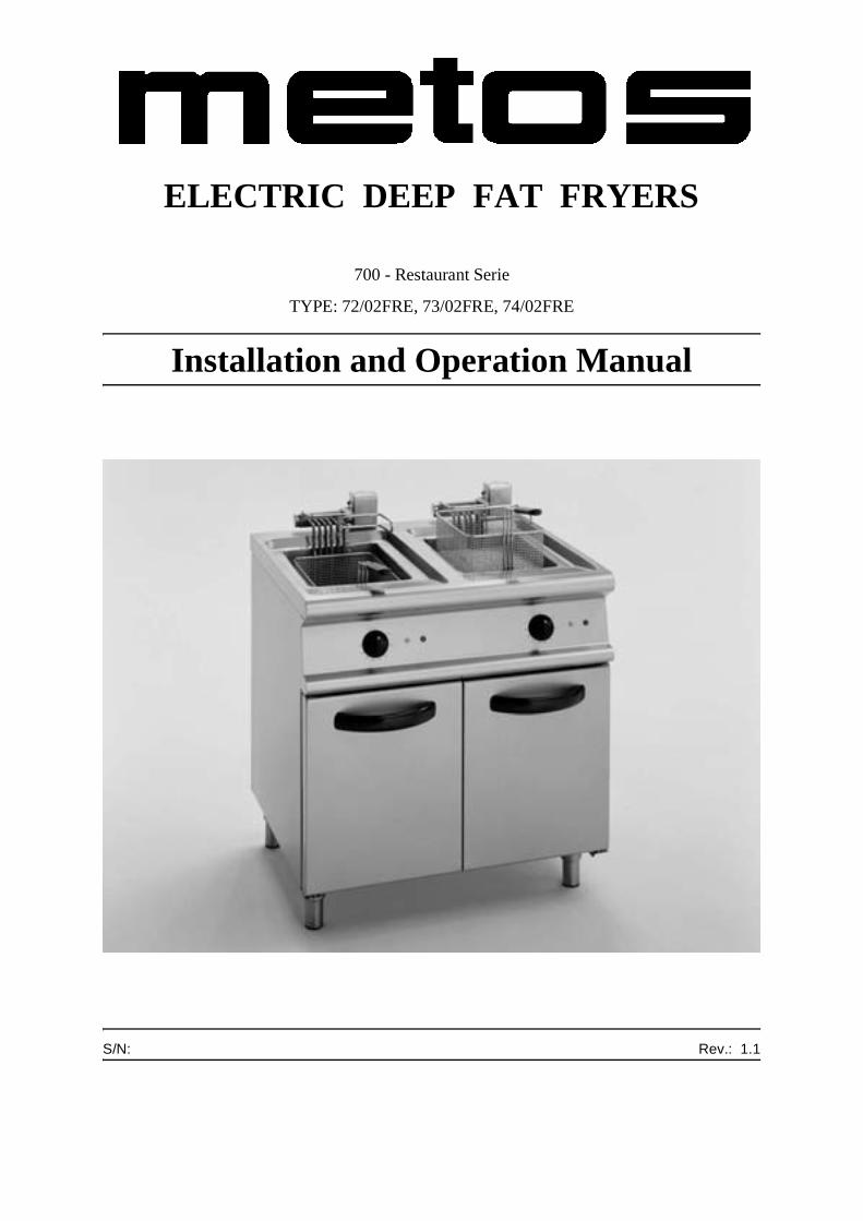
ELECTRIC DEEP FAT FRYERS
700 - Restaurant Serie
TYPE: 72/02FRE, 73/02FRE, 74/02FRE
Installation and Operation Manual
S/N: Rev.: 1.1

1.12.2003 Rev. 1.1
Dear Customer,
Congratulations on deciding to choose a Metos appliance for your kitchen activities. Youmade an excellent choice. We will do our best to make you a satisfied Metos customerlike thousands of customers we have around the world.
Please read this manual carefully. You will learn correct, safe and efficient working meth-ods in order to get the best possible benefit from the appliance. The instructions and hintsin this manual will give you a quick and easy start, and you will soon note how nice it isto use the Metos equipment.
All rights are reserved for technical changes.
You will find the main technical data on the rating plate fixed to the equipment. When youneed service or technical help, please let us know the serial number shown on the ratingplate. This will make it easier to provide you with correct service.
For your convenience, space is provided below for you to record your local Metos servicecontact information.
METOS TEAM
Metos service phone number:...............................................................................................
Contact person:....................................................................................................................

1.12.2003 Rev. 1.1
1.12.2003 Rev.
1. General .......................................................................................................... 11.1 Symbols used in the manual .......................................................................................... 11.2 Symbols used on the appliance ...................................................................................... 11.3 Checking the relationship of the appliance and the manual .......................................... 2
2. Safety .............................................................................................................. 32.1 Using the appliance safely ............................................................................................. 32.2 Safety instructions in the event of a fault ...................................................................... 32.3 Disposing of the appliance ............................................................................................ 4
3. Functional description .................................................................................. 53.1 Application of the appliance .......................................................................................... 5
3.1.1 Prohibited use/Use for unintended purposes ......................................................... 53.2 Construction .................................................................................................................. 53.3 Operating principle ........................................................................................................ 6
3.3.1 Operating switches and indicator lights ................................................................ 6
4. Operating instructions ................................................................................. 74.1 Prior to use ..................................................................................................................... 7
4.1.1 Preparing the appliance for use .............................................................................. 74.2 Using the appliance ....................................................................................................... 8
4.2.1 Filling the tank with oil .......................................................................................... 84.2.2 Switching on the appliance .................................................................................... 94.2.3 Frying ..................................................................................................................... 94.2.4 Switching off the appliance ................................................................................... 94.2.5 Safety thermostat ................................................................................................. 104.2.6 Emptying the tank ................................................................................................ 11
4.3 After-use care .............................................................................................................. 124.3.1 Cleaning ............................................................................................................... 124.3.2 Idle period ............................................................................................................ 144.3.3 Periodic maintenance ........................................................................................... 14
1.12.2003 Rev.
5. Installation ................................................................................................... 155.1 General information ..................................................................................................... 15
5.1.1 Regulatory installation conditions ....................................................................... 155.2 Exhausting fumes ........................................................................................................ 155.3 Possible environmental interference ............................................................................ 165.4 Storage ......................................................................................................................... 165.5 Unpacking the appliance ............................................................................................. 165.6 Disposing of packaging materials ............................................................................... 165.7 Positioning ................................................................................................................... 165.8 Electrical connections .................................................................................................. 17
5.8.1 General information ............................................................................................. 175.8.2 Connecting a type "Y" power cord to the appliance’s terminal block ................. 18
5.9 Staff training ................................................................................................................ 195.10 Rating plate ................................................................................................................ 19
6. Troubleshooting .......................................................................................... 21
8. Technical specifications .............................................................................. 31
1.12.2003 Rev. 1.1General
1. General
Carefully read the instructions in this manual as they contain important information re-garding proper, efficient and safe installation, use and maintenance of the appliance.
Keep this manual in a safe place for eventual use by other operators of the appliance.
The installation of this appliance must be carried out in accordance with the manufactur-er’s instructions and following local regulations. The connection of the appliance to thepower supply must be carried out by qualified persons only.
Persons using this appliance should be specifically trained in its operation.
Switch off the appliance in the case of failure or malfunction. The periodical functionchecks requested in the manual must be carried out according to the instructions. Have theappliance serviced by a technically qualified person authorized by the manufacturer andusing original spare parts.
Not complying with the above may put the safety of the appliance in danger.
1.1 Symbols used in the manual
This symbol informs about a situation where a safety risk might be at hand. Given instruc-tions are mandatory in order to prevent injury.
This symbol informs about the right way to perform in order to prevent bad results, appli-ance damage or hazardous situations.
This symbol informs about recommendations and hints that help to get the best perform-ance out of the appliance.
This symbol informs about a function that has to be taken into account in self-control.
1.2 Symbols used on the appliance
This symbol on a part informs about electrical terminals behind the part. The removal ofthe part must be carried out by qualified persons only.
1
1.12.2003 Rev. 1.1General
1.3 Checking the relationship of the appliance and the manual
The rating plate of the appliance indicates the serial number of the appliance. If the man-uals are missing, it is possible to order new ones from the manufacturer or the local rep-resentative. When ordering new manuals it is essential to quote the serial number shownon the rating plate.
2
1.12.2003 Rev. 1.1Safety
2. Safety
2.1 Using the appliance safely
Being an appliance designed for professional use only, it should be operated by qualifiedpersonnel exclusively. Never leave the deep fat fryer unattended while in operation.
Cooking with old and filthy oil is a safety risk; make sure that you always use fresh orpurified oil.
Foodstuffs to be fried should always be as dry as possible. Cooking foodstuffs with highmoisture content causes oil to foam and overflow.
Do not try to fry too much food at the same time. The maximum recommended quantityto be fried at the same time is about half of the basket capacity.
If oil level approaches the minimum level line marked on the side panel of the tank, poursome more oil into the tank until you reach the maximum level. If you should need to addoil while the appliance is in operation, use cold oil and pour it into the tank very carefully.In this way, you will prevent oil from splashing (fire hazard). In any case, do not mix largeamounts of fresh and old oil or fat because fresh oil will spoil much faster when in contactwith old oil.
Too little oil in the tank may result in overheating.
Never leave the deep fat fryer on without oil in the tank! Should this happen accidentally,the safety thermostat will turn off the appliance.
Do not move the appliance while hot.
IF OIL SHOULD CATCH FIRE, NEVER USE WATER TO EXTINGUISH IT.
2.2 Safety instructions in the event of a fault
Always keep the lid close at hand, in an easily accessible place.
Should oil catch fire, use the lid as first extinguishing means and then smother the firewith a fire blanket.
In the event of a fault or malfunction, switch off the appliance and call the service.
If an emergency occurs, use the main switch to disconnect power to the appliance.
3
1.12.2003 Rev. 1.1Safety
2.3 Disposing of the appliance
This appliance was built by using recyclable raw materials and does not contain any haz-ardous or toxic substances. To dispose of the appliance and all its packaging materials,strictly follow all local regulations in force in the place where it is installed. Packagingmaterials should be divided according to the type and delivered to a specific collectionsite. Ensure compliance of applicable environmental protection regulations.
4
1.12.2003 Rev. 1.1Functional description
3. Functional description
3.1 Application of the appliance
The deep fat fryer is intended to cook fresh or deep-frozen products and to fry half-cookedproducts continuously.
3.1.1 Prohibited use/Use for unintended purposes
The deep fat fryer is not designed for use as a bain-marie or pasta cooker.
The manufacturer cannot be held liable for any faults caused by defective installation orinappropriate use of the appliance. In such cases the warranty shall be null and void.
3.2 Construction
Exterior finish and adjustable feet are all AISI 18/10 stainless steel.
Tanks are stainless steel type AISI 18/10 with cool zone and foam area.
Worktops are pressed and have rounded corners.
Immersion swing-out heating elements.
Knobs fitted with watertight gasket.
5
1.12.2003 Rev. 1.1Functional description
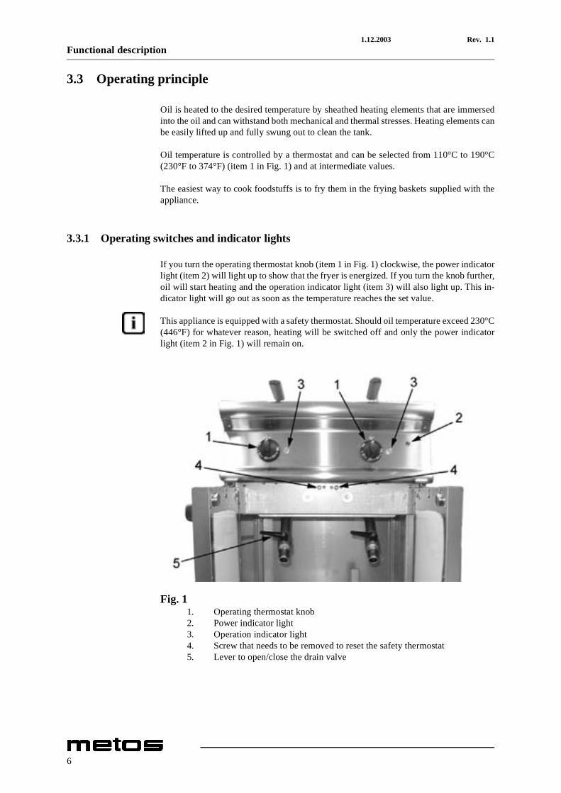
3.3 Operating principle
Oil is heated to the desired temperature by sheathed heating elements that are immersedinto the oil and can withstand both mechanical and thermal stresses. Heating elements canbe easily lifted up and fully swung out to clean the tank.
Oil temperature is controlled by a thermostat and can be selected from 110°C to 190°C(230°F to 374°F) (item 1 in Fig. 1) and at intermediate values.
The easiest way to cook foodstuffs is to fry them in the frying baskets supplied with theappliance.
3.3.1 Operating switches and indicator lights
If you turn the operating thermostat knob (item 1 in Fig. 1) clockwise, the power indicatorlight (item 2) will light up to show that the fryer is energized. If you turn the knob further,oil will start heating and the operation indicator light (item 3) will also light up. This in-dicator light will go out as soon as the temperature reaches the set value.
This appliance is equipped with a safety thermostat. Should oil temperature exceed 230°C(446°F) for whatever reason, heating will be switched off and only the power indicatorlight (item 2 in Fig. 1) will remain on.
Fig. 11. Operating thermostat knob2. Power indicator light3. Operation indicator light4. Screw that needs to be removed to reset the safety thermostat5. Lever to open/close the drain valve
6
1.12.2003 Rev. 1.1Operating instructions
4. Operating instructions
4.1 Prior to use
4.1.1 Preparing the appliance for use
Before cooking food for the first time, we recommend cleaning the appliance --and espe-cially the tanks-- thoroughly. Remove all packaging materials and adhesive films from thedeep fat fryer very carefully. Clean the deep fat fryer using hot water.
Clean the tank and the swung-up heating elements using a sponge.
Drain cleaning water from the tank (see chapter "Emptying the tank" further below). Wipethe appliance dry with a clean cloth.
All stainless steel parts should be cleaned using a detergent free from abrasive substancesand specifically suited to clean steel surfaces.
Never use water jets to clean the appliance.
7
1.12.2003 Rev. 1.1Operating instructions
4.2 Using the appliance
4.2.1 Filling the tank with oil
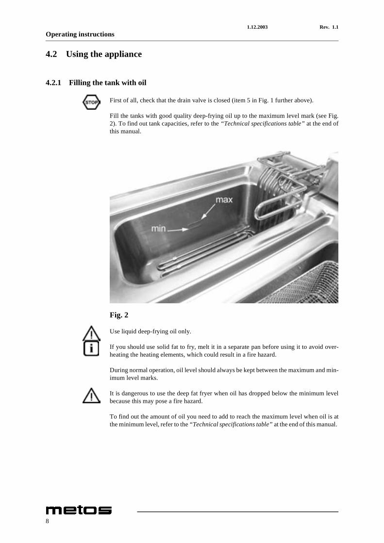
First of all, check that the drain valve is closed (item 5 in Fig. 1 further above).
Fill the tanks with good quality deep-frying oil up to the maximum level mark (see Fig.2). To find out tank capacities, refer to the “Technical specifications table” at the end ofthis manual.
Fig. 2
Use liquid deep-frying oil only.
If you should use solid fat to fry, melt it in a separate pan before using it to avoid over-heating the heating elements, which could result in a fire hazard.
During normal operation, oil level should always be kept between the maximum and min-imum level marks.
It is dangerous to use the deep fat fryer when oil has dropped below the minimum levelbecause this may pose a fire hazard.
To find out the amount of oil you need to add to reach the maximum level when oil is atthe minimum level, refer to the “Technical specifications table” at the end of this manual.
8
1.12.2003 Rev. 1.1Operating instructions
4.2.2 Switching on the appliance
Energize the appliance by turning on the safety switch located outside the appliance. Setthe operating thermostat (item 1 in Fig. 1 further above) to the desired cooking tempera-ture (160°C-190°C) (320°F-374°F). The indicator lights will come on; the power indica-tor light (item 2 in Fig. 1) shows that the appliance is energized while the operationindicator light (item 3 in Fig. 1) shows that the heating elements are on. When the set tem-perature has been reached, the operation indicator light will turn off.
4.2.3 Frying
Prior to frying, remove as much moisture as possible from the foodstuffs with a twofoldpurpose: to prevent oil from overflowing due to foam build-up and to avoid excessive hotoil splashes. Total weight of product to be cooked should not exceed 1.5 kg in 10-litretanks (models 73) and 2.5 kg in 15-litre tanks (models 72 and 74).
• Use the thermostat to set the desired cooking temperature; the ideal temperature is180°C (356°F).
• Place the products into the basket; fill the basket to 1/3 or 1/2 (maximum load) ofits full capacity.
• Shake frozen products well before dipping them into the oil. • Lower the basket into the oil.• When product is ready, lift the basket and hang it from the basket support to allow
excess oil to drip away.
Always monitor oil quality during operation. Overused oil can be recognized by its typicaldark colour, viscosity and tendency to smoke even at low temperatures.
Never leave the appliance unattended while in use.
4.2.4 Switching off the appliance
To switch off the deep fat fryer, turn the thermostat to position "0". Now, the power indi-cator light will also go out.
9
1.12.2003 Rev. 1.1Operating instructions
4.2.5 Safety thermostat
This appliance is equipped with a safety thermostat. Should oil temperature exceed themaximum value, i.e. 230°C (446°F), power supply will be automatically shut off to pre-vent oil from overheating to such an extent that there may be a fire hazard or that poison-ous fumes may be produced. This is a safety feature that protects the appliance when acomponent breaks down or the fryer is used against the instructions (too little oil in thetank, using solid fat without melting it first, using oil that is dirty and/or too old).
If the safety thermostat trips, disconnect the appliance from power supply and proceed asfollows:
1. wait for a few minutes so that oil temperature drops below 180°C (356°F); 2. reset the safety thermostat as follows:
• open the doors;• remove the nut shown as item 4 in Fig. 1 further above; • insert a tool having a maximum diameter of 6 mm and press the small red
reset button until you hear a metal click; 3. filter or change used oil or top up oil to the maximum level mark; 4. switch on the appliance.
If the safety thermostat trips again, call service.
10
1.12.2003 Rev. 1.1Operating instructions
4.2.6 Emptying the tank
Empty the tank every day to clean it and to filter oil with the purpose of removing anyfrying residues. Give utmost attention to this operation, which should not be carried outbefore oil temperature has dropped to 100°C (212°F).
Empty the tank as follows:
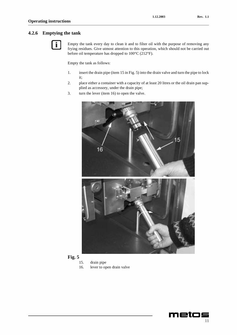
1. insert the drain pipe (item 15 in Fig. 5) into the drain valve and turn the pipe to lockit;
2. place either a container with a capacity of at least 20 litres or the oil drain pan sup-plied as accessory, under the drain pipe;
3. turn the lever (item 16) to open the valve.
Fig. 515. drain pipe16. lever to open drain valve
11

1.12.2003 Rev. 1.1Operating instructions
4.3 After-use care
4.3.1 Cleaning
Before cleaning, turn off the appliance and disconnect power supply to it by switching offthe safety switch located upstream of the appliance.
Wait until the deep fat fryer has cooled down before you start cleaning it.
Drain all oil from the tank, see chapter "Emptying the tank" further above.
General information
The main causes for stainless steel wear or corrosion are:
• using abrasive or acid detergents, especially chlorine-based products such as hy-drochloric acid or sodium hypochlorite (bleach). Therefore, before buying a clean-ing product, make sure it does not corrode stainless steel (see also paragraph"Routine cleaning" below);
• stagnation of ferrous deposits (such as those created by rust dissolved in the waterflowing through the piping, especially after the appliance has remained idle forsome time). Therefore, avoid such stagnation. Do not use wire wool pads to re-move the most stubborn food residues. Use, rather, pads or spatulas made of stain-less steel or softer, non-ferrous materials;
• stagnation of substances having acid components such as vinegar, lemon juice,sauces, salt, etc. Avoid prolonged contact of the stainless steel parts of the appli-ance with those substances. The evaporation of saline solutions over the surfacesof the appliance is particularly harmful to them.
Routine cleaning
Cleaning the appliance thoroughly on a daily basis is the key to keep it in perfect workingcondition and prolonging its life. Clean the appliance with a damp cloth using water andsoap or detergents, provided that they are not acid or abrasive as discussed further above.Such detergents should not even be used to wash the floor near the appliance, as theirfumes may deposit on the steel surfaces and damage them. If the deep fat fryer is verydirty, use a Scotch-BriteTM type synthetic scrub sponge. Rinse it off with clean water andwipe it dry with a clean cloth. Do not rub the appliance with steel wool pads as they couldleave rust stains. For the same reason, avoid touching the appliance with ferrous objects.
In order to prevent corrosion spots from forming, ensure that any salt residues are care-fully removed from the tank’s sides and bottom.
Never use direct water jets to clean the appliance because this could result in water enter-ing into it and damaging it.
12
1.12.2003 Rev. 1.1Operating instructions
Stains and abrasions on the steel surface
Scratches and dark stains may be smoothed or removed using stainless steel wool pads orsynthetic abrasive sponges, which should always be rubbed in the same direction as thesatin finish.
Rust
If you need to remove rust stains, contact manufacturers of industrial detergents to find asuitable product. Industrial descaling products can also be used to that end. After usingthe descaler and rinsing off the appliance with clean water, an alkaline detergent may berequired to neutralize any acid compounds left on the surface.
Cleaning the deep fat fryer
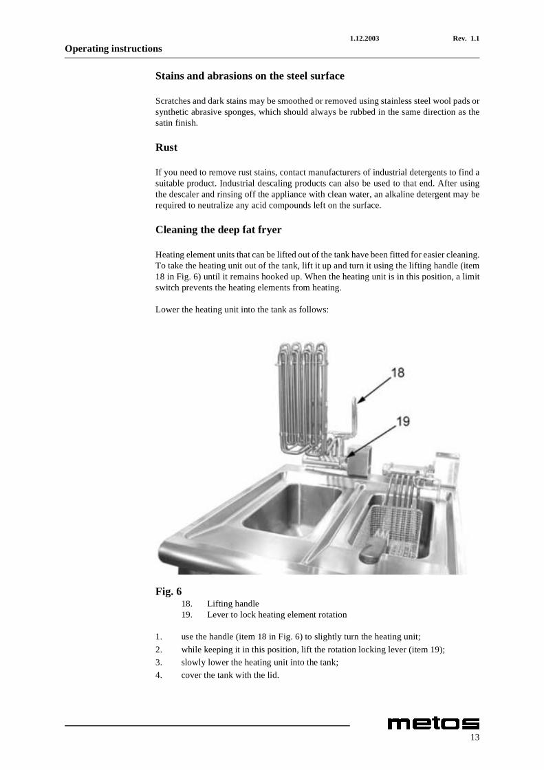
Heating element units that can be lifted out of the tank have been fitted for easier cleaning.To take the heating unit out of the tank, lift it up and turn it using the lifting handle (item18 in Fig. 6) until it remains hooked up. When the heating unit is in this position, a limitswitch prevents the heating elements from heating.
Lower the heating unit into the tank as follows:
Fig. 618. Lifting handle19. Lever to lock heating element rotation
1. use the handle (item 18 in Fig. 6) to slightly turn the heating unit;2. while keeping it in this position, lift the rotation locking lever (item 19); 3. slowly lower the heating unit into the tank;4. cover the tank with the lid.
13
1.12.2003 Rev. 1.1Operating instructions
4.3.2 Idle period
If the appliance will remain idle for a certain period of time, clean it and wipe it dry first,and then apply a film of a suitable product (such as vaseline oil spray or similar products)to protect it.
Turn off the safety switch fitted outside the appliance to shut off power supply to it.
4.3.3 Periodic maintenance
Only qualified personnel are allowed to carry out service and maintenance operations.
The following maintenance operation should be carried out at least once a year:
• checking for proper operation of all control and safety devices;
We recommend signing a service agreement providing for at least one check-up a year.
14

1.12.2003 Rev. 1.1Installation
5. Installation
5.1 General information
The manufacturer cannot be held liable for any injuries to persons or damage to propertyresulting from installation errors or from inappropriate use of the appliance and is not re-sponsible for any faults caused by defective installation. In such cases the warranty shallbe null and void.
Installation, maintenance, connection to power supply, and start-up should all be per-formed by an authorised installer who must ensure compliance with all applicable safetyregulations in force in the location where the appliance is being installed.
Check that the appliance is pre-set to operate on the voltage available at the place of use.Should the available voltage rating be different, do not install the appliance.
5.1.1 Regulatory installation conditions
We remind you that all appliances installed in public assembly buildings must meet therequirements specified below. The appliance must be both installed and serviced in com-pliance with all applicable rules and legal regulations in force, namely:
• safety regulations on fire hazard and panic in public assembly buildings. • general regulations applicable to all appliances;• heating, ventilation, refrigeration, air conditioning, and generation of steam and
hot water for sanitary use;• installation of foodservice cooking appliances;• specific regulations applicable to each type of public assembly building (hospitals,
shops, etc.).
5.2 Exhausting fumes
The appliance should be installed in a well-ventilated area, if possible under an exhausthood, in compliance with all applicable regulations in force, in order to ensure that steamand cooking fumes are effectively exhausted.
15
1.12.2003 Rev. 1.1Installation
5.3 Possible environmental interference
If the appliance is installed in the immediate vicinity of other electric units, ensure thatthey do not interfere with each other. They should all have independent power supplies.
If the appliance is installed with its sides next to flammable walls (made of wood or sim-ilar materials) or to heat-sensitive walls (made of plasterboard or similar materials), suit-able protective measures should be taken to keep such walls undamaged. Either apply acoating over the wall to insulate it against radiative heat or keep a minimum clearance of100 mm (4") from the sides of the appliance.
5.4 Storage
If the appliance is stored in a warehouse where room temperature is below 0°C (32°F), itshould be warmed up to at least +10°C (50°F) before switching it on.
5.5 Unpacking the appliance
Prior to installation, remove all packaging materials from the deep fat fryer. Some partsare wrapped in adhesive film, which should be thoroughly removed. Remove any gluetraces left on the surfaces of the appliance using a suitable non-flammable solvent. Abso-lutely avoid using abrasive substances.
5.6 Disposing of packaging materials
All packaging materials should be disposed of in compliance with the local regulations inforce where the appliance is installed. Packaging materials should be separated accordingto their types and delivered to specific collection sites. Please abide by environmental pro-tection regulations.
5.7 Positioning
Level the appliance using a bubble level. Small adjustments can be done with the help ofthe adjustable feet.
16
1.12.2003 Rev. 1.1Installation
5.8 Electrical connections
5.8.1 General information
The appliance must always be connected to an earthing (grounding) system while in op-eration.
The appliance is pre-set to be connected to the electrical switchboard. Before connectingthe appliance to the power supply network check:
• that distribution network voltage matches the voltage shown on the appliance’s rat-ing plate;
• that the grounding (earthing) system is effective; • that the power cord is made of rubber and is of at least the same quality as cable
type H07RN-F, with conductors having a cross section suited to the maximum loadthey will carry (refer to "Technical specifications table" at the end of this manual);
• an effective multi-pole breaker having a contact gap of at least 3 mm should be fit-ted upstream of the appliance at the time of installation. Automatic thermal-mag-netic circuit breakers may be used for this purpose. The multi-pole breaker shouldbe installed in the immediate vicinity of the appliance and be readily accessible.We recommend fitting a thermal-magnetic circuit breaker with built-in fuse pro-tection;
• the power cord of the appliance should not be exposed to direct heat sources.
17
1.12.2003 Rev. 1.1Installation
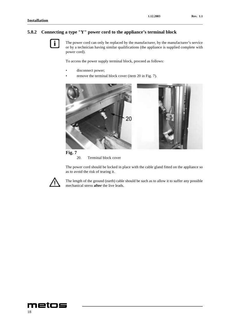
5.8.2 Connecting a type "Y" power cord to the appliance’s terminal block
The power cord can only be replaced by the manufacturer, by the manufacturer’s serviceor by a technician having similar qualifications (the appliance is supplied complete withpower cord).
To access the power supply terminal block, proceed as follows:
• disconnect power; • remove the terminal block cover (item 20 in Fig. 7).
Fig. 720. Terminal block cover
The power cord should be locked in place with the cable gland fitted on the appliance soas to avoid the risk of tearing it.
The length of the ground (earth) cable should be such as to allow it to suffer any possiblemechanical stress after the live leads.
18
1.12.2003 Rev. 1.1Installation
5.9 Staff training
Train personnel in the operation of the appliance by referring to the user’s manual andhand them over the manual as well.
5.10 Rating plate
The rating plate showing the specifications of the corresponding model is applied in theposition shown in the installation and connection drawings and includes the data listedbelow:
Manufacturer:Model: (see front page)Serial number:Year of manufacture:Category: (see "Technical specifications table")Heating power: (see "Technical specifications table")Natural gas consumption: (see "Table 1: gas categories and pressure values")Liquid gas consumption: (see "Table 1: gas categories and pressure values")Supply pressure :natural gases: G20 (see "Table 2: burner specifications" further above)liquid gases (butane/propane): G30/G31 (see "Table 2: burner specifications" further above)town gas: G110/G120 (see "Table 2: burner specifications" further above)Gas inlet pipe size: (see "Technical specifications table")Supply voltage: (see the label on the packaging and on the appliance)Appliance adjusted to use:
19

1.12.2003 Rev. 1.1Installation
20
1.12.2003 Rev. 1.1Troubleshooting
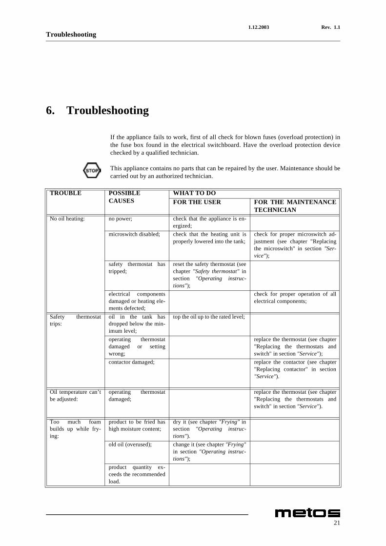
6. Troubleshooting
If the appliance fails to work, first of all check for blown fuses (overload protection) inthe fuse box found in the electrical switchboard. Have the overload protection devicechecked by a qualified technician.
This appliance contains no parts that can be repaired by the user. Maintenance should becarried out by an authorized technician.
TROUBLE POSSIBLECAUSES
WHAT TO DOFOR THE USER FOR THE MAINTENANCE
TECHNICIANNo oil heating: no power; check that the appliance is en-
ergized;microswitch disabled; check that the heating unit is
properly lowered into the tank;check for proper microswitch ad-justment (see chapter "Replacingthe microswitch" in section "Ser-vice");
safety thermostat hastripped;
reset the safety thermostat (seechapter "Safety thermostat" insection "Operating instruc-tions");
electrical componentsdamaged or heating ele-ments defected;
check for proper operation of allelectrical components;
Safety thermostattrips:
oil in the tank hasdropped below the min-imum level;
top the oil up to the rated level;
operating thermostatdamaged or settingwrong;
replace the thermostat (see chapter"Replacing the thermostats andswitch" in section "Service");
contactor damaged; replace the contactor (see chapter"Replacing contactor" in section"Service").
Oil temperature can’tbe adjusted:
operating thermostatdamaged;
replace the thermostat (see chapter"Replacing the thermostats andswitch" in section "Service").
Too much foambuilds up while fry-ing:
product to be fried hashigh moisture content;
dry it (see chapter "Frying" insection "Operating instruc-tions").
old oil (overused); change it (see chapter "Frying"in section "Operating instruc-tions");
product quantity ex-ceeds the recommendedload.
21

1.12.2003 Rev. 1.1Troubleshooting
22
1.12.2003 Rev. 1.1Technical specifications
8. Technical specifications
Connection diagrams ................................................... 32
Installation and connection drawings......................... 40
Technical specifications table...................................... 43
CE conformity declaration .......................................... 45
31
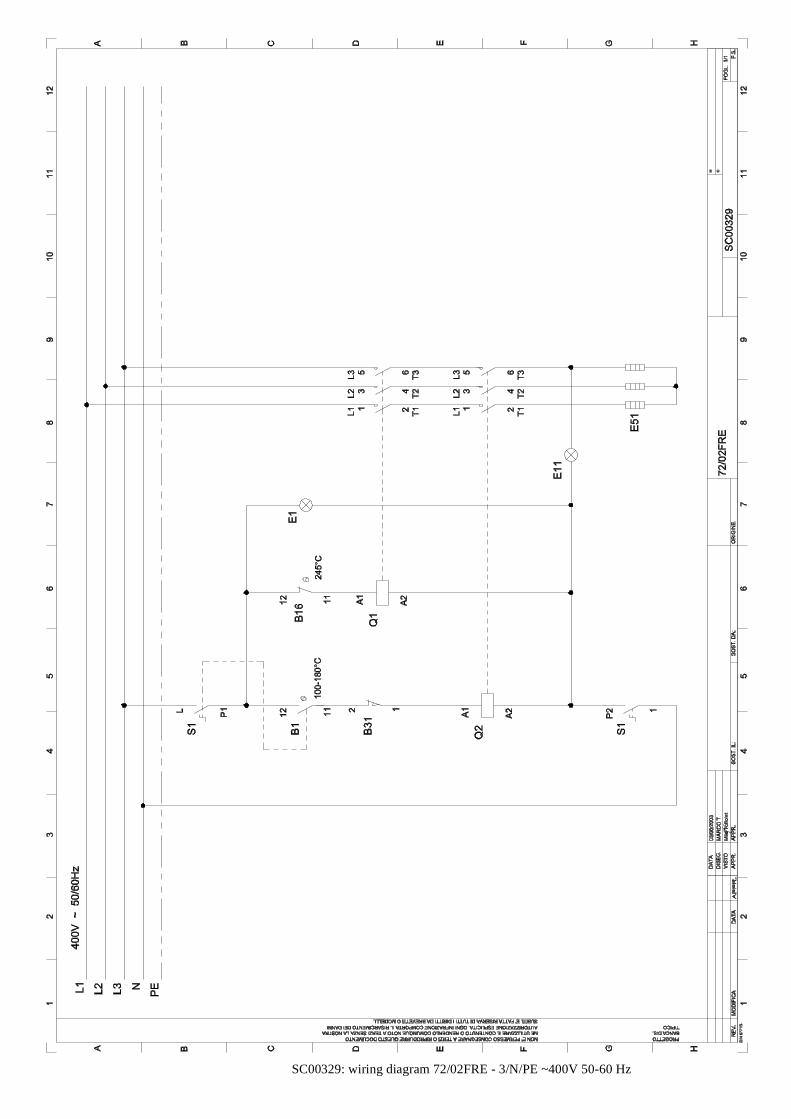
SC00329: wiring diagram 72/02FRE - 3/N/PE ~400V 50-60 Hz
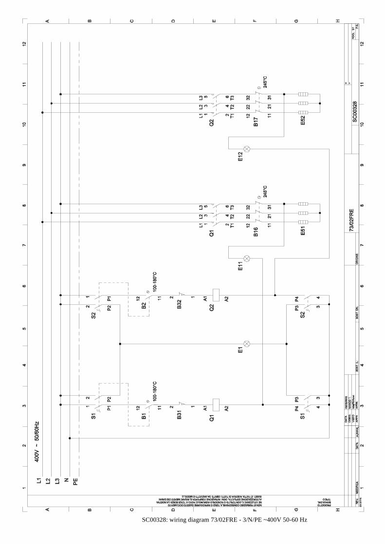
SC00328: wiring diagram 73/02FRE - 3/N/PE ~400V 50-60 Hz
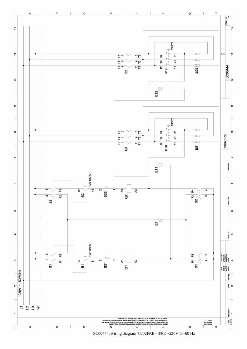
SC00444: wiring diagram 73/02FRE - 3/PE ~230V 50-60 Hz

SC00330: wiring diagram 74/02FRE - 3/N/PE ~400V 50-60 Hz
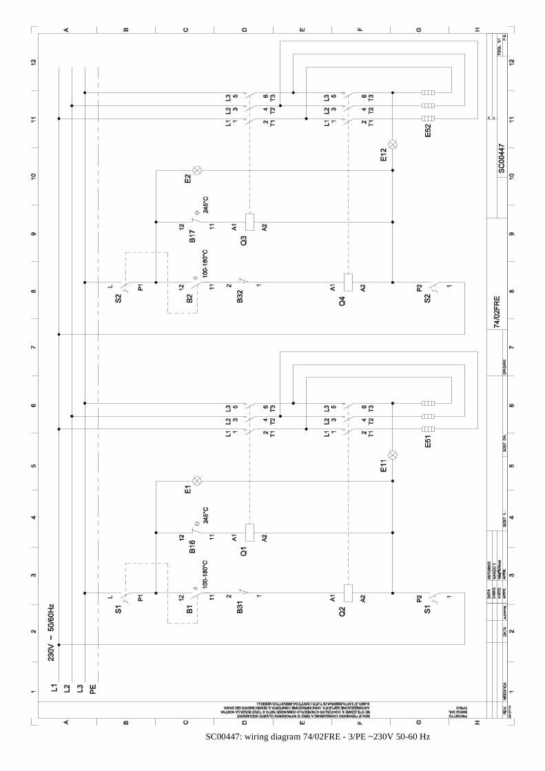
SC00447: wiring diagram 74/02FRE - 3/PE ~230V 50-60 Hz

SC00451: wiring diagram 74/02FRE - 3/PE ~400V 50 Hz
1.12.2003 Rev. 1.1Technical specifications
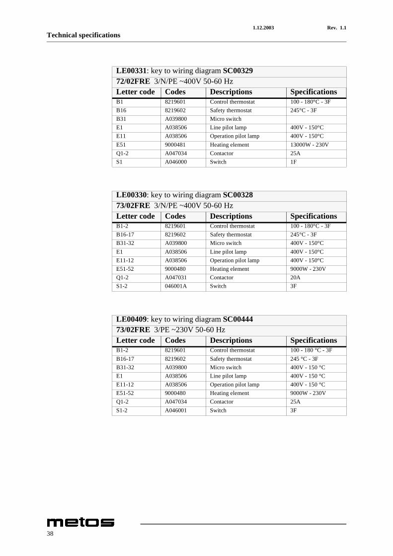
LE00331: key to wiring diagram SC0032972/02FRE 3/N/PE ~400V 50-60 HzLetter code Codes Descriptions SpecificationsB1 8219601 Control thermostat 100 - 180°C - 3FB16 8219602 Safety thermostat 245°C - 3FB31 A039800 Micro switch E1 A038506 Line pilot lamp 400V - 150°CE11 A038506 Operation pilot lamp 400V - 150°CE51 9000481 Heating element 13000W - 230VQ1-2 A047034 Contactor 25AS1 A046000 Switch 1F
LE00330: key to wiring diagram SC0032873/02FRE 3/N/PE ~400V 50-60 HzLetter code Codes Descriptions SpecificationsB1-2 8219601 Control thermostat 100 - 180°C - 3FB16-17 8219602 Safety thermostat 245°C - 3FB31-32 A039800 Micro switch 400V - 150°CE1 A038506 Line pilot lamp 400V - 150°CE11-12 A038506 Operation pilot lamp 400V - 150°CE51-52 9000480 Heating element 9000W - 230VQ1-2 A047031 Contactor 20AS1-2 046001A Switch 3F
LE00409: key to wiring diagram SC0044473/02FRE 3/PE ~230V 50-60 HzLetter code Codes Descriptions SpecificationsB1-2 8219601 Control thermostat 100 - 180 °C - 3FB16-17 8219602 Safety thermostat 245 °C - 3FB31-32 A039800 Micro switch 400V - 150 °CE1 A038506 Line pilot lamp 400V - 150 °CE11-12 A038506 Operation pilot lamp 400V - 150 °CE51-52 9000480 Heating element 9000W - 230VQ1-2 A047034 Contactor 25AS1-2 A046001 Switch 3F
38
1.12.2003 Rev. 1.1Technical specifications
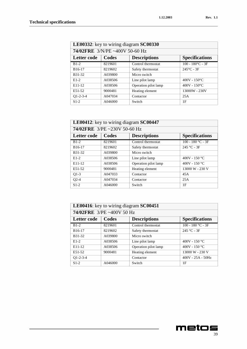
LE00332: key to wiring diagram SC0033074/02FRE 3/N/PE ~400V 50-60 HzLetter code Codes Descriptions SpecificationsB1-2 8219601 Control thermostat 100 - 180°C - 3FB16-17 8219602 Safety thermostat 245°C - 3FB31-32 A039800 Micro switchE1-2 A038506 Line pilot lamp 400V - 150°CE11-12 A038506 Operation pilot lamp 400V - 150°CE51-52 9000481 Heating element 13000W - 230VQ1-2-3-4 A047034 Contactor 25AS1-2 A046000 Switch 1F
LE00412: key to wiring diagram SC0044774/02FRE 3/PE ~230V 50-60 HzLetter code Codes Descriptions SpecificationsB1-2 8219601 Control thermostat 100 - 180 °C - 3FB16-17 8219602 Safety thermostat 245 °C - 3FB31-32 A039800 Micro switchE1-2 A038506 Line pilot lamp 400V - 150 °CE11-12 A038506 Operation pilot lamp 400V - 150 °CE51-52 9000481 Heating element 13000 W - 230 VQ1-3 A047033 Contactor 45AQ2-4 A047034 Contactor 25AS1-2 A046000 Switch 1F
LE00416: key to wiring diagram SC0045174/02FRE 3/PE ~400V 50 HzLetter code Codes Descriptions SpecificationsB1-2 8219601 Control thermostat 100 - 180 °C - 3FB16-17 8219602 Safety thermostat 245 °C - 3FB31-32 A039800 Micro switchE1-2 A038506 Line pilot lamp 400V - 150 °CE11-12 A038506 Operation pilot lamp 400V - 150 °CE51-52 9000481 Heating element 13000 W - 230 VQ1-2-3-4 Contactor 400V - 25A - 50HzS1-2 A046000 Switch 1F
39
1.12.2003 Rev. 1.1Technical specifications
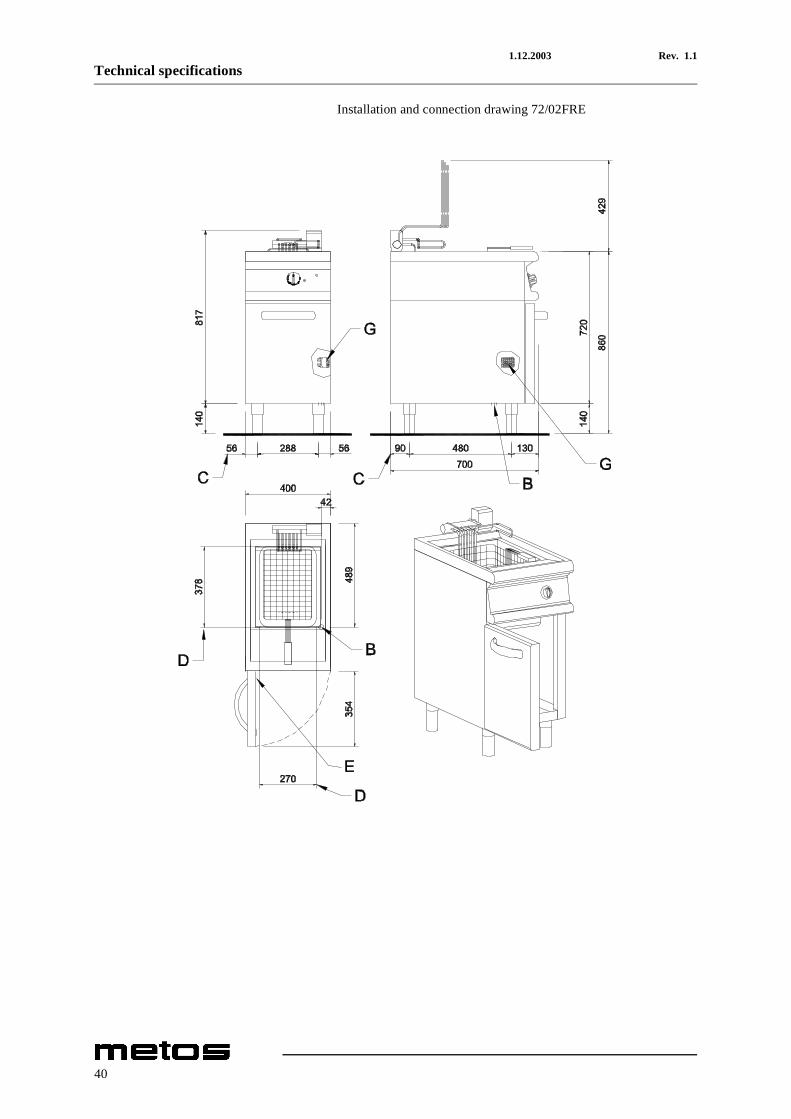
Installation and connection drawing 72/02FRE
40
1.12.2003 Rev. 1.1Technical specifications
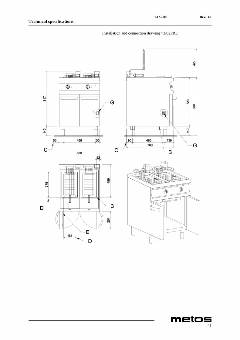
Installation and connection drawing 73/02FRE
41
1.12.2003 Rev. 1.1Technical specifications
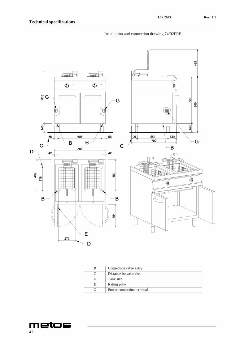
Installation and connection drawing 74/02FRE
B Connection cable entryC Distance between feetD Tank sizeE Rating plateG Power connection terminal
42
31.3.2006 Rev. 1.1Technical specifications
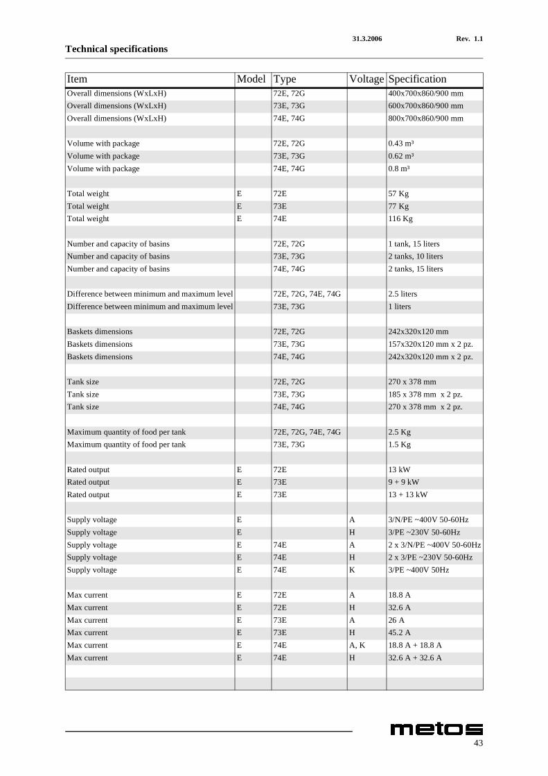
Item Model Type Voltage SpecificationOverall dimensions (WxLxH) 72E, 72G 400x700x860/900 mmOverall dimensions (WxLxH) 73E, 73G 600x700x860/900 mmOverall dimensions (WxLxH) 74E, 74G 800x700x860/900 mm
Volume with package 72E, 72G 0.43 m³Volume with package 73E, 73G 0.62 m³Volume with package 74E, 74G 0.8 m³
Total weight E 72E 57 KgTotal weight E 73E 77 KgTotal weight E 74E 116 Kg
Number and capacity of basins 72E, 72G 1 tank, 15 litersNumber and capacity of basins 73E, 73G 2 tanks, 10 litersNumber and capacity of basins 74E, 74G 2 tanks, 15 liters
Difference between minimum and maximum level 72E, 72G, 74E, 74G 2.5 litersDifference between minimum and maximum level 73E, 73G 1 liters
Baskets dimensions 72E, 72G 242x320x120 mmBaskets dimensions 73E, 73G 157x320x120 mm x 2 pz.Baskets dimensions 74E, 74G 242x320x120 mm x 2 pz.
Tank size 72E, 72G 270 x 378 mmTank size 73E, 73G 185 x 378 mm x 2 pz.Tank size 74E, 74G 270 x 378 mm x 2 pz.
Maximum quantity of food per tank 72E, 72G, 74E, 74G 2.5 KgMaximum quantity of food per tank 73E, 73G 1.5 Kg
Rated output E 72E 13 kWRated output E 73E 9 + 9 kWRated output E 73E 13 + 13 kW
Supply voltage E A 3/N/PE ~400V 50-60HzSupply voltage E H 3/PE ~230V 50-60HzSupply voltage E 74E A 2 x 3/N/PE ~400V 50-60HzSupply voltage E 74E H 2 x 3/PE ~230V 50-60HzSupply voltage E 74E K 3/PE ~400V 50Hz
Max current E 72E A 18.8 AMax current E 72E H 32.6 AMax current E 73E A 26 AMax current E 73E H 45.2 AMax current E 74E A, K 18.8 A + 18.8 AMax current E 74E H 32.6 A + 32.6 A
43
1.12.2003 Rev. 1.1Technical specifications
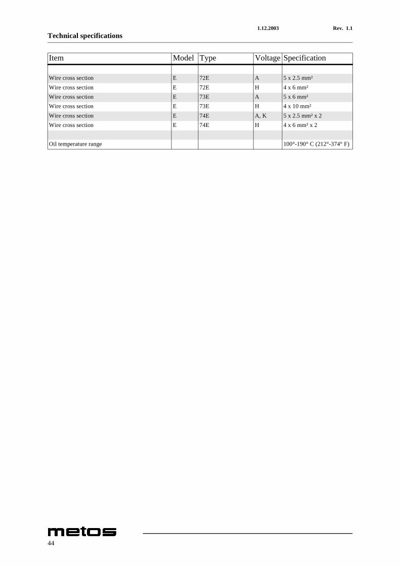
Wire cross section E 72E A 5 x 2.5 mm²Wire cross section E 72E H 4 x 6 mm²Wire cross section E 73E A 5 x 6 mm²Wire cross section E 73E H 4 x 10 mm²Wire cross section E 74E A, K 5 x 2.5 mm² x 2Wire cross section E 74E H 4 x 6 mm² x 2
Oil temperature range 100°-190° C (212°-374° F)
Item Model Type Voltage Specification
44
DICHIARAZIONE DI CONFORMITÀ CECE CONFORMITY DECLARATION
DECLARATION DE CONFORMITE CE
CE KONFORMITÄTSERKLÄRUNG
DECLARACIÓN DE CONFORMIDAD CE
OLIS S.p.A.
IMPIANTI PER LA RISTORAZIONE
32030 BRIBANO - Belluno - Italy
Via Cavalieri di Vittorio Veneto,14
Telefono +39-437-8558 (5 linee r.a.)
Fax +39-0437- 838274
http://ww.olis.it e-mail:[email protected]
Cap. Soc. € 2.500.000
Registro delle Imprese 00917220253 R.E.A. n. 82605
Codice Fiscale e Partita IVA IT 009177220253
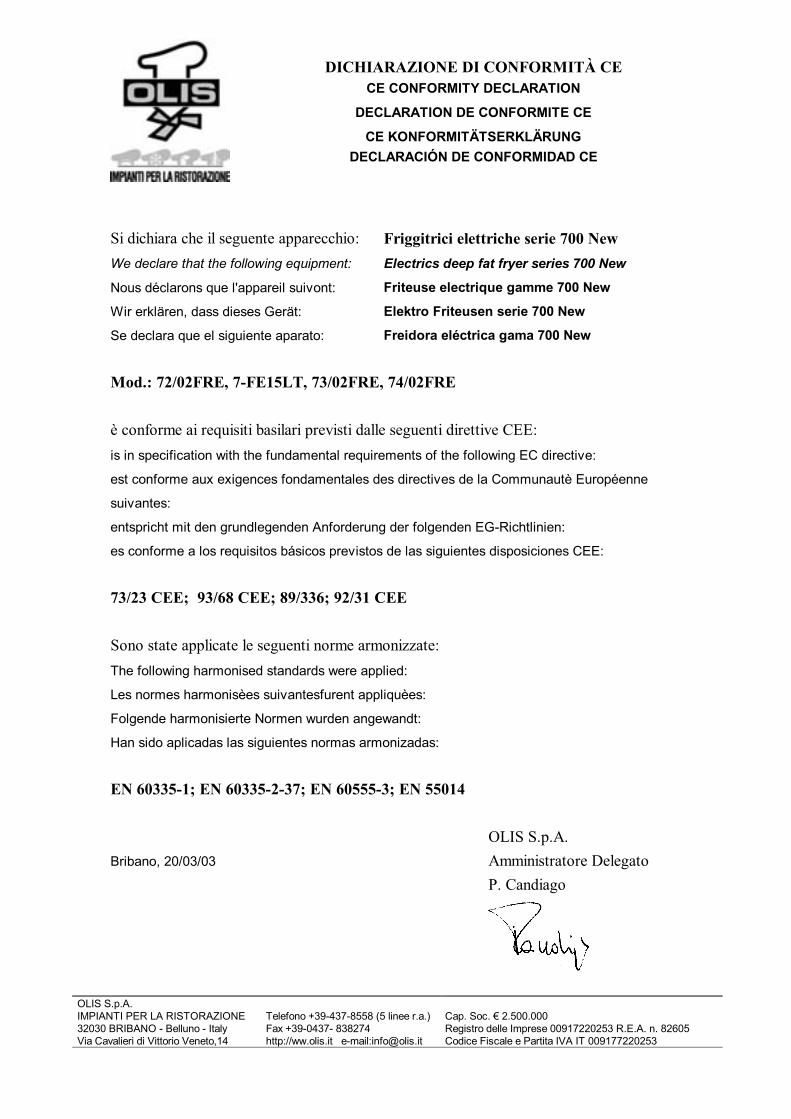
Si dichiara che il seguente apparecchio: Friggitrici elettriche serie 700 New
We declare that the following equipment: Electrics deep fat fryer series 700 New
Nous déclarons que l'appareil suivont: Friteuse electrique gamme 700 New
Wir erklären, dass dieses Gerät: Elektro Friteusen serie 700 New
Se declara que el siguiente aparato: Freidora eléctrica gama 700 New
Mod.: 72/02FRE, 7-FE15LT, 73/02FRE, 74/02FRE
è conforme ai requisiti basilari previsti dalle seguenti direttive CEE:
is in specification with the fundamental requirements of the following EC directive:
est conforme aux exigences fondamentales des directives de la Communautè Européenne
suivantes:
entspricht mit den grundlegenden Anforderung der folgenden EG-Richtlinien:
es conforme a los requisitos básicos previstos de las siguientes disposiciones CEE:
73/23 CEE; 93/68 CEE; 89/336; 92/31 CEE
Sono state applicate le seguenti norme armonizzate:
The following harmonised standards were applied:
Les normes harmonisèes suivantesfurent appliquèes:
Folgende harmonisierte Normen wurden angewandt:
Han sido aplicadas las siguientes normas armonizadas:
EN 60335-1; EN 60335-2-37; EN 60555-3; EN 55014
OLIS S.p.A.
Bribano, 20/03/03 Amministratore Delegato
P. Candiago