
Determination of the adjoint state evolution for the efficient operation of a hybrid electric...
22
, 1
Transcript of Determination of the adjoint state evolution for the efficient operation of a hybrid electric...

,
1

Determination of the Adjoint State Evolution for the
Efficient Operation of a Hybrid Electric Vehicle
Laura V. Pereza, Cristian H. de Angeloa, Vıctor Pereyrab
aGrupo de Electronica Aplicada, Facultad de Ingenierıa, Universidad Nacional de Rıo
Cuarto, Cordoba, Argentina.bSan Diego State University.
Abstract
To minimize fuel consumption in hybrid electric vehicles it is necessary todefine a strategy for the management of the power flows within the vehicle.Under the assumption that the velocity to be developed by the vehicle isknown a priori, this problem may be posed as a non linear optimal controlproblem with control and state constraints. We find the solution to this prob-lem using the optimality conditions given by Pontryagin Maximum Principle.This leads to boundary value problems that we solve using a software toolnamed PASVA4. On real time operation, the velocity to be developed by thevehicle is not known in advance. We show how the adjoint state obtainedfrom the former problem may be used as a weighing factor, called “equivalentconsumption”. This weighing factor may be used to design suboptimal realtime algorithms for power management.
Keywords: non linear constrained optimal control, Pontryagin MaximumPrinciple, boundary value problems solvers, hybrid electric vehicles,equivalent consumption minimization algorithms
1. Introduction
Hybrid Electric Vehicles (HEVs) are those where the power needed todrive the vehicle is provided by one or more electric motors fed by electro-chemical batteries and that in addition have on board an internal combustion
Email address: [email protected] (Laura V. Perez)
Preprint submitted to Mathematical and Computer Modelling June 22, 2011

engine. The engine power not only contributes to the traction when neces-sary but also is used to recharge the batteries. Among the many advantagesthat these vehicles present concerning fuel economy and reduction of pollu-tant emissions, it is that of regenerative braking. That means that duringbraking, electric motors may change their operation mode, turn into genera-tors and recover the kinetic energy accumulated on the vehicle by turning itinto electrical energy that is sent back to the batteries. In order to achievean efficient operation, a sophisticated control system that optimizes all theenergy flows that take place within the vehicle must be defined. This energymanagement problem is usually referred to as the “supervisory control” andis usually stated as a high level control problem, whose commands have tobe obeyed at a lower level by the controllers of the particular vehicle devices.
Many real-time supervisory control algorithms for HEVs are based in theso called “Equivalent Consumption Minimization Strategy” (ECMS) ([1],[2],[3]). This strategy consists of multiplying the power supplied by the bat-teries by a weighing factor in order to turn it into an equivalent power thatcan be added to the power supplied by the internal combustion engine. Theinterest of this approach raises from the fact that by means of this equiv-alence the problem of minimizing consumption during a whole mission (aglobal problem), may be turned into an instantaneous minimization of thisweighted sum of powers, thus allowing its use in a real time algorithm. Inthis way, the optimal control problem reduces to determining this “equivalentconsumption” factor ([1], [3], [4]).
However, this weighing factor varies according to the relative efficiencyof the energy sources and to the features of the velocity cycle required of thevehicle. A great effort in current research is devoted to the determination ofthis parameter ([1], [2], [3]).
In a previous work [5] we formulated the supervisory control problem inHEVs as an optimal control problem with state and control constraints andderived the optimality conditions given by Pontryagin Maximum Principle([6], [7], [8], [9], [10]). In this approach, it is observed that the equivalentconsumption factor is related to the adjoint state of the optimal controlproblem [1] . Hence, by solving the optimality conditions and obtainingthe evolution in time of the adjoint state it would be possible to obtain anestimation of the equivalent consumption factor. This is the purpose of thiswork.
It is worth noting that the numerical solution of these problems is notstraightforward. Generally, the optimality conditions are differential-algebraic
3

equations ([11], [12]). Sometimes, the algebraic equations may be solved in-dependently and, after suitable replacements, the problem may be turnedinto an ordinary differential equations boundary value problem. It is thenneeded to use a solver for this kind of problems. In addition, in this partic-ular problem, the control and state constraints introduce discontinuities inthe solution and in the right hand side (RHS) of the differential equations.Moreover these discontinuities occur at unknown times, since they dependon the solution itself [5].
PASVA4 is a software tool able to solve non linear boundary value prob-lems with discontinuities in the RHS and in the solution, even in unknownlocations, multipoint boundary conditions and unknown algebraic parame-ters ([13],[14]). This tool has been successfully used for problems with theabove difficulties that appear in geophysics, electronics, mechanics, etc. andhence, we will use it to solve this problem. We hope the same approach canbe used for other optimal control problems with constraints.
In what follows we will first present the model we use (section 2) and thestatement of the problem (section 3). Later, by taking a particular case, wewill describe how we obtain the off-line solution. We start from two simplerformulations of the problem where the state constraints are not taken intoaccount and then we show some results (sections 4 and 5). With theseresults we propose an algorithm to implement a primitive suboptimal powermanagement strategy (section 6). Finally we mention some final commentsand the work in progress in section 7.
2. Model
2.1. Power flows
In order to consider the supervisory control problem, a simplified schemefor the system that represents the vehicle ([16], [17], [15]) is normally used.In this scheme, the intermediate energy conversion devices of the power-train such as generators and electronic converters are replaced by the netpower flow from each energy source (the fuel tank and the electrical stor-age system). We will use u to indicate the power flow at time t in thefuel tank/engine/generator path (which we shall call fuel-path henceforth),(see Figure 1). We establish the following convention: a positive power flow
means power flowing away from the sources towards the vehicle. That meansthat a negative flow will take place in the electrical path during regenerativebraking. Besides, the power flow from the fuel tank cannot be negative, as
4

Fuel Tank
Batteries
Vehicle
u
fC(u)
r-u
fB(r-u)
r
>0
Figure 1: Simplified scheme of a series hybrid electric vehicle.
it cannot absorb any power. The velocity profile to be performed by thevehicle is considered a given function. The required power is computed fromthis profile using a model of the inverse longitudinal dynamics of the vehicleand it will be denoted by r(t) (in the real case, the required power is notknown a priori since it depends on the transit and road conditions). In orderto maintain drivability it is required that the sum of the power from bothsources be equal to the required power at all times. Then, the energy flowfrom the electrical source has to be equal to r(t) − u(t).
2.2. Energy from the sources
Regarding the net energy consumed from each source it must be taken intoaccount that not all the power delivered by the sources can be actually usedto supply the demand, since in the intermediate energy conversion processesthere are losses. This fact will be represented by means of two functionsfC and fB that depend on the power flows. We consider that these areknown functions that in practice will be obtained by interpolation of a set ofvalues determined by laboratory tests, setting the vehicle at different power
5

operating points. This functions are normally increasing and non linear.The fuel consumption during a time interval [0, T ], where T is known, is
represented by the net energy consumed from the fuel source in the interval,i.e.:
∫ T
0
fC(u)dt. (1)
Our control objective will be the minimization of this energy or equiva-lently, the maximization of the negative of this functional. To compute thenet energy in the batteries it has to be considered that the effect of lossesimplies a power contribution from the batteries greater than that requiredduring acceleration (i. e., for r−u > 0), but a power income lower than thatproduced by regenerative braking (i. e., for r − u < 0). This fact is repre-sented by means of the function fB. Then, the net energy in the batteries attime t is
x(t) = x0 −
∫ t
0
fB(r(s) − u(s))ds (2)
where x0 is the initial energy. From (2) we arrive at
x(t) = −fB(r(t) − u(t)). (3)
This will be considered the state equation with initial condition x0. Thelosses in this path will probably also depend on the state, increasing as itdeviates from the nominal value, since it is clear that common batteries areless efficient as they get depleted and also when overcharged. So, we willmodify the state equation with a new function fB of the following form.Note that the state equation is non linear.
x(t) = −fB(x(t), r(t) − u(t)). (4)
It is not necessary to impose a terminal condition to the state. It may be free,which means that it does not matter how much energy is there in the batteriesat the end of the cycle (charge depleting operation mode). However, forbrevity, we shall limit the exposition to the case of a fixed terminal state xf .If it is equal to the initial state, it represents a “charge sustaining operationmode” of the vehicle.
6
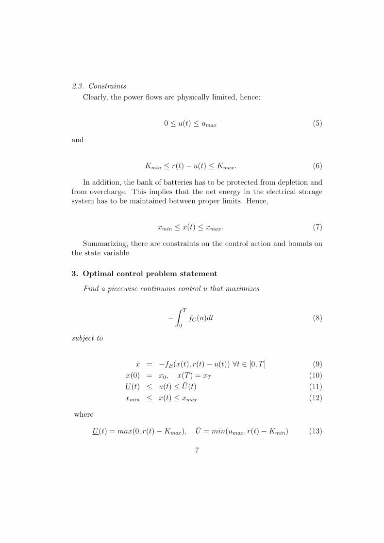
2.3. Constraints
Clearly, the power flows are physically limited, hence:
0 ≤ u(t) ≤ umax (5)
and
Kmin ≤ r(t) − u(t) ≤ Kmax. (6)
In addition, the bank of batteries has to be protected from depletion andfrom overcharge. This implies that the net energy in the electrical storagesystem has to be maintained between proper limits. Hence,
xmin ≤ x(t) ≤ xmax. (7)
Summarizing, there are constraints on the control action and bounds onthe state variable.
3. Optimal control problem statement
Find a piecewise continuous control u that maximizes
−
∫ T
0
fC(u)dt (8)
subject to
x = −fB(x(t), r(t) − u(t)) ∀t ∈ [0, T ] (9)
x(0) = x0, x(T ) = xT (10)
U(t) ≤ u(t) ≤ U(t) (11)
xmin ≤ x(t) ≤ xmax (12)
where
U(t) = max(0, r(t) − Kmax), U = min(umax, r(t) − Kmin) (13)
7

and where Kmax, Kmin, umax, xmin and xmax are known.Much of the difficulty of the problem arises from the form of the function
r(t). For the case of our prototype, a neighborhood electric vehicle, it isinteresting to consider the case where this function presents a highly nonlinear form since it follows from the train of successive accelerations anddecelerations that such a vehicle must perform in any urban mission requiredof it. This required power function determines in turn the form of U and U .We based our tests on the Normalized European Driving Schedule (NEDS),scaled to fit the power capabilities of our vehicle. A piece of this drivingcycle corresponding to the urban section is shown in the top graph of figure2. The middle graph of that figure shows the power that this vehicle requiresto perform the above driving cycle. A negative power means that the vehicleis braking. The bottom graph shows the resulting functions U and U . Notethat the searched control function u must lie between this two limits.
To solve this problem using the optimality conditions given by PontryaginMaximum Principle, it is necessary to define the corresponding Hamiltonianfunction which in this case is
H(t, x, λ, u) = −fC(u(t)) − λ(t)fB(x(t), r(t) − u(t)),
where λ is a new state variable, called the adjoint state or co-state whosedynamics is inherited from the fact that the state equation is a dynamicalconstraint. Later, the algebraic constraints will be taken into account inthe so called augmented Hamiltonian or Lagrangian. The optimal solutionis the function u(t), t ∈ [0, T ], that maximizes H or equivalently minimizes−H, over the set of all functions satisfying the constraints. That meansthat the optimal u minimizes the sum of the power (including losses) thathas to be supplied by the fuel-path plus the complementary power that hasto be supplied by the electrical path times the adjoint state. Hence λ(t)can be thought of as a weighing factor that scales the “cost” of using powerfrom the electrical path against the “cost” of using power from the fuelpath. If this “equivalent consumption factor” were known in advance wecould compute the optimal control just by an instantaneous minimization ofthe Hamiltonian using only the current required power r(t). Unfortunately,the optimality conditions must be solved globally, using the knowledge ofthe power requirements r(t) in the whole interval [0, T ]. Nevertheless, thecomputation off-line of λ(t) over intervals with typical forms of r(t) or overshort time intervals, previous to the current one, may allow the design of
8

0 50 100 150 2000
5
10
15
U,U
(kW
)
t (sec)
0 50 100 150 200−10
0
10
r(t
)(kW
)
0 50 100 150 2000
20
40
60
v(t
)(km
/h)
Figure 2: Required velocity cycle, corresponding required power for our neighborhoodelectrical vehicle and upper and lower control limiting functions.
9

algorithms to compute suboptimal control functions by an instantaneousoptimization. This is our purpose.
To address this problem we begin by solving formulations of the problemthat, although physically meaningful, are simpler to be treated. Then, asusual in constrained control, we will be progressively adding difficulties stepby step. So, at this first step we will ignore the bounds on the state. Inaddition, we chose to approximate the functions fC and fB by quadraticpolynomials in u, in order to obtain analytical expressions for the maximizingcontrol. In the general case a numerical constrained maximization algorithmmust be used to derive the control function.
4. Linear state equation case
To simplify the treatment of the above problem, we will additionallyassume that fB(r − u) = r − u. Note (see (2)) that this means that weare not taking into account the losses in the electrical path. Instead, all thepower flow in the electrical path is supposed to enter or to go away from theelectrical storage system. This approximation is somehow acceptable sinceelectrical losses are much smaller than losses in the fuel path. Normally lossesin the electrical path are less than 30% while those in the fuel-path are about70%. Note also that this choice of fB implies that the power flow from thebatteries do not depend on their state of energy, represented by the statevariable x. We also assume we can fit a quadratic polynomial to fC . As ourprototype has not yet an internal combustion engine, we used an hypotheticalefficiency function. To design this function we took into account three typicalfeatures of internal combustion engines: 1) their energetic losses are greaterthan 60%; 2) the few losses occur at an operating point which is a bit to theleft of the highest power that they can deliver; 3) losses increase at lowerdelivered power. These features constraint the set of possible quadratics.In the examples below we used fC(u) = aCu2 + bCu + cC , u ∈ [0, umax],umax = 15kW , aC = .0476, bC = 1.7517, cC = 3.2738.
Under the previous assumptions, the problem is then the following:Find a piecewise continuous control u that maximizes
−
∫ T
0
fC(u)dt (14)
subject to
10

x = −(r(t) − u(t)) ∀t ∈ [0, T ] (15)
x(0) = x0, x(T ) = xT (16)
U(t) ≤ u(t) ≤ U(t). (17)
4.1. Optimality conditions
To derive the optimality conditions we need to define the Hamiltonian orLagrangian [6]
H(t, u, x, λ, θ, θ) = −(aCu2 + bCu + cC) − λ(r − u) + (18)
+θ(u − U) + θ(U − u).
where θ(t) and θ(t) are the Lagrange multipliers functions (see [7] for details).Then the optimality conditions are:
u = argmaxH (19)
u ≤ U θ ≥ 0 θ(U − u) = 0 (20)
U ≤ u θ ≥ 0 θ(u − U) = 0 (21)
x = −(r(t) − u(t)) ∀t ∈ [0, T ] (22)
λ = 0
x(0) = x0, x(T ) = xT .
4.2. Solving the problem
Using (19),(20),(21), we get:
u =
U if λ−bC
2aC
< U
λ−bC
2aC
if U ≤ λ−bC
2aC
≤ U∆= sat(λ−bC
2aC
, U, U)
U if λ−bC
2aC
≥ U .
(23)
Then the ODE system to be solved is
11

x = −(r(t) − sat(λ − bC
2aC
, U, U) (24)
λ = 0
x(0) = x0, x(T ) = xT .
The RHS is piecewise defined according to the adjoint state values. Thissituation is typical of control constrained fuel optimal problems. Note that,as fB does not depend on the state, λ results constant.
4.3. Solution
We set up this boundary value problem to be solved using PASVA4. Thisentails the computation of the Jacobian of the differential equation RHS withrespect to the state and to the adjoint state variable and the Jacobian of theboundary values with respect to x(0), λ(0), x(T ) and λ(T ). In most cases,the solver could find the solution even if the starting point was not close tothe true solution. Particularly, the solution could be found if the startingpoint was taken as the state trajectory corresponding to the case of pureelectric operation mode, i.e., if u(t) = 0 for all t. Hence, this state trajectory,not necessarily a feasible solution but able to be computed a priori from theinput data, can be taken as starting point for the state variable in all cases.
Concerning the starting point for the adjoint variable, independently ofthe starting point for the state and for several values for the starting pointof the adjoint state, including 0, the solver converged to the same value forthe adjoint state.
In figure 3 we show the results obtained for the case considered over aurban driving cycle. In the figures we used Kmax = 6kW , Kmin = −6kW ,T = 200sec and x0 = 400kWsec. The first two graphs show respectively thecontrol u that minimizes fuel consumption and the complementary powerthat has to be supplied by the batteries. The required power r was alsoincluded (dotted line) as a reference. In the bottom graph it is represented thecorresponding state trajectory, i. e., the evolution of energy in the batteries.Note that in this example it was set x0 = xT . The objective value and theequivalence consumption factor λ are indicated.
5. Non linear state equation case
Next we solved the problem using fB(u) = aB(r − u)2 + (r − u). Thisfunction is fictitious since up to date we had only one experimental value of
12

0 50 100 150 200−10
0
10
u (
kW)
0 50 100 150 200−10
0
10
PB
at (
kW)
0 20 40 60 80 100 120 140 160 180200
300
400
500
x (
kWse
c)
time (sec)
λ = 1.782;consump. = 770.1474kWsec
Figure 3: Results for the case where electrical losses are not considered; urban cycle.
13

the efficiency of the electrical path of our vehicle, namely that correspond-ing to the electrical motors nominal power (u = 3kW ). The choice of thequadratics fulfils two requirements in order to emulate a typical behaviourof these efficiency functions: a) fB(u) must be always greater than u, whichmeans that if power is positive, a greater amount must be delivered to com-pensate for losses; if power is negative, that means regenerative braking, notall the mechanic energy will be sent back to the batteries, since in this casethere also will be losses. Then, the absolute value of the power entering thebatteries will be less than the originated by regenerative braking. b) It isneeded that fB(0) = 0. We set aB = 0.0684
The corresponding expression for the Hamiltonian is now
H(t, u, x, λ, θ, θ) = −(aCu2 + bCu + cC) −
−λ(aB(r − u)2 + (r − u)) +
+θ(u − U) + θ(U − u). (25)
The derivation of the maximizing control is analogous to what was done inthe previous section, leading to the following optimality conditons
u = argmaxH (26)
u ≤ U θ ≥ 0 θ(U − u) = 0 (27)
U ≤ u θ ≥ 0 θ(u − U) = 0 (28)
x = −(aB(r(t) − u(t))2 + (r(t) − u(t)) ∀t ∈ [0, T ] (29)
λ = 0
x(0) = x0, x(T ) = xT ,
where
u =
U ifbC−λ(2aBr(t)+1)
2(aC+aBλ)< U
bC−λ(2aBr(t)+1)2(aC+aBλ)
if U ≤ bC−λ(2aBr(t)+1)2(aC+aBλ)
≤ U
U ifbC−λ(2aBr(t)+1)
2(aC+aBλ)≥ U
∆= sat( bC−λ(2aBr(t)+1)
2(aC+aBλ), U, U).
(30)
5.1. Solution
To run PASVA4, we took as starting point the solution found for the pre-vious formulation. The optimal power split appears in figure 4. Because of
14

0 50 100 150 200−10
0
10
u (
kW)
0 50 100 150 200−10
0
10
PB
at (
kW)
0 20 40 60 80 100 120 140 160 180200
300
400
500
x (
kWse
c)
time (sec)
λ = 1.689;consump. = 830.77kWsec
Figure 4: Results for the case where electrical losses are considered; urban cycle.
the addition of the electrical losses effect in the model, the power contributionfrom the fuel-path (top graph) increased with respect to the previous caseand, consequently, consumption increased. Instead, the equivalent consump-tion factor decreased, which means that the cost of using the electrical-pathis now comparatively closer to the cost of using the fuel-path. In the middleand bottom graphs, a minor contribution from the batteries is apparent.
6. Example of a real time algorithm
After a number of runs, we observed that λ changes according to
1. the relative size of xT with respect to x0,
2. the shape of r(t),
15

3. the length of the time interval T ,
4. the shape of fC ,
5. the shape of fB.
Concerning 1) it is found that λ decreases as the difference xT − x0 de-creases. Table 1 shows the values found for the cycle in figures 4 and 3 fordifferent values of that difference.
Table 1xT − x0 40 kWsec 0kWsec -20 kWsec
λ 1.774 1.691 1.631
Concerning 2), if the vehicle is to fulfil a driving cycle where the speedremains constant for a longer period of time, e.g., a path on an avenue orhigher speed road, the corresponding required power will be lower, since nopower for acceleration or deceleration is needed. Only the necessary powerto compensate for the losses in the system will be required in constant speedintervals. In figure 5 such a situation is depicted. It should be expected thatthe value for λ is greater in this case, since in the absence of regenerativebraking situations, the cost of using the electrical path should increase. Wefound λ = 1.885 against λ = 1.691 obtained for a urban path of similarfeatures (equal time length and similar power peaks).
Concerning the remaining aspects, the way λ changes is far from beingintuitive. This is why any on-line algorithm must update permanently itsvalue. There are many possibilities to design suboptimal real time algorithms.For instance, we now propose the following simple algorithm to be used on-line. Basically it consists in updating λ each 200 seconds, using as requiredpower the data of the previous 200 seconds and imposing a terminal conditionequal to the initial condition in each subinterval.
6.1. Real time algorithm
Array r[1...200]Initialize λ
For INTERV AL = 1, NINTERV AL
For t = 1, ..., 200s = t + INTERV AL ∗ 200read r[s]Compute u∗ = argminu(fC(u) + λ ∗ fB(r[s] − u))
end for
16

Compute λ using r[1, ..., 200]end for
Application of this algorithm to a modification of the Normalized Euro-pean Driving Schedule is shown in figure 6. This cycle presents an urbaninterval [0 sec,800 sec] followed by an interval [800 sec,1200 sec] at approxi-mately constant speed, i. e., without accelerations and decelerations. It waschosen to highlight the behaviour of the algorithm with respect to changesin the driving mode. Figure 6 shows the minimizing control obtained bysolving the optimality conditions in the whole interval setting xT = x0 (topgraph) and suboptimal controls given by the algorithm when λ initial wassimply set equal to 0 (middle graph) and when a better initial guess for λ isused (bottom graph). It can be seen that for this driving cycle the only sig-nificant differences among the resulting control functions appear in the firstinterval, due to the arbitrary choice of initial λ, and in the last intervals, dueto the changes in the driving mode. Fuel consumption and electrical energyconsumed from the batteries are also indicated in the graphs. Note that fuelconsumption was smaller for the suboptimal controls, but at the expenses ofa positive energy consumption from the batteries.
7. Discussion and conclusions
In the above sections we computed the equivalent consumption factor λ
under the condition that the final state was equal to the initial state. As itcan be seen in the examples of figures 4 and 5, for many driving cycles thiscondition is sufficient to ensure that the state trajectory does not deviate verymuch from that initial value and so the bounds for the state are not reachedduring the whole cycle. This particularly occurs in algorithms like the onepresented, where the control problem is to be solved in a short time window.Moreover, the final state value is a parameter of the algorithm that may bemodified along the iterative process in order to force a stable trajectory.
Most authors do not take into account the bounds on the state. Usuallysome function of the difference x(T ) − x(0) is added as a penalty term tothe objective to penalize battery use (see [1]) and obtain a state trajectorythat remains within bounds. This approach led to optimal control problemsthat can also be solved in a similar form using PASVA4. For example, wetested the case where the penalty term was 1
2(x(T )−x(0))2, which leads to a
boundary value problem with mixed boundary conditions. Results from this
17

0 50 100 150 200 250 300 350 400−10
0
10
u (
kW)
0 50 100 150 200 250 300 350 400−10
0
10
PB
at (
kW)
0 50 100 150 200 250 300 350200
300
400
500
x (
kWse
c)
time (sec)
λ = 1.885;consump. = 2521.72934kWsec
Figure 5: Results for the case where electrical losses are considered; almost constant speedcycle.
18

0 200 400 600 800 1000 1200−10
0
10
uop
t (kW
)
fuelcons. = 5526.7kWsec;elec.cons.224.9497kWsec
fuelcons. = 5853.3kWsec;elec.cons.0kWsec
0 200 400 600 800 1000 1200−10
0
10
uλ
init=
0 (kW
)
fuelcons. = 5701.8kWsec;elec.cons.99.2253kWsec
fuelcons. = 5526.7kWsec;elec.cons.224.9497kWsec
0 200 400 600 800 1000 1200−10
0
10
uλ
init=
1.69
1 (kW
)
time (sec)
fuelcons. = 5701.8kWsec;elec.cons.99.2253kWsec
Figure 6: Comparison of the optimal control function with suboptimal control functionscomputed using a simple equivalent consumption minimization algorithm
19

formulation were quite similar to those presented here. The case where thepenalty term was |x(T )− x(0)| leads to two different values for λ dependingof the sign that is imposed to that difference.
Nevertheless, there may be driving cycles for which including the stateconstraints in the form (12) is necessary to ensure that the trajectory will re-main within the bounds. It is in that case where the facilities of PASVA4 willbe most useful. It can be seen that the boundary value problem that results,has switchings in the RHS, that occur at unknown locations. These locationsare determined by the junction points, where the state trajectory enters orleaves the binding interval. We are currently working on this problem wherethese junctions points are also estimated. Tests made by using PASVA4 forthe classical linear time invariant fuel optimal state constrained control prob-lem, in which analytical solutions can be obtained and used as a reference,were successful and will be included in detail in a future publication.
Our future work will also be concerned with the use of numerical al-gorithms to obtain the control from the maximization of the Hamiltonian,without the need of the assumption that a quadratic polynomial may befit to the experimental efficiency functions. The maximization must be fastenough to allow the whole algorithm to run in real time.
Summarizing, altough this work is still in progress, we think we have donea first step in the design of a real time control strategy for optimizing powermanagement in HEVs. In addition, we gained experience in the numericalsolution of constrained control problems, by means of solving the bound-ary value problem that results from the statement of Pontryagin MaximumPrinciple optimality conditions.
8. Acknowledgments
We are infinitely grateful to Professor Horst Ecker who patiently recoveredthe PASVA4 code from a floppy disk sent to him in 1989 by one of the authorsand kindly send it to us together with his own examples of use.
9. References
[1] A. Sciaretta, L. Guzzella, Control of Hybrid Electric Vehicles, IEEEControl Systems Magazine. 27 (2007) 60-70. Digital Object Identifier10.1109/MCS.2007.338280.
20
[2] A. Sciaretta, M. Back, L. Guzzella, Optimal Control of Parallel HybridElectric Vehicles, IEEE Transactions on Control System Technology. 12(2004) 352-363.
[3] C. Musardo, G. Rizzoni, B. Staccia, A-ECMS: An Adaptive Algorithmfor Hybrid Electric Vehicle Energy Management, 44th IEEE Conferenceon Decision and Control, 2005 and 2005 European Control Conference,CDC-ECC ’05. (2005) 1816-1823.
[4] C. Paganelli, A. Brahma, Y. Guezennec, G. Rizzoni, General Supervi-sory Control Policy for the Energy Optimization of Charge-SustainingHybrid Electric Vehicles, Ohio State Univ., Center for Automotive Re-search and Intelligent Transportation, preprint facilitated by the au-thors.(2002).
[5] L. V. Perez, G.O. Garcıa, State-Constrained Optimal Control Appliedto Supervisory Control in Hybrid Electric Vehicles, Oil & Gas Scienceand Technology, Revue de l’Institut Francais du Petrole. 65 (2010) 191-201. DOI: 10.2516/ogst/2009040.
[6] H. P. Geering, Optimal Control with Engineering Applications,Springer-Verlag, 2007.
[7] A. Chiang, Elements of Dynamic Optimization, McGraw-Hill, 1992.
[8] R. Hartl, S. Sheti, G. Vickson, A Survey of the Maximum Principlesfor Optimal Control Problems with State Constraints, SIAM Review.37 (1995) 181-218.
[9] S. Delprat, T. M. Guerra, G. Paganelli, J. Lauber, M. Delhom, ControlStrategy Optimization for an Hybrid Parallel Powertrain, Proc. of theAmerican Control Conference. (2001) 1315-1320.
[10] S. Delprat, J. Lauber, T. M. Guerra, J. Rimaux, Control of a ParallelHybrid Powertrain: Optimal Control, IEEE Transactions on VehicularTechnology. 53 (2004) 872-881.
[11] U. M. Ascher, L.R. Petzold, Computer Methods for Ordinary Differen-tial Equations and Differential-Algebraic Equations, SIAM, 1998.
21

[12] J. T. Betts, Practical Methods for Optimal Control Using NonlinearProgramming, SIAM, 2001.
[13] M. Lentini, V. Pereyra, PASVA4: An O.D.E Boundary Solver for Prob-lems with Discontinuous Interfaces and Algebraic Parameters, Mat.Aplic. Comp.. 2 (1983) 103-118.
[14] V. L. Pereyra, Solucion numerica de ecuaciones diferenciales con valoresde frontera, Acta Cientıfica Venezolana. 30 (1979) 7-22.
[15] G. Rizzoni, L. Guzzella, B. Baumann, Unified Modeling of Hybrid Elec-tric Vehicles, IEEE/ASME Transactions on Mechatronics, 4 (1999) 246-257.
[16] A. Brahma, Y. Guezennec, G. Rizzoni, Optimal Energy Management inSeries Hybrid Vehicle, Proc. of the Amer. Control Conf.. (2000) 60-64.
[17] A. Brahma, Y. Guezennec, G. Rizzoni, Dynamic Optimization of Me-chanical/Electric Power Flow in Parallel Hybrid Electric Vehicles, Proc.of AVEC 2000, 5th. Intern. Symp. on Advanced Vehicle Control, AnnArbor, Michigan,( 2000).
22