Gates Executive Stereo Audio Console Operation, Installation ...
144
Gates Executive Stereo Audio Console Operation, Installation, and Service Manual Volume I
-
Upload
khangminh22 -
Category
Documents
-
view
0 -
download
0
Transcript of Gates Executive Stereo Audio Console Operation, Installation ...

Gates Executive Stereo Audio Console
Operation, Installation, and Service Manual
Volume I
2
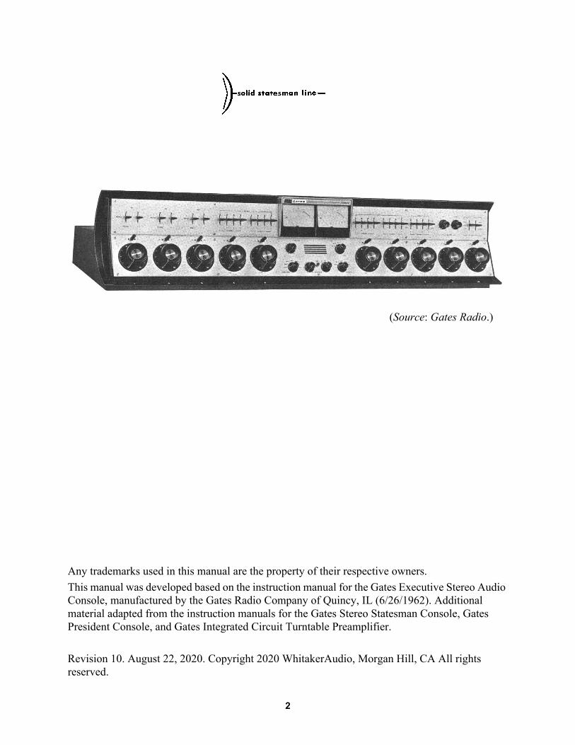
Any trademarks used in this manual are the property of their respective owners.This manual was developed based on the instruction manual for the Gates Executive Stereo Audio Console, manufactured by the Gates Radio Company of Quincy, IL (6/26/1962). Additional material adapted from the instruction manuals for the Gates Stereo Statesman Console, Gates President Console, and Gates Integrated Circuit Turntable Preamplifier.
Revision 10. August 22, 2020. Copyright 2020 WhitakerAudio, Morgan Hill, CA All rights reserved.
(Source: Gates Radio.)

Gates Executive Stereo Audio Console, Volume I
Table of Contents1 Introduction and Overview 7
1.1 Definition of Terms 112 Operation and Features 13
2.1 Channels 1, 2, 3 – Microphone Inputs 142.2 Channels 4 and 5 – Auxiliary Inputs 152.3 Channels 6 and 7, Turntable Inputs 162.4 Channel 8, Remote Inputs 172.5 Channel 9, Network Input 182.6 Channel 10, DAW 182.7 Monitor Input 192.8 Line Amplifier Inputs 202.9 Master Gain Controls 212.10 Cue/Intercom System 222.11 VU Meter Switch 232.12 Headphone Jacks 23
3 Installation 253.1 Recommended Installation Practices 26
3.1.1 Grounding 263.1.2 Balanced and Unbalanced Lines 283.1.3 Circuit Impedances 28
3.2 TB1, Microphone/Line Amplifier Inputs 293.3 TB2, Optional/Breakout Connections 313.4 TB3, Auxiliary, Turntable, and Remote Inputs 323.5 TB4, Program Outputs 343.6 TB5, Ancillary Connections 363.7 TB6, Speaker Connections 383.8 TB7, Studio Warning Lights 423.9 TB8, Power Connections 433.10 System Customization 44
3.10.1 Patch Panel 443.10.2 Muting Relay 443.10.3 Stereo Network Operation 45
4 System Architecture 474.1 Technical Description 48
4.1.1 Attenuator Circuits 494.1.2 VU Meter Operation and Level Matching 524.1.3 Other Implementation Considerations 554.1.4 System Wiring Codes 584.1.5 Pad Component Values 63
5 Gates M-6034 Preamplifier 675.1 Overview and Specifications 685.2 Circuit Description 695.3 Measured Performance 725.4 Connection Details 77
3
Operation and Installation Manual, Table of Contents
5.5 Troubleshooting Guidelines 786 Gates M-5700 Line Amplifier 81
6.1 Overview and Specifications 826.2 Circuit Description 846.3 Measured Performance 88
6.3.1 M-5700 Driver PCB 886.3.2 M-5700 Power Output PCB 926.3.3 M-5700 Composite System 96
6.4 Connection Details 1016.5 Troubleshooting Guidelines 102
7 Gates M-6108A Monitor Amplifier 1057.1 Overview and Specifications 1067.2 Circuit Description 1087.3 Measured Performance 112
7.3.1 Measurement Considerations 1167.4 Connection Details 1187.5 Troubleshooting Guidelines 119
8 Gates M-6035 Cue/Intercom Amplifier 1218.1 Overview and Specifications 1228.2 Circuit Description 1248.3 Measured Performance 1278.4 Connection Details 1318.5 Troubleshooting Guidelines 132
9 Gates M-6205 Power Supply 1359.1 Overview and Specifications 1369.2 Circuit Description 1379.3 Connection Details 1409.4 Troubleshooting Guidelines 141
10 Safety Notice 143
4

Gates Executive Stereo Audio Console, Volume I
PrefaceThis document describes the installation, configuration, and operation of the Executive Stereo Audio Console, manufactured by the Gates Radio Company, Quincy, IL, during the 1960s and 1970s. Volume I focuses on the Executive console in its original, as-built form. Volume II focuses on updates and improvements to the basic design. These updates and improvements maintain the spirit of the original hardware—and in many cases the same circuits—but incorporate modern construction techniques and current components. Volume III focuses on implementation and systems integration issues.
The Executive was the top of the line product at Gates, offering a wide list of features and switching capabilities for the then-emerging field of stereo FM broadcasting. Like most audio consoles of the day, various inputs could be switched into the separate mixing channels and routed to cue, program, and audition circuits. Each served a specific purposes at a radio station. The Executive did all this and whole a lot more. It was intended to serve as a central mixing and control point for a suite of studios that included the control room and two announce booths. A full complement of resources were provided for the announce rooms, including microphone inputs, cue and intercom, monitoring, speaker muting, and “on-air” light control.
With 10 mixing channels, the board was about as large as practical, measuring a full 54-inches across. The series also introduced a very stylish knob, unique to Gates, that is about as ergonomically perfect as possible. The Executive was one of the largest radio consoles made by the company during the rotary pot era. The 1971 list price in Gates catalog #99 was $5,300—making it the most expensive radio console in the book. The next largest board was the Dualux II, another 10 channel mixer, also intended for combined AM/FM stereo operation.
The Executive console has stood the test of time. More than 50 years later, it is still quite functional and sounds great. And, it is arguably the best industrial design of its product class.
Jerry C WhitakerAugust 2020
5

Operation and Installation Manual, Table of Contents
6

Gates Executive Stereo Audio Console, Volume I
Section 1: Introduction and Overview
The Gates Executive Stereo Control Console is a versatile and efficient ten channel audio control center specifically designed for stereo broadcasting. The console provides for the mixing, cueing, and monitoring of a variety of program sources. These sources include microphones, turntables, tape recorders, remote pickups, and network feeds.
Due to the flexibility of the console, other combinations of output feeds are also possible. Provisions are included for the addition of a third output channel so that, simultaneously with the stereo program feed, a compatible mono signal (a combination of the left and right channels) may be fed to another program service. This third channel may also be used to produce a completely different monophonic program stream.
Microphone input switching is arranged so that a single microphone can feed both channels for monophonic announcements, or two microphones can be used for stereo performances. Stereo monitoring of both the Program buss and the Audition buss is provided, as well as an external stereo monitor amplifier input.
The console is completely transistorized and self-contained except for the power transformers, which are placed externally to minimize hum pickup in the console, and the earphone jack panel. Breaking and jumpering of all major circuits allows full use of normal-link jack fields, with all appropriate connections brought out to terminal blocks for ease of installation and future circuit checking. Three speaker muting and warning light relays are supplied, with provisions included for the control of a fourth relay. Compensation of signal levels by the use of fixed pads throughout the console minimizes the necessity of readjusting gain controls when switching from one circuit to another.
The cue-intercom system provides for cueing of turntable and tape sources, as well as intercom facilities between the control room and each of the two studios and remote lines. The cue intercom system is interlocked with the speaker muting relays so that cueing and intercom signals cannot inadvertently disturb normal operation.
7

Operation and Installation Manual, Introduction and Overview
Specifications for the Gates Executive Stereo Control Console are listed in Table 1.1.
An overall block diagram of the console is shown in Figure 1.1. The amplifier complement includes six microphone preamplifiers (three stereo pairs), two line amplifiers, two high fidelity monitoring amplifiers, and a cue/intercom amplifier. Also supplied are two audition booster
Table 1.1 Executive Stereo Control Console SpecificationsParameter SpecificationNominal Gain: Microphone input to line output 102 dB ± 2 dB Microphone input to speaker output 106 dB minimum Turntable input to line output 56 dB ± 2 dB Turntable input to speaker output 64 dB minimum Remote/network to line output 50 dB ± 2 dB Remote/network to speaker output 58 dB minimumFrequency Response (1 kHz reference):
Program circuits (left and right channels) ±1 dB, 30 Hz – 15 kHz at +8 dBm output on all program lines
Auxiliary program circuit ±2 dB, 30 Hz – 15 kHz at +8 dBm output Monitor speaker circuits ±1.5 dB, 30 Hz – 15 kHz in all monitoring speaker circuitsHarmonic Distortion:
Program lines, +8 dBm output
0.5% maximum, 30 Hz – 15 kHz at +8 dBm output on all program lines
0.5% maximum, 50 Hz – 15 kHz at +18 dBm output on all program lines
Monitor amplifier, +38 dBm (8 W) output 1.0% maximum, 50 Hz – 15 kHz on all monitor speaker outputs
Intermodulation Distortion (40 Hz/7 kHz, 4:1):
Program circuits0.5% maximum at +8 dBm equivalent sine wave output1.5% maximum at +18 dBm equivalent sine wave output
Monitor speaker circuits 1.0% maximum at +38 dBm equivalent sine wave outputNoise: Microphone channels −122 dBm relative input noise Turntable channels −75 dBm relative input noise Crosstalk Below noise on all stereo channelsCapabilities: Total number of mixing channels 10
Inputs
6 stereo microphones4 stereo turntables4 stereo auxiliary inputs4 mono remotes1 mono network (can be wired for stereo)1 high level auxiliary stereo input
Outputs
Program leftProgram rightAuxiliary Program3 stereo speaker lines with muting (plus one optional)1 stereo speaker line without muting2 studio intercom speaker lines2 phone jacks
Physical size 53.5 inches long, 11.375 inches high, 17.375 inches deepNet weight = 107 lbs.
8

9
Gates Executive Stereo Audio Console, Volume I
Figure 1.1 Block diagram of the Gates Executive Stereo Audio Console. Note that in the implementation described in this manual, the Turntable inputs appear on Channels 6 and 7, and
the Tape inputs (now relabeled as Auxiliary) appear on Channels 4 and 5. These are labeling changes only; the wiring is the same as shown above. (Source: Gates Radio.)

Operation and Installation Manual, Introduction and Overview
amplifiers, which are part of the internal circuit arrangement. Space is provided for two additional preamplifiers and one additional line amplifier. The power supply is self-contained (except for the external power transformers) and fully regulated. The amplifiers and power supply are completely solid state.
All mixing channels of the Executive console are stereo, except for the network and remote inputs. By adding a third plug-in line amplifier, a compatible “left plus right” signal is available to feed monaural and stereo programming simultaneously.
Additional facilities include dual headphone jacks (optional), a cue/intercom selector switch, left and right channel meters, gain controls for the line amplifiers, a dual monitoring amplifier gain control, and 28 tab keys (the top row) performing a large number of switching functions. Three muting relays are supplied to mute three pairs of loudspeakers. A fourth relay is available for custom applications. Warning light contacts are also provided. These relays operate from the microphone keys and cue/intercom system.
Exclusively styled by one of America’s leading industrial designers, the Executive’s satin anodized aluminum control panel floats in a 3-dimensional setting. The “shadow mold” styling is strikingly modern in appearance. The front panel hinges down and the cabinet top cover hinges up for service access. Owing to the all-transistor design, ventilation of the cabinet is not necessary.
The Executive console measures 53.5 inches long, 11.375 inches high, 17.375 inches deep. The side profile of the console is shown in Figure 1.2. The recommended cable access holes for the console cabinet are shown in Figure 1.3. As shown, two rectangular openings are used for cable access to the console desk. Optionally, the console may by elevated with 8 mounting feet to raise the console above the desk, allowing wiring access between the desk and the console.
External cables exit the bottom of the console via a series of round cutouts measuring 0.9-inches in diameter. The edges of the holes are rounded to as to prevent wire chafing.
4516"
618"
11916"
1'-5516"
1'-0516"
Figure 1.2 Executive console side profile with dimensions.
10

Gates Executive Stereo Audio Console, Volume I
1.1 Definition of TermsThe following terms are used in this manual.ABx – Audio booster preamplifier (number). Two audio booster preamplifiers are used: AB1
(Audition left channel monitor) and AB2 (Audition right channel monitor)ALx – Audio line amplifier (number). Three audio line amplifiers are used: AL1 (Left channel line
output), AL2 (Audition channel line output), and AL3 (Right channel line output).AMx – Audio monitor amplifier (number). Two audio monitor amplifiers are used: AM1 (Left
channel monitor amplifier) and AM2 (Right channel monitor amplifier).APx – Audio preamplifier (number). Eight audio preamplifiers are used: AP1 through AP6
(microphone inputs), and AP7 and AP8 (special purpose applications).AQx – Audio cue amplifier (number). One audio cue amplifier is used: AQ1 (intercom/cue
system).ATx – Audio attenuator (number). There are a variety of audio attenuators in the console: AT1
through AT10 are variable attenuators (Channel 1 through Channel 10 faders) while all other attenuators are fixed.
DAW – Digital Audio Workstation.PCB – Printed circuit board.PSx – Power supply (number). One power supply is used: PS1, the main console power supply (–
37 V dc and –30 V dc regulated).RF – Radio FrequencyRU – Rack Unit
Figure 1.3 Executive console cable access.
11

Operation and Installation Manual, Introduction and Overview
TBx – Terminal board (number). Eight terminal boards are used: TB1 through TB6 for all input/output signals, TB7 for warning light connections, and TB8 for power.
VU – Volume Unit.WL – Warning (On Air) light.Additional terms are defined as needed in the sections that follow.
In the sections that follow, a different font (e.g., TB1) is used to identify components in the Executive audio console and sub-systems.
12

Gates Executive Stereo Audio Console, Volume I
Section 2: Operation and Features
The basic operation of the Gates Executive Stereo Audio Console is detailed in the following sections. The arrangement of panel controls provides maximum versatility for console configuration while keeping actual operation as simple as possible.
The mixing system contains 10 channels, all with dual (stereo) controls. Channels 1, 2, and 3 are for microphones. Channels 4 and 5 will accept four stereo auxiliary sources in any combination, while Channels 6 and 7 accommodate four stereo turntable inputs. Channel 8 handles four remote lines, and Channels 9 and 10 are network and auxiliary channels, respectively. Channels 4 through 10 are all cueing attenuators, which feed the cue/intercom system.
Stereo only, or monaural only, programming may be fed to either Program or Audition mixer circuits.
Dual 4-inch illuminated meters are provided. The left meter is permanently connected to the left channel output, while the right meter may be switched among several inputs. During normal operation, the right meter is connected to the right channel output. The right meter also may be switched to a calibration mode for balancing output levels for stereo operation.
13

Operation and Installation Manual, Operation and Features
2.1 Channels 1, 2, 3 – Microphone InputsSix preamplifiers in three stereo pairs are connected to dual-position input selector keys, permitting 12 microphones (6 stereo pairs) to be selected.
Figure 2.1 shows the layout of the front panel microphone inputs. On the upper left side of the panel, above channel mixers 1, 2, and 3, are three pairs of switches. These switches perform identical functions for each channel. The microphone selector is used to switch between two sets of stereo microphones in each studio. With the MONO/STEREO switch in the STEREO position, the left and right microphones are routed to the left and right Program buss when the proper Channel key is moved to the right. These same microphones are routed to the left and right Audition buss when the Channel key is moved to the left.
If the MONO/STEREO switch is placed in the MONO position, the left microphone will feed both left and right Program or Audition busses when the Channel key is placed in the Program or Audition position. This allows announcements to be made on both channels while broadcasting stereo from other microphone combinations.
Figure 2.1 Executive console microphone inputs.
14

Gates Executive Stereo Audio Console, Volume I
2.2 Channels 4 and 5 – Auxiliary InputsFour auxiliary sources may be switched to Channels 4 and 5. All faders are stereo, and cue positions are provided on each attenuator.
Figure 2.2 shows the layout of the front panel auxiliary inputs. The four input switches, above Channels 4 and 5, select the desired input to each mixer. When the channel switches above mixer 4 are in the OFF position, auxiliary inputs are normalled through to the Channel 5 switches. When any of the switches in Channel 4 are switched ON, the auxiliary input will appear at the output of Channel 4. Moving the Channel 4 mixer key to the right wil1 bring up the auxiliary input on the left and right Program buss, while moving the mixer key to the left will switch the signal to the left and right Audition buss.
Moving the desired auxiliary input switch to the ON position, above Channel 5, will switch the desired input into this mixer. Switching is arranged so that an auxiliary input cannot be switched into Channel 5 if it is already switched into Channel 4. This prevents loading the auxiliary output by paralleling it into two console inputs.
Cueing facilities are provided for by turning either mixer fader fully counter-clockwise. This connects the auxiliary inputs to the cue/intercom amplifier. Cueing can be accomplished by using the panel-mounted speaker or headphones plugged into the external cue phono jack. The operation of the cue/intercom system is discussed later in this manual.
Figure 2.2 Executive console auxiliary inputs.
15

Operation and Installation Manual, Operation and Features
2.3 Channels 6 and 7, Turntable InputsFour turntable sources may be switched into Channels 6 and 7 in any sequence. All faders are stereo, and cue positions are provided on each attenuator.
Figure 2.3 shows the layout of the front panel turntable inputs. Channels 6 and 7, located to the right of the VU meters, are identical in operation to the auxiliary inputs discussed previously. Four stereo inputs can be switched to either Channels 6 or 7. The outputs of Channels 6 and 7 can be switched to the Program or Audition buss. Cueing facilities are provided for by turning mixer 6 or 7 fully counter-clockwise, thus, connecting the mixer to the cue/intercom system.
Figure 2.3 Executive console turntable inputs.
16

Gates Executive Stereo Audio Console, Volume I
2.4 Channel 8, Remote InputsFour remote lines may be switched into Channel 8 through a built-in line isolation transformer. The channel is stereo equipped, but has a splitting pad for monophonic input signals. A cue position is provided on the attenuator.
Figure 2.4 shows the layout of the remote inputs. Four lever switches, located above Channel 8, control the four remote inputs. The remote switches provide talkback and cueing facilities to the remote operator, as follows:
• CUE (center) position: The remote receives the program cue signal from the monitoring amplifier (left channel). The level is set at approximately +8 dBm. This level is determined by the setting of the monitor volume control.
• MIX (lower) position: The remote program is switched into the Program or Audition buss through Channel 8.
• TB (upper) position: A terminating load is applied to the remote line with the provision for override and talkback functions. (See the “Cue/Intercom System” section for an explanation of these functions.)
The remote lines are not tied together when any or all of the remote keys are in the talkback position. There is sufficient isolation between them even with the override tie-in on all lines.
A typical sequence of operation for a remote broadcast is as follows:
• Before air time, the studio operator places the appropriate remote line switch in the TB position, and the cue/intercom input selector switch to the REMOTE position.
• The remote operator arrives at the broadcast site and calls-in on the remote line.
• The studio operator hears the call and is able to talk back via the cue/intercom system.
• After preliminary coordination, the remote input switch is placed in the CUE position.
• When the remote operator receives the cue, the remote input switch is moved to the MIX position and the remote signal is brought up on Channel 8.
An alternate method of operation, before contact is established with the remote operator, is to place the appropriate remote input switch in the MIX position and the Channel 8 mixer in the CUE position. This allows the remote operator to call in and be heard. After the call is heard, the remote switch is placed in the TB position and the cue/intercom input selector to the REMOTE position, and the above procedure is followed. Figure 2.4 Executive console
remote inputs.
17

Operation and Installation Manual, Operation and Features
2.5 Channel 9, Network InputChannel 9 is for a mono network input. The channel can be modified for stereo operation, if needed.
The network input is connected directly to Channel 9 and is put in use by placing the mixer key to the Program or Audition position and turning up the mixer gain control. Preview monitoring of the network is provided by turning the mixer control fully counter-clockwise into the CUE position. The network can then be monitored with the intercom input switch in any position. If it is desired to monitor the network with the mixer turned up and ready for use, the intercom input switch should be set to the NET position, allowing the network to be heard in the cue/intercom system.
The nominal input level for the Network channel is –10 dBm, 600 Ω, balanced, when the channel is configured for mono inputs; for stereo, the nominal input level is –20 dBm.
2.6 Channel 10, DAWChannel 10 has dual line isolation transformers and is uniquely equipped to accommodate the output of a computer or digital audio workstation (DAW). A cue position is provided on this fader. Channel 10 is a stereo channel with the input connected directly into the mixer key switch.
18

Gates Executive Stereo Audio Console, Volume I
2.7 Monitor InputLayout of the center control panel is shown in Figure 2.5.
The monitor input selector is located on the lower center of the panel. Input switching allows stereo monitoring of Program, Audition, or an external (EXT) signal source. The gain of both the left and right monitor amplifiers is adjusted by the gain control located to the left of the monitor input selector.
Figure 2.5 Executive console center control panel, which includes monitor, VU meter, and cue/intercom functions.
19

Operation and Installation Manual, Operation and Features
2.8 Line Amplifier InputsThe inputs to line amplifiers 2 and 3 are selected by the two switches in the upper right corner of the panel. See Figure 2.6. Only the inputs to amplifiers 2 and 3 are switch-selected; line amplifier 1 is fed from the left Program buss at all times.
For stereo broadcasting, the line amplifier 3 (AL3) input is switched to the STEREO position This connects the right Program buss into line amplifier 3; the left and right stereo output will thus appear at the outputs of line amplifiers 1 and 3, respectively.
If it is desired to feed the same program to lines 1 and 3 simultaneously, the AL3 input switch is placed in the upper SIMUL position. In this position, the signal on the left Program buss will appear at both the line 1 and 3 outputs.
Placing the AL3 input switch in the center AUD L position connects the line amplifier 3 input to the left Audition buss. This enables the console to be operated as a dual channel console, with line 1 being fed from the left Program buss and line 3 being fed from the left Audition buss. Stereo programs cannot be broadcast when the console is operated in this manner.
Provisions are included for the addition of a third line amplifier to feed the line 2 output (AL2). With this module in place, the versatility of the console is greatly increased. The AL2 input switch selects the desired function. In the L+R position, a compatible monophonic signal is available at the output of line amplifier 2. This allows broadcasting a compatible monophonic signal on line 2 while a stereo program is carried on lines l and 3.
With the AL2 input switch in the AUD L position, the line amplifier is connected to the left Audition buss. This allows a completely different monaural signa1 to be carried while stereo is being broadcast on line amplifiers 1 and 3. When the AL2 input switch is placed in the SIMUL position, the signal on the left Program buss will appear simultaneously at both the line 1 and 2 outputs.
It is evident that several possible operational setups are possible. Stereo can be broadcast on line 1 and 3 with a compatible (L+R) signal on line 2, or a completely independent program can be handled on line 2 through the Audition buss. All three lines can handle the same program material, or the console can be used as a dual-channel system, handling two separate programs into two or three lines.
Figure 2.6 Executive console line amplifier (AL) inputs.
20

Gates Executive Stereo Audio Console, Volume I
2.9 Master Gain ControlsThe gain controls for line amplifiers 1 (left) and 3 (right) are located on the upper right side of the panel. See Figure 2.7. The gain control for the optional line amplifier (AL2) is located on the amplifier module itself and is accessible at the right end of the amplifier when the console cover is raised. Signal levels in the console are adjusted with the input channel mixers so that the line amplifier control should not need adjustment after being initially set to match the output levels of lines l and 3.
Once the gain of line amplifier 1 (left channel) has been adjusted to the desired level, inter-channel (left/right) balance can be set using the channel balance lever switch (S44) located inside to the left of the console monitor speaker on the hinged control panel. With S44 in the NULL position, VU meter #2 is connected across the left and right channels to display the difference in signal levels between channels. Adjust the level of line amplifier 3 (right master gain control) until VU meter #2 nulls. This indicates there is no difference in level between channels, and thus the left and right channels are balanced. It should be obvious that a monophonic source must be used when balancing the stereo channels, since a stereo source seldom has the same levels simultaneously on left and right channels. For best results, use a 1 kHz tone. The balance circuit is capable of matching the left and right channel outputs to within about ±0.25 dB.
When the balancing procedure is completed, S44 should be returned to the NORMAL position.
Figure 2.7 Executive console master gain controls.
21

Operation and Installation Manual, Operation and Features
2.10 Cue/Intercom SystemControls for the cue/intercom amplifier are located below the VU meters, as shown in Figure 2.8. The top control is gain and it sets the level for both the Talk and Listen functions. Below the level control is the cue/intercom input selector switch, which has 6 positions. In the NET position, the network line (Channel 9) can be monitored. Talkback is not possible in the network position. The remote 1, 2, 3, and 4 (RM 1, RM 2, RM 3, and RM 4) positions tie the cue-intercom amplifier to the 1, 2, 3, or 4 remote lines. For talkback facilities, the intercom selector is switched to the desired remote line and the appropriate remote input switch is placed in the TB position. The incoming remote signal line will then be heard in the panel-mounted speaker. When the control room operator desires to talk out on the remote line, the red TALK button in the center of the panel is pressed and the operator speaks into the panel speaker. The ST 1 and ST 2 positions allow listening and talk-back into Studios 1 and 2 (if intercom units have been installed in them).
Level are adjusted so that normal 1istening volume will provide sufficient gain for talkback purposes. The system is quite sensitive and allows a conversational volume to be used for communications.
Turntable and tape cueing circuits are connected directly to the input of the cue/intercom amplifier and may be used regardless of the position of the cue/intercom input selector.
The intercom speaker on the console is configured to mute when the Channel 3 lever key is operated. This muting does not disable the cue phone jack, so it is still possible to cue a record by monitoring the cue circuit with headphones. This jack is labeled CUE. The intercom speaker is interlocked with the headphone jack, so that the speaker is muted whenever a phone plug is inserted in the CUE jack. (Note that the cue phone jack and monitor phone jack are mounted on an optional, separate panel external to the console.)
The studio intercom speakers are muted with the regular speaker muting relays so that it is impossible to talk-back to a studio when the microphone channel is switched to either the Program buss or the Audition buss. This interlocking feature makes it impossible to disturb the program or the console operator by using the intercom system.
Figure 2.8 Executive console cue/intercom controls.
22

Gates Executive Stereo Audio Console, Volume I
2.11 VU Meter SwitchVU meter #1 is not switched but rather is connected permanently across the output of line amplifier 1. VU meter #2 is switched by the control directly beneath it. (See Figure 2.7.) VU meter #2 may be used to monitor the level of output lines 1 (AL 1), 2 (AL 2), or 3 (AL3), as well as the incoming network line (NET). A utility position (UTIL) is also furnished to allow the panel-mounted meter to monitor an external circuit.
2.12 Headphone JacksThe headphone jack labeled LINE is provided for headphone monitoring of all output program circuits. Phones can be connected to the desired circuit by the switch labeled PHONES. (See Figure 2.7.) The STEREO position provides monitoring of the stereo program on lines 1 and 3. Stereo headphones with balanced, separated inputs must be used. Switch positions marked AL 1, AL 2, and AL 3 provide monophonic monitoring of the outputs of line amplifiers 1, 2, and 3, respectively. The NET position allow monitoring the incoming network line (Channel 9).
The jack labeled CUE allows monitoring the cue/intercom system with headphones, if desired.The cue/intercom phone jack and monitor phone jack are mounted on an optional separate
panel external to the console.
23

Operation and Installation Manual, Operation and Features
24
Gates Executive Stereo Audio Console, Volume I
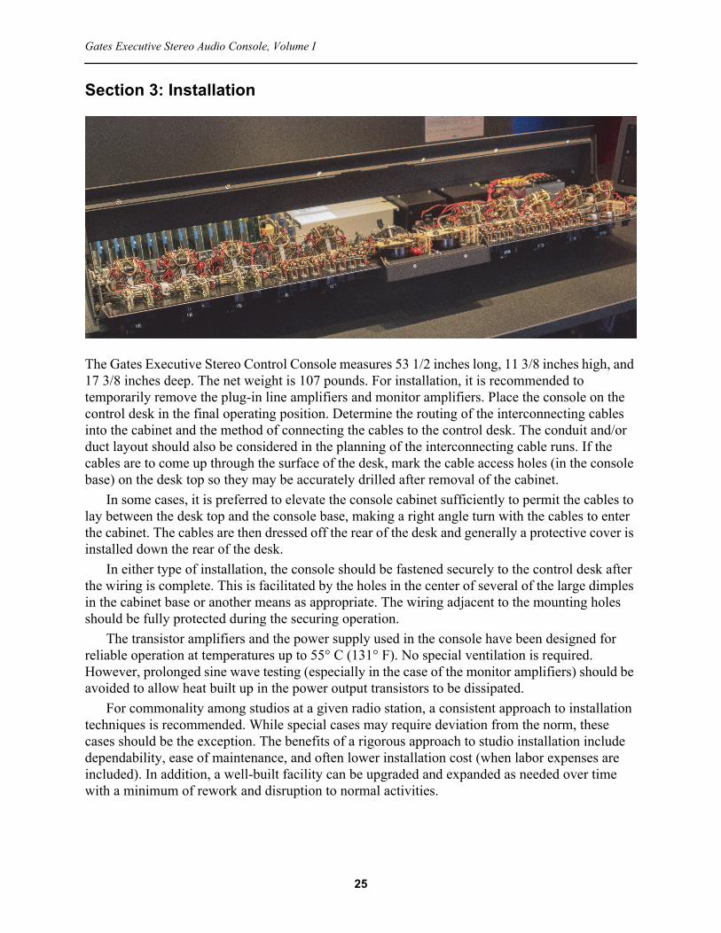
Section 3: Installation
The Gates Executive Stereo Control Console measures 53 1/2 inches long, 11 3/8 inches high, and 17 3/8 inches deep. The net weight is 107 pounds. For installation, it is recommended to temporarily remove the plug-in line amplifiers and monitor amplifiers. Place the console on the control desk in the final operating position. Determine the routing of the interconnecting cables into the cabinet and the method of connecting the cables to the control desk. The conduit and/or duct layout should also be considered in the planning of the interconnecting cable runs. If the cables are to come up through the surface of the desk, mark the cable access holes (in the console base) on the desk top so they may be accurately drilled after removal of the cabinet.
In some cases, it is preferred to elevate the console cabinet sufficiently to permit the cables to lay between the desk top and the console base, making a right angle turn with the cables to enter the cabinet. The cables are then dressed off the rear of the desk and generally a protective cover is installed down the rear of the desk.
In either type of installation, the console should be fastened securely to the control desk after the wiring is complete. This is facilitated by the holes in the center of several of the large dimples in the cabinet base or another means as appropriate. The wiring adjacent to the mounting holes should be fully protected during the securing operation.
The transistor amplifiers and the power supply used in the console have been designed for reliable operation at temperatures up to 55° C (131° F). No special ventilation is required. However, prolonged sine wave testing (especially in the case of the monitor amplifiers) should be avoided to allow heat built up in the power output transistors to be dissipated.
For commonality among studios at a given radio station, a consistent approach to installation techniques is recommended. While special cases may require deviation from the norm, these cases should be the exception. The benefits of a rigorous approach to studio installation include dependability, ease of maintenance, and often lower installation cost (when labor expenses are included). In addition, a well-built facility can be upgraded and expanded as needed over time with a minimum of rework and disruption to normal activities.
25

Operation and Installation Manual, Installation
3.1 Recommended Installation PracticesCable and conduit layout is of utmost importance in the studio installation. Good results, with a minimum of noise and crosstalk, requires careful planning and construction. A system hastily installed, without thorough planning, invariably results in continuous trouble until rebuilt.
First, the matter of signal levels must be considered. Cables should be divided into four main groups:
• Low level, which typically includes signal levels from −60 dBm to −40 dBm. This group encompasses all microphone cables.
• Medium level, which typically includes signal levels from −20 dBm to +8 dBm. This group encompasses line level input and output cables.
• High level, which typically includes signal levels at +15 dBm and higher. This group encompasses speaker output cables and other high-level signal cables.
• AC power, which typically includes ac line voltages. This group encompasses primary power for the console power transformers, the three 28 V ac supply lines from the power transformers to the console, and the switched “on air” lamps.
Do not run any of the four cable groups listed above in a conduit along with cables of a different level classification. Use high-quality shielded twisted pair (STP) cable for all audio wiring. Minimize cable lengths, particularly for low-level signals. Be very careful to avoid ground loops, which may result from a single device being grounded via more than one path.
In the event of parallel cable runs of different levels, the most important aid is physical isolation. Up to six inch spacing is preferred. If there is insufficient room for this level of isolation, keep the cables laced separately for the different level classifications, even if two or more must lay together. This will give much better isolation than when formed into a single cable. Deviations from the preferred installation methods must not be taken lightly; use them only as a last resort, not just for convenience.
Terminal layout is arranged in the console to allow adequate separation of cables up to the point of connecting to the terminal blocks. Low-level microphone cables connect on the left to TB1. Medium level cables connect in the center to TB2–TB5. High level cables connect to TB6 (in the rear). Intercom wiring connections are brought out to TB6 since these are auxiliary circuits, which may vary in level from −50 dBm to +28 dBm. The speaker output cables are high level and should not be run with low-level cables.
Conduit generally affords enough shielding so that different signal levels carried in separate conduit presents no isolation problem, even without physical separation of the conduit. Microphone-level conduit and speaker-level conduit can probably run along together with no crosstalk. However, if practical, it is advisable to maintain physical separation, which may eliminate problems in certain situations.
Power circuits, especially those carrying high current, should not be in close proximity to signal-carrying conduit, as electromagnetic shielding is poor in most conduit.
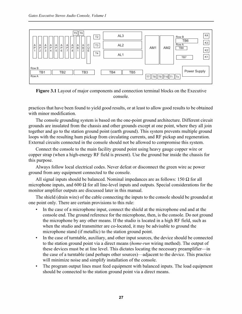
The overall arrangement of connection points and amplifier modules is shown in Figure 3.1.
3.1.1 GroundingCircuit grounding, like cable layout and certain systems work methods, is usually (but not always) predictable. With regard to grounding, hard and fast rules do not necessarily apply 100% of the time. In this section we attempt to cover the things to avoid and to present generally accepted
26
Gates Executive Stereo Audio Console, Volume I
practices that have been found to yield good results, or at least to allow good results to be obtained with minor modification.
The console grounding system is based on the one-point ground architecture. Different circuit grounds are insulated from the chassis and other grounds except at one point, where they all join together and go to the station ground point (earth ground). This system prevents multiple ground loops with the resulting hum pickup from circulating currents, and RF pickup and regeneration. External circuits connected in the console should not be allowed to compromise this system.
Connect the console to the main facility ground point using heavy gauge copper wire or copper strap (when a high-energy RF field is present). Use the ground bar inside the chassis for this purpose.
Always follow local electrical codes. Never defeat or disconnect the green wire ac power ground from any equipment connected to the console.
All signal inputs should be balanced. Nominal impedances are as follows: 150 Ω for all microphone inputs, and 600 Ω for all line-level inputs and outputs. Special considerations for the monitor amplifier outputs are discussed later in this manual.
The shield (drain wire) of the cable connecting the inputs to the console should be grounded at one point only. There are certain provisions to this rule:
• In the case of a microphone input, connect the shield at the microphone end and at the console end. The ground reference for the microphone, then, is the console. Do not ground the microphone by any other means. If the studio is located in a high RF field, such as when the studio and transmitter are co-located, it may be advisable to ground the microphone stand (if metallic) to the station ground point.
• In the case of turntable, auxiliary, and other input sources, the device should be connected to the station ground point via a direct means (home-run wiring method). The output of these devices must be at line level. This dictates locating the necessary preamplifier—in the case of a turntable (and perhaps other sources)—adjacent to the device. This practice will minimize noise and simplify installation of the console.
• The program output lines must feed equipment with balanced inputs. The load equipment should be connected to the station ground point via a direct means.
Figure 3.1 Layout of major components and connection terminal blocks on the Executive console.
TB1 TB2 TB3 TB4 TB5
TB6AL3
AL2
AL1
AM1 AM2
Power SupplyRow B
Row A
T5 T6T2
T3
T4
T7 T8 T9
K4
K3
K2
K1
TB8
TB7
Row B
Row A
T10 T1 T
27

Operation and Installation Manual, Installation
• For systems that include a patch panel, each shield ground wire is typically carried through the individual patch points. Special considerations may apply, however, depending on the circuit configuration.
To prevent ground loops, all wiring connected to the console must be free from ground connections in the source and load equipment (microphones, turntables, tape players, recorders, speakers, etc.). An ohmmeter check is recommended to be certain that each wire is not grounded before connecting it to the console. If any source or load equipment has a grounded connection wire (an unbalanced source), an isolating transformer must be used between that equipment and the console.
A final ohmmeter check is recommended. After all system connections are made, remove all power from the console and from the devices that feed the console. Then, temporarily disconnect the station ground from the console and measure the resistance (ohms) from the console ground stud to the station ground. A very high resistance is normal; a low reading indicates a ground loop. All ground loops must be eliminated before operating the console. Be sure to reattach the station ground to the console after testing.
A thorough examination of grounding practices is beyond the scope of this manual.1
For all signal wiring, the red (+) wire connects to the “A” terminal block row and the black wire (–) connects to the “B” terminal block row.
3.1.2 Balanced and Unbalanced LinesIf a circuit is ungrounded, it is considered balanced to ground. If one side is grounded, it is unbalanced. If the circuit is center-tap grounded through the use of a pad or transformer, it is balanced to ground.
If it is necessary to connect a balanced line to an unbalanced line, or vice-versa, an isolation transformer should be used between them. For broadcast applications, the transformer must provide good balance, including an electro-static shield, and provide magnetic shielding sufficient to reduce the hum pickup to at least 70 dB below the nominal signal level. Impedance taps on the primary and secondary may be necessary to properly match both circuits.
Balanced lines require balanced pads and attenuators, while unbalanced lines require unbalanced ones. Mixing these types generally results in poor performance.
3.1.3 Circuit ImpedancesThe microphone inputs are factory connected for 150 Ω. These are balanced inputs. The turntables and tape inputs are 600 Ω unbalanced. These impedances cannot be changed in the console. If other impedances are desired, a matching pad or an isolation transformer must be used. If a matching pad is used it should be unbalanced, with the common side connected to the common or grounded side of the inputs.
1. A number of reference books are available that discuss grounding practices in detail. One such book is: Jerry C. Whitaker: AC Power Systems Handbook, 3rd ed., CRC Press, Boca Raton, FL, 2007. See also: Section 6, “Facility Issues,” in SBE Broadcast Engineering Handbook, Jerry C. Whitaker (ed.), McGraw-Hill, New York, NY, 2016.
28

Gates Executive Stereo Audio Console, Volume I
3.2 TB1, Microphone/Line Amplifier InputsTable 3.1 lists the wiring codes for the TB1 microphone and line amplifier connections. In all cases, the red wire goes to the “A” terminal and the black wire goes to the “B” terminal. In this table, and the tables that follow in this section, a column is provided so that the wire number of the source equipment cable can be documented efficiently.
The microphone inputs are balanced 150 Ω inputs and the external circuit should not be grounded.
It is important in stereo broadcasting that the left and right program sources be in the correct phase in order to maintain the proper sound perspective. This fact must be taken into account when connecting inputs to the stereo console. Color coding of microphone cables and connector pin numbering should be noted and the same lead connected from each microphone to the corresponding terminal on TB1 for each channel.
Each microphone channel has provisions for two stereo microphone combinations, or a total of four microphones per channel. Switching between combinations, or from stereo to monaural, is done from the front panel as follows:
• Channel 1 − With S9 in the MIC 1 position and S12 in the STEREO position, the console is set up for stereo broadcasting from microphones connected to TB1 terminals 1 and 2. With S12 in the MONO position, the signal from microphone input 1 is fed through both preamplifiers so that both left and right channels will carry the same signal. Moving S9 to the MIC 2 position switches the microphones connected to TB1 terminals 3 and 4 into the Channel 1 preamplifiers. The function of S12, the mono/stereo switch, remains the same, with microphone 3 feeding both the 1eft and right channe1s (when S12 is placed in the MONO position). Channel 1 microphones should be located in the same studio as the
Table 3.1 Pinout for Terminal Block #1 (Low Level Inputs)TB1 Internal Wire No. Function External Connection Notes1 115 Microphone 1 Left Input2 103 Microphone 1 Right Input3 107 Microphone 2 Left Input4 102 Microphone 2 Right Input5 114 Microphone 3 Left Input6 116 Microphone 3 Right Input7 105 Microphone 4 Left Input8 109 Microphone 4 Right Input9 112 Microphone 5 Left Input10 108 Microphone 5 Right Input11 111 Microphone 6 Left Input12 104 Microphone 6 Right Input13 110 Program Buss Left Output
Jump TB1-13 to TB1-1414 89 AL1 Line Amplifier Input15 100 S36 Output (line amplifier input)
Jump TB1-15 to TB1-1616 88 AL2 Line Amplifier Input17 113 S37 Output (line amplifier input)
Jump TB1-17 to TB1-1818 87 AL3 Line Amplifier Input19 101 Audition Buss Output
Jump TB1-19 to TB1-2020 97 AB1 Input
29

Operation and Installation Manual, Installation
speakers that are muted when the Channel 1 lever (Program/Audition) switch is operated. (See Section 3.7, “TB6, Speaker Connections.”)
• Channel 2 − Microphone arrangements for Channel 2 are the same as for Channel 1. The switching functions of S10 and S13 are the same as S9 and S12, respectively (as explained above). Channel 2 microphones should be located in the same studio as the speakers that are muted when the Channel 2 lever key is operated.
• Channel 3 −Switches S11 and S14 perform the same functions as S9 and S12, respectively (as explained above). Channel 3 microphones should be in the same studio as the speakers that are muted when the Channel 3 lever switch is operated.
Figure 3.2 is an illustration of the microphone connection block.In addition to microphone inputs, TB1 includes inputs for the three line amplifiers. For normal
operation, jumpers are installed as shown in Table 3.1.
Figure 3.2 Microphone connections for TB1. (Source: Gates Radio.)
30

Gates Executive Stereo Audio Console, Volume I
3.3 TB2, Optional/Breakout ConnectionsTable 3.2 lists the wiring codes for the TB2 optional/breakout connections. In all cases, the red wire goes to the “A” terminal and the black wire goes to the “B” terminal.
TB2 provides the means to customize the microphone preamplifiers and the Channel 1, 2, and 3 inputs. The preamplifier outputs—and in the case of optional preamplifiers 7 and 8, inputs and output—are available at TB2. For normal operation, the jumpers shown in Table 3.2 are installed. For custom applications, some or all of these connections may be brought out to an external patch panel.
Table 3.2 Pinout for Terminal Block #2TB2 Internal Wire No. Function External Connection Notes1 109 Audition Buss Output
Jump TB2-1 to TB2-22 98 AB2 Input3 - Not Used4 - Not Used5 176, 166 AP1 Preamplifier Output
Jump TB2-5 and TB2-66 169, 166 Channel 1 Input, Left7 177 AP2 Preamplifier Output
Jump TB2-7 and TB2-88 170 Channel 1 Input, Right9 178, 167 AP3 Preamplifier Output
Jump TB2-9 and TB2-1010 171, 167 Channel 2 Input, Left11 179 AP4 Preamplifier Output
Jump TB2-11 and TB2-1212 172 Channel 2 Input, Right13 180,168 AP5 Preamplifier Output
Jump TB2-13 and TB2-1414 173, 168 Channel 3 Input, Left15 181 AP6 Preamplifier Output
Jump TB2-15 and TB2-1616 174 Channel 3 Input, Right17 250 AP7 Preamplifier Input18 251 AP7 Preamplifier Output19 252 AP8 Preamplifier Input20 253 AP8 Preamplifier Output
31

Operation and Installation Manual, Installation
3.4 TB3, Auxiliary, Turntable, and Remote InputsTable 3.3 lists the wiring codes for the TB3 auxiliary, turntable, and remote connections. In all cases, the red wire goes to the “A” terminal and the black wire goes to the “B” terminal.
Inputs to the turntable and auxiliary channels should not be grounded externally. Isolation transformers may be used, if necessary, to isolate external grounds or to connect inputs that should not be grounded via the unbalanced console inputs. It is recommended that turntable preamplifiers and auxiliary sources provide a transformer-balanced output. If the source output is unbalanced, the common side should be connected to the common side of the input terminals (row B) on TB3.
As with microphone inputs, proper polarity of the turntable preamps and auxiliary sources must be observed to ensure that the right and left channel signals have the proper phase relationship. In the case of the turntable preamp, this requires checking of all the wiring, from the stereo pickup through the preamp to the console, for proper connections. Proper phasing of a stereo source can be confirmed by placing the input into the CUE position. If the vocals, or other primary elements of the mix disappear, then a phasing issue exists.
Provision are made for four stereo auxiliary inputs, each of which can be switched to Channels 4 or 5. Auxiliary inputs are medium level (−20 dBm) 600 Ω unbalanced.
Four stereo turntable inputs are provided, switchable between Channels 6 and 7. These are medium-level 600 Ω unbalanced inputs.
Although the console is intended to handle 4 turntables and 4 auxiliary sources, more than this number of turntables may be used by connecting those sources to auxiliary inputs and switching them into Channels 4 and 5. Of course, one or more of the auxiliary inputs must be sacrificed. In the same manner, more than 4 auxiliary inputs can be obtained by using turntable inputs and
Table 3.3 Pinout for Terminal Block #3 (Medium Level Inputs)TB3 Internal Wire No. Function External Connection Notes1 159 Auxiliary 1 Left Input2 158 Auxiliary 1 Right Input3 157 Auxiliary 2 Left Input4 156 Auxiliary 2 Right Input5 155 Auxiliary 3 Left Input6 154 Auxiliary 3 Right Input7 153 Auxiliary 4 Left Input8 152 Auxiliary 4 Right Input9 151 Turntable 1 Left Input10 150 Turntable 1 Right Input11 149 Turntable 2 Left Input12 148 Turntable 2 Right Input13 147 Turntable 3 Left Input14 146 Turntable 3 Right Input15 145 Turntable 4 Left Input16 144 Turntable 4 Right Input17 134 Remote Line 1 Input18 135 Remote Line 2 Input19 136 Remote Line 3 Input20 137 Remote Line 4 Input
32

Gates Executive Stereo Audio Console, Volume I
bringing the additional aux sources into Channels 6 and 7. In this case, one or more turntable inputs will be sacrificed. Of course, not all the auxiliary or turntable inputs need be used.
Provisions are made for the connection of four remote lines to Channel 8. These are medium-level 600 Ω balanced monophonic inputs. It is suggested that, rather than connect the remote lines directly to the console, they be brought out to jacks in the studio patch panel to allow greater versatility in operation. External circuits should not be grounded. The input level of these lines should be about –10 dBm. This allows the use of isolation pads or equalizers and still have sufficient gain for proper operation.
33

Operation and Installation Manual, Installation
3.5 TB4, Program OutputsTable 3.4 lists the wiring codes for the TB4 line output connections. In all cases, the red or white wire goes to the “A” terminal and the black wire goes to the “B” terminal.
The program output lines are nominally +8 dBm, 600 Ω. They should be routed carefully to prevent crosstalk back into low level input circuits.
• Connect output line 1 (left channel) to TB4-13A and TB4-l3B• Connect output line 2 (audition channel) to TB4-l4A and TB4-l4B• Connect output line 3 (right channel) to TB4-15A and TB4-15BObserve correct phase relationship between output lines to insure proper stereo perspective
between the left and right channe1s.Line amplifier outputs and console returns are provided on TB4, as shown in Table 3.4. For
normal operation, install the jumpers as shown.VU meter #1 is not switched but is connected permanently across the output of line 1. VU
meter #2 may be used to monitor the level of output lines 1, 2, or 3, as well as the incoming Network line. For monitoring, the Network input should be connected to TB4-16A and TB4-16B (balanced input). An additional Utility input is provided at TB4-17A and TB4-17B. For the Network and Utility VU meter inputs, an input level of +8 dBm results in a reading of 0 VU on the right channel VU meter.
The VU meters are set to read 0 VU with an input level of +14 dBm. With the 6 dB isolated pads in the output of each line, this setting gives the standard +8 dBm level on the outgoing lines. This level can be changed by modifying the pads on the rear of each meter. These pads are marked AT21 and AT23.
Table 3.4 Pinout for Terminal Block #4 (High Level Outputs)TB4 Internal Wire No. Function External Connection Notes1 162 AB1 Output
Jump TB4-1 and TB4-22 142 Console Return3 163 AB2 Output
Jump TB4-3 to TB4-44 143 Console Return5 30 Channel 5 Remote Start Optional feature, see the text6 31 Channel 6 Remote Start Optional feature, see the text7 71 AL1 Line Amplifier Output
Jump TB4-7 and TB4-88 121 AL1 Console Return9 70 AL2 Line Amplifier Output
Jump TB4-9 and TB4-1010 122 AL2 Console Return11 69 AL3 Line Amplifier Output
Jump TB4-11 and TB4-1212 123 AL3 Console Return13 124 Output Line 1, Left Channel14 125 Output Line 2, Audition15 126 Output Line 3, Right Channel16 164 Network VU Monitor Input17 165 Utility VU Monitor Input18 37 External cue high-fidelity signal output Optional feature, see the text
19 35 K4 auxiliary contacts for external cue high-fidelity output mute Optional feature, see the text
20 - Not Used
34

Gates Executive Stereo Audio Console, Volume I
The line amplifier input switches allow routing the output of line amplifier 1 into line amplifiers 2 and 3. Pads AT12, AT13, and AT14 adjust the signal to a level comparable to those appearing at the other positions of the line input switches. The absolute output level of line amplifier 2 depends upon the relative gain control settings of both line amplifiers 1 and 2. For example, pads AT12 and AT13 have a total loss of 65 dB. If both line amplifiers are set to have a gain of 65 dB, a –55 dBm signal app1ied to the input of AL1 will appear at the output at a +10 dBm level. After passing through the pads the signal will appear at the input of AL2 at a –55 dBm level. AL2 has the same gain as AL1 so it will appear at the output of AL2 at +10 dBm also. However, if the amplifiers are set for different amounts of gain, the signal will not be the same at both outputs. A signal amp1ified 70 dB, for example, will be padded down only 65 dB and again amplified 70 dB, so the output of AL2 will be 10 dB higher than the output of AL1. Pads AT12 and ATl4 are adjusted to give equal levels at the outputs of all line amplifiers when input switches are in the SIMUL position, with normal operating levels. Pads AT13 and AT14 can be modified, if necessary, to better suit specific requirements.
In order to achieve proper levels when switching between various modes, the output terminals of the three line amplifiers must be loaded at their rated 600 Ω.
Two optional features are listed in Table 3.4, specifically:• TB4-5 provides a contact closure when the Channel 4 lever switch is put in the PGM or
AUD position. This is intended to serve as a remote start function. TB4-6 performs the remote start function for Channel 5. These are dry contact closures. A 0.01 μF 1000 V ceramic capacitor is placed across each of the contacts.
• One of the spare preamplifiers (AP7 or AP8) may be used to facilitate a high-quality cue system output with full frequency response. This feature is useful when cueing tapes and records. If implemented, the appropriate connections are made at TB4-18 and TB4-19.
These custom modification were not included in the original Executive Audio Console design. See Volume II for a description of optional features.
35

Operation and Installation Manual, Installation
3.6 TB5, Ancillary ConnectionsTable 3.5 lists the wiring codes for the TB5 speaker, network, and DAW connections. In all cases, the red or white wire goes to the “A” terminal and the black wire goes to the “B” terminal.
Connect external monitor inputs, if used, to terminals TB5-1A and TB5-1B for the left channel and terminals TB5-2A and TB5-2B for the right channel. The nominal input level is –20 dBm, 600 Ω balanced.
A 600 Ω monophonic network input is provided, with mixing accomplished through Channel 9. This channel can be converted to stereo if desired. As originally wired, the network input on terminal TB5-17 will feed both the left and right program channels through an isolation pad.
Channel 10 is a high level stereo channel provided for auxiliary use. These inputs are designated as DAW (digital audio workstation) in Table 3.5. The inputs are applied to an isolation transformer prior to the mixer channel. The input is 600 Ω balanced.
The earphone jacks for both the cue intercom system and the line monitoring circuits are mounted externally on an optional jack panel. The panel should be mounted in a convenient location in the control room. Use shielded twisted pair wiring to connect to the console. The earphone jack connections are shown in Figure 3.3. Note that when the earphone jack panel is not used, jump terminals TB5-13A and TB5-14A.
As shown in Table 3.5, the monitor amplifier inputs are brought out to TB5. For normal operation, install the jumpers as shown.
TB5-15 provides an optional contact closure when the Channel 6 lever switch is put in the PGM or AUD position. This is intended to serve as a remote start function. TB5-16 performs the remote start function for Channel 7. These are dry contact closures. A 0.01 μF 1000 V ceramic capacitor
Table 3.5 Pinout for Terminal Block #5TB5 Internal Wire No. Function External Connection Notes1 139 External Monitor Input, Left2 139 External Monitor Input, Right3 140 S35 Output, Left
Jump TB5-3 and TB5-44 160 AM1 Monitor Amplifier Input5 141 S35 Output, Right
Jump TB5-5 and TB5-66 151 AM2 Monitor Amplifier Input7 - Not used8 - Not used9 2.7 k resistors to 11 Line Phones10 2.7 k resistors to 12 Line Phones11 85 From S40, Left Not connected12 86 From S40, Right Not connected13 203 Cue/Phones14 73 Cue/Phones15 32 Channel 6 Remote Start Optional feature, see the text16 33 Channel 7 Remote Start Optional feature, see the text17 274, 254 Network Input, Left18 38 Network Input, Right19 255 DAW Left20 256 DAW Right
36

Gates Executive Stereo Audio Console, Volume I
is placed across the contacts. This custom modification was not included in the original Executive Audio Console design. See Volume II for a description of optional features.
Figure 3.3 Earphone jack connections. When installing external cue phones, remove the jumper between TB5-13A and TB5-14A before connecting leads from the phone jack. (Source: Gates
Radio.)
37

Operation and Installation Manual, Installation
3.7 TB6, Speaker ConnectionsTable 3.6 lists the wiring codes for the TB6 speaker and muting relay deck connections. In all cases, except as noted, the red wire goes to the “A” terminal and the black wire goes to the “B” terminal.
All speaker wiring is high-level and must be run separately from low-level program circuits. Speaker circuits must not be grounded.
Table 3.6 Pinout for Terminal Block #6TB6 Internal Wire No. Function External Connection Notes1A 29 red S1 (Channel 1) muting switch
Jump 1A to 1B1B 54 red Hot side of relay coil K12A 31 red S2 (Channel 2) muting switch
Jump 2A to 2B2B 53 red Hot side of relay coil K23A 30 red, 55 black S3 (Channel 3) muting switch
Jump 3A to 3B3B 55 red Hot side of relay coil K34A 33 red, 51 red Not Used4B 28 white Hot side of relay coil K45A 33 black Studio A Intercom5B 51 black Studio A Intercom6A 36 red, 52 red Not Used
6B 36 shield, 33 shield, 84 white Not Used
7A 36 black Studio B Intercom7B 52 black Studio B Intercom8A 37 white Studio A Speaker Left8B white Internal jumper to Speaker Left common9A 38 white Studio A Speaker Right9B white Internal jumper to Speaker Right common10A 39 white Studio B Speaker Left10B white Internal jumper to Speaker Left common11A 40 white Studio B Speaker Right11B white Internal jumper to Speaker Right common12A 41 white Control Room Speaker Left12B white Internal jumper to Speaker Left common13A 42 white Control Room Speaker Right13B white Internal jumper to Speaker Right common14A 43 white Optional Speaker Left14B white Internal jumper to Speaker Left common15A 44 white Optional Speaker Right15B white Internal jumper to Speaker Right common16 - Not Used17 49 AM1 Monitor Amplifier Output
Jump TB6-17 to TB6-1818A 32 red, 45 white Intercom relay panel, Lobby Speaker Left18B 32 black, 46 white Intercom relay panel, Speaker Left common19 50 AM2 Monitor Amplifier Output
Jump TB6-19 to TB6-2020A 47 white Lobby Speaker Right20B 48 white Lobby Speaker Right common
38

Gates Executive Stereo Audio Console, Volume I
Stereo monitoring is provided to all studios as well as external lobby speakers. 45/60 to 6/8 Ω speaker matching transformers may be used. Do not parallel speakers across the monitor outputs unless matching transformers are used. Serious damage to the monitor amplifiers will result if they are operated with a combined load of less than 4 Ω. Connect the “hot” side of each speaker to the A terminal on TB6 to insure proper phasing of speakers for proper stereo monitoring.
The default muting operation is as follows:• Studio A speakers will mute when the Channel 1 lever switch is in the Program or
Audition position.• Studio B speakers mute when the Channel 2 lever switch is in the Program or Audition
position.• Control Room speakers will mute when the Channel 3 lever switch is in the Program or
Audition position.Connect the Studio A intercom speaker to TB6-5A and TB6-5B. Connect the Studio B intercom
speaker to TB6-7A and TB6-7B. These circuits must not be grounded. When connecting the studio intercom units, keep the wiring separated from program circuits.
Figure 3.4 Monitor speaker connections. (Source: Gates Radio.)
39

Operation and Installation Manual, Installation
The speaker muting relays are located on a shock-mounted deck to reduce mechanica1 noise. Each relay has two sets of “C” contacts, one “A” contact and one “B” contact that are configured to mute the studio speakers and connect a 47 Ω load resistor in place of the speakers. The resistor prevents the load from changing appreciably when the speakers are muted. The relay also energizes the proper warning light in the studio, and mutes the intercom speaker to prevent intercom use in a studio with a live microphone.
As described here, it is assumed that a single microphone (or stereo pair) will be used in any given studio or the control room at a time. If however, for example, two (or even all three) microphone input channels will be used in a given studio or the control room, muting can be adjusted as needed by changing the configuration of the relay coils on TB6-1, TB6-2, and TB6-3. See Table 3.6.
Figure 3.4 illustrates the speaker connections to TB6. Operation of the optional relay is discussed in Section 3.10.2.
Figure 3.5 illustrates two typical monitor speaker connection scenarios.It is recommended that if intercom speakers are not used for the Studio A and/or Studio B
connections, then a 47 Ω resistor be placed across TB6-5 and/or TB6-7, respectively.
40

41
Gates Executive Stereo Audio Console, Volume I
(a)
(b)
Figure 3.5 Example monitor speaker connections: (a) single speaker using a matching output transformer, (b) multiple speakers using matching output transformers. (Source: Gates Radio.)

Operation and Installation Manual, Installation
3.8 TB7, Studio Warning LightsTable 3.7 lists the wiring codes for the TB7 studio warning light connections.
Connect the appropriate voltage source (e.g., 117 V ac) for the On Air warning lights to TB7- 1 and TB7-2.
Connect the Studio A warning light to TB7-3 and TB7-4. 117 V ac will appear at these terminals when the Channel 1 lever switch is placed in the Program or Audition position. The light connected to these terminals should, therefore, be in the same studio as the microphone(s) connected to the Channel 1 input(s).
Connect the Studio B warning light to TB7-5 and TB7-6. 117 V ac will appear at these terminals when the Channel 2 lever switch is in the Program or Audition position. The light connected to these terminals should, therefore, be in the same studio as the microphone(s) connected to the Channel 2 input(s).
Connect the Control Room warning light to TB7-7 and TB7-8. 117 V ac will appear at these terminals when the Channel 3 lever switch is in the Program or Audition position. The light connected to these terminals should, therefore, be in the same studio as the microphone(s) connected to the Channel 3 input(s).
Terminals TB7-9 and TB7-10 may be wired for use with a fourth relay. Figure 3.6 illustrates the studio warning light connections to TB7.
Note that some modern On-Air warning lights operate at 24 V ac, rather than 117 V ac. For this case, apply 24 V ac to TB7-1 and TB7-2.
Table 3.7 Pinout for Terminal Block #7TB7 Internal Wire No. Function External Connection Notes1 20 white AC Input for Studio Warning Lights2 red common AC Input for Studio Warning Lights3 21 white Studio A Warning Light4 red common Studio A Warning Light5 22 white Studio B Warning Light6 red common Studio B Warning Light7 23 white Control Room Warning Light8 red common Control Room Warning Light9 27 white Auxiliary Relay Contact10 red common Auxiliary Relay Contact
Figure 3.6 Studio warning light connections. (Source: Gates Radio.)
42

Gates Executive Stereo Audio Console, Volume I
3.9 TB8, Power ConnectionsTable 3.7 lists the wiring codes for the TB8 power input connections.
The power supply transformer panel is mounted external to the console.Connect the 28 V ac secondary windings of the power transformers to TB8 as shown in
Figure 3.7. The internal loads are as follows:• TB8-1 and TB8-2, power monitor amplifier #1• TB8-3 and TB8-4, power monitor amplifier #2• TB8-5 and TB8-6, power the regulated dc power supply
Table 3.8 Pinout for Terminal Block #8 TB8 Internal Wire No. Function External Connection Notes1 26 red 28 V ac power source 12 25 red 28 V ac power source 13 34 red 28 V ac power source 24 35 red 28 V ac power source 25 18 red 28 V ac power source 36 19 red 28 V ac power source 3
Figure 3.7 Power transformer connections. (Source: Gates Radio.)
43

Operation and Installation Manual, Installation
3.10 System CustomizationIn the design and construction of the Executive audio console every attempt has been made to provide a product that will give most installations adequate operating facilities. Realizing, however, that some users may require facilities that are not common, this section includes information about modifications that can be made to the way the console functions using available connection points on the input/output terminal blocks.
3.10.1 Patch PanelAll of the important internal circuits of the console are terminated and jumpered on the main terminal boards. These jumpers may be removed, and the normalling jacks of an external patch panel wired in their place. This permits patching around sections of the console, feeding the console signal to other equipment, and feeding signals into selected sections of the console. Of course, any of the inputs or outputs may normal through patch panels before the external connections. The proper use of patch panels can make the difference between a versatile installation and a restricted installation. On the other hand, if patch panel facilities are not required, their elimination will reduce the number of possible operational errors. The studio engineer must weigh all of the relevant factors carefully and act accordingly.
If a patch panel is used, it must be wired correctly. Plan the installation so the polarity of the circuits is phased properly in nomalling and patching operations. The patch panel should not introduce grounds in any of the circuits.
Signals of more than 40 dB difference in level should be separated in the patch panel. It is recommended that the jacks be segregated into low-level, medium-level, and high-level groups, and all wiring attached to the different groups be cabled separately. The cables must have sufficient physical separation to prevent crossta1k. If the circuits on the patch panel are arranged in a progressive order, as located on the console, patching will be easier.
3.10.2 Muting RelayA spare relay is provided on the relay deck for a fourth muting relay, if needed. This relay may be wired to mute with the operation of Channel 1, 2, or 3 when the lever key is actuated.
The “hot” side of the relay coil appears at TB6-4B. For operation with S1 (Channel 1), connect TB6-4B to TB6-1B. For operation with S2, connect TB6-4B to TB6-2B. For operation with S3, connect TB6-4B to TB6-3B.
With the fourth relay in service, warning light connections (1 A maximum load) can be made to TB7-9 and TB7-10. Monitor speaker connections may be made on TB6 as follows:
• Left speaker, terminals TB6-14A and TB6-14B• Right speaker, terminals TB6-l5A and TB6-15B
The speakers will mute, and the warning lights will operate simultaneously with the other relay already connected to the channel key selected. The fourth relay (as well as the other three relays) may also be wired to operate with external switching, if desired. Connect TB6-4B to the switch contact and run a load from the regulated +30 V dc buss on the power supply to the other switch contact.
Muting of relays 1, 2, and 3 may be changed, if desired. The “hot” side of relay coils 1, 2, and 3 appear on TB6 terminals 1A, 2A, and 3A, respectively. Muting voltage from channel switches S1, S2, and S3 appear on terminals TB6-1B, TB6-2B, and TB6-3B, respectively. To change relay
44
Gates Executive Stereo Audio Console, Volume I
operation, remove the factory installed jumpers and connect the desired relay coil terminal to the desired channel switch terminal. For example, if it is desired to operate relay 3 from the Channel 1 key switch, jumper TB6-3A to TB6-1B.
3.10.3 Stereo Network OperationFor applications where it is necessary to operate Channel 9 as a stereo source, the splitting pad (AT27) at the input to the attenuator should be removed and the inputs applied directly to the mixer. Shielded twisted pair should be used for this purpose. Connect TB5-17A and TB5-17B to the attenuator 9 terminals marked IN and C, respectively, on the rear section of the device. Connect TB5-18A and TB5-18B to the attenuator 9 terminals marked IN and C, respectively, on the front section (closest to the panel) of the device. The left program input will then connect to TB5-17A·and TB5-17B. The right program source wil1 connect to TB5-18A and TB5-18B.
45

Operation and Installation Manual, Installation
46

Gates Executive Stereo Audio Console, Volume I
Section 4: System Architecture
The Gates Executive Stereo Audio Console is a ten channel mixer, utilizing ladder-type attenuators connected in a parallel configuration. If sealed types are used, they require no maintenance. If unsealed types are used, they will require periodic cleaning; about two times a year (on average) should be sufficient. Use an appropriate contact cleaner/lubricant and a soft, lint-free cloth to remove contaminates from the contact surfaces. Because of the possibility of over-spray and resulting collection of dust and dirt, do not use a spray-on cleaning product.
The relays and the channel lever keys are designed to provide for long life and trouble-free service. The contacts are self-wiping and everyday use will keep the contacts burnished. The contacts on the keys and relays that receive infrequent use can be cleaned by operating the device several times; thus, periodic operation of unused switches will keep the contacts clean. The lever keys have excellent wiping action and should not require any cleaning. In case of stubborn trouble, a contact burnishing tool may be used. Abrasive papers, files, and grease solvents should never be used on switch and relay contacts. Grease or oil should not be used on key or relay components; this could lead to dust collection and impair proper operation of the device.
The two VU meters are set up to read “zero” when a signal level of +8 dBm is being delivered to the program line. Isolation pads are placed in each output line to decouple the console circuits from various external load effects.
The transistor amplifiers and the power supply used in the console have been designed for reliable operation at temperatures up to 55° C (or 131° F). No special ventilation is required. However, long-term sine wave testing (especially of the monitor amplifiers) should be avoided to allow heat build-up in the power output transistors to be dissipated.
47
Operation and Installation Manual, System Architecture
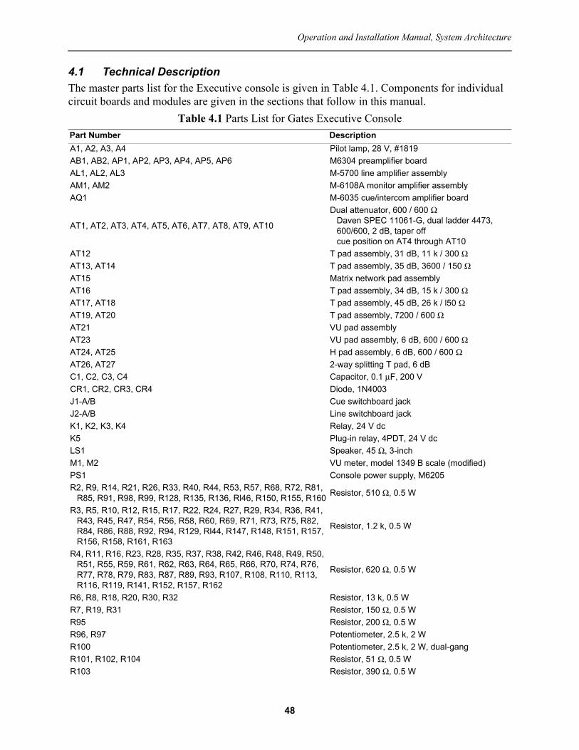
4.1 Technical DescriptionThe master parts list for the Executive console is given in Table 4.1. Components for individual circuit boards and modules are given in the sections that follow in this manual.
Table 4.1 Parts List for Gates Executive ConsolePart Number DescriptionA1, A2, A3, A4 Pilot lamp, 28 V, #1819AB1, AB2, AP1, AP2, AP3, AP4, AP5, AP6 M6304 preamplifier boardAL1, AL2, AL3 M-5700 line amplifier assemblyAM1, AM2 M-6108A monitor amplifier assemblyAQ1 M-6035 cue/intercom amplifier board
AT1, AT2, AT3, AT4, AT5, AT6, AT7, AT8, AT9, AT10
Dual attenuator, 600 / 600 Ω Daven SPEC 11061-G, dual ladder 4473, 600/600, 2 dB, taper off cue position on AT4 through AT10
AT12 T pad assembly, 31 dB, 11 k / 300 ΩAT13, AT14 T pad assembly, 35 dB, 3600 / 150 ΩAT15 Matrix network pad assemblyAT16 T pad assembly, 34 dB, 15 k / 300 ΩAT17, AT18 T pad assembly, 45 dB, 26 k / l50 ΩAT19, AT20 T pad assembly, 7200 / 600 ΩAT21 VU pad assemblyAT23 VU pad assembly, 6 dB, 600 / 600 ΩAT24, AT25 H pad assembly, 6 dB, 600 / 600 ΩAT26, AT27 2-way splitting T pad, 6 dBC1, C2, C3, C4 Capacitor, 0.1 μF, 200 VCR1, CR2, CR3, CR4 Diode, 1N4003J1-A/B Cue switchboard jackJ2-A/B Line switchboard jackK1, K2, K3, K4 Relay, 24 V dcK5 Plug-in relay, 4PDT, 24 V dcLS1 Speaker, 45 Ω, 3-inchM1, M2 VU meter, model 1349 B scale (modified)PS1 Console power supply, M6205R2, R9, R14, R21, R26, R33, R40, R44, R53, R57, R68, R72, R81,
R85, R91, R98, R99, R128, R135, R136, Rl46, R150, R155, R160 Resistor, 510 Ω, 0.5 W
R3, R5, R10, R12, R15, R17, R22, R24, R27, R29, R34, R36, R41, R43, R45, R47, R54, R56, R58, R60, R69, R71, R73, R75, R82, R84, R86, R88, R92, R94, R129, Rl44, R147, R148, R151, R157, R156, R158, R161, R163
Resistor, 1.2 k, 0.5 W
R4, R11, R16, R23, R28, R35, R37, R38, R42, R46, R48, R49, R50, R51, R55, R59, R61, R62, R63, R64, R65, R66, R70, R74, R76, R77, R78, R79, R83, R87, R89, R93, R107, R108, R110, R113, R116, R119, R141, R152, R157, R162
Resistor, 620 Ω, 0.5 W
R6, R8, R18, R20, R30, R32 Resistor, 13 k, 0.5 WR7, R19, R31 Resistor, 150 Ω, 0.5 WR95 Resistor, 200 Ω, 0.5 WR96, R97 Potentiometer, 2.5 k, 2 WR100 Potentiometer, 2.5 k, 2 W, dual-gangR101, R102, R104 Resistor, 51 Ω, 0.5 WR103 Resistor, 390 Ω, 0.5 W
48

Gates Executive Stereo Audio Console, Volume I
The overall schematic diagram of the Gates Executive Stereo Audio Console is shown in Figure 4.1. Note that in the implementation documented in this manual, the Turntable inputs appear on Channels 6 and 7, and the Tape inputs (now relabeled as Auxiliary) appear on Channels 4 and 5. These are labeling changes only; the wiring is the same as shown in Figure 4.1.
Complete details on the various amplifiers used in the console will be found in the individual sections later in this manual. However, a word about the circuitry will aid in explaining overall console setup. The preamplifiers, cue/intercom amplifier, and monitor amplifiers have transformerless output circuits. Proper grounding of external wiring is critical for low noise and to avoid crosstalk, especially in the high-gain cue/intercom system. If modifications are made on the console, care should be exercised to insure that unwanted ground loops do not occur. Document any changes in detail.
Under no circumstances should the monitor speaker or intercom speaker wiring be grounded externally.
4.1.1 Attenuator CircuitsA number of fixed attenuators are used in the console to adjust signal levels at various points in the system. Typical circuits for unbalanced and balanced fixed attenuators are shown in Figure 4.2. Fixed attenuator networks may be cascaded and switched as needed to provide step
R105 Resistor, 10 k, 0.5 WR106, R109, R111, R112, R114, R115, R117, R118, R142, R143 Resistor, 5.1 k, 0.5 WR120, R121, R122, R123, R124, R125, R126, R127 Resistor, 47 Ω, 2 WR137, R138, R139, R140 Resistor, 2.7 k, 0.5 WR164 Resistor, 3.9 k, 0.5 W
S1, S2, S3, S4, S5, S6, S7, S8, S9, S10
Lever key, series 4803Position 1, locking, 1A, 1B, 1D, left and rightPosition 2, locking, 1A, 1B, 1D, left and right602 0047 000
S11, S12, S13, S14, S15, S16, S17, S18, S19, S20, S21, S22, S23, S24, S25, S26, S27, S28, S29, S30, S41, S42, S44
Lever switch, 602 0007 000 Electroswitch E2G0402N
S31, S32, S33, S34, S36, S37 Lever switch, 602 0005 000 Electroswitch E2G0203N
S35 Rotary switch (monitor selector), 914 8507 002S38 Rotary switch (intercom selector), 600 6210 000
S39 Lever switch (VU2 meter selector), 914 8507 004-
S40 Rotary switch (phone selector), 914 8507 009S43 Pushbutton switch, SPST, N.O. T1, T5, T6, T7, T8, T9, T10 Transformer, audio, Triad A21T2, T4 Transformer, speaker, Triad A-36283T3 Transformer, speaker, Triad A-36792T11 Transformer, power, Triad A-36766TB1, TB2, TB3, TB4, TB5, TB6 Terminal block, 20 pairTB7 Terminal boardTB8 Terminal boardXA1, XA2, XA3, XA4 Pilot light socketXK5 Relay socket
Table 4.1 Parts List for Gates Executive Console
49

50
Operation and Installation Manual, System Architecture
Figure 4.1 Overall schematic diagram of the Executive console. For simplicity, single-line connections are shown. (Source: Gates Radio.)

Gates Executive Stereo Audio Console, Volume I
adjustments. Audio attenuators are generally designed for a circuit impedance of 150 Ω or 600 Ω. Component values are determined as shown in the figure.1
For reference, decibel conversion is detailed in Table 4.2.
1. Figure and equations from: Television and Audio Handbook for Technicians and Engineers, K. Blair Benson and Jerry Whita-ker (eds.), McGraw-Hill, New York, NY, 1990.
Table 4.2 Common Decibel Values and Conversion RatiosdB Value Voltage Ratio Power Ratio–40 0.01 0.0001–20 0.1 0.01–10 0.3163 0.1–6 0.501 0.251–3 0.707 0.501–2 0.794 0.631–1 0.891 0.7940 1 1+1 1.122 1.259+2 1.259 1.586+3 1.412 1.995+6 1.995 3.981+10 3.162 10+20 10 100+40 100 10,000
A
RR
RR
AA
R
Input Voltage
OutputVoltageattenuation
1
0
0
3
2
1
1
RRRR A A
RR
RR
A
0
0
4
5
0
0
6
2
1
1
Figure 4.2 Balanced and unbalanced fixed attenuator networks for equal source and load resistance: (a) T configuration, (b) π configuration, (c) bridged-T configuration.
51

Operation and Installation Manual, System Architecture
Calculated loss pad values are given in Table 4.3 for common operating points.
Circuit board layouts for mono and stereo versions of the H-pad described in Table 4.3 are shown in Figure 4.3.
4.1.2 VU Meter Operation and Level MatchingThe VU meters on the front panel of the console are very important to proper operation of the overall system. As such, an easy way to verify the accuracy of the meters is desirable. The following steps can be used to confirm proper operation of the meters.
Table 4.3 Common Pad Values (Ohms)Schematic Description Loss R1 R2 R3 R4 R5
600/600 T
2 dB 68 68 27004 dB 130 130 12006 dB 200 200 8208 dB 270 270 51010 dB 330 330 39015 dB 430 430 22020 dB 470 470 12025 dB 510 510 68
150/150 T
2 dB 18 18 7504 dB 36 36 3306 dB 51 51 2008 dB 52 62 12010 dB 82 82 10015 dB 110 110 5620 dB 120 120 3025 dB 130 130 16
600/150 T
12 dB 510 6.8 16015 dB 510 51 11020 dB 560 100 6225 dB 560 120 33
600/600 H
2 dB 34 34 2700 34 344 dB 65 65 1200 65 656 dB 100 100 820 100 1008 dB 135 135 510 135 13510 dB 165 165 390 165 16515 dB 215 215 220 215 21520 dB 235 235 120 235 23525 dB 255 255 68 255 255
150/150 H
2 dB 9 9 750 9 94 dB 18 18 330 18 186 dB 25 25 200 25 258 dB 31 31 120 31 3110 dB 41 41 100 41 4115 dB 55 55 56 55 5520 dB 60 60 30 60 6025 dB 65 65 16 65 65
52

Gates Executive Stereo Audio Console, Volume I
– Apply a 1 kHz tone to one of the Remote inputs and adjust the fader for an indication of 0 as displayed on the VU meters. Adjust the LEFT/RIGHT CHANNEL MASTER controls as needed so both meters read 0 VU.
– Open the front panel of the console and measure the ac voltage across the input terminals of the pads attached to each meter. Use a portable rms voltmeter; do not ground any of the connection points. A reading of 2.7 V rms should be measured.
– Measure the ac voltage across the input terminals of the meters. A reading of 0.3 V rms should be measured.
Diagrams of the attenuator pads used on the two VU meters in the Executive console are shown in Figure 4.4. The terminals marked “output” on the VU1 meter pad (left channel) feed the left channel Program output terminals of the console. The right channel output terminals of the console are provided at pad AT24, which is mounted adjacent to the VU2 meter.
The matching of left and right signal levels on a given channel is important for proper operation. Matching can be checked by applying a 1 kHz tone at the proper level to the left and right inputs. With the level set to produce 0 VU, the left and right channel meters should agree within 1 dB. There are several elements that impact level matching among channels, notably:
• The fader (variable attenuator). The devices used in the Executive console provide a resolution of 2 dB. Depending on the setting of the fader knob, a mismatch between channels may be observed. Slight movement of the fader one way or the other will usually bring the levels into balance.
• Aging of certain carbon composition resistors. An isolation resistor of 510 Ω is included between the output of each fader channel and the main Program/Audition buss. Over time these resistors may change in value. Experience has shown that when values change, they do so in an upward direction. Resistors that no longer are within the ±5% tolerance should be replaced. It is recommended that if one resistor in a given channel is changed, the other be changed as well. The 510 Ω resistors are located on the connection end of the channel lever switches. The resistor closest to the ground bar is for the left channel.
(a) (b)
Figure 4.3 Circuit board layouts of the H-pad described in Table 4.3: (a) mono implementation, (b) stereo implementation.
53

Operation and Installation Manual, System Architecture
• Pad value changes. There are a number of pads within the Executive console. For Channels 1–3, pads AT9, AT10, and AT11 determine the left/right signal level match when the microphone channel is in the Mono mode. For Channel 8, pad AT26 takes the monophonic Remote input and applies it equally to the left/right signal paths. Pad AT27 performs a similar function for Channel 9 (when configured for mono operation). Resistors that are out of tolerance in any of these pads may cause the left and right channels to vary from their normal levels.
The equivalent mixing circuit of a single channel is illustrated in Figure 4.5. It can be observed that:
• When the input lever switch is in the center (off) position, the output of the mixer attenuator is applied to a 620 Ω load resistor. When the lever switch is in the Program or Audition position, the load resistor is removed.
• When the lever switch is in the Program position, the output of the mixer attenuator is applied to the Program buss through a 510 Ω resistor. Otherwise, the Program buss is loaded with a 1.2 kΩ resistor.
Figure 4.4 Attenuator pads used on the Executive console VU meters.
54

Gates Executive Stereo Audio Console, Volume I
• When the lever switch is in the Audition position, the output of the mixer attenuator is applied to the Audition buss through the 510 Ω resistor. Otherwise, the Audition buss is loaded with a 1.2 kΩ resistor.
This arrangement maintains a constant load on the input signal, and it maintains a constant operating point for the Program buss and Audition buss.
It should be noted that with time, components within the VU meters may age, resulting in discrepancies between two otherwise identical meters with identical input levels. Differences in the range of 1 dB have been observed. Because of the number of variables involved, response within ±1 dB should be considered normal.
The Executive console has provisions for balancing the left and right channels when a monophonic input is available, such as an tone generator. The equivalent circuit is shown in Figure 4.6. (Note that the balance circuit is not shown in the simplified line drawing of Figure 4.1.) Switch S44 is located on the inside front panel just below the VU meters. When set to Null, the right channel (AL3) master gain control is adjusted to produce minimum deflection on VU2. The accuracy of this adjustment is typically with 0.25 dB for high-accuracy (1% tolerance) resistors.
4.1.3 Other Implementation ConsiderationsBe advised that there is an apparent discrepancy in the overall system diagram shown in Figure 4.1. Focusing on the cue/intercom circuit, the diagram indicates that the output of the cue/intercom amplifier PCB is passed through relay K3 for muting when the control room microphone is opened. In at least some Executive consoles, the output common wire is applied to K3, not the hot wire. Also the Cue Phones connector shown as TB5-12 is in error; it should be TB5-13A. A schematic diagram of the as-built configuration described here is illustrated in Figure 4.7. Note that not all Executive consoles may be wired this way.
Figure 4.5 Equivalent mixing circuit of a single channel of the Executive console.
55

Operation and Installation Manual, System Architecture
As designed, the Executive audio console program outputs are inconsistent with regard to reference to ground. The Audition channel is balanced and floating; there is infinite resistance to chassis ground. The Left and Right program channels, however, are balanced and referenced to ground. At the output terminals, about 5.8 kΩ can be measured between the + and – output terminals and chassis ground.
As illustrated in Figure 4.8, the output of line amplifier AL1 is applied to the following loads:• Pad AT23, which drives the VU meter and the line output terminals on TB4.• Front panel rotary switches S39 and S40, which drive the VU2 meter input and Phones
output, respectively.• Pad AT19, which is applied to front panel Monitor input switch S35.• Pad AT12, which drives the primary of isolation transformer T7. The secondary of T7
serves as a source for the SIMUL and L+R signals that appear at front panel switches S36 and S37. (See Figure 4.1.)
Figure 4.7 Cue/intercom muting system wiring as found in some Executive consoles. Cable numbers and wire colors are as shown.
Figure 4.6 Equivalent VU meter balance circuit of the Executive console.
56

Gates Executive Stereo Audio Console, Volume I
Focusing on AT12, the lower portion of Figure 4.8 shows the actual circuit. Note that the shunt element, consisting of two 150 Ω resistors in series, is grounded to chassis at their junction. This, in effect, places a resistance of approximately 5.8 kΩ between the + and – left program output line and ground. The same configuration is used in pad AT16 on the right channel. The reasoning for this design decision is unclear. One would assume that the best (lowest) noise performance from the system would be realized with a balanced and floating output, which is the arrangement used for the Audition channel line output.
Bench tests on an Executive console showed a reduction in noise of up to 3 dB when the ground connection on AT12/AT16 was lifted. This change had no discernible impact on the SIMUL and L+R feeds to AL2 and AL3. These tests were not conducted in the presence of an RF field. It is possible that the ground was originally intended to reduce potential interference from RF energy, which would be found at a radio station where the studio and transmitter are co-located.
It may be worthwhile to identify the ground wire to AT12 for the left channel and AT16 for the right channel and insert quick-disconnect connectors into each ground wire. Upon final installation, noise measurements can then be made on the balanced and floating versus balanced-to-ground configurations. If the balanced-to-ground implementation is used, all resistors in the AT12/AT16 pads should be 1% precision types.
Figure 4.8 Left channel output circuit: (top) line representation with cable numbers, (bottom) detail of attenuator pad AT12. (See the text.)
57
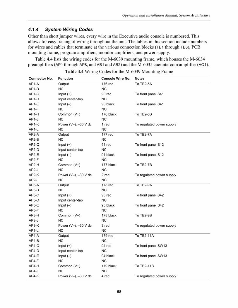
Operation and Installation Manual, System Architecture
4.1.4 System Wiring CodesOther than short jumper wires, every wire in the Executive audio console is numbered. This allows for easy tracing of wiring throughout the unit. The tables in this section include numbers for wires and cables that terminate at the various connection blocks (TB1 through TB8), PCB mounting frame, program amplifiers, monitor amplifiers, and power supply.
Table 4.4 lists the wiring codes for the M-6039 mounting frame, which houses the M-6034 preamplifiers (AP1 through AP8, and AB1 and AB2) and the M-6035 cue/intercom amplifier (AQ1).
Table 4.4 Wiring Codes for the M-6039 Mounting FrameConnector No. Function Console Wire No. NotesAP1-A Output 176 red To TB2-5AAP1-B NC NCAP1-C Input (+) 90 red To front panel S41AP1-D Input center-tap NCAP1-E Input (–) 90 black To front panel S41AP1-F NC NCAP1-H Common (V+) 176 black To TB2-5BAP1-J NC NCAP1-K Power (V–), –30 V dc 1 red To regulated power supplyAP1-L NC NCAP2-A Output 177 red To TB2-7AAP2-B NC NCAP2-C Input (+) 91 red To front panel S12AP2-D Input center-tap NCAP2-E Input (–) 91 black To front panel S12AP2-F NC NCAP2-H Common (V+) 177 black To TB2-7BAP2-J NC NCAP2-K Power (V–), –30 V dc 2 red To regulated power supplyAP2-L NC NCAP3-A Output 178 red To TB2-9AAP3-B NC NCAP3-C Input (+) 93 red To front panel S42AP3-D Input center-tap NCAP3-E Input (–) 93 black To front panel S42AP3-F NC NCAP3-H Common (V+) 178 black To TB2-9BAP3-J NC NCAP3-K Power (V–), –30 V dc 3 red To regulated power supplyAP3-L NC NCAP4-A Output 179 red To TB2-11AAP4-B NC NCAP4-C Input (+) 94 red To front panel SW13AP4-D Input center-tap NCAP4-E Input (–) 94 black To front panel SW13AP4-F NC NCAP4-H Common (V+) 179 black To TB2-11BAP4-J NC NCAP4-K Power (V–), –30 V dc 4 red To regulated power supply
58

Gates Executive Stereo Audio Console, Volume I
AP4-L NC NCAP5-A Output 180 red To TB2-13AAP5-B NC NCAP5-C Input (+) 95 red To front panel S11AP5-D Input center-tap NCAP5-E Input (–) 95 black To front panel S11AP5-F NC NCAP5-H Common (V+) 180 black To TB2-13BAP5-J NC NCAP5-K Power (V–), –30 V dc 5 red To regulated power supplyAP5-L NC NCAP6-A Output 181 red To TB2-15AAP6-B NC NCAP6-C Input (+) 96 red To front panel S14AP6-D Input center-tap NCAP6-E Input (–) 96 black To front panel S14AP6-F NC NCAP6-H Common (V+) 181 black To TB2-15BAP6-J NC NCAP6-K Power (V–), –30 V dc 6 red To regulated power supplyAP6-L NC NCAP7-A Output 251 red To TB2-18AAP7-B NC NCAP7-C Input (+) 250 red To TB2-17AAP7-D Input center-tap NCAP7-E Input (–) 250 black To TB2-17BAP7-F NC NC
AP7-H Common (V+) 251 blackWhite
TB2-18BTo chassis ground buss via T5 ground wire
AP7-J NC NCAP7-K Power (V–), –30 V dc 81 red To regulated power supplyAP7-L NC NCAP8-A Output 253 red To TB2-20AAP8-B NC NCAP8-C Input (+) 252 red To TB2-19AAP8-D Input center-tap NCAP8-E Input (–) 252 black To TB2-19BAP8-F NC NC
AP8-H Common (V+) 253 blackWhite
To TB2-20BTo chassis ground buss via T5 ground wire
AP8-J NC NCAP8-K Power (V–), –30 V dc 82 red To regulated power supplyAP8-L NC NCAB1-A Output White To T5 pin 4AB1-B NC NCAB1-C Input (+) 97 red To TB1-20AAB1-D Input center-tap NCAB1-E Input (–) 97 black To TB1-20B
Table 4.4 Wiring Codes for the M-6039 Mounting Frame
59

Operation and Installation Manual, System Architecture
The outputs of AB1 and AB2 drive isolation transformers T5 and T6. Connection details for these components are given below.
• The output of AB1 is applied to T5 pin 4 (white) and pin 6 (white), for an impedance of 500 Ω. Pins 4 and 6 are for the secondary winding of T5.
• The output of AB2 is applied to T6 pin 4 (white) and pin 6 (white), for an impedance of 500 Ω. Pins 4 and 6 are for the secondary winding of T6.
• The output of T5 is taken from pin 1 (cable #162, red) and pin 3 (cable #162, black), for an impedance of 500 Ω. Pins 1 and 3 are for the primary winding of T5.
• The output of T6 is taken from pin 1 (cable #163, red) and pin 3 (cable #163, black), for an impedance of 500 Ω. Pins 1 and 3 are for the primary winding of T6.
• The GND terminal on T5 is connected as follows: white to the common pin on AB1, green to chassis ground.
• The GND terminal on T6 is connected as follows: white to the common pin on AB2, green to chassis ground.
AB1-F NC NC
AB1-H Common (V+) 85 redWhite
To power supply commonTo T5 pin 6
AB1-J NC NCAB1-K Power (V–), –30 V dc 7 red To regulated power supplyAB1-L NC NCAB2-A Output White To T6 pin 4AB2-B NC NCAB2-C Input (+) 98 red To TB2-2AAB2-D Input center-tap NCAB2-E Input (–) 98 black To TB2-2BAB2-F NC NC
AB2-H Common (V+) 86 redWhite
To power supply commonTo T6 pin 6
AB2-J NC NCAB2-K Power (V–), –30 V dc 8 red To regulated power supplyAB2-L NC NCAQ1-A Power (V–), –37 V dc 15 red To power supplyAQ1-B Input (+) 92 red To intercom relay panelAQ1-C NC NC
AQ1-D Input (–)92 black131 shieldWhite
To intercom relay panelTo front panel cue gain control lowTo CUE-K
AQ1-E NC NCAQ1-F NC NCAQ1-H Potentiometer arm 131 black To front panel cue gain control armAQ1-J Potentiometer high 131 white To front panel cue gain control high
AQ1-K Common (V+)72 black16 redWhite
To intercom relay panelTo power supply commonTo CUE-D
AQ1-L Output 72 red To intercom relay panel
Table 4.4 Wiring Codes for the M-6039 Mounting Frame
60

Gates Executive Stereo Audio Console, Volume I
Table 4.5 lists the wiring codes for the M-6031 mounting frames, which house the M-5700 line amplifiers (AL1, AL2, and AL3).
Table 4.5 Wiring Codes for the M-6031 Mounting FramesConnector No. Function Console Wire No. NotesAL1-1 Potentiometer high 129 white
Gain control on front panelAL1-2 Potentiometer arm 129 blackAL1-3 Potentiometer common 129 shieldAL1-4 Common (V+) 9 red To power supply commonAL1-5 Output (+) 71 red To TB4-7AAL1-6 Output (–) 71 black To TB4-7BAL1-7 Output center-tap NCAL1-8 NC NCAL1-9 Input (+) 89 red To TB1-14AAL1-10 Input (–) 89 black To TB1-14BAL1-11 Input center-tap NCAL1-12 Power (V–), –30 V dc 14 red To regulated power supplyAL1-13 Chassis ground 78 white To ground buss barAL1-14 NC NCAL1-15 NC NCAL1-16 NC NCAL2-1 Potentiometer high NC
Not used; internal gain controlAL2-2 Potentiometer arm NCAL2-3 Potentiometer common NCAL2-4 Common (V+) 13 red To power supply commonAL2-5 Output (+) 70 red To TB4-9AAL2-6 Output (–) 70 black To TB4-9BAL2-7 Output center-tap NCAL2-8 NC NCAL1-9 Input (+) 88 red To TB1-16AAL2-10 Input (–) 88 black To TB1-16BAL2-11 Input center-tap NCAL2-12 Power (V–), –30 V dc 12 red To regulated power supplyAL2-13 Chassis ground 77 white To ground buss barAL2-14 NC NCAL2-15 NC NCAL2-16 NC NCAL3-1 Potentiometer high 130 white
To gain control on front panelAL3-2 Potentiometer arm 130 blackAL3-3 Potentiometer common 130 shieldAL3-4 Common (V+) 11 red To power supply commonAL3-5 Output (+) 69 red To TB4-11AAL3-6 Output (–) 69 black To TB4-11BAL3-7 Output center-tap NCAL3-8 NC NCAL3-9 Input (+) 87 red To TB1-18AAL3-10 Input (–) 87 black To TB1-18BAL3-11 Input center-tap NCAL3-12 Power (V–), –30 V dc 10 red To regulated power supplyAL3-13 Chassis ground 76 white To ground buss bar
61

Operation and Installation Manual, System Architecture
Table 4.6 lists the wiring codes for the left and right M-6108A monitor amplifiers (AM1 and AM2).
Table 4.7 lists the wiring codes for the M-6205 power supply (PS1).
AL3-14 NC NCAL3-15 NC NCAL3-16 NC NC
Table 4.6 Wiring Codes for the M-6108A Monitor AmplifiersConnection Point Function Console Wire No., Left Console Wire No., RightTB1, input terminal strip1 Gain control (arm) 128 black 127 black2 Input + 160 red 161 red3 Jump to #2 4 Jump to #55 Input – 160 black 161 black6 Gain control (high) 128 white 127 white7 Gain control (low) 128 shield 127 shield
Ground 64 white 63 whiteTB2, speaker terminal strip1 (closest to chassis edge) Speaker ground 49 black 50 black2 Speaker hot 49 red 50 redTB3, power supply terminals1 28 V ac input 25 red 34 red2 28 V ac input 26 red 35 red
Table 4.7 Wiring Codes for the M-6205 Power SupplyTerminal Number Supply Function Console Wire No. Console FunctionTB1-1 28 V ac input 19 red to TB6-6 Power supply ac input
58 red VU meter lampsTB1-2 28 V ac input 18 red to TB6-5 Power supply ac input
58 black VU meter lampsTB1-3 37 V dc supply com-
mon (V+)16 red Cue amplifier 37 V dc supply common
(V+)TB1-4 –37 V dc output 15 red Cue amplifier V–
TB2 (all positions) 30 V dc supply com-mon (V+)
275 gray Chassis common9 red AL1 30 V dc supply common (V+)11 red AL3 30 V dc supply common (V+)13 red AL2 30 V dc supply common (V+)59 red Cue relay 30 V dc supply common (V+)85 red AB1 30 V dc supply common (V+)86 red AB2 30 V dc supply common (V+)
Table 4.5 Wiring Codes for the M-6031 Mounting Frames
62

Gates Executive Stereo Audio Console, Volume I
4.1.5 Pad Component ValuesAs stated previously, attenuator pads are used in a number of circuits in the Executive console for signal isolation and level-matching. The pads use the same circuit board layout, a schematic of which is shown in Figure 4.9. Note that for some pads, not all resistors are installed and a jumper wire is used instead. Exceptions to this practice include: 1) the meter-mounted pads illustrated in Figure 4.4 2) the microphone mono matching pads (AT9, AT10, AT11), and 3) the L+R mix pad (AT15). Note that for the microphone mono matching pads, the value of the pad should be equal to the gain of the M-6034 preamplifier (nominally 45 dB).
Table 4.8 lists the resistor values for the pads used in the Executive console.
TB3 (all positions) –30 V dc output 1 red AP1 V–2 red AP2 V–3 red AP3 V–4 red AP4 V–5 red AP5 V–6 red AP6 V–7 red AB1 V–8 red AB2 V–10 red AL3 V–12 red AL2 V–14 red AL1 V–17 white S1/S2/S3 muting circuit24 red Cue relay V–81 red AP7 V–82 red AP8 V–
Note 1: The Executive console line schematic shown in Figure 4.1 clearly shows the S1/S2/S3 relay panel powered by the –37 V unregulated supply. However, in at least some implementations (and in this table) the relay panel is powered by the –30 V dc supply.
Table 4.8 Fixed Attenuator Pad Resistor Values (0.5 W)Pad Number Function Resistor Value
AT9Channel 1 microphone mono mix pad series resistance (x2) 13 k parallel resistance 150 ohms
AT10Channel 2 microphone mono mix pad series resistance (x2) 13 k parallel resistance 150 ohms
Table 4.7 Wiring Codes for the M-6205 Power Supply
Figure 4.9 Basic fixed attenuator pad used for isolation and level-matching.
63

Operation and Installation Manual, System Architecture
AT11Channel 3 microphone mono mix pad series resistance (x2) 13 k parallel resistance 150 ohms
AT12 T pad assembly, 31 dB, 11 k / 300 ohm AL1 output to T7 input
R1 5.6 kR2 JumperR3 150 ohmsR4 150 ohmsR5 5.6 kR6 Jumper
AT13 T pad assembly, 35 dB, 3600 / 150 ohms T7 (AL1 output) to S36 (AL2 input)
R1 1.8 kR2 JumperR3 150 ohmsR4 JumperR5 1.8 kR6 Jumper
AT14 T pad assembly, 35 dB, 3600 / 150 ohms T7 (AL1 output) to S37 (AL3 input)
R1 1.8 kR2 JumperR3 150 ohmsR4 JumperR5 1.8 kR6 Jumper
AT15Matrix network pad assembly
From T7 (AL1 output) and T8 (AL3 output) to S36 (L+R source) See Figure 4.10
R1 2.7 kR2 2.7 kR3 2.7 kR4 2.7 kR5 200 ohmskR6 200 ohmsR7 200 ohmsR8 200 ohms
AT16 T pad assembly, 34 dB, 15 k / 300 ohms AL3 output to T8
R1 7.5 kR2 JumperR3 150 ohmsR4 150 ohmsR5 7.5 kR6 Jumper
AT17 T pad assembly, 45 dB, 26 k / l50 ohms T5 (Audition left) output to S37 (AL3 input)
R1 13 kR2 JumperR3 150 ohmsR4 JumperR5 13 kR6 Jumper
AT18 T pad assembly, 45 dB, 26 k / l50 ohms T5 (Audition left) output to S36 (AL2 input)
R1 13 kR2 JumperR3 150 ohmsR4 JumperR5 13 kR6 Jumper
Table 4.8 Fixed Attenuator Pad Resistor Values (0.5 W)
64

Gates Executive Stereo Audio Console, Volume I
AT19 T pad assembly, 7.2 k / 600 ohms AL1 output to S35 (monitor input switch), cable #74
R1 3.6 k1
R2 JumperR3 620 ohmsR4 JumperR5 3.6 k1
R6 Jumper
AT20 T pad assembly, 7.2 k / 600 ohms AL3 output to S35 (monitor input switch), cable #75
R1 3.6 k1
R2 JumperR3 620 ohmsR4 JumperR5 3.6 k1
R6 Jumper
AT21 VU pad assembly; 6 dB, 600 ohms / 600 ohms; See Figure 4.4. VU2 meter pad
AT22 Not used
AT23VU pad assembly, 6 dB, 600 ohms / 600 ohms; See Figure 4.4.
AL1 output to VU1 AL1 output to Program Left output
AT24 H pad assembly, 6 dB, 600 / 600 ohms AL2 output to Audition mono output
R1 75 ohmsR2 75 ohmsR3 510 ohmsR4 510 ohmsR5 75 ohmsR6 75 ohms
AT25 H pad assembly, 6 dB, 600 ohms / 600 ohms AL3 output to Program Right output
R1 75 ohmsR2 75 ohmsR3 510 ohmsR4 510 ohmsR5 75 ohmsR6 75 ohms
AT26 2-way splitting T pad, 6 dB T1 output (Remote mix) to fader AT8
R1 200 ohmsR2 200 ohmsR3 200 ohmsR4 JumperR5 OpenR6 Jumper
AT27 2-way splitting T pad, 6 dB Channel 9 mono Network input to fader AT9
R1 200 ohmsR2 200 ohmsR3 200 ohmsR4 JumperR5 OpenR6 Jumper
No number Pad from Audition preamplifier AB1 to Monitor input switch S35 via cable #143
R1 511 ohmsR2 511 ohms
No number Pad from Audition preamplifier AB2 to Monitor input switch S35 via cable #273
R1 511 ohmsR2 511 ohms
Notes: 1 3.6 k is not commonly available; 3.68 k may be used as a substitute
Table 4.8 Fixed Attenuator Pad Resistor Values (0.5 W)
65

Operation and Installation Manual, System Architecture
Pad AT15, which is used to produce an L+R signal for application to the Audition channel via switch S36, is a special case. See Figure 4.10.
Figure 4.10 AT15 fixed attenuator pad
66

Gates Executive Stereo Audio Console, Volume I
Section 5: Gates M-6034 PreamplifierThe Executive audio console includes a card frame that houses ten Gates M-6034 preamplifier circuit boards. Six of these boards are used for microphone inputs, two are used for the Audition channel monitor circuit, and two are spares for specialized applications. These boards are highlighted in Figure 5.1.
Figure 5.1 M-6034 preamplifier boards used in the Gates Executive audio console (highlighted).
67

Operation and Installation Manual, Gates M-6034 Preamplifier
5.1 Overview and Specifications
The Gates M-6034 Preamplifier is a premium quality, low noise unit intended for use in audio mixing consoles. The amplifier has a gain of 45 dB. The input is balanced, floating, and is connected for a 150 Ω source impedance at the factory but may be reconnected for operation at 50 Ω in the field if needed. The output is unbalanced and designed to operate into a 600 Ω variable attenuator.
In the Executive audio console, the M-6034 serves as the microphone preamplifier (AP1 through AP6) and the Audition buss preamplifier for monitoring functions (AB1 and AB2). In addition, two spare positions are provided for special applications (AP7 and AP8).
Typical performance data are listed in Table 5.1.
The M-6034 is intended to be used with the Gates M-6039 mounting frame, which carries mating receptacles for the printed card-type connections. The fingers on the printed circuit board are gold-flashed for positive mating with the gold contacts on the receptacle.
Table 5.1 M-6034 Preamplifier Technical DataParameter SpecificationGain 45 dB ±1 dB operated into a 600 Ω loadFrequency response ±1 dB, 30 Hz to 15 kHz
Harmonic distortion Less than 0.5% from 30 Hz to 15 kHz at –5 dBm outputLess than 0.5% from 50 Hz to 15 k Hz at +5 dBm output
Intermodulation distortionLess than 0.5% at –5 dBm output levelLess than 1% at +5 dBm output levelDistortion measured at equivalent sine wave output using 40 Hz and 7 kHz, mixed 4:1
Noise level –122 dBm equivalent input noiseSource impedance 150 Ω (50 Ω optional) balanced, floating
Input impedance Input transformer unloaded, resulting in input impedance being substantially higher than the source impedance
Output load impedance 600 Ω ±10%Maximum input level –40 dBmMaximum output level +5 dBmMaximum operating tem-
perature 55º C (13Iº F)
Power requirements –30 V dc at 15 mA with less than 1 mV ripple
68

Gates Executive Stereo Audio Console, Volume I
5.2 Circuit DescriptionThe schematic diagram of the M-6034 preamplifier is shown in Figure 5.2. The preamplifier is a four-stage circuit that utilizes a transformerless output arrangement capable of driving a 600 Ω load to +5 dBm. The amplifier features negative feedback to reduce distortion to a very low level. The input impedance is 150 Ω by default; however, the configuration can be changed if needed for operation at 50 Ω. See Table 5.2.
The input signal is applied to pins C and E of the card edge connector, and is fed through transformer T1 to the base of Q1 (2N5087), a low noise transistor operated at ideal collector current for minimum noise. It will be noted that the first stage bias is series-fed through T1 to provide the maximum input gain. R1 and C1 are connected across the secondary of Tl to stabilize the amplifier. The values of R1 and C1 are selected to provide a roll-off above the audio range to prevent amplification of high frequency noise. The bias point of Q1 is established by R2 and R3.
The first-stage signal is direct-coupled from the collector of Q1 to the base of Q2 (2N5087), which is a very high gain stage because the emitter is completely bypassed (C6). The signal is then coupled from the collector of Q2 (through C8) to the base of Q3 (2N5087). The collector of Q3 is direct-coupled to the base of Q4 (40319), configured as an emitter-follower. The emitter-follower circuit is very stable and is virtually distortionless. This configuration also provides the low output impedance required to feed a 600 Ω fader. The output is taken through C10. Note that output transistor Q4 may be selected for best overall performance.1 The bias points of Q3 and Q4 are set by the resistive divider of R14 and R15 as applied to the base of Q3.
Feedback is applied from the junction of R17/Q3-emitter through R13 and C9, R7, and C3 to emitter resistors R5/R6 of the first stage. R13 and C9 provide a boost of about 1 dB at 30 Hz to flatten frequency response in the audio band. In general, overall low frequency response is determined by the combination R13/C9, while overall high frequency response is determined by the combination of R1/C1. Apart from the negative feedback, low frequency response is influenced significantly by the values of C8 and C10.
In some versions of the M-6034 circuit board, resistor R7 is attached via turret posts, which allows for easy changes in the amount of negative feedback to accommodate component variations. In later versions of the board, R7 is soldered directly onto the PCB.
The –30 V dc regulated power supply drives the Q3 and Q4 stages. Dropping resistor R8 provides a lower operating voltage of –14 V dc for the Q1 stage. Dropping resistor R9 provides an operating voltage of –17.4 V dc for the Q2 stage. Typical operating voltages are shown in Figure 5.2 (taken with a Simpson model 260 voltmeter). Variations of up to ±10% are considered normal.
Table 5.2 M-6034 Input Impedance Configurations Options150 Ohm Input Impedance (default) 50 Ohm Input ImpedancePin C (input+) = blue Pin C (input+) = bluePin E (input–) = brown Pin E (input–) = yellowPin D (input center-tap) = yellow + red Pin D (input center-tap) = R/YThe R/Y wire is not connected Join blue to red. Join yellow to brown.
1. Some versions of the M-6034 preamplifier used socket-mounted transistors. In other versions, the devices are soldered in place, making selection of Q4 for best performance impractical.
69

70
Operation and Installation Manual, Gates M-6034 Preamplifier
Figure 5.2 Schematic diagram of the M-6034 preamplifier. Values shown in parenthesis are typical rms signal voltages with 1 kHz input at –40 dBm. (Source: Gates Radio.)

Gates Executive Stereo Audio Console, Volume I
The parts list for the M-6034 preamplifier is given in Table 5.3.
Note that the M-6034 circuit board should not be removed from or inserted into the card frame when power is applied. Likewise, for cases where transistors are socket-mounted, active devices should not be changed while the power is applied.
Table 5.3 Parts List for the M-6034 Preamplifier Part Number Component DescriptionC1 Capacitor, 0.0075 μF, 100 VC2 Capacitor, electrolytic, 25 μF, 6 VC3 Capacitor, electrolytic, 100 μF, 3 VC4, C7, C8, CI0 Capacitor, electrolytic, 25 μF, 25 VC5 Capacitor, 100 pF, 500 VC6 Capacitor, electrolytic, 200 μF, 6 VC9 Capacitor, electrolytic, 50 μF, 3 VQ1, Q2, Q3 Transistor, 2N5087Q4 Transistor, 40319 (selected)R1 Resistor, 270 Ω, 0.5 WR4 Resistor, 20 k, 0.5 WR3 Resistor, 3.6 k, 0.5 WR5 Resistor, 5.1 k, 0.5 WR6 Resistor, 100 Ω, 0.5 W, 1%R7 Resistor, 260 Ω, 0.5 WR8 Resistor, 15 k, 0.5 WR9 Resistor, 6.2 k, 0.5 WRI0 Resistor, 4.3 k, 0.5 WR11 Resistor, 22 k, 0.5 WR12 Resistor, 3.6 k, 0.5 WR13 Resistor, 100 Ω, 0.5 WR14 Resistor, 30 k, 0.5 WR15 Resistor, 910 Ω, 0.5 WR16 Resistor, 3.9 k, 0.5 WR17 Resistor, 300 Ω, 0.5 WR18 Resistor, 2.4 k, 0.5 WR2 Resistor, 13 k, 0.5 WT1 Transformer, input, 478 0285 000
71

Operation and Installation Manual, Gates M-6034 Preamplifier
5.3 Measured PerformanceOverall performance of the M-6034 preamplifier is documented in this section for the following operating conditions:
• Board removed from the console and powered by a bench supply.• Input power = –30 V dc, regulated, connected to pin K and common connected to pin H.• Input = –40 dBm (unless otherwise noted), balanced, floating, 150 Ω, connected to pins C
and E. –40 dBm is the maximum recommended operating level per Table 5.1.• Measuring instrument load = 600 Ω, connected to pin A and common (pin H).• Output level = +6.5 dBm.
It is important to note that:• The performance documented here is representative of a collection of M-6034
preamplifiers. Variations in performance from one unit to the next are to be expected.• Measurements in which the M-6034 is intentionally operated beyond its normal input
range should be conducted only on the test bench; they should not be conducted while the unit is installed in the Executive audio console. Unexpected consequences may result. This warning applies specifically to the following measurements: clipping, linearity, and power bandwidth.
The preamplifier clips at an input of –35 dBm. Clipping is symmetrical within 2 dB. At just below observable clipping, the output is +12 dBm. At this output level, the preamplifier draws 20 mA from the power source.
Figure 5.3 documents the input/output linearity of the preamplifier. This test compares the input amplitude with the output amplitude in units of dBg, which is decibels relative to the generator output (preamplifier input). Measurement of a perfectly linear device will result in a flat horizontal trace across the entire input range. A trace at zero dBg indicates a unity (×1) gain device. Linearity is charted in Figure 5.3 with an input level of –60 dBm to –20 dBm at 1 kHz. Note that linearity begins to deteriorate at about –35 dBm, which is expected given the clipping observation previously mentioned. Over the linear region, the board provides approximately 45 dB of gain, which matches the specifications stated in Table 5.1.
The maximum operating capability of the preamplifier is examined from a different perspective in Figure 5.4, which charts the power bandwidth. Here, the input is run from a value equal to the maximum operating level of –40 dBm up to a value well above the maximum operating level. The test instrument increases the input level until the measured THD+N (total harmonic distortion plus noise) reaches 3% (measurement bandwidth = 22 Hz to 80 kHz). To provide for efficient computation, a variation of ± 0.5% is allowed. The trace shows the output level achieved in a range of 20 Hz to 20 kHz. Note that the preamplifier is capable of producing more than +12 dBm into a 600 Ω load across the audio spectrum, albeit at 3% THD+N. Keeping in mind that the rated maximum output level of the preamplifier is +5 dBm, it is evident that this parameter is conservatively specified.
Frequency response is charted in Figure 5.5 from 20 Hz to 20 kHz. Deviation relative to 1 kHz across the audio band is quite small, approximately 0.75 dB or less. Performance is well within the stated specifications contained in Table 5.1. Figure 5.6 shows the –3 dB points, approximately 10 Hz on the low end and 40 kHz on the high end.
72

73
Gates Executive Stereo Audio Console, Volume I
Figure 5.3 M-6034 preamplifier input/output linearity at 1 kHz across the specified range of input levels.
Figure 5.4 M-6034 preamplifier power bandwidth across the audio spectrum.
Figure 5.5 M-6034 preamplifier frequency response at the maximum rated input level.
+0
+60
+10
+20
+30
+40
+50
d B g
-60 -20 -55 -50 -45 -40 -35 -30 -25
dBm
+5
+20
+7.5
+10
+12.5
+15
+17.5
d B m
20 20k 50 100 200 500 1k 2k 5k 10k
Hz
-3
+3
-2
-1
+0
+1
+2
d B r
20 20k 50 100 200 500 1k 2k 5k 10k
Hz

74
Operation and Installation Manual, Gates M-6034 Preamplifier
Figure 5.7 M-6034 preamplifier THD+N at the maximum rated input level.
Figure 5.8 M-6034 preamplifier harmonic spectrum at the maximum rated input level, 1 kHz.
Figure 5.6 M-6034 preamplifier frequency response –3 dB points at the maximum rated input level.
-3
+3
-2
-1
+0
+1
+2
d B r
10 20 50 100 200 500 1k 2k 5k 10k 20k 30k
Hz
0.2
1
0.4
0.6
0.8
%
20 20k 50 100 200 500 1k 2k 5k 10k
Hz
-140
+0
-120
-100
-80
-60
-40
-20
d B r
20 20k 50 100 200 500 1k 2k 5k 10k
Hz

75
Gates Executive Stereo Audio Console, Volume I
Figure 5.9 M-6034 preamplifier SMPTE IMD across the specified input range.
Figure 5.10 M-6034 preamplifier input/output phase at the maximum rated input level.
Figure 5.11 M-6034 preamplifier residual noise spectrum relative to the maximum rated input level, 1 kHz.
0.2
1
0.4
0.6
0.8
%
-60 -40 -57.5 -55 -52.5 -50 -47.5 -45 -42.5
dBm
-40
+40
-20
+0
+20
d e g
20 20k 50 100 200 500 1k 2k 5k 10k
Hz
-140
+0
-120
-100
-80
-60
-40
-20
dB r
20 20k 50 100 200 500 1k 2k 5k 10k
Hz
Operation and Installation Manual, Gates M-6034 Preamplifier
Total harmonic distortion plus noise (THD+N) is documented in Figure 5.7 at the maximum rated input across the audio spectrum. Performance is easily within the specification of less than 0.5%. The measurement bandwidth = 22 Hz to 80 kHz. Figure 5.8 shows the output spectrum with an input of 1 kHz. As shown, distortion is primarily second and third harmonic.
SMPTE IMD (60 Hz/7 kHz, 4:1) is shown in Figure 5.9 at input levels of –60 dBm to –40 dBm. IMD is below 0.2% across this input range.
Input-output phase is shown in Figure 5.10 as a function of frequency. Transitions at the low and high end are smooth and gradual. Total phase shift is approximately 60 degrees.
Noise (unweighted) is –85 dB, relative to an input of –40 dBm, measurement bandwidth = 22 Hz to 22 kHz, input termination = 150 Ω. The residual noise spectrum is shown in Figure 5.11. Equivalent input noise = –125 dB. Note that the board has no shielding in this test configuration.
76

Gates Executive Stereo Audio Console, Volume I
5.4 Connection DetailsThe PC board edge connector pin-out for the M-6034 preamplifier is given in Table 5.4.
Table 5.4 M-6034 Preamplifier PC Board Pin-outEdge Connector # FunctionB, F, J, L Not connectedA OutputC Input (+)D Input center-tapE Input (–)H Common (V+)K Power (V–), –30 V dc, regulated
77

Operation and Installation Manual, Gates M-6034 Preamplifier
5.5 Troubleshooting GuidelinesThe M-6034 preamplifier is designed for long, trouble-free service. However, problems can sometimes occur. The following guidelines are offered as a starting point for troubleshooting.
• Step 1 – Place the circuit board on the bench. Do not troubleshoot the preamplifier while installed in the Executive audio console.
• Step 2 – With a spare PCB card edge connector, build up a bench test fixture. Use the connections described in Section 5.3. Use a regulated bench power supply to provide the specified input of –30 V dc. Monitor the current draw of the board and observe for excessive loading of the supply (10 to 20 mA is considered normal). Confirm that the output is properly terminated in a 600 Ω load.
• Step 3 – Check all dc voltages; see Figure 5.2. The dc voltages determine the bias points of the transistors and any departure of 20% or more can be considered a defect.
• Step 4 – Before signal measurements are made, replace any defective components to bring the dc voltages within tolerance.
• Step 5 – After all dc voltages are correct, signal tests may be performed. The typical (rms) voltages are shown in Figure 5.2. Signal voltages shown are for an input of –40 dBm at 150 Ω, unterminated.
Do not use an ohmmeter to check the components when transistors are in the circuit. Excessive current flow can result in damage. Do not remove or insert transistors with the power on. Remember, in this circuit V+ is ground; therefore, filter capacitors have the positive side connected to ground (common).
Table 5.5 lists typical resistances for the connections shown. These measurements are taken with Q1, Q2, Q3, and Q4 removed from the board.
Some electronic components are subject to deterioration over time. Notably, electrolytic capacitors can lose value with age or otherwise fail to meet the new device specifications. For a well-built component, decades of service can be expected. While less common, carbon composition resistors can change value over time, usually increasing in resistance (sometimes dramatically). It is recommended that these issues be addressed on an as-needed basis. Wholesale replacement of devices is not recommended unless experience has shown that a particular type or value of component is prone to failure.
In the M-6034 preamplifier, significant loss of capacitance in a coupling capacitor (e.g., C8, and/or C10) can lead to a sharp roll-off in frequency response at low frequencies. In extreme cases, response at 20 kHz may be close to normal, while response a 1 kHz is down 30 dB (or more).
Printed circuit boards manufactured in the 1960s and 70s are not tolerant of rework. The base material may be damaged by heat and the circuit board traces may lift at the connection pads. For
Table 5.5 M-6034 Preamplifier Troubleshooting Resistance Chart (units in Ω)Measure Resistance From
Q1 Q2 Q3 Q4To GND To V– To GND To V– To GND To V– To GND To V–
Base 3.2 k 15 k 30 k 30 k 900 10 k 14 k 3.5 kEmitter 4.7 k 15 k 2.9 k 13 k 175 10 k 2.2 k 12 kCollector 30 k 30 k 15 k 9 k 14 k 3.5 k 10 k 0
78

Gates Executive Stereo Audio Console, Volume I
these reasons, it is recommended that only needed replacements are made. Troubleshooting through substitution may end up creating new issues and problems.
79

80
Operation and Installation Manual, Gates M-6034 Preamplifier

Gates Executive Stereo Audio Console, Volume I
Section 6: Gates M-5700 Line AmplifierThe Executive audio console includes a mounting frame that houses three M-5700 line amplifier modules. Two are used for the left and right program channels, and the third is used for the audition channel. These modules are highlighted in Figure 6.1.
Figure 6.1 Line amplifier modules used in the Gates Executive audio console (highlighted).
81

Operation and Installation Manual, Gates M-5700 Line Amplifier
6.1 Overview and Specifications
The M-5700 line amplifier is designed specifically for use in the Gates Executive Stereo Audio Console. For the left and right program channels (AL1 and AL3), the amplifier is supplied without the interstage gain control and with the input unterminated. The left and right gain controls are mounted externally on the console front panel. The Audition channel (AL2) is equipped with an internal gain control.
Performance data for the M-5700 is given in Table 6.1.
The M-5700 line amplifier is completely transistorized, and is designed for use as a program or isolation amplifier in broadcasting and recording applications. Special techniques have been employed to obtain low noise, low distortion, and good temperature stability.
The amplifier is used with the M-6031 mounting tray, which carries a mating receptacle and is supplied with mounting hardware. A keying pin is provided with the mounting tray to prevent accidental interchange of non-similar plug-in units in the system.
Table 6.1 M-5700 Technical Data Parameter Specification
GainM-5700: 80 dB, M-5700B: 76 dBGain may be reduced as required with an external gain control (M-5700), or
internal gain control (M-5700B).Frequency response ±1 dB, 30 Hz to 15 kHzHarmonic distortion Less than 0.75% at 30 Hz, 0.5% from 50 Hz to 15 kHz, +24 dBm output
Intermodulation distortionLess than 0.3% at +14 dBm equivalent sine wave power output, using 40 Hz and
7 kHz, mixed 4:1Less than 1.5% at +24 dBm
Noise –122 dBm equivalent input noiseSource impedance 150 Ω or 600 ΩInput impedance Factory connected for 150 Ω. May also be connected for 600 Ω.Load impedance Factory connected for 600 Ω. May also be connected for 150 Ω.Maximum input level –35 dBmMaximum output level +24 dBmMaximum operating ambient tem-
perature 55º C (131º F)
Power requirements 30 V dc, 90 mA, 0.1 mV maximum ripple
(Source: Gates Radio.)
82

Gates Executive Stereo Audio Console, Volume I
The interstage gain control is located on the front panel of the M-5700B model. The output transformer and receptacle are attached to the frame, and all other components are mounted on the printed circuit boards.
Typical frequency response and distortion curves are shown in Figure 6.2. These measurements were taken with all transistors selected at random.
Input transformer connections are illustrated in Figure 6.3. The input transformer is factory connected for 150 Ω primary impedance. If a terminated input is desired, a 150 Ω resistor should be connected to terminals #9 and 10 on the amplifier mounting tray connector, P1. The configuration for a 600 Ω input impedance connection is shown in Figure 6.3. If a terminated input is required, connect a 620 Ω resistor across terminals #9 and 10 on P1.
If 6 dB more gain is required, the input terminating resistor may be eliminated. In this case, however, the system component preceding the amplifier may not be properly terminated.
The output transformer is factory connected for 600 Ω secondary impedance. To configure for 150 Ω, remove the green/white and black wires from terminal #7 on P1. Connect the black wire to terminal #5 and the green/white wire to terminal #6.
Figure 6.2 M-5700 line amplifier frequency response and distortion measurements. (Source: Gates Radio.)
Figure 6.3 M-5700 input transformer connections. (Source: Gates Radio.)
83

Operation and Installation Manual, Gates M-5700 Line Amplifier
6.2 Circuit DescriptionA schematic diagram of the M-5700 line amplifier is shown in Figure 6.4. For the purpose of explanation, the line amplifier can be considered to be made up of two main elements: the driver and the power amplifier.
The four-stage driver has a transformer-coupled input and emitter-follower output, with direct coupling utilized between Q1 (2N5087) and Q2 (2N5087), and between Q3 (2N1414) and Q4 (2N1414). Transistors Q1 and Q2 are low noise types designed for use in critical low noise applications.
Biasing of Q1 and Q2 is accomplished by a combination of voltage divider and emitter resistance, with R2, R3, and R5. This method of biasing insures a high degree of temperature stability. The bias points of Q3 and Q4 are set by the voltage divider combination of R14 and R15.
Signal degeneration is provided for Q1 by R6, and for Q3 by R17. A loop feedback network connects from the emitter of Q3, through R7 and C5, to the emitter circuit of Q1. The large amount of feedback and degeneration obtained by these methods reduces distortion in the driver to an extremely low value, and makes the circuit almost completely independent of normal variations in transistor parameters.
The Q4 output stage is configured as an emitter-follower, with the output taken across R18 via C10. With a nominal input level of –60 dBm, the driver stage produces approximately 340 mV rms into a 2.5 kΩ load at pin #1 of connector P1.
The –30 V dc regulated power supply is connected to pin #12 of P1. Power supply common is connected to pin #4. The –30 V supply drives the Q3 and Q4 stages directly. The Q2 stage is powered at –15 V dc by a voltage divider consisting of resistors R9 and R11, and filter capacitor C7. The Q1 stage is powered at –14 V dc through dropping resistor R8 and filter capacitor C4.
The input to the power amplifier board is taken from the gain potentiometer, which is either mounted external to the M-5700 module, on the front panel of the Executive console, or internal to the M-5700B module. Transistor Q5 (2N1414) provides a small amount of gain for the final two stages of the amplifier. The operating point of Q5 is established by a voltage divider consisting of R20 and R21.
The final stage requires a low driving impedance, which is obtained from emitter follower Q6 (2N1414). The final two stages are direct-coupled, with R25 and R26 establishing the bias on both Q6 and Q7 (2N1183A). Output transistor Q7 is connected in the common-emitter configuration, with series-fed output transformer T2 in the collector circuit. Emitter resistor R29 provides a large amount of degeneration to reduce large-signal distortion to a low value. The feedback network consisting of R28 and C16, connected between the collector of Q7 and the emitter of Q5, is used primarily for low frequency response compensation.
Note that in some versions of the M-5700 line amplifier, output transistor Q7 is a 2N5954 or 40829 type, rather than the 2N1183A. Performance of both versions is essentially the same, although different mounting arrangements are required. The 2N1183A is housed in a TO8 case while the 2N5954 and 40829 are TO66 cases. In addition, the 2N1183A is a germanium device, while the 2N5954/40829 are silicon devices.
The –30 V dc regulated power supply drives the three stages on the power amplifier board directly.
84

85
Gates Executive Stereo Audio Console, Volume I
Figure 6.4 Schematic diagram of the M-5700 line amplifier. Values shown in parenthesis are V rms at 1 kHz with –56 dBm input and +24 dBm output. (Source: Gates Radio.)
Notes:1) R28 = 2.7 k for M-5700B,
R28 = 4.3 k for M-57002) C16 = 5 μF for M-5700B,
C16 = 2.7 μF for M-57003) C1 = 0.01 μF for M-5700B,
C1 = 0.005 μF for M-5700.

Operation and Installation Manual, Gates M-5700 Line Amplifier
Typical operating voltages for the M-5700 line amplifier are given in Figure 6.4. Note that dc voltages shown were measured with a 20 kΩ/volt meter. Signal voltages (rms) were measured with an input of 1 kHz, –56 dBm, +24 dBm output.
The parts list for the M-5700 amplifier is given in Table 6.2. Note that some components are different depending on whether the M-5700 or M-5700B is used. The “B” version includes an internal gain control.
Table 6.2 M-5700 Amplifier Parts ListPart Number Component DescriptionC1 (M-5700) Capacitor, 0.005 μF, 100 VC1 (M-5700B) Capacitor, 0.01 μF, 100 VC2, C11 Capacitor, electrolytic, 25 μF, 6 VC3 Capacitor, electrolytic, 100 μF, 3 VC8 Capacitor, electrolytic, 50 μF, 15 VC4, C7, C10, C13 Capacitor, electrolytic, 25 μF, 25 VC5 Capacitor, 0.001 μF, 1 kVC6 Capacitor, electrolytic, 200 μF, 6 VC9, C12 Capacitor, 470 pF, 1 kVC14 Capacitor, electrolytic, 300 μF, 6 VC15 Capacitor, 0.005 μF, 1 kVC16 (M-5700) Capacitor, electrolytic, 2.7 μF, 60 VC16 (M-5700B) Capacitor, electrolytic, 5 μF, 50 VC17 Capacitor, 250 pF, 1 kVC18, C19, C20, C21, C23, C24, C25 Capacitor, 0.005 μF, 500 VC22, C26 Capacitor, 0.00 μF, 100 VC27 Capacitor, 100 pF, 500 VQ1, Q2 Transistor, 2N5087Q3, Q4, Q5, Q6 Transistor, 2N1414Q7 Transistor, 2N1183AR1 (M-5700A) Resistor, 620 Ω, 0.5 WR11(M-5700B) Resistor, 240 Ω, 0.5 WR2, R4 Resistor, 20 k, 0.5 W, 1%R12, R22 Resistor, 3.6 k, 0.5 WR5 Resistor, 5.1 k, 0.5 WR6 Resistor, 100 Ω, 0.5 W, 1 %R7 Resistor, 750 Ω, 0.5 WR8 Resistor, 15 k, 0.5 WR9 Resistor, 6.2 k, 0.5 WR3, R10 Resistor, 4.3 k, 0.5 WR11 Resistor, 82 k, 0.5 WR14 Resistor, 36 k, 0.5 WR15 Resistor, 910 Ω, 0.5 WR16 Resistor, 3.9 k, 0.5 WR17 Resistor, 200 Ω, 0.5 WR18 Resistor, 2.4 k, 0.5 WR19 Resistor, 270 Ω, 0.5 WR20 Resistor, 47 k, 0.5 WR21 Resistor, 10 k, 0.5 WR23 Resistor, 100 Ω, 0.5 W
86

Gates Executive Stereo Audio Console, Volume I
The component layouts of the M-5700 driver and power amplifier boards are shown in Figure 6.5
R24 Resistor, 1 k, 0.5 WR25 Resistor, 25 k, 0.5 W, 1%R26 Resistor, 4640 Ω, 0.5 W, 1%R27, R31 Resistor, 1.5 k, 0.5 WR28 (M-5700) Resistor, 4.3 k, 0.5 WR28 (M-5700B) Resistor, 2.7 k, 0.5 WR29 Resistor, 61.9 Ω, 5 W, 1%R30 (M-5700A/B) Potentiometer, 2.5 k
Tl Transformer, input, 478 0183 000 150/600 ohms primary, ct; 380 ohms secondary,
T2 Transformer, output, 478 0125 000 (UTRAD 4553) 250 ohms primary, 85 mA dc max.; 150/600 ohms secondary, ct;
Table 6.2 M-5700 Amplifier Parts List
Figure 6.5 Printed board component layout, viewed from the foil side: (top) driver, (bottom) power amplifier. (Source: Gates Radio.)
87
Operation and Installation Manual, Gates M-5700 Line Amplifier
6.3 Measured PerformanceSince the M-5700 line amplifier is composed of two separate circuit boards, performance is characterized in three sections: the driver stage, power output stage, and composite (overall) system.
It is important to note that:• The performance documented here is representative of a collection of M-5700 line
amplifiers. Variations in performance from one unit to the next are to be expected.• Measurements in which the M-5700 is intentionally operated beyond its normal input
range should be conducted only on the test bench; they should not be conducted while the unit is installed in the Executive audio console. Unexpected consequences may result. This warning applies specifically to the following measurements: clipping, linearity, and power bandwidth.
6.3.1 M-5700 Driver PCBPerformance of the M-5700 driver PCB is documented in this section for the following operating conditions:
• Circuit board on the bench with no external shielding.• Input power = –30 V dc, regulated, applied to terminals E7 (V–) and E6 (common).• Input –40 dBm, 150 Ω, balanced floating, applied to terminals E2 (+) and E4 (–).• Measuring instrument load = 2.5 kΩ, applied to terminals E1 (hot) and E6 (common).With no input, the PCB draws approximately 16 mA from the bench power supply. The
current draw does not change within the normal range of input signal levels.Unless noted, all measurements were made with an input of –40 dBm. This optimal maximum
operating point was identified by measuring the clipping point of the amplifier, and backing off 6 dB. Clipping occurs with an input of approximately –34 dBm1, resulting in an output voltage of 6.1 V rms. Clipping is symmetrical within about 3 dB of input. With an input of –40 dBm, the output is approximately 3.0 V rms.
Figure 6.6 documents the input/output linearity of the driver PCB. This test compares the input amplitude with the output amplitude in units of dBg, which is decibels relative to the generator output (line amplifier input). Linearity is charted with an input level of –60 dBm to –25 dBm. Within the linear range of input levels, gain is approximately 50 dB. Note that linearity begins to deteriorate at about –32 dBm input, which is in line with expectations given the clipping observation described previously.
The maximum output capability of the driver board in a bench test configuration is examined from a different perspective in Figure 6.7, which charts the power bandwidth. Here, the input is run from a value equal to the operating level of –40 dBm up to a value well above the maximum operating level. The test instrument increases the input level until the measured THD+N (total harmonic distortion plus noise) reaches 3% (measurement bandwidth = 22 Hz to 80 kHz). To provide for efficient computation, a variation of ± 0.5% is allowed. The trace shows the output level achieved in a range of 20 Hz to 20 kHz. Note that the driver board is capable of producing nearly 7 V rms output into a 2.5 kΩ load across the audio spectrum.
1. Note that per Table 6.1, the maximum rated input of the M-5700 amplifier is –35 dBm.
88

89
Gates Executive Stereo Audio Console, Volume I
Figure 6.6 M-5700 driver PCB input/output linearity across the specified range of input levels.
Figure 6.7 M-57000 driver PCB power bandwidth across the audio spectrum.
Figure 6.8 M-57000 driver PCB frequency response at the normal operating input level.
+0
+100
+20
+40
+60
+80
d B g
-60 -25 -55 -50 -45 -40 -35 -30
dBm
2
10
4
6
8
V
20 20k 50 100 200 500 1k 2k 5k 10k
Hz
-3
+3
-2
-1
+0
+1
+2
d Br
20 20k 50 100 200 500 1k 2k 5k 10k
Hz

90
Operation and Installation Manual, Gates M-5700 Line Amplifier
Figure 6.10 M-57000 driver PCB THD+N at the normal operating input level.
Figure 6.11 M-6034 driver PCB harmonic spectrum at the normal operating input level, 1 kHz.
Figure 6.9 M-5700 driver PCB frequency response –3 dB points at the normal operating input level.
-150
+0
-125
-100
-75
-50
-25
dB r
20 20k 50 100 200 500 1k 2k 5k 10k
Hz
0.2
1
0.4
0.6
0.8
%
20 20k 50 100 200 500 1k 2k 5k 10k
Hz
-3
+3
-2
-1
+0
+1
+2
dB r
10 20 50 100 200 500 1k 2k 5k 10k 20k 30k
Hz

91
Gates Executive Stereo Audio Console, Volume I
Figure 6.12 M-57000 driver PCB SMPTE IMD across the specified input range.
Figure 6.13 M-57000 driver PCB input/output phase at the normal operating input level.
Figure 6.14 M-5700 driver PCB residual noise spectrum relative to the normal operating input level, 1 kHz.
0.2
1
0.4
0.6
0.8
%
-60 -40 -57.5 -55 -52.5 -50 -47.5 -45 -42.5
dBm
-60
+40
-40
-20
+0
+20
d e g
20 20k 50 100 200 500 1k 2k 5k 10k
Hz
-150
+0
-125
-100
-75
-50
-25
dB r
20 20k 50 100 200 500 1k 2k 5k 10k
Hz

Operation and Installation Manual, Gates M-5700 Line Amplifier
Frequency response is shown in Figure 6.8 from 20 Hz to 20 kHz. Deviation relative to 1 kHz across the audio band is less than 1 dB. Note the falloff in response at low frequencies. The output circuit board exhibits a slight boost in low frequency response, which offsets the deficiencies of this curve. Figure 6.9 documents the –3 dB points, which are below 10 Hz on the low end and 35 kHz on the high end.
Total harmonic distortion plus noise (THD+N) is shown in Figure 6.10 at the normal operating level across the audio spectrum. THD+N is less than 0.1%, except at the very low end of the operating band. The measurement bandwidth = 22 Hz to 80 kHz. Figure 6.11 shows the output spectrum with an input of 1 kHz.
Intermodulation distortion is charted in Figure 6.12 at input levels from –60 dBm to –40 dBm. As shown, the measured SMPTE IMD is exceptionally low, less than 0.25%.
Phase shift from input to output is shown in Figure 6.13. Across the audio band, the shift is about 60 degrees total.
The SNR is approximately –83 dB, unweighted, measurement bandwidth = 22 Hz to 22 kHz, input termination = 150 Ω. The residual noise spectrum is shown in Figure 6.14. Note that the board has no shielding in this test configuration.
6.3.2 M-5700 Power Output PCBOverall performance of the M-5700 power output board is documented in this section for the following operating conditions:
• Module on the bench with no external shielding.• Input power = –30 V dc, regulated, applied to terminals E14 (V–) and E13 (common).• Input 250 mV rms, unbalanced, across an input resistance of 2500 Ω. connected to
terminals E11 (+) and E12 (common).• Measuring instrument load = 600 Ω, connected to the output of transformer T2. The output circuit board draws approximately 70 mA at –30 V dc input. The current draw
does not change within the normal range of input signal levels. In the following tests, the output was terminated in a 600 Ω load, which is characteristic of
the operating environment in the Executive audio console. Unless noted, all measurements were made with an input of 250 mV rms.
With an input of 250 mV rms, the output is approximately 20.5 dBm. Clipping occurs with an input of about 520 mV rms, which results in an output of 26.5 dBm at 1 kHz. Clipping is symmetrical.
The nominal input level for the tests documented in this section (250 mV rms) was chosen to be about 6 dB below the input level that will produce clipping.
Figure 6.15 documents the input/output linearity of the output board. This test compares the input amplitude with the output amplitude in units of dBg, which is decibels relative to the generator output (amplifier input). Linearity is charted with an input level of 250 mV rms to 750 mV rms. Within the linear range of input levels, gain is approximately 30 dB. Note that linearity begins to deteriorate at about 525 mV rms input, which is expected given the clipping point previously reported.
The maximum output capability of the output board in a bench test configuration is examined from a different perspective in Figure 6.16, which charts the power bandwidth. Here, the input is
92

93
Gates Executive Stereo Audio Console, Volume I
Figure 6.15 M-5700 power output PCB input/output linearity across the specified range of input levels.
Figure 6.16 M-57000 output PCB power bandwidth across the audio spectrum.
Figure 6.17 M-57000 power output PCB frequency response at the normal operating input level.
+10
+30
+15
+20
+25
d Bm
20 20k 50 100 200 500 1k 2k 5k 10k
Hz
-3
+3
-2
-1
+0
+1
+2
d B r
20 20k 50 100 200 500 1k 2k 5k 10k
Hz
+0
+40
+5
+10
+15
+20
+25
+30
+35
dBg
300m 700m 400m 500m 600m
Vrms

94
Operation and Installation Manual, Gates M-5700 Line Amplifier
Figure 6.19 M-57000 power output PCB THD+N at the normal operating input level.
Figure 6.20 M-6034 power output PCB harmonic spectrum at the normal operating input level, 1 kHz.
Figure 6.18 M-5700 power output PCB frequency response –3 dB points at the normal operating input level.
0.2
1
0.4
0.6
0.8
%
20 20k 50 100 200 500 1k 2k 5k 10k
Hz
-150
+0
-125
-100
-75
-50
-25
d B r
20 20k 50 100 200 500 1k 2k 5k 10k
Hz
-3
+3
-2
-1
+0
+1
+2
d Br
20 70k 50 100 200 500 1k 2k 5k 10k 20k
Hz

95
Gates Executive Stereo Audio Console, Volume I
Figure 6.21 M-57000 power output PCB SMPTE IMD across the specified input range.
Figure 6.22 M-57000 power output PCB input/output phase at the normal operating input level.
Figure 6.23 M-5700 power output PCB residual noise spectrum relative to the normal operating input level, 1 kHz.
0.2
1
0.4
0.6
0.8
%
100m 240m 120m 140m 160m 180m 200m 220m
Vrms
-40
+40
-20
+0
+20
deg
20 20k 50 100 200 500 1k 2k 5k 10k
Hz
-150
+0
-125
-100
-75
-50
-25
dB r
20 20k 50 100 200 500 1k 2k 5k 10k
Hz

Operation and Installation Manual, Gates M-5700 Line Amplifier
run from a value equal to the operating level of 250 mV rms up to a value well above the maximum operating level. The test instrument increases the input level until the measured THD+N (total harmonic distortion plus noise) reaches 3% (measurement bandwidth = 22 Hz to 80 kHz). To provide for efficient computation, a variation of ± 0.5% is allowed. The trace shows the output level achieved in a range of 20 Hz to 20 kHz. Note that the board is capable of producing about +26 dBm output into a 600 Ω load across most of the audio spectrum.
Frequency response is shown in Figure 6.17 from 20 Hz to 20 kHz. Deviation relative to 1 kHz across the audio band is less than 0.25 dB, except for the very low end. Note the bump in response at low frequencies, and recall the slight fall-off in response on the low end with the driver board. This bump offsets the shortcomings of the driver board to yield a relatively flat overall (composite) response. The –3 dB bandwidth is shown in Figure 6.18, extending from below 10 Hz to 75 kHz.
Total harmonic distortion plus noise (THD+N) is shown in Figure 6.19 at the stated operating level across the audio spectrum. THD+N is less than 0.2%. The measurement bandwidth = 22 Hz to 80 kHz. Figure 6.20 shows the output spectrum with an input of 1 kHz.
Intermodulation distortion is charted in Figure 6.21 at input levels from 100 mV rms to 250 mV rms. As shown, the measured SMPTE IMD is less than 0.2%.
Phase shift from input to output is shown in Figure 6.22. Performance is within approximately ±20 degrees relative to 1 kHz.
The SNR is approximately –86 dB, unweighted, measurement bandwidth = 22 Hz to 22 kHz, input termination = 2500 Ω. The residual noise spectrum is shown in Figure 6.23. Note that the board has no shielding in this test configuration.
6.3.3 M-5700 Composite SystemOverall performance of the M-5700 line amplifier is documented in this section for the following operating conditions:
• Module on the bench with the cover removed.• Input power = –30 V dc, regulated, applied to P1 terminals #12 (V–) and 4 (common).• Gain hardwired at maximum; P1 terminals #1 and 2 connected, and a 2.5 kΩ resistor
connected from terminal #1 to terminal #3. Alternatively, the module gain control set fully clockwise.
• Input = –60 dBm, 150 Ω, balanced floating, applied to P1 terminals #9 (+) and 10 (–).• Output taken from P1 terminals #5 (+) and 6 (–).• Measuring instrument load = 600 Ω.The M-5700 line amplifier draws approximately 70 mA at –30 V dc input. Current is
essentially constant from zero audio input to full rated output. When over-driven to the point of producing a square-wave output, the line amplifier current draw can rise to 100 mA or more.
In the following tests, the output was terminated in a 600 Ω load, which is characteristic of the operating environment in the Executive audio console.
Unless noted, all measurements were made with an input of –60 dBm. Clipping occurs with an input of approximately –57 dBm, resulting in an output of +24.5 dBm at 1 kHz. Clipping is symmetrical within approximately 2 dB.
With an input of –60 dBm, the output is approximately +21.5 dBm,
96

Gates Executive Stereo Audio Console, Volume I
Figure 6.24 documents input/output linearity. This test compares the input amplitude with the output amplitude in units of dBg, which is decibels relative to the generator output (line amplifier input). Linearity is charted with an input level of –70 dBm to –50 dBm. Within the linear range of input levels, gain is approximately 80 dB. Note that linearity begins to deteriorate at about –56 dBm, which is in line with expectations given the clipping observation described previously.
The maximum capability of the line amplifier in a bench test configuration is examined from a different perspective in Figure 6.25, which charts the power bandwidth. Here, the input is run from a value equal to the operating level of –60 dBm up to a value well above the maximum operating level. The test instrument increases the input level until the measured THD+N (total harmonic distortion plus noise) reaches 3% (measurement bandwidth = 22 Hz to 80 kHz). To provide for efficient computation, a variation of ± 0.5% is allowed. The trace shows the output level achieved in a range of 20 Hz to 20 kHz. Note that the amplifier is capable of producing about +25 dBm into a 600 Ω load across the audio spectrum.
Frequency response is shown in Figure 6.26 from 20 Hz to 20 kHz. Deviation relative to 1 kHz across the audio band is less than 0.5 dB. Note that the falloff in response at low frequencies documented in Figure 6.8 has been compensated for by the low frequency response bump shown in Figure 6.17. The 3 dB bandwidth of the line amplifier is shown in Figure 6.27. As shown, the 3 dB frequency response limits extend from less than 10 Hz on the low end to more than 80 kHz on the high end.
Total harmonic distortion plus noise (THD+N) is shown in Figure 6.28 at the normal operating level across the audio spectrum. THD+N is less than 0.4%, except at the very low end of the band. The measurement bandwidth = 22 Hz to 80 kHz. Figure 6.29 shows the output spectrum with an input of 1 kHz.
Intermodulation distortion is charted in Figure 6.30 at input levels from –70 dBm to –60 dBm. As shown, the measured SMPTE IMD is less than 0.3%.
Phase shift from input to output is shown in Figure 6.31. The total phase shift is roughly ±40 degrees or so.
The SNR is approximately –64 dB at the –60 dBm input reference with the metal cover removed. This measurement is unweighted, with a measurement bandwidth = 22 Hz to 22 kHz, input termination = 150 Ω. The noise spectrum is shown in Figure 6.32. The equivalent input noise = –124 dB.
97

98
Operation and Installation Manual, Gates M-5700 Line Amplifier
Figure 6.24 M-5700 line amplifier input/output linearity across the specified range of input levels.
Figure 6.25 M-57000 line amplifier power bandwidth across the audio spectrum.
Figure 6.26 M-57000 line amplifier frequency response at the normal operating input level.
+0
+100
+20
+40
+60
+80
d B g
-70 -50 -67.5 -65 -62.5 -60 -57.5 -55 -52.5
dBm
+5
+40
+10
+15
+20
+25
+30
+35
d B m
20 20k 50 100 200 500 1k 2k 5k 10k
Hz
-3
+3
-2
-1
+0
+1
+2
d Br
20 20k 50 100 200 500 1k 2k 5k 10k
Hz

99
Gates Executive Stereo Audio Console, Volume I
Figure 6.28 M-5700 line amplifier THD+N at the normal operating input level.
Figure 6.29 M-6034 line amplifier harmonic spectrum at the normal operating input level, 1 kHz.
Figure 6.27 M-5700 line amplifier frequency response –3 dB points at the normal operating input level.
0.2
1
0.4
0.6
0.8
%
20 20k 50 100 200 500 1k 2k 5k 10k
Hz
-3
+3
-2
-1
+0
+1
+2
dB r
10 80k 20 50 100 200 500 1k 2k 5k 10k 20k
Hz
-120
+0
-100
-80
-60
-40
-20
dB r
20 20k 50 100 200 500 1k 2k 5k 10k
Hz

100
Operation and Installation Manual, Gates M-5700 Line Amplifier
Figure 6.30 M-57000 line amplifier SMPTE IMD across the specified input range.
Figure 6.31 M-57000 line amplifier input/output phase at the normal operating input level.
Figure 6.32 M-5700 line amplifier residual noise spectrum relative to the normal operating input level, 1 kHz.
0.5
3
1
1.5
2
2.5
%
-70 -60 -68 -66 -64 -62
dBm
-80
+60
-60
-40
-20
+0
+20
+40
deg
20 20k 50 100 200 500 1k 2k 5k 10k
Hz
-120
+0
-100
-80
-60
-40
-20
dB r
20 20k 50 100 200 500 1k 2k 5k 10k
Hz

Gates Executive Stereo Audio Console, Volume I
6.4 Connection DetailsExternal connections are made to the mounting tray receptacle as shown in Table 6.3.
Table 6.3 M-5700 External Connections Circuit TerminalExternal gain control (optional) Potentiometer high 1 Potentiometer arm 2 Potentiometer common 3Common (V+) 4Output + 5Output – 6Output center-tap 7Input + 9Input – 10Input center-tap 11Power (V–), –30 V dc, regulated 12Chassis ground 13No connection 8, 14, 15, 16
101

Operation and Installation Manual, Gates M-5700 Line Amplifier
6.5 Troubleshooting GuidelinesThe M-5700 line amplifier is designed for long, trouble-free service. However, problems can sometimes occur. The following guidelines are offered as a starting point for troubleshooting.
• Step 1 – Place the module on the bench. Do not troubleshoot the line amplifier while installed in the Executive audio console.
• Step 2 – With a spare 16-pin connector (Blue Ribbon 26 Series), build up a bench test fixture. Use the connections described in Section 6.4. Use a regulated bench power supply to provide the specified input of –30 V dc. Monitor the current draw of the module and observe for excessive loading of the supply. A current draw of approximately 75 mA is normal. Confirm that the output is properly terminated in a 600 Ω load. Check power devices for over-heating.
• Step 3 – Check all dc voltages; see Figure 6.4. The dc voltages determine the bias points of the transistors and any departure of 20% or more should be considered a defect.
• Step 4 – Before signal measurements are made, replace any defective components to bring the dc voltages within tolerance.
• Step 5 – After all dc voltages are correct, signal tests may be performed. The typical (rms) voltages are shown in Figure 6.4 with an input level that produces +24 dBm output at full gain.
Do not use an ohmmeter to check the circuit board when transistors are in their sockets. Excessive current flow can result in damage. Do not remove or insert transistors with the power on. Remember, in this circuit V+ is ground; therefore, filter capacitors have the positive side connected to ground (common).
When troubleshooting the M-5700 line amplifier, the following steps should be taken to narrow the scope of work.1) Determine whether the problem exists in the driver PCB or the power output PCB, using the
performance data contained in Section 6.3.1and Section 6.3.2.2) Determine the overall condition of each PCB:
On the driver board, check the collector (case) of Q4. A reading of –30 V dc should be measured. Check the voltages on the other stages of the driver PCB, starting with Q1 and working toward Q4.
On the power output board, check the collector (case) of Q7. A reading of –27.5 V dc should be measured. Check the voltages on the other stages of the power output PCB, starting with Q5 and working toward Q7.
3) If frequency response of the line amplifier is an issue:Overall low frequency response is largely determined by C16 on the power output PCB.
Note that specific values are used for the M-5700 and M-5700B. See Figure 6.4.Overall high frequency response is largely determined by C5, and to a lesser extent C1, on
the driver PCB. Note that for C1, specific values are used for the M-5700 and M-5700B. See Figure 6.4.
Some electronic components are subject to deterioration over time. Notably, electrolytic capacitors may lose value with age or otherwise fail to meet the new device specifications. For a well-built component, decades of service can be expected. While less common, carbon composition resistors may change value over time, usually increasing in resistance (sometimes dramatically). It is recommended that these issues be addressed on an as-needed basis. Wholesale
102
Gates Executive Stereo Audio Console, Volume I
replacement of devices is not recommended unless experience has shown that a particular type or value of component is prone to failure.
In the M-5700 amplifier, significant loss of capacitance in a coupling capacitor (e.g., C8, C10, C11, and/or C13) can lead to a sharp roll-off in frequency response at low frequencies. In extreme cases, response at 20 kHz may be close to normal, while response a 1 kHz is down 30 dB (or more).
Printed circuit boards manufactured in the 1960s and 70s are not tolerant of rework. The base material may be damaged by heat and the circuit board traces may lift at the connection pads. For these reasons, it is recommended that only needed replacements are made. Troubleshooting through substitution may end up creating new issues and problems.
103

104
Operation and Installation Manual, Gates M-5700 Line Amplifier

Gates Executive Stereo Audio Console, Volume I
Section 7: Gates M-6108A Monitor AmplifierThe Executive audio console includes two M-6108A monitor amplifiers: AM1 for the left channel and AM2 for the right channel. These modules are highlighted in Figure 7.1.
Figure 7.1 Monitor amplifier modules used in the Gates Executive audio console (highlighted).
105

Operation and Installation Manual, Gates M-6108A Monitor Amplifier
7.1 Overview and Specifications
The M-6108A monitor amplifier is a transistorized, self-contained power amplifier designed for use in broadcasting, recording, and general sound reinforcement applications. Special techniques have been employed to obtain reliability, low distortion, and good temperature stability. The amplifier can be mounted in any position and does not require ventilation when handling up to 8 W of program material. The input/power/output connections, fuse, and input level control are mounted on end panels of the chassis. Specifications are given in Table 7.1.
Provisions are made for changing from 600 Ω matching to 6,000 Ω bridging on the input terminal strip. (See Table 7.2.) In the event that a preamplifier driver is used requiring a minimum load of 10,000 Ω, a 2.2 k resistor may be added at each bridging input terminal. With this change, 1.5 V rms input will be required for full output.
Table 7.1 M-6108A Monitor Amplifier SpecificationsParameter SpecificationGain 53 dB (matching 600 Ω); 39 dB min. (bridging 6 kΩ)Frequency response ±1.0 dB from 20 Hz to 20 kHz at normal output levelHarmonic distortion Less than 1.0% from 30 Hz to 15 kHz at +39 dBm output (8 watts)
Intermodulation distortion Less than 1.0% at +39 dBm equivalent sine wave power output, using 40 Hz and 7 kHz mixed 4:1
Noise level –85 dB below rated output level (+39 dBm)Source impedances 600 Ω for 600 Ω matching input; 150/600 Ω for 6,000 Ω to 10,000 Ω bridging input
Input impedances 600 Ω matching input, balanced (transformer input)6,000 Ω bridging input, balanced (bridging pad and transformer input)
Load impedances 4 to 16 Ω (rated at 8 Ω), unbalancedOutput impedance 1.2 Ω, approximatelyMaximum input level 0 dBmMaximum output level +40 dBm into 8 Ω (10 W)Maximum operating ambient tem-
perature 55° C (131° F)
Power requirements 28 V ac, 1 A at typical output
106

Gates Executive Stereo Audio Console, Volume I
Output connections are made to the two-lug terminal strip on the end plate of the chassis. Groups of speakers may be driven with this amplifier—connected in series, parallel, or a series/parallel combination. However, the combined impedance must not be less than 4 Ω. For a load impedance of more than 12 Ω, the amplifier will not be able to deliver full output power. Matching transformers should be used when multiple speakers are wired in parallel. When wiring speaker loads it should be remembered that 8 W across 8 Ω represents 1 A of audio current. The recommended use of No. 16 gauge speaker wire will prevent power loss in the cabling for most reasonably long runs.
It is not recommended that amplifiers of this type be paralleled at their outputs to obtain higher power. Where more power is required than can be supplied by one amplifier, the speaker load should be divided among several amplifiers that have their inputs bridged across the common signal source. Note that while the amplifier can handle a continuous 8 W of program material, caution should be exercised during full-power sine wave testing to avoid exceeding the thermal capabilities of the chassis heat sink.
28 V ac, 50/60 Hz, is supplied through the terminal strip on the chassis end plate. A power switch is not required due to the low power consumption and low heat dissipation of the unit.
Table 7.2 Input Impedance ConfigurationInput Terminal Settings for 600 Ω Settings for 6000 Ω1 Not connected Input +2 Input +
Jump 2 and 3Not connected
3Jump 3 and 4
4 Input – Jump 4 and 55 Not connected
6 Not connected Input –7 Ground Ground
107

Operation and Installation Manual, Gates M-6108A Monitor Amplifier
7.2 Circuit DescriptionA schematic diagram of the M-6108A monitor amplifier is shown in Figure 7.2. The amplifier is driven by input transformer T1, which provides for isolation and matching functions in the primary by means of split windings and resistive pads. The input level control, R100 (2.5 kΩ, dual-gang), is mounted on the front panel of the console. The potentiometer is configured to provide a constant load to the input transformer secondary circuit while furnishing a gain control function.
Transistor Q1 (2N1414) operates as an emitter-follower and provides impedance matching from the input transformer/gain control circuit to voltage amplifier Q2 (2N5087). Note that Q2 is the only stage that has voltage gain. A high frequency transistor is used in this stage to improve stability. Thermistor R4 compensates for variations in amplifier bias due to temperature changes.
The output stages of the amplifier operate Class B and are arranged in the circuit configuration known as single ended push-pull. The upper and lower elements are in series across the power supply, and the load is connected at their junction. When the signal at the collector of Q2 goes negative, Q3 (2N1414), Q5 (2N1183A), and Q7 (2N3614) conduct since they are all PNP types. When the signal goes positive, Q4 (2N214), Q6 (2N1183A), and Q8 (2N3614) all conduct since Q4 is an NPN type. Thus, the full signal appears at the junction point. Transistors Q3, Q5, Q6, Q7, and Q8 are connected in a compound (Darlington) configuration, an arrangement that provides high current gain and improves linearity at high signal levels.
For best performance, it is important that the output stages are well-balanced. This provides for minimum distortion and maximum power output. It is recommended that output transistors Q7 and Q8 are a matched pair. It is possible to trim the balance of the output stages through small changes to the value of R11. This approach is recommended when matching transistor pairs Q5/Q6 and Q7/Q8 is impractical.
General feedback loops are employed in the amplifier, including R3, R19, C2, C4, and C5. Capacitors C2 and C4 provide high frequency feedback while C5 supplies positive feedback from the output to the collector circuit of Q2 to increase the signal handling capacity of this stage.
Choke L1 renders the amplifier relatively insensitive to variations in capacity across the output terminals.
The power supply is a conventional full-wave bridge rectifier utilizing a capacitor-input filter to deliver approximately –33 V dc (unregulated). The first stage of the amplifier is powered from dropping resistor R7 and filter capacitor C3. The remaining stages of the amplifier are driven directly from the V– supply. Circuit breaker CB1 (or optionally fuse F1) protects the amplifier from fault conditions.
All components of the monitor amplifier are mounted on the circuit board, except for input transformer T1, output transistors Q7 and Q8, capacitors C9, C10, and C11, and circuit breaker CB1 (or fuse F1).
Voltages shown in Figure 7.2 were measured with a 20 kΩ/volt meter. Variations of up to 10% are considered normal. Note that the first stage voltages can change depending on the ambient temperature due to R4 being in the circuit. Also, since the power supply is not regulated, variations in the ac primary voltage will impact the dc power supply output. These considerations are not usually significant, however, for normal program material.
108
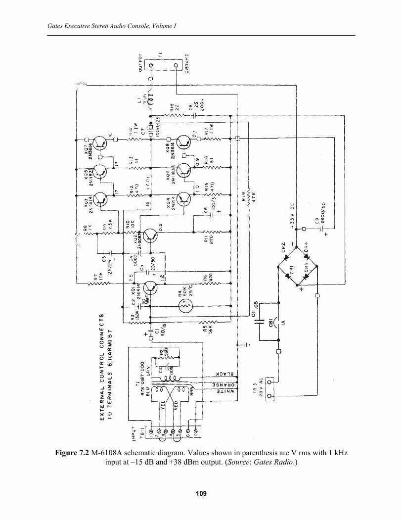
109
Gates Executive Stereo Audio Console, Volume I
Figure 7.2 M-6108A schematic diagram. Values shown in parenthesis are V rms with 1 kHz input at –15 dB and +38 dBm output. (Source: Gates Radio.)

Operation and Installation Manual, Gates M-6108A Monitor Amplifier
The parts list for the M-6108A monitor amplifier is given in Table 7.3.
It is commonly known that potentiometers tend to deteriorate after repeated use over time. The monitor volume control mounted on the front panel of the Executive console (R100) can experience problems where the volume is uneven or noise is heard at certain settings. Because this device is sealed, the only solution is replacement.
Potentiometer R100 is a 2.5 kΩ dual-gang sealed device. This value is difficult to find in a new replacement component. The closest common match is 5 kΩ dual-gang sealed, such as the KKU5021S28 from Precision Electronics Corp. This component has a linear taper; an audio taper (logarithmic) device can be used if preferred (KKA5021S28-ND). Performance of the monitor
Table 7.3 Parts List for the M-6108A Monitor AmplifierPart Number Component DescriptionC1 Capacitor, electrolytic, 50 μF, 15 VC2 Capacitor, 50 pF, 500 VC3 Capacitor, electrolytic, 20 μF, 50 VC4 Capacitor, 500 pF, 1 kVC5 Capacitor, electrolytic, 25 μF, 25 VC6 Capacitor, electrolytic, 100 μF, 3 VC7 Capacitor, electrolytic, 1000 μF, 25 VC8 Capacitor, 0.25 μF, 200 VC9 Capacitor, electrolytic, 2600 μF, 50 VC10 Capacitor, 0.005 μF, 100 VC11 Capacitor, 0.05 μF, 600 VCB1 Circuit Breaker, 1 ACR1, CR2, CR3, CR4 Silicon Rectifier, 1N4003L1 Choke, RF, 5 mH, 494 0135 000Q1, Q3 Transistor, 2N1414Q2 Transistor, 2N5087Q4 Transistor, 2N214Q5, Q6 Transistor, 2N1183AQ7, Q8 Transistor, 2N3614R2 Resistor, 560 Ω, 0.5 WR3 Resistor, 130 k, 0.5 WR4 Thermistor, 50 k, 559 0002 000R5 Resistor, 56 k, 0.5 WR6 Resistor, 470 Ω, 0.5 W (on some units R6 is 390 ohms)R7 Resistor, 10 k, 0.5 WR8 Resistor, 1 k, 0.5 WR9 Resistor, 7.5 k, 0.5 WR10 Resistor, 100 Ω, 0.5 WR11 Resistor, 270 Ω, 0.5 W (on some units R11 is 390 ohms)R12, R15 Resistor, 470 Ω, 0.5 WR13, R16 Resistor, 51 Ω, 0.5 WR14, R17 Resistor, 1 Ω, 2 WR18 Resistor, 22 Ω, 0.5 WR19 Resistor, 47 k, 0.5 WT1 Transformer, input, 478 0187 000
110

Gates Executive Stereo Audio Console, Volume I
amplifier with the 5 kΩ volume control is essentially identical to the 2.5 kΩ device, other than a small reduction in THD and IMD with the higher value component installed.
111

Operation and Installation Manual, Gates M-6108A Monitor Amplifier
7.3 Measured PerformanceOverall performance of the M-6108A monitor amplifier is documented in this section for the following operating conditions:
• Module on the bench with the cover in place.• Input power = 28 V ac, applied to terminals 1 and 2 of TB3.• Input = –15 dBm1 applied to monitor input terminals 2 and 4 on TB1. Terminals 2 and 3
are connected, and terminals 4 and 5 are connected. Terminals 1 and 6 are connected. A 2.5 kΩ resistor is connected between terminals 6 and 7.
• Measuring instrument load = 8 Ω, connected to terminals 1 and 2 of TB2.It is important to note that:• The performance documented here is representative of a collection of M-6108A monitor
amplifiers. Variations in performance from one unit to the next are to be expected.• Measurements in which the M-6108A is intentionally operated beyond its normal input
range should be conducted only on the test bench; they should not be conducted while the unit is installed in the Executive audio console. Unexpected consequences may result. This warning applies specifically to the following measurements: clipping, linearity, and power bandwidth.
The M-6108A draws approximately 100 mA from the 120 V ac line with no input signal. At an input level of –15 dBm (1 kHz), the amplifier draws 150 mA from the ac line. At the threshold of clipping it draws 250 mA.
In the following tests, the output was terminated in an 8 Ω load, which is characteristic of the operating environment in the Executive audio console. Unless noted, all measurements were made with an input of –15 dBm.
With an input of –15 dBm, the output is approximately 7.25 W. Clipping occurs with an input of about –12 dBm, which results in an output of 13 W at 1 kHz. Clipping is symmetrical.
The nominal input level for the tests documented in this section (–15 dBm) was chosen to be about 3 dB below the input level that will produce clipping. Allow the amplifier to warm up for about 5 minutes before taking measurements.
Figure 7.3 documents the input/output linearity of the monitor amplifier at 1 kHz. This test compares the input amplitude with the output amplitude in units of dBg, which is decibels relative to the generator output (monitor amplifier input). Linearity is charted with an input level of –40 dBm to 0 dBm at 1 kHz. Note that linearity begins to deteriorate at about –13 dBm, which is expected.
The maximum output capability of the monitor amplifier is examined from a different perspective in Figure 7.4, which charts the power bandwidth. Here, the input is run from a value equal to the operating level of –15 dBm up to a value well above the maximum operating level. The test instrument increases the input level until the measured THD+N (total harmonic distortion plus noise) reaches 3% (measurement bandwidth = 22 Hz to 80 kHz). To provide for efficient computation, a variation of ± 0.5% is allowed. The trace shows the output level achieved in a range of 20 Hz to 20 kHz. As shown, the amplifier can make in excess of 15 W across most of the audio band of 30 Hz to 15 kHz (as specified in Table 7.1).
1. Unless otherwise specified in the text.
112

113
Gates Executive Stereo Audio Console, Volume I
Figure 7.3 M-6108A input/output linearity at 1 kHz across the specified range of input levels.
Figure 7.4 M-6108A power bandwidth across the audio spectrum.
Figure 7.5 M-6108A frequency response at the normal operating level.
0
15
2.5
5
7.5
10
12.5
W
30 10k 50 100 200 500 1k 2k 5k
Hz
-3
+3
-2
-1
+0
+1
+2
dB r
20 20k 50 100 200 500 1k 2k 5k 10k
Hz
-10
+50
+0
+10
+20
+30
+40
d B g
-40 +0 -35 -30 -25 -20 -15 -10 -5
dBm

114
Operation and Installation Manual, Gates M-6108A Monitor Amplifier
Figure 7.8 M-6108A harmonic spectrum at the normal operating level, 1 kHz.
Figure 7.6 M-6108A frequency response –3 dB points at the normal operating level.
Figure 7.7 M-6108A THD+N versus frequency at the normal operating level.
-3
+3
-2
-1
+0
+1
+2
d B r
10 20 50 100 200 500 1k 2k 5k 10k 20k 40k
Hz
0.2
1
0.4
0.6
0.8
%
30 10k 50 100 200 500 1k 2k 5k
Hz
-150
+0
-125
-100
-75
-50
-25
d B r
20 20k 50 100 200 500 1k 2k 5k 10k
Hz

115
Gates Executive Stereo Audio Console, Volume I
Figure 7.9 M-6108A SMPTE IMD across the stated range of input levels.
Figure 7.10 M-6108A input/output phase at the normal operating level.
Figure 7.11 M-6108A residual noise spectrum.
-60
+80
-40
-20
+0
+20
+40
+60
d e g
20 20k 50 100 200 500 1k 2k 5k 10k
Hz
-150
+0
-125
-100
-75
-50
-25
d B r
20 20k 50 100 200 500 1k 2k 5k 10k
Hz
0.2
1
0.4
0.6
0.8
%
-24 -16 -22 -20 -18
dBm

Operation and Installation Manual, Gates M-6108A Monitor Amplifier
Frequency response is shown in Figure 7.5 from 20 Hz to 20 kHz. Deviation relative to 1 kHz across the band is less than 0.25 dB. The –3 dB points are shown in Figure 7.6. It can be seen that response extends from 10 Hz on the low end to more than 40 kHz on the high end.
Total harmonic distortion plus noise (THD+N) is shown in Figure 7.7 at the normal operating level across a range of frequencies from 30 Hz to 15 kHz (per the original equipment specifications). Distortion is less than 0.8%. The measurement bandwidth = 22 Hz to 80 kHz. Note that this trace is approximately the inverse of Figure 7.4, which is expected. Figure 7.8 shows the spectral components when reproducing a 1 kHz tone.
The matching of output transistors Q7 and Q8 has a significant impact on THD. In this particular measurement, the transistors were randomly selected. It is possible, and recommended, to purchase and install a matched pair of output transistors. These are readily available commercially in the NTE121MP device.
SMPTE IMD (60 Hz/7 kHz, 4:1) is shown in Figure 7.9 at input levels of –25 dBm to –15 dBm.
Input-output phase is shown in Figure 7.10 as a function of frequency. Transitions at the low and high end are smooth and gradual. The shift from 20 Hz to 20 kHz is approximately ±40 degrees.
Noise (unweighted) is –88 dB, relative to an input of –15 dBm, measurement bandwidth = 22 Hz to 22 kHz, input termination = 600 Ω. The residual noise spectrum is shown in Figure 7.11.
Measurement of amplifier performance at full power requires that interconnecting cables of sufficient size are used. For the power transformer, which is mounted external to the console, use #18 or larger and keep the run as short as possible. For the load, use #16 or larger and keep cable lengths to a minimum.
The M-6108A diagram shown in Figure 7.2 calls for a power input fuse (or circuit breaker) of 1 A. This value is sufficient for typical operation. However, when running tests using sine waves at full power, a 1 A fuse may be inadequate. The most stressful measurements insofar as power consumption are concerned are the linearity and power bandwidth tests, since these intentionally push the amplifier beyond its normal operating limits.
7.3.1 Measurement ConsiderationsIt is important to note that the power drawn by the M-6108A amplifier increases dramatically at high frequencies. This is the result of reduced output transistor efficiency with increasing frequency. For example, the current draw from the ac line when reproducing a 1 kHz sine wave at 8 W output is 150 mA, while the current draw from the ac line when reproducing a 20 kHz sine wave at 8 W output is 1 A or more. Keeping in mind that the power transformer has a step-down ratio of about four (120 V to 28 V), disregarding losses, the power supply in the M-6108A monitor amplifier must deliver ~4 A under these conditions, the majority of which is handled by output transistors Q7 and Q8. The power supply and output transistors are capable of operating at this level, but not for extended periods of time when reproducing high frequency sine waves at full power.
The current draw of the amplifier when producing the rated 8 W is essentially constant from 20 Hz to about 5 kHz, after which it rises sharply, peaking above 20 kHz. For a typical case where the high frequency –3 dB point is in the range of 40 kHz, peak current is usually observed at frequencies near that value. Driving the M-6108A at frequencies above 20 kHz at full power for
116

Gates Executive Stereo Audio Console, Volume I
more than a few seconds will cause the power input fuse to open. For the measurements documented in this section, the test instrument performs a sweep of frequencies in succession lasting only a few seconds. Measurements made with manual test equipment at full power are not practical.
Keeping in mind the current draw of the M-6108A at high frequencies, it is very important that a power transformer of sufficient current capability is used. Table 7.1 states the power requirements of the amplifier as 28 V at 1 A at normal operating levels. For program material, this is quite sufficient. However, for performance testing as documented in this section, a 28 V at 1 A ac source is inadequate; a minimum value of 28 V at 2.8 A is recommended. Likewise, the interconnecting cable from the power transformer to the ac input terminals of the M-6108A must be sufficient to handle the current without introducing voltage losses.
For applications where a higher value load is used (e.g., 45 Ω), the current increase at high frequencies is reduced; however, the considerations outlined in this section still apply.
117
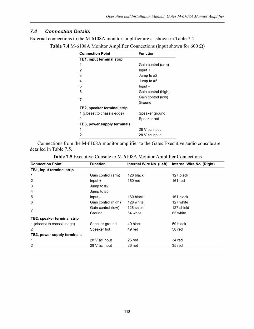
Operation and Installation Manual, Gates M-6108A Monitor Amplifier
7.4 Connection DetailsExternal connections to the M-6108A monitor amplifier are as shown in Table 7.4.
Connections from the M-6108A monitor amplifier to the Gates Executive audio console are detailed in Table 7.5.
Table 7.4 M-6108A Monitor Amplifier Connections (input shown for 600 Ω)Connection Point FunctionTB1, input terminal strip1 Gain control (arm)2 Input +3 Jump to #24 Jump to #55 Input –6 Gain control (high)
7Gain control (low)Ground
TB2, speaker terminal strip1 (closest to chassis edge) Speaker ground2 Speaker hotTB3, power supply terminals1 28 V ac input2 28 V ac input
Table 7.5 Executive Console to M-6108A Monitor Amplifier ConnectionsConnection Point Function Internal Wire No. (Left) Internal Wire No. (Right)TB1, input terminal strip1 Gain control (arm) 128 black 127 black2 Input + 160 red 161 red3 Jump to #2 4 Jump to #55 Input – 160 black 161 black6 Gain control (high) 128 white 127 white
7Gain control (low) 128 shield 127 shieldGround 64 white 63 white
TB2, speaker terminal strip1 (closest to chassis edge) Speaker ground 49 black 50 black2 Speaker hot 49 red 50 redTB3, power supply terminals1 28 V ac input 25 red 34 red2 28 V ac input 26 red 35 red
118

Gates Executive Stereo Audio Console, Volume I
7.5 Troubleshooting GuidelinesThe M-6108A monitor amplifier is designed for long, trouble-free service. However, problems can sometimes occur. The following guidelines are offered as a starting point for troubleshooting.
• Step 1 – Place the amplifier on the bench. Do not troubleshoot the monitor amplifier while installed in the Executive audio console.
• Step 2 – Connect the amplifier for testing; use the configuration described in Section 7.3. Confirm that the output is properly terminated in an 8 Ω load. Monitor the ac current draw and observe for excessive loading of the power transformer.
• Step 3 – Check all dc voltages. The dc voltages determine the bias points of the transistors and any departure of 20% or more should be considered a defect.
• Step 4 – Before signal measurements are made, replace any defective components to bring the dc voltages within tolerance.
• Step 5 – After all dc voltages are correct, signal tests may be performed. The typical (rms) voltages are shown in Figure 7.2 with an input of –15 dBm, 600 Ω, balanced, unloaded.
Do not use an ohmmeter to check the circuit board when transistors are in their sockets. Excessive current flow can result in damage. Do not remove or insert transistors with the power on. Remember, in this circuit V+ is ground; therefore, filter capacitors have the positive side connected to ground (common).
When troubleshooting the M-6108A monitor amplifier, the following steps should be taken to narrow the scope of work.1) Determine the overall condition of the output stage by taking the following voltage
measurements:Check the collector (case) of Q7. A reading of approximately –33 V dc should be
measured.Check the collector (case) of Q8. A reading of approximately –16 V dc should be
measured.2 Check the voltages at the driver stage:
Check the collector (case) of Q5. A reading of approximately –33 V dc should be measured.
Check the collector (case) of Q6. A reading of approximately –16 V dc should be measured.
Keeping in mind the discussion in Section 7.3.1, if the problem is high distortion at high frequencies, check the power supply for proper operation. If the supply cannot deliver the required current, THD+N will be high at high frequencies.
The operating point at the collector of Q1 is important for proper biasing of the stages that follow. As shown in Figure 7.2, this voltage should be in the neighborhood of –7.5 V dc. In the event that it is outside of the ±10% tolerance, check component values, particularly carbon resistors, and replace as needed. If these steps are not effective in bringing the Q1 collector to within specifications, one solution is to change the value of R7 from the 10 kΩ specified in Table 7.3 to a different value: lower if the voltage is low, or higher is the voltage is high. For the more common case of the Q1 collector voltage being below the target level of –7.5 V dc, the best approach is to add a resistor in parallel, soldered from the foil side of the PCB. The minimum parallel value that should be used is 47 kΩ, which provides an effective value for R10 of 8.2 kΩ. Adding a parallel resistor is usually a better approach than installing a different value resistor in
119
Operation and Installation Manual, Gates M-6108A Monitor Amplifier
the R10 position because it clearly indicates to any service personnel that a change has been made in the circuit.
Uniform frequency response of the M-6108A amplifier at high frequencies is important for stability of the amplifier. An increase of 1 dB or more at any frequency above 1 kHz should be investigated further. A frequency scan out to 100 kHz is recommended at –25 dBm, rather than the normal operating input level of –15 dBm. This will maintain the current draw from the power supply to within a safe level. If problems are identified from the frequency scan, investigate feedback components C2 and C4. It is possible to correct for minor response issues by increasing the value of C2 from the specified value of 50 pF to as much as 100 pF. It is recommended that the additional capacitance is gained by adding a capacitor of up to 47 pF in parallel with C2. Solder the device to the foil side of the PCB. This will minimize rework on the board, and clearly indicate to any service personnel that a change has been made in the circuit. Repeat the frequency scan to ensure that the desired overall trace has been achieved. One byproduct of the higher capacitance of C2 will be a reduction in distortion at high frequencies.
Note that the frequency response of the M-6108A amplifier is influenced by the load on the output of the amplifier, particularly at the high and low ends of the audio band. Generally speaking, if the frequency response with an 8 Ω load is within specifications, then the response with a 45 Ω load will be within specifications as well. The converse, however, is not necessarily true.
When replacing either Q7 or Q8, and before turning on the power, check with an ohmmeter between the transistor case and the chassis to make certain that a short circuit does not exist. Note that insulating washers must be placed under the transistors to provide insulation from chassis ground.
Important note: When securing the printed circuit board to the chassis, use nylon insulating washers under the board at each of the four mounting holes. The clearance between the chassis and R14 is quite tight. Failure to use the insulating washers may short one end of R14 to ground. At minimum this will open fuse F1 and possibly damage R14 and/or Q7.
Some electronic components are subject to deterioration over time. Notably, electrolytic capacitors can lose value with age or otherwise fail to meet the new device specifications. For a well-built component, decades of service can be expected. While less common, carbon resistors can change value over time, usually increasing in resistance (sometimes dramatically). It is recommended that these issues be addressed on an as-needed basis. Wholesale replacement of devices is not recommended unless experience has shown that a particular type or value of component is prone to failure.
Printed circuit boards manufactured in the 1960s and 70s are not tolerant of rework. The base material may be damaged by heat and the circuit board traces may lift at the connection pads. For this reason, it is recommended that only needed replacements are made. Troubleshooting through substitution may end up creating new issues and problems.
120

Gates Executive Stereo Audio Console, Volume I
Section 8: Gates M-6035 Cue/Intercom AmplifierThe Executive audio console includes a cue/intercom system for off-air setup and communications, such as record and tape cueing, studio intercommunication, and remote broadcasts. The cue/intercom system is highlighted in Figure 8.1.
Figure 8.1 Cue/intercom system in the Gates Executive audio console (highlighted).
121

Operation and Installation Manual, Gates M-6035 Cue/Intercom Amplifier
8.1 Overview and Specifications
The M-6035 Cue/Intercom Amplifier is designed to be used in the Executive audio console for cueing and talk-back purposes. The amplifier is fed from a 45 Ω source and operates into a 45 Ω speaker or resistive load.
An interstage volume control, remotely located on the console front panel, helps to reduce noise at normal operating levels. The frequency response of the amplifier is rolled off severely on both ends of the audio spectrum to provide the best compromise of cueing and intercom functions.
Specifications for the M-6035 amplifier are given in Table 8.1.
The M-6035 Cue/Intercom Amplifier is intended to be used with the M-6039 mounting frame, which carries a mating receptacle for the printed card-type connections. The fingers on the printed circuit board are gold-flashed for positive mating with the gold contacts on the receptacle. The amplifier requires a –37 V dc unregulated power source. The current draw ranges from 40 mA at average power output to a maximum of 120 mA.
On the Executive audio console, the incoming remote lines normally operate with a signal level of up to +8 dBm. This is padded down to a level sufficiently low to prevent overloading the cue amplifier when listening to the remote lines. The pads consist of a 620 Ω resistor across the input of each remote line and 5100 Ω resistors in series with each side of the line. The pads are
Table 8.1 Specifications of the M-6035 Cue/Intercom AmplifierParameter Specification
Gain 86 dB ±2 dB at 1 kHzVariable gain requires a 10 k potentiometer (part of the console)
Frequency response Peaked for maximum intelligibilityHarmonic distortion Less than 4% at +28 dBm (6 W at mid-band frequencies)Noise –105 dBm equivalent input noiseSource impedance 45 ΩOutput load impedance 45 Ω (high Impedance speaker)Maximum input level –40 dBmMaximum output level +30 dBmMaximum ambient operating temperature 55º C (131º F)Power requirements –37 V dc (unregulated), 30 to 100 mA
122

Gates Executive Stereo Audio Console, Volume I
built up on S38, the cue/intercom input selector switch located on the front panel of the console. The pads also provide isolation between lines when more than one line is switched into the cue/intercom amplifier.
The maximum gain of the cue/intercom amplifier is more than 80 dB. Because the input and output of the amplifier are in close proximity to the talk/listen relay (K5), wire dress is very important. Grounding of the cue/intercom system is also critical. Do not allow any part of the external speaker to be grounded. Speakers are grounded inside the console. Shielding of all external speaker lines is necessary to prevent hum and possible RF regeneration. In addition, the input and output signals of the M-6035 are 180 degrees out of phase, which aids in controlling acoustic and electrical feedback.
123

Operation and Installation Manual, Gates M-6035 Cue/Intercom Amplifier
8.2 Circuit DescriptionThe schematic diagram of the M-6035 cue/intercom amplifier is shown in Figure 8.2. For the purpose of explanation, the system can be considered to be made up of two distinct parts: the preamplifier and the power amplifier.
The two-stage preamplifier is driven by input transformer T1, which is lightly loaded by input resistor R1. This device prevents excessive signals from being developed by the intercom speaker at its resonance frequency, which would over-drive the input stage. Both stages are of the common-emitter configuration, with direct-coupling utilized between the first stage (Q1, 2N5088) and the second stage (Q2, 2N5087). Note that Q1 is an NPN type transistor and has its emitter returned to B– for biasing purposes.
Biasing of the first stage is accomplished by a combination of the voltage divider R1 and R2, and Q1 emitter resistance. This configuration insures a high degree of temperature stability. Operating voltage for the first stage (–20.6 V dc) is derived from dropping resistor R5 and filter capacitor C2. The remaining stages work directly from the –37 V dc supply.
As noted previously, the amplifier is designed for restricted frequency response. This shaping is done in the preamplifier section; the power amplifier is essentially flat, other than some intentional roll-off at the high end. High frequency shaping in the preamplifier is largely determined by C14, while low frequency shaping is largely determined by C5. Other than unbypassed emitter resistors R7 and R24, negative feedback is not employed in the preamplifier section. This results in an amplifier with very high gain. (See Table 8.1.)
The volume control (located on the console), situated between the preamplifier and power amplifier, is connected “in reverse” in order to maintain the high source impedance at all settings that the power amplifier requires.
The front panel volume control feeds power amplifier input stage Q3 (2N1414). The output stages of the power amplifier operate Class B, and are arranged in a single-ended push-pull architecture. The upper and lower units are in series across the power supply, and the load is connected at their junction. When the signal at the collector of Q4 (2N1414) goes negative, Q5 (2N1414) and Q7 (2N1183) conduct, since they are both PNP types. When the signal goes positive, Q6 (2N214) and Q8 (2N1183) conduct since Q5 is an NPN type. Thus, the full signal appears at the junction point.
Note that Q4 is the only stage of the power amplifier that provides voltage gain. A high frequency transistor is used in this stage to improve stability. The combination of R23 and C13 assist in stabilizing the amplifier, particularly when the amplifier is operated into an open-circuit, which can happen during use depending on the settings of the intercom input switch.
Several feedback loops are employed in the output circuit, including R10, C7, and C9. Capacitor C7 ensures high frequency stability by providing a smooth roll-off in high frequency response above 10 kHz. C9 supplies positive feedback from the output to the collector circuit of Q4 to increase the signal handling capability of the stage.
Press-on heat sinks are used on output transistors Q7 and Q8. These transistors typically run cool during normal usage. However, at high volume the transistors can heat appreciably, requiring the heat sinks.
Typical operating voltages are shown in Figure 8.2 (taken with a Simpson 260). Variations of up to ±10% are considered normal. Note that because the input voltage to the cue/intercom
124

125
Gates Executive Stereo Audio Console, Volume I
Figure 8.2 Schematic diagram of the M-6035 cue/intercom amplifier. Values shown in parenthesis are V rms with a level that produces +32 dBm output at full gain. (Source: Gates
Radio.)

Operation and Installation Manual, Gates M-6035 Cue/Intercom Amplifier
amplifier is not regulated, variations in the ac power line voltage can impact the measured dc voltages. The differences are usually not significant, however.
The parts list for the M-6035 cue/intercom amplifier is given in Table 8.2.
The circuit board layout is shown in Figure 8.3.The M-6035 circuit board should not be removed from or inserted into the card frame when
power is applied. Likewise, for cases where transistors are socket-mounted, active devices should not be changed while the power is applied.
Table 8.2 Parts List for M-6035 Cue/Intercom Amplifier Part Number Component DescriptionCl, C2, C3, C4, C9 Capacitor, electrolytic, 25 μF, 25 VC5 Capacitor, 0.1 μF, 200 VC6 Capacitor, electrolytic, 25 μF, 6 VC7 Capacitor, 0.001 μF, 1 kVC8 Capacitor, electrolytic, 20 μF, 50 VC12 Capacitor, electrolytic, 100 μF, 25 VC13 Capacitor, electrolytic, 25 μF, 200 VC14 Capacitor, 0.05 μF, 200 VQ1 Transistor, 2N5088Q6 Transistor, 2N214Q2, Transistor, 2N5087Q3. Q4, Q5 Transistor, 2N1414Q7, Q8 Transistor, 2N1183R1 Resistor, 22 k, 0.5 WR2, R3 Resistor, 8.2 k, 0.5 WR4 Resistor, 13 k, 0.5 WR5 Resistor, 12 k, 0.5 WR6 Resistor, 2.2 k, 0.5 WR7 Resistor, 300 Ω, 0.5 WR8 Resistor, 680 Ω, 0.5 WR9, R19, R20 Resistor, 470 Ω, 0.5 WR10, R14 Resistor, 10 k, 0.5 WR11 Resistor, 33 k, 0.5 WR12, R18 Resistor, 390 Ω, 0.5 WR13 Resistor, 110 k, 0.5 WRI5 Resistor, 1 k, 0.5 WR16 Resistor, 7.5 k, 0.5 WR23 Resistor, 47 Ω, 0.5 WR24 Resistor, 82 Ω, 0.5 WR21, R22 Resistor, 15 Ω, 0.5 WR25 Resistor, 6.8 Ω, 0.5 WR17 Resistor, 100 Ω, 0.5 WT1 Transformer, input, 478 0285 000
126

Gates Executive Stereo Audio Console, Volume I
8.3 Measured PerformancePerformance of the M-6035 amplifier is documented in this section for the following operating conditions:
• Module removed from the console and powered from a bench supply.• Module wired for maximum gain: a 10 kΩ resistor is connected between pins J and K, and
pins H and J are connected together.• Input power = –37 V dc, regulated, connected to pin A and common.• Input = 1 mV rms1 balanced, floating, 50 Ω, connected to pins B and D.• Measuring instrument load = 47 Ω resistive, connected to pin L and common.• With 1 mV rms input, the output of the amplifier is approximately 500 mW into a 47 Ω
load.It is important to note that:
• The performance documented here is representative of a collection of M-6035 amplifiers. Variations in performance from one unit to the next are to be expected.
• Measurements in which the M-6035 is intentionally operated beyond its normal input range should be conducted only on the test bench; they should not be conducted while the unit is installed in the Executive audio console. Unexpected consequences may result. This warning applies specifically to the following measurements: clipping, linearity, and power bandwidth. In addition, higher than normal input levels should be applied to the unit only long enough to make the measurement in question. Excessive heat buildup in the output transistors may result in the failure of one or more devices.
At zero audio input, the amplifier draws about 30 mA from the bench power supply. When operating at just below clipping, the current draw is approximately 100 mA. Driving the amplifier well into clipping will result in a current draw of 150 mA or so. Clipping is symmetrical.
1. Unless otherwise specified in the text.
Figure 8.3 PC board layout of the M-6035 Cue/Intercom Amplifier. (Source: Gates Radio.)
127

Operation and Installation Manual, Gates M-6035 Cue/Intercom Amplifier
The amplifier clips at an input level of about 1.75 mV rms at 1 kHz. At this level, the amplifier delivers 8 V into a 47 Ω resistive load (1.35 W). Note that the amplifier is designed to work into a 45 Ω load; a 47 Ω resistor was the closest match available for these measurements.
As described in the previous section, the frequency response of the cue/intercom amplifier has been shaped to provide for maximum intelligibility of voice communications. This characteristic is reflected in the frequency response curve of the amplifier across the audio band, as shown in Figure 8.4. It can be seen that response is down more than 16 dB at 20 kHz, and down more than 42 dB at 20 Hz. Shaping of the frequency response is done primarily in the preamplifier section of the cue/intercom amplifier.
Figure 8.5 shows the frequency response across the –6 dB points. As shown, the response covers the range of 250 Hz to 7 kHz. This frequency range is critical for intelligibility of voice communications. The remainder of the measurements in this section were taken across this range of frequencies. From the chart, it can be seen that the –3 dB points are approximately 450 Hz to 5 kHz.
Figure 8.6 documents the input/output linearity of the amplifier. This test compares the input amplitude with the output amplitude in units of dBg, which is decibels relative to the generator output (amplifier input). Measurement of a perfectly linear device will result in a flat horizontal trace across the entire input range. A trace at zero dBg indicates a unity (×1) gain device. Linearity is charted in Figure 8.6 with an input level of 1 mV rms to 2.5 mV rms at 1 kHz. Note that linearity begins to deteriorate at about 1.75 mV rms, which is expected given the clipping observation previously mentioned.
Figure 8.7 documents the power bandwidth over a range of 250 Hz to 7 kHz. In this test, the input is run from a value equal to the nominal operating level of 1 mV rms up to a value well above the maximum operating level. The test instrument increases the input level until the measured THD+N reaches 3% (measurement bandwidth = 22 Hz to 80 kHz). To provide for efficient computation, a variation of ± 0.5% is allowed. Note that the M-6035 amplifier is capable of producing more than 1.5 W across the operating frequency range into a 47 Ω load.
THD+N is shown in Figure 8.8. Distortion is at or below 1.8% across the frequency range of interest for a normal operating level of 1 mV rms input (0.5 W output). The measurement bandwidth = 22 Hz to 80 kHz. The spectral components of the amplifier when reproducing a 1 kHz tone are shown in Figure 8.9.
SMPTE IMD measurements were not taken because the frequency response curve of the cue/intercom amplifier would invalidate the reading (response at 60 Hz is down more than 20 dB).
Input/output phase of the cue/intercom amplifier is shown in Figure 8.10 as a function of frequency. Note that at 1 kHz, phase is reversed 180 degrees from input to output.
Noise (unweighted) is –74 dB, relative to an input of 1 mV rms, measurement bandwidth = 22 Hz to 22 kHz, input termination = 50 Ω. The residual noise spectrum is shown in Figure 8.11. Note that the board has no shielding in the test configuration.
128

129
Gates Executive Stereo Audio Console, Volume I
Figure 8.4 M-6035 cue/intercom amplifier frequency response across the audio band.
Figure 8.5 M-6035 cue/intercom amplifier frequency response across the –6 dB points.
Figure 8.6 M-6035 cue/intercom amplifier input/output linearity across the specified range of input levels.
-50
+10
-40
-30
-20
-10
+0
d B r
20 20k 50 100 200 500 1k 2k 5k 10k
Hz
-8
+8
-6
-4
-2
-0
+2
+4
+6
dB r
300 400 500 600 700 1k 2k 3k 4k 5k 6k 7k
Hz
+50
+90
+60
+70
+80
d B g
1m 2.5m 1.25m 1.5m 1.75m 2m 2.25m
Vrms

130
Operation and Installation Manual, Gates M-6035 Cue/Intercom Amplifier
Figure 8.7 M-6035 cue/intercom amplifier power bandwidth across the operating frequency range.
Figure 8.8 M-6035 cue/intercom amplifier THD+N across the operating frequency range.
Figure 8.9 M-6035 cue/intercom amplifier harmonic spectrum at the specified input, 1 kHz.
500m
2
1
1.5
W
300 400 500 600 700 1k 2k 3k 4k 5k 6k 7k
Hz
0.5
3
1
1.5
2
2.5
%
300 400 500 600 700 1k 2k 3k 4k 5k 6k 7k
Hz
-150
+0
-125
-100
-75
-50
-25
d B r
20 20k 50 100 200 500 1k 2k 5k 10k
Hz

Gates Executive Stereo Audio Console, Volume I
8.4 Connection DetailsThe PC board edge connector pin-out for the M-6035 cue/intercom amplifier is given in Table 8.3.
Table 8.3 M-6035 Cue/Intercom Amplifier PC Board Pin-outEdge Connector # FunctionC, E, F Not connectedA Power (V–), –37 V dcB Input (+)D Input (–)H Volume control armJ Volume control highK Common (V+)L Output
Figure 8.10 M-6035 cue/intercom amplifier input/output phase.
-300
-100
-250
-200
-150
d e g
300 400 500 600 700 1k 2k 3k 4k 5k 6k 7k
Hz
-120
+0
-100
-80
-60
-40
-20
dB r
20 20k 50 100 200 500 1k 2k 5k 10k
Hz
Figure 8.11 M-6035 cue/intercom amplifier residual noise spectrum.
131

Operation and Installation Manual, Gates M-6035 Cue/Intercom Amplifier
8.5 Troubleshooting GuidelinesThe M-6035 cue/intercom amplifier is designed for long, trouble-free service. However, problems can sometimes occur. The following guidelines are offered as a starting point for troubleshooting.
• Step 1 – Place the circuit board on the bench. Do not troubleshoot the cue/intercom amplifier while installed in the Executive audio console.
• Step 2 – With a spare PCB card edge connector, build up a bench test fixture. Use the connections described in Section 8.3. Use a regulated bench power supply to provide the specified input of –37 V dc. Monitor the current draw of the board and observe for excessive loading of the supply. Confirm that the output is properly terminated in a 45 Ω load (a 47 Ω load is acceptable).
• Step 3 – Check all dc voltages. The dc voltages determine the bias points of the transistors and any departure of 20% or more should be considered a defect.
• Step 4 – Before signal measurements are made, replace any defective components to bring the dc voltages within tolerance.
• Step 5 – After all dc voltages are correct, signal tests may be performed. The typical (rms) voltages are shown in Figure 8.2 with an input level that produces +32 dBm output at full gain.
Do not use an ohmmeter to check the circuit board when transistors are in their sockets. Excessive current flow can result in damage. Do not remove or insert transistors with the power on. Remember, in this circuit V+ is ground; therefore, filter capacitors have the positive side connected to ground (common).
When troubleshooting the M-6035 amplifier, the following steps may be taken to narrow the scope of work.1) Determine the overall condition of the output stage by taking the following voltage
measurements:Check the collector (case) of Q7. A reading of approximately –37 V dc should be
measured.Check the collector (case) of Q8. A reading of approximately –18.8 V dc should be
measured.2) Check the voltage at the junction of R5 and R24. A reading of approximately –20.6 V dc
should be measured.3) With an appropriate input to the board (e.g., 1 mV rms, 45 Ω, 1 kHz, pins B and D), measure
the signal at the output of the preamplifier stage (pins H and K). A reading in excess of 0.5 V rms should be measured.
When troubleshooting performance issues with the M-6035, it is often helpful to identify whether the problem is centered in the preamplifier stages (Q1 and Q2) or the output stages (Q3 – Q8. This is best accomplished by applying an input signal to the board as described in Section 8.3 and measuring the output of the preamplifier at pins H and K.
Some electronic components are subject to deterioration over time. Notably, electrolytic capacitors may lose value with age or otherwise fail to meet the new device specifications. For a well-built component, decades of service can be expected. While less common, carbon composition resistors may change value over time, usually increasing in resistance (sometimes dramatically). It is recommended that these issues be addressed on an as-needed basis. Wholesale
132

Gates Executive Stereo Audio Console, Volume I
replacement of devices is not recommended unless experience has shown that a particular type or value of component is prone to failure.
In the M-6035 amplifier, significant loss of capacitance in a coupling capacitor (e.g., C6) can lead to a sharp roll-off in frequency response at low frequencies. In extreme cases, response at 5 kHz may be close to normal, while response a 500 Hz is down 10 dB (or more).
Printed circuit boards manufactured in the 1960s and 70s are not tolerant of rework. The base material may be damaged by heat and the circuit board traces may lift at the connection pads. For these reasons, it is recommended that only needed replacements are made. Troubleshooting through substitution may end up creating new issues and problems.
133

134
Operation and Installation Manual, Gates M-6035 Cue/Intercom Amplifier

Gates Executive Stereo Audio Console, Volume I
Section 9: Gates M-6205 Power SupplyThe Executive audio console includes an M-6205 power supply module that provides operating voltages to the ten preamplifier circuit boards, the cue-intercom amplifier board, and the line-level output modules (Left, Right, and Audition). These circuits are highlighted in Figure 9.1.
Figure 9.1 Power supply loads in the Gates Executive audio console (highlighted).
135

Operation and Installation Manual, Gates M-6205 Power Supply
9.1 Overview and Specifications
The M-6205 power supply provides two dc outputs for the Executive audio console: a –37 V unregulated source for the cue/intercom amplifier, and a –30 V regulated source for the preamplifier and line amplifier modules. In this application, the total required current from the unregulated supply is approximately 75 mA, and for the –30 V regulated supply it is approximately 500 mA. For the regulated supply, ripple and noise is about 2 mV rms with no load.
136

Gates Executive Stereo Audio Console, Volume I
9.2 Circuit DescriptionThe schematic diagram of the M-6205 power supply is shown in Figure 9.2.
Input ac power is provided by a transformer mounted external to the Executive audio console. The transformer is rated for 28 V ac, 2 A (minimum). The input power is applied to fuse F1 (1.5 A) and then to a bridge rectifier consisting of diodes CR1 – CR4. The input ac is also supplied to diodes CR5 and CR6 for an ancillary –75 V dc source, which is used by the regulator circuit.
The output of the bridge rectifier is filtered by C3 and applied to the regulator circuit. This voltage source is also routed to the –37 V dc supply output terminals through series resistor R14 and filter capacitor C6. The –37 V dc supply is protected by fuse F2 (1 A).
The –75 V dc source is developed by a voltage-doubler circuit consisting of CR5, CR6, C1, and C2.
Transistors Q4 (2N1307), Q5 (2N214), and Q6 (2N1414) amplify any change in the output voltage, which is sensed across the –30 V dc terminals. This control signal is then fed to Q2 (2N1414), which in turn controls the voltage drop across series regulator Q1 (2N1539). Transistor Q1 is in series with the output and maintains a constant voltage with varying loads and with changes in the input ac voltage from the utility line. Zener diodes CR9, CR10, and CR11 provide reference levels for the voltage-sensing amplifier. Capacitor C4 and RC pair C8/R15 suppress high frequency noise in the high-gain voltage-sensing stages.
Overload protection is provided by Q3 (2N1539) and the associated circuitry. Maximum current output from the power supply is limited to approximately 600 mA. The common supply returns for the –30 and –37 V dc sources pass through Q3, which normally operates at near saturation. However, when sufficient voltage builds up across R3 due to current through the load, Q3 acts to limit the current to a safe level.
Potentiometer R12 provides a means for adjusting the output voltage over a small range to allow for zener diode voltage tolerances. When installing the Executive console, this voltage should be checked and, if necessary, R12 adjusted to yield –30 volts at the output + and – buss. When unloaded, R12 has an adjustment range from approximately 26 V to 37 V. Clockwise rotation decreases the voltage; counter-clockwise rotation increases it.
The console power transformers, three 28 V ac sources, are mounted externally. This prevents the magnetic field surrounding the power transformers from inducing hum into the 1ow-level audio circuits of the Executive audio console. Three independent 28 V windings are necessary to provide complete isolation among each monitor amplifier and the main console power supply.
The parts list for the M-6205 power supply is given in Table 9.1.
137

138
Operation and Installation Manual, Gates M-6205 Power Supply
Figure 9.2 Schematic diagram of the M-6205 power supply. Voltages shown were measuredwith a 20 kΩ/V meter. (Source: Gates Radio.)

Gates Executive Stereo Audio Console, Volume I
Table 9.1 Parts List for the M-6205 Power Supply ModulePart No. Component DescriptionC1, C2 Capacitor, electrolytic, 20 μF, 100 VC3 Capacitor, electrolytic, 1000 μF, 50 VC4 Capacitor, 0.1 μF, 200 VC5 Capacitor, electrolytic, 250 μF, 50 VC6 Capacitor, electrolytic, 500 μF, 50 VC7 Capacitor, electrolytic, 100 μF, 50 VC8 Capacitor, 0.001 μF, 1 kVCR1, CR2, CR3, CR4, CR5, CR6, CR7, CR12 Silicon Rectifier, 1N4003CR8, CR9, CR10, CR11 Zener diode, 1N754F1 Fuse, 1.5 A, Slo-BloF2 Fuse, 1 A, 250 VQ1, Q3 Transistor, 2N1539Q2, Q6 Transistor, 2N1414Q4 Transistor, 2N1307Q5 Transistor, 2N214R1, R5, R8, R11 Resistor, 10 k, 0.5 WR2 Resistor, 5,1 k, 0.5 WR3 Resistor, 0.75 Ω, 0.5 WR4 Resistor, 3.3 k, 2 WR6, R7, R9 Resistor, 8,2 k, 0.5 WR10 Resistor, 2.7 k, 0.5 WR12 Potentiometer, trimmer, 2 k, 0.5 WR13 Resistor, 2.4 k, 0.5 WR14 Resistor, 20 Ω, 0.5 WR15 Resistor, 4.7 k, 0.5 WTB1 Terminal boardTB2 Terminal strip
139

Operation and Installation Manual, Gates M-6205 Power Supply
9.3 Connection DetailsWiring of the M-6205 power supply to the Executive audio console is detailed in Table 9.2.
Table 9.2 Wiring Codes for the M-6205 Power Supply in the Executive ConsoleTerminal Number Supply Function Internal Wire No. Console Function
TB1-1 28 V ac input19 red to TB6-6 Power supply ac input58 red VU meter lamps
TB1-2 28 V ac input18 red to TB6-5 Power supply ac input58 black VU meter lamps
TB1-3 37 V dc supply com-mon (V+) 16 red Cue amplifier 37 V dc supply common
(V+)TB1-4 –37 V dc output 15 red Cue amplifier V–
TB2 (all positions) 30 V dc supply com-mon (V+)
275 gray Chassis common9 red AL1 30 V dc supply common (V+)11 red AL3 30 V dc supply common (V+)13 red AL2 30 V dc supply common (V+)59 red Cue relay 30 V dc supply common (V+)85 red AB1 30 V dc supply common (V+)86 red AB2 30 V dc supply common (V+)
TB3 (all positions) –30 V dc output
1 red AP1 V–2 red AP2 V–3 red AP3 V–4 red AP4 V–5 red AP5 V–6 red AP6 V–7 red AB1 V–8 red AB2 V–10 red AL3 V–12 red AL2 V–14 red AL1 V–17 white S1/S2/S3 muting circuit24 red Cue relay V–81 red AP7 V–82 red AP8 V–
Note 1: The Executive console line schematic shown in Figure 4.1 (Section 4, Architecture) clearly shows the S1/S2/S3 relay panel powered by the –37 V unregulated supply. However, in at least some implementations (and in this table) the relay panel is powered by the –30 V dc supply.
140

Gates Executive Stereo Audio Console, Volume I
9.4 Troubleshooting GuidelinesThe M-6205 power supply is designed for long, trouble-free service. However, problems can sometimes occur. The following guidelines are offered as a starting point for troubleshooting. Be very careful when operating the console with a known power supply issue. Have the console powered-up only long enough to make the needed measurements. Be observant for signs of problems, such as over-heated components or smoke.
• Step 1 – Determine the state of the power supply.– Remove all power from the console. If a separate power source is connected to the On-Air
warning lights (TB7), it should be disconnected as well.– With all power removed, make the following resistance measurements:
TB1-1 to TB1-2 (28 V ac input) should equal approximately 33 Ω with the external power transformer connected.
TB1-3 to TB1-4 (–37 Vdc unregulated output) should measure in excess of 100 Ω. Note that the reading should start off in excess of 100 Ω and slowly increase as the capacitors in the circuit respond to the applied ohmmeter voltage.
TB2 to TB3 (–30 Vdc regulated output) should measure in excess of 100 Ω. Note that the reading should start off in excess of 100 Ω and slowly increase as the capaci-tors in the circuit respond to the applied ohmmeter voltage.
– Check the two fuses, F1 and F2. Replace as necessary with the proper size.– If F2 has opened, remove the cue/intercom amplifier PCB from the card frame and test the
system again.– If F1 has opened, remove all preamplifier PCBs and the cue amplifier PCB from the card
frame. Also remove the three line amplifiers, making note of which module is in which tray. You will want to return the modules to the same positions.
– Power-up the console and measure the input ac voltage between TB1-1 and TB1-2. A reading of 28 V ac is normal.
– Measure the unregulated –37 V dc supply on TB1-3 and TB1-4. A range of –35 V dc to –40 V dc is normal. A failure at this point would indicate problems with one or both fuses, the bridge rectifier (CR1 through CR4), and/or the main filter capacitor (C3).
– Measure the output of the –30 V dc supply on TB2 and TB3. A reading of –30 V should be observed. Small changes to the output voltage can be made by adjusting R12 on the circuit board; however, if the console is not operating properly, the setting of R12 is unlikely to be the problem. If the proper voltage is not measured between TB2 and TB3:
Remove power from the console and then remove all connections to TB3 (the –30 V dc regulated output). Carefully collect the wires to avoid contact with any exposed portions of the console. Then apply power to the console and measure the output of the –30 V dc regulated supply. If the supply returns to normal, then a wiring prob-lem exists in the console.
If the previous step does not return the –30 V dc regulated supply to normal, remove all power from the console and then remove the power supply for additional work on the bench. Be certain to record the exact position of each connector on the power supply output terminals. Label as needed. This information will be vital when the supply is reinstalled. Note that a long-shaft Phillips screwdriver (e.g., 10-
141

Operation and Installation Manual, Gates M-6205 Power Supply
inches in length) will be required to remove and install the power supply.• Step 2 – With a spare 28 V ac transformer, build up a bench test fixture. Power-up the
supply and repeat measurements on the –37 and –30 V dc outputs. If the readings return to normal, the problem is likely a wiring issue within the console or an intermittent condition. An intermittent failure can be caused by a poor solder joint on the circuit board or a loose connection on one of the chassis-mounted devices. Intermittent failures can also result from a transistor or zener diode that is not seated properly in its socket.
• Step 3 – Check all dc voltages on the M-6205 PCB. Any departure of 20% or more should be considered a defect. In particular, note the reference voltage points established by zener diodes CR8 through CR11.
• Step 4 – Look for signs of heat-related stress in resistors and other components on the circuit board; it may point to a problem area.
• Step 5 – Check transistors as appropriate using a semiconductor test instrument, or by substitution of a known-good device. Make certain that all transistors and zener diodes are mounted firmly in their sockets. Remember also that with direct-coupled devices, a failure in one transistor may damage other transistors in the circuit. Do not change transistors or zener diodes while power is applied.
Due to the high gain of the voltage-sensing amplifier (transistors Q4, Q5, and Q6), noise can be a problem with the power supply. Observe the output at TB2 and TB3 with an oscilloscope. If high-frequency noise is detected, check (in particular) C4 and C8.
Note that it is normal for power supply ripple to increase slightly as the loading on the supply is increased. The increased low frequency noise may be measurable under certain conditions. To confirm proper operation, verify the no-load ripple specification stated previously (2 mV rms).
Do not use an ohmmeter to check the circuit board when transistors are in their sockets. Excessive current flow can result in damage. Do not remove or insert transistors (or circuit boards) with the power on. Remember, in this circuit V+ is ground; therefore, filter capacitors have the positive side connected to ground (common).
Some electronic components are subject to deterioration over time. Notably, electrolytic capacitors can lose value with age or otherwise fail to meet the new device specifications. For a well-built component, decades of service can be expected. While less common, carbon composition resistors can change value over time, usually increasing in resistance (sometimes dramatically). It is recommended that these issues be addressed on an as-needed basis. Wholesale replacement of devices is not recommended unless experience has shown that a particular type or value of component is prone to failure.
Printed circuit boards manufactured in the 1960s and 70s are not tolerant of rework. The base material may be damaged by heat and the circuit board traces may lift at the connection pads. For this reason, it is recommended that only needed replacements are made. Troubleshooting through substitution may end up creating new issues and problems.
142

143
Gates Executive Stereo Audio Console, Volume I
Section 10: Safety NoticeWARNING: THE CURRENTS AND VOLTAGES IN THIS EQUIPMENT ARE DANGEROUS
AND UNDER CERTAIN CONDITIONS, COULD BE FATAL.This Manual is intended as general guidance for trained and qualified installation, operating,
maintenance, and service personnel who are familiar with and aware of the dangers inherent to handling potentially hazardous electrical and/or electronic circuits. It is not intended to contain a complete statement of all safety precautions that should be observed by personnel in using this or other electronic equipment.
The installation, operation, maintenance, and servicing of this equipment involves risks to both personnel and equipment, and must be performed only by properly trained and experienced personnel exercising due care, with the proper tools. Personnel must familiarize themselves with safety requirements, safe handling and operating practices, and related first-aid procedures (e.g., for electrical burns and electrical shock).
The equipment suppler shall not be responsible for injury or damage resulting from improper installation, operation, maintenance, and servicing, or from the use of improperly trained or inexperienced personnel in the performance of such tasks, or from the failure of persons engaged in such tasks to exercise due care.
As with all electronic equipment, care should be taken to avoid electrical shock in all circuits where substantial currents or voltages may be present, either through design or short-circuit.
Caution should also be observed in lifting and hoisting equipment, especially regarding large structures, during installation.
LIABILITY LIMITATIONThe procedures outlined in this Manual are based on the information available at the time of
publication and should permit the specified use with minimum risk. However, the equipment supplier cannot assume liability with respect to technical application of the contents and shall, under no circumstances, be responsible for damage or injury (whether to person or property) resulting from its use.
The equipment supplier is specifically not liable for any damage or injury arising out of failure to follow the instructions in this Manual or failure to exercise due care and caution during installation, operation, maintenance, and service of this equipment.
CAUTIONARY NOTICEAlways disconnect power before opening covers, doors, enclosures, gates, panels, or shields.
Always use grounding sticks and short out high voltage points before servicing. Never make internal adjustments, perform maintenance, or service when alone or when tired.
Never remove, short-circuit, or tamper with interlock switches on access covers, doors, enclosures, gates, panels, or shields. Keep away from live circuits, know your equipment, and don’t take chances. Proper training of experienced personnel and observing the above guidelines will help assure safe and continued operation of this equipment.