Installation & Operation Manual - Alena Energy
56
编号:GR-UM-C -00 1 / 56 Installation & Operation Manual Guangdong Growatt New Energy Co., LTD No.28 Guangming Road, Shiyan Street, Bao'an District, Shenzhen, PR. China T: +86 0755 2747 1942 E: [email protected] W: www.ginverter.com
-
Upload
khangminh22 -
Category
Documents
-
view
1 -
download
0
Transcript of Installation & Operation Manual - Alena Energy

编号:GR-UM-C -00
1 / 56
Installation & Operation Manual
Guangdong Growatt New Energy Co., LTD
No.28 Guangming Road, Shiyan Street, Bao'an District, Shenzhen, PR. China
T: +86 0755 2747 1942
W: www.ginverter.com

编号:GR-UM-C -00
2 / 56
目录
1. Overview ............................................................................................................................................. 5
1.1 Product Overview ...................................................................................................................... 5
1.2 Applicable Personnel ............................................................................................................... 5
2. Safety Precautions ........................................................................................................................... 5
2.1 Safety Overview ......................................................................................................................... 5
2.2 Symbol Conventions ................................................................................................................ 7
2.3 Lable Description ....................................................................................................................... 8
3. Product Introduction....................................................................................................................... 9
3.1 Appearance ................................................................................................................................. 9
3.2 Basic Data ................................................................................................................................... 10
3.3 Nameplate ................................................................................................................................. 11
3.4 Working Principle .................................................................................................................... 11
3.5 Inverter Storage ....................................................................................................................... 12
3.6 Grid Types .................................................................................................................................. 12
3.7 AFCI Detection Function ....................................................................................................... 13
3.8 Anti-PID Function .................................................................................................................... 13
4 Unpacking .......................................................................................................................................... 13
5. Installation ........................................................................................................................................ 14

编号:GR-UM-C -00
3 / 56
5.1 Basic Installation Requirements ......................................................................................... 15
5.2 Installation Environment Requirements .......................................................................... 16
5.3 Moving Requirements ........................................................................................................... 18
5.4 Wall Mount Bracket Installation ......................................................................................... 19
5.5 Installing The Inverter ............................................................................................................ 20
6. Connecting Cable ........................................................................................................................... 21
6.1 Connection on AC side .......................................................................................................... 21
6.2 Connection On DC Side ........................................................................................................ 25
6.3 Connection Of Communication Cables ........................................................................... 26
6.3.1 RS485 port ................................................................................................................. 26
6.3.2 USB port ...................................................................................................................... 28
6.4 Connecting The Ground Cables ......................................................................................... 29
7. Commissioning ............................................................................................................................... 31
7.1 Commission The Inverter ..................................................................................................... 31
7.1.1 Set inverter address ................................................................................................ 31
7.1.2 Set inverter time and date.................................................................................... 33
7.2 Operation Mode ...................................................................................................................... 33
7.2.1 Waiting mode ........................................................................................................... 33
7.2.2 Working mode .......................................................................................................... 33

编号:GR-UM-C -00
4 / 56
7.2.3 Fault mode ................................................................................................................. 34
7.2.4 Off mode .................................................................................................................... 34
7.3 LED Display ................................................................................................................................ 34
8 Remote Data Monitoring ............................................................................................................. 36
8.1 Remote Data Monitoring ..................................................................................................... 36
8.1.1 Mobile phone APP(ShinePhone) remote monitoring ................................. 36
8.2 Local Data Monitoring ........................................................................................................... 39
8.2.1 Mobile phone app (Shinephone) Local Monitoring .................................... 39
8.2.2 U Disk Monitoring ................................................................................................... 44
9. System Maintenance ..................................................................................................................... 46
9.1 Routine Maintenance ............................................................................................................. 46
9.1.1 Cleaning Inverter ..................................................................................................... 46
9.1.2 Fan Maintenance ...................................................................................................... 46
9.2 Trouble Shooting..................................................................................................................... 49
9.2.1 Warning ....................................................................................................................... 49
9.2.2 Error .............................................................................................................................. 50
10. Specification .................................................................................................................................. 51
11. Decommissioning ........................................................................................................................ 55
12. Quality assurance......................................................................................................................... 56
13. Contact ............................................................................................................................................ 56

编号:GR-UM-C -00
5 / 56
1. Overview
1.1 Product Overview
This manual is aimed at providing sufficient information and installing instruction for
consumers buying Shenzhen Growatt New Energy Co., Ltd (short as Growatt) MAX
80-150KTL3-X LV/MV Series solar inverters. Please read this manual carefully before
using the MAX 80-150KTL3-X LV/MV series inverters and store the manual in a
reachable place for an authorized technician. No further notice if there is any change
in this manual.
1.2 Applicable Personnel
Only qualified electrical technicians are allowed to install MAX 80-150KTL3-X LV/MV
series inverter. With reading through this manual and following all the precautions,
qualified electrical technician can properly install MAX 80-150KTL3-X LV/MV serial
inverter, finish trouble shooting and communication settings. If there is any problem
during the installation, the installer can either log on www.ginverter.com and leave a
message or call consumer service hotline +86 75527471942.
2. Safety Precautions
2.1 Safety Overview
1>Before installation please make sure reading through this manual, any damage
caused by improper installation, Growatt reserve the right to disclaim any warranty.
2>All the operations and connections must be done by trained qualified electrical
technician.
3>During installation except for terminals, do not touch any inside part of the
inverter.
4>All the electrical connections must meet local country's safety regulations.
5>If you need maintenance for this inverter, please contact our local authorized
installing and maintenance technician.
编号:GR-UM-C -00
6 / 56
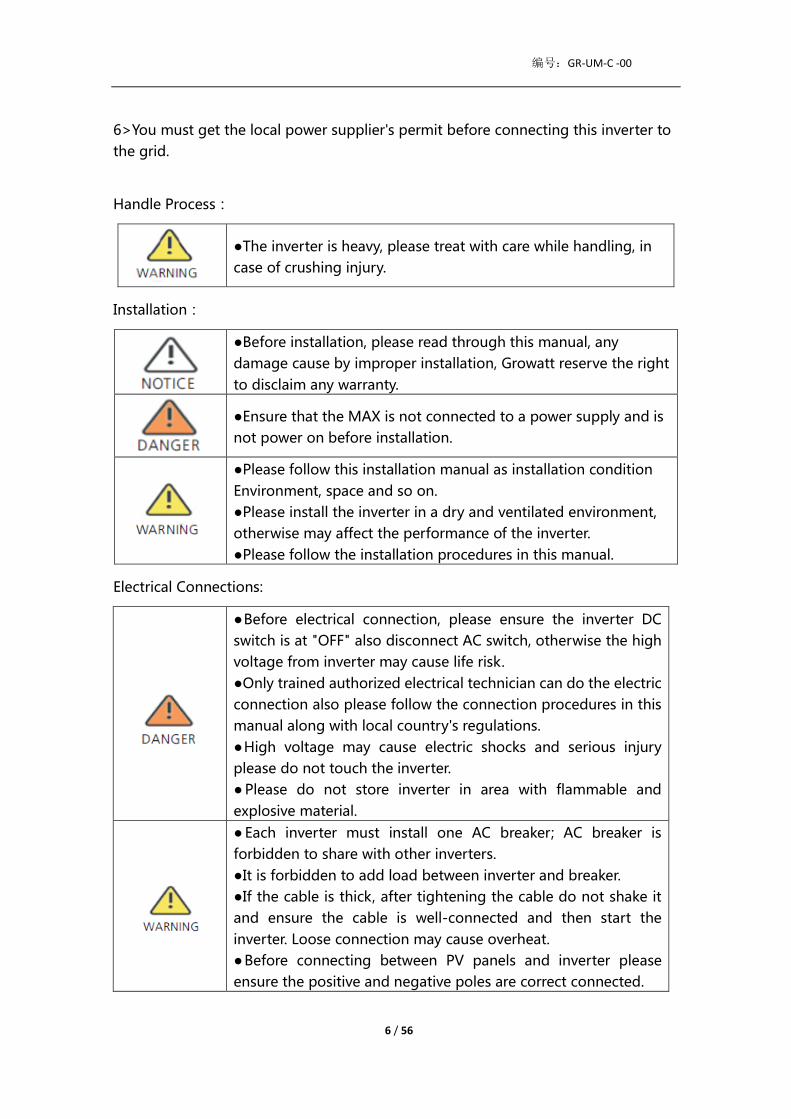
6>You must get the local power supplier's permit before connecting this inverter to
the grid.
Handle Process:
●The inverter is heavy, please treat with care while handling, in
case of crushing injury.
Installation:
●Before installation, please read through this manual, any
damage cause by improper installation, Growatt reserve the right
to disclaim any warranty.
●Ensure that the MAX is not connected to a power supply and is
not power on before installation.
●Please follow this installation manual as installation condition
Environment, space and so on.
●Please install the inverter in a dry and ventilated environment,
otherwise may affect the performance of the inverter.
●Please follow the installation procedures in this manual.
Electrical Connections:
●Before electrical connection, please ensure the inverter DC
switch is at "OFF" also disconnect AC switch, otherwise the high
voltage from inverter may cause life risk.
●Only trained authorized electrical technician can do the electric
connection also please follow the connection procedures in this
manual along with local country's regulations.
●High voltage may cause electric shocks and serious injury
please do not touch the inverter.
● Please do not store inverter in area with flammable and
explosive material.
● Each inverter must install one AC breaker; AC breaker is
forbidden to share with other inverters.
●It is forbidden to add load between inverter and breaker.
●If the cable is thick, after tightening the cable do not shake it
and ensure the cable is well-connected and then start the
inverter. Loose connection may cause overheat.
●Before connecting between PV panels and inverter please
ensure the positive and negative poles are correct connected.

编号:GR-UM-C -00
7 / 56
Maintenance and replacement:
● Must be installed by trained and authorized electrical
technician and accurately follow this manual.
●Please disconnect the DC and AC switch for at least five
minutes, all the operations should be carried after power
disconnection.
●If there is PV isolation low alarm, the inverter case may be
ungrounded, please do not touch the inverter case.
●High voltage of inverter may result in electric shock.
●For better cooling purpose, please regularly clean the fans.
●Do not use air pump to clean the fans, cause it may damage the
fans.
Other:
●After you receiving the inverter please check the packing
materials for damage, if there is any damage please contact your
supplier.
●The Max PV input voltage should not exceed 1100V.
●For the disposed inverter, the consumer should dispose it
according to local disposal rules for electrical equipment waste.
2.2 Symbol Conventions
Symbol Description
Indicates an imminently hazardous situation which, if not
avoided, will result in serious injury or death.
Indicates potentially hazardous situation which, if not avoided,
will result in serious injury or death.

编号:GR-UM-C -00
8 / 56
Indicates potentially hazardous situation which, if not avoided,
will result in minor or moderate injury.
Indicates certain hazardous situation which, if not avoided, will
Result in property damage.
Reminds operator to read installation manual before operating
or installing inverter.
2.3 Lable Description
Symbol Name Meaning
High Voltage
Electric Shock
Inverter operating with high voltage, any
operation regarding inverter need to be
done by trained and authorized electrical
technician.
Burn Warning
Do not touch a running inverter cause it
generates high temperature on the case.
Protective
Grounding Connect inverter to grounding bar.
Delay discharge
Residual voltage exists after the inverter is
powered off, it takes 5 minutes for the
inverter to discharge to the safe voltage.
Read the
installation
manual
Reminds operator to read installation
manual before operating or installing
inverter.
DC Means this terminal is for DC side.
AC Means this terminal is for AC side.
CE Mark
The inverter complies with the
requirements of the applicable CE
guidelines.

编号:GR-UM-C -00
9 / 56
3. Product Introduction
3.1 Appearance
Front view:
Fig 3.1
Bottom view (Termial):
Fig 3.2
Mark Description Mark Description
A Front panel B LED

编号:GR-UM-C -00
10 / 56
C PV terminal D DC switch
E Breathing valve F Safety ground screw
G USB interface H COM interface
I Corner guard J Waterproof silicone pad
3.2 Basic Data
Model Size(mm) Weight
(kg) Width Height Thickness
MAX 80-150KTL3-X LV/MV
Series Inverter 970 640 345 84
MAX 80-150KTL3-X LV/MV
Series Inverter with package 1100 760 500 93

编号:GR-UM-C -00
11 / 56
3.3 Nameplate
Note: Other models of MAX 80-150KTL3-X LV/MV series share the same label design
with MAX 125KTL3-X LV, only with different model name and parameters, detail
parameter please refer to specification in Chapter 10.
3.4 Working Principle
The MAX 80-150KTL3-X LV/MV series inverter works as follows:
1>The PV panels gather solar to generate DC power to inverter.
2>With input current detection circuit, it can monitor all the PV panels' working
status and use MPPT to track the maximum power point.
3>With inverter circuit change DC power to AC power, and feed power back to grid
per grid requirement.
4>With output isolation relay can isolate AC output and grid, if anything goes wrong
on either inverter side or grid side, isolation relay can disconnect inverter
immediately.

编号:GR-UM-C -00
12 / 56
On-grid connection system diagram:
Fig 3.4
3.5 Inverter Storage
1>Do not unpack the inverter and store it in a ventilation dry place .
2>Keep the storage temperature at -30℃-+60℃ and humidity at 0-100%.
3>A maximum of four inverters with package can be stacked.
4>If the inverter has been long-term stored, inspections and tests should be
conducted by qualified personnel before it is put into use.
After being stored for a month or longer, the inverter's
time and date could be wrong, you need set the time
and date before using, for more details please refer to
Chapter 7.1 inverter commissioning.
3.6 Grid Types
The 80-150KTL3-X LV/MV series, 80-133KTL3-X LV inverters connect to the grid like
following drawing3.5,125- 8150KTL3-X MV inverters connect to the grid like
following drawing3.6.
A B C D
symbol Description symbol Description
A PV string C Electric meter
B Inverter D Gird

编号:GR-UM-C -00
13 / 56
Fig 3.5 Fig 3.6
3.7 AFCI Detection Function
AFCI (Arc Fault Circuit Interrupter) is a kind of circuit protection device, the main
function is to prevent the fire caused by fault arc. The electrical insulation aging,
breakage, loose connection, air breakdown caused by air humidity and so on, all of
these may cause an electric spark, which is called arc.
The AFCI function of the MAX series inverter is optional, and the detection equipment
is assembled inside the inverter. When an arc-drawing condition is detected on the
PV input side, the arc current could be detected by the CT assembled on the PV
input-side wire. Then the inverter will shut down. Meanwhile, the inverter will display
the corresponding fault message and the buzzer will sound, which could help to
avoid harm and economic loss to the user.
NOTE: AFCI function is optional.
3.8 Anti-PID Function
The full name of PID is Potential Induced Degradation. Since the PID effect, a large
amount of charge could accumulate on the surface of the photovoltaic module,
which makes the surface passivation of the module worse. Eventually, the fill factor,
open circuit voltage, and short-circuit current of the module are reduced, and the
power of the photovoltaic module is attenuated.
The Anti-PID function uses the principle of reversible PID changes. MAX series
inverters rectify AC voltage at night and boost it to generate a DC voltage. The DC
voltage is connected to PV + and the ground respectively. When add a positive bias
voltage to the module to make the PID effect reverse, the Anti-PID function could
repair the photovoltaic modules at night and prolong the service life of photovoltaic
modules.
NOTE: Anti-PID function is optional.
4 Unpacking
Checking before installation
1>Before unpacking the inverter, check the outer packing materials for damage.
2>After unpacking the inverter, check that the contents are intact and complete. If
any damage is found or any component is missing, contact your supplier.

编号:GR-UM-C -00
14 / 56
Package contents:
Fig 4.1
Mark Descriptions Number
A Inverter 1
B Wall mount 1
C PV + terminal, PV- terminal 14/14(7 MPPT)
20/20(10MPPT)
D PV terminal metal core 14/14(7 MPPT)
20/20(10MPPT)
E Removal tool of PV terminals 1
F Installation manual 1
G Warranty card 1
H Rs485 terminal 1
I Removal handle(opt) 2
J Wall mount screw 5
K Ground screw 2
L Security screw 1
5. Installation
•To prevent device damage and personal injury, keep
balance when moving the inverter because it is heavy.
•Do not place the inverter with its wiring and signal
terminals at the bottom contacting with floor or any
other object because the terminals are not designed to
support the weight of inverter.
•When placing inverter on the floor, put foam or paper
A B C D E
F G H I J K L

编号:GR-UM-C -00
15 / 56
under the inverter to protect its cover.
5.1 Basic Installation Requirements
A. Ensure that the installation wall is solid enough to bear the inverter(Inverter weight
please refer to installation manual Chapter3, 3.2 ).
B. There must be enough installation space to fit the size of inverter.
C. Do not install inverter on flammable or heat-intolerant buildings.
D. This inverter is IP66 protection, you can install it indoor or outdoor.
E. To avoid inverter performance de-rate due to the over heat, please do not expose
the inverter under direct sunlight.
F. The installation humidity should be from 0-100%.
G. The surrounding temperature of inverter should be from -30℃-+60℃.
H. Inverter should be installed in a vertically or rear tilted surface, please refer to
following drawings.
Fig 5.1
I. To ensure the inverter can work smoothly and easy for personnel to operate, please
notice there is sufficient space for inverter, refer to following drawing.

编号:GR-UM-C -00
16 / 56
Fig 5.2
J. Do not install inverter close to strong electromagnetic signal.
K. Install the inverter out of children's reach.
5.2 Installation Environment Requirements
A. Although the inverter's protection level is IP 66, to extent inverter lifespan you still
need to avoid rain and snow, please refer to following drawings.
Fig 5.3
B. To reduce the de-rate performance of the inverter and extend inverter's life span,
we strongly recommend you install an awning, for the distance between an awning
and inverter, please refer to following drawing.
≥600mm
≥600mm
≥600mm
≥600mm
≥1000mm

编号:GR-UM-C -00
17 / 56
Fig 5.4
C. When you install multiple inverters on one surface, inverters should be installed as
following drawing.
Fig 5.5
D. Do not install inverter into an enclosed space like following drawing.
Fig 5.6

编号:GR-UM-C -00
18 / 56
5.3 Moving Requirements
•The inverter is heavy, please move it with care and
keep balance to avoid personnel injury.
•Do not place the inverter with its wiring and signal
terminals at the bottom contacting with floor or any
other object because the terminals are not designed to
support the weight of inverter.
Plan 1:
1>As shown in Fig5.7, use a rope to tie at ring and handle, lift the inverter from
package and move to installation position.
2>When you are moving the inverter, please keep the balance.
Notice: There is front and bottom mark on the package.
Plan 2(Optional):
1> As shown in Fig5.8, 4-6 persons lift the inverter out of package swap the ring to
moving handles.
2>When you are moving the inverter, please keep the balance.
Notice: There will be front and bottom mark on the package.
Fig 5.7 Fig 5.8

编号:GR-UM-C -00
19 / 56
5.4 Wall Mount Bracket Installation
Before install the inverter you need install the wall mount bracket so that the inverter
can be firmly installed on the wall.
Wall mount plan:
Fig 5.9
1>Use the wall mount plate as a template drill holes on the wall and put in expansion
bolts.
Fig 5.10
Notice:Expansion bolt should be installed on solid walls with at least 100mm
thickness.
2>Follow the following drawing put the bolt to install the wall mount plate on the
wall.

编号:GR-UM-C -00
20 / 56
Fig 5.11
Notice: Do not install inverter unless you have confirmed the wall mount plate has
been firmly installed on the wall.
5.5 Installing The Inverter
After the wall mount bracket has been firmly installed on the wall , put the inverter on
that plate.
1>Use the rope(must meet the weight requirement of the inverter) through two rings
and lift the inverter up, just as following Figure.
2>Before hanging the inverter on the wall mount bracket use screws to fix the
inverter and please keep the inverter balance.
3>Check the inverter if it is firm enough and lock all the screws.
Fig 5.12

编号:GR-UM-C -00
21 / 56
Fig 5.13
Fig 5.14
6. Connecting Cable
6.1 Connection on AC side
•Before electrical connection, please ensure the inverter DC switch
is at "OFF” also disconnect AC switch, otherwise the high voltage
from inverter may cause life risk.
•Only trained authorized electrical technician can do the electric
connection also please follow the connection procedures in this
manual along with local country's regulations.
•High voltage may cause electric shocks and serious injury please
do not touch the inverter.
•Please do not store inverter in area with flammable and explosive
material.

编号:GR-UM-C -00
22 / 56
•Each inverter must install one AC breaker AC breaker is forbidden
to share with other inverters.
•It is forbidden to add load between inverter and breaker.
Preparation before connection:
1>Disconnect inverter DC switch and AC breaker or switch.
2>When you lock the AC cable's screw, the torque force should be 100kgf·cm.
When you lock the cover screw, the torque force should be 35kgf·cm.
3>Measure the grid voltage and frequency, please refer to chapter 10.
AC breaker specification:
Inverter model Breaker model
MAX 80KTL3-X LV 160A/400Vac
MAX 100KTL3-X LV 200A/400Vac
MAX 110KTL3-X LV 200A/400Vac
MAX 120KTL3-X LV 200A/400Vac
MAX 125KTL3-X LV 250A/400Vac
MAX 133KTL3-X LV 250A/400Vac
MAX 125KTL3-X MV 200A/500Vac
MAX 136KTL3-X MV 200A/500Vac
MAX 150KTL3-X MV 200A/500Vac
AC wire specification:
Inverter Model
Copper wire
crosssectional
area(mm²)
Copper wire
recommendation(
mm²)
Aluminum wire
recommendation(mm²)
MAX 80KTL3-X
LV 70-240 70 95
MAX 100KTL3-X
LV 70-240 70 95
MAX 110KTL3-X
LV 70-240 70 95
MAX 120KTL3-X
LV 70-240 70 95
MAX 125KTL3-X
LV 70-240 70 95
MAX 133KTL3-X
LV 70-240 70 95
MAX 125KTL3-X
MV 70-240 70 95
MAX 136KTL3-X
MV 70-240 70 95
编号:GR-UM-C -00
23 / 56
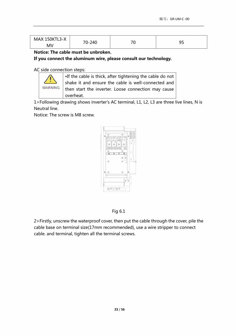
MAX 150KTL3-X
MV 70-240 70 95
Notice: The cable must be unbroken.
If you connect the aluminum wire, please consult our technology.
AC side connection steps:
•If the cable is thick, after tightening the cable do not
shake it and ensure the cable is well-connected and
then start the inverter. Loose connection may cause
overheat.
1>Following drawing shows inverter's AC terminal, L1, L2, L3 are three live lines, N is
Neutral line.
Notice: The screw is M8 screw.
Fig 6.1
2>Firstly, unscrew the waterproof cover, then put the cable through the cover, pile the
cable base on terminal size(17mm recommended), use a wire stripper to connect
cable. and terminal, tighten all the terminal screws.

编号:GR-UM-C -00
24 / 56
Fig 6.2
Diagram of how to install a terminal:
Fig 6.3
3>Put the water proof cover back to the inverter and fill the cover with fireproof mud,
just as following drawing.
Fig 6.4
•Must tighten the waterproof cover, otherwise there will be a risk of water
leakage.
编号:GR-UM-C -00
25 / 56
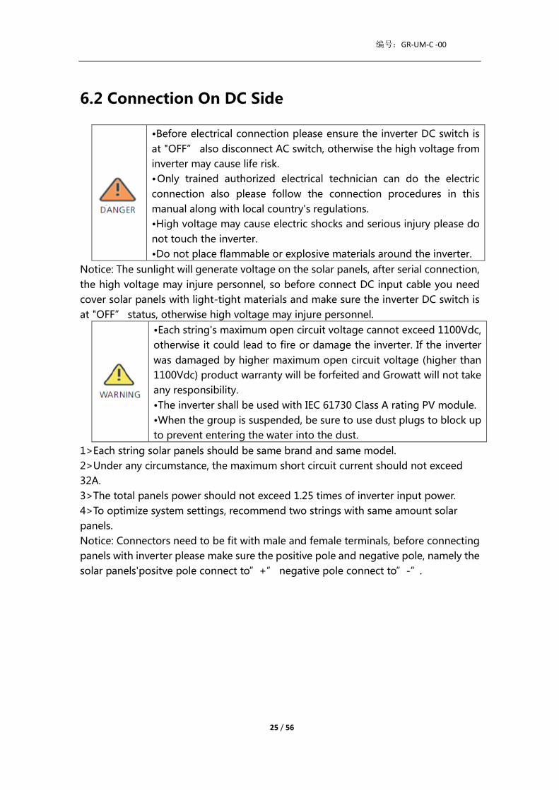
6.2 Connection On DC Side
•Before electrical connection please ensure the inverter DC switch is
at "OFF” also disconnect AC switch, otherwise the high voltage from
inverter may cause life risk.
•Only trained authorized electrical technician can do the electric
connection also please follow the connection procedures in this
manual along with local country's regulations.
•High voltage may cause electric shocks and serious injury please do
not touch the inverter.
•Do not place flammable or explosive materials around the inverter.
Notice: The sunlight will generate voltage on the solar panels, after serial connection,
the high voltage may injure personnel, so before connect DC input cable you need
cover solar panels with light-tight materials and make sure the inverter DC switch is
at "OFF” status, otherwise high voltage may injure personnel.
•Each string's maximum open circuit voltage cannot exceed 1100Vdc,
otherwise it could lead to fire or damage the inverter. If the inverter
was damaged by higher maximum open circuit voltage (higher than
1100Vdc) product warranty will be forfeited and Growatt will not take
any responsibility.
•The inverter shall be used with IEC 61730 Class A rating PV module.
•When the group is suspended, be sure to use dust plugs to block up
to prevent entering the water into the dust.
1>Each string solar panels should be same brand and same model.
2>Under any circumstance, the maximum short circuit current should not exceed
32A.
3>The total panels power should not exceed 1.25 times of inverter input power.
4>To optimize system settings, recommend two strings with same amount solar
panels.
Notice: Connectors need to be fit with male and female terminals, before connecting
panels with inverter please make sure the positive pole and negative pole, namely the
solar panels'positve pole connect to”+” negative pole connect to”-”.

编号:GR-UM-C -00
26 / 56
Fig 6.5
5>Decide the length of peeling base on cable terminal, use the wire stripper to
connect cable and terminal, and separately connect to specific connector.
6>Connect the positive and negative poles to inverter terminals, different inverter's
maximum single string input current please refer to following table.
Inverter model Max. single string input current
MAX 80-150KTL3-X LV/MV 16A*2
7. Cable specifications:
Inverter model Cross-sectional area
(mm )
Recommendation
(mm²)
Cable outer
diameter(mm)
MAX 80-150KTL3-X
LV/MV 4-6 4 4.5-7.8
Notice:1. Under any circumstance, the total current of all strings cannot exceed the
inverter's maximum current.
2. Do not touch any working solar panels.
3. Make sure the cable is unbroken.
6.3 Connection Of Communication Cables
6.3.1 RS485 port
RS485 can be used for single inverter communication also can be used for multiple
Inverters (Maximum 32 inverters) , the longest distance is 500 meters, high speed
(Baud rate 38400) , the communication port as following.
485 can be used for single inverter communication also can be used for multiple

编号:GR-UM-C -00
27 / 56
Inverters (Maximum 32 inverters) , the longest distance is 500 meters, high speed
(Baud rate 38400) , the communication port as following.
It is recommended to use shielded twisted pair for RS485 cable When a single
inverter communicates, the shielding layer of the RS485 cable needs to be connected
to the ground and can be connected to the PE of the inverter case; When multiple
inverters are connected in parallel, both RS485 interfaces must be used. The shield of
the RS485 cable should be connected to the GND of the RS485 terminal, and then the
GND of all inverters should be shorted together by wire. Finally, Connect the
communication ground GND of the inverter that is last connected to the monitoring
device to the protective ground of the inverter housing.
Fig 6.6A
Mark Description Mark Description
1/2 485-1 PE Shield 9 DRM1/5
3 485-1 A1 10 DRM2/6
4 485-1 B1 11 DRM3/7
5 485-1 A1 12 DRM4/8

编号:GR-UM-C -00
28 / 56
6 485-1 B1 13 REF/GEN
7 485-2 A1 14 NC
8 485-2 B1 15/16
485-1 Matching
resistance
Notice: When multiple inverters are connected in parallel or the transmission
distance is long, The reason for this is to increase the matching resistance.
Fig 6.7
6.3.2 USB port
MAX 80-150KTL3-X LV/MV series inverter is configured with USB_A port ,can be
connected to USB to WIFI module, Shine GPRS-X, Shine Wifi-X, Shine 4G-X, Shine
Link-X, etc. The monitoring module is selected to implement the monitoring function.
In addition, you can quickly update the software via a USB flash drive.
Steps to install the monitoring module:
1> Loose waterproof cover, and remove waterproof plug.
2> As shown in Figure 6.8A,plug the USB to WIFI dongle to USB_A port, the indicating
LED will lit up.
3> As shown in Figure 6.8B, make sure that △ is on the front side, plug the
monitoring module to USB_A port, and tighten the screws.
Note: When the operator leaves please take the monitoring module and data cable
away, and tighten the waterproof cover to avoid water entering the interface.

编号:GR-UM-C -00
29 / 56
6.4 Connecting The Ground Cables
In this solar system all the unloaded metal components and cases should be
connected to the ground.
Single inverter need grounding over a PE point, multiple inverters need connect all
the inverter PE cable and solar panels shelves to the same grounding point to achieve
equipotential.
The grounding steps as following:
Take out the ground screw at the inverter bottom, connect the ground cables as
following figure.
Notice: 1.The machine is safely separated from the lightning protection and the
distance is as far as possible.
2.Do not expose Grounding terminal in the air and precaution for the rain.
3.When you lock the case ground screw, the torque force should be 60kgf·cm.
Fig 6.9
According to the relevant provisions of IEC 61643-32 "Connecting to photovoltaic
devices surge protectors - selection and use of guidelines", whether for household or
outdoor photovoltaic power plants, it is necessary to ensure the implementation of
lightning protection measures for photovoltaic systems:
The lightning protection measures for photovoltaic systems shall be
carried out in accordance with the corresponding national standards and
IEC standards. Otherwise, photovoltaic devices such as components,
inverters and power distribution facilities may be damaged by lightning.
In this case, the company does not carry out warranty and assumes any
responsibility.

编号:GR-UM-C -00
30 / 56
Fig 6.10
1)It is generally recommended to install lightning protection devices (such as
lightning rods / lightning protection belts and down conductors) to prevent lightning
from hitting the PV array.
2) Lightning protection devices and down-conductors and related equipment in
photovoltaic systems (including photovoltaic panels, inverters, cables, power
distribution equipment) should maintain a safe separation distance S.
A. When the safety distance S is satisfied The position ①③ of the figure should be
equipped with a lightning protection module. In general, it is recommended to install
Type II in position ① and Type I in position ③.
B. When the safety and safety distance S is not met:
In addition to position 3, Type I lightning protection module should be installed in
Figure①②④.
3) The lightning down conductor and the equipment ground wire eventually sink at
a total ground point, but the two cannot share the wire. That is, the equipment
grounding wire should be pulled separately, and the wire diameter
requirement >6mm² when the safety interval distance S is satisfied.
4) About the above lightning protection lightning receptor system related design
reference GB/T 21714.3-2015 Suggested value of S: According to the general 5 storey
height (about 15m) building roof, S takes 2.5m enough, this distance can be
simplified according to the inverse relationship of the floor height.

编号:GR-UM-C -00
31 / 56
7. Commissioning
7.1 Commission The Inverter
•If the inverter is stored over one month, its default time
and date may looks wrong, the time and date should be
reset before connection to the grid.
7.1.1 Set inverter address
After inverter is started normally, inverter address can be set via RS485/USB
converting to WIFI. When multiple inverters are connected in parallel via RS485, the
inverter must be set to a different communication address. When a single inverter
communicates, the default communication address can be used.
Note: The default communication address of the inverter is 1, which can be set to
1-254.
7.1.1.1 Set RS485 address with Shinebus
The 485 address of the inverter can be modified by Shinebus, This operation is
performed by a professional.
7.1.1.2 Set RS485 address on ShinePhone APP
Refer to 8.2 download mobile APP ShinePhone and connect to inverter WIFI to enter
local monitoring page, this operation is performed by a professional.
1>Click “Parameters”
2>Enter password.(When you use it for the first time, you need to set the password
first. Click "Reset password" to enter the OSS account number and password. The
distributor and installer can apply for the OSS account from Growatt. Click "Sign in"
to set the password. After the setting is successful, you can start using it.)
3>Click top item “COM Address”;
4>Click the "Read" button in the upper right corner to read the current

编号:GR-UM-C -00
32 / 56
communication address of the inverter;
5> Set inverter com address;
6>Read inverter com address to ensure setting is successful;

编号:GR-UM-C -00
33 / 56
7.1.2 Set inverter time and date
Method 1:
Please refer to section 8.2.1 and login ShinePhone APP.Click "system time(45-50)"to
set inverter time and date on the parameter setting page.
Method 2:
Please connect GPRS antenna to the inverter as section 6.3.3, when the inverter is
powered on, connect the inverter to the server as section 8.1.2, then the inverter time
will be updated automatically.
7.2 Operation Mode
7.2.1 Waiting mode
When the DC voltage is more than 180Vdc, inverter will be powered on and enters
the "waiting" state.
At this mode, inverter will check the system parameter. If the system is normal and PV
voltage is more than 195Vdc, inverter will try to connect to the grid.
7.2.2 Working mode
At this mode, inverter work normally, and the Power or fault code indicator light
shows the power delivered by the inverter to the grid.
When the DC voltage is more than 180Vdc,inverter converts the DC power generated

编号:GR-UM-C -00
34 / 56
by the PV modules into AC power and supplies them to the grid.
When the DC voltage is lower than 180Vdc, inverter will enter into “waiting” state
and try to connect to the grid, at this status, inverter consume very small power to
check the internal system status.
Note: only when the PV modules supply enough power(voltage>195Vdc) then the
inverter will start automatically.
7.2.3 Fault mode
Inverter intelligent control system will continuously monitor and adjust system
status. When there is a fault detected, LED will show the fault message.
Note: Please refer to section 8.2 to check the fault message and take corrective
measures.
7.2.4 Off mode
When the sunlight is weak or no light, inverter will stop working automatically. When
it is off, inverter will not consume gird power or PV module. At the same time, the LED
of inverter will be turned off.
Note: When PV string DC voltage is too low(≤ 150Vdc), inverter will be off.
7.3 LED Display
Inverter current operation status can be visually checked from LED display directly.
Description of LED status
Position
of LED Type of LED Inverter status LED status

编号:GR-UM-C -00
35 / 56
A PV voltage
indicator light
PV voltage reaches grid
voltage Green light is on
PV voltage does not
reach the grid voltage Light is not on
B
AC voltage
indicator light
Inverter is in the grid
state Green light is on
No AC voltage Light is not on
With AC voltage,
inverter is in the grid
countdown state
The green light flashes
slowly, and the alarm or
fault indicator light is not
on
C Alarm or fault
indicator light
Inverter works normally Light is not on
Inverter is in alarm state Red light flashes slowly
Inverter is in fault state Red light is on
D Communication
indicator light
Inverter has external
communication, such
as RS485, GPRS, etc.
Green light is on
Inverter has no external
communication Light is not on
Inverter upgrade or
USB interface is reading
and writing data
Green light flashes
E
Power or fault
code indicator
light
Inverter is in the grid
state
The eight LEDs from left to
right represent the power
of the inverter: if 8 green
lights are on, it represents
100% of the inverter
power. As shown in Figure
7.3, it represents 37.5% of
the inverter power, and so
on.
Inverter is in fault state
The five LEDs from right to
left represent 1, 2, 4, 8, 16
in turn, representing the
fault code of the inverter.
As shown in Figure 7.4, the
LED status represents 2,
and then 2 is added to the
specific 99 to get 101, so it
can be known that the

编号:GR-UM-C -00
36 / 56
inverter reported error 101.
8 Remote Data Monitoring
8.1 Remote Data Monitoring
MAX 80-150KTL3-X LV/MV series inverter remote monitoring ways include APP
(ShinePhone) and server Web page, RS485,GPRS,4G,PLC(reserved) can satisfy both
ways of monitoring.
8.1.1 Mobile phone APP(ShinePhone) remote monitoring
1>Scan the following QR code, or download from Android store or App store by
searching“Shinephone”, download and install software.
Note: 1.Make you it's the latest version.
2.Please find more details on http://server.growatt.com.
2>Users can register their mobile APP account by following the steps below: Run
ShinePhone go to login page click register”.Registration is required to fill in the
information, with the * is required, the agreement is mandatory, you can log in to the
main interface of ShinePhone after registration, the registration page and the main
interface are as shown below.
Shinephone login and main page:
编号:GR-UM-C -00
37 / 56
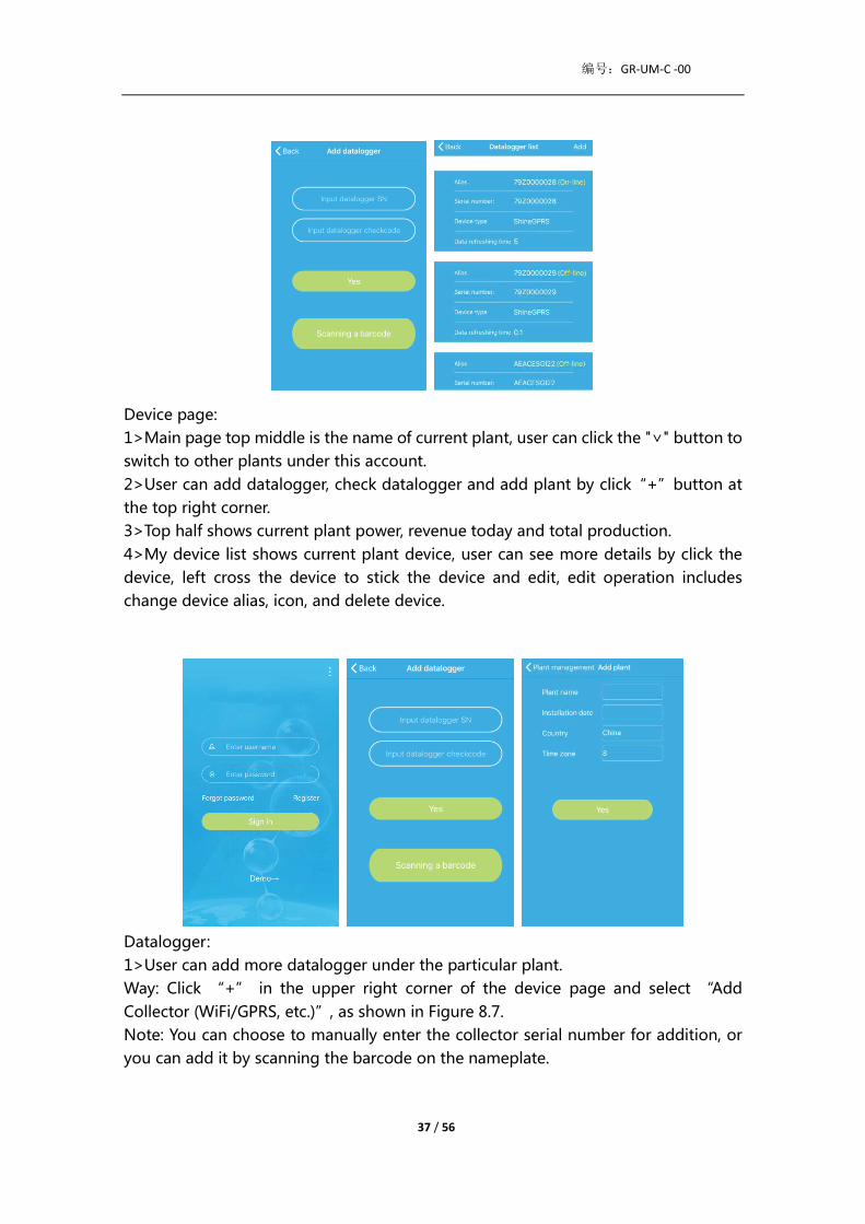
Device page:
1>Main page top middle is the name of current plant, user can click the "∨" button to
switch to other plants under this account.
2>User can add datalogger, check datalogger and add plant by click“+”button at
the top right corner.
3>Top half shows current plant power, revenue today and total production.
4>My device list shows current plant device, user can see more details by click the
device, left cross the device to stick the device and edit, edit operation includes
change device alias, icon, and delete device.
Datalogger:
1>User can add more datalogger under the particular plant.
Way: Click “+” in the upper right corner of the device page and select “Add
Collector (WiFi/GPRS, etc.)”, as shown in Figure 8.7.
Note: You can choose to manually enter the collector serial number for addition, or
you can add it by scanning the barcode on the nameplate.

编号:GR-UM-C -00
38 / 56
图 8.7
2>User can add datalogger at the datalogger list page to add a datalogger, edit,
delete, configure etc.
3>User can add more plants with the add Plant function.
Device page and function:
1>Device page: User can click the device to see more details, the device page show
current power and Energy today and daily power chart, user can find more with
control, parameter, data and Events page.
2>Control: user set inverter on/off, set active power, set reactive power, set PF, set
inverter time, set grid voltage high, set grid voltage low. The operation password is
: inverter+ date, for example inverter20170722.
3>Parameter: user can see device SN, rated power, firmware version, PV1 voltage,
current, and power etc.
4>Data page: user can see the PV power, voltage, current, R phase power, S phase
power, S phase power, T phase power, output power by day, month, year, by finger up
cross the screen.

编号:GR-UM-C -00
39 / 56
5>Events: User can see the fault message if there it is.
8.2 Local Data Monitoring
MAX 80-150KTL3-X LV/MV Series Inverter local data monitoring mode has a mobile
phone app phone) and PC direct connection, u disk, details are as follows.
8.2.1 Mobile phone app (Shinephone) Local Monitoring
8.2.1.1 Log on to app for local monitoring
Method 1
When you open the app login front page, click the top right corner toolbox icon. Pop
up the toolbox, click the local debugging tool, and you can get the wifi name of the
collector by scanning the QR code or barcode(The default password for WIFI is
12345678. If you have already connected, you can click "Skip" to connect directly to
the WIFI.)
编号:GR-UM-C -00
40 / 56
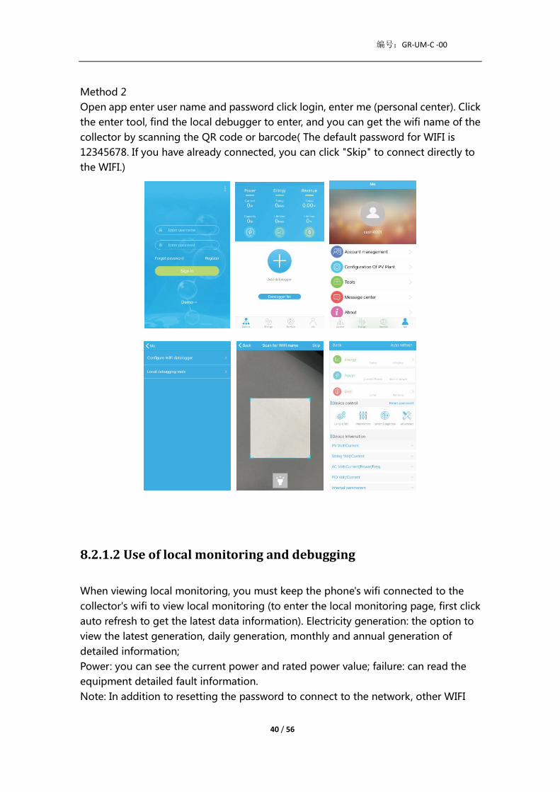
Method 2
Open app enter user name and password click login, enter me (personal center). Click
the enter tool, find the local debugger to enter, and you can get the wifi name of the
collector by scanning the QR code or barcode( The default password for WIFI is
12345678. If you have already connected, you can click "Skip" to connect directly to
the WIFI.)
8.2.1.2 Use of local monitoring and debugging
When viewing local monitoring, you must keep the phone's wifi connected to the
collector's wifi to view local monitoring (to enter the local monitoring page, first click
auto refresh to get the latest data information). Electricity generation: the option to
view the latest generation, daily generation, monthly and annual generation of
detailed information;
Power: you can see the current power and rated power value; failure: can read the
equipment detailed fault information.
Note: In addition to resetting the password to connect to the network, other WIFI

编号:GR-UM-C -00
41 / 56
modules that must connect to the collector can view information.
A. Reset password
Need network connection login oss account to set up or modify the local debug
password.
B. Setting configuration
The configuration data of inverter, voltage, power and so on can be modified
according to the usage (Fig 8.36).
C. Parameter configuration
The parameter data of the equipment can be modified according to the usage (Fig
8.37).
D. Intelligent detection
Detailed and accurate view of the device's detailed data and status (Fig 8.38)
.

编号:GR-UM-C -00
42 / 56
E. Intelligent I-V curve scanning
Can remotely scan each mppt (Fig 8.39).
F. Fault recording detection
Remote, fast and accurate fault location (Fig 8.40).
G. Real-time recording detection
Inverter voltage and current quality can be observed in real time (Fig 8.41).

编号:GR-UM-C -00
43 / 56
H. One click diagnosis
I-V curve diagnosis, grid waveform, THDV and cable impedance detection all at one
click (Fig 8.42).
I High level setting
According to the register address set parameters (professionals).
J. Device information
Check PV voltage/current, string voltage/current, AC voltage /current /power/
frequency, PID voltage/current, internal parameters and device detail information
and parameters( Fig 8.43).

编号:GR-UM-C -00
44 / 56
8.2.2 U Disk Monitoring
Refer to 6.3.2 USB to WIFI/ U disk communicate connection, the local monitoring of U
disk can realize the functions of software burning, fault recording, curve analysis and
real time recording. Details are as follows:
1>Firmware Programming
Create the bconfig.txt file under the root of the U disk, write to the following content,
then insert the U disk to programming. Note the M3 program needs to be
programming at last time.
2>Fault Recording
Create the bconfig.txt file under the root of the U disk, write the following content,
then insert the U disk that can be read fault information, then generates a form under
the files in the root directory, A total of 60 fault recording information is stored, the
latest Numbers is 0.
3>Curve Analysis
Create the bconfig.txt file under the root of the U disk, write the following content,

编号:GR-UM-C -00
45 / 56
the insert U disk to record I-V curve, then generates a form under the files in the root
directory.
4>Real Time Recording
Create the bconfig.txt file under the root of the U disk, write the following content,
then insert U disk to read real time recording information,then generates a form
under the files in the root directory,the form record's waveform is consistent with the
ID of the command setting.

编号:GR-UM-C -00
46 / 56
9. System Maintenance
9.1 Routine Maintenance
9.1.1 Cleaning Inverter
•Before any operation, please disconnect the DC switch and
AC switch, and wait for at least 5 minutes until internal
capacitance discharge completely.
1>Check the ambient temperature and dust of the inverter, clean the inverter when
necessary.
2>Observe whether the air outlets is normal, when necessary, clean the air outlets or
clean the fan step by step, steps refer to 9.1.2.
9.1.2 Fan Maintenance
•It must be carried out by qualified, trained personnel and
comply with all prevailing local code and regulations.
•Please disconnect the DC switch and AC switch before any
operation, and wait for at least 5 minutes until the internal
bus capacitance discharge completely.
•Do not use the air pump cleaning fan, which may cause fan
damage.
When the Growatt MAX series inverter work in high temperature environment, good
ventilation and heat dissipation can effectively reduce the chance of load derating.
Inverter equipped with internal cooling fans, when the internal temperature is too
high, the fans work in to reduce the internal temperature. When the inverter is
derating because of the internal temperature is too high, the following are the
possible reasons or solutions.
1) Fan is blocked or the heat sink gathers too much dust, it needs to clean the fan, fan
cover or heat sink.
2) Fan is damaged, it need to replace the fan.
3) Poor ventilation of the installation location, it needs to select the appropriate
installation location according to the basic in stallation requirements .
Fan cleaning and replacement procedure;

编号:GR-UM-C -00
47 / 56
1>Please ensure that the DC side and AC side of the inverter have been disconnected
before cleaning or replacement of the fan.
1) Turn off DC switch.
2) Disconnect DC terminals from inverter (Users need tools to disconnect the DC
connection terminals).
3) Turn off AC switch.
2>Remove the screws on the fan guards with a cross screwdriver. it is shown as below.
Fig 9.1 External fan view
Fig 9.2 Internal fan view
3>Disconnect the wire connector of the fans with a flat head screw driver and remove
the fans from the fan guards, it is shown as below.

编号:GR-UM-C -00
48 / 56
Fig 9.3
Fig 9.4 External fan view
Fig 9.5 Internal fan view
Notice:MAX 80-150KTL3-X LV/MV series inverter has seven fans(internal fan*2Pcs,
external fan*5Pcs).
4>Clean fan, fan guards and heat sink or replace fan.
1) Clean the fan and fan guards with air pump, brush or a damp cloth.
2) Remove each fan separately for cleaning if necessary.
3) Remove the fan that need to replace with a cross screwdriver, replace a new fan.
4) Tidy up the wire.
5>Install the fan, fan guard fixed and the inverter again.
编号:GR-UM-C -00
49 / 56
9.2 Trouble Shooting
•Work on the Growatt Max must be carried out by
qualified personnel.
•Normally grounded conductors may be ungrounded
and energized when a PV isolation low is indicated.
•Risk of electric shock.
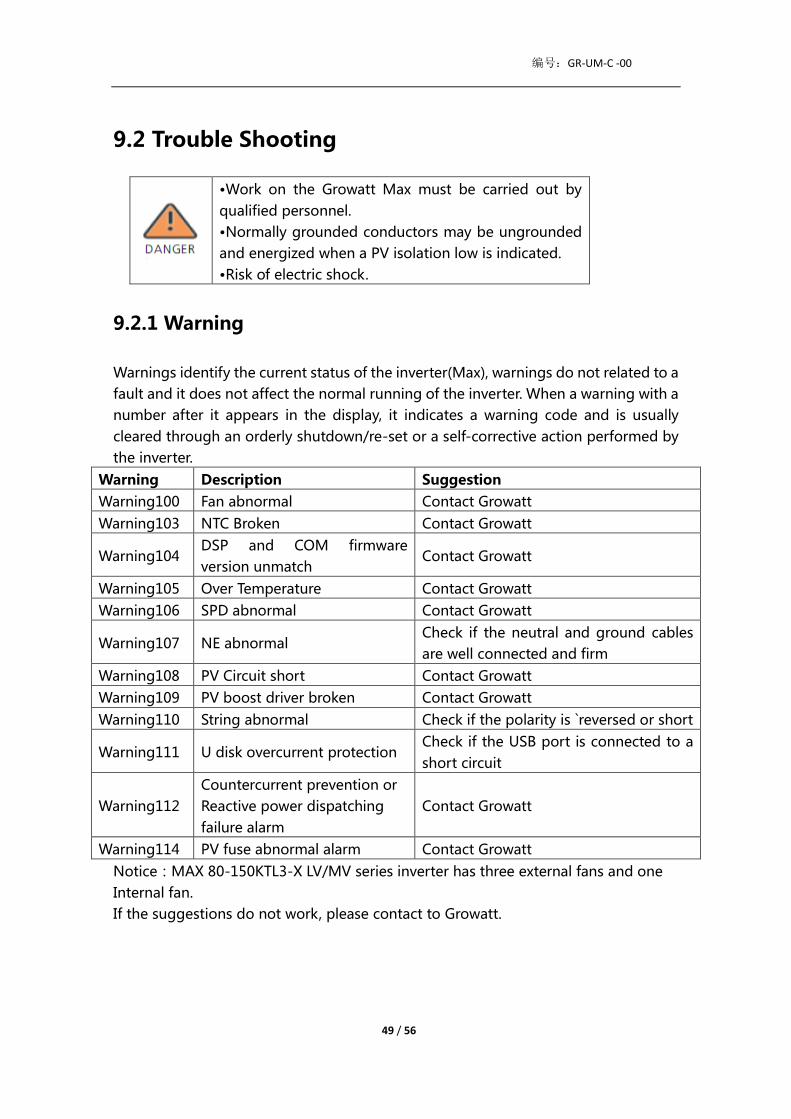
9.2.1 Warning
Warnings identify the current status of the inverter(Max), warnings do not related to a
fault and it does not affect the normal running of the inverter. When a warning with a
number after it appears in the display, it indicates a warning code and is usually
cleared through an orderly shutdown/re-set or a self-corrective action performed by
the inverter.
Warning Description Suggestion
Warning100 Fan abnormal Contact Growatt
Warning103 NTC Broken Contact Growatt
Warning104 DSP and COM firmware
version unmatch Contact Growatt
Warning105 Over Temperature Contact Growatt
Warning106 SPD abnormal Contact Growatt
Warning107 NE abnormal Check if the neutral and ground cables
are well connected and firm
Warning108 PV Circuit short Contact Growatt
Warning109 PV boost driver broken Contact Growatt
Warning110 String abnormal Check if the polarity is `reversed or short
Warning111 U disk overcurrent protection Check if the USB port is connected to a
short circuit
Warning112
Countercurrent prevention or
Reactive power dispatching
failure alarm
Contact Growatt
Warning114 PV fuse abnormal alarm Contact Growatt
Notice:MAX 80-150KTL3-X LV/MV series inverter has three external fans and one
Internal fan.
If the suggestions do not work, please contact to Growatt.

编号:GR-UM-C -00
50 / 56
9.2.2 Error
Errors codes identify a possible equipment failure, fault or incorrect inverter setting
or configuration, any or all attempts to correct or clear a fault must be performed by
qualified personnel.
Typically, the error code can be cleared once the cause or fault is removed.
Some of error code as table shows below, may indicate a fatal error and require you
to contact the supplier or Growatt for help.
Error Code Description Suggestion
Error 101 Communication error Contact Growatt
Error 102 Sample of main DSP and
slave DSP are inconsistent Contact Growatt
Error 106 PV CurrSample Fault Contact Growatt
Error 107 AC CurrSample Fault Contact Growatt
Error 108 SPS Power Fault Contact Growatt
Error 110 Current over limit Contact Growatt
Error112 AFCI Fault Contact Growatt
Error113 IGBT drive fault Contact Growatt
Error114 AFCI Module check fail Contact Growatt
Error117 Relay fault Contact Growatt
Error120 N - PE fault detection
(PV - ground machine) Contact Growatt
Error121 CPLD abnormal Contact Growatt
Error122 Bus Fault Contact Growatt
Error124 No AC connection Check if the mains connection/mains
voltage and frequency are correct
Error125 PV isolation low Check panel and line insulation to
ground is good
Error126 Leakage current too high Contact Growatt
Error127 Output DC current too
high Contact Growatt
Error128 PV voltage high Check PV actual voltage
Error129 Grid voltage fault Check the actual voltage and wiring of
the grid
Error130 Grid frequency fault Check the actual frequency of the grid

编号:GR-UM-C -00
51 / 56
10. Specification
Specifications Model MAX
80KTL3-X LV
MAX
100KTL3-X LV
MAX
110KTL3-X LV
MAX
120KTL3-X LV
MAX
125KTL3-X LV
Input Data(DC)
Max. recommended PV
power(for module STC) 120000W 150000W 165000W 180000W 187500W
Max. DC voltage 1100V
Start voltage 195V
Nominal voltage 600V
MPP voltage range 550V-850V 550V-850V 550V-850V 600V-850V 600V-850V
No. of MPP trackers 7 10 10 10 10
No. of PV strings per MPP
trackers 2
Max. input current per MPP
trackers 32A
Max. short-circuit current
per MPP trackers 40A
DC overvoltage category Category II
Output Data(AC)
AC nominal power 80000W 100000W 110000W 120000W 125000W
Max. AC apparent power 88000VA 110000VA 121000VA 132000VA 137500VA
Nominal AC voltage/range 230V/400V
340-440VAC
AC grid frequency/range 50/60Hz
45-55Hz/55-65Hz
Max. output current 133.7A 167.1A 183.8A 200.5A 208.9A
Power factor(@nominal >0.99
Max. inrush
current/duration 20KA/tr:8us,tf:20us
Max. output facult
current/duration 400A/30us
Adjustable power factor 0.8leading ...0.8lagging
THDi <3%
AC grid
connection type 3W/N/PE

编号:GR-UM-C -00
52 / 56
AC overvoltage category Category III
efficiency
Max. efficiency 98.80% 99.00% 99.00% 99.00%
Euro-eta 98.50%
Protection devices
DC reverse-polarity
protection Yes
DC switch Yes
DC Surge protection Type II
Insulation resistance
monitoring Yes
AC surge protection Type II
AC short-circuit protection Yes
Grid monitoring Yes
Anti-islanding protection Yes
Residual-current monitoring
unit Yes
String monitoring Yes
Anti-PID function Optional
AFCI protection Optional
General data
Dimensions (W /H / D) in
mm 970*640*345mm
Weight 84kg
Operating
temperature
range
-30℃- +60℃
Altitude 4000m
Internal consumption at <1W(Note1)
Topology Transformerless
Cooling Fan cool
Protection degree IP66
Relative humidity 0~100%
DC connection CN4U
AC connection Cable gland +OT terminal
Interfaces
Display LED/WIFI+APP
RS485/USB Yes
PLC/GPRS/4G Optional
Warranty: 5 /10 years Optional
Certificates and approvals

编号:GR-UM-C -00
53 / 56
Grid regulation
AS/NZS 4777.2,CEI 0-21,CEI 0-16,VDE-AR-N 4105,
DIN V VDE V 0126-1-1,UTE C 15-712-1,EN 50438,
IEC 60068,IEC 61683,IEC 62116,IEC 61727,
MEA,PEA,DRRG/DEWA:2016,BDEW,G59/3
EMC EN61000-6-2,EN61000-6-4
Safety IEC/EN62109-1,IEC/EN62109-2
Note1. Self-consumption less than 15W when AC power supply at night.
Specifications Model MAX
133KTL3-X LV
MAX
125KTL3-X MV
MAX
136KTL3-X MV
MAX
150KTL3-X MV
Input Data(DC)
Max. recommended PV
power(for module STC) 19950W 187500W 204000W 204000W
Max. DC voltage 1100V
Start voltage 195V
Nominal voltage 600V 720V 720V 720V
MPP voltage range 600V-850V 600V-850V 685V-850V 685V-850V
No. of MPP trackers 10
No. of PV strings per MPP
trackers 2
Max. input current per MPP
trackers 32A
Max. short-circuit current per
MPP trackers 40A
DC overvoltage category Category II
Output Data(AC)
AC nominal power 133000W 125000W 136000W 1500000W
Max. AC apparent power 146300VA 137500VA 149600VA 165000VA
Nominal AC voltage/range 230V/400V
340-440VAC
277V/480V
408-528VAC
277V/480V
408-528VAC
277V/480V
408-528VAC
AC grid frequency/range 50/60Hz
45-55Hz/55-65Hz
Max. output current 222.3A 165.4A 179.9A 198.5A
Power factor(@nominal >0.99
Max. inrush current/duration 20KA/tr:8us,tf:20us
Max. output facult 400A/30us

编号:GR-UM-C -00
54 / 56
current/duration
Adjustable power factor 0.8leading ...0.8lagging
THDi <3%
AC grid
connection type 3W/N/PE 3W+PE 3W+PE 3W+PE
AC overvoltage category Category III
Efficiency
Max. efficiency 98.80% 99.00% 99.00% 99.00%
Euro-eta 98.50%
Protection devices
DC reverse-polarity
protection Yes
DC switch Yes
DC Surge protection Type II
Insulation resistance
monitoring Yes
AC surge protection Type II
AC short-circuit protection Yes
Grid monitoring Yes
Anti-islanding protection Yes
Residual-current monitoring
unit Yes
String monitoring Yes
Anti-PID function Optional
AFCI protection Optional
General data
imensions (W /H / D) in mm 970*640*345mm
Weight 84kg
Operating
temperature
range
-30℃- +60℃
Altitude 4000m
Internal consumption at <1W(Note1)
Topology Transformerless
Cooling Fan cool
Protection degree IP66
Relative humidity 0~100%
DC connection CN4U
AC connection Cable gland +OT terminal
Interfaces
Display LED/WIFI+APP

编号:GR-UM-C -00
55 / 56
RS485/USB Yes
PLC/GPRS/4G Optional
Warranty: 5 /10 years Optional
Certificates and approvals
Grid regulation
AS/NZS 4777.2,CEI 0-21,CEI 0-16,VDE-AR-N 4105,
DIN V VDE V 0126-1-1,UTE C 15-712-1,EN 50438,
IEC 60068,IEC 61683,IEC 62116,IEC 61727,
MEA,PEA,DRRG/DEWA:2016,BDEW,G59/3
EMC EN61000-6-2,EN61000-6-4
Safety IEC/EN62109-1,IEC/EN62109-2
Note1. Self-consumption less than 15W when AC power supply at night.
11. Decommissioning
If the inverter does not operate in the future, it needs to be properly disposed. The
steps are as follows:
1> Disconnect the external AC short-circuit device and prevent reconnection due to
misoperation.
2>Turn the DC switch to "OFF" position.
3>Wait at least 5 minutes until the internal capacitor discharge is completed.
4>Disconnect the AC connector.
5>Disconnect the DC connector.
6>Remove the inverter from the wall.
7>Disposing of the inverter.
11.1 Disposing Of The MAX Series Inverter
Do not dispose of MAX 80-150KTL3-X LV/MV series
inverter together with household waste. Please
accordance with the disposal regulations for electronic
waste which apply at the installation site at that time.
Ensure that the old unit and, where applicable, any
accessories are disposed of in a proper manner.

编号:GR-UM-C -00
56 / 56
12. Quality assurance
Please refer to related file.
13. Contact
If you have technical problems concerning our products, contact your installer or
Growatt, please provide information below for better support.
1. Inverter type
2. Serial number of inverter
3. Error code of inverter
4. LED status of inverter
5. DC input voltage of inverter (Modules information)
6. Inverter communication method
Guangdong Growatt New Energy Co., LTD
No.28 Guangming Road, Shiyan Street, Bao'an District, Shenzhen, PR. China
T: +86 0755 2747 1942
W: www.ginverter.com