Gates Executive Stereo Audio Console Operation, Installation ...
Upload
khangminh22Category
view
6download
0
OPERATION ANDINSTALLATION MANUAL
SYS CWC IMS 10.1 Centralized controller IMS with Touch screen 10.1"
Thank you very much for purchasing our product.Before using your product, please read this manual carefully and keep it for future reference.

Table of Contents1. HARDWARE INSTALLATION ..............................................................................12. ABOUT CCM-270A/WS .......................................................................................83. FUNCTION DESCRIPTION.................................................................................9Preparation...............................................................................................................9Startup Screen .......................................................................................................113.0 Login ..............................................................................................................123.1 Home Page....................................................................................................133.1.1 Overview of Indoor Unit Running Status......................................................133.1.2 Special Menu ...............................................................................................143.2 Device Monitor...............................................................................................153.2.1 Indoor Unit View - Group .............................................................................183.2.2 Indoor Unit View - System ...........................................................................213.2.3 Indoor Unit View - Map (this function is not available for
Web terminals).............................................................................................213.3 Schedule ........................................................................................................223.3.1 View Schedule .............................................................................................233.3.2 Add Schedule ..............................................................................................273.4 Report.............................................................................................................323.4.1 Operating Duration ......................................................................................333.4.2 Running Record...........................................................................................363.4.3 Energy Statistics ..........................................................................................363.4.4 Log...............................................................................................................383.4.5 Export Function............................................................................................393.5 Lock................................................................................................................423.6 Installation ......................................................................................................453.6.1 Edit...............................................................................................................453.6.2 Group...........................................................................................................453.6.3 Edit Map.......................................................................................................493.7 Settings ..........................................................................................................533.7.1 User Management .......................................................................................543.7.2 Date and Time Settings ...............................................................................553.7.3 Holiday Settings...........................................................................................573.7.4 Network Settings..........................................................................................583.7.5 General Settings ..........................................................................................593.7.6 Mail Settings ................................................................................................603.7.7 Advanced Settings.......................................................................................633.7.8 Public Settings .............................................................................................653.7.9 Energy Settings ...........................................................................................664. APPENDIX .....................................................................................................674.1 Table of Error Codes ......................................................................................674.2 Software Use Precautions..............................................................................704.3 Wired Controller Group ..................................................................................70

Statement:Along with upgrades in the product, the information in this document is subject to change without notice.
Packing List
1X SYS CWC IMS 10.1 1X 3-port terminal with gap of 5.08 mm
1X Manual 2X 9-port terminal with gap of 3.81 mm
1X Mounting board 3X 4-port terminal with gap of 3.81 mm
8X Plastic washers (Ø 4mm hole) 6X GB/T950 M4*20 screws (short)
1X Embedded junction box 4X GB/T823 M5*25 screws (long)
6X Plastic expansion nails

1
1.1. General Safety Precautions
1. HARDWARE INSTALLATION
Please read these general safety precautions carefully before installing the CCM-270A/WS.After completing the installation, make sure the power supply and CCM-270A/WS operate properly during the startup operation.
If you are not sure how to install or operate CCM-270A/WS , contact your dealer.1.1.1 General
Do NOT install the equipment in a potentially explosive atmosphere.1.1.2 Installation Site
1.1.3 Electrical
NOTICEImproper installation or attachment of equipment or accessories could result in electric shock, short-circuit, leaks, fire or other damage to the equipment. Only use accessories, optional equipment and spare parts made or approved.
Make sure installation, testing and applied materials comply with the applicable legislation.
WARNING
Wear adequate personal protective equipment (protective gloves, safety glasses,…) when installing, maintaining or servicing the system.
CAUTION
Tear apart and throw away plastic packaging bags so that nobody, especially children, can play with them. Possible risk: suffocation.
WARNING
Turn OFF all power supply before connecting electrical wiring or touching electrical parts.Disconnect the power supply for more than 1 minute, and measure the voltage at the terminals of main circuit capacitors or electrical components before servicing. The voltage must be less than 50 V DC before you can touch electrical components. For the location of the terminals, see the wiring diagram.Do NOT touch electrical components with wet hands.Do NOT leave the equipment unattended when the service cover is removed.
DANGER: RISK OF ELECTROCUTION
A main switch or other means for disconnection, having a contact separation in all poles providing full disconnection under overvoltage category III condition, shall be installed in the fixed wiring.
WARNING
2
Warning!
Do not install the CCM-270A/WS near areas of electromagnetic interference or next to a base station;Locate the CCM-270A/WS away from sources of steams, possible flammable gas leaks, heat or sulfurous gases.Reserve sufficient space for the installation, and leave adequate spacing between the device and surrounding community service network devices for heat dissipation.Make sure the installation site is indoors, and the CCM-270A/WS is installed at a height that is 50 cm above ground;Make sure the installation site is not affected by dust and electromagnetic interference;Make sure the installation site is not exposed to sun and heating devices;Make sure the device is not installed in humid places or where it is easy for the device to come in contact with water.Make sure the device is not installed in locations where it can be easily corroded or where there are flammable gases.Please install the CCM-270A/WS in strict accordance with the above, and do check the installa-tion site carefully before installation.
Touch-screen CCM-270A/WS structure1) Touch-screen CCM-270A/WS: Front and side views
1.2 CCM-270A/WS Installation
Only use copper wires.Make sure the field wiring complies with the applicable legislation.All field wiring must be performed in accordance with the wiring diagram supplied with the product.Make sure to install earth wiring. Do NOT earth the unit to a utility pipe, surge absorber, or telephone earth. Incomplete earth may cause electrical shock.Make sure to use a dedicated power circuit. NEVER use a power supply shared by another appliance.Make sure to install the required fuses or circuit breakers.Make sure to install an earth leakage protector.Failure to do so may cause electric shock or fire.
Install the wires at least 1 meter away from televisions or radios to prevent interference. Depending on the radio waves, a distance of 1 meter may not be sufficient.
After finishing the electrical work, confirm that each electrical component and terminal inside the electrical cabinet is securely connected.Make sure all covers are closed before starting up the units.
WARNING
WARNING

2) Structural dimensions of the embedded junction box
Figure 1.23) Installation procedures
CCM-270A/WS Metal partsEmbedded junction box Screws
Figure 1.1
(Unit: mm)
267
170.
8
60
① ② ③ ④
WallWall
③
Wall
③
WallWall Wall
③② ①
④
276
187
34
9.5
(unit: mm) Before you drill an opening in the wall, make sure that the opening is largeenough for you to fit in the embedded junction box.
3

4
The CCM-270A/WS is used to query and control the indoor unit of the air conditioner, transmit the status information of the indoor unit to the computer, and forward the control and query instructions from the computer to the indoor unit.
1.3 System Architecture
Figure 1.4
CCM-270A/WS
Poweradapter
Power
Router
up to 8 refrigerant systemsor
Each port
supports up to 64 indoor unitsODU
IDU
ODU
IDU
ODU
IDU
ODU
IDU
Note: Devices in the dashed line box are not supplied as a standard part of the product.
LAN 24V ACINCOM 1~6
R CX E Y X E Y X E Y X E YEX Y X E Y1 2 3 4 5 6
X
P Q E
Y E
P Q E P Q E
X
P Q E
Y E X
P Q E
P Q E
Y E X
PQ E
PQ E
Y E
1. Mount the embedded junction box
Mount the embedded junction box within the wall. Ensure that the outer surface ③ of the embedded junction box is level with the wall surface.
3. Install CCM-270A/WSOnce the connections aredone, place the main unitvertically into the installationbase. You will feel a magnetic force at this point. Exert force downwards to mount it ontothe metal part.
1 2 3
NOTE
2. Install metal parts Make sure the hooks of the metalparts face upwards. Use 4 screws ④ provided as accessories to secure itonto the installation base.
Special note: Make sure you exert appropriate force to secure the metal parts with the screws. Excessive force may cause deformation of the four screw holes for the metal parts, making it harder to mount the metal mounting board.
Client PC(for remote control and IMMPro, the upper computer software)

5
Back Wiring
Caution!
The CCM-270A/WS has six M-net ports, one LAN port, one USB extension port, and six reserved IO ports. It can connect to the MCAC central air conditioning system through the M-net ports, and connect to the local area network or Internet through the LAN port. You may use a browser on a computer or other similar devices to access the CCM-270A/WS to monitor the VRF unit locally or remotely.
Figure 1.5
The CCM-270A/WS is installed at one end of the M-net communication bus. Do not install it in the middle of the bus.You need a three-core shielded cable of 0.7~1.0 mm2 for the signalling wires. For details, please consult a professional technician.

Figure 1.6
Port Diagram
Interface X, XYE bus (COM1-6)
Interface Y, XYE bus (COM1-6)
Interface E, XYE bus (COM1-6)
Reserved
Reserved
Reserved
Reserved
Reserved
Reserved
X1 E Y1 · X2 E Y2 · X3 E Y3R C X4 E Y4 · X5 E Y5 · X6 E Y6 DI1 · DI2 DO1 · DO2 AI1 · AI2 LAN USB
1 2 3 4 5 6
LAN
USB
R 24VAC
24VACC
X
Y
E
DI1
DI2
DO1
DO2
AI1
AI2
LAN
USB
The Ethernet interface connected to the network is used to access the device.
The USB 2.0 interface is used to exports reports, import floor plans and topology files and so on.
6

CCM-270A/WS Specifications
Power SupplySpecifications Voltage range
Powerconsumption
Single phase, 24VAC, 50/60Hz
24W Maximum
OperatingConditions
Voltagefluctuations ±10% of rated value
Ambienttemperature
Ambienthumidity
Storagetemperature
Dimensions Unit (mm)Weight
Device Colour Black
0~40°C
10~90%
-10~60°C
270(W)×183(H)×26.7(D)0.85kg
7

The six M-Net ports are all XYE ports, and can connect to outdoor units directly. A switch is required to connect computer or other similar equipment to the network of the CCM-270A/WS.
1) Supports the V6 of outdoor unit models.2) Communication line to the M-net port must be connected from the outdoor unit.
2.3 Supported Models
*Please check with the engineer on the applicable outdoor and indoor unit models as well as thefunctions.
2.4 Based on Web Technologies
The CCM-270A/WS is a gateway controller based on Web technologies, and has nothing to do with the operating systems of computer or other similar equipment. Once it is connected to the network, you can use the browser on the system platform to view the Web page any time, anywhere. The Chrome browser (version 52.0 or above) is recommended.
2. ABOUT CCM-270A/WS
2.1 System OverviewThe CCM-270A/WS, CCM-270A/WS, is the network gateway for V6 series of VRF central air conditioning units, and is an important component of MCAC smart management system (IMMPro) for VRF units. It can also work independently. The controller can connect to VRF unit through the M-net port. In the automatic topology mode, it supports up to 48 refrigerant systems (up to 384 indoor units and 192 outdoor units).
2.2 CCM-270A/WS Network ArchitectureThe CCM-270A/WS uses the M-net port to connect to the VRF unit, and the LAN port to connect to the local area network or Internet. The network topology is shown in the following diagram:
Figure 2.1
8

The CCM-270A/WS uses a switch to connect to the local area network. The IP addresses of the computer or other similar equipment and that of the CCM-270A/WS must be located in the same subnet segment.
Local Network Connections
Preparation3. FUNCTION DESCRIPTION
IP Settings
Open the Internet Protocol TCP/IP Properties page to configure the IP address and subnet mask. For example, set the IP address to 192.168.100.44 and the subnet mask to 255.255.255.0.
You need to first configure a static IP address before you can add multiple IP addresses. The steps toconfigure the static IP address are as follows:1) Check local IP address
Open the Internet Protocol TCP/IP Properties page, as shown in Figure 2.2. If the option "Use thefollowing IP address:" is selected, and there is an IP address listed here, it indicates that the localIP address is a static IP address. Otherwise, it is a dynamic IP address, and you need to configurea static IP address.
2) Configure static IP addressOpen the Run Command box from the Start Menu, as shown in the following figure:
- Configure single IP address
- Add multiple IP addressesClick "OK" when the configuration is done.
By default, the IP address of the CCM-270A/WS is 192.168.100.40 and the subnet mask is 255.255.255.0.For the IP address of a computer or other similar equipment, you need to manually configure the static IP address that must be on the 192.168.100 segment with 255.255.255.0 as the subnet mask. If the computer only connects to the CCM-270A/WS, then this is implemented using a single IP address. If the computer also connects to the local networks in addition to the CCM-270A/WS network, then you will need multiple IP addresses. The following figure shows the implementation method (Windows 7 system is taken as an example).
9

Enter "ipconfig" and press "Enter". The local dynamic IP address is displayed. Use this IP address as the IP address in the Internet Protocol TCP/IP Properties page to complete the static IP address configuration. Consult the local network administrator for details.Once the static IP address has been configured, open the Internet Protocol TCP/IP Properties page again. Select "Advanced..." to go to the TCP/IP Address page, as shown in the following figure.
Click "Add" under the IP addresses bar to add an IP address in the same segment as "192.168.100.40". For example, IP address is 192.168.100.101 with 255.255.255.0 as the subnet mask. Then, click "OK".
10
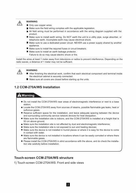
Local LAN Access
As long as the computer or other similar equipment in the LAN is in the same segment as the CCM-270A/WS, you can use the address bar in the browser on its operating system to enter theaddress to link to the Web page of the CCM-270A/WS (for example:http://192.168.100.40:8000/ui/login/login.html) to directly access, operate and control the airconditioners. The topology of local access is as shown below:
You can use a browser to enable the Web service functions:The port number of the URL is 8000. For example, if the gateway IP address is 192.168.100.40, then its Web service address is http://192.168.100.40:8000/ui/login/login.html. The interface displayed on the browser is similar to that of the CCM-270A/WS. The following only displays the functions.
Startup Screen
11

12
(Features in this section on the Web terminal and touch-screen are consistent. The "Remember Password" may be available depending on the browser you used.)
3.0 Login
Username
Password
Save password
Auto login
Login
Guest login
Default accountname
Initial password
123423
normal
1
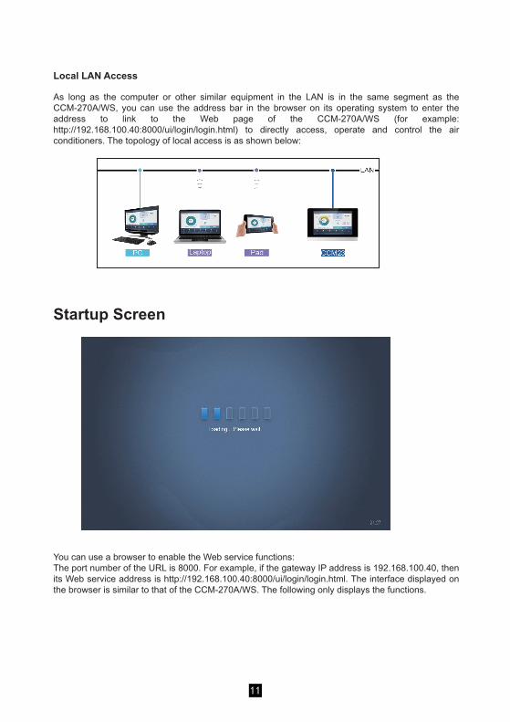
3.1 Home PageDefault software display page once you have logged in successfully:
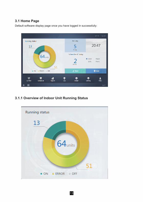
3.1.1 Overview of Indoor Unit Running Status
13

This section classifies the status of the indoor unit into the following three categories:
Running
Error (Error includeserror and offline)
Off
Function Menu
Navigation for all the functions is available at the bottom of the home page;
3.1.2 Special Menu
Function General
Back to Home
Operating History
14

3.2 Device Monitor
Function Inactive Active
Indoor Unit View - Group
Indoor Unit View - System
Indoor Unit View - Map
Device monitor
Select "Group" to view information of the corresponding indoor unit on the right. A series of icons are displayed, and the details are as follows:
21
43
5
6
7
15

Basic Mode Images
Function Remarks
Error
Schedule
Lock
Swing
No. Description
The colours here represent the operating modes. For details, refer to the Tableof Basic Mode Images.
Displays the corresponding device model. For details, refer to the Model Table.
The icons here represent the operating modes. For details, refer to the Table of Basic Mode Images.
Ambient temperature
Set temperature
You can change the indoor unit name on the "Install" page.
Auto (dark blue) Cool (light blue) Heat (red) Fan (green) Dry (orange)
Indicators (in order from left to right): error, schedule, lock, swing. Icon is white when active, such as the lock indicator in the figure.
Off, Error, Offline (grey)
1
2
3
4
5
6
7
Note: The error code shown in the indoor unit on the old platform is different from the error code shown in the nixie tube display of the indoor unit.
16

Model:
Old IDU
4-Way Cassette(4-WAY)
Wall-mounted
Medium Static Pressure Duct (M-Duct)
Low Static PressureDuct (L-Duct)
Air Handling Unit(AHU)
High Static PressureDuct (H-Duct)
Picture
Compact 4-WayCassette (COMPACT)
Ceiling & Floor
Vertical TypeConcealed
Vertical Type Exposed
Wired controller group*For details, refer to"Wired Controller Group"in the Appendix.
0
1
2
3
4
5
6
7
8
9
10
11
17

Function Inactive Active
Sort by name
3.2.1 Indoor Unit View - Group
The user defined groups are shown on the left of the device monitor page. Once a group is selected, the indoor units of the selected group are shown on the right.
Note: The group interface has a default "Ungrouped". All the devices that have not been assigned a group are included here.
The top left corner shows the number of indoor units in the group.
3.2.1.1 Order of Display for Indoor UnitIndoor units can be sorted by name or mode.
Sort by modeAuto, Cool, Heat, Dry, Fan, Off, Error, Offline
18
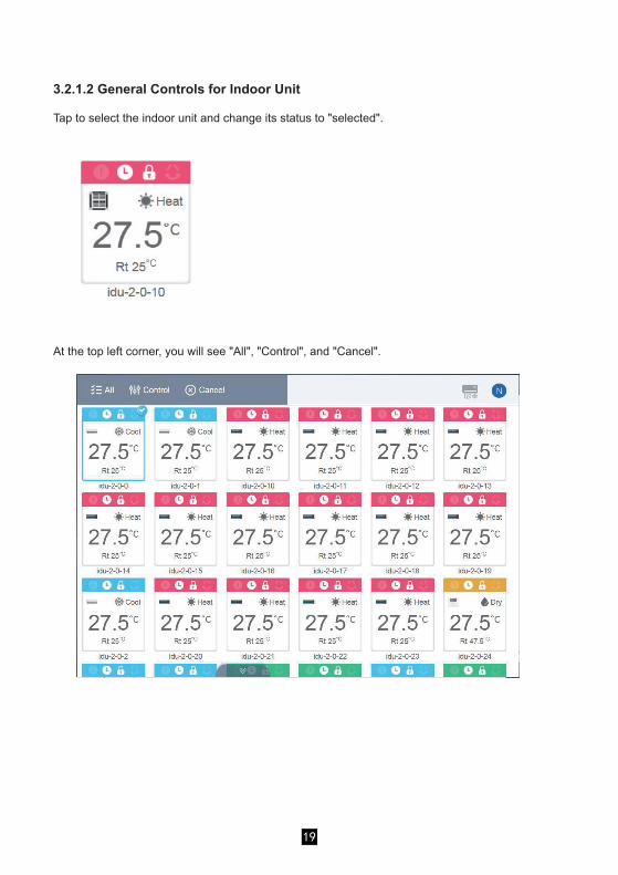
3.2.1.2 General Controls for Indoor Unit
Tap to select the indoor unit and change its status to "selected".
At the top left corner, you will see "All", "Control", and "Cancel".
19
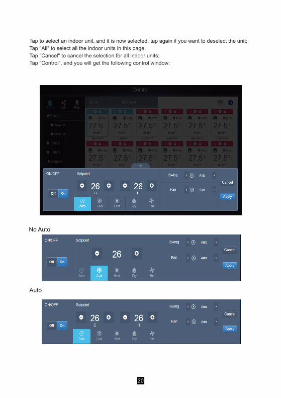
Tap to select an indoor unit, and it is now selected, tap again if you want to deselect the unit;Tap "All" to select all the indoor units in this page.Tap "Cancel" to cancel the selection for all indoor units;Tap "Control", and you will get the following control window:
No Auto
Auto
20

3.2.2 Indoor Unit View - System
3.2.3 Indoor Unit View - Map (this function is not available for Web terminals)
This is similar to "Group Navigation", except that the system (instead of the groups) is on the left. System name is default and cannot change.
You need to configure the map when you install the functions before you can use it.
21

3.3 Schedule
No. Functions
From left to right, the respective corresponding options to display the schedule are:1. Calendar View (by date);2. Plan View (by plan);3. Device View (by device);Tap the corresponding icon to go to the respective schedule view.Default is the calendar view.
Tap in the group area on the left to select and view different maps (Note: this group is different from the group in the "group" mode). Tap the different IDU icon on the map to select the specific indoor unit. Once selected, the control method is similar to that in the "group" mode. Tap "+", or "-" at the lower-left corner to zoom in and out the map.
Once you have tapped on the Home Page to go to the function module, go to the page to view the schedules.
1
1
22

3.2.1 View Schedule3.3.1.1 Calendar ViewWith the calendar view, select the date on the left to retrieve and view the schedule correspond-ing to the selected date on the right.
Calendar View
1 2
5
6
7
3 4
23

No. Functions
Tap to shift the calendar to display the previous month.
Displays the year and month information of the current date.
Tap to shift the calendar to display the next month.
Tap to quickly jump to the month that today's date belongs to, and selecttoday's date.
Date selected (dark blue background).
The grey numbers are dates not in the month shown now. Tap to jump tothe month that the date belongs to.
Today's date that has not been selected (light blue background). Tap toselect this date.
Calendar view
Schedule viewThe schedule page only shows scheduled tasks that have not been performed for the selected date (arranged in the order of implementation time). The displayed information is as follows1. Time2. Schedule name3. Details of the executed command (On/off, mode, set temperature, fan speed)
1
2
3
4
5
6
7
24

3.3.1.2 Plan View
Tap the second icon to view the schedule by plan as shown in the figure above.1
2 3 4
25

No. Functions
Calendar view (part)
Tap the left icon to go to the schedule editor. Tap the right icon to delete the selected schedule.The schedules are arranged in order of their time created. Tap to select the schedule you need. Selected schedule has a blue background colour. The schedule name is on the left of the schedule bar, and the status (ON/OFF) of the schedule is on the right.Shows all the timings for the selected schedule. Use the On/Off slider to perform on/off operations on the schedule. All the events on the dates of the schedule that has been turned off are not implemented, and the status "OFF" is displayed on the schedule bar. The schedule will not come into effect until it is turned on again.Shows all the indoor units associated with the schedule.
3.3.1.3 Device View
Tap the third icon to go to the device view.
The page is divided into three sections.1. Group list: this makes it easy to locate the device quickly. Tap "+" to expand the group, and "-" to
fold the group. All the IDUs in the selected group are displayed in the second column. Tap"Ungrouped" to view devices that have not been grouped.
2. The second column is a list of all the devices in the selected group.3. The third column is the list of schedules, and displays names of all the schedules associated with
the selected device.
1
2
3
4
1 2 3
26

3.3.2 Add Schedule
No. Functions
The device list displays all the devices related to the schedule. Tap to select and add the IDU
Cancel and save
Copy and add the schedule timings.
Settings related to the timings and commands.
Settings related to the schedule name and effective date.
1 2
4 5
3
1
2
3
4
5
27

No. Functions
Devices waiting to be selected are displayed in the rightmost area, and these are the devices that have not been added to the selected subgroup. "1" is a selected device and its top right corner is marked with ."2" is a device that has not been selected. Tap the unselected device to select the device. Tap again to deselect the selected device.
Tap to add the selected device.
Displays the device that has been added. Tap to select this operation. "5" is a device that has not been selected, tap to select it.
Displays the device that has been added. Tap to select this operation. "6" is a selected device, tap to deselect it. Left of the selected device is marked with .
Move the device that has been selected to be added to the group out of the "Add device" queue.Exit without saving.
Save and exit.
Tap to activate "Select All". is an active status. After activation, all the devices waiting to be selected in the group are selected. Tap again to deselect all. Manually cancel the selected status of a few devices after "Select All" has been activated will not cancel "Select All". Tap again to cancel the "Select All" option.
Tap to activate "Select All". is an active status. After activation, all the devices waiting to be selected in the group are selected. Tap again to deselect all. Manually cancel the selected status of a few devices after "Select All" has been activated will not cancel "Select All". Tap again to cancel the "Select All" option.
3.3.2.1 Add Device
3.3.2.1 Device Selection Page
5
79
1 2
3 4
6
810
1
2
3
4
5
6
7
8
9
10
28

No. Functions
Tap in the white space next to the blue icon on the left to activate the date selection dialog box. Tap to select the corresponding dates, the start date is on the left and the end date is on the right. The end date cannot be earlier than the start date.
Quick select for the weekly plan. Select the particular day to implement the plan for the day. If the day falls on a working day (Mon to Fri), the schedule for the day is implemented on the day itself.
Manual option for weekly plan. Tap the date to activate or deactivate it. Blue indicates active status, while white indicates inactive status.
You can add a custom date to the schedule as an individual date. Tap the "+" sign to add a date each time, and you may add up to 5 dates. Tap once to select and add the date. Tap "x" at the top left corner to delete this date. Tap the date in other areas to deselect it.
Note:The schedule will not be implemented during the holidays unless the holiday exception is selected;The schedule in the custom dates outside the holiday is implemented, even if the date falls outside the period of validity (expiration date) or is part of a weekly plan;The schedule for the remaining dates must be within the period of validity (before expiration date), and must satisfy the weekly plan.
Check the blue icon on the left next to Holiday to activate the holiday exception function which is to carry out all the plans in the schedule during the holiday period. The icons that are checked are active.
3.3.2.2 Date Settings
3.3.2.3 Add Schedule Command
Tap to create a table and you will get the dialog box to add the timings. Four optional
command types are FAPU, HRV, Auto and No Auto. Once the table is ready, you can use to
create a schedule command.
1. For Fresh Air Processing Unit (FAPU), three modes (cool, heat and fan) are available. In Fan mode, you cannot change the set temperature. The range of the set temperature in cool/heat mode is 17-30 degrees Celsius. The fan speed for cool and heat with fan is Speed 7 + Auto.
1
2
4
65
3
1
2
3
4
5
6
29
Tap the input box to enter a name. Maximum length is 80 English characters (40 Chinese characters). Note that system is unable to save the name if it contains the following symbols: ([`~!#$^&*()=|{}':;,\.<>/…?~!¥…()——【】‘’:“”。,、?;《》])

2. HRV (heat recovery ventilator) has four operating modes: Heat Exchange, Bypass, Discharge and Fan. You cannot change the set temperature in all four modes, and the fan speed is Speed 7 + Auto;
30
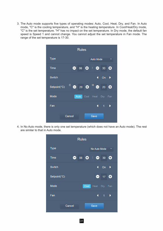
3. The Auto mode supports five types of operating modes: Auto, Cool, Heat, Dry, and Fan. In Auto mode, "C" is the cooling temperature, and "H" is the heating temperature. In Cool/Heat/Dry mode, "C" is the set temperature. "H" has no impact on the set temperature. In Dry mode, the default fan speed is Speed 1 and cannot change. You cannot adjust the set temperature in Fan mode. The range of the set temperature is 17-30.
4. In No Auto mode, there is only one set temperature (which does not have an Auto mode). The rest are similar to that in Auto mode.
31

Note:1. Tap "+" or "-" on Setpoint to increase or decrease the temperature by 0.5.2. Tap "+" or "-" on Time to increase or decrease the time by 1.3. Tap the left and right arrows to turn on/off the switch. No impact on the mode settings when the Off
command is sent.4. Tap the left and right arrows to toggle the fan speed.5. If the model in the schedule does not support this command, refer to the response of the actual
indoor unit.6. Tap to copy the task at the latest timing, and add one more minute to the implementation time.
The 23:59 command cannot be copied.7. For the timings that have been saved, tap to edit again, and to delete.
3.3.2.4 Save
Tap "Save" to save all the operations on this page, and open a new schedule to add pages. If there are illegal or incomplete items, you will receive the corresponding prompts.Tap "Cancel" to cancel all operations to add this schedule, and exit to the calendar view for the schedule.
3.3.2.5 Change Schedule
Tap on the Home Page or tap on the schedule in the calendar view to change the schedule. On the Home Page, the schedule is marked by . On the schedule view page, the entry point is the selected schedule.The operating method for the schedule editor is similar to that for adding a new page. The difference is that the screen will remain on the schedule editor page for "Save".
3.4. Report(Files are exported to local folder when the software is opened on a Web terminal.)
On the Home Page, tap .
There are 3 modules for users to choose from:1. Operating Duration2. Running Record3. Energy StatisticsTap the corresponding key to enter the module.
32

3.4.1 Operating DurationOperating duration report: View the total operation duration of the IDUs within a specified time period.Note: You can query the time and energy statistics reports only after the operating electricity file has been generated. The electricity file is generated at every point.
3.4.1.1 Query Operating Duration
3.4.1.1 Operating Duration
33

3.4.1.2 Operating Procedures1. Tap the selected device to go to the device selection page.2. Details of the device selection page are as follows:
3.4.1.2a Device Selection Page
5
6
7
9
8 3 21 410
34

3. Perform the time selection once the device has been added.
No. Functions
Devices waiting to be selected are displayed in the rightmost area, and these are the devices that have not been added to the selected subgroup. "1" is a selected device and its top right corner is marked with .
"2" is a device that has not been selected. Tap the unselected device to select the device. Tap again to deselect the selected device.
Tap to activate "Select All". is an active status. After activation, all the devices waiting to be selected in the group are selected. Tap again to deselect all. Manually cancel the selected status of a few devices after "Select All" has been activated. Will not cancel "Select All". Tap again to cancel the "Select All" option.
Tap to add the selected device.
Displays the device that has been added. Tap to select this operation. "5" is a device that has not been selected, tap to select it.
Tap to activate "Select All". is an active status. After activation, all the devices waiting to be selected in the group are selected. Tap again to deselect all. Manually cancel the selected status of a few devices after "Select All" has been activated will not cancel "Select All". Tap again to cancel the "Select All" option.
Move the device that has been selected to be added to the group out of the "Add device" queue.
Exit without saving.
Save and exit.
3.4.1.2b Time Selection Page
Displays the device that has been added. Tap to select this operation. "6" is a selected device, tap to deselect it. Left of the selected device is marked with .
1
2
3
4
5
6
7
8
9
10
1
2
35

No. Functions
Tap in this area (except the blue calendar icon) to activate the calendar.
Tap any number to select the date. Selected date in the box has a light blue background, otherwise today's date is selected. The grey text is a date that is outside this month. Tap to select it. Tap the time at the top to quickly locate the date. Tap once to go to the quick selection function for the month. Tap twice to go to the quick selection function for the year. Use the arrows on both sides at the top to quickly toggle the year and month. Each toggle is a 12-year duration for quick selection of year, 1-year duration for quick selection of month, and 1-month duration for quick selection of date. Tap the left arrow to move to previous month or year, and the right arrow to move to the next month or year.
3.4.2 Running RecordThe running record also needs to satisfy two conditions before the query is carried out. The operating procedures and query method are similar to 2.4.1 Operating Duration.The query results are displayed in a table form. You can query the following data:Operating duration, IDU name, model, IDU group number, IDU ID, operating mode, set temperature/cool temp_set in auto mode, heat temp set in auto mode, fan speed, IDU ambient temperature, error code, lock cooling set temp., lock heating set temp. mode-lock, wired controller lock, remote controller lock, fan-lock, On/Off lock, swing lock, up/down swing.Note: Historical records can only display and export the most recent 500 records within the specified period.
3.4.3 Energy Statistics
The method to query energy statistics is similar to that for the previous two functions. However, in the coordinate mode, you can only add up to three devices to search. There are no restrictions in the table mode.
Use at the top right corner to select the different modes. The selected mode is blue. The three modes are histogram, line graph and table respectively.
3.4.3.1 List View
1
2
36

List View
3.4.3.2 Histogram and Graph
Line Chart
37

Histogram
For histograms and graphs, you can only select three objects, and select either IDU or refrigerant system. The selected time for graphs and lists is based on the month (effective graph is based on day).
In the graphs, histograms and tables, the optional parameters are "Total Energy" and "Operating Energy".
There are only two options in total energy: total energy, and operating energy.
Operating Energy
Operating Electricity
Operating Electricity
Total Energy
Operating electricity + standby power
Operating electricity + standby power + exceptionalenergy
IDU
ODU
3.4.4 Log
Tap at the lower-left corner of the Home Page to go to the log page.
38

3.4.5 Export FunctionFor Operating Duration, Running Record, and Energy Statistics reports, there are functions to export
the queries records to .csv files (except for histograms and graphs). The contents of the exported files
are consistent with the current results of the queries. The format of the file is .csv, and it can be viewed
and edited with Excel. Naming convention of the exported file is:
Operating Duration: running_timestamp.csv;
Running Record: record_timestamp.csv;
Energy Statistics: energy_timestamp.csv.
Certain operations of the software are recorded in logs, and these are classified into the following categories:General control commandECO control commandSchedule control commandLogin and logoutSelect the start time and end time at the lower-left corner. Tap "Query" to display the log contents within this statistic compilation period.Note:When you switch the language, the language used to record the data in the schedule is not refreshed, and the log record is based on the data language at the time of creation.
39

On the touch-screen, you can also use the configured mail address in the settings to export the report
using mail and send the .csv file to the specified mailbox.
Tap mail export and you will be prompted to select the mail recipients. Once that is done, tap Send to
send the mail.
You can only save to local folder at the Web terminal, and the export target is the default download
path for the current browser.
When the file is exported to a USB drive through the touch-screen, you will receive a prompt once the
export is successful:
40

If mail is sent successfully, you will receive the following prompt:
The recipients will receive the mail with the exported file as a mail attachment.If the mailbox settings are wrong, the mail will not be sent successfully.
41
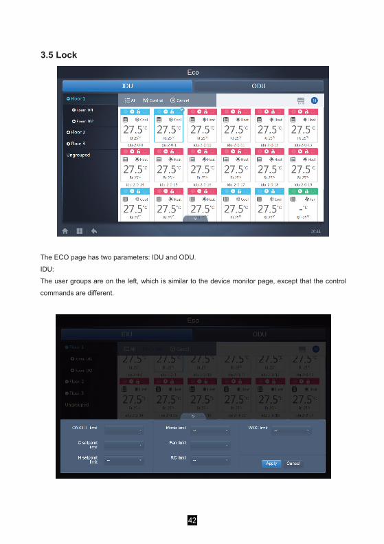
3.5 Lock
The ECO page has two parameters: IDU and ODU.
IDU:
The user groups are on the left, which is similar to the device monitor page, except that the control
commands are different.
42

Certain outdoor units may not support one or more lock commands described above.The CCM-270A/WS can send any lock command to the outdoor unit. If the outdoor unit does not support the lock command, the outdoor unit will process the command based on its own logic. For details on the different lock functions supported by different outdoor units, refer to the function manual of the corresponding outdoor unit.All parameters are "-" by default which means that no command is sent.
Certain indoor units may not support one or more locks described above.All parameters are "-" by default which means that no command is sent.*Certain indoor unit models may not support all the lock functions mentioned above. Please consult the engineer on details regarding the different lock functions supported by different IDU models.*Certain wired controllers may contain a "remote control/wired control, choose 1 of 2" function. This function is not related to the remote-lock in the CCM-270A/WS, and they are independent.
ODU:Outdoor unit page directly displays ODU objects.
43
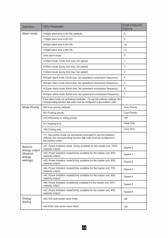
Definition ODU Parameter
0:Night silent time is 6h/10h (default)Silent mode
Auto Priority
Cool Priority
Heat Only
Cool Only
Speed 0
Speed 1
Speed 2
Speed 3
Speed 4
Speed 5
Speed 6
Off
ON
VIP
Mode Priority
Restrict energy output (Restrict energy settings)
Energy Saving
1:Night silent time is 6h/12h
2:Night silent time is 8h/10h
3:Night silent time is 8h/12h
4:No silent mode
5:Silent mode 1(only limit max. fan speed)
6:Silent mode 2(only limit max. fan speed)
7:Silent mode 3(only limit max. fan speed)
8:Super silent mode 1(limit max. fan speedand compressor frequency)
9:Super silent mode 2(limit max. fan speedand compressor frequency)
A:Super silent mode 3(limit max. fan speedand compressor frequency)
B:Super silent mode 4(limit max. fan speed and compressor frequency)
F:Set silent mode via centralized controller(To use the software settings, the corresponding function dial code must be configured in the outdoor units)
000:Auto priority (default)
001:Cooling priority
010:VIPpriority or voting priority
011:Heating only
100:Cooling only
111: Set priority mode via centralized controller(To use the software settings, the corresponding function dial code must be configured in the outdoor units)
n41: Power limitation mode 1(Only available for the master unit, 100% capacity output)
n42: Power limitation mode2(Only available for the master unit, 90% capacity output)
n43: Power limitation mode3(Only available for the master unit, 80% capacity output)
n44: Power limitation mode4(Only available for the master unit, 70% capacity output)
n45: Power limitation mode5(Only available for the master unit, 60% capacity output)
n46: Power limitation mode6Only available for the master unit, 50% capacity output
n47: Power limitation mode7(Only available for the master unit, 40% capacity output)
nb3::Exit auto power save mode
nb4:Enter auto power save mode
CCM-270A/WS Options
8
9
10
11
0
1
2
3
4
5
6
7
44

3.6 Installation
3.6.1 Edit
3.6.2 Group
Edit the name, model, fan power, auxiliary heating power (other parameters cannot be modified) of the indoor and outdoor units. Tap "Save" to save the edits.
Note:The acceptable range for the model is an integer from 0 to 12, and the model corresponds to the unit number in the device monitor.The maximum values of the fan power and the auxiliary heating power must not exceed 65535, and must not be negative values.The device name length cannot exceed 12 characters. Otherwise, you will receive a prompt that the name is ineligible. The device name cannot be duplicated.
Tap at the lower-left corner to go to the group editor from the installation page.
Under "Install", perform operations like device search, group edit, and name change when you use 10.1 for the first time.
45

3.6.2.1 Create, Edit, and Delete Group
Tap at the lower-left corner to go to the pages to create, edit and delete group.The CCM-270A/WS supports three group levels.
Group creation is on the left.When a group is selected, the group and the indoor units in that group are shown in the middle.Indoor units that have not been grouped are shown on the left.
46

Tap the back key at lower-left corner to return to the group page.
Create Group
Tap , and you will get a text box for you to edit the group at the corresponding level, and the mouse is active.
Enter the name. Tap the CR ("Go") key on the keyboard, or tap in the blank space to exit the editor.Groups at the same level cannot have the same names.A group name may include up to 12 characters. You will receive a prompt during "Save" if the name exceeds 12 characters.
When a group is selected, you will see the edit and delete function keys for the selected group.
Tap the edit icon to go to the group name editor
Edit, Delete Group
47

Tap "Delete" to delete the group.
Note: Make sure you tap "Save" at the bottom of the page to save all create and edit operations. Otherwise, the changes will be discarded.
Select the indoor unit you need to operate from the group list on the left. Tap to add the indoor unit to the corresponding group.
Add indoor unit to groupIn the group page, you can add and delete the indoor units in the group.
If the selected group has subgroups, they are displayed as follows:
48

Note: Once the edits to the indoor units in the group have been completed, tap (at the bottom of page) to save the changes. If the changes have not been saved and you directly switch to other groups, you will receive the following prompt, "Changes have not been saved. Save the changes?"
This function is invalid for the web page.Once you are in the installation module, tap "Map" to enter the map editor to edit the map and the devices in it.
You will be taken to the group editor of the map when you enter the map editor for the first time to add groups to the map navigation function (Note: This group is independent of the group in the control function).
3.6.3 Edit Map
In the middle area, select the indoor unit to be deleted, tap to remove the indoor unit from the corresponding group.
49

Figure 2.1
Figure 2.2
The method to add groups in this page is similar to that in section 3.6.2.1. For details, refer to
3.6.2.1. Once the edits are completed, tap to go to the map editor to edit the
map, as well as to add and position the indoor units.
5
432
1
7
6
8
10 11
1
9
50

No. Function Explanation
Group selection area. Tap "Edit" to edit the map in the selected group. Groups with subgroups are marked with an icon on the left of the group, if the group has not been expanded, and if the group has been expanded. Tap the icons to switch the status. Expand the tree structure to see the subgroups (branches).
Tap to go to the functions to add, delete, and edit group.
In the Edit mode, tap 5 to activate the Add panel, as shown in Figure 2.2. If you tap "Edit" before selecting any groups, the following error message is prompted:
If you tap 5 before entering the Edit mode, the following error message is prompted:
Tap to zoom into the map. Tap to zoom out of the map. Zoom range is 75%-150%.
Tap to go to the edit function to add or move the devices, as well as add or change the map (floor plan). The edit page is shown in Figure 2.2.
1
2
3
4
5
51

Shows devices that are not in the map. Default is to sort by name. Use 7 to switch to sort by mode. Tap to select the device. Tap again to deselect the device. Add up to seven devices each time.
The blue icon is the sort logic in the active status, is to sort by mode, is to sort by name.Add the selected device. If you select more than seven devices, you will receive the following error prompt:
Tap 9 when the Add panel is not activated to view a list of maps. System will search and display all .jpg and .png images that are less than 1MB in the root directory of the USB device.
Save all operations.
Cancel to exit the page.
6
7
8
9
10
11
52

Tap on the Home Page to go to the Settings page. Default is the user management module.
3.7 Settings
No. Functions
List of available functions in the settings page. Tap to jump to the corresponding tab.
Shows details of the different tabs.
21
1
2
53
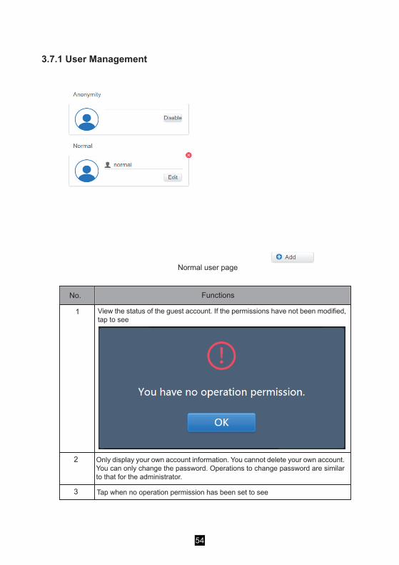
View the status of the guest account. If the permissions have not been modified, tap to see
Only display your own account information. You cannot delete your own account. You can only change the password. Operations to change password are similar to that for the administrator.
Tap when no operation permission has been set to see
3.7.1 User Management
No. Functions
Normal user page
1
2
3
54

Figure 3.7.2.1 No Edit mode
Default is maximum 15 characters for account name and password.Default account is "normal", password "1";
Tap the list to go to the tab to set the date and time as shown in Figure 3.7.2.1. Default is the No Edit page. View the current date and time. Use " " and " " or any grey numbers that do not belong to this month to jump to another month. Tap to check the blue icon on the left of "Modify date and time" to enter the Edit mode as shown in Figure 3.7.2.2.
3.7.2 Date and Time Settings
55
No. Functions
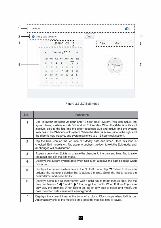
Use to switch between 24-hour and 12-hour clock system. You can adjust the system timing system in both Edit and No Edit modes. When the slider is white and inactive, slide to the left, and the slider becomes blue and active, and the system switches to the 24-hour clock system. When the slider is active, slide to the right and the slider is now inactive, and system switches to a 12-hour clock system.
Tap the blue icon on the left side of "Modify date and time". Once this icon is checked, Edit mode is on. Tap again to uncheck the icon to exit the Edit mode, and all changes will be discarded.
Appears only when Edit is on to save the changes to the date and time. Tap to save the result and exit the Edit mode.Displays the current system date when Edit is off. Displays the date selected when Edit is on.
Displays the current system time in the No Edit mode. Tap "▼" when Edit is on to activate the number selection list to adjust the time. Scroll the list to select the desired time, and close the list.Displays dates in a calendar format with a solid box to frame today's date. Tap the grey numbers or " " and " " to change the month. When Edit is off, you can only view the calendar. When Edit is on, tap on any date to select and modify the date. Selected dates have a blue background.
Displays the current time in the form of a clock. Clock stops when Edit is on. Automatically skip to the modified time once the modified time is saved.
Figure 3.7.2.2 Edit mode
1
2
4
6
3
5
7
1
2
3
4
5
6
7
56

3.7.3 Holiday Settings
Figure 3.7.3.1
No. Functions
Displays current year and month. Tap " " and " " to change the month.
Shortcut to return to the current system date. Tap to activate it immediately.
Dates in grey do not belong to the current displayed month. Tap to jump to the date that the grey number belongs to and select the date.
Light blue background colour and blue font for today's date.
Dates with light blue background and red text are marked as holidays.
Selected date has a dark blue background. Tap the dates in black or blue font to select the date.
Non-holidays are marked with . Holidays are marked with . Select the corresponding date to view its status. Tap the blue icon to switch the status.
1
34
6
5
7
2
1
2
3
45
6
7
57

(Wireless network settings are invalid for the web page.)
Displays the name of the current network.
Tap to jump to the Settings page for the wireless network. Tap at the bottom right corner to restart app and go to
3.7.4 Network Settings
No. Functions
1
2
4
3
1
58

DHCP is not available for the wired network. Change the corresponding details, and tap "Save" to save.
Tap "Save" to save the changes to the wired network.
(Adjustment to screen brightness is only for the touch screen)
General Settings
3.7.5 General Settings
Tap the Wi-Fi name to fill in the corresponding details, then tap "Connect" to connect.
3
4
1
2
3
4
5
59

Mail Settings
3.7.6 Mail Settings
No. Functions
Changes the display language. Tap to activate the drop-down box, and tap to select the desired language.Adjusts the group's display mode. Selected mode is highlighted in blue. Tap the grey icon to activate its mode. The two modes are mutually exclusive.The function targets the Group Navigation at the Device Monitor and Installation. Image on the right is related to the display of indoor units in the subgroups. Expand to display the indoor units in the subgroups on the right. Otherwise, the indoor units in the subgroups are merged into the subgroup folder and only the number of indoor units is displayed.
If the indoor ambient temperature for T1 is displayed. Left is Display, right is No Display. Selected mode is highlighted in blue. Tap the grey icon to activate its mode. The two modes are mutually exclusive.
Unit of temperature. Selected mode is highlighted in blue. Tap the grey icon to activate its mode. The two modes are mutually exclusive.
1
2
3
4
5
1
2
3 4
60
Adjusts the display brightness. Tap to adjust. Slide left to reduce the brightness, and right to increase the brightness.

Displays the configuration of the current sender. Tap to configure and edit the sender.
Fill in the corresponding details. Tap "OK" to save and exit. Tap "Cancel" to cancel all operations and exit. (please verify with the mail service provider that the details are correct)
Displays information about the recipient. Tap to edit.
No. Functions
1
2
61

Fill in the corresponding details. Tap "OK" to save and exit. Tap "Cancel" to cancel all operations and exit.If the mailbox format is wrong, you will receive the prompt to "Fill in the corresponding details. Tap "OK" to save and exit. Tap "Cancel" to cancel all operations and exit." System will discard the operation.Examples:1. "@" is missing.
2. Incomplete Email domain name.
3. Invalid username.
62

(Version upgrade is only for the touch screen terminal)3.7.7 Advanced Settings
Tap "Add" to add up to six recipients.
Fill in the corresponding details. Tap "OK" to save and exit. Tap "Cancel" to cancel all operations and exit.
Tap "Delete" to activate the delete mode,
Recipient has a delete mark at the top right corner, tap the delete mark to receive a confirmation that delete has been carried out. Tap "OK" to save and exit. Tap "Cancel" to cancel all operations and exit.Tap "Delete" again to exit the delete mode.
3
4
63

Advanced Settings
No. Functions
Tap the slider to activate the dialog box. Tap "OK" to restore device to factory settings (clear topology information, schedules, history, operating duration, running records, energy statistics, settings). Tap "Cancel" to cancel all operations and exit.
Displays the current version of the software.
Tap the blue icon, and the app will automatically search for the update.apk file in the inserted USB root directory. If the file exists, you will get the installation page.Note: Make sure that the update.apk file is the correct installation file; otherwise, the installation will fail.
Tap the slider to activate the dialog box. Tap "OK" to restart the device. Tap "Cancel" to cancel all operations and exit.
1
2
3
4
1
2
3
4
64

Public Settings
No. Functions
Displays the group option. All the devices in the groups (including subgroups) are displayed on the right, and the groups are arranged based on the time of creation.
Changes the properties of the selected devices. Public refers to public devices. Enabled refers to devices that have been enabled. Tap to select all the devices that can be selected. Tap "Cancel" to unselect all.
Method to display public devices.
Displays enabled devices. Selected device is marked by an icon at the top right corner. indicates enabled devices that are selected. indicates public devices that are selected.Filters the devices in the group. Tap "All" to display all devices. Tap "Public" to display the public devices. Tap "Enable" to display all the enabled devices.
3.7.8 Public Settings
Note:1. For those marked as Public devices, its power will shared to all enabled devices during power
allocation.2. Power from public devices is shared equally to other devices where fees are being charged. It does
not distinguish the time settings. Once it is set as a public device, all queries will see that device as a public devices (power allocation is only effective during the query, the database records the original file, and the calculation is performed only during the query).
3. Devices in the wired controller group do not support this function.
2
4
1
5
3
1
2
3
4
5
65

3.7.9 Energy Settings
Energy Settings
66

4. APPENDIX4.1 Table of Error CodesThis manual is intended for reference only, refer to the error shown on the actual device for troubleshooting.Please consult the engineer to check if the error code of the specific model belongs to a "new generation of refrigerant system".
Table of Error Codes for V6 and V6i Outdoor Unit:
E0 Communication error between outdoor units
E1 Phase sequence error
E2 Communication error between indoor and master unit
E4 Outdoor heat exchanger temperature sensor (T3) error or outdoor ambient temperature sensor (T4) error
E5 Abnormal power supply voltage
E7 Compressor top or discharge pipe temperature sensor (T7C1/2) error
E8 Outdoor unit address error
xE9 EEPROM mismatch
xF1 DC bus voltage error
F3 Plate heat exchanger cooling refrigerant outlet temperature sensor (T6B) error
F5 Plate heat exchanger cooling refrigerant inlet temperature sensor (T6A) error
F6 Electronic expansion valve connection error
xH0 Communication error between main control chip and inverter driver chip
H2 Number of slave units detected by master unit has decreased
H3 Number of slave units detected by master unit has increased
xH4 Inverter module protection
H5 P2 protection appears three times in 60 minutes
H6 P4 protection appears three times in 100 minutes
Error code1 Content
67

Notes:1. 'x' is a placeholder for the compressor system (compressor and related electrical components), with 1
representing compressor system A and 2 representing compressor system B. 'y' is a placeholder for the address (1 or 2) of the slave unit with the error.
2. For some error codes, a manual restart is required before the system can resume operation.3. Once the EXV has been connected properly, the error code will flash to indicate that the connection has
been re-established. A manual restart is then required before the system can resume operation.
H7 Number of indoor units detected by master unit not same as number set on main PCB
H8 High pressure sensor error
H9 P9 protection appears ten times in 120 minutes
yHd Slave unit malfunction
C7 PL protection appears three times in 100 minutes
P1 Discharge pipe high pressure protection
P2 Suction pipe low pressure protection
xP3 Compressor current protection
P4 Discharge temperature protection
P5 Outdoor heat exchanger temperature protection
P9 Fan module protection
Error code1 Content
PL Inverter module temperature protection
PP Compressor discharge insufficient superheat protection
xL0 Inverter module protection
xL1 DC bus low voltage protection
xL2 DC bus high voltage protection
xL4 MCE error
xL5 Zero speed protection
xL7 Phase sequence error
xL8 Compressor frequency variation greater than 15Hz within one second protection
xL9 Actual compressor frequency differs from target frequency by more than 15Hz protection
Error code1 Content
68

Table of Error Codes for Indoor Units
Error code Content
E0 Mode conflict
E1 Communication error between indoor and outdoor units
E2 Indoor ambient temperature sensor error
E3 Indoor heat exchanger mid-point temperature sensor error
E4 Indoor heat exchanger outlet temperature sensor error
E6 Fan error
E7 EEPROM mismatch
Ed Outdoor unit error
EE Water level error
FE Indoor unit has not been assigned an address
69

a) If there are display errors on the web page such as header errors and wrong icon placements, use the browser's mandatory refresh function to refresh the page (such as "Shift+F5" for the Chrome browser).
b) You can only enter English characters on the touch-screen. Use the Web page if you need to use other language and characters.
4.2 Software Use Precautions
4.3 Wired Controller GroupFor the new units, certain wired controllers support the access of multiple indoor units (IDU) where these IDUs will then form a "wired controller group". In IMMPro, these IDUs will be treated as a single virtual IDU, and in the icon view in "Device Monitor" the wired controller group of IDUs will have its own icon. The name of the wired controller group is the same as the name of the smallest IDU.Note: Refer to the relevant manuals on wired controllers, and indoor units for specific information on how to set the address of the wires controller group.
IDUs in wired controller group
The same commands are sent to the wired controllers in the group.
"Device monitor" icon view
"Device monitoring" list view
"Statistical data", "Energy statistics"
When one or more IDUs are offline in the wired controller group, the wired controller group icon will display an offline status.When there are errors in one or more IDUs in the wired controller group, the wired controller group icon will display an error status, and the error code will be the error code in the IDU with the smallest address.When the wired controller group is normal, the wired controller group icon will show the operating state of the smallest IDU.
In a list view, each IDU in the group is displayed on a separate line, and you can view the details of each IDU in the group.
Each IDU in the group is displayed on a separate line, and you can view the statistics of each IDU in the group.
70
Send controlcommand

16111500000630
MD17IU-031AW
Copyright © 2022 FDOKUMEN