Fish Passage Plan
405
Top Photo: McNary Dam Bypass Outfall Flume (Scott Bettin, BPA). Bottom Photo: Bonneville Dam Adult Fish Ladder (Tammy Mackey, COE-NWP). Northwestern Division Fish Passage Plan Corps of Engineers Projects CENWD-PDW-R MARCH 2013
-
Upload
khangminh22 -
Category
Documents
-
view
0 -
download
0
Transcript of Fish Passage Plan

Top Photo: McNary Dam Bypass Outfall Flume (Scott Bettin, BPA). Bottom Photo: Bonneville Dam Adult Fish Ladder (Tammy Mackey, COE-NWP).
Northwestern Division
Fish Passage Plan Corps of Engineers Projects CENWD-PDW-R
MARCH 2013

2013 Fish Passage Plan Table of Contents
Section 1 Overview 1. Fish Passage Plan ................................................................................................ OVE-01
1.1. Background .......................................................................................... OVE-01 1.2. Emergency Deviations from the FPP ................................................... OVE-02 1.3. Technical Management Team .............................................................. OVE-02 1.4. Spill at Corps Mainstem Projects ......................................................... OVE-03 1.5. Total Dissolved Gas Monitoring .......................................................... OVE-03 1.6. System Load Shaping ........................................................................... OVE-03 1.7. Juvenile Fish Transportation Plan ........................................................ OVE-04 1.8. Lamprey Passage .................................................................................. OVE-04
2. Fish Passage Facilities Inspection and Reporting Criteria .................................. OVE-04 2.1. Annual Reporting ................................................................................... OVE-04 2.2. Reporting of Excursions Not Covered by Appendix C .......................... OVE-05 3. Turbine Dewatering at Chief Joseph Dam .......................................................... OVE-05 4. Turbine Dewatering for Dworshak Dam............................................................. OVE-05 5. Implementation and Coordination of the FPP..................................................... OVE-05 5.1. Agency Responsibilities ......................................................................... OVE-06 5.2. FPOM Coordination............................................................................... OVE-08 5.3. TMT Coordination ................................................................................. OVE-09 5.4. Day-to-Day Coordination of the FCRPS ............................................... OVE-09 Section 2 Bonneville Dam 1. Fish Passage Information ......... .............................................................. ............BON-01
1.1. Juvenile Fish Passage ............. ................................................ .............BON-01 1.2. Adult Fish Passage ............... ................................................. ..............BON-09
2. Project Operation ................ ................................................................. ..............BON-10 2.1. General .............................. ........................................................ ..........BON-10 2.2. Spill Management ............. ................................................ ..................BON-11 2.3. Total Dissolved Gas Management and Control .. ............................. ...BON-13 2.4. Juvenile Fish Passage Facilities ............ ........................................... ...BON-13 2.5. Adult Fish Passage Facilities ........ ............................................ ..........BON-20
3. Facility Monitoring and Reporting .......................................................... ...........BON-26 3.1. Inspections................................ ....................................................... ....BON-26 3.2. Zebra Mussel Monitoring..................................................... ................BON-26 3.3. Reporting................................... ........................................................ ...BON-26
4. Fish Facilities Maintenance ......... ........................................................... ...........BON-27 4.1. General ..................................... ........................................................ ...BON-27 4.2. Juvenile Fish Passage Facilities ....... ........................................... ........BON-28

2013 Fish Passage Plan TOC-ii Table of Contents
4.3. Adult Fish Passage Facilities ............................................. .................BON-30 5. Turbine Unit Operation and Maintenance.. ................................................. .......BON-34 6. Dewatering Plans ........................ ................................................................ .......BON-36
6.1. Guidelines for Any Dewatering.................. .............................. ...........BON-36 6.2. Juvenile Bypass Systems ....................................................... ..............BON-37 6.3. Adult Fish Ladder.................... .................................................. ..........BON-37 6.4. Powerhouse Fish Collection System ... ..................................... ...........BON-37 6.5. Turbines................................... ........................................................ ....BON-38
7. Forebay Debris Removal ........................................................................... .........BON-39 8. Response to Hazardous Materials Spills.... .................................................... .....BON-39 9. Endnotes .............................................................................................................. BON-39 Section 3 The Dalles Dam 1. Fish Passage Information .................................................................................... TDA-01
1.1. Juvenile Fish Passage ........................................................................... TDA-01 1.2. Adult Fish Passage ............................................................................... TDA-07
2. Project Operation ................................................................................................ TDA-08 2.1. General ................................................................................................. TDA-08 2.2. Spill Management ................................................................................ TDA-08 2.3. Total Dissolved Gas Management and Control ................................... TDA-08 2.4. Juvenile Fish Passage Facilities ........................................................... TDA-09 2.5. Adult Fish Passage Facilities ............................................................... TDA-10
3. Facility Monitoring and Reporting...................................................................... TDA-13 3.1. Inspections ........................................................................................... TDA-13 3.2. Zebra Mussel Monitoring..................................................................... TDA-14 3.3. Reporting .............................................................................................. TDA-14
4. Fish Facilities Maintenance ................................................................................ TDA-15 4.1. General ................................................................................................. TDA-15 4.2. Juvenile Fish Passage Facilities ........................................................... TDA-15 4.3. Adult Fish Passage Facilities ............................................................... TDA-17
5. Turbine Unit Operation and Maintenance .......................................................... TDA-19 6. Dewatering Plans ................................................................................................ TDA-20
6.1. Guidelines for Dewatering and Fish Handling Plans ........................... TDA-20 6.2. Juvenile Bypass Systems...................................................................... TDA-21 6.3. Adult Fish Ladder ................................................................................ TDA-21 6.4. Powerhouse Collection System Routine Maintenance ........................ TDA-22 6.5. Turbines ............................................................................................... TDA-22
7. Forebay Debris Removal..................................................................................... TDA-22 8. Response to Hazardous Materials Spills ............................................................. TDA-23 9. Endnotes .............................................................................................................. TDA-23

2013 Fish Passage Plan TOC-iii Table of Contents
Section 4 John Day Dam 1. Fish Passage Information ..................................................................................... JDA-01
1.1. Juvenile Fish Passage ............................................................................ JDA-01 1.2. Adult Fish Passage ................................................................................ JDA-03
2. Project Operation ................................................................................................. JDA-07 2.1. General .................................................................................................. JDA-07 2.2. Spill Management ................................................................................. JDA-07 2.3. Dissolved Gas Management and Control.............................................. JDA-07 2.4. Juvenile Fish Passage Facilities ............................................................ JDA-07 2.5. Adult Fish Passage Facilities ................................................................ JDA-12
3. Facilities Monitoring and Reporting....... ............................................... .............JDA-15 3.1. Inspections ........................................................................................... .JDA-15 3.2. Zebra Mussel Monitoring...................................................................... JDA-15 3.3. Reporting ............................................................................................... JDA-15
4. Fish Facilities Maintenance ................................................................................. JDA-16 4.1. General .................................................................................................. JDA-16 4.2. Juvenile Fish Passage Facilities ............................................................ JDA-16 4.3. Adult Passage Facilities ........................................................................ JDA-18
5. Turbine Unit Operation and Maintenance ........................................................... JDA-21 5.1. Guidelines........................ ............................................................... ......JDA-21 5.2. Juvenile Fish Passage... ............................................................. ............JDA-22
6. Dewatering Plans ................................................................................................. JDA-25 6.1. Adult Fish Ladders ................................................................................ JDA-25 6.2. Non-Routine Maintenance .................................................................... JDA-25 6.3. Powerhouse Fish Collection System ..................................................... JDA-26 6.4. Juvenile Bypass System ........................................................................ JDA-26 6.5. Turbines ................................................................................................ JDA-26
7. Forebay Debris Removal...................................................................................... JDA-27 8. Response to Hazardous Materials Spills............................ ....................... ...........JDA-27 9. Endnotes ............................................................................................................... JDA-27 Section 5 McNary Dam 1. Fish Passage Information.......... ......................................................................... MCN-01
1.1. Juvenile Fish Passage .......................................................................... MCN-01 1.2. Adult Fish Passage .............................................................................. MCN-05
2. Project Operation ............................................................................................... MCN-06 2.1. Spill Management ............................................................................... MCN-06 2.2. Dissolved Gas Management and Control............................................ MCN-06 2.3. Operating Criteria ............................................................................... MCN-06
3. Project Maintenance ........................................................................................... MCN-17 3.1. Juvenile Fish Passage Facilities .......................................................... MCN-17

2013 Fish Passage Plan TOC-iv Table of Contents
3.2. Adult Fish Passage Facilities .............................................................. MCN-20 4. Turbine Unit Operation and Maintenance ......................................................... MCN-22
4.1. Turbine Unit Operation ....................................................................... MCN-22 4.2. Turbine Unit Maintenance .................................................................. MCN-24
5. Forebay Debris Removal.................................................................................... MCN-25 5.1. Special Spills ....................................................................................... MCN-26
Section 6 Ice Harbor Dam 1. Fish Passage Information.......... ........................................................................... IHR-01
1.1. Juvenile Fish Passage ............................................................................ IHR-01 1.2. Adult Fish Passage ................................................................................ IHR-01
2. Project Operation ................................................................................................. IHR-05 2.1. Spill Management ................................................................................. IHR-05 2.2. Dissolved Gas Management and Control.............................................. IHR-05 2.3. Operating Criteria ................................................................................. IHR-05
3. Project Maintenance ............................................................................................. IHR-14 3.1. Juvenile Fish Passage Facilities ............................................................ IHR-14 3.2. Adult Fish Passage Facilities ................................................................ IHR-16
4. Turbine Unit Operation and Maintenance ........................................................... IHR-18 4.1. Turbine Unit Operation ......................................................................... IHR-18 4.2. Turbine Unit Outages During High River Flow Periods ..................... IHR-19 4.3. Turbine Unit Maintenance .................................................................... IHR-20
5. Forebay Debris Removal...................................................................................... IHR-21 5.1. Special Spills ......................................................................................... IHR-22
Section 7 Lower Monumental Dam 1. Fish Passage Information.......... ......................................................................... LMN-01
1.1. Juvenile Fish Passage .......................................................................... LMN-01 1.2. Adult Fish Passage .............................................................................. LMN-05
2. Project Operation ............................................................................................... LMN-06 2.1. Spill Management ............................................................................... LMN-06 2.2. Dissolved Gas Management and Control............................................ LMN-06 2.3. Operating Criteria ............................................................................... LMN-06 2.4. Navigation Spill Operations ................................................................ LMN-16
3. Project Maintenance ........................................................................................... LMN-17 3.1. Juvenile Fish Passage Facilities .......................................................... LMN-17 3.2. Adult Fish Passage Facilities .............................................................. LMN-19
4. Turbine Unit Operation and Maintenance ......................................................... LMN-20 4.1. Turbine Unit Operation ....................................................................... LMN-20 4.2. Turbine Unit Outages During High River Flow Periods ................... LMN-25 4.3. Turbine Unit Maintenance .................................................................. LMN-26

2013 Fish Passage Plan TOC-v Table of Contents
5. Forebay Debris Removal.................................................................................... LMN-28 5.1. Special Spills ....................................................................................... LMN-28
Section 8 Little Goose Dam 1. Fish Passage Information.......... ........................................................................... LGS-01
1.1. Juvenile Fish Passage ............................................................................ LGS-01 1.2. Adult Fish Passage ................................................................................ LGS-05
2. Project Operations ................................................................................................ LGS-06 2.1. Spill Management ................................................................................. LGS-06 2.2. Dissolved Gas Management and Control.............................................. LGS-06 2.3. Operating Criteria ................................................................................. LGS-06
3. Project Maintenance ............................................................................................. LGS-17 3.1. Juvenile Fish Passage Facilities ............................................................ LGS-17 3.2. Adult Fish Passage Facilities ................................................................ LGS-19
4. Turbine Unit Operation and Maintenance ........................................................... LGS-21 4.1. Turbine Unit Operation ......................................................................... LGS-21 4.2. Turbine Unit Outages During High River Flow Periods ..................... LGS-23 4.3. Turbine Unit Maintenance .................................................................... LGS-25
5. Forebay Debris Removal...................................................................................... LGS-27 5.1. Special Spills ......................................................................................... LGS-27
Section 9 Lower Granite Dam 1. Fish Passage Information.......... ......................................................................... LWG-01
1.1. Juvenile Fish Passage .......................................................................... LWG-01 1.2. Adult Fish Passage .............................................................................. LWG-05
2. Project Operation ............................................................................................... LWG-06 2.1. Spill Management ............................................................................... LWG-06 2.2. Dissolved Gas Management and Control............................................ LWG-06 2.3. Operating Criteria ............................................................................... LWG-06 2.4. Navigation Spill Operations ................................................................ LWG-17
3. Project Maintenance ........................................................................................... LWG-18 3.1. Juvenile Fish Passage Facilities .......................................................... LWG-18 3.2. Adult Fish Passage Facilities .............................................................. LWG-20
4. Turbine Unit Operation and Maintenance ......................................................... LWG-22 4.1. Turbine Unit Operation ....................................................................... LWG-22 4.2. Turbine Unit Outages During High River Flow Periods .................... LWG-25 4.3. Turbine Unit Maintenance .................................................................. LWG-26
5. Forebay Debris Removal.................................................................................... LWG-27 5.1. Special Spills ....................................................................................... LWG-27

2013 Fish Passage Plan TOC-vi Table of Contents
Appendices
Appendix A Special Project Operations and Studies
Appendix B Corps of Engineers Juvenile Fish Transportation Plan
Appendix C Bonneville Power Administration's System Load Shaping Guidelines Regarding Turbine Operation and Best Efficiency
Appendix D Project Operations for Non-ESA Listed Fish Species (Lamprey, etc.)
Appendix E Operations Related to Project Spill for Fish Passage and Transportation (Fish Operations Plan)
Appendix F Guidelines for Dewatering and Fish Handling Plans
Appendix G Protocols for Adult Fish Trapping Operation at Bonneville, Ice Harbor, and Lower Granite Dams
Appendix H Turbine Dewatering Procedure for Chief Joseph Dam
Appendix I Dworshak Fish Protection Procedures for Turbine Maintenance
Appendix J Protocols for Juvenile Monitoring Facility Operations at Bonneville Dam
Appendix K Protocols for Smolt Monitoring Facility Operations at John Day Dam
Appendix L List of Acronyms

2013 Fish Passage Plan
2013 Fish Passage Plan
Section 1 – Overview Table of Contents
1. Fish Passage Plan ................................................................................................ OVE-01
1.1. Background .......................................................................................... OVE-01
1.2. Emergency Deviations from the FPP ................................................... OVE-02
1.3. Technical Management Team .............................................................. OVE-02
1.4. Spill at Corps Mainstem Projects ......................................................... OVE-03
1.5. Total Dissolved Gas Monitoring .......................................................... OVE-03
1.6. System Load Shaping .......................................................................... OVE-03
1.7. Juvenile Fish Transportation Plan ........................................................ OVE-04
1.8. Lamprey Passage ................................................................................. OVE-04
2. Fish Passage Facilities Inspection and Reporting Criteria .................................. OVE-04
2.1. Annual Reporting ................................................................................... OVE-04
2.2. Reporting of Excursions Not Covered by Appendix C ......................... OVE-05
3. Turbine Dewatering at Chief Joseph Dam .......................................................... OVE-05
4. Turbine Dewatering for Dworshak Dam ............................................................ OVE-05 5. Implementation and Coordination of the FPP .................................................... OVE-05
5.1. Agency Responsibilities......................................................................... OVE-06
5.2. FPOM Coordination............................................................................... OVE-08
5.3. TMT Coordination ................................................................................. OVE-09
5.4. Day-to-Day Coordination of the FCRPS ............................................... OVE-09

2013 Fish Passage Plan Overview
OVE-1
Section 1 Overview
1. Fish Passage Plan Overview
1.1. Background
The Fish Passage Plan (FPP) is developed annually by the U.S. Army Corps of Engineers (Corps) in coordination with the region's federal and state fish agencies, Indian tribes, the Bonneville Power Administration (BPA), and other regional partners through the Corps’ Fish Passage Operations and Maintenance (FPOM) coordination team. The FPP describes year-round operation and maintenance (O&M) activities at Corps mainstem hydroelectric projects in the Federal Columbia River Power System (FCRPS) that are coordinated through FPOM so as to protect and enhance anadromous and resident fish species listed as endangered or threatened under the Endangered Species Act (ESA), as well as other resident and migratory fish species (e.g., lamprey, sturgeon). The FPP guides Corps actions in regard to providing fish protection and passage at the eight Corps projects on the mainstem lower Columbia and lower Snake rivers, and at Chief Joseph Dam on the upper Columbia River. Other Corps documents and agreements related to fish passage at these projects are consistent with the FPP.
The FPP is drafted in accordance with the ESA Section 7 Biological Opinion (BiOp) by NOAA Fisheries on the effects of operating the FCRPS on ESA-listed anadromous fish species, issued May 5, 2008, and titled “Consultation on Remand for Operation of the Federal Columbia River Power System, 11 Bureau of Reclamation Projects in the Columbia Basin and ESA Section 10(a)(I)(A) Permit for Juvenile Fish Transportation Program (Revised and reissued pursuant to court order, NWF v. NMFS, Civ. No. CV 01-640-RE (D. Oregon))”. On May 20, 2010, NOAA Fisheries issued a Supplemental FCRPS BiOp which integrated the entire 2008 FCRPS BiOp and its Reasonable and Prudent Alternative (RPA) with new information and an Adaptive Management Integration Plan (AMIP). The Corps prepared a Record of Consultation and Statement of Decision (ROCASOD) in response to both the 2008 and 2010 NOAA Fisheries BiOps. The Corps also prepared a ROCASOD in response to the US Fish & Wildlife Service (USFWS) BiOp issued in 2000 and supplemented in 2006 on the effects of operating the FCRPS on ESA-listed resident fish species. The ROCASODs document the Corps’ decision to implement the actions recommended in the BiOps and associated RPAs so that the FCRPS is operated consistent with the ESA in a manner that protects and enhances ESA-listed fish species, as well as other regionally important fish species. The FCRPS BiOps, decision documents and other related information can be found on the following website: http://www.salmonrecovery.gov
The FPP is defined in NOAA Fisheries’ 2008 BiOp RPA as part of the hydropower strategy of operating and maintaining fish passage facilities at Corps mainstem projects in order to maintain biological performance. Key elements of the FPP include:
• Operate according to project-specific criteria and dates to operate and maintain fish facilities, turbine operating priorities, and spill patterns;
• Operate according to fish transportation criteria; • Maintain turbine operations within the 1% of best efficiency range; • Maintain spillway discharge levels and dates to provide project spill for fish passage;

2013 Fish Passage Plan Overview
OVE-2
• Implement TDG monitoring plan; • Operate according to protocols for fish trapping and handling; • Take advantage of low river conditions, low reservoir elevations or periods outside the
juvenile migration season to accomplish repairs, maintenance, or inspections so there is little or no effect on juvenile fish;
• Coordinate routine and non-routine maintenance that affects fish operations or structures to eliminate and/or minimize fish operation impacts;
• Schedule routine maintenance during non-fish passage periods; • Conduct non-routine maintenance activities as needed; and • Coordinate criteria changes and emergency operations with FPOM.
The FPP is revised as necessary to incorporate changes to project operations and maintenance as a result of new facilities or changes in operational procedures. Revisions will incorporate changes adopted through coordination with NOAA Fisheries and USFWS as part of the ESA Section 7 consultation, Recovery Plan, or Section 10 permit processes, and through consideration of other regional input and plans. When revising the FPP, the Corps also considers the amended Northwest Power and Conservation Council’s Columbia River Basin Fish and Wildlife Program to the fullest extent practicable. If any revisions to the FPP are necessary, they will be made in accordance with the coordination process for revisions as described in Section 5.2 below.
Comments on the FPP are welcome and may be sent to FPOM and/or the Corps’ Northwestern Division, Reservoir Control Center (RCC) Fish Team in Portland, Oregon.
1.2. Emergency Deviations from the Fish Passage Plan
River operations emergencies may occur which require projects to deviate temporarily from the FPP. To the extent practicable, these operations will be coordinated with fish agencies and tribes and conducted in a manner to avoid or minimize fish impacts. Normally, coordination occurs prior to an action; however, if an emergency situation requires immediate attention, coordination will be completed as soon as practicable afterwards. See Section 5.2 for more detail.
The phrase "when practicable" appears in the FPP to help describe those project actions for fish that may vary on a case-by-case basis and thus require the exercise of professional judgment by the project for a particular situation. This is due to factors such as real time biological or other environmental conditions, project manpower or mechanical equipment availability, and fish facility or dam structural integrity. In these cases, the project biologist and other project personnel will consider all relevant factors and determine the best way to proceed and implement an appropriate action. These actions will be coordinated with fish agencies and tribes when they deviate from the FPP.
1.3. Technical Management Team
In-season decisions on river operations to achieve BiOp biological performance standards for spring and summer outmigrants will be made in coordination with the Regional Forum Technical Management Team (TMT). Coordination of special operations identified in the FPP will occur through the TMT and be identified in the Water Management Plan. These may include maintenance or research activities requiring unit outages that affect other river operations,

2013 Fish Passage Plan Overview
OVE-3
operation of turbines outside of the 1% of best efficiency range, zero nighttime generation, and implementation of the Juvenile Fish Transportation Plan (JFTP; see Appendix B).
1.4. Spill at Corps Mainstem Projects
Corps mainstem projects will provide spill for juvenile fish passage in accordance with NOAA Fisheries 2008 FCRPS BiOp RPA Table 2: “Initial Voluntary Spill Operations at Columbia and Snake River Dams”.
1.5. Total Dissolved Gas Monitoring
Total dissolved gas (TDG) saturation levels are monitored at the forebay and tailrace of each mainstem project during the fish passage season. The water quality standard and criterion for TDG developed by the states of Idaho, Montana, Oregon, and Washington, in coordination with EPA, is 110% of saturation at ambient temperature and pressure. The Corps' policy is to operate each mainstem project to meet state standards insofar as physically possible unless other overriding reasons cause temporary deviations. The 2008/2010 NOAA Fisheries FCRPS BiOp calls for spill levels to benefit fish (fish spill) that results in TDG levels higher than 110% (Appendix D). State waivers from Oregon and Washington allow the FCRPS projects to exceed the 110% standard so long as forebays do not exceed 115% and tailwaters do not exceed 120% TDG levels due to voluntary spill provided for anadromous fish passage.
Spring freshet river flows above the generation capacity of the FCRPS projects has occurred in the past, causing levels of involuntary spill that exceed the 115% and 120% TDG limits. Furthermore, implementation of requests for additional fish spill from fish agencies and tribes has resulted in TDG levels of 120% or greater. Therefore, fish spill implementation will be subject to further coordination with appropriate entities through TMT if excessive TDG levels occur or if evidence of gas bubble disease is observed in fish.
The Corps will take those actions necessary to coordinate with the region and provide spill to protect ESA-listed fish. RCC issues a teletype Spill Priority List which specifies spill discharge levels and the sequence in which projects are to spill at higher TDG levels in order to manage both spill for fish passage and involuntary spill. The sequence is coordinated through TMT while spill levels are evaluated daily by RCC during the spill season and modified as needed in subsequent teletypes. TDG information is provided to TMT and summarized for the year in the Corps’ TDG and Water Temperature Annual Report.
The Corps has coordinated with the Bureau of Reclamation on a joint operation of Chief Joseph and Grand Coulee dams to minimize TDG levels. This operation may result in greater volumes of spill from Chief Joseph Dam (Appendix D). This spill management action is intended to reduce TDG downstream of those projects and is not a fish passage operation.
1.6. System Load Shaping
BPA coordinated the development of guidelines of system load shaping that avoid or minimize impacts on fish (Appendix C). The guidelines define how BPA requests hydropower load so that the Corps can operate consistent with the criterion to operate turbine units within 1% of best

2013 Fish Passage Plan Overview
OVE-4
efficiency. The time period for this operation is April 1 through October 31 at both the lower Columbia and lower Snake River projects.
1.7. Juvenile Fish Transportation Plan
Juvenile fish will be transported in accordance with the Fish Operations Plan (FOP - Appendix E), the FPP, and Section 10 permit. Transport criteria are contained in the Juvenile Fish Transportation Plan (JFTP - Appendix B). The JFTP covers collection, holding, and transport of juvenile fish. Other project criteria on operation of the juvenile fish bypass facilities are contained in the Fish Passage Plan Sections 2 through 9 (project-specific sections). Additional criteria may be developed as part of the ESA Section 10 permit process and/or in coordination with the TMT. Implementation of the JFTP, including deviation from the plan described in Appendix B, will be coordinated through TMT and NOAA Fisheries.
1.8. Lamprey Passage
The Fish Accords signed in May 2008 address actions to protect Pacific lamprey. The goals of the Pacific lamprey passage program are to improve both juvenile and adult lamprey passage through the FCRPS. Guidance for project operations to improve passage conditions for adult and juvenile lamprey are addressed in FPOM and specific operations for juvenile and adult lamprey will be defined in the appropriate project sections of the annual FPP. In-season conflicts between operations for listed species and Pacific lamprey not addressed in the FPP may be reviewed by FPOM and/or TMT.
2. Fish Passage Facilities Inspection and Reporting Criteria
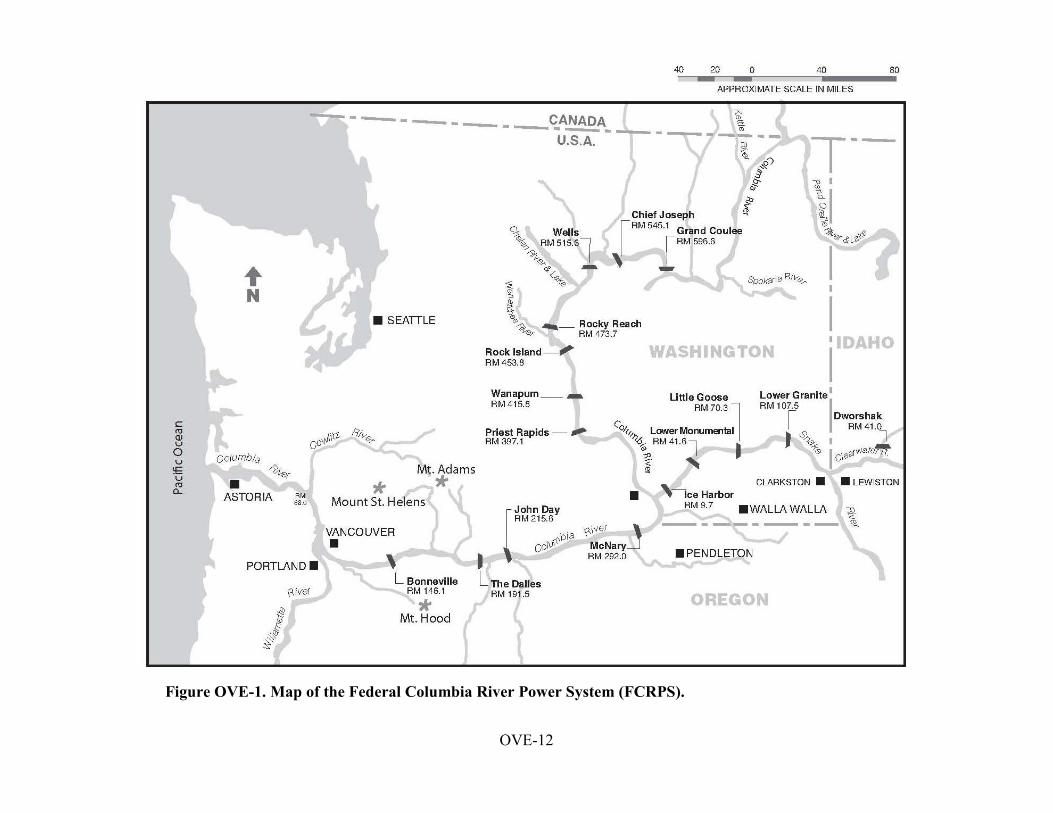
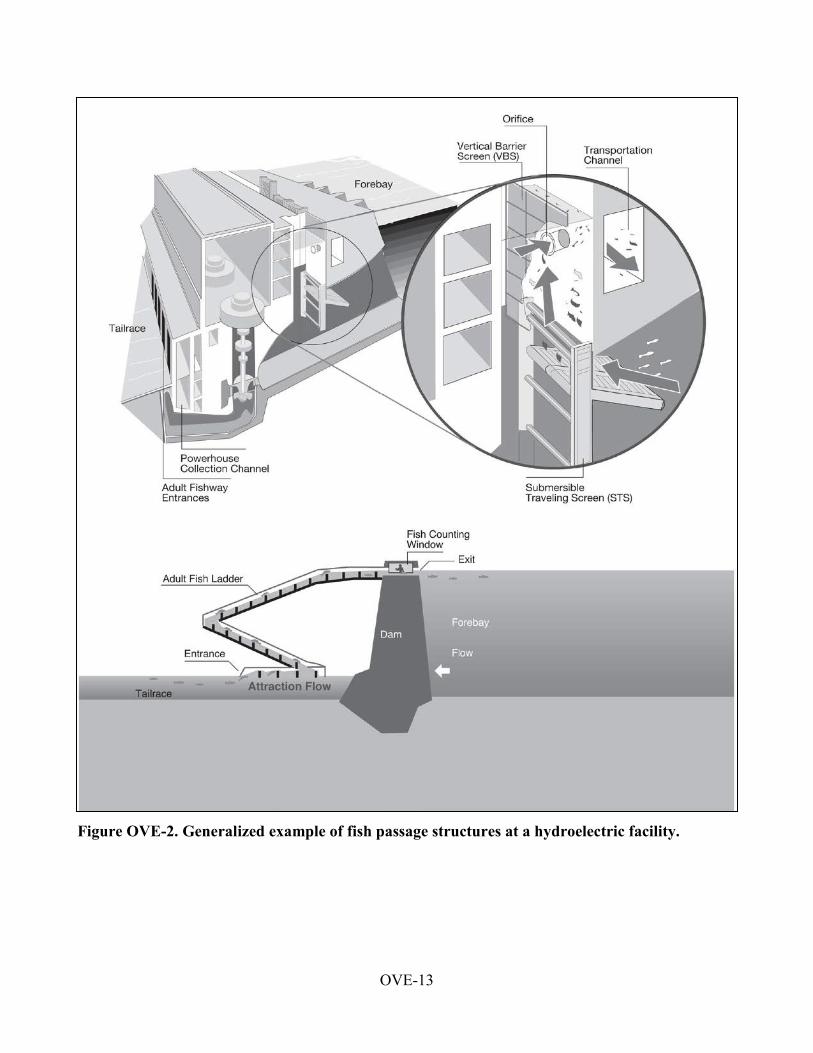
Sections 2 through 9 of the FPP are project-specific and include detailed inspection and reporting criteria for fish passage facilities at Corps projects on the lower Snake and lower Columbia Rivers (Figure OVE-1). An example of a typical fish passage system is illustrated in Figure OVE-2. The Corps provides weekly written inspection reports to the NOAA Fisheries Hydropower Program office in Portland, Oregon, describing out-of-criteria situations, adjustments made to resolve problems, and a detailed account of how out-of-criteria situations affected project fish passage and survival. The weekly inspection reports also include summaries of equipment calibrations, adult fish collection channel velocity monitoring, and water temperature monitoring. Equipment which does not require calibration will not routinely be included in the weekly report. The Corps also provides an annual report to NOAA Fisheries that summarizes project operations and maintenance, fish passage facility inspections and monitoring, severity of out-of-criteria conditions, and avian predation abatement actions. In addition, the Corps is developing methods to report hourly individual spill bay and turbine unit operations at mainstem projects as called for in the UPA. An acceptable procedure will be coordinated with NOAA Fisheries and other FPOM participants.
2.1. Annual Reporting
Excursions outside the 1% of best efficiency turbine operating range are tracked by BPA for each project during the fish passage season. The Corps determines the cause of each excursion and compiles this information approximately bi-weekly. After the fish passage season, the Corps submits an annual report to NOAA Fisheries which describes instances where turbines at lower

2013 Fish Passage Plan Overview
OVE-5
Columbia and lower Snake River projects operated outside the 1% of best efficiency range for significant periods, as defined under the guidelines in Appendix C. The intent of excursion reporting is to provide a means for quality assurance for project operations.
2.2. Reporting of Excursions Not Covered by Appendix C
BPA and the Corps will take all reasonable and practicable steps to provide advance notification through the existing interagency coordinating mechanisms prior to departure from the fish-protection measures set out in the 2008 BiOp. If unforeseen circumstances arise that preclude BPA or the Corps from notifying the TMT prior to a variation from required 1% operating criteria and those circumstances are not covered by Appendix C, those variations will be reported to the TMT as soon as practicable.
3. Turbine Dewatering Procedure at Chief Joseph Dam
The Corps has coordinated and adopted a procedure to dewater turbine draft tubes for maintenance at Chief Joseph Dam (Appendix H). While this project does not have fish passage facilities, ESA-listed salmon and steelhead occur in the tailrace. The procedure provides for turbine dewaterings and recovery of any trapped fish in a manner that protects those fish.
4. Turbine Dewatering Procedure at Dworshak Dam
The Corps has coordinated and adopted a procedure to dewater turbine draft tubes for maintenance at Dworshak Dam (Appendix I). While this project does not have fish passage facilities, ESA-listed salmon and steelhead occur in the tailrace. The procedure provides for turbine dewaterings and recovery of any trapped fish in a manner that protects those fish.
5. Implementation and Coordination of the Fish Passage Plan
Implementation of the FPP requires information exchange and coordination with NOAA Fisheries, BPA, other Federal and state fish agencies, and tribes. The RCC coordinates operations of Corps projects through the TMT that have system-wide effects, such as water management, spill volume, and unit availability. District biologists coordinate through the FPOM on spill patterns, unit priority, adult and juvenile fish facilities, and other project-specific operations that do not have system-wide impacts.
The RCC participates in TMT meetings throughout the year to consider recommendations for river operations to implement the FOP, BiOps, and other recommendations from fish interests. As part of this process, TMT may evaluate research data and advice on whether existing operations are consistent with current study results. These meetings are held in the Corps’ Northwestern Division office in Portland, Oregon, and are open to the public. Corps representatives are available at these meetings to discuss the latest weather and runoff forecasts, as well as fish, hydrologic, water quality, and power generation information to assist in planning upcoming operations for fish passage. Fish operation recommendations are evaluated by the Corps to determine impact on overall system operations. See Section 5.3 for TMT coordination procedures.

2013 Fish Passage Plan Overview
OVE-6
District biologists and RCC biologists attend monthly FPOM meetings dealing with project-specific issues below (see Section 5.2 for FPOM coordination procedures):
• Consider recommendations from affected interests. • Provide updates on construction, operations and maintenance, research, and other topics. • Develop criteria for the annual FPP. • Coordinate fish passage issues that may require deviation from FPP criteria.
5.1. Agency Responsibilities
5.1.1. U.S. Army Corps of Engineers:
a) Coordinate with NOAA Fisheries and USFWS on operational actions that might impact threatened, endangered, or candidate species.
b) Prepare Water Management Plans and seasonal updates for in-season management, in coordination with TMT members, to implement the Corps’ ROCASOD.
c) In cooperation with the fish agencies and tribes, provide fish passage monitoring, surveillance, and reporting at Corps projects throughout the migration period.
d) Provide timely information on all proposed and/or scheduled studies or special operations that may negatively impact or otherwise constrain fish passage or energy production. Discuss unforeseen changes in fish passage operation with fish agencies and tribes.
e) Carry out routine and emergency fish passage operations and maintenance procedures in accordance with criteria in Sections 2 through 9 and Appendix A.
f) Conduct the TDG Monitoring Program as described in Appendix D.
5.1.2. Fishery Agencies and Indian Tribes:
a) Request spill for fish through TMT to protect ESA-listed species or other species in accordance with the TMT Guidelines.
b) Through TMT, provide RCC with a spill priority list and recommendations for modifications.
c) Provide biological monitoring and surveillance reports throughout the migration period from predetermined locations, such as Smolt Monitoring Program sample sites.
d) Provide status reports on the timing of the downstream migration, including pertinent marked fish release and recovery data, with weekly written reports estimating percentage of runs past key projects.

2013 Fish Passage Plan Overview
OVE-7
e) Where biologically and logistically feasible, coordinate hatchery releases to ensure they are protected by regulated fish flows and spills while minimizing impacts on ESA-listed species. Provide and update hatchery release schedules weekly.
f) Provide recommendations to the operating agencies for maintaining acceptable fish passage conditions. This information can be used to maximize other project uses, including power generation.
g) Provide information on all proposed and scheduled studies or special operations designed to improve fish passage operations that may affect energy production or project operation. Discuss unforeseen changes with the Corps.
h) Recommend viable methods and procedures to reduce mortality to migratory and resident fish. This may include such operations as collection and transport of migrants, use of alternate bypass strategies, or other methods to minimize fish mortality.
5.1.3. Bonneville Power Administration:
a) Report to RCC on updated load-resource studies during the April-to-September period to supplement the National Weather Service River Forecast Center's runoff volume forecast for fish passage planning assistance.
b) Provide to RCC, NOAA Fisheries, other fish agencies, and tribes, the BPA estimate of power market impacts of requested spill operations.
c) Utilize available flexibility of the Federal Columbia River Power System to shape flow requirements, spill priorities, and plant generation consistent with BPA policies and statutory requirements related to fish protection.
d) Adjust system generation to provide adequate water to meet fish operations requirements in accordance with the FOP and the NOAA Fisheries and USFWS BiOps on hydrosystem operations.
e) Provide project load requests on a real-time, hourly basis that enable the Corps to implement spill priorities.
f) Provide information on unit operation outside the 1% of best efficiency operating range, as indicated in Appendix C.
5.1.4. Mid-Columbia Public Utility Districts:
a) Operate projects for spill transfer in accordance with provisions of the FPP with at least one and one-half hours notification to start or stop spill.

2013 Fish Passage Plan Overview
OVE-8
5.2. FPOM Coordination
Project operations and maintenance activities are coordinated with the Region through FPOM, pursuant to actions defined in the 2008/2010 NOAA Fisheries FCRPS BiOp (RPA No. 32). The FPP is effective year-round and revisions are coordinated through FPOM, which includes representatives from the Corps, NOAA Fisheries, USFWS, BPA, state fish agencies (OR, WA, ID), tribes, and other interested parties. The annual revision process begins in October and the final FPP is issued on/about March 1, although the FPP may be revised throughout the year by amendment. Suggested revisions should be submitted to FPOM chairs for consideration by the Corps. Draft FPP revisions will be provided to FPOM members by FPOM chairs for a minimum two-week regional review before the revision is published and added to the FPP. FPP revisions are provided to TMT for use as part of the overall river operation plan. Sections dealing with special operational requirements also will be included in the Action Agency’s annual Water Management Plan.
Project-specific activities under the purview of FPOM that may require deviations from FPP criteria will be fully coordinated in a timely manner. Issues discussed and resolved at FPOM meetings will be considered regionally coordinated upon documentation in the final meeting minutes. Outside of the meeting forum, the coordination procedures below should be followed.
For operations and maintenance activities within the District’s Operations Division, project personnel will communicate their needs to a District biologist (or other appropriate personnel). The District biologist will then provide essential information to the fish agencies, tribes, and other affected interests via FPOM by submitting a Memorandum of Coordination1 (MOC). If necessary, the District biologist will follow up with telephone calls to appropriate FPOM representatives and/or an email. Information for planned activities should be provided at least two weeks in advance to FPOM representatives for review. For O&M activities that are not anticipated but are not considered an emergency (e.g., equipment failures), information should be provided to FPOM at least three workdays in advance. Emergency coordination may be performed immediately prior to or subsequent to the required action (see Section 1.2). Information provided to affected interests will include a summary of the problem, location, date and time, analyses of potential impacts to salmon stocks, and potential alternative actions. The affected interests should in turn respond by email, in person, or by phone. All responses will be documented on the MOC, and then the final MOC will be distributed to FPOM and filed for future reference. A District biologist will forward the decision to project personnel, and if necessary, RCC will issue a teletype to the project for approved activities.
For research and construction activities involving both the District’s Planning and Operations divisions, Planning Division biologists will generally take the lead in coordination while keeping Operations Division biologists apprised of the proceedings. Research coordination is largely carried out and documented through the Corps’ Anadromous Fish Evaluation Program (AFEP). Coordination of new construction or modification of fish facilities is typically carried out and documented through the Fish Facility Design Review Work Group (FFDRWG). If
1 A template for the Memorandum of Coordination (MOC) is included at the end of this section.

2013 Fish Passage Plan Overview
OVE-9
implementation requires assistance from project personnel, temporary equipment installation, temporary facility modification, or operational changes, then Planning and Operations division biologists will work closely with project personnel and others to ensure success. Following are some of the individuals that are involved with the FPOM coordination process:
• Bernard Klatte*, Tammy Mackey, Robert Stansell (Corps - Portland District, Operations Division)
• Mike Langeslay (Corps - Portland District, Planning, Programs & Project Management Division)
• Ann Setter, John Bailey, Greg Moody (Corps - Walla Walla District, Operations Division)
• Marvin Shutters (Corps - Walla Walla District, Planning, Programs & Project Management Division)
• Doug Baus, Lisa Wright (Corps - Northwestern Division, Reservoir Control Center) • Scott Bettin, Agnes Lut (BPA) • Gary Fredricks, Trevor Conder, Bill Hevlin, Paul Wagner (NOAA Fisheries) • David Wills (USFWS) • Tom Lorz (CRITFC) • Rick Kruger (ODFW) • Steve Richards (WDFW) • Russ Kiefer (IDFG) • Dave Benner (Fish Passage Center) *FPOM chair
5.3. TMT Coordination
Actions that may impact fish system-wide will be coordinated and documented through the TMT forum. Actions that may impact fish at a specific project which are a result of actual operations, implementation of FOP/BiOp actions, incidental take, terms and conditions contained in the BiOps, or research projects will be coordinated through the process outlined below. TMT Guidelines are posted as an Appendix to the annual Water Management Plan, available online at: http://www.nwd-wc.usace.army.mil/tmt/documents/wmp/
5.4. Day-to-Day Coordination of FCRPS
Procedures described in the annual Water Management Plan will be used for fish operations. Coordination for system and project operations for flow augmentation and recommended reservoir operations will occur through TMT. This will include operation of turbine units outside of the 1% best efficiency range, zero nighttime flow in the Snake River, reservoir operation at minimum operating pool (MOP) or some other specific level, and special operations for implementation of approved research projects as identified in Appendix A. During the time when reservoirs are not being operated to provide special protection for fish passage, projects may be operated within the full reservoir operating range.

2013 Fish Passage Plan Overview
OVE-10
5.4.1. Fish Spill Management The Corps will implement fish spill provisions described in the Fish Operations Plan (FOP), included in the Fish Passage Plan as Appendix E, including special TDG conditions for juvenile fish passage. The TDG and gas bubble trauma signs in fish will be monitored and evaluated during the spill season by the Corps, NOAA Fisheries, other fish agencies, tribes, and water quality agencies. Project spill levels will be adjusted as needed, based on daily physical and biological monitoring results, and coordinated with TMT and the tribes.
5.4.2. Special Operations – Requests and Recommendations Related to Fish and/or Project O&M Activities
Recommendations for special fish operations outside the Water Management Plan may be made to RCC. Coordination of these recommendations will be made through the TMT. Recommendations related to project O&M activities requiring special operations will be evaluated for impacts on fish migration and survival. Sufficient lead time will be given for a planned operation, whenever practical, to allow ESA coordination with TMT, NOAA Fisheries, and USFWS. Preferably, as much lead time as possible will be provided for activities requiring immediate action. After-action coordination will occur when advance notice is not possible, such as in emergency actions.
5.4.3. Special Operations – Other Requests As with Corps O&M requests, all other operational recommendations will be evaluated for impacts on fish migration and survival and effects on other project O&M requirements. Coordination of special operations with NOAA Fisheries, USFWS, other fish agencies, and tribes will occur through TMT. Except as necessary for emergency actions, adequate time will be allowed for evaluation of all project and fish impacts prior to implementation. Coordination of emergencies, as identified in the Emergency Protocols adopted by TMT (Water Management Plan, Appendix 2), will be followed.
5.4.4. Activities by Non-Corps Personnel All non-Corps personnel intending to conduct any activity, such as fish handling or minor facility modifications at a Corps facility must have prior written approval. This approval must be requested in writing to the Chief, Operations Division, at the Corps District office responsible for a particular project. If the activity could affect ESA-listed fish, proof of consultation with NOAA Fisheries or USFWS (Section 10 permit) must be provided. Appropriate state permits must be provided as well for activities that may impact ESA-listed or non-listed fish.

OVE-11
OFFICIAL COORDINATION REQUEST FOR NON-ROUTINE OPERATIONS AND MAINTENANCE
COORDINATION TITLE- (filled in by NWP or NWW OD Bio)
COORDINATION DATE-
PROJECT-
RESPONSE DATE-
Description of the problem
Type of outage required
Impact on facility operation
Dates of impacts/repairs
Length of time for repairs
Expected impacts on fish passage
Comments from agencies
Final results
Please email or call with questions or concerns.
Thank you,
OVE-12
Figure OVE-1. Map of the Federal Columbia River Power System (FCRPS).
OVE-13
Figure OVE-2. Generalized example of fish passage structures at a hydroelectric facility.

2013 Fish Passage Plan
2013 Fish Passage Plan Section 2 – Bonneville Dam
Table of Contents
1. Fish Passage Information ......... .............................................................. ............BON-01
1.1. Juvenile Fish Passage ............. ................................................ .............BON-01
1.2. Adult Fish Passage ............... ................................................. ..............BON-09
2. Project Operation ................ ................................................................. ..............BON-10
2.1. General .............................. ........................................................ ..........BON-10
2.2. Spill Management ............. ................................................ ..................BON-11
2.3. Total Dissolved Gas Management and Control .. ............................. ...BON-13
2.4. Juvenile Fish Passage Facilities ............ ........................................... ...BON-13
2.5. Adult Fish Passage Facilities ........ ............................................ ..........BON-20
3. Facility Monitoring and Reporting .......................................................... ...........BON-26
3.1. Inspections................................ ....................................................... ....BON-26
3.2. Zebra Mussel Monitoring..................................................... ................BON-26
3.3. Reporting................................... ........................................................ ...BON-26
4. Fish Facilities Maintenance ......... ........................................................... ...........BON-27
4.1. General ..................................... ........................................................ ...BON-27
4.2. Juvenile Fish Passage Facilities ....... ........................................... ........BON-28
4.3. Adult Fish Passage Facilities ............................................. .................BON-30
5. Turbine Unit Operation and Maintenance.. ................................................. .......BON-34
6. Dewatering Plans ........................ ................................................................ .......BON-36
6.1. Guidelines for Any Dewatering.................. .............................. ...........BON-36
6.2. Juvenile Bypass Systems ....................................................... ..............BON-37
6.3. Adult Fish Ladder.................... .................................................. ..........BON-37
6.4. Powerhouse Fish Collection System ... ..................................... ...........BON-37
6.5. Turbines................................... ........................................................ ....BON-38
7. Forebay Debris Removal ........................................................................... .........BON-39
8. Response to Hazardous Materials Spills.... .................................................... .....BON-39
9. Endnotes .............................................................................................................. BON-39
2013 Fish Passage Plan Bonneville Dam
BON-1
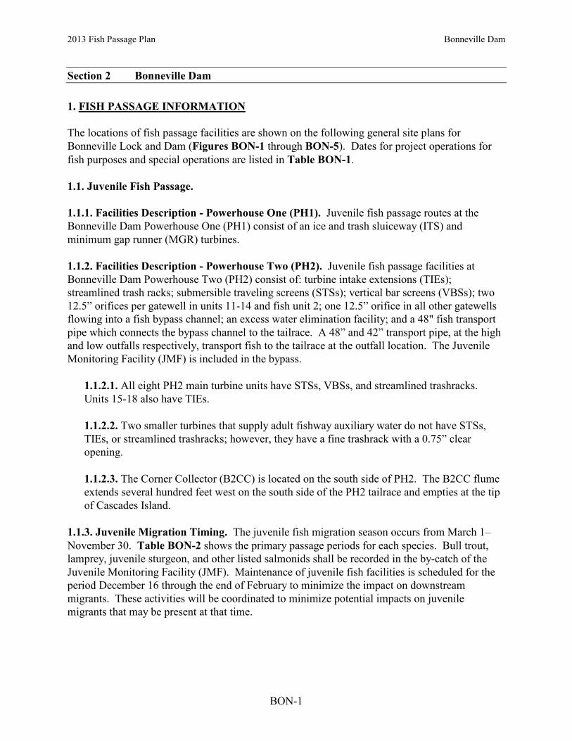
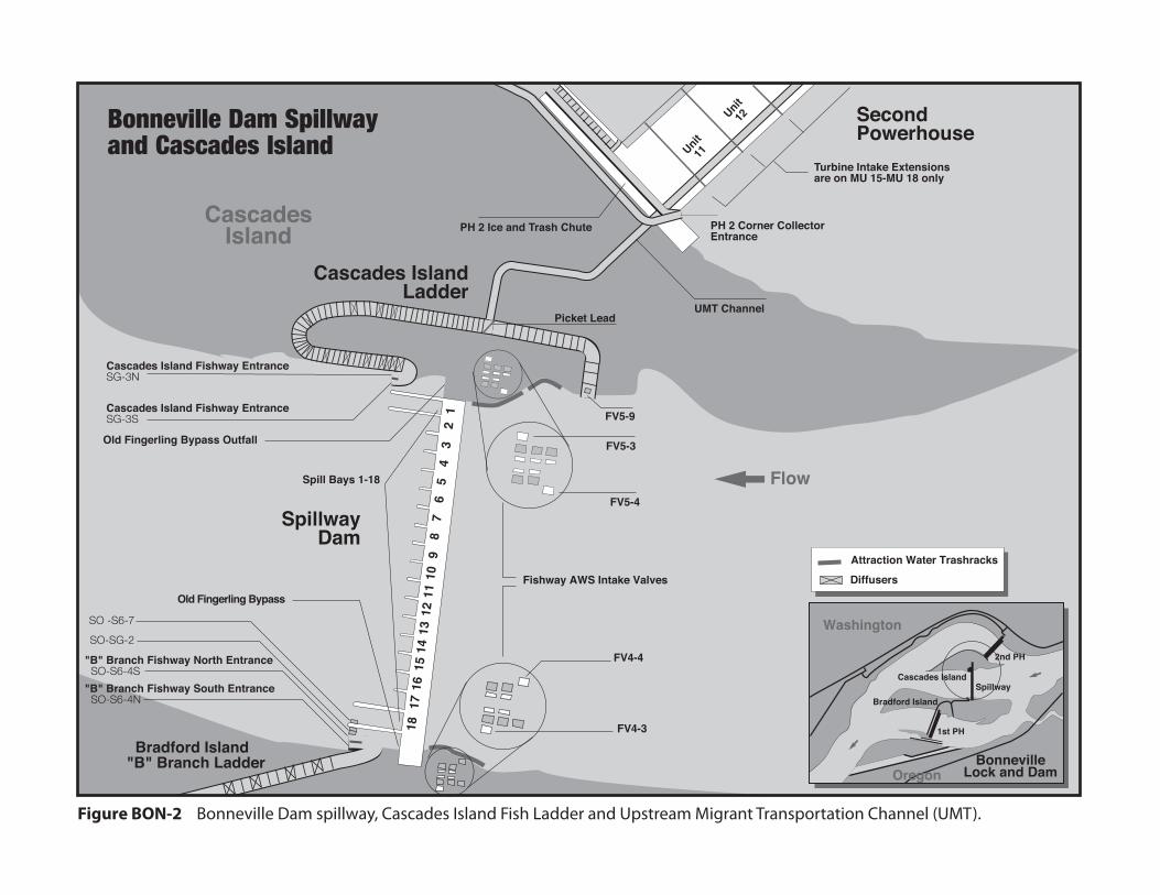
Section 2 Bonneville Dam 1. FISH PASSAGE INFORMATION The locations of fish passage facilities are shown on the following general site plans for Bonneville Lock and Dam (Figures BON-1 through BON-5). Dates for project operations for fish purposes and special operations are listed in Table BON-1. 1.1. Juvenile Fish Passage. 1.1.1. Facilities Description - Powerhouse One (PH1). Juvenile fish passage routes at the Bonneville Dam Powerhouse One (PH1) consist of an ice and trash sluiceway (ITS) and minimum gap runner (MGR) turbines. 1.1.2. Facilities Description - Powerhouse Two (PH2). Juvenile fish passage facilities at Bonneville Dam Powerhouse Two (PH2) consist of: turbine intake extensions (TIEs); streamlined trash racks; submersible traveling screens (STSs); vertical bar screens (VBSs); two 12.5” orifices per gatewell in units 11-14 and fish unit 2; one 12.5” orifice in all other gatewells flowing into a fish bypass channel; an excess water elimination facility; and a 48" fish transport pipe which connects the bypass channel to the tailrace. A 48” and 42” transport pipe, at the high and low outfalls respectively, transport fish to the tailrace at the outfall location. The Juvenile Monitoring Facility (JMF) is included in the bypass.
1.1.2.1. All eight PH2 main turbine units have STSs, VBSs, and streamlined trashracks. Units 15-18 also have TIEs. 1.1.2.2. Two smaller turbines that supply adult fishway auxiliary water do not have STSs, TIEs, or streamlined trashracks; however, they have a fine trashrack with a 0.75” clear opening. 1.1.2.3. The Corner Collector (B2CC) is located on the south side of PH2. The B2CC flume extends several hundred feet west on the south side of the PH2 tailrace and empties at the tip of Cascades Island.
1.1.3. Juvenile Migration Timing. The juvenile fish migration season occurs from March 1–November 30. Table BON-2 shows the primary passage periods for each species. Bull trout, lamprey, juvenile sturgeon, and other listed salmonids shall be recorded in the by-catch of the Juvenile Monitoring Facility (JMF). Maintenance of juvenile fish facilities is scheduled for the period December 16 through the end of February to minimize the impact on downstream migrants. These activities will be coordinated to minimize potential impacts on juvenile migrants that may be present at that time.

12
34
56
78
910
"A" Branch Bradford Island Fish Ladder
"B" Branch Bradford Island Ladder
Picket Lead
FirstPowerhouse
"B" Branch Fishway North Entrance S0-S6-4N"B" Branch Fishway South Entrance SO-S6-4S
Fish Counting Station
Auxiliary Water Trash Racks
Bradford IslandLadder Exit
FV3 - 7
FV3 - 9
DSM Sampler
"A" Branch Entrance WG-65 & SG-64
Downstream Migrant Outfall (underwater)
Spillway
BradfordIsland
Master Control PanelGate 34
Collection ChannelWater Velocity Meter
South Adult Collection SystemEntrances WG-1 and SG-2
Ice and TrashSluiceway Outfall
FV1-1
Figure BON-1 Bonneville Dam First Powerhouse and Bradford Island Fish Ladder.
Flow
16 17 18
Junction Pool
Collection Channel
Downstream Migrant (DSM) Channel
NewNavigationLock
Ice and Trash Sluiceway
Washington
OregonBonneville
Lock and Dam
Spillway
1st PH
2nd PHCascades Island
Bradford Island
Attraction Water Trash RacksDiffusers
AuxiliaryWater Channel
Old Fingerling Bypass
Old Fingerling Bypass Outfall
Bonneville Dam First Powerhouse and Bradford Island
MU
MU
MU
MU
MU
MU
MU
MU
MU
MU
G0PDWLSW
Text Box
BON-2
G0PDWLSW
Text Box
Figure BON-1. Bonneville Dam Powerhouse One and Bradford Island Fish Ladder.
G0PDWLSW
Text Box
2013 Fish Passage Plan Bonneville Dam
G0PDWLSW
Text Box
G0PDWLSW
Text Box
POWERHOUSE ONE
G0PDWLSW
Text Box
SO-SG-4N
G0PDWLSW
Text Box
SO-SG-4S
G0PDWLSW
Text Box
POWERHOUSE ONE (PH1)
G0PDWLSW
Text Box
WLT-64
G0PDWLSW
Text Box
WLT-2
G0PDWLSW
Text Box
PH2
G0PDWLSW
Text Box
PH1
G0PDWLSW
Text Box
G0PDWLSW
Text Box
G0PDWLSW
Text Box
SpillwayDam
FV4-4
FV4-3
FV5-4
Fishway AWS Intake Valves
SecondPowerhouse
PH 2 Ice and Trash Chute
UMT Channel
Cascades IslandLadder
Cascades Island Fishway Entrance SG-3N
Cascades Island Fishway EntranceSG-3S
Picket Lead
Bradford Island"B" Branch Ladder
"B" Branch Fishway South Entrance SO-S6-4N
"B" Branch Fishway North Entrance SO-S6-4S
Unit11
Unit12
FV5-3
FV5-9
CascadesIsland
Flow
Attraction Water Trashracks
Diffusers
12
34
56
7 8
910
1112
1314
1516
1718
SO-SG-2
SO -S6-7
Old Fingerling Bypass Outfall
Old Fingerling Bypass
Bonneville Dam Spillwayand Cascades Island
Washington
OregonBonneville
Lock and Dam
Spillway
1st PH
2nd PH
Cascades Island
Bradford Island
Figure BON-2 Bonneville Dam spillway, Cascades Island Fish Ladder and Upstream Migrant Transportation Channel (UMT).
PH 2 Corner CollectorEntrance
Spill Bays 1-18
Turbine Intake Extensionsare on MU 15-MU 18 only
G0PDWLSW
Text Box
G0PDWLSW
Text Box
2013 Fish Passage Plan Bonneville Dam
G0PDWLSW
Text Box
BON-3
G0PDWLSW
Text Box
Figure BON-2. Bonneville Dam Spillway, Cascades Island Fish Ladder and Upstream Migrant Transportation (UMT) Channel.
G0PDWLSW
Text Box
POWERHOUSE TWO (PH2)
G0PDWLSW
Text Box
SPILLWAY
G0PDWLSW
Text Box
North Entrance
G0PDWLSW
Text Box
South Entrance
G0PDWLSW
Text Box
SO-SG-7
G0PDWLSW
Text Box
SO-SG-4N
G0PDWLSW
Text Box
SO-SG-4S
G0PDWLSW
Text Box
PH2
G0PDWLSW
Text Box
PH1
G0PDWLSW
Text Box
G0PDWLSW
Text Box

18
17
16
15
14
13
12
11
12
34
5
7
1012
1314
1516
Fish Ladder Exit
FV6-9
AuxillaryWater Channel
Counting Station Picket Lead
Junction Pool
UMT Channel
UMTChannel
Adult Fish Counting Station
DSM ChannelGatewell
Gatewell Orifice Turbine Bays
FLOW
FLOW
PH2 Ice & trashChute/CornerCollector
UMT Channel
Cascades Island Ladder Picket Lead
Ice & Trash Chute Outfall/Corner Collector
South EntranceSD-E
South Entrance SU-E
Collection System
Floating Entrance Orifice Gates(1-5, 7, 10, 12-16)
Washington Shore Fish (North) Ladder
Adult Collection and Monitoring Facility
Picket Lead Adult Facility Entrance Ladder
Adult Facility Exit Ladder
Weir 37 Drain Valve
Junction PoolNorth EntranceNU-E
North Entrance ND-E
Floating Entrance Orifice GatesDiffusers
Cascades IslandFish Ladder
Exit Trashrack
Figure BON-3 Bonneville Dam Second Powerhouse and Washington (North) Fish Ladder.
Flow
OpenClosed
F1F2
Attraction Water Supply Turbines(fish units)
Bonneville Dam Second Powerhouse
Washington
OregonBonneville
Lock and Dam
Spillway
1st PH
2nd PHCascades Island
Bradford Island
Turbine IntakeExtension
Juvenile Bypass System Outfall Flume
Fishway AuxiliaryWater Gauges
MU
MU
MU
MU
MU
MU
MU
MU
G0PDWLSW
Text Box
2013 Fish Passage Plan Bonneville Dam
G0PDWLSW
Text Box
BON-4
G0PDWLSW
Text Box
Figure BON-3. Bonneville Dam Powerhouse Two and Washington Shore (WS) North Fish Ladder.
G0PDWLSW
Text Box
POWERHOUSE TWO (PH2)
G0PDWLSW
Text Box
North Downstream Entrance (NDE)
G0PDWLSW
Text Box
North Upstream Entrance (NUE)
G0PDWLSW
Text Box
South Upstream Entrance (SUE)
G0PDWLSW
Text Box
South Downstream Entrance (SDE)
G0PDWLSW
Text Box
PH2 Corner Collector (B2CC)
G0PDWLSW
Text Box
PH2 Collection Channel
G0PDWLSW
Text Box
PH2 Corner Collector (B2CC) Entrance
G0PDWLSW
Text Box
(Fish Units F1, F2)
G0PDWLSW
Text Box
AFF
G0PDWLSW
Text Box
AFF
G0PDWLSW
Text Box
Fish Facility (AFF)
G0PDWLSW
Text Box
PH2
G0PDWLSW
Text Box
PH1
G0PDWLSW
Text Box
G0PDWLSW
Text Box
G0PDWLSW
Text Box

14
Col
umbi
a R
iver
Navigation Lock
Bradford Island
Cascades Island
N
Robins Island
FLOW
FirstPowerhouse
SecondPowerhouse
Spillway
11
12
13
14
15 1
6 1
7 18
18 1
7 16
15
14
13 1
2 1
0 9
8
7
6
5
4 3
2 1
1
2
3
4
5
6
7
8
9
10
FortCascadeNationalHistoric
Site
TransportationFlume
LowOutfall
HighOutfall
84
MonitoringFacility
Oregon
Washington
Figure BON-4 Bonneville Juvenile Fish Passage System.
Bonneville Dam
Corner Collector PH2 Corner CollectorEntrance
Fish ladder
LegendPotential First Powerhouse Transportation FlumeBonneville Second PowerhouseTransportation FlumeBonneville Second PowerhouseCorner Collector
G0PDWLSW
Text Box
2013 Fish Passage Plan Bonneville Dam
G0PDWLSW
Text Box
BON-5
G0PDWLSW
Text Box
Figure BON-4. Bonneville Dam Juvenile Bypass System (JBS), including Powerhouse Two Bypass Flume, Juvenile Monitoring Facility (JMF), JBS Outfall, and Corner Collector (B2CC).
G0PDWLSW
Text Box
B-Branch
G0PDWLSW
Text Box
A-Branch
G0PDWLSW
Text Box
B2CC
G0PDWLSW
Text Box
Juvenile Bypass System (JBS) Flume
G0PDWLSW
Text Box
Washington Shore Fish Ladder
G0PDWLSW
Text Box
PH2
G0PDWLSW
Text Box
B2CC Entrance
G0PDWLSW
Text Box
Cascades Island Fish Ladder
G0PDWLSW
Text Box
Bradford Island Fish Ladder
G0PDWLSW
Text Box
PH1
G0PDWLSW
Text Box
Tower Island
G0PDWLSW
Text Box
(JMF)
G0PDWLSW
Text Box
Juvenile
G0PDWLSW
Text Box
PH2 Juvenile Bypass System (JBS) Flume
G0PDWLSW
Text Box
PH2 Corner Collector (B2CC)
G0PDWLSW
Line
G0PDWLSW
Line
G0PDWLSW
Line
G0PDWLSW
Line
G0PDWLSW
Text Box
HIgh Water Level Outfall
Bonneville Dam
Low Water Level Outfall
HIgh Level Transportation Flume
Bypass Flume B-2
Low Level Transportation Flume
HIgh / Low Level Switch Gates
Examination Building
SecondaryDewateringStructure
PrimaryDewateringStructure
Bypass (upper) Switch Gate
Bypass Flume B-1
Second PowerhouseTransportation Flume
ParkingArea
Head Box/Pumphouse
Fishing Access Road
Access Drive
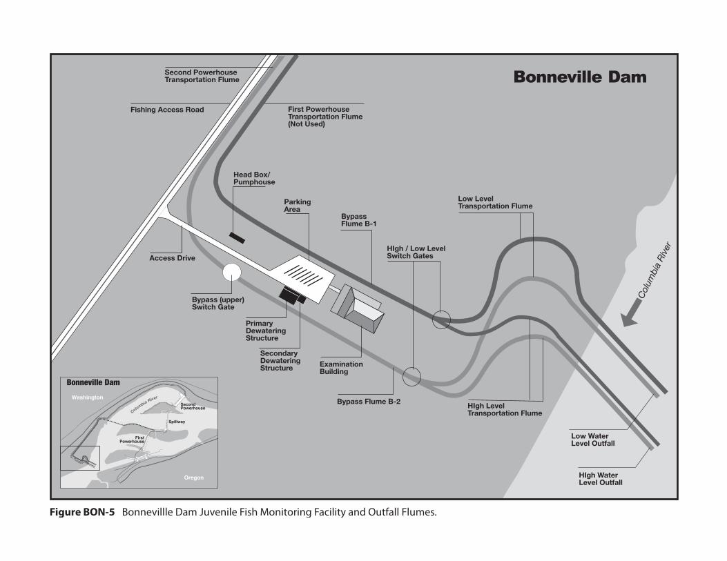
Figure BON-5 Bonnevillle Dam Juvenile Fish Monitoring Facility and Outfall Flumes.
First PowerhouseTransportation Flume(Not Used)
Col
umbi
a R
iver
Columbia River
FirstPowerhouse
SecondPowerhouse
Spillway
11
12
13
14
15 1
6 1
7 18
18 1
7 16
15
14
13 1
2 1
0 9
8
7
6
5
4 3
2 1
1
2
3
4
5
6
7
8
9
10
Oregon
Washington
Bonneville Dam
G0PDWLSW
Text Box
2013 Fish Passage Plan Bonneville Dam
G0PDWLSW
Text Box
BON-6
G0PDWLSW
Text Box
Figure BON-5. Bonneville Dam Powerhouse Two (PH2) Juvenile Bypass System (JBS) -- Juvenile Monitoring Facility (JMF) and Outfall Flumes.
G0PDWLSW
Text Box
Full-flow PIT-Tag Reader Building
G0PDWLSW
Text Box
Juvenile Bypass System (JBS) Flume
G0PDWLSW
Text Box
Secondary Outfall Flume
G0PDWLSW
Text Box
Low Outfall Flume
G0PDWLSW
Text Box
PH2
G0PDWLSW
Text Box
PH1
G0PDWLSW
Line
G0PDWLSW
Rectangle
G0PDWLSW
Line
G0PDWLSW
Polygonal Line
G0PDWLSW
Text Box
G0PDWLSW
Text Box
High Outfall Flume
G0PDWLSW
Text Box
G0PDWLSW
Text Box
G0PDWLSW
Text Box
G0PDWLSW
Text Box
G0PDWLSW
Text Box
G0PDWLSW
Text Box
G0PDWLSW
Text Box
G0PDWLSW
Line
G0PDWLSW
Text Box
G0PDWLSW
Text Box
G0PDWLSW
Line
G0PDWLSW
Text Box
G0PDWLSW
Line
G0PDWLSW
Text Box
G0PDWLSW
Text Box
G0PDWLSW
Text Box
G0PDWLSW
Polygon
G0PDWLSW
Oval
G0PDWLSW
Polygon
G0PDWLSW
Line
G0PDWLSW
Line
G0PDWLSW
Polygon
G0PDWLSW
Polygon
G0PDWLSW
Polygon
G0PDWLSW
Polygon
G0PDWLSW
Polygon
G0PDWLSW
Polygon
G0PDWLSW
Polygon

Task Name Start Finish Reference
2013 FISH PASSAGE SEASON 3/1/13 11/30/13 BON 2.4.Juvenile Fish Passage Season 3/1/13 11/30/13 BON 2.4.1.2Adult Fish Passage Season 3/1/13 11/30/13 BON 2.4.2.2Lamprey Passage Season 6/1/13 8/31/13 BON 2.5.4.c
2013-2014 WINTER MAINTENANCE PERIOD 12/1/13 2/28/14 BON 2.4.Juvenile Fish Facilities Winter Maintenance 12/1/13 2/28/14 BON 2.4.1.1Adult Fish Facilities Winter Maintenance 12/1/13 2/28/14 BON 2.4.2.1
ADULT FISH COUNTING (YEAR-ROUND) 3/1/13 2/28/14 Table BON-3Video 0400 - 2000 PST 3/1/13 3/31/13Visual 0500 - 2100 DST 4/1/13 10/31/13Video Night 2100 - 0500 DST 6/15/13 9/30/13Video 0400 - 2000 PST 11/1/13 2/28/14
1% CONSTRAINTS (YEAR-ROUND) 3/1/13 2/28/14 BON 5.31% soft constraint 3/1/13 3/31/131% hard constraint 4/1/13 10/31/131% soft constraint 11/1/13 2/28/14
TDG MONITORING (YEAR-ROUND) 3/1/13 2/28/14 BON 2.3TDG Monitoring - Tailrace (year-round) 3/1/13 2/28/14 WRNOTDG Monitoring - Tailrace 4/1/13 8/31/13 CCIW, CWMWTDG Monitoring - Forebay 4/1/13 8/31/13 BON
Operation of Ice & Trash Sluiceway (year-round) 3/1/13 2/28/14 BON 1.2.1.1
PH2 Screens Installed 3/1/13 12/15/13 BON 2.4.2.2.a
AVIAN ABATEMENT MEASURES 3/1/13 12/1/13 BON 2.4Avian Predator Control Lines 3/1/13 12/1/13 BON 2.4.1.1.c.JMF Outfall Avian Cannons 3/1/13 11/1/13 BON 2.4.2.5.a.5Avian Hazing 4/1/13 8/31/13 BON 2.4.1.2 c
SPECIAL OPERATIONS & STUDIES 3/1/13 10/31/13 Appendix ASea Lion Predation Study 3/1/13 5/31/13 App A BON 2.4PH2 FGE Test of Turbulence Reduction Device 3/6/13 7/31/13 App A BON 2.1Adult Salmon Studies 3/20/13 10/15/13 App A BON 2.2Lamprey Passage Evaluations 6/3/13 10/31/13 App A BON 2.3
Spillbays 1 & 18 - Gates Open 6" 3/1/13 4/10/13 BON 2.2.3.1
Operate PH2 Corner Collector (B2CC) 4/10/13 8/31/13 BON 2.4.2.3
SPILL FOR FISH PASSAGE 4/10/13 8/31/13Spring Spill - 100 kcfs 4/10/13 6/15/13Summer Spill - 85 kcfs/121 kcfs 6/16/13 7/20/13Summer Spill - 75 kcfs/TDG cap 7/21/13 8/31/13
Spillbays 1 & 18 - Gates Open 6" 9/1/13 11/30/13 BON 2.2.3.1
Weekly Reports (year-round) 3/1/13 2/28/14 BON 3.3.1
Annual Report (for Dec 1, 2012 - Nov 30, 2013) 1/31/14 1/31/14 BON 3.3.4
Jan Feb Mar Apr May Jun Jul Aug Sep Oct Nov Dec Jan Feb1st Quarter 2nd Quarter 3rd Quarter 4th Quarter 1st Quarte
2013 2014
Table BON-1. Bonneville Dam Dates of Fish-Related Operations for 2013 Fish Passage Season and 2013/14 Winter Maintenance Period.
BON-7

2013 Fish Passage Plan Bonneville Dam
BON-8
Table BON-2. Bonneville Dam 10-Year Juvenile Salmonid Passage Data (2003-2012). Yearling Chinook Subyearling Chinook (“Brights” only*)
10 % 50% 90 % # of Days 10 % 50% 90 % # of Days 2003 Apr 22 May 14 May 31 40 2003 Jun 15 Jul 01 Jul 19 35 2004 Apr 17 May 04 May 30 44 2004 Jun 10 Jun 28 Jul 14 35 2005 Apr 19 May 07 May 25 37 2005 Jun 15 Jun 28 Jul 20 36 2006 Apr 16 May 9 May 21 36 2006 Jun 16 Jun 29 Jul 15 30 2007 Apr 20 May 11 May 23 34 2007 Jun 19 Jul 08 Jul 22 34 2008 Apr 20 May 12 May 27 38 2008 Jun 22 Jul 06 Jul 23 32 2009 Apr 19 May 11 May 26 38 2009 Jun 20 Jun 30 Jul 19 30 2010 Apr 27 May 13 Jun 01 36 2010 Jun 19 Jul 05 Jul 20 32 2011 Apr 17 May 10 May 18 32 2011 Jun 24 Jul 14 Aug 02 40 2012 Apr 24 May 12 May 23 30 2012 Jun 23 Jul 09 Jul 26 34
MEDIAN Apr 19 May 11 May 25 37 MEDIAN Jun 19 Jul 03 Jul 20 32 MIN Apr 16 May 04 May 18 30 MIN Jun 10 Jun 28 Jul 14 30 MAX Apr 27 May 14 Jun 01 44 MAX Jun 24 Jul 14 Aug 02 70
Unclipped Steelhead Clipped Steelhead 10 % 50% 90 % # of Days 10 % 50% 90 % # of Days
2003 May 03 May 27 Jun 09 38 2003 May 07 May 30 Jun 11 36 2004 Apr 17 May 16 May 31 45 2004 Apr 30 May 16 May 27 28 2005 Apr 23 May 11 May 29 37 2005 Apr 26 May 15 May 30 35 2006 Apr 24 May 07 May 29 36 2006 Apr 27 May 08 May 29 33 2007 Apr 29 May 16 Jun 03 36 2007 May 08 May 17 Jun 04 28 2008 May 5 May 14 May 30 26 2008 May 07 May 13 May 25 19 2009 Apr 30 May 13 May 29 30 2009 May 04 May 13 May 26 23 2010 May 01 May 14 Jun 01 32 2010 May 06 May 14 Jun 07 33 2011 Apr 23 May 15 May 31 39 2011 Apr 24 May 12 May 29 36 2012 Apr 26 May 11 May 29 34 2012 Apr 29 May 10 May 28 30
MEDIAN Apr 27 May 14 May 30 34 MEDIAN May 02 May 13 May 29 28 MIN Apr 17 May 07 May 29 26 MIN Apr 24 May 08 May 25 19 MAX May 05 May 27 Jun 09 45 MAX May 08 May 30 Jun 11 41
Coho Sockeye (Wild & Hatchery) 10 % 50% 90 % # of Days 10 % 50% 90 % # of Days
2003 Apr 29 May 16 Jun 09 42 2003 May 12 May 20 Jun 05 25 2004 Apr 18 May 05 May 27 40 2004 May 21 Jun 01 Jun 15 26 2005 Apr 22 May 9 May 27 36 2005 May 15 May 23 Jun 01 18 2006 Apr 27 May 17 May 27 31 2006 May 10 May 19 May 31 22 2007 Apr 26 May 13 May 31 36 2007 May 16 May 25 Jun 07 23 2008 May 01 May 18 May 30 30 2008 May 24 May 29 Jun 08 16 2009 Apr 29 May 22 Jun 01 35 2009 May 15 May 26 Jun 05 22 2010 Apr 24 May 14 Jun 05 43 2010 May 19 Jun 01 Jun 10 23 2011 Apr 11 May 14 May 24 44 2011 May 04 May 17 Jun 04 32 2012 Apr 26 May 18 Jun 07 43 2012 May 9 May 14 May 23 15
MEDIAN Apr 26 May 15 May 30 35 MEDIAN May 15 May 24 Jun 05 22 MIN Apr 11 May 05 May 24 20 MIN May 04 May 14 May 23 15 MAX Apr 26 May 18 Jun 07 44 MAX May 24 Jun 01 Jun 15 34
* Includes upriver brights only in order to exclude influence by Spring Creek NFH Tules.

2013 Fish Passage Plan Bonneville Dam
BON-9
1.2. Adult Fish Passage. 1.2.1. Facilities Description. Adult fish passage facilities at Bonneville Dam consist of two main fishway segments:
1.2.1.1. Bradford Island Fishway (Figure BON-1) is formed by the PH1 collection channel and Bradford Island A-branch ladder that join the south spillway ladder entrance and B-branch ladder at the Bradford Island ladder junction pool. The ice and trash sluiceway (ITS) is also used for adult passage throughout the year. The system consists of 3 automated chain gates and 27 manual chain gates. 1.2.1.2. Washington Shore Fishway (Figure BON-2) is formed by the PH2 collection channel and the north and south monoliths that join the Washington Shore (North) ladder and the Cascades Island (north spillway) ladder at the upstream migrant transportation (UMT) channel. 1.2.1.3. The Bradford Island, Cascades Island and Washington Shore fishways have counting stations. The Washington Shore ladder also has an adult fish facility (AFF). All four collection systems have auxiliary water supplies for fish attraction.
1.2.2. Adult Migration Timing and Counting. Upstream migrants are present at Bonneville Dam throughout the year and adult passage facilities are operated year-round. Adult salmon, steelhead, shad, and lamprey are normally counted year-round (Table BON-3), and these data appear daily (or every three days during video counting periods) on the Corps’ adult fish count website (http://www.nwp.usace.army.mil/Missions/Environment/Fishdata.aspx). Migration timing data for these species, except shad, appear in Table BON-4. Sturgeon and bull trout are also counted and recorded on the fish counters’ daily summary sheet comments section, but do not appear on the Corps daily website total due to relative infrequency of passage. These data are posted periodically during the passage season in the Miscellaneous Fish Counts report on the Corps’ website, and summarized in the Annual Fish Passage Report.
1.2.2.1. The adult fish counting schedule is shown in Table BON-3. Fish passage from November through March is relatively light; therefore, fish counting is done by video, primarily to monitor winter steelhead passage, especially ESA-listed winter steelhead.
Table BON-3. Adult Fish Counting Schedule at Bonneville Dam.
Count Period Counting Method and Hours 1 March 01, 2013 – March 31, 2013 Video 0400–2000 hours (PST) April 01, 2013 – October 31, 2013 Visual 0500–2100 hours (DST) June 15, 2013 – September 30, 2013 Night Video 2100–0500 hours (DST) November 01, 2013 – February 28, 2014 Video 0400–2000 hours (PST) 1. In 2013, daylight saving time (DST) is in effect from March 10–November 3, and hours are adjusted forward one hour from Pacific Standard Time (PST). DST = PST+1.

2013 Fish Passage Plan Bonneville Dam
BON-10
1.2.2.2. Annual winter maintenance of adult fish facilities is scheduled from December 1 through February (in-water work period) to minimize the impact on upstream migrants and to minimize adult fall Chinook and steelhead fallback. 1.2.2.3. Adult fish migration timing has been calculated for Bonneville Dam from count data collected by the Corps since 1938. Table BON-4 summarizes count periods and peak adult fish passage timing through 2012, and includes count periods and the earliest and latest peaks of migration for each species (except shad) at Bonneville Dam. Steelhead are counted by video at Bonneville Dam from November 01 through March 31 as described in Table BON-3, but the ESA-listed winter steelhead population passage period is considered to be from November 16 through March 31 as described in Table BON-4. Peak migration timing is based on yearly data beginning in 1999 for winter steelhead, and in 2001 for lamprey.
Table BON-4. Adult Count Periods and Peak Migration Timing at Bonneville Dam (based on 1938-2012 fish count data*).
Species Count Period Earliest Peak Latest Peak Spring Chinook 3/14 – 5/31 4/15 5/27 Summer Chinook 6/1 – 7/31 6/3 7/31 Fall Chinook 8/1 – 11/15 8/30 9/17 Sockeye 6/1 – 8/15 6/20 7/13 Steelhead 4/1 – 3/31 7/16 9/22 Winter steelhead* 11/16 – 3/31 3/1 3/28 Coho 7/15 – 11/15 8/29 10/11 Lamprey* 3/15 – 11/15 6/20 7/18
*Peak migration timing based on yearly data beginning in 1999 for winter steelhead, and in 2001 for lamprey. 2. PROJECT OPERATION 2.1. General. Yearling Chinook and most other juvenile salmonids migrate downstream in the spring, whereas during the summer, after mid-June, sub-yearling Chinook dominate. Studies specific to Bonneville Dam indicate that fish survival rates for passage through various routes differ between spring and summer. 2.1.1. Powerhouse Flow Distribution. Bonneville turbine operating priority is established as outlined in Table BON-14. If a turbine is out of service, use the next turbine in the priority list. 2.1.2. When adult and jack salmonid counts equal or exceed 30,000 fish per day before August 31, project fisheries will initiate Fish Passage Operations and Maintenance Team (FPOM) coordination to discuss options for powerhouse flow-splitting to provide additional flow attraction areas to help balance adult passage among the project’s fishways. When adult and jack salmonid counts equal or exceed 25,000 fish per day after August 31, the Project will operate two priority turbines at PH1 in an attempt to balance adult passage between both powerhouses

2013 Fish Passage Plan Bonneville Dam
BON-11
(assuming there was no prior unit operation at PH1). This operation will continue until Project adult and jack salmon counts fall below 20,000 fish.
2.1.2.1. Turbine units at PH1 should be operated at the mid or upper 1% range whenever possible during the split flows operation. 2.1.2.2. Turbine units at PH2 should be operated at the mid to lower 1% range whenever possible during the split flows operation. 2.1.2.3. Split flow operations, prior to the end of summer spill, may only occur if flows exceed 120 kcfs.
2.1.3. Other Activities. Research, non-routine maintenance, other fish-related activities, and construction activities will not be conducted within 100' of any fishway entrance or exit or within 50' of the rest of the fishway, or directly in, above, or adjacent to any fishway, unless coordinated by the Project, Portland District Operations and/or Planning, the Dive operation coordinator, or CEWNP Construction office through FPOM and FFDRWG with the Region. Currently coordinated special operations related to research are described in Appendix A. Alternate actions will be considered by district and project biologists in coordination with the Regional fish agencies on a case-by-case basis. Emergency situations should be dealt with immediately by the project in consultation with the project or district biologist. If unavailable, the biologists will be informed of steps taken to correct the situation immediately following the incident. All activities within boat-restricted zones (BRZ) will be coordinated at least two weeks in advance with the project, unless it is deemed an emergency (see also Overview for coordination guidance). 2.2. Spill Management. See the Fish Operations Plan (Appendix E) for more information. 2.2.1. General. Only one spill schedule will be used at Bonneville Dam (Table BON-17).
2.2.1.1. Decisions regarding spill changes will be made through regional agreement at TMT. 2.2.1.2. Nighttime spill is limited as necessary to control total dissolved gas (TDG) super-saturation. Adjustments of the nighttime spill level may be granted on a case-by-case basis by the Reservoir Control Center (RCC), dependent upon TDG monitoring at stations downstream of the dam, biological monitoring, and fish movement. 2.2.1.3. The hours of nighttime spill are the daily complements of the periods of daytime spill (Table BON-5). The transition from daytime spill cap to nighttime spill cap and vice versa will normally take 15 to 20 minutes due to the time required to start, synchronize, and load multiple generators. The transition to the daytime spill period should not start until after the nighttime cap period is over.
2.2.1.4. Frequently, a total river discharge change will occur concurrently with these spill transitions. The transition to the nighttime cap should begin early enough to minimize chances of violating the defined nighttime spill maximum.

2013 Fish Passage Plan Bonneville Dam
BON-12
2.2.2. Juvenile Fish. Minimum spill level is 50 kcfs from April 10 through August 31 to provide acceptable conditions for juvenile fish tailrace egress. However, under extreme low flow conditions, lower spill levels may be considered and coordinated through the TMT. There is no minimum spill level from September 1 through April 9. For spill specific information see Appendix E: Operations Related to Project Spill for Fish Passage. 2.2.3. Adult Fish. To reduce adult fallback from June 16 through August, whenever PH1 is in operation, daytime spill will be limited to 100 kcfs or less (see also 2.2.2). Normally, this restriction will be from 1 hour before sunrise to ½ hour after sunset (Table BON-5). During that portion of the sockeye run that occurs from June 16 through July 15, the cap will apply until 1 hour after sunset only when PH1 is in operation.
2.2.3.1. From September 1 through November 30 and from March 1 through April 10 (beginning of spill for juvenile fish passage), provide spill from bays 1 and 18 with each gate open 6” (one stop) during daylight hours as defined in Table BON-5. From December 1 through February 28, spill only from the bay(s) that are adjacent to an operating fishway entrance with each spill gate open 6” (one stop).
Table BON-5. Daytime Spill Schedule for Bonneville Dam.
Date Range Daytime Spill Hours
Begin End Jan 01 – Jan 19 0700 1730 Jan 20 – Feb 14 0630 1800 Feb 15 – Mar 01 0600 1830 Mar 02 – Apr 02 0600 1930 Apr 03 – Apr 20 0500 2030 Apr 21 – May 16 0500 2100 May 17 – May 31 0430 2130 Jun 01 – Jun 30 0430 2130 Jul 01 – Jul 31 0430 2200
Aug 01 – Aug 15 0500 2145 Aug 16 – Aug 31 0500 2030 Sep 01 – Sep 16 0530 2000 Sep 17 – Oct 04 0600 1930 Oct 05 – Oct 19 0630 1900 Oct 20 – Oct 29 0630 1830 Oct 30 – Nov 30 0600 1700 Dec 01 – Dec 31 0630 1700

2013 Fish Passage Plan Bonneville Dam
BON-13
2.3. Total Dissolved Gas (TDG) Management and Control. Total dissolved gas (TDG) levels at all projects are monitored in accordance with the TDG Monitoring Plan, included in the Water Management Plan as Appendix 4, and available online at: http://www.nwd-wc.usace.army.mil/tmt/documents/wmp/2013/. 2.3.1. The TDG data will be reported every four hours starting March 1 for Cascades Island station at Bonneville. Spill volume and total project flow will be reported at the same time. 2.3.2. Excessive TDG levels may harm fish and will be controlled to the extent possible, subject to river flow conditions. Control measures will include system spill allocation through the spill priority list issued by RCC, nighttime or daytime spill limits, and shaping of spill discharge. 2.4. Juvenile Fish Passage Facilities. 2.4.1. Powerhouse One (PH1) Operating Criteria.
2.4.1.1. December 01 through February 28 (Winter Maintenance Period).
a. Remove debris from forebay, trash racks, and gatewell slots to maintain these areas debris-free. b. Ice and trash sluiceway (ITS) operations after November 30 are detailed in section 2.5.1.1.m. c. Avian Abatement Measures. Reinstall or repair avian predator control lines as soon as possible following damage or removal. Install and maintain new avian predator control lines in locations determined to be significantly impacted by avian predators. Avian abatement measures shall be in place by March 01 unless this work is delayed because of inclement weather. If this occurs, the work will be completed as soon as the weather permits after that date. However, there will be no avian abatement measures, other than avian lines, performed from September through March each year.
2.4.1.2. March 01 through November 30 (Juvenile Fish Passage Season).
a. Main unit gatewell drawdown will be measured a minimum of once per week. Remove debris from forebay and trashracks as required to maintain less than 1.5' of total drawdown in gatewells. b. A slight oily sheen is commonly found in many gatewells. This may come from sources such as lubricated lifting beams, etc. When unusual accumulations of oil (e.g., oil slick) occur in gate slots, they will be removed within 24 hours. Appropriate procedures to remove fish during this situation will be determined in coordination with FPOM. Regardless of unit operating status, oil accumulations will be dealt with promptly.
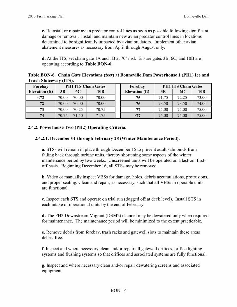
2013 Fish Passage Plan Bonneville Dam
BON-14
c. Reinstall or repair avian predator control lines as soon as possible following significant damage or removal. Install and maintain new avian predator control lines in locations determined to be significantly impacted by avian predators. Implement other avian abatement measures as necessary from April through August only. d. At the ITS, set chain gate 1A and 1B at 70’ msl. Ensure gates 3B, 6C, and 10B are operating according to Table BON-6.
Table BON-6. Chain Gate Elevations (feet) at Bonneville Dam Powerhouse 1 (PH1) Ice and Trash Sluiceway (ITS).
Forebay Elevation (ft)
PH1 ITS Chain Gates Forebay Elevation (ft)
PH1 ITS Chain Gates 3B 6C 10B 3B 6C 10B
<72 70.00 70.00 70.00 75 71.75 72.25 73.00 72 70.00 70.00 70.00 76 73.50 73.50 74.00 73 70.00 70.25 70.75 77 75.00 75.00 75.00 74 70.75 71.50 71.75 >77 75.00 75.00 75.00
2.4.2. Powerhouse Two (PH2) Operating Criteria.
2.4.2.1. December 01 through February 28 (Winter Maintenance Period).
a. STSs will remain in place through December 15 to prevent adult salmonids from falling back through turbine units, thereby shortening some aspects of the winter maintenance period by two weeks. Unscreened units will be operated on a last-on, first-off basis. Beginning December 16, all STSs may be removed. b. Video or manually inspect VBSs for damage, holes, debris accumulations, protrusions, and proper seating. Clean and repair, as necessary, such that all VBSs in operable units are functional. c. Inspect each STS and operate on trial run (dogged off at deck level). Install STS in each intake of operational units by the end of February. d. The PH2 Downstream Migrant (DSM2) channel may be dewatered only when required for maintenance. The maintenance period will be minimized to the extent practicable. e. Remove debris from forebay, trash racks and gatewell slots to maintain these areas debris-free. f. Inspect and where necessary clean and/or repair all gatewell orifices, orifice lighting systems and flushing systems so that orifices and associated systems are fully functional. g. Inspect and where necessary clean and/or repair dewatering screens and associated equipment.

2013 Fish Passage Plan Bonneville Dam
BON-15
h. Inspect and correct any deficiencies in DSM channel, conduit outfall walls and floor. j. Flume Pipe (from exit of DSM to outfall). Visually inspect outfall flume pipe and associated switch gates once per year from the transition section leaving the powerhouse to the outfall return to the river for obstructions, protrusions, or structural deficiencies that may affect fish passage. k. Avian Predation Lines. Reinstall or repair avian predator control lines as soon as possible following significant damage or removal. Install and maintain new avian predator control lines in locations determined to be significantly impacted by avian predators. Avian abatement measures shall be in place by March 01 unless this work is delayed because of inclement weather. If this occurs, the work will be completed as soon as possible after that date. However, there will be no avian abatement measures, other than avian lines, performed from September through March each year.
2.4.2.2. March 01 through November 30 (Juvenile Fish Passage Season).
a. Juvenile fish protection devices (STS, etc.) will be in place prior to the juvenile fish passage season. Screens (STSs and VBSs) will remain in operation through December 15 to prevent adult salmonids from falling back through turbine units.
b. Main unit gatewell drawdown will be measured a minimum of once per week. Check more often during times of overwhelming debris, as described in section 2.4.2.2.j. c. Remove debris from the forebay and trash racks as required to maintain less than 1.5' of drawdown in gatewells, or as indicated by fish condition (e.g., higher than expected descaling), or as determined by the project biologist. The STSs in units being raked will be run continuously during raking operations. Gatewell orifices of the unit being raked must be closed during the procedure. d. Measure fish unit gatewell drawdown at least once per week. When the head across trash racks exceeds 1.5', the trash racks will be cleaned that day. This may be done by raking late in the workday or by turning the unit off at night and letting the debris float off the racks. However, if the head exceeds 3' or if the adult fishway head is reduced, the unit’s racks will be raked immediately, even if it is early in the day. When debris accumulation is persistent, unit 18 may be operated while the fish unit is off at night to help draw loosened debris away.
e. Operate STSs at angle of 60o from vertical. f. Turbines without a full complement of STSs will not operate except when in compliance with other coordinated fish measures. g. Observe each STS watt and/or amp gauge and record reading at least once per day. If an STS failure occurs, then follow procedures in Fish Facility Maintenance.

2013 Fish Passage Plan Bonneville Dam
BON-16
h. Video or manually inspect each STS once per month (or 720 hours run time) and each VBS a minimum of once every two months (or 1440 hours run time). Frequency of monthly inspections may be based on individual turbine unit run time.
1. No STS inspections will be scheduled when they will cause excessive TDG due to increased forced spill. 2. VBS inspections will occur immediately prior to peaks in juvenile fish migrations, which begin about May 01, mid-July, and September 01. 3. More frequent inspections may be required by the project biologist or under the following conditions: deterioration of fish conditions, increased debris load in bypass system, and other indications of STS or VBS malfunctions or failure. 4. If manually inspecting VBSs, prior to pulling VBSs for inspections, shut off units and dip gatewells. It is not necessary to dip gatewells of units that have been off for 48 hours or longer. 5. VBSs will be cleaned when drawdowns read 1.1’ on any day (including weekends) and when drawdowns reach 0.9’ on Thursdays. 6. If a screen has reached the cleaning threshold, all three screens in that unit will be cleaned. 7. A unit will be shutdown if VBS drawdown equals or exceeds 1.5’ in a 12-hour period.
i. Rake unit 11 and unit 12 trashracks prior to March 1 and at least once a month throughout fish passage season. j. If STS or VBS damage or plugging is detected, follow procedures in Section 4 Fish Facilities Maintenance. In the event of overwhelming debris (as defined below) follow the procedures outlined below. Monitor gatewell drawdown daily.
1. TIE Crane in service:
A. VBSs will be cleaned by installing the spare VBS in the back slot, pulling the main VBS up and spray it off with a fire hose, then replace back in slot and pull spare (reverse order). B. If the VBS drawdown criteria of <1.1’ CANNOT be maintained during the day due to debris, the spare VBS will not be installed in the back slot and the gatewells will not be dipped. The Project will pull the main screen, spray it off with a fire hose, and then re-install.
2013 Fish Passage Plan Bonneville Dam
BON-17
C. If the VBS drawdown criteria of <1.5’ over a 12-hour period CANNOT be maintained due to debris, even after performing the above operations, then the STSs will be pulled out until the screen re-installation criteria (see 2.4.2.2.j.3) have been met. D. Once the screens have been removed, these units should operate only as necessary to maintain TDG levels below dissolved gas cap limits.
2. TIE Crane OOS = use Gantry Crane:
A. If the Gantry Crane is used to pull the main VBS, the spare VBS will not be installed in the back slot. B. If the VBS drawdown criteria of <1.5’ over a 12 hour period CANNOT be maintained due to debris, even after performing the above operations, then the STSs will be pulled out until the screen re-installation criteria (see 2.4.2.2.j.3) have been met. C. Once the screens have been removed, these units should be operated only as necessary to maintain TDG levels below dissolved gas cap limits.
3. SCREEN RE-INSTALLATION CRITERIA: Once flows drop below 300 kcfs and water clarity is 4’ or greater, the Project will install STSs in the highest priority unit available. When VBS drawdown for that unit remains below 1.1’ for 24 hours, the Project will re-install the remaining STSs. The reinstallation process may occur before or after the above criteria are reached at the discretion of the Project Biologist followed by a discussion with FPOM.
k. All gatewell orifice systems should be operational.
1. Orifices automatically flush 3 times per day, one orifice every 10 minutes. Orifices with less than a clear flow jet will be flushed manually during the inspection. 2. Manually flush orifices known to have recurring plugging or other problems. 3. Orifice jets will be observed through the light tubes during the inspection. Light tubes and orifice tube lenses shall be replaced and kept clean as required so that visual observations of orifice jets are possible during fishway inspections.
l. Replace all non-operational orifice lights within 24 hours. Orifice lights shall remain lighted 24 hours/day.
1. The DSM gallery lights should be left off except when project or other staff is in the gallery.

2013 Fish Passage Plan Bonneville Dam
BON-18
m. The project will clean gatewells before the water surface becomes 50% covered with debris. If due to the volume of debris, it is not possible to keep the gatewell surfaces 50% clear, they will be cleaned at least once daily.
1. Turbines with a gatewell fully covered with debris will not be operated except to be in compliance with other coordinated fish measures, and then only on a last-on/first-off basis. 2. Gatewell orifices will be closed during the cleaning operations. After cleaning a gatewell, inspect and, if necessary, clean the orifice in that gatewell and then check gatewell drawdown. 3. Coordinate gatewell cleaning with JMF personnel operating downstream juvenile sampling facilities.
n. A slight oily sheen is commonly found in many gatewells. When unusual accumulations of oil occur in gate slots, it will be removed within 24 hours. When this is not possible, the gatewell orifice will be closed and the turbine unit will be shut down until cleaning is accomplished. Appropriate procedures to remove fish during this situation will be determined in coordination with FPOM. Regardless of unit operating status, oil accumulations will be dealt with promptly. o. Reinstall or repair avian predator control lines in present locations as soon as possible following significant damage or removal. Install and maintain new avian predator control lines in locations determined to be significantly impacted by avian predators. Implement other avian abatement measures as necessary from April through August only.
2.4.2.3. Powerhouse Two Corner Collector (B2CC) Operation. Operate the B2CC during spill season. Open and close the B2CC within one hour of the start and end of spill season, respectively.
a. Beginning on March 01, JMF personnel will enumerate steelhead kelt at the JMF adult/debris separator. If 2 kelts per day are observed at the JMF separators for 2 consecutive days for a cumulative total of 20 kelts, JMF personnel will notify the Control Room and Project Fisheries, and the B2CC will be opened within 1 hour.
2.4.2.4. DSM2 Channel Operation.
a. Screen cleaners. The primary screen cleaner will be the airburst system. The system may be set to cycle every 20, 60, or 180 minutes, depending on debris loads.
1. In the event that the air system is unable to maintain the desired water elevation at the dewatering area, then the duration of the cleaning cycle will be increased as necessary.

2013 Fish Passage Plan Bonneville Dam
BON-19
2. If the system is still unable to accommodate the debris load, then the mechanical brush system will be activated in conjunction with the airburst system to maintain the desired water elevation. The systems will continue to work in tandem until debris loads lessen and the airburst system can maintain a correct water elevation. 3. Once water elevations can be maintained, the mechanical system will be returned to standby and the airburst system cleaning will be the primary system once again. 4. The Project biologists shall have the discretion to modify the cleaning system program at anytime to maintain FPP criteria. 5. The mechanical screen cleaners will be run once a week to exercise the equipment.
b. Operation. Maintain the channel elevation between 64.2’–64.4’ as measured at the staff gauge in front of the ERG.
Table BON-7. Regulating Orifice Control at Bonneville Dam DSM2. Orifice FB ≤ 71.5’ FB ≤ 72.5’ FB ≤ 73.5’ FB ≤ 74.5’ FB ≤ 75.5’ FB ≤ 76.5’ 11A-S Open Open Open Open Open 11B-S Open Open Open Open 11C-S Open Open Open Open 12A-S Open Open Open 12B-S Open Open Open 12C-S Open Open 13A-S Open Open 13B-S Open Open 13C-S Open 14A-S Open 14B-S Open 14C-S Open
2.4.2.5. Juvenile Monitoring Facility (JMF).
a. Operation.
1. Project Biologists or JMF personnel will operate the upper switchgate as necessary for sampling requirements. 2. The lower switchgate is in automatic control. JMF personnel (PSMFC) will monitor and report to Project Biologists any problems with the lower switchgate. 3. On seasonal ascending tailwater elevations, the transition from low to high outfall should be between tailwater elevations at the upper end of 16’ to 18’ range. 4. On seasonal descending tailwater elevations, the transition from high to low outfall should be between tailwater elevations at the lower end of 18’ to 16’ range.

2013 Fish Passage Plan Bonneville Dam
BON-20
5. Operate the outfall avian cannons from March 1 through November 1. The cannons will be operated 24 hours/day during fish passage season. 6. For specific monitoring facility guidance, see also Appendix J Protocols for Juvenile Monitoring Facility Operations at Bonneville Dam.
2.4.3. Spillway Operating Criteria.
2.4.3.1. December 01 through February 28 (Winter Maintenance Period). a. Inspect and repair where necessary spill gates and control systems. The spillway, except for coordinated exceptions, must be able to achieve spill patterns on the first day of the juvenile fish passage season. b. As per procedures in Bonneville Operating Order 14, each spill gate will be raised and lowered to test for operability and check calibration prior to start of spill season, usually in March. c. For spill guidance during winter maintenance periods, see Appendix E or section 2.2.
2.4.3.2. March 01 through November 30 (Juvenile Fish Passage Season). Spill will be provided according to the guidance in Appendix E and section 2.2.
2.5. Adult Fish Passage Facilities. 2.5.1. All Adult Fish Passage Facilities Operating Criteria.
2.5.1.1. December 01 through end of February (Winter Maintenance Period).
a. Operate adult fish passage facilities according to fish passage season standards. Systems may be dewatered or operated out of criteria for repair and maintenance.
b. Only one ladder servicing the powerhouses and the associated powerhouse collection system (including the auxiliary water supply system) may be out of service or operating out of standard operating criteria at any one time, unless specifically coordinated. c. Turbines will be operated in the priority order in Table BON-14. d. One of the two ladders servicing the spillway channel will be in full operation at all times unless otherwise coordinated. e. Outage periods will be minimized to the extent practicable.
f. Operate spillbays 1 and 18 as described in section 2.2.3.1 and Table BON-5.

2013 Fish Passage Plan Bonneville Dam
BON-21
g. Adjust fish counting stations crowders to fully open if videotaping is temporarily discontinued due to unscheduled events or during winter maintenance (dewatering) period only. h. Sea Lion Exclusion Devices (SLEDs) will be installed at all 8 main fishway entrances and B2 FOGs on or before February 1 and removed by June 15 each season. SLEDs may be installed earlier or kept in place later if significant numbers of pinnipeds are present at Bonneville outside of these dates.
i. Inspect and calibrate all staff gauges and water level indicators. Repair and/or clean where necessary. j. Unless specially coordinated, dewater all ladders and inspect all dewatered sections of fish facilities for projections, debris, or plugged orifices that could injure fish or slow their progress up the ladder. Repair deficiencies.
k. Inspect for and clear debris in the ladder exits.
l. Reinstall counting station picket leads prior to watering up ladders during maintenance. m. Except when closed to facilitate maintenance activities, the PH1 ITS gates 1A, 1B, 3B, 6C, and 10B should remain open from December 01 through the end of February to provide steelhead kelt passage.
1. Set chain gate 1A and 1B at 70’ msl. Ensure gates 3B, 6C, and 10B are operating according to Table BON-6. 2. From December 15 through the end of February the Project may close the ITS endgate or ITS gates to facilitate winter maintenance (including researcher equipment O&M) in the PH1 forebay. Closures may not exceed six hours per day unless otherwise coordinated with FPOM.
n. In the appropriate year (when the fishway is out of service for winter maintenance), dredge AWS intakes to maintain the following elevations:
1. -22’ to -24’msl at PH2 Fish Unit intake; 2. +63’ msl at BI exit, FV3-7 and FV3-9.
2.5.1.2. March 01 through November 30 (Adult Fish Passage Season).
a. Maintain water depth over fish ladder weirs at 1.0’ ±0.1’ during non-shad passage season (<5,000 shad per day/per count station) and 1.3’ ±0.1’ during shad passage season (≥ 5,000 shad per day/per count station). Water depths will be measured at the A- and B-branch staff gages in the Bradford Island fishway, at weirs 37 and 38 in the Washington shore fishway, and at the UMT staff gage in the Cascades Island fishway.

2013 Fish Passage Plan Bonneville Dam
BON-22
b. Water temperature will be measured in an adult fishway at each powerhouse. When water temperature reaches 70°F, all fish handling activities will be coordinated through FPOM prior to any action to verify protocols that will be followed. Fish handling activities in the Adult Fish Facility (AFF) will implement protocols in Appendix G.
c. Head on all entrances should be: 1' to 2' (1.5' preferred). Head at the NUE is calculated differently because the collection channel staff gage is in the junction pool. A head of approximately 1' to 2' at the NUE entrance is indicated by a 1.2' to 2.2' (1.7' preferred) entrance head calculated using the fishway and tailwater staff gages closest to NUE. Refer to Table BON-13 when unable to achieve head criterion.
d. A water velocity of 1.5 to 4 fps (2 fps preferred) shall be maintained for the full length of the powerhouse collection channel, and the lower ends of the fish ladders that are below the tailwater. Water velocities will be measured directly, and monitored during fishway inspections to verify channels are operating between 1.5 and 4 fps. e. A maximum of 0.5' head will be allowed on the PH1 attraction water intakes and trash racks at all the ladder exits, with 4" maximum head on all picket leads. Debris shall be removed when significant amounts accumulate.
f. Staff gages and water level indicators will be readable at all water levels encountered during the fish passage period. These include: PH1 south collection channel, PH1 north collection channel, PH1 north tailwater, PH1 south forebay, BI A- and B-branch ladders, BI weir, B-branch entrance, CI entrance, CI ladder below the UMT entrance, NUE/NDE/SUE/SDE collection channel, NUE/SUE tailwater, and PH2 north forebay. g. Stillwells used in lieu of staff gages will be checked for calibration once per week. h. The current fish counting program is conducted 16 hours per day, year around (see Table BON-3). Count station crowders shall remain in the operating position while visual counting and/or videotaping is being conducted. All equipment should be maintained and in good condition. The counting window and backboard should be cleaned as needed to maintain good visibility.
1. The crowder shall be opened to full count slot width when not counting. The crowder shall be open as far as possible to allow accurate counting and shall not be closed to less than 18” while counting. This will usually occur during high turbidity conditions to maintain count accuracy. All equipment will be maintained in good condition. The counting window and backboard will be cleaned as needed to maintain good visibility. The crowder ranges are as follows:
• Washington Shore = 22.8”–38.4”; • Cascades Island = currently out of service (max. opening approximately 36”); • Bradford Island = 20.4”–36”.

2013 Fish Passage Plan Bonneville Dam
BON-23
2. If passage is impaired by this condition, the count slot may be widened until proper passage conditions are achieved, even though count accuracy may be compromised to some degree. 3. Project biologists, FFU, and the fish count supervisor shall coordinate to achieve optimum count slot passage and/or count accuracy conditions. 4. If counting is temporarily discontinued due to unscheduled events, the crowder shall be fully opened. 5. The crowder may remain in operating position during the counters’ hourly ten-minute break period. 6. Leave the fish passage slot lighted overnight.
i. Upstream light banks in both count stations shall remain off to facilitate fish passage through the count slot and help reduce the number of fish impacting the count window framework, unless other passage problems result, or count accuracy is compromised as determined by the fish count supervisor and coordinated through FPOM.
j. Inspect and ensure that optimum passage conditions are maintained at fishway entrances, exits, and in the count slots. k. Take soundings annually at the PH2 Fish Unit intake and the BI exit/AWS intake to determine sediment accumulation and plan for the appropriate dredging need.
2.5.2. Main Dam Ladders.
2.5.2.1. When spilling exclusively for adult attraction, spill only during the daylight hours (see Table BON-5). Spill Bays 1 and/or 18 shall be open 6” only if adjacent to operating fishway entrances (see section 2.2.3.1). 2.5.2.2. Side entrances SW-SG-5 and SO-SG-7 shall remain closed. Downstream entrances SW-SG-1 and SO-SG-2 shall operate as continuously open free-flowing vertical slots. Downstream entrances SW-SG-3 and SO-SG-4 (adjacent to shore) consist of pairs of sluice gates. SO-SG-4N and SO-SG-4S shall be closed at all tailwater elevations. When the tailwater is below 9', sluice gates SW-SG-3N, SW-SG-3S, shall be open. When the tailwater is between 9' and 17', sluice gate SW-SG-3N shall close. When the tailwater exceeds 17', sluice gates SW-SG-3N and SW-SG-3S shall be closed.

2013 Fish Passage Plan Bonneville Dam
BON-24
Table BON-8. Diffuser Operating Ranges at Bonneville Dam Bradford Island B-Branch.
Diffuser Operating Range (feet) Diffuser Operating
Range (feet) Diffuser Operating Range (feet)
FG3-18 >34 FG3-23 >19 FG3-28 <25 FG3-19 >31 FG3-24 >16 FG3-29 Manual open FG3-20 >28 FG3-25 13'-34 FG3-30 Manual open FG3-21 >25 FG3-26 12'-31 FG3-31 >25 FG3-22 >22 FG3-27 10.5-28 FG3-32 >26
FG3-33 >27 Table BON-9. Diffuser Operating Ranges at Bonneville Dam Cascades Island.
Diffuser Operating Range (feet) Diffuser Operating
Range (feet) Diffuser Operating Range (feet)
FG6-5 >31 FG6-10 >17 FG6-15 Manual open FG6-6 >29 FG6-11 >14 FG6-16 Manual open FG6-7 >25 FG6-12 >11 FG6-17 Manual open FG6-8 >23 FG6-13 >10 FG6-18 >12 FG6-9 >20 FG6-14 >9 FG6-19 >15
FG6-20 >19 2.5.3. Powerhouse One (PH1).
2.5.3.1. Weir Gates. The PH1 weir gates will be operated as shown in Table BON-10. a. Gate Pairing. The four weir gates will be operated in two pairs. Only one gate pair will be allowed to operate at any given time. Gates 1 and 65 will operate together as the active pair for tailwater elevations greater than 23' msl, while gates 2 and 64 will operate together as the active pair for tailwater elevations less than 26' msl. For tailwater elevations between 23' and 26', the designated active pair will depend on whether the tailwater elevation has been rising or falling with a "dead band" of 1.5'. b. Transition Positioning. During a transition, the former active pair is closed and the new active pair is positioned according to tailwater.
Table BON-10. Weir Gate Requirements at Bonneville Dam Powerhouse One.
Weir Gate Submergence Requirement (feet)
Differential Requirement (feet)
Sill Elevation (feet)
1 >8' 1'-2' 8.5' 2 >8' 1'-2' 2' 64 8'-8.4' 1'-2' 2' 65 8'-8.4' 1'-2' 8.5'

2013 Fish Passage Plan Bonneville Dam
BON-25
2.5.3.2. Control of Fish Valve FV1-1.
a. Emergency Closure. If the collection channel/tailwater differential is greater than 2.5', or if the pressure differential between the auxiliary water supply conduit and the collection channel becomes excessive, as determined by operators, close FV1-1.
b. Differential. Low: if the collection channel/tailwater differential is less than 1'. High: if the collection channel/tailwater differential is more than 2.0'.
2.5.3.3. Control of Fish Valve FV3-7. Maintain the opening concurrent with the charts for valve opening, as set by the forebay and tailwater elevations. 2.5.3.4. Control of A-Branch Diffusion Gates FG3-3 through FG3-9. Bradford Island A-branch diffusers are open according to the pattern in Table BON-11.
Table BON-11. Diffuser Operating Ranges at Bonneville Dam Bradford Island A-branch.
Diffuser Operating Range – Tailwater Elevation (feet) Dead Bands (feet)
FG3-3 8.2 – 13.3 7.8 – 8.2 FG3-4 13.7 – 16.3 13.3 – 13.7 FG3-5 16.7 – 19.3 16.3 – 16.7 FG3-6 19.7 – 24.8 19.3 – 19.7 FG3-7 25.2 – 27.8 24.8 – 25.2 FG3-8 28.2 – 30.8 27.8 – 28.2 FG3-9 > 31.2 30.8 - 31.2
2.5.3.5. Powerhouse One Collection Channel Diffusers. Diffuser valves are operated according to the pattern in Table BON-12.
Table BON-12. Open Adult Fish Collection Channel Diffuser Valves at Bonneville Dam Powerhouse One. Any diffusers not listed should be Closed.
Valve Setting Valve Setting FG2-4 Open FG2-20 Open FG2-8 Open FG2-21 Open FG2-12 Open FG2-22A Open FG2-19 Open FG2-22B Open
2.5.4. Powerhouse Two (PH2).
a. During daytime spill hours (Table BON-5), operate all north (NUE and NDE) and south (SUE and SDE) entrances. Operate weir crests at elevation 1' (fully lowered) for tailwater elevations up to 14'. For tailwater elevations greater than 14', operate weir crest 13' or greater below tailwater.
b. Operate all 12 active PH2 floating gate fishway entrances.

2013 Fish Passage Plan Bonneville Dam
BON-26
c. Lamprey Operations, June 1–August 31: During nighttime spill hours (Table BON-5), reduce fish unit output to operate all north (NUE and NDE) and south (SUE and SDE) entrances at 0.5’ of entrance head. To ensure proper function of the fish units, B2 fish unit output can be further reduced or placed on standby to float debris as necessary from 2200-0400 hours.
3. FACILITY MONITORING AND REPORTING 3.1. Inspections. 3.1.1. The results of all inspections and the readiness of the facilities for operation will be reported to the FPOM at the meeting immediately prior to the fish passage season. 3.1.2. During fish passage season, fish passage facilities will be inspected at least three times per day/seven days a week to assure operation according to established criteria. 3.1.3. During winter maintenance season, fish passage facilities will be inspected three times per day/at least three days a week. 3.1.4. More frequent inspections will occur as noted throughout the text. 3.1.5. The project fish biologists and fish biological staff will conduct at least three inspections per week though additional fishway inspections may be performed by FFU and fish agencies. 3.2. Zebra Mussel Monitoring. A zebra mussel monitoring program will continue. These organisms have become a serious problem elsewhere in the country and may become introduced into the Columbia River basin. Inspections should also be made when dewatering all project facilities. 3.3. Reporting. 3.3.1. Project biologists shall prepare weekly reports throughout the year summarizing project operations. The weekly reports will provide an overview of how the project and the fish passage facilities operated during the week and an evaluation of resulting fish passage conditions. The reports shall include:
a. Any out-of-criteria situations observed and subsequent corrective actions taken. b. Any equipment malfunctions, breakdowns, or damage along with a summary of resulting repair activities. c. Adult fishway control calibrations. d. STS and VBS inspections. e. AWS closures (i.e. cleaning times). f. When trapping is occurring in the AFF. g. Any unusual activities which occurred at the project which may affect fish passage.

2013 Fish Passage Plan Bonneville Dam
BON-27
3.3.2. The weekly reports shall cover a Sunday through Saturday period and they shall be e-mailed to CENWP-OD and other interested parties as soon as possible the following week, with a copy to CENWD-PDW-R (RCC). 3.3.3. The project biologists shall prepare a memo for the record for any negative impact to fish or fishways. This memo will be sent to FPOM by the next working day. Items that shall be included in the memo are:
a. Time and date. b. Nature of activity that leads to fish impact. c. Agency responsible for the impact, or the name of the reporter if no responsible party can be identified. d. Fish numbers, species, origin, discernible external injuries, tags, etc. e. Future actions to avoid a similar impact. f. Any relevant photos.
3.3.4. The project biologists shall prepare an annual report by January 31, summarizing the operation of the project fish passage facilities for the previous year.
3.3.4.1. The report will cover from the beginning of one adult fish facility winter maintenance period to the beginning of the next. 3.3.4.2. The annual report also will include a description of all actions taken to discourage avian predation at the project, with an overview of the effectiveness of the activities in discouraging avian predation. 3.3.4.3. The annual report will be provided to CENWP-OD in time for distribution to FPOM members at the February meeting.
4. FISH FACILITIES MAINTENANCE 4.1. General. 4.1.1. Routine Maintenance.
4.1.1.1. Staff gages and other water-level sensors will be installed, cleaned, and/or repaired as required. 4.1.1.2. Scheduled fishway maintenance, to the extent practicable, will be conducted during periods when passage has been documented to be at its lowest during the regular scheduled workday, to minimize impacts to migrating salmonids. 4.1.1.3. Maintenance activities that occur during the fish passage period and that may affect fish passage will be reported in the weekly reports.

2013 Fish Passage Plan Bonneville Dam
BON-28
4.2. Juvenile Fish Passage Facilities. 4.2.1. Routine Maintenance.
4.2.1.1. Submersible Traveling Screens. The STS system will receive preventive maintenance or repair at all times of the year, including the winter maintenance period. Whenever a generator malfunctions or is scheduled for maintenance, the three STSs in that turbine may be maintained, repaired, or exchanged for other STSs needing maintenance or repair. One third of the STSs at Bonneville are scheduled for complete overhaul each year resulting in a three-year maintenance cycle unless future developments indicate that longer life expectancy is possible. 4.2.1.2. Juvenile Bypass Systems (JBS). The JBS will receive preventive maintenance throughout the year. During the juvenile fish passage season, this will normally be above-water work such as maintenance of automatic systems, air lines, electrical systems, and monitoring equipment. During the winter maintenance period, the systems may be dewatered downstream of the gatewell orifices. The systems will then be visually inspected in all accessible areas for damaged equipment and in areas that may cause problems to the juvenile fish. Any problem areas identified are to be repaired if the project is able. In extreme cases, the work will be contracted as soon as possible or repaired during the next winter maintenance period. Channel modifications and general maintenance also should be completed at this time.
a. The trash racks are to be raked just prior to the juvenile fish passage season and whenever trash accumulations are suspected because of increased head across the trash racks (>1.5') or increased juvenile fish descaling. Additional trash rack raking may be necessary when a storm brings large quantities of debris down river to the project. Gatewell orifices in the unit being raked will be closed during the procedure.
4.2.1.3. Turbines and Spillways. Maintenance and routine repair of project turbines and spillways is a regular and recurring process which requires units to be shut down for extended periods of time
a. The maintenance schedules for turbines and spillways will reflect equal weighting given to fish, power, and water management and will be coordinated with the appropriate fish and resource agencies through FPOM.
b. Certain turbine and spillway discharges at the projects are secondarily used to attract adult fish to fishway entrances, to keep predator fish from accumulating near juvenile release sites, and to move juveniles downstream away from the project. During the fish passage season, do not take units F1, F2, 1, 3, 11, and 18 out of service, when practicable. c. Whenever practicable, except during split flows operation, do not take any other PH2 units out of service from June 21 through September 15, to minimize PH1 operation.

2013 Fish Passage Plan Bonneville Dam
BON-29
d. Fish units may be taken out of service to facilitate cleaning of the fish unit brush rigging. Through trial and error, it has been determined that the rigging should be cleaned twice during the passage season. One cleaning operation is performed in conjunction with the mid-year collection channel diffuser grating inspection, and the second stands alone on the outage schedule. e. Some types of turbine maintenance will require testing the turbine throughout its full operating range before returning it to normal service. These operations will be coordinated with the appropriate resource agencies.
4.2.2. Non-Routine Maintenance. Maintenance of facilities such as fish screens, which sometimes break down during the fish passage season, will be carried out as described below.
4.2.2.1. Unscheduled maintenance that will have a significant impact on juvenile fish passage shall be coordinated with the Regional fish agencies through FPOM and with RCC on a case-by-case basis by CENWP-OD biologists. The CENWP-OD biologists will be notified by the project as soon as possible after it becomes apparent that maintenance repairs are required. The Project Operations Manager has the authority to initiate work prior to notifying CENWP-OD when delay of the work will result in an unsafe situation for people, property, or fish. Information required by CENWP-OD includes (see Overview for coordination form):
1. Description of the problem. 2. Type of outage required. 3. Impact on facility operation. 4. Length of time for repairs. 5. Expected impacts on fish passage.
4.2.2.2. Submersible Traveling Screens. If an STS or VBS is found to be damaged or inoperative in an operating unit, the unit will be regarded as an unscreened unit. The screen will be repaired or replaced before returning the unit to normal service. 4.2.2.3. Juvenile Bypass Systems (JBS).
a. The JBS is controlled automatically (PLC). When an automatic system fails, it can usually be operated manually. This allows either facility to operate according to criteria while repair of the automatic system is completed.
b. Orifices allow fish out of the gatewells into a bypass channel. If an orifice valve system becomes inoperative, it will be repaired expeditiously. When the orifices become plugged with debris they are pneumatically flushed. c. If automatic systems fail and the system is operated manually, facility inspections should increase to a frequency that ensures systems continue to operate within criteria. d. All STS gatewells will be inspected daily and cleaned before they become 50% covered with debris. If due to volume of debris it is not possible to keep the gatewell

2013 Fish Passage Plan Bonneville Dam
BON-30
surfaces at least 50% clear, they will be cleaned at least once daily. Turbines with a gatewell fully covered with debris will not be operated, except on a last-on/first-off basis, if required to be in compliance with other coordinated fish measures. This is to maintain clean orifices and minimize fish injury. The gatewell orifices will be closed during the cleaning operation. Check gatewell drawdown and clean trashracks if necessary. e. Powerhouse One (PH1). PH1 juvenile passage routes consist of the ITS and MGR turbines. The DSM is no longer in service. f. Powerhouse Two (PH2). If the bypass system fails in the dewatering section or release pipe, fish may be released through the emergency relief conduit. This operation will continue until repairs are accomplished or until the end of the fish passage season. Any decision on whether or not to shut this system down for dewatering and repairs will be made in coordination with the FPOM. During this emergency operating mode, power generation will be minimized at the PH2. Repairs will receive high priority. g. During fishway inspections the VBSs may be found plugged, damaged, or not properly seated. In these cases, the associated unit will be taken out of service as if unscreened and repairs will be made before returning the unit to normal service. If screens are pulled and replaced, the underwater video inspection camera will be deployed to check the screens for proper seating.
4.2.2.4. Turbines and Spillways. If a spill gate becomes inoperable, the operator will make the changes necessary to accommodate the spill and then immediately notify the operations supervisor and project biologist to determine the best pattern to follow until repairs are completed. This interim operation shall be coordinated with the FPOM through the district biologist who will provide additional guidance to the project.
4.3. Adult Fish Passage Facilities. 4.3.1. Routine Maintenance. Maintenance activities that occur during the fish passage period and that may affect fish passage will be reported in the weekly reports.
4.3.1.1. Fishway Auxiliary Water Systems. Bonneville Project auxiliary water systems consist of gravity flow and hydroelectric generating systems. Preventive maintenance and normal repair are carried out as needed throughout the year. Trash racks for the AWS intakes will be raked when drawdown exceeds criteria. When practicable, rake trash racks during the time of day when fish passage is least affected. 4.3.1.2. Powerhouse and Spillway Adult Fish Collection Systems. Preventive maintenance and repair occurs throughout the year. During the primary adult fish passage season this maintenance will not involve any operations which will cause failure to comply with the adult fishway criteria except as specially coordinated or as needed for semi-annual maintenance. Inspection of those parts of the adult collection channel systems which require dewatering, such as diffusion gratings, leads, and entrance gates, will be scheduled once per

2013 Fish Passage Plan Bonneville Dam
BON-31
year during the winter maintenance season while the system is dewatered, with one additional inspection during the fish passage season, unless a channel must be dewatered for fishway modifications or to correct observed problems.
a. An underwater video system or diver may be used for underwater inspections. This scheduled inspection and any associated maintenance will occur during winter maintenance period and once during fish passage season unless specially coordinated. Any non-routine maintenance and fishway modifications will be handled individually.
b. A project biologist will attend all dewatering activities potentially involving fish, as well as inspections, to provide fish related input.
4.3.1.3. Diffuser Gratings: Diffuser chambers for adding auxiliary water to fish ladders and collection channels are covered by gratings attached by several different methods. Diffuser gratings are normally checked during the winter maintenance period to make sure they are in place. These inspections are done by either dewatering the fish passage way and physically inspecting the diffuser gratings, or by using other methods to inspect the gratings. Diffuser gratings may come loose during the fish passage season.
a. Daily inspections of fish ladders and collection systems should include looking for any flow changes that may indicate problems with diffuser gratings. b. If a diffuser grating is known to or suspected of having moved, creating an opening into a diffuser chamber, efforts must immediately be taken to correct the situation and minimize impacts on adult fish in the fishway.
c. If possible, a video inspection should be made ASAP to determine the extent of the problem. If diffusers gratings are found to be missing or displaced, creating openings into the diffuser chambers, a method of repair shall be developed and coordinated with the fish agencies and tribes through the established FPOM coordination procedure. d. Repairs shall be made as quickly as possible unless coordinated differently.
4.3.1.4. Adult Fish Ladders and Counting Stations. (Also see Appendix G Adult Fish Trapping Protocols.) The adult fish ladders will be dewatered once each year during the winter maintenance period. During this time, the ladders will be inspected for blocked orifices, projections into the fishway that may injure fish, stability of the weirs, damaged picket leads, exit gate problems, loose diffusion gratings, unreadable or damaged staff gauges, defective diffusion valves, and malfunctioning operating equipment at the counting stations, as well as other potential problems. Problems identified throughout the passage year that do not affect fish passage, as well as those identified during the dewatered period, may then be repaired. Trash racks at the ladder exits will be raked when criteria is approached or exceeded. When practicable, rake trash racks during the time of day when fish passage is least affected, usually late morning fish count station windows, light panels, and crowder
2013 Fish Passage Plan Bonneville Dam
BON-32
panels will be cleaned as needed to achieve accurate counts and, when practicable, during the time of day when fish passage is least affected, usually late morning.
4.3.2. Non-Routine Maintenance. Maintenance activities that occur during the fish passage period and that may affect fish passage will be reported in the weekly reports. Non-routine maintenance that will significantly affect the operation of a facility, such as repair of displaced diffuser gratings, will be coordinated with the Regional fish agencies through FPOM and with RCC. Coordination procedures for non-routine maintenance of adult facilities are the same as for juvenile facilities. Any non-routine maintenance and fishway modifications will be handled on an individual basis.
4.3.2.1. Fishway Auxiliary Water Systems. Most fishway auxiliary water systems are operated automatically. If the automatic system fails, then the system will be manually operated by project personnel to maintain criteria while repair of the automatic system is carried out. When this operation becomes necessary, project personnel will increase the surveillance of the adult system to ensure that criteria are being met. In the event of AWS failure, FPOM will be used in an advisory capacity to assist the project as needed.
a. Powerhouse One (PH1). If any valves or any other part of the system fails, the project shall attempt to maintain criteria by adjusting those valves which continue to function. Conduit pressure must be monitored and not allowed to exceed the established limits. b. Spillway. Two separate fishway auxiliary water valves add water to each spillway ladder (Cascades Island and B-branch ladders). If one of these valves or any other part of the system malfunctions, the functioning parts of the system are to be adjusted to compensate. If repairs cannot be made in 24 hours, close the sluice gate entrance, if open. This will divert the reduced available water to the entrance slots. If a head of 1' is still not achieved, stop logs are to be added to the entrance slots until the desired head or a weir depth of not less than 6' below the tailwater surface is reached. At this point maintain the gate positions until the auxiliary water system is repaired. c. Powerhouse Two (PH2).
1. If either or both of the fishway auxiliary water turbines is unable to provide water sufficient to meet full criteria, the adult facilities will be operated according to Table Bon-13, Emergency Operations for Bonneville PH2 AWS Systems Operations or until a fishway head of 1’ is achieved. 2. Table Bon-13 is a guide for configuring turbine flows, floating orifices, diffuser gates, and main gates during emergency situations when one of the fish turbines has failed or been taken out of service. Table BON-13 guidance should be followed to the extent practicable, and shore entrance weirs should be raised in increments or closed as needed to maintain the proper fishway head.

2013 Fish Passage Plan Bonneville Dam
BON-33
3. If both fish unit turbines fail between September 01 and March 31 and repairs cannot be made within 8 hours, coordination with FPOM will occur to develop operational guidelines that may include modified powerhouse priority operations. 4. PH2 adult fishway diffusion system valves A3 and A4 were found damaged and have been removed. These valves were designed to be closed when tailwater drops below 11' and 9', respectively. Even though the valves cannot be closed, velocity in the channel has remained in criteria.
Table BON-13. Emergency Operations for Bonneville Dam Powerhouse Two Auxiliary Water Supply. Tailwater Elevation
(ft)
Turbine (MW)
Turbine Q (cfs)
******************CLOSED**************** Floating Orifices
South “B” Diffusers
PH “C” Diffusers
Main Entrances
8 13.90 2,950 All B3-8 C1-5 None 9 13.95 3,010 All B3-8 C1-5 None
10 14.05 3,090 All B3-8 C1-5 None 11 14.15 3,165 All B3-8 C1-5 None 12 14.20 3,230 All B3-8 C1-5 None 13 14.40 3,340 All B3-8 C1-5 None 14 14.40 3,400 All B3-8 C1-5 None 15 14.60 3,520 All B3-8 C1-5 None 16 14.30 3,515 All B3-8 C1-5 None 17 14.20 3,560 All B3-8 C1-5 None 18 14.00 3,575 All B5-8 None NU-E 19 13.60 3,535 All B5-8 None NU-E 20 13.30 3,520 All B4-8 None NU-E 21 13.00 3,510 All B4-8 None NU-E 22 12.70 3,505 All B4-8 None NU-E 23 12.40 3,505 All B4-8 None NU-E 24 12.20 3,535 All B4-8 None NU-E 25 11.60 3,535 All B4-8 None NU-E 26 11.10 3,365 All B4-8 None NU-E 27 10.60 3,285 All B4-8 None NU-E 28 10.00 3,160 All B3-8 None NU-E
4.3.2.2. Powerhouse and Spillway Adult Fish Collection Systems. Bonneville Project contains several types of fishway entrances. In most cases, if failures occur, the entrance can and will be operated manually by project personnel until repairs are made. If this operation becomes necessary, project personnel will increase the surveillance of the adult system to ensure that criteria are being met. In those cases in which the failure will not allow the entrance to be operated manually, the gate will be maintained, to the extent possible, in an operational position. If this is not possible, the entrance will be repaired expediently and returned to manual or automatic control at the earliest possible date. 4.3.2.3. Adult Fish Ladders and Counting Stations. Ladder components include picket leads, counting stations, fishway exits, and overflow weirs with orifices. Pickets with

2013 Fish Passage Plan Bonneville Dam
BON-34
excessive spacing (greater than 1"), concrete erosion around the leads, or missing pickets can allow fish into areas where escape is difficult. In some instances of picket lead failure, spare leads and spare installation slots are available. In these cases the spare leads are installed and the damaged leads are removed and repaired. In the remaining instances of picket lead failure or concrete erosion, the timing and method of repair will depend upon the severity of the problem. The decision of whether or not to dewater the fishway and repair any problems will be made in coordination with the Regional fish agencies through FPOM. 4.3.2.4. Diffuser Gratings. Diffuser chambers for adding auxiliary water to fish ladders and collection channels are covered by gratings attached by several different methods. Diffuser gratings are normally checked during the winter maintenance period to make sure they are in place. These inspections are done by either dewatering the fish passage way and physically inspecting the diffuser gratings, or by using other methods to inspect the gratings. Diffuser gratings may come loose during the fish passage season.
a. Daily inspections of fish ladders and collection systems should include looking for any flow changes that may indicate problems with diffuser gratings.
b. If a diffuser grating is known to or suspected of having moved, creating an opening into a diffuser chamber, efforts must immediately be taken to correct the situation and minimize impacts on adult fish in the fishway.
c. If possible, a video inspection should be made as soon as possible to determine the extent of the problem. If diffuser gratings are found to be missing or displaced, creating openings into the diffuser chambers, a method of repair shall be developed and coordinated with the Regional fish agencies through FPOM.
d. Repairs shall be made as quickly as possible unless coordinated differently.
5. TURBINE UNIT OPERATION AND MAINTENANCE 5.1. Powerhouse priority is detailed in Table BON-14. When splitting flows, as directed in section 2.1.2, the top two available priority units for PH1 will be operated first followed by normal unit priority at PH2. If there is a need for more units, and all available units at PH2 are in operation, proceed with the normal unit priority for PH1. 5.2. Turbine units at PH1 will operate within 1% of best efficiency and within cavitation limits at various head ranges as shown in Table BON-15. 5.2.1. Turbine units at PH2 will operate at the mid to lower 1% range (unless total dissolved gas waivers are exceeded in the tailrace) of best efficiency and within cavitation limits at various head ranges as shown in Table BON-16.

2013 Fish Passage Plan Bonneville Dam
BON-35
5.3. Turbines will be operated within ±1% of best turbine efficiency from April 1 through October 31 (as specified in the BPA load shaping guidelines), except as outlined in Appendix C. 5.4. The project turbine unit maintenance schedules will be reviewed by Project and Operations Division biologists for fish impacts. If possible, maintenance of priority units will be scheduled for winter maintenance periods, or when there are low numbers of fish passing the project. Table BON-14. Turbine Unit Operating Priorities at Bonneville Dam (Units 1-18).
PERIOD PRIORITY *
Year-Round; Adult Fish Ladders in service PH2 Priority: 11,18,12,17,13,14,15,16,
1,10,3,6,2,4,5,8,7,9 PH1 Adult Fish Ladder out of service
PH2 Adult Fish Ladder out of service PH1 Priority:
1,10,3,6,2,4,5,8,7,9 11,18,12,17,13,14,15,16,
Split Flows (all units available) 1,10,11,18,12,17,13,14,15,16,3,6,2,4,5,8,7,9
PH1 Unit priority 1,10,3,6,2,4,5,8,7,9
PH2 Unit priority 11,18,12,17,13,14,15,16 * Changes in unit priorities may occur and will be authorized in RCC teletypes as needed. 5.4.1. When PH1 is operating, Unit 1 provides important attraction flow for adult fish and helps move juvenile fish downstream. To maintain the priority importance of Unit 1 when PH1 must be used, long-term outages will be avoided after the beginning of the juvenile fish passage season until after the adult fall Chinook and coho runs at the end of October. 5.4.2. In the event of long-term powerhouse outages, affected units will be exercised periodically. Each unit will be operated 4-8 hours every two weeks to exercise governor components and clean wetted surfaces of corrosion, so that if needed, fish injury will be minimized and the units will be in good operating condition. Actual runtime will be the minimum amount needed to keep the unit in good working condition. This may be performed at night, daytime, or whenever unit cycling will have the least effect on fish passage as determined by the project biologist. 5.4.3. Units may be operationally tested for up to 30 minutes before going into maintenance status by running the unit at speed-no-load and various loads within the 1% range to allow pre-maintenance measurements and testing, AND TO ALLOW ALL FISH TO MOVE THROUGH THE UNIT. Units may be operationally tested after maintenance or repair while remaining in maintenance or forced outage status. Operational testing may consist of running the unit for up to a cumulative time of 30 minutes (within 1% range) before it is returned to operational status. Operational testing OF UNIT UNDER MAINTENANCE is in addition to a unit in run status (e.g., MINIMUM GENERATION) required for power plant reliability. Operational testing may deviate from fish priority units and may require water that would otherwise be used for spill if the running unit for reliability is at its 1% minimum load. Water will be used from powerhouse

2013 Fish Passage Plan Bonneville Dam
BON-36
allocation if possible, and water diverted from spill for operational testing will be minimized to that necessary to maintain and assure generation system reliability. 5.5. The headgates at units 11 through 18 have been dogged off and the system has been depressurized. Oil leaks develop frequently when the system operates with normal pressure. Further related instructions are described in a memorandum from the project operations superintendent. (Memorandum for All Operations, from BON Chief of Operations, dated September 23, 1993. Subject: Powerhouse 2 Hydraulic Head Gate Operation). 5.6. From December 1 through April 30, priority units 1, 3, 11, and 18 will be scheduled for any necessary extended outages. During this time, non-priority units should not be scheduled for routine or extended outages if the outage will delay or conflict with priority unit maintenance. 5.7. Turbines which have been idle/out of service for more than 12 hours will be started by slow rolling the unit after manually tipping turbine blades from flat to steep and back to flat. 5.8. During high head events (such as a higher than normal forebay) the top priority unit at PH1 may be operated, when necessary, to keep PH2 units within the 1% efficiency range. 6. DEWATERING PLANS 6.1. Guidelines for any dewatering. Guidelines for Dewatering and Fish Handling Plans (Appendix F) have been developed and are followed for most project facilities dewaterings. These plans include consideration for fish safety and are consistent with the following general guidance. The appropriate plans are reviewed by participants before each salvage operation. Dewatering Plans are also available online at: http://www.nwd-wc.usace.army.mil/tmt/documents/FPOM/2010/ 6.1.2. Whether pumps or drain valves are used, automatic pump shut off devices will be utilized to prevent stranding fish. If automatic pump shut off devices and low water alarms are not used, the dewatering process must be continuously monitored to prevent stranding. 6.1.3. Project Biologist and/or alternate Corps fish personnel will attend all project activities involving fish handling. 6.1.4. The fish agencies and tribes will be notified of any dewaterings and may be invited if additional help is deemed necessary, and all safety considerations can be met. 6.1.5. Adult salmonids will be released into the forebay and juvenile salmonids will be released into the tailrace, depending on the age composition of fish in the tank. If a ladder is dewatered in the spring or summer, steelhead kelts will be released into the tailrace. If large numbers of sturgeon are present, it may be necessary to release them into either the forebay or tailrace, depending on the location of the recovery operation.

2013 Fish Passage Plan Bonneville Dam
BON-37
6.2. Juvenile Bypass Systems (JBS). Guidelines for Dewatering and Fish Handling Plans (Appendix F) and the Dewatering Plans are available online at: http://www.nwd-wc.usace.army.mil/tmt/documents/FPOM/2010/. 6.3. Adult Fish Ladder. 6.3.1. Routine Maintenance.
6.3.1.1. When possible, operate the ladder to be dewatered at orifice flow for at least 24 hours, and up to 96 hours, prior to dewatering. This operation shall not be initiated prior to 1800 hours on November 30 if a ladder outage is scheduled for December 1. 6.3.1.2. Discontinue all fishway auxiliary water supplies at least 24 hours, but no more than 96 hours, prior to dewatering. This operation shall not be initiated until 1800 hours on November 30 if a ladder outage is scheduled for December 1. 6.3.1.3. A project biologist will assure that fish rescue equipment is available and will coordinate to ensure adequate numbers of personnel will be available to move fish out of the dewatered ladder. 6.3.1.4. Project personnel will install head gates to shut down ladder flow. Where possible, a minimum depth of 1" - 2" will be maintained in ladder until fish are rescued. 6.3.1.5. Orifice blocking devices that are placed in the lower-most weirs to prevent fish from re-ascending the dewatered portion of the adult fishway shall have ropes placed on them to be tied to fishway railings. The orifice blocks shall be removed just before the fishway is returned to service. The ropes will help identify and prevent the orifice blocks from being accidentally left in place after fishway water-up. The orifice blocking devices will appear on the pre-water-up checklist maintained by the project biologist.
6.3.2. Non-Routine Maintenance.
6.3.2.1. When possible discontinue fishway auxiliary water and operate the ladder at orifice flow as long as possible (prefer 3-24 hours) prior to dewatering. 6.3.2.2. Follow 6.3.1.3 - 6.3.1.5 above.
6.4. Powerhouse Fish Collection System. 6.4.1. Routine Maintenance.
6.4.1.1. During the pumping or draining operation to dewater a portion or the entire collection channel, the water level will not be allowed to drop to a level which strands fish. Personnel shall remain onsite during pumping operations to ensure stranding does not occur, or a water-level sensor that deactivates the dewatering process will be used.

2013 Fish Passage Plan Bonneville Dam
BON-38
6.4.1.2. Project Fisheries will directly assist fish rescue operations, provide technical guidance, ensure fish safety and ensure rescue equipment/personnel are available if needed.
6.5. Turbines. 6.5.1. From December 1 through April 30, priority units 1, 3, 11, and 18 will be scheduled for any necessary extended outages. During this time, non-priority units should not be scheduled for routine or extended outages if the outage will delay or conflict with priority unit maintenance. 6.5.2. Turbines which have been idle/out of service will be started by slow rolling the unit after manually tipping turbine blades from flat to steep and back to flat. 6.5.3. Immediately before setting the head gates, remove juvenile fish from the gatewell(s) that will be drained. This is done by use of a special dipping basket. Typically, at least one gatewell is drained to allow ventilation into the draft tube. 6.5.4. When possible place head gates and tail logs immediately after a turbine unit is shut down if the draft tube is to be dewatered. This is necessary for both scheduled and unscheduled outages. Bottom tail logs should be placed first. 6.5.5. If a turbine unit draft tube is to be dewatered and the turbine unit has been idle, it will be operated when possible at full load for a minimum of one hour, four hours preferred. Stop logs will then be placed immediately. It is recommended adjacent units be operated a minimum of one hour, four hours preferred, to flush fish prior to placing tail logs in the unit to be OOS. It is also recommended that units located adjacent to OOS units not be voluntarily taken out of service until the adjacent units return to service. 6.5.6. Water levels in the draft tube will not be allowed to drop to a level that strands fish. Adequate inspections will be conducted to ensure that stranding does not occur. 6.5.7. Fish rescue personnel will inspect dewatered turbine draft tubes, scroll cases, and intakes as soon as water levels reach a depth permitting visual inspection and the hatch cover is opened. 6.5.8. A project biologist and/or alternate Corps fish personnel will provide technical guidance for fish safety and will directly participate in fish salvage. 6.5.9. A project biologist will invite FPOM members to participate in the dewatering, and will assure that rescue equipment is available if needed. 6.5.10. If the unit is planned to be out of service and partially drained for less than 4 days and low numbers of fish are trapped, then it will not be necessary to remove fish from draft tubes as long as an adequate safety pool is maintained. Adequate inspections will be conducted to ensure the safety pool is maintained and fish are in good condition.
2013 Fish Passage Plan Bonneville Dam
BON-39
7. FOREBAY DEBRIS REMOVAL Debris can impact fish passage conditions in several ways. It can plug or block trash racks, VBSs, gatewell orifices, dewatering screens, and facility piping, resulting in impingement, injuries, and descaling of fish. 7.1. Debris is removed by operating the PH1 ITS, the B2CC, or passing it through the spillway with a special spill gate operation. 7.2. Special spill operations that don’t follow the normal spill schedule or volume limits will be coordinated prior to their execution. Normally, the project shall contact CENWP-OD at least two workdays prior to the day the special operation is required. Using information provided by the project, CENWP-OD will coordinate with FPOM and with RCC, as necessary. Once the coordination is complete, RCC will issue a Teletype detailing the special operations. 8. RESPONSE TO HAZARDOUS MATERIALS SPILLS Bonneville Project’s guidance for responding to hazardous substance spills is contained in its Emergency Spill Response Plan. This guidance will be followed in case of a spill. 8.1. Project Fisheries will be contacted as soon as possible after a hazardous material release and prior to any modification to fishway operations. The project biologist will in turn contact the CENWP-OD biologist and FPOM. Attempts should be made to first contact the project biologist on duty. During fish passage season there is a project biologist on duty seven days a week. If a project biologist cannot be reached by radio or in the office, attempts to contact Project Fisheries will occur in the following order (contact information is available in the Control Room): 1. Ben Hausmann, Supervisory Fishery Biologist
2. Andrew Traylor, Fishery Biologist 3. Ida Royer, Fishery Biologist 4. Bern Klatte, Fisheries Section Supervisor, or Tammy Mackey, Fishery Biologist 9. ENDNOTES Not applicable to this Project.

2013 Fish Passage Plan Bonneville Dam
BON-40
Table BON-15. Bonneville Dam Powerhouse One Turbine Units 1-10 Output (MW) and Discharge (cfs) at the Upper and Lower Limits of the 1% of Peak Efficiency Operating Range and at the Best Operating Point for Head Elevations of 35-70 feet. i
i. Table based on June 2000 data provided by HDC; 2009–removed STS reference; 2013–added “Best Operating Point” columns.
ii. Best Operating Point (also referred to as best geometry): when turbine wicket gates and stay vanes align for maximum water discharge at any operating head (i.e., flow entering turbine runner encounters least amount of cross-sectional area of combined wicket gate and stay vane profiles). The best operating point of PH1 turbines is above the existing upper 1% limit and below the cavitation limit. From April 01–October 31, turbines will operate within 1% limits as a hard constraint, unless otherwise coordinated with the region as a special operation for fish passage.
Head (ft)
Powerhouse One (Units 1-10) Lower 1% Limit Upper 1% Limit Best Operating Point ii
(MW) (cfs) (MW) (cfs) (MW) (cfs) 35 18.9 7,203 23.6 9,019 27.3 10,527 36 19.5 7,205 24.3 8,985 28.3 10,564 37 20.1 7,205 25.0 8,951 29.2 10,598 38 20.7 7,204 25.6 8,918 30.2 10,627 39 21.3 7,202 26.3 8,886 31.2 10,654 40 21.9 7,199 26.9 8,854 32.1 10,677 41 22.5 7,201 28.0 8,969 33.2 10,759 42 23.1 7,202 29.1 9,077 34.3 10,837 43 23.6 7,203 30.1 9,180 35.4 10,910 44 24.2 7,203 31.2 9,278 36.5 10,979 45 24.8 7,203 32.3 9,370 37.6 11,045 46 25.4 7,210 33.2 9,416 38.8 11,109 47 26.0 7,217 34.1 9,459 39.9 11,170 48 26.6 7,223 35.0 9,500 41.0 11,227 49 27.3 7,229 36.0 9,539 42.1 11,282 50 27.9 7,234 36.9 9,575 43.2 11,333 51 28.5 7,241 37.8 9,618 44.2 11,356 52 29.1 7,248 38.4 9,577 45.2 11,378 53 29.7 7,254 39.0 9,537 46.2 11,398 54 30.3 7,260 39.7 9,499 47.2 11,418 55 30.9 7,266 41.6 9,768 48.2 11,465 56 31.5 7,269 42.5 9,808 49.2 11,478 57 32.1 7,272 43.4 9,846 50.3 11,518 58 32.7 7,274 44.4 9,883 51.4 11,557 59 33.3 7,277 45.3 9,918 52.4 11,594 60 33.8 7,279 46.3 9,952 53.5 11,630 61 34.5 7,296 46.9 9,930 54.3 11,610 62 35.1 7,311 47.6 9,909 55.1 11,591 63 35.8 7,326 48.3 9,889 56.0 11,572 64 36.5 7,340 49.0 9,868 56.6 11,519 65 37.1 7,354 49.7 9,849 66 37.6 7,341 50.6 9,876 67 38.1 7,329 51.4 9,902 68 38.6 7,317 52.3 9,928 69 39.0 7,305 53.2 9,954 70 39.5 7,294 54.1 9,979

2013 Fish Passage Plan Bonneville Dam
BON-41
Table BON-16. Bonneville Dam Powerhouse Two Turbine Units 11-18 (with and without STSs) Output (MW) and Discharge (cfs) at the Upper and Lower Limits of the 1% of Peak Efficiency Operating Range.
Head (feet)
Powerhouse Two (units 11-18) With STS Without STS
Lower 1% Limit Upper 1% Limit Lower 1% Limit Upper 1% Limit (MW) (cfs) (MW) (cfs) (MW) (cfs) (MW) (cfs)
35 27.6 11,259 44.3 18,068 28.2 11,444 45.1 18,277 36 28.5 11,271 45.8 18,097 29.2 11,455 46.6 18,306 37 29.4 11,279 47.3 18,121 30.1 11,464 48.1 18,331 38 30.3 11,284 48.8 18,139 31.0 11,470 49.7 18,350 39 31.3 11,287 50.3 18,153 32.0 11,473 51.2 18,364 40 32.2 11,288 51.8 18,162 32.9 11,474 52.7 18,374 41 33.0 11,259 53.3 18,197 33.7 11,445 54.3 18,409 42 33.8 11,230 54.9 18,228 34.6 11,415 55.8 18,441 43 34.6 11,201 56.4 18,255 35.4 11,386 57.4 18,468 44 35.4 11,172 57.9 18,278 36.2 11,357 58.9 18,493 45 36.2 11,144 59.4 18,299 37.0 11,328 60.5 18,514 46 37.0 11,139 61.0 18,366 37.9 11,324 62.1 18,581 47 37.8 11,135 61.9 18,200 38.7 11,319 63.0 18,415 48 38.7 11,129 62.7 18,040 39.6 11,314 63.8 18,255 49 39.5 11,124 63.5 17,887 40.4 11,308 64.7 18,101 50 40.3 11,118 67.5 18,598 41.3 11,303 68.7 18,817 51 41.3 11,154 69.8 18,850 42.2 11,339 71.1 19,072 52 42.3 11,187 72.1 19,091 43.2 11,373 73.4 19,316 53 43.2 11,219 74.5 19,323 44.2 11,405 75.8 19,551 54 44.2 11,249 76.5 19,536 45.2 11,436 76.5 19,431 55 45.2 11,278 76.5 19,115 46.2 11,466 76.5 18,975 56 46.4 11,343 76.5 18,718 47.4 11,531 76.5 18,581 57 47.6 11,404 76.5 18,336 48.6 11,593 76.5 18,202 58 48.8 11,461 76.5 17,967 49.9 11,652 76.5 17,836 59 50.0 11,515 76.5 17,611 51.1 11,707 76.5 17,483 60 51.2 11,567 76.5 17,267 52.3 11,760 76.5 17,142 61 51.8 11,532 76.5 16,978 53.0 11,724 76.5 16,857 62 52.5 11,498 76.5 16,699 53.7 11,690 76.5 16,582 63 53.1 11,466 76.5 16,428 54.3 11,657 76.5 16,315 64 53.7 11,434 76.5 16,166 55.0 11,625 76.5 16,056 65 54.4 11,405 76.5 15,912 55.6 11,595 76.5 15,806 66 55.4 11,448 76.5 15,671 56.7 11,639 76.5 15,570 67 56.5 11,490 76.5 15,437 57.8 11,682 76.5 15,341 68 57.5 11,532 76.5 15,210 58.9 11,724 76.5 15,119 69 58.6 11,571 76.5 14,990 59.9 11,764 76.5 14,903 70 59.6 11,610 76.5 14,775 61.0 11,803 76.5 14,693
* Table based on data provided by HDC, January 2001 (Table BON-16 revised 2006).

2013 Fish Passage Plan Bonneville Dam
BON-42
Table BON-17 (page 1 of 9). Spill Patterns for Bonneville Dam. (Flow calculations updated in 2007.) Bonneville Dam Spillway Bay Number 1 Stop =
½ ft FB =
74.0 ft 1 2 3 4 5 6 7 8 9 10 11 12 13 14 15 16 17 18
Spill Gate Vertical Opening (feet) # Gate Stops
Total Spill (kcfs)
0.5 0.5 2 2.3 0.5 0.5 0.5 3 3.4 0.5 0.5 0.5 0.5 4 4.6 0.5 0.5 0.5 0.5 0.5 5 5.7 0.5 0.5 0.5 0.5 0.5 0.5 6 6.9 0.5 0.5 0.5 0.5 0.5 0.5 0.5 7 8.0 0.5 0.5 0.5 0.5 0.5 0.5 0.5 0.5 8 9.2 0.5 0.5 0.5 0.5 0.5 0.5 0.5 0.5 0.5 9 10.3 0.5 0.5 0.5 0.5 0.5 0.5 0.5 0.5 0.5 0.5 10 11.5 0.5 0.5 0.5 0.5 0.5 0.5 0.5 0.5 0.5 0.5 0.5 11 12.6 0.5 0.5 0.5 0.5 0.5 0.5 0.5 0.5 0.5 0.5 0.5 0.5 12 13.8 0.5 0.5 0.5 0.5 0.5 0.5 0.5 0.5 0.5 0.5 1 0.5 13 14.9 0.5 1 0.5 0.5 0.5 0.5 0.5 0.5 0.5 0.5 1 0.5 14 16.0 0.5 1 0.5 0.5 0.5 0.5 0.5 0.5 0.5 0.5 0.5 1 0.5 15 17.2 0.5 1 0.5 0.5 0.5 0.5 0.5 0.5 0.5 0.5 0.5 0.5 1 0.5 16 18.3 0.5 1 0.5 0.5 0.5 0.5 0.5 0.5 0.5 0.5 0.5 0.5 0.5 1 0.5 17 19.5 0.5 1 0.5 0.5 0.5 0.5 0.5 0.5 0.5 0.5 0.5 0.5 0.5 0.5 1 0.5 18 20.6 0.5 1 0.5 0.5 0.5 0.5 0.5 0.5 0.5 0.5 0.5 0.5 0.5 0.5 0.5 1 0.5 19 21.8 0.5 1 0.5 0.5 0.5 0.5 0.5 0.5 0.5 0.5 0.5 0.5 0.5 0.5 0.5 0.5 1 0.5 20 22.9 0.5 1 1 0.5 0.5 0.5 0.5 0.5 0.5 0.5 0.5 0.5 0.5 0.5 0.5 0.5 1 0.5 21 24.1 0.5 1 1 0.5 0.5 0.5 0.5 0.5 0.5 0.5 0.5 0.5 0.5 0.5 0.5 0.5 1 1 22 25.2 1 1 1 0.5 0.5 0.5 0.5 0.5 0.5 0.5 0.5 0.5 0.5 0.5 0.5 0.5 1 1 23 26.3 1 1 1 0.5 0.5 0.5 0.5 0.5 0.5 0.5 0.5 0.5 0.5 0.5 0.5 1 1 1 24 27.4 1 1 1 1 0.5 0.5 0.5 0.5 0.5 0.5 0.5 0.5 0.5 0.5 0.5 1 1 1 25 28.6 1 1 1 1 0.5 0.5 0.5 0.5 0.5 0.5 0.5 0.5 0.5 0.5 1 1 1 1 26 29.7 1 1 1 1 0.5 0.5 0.5 0.5 1 0.5 0.5 0.5 0.5 0.5 1 1 1 1 27 30.8 1 1 1 1 0.5 0.5 1 0.5 1 0.5 0.5 0.5 0.5 0.5 1 1 1 1 28 31.9 1 1 1 1 0.5 0.5 1 0.5 1 0.5 0.5 1 0.5 0.5 1 1 1 1 29 33.1 1 1 1 1 0.5 1 1 0.5 1 0.5 0.5 1 0.5 0.5 1 1 1 1 30 34.2 1 1 1 1 0.5 1 1 0.5 1 0.5 0.5 1 1 0.5 1 1 1 1 31 35.3 1 1 1 1 0.5 1 1 0.5 1 1 0.5 1 1 0.5 1 1 1 1 32 36.4 1 1 1 1 1 1 1 0.5 1 1 0.5 1 1 0.5 1 1 1 1 33 37.6 1 1 1 1 1 1 1 1 1 1 0.5 1 1 0.5 1 1 1 1 34 38.7 1 1 1 1 1 1 1 1 1 1 0.5 1 1 1 1 1 1 1 35 39.8

2013 Fish Passage Plan Bonneville Dam
BON-43
Bonneville Dam Spillway Bay Number 1 Stop = ½ ft
FB = 74.0 ft 1 2 3 4 5 6 7 8 9 10 11 12 13 14 15 16 17 18
Spill Gate Vertical Opening (feet) # Gate Stops
Total Spill (kcfs)
1 1 1 1 1 1 1 1 1 1 1 1 1 1 1 1 1 1 36 40.9 1 1.5 1 1 1 1 1 1 1 1 1 1 1 1 1 1 1 1 37 42.0 1 1.5 1 1 1 1 1 1 1 1 1 1 1 1 1 1 1.5 1 38 43.2 1 1.5 1 1 1 1 1 1 1 1 1 1 1 1 1 1.5 1.5 1 39 44.3 1 1.5 1.5 1 1 1 1 1 1 1 1 1 1 1 1 1.5 1.5 1 40 45.4
1.5 1.5 1.5 1 1 1 1 1 1 1 1 1 1 1 1 1.5 1.5 1 41 46.5 1.5 1.5 1.5 1 1 1 1 1 1 1 1 1 1 1 1 1.5 1.5 1.5 42 47.6 1.5 1.5 1.5 1 1 1 1 1 1 1 1 1 1 1 1 1.5 2 1.5 43 48.6 2 2 2 0 2 0 0 2 0 2 0 0 2 2 0 2 2 2 44 49 2 2 2 0 2 0 0 2 0 2 0 0 2 2 0 2 2.5 2 45 50 2 2.5 2 0 2 0 0 2 0 2 0 0 2 2 0 2 2.5 2 46 52 2 2.5 2 0 2 0 0 2 0 2 0 0 2 2 0 2.5 2.5 2 47 53 2 2 2 0 2 0 2 2 0 2 0 0 2 2 0 2 2 2 48 54 2 2 2 0 2 0 2 2 0 2 0 0 2 2 0 2 2.5 2 49 55 2 2.5 2 0 2 0 2 2 0 2 0 0 2 2 0 2 2.5 2 50 56 2 2.5 2 0 2 0 2 2 0 2 0 0 2 2 0 2.5 2.5 2 51 57 2 2 2 0 2 0 2 2 0 2 2 0 2 2 0 2 2 2 52 58 2 2 2 0 2 0 2 2 0 2 2 0 2 2 0 2 2.5 2 53 59 2 2.5 2 0 2 0 2 2 0 2 2 0 2 2 0 2 2.5 2 54 61 2 2.5 2 0 2 0 2 2 0 2 2 0 2 2 0 2.5 2.5 2 55 62 2 2 2 2 2 0 2 2 0 2 2 0 2 2 0 2 2 2 56 63 2 2 2 2 2 0 2 2 0 2 2 0 2 2 0 2 2.5 2 57 64 2 2.5 2 2 2 0 2 2 0 2 2 0 2 2 0 2 2.5 2 58 65 2 2.5 2 2 2 0 2 2 0 2 2 0 2 2 0 2.5 2.5 2 59 66 2 2 2 2 2 0 2 2 0 2 2 0 2 2 2 2 2 2 60 67 2 2 2 2 2 0 2 2 0 2 2 0 2 2 2 2 2.5 2 61 68 2 2.5 2 2 2 0 2 2 0 2 2 0 2 2 2 2 2.5 2 62 70 2 2.5 2 2 2 0 2 2 0 2 2 0 2 2 2 2.5 2.5 2 63 71 2 2 2 2 2 2 2 2 0 2 2 0 2 2 2 2 2 2 64 72 2 2 2 2 2 2 2 2 0 2 2 0 2 2 2 2 2.5 2 65 73 2 2.5 2 2 2 2 2 2 0 2 2 0 2 2 2 2 2.5 2 66 74 2 2.5 2 2 2 2 2 2 0 2 2 0 2 2 2 2.5 2.5 2 67 75 2 2 2 2 2 2 2 2 0 2 2 2 2 2 2 2 2 2 68 76 2 2 2 2 2 2 2 2 0 2 2 2 2 2 2 2 2.5 2 69 77 2 2.5 2 2 2 2 2 2 0 2 2 2 2 2 2 2 2.5 2 70 78

2013 Fish Passage Plan Bonneville Dam
BON-44
Bonneville Dam Spillway Bay Number 1 Stop = ½ ft
FB = 74.0 ft 1 2 3 4 5 6 7 8 9 10 11 12 13 14 15 16 17 18
Spill Gate Vertical Opening (feet) # Gate Stops
Total Spill (kcfs)
2 2.5 2 2 2 2 2 2 0 2 2 2 2 2 2 2.5 2.5 2 71 80 2 2 2 2 2 2 2 2 2 2 2 2 2 2 2 2 2 2 72 81 2 2 2 2 2 2 2 2 2 2 2 2 2 2 2 2 2.5 2 73 82 2 2.5 2 2 2 2 2 2 2 2 2 2 2 2 2 2 2.5 2 74 83 2 2.5 2 2 2 2 2 2 2 2 2 2 2 2 2 2.5 2.5 2 75 84 2 2.5 2.5 2 2 2 2 2 2 2 2 2 2 2 2 2.5 2.5 2 76 85 2 2.5 2.5 2 2 2 2 2 2 2 2 2 2 2 2 2.5 2.5 2.5 77 86
2.5 2.5 2.5 2 2 2 2 2 2 2 2 2 2 2 2 2.5 2.5 2.5 78 87 2.5 2.5 2.5 2 2 2 2 2 2 2 2 2 2 2 2 2.5 3 2.5 79 88 2.5 3 2.5 2 2 2 2 2 2 2 2 2 2 2 2 2.5 3 2.5 80 89 2.5 3 2.5 2 2 2 2 2 2 2 2 2 2 2 2 2.5 3 3 81 90 3 3 2.5 2 2 2 2 2 2 2 2 2 2 2 2 2.5 3 3 82 91 3 3 2.5 2 2 2 2 2 2 2 2 2 2 2 2 3 3 3 83 92 3 3 3 2 2 2 2 2 2 2 2 2 2 2 2 3 3 3 84 94 3 3 3 2 2 2 2 2 2 2 2 2 2 2 2.5 3 3 3 85 95 3 3 3 2.5 2 2 2 2 2 2 2 2 2 2 2.5 3 3 3 86 96 3 3 3 2.5 2 2 2 2 2 2 2 2 2 2.5 2.5 3 3 3 87 97 3 3 3 2.5 2.5 2 2 2 2 2 2 2 2 2.5 2.5 3 3 3 88 98 3 3 3 2.5 2.5 2 2 2 2 2 2 2.5 2 2.5 2.5 3 3 3 89 99 3 3 3 2.5 2.5 2 2 2 2.5 2 2 2.5 2 2.5 2.5 3 3 3 90 100 3 3 3 2.5 2.5 2.5 2 2 2.5 2 2 2.5 2 2.5 2.5 3 3 3 91 101 3 3 3 2.5 2.5 2.5 2.5 2.5 2 2 2 2.5 2.5 2.5 2.5 3 3 3 93 103 3 3 3 2.5 3 2.5 2.5 2.5 2 2 2 2.5 2.5 2.5 3 3 3 3 95 105 3 3 3 3 3 2.5 2.5 2.5 2 2 2 2.5 2.5 2.5 3 3.5 3 3 97 107 3 3.5 3 3 3 2.5 2.5 2.5 2 2.5 2 2.5 2.5 2.5 3 3.5 3.5 3 100 110 3 3.5 3.5 3 3 2.5 2.5 2.5 2 2.5 2 2.5 2.5 2.5 3 3.5 3.5 3 101 110.5 3 3.5 3.5 3 3 2.5 2.5 2.5 2 2.5 2.5 2.5 2.5 2.5 3 3.5 3.5 3 102 111.6 3 3.5 3.5 3 3 2.5 2.5 2.5 2.5 2.5 2.5 2.5 2.5 2.5 3 3.5 3.5 3 103 112.6 3 3.5 3.5 3 3 3 2.5 2.5 2.5 2.5 2.5 2.5 2.5 2.5 3 3.5 3.5 3 104 113.7 3 3.5 3.5 3 3 3 3 2.5 2.5 2.5 2.5 2.5 2.5 2.5 3 3.5 3.5 3 105 114.7 3 3.5 3.5 3 3 3 3 2.5 2.5 2.5 2.5 2.5 2.5 2.5 3 3.5 3.5 3.5 106 115.7 3 3.5 3.5 3 3 3 3 2.5 2.5 2.5 2.5 2.5 2.5 2.5 3 3.5 4 3.5 107 116.7 3 3.5 3.5 3 3 3 3 3 2.5 2.5 2.5 2.5 2.5 2.5 3 3.5 4 3.5 108 117.8 3 3.5 3.5 3 3 3 3 3 2.5 2.5 2.5 2.5 2.5 3 3 3.5 4 3.5 109 118.8

2013 Fish Passage Plan Bonneville Dam
BON-45
Bonneville Dam Spillway Bay Number 1 Stop = ½ ft
FB = 74.0 ft 1 2 3 4 5 6 7 8 9 10 11 12 13 14 15 16 17 18
Spill Gate Vertical Opening (feet) # Gate Stops
Total Spill (kcfs)
3 3.5 3.5 3 3 3 3 3 2.5 2.5 2.5 2.5 3 3 3 3.5 4 3.5 110 119.8 3 3.5 3.5 3 3 3 3 3 2.5 2.5 3 2.5 3 3 3 3.5 4 3.5 111 120.9 3 3.5 3.5 3 3 3 3 3 2.5 2.5 3 3 3 3 3 3.5 4 3.5 112 121.9
3.5 3.5 3.5 3 3 3 3 3 2.5 2.5 3 3 3 3 3 3.5 4 3.5 113 122.9 3.5 3.5 3.5 3.5 3 3 3 3 2.5 2.5 3 3 3 3 3 3.5 4 3.5 114 124.0 3.5 3.5 3.5 3.5 3 3 3 3 2.5 2.5 3 3 3 3 3 3.5 4 4 115 124.9 3.5 3.5 3.5 3.5 3 3 3 3 2.5 2.5 3 3 3 3 3.5 3.5 4 4 116 126.0 3.5 3.5 3.5 3.5 3 3 3 3 2.5 2.5 3 3 3 3 3.5 4 4 4 117 127.0 3.5 3.5 3.5 3.5 3 3 3 3 2.5 3 3 3 3 3 3.5 4 4 4 118 128.0 3.5 3.5 3.5 3.5 3 3 3 3 3 3 3 3 3 3 3.5 4 4 4 119 129.0 3.5 4 3.5 3.5 3 3 3 3 3 3 3 3 3 3 3.5 4 4 4 120 130.0 3.5 4 4 3.5 3 3 3 3 3 3 3 3 3 3 3.5 4 4 4 121 131.0 4 4 4 3.5 3 3 3 3 3 3 3 3 3 3 3.5 4 4 4 122 132.0 4 4 4 4 3 3 3 3 3 3 3 3 3 3 3.5 4 4 4 123 133.0 4 4 4 4 3 3 3 3 3 3 3 3 3 3 4 4 4 4 124 134.0 4 4 4 4 3 3.5 3 3 3 3 3 3 3 3 4 4 4 4 125 135.0 4 4 4 4 3.5 3.5 3 3 3 3 3 3 3 3 4 4 4 4 126 136.1 4 4 4 4 3.5 3.5 3 3 3 3 3 3 3.5 3 4 4 4 4 127 137.1 4 4 4 4 3.5 3.5 3 3 3 3 3 3 3.5 3.5 4 4 4 4 128 138.1 4 4 4 4 3.5 3.5 3 3 3 3 3 3 3.5 3.5 4 4 4.5 4 129 139.1 4 4 4 4 3.5 3.5 3.5 3 3 3 3 3 3.5 3.5 4 4 4.5 4 130 140.1 4 4 4 4 3.5 3.5 3.5 3 3 3 3 3.5 3.5 3.5 4 4 4.5 4 131 141.1 4 4 4 4 3.5 3.5 3.5 3 3 3 3 3.5 3.5 3.5 4 4.5 4.5 4 132 142.1 4 4.5 4 4 3.5 3.5 3.5 3 3 3 3 3.5 3.5 3.5 4 4.5 4.5 4 133 143.1 4 4.5 4.5 4 3.5 3.5 3.5 3 3 3 3 3.5 3.5 3.5 4 4.5 4.5 4 134 144.0 4 4.5 4.5 4 3.5 3.5 3.5 3 3 3.5 3 3.5 3.5 3.5 4 4.5 4.5 4 135 145.1 4 4.5 4.5 4 3.5 3.5 3.5 3.5 3 3.5 3 3.5 3.5 3.5 4 4.5 4.5 4 136 146.1 4 4.5 4.5 4 3.5 3.5 3.5 3.5 3 3.5 3.5 3.5 3.5 3.5 4 4.5 4.5 4 137 147.1 4 4.5 4.5 4 3.5 3.5 3.5 3.5 3.5 3.5 3.5 3.5 3.5 3.5 4 4.5 4.5 4 138 148.1 4 4.5 4.5 4 4 3.5 3.5 3.5 3.5 3.5 3.5 3.5 3.5 3.5 4 4.5 4.5 4 139 149.1 4 4.5 4.5 4 4 4 3.5 3.5 3.5 3.5 3.5 3.5 3.5 3.5 4 4.5 4.5 4 140 150.1 4 4.5 4.5 4 4 4 3.5 3.5 3.5 3.5 3.5 3.5 3.5 4 4 4.5 4.5 4 141 151.1 4 4.5 4.5 4 4 4 4 3.5 3.5 3.5 3.5 3.5 3.5 4 4 4.5 4.5 4 142 152.1 4 4.5 4.5 4 4 4 4 3.5 3.5 3.5 3.5 3.5 4 4 4 4.5 4.5 4 143 153.1

2013 Fish Passage Plan Bonneville Dam
BON-46
Bonneville Dam Spillway Bay Number 1 Stop = ½ ft
FB = 74.0 ft 1 2 3 4 5 6 7 8 9 10 11 12 13 14 15 16 17 18
Spill Gate Vertical Opening (feet) # Gate Stops
Total Spill (kcfs)
4 4.5 4.5 4 4 4 4 3.5 3.5 3.5 3.5 4 4 4 4 4.5 4.5 4 144 154.1 4 4.5 4.5 4 4 4 4 4 3.5 3.5 3.5 4 4 4 4 4.5 4.5 4 145 155.1 4 4.5 4.5 4 4 4 4 4 3.5 3.5 4 4 4 4 4 4.5 4.5 4 146 156.1 4 4.5 4.5 4 4 4 4 4 4 3.5 4 4 4 4 4 4.5 4.5 4 147 157.1 4 4.5 4.5 4 4 4 4 4 4 4 4 4 4 4 4 4.5 4.5 4 148 158.1 4 4.5 4.5 4.5 4 4 4 4 4 4 4 4 4 4 4 4.5 4.5 4 149 159.1 4 4.5 4.5 4.5 4 4 4 4 4 4 4 4 4 4 4.5 4.5 4.5 4 150 160.0 4 4.5 4.5 4.5 4.5 4 4 4 4 4 4 4 4 4 4.5 4.5 4.5 4 151 161.0 4 4.5 4.5 4.5 4.5 4 4 4 4 4 4 4 4 4.5 4.5 4.5 4.5 4 152 162.0 4 4.5 4.5 4.5 4.5 4.5 4 4 4 4 4 4 4 4.5 4.5 4.5 4.5 4 153 163.0 4 4.5 4.5 4.5 4.5 4.5 4 4 4 4 4 4 4.5 4.5 4.5 4.5 4.5 4 154 163.9 4 4.5 4.5 4.5 4.5 4.5 4 4 4 4 4 4 4.5 4.5 4.5 4.5 5 4 155 164.9 4 5 4.5 4.5 4.5 4.5 4 4 4 4 4 4 4.5 4.5 4.5 4.5 5 4 156 165.9 4 5 4.5 4.5 4.5 4.5 4 4 4 4 4 4.5 4.5 4.5 4.5 4.5 5 4 157 166.8 4 5 4.5 4.5 4.5 4.5 4.5 4 4 4 4 4.5 4.5 4.5 4.5 4.5 5 4 158 167.8 4 5 4.5 4.5 4.5 4.5 4.5 4 4 4 4 4.5 4.5 4.5 4.5 5 5 4 159 168.8 4 5 4.5 4.5 4.5 4.5 4.5 4 4 4 4.5 4.5 4.5 4.5 4.5 5 5 4 160 169.8 4 5 5 4.5 4.5 4.5 4.5 4 4 4 4.5 4.5 4.5 4.5 4.5 5 5 4 161 170.7 4 5 5 4.5 4.5 4.5 4.5 4 4 4 4.5 4.5 4.5 4.5 5 5 5 4 162 171.7 4 5 5 5 4.5 4.5 4.5 4 4 4 4.5 4.5 4.5 4.5 5 5 5 4 163 172.6 4 5 5 5 4.5 4.5 4.5 4 4.5 4 4.5 4.5 4.5 4.5 5 5 5 4 164 173.6 4 5 5 5 4.5 4.5 4.5 4 4.5 4 4.5 4.5 4.5 5 5 5 5 4 165 174.6 4 5 5 5 4.5 4.5 4.5 4.5 4.5 4 4.5 4.5 4.5 5 5 5 5 4 166 175.6 4 5 5 5 4.5 4.5 4.5 4.5 4.5 4.5 4.5 4.5 4.5 5 5 5 5 4 167 176.5 4 5 5 5 4.5 5 4.5 4.5 4.5 4.5 4.5 4.5 4.5 5 5 5 5 4 168 177.5 4 5 5 5 4.5 5 4.5 4.5 4.5 4.5 4.5 5 4.5 5 5 5 5 4 169 178.5 4 5 5 5 4.5 5 4.5 4.5 4.5 4.5 4.5 5 5 5 5 5 5 4 170 179.4 4 5 5 5 5 5 4.5 4.5 4.5 4.5 4.5 5 5 5 5 5 5 4 171 180.4 4 5 5 5 5 5 4.5 5 4.5 4.5 4.5 5 5 5 5 5 5 4 172 181.3 4 5 5 5 5 5 4.5 5 4.5 5 4.5 5 5 5 5 5 5 4 173 182.3 4 5 5 5 5 5 4.5 5 5 5 4.5 5 5 5 5 5 5 4 174 183.3 4 5 5 5 5 5 5 5 5 5 4.5 5 5 5 5 5 5 4 175 184.2 4 5 5 5 5 5 5 5 5 5 5 5 5 5 5 5 5 4 176 185.2 4 5.5 5 5 5 5 5 5 5 5 5 5 5 5 5 5 5 4 177 186.1

2013 Fish Passage Plan Bonneville Dam
BON-47
Bonneville Dam Spillway Bay Number 1 Stop = ½ ft
FB = 74.0 ft 1 2 3 4 5 6 7 8 9 10 11 12 13 14 15 16 17 18
Spill Gate Vertical Opening (feet) # Gate Stops
Total Spill (kcfs)
4 5.5 5 5 5 5 5 5 5 5 5 5 5 5 5 5 5.5 4 178 187.1 4 5.5 5 5 5 5 5 5 5 5 5 5 5 5 5 5.5 5.5 4 179 188.0 4 5.5 5.5 5 5 5 5 5 5 5 5 5 5 5 5 5.5 5.5 4 180 189.0 4 5.5 5.5 5 5.5 5 5 5 5 5 5 5 5 5 5 5.5 5.5 4 181 189.9 4 5.5 5.5 5 5.5 5 5 5 5 5 5 5 5 5 5.5 5.5 5.5 4 182 190.8 4 5.5 5.5 5.5 5.5 5 5 5 5 5 5 5 5 5 5.5 5.5 5.5 4 183 191.8 4 5.5 5.5 5.5 5.5 5 5 5 5 5.5 5 5 5 5 5.5 5.5 5.5 4 184 192.7 4 5.5 5.5 5.5 5.5 5 5 5.5 5 5.5 5 5 5 5 5.5 5.5 5.5 4 185 193.7 4 5.5 5.5 5.5 5.5 5 5 5.5 5 5.5 5 5 5.5 5 5.5 5.5 5.5 4 186 194.6 4 5.5 5.5 5.5 5.5 5 5 5.5 5.5 5.5 5 5 5.5 5 5.5 5.5 5.5 4 187 195.6 4 5.5 5.5 5.5 5.5 5.5 5 5.5 5.5 5.5 5 5 5.5 5 5.5 5.5 5.5 4 188 196.5 4 5.5 5.5 5.5 5.5 5.5 5 5.5 5.5 5.5 5 5.5 5.5 5 5.5 5.5 5.5 4 189 197.5 4 5.5 5.5 5.5 5.5 5.5 5 5.5 5.5 5.5 5 5.5 5.5 5.5 5.5 5.5 5.5 4 190 198.4 4 5.5 5.5 5.5 5.5 5.5 5.5 5.5 5.5 5.5 5 5.5 5.5 5.5 5.5 5.5 5.5 4 191 199.3 4 5.5 5.5 5.5 5.5 5.5 5.5 5.5 5.5 5.5 5.5 5.5 5.5 5.5 5.5 5.5 5.5 4 192 200.3 4 5.5 5.5 5.5 6 5.5 5.5 5.5 5.5 5.5 5.5 5.5 5.5 5.5 5.5 5.5 5.5 4 193 201.2 4 5.5 5.5 5.5 6 5.5 5.5 5.5 5.5 5.5 5.5 5.5 6 5.5 5.5 5.5 5.5 4 194 202.1 4 5.5 5.5 5.5 6 5.5 5.5 5.5 5.5 5.5 5.5 6 6 5.5 5.5 5.5 5.5 4 195 203.1 4 5.5 5.5 5.5 6 6 5.5 5.5 5.5 5.5 5.5 6 6 5.5 5.5 5.5 5.5 4 196 204.0 4 5.5 5.5 5.5 6 6 5.5 6 5.5 5.5 5.5 6 6 5.5 5.5 5.5 5.5 4 197 204.9 4 5.5 5.5 5.5 6 6 5.5 6 5.5 6 5.5 6 6 5.5 5.5 5.5 5.5 4 198 205.9 4 6 5.5 5.5 6 6 5.5 6 5.5 6 5.5 6 6 5.5 5.5 5.5 5.5 4 199 206.8 4 6 5.5 5.5 6 6 5.5 6 5.5 6 5.5 6 6 5.5 5.5 5.5 6 4 200 207.7 4 6 5.5 5.5 6 6 5.5 6 5.5 6 5.5 6 6 5.5 5.5 6 6 4 201 208.6 4 6 6 5.5 6 6 5.5 6 5.5 6 5.5 6 6 5.5 5.5 6 6 4 202 209.6 4 6 6 5.5 6 6 5.5 6 5.5 6 5.5 6 6 6 5.5 6 6 4 203 210.5 4 6 6 5.5 6 6 5.5 6 5.5 6 5.5 6 6 6 5.5 6 6 4.5 204 211.5
4.5 6 6 5.5 6 6 5.5 6 5.5 6 5.5 6 6 6 5.5 6 6 4.5 205 212.4 4.5 6 6 6 6 6 5.5 6 5.5 6 5.5 6 6 6 5.5 6 6 4.5 206 213.4 4.5 6 6 6 6 6 5.5 6 5.5 6 5.5 6 6 6 6 6 6 4.5 207 214.3 4.5 6 6 6 6 6 5.5 6 6 6 5.5 6 6 6 6 6 6 4.5 208 215.2 4.5 6 6 6 6 6 6 6 6 6 5.5 6 6 6 6 6 6 4.5 209 216.2 4.5 6 6 6 6 6 6 6 6 6 6 6 6 6 6 6 6 4.5 210 217.1 4.5 6 6 6 6.5 6 6 6 6 6 6 6 6 6 6 6 6 4.5 211 218.0

2013 Fish Passage Plan Bonneville Dam
BON-48
Bonneville Dam Spillway Bay Number 1 Stop = ½ ft
FB = 74.0 ft 1 2 3 4 5 6 7 8 9 10 11 12 13 14 15 16 17 18
Spill Gate Vertical Opening (feet) # Gate Stops
Total Spill (kcfs)
4.5 6 6 6 6.5 6 6 6 6 6 6 6 6.5 6 6 6 6 4.5 212 218.9 4.5 6 6 6 6.5 6 6 6 6 6 6 6.5 6.5 6 6 6 6 4.5 213 219.8 4.5 6 6 6 6.5 6.5 6 6 6 6 6 6.5 6.5 6 6 6 6 4.5 214 220.7 4.5 6 6 6 6.5 6.5 6 6.5 6 6 6 6.5 6.5 6 6 6 6 4.5 215 221.6 4.5 6 6 6 6.5 6.5 6 6.5 6 6 6 6.5 6.5 6 6 6 6.5 4.5 216 222.6 4.5 6.5 6 6 6.5 6.5 6 6.5 6 6 6 6.5 6.5 6 6 6 6.5 4.5 217 223.5 4.5 6.5 6 6 6.5 6.5 6 6.5 6 6 6 6.5 6.5 6 6 6.5 6.5 4.5 218 224.4 4.5 6.5 6.5 6 6.5 6.5 6 6.5 6 6 6 6.5 6.5 6 6 6.5 6.5 4.5 219 225.3 4.5 6.5 6.5 6 6.5 6.5 6 6.5 6 6.5 6 6.5 6.5 6 6 6.5 6.5 4.5 220 226.2 4.5 6.5 6.5 6 6.5 6.5 6 6.5 6 6.5 6 6.5 6.5 6 6.5 6.5 6.5 4.5 221 227.1 4.5 6.5 6.5 6.5 6.5 6.5 6 6.5 6 6.5 6 6.5 6.5 6 6.5 6.5 6.5 4.5 222 228.0 4.5 6.5 6.5 6.5 6.5 6.5 6 6.5 6 6.5 6 6.5 6.5 6.5 6.5 6.5 6.5 4.5 223 228.9 4.5 6.5 6.5 6.5 6.5 6.5 6.5 6.5 6 6.5 6 6.5 6.5 6.5 6.5 6.5 6.5 4.5 224 229.9 4.5 6.5 6.5 6.5 6.5 6.5 6.5 6.5 6 6.5 6.5 6.5 6.5 6.5 6.5 6.5 6.5 4.5 225 230.8 4.5 6.5 6.5 6.5 6.5 6.5 6.5 6.5 6.5 6.5 6.5 6.5 6.5 6.5 6.5 6.5 6.5 4.5 226 231.7 4.5 6.5 6.5 6.5 6.5 6.5 6.5 6.5 6.5 6.5 6.5 6.5 6.5 6.5 6.5 6.5 6.5 5 227 232.6 5 6.5 6.5 6.5 6.5 6.5 6.5 6.5 6.5 6.5 6.5 6.5 6.5 6.5 6.5 6.5 6.5 5 228 233.6 5 6.5 6.5 6.5 7 6.5 6.5 6.5 6.5 6.5 6.5 6.5 6.5 6.5 6.5 6.5 6.5 5 229 234.5 5 6.5 6.5 6.5 7 6.5 6.5 6.5 6.5 6.5 6.5 6.5 7 6.5 6.5 6.5 6.5 5 230 235.4 5 6.5 6.5 6.5 7 6.5 6.5 6.5 6.5 6.5 6.5 7 7 6.5 6.5 6.5 6.5 5 231 236.3 5 6.5 6.5 6.5 7 7 6.5 6.5 6.5 6.5 6.5 7 7 6.5 6.5 6.5 6.5 5 232 237.2 5 6.5 6.5 6.5 7 7 6.5 7 6.5 6.5 6.5 7 7 6.5 6.5 6.5 6.5 5 233 238.1 5 6.5 6.5 6.5 7 7 6.5 7 6.5 6.5 6.5 7 7 6.5 6.5 6.5 7 5 234 239.0 5 7 6.5 6.5 7 7 6.5 7 6.5 6.5 6.5 7 7 6.5 6.5 6.5 7 5 235 239.9 5 7 6.5 6.5 7 7 6.5 7 6.5 6.5 6.5 7 7 6.5 6.5 7 7 5 236 240.8 5 7 7 6.5 7 7 6.5 7 6.5 6.5 6.5 7 7 6.5 6.5 7 7 5 237 241.7 5 7 7 6.5 7 7 6.5 7 6.5 7 6.5 7 7 6.5 6.5 7 7 5 238 242.6 5 7 7 6.5 7 7 6.5 7 6.5 7 6.5 7 7 6.5 7 7 7 5 239 243.5 5 7 7 7 7 7 6.5 7 6.5 7 6.5 7 7 6.5 7 7 7 5 240 244.4 5 7 7 7 7 7 6.5 7 6.5 7 6.5 7 7 7 7 7 7 5 241 245.3 5 7 7 7 7 7 7 7 6.5 7 6.5 7 7 7 7 7 7 5 242 246.2 5 7 7 7 7 7 7 7 6.5 7 7 7 7 7 7 7 7 5 243 247.1 5 7 7 7 7 7 7 7 7 7 7 7 7 7 7 7 7 5 244 248.0 5 7 7 7 7.5 7 7 7 7 7 7 7 7 7 7 7 7 5 245 248.8

2013 Fish Passage Plan Bonneville Dam
BON-49
Bonneville Dam Spillway Bay Number 1 Stop = ½ ft
FB = 74.0 ft 1 2 3 4 5 6 7 8 9 10 11 12 13 14 15 16 17 18
Spill Gate Vertical Opening (feet) # Gate Stops
Total Spill (kcfs)
5 7 7 7 7.5 7 7 7 7 7 7 7 7.5 7 7 7 7 5 246 249.7 5 7 7 7 7.5 7 7 7 7 7 7 7.5 7.5 7 7 7 7 5 247 250.6 5 7 7 7 7.5 7.5 7 7 7 7 7 7.5 7.5 7 7 7 7 5 248 251.5 5 7 7 7 7.5 7.5 7 7.5 7 7 7 7.5 7.5 7 7 7 7 5 249 252.4 5 7 7 7 7.5 7.5 7 7.5 7 7 7 7.5 7.5 7 7 7.5 7 5 250 253.3 5 7 7.5 7 7.5 7.5 7 7.5 7 7 7 7.5 7.5 7 7 7.5 7 5 251 254.1 5 7 7.5 7 7.5 7.5 7 7.5 7 7.5 7 7.5 7.5 7 7 7.5 7 5 252 255.0 5 7 7.5 7 7.5 7.5 7 7.5 7 7.5 7 7.5 7.5 7 7.5 7.5 7 5 253 255.9 5 7 7.5 7.5 7.5 7.5 7 7.5 7 7.5 7 7.5 7.5 7 7.5 7.5 7 5 254 256.8 5 7 7.5 7.5 7.5 7.5 7 7.5 7 7.5 7 7.5 7.5 7.5 7.5 7.5 7 5 255 257.7 5 7 7.5 7.5 7.5 7.5 7.5 7.5 7 7.5 7 7.5 7.5 7.5 7.5 7.5 7 5 256 258.6 5 7 7.5 7.5 7.5 7.5 7.5 7.5 7 7.5 7.5 7.5 7.5 7.5 7.5 7.5 7 5 257 259.5 5 7 7.5 7.5 7.5 7.5 7.5 7.5 7.5 7.5 7.5 7.5 7.5 7.5 7.5 7.5 7 5 258 260.3 5 7 7.5 7.5 8 7.5 7.5 7.5 7.5 7.5 7.5 7.5 7.5 7.5 7.5 7.5 7 5 259 261.2 5 7 7.5 7.5 8 7.5 7.5 7.5 7.5 7.5 7.5 7.5 8 7.5 7.5 7.5 7 5 260 262.1 5 7 7.5 7.5 8 7.5 7.5 7.5 7.5 7.5 7.5 8 8 7.5 7.5 7.5 7 5 261 262.9 5 7 7.5 7.5 8 8 7.5 7.5 7.5 7.5 7.5 8 8 7.5 7.5 7.5 7 5 262 263.8 5 7 7.5 7.5 8 8 7.5 8 7.5 7.5 7.5 8 8 7.5 7.5 7.5 7 5 263 264.7 5 7 7.5 7.5 8 8 7.5 8 7.5 7.5 7.5 8 8 7.5 7.5 7.5 7.5 5 264 265.6 5 7.5 7.5 7.5 8 8 7.5 8 7.5 7.5 7.5 8 8 7.5 7.5 7.5 7.5 5 265 266.5 5 7.5 7.5 7.5 8 8 7.5 8 7.5 7.5 7.5 8 8 7.5 7.5 8 7.5 5 266 267.3 5 7.5 8 7.5 8 8 7.5 8 7.5 7.5 7.5 8 8 7.5 7.5 8 7.5 5 267 268.2 5 7.5 8 7.5 8 8 7.5 8 7.5 8 7.5 8 8 7.5 7.5 8 7.5 5 268 269.1 5 7.5 8 7.5 8 8 7.5 8 7.5 8 7.5 8 8 7.5 8 8 7.5 5 269 269.9 5 7.5 8 8 8 8 7.5 8 7.5 8 7.5 8 8 7.5 8 8 7.5 5 270 270.8 5 7.5 8 8 8 8 7.5 8 7.5 8 7.5 8 8 8 8 8 7.5 5 271 271.7 5 7.5 8 8 8 8 8 8 7.5 8 7.5 8 8 8 8 8 7.5 5 272 272.5 5 7.5 8 8 8 8 8 8 7.5 8 8 8 8 8 8 8 7.5 5 273 273.4 5 7.5 8 8 8 8 8 8 8 8 8 8 8 8 8 8 7.5 5 274 274.3 5 7.5 8 8 8.5 8 8 8 8 8 8 8 8 8 8 8 7.5 5 275 275.1 5 7.5 8 8 8.5 8 8 8 8 8 8 8 8.5 8 8 8 7.5 5 276 276.0 5 7.5 8 8 8.5 8 8 8 8 8 8 8.5 8.5 8 8 8 7.5 5 277 276.9 5 7.5 8 8 8.5 8.5 8 8 8 8 8 8.5 8.5 8 8 8 7.5 5 278 277.7 5 7.5 8 8 8.5 8.5 8 8.5 8 8 8 8.5 8.5 8 8 8 7.5 5 279 278.6

2013 Fish Passage Plan Bonneville Dam
BON-50
Bonneville Dam Spillway Bay Number 1 Stop = ½ ft
FB = 74.0 ft 1 2 3 4 5 6 7 8 9 10 11 12 13 14 15 16 17 18
Spill Gate Vertical Opening (feet) # Gate Stops
Total Spill (kcfs)
5 7.5 8 8 8.5 8.5 8 8.5 8 8 8 8.5 8.5 8 8 8 8 5 280 279.5 5 8 8 8 8.5 8.5 8 8.5 8 8 8 8.5 8.5 8 8 8 8 5 281 280.3 5 8 8 8 8.5 8.5 8 8.5 8 8 8 8.5 8.5 8 8 8.5 8 5 282 281.2 5 8 8.5 8 8.5 8.5 8 8.5 8 8 8 8.5 8.5 8 8 8.5 8 5 283 282.0 5 8 8.5 8 8.5 8.5 8 8.5 8 8.5 8 8.5 8.5 8 8 8.5 8 5 284 282.9 5 8 8.5 8 8.5 8.5 8 8.5 8 8.5 8 8.5 8.5 8 8.5 8.5 8 5 285 283.8 5 8 8.5 8.5 8.5 8.5 8 8.5 8 8.5 8 8.5 8.5 8 8.5 8.5 8 5 286 284.6 5 8 8.5 8.5 8.5 8.5 8 8.5 8 8.5 8 8.5 8.5 8.5 8.5 8.5 8 5 287 285.5 5 8 8.5 8.5 8.5 8.5 8.5 8.5 8 8.5 8 8.5 8.5 8.5 8.5 8.5 8 5 288 286.3 5 8 8.5 8.5 8.5 8.5 8.5 8.5 8 8.5 8.5 8.5 8.5 8.5 8.5 8.5 8 5 289 287.2 5 8 8.5 8.5 8.5 8.5 8.5 8.5 8.5 8.5 8.5 8.5 8.5 8.5 8.5 8.5 8 5 290 288.1 5 8 8.5 8.5 9 8.5 8.5 8.5 8.5 8.5 8.5 8.5 8.5 8.5 8.5 8.5 8 5 291 288.9 5 8 8.5 8.5 9 8.5 8.5 8.5 8.5 8.5 8.5 8.5 9 8.5 8.5 8.5 8 5 292 289.7 5 8 8.5 8.5 9 8.5 8.5 8.5 8.5 8.5 8.5 9 9 8.5 8.5 8.5 8 5 293 290.6 5 8 8.5 8.5 9 9 8.5 8.5 8.5 8.5 8.5 9 9 8.5 8.5 8.5 8 5 294 291.4 5 8 8.5 8.5 9 9 8.5 9 8.5 8.5 8.5 9 9 8.5 8.5 8.5 8 5 295 292.3 5 8 8.5 8.5 9 9 8.5 9 8.5 8.5 8.5 9 9 8.5 8.5 8.5 8.5 5 296 293.1 5 8 8.5 8.5 9 9 8.5 9 8.5 8.5 8.5 9 9 8.5 8.5 9 8.5 5 297 294.0 5 8 9 8.5 9 9 8.5 9 8.5 8.5 8.5 9 9 8.5 8.5 9 8.5 5 298 294.8 5 8 9 8.5 9 9 8.5 9 8.5 9 8.5 9 9 8.5 8.5 9 8.5 5 299 295.7 5 8 9 8.5 9 9 8.5 9 8.5 9 8.5 9 9 8.5 9 9 8.5 5 300 296.5

2013 Fish Passage Plan
2013 Fish Passage Plan Section 3 – The Dalles Dam
Table of Contents 1. Fish Passage Information ............. ............................................................ ..........TDA-01
1.1. Juvenile Fish Passage................. ................................................. .........TDA-01 1.2. Adult Fish Passage.................... .................................................. .........TDA-07
2. Project Operation ...................... ................................................................. ........TDA-08 2.1. General................................... ......................................................... .....TDA-08 2.2. Spill Management .................. ................................................ .............TDA-08 2.3. Total Dissolved Gas Management and Control ... ............................. ..TDA-08 2.4. Juvenile Fish Passage Facilities .......... ........................................... .....TDA-09 2.5. Adult Fish Passage Facilities ............. ............................................ .....TDA-10
3. Facility Monitoring and Reporting............ ................................................... ......TDA-13 3.1. Inspections................................ ................................................... ........TDA-13 3.2. Zebra Mussel Monitoring ......... .................................................... ......TDA-14 3.3. Reporting ....................................................................................... ......TDA-14
4. Fish Facilities Maintenance .......................................................................... ......TDA-15 4.1. General ................................................................................................. TDA-15 4.2. Juvenile Fish Passage Facilities ........................................................... TDA-15 4.3. Adult Fish Passage Facilities ............................................................... TDA-17
5. Turbine Unit Operation and Maintenance ............................ .......................... ...TDA-19 6. Dewatering Plans.......... ...................................................................... ................TDA-20
6.1. Guidelines for Dewatering and Fish Handling Plans ........................... TDA-20 6.2. Juvenile Bypass Systems ..................................................................... TDA-21 6.3. Adult Fish Ladder ................................................................................ TDA-21 6.4. Powerhouse Collection System Routine Maintenance ........................ TDA-22 6.5. Turbines ............................................................................................... TDA-22
7. Forebay Debris Removal .................................................................................... TDA-22 8. Response to Hazardous Materials Spills ............................................................. TDA-23 9. Endnotes .............................................................................................................. TDA-23

2013 Fish Passage Plan The Dalles Dam
TDA-1
Section 3 The Dalles Dam 1. FISH PASSAGE INFORMATION The locations of fish passage facilities at The Dalles Dam are shown on Figures TDA-1 through TDA-4. Dates for project operations for fish purposes and special operations are listed in Table TDA-1. 1.1. Juvenile Fish Passage. 1.1.1. Facilities Description. Turbine units at The Dalles Dam are not screened. Juvenile fish passage consists of the Ice & Trash Sluiceway and one 6”orifice in each gatewell. All 6” orifices will be closed as units are dewatered. The Ice & Trash Sluiceway is a rectangular channel extending along the total length of the 22-unit powerhouse and is located in the forebay side of the powerhouse. When any of the sluiceway gates (located in the forebay side of the sluiceway) are opened, water and juvenile migrants are skimmed from the forebay into the sluiceway and deposited in the tailrace downstream of the project. 1.1.2. Juvenile Migration Timing. The primary juvenile fish passage period at The Dalles Dam is April through November. Juvenile migration timing is monitored at the John Day Dam Smolt Monitoring Facility, and the 10-year passage timing data is reported in Table JDA-2 in Section 4 (John Day Dam) of the Fish Passage Plan. No juvenile monitoring is done at The Dalles Dam; therefore, refer to this table and add approximately 1 day to the dates to estimate juvenile fish arrival at The Dalles Dam.
1.1.2.1. Diel passage at The Dalles Dam sluiceway is affected by spill and flow conditions. In years of consistently high flow and spill, fish may be distributed higher in the water column and daytime passage may increase.

Exit Weir 159
Counting Station
Picketed Lead
Flow Control Weirs 154 - 157
Fishway Exit
EastFishway
Junction Pool
East Entrances(E - 1, E - 2, E - 3)
Collection Channel
Adult Transportation Channel
West Entrances(W - 3, W - 2, W - 1)
Ice and Trash Sluiceway
Paired Gatewells(3 pairs / turbine bay
Ice and Trash Sluiceway Gates(1 -1, 1 -2, 1 - 3)
Ice and Trash Sluiceway Gates (18 -1, 2,3)
NorthFishway
NavigationLock
Spillway Dam(22 gates)
Fishway Exit
Fishway AttractionWater Intake
South Entrances(S - 1, S - 2)
The DallesLock and Dam
Figure TDA-1 The Dalles Dam.
G0PDWLSW
Text Box
Fish Counting Station
G0PDWLSW
Line
G0PDWLSW
Text Box
Wasco PUD
G0PDWLSW
Line
G0PDWLSW
Text Box
(18-1, 18-2)
G0PDWLSW
Text Box
Figure TDA-1. The Dalles Dam.
G0PDWLSW
Text Box
TDA-2

(JP2)(JP4)(JP6)
Paired Gatewells(3 pairs / turbine bay)
Picket Lead
East Counting Station
FishLadder Exit
Junction Pool Weir Gates
Spillway Entrance Transportation Channel
East Fish Ladder Entrances(E -1, E - 2, E - 3)
Adult Collection Channel
Junction Pool Diffusers (J1 - J8)
East Fish Ladder Diffusers(L1 - L15)
Figure TDA-2 The Dalles Dam East Fish Ladder.
Oregon
WashingtonFlow
EastFish Ladder
Junction Pool
Flow Control Weirs154 - 157
Exit Weir 159Weir 158
22
21
20
Powerhouse
Fish Ladder Diffusers
Spillway
Powerho
use
ab
cd
ef
Transportation Channel Diffusers
East Entrances Diffusers(E1 -1, E1-2, E1-3, E1-4, E1-5, E1 - 6)
The Dalles Dam
MU
MU
G0PDWLSW
Text Box
Figure TDA-2. The Dalles Dam East Fish Ladder.
G0PDWLSW
Text Box
TDA-3

Figure TDA-3 The Dalles Dam South and West Fish Ladder Entrances.
a b c d e f
1 2 3 4
23
22
21
20
19
Spillway Dam23 Gates
Fish Turbine Intakes
Paired Gatewells(3 pairs / turbine bay)
South Entrances(S - 1, S - 2)
Ice & TrashSluiceway
West Entrances(W - 3, W - 2, W - 1)
Fish Turbines
a b c d e f a b c d e
Powerhouse
Ice & Trash Sluiceway Gates1-1, 1-2, 1-3
Turbine Bay
Turbine Draft TubeIntake Slots
( 3 / unit)
a b c
Spillway EntranceTransportation Channel a b c d e f
F1 F2
Ice and Trash Sluiceway Outfall
South Entrance Diffusers(E3 - 1, E3-2, E3-3, E3-4, E3-5, E3-6, E3-7, E3 - 8)
West Entrance Diffusers(E2 - 1, E2-2, E2-3, E2 - 4)
Transportation Channel Diffuser
The Dalles Dam
Oregon
WashingtonFlow
South & WestEntrances
Spillway
Powerho
use
G0PDWLSW
Text Box
Figure TDA-3. The Dalles Dam South and West Fish Ladder Entrances.
G0PDWLSW
Text Box
TDA-4

North Counting Station
Picket Lead
Wasco Co. Generator Supply Water Sluice Gate
Valves, West & East
North Fish Laddder EntrancesN-1, N-2
North Counting StationDiffuser
Fish Ladder Exit
Fish Attraction Water IntakeAuxiliary Water Intake Trash Racks
Wasco CountyGenerator
Fingerling Bypass Pipe
Figure TDA-4 The Dalles Dam North Fish Ladder and Spillway.
Fish LadderAttraction Water Channel
NorthFish Ladder
Tainter Gate
1
2
3
4
5
6
Oregon
Washington
Flow
Fish Ladder DiffusersNorthFish Ladder
NavigationLock
Spillway Dam(23 gates)
Spillway
Powerho
use
FingerlingBypassOutfall
Sluice Gates & Emergency Auxiliary Water Supply
The Dalles Dam
G0PDWLSW
Text Box
Figure TDA-4. The Dalles Dam North Fish Ladder and Spillway.
G0PDWLSW
Text Box
TDA-5

Task Name Start Finish Reference
2013 FISH PASSAGE SEASON 3/1/13 11/30/13 TDA 2Juvenile Fish Passage Season 4/1/13 11/30/13 TDA 2.4.1.2Adult Fish Passage Season 3/1/13 11/30/13 TDA 2.5.1.2
2013-2014 WINTER MAINTENANCE PERIOD 12/1/13 3/31/14 TDA 2Juvenile Fish Facilities Winter Maintenance 12/1/13 3/31/14 TDA 2.4.1.1Adult Fish Facilities Winter Maintenance 12/1/13 2/28/14 TDA 2.5.1.1
ADULT FISH COUNTING 4/1/13 10/31/13 Table TDA-1Visual 0500 - 2100 DST 4/1/13 10/31/13Video Night 2100 - 0500 DST 6/15/13 9/30/13
1% CONSTRAINTS (YEAR-ROUND) 3/1/13 2/28/14 TDA 5.41% soft constraint 3/1/13 3/31/131% hard constraint 4/1/13 10/31/131% soft constraint 11/1/13 2/28/14
TDG MONITORING (YEAR-ROUND) 3/1/13 2/28/14 TDA 2.3TDG Monitoring - Tailrace 3/1/13 2/28/14 TDDOTDG Monitoring - Forebay 4/1/13 8/31/13 TDA
SPECIAL OPERATIONS & STUDIES 3/1/13 10/31/13 Appendix AAdult Lamprey Studies 3/1/13 8/31/13 App A TDA 2.1Adult Salmon Studies 3/20/13 10/31/13 App A TDA 2.2
Operation of Ice & Trash Sluiceway 3/1/13 12/15/13 TDA 2.4.1.2.e
AVIAN ABATEMENT MEASURES 4/1/13 12/1/13 TDA 2.4.1.1.eAvian Predator Control Lines 4/1/13 12/1/13Avian Hazing 4/15/13 7/31/13
SPILL FOR FISH PASSAGE 4/10/13 8/31/13 Appendix ESpring Spill - 40% 4/10/13 6/30/13Summer Spill - 40% 7/1/13 8/31/13
Weekly Reports (year-round) 3/1/13 2/28/14 TDA 3.3.1
Annual Report (for Dec 1, 2012 - Nov 30, 2013) 1/31/14 1/31/14 TDA 3.3.4
Jan Feb Mar Apr May Jun Jul Aug Sep Oct Nov Dec Jan Feb Mar1st Quarter 2nd Quarter 3rd Quarter 4th Quarter 1st Quarter
2013 2014
Table TDA-3. The Dalles Dam Dates of Fish-Related Operations for 2013 Fish Passage Season and 2013/14 Winter Maintenance Period.
TDA-6

2013 Fish Passage Plan The Dalles Dam
TDA-7
1.2. Adult Fish Passage. 1.2.1. Facilities Description. Adult fish passage facilities at The Dalles Dam are composed of a north shore fish ladder, which passes fish collected at the north end of the spillway, and an east fish ladder that passes those fish collected at the south end of the spillway and across the downstream face of the powerhouse.
1.2.1.1. A small hydropower facility, utilizing the north fishway ladder auxiliary water supply, was constructed in 1991 and is operated by the North Wasco PUD. Adult fishway criteria associated with this facility are monitored and maintained during the daily fishway inspections. A backup auxiliary water supply system, unscreened for juveniles has been upgraded to facilitate its use if required.
1.2.2. Adult Migration Timing and Counting. Upstream migrants are present at The Dalles Dam throughout the year and adult passage facilities are operated year round. Adult salmon, steelhead, and lamprey are normally counted from April 1 through October 31 (Table TDA-2), and these data appear daily on the Corps adult count website at: http://www.nwp.usace.army.mil/Missions/Environment/Fishdata.aspx. Migration timing data for these species appear in Table TDA-3. Sturgeon and bull trout are also counted and recorded on the fish counters’ daily summary sheet comments section, but do not appear daily on the Corps website total due to relative infrequency of passage. These data are posted periodically during the passage season in the Miscellaneous Fish Counts report on the Corps’ website, and summarized in the Annual Fish Passage Report.
1.2.2.1. The adult fish counting schedule is shown in Table TDA-1. Table TDA-2. Adult Fish Counting Schedule at The Dalles Dam.
Count Period Counting Method and Hours 1
April 01 – October 31 Visual 0500–2100 hours (DST) June 15 – September 30 Night Video 2100–0500 hours (DST) 1. In 2013, daylight saving time (DST) is in effect from March 10–November 3, and hours are adjusted forward one hour from Pacific Standard Time (PST). DST = PST+1.
1.2.2.2. Annual winter maintenance of adult fish facilities is scheduled from December 1 through February (in-water work period) to minimize impacts on upstream migrants. One ladder shall be dewatered at a time, unless coordinated through FPOM. 1.2.2.3. Adult fish migration timing has been calculated for The Dalles Dam from count data collected by the Corps since 1957. Table TDA-2 summarizes adult counting periods and peak fish passage timing through 2012. The primary passage period and the earliest and latest peaks of migration recorded are listed for each species (except shad). Peak lamprey migration timing for only the years 2000-2012 appears in this table.

2013 Fish Passage Plan The Dalles Dam
TDA-8
Table TDA-3. Adult Count Periods and Peak Migration Timing at The Dalles Dam (based on fish count data for years 1957-2012).
Species Count Period Earliest Peak Latest Peak Spring Chinook 2/20 – 6/3 4/13 5/13 Summer Chinook 6/4 – 8/3 6/6 8/1 Fall Chinook 8/4 – 12/7 9/2 9/23 Sockeye 2/20 – 12/7 6/20 7/10 Steelhead 2/20 – 12/7 7/9 9/23 Coho 2/20 – 12/7 9/3 10/25 Lamprey* 2/20 – 12/7 7/12 8/1 *Peak lamprey migration timing based on lamprey count data for years 2000-2012. 2. PROJECT OPERATION 2.1. General. 2.1.1. Research, non-routine maintenance, other fish related activities, and construction activities will not be conducted within 100' of any fishway entrance or exit, or within 50' of any other part of the adult fishway, or directly in, above, below, or adjacent to any fishway, unless coordinated by the project, Portland District Operations and/or Planning, or CENWP Construction office through Fish Passage Operation and Maintenance Team (FPOM) and Fish Facility Design and Review Work Group (FFDRWG). Currently coordinated special operations related to research are described in Appendix A. Alternate actions will be considered by district and project biologists in conjunction with the Regional fish agencies on a case by case basis. 2.1.2. Emergency situations should be dealt with immediately by the project in coordination with the project or district biologist. If unavailable, the biologists will be informed of steps taken to correct the situation immediately following the incident. All activities within the boat-restricted zone (BRZ) will be coordinated at least 2 weeks in advance with the project, unless it is deemed an emergency (see also Overview for coordination guidance.) 2.1.3. All fish passage related equipment and operation will be inspected twice daily. Additionally, a 12-hour trend for entrance differential and weir depth will be monitored daily from the data logging system to track operational changes. Results will be reported in the weekly status report. 2.2. Spill Management. See the Fish Operations Plan (Appendix E) for more information. A summary of the spill patterns is provided in Table TDA-6. 2.3. Total Dissolved Gas Management and Control. Total dissolved gas (TDG) levels at all projects are monitored in accordance with the TDG Monitoring Plan, included in the Water Management Plan as Appendix 4, and available online at: http://www.nwd-wc.usace.army.mil/tmt/documents/wmp/2013/.

2013 Fish Passage Plan The Dalles Dam
TDA-9
2.3.1. Excessive TDG levels, which may harm fish, will be controlled to the extent possible, subject to river flow conditions. Control measures will include system spill allocations through the spill priority list issued by Reservoir Control Center (RCC), nighttime or daytime spill limits, and shaping of spill discharge. 2.4. Juvenile Fish Passage Facilities. 2.4.1. Operating Criteria.
2.4.1.1. December 1 through March 31 (Winter Maintenance Period)
a. With the use of an ROV, inspect trashracks and main unit intakes, and if necessary, remove debris from forebay, trashracks, gatewell slots, and gatewell orifices such that these areas are free of debris on April 1. b. Inspect, lubricate, and test hoist-operated chain gates, end gates, and hoists for operation as needed.
c. Inspect and correct any epoxy or concrete deficiencies on the Ice & Trash Sluiceway walls and floors, where accessible.
d. Inspect and, where necessary, repair spill gates and control systems. The spillway, except for coordinated changes, must be able to achieve spill patterns on April 1.
e. Reinstall or repair avian predator control lines as soon as possible following damage or removal. Install and maintain new avian predator control lines in locations determined to be significantly impacted by avian predators. Avian abatement measures shall be in place by April 1 unless this work is delayed because of inclement weather. If this occurs, the work will be completed as soon as the weather permits after that date. Hazing will be implemented mid-April through July 31. However, there will be no avian abatement measures, other than avian lines, performed from August through mid-April each year.
f. December 1 through December 15, see 2.5.1.1.f and 2.5.1.1.g for Ice & Trash Sluiceway (ITS) operations for adult fallback and steelhead kelts. g. December 16 through February 28, discontinue operation of the ITS on a 24-hour basis. Close endgate, and open sluice gates 1-1 and 18-3 to allow fish egress from the ITS when equalized with the forebay.
2.4.1.2. April 1 through November 30 (Juvenile Fish Passage Season).
a. Measure gatewell drawdown a minimum of once per week, and more frequently, three times per week or more, as needed during high debris periods. Clean trashracks as flow conditions dictate, or when drawdown in gatewell slots exceeds 1.5'. Inspect unit 3 (or any other unit 1-5 which minimizes fish impacts), 8 and 18 by ROV between June 1 and

2013 Fish Passage Plan The Dalles Dam
TDA-10
June 15 to determine if there is debris buildup on the trashracks. If so, trashracks will be raked. All trashracks can be raked using the Hammerhead crane. b. Remove debris from the forebay as needed by operating sluiceway.
c. Inspect all gatewells daily. Clean gatewells before the gatewell water surface becomes 50% covered with debris. If due to the volume of debris, it is not possible to keep the gatewell surfaces at least 50% clear, they will be cleaned at least once daily. Turbines with a gatewell fully covered with debris will not be operated except to be in compliance with other coordinated fish measures, and then only on a last-on/first-off basis.
d. Project maintenance will permanently close the gate slot orifices as the unit intakes are serviced over the next few years, utilizing orifice plates as covers.
e. Open ITS gates 1-1, 1-2, and 1-3 over operating Main Unit (MU) 1; sluiceway gate 8-3 over operating MU 8; and sluiceway gates 18-2 and 18-3 over operating MU 18. If any these MUs are out of service, operate the next available MU and associated gates adjacent to the unit (i.e., if MU-1 is OOS, then operate MU-2 w/gates; if MU-18 is OOS, then operate MU-17 w/gates or MU-19 w/gates). The ITS will be operated on a 24-hour basis March 1 through December 15.
f. When units are being dewatered, leave endgate open and close sluice gates to expose gatewell orifices, and then install orifice blocker. After orifice-sealing devices are installed, sluice gates should be returned to the open position. Installation time should be approximately 30 minutes.
g. Efforts should be made to keep all petroleum out of gatewells. Project environmental section will determine cleanup efforts if needed. Regardless of unit operating status, oil accumulations will be dealt with promptly.
h. Reinstall or repair avian predator control lines as soon as possible following damage or removal. Install and maintain new avian predator control lines in locations determined to be significantly impacted by avian predators. Implement avian hazing measures as necessary from April through September only.
i. Follow the schedule in Table TDA-6 for spill. This schedule was developed for juvenile fish passage.
2.5. Adult Fish Passage Facilities. 2.5.1. Operating Criteria.
2.5.1.1. December 1 through February (Winter Maintenance Period).
a. Inspect and calibrate all staff gages and water level indicators. Repair and/or clean where necessary.

2013 Fish Passage Plan The Dalles Dam
TDA-11
b. Dewater all ladders and inspect for projections, debris, or plugged orifices that could injure fish or slow their progress up the ladder. Make necessary repairs and complete preventative maintenance.
c. Pull exit trashracks and inspect and clear debris from the ladder exits.
d. Inspect count station equipment and assure operational. Reinstall picket leads at counting stations prior to watering up the ladders. Ensure the leads are properly seated.
e. Only one of the two adult fish facilities may be out of service at any one time unless coordinated through FPOM. The operating facility shall be operated at full fish passage season criteria unless specially coordinated. Outage periods will be minimized to the extent practicable. f. December 1 through December 15, open ITS gates 1-2 and 1-3 over operating MU 1, and gates 18-1 and 18-2 over operating MU 18. If either of these MUs is out of service, operate the next available MU and associated adjacent gates (i.e., if MU-1 is OOS, then operate MU-2 w/gates; if MU-18 is OOS, then operate MU-17 w/gates or MU-19 w/gates). The ITS will be operated on a 24-hour basis December 1 through December 15. This operation will be implemented on a trial basis and considered for longer term implementation pending review at the comprehensive check-in in 2013. g. December 16 through February 28, discontinue operation of the ITS on a 24-hour basis. Close endgate and open sluice gates 1-1 and 18-3 to allow fish egress from the ITS when equalized with the forebay.
2.5.1.2. March 1 through November 30 (Adult Fish Passage Season).
a. All Adult Facilities.
1. Water depth over fish ladder weirs: 1.0’ ±0.1'. During the shad passage season (> 5,000 shad/count station/day/at Bonneville Dam): 1.3’ ±0.1’. (See 2.5.1.2.b.2. and 3. for an exception). 2. Water temperatures will be measured in count station of each adult fishway and station service penstock. Temperatures will be recorded in the fishway status report. When water temperature reaches 70°F, all fish handling activities will be coordinated through FPOM prior to any action to verify protocols that will be followed. 3. Head on all entrances: 1' to 2' (1.5’ optimum). Refer to paragraph 3.3.1., Routine Maintenance, when unable to achieve head criteria. 4. A water velocity of 1.5 to 4 fps (2 fps optimum) shall be maintained for the full length of the powerhouse collection channel and the lower ends of the fish ladders that are below the tailwater. Fishway channel water velocities will be measured three times weekly, daily preferred, during adult fish passage (Mar 1 – Dec 1) part of the

2013 Fish Passage Plan The Dalles Dam
TDA-12
fishway inspection program. Floats will be timed through all fishway channels that are supplemented by auxiliary water. Results will be provided in the project weekly fishway status report. 5. Remove debris as required to maintain head below 0.5' on attraction water intakes and trash racks at all the ladder exits, with a 0.3' maximum head on all picket leads. Debris shall be removed when significant amounts accumulate. 6. Necessary staff gauges and water level indicators will be readable at all water levels encountered during the fish passage period and accuracy checked weekly. Instruments will be cleaned and/or recalibrated when necessary, and ASAP. 7. Main entrance weir depths: 8' or greater below tailwater. Maintain a minimum tailwater at 70' msl to remain in entrance weir criteria operating range, which is regulated by RCC. 8. The current fish counting program is conducted 16 hours per day, from April through October (see Table TDA-1). Count station crowders shall remain in the operating position while visual counting and/or videotaping is being conducted.
A. The crowder shall be opened to full count slot width when not counting. The crowder shall be open as far as possible to allow accurate counting and shall not be closed to less than 18” while counting. This will usually occur during high turbidity conditions to allow count accuracy criteria to be achieved. Crowder ranges are as follows:
• TDA-East = 20”-34”; • TDA-North = 18”-38”.
B. If passage is impaired by this condition, the count slot may be widened until proper passage conditions are achieved, even though count accuracy may be compromised to some degree.
C. Project biologists, FFU, and the fish count supervisor shall coordinate to achieve optimum count slot passage and/or count accuracy conditions.
D. If counting is temporarily discontinued due to unscheduled events, the crowder shall be fully opened. E. The crowder may remain in operating position during the counters’ hourly ten-minute break period.
9. March 1–March 31, operate the ITS on a 24-hour basis. Open ITS gates 1-2 and 1-3 over operating MU-1, and gates 18-1 and 18-2 over operating MU-18. If either of these MUs is out of service, operate the next available MU and associated adjacent gates (i.e., if MU-1 is OOS, operate MU-2 w/gates; if MU-18 is OOS, operate MU-17 w/gates or MU-19 w/gates).

2013 Fish Passage Plan The Dalles Dam
TDA-13
b. East Fishway.
1. Removable weirs #154 -#157 will drop into the ladder at a differential (water surface at respective weir location relative to the forebay) of 2.5' ±0.1'. 2. Telescoping weir #159 will adjust to maintain 1.1 ±0.1' depth over the weirs, measured below the counting station. 3. Telescoping weir #158 will track 1' ±0.1' below weir #159 at all times during fishway operation.
c. North Fishway Entrance. Operate one entrance weir—N1. Project biologists will work in conjunction with Wasco County to maintain fishway entrances within established criteria. d. Powerhouse.
1. West Powerhouse Entrance: Operate entrance weirs W1 and W2. W3 will be closed at 81’msl, but remain operational as backup to W1 and W2. 2. East Powerhouse Entrance: Operate entrance weirs E2 and E3 to maintain gate crest > 8’below tailwater, currently operated at 13’below tailwater. Weir E1 to be closed at 81' msl but will remain operational. At lower range of tailwater elevation, E1 may be operated manually at any depth to provide criteria entrance differential. 3. Operate east ladder junction pool weirs at the following minimum depths in relation to east entrance tailwater surface elevation:
• JP6..........................>7’
4. South Spillway Entrance: Operate entrance weirs S1 and S2 to maintain gate crest at 8’ or greater below tailwater. 5. Discharge from the two operating fish units will be adjusted to maintain criteria at all associated fishway entrances. Discharge volume will be dependent on criteria levels at entrances.
3. FACILITY MONITORING AND REPORTING 3.1. Inspections. 3.1.1. The results of all inspections and the readiness of the facilities for operation will be reported to the FPOM at the meeting immediately prior to the fish passage season. 3.1.2. During fish passage season, fish passage facilities will be inspected at least twice per day/seven days a week to assure operation according to established criteria. A third inspection

2013 Fish Passage Plan The Dalles Dam
TDA-14
will be made using the data logging system. Entrance conditions for the previous 24 hours will be checked daily for entrance criteria. 3.1.3. During winter maintenance season, fish passage facilities will be inspected once per day/at seven days a week. 3.1.4. More frequent inspections of some facility components will occur as noted in the text. 3.1.5. Additional fishway inspections may be performed by FFU and fish agencies. 3.2. Zebra Mussel Monitoring. A zebra mussel monitoring program will continue. These organisms have become a serious problem elsewhere in the country and may become introduced into the Columbia River basin. Inspections should also be made when dewatering all project facilities. 3.3. Reporting. 3.3.1. Project biologists shall prepare weekly reports throughout the year summarizing project operations. The weekly reports will provide an overview of how the project and the fish passage facilities operated during the week and an evaluation of resulting fish passage conditions. The reports shall include:
a. Any out-of-criteria situations observed and subsequent corrective actions taken; b. Any maintenance or equipment malfunctions, breakdowns, or damage along with a summary of resulting repair activities; c. Adult fishway control calibrations; d. STS and VBS inspections; e. AWS closures (i.e. cleaning times); f. Any unusual activities which occurred at the project which may affect fish passage.
3.3.2. The weekly reports shall cover a Sunday through Saturday period and they shall be e-mailed to CENWP-OD and other interested parties as soon as possible the following week, with a copy to CENWD-PDW-R (RCC). 3.3.3. The project biologists shall prepare a memo for the record for any negative impact to fish or fishways. This memo will be sent to FPOM by the next working day. Items that shall be included in the memo are:
a. Time and date. b. Nature of activity that lead to fish impact. c. Agency responsible for the impact, or the reporter if no responsible party can be identified. d. Fish numbers, species, origin, discernible external injuries, tags, etc. e. Future actions to avoid a similar impact. f. Any relevant photos.
3.3.4. The project biologists shall prepare an annual report by January 31, summarizing the operation of the project fish passage facilities for the previous year.

2013 Fish Passage Plan The Dalles Dam
TDA-15
3.3.4.1. The report will cover from the beginning of one adult fish facility winter maintenance period to the beginning of the next. 3.3.4.2. The annual report also will include a description of all actions taken to discourage avian predation at the project, with an overview of the effectiveness of the activities in discouraging avian predation.
3.3.4.3. The annual report will be provided to CENWP-OD in time for distribution to FPOM members at the February meeting.
4. FISH FACILITIES MAINTENANCE 4.1. General. 4.1.1. Routine Maintenance.
4.1.1.1. Staff gages will be installed, cleaned, and/or repaired as required. 4.1.1.2. The zebra mussel monitoring program will continue. This includes veliger sampling, colonization sample units, and dewatering inspections. These organisms have become a serious problem elsewhere in the country and may become introduced into the Columbia River basin. 4.1.1.3. Routine fishway maintenance, to the extent practicable, will be conducted during periods when passage has been documented to be at its lowest to minimize impacts to migrating salmonids. Maintenance activities that occur during the fish passage period and that may affect fish passage will be reported in the weekly reports.
4.2. Juvenile Fish Passage Facilities. 4.2.1. Routine Maintenance.
4.2.1.1. Collection and Transportation Systems. The Dalles Dam Ice & Trash Sluiceway will receive preventive maintenance throughout the year. During the juvenile fish passage season, this will normally be above water work, such as maintenance of automatic systems, air lines, electrical systems, and monitoring equipment. The system is visually inspected in all accessible areas for damaged equipment and areas that may cause problems to the juvenile fish. Any problem areas identified are repaired and modifications to the channel and general maintenance are completed. 4.2.1.2. Turbines and Spillways. Maintenance and routine repair of project turbines and spillways is a regular and recurring process that requires units to be shut down for extended periods (see Appendix F. Dewatering Plans.) The schedule for this maintenance is reviewed by the project and district biologists and coordinated within NWP, NWD, BPA, and among fish agencies and tribes through the FPOM. Certain turbine and spillway discharges

2013 Fish Passage Plan The Dalles Dam
TDA-16
at the projects are secondarily used to attract adult fish to the fishway entrance areas. The maintenance schedules for these turbines and spillways will reflect equal weighting given to fish, power, and water management, and will be coordinated with the appropriate resource agencies. No other fish related restrictions regarding maintenance will be placed on any units at this project, except to coordinate research activities. Some types of turbine maintenance will require testing operation of the turbine throughout its full range before returning it to normal service. Units which should receive low priority for scheduling maintenance during the fish passage season are F1, F2, 1, 2, 3, 4, 8, and 18 (during Ice & Trash Sluiceway operation). The trash racks are raked if necessary as determined by ROV inspection just prior to the juvenile fish passage season (April 1), between June 1 and June 15, and whenever trash accumulations are suspected because of increased head across the trash racks.
4.2.2. Non-Routine Maintenance. Maintenance of all fish related facilities will be carried out as described below. Unscheduled maintenance that will have a significant impact on juvenile fish passage shall be coordinated through FPOM on a case-by-case basis by project and CENWP-OD biologists. The CENWP-OD biologists will be notified as soon as possible after it becomes apparent that maintenance repairs are required. The Operations Project Manager has the authority to initiate work prior to notifying CENWP-OD when delay of work will result in unsafe situations for people, property, or fish. Information required by CENWP-OD includes: (see also Overview for the coordination form):
1. Description of the problem. 2. Type of outage required. 3. Impact on facility operation. 4. Length of time for repairs. 5. Expected impacts on fish passage.
4.2.2.1. Collection and Transportation Systems. The Ice & Trash Sluiceway is now being used as a juvenile bypass system.
a. The chain/hoist gates are fully opened during normal operation. If a chain gate fails, an adjacent gate can be operated until repairs can be made. b. If a gate hoist fails, it will be repaired promptly. The gate will be removed when there are problems with the seal and the difficulty cannot be repaired promptly. If the epoxy- lined section of the sluiceway is damaged, it will be repaired. c. To prepare a turbine for dewatering, the ice/trash sluiceway can be temporarily closed to install a gatewell orifice plug.
4.2.2.2. Turbines and Spillways - Spill Gate Failure. If a spill gate becomes inoperable, the operators will make necessary changes to accommodate spill and then immediately notify the Project Operations supervisor and the project biologist to determine the best pattern to follow until repairs can be made. This interim operation shall be coordinated with FPOM and FFDRWG through the CENWP-OD biologist, who will, depending on coordination, provide additional guidance to the project (see also 2.2. Spill Management).

2013 Fish Passage Plan The Dalles Dam
TDA-17
4.3. Adult Fish Passage Facilities. 4.3.1. Routine Maintenance. Maintenance activities that occur during the fish passage period and that may affect fish passage will be reported in the weekly reports.
4.3.1.1. Fishway Auxiliary Water Systems. The Dalles Project fishway auxiliary water is provided by discharge from hydroelectric turbine systems. Preventive maintenance and normal repair occur throughout the year. Trashracks for the AWS intakes will be raked when drawdown exceeds criteria. When practicable, rake trashracks during the time of day when fish passage is least affected. 4.3.1.2. Powerhouse and Spillway Adult Collection Systems. Preventive maintenance and repair occurs throughout the year. During the adult fish passage season the maintenance will not involve any operations that will cause a failure to comply with the fishway criteria, unless specially coordinated. Inspection of those parts of the adult collection channel systems, such as diffusion gratings, picket leads, and entrance gates, will be scheduled once per year during the winter maintenance season while the system is dewatered. An inspection during first week of August with the system watered up will also be conducted (see section 5. Dewatering Plans.). A diver or underwater video system may be used for underwater inspections. Any non-routine maintenance and fishway modification will be handled on a case-by-case basis.
4.3.1.2.1. The project fish biologist or alternate Corps fish personnel will attend all dewatering activities potentially involving fish, as well as inspections to provide fish input.
4.3.1.3. Adult Fish Ladders and Counting Stations. The adult fish ladders will be dewatered once each year during the winter maintenance period. Unless specially coordinated, only one ladder will be dewatered at a time, with the other ladder capable of operating within criteria. During this time, the ladders are inspected for blocked orifices, projections into the fishway that may injure fish, stability of the weirs, damaged picket leads, exit gate problems, loose diffuser valves, ladder orifice reduction plates, malfunctioning equipment at the counting stations, and other potential problems. Problems identified throughout the passage year that do not affect fish passage, as well as those identified during the dewatered period are then repaired. Trashracks at the ladder exits and the north AWS intake will be raked when criteria are exceeded. Rake trashracks between 1100 and one hour prior to sunset. Fish count station windows will be cleaned when necessary, and when practicable.
4.3.2. Non-Routine Maintenance. Maintenance activities that occur during the fish passage period and that may affect fish passage will be reported in the weekly reports. Non-routine maintenance that will significantly affect the operation of a facility, such as repair of displaced diffuser gratings, will be coordinated with the Region, through FPOM. Coordination procedures for non-routine maintenance of adult facilities are the same as for juvenile facilities (paragraph 3.2.2, and Overview section).
2013 Fish Passage Plan The Dalles Dam
TDA-18
4.3.2.1. Fishway Auxiliary Water Systems. Most fishway auxiliary water systems operate automatically. If the automatic system fails, the system will be manually operated by the project personnel until the system is repaired. When this operation becomes necessary, project personnel will increase surveillance on the adult system to ensure that criteria are being met. In the event of AWS failure, FPOM will work with the project to determine the best operating procedure.
a. Powerhouse. If one of the two fishway auxiliary water turbines fails or malfunctions for any duration, use the following sequential procedure until a fishway entrance head of 1' is achieved:
1. Increase discharge of remaining operating fish unit to maximum operating capacity. 2. Close entrance weir S1. 3. Raise entrance weir E2 and E3 to 8’ depth. 4. Close entrance weir S2 in 1’ increments. 5. Close entrance weir W2 in 1’ increments. 6. Close entrance weir W1 in 1’ increments. 7. Differentials for open entrances should be checked between each of the above steps.
b. If both of the fishway auxiliary water turbines fail or malfunction, regardless of fish passage season, the adult fish passage facility will be operated as follows:
1. Raise the south entrance weirs to elevation 81’msl (closed position). 2. Close west entrance. 3. Close entrance weir E1 and E2 and keep E3 at 6’ depth
c. North Ladder. If the North Wasco County power unit auxiliary water system fails, the backup auxiliary water system will be started and the system operated at criteria. If the backup auxiliary water system fails, N1 will remain open with a weir depth of 6' below the tailwater surface.
4.3.2.2. Powerhouse and Spillway Adult Fish Collection Systems. The Dalles Dam contains several types of fishway entrances. In most cases, if failures occur, the entrance will be operated manually by project personnel until repairs are made. If this operation becomes necessary, project personnel will increase surveillance on the adult system to ensure criteria are being met. In those cases in which the failure will not allow the entrance to be operated manually, the gate will be maintained, to the extent possible, in an operational position. If this is not possible, the entrance will be repaired expediently, and it will be returned to manual or automatic control at the earliest possible date. 4.3.2.3. Adult Fish Ladders and Counting Stations. The ladder structures include picket leads, counting stations, fishway exits, and overflow weirs with orifices. Picket leads with excessive spacing (greater than 1") erosion of concrete around the picket leads, or missing pickets can allow fish into areas where escape is not likely. If picket lead failure or concrete erosion occurs, then the timing and method of repair will depend upon the severity of the

2013 Fish Passage Plan The Dalles Dam
TDA-19
problem. The decision of whether or not to dewater the fishway and repair any problem will be made in coordination with the fish agencies and tribes through the FPOM. 4.3.2.4. Diffuser Gratings. Diffuser chambers for adding auxiliary water to fish ladders and collection channels are covered by gratings attached by several different methods. Diffuser gratings are normally checked during the winter maintenance period to make sure they are in place. These inspections are done by either dewatering the fish passage system and physically inspecting the diffuser gratings, or using underwater video cameras and divers or other methods to inspect the gratings. Diffuser gratings may come loose during the fish passage season due to a variety of reasons. If a diffuser grating is known to or suspected of having moved, creating an opening into a diffuser chamber, close associated diffuser valve ASAP. Efforts must immediately be taken to correct the situation and minimize impacts on adult fish in the fishway. If possible, a video inspection should be made as soon as possible to determine the extent of the problem. If diffuser gratings are found to be missing or displaced, creating openings into the diffuser chambers, a method of repair shall be developed and coordinated with the fish agencies and tribes through the established FPOM coordination procedure. Repairs shall be made as quickly as possible unless coordinated differently.
5. TURBINE UNIT OPERATION AND MAINTENANCE 5.1. Through the juvenile fish passage season, April 1 through November 30, and from March 1 through March 31 and December 1 through December 15 to aid adult steelhead fallbacks or kelts, either turbine unit 1 or unit 2 or both units will operate during daylight hours unless specially coordinated with FPOM. In order to provide favorable adult fish passage conditions while meeting transmission line needs, the main powerhouse turbine units will operate in the priority outlined in Table TDA-4 below. Table TDA-4. Turbine Unit Operating Priorities at The Dalles Dam.
PERIOD PRIORITY
Fish Passage Season: April 1–November 30 1 and/or 2, 3 and/or 4, 8, 18*
If additional units needed, operate one unit from each block moving west to east.
block 5-8, block 9-12, block 13-16, block 17-22
If additional units still needed, operate one unit from each block moving west to east.
block 5-8, block 9-12, block 13-16, block 17-22
December 1–December 15 1 and/or 2, 18†
December 16–February 28 1-22 in any order
March 1–March 31 1 and/or 2, 3 and/or 4, 8, 18†
*During fish passage season – Unit 1 and/or 2, Unit 3 or 4, Units under open sluice gates 1,8,18 † During the March and December operation for adult steelhead fallbacks and kelt passage – Unit 1 and/or 2 and Unit 18 must be operated under at least 2 open sluice gates per unit

2013 Fish Passage Plan The Dalles Dam
TDA-20
5.2. The project turbine unit maintenance schedules will be reviewed by project and district biologists for fish impacts and be coordinated with FPOM. 5.3. Guidelines for operation of the turbine units within 1% of best efficiency at various head ranges are shown in Table TDA-5. 5.4. To the extent technically feasible, turbines will be operated within ±1% of best turbine efficiency from April 1 through October 31 (as specified in the BPA load shaping guidelines). However, during the rest of the year, the project will continue to operate units within the turbine efficiency range, except as specifically requested by BPA to do otherwise as power requirements demand. 5.5. When it is necessary to operate turbines outside of the 1% efficiency range, the units will be selected according to the following guidance: Units 7 through 14 will be selected first, spacing by at least one unit. For example, assuming they are available to operate, the following sequence might be used: 7, 9, 11, 13, 15, 5, 2, 1, 8, etc. Since each successive unit in this list is thought to pass more fish, this outage priority sequence is intended to have a lower negative impact on fish during turbine unit passage, if units are taken out of service in this order. 5.6. Units may be operationally tested for up to 30 minutes before going into maintenance status by running the unit at speed no load and various loads within the 1% criteria to allow pre-maintenance measurements and testing AND TO ALLOW ALL FISH TO MOVE THROUGH THE UNIT. Units may be operationally tested after maintenance or repair while remaining in maintenance or forced outage status. Operational testing may consist of running the unit for up to a cumulative time of 30 minutes (within 1% criteria) before it is returned to operational status. Operational testing OF UNIT UNDER MAINTENANCE is in addition to a unit in run status (E.G. MINIMUM GENERATION) required for power plant reliability. Operational testing may deviate from fish priority units and may require water that would otherwise be used for spill if the running unit for reliability is at its 1% minimum load. Water will be used from the powerhouse allocation if possible, and water diverted from spill for operational testing will be minimized to that necessary to maintain and assure generation system reliability. 5.7. To reduce the chance of debris washing onto the tail log sill during tail log installation in units 19 - 22, fish unit loading may be reduced to about 8 MW for 30 to 60 minutes; and entrance weir E1 may be closed for the same duration of time. 6. DEWATERING PLANS 6.1. Guidelines for Dewatering and Fish Handling Plans (Appendix F) have been developed by the projects and approved by FPOM, and are followed for most project facilities dewaterings. These plans include consideration for fish safety and are consistent with the following general guidance. The appropriate plans are reviewed by participants before each salvage operation. Dewatering Plans are available online at: http://www.nwd-wc.usace.army.mil/tmt/documents/FPOM/2010/

2013 Fish Passage Plan The Dalles Dam
TDA-21
6.1.2. The project fish biologist and/or alternate Corps fish personnel will attend all project activities involving fish handling. 6.1.3. The fish agencies and tribes are encouraged to participate in all ladder dewaterings. 6.2. Juvenile Bypass Systems. (Not applicable for this Project) 6.3. Adult Fish Ladder. 6.3.1. Routine maintenance.
6.3.1.1. When possible, operate the ladder to be dewatered at orifice flow with the AWS off for at least 24 hours, but not more than 96 hours prior to dewatering.
6.3.1.2. A project biologist will assure that fish rescue equipment is available, and will coordinate to ensure adequate numbers of personnel will be available to move fish out of the dewatered ladder. 6.3.1.3. Project personnel will install exit bulkheads to shut down ladder flow. Where possible, a minimum flow of 1"-2" will be maintained in the ladder until fish are rescued. 6.3.1.4. The project biologist or alternate Corps fish personnel will oversee fish rescue when the ladders are dewatered. The fish are then transported to the forebay or tailwater, depending on the fish life stage (adults to forebay, juveniles to tailrace), for release. If a ladder is dewatered in the spring or summer, identifiable steelhead kelts should be released into the tailrace. 6.3.1.5. Orifice blocking devices, with attachment ropes tied to handrails may be placed in the lower-most weirs to prevent fish from re-ascending the dewatered portion of the adult fishway. Use of orifice blocking devices will be at the discretion of the project biologist. The fishway return-to-service checklist is as follows:
a. Remove orifice blocking devices if used. b. Activate automation for systems. c. Assure all count station lighting is operational. d. Open count station crowder e. Close picket leads. f. Remove all tools, equipment, and debris from inside ladder.
6.3.2. Non-Routine Maintenance.
6.3.2.1. When possible, discontinue fishway auxiliary water and operate ladder at reduced flow as long as possible (prefer 3-24 hours) prior to dewatering. 6.3.2.2. Follow steps 6.3.1.3. through 6.3.1.5. above.
2013 Fish Passage Plan The Dalles Dam
TDA-22
6.4. Powerhouse Collection System Routine Maintenance. 6.4.1. During the pumping or draining operation to dewater a portion or the entire collection channel, the water level will not be allowed to drop so low it strands fish. Personnel shall remain present onsite during pumping operations to ensure stranding does not occur or a water level sensor that de-activates the dewatering process will be used. 6.4.2. The project biologist will ensure that rescue equipment is available if needed. 6.4.3. The project biologist or alternate Corps fish personnel will provide technical guidance on fish safety and will assist directly in rescue operations. 6.5. Turbines. 6.5.1. Gatewells need not be dipped as is required at other projects due to the lack of VBSs. Immediately before draining it will be operated at speed/no load briefly to flush fish out of the draft tube. 6.5.2. If the turbine unit draft tube is dewatered, operate unit with full load for a minimum 15 minutes prior to immediately installing tail logs. If not possible to load, run unit at speed-no-load for minimum 15 minutes. Install bottom two tail logs side-by-side first before stacking the remainder to minimize sturgeon from entering the draft tube before dewatering. This is necessary for both scheduled and unscheduled outages. 6.5.3. If a turbine unit is idle and partially dewatered, and tail logs are put into place, an adequate safety pool may be maintained for up to 4 days to accommodate fish trapped in the draft tube (If longer timeframes are needed for the safety pool, project fisheries will coordinate with FPOM on a case-by-case basis). The safety pool will be maintained at an appropriate level which will be determined by the project biologist. 6.5.4. Fish rescue personnel will inspect dewatered turbine draft tubes and intakes as soon as the water levels reach a depth permitting visual inspection and the hatch cover is opened. The project biologist or alternate Corps fish personnel will provide technical guidance on fish safety, will assure that rescue equipment is available if needed, and will directly participate in fish salvage. 7. FOREBAY DEBRIS REMOVAL 7.1. Debris at projects can impact fish passage conditions. It can plug or block trashracks, gatewell orifices, dewatering screens, separators, and facility piping resulting in impingement, injuries, and descaling of fish. The preferred option is to remove debris at each project when possible to avoid passing a debris problem on to the next project downstream. This is not always possible at each project as some projects do not have forebay debris removal capability. In this case, the only viable alternative is to spill to pass the debris.

2013 Fish Passage Plan The Dalles Dam
TDA-23
7.2. Special spill operations that don’t follow the normal spill schedule or volume limits will be coordinated prior to their execution. Normally, the project shall contact CENWP-OD at least two workdays prior to the day the special operation is required. Using information provided by the project, CENWP-OD will coordinate with FPOM and with RCC, as necessary. Once the coordination is complete, RCC will issue a teletype detailing the special operations. 8. RESPONSE TO HAZARDOUS MATERIALS SPILLS The Dalles Project’s guidance for responding to hazardous substance spills is contained in its Emergency Spill Response Plan. This guidance will be followed in case of a spill. 8.1. Project Fisheries will be contacted as soon as possible after a hazardous material release and prior to any modification to fishway operations. The project biologist will in turn contact the CENWP-OD biologist and FPOM. Attempts should be made to first contact the project biologist on duty. During fish passage season there is a project biologist on duty seven days a week. If a project biologist cannot be reached by radio or in the office, attempts to contact Project Fisheries will occur in the following order:
1. Bob Cordie - home and mobile numbers available in Control Room. 2. Paul Keller - home and mobile numbers available in Control Room. 3. Jeff Randall - home and mobile numbers available in Control Room. 4. Erin Kovalchuk - home and mobile numbers available in Control Room. 5. Bern Klatte (503-808-4318) or Tammy Mackey (503-961-5733).
9. ENDNOTES Not applicable to this Project.

2013 Fish Passage Plan The Dalles Dam
TDA-24
Table TDA-5. Turbine Unit Operating Ranges Within 1% of Peak Efficiency for The Dalles Dam Units 1-14 and Units 15-22.
Head (feet)
Units 1-14 Units 15-22
Lower Limit Upper Limit Lower Limit Upper Limit MW cfs MW cfs MW cfs MW cfs
55 35.1 8,854 44.1 11,108 38.5 9,643 49.3 12,346 56 35.9 8,875 45.1 11,147 39.0 9,554 50.6 12,402 57 36.7 8,894 46.2 11,184 39.4 9,468 51.9 12,454 58 37.5 8,912 47.2 11,219 39.9 9,384 53.2 12,503 59 38.3 8,929 48.3 11,252 40.4 9,302 54.4 12,548 60 39.1 8,945 49.4 11,282 40.8 9,223 55.7 12,590 61 39.5 8,870 50.8 11,415 41.6 9,219 56.8 12,599 62 39.9 8,798 52.3 11,543 42.3 9,215 57.9 12,607 63 40.3 8,728 53.8 11,665 43.0 9,211 58.9 12,613 64 40.7 8,660 55.3 11,783 43.8 9,207 60.0 12,619 65 41.0 8,593 56.8 11,896 44.5 9,202 61.1 12,624 66 41.8 8,614 58.0 11,939 45.1 9,164 62.5 12,719 67 42.6 8,633 59.2 11,980 45.6 9,127 64.0 12,810 68 43.4 8,652 60.3 12,019 46.1 9,091 65.5 12,899 69 44.2 8,670 61.5 12,056 46.7 9,056 66.9 12,984 70 45.0 8,686 62.7 12,092 47.2 9,021 68.4 13,066 71 45.8 8,693 63.7 12,111 47.9 9,019 70.0 13,168 72 46.5 8,700 64.5 12,067 48.6 9,016 70.6 13,105 73 47.2 8,706 65.2 12,024 49.3 9,014 71.3 13,043 74 47.9 8,712 65.9 11,982 50.0 9,011 72.0 12,983 75 48.6 8,717 68.0 12,179 50.7 9,008 76.2 13,542 76 49.1 8,673 69.2 12,226 51.3 8,984 77.8 13,638 77 49.5 8,629 70.4 12,270 51.8 8,960 79.4 13,731 78 49.9 8,587 71.6 12,314 52.4 8,936 81.0 13,821 79 50.4 8,545 72.8 12,356 53.0 8,913 82.6 13,908 80 50.8 8,505 74.0 12,396 53.5 8,891 84.3 13,993 81 51.4 8,493 75.4 12,471 54.2 8,896 85.9 14,092 82 52.0 8,482 76.8 12,543 54.9 8,902 87.5 14,188 83 52.5 8,471 78.2 12,613 55.6 8,908 89.2 14,283 84 53.1 8,460 79.6 12,681 56.3 8,914 90.8 14,375 85 53.7 8,449 81.0 12,748 57.0 8,919 92.4 14,465 86 54.3 8,441 82.5 12,833 57.5 8,898 94.1 14,564 87 54.9 8,433 84.0 12,916 58.0 8,877 95.8 14,660 88 55.5 8,425 85.6 12,997 58.5 8,856 97.4 14,755 89 56.0 8,417 87.1 13,076 59.0 8,836 98.7 14,786 90 56.6 8,409 88.6 13,154 59.5 8,817 98.7 14,602 91 57.3 8,411 89.7 13,236 60.1 8,815 98.7 14,429 92 57.9 8,414 89.7 13,080 60.8 8,813 98.7 14,260 93 58.6 8,416 89.7 12,928 61.4 8,811 98.7 14,094 94 59.2 8,418 89.7 12,779 62.1 8,809 98.7 13,932 95 59.8 8,420 89.7 12,634 62.7 8,808 98.7 13,773
Note: Table is based on information provided by HDC in 2001 and 2002 (Table TDA-5 revised 2006).

2013 Fish Passage Plan The Dalles Dam
TDA-25
Table TDA-6 (page 1 of 4). The Dalles Dam Spill Distribution Pattern – 40% Spill for Juvenile Fish Passage (see footnotes at bottom of table). Table calculated for forebay elevation = 158.5 feet.1
Spillbay Number 2 – Vertical Gate Opening (ft) Total Gate Open
(ft)
Forebay Elevation = 158.5 feet 1
Total Spill (cfs)
Total River Flow (cfs)
Range of Total River Flow
Range of % Spill 3
See Footnote 1 2 3 4 5 6 7 8 9 10 11 12 13 14 15 16 17 18 19 20 21 22 23 Low
(cfs) High (cfs)
Low (%)
High (%)
4 4 8 11,700 61,700 61,700 62,450 18.7% 19.0% 4
4.5 4.5 9 13,200 63,200 62,450 63,900 20.7% 21.1% 4
5 5 10 14,600 64,600 63,900 65,350 22.3% 22.8% 4
5.5 5.5 11 16,100 66,100 65,350 66,850 24.1% 24.6% 4
6 6 12 17,600 67,600 66,850 68,300 25.8% 26.3% 4
6.5 6.5 13 19,000 69,000 68,300 69,750 27.2% 27.8% 4
7 7 14 20,500 70,500 69,750 71,200 28.8% 29.4% 4
7.5 7.5 15 21,900 71,900 71,200 72,600 30.2% 30.8% 4
8 8 16 23,300 73,300 72,600 74,050 31.5% 32.1% 4
8.5 8.5 17 24,800 74,800 74,050 75,500 32.8% 33.5% 4
9 9 18 26,200 76,200 75,500 76,950 34.0% 34.7% 4
9.5 9.5 19 27,700 77,700 76,950 78,400 35.3% 36.0% 4
10 10 20 29,100 79,100 78,400 79,800 36.5% 37.1% 4
10.5 10.5 21 30,500 80,500 79,800 81,200 37.6% 38.2% 4
11 11 22 31,900 81,900 81,200 82,600 38.6% 39.3% 4
11.5 11.5 23 33,300 83,300 82,600 85,150 39.1% 40.3% 4
12 12 24 34,800 87,000 85,150 87,375 39.8% 40.9%
4 4 4 4 4 4 24 35,100 87,750 87,375 90,000 39.0% 40.2%
4.2 4.2 4.2 4.2 4.2 4.2 25.2 36,900 92,250 90,000 95,500 38.6% 41.0% 5
4.5 4.5 4.5 4.5 4.5 4.5 27 39,500 98,750 95,500 100,625 39.3% 41.4% 5
4 4 4 4 4 4 4 28 41,000 102,500 100,625 105,000 39.0% 40.7%
4.2 4.2 4.2 4.2 4.2 4.2 4.2 29.4 43,000 107,500 105,000 111,375 38.6% 41.0% 5
4.5 4.5 4.5 4.5 4.5 4.5 4.5 31.5 46,100 115,250 111,375 116,125 39.7% 41.4% 5
4 4 4 4 4 4 4 4 32 46,800 117,000 116,125 120,000 39.0% 40.3%
4.2 4.2 4.2 4.2 4.2 4.2 4.2 4.2 33.6 49,200 123,000 120,000 127,375 38.6% 41.0% 5
4.5 4.5 4.5 4.5 4.5 4.5 4.5 4.5 36 52,700 131,750 127,375 134,750 39.1% 41.4% 5

2013 Fish Passage Plan The Dalles Dam
TDA-26
Spillbay Number 2 – Vertical Gate Opening (ft) Total Gate Open
(ft)
Forebay Elevation = 158.5 feet 1
Total Spill (cfs)
Total River Flow (cfs)
Range of Total River Flow
Range of % Spill 3
See Footnote 1 2 3 4 5 6 7 8 9 10 11 12 13 14 15 16 17 18 19 20 21 22 23 Low
(cfs) High (cfs)
Low (%)
High (%)
4.7 4.7 4.7 4.7 4.7 4.7 4.7 4.7 37.6 55,100 137,750 134,750 142,000 38.8% 40.9% 5
5 5 5 5 5 5 5 5 40 58,500 146,250 142,000 149,250 39.2% 41.2% 5
5.2 5.2 5.2 5.2 5.2 5.2 5.2 5.2 41.6 60,900 152,250 149,250 156,625 38.9% 40.8% 5
5.5 5.5 5.5 5.5 5.5 5.5 5.5 5.5 44 64,400 161,000 156,625 163,875 39.3% 41.1% 5
5.7 5.7 5.7 5.7 5.7 5.7 5.7 5.7 45.6 66,700 166,750 163,875 171,125 39.0% 40.7%
6 6 6 6 6 6 6 6 48 70,200 175,500 171,125 178,375 39.4% 41.0%
6.2 6.2 6.2 6.2 6.2 6.2 6.2 6.2 49.6 72,500 181,250 178,375 185,625 39.1% 40.6%
6.5 6.5 6.5 6.5 6.5 6.5 6.5 6.5 52 76,000 190,000 185,625 193,000 39.4% 40.9%
6.7 6.7 6.7 6.7 6.7 6.7 6.7 6.7 53.6 78,400 196,000 193,000 200,375 39.1% 40.6%
7 7 7 7 7 7 7 7 56 81,900 204,750 200,375 207,625 39.4% 40.9%
7.2 7.2 7.2 7.2 7.2 7.2 7.2 7.2 57.6 84,200 210,500 207,625 214,750 39.2% 40.6%
7.5 7.5 7.5 7.5 7.5 7.5 7.5 7.5 60 87,600 219,000 214,750 221,875 39.5% 40.8%
7.7 7.7 7.7 7.7 7.7 7.7 7.7 7.7 61.6 89,900 224,750 221,875 229,000 39.3% 40.5%
8 8 8 8 8 8 8 8 64 93,300 233,250 229,000 236,125 39.5% 40.7%
8.2 8.2 8.2 8.2 8.2 8.2 8.2 8.2 65.6 95,600 239,000 236,125 243,375 39.3% 40.5%
8.5 8.5 8.5 8.5 8.5 8.5 8.5 8.5 68 99,100 247,750 243,375 250,625 39.5% 40.7%
8.7 8.7 8.7 8.7 8.7 8.7 8.7 8.7 69.6 101,400 253,500 250,625 257,875 39.3% 40.5%
9 9 9 9 9 9 9 9 72 104,900 262,250 257,875 265,125 39.6% 40.7%
9.2 9.2 9.2 9.2 9.2 9.2 9.2 9.2 73.6 107,200 268,000 265,125 272,375 39.4% 40.4%
9.5 9.5 9.5 9.5 9.5 9.5 9.5 9.5 76 110,700 276,750 272,375 279,625 39.6% 40.6%
9.7 9.7 9.7 9.7 9.7 9.7 9.7 9.7 77.6 113,000 282,500 279,625 286,625 39.4% 40.4%
10 10 10 10 10 10 10 10 80 116,300 290,750 286,625 293,625 39.6% 40.6%
10.2 10.2 10.2 10.2 10.2 10.2 10.2 10.2 81.6 118,600 296,500 293,625 300,625 39.5% 40.4%
10.5 10.5 10.5 10.5 10.5 10.5 10.5 10.5 84 121,900 304,750 300,625 307,625 39.6% 40.5%
10.7 10.7 10.7 10.7 10.7 10.7 10.7 10.7 85.6 124,200 310,500 307,625 314,875 39.4% 40.4%
11 11 11 11 11 11 11 11 88 127,700 319,250 314,875 322,000 39.7% 40.6%
11.2 11.2 11.2 11.2 11.2 11.2 11.2 11.2 89.6 129,900 324,750 322,000 329,125 39.5% 40.3%
11.5 11.5 11.5 11.5 11.5 11.5 11.5 11.5 92 133,400 333,500 329,125 336,375 39.7% 40.5%

2013 Fish Passage Plan The Dalles Dam
TDA-27
Spillbay Number 2 – Vertical Gate Opening (ft) Total Gate Open
(ft)
Forebay Elevation = 158.5 feet 1
Total Spill (cfs)
Total River Flow (cfs)
Range of Total River Flow
Range of % Spill 3
See Footnote 1 2 3 4 5 6 7 8 9 10 11 12 13 14 15 16 17 18 19 20 21 22 23 Low
(cfs) High (cfs)
Low (%)
High (%)
11.7 11.7 11.7 11.7 11.7 11.7 11.7 11.7 93.6 135,700 339,250 336,375 343,500 39.5% 40.3%
12 12 12 12 12 12 12 12 96 139,100 347,750 343,500 350,500 39.7% 40.5%
12.2 12.2 12.2 12.2 12.2 12.2 12.2 12.2 97.6 141,300 353,250 350,500 357,375 39.5% 40.3%
12.5 12.5 12.5 12.5 12.5 12.5 12.5 12.5 100 144,600 361,500 357,375 364,250 39.7% 40.5%
12.7 12.7 12.7 12.7 12.7 12.7 12.7 12.7 101.6 146,800 367,000 364,250 371,250 39.5% 40.3%
13 13 13 13 13 13 13 13 104 150,200 375,500 371,250 378,375 39.7% 40.5%
13.2 13.2 13.2 13.2 13.2 13.2 13.2 13.2 105.6 152,500 381,250 378,375 385,375 39.6% 40.3%
13.5 13.5 13.5 13.5 13.5 13.5 13.5 13.5 108 155,800 389,500 385,375 392,250 39.7% 40.4%
13.7 13.7 13.7 13.7 13.7 13.7 13.7 13.7 109.6 158,000 395,000 392,250 399,125 39.6% 40.3%
14 14 14 14 14 14 14 14 112 161,300 403,250 399,125 406,000 39.7% 40.4% 6
14.2 14.2 14.2 14.2 14.2 14.2 14.2 14.2 113.6 163,500 408,750 406,000 413,000 39.6% 40.3%
14.5 14.5 14.5 14.5 14.5 14.5 14.5 14.5 116 166,900 417,250 413,000 420,000 39.7% 40.4%
14.7 14.7 14.7 14.7 14.7 14.7 14.7 14.7 117.6 169,100 422,750 420,000 433,875 39.0% 40.3%
14.7 14.7 14.7 14.7 14.7 14.7 14.7 14.7 4 121.6 175,000 445,000
14.7 14.7 14.7 14.7 14.7 14.7 14.7 14.7 4 4 125.6 180,800 450,800
14.7 14.7 14.7 14.7 14.7 14.7 14.7 14.7 4 4 4 129.6 186,700 456,700
14.7 14.7 14.7 14.7 14.7 14.7 14.7 14.7 4 4 4 4 133.6 192,500 462,500
14.7 14.7 14.7 14.7 14.7 14.7 14.7 14.7 4 4 4 4 4 137.6 198,400 468,400
14.7 14.7 14.7 14.7 14.7 14.7 14.7 14.7 4 4 4 4 4 4 141.6 204,200 474,200
14.7 14.7 14.7 14.7 14.7 14.7 14.7 14.7 4 4 4 4 4 4 4 145.6 210,100 480,100
14.7 14.7 14.7 14.7 14.7 14.7 14.7 14.7 8 4 4 4 4 4 4 149.6 215,900 485,900
14.7 14.7 14.7 14.7 14.7 14.7 14.7 14.7 8 8 4 4 4 4 4 153.6 221,700 491,700
14.7 14.7 14.7 14.7 14.7 14.7 14.7 14.7 8 8 8 4 4 4 4 157.6 227,500 497,500
14.7 14.7 14.7 14.7 14.7 14.7 14.7 14.7 8 8 8 8 4 4 4 161.6 233,300 503,300
14.7 14.7 14.7 14.7 14.7 14.7 14.7 14.7 8 8 8 8 8 4 4 165.6 239,100 509,100
14.7 14.7 14.7 14.7 14.7 14.7 14.7 14.7 8 8 8 8 8 8 4 169.6 245,000 515,000
14.7 14.7 14.7 14.7 14.7 14.7 14.7 14.7 8 8 8 8 8 8 8 173.6 250,800 520,800
14.7 14.7 14.7 14.7 14.7 14.7 14.7 14.7 12 8 8 8 8 8 8 177.6 256,500 526,500

2013 Fish Passage Plan The Dalles Dam
TDA-28
Spillbay Number 2 – Vertical Gate Opening (ft) Total Gate Open
(ft)
Forebay Elevation = 158.5 feet 1
Total Spill (cfs)
Total River Flow (cfs)
Range of Total River Flow
Range of % Spill 3
See Footnote 1 2 3 4 5 6 7 8 9 10 11 12 13 14 15 16 17 18 19 20 21 22 23 Low
(cfs) High (cfs)
Low (%)
High (%)
14.7 14.7 14.7 14.7 14.7 14.7 14.7 14.7 12 12 8 8 8 8 8 181.6 262,200 532,200
14.7 14.7 14.7 14.7 14.7 14.7 14.7 14.7 12 12 12 8 8 8 8 185.6 267,900 537,900
14.7 14.7 14.7 14.7 14.7 14.7 14.7 14.7 12 12 12 12 8 8 8 189.6 273,700 543,700
14.7 14.7 14.7 14.7 14.7 14.7 14.7 14.7 12 12 12 12 12 8 8 193.6 279,400 549,400
14.7 14.7 14.7 14.7 14.7 14.7 14.7 14.7 12 12 12 12 12 12 8 197.6 285,100 555,100
14.7 14.7 15 15 15 15 15 15 12 12 12 12 12 12 12 203.4 293,300 563,300
15 15 15.5 15.5 15.5 15.5 15.5 15.5 12 12 12 12 12 12 12 207 298,200 568,200
15 15 16 16 16 16 16 16 12 12 12 12 12 12 12 210 302,500 572,500
15 15 16.5 16.5 16.5 16.5 16.5 16.5 12 12 12 12 12 12 12 213 306,700 576,700
15 15 17 17 17 17 17 17 12 12 12 12 12 12 12 216 310,600 580,600
15 16 18 18 18 18 18 18 12 12 12 12 12 12 12 223 320,500 590,500
15 16 19 19 19 19 19 19 12 12 12 12 12 12 12 229 328,400 598,400
15 16 19 19 19 19 19 19 14 14 14 12 12 12 12 235 336,700 606,700
15 16 19 19 19 19 19 19 15 15 15 14 12 12 12 240 343,700 613,700
15 16 19 19 19 19 19 19 16 16 16 16 14 12 12 247 353,400 623,400
15 16 19 19 19 19 19 19 17 17 17 17 14 12 12 251 358,800 628,800
15 16 19 19 19 19 19 19 18 18 18 18 12 12 12 253 361,700 631,700
15 16 19 19 19 19 19 19 19 19 19 19 12 12 12 257 367,000 637,000 7
1. UPDATE 7/24/12: flow and spill (cfs and %) calculated based on forebay elevation of 158.5 feet. Previous spill pattern tables were based on 1,500 cfs per foot of gate opening, which corresponded to a forebay elevation of 160 feet. Median TDA April-August forebay elevation for the years 2009-2012 is 158.5 feet.
2. The highlighted columns are spillbays that are operationally restricted because of structural or wire rope issues. Highlighted bays will be used only if needed for dam safety. 3. Uniform spill patterns are critical to increasing juvenile fish survival through the tailrace. To accomplish the uniform spill pattern, fixed amounts of spill will occur that result
in hourly spill percentages within the ranges shown in the table above. 4. Minimum generation powerhouse requirement = 50 kcfs. 40% spill is not achievable until total river flow is ≥84 kcfs. At total river flow <84 kcfs, spill all flow in excess of
the minimum generation requirement. 5. At certain flow ranges, spill could exceed ±1% of the target spill rate of 40%. At total river flows 92,250–161,000 cfs, spill could range from 38.6–41.4% (up to ±1.4% of the
40% rate). 6. At forebay elevation of 160 ft, the maximum gate opening through bays 1-8 is 14 ft (minimum gate opening is 4 ft), thus higher spillbays will be utilized prior to opening any
of spillbays 1-8 more than 14.0 ft. At lower forebay elevations, the gate openings can be increased up to 14.7 feet before opening up higher spillbays. 7. If gate openings greater than shown in table above are needed, to the extent feasible, incrementally increase gate openings. If all available spillbays are fully open and more
flow is needed to limit pool surcharge, use restricted spillbays in following priority order: 10, 11, 13, 16, 18, 19, and 23. Fully open each bay as needed before moving to next.

2013 Fish Passage Plan The Dalles Dam
TDA-29
Table TDA-6. Spillway Configuration at Various Flow Ranges.
Min Flow (cfs) Max Flow (cfs) Spillbay Gates
Gate Opening per Bay (ft)
Total Gate Opening (ft) Total Spill (cfs)
62,000 65,000 7,8 4 8 12,000 65,000 71,000 7,8 6 12 18,000 71,000 77,000 7,8 8 16 24,000 77,000 85,000 7,8 10 20 30,000 85,000 97,500 7,8 12 24 36,000 85,000 97,500 1-8 4 24 36,000 97,500 112,500 1-8 4 28 42,000
112,500 127,500 1-8 4 32 48,000 127,500 142,500 1-8 4.5 36 54,000 142,500 157,500 1-8 5 40 60,000 157,500 172,500 1-8 5.5 44 66,000 172,500 187,500 1-8 6 48 72,000 187,500 202,500 1-8 6.5 52 78,000 202,500 217,500 1-8 7 56 84,000 217,500 232,500 1-8 7.5 60 90,000 232,500 247,500 1-8 8 64 96,000 247,500 262,500 1-8 8.5 68 102,000 262,500 277,500 1-8 9 72 108,000 277,500 292,500 1-8 9.5 76 114,000 292,500 307,500 1-8 10 80 120,000 307,500 322,500 1-8 10.5 84 126,000 322,500 337,500 1-8 11 88 132,000 337,500 352,500 1-8 11.5 92 138,000 352,500 367,500 1-8 12 96 144,000 367,500 382,500 1-8 12.5 100 150,000 382,500 397,500 1-8 13 104 156,000 397,500 412,500 1-8 13.5 108 162,000 412,500 438,000 1-8 14 112 168,000

2013 Fish Passage Plan
2013 Fish Passage Plan Section 4 – John Day Dam
Table of Contents 1. Fish Passage Information ............ ............................................................. ...........JDA-01
1.1. Juvenile Fish Passage ................ ................................................. ..........JDA-01 1.2. Adult Fish Passage ................... .................................................. ..........JDA-03
2. Project Operation. ............................................................................................... JDA-07 2.1. General ................................................................................................. JDA-07 2.2. Spill Management ................................................................................. JDA-07 2.3. Dissolved Gas Management and Control ............................................. JDA-07 2.4. Juvenile Fish Passage Facilities ............................................................ JDA-07 2.5. Adult Fish Passage Facilities ................................................................ JDA-12
3. Facilities Monitoring and Reporting....... ............................................... .............JDA-15 3.1. Inspections ........................................................................................... .JDA-15 3.2. Zebra Mussel Monitoring ..................................................................... JDA-15 3.3. Reporting............................................................................................... JDA-15
4. Fish Facilities Maintenance ................................................................................. JDA-16 4.1. General .................................................................................................. JDA-16 4.2. Juvenile Fish Passage Facilities ............................................................ JDA-16 4.3. Adult Passage Facilities ........................................................................ JDA-18
5. Turbine Unit Operation and Maintenance ........................................................... JDA-21 5.1. Guidelines........................ ............................................................... ......JDA-21 5.2. Juvenile Fish Passage... ............................................................. ............JDA-22
6. Dewatering Plans ................................................................................................. JDA-25 6.1. Adult Fish Ladders ................................................................................ JDA-25 6.2. Non-Routine Maintenance .................................................................... JDA-25 6.3. Powerhouse Fish Collection System ..................................................... JDA-26 6.4. Juvenile Bypass System ........................................................................ JDA-26 6.5. Turbines ................................................................................................ JDA-26
7. Forebay Debris Removal ..................................................................................... JDA-27 8. Response to Hazardous Materials Spills............................ ....................... ...........JDA-27 9. Endnotes ............................................................................................................... JDA-27

2013 Fish Passage Plan John Day Dam
JDA-1
Section 4 John Day Dam 1. FISH PASSAGE INFORMATION The locations of fish passage facilities at John Day Lock and Dam are shown in Figures JDA-1 and JDA-2. Dates for project operations for fish purposes and special operations are listed in Table JDA-4. 1.1. Juvenile Fish Passage 1.1.1. Juvenile Bypass Facilities Description. Juvenile fish bypass facilities at John Day Dam were completed in 1987, with the Smolt Monitoring Facility (SMF) completed in 1998, and include one vertical barrier screen (VBS), submersible traveling screen (STS) and one 14"-diameter orifice per gatewell in each of the project’s 16 turbine units for a total of 48 orifices. The bypass collection conduit leads to a transport channel which carries collected juvenile fish to the river below the dam when the SMF is not in operation (bypass mode). Differential between the forebay and bypass conduit is controlled by the tainter gate. 1.1.2 Smolt Monitoring Facilities (SMF) Description. During the juvenile sampling season, flow with collected fish from the SMF is sent over the crest gate and down an elevated chute to the dewatering structure. Most of the flow is dewatered and the remaining 30 cfs of water is directed to the transport flume and past a switch gate. This gate directs fish to either the SMF or directly to the outfall (emergency bypass only). Fish diverted for sampling pass a fish and debris separator, where debris and adult fish are directed into a separate discharge flume leading to the outfall. Juvenile fish are interrogated by PIT-tag detectors and are diverted either to the outfall or to the SMF for sampling (Figure JDA-1). 1.1.3. Juvenile Migration Timing. Juvenile passage timing has been determined by gatewell and SMF sampling at John Day Dam (Table JDA-1) Results to date of ongoing research show significant daytime passage during daytime operations. Bull trout, lamprey, juvenile sturgeon, and other listed salmonids shall be recorded in the by-catch of the SMF report. The juvenile bypass system (JBS) will operate through December 15. Sample collection in lab will operate through September 15. PIT-tag interrogation will continue through November 30, weather permitting. Maintenance of juvenile fish facilities is scheduled from approximately December 16 through March 31 to minimize impact on downstream migrants and reduce the possibility of adult fallbacks through turbine units. During this time, the JBS will be dewatered.
1.1.3.1. Peak passage occurs from 2300–2400 hours with a long period of elevated passage until dawn when passage decreases. Passage increases dramatically at dusk. Gatewell sampling data indicate that roughly 80% of the juvenile migrants pass John Day Dam between 2100 and 0600 hours. During the peak spring juvenile migration period at John Day Dam, 40% of the spring Chinook and steelhead daily passage occurred between 0700 and 2200 hours. Note the above information is for powerhouse passage only. Recent radio-tracking and hydroacoustic data indicate different passage patterns for the spillway and project when spill is occurring 24 hours a day.

2013 Fish Passage Plan John Day Dam
JDA-2
Table JDA-1. John Day Dam 10-Year Juvenile Salmonid Passage Data (2003-2012). Yearling Chinook Subyearling Chinook*
10 % 50% 90 % # of Days 10 % 50% 90 % # of Days 2003 May 03 May 19 Jun 02 31 2003 Jun 06 Jun 27 Jul 30 55 2004 Apr 28 May 16 May 30 33 2004 Jun 14 Jun 28 Jul 23 40 2005 Apr 25 May 12 May 22 28 2005 Jun 19 Jul 05 Jul 27 39 2006 Apr 25 May 11 May 24 30 2006 Jun 14 Jul 03 Jul 18 35 2007 May 02 May 13 May 25 24 2007 Jun 25 Jul 08 Jul 17 23 2008 May 04 May 22 Jun 01 29 2008 Jun 24 Jul 09 Aug 05 43 2009 Apr 27 May 17 Jun 01 36 2009 Jun 17 Jul 01 Jul 17 31 2010 May 01 May 18 Jun 06 37 2010 Jun 14 Jul 01 Jul 20 37 2011 May 02 May 17 May 28 27 2011 Jun 16 Jul 14 Aug 3 49 2012 Apr 27 May 06 May 22 26 2012 Jun 27 Jul 13 Jul 29 33
MEDIAN Apr 29 May 16 May 29 31 MEDIAN* Jun 16 Jun 29 Jul 28 43 MIN Apr 25 May 06 May 22 24 MIN* Jun 06 Jun 27 Jul 20 23 MAX May 04 May 22 Jun 06 46 MAX* Jun 27 Jul 30 Aug 22 59
Unclipped Steelhead Clipped Steelhead
10 % 50% 90 % # of Days 10 % 50% 90 % # of Days 2003 Apr 30 May 28 Jun 04 36 2003 May 02 May 29 Jun 04 34 2004 Apr 30 May 23 Jun 02 34 2004 May 07 May 20 May 29 23 2005 May 01 May 14 May 24 24 2005 May 04 May 19 May 26 23 2006 Apr 24 May 13 May 29 36 2006 Apr 28 May 10 May 29 32 2007 Apr 29 May 13 May 28 30 2007 May 04 May 12 May 26 23 2008 May 06 May 21 Jun 01 27 2008 May 07 May 16 May 30 24 2009 Apr 26 May 11 May 28 33 2009 Apr 29 May 10 May 27 29 2010 Apr 27 May 12 Jun 08 43 2010 May 03 May 11 Jun 09 38 2011 Apr 25 May 19 May 31 37 2011 Apr 19 May 19 May 30 42 2012 Apr 25 May 01 May 19 25 2012 Apr 25 May 03 May 15 21
MEDIAN Apr 28 May 13 May 30 33 MEDIAN May 02 May 14 May 29 28 MIN Apr 24 May 01 May 19 24 MIN Apr 19 May 03 May 15 21 MAX May 06 May 28 Jun 08 51 MAX May 07 May 29 Jun 09 44
Coho Sockeye (Wild + Hatchery)
10 % 50% 90 % # of Days 10 % 50% 90 % # of Days 2003 May 09 May 30 Jun 08 31 2003 May 10 May 19 Jun 02 24 2004 May 12 May 27 Jun 12 32 2004 May 20 Jun 01 Jun 12 24 2005 May 05 May 16 Jun 03 30 2005 May 16 May 21 May 31 16 2006 May 10 May 26 Jun 12 27 2006 May 07 May 20 May 30 24 2007 May 05 May 16 Jun 04 31 2007 May 09 May 25 Jun 07 30 2008 May 11 May 25 Jun 06 27 2008 May 22 May 29 Jun 06 16 2009 May 16 May 29 Jun 13 29 2009 May 10 May 25 Jun 07 29 2010 May 09 Jun 03 Jun 16 39 2010 May 11 May 29 Jun 09 30 2011 May 10 May 23 Jun 06 28 2011 May 10 May 22 Jun 02 24 2012 May 06 May 21 Jun 05 31 2012 May 02 May 11 May 25 24
MEDIAN May 09 May 25 Jun 06 30 MEDIAN May 10 May 23 Jun 04 26 MIN May 05 May 16 Jun 03 24 MIN May 02 May 11 May 25 16 MAX May 16 Jun 03 Jun 16 90 MAX May 22 Jun 01 Jun 12 41
* Subyearling Chinook median, min and max values based on data from 1998-2005. Data from 2006-2012 were not included due to potential bias from missed sample days resulting from the implementation of sampling protocols during periods of high water temperature (Appendix K).
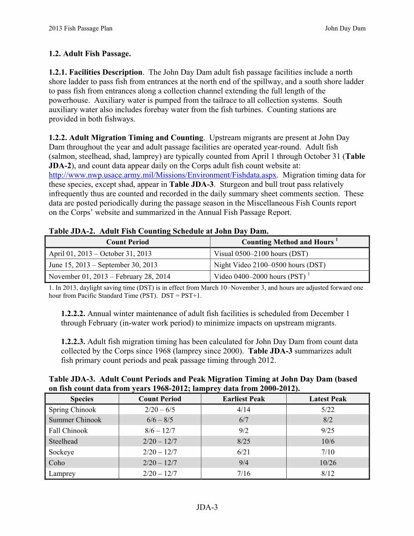
2013 Fish Passage Plan John Day Dam
JDA-3
1.2. Adult Fish Passage. 1.2.1. Facilities Description. The John Day Dam adult fish passage facilities include a north shore ladder to pass fish from entrances at the north end of the spillway, and a south shore ladder to pass fish from entrances along a collection channel extending the full length of the powerhouse. Auxiliary water is pumped from the tailrace to all collection systems. South auxiliary water also includes forebay water from the fish turbines. Counting stations are provided in both fishways. 1.2.2. Adult Migration Timing and Counting. Upstream migrants are present at John Day Dam throughout the year and adult passage facilities are operated year-round. Adult fish (salmon, steelhead, shad, lamprey) are typically counted from April 1 through October 31 (Table JDA-2), and count data appear daily on the Corps adult fish count website at: http://www.nwp.usace.army.mil/Missions/Environment/Fishdata.aspx. Migration timing data for these species, except shad, appear in Table JDA-3. Sturgeon and bull trout pass relatively infrequently thus are counted and recorded in the daily summary sheet comments section. These data are posted periodically during the passage season in the Miscellaneous Fish Counts report on the Corps’ website and summarized in the Annual Fish Passage Report. Table JDA-2. Adult Fish Counting Schedule at John Day Dam.
Count Period Counting Method and Hours 1 April 01, 2013 – October 31, 2013 Visual 0500–2100 hours (DST) June 15, 2013 – September 30, 2013 Night Video 2100–0500 hours (DST) November 01, 2013 – February 28, 2014 Video 0400–2000 hours (PST) 1 1. In 2013, daylight saving time (DST) is in effect from March 10–November 3, and hours are adjusted forward one hour from Pacific Standard Time (PST). DST = PST+1.
1.2.2.2. Annual winter maintenance of adult fish facilities is scheduled from December 1 through February (in-water work period) to minimize impacts on upstream migrants. 1.2.2.3. Adult fish migration timing has been calculated for John Day Dam from count data collected by the Corps since 1968 (lamprey since 2000). Table JDA-3 summarizes adult fish primary count periods and peak passage timing through 2012.
Table JDA-3. Adult Count Periods and Peak Migration Timing at John Day Dam (based on fish count data from years 1968-2012; lamprey data from 2000-2012).
Species Count Period Earliest Peak Latest Peak Spring Chinook 2/20 – 6/5 4/14 5/22 Summer Chinook 6/6 – 8/5 6/7 8/2 Fall Chinook 8/6 – 12/7 9/2 9/25 Steelhead 2/20 – 12/7 8/25 10/6 Sockeye 2/20 – 12/7 6/21 7/10 Coho 2/20 – 12/7 9/4 10/26 Lamprey 2/20 – 12/7 7/16 8/12

Oregon
15 12 9 6 3 2 120 16 14 13 11 10 8 7 5 4
South Ladder Exit
Transport Flume
Gatewell Slots(3 pairs / turbine unit) Transformers
North Collection System Entrances(NE2, NE1)
Downstream Migrant (DSM)Transportation Channel
DSM Conduit Well
Tainter Gate
Hydraulic Weir Gates
South Fish Ladder Entrance(SE1)
Flow
Figure JDA-1 John Day South Fish Ladder, Powerhouse Collection System, and Juvenile Fish Bypass System.
Powerhouse
SouthFish Ladder
Adult Collection Channel
South Ladder Fish Pumps
Fish Pump Intake Basin
Outfall Chute
Turbine Unit BayThree Slots per Turbine
Shaded Areas = Floating Orifices Gates(1, 2, 18, 19)
FloatingOrifice Gates
ClosedOpen
South Counting Station
Picket Lead
Diffuser
NavigationLock
Powerhouse
Spillway
OR
WA
NorthFish Ladder
SouthFish Ladder
Juvenile BypassOutfall
John Day Dam
Dewatering Structure
Elevated Chute
Sampling & Monitoring Facility
Bypass Flume
DebrisSeperator
DewateringUnits Pit Tag
Detectors
HoldingTanksSorting
TanksRecoveryTanks
Sampling & Monitoring Facility
Crest Gate
19 18 17
Skeleton Bays
SynchronousCondensing Units
G0PDWLSW
Text Box
G0PDWLSW
Text Box
G0PDWLSW
Text Box
JDA-4
G0PDWLSW
Text Box
Figure JDA-1. John Day Dam South Fish Ladder, Powerhouse Collection System, and Juvenile Fish Bypass System.
G0PDWLSW
Text Box
Smolt Monitoring Facility (SMF)
G0PDWLSW
Text Box
Picket Leads
G0PDWLSW
Text Box
Smolt Monitoring Facility (SMF)
G0PDWLSW
Text Box
2013 Fish Passage Plan John Day Dam

North Counting Station
Picket Lead and Diffuser
Spillway Dam
PH
Fish Ladder Exit
Fishladder Auxiliary Water Intakeand Trashracks
North Fish Pumps (6)
NavigationLock
Fish ladder Netting
Fish ladder Netting
NorthFish Ladder
1 2 3 4 5 6 7 8 9 10 11 12 13 14 15 16 17 18 19 20
20 19 18
Auxiliary Water Conduit toFish Ladder Diffusers
Fi
Figure JDA-2 John Day Dam Spillway and North Fish Ladder.
NavigationLock
Powerhouse
Spillway
OR
WA
NorthFish Ladder
SouthFish Ladder
North Fish Ladder Entrances (EW-1, EW-2)
Juvenile BypassOutfall
North Collection System Entrances (NE-2, NE-3)
Flow
John Day Dam
MU MU MUSpill Deflectors on 2-19
Spillway Weirs
Regulating Sills
G0PDWLSW
Text Box
2013 Fish Passage Plan John Day Dam
G0PDWLSW
Text Box
JDA-5
G0PDWLSW
Text Box
G0PDWLSW
Text Box
Figure JDA-2. John Day Dam Spillway and North Fish Ladder.
G0PDWLSW
Text Box
Bays 18-19
G0PDWLSW
Line
G0PDWLSW
Line
G0PDWLSW
Text Box
Fixed weir
G0PDWLSW
Text Box
North Fish Ladder Entrance
G0PDWLSW
Text Box
NE-1, NE-2
G0PDWLSW
Text Box

Task Name Start Finish Reference
2013 FISH PASSAGE SEASON 3/1/13 11/30/13 JDA 2Juvenile Fish Passage Season 4/1/13 11/30/13 JDA 2.4.1.2Adult Fish Passage Season 3/1/13 11/30/13 JDA 2.5.1.2
2013-2014 WINTER MAINTENANCE PERIOD 12/1/13 3/31/14 JDA 2Juvenile Fish Facilities Winter Maintenance 12/1/13 3/31/14 JDA 2.4.1.1Adult Fish Facilities Winter Maintenance 12/1/13 2/28/14 JDA 2.5.1.1
ADULT FISH COUNTING 4/1/13 2/28/14 Table JDA-2Visual 0500 - 2100 DST 4/1/13 10/31/13Video Night 2100 - 0500 DST 6/15/13 9/30/13Video 0400 - 2000 PST 11/1/13 2/28/14
1% CONSTRAINTS (YEAR-ROUND) 3/1/13 2/28/14 JDA 5.11% soft constraint 3/1/13 3/31/131% hard constraint 4/1/13 10/31/131% soft constraint 11/1/13 2/28/14
TDG MONITORING (YEAR-ROUND) 3/1/13 2/28/14 JDA 2.3TDG Monitoring - Tailrace 3/1/13 2/28/14 JHAWTDG Monitoring - Forebay 4/1/13 8/31/13 JDY
SPECIAL OPERATIONS & STUDIES 3/1/13 10/31/13 Appendix AAdult Lamprey Studies 3/1/13 10/31/13 App A JDA 2.1Adult Salmon Studies 3/20/13 10/31/13 App A JDA 2.2
AVIAN ABATEMENT MEASURES 4/1/13 12/1/13 JDA 2.4.1.1.jAvian Predator Control Lines 4/1/13 12/1/13Avian Hazing 4/15/13 7/31/13
SPILL FOR FISH PASSAGE 4/10/13 8/31/13 Appendix ESpring Spill - 30% 4/10/13 4/26/13 end date approximateSpring Spill - alternate 2-day blocks of 30% vs. 40% 4/27/13 6/30/13 dates approximateSummer Spill - alternate 2-day blocks of 30% vs. 40% 7/1/13 7/19/13 dates approximateSummer Spill - 30% 7/20/13 8/31/13 start date approximate
Operation of Juvenile Bypass System; STSs installed 4/1/13 12/15/13 JDA 2.4.1.2; 2.4.1.3.a
Monthly trash rack raking 4/1/13 8/1/13 JDA 2.4.1.2.b
Spill through Bay 2 9/1/13 11/30/13 JDA 2.2
Weekly Reports (year-round) 3/1/13 2/28/14 JDA 3.3.1
Annual Report (for Dec 1, 2012 - Nov 30, 2013) 1/31/14 1/31/14 JDA 3.3.4
Jan Feb Mar Apr May Jun Jul Aug Sep Oct Nov Dec Jan Feb Mar1st Quarter 2nd Quarter 3rd Quarter 4th Quarter 1st Quarter
2013 2014
Table JDA-3. John Day Dam Dates of Fish-Related Operations for 2013 Fish Passage Season and 2013/14 Winter Maintenance Period.
JDA-6

2013 Fish Passage Plan John Day Dam
JDA-7
2. PROJECT OPERATIONS 2.1. General. 2.1.1. Research, non-routine maintenance, other fish related activities, and construction activities will not be conducted within 100' of any fishway entrance or exit, within 50' of any other part of the adult fishway, or directly in, above, or adjacent to any fishway, unless coordinated by the project, Portland District Operations and/or Planning, or CENWP Construction office through FPOM or FFDRWG. Currently coordinated special operations related to research are described in Appendix A. Alternate actions will be considered by district and project biologists in conjunction with the Regional fish agencies on a case by case basis. Emergency situations should be dealt with immediately by the project in coordination with the project or district biologist. If unavailable, the biologists will be informed of steps taken to correct the situation immediately following the incident. All activities within boat restricted zone (BRZ) will be coordinated at least two weeks in advance with the project, unless it is deemed an emergency (see also Overview for coordination guidance). 2.2. Spill Management. See the Fish Operations Plan (Appendix E) for more information. Spill patterns formulated with spillway deflectors in place are provided in Table JDA-9. These will be used for both adult and juvenile patterns. Minimum spill of 25% is to provide adequate tailrace egress for juvenile salmonids. Spill from Bay 2 (1 stop=1.6K) is provided for adult attraction during daylight hours from September 1–November 30. Provisions are in place for deviations from normal spill patterns for barge traffic entering the navigation lock and have been coordinated with the fish agencies and tribes through the proper fish regulatory forums (e.g., TMT, FPOM, FFDRWG). Minimum spill rate is 30% from April 10–August 31. 2.3. Total Dissolved Gas (TDG) Management and Control. Total dissolved gas (TDG) levels at all projects are monitored in accordance with the TDG Monitoring Plan, included in the Water Management Plan as Appendix 4, and available online at: http://www.nwd-wc.usace.army.mil/tmt/documents/wmp/2013/. 2.3.1. Excessive total TDG levels, which may harm fish, will be controlled to the extent possible, subject to river flow conditions. Control measures will include system spill allocations through the spill priority list issued by Reservoir Control Center (RCC), nighttime or daytime spill limits, and shaping of spill discharge. 2.4. Juvenile Fish Passage Facilities. 2.4.1. Operating Criteria.
2.4.1.1. December 1 through March 31 (Winter Maintenance Period).
a. Remove debris from forebay, all trash racks, and gatewell slots, so these areas are debris-free by April 1.

2013 Fish Passage Plan John Day Dam
JDA-8
b. Inspect all VBSs for damage, holes, debris accumulations, or protrusions (video inspection acceptable). Clean and repair when necessary.
c. Inspect and operate each STS. d. By April 1, place STSs in each intake slot of all operational units unless otherwise coordinated with the fish agencies and tribes.
e. Inspect and, where necessary, clean and/or repair all gatewell orifices and orifice lighting systems, such that these systems are debris-free and operable on April 1.
f. Check automatic control calibration/operation for the DSM tainter gate and other necessary sensors weekly and recalibrate as necessary. Report summaries of equipment recalibration in the weekly SMF operation monitoring reports.
g. Inspect, maintain and, where necessary, repair the DSM conduit tainter gate.
h. Inspect and, where necessary, correct any deficiencies of walls and floor of DSM conduit, raceway, and outfall.
i. Inspect and, where necessary, repair spill gates and the associated control system. Spillways, except for coordinated exceptions, must be able to achieve standard spill patterns on April 1.
j. Avian Abatement Measures. Avian abatement measures shall be in place by April 1. Repair avian predator control lines as soon as possible following damage or removal. Install and maintain new avian predator control lines in locations determined to be significantly impacted by avian predators. Avian hazing will occur mid-April – July 31. However, there will be no avian abatement measures, other than avian lines, performed from August through mid-April each year.
k. Smolt Monitoring Facility (SMF): Insure all following items are fully operational:
1. Dewatering facilities, including weir gates, clean perforated plates, the screens (free of holes or gaps), and the screen cleaner brush system; 2. All valves and auxiliary water systems; 3. Flushing water valves and their perforated plates; 4. All gates, including the crest, tainter, switch, and rotating gates; 5. Fish and debris separator, including perforated plates and adult passage chamber; 6. PIT-tag detectors;

2013 Fish Passage Plan John Day Dam
JDA-9
7. All sampling building systems, including holding tanks, valves, and conduits. (Note: A specific list can be found in the SMF Operation and Maintenance Manual.)
2.4.1.2. April 1 through November 30 (Juvenile Fish Passage Season). Juvenile fish protection devices, submersible traveling screens (STSs), will be in place prior to the beginning of the juvenile fish passage season. STSs will remain in operation through December 15 to prevent adult salmonids from falling back through turbine units, even though the juvenile passage season officially ends November 30.
a. Measure gatewell drawdown across the trashrack a minimum of once per week. Remove debris from forebay and trash racks as required to maintain gatewell drawdown less than 1.5'. If VBS drawdown reaches 1.2’, the Project will inspect the screen and prepare to clean as necessary.
b. From April 1 through August 1, units 1–5 will be raked monthly, and units 6–10 or units 11–16 will be alternately raked monthly. After August 1, units will be raked as necessary as determined by ROV inspection, or as needed to maintain gatewell drawdown in criteria. c. Debris accumulations in the forebay of 300' or more in any direction from the face of the dam will be removed within 48 hours. Debris removal efforts should continue until the debris load has been removed.
d. If debris loads are obvious in the forebay, trash will be raked in front of the affected units weekly until the debris load has been removed.
e. Additional raking will occur whenever trash accumulations are suspected because of increased differential (≥1.5') across the trash racks, or as determined by the project biologist in reference to indicators such as increased juvenile fish descaling at the dam, deteriorating fish condition as noted by SMF personnel, or increased accumulation of tumbleweeds in the forebay. Gatewell orifices of the unit being raked must be closed during the raking operation.
f. Inspect each STS, VBS, and orifices once per month or every 720 hours run time. Video inspections are acceptable. More frequent inspections may be required under the following conditions: deterioration of fish condition, increased debris load in bypass system, or other indications of STS or VBS malfunction or failure. If STS or VBS damage or plugging is detected, follow procedures in Section 3. Fish Facilities Maintenance. Records of inspections will be reported in weekly fishway status reports and provided to FPOM. Unit 2 will operate when unit 1 is out of service for STS inspections.
g. Open all gatewell orifices April 1–December 15. Inspect orifice lights daily to ensure orifice lights are operating. Replace all burned out orifice lights within 24 hours. Close and open each orifice three times daily, or more frequently as determined by the project

2013 Fish Passage Plan John Day Dam
JDA-10
biologist, due to heavy debris accumulation in gatewells. If a unit goes out of service, orifices are to remain open in associated gatewells unless that gatewell is dewatered.
h. Observe each STS amp and/or watt meter readings at least once per shift. If an STS failure occurs, then follow procedures in Section 3. Fish Facilities Maintenance.
i. Inspect all STS gatewells daily. The project will clean gatewells before the gatewell water surface becomes 50% covered with debris. If due to the volume of debris it is not possible to keep the gatewell surfaces at least 50% clear, they will be cleaned at least once daily. Turbines with a gatewell fully covered with debris will not be operated except to be in compliance with other coordinated fish measures, and then only on a last-on/first-off basis. The powerhouse gatewell orifices will be closed during cleaning. After gatewell de-barking, cycle the orifice in that gatewell. Check gatewell drawdown.
j. Efforts should be made to keep all petroleum out of gatewells. Project environmental section will determine cleanup efforts if needed. Regardless of unit operating status, oil accumulations will be dealt with promptly.
k. When using a dip basket for gatewell cleaning, coordinate with SMF personnel.
l. Reinstall or repair avian predator control lines as soon as possible following damage or removal. Install and maintain new avian predator control lines in locations determined to be significantly impacted by avian predators. Implement other avian abatement (hazing) as necessary from April through August only.
m. Turbine units without a full complement of rotating STSs will not operate, except to be in compliance with other coordinated fish measures. n. Maintain water level in the bypass conduit between 4.0’–5.0’, as measured at Unit 16.
o. Smolt Monitoring Facility (SMF). Ensure the proper function of sampling systems. Direct particular attention to the following:
1. Dewatering facilities, including the screens being free of holes or gaps, and the screen cleaner brush system; 2. All valves and auxiliary water systems; 3. Flushing water valves and their perforated plates; 4. All gates, including the crest, tainter, switch, and rotating gates; 5. Fish and debris separator, including perforated plates and adult passage chamber; 6. PIT-tag detectors;

2013 Fish Passage Plan John Day Dam
JDA-11
7. All sampling building systems, including holding tanks, valves, and conduits; 8. From April 1–September 15, the SMF will be monitored 24 hours per day, 7 days per week by the project fish personnel to ensure proper functioning and to provide quick response to an emergency. Inspect every 2 hours. Therefore, the system will be fully staffed while the SMF is in operation (i.e., crest gate is deployed and the secondary dewatering structure is receiving fish-laden flow). 9. Cycle the Primary Dewatering Screen (PDS) sweepers twice per shift (6 per day) during low to normal debris loads. If debris loads increase, increase frequency of screen sweeper cycling as determined by the project biologist through inspections. 10. A person on duty will perform a walking inspection of the entire SMF system every two hours to ensure safe passage conditions. 11. Particular attention will be paid to the fish/debris separator (FDS) that needs to be visually inspected every 30 minutes to prevent injury and/or mortality to passing fish. 12. During any high debris loading periods (likely during spring runoff) additional personnel may be required to keep the FDS free of any obstruction to fish passage. The project biologist will decide to assign a person to remove debris from the FDS on a shift basis (possible constant, 24 hours/day presence) for as long as it is necessary to assure the safety of passing fish. 13. For adult fish removal from the PDS area when river temperatures reach 70°F or greater, all fish handling will be coordinated through FPOM.
2.4.1.3. December 1 through March 31 (Winter Maintenance Period).
a. Screens (STS, ESBS) will remain in place through December 15 to prevent adult salmonids from falling back through turbine units, thereby shortening some aspects of the winter maintenance period by two weeks. To reduce adult fallback mortality, the juvenile bypass system (JBS) channel will operate from November 30 through December 15. Priority units will be left screened during this period to the extent practicable (barring operational failure), and screens from non-priority units will only be removed when necessary to begin maintenance. After December 15, all STSs may be removed.
b. Dewater DSM channel only when required for inspection, maintenance, or structural modifications (see section 5. Dewatering Plans; also, paragraph 3.2.1.2. Juvenile Bypass System). The outage period will be minimized to the extent practicable.
c. All units are available to meet power demands.
G0PDWLSW
Cross-Out

2013 Fish Passage Plan John Day Dam
JDA-12
2.5. Adult Fish Passage Facilities. 2.5.1. Operating Criteria.
2.5.1.1. December 1 through February (Winter Maintenance Period).
a. Inspect and calibrate all staff gages, water level sensors, and indicators. Repair and/or clean where necessary. b. Dewater and inspect repair as needed all ladders and all other dewatered sections of fish facilities for projections, debris, or plugged orifices which could injure fish, or slow their progress up the ladder.
c. Inspect for and, when necessary, clear debris in ladder exits.
d. Reinstall picket leads at counting stations prior to watering up ladders during maintenance.
e. Repair or, when necessary, upgrade netting and padding at top of north fish ladders to address the fish jumping problem in this area.
f. Outage periods will be minimized to the extent practicable. Only one ladder may be out of service or operating out of standard operating criteria at any one time, unless specifically coordinated.
2.5.1.2. March 1 through November 30 (Adult Fish Passage Season).
a. All Adult Facilities.
1. Water depth over fish ladder weirs: 1.0' ±0.1'. When shad numbers exceed 5,000 per day per count station at Bonneville Dam, water depth should be increased to 1.3' ±0.1'. 2. Measure water temperatures at the count stations of each ladder and include the weekly means in the status report. When water temperature reaches 70°F all fish handling activities will be coordinated with the Regional fish agencies through FPOM prior to any action to verify protocols that will be followed. 3. Head on all entrances: 1'–2' (1.5' optimum). Refer to paragraph 3.3.1 when unable to achieve head criteria. 4. Maintain water velocity at 1.5–4.0 feet per second (2 fps optimum) in all channels and the lower ends of fish ladders that are below the tailwater. Open floating orifice gates 1, 2, 18 and 19, and operate three fish pumps to maintain fishway criteria. The entrance gate should be submerged 8’ deep or greater to be in criteria. Fishway channel water velocities will be measured a minimum of three times weekly (daily

2013 Fish Passage Plan John Day Dam
JDA-13
preferred) during adult fish passage season (Mar 1 – Dec 1) as part of the fishway inspection program. Floats will be timed through all fishway channels that are supplemented by auxiliary water, and results reported in the project weekly fishway status report. 5. Maximum head of 0.5' on attraction water intakes and trash racks at all the ladder exits, with a 0.3' maximum head on all picket leads. Debris shall be removed when significant amounts accumulate. 6. Staff gages and water level indicators will be readable at all water levels encountered during the fish passage period, and calibration checked weekly. Instruments will be cleaned and/or recalibrated when necessary as soon as practicable. 7. Main entrance weir depths: 8' or greater below tailwater. Maintain tailwater elevation above 158’msl to stay within criteria operation range for entrance weirs. 8. The current fish counting program is conducted 16 hours per day from April through October (see Table JDA-3). The crowder shall be opened to full count slot width when not counting. The crowder shall be open as far as possible to allow accurate counting and shall not be closed to less than 18 inches while counting. This will usually occur during high turbidity conditions to maintain count accuracy.
A. Count station crowders shall be at maximum width that allows count or video tape accuracy. The minimum count slot width shall be no less than 18”. Crowder ranges are as follows:
• JDA-North = 18”–28” • JDA-South = 18”–30”
B. . If passage is impaired by narrow count slot conditions, the count slot will be widened until proper passage conditions are achieved, despite count accuracy. C. Project biologists, FFU, and the fish count supervisor shall coordinate to achieve optimum count slot passage and/or count accuracy conditions. D. If counting is temporarily discontinued due to unscheduled events, the crowder shall be fully opened. E. The crowder may remain in operating position during the counters’ hourly ten-minute break period.
b. North Fishway.
1. Operate one entrance weir (EW-1) at 8’ or greater depth. Entrance head: 1’–2’ (1.5’ optimum).

2013 Fish Passage Plan John Day Dam
JDA-14
2. Starting September 1, spill from Bay 2 (1 stop = 1.5K) for adult attraction during daylight hours through November. 3. Maintain netting and padding for the North fishway to address the adult salmonid jumping problem. All holes in the netting large enough to catch or allow escapement of an adult salmonid must be closed.
c. South Fishway. Operate entrance weir SE-1. d. Powerhouse.
1. Operate entrances NE-1 and NE-2. 2. Operate four powerhouse floating orifices (1, 2, 18, 19) and open associated auxiliary water diffusers (see also 2.5.1.2.a.4.). 3. From 0400–2000 hours, operate unit 1 near 100 megawatts (±10 MW) to facilitate best entrance conditions. If additional load is required by BPA, unit 1 may be operated at above 100MW, but it should be the last to be brought up to full load when demand increases and the first to drop off when demand decreases. (See also Load Shaping Guidelines, Appendix C).
2.5.1.3. December 16 through February (Winter Maintenance Period).
a. Operate according to fish passage season standards, except facilities may be dewatered or operated out of criteria for maintenance or repair. Outage periods will be minimized to the extent practicable. b. Only one of the two adult fish passage facilities may be out of service at a time. The other facility must be operated at full passage season criteria unless specially coordinated with the Regional fish agencies through FPOM. However, operation of unit 2 may be substituted for unit 1 without special coordination when the south fishway is in service. c. Pull picket leads at counting stations and have crowders adjusted such that the counting slots are fully opened at the end of the counting season (this will be done shortly after adult fish counting ends). d. Maximum head of 0.5' on attraction water intakes and trash racks at all ladder exits. Debris shall be removed when significant amounts accumulate.

2013 Fish Passage Plan John Day Dam
JDA-15
3. FACILITY MONITORING AND REPORTING 3.1. Inspections. 3.1.1. The results of all inspections and the readiness of the facilities for operation will be reported to the FPOM at the meeting immediately prior to the fish passage season. 3.1.2. During fish passage season, fish passage facilities will be inspected at least twice per day/seven days a week to assure operation according to established criteria. 3.1.3. During winter maintenance season, fish passage facilities will be inspected once per day/at seven days a week. 3.1.4. More frequent inspections of some facility components will occur as described throughout this document. 3.1.5 Additional fishway inspections may be performed by FFU and fish agencies. 3.2. Zebra Mussel Monitoring. A zebra mussel monitoring program will continue. These organisms are a serious problem elsewhere in the country and may become introduced into the Columbia River basin. Inspections should also be made when dewatering all project facilities. 3.3. Reporting. 3.3.1. Project biologists shall prepare weekly reports throughout the year summarizing project operations. The weekly reports will provide an overview of how the project and the fish passage facilities operated during the week and an evaluation of resulting fish passage conditions. The reports shall include:
a. Any out-of-criteria situations observed and subsequent corrective actions taken; b. Any equipment malfunctions, breakdowns, or damage along with a summary of resulting repair activities; c. Adult fishway control calibrations; d. STS and VBS inspections; e. AWS closures (i.e. cleaning times); f. Any unusual activities which occurred at the project which may affect fish passage.
3.3.2. Weekly reports shall cover Sunday–Saturday period and shall be e-mailed to CENWP-OD, CENWD-PDW-RCC, and other interested parties as soon as possible the following week. 3.3.3. The project biologists shall prepare a memo for the record for any negative impact to fish or fishways. This memo will be sent to FPOM by the next working day. Items that shall be included in the memo are:
a. Time and date; b. Nature of activity that lead to fish impact; c. Agency responsible for the impact or the reporter if no responsible party can be identified; d. Fish numbers, species, origin, discernible external injuries, tags, etc;

2013 Fish Passage Plan John Day Dam
JDA-16
e. Future actions to avoid a similar impact; f. Any relevant photos.
3.3.4. The project biologists shall prepare an annual report by January 31, summarizing the operation of the project fish passage facilities for the previous year.
3.3.4.1. The report will cover from the beginning of one adult fish facility winter maintenance period to the beginning of the next. 3.3.4.2. The annual report also will include a description of all actions taken to discourage avian predation at the project, with an overview of the effectiveness of the activities in discouraging avian predation. 3.3.4.3. The annual report will be provided to CENWP-OD in time for distribution to FPOM members at the February meeting.
4. FISH FACILITIES MAINTENANCE 4.1. General. 4.1.1. Routine Maintenance. Scheduled fishway maintenance, to the extent practicable, will be conducted during periods when passage has been documented to be at its lowest to minimize impacts to migrating salmonids. Maintenance activities that occur during the fish passage period, and that may affect fish passage, will be reported in the weekly reports (section 3.3).
4.1.1.1. Staff gages will be installed, cleaned, and/or repaired as required. 4.2. Juvenile Fish Passage Facilities. 4.2.1. Routine Maintenance.
4.2.1.1. Submersible Traveling Screens (STS). The STS system may receive preventive maintenance or repair any time of the year as necessary. Most maintenance will occur during the winter maintenance period when all STSs may be removed from intakes. From April 1–December 15, a turbine unit cannot operate without a full complement of functioning STSs. 4.2.1.2. Juvenile Bypass System (JBS). The JBS facilities may receive preventive maintenance at any time of the year as necessary in coordination with FPOM. During the juvenile fish passage season, this will normally be out-of-water work (e.g., maintenance of automatic systems, air lines, electrical systems, and monitoring equipment). During the winter maintenance period, the system is dewatered and visually inspected in all accessible areas for damaged equipment and areas that may cause potential problems to juvenile fish. Identified problems will be repaired by project maintenance or the contractor as soon as possible. Extended repair projects will be coordinated through FPOM.

2013 Fish Passage Plan John Day Dam
JDA-17
4.2.1.3. Turbines and Spillway. Maintenance and routine repair of project turbines and spillways is a regular and recurring process which requires that units be shut down for extended periods of time (see section 5. Dewatering Plans). Maintenance schedules for these turbines and spillways will be coordinated through FPOM. Certain turbine and spillway discharges at the projects are secondarily used to attract adult fish near fishway entrances to keep predator fish from accumulating in the area of juvenile release sites and to move juveniles downstream away from the project. The maintenance schedules for these turbines and spillways will reflect equal weight given to fish, power, and water management and will be coordinated with the appropriate fish agencies. Units that should not be scheduled for maintenance during the fish passage season are 1, 2, and 5. Some types of turbine maintenance will require testing turbine operation throughout the full operating range before returning it to normal service.
4.2.2. Non-Routine Maintenance. Non-routine maintenance of facilities will be carried out as described below. Activities that will have a significant impact on juvenile fish passage shall be coordinated through FPOM on a case-by-case basis by project and CENWP-OD biologists. The CENWP-OD biologists will be notified as soon as possible after it becomes apparent that maintenance repairs are required. The Project Operations Manager has the authority to initiate work prior to notifying CENWP-OD when delay of the work will result in an unsafe situation for people, property, or fish. Information required by CENWP-OD includes (see also Overview for the coordination form):
a. Description of the problem. b. Type of outage required. c. Impact on facility operation. d. Length of time for repairs. e. Expected impacts on fish passage.
4.2.2.1. Submersible Traveling Screens (STS). If an STS or VBS is damaged or inoperative in an operating unit, the unit will be regarded as an unscreened unit. The screen will be repaired or replaced before returning the unit to service. 4.2.2.2. Juvenile Bypass System (JBS).
a. The JBS is automatically controlled. If the automatic system fails, it will be operated manually until automation repairs are made. If the orifices become plugged with debris, the turbine will not be operated until it has been cleaned. b. Inspect all STS gatewells daily. The project will clean gatewells before the water surface becomes 50% covered with debris. If due to the volume of debris it is not possible to keep the gatewell surfaces at least 50% clear, they will be cleaned at least daily. Turbines with a gatewell fully covered with debris will not be operated except on a last-on/first-off basis if required to be in compliance with other coordinated fish measures. The gatewell orifices must be closed during the cleaning process. Juvenile mortality numbers will be monitored in all gatewells, as potential indicators of gatewell environment problems. Mortality estimates will be recorded and reported in the weekly status reports.

2013 Fish Passage Plan John Day Dam
JDA-18
c. If the bypass system fails in the powerhouse conduit, tainter gate, or transportation outfall making the system unsafe for fish, an action decision will be made in coordination with the FPOM. During this emergency operating mode, power generation will be minimized to the extent practicable. If this operating mode is expected to last longer than four days, then all units required for generation will be sequentially shut down, fish salvaged from the gatewells, the STSs removed, and the unit restarted. The orifice gates will be closed during this process. d. During fishway inspection activities, VBSs may be found plugged with debris, damaged or not properly seated. In these cases, the associated unit will be regarded as if unscreened and repairs will be made before returning the unit to operation.
4.2.2.3. Turbines and Spillways.
a. If a spill gate becomes inoperable, the operators will make the changes necessary to accommodate the spill and then immediately notify the operations supervisor and project biologist to determine the best pattern to follow until repairs can be made. This interim operation shall be coordinated with the FPOM through the district biologist who will provide additional guidance to the project.
b. Unit 2 will replace unit 1 for adult attraction whenever unit 1 is not operating.
c. From September 15 through the end of February, spillbay gate 2 may be closed for up to one work day for maintenance activities. During the outage, spill gate 3 will be opened to provide attraction flow.
4.3. Adult Passage Facilities. 4.3.1. Routine Maintenance. Maintenance activities that occur during the fish passage period and that may affect fish passage will be reported in the weekly reports (section 3.0).
4.3.1.1. Fishway Auxiliary Water Systems. John Day Dam has tailwater pump auxiliary water systems. Preventive maintenance and normal repair are carried out throughout the year. Trash racks for the AWS intakes will be raked when drawdown exceeds criteria. When practicable, rake trash racks during the time of day when fish passage is least affected. During the annual navigation lock maintenance outage, the north fish ladder auxiliary water is shut off for about half a day. This is required to allow divers to clean off the navigation lock discharge sill so that a bulkhead can be placed. 4.3.1.2. Powerhouse and Spillway Fish Collection Systems. Preventive maintenance and repair occurs throughout the year as needed. During the adult fish passage season, this maintenance will not involve operation that will cause failure to comply with the adult fishway criteria, unless coordinated through FPOM. During the winter maintenance period, an inspection will occur through dewatering or divers per discretion of the project biologists. One additional underwater diver/ROV will occur during August 1 - 15. Timing of this

2013 Fish Passage Plan John Day Dam
JDA-19
inspection will be coordinated through FPOM. The project biologist or alternate Corps fish personnel will attend all dewatering and inspection activities potentially involving fish (section 5. Dewatering Plans). 4.3.1.3. Adult Fish Ladders and Counting Stations. Adult fish ladders will be dewatered once per year during the winter maintenance period. Unless specially coordinated, only one ladder will be dewatered at a time with the other ladder operating within criteria. During this time, the ladders are inspected for necessary maintenance needs and potential fish passage problems (e.g., blocked orifices, projections into the fishway that may injure fish, unstable weirs, damaged picket leads, exit gate problems, loose diffuser gratings, unreadable or damaged staff gauges, defective diffuser valves, and malfunctioning equipment at the counting stations). Potential problems identified throughout the passage year that do not impact fish passage, as well as those identified during the dewatered period, are then repaired. Trash racks at ladder exits will be raked when criteria are exceeded. When practicable, rake trash racks during the time of day when fish passage would be least impacted. Fish count station windows, light panels, and crowder panels will be cleaned as needed to achieve accurate counts and, when practicable, during the time of day when fish passage is least impacted. North netting installed on ladders to prevent fish leaping will be inspected daily and maintained as necessary. Inspection summaries will be included in the weekly activity report.
4.3.2. Non-Routine Maintenance. Maintenance activities that occur during the fish passage period and that may affect fish passage will be reported in the weekly reports (section 3.3.1.). Non-routine maintenance that will significantly affect the operation of a facility, such as repair of displaced diffuser gratings, will be coordinated through FPOM. Coordination procedures for non-routine maintenance of adult facilities are the same as for juvenile facilities (section 4.2.2).
4.3.2.1. Fishway Auxiliary Water Systems. The fishway auxiliary water systems are mostly automated. If the automatic system fails, the system will be operated manually by project personnel. This will allow the fish facility to operate according to criteria while the automatic system is repaired. When this operation becomes necessary, project personnel will increase the surveillance of the adult system to ensure that criteria are being met. The FPOM will work with the project to determine the best operation in the event of an AWS failure during the adult passage season.
a. South Ladder. If one of the three auxiliary water turbines fails, assuming all three turbines are being used to meet criteria, the output of the two remaining turbines will be increased to meet adult fishway criteria. If a second turbine unit fails, the adult fish facility will be operated as follows until a fishway head of 1' is achieved:
1. Increase discharge of the remaining unit to maximum capacity; 2. Close NE-1; 3. Leave NE-2 at a depth of 8’;
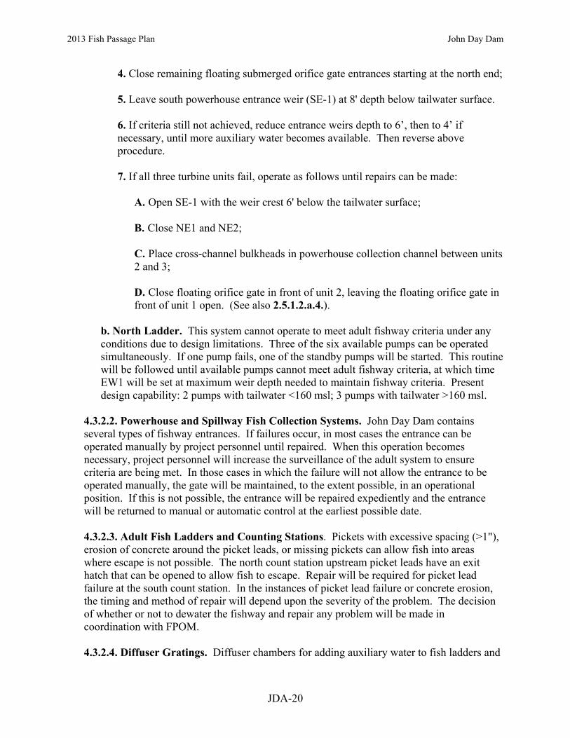
2013 Fish Passage Plan John Day Dam
JDA-20
4. Close remaining floating submerged orifice gate entrances starting at the north end; 5. Leave south powerhouse entrance weir (SE-1) at 8' depth below tailwater surface. 6. If criteria still not achieved, reduce entrance weirs depth to 6’, then to 4’ if necessary, until more auxiliary water becomes available. Then reverse above procedure. 7. If all three turbine units fail, operate as follows until repairs can be made:
A. Open SE-1 with the weir crest 6' below the tailwater surface; B. Close NE1 and NE2; C. Place cross-channel bulkheads in powerhouse collection channel between units 2 and 3; D. Close floating orifice gate in front of unit 2, leaving the floating orifice gate in front of unit 1 open. (See also 2.5.1.2.a.4.).
b. North Ladder. This system cannot operate to meet adult fishway criteria under any conditions due to design limitations. Three of the six available pumps can be operated simultaneously. If one pump fails, one of the standby pumps will be started. This routine will be followed until available pumps cannot meet adult fishway criteria, at which time EW1 will be set at maximum weir depth needed to maintain fishway criteria. Present design capability: 2 pumps with tailwater <160 msl; 3 pumps with tailwater >160 msl.
4.3.2.2. Powerhouse and Spillway Fish Collection Systems. John Day Dam contains several types of fishway entrances. If failures occur, in most cases the entrance can be operated manually by project personnel until repaired. When this operation becomes necessary, project personnel will increase the surveillance of the adult system to ensure criteria are being met. In those cases in which the failure will not allow the entrance to be operated manually, the gate will be maintained, to the extent possible, in an operational position. If this is not possible, the entrance will be repaired expediently and the entrance will be returned to manual or automatic control at the earliest possible date. 4.3.2.3. Adult Fish Ladders and Counting Stations. Pickets with excessive spacing (>1"), erosion of concrete around the picket leads, or missing pickets can allow fish into areas where escape is not possible. The north count station upstream picket leads have an exit hatch that can be opened to allow fish to escape. Repair will be required for picket lead failure at the south count station. In the instances of picket lead failure or concrete erosion, the timing and method of repair will depend upon the severity of the problem. The decision of whether or not to dewater the fishway and repair any problem will be made in coordination with FPOM. 4.3.2.4. Diffuser Gratings. Diffuser chambers for adding auxiliary water to fish ladders and

2013 Fish Passage Plan John Day Dam
JDA-21
collection channels are covered by gratings attached by several different methods. Diffuser gratings are normally inspected during the winter maintenance period to assure integrity. These inspections are done by either dewatering the fishway and/or collection channel, or by using video cameras and divers or other methods to inspect the gratings underwater. Diffuser gratings may come loose during the fish passage season due to a variety of reasons. Daily inspections of the fish ladders and collection systems should include looking for any flow changes that may indicate problems with diffuser gratings. If a diffuser grating is known to or suspected of having moved, creating an opening into a diffuser chamber, efforts must immediately be taken to correct the situation and minimize impacts on adult fish in the fishway. If possible, a video inspection should be made as soon as possible to determine the extent of the problem. If diffusers gratings are found to be missing or displaced, close associated diffuser and develop a method of repair as coordinated with FPOM. Repair as quickly as possible unless coordinated differently.
5. TURBINE UNIT OPERATION AND MAINTENANCE Unit operating priority (Table JDA-5) includes that time when synchronous condensing occurs. Unit maintenance schedules will be reviewed by project and district biologists for fish impacts. Table JDA-5. Turbine Unit Operating Priorities at John Day Dam.
Season TSWs 1 Unit Operating Priority*
Fish Passage Season March 1–November 30 (24 hours/day)
no TSWs 1 1-4 in any order, then 5-16 in any order.
with TSWs 1 5,1,3,16,14,12,10,8,15,2,11,7,4,13,9,6
Winter Maintenance Season December 1–February 28 (24 hours/day) n/a any unit
*When a main unit is not available, the paired “sister unit” will be used to comply with the requested priority. 5.1. Operating points for turbine units within the 1% of peak efficiency range at various heads are shown in Tables JDA-6 and JDA-7. To the extent technically feasible, units will be operated within ±1% of peak efficiency, unless operation outside of that range is necessary to meet BPA load requirements consistent with BPA System Load Shaping Guidelines (Appendix C), or to comply with other coordinated fish measures. The System Load Shaping Guidelines apply from April 1–October 31. During the rest of the year, the project will continue to operate units within the 1% range except as specifically requested by BPA for power production. 5.2. Juvenile fish passage decreases through units from south to north, making inefficient operation of unit 16 least likely to impact fish. Based on this, if it is necessary to select turbines to operate outside the 1% efficiency range, they will be selected in sequence from north to south. However, allowance will also be given to special project requirements for stable voltage control which require load distribution between transformer banks.
1 Temporary spillway weirs (TSWs) are installed at John Day, McNary and Little Goose dams. TSWs are differentiated from Removable Spillway Weirs (RSWs, installed at Lower Granite, Lower Monumental and Ice Harbor dams) by the ability to install, uninstall and move TSWs between spillbays using the project’s gantry crane.
2013 Fish Passage Plan John Day Dam
JDA-22
5.3. Units may be operationally tested for up to 30 minutes before going into maintenance status by running the unit at speed no load and various loads within the 1% criteria to allow pre-maintenance measurements and testing AND TO ALLOW ALL FISH TO MOVE THROUGH THE UNIT. Units may be operationally tested after maintenance or repair while remaining in maintenance or forced outage status. Operational testing may consist of running the unit for up to a cumulative time of 30 minutes (within 1% criteria) before it is returned to operational status. Operational testing OF UNIT UNDER MAINTENANCE is in addition to a unit in run status (E.G. MINIMUM GENERATION) required for power plant reliability. Operational testing may deviate from fish priority units and may require water that would otherwise be used for spill if the running unit for reliability is at its 1% minimum load. Water will be used from the powerhouse allocation if possible, and water diverted from spill for operational testing will be minimized to that necessary to maintain and assure generation system reliability.

2013 Fish Passage Plan John Day Dam
JDA-23
Table JDA-6. Turbine Operating Ranges Within 1% of Peak efficiency at John Day Dam.
Head (feet)
With STSs Installed * With ESBSs Installed ** 1% Lower Limit 1% Upper Limit 1% Lower Limit 1% Upper Limit
(MW) (cfs) (MW) (cfs) (MW) (cfs) (MW) (cfs) 80 65.4 11,338 118.0 20,472 81 66.7 11,416 120.8 20,671 82 68.1 11,492 123.6 20,864 83 69.4 11,566 126.4 21,052 84 70.8 11,638 129.1 21,234 85 72.1 11,707 131.9 21,411 69.6 11,396 111.5 18,269 86 72.9 11,692 134.7 21,593 70.3 11,381 113.7 18,402 87 73.7 11,676 137.5 21,770 71.1 11,366 115.9 18,531 88 74.5 11,661 140.2 21,942 71.9 11,351 118.1 18,657 89 75.3 11,646 143.0 22,110 72.6 11,336 120.3 18,779 90 76.1 11,632 145.8 22,274 73.4 11,322 122.5 18,898 91 77.0 11,622 146.9 22,164 74.3 11,313 122.9 18,717 92 77.9 11,613 148.0 22,057 75.1 11,304 123.2 18,540 93 78.8 11,604 149.1 21,951 76.0 11,295 123.6 18,367 94 79.7 11,595 150.2 21,848 76.9 11,285 123.9 18,197 95 80.6 11,585 151.3 21,746 77.7 11,276 124.3 18,031 96 81.7 11,604 151.6 21,532 78.8 11,294 124.4 17,841 97 82.8 11,623 151.8 21,323 79.8 11,312 124.6 17,654 98 83.8 11,640 152.1 21,118 80.9 11,329 124.7 17,472 99 84.9 11,657 152.4 20,917 81.9 11,346 124.8 17,293
100 86.0 11,674 152.7 20,720 82.9 11,361 125.0 17,117 101 86.9 11,675 154.9 20,800 83.8 11,363 126.6 17,163 102 87.9 11,677 155.2 20,613 84.7 11,364 128.3 17,207 103 88.8 11,678 155.2 20,378 85.6 11,365 129.9 17,250 104 89.7 11,679 155.2 20,149 86.5 11,367 131.6 17,293 105 90.6 11,680 155.2 19,923 87.4 11,367 133.2 17,334 106 91.4 11,658 155.2 19,711 107 92.1 11,637 155.2 19,503 108 92.8 11,615 155.2 19,299 109 93.6 11,594 155.2 19,098 110 94.3 11,574 155.2 18,901
* The turbine efficiency table was revised to reflect information using a 2001 Unit 9 NS index test and a 1962 model test with STS adjustment Factor (Table JDA-6 revised 2005). Table prepared by HDC dated November 2002. **John Day Dam turbine efficiency tables are being revised to reflect new data. This table is based on data from Little Goose Dam (LGS-5).
G0PDWLSW
Cross-Out
G0PDWLSW
Cross-Out
G0PDWLSW
Cross-Out
G0PDWLSW
Cross-Out
G0PDWLSW
Cross-Out
G0PDWLSW
Cross-Out
G0PDWLSW
Cross-Out
G0PDWLSW
Cross-Out
G0PDWLSW
Cross-Out
G0PDWLSW
Cross-Out
G0PDWLSW
Cross-Out
G0PDWLSW
Cross-Out
G0PDWLSW
Cross-Out
G0PDWLSW
Cross-Out
G0PDWLSW
Cross-Out
G0PDWLSW
Cross-Out
G0PDWLSW
Cross-Out
G0PDWLSW
Cross-Out
G0PDWLSW
Cross-Out
G0PDWLSW
Cross-Out
G0PDWLSW
Cross-Out
G0PDWLSW
Cross-Out
G0PDWLSW
Cross-Out
G0PDWLSW
Cross-Out
G0PDWLSW
Cross-Out
G0PDWLSW
Cross-Out
G0PDWLSW
Text Box
Revised 04-11-2013 per change form 13JDA009.

2013 Fish Passage Plan John Day Dam
JDA-24
Table JDA-7. Turbine Operating Ranges Within 1% of Peak Efficiency with No Screens Installed at John Day Dam.
Head (Feet)
1% Lower Limit (No Screens) 1% Upper Limit (No Screens)
(MW) (cfs) (MW) (cfs)
80 71.7 12,305 122.8 21,074 81 73.2 12,391 125.7 21,290 82 74.7 12,473 128.7 21,500 83 76.1 12,554 131.6 21,703 84 77.6 12,631 134.6 21,901 85 79.1 12,707 137.5 22,093 86 80.0 12,690 140.1 22,223 87 80.9 12,674 142.6 22,349 88 81.7 12,657 145.1 22,471 89 82.6 12,641 147.6 22,591 90 83.5 12,625 150.2 22,707 91 84.5 12,616 151.7 22,656 92 85.5 12,606 153.2 22,606 93 86.4 12,596 154.8 22,556 94 87.4 12,586 155.1 22,321 95 88.4 12,576 155.2 22,062 96 89.6 12,597 155.2 21,797 97 90.8 12,617 155.2 21,538 98 92.0 12,636 155.2 21,284 99 93.1 12,655 155.2 21,035
100 94.3 12,673 155.2 20,792 101 95.3 12,675 155.2 20,554 102 96.4 12,676 155.2 20,321 103 97.4 12,678 155.2 20,092 104 98.4 12,679 155.2 19,868 105 99.4 12,680 155.2 19,649 106 100.2 12,656 155.2 19,442 107 101.0 12,633 155.2 19,239 108 101.8 12,610 155.2 19,040 109 102.6 12,587 155.2 18,845 110 103.5 12,565 155.2 18,653
NOTE: The turbine efficiency table was revised to reflect information using a 2001 Unit 9 NS index test and a 1962 model test (Table JDA-8 revised, 2006). Table prepared by HDC dated November 2002.

2013 Fish Passage Plan John Day Dam
JDA-25
6. DEWATERING PLANS Guidelines for dewatering and fish handling plans (Appendix F) have been developed and are followed for dewatering project facilities. Dewatering Plans are available online at: http://www.nwd-wc.usace.army.mil/tmt/documents/FPOM/2010/. These plans include consideration for fish safety and are consistent with the following general guidance. The appropriate plans are reviewed by participants before each salvage operation. The project fish biologist and/or alternate Corps fish personnel will attend all project activities involving fish handling. The fish agencies and tribes will be encouraged to participate in all ladder dewaterings. During the pumping or draining operation to dewater a portion or all, the water level will not be allowed to drop so low it strands fish. Personnel shall remain present onsite during pumping operations to ensure stranding does not occur or a water level sensor that deactivates the dewatering process will be used. 6.1. Adult Fish Ladders. 6.1.1. Routine Maintenance.
6.1.1.1. When possible, operate ladders to be dewatered at orifice flow, with the AWS off, for at least 24 hours, but not more than 96 hours prior to dewatering. 6.1.1.2. The project biologist will ensure that fish rescue equipment is available and will coordinate to provide adequate personnel to move fish out of the dewatered ladder. 6.1.1.3. Project personnel will install head gates to shut down ladder flow. Where possible, a flushing flow of 1”–2" will be maintained in the ladder until fish are rescued. 6.1.1.4. The project biologist or alternate Corps fish personnel will oversee fish rescue when the ladders are dewatered. The project biologist will invite fish agency and/or tribal biologists to participate in the dewatering activities. Captured fish will then be transported to the forebay or tailwater, depending on the fish life stage (adults to forebay, juveniles to tailrace), for release. If a ladder is dewatered in the spring or summer, steelhead kelts should be released into the tailrace. 6.1.1.5. Orifice blocking devices, which are placed in the lower-most weirs to prevent fish from re-ascending the dewatered portion of the adult fishway, shall have ropes attached to them by project operations and be tied off to fishway railings. The blocking devices shall be removed just before the fishway is returned to service. These devices will be noted on the pre-water-up checklist maintained by project fish biologists. This will prevent the orifice blocks from being unintentionally left in place following fishway water-up.
6.2. Non-Routine Maintenance. When possible, discontinue auxiliary water and operate ladder at reduced flow as long as possible for up to 72 hours prior to dewatering. Follow guidance in paragraphs 6.4.1.3.–6.4.1.6.

2013 Fish Passage Plan John Day Dam
JDA-26
6.3. Powerhouse Fish Collection System. 6.3.1. Routine Maintenance. During the pumping or draining operation to dewater a portion or the entire collection channel, the water will not be allowed to drop to a level which strands fish. Personnel shall remain present onsite during pumping operations to ensure that stranding does not occur. The project biologist will assure that all necessary rescue equipment is available. The project biologist or alternate Corps fish personnel will provide technical guidance on fish safety and will assist directly in rescue operations. 6.4. Juvenile Bypass System (JBS). 6.4.1. Routine Maintenance. When draining the juvenile bypass channel, it is typical to flush the channel with only bay 16 bypass orifices open. Bay 16 gatewells will be dipped in advance to minimize the number of fish contained in this flushing water during fish passage season. 6.5. Turbines. 6.5.1. Remove juvenile fish from the gatewell(s) that will be drained. This is done by use of a special dipping basket. Dipping is not required when fish screens have been removed. Immediately before setting the headgates, spin the unit to move fish out of the draft tube. 6.5.2. If the turbine unit draft tube is dewatered, operate unit with full load for a minimum 15 minutes prior to immediately installing tail logs. If not possible to load, run unit at speed-no-load for minimum 15 minutes. Install bottom two tail logs side-by-side first before stacking the remainder to minimize sturgeon from entering the draft tube before dewatering. This is necessary for both scheduled and unscheduled outages. 6.5.3. If a turbine unit is idle and partially dewatered, and tail logs are to be put into place, an adequate safety pool may be maintained for up to 4 days to accommodate fish trapped in the draft tube. If longer timeframes are needed for the safety pool, project fisheries will coordinate with FPOM on a case-by-case basis. Adequate inspections will need to be conducted to ensure that the safety pool is maintained and fish are in good condition. Water levels in the draft tube will not be allowed to drop to a level that strands fish. 6.5.4. Fish rescue personnel will inspect dewatered turbine draft tubes, scroll cases, and intakes as soon as they can gain access and the water levels reach a depth permitting visual inspection. The project biologist or alternative fish personnel will provide technical guidance on fish safety and will directly participate in fish salvage. 6.5.5. The project biologist will assure that all necessary rescue equipment is available.

2013 Fish Passage Plan John Day Dam
JDA-27
7. FOREBAY DEBRIS REMOVAL 7.1. Debris at projects can impact fish passage conditions. It can plug or block trash racks, VBSs, gatewell orifices, dewatering screens, separators, and facility piping resulting in impingement, injuries, and descaling of fish. Removing debris at its source in the forebay is sometimes necessary to maintain safe and efficient fish passage conditions, navigation, and other project activities. In this case, the only viable alternative is to spill to pass the debris. 7.2. Special spill operations that don’t follow the normal spill schedule or volume limits will be coordinated prior to their execution. Normally, the project shall contact CENWP-OD at least two workdays prior to the day the special operation is required. Using information provided by the project, CENWP-OD will coordinate with FPOM and with RCC, as necessary. Once the coordination is complete, RCC will issue a teletype detailing the special operations. 8. RESPONSE TO HAZARDOUS MATERIALS SPILLS John Day Project’s guidance for responding to hazardous substance spills is contained in its Emergency Spill Response Plan. This guidance will be followed in case of a spill. 8.1. Project Fisheries will be contacted as soon as possible after a hazardous material release and prior to any modification to fishway operations. The project biologist will in turn contact the CENWP-OD biologist and FPOM. Attempts should be made to first contact the project biologist on duty. During fish passage season there is a project biologist on duty seven days a week. If a project biologist cannot be reached by radio or in the office, attempts to contact Project Fisheries will occur in the following order: 1. Miro Zyndol - (541) 506-7860 or (541) 980-9958. Home # available in Control Room. 2. Bern Klatte (503) 808-4318 or Tammy Mackey (503) 961-5733. 9. ENDNOTES 9.1. Hydroacoustic Monitoring of Downstream Migrant Juvenile Salmonids at John Day Dam in 1983. R. Magne et. al., US COE research Report. 35 pp. plus appendices.
9.2. Hydroacoustic Monitoring of Downstream Migrant Juvenile Salmonids at John Day Dam 1984-85. R. Magne et. al., US COE Research Report. 29 pp. plus appendices.
9.3. Hydroacoustic Evaluation of Juvenile Salmonid Fish Passage at John Day Dam in Summer 1986. Sue Kuehl, BioSonics, Inc. Final Report. Prepared for US COE under Contract No. DACW57-86-C-0088. 61 pp. plus appendices.
9.4. Hydroacoustic Evaluation of the Spill Program for Fish Passage at John Day Dam in 1987. L. Johnson et. al. Associated Fish Biologists, Inc. Final Report prepared for US COE under Contract No. DACW57-87-C-0077. 71 pp. plus appendices.

2012 Fish Passage Plan Spill Pattern with TSWs – pg 1 of 7 John Day Dam
JDA-28
Table JDA-8. John Day Dam Spill Pattern with Temporary Spillway Weirs (TSWs).

2013 Fish Passage Plan Spill Pattern with TSWs – pg 2 of 7 John Day Dam
JDA-29

2012 Fish Passage Plan Spill Pattern with TSWs – pg 3 of 7 John Day Dam
JDA-30

2012 Fish Passage Plan Spill Pattern with TSWs – pg 4 of 7 John Day Dam
JDA-31

2012 Fish Passage Plan Spill Pattern with TSWs – pg 5 of 7 John Day Dam
JDA-32

2012 Fish Passage Plan Spill Pattern with TSWs – pg 6 of 7 John Day Dam
JDA-33
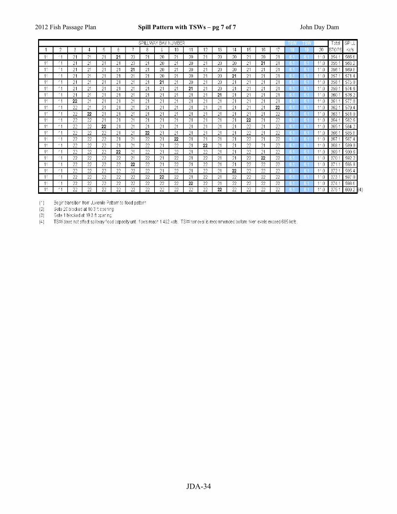
2012 Fish Passage Plan Spill Pattern with TSWs – pg 7 of 7 John Day Dam
JDA-34

2012 Fish Passage Plan Spill Pattern with No TSWs – pg 1 of 5 John Day Dam
JDA-35
Table JDA-9. John Day Dam Spill Pattern with No Temporary Spillway Weirs (TSWs).

2012 Fish Passage Plan Spill Pattern with No TSWs – pg 2 of 5 John Day Dam
JDA-36

2012 Fish Passage Plan Spill Pattern with No TSWs – pg 3 of 5 John Day Dam
JDA-37

2012 Fish Passage Plan Spill Pattern with No TSWs – pg 4 of 5 John Day Dam
JDA-38

2012 Fish Passage Plan Spill Pattern with No TSWs – pg 5 of 5 John Day Dam
JDA-39

2013 Fish Passage Plan
2013 Fish Passage Plan Section 5 – McNary Dam
Table of Contents 1. Fish Passage Information.......... ......................................................................... MCN-01
1.1. Juvenile Fish Passage .......................................................................... MCN-01 1.2. Adult Fish Passage .............................................................................. MCN-05
2. Project Operation ............................................................................................... MCN-06 2.1. Spill Management ............................................................................... MCN-06 2.2. Dissolved Gas Management and Control ........................................... MCN-06 2.3. Operating Criteria ............................................................................... MCN-06
3. Project Maintenance........................................................................................... MCN-17 3.1. Juvenile Fish Passage Facilities .......................................................... MCN-17 3.2. Adult Fish Passage Facilities .............................................................. MCN-20
4. Turbine Unit Operation and Maintenance ......................................................... MCN-22 4.1. Turbine Unit Operation ....................................................................... MCN-22 4.2. Turbine Unit Maintenance .................................................................. MCN-24
5. Forebay Debris Removal ................................................................................... MCN-25 5.1. Special Spills ....................................................................................... MCN-26

2013 Fish Passage Plan McNary Dam
MCN-1
Section 5 McNary Dam 1. FISH PASSAGE INFORMATION The locations of fish passage facilities at McNary Lock and Dam are shown in Figure MCN-1. Dates of project operations for fish purposes and special operations are listed in Table MCN-2. 1.1. Juvenile Fish Passage.
1.1.1. Facilities Description. The juvenile facilities at McNary Dam consist of extended-length submersible bar screens (ESBSs) with flow vanes, vertical barrier screens (VBSs), gatewell orifices, a concrete collection channel with emergency bypass outlets, primary and secondary dewatering structures, a pipeline/corrugated metal flume for transporting juvenile fish to the transportation facilities or bypassing them back to the river, and a full-flow PIT tag detection system. Juvenile transportation facilities at McNary include: a separator to sort juvenile fish by size and to separate them from adult fish; a flume system for distributing fish among the raceways; covered raceways for holding fish; sampling facilities; an office and sampling building with fish marking facilities; barge and truck loading facilities; and PIT tag detection and deflection systems.
1.1.2. Juvenile Migration Timing. Juvenile migration timing at McNary Dam is indicated in Table MCN-1. The dates in the table are based on juvenile fish collection numbers and do not reflect FGE or spill passage. Salmon, steelhead, bull trout, lamprey, and other species are routinely counted. Maintenance of juvenile fish passage facilities that may impact juvenile fish passage or facility operations should be conducted during the winter maintenance season.

2013 Fish Passage Plan McNary Dam
MCN-2
Table MCN-1. Juvenile Migration Timing at McNary Dam, 2003–2012.1
Yearling Chinook Subyearling Chinook 10 % 50% 90 % # of Days 10 % 50% 90 % # of Days
2003 29-Apr 13-May 29-May 30 2003 20-Jun 2-Jul 31-Jul 41 2004 27-Apr 11-May 31-May 34 2004 22-Jun 30-Jun 18-Jul 26 2005 3-May 15-May 29-May 26 2005 16-Jun 25-Jun 3-Jul 17 2006 21-Apr 9-May 19-May 28 2006 14-Jun 6-Jul 19-Jul 35 2007 1-May 11-May 25-May 24 2007 22-Jun 6-Jul 28-Jul 36 2008 9-Apr 15-May 27-May 48 2008 22-Jun 8-Jul 9-Aug 48 2009 2-May 15-May 25-May 23 2009 18-Jun 4-Jul 22-Jul 34 2010 3-May 17-May 27-May 24 2010 18-Jun 4-Jul 4-Aug 47 2011 29-Apr 8-May 23-May 24 2011 24-Jun 24-Jul 19-Aug 56 2012 29-Apr 11-May 25-May 26 2012 22-Jun 18-Jul 22-Aug 61
MEDIAN 29-Apr 12-May 26-May 26 MEDIAN 21-Jun 5-Jul 29-Jul 39 MIN 9-Apr 8-May 19-May 23 MIN 14-Jun 25-Jun 3-Jul 17 MAX 3-May 17-May 31-May 48 MAX 24-Jun 24-Jul 22-Aug 61
Unclipped Steelhead Clipped Steelhead 10 % 50% 90 % # of Days 10 % 50% 90 % # of Days
2003 19-Apr 25-May 4-Jun 46 2003 1-May 25-May 2-Jun 32 2004 23-Apr 13-May 4-Jun 42 2004 23-Apr 10-May 31-May 38 2005 1-May 17-May 27-May 26 2005 19-Apr 15-May 29-May 40 2006 19-Apr 7-May 27-May 38 2006 23-Apr 1-May 23-May 30 2007 27-Apr 11-May 25-May 28 2007 29-Apr 9-May 23-May 24 2008 1-May 15-May 29-May 28 2008 3-May 11-May 23-May 20 2009 25-Apr 7-May 23-May 28 2009 27-Apr 7-May 23-May 26 2010 1-May 13-May 2-Jun 32 2010 1-May 9-May 29-May 28 2011 19-Apr 7-May 27-May 38 2011 19-Apr 1-May 17-May 28 2012 24-Apr 5-May 25-May 31 2012 23-Apr 1-May 17-May 24
MEDIAN 24-Apr 12-May 27-May 32 MEDIAN 25-Apr 9-May 23-May 28 MIN 19-Apr 5-May 23-May 26 MIN 19-Apr 1-May 17-May 20 MAX 1-May 25-May 4-Jun 46 MAX 3-May 25-May 2-Jun 40
Coho Sockeye (Wild & Hatchery) 10 % 50% 90 % # of Days 10 % 50% 90 % # of Days
2003 25-May 4-Jun 29-Jun 35 2003 3-May 15-May 27-May 24 2004 15-May 31-May 18-Jun 34 2004 15-May 31-May 14-Jun 30 2005 5-May 21-May 6-Jun 32 2005 11-May 19-May 31-May 20 2006 9-May 27-May 2-Jun 24 2006 3-May 17-May 29-May 26 2007 3-May 21-May 8-Jun 36 2007 11-May 21-May 31-May 20 2008 13-May 25-May 6-Jun 24 2008 15-May 25-May 6-Jun 22 2009 13-May 23-May 12-Jun 30 2009 5-May 21-May 2-Jun 28 2010 9-May 31-May 12-Jun 34 2010 11-May 29-May 2-Jun 22 2011 24-Apr 19-May 8-Jun 45 2011 4-May 13-May 31-May 27 2012 7-May 23-May 4-Jun 28 2012 1-May 11-May 21-May 20
MEDIAN 9-May 24-May 8-Jun 33 MEDIAN 8-May 20-May 31-May 23 MIN 24-Apr 19-May 2-Jun 24 MIN 1-May 11-May 21-May 20 MAX 25-May 4-Jun 29-Jun 45 MAX 15-May 31-May 14-Jun 30 1. Dates are derived from daily and yearly facility collection numbers.

Juvenile Collection Channel
Bypass Outfall Flume
Navigation Lock
Exit
Fish Ladder Entrance WFE 2 & 3
(JFF)
Washington Shore Fish Ladder Exit
North Powerhouse Entrance NEF2, & NFE3
Bays 19-20
Juvenile Flume / Pipeline
PIT-Tag Detectors (4)
G0PDWLSW
Text Box
Figure 1. McNary Lock and Dam General Site Plan.
G0PDWLSW
Text Box
2013 Fish Passage Plan McNary Dam
G0PDWLSW
Text Box
MCN-3

Task Name Start Finish Reference
2013 FISH PASSAGE SEASON 3/1/13 12/31/13 MCN 2.3Juvenile Fish Passage Season 4/1/13 12/15/13 MCN 2.3.1.2Adult Fish Passage Season 3/1/13 12/31/13 MCN 2.3.2.2Lamprey Passage Season 6/15/13 9/30/13 MCN 2.3.2.2.j
2013-2014 WINTER MAINTENANCE PERIOD 12/16/13 3/31/14 MCN 2.Juvenile Fish Facilities Winter Maintenance 12/16/13 3/31/14 MCN 2.3.1.1Adult Fish Facilities Winter Maintenance 1/1/14 2/28/14 MCN 2.3.2.1
OPERATION OF JUVENILE BYPASS SYSTEM 4/1/13 12/15/13 MCN 2.3.1.Juvenile Fish Bypass, Collection and Transportation 4/1/13 9/30/13Adult Fish Fallback Bypass 10/1/13 12/15/13
ADULT FISH COUNTING 4/1/13 10/31/13 Table MCN-3Visual 0400-2000 PST 4/1/13 10/31/13Video Night 2000-0400 PST 7/1/13 9/30/13
1% CONSTRAINTS (YEAR-ROUND) 3/1/13 2/28/14 MCN 4.1.11% soft constraint 3/1/13 3/31/131% hard constraint 4/1/13 10/31/131% soft constraint 11/1/13 2/28/14
TDG MONITORING (YEAR-ROUND) 3/1/13 2/28/14 MCN 2.2TDG Monitoring - Tailrace 3/1/13 2/28/14 MCPWTDG Monitoring - Forebay 4/1/13 8/31/13 MCNA
Operate Turbine Priority for Fish Passage 3/1/13 11/30/13 MCN 4.1; Table MCN-5
SPECIAL OPERATIONS & STUDIES 3/1/13 2/1/14 Appendix ALamprey Passage Evaluations 3/1/13 10/31/13 App A MCN 2.2Adult Salmon Studies 3/30/13 10/31/13 App A MCN 2.1FGE and Fish Condition Study 4/1/13 9/30/13 App A MCN 2.3Video Monitoring of Oregon Shore Intake Screen 4/10/13 8/31/13 App A MCN 2.5Waterfowl Nesting (Restricted Forebay Operating Range) 4/28/13 7/6/13 App A MCN 1.5Units 4 and 11 Rewind (OOS) 6/1/13 2/1/14 App A MCN 1.6Video Monitoring of Fish Ladder Lamprey Modifcations 6/15/13 9/30/13 App A MCN 2.4Doble Testing 7/8/13 7/19/13 App A MCN 1.3
SPILL FOR FISH PASSAGE 4/10/13 8/31/13 Appendix ESpring Spill - 40% (TSWs installed) 4/10/13 6/19/13 end date approximateSummer Spill - 50% (no TSWs) 6/20/13 8/31/13 start date approximate
Avian Abatement Measures 4/1/13 12/15/13 MCN 2.3.1.2.f
Spillway Weirs in Bays 19 and 20 4/10/13 6/8/13 MCN 2.3.1.2.h
Inspect and/or rake up to four trashracks 12/16/13 1/15/14 MCN 2.3.1.1
Weekly Reports 3/1/13 12/31/13 MCN 2.3.3.1
Annual Report (for Dec 1, 2012 - Nov 30, 2013) 3/15/14 3/15/14 MCN 2.3.3.2
Jan Feb Mar Apr May Jun Jul Aug Sep Oct Nov Dec Jan Feb Mar1st Quarter 2nd Quarter 3rd Quarter 4th Quarter 1st Quarter
2013 2014
Table MCN-2. McNary Dam Dates of Fish-Related Operations for 2013 Fish Passage Season and 2013/14 Winter Maintenance Period.
MCN-4

2013 Fish Passage Plan McNary Dam
MCN-5
1.2. Adult Fish Passage.
1.2.1. Facilities Description. The adult fish passage facilities at McNary consist of separate north and south shore facilities.
1.2.1.1 North Shore Adult Fish Passage Facility. The north shore facilities are made up of a fish ladder with counting station, submerged orifice PIT tag antennas in the ladder, a small collection system, and a gravity-flow auxiliary water supply system. The gravity-flow auxiliary water supply system has a turbine unit installed on it, operated by North Wasco County PUD. The gravity-flow auxiliary water supply system takes water from the forebay through two conduits, passes the water through a turbine unit or through a bypass/energy dissipater when the turbine unit is not in operation, and distributes the water through a diffuser system at the bottom of the ladder and in the transportation channel. The north shore collection system has three downstream entrances and a side entrance into the spillway basin. Two of the downstream entrances are used during normal operation.
1.2.1.2 South Shore Adult Fish Passage Facility. The south shore facilities are comprised of a fish ladder with counting station, submerged orifice PIT tag antennas in the ladder and antennas at the counting station, two south shore entrances, a powerhouse collection system, and gravity and pumped auxiliary water supply systems.
1.2.1.3 Powerhouse Collection System. The powerhouse collection system contains three downstream entrances and one side entrance into the spillway basin at the north end of the powerhouse, twelve operating floating orifices, and a common transportation channel. At the north end of the powerhouse, two of the downstream entrances are used during normal operation with the other downstream and side entrances closed. The gravity-flow auxiliary water is provided by one conduit from the forebay and supplies the diffusers at the bottom of the ladder at tailwater level. The pumped auxiliary water is supplied by three electric pumps with variable-pitched blades. Two pumps are capable of providing the required flow when the third pump is bulkheaded to prevent water from flowing back through the pump to the river. The electric pumps supply the auxiliary water for the diffusers at the entrances and in the transportation channel. Excess water from the primary dewatering structure in the juvenile fish collection channel is routed to the adult collection system at the north end of the powerhouse.
1.2.2. Adult Migration Timing. Upstream migrants are present at McNary Dam throughout the year and adult passage facilities are operated year round. Maintenance of adult fish facilities is scheduled for January and February to minimize impacts on upstream migrants. Facilities are usually shut down one shore at a time for maintenance. Adult fish (salmon, steelhead, shad, and lamprey) are counted as per Table MCN-3; these data appear daily on the Corps adult fish count website at: http://www.nwp.usace.army.mil/Missions/Environment/Fishdata.aspx. Salmon migration timing data appear in Table MCN-4. Sturgeon and bull trout are also counted and recorded on the fish counters’ daily summary sheet comments section, but do not appear on the Corps daily website total due to relative infrequency of passage. These data are posted periodically during the passage season in the Miscellaneous Fish Counts report on the Corps’ website, and summarized in the Annual Fish Passage Report.

2013 Fish Passage Plan McNary Dam
MCN-6
Table MCN-3. Adult Fish Counting Schedule at McNary Dam. Count Period Counting Method and Hours 1
April 01 – October 31 Visual 0400–2000 hours (PST) July 01 – September 30 Night Video 2000–0400 hours (PST) 1. All count hours are shown in Pacific Standard Time (PST). Note that during daylight saving time (DST) from March 10–November 3, 2013, count hours will be adjusted forward one hour (DST = PST+1). Table MCN-4. Adult Fish Count Period and Peak Migration Timing at McNary Dam (based on fish count data for 1954-2012).
Species Count Period Earliest Peak Latest Peak Spring Chinook 4/1 – 6/8 4/20 5/26 Summer Chinook 6/9 – 8/8 6/17 7/26 Fall Chinook 8/9 – 10/31 9/10 9/28 Steelhead 4/1 – 10/31 7/9 10/13 Sockeye 4/1 – 10/31 9/5 10/11 Coho 4/1 – 10/31 7/23 7/16 Lamprey 4/1 – 10/31 7/21 8/12 2. PROJECT OPERATION 2.1. Spill Management. See the Fish Operations Plan (Appendix E) for more information.
2.1.1. Involuntary Spill. Involuntary spill at McNary Dam is the result of river flow exceeding powerhouse capacity, insufficient generation loads to pass the river flow, turbine unit outages (forced or scheduled), or the failure of a key component of the juvenile fish passage facility which forces the project to spill to provide juvenile fish passage. Spill at McNary Dam shall be distributed in accordance with the spill pattern for fish passage (Table MCN-7) or the appropriate spill pattern during TSW removal (Table MCN-10) and after TSW removal (Table MCN-9). 2.2. Total Dissolved Gas Management and Control. Total dissolved gas (TDG) levels at all projects are monitored in accordance with the TDG Monitoring Plan, included in the Water Management Plan as Appendix 4, and available online at: http://www.nwd-wc.usace.army.mil/tmt/documents/wmp/2013/. 2.3. Operating Criteria
2.3.1. Juvenile Fish Passage Facilities. Operate from April 1 through September 30 for juvenile fish bypass, collection, and transportation and from October 1 through December 15 for bypassing adult fallbacks. Operate according to the criteria listed below and in Appendix B (Corps' of Engineers Juvenile Fish Transportation Program) for the bypassing, collection, and transportation of juvenile salmonids. The transportation program may be revised in accordance with the ESA Section 10 permit and the NOAA Fisheries biological opinion.

2013 Fish Passage Plan McNary Dam
MCN-7
2.3.1.1 Winter Maintenance Period (December 16 through March 31). Check and perform maintenance as required on the items listed below. Prior to the end of January 15, inspect or rake up to four trashracks to determine if debris is present. Prioritize raking trashracks at units with known debris issues and longer run times, and insure to the extent practicable that raked units are distributed evenly across the powerhouse.
a. Forebay Area and Intakes
1. Remove debris from forebay and trashracks.
2. Rake trashracks.
3. Remove debris from gatewell slots.
4. Measure and log drawdown in gatewell slots.
5. Inspect and repair gatewell dip net as needed.
b. Extended-Length Submersible Bar Screens (ESBSs), Flow Vanes, and Vertical Barrier Screens (VBSs)
1. Maintenance completed on all ESBSs.
2. Inspect ESBSs for good running order and operate debris cleaner one trial run (dogged off at deck level).
3. Inspect flow vanes to make sure they are in good condition and all surfaces are smooth. Repair as needed.
4. Inspect all VBSs at least once per year by either raising the VBS and visually inspecting or inspecting with an underwater video camera.
c. Collection Channel.
1. Orifice lights are operational.
2. Orifices clean and valves operating correctly.
3. Orifice air backflush system works correctly.
4. Netting over handrails and orifice chutes maintained and in good condition.
5. Plastic covers over orifice chutes maintained and in good condition and clean so orifice flow is visible.
d. Dewatering Structure and Flume.
1. Inclined and side dewatering screens are clean and in good condition with no gaps between screen panels, no damaged panels, and no missing silicone.

2013 Fish Passage Plan McNary Dam
MCN-8
2. Cleaning brush systems are maintained and operating correctly.
3. All valves in good condition and operating correctly.
4. Stilling well water level sensing device inspected and operable.
5. Flume and pipe interiors smooth with no rough edges.
6. Maintain full-flow PIT tag system as required. Coordinate with PSMFC.
e. Transportation Facilities.
1. Flume switch gate is maintained and operational.
2. Flume is smooth with no rough edges.
3. Perforated plate and bar screen edges are smooth with no rough edges.
4. Wet separator and fish distribution system maintained and operating as designed.
5. Brushes on all crowders in good condition or new.
6. Crowders maintained and operating properly.
7. All valves, slide gates, and switch gates maintained and operating correctly.
8. Raceway and tank retainer screens set in place with no holes or sharp wires protruding.
9. Barge and truck loading pipes are free of debris, cracks, or blockages.
10. Barge loading boom maintained and tested.
11. All sampling equipment should be maintained and operating correctly.
12. Maintain juvenile PIT tag system as required (see “Columbia Basin PIT Tag Information System, General Gate Maintenance and Inspection, Walla Walla District”, February 2003). Coordinate with PSMFC.
f. Avian Predation Areas (Forebay and Tailrace). Inspect bird wires, water cannon, and other deterrent devices and repair or replace as needed. Where possible, install additional bird wires or other deterrent devices to cover areas of known avian predation activity. Prepare avian abatement contract as needed.
g. Fish Transport Trailers.
1. All systems are maintained, including refrigeration system, and operating properly.
2. No leaks around air stone fittings; repair where necessary.

2013 Fish Passage Plan McNary Dam
MCN-9
3. Plugs should be placed in end of air stones.
4. Turn air stones on lathe if necessary to allow free air passage through stones.
5. Each trailer should carry two hoses of the right size with necessary cam lock caps.
6. All air and water valves should operate correctly.
7. Overall condition of trailer should be maintained and in good condition including hatch covers, release gates, and oxygen manifold system.
h. Maintenance Records.
1. Record all maintenance and inspections.
2.3.1.2 Juvenile Fish Passage Period (April 1 through December 15)
a. Forebay Area and Intakes
1. Remove debris from forebay.
2. Inspect gatewell slots daily for debris, fish buildup, and contaminating substances (particularly oil). Clean gatewells before they become 50% covered with debris. If due to the volume of the debris, it is not possible to keep the gatewell at least 50% clear, clean gatewells at least once daily. If flows through an orifice or fish sampling results indicate that an orifice may be partially obstructed with debris, close the orifice(s) and backflush to remove the obstruction. If the obstruction cannot be removed, the orifice shall be closed and the alternate orifice for that gatewell slot shall be operated. If both orifices become obstructed or plugged with debris, the turbine unit will not be operated until the gatewell and orifices are cleared of debris.
3. If a visible accumulation of contaminating substances (such as oil) is detected in a gatewell and it cannot be removed within 24 hours, the gatewell orifices shall be closed immediately and the turbine unit shut down within one hour until the material has been removed and any problems corrected. A preferred method for removing oil from the water surface is to install absorbent socks, booms, or pads capable of encapsulating the material, tied off with a rope for later disposal. Action should be taken as soon as possible to remove the oil from the gatewell so the orifice can be reopened to allow the fish to exit the gatewell. Orifices shall not be closed for longer than 48 hours.
4. Remove debris from forebay and trashracks as required to minimize fish impacts. Generally this will result in removing debris from trashracks at least four times per year - just prior to the fish passage season and, monthly for the first three months Raking may be required when heavy debris loads are present in the river. Fish quality and trash rack differential may also be an indicator of debris buildup on the trashracks. Project biologist shall determine when trash raking is required.

2013 Fish Passage Plan McNary Dam
MCN-10
5. Coordinate cleaning efforts with personnel operating juvenile collection facilities.
6. Dip bulkhead gatewell slots to remove fish prior to installing bulkhead for dewatering bulkhead slot.
b. Extended-Length Submersible Bar Screens (ESBSs) and Vertical Barrier Screens (VBSs).
1. Operate ESBSs with flow vanes attached to the screen. Installation of the ESBSs will not start before April 5 and will be completed no later than April 15.
2. Operate ESBSs with debris cleaners in automatic mode. Set cleaning frequency as required to maintain good fish condition, with initial settings of every 15 minutes. Increase or decrease cleaning frequency if needed to maintain clean screens.
3. Inspect ESBSs in at least 3 operating turbine units per week by means of underwater video. Spot-check VBSs at the same time.
4. Conduct additional ESBS inspections if fish condition warrants it.
5. If an ESBS is damaged or fails during the juvenile fish passage season, follow procedures detailed under unscheduled maintenance of ESBSs (section 3.1.2.1). In no case should a turbine unit be operated with a missing or known non-operating or damaged ESBS or VBS. Turbine units shall not operate for more than 10 hours, and preferably less than 3 hours, with ESBSs in place and orifices closed. Orifice closure should be minimized by efficient planning and completion of the work to be done (e.g., having equipment, materials and personnel ready before orifices are closed).
6. Make formal determination at end of season as to adequacy of bar screen panels and debris cleaner brushes and replace components as necessary.
7. Measure head differentials across VBSs daily during times of debris. Clean and inspect VBS when head differentials reach 1.5'. When a head differential of 1.5' is reached, the respective turbine unit should be operated at a reduced generation loading if the VBSs cannot be cleaned within 8 hours, to minimize loading on the VBS and potential fish impingement.
8. Between the spring and summer periods, inspect at least four VBSs in two different turbine units that were operated frequently during the spring. If debris accumulation is noted, inspect other VBSs and clean debris as necessary.
9. Inspect all VBSs at least once per year and when pulled for cleaning. Since VBSs in the northern turbine units (generally units 9-14) rarely need cleaning, they should be pulled and inspected at least twice per year. Repair as needed.
c. Collection Channel.
1. Orifices clean and operating. Operate at least one orifice per gatewell slot

2013 Fish Passage Plan McNary Dam
MCN-11
(preferably the south orifice). If orifices must be closed to repair any part of the facility, do not close orifices in operating turbine units with ESBSs in place for longer than 10 hours, and preferably less than 3 hours. During periods of high fish numbers or high debris, this time period may be less. Reduce turbine unit loading to the lower end of the 1% efficiency range if deemed necessary by the project biologist. Monitor fish conditions in gatewells hourly or more frequently during orifice closure periods.
2. Orifice lights operational and operating on open orifices. Orifice lights and area lights may be turned off the evening before the channel is dewatered at the end of the season (dewatering occurs on December 16 or later) to encourage fish to exit the channel volitionally. Area lights can be turned on briefly for personnel access if necessary.
3. Replace all burned out orifice lights within 24 hours of notification. Orifice lights shall remain lighted 24 hours/day.
4. Orifice jets hitting no closer than 3’ from back wall, collection channel full.
5. Orifice valves are either fully open or closed.
6. Backflush orifices at least once per day and more frequently if required. During periods of high fish and debris passage, April 1 through August 15, orifices should be inspected and backflushed twice daily or more frequently as determined by the project biologist, to keep orifices clean. If debris is causing continual orifice plugging problems in a particular turbine unit gatewell, the respective turbine unit generation may be restricted to the lower end of the 1% turbine efficiency range to minimize orifice plugging problems.
7. The netting along handrails should be maintained in good condition with no holes or gaps in the netting.
8. Plastic covers over orifice chutes in good condition.
d. Dewatering Structure.
1. No gaps between panels or missing silicone in side and inclined screens.
2. Trash sweeps operating correctly.
3. The project biologist shall determine the frequency of operation of the trash sweeps. The sweeps should operate at a frequency to maintain a clean screen given present debris loads. Frequency of operation may vary from as low as once every 15 minutes to once every 2 or more hours. This frequency should coincide with the ESBS cycle time.
4. If automated cleaning system problems occur, project personnel shall operate cleaners at least once per shift unless determined differently by the project biologist.

2013 Fish Passage Plan McNary Dam
MCN-12
5. The dewatering structure may be dewatered twice during the season, during low fish passage periods in June and September, for inspection and cleaning of the dewatering screens. Before dewatering occurs, the project biologist must notify CENWW-OD-T who in turn will coordinate the proposed action with NOAA Fisheries and other FPOM participants.
6. Lights at the dewatering structure should be turned off at night, unless needed for personnel access, to encourage fish to move downstream volitionally.
e. Transportation Facilities. Note: Normal operations when not transporting fish in the spring is to operate the juvenile bypass facilities in full flow bypass to the river. During this operation, fish may be periodically routed through the transportation facilities to sample fish for the Smolt Monitoring Program or for routine sampling to monitor facility descaling and fish condition. Sampling during full flow bypass operations will be coordinated on an as needed basis. Sampling during the spring is normally done every other day per Appendix B.
1. There should be no holes or gaps between screen panels. All silicone sealer should be in good condition.
2. Crowder screen brushes should be in good operating condition.
3. Assure that retainer screens in raceways and tanks are clean with no holes or protruding wires.
4. Operate wet separator and fish distribution system as designed.
5. Project personnel shall release ice blocks through each 10-inch bypass line, one to three times per day as warranted by woody debris loads, during the spring as a preventative measure for debris plugging. Additional ice blocks shall be passed down the pipelines during high debris periods as needed to keep the pipes debris free. Releasing ice blocks through the pipes should continue during the summer when transporting fish, as determined by the project biologist to keep the pipelines debris free.
6. Truck and barge loading facilities should be kept in good operating condition.
7. Inform PSMFC, in advance if possible, of situations that cause the PIT tag system to become inoperable (e.g. power outages) or that could result in confounding the interpretation of PIT tag data (e.g. bypassing fish from raceways to the river, operating in primary bypass mode without an operational full-flow detector, emergency dewatering).
f. Avian Predation Areas (Forebay, Tailrace, and Collection Channel)
1. Bird wires and other avian deterrent devices should be monitored to assure they are in good condition. Any broken wires or devices should be replaced as soon as possible.

2013 Fish Passage Plan McNary Dam
MCN-13
2. Harassment program in place to deter avian predation in areas actively used by birds and not covered by bird wires or other devices.
3. Project biologists shall routinely monitor project areas to determine areas of active avian predation and, if possible, adjust harassment program to cover these areas or install bird wires or other deterrent devices to discourage avian predation activities. Grebes should be routinely captured in the juvenile fish channel and released below the dam, in coordination with USDA/Wildlife Services.
g. Inspection and Record Keeping. Inspect all facilities according to fish facilities monitoring plan. Record all inspections.
h. TSW Operation. A temporary spillway weir (TSW1) will be installed in spillbays 19 and 20, available for the start of the spring spill operations. During spring spill operations when TSWs are in service, implement the “Spill Pattern for Fish Passage” (Table MCN-7). Both TSWs will be removed from service on June 8 or the next available work day. To allow crews to safely remove the TSWs from service, temporarily implement the “Spill Pattern During TSW Removal” (Table MCN-10) throughout the TSW removal process. Upon completion of the TSW removal process when both TSWs have been removed from service, implement the “Spill Pattern After Both TSWs Removed” (Table MCN-9) for the remainder of the fish passage spill season.
i. Emergency Bypass During Freezing Conditions
1. When cold weather is forecasted for Umatilla, Oregon, between November 1 and December 15, the McNary Fisheries staff may place the McNary Juvenile Fish Facility (JFF) channel in emergency bypass mode until the beginning of the winter maintenance season when the juvenile channel is fully dewatered.
2. “Cold weather” is defined as: forecasted daily high temperature below 32°F or daily low temperature below 20°F. Staff shall use the forecast for Umatilla, Oregon, provided by NOAA’s National Weather Service at www.weather.gov.
3. If the projects installs a proposed “X” or “Y” valve in the south trash sluiceway that eliminates the need for emergency bypass, then the fisheries staff may shut down the water supply to the JFF after November 1 until the JFF is re-watered the following March, unless earlier re-watering is required for testing or maintenance.
j. Emergency Bypass During Late Season Mechanical Failure. After November 30, if a mechanical failure forces the McNary JFF juvenile channel into emergency bypass mode, the McNary Fisheries staff may leave the juvenile channel in emergency bypass mode until the beginning of the winter maintenance season when the juvenile channel is fully dewatered.
1 Temporary spillway weirs (TSWs) are installed at McNary, John Day and Little Goose dams. TSWs are differentiated from Removable Spillway Weirs (RSWs, installed at Lower Granite, Lower Monumental and Ice Harbor dams) by the ability to install, uninstall and move TSWs between spillbays using the project’s gantry crane.
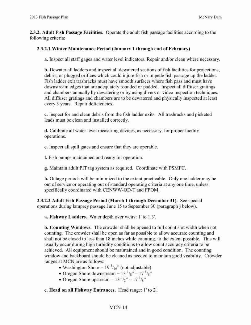
2013 Fish Passage Plan McNary Dam
MCN-14
2.3.2. Adult Fish Passage Facilities. Operate the adult fish passage facilities according to the following criteria:
2.3.2.1 Winter Maintenance Period (January 1 through end of February)
a. Inspect all staff gages and water level indicators. Repair and/or clean where necessary.
b. Dewater all ladders and inspect all dewatered sections of fish facilities for projections, debris, or plugged orifices which could injure fish or impede fish passage up the ladder. Fish ladder exit trashracks must have smooth surfaces where fish pass and must have downstream edges that are adequately rounded or padded. Inspect all diffuser gratings and chambers annually by dewatering or by using divers or video inspection techniques. All diffuser gratings and chambers are to be dewatered and physically inspected at least every 3 years. Repair deficiencies.
c. Inspect for and clean debris from the fish ladder exits. All trashracks and picketed leads must be clean and installed correctly.
d. Calibrate all water level measuring devices, as necessary, for proper facility operations.
e. Inspect all spill gates and ensure that they are operable.
f. Fish pumps maintained and ready for operation.
g. Maintain adult PIT tag system as required. Coordinate with PSMFC.
h. Outage periods will be minimized to the extent practicable. Only one ladder may be out of service or operating out of standard operating criteria at any one time, unless specifically coordinated with CENWW-OD-T and FPOM.
2.3.2.2 Adult Fish Passage Period (March 1 through December 31). See special operations during lamprey passage June 15 to September 30 (paragraph j below).
a. Fishway Ladders. Water depth over weirs: 1' to 1.3'.
b. Counting Windows. The crowder shall be opened to full count slot width when not counting. The crowder shall be open as far as possible to allow accurate counting and shall not be closed to less than 18 inches while counting, to the extent possible. This will usually occur during high turbidity conditions to allow count accuracy criteria to be achieved. All equipment should be maintained and in good condition. The counting window and backboard should be cleaned as needed to maintain good visibility. Crowder ranges at MCN are as follows:
• Washington Shore = 19 3/16” (not adjustable) • Oregon Shore downstream = 13 1/8” – 17 5/8” • Oregon Shore upstream = 13 1/2” – 17 1/8”
c. Head on all Fishway Entrances. Head range: 1' to 2'.

2013 Fish Passage Plan McNary Dam
MCN-15
d. Channel Velocity. Adult collection channel water velocities must flow between 1.5’ - 4’ per second. This velocity is optimum criteria for returning adult salmon and steelhead to migrate upstream though the fishway. Velocity readings are completed three times a week and are included in required fishway inspections and reported in the weekly and annual reports.
1. Surface water velocities will be measured in the open access area near the south shore fish entrance. The surface velocity will be measured using a large piece of woody debris (stick, bark) timed over a marked fixed distance. A Doppler meter location near the same location measures the subsurface flow. The measurement of the water velocity at this location typifies the slowest velocity conditions throughout the length of the channel.
e. North Shore Entrances (WFE 2 & 3).
1. Operate 2 downstream gates.
2. Weir depth: 8' or greater below tailwater.
f. North Powerhouse Entrances (NFE 2 & 3).
1. Operate 2 downstream gates.
2. Weir depth: 8' or greater below tailwater.
g. Floating Orifice Gates. Operate 12 floating orifices (O.G. numbers 1, 3, 4, 8, 14, 21, 26, 32, 37, 41, 43, and 44).
h. South Shore Entrances (SFE 1 & 2).
1. Operate 2 downstream gates.
2. Weir depth: 8' or greater below tailwater.
i. Head on Trashracks.
1. Maximum head of 0.5' on ladder exits.
2. Maximum head on picketed leads shall be 0.5'. Normal head differential on clean leads is 0.3'.
3. Trashracks and picketed leads installed correctly.
j. Lamprey passage season June 15 to September 30 modifications with removal of the stationary section of the segmental gate.
1. Implement following nighttime segmental gate operations from 2100–0400 hours:
i. Lower the SFE 1 & 2 entrance weir to the lowest elevation (243 fmsl).

2013 Fish Passage Plan McNary Dam
MCN-16
ii. Lower the NFE 2 & 3 entrance weir to the lowest elevation (243 fmsl).
2. Daytime operations from 0400–2100 hours:
i. Extend telescoping segmental gates SFE 1 & 2 and NFE 2 & 3 depth: 8’ or greater below tailwater.
ii. Maintain tail water and channel differential of 1.0–2.0’.
k. Staff Gages and Water Level Indicators. All staff gages should be readable at all water levels encountered during the fish passage period. Repair or clean as necessary.
l. Inform PSMFC, in advance if possible, of situations that cause the PIT tag system to become inoperable (e.g. power outages) or that could result in confounding the interpretation of PIT tag data (e.g. emergency dewatering).
m. Facility Inspections
1. Powerhouse operators shall inspect facilities once per day shift and check computer monitor information at least once during each back shift.
2. Project biologists shall inspect facilities three times per week. Inspect all facilities according to fish facilities monitoring program.
3. Picketed leads shall be inspected during all inspections to ensure they are clean and in the correct position (all the way down).
4. Project personnel shall check calibration of fishway control system twice per month to ensure that it is kept within calibration. This may be done as part of routine fishway inspections.
5. Inspect fishways daily for foreign substances (particularly oil). If substances are found, corrective actions should be undertaken immediately.
6. Record all inspections.
2.3.3. Facility Monitoring and Reporting. Project biologists shall inspect fish passage facilities at the frequencies listed in the juvenile and adult fish facilities operating criteria sections.
2.3.3.1 Weekly Reports. Project biologists shall prepare weekly reports, from March 1 through December 31, summarizing project operations. The weekly reports should provide an overview of how the project and the fish passage facilities operated during the week and an evaluation of resulting fish passage conditions. The weekly reports shall cover a Friday through Thursday time period and shall be sent to CENWW-OD-T by noon the following Monday via electronic mail. The reports shall include:
a. Any out-of-criteria situations observed and subsequent corrective actions taken;

2013 Fish Passage Plan McNary Dam
MCN-17
b. Any equipment malfunctions, breakdowns, or damage along with a summary of resulting repair activities;
c. Adult fishway control calibrations;
d. ESBS and VBS inspections;
e. Any unusual activities that occurred at the project that may affect fish passage.
2.3.3.2 Annual Reports. Project biologists shall prepare a draft annual report by February 10 and a final report by March 15 summarizing the operation of the project fish passage facilities for the previous year. The annual report shall also include a description of all actions taken to discourage avian predation at the project, with an overview of the effectiveness of the activities in discouraging avian predation.
2.3.3.3 Monthly Inspections. Project biologists inspect project facilities once per month and during dewaterings for the presence of zebra and Quagga mussels. Biologists shall provide a report to CENWW-OD-T on a monthly basis summarizing mussel inspections.
3. PROJECT MAINTENANCE
Project biologists should be present to provide technical guidance at all project activities that may involve fish handling. All dewaterings shall be accomplished in accordance with approved project dewatering and fish handling plans. When river temperatures reach 70 degrees Fahrenheit or greater, all adult fish handling will be coordinated through CENWW-OD-T. Dewatering and fish handling plans were reviewed and revised in 2011 to ensure that they comply with Appendix F, Guidelines for Dewatering and Fish Handling Plans.
3.1. Juvenile Fish Passage Facilities.
3.1.1. Scheduled Maintenance. Scheduled maintenance of the juvenile facilities is conducted during the entire year. Long-term maintenance or modifications of facilities that require them to be out of service for extended periods of time are conducted during the winter maintenance period from December 16 through March 31. During the fish passage season parts of the facilities are maintained on a daily, weekly, or longer interval to keep them in proper operating condition.
3.1.2. Unscheduled Maintenance. Unscheduled maintenance is the correction of any situation that prevents the facilities from operating according to criteria or that will impact fish passage or survival. Maintenance of facilities such as ESBSs, which sometimes break down during the fish passage season, will be carried out as described below. In these cases, repairs will be made as prescribed and CENWW-OD-T notified for further coordination. Unscheduled maintenance that will have a significant impact on juvenile fish passage shall be coordinated with NOAA Fisheries and other FPOM participants on a case-by-case basis by CENWW-OD-T. CENWW-OD-T will be notified as soon as possible after it becomes apparent that maintenance repairs are required. The Operations Manager has the authority to initiate work prior to notifying CENWW-OD-T when in his opinion delay of the work will result in an unsafe situation for people, property, or
2013 Fish Passage Plan McNary Dam
MCN-18
fish. Information required by CENWW-OD-T includes (see also the Overview (FPP Section 1) for the coordination form):
a. Description of outage. b. Type of outage required. c. Impact on facility operation. d. Length of time for repairs. e. Expected impacts on fish passage and proposed measures to mitigate them.
3.1.2.1 Extended-Length Submersible Bar Screens (ESBSs). The ESBSs are inspected periodically throughout the juvenile migration season with a video monitoring system. If a screen is found to be damaged it will be removed and either replaced with a spare ESBS or repaired and returned to service. A turbine unit shall not be operated with a known damaged or nonfunctioning ESBS or VBS, or without a full complement of ESBSs, flow vanes, and VBSs. If a screen fails on a weekend or at night when maintenance crews are not available, the respective turbine unit will be shut down and generation switched to another, fully screened unit. If all screened turbine units are in service, water may be spilled until the affected screen can be removed and repaired or replaced.
3.1.2.2 Vertical Barrier Screen (VBS) Cleaning. The ESBSs deflect fish and water up the gatewell slots as part of the fish collection process. Each gatewell has a VBS located vertically between the bulkhead slot and the operating gate slot. The VBSs keep guided juvenile and adult fish from passing through the bulkhead slot into the operating gate slot where the fish can pass back into the turbine intake. The VBSs are designed to distribute the flow evenly through the screens to minimize fish impingement and descaling. The water surface elevations in the gatewells are routinely measured to determine head differential across the VBSs caused by debris plugging the VBSs. VBSs are to be pulled and cleaned when head differentials reach 1.5'. Prior to pulling a VBS for cleaning, the turbine unit loading will be lowered to the lower end of the 1% turbine efficiency range and the gatewell dipped with a gatewell basket to remove all fish present in the gatewell unless doing so results in increased mortality (e.g. high numbers of adult or juvenile shad in gatewells). Immediately after dipping, the VBS shall be raised and impinged debris hosed off. The turbine unit shall remain operating at the lower end of the 1% turbine efficiency range while the VBS is being cleaned so gatewell flow will carry the debris into the operating gatewell, where it will pass through the turbine unit. Immediately after cleaning the VBS, the VBS shall be lowered to the normal operating position to prevent fish passage from the bulkhead slot into the operating gate slot. The VBSs shall not be raised longer than 30 minutes with the turbine unit running. If VBSs cannot be cleaned within one workday of the head differential reaching 1.5', the turbine unit loading will be lowered to the lower end of the 1% turbine efficiency range until the VBS can be cleaned. If the cleaning frequency of VBSs exceeds project personnel’s cleaning capability of approximately 10 VBSs per day, 7 days per week, project personnel will notify CENWW-OD-T. Then CENWW-OD-T will coordinate with NOAA Fisheries and other FPOM participants regarding an exemption to dipping gatewells prior to cleaning VBSs. An exemption to dipping gatewells prior to cleaning VBSs will be based on fish numbers and TDG levels. If a VBS is found to be damaged during an inspection or cleaning, the VBS panel will be repaired or replaced with a spare panel. The turbine unit will not be operated with a known damaged VBS.

2013 Fish Passage Plan McNary Dam
MCN-19
3.1.2.3 Gatewell Orifices. Each gatewell has two orifices with valves to allow fish to exit the gatewell. Under normal operation, one orifice per gatewell (normally the south orifice) is operated. If an orifice becomes blocked with debris or is damaged, it will be closed and the alternate orifice for that gatewell operated until repairs can be made. If both orifices are blocked with debris, damaged, or must be kept closed, the turbine unit will be taken out of service until repairs can be made. If there is a major failure with the bypass system that prevents the gatewell orifices from operating, traveling screens and bar screens will remain in operation. Turbine units shall not be operated with blocked or closed orifices for longer than 10 hours. During any orifice closure, project personnel shall monitor gatewells for signs of fish problems or mortality. If repairs are expected to take longer than two days, a salvage program will be initiated to dip the juveniles from the gatewells with a gatewell basket until repairs are made and the system watered up again or orifices opened. Juvenile fish shall not remain in gatewells longer than 48 hours. During periods of high fish passage, it may be necessary to cease operation of turbine units with ESBSs in place and with closed orifices in less than 10 hours, depending on fish numbers and condition. Spill may occur to provide an alternate avenue for fish passage during facility outages.
3.1.2.4 Dewatering Structure. The dewatering structure acts as a transition from the collection channel to the bypass pipe/flume. An inclined screen and a side dewatering screen allow excess water to be bled off, with all fish and remaining water transitioning into the bypass pipe. Some of the excess water is discharged into the adult fish facility auxiliary water supply system and some is used as the water supply for the transportation facilities. The dewatering structure contains trash sweeps and an air-burst system for cleaning the dewatering screens of impinged debris. If a trash sweep breaks and interferes with juvenile fish passage through the structure or if a screen is damaged, an emergency bypass system in the collection channel may be used to bypass juveniles while repairs are made. Operation of the emergency bypass system requires the juvenile bypass system to be dewatered and stoplogs inserted at the upstream end of the dewatering structure. The emergency bypass is then opened and the bypass system operated with one orifice per gatewell open. Spill may also be required to bypass juvenile fish while in emergency bypass operations. Prior to any emergency dewatering of the collection channel, CENWW-OD-T will be notified. Then CENWW-OD-T will be responsible for notifying NOAA Fisheries and other FPOM participants of the action and coordinating changes in spill or other project operations.
3.1.2.5 Bypass Pipe/Flume. The bypass pipe/corrugated metal flume transports juveniles to either the transportation facilities or to the river below the project through the primary bypass pipe. If there is a problem with the flume that interferes with its operation, the emergency bypass system in the collection system can be opened and all of the fish in the bypass system diverted into the ice and trash sluiceway and passed to the river through the north powerhouse ice and trash sluiceway exit.
3.1.2.6 Transportation Facilities. The transportation facilities can be operated to either collect and hold juveniles for the transportation program or to separate fish by species (based on fish size), enumerate the fish through the sampling system, and bypass part or all of the fish back to the river (secondary bypass). If part of the facility malfunctions or is damaged, efforts will first be made to bypass the fish around the damaged area. If this is not possible,

2013 Fish Passage Plan McNary Dam
MCN-20
the switch gate in the bypass flume will be used to bypass fish directly to the river until repairs can be made (primary bypass).
3.2. Adult Fish Passage Facilities.
3.2.1. Scheduled Maintenance. Scheduled maintenance of a facility that must be dewatered to work on or whose maintenance will have a significant effect on fish passage will be done during the January and February winter maintenance period. Maintenance of facilities that will have no effect on fish passage may be conducted at any time. Maintenance is normally conducted on one fish ladder at a time during the winter to provide some fish passage at the project at all times. When facilities are not being maintained during the winter maintenance period, they will be operated according to normal criteria unless otherwise coordinated with NOAA Fisheries and other FPOM participants.
3.2.2. Unscheduled Maintenance. Unscheduled maintenance that will significantly affect the operation of a facility will be coordinated with NOAA Fisheries and other FPOM participants. Coordination procedures for unscheduled maintenance of adult facilities are the same as for juvenile facilities (see section 3.1.2.). If part of a facility malfunctions or is damaged during the fish passage season and the facility can still be operated within criteria without any detrimental effects on fish passage, repairs may not be conducted until the winter maintenance period or until fewer numbers of fish are passing the project. If part of a facility is damaged or malfunctions that may significantly impact fish passage, it will be repaired as soon as possible.
3.2.2.1 Fish Ladders and Counting Stations. The fish ladders contain tilting weirs, fixed weirs, counting stations with picket leads, and fish exits with trashracks. If any part of the fish ladder fails or is blocked with debris during the fish passage season, efforts will first be made to correct the problem without dewatering the ladder. Trashracks, picket leads, tilting weir mechanisms, and counting stations can sometimes be repaired or maintained without dewatering the ladder. The decision to dewater the ladder and make repairs during the fish passage season or wait until the winter maintenance period will be made after coordination with the fish agencies and tribes.
3.2.2.2 North Shore Auxiliary Water Supply System. The auxiliary water for the north shore fish ladder is provided by gravity-flow from the forebay. The water passes either through a turbine unit or through a bypass system. The turbine/bypass system is operated by North Wasco County PUD. During normal operations, when the turbine unit is operating, water passes through conduits 3 and 4 to the turbine unit. From the turbine unit, the water discharges into an open pool where it feeds into ladder diffusers. If there are problems with the turbine unit, automatic valves close and the auxiliary water is diverted through conduits 1 and 3A to the baffled bypass system within the old fish lock, where the hydraulic head is dissipated and the water discharged into the diffuser pool.
3.2.2.3 South Shore Auxiliary Water Supply System. The south shore auxiliary water is made up of a combination of gravity flow from the forebay and pumped water from the tailrace. The gravity flow supplies the diffusers above weir 253 (diffusers 7 through 14) and the pumps supply the diffusers below weir 253 (diffusers 1 through 7 and the main unit diffusers). Diffuser 7 is where both systems meet and is supplied by either gravity flow or

2013 Fish Passage Plan McNary Dam
MCN-21
pumped flow. The gravity flow diffusers are regulated by rotovalves and the pumped flow diffusers by sluice gates. If a rotovalve fails, the nearest closed rotovalve will be opened to supply the flow. If more rotovalves fail than there are closed valves the sluice gates in diffusers 3 through 7 will be opened more to provide the required transportation flows. If any sluice gates fail, the sluice gates nearest it will be opened further to make up the water. If one pump fails, the other two pumps will be operated to maintain the facilities within criteria. If two pumps fail, and the outages are expected to be long-term then the middle eight of twelve open floating orifices should be closed and monitored (4,8,14,21,26,32,37,41) before closing main entrances, if extra water is still needed, NFE3 will be closed and SFE1, SFE2, and NFE2 will be operated as deep as possible to maintain the 1' to 2' head differential. . If two pumps fail and the outages are expected to be short-term then NFE3 will be closed and SFE1, SFE2, and NFE2 will be operated as deep as possible to maintain the 1' to 2' head differential. If all three pumps fail and the outage is expected to last six days or longer, the powerhouse transportation channel will be bulkheaded off at the junction pool and SFE1 and SFE2 operated a deep as possible and to maintain the 1' to 2' head differential. If a depth of 6' on both gates cannot be maintained, SFE2 will be closed. If all three pumps fail and the outage is expected to last five days or less, CENWW-OD-T will be notified and in turn will coordinate with NOAA Fisheries and other FPOM participants. If the gravity flow and pumped auxiliary water supply systems both fail, the powerhouse transportation channel will be bulkheaded off at the junction pool, SFE2 closed, and SFE1 operated at 6' below tailwater until repairs can be made.
3.2.2.4 Fishway Entrances. The fishway entrances consist of main entrance weirs with hoists and automatic controls, and floating orifices that self-regulate with tailwater fluctuations. If any automatic controls malfunction, the weirs can be operated manually by project personnel and kept within criteria. If there is a further failure that prevents the entrance from being operated manually, the entrance may be lowered down and left in an operating position or an alternate entrance opened until repairs can be made. If a floating orifice fails, it will be pulled out of the water and replaced with a spare floating orifice.
3.2.2.5 Diffuser Gratings. Diffuser chambers for adding auxiliary water to fish ladders and collection channels are covered by gratings attached by several different methods. Diffuser gratings are normally checked during the winter maintenance period to make sure they are in place. These inspections are done by both dewatering and physically inspecting the diffuser gratings, or by using underwater video cameras, divers, or other methods. Diffuser gratings may come loose during the fish passage season due to a variety of reasons. Daily inspections of fish ladders and collection systems should include looking for any flow changes that may indicate problems with diffuser gratings. If a diffuser grating is known or suspected to have moved, creating an opening into a diffuser chamber, efforts must immediately be taken to correct the situation and minimize impacts on adult fish in the fishway. Coordination of the problems should begin immediately through the established unscheduled maintenance coordination procedure (see section 3.1.2). If possible, a video inspection should be made as soon as possible to determine the extent of the problem. If diffuser gratings are found to be missing or displaced, creating openings into the diffuser chambers, a method of repair shall be developed and coordinated with the fish agencies and tribes through the established coordination procedure. Repairs shall be made as quickly as possible unless otherwise coordinated.

2013 Fish Passage Plan McNary Dam
MCN-22
4. TURBINE UNITS OPERATION AND MAINTENANCE
4.1. Turbine Units Operation.
From March 1 through November 30, turbine units will be operated in a priority order to enhance adult and juvenile fish passage and juvenile bypass (Table MCN-5). During this time period, turbine units will be operated as needed to meet generation requirements in the following priority order: 1, then 14 through 2 in descending order, when units are available for operation. Unit operating priority may be coordinated differently to allow for fish research, construction, or project maintenance activities. Unit operations during warm water events are described below in section 4.1.2 Warm Water Operations.
Table MCN-5. Turbine Unit Operation Priority for McNary Dam. Operation Unit Priority
March 1–November 30 Fish Passage Season,
Fish Bypass 1, then 14 through 2 in descending order a
Warm Water Operations b
STOP Units during Warm Water Operations in the following order: Unit 1 available: stop every other unit starting w/ 2 and move north (2, 4, 6, 8, 10, 12, 14, 3, 5, 7, 9, 11, 13, then 1) Unit 1 OOS: stop every other unit starting w/ 3 and move north (3, 5, 7, 9, 11, 13, 2, 4, 6, 8, 10, 12, 14)
a. Provides positive downstream flows at the outfall and based on unit availability. b. See paragraph 4.1.2. below for criteria and protocols during Warm Water Operations. Shut down units in a staggered manner (every other unit) starting with unit 2 and moving northward. If unit 1 is OOS, start with unit 3 and move northward. This order may be adjusted if necessary as coordinated by the Project Biologist. 4.1.1. Turbine Unit Operating Range. Turbine units will be operated within 1% of best efficiency from April 1 through October 31 (as specified in BPA's load shaping guidelines, Appendix C) unless operation outside of that range is necessary to:
a. meet the load requirements of the BPA Administrator whose load requests will be made in accordance with BPA's policy, statutory requirements, and load shaping guidelines (Appendix C);
b. If the turbine unit draft tube is to be dewatered, operate unit with full load for a minimum of 15 minutes prior to installing tail logs. If not possible to load, run unit at speed-no-load for minimum of 15 minutes. This is to reduce the number of fish in the scrollcase prior to installing stop logs;
c. Operating a turbine unit solely to provide station service; or
d. Be in compliance with other coordinated fish measures. Project personnel shall record when turbine units are operated outside the 1% efficiency range and shall provide the information to BPA on a weekly basis according to the load shaping guidelines. Between November 1 and March 31, turbine units will continue to be operated within the 1%

2013 Fish Passage Plan McNary Dam
MCN-23
efficiency range except when BPA load requests require the units to be operated outside the 1% range. Guidelines for operation of the turbine units within the 1% efficiency range at various heads are shown in Table MCN-6.
4.1.2. Warm Water Operations. At the request of McNary Fisheries, the McNary Project will implement the following protocols during warm water operations when water temperatures at the McNary Juvenile Fish Facility (JFF) exceed 68° Fahrenheit, in order to minimize thermal stress on salmonid species. The project and CENWW will coordinate these protocols with fish agencies and tribes through the Fish Passage Operation and Maintenance (FPOM) Coordination Team and other entities as necessary. The purpose of these protocols is to provide precautionary measures to avoid or minimize any direct or delayed mortality resulting from additional thermal stress when handling juvenile salmonid fishes.
4.1.2.1 Operation in Secondary Bypass or Transport & Sample Mode. When any of the criteria listed below occur, the project will begin to shut down turbine units in a staggered priority, stopping every other unit starting with unit 2, and ascending as necessary to avoid temperature shocks within the juvenile channel (i.e., shutting down units 2, 4, 6, 8, 10, 12 and 14 as necessary). If possible, unit 1 shall be left in operation to provide attraction flow to the two entrances of the Oregon shore fish ladder. The Project Biologist will coordinate with CENWW to modify this sequence if necessary to provide equal or better levels of protection to salmonid fishes. Starting and stopping of two or more units at a time should be avoided if possible during periods of warm water, especially during the hours of 1000–2400. Turbine operations during periods of warm water will begin when any of the following criteria occur:
a. Water temperatures in the McNary JFF >68°F; or b. Water temperatures elsewhere at the project (e.g., gatewells) are likely to induce
thermal stress in juvenile salmonids; or
c. Temperature gradients are >5°F; or
d. Sample mortality is >3%; or
e. System mortality is >6%.
4.1.2.2 Continued Mortality. If juvenile salmonid populations continue to experience high mortality after implementing the above procedures, fish collection for transport shall cease but collection for fish condition sampling by smolt monitoring staff should continue for up to 8 hours a day. The project shall switch to primary bypass, routing fish past the JFF and through the outfall bypass line, except for daily monitoring, for the duration of the event.

2013 Fish Passage Plan McNary Dam
MCN-24
Table MCN-6. Turbine Unit Operating Range Within 1% of Best Efficiency at McNary Dam With and Without Extended-Length Submersible Bar Screens (ESBSs) Installed.*
Head (feet)
With ESBSs Installed Without ESBSs Lower Limit Upper Limit Lower Limit Upper Limit
(MW) (cfs) (MW) (cfs) (MW) (cfs) (MW) (cfs) 67 37.5 7,934 56.7 11,997 37.7 7,739 57.9 11,887 68 38.0 7,911 58.2 12,121 38.2 7,716 59.4 12,009 69 38.5 7,887 59.7 12,240 38.7 7,694 60.9 12,128 70 39.0 7,864 61.2 12,355 39.2 7,671 62.5 12,243 71 39.6 7,874 62.1 12,355 39.8 7,681 63.4 12,243 72 40.2 7,883 63.1 12,354 40.4 7,691 64.4 12,242 73 40.9 7,892 64.0 12,353 41.1 7,699 65.3 12,241 74 41.5 7,901 64.9 12,351 41.7 7,708 66.3 12,240 75 42.2 7,909 65.8 12,350 42.4 7,716 67.2 12,239 76 42.8 7,907 66.4 12,282 43.0 7,714 67.9 12,172 77 43.4 7,905 67.1 12,216 43.6 7,713 68.5 12,107 78 44.0 7,903 67.7 12,151 44.2 7,711 69.1 12,043 79 44.6 7,900 68.3 12,088 44.8 7,709 69.7 11,980 80 45.2 7,897 68.9 12,026 45.5 7,706 70.3 11,920 81 45.9 7,893 70.0 12,039 46.1 7,720 71.5 11,961 82 46.5 7,889 71.1 12,050 46.8 7,734 72.6 12,000 83 47.2 7,884 72.2 12,061 47.4 7,747 73.7 12,038
* Note: These tables were revised to reflect new information using the 1998 index test and 1955 Prototype Hill Curve. This table contains the best information currently available. 4.2. Turbine Unit Maintenance.
The project turbine unit maintenance schedule will be reviewed annually by project and Operations Division biologists for fish impacts. If possible, maintenance of priority units will be scheduled for non-fish passage periods, or when there are low numbers of fish passing the project. Each turbine unit requires annual maintenance that may take from several days to two weeks. Annual maintenance of all turbine units is normally scheduled during the mid-July to late December time frame. The maintenance of priority units for adult passage is normally conducted in November or December but can be completed in mid-August. Impacts to migrating adults should be minimized. When possible, units used for temperature operations should remain available. Turbine units may occasionally require overhauls to repair major problems with the turbine or generator. Overhauls may take over one year to accomplish. Turbine units, governors, exciters, and control systems require periodic maintenance, calibration, and testing which may take them outside of the one percent best efficiency range. This work will be scheduled in compliance with BPA load shaping guidelines (Appendix C) to minimize impacts on juvenile fish.
4.2.1. Operating Gates. Turbine units at McNary Dam are to be operated with raised operating gates to improve fish passage conditions when ESBSs are installed. To facilitate annual maintenance, operating gates are used to dewater the turbine units. To minimize turbine outage periods to the actual time required for maintenance (during the August 1 through December 15

2013 Fish Passage Plan McNary Dam
MCN-25
time period), operating gates may be lowered to the standard operating position and connected to hydraulic cylinders on the afternoon of the last regular workday (normally Thursday) prior to the start of the maintenance. With the operating gate in the standard operating position, turbine units may be operated until 0700 hours of the next regular workday (normally Monday) with generation loads restricted to 60 MWs or less. On the completion of maintenance, the turbine unit can be operated with the operating gates in the standard operating position at 60 MWs or less until the 0700 hours of the first regular workday after the maintenance is completed. The project biologist will be notified when the operating gates are set in the standard operating position. The gatewells will be monitored 2 times per day to observe fish condition while the operating gates are in the standard operating position. If turbine maintenance or the raising of the operating gates to the raised operating position is delayed after the time periods stated above, the turbine unit shall be immediately taken out of service until the work can be accomplished. Operation of turbine units with operating gates in the standard operating position shall be restricted to the August 1 through December 15 time period, and shall not begin until juvenile fish collection numbers drop to less than 10,000 fish per day. No more than 2 turbine units at a time shall be operated with operating gates in the standard operating position and the turbine units will be operated on last on, first off operating priority.
4.2.2. Unwatering Turbine Units. Unwatering turbine units should be accomplished in accordance with project unwatering plans. If the turbine unit draft tube is to be dewatered, operate unit with full load for a minimum of 15 minutes prior to installing tail logs. If not possible to load, run unit at speed-no-load for minimum of 15 minutes. This is to reduce the number of fish in the scrollcase prior to installing stop logs. If a turbine unit is out of service for maintenance for an extended period of time without tailrace stoplogs in place, efforts should be made to not open the wicket gates if the scroll case must be dewatered at a later date without the unit being spun beforehand.
4.2.3. Operational Testing. Units may be operationally tested for up to 30 minutes before going into maintenance status by running the unit at speed no load and various loads within the 1% criteria to allow pre-maintenance measurements and testing and to allow all fish to move through the unit. Units may be operationally tested after maintenance or repair while remaining in maintenance or forced outage status. Operational testing may consist of running the unit for up to a cumulative time of 30 minutes (within 1% criteria) before it is returned to operational status. Operational testing of unit under maintenance is in addition to a unit in run status (E.G. minimum generation) required for power plant reliability. Operational testing may deviate from fish priority units and may require water that would otherwise be used for spill if the running unit for reliability is at its 1% minimum load. Water will be used from the powerhouse allocation if possible, and water diverted from spill for operational testing will be minimized to that necessary to maintain and assure generation system reliability.
5. FOREBAY DEBRIS REMOVAL
Debris at projects can adversely impact fish passage conditions. Debris can plug or block trashracks, VBSs, gatewell orifices, dewatering screens, separators, and facility piping resulting in impingement, injuries, and descaling of fish. Removing debris at its source in the forebay is sometimes necessary to maintain safe and efficient fish passage conditions, navigation, and other

2013 Fish Passage Plan McNary Dam
MCN-26
project activities. Debris can be removed from the forebay by: physically encircling the debris with log booms and pulling it to the spillway with boats where operators can spill it or to the shore where it can be removed with a crane; removing the debris from the top of the dam using a crane and scoop; or passing the debris through the spillway with special powerhouse operations and spill. The preferred option is to remove debris at each project when possible to avoid passing debris on to the next project downstream. This is not always possible at each project as some projects do not have forebay debris removal capability. In this case, the only viable alternative is to spill to pass the debris. Normally, the project shall contact CENWW-OD-T and the John Day Dam Control Room and Fishery Biologist at least two workdays prior to the day the special operation is required. Using information provided by the project, CENWW-OD-T will notify FPOM. The special operation will be detailed in a teletype issued by RCC.
5.1. Special Spills.
All special spills (other than normal spill patterns for ongoing spill operations) and project operations for passing debris will be coordinated prior to the operations taking place. Each project shall contact CENWW-OD-T at least two workdays prior to the day they want the special project operations for spilling to pass debris. Then CENWW-OD-T shall coordinate the special operations with RCC, NOAA Fisheries, and other FPOM participants. Project personnel shall provide CENWW-OD-T the reason for the debris spill request including an explanation of project facilities being impacted by the debris, the date and time of the requested spill, and any special powerhouse or other operations required to move the debris to the spillway. When a debris spill is coordinated and approved, RCC shall issue a teletype detailing the specifics of the special operations.
5.1.1. Emergency Spills. Implement as necessary to pass woody debris that is accumulating in front of one or both TSWs, compromising the safe, unobstructed passage of fish. The operating project will immediately spill the woody debris to remove the obstructions to fish passage. The operating project will notify CENWW-OD-T of the emergency spill as soon as possible to provide notification to RCC, NOAA Fisheries, and other FPOM participants.

2013 Fish Passage Plan McNary Dam
MCN-27
Table MCN-7 (pg 1 of 5). McNary Dam Spill Pattern for Fish Passage (discharge at forebay elevation 339 ft). *
* TSWs in bays 19 and 20 have flows equivalent to 5.5 and 5.2 stops, respectively, at forebay elevation of 339 feet. * Raise gates for TSWs approximately 3-5 feet above water surface to ensure free surface and debris passage.

2013 Fish Passage Plan McNary Dam
MCN-28
Table MCN-7 (pg 2 of 5). McNary Dam Spill Pattern for Fish Passage (discharge at forebay elevation 339 ft). *
* TSWs in bays 19 and 20 have flows equivalent to 5.5 and 5.2 stops, respectively, at forebay elevation of 339 feet. * Raise gates for TSWs approximately 3-5 feet above water surface to ensure free surface and debris passage.

2013 Fish Passage Plan McNary Dam
MCN-29
Table MCN-7 (pg 3 of 5). McNary Dam Spill Pattern for Fish Passage (discharge at forebay elevation 339 ft). *
* TSWs in bays 19 and 20 have flows equivalent to 5.5 and 5.2 stops, respectively, at forebay elevation of 339 feet. * Raise gates for TSWs approximately 3-5 feet above water surface to ensure free surface and debris passage.

2013 Fish Passage Plan McNary Dam
MCN-30
Table MCN-7 (pg 4 of 5). McNary Dam Spill Pattern for Fish Passage (discharge at forebay elevation 339 ft). *
* TSWs in bays 19 and 20 have flows equivalent to 5.5 and 5.2 stops, respectively, at forebay elevation of 339 feet. * Raise gates for TSWs approximately 3-5 feet above water surface to ensure free surface and debris passage.
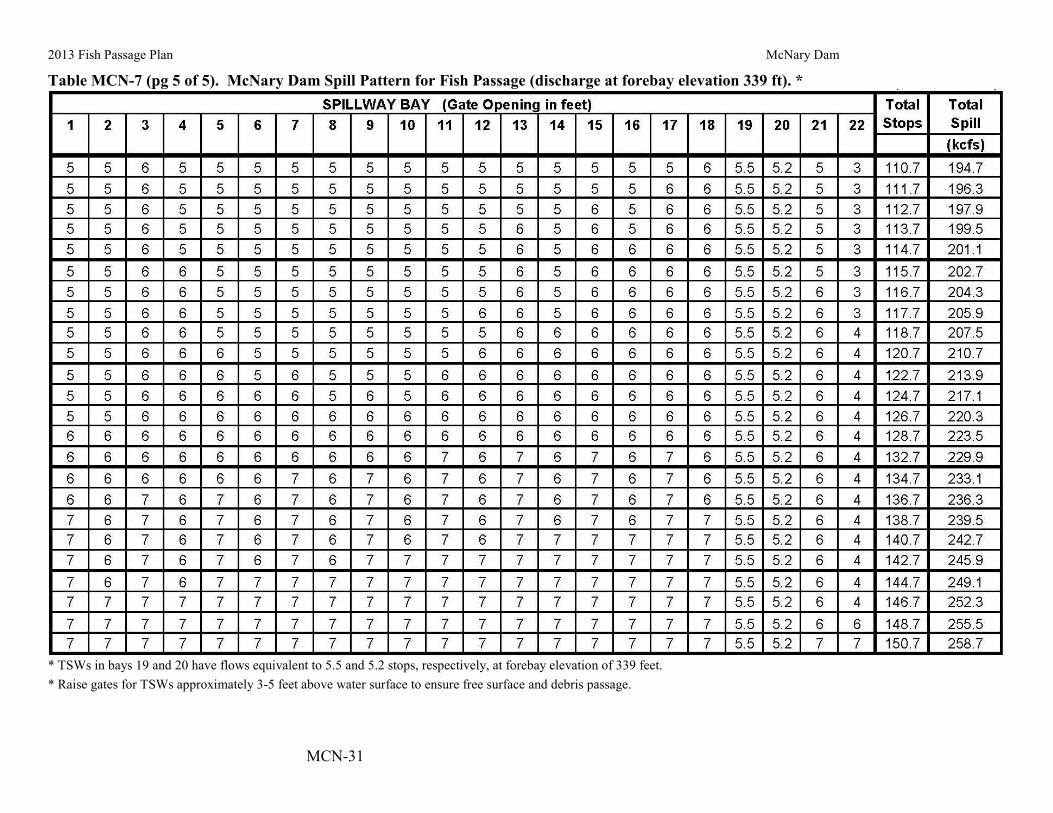
2013 Fish Passage Plan McNary Dam
MCN-31
Table MCN-7 (pg 5 of 5). McNary Dam Spill Pattern for Fish Passage (discharge at forebay elevation 339 ft). *
* TSWs in bays 19 and 20 have flows equivalent to 5.5 and 5.2 stops, respectively, at forebay elevation of 339 feet. * Raise gates for TSWs approximately 3-5 feet above water surface to ensure free surface and debris passage.

2013 Fish Passage Plan McNary Dam
MCN-32
Table MCN-8. McNary Dam Spill Pattern for Navigation (discharge at forebay elevation 339 ft). *
* TSWs in bays 19 and 20 have flows equivalent to 5.5 and 5.2 stops, respectively, at forebay elevation of 339 feet. * Raise gates for TSWs approximately 3-5 feet above water surface to ensure free surface and debris passage.
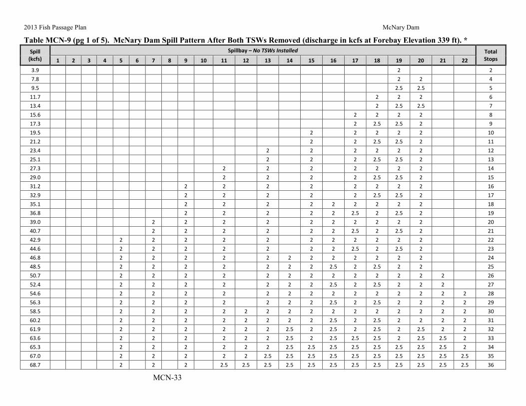
2013 Fish Passage Plan McNary Dam
MCN-33
Table MCN-9 (pg 1 of 5). McNary Dam Spill Pattern After Both TSWs Removed (discharge in kcfs at Forebay Elevation 339 ft). * Spill
(kcfs) Spillbay – No TSWs Installed Total
Stops 1 2 3 4 5 6 7 8 9 10 11 12 13 14 15 16 17 18 19 20 21 22
3.9 2 2 7.8 2 2 4 9.5 2.5 2.5 5
11.7 2 2 2 6 13.4 2 2.5 2.5 7 15.6 2 2 2 2 8 17.3 2 2.5 2.5 2 9 19.5 2 2 2 2 2 10 21.2 2 2 2.5 2.5 2 11 23.4 2 2 2 2 2 2 12 25.1 2 2 2 2.5 2.5 2 13 27.3 2 2 2 2 2 2 2 14 29.0 2 2 2 2 2.5 2.5 2 15 31.2 2 2 2 2 2 2 2 2 16 32.9 2 2 2 2 2 2.5 2.5 2 17 35.1 2 2 2 2 2 2 2 2 2 18 36.8 2 2 2 2 2 2.5 2 2.5 2 19 39.0 2 2 2 2 2 2 2 2 2 2 20 40.7 2 2 2 2 2 2 2.5 2 2.5 2 21 42.9 2 2 2 2 2 2 2 2 2 2 2 22 44.6 2 2 2 2 2 2 2 2.5 2 2.5 2 23 46.8 2 2 2 2 2 2 2 2 2 2 2 2 24 48.5 2 2 2 2 2 2 2 2.5 2 2.5 2 2 25 50.7 2 2 2 2 2 2 2 2 2 2 2 2 2 26 52.4 2 2 2 2 2 2 2 2.5 2 2.5 2 2 2 27 54.6 2 2 2 2 2 2 2 2 2 2 2 2 2 2 28 56.3 2 2 2 2 2 2 2 2.5 2 2.5 2 2 2 2 29 58.5 2 2 2 2 2 2 2 2 2 2 2 2 2 2 2 30 60.2 2 2 2 2 2 2 2 2 2.5 2 2.5 2 2 2 2 31 61.9 2 2 2 2 2 2 2.5 2 2.5 2 2.5 2 2.5 2 2 32 63.6 2 2 2 2 2 2 2.5 2 2.5 2.5 2.5 2 2.5 2.5 2 33 65.3 2 2 2 2 2 2 2.5 2.5 2.5 2.5 2.5 2.5 2.5 2.5 2 34 67.0 2 2 2 2 2 2.5 2.5 2.5 2.5 2.5 2.5 2.5 2.5 2.5 2.5 35 68.7 2 2 2 2.5 2.5 2.5 2.5 2.5 2.5 2.5 2.5 2.5 2.5 2.5 2.5 36

2013 Fish Passage Plan McNary Dam
MCN-34
Spill (kcfs)
Spillbay – No TSWs Installed Total Stops 1 2 3 4 5 6 7 8 9 10 11 12 13 14 15 16 17 18 19 20 21 22
70.4 2 2 2 2.5 2.5 2.5 2.5 2.5 3 2.5 3 2.5 2.5 2.5 2.5 37 71.3 2 3.5 3.5 2 2 2 2 2 2 2 2 2 2 2 2 2 2 37 73.0 2 3.5 3.5 2.5 2.5 2 2 2 2 2 2 2 2 2 2 2 2 38 74.7 2.5 3.5 3.5 2.5 2.5 2.5 2 2 2 2 2 2 2 2 2 2 2 39 76.3 2.5 4 4 2.5 2.5 2.5 2 2 2 2 2 2 2 2 2 2 2 40 78.0 2.5 4 4 2.5 2.5 2.5 2.5 2.5 2 2 2 2 2 2 2 2 2 41 79.6 2.5 4.5 4.5 2.5 2.5 2.5 2.5 2.5 2 2 2 2 2 2 2 2 2 42 81.3 2.5 4.5 4.5 2.5 2.5 2.5 2.5 2.5 2.5 2.5 2 2 2 2 2 2 2 43 82.9 2.5 5 5 2.5 2.5 2.5 2.5 2.5 2.5 2.5 2 2 2 2 2 2 2 44 85.1 2.5 5 5 2.5 2.5 2.5 2.5 2.5 2 2 2 2 2 2 2 2 2 2 45 86.8 2.5 5 5 2.5 2.5 2.5 2.5 2.5 2.5 2.5 2 2 2 2 2 2 2 2 46 88.5 2.5 5 5 2.5 2.5 2.5 2.5 2.5 2.5 2.5 2.5 2.5 2 2 2 2 2 2 47 90.2 2.5 5 5 2.5 2.5 2.5 2.5 2.5 2.5 2.5 2.5 2.5 2.5 2 2.5 2 2 2 48 92.4 2.5 5 5 2.5 2.5 2.5 2.5 2.5 2.5 2.5 2.5 2.5 2 2 2 2 2 2 2 49 94.1 2.5 5 5 2.5 2.5 2.5 2.5 2.5 2.5 2.5 2.5 2.5 2.5 2 2.5 2 2 2 2 50 95.8 2.5 5 5 2.5 2.5 2.5 2.5 2.5 2.5 2.5 2.5 2.5 2.5 2.5 2.5 2 2.5 2 2 51 98.0 2.5 5 5 2.5 2.5 2.5 2.5 2.5 2.5 2.5 2.5 2.5 2.5 2 2.5 2 2 2 2 2 52 99.7 2.5 5 5 2.5 2.5 2.5 2.5 2.5 2.5 2.5 2.5 2.5 2.5 2 2.5 2 2.5 2 2.5 2 53
101.4 3 5 5 2.5 2.5 2.5 2.5 2.5 2.5 2.5 2.5 2.5 2.5 2.5 2.5 2 2.5 2 2.5 2 54 103.1 3 5 5 2.5 2.5 2.5 2.5 2.5 2.5 2.5 2.5 2.5 2.5 2.5 2.5 2.5 2.5 2.5 2.5 2 55 105.3 3 5 5 2.5 2.5 2.5 2.5 2.5 2.5 2.5 2.5 2.5 2.5 2.5 2.5 2 2.5 2 2.5 2 2 56 107.0 3 5 5 2.5 2.5 2.5 2.5 2.5 2.5 2.5 2.5 2.5 2.5 2.5 2.5 2.5 2.5 2.5 2.5 2 2 57 108.7 3 5 5 3 3 2.5 2.5 2.5 2.5 2.5 2.5 2.5 2.5 2.5 2.5 2.5 2.5 2.5 2.5 2 2 58 110.4 3 5 5 3 3 3 3 2.5 2.5 2.5 2.5 2.5 2.5 2.5 2.5 2.5 2.5 2.5 2.5 2 2 59 112.1 3 5 5 3 3 3 3 2.5 2.5 2.5 2.5 2.5 2.5 2.5 2.5 2.5 2.5 2.5 2.5 2.5 2.5 60 114.3 3 5 5 3 3 3 3 2.5 2.5 2.5 2.5 2.5 2.5 2.5 2.5 2.5 2.5 2.5 2.5 2 2 2 61 116.0 3.5 5 5 3 3 3 3 2.5 2.5 2.5 2.5 2.5 2.5 2.5 2.5 2.5 2.5 2.5 2.5 2.5 2 2 62 117.7 3.5 5 5 3 3 3 3 2.5 2.5 2.5 2.5 2.5 2.5 2.5 2.5 2.5 2.5 2.5 2.5 2.5 2.5 2.5 63 119.4 3.5 5 5 3 3 3 3 3 3 2.5 2.5 2.5 2.5 2.5 2.5 2.5 2.5 2.5 2.5 2.5 2.5 2.5 64 121.1 3.5 5 5 3 3 3 3 3 3 3 3 2.5 2.5 2.5 2.5 2.5 2.5 2.5 2.5 2.5 2.5 2.5 65 122.8 3.5 5 5 3 3 3 3 3 3 3 3 2.5 3 2.5 3 2.5 2.5 2.5 2.5 2.5 2.5 2.5 66 124.5 3.5 5 5 3 3 3 3 3 3 3 3 2.5 3 2.5 3 2.5 3 2.5 3 2.5 2.5 2.5 67 126.0 3.5 6 6 3 3 3 3 3 3 3 3 2.5 3 2.5 3 2.5 2.5 2.5 2.5 2.5 2.5 2.5 68 127.6 4 6 6 3 3 3 3 3 3 3 3 2.5 3 2.5 3 2.5 3 2.5 2.5 2.5 2.5 2.5 69 129.3 4 6 6 3 3 3 3 3 3 3 3 3 3 2.5 3 2.5 3 2.5 3 2.5 2.5 2.5 70

2013 Fish Passage Plan McNary Dam
MCN-35
Spill (kcfs)
Spillbay – No TSWs Installed Total Stops 1 2 3 4 5 6 7 8 9 10 11 12 13 14 15 16 17 18 19 20 21 22
131.0 4 6 6 3 3 3 3 3 3 3 3 3 3 3 3 3 3 2.5 3 2.5 2.5 2.5 71 132.7 4 6 6 3 3 3 3 3 3 3 3 3 3 3 3 3 3 3 3 3 2.5 2.5 72 134.4 4 6 6 3 3 3 3 3 3 3 3 3 3 3 3 3 3 3 3 3 3 3 73 136.0 4 6 6 3.5 3 3.5 3 3 3 3 3 3 3 3 3 3 3 3 3 3 3 3 74 137.6 4 6 6 3.5 3 3.5 3 3.5 3 3.5 3 3 3 3 3 3 3 3 3 3 3 3 75 139.2 4 6 6 3.5 3 3.5 3 3.5 3 3.5 3 3.5 3 3.5 3 3 3 3 3 3 3 3 76 140.8 4.5 7 7 3.5 3 3.5 3 3.5 3 3 3 3 3 3 3 3 3 3 3 3 3 3 77 142.4 4.5 7 7 3.5 3 3.5 3 3.5 3 3.5 3 3.5 3 3 3 3 3 3 3 3 3 3 78 144.0 4.5 7 7 3.5 3.5 3.5 3 3.5 3 3.5 3 3.5 3 3.5 3 3 3 3 3 3 3 3 79 145.6 4.5 7 7 3.5 3.5 3.5 3.5 3.5 3.5 3.5 3 3.5 3 3.5 3 3 3 3 3 3 3 3 80 147.2 4.5 7 7 4 3.5 4 3.5 3.5 3.5 3.5 3 3.5 3 3.5 3 3 3 3 3 3 3 3 81 148.8 4.5 7 7 4 3.5 4 3.5 3.5 3.5 3.5 3.5 3.5 3.5 3.5 3 3 3 3 3 3 3 3 82 150.4 4.5 7 7 4 3.5 4 3.5 3.5 3.5 3.5 3.5 3.5 3.5 3.5 3 3.5 3 3.5 3 3 3 3 83 152.0 4.5 7 7 4 3.5 4 3.5 3.5 3.5 3.5 3.5 3.5 3.5 3.5 3.5 3.5 3 3.5 3 3.5 3 3 84 153.6 4.5 7 7 4 3.5 4 3.5 3.5 3.5 3.5 3.5 3.5 3.5 3.5 3.5 3.5 3.5 3.5 3.5 3.5 3 3 85 155.2 4.5 7 7 4 3.5 4 3.5 3.5 3.5 3.5 3.5 3.5 3.5 3.5 3.5 3.5 3.5 3.5 3.5 3.5 3.5 3.5 86 157.0 4.5 8 8 4 3.5 4 3.5 3.5 3.5 3.5 3.5 3.5 3.5 3.5 3.5 3.5 3.5 3.5 3.5 3.5 3 3 87 158.6 4.5 8 8 4 3.5 4 3.5 3.5 3.5 3.5 3.5 3.5 3.5 3.5 3.5 3.5 3.5 3.5 3.5 3.5 3.5 3.5 88 160.2 4.5 8 8 4 3.5 4 3.5 3.5 3.5 3.5 3.5 3.5 3.5 3.5 3.5 4 3.5 4 3.5 3.5 3.5 3.5 89 161.8 4.5 8 8 4 3.5 4 3.5 3.5 3.5 3.5 3.5 3.5 3.5 4 3.5 4 3.5 4 3.5 4 3.5 3.5 90 163.4 4.5 8 8 4 3.5 4 3.5 3.5 3.5 4 3.5 4 3.5 4 3.5 4 3.5 4 3.5 4 3.5 3.5 91 165.0 4.5 8 8 4 3.5 4 3.5 4 3.5 4 3.5 4 3.5 4 3.5 4 3.5 4 3.5 4 3.5 4 92 166.6 4.5 8 8 4 3.5 4 3.5 4 3.5 4 3.5 4 3.5 4 3.5 4 4 4 4 4 3.5 4 93 168.2 4.5 8 8 4 3.5 4 3.5 4 3.5 4 3.5 4 4 4 4 4 4 4 4 4 3.5 4 94 169.8 4.5 8 8 4 3.5 4 3.5 4 3.5 4 4 4 4 4 4 4 4 4 4 4 4 4 95 171.4 4.5 8 8 4 3.5 4 3.5 4 3.5 4 4 4 4 4 4 4.5 4 4.5 4 4 4 4 96 173.0 4.5 8 8 4 3.5 4 3.5 4 3.5 4 4 4 4 4 4 4.5 4.5 4.5 4.5 4 4 4 97 174.6 4.5 8 8 4 3.5 4 3.5 4 3.5 4 4 4 4 4.5 4 4.5 4.5 4.5 4.5 4.5 4 4 98 176.2 5 8 8 4 3.5 4 3.5 4 4 4 4 4 4 4.5 4 4.5 4.5 4.5 4.5 4.5 4 4 99 177.8 5 8 8 4 3.5 4 3.5 4 4 4.5 4 4.5 4 4.5 4 4.5 4.5 4.5 4.5 4.5 4 4 100 179.4 5 8 8 4 3.5 4 3.5 4 4 4.5 4 4.5 4 4.5 4.5 4.5 4.5 4.5 4.5 4.5 4.5 4 101 181.0 5 8 8 4 3.5 4 3.5 4 4 4.5 4 4.5 4.5 4.5 4.5 4.5 4.5 4.5 4.5 4.5 4.5 4.5 102 182.6 5 8 8 4 3.5 4 3.5 4 4 4.5 4 4.5 4.5 4.5 4.5 5 4.5 5 4.5 4.5 4.5 4.5 103 184.2 5 8 8 4 3.5 4 3.5 4 4 4.5 4 4.5 4.5 5 4.5 5 4.5 5 4.5 5 4.5 4.5 104 185.8 5 8 8 4 4 4 4 4 4 4.5 4 4.5 4.5 5 4.5 5 4.5 5 4.5 5 4.5 4.5 105

2013 Fish Passage Plan McNary Dam
MCN-36
Spill (kcfs)
Spillbay – No TSWs Installed Total Stops 1 2 3 4 5 6 7 8 9 10 11 12 13 14 15 16 17 18 19 20 21 22
187.4 5 8 8 4 4 4 4 4.5 4 4.5 4 4.5 4.5 5 4.5 5 5 5 4.5 5 4.5 4.5 106 189.0 6 8 8 4 4 4 4 4.5 4 4.5 4 4.5 4.5 5 4.5 5 5 5 4.5 5 4.5 4.5 107 190.6 6 8 8 4 4 4 4 4.5 4 4.5 4 4.5 4.5 5 5 5 5 5 5 5 4.5 4.5 108 192.2 6 8 8 4 4 4 4 4.5 4 4.5 4.5 4.5 4.5 5 5 5 5 5 5 5 5 4.5 109 193.8 6 8 8 4.5 4 4.5 4 4.5 4 4.5 4.5 4.5 4.5 5 5 5 5 5 5 5 5 4.5 110 195.4 6 8 8 4.5 4 4.5 4 4.5 4.5 4.5 4.5 5 4.5 5 5 5 5 5 5 5 5 4.5 111 197.0 6 8 8 4.5 4 4.5 4.5 4.5 4.5 5 4.5 5 4.5 5 5 5 5 5 5 5 5 4.5 112 198.6 6 8 8 4.5 4.5 4.5 4.5 5 4.5 5 4.5 5 4.5 5 5 5 5 5 5 5 5 4.5 113 200.2 6 8 8 5 4.5 5 4.5 5 4.5 5 4.5 5 4.5 5 5 5 5 5 5 5 5 4.5 114 201.8 6 8 8 5 4.5 5 4.5 5 4.5 5 4.5 5 5 5 5 5 5 5 5 5 5 5 115 203.4 6 8 8 5 4.5 5 4.5 5 4.5 5 4.5 5 5 5 5 5 6 5 5 5 5 5 116 206.6 6 8 8 5 4.5 5 4.5 5 4.5 5 4.5 5 5 5 6 5 6 5 6 5 5 5 118 209.8 6 8 8 5 4.5 5 4.5 5 4.5 5 4.5 5 6 5 6 5 6 5 6 5 6 5 120 213.0 6 8 8 5 4.5 5 4.5 5 4.5 5 4.5 5 6 5 6 6 6 6 6 5 6 5 122 216.2 6 8 8 5 5 5 5 5 5 5 5 5 6 5 6 6 6 6 6 5 6 5 124 219.4 7 9 8 5 5 5 5 5 5 5 5 5 6 5 6 6 6 6 6 5 6 5 126 222.6 7 9 8 5 5 5 5 5 5 5 5 5 6 6 6 6 6 6 6 6 6 5 128 225.8 7 9 8 5 5 5 5 5 5 5 5 6 6 6 6 6 6 6 6 6 6 6 130 229.0 7 9 8 5 5 5 5 5 5 6 6 6 6 6 6 6 6 6 6 6 6 6 132 232.2 7 9 8 5 5 5 5 5 5 6 6 6 6 6 7 6 6 7 6 6 6 6 134 235.4 7 9 8 5 5 5 5 5 5 6 6 6 6 6 7 7 6 7 7 6 6 6 136 238.6 7 9 8 5 5 5 5 5 5 6 6 6 6 7 7 7 7 7 7 6 6 6 138 241.8 7 9 8 5 5 5 5 6 6 6 6 6 6 7 7 7 7 7 7 6 6 6 140 245.1 7 9 8 5 5 5 5 6 6 6 6 6 6 7 7 7 8 7 7 7 6 6 142 248.5 7 9 8 5 5 5 5 6 6 6 6 6 6 7 8 7 8 7 8 7 6 6 144 251.7 7 9 8 5 5 5 5 6 6 7 6 7 6 7 8 7 8 7 8 7 6 6 146 254.9 7 9 8 6 5 6 5 6 6 7 6 7 6 7 8 7 8 7 8 7 6 6 148 258.1 7 9 8 6 5 6 5 6 6 7 6 7 7 7 8 7 8 7 8 7 7 6 150 261.4 7 9 8 6 5 6 5 6 6 7 6 7 8 7 8 7 8 7 8 7 7 7 152 264.6 7 9 8 6 6 6 6 6 6 7 6 7 8 7 8 7 8 7 8 7 7 7 154 267.9 7 9 8 6 6 6 6 6 6 7 7 7 8 7 8 8 8 7 8 7 7 7 156 271.3 7 9 8 6 6 6 6 6 6 7 7 7 8 8 8 8 8 8 8 7 7 7 158 274.7 7 9 8 6 6 6 6 6 6 7 7 8 8 8 8 8 8 8 8 8 7 7 160 277.9 7 9 8 6 6 7 6 6 7 7 7 8 8 8 8 8 8 8 8 8 7 7 162 281.3 7 9 8 6 6 7 6 6 7 7 8 8 8 8 8 8 8 8 8 8 8 7 164

2013 Fish Passage Plan McNary Dam
MCN-37
Spill (kcfs)
Spillbay – No TSWs Installed Total Stops 1 2 3 4 5 6 7 8 9 10 11 12 13 14 15 16 17 18 19 20 21 22
284.5 7 9 8 7 6 7 6 7 7 7 8 8 8 8 8 8 8 8 8 8 8 7 166 287.9 7 9 8 7 6 7 6 7 7 8 8 8 8 8 8 8 8 8 8 8 8 8 168 291.1 7 9 8 7 7 7 7 7 7 8 8 8 8 8 8 8 8 8 8 8 8 8 170 294.5 8 9 8 7 7 7 7 7 8 8 8 8 8 8 8 8 8 8 8 8 8 8 172 297.9 8 9 8 7 8 7 8 7 8 8 8 8 8 8 8 8 8 8 8 8 8 8 174 301.3 8 9 8 7 8 8 8 8 8 8 8 8 8 8 8 8 8 8 8 8 8 8 176
* Special care MAY be required to open and close Bays 1 & 22. (This will need to be verified by field testing.) Opening sequence:
a) Open Bays 2 – 21 first, as specified in the spill pattern table. b) After Bays 2 - 21 have been set and operating for at least 10 minutes, open Bays 1 & 22 to their desired settings.
Closing Sequence: a) Close Bays 1 & 22 prior to closing Bays 2-21.

2013 Fish Passage Plan McNary Dam
MCN-38
Table MCN-10 (pg 1 of 3). McNary Dam Spill Pattern During TSW Removal (discharge in kcfs at Forebay Elevation 339 ft).* Spill
(kcfs) Spillbay – During TSW Removal Total
Stops 1 2 3 4 5 6 7 8 9 10 11 12 13 14 15 16 17 18 19 20 21 22
73.5 2 3 4 3 2 2 2 2 2 2 2 2 2 2 2 2 2 38 75.1 2 4 4 3 2 2 2 2 2 2 2 2 2 2 2 2 2 39 76.8 3 4 4 3 2 2 2 2 2 2 2 2 2 2 2 2 2 40 78.4 3 4 4 3 3 2 2 2 2 2 2 2 2 2 2 2 2 41 80.1 3 4 4 3 3 3 2 2 2 2 2 2 2 2 2 2 2 42 81.6 3 4 5 3 3 3 2 2 2 2 2 2 2 2 2 2 2 43 83.2 3 5 5 3 3 3 2 2 2 2 2 2 2 2 2 2 2 44 84.9 3 5 5 3 3 3 3 2 2 2 2 2 2 2 2 2 2 45 86.5 3 5 5 3 3 3 3 3 2 2 2 2 2 2 2 2 2 46 88.2 3 5 5 3 3 3 3 3 3 2 2 2 2 2 2 2 2 47 89.8 3 5 5 3 3 3 3 3 3 3 2 2 2 2 2 2 2 48 91.5 3 5 5 3 3 3 3 3 3 3 3 2 2 2 2 2 2 49 93.1 3 5 5 3 3 3 3 3 3 3 3 3 2 2 2 2 2 50 94.8 3 5 5 3 3 3 3 3 3 3 3 3 3 2 2 2 2 51 96.4 4 5 5 3 3 3 3 3 3 3 3 3 3 2 2 2 2 52 98.1 4 5 5 4 3 3 3 3 3 3 3 3 3 2 2 2 2 53 99.7 4 5 5 4 4 3 3 3 3 3 3 3 3 2 2 2 2 54
101.3 4 5 6 4 4 3 3 3 3 3 3 3 3 2 2 2 2 55 102.9 4 6 6 4 4 3 3 3 3 3 3 3 3 2 2 2 2 56 104.6 4 6 6 4 4 4 3 3 3 3 3 3 3 2 2 2 2 57 106.2 4 6 6 4 4 4 4 3 3 3 3 3 3 2 2 2 2 58 107.9 4 6 6 4 4 4 4 4 3 3 3 3 3 2 2 2 2 59 109.5 4 6 6 4 4 4 4 4 4 3 3 3 3 2 2 2 2 60 111.2 4 6 6 4 4 4 4 4 4 4 3 3 3 2 2 2 2 61 112.8 4 6 6 4 4 4 4 4 4 4 4 3 3 2 2 2 2 62 114.5 4 6 6 4 4 4 4 4 4 4 4 4 3 2 2 2 2 63 116.1 4 6 6 4 4 4 4 4 4 4 4 4 4 2 2 2 2 64 117.8 4 6 6 4 4 4 4 4 4 4 4 4 4 3 2 2 2 65 119.4 4 6 6 4 4 4 4 4 4 4 4 4 4 3 3 2 2 66 121.1 4 6 6 4 4 4 4 4 4 4 4 4 4 3 3 3 2 67 122.7 4 6 6 4 4 4 4 4 4 4 4 4 4 3 3 3 3 68 124.3 5 6 6 4 4 4 4 4 4 4 4 4 4 3 3 3 3 69 125.8 5 6 6 5 4 4 4 4 4 4 4 4 4 3 3 3 3 70

2013 Fish Passage Plan McNary Dam
MCN-39
Spill (kcfs)
Spillbay – During TSW Removal Total Stops 1 2 3 4 5 6 7 8 9 10 11 12 13 14 15 16 17 18 19 20 21 22
127.4 5 6 6 5 5 4 4 4 4 4 4 4 4 3 3 3 3 71 129.1 5 6 7 5 5 4 4 4 4 4 4 4 4 3 3 3 3 72 130.7 5 7 7 5 5 4 4 4 4 4 4 4 4 3 3 3 3 73 132.3 5 7 7 5 5 5 4 4 4 4 4 4 4 3 3 3 3 74 133.8 5 7 7 5 5 5 5 4 4 4 4 4 4 3 3 3 3 75 135.4 5 7 7 5 5 5 5 5 4 4 4 4 4 3 3 3 3 76 136.9 5 7 7 5 5 5 5 5 5 4 4 4 4 3 3 3 3 77 138.5 5 7 7 5 5 5 5 5 5 5 4 4 4 3 3 3 3 78 140.1 5 7 7 5 5 5 5 5 5 5 5 4 4 3 3 3 3 79 141.6 5 7 7 5 5 5 5 5 5 5 5 5 4 3 3 3 3 80 143.2 5 7 7 5 5 5 5 5 5 5 5 5 5 3 3 3 3 81 144.8 5 7 7 5 5 5 5 5 5 5 5 5 5 4 3 3 3 82 146.5 5 7 7 5 5 5 5 5 5 5 5 5 5 4 4 3 3 83 148.1 5 7 7 5 5 5 5 5 5 5 5 5 5 4 4 4 3 84 149.8 5 7 7 5 5 5 5 5 5 5 5 5 5 4 4 4 4 85 151.3 6 7 7 5 5 5 5 5 5 5 5 5 5 4 4 4 4 86 152.9 6 7 7 6 5 5 5 5 5 5 5 5 5 4 4 4 4 87 154.5 6 7 7 6 6 5 5 5 5 5 5 5 5 4 4 4 4 88 156.1 6 7 8 6 6 5 5 5 5 5 5 5 5 4 4 4 4 89 157.7 6 8 8 6 6 5 5 5 5 5 5 5 5 4 4 4 4 90 159.3 6 8 8 6 6 6 5 5 5 5 5 5 5 4 4 4 4 91 160.9 6 8 8 6 6 6 6 5 5 5 5 5 5 4 4 4 4 92 162.5 6 8 8 6 6 6 6 6 5 5 5 5 5 4 4 4 4 93 164.1 6 8 8 6 6 6 6 6 6 5 5 5 5 4 4 4 4 94 165.7 6 8 8 6 6 6 6 6 6 6 5 5 5 4 4 4 4 95 167.3 6 8 8 6 6 6 6 6 6 6 6 5 5 4 4 4 4 96 168.9 6 8 8 6 6 6 6 6 6 6 6 6 5 4 4 4 4 97 170.5 6 8 8 6 6 6 6 6 6 6 6 6 6 4 4 4 4 98 172.1 6 8 8 6 6 6 6 6 6 6 6 6 6 5 4 4 4 99 173.6 6 8 8 6 6 6 6 6 6 6 6 6 6 5 5 4 4 100 175.2 6 8 8 6 6 6 6 6 6 6 6 6 6 5 5 5 4 101 176.7 6 8 8 6 6 6 6 6 6 6 6 6 6 5 5 5 5 102 178.4 7 8 8 6 6 6 6 6 6 6 6 6 6 5 5 5 5 103 180.1 7 8 8 7 6 6 6 6 6 6 6 6 6 5 5 5 5 104 181.7 7 8 8 7 7 6 6 6 6 6 6 6 6 5 5 5 5 105

2013 Fish Passage Plan McNary Dam
MCN-40
Spill (kcfs)
Spillbay – During TSW Removal Total Stops 1 2 3 4 5 6 7 8 9 10 11 12 13 14 15 16 17 18 19 20 21 22
183.3 7 8 9 7 7 6 6 6 6 6 6 6 6 5 5 5 5 106 184.9 7 9 9 7 7 6 6 6 6 6 6 6 6 5 5 5 5 107 186.6 7 9 9 7 7 7 6 6 6 6 6 6 6 5 5 5 5 108 188.2 7 9 9 7 7 7 7 6 6 6 6 6 6 5 5 5 5 109 189.9 7 9 9 7 7 7 7 7 6 6 6 6 6 5 5 5 5 110 191.5 7 9 9 7 7 7 7 7 7 6 6 6 6 5 5 5 5 111 193.2 7 9 9 7 7 7 7 7 7 7 6 6 6 5 5 5 5 112 194.9 7 9 9 7 7 7 7 7 7 7 7 6 6 5 5 5 5 113 196.5 7 9 9 7 7 7 7 7 7 7 7 7 6 5 5 5 5 114 198.2 7 9 9 7 7 7 7 7 7 7 7 7 7 5 5 5 5 115 199.8 7 9 9 7 7 7 7 7 7 7 7 7 7 6 5 5 5 116 201.4 7 9 9 7 7 7 7 7 7 7 7 7 7 6 6 5 5 117 203.0 7 9 9 7 7 7 7 7 7 7 7 7 7 6 6 6 5 118 204.6 7 9 9 7 7 7 7 7 7 7 7 7 7 6 6 6 6 119 206.2 8 9 9 7 7 7 7 7 7 7 7 7 7 6 6 6 6 120 207.8 8 9 9 8 7 7 7 7 7 7 7 7 7 6 6 6 6 121.0 209.3 8 9 9 8 8 7 7 7 7 7 7 7 7 6 6 6 6 122.0 210.9 8 9 10 8 8 7 7 7 7 7 7 7 7 6 6 6 6 123.0 212.5 8 10 10 8 8 7 7 7 7 7 7 7 7 6 6 6 6 124.0 214.1 8 10 10 8 8 8 7 7 7 7 7 7 7 6 6 6 6 125.0 215.7 8 10 10 8 8 8 8 7 7 7 7 7 7 6 6 6 6 126.0 217.3 8 10 10 8 8 8 8 8 7 7 7 7 7 6 6 6 6 127.0 218.9 8 10 10 8 8 8 8 8 8 7 7 7 7 6 6 6 6 128.0 220.5 8 10 10 8 8 8 8 8 8 8 7 7 7 6 6 6 6 129.0 222.1 8 10 10 8 8 8 8 8 8 8 8 7 7 6 6 6 6 130.0
* Special care MAY be required to open and close Bays 1 & 22. (This will need to be verified by field testing.) Opening sequence:
a) Open Bays 2 – 21 first, as specified in the spill pattern table. b) After Bays 2 - 21 have been set and operating for at least 10 minutes, open Bays 1 & 22 to their desired settings.
Closing Sequence: a) Close Bays 1 & 22 prior to closing Bays 2-21.

2013 Fish Passage Plan
2013 Fish Passage Plan Section 6 – Ice Harbor Dam
Table of Contents 1. Fish Passage Information.......... ........................................................................... IHR-01
1.1. Juvenile Fish Passage ............................................................................ IHR-01 1.2. Adult Fish Passage ................................................................................ IHR-01
2. Project Operation ................................................................................................. IHR-05 2.1. Spill Management ................................................................................. IHR-05 2.2. Dissolved Gas Management and Control ............................................. IHR-05 2.3. Operating Criteria ................................................................................. IHR-05
3. Project Maintenance............................................................................................. IHR-14 3.1. Juvenile Fish Passage Facilities ............................................................ IHR-14 3.2. Adult Fish Passage Facilities ................................................................ IHR-16
4. Turbine Unit Operation and Maintenance ........................................................... IHR-18 4.1. Turbine Unit Operation ......................................................................... IHR-18 4.2. Turbine Unit Outages During High River Flow Periods ..................... IHR-19 4.3. Turbine Unit Maintenance .................................................................... IHR-20
5. Forebay Debris Removal ..................................................................................... IHR-21 5.1. Special Spills ......................................................................................... IHR-22

2013 Fish Passage Plan Ice Harbor Dam
IHR-1
Section 6 Ice Harbor Dam
1. FISH PASSAGE INFORMATION The locations of fish passage facilities at Ice Harbor Lock and Dam are shown in Figure IHR-1. Dates of project operations for fish purposes and special operations are listed in Table IHR-3. 1.1. Juvenile Fish Passage. 1.1.1. Facilities Description. The juvenile fish passage facilities at Ice Harbor consist of standard length submersible traveling screens, vertical barrier screens, 12" orifices, collection channel and dewatering structure, sampling facilities, transportation flume/pipe to the tailrace below the project, and a full-flow PIT tag detection system. 1.1.2. Juvenile Migration Timing. Juvenile passage timing at Ice Harbor Dam corresponds closely with juvenile passage at Lower Monumental Dam (Table LMN-1). Salmon, steelhead, bull trout, lamprey, and other species are routinely counted when sampling occurs at Ice Harbor. Maintenance of juvenile fish passage facilities that may impact juvenile fish passage or facility operations should be conducted during the winter maintenance season.
1.2. Adult Fish Passage. 1.2.1. Facilities Description. The adult fish passage facilities at Ice Harbor are made up of separate north and south shore facilities. The north shore facilities include a fish ladder with counting station, a small collection system, and a pumped auxiliary water supply system. The collection system includes two downstream entrances and one side entrance into the spillway basin. In normal operation one downstream entrance is used and the other two entrances are closed. The auxiliary water is supplied by two electric pumps with a third pump as a backup. The south shore facilities are comprised of a fish ladder with counting station, two south shore entrances, a powerhouse collection system, and a pumped auxiliary water supply system. The powerhouse collection system includes two downstream entrances and one side entrance into the spillway basin at the north end of the powerhouse, four operating floating orifices, and a common transportation channel. One of the downstream north powerhouse entrances and four of the floating orifices are used during normal operation. At the south shore entrances, one entrance is normally used. The auxiliary water is supplied by eight electric pumps of which from six to eight are normally used to provide the required flows. The excess water from the juvenile fish passage facilities is routed into the fish pump discharge chamber to provide additional attraction flow. The upper ends of both ladders have PIT tag detectors. 1.2.2. Adult Migration Timing. Upstream migrants are present at Ice Harbor Dam throughout the year and adult passage facilities are operated year-round. Maintenance of adult fish facilities is scheduled for January and February to minimize impacts on upstream migrants. Facilities are usually shut down one shore at a time for maintenance. Adult salmon, steelhead, shad, and lamprey are counted as per Table IHR-1, and these data appear daily on the Corps adult fish count website at: http://www.nwp.usace.army.mil/Missions/Environment/Fishdata.aspx. Salmon migration timing data appear in Table IHR-2. Sturgeon and bull trout are counted and recorded

2013 Fish Passage Plan Ice Harbor Dam
IHR-2
on the daily count summary sheet in the comments section, but do not appear daily on the Corps website due to relatively infrequent passage. These data are posted periodically during the passage season in the Miscellaneous Fish Counts report on the Corps’ website and summarized in the Annual Fish Passage Report. Table IHR-1. Adult Fish Counting Schedule at Ice Harbor Dam.
Count Period Counting Method and Hours 1
March 01, 2013 – March 31, 2013 Video 0400–2000 hours (PST) April 01, 2013 – October 31, 2013 Visual 0400–2000 hours (PST) November 01, 2013 – February 28, 2014 Video 0400–2000 hours (PST) 1. All count hours are shown in Pacific Standard Time (PST). Note that during daylight saving time (DST) from March 10–November 3, 2013, count hours will be adjusted forward one hour (DST = PST+1). Table IHR-2. Adult Counting Periods and Peak Migration Timing at Ice Harbor Dam (based on fish count data from years 1962-2012).
Species Count Period Earliest Peak Latest Peak Spring Chinook 4/1 – 6/11 4/22 5/26 Summer Chinook 6/12 – 8/11 6/12 7/23 Fall Chinook 8/12 – 10/31 9/2 9/30 Steelhead 4/1 – 10/31 9/15 10/12 Sockeye 4/1 – 10/31 7/1 9/22 Lamprey 4/1 – 10/31 7/21 9/3

Spillway Powerhouse
South ShoreFishway
North ShoreFishway
Fish Pumps
NavigationLock
FLO
W
Ice HarborLock and Dam
Fish Pumps
Fish CountingStation
Visitor Center andFish Counting and
Viewing Area
6 5 4 3 2 1
10 9 8 7 6 5 4 3 2 1
Tailrace DeckFishwayEntranceNEW 1
FishwayEntranceNFW 1 & 2
Figure IHR-1 Ice Harbor Lock and Dam General Site Plan
Juvenile FishSampling
Fishway Entrance
SFE 1
Juvenile Bypass Outfall
Lake Sacajawea
Snake River
Lake Wallula
Removable Spillway Weir(RSW)
G0PDWLSW
Text Box
Figure IHR- 1. Ice Harbor Lock and Dam General Site Plan.
G0PDWLSW
Text Box
IHR-3
G0PDWLSW
Text Box
Adult Fish Trap
G0PDWLSW
Line
G0PDWLSW
Text Box
2013 Fish Passage Plan Ice Harbor Dam

Task Name Start Finish Reference
2013 FISH PASSAGE SEASON 3/1/13 12/31/13 IHR 2.3Juvenile Fish Passage Season 4/1/13 12/15/13 IHR 2.3.1.2Adult Fish Passage Season 3/1/13 12/31/13 IHR 2.3.2.2
2013-2014 WINTER MAINTENANCE PERIOD 12/16/13 3/31/14 IHR 2.3.Juvenile Fish Facilities Winter Maintenance 12/16/13 3/31/14 IHR 2.3.1.1Adult Fish Facilities Winter Maintenance 1/1/14 2/28/14 IHR 2.3.2.1
ADULT FISH COUNTING 3/1/13 2/28/14 Table IHR-2Video 0400-2000 PST 3/1/13 3/31/13Visual 0400-2000 PST 4/1/13 10/31/13Video 0400-2000 PST 11/1/13 2/28/14
1% CONSTRAINTS (YEAR-ROUND) 3/1/13 2/28/14 IHR 4.1.21% soft constraint 3/1/13 3/31/131% hard constraint 4/1/13 10/31/131% soft constraint 11/1/13 2/28/14
TDG MONITORING 3/1/13 2/28/14 IHR 2.2TDG Monitoring - Tailrace (year-round) 3/1/13 2/28/14 IDSWTDG Monitoring - Forebay 4/1/13 8/31/13 IHRA
Operate Turbine Priority for Fish Passage 3/1/13 11/30/13 IHR 4.1; Table IHR-4
SPECIAL OPERATIONS & STUDIES 3/1/13 2/28/14 Appendix AFish Counting Accuracy Evaluation 3/1/13 2/28/14 App A IHR 2.4Lamprey Passage Evaluations 3/1/13 10/31/13 App A IHR 2.2DC System and Low Voltage Switchgear Replacement 3/1/13 8/31/13 App A IHR 1.5Adult Salmon Studies 3/30/13 10/31/13 App A IHR 2.1Video Monitoring of Fish Ladder Lamprey Modifications 6/15/13 9/30/13 App A IHR 2.3Doble Testing and Line #1 Disconnect Maintenance 8/1/13 9/30/13 App A IHR 1.3, 1.9
OPERATION OF JUVENILE FISH PASSAGE SYSTEM 4/1/13 12/15/13 IHR 2.3.1Juvenile Fish Bypass, Collection and Transportation 4/1/13 10/31/13Adult Fish Fallback Bypass 11/1/13 12/15/13
SPILL FOR FISH PASSAGE 4/3/13 8/31/13 Appendix ESpring Spill 4/3/13 6/20/13 end date approximateSummer Spill 6/21/13 8/31/13 start date approximate
Avian Abatement Measures 4/1/13 12/15/13 IHR 2.3.1.2.f
Backflush orifices once per 8-hour shift (at minimum) 4/1/13 7/31/13 IHR 2.3.1.2.c.6
Removable Spillway Weir (RSW) in service 4/3/13 8/31/13 IHR 2.3.1.2.g
Weekly Reports 3/1/13 12/31/13 IHR 2.3.3.1
Annual Report (for Dec 1, 2012 - Nov 30, 2013) 3/15/14 3/15/14 IHR 2.3.3.4
Jan Feb Mar Apr May Jun Jul Aug Sep Oct Nov Dec Jan Feb Mar1st Quarter 2nd Quarter 3rd Quarter 4th Quarter 1st Quarter
2013 2014
Table IHR-3. Ice Harbor Dam Dates of Fish-Related Operations for 2013 Fish Passage Season and 2013/14 Winter Maintenance Period.
IHR-4
2013 Fish Passage Plan Ice Harbor Dam
IHR-5
2. PROJECT OPERATIONS 2.1. Spill Management. See the Fish Operations Plan (Appendix E) for more information. 2.1.1. Involuntary spill at Ice Harbor is the result of river flow exceeding powerhouse capacity, insufficient generation loads to pass the river flow, turbine unit outages (forced or scheduled), or the failure of a key component of the juvenile fish passage facility which forces the project to spill to provide juvenile fish passage. Spill at Ice Harbor will be distributed in accordance with the spill patterns listed in Tables IHR-8, IHR-9, and IHR-10. Special spills for juvenile fish passage will be provided as detailed in Appendices A and E. 2.2. Dissolved Gas Management and Control. Total dissolved gas (TDG) levels at all projects are monitored in accordance with the TDG Monitoring Plan, included in the Water Management Plan as Appendix 4 and available online at: http://www.nwd-wc.usace.army.mil/tmt/documents/wmp/2013/. 2.3. Operating Criteria. 2.3.1. Juvenile Fish Passage Facilities. Operate from April 1–October 31 for juvenile fish passage and from November 1–December 15 for protecting adult fallbacks. The facilities should be operated according to the criteria below.
2.3.1.1. Winter Maintenance Period (December 16–March 31). Check and perform maintenance as required on the items listed below.
a. Forebay Area and Intakes.
1. Remove debris from forebay and gatewell slots. 2. Rake trashracks just prior to the operating season. 3. Measure gatewell drawdown in slots after cleaning trashracks with STSs in place. 4. Inspect and repair gatewell dip net as needed.
b. Submersible Traveling Screens (STSs) and Vertical Barrier Screens (VBSs).
1. Maintenance completed on all screens. 2. Inspect STSs prior to installation and operate one trial run (dogged off on deck) to ensure proper operation. 3. Log trial run. 4. Inspect all VBSs at least once per year with underwater video camera. Repair as needed.

2013 Fish Passage Plan Ice Harbor Dam
IHR-6
c. Collection Channel.
1. Water-up valve capable of operating when needed. 2. Orifice lights are operational. 3. Orifices clean and valves operating correctly. 4. Orifice air backflush system works correctly. 5. Netting along handrails maintained and in good condition. 6. Netting or covers over orifice chutes maintained and in good condition.
d. Dewatering Structure and Flume.
1. Inclined screen should be clean and in good condition with no gaps between screen panels, damaged panels, or missing silicone. 2. Screen cleaning system (brush and air flush) maintained and operating correctly. 3. Overflow weirs should be maintained, tested, and operating correctly. 4. All valves should be operating correctly. 5. Flume interior should be smooth with no rough edges. 6. Maintain full-flow PIT tag system as required. Coordinate with PSMFC.
e. Sampling Facilities.
1. Flume dewatering structure maintained in good operating condition with no holes or gaps between dewatering screen panels. Silicone sealer in good condition. 2. Flume drop gate should be maintained and in good operating condition. 3. The wet separator and fish distribution system should be maintained and ready for operation as designed. 4. All dewatering screens and seals in separator and flume must be in good condition with no holes or gaps between panels, or sharp edges. 5. All valves and switch gates maintained and in good operating condition. 6. All sampling equipment maintained and in good operating condition.

2013 Fish Passage Plan Ice Harbor Dam
IHR-7
7. Maintain juvenile PIT tag system as required. Coordinate with PSMFC.
f. Avian Predation Areas (Forebay and Tailrace). Inspect bird wires, water cannon, and other deterrent devices and repair or replace as needed. Where possible, install additional bird wires or other deterrent devices to cover areas of known avian predation activity. Prepare avian abatement contract as needed.
g. Maintenance Records. Record all maintenance and inspections.
2.3.1.2. Juvenile Fish Passage Period (April 1–December 15).
a. Forebay Area and Intakes.
1. Remove debris from forebay. 2. Remove debris from trashracks as required to maintain less than 1' of additional drawdown in gate slots. Additional raking may be required when heavy debris loads are present in the river. Coordinate turbine unit outages with other project work activities, if possible, to minimize turbine unit outages during the spring. 3. Inspect gatewell slots daily for debris, fish buildup, and contaminating substances (particularly oil). Clean gatewells before they become half covered with debris. If, due to the volume of the debris, it is not possible to keep the gatewell surfaces at least half clear, they should be cleaned at least once daily. If flows through an orifice indicate that an orifice may be partially obstructed with debris, the orifice will be closed and backflushed to remove the obstruction. If the obstruction can not be removed, the orifice shall be closed and the alternate orifice for that gatewell slot shall be operated. If both orifices become obstructed or plugged with debris, the turbine unit shall not be operated until the gatewell and orifices are cleared of debris. 4. If a visible accumulation of contaminating substances (such as oil) is detected in a gatewell and it cannot be removed within 24 hours, the gatewell orifices shall be closed immediately and the turbine unit shut down within one hour until the material has been removed and any problems corrected. A preferred method for removing oil from the water surface is to install absorbent (not adsorbent) socks, booms, or pads capable of encapsulating the material, tied off with a rope for later disposal. Action should be taken as soon as possible to remove the oil from the gatewell so the orifice can be reopened to allow the fish to exit the gatewell. Orifices shall not be closed for longer than 48 hours. 5. Dip bulkhead gatewell slots to remove fish prior to installing bulkhead for dewatering bulkhead slot.

2013 Fish Passage Plan Ice Harbor Dam
IHR-8
b. Submersible Traveling Screens (STSs) and Vertical Barrier Screens (VBSs).
1. Operate STSs in cycling mode when average fork length of sub-yearling chinook or sockeye is greater than 120 mm at Lower Monumental collection facility. 2. Operate STSs in continuous operational mode when average fork length of sub-yearling chinook or sockeye is less than 120 mm at Lower Monumental collection facility, or if there is evidence that smaller juvenile fish are present at the project. Return to cycling mode after one week has passed and re-evaluate. 3. Inspect each STS once per month by means of underwater video. Spot check VBSs at the same time. 4. Record STS amp readings daily. 5. If an STS or VBS is damaged or fails during the juvenile fish passage season, follow procedures detailed under unscheduled maintenance of STSs. In no case should a turbine unit be operated with a missing or a known non-operating or damaged STS or VBS. 6. Up to one-half of the STSs may be removed after October 1 for annual maintenance provided there is no operation of units without screens. 7. Make formal determination at end of season as to adequacy of STS screen mesh and replacement if necessary. 8. Inspect at least 2 VBSs in 2 different turbine units between spring and summer migration periods. Both turbine units should have been operated frequently during the spring. If a debris accumulation is noted, inspect other VBSs and clean debris as necessary.
9. When extreme cold weather is forecasted to occur for an extended period of time (defined as: forecasted temperatures <20°F for ≥24 hours) between Thanksgiving and December 15, ESBSs and STSs may be removed. The project will first request special permission from CENWW-OD-T. CENWW-OD-T will inform NOAA Fisheries and other FPOM participants of the action.
c. Collection Channel.
1. Orifices clean and operating. Operate at least one orifice per gatewell slot (preferably the north orifice). If the project is operating at MOP, additional orifices may be operated to maintain a full collection channel. If orifices must be closed to repair any part of the facility, monitor the gatewells hourly (unit is operating) or at least every two hours (unit is not operating) for fish condition and behavior. Also see section 3.1.2.2. to determine if the turbine unit must be shut down and if fish must be dipped from the gatewell(s).

2013 Fish Passage Plan Ice Harbor Dam
IHR-9
2. Orifice lights operational and operating on open orifices. Orifice lights and area lights may be turned off the evening before the channel is dewatered at the end of the season (dewatering occurs on December 16 or later) to encourage fish to exit the channel volitionally. Area lights can be turned on briefly for personnel access if necessary. 3. Replace all burned out orifice lights within 24 hours of notification. Orifice lights shall remain lighted 24 hours/day. 4. Orifice jets hitting no closer than 3’ from back wall, collection channel full. 5. Orifice valves are either fully open or closed. 6. Backflush orifices at least once per day. During periods of high fish and debris passage, April 1 through July 31, orifices should be inspected and backflushed once per 8-hour shift or more frequently as determined by the project biologist, to keep orifices clean. 7. Water-up valve capable of operating when needed. 8. The netting along handrails should be maintained in good condition with no holes or gaps in the netting. 9. Netting or covers over orifice chutes in good condition.
d. Dewatering Structure.
1. Trash sweep operating correctly. The Project Fisheries Biologist shall determine the frequency of sweep. It should be set as necessary to maintain a clean screen, with a minimum operation of at least once every 4 hours. If automated cleaning system problems occur, operate manually at least once per work shift, or more as necessary, to maintain a clean screen. 2. Clean trapezoidal section at least once per day, and more frequently if required, to maintain a clean condition. 3. Check overflow weirs to make sure they are operating correctly, perform maintenance as required. 4. There should be no gaps between screen panels in the inclined screen or holes in the screen panels. 5. Lights at the dewatering structure should be turned off at night, unless needed for personnel access, to encourage fish to move downstream volitionally.

2013 Fish Passage Plan Ice Harbor Dam
IHR-10
e. Sampling Facilities.
1. All screens should be inspected to make sure there are no holes or sharp edges. 2. Operate wet separator and fish distribution system as designed. Sample fish twice per week during the main juvenile bypass season to monitor juvenile fish descaling and other fish condition parameters. Sampling is not recommended when water temperatures exceed 70o F unless authorized by an ESA permit. Provide information in weekly report. 3. Crowder screen brushes should be maintained in good operating condition with no holes or sharp edges in the crowder screen. 4. Operate pre-anesthetic system as designed. 5. Inform PSMFC, in advance if possible, of situations that cause the PIT tag system to become inoperable (e.g. power outages) or that could result in confounding the interpretation of PIT tag data (e.g. operating in primary bypass mode without an operational full-flow detector, emergency dewaterings).
f. Avian Predation Areas (Forebay and Tailrace).
1. Bird wires and other avian deterrent devices shall be monitored to assure they are in good condition. Any broken wires or devices shall be replaced as soon as possible. 2. Harassment program in place to deter avian predation in areas actively used by birds and not covered by bird wires or other devices. 3. Project biologists shall routinely monitor project areas to determine areas of active avian predation and, if possible, adjust harassment program to cover these areas or install bird wires or other deterrent devices to discourage avian predation activities.
g. Removable Spillway Weir1 (RSW). The RSW will be in the raised position and operational on the first day of spill.
1. When the RSW is in operation, the spillgate shall be raised to where it does not touch flow passing down the RSW. 2. When the National Weather Service forecasts Ice Harbor inflows to exceed 200,000 cfs, initiate aggressive forebay debris removal so that RSW operation will not be impeded and coordinate with RCC and CENWW-OD-T.
1 Removable spillway weirs (RSWs) are installed at Ice Harbor, Lower Monumental and Lower Granite dams. RSWs are differentiated from Temporary Spillway Weirs (TSWs, installed at McNary, John Day and Little Goose dams) by being designed to be “removable” from the spillbay by controlled descent to the bottom of the forebay.

2013 Fish Passage Plan Ice Harbor Dam
IHR-11
3. Complete RSW stow (complete rotation to the landing pad) when inflows exceed 260,000 cfs, upstream river gage flows are increasing, and the NWS forecasts Ice Harbor inflow to exceed 300,000 cfs.
h. Inspection and Record Keeping. Inspect all facilities according to fish facilities monitoring plans. Record all maintenance and inspections.
2.3.2. Adult Fish Passage Facilities. Operate the adult fish passage facilities according to the following criteria.
2.3.2.1. Winter Maintenance Period (January 1–February 28).
a. Inspect all staff gages and water level indicators. Repair and/or clean where necessary. b. Dewater all ladders and inspect all dewatered sections of fish facilities for projections, debris, or plugged orifices which could injure fish or impede fish passage up the ladder. Fish ladder exit trashracks must have smooth surfaces where fish pass, and must have downstream edges that are adequately rounded or padded. Spare trashracks should be on hand for use as necessary. Inspect all diffuser gratings and chambers annually by dewatering or by using divers or video inspection techniques. All diffuser gratings and chambers are to be dewatered and physically inspected at least every 3 years. Repair deficiencies. c. Inspect for and clean debris from the fish ladder exits. All trashracks and picketed leads must be clean and installed correctly. d. Calibrate all water level measuring devices, as necessary, for proper facility operations. e. Inspect all spill gates and ensure that they are operable. f. Fish pumps maintained and ready for operation. g. Maintain adult PIT tag system as required. Coordinate with PSMFC. h. Maintain the adult fish trap as required. This can also be done outside of the January-February period because the trap is removable.
2.3.2.2. Fish Passage Period (March 1–December 31). Note: During extremely high flow periods when tailwater level exceeds elevation 353' msl, the fish pumps will be turned off so that the head differential on the auxiliary water supply conduit ceiling slab does not force water into the warehouse inside the dam.
a. Fishway Ladders. Water depth over weirs: 1' to 1.3'.

2013 Fish Passage Plan Ice Harbor Dam
IHR-12
b. Counting Windows. The crowder shall be opened to full count slot width when not counting. The crowder shall be open as far as possible to allow accurate counting and shall not be closed to less than 18” while counting. This will usually occur during high turbidity conditions to allow count accuracy criteria to be achieved. All equipment should be maintained and in good condition. The counting window and backboard should be cleaned as needed to maintain good visibility. Crowder ranges at IHR are as follows:
• North = 19.5” (fixed width) • South = 19.5” (fixed width)
c. Head on all Fishway Entrances. Head range: 1' to 2'. d. North Shore Entrance (NEW 1). Elevation of top of gate when on sill = 332.25'.
1. Operate downstream gate closest to shore. 2. Weir depth: 8' or greater below tailwater. At tailwaters less than elevation 340.25', weirs should be on sill. Note that at low river flow and tailwater, some of the diffusers are above tailwater and project may only be able to maintain a 6' weir depth. 3. North Shore Lower Diffuser Gates: If the tailwater is below elevation 344', the diffuser gates should be fully open. If the tailwater is above elevation 344', the diffuser gates should be one-half open.
e. North Powerhouse Entrances (NFE 1 and 2). Elevation at top of gate when on sill = 332.25'.
1. Operate 1 downstream gate. 2. Weir depth: 8' or greater below tailwater. At tailwaters less than elevation 340.25', weirs should be on sill. [Note: At low tailwater, weirs will bottom out and will be less than 8' below tailwater.]
f. Floating Orifice Gates. Operate 4 floating orifices, OG1, 4, 10, and 12. g. South Shore Entrance (SFE-1). Elevation of top of gate when on sill = 332.25'.
1. Operate entrance closest to powerhouse. 2. Weir depth: 8' or greater below tailwater. At tailwaters less than elevation 340.25', weirs should be on sill. [Note: At low tailwater, weirs will bottom out and will be less than 8' below tailwater.]
h. Channel Velocity. 1.5–4.0 feet per second (fps). Ice Harbor Dam monitors water velocity at the junction pool in the lower south fish ladder. The current device utilizes Doppler Technology. Decision for placement was not only what was considered to be

2013 Fish Passage Plan Ice Harbor Dam
IHR-13
the single most representative position, but also the placement for maintenance and ease of installation. In addition, head is measured at the north, north powerhouse, and south fishway entrances. i. Head on Trashracks.
1. Maximum head of 0.5' on ladder exits. 2. Maximum head on picketed leads shall be 0.3'. 3. Trashracks and picketed leads installed correctly.
j. Staff Gages and Water Level Indicators. All staff gages should be readable at all water levels encountered during the fish passage period. Repair or clean as necessary. k. Inform PSMFC, in advance if possible, of situations that cause the PIT tag system to become inoperable (e.g. power outages) or that could result in confounding the interpretation of PIT tag data (e.g. emergency dewaterings).
l. Facility Inspections.
1. Powerhouse operators shall inspect facilities once per day shift and check computer monitor information at least once during each back shift. 2. Project biologists shall inspect facilities three times per week. Inspect all facilities according to fish facilities monitoring program. 3. Picketed leads shall be inspected during all inspections to ensure they are clean and in the correct position (all the way down). 4. Project personnel shall check calibration of fishway control system twice per month to ensure that it is kept within calibration. This may be done as part of routine fishway inspections. 5. Inspect fishways daily for foreign substances (particularly oil). If substances are found, corrective actions should be undertaken immediately. 6. Record all inspections.
2.3.3. Facility Monitoring and Reporting. Project biologists shall inspect fish passage facilities at the frequencies listed in the juvenile and adult fish facilities operating criteria sections.
2.3.3.1. Project biologists shall prepare weekly reports, from March 1–December 31, summarizing project operations. The weekly reports should provide an overview of how the

2013 Fish Passage Plan Ice Harbor Dam
IHR-14
project and the fish passage facilities operated during the week and an evaluation of resulting fish passage conditions.
2.3.3.2. The reports shall include:
a. Any out-of-criteria situations observed and subsequent corrective actions taken; b. Any equipment malfunctions, breakdowns, or damage along with a summary of resulting repair activities; c. Adult fishway control calibrations; d. ESBS and VBS inspections; g. Any unusual activities which occurred at the project which may affect fish passage.
2.3.3.3. The weekly reports shall cover Friday–Thursday and emailed to CENWW-OD-T by noon the following Monday. 2.3.3.4. Project biologists shall prepare a draft annual report by February 10 and a final report by March 15 summarizing the operation of the project fish passage facilities for the previous year. The annual report shall also include a description of all actions taken to discourage avian predation at the project, with an overview of the effectiveness of the activities in discouraging avian predation. 2.3.3.5. Project biologists also inspect project facilities once per month and during dewaterings for the presence of zebra and quagga mussels. Biologists shall provide a report to CENWW-OD-T on a monthly basis summarizing mussel inspections.
3. PROJECT MAINTENANCE Project biologists should be present to provide technical guidance at all project activities that may involve fish handling. All dewaterings shall be accomplished in accordance with approved project dewatering and fish handling plans. When river temperatures reach 70 degrees Fahrenheit or greater, all adult fish handling will be coordinated through CENWW-OD-T. Dewatering and fish handling plans were reviewed and revised in 2011 to ensure that they comply with Appendix F, Guidelines for Dewatering and Fish Handling Plans. 3.1. Juvenile Fish Passage Facilities. 3.1.1. Scheduled Maintenance. Scheduled maintenance of the juvenile facilities is conducted during the entire year. Long-term maintenance or modifications of facilities that require them to be out of service for extended periods of time are conducted during the winter maintenance period from December 16 through March 31. During the fish passage season parts of the facilities are maintained on a daily, weekly, or longer interval to keep them in proper operating condition. 3.1.2. Unscheduled Maintenance. Unscheduled maintenance is the correction of any situation that prevents the facilities from operating according to criteria or that will impact fish passage or survival. Maintenance of facilities such as STSs, which sometimes break down during the fish

2013 Fish Passage Plan Ice Harbor Dam
IHR-15
passage season, will be carried out as described below. In these cases, repairs will be made as prescribed and CENWW-OD-T notified for further coordination. Unscheduled maintenance that will have a significant impact on juvenile fish passage shall be coordinated with NOAA Fisheries and other FPOM participants on a case-by-case basis by CENWW-OD-T. CENWW-OD-T will be notified as soon as possible after it becomes apparent that maintenance repairs are required. The Operations Manager has the authority to initiate work prior to notifying CENWW-OD-T when in his opinion delay of the work will result in an unsafe situation for people, property, or fish. Information required by CENWW-OD-T includes:
a. Description of the problem. b. Type of outage required. c. Impact on facility operation. d. Length of time for repairs. e. Expected impacts on fish passage and proposed measures to mitigate them.
3.1.2.1. Submersible Traveling Screens (STSs). The STSs are inspected periodically throughout the juvenile migration season with a video monitoring system. If a screen is found to be damaged it will be removed and either replaced with the spare STS or repaired and returned to service. A turbine unit shall not be operated with a known damaged or nonfunctioning STS or without a full complement of STSs. If an STS fails on a weekend or at night when maintenance crews are not available, the respective turbine unit will be shut down and generation switched to another fully screened unit. If all screened turbine units are in service, additional water may be spilled until the effected STS can be removed and repaired or replaced. 3.1.2.2. Gatewell Orifices. Each gatewell has two 12" orifices with air operated valves to allow fish to exit the gatewell. Under normal operation, one orifice per gatewell is operated. To minimize blockage from debris, orifices are cycled and back flushed at least once per day, and more frequently if required by heavy debris loads. If an air valve fails or is blocked with debris, the valve should be closed and the alternate orifice for that gatewell operated until repairs can be made. If both orifices are blocked with debris, damaged, or must be kept closed, the turbine unit will be taken out of service until repairs can be made. If repairs are to take longer than 48 hours, juvenile fish will be dipped from the gatewell with a gatewell dip basket in accordance with the project dewatering and fish-handling plan. 3.1.2.3. Dewatering Structure. The dewatering structure acts as a transition from the collection channel to the corrugated metal flume. An inclined screen allows excess water to be bled off, with all fish and remaining water transitioning into the corrugated metal flume. The excess water is discharged into the adult fish facility auxiliary water supply system and is also used as the water supply for the sampling facilities. The dewatering structure contains a trash sweep for cleaning the rectangular portion of the inclined screen, and an air blow back system for cleaning the transition (trapezoidal) section of the screen. The dewatering screen has a set of differential pressure sensors for determining head differential across the screen. If the sensors detect a 0.15 foot differential it initiates continuous screen cleaning. If the sensors detect a differential of .30 foot it closes all but 3 orifices (unit 1 orifices remain open) in the juvenile collection channel. Both conditions trigger an alarm at the control panel and in the control room. If the trash sweep breaks and interferes with juvenile fish passage

2013 Fish Passage Plan Ice Harbor Dam
IHR-16
through the structure or if the inclined screen or other component of the structure is damaged, the orifices may need be closed and the collection channel dewatered to allow repairs to be made. If the orifices are closed and the collection channel dewatered, the traveling screens will remain in operation. Fish will be allowed to accumulate in the gatewells for up to 2 days. If repairs are expected to take longer than 2 days, a salvage program will be initiated to remove fish from gatewells, with a gatewell dip basket, until repairs can be made and the system watered up again. While the collection channel is out of service, project personnel shall monitor gatewells for signs of fish problems or mortality. Spill may be provided as an alternative avenue for fish passage during the collection channel outage. 3.1.2.4. Bypass Flume/Pipe. The bypass flume/pipe transports fish to the sampling facilities and to the tailrace below the project. If there is a problem with the flume/pipe that requires it to be dewatered, procedures will be taken similar to section 3.1.2.3. 3.1.2.5. Sampling Facilities. Under normal operation, juvenile fish are routed around the sampling facilities, except when sampling is being conducted. If there is a problem with the sampling facilities when it is in operation, the drop gate will be lowered to keep all juvenile fish in the bypass flume/pipe to bypass them directly to the river below the project. All fish in the sampling facility will then be released back to the river prior to sampling if there are any problems with holding them in the sample tank until they can be sampled.
3.2. Adult Fish Passage Facilities. 3.2.1. Scheduled Maintenance. Scheduled maintenance of a facility that must be dewatered to work on or whose maintenance will have a significant effect on fish passage will be done during the January and February winter maintenance period. Maintenance of facilities that will have no effect on fish passage may be conducted at any time. Maintenance is normally conducted on one fish ladder at a time during the winter to provide some fish passage at the project at all times. When facilities are not being maintained during the winter maintenance period, they will be operated according to normal criteria unless otherwise coordinated with NOAA Fisheries and other FPOM participants. 3.2.2. Unscheduled Maintenance. Unscheduled maintenance that will significantly affect the operation of a facility will be coordinated with NOAA Fisheries and other FPOM participants. Coordination procedures for unscheduled maintenance of adult facilities are the same as for juvenile facilities (see section 3.1.2.). If part of a facility malfunctions or is damaged during the fish passage season, and the facility can still be operated within criteria without any detrimental effects on fish passage, repairs may not be conducted until the winter maintenance period or until fewer numbers of fish are passing the project. If part of a facility is damaged or malfunctions that may significantly impact fish passage, it will be repaired as soon as possible.
3.2.2.1. Fish Ladders and Counting Stations. The fish ladders contain fixed weirs, counting stations with picket leads, and fish exits with trashracks. If any part of the ladder fails or is blocked with debris during the fish passage season, efforts will first be made to correct the problem without dewatering the ladder. Trashracks, picket leads, and counting stations can sometimes be repaired or maintained without dewatering the ladder. The decision to dewater the ladder and make repairs during the fish passage season or wait until

2013 Fish Passage Plan Ice Harbor Dam
IHR-17
the winter maintenance period will be made after coordination with the fish agencies and tribes. 3.2.2.2. North Shore Auxiliary Water Supply System. The north shore facilities contain three electric pumps that provide auxiliary water to the diffusers at the bottom of the ladder and at the entrances. During normal operation two pumps are required to provide the necessary auxiliary water. If a pump fails during two-pump operation, the pump on standby will be operated to provide the necessary flows. If two or all three pumps fail, the NEW1 weir will be maintained at a level of 6' below tailwater until repairs are made. 3.2.2.3. South Shore Auxiliary Water Supply System. The south shore auxiliary water is supplied by eight electric pumps and 150-180 cfs of excess water from the juvenile fish passage facilities. Fluctuating water levels can require up to eight pumps to be operated to provide the auxiliary water and meet criteria. If one pump fails, a standby pump will be started to keep the fishway within criteria. If more pumps fail, this procedure will continue until all the standby pumps are in operation. If criteria cannot be met due to fish pump outages within 24 hours, the floating orifices should be closed in the following order: OG-12 and OG-10. If the required head differential of 1' to 2' cannot be reached when the floating orifices are closed, SSE 1 and NFE 2 will be closed equally at 1' intervals until it is reached or until the weirs are 5' below tailwater. Then the remaining floating orifices should be closed in the following order: OG-4 and OG-1. If there is still not enough auxiliary water to maintain the head differential on the two main entrances, NFE 2 will be closed, the transportation channel bulkheaded off at the junction pool, and SSE 1 operated as deep as possible to maintain the head differential. If it cannot be maintained at a depth of 6' or greater, the weir will remain at 6' regardless of the head. 3.2.2.4. Fishway Entrances. The fishway entrances consist of main entrance weirs with hoists and automatic controls, and floating orifices which regulate themselves with tailwater fluctuations. If any of the automatic controls malfunction, the weirs can be operated manually by project personnel and kept within criteria. If there is a further failure which prevents the entrance from being operated manually, an alternate entrance will be opened until repairs can be made. If a floating orifice fails, it will be pulled out of the water and the entrance bulkheaded off until the floating orifice is repaired. 3.2.2.5. Diffuser Gratings. Diffuser chambers for adding auxiliary water to fish ladders and collection channels are covered by gratings attached by several different methods. Diffuser gratings are normally checked during the winter maintenance period to make sure they are in place. These inspections are done by either dewatering and physically inspecting the diffuser gratings, or by using underwater video cameras, divers, or other methods. Diffuser gratings may come loose during the fish passage season due to a variety of reasons. Daily inspections of fish ladders and collection systems should include looking for any flow changes that may indicate problems with diffuser gratings. If a diffuser grating is known or suspected to have moved, creating an opening into a diffuser chamber, efforts must immediately be taken to correct the situation and minimize impacts on adult fish in the fishway. Coordination of the problems should begin immediately through the established unscheduled maintenance coordination procedure (see section 3.1.2). If possible, a video inspection should be made as

2013 Fish Passage Plan Ice Harbor Dam
IHR-18
soon as possible to determine the extent of the problem. If diffuser gratings are found to be missing or displaced, creating openings into the diffuser chambers, a method of repair shall be developed and coordinated with the fish agencies and tribes through the established coordination procedure. Repairs shall be made as quickly as possible unless coordinated differently.
4. TURBINE UNIT OPERATION AND MAINTENANCE 4.1. Turbine Unit Operation. When in operation, units will be operated to enhance adult and juvenile fish passage from March 1–November 30. During this time period, units will be operated as needed to meet generation requirements in the priority order shown in Table IHR-4. Model studies of Ice Harbor Dam show that spilling at lower river flows can cause eddying in front of the powerhouse. To provide the best fish passage conditions during periods of spill, it is important that the units operate in a specific operating order to minimize eddying conditions. The original and desired unit prioritization is 1, 3, 6, 4, 2, 5. The Sacajawea 500/115kV transformer is connected to the Ice Harbor-Franklin No. 2 115kV line, and Ice Harbor should not operate a single unit on the Ice Harbor-Franklin No. 2 115 kV line. The operation of a single unit on the Ice Harbor-Franklin No. 2 115kV line jeopardizes BPA system reliability. IHR should not be run as a single or two unit project if that unit(s) is unit 3 and/or 4 without switching those units to the Ice Harbor-Franklin No. 3 115kV line, disconnecting the Ice Harbor-Franklin No. 2 115kV line from Ice Harbor and disabling the transfer trip for the Ice Harbor-Franklin No. 2 115kV line at Ice Harbor. This switching is necessary to prevent the loss of all Ice Harbor generation and the Sacajawea transformer if there is an outage of the Ice Harbor-Franklin No. 2 115kV line. If single unit operation is necessary and switching has not occurred in the yard, run unit 1, 2, 5, 6. Running units 3 and 4 alone on the Ice Harbor-Franklin No. 2 115kV line can only occur if the powerhouse operator can accomplish the needed switching. If unit 1 is out of service and switching has not occurred, then operate the following unit priority when operating more than one unit: 2, 3, 4, 5, 6. Table IHR-4. Unit Operating Priority for Ice Harbor Dam.
Operation Season Unit Priority (see Section 4.1)
Single Unit Operation w/ NO Switching Switching must occur to return to normal operating priority below.
Year-Round 24 hours/day 1,2,6,5
Multiple Unit Operation
Fish Passage Season March 01 – November 30
24 hours/day
1,3,6,4,2,5
2,3,6,4,5 (if Unit 1 OOS and switching has not occurred)
Winter Maintenance Period December 01 – February 28
24 hours/day Any order

2013 Fish Passage Plan Ice Harbor Dam
IHR-19
4.1.1. The hours of operations may be coordinated and adjusted in-season by CENWW-OD-T (through coordination with TMT) if fish passage or other conditions at the project require it. Unit operating priority may be coordinated differently to allow for fish research, construction, or project maintenance activities. If a turbine unit is taken out of service for maintenance or repair, the next unit in the priority list shall be operated. 4.1.2. Turbine units will be operated within 1% of peak efficiency from April 1–October 31 (as specified in BPA's load shaping guidelines, Appendix C) unless operation outside of that range is necessary to:
a. Meet BPA load requirements whose load requests will be made in accordance with BPA's policy, statutory requirements, and load shaping guidelines (Appendix C); b. If the turbine unit draft tube is to be dewatered, operate unit with full load for a minimum of 15 minutes prior to installing tail logs. If not possible to load, run unit at speed-no-load for minimum of 15 minutes. This is to reduce the number of fish in the scrollcase prior to installing stop logs; c. Operating a turbine unit solely to provide station service; or d. Be in compliance with other coordinated fish measures. Project personnel shall record when turbine units are operated outside the 1% efficiency range and shall provide the information to BPA on a weekly basis according to the load shaping guidelines. Between November 1 and March 31, turbine units will continue to be operated within the 1% efficiency range except when BPA load requests require the units to be operated outside the 1% range. Guidelines for operation of the turbine units within the 1% efficiency range at various heads are shown in Tables IHR-5 through IHR-7.
4.1.3. All of the lower Snake River powerhouses may be required to keep one generating turbine unit on line at all times to maintain power system reliability. During low flows, there may not be enough river flow to meet this generation requirement and required minimum spill. Under these circumstances the power generation requirement will take precedence over the minimum spill requirement. At Ice Harbor Dam, minimum generation requirements are 8.5-10.3 kcfs through turbine units 1 and 3-6, and 11.3-13.1 kcfs through turbine unit 2. Actual attainable minimum generation levels may vary depending on project conditions. 4.2. Turbine Unit Outages During High River Flow Periods. During high spring flows, turbine unit outages for NERC regulatory requirements, inspecting fish screens, repairing research equipment such as hydroacoustic or radio telemetry equipment, and other fish items may cause increased spill at a project in order to maintain reservoir levels within operating levels. This may result in TDG levels exceeding standards. It is important that this work be conducted when scheduled to ensure that facilities are working correctly and not injuring migrating fish, and that important fish research data is collected. To facilitate this work, reservoir storage may be utilized to minimize impacts from taking turbine units out of service and increasing spill. At Ice Harbor, this special operation may take place when river flows are above 100 kcfs or when increasing spill levels will result in TDG levels exceeding standards.

2013 Fish Passage Plan Ice Harbor Dam
IHR-20
The activities covered under these operations will be coordinated with and approved by the TMT whenever possible.
4.2.1. For scheduled inspection or repair of research equipment, reservoirs shall be drafted to MOP and allowed to fill to 1' above the 1’ MOP operating range as the work is accomplished. After the work, reservoirs will be slowly drafted back to the MOP operating range. When inspection or repair work can be scheduled ahead of time, the following process will be followed:
a. Project personnel shall schedule turbine unit outages through the approved turbine outage scheduling procedure by noon of the Tuesday of the week prior to the outage. b. Project personnel shall also contact CENWW-OD-T and RCC by the same time period and inform them of the intended work. c. The RCC will coordinate the work activities through the TMT. d. After coordination with the TMT, RCC shall issue a teletype through the CBTT issuing instructions to project and BPA personnel for the scheduled work. e. Spill will be increased by one gate stop setting (about 1.7 kcfs) above passing inflow to slowly lower the level of Ice Harbor pool to MOP prior to the scheduled work taking place. f. When the work takes place, additional spill will not be provided and the reservoir will be allowed to refill until the reservoir is 1' above the normal MOP range (a 2' pondage from where the pool was when the work started). At this point, screen inspections shall stop. (At Snake River projects, this should allow about one normal workday for the scheduled work.) g. At the conclusion of the work, the reservoir shall be drafted back down to the MOP range utilizing a one spill bay stop increase in spill above passing inflow. h. If work, such as screen inspections, is not finished, project personnel shall schedule another turbine unit outage for a date where it can be implemented again.
4.2.2. If the work that needs to be done is of an emergency nature that does not normally require the turbine unit to be taken out of service (such as a failed hydroacoustic transducer versus a failed fish screen), and cannot wait for the above process to be implemented, project personnel shall notify CENWW-OD-T and RCC to get approval to do the work. If approval to do the work is given, the turbine unit shall be taken out of service and the reservoir level allowed to increase until it reaches 1' above the MOP operating range. At this point, the turbine unit must be returned to service and the reservoir will be drafted back to the MOP range using one spill bay stop setting above passing inflows. 4.3. Turbine Unit Maintenance. The project turbine unit maintenance schedule will be reviewed annually by project and Operations Division biologists for fish impacts. If possible, maintenance of priority units will be scheduled for non-fish passage periods, or when there are

2013 Fish Passage Plan Ice Harbor Dam
IHR-21
low numbers of fish passing the project. Each turbine unit requires annual maintenance that may take from several days to two weeks. Annual maintenance of all turbine units is normally scheduled during the mid-July to late November time frame. The maintenance of priority units for adult passage is normally conducted in November or December but can be conducted in mid-August. Impacts to migrating adults should be minimized. Turbine units may occasionally require overhauls to repair major problems with the turbine or generator. Overhauls may take over one year to accomplish. Turbine units, governors, exciters, and control systems require periodic maintenance, calibration, and testing which may take them outside of the 1% turbine efficiency range. This work will be scheduled in compliance with BPA load shaping guidelines (Appendix C) to minimize impacts on juvenile fish.
4.3.1. Unwatering turbine units should be accomplished in accordance with project dewatering plans. If the turbine unit draft tube is to be dewatered, operate unit with full load for a minimum of 15 minutes prior to installing tail logs. If not possible to load, run unit at speed-no-load for minimum of 15 minutes. This is to reduce the number of fish in the scrollcase prior to installing stop logs. If a turbine unit is out of service for maintenance for an extended period of time without tailrace stoplogs in place, efforts should be made to not open the wicket gates if the scroll case must be dewatered at a later date without the unit being spun before hand. 4.3.2. Units may be operationally tested for up to 30 minutes before going into maintenance status by running the unit at speed no load and various loads within the 1% criteria to allow pre-maintenance measurements and testing AND TO ALLOW ALL FISH TO MOVE THROUGH THE UNIT. Units may be operationally tested after maintenance or repair while remaining in maintenance or forced outage status. Operational testing may consist of running the unit for up to a cumulative time of 30 minutes (within 1% criteria) before it is returned to operational status. Operational testing OF UNIT UNDER MAINTENANCE is in addition to a unit in run status (E.G. MINIMUM GENERATION) required for power plant reliability. Operational testing may deviate from fish priority units and may require water that would otherwise be used for spill if the running unit for reliability is at its 1% minimum load. Water will be used from the powerhouse allocation if possible, and water diverted from spill for operational testing will be minimized to that necessary to maintain and assure generation system reliability. 5. FOREBAY DEBRIS REMOVAL Debris at projects can impact fish passage conditions. Debris can plug or block trashracks, VBSs, gatewell orifices, dewatering screens, separators, and facility piping resulting in impingement, injuries, and descaling of fish. Removing debris at its source in the forebay is sometimes necessary to maintain safe and efficient fish passage conditions, navigation, and other project activities. Debris can be removed from the forebay by: physically encircling the debris with log booms and pulling it to shore with boats where it can be removed with a crane, removing the debris from the top of the dam using a crane and scoop, or passing the debris through the spillway with special powerhouse operations and spill. The preferred option is to remove debris at each project when possible to avoid passing debris on to the next project downstream. This is not always possible at each project, as some projects do not have forebay debris removal capability. In this case, the only viable alternative is to spill the debris.

2013 Fish Passage Plan Ice Harbor Dam
IHR-22
Normally, the project shall contact CENWW-OD-T at least two workdays prior to the day the special operation is required. Using information provided by the project, CENWW-OD-T will notify FPOM and RCC will issue a teletype detailing the special operations.
5.1. Special Spills. All special spills (other than normal spill patterns for ongoing spill operations) and project operations for passing debris will be coordinated prior to the operations taking place. Each project shall contact CENWW-OD-T at least two workdays prior to the day they want the special project operations for spilling to pass debris. CENWW-OD-T shall coordinate the special operations with RCC, NOAA Fisheries, and other FPOM participants. Project personnel shall provide CENWW-OD-T the reason for the debris spill request, including an explanation of project facilities being impacted by the debris, the date and time of the requested spill, and any special powerhouse or other operations required to move the debris to the spillway. When a debris spill is coordinated and approved, RCC shall issue a teletype detailing the specifics of the special operations.
5.1.1. Emergency spills may be implemented if necessary to pass woody debris that are accumulating in front of the spillbay weir(s), compromising the safe, unobstructed passage of fish. The operating project will immediately spill the woody debris to remove the obstructions to fish passage. The operating project will notify CENWW-OD-T of the emergency spill as soon as possible to provide notification to RCC, NOAA Fisheries, and other FPOM participants.

2013 Fish Passage Plan Ice Harbor Dam
IHR-23
Table IHR-5. Turbine Unit Operating Range Within 1% of Peak Efficiency at Ice Harbor Dam – Units 1 and 3 With and Without STSs Installed.*
Head (feet)
Units 1 & 3 with STSs Units 1 & 3 with No STSs 1% Lower Limit 1% Upper Limit 1% Lower Limit 1% Upper Limit
(MW) (cfs) (MW) (cfs) (MW) (cfs) (MW) (cfs) 85 51.7 8,417 83.6 13,590 51.9 8340 89.9 14,452
86 52.6 8,443 84.6 13,585 52.7 8367 91 14,447
87 53.4 8,469 85.6 13,580 53.5 8392 92 14,441
88 54.2 8,494 86.6 13,574 54.3 8417 93.1 14,436
89 55 8,518 87.6 13,569 55.1 8441 94.2 14,430
90 55.8 8,542 88.6 13,563 55.9 8465 95.3 14,424
91 56.5 8,548 89.8 13,585 56.6 8471 96.5 14,448
92 57.1 8,554 90.9 13,607 57.3 8477 97.8 14,471
93 57.8 8,559 92.1 13,628 58 8482 99 14,494
94 58.5 8,565 93.2 13,649 58.6 8,047 100.3 14,516
95 59.2 8,570 94.4 13,669 59.3 8,052 101.5 14,537
96 59.9 8,589 95.3 13,662 59 8,070 102.5 14,530
97 60.7 8,607 96.3 13,655 59 8,087 103.5 14,522
98 61.5 8,624 97.3 13,648 60 8,103 104.6 14,515
99 62.2 8,641 98.2 13,641 61 8,119 105.7 14,508
100 63 8,658 99.2 13,634 62 8,135 106.7 14,500
101 64 8,707 99.9 13,590 62 8,182 107.4 14,454
102 65 8,354 100.6 13,547 63 8,227 108.2 14,408
103 66 8,804 101.3 13,505 64 8,272 108.9 14,363
104 67 8,850 102 13,463 65 8,316 109.7 14,319
105 68 8,896 102.6 13,422 66 8,359 110.4 14,275 * NOTE: Table based on the 1978 model test and 2006 Unit 3 index test (IHR -5&6 revised 2008)

2013 Fish Passage Plan Ice Harbor Dam
IHR-24
Table IHR-6. Turbine Unit Operating Range Within 1% of Peak Efficiency at Ice Harbor Dam – Units 4 and 6 With and Without STSs Installed.*
Head (feet)
Units 4 & 6 with STSs Units 4 & 6 with No STSs 1% Lower Limit 1% Upper Limit 1% Lower Limit 1% Upper Limit
(MW) (cfs) (MW) (cfs) (MW) (cfs) (MW) (cfs) 85 58.9 9,369 93.1 14,810 62 9,745 110.7 17,413
86 59.7 9,380 94.4 14,824 62.8 9,756 112.3 17,430
87 60.6 9,390 95.7 14,838 63.7 9,767 113.8 17,447
88 61.4 9,400 97 14,851 64.5 9,777 115.3 17,462
89 62.2 9,410 98.2 14,864 65.4 9,787 116.8 17,477
90 63 9,419 99.5 14,876 66.3 9,797 118.3 17,492
91 63.7 9,416 100.7 14,885 67 9,794 119.8 17,503
92 64.5 9,414 102 14,895 67.8 9,792 121.3 17,515
93 65.2 9,411 103.2 14,904 68.6 9,789 122.7 17,525
94 65.9 9,409 104.5 14,912 69.3 9,787 124.2 17,535
95 66.6 9,406 105.7 14,921 70.1 9,784 125.7 17,545
96 67.5 9,416 106.7 14,892 70.9 9,794 126.8 17,512
97 68.3 9,425 107.7 14,864 71.8 9,804 128 17,479
98 69.1 9,434 108.6 14,836 72.7 9,813 129.2 17,446
99 69.9 9,442 109.6 14,809 73.5 9,822 130.3 17,414
100 70.7 9,451 110.6 14,782 74.4 9,831 131.5 17,382
101 71.4 9,446 112.9 14,939 75.1 9,825 134.2 17,567
102 72 9,441 115.1 15,093 75.7 9,820 136.9 17,748
103 72.7 9,436 117.4 15,224 76.4 9,815 139.6 17,926
104 73.3 9,431 119.7 15,392 77.1 9,810 142.3 18,100
105 74 9,426 121.9 15,538 77.8 9,805 145 18,271 * NOTE: Table based on the 1978 model test and 2006 Unit 6 index test (IHR -7&8 revised 2008).

2013 Fish Passage Plan Ice Harbor Dam
IHR-25
Table IHR-7. Turbine Unit Operating Range Within 1% of Peak Efficiency at Ice Harbor Dam – Unit 2 With and Without STSs Installed.*
Head (feet)
Unit 2 with STSs Unit 2 with No STSs 1% Lower Limit 1% Upper Limit 1% Lower Limit 1% Upper Limit
(MW) (cfs) (MW) (cfs) (MW) (cfs) (MW) (cfs) 85 67.6 10,986 72.9 11,854 68.7 11,032 74 11,896
86 68.6 11,017 73.9 11,864 69.7 11,064 75 11,905
87 69.6 11,047 74.8 11,873 70.7 11,094 76 11,914
88 70.6 11,077 75.8 11,882 71.8 11,124 76.9 11,923
89 71.7 11,105 76.7 11,890 72.8 11,153 77.9 11,932
90 72.7 11,133 77.7 11,899 73.8 11,181 78.8 11,940
91 73.4 11,120 78.7 11,917 74.6 11,167 79.9 11,959
92 74.2 11,107 79.8 11,936 75.4 11,154 80.9 11,978
93 75 11,093 80.8 11,953 76.2 11,141 82 11,995
94 75.8 11,080 81.8 11,970 76.9 11,128 83.1 12,013
95 76.5 11,068 82.9 11,987 77.7 11,115 84.1 12,029
96 77.3 11,071 83.5 11,955 78.6 11,118 84.8 11,998
97 78.2 11,073 84.2 11,924 79.4 11,121 85.4 11,966
98 79 11,076 84.8 11,894 80.2 11,124 86.1 11,936
99 79.8 11,079 85.5 11,864 81.1 11,127 86.7 11,906
100 80.6 11,082 86.1 11,835 81.9 11,130 87.4 11,877
101 81.5 11,096 87.1 11,852 82.8 11,144 88.4 11,894
102 82.5 11,110 88.1 11,869 83.8 11,158 89.4 11,911
103 83.4 11,124 89.1 11,886 84.7 11,172 90.4 11,928
104 84.3 11,138 90.1 11,902 85.6 11,186 91.4 11,944
105 85.2 11,151 91.1 11,918 86.5 11,199 92.4 11,960 * NOTE: Based on the 1956 Model Test and 2008 Unit 2 Index Test (IHR new 2008).

2013 Fish Passage Plan Ice Harbor Dam
IHR-26
Table IHR-8 (pg 1 of 2). Ice Harbor Dam High Spill Gate Pattern – Deflectors in All Spillbays and No Removable Spillway Weir (RSW).
Ice Harbor Dam Spill Pattern w/ Deflectors and No RSW Total Stops
(#)
Total Spill (kcfs)
Number (#) of Gate Stops per Spillbay Bay 1 Bay 2 Bay 3 Bay 4 Bay 5 Bay 6 Bay 7 Bay 8 Bay 9 Bay 10
5
5 8.5
5
1 6 10.2
5
1 1 7 11.9
5
1.5 1.5 8 13.6
5
2 2 9 15.4
5
5
10 17.0
5
5
1 11 18.7
5.5
5.5
1 12 20.4
5.5
5.5
1 1 13 22.1
5.5
5.5
1.5 1.5 14 23.8
5
5
5
15 25.5
5
5
5
1 16 27.2
5.5
5.5
5
1 17 28.9
5.5
5.5
5.5
1.5 18 30.5
6
6
6
1 19 32.0
5
5
5
5
20 34.0
5
5
5
5 1 21 35.7
5.5
5
5
5.5 1 22 37.3
5.5
5.5
5.5
5.5 1 23 39.0
6
5.5
5.5
6 1 24 40.6
6
6
6
6 1 25 42.1
5 5 5
5
5 1 26 44.2
5.5 5 5
5
5.5 1 27 45.8
5.5 5 5.5
5.5
5.5 1 28 47.5
5.5 5.5 5.5
5.5
6 1 29 49.1
5.5 5.5 6
6
6 1 30 50.7
6 6 6
6
6 1 31 52.2
6 6 6.5
6.5
6 1 32 54.0
6.5 6.5 6.5
6.5
6 1 33 55.8
6 6 5 5 5
6 1 34 57.5
6 6 5 5 6
6 1 35 59.1
6 6 6 5 6
6 1 36 60.7
6 6 6 6 6
6 1 37 62.3
6 6 6 6 7
6 1 38 64.1
6 6 6 6 7
7 1 39 65.7
6 6 6 7 7
7 1 40 67.4
6 6 7 7 7
7 1 41 69.1
6 7 7 7 7
7 1 42 70.8
7 7 7 7 7
7 1 43 72.5
6
6 6 6 6 7
6 1 44 74.1 6
6 6 6 7 7
6 1 45 75.8
6
6 6 7 7 7
6 1 46 77.5 6
6 7 7 7 7
6 1 47 79.2

2013 Fish Passage Plan Ice Harbor Dam
IHR-27
Ice Harbor Dam Spill Pattern w/ Deflectors and No RSW Total Stops
(#)
Total Spill (kcfs)
Number (#) of Gate Stops per Spillbay Bay 1 Bay 2 Bay 3 Bay 4 Bay 5 Bay 6 Bay 7 Bay 8 Bay 9 Bay 10
6
7 7 7 7 7
6 1 48 80.9 6
6 6 6 6 6 6 6 1 49 82.5
6
6 6 6 6 7 6 6 1 50 84.2 6
6 6 6 7 7 6 6 1 51 85.9
6
6 6 6 7 7 6 7 1 52 87.6 6
6 6 7 7 7 6 7 1 53 89.3
6
6 7 7 7 7 6 7 1 54 91.0 6
7 7 7 7 7 6 7 1 55 92.7

2013 Fish Passage Plan Ice Harbor Dam
IHR-28
Table IHR-9 (pg 1 of 2). Ice Harbor Dam Spill Pattern - RSW 30%. Revised May 17, 2011. Ice Harbor Dam Spill Pattern - RSW 30% Total
Stops (#)
Total Spill* (kcfs)
Total River (kcfs)
Number (#) of Gate Stops per Spillbay Bay 1 Bay 2 Bay 3 Bay 4 Bay 5 Bay 6 Bay 7 Bay 8 Bay 9 Bay 10
0 RSW 0 0 0 0 0 0 0 0 0 8.4 28.0 0 RSW 0 0 0 0 0 0 0 1 1 10.1 33.7 0 RSW 0 0 0 0 0 0 1 1 2 11.8 39.3 0 RSW 0 0 0 0 0 1 1 1 3 13.5 45.0 0 RSW 0 0 0 0 1 1 1 1 4 15.2 50.7 0 RSW 0 0 0 1 1 1 1 1 5 16.9 56.3 0 RSW 5 0 0 0 0 0 0 1 6 18.6 62.0 0 RSW 5 0 0 0 0 0 1 1 7 20.3 67.7 0 RSW 5 0 0 0 0 1 1 1 8 22.0 73.3 0 RSW 5 0 0 0 1 1 1 1 9 23.7 79.0 0 RSW 5 0 0 1 1 1 1 1 10 25.4 84.7 0 RSW 5 0 5 0 0 0 0 1 11 27.1 90.3 0 RSW 5 0 5 0 0 0 1 1 12 28.8 96.0 0 RSW 5 0 5 0 0 1 1 1 13 30.5 101.7 0 RSW 5 0 5 0 0 1 1 2 14 32.2 107.3 0 RSW 5 0 5 0 0 1 2 2 15 33.9 113.0 0 RSW 5 0 5 0 0 2 2 2 16 35.6 118.7 0 RSW 6 0 5 0 0 2 2 2 17 37.3 120.4 0 RSW 6 0 6 0 0 2 2 2 18 39.0 122.1 0 RSW 6 0 6 0 1 2 2 2 19 40.7 123.8 0 RSW 6 0 6 0 2 2 2 2 20 42.4 125.5 0 RSW 5 0 5 0 5 2 2 2 21 44.1 127.2 0 RSW 5 0 5 0 6 2 2 2 22 45.8 128.9 0 RSW 5 0 6 0 6 2 2 2 23 47.5 130.6 0 RSW 6 0 6 0 6 2 2 2 24 49.2 132.3 0 RSW 6 0 6 0 6 2 3 2 25 50.9 134.0 0 RSW 6 0 6 0 6 2 4 2 26 52.6 135.7 0 RSW 6 0 6 0 6 2 5 2 27 54.3 137.4 0 RSW 6 0 6 0 6 2 6 2 28 56.0 139.1 0 RSW 6 0 6 1 6 2 6 2 29 57.7 140.8 0 RSW 6 0 6 2 6 2 6 2 30 59.4 142.5 0 RSW 6 0 6 3 6 2 6 2 31 61.1 144.2 0 RSW 6 0 6 4 6 2 6 2 32 62.8 145.9 0 RSW 6 0 6 5 6 2 6 2 33 64.5 147.6 0 RSW 6 0 6 6 6 2 6 2 34 66.2 149.3 0 RSW 6 0 6 6 6 3 6 2 35 67.9 151.0 0 RSW 6 0 6 6 6 4 6 2 36 69.6 152.7 0 RSW 6 0 6 6 6 5 6 2 37 71.3 154.4 0 RSW 6 0 6 6 6 6 6 2 38 73.0 156.1 0 RSW 6 1 6 6 6 6 6 2 39 74.7 157.8 0 RSW 6 2 6 6 6 6 6 2 40 76.4 159.5 0 RSW 6 3 6 6 6 6 6 2 41 78.1 161.2 0 RSW 6 4 6 6 6 6 6 2 42 79.8 162.9 0 RSW 6 5 6 6 6 6 6 2 43 81.5 164.6

2013 Fish Passage Plan Ice Harbor Dam
IHR-29
Ice Harbor Dam Spill Pattern - RSW 30% Total Stops
(#)
Total Spill* (kcfs)
Total River (kcfs)
Number (#) of Gate Stops per Spillbay Bay 1 Bay 2 Bay 3 Bay 4 Bay 5 Bay 6 Bay 7 Bay 8 Bay 9 Bay 10
0 RSW 6 6 6 6 6 6 6 2 44 83.2 166.3 0 RSW 7 6 6 6 6 6 6 2 45 84.9 168.0 0 RSW 7 7 6 6 6 6 6 2 46 86.6 169.7 0 RSW 7 7 7 6 6 6 6 2 47 88.3 171.4 0 RSW 7 7 7 7 6 6 6 2 48 90.0 173.1 0 RSW 7 7 7 7 7 6 6 2 49 91.7 174.8 0 RSW 7 7 7 7 7 7 6 2 50 93.4 176.5 0 RSW 8 7 7 7 7 7 7 2 51 95.1 178.2 0 RSW 8 7 7 7 7 7 7 2 52 96.8 179.9 0 RSW 8 8 7 7 7 7 7 2 53 98.5 181.6 0 RSW 8 8 8 7 7 7 7 2 54 100.2 183.3 0 RSW 8 8 8 8 7 7 7 2 55 101.9 185.0 0 RSW 8 8 8 8 8 7 7 2 56 103.6 186.7 0 RSW 8 8 8 8 8 8 7 2 57 105.3 188.4 0 RSW 8 8 8 8 8 8 8 2 58 107.0 190.1 0 RSW 9 8 8 8 8 8 8 2 59 108.7 191.8 0 RSW 9 9 8 8 8 8 8 2 60 110.4 193.5 0 RSW 9 9 9 8 8 8 8 2 61 112.1 195.2 0 RSW 9 9 9 9 8 8 8 2 62 113.8 196.9 0 RSW 9 9 9 9 9 8 8 2 63 115.5 198.6 0 RSW 9 9 9 9 9 9 8 2 64 117.2 200.3 0 RSW 9 9 9 9 9 9 9 2 65 118.9 202.0 0 RSW 10 9 9 9 9 9 9 2 66 120.6 203.7 0 RSW 10 10 9 9 9 9 9 2 67 122.3 205.4 0 RSW 10 10 10 9 9 9 9 2 68 124.0 207.1 0 RSW 10 10 10 10 9 9 9 2 69 125.7 208.8 0 RSW 10 10 10 10 10 9 9 2 70 127.4 210.5 0 RSW 10 10 10 10 10 10 9 2 71 129.1 212.2 0 RSW 10 10 10 10 10 10 10 2 72 130.8 213.9 0 RSW 11 10 10 10 10 10 10 2 73 132.5 215.6 0 RSW 11 11 10 10 10 10 10 2 74 134.2 217.3 0 RSW 11 11 11 10 10 10 10 2 75 135.9 219.0 0 RSW 11 11 11 11 10 10 10 2 76 137.6 220.7 0 RSW 11 11 11 11 11 10 10 2 77 139.3 222.4 0 RSW 11 11 11 11 11 11 10 2 78 141.0 224.1 0 RSW 11 11 11 11 11 11 11 2 79 142.7 225.8 0 RSW 12 11 11 11 11 11 11 2 80 144.4 227.5 0 RSW 12 12 11 11 11 11 11 2 81 146.1 229.2 0 RSW 12 12 12 11 11 11 11 2 82 147.8 230.9 0 RSW 12 12 12 12 11 11 11 2 83 149.5 232.6 0 RSW 12 12 12 12 12 11 11 2 84 151.2 234.3
* Note: The normal minimum spill rate is 15.2 kcfs.

2013 Fish Passage Plan Ice Harbor Dam
IHR-30
Table IHR-10 (pg 1 of 3). Ice Harbor Dam Spill Pattern - RSW 45 kcfs/Spill Cap. Ice Harbor Dam Spill Pattern - RSW 45 kcfs/Spill Cap Total
Stops (#)
Total Spill (kcfs)
Number (#) of Gate Stops per Spillbay Bay 1 Bay 2 Bay 3 Bay 4 Bay 5 Bay 6 Bay 7 Bay 8 Bay 9 Bay 10
0 RSW 0 0 0 0 0 0 0 0 0 8.4 0 RSW 0 0 0 0 0 0 0 1 1 10.1 0 RSW 0 0 0 0 0 0 1 1 2 11.8 0 RSW 0 0 0 0 0 1 1 1 3 13.5 0 RSW 0 0 0 0 1 1 1 1 4 15.2 0 RSW 0 0 0 1 1 1 1 1 5 17 0 RSW 0 5 0 0 0 0 0 1 6 18.6 0 RSW 0 5 0 0 0 0 1 1 7 20.3 0 RSW 0 5 0 0 0 1 1 1 8 22 0 RSW 0 5 0 0 1 1 1 1 9 23.7 0 RSW 0 5 0 5 0 0 0 0 10 25.3 0 RSW 0 5 0 5 0 0 0 1 11 27 0 RSW 0 5 0 5 0 0 1 1 12 28.7 0 RSW 0 5 0 5 0 1 1 1 13 30.4 0 RSW 0 5 0 5 1 1 1 1 14 32.1 0 RSW 0 5 0 5 1 1 1 2 15 33.8 0 RSW 0 5 0 5 1 1 2 2 16 35.5 0 RSW 0 5 0 5 1 2 2 2 17 37.2 0 RSW 0 5 0 5 2 2 2 2 18 38.9 0 RSW 0 5 0 5 2 2 2 3 19 40.6 0 RSW 0 5 0 5 2 2 3 3 20 42.3 0 RSW 0 5 0 5 5 2 2 2 21 44 0 RSW 0 6 0 5 5 2 2 2 22 45.6 0 RSW 0 6 0 6 5 2 2 2 23 47.3 0 RSW 0 6 0 6 6 2 2 2 24 48.9 0 RSW 0 6 5 5 5 1 1 2 25 50.7 0 RSW 0 6 5 5 5 1 2 2 26 52.4 0 RSW 0 6 5 5 5 2 2 2 27 54.1 0 RSW 0 6 6 5 5 2 2 2 28 55.7 0 RSW 0 6 6 5 5 2 3 2 29 57.4 0 RSW 0 6 6 5 5 2 4 2 30 59.1 0 RSW 0 6 6 5 5 2 5 2 31 60.7 0 RSW 0 6 6 5 5 3 5 2 32 62.4 0 RSW 0 6 6 5 5 4 5 2 33 64.1 0 RSW 0 6 6 5 5 5 5 2 34 65.8 0 RSW 1 6 6 5 5 5 5 2 35 67.5 0 RSW 2 6 6 5 5 5 5 2 36 69.2 0 RSW 3 6 6 5 5 5 5 2 37 70.9 0 RSW 4 6 6 5 5 5 5 2 38 72.6 0 RSW 5 6 6 5 5 5 5 2 39 74.2 0 RSW 6 6 6 5 5 5 5 2 40 75.9 0 RSW 6 6 6 6 5 5 5 2 41 77.5 0 RSW 6 6 6 6 6 5 5 2 42 79.2 0 RSW 6 6 6 6 6 6 5 2 43 80.9 0 RSW 6 6 6 6 6 6 6 2 44 82.5

2013 Fish Passage Plan Ice Harbor Dam
IHR-31
Ice Harbor Dam Spill Pattern - RSW 45 kcfs/Spill Cap Total Stops
(#)
Total Spill (kcfs)
Number (#) of Gate Stops per Spillbay Bay 1 Bay 2 Bay 3 Bay 4 Bay 5 Bay 6 Bay 7 Bay 8 Bay 9 Bay 10
0 RSW 7 6 6 6 6 6 6 2 45 84.1 0 RSW 7 7 6 6 6 6 6 2 46 85.7 0 RSW 7 7 7 6 6 6 6 2 47 87.3 0 RSW 7 7 7 7 6 6 6 2 48 88.9 0 RSW 7 7 7 7 7 6 6 2 49 90.5 0 RSW 7 7 7 7 7 7 6 2 50 92.1 0 RSW 7 7 7 7 7 7 7 2 51 93.7 0 RSW 8 7 7 7 7 7 7 2 52 95.3 0 RSW 8 8 7 7 7 7 7 2 53 96.9 0 RSW 8 8 8 7 7 7 7 2 54 98.5 0 RSW 8 8 8 8 7 7 7 2 55 100.1 0 RSW 8 8 8 8 8 7 7 2 56 101.7 0 RSW 8 8 8 8 8 8 7 2 57 103.3 0 RSW 8 8 8 8 8 8 8 2 58 104.9 0 RSW 9 8 8 8 8 8 8 2 59 106.6 0 RSW 9 9 8 8 8 8 8 2 60 108.3 0 RSW 9 9 9 8 8 8 8 2 61 110.0 0 RSW 9 9 9 9 8 8 8 2 62 111.7 0 RSW 9 9 9 9 9 8 8 2 63 113.4 0 RSW 9 9 9 9 9 9 8 2 64 115.2 0 RSW 9 9 9 9 9 9 9 2 65 116.9 0 RSW 10 9 9 9 9 9 9 2 66 118.4 0 RSW 10 10 9 9 9 9 9 2 67 119.9 0 RSW 10 10 10 9 9 9 9 2 68 121.4 0 RSW 10 10 10 10 9 9 9 2 69 122.9 0 RSW 10 10 10 10 10 9 9 2 70 124.4 0 RSW 10 10 10 10 10 10 9 2 71 125.9 0 RSW 10 10 10 10 10 10 10 2 72 127.4 0 RSW 11 10 10 10 10 10 10 2 73 129.1 0 RSW 11 11 10 10 10 10 10 2 74 130.8 0 RSW 11 11 11 10 10 10 10 2 75 132.5 0 RSW 11 11 11 11 10 10 10 2 76 134.2 0 RSW 11 11 11 11 11 10 10 2 77 135.9 0 RSW 11 11 11 11 11 11 10 2 78 137.6 0 RSW 11 11 11 11 11 11 11 2 79 139.3 0 RSW 12 11 11 11 11 11 11 2 80 140.8 0 RSW 12 12 12 11 11 11 11 2 82 143.8 0 RSW 12 12 12 12 11 11 11 2 83 145.3 0 RSW 12 12 12 12 12 11 11 2 84 146.8 0 RSW 12 12 12 12 12 12 11 2 85 148.3 0 RSW 12 12 12 12 12 12 12 2 86 149.8 0 RSW 13 12 12 12 12 12 12 2 87 151.4 0 RSW 13 13 12 12 12 12 12 2 88 153.0 0 RSW 13 13 13 12 12 12 12 2 89 154.6 0 RSW 13 13 13 13 12 12 12 2 90 156.2 0 RSW 13 13 13 13 13 12 12 2 91 157.8

2013 Fish Passage Plan Ice Harbor Dam
IHR-32
Ice Harbor Dam Spill Pattern - RSW 45 kcfs/Spill Cap Total Stops
(#)
Total Spill (kcfs)
Number (#) of Gate Stops per Spillbay Bay 1 Bay 2 Bay 3 Bay 4 Bay 5 Bay 6 Bay 7 Bay 8 Bay 9 Bay 10
0 RSW 13 13 13 13 13 13 12 2 92 159.4 0 RSW 13 13 13 13 13 13 13 2 93 161.0 0 RSW 14 13 13 13 13 13 13 2 94 162.6 0 RSW 14 14 13 13 13 13 13 2 95 164.2 0 RSW 14 14 14 13 13 13 13 2 96 165.8 0 RSW 14 14 14 14 13 13 13 2 97 167.4 0 RSW 14 14 14 14 14 13 13 2 98 169.0 0 RSW 14 14 14 14 14 14 13 2 99 170.6 0 RSW 14 14 14 14 14 14 14 2 100 172.2
* Note: The normal minimum spill rate is 15.2 kcfs. Table expanded for higher spill levels on 6/7/2010.

2013 Fish Passage Plan
2013 Fish Passage Plan
Section 7 – Lower Monumental Dam Table of Contents
1. Fish Passage Information.......... ......................................................................... LMN-01 1.1. Juvenile Fish Passage .......................................................................... LMN-01 1.2. Adult Fish Passage .............................................................................. LMN-05
2. Project Operation ............................................................................................... LMN-06 2.1. Spill Management ............................................................................... LMN-06 2.2. Dissolved Gas Management and Control ........................................... LMN-06 2.3. Operating Criteria ............................................................................... LMN-06 2.4. Navigation Spill Operations ................................................................ LMN-16
3. Project Maintenance........................................................................................... LMN-17 3.1. Juvenile Fish Passage Facilities .......................................................... LMN-17 3.2. Adult Fish Passage Facilities .............................................................. LMN-19
4. Turbine Unit Operation and Maintenance ......................................................... LMN-20 4.1. Turbine Unit Operation ....................................................................... LMN-20 4.2. Turbine Unit Outages During High River Flow Periods ................... LMN-25 4.3. Turbine Unit Maintenance .................................................................. LMN-26
5. Forebay Debris Removal ................................................................................... LMN-28 5.1. Special Spills ....................................................................................... LMN-28

2013 Fish Passage Plan Lower Monumental Dam
LMN-1
Section 7 Lower Monumental Dam
1. FISH PASSAGE INFORMATION The locations of fish passage facilities at Lower Monumental Lock and Dam are in Figure LMN-1. Dates of project operations for fish purposes and special operations are shown in Table LMN-2. 1.1. Juvenile Fish Passage. 1.1.1. Facilities Description. The Lower Monumental juvenile facilities consist of standard length submersible traveling screens (STSs), vertical barrier screens (VBSs), 12" orifices, collection gallery, dewatering structure, and bypass flume to the tailrace below the project. Transportation facilities consist of a separator to sort juvenile fish by size and to separate them from adult fish, sampling facilities, raceways, office and sampling building, truck and barge loading facilities, and PIT tag detection and deflector systems. 1.1.2. Juvenile Migration Timing. Juvenile migration timing at Lower Monumental Dam is indicated in Table LMN-1. The dates in the table are based on juvenile fish collection numbers and do not reflect fish guidance efficiency (FGE) or passage via the RSW or spillway. Salmon, steelhead, bull trout, lamprey, and other species are routinely counted. Maintenance of juvenile fish passage facilities that may impact juvenile fish passage or facility operations should be conducted during the winter maintenance season.

2013 Fish Passage Plan Lower Monumental Dam
LMN-2
Table LMN-1. Lower Monumental Dam Juvenile Migration Timing Data, 2003–2012.* Yearling Chinook Subyearling Chinook
10 % 50% 90 % # of Days 10 % 50% 90 % # of Days 2003 15-Apr 9-May 29-May 44 2003 5-Jun 21-Jun 20-Jul 45 2004 16-Apr 22-Apr 18-May 32 2004 16-May 26-Jun 13-Jul 58 2005 18-Apr 8-May 17-May 29 2005 2-Jun 12-Jun 30-Jun 28 2006 1-May 10-May 20-May 19 2006 26-May 8-Jun 1-Jul 36 2007 12-May 15-May 20-May 8 2007 30-May 11-Jun 8-Jul 39 2008 18-May 21-May 28-May 10 2008 5-Jun 14-Jun 5-Jul 30 2009 10-May 20-May 27-May 17 2009 2-Jun 9-Jun 3-Jul 31 2010 18-May 21-May 8-Jun 21 2010 8-Jun 12-Jun 7-Jul 29 2011 10-May 15-May 21-May 11 2011 31-May 23-Jun 24-Jul 54 2012 6-May 12-May 24-May 18 2012 6-Jun 19-Jun 6-Jul 30
MEDIAN 8-May 13-May 22-May 19 MEDIAN 2-Jun 13-Jun 6-Jul 34 MIN 15-Apr 22-Apr 17-May 8 MIN 16-May 8-Jun 30-Jun 28 MAX 18-May 21-May 8-Jun 44 MAX 8-Jun 26-Jun 24-Jul 58
Unclipped Steelhead Clipped Steelhead 10 % 50% 90 % # of Days 10 % 50% 90 % # of Days
2003 1-May 26-May 31-May 30 2003 1-May 26-May 30-May 29 2004 17-Apr 16-May 1-Jun 45 2004 23-Apr 15-May 4-Jun 42 2005 6-May 14-May 24-May 18 2005 20-Apr 13-May 20-May 30 2006 2-May 16-May 25-May 23 2006 29-Apr 9-May 22-May 23 2007 12-May 15-May 23-May 11 2007 12-May 15-May 21-May 9 2008 20-May 21-May 31-May 11 2008 18-May 21-May 28-May 10 2009 10-May 22-May 6-Jun 27 2009 10-May 20-May 1-Jun 22 2010 18-May 26-May 11-Jun 24 2010 8-May 23-May 9-Jun 32 2011 14-May 20-May 1-Jun 18 2011 11-May 16-May 29-May 18 2012 8-May 19-May 2-Jun 25 2012 7-May 15-May 27-May 20
MEDIAN 9-May 20-May 31-May 24 MEDIAN 7-May 15-May 28-May 23 MIN 17-Apr 14-May 23-May 11 MIN 20-Apr 9-May 20-May 9 MAX 20-May 26-May 11-Jun 45 MAX 18-May 26-May 9-Jun 42
Coho Sockeye (Wild & Hatchery) 10 % 50% 90 % # of Days 10 % 50% 90 % # of Days
2003 19-May 28-May 7-Jun 19 2003 26-May 2-Jun 11-Jun 16 2004 15-May 29-May 8-Jun 24 2004 16-May 25-May 3-Jun 18 2005 11-May 16-May 23-May 12 2005 30-Apr 24-May 5-Jun 36 2006 14-May 22-May 31-May 17 2006 4-May 21-May 29-May 25 2007 14-May 16-May 23-May 9 2007 14-May 19-May 26-May 12 2008 20-May 20-May 24-May 4 2008 21-May 22-May 3-Jun 13 2009 18-May 26-May 30-Jun 43 2009 20-May 23-May 2-Jun 13 2010 19-May 5-Jun 14-Jun 26 2010 23-May 3-Jun 16-Jun 24 2011 13-May 21-May 3-Jun 21 2011 13-May 30-May 12-Jun 30 2012 9-May 22-May 5-Jun 27 2012 9-May 22-May 3-Jun 25
MEDIAN 14-May 22-May 4-Jun 20 MEDIAN 15-May 23-May 3-Jun 21 MIN 9-May 16-May 23-May 4 MIN 30-Apr 19-May 26-May 12 MAX 20-May 5-Jun 30-Jun 43 MAX 26-May 3-Jun 16-Jun 36
* Dates are derived from daily and yearly facility collection numbers.

Snake River
Flow
FishCounting Station
Visitor Center andFish Counting and Viewing Area
Fish Ladder
Powerhouse
Spillway
NavigationLock
Juvenile FishHolding and Loading Facilities
Fishway EntrancesSSE 1 & 2
Fish Ladder
Fish CountingStation
Fishway EntrancesSPE 1 & 2
Fishway EntrancesNSE 1 & 2
8 7 6 5 4 3 2 1
1 2 3 4 5 6
Lower MonumentalLock and Dam
Figure LMN-1 Lower Monumental Lock and Dam General Site Plan
Barge Loading Dock
Lake Sacajawea
Lake Herbert G. West
Removable Spillway Weir(RSW)
G0PDWLSW
Text Box
Figure LMN- 1. Lower Monumental Lock and Dam General Site Plan.
G0PDWLSW
Text Box
2013 Fish Passage Plan Lower Monumental Dam
G0PDWLSW
Text Box
LMN-3
G0PDWLSW
Text Box
Bypass Outfall Flume
G0PDWLSW
Text Box
G0PDWLSW
Line
G0PDWLSW
Polygon
G0PDWLSW
Polygon

Task Name Start Finish Reference
2013 FISH PASSAGE SEASON 3/1/13 12/31/13 LMN 2.3.Juvenile Fish Passage Season 4/1/13 12/15/13 LMN 2.3.1.2Adult Fish Passage Season 3/1/13 12/31/13 LMN 2.3.2.2
2013-2014 WINTER MAINTENANCE PERIOD 12/16/13 3/31/14 LMN 2.3.Juvenile Fish Facilities Winter Maintenance 12/16/13 3/31/14 LMN 2.3.1.1Adult Fish Facilities Winter Maintenance 1/1/14 2/28/14 LMN 2.3.2.1
ADULT FISH COUNTING 4/1/13 10/31/13 Table LMN-3Visual 0400-2000 PST 4/1/13 10/31/13
1% CONSTRAINTS (YEAR-ROUND) 3/1/13 2/28/14 LMN 4.1.11% soft constraint 3/1/13 3/31/131% hard constraint 4/1/13 10/31/131% soft constraint 11/1/13 2/28/14
TDG MONITORING 3/1/13 2/28/14 LMN 2.2TDG Monitoring - Tailrace (year-round) 3/1/13 2/28/14 LMNWTDG Monitoring - Forebay 4/1/13 8/31/13 LMNA
Operate Turbine Priority for Fish Passage 3/1/13 11/30/13 LMN 4.1; Table LMN-5
SPECIAL OPERATIONS & STUDIES 3/1/13 3/1/14 Appendix AFish Counting Accuracy Evaluation 3/1/13 2/28/14 App A LMN 2.1Lamprey Passage Evaluations 3/1/13 10/31/13 App A LMN 2.5Adult Salmon Studies 3/30/13 10/31/13 App A LMN 2.3BiOp Performance Standard Compliance Test 4/20/13 7/15/13 App A LMN 2.4BiOp Kelt Passage & Survival Monitoring 6/15/13 9/30/13 App A LMN 2.2Doble Testing 8/19/13 8/23/13 App A LMN 1.4RSW Transition Plate Replacement 9/1/13 9/30/13 App A LMN 1.9MU 2 Liner 10/1/13 3/1/14 App A LMN 1.7
OPERATION OF JUVENILE FISH PASSAGE SYSTEM 4/1/13 12/15/13 LMN 2.3.1Juvenile Fish Bypass, Collection and Transportation 4/1/13 9/30/13Adult Fish Fallback Bypass 10/1/13 12/15/13
SPILL FOR FISH PASSAGE 4/3/13 8/31/13 Appendix ESpring Spill 4/3/13 6/20/13 end date approximateSummer Spill 6/21/13 8/31/13 start date approximate
Avian Abatement Measures 4/1/13 12/15/13 LMN 2.3.1.2.f
Backflush orifices once per 8-hour shift (at minimum) 4/1/13 7/31/13 LMN 2.3.1.2.c.6
Removable Spillway Weir (RSW) in service 4/3/13 8/31/13 LMN 2.3.1.2.g
Weekly Reports 3/1/13 12/31/13 LMN 2.3.3.1
Annual Report (for Dec 1, 2012 - Nov 30, 2013) 3/15/14 3/15/14 LMN 2.3.3.2
Jan Feb Mar Apr May Jun Jul Aug Sep Oct Nov Dec Jan Feb Mar1st Quarter 2nd Quarter 3rd Quarter 4th Quarter 1st Quarter
2013 2014
Table LMN-2. Lower Monumental Dam Dates of Fish-Related Operations for 2013 Fish Passage Season and 2013/14 Winter Maintenance Period.
LMN-5
G0PDWLSW
Typewritten Text
G0PDWLSW
Typewritten Text
G0PDWLSW
Text Box
LMN-4

2013 Fish Passage Plan Lower Monumental Dam
LMN-5
1.2. Adult Fish Passage. 1.2.1. Facilities Description. The adult fish passage facilities at Lower Monumental are comprised of north and south shore fish ladders and collection systems with a common auxiliary water supply. The north shore fish ladder connects to two north shore entrances and the powerhouse collection system. The powerhouse collection system has two downstream entrances at the south end of the powerhouse (a former side entrance has been permanently closed), and a common transportation channel. Two north shore entrances, two downstream south powerhouse entrances, and none of the floating orifices will be used during the fish passage season. The south shore fish ladder has two downstream entrances (a former side entrance has been permanently closed). The auxiliary water is supplied by three turbine-driven pumps located in the powerhouse on the north side of the river. The water is pumped into a supply conduit that travels under the powerhouse collection channel, distributing water to the powerhouse diffusers, and then under the spillway to the diffusers in the south shore collection system. Excess water from the juvenile fish bypass system (approximately 200-240 cfs) is added to the auxiliary water supply system for the powerhouse collection system. 1.2.2. Adult Migration Timing. Upstream migrants are present at Lower Monumental Dam throughout the year and adult passage facilities are operated year-round. Maintenance of adult fish facilities occurs in January–February to minimize impacts on upstream migrants (facilities are typically shut down one shore at a time). Adult fish (salmon, steelhead, shad, and lamprey) are counted as per Table LMN-3, and count data are posted daily on the Corps adult fish count website at: http://www.nwp.usace.army.mil/Missions/Environment/Fishdata.aspx. Salmon migration timing data appear in Table LMN-4. Sturgeon and bull trout are counted and recorded on the daily summary sheet comments section but are not posted in the daily reports on the Corps website due to relatively infrequent passage. These data are posted periodically during the passage season in the Miscellaneous Fish Counts report on the Corps’ website, and summarized in the Annual Fish Passage Report. Table LMN-3. Adult Fish Counting Schedule at Lower Monumental Dam.
Count Period Counting Method and Hours 1
April 01 – October 31 Visual 0400–2000 hours (PST) 1. All count hours are shown in Pacific Standard Time (PST). Note that during daylight saving time (DST) from March 10–November 3, 2013, count hours will be adjusted forward one hour (DST = PST+1). Table LMN-4. Adult Count Periods and Peak Migration Timing at Lower Monumental Dam based on 1969-2012 fish counts.
Species Count Period Earliest Peak Latest Peak Spring Chinook 4/1 – 6/13 4/20 5/27 Summer Chinook 6/14 – 8/13 6/14 7/12 Fall Chinook 8/14 – 10/31 9/4 9/30 Steelhead 4/1 – 10/31 9/15 10/13 Sockeye 4/1 – 10/31 6/24 7/25 Lamprey 4/1 – 10/31 7/20 7/27

2013 Fish Passage Plan Lower Monumental Dam
LMN-6
2. PROJECT OPERATIONS 2.1. Spill Management - see the Fish Operations Plan (Appendix E) for more information.
2.1.1. Involuntary Spill. Involuntary spill at Lower Monumental is the result of river flow exceeding powerhouse capacity, insufficient generation loads to pass the river flow, turbine unit outages (forced or scheduled), or the failure of a key component of the juvenile fish passage facility which forces the project to spill to provide juvenile fish passage. Spill at Lower Monumental shall be distributed in accordance with the spill patterns included at the end of this section, Tables LMN-9 and LMN-10.
2.1.2. Voluntary Spill for Fish Passage. To improve tailrace juvenile egress conditions and minimize eddying, it is recommended that the Lower Monumental project be operated as shown in Table LMN-5 while voluntarily spilling for fish passage. If possible, involuntary spill under the flow levels shown should follow these project operations also.
2.2. Total Dissolved Gas (TDG) Management. Total dissolved gas (TDG) levels at all projects are monitored in accordance with the TDG Monitoring Plan, included in the Water Management Plan as Appendix 4 and available online at: http://www.nwd-wc.usace.army.mil/tmt/documents/wmp/2013/.
2.3. Operating Criteria.
2.3.1. Juvenile Fish Passage Facilities. Operate from April 1–September 30 for juvenile fish bypass, collection and transportation, and from October 1–December 15 for bypassing adult fallbacks. Operate the juvenile facilities according to the criteria listed below and in Appendix B for bypassing, collection, and transportation of juvenile salmonids. The transportation program may be revised in accordance with the ESA Section 10 permit and the NOAA Fisheries Biological Opinion.
2.3.1.1 Winter Maintenance Period (December 16–March 31). Check and perform maintenance as required on the items listed below.
a. Forebay Area and Intakes.
1. Remove debris from forebay and gatewell slots.
2. Rake trashracks just prior to the operating season.
3. Measure drawdown in gatewell slots after cleaning trashracks with STSs in place.
4. Inspect and repair gatewell dip net as needed.
b. Submersible Traveling Screens and Vertical Barrier Screens.
1. Maintenance completed on all screens.

2013 Fish Passage Plan Lower Monumental Dam
LMN-7
2. Inspect STSs prior to installation and operate one trial run (dogged off on deck) to ensure proper operation.
3. Log results of trial run.
4. Inspect all VBSs with an underwater video camera at least once per year. Repair as needed.
c. Collection Channel.
1. Water-up valve capable of operating when needed.
2. Orifice lights are operational.
3. Orifices clean and valves operating correctly.
4. Orifice air backflush system works correctly.
d. Dewatering Structure and Flume.
1. Inclined screen clean and in good condition with no gaps between screen panels, damaged panels, or missing silicone.
2. Screen cleaning system (brush and air flush) maintained and operating correctly.
3. Overflow weirs should be maintained, tested and operating correctly.
4. All valves should be operating correctly.
5. Flume interior should be smooth with no rough edges.
e. Transportation Facilities.
1. Primary bypass flume switch gate maintained and in good operating condition.
2. Flume interior smooth with no rough edges.
3. Perforated plate edges smooth with no rough edges.
4. Wet separator and fish distribution system should be maintained and ready for operation as designed.
5. Brushes and screens on crowders in good condition with no holes in screens or rough edges.
6. Crowders maintained, tested, and operating correctly.
7. All valves, slide gates, and switch gates maintained and in good operating condition.

2013 Fish Passage Plan Lower Monumental Dam
LMN-8
8. Retainer screens in place with no holes in screens or sharp wires protruding.
9. Barge and truck loading pipes should be free of debris, cracks, or blockages. Truck and barge loading hose couplings should have no rough edges and barge loading boom should be maintained and tested.
10. All sampling equipment should be maintained and in good operating condition prior to watering up the facilities.
11. Maintain juvenile PIT tag system as required (see “Columbia Basin PIT Tag Information System, General Gate Maintenance and Inspection, Walla Walla District”, February 2003). Coordinate with PSMFC.
12. Mini- and midi-tanks maintained and in good operating condition.
f. Avian Predation Areas (Forebay and Tailrace). Inspect bird wires, avian deterrent devices, and other deterrent devices and repair or replace as needed. Where possible, install additional bird wires or other deterrent devices to cover areas of known avian predation activity. Prepare avian abatement contract as needed.
g. Maintenance Records. Record all maintenance and inspections.
2.3.1.2 Juvenile Fish Passage Period (April 1–December 15). Check and perform maintenance as required on the items listed below.
a. Forebay Area and Intakes.
1. Remove debris from forebay.
2. Log gatewell drawdown differentials in bulkhead slots at least once a week.
3. Remove debris from forebay and trashracks as required to maintain less than 1' of additional drawdown in gate slots. Additional raking may be required when heavy debris loads are present in the river. Coordinate turbine unit outages with other project work activities, if possible, to minimize turbine unit outages during the spring.
4. Inspect gatewell slots daily (preferably early in day shift) for debris, fish buildup, and contaminating substances (particularly oil). Clean gatewells before they become half covered with debris. If, due to the volume of the debris, it is not possible to keep the gatewell surfaces at least half clear, they should be cleaned at least once daily. If flows through an orifice or fish conditions give indications that an orifice may be partially obstructed with debris, the orifice will be closed and backflushed to remove the obstruction. If the obstruction cannot be removed, the orifice shall be closed and the alternate orifice for that gatewell slot shall be operated. If both orifices become obstructed or plugged with debris, the turbine unit will not be operated until the gatewell and orifices are cleared of debris.

2013 Fish Passage Plan Lower Monumental Dam
LMN-9
5. If a visible accumulation of contaminating substances (such as oil) is detected in a gatewell and it cannot be removed within 24 hours, the gatewell orifices shall be closed immediately and the turbine unit shut down within one hour until the material has been removed and any problems corrected. A preferred method for removing oil from the water surface is to install lipophilic socks, booms, or pads capable of encapsulating the material, tied off with a rope for later disposal. Action should be taken as soon as possible to remove the oil from the gatewell so the orifice can be reopened to allow fish to exit the gatewell. Orifices shall not be closed for longer than 48 hours.
6. Coordinate cleaning efforts with personnel operating juvenile collection facilities.
7. Dip bulkhead gatewell slots to remove fish prior to installing bulkhead for dewatering bulkhead slot.
b. Submersible Traveling Screens (STSs), Vertical Barrier Screens (VBSs), and Operating Gates.
1. Operate STSs in cycle mode when average fork length of sub-yearling Chinook or sockeye is greater than 120 mm.
2. Operate STSs in continuous run mode when average fork length of sub-yearling chinook or sockeye is less than 120 mm or if fish condition deteriorates. Return to cycle mode after one week has passed and re-evaluate.
3. Inspect each installed STS once per month by means of underwater video camera. Spot check VBSs at the same time.
4. Record STS amp readings daily.
5. If an STS is damaged or fails during the juvenile fish passage season, follow procedures detailed under unscheduled maintenance of STSs. In no case should a turbine unit be operated with a missing or a known non-operating or damaged STS.
6. Half of the STSs may be pulled after October 1 for maintenance as long as unscreened turbine units are not operated.
7. Make formal determination at end of season as to adequacy of STS mesh and any replacement needs.
8. Inspect at least 2 VBSs in 2 different turbine units between the spring and summer migration periods. Both turbine units should have been operated frequently during the spring. If a debris accumulation is noted, inspect other VBSs and clean debris as necessary.
9. Turbine units are to be operated with raised operating gates to improve fish guidance efficiency when STSs are installed (April 1 through December 15), except as provided for in Section 4.3., Turbine Unit Maintenance.

2013 Fish Passage Plan Lower Monumental Dam
LMN-10
10. When extreme cold weather is forecasted (as defined as: anticipated temperatures below 20o Fahrenheit for 24 hours) to occur for an extended period of time between Thanksgiving and December 15, ESBSs and STSs may be removed. The project will first request special permission from CENWW-OD-T. CENWW-OD-T will inform NOAA Fisheries and other FPOM participants of the action.
c. Collection Channel.
1. Assure that orifices are clean and operable. Operate at least one orifice per gatewell slot (preferably the north orifice). If the project is operating at MOP, additional orifices may be operated to maintain a full collection channel. If orifices must be closed to repair any part of the facility, monitor the gatewells hourly (unit is operating) or at least every two hours (unit is not operating) for fish condition and behavior. Also see section 3.1.2.2. to determine if the turbine unit must be shut down and if fish must be dipped from the gatewell(s).
2. Assure that orifice lights are functional and operating in open orifices. Orifice lights and area lights may be turned off the evening before the channel is dewatered at the end of the season to encourage fish to exit the channel volitionally (dewatering occurs December 16 or later). Area lights can be turned on briefly for personnel access if necessary.
3. Replace all burned out orifice lights within 24 hours of notification. Orifice lights shall remain lighted 24 hours/day.
4. Orifice jets must hit no closer than 3’ from the back wall with the collection channel full.
5. Orifice valves must be either fully open or fully closed.
6. Backflush orifices at least once per day and more frequently if required. During periods of high debris volumes and fish numbers, April 1 through July 31, orifices should be inspected and backflushed once per 8-hour shift or more frequently as determined by the project biologist, to keep orifices clean. 7. Water-up valve capable of operating when needed.
d. Dewatering Structure.
1. Assure the trash sweep is operating correctly. The frequency of the sweep should be set as necessary to maintain a clean screen, with a minimum operation of at least once per hour. Operate the air flush as specified by the project biologist to maintain a clean screen. 2. Hand clean trapezoidal section once a day or as often as needed to maintain a clean condition.

2013 Fish Passage Plan Lower Monumental Dam
LMN-11
3. Check overflow weirs to make sure they are operating correctly, perform maintenance as required. 4. There should be no gaps between screen panels or damaged panels in the inclined screen. 5. Lights at the dewatering structure should be turned off at night, unless needed for personnel access, to encourage fish to move downstream volitionally.
e. Transportation Facilities.
1. All screens should be inspected to make sure there are no holes or sharp edges. 2. Crowder screen brushes should be maintained in good operating condition, with no holes or sharp edges on crowder screens. 3. Inspect raceway and tank retainer screens to make sure they are clean with no holes or protruding wires. 4. Operate wet separator and fish distribution system as designed. 5. Truck and barge loading facilities in good operating condition. 6. Inform PSMFC, in advance if possible, of situations that will require the PIT tag system to become inoperable (e.g. power outages) or that could result in confounding the interpretation of PIT tag data (e.g. bypassing fish from raceways to the river, operating in primary bypass mode without an operational full-flow detector, emergency dewaterings).
f. Avian Predation Areas (Forebay and Tailrace).
1. Bird wires and other avian deterrent devices should be monitored to assure they are in good condition. Any broken wires or devices should be replaced as soon as possible. 2. Harassment program in place to deter avian predation in areas actively used by birds and not covered by bird wires or other devices. 3. Project biologists shall routinely monitor project areas to determine areas of active avian predation and, if possible, adjust harassment program to cover these areas or install bird wires or other deterrent devices to discourage avian predation activities.

2013 Fish Passage Plan Lower Monumental Dam
LMN-12
g. Removable Spillway Weir1 (RSW) Operations. The RSW will be in the raised position and operational on the first day of spill.
1. When the RSW is in operation, the spillgate shall be raised to where it does not touch flow passing down the RSW. 2. When the National Weather Service forecasts Lower Monumental inflows to exceed 200,000 cfs, initiate aggressive forebay debris removal so that RSW operation will not be impeded and coordinate with RCC and CENWW-OD-T. 3. Complete RSW stow (complete rotation to the landing pad) when inflows exceed 260,000 cfs, upstream river gage flows are increasing, and the NWS forecasts Lower Monumental inflow to exceed 300,000 cfs. 4. Operation of the RSW for short periods of time may be requested by the project biologist through CENWW during low flow years if it appears the juvenile fish transportation facility and barge holding capacities will be exceeded (refer to Appendix B, Juvenile Fish Transportation Plan, Section 4.d.(4)).
h. Removable Spillway Weir (RSW) Maintenance (September 1 through April 1).
1. Forebay debris removal; Prior to the onset of the inspections listed below in paragraphs 2-4, if a debris raft is present in the forebay and will interfered with the defined operations, a debris spill will be coordinated in accordance with paragraph 5.1. Debris entrapment in the RSW seals or between the transition plate and ogee will adversely affect the operation of the RSW. 2. Transition Plate Inspection will be performed annually to validate that the transition from the RSW to the ogee is intact. The primary means of inspection will be done with either a ROV or divers.
i. If divers are used, Powerhouse Units 5&6 will be removed from service as well as Spillbays 7&8. Units 5&6 outage will require a deviation from the Unit Priority listed in Paragraph 4.1. Coordination of the units being out of service will follow normal outage notification guidelines. Up to a week before the inspection, bay 8 will need to be opened 1 or 2 stops to facilitate the clearing of debris and silt from the transition plates. The spilling of water through bay 8 will be coordinated with RCC following normal guidelines. ii. If an ROV is used for the inspection, spillbay 8 will be out of service for the inspection. The morning of the inspection, bay 8 will need to be opened 1 or 2
1 Removable spillway weirs (RSWs) are installed at Lower Monumental, Ice Harbor, and Lower Granite dams. RSWs are differentiated from Temporary Spillway Weirs (TSWs, installed at McNary, John Day and Little Goose dams) by being designed to be “removable” from the spillbay by controlled descent to the bottom of the forebay.

2013 Fish Passage Plan Lower Monumental Dam
LMN-13
stops to facilitate the clearing of debris and silt from the transition plates. The spilling of water through bay 8 will be coordinated with RCC following normal guidelines.
3. Transition Plate bolts, umbilical and seal inspection. To facilitate this level of inspection, the RSW will need to be disengaged from the face of the dam and tipped back to the pierce point. Prior to moving the RSW, bay 8 will need to be opened 1 or 2 stops to remove and debris or silt that has accumulated on the transition plates or beak region. This debris or silt will slide off and land on the ogee, thus causing problems when the RSW is stowed. The spill of water through bay 8 will be coordinated through normal guidelines with RCC. The spill will occur up to a week before the inspection. This level of inspection will also require that bays 7&8 be out of serve, as well as Powerhouse Main units 5&6. Units 5&6 being out of service will require a deviation in unit priority as listed in paragraph 4.1. Coordination of the units out of service will follow normal outage notification guidelines. This level of inspection will be done with divers. Upon completion of the dive, prior to stowing the RSW, bay 8 will need to be opened up to 3 stops, to clean any debris from the ogee. The anticipated duration of this inspection is 1 to 3 days of effort. Reports of the inspection will be relayed back to the district biological staff. 4. Loss of Transition Plate or seals; the loss of a transition plate(s) or seals will render the RSW out of service until repaired. The level of inspection will initialize with a diver or ROV inspection as defined above for Transition Plate Inspection. The repair and replacement effort will be similar to Transition Plate Bolt, Umbilical and seal inspection above. The timeframe will be longer to repair and or install a new plate(s) or seals. 5. The outages will be coordinated as listed above for the necessary actions.
i. Inspection and Record Keeping.
1. Inspect fish facilities at least once every 8 hours. Inspect all facilities according to fish facilities monitoring program. 2. Record all maintenance and inspections.
2.3.2. Adult Fish Passage Facilities. Operate adult fish passage facilities according to the following criteria.
2.3.2.1 Winter Maintenance Period (January 1–February 28).
a. Inspect all staff gages and water level indicators. Repair and/or clean where necessary. b. Dewater all ladders and inspect all dewatered sections of fish facilities for projections, debris, or plugged orifices which could injure fish or impede fish passage up the ladder. Fish ladder exit trashracks must have smooth surfaces where fish pass, and must have

2013 Fish Passage Plan Lower Monumental Dam
LMN-14
downstream edges that are adequately rounded or padded. Spare trashracks should be on hand for use as necessary. Inspect all diffuser gratings and chambers annually by dewatering or by using divers or video inspection techniques. All diffuser gratings and chambers are to be dewatered and physically inspected at least every 3 years. Repair deficiencies. c. Inspect for and clean debris from the fish ladder exits. All trashracks and picketed leads must be clean and installed correctly. d. Calibrate all water level measuring devices, as necessary, for proper facility operations.
e. Inspect all spill gates and ensure that they are operable. f. Fish pumps maintained and ready for operation. g. Maintain adult PIT tag system as required. Coordinate with PSMFC.
2.3.2.2 Adult Fish Passage Period (March 1–December 31).
Note: Ice Harbor pool may be operated at minimum operating pool (MOP), between elevations 437' and 438' msl, as part of the Corps' efforts for improving migration conditions for juvenile salmonids. This may result in some of the adult fishway entrances at Lower Monumental Dam bottoming out on their sills prior to reaching criteria depths. Continuous operation at MOP may also result in increased pumping head on the auxiliary water supply pumps, decreasing the amount of water supplied by the pumps.
a. Fishway Ladders. Water depth over weirs: 1' to 1.3'. b. Counting Windows. All counting slots at Lower Monumental Dam are fixed at a width of 19”. All equipment should be maintained and in good condition. The counting window and backboard should be cleaned as needed to maintain good visibility.
c. Head on all Fishway Entrances. Head range: 1' to 2'. d. North Shore Entrances (NSE 1 & 2). Elevation of top of gate when on sill = 429'.
1. Operate both gates. 2. Weir depth: 8' or greater below tailwater.
e. Floating Orifice Gates. No floating orifice gates will be operated. f. South Powerhouse Entrances (SPE 1 & 2). Elevation at top of gate when on sill=432'.

2013 Fish Passage Plan Lower Monumental Dam
LMN-15
1. Operate both downstream gates. 2. Weir depth: 8' or greater below tailwater. At tailwaters below elevation 440', weirs should be on sill.
g. South Shore Entrances (SSE 1 & 2). Elevation of top of gate when on sill = 431'.
1. Operate both downstream gates. 2. Weir depth: SSE 1 operate 8' or greater below tailwater. SSE 2 raised 6' above sill. At tailwaters below elevation 439', SSE 1 weir should be on sill.
h. Channel Velocity. 1.5' to 4' per second.
1. A permanently installed “RED LION PLC with DETEC sensor” type 3020-1002, 4-20 milliamp unit was installed (by Leopold Stevens Inc., Gresham, OR) in the collection channel at the unit 1 / unit 2 transition. The unit is located in the channel’s length and width to avoid the non-characteristic high readings that would occur on the slope near an entrance or the non-characteristic low reading that would occur in the turbulent zone on the curve from the pump discharge supply conduit. The location of the sending unit typifies the velocity conditions throughout the length of the channel. 2. To read the meter, the toggle switch is positioned in the “ON” position. As the unit warms up the velocity reading output shows the numerical readout increasing. When it stabilizes and repeats a number the reading is recorded. 3. The velocity reading is a part of the ladder inspections that are done 3 times per week at Lower Monumental; additionally the reading will be added to the state biologists daily inspection form so that daily readings are documented.
i. Head on Trashracks.
1. Maximum head of 0.5' on ladder exits. 2. Maximum head on south shore picketed leads shall be 0.3'. Maximum head on north shore picketed leads shall be 0.4'. 3. Trashracks and picketed leads installed correctly.
j. Staff Gages and Water Level Indicators. All staff gages should be readable at all water levels encountered during the fish passage period. Repair or clean as necessary.
k. Facility Inspections.
1. Powerhouse operators shall physically inspect facilities once per day shift and check computer monitor information at least once during each back shift.

2013 Fish Passage Plan Lower Monumental Dam
LMN-16
2. Project biologists shall inspect facilities three times per week. Inspect all facilities according to fish facilities monitoring program. 3. Picketed leads shall be inspected during all inspections to ensure they are clean and in the correct position (all the way down). 4. Project personnel shall check calibration of fishway control system twice per month to ensure that it is kept within calibration. This may be done as part of routine fishway inspections. 5. Inspect fishways daily for foreign substances (particularly oil). If substances are found, corrective actions should be undertaken immediately. 6. Record all inspections.
2.3.3. Facility Monitoring and Reporting. Project biologists shall inspect fish passage facilities at the frequencies listed in the juvenile and adult fish facilities operating criteria sections.
2.3.3.1 Weekly Reports. From March 1 through December 31, Project Biologists shall prepare weekly reports summarizing project operations. The weekly reports provide an overview of how the project and the fish passage facilities operated during the week and an evaluation of resulting fish passage conditions. The weekly reports shall cover a Friday through Thursday time period and shall be sent to CENWW-OD-T by noon the following Monday via electronic mail. The reports shall include:
a. Any out-of-criteria situations observed and subsequent corrective actions taken; b. Any equipment malfunctions, breakdowns, or damage along with a summary of resulting repair activities; c. Adult fishway control calibrations; d. STS and VBS inspections; e. Any unusual activities which occurred at the project which may affect fish passage.
2.3.3.2 Annual Reports. Project biologists shall prepare a draft annual report by February 10 and a final report by March 15 summarizing the operation of the project fish passage facilities for the previous year. The annual report shall also include a description of actions taken to discourage avian predation at the project, and an overview of the effectiveness of those activities in discouraging predation. 2.3.3.3. Project Inspections. Project biologists inspect project facilities once per month and during dewaterings for the presence of zebra and Quagga mussels. Biologists shall provide a report to CENWW-OD-T on a monthly basis summarizing mussel inspections.
2.4. Navigation Spill Operations. Short-term adjustments in spill are required for navigation safety. Types of adjustments may include: reductions in spill discharge rates, adjustments in spill patterns, and/or spill stoppages

2013 Fish Passage Plan Lower Monumental Dam
LMN-17
that result in exceedances of the Minimum Operating Pool elevation. Actual operations will vary due to conditions such as spill patterns, turbine unit operations, wind, experience of boat captains, etc. The Corps will make short-term adjustment in spill as appropriate in real-time to provide safe navigation conditions. Additional information regarding specific spill operations associated with navigation may be found in Appendix E: Operations Related to Project Spill for Fish Passage. 3. PROJECT MAINTENANCE Project biologists should be present to provide technical guidance at all project activities that may involve fish handling. All dewaterings shall be accomplished in accordance with approved project dewatering and fish handling plans. When river temperatures reach 70 degrees Fahrenheit or greater, all adult fish handling will be coordinated through CENWW-OD-T. Dewatering and fish handling plans were reviewed and revised in 2011 to ensure that they comply with Appendix F, Guidelines for Dewatering and Fish Handling Plans.
3.1. Juvenile Fish Passage Facilities.
3.1.1. Scheduled Maintenance. Scheduled maintenance of the juvenile facilities is conducted during the entire year. Long-term maintenance or modifications that require facilities to be out of service for extended periods of time are conducted during the winter maintenance period from December 16 through March 31. During the fish passage season parts of the facilities are maintained on a daily, weekly, or longer interval to keep them in proper operating condition.
3.1.2. Unscheduled Maintenance. Unscheduled maintenance is the correction of any situation that prevents the facilities from operating according to criteria or that will impact fish passage or survival. Maintenance of facilities such as STSs, which sometimes break down during the fish passage season, will be carried out as described below. In these cases, repairs will be made as prescribed and CENWW-OD-T notified for further coordination. Unscheduled maintenance that will have a significant impact on juvenile fish passage shall be coordinated with NOAA Fisheries and other FPOM participants on a case-by-case basis by CENWW-OD-T. CENWW-OD-T will be notified as soon as possible after it becomes apparent that maintenance repairs are required. The Operations Manager has the authority to initiate work prior to notifying CENWW-OD-T when in his opinion delay of the work will result in an unsafe situation for people, property, or fish. Information required by CENWW-OD-T includes:
a. Description of the problem. b. Type of outage required. c. Impact on facility operation. d. Length of time for repairs. e. Expected impacts on fish passage and proposed measures to mitigate them.
3.1.2.1 Submersible Traveling Screens. The STSs are inspected periodically throughout the juvenile migration season with a video monitoring system. If a screen is found to be damaged it will be removed and either replaced with the spare STS or repaired and returned to service. A turbine unit shall not be operated with a known damaged or nonfunctioning STS or without a full complement of STSs. If an STS fails on a weekend or at night when

2013 Fish Passage Plan Lower Monumental Dam
LMN-18
maintenance crews are not available, the respective turbine unit will be shut down and generation switched to another, fully screened unit. If all screened turbine units are in service, water may be spilled until the effected STS can be removed and repaired or replaced.
3.1.2.2 Gatewell Orifices. Each gatewell has two 12" orifices with air operated valves to allow fish to exit the gatewell. Under normal operation, one orifice per gatewell is operated. To minimize blockage from debris, orifices are cycled and backflushed at least once per day, and more frequently if required by heavy debris loads. If an air-valve fails, the valve should be closed and the alternate orifice for that gatewell operated until repairs can be made. If both orifices are blocked with debris, damaged, or must be kept closed, the turbine unit will be taken out of service until repairs can be made. If repairs are to take longer than 48 hours, juvenile fish will be dipped from the gatewell with a gatewell dip basket. During any closure event of orifices in an operating turbine unit, gatewells will be checked hourly. During times of high fish passage or if there is evidence of any difficulty in holding fish in gatewells, fish are to be dipped from the gatewells at a more frequent interval.
3.1.2.3 Dewatering Structure. The dewatering structure acts as a transition from the collection channel to the corrugated metal flume. An inclined screen allows excess water to be bled off, with all fish and remaining water transitioning into the corrugated metal flume. The excess water is discharged into the adult fish facility auxiliary water supply system and is also used as the water supply for the transportation facilities. The dewatering structure contains a trash sweep and air burst system for cleaning the inclined screen of impinged debris. If the cleaning systems break and interfere with juvenile fish passage through the structure or if the inclined screen is damaged, an emergency bypass system at the upstream end of the dewatering structure will be used to bypass juveniles while repairs are made. Operation of the emergency bypass system requires the juvenile bypass system to be dewatered and stoplogs inserted at the upstream end of the inclined screen. The emergency bypass is then opened and the bypass system operated with 6 gatewell orifices open. Orifices will then need to be routinely rotated, every three hours, in order to let juveniles emigrate from all of the gatewells. While the facilities are in emergency bypass operation, project personnel shall monitor gatewells for signs of fish problems or mortality. Spill may be provided as an alternative avenue for fish passage during a collection channel outage.
3.1.2.4 Bypass Flume. The corrugated metal flume transports juveniles to either the transportation facilities or to the river below the project (primary bypass). If there is a problem with the flume that interferes with its operation, the emergency bypass system at the upper end of the flume can be opened and all of the fish in the bypass system diverted to the river below the project through the secondary emergency bypass system while repairs are made. Since the piping to the river for secondary emergency bypass is also part of the raw water supply for the load and hold facility, the load and hold must be evacuated of fish and dewatered before going into secondary emergency bypass.
3.1.2.5 Transportation Facilities. The transportation facilities can be operated to collect and hold juveniles for the transportation program or to bypass them back to the river (secondary bypass). If part of the facility malfunctions or is damaged, efforts will first be made to bypass the fish around the damaged area. If this is not possible, the fish will be bypassed to the river via the primary bypass pipe.

2013 Fish Passage Plan Lower Monumental Dam
LMN-19
3.2. Adult Fish Passage Facilities.
3.2.1. Scheduled Maintenance. Scheduled maintenance of a facility that must be dewatered to work on or whose maintenance will have a significant effect on fish passage will be done during the January and February winter maintenance period. Maintenance of facilities that will have no effect on fish passage may be conducted at any time. Maintenance is normally conducted on one fish ladder at a time during the winter to provide some fish passage at the project at all times. When facilities are not being maintained during the winter maintenance period, they will be operated according to normal criteria unless otherwise coordinated with NOAA Fisheries and other FPOM participants.
3.2.1.1 Auxiliary Water Supply System. The auxiliary water for the fish ladders and the collection systems is supplied by three turbine-driven pumps on the north shore, with at least two pumps being required for normal operation. On a monthly basis, each pump, one pump at a time, may be taken out of service for up to two days to perform maintenance. The maintenance performed during this outage is routine monthly and quarterly maintenance as defined within the COE maintenance program. This maintenance will not be performed when river conditions will not allow the ladder to remain in criteria using only a two-pump operation.
3.2.2. Unscheduled Maintenance. Unscheduled maintenance that will significantly affect the operation of a facility will be coordinated with NOAA Fisheries and other FPOM participants. Coordination procedures for unscheduled maintenance of adult facilities are the same as for juvenile facilities (see section 3.1.2.). If part of a facility malfunctions or is damaged during the fish passage season and the facility can still be operated within criteria without any detrimental effects on fish passage, repairs may not be conducted until the winter maintenance period or until fewer numbers of fish are passing the project. If part of a facility is damaged or malfunctions that may significantly impact fish passage, it will be repaired as soon as possible.
3.2.2.1 Fish Ladders and Counting Stations. The fish ladders contain fixed weirs, counting stations with picket leads, and fish exits with trashracks. If any part of the ladder fails or is blocked with debris during the fish passage season, efforts will first be made to correct the problem without dewatering the ladder. Trashracks, picket leads, and counting stations can sometimes be repaired or maintained without dewatering the ladder. The decision to dewater the ladder and make repairs during the fish passage season or wait until the winter maintenance period will be made after coordination with the fish agencies and tribes.
3.2.2.2 Auxiliary Water Supply System. The auxiliary water for the fish ladders and the collection systems is supplied by three turbine-driven pumps on the north shore, with at least two pumps being required for normal operation. If one, two, or all three pumps fail, the fishway will be adjusted in the following manner until repairs can be made: SPE 2 and/or SSE 2 will be closed and SPE 1 raised to provide the required 1' to 2' head differential in the system. If the desired head differential cannot be reached by the time SPE 1 reaches 5' below tailwater, SPE 1 should be closed, the collection channel bulkheaded off at the junction pool, and NSE 1 and 2 and SSE 1 operated as deep as possible to maintain the head. If it cannot be

2013 Fish Passage Plan Lower Monumental Dam
LMN-20
maintained at a depth greater than 6', the weirs should be maintained at 6' regardless of the head differential.
3.2.2.3 Fishway Entrances. The fishway entrances consist of main entrance weirs with hoists and automatic controls. If any of the automatic controls malfunction, the weirs can be operated manually by project personnel and kept within criteria. If there is a further failure which prevents an entrance from being operated manually, the weirs can usually be left in a lowered position while repairs are being conducted or the entrance may be closed and the water redistributed to other entrances while repairs are made.
3.2.2.4 Diffuser Gratings. Diffuser chambers for adding auxiliary water to fish ladders and collection channels are covered by gratings attached by several different methods. Diffuser gratings are normally checked during the winter maintenance period to make sure they are in place. These inspections are done by either dewatering and physically inspecting the diffuser gratings, or by using underwater video cameras, divers, or other methods. Diffuser gratings may come loose during the fish passage season due to a variety of reasons. Daily inspections of fish ladders and collection systems should include looking for any flow changes that may indicate problems with diffuser gratings. If a diffuser grating is known or suspected to have moved, creating an opening into a diffuser chamber, efforts must immediately be taken to correct the situation and minimize impacts on adult fish in the fishway. Coordination should begin immediately through the established unscheduled maintenance coordination procedures (see section 3.1.2). If possible, a video inspection should be made as soon as possible to determine the extent of the problem. If diffuser gratings are found to be missing or displaced, creating openings into the diffuser chambers, a method of repair shall be developed and coordinated with the fish agencies and tribes through the established coordination procedure. Repairs shall be made as quickly as possible unless coordinated differently.
4. TURBINE UNIT OPERATION AND MAINTENANCE
4.1. Turbine Unit Operation.
When in operation, turbine units will be operated to enhance adult and juvenile fish passage from March 1 through November 30. During this time period turbine units will be operated as needed to meet generation requirements in the priority order shown in Table LMN-5. Unit operating priority may be coordinated differently to allow for fish research, construction, or project maintenance activities. If a turbine unit is taken out of service for maintenance or repair, the next unit on the priority list shall be operated. Flows listed in Table LMN-5 are based upon daily average flows. Also see Section 2.1, Spill Management.
Turbine Unit 1 was the Fish Priority unit prior to the failure of blade linkages. Temporary repairs included blades being welded in fixed positions. Operating turbine unit 1 improves juvenile fish passage by eliminating the eddy at the fish loading dock. Turbine unit 1 operation is also preferred as operation attracts adult fish to the North fish ladder. Since this turbine unit has fixed blades and a narrow operation window, starts and stops can cause excessive wear and tear. Turbine unit 1 should be turned on and left on for extended periods to minimize starting and stopping the unit. The operation of turbine unit 1 in first priority position should be initiated

2013 Fish Passage Plan Lower Monumental Dam
LMN-21
when flows are in an increasing trend, and flows are over 70kcfs. Turbine unit 1 may be turned off at the power plant operator’s discretion, when the flows are between 55kcfs-70kcfs.
Table LMN-5. Turbine Unit Operating Priority for Lower Monumental Dam. Season River Flow Spill Rate Unit Priority
Fish Passage Season March 1 – November 30
< 70 kcfs Bulk Spill Gas Cap 2, 3, 4, 5, 6 then 1 > 70 kcfs Bulk Spill Gas Cap 1*, 2, 3, 4, 5, then 6
Any River Flow No Spill 2, 3, 4, 5, 6 then 1**
December 1 – end of February Any River Flow Any Spill Level, including No Spill Any Order
* If U1 is OOS, run U2. ** If no spill is occurring, U1 may be operated at any priority level at the discretion of project personnel. NOTE: U1 has fixed-pitch blades and can operate only at about 130 megawatts.
4.1.1. Load Shaping. Turbine units will be operated within 1% of peak efficiency from April 1 through October 31 (as specified in BPA's load shaping guidelines, Appendix C) unless operation outside of that range is necessary to:
a. meet BPA load requirements whose load requests will be made in accordance with BPA's policy, statutory requirements, and load shaping guidelines (Appendix C);
b. if the turbine unit draft tube is to be dewatered, operate unit with full load for a minimum of 15 minutes prior to installing tail logs. If not possible to load, run unit at speed-no-load for minimum of 15 minutes. This is to reduce the number of fish in the scrollcase prior to installing stop logs;
c. operating a turbine unit solely to provide station service; or
d. be in compliance with other coordinated fish measures. Project personnel shall record when turbine units are operated outside the 1% efficiency range and shall provide the information to BPA on a weekly basis according to the load shaping guidelines. Between November 1 and March 31, turbine units will continue to be operated within the 1% efficiency range except when BPA load requests require the units to be operated outside the 1% range. Guidelines for operation of the turbine units within the 1% efficiency range at various heads are shown in Tables LMN-6, LMN-7 and LMN-8.
4.1.2. Power System Reliability. All of the lower Snake River powerhouses may be required to keep one generating turbine unit on line at all times to maintain power system reliability. During low flows, there may not be enough river flow to meet this generation requirement and required minimum spill. Under these circumstances the power generation requirement will take precedence over the minimum spill requirement. At Lower Monumental Dam, minimum generation requirements are: 16.5–19.5 kcfs, for turbine unit 1 (blades are fixed); 11.3–13.1 kcfs, for turbine units 2-3, and; 13.5–14.5 kcfs, for turbine units 4-6. Actual attainable minimum generation levels may vary depending on project conditions.

2013 Fish Passage Plan Lower Monumental Dam
LMN-22
Table LMN-6. Turbine Operating Ranges Within 1% of Peak Efficiency for Lower Monumental Dam Unit 1* with and without STSs.
Head (feet)
TURBINE UNIT 1* With STS Without STS
1% Lower Limit 1% Upper Limit 1% Lower Limit 1% Upper Limit (MW) (cfs) (MW) (cfs) (MW) (cfs) (MW) (cfs)
85 106.9 18,185 113.8 19,346 108.5 18,234 115.3 19,383 86 108.6 18,222 115.4 19,361 110.1 18,268 116.9 19,395 87 110.2 18,258 116.9 19,375 111.8 18,301 118.5 19,406 88 111.8 18,292 118.5 19,388 113.4 18,332 120.1 19,416 89 113.5 18,325 120.1 19,400 115.1 18,361 121.7 19,425 90 115.0 18,338 121.6 19,394 116.7 18,390 123.3 19,433 91 116.4 18,335 123.1 19,390 118.1 18,384 124.8 19,426 92 117.8 18,331 124.6 19,385 119.5 18,377 126.3 19,418 93 119.2 18,328 126.0 19,381 120.9 18,370 127.7 19,411 94 120.6 18,323 127.5 19,375 122.3 18,364 129.2 19,403 95 121.9 18,304 128.9 19,354 123.7 18,356 130.7 19,394 96 123.3 18,310 130.4 19,367 125.1 18,360 132.2 19,404 97 124.7 18,315 131.9 19,379 126.5 18,362 133.7 19,413 98 126.1 18,321 133.5 19,390 127.9 18,365 135.3 19,421 99 127.5 18,326 135.0 19,401 129.3 18,367 136.8 19,430
100 128.8 18,316 136.4 19,396 130.7 18,369 138.3 19,437 101 130.3 18,322 138.1 19,430 132.2 18,373 140.0 19,468 102 131.7 18,328 139.8 19,463 133.6 18,376 141.7 19,498 103 133.1 18,334 141.5 19,494 135.0 18,380 143.4 19,526 104 134.5 18,340 143.2 19,525 136.4 18,382 145.1 19,554 105 135.9 18,331 144.8 19,539 137.9 18,385 146.8 19,581
* NOTE: Turbine unit 1 has fixed-pitch blades. Tables based on 1962 model test and 2005 U1 abbreviated index test.

2013 Fish Passage Plan Lower Monumental Dam
LMN-23
Table LMN-7. Turbine Operating Ranges Within 1% of Peak Efficiency for Lower Monumental Dam Units 2 and 3 with and without STSs.*
Head (feet)
TURBINE UNITS 2 and 3* With STS Without STS
1% Lower Limit 1% Upper Limit 1% Lower Limit 1% Upper Limit (MW) (cfs) (MW) (cfs) (MW) (cfs) (MW) (cfs)
80 62.2 10,817 114.4 19,891 62.8 10,772 112.1 19,234 81 63.5 10,892 117.2 20,106 64.1 10,846 114.8 19,442 82 64.8 10,964 120.0 20,314 65.4 10,919 117.6 19,644 83 66.1 11,035 122.8 20,517 66.6 10,989 120.3 19,840 84 67.3 11,103 125.6 20,714 67.9 11,057 123.1 20,031 85 68.6 11,169 128.5 20,905 69.2 11,123 125.8 20,216 86 69.4 11,154 131.0 21,056 70.0 11,109 128.3 20,363 87 70.2 11,140 133.5 21,204 70.8 11,094 130.8 20,506 88 70.9 11,125 136.1 21,348 71.6 11,080 133.3 20,645 89 71.7 11,111 138.6 21,488 72.3 11,066 135.8 20,781 90 72.4 11,097 141.2 21,625 73.1 11,052 138.3 20,913 91 73.3 11,088 141.6 21,418 74.0 11,043 138.7 20,714 92 74.1 11,079 142.0 21,216 74.8 11,035 139.1 20,518 93 75.0 11,071 142.4 21,018 75.7 11,026 139.5 20,327 94 75.8 11,061 142.8 20,824 76.5 11,017 139.9 20,140 95 76.7 11,052 143.2 20,634 77.4 11,009 140.3 19,956 96 77.7 11,071 143.3 20,416 78.4 11,027 140.4 19,746 97 78.8 11,088 143.5 20,203 79.5 11,044 140.6 19,540 98 79.8 11,105 143.6 19,994 80.5 11,061 140.7 19,338 99 80.8 11,121 143.8 19,789 81.5 11,078 140.9 19,141
100 81.8 11,137 144.0 19,589 82.6 11,093 141.0 18,947 101 82.7 11,138 145.9 19,641 83.5 11,095 142.9 18,998 102 83.6 11,140 147.8 19,692 84.3 11,096 144.8 19,047 103 84.5 11,141 149.7 19,741 85.2 11,098 146.7 19,095 104 85.4 11,142 151.6 19,789 86.1 11,099 148.5 19,142 105 86.2 11,143 153.5 19,837 87.0 11,100 150.4 19,188 106 86.9 11,122 154.9 19,822 87.7 11,079 151.8 19,173 107 87.6 11,101 155.2 19,632 88.4 11,059 153.2 19,159 108 88.4 11,081 155.2 19,420 89.1 11,038 154.6 19,145 109 89.1 11,061 155.2 19,221 89.9 11,019 155.2 19,016 110 89.8 11,041 155.2 19,007 90.6 10,999 155.2 18,818
NOTE: The turbine efficiency tables were revised to reflect new information using a 2002 index test and original 1975 turbine model test. Table is based on information provided by HDC in letter to NWW dated August 20, 2003 (Table LMN-7 revised 2005).

2013 Fish Passage Plan Lower Monumental Dam
LMN-24
Table LMN-8. Turbine Operating Ranges Within 1% of Peak Efficiency for Lower Monumental Dam Units 4, 5 and 6 with and without STSs.*
Head (feet)
TURBINE UNITS 4, 5 and 6* With STS Without STS
1% Lower Limit 1% Upper Limit 1% Lower Limit 1% Upper Limit (MW) (cfs) (MW) (cfs) (MW) (cfs) (MW) (cfs)
80 84.3 14,189 115.1 19,364 84.0 13,999 113.9 18,975 81 85.4 14,181 116.8 19,392 85.1 13,992 115.6 19,002 82 86.5 14,174 118.5 19,419 86.2 13,985 117.3 19,029 83 87.6 14,166 120.3 19,445 87.3 13,977 119.1 19,054 84 88.7 14,158 122.0 19,469 88.4 13,969 120.8 19,079 85 89.8 14,150 123.8 19,493 89.5 13,962 122.5 19,102 86 91.0 14,160 125.5 19,519 90.7 13,971 124.2 19,128 87 92.2 14,169 127.2 19,545 91.9 13,981 125.9 19,153 88 93.4 14,178 128.9 19,569 93.1 13,990 127.6 19,177 89 94.6 14,187 130.6 19,593 94.2 13,998 129.3 19,201 90 95.7 14,195 132.3 19,616 95.4 14,006 131.0 19,224 91 96.9 14,196 133.9 19,613 96.5 14,007 132.5 19,221 92 98.0 14,197 135.4 19,610 97.7 14,008 134.0 19,218 93 99.2 14,197 136.9 19,607 98.8 14,009 135.5 19,215 94 100.3 14,198 138.5 19,603 99.9 14,010 137.1 19,211 95 101.4 14,198 140.0 19,600 101.1 14,010 138.6 19,208 96 102.3 14,170 140.5 19,456 102.0 13,982 139.1 19,067 97 103.2 14,142 141.0 19,315 102.9 13,954 139.6 18,929 98 104.1 14,114 141.5 19,177 103.8 13,928 140.1 18,794 99 105.1 14,087 142.0 19,042 104.7 13,901 140.5 18,662
100 106.0 14,061 142.5 18,909 105.6 13,875 141.0 18,532 101 107.3 14,091 143.9 18,909 106.9 13,904 142.5 18,532 102 108.5 14,120 145.4 18,909 108.2 13,933 143.9 18,532 103 109.8 14,149 146.8 18,909 109.4 13,962 145.3 18,532 104 111.1 14,177 148.2 18,909 110.7 13,989 146.7 18,532 105 112.4 14,204 149.6 18,909 112.0 14,017 148.1 18,532 106 113.5 14,203 151.6 18,981 113.1 14,015 150.1 18,602 107 114.5 14,202 153.6 19,051 114.1 14,014 152.0 18,670 108 115.6 14,200 155.2 19,099 115.2 14,013 154.0 18,738 109 116.6 14,199 155.2 18,894 116.2 14,011 155.2 18,725 110 117.7 14,198 155.2 18,694 117.3 14,010 155.2 18,531
* NOTE: The turbine efficiency tables were revised to reflect new information using a 2002 index test and original 1975 turbine model test. Table is based on information provided by HDC in letter to NWW dated August 20, 2003 (Table LMN-8 revised 2005).

2013 Fish Passage Plan Lower Monumental Dam
LMN-25
4.2. Turbine Unit Outages During High River Flow Periods.
During high spring flows, turbine unit outages for inspecting fish screens, repairing research equipment such as hydroacoustic or radio telemetry equipment, and other fish items may cause increased spill at a project in order to maintain reservoir levels within operating levels. This may result in TDG levels exceeding standards. It is important that this work be conducted when scheduled to ensure that facilities are working correctly and not injuring migrating fish, and that important fish research data is collected. To facilitate this work, reservoir storage may be utilized to minimize impacts from taking turbine units out of service and increasing spill. At Lower Monumental, this special operation shall take place when river flows are above 120 kcfs or when increasing spill levels will result in TDG levels exceeding standards. The activities covered under these operations will be coordinated with and approved by the TMT whenever possible.
4.2.1. Scheduled Maintenance. For scheduled inspection or repair of research equipment, reservoirs shall be drafted to MOP and allowed to fill to 1' above the 1’ MOP operating range as the work is accomplished. After the work, reservoirs will be slowly drafted back to the MOP operating range. When inspection or repair work can be scheduled ahead of time, the following process will be followed:
a. Project personnel shall schedule turbine unit outages through the approved turbine outage scheduling procedure by noon of the Tuesday of the week prior to the outage.
b. Project personnel shall also contact CENWW-OD-T and RCC by the same time period and inform them of the intended work.
c. The RCC will coordinate the work activities through the TMT.
d. After coordination with the TMT, RCC shall issue a teletype through the CBTT issuing instructions to project and BPA personnel for the scheduled work.
e. Spill will be increased by one spillbay stop setting (about 1.7 kcfs) above passing inflow to slowly lower the level of Lower Monumental pool to MOP prior to the scheduled work taking place.
f. When the work takes place, additional spill will not be provided and the reservoir will be allowed to refill until the reservoir is 1' above the normal MOP range (a 2' pondage from where the pool was when the work started). At this point, screen inspections shall stop. (At Snake River projects, this should allow about one normal workday for the scheduled work.)
g. At the conclusion of the work, the reservoir shall be drafted back down to the MOP range utilizing a one spillbay stop increase in spill above passing inflow.
h. If work, such as screen inspections, is not finished, project personnel shall schedule another turbine unit outage for a date where it can be implemented again.

2013 Fish Passage Plan Lower Monumental Dam
LMN-26
4.2.2. Emergency Maintenance. If the work that needs to be done is of an emergency nature that does not normally require the turbine unit to be taken out of service (such as a failed hydroacoustic transducer versus a failed fish screen), and can not wait for the above process to be implemented, project personnel shall notify CENWW-OD-T and RCC to get approval to do the work. If approval to do the work is given, the turbine unit shall be taken out of service and the reservoir level allowed to increase until it reaches 1' above the MOP operating range. At this point, the turbine unit must be returned to service and the reservoir will be drafted back to the MOP range using one spillbay stop setting above passing inflows.
4.3. Turbine Unit Maintenance.
The project turbine unit maintenance schedule will be reviewed annually by project and Operations Division biologists for fish impacts. If possible, maintenance of priority units will be scheduled for non-fish passage periods, or when there are low numbers of fish passing the project. Each turbine unit requires annual maintenance that may take from several days to two weeks. Annual maintenance of all turbine units is normally scheduled during the mid-July to late November time frame. The maintenance of priority units for adult passage is normally completed in November and December but can be completed in mid-August. Impacts to migrating adults should be minimized. Turbine units may occasionally require overhauls to repair major problems with the turbine or generator. Overhauls may take over one year to accomplish. Turbine units, governors, exciters, and control systems require periodic maintenance, calibration, and testing which may take them outside of the one percent peak efficiency range. This work will be scheduled in compliance with BPA load shaping guidelines (Appendix C) to minimize impacts on juvenile fish. Transformers are Doble tested every 3 years. Testing may need to be more frequent if there is a known problem with a transformer. These tests normally take 2 to 3 workdays. To conduct the testing, the distribution lines have to be disconnected from the transformers and normal generation stopped. One turbine unit will operate in a speed-no-load condition to provide project power and operation of fish passage facilities. Spill may be provided to meet minimum required project discharges during the testing hours. The Doble tests are normally scheduled for the August or early September time period to minimize impacts on adult and juvenile fish passage. If doble testing impacts priority units for fish passage, adult passage timing should be considered. Impacts to migrating adults should be minimized.
4.3.1. Turbine units are to be operated with raised operating gates to improve fish passage conditions when STSs are installed, except as provided below. To facilitate annual maintenance, operating gates are used to dewater the turbine units. To minimize turbine outage periods to the actual time required for maintenance (during the July 1 through December 15 time period), operating gates in one turbine unit may be lowered to the standard operating position and connected to hydraulic cylinders on the afternoon of the last regular workday (normally Thursday) prior to the start of the maintenance. With the operating gates in the standard operating position, the turbine unit may be operated until 0700 hours of the next regular workday (normally Monday). On the completion of maintenance, the turbine unit can be operated with the operating gates in the standard operating position until 1200 hours of the first regular workday after the maintenance is completed. If turbine maintenance or the raising of the operating gates to the raised operating position is delayed after the time periods stated above, the turbine unit shall be immediately taken out of service until the work can be accomplished.

2013 Fish Passage Plan Lower Monumental Dam
LMN-27
Operation of turbine units with operating gates in the standard operating position shall be restricted to the July 1 through December 15 time period, and shall not occur unless at least 4 other turbine units are available for service. No more than 1 turbine unit at a time shall be operated with operating gates in the standard operating position and the turbine unit will be operated on last on, first off operating priority.
4.3.2. Unwatering turbine units should be accomplished in accordance with project dewatering plans. If the turbine unit draft tube is to be dewatered, operate unit with full load for a minimum of 15 minutes prior to installing tail logs. If not possible to load, run unit at speed-no-load for minimum of 15 minutes. This is to reduce the number of fish in the scrollcase prior to installing stop logs. If a turbine unit is out of service for maintenance for an extended period of time without tailrace stoplogs in place, efforts should be made to not open the wicket gates if the scroll case must be dewatered at a later date without the unit being spun before hand.
4.3.3. Units may be operationally tested for up to 30 minutes before going into maintenance status by running the unit at speed no load and various loads within the 1% criteria to allow pre-maintenance measurements and testing AND TO ALLOW ALL FISH TO MOVE THROUGH THE UNIT. Units may be operationally tested after maintenance or repair while remaining in maintenance or forced outage status. Operational testing may consist of running the unit for up to a cumulative time of 30 minutes (within 1% criteria) before it is returned to operational status. Operational testing OF UNIT UNDER MAINTENANCE is in addition to a unit in run status (E.G. MINIMUM GENERATION) required for power plant reliability. Operational testing may deviate from fish priority units and may require water that would otherwise be used for spill if the running unit for reliability is at its 1% minimum load. Water will be used from the powerhouse allocation if possible, and water diverted from spill for operational testing will be minimized to that necessary to maintain and assure generation system reliability.
4.3.4 One unit per year will be selected for 6-year overhaul at Lower Monumental. A 6-year maintenance outage requires unwatering the unit and performing a more in-depth maintenance program than the annual checks. This level of maintenance requires additional consideration before the outage (pre-outage) and after the work is complete (post-outage). During the course of this work, many systems and sub-systems of the unit may be disassembled, replaced or repaired.
a. Scheduling: One unit per year will be selected for 6-year overhaul at Lower Monumental. To minimize impacts to fish, the unit selected for overhaul will be the first unit of the serviced. The work will start as recommended in paragraph 4.3 Turbine Unit Maintenance, above.
b. Pre-Outage Run Time: Prior to the unit coming out of service for 6-year overhaul, the selected unit may need to be run continuously for 48 hours. Running the unit will require a deviation from unit priority in table LMN-5. Scheduling the unit first in line for maintenance should allow for ample water to accommodate a 48-hour run time to finalize pre-maintenance checks. If the unit selected is unit 4, 5 or 6, more water (kcfs) will be required to run at this time. This will require a deviation from Minimum Generation paragraph in the Fish Operations Plan (FOP), included in the FPP as Appendix E.

2013 Fish Passage Plan Lower Monumental Dam
LMN-28
c. Post-Outage Run Time: Following a 6-year overhaul, the unit must be run continuous for 48 hours to ensure the unit is ready for service. Following the 48 hours of continuous run time, a second period of 48 hours of intermittent testing may be required to fix minor items that were detected in the continuous run time. This post-outage run will require a deviation from the unit priority table in LMN-5. The post-outage run will require a deviation from paragraph 4.3.1 to allow the unit to run with the headgate cylinder in place and the headgate in the lower position. If the unit selected for 6-year overhaul is unit 4, 5 or 6, a deviation from minimum generation as defined in the FOP will be necessary as units 4-6 require an additional 2-3 kcfs at lower ranges of operation. The constraint of running the unit within the 1% efficiency guideline will remain in place.
5. FOREBAY DEBRIS REMOVAL Debris at projects can impact fish passage conditions. Debris can plug or block trashracks, VBSs, gatewell orifices, dewatering screens, separators, and facility piping resulting in impingement, injuries, and descaling of fish. Removing debris at its source in the forebay is sometimes necessary to maintain safe and efficient fish passage conditions, navigation, and other project activities. Debris can be removed from the forebay by: physically encircling the debris with log booms and pulling it to shore with boats where it can be removed with a crane, removing the debris from the top of the dam using a crane and scoop, or passing the debris through the spillway with special powerhouse operations and spill. The preferred option is to remove debris at each project when possible to avoid passing debris on to the next project downstream. This is not always possible at each project as some projects do not have forebay debris removal capability. In this case, the only viable alternative is to spill the debris. Normally, the project shall contact CENWW-OD-T at least two workdays prior to the day the special operation is required. Using information provided by the project, CENWW-OD-T will notify FPOM and RCC will issue a teletype detailing the special operations.
5.1. Special Spills.
All special spills (other than normal spill patterns for ongoing spill operations and project operations for passing debris) will be coordinated prior to the operations taking place. Each project shall contact CENWW-OD-T at least two workdays prior to the day they want the special project operations for spilling to pass debris. The CENWW-OD-T shall coordinate the special operations with RCC, NOAA Fisheries, and other FPOM participants. Project personnel shall provide CENWW-OD-T the reason for the debris spill request including an explanation of project facilities being impacted by the debris, the date and time of the requested spill, and any special powerhouse or other operations required to move the debris to the spillway. When a debris spill is coordinated and approved, RCC shall issue a teletype detailing the specifics of the special operations.
5.1.1. Emergency Spills. Emergency spills may be implemented if necessary to pass woody debris that are accumulating in front of the spillbay weir(s) and compromising the safe, unobstructed passage of fish. The operating project will immediately spill the woody debris to remove the obstructions to fish passage. The operating project will notify CENWW-OD-T of the emergency spill as soon as possible to provide notification to RCC, NOAA Fisheries, and other FPOM participants.

2013 Fish Passage Plan Lower Monumental Dam
LMN-29
Table LMN-9 (page 1 of 3). Lower Monumental Dam Spill Pattern - Bulk. Number of Spill Gate Stops – Bulk Spill Pattern Total
Stops 2
Total Spill
(kcfs) 1
Bay 1 Bay 2 Bay 3 Bay 4 Bay 5 Bay 6 Bay 7 Bay 8
0 1 0 0 0 0 0 R 5.5 8.6 0 2 0 0 0 0 0 R 6.5 10.1 0 2 0 0 0 1 0 R 7.5 11.9 0 2 0 0 0 2 0 R 8.5 13.4 0 2 0 0 0 3 0 R 9.5 14.9 0 2 0 0 0 4 0 R 10.5 16.3 0 3 0 0 0 4 0 R 11.5 17.8 SUMMER 0 3 0 0 1 4 0 R 12.5 19.6 0 3 0 0 1 5 0 R 13.5 21.3 1 3 0 0 1 5 0 R 14.5 23.1 1 1 1 1 1 6 0 R 15.5 25.4 1 1 1 1 2 6 0 R 16.5 26.9 1 1 1 2 2 6 0 R 17.5 28.4 1 1 1 2 4 5 0 R 18.5 29.6 1 1 1 2 5 5 0 R 19.5 31.3 2 1 1 2 5 5 0 R 20.5 32.8 2 1 2 2 5 5 0 R 21.5 34.3 2 2 2 2 5 5 0 R 22.5 35.8 3 2 2 2 5 5 0 R 23.5 37.3 3 3 2 2 5 5 0 R 24.5 38.8 3 3 2 2 5 5 1 R 25.5 40.6 3 3 2 2 5 5 2 R 26.5 42.1 3 3 2 3 5 5 2 R 27.5 43.6 3 3 3 3 5 5 2 R 28.5 45.1 3 3 3 3 5 6 2 R 29.5 46.8 3 3 3 3 6 6 2 R 30.5 48.5 3 3 3 3 6 6 3 R 31.5 50.0 3 3 3 3 6 6 4 R 32.5 51.4 3 3 3 3 6 6 5 R 33.5 53.1 3 3 3 3 6 6 6 R 34.5 54.8 3 3 3 4 6 6 6 R 35.5 56.2 3 3 4 4 6 6 6 R 36.5 57.6 3 4 4 4 6 6 6 R 37.5 59.0 4 4 4 4 6 6 6 R 38.5 60.4 4 4 4 5 6 6 6 R 39.5 62.1 4 4 5 5 6 6 6 R 40.5 63.8 4 5 5 5 6 6 6 R 41.5 65.5 5 5 5 5 6 6 6 R 42.5 67.2 5 5 5 6 6 6 6 R 43.5 68.9 5 5 6 6 6 6 6 R 44.5 70.6 5 6 6 6 6 6 6 R 45.5 72.3 6 6 6 6 6 6 6 R 46.5 74.0 6 6 6 6 6 7 6 R 47.5 75.6 6 7 6 6 6 7 6 R 48.5 77.2 6 7 6 6 7 7 6 R 49.5 78.8 6 7 7 6 7 7 6 R 50.5 80.4

2013 Fish Passage Plan Lower Monumental Dam
LMN-30
Number of Spill Gate Stops – Bulk Spill Pattern Total Stops 2
Total Spill
(kcfs) 1
Bay 1 Bay 2 Bay 3 Bay 4 Bay 5 Bay 6 Bay 7 Bay 8
6 7 7 7 7 7 6 R 51.5 82.0 7 7 7 7 7 7 6 R 52.5 83.6 7 7 7 7 7 7 7 R 53.5 85.2 7 7 7 7 7 8 7 R 54.5 87.0 7 8 7 7 7 8 7 R 55.5 88.8 7 8 7 7 8 8 7 R 56.5 90.6 7 8 8 7 8 8 7 R 57.5 92.4 7 8 8 8 8 8 7 R 58.5 94.2 8 8 8 8 8 8 7 R 59.5 96.0 8 8 8 8 8 8 8 R 60.5 97.8 8 8 8 8 8 9 8 R 61.5 99.4 8 9 8 8 8 9 8 R 62.5 101.0 8 9 8 8 9 9 8 R 63.5 102.6 8 9 9 8 9 9 8 R 64.5 104.2 8 9 9 9 9 9 8 R 65.5 105.8 9 9 9 9 9 9 8 R 66.5 107.4 9 9 9 9 9 9 9 R 67.5 109.0 9 9 9 9 9 10 9 R 68.5 110.8 9 10 9 9 9 10 9 R 69.5 112.6 9 10 9 9 10 10 9 R 70.5 114.4 9 10 10 9 10 10 9 R 71.5 116.2 9 10 10 10 10 10 9 R 72.5 118.0
10 10 10 10 10 10 9 R 73.5 119.8 10 10 10 10 10 10 10 R 74.5 121.6 10 10 10 10 10 11 10 R 75.5 123.3 10 11 10 10 10 11 10 R 76.5 125.0 10 11 10 10 11 11 10 R 77.5 126.7 10 11 11 10 11 11 10 R 78.5 128.4 10 11 11 11 11 11 10 R 79.5 130.1 11 11 11 11 11 11 10 R 80.5 131.8 11 11 11 11 11 11 11 R 81.5 133.5 11 11 11 11 11 12 11 R 82.5 135.2 11 12 11 11 11 12 11 R 83.5 136.9 11 12 11 11 12 12 11 R 84.5 138.6 11 12 12 11 12 12 11 R 85.5 140.3 11 12 12 12 12 12 11 R 86.5 142.0 12 12 12 12 12 12 11 R 87.5 143.7 12 12 12 12 12 12 12 R 88.5 145.4 12 12 12 12 12 13 12 R 89.5 147.1 12 13 12 12 12 13 12 R 90.5 148.8 12 13 12 12 13 13 12 R 91.5 150.5 12 13 13 12 13 13 12 R 92.5 152.2 12 13 13 13 13 13 12 R 93.5 153.9 13 13 13 13 13 13 12 R 94.5 155.6 13 13 13 13 13 13 13 R 95.5 157.3

2013 Fish Passage Plan Lower Monumental Dam
LMN-31
Number of Spill Gate Stops – Bulk Spill Pattern Total Stops 2
Total Spill
(kcfs) 1
Bay 1 Bay 2 Bay 3 Bay 4 Bay 5 Bay 6 Bay 7 Bay 8
13 13 13 13 13 14 13 R 96.5 159.0 13 14 13 13 13 14 13 R 97.5 160.7 13 14 13 13 14 14 13 R 98.5 162.4 13 14 14 13 14 14 13 R 99.5 164.1 13 14 14 14 14 14 13 R 100.5 165.8 14 14 14 14 14 14 13 R 101.5 167.5 14 14 14 14 14 14 14 R 102.5 169.2 14 14 14 14 14 15 14 R 103.5 171.0 14 15 14 14 14 15 14 R 104.5 172.8 14 15 14 14 15 15 14 R 105.5 174.6 14 15 15 14 15 15 14 R 106.5 176.4 14 15 15 15 15 15 14 R 107.5 178.2 15 15 15 15 15 15 14 R 108.5 180.0 15 15 15 15 15 15 15 R 109.5 181.8
1) Total spill is based on a forebay elevation of 537.0 feet and interim spillway rating table dated 2 Apr 2009.
2) RSW in Bay 8 has a flow equivalent of 4.5 stops at forebay elevation 537.0 feet. 3) Raise gate for the RSW bay above Stop 9 to ensure free surface and debris passage.

2013 Fish Passage Plan Lower Monumental Dam
LMN-32
Table LMN-10 (page 1 of 3). Lower Monumental Dam Spill Pattern - Uniform. Number of Spill Gate Stops – Uniform Spill Pattern
Total Stops2 Total Spill (kcfs)1 Bay 1 Bay 2 Bay 3 Bay 4 Bay 5 Bay 6 Bay 7 Bay 8
0 0 0 0 0 1 0 R 5.5 8.6 0 1 0 0 0 1 0 R 6.5 10.4 0 1 0 0 1 1 0 R 7.5 12.2 0 1 1 0 1 1 0 R 8.5 14.0 0 1 1 1 1 1 0 R 9.5 15.8 1 1 1 1 1 1 0 R 10.5 17.6 1 1 1 1 1 1 1 R 11.5 19.4 1 1 1 1 1 2 1 R 12.5 20.9 1 2 1 1 1 2 1 R 13.5 22.4 1 2 1 1 2 2 1 R 14.5 23.9 1 2 2 1 2 2 1 R 15.5 25.4 1 2 2 2 2 2 1 R 16.5 26.9 2 2 2 2 2 2 1 R 17.5 28.4 2 2 2 2 2 2 2 R 18.5 29.9 2 2 2 2 2 3 2 R 19.5 31.4 2 3 2 2 2 3 2 R 20.5 32.9 2 3 2 2 3 3 2 R 21.5 34.4 2 3 3 2 3 3 2 R 22.5 35.9 2 3 3 3 3 3 2 R 23.5 37.4 3 3 3 3 3 3 2 R 24.5 38.9 3 3 3 3 3 3 3 R 25.5 40.4 3 3 3 3 3 4 3 R 26.5 41.8 3 4 3 3 3 4 3 R 27.5 43.2 3 4 3 3 4 4 3 R 28.5 44.6 3 4 4 3 4 4 3 R 29.5 46.0 3 4 4 4 4 4 3 R 30.5 47.4 4 4 4 4 4 4 3 R 31.5 48.8 4 4 4 4 4 4 4 R 32.5 50.2 4 4 4 4 4 5 4 R 33.5 51.9 4 5 4 4 4 5 4 R 34.5 53.6 4 5 4 4 5 5 4 R 35.5 55.3 4 5 5 4 5 5 4 R 36.5 57.0 4 5 5 5 5 5 4 R 37.5 58.7 5 5 5 5 5 5 4 R 38.5 60.4 5 5 5 5 5 5 5 R 39.5 62.1 5 5 5 5 5 6 5 R 40.5 63.8 5 6 5 5 5 6 5 R 41.5 65.5 5 6 5 5 6 6 5 R 42.5 67.2 5 6 6 5 6 6 5 R 43.5 68.9 5 6 6 6 6 6 5 R 44.5 70.6 6 6 6 6 6 6 5 R 45.5 72.3 6 6 6 6 6 6 6 R 46.5 74.0 6 6 6 6 6 7 6 R 47.5 75.6 6 7 6 6 6 7 6 R 48.5 77.2 6 7 6 6 7 7 6 R 49.5 78.8 6 7 7 6 7 7 6 R 50.5 80.4

2013 Fish Passage Plan Lower Monumental Dam
LMN-33
Number of Spill Gate Stops – Uniform Spill Pattern Total Stops2 Total Spill
(kcfs)1 Bay 1 Bay 2 Bay 3 Bay 4 Bay 5 Bay 6 Bay 7 Bay 8 6 7 7 7 7 7 6 R 51.5 82.0 7 7 7 7 7 7 6 R 52.5 83.6 7 7 7 7 7 7 7 R 53.5 85.2 7 7 7 7 7 8 7 R 54.5 87.0 7 8 7 7 7 8 7 R 55.5 88.8 7 8 7 7 8 8 7 R 56.5 90.6 7 8 8 7 8 8 7 R 57.5 92.4 7 8 8 8 8 8 7 R 58.5 94.2 8 8 8 8 8 8 7 R 59.5 96.0 8 8 8 8 8 8 8 R 60.5 97.8 8 8 8 8 8 9 8 R 61.5 99.4 8 9 8 8 8 9 8 R 62.5 101.0 8 9 8 8 9 9 8 R 63.5 102.6 8 9 9 8 9 9 8 R 64.5 104.2 8 9 9 9 9 9 8 R 65.5 105.8 9 9 9 9 9 9 8 R 66.5 107.4 9 9 9 9 9 9 9 R 67.5 109.0 9 9 9 9 9 10 9 R 68.5 110.8 9 10 9 9 9 10 9 R 69.5 112.6 9 10 9 9 10 10 9 R 70.5 114.4 9 10 10 9 10 10 9 R 71.5 116.2 9 10 10 10 10 10 9 R 72.5 118.0
10 10 10 10 10 10 9 R 73.5 119.8 10 10 10 10 10 10 10 R 74.5 121.6 10 10 10 10 10 11 10 R 75.5 123.3 10 11 10 10 10 11 10 R 76.5 125.0 10 11 10 10 11 11 10 R 77.5 126.7 10 11 11 10 11 11 10 R 78.5 128.4 10 11 11 11 11 11 10 R 79.5 130.1 11 11 11 11 11 11 10 R 80.5 131.8 11 11 11 11 11 11 11 R 81.5 133.5 11 11 11 11 11 12 11 R 82.5 135.2 11 12 11 11 11 12 11 R 83.5 136.9 11 12 11 11 12 12 11 R 84.5 138.6 11 12 12 11 12 12 11 R 85.5 140.3 11 12 12 12 12 12 11 R 86.5 142.0 12 12 12 12 12 12 11 R 87.5 143.7 12 12 12 12 12 12 12 R 88.5 145.4 12 12 12 12 12 13 12 R 89.5 147.1 12 13 12 12 12 13 12 R 90.5 148.8 12 13 12 12 13 13 12 R 91.5 150.5 12 13 13 12 13 13 12 R 92.5 152.2 12 13 13 13 13 13 12 R 93.5 153.9 13 13 13 13 13 13 12 R 94.5 155.6 13 13 13 13 13 13 13 R 95.5 157.3 13 13 13 13 13 14 13 R 96.5 159.0

2013 Fish Passage Plan Lower Monumental Dam
LMN-34
Number of Spill Gate Stops – Uniform Spill Pattern Total Stops2 Total Spill
(kcfs)1 Bay 1 Bay 2 Bay 3 Bay 4 Bay 5 Bay 6 Bay 7 Bay 8 13 14 13 13 13 14 13 R 97.5 160.7 13 14 13 13 14 14 13 R 98.5 162.4 13 14 14 13 14 14 13 R 99.5 164.1 13 14 14 14 14 14 13 R 100.5 165.8 14 14 14 14 14 14 13 R 101.5 167.5 14 14 14 14 14 14 14 R 102.5 169.2 14 14 14 14 14 15 14 R 103.5 171.0 14 15 14 14 14 15 14 R 104.5 172.8 14 15 14 14 15 15 14 R 105.5 174.6 14 15 15 14 15 15 14 R 106.5 176.4 14 15 15 15 15 15 14 R 107.5 178.2 15 15 15 15 15 15 14 R 108.5 180.0 15 15 15 15 15 15 15 R 109.5 181.8
1) Total spill is based on a forebay elevation of 537.0 feet and interim spillway rating table dated 2 Apr 2009. 2) RSW in Bay 8 has a flow equivalent of 4.5 stops at forebay elevation 537.0 feet. 3) Raise gate for the RSW bay above Stop 9 to ensure free surface and debris passage.

2013 Fish Passage Plan
2013 Fish Passage Plan Section 8 – Little Goose Dam
Table of Contents 1. Fish Passage Information.......... ........................................................................... LGS-01
1.1. Juvenile Fish Passage ............................................................................ LGS-01 1.2. Adult Fish Passage ................................................................................ LGS-05
2. Project Operations ................................................................................................ LGS-06 2.1. Spill Management ................................................................................. LGS-06 2.2. Dissolved Gas Management and Control ............................................. LGS-06 2.3. Operating Criteria ................................................................................. LGS-06
3. Project Maintenance............................................................................................. LGS-17 3.1. Juvenile Fish Passage Facilities ............................................................ LGS-17 3.2. Adult Fish Passage Facilities ................................................................ LGS-19
4. Turbine Unit Operation and Maintenance ........................................................... LGS-21 4.1. Turbine Unit Operation ......................................................................... LGS-21 4.2. Turbine Unit Outages During High River Flow Periods ..................... LGS-23 4.3. Turbine Unit Maintenance .................................................................... LGS-25
5. Forebay Debris Removal ..................................................................................... LGS-27 5.1. Special Spills ......................................................................................... LGS-27
2013 Fish Passage Plan Little Goose Dam
LGS-1
Section 8 Little Goose Dam 1. FISH PASSAGE INFORMATION Fish passage facilities at Little Goose Dam are shown in Figure LGS-1. Project operations for fish and special operations are in Table LGS-2. 1.1 Juvenile Fish Passage. 1.1.1. Facilities Description. The Little Goose juvenile facilities consist of a bypass system and juvenile transportation facilities. The bypass system contains of extended length submersible bar screens (ESBSs) with flow vanes, vertical barrier screens (VBSs), 35 12" and 1 14” gatewell orifices, a bypass channel running the length of the powerhouse, a metal flume mounted on the face of the dam and the upper end of the fish ladder, a dewatering structure to eliminate excess water, 2 emergency bypass systems, and 1 corrugated metal flume to transport the fish to either the transportation facilities or to the river. The transportation facilities include a separator structure, raceways for holding fish, a distribution system for distributing the fish among the raceways, a sampling and marking building, truck and barge loading facilities, and PIT tag detection and diversion systems. 1.1.2 Juvenile Migration Timing. Juvenile passage timing at Little Goose Dam for the most recent 10-year period (2003-2012) is shown in Table LGS-1. During the period from 2006–2009, fish collection started later in the season, thus the passage timing dates shown may have been affected by the timing of data collection during these years. Passage timing dates in the table are based on juvenile fish collection numbers only. Salmon, steelhead, bull trout, lamprey, and other species are counted when they are observed in the juvenile monitoring facility. Maintenance of fish passage facilities that may impact juvenile passage or facility operation should be conducted during the winter maintenance season.

2013 Fish Passage Plan Little Goose Dam
LGS-2
Table LGS-1. Juvenile Migration Timing at Little Goose Dam, 2003–2012. 1 Yearling Chinook Subyearling Chinook
10 % 50% 90 % # of Days 10 % 50% 90 % # of Days 2003 26-Apr 11-May 3-Jun 38 2003 4-Jun 22-Jun 24-Jul 50 2004 24-Apr 5-May 18-May 24 2004 9-Jun 21-Jun 17-Jul 38 2005 3-May 11-May 19-May 16 2005 12-May 6-Jun 20-Jun 39 2006 23-Apr 6-May 20-May 27 2006 24-May 9-Jun 4-Jul 41 2007 8-May 14-May 22-May 14 2007 7-Jun 15-Jun 6-Jul 29 2008 5-May 15-May 28-May 23 2008 4-Jun 20-Jun 23-Jul 49 2009 24-Apr 7-May 23-May 29 2009 29-May 7-Jun 30-Jun 32 2010 2-May 15-May 29-May 27 2010 6-Jun 12-Jun 8-Jul 32 2011 5-May 12-May 19-May 14 2011 4-Jun 17-Jun 20-Jul 46 2012 30-Apr 7-May 21-May 21 2012 4-Jun 16-Jun 12-Jul 38
MEDIAN 1-May 11-May 21-May 24 MEDIAN 4-Jun 15-Jun 10-Jul 39 MIN 23-Apr 5-May 18-May 14 MIN 12-May 6-Jun 20-Jun 29 MAX 8-May 15-May 3-Jun 38 MAX 9-Jun 22-Jun 24-Jul 50
Unclipped Steelhead Clipped Steelhead 10 % 50% 90 % # of Days 10 % 50% 90 % # of Days
2003 28-Apr 24-May 30-May 32 2003 30-Apr 24-May 29-May 29 2004 25-Apr 11-May 2-Jun 38 2004 27-Apr 10-May 1-Jun 35 2005 6-May 12-May 24-May 18 2005 6-May 12-May 22-May 16 2006 20-Apr 5-May 23-May 33 2006 21-Apr 4-May 20-May 29 2007 11-May 15-May 30-May 19 2007 10-May 15-May 27-May 17 2008 8-May 18-May 1-Jun 24 2008 1-May 12-May 23-May 22 2009 24-Apr 4-May 29-May 35 2009 23-Apr 30-Apr 25-May 32 2010 3-May 22-May 8-Jun 36 2010 2-May 20-May 7-Jun 36 2011 7-May 16-May 6-Jun 30 2011 4-Apr 12-May 20-May 46 2012 30-Apr 17-May 2-Jun 33 2012 25-Apr 9-May 26-May 31
MEDIAN 1-May 20-May 31-May 33 MEDIAN 28-Apr 12-May 25-May 30 MIN 20-Apr 4-May 23-May 18 MIN 4-Apr 30-Apr 20-May 16 MAX 11-May 24-May 8-Jun 38 MAX 10-May 24-May 7-Jun 46
Coho Sockeye (Wild & Hatchery) 10 % 50% 90 % # of Days 10 % 50% 90 % # of Days
2003 23-May 28-May 5-Jun 13 2003 22-May 1-Jun 6-Jun 15 2004 19-May 30-May 19-Jun 31 2004 3-May 25-May 11-Jun 39 2005 11-May 15-May 24-May 13 2005 12-May 24-May 5-Jun 24 2006 5-May 22-May 1-Jun 27 2006 22-Apr 20-May 27-May 35 2007 14-May 17-May 5-Jun 22 2007 13-May 19-May 30-May 17 2008 12-May 22-May 30-May 18 2008 20-May 26-May 6-Jun 17 2009 16-May 24-May 21-Jun 36 2009 28-Apr 22-May 30-May 32 2010 15-May 22-May 7-Jun 23 2010 20-May 28-May 8-Jun 19 2011 7-May 16-May 22-May 15 2011 14-Apr 13-May 15-Jun 62 2012 5-May 20-May 31-May 26 2012 13-May 23-May 3-Jun 21
MEDIAN 13-May 22-May 3-Jun 23 MEDIAN 12-May 23-May 5-Jun 23 MIN 5-May 15-May 22-May 13 MIN 14-Apr 13-May 27-May 15 MAX 23-May 30-May 21-Jun 36 MAX 22-May 1-Jun 15-Jun 62
1. Dates are derived from daily and yearly facility collection numbers.

BargeLoading Facility
Flume
Juvenile FishHolding and Loading Facility
Primary Bypass Outlet
Fishway EntrancesNPE-1, NPE-2Visitor Center and
Viewing Area
Fish Ladder
Spillway
Powerhouse
Navigation Lock
Snake River
FLOW
Little GooseLock and Dam
6 5 4 3 2 1
8 7 6 5 4 3 2 1Fishway EntrancesNSE-1, NSE-2
Powerhouse FishCollection System
Fishway EntrancesSSE-1, SSE-2
Figure 12 Little Goose Lock and Dam General Site Plan
Lake Herbert G. West
Lake Bryan
PIT Tag and SecondaryBypass Outfall
Floating Orifice Gates(closed)
Spillway Weir
Figure LGS-1 Little Goose Lock and Dam General Site Plan
G0PDWLSW
Text Box
Fish Counting and Visitor Viewing Area
G0PDWLSW
Text Box
Bay 1
G0PDWLSW
Text Box
2013 Fish Passage Plan Little Goose Dam
G0PDWLSW
Text Box
LGS-3

Task Name Start Finish Reference
2013 FISH PASSAGE SEASON 3/1/13 12/31/13 LGS 2.3Juvenile Fish Passage Season 4/1/13 12/15/13 LGS 2.3.1.2Adult Fish Passage Season 3/1/13 12/31/13 LGS 2.3.2.2
2013-2014 WINTER MAINTENANCE PERIOD 12/16/13 3/31/14 LGS 2.3Juvenile Fish Facilities Winter Maintenance 12/16/13 3/31/14 LGS 2.3.1.1Adult Fish Facilities Winter Maintenance 1/1/14 2/28/14 LGS 2.3.2.1
ADULT FISH COUNTING 4/1/13 10/31/13 Table LGS-3Visual 0400-2000 PST 4/1/13 10/31/13
1% CONSTRAINTS (YEAR-ROUND) 3/1/13 2/28/14 LGS 4.1.11% soft constraint 3/1/13 3/31/131% hard constraint 4/1/13 10/31/131% soft constraint 11/1/13 2/28/14
TDG MONITORING 3/1/13 2/28/14 LGS 2.2TDG Monitoring - Tailrace (year-round) 3/1/13 2/28/14 LGSWTDG Monitoring - Forebay 4/1/13 8/31/13 LGSA
Operate Turbine Priority for Fish Passage 3/1/13 11/30/13 LGS 4.1; Table LGS-5
SPECIAL OPERATIONS & STUDIES 1/1/13 10/31/13 Appendix AExciter Replacement 1/1/13 4/30/13 App A LGS 1.5Lamprey Passage Evaluations 3/1/13 10/31/13 App A LGS 2.4Intake Gantry Crane Replacement 3/1/13 7/31/13 App A LGS 1.7Adult Salmon Studies 3/30/13 10/31/13 App A LGS 2.3BiOp Performance Standard Compliance Test 4/20/13 7/15/13 App A LGS 2.1Video Monitoring of Fish Ladder Modifications for Lamprey 6/15/13 9/30/13 App A LGS 2.5BiOp Kelt Passage & Survival Monitoring 6/15/13 9/30/13 App A LGS 2.2Doble Testing 8/5/13 8/15/13 App A LGS 1.6
OPERATION OF JUVENILE FISH PASSAGE SYSTEM 4/1/13 12/15/13 LGS 2.3.1Juvenile Fish Bypass, Collection and Transportation 4/1/13 10/31/13Adult Fish Fallback Bypass 11/1/13 12/15/13
SPILL FOR FISH PASSAGE 4/3/13 8/31/13 Appendix ESpring Spill 4/3/13 6/20/13 end date approximateSummer Spill 6/21/13 8/31/13 start date approximate
Avian Abatement Measures 4/1/13 12/15/13 LGS 2.3.1.2.f
Spillway Weir in service (removed from service no later thanAugust 31)
4/3/13 8/31/13 LGS 2.3.1.2.g
Weekly Reports 3/1/13 12/31/13 LGS 2.3.3.1
Annual Report (for Dec 1, 2012 - Nov 30, 2013) 3/15/14 3/15/14 LGS 2.3.3.4
Jan Feb Mar Apr May Jun Jul Aug Sep Oct Nov Dec Jan Feb Mar1st Quarter 2nd Quarter 3rd Quarter 4th Quarter 1st Quarter
2013 2014
Table LGS-2. Little Goose Dam Dates of Fish-Related Operations for 2013 Fish Passage Season and 2013/14 Winter Maintenance Period.
LGS-4

2013 Fish Passage Plan Little Goose Dam
LGS-5
1.2. Adult Fish Passage. 1.2.1. Facilities Description. The adult fish passage facilities at Little Goose are comprised of one fish ladder on the south shore, two south shore entrances, a powerhouse collection system, north shore entrances with a transportation channel underneath the spillway to the powerhouse collection system, and auxiliary water supply system. The powerhouse collection system is comprised of two downstream facing entrances into the spillway basin on the north end of the powerhouse, and a common transportation channel. The north shore entrances are comprised of two downstream facing entrances into the spillway basin. The auxiliary water is supplied by three turbine-driven pumps that pump water from the tailrace into the distribution system for the diffusers. Additional water is supplied to the auxiliary water supply system from the juvenile fish facilities primary dewatering structure. 1.2.2. Adult Migration Timing. Upstream migrants are present at Little Goose Dam throughout the year and adult passage facilities are operated year-round. Maintenance of adult fish facilities is scheduled for January–February to minimize impacts on upstream migrants. Adult salmon, steelhead, shad, and lamprey are counted as per Table LGS-3, and count data are posted daily on the Corps adult fish count website at: http://www.nwp.usace.army.mil/Missions/Environment/Fishdata.aspx. Salmon migration timing data appear in Table LGS-4. Sturgeon and bull trout are counted and recorded on the daily summary sheet comments section but are not posted in the daily reports on the Corps website due to relatively infrequent passage. These data are posted periodically during the passage season in the Miscellaneous Fish Counts report on the Corps’ website, and summarized in the Annual Fish Passage Report. Table LGS-3. Adult Fish Counting Schedule at Little Goose Dam.
Count Period Counting Method and Hours 1
April 01 – October 31 Visual 0400–2000 hours (PST) 1. All count hours are shown in Pacific Standard Time (PST). Note that during daylight saving time (DST) from March 10–November 3, 2013, count hours will be adjusted forward one hour (DST = PST+1). Table LGS-4. Adult Count Periods and Peak Migration Timing at Little Goose Dam Based on Fish Count Data from 1970-2012.
Species Count Period Earliest Peak Latest Peak Spring Chinook 4/1 – 6/15 4/20 6/1 Summer Chinook 6/16 – 8/15 6/16 7/12 Fall Chinook 8/16 – 10/31 9/3 9/30 Steelhead 4/1 – 10/31 9/6 10/14 Sockeye 6/15 – 10/31 6/24 7/25 Lamprey 4/1 – 10/31 7/6 8/20

2013 Fish Passage Plan Little Goose Dam
LGS-6
2. PROJECT OPERATION 2.1. Spill Management. See the Fish Operations Plan (Appendix E) for more information. 2.1.2. Involuntary spill at Little Goose is the result of river flow exceeding powerhouse capacity, insufficient generation loads to pass the river flow, turbine unit outages (forced or scheduled), or the failure of a key component of the juvenile fish passage facility which forces the project to spill to provide juvenile fish passage. Spill at Little Goose shall be distributed in accordance with the spill pattern included at the end of this section, Tables LGS-9 through LGS-12. Special spills for juvenile fish passage will be provided as detailed in Appendices A and E. 2.1.3. During years when fish passage spill is provided at Little Goose, and project biologists or researchers at Little Goose notice an extraordinary congregation of juvenile fish delaying in the forebay, they will notify NOAA Fisheries and CENWW to request a fish flush spill (FFS) that evening. The FFS request will be for up to three hours, 8 pm to 11 pm, and be up to 50% of river flow during those hours, using a uniform spill pattern to lessen dissolved gas entrainment. 2.1.4. Change from 30% Spill to a Constant Spill Rate. When forecast daily average inflows at Little Goose Dam (LGS) are 33 kcfs or less for 3 consecutive days, and forecasts indicate a continued decline, change the 30% spill operation to a constant rate of spill of approximately 11.2, 9.3, or 7.5 kcfs. The rate selected should be the rate that will result in the daily spill average closest to 30%. These consistent spill levels are approximate and may vary depending on changing inflow, forebay and tailwater elevations, and other operational demands. It is difficult for LGS to achieve 30% spill when inflows are less than 38 kcfs because it requires switching frequently between one and two unit operations. Spilling 30% at these low flows is incompatible with the more constant discharge upstream at Lower Granite Dam (18 kcfs - 2013 FOP Spill Operation) and downstream at Lower Monumental Dam (17 kcfs – 2013 FOP). This causes both spillway and turbine discharge to vary considerably to maintain 30% spill within the forebay minimum operating pool (MOP) 1‐foot range, as total discharge must either be approximately 25 or 38 kcfs to meet 30% spill. It is also difficult to achieve the FOP-prescribed spill rate downstream at Lower Monumental Dam and maintain the MOP operation at LGS. 2.2. Dissolved Gas Management and Control. Total dissolved gas (TDG) levels at all projects are monitored in accordance with the TDG Monitoring Plan, included in the Water Management Plan as Appendix 4, and available online at: http://www.nwd-wc.usace.army.mil/tmt/documents/wmp/2013/. 2.3. Operating Criteria. 2.3.1. Juvenile Fish Passage Facilities. Operate from April 1–October 31 for juvenile fish bypass, collection, and transportation and from November 1 through December 15 for bypassing adult fallbacks. Operate according to the criteria listed below and in Appendix B (Corps' Juvenile Fish Transportation Program Operating Criteria) for the bypassing, collection, and transportation of juvenile salmonids. The transportation program may be revised in accordance with the ESA Section 10 permit and the NOAA Fisheries biological opinion.
G0PDWLSW
Text Box
Revised 6/28/2013 per change form 12LGS002 (approved 6/30/2011).
G0PDWLSW
Cross-Out

2013 Fish Passage Plan Little Goose Dam
LGS-7
2.3.1.1. Winter Maintenance Period (December 16 through March 31). Check and perform maintenance as required on the items listed below.
a. Forebay Area and Intakes.
1. Remove debris from forebay and gatewell slots. 2. Rake trashracks just prior to the operating season. 3. Measure drawdown in gatewell slots after cleaning trashracks with ESBSs in place. 4. Inspect and repair gatewell dip net as needed.
b. Extended-Length Submersible Bar Screens(ESBSs), Flow Vanes, and Vertical Barrier Screens (VBSs).
1. Maintenance completed on all screens. 2. Inspect ESBSs prior to installation and operate debris cleaner (dogged off on deck) to ensure proper operation. 3. Log results of trial run. 4. Inspect VBSs with an underwater video camera at least once per year. Repair as needed. 5. Inspect flow vanes to make sure they are in good condition and all surfaces smooth. Repair as needed.
c. Collection Channel.
1. Water-up valve capable of operating when needed. 2. Orifice lights are operational. 3. Orifices clean and valves operating correctly. 4. Orifice cycling and air backflush system works correctly.
d. Dewatering Structure and Flume.
1. Inclined screen clean and in good condition with no gaps between screen panels or damaged panels. 2. Cleaning brush and air burst systems maintained and operating correctly.

2013 Fish Passage Plan Little Goose Dam
LGS-8
3. Overflow weirs should be maintained, tested and operating correctly. 4. All valves should be operating correctly. 5. Baffle boards under inclined screen in good condition. 6. Flume interior should be smooth with no rough edges.
e. Transportation Facilities.
1. Flume switch gate maintained and in good operating condition. 2. Flume interior smooth with no rough edges. 3. Perforated plate smooth with no rough edges. 4. Wet separator and fish distribution system maintained and ready for operation as designed. 5. Brushes and screens on crowders in good condition with no holes in screens or rough edges. 6. Crowders maintained, tested, and operating correctly. 7. All valves, slide gates, and switch gates maintained and in good operating condition. 8. Retainer screens in place with no holes in screens or sharp wires protruding. 9. Barge and truck loading pipes free of debris, cracks, or blockages and barge loading boom maintained and tested. 10. All sampling equipment should be maintained and in good operating condition prior to watering up the facilities. 11. Maintain juvenile PIT tag system as required (see “Columbia Basin PIT Tag Information System, General Gate Maintenance and Inspection, Walla Walla District”, February 2003). Coordinate with PSMFC. 12. Mini- and midi-tanks maintained and in good operating condition.
f. Avian Predation Areas (Forebay and Tailrace). Inspect bird wires, water cannon, and other deterrent devices and repair or replace as needed. Where possible, install additional bird wires or other deterrent devices to cover areas of known avian predation activity. Prepare avian abatement contract as needed.

2013 Fish Passage Plan Little Goose Dam
LGS-9
g. Maintenance Records. Record all maintenance and inspections.
2.3.1.2. Juvenile Fish Passage Period (April 1–December 15). a. Forebay Area and Intakes.
1. Remove debris from forebay. All floating debris will be removed whenever two acres of debris accumulates in the spring and one acre in the summer and fall. 2. Log drawdown differentials in bulkhead slots at least once a week. 3. Remove debris from forebay and trashracks as required to maintain less than 1' of additional drawdown in gate slots. Additional raking may be required when heavy debris loads are present in the river or when fish condition requires it. 4. Inspect gatewell slots daily (preferably early in day shift) for debris, fish buildup, and contaminating substances (particularly oil). Clean gatewells before they become half covered with debris. If, due to the volume of the debris, it is not possible to keep the gatewell at least half clear, they should be cleaned at least once daily. If flows through an orifice, or fish conditions give indications that an orifice may be partially obstructed with debris, the orifice will be closed and backflushed to remove the obstruction. If the obstruction can not be removed, the orifice shall be closed and the alternate orifice for that gatewell slot shall be operated. If both orifices become obstructed or plugged with debris the turbine unit will not be operated until the gatewell and orifices are cleared of debris. 5. If a visible accumulation of contaminating substances (such as oil) is detected in a gatewell and it cannot be removed within 24 hours, the gatewell orifices shall be closed immediately and the turbine unit shut down within one hour until the material has been removed and any problems corrected. A preferred method for removing oil from the water surface is to install absorbent (not adsorbent) socks, booms, or pads capable of encapsulating the material, tied off with a rope for later disposal. Action should be taken as soon as possible to remove the oil from the gatewell so the orifice can be reopened to allow the fish to exit the gatewell. Orifices shall not be closed for longer than 48 hours. 6. Coordinate cleaning efforts with personnel operating juvenile collection facilities. 7. Dip bulkhead gatewell slots to remove fish prior to installing bulkhead for dewatering a bulkhead slot.
b. Extended-Length Submersible Bar Screens (ESBSs), Vertical Barrier Screens (VBSs), and Operating Gates.
1. Operate ESBSs with flow vanes attached to screen.

2013 Fish Passage Plan Little Goose Dam
LGS-10
2. Operate ESBSs with debris cleaners in automatic mode. Set cleaning frequency as required to maintain clean screens and good fish passage condition. Change cleaning frequency as needed. 3. Monitor ESBS operating status regularly throughout work shifts via the ESBS operating computer display located in the control room. 4. Inspect ESBS, cleaning brush control panels located in the orifice gallery for cleaning brush failures (trouble lights) at least once per day throughout the entire fish passage season. 5. Manually operate ESBS cleaning brush monthly during the fish passage season April through December 15 (more frequently if required) to verify proper and complete up-and-down brush travel and to monitor and record amperage draws. 6. Inspect ESBS by underwater video during turbine unit annual maintenance (more frequently if required). Thoroughly inspect VBSs at the same time. 7. Inspect at least 2 VBSs in 2 different turbine units by means of underwater video between the spring and summer migration periods. Both turbine units should have been operated frequently during the spring. If a debris accumulation is noted, inspect other VBSs and clean debris as necessary. 8. If an ESBS is damaged or fails during the juvenile fish passage season, follow procedures detailed under unscheduled maintenance of ESBSs (see section 3.1.2.1). In no case should a turbine unit be operated with a missing or a known non-operating or damaged ESBS, except as noted. 9. One-half of the ESBSs may be pulled after October 1 for maintenance as long as unscreened turbine units are not operated. 10. Make formal determination at end of season as to adequacy of ESBS bar screen panels and debris cleaner brushes and replace components as necessary. 11. Measure head differentials across VBSs at least once per week from April 1 through June 30 (more frequently if required) and biweekly for the remainder of the operating season. Clean VBS when head differentials reach 1.5'. When a head differential of 1.5' is reached, the respective turbine unit should be operated at a reduced loading, not more than 110 MW, to minimize loading on the VBS and potential fish impingement until the VBS can be cleaned. Clean VBSs as soon as possible after a 1.5' head differential is reached. 12. Inspect at least 2 VBSs in 2 different turbine units between spring and summer migration periods. Both units should have been operated frequently during spring. If debris accumulation is noted, inspect other VBSs and clean debris as necessary.

2013 Fish Passage Plan Little Goose Dam
LGS-11
13. Turbine units are to be operated with raised operating gates to improve fish guidance efficiency when ESBSs are installed (April 1 through December 15), except as provided for in Section 4.3., Turbine Unit Maintenance. 14. When cold weather is forecasted for an extended period of time between Thanksgiving and December 15, ESBSs and STSs may be removed. The project will first request special permission from CENWW-OD-T. CENWW-OD-T will inform NOAA Fisheries and other FPOM participants. “Cold weather” is defined as: forecasted daily high temperature below 32°F or daily low temperatures below 20°F as forecasted for the Little Goose Dam area by NOAA’s National Weather Service (http://www.weather.gov).
c. Collection Channel.
1. Orifices clean and operating. Operate at least one orifice per gatewell slot (preferably the north orifice). If the project is operating at MOP, additional orifices may be operated to maintain a full collection channel. If orifices must be closed to repair any part of the facility, do not close orifices in operating turbine units with ESBSs in place for longer than 5 hours. If possible, keep to less than 3 hours. Reduce turbine unit loading to the lower end of the 1% efficiency range if deemed necessary by the project biologist. Monitor fish conditions in gatewells hourly or more frequently during orifice closure periods. 2. Orifice lights operational and operating on open orifices. Orifice lights and area lights may be turned off the evening before channel is dewatered at end of season (dewatering occurs on December 16 or later) to encourage fish to exit the channel volitionally. Area lights can be turned on briefly for personnel access if necessary. 3. Replace all burned out orifice lights within 24 hours of notification. Orifice lights shall remain lighted 24 hours/day. 4. Orifice jets hitting no closer than 3’ from back wall, collection channel full. 5. Orifice valves are either fully open or closed. 6. Backflush orifices at least once per day and more frequently if required. During periods of high fish and debris passage, April 1 through July 31, orifices should be inspected and backflushed once per 8-hour shift or more frequently as determined by the project biologist, to keep orifices clean. If debris is causing continual orifice plugging problems in a particular turbine unit gatewell, the respective turbine unit generation may be restricted to the lower end of the 1% turbine efficiency range to minimize orifice plugging problems.
7. If utilizing the automatic orifice backflush system, inspect as determined by the project biologist (but at least once per 8-hour shift unless coordinated differently) to ensure that the orifices are opening and closing correctly and are clear of debris. The

2013 Fish Passage Plan Little Goose Dam
LGS-12
project biologist will determine the frequency of automatic orifice cycling and backflushing to maintain clear orifices. 8. Water-up valve capable of operating when needed.
d. Dewatering Structure.
1. Trash sweep and air burst systems operating correctly. The frequency of screen cleaning should be set as necessary to maintain a clean screen. 2. Hand clean trapezoidal section as often as required to maintain in clean condition, with a minimum of once per day. 3. Check overflow weirs to make sure they are operating correctly, perform maintenance as required. 4. There should be no gaps between screen panels or damaged panels in the inclined screen. Screen panels in place and tightly secured. 5. Lights at the dewatering structure should be turned off at night, unless needed for personnel access, to encourage fish to move downstream volitionally.
e. Transportation Facilities.
1. Operate wet separator and fish distribution system as designed. 2. Crowder screen brushes should be maintained in good operating condition with no holes or sharp edges on crowder screens. . 3. Inspect raceway and tank retainer screens to make sure they are clean with no holes or protruding wires. 4. Barge and truck loading pipes and related equipment free of debris, cracks, or blockages and in good condition. Barge loading boom in good operating condition 5. Inform PSMFC, in advance if possible, of situations that cause the PIT tag system to become inoperable (e.g. power outages) or that could result in confounding the interpretation of PIT tag data (e.g. bypassing fish from raceways to the river, operating in primary bypass mode without an operational full-flow detector, emergency dewaterings).
f. Avian Predation Areas (Forebay and Tailrace).
1. Bird wires and other avian deterrent devices should be monitored to ensure they are in good condition, and any broken wires or devices replaced as soon as possible.

2013 Fish Passage Plan Little Goose Dam
LGS-13
2. Harassment program in place to deter avian predation in areas actively used by birds and not covered by bird wires or other devices. 3. Project biologists shall routinely monitor project areas to determine areas of active avian predation and, if possible, adjust harassment program to cover these areas or install bird wires or other deterrent devices to discourage avian predation activities.
g. Temporary Spillway Weir (TSW).1
1. Spring fish passage season will start with the TSW deployed in the high crest (SW-HI) position [elevation 622 msl]. It will be operated in this position the entire spill season unless the conditions described in paragraph #2 below are met. 2. Change to TSW Low Crest (SW-LO) position three normal working days prior to the date on which the most recent stream flow forecast (STP) projects daily average flows above 85 kcfs for at least seven consecutive days or if actual flows indicate that 85 kcfs will be exceeded before the next STP forecast is issued, as determined by NWW Water Management staff. The position change will take place within three normal working days after RCC has issued the operating project a teletype. During the period when the change is occurring, the uniform spill pattern will be used, with the exception that spillbay 2 will not be used for safety reasons. The trigger to change to the SW-LO position is further based on the following:
a. review of the juvenile fish passage at Lower Granite and Little Goose dams to prevent changes during a peak in outmigration; b. coordination with regional fish managers.
3. After the spring freshet has passed, change to the SW-HI position after river discharge falls below 85 kcfs and streamflow forecasts indicate river discharges to remain below 85 kcfs for at least seven consecutive days. The TSW will not be operated in the SW-LO position for the rest of the season, even if river discharges subsequently increase above 85 kcfs. The position change will take place within three normal working days after RCC has issued the operating project a teletype. During the period when the change is occurring, the uniform spill pattern will be used, with the exception that spillbay 2 will not be used for safety reasons. The trigger to change to the SW-HI position is further based on the following:
a. a review of the juvenile fish passage at Lower Granite and Little Goose dams to prevent changes during a peak in outmigration; b. coordination with regional fish managers.
1 Temporary spillway weirs (TSWs) are installed at Little Goose, McNary and John Day dams. TSWs are differentiated from Removable Spillway Weirs (RSWs, installed at Lower Granite, Lower Monumental and Ice Harbor dams) by the ability to install, uninstall and move TSWs between spillbays using the project’s gantry crane.

2013 Fish Passage Plan Little Goose Dam
LGS-14
4. When daily average discharge drops below 35 kcfs in the summer while the SW-HI is installed and forecasts predict flows to remain below 35 kcfs for at least three days, the TSW will be closed for the remainder of the spill season. The TSW will be closed within three normal working days and coordinated through CENWW-OD-T. 5. Special turbine unit 1 operations will change from the upper 25% of the 1% of peak efficiency range to the full 1% of peak efficiency range when project discharge is below 38 kcfs and above 31 kcfs. 6. The uniform spill pattern with no TSW operating will be used as an alternate pattern when the TSW must be closed for any reason, such as when switching the crest elevation or when the TSW is removed from service due to low river flows.
h. Inspection and Record Keeping.
1. Inspect fish facilities at least once every 8 hours. Inspect all facilities according to fish facilities monitoring program. 2. Record all maintenance and inspections.
2.3.2. Adult Fish Passage Facilities. Operate the adult fish passage facilities according to the following criteria.
2.3.2.1. Winter Maintenance Period (January 1–February 28).
a. Inspect all staff gages and water level indicators. Repair and/or clean where necessary.
b. Dewater the ladder and inspect all dewatered sections of fish facilities for projections, debris, or plugged orifices which could injure fish or impede fish passage up the ladder. The fish ladder exit trashrack must have smooth surfaces where fish pass, and must have downstream edges that are adequately rounded or padded. A spare trashrack should be on hand for use as necessary. Inspect all diffuser gratings and chambers, and the fallout fence, annually by dewatering or by using divers or video inspection techniques. All diffuser gratings and chambers are to be dewatered and physically inspected at least every 3 years. Repair deficiencies.
c. Inspect for and clean debris from the fish ladder exit. The trashrack and picketed leads must be clean and installed correctly.
d. Calibrate all water level measuring devices, as necessary, for proper facility operations.
e. Inspect all spill gates and ensure that they are operable.
f. Fish pumps maintained and ready for operation.

2013 Fish Passage Plan Little Goose Dam
LGS-15
g. Inspect ladder netting and repair prior to fish passage season.
2.3.2.2. Adult Fish Passage Period (March 1–December 31). Note: Lower Monumental pool may be operated at minimum operating pool (MOP), between elevations 537' and 538' msl, as part of the Corps' efforts to improve migration conditions for juvenile salmonids. This may result in some of the adult fishway entrances at Little Goose bottoming out on their sills prior to reaching criteria depths. Continuous operation at MOP may also result in increased pumping head on the auxiliary water supply pumps, decreasing the amount of water supplied by the pumps.
a. Fishway Ladder. Water depth over weirs: 1' to 1.3'.
b. Counting Window. The counting window slot at Little Goose Dam is fixed at a width of no less than 18”. All equipment should be maintained and in good condition. The counting window and backboard should be cleaned as needed to maintain good visibility.
c. Head on all Fishway Entrances. Head range: 1' to 2'.
d. North Shore Entrances (NSE 1 & 2). Elev. at top of gates when on sill = 529'.
1. Operate both downstream gates. 2. Weir depth: 6' or greater below tailwater.
e. North Powerhouse Entrances (NPE 1 & 2). Elev. at top of gates when on sill = 532'.
1. Operate both downstream gates. 2. Weir Depth: 7' or greater below tailwater, tailwater permitting. At tailwater below elevation 539', entrance weirs should be on sill.
f. Floating Orifice Gates. No floating orifice gates will be operated. Inspect fish fallout fence for debris buildup, holes, etc.
g. South Shore Entrances (SSE 1 & 2). Elev. of top of gates when on sill = 529'.
1. Operate both gates. 2. Weir depth: 8' or greater below tailwater.
h. Channel Velocity. 1.5' to 4' per second.
1. Adult collection channel water velocities must flow between 1.5’ and 4’ per second. This velocity is optimum criteria for returning adult salmon and steelhead to

2013 Fish Passage Plan Little Goose Dam
LGS-16
migrate upstream though the fishway. Velocity readings will be included in required fishway inspections and reported in the weekly and annual reports.
2. Surface water velocities will be measured in the open access area near the south shore weir / fish Entrance. The surface velocity will be measured using a piece of woody debris (stick, bark) or water bubble timed over a marked fixed distance. The measurement of the water velocity at this location typifies the velocity conditions throughout the length of the channel.
3. Subsurface water velocity will be measured and reported once per month using an underwater flowmeter. The average velocity will be calculated using several measurements taken at various depths across the width of the channel that best represents the average subsurface flow. The measurements will be taken at a location in the channel that represents the overall flow characteristic.
i. Tunnel Lights. Lights in the tunnel section under the spillway shall be on during fish passage period.
j. Head on Trashracks.
1. Maximum head of 0.5' on ladder exit. 2. Maximum head on picketed leads shall be 0.3'. 3. Trashrack and picketed leads installed correctly.
k. Staff Gages and Water Level Indicators. All staff gages should be readable at all water levels encountered during the fish passage period. Repair or clean as necessary.
l. Facility Inspections.
1. Powerhouse operators shall inspect facilities once per day shift and check computer monitor information at least once during each back shift. 2. Project biologists shall inspect facilities three times per week. Inspect all facilities according to fish facilities monitoring program. 3. Picketed leads shall be checked during all inspections to ensure they are clean and in the correct position (all the way down and vanes in line with flow). 4. Project personnel shall check calibration of fishway control system twice per month to ensure that it is kept within calibration. This may be done as part of routine fishway inspections. 5. Inspect fishways daily for foreign substances (particularly oil). If substances are found, corrective actions should be undertaken immediately.

2013 Fish Passage Plan Little Goose Dam
LGS-17
6. Record all inspections. 2.3.3. Facility Monitoring and Reporting. Project biologists shall inspect fish passage facilities at frequencies listed in the juvenile and adult fish facilities operating criteria sections.
2.3.3.1. Project biologists shall prepare weekly reports, from March 1 through December 31, summarizing project operations. The weekly reports should provide an overview of how the project and the fish passage facilities operated during the week and an evaluation of resulting fish passage conditions.
2.3.3.2. The reports shall include:
a. Any out-of-criteria situations observed and subsequent corrective actions taken; b. Any equipment malfunctions, breakdowns, or damage along with a summary of resulting repair activities; c. Adult fishway control calibrations; d. ESBS and VBS inspections; e. Any unusual activities which occurred at the project which may affect fish passage.
2.3.3.3. The weekly reports shall cover a Friday through Thursday time period and shall be sent to CENWW-OD-T by noon the following Monday via electronic mail. 2.3.3.4. Project biologists shall prepare a draft annual report by February 10 and a final report by March 15 summarizing the operation of the project fish passage facilities for the previous year. The annual report shall also include a description of all actions taken to discourage avian predation at the project, with an overview of the effectiveness of the activities in discouraging avian predation.
2.3.3.5. Project biologists also inspect project facilities once per month and during dewaterings for the presence of zebra and Quagga mussels. Biologists shall provide a report to CENWW-OD-T on a monthly basis summarizing mussel inspections.
3. PROJECT MAINTENANCE Project biologists should be present to provide technical guidance at all project activities that may involve fish handling. All dewaterings shall be accomplished in accordance with approved project dewatering and fish handling plans. When river temperatures reach 70°F or greater, all adult fish handling will be coordinated through CENWW-OD-T. Dewatering and fish handling plans were reviewed and revised in 2011 to ensure that they comply with Appendix F, Guidelines for Dewatering and Fish Handling Plans. 3.1. Juvenile Fish Passage Facilities. 3.1.1. Scheduled Maintenance. Scheduled maintenance of the juvenile facilities is conducted during the entire year. Long-term maintenance or modifications of facilities that require them to be out of service for extended periods of time are conducted during the winter maintenance

2013 Fish Passage Plan Little Goose Dam
LGS-18
period from December 16 through March 31. During the fish passage season parts of the facilities are maintained on a daily, weekly, or longer interval to keep them in proper operating condition. 3.1.2. Unscheduled Maintenance. Unscheduled maintenance is the correction of any situation that prevents the facilities from operating according to criteria or that will impact fish passage or survival. Maintenance of facilities such as ESBSs, which sometimes break down during the fish passage season, will be carried out as described below. In these cases, repairs will be made as prescribed and CENWW-OD-T notified for further coordination. Unscheduled maintenance that will have a significant impact on juvenile fish passage shall be coordinated with NOAA Fisheries and other FPOM participants on a case-by-case basis by CENWW-OD-T. CENWW-OD-T will be notified as soon as possible after it becomes apparent that maintenance repairs are required. The Operations Manager has the authority to initiate work prior to notifying CENWW-OD-T when in his opinion delay of the work will result in an unsafe situation for people, property, or fish. Information required by CENWW-OD-T includes:
a. Description of the problem. b. Type of outage required. c. Impact on facility operation. d. Length of time for repairs. e. Expected impacts on fish passage and proposed measures to mitigate them.
3.1.2.1. Extended-length Submersible Bar Screens. The ESBSs are inspected periodically throughout the juvenile migration season with a video monitoring system. If a screen is found damaged or malfunctions at any time it will be removed and either replaced with a spare ESBS or repaired and returned to service. A turbine unit shall not be operated during the juvenile bypass season with a missing, known damaged or non-operating ESBS (except as detailed below). If an ESBS fails on a weekend or at night when maintenance crews are not available, the respective turbine unit will be shut down and generation switched to another fully screened unit. If all screened turbine units are in service, water may be spilled until the effected ESBS can be removed and repaired or replaced. During the spring runoff when river flows are at the level where taking a unit out of service and spilling will exceed the TDG limits allowed by state standards, project personnel may operate a turbine unit at 110 MWs or less with a failed screen cleaner if there is evidence that the ESBS will not plug with debris. Evidence of this is a lack of debris accumulation in the gatewell and along the face of the powerhouse. This will only happen if an ESBS screen cleaner fails after 1400 hours on a regular workday or any time on a weekend. Project personnel will pull and replace the screen the next morning, weekday or weekend inclusive. If the screen cannot be pulled and repaired first thing the next morning, the turbine unit will be removed from service until the screen can be repaired. If there is evidence that fish are being injured under this operation, by either observing injured fish in the gatewells or injured fish appearing on the separator, the turbine unit will be removed from service immediately. This operation will not take place when daily average river flows are less than total powerhouse capacity and the turbine unit will not be operated during power peaking operations where turbine units are being turned on and off.

2013 Fish Passage Plan Little Goose Dam
LGS-19
3.1.2.2. Gatewell Orifices. Each gatewell has two 12" orifices (gatewell slot 1A has one 14" test orifice) with air operated valves to allow fish to exit the gatewell. Under normal operation, at least one orifice per gatewell is operated. To minimize blockage from debris, orifices should be backflushed every day. If an air valve fails, the valve should be closed and the alternate orifice and air valve for that gatewell operated until repairs can be made. If both orifices are blocked with debris, damaged, or must be kept closed, the turbine unit will be taken out of service until repairs can be made. If repairs are to take longer than 48 hours, juvenile fish will be dipped from the gatewell with a gatewell dip basket. 3.1.2.3. Dewatering Structure. The dewatering structure acts as a transition from the collection channel to the corrugated metal flume. An inclined screen allows excess water to be bled off, with all fish and remaining water transitioning into the corrugated metal flume. The excess water can be either discharged into the river or added to the adult passage facilities auxiliary water supply system, and is also used as the water supply for the transportation facilities. The dewatering structure contains a trash sweep for cleaning the inclined screen of impinged debris. If the trash sweep breaks and interferes with juvenile fish passage through the structure or if the inclined screen is damaged, an emergency bypass system at the upstream end of the dewatering structure can be used, if required, to bypass juveniles while repairs are made. Operation of the emergency bypass system requires the juvenile bypass system to be dewatered and stoplogs inserted at the upstream end of the inclined screen. During this setup process, turbine units may be operated at the lower end of the 1% efficiency range. The emergency bypass is then opened and the bypass system operated with six gatewell orifices open. Orifices will then need to be routinely rotated, at a minimum of every 2 hours, to allow juveniles to emigrate from all of the gatewells. During any orifice closure, gatewells shall be monitored hourly by project personnel for signs of fish problems or mortality. Orifices shall not be closed for longer than 5 hours in an operating turbine unit with ESBSs in place. During periods of high fish passage, orifice closure times may need to be less than 5 hours depending on fish numbers and condition. If orifices are closed, gatewells shall be monitored hourly. Spill may be used as an alternative avenue for fish passage during a collection channel outage. 3.1.2.4. Bypass Flume. The corrugated metal flume transports juveniles to either the transportation facilities or to the river below the project. If there is a problem with the flume that interferes with its operation, an emergency bypass system at the upper end of the flume can be opened and all of the fish in the bypass system diverted to the river below the project through a 30" pipe while repairs are made. 3.1.2.5. Transportation Facilities. Transportation facilities can be operated either to collect and hold juveniles for the transportation program or to bypass fish back to the river. If part of the facility malfunctions or is damaged, efforts will first be made to bypass fish around the damaged area. If this is not possible, fish will be bypassed around the transportation facility.
3.2. Adult Fish Passage Facilities. 3.2.1. Scheduled Maintenance. Scheduled maintenance of a facility that must be dewatered to work on or whose maintenance will have a significant effect on fish passage will be done during
2013 Fish Passage Plan Little Goose Dam
LGS-20
the January and February winter maintenance period. Maintenance of facilities that will have no effect on fish passage may be conducted at any time. When facilities are not being maintained during the winter maintenance period, they will be operated according to normal criteria unless otherwise coordinated with NOAA Fisheries and other FPOM participants. 3.2.2. Unscheduled Maintenance. Unscheduled maintenance that will significantly affect the operation of a facility will be coordinated with NOAA Fisheries and other FPOM participants. Coordination procedures for unscheduled maintenance of adult facilities are the same as for juvenile facilities (see section 3.1.2.). If part of a facility malfunctions or is damaged during the fish passage season and the facility can still be operated within criteria without any detrimental effects on fish passage, repairs may not be conducted until the winter maintenance period or until fewer numbers of fish are passing the project. If part of a facility is damaged or malfunctions that may significantly impact fish passage, it will be repaired as soon as possible.
3.2.2.1. Fish Ladder and Counting Station. The fish ladder contains fixed weirs, a counting station with picket leads, and a fish exit with trashrack. If any part of the ladder fails or is blocked with debris during the fish passage season, efforts will first be made to correct the problem without dewatering the ladder. Trashracks, picket leads, and counting stations can sometimes be repaired or maintained without dewatering the ladder. The decision to dewater the ladder and make repairs during the fish passage season or wait until the winter maintenance period will be made after coordination with the fish agencies and tribes. 3.2.2.2. Auxiliary Water Supply System. Three turbine-driven pumps on the south shore supply the auxiliary water for the fish ladder and the powerhouse collection system. All three pumps are required for normal operation. Approximately 150 to 180 cfs of excess water from the juvenile fish passage facilities is also added to the auxiliary water supply system. If one, two, or all three pumps fail, the fishway will be adjusted in the following manner to get the best fish passage conditions possible until repairs can be made: first, increase the speed of the operable pump(s). As necessary, then close NSE 2 and NPE 2 and operate NPE 1 to provide the required 1' to 2' head differential. If the desired head differential cannot be maintained at a depth of 5' or greater, then NSE 1 should be raised until a depth of 5' below tailwater is reached. If the head differential cannot be maintained at this point, SSE 1 and 2 should be raised at 1' increments until 6' below tailwater is reached. If the head differential still cannot be maintained, the transportation channel to the north shore should be bulkheaded off at the end of the powerhouse collection channel. Next, NPE 1 should be closed and the powerhouse collection channel bulkheaded off at the junction pool. SSE 1 and 2 should then be operated as deep as possible to maintain the head, but not shallower than 6' regardless of the head. 3.2.2.3. Fishway Entrances. The fishway entrances consist of main entrance weirs with hoists and automatic controls. If any of the automatic controls malfunction, the weirs can be operated manually by project personnel and kept within criteria. If there is a further failure which prevents an entrance from being operated manually, the weirs can usually be left in a lowered position while repairs are being conducted or the entrance closed and the water redistributed to other entrances while repairs are made.

2013 Fish Passage Plan Little Goose Dam
LGS-21
3.2.2.4. Diffuser Gratings. Diffuser chambers for providing auxiliary water to fish ladders and collection channels are covered by gratings attached by several different methods. Diffuser gratings are normally checked during the winter maintenance period to ensure they are in place. These inspections are done either by dewatering and physically inspecting the diffuser gratings, or by using underwater video cameras, divers, or other methods. Diffuser gratings may come loose during the fish passage season due to a variety of reasons. Daily inspections of fish ladders and collection systems should include looking for any flow changes that may indicate problems with diffuser gratings. If a diffuser grating is known or suspected to have moved, creating an opening into a diffuser chamber, efforts must immediately be taken to correct the situation and minimize impacts on adult fish in the fishway. Coordination of the problems should begin immediately through the established unscheduled maintenance coordination procedure (see section 3.1.2). If possible, a video inspection should be made as soon as possible to determine the extent of the problem. If diffuser gratings are found to be missing or displaced, creating openings into the diffuser chambers, a method of repair shall be developed and coordinated with the fish agencies and tribes through the established coordination procedure. Repairs shall be made as quickly as possible unless otherwise coordinated.
4. TURBINE UNIT OPERATION AND MAINTENANCE 4.1. Turbine Unit Operation. Turbine units will be operated to enhance adult and juvenile fish passage from March 1 through November 30. During this time period turbine units will be operated in the priority order shown in Table LGS-5. Unit operating priority may be coordinated differently to allow for fish research, construction, or project maintenance activities. Turbine unit operating priority shall be turbine unit 1, then turbine units 2 through 6 (Table LGS-5). If more than one turbine unit is operating, maximize discharge (i.e.: operated at the upper 1% limit) through the southernmost turbine units to the extent possible without exceeding 1% guidelines, starting with turbine unit 1. If a turbine unit is taken out of service for maintenance or repair, the next unit in the priority list shall be operated. Table LGS-5. Turbine Unit Operating Priority for Little Goose Dam. 1
Season Time of Day Unit Priority* Fish Passage Season
March 1 – November 30 24 hours/day 1, 2, 3, 4, 5, 6 Maximize discharge through lowest numbered turbine units
Winter Maintenance Period December 1 – February 28 24 hours/day Any Order
* Unit 1 operation is manually restricted to operate between 115–125 MW, which is approximately 16.0-17.5 kcfs. Assume Unit 1 will be at the lower end of this range if other units are operating at discharges lower than 16.0 kcfs. Assume other units will be operated approximately uniformly, within constraints of normal 1% operation (Units 4-6 are different than units 1-3). When average unit discharge is higher than 16.0 kcfs, assume all units will operate uniformly, again given different 1% range for units 4-6. For low river discharges (Qr<38 kcfs), with only 1 unit operating, Unit 1 may operate at less than 16 kcfs.
4.1.1. Turbine units will be operated within 1% of peak efficiency from April 1–October 31, as specified in BPA's Load Shaping Guidelines (Appendix C) unless operation outside of that range is necessary to:

2013 Fish Passage Plan Little Goose Dam
LGS-22
a. Meet BPA load requirements whose load requests will be made in accordance with BPA's policy, statutory requirements, and load shaping guidelines (Appendix C); b. If the turbine unit draft tube is to be dewatered, operate unit with full load for a minimum of 15 minutes prior to installing tail logs. If not possible to load, run unit at speed-no-load for minimum of 15 minutes. This is to reduce the number of fish in the scrollcase prior to installing stop logs; c. Operating a turbine unit solely to provide station service; or d. Comply with other coordinated fish measures. Project personnel shall record when turbine units are operated outside the 1% efficiency range and shall provide the information to BPA on a weekly basis according to the load shaping guidelines. Between November 1 and March 31, turbine units will continue to be operated within the 1% efficiency range except when BPA load requests require the units to be operated outside the 1% range. Guidelines for operation of the turbines within the 1% efficiency range at various heads are shown in Tables LGS-7 and LGS-8.
4.1.2. During fish passage season, Unit 1 lower operating limits shall follow Table LGS-6. Historic operation within the GDACS program tended to balance flows out of any units in operation. This year’s operation will, at times, result in an unbalanced operation where more flow is passing through Unit 1 than other operating units. A heavier flow out of Unit 1 has been shown, in the Little Goose physical model, to be very important in disrupting the eddy that forms along the south shore downstream of the powerhouse. Disrupting the eddy optimizes the tailrace conditions for both adult passage and juvenile egress with the TSW operating in spillway bay 1. Table LGS-6. Little Goose Unit 1 Spill Season Operating Limits.
ESBSs Installed
Powerhouse Discharge (kcfs) Lower Limit Upper Limit
YES < 16 kcfs 1% Lower Generation Limit (Varies w/Head)
1% Upper Generation Limit (Varies w/Head)
YES > 16 kcfs 115 MW (16 kcfs)*
1% Upper Generation Limit (Varies w/Head)
NO < 17.5 kcfs 1% Lower Generation Limit (Varies w/Head)
1% Upper Generation Limit (Varies w/Head)
NO > 17.5 kcfs 125 MW (17.5 kcfs)*
1% Upper Generation Limit (Varies w/Head)
* See Tables LGS-7 and LGS-8 for the 1% Generation Limits at specific heads. * Discharges are approximate. 4.1.3. All of the lower Snake River powerhouses may be required to keep one generating turbine unit on line at all times to maintain power system reliability. During low flows, there may not be enough river flow to meet this generation requirement and required minimum spill. Under these circumstances the power generation requirement will take precedence over the minimum spill requirement. At Little Goose Dam, minimum generation requirements are 11.3 – 13.1 kcfs for

2013 Fish Passage Plan Little Goose Dam
LGS-23
turbine units 1 – 3 and 13.5 – 14.5 kcfs for turbine units 4-6. Actual attainable minimum generation levels may vary depending on project conditions. 4.2. Turbine Unit Outages During High River Flow Periods. During high spring flows, turbine unit outages for inspecting fish screens, repairing research equipment such as hydroacoustic or radio telemetry equipment, and other fish items may cause increased spill at a project in order to maintain reservoir levels within operating levels. This may result in TDG levels exceeding standards. It is important that this work be conducted when scheduled to ensure that facilities are working correctly and not injuring migrating fish, and that important fish research data are collected. To facilitate this work, reservoir storage may be utilized to minimize impacts from taking turbine units out of service and increasing spill. At Little Goose, this special operation shall take place when river flows are above 120 kcfs or when increasing spill levels will result in TDG levels exceeding standards. The activities covered under these operations will be coordinated with and approved by the TMT whenever possible. 4.2.1. For scheduled inspection or repair of research equipment, reservoirs shall be drafted to MOP and allowed to fill to 1' above the 1’ MOP operating range as the work is accomplished. After the work, reservoirs will be drafted back to the MOP operating range. When inspection or repair work can be scheduled ahead of time, the following process will be followed:
a. Project personnel shall schedule turbine unit outages through the approved turbine outage scheduling procedure by noon of the Tuesday of the week prior to the outage. b. Project personnel shall also contact CENWW-OD-T and RCC by the same time period and inform them of the intended work. c. The RCC will coordinate the work activities through the TMT. d. After coordination with the TMT, RCC shall issue a teletype through the CBTT issuing instructions to project and BPA personnel for the scheduled work. e. Spill will be increased by one spillbay stop setting (about 1.7 kcfs) above passing inflow to slowly lower the level of Little Goose pool to MOP prior to the scheduled work taking place. f. When the work takes place, additional spill will not be provided and the reservoir will be allowed to refill until the reservoir is 1' above the normal MOP range (a 2' pondage from where the pool was when the work started). At this point, screen inspections shall stop. (At Snake River projects, this should allow about one normal workday for the scheduled work.) g. At the conclusion of the work, the reservoir shall be drafted back down to the MOP range utilizing a one spillbay stop increase in spill above passing inflow. h. If work, such as screen inspections, is not finished, project personnel shall schedule another turbine unit outage for a date where it can be implemented again.
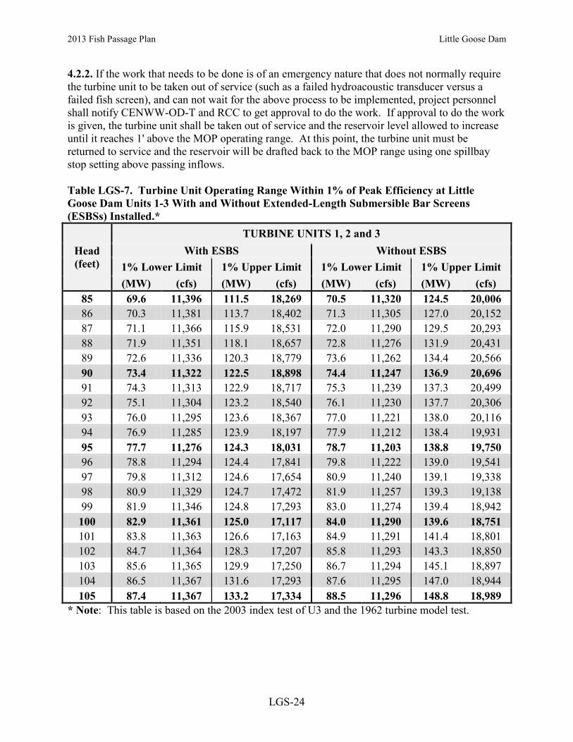
2013 Fish Passage Plan Little Goose Dam
LGS-24
4.2.2. If the work that needs to be done is of an emergency nature that does not normally require the turbine unit to be taken out of service (such as a failed hydroacoustic transducer versus a failed fish screen), and can not wait for the above process to be implemented, project personnel shall notify CENWW-OD-T and RCC to get approval to do the work. If approval to do the work is given, the turbine unit shall be taken out of service and the reservoir level allowed to increase until it reaches 1' above the MOP operating range. At this point, the turbine unit must be returned to service and the reservoir will be drafted back to the MOP range using one spillbay stop setting above passing inflows. Table LGS-7. Turbine Unit Operating Range Within 1% of Peak Efficiency at Little Goose Dam Units 1-3 With and Without Extended-Length Submersible Bar Screens (ESBSs) Installed.*
Head (feet)
TURBINE UNITS 1, 2 and 3 With ESBS Without ESBS
1% Lower Limit 1% Upper Limit 1% Lower Limit 1% Upper Limit (MW) (cfs) (MW) (cfs) (MW) (cfs) (MW) (cfs)
85 69.6 11,396 111.5 18,269 70.5 11,320 124.5 20,006 86 70.3 11,381 113.7 18,402 71.3 11,305 127.0 20,152 87 71.1 11,366 115.9 18,531 72.0 11,290 129.5 20,293 88 71.9 11,351 118.1 18,657 72.8 11,276 131.9 20,431 89 72.6 11,336 120.3 18,779 73.6 11,262 134.4 20,566 90 73.4 11,322 122.5 18,898 74.4 11,247 136.9 20,696 91 74.3 11,313 122.9 18,717 75.3 11,239 137.3 20,499 92 75.1 11,304 123.2 18,540 76.1 11,230 137.7 20,306 93 76.0 11,295 123.6 18,367 77.0 11,221 138.0 20,116 94 76.9 11,285 123.9 18,197 77.9 11,212 138.4 19,931 95 77.7 11,276 124.3 18,031 78.7 11,203 138.8 19,750 96 78.8 11,294 124.4 17,841 79.8 11,222 139.0 19,541 97 79.8 11,312 124.6 17,654 80.9 11,240 139.1 19,338 98 80.9 11,329 124.7 17,472 81.9 11,257 139.3 19,138 99 81.9 11,346 124.8 17,293 83.0 11,274 139.4 18,942 100 82.9 11,361 125.0 17,117 84.0 11,290 139.6 18,751 101 83.8 11,363 126.6 17,163 84.9 11,291 141.4 18,801 102 84.7 11,364 128.3 17,207 85.8 11,293 143.3 18,850 103 85.6 11,365 129.9 17,250 86.7 11,294 145.1 18,897 104 86.5 11,367 131.6 17,293 87.6 11,295 147.0 18,944 105 87.4 11,367 133.2 17,334 88.5 11,296 148.8 18,989
* Note: This table is based on the 2003 index test of U3 and the 1962 turbine model test.

2013 Fish Passage Plan Little Goose Dam
LGS-25
Table LGS-8. Turbine Unit Operating Range Within 1% of Peak Efficiency at Little Goose Dam Units 4-6 With and Without Extended-Length Submersible Bar Screens (ESBSs) Installed.*
Head (feet)
TURBINE UNITS 4, 5 and 6 With ESBS Without ESBS
1% Lower Limit 1% Upper Limit 1% Lower Limit 1% Upper Limit (MW) (cfs) (MW) (cfs) (MW) (cfs) (MW) (cfs)
85 87.1 13,880 119.6 19,076 86.4 13,479 122.2 19,052 86 88.2 13,890 121.3 19,102 87.6 13,488 123.9 19,078 87 89.3 13,899 122.9 19,127 88.7 13,497 125.6 19,104 88 90.5 13,908 124.6 19,151 89.8 13,506 127.2 19,128 89 91.6 13,916 126.3 19,174 91.0 13,514 128.9 19,151 90 92.8 13,924 127.9 19,196 92.1 13,522 130.6 19,174 91 93.9 13,925 129.4 19,193 93.2 13,523 132.1 19,171 92 95.0 13,925 130.9 19,190 94.3 13,524 133.7 19,168 93 96.1 13,926 132.4 19,186 95.4 13,524 135.2 19,165 94 97.2 13,926 133.9 19,183 96.5 13,525 136.7 19,162 95 98.3 13,926 135.3 19,179 97.6 13,525 138.2 19,158 96 99.2 13,898 135.8 19,038 98.4 13,498 138.7 19,018 97 100.0 13,871 136.3 18,900 99.3 13,472 139.2 18,880 98 100.9 13,844 136.8 18,765 100.2 13,446 139.7 18,745 99 101.8 13,818 137.3 18,633 101.1 13,420 140.2 18,613 100 102.7 13,791 137.8 18,503 101.9 13,395 140.7 18,484 101 103.9 13,821 139.1 18,503 103.2 13,423 142.1 18,484 102 105.2 13,849 140.5 18,503 104.4 13,451 143.5 18,484 103 106.4 13,878 141.9 18,503 105.7 13,478 144.9 18,484 104 107.7 13,905 143.3 18,503 106.9 13,505 146.3 18,484 105 108.9 13,932 144.6 18,503 108.1 13,532 147.7 18,484
* Note: This table is based on the 2003 index test of U4 and the 1975 turbine model test. 4.3. Turbine Unit Maintenance. The project turbine unit maintenance schedule will be reviewed annually by project and Operations Division biologists for fish impacts. If possible, maintenance of priority units will be scheduled for non-fish passage periods, or when there are low numbers of fish passing the project. Each turbine unit requires annual maintenance that may take from several days to three weeks. Annual maintenance of all turbine units is normally scheduled during the mid-July to late November time frame. The maintenance of priority units for adult passage is normally conducted in November or December, but can be conducted in mid-August. Impacts to migrating adults should be minimized. Turbine units may occasionally require overhauls to repair major problems with the turbine or generator. Overhauls may take over one year to accomplish. Turbine units, governors, exciters, and control systems require periodic maintenance, calibration, and testing which may take them outside of the one percent peak efficiency range. This work will be scheduled in compliance with BPA load shaping

2013 Fish Passage Plan Little Goose Dam
LGS-26
guidelines (Appendix C) to minimize impacts on juvenile fish. Transformers are Doble tested every 3 years. Testing may need to be more frequent if there is a known problem with a transformer. These tests normally take 2 to 3 workdays. To conduct the testing, the transmission lines have to be disconnected from the transformers and normal generation stopped. One turbine unit will operate in a speed-no-load condition to provide project power and operation of fish passage facilities. Spill may be provided to meet minimum required project discharges during the testing hours. The Doble tests are normally scheduled for the August or early September time period to minimize impacts on adult and juvenile fish passage. If Doble testing impacts priority units for adult fish passage, adult passage timing should be considered. Impacts to migrating adults should be minimized. 4.3.1. Turbine units are to be operated with raised operating gates to improve fish passage conditions when ESBSs are installed, except as provided below. To facilitate annual maintenance, operating gates are used to dewater the turbine units. To minimize turbine outage periods to the actual time required for maintenance (during the July 1 through December 15 time period), operating gates in one turbine unit may be lowered to the standard operating position and connected to hydraulic cylinders on the afternoon of the last regular workday (normally Thursday) prior to the start of the maintenance. With the operating gates in the standard operating position, the turbine unit may be operated until 0700 hours of the next regular workday (normally Monday) with generation loads restricted to 100 MWs or less. On the completion of maintenance, the turbine unit can be operated with the operating gates in the standard operating position at 100 MWs or less until 0700 hours of the first regular workday after the maintenance is completed. The project biologist will be notified when the operating gates are set in the standard operating position. The gatewells will be monitored 2 times per day to observe fish condition while the operating gates are in the standard operating position. If turbine maintenance or the raising of the operating gates to the raised operating position is delayed after the time periods stated above, the turbine unit shall be immediately taken out of service until the work can be accomplished. Operation of turbine units with operating gates in the standard operating position shall be restricted to the July 1 through December 15 time period, and shall not occur unless at least 4 other turbine units are available for service. No more than 1 turbine unit at a time shall be operated with operating gates in the standard operating position and the turbine unit will be operated on last on, first off operating priority. 4.3.2. Unwatering turbine units should be accomplished in accordance with project dewatering plans. If the turbine unit draft tube is to be dewatered, operate unit with full load for a minimum of 15 minutes prior to installing tail logs. If not possible to load, run unit at speed-no-load for minimum of 15 minutes. This is to reduce the number of fish in the scrollcase prior to installing stop logs. If a turbine unit is out of service for maintenance for an extended period of time without tailrace stoplogs in place, efforts should be made to not open the wicket gates if the scroll case must be dewatered at a later date without the unit being spun beforehand. 4.3.3. Units may be operationally tested for up to 30 minutes before going into maintenance status by running the unit at speed no load and various loads within the 1% criteria to allow pre-maintenance measurements and testing AND TO ALLOW ALL FISH TO MOVE THROUGH THE UNIT. Units may be operationally tested after maintenance or repair while remaining in maintenance or forced outage status. Operational testing may consist of running the unit for up

2013 Fish Passage Plan Little Goose Dam
LGS-27
to a cumulative time of 30 minutes (within 1% criteria) before it is returned to operational status. Operational testing OF UNIT UNDER MAINTENANCE is in addition to a unit in run status (E.G. MINIMUM GENERATION) required for power plant reliability. Operational testing may deviate from fish priority units and may require water that would otherwise be used for spill if the running unit for reliability is at its 1% minimum load. Water will be used from the powerhouse allocation if possible, and water diverted from spill for operational testing will be minimized to that necessary to maintain and assure generation system reliability. 5. FOREBAY DEBRIS REMOVAL Debris at projects can impact fish passage conditions. Debris can plug or block trashracks, VBSs, gatewell orifices, dewatering screens, separators, and facility piping resulting in impingement, injuries, and descaling of fish. Removing debris at its source in the forebay is sometimes necessary to maintain safe and efficient fish passage conditions, navigation, and other project activities. Debris can be removed from the forebay by: physically encircling the debris with log booms and pulling it to shore with boats where it can be removed with a crane, removing the debris from the top of the dam using a crane and scoop, or passing the debris through the spillway with special powerhouse operations and spill. The preferred option is to remove debris at each project when possible to avoid passing debris on to the next project downstream. This is not always possible at each project as some projects do not have forebay debris removal capability. In this case, the only viable alternative is to spill to pass the debris. Normally, the project shall contact CENWW-OD-T at least two workdays prior to the day the special operation is required. Using information provided by the project, CENWW-OD-T will notify FPOM and RCC will issue a teletype detailing the special operations. 5.1. All special spills (other than normal spill patterns for ongoing spill operations) and project operations for passing debris will be coordinated prior to the operations taking place. Each project shall contact CENWW-OD-T at least two workdays prior to the day they want the special project operations for spilling to pass debris. CENWW-OD-T shall coordinate the special operations with RCC, NOAA Fisheries, and other FPOM participants. Project personnel shall provide CENWW-OD-T the reason for the debris spill request including an explanation of project facilities being impacted by the debris, the date and time of the requested spill, and any special powerhouse or other operations required to move the debris to the spillway. When a debris spill is coordinated and approved, RCC shall issue a teletype detailing the specifics of the special operations. 5.1.1. Emergency spills may be implemented if necessary to pass woody debris that are accumulating in front of the spillbay weir(s), compromising the safe, unobstructed passage of fish. The operating project will immediately spill the woody debris to remove the obstructions to fish passage. The operating project will notify CENWW-OD-T of the emergency spill as soon as possible to provide notification to RCC, NOAA Fisheries, and other FPOM participants.

2013 Fish Passage Plan Little Goose Dam
LGS-28
Table LGS-9 (pg 1 of 2). Little Goose Dam Spill Pattern for Spillway Weir in Low Crest (SW-Lo) Configuration (Crest Elev = 618 ft).
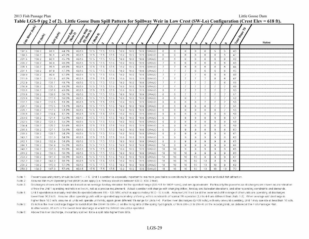
2013 Fish Passage Plan Little Goose Dam
LGS-29
Table LGS-9 (pg 2 of 2). Little Goose Dam Spill Pattern for Spillway Weir in Low Crest (SW-Lo) Configuration (Crest Elev = 618 ft).

2013 Fish Passage Plan Little Goose Dam
LGS-30
Table LGS-10 (pg 1 of 2). Little Goose Dam Spill Pattern for Spillway Weir in High Crest (SW-Hi) Configuration (Crest Elev = 622 ft).

2013 Fish Passage Plan Little Goose Dam
LGS-31
Table LGS-10 (pg 2 of 2). Little Goose Dam Spill Pattern for Spillway Weir in High Crest (SW-Hi) Configuration (Crest Elev = 622 ft).

2013 Fish Passage Plan Little Goose Dam
LGS-32
Table LGS-11 (pg 1 of 2). Little Goose Dam Spill Pattern for Uniform Spill Configuration (No Spillway Weir).

2013 Fish Passage Plan Little Goose Dam
LGS-33
Table LGS-11 (pg 2 of 2). Little Goose Dam Spill Pattern for Uniform Spill Configuration (No Spillway Weir).

2013 Fish Passage Plan Little Goose Dam
LGS-34
Table LGS-12 (pg 1 of 2). Little Goose Dam Spill Pattern for ALTERNATE UNIFORM Spill Configuration (Spillway Weir Crest Change). [Note 7]

2013 Fish Passage Plan Little Goose Dam
LGS-35
Table LGS-12 (pg 2 of 2). Little Goose Dam Spill Pattern for ALTERNATE UNIFORM Spill Configuration (Spillway Weir Crest Change). [Note 7]

2013 Fish Passage Plan Lower Granite Dam
2013 Fish Passage Plan Section 9 – Lower Granite Dam
Table of Contents 1. Fish Passage Information.......... ......................................................................... LWG-01
1.1. Juvenile Fish Passage .......................................................................... LWG-01 1.2. Adult Fish Passage .............................................................................. LWG-05
2. Project Operation ............................................................................................... LWG-06 2.1. Spill Management ............................................................................... LWG-06 2.2. Dissolved Gas Management and Control ........................................... LWG-06 2.3. Operating Criteria ............................................................................... LWG-06 2.4. Navigation Spill Operations ................................................................ LWG-17
3. Project Maintenance........................................................................................... LWG-18 3.1. Juvenile Fish Passage Facilities .......................................................... LWG-18 3.2. Adult Fish Passage Facilities .............................................................. LWG-20
4. Turbine Unit Operation and Maintenance ......................................................... LWG-22 4.1. Turbine Unit Operation ....................................................................... LWG-22 4.2. Turbine Unit Outages During High River Flow Periods ................... LWG-25 4.3. Turbine Unit Maintenance .................................................................. LWG-26
5. Forebay Debris Removal ................................................................................... LWG-27 5.1. Special Spills ....................................................................................... LWG-27

2013 Fish Passage Plan Lower Granite Dam
LWG-1
Section 9 Lower Granite Dam 1. FISH PASSAGE INFORMATION The locations of fish passage facilities at Lower Granite Lock and Dam are in Figure LWG-1. Dates of project operations for fish purposes and special operations are listed in Table LWG-2. 1.1. Juvenile Fish Passage. 1.1.1. Facilities Description. The Lower Granite juvenile facilities consist of a bypass system and juvenile transportation facilities. The bypass system contains extended length submersible bar screens with flow vanes, improved modified balanced flow vertical barrier screens, gatewell orifices, a bypass channel running the length of the powerhouse, and a bypass pipe to transport the fish to the transportation facilities or to the river. The transportation facilities include an upwell and separator structure to separate the juveniles from the excess water and adult fish, raceways for holding fish, a distribution system for distributing the fish among the raceways or to the barge or back to the river, a sampling and marking building, truck and barge loading facilities, and PIT-tag detection and diversion systems. 1.1.2. Juvenile Migration Timing. Juvenile migration timing at Lower Granite Dam is indicated in Table LWG-1. The dates in the table are based on juvenile fish collection numbers and do not reflect fish guidance efficiency (FGE) or passage via the spillway. Salmon, steelhead, bull trout, lamprey, and other species are routinely counted. Maintenance of juvenile fish passage facilities that may impact juvenile fish passage or facility operations should be conducted during the winter maintenance season.

2013 Fish Passage Plan Lower Granite Dam
LWG-2
Table LWG-1. Juvenile Migration Timing at Lower Granite Dam, 2003–2012. 1 Yearling Chinook Subyearling Chinook
10 % 50% 90 % # of Days 10 % 50% 90 % # of Days 2003 21-Apr 6-May 20-May 29 2003 4-Jun 22-Jun 16-Jul 42 2004 24-Apr 5-May 12-May 18 2004 8-Jun 21-Jun 14-Jul 36 2005 24-Apr 5-May 10-May 16 2005 29-May 3-Jun 17-Jun 19 2006 20-Apr 5-May 15-May 25 2006 26-May 5-Jun 3-Jul 38 2007 19-Apr 4-May 14-May 25 2007 3-Jun 9-Jun 12-Jul 39 2008 26-Apr 9-May 18-May 22 2008 31-May 20-Jun 28-Jul 58 2009 22-Apr 7-May 20-May 28 2009 29-May 11-Jun 2-Jul 34 2010 24-Apr 4-May 21-May 27 2010 2-Jun 9-Jun 14-Jul 42 2011 19-Apr 8-May 16-May 27 2011 26-May 11-Jun 16-Jul 51 2012 14-Apr 27-Apr 17-May 33 2012 29-May 13-Jun 11-Jul 43
MEDIAN 21-Apr 5-May 16-May 26 MEDIAN 30-May 11-Jun 13-Jul 41 MIN 14-Apr 27-Apr 10-May 16 MIN 26-May 3-Jun 17-Jun 19 MAX 26-Apr 9-May 21-May 33 MAX 8-Jun 22-Jun 28-Jul 58
Unclipped Steelhead Clipped Steelhead 10 % 50% 90 % # of Days 10 % 50% 90 % # of Days
2003 19-Apr 17-May 30-May 41 2003 25-Apr 14-May 28-May 33 2004 29-Apr 9-May 24-May 25 2004 27-Apr 9-May 24-May 27 2005 27-Apr 9-May 20-May 23 2005 26-Apr 8-May 16-May 20 2006 19-Apr 5-May 21-May 32 2006 21-Apr 4-May 19-May 28 2007 1-May 10-May 21-May 20 2007 28-Apr 7-May 20-May 22 2008 20-Apr 11-May 27-May 37 2008 28-Apr 8-May 21-May 23 2009 22-Apr 6-May 29-May 37 2009 21-Apr 1-May 21-May 30 2010 26-Apr 19-May 5-Jun 40 2010 25-Apr 11-May 4-Jun 40 2011 22-Apr 13-May 31-May 39 2011 3-Apr 6-May 20-May 47 2012 18-Apr 3-May 24-May 36 2012 16-Apr 27-Apr 19-May 33
MEDIAN 22-Apr 20-May 25-May 37 MEDIAN 25-Apr 7-May 20-May 29 MIN 18-Apr 3-May 20-May 20 MIN 3-Apr 27-Apr 16-May 20 MAX 1-May 19-May 5-Jun 41 MAX 28-Apr 14-May 4-Jun 47
Coho Sockeye (Wild & Hatchery) 10 % 50% 90 % # of Days 10 % 50% 90 % # of Days
2003 18-May 27-May 15-Jun 28 2003 15-May 31-May 6-Jun 22 2004 8-May 21-May 28-May 20 2004 12-May 22-May 19-Jun 38 2005 30-Apr 10-May 17-May 17 2005 9-May 20-May 1-Jun 23 2006 2-May 18-May 1-Jun 30 2006 11-Apr 12-May 28-May 47 2007 5-May 15-May 23-May 18 2007 11-May 16-May 21-May 10 2008 6-May 10-May 22-May 16 2008 17-May 20-May 8-Jun 22 2009 13-May 21-May 23-Jun 41 2009 21-Apr 20-May 28-May 37 2010 6-Jun 21-May 5-Jul 29 2010 19-May 30-May 5-Jun 17 2011 5-May 15-May 1-Jun 27 2011 4-Apr 20-May 4-Jun 61 2012 28-Apr 18-May 26-May 28 2012 5-May 19-May 26-May 21
MEDIAN 5-May 18-May 30-May 28 MEDIAN 10-May 20-May 2-Jun 23 MIN 28-Apr 10-May 17-May 16 MIN 4-Apr 12-May 21-May 10 MAX 6-Jun 27-May 5-Jul 41 MAX 19-May 31-May 19-Jun 61
1. Dates are derived from daily and yearly facility collection numbers.

n
Fishway EntranceNSE-1, NSE-2
Floating Orifice Gates
NavigationLock
Lower GraniteLock and Dam
8 7 6 5 4 3 2 1
6 5 4 3 2 1
Adult Fish Trap
Visitor Center andFish Counting and Viewing Area
Lake Bryan
Snake River
Lower GraniteLake
Powerhouse
Spillway
Fishway EntranceSSE-1, SSE-2
Fishway EntranceNPE-1, NPE-2
Juvenile FishFacility
Fish Ladder
FLOW
Figure LWG-1 Lower Granite Lock and Dam general site plan.
Powerhouse FishCollection System
Barge LoadingDock
Fish FacilityOutfall
Removable Spillway Weir(RSW)
G0PDWLSW
Text Box
LWG-3
G0PDWLSW
Text Box
Figure LWG- 1. Lower Granite Lock and Dam General Site Plan.
G0PDWLSW
Text Box
2013 Fish Passage Plan Lower Granite Dam

Task Name Start Finish Reference
2013 FISH PASSAGE SEASON 3/1/13 12/31/13 LWG 2.3.Juvenile Fish Passage Season 3/25/13 12/15/13 LWG 2.3.1.2Adult Fish Passage Season 3/1/13 12/31/13 LWG 2.3.2.2
2013-2014 WINTER MAINTENANCE PERIOD 12/16/13 3/24/14 LWG 2.3.Juvenile Fish Facilities Winter Maintenance 12/16/13 3/24/14 LWG 2.3.1.1Adult Fish Facilities Winter Maintenance 1/1/14 2/28/14 LWG 2.3.2.1
ADULT FISH COUNTING 3/1/13 12/30/13 Table LWG-3Video 0400-2000 PST 3/1/13 3/31/13Visual 0400-2000 PST 4/1/13 10/31/13Video Night 2000-0400 PST 6/15/13 9/30/13Video 0400-2000 PST 11/1/13 12/30/13
1% CONSTRAINTS (YEAR-ROUND) 3/1/13 2/28/14 LWG 4.1.11% soft constraint 3/1/13 3/31/131% hard constraint 4/1/13 10/31/131% soft constraint 11/1/13 2/28/14
TDG MONITORING 3/1/13 2/28/14 LWG 2.2TDG Monitoring - Tailrace (year-round) 3/1/13 2/28/14 LGNWTDG Monitoring - Forebay 4/1/13 8/31/13 LWG
Operate Turbine Priority for Fish Passage 3/1/13 11/30/13 LWG 4.1; Table LWG-5
SPECIAL OPERATIONS & STUDIES 3/1/13 12/7/13 Appendix ALamprey Passage Evaluations 3/1/13 10/31/13 App A LWG 2.5Tailrace ADCP Data Collection 3/1/13 8/31/13 App A LWG 2.6Unit 5 Cavitation Repair 3/1/13 4/12/13 App A LWG 1.4BiOp Kelt Passage & Survival Monitoring 3/15/13 8/30/13 App A LWG 2.3Prototype Overflow Weir and 14" Orifice Evaluation 4/15/13 6/30/13 App A LWG 2.1Video Monitoring of Fish Ladder Modifications for Lamprey 6/15/13 9/30/13 App A LWG 2.8Unit 6 Cavitation Repair 7/1/13 12/7/13 App A LWG 1.4Adult Salmon Studies 7/1/13 9/30/13 App A LWG 2.4Unit 4 Turbine Guide Bearing Replacement 7/26/13 8/16/13 App A LWG 1.7Doble Testing 8/12/13 8/16/13 App A LWG 1.3Outfall Geotechnical Exploration 9/1/13 10/31/13 App A LWG 2.7Doble Testing 8/12/13 8/16/13 App A LWG 1.3
OPERATION OF JUVENILE FISH PASSAGE SYSTEM 3/25/13 12/15/13 LWG 2.3.1Juvenile Fish Bypass, Collection and Transportation 3/25/13 10/31/13Adult Fish Fallback Bypass 11/1/13 12/15/13
SPILL FOR FISH PASSAGE 4/3/13 8/31/13 Appendix ESpring Spill 4/3/13 6/20/13 end date approximateSummer Spill 6/21/13 8/31/13 start date approximate
Avian Abatement Measures 4/1/13 12/15/13 LWG 2.3.1.2.f
Spillway Weir in service (removed from service no later thanAugust 31)
4/3/13 8/31/13 LWG 2.3.1.2.f
Weekly Reports 3/1/13 12/31/13 LWG 2.3.3.1
Annual Report (for Dec 1, 2012 - Nov 30, 2013) 3/15/14 3/15/14 LWG 2.3.3.4
Jan Feb Mar Apr May Jun Jul Aug Sep Oct Nov Dec Jan Feb Mar1st Quarter 2nd Quarter 3rd Quarter 4th Quarter 1st Quarter
2013 2014
Table LWG-2. Lower Granite Dam Dates of Fish-Related Operations for 2013 Fish Passage Season and 2013/14 Winter Maintenance Period.
LWG-4

2013 Fish Passage Plan Lower Granite Dam
LWG-5
1.2. Adult Fish Passage. 1.2.1. Facilities Description. Adult fish passage facilities at Lower Granite are made up of one south shore fish ladder with two entrances, a powerhouse collection system, north shore entrances with a transportation channel underneath the spillway to the powerhouse collection system, and an auxiliary water supply system. The powerhouse collection system is comprised of four operating floating orifices, two downstream entrances and one side entrance into the spillway basin on the north end of the powerhouse, and a common transportation channel. Four of the floating orifices and the two downstream entrances at the north end of the collection system are operated. North shore entrances are made up of two downstream entrances and a side entrance into the spillway basin with the two downstream entrances normally used. Auxiliary water is supplied from the tailrace by three electric pumps, as well as from the forebay through diffuser 14. Two pumps are normally used to provide required flows. Four weirs in the upper end of the ladder were outfitted with PIT-tag detectors in early 2003. 1.2.2. Adult Migration Timing. Upstream migrants are present at Lower Granite Dam throughout the year and adult passage facilities are operated year-round. Maintenance of adult fish facilities is scheduled in January–February to minimize impacts on upstream migrants. Adult fish (salmon, steelhead, shad and lamprey) are counted (Table LWG-3) and daily count data are posted on the Corps’ adult fish count website at: http://www.nwp.usace.army.mil/Missions/Environment/Fishdata.aspx. Salmon migration timing data are in Table LWG-4. Sturgeon and bull trout counts are recorded on the daily summary sheet comments section but are not posted in the website daily reports due to relatively infrequent passage. These data are posted periodically on the website during the passage season in the Miscellaneous Fish Counts report and summarized in the Annual Fish Passage Report. Table LWG-3. Adult Fish Counting Schedule at Lower Granite Dam.
Count Period Counting Method and Hours 1
March 01 – March 31 Video 0400–2000 hours (PST)
April 01 – October 31 Visual 0400–2000 hours (PST)
June 15 – September 30 Night Video 2000–0400 hours (PST)
November 01 – December 30 Video 0400–2000 hours (PST) 1. All count hours are shown in Pacific Standard Time (PST). Note that during daylight saving time (DST) from March 10–November 3, 2013, count hours will be adjusted forward one hour (DST = PST+1). Table LWG-3. Adult Count Period and Peak Migration Timing at Lower Granite Dam (based on 1975-2012 count data).
Species Counting Period
Date of Peak Passage Earliest Latest
Spring Chinook 3/1 – 6/17 4/26 6/17 Summer Chinook 6/18 – 8/17 6/18 7/17 Fall Chinook 8/18 – 12/30 9/5 10/6 Steelhead 3/1 – 12/30 9/1 10/16 Sockeye 3/1 – 10/31 7/1 7/19
Lamprey 4/1 – 10/31 7/18 7/25

2013 Fish Passage Plan Lower Granite Dam
LWG-6
2. PROJECT OPERATION 2.1. Spill Management. See Fish Operations Plan (Appendix E) for more information. 2.1.1. Involuntary spill at Lower Granite is the result of river flow exceeding powerhouse capacity, insufficient generation loads to pass the river flow, turbine unit outages (forced or scheduled), or the failure of a key component of the juvenile fish passage facility which forces the project to spill to provide juvenile fish passage. Spill at Lower Granite shall be distributed in accordance with the spill patterns included at the end of this section, Tables LWG-10 and LWG-11, and summer LWG-12. Special spills for juvenile fish passage will be provided as detailed in Appendixes A and E.
2.2. Total Dissolved Gas (TDG) Management. TDG levels at all projects are monitored in accordance with the TDG Monitoring Plan, included in the Water Management Plan as Appendix 4 and available online at: http://www.nwd-wc.usace.army.mil/tmt/documents/wmp/2013/.
2.3. Operating Criteria. 2.3.1. Juvenile Fish Passage Facilities. Operate from March 25 through October 31 for juvenile fish bypass, collection, and transportation and from November 1 through December 15 for bypassing adult fallbacks. Operate the juvenile facilities according to the criteria listed below and in Appendix B (Corps' Juvenile Fish Transportation Program Operating Criteria) for the bypassing, collection, and transportation of juvenile salmonids. The transportation program may be revised in accordance with the ESA Section 10 permit and the NOAA Fisheries biological opinion. Project personnel shall retain the authority to dewater the juvenile fish collection system to the extent necessary to prevent frost damage to pipes and other structures during late fall and extended winter operations.
2.3.1.1. Winter Maintenance Period (December 16–March 24). Check and perform maintenance as required on the items listed below.
a. Forebay Area and Intakes.
1. Remove debris from forebay and gatewell slots. 2. Rake trashracks just prior to the operating season. 3. Measure gatewell drawdown after cleaning trashracks and with ESBSs in. 4. Inspect and repair gatewell dipnet as needed.
b. Extended-Length Submersible Bar Screens (ESBSs), Flow Vanes, and Vertical Barrier Screens (VBSs).
1. Maintenance completed on all screens.
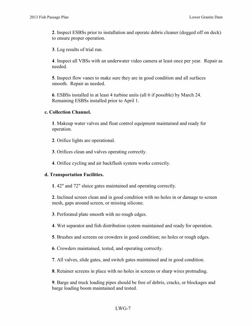
2013 Fish Passage Plan Lower Granite Dam
LWG-7
2. Inspect ESBSs prior to installation and operate debris cleaner (dogged off on deck) to ensure proper operation. 3. Log results of trial run. 4. Inspect all VBSs with an underwater video camera at least once per year. Repair as needed. 5. Inspect flow vanes to make sure they are in good condition and all surfaces smooth. Repair as needed. 6. ESBSs installed in at least 4 turbine units (all 6 if possible) by March 24. Remaining ESBSs installed prior to April 1.
c. Collection Channel.
1. Makeup water valves and float control equipment maintained and ready for operation. 2. Orifice lights are operational. 3. Orifices clean and valves operating correctly. 4. Orifice cycling and air backflush system works correctly.
d. Transportation Facilities.
1. 42" and 72" sluice gates maintained and operating correctly. 2. Inclined screen clean and in good condition with no holes in or damage to screen mesh, gaps around screen, or missing silicone. 3. Perforated plate smooth with no rough edges. 4. Wet separator and fish distribution system maintained and ready for operation. 5. Brushes and screens on crowders in good condition; no holes or rough edges. 6. Crowders maintained, tested, and operating correctly. 7. All valves, slide gates, and switch gates maintained and in good condition. 8. Retainer screens in place with no holes in screens or sharp wires protruding. 9. Barge and truck loading pipes should be free of debris, cracks, or blockages and barge loading boom maintained and tested.

2013 Fish Passage Plan Lower Granite Dam
LWG-8
10. All sampling equipment should be maintained and in good operating condition prior to watering up the facilities. 11. Maintain juvenile PIT-tag system as required (see “Columbia Basin PIT-tag Information System, General Gate Maintenance and Inspection, Walla Walla District”, February 2003). Coordinate with PSMFC. 12. Mini- and midi-tanks maintained and in good operating condition.
e. Barges.
1. All engines and pumps maintained and in good operating condition. 2. Fish release openings and related equipment in good operating condition. 3. No rough edges or support beams protruding into compartments. 4. No brass or galvanized fittings in circulation lines. 5. All loading hoses properly installed so fish will not hit sides of compartments or support beams when loading. 6. Loading hoses in good shape with rubber gaskets in cam lock fittings. 7. Inside edges of cam lock joints should be beveled to avoid sharp edges. 8. Warning systems tested and operational. 9. Provide net and/or deck covers. 10. Net pens maintained and installed in barge holds for transport of steelhead kelts or juveniles as required. 11. Deck wash systems fully operational. 12. Oxygen monitoring probes installed and tested; monitoring system operational.
f. Avian Predation Areas (Forebay and Tailrace). Inspect bird wires, water cannon, and other deterrent devices and repair or replace as needed. Where possible, add additional bird wires or other deterrent devices to cover areas of known avian predation activity. Prepare avian abatement contract as needed.
g. Maintenance Records. Record all maintenance and inspections.

2013 Fish Passage Plan Lower Granite Dam
LWG-9
2.3.1.2. Juvenile Fish Passage Period (March 25–December 15).
a. Forebay Area and Intakes.
1. Remove debris from forebay. 2. Inspect gatewell slots daily for debris, fish buildup, and contaminating substances (particularly oil). Clean gatewells before they become 50% covered with debris. If, due to the volume of the debris it is not possible to keep the gatewell at least 50% clear, they should be cleaned at least once daily. If flows through an orifice or fish conditions indicate that an orifice may be partially obstructed with debris, the orifice will be closed and backflushed to remove the obstruction. If the obstruction cannot be removed, the orifice shall be closed and the alternate orifice for that gatewell slot shall be operated. If both orifices become obstructed or plugged with debris, the turbine unit will not be operated until the gatewell and orifices are cleared of debris. 3. If a visible accumulation of contaminating substances is detected in a gatewell and cannot be removed within 24 hours, the gatewell orifices shall be closed immediately and the turbine unit shut down within one hour until the material has been removed and any problems corrected. A preferred method for removing oil from the water surface is to install absorbent socks, booms, or pads capable of encapsulating the material, tied off with a rope for later disposal. Action should be taken as soon as possible to remove the oil from the gatewell so the orifice can be reopened to allow the fish to exit the gatewell. Orifices shall not be closed for longer than 48 hours. 4. Log drawdown differentials in bulkhead slots at least once per week. 5. Remove debris from forebay and trashracks as required to maintain less than 1' of additional drawdown in gate slots (relative to the drawdown with a clean screen). Additional raking may be required when heavy debris loads are present in the river or if fish condition requires it. 6. Coordinate cleaning effort with personnel operating juvenile collection facilities. 7. Dip bulkhead gatewell slots to remove fish prior to installing bulkhead for dewatering bulkhead slot.
b. ESBSs, VBSs, and Operating Gates.
1. ESBSs and flow vanes installed in all operating turbine units by March 24. 2. Operate ESBSs with flow vanes attached to screen. 3. Operate ESBSs with debris cleaners in automatic mode. Set cleaning frequency as required to maintain clean screens and good fish condition. Change cleaning frequency as needed.

2013 Fish Passage Plan Lower Granite Dam
LWG-10
4. Inspect each ESBS once per month by means of underwater video in April, May, and June. Conduct similar inspections in August and October, focusing on at least three turbine units as the judgment of project personnel dictates. Spot check VBSs at the same time. 5. If an ESBS is damaged or fails during the juvenile fish passage season, follow procedures detailed under unscheduled maintenance of ESBSs (see section 3.1.2.1). In no case should a turbine unit be operated with a missing or a known non-operating or damaged ESBS, except as noted. 6. One-half of the ESBSs may be pulled after October 1 for maintenance as long as unscreened turbine units are not operated. 7. Make formal determination at end of season as to adequacy of ESBS bar screen panels and debris cleaner brush and replace components as necessary. 8. Measure head differentials across VBSs at least once per week from April 1 through June 30 (more frequently if required) and biweekly for the remainder of the operating season. Clean VBS when head differentials reach 1.5'. When a head differential of 1.5' is reached, the respective turbine unit should be operated at a reduced loading, not more than 110 MW, to minimize loading on the VBS and potential fish impingement. Clean VBSs as soon as possible after a 1.5' head differential is reached. 9. Inspect at least two VBSs in two different turbine units between the spring and summer migration periods. Both turbine units should have been operated frequently during the spring. If a debris accumulation is noted, inspect other VBSs and clean debris as necessary. 10. Turbine units are to be operated with raised operating gates to improve fish guidance efficiency when ESBSs are installed (March 25 through December 15), except as provided for in Section 4.3., Turbine Unit Maintenance. 11. When extreme cold weather is forecasted (as defined as: anticipated temperatures below 20o Fahrenheit for 24 hours) to occur for an extended period of time between Thanksgiving and December 15, ESBSs and STSs may be removed. The project will first request special permission from CENWW-OD-T. CENWW-OD-T will inform NOAA Fisheries and other FPOM participants of the action.
c. Collection Channel.
1. Orifices clean and operating. Operate at least one orifice per gatewell slot (preferably the north orifice) unless a unit is scheduled out of service with non-operational fish screens. If the project is operating at MOP, additional orifices may be operated to maintain a full collection channel. If orifices must be closed to repair any part of the facility, do not close orifices/ in operating turbine units with ESBSs in

2013 Fish Passage Plan Lower Granite Dam
LWG-11
place for longer than 5 hours. If possible, keep to less than 3 hours. Reduce turbine unit loading to the lower end of the 1% efficiency range if deemed necessary by the project biologist. Monitor fish conditions in gatewells hourly or more frequently during orifice closure periods. 2. Orifice lights operational and operating on open orifices. Orifice lights and area lights may be turned off the evening before the channel is dewatered at the end of the season (dewatering occurs on December 16 or later) to encourage fish to exit the channel volitionally. Area lights can be turned on briefly for personnel access if necessary. 3. Replace all burned out orifice lights within 24 hours of notification. Orifice lights shall remain lighted 24 hours/day. 4. Orifice jets hitting no closer than 3’ from back wall, collection channel full. 5. Rotate orifices in fish screens slots weekly (6 open). 6. Orifice valves are either fully open or closed. 7. Backflush orifices in the bulkhead slots every four hours and more frequently if required. During periods of high fish and debris passage, April 1 through August 15, orifices should be inspected and backflushed more frequently as determined by the project biologist, to keep orifices clean. If debris is causing continual orifice plugging problems in a particular turbine unit gatewell, the respective turbine unit generation may be restricted to the lower end of the 1% turbine efficiency range to minimize orifice plugging problems. 8. If utilizing the automatic orifice backflush system, inspect as determined by the project biologist (but at least once per 8-hour shift unless coordinated differently) to ensure that the orifices are opening and closing correctly and are clear of debris. The project biologist will determine the frequency of automatic orifice cycling and backflushing to maintain clear orifices. 9. Makeup water valves and associated float controls operational and maintaining stable channel flow.
d. Transportation Facilities.
1. 42" and 72" sluice gates operational; 42-inch separator remote controller switch fully operational. 2. Maintain stable water conditions in upwell and separator. No holes, broken wires, or gaps in inclined screen. Operate separator and fish distribution system as designed.
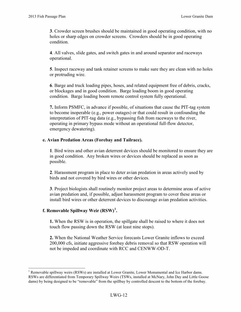
2013 Fish Passage Plan Lower Granite Dam
LWG-12
3. Crowder screen brushes should be maintained in good operating condition, with no holes or sharp edges on crowder screens. Crowders should be in good operating condition. 4. All valves, slide gates, and switch gates in and around separator and raceways operational. 5. Inspect raceway and tank retainer screens to make sure they are clean with no holes or protruding wire. 6. Barge and truck loading pipes, hoses, and related equipment free of debris, cracks, or blockages and in good condition. Barge loading boom in good operating condition. Barge loading boom remote control system fully operational. 7. Inform PSMFC, in advance if possible, of situations that cause the PIT-tag system to become inoperable (e.g., power outages) or that could result in confounding the interpretation of PIT-tag data (e.g., bypassing fish from raceways to the river, operating in primary bypass mode without an operational full-flow detector, emergency dewatering).
e. Avian Predation Areas (Forebay and Tailrace).
1. Bird wires and other avian deterrent devices should be monitored to ensure they are in good condition. Any broken wires or devices should be replaced as soon as possible. 2. Harassment program in place to deter avian predation in areas actively used by birds and not covered by bird wires or other devices. 3. Project biologists shall routinely monitor project areas to determine areas of active avian predation and, if possible, adjust harassment program to cover these areas or install bird wires or other deterrent devices to discourage avian predation activities.
f. Removable Spillway Weir (RSW)1.
1. When the RSW is in operation, the spillgate shall be raised to where it does not touch flow passing down the RSW (at least nine stops). 2. When the National Weather Service forecasts Lower Granite inflows to exceed 200,000 cfs, initiate aggressive forebay debris removal so that RSW operation will not be impeded and coordinate with RCC and CENWW-OD-T.
1 Removable spillway weirs (RSWs) are installed at Lower Granite, Lower Monumental and Ice Harbor dams. RSWs are differentiated from Temporary Spillway Weirs (TSWs, installed at McNary, John Day and Little Goose dams) by being designed to be “removable” from the spillbay by controlled descent to the bottom of the forebay.

2013 Fish Passage Plan Lower Granite Dam
LWG-13
3. Complete RSW stow (complete rotation to the landing pad) when inflows exceed 260,000 cfs, upstream river gage flows are increasing, and the NWS forecasts Lower Granite inflow to exceed 300,000 cfs. 4. Operation of the RSW for short periods of time may be requested by the project biologist through CENWW during low flow years if it appears the juvenile fish transportation facility and barge holding capacities will be exceeded (refer to Appendix B, Juvenile Fish Transportation Plan, Section 4.d.(4)).
g. Inspection and Record Keeping.
1. Inspect fish facilities at least once every 8 hours. Inspect facilities according to fish facilities monitoring program. 2. Record all maintenance and inspections.
2.3.2. Adult Fish Passage Facilities. Operate the adult fish passage facilities according to the following criteria.
2.3.2.1. Winter Maintenance Period (January 1–February 28).
a. Inspect all staff gages and water level indicators. Repair and/or clean where necessary.
b. Dewater the ladder and inspect all dewatered sections of fish facilities for projections, debris, or plugged orifices which could injure fish or impede fish passage up the ladder. The fish ladder exit trashrack must have smooth surfaces where fish pass, and must have downstream edges that are adequately rounded or padded. A spare trashrack should be on hand for use as necessary. Inspect all diffuser gratings and chambers, and the fallout fence, annually by dewatering or by using divers or video inspection techniques. All diffuser gratings and chambers are to be dewatered and physically inspected at least every 3 years. Repair deficiencies. c. Inspect for and clean debris from the fish ladder exit. The trashrack and picketed leads must be clean and installed correctly. d. Calibrate all water level measuring devices, as necessary, for proper facility operations. e. Inspect all spill gates and ensure that they are operable.
f. Fish pumps maintained and ready for operation. g. Maintain adult PIT-tag system as required. Coordinate with PSMFC. h. Maintain the adult fish trap as required.

2013 Fish Passage Plan Lower Granite Dam
LWG-14
i. Clean debris from the diffuser 14 trashrack (entrance). Check under the diffuser 14 ladder grating for debris accumulation and remove – if necessary. Check limit switch settings on diffuser 14 controller and ensure full operation.
2.3.2.2. Adult Fish Passage Period (March 1–December 31). Note: Little Goose pool may be operated at minimum operating pool (MOP), between elevations 633' and 634' msl, as part of the Corps' efforts to improve migration conditions for juvenile salmonids. This may result in some of the adult fishway entrances at Lower Granite bottoming out on their sills prior to reaching criteria depths. Continuous operation at MOP may also result in increased pumping head on the auxiliary water supply pumps, decreasing the amount of water supplied by the pumps. Fish pump 1 may be run at the “slow speed” setting to avoid frequent tripping from an overload condition while operating under MOP.
a. Fishway Ladder. Water depth over weirs: 1' to 1.3'.
1. In order to facilitate proper operation of the adult fishway weirgate entrances, powerhouse electricians shall raise and lower individual weirgates to check the limit switch settings and make necessary adjustments and/or begin planning for necessary repairs to occur during the winter maintenance period (Jan 1-Feb 28). The checks must be performed while the ladder is watered up and are expected to take approximately one hour per weirgate. The checks shall be conducted near the end of the day during the period of December 15-31 when adult fish passage is minimal.
b. Counting Window. The crowder shall be opened to full count slot width when not counting. The crowder shall be open as far as possible to allow accurate counting and shall not be closed to less than 18” while counting. This will usually occur during high turbidity conditions to allow count accuracy criteria to be achieved. The counting slot has a width range of 12-30”. All equipment should be maintained in good condition. Counting window and backboard should be cleaned as needed to maintain good visibility.
c. Head on all Fishway Entrances. Head range: 1' to 2'. d. North Shore Entrances (NSE 1 & 2). Elevation at top of gates when on sill = 625'.
1. Operate both downstream gates. 2. Weir depth: 7' or greater below tailwater.
e. North Powerhouse Entrances (NPE 1 & 2). Elevation at top of gates, on sill = 628'. 1. Operate both downstream gates. 2. Weir depth: 8' or greater below tailwater. At tailwater below elevation 636', weirs should be on sill.
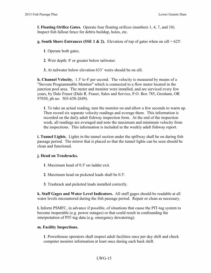
2013 Fish Passage Plan Lower Granite Dam
LWG-15
f. Floating Orifice Gates. Operate four floating orifices (numbers 1, 4, 7, and 10). Inspect fish fallout fence for debris buildup, holes, etc.
g. South Shore Entrances (SSE 1 & 2). Elevation of top of gates when on sill = 625'.
1. Operate both gates. 2. Weir depth: 8' or greater below tailwater. 3. At tailwater below elevation 633’ weirs should be on sill.
h. Channel Velocity. 1.5' to 4' per second. The velocity is measured by means of a "Stevens Programmable Monitor" which is connected to a flow meter located in the junction pool area. The meter and monitor were installed, and are serviced every few years, by Dale Fraser (Dale R. Fraser, Sales and Service, P.O. Box 785, Gresham, OR 97030, ph no: 503-658-2649).
1. To take an actual reading, turn the monitor on and allow a few seconds to warm up. Then record six separate velocity readings and average them. This information is recorded on the daily adult fishway inspection form. At the end of the inspection week, all readings are averaged and note the maximum and minimum velocity from the inspections. This information is included in the weekly adult fishway report.
i. Tunnel Lights. Lights in the tunnel section under the spillway shall be on during fish passage period. The mirror that is placed so that the tunnel lights can be seen should be clean and functional.
j. Head on Trashracks.
1. Maximum head of 0.5' on ladder exit. 2. Maximum head on picketed leads shall be 0.3'. 3. Trashrack and picketed leads installed correctly.
k. Staff Gages and Water Level Indicators. All staff gages should be readable at all water levels encountered during the fish passage period. Repair or clean as necessary.
l. Inform PSMFC, in advance if possible, of situations that cause the PIT-tag system to become inoperable (e.g. power outages) or that could result in confounding the interpretation of PIT-tag data (e.g. emergency dewatering).
m. Facility Inspections.
1. Powerhouse operators shall inspect adult facilities once per day shift and check computer monitor information at least once during each back shift.

2013 Fish Passage Plan Lower Granite Dam
LWG-16
2. Project biologists shall inspect adult facilities at least three times per week. Inspect all facilities according to fish facilities monitoring program. 3. Picketed leads shall be checked during all inspections to ensure they are clean and in the correct position (all the way down). 4. Project personnel shall check calibration of fishway control system twice per month to ensure that it is kept within calibration. This may be done as part of routine fishway inspections. Deviations in readings should be reported to the electrical crew foreman for corrective action. 5. Inspect fishways daily for foreign substances (particularly oil). If substances are found, corrective actions should be undertaken immediately. 6. Record all inspections.
n. Adult Trap Holding Tanks. Protocols for operating the adult trap for research and other activities are covered in Appendix G. This criterion supplements that appendix and governs use of the holding tanks for research or broodstock collection and the water supply for the tanks. The water supply for the trap comes from the diffuser water supply at the top of the ladder and trap operations can affect the amount of water in the ladder proper. Operating all six holding tanks may require that modifications be made to the auxiliary water supply to diffuser #14.
1. Prior to and during the period of use of any holding tanks at the Adult Trap, the COE should inspect and clean if necessary the intake to the diffuser #14 auxiliary water supply. Additionally, the COE should inspect and repair potential sources of leakage in the diffuser #14 water supply. 2. No holding tanks can be used prior to September 1 of each year if their usage affects the amount of water passing down the fish ladder and a water depth of less than 12 inches of water is maintained over the ladder weirs. 3. After September 1 of each year, the two smaller of the six holding tanks only may be used to hold adult fish, for hatchery broodstock or other research needs, if the use of more tanks will limit the ability of the LGR fish ladder to meet its depth over ladder weir criteria. 4. Additional holding tanks may be used if modifications are made to the diffuser #14 water supply that allow a water depth of 12 inches or greater over the ladder weirs in addition to meeting the needs of the additional tanks. 5. Current configuration and operation of the adult fish trap are being reviewed during winter maintenance period 2009. Changes if needed to existing configurations will be completed prior to the fish passage season. If any changes in the Lower Granite reservoir elevation are needed, these will be coordinated through CENWW-OD-T, in

2013 Fish Passage Plan Lower Granite Dam
LWG-17
consultation with NOAA Fisheries, and the regional members of FPOM. In-season operational changed that deviate from MOP will be coordinated through TMT.
2.3.3. Facility Monitoring and Reporting. Project biologists shall inspect fish passage facilities at the frequencies listed in the juvenile and adult fish facilities operating criteria sections.
2.3.3.1. Project biologists shall prepare weekly reports, from March 1 through December 31, summarizing project operations. The weekly reports should provide an overview of how the project and the fish passage facilities operated during the week and an evaluation of resulting fish passage conditions.
2.3.3.2. The reports shall include:
a. Any out-of-criteria situations observed and subsequent corrective actions taken; b. Any equipment malfunctions, breakdowns, or damage along with a summary of resulting repair activities; c. Adult fishway control calibrations; d. ESBS and VBS inspections; e. Any unusual activities which occurred at the project which may affect fish passage.
2.3.3.3. The weekly reports shall cover a Friday through Thursday time period and shall be sent to CENWW-OD-T by noon the following Monday via electronic mail. 2.3.3.4. Project biologists shall prepare a draft annual Adult and Juvenile Monitoring Report by February 10 and a final report by March 15 summarizing the operation of the adult project fish passage facilities for the previous year and giving a brief overview of the juvenile fish operations.. The annual report shall also include a description of all actions taken to discourage avian predation at the project, with an overview of the effectiveness of the activities in discouraging avian predation. 2.3.3.5. Project biologists also inspect project facilities once per month and during dewaterings for the presence of zebra and Quagga mussels. Biologists shall provide a report to CENWW-OD-T on a monthly basis summarizing mussel inspections.
2.4 Navigation Spill Operations. Short-term adjustments in spill are required for navigation safety. Types of adjustments may include: reduction in spill discharges rates, adjustments in spill patterns, and/or spill stoppages that result in exceedances of the Minimum Operating Pool. Actual operations will vary due to conditions such as spill patterns, turbine unit operations, experience of boat captains, etc. The Corps will make short-term adjustments in spill as appropriate in real-time to provide safe navigation conditions. Additional information regarding spill-specific operations associated with navigation may be found in Appendix E (Operations Related to Project Spill for Fish Passage).

2013 Fish Passage Plan Lower Granite Dam
LWG-18
3. PROJECT MAINTENANCE Project biologists should be present to provide technical guidance at all project activities that may involve fish handling. All dewaterings shall be accomplished in accordance with approved project dewatering and fish handling plans. When river temperatures reach 70 degrees Fahrenheit or greater, all adult fish handling will be coordinated through CENWW-OD-T. Dewatering and fish handling plans were reviewed and revised in 2011 to ensure that they comply with Appendix F, Guidelines for Dewatering and Fish Handling Plans. 3.1. Juvenile Fish Passage Facilities. 3.1.1. Scheduled Maintenance. Scheduled maintenance of the juvenile facilities is conducted throughout the year. Long-term maintenance or modifications of facilities, which require extended out of service periods, are conducted during the winter maintenance period from December 16 through March 24. During the fish passage season parts of the facilities are maintained on a daily, weekly, or longer interval to keep them in proper operating condition. 3.1.2. Unscheduled Maintenance. Unscheduled maintenance is the correction of any situation that prevents the facilities from operating according to criteria or that will impact fish passage or survival. Maintenance of facilities such as ESBSs, which sometimes break down during the fish passage season, will be carried out as described below. In these cases, repairs will be made as prescribed and CENWW-OD-T notified for further coordination. Unscheduled maintenance that will have a significant impact on juvenile fish passage shall be coordinated with NOAA Fisheries and other FPOM participants on a case-by-case basis by CENWW-OD-T. CENWW-OD-T will be notified as soon as possible after it becomes apparent that maintenance repairs are required. The Operations Manager has the authority to initiate work prior to notifying CENWW-OD-T when in his opinion delay of the work will result in an unsafe situation for people, property, or fish. Information required by CENWW-OD-T includes: a. Description of the problem. b. Type of outage required. c. Impact on facility operation. d. Length of time for repairs. e. Expected impacts on fish passage and proposed measures to mitigate them.
3.1.2.1. Extended-length Submersible Bar Screens. The ESBSs are inspected periodically throughout the juvenile migration season with a video monitoring system. If a screen is found to be damaged or malfunctions at any time it will be removed and either replaced with a spare ESBS or repaired and returned to service. A turbine unit shall not be operated during the juvenile bypass season with a missing, known damaged or non-operating ESBS (except as detailed below). If an ESBS fails on a weekend or at night when maintenance crews are not available, the respective turbine unit will be shut down and generation switched to another fully screened unit. If all screened turbine units are in service, water may be spilled until the effected ESBS can be removed and repaired or replaced. During the spring runoff when river flows are at the level where taking a unit out of service and spilling will exceed the TDG limits allowed by state standards, project personnel may

2013 Fish Passage Plan Lower Granite Dam
LWG-19
operate a turbine unit at 110 MWs or less with a failed screen cleaner if there is evidence that the ESBS will not plug with debris. Evidence of this is a lack of debris in the gatewell and along the face of the powerhouse. This will only happen if an ESBS screen cleaner fails after 1400 hours on a regular workday or any time on a weekend. Project personnel will pull and replace the screen the next morning, weekday or weekend inclusive. If the screen cannot be pulled and repaired first thing the next morning, the turbine unit will be removed from service until the screen can be repaired. If there is evidence that fish are being injured under this operation, by either observing injured fish in the gatewells or injured fish appearing on the separator, the turbine unit will be removed from service immediately. This operation will not take place when daily average river flows are less than total powerhouse capacity and the turbine unit will not be operated during power peaking operations where turbine units are being turned on and off. 3.1.2.2. Gatewell Orifices. Each turbine intake has four orifices, two 10" orifices with air operated valves in the bulkhead slot and two 8" orifices with manually operated slide gates in the fish screen slot, for allowing the fish to exit the slots. Under normal operation, a total of 24 orifices are operated with 18 being bulkhead slot orifices and 6 being fish screen slot orifices. At least one orifice is open in each bulkhead slot with the fish screen slot orifices rotated. If high flow conditions in the collection gallery prevent the operation of all 24 previously mentioned orifices, priority shall be given to operating the 18 bulkhead slot orifices. With the exception of the condition where a turbine unit is out of service for an indefinite period of time (with fish screens non-operational and no fish being diverted into bulkhead slots), the six fish screen slot orifices shall be closed (as needed) prior to closing any bulkhead slot orifices. If an orifice becomes blocked with debris it will normally be cleaned and remain in operation. If an orifice is damaged, it will be closed and the alternate orifice for that gatewell operated until repairs can be made. If both orifices are blocked with debris, damaged, or must be kept closed, the turbine unit will be taken out of service until repairs can be made. If repairs are to take longer than 48 hours, juvenile fish will be dipped from the gatewell with a gatewell dip basket. 3.1.2.3. Bypass Pipe. The bypass pipe goes from the end of the powerhouse bypass channel to the transportation facilities downstream of the dam. All juvenile fish in the bypass system must pass through this to the transportation facilities or to the tailrace. If any part of the bypass pipe is damaged, the gatewell orifices will be closed and the bypass system dewatered until repairs can be made. Turbine units will not be operated for longer than 5 hours with ESBSs in place and orifices closed. If possible, keep to less than 3 hours. If an outage takes longer than 5 hours, spill will be provided to bypass juvenile fish. During any orifice closure, gatewells shall be monitored by project personnel for signs of fish problems or mortality. During periods of high fish passage, orifice closure times may be much less than 5 hours depending on fish numbers and condition.
3.1.2.4. Transportation Facilities. The transportation facilities can be operated to either collect and hold juveniles for the transportation program, and/or to bypass them back to the river. If part of the facility malfunctions or is damaged, efforts will first be made to bypass the fish around the damaged area. If this is not possible, the fish will be bypassed around the

2013 Fish Passage Plan Lower Granite Dam
LWG-20
transportation facilities or the entire bypass system dewatered until repairs are made. Spill may be used as an alternative avenue for fish passage during a bypass system outage.
3.2. Adult Fish Passage Facilities. 3.2.1. Scheduled Maintenance. Scheduled maintenance of a facility that must be dewatered to work on or whose maintenance will have a significant effect on fish passage will be done during the January and February winter maintenance period. Maintenance of facilities that will have no effect on fish passage may be conducted at any time. When facilities are not being maintained during the winter maintenance period, they will be operated according to normal criteria unless otherwise coordinated with NOAA Fisheries and other FPOM participants. 3.2.2. Unscheduled Maintenance. Unscheduled maintenance that will significantly affect the operation of a facility will be coordinated with NOAA Fisheries and other FPOM participants. Coordination procedures for unscheduled maintenance of adult facilities are the same as for juvenile facilities (see section 3.1.2.). If part of a facility malfunctions or is damaged during the fish passage season and the facility can still be operated within criteria without any detrimental effects on fish passage, repairs may not be conducted until the winter maintenance period or until fewer numbers of fish are passing the project. If part of a facility is damaged or malfunctions that may significantly impact fish passage, it will be repaired as soon as possible.
3.2.2.1. Fish Ladder and Counting Station. The fish ladder contains fixed weirs, a counting station with picket leads, an adult fish trap, and a fish exit with trashrack. If any part of the ladder fails or is blocked with debris during the fish passage season, efforts will first be made to correct the problem without dewatering the ladder. Trashracks, picket leads, and counting stations can sometimes be repaired or maintained without dewatering the ladder. If the fish trap malfunctions or is damaged, fish may be passed around it until repairs are made. The decision to dewater the ladder and make repairs during the fish passage season or wait until the winter maintenance period will be made after coordination with the fish agencies and tribes. 3.2.2.2. Auxiliary Water Supply System. Three electric pumps supply the auxiliary water for the fish ladder and the powerhouse collection system. During normal operations and most flow conditions, two pumps are capable of providing the required flows. If a pump fails during the two-pump operation, the pump on standby will be operated to make up the flows. If two pumps fail, and the outage is expected to be long-term, the floating orifices should be closed and monitored in the following order: OG-4, OG-7, OG-10, and OG-1. If fishway criteria still cannot be met, NSE 2 and NPE 2 will be closed and NPE 1 raised in 1' increments to provide the required 1' to 2' head differential. If the head cannot be maintained by the time the top of the weir reaches 5', then SSE 1 and SSE 2 should be raised in 1' increments until 5' below tailwater is reached. If all three pumps fail, NSE 1 and NPE 1 should be closed, the powerhouse collection channel bulkheaded off at the junction pool, and SSE 1 and SSE 2 operated at 6' below tailwater regardless of the head. 3.2.2.3. Fishway Entrances. The fishway entrances consist of main entrance weirs with hoists and automatic controls, and floating orifices which regulate themselves with tailwater

2013 Fish Passage Plan Lower Granite Dam
LWG-21
fluctuations. If any of the automatic controls malfunction, the weirs can be operated manually by project personnel and kept within criteria. If there is a further failure which prevents an entrance from being operated manually, the weirs can usually be left in a lowered position while repairs are being conducted or the entrance closed and the water redistributed to other entrances while repairs are made. If a floating orifice fails, it will be pulled out of the water and the entrance bulkheaded off until it is repaired. 3.2.2.4. Diffuser Gratings. Diffuser chambers for adding auxiliary water to fish ladders and collection channels are covered by gratings attached by several different methods. Diffuser gratings are normally checked during the winter maintenance period to make sure they are in place. These inspections are done by either dewatering and physically inspecting the diffuser gratings, or by using underwater video cameras, divers, or other methods. Diffuser gratings may come loose during the fish passage season due to a variety of reasons. Daily inspections of fish ladders and collection systems should include looking for any flow changes that may indicate problems with diffuser gratings. If a diffuser grating is known or suspected to have moved, creating an opening into a diffuser chamber, efforts must immediately be taken to correct the situation and minimize impacts on adult fish in the fishway. Coordination of the problems should begin immediately through the established unscheduled maintenance coordination procedure (see section 3.1.2). If possible, a video inspection should be made as soon as possible to determine the extent of the problem. If diffuser gratings are found to be missing or displaced, creating openings into the diffuser chambers, a method of repair shall be developed and coordinated with the fish agencies and tribes through the established coordination procedure. Repairs shall be made as quickly as possible unless coordinated differently. 3.2.2.5. Fallback Fence. The fallback fence located near the north powerhouse fishway entrances shall be inspected during the winter maintenance period. Loose mesh attached to the frame will be reattached. If any section of the netting is severely damaged, that section will be replaced.
4. TURBINE UNIT OPERATION AND MAINTENANCE 4.1. Turbine Unit Operation. When in operation, turbine units will be operated to enhance adult and juvenile fish passage from March 1 through December 15. During this time period turbine units will be operated as needed to meet generation requirements in the priority order shown in Table LWG-5. Unit operating priority may be coordinated differently to allow for fish research, construction, or project maintenance activities. To minimize mortality to juvenile fish passing through the turbine units from April 1 through October 31, operate turbine units within 1% of best turbine efficiency. If a turbine unit is taken out of service for maintenance or repair, the next unit in the priority list shall be operated.

2013 Fish Passage Plan Lower Granite Dam
LWG-22
Table LWG-4. Lower Granite Dam Turbine Unit Operating Priority Order. Season Duration Unit Priority
Fish Passage Season March 1 – December 15
24 hours/day
Start Units 2, 3, then 4-6 any order, then 1 a
Stop Units b 4-6 any order, then 3, 2, 1 b
December 16 – February 28 24 hours/day Stop/Start Units Any Order
a. Unit 1 has fixed Kaplan blades and can only run at 130 megawatts. The Unit Priority order in Table LWG-5 minimizes starts and stops of Unit 1 and allows for the longest runtime once Unit 1 is started. b. Stop Units in reverse Start order except run unit 1 as long as BPA load request and required spill rate can be met. 4.1.1. Turbine units will be operated within 1% of peak efficiency from April 1 through October 31, as specified in BPA's Load Shaping Guidelines (Appendix C) unless operation outside of that range is necessary to:
a. Meet the load requirements of the BPA Administrator whose load requests will be made in accordance with BPA's policy, statutory requirements, and load shaping guidelines (Appendix C); b. If the turbine unit draft tube is to be dewatered, operate unit with full load for a minimum of 15 minutes prior to installing tail logs. If not possible to load, run unit at speed-no-load for minimum of 15 minutes. This is to reduce the number of fish in the unit prior to installing stop logs; c. Operating a turbine unit solely to provide station service; or d. Be in compliance with other coordinated fish measures. Project personnel shall record when turbine units are operated outside the 1% efficiency range and shall provide the information to BPA on a weekly basis according to the load shaping guidelines. Between November 1 and March 31, turbine units will continue to be operated within the 1% efficiency range except when BPA load requests require the units to be operated outside the 1% range. Guidelines for operation of the turbine units within the 1% efficiency range at various heads are shown in Tables LWG-6 through LWG-9.
4.1.2. All of the lower Snake River powerhouses may be required to keep one generating turbine unit on line at all times to maintain power system reliability. During low flows, there may not be enough river flow to meet this generation requirement and required minimum spill. Under these circumstances the power generation requirement will take precedence over the minimum spill requirement. At Lower Granite Dam, minimum generation requirements are 11 - 12 kcfs for turbine units 1 – 3 and 12.5 – 13.5 kcfs for turbine units 4-6.

2013 Fish Passage Plan Lower Granite Dam
LWG-23
Table LWG-5. Turbine Operating Range Within 1% of Peak Efficiency at Lower Granite Dam Units 1-3 With Extended-Length Submersible Bar Screens (ESBSs) Installed.* Head (ft) Lower Generator Limits Upper Generator Limits (MW) (CFS) (MW) (CFS) 85 69.9 11,938 116.2 19,863 86 70.6 11,922 118.5 20,007 87 71.4 11,906 120.8 20,146 88 72.2 11,890 123.1 20,282 89 73.0 11,875 125.4 20,415 90 73.7 11,859 127.7 20,544 91 74.6 11,849 128.1 20,346 92 75.5 11,839 128.5 20,152 93 76.3 11,829 128.8 19,963 94 77.2 11,818 129.2 19,777 95 78.1 11,808 129.5 19,596 96 79.1 11,825 129.7 19,385 97 80.2 11,841 129.8 19,179 98 81.2 11,857 130.0 18,978 99 82.3 11,872 130.1 18,780 100 83.3 11,887 130.3 18,586 101 84.2 11,890 132.0 18,637 102 85.1 11,892 133.7 18,687 103 86.0 11,895 135.4 18,736 104 86.9 11,897 137.2 18,784 105 87.8 11,899 138.9 18,830 Table LWG-6. Turbine Operating Range Within 1% of Peak Efficiency at Lower Granite Dam Units 1-3 Without Extended-Length Submersible Bar Screens (ESBSs) Installed.* Head (ft) Lower Generator Limits Upper Generator Limits (MW) (CFS) (MW) (CFS) 85 65.7 10,897 120.6 20,010 86 66.4 10,882 123.0 20,155 87 67.2 10,868 125.4 20,296 88 67.9 10,853 127.8 20,434 89 68.6 10,839 130.2 20,568 90 69.3 10,826 132.6 20,698 91 70.2 10,817 133.0 20,500 92 71.0 10,808 133.3 20,305 93 71.8 10,799 133.7 20,115 94 72.6 10,790 134.1 19,929 95 73.4 10,781 134.4 19,747 96 74.4 10,797 134.6 19,536 97 75.4 10,813 134.7 19,329 98 76.4 10,827 134.9 19,126 99 77.4 10,842 135.0 18,928 100 78.3 10,855 135.2 18,734 101 79.2 10,858 137.0 18,785 102 80.0 10,860 138.8 18,836 103 80.9 10,863 140.6 18,885 104 81.7 10,865 142.4 18,934 105 82.5 10,867 144.2 18,981 NOTE: The turbine efficiency tables are being revised to reflect new information using a 2004 Unit 3 NS index test and a 1962 model test regarding extended-length submersible bar screens.

2013 Fish Passage Plan Lower Granite Dam
LWG-24
Table LWG-7. Turbine Operating Range Within 1% of Peak Efficiency at Lower Granite Dam Units 4-6 With Extended-Length Submersible Bar Screens (ESBSs) Installed.* Head (ft) Lower Generator Limits Upper Generator Limits (MW) (CFS) (MW) (CFS) 85 83.9 13,761 107.2 17,586 86 85.0 13,769 108.9 17,652 87 86.1 13,777 110.7 17,717 88 87.1 13,784 112.4 17,780 89 88.2 13,791 114.2 17,841 90 89.3 13,798 115.9 17,900 91 90.3 13,778 117.1 17,878 92 91.2 13,759 118.4 17,857 93 92.1 13,740 119.6 17,836 94 93.1 13,722 120.8 17,815 95 94.0 13,703 122.0 17,795 96 95.1 13,707 122.6 17,676 97 96.1 13,711 123.1 17,560 98 97.2 13,714 123.7 17,446 99 98.3 13,717 124.2 17,335 100 99.4 13,720 124.8 17,225 101 100.4 13,724 126.0 17,227 102 101.4 13,728 127.3 17,229 103 102.5 13,731 128.6 17,230 104 103.5 13,735 129.8 17,232 105 104.5 13,739 131.1 17,233 Table LWG-8. Turbine Operating Range Within 1% of Peak Efficiency at Lower Granite Dam Units 4-6 Without Extended-Length Submersible Bar Screens (ESBSs) Installed.* Head (ft) Lower Generator Limits Upper Generator Limits (MW) (CFS) (MW) (CFS) 85 85.1 13,602 116.0 18,546 86 86.1 13,600 117.9 18,616 87 87.2 13,597 119.8 18,685 88 88.2 13,595 121.7 18,751 89 89.2 13,592 123.5 18,816 90 90.3 13,589 125.4 18,879 91 91.4 13,598 126.8 18,856 92 92.5 13,607 128.1 18,834 93 93.7 13,615 129.4 18,812 94 94.8 13,623 130.8 18,791 95 95.9 13,630 132.1 18,769 96 96.9 13,620 132.7 18,645 97 97.9 13,609 133.3 18,523 98 98.9 13,599 133.9 18,403 99 99.9 13,589 134.5 18,285 100 100.9 13,579 135.0 18,170 101 101.9 13,579 136.4 18,172 102 102.9 13,580 137.8 18,174 103 104.0 13,580 139.1 18,175 104 105.0 13,581 140.5 18,177 105 106.0 13,581 141.9 18,179 NOTE: The turbine efficiency tables were revised to reflect new information using a 2004 unit 3 NS index test and the 1975 model test and extended-length submersible bar screens.

2013 Fish Passage Plan Lower Granite Dam
LWG-25
4.2. Turbine Unit Outages During High River Flow Periods. During high spring flows, turbine unit outages for inspecting fish screens, repairing research equipment such as hydroacoustic or radio telemetry equipment, and other fish items may cause increased spill at a project in order to maintain reservoir levels within operating levels. This may result in TDG levels exceeding standards. It is important that this work be conducted when scheduled to ensure that facilities are working correctly and not injuring migrating fish, and that important fish research data are collected. To facilitate this work, reservoir storage may be utilized to minimize impacts from taking turbine units out of service and increasing spill. At Lower Granite, this special operation shall take place when river flows are above 120 kcfs or when increasing spill levels will result in TDG levels exceeding standards. The activities covered under these operations will be coordinated with and approved by the TMT whenever possible. For scheduled inspection or repair of research equipment, reservoirs shall be drafted to MOP and allowed to fill to 1' above the 1’ MOP operating range as the work is accomplished. After the work, reservoirs will be drafted back to the MOP operating range. When inspection or repair work can be scheduled ahead of time, the following process will be followed:
a. Project personnel shall schedule turbine unit outages through the approved turbine outage scheduling procedure by noon of the Tuesday of the week prior to the outage. b. Project personnel shall also contact CENWW-OD-T and RCC by the same time period and inform them of the intended work. c. The RCC will coordinate the work activities through the TMT. d. After coordination with the TMT, RCC shall issue a teletype through the CBT issuing instructions to project and BPA personnel for the scheduled work. e. Spill will be increased by one spillbay stop setting (about 1.7 kcfs) above passing inflow to lower the level of Lower Granite pool to MOP prior to the scheduled work taking place. f. When the work takes place, additional spill will not be provided and the reservoir will be allowed to refill until the reservoir is 1' above the normal MOP range (a 2' pondage from where the pool was when the work started). At this point, screen inspections shall stop. (At Snake River projects, this should allow about one normal workday for the scheduled work.)
g. At the conclusion of the work, the reservoir shall be drafted back down to the MOP range utilizing a one spillbay stop increase in spill above passing inflow.
h. If work, such as screen inspections, is not finished, project personnel shall schedule another turbine unit outage for a date where it can be implemented again.
If the work that needs to be done is of an emergency nature that does not normally require the turbine unit to be taken out of service (such as a failed hydroacoustic transducer versus a failed

2013 Fish Passage Plan Lower Granite Dam
LWG-26
fish screen), and cannot wait for the above process to be implemented, project personnel shall notify CENWW-OD-T and RCC to get approval to do the work. If approval to do the work is given, the turbine unit shall be taken out of service and the reservoir level allowed to increase until it reaches 1' above the MOP operating range. At this point, the turbine unit must be returned to service and the reservoir will be drafted back to the MOP range using one spillbay stop setting above passing inflows.
4.3. Turbine Unit Maintenance. The project turbine unit maintenance schedule will be reviewed annually by project and Operations Division biologists for fish impacts. If possible, maintenance of priority units will be scheduled for non-fish passage periods, or when there are low numbers of fish passing the project. Each turbine unit requires annual maintenance that may normally take 2 to 5 weeks. Annual maintenance of all turbine units is normally scheduled during the mid-July to late November time frame. The maintenance of priority units for adult passage is normally conducted during mid-August, when fewer adults are migrating, to minimize impacts on migrating adults. Turbine units may occasionally require overhauls to repair major problems with the turbine or generator. Overhauls may take over one year to accomplish. Turbine units, governors, exciters, and control systems require periodic maintenance, calibration, and testing which may take them outside of the 1% turbine efficiency range. This work will be scheduled in compliance with BPA load shaping guidelines (Appendix C) to minimize impacts on juvenile fish. Transformers are Doble tested every 3 years. Testing may need to be more frequent if there is a known problem with a transformer. These tests normally take 3 to 5 workdays. To conduct the testing, the transmission lines have to be disconnected from the transformers and normal generation stopped. One turbine unit will operate in a speed-no-load condition to provide project power and operation of fish passage facilities. Spill may be provided to meet minimum required project discharges during the testing hours. The Doble tests are normally scheduled for the August or early September time period to minimize impacts on adult and juvenile fish passage. 4.3.1. Turbine units are to be operated with raised operating gates to improve fish passage conditions when ESBSs are installed, except as provided below. To facilitate annual maintenance, operating gates are used to dewater the turbine units. To minimize turbine outage periods to the actual time required for maintenance (during the July 1 through December 15 time period), operating gates in one turbine unit may be lowered to the standard operating position and connected to hydraulic cylinders on the afternoon of the last regular workday (normally Thursday) prior to the start of the maintenance. With the operating gates in the standard operating position, the turbine unit may be operated until 0700 hours of the next regular workday (normally Monday). On the completion of maintenance, the turbine unit can be operated with one operating gate in the standard operating position until 0700 hours of the first regular workday after the maintenance is completed. The project biologist will be notified when the operating gates are set in the standard operating position. The gatewells will be monitored 2 times per day to observe fish condition while the operating gates are in the standard operating position. If turbine maintenance or the raising of the operating gates to the raised operating position is delayed after the time periods stated above, the turbine unit shall be immediately taken out of service until the work can be accomplished. Operation of turbine units with operating gates in the standard operating position shall be restricted to the July 1 through December 15 time period, and shall not occur unless at least four other turbine units are available

2013 Fish Passage Plan Lower Granite Dam
LWG-27
for service. No more than one turbine unit at a time shall be operated with operating gates in the standard operating position. 4.3.2. Dewatering turbine units should be accomplished in accordance with project dewatering plans. If the turbine unit draft tube is to be dewatered, operate unit with full load for a minimum of 15 minutes prior to installing tail logs. If not possible to load, run unit at speed-no-load for minimum of 15 minutes. This is to reduce the number of fish in the scroll case prior to installing stop logs. If a turbine unit is out of service for maintenance for an extended period of time without tailrace stop logs in place, efforts should be made to not open the wicket gates if the scroll case must be dewatered at a later date without the unit being spun before hand. 4.3.3. Units may be operationally tested for up to 30 minutes before going into maintenance status by running the unit at speed no load and various loads within the 1% criteria to allow pre-maintenance measurements and testing AND TO ALLOW ALL FISH TO MOVE THROUGH THE UNIT. Units may be operationally tested after maintenance or repair while remaining in maintenance or forced outage status. Operational testing may consist of running the unit for up to a cumulative time of 30 minutes (within 1% criteria) before it is returned to operational status. Operational testing OF UNIT UNDER MAINTENANCE is in addition to a unit in run status (E.G. MINIMUM GENERATION) required for power plant reliability. Operational testing may deviate from fish priority units and may require water that would otherwise be used for spill if the running unit for reliability is at its 1% minimum load. Water will be used from the powerhouse allocation if possible, and water diverted from spill for operational testing will be minimized to that necessary to maintain and assure generation system reliability. 5. FOREBAY DEBRIS REMOVAL Debris at projects can impact fish passage conditions. Debris can plug or block trashracks, VBSs, gatewell orifices, dewatering screens, separators, and facility piping resulting in impingement, injuries, and descaling of fish. Removing debris at its source in the forebay is sometimes necessary to maintain safe and efficient fish passage conditions, navigation, and other project activities. Debris can be removed from the forebay by: physically encircling the debris with log booms and pulling it to shore with boats where it can be removed with a crane, removing the debris from the top of the dam using a crane and scoop, or passing the debris through the spillway with special powerhouse operations and spill. The preferred option is to remove debris at each project when possible to avoid passing a debris problem on to the next project downstream. This is not always possible at each project, as some projects do not have forebay debris removal capability. In this case, the only viable alternative is to spill to pass the debris. Normally, the Project shall contact CENWW-OD-T at least two workdays prior to the day the special operation is required. Using information provided by the Project, CENWW-OD-T will notify FPOM and RCC will issue a teletype detailing the special operations. 5.1. Special Spills. All special spills (other than normal spill patterns for ongoing spill operations) and project operations for passing debris will be coordinated prior to the operations taking place. Each project shall contact CENWW-OD-T at least two workdays prior to the day they want the special project operations for spilling to pass debris. CENWW-OD-T shall coordinate the special operations with RCC, NOAA Fisheries, and other FPOM participants.

2013 Fish Passage Plan Lower Granite Dam
LWG-28
Project personnel shall provide CENWW-OD-T the reason for the debris spill request including an explanation of project facilities being impacted by the debris, the date and time of the requested spill, and any special powerhouse or other operations required to move the debris to the spillway. When a debris spill is coordinated and approved, RCC shall issue a teletype detailing the specifics of the special operations. 5.1.1. Emergency spills may be implemented if necessary to pass woody debris that are accumulating in front of the spillbay weir(s), compromising the safe, unobstructed passage of fish. The operating project will immediately spill the woody debris to remove the obstructions to fish passage. The operating project will notify CENWW-OD-T of the emergency spill as soon as possible to provide notification to RCC, NOAA Fisheries, and other FPOM participants.

2013 Fish Passage Plan Lower Granite Dam
LWG-29
Table LWG-10. Lower Granite Dam Spring Spill Pattern for Fish Passage (with RSW Operating at Pool Elevation 734 feet).
Number of Gate Stops per Spillbay Total Stops Total Spill (kcfs)
Bay 1 Bay 2 Bay 3 Bay 4 Bay 5 Bay 6 Bay 7 Bay 8 3.5 0 1 0 1 1 1 1 8.5 15.2 3.5 0 1 1 1 1 1 1 9.5 16.9 3.5 1 1 1 1 1 1 1 10.5 18.6 3.5 1 1 2 1 1 1 1 11.5 20.4 3.5 1 1 2 1 1 1 2 12.5 22.2 3.5 1 1 2 2 1 1 2 13.5 24.0 3.5 1 1 2 2 2 1 2 14.5 25.8 3.5 1 2 2 2 2 1 2 15.5 27.7 3.5 2 2 2 2 2 1 2 16.5 29.5 3.5 2 2 2 2 2 2 2 17.5 31.3 3.5 2 2 3 2 2 2 2 18.5 36.6 3.5 2 2 3 3 2 2 2 19.5 35.0 3.5 2 2 3 3 3 2 2 20.5 36.9 3.5 2 3 3 3 3 2 2 21.5 38.7 3.5 3 3 3 3 3 2 2 22.5 40.6 3.5 3 3 4 3 3 2 2 23.5 42.4 3.5 3 3 4 4 3 2 2 24.5 44.3 3.5 3 3 4 4 4 2 2 25.5 46.2 3.5 3 4 4 4 4 2 2 26.5 48.0 3.5 4 4 4 4 4 2 2 27.5 49.9 3.5 4 4 4 4 4 2 3 28.5 51.7 3.5 4 4 4 4 4 3 3 29.5 53.6 3.5 4 4 5 4 4 3 3 30.5 55.5 3.5 4 4 5 5 4 3 3 31.5 57.3 3.5 4 4 5 5 5 3 3 32.5 59.2 3.5 4 5 5 5 5 3 3 33.5 61.0 3.5 5 5 5 5 5 3 3 34.5 62.9 3.5 5 5 5 5 5 3 4 35.5 64.8 3.5 5 5 5 5 5 4 4 36.5 66.6 3.5 5 5 6 5 5 4 4 37.5 68.5 3.5 5 5 6 6 5 4 4 38.5 70.3 3.5 5 5 6 6 6 4 4 39.5 72.2 3.5 5 6 6 6 6 4 4 40.5 74.1 3.5 6 6 6 6 6 4 4 41.5 75.9
Note: Minimum spill with RSW operating is 15.2 kcfs. Note: At approximately 3.5 stops, the tainter gate no longer regulates flow through the RSW. The tainter gate should be raised at least 9 stops so the gate does not interfere with the spillbay flow. Note: Spillbay discharge at pool elevation 734: Stops Discharge (kcfs) (without RSW) Stops Discharge (kcfs) (without RSW) 1 1.7 5 9.1 2 3.5 6 11.0 3 5.4 7 12.8 4 7.2 8 14.7 RSW Discharge (Bay 1) = 6.7 kcfs (equivalent to about 3.5 stops on a gated spillbay)

2013 Fish Passage Plan Lower Granite Dam
LWG-30
Table LWG-11. Lower Granite Dam Spill Pattern for Fish Passage (RSW NOT Operating, Pool Elevation 734 feet).
Number of Gate Stops per Spillbay Total Stops
Total Spill (kcfs) Bay 1
(RSW) Bay 2 Bay 3 Bay 4 Bay 5 Bay 6 Bay 7 Bay 8
Closed 1 1 1 1 2 6.0 10.3 Closed 1 1 1 2 2 7.0 12.1 Closed 2 1 1 2 2 8.0 13.9 Closed 2 2 1 2 2 9.0 15.7 Closed 2 2 1 1 2 2 10.0 17.4 Closed 2 2 1 1 1 2 2 11.0 19.1 Closed 2 2 2 1 1 2 2 12.0 20.9 Closed 2 2 2 1 2 2 2 13.0 22.7 Closed 2 2 2 2 2 2 2 14.0 24.5 Closed 2 2 2 2 2 2 3 15.0 26.4 Closed 2 2 2 2 2 3 3 16.0 28.3 Closed 3 2 2 2 2 3 3 17.0 30.2 Closed 3 3 2 2 2 3 3 18.0 32.1 Closed 3 3 3 2 2 3 3 19.0 34.0 Closed 3 3 3 2 3 3 3 20.0 35.9 Closed 3 3 3 3 3 3 3 21.0 37.8 Closed 3 3 3 3 3 3 4 22.0 39.6 Closed 3 3 3 3 3 4 4 23.0 41.4 Closed 4 3 3 3 3 4 4 24.0 43.2 Closed 4 4 3 3 3 4 4 25.0 45.0 Closed 4 4 4 3 3 4 4 26.0 46.8 Closed 4 4 4 3 4 4 4 27.0 48.6 Closed 4 4 4 4 4 4 4 28.0 50.4 Closed 4 4 4 4 4 4 5 29.0 52.3 Closed 5 4 4 4 4 4 5 30.0 54.2 Closed 5 4 4 4 4 5 5 31.0 56.1 Closed 5 5 4 4 4 5 5 32.0 58.0 Closed 5 5 5 4 4 5 5 33.0 59.9 Closed 5 5 5 4 5 5 5 34.0 61.8 Closed 5 5 5 5 5 5 5 35.0 63.7 Closed 5 5 5 5 5 5 6 36.0 65.6 Closed 5 5 5 5 5 6 6 37.0 67.5
Notes: Patterns in bold were evaluated with the Corps’ Lower Granite 1:80 physical general model.

2013 Fish Passage Plan Lower Granite Dam
LWG-31
Table LWG-12 (pg 1 of 2). Lower Granite Dam Summer Spill Pattern for Fish Passage (with RSW Operating at Pool Elevation 734 feet).
Number of Gate Stops per Spillbay Total Stops Total Spill (kcfs)
Bay 1 Bay 2 Bay 3 Bay 4 Bay 5 Bay 6 Bay 7 Bay 8 3.5 0 0 0 0 0 0 0 3.5 6.1 3.5 0 1 0 0 0 0 0 4.5 7.9 3.5 0 2 0 0 0 0 0 5.5 9.6 3.5 0 3 0 0 0 0 0 6.5 11.4 3.5 0 4 0 0 0 0 0 7.5 13.1 3.5 0 4 0 0 0 1 0 8.5 14.9 3.5 0 4 0 0 1 1 0 9.5 16.6 3.5 0 4 0 0 1 1 1 10.5 18.4 3.5 0 4 0 1 1 1 1 11.5 20.1 3.5 1 4 0 1 1 1 1 12.5 21.9 3.5 1 4 1 1 1 1 1 13.5 23.6 3.5 1 5 1 1 1 1 1 14.5 25.4 3.5 1 5 1 2 1 1 1 15.5 27.1 3.5 1 5 1 3 1 1 1 16.5 28.9 3.5 1 5 1 4 1 1 1 17.5 30.6 3.5 1 5 1 5 1 1 1 18.5 32.4 3.5 1 5 1 5 1 2 1 19.5 34.1 3.5 1 5 1 5 1 3 1 20.5 35.9 3.5 1 5 1 5 1 4 1 21.5 37.6 3.5 1 5 1 5 1 5 1 22.5 39.4 3.5 1 5 2 5 1 5 1 23.5 41.1 3.5 1 5 3 5 1 5 1 24.5 42.9 3.5 1 5 4 5 1 5 1 25.5 44.6 3.5 1 5 5 5 1 5 1 26.5 46.4 3.5 1 5 5 5 2 5 1 27.5 48.1 3.5 1 5 5 5 3 5 1 28.5 49.9 3.5 1 5 5 5 4 5 1 29.5 51.6 3.5 1 5 5 5 5 5 1 30.5 53.4 3.5 1 5 5 5 5 5 2 31.5 55.1 3.5 1 5 5 5 5 5 3 32.5 56.9 3.5 1 5 5 5 5 5 4 33.5 58.6 3.5 1 5 5 5 5 5 5 34.5 60.4 3.5 2 5 5 5 5 5 5 35.5 62.1 3.5 3 5 5 5 5 5 5 36.5 63.9 3.5 4 5 5 5 5 5 5 37.5 65.6 3.5 5 5 5 5 5 5 5 38.5 67.4 3.5 5 5 6 5 5 5 5 39.5 69.1 3.5 5 5 6 6 5 5 5 40.5 70.9 3.5 5 6 6 6 5 5 5 41.5 72.6 3.5 5 6 6 6 6 5 5 42.5 74.4 3.5 5 6 6 6 6 6 5 43.5 76.1 3.5 5 6 6 6 6 6 6 44.5 77.9 3.5 6 6 6 6 6 6 6 45.5 79.6 3.5 6 6 7 6 6 6 6 46.5 81.4

2013 Fish Passage Plan Lower Granite Dam
LWG-32
Number of Gate Stops per Spillbay Total Stops Total Spill (kcfs)
Bay 1 Bay 2 Bay 3 Bay 4 Bay 5 Bay 6 Bay 7 Bay 8 3.5 6 6 7 7 6 6 6 47.5 83.1 3.5 6 7 7 7 6 6 6 48.5 84.9 3.5 6 7 7 7 7 6 6 49.5 86.6 3.5 6 7 7 7 7 7 6 50.5 88.4 3.5 6 7 7 7 7 7 7 51.5 90.1 3.5 7 7 7 7 7 7 7 52.5 91.9 3.5 7 7 8 7 7 7 7 53.5 93.6
Note: At approximately 3.5 stops, the tainter gate no longer regulates flow through the RSW. The tainter gate should be raised at least 9 stops so the gate does not interfere with the spillbay flow. Note: Spillbay discharge at pool elevation 734: Stops Discharge (kcfs) (without RSW) Stops Discharge (kcfs) (without RSW) 1 1.7 5 9.1 2 3.5 6 11.0 3 5.4 7 12.8 4 7.2 8 14.7 RSW Discharge (Bay 1) = 6.7 kcfs (equivalent to about 3.5 stops on a gated spillbay)

2013 Fish Passage Plan
A-1
Appendix A – Special Project Operations & Studies Bonneville Dam
The purpose of this Appendix is to notify regional interests of special project operations and studies that are planned to occur during the current year that will or may affect fish passage. Further coordination may occur as needed.
1. Special Project Operations. RCC will coordinate needed changes with the project and authorize operational changes with issuance of a teletype describing the regulations. 1.1. Spill. Spill for fish passage will be provided during the spring and summer juvenile salmonid outmigration seasons in accordance with spill specifications in the Fish Operations Plan (FOP), pursuant to the U.S. District of Oregon Court Order for Fish Operations, and as coordinated through the TMT. The FOP and Court Order are included in the Fish Passage Plan as Appendix E. Alternative spill patterns to control total dissolved gas levels or change fish passage conditions will be coordinated through FPOM. Planning dates for spill at projects on the Lower Columbia River are from April 10 through August 31 for spring and summer migrants.
1.2. Navigation. In 2013, the annual maintenance navigation lock closure for Lower Columbia River projects is scheduled for March 02–16. During this 2-week period, the navigation lock at Bonneville Dam will be closed for annual inspection, maintenance and repair. 2. Studies.
2.1. Powerhouse Two (PH2) Fish Guidance Efficiency (FGE) Program Research. From March through July, 2013, the COE-funded study “Validation of the Computational Fluid Dynamics Analysis and Evaluation of Fish Condition and Gatewell Residence Time for Juvenile Salmonids in a Modified Gatewell at the Bonneville Dam Second Powerhouse” is scheduled to occur. Powerhouse 2 (PH2) unit 14 will be out of service March 04–23, 2013, for installation of a Turbulence Reduction Device (TRD) in gatewell 14A. Proof-of-concept testing will determine if the TRD reduces gatewell turbulence during operation at the upper end of the 1% peak efficiency operating range, and if so, whether the turbulence reduction results in measureable fish condition improvements for juvenile Chinook salmon passing through the modified PH2 gatewells.
The first phase of testing consists of physical velocity measurements in gatewells 14A, 15A, and 14C from approximately March 25–April 05. Gatewell 14A will be equipped with a TRD. Velocity measurements will occur in 14C and 15A without TRDs. Instrumentation will be present in the gatewells for approximately 10 hours each day. Units will be operated at specified flow ranges in the 1% peak efficiency range during velocity testing and a schedule will be provided to Bonneville Dam Operations. PH 2 unit priority during velocity testing (approx. March 25–April 5) will be as follows:
• 14A Test: 12, 18, 14, 13, 15, 17, 16 (unit 11 out-of-service) • 14C Test: 12, 18, 14, 15, 13, 17, 16 (unit 11 out-of-service)

2013 Fish Passage Plan Appendix A – Special Project Operations & Studies Bonneville Dam
A-2
• 15A Test: 12, 18, 15, 14, 16, 13, 17 (unit 11 out-of-service) The second phase consists of biological testing in gatewell 14A. Spring Creek and run-of-the-river juvenile Chinook salmon will be released through a pipe at the unit 14 intake trash rack and the bypass system collection channel to compare post-passage descaling, mortality rates, and gatewell retention times. This will occur during turbine operation at the high end of the 1% peak efficiency range with and without TRDs installed, and also at the low end of the 1% range without TRDs installed. Units will be operated at specified flow ranges during fish releases and a schedule will be provided to Bonneville Dam Operations. The first releases will occur early April and continue periodically through mid-July. Project support will be needed for the reinstallation of the trash rack release pipe in March. Short unit outages will be required for VBS cleaning and weekly VBS seal inspection. PIT-tagged test fish will be recovered in the PH2 Juvenile Monitoring Facility via sort-by-code (SbyC). PH2 unit priority during biological testing with fish (approx. April 8–July 18) will be as follows:
• 14A Test: 18, 12, 14, 13, 15, 17, 16 (unit 11 out-of-service) PH2 unit priority as defined in the 2013 Fish Passage Plan will occur during non-test periods (i.e., the period between velocity testing and biological testing, Spring Creek NFH releases, and weekends or weeks when not conducting biological testing).
2.2. Adult Salmon Studies. From late March to early October, up to 600 adult and 400 jack spring-summer Chinook salmon, 400 sockeye salmon, and up to 800 steelhead will be captured and radio-tagged and/or PIT-tagged at the Bonneville Dam Adult Fish Facility (AFF) and released below the dam to evaluate passage and migration behavior. At Bonneville Dam, the primary focus of this study will be on passage behavior at the modified Washington Shore Fish Ladder – North Downstream Entrance. Access to antenna and receivers for downloading and maintenance at all fishways will be needed from March through October. Any new radio-telemetry antenna or receiver installations or maintenance will be completed during the 2012-2013 IWW period.
2.3. Lamprey Passage Evaluations. From early June to the end of August, up to 900 adult Pacific lamprey will be captured and tagged at the Adult Fish Facility, tagged with half-duplex PIT-tags and released below the dam to evaluate efficacy of fishway modifications and overall migration through the FCRPS. Access to antennas and receivers for downloading and maintenance will be needed from March through October. LPS and half-duplex PIT antennas will be operational no later than the middle of May and run until at least October 1. Any new antenna or receiver installations will be completed during the 2012-2013 IWW period.
Installation of a prototype Lamprey Flume System (LFS) at the Washington Shore Fish Ladder – North Downstream Entrance is expected to be completed in March 2013. Testing of the LFS will include an evaluation of various flow settings for the gravity-flow water supply system, with the intent of determining an optimal set point for attracting and successfully passing adult lamprey via this route. The LFS system will terminate in a holding tank installed on the tailrace deck. Lamprey collected from this location may be used for passage studies, released in the forebay of the dam, or transferred to tribal lamprey biologists for upriver studies and restoration efforts. Allocation details will be coordinated with the Tribes and FPOM.

2013 Fish Passage Plan Appendix A – Special Project Operations & Studies Bonneville Dam
A-3
To evaluate the use of JSATS acoustic telemetry tags in adult Pacific lamprey studies and to determine the fate of adult lamprey in the FCRPS, up to 400 adult Pacific lamprey will be captured and tagged with a JSATS and half-duplex PIT-tag. Some will be released in the Bonneville Dam forebay, and some in the tailrace for this study. Movements will be monitored via fixed autonomous receivers equipped with hydrophones and through boat-based mobile tracking. This work may require a permit for access to the BRZ of Bonneville Dam. In addition, a DIDSON and low-light optical video cameras will be used to evaluate fine-scale passage behavior of Pacific lamprey at the North Downstream Entrance, junction pool, and transition pool of the Washington Shore Fish Ladder. As with other lamprey study objectives, operation of the DIDSON and conventional video cameras will occur throughout the adult lamprey passage season (early June – October). 2.4. Sea Lion Predation. From early January through May 31, 2013, the Fisheries Field Unit (FFU) will monitor sea lion predation and evaluate sea lion deterrent efforts from the powerhouse decks and the spillway public parking lot. Beginning when the first sea lions appear at Bonneville Dam until the last sea lion leaves (usually mid-November through June 1, or as coordinated through FPOM), exclusion gates will be installed at all downstream slots of all entrances, and barriers will be installed at PH2 floating orifice gates (FOGs). In addition, NOAA Fisheries-approved sea lion harassment activities will occur from land and water during sea lion season.
2.5. Summary. All dates shown are approximate and could be advanced or delayed depending on variables such as river flows, contractor schedules, equipment failures, etc. Some evaluations may not proceed. Therefore, a final description of studies and outages being conducted will be coordinated with the region through AFEP (FFDRWG and SRWG), prior to April 1. All significant special operation requests or schedule changes will be coordinated with the fisheries agencies and tribes through the appropriate regional forum with the action agencies making the final decision.

2013 Fish Passage Plan
A-4
Appendix A – Special Project Operations & Studies The Dalles Dam
The purpose of this Appendix is to notify regional interests of special project operations and studies that are planned to occur during the current year that will or may affect fish passage. Further coordination may occur as needed.
1. Special Project Operations. RCC will coordinate needed changes with the project and authorize operational changes with issuance of a teletype describing the regulations. 1.1. Spill. Spill for fish passage will be provided during the spring and summer juvenile salmonid outmigration seasons in accordance with spill specifications in the Fish Operations Plan (FOP), pursuant to the U.S. District of Oregon Court Order for Fish Operations, and as coordinated through the TMT. The FOP and Court Order are included in the Fish Passage Plan as Appendix E. Alternative spill patterns to control total dissolved gas levels or change fish passage conditions will be coordinated through FPOM. Planning dates for spill at projects on the Lower Columbia River are from April 10 through August 31 for spring and summer migrants.
1.2. Navigation. In 2013, the annual maintenance navigation lock closure for Lower Columbia River projects is scheduled for March 02–16. During this 2-week period, the navigation lock at The Dalles Dam will be closed for annual inspection, maintenance and repair. 2. Studies.
2.1. Adult Lamprey Studies. Half-duplex PIT-tag systems will be operational to monitor adult lamprey passage no later than mid-May, 2013. Access to antennas and receivers for downloading and maintenance will be needed from March until August. Any new antenna installations will be completed during the 2012-2013 IWW period.
JSATS-tagged adult lamprey will be released in the Bonneville Dam forebay and tailrace and mobile tracked by boat through the reservoir reaches, tributary mouths, and tailraces of upstream dams. This work may require a permit for access to the tailrace BRZ of The Dalles Dam. 2.2. Adult Salmon Studies. Passage of salmon and steelhead collected, tagged with radio-telemetry transmitters and/or PIT-tags, and released below Bonneville Dam will be monitored at The Dalles Dam from late March through October, 2013. The primary focus of the passage study will be on impacts of the 8/9 extended spillwall and associated spill pattern on passage behavior of adult salmonids. Inter-dam conversion of PIT-tagged fish will also be used to assess losses from Bonneville Dam to McNary Dam.
Prototype full-duplex PIT-tag antennas are to be installed at both the East and North fish ladder count stations during the 2012-2013 IWW period. Any new radio-telemetry antenna or receiver installations or maintenance will be completed during the 2013-2014 IWW period. Access to

2013 Fish Passage Plan Appendix A – Special Project Operations & Studies The Dalles Dam
A-5
antennas and receivers for downloading and maintenance will be needed from March through the 2013-2014 IWW period. 2.3. Summary. All dates shown are approximate and could be advanced or delayed depending on variables such as river flows, contractor schedules, equipment failures, etc. Some evaluations may not proceed. Therefore, a final description of studies and outages being conducted will be coordinated with the region through AFEP (FFDRWG and SRWG), prior to April 1. All significant special operation requests or schedule changes will be coordinated with the fisheries agencies and tribes through the appropriate regional forum with the action agencies making the final decision.

2013 Fish Passage Plan
A-6
Appendix A – Special Project Operations & Studies John Day Dam
The purpose of this Appendix is to notify regional interests of special project operations and studies that are planned to occur during the current year that will or may affect fish passage. Further coordination may occur as needed.
1. Special Project Operations. RCC will coordinate needed changes with the project and authorize operational changes with issuance of a teletype describing the regulations. 1.1. Spill. Spill for fish passage will be provided during the spring and summer juvenile salmonid outmigration seasons in accordance with spill specifications in the Fish Operations Plan (FOP), pursuant to the U.S. District of Oregon Court Order for Fish Operations, and as coordinated through the TMT. The FOP and Court Order are included in the Fish Passage Plan as Appendix E. Alternative spill patterns to control total dissolved gas levels or change fish passage conditions will be coordinated through FPOM. Planning dates for spill at projects on the Lower Columbia River are from April 10 through August 31 for spring and summer migrants.
1.2. Navigation. In 2013, the annual maintenance navigation lock closure for Lower Columbia River projects is scheduled for March 02–16. During this 2-week period, the navigation lock at John Day Dam will be closed for annual inspection, maintenance and repair. 2. Studies.
2.1. Adult Lamprey Studies. Half-duplex PIT-tag systems will be operational to monitor adult lamprey passage no later than mid-May, 2013. Access to antennas and receivers for downloading and maintenance will be needed from March until October, 2013. Of particular interest in 2013 is passage behavior in response to modifications at the North Fish Ladder entrance and lower ladder. Any new antenna installations will be completed during the 2012-2013 IWW period.
Installation of a prototype Lamprey Passage Structure (LPS) at the North Fish Ladder is expected to be completed in March, 2013. This LPS will terminate in a holding tank installed on the tailrace deck. Lamprey collected from this location may be used for passage studies, released directly into the forebay of the dam, or transferred to tribal lamprey biologists for upriver studies and restoration efforts. Allocation details will be coordinated with the Tribes and FPOM. In addition, a DIDSON camera will be used to evaluate fine-scale passage behavior of Pacific lamprey at the entrance and transition pool of the North Fish Ladder. As with other lamprey study objectives, operation of the DIDSON and conventional video cameras will occur throughout the adult lamprey passage season (early June–October). Installation of a prototype lamprey trap and counting structure behind picket leads at the South Fish Ladder count station should be completed in February 2013. This structure can be operated

2013 Fish Passage Plan Appendix A – Special Project Operations & Studies John Day Dam
A-7
in either a “bypass” mode or in a “trap” mode. When actively trapping, the system will terminate in a submerged trap behind the picket leads. Tribal lamprey biologists will operate the trap in lieu of conventional trapping at this location. Collected lamprey will be transported by the Tribes for upriver studies and restoration efforts. Additional details on trap operations will be coordinated with the Tribes and FPOM. JSATS-tagged adult lamprey will be released in the Bonneville Dam forebay and tailrace and mobile tracked by boat through the reservoir reaches, tributary mouths, and tailraces of upstream dams. This work may require a permit for access to the tailrace BRZ of John Day Dam. 2.2. Adult Salmon Studies. Passage of salmon and steelhead collected, tagged with radio-telemetry transmitters and/or PIT-tags, and released below Bonneville Dam will be monitored at John Day Dam from late March through October, 2013. The primary focus of the passage study will be on the efficacy of improvements to the North Fish Ladder entrance and transition pool area.
Any new radio-telemetry antenna or receiver installations or maintenance will be completed during the 2012-2013 IWW period. Access to antennas and receivers for downloading and maintenance will be needed from March through the 2013-2014 IWW period. 2.3. Summary. All dates shown are approximate and could be advanced or delayed depending on variables such as river flows, contractor schedules, equipment failures, etc. Some evaluations may not proceed. Therefore, a final description of studies and outages being conducted will be coordinated with the region through AFEP (FFDRWG and SRWG), prior to April 1. All significant special operation requests or schedule changes will be coordinated with the fisheries agencies and tribes through the appropriate regional forum with the action agencies making the final decision.
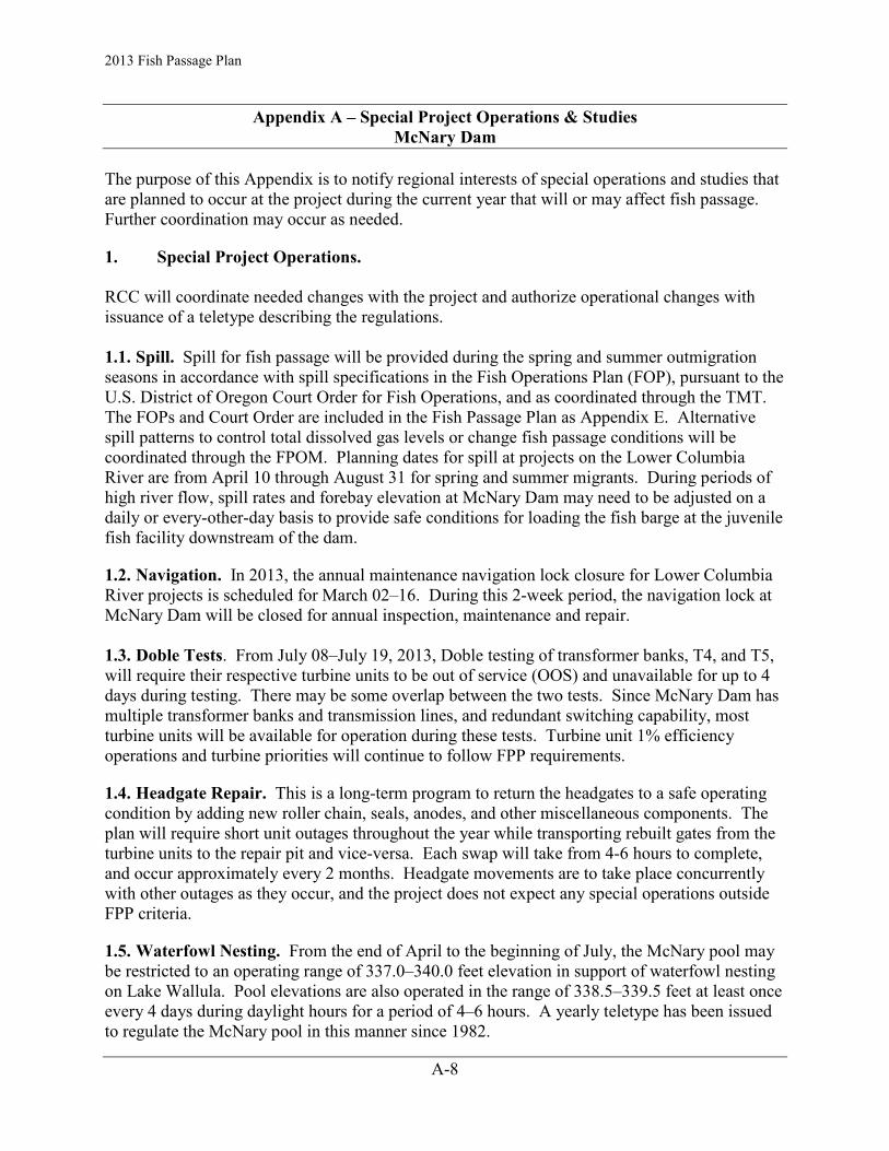
2013 Fish Passage Plan
A-8
Appendix A – Special Project Operations & Studies McNary Dam
The purpose of this Appendix is to notify regional interests of special operations and studies that are planned to occur at the project during the current year that will or may affect fish passage. Further coordination may occur as needed.
1. Special Project Operations. RCC will coordinate needed changes with the project and authorize operational changes with issuance of a teletype describing the regulations. 1.1. Spill. Spill for fish passage will be provided during the spring and summer outmigration seasons in accordance with spill specifications in the Fish Operations Plan (FOP), pursuant to the U.S. District of Oregon Court Order for Fish Operations, and as coordinated through the TMT. The FOPs and Court Order are included in the Fish Passage Plan as Appendix E. Alternative spill patterns to control total dissolved gas levels or change fish passage conditions will be coordinated through the FPOM. Planning dates for spill at projects on the Lower Columbia River are from April 10 through August 31 for spring and summer migrants. During periods of high river flow, spill rates and forebay elevation at McNary Dam may need to be adjusted on a daily or every-other-day basis to provide safe conditions for loading the fish barge at the juvenile fish facility downstream of the dam.
1.2. Navigation. In 2013, the annual maintenance navigation lock closure for Lower Columbia River projects is scheduled for March 02–16. During this 2-week period, the navigation lock at McNary Dam will be closed for annual inspection, maintenance and repair. 1.3. Doble Tests. From July 08–July 19, 2013, Doble testing of transformer banks, T4, and T5, will require their respective turbine units to be out of service (OOS) and unavailable for up to 4 days during testing. There may be some overlap between the two tests. Since McNary Dam has multiple transformer banks and transmission lines, and redundant switching capability, most turbine units will be available for operation during these tests. Turbine unit 1% efficiency operations and turbine priorities will continue to follow FPP requirements.
1.4. Headgate Repair. This is a long-term program to return the headgates to a safe operating condition by adding new roller chain, seals, anodes, and other miscellaneous components. The plan will require short unit outages throughout the year while transporting rebuilt gates from the turbine units to the repair pit and vice-versa. Each swap will take from 4-6 hours to complete, and occur approximately every 2 months. Headgate movements are to take place concurrently with other outages as they occur, and the project does not expect any special operations outside FPP criteria.
1.5. Waterfowl Nesting. From the end of April to the beginning of July, the McNary pool may be restricted to an operating range of 337.0–340.0 feet elevation in support of waterfowl nesting on Lake Wallula. Pool elevations are also operated in the range of 338.5–339.5 feet at least once every 4 days during daylight hours for a period of 4–6 hours. A yearly teletype has been issued to regulate the McNary pool in this manner since 1982.

2013 Fish Passage Plan Appendix A – Special Project Operations & Studies McNary Dam
A-9
1.6. Unit 4 and 11 Rewind. Units 4 and 11 will be taken out of service from June, 2013 through February 01, 2014, for winding and replacement of various other electrical and mechanical components, from the old excitation system down to the wicket gate servomotors.
2. Studies
2.1. Adult Salmon Studies. Both a lower Columbia River and a Snake River adult salmon passage study are planned for the 2013 adult passage season. Any new radio-telemetry antenna or receiver installations or maintenance will be completed in March-April 2013.
2.2. Evaluation of Adult Pacific Lamprey Passage Success at McNary Dam. This study will evaluate passage success for adult Pacific lamprey at McNary Dam, Ice Harbor Dam, and the remaining lower Snake River dams and associated river segments using half-duplex (HD) PIT-tag systems. This study will require McNary, Ice Harbor and Lower Snake River dams to provide power for electronics, and access for the downloading of data from the PIT-tag detection equipment. Maintenance of equipment will occur during the winter maintenance period when adult fishways are dewatered.
2.3. Fish Guidance Efficiency (FGE) and Fish Condition Study relative to partially raised operating gate (PROG) and stored operating gate (SOG) position will occur at McNary Dam during the 2013 fish passage season. The study will occur over a period of approximately two weeks during April–May and June–July. Prior to the fish passage season, hydroacoustic transducers will be installed behind the trashracks and on the ESBS brackets in the A, B, and C intakes in turbine units 6, 7, 12, and 13. The use of turbines 6 and 7 may cause unit priority to deviate from that stated in the FPP and will be coordinated appropriately. Turbine units will be operated within the 1% range. It is expected that the install of hydroacoustic transducers behind the trashrack will require approximately 7 days and occur during the timeframe of April 01–12, 2013. Hydroacoustic transducers to be installed on the ESBSs will be coordinated prior to the install of the ESBSs to reduce the possibility of any unnecessary outages. Final study dates, required outages for hydroacoustic transducer install and intake gate position changes will be coordinated appropriately through SRWG and FPOM. Equipment removal will occur subsequent to the fish passage season in September, 2013.
2.4. Underwater Video Monitoring of Adult Fish Ladder Modifications to Improve Pacific Lamprey Passage at McNary Dam. The purpose of this study is to use underwater video, acoustic imaging, and/or other non-invasive technologies to count and observe adult salmonids and Pacific lamprey in the fish ladders at McNary Dam. The primary goal of this work is to estimate the numbers of adult lamprey passing behind the picketed lead gates at count stations and to develop escapement estimates of the total number of lamprey passing McNary Dam. This study will require McNary to provide power for electronics equipment in the fishways, access for the installation, repair, and testing of electronic equipment and access for the downloading of data from video camera equipment.
2.5. Oregon Shore Ladder Intake Screen Monitoring. The purpose of this monitoring study is to ensure that the current Oregon shore adult ladder fish screens are not impinging ESA-listed juvenile fish, Pacific lamprey or bull trout. The screens were designed and installed in the early 1950s, thus do not meet the current screening criteria defined by NOAA Fisheries. The area in

2013 Fish Passage Plan Appendix A – Special Project Operations & Studies McNary Dam
A-10
front of this intake screen will be monitored using video cameras to discern the extent to which fish populations are impacted by operation of these travelling screens. In addition, the fingerling bypass ports on either side of the ladder downstream of the ladder exit will also be monitored using video cameras. Monitoring will be conducted throughout the juvenile fish passage season, approximately April 10 through August 31. The video cameras will be attached in front of the screens to existing frames used since the 2011 monitoring season. These cameras will be aimed at different angles in order to record as much of the screens as possible. The cameras for the bypass ports will be lowered into place on new mounting frames installed at the exits of the ports during the ladder outage in February 2013.

2013 Fish Passage Plan
A-11
Appendix A – Special Project Operations & Studies Ice Harbor Dam
The purpose of this Appendix is to notify regional interests of special project operations and studies that are planned to occur during the current year that will or may affect fish passage. Further coordination may occur as needed. 1. Special Project Operations. RCC will coordinate needed changes with the project and authorize operational changes with issuance of a teletype describing the regulations. 1.1. Spill. Spill for fish passage will be provided during the spring and summer outmigration seasons in accordance with spill specifications in the Fish Operations Plan (FOP), pursuant to the U.S. District of Oregon Court Order for Fish Operations, and as coordinated through the TMT. The FOPs and Court Order are included in the Fish Passage Plan as Appendix E. Alternative spill patterns to control total dissolved gas levels or change fish passage conditions will be coordinated through the FPOM. Planning dates for spill at projects on the Lower Snake River are from April 3 through August 31 for spring and summer migrants.
1.2. Navigation. In 2013, the annual maintenance navigation lock closure for Snake River projects is scheduled for March 02–23. During this 3-week period, the Projects have scheduled routine inspections and maintenance, as well as some non-routine work, such as replacement of an unwatering pump, upstream lock gate seal and wire rope replacement, and mooring bit repair.
1.3. Doble Testing. In 2013, Doble testing will take the following out of service: two transformers, TW1, TW2, and TJO and turbine units 1 and 2. The outage is tentatively scheduled for August–September, 2013. Since Ice Harbor Dam has multiple transformer banks, transmission lines, and redundant switching capability, the remaining turbine units will be available for operation during these tests. Turbine units will operate within the 1% of peak efficiency operating range, in accordance with the turbine priority order defined in the Fish Passage Plan. During the test, units 3 and 4 will be required to generate power out of Line #2 of Ice Harbor which could be against section 4.1 of the Fish Passage Plan depending on river flows. The switching necessary to support power generation and BPA system reliability may not be able to occur in August and September 2013. This outage will be coordinated with the Line #1 Disconnect Switch Maintenance in item 1.9.
1.4. Steady State Model Validation Testing. Western Electricity Coordinating Council (WECC) requires steady state model validation testing on a periodic basis to ensure the generating equipment will meet real and reactive power ratings. All units will be tested on a 1-2 year cycle. Tests will involve running the unit out of fish priority sequence and outside the 1% range. Testing can occur at any time from September 01–March 31, and will not occur during fish passage season (April 01–August 31). Tests will preferably be conducted just after unit annual maintenance, but may happen at other times. Tests will last for a standard of 30 minutes at maximum load with additional time to run the unit along the maximum real/reactive power curve to the minimum settings. Total test time is anticipated to be 90 minutes or less. Test

2013 Fish Passage Plan Appendix A – Special Project Operations & Studies Ice Harbor Dam
A-12
durations will be minimized to the extent possible and will only be run for the purpose of completing the required model validation testing.
1.5. DC System and Low Voltage Switchgear replacement. This project will start in May 2012 through August 2013 and will require turbine unit outages for the replacement of the associated panels. There are times during this evolution when switching electrical unit control busses must occur in which the unit will be brought down to accommodate switching. This switching will affect unit priority to assist with lineup of power on the units to minimize downtime on evolutions for this project. At times all turbine units or priority units will be out of service during panel replacements and temporary power installations and these outages will be limited in duration. After the panel, breaker and switchgear replacements, the turbine units will be ran and tested out of unit priority to support commissioning of the modifications. These evolutions may utilize water that would normally be used for spill.
1.5.1 SQO Tie Breaker Replacement. From March–May, 2013, the tie breaker for the 480-volt SQO switchgear will be replaced as part of this project. In order to replace this breaker, the STSs and count station will require temporary power to support the replacement of this breaker. The cut-over for temporary power and replacement of this breaker will take less than 10 hours. The replacement of this breaker will take less than a shift.
1.5.2 SQ1 Tie Breaker Replacement. From March–May, 2013, the tie breaker for the 480-volt SQ1 switchgear will be replaced as part of this project. In order to replace this breaker, units 1–3 will be taken out of service. The replacement of this breaker will take one day and will impact unit operation priority order.
1.6. Main Unit #5 and #6 Reactive Limit Testing. In FY13, after repairs of units 5 and 6 are complete, reactive limit testing will be performed. The test is required every two years for generator owners to quantitatively measure machine performance limits to ensure it is capable of providing protective functions during grid disturbances and to ensure it is not a contributor to these disturbances. The test requires operating outside of the 1% operating range for approximately 15 minutes to ensure the reactive limits of the generator can be met and held for a period of time. Testing of the units may utilize water that would normally be used for spill.
1.7. Transformer Oil Replacement. In FY13 and FY14, Ice Harbor project will be replacing transformer oil on TW-4, TW-5, TJ-0, and TW-0 based on the condition of the oil and the PCB levels within these transformers. Currently the outages are not scheduled for these items but they will occur in 2013 and will impact testing of units that may utilize water that would normally be used for spill.
1.8. Main Unit Digital Governor Upgrades. From June 2013 to December 2015, the Main Unit Digital Governors at Ice Harbor will be replaced starting on unit 4 and proceeding up to unit 6. Each unit will take about 5 weeks for the governors to be replaced. This will also involve response testing prior to the unit coming back online that will require the unit be operated outside of the 1% range and out of unit priority order in the Fish Passage Plan.

2013 Fish Passage Plan Appendix A – Special Project Operations & Studies Ice Harbor Dam
A-13
1.9. Line #1 Disconnect Maintenance. In August 2013, required maintenance and routine PMs will be performed on the 115KV Line #1 disconnect and ground switch at Ice Harbor. This maintenance will be coordinated with the Doble testing in item 1.2. During this time Main Units 3 and 4 will be required to generate power out of Line #2 of Ice Harbor which could be against section 4.1 of the Fish Passage Plan depending on river flows. Switching may not be able to occur to support power generation and BPA system reliability from August 19–September 09, 2013.
1.10. Drainage/Unwatering Pump Replacements. Beginning in December 2013, the project will install new switchgear that will be supplied by the station service 480 volt switchgear SQO. To perform this cutover and installation each bus on SQO will be taken out at different times. This will impact the south shore count station and controls while temporary power is installed to support this cutover.
1.11. 2014 Dam Safety Periodic Inspection. After October 2013, the periodic safety inspection will occur. These inspections will involve running the spillway diesel generator with all spillway gates running on the diesel generator. The spillways gates will be operated with water while on the diesel generator. 2. Studies 2.1. Adult Salmon Studies. Both a lower Columbia River and a Snake River adult salmon passage study are planned for the 2013 adult passage season. Any new radio-telemetry antenna or receiver installations or maintenance will be completed in March-April 2013. A new water-to-water transfer adult trap in the old trap location of the south fish ladder will be completed during the 2012-2013 IWW and operational beginning in March 2013. Adult spring Chinook salmon will be collected from the adult trap by a contractor for radio-tagging from April–June, 2013.
2.2. Evaluation of Adult Pacific Lamprey Passage Success at Ice Harbor Dam. This study will evaluate passage success for adult Pacific lamprey Entosphenus tridentatus at McNary Dam, Ice Harbor Dam, and the remaining lower Snake River dams and associated river segments using half-duplex (HD) PIT-tag systems. This study will require McNary, Ice Harbor and Lower Snake River dams to provide power for electronics and access for the downloading of data from the PIT-tag detection equipment. Maintenance of equipment will occur during the winter maintenance period when adult fishways are dewatered.
2.3. Underwater Video Monitoring of Adult Fish Ladder Modifications to Improve Pacific Lamprey Passage at Ice Harbor Dam. The purpose of this study is to use underwater video, acoustic imaging, and/or other non-invasive technologies to count and observe adult salmonids and Pacific lampreys, Entosphenus tridentatus, in the fish ladders at Ice Harbor Dam. The goal of this work is to estimate the number of adult lamprey passing behind the picketed lead gates at count stations and to develop escapement estimates of the total number of lamprey passing Ice Harbor Dam. This study will require Ice Harbor to provide power for electronics equipment in the fishways, access for the installation, repair, and testing of electronic equipment and access for the downloading of data from video camera equipment. Maintenance and installation of camera equipment and will occur during the winter maintenance period when adult fishways are dewatered.

2013 Fish Passage Plan Appendix A – Special Project Operations & Studies Ice Harbor Dam
A-14
2.4. Evaluation of Fish Counting Accuracy Issues at FCRPS Dams, Ice Harbor and Lower Monumental Dams. This study is to determine if counting slot lighting modifications, video camera location and upgrades, and video monitor placement can improve fish counting accuracy at Ice Harbor and Lower Monumental dams. During daytime, the IHR north counting slot is exposed to direct sunlight, particularly in June and July, when the sun is highest and when the majority of count discrepancies are seen, and this creates difficult viewing conditions for fish counters. By conducting random visual sampling counts of the video recorded count stations (and sample video recordings periods) and comparing to the visual counter at the other count station, we can determine if there are count accuracy and/or identification issues. Fish counts at IHR are often lower than those at upstream dams, possibly suggesting some issue with fish counting accuracy at IHR. This is particularly frequent in June and July, when the sun is highest and glare may be at its worst at these count windows. At IHR and at LMN, all fish counting is done by video in the IHR north and the LMN south fish ladder counting slots.

2013 Fish Passage Plan
A-15
Appendix A – Special Project Operations & Studies Lower Monumental Dam
The purpose of this Appendix is to notify regional interests of special project operations and studies that are planned to occur during the current year that will or may affect fish passage. Further coordination may occur as needed.
1. Special Project Operations. RCC will coordinate needed changes with the project and authorize operational changes with issuance of a teletype describing the regulations. 1.1. Spill. Spill for fish passage will be provided during the spring and summer outmigration seasons in accordance with spill specifications in the Fish Operations Plan (FOP), pursuant to the U.S. District of Oregon Court Order for Fish Operations, and as coordinated through the TMT. The FOPs and Court Order are included in the Fish Passage Plan as Appendix E. Alternative spill patterns to control total dissolved gas levels or change fish passage conditions will be coordinated through the FPOM. Planning dates for spill at projects on the Lower Snake River are from April 3 through August 31 for spring and summer migrants. During periods of high river flow, spill rates and forebay elevation at Lower Monumental Dam may need to be adjusted on a daily or every-other-day basis to provide safe conditions for loading the fish barge at the juvenile fish facility downstream of the dam.
1.2. Navigation. In 2013, the annual maintenance navigation lock closure for Snake River projects is scheduled for March 02–23. During this 3-week period, the Projects have scheduled routine inspections and maintenance, as well as some non-routine work, such as replacement of an unwatering pump, upstream lock gate seal and wire rope replacement, and mooring bit repair.
1.3. Steady State Model Validation Testing. Western Electricity Coordinating Council (WECC) requires steady state model validation testing on a periodic basis to ensure the generating equipment will meet real and reactive power ratings. All units will be tested on a 1-2 year cycle. Tests will involve running the unit out of fish priority sequence and outside the 1% range. Testing can occur at any time from September 01–March 31, and will not occur during fish passage season (April 01–August 31). Tests will preferably be conducted just after unit annual maintenance, but may happen at other times. Tests will last for a standard of 30 minutes at maximum load with additional time to run the unit along the maximum real/reactive power curve to the minimum settings. Total test time is anticipated to be 90 minutes or less. Test durations will be minimized to the extent possible and will only be run for the purpose of completing the required model validation testing.
1.4. T2 Doble Tests. Transformer bank T1 and turbine units 1, 2, 3, and 4 will be taken out of service for doble testing in 2013. The outage is tentatively scheduled for August 19 to Aug 23, 2013. This work will require a total powerhouse outage, and 100% spill (except for station service) for up to 4 hours. By then, all clearance tags should be hung, and the line could be re-energized allowing generation availability of Units 5 and 6. Turbine unit 1% efficiency operations and turbine priorities will continue to follow fish passage plan requirements during

2013 Fish Passage Plan Appendix A – Special Project Operations & Studies Lower Monumental Dam
A-16
these tests. Another total plant outage will be required on the last day of testing to remove clearance tags and restore T1 bank.
1.5. Lower Snake Exciter Replacement: Lower Snake exciter replacement took place at Lower Monumental in FY12. During the commissioning process at Little Goose, some commissioning process errors were noticed that derated the Units at Lower Monumental and Lower Granite. The team is evaluating whether or not to re-commission the Units at Lower Monumental and Lower Granite. Units 4-6 at Lower Monumental may need to undergo re-commissioning to bring the capability of the Units back to original levels. This work will also require performance testing and model validation testing. Thus running units out of priority order and outside the 1% operating range. See model validation testing paragraph number 1.3. This contract work is subject to normal contracting and construction delays. The schedule for this evolution is not yet determined, but will be scheduled so that impacts to fish are minimized.
1.6. Lower Monumental Head Gate Rehab: Under the BPA Large Cap Program, parts and materials have been acquired to rehabilitate the headgates at Lower Monumental Dam. To facilitate the process, units will be scheduled out of service to remove or replace headgates. The headgates will be serviced in the repair pit and then placed back into service. Deviation from unit priority will be necessary to swap headgates from the unit to the pit. The duration of the outages is expected to be one day. The work is expected to start in December of 2012 and continue in to 2014.
1.7. Lower Monumental Main Unit 2 Liner: Under the BPA Large Cap Program, Unit 2 is scheduled to receive a liner replacement. The work is scheduled to start in October of 2013 and go to March of 2014. During this time, Unit 2 will be out of service. Testing following the repairs will be addressed in the 2014 FPP.
1.8. Lower Monumental AWS Fish Pump 2 Rehab: Lower Monumental Staff will undertake the rehab of fish pump 2 in FY13. The present rehab schedule is to have fish pump 2 returned to service by April 01, 2013. The AWS system should remain in compliance with a 2-pump operation. However, the monthly PMs will require us to operate on single-pump operation for the required two day outage necessary to work on pump 1 and pump 3. This work is subject to normal construction-type delays.
1.9. RSW Transition Plate Replacement: The Lower Monumental RSW is scheduled to have the transition plates and bolts replaced in FY13. This effort will be done with divers. Units 5 and 6 will be out of service while dive operations are taking place. The in-water work period is scheduled to start on September 1, 2013. This contracting work is subject to normal construction and contracting delays.
2. Studies
2.1. Evaluation of Fish Counting Accuracy Issues at FCRPS Dams, at Ice Harbor and Lower Monumental Dams. This study is to determine if counting slot lighting modifications, video camera location and upgrades, and video monitor placement can improve fish counting accuracy at Ice Harbor and Lower Monumental dams. During daytime, the IHR north counting slot is exposed to direct sunlight, particularly in June and July, when the sun is highest and when

2013 Fish Passage Plan Appendix A – Special Project Operations & Studies Lower Monumental Dam
A-17
the majority of count discrepancies are seen, and this creates difficult viewing conditions for fish counters. By conducting random visual sampling counts of the video recorded count stations (and sample video recordings periods) and comparing to the visual counter at the other count station, we can determine if there are count accuracy and/or identification issues. Fish counts at IHR are often lower than those at upstream dams, possibly suggesting some issue with fish counting accuracy at IHR. This is particularly frequent in June and July, when the sun is highest and glare may be at its worst at these count windows. At IHR and at LMN, all fish counting is done by video in the IHR north and the LMN south fish ladder counting slots.
2.2. BiOp Kelt Passage and Survival Monitoring. In 2013, a contractor will conduct the second year of a two year study to assess dam route passage efficiency and survival for downriver migrating steelhead kelt utilizing the existing acoustic telemetry receiver system installed by PNNL for the BiOp Juvenile Summer-run Salmon Performance Standard. Access for contractor downloading acoustic data from the arrays of receivers is the only requirement for this study.
2.3. Adult Salmon Studies. Both a lower Columbia River and a Snake River adult salmon passage study are planned for the 2013 adult passage season. Any new radio-telemetry antenna or receiver installations or maintenance will be completed in March-April 2013.
2.4. BiOp Performance Standard Compliance Test at Lower Monumental Dam. In 2013, Battelle will conduct the second year of a two year study to assess compliance with the BiOp Juvenile Salmon Performance Standard. This test will utilize acoustic telemetry to estimate dam passage survival for subyearling Chinook salmon. Hydrophones will be deployed on the upstream face of the dam to monitor all major routes of passage available to juvenile salmon. In addition, hydrophones will be deployed in the forebays of the spillway and powerhouse and autonomous receivers will be deployed in both the Forebay and tailrace each approximately two kilometers from the dam. At Lower Monumental Dam forebay coverage will include two additional clusters stationed upstream of the RSW to monitor RSW passage. These clusters will be positioned far enough upstream as not to interfere with RSW operation.
2.5. Evaluation of Adult Pacific Lamprey Passage Success at Lower Monumental Dam. This study will evaluate passage success for adult Pacific lamprey Entosphenus tridentatus at McNary Dam, Ice Harbor Dam, and the remaining lower Snake River dams and associated river segments using half-duplex (HD) PIT-tag systems. This study will require McNary, Ice Harbor and Lower Snake River dams to provide power for electronics, and access for the downloading of data from the PIT-tag detection equipment. Maintenance of equipment will occur during the winter maintenance period when adult fishways are dewatered.

2013 Fish Passage Plan
A-18
Appendix A – Special Project Operations & Studies Little Goose Dam
The purpose of this Appendix is to notify regional interests of special project operations and studies that are planned to occur during the current year that will or may affect fish passage. Further coordination may occur as needed.
1. Special Project Operations.
RCC will coordinate needed changes with the project and authorize operational changes with issuance of a teletype describing the regulations.
1.1. Spill. Spill for fish passage will be provided during the spring and summer outmigration seasons in accordance with spill specifications in the Fish Operations Plan (FOP), pursuant to the U.S. District of Oregon Court Order for Fish Operations, and as coordinated through the TMT. The FOPs and Court Order are included in the Fish Passage Plan as Appendix E. Alternative spill patterns to control total dissolved gas levels or change fish passage conditions will be coordinated through the FPOM. Planning dates for spill at projects on the Lower Snake River are from April 3 through August 31 for spring and summer migrants.
1.2. Navigation. In 2013, the annual maintenance navigation lock closure for Snake River projects is scheduled for March 02–23. During this 3-week period, the Projects have scheduled routine inspections and maintenance, as well as some non-routine work, such as replacement of an unwatering pump, upstream lock gate seal and wire rope replacement, and mooring bit repair.
1.3. Periodic Inspection. The Little Goose project is scheduled to be inspected during May 2013. This is part of the 5-year formal Periodic Inspection process.
1.4. Steady State Model Validation Testing. Western Electricity Coordinating Council (WECC) requires steady state model validation testing on a periodic basis to ensure the generating equipment will meet real and reactive power ratings. All units will be tested on a 1-2 year cycle. Tests will involve running the unit out of fish priority sequence and outside the 1% range. Testing can occur at any time from September 01–March 31, and will not occur during fish passage season (April 01–August 31). Tests will preferably be conducted just after unit annual maintenance, but may happen at other times. Tests will last for a standard of 30 minutes at maximum load with additional time to run the unit along the maximum real/reactive power curve to the minimum settings. Total test time is anticipated to be 90 minutes or less. Test durations will be minimized to the extent possible and will only be run for the purpose of completing the required model validation testing.
1.5. Lower Snake Exciter Replacement. Little Goose units 1 or 2 exciter replacement is scheduled for January–February 2013, but may extend into April for testing. This work will also require performance testing and model validation testing. Thus running units out of priority and outside 1%. See model validation testing paragraph number 1.5 and 1.6. This contract work is subject to normal contracting and construction delays or issues.

2013 Fish Passage Plan Appendix A – Special Project Operations & Studies Little Goose Dam
A-19
1.6. Doble Testing. In 2013, two transformers, T-1 and turbine units 1 to 4 will be taken out of service for Doble testing. The outage is tentatively scheduled for August 5–15, 2013. Since Little Goose Dam has multiple transformer banks, the remaining turbine units will be available for operation during these tests. Turbine unit 1% efficiency operations and turbine priorities will continue to follow fish passage plan requirements during these tests.
1.7. Intake Gantry Crane. Little Goose intake gantry crane will be replaced in 2013. The completion of installation is scheduled for July, 2013. Upon completion, a functional test will be required to be completed before acceptance. The functional test consists of installing a main unit headgate with the cylinder attached, installing, deploying and uninstalling an ESBS, and installing a spillway stop log and testing installation of the TSW. This will require one Unit and one spill bay to be out of service for a day for each functional test. The choice of spillbay and Unit will be approved by NWW OD-T personnel to minimize fish passage impacts.
2. Studies.
2.1. BiOp Performance Standard Compliance Test at Little Goose Dam. In 2013, Battelle will conduct the second year of a two year study to assess compliance with the BiOp Juvenile Salmon Performance Standard. This test will utilize acoustic telemetry to estimate dam passage survival for subyearling Chinook salmon. Hydrophones will be deployed on the upstream face of the dam to monitor all major routes of passage available to juvenile salmon. In addition, hydrophones will be deployed in the forebays of the spillway and powerhouse and autonomous receivers will be deployed in both the Forebay and tailrace each approximately two kilometers from the dam. At Little Goose Dam forebay coverage will include two additional clusters stationed upstream of the RSW to monitor RSW passage. These clusters will be positioned far enough upstream as not to interfere with RSW operation.
2.2. BiOp Kelt Passage and Survival Monitoring. In 2013, researchers will conduct the second year of a 2-year study to assess dam route passage efficiency and survival for downriver migrating steelhead kelt utilizing the existing acoustic telemetry receiver system installed by Battelle for the BiOp Juvenile Summer-run Salmon Performance Standard. Access for contractor downloading acoustic data from the arrays of receivers is the only requirement for this study.
2.3. Adult Salmon Studies. Both a lower Columbia River and a Snake River adult salmon passage study are planned for the 2013 adult passage season. Any new radio-telemetry antenna or receiver installations or maintenance will be completed during March-April 2013. The adult ladder count window slot will be modified during the IWW for a minimum slot opening of 18’ in preparation of temporary PIT-tag antennae in January 2014.
2.4. Evaluation of Adult Pacific Lamprey Passage Success at Little Goose Dam. This study will evaluate passage success for adult Pacific lamprey Entosphenus tridentatus at McNary Dam, Ice Harbor Dam, and the remaining lower Snake River dams and associated river segments using half-duplex (HD) PIT-tag systems. This study will require McNary, Ice Harbor and Lower Snake River dams to provide power for electronics, and access for the downloading of data from the PIT-tag detection equipment. Maintenance of equipment will occur during the winter maintenance period when the adult fishway are dewatered.

2013 Fish Passage Plan Appendix A – Special Project Operations & Studies Little Goose Dam
A-20
2.5. Underwater Video Monitoring of Adult Fish Ladder Modifications to Improve Pacific Lamprey Passage at Little Goose Dam. The purpose of this study is to use underwater video, acoustic imaging, and/or other non-invasive technologies to count and observe adult salmonids and Pacific lampreys, Entosphenus tridentatus, in the fish ladders at Little Goose Dam. The goal is to evaluate the behavior of adult salmonids and lamprey at newly installed lamprey orifices in the control section of the adult fish ladder using underwater video equipment. This study will require Little Goose to provide power for electronics equipment in the fishway, access for the installation, repair, and testing of electronic equipment and access for the downloading of data from video camera equipment. Installation of camera equipment will occur during the winter maintenance period when the adult fishway is dewatered.

2013 Fish Passage Plan
A-21
Appendix A – Special Project Operations & Studies Lower Granite Dam
The purpose of this Appendix is to notify regional interests of special project operations and studies that are planned to occur during the current year that will or may affect fish passage. Further coordination may occur as needed.
1. Special Project Operations. RCC will coordinate needed changes with the project and authorize operational changes with issuance of a teletype describing the regulations.
1.1. Spill. Spill for fish passage will be provided during the spring and summer outmigration seasons in accordance with spill specifications in the Fish Operations Plan (FOP), pursuant to the U.S. District of Oregon Court Order for Fish Operations, and as coordinated through the TMT. The FOPs and Court Order are included in the Fish Passage Plan as Appendix E. Alternative spill patterns to control total dissolved gas levels or change fish passage conditions will be coordinated through the FPOM. Planning dates for spill at projects on the Lower Snake River are from April 3 through August 31 for spring and summer migrants. During periods of high river flow, spill rates and forebay elevation at Lower Granite Dam may need to be adjusted on a daily or every-other-day basis to provide safe conditions for loading the fish barge at the juvenile fish facility downstream of the dam.
1.2. Navigation. In 2013, the annual maintenance navigation lock closure for Snake River projects is scheduled for March 02–23. During this 3-week period, the Projects have scheduled routine inspections and maintenance, as well as some non-routine work, such as replacement of an unwatering pump, upstream lock gate seal and wire rope replacement, and mooring bit repair.
1.3. Doble Test. Lower Granite transformer bank T1 will be Doble tested this year. A full line outage will be taken daily. Unit 5 will be run at speed-no-load daily to supply station service power. At night, T2 (Units 5 and 6) will be returned to service. T1 (Units 1-4) will remain out of service for the duration of the Doble test. The Doble test is scheduled for 5 days starting at 0400 12 August 2013. T1 is scheduled to return to service August 16, 2013 at 1600.
1.4. Unit Cavitation Repairs. Lower Granite has a contract in place to continue cavitation repairs on Units 5 and 6. Each unit will be out one at a time for blade and liner cavitation repairs. Unit 5 will continue through March, 2013. After which LWG project maintenance will replace the blade seal packing. Unit 5 is scheduled to return to service April 12, 2013. Unit 6 will be OOS July 01–December 07, 2013, for cavitation repair.
1.5. Headgate Repair. This is a long-term program to return the headgates to a safe operating condition by adding new roller chain, seals, anodes, and other miscellaneous components. The plan will require short unit outages throughout the year while transporting rebuilt gates from the turbine units to the repair pit and vice versa. Each swap will take from 4 to 6 hours to complete, and take place approximately every 2 months. Headgate movements are to take place

2013 Fish Passage Plan Appendix A – Special Project Operations & Studies Lower Granite Dam
A-22
concurrently with other outages as they occur, and no special operations outside the Fish Passage Plan are expected, but it may cause an occasional outage on a priority unit.
1.6. Fish Screen Repair. This is a long-term program to return the fish screens to a safe operating condition by tearing down, repainting and rebuilding the screens. The plan will require short unit outages throughout the year while transporting rebuilt screens from the turbine units to the repair pit and vice versa. Each swap will take from 4 to 6 hours to complete, and take place approximately every 2 months. Fish screen movements are to normally take place concurrently with other outages as they occur, and no special operations outside the Fish Passage Plan are expected, but it may cause an occasional outage on a priority unit.
1.7. Unit 4 Turbine Guide Bearing. From July 26–August 16, 2013, the unit 4 turbine guide bearing will be replaced following the normal unit 4 annual maintenance. Unit 4 annual maintenance is scheduled for July 01–26, 2013.
1.8. NSE3 bulkhead is in need of being replaced. The new bulkhead is anticipated to be completed and installed during the winter maintenance period. If delivery of the bulkhead is delayed, we will need to coordinate with OD-T to request a shutdown of the AWS system to swap out these bulkheads. The old NSE3 bulkhead will be placed in NPE3 bulkhead slot as there is a temporary steel one there that does not seal correctly. This year, we will be getting an NPE3 bulkhead fabricated to replace the old NSE3 bulkhead placed in the NPE3 slot. There may be damage to the NPE3 bulkhead slot where the temporary steel bulkhead has resided for over a year.
1.9. AWS pumps. Due to the large amount of work being done on the adult collection channel fishway grating, the project will not be able to complete a gearbox oil change on all the AWS pumps. Last year, there were elevated temperatures on all AWS pump gearboxes. The gearbox oil changes can be completed one at a time during the year, but will require coordination of an approximate 2-hour AWS pump outage to swap bulkheads from the standby pump to an operational pump (hence swapping standby pumps). This outage needs to be coordinated with OD-T on two separate occasions throughout the year to enable the changing of AWS gearbox oil.
2. Studies
2.1. Evaluation of Prototype Overflow Weir and 14-inch Orifice for the Lower Granite Juvenile Bypass System Upgrade. A prototype overflow weir and enlarged 14” orifice are being installed into intake gatewell 5A during the winter of 2012/13 for biological testing during the 2013 fish passage season from April 15–June 30, 2013. This testing period is intended to coincide with peak fish outmigration periods, water passage, and cavitation repairs of unit 5 through mid-April 2013. Preliminary plans for a new Juvenile Fish Facility at Lower Granite include the use of larger orifices and/or overflow weirs for fish to pass from the gatewells to the collection channel. Results of this study will be used to inform management decisions on final structural modifications and operational changes at Lower Granite Dam to optimize survival and passage for salmonids.

2013 Fish Passage Plan Appendix A – Special Project Operations & Studies Lower Granite Dam
A-23
Final study plans during the test period are still being developed and will be coordinated with RCC and Lower Granite project staff for implementation. In order to conduct the necessary biological testing, deviations from the standard turbine priorities (see the Fish Passage Plan Table LWG-5 below) will be necessary to operate unit 5 during the testing periods.
Unit 2 will remain the first priority during the test period to provide fish ladder attraction flow. There will be no changes to spill or spill patterns for this study. From April 15–June 30, 2013, unit 5 will be operated at the upper end of the 1% operating range, or at an alternative fixed discharge if possible, during each test block to provide consistent testing conditions. Based on historical river flows, it is likely that sufficient inflows will permit operation of unit 5 for this test through June 30. Final unit operations will be dictated by final study plans (i.e., days per week) and will be coordinated with RCC and Lower Granite Dam project staff.
Fish Passage Plan Table LWG- 1. Turbine unit operating priority for Lower Granite Dam. Highlighted text is added for the 2013 test only.
Season Duration Unit Priority
March 1 – December 15 24 hours/day
Except during 2013 Test Periods below
Start Units 2, 3, then 4-6 any order, then 1 a
Stop Units b 4-6 any order, then 3, 2, 1 a
April 15 – June 30 24 hours/day
During 2013 Test Periods c
Start Units 2, 5, 3, then 4 or 6 any order, then 1
Stop Units b 4 or 6 any order, then 3, 5, 2, 1
December 16 – February 28 24 hours/day Start/Stop Units Any Order
a. Unit 1 has fixed Kaplan blades and can only run at 130 megawatts. The Unit Priority order in Table LWG-5 minimizes starts and stops of Unit 1 and allows for the longest runtime once Unit 1 is started. b. Stop Units in reverse Start Unit order, except run Unit 1 as long as BPA load request and required spill rates can be met. c. In 2013, modifications to turbine unit priorities are only needed during testing of the prototype overflow weir and enlarged 14” orifice installed in Unit 5. Unit priority operations during the test period are currently anticipated to be 24 hours per day, 6 days per week. Implementation of final study plans will be coordinated with RCC and Lower Granite Dam project staff.
2.2. Kelt Reconditioning / Transportation / In-river Survival. Provide assistance to Nez Perce Tribe for collection and tagging of post-spawn steelhead (kelt) off the Lower Granite separator for reconditioning study, temporary rearing and feed, and JSATS route survival determination in order to determine the feasibility and success of these alternatives for increased steelhead population growth. Depending on flow year conditions, separator technicians will collect a similar number of A-run and B-run kelt for transfer to CRITFC/NPT researchers for reconditioning facilities at Dworshak Dam (about 400 kelt), JSATS and PIT-tagging (300 kelt) with direct release into the tailwaters, or PIT-tagging with direct release into the tailwaters (about 1200-1400 kelt).
2.3. BiOp Kelt Passage and Survival Monitoring. In 2013, a contractor will conduct the second year of a two year study to assess dam route passage efficiency and survival for downriver migrating steelhead kelt utilizing the existing acoustic telemetry receiver system installed by Battelle for the BiOp Juvenile Summer-run Salmon Performance Standard at Little Goose and Lower Monumental dams. Two-thirds of sample kelt will be dominated by A-run

2013 Fish Passage Plan Appendix A – Special Project Operations & Studies Lower Granite Dam
A-24
steelhead collected off the LGR JFF separator as collaboration with the CRITFC study. The remaining one-third of the sample will be double-tagged PIT- and JSAT from 4-5 subbasin stream weirs in the Clearwater and South Fork Salmon rivers. Passage route distribution and survivals at Lower Granite require installation of acoustic receiver arrays in the Lower Granite forebay and tailrace beginning in March prior to scheduled voluntary spill. Using the existing trolley pipes and an inriver receiver rosette, minimal array systems will cover the RSW and remaining spillbays, all Turbine units, as well as the forebay entrance and tailwater exit lines placed outside the BRZs. No unit outages are planned as necessary for receiver installation. The Contractor will likely request placement of a single computer trailer with cable routing and electrical hook-up for the trolley pipes for receiver deployment. Access for contractor downloading acoustic data from the arrays of receivers between mid-March and 30 August is required for this study.
2.4. Adult Salmon Studies. Both a lower Columbia River and a Snake River adult salmon passage study are planned for the 2013 adult passage season. Any new radio-telemetry antenna or receiver installations or maintenance will be completed in March-April 2013. Adult steelhead will be collected from the adult trap at Lower Granite by a contractor for radio-tagging during July–September.
2.5. Evaluation of Adult Pacific Lamprey Passage Success at Lower Granite Dam. This study will evaluate passage success for adult Pacific lamprey Entosphenus tridentatus at McNary Dam, Ice Harbor Dam, and the remaining lower Snake River dams and associated river segments using half duplex passive integrated transponder (HD PIT) systems. This study will require McNary, Ice Harbor and Lower Snake River dams to provide power for electronics, and access for the downloading of data from the PIT-tag detection equipment. Maintenance of equipment will occur during the winter maintenance period when the adult fishway are dewatered.
2.6. Lower Granite Winter / Spring 2013 Tailrace Field Data Collection. A physical general tailrace model (1:55 scale) and 2-D Computational Fluid Dynamics (CFD) model are currently being developed for the Lower Granite tailrace area. Extensive tailrace data will need to be collected during the winter, spring, and early summer of 2013 to verify and calibrate these new models and for providing direct hydraulic field information. Field data will primarily consist of Acoustic Doppler Current Profile (ADCP) transects, time-lapse video of the tailrace, and local wind measurements. In order to collect relevant data, project operations will need to remain constant for 10-12 hours during each test condition. Every effort will be made to collect desired flow/operating conditions as they occur during normal system operations during the winter, spring and summer (1 February to August 2013) in order to avoid requests for operational changes to the FCRPS. However, it is anticipated that operational changes to the FCRPS may need to be requested in order to collect the necessary data in a timely manner for development of potential Lower Granite JBS outfall locations during the summer of 2013. There are two operational conditions that may require special operating conditions during fish passage plan (FPP) spill: total in-river flow of approximately 50 kcfs with no spill and total in-river flow of approximately 75 kcfs with no spill. If these target flow ranges are not attained prior to April 3rd (commencement of FPP spill), it would be requested to temporarily (10 to 12 hours) suspend FPP spill in order to obtain field measurements under these conditions. If special operations are required, a coordination request will be submitted to FPOM and coordinated with RCC and BPA

2013 Fish Passage Plan Appendix A – Special Project Operations & Studies Lower Granite Dam
A-25
for regional approval and coordination.
2.7. Lower Granite Outfall Geotechnical Explorations. In order to collect necessary data for construction of a new Lower Granite Juvenile Bypass System (JBS), it will be necessary to conduct geotechnical explorations at Lower Granite both on-shore (upland) and in the water. Upland (on-shore) geotechnical explorations will occur on the south shore of the tailrace near the JFF and adult ladder starting in March utilizing light-weight (e.g., man-portable) drill rig and a standard truck mounted drill rig. In-water explorations within the tailrace area is expected to take place in the September-October 2013 or January-February 2014 timeframe. It is anticipated in-water geotechnical explorations will be conducted 1,500-3,500 feet downriver of the Lower Granite Dam powerhouse outside of the Boat Restricted Zone (BRZ) based on final decisions for placement of the new bypass outfall. In-water geotechnical exploration work will include deployment of a floating barge in the tailrace for support of a drill rig and ancillary equipment. The drill rig will advance a boring through the alluvial material into the underlying basalt. Standard Penetration Tests (SPTs) will be performed in the alluvial material and coring in the basalt. Geotechnical exploration efforts are not expected to require any special project operations. Any deviations from this project schedule or area of work will be submitted to FPOM for regional coordination and approval.
2.8. Underwater Video Monitoring of Adult Fish Ladder Modifications to Improve Pacific Lamprey Passage at Lower Granite Dam. The purpose of this study is to use underwater video, acoustic imaging, and/or other non-invasive technologies to count and observe adult salmonids and Pacific lampreys, Entosphenus tridentatus, in the fish ladders at Lower Granite Dam. The goal is to evaluate the behavior of adult salmonids and lamprey at newly installed lamprey orifices in the control section of the adult fish ladder using underwater video equipment. This study will require Lower Granite to provide power for electronics equipment in the fishway, access for the installation, repair, and testing of electronic equipment and access for the downloading of data from video camera equipment. Installation of camera equipment will occur during the winter maintenance period when the adult fishway is dewatered.

2013 Fish Passage Plan
Appendix B Corps of Engineers Juvenile Fish Transportation Plan 1
1. INTRODUCTION
The Juvenile Fish Transportation Plan (JFTP) describes operations and establishes criteria for the collection and transportation of juvenile salmon and steelhead from Lower Granite, Little Goose, Lower Monumental, and McNary dams (collector dams) to release areas below Bonneville Dam. This work plan supplements normal operating criteria for the collector dams presented in the Fish Passage Plan (FPP), Sections 5, 7, 8, and 9, available online at: http://www.nwd-wc.usace.army.mil/tmt/documents/fpp/2012/.
The JFTP is implemented by the Corps of Engineers’ Walla Walla District (CENWW) under an Endangered Species Act (ESA) Section 10 (a)(1)(A) incidental take permit issued by the National Oceanic and Atmospheric Administration’s National Marine Fisheries Service (NOAA Fisheries, formerly referred to as NMFS).
On-site biological assistance is provided by fishery agencies through a contract with the Pacific States Marine Fisheries Commission (PSMFSC) and sub-contracts with Washington Department of Fish & Wildlife (WDFW) and Oregon Department of Fish & Wildlife (ODFW). On-site biological assistance is provided by WDFW at Lower Granite, Lower Monumental, and McNary dams and by ODFW at Little Goose Dam.
The transport program will be coordinated with other fishery monitoring, research, and management activities by CENWW. Coordination will be achieved with the fishery agencies and tribes through the appropriate regional forums, such as the Fish Passage Operations and Maintenance (FPOM) Coordination Team and the Technical Management Team (TMT), and with other agencies as required.
2. OBJECTIVE
The objective of CENWW and the transportation program is to transport juvenile fish when the best scientific information indicates doing so will increase adult return rates. This can be achieved by:
2.1. Providing safe and efficient collection and barge or truck transport of juvenile salmon and steelhead from collector dams to release areas below Bonneville Dam;
2.2. Identifying and recommending programs or facility changes that would benefit fish collection and transportation or bypass operations;
2.3. Assuring that collection, transport, and release site facilities are ready for operation prior to the beginning of transport operations;
1 If any provisions herein conflict with the Corps’ annual Fish Operations Plan (Appendix E), the latter shall prevail.

2012 Fish Passage Plan Appendix B Juvenile Fish Transportation Plan
B-2
2.4. Assuring that collection, transport, and release site facilities are properly maintained throughout the transport season;
2.5. Establishing operating criteria for facilities, barges, and trucks including fish holding and transport densities, sampling rates, and facility operations and maintenance;
2.6. Coordinating changes needed to accommodate fluctuations in the outmigration with projects, NOAA Fisheries, PSMFC, FPOM, and TMT personnel;
2.7. Coordinating transport evaluation and other research with the transportation program;
2.8. Providing the training of new personnel associated with collection and transport facilities and equipment;
2.9. Providing all parties involved a list of emergency points of contact and appropriate telephone numbers so that any emergency can be coordinated and corrected efficiently;
2.10. Preparing an annual report detailing transportation activities and results for the previous year, and identifying maintenance, replacement, or modifications needed for the next transport season.
3. PROGRAM DURATION
3.1. Starting Operations: Consistent with the Fish Operations Plan (FOP), which is included with the Fish Passage Plan as Appendix E, and guidance provided by TMT, the juvenile fish transportation program allows for a variable start date, based on expected river flow. During years when the spring seasonal average river flows in the Snake River are expected to equal or exceed 65 kcfs, transport operations will begin between April 21 and May 1 at Lower Granite as determined by TMT. In these years, transportation will begin at Little Goose and Lower Monumental dams in a staggered fashion, with the start dates being determined at TMT. Prior to the start of transportation at a given collector project all collected fish will be bypassed directly to the river unless needed for a regionally approved study. In years when the spring seasonal average river flows are expected to be below 65 kcfs, transport operations will start on April 3 at Lower Granite, Little Goose, and Lower Monumental dams. McNary Dam will begin sampling for PIT tags, monitoring facility operations, and the Smolt Monitoring Program (SMP) on April 17. Transport operations at McNary Dam will not begin until conditions specified under paragraph 4.b. (2) in coordination and discussions with TMT are met.
3.2. Summer Transport Operations: At McNary Dam, summer operations will begin when in-river migration conditions are no longer spring-like (see 4.b.(2) below). At Lower Granite, Little Goose, and Lower Monumental dams, summer operations will begin in coordination and discussions with TMT. Fish collected during summer operations will be held in shaded raceways or holding tanks. Sampling may convert to 100% when fish numbers at Snake River projects are below 500 fish per day (per PSMFC sampling guidelines) and smaller pickup mounted transport tanks may be used. Steelhead, which state biologists determine are in poor condition or are reverting to the parr stage, may be bypassed to the river.

2012 Fish Passage Plan Appendix B Juvenile Fish Transportation Plan
B-3
3.3. Ending Operations: Transport operations are anticipated to continue through approximately September 30 at Lower Monumental and McNary dams and through October 31 at Lower Granite and Little Goose dams. However, the presence of factors such as excess shad, algae, bryozoans that can clog screens and flumes may result in discontinuing transport operations at McNary before September 30.
3.4. Emergency Notification Criteria: Project Biologists will report to the CENWW Transportation Coordinator when high water temperatures or other factors increase collection mortality to 6 percent of daily collection for 3 consecutive days: if daily collection mortality exceeds 10,000 fish, and provide early notice if mortality rates are increasing at such a rate that these numbers are likely to be met. The Transportation Coordinator will evaluate the situation and shall notify NOAA Fisheries and may arrange a conference call, if needed, with TMT to discuss options to provide adequate fish protection measures. In the event of a fish loss exceeding conditions set forth in the ESA Section 10 Permit for the transportation program, the Corps shall notify NOAA Fisheries and reopen consultation as needed. If icing conditions threaten facility integrity or present unsafe conditions on the transport route, transport operations may be terminated early by the project’s Operations Manager. Emergency termination or modification of the transportation program will be coordinated by the CENWW Transportation Coordinator with NOAA Fisheries and TMT.
4. OPERATING CRITERIA
4.1. Early Season, Non-Transport Operations: Prior to initiation of transport in flow years when fish are not being transported from the Snake River projects, fish collection facilities will be operated in the following manner:
4.1.1. Lower Granite: Juvenile fish will be bypassed via normal separator operations and routed to the mid-river release outfall. All juvenile fish collected will be interrogated for PIT tags and normal 24-hour sampling for the SMP shall take place.
4.1.2. Little Goose: Juvenile fish will be bypassed and routed to the mid-river release outfall and full flow PIT tag detection system. Limited sampling may take place daily from April 1 to monitor fish condition, ensure sampling systems are operating correctly prior to when transport begins, and to train personnel on facility operations and sampling protocol. Prior to initiating transportation, full 24 hour samples may be taken to determine species composition to help inform a decision to initiate transportation at this project.
4.1.3. Lower Monumental: Juvenile fish will be bypassed and routed to the primary bypass outfall and full flow PIT tag detection system. Limited sampling may take place daily from April 1 to monitor fish condition, ensure sampling systems are operating correctly prior to when transport begins, and to train personnel on facility operations and sampling protocol. Prior to initiating transportation, full 24 hour samples may be taken to determine species composition to help inform a decision to initiate transportation at this project.
4.2. Collection and Transportation: Juvenile fish shall be transported in accordance with the ESA Section 10 permit, the Updated Proposed Action prepared under ESA Section 7 consultation with NOAA Fisheries, and transportation program criteria. During transport

2012 Fish Passage Plan Appendix B Juvenile Fish Transportation Plan
B-4
operations, collected juvenile fish will be bypassed back to the river if the number of collected fish exceeds or is expected to exceed the facility and barge holding capacities. Holding for transportation will resume when adequate capacities are available to hold and transport fish according to transportation program criteria. Maximum holding time and loading criteria will not be exceeded without CENWW review and approval. Marked or PIT tagged fish will be released to the river if they are part of an approved research study or smolt monitoring program travel time evaluation. Specifics of the transportation program may be altered during the transportation season based on recommendations from the TMT.
4.2.1. Lower Granite, Little Goose, and Lower Monumental: All juvenile fish collected, with the exception of those marked for in-river studies, shall be transported once transport operations begin (paragraph 3.a.). The default dates for fish collection and barging operations to begin are April 6 during low flow years (first barge departs April 8)and on April 21 in higher flow years (first barge departs April 22 or 23), continuing through approximately August 15 of each year.
4.2.2. McNary: Fish collected during the spring shall be bypassed back to the river either through the main bypass pipe and full flow PIT tag detection system or through the transportation facilities in order to collect fish for research, fish condition information, and to obtain PIT tag data. The preferred operation when not collecting spring fish for research is full flow bypass to the river. Full flow bypass may be alternated with every other day bypass through the transportation facilities to allow sampling of fish under the SMP. Transportation operations at McNary Dam will be adjusted if the projected seasonal average flows at McNary Dam are greater than 125 kcfs, juvenile fish will be bypassed to the river at McNary Dam from April 10 through July 14. The Corps will adaptively manage starting July 15 through July 30. (2008 Biological Opinion Table – RPA 30, Table 4). The term “adaptive” in this table refers to a transition between (Spill and Bypass) and (Spill and Transport). The decision for each option would be made based on RM&E and in-season data in coordination and discussions with TMT. Transportation operations may be adjusted for research purposes, due to conditions at the collection facilities, or as a result of the adaptive management process (to better match juvenile outmigration timing and/or to achieve or maintain performance standards). If new information indicates that modifying or eliminating transportation operations at McNary Dam is warranted, adaptive management will be used to make appropriate adjustments. In August (spill and transport) and September (transport and no voluntary spill), transportation operations will occur. Transportation of juvenile fish from McNary will be via barges through August 16. After August 16, trucks will be used for transporting juvenile fish from McNary on an every-other-day basis through September 30, 2009.When transport operations begin, fish will be collected and held for transportation with all fish collected being transported, with the exception of those marked for in-river studies. During the spring, juvenile fish may be periodically sampled for the SMP and for monitoring facility operations.
4.3. Peak Migration Periods: For the purpose of transport operations, the peak migration period is defined as beginning when total collection at an individual project reaches 20,000 fish per day (actual peak days may range from 250,000 to 1,000,000 fish per day). Fish will be transported by truck from April 3 through April 6 during low runoff years when early collected fish are transported. Peak migration generally occurs between April 15 and June 10 at Lower Granite,

2012 Fish Passage Plan Appendix B Juvenile Fish Transportation Plan
B-5
Little Goose, Lower Monumental, and McNary dams. At McNary Dam, a summer peak of subyearling chinook salmon also occurs from late June through mid-August with a smaller peak occurring during this time period at Snake River projects.
4.4. Collection Facility Operations:
4.4.1. Once transport operations begin, collection facilities will be staffed 24 hours per day until transport operations cease.
4.4.2. Flows and fish passage at juvenile fish separators will be monitored at least every 15 minutes throughout separator operations.
4.4.3. When collection systems are not providing safe fish passage or meeting operating criteria, project operations managers and biologists will make operational changes that are in the best interests of the fish, then notify CENWW as soon as possible. The CENWW Transportation Coordinator will coordinate changes with NOAA Fisheries and TMT.
4.4.4. Fish collection numbers at Lower Granite, Little Goose, and Lower Monumental dams may exceed facility and barge capacities for short periods of time. This is most likely to happen during low flow years when the project is not spilling. During low flow years when there is no spill, CENWW will coordinate with RCC at the beginning of the transport season for permission to spill if a facility appears to be exceeding its carrying capacity. During low flow years, if it appears that holding capacity may be exceeded on a given day, the project biologist shall immediately inform CENWW. The project biologist will report the hourly fish collection numbers, barge arrival time or holding capabilities, along with facility descaling and mortality information. The CENWW Transportation Coordinator shall promptly coordinate this information with RCC and NOAA Fisheries. Spill through the RSW/spillway at the affected project may be requested if it appears that holding capacity will be exceeded or fish condition information indicates that spill passage is a better passage route than bypassing through the facility. If it is determined that the best course of action is to spill, spill operations shall begin prior to the facility reaching its holding capacity (around when the eighth of 10 raceways is filled). Spill may continue until holding capacity becomes available or fish condition improves.
4.4.5. To avoid attracting predatory birds, mortalities should be returned to the river at night if deemed necessary by the project biologist.
4.4.6. At Little Goose, Lower Monumental, and McNary dams, lamprey-friendly tailscreens will be installed for the entire fish collection season. Fishery staff at these projects have never observed salmon fry being impinged on these screens. At Lower Granite Dam, lamprey-friendly tailscreens will be installed as needed at the discretion of Project Biologists based on the presence of lamprey in the raceways, while considering the risk of impingement of salmon fry on the lamprey friendly tailscreens. Project biologists will switch back to salmon-criteria screens at the first sign of impingement of salmon fry on the lamprey-friendly tailscreens or when there are fry observed in the sample. The salmon-criteria screens will be left in place until salmon fry are no longer present in the sample.

2012 Fish Passage Plan Appendix B Juvenile Fish Transportation Plan
B-6
4.4.1. Juvenile lamprey are sometimes found in dewatered raceways after truck/barge loading operations. If debris is not a problem, lamprey should be promptly and safely flushed or otherwise returned to the river. If debris is a problem, and when practicable, lamprey should be removed by hand and put in a container with water and later returned to the river.
4.5. Sampling Procedures:
4.5.1. When sampling is being conducted, it will normally be accomplished in accordance with smolt monitoring program sampling guidelines recommended by the PSMFC. Sampling guidelines may occasionally be altered if transportation program or fish research activities require it. Normal alterations of sampling guidelines are to adjust the number of fish sampled to meet approved research needs, to minimize the handling of fish during warm water temperature periods, or to meet deadlines for loading fish transport vehicles.
4.5.2. Fish that are sampled will be counted by electronic counting tunnels and the counts verified and adjusted by hand counts. All fish number estimates, raceway, truck, and barge loading densities and rates will be based on a sample of fish collected. Samples will be taken hourly 24 hours per day. Sample rates will be coordinated with SMP personnel and set by project biologists.
4.5.3. Species composition and weight samples will be taken to determine loading densities for raceways, barges, and trucks. Project personnel will keep a running total of hourly estimates of fish numbers, raceway totals, and direct loading totals for barges based on these estimates. Daily samples for monitoring descaling will include a minimum of 100 fish of the dominant group(s) for which descaling information is recorded. During periods of low fish passage, descaling will be monitored daily for facility operations. Full sample descaling may be conducted instead of 100 fish subsamples as long as it does not impact other facility operations. During extended transport operations (after August 15 at Snake River projects), samples may be evaluated every other day to minimize handling stress and to allow all collected fish to be held in the sample holding tanks.
4.5.4. Where SMP activities are conducted at collector dams, project biologists may utilize daily total information gathered by those personnel.
4.6. Loading Criteria:
4.6.1. Raceways: Maximum raceway holding capacity will be 0.5 lbs. of fish per gallon of water. Inflow to raceways is approximately 1,200 gallons per minute (gpm) at Lower Granite and Little Goose dams, and 2,400 gpm at Lower Monumental and McNary dams. Individual raceway volume is approximately 12,000 gallons of water at Lower Granite and Little Goose, and 24,000 gallons at Lower Monumental and McNary. The 0.5 pounds per gallon criterion is not to be exceeded without CENWW review and approval. Such decisions will be coordinated with NOAA Fisheries and TMT and a joint decision whether to exceed criteria or bypass fish to the river will be made based on:
• species composition; • total anticipated collection during the critical holding period; • in-river fish passage conditions; and
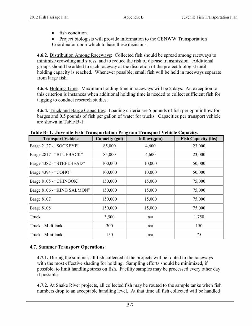
2012 Fish Passage Plan Appendix B Juvenile Fish Transportation Plan
B-7
• fish condition. • Project biologists will provide information to the CENWW Transportation Coordinator upon which to base these decisions.
4.6.2. Distribution Among Raceways: Collected fish should be spread among raceways to minimize crowding and stress, and to reduce the risk of disease transmission. Additional groups should be added to each raceway at the discretion of the project biologist until holding capacity is reached. Whenever possible, small fish will be held in raceways separate from large fish.
4.6.3. Holding Time: Maximum holding time in raceways will be 2 days. An exception to this criterion is instances when additional holding time is needed to collect sufficient fish for tagging to conduct research studies.
4.6.4. Truck and Barge Capacities: Loading criteria are 5 pounds of fish per gpm inflow for barges and 0.5 pounds of fish per gallon of water for trucks. Capacities per transport vehicle are shown in Table B-1.
Table B- 1. Juvenile Fish Transportation Program Transport Vehicle Capacity. Transport Vehicle Capacity (gal) Inflow(gpm) Fish Capacity (lbs)
Barge 2127 - “SOCKEYE” 85,000 4,600 23,000
Barge 2817 - “BLUEBACK” 85,000 4,600 23,000
Barge 4382 - “STEELHEAD” 100,000 10,000 50,000
Barge 4394 - “COHO” 100,000 10,000 50,000
Barge 8105 - “CHINOOK” 150,000 15,000 75,000
Barge 8106 - “KING SALMON” 150,000 15,000 75,000
Barge 8107 150,000 15,000 75,000
Barge 8108 150,000 15,000 75,000
Truck 3,500 n/a 1,750
Truck - Midi-tank 300 n/a 150
Truck - Mini-tank 150 n/a 75
4.7. Summer Transport Operations:
4.7.1. During the summer, all fish collected at the projects will be routed to the raceways with the most effective shading for holding. Sampling efforts should be minimized, if possible, to limit handling stress on fish. Facility samples may be processed every other day if possible.
4.7.2. At Snake River projects, all collected fish may be routed to the sample tanks when fish numbers drop to an acceptable handling level. At that time all fish collected will be handled

2012 Fish Passage Plan Appendix B Juvenile Fish Transportation Plan
B-8
as part of the daily sample per smolt monitoring program sampling guidelines. To minimize handling stress, facility samples may be processed every other day. When large trucks are used, fish may be loaded from either the raceways or labs. When mini or midi-tankers are used, Corps and agency project biologists will select the best method of transferring fish from the lab to the tankers.
4.8. During summer months from June 15–August 31 at McNary Dam water temperatures will be measured along the face of the powerhouse, in B-slot gatewells, and within the collection channel on a daily basis. These temperature measurements will be used for management of project operations per criteria contained in the Fish Passage Plan. During warm water periods, collected fish may be transported by truck or barge on a daily basis to minimize stress and mortality from warm water conditions. Other special operations may be required at McNary Dam during summer months to minimize impacts of project operations on juvenile fish collection during warm water temperature periods (see Fish Passage Plan, section 4.1., Turbine Unit Loading).
4.8.1. During the summer trucking season, if fish collection numbers begin increasing to where it appears the project will have difficulty transporting the fish with available equipment, the project shall notify the CENWW Transportation Coordinator immediately. The Transportation Coordinator will arrange for an additional transport vehicle if possible or prioritize transport/bypass operations between the projects.
4.8.2. When water temperatures are above 680F, all personnel handling fish shall take extra care to minimize stress and other impacts on fish.
4.8.3. If a temperature gradient between the forebay and the gatewells or the gatewells and the collection channel is observed in real time or predicted from temperature modeling at McNary exceeds 60F; collection mortality increases to 6 percent of daily collection for any 3 days in a rolling 5 day period; or the mortality is increasing at such a rate that these mortality numbers are likely to be met, the project will immediately alter turbine operations to reduce mortality and temperature where possible.
4.8.4. If turbine operations are already optimized for temperature and collection mortality increases to 6 percent of daily collection for any 3 days in a rolling 5 day period, or if daily collection mortality exceeds 10,000 fish, then additional spill may be provided so long as the spill levels do not exceed the gas cap. Transportation will be shifted to everyday, if possible, to reduce holding of fish in raceways. If everyday transport is not possible, redirect fish to the outfall instead of the raceways. Emergency operations will be implemented by RCC and coordinated with an emergency conference call with TMT.
4.9. Facility and Equipment Logbooks and Records: To document collection and transportation activities, the following items will be logged at each dam by either project personnel or state biologists:
4.10. Juvenile Fish Facilities: Records will be maintained recording fish counts by hour, by day, and by species, numbers and species of fish trucked or barged, number and species of fish sampled, descaling rates, and mortality rates. Records will be transmitted daily to CENWW for

2012 Fish Passage Plan Appendix B Juvenile Fish Transportation Plan
B-9
consolidation and transmittal to CENWD. Facility personnel will follow standard operating procedures (SOP's), and will note in facility logbooks accomplishment of SOP's at various stations at the collection facilities. General observations of fish condition and juvenile fish passage will be documented in facility logbooks by state biologists.
4.11. Truck and Barge Logbooks: Each truck and barge shall have a logbook for recording fish loading rates, fish condition, estimated mortalities, area of release, equipment malfunctions, and accomplishment of scheduled work under the SOPs. When consecutive loading of trucks or barges occurs at downstream projects, truck drivers or barge riders will record numbers and condition of fish loaded. Towboat captains will keep logbooks on towboat activities. Barge riders will be authorized as inspectors by the Contracting Officer's Representative to initial entries noting towboat passage, loading, or fish release activities, and comments on barging operations. State biologists will report truck and barge mortality information in their weekly reports.
4.12. Weekly Reports: State biologists shall prepare weekly reports documenting daily and weekly collection and transportation numbers, sampling information, facility and sampling mortality, descaling rates, and adult fallbacks. The weekly reports will be used by CENWW for any weekly reports required in the ESA Section 10 permit issued by NOAA Fisheries. State biologists shall distribute the weekly reports to other regionally interested parties as directed by the CENWW Transportation Coordinator.
5. TRANSPORT OPERATIONS
5.1. Truck Operations: Eight 3,500-gallon fish transport trailers and four tractors, three 300-gallon midi-tanks, and three 150-gallon mini-tanks are available for hauling fish. One midi-tank and one mini-tank will be provided at each Snake River collector project. Mini- and midi-tanks are small units that can be mounted onto pickup trucks. Normally during the early spring trucking, transport trucks/trailers will be distributed two at Lower Granite Dam, one at Little Goose Dam, one at Lower Monumental Dam. During late summer trucking, one truck/trailer will be stationed at each dam. Spare trailers will be kept at McNary Dam. Trucks may be redistributed to meet transport demands and when smaller transport vehicles begin operating in late summer.
5.1.1. Truck Release Sites: The normal early spring release site for trucked fish will be a truck pad behind the Bonneville Dam Smolt Monitoring Facility (SMF). Fish released from the truck pad pass through the SMF outfall into the Columbia River. From August 15 through the end of the transport season, trucks, midi-tanks and mini-tanks will also release fish into the Bonneville SMF outfall flume. Dalton Point will be utilized as an alternate release site in the case of an emergency or if unsafe conditions exist at the Bonneville facility.
5.1.2. Operation of Truck Life Support Systems: Truck drivers will be trained by project biologists and maintenance personnel on the operation of truck life support systems, the requirements of fish to be met, and signs of stress for which to watch. Routine checks will be made on support systems and fish condition at check points identified by project biologists. Life support system data and information on fish condition will be entered into the truck

2012 Fish Passage Plan Appendix B Juvenile Fish Transportation Plan
B-10
driver's logbook at each check point and at the release point. The truck driver's logbook will be reviewed by the project biologist upon the truck driver's return after each trip.
5.1.3. Truck Loading Schedules: If required to maintain transport schedules at the Snake River projects, transport trucks, midi-tanks, and mini-tanks leaving Lower Granite may take on additional fish at Little Goose Dam, or trucks leaving Little Goose may take on additional fish at Lower Monumental Dam. Loading schedules will be coordinated so that fish will be kept separated by size as much as possible.
5.2. Barge Operations: Eight fish barges and four towboats will be available for use.
5.2.1. Barge Scheduling: Barges with 75,000 pound capacity will operate from Lower Granite Dam. It takes approximately 79 hours to make a trip from Lower Granite Dam to the release area near the Skamania light buoy below Bonneville Dam and return. One barge will leave Lower Granite Dam every-other-day beginning on about the second day after the initiation of collection. The FOP (Appendix E) specifies the date collection will start for transportation in coordination and discussion with TMT. When fish numbers increase, barging operations will switch to one barge leaving Lower Granite daily. When fish numbers decline in late spring, operations will change back to every-other-day barging from Lower Granite Dam, with barging operations continuing through August 15. During spring operations, barges will take on additional fish at Little Goose, and Lower Monumental dams as barge capacity allows. The two medium and two small barges may also be used from Lower Granite Dam for additional barging capacity or they will be used for direct loading of fish at Little Goose Dam. When daily collection exceeds barge capacity, juvenile fish may be spilled per 4.d.(4) above or will be bypassed to the river until collection numbers drop to where juvenile fish can be barged within barge carrying capacity criteria. During the summer, barges traveling from the Snake River projects may stop at McNary Dam to load fish collected there. Barging from McNary Dam may continue after Snake River barging ceases, past August 15, on an every-other-day basis if fish numbers warrant it. Summer barge operations at McNary after August 15 will continue while collection exceeds 3,500 pounds of fish per day (the capacity of two trucks) or trends indicate numbers will exceed the 3,500 pound trigger number.
5.2.2. Barge Loading: Whenever possible, small and large fish will be loaded in separate compartments in barges.
5.2.3. Barge Riders: Project barge riders will accompany each barge trip, supervising all loading and release operations, and barge operations en-route. Barge riders will be trained on barge operation, maintenance, and emergency procedures by project biologists and maintenance personnel. Barge riders will also be cross-trained in facility operations, and may rotate with facility operators as decided by project management. Barge riders shall be responsible for monitoring fish condition, barge equipment operations, and water quality (temperature and dissolved oxygen levels) at regular intervals during downriver trips. Barge riders shall maintain logbooks and forms recording loading activities and times, loading densities by barge compartment, information on equipment operations, and release locations. Standard operational procedure forms shall be filled out during routine monitoring of equipment operation and shall include fish mortality and water quality data. At each

2012 Fish Passage Plan Appendix B Juvenile Fish Transportation Plan
B-11
subsequent dam where fish are loaded onto the barge, the barge rider shall make appropriate notations in the logbook and/or appropriate form. The barge rider shall also serve as an inspector for the towboat contract, and record information required by the Contracting Officer's Representative, and shall initial the towboat captain's logbook confirming operational information and lockage times. Any unresolved differences between barge riders and towboat crews shall be reported immediately to the Contracting Officer's Representative.
5.2.4. Barge Release Area: The barge schedule is based on releasing fish between river miles 138 and 141 with arrival at that point pre-determined to occur during nighttime hours to minimize predation impacts. As a reference point, Bonneville Dam is at RM 146. Barge travel time is affected by weather and river flows. Each towboat will be assigned a designated river mile for fish releases to ensure fish are not released in the same area on consecutive trips. Lower Granite project biologists will furnish maps of the release site and clearly designate the assigned river mile for fish release on each trip. As warranted, barge riders may randomly select a barge release site between river miles 138 and 141 to further decrease the ability of predators to prey on fish released from the barge. The alternate release site should be coordinated with the Lower Granite project biologist, if possible.
5.2.5. Barge Lockage Priority: During the fish barging season, April 8 to August 18, fish barges as Government vessels should be provided priority lockage over commercial and recreational traffic when locking through navigation locks, per 33 CFR 207.718(f). However, safety will not be compromised during lockages.
6. EMERGENCY PROCEDURES
6.1. Emergency procedures will be followed at any time an emergency occurs, 24 hours per day, 7 days per week during the transport season. Emergencies will be reported to the CENWW Transportation Coordinator as soon as possible.
6.2. In the event of an emergency (equipment failure at a facility or on a truck or barge, emergency lock outage, chemical spill in the river, etc.), facility workers, truck drivers, and barge riders will be expected to take immediate appropriate actions to protect fish. If time allows, the worker, driver, or rider should consult with his/her supervisor by phone or radio to jointly make emergency decisions. If time does not allow consultation, the worker, driver, or rider must take appropriate action on his/her own initiative, then report to his/her supervisor as soon as possible after the action has been completed.
6.3. A complete listing of persons to be notified in case of emergencies and their business and home telephone numbers will be provided to each person involved in the transport program. Facility operators, truck drivers, and barge riders will be trained on emergency notification procedures by project biologists and CENWW. For the purpose of reporting an emergency, the person involved will immediately notify his/her supervisor, or the next person up the line until the emergency has been properly reported and corrective action has been initiated. In addition to telephone reporting, barge riders will report emergencies by the towboat radio to the nearest Corps dam. The operator on duty will relay the message to the person or persons identified by the barge rider.

2012 Fish Passage Plan Appendix B Juvenile Fish Transportation Plan
B-12
7. FISHERY AGENCY ROLES
7.1. The fishery agencies provide biological assistance at transportation dams. CENWW contracts for state fish biologists to work at each collector facility.
7.2. Contracts specify that state agency personnel at collector dams accomplish specific tasks for the Corps, including:
7.3. Reviewing or conducting handling, inspection, and recording of data from fish sampled at the collection facility;
7.4. Evaluating and recording fish condition, and recommending operational changes or inspection of facilities if fish condition indicates a problem;
7.5. Providing hand counts of sampled fish, assisting the project biologist in adjusting electronic fish counts, checking hourly and daily fish counts for accuracy, and coordinating facility counts with counts of PSMFC Smolt Monitoring Program personnel where appropriate;
7.6. Conducting quality control inspections of collection facilities and transport equipment including visits to other collection facilities when work schedules can be so arranged;
7.7. Monitoring the effects of smolt monitoring and research projects on fish condition and transportation activities and reporting impacts, including numbers of fish handled for research purposes and the disposition of those fish, to the project biologist;
7.8. Participating in gatewell dipping as required to monitor fish condition;
7.9. Preparing weekly reports summarizing fish numbers and transport activities, and;
7.10. Preparing accurate text and tabular data in the correct format for project annual reports.
8. DISSEMINATION OF INFORMATION
8.1. Daily Reports: Project biologists or agency biologists at each collector dam will be responsible for entering all pertinent information into the computer database and for transmitting daily reports to CENWW. Weekday information will be transmitted by 1500 hours on the day collected. Weekend information will be transmitted to CENWW by 1200 hours on the following Monday.
8.2. Weekly Reports: Agency biologists will provide weekly reports detailing fish collection and transportation numbers, descaling estimates, and facility and transportation mortality estimates. The reports will also contain a narrative on project activities and compliance with operating criteria. If research or smolt monitoring activities are occurring at the project, the weekly reports will include information on the number of fish sampled and sacrificed also. Agency biologists shall provide the reports to interested parties within the region.

2012 Fish Passage Plan Appendix B Juvenile Fish Transportation Plan
B-13
9. REQUIREMENTS FOR FISHERY AGENCY ACTIVITIES AND RESEARCH
9.1. Coordination: Agencies and tribes expecting to work at Corps dams will provide early coordination including work proposals, evidence of approval by CBFWA, copies of ESA permits, and project needs and requirements through written correspondence to the Chief, Operations Division, of CENWW, and shall not start work until written approval has been received. The Corps also expects the PSMFC to coordinate Smolt Monitoring Program sampling guidelines with the Corps on annually.
9.2. Protocol: To maintain good working relationships and safe working conditions, fishery agencies, tribes, and research organizations will be required to follow courtesy, security, and safety protocols as follows:
9.3. Have agency picture identification and present it to project security on arrival;
9.4. Check in with the Operations Manager upon first arrival at the project to receive information on who will be the project point of contact, and what courtesy and safety requirements must be followed;
9.5. Notify the point of contact whenever arriving or departing from the project so they will know where personnel will be working and when they will be on the project;
9.6. Adhere to project clearance, safety, security, and work procedures, including preparing an Activity Hazard Analysis as specified in the Corps Safety Manual, 385-1-1.;
9.7. Notify the Operations Manager or his/her representative of unscheduled or non-routine work and activities, and;
9.8. Notify the point of contact of expected guests or changes in personnel and assure that these individuals are aware of safety and work procedures.

Fish Passage Plan
C-1
Appendix C Bonneville Power Administration's System Load Shaping Guidelines Regarding Turbine Operation and Best Efficiency
1. Background: Outmigrating juvenile salmonids have several potential routes of passage past hydroelectric dams on the mainstem Columbia and Snake Rivers, including turbines, mechanical bypass, sluiceways, and spillways. Fish passage survival varies depending on the route of passage. As a result of reported higher mortality rates for fish passage through turbines (Iwamoto and Williams 1993), regional efforts have been focused on providing non-turbine passage routes for juvenile fish as a means to improve fish survival through the Federal Columbia River Power System (FCRPS). Nevertheless, substantial numbers of juvenile fish will continue to pass through turbines; therefore, effort to minimize turbine-related mortality is a priority of the fishery agencies and Indian Tribes, the National Oceanic and Atmospheric Administration’s Fisheries Service (NOAA Fisheries, formerly National Marine Fisheries Service [NMFS]), U.S. Army Corps of Engineers (Corps), and Bonneville Power Administration (BPA). Kaplan turbine operating efficiency has a relatively direct effect on fish passage survival. The relationship between survival of juvenile fish passing through Kaplan turbines is positively correlated and roughly linear to the efficiency at which the turbines are operated. Bell (1981) recommended making every effort to operate turbines at best efficiency at a given head during periods of peak fish passage to minimize fish mortality. 2. Turbine Efficiency: For the purposes of this document, best turbine efficiency operation shall be based on efficiency tables provided by the Corps for each project in the Fish Passage Plan (FPP). The Corps shall ensure that these efficiency ranges are based on the best available information, and that updates are coordinated with BPA, the Fish Passage Operation and Maintenance Coordination Team (FPOM), and operating agencies. The tables will be distributed to all operating agencies prior to implementation, allowing up to two weeks after receipt of the tables for implementation. Operating efficiency of turbines is a result of wicket gate opening and blade angle for a given head (Bell 1981). As a result, there is a family of turbine efficiency curves for each project (or turbine design) for various head differentials. Operational decisions affecting turbine operations are based on efficiency curves for incremental changes in head, as provided by turbine manufacturers or empirical testing. 3. Guidelines:
a. Objective: To reduce the mortality of out migrating juvenile salmonids, BPA will provide the Corps' hydro system projects with generation requests that allow turbines at the Lower Snake (LSN) and Lower Columbia (LCOL) projects to operate within 1% of best efficiency, or as otherwise specified, during the Best Efficiency Operating Period, within the guidelines outlined below.
b. In-Season Best Efficiency Operating Period: This period is defined as 24 hours per day from April 1 through October 31 for all Lower Columbia (LCOL) and Lower Snake (LSN)

Fish Passage Plan Appendix C Turbine Operations
C-2
hydroelectric projects. BPA will maintain generation requests that allow turbines to operate within 1% of best efficiency in accordance with these guidelines. When units operate outside 1% of best efficiency during this period the excursions will be tracked using the codes in Table 1.
c. Off-Season operations: While not required to do so during the period of November 1 through March 31, turbines will normally run within the 1% range since it is the optimum point for maximizing the energy output of a given unit of water over time. Operation outside 1% is allowed if needed for power generation or other needs. Additional details of the 1% operation may also be found in each project’s section of the Fish passage Plan labeled “turbine unit operation and maintenance”. There are no reporting requirements for this period.
d. Unit priorities: The Corps should make every effort to adhere to the unit operating priorities specified in the FPP (the order in which turbines are put on or taken off line). The Corps shall follow a unit priority list that specifies which units at each LSN and LCOL project should be operated within the range of best efficiency to minimize impact to salmon stocks. The Corps through the FPOM process will develop a sequence for operating units outside of the 1% of best efficiency range, if it is necessary to operate units in this manner during the fish migration season. Both unit priority sequences will be based on the best available fish passage and turbine efficiency information in the FPP.
e. Project Priorities: If units must be operated out of the 1% of best efficiency range, BPA will make every effort to assure that generation requests to the Corps projects adhere to project priorities (emergencies, spill management, research, etc). These priorities may be developed weekly, based on in-season fish passage information, by the Action Agencies through the Technical Management Team (TMT).
f. Coordination: Coordination will occur through existing interagency coordinating mechanisms, such as the in-season management process described in the 2004 Updated Proposed Action prepared by the Corps, U.S. Bureau of Reclamation, and BPA (Action Agencies).
Coordination is also intended to allow the action agencies sufficient lead time to include system operational changes in their planning activities. Sufficient time is defined as the time needed to enter the information into the GDACs system (COE) and the Columbia Vista model (BPA). This can take up to two weeks to accomplish. If an emergency situation exists, implementation will begin as soon as practical given concurrent operations, hydraulic situations and loads.
Reasonable and prudent operations outside of best efficiency for limitations listed in paragraphs 4.a (system reliability) and 4.b (routine starting) are at the discretion of the BPA and Corps. BPA and the Corps will coordinate with NOAA Fisheries when operation of turbines outside of the best efficiency range may be appropriate under provisions in paragraphs 4.c (total dissolved gas) through 4.h (flood control). Additional coordination may also occur during the next scheduled TMT meeting.
Emergency situations, described in paragraph 4.a (system reliability), that require an immediate change in FCRPS operation will be coordinated directly by the action agencies with NOAA Fisheries when time allows. If coordination of an emergency change in FCRPS operation cannot be completed immediately, information will be supplied to the TMT as soon as practical. The action agencies shall establish points of contact with the appropriate agencies to allow such emergency coordination to occur.
Fish Passage Plan Appendix C Turbine Operations
C-3
g. Grand Coulee (GCL) and Chief Joseph (CHJ) Flexibility: Within system reliability and firm load limitations, flexibility at GCL and CHJ will be fully used, whenever possible, before generation requests to LCOL and LSN projects are outside the best efficiency range.
4. Limitations for the period April 1 through October 31: There are a number of conditions that occur in the system that will limit the Corps and BPA ability to operate the turbines continuously within the 1% best efficiency range. These include the following:
a. System Reliability: BPA's ability to operate the power system in a manner that enables the Corps to maximize operation of turbines within best range will be constrained by requirements to maintain system reliability (including requirements necessary for transient and voltage stability of the transmission system), and the ability to meet system response criteria. Additionally, it is necessary to maintain a margin of resource generation on line to fulfill Northwest Power Pool (NWPP), Western Electricity Coordinating Council (WECC), and the North American Electric Reliability Council (NERC) reliability requirements. If BPA overrides the BIOP operations for system reliability, BPA will provide an automated e-mail to the Corps. For longer term emergencies, see Water Management Plan Appendix 1. Emergency Protocols.
BPA's Reliability Criteria for Operations, the Northwest Power Pool Operating Manual, the Western Systems Coordinating Council Operations Committee Handbook, and the North American Electric Reliability Council Operating Manual define system response criteria and margin of resource generation. According to the Regional Act, the Power Sales Contract with the DSIs and House Report 96-976, dated September 16, 1980," the total DSI load will be considered firm for purposes of resource operation."
Predictable instances of deviation from within the best range as a consequence of prudent utility operation for control of short-term system dynamics include:
1) Routine responses to loss of generation, load or transmission within the interconnection including delivery of Operating Reserve Obligation to NWPP members upon request. The duration of these deviations is minimal, but dependent upon recovery by the interconnection member with the problem.
2) Deliberate dropping of generation, i.e., instantaneous interruption of output, to preserve system integrity. This dropping could cause a brief excursion.
b. Routine start up and stop: Routine starting and stopping of generation units are
unavoidable deviations, usually short in duration but on occasion can extend beyond the 5 minute reporting window. (see section 5 for reporting criteria)
Implementation of operations 4c through 4h will include a lead time of at least two working days for NOAA Fisheries to evaluate the effects of the proposed actions (non-emergency situations).
c. Total Dissolved Gas Supersaturation (TDG): The TDG levels will be monitored at each project during the fish passage season. Signs of gas bubble disease will be monitored at all Smolt Monitoring Program sampling sites and selected in-river sites. Best turbine efficiency operation may be modified if representative monitoring data indicate that TDG is affecting fish

Fish Passage Plan Appendix C Turbine Operations
C-4
survival. Necessary operational modifications will be coordinated through the process outlined in paragraph 3.f (coordination).
d. Coordinated Fishery Operations: In the event that coordinated fishery operations and approved fishery research are not in accord with operating turbines at best efficiency, operational modifications will be coordinated through the process outlined in paragraph 3.f (Coordination).
e. Flow Augmentation Operations: Flow augmentation requests for LCOL flows at McNary (MCN) are primarily met by water releases from GCL. The decision on whether to use GCL flexibility to provide inflows to MCN at the level necessary to meet the week's LCOL flow request when fish collection is maximized for transport during the flow augmentation period shall be made through the coordination process outlined in paragraph 3.f (coordination).
The TMT flow augmentation requests may exceed the 1% best efficient operation range at LCOL/LSN projects. Meeting this flow request will take precedent over best efficient operations. Coordination of the implementation of the flow requests will occur through the process outlined in paragraph 3.f (coordination).
f. Transport Projects: Resolution of the conflict between spill management and turbine operation within 1% of best efficiency at transport projects during the transport season shall be determined through the coordination process outlined in 3.f., and in accordance with fish transportation guidelines, based on in-season flow and fish passage information. Care should be taken during transition periods close to the upper flow boundary to avoid frequent switching of priorities between spill and generation.
g. Routine Maintenance and Testing: All units at all projects must undergo maintenance and associated testing. The testing necessitates deviation from the 1% best efficiency band for periods of from 15 minutes to 8 hours. Scheduling of maintenance testing will be coordinated through the process outlined in 3.f., to ensure that it is conducted during times of low fish passage within a day to minimize impacts on fish.
h. Flood Control: The FCRPS provides multiple benefits to the region. Flood control is the primary function of many of the projects on the Columbia River. In the event that river flow conditions require flood control operations, operation of turbines within the 1% best efficiency range may be modified or suspended based on the Corps' direction. Allowing excursions from 1% best efficiency for flood control operations would facilitate transportation, reduce excessive dissolved gas levels, and lower the risk of gas bubble disease in fish. Coordination of flood control operations will occur as outlined in paragraph 3.f (coordination). See also paragraphs 4.c (total dissolved gas) and 3.g (Grand Coulee and Chief Joseph Flexibility).
i. Other: In the event that the excursion was not explainable or caused by human error.
5. Quality Control: Significant deviations from 1% will be recorded. Data on unit status will be compiled by BPA during the 1% operating season and provided to the COE monthly. Documentation will be kept when excursions 1) exceed 15 minutes in duration; and or (2) occur five or more times exceeding 5 minutes within a calendar day. The reason (limitation or other factor) for the excursions will be kept in project logs at each dam as well as inserted into the spreadsheet provided by BPA using the reason codes listed in Table 1 below. The COE will annually provide a report to NOAA Fisheries of reportable excursions from the 1% operating range during the 1% operating season.

Fish Passage Plan Appendix C Turbine Operations
C-5
Upon request of the TMT, a case-by-case brief explanation of the reason(s) for unit operation outside the 1% of best efficiency range, the date, and the length of time outside the range, will be provided by the appropriate parties. For the report, the following numerical codes will be used to explain the excursions outside the 1% best efficiency range. The codes provide a more simplified method of tracking excursions than using the listed limitations in section 4. Table C-1. Codes for Reporting Excursions outside 1% of Best Efficiency Range. Code Reason
1 Equipment reporting errors, including lack of data (GDAC or AGC not operating correctly and not recording the readings, dead band and precision issues)
2 Changing spill levels in support of NMFS Biological Opinion or court order (requested flow augmentation, coordinated fisheries operation)
3 O&M requirements (fish screen inspection, trash racking, doble testing ,or dam safety)
4 Operational tests (index testing, testing or calibrating new or repaired equipment)
5 BPA requested operation (request operation via the AGC)
6 Turbine startup or stops that take longer than 5 minutes
7 Emergency conditions or system failures (these include transmission system emergencies, remedial action schemes (RAS), also see section 4.a system reliability)
8 Fish research
9 Human error
10 Unknown causes
11 Please specify new reason
12 Flood control
13 Reducing TDG levels

2013 Fish Passage Plan
D-1
Appendix D Project Operations for Non-ESA Listed Fish Species (Lamprey, etc.)
This appendix is intended to define FPOM-recommended special operations for species other than salmonids (e.g., lamprey) that may pass a project via the juvenile or adult passage facilities.
1. Lamprey
Below are project-specific changes to support improving lamprey survival that have been implemented annually since approved regionally through FPOM or FFDRWG.
1.1. Bonneville Dam
When adult lamprey are recovered during dewaterings, they will be transported and released into the BON forebay whenever possible. No fish, including lamprey, will be held for other uses when recovered during dewaterings.
Several adult lamprey passage improvements have been made to fish ladders at BON. In 2004, a Lamprey Passage System (LPS) was added at the Bradford Island ladder to the FV 3-9 AWS channel, and received an expansion and PIT-tag detection in 2006. Counting improvements, including video verification at the exit flume, were added in 2001. Also in 2011, one-inch picket lead spacers were added, and in 2012 these spacers were upgraded and improved to insure sufficient lamprey passage while not interfering with adult salmonid passage.
At Cascades Island, half-duplex PIT-tag detectors were installed along the picket leads to help track lamprey in 2006. A LPS, complete with a bollard floor guidance path and a variable width entrance weir, were installed in 2009. This LPS is currently being expanded to allow fully volitional passage to the forebay.
The Washington Shore fish ladder received guidance plates installed over the diffuser grates in 2001. A lamprey ramp and trap box were installed at the North Downstream Entrance (NDE) in 2005. In 2008, a LPS was added to the FV 6-9 AWS channel, similar to the LPS at the Bradford Island FV 3-9 AWS. One-inch picket lead spacers were installed in 2010 for passage under leads, and in 2011, NOAA Fisheries installed a picket lead sill ramp. NOAA Fisheries also installed ¾-inch crowder picket leads at the count station. Improvements to the picket lead spacers are planned for 2013. Additionally, the NDE lamprey trap will be removed and replaced with a complete LPS and entrance guidance system in 2013.
During nighttime spill hours, Fish Unit output is reduced to operate the Washington Shore fish ladder entrances at 0.5 feet of head to encourage lamprey to enter the fish ladder. This operation occurs from June 01 –August 31.
1.1.1. Adult Lamprey Passage - Facilities Description:
1.1.1.1. Powerhouse One: At the Bradford Island ladder, the FV 3-9 AWS channel is equipped with a LPS that allows lamprey to bypass the serpentine section of the fish ladder

2013 Fish Passage Plan Appendix D Operations for Non-Listed Species
D-2
and exit directly into the forebay, adjacent to the fish ladder exit. The picket leads that block passage of adult salmonids into the AWS channel are raised off the floor of the ladder 1”, allowing lamprey to pass under the leads and into the AWS channel.
1.1.1.2. Spillway. The Cascades Island fish ladder entrance is equipped with a variable width weir entrance gate. This entrance is coupled with a bollard field on the floor of the ladder, leading to a LPS located in the entrance bay. This LPS bypasses the overflow weirs and provides a direct route to the forebay. This LPS is currently being converted into a fully volitional passage route with an exit directly into the forebay, adjacent to the Cascades Island fish ladder exit.
1.1.1.3. Powerhouse Two. At the Washington Shore ladder, the FV 6-9 AWS channel is equipped with a LPS that allows lamprey to bypass the serpentine section of the fish ladder and exit directly into the exit channel of the fish ladder. The picket leads that block passage of adult salmonids into the AWS channel are raised off the floor of the ladder 1.5”, allowing lamprey to pass under the leads and into the AWS channel.
1.1.2. Adult Migration Timing and Counting
1.1.2.1. Adult lamprey migration season occurs from March 1 through November 30 with the majority of the run passing BON in June and July. Maintenance of the LPSs is scheduled for December 1 through the end of February.
1.1.2.2. Adult lamprey counting is conducted in conjunction with other adult fish counting. Counting hours and visual/video counting periods are shown in Table BON-1. In addition to count window operations, each volitional passage LPS is equipped with a mechanical counting system and video verification in the exit sections.
1.1.3. Lamprey Passage System (LPS) Operation & Maintenance
1.1.3.1. General. Maintain adequate water depth for lamprey passage in all LPS flumes.
1.1.3.2. Cleaning criteria. When water levels in an LPS flume drop below the required level, the water supply pump intakes must be cleaned and debris removed.
1.1.3.3. Trapping. All LPSs are designed for volitional passage; however while new potential locations are tested for usage by fish, LPSs may be temporarily set-up with a trap box at the terminus. These trap boxes are operated solely by research groups who are responsible for monitoring, handling, and transportation of lamprey from the boxes.
1.1.3.4. Water temperature. Temperatures will be measured in each LPS. When water temperature reaches 70° F, all fish handling activities will be coordinated through FPOM prior to any action to verify protocols that will be followed. Fish handling activities in the Adult Fish Facility (AFF) will implement protocols in Appendix G.
1.1.3.5. Winter maintenance season. The water supply pumps should be removed and winterized. The pumps should be inspected for damage and replaced if necessary. The

2013 Fish Passage Plan Appendix D Operations for Non-Listed Species
D-3
flumes and rest boxes should be power sprayed to remove excessive algal growth and any debris should be removed. All joints should be inspected and re-caulked if necessary.
1.2. The Dalles Dam
1.2.1. Adult lamprey. Passage improvements were made in the east fish ladder by installing 4 orifice ramps to eliminate 90° edges. Additional ramps are under planning. Several concrete 90°s were also rounded with 2” radius. Picket leads were raised 1.5” for both north and east count stations.
1.2.2. Juvenile lamprey. Data are being collected in the powerhouse turbine cooling water strainers for informational purposes. These data will not be available as the strainers are now being replaced with self-cleaning mechanisms.
1.2.3. Dewatering collections. Lamprey are collected and returned to the forebay during fishway dewaterings. Tribal restocking efforts collect lamprey from some dewaterings. These lamprey are held for no more than 12 hours.
1.3. NWW Projects
1.3.1. Raceway tailscreens. By 2012, all of the juvenile fish facilities that are collector projects for transportation had implemented lamprey-friendly raceway tailscreens to allow collected lamprey to be returned to the river rather than transported. The new tailscreen has wire mesh with .063” diameter and 0.337” open width/height. The open diagonal dimension of the wire mesh is 0.477" with an overall screen open area of 71.0%. Lower Monumental tested a perforated plate tailscreen that can be cleaned with brushes without entangling lamprey. The perforated plate is 0.25” thick, with 0.312” x 1.0” slots oriented vertically, with a side-staggered slot pattern, and the slots spaced 0.25” apart. With the approveal from regional partners, the replacement of the remaining mesh screens at Lower Monumental with the perforated plate screens is scheduled for the 2012-2013 winter maintenance season.
1.3.2. McNary Dam. Unit trash racks are raked prior to January 15 to minimize the potential for lamprey entanglement in built-up debris when river flows increase. ESBS screens are placed into operation prior to April 16 (two weeks later than other NWW projects) to allow for juvenile lamprey passage directly through turbines without any bypass system collection. Since 2010, nighttime (2100-0400 hours) velocities are reduced at adult fishway entrances SFE and NFE by lowering the entrance weir depth to sill to encourage lamprey entrance into the fish ladder. This operation occurs to coincide with lamprey passage season, June 15–September 30. During the 2009-2010 winter maintenance period, horizontal slots were cut at the bottom of the stem walls in the upper section of the Oregon fish ladder to allow adult lamprey attachment through a level pathway through the weir. Plating was also attached on the diffuser gratings near the walls in the fish ladder to create a continuous path of attachment for lamprey.
1.3.3. Other Improvements for Adult lamprey. Adult lamprey passage improvements were made to upper fish ladder weirs at Ice Harbor Dam and Lower Monumental Dam during the winter of 2011-2012. These included cutting horizontal slots in weirs at the floor to allow adult lamprey attachment through a level pathway through the weir. Additionally,

2013 Fish Passage Plan Appendix D Operations for Non-Listed Species
D-4
ramps were installed from the fish ladder floor to the bottom of elevated salmon orifices in the upper ladder weirs to assist lamprey in maintaining attachment as they maneuver through these areas. Plates were installed on diffuser grating adjacent to orifices in the Ice Harbor north fish ladder to provide attachment surfaces for lamprey in higher-velocity areas. Similar lamprey orifices and plating are being installed in the Little Goose and Lower Granite Fish Ladders during the 2012-2013 winter maintenance period.In 2011, picketed leads were raised and secured 1.5” off of the floor of the adult fish ladder at the count stations at all projects. This was done to enable adult lamprey passage under the picketed leads, thereby providing a low-velocity passage route around the adult fish count slot for lamprey.
Fallback adult lamprey collected off of the fish separators and other areas of the juvenile fish facilities at Lower Monumental, Little Goose and Lower Granite are released into the forebay above the dams rather than being bypassed back into the tailrace or transported downstream.

Fish Passage Plan
Appendix F - Guidelines for Dewatering and Fish Handling (Salvage) Plans Each Corps of Engineers mainstem project on the Columbia and Snake Rivers has dewatering and fish handling plans which cover the dewatering of various project facilities which may contain fish at the time of dewatering. The plans contain procedures for any handling or salvaging of fish within a facility or project area when it is dewatered. All dewatering and fish handling plans should be reviewed and revised where appropriate to reflect any new information and guidelines listed below. The plans shall be reviewed by the Fish Passage O&M Coordination Team.
1. Coordination: The dewatering and fish handling (salvage) plan for each project shall include coordination procedures for planned and emergency fish salvage activities. The project fishery biologist shall coordinate all fish salvage activities with project and District personnel.
2. Fish Salvage Briefing: The plans shall include a requirement that a fish salvage briefing for all participants involved in a dewatering activity be held prior to each dewatering activity. The briefings should lay out responsibilities for each participant in the dewatering activity. All emergency fish salvage operations will be coordinated and overseen by the project fishery biologist or fisheries staff if possible.
3. Personnel: The dewatering plans shall specify the number and specialization of personnel required for each type of dewatering activity. Personnel for fish salvage include the project fishery biologist, fisheries staff, crane operators, riggers, winch operators, forklift operators, and maintenance workers. To minimize fish stress and mortality, adequate personnel must be available for fish salvage activities.
4. Facilities and Dewatering Procedures: The salvage plans shall be project specific and shall contain step by step dewatering and fish salvaging procedures for all facilities and project features which may contain fish. The most common areas include adult fish ladders and collection channels, juvenile bypass systems, juvenile fish sampling facilities, turbines scroll cases and draft tubes, gatewell slots, and navigation locks. Individual projects may have other facilities or features that contain fish. The plans shall specify how the facility is to be dewatered and where and how fish are to be salvaged. Each project shall have designated release sites for the various types of fish expected to be encountered during each dewatering activity.
5. Fish Handling Equipment: The plans shall specify all fish handling equipment required for handling fish during each type of dewatering activity. Typical fish salvage equipment includes gloves, hand held fish nets, seines, fish buckets, gatewell dip baskets, and fish transportation tanks and vehicles. All equipment should be in good condition and pre-positioned before dewatering begins.
6. Support Equipment: The plans shall include a detailed listing of all support equipment required for each dewatering activity. This should include items such as hard-hats, boots, safety harnesses, flashlights, portable radios, ladders, cranes, man-baskets, pumps, forklifts, and any other equipment required for a dewatering activity. The plans shall specify where equipment is

Fish Passage Plan Appendix F Dewatering and Fish Salvage Plans
F-2
required for use during a dewatering, where certain equipment should be pre-positioned before work begins, and the heavy equipment needed for fish salvage activities.
7. Fish Safety Pools: The fish salvage plans shall identify the areas in each facility which pond enough water to hold fish temporarily. The plan shall specify whether the safety pools are usually maintained by leakage or a controlled water flow. The plans shall specify how long and under what conditions each safety pool can be used to hold fish safely. If the there is the potential for the safety pools to freeze over or loose their water source, the fish should be evacuated as soon as possible.
8. Fish Handling Procedures/Practices: The plans shall include procedures to minimize fish mortality and stress. The primary fish handling objective will be to collect and transport fish to release sites with minimal stress and without injury or mortality to any fish. Plans shall specify the details of all fish handling activities including how to crown and handle fish within each facility, specifics on the number of fish which can be hauled or transported in containers or transport tanks at varying water temperatures, and how and where to release fish at each project.
9. Fish Handling Guidelines: General fish handling guidelines which should be reflected in fish handling/salvage plans are detailed here. Adult salmonids and other large adult fish should be salvaged first. Netting of fish should be minimized whenever possible. Fish should not be crowded in the holding containers. Fish will be less stressed in larger containers (300 gallons or larger preferred), in colder water, and with supplemental oxygen or aeration. If fish are transported in warmer water (>65o F), fewer fish should be transported in a container and holding times should be shorter. All fish will be returned to the river as soon as possible at specified, predetermined release sites. Fish should not be held in holding tanks or containers for more than two hours under any circumstances. Fish should be released from the holding tanks into the river as soon as the fish salvage operation stops for any reason. Fish should be carefully released into the tailwater or forebay with a short vertical drop to the river. Fish release slides are desirable. The water temperature in the transport tank should be monitored. The water temperature in the transport or holding tanks will not be more than 2o F different from the river water. Fish should be removed prior to debris removal if possible.
10. Fish Salvage Report: The fish salvage plan should include a report form for the fish salvage operations. These forms should be completed for all fish salvage activities and kept permanently on file at each project.

2013 Fish Passage Plan
1
Appendix G Protocols for Adult Fish Facility Trapping Operations – BONNEVILLE DAM
The following protocols will be implemented by agencies conducting research in the Bonneville Dam second powerhouse Adult Fish Facility (AFF). These protocols were coordinated with fish agencies and tribes through the Fish Passage Operation and Maintenance Coordination Team (FPOM). The purpose of these protocols is to provide measures to limit mortality resulting from stress when handling fish. 1. General Facility Protocols
1.1. Users must have appropriate documentation for conducting research at the dam (See Guide for Researchers at Bonneville Dam). This includes valid state and federal permits that cover all listed species passing the project during the trapping period and users shall comply with all fish handling conditions in the permits. Note: If permit conditions are more restrictive than the following protocols, users must follow permit conditions.
1.2. The Corps reserves the right to terminate trapping operations at any time.
1.3. Users will be trained in the proper operation of the AFF to insure fish and personnel safety. Users may request training through the Project Biologists.
1.4. Bridge crane certification is required prior to operating the overhead crane. Training will not be provided by the Corps of Engineers.
1.5. Hard hats, long pants or raingear, steel-toed shoes or rubber boots are to be worn at all times. Shorts, tennis shoes, or sandals will not be permitted in the lab.
1.6. Water temperatures should be observed upon arrival and periodically during the day.
1.7. Personnel conducting research are required to be present in the AFF to divert desired fish into the anesthetic tank using the flume swing gates. While the AFF is in operation, flumes shall be open and a researcher must be on-site.
1.8. Undesired fish will be bypassed to the return pool.
1.9. Researchers shall perform no maintenance on Corps owned/installed equipment. Nets may be mended as necessary.
1.10. Qualified users may lower the main ladder picket leads and downstream exit bulkhead when they arrive, and must raise the picket leads when they are completed for the day. The downstream exit bulkhead may be left down when shad and lamprey are attempting to pass.
1.11. Users will be permitted to operate valves 9 and 10 to control flow down the flumes at their discretion and to operate the raw water booster pump. Users may operate valve 12 to provide flow in the holding pool and valve 15 to drain water at the return pool.

2013 Fish Passage Plan Appendix G - Adult Trap Protocols Bonneville Dam
2
1.12. Users must use a cotton mesh net, large enough to safely handle the largest fish passing the project during the trapping period.
1.13. Fish greater than 100 cm in length may be diverted into the main anesthetic tank or returned to the ladder untouched. These fish will not be diverted into any auxiliary anesthetic tanks.
2. Notification and Documentation
2.1. Users will notify the control room when they set up and close down the lab.
2.2. Users will record the times picket leads are lowered and raised and which agency they are representing on the sheet provided by the project biologists.
2.3. Lamprey may be held up to 48 hours in the AFF. Researchers will notify Project Fisheries and the Control Room whenever lamprey are held.
2.4. Any and all mortalities must be immediately reported to a Project Biologist. The Project Biologist will examine the mortality and take any photos. The researcher shall give a detailed report including:
a. Species b. Origin c. Length d. Weight e. Marks and injuries f. Cause and time of death g. Future preventative measures.
2.5. All mortalities are included in the Project Fisheries weekly report and the reports are submitted to FPOM.
3. Trapping Protocols - Fish Ladder Water Temperatures <70°F
3.1. There will be no time restriction for trapping operations.
3.2. There will be no more than four Chinook, or four steelhead, or six sockeye, or any combination of four adult salmonids allowed in the anesthetic tank at any one time. This assumes that users can effectively track the length of time fish stay in the anesthetic tank.
3.3. There will be no more than one adult Chinook or steelhead or two sockeye allowed in the small recovery tank at any one time. The brail pool is the primary and preferred recovery area.
3.4. Water in the anesthetic tank will be replaced at least two times per day. Water temperatures in the anesthetic tank will be maintained within 2°F of the fish ladder water temperature. Note: If anesthetic tank water temperature exceeds 70°F, criteria in section 4 will go into effect.

2013 Fish Passage Plan Appendix G - Adult Trap Protocols Bonneville Dam
3
3.5. Water in the small recovery tank will be running continuously to allow a constant exchange of water through the tank.
3.6. Personnel shall ensure fish are sampled as quickly as possible. It is recommended that it take no longer than 25 minutes to transition the fish from entry into the anesthetic tank to release back into the return ladder or transportation tank.
3.7. Personnel shall ensure that fish are fully recovered from anesthetization prior to release into the return ladder. Fish may volitionally leave the brail pool when they are ready.
3.8. When trapping is completed for the day, users will properly shut down the lab.
3.9. Four picket leads will be allowed during trap operations for up to 4 hours. After all picketed leads are raised, fish already in the AFF can be sampled for an additional one hour. The picketed lead operations are as follows. (*All counts are adult salmonids as enumerated at the Washington Shore count station for the previous day. Assumes that 4 shad = 1 salmonid):
A. zero – 6,000* - All 4 picket leads can be lowered for 4 continuous hours.
B. 6,000 -12,000* - All 4 picket leads down for 3 hours. At the 3rd hour raise at least one picket lead for ½ hour, and then continue sampling for an additional 1 hour.
C. 12,000 -18,000* - All four picket leads down for 2 hours. At the 2nd hour raise at least 2 picket leads for ½ hour, and then continue sampling for an additional 2 hours.
D. Greater than 18,000* - All four picket leads down for 1 hour. At the end of the 1 hour raise at least 2 picket leads for ½ hour, and then continue sampling for 1 hour and raise 2 picket leads for ½ hour. Continue until 4 hours of operations with 4 picket leads down has been achieved.
3.10. Researchers will also be required to monitor the ladder every hour to ensure that crowding is not taking place. If evidence of crowding is occurring at least two picket leads will be raised for a minimum 1/2 hour before all four picket lead may be deployed again.
3.11. FPOM will be notified as soon as Weir 37 violates FPP criteria.
3.12. Project biologists retain the authority to raise additional picket leads depending on fish densities and ladder conditions.
4. Trapping Protocols - Fish Ladder Water Temperatures ≥70°F
4.1. Trapping will not occur when fish ladder water temperatures meet or exceed 70°F as measured in the brail pool. The only exception is for US v Oregon requirements and for nighttime lamprey trapping.
4.1.1 Project Biologists will use the Corps temperature probe reading as the official temperature.

2013 Fish Passage Plan Appendix G - Adult Trap Protocols Bonneville Dam
4
4.1.2 Temperatures are both instantaneous readings and 0000 to 2400 daily averages. Researchers can review temperatures from (insert web based temp address here) to determine if the trap is within temperature criteria prior to traveling to BON. Instantaneous temperatures will still be used to determine if trapping operations will continue for the day.
4.1.3 Project biologists will collect temperature data weekly from the data logger in the exit ladder. Daily checks may be requested when temperatures approach 70°F.
4.2. Between 70°F and 72°F, sampling will be permitted as defined below for up to four days per week from 0600-1030 hours to allow for U.S. v Oregon requirements and for nighttime lamprey trapping. This operation will remain in effect until daily average water temperatures drop to ≤ 69.9°F. All sampling will cease when temperatures reach 72°F. No sampling may resume until daily average water temperatures drop to ≤ 71.9°F.
4.2.1 Researchers may continue to work through fish in the holding pool for one hour after picket leads have been raised.
4.2.2 FPOM will be notified as soon as Weir 37 violates FPP criteria.
4.2.3 The density criteria for picket lead operations will be reduced by half and the operations will be as follows The density criteria and monitoring of the adult ladder by the researchers as outlined in 3.9.1 also apply. (*All counts are adult salmonids as enumerated at the Washington Shore count station for the previous day. Assumes that 4 shad = 1 salmonid):
A. Zero – 3,000* - All four picket leads can be lowered for four continuous hours.
B. 3,000-6,000* - All four picket leads down for 3 hours, at the 3rd hour raise at least one picket lead for ½ hour and then continue sampling for an additional one hour.
C. 6,000-9,000* - All four picket leads down for 2 hours, at the 2rd hour raise at least one picket lead for ½ hour and then continue sampling for an additional 2 hours.
D. > 9,000* - All four picket leads down for one hour, at the end of the hour raise at least 2 picket lead for ½ hour and then continue sampling for one hour and raise 2 picket lead for ½ hour. Continue until four hours of four picket lead operation has been achieved and all picket leads need to be raised by 10:30 am.
4.2.4 There will be no more than three adult Chinook or steelhead or four sockeye in the anesthetic tank at a time. A combination of salmonids is allowed, with the maximum of either two Chinook or steelhead and a sockeye or one Chinook or steelhead and two sockeye. This assumes users can effectively track the length of time fish stay in the anesthetic tank.
4.2.5 The brail pool is the primary and preferred recovery pool.

2013 Fish Passage Plan Appendix G - Adult Trap Protocols Bonneville Dam
5
4.2.6 The small recovery tank will only be used in emergencies. If used, there will be no more than one adult Chinook or steelhead or two sockeye allowed in the small recovery tank at any one time.
4.2.7 If used, water in the small recovery tank will be running continuously allowing a constant exchange of water through the tank.
4.2.8 Assure oxygen levels are maintained at saturation in the anesthetic and recovery tanks. There will be no depression in oxygen levels in the anesthetic or recovery tanks. To assure this, water in the anesthetic tank will be replaced at least every three hours.
4.2.9 Maintain the anesthetic and recovery tank water temperatures 1-2°F lower than the ladder water temperature. If ice is used to cool the anesthetic or recovery tank water, the ice should be from river water or from an un-chlorinated water source. Do not exceed a 2°F difference between the anesthetic or recovery tank water and fish ladder water.
4.2.10 Personnel shall ensure fish are sampled as quickly as possible. It is recommended that it take no longer than 25 minutes to transition the fish from entry into the anesthetic tank to release back into the return ladder or transportation tank.
4.2.11 Personnel shall ensure fish are fully recovered from anesthetization prior to release. Fish may volitionally leave the brail pool when they are ready.
4.2.12 Project biologists retain the authority to raise additional picket leads depending on fish densities and ladder conditions.
5. Winter Trapping Protocols - December 01 through March 14
The purpose of these protocols is to provide measures to limit passage delay, and stress from overcrowding in the brail pool. Personnel conducting research during this time are not required to be present in the AFF. Users are allowed to activate the flume swing gates to divert all fish into the brail pool.
5.1. Fish will not be permitted to remain in the brail pool longer than 24 hours. It is recommended that handling of fish occurs daily by 1800 hours. This assures that if fish are sampled at the end of the day, most of the fish captured are only held from the morning until afternoon since passage at night is minimal, thus reducing delay.
5.2. During sampling, the brail pool should be raised and one adult salmonid netted, via a sanctuary net, and placed into the anesthetic tank at a time. After removing fish from the brail pool into the anesthetic tank, the brail pool will be lowered back to its full depth.
5.3. There will be no more than three adult salmonids in the anesthetic tank at a time. This assumes users can effectively track the length of time fish are in the anesthetic tank.
5.4. There will be no more than two adult salmonids in the recovery tank at a time.

2013 Fish Passage Plan Appendix G - Adult Trap Protocols Bonneville Dam
6
5.5. Water in the recovery tank will be running continuously, allowing a constant exchange of water through the tank.
5.6. Personnel shall ensure fish are sampled as quickly as possible. It is recommended that it take no longer than 25 minutes to transition the fish from entry into the anesthetic tank to release back into the return ladder or transportation tank.
5.7. Personnel shall ensure fish are fully recovered from anesthesia prior to release.
5.8. If daily sampling is not to occur within 24 hours, the main ladder picket leads and downstream exit gate will be raised. The lab will be properly returned to bypass mode.

2013 Fish Passage Plan
7
Appendix G Protocols for Adult Fish Facility Trapping Operations – ICE HARBOR DAM
1. General.
Personnel conducting research at the adult fish trapping facility at Ice Harbor Dam will implement the following protocols. These protocols were coordinated with fisheries agencies and tribes through the Fish Passage Operations and Maintenance Coordination Team (FPOM).
2. Administrative Requirements.
All researchers and managers working at the facility will adhere to the following requirements:
A. The facility will not be operated unless there is an approved Corps-funded research project that requires its use, or the user has a letter from the Corps that permits use of the facility. Users not funded by the Corps should request permission to use the trap by sending a letter to: Chief, Operations Division, U.S. Army Corps of Engineers, 201 North Third Avenue, Walla Walla, WA 99362. Appropriate authorizations from the relevant federal and state fishery agencies, as indicated in paragraph b below, should be included with the letter. Upon approval of the user’s request, the Corps will provide copies of the user’s letter and authorizations to the Corps’ project biologist at Ice Harbor Dam.
B. Users must have the proper federal authorization (e.g. ESA Section 10 permit) from the U.S. Fish and Wildlife Service and/or NOAA Fisheries if their activity may or will affect listed species, as well as any required state authorization from the Washington Department of Fish and Wildlife for listed or unlisted species. Note: If federal or state fishery agency requirements are more restrictive than the following protocols, users must follow the fishery agency requirements.
C. Hard hats will be worn if so required by the Corps’ Operations Manager at Ice Harbor (509-543-3256).
D. Long pants are to be worn at all times.
E. Steel-toed shoes or steel-toed rubber boots are to be worn at all times.
F. Notification Required For Work During Regular Business Hours (Monday through Thursday, 0630 to 1700 hours). Users will notify the project biologist when they arrive on site and when they depart (509-543-3208). If users supply the project biologist with a season schedule, it will not be necessary to notify project biologist upon arrival and departure.
G. Notification Required For Work During All Other Hours (Monday through Thursday, 1700 to 0630 hours, or anytime from Friday through Sunday). If users are on site during times other than regular business hours, specific notification procedures must be worked

2013 Fish Passage Plan Appendix G - Adult Trap Protocols Ice Harbor Dam
8
out with the Operations Manager at Ice Harbor in advance. Users may be required to contact the control room (509-543-3231) upon arrival and departure.
H. Users must present a safety plan to the project biologist, who can provide guidance for developing the plan.
3. Trapping Protocols during Fish Passage Season (March 1 - December 15) when Fish Ladder Water Temperatures are < 70°F.
Since the trap is operated manually, personnel conducting research are required to be present at the facility to divert desired fish.
A. The trap will be tested for proper operation before trapping begins. After each day’s use the trap will be promptly removed from the water by completely removing it from the fish ladder.
B. Trapping operations can take place between 0600 and 1200 hours, for up to 4 hours per day or until the designated number of desired fish are obtained, whichever occurs first. During the summer months, the period from 0600 to 1000 hours is preferred. The trap shall not be in the water for more than 4 hours. Trapping operations shall limit the number fish lifted from the trap to the powerhouse deck to two per lifting cycle.
C. Netting of fish is not recommended. If transfer of fish is necessary, fish should stay in water at all times through the use of a water-filled bag, sanctuary net, or other means. The device used should be large enough to safely handle the largest fish.
D. Non-target fish will be released to the ladder.
E. Oxygen levels in fish handling tanks will be maintained at saturation by replacing the water and providing aeration as necessary.
F. Water temperatures in all fish handling tanks will be maintained within 1°F of the fish ladder water temperature. Ice will not be used to regulate water temperature of the anesthetic tank.
G. Personnel shall sample fish as quickly as possible. It should require no longer than 25 minutes to transition the fish from entry into the anesthetic tank to release back into the ladder or transportation tank. River water shall be cycled through recovery and/or transportation tanks while holding fish at the dam until transported to the river for release or returned to the ladder.
H. Fish must be adequately recovered from anesthetization prior to the next step in the handling process, whether placed in the ladder or transported.
4. Trapping Protocols during Fish Passage Season (March 1 - December 15) when Fish Ladder Water Temperatures are ≥70°F and ≤ 72°F.

2013 Fish Passage Plan Appendix G - Adult Trap Protocols Ice Harbor Dam
9
The trap may be operated when water temperatures are within the range of 70°F to 72°F, provided that researchers closely adhere to the restrictions below. Trapping operations will not be allowed, and trapping must cease immediately, if fish ladder water temperatures exceed 72°F. Due to the narrow temperature range involved, researchers must use reliable digital thermometers.
A. Researchers must notify the Corps project biologist in advance when trapping is to occur in this temperature range. The project biologist will occasionally monitor trapping operations.
B. The trap will be tested for proper operation before trapping begins. After each day’s use, the trap will be promptly removed from the fish ladder.
C. Trapping operations can take place between 0600 and 1200 hours, for up to 4 hours per day or until the designated number of desired fish are obtained, whichever occurs first. During the summer months, the period from 0600 to 1000 hours is preferred. The trap shall not be in the water for more than 4 hours. Trapping operations shall limit the number fish lifted from the trap to the powerhouse deck to two per lifting cycle.
D. Trapping operations may take place up to 4 days per week.
E. Netting of fish is not recommended. If transfer of fish is necessary, fish should stay in water at all times through the use of a water-filled bag, sanctuary net, or other means. The device used should be large enough to safely handle the largest fish.
F. Non-target fish will be released to ladder.
G. Oxygen levels in fish handling tanks will be maintained at saturation by replacing the water and providing aeration as necessary.
H. Water temperature in the anesthetic tank will be maintained within 1°F of the ladder water temperature (not to exceed 72°F). Ice will not be used to regulate water temperature in the anesthetic tank. If practical, water temperature in the recovery tank should be maintained within 1°F of the ladder water temperature or flow-through water should be running continuously. Water in the anesthetic and transport tanks shall not exceed 72°F at any time.
I. Personnel shall sample fish as quickly as possible. It should require no longer than 25 minutes to transition the fish from entry into the anesthetic tank to release back into the ladder or transportation tank.
J. Fish must be adequately recovered from anesthetization prior to the next step in the handling process, whether placed in the ladder or transported.

2013 Fish Passage Plan
10
Appendix G Protocols for Adult Fish Facility Trapping Operations – LOWER GRANITE DAM
1. General.
Personnel conducting research at the adult fish trapping facility at Lower Granite Dam will implement the following protocols. These protocols were coordinated with fisheries agencies and tribes through the Fish Passage Operations and Maintenance Coordination Team (FPOM).
2. Administrative Requirements.
NOAA Fisheries is the primary user of the facility and employs personnel that are permanently based there. These and all other researchers and managers working at the facility will adhere to the following requirements.
A. The facility will not be operated unless there is an approved Corps-funded research project that requires its use, or the user has a letter from the Corps that permits use of the facility. Users not funded by the Corps should request permission to use the trap by sending a letter to: Chief, Operations Division, U.S. Army Corps of Engineers, 201 North Third Avenue, Walla Walla, WA 99362. Appropriate authorizations from the relevant federal and state fishery agencies, as indicated in paragraph b below, should be included with the letter. Upon approval of the user’s request, the Corps will provide copies of the user’s letter and authorizations to the Corps’ project biologist at Lower Granite Dam.
B. Users must have the proper federal authorization (e.g. ESA Section 10 permit) from the U.S. Fish and Wildlife Service and/or NOAA Fisheries if their activity may or will affect listed species, as well as any required state authorization from the Washington Department of Fish and Wildlife for listed or unlisted species. Note: If federal or state fishery agency requirements are more restrictive than the following protocols, users must follow the fishery agency requirements.
C. Hard hats will be worn if so required by the Corps’ Operations Manager at Lower Granite (509-843-1493 x258).
D. Long pants are to be worn at all times.
E. Steel-toed shoes or steel-toed rubber boots are to be worn at all times.
F. Notification Required For Work During Regular Business Hours (Monday through Thursday, 0630 to 1700 hours). Users will notify the project biologist when they arrive on site and when they depart (509-843-1493 x263 or x264). If users supply the project biologist with a season schedule, it will not be necessary to notify project biologist upon arrival and departure.
G. Notification Required For Work During All Other Hours (Monday through Thursday, 1700 to 0630 hours, or anytime from Friday through Sunday). If users are on site during times other than regular business hours, specific notification procedures must be worked

2013 Fish Passage Plan Appendix G - Adult Trap Protocols Lower Granite Dam
11
out with the Operations Manager at Lower Granite in advance. Users may be required to contact the control room (509-843-1493 x231) upon arrival and departure.
H. Users must present a safety plan to the project biologist, who can provide guidance for developing the plan.
3. Trapping Protocols during Fish Passage Season (March 1 - December 15) when Fish Ladder Water Temperatures are < 70°F.
During the years just prior to 2003 the trap was operated automatically, 24 hours per day, during much of the fish passage season. Personnel conducting research during this time were therefore not always required to be present at the facility to divert desired fish. Automatic operation and the temporary absence of on-site personnel can continue as required. However, PIT tag detectors were installed in the upper end of the fish ladder in early 2003. As a result, the new detectors will collect PIT tag data normally collected at the trap. It is therefore anticipated that trap operation will be minimized in future years. Refer to section 2.3.2.2.n “Adult Trap Holding Tanks” in the 2009 Fish Passage Plan for further information on the operation of the adult fish trap.
A. During lengthy periods of non-use (two days or more), the facility shall be dewatered or the water supply will be shut down. Since the facility obtains water from the fish ladder, this action will avoid out-of-criteria water flows in the ladder. If freezing weather may cause damage during such a non-use period, the facility will be dewatered.
B. There will be no time-of-day restrictions for trapping operations.
C. Adult fish generally do not need to be netted due to the layout of the facility. Netting of fish is not recommended. If transfer of fish is necessary, fish should stay in water at all times through the use of a water-filled bag, sanctuary net, or other means. The device used should be large enough to safely handle the largest fish.
D. Non-target fish will be released to the return pool.
E. There will be no more than 12 adult salmonids allowed in the anesthetic tank at any one time. This assumes that users can effectively track the length of time fish stay in the anesthetic tank.
F. There will be no more than 12 adult salmonids allowed in the recovery tank at any one time.
G. Oxygen levels in fish handling tanks will be maintained at saturation by replacing the water and providing aeration as necessary.
H. Water temperatures in fish handling tanks will be maintained within 2°F of the fish ladder water temperature but less than 70°F.

2013 Fish Passage Plan Appendix G - Adult Trap Protocols Lower Granite Dam
12
I. Personnel shall sample fish as quickly as possible. It should require no longer than 25 minutes to transition the fish from entry into the anesthetic tank to release back into the return ladder or transportation tank.
J. Fish must be adequately recovered from anesthetization prior to the next step in the handling process, whether placed in the return ladder or transported. In the case of the return ladder, full recovery is not desirable because fish may jump onto a grating.
K. Fish must be released or transported from the trap within four days.
L. Researchers and managers conducting studies or obtaining broodstock are responsible for ensuring the wellbeing of their fish at all times. Twenty-four hour monitoring by personnel on-site is advised but not required.
4. Trapping Protocols during Fish Passage Season (March 1 - December 15) when Fish Ladder Water Temperatures are ≥ 70°F and ≤ 72°F.
The trap may be operated when water temperatures are within the range of 70°F to 72°F, provided that researchers closely adhere to the restrictions below. Trapping operations will not be allowed, and trapping must cease immediately, if fish ladder water temperatures exceed 72°F. Due to the narrow temperature range involved, researchers must use reliable digital thermometers.
A. Researchers must notify the Corps project biologist in advance when trapping is to occur in this temperature range. The project biologist will occasionally monitor trapping operations.
B. During lengthy periods of non-use (two days or more), the facility shall be dewatered or the water supply will be shut down. Since the facility obtains water from the fish ladder, this action will avoid out-of-criteria water flows in the ladder.
C. Trapping operations can take place between 0600 and 1200 hours, for up to 4 hours per day or until the designated number of desired fish are obtained, whichever occurs first. During the summer months, the period from 0600 to 1000 hours is preferred.
D. Trapping operations may take place up to 4 days per week.
E. Adult fish generally do not need to be netted due to the layout of the facility. Netting of fish is not recommended. If transfer of fish is necessary, fish should stay in water at all times through the use of a water-filled bag, sanctuary net, or other means. The device used should be large enough to safely handle the largest fish.
F. Non-target fish will be released to the return pool.
G. There will be no more than 3 adult salmonids allowed in the anesthetic tank at any one time. This assumes that users can effectively track the length of time fish stay in the anesthetic tank.

2013 Fish Passage Plan Appendix G - Adult Trap Protocols Lower Granite Dam
13
H. There will be no more than 3 adult salmonids allowed in the recovery tank at any one time.
I. Oxygen levels in fish handling tanks will be maintained at saturation by replacing the water and providing aeration as necessary.
J. Water temperature in the anesthetic tank will be maintained 1-2°F lower than the ladder water temperature. If ice is used, the ice should be from river water or from an un-chlorinated water source. If practical, water temperature in the recovery tank should also be maintained 1-2°F lower than the ladder water temperature; otherwise flow-through water should be running continuously.
K. Personnel shall sample fish as quickly as possible. It should require no longer than 25 minutes to transition the fish from entry into the anesthetic tank to release back into the return ladder or transportation tank.
L. Fish must be adequately recovered from anesthetization prior to the next step in the handling process, whether placed in the return ladder or transported. In the case of the return ladder, full recovery is not desirable because fish may jump onto a grating.
M. Fish must be released or transported from the holding tanks as soon as possible, preferably by 1000 hours the following day but no later than 1700 hours the following day. This provision applies to all situations but mostly involves fish held for hatchery broodstock.
N. Researchers and managers conducting studies or obtaining broodstock are responsible for ensuring the wellbeing of their fish at all times. Twenty-four hour monitoring by personnel on-site is advised but not required.

Fish Passage Plan Appendix H CHJ Turbine Dewatering Procedure
H-1
DEPARTMENT OF THE ARMY CHIEF JOSEPH DAM PROJECT OFFICE, CORPS OF ENGINEERS
SEATTLE DISTRICT
BRIDGEPORT, WASHINGTON 98813
CENWS-OD-CJ 13 Aug 02 EFFECTIVE UNTIL SUPERSEDED OR RESCINDED PROJECT STANDING OPERATING PROCEDURE NO. 406 CHIEF JOSEPH DAM SUBJECT: Fish Protection Procedures for Turbine Maintenance To: Operations, Maintenance, and Resource Management Sections Purpose: Outline key criteria and operational constraints intended to protect, and provide for the recovery of, any fish, which may become trapped in generator draft tubes at the Chief Joseph Dam Project. 1. This procedure provides a general outline of the dewatering process itself, and includes details for only those constraints specifically intended to promote fish survival. It is not intended to address the details of personnel safety policy or procedures, or any detailed operational instructions for the actual dewatering process. Personnel safety provisions are detailed in the appropriate activity hazard analyses. Details of the operational steps for dewatering are covered by separate Operating Procedures and, to some extent, may be dictated by circumstances unique to each dewatering. However, all dewatering efforts will adhere to the fish protection provisions outlined in this procedure. 2. Hydroelectric turbines and water passages must be inspected and serviced periodically. This requires draining the water passages between the intake bulkhead gates and the tailrace stoplogs. After the water reaches tail water level, the remaining water is drained to an dewatering sump and then pumped out into the river. Any fish trapped in the draft tube area must be removed before being stranded or lost through drains. It is therefore desirable to minimize numbers of fish involved in the draining process and then to quickly salvage any fish that may have been trapped. 3. Natural Resource Management section personnel will carry out fish protection and recovery operations with the help of maintenance personnel. During the dewatering process they will be present at the draft tube entry door, and will direct and monitor it through the final stages of the draft tube dewatering. 4. The Project’s Natural Resource Management personnel will direct and coordinate the fish protection procedures and the recovery and release process. The Maintenance and Operations

Fish Passage Plan Appendix H CHJ Turbine Dewatering Procedure
H-2
Sections will provide Natural Resource Management advance notice of planned unit dewatering as soon as possible prior to the date of dewatering. Natural Resource Management personnel will conduct meetings and briefings as necessary to ensure all dewatering team members are familiar with the required fish recovery process. 5. Natural Resource Management personnel will coordinate with the National Marine Fisheries Service, Hydro Program Office, 503-231-6855, [email protected], to provide notification at least two weeks, if possible, in advance of any maintenance requiring dewatering or otherwise potentially affecting fish. In addition, the Fish Passage Operations and Maintenance Group will be notified with an annual schedule, contact USACE Portland District Office, Operations Div., 503-808-4304. 6. Several hours before the unit is to be dewatered the Operations Section will contact BPA to get final approval for the outage and make sure all the clearance tags are ready to be placed. Early on the day of the dewatering, the mechanics and operators will coordinate to lower the intake service gate and/or install the intake bulkhead. This will isolate the intake water passage from the forebay. 7. Operators will prepare to drain the water out of the penstock down to tailrace water elevation while mechanics prepare to install the intake bulkhead and tailrace stoplogs. The mechanics will place the tailrace stoplogs as soon as possible after the unit is flushed out. This entire process from flushing remaining water out of the penstock through complete installation of bulkheads and stoplogs should be completed within 3 hours, barring complications. 8. Operators will open the draft tube dewatering valve and start draining the draft tube to the dewatering sump. At the same time the sump dewatering pump or pumps will be started but the dewatering sump will not be allowed to go below an elevation of 733 feet above sea level. The draft tube is drained by gravity to this dewatering sump, so by restricting the dewatering sump to a minimum elevation of 733 feet, the draft tube is also restricted to this minimum elevation. The bottom of the draft tube is at an elevation of 725 feet above sea level, so this leaves a large area of water eight feet deep for any trapped fish. The water level in the draft tube will be monitored remotely from this dewatering sump. At no time will the water level in the dewatering sump drop below 733 feet without all aspects of the fish recovery plan in place including recovery devices, insulated transport device, etc. Project personnel will have the dip net, lifting sling, insulated fish carrying tank, and all required safety equipment at the unit during the final dewatering process. Fish can survive four days in the draft tube at a water level of 733 feet and above. 9. For safety reasons, the draft tube entry door will not be opened until confirmation that the tailrace stoplogs are sealed, i.e.: the water level is verified to be below the draft tube man door petcock and a maximum of one dewatering pump is maintaining the water level in the sump. Once Operations has declared a satisfactory seal has been achieved, the mechanics will then open the draft tube access door. General Maintenance personnel will either install safety gear at this time for access to the bottom of the draft tube, or, if the suspended work platform is to be required during this unit outage, it will be installed first. Once the draft tube door is open, the work platform can be installed when necessary and the water level in the draft tube can be monitored from the draft tube man door.
Fish Passage Plan Appendix H CHJ Turbine Dewatering Procedure
H-3
10. When satisfied all fish recovery preparations are in place, the designated Natural Resource Management Section person will authorize the Maintenance Section clearance holder to request the water level in the draft tube be lowered below the 733-foot elevation to a level that allows for safe entry into the draft tube. Upon authorization, the Maintenance Section clearance holder will request the Chief Operator lower the water level in the sump/draft tube below an elevation of 733 feet. Upon receiving the clearance holder’s request to go below 733 feet, the Chief Operator shall contact the designated Natural Resource Management Section person to confirm that all fish recovery preparations are complete, and lowering the water level below 733 feet is authorized. After receiving this confirmation, the Chief Operator will authorize journeymen operators to operate the sump as required to control the water level in the draft tube as requested by the designated Natural Resource Management Section person. Once the level in the sump drops below 733 feet, the designated Natural Resource Management Section person will visually monitor the draft tube water level. 11. When the water is down to a level where entry is safe, approximately two to four feet in depth, personnel will enter the draft tube through the draft tube access door at 747-foot level to inspect for trapped fish. Any live fish will be netted out with a dip net and placed in a rubber-lifting sling that is sized to hold the fish and water. The sling will then be lifted vertically to the 747-foot level and then to the 785-foot level generator floor through a series of hatches and stairways. This should take less than five minutes, during which time the fish will be in water. They will be placed in a large insulated fish carrying tank full of river water located on a cart which will be transported to the freight elevator, from which it will be loaded into a truck for eventual release of fish at the downstream boat ramp, using a flume if necessary. The fish will be handled only once during the netting process. At all other times the fish will be kept in water. 12. When the designated Natural Resource Management Section person has determined that either there are no fish in the draft tube or that all the fish have been safely removed, he will notify the Chief Operator that all fish recovery operations are complete. He will also notify the clearance holder that all fish protection restrictions on water levels in the draft tube and dewatering sump have been released. 13. Other considerations for fish protection include the following:
a. Tailrace logs have structural cross-members that form shelves, which may trap fish. These will be screened off as the bulkheads are removed for maintenance in 2002, but will be inspected for fish as applicable prior to screen installation.
b. Work windows intended to minimize likelihood of trapping endangered species will be investigated, although BPA power demands somewhat limit the timing of unit outages. Initially, avoidance of the month of October is suggested; adjustments may be considered according to experience.

Fish Passage Plan Appendix H CHJ Turbine Dewatering Procedure
H-4
c. Units 1 through 16 have floor drains with a grate with 2.5 inch spacing. It is possible for fish smaller than about ten inches to slip through these draft tube floor drains before they can be salvaged. Units 17 through 27 have side drains with small grate spacing. If necessary, smaller-mesh grating will be added or substituted on the floor drains to prevent entrapment of fish. 14. Equipment required for performing this procedure: a. Two water hoses to supply water to gallery tank as well as transport tank.. b. Waders. d. Two 5 gallon buckets to fill water tanks. e. Large dip nets. f. Fish bags/large fish stretcher.
g. Rope access ladder and anchors.
h. Rope to assist in hauling fish up ladder.
i. Life vests.
j. Safety belts, 1 per person; also anchored rope or cable for attachment to safety belt during entry and exit.
k. Dollies, one for gallery fish tank and one for transport tank used to take fish up the elevator.
l. Truck with fish transport tank (and possibly flume), to be procured as necessary. 15. Personnel required for performing this procedure:
a. Biologist or other trained personnel to advise on fish handling.
b. Personnel to net and transport fish in draft tube. Fish removal from draft tube requires a minimum of two people, however, three are preferred.
MARK C. JENSON, P. E. Operations Project Manager

Fish Passage Plan Appendix H CHJ Turbine Dewatering Procedure
H-5
CJD FLOW DEFLECTOR CONSTRUCTION SPECIFICATIONS: (Provided By J. Laufle 2006) 1 Fish Salvage Operations The contractor shall provide 5 working days notice prior to initial dewatering of each work area to allow for a Government Fisheries Biologist to be on site to perform fish salvage operations. During dewatering, if fish become trapped within the work area, the Contractor shall stop dewatering activities at a time directed by the Government Fisheries Biologist to allow the trapped fish to be removed from the work area. Removal of trapped fish will require the use of on-site equipment provided by the contractor to access the bottom of the dewatering caisson (e.g. ladder) and to lift a tank or sling containing fish and water out of the dewatering caisson and to place it into the river (e.g. crane or pulley system). Government personnel will capture and remove the trapped fish, following which the Contractor may resume dewatering activities. 2 Bubble Curtain To exclude fish from work areas and to attenuate potentially harmful underwater vibrations, the Contractor shall design, furnish, install, and operate a bubble curtain to help minimize impacts of work on fish. The bubble curtain shall consist of one or more air compressors and air distribution piping. The distribution piping shall have a pipe installed on the river bottom and encircling the work area. The distribution pipe shall have holes drilled at 6 inches on center maximum along the top side of the pipe. The system shall be designed to provide a minimum of 0.25 cfm of air from each hole in the pipe. The pipe shall be weighted sufficiently to maintain its position on the river bottom and to maintain the upward orientation of the holes. The bubble curtain shall be operated whenever the dewatering caissons are being placed to begin work on a new flow deflector. The bubble curtain may be removed upon successful sealing of the dewatering caisson. In addition, a bubble curtain must be used during any pile driving activities, and may be required during drilling activities. Use of the bubble curtain may be required during any activities that are identified as having the potential to cause harm to fish. The Contractor may propose the use of a proven alternative method to the Contracting Officer. Any alternative method must be approved by the Contracting Officer. Note that the contractor was allowed to elect to use strobes instead of a bubble curtain, and has also employed a diver to sweep the area enclosed by the cofferdam prior to sealing.

Fish Passage Plan Appendix I DWR Fish Protection Procedures
I-1
OPERATING GUIDANCE #14
Fish Protection Procedures for Turbine Maintenance
Dworshak O&M Section Date of Issue: March 2012 Last Revision: 17 November 2011
1. PURPOSE: Define operational procedures to minimize the number of fish that can become
trapped when unwatering a penstock/scrollcase for annual maintenance, repairs, or overhaul of a power unit. If any fish are trapped, define proper handling procedures and documentation requirements. These activities will be followed to completion including the fish protection and recovery provisions outlined in this procedure, regardless of overtime requirements.
2. This procedure provides a general outline of the unwatering process itself and includes
details for only those constraints specifically intended to promote fish survival. It is not intended to address the details of personnel safety policy or procedures, or any detailed operational instructions for the actual unwatering process. Personnel safety provisions are detailed in the appropriate activity hazard analysis. Details of the operational steps for unwatering are covered by separate Operating Procedures. All unwatering efforts will be adhered to in reducing the time incurred throughout the unwatering process.
3. Hydroelectric turbines and water passages must be inspected and serviced periodically. This
requires draining the water passages between the emergency (headgate) gates and the tailrace stoplogs. After the water reaches tail water level, the remaining water is drained to an unwatering sump and then pumped out into the river. Any fish trapped in the draft tube area must be removed before being stranded or lost through drains. It is therefore desirable to minimize the numbers of fish involved in the draining process and then to quickly salvage any fish that may have been trapped.
4. The DWR Operations and Maintenance Section will coordinate with the NWW District
Operations Technical Support Branch and provide notification at least two weeks if possible in advance of any maintenance requiring unwatering or otherwise potentially affecting fish. District Operations will inform NOAA and other regional fishery agencies through Fish Passage Operations and Maintenance (FPOM) Team standard coordination process when any fish salvage operations are to occur.
5. DWR Operations and Maintenance Section will notify LWG of the need to provide the LWG
Fisheries Biologist to lead the planned turbine unit unwatering as soon as possible prior to the date of unwatering. LWG Fisheries Biologist will direct and coordinate the fish protection procedures and the recovery and release process. The exact location for any fish release will be identified and visited just before fish salvage operations begins. If a flume is used, there will need to be flushing flow and the impact velocity with the tailrace will need to be at a level that does not harm fish of the size anticipated in this salvage operation. The LWG Fisheries Biologist will conduct meetings and briefings as necessary to ensure all unwatering team

Fish Passage Plan Appendix I DWR Fish Protection Procedures
I-2
members are familiar with this Operating Guidance, documenting entrapped fish, and the required ESA safe fish handling and recovery process.
6. LWG Fisheries Biologist directs fish protection and recovery operations with the help of
operations and maintenance personnel from the operating project. The LWG Fisheries Biologist may request additional personnel from USFWS Dworshak hatchery personnel to work in concert with and assist with the activity at the discretion of the Dworshak Operations Manager. During the unwatering process, the LWG Fisheries Biologist will be present at the draft tube entry door and will direct and monitor water levels, and fish condition through the final stages of the draft tube unwatering.
7. Several hours before the unit is to be unwatered the DWR Operations Section will contact
BPA to get final approval for the outage and make sure all the clearance tags are ready to be placed. Early on the day of the unwatering, the mechanics and operators will coordinate to lower the emergency gate and/or install the intake bulkhead. This will isolate the intake water passage from the forebay. A least one day in advance the LWG Fisheries Biologist will ensure that adequate fish recovery equipment and personnel trained in fish handling are available for the unwatering and fish recovery event. Trained personnel to assist in the salvage procedure may come from local fish facilities and/or district operations division.
8. When the turbine unit draft tube is to be unwatered, the operator will coordinate with local
agencies (e.g., USFWS personnel from Dworshak Hatchery), RCC, and BPA to run the unit with a full load for 15 minutes to flush the scroll case and the draft tube of fish. In the case of unit 3, full load will not be achieved and 2.5 kcfs will be used to stay within the river rate-of-change restrictions. At pool elevation of 1520’ minimum discharge of 3.5kcfs is required to obtain stable operation and reduce gassing, at the same time a small unit would be cut back to allow for the rate of change which is still limited to 1’/hr on ramp up and down. The operator will close the penstock emergency gate (hydraulic headgate) to drain the water out of the penstock down to tailrace water elevation. Once a seal is confirmed by closing the unit wicket gates and monitoring penstock pressure and flow, the mechanics will place the tailrace stoplogs. The process from flushing the remaining water out of the penstock and confirmation of a seal through complete installation of tailrace stoplogs is estimated to take 4-6 hours barring any complications. All efforts in this step will be made to reduce the time involved from flushing to the installation of stop logs via staging equipment, support supplies material and crews. (Units 1&2 have 2 stop logs each and unit 3 has 4 each). If a seal is not obtained, the process, including flushing, must be repeated. Installation of the penstock maintenance bulkhead may be accomplished after the tailrace stoplogs are installed.
9. Once seal is confirmed, the operator will open the penstock drain and the draft tube
unwatering valve and start draining the draft tube thorough the unwatering sump. At the same time the sump unwatering pumps will be initially reprogrammed to maintain water level in the draft tube to an elevation between 936 to 938 feet, depending on the unit to provide a sanctuary pool. The draft tube is drained by gravity to the unwatering sump, so by restricting the unwatering sump to a minimum elevation of 936 to 938 feet, the draft tube is also restricted to this minimum elevation. The bottom of the draft tube is at an elevation of 929’ for unit 3 and 933’ for units 1 and 2, creating a large sanctuary pool between 3 to 7 feet

Fish Passage Plan Appendix I DWR Fish Protection Procedures
I-3
deep for any trapped fish. The water level in the draft tube will be monitored remotely from the draft tube access door. At no time will the water level in the unwatering sump drop below 936’ or 938’ depending on the unit, without all aspects of the fish recovery plan in place to include; recovery devices, insulated transport device, etc. Project personnel will have dip nets, lifting sling, and insulated fish carrying tank, and all other required fish recovery equipment and safety equipment at the unit during the final unwatering process.
10. For safety reasons, the draft tube entry door will not be opened until confirmation that the
tailrace stoplogs are sealed, i.e.: the water level is verified to be below the draft tube man door petcock and a maximum of two unwatering pumps maintaining the water level in the sump. Once Operations has declared a satisfactory seal has been achieved, the mechanics will then open the draft tube access door, maintenance personnel will place a tube with a bubbling device turned on to provide additional oxygen to any trapped fish. The biologist will deploy sonar into the draft tube capable of viewing fish to determine if a large number of fish are present. If a large number of fish are present, the process will be reversed and the turbine will be readied to be re-run at night when fish are less likely to move into the unit. If an unusually large number of fish are not identified, maintenance personnel will prepare for access into the draft tube.
11. When satisfied all fish recovery preparations are in place, the LWG Fisheries Biologist will
authorize the clearance holder to request the water level in the draft tube be lowered to 935 feet for units 1 and 2, and 931.5’ for unit 3, a level that allows for safe entry into the draft tube. Upon receiving the clearance holder’s request to lower the draft tube water elevation, the shift operator shall contact the LWG Fisheries Biologist to confirm that all fish recovery preparations are complete, and lowering the water level that allows safe entry is authorized. Once the level in the draft tube drops below 935 to 938 feet, the LWG Fisheries Biologist and project maintenance personnel will visually monitor the draft tube water level.
12. When the water is down to a level where entry is safe, approximately two feet in depth,
personnel should enter the draft tube through the draft tube access door to inspect for trapped fish. Any live fish will be netted one at a time with a knotless dip net and placed in a lifting sling that is sized to hold the fish and water. The sling will then be lifted vertically to the entry door then transferred directly to large insulated fish carrying tank full of river water with no more than ½ pound of fish per gallon of water in the tank at one time. The container will then be transported to the freight elevator, and be taken to the 1005-foot level erection floor, transferred to the release site as determined by the LWG Fisheries Biologist earlier and released into the tailwater, using a flume if necessary, as determined previously in section 5. All fish handling only once during the process. At all other times the fish transfer will be water to water. Adequate flushing flow must be maintained throughout each step the fish salvage process. If a large number of fish are involved, it may be necessary to remove the salvage personnel, allow a sanctuary pool to refill, allowing the fish to recover from the activity and low oxygen levels.
13. When the LWG Fisheries Biologist has determined that either there are no fish in the draft tube
or that all the fish have been safely removed, he will notify the shift operator that all fish

Fish Passage Plan Appendix I DWR Fish Protection Procedures
I-4
recovery operations are complete. He will also notify the clearance holder that all fish protection restrictions on water levels in the draft tube and unwatering sump have been released.
14. Other considerations for fish protection include the following:
a. Annual routine maintenance work windows intended to minimize likelihood of trapping
endangered species will be investigated to determine if work can be shifted to a time with less migration of endangered species, although BPA power demands and requirements to control TDG, provide temperature to the river and hatchery along with providing flow augmentation somewhat limit the timing of unit outages. Initially, avoidance of the peak adult fish migration from October thru February. Unwatering work is recommended to occur as soon as possible during the month of September. Adjustments may be considered according to experience.
b. A routine annual maintenance schedule will be submitted to NWW Operations, Technical
Support Branch, Adult Fish Passage Coordinator for review.
c. Within 24 hours of Operation and Maintenance activities being completed, fish salvage activities should be documented with a “Record of Fish Salvage Operations”. The records should be maintained providing helpful information to predict the numbers of fish to be salvaged in a forthcoming unwatering activity. The records should also contain comments on how well the unwatering and fish recovery activities preceded, any problems encountered, and observations on fish and holding conditions. Submit this report to NWW-OD-T Adult Fish Passage Coordinator.
15. Equipment required for performing this procedure:
a. Hose attached to tailrace deck wash system (river water) for filling fish transfer tanks as
needed. b. Two large fish nets, knotless, one for each worker. c. Two small fish nets, knotless, one for each worker. d. Two vinyl slings sized to hold fish and water e. Headlamps for workers in draft tube. f. One radio. g. Waders for workers. h. Rubber or neoprene gloves for workers. i. Wristwatches. j. Thermometers. k. Hard hats, waders/rubber boots, neoprene gloves and rain gear for personnel entering
draft tube. l. Fish bucket lifting gear (station at entry door). m. Four wheel carts (2) with 150 gallon fish tanks approximately 1/3 filled with water on
each return from the tailrace or industrial water supply. Have supplemental oxygen system, air lines and air stones standing by at same location. The four wheel carts should have a portable source of oxygen and air lines during transport to the release location.
n. Hazardous atmosphere monitoring device for sensing inside the draft tube (at entry door).

Fish Passage Plan Appendix I DWR Fish Protection Procedures
I-5
o. Record of Fish Salvage Operations
16. Personnel required for performing this procedure:
a. Operators for lift line (lowers and raises fish). b. LWG Fisheries Biologist. c. Shift operator (ensures slow and proper timing of draft tube drainage). d. Four laborers (two inside draft tube to net fish into rubber lifting slings and at least two
outside draft tube to transfer fish to release site).
17. Fish Handling Procedures:
a. Establish an unwatering coordinator, usually the LWG Fisheries Biologist.
b. Roll the unit for about 15 minutes before lowering the emergency gate and tailrace stoplogs. (all done within 4-6 hours)
c. Attend a safety meeting and discuss safe operating and Walla Walla District ESA fish
handling policy and procedures. Be sure proper clearance procedures are discussed. Also, the draft tube area should be treated as a confined space.
d. Begin draining the draft tube as described above. This requires several hours.
e. Obtain a tailrace river temperature, draft tube reading.
f. Allow the deck wash system to run until the water temperature matches within 2oF of the river temperature, then fill the fish transport tanks with this water.
g. Ensure that unwatering is done very slowly once the water is about two feet deep. Mechanics and LWG Fisheries Biologist will monitor water level throughout the unwatering process.
h. Two workers enter the draft tube.
i. Net fish into fish slings and lift them out of the draft tube via the rope hoist. Nets should be knotless and no more than one fish should be in a net at one time. When it is necessary to transport fish in sanctuary bags, ensure the bags contain a sufficient amount of water and that fish return to fresh water as soon as possible. Pour fish into the fish transfer tank. The LWG Fisheries Biologist will determine if water should be refreshed and if oxygen is needed by monitoring the overall fish condition. Generally from the draft tube to release in the river tailrace, it should take no more than 6 to 8 minutes to capture, transport and release a fish.
j. The LWG Fisheries Biologist monitors the number of fish in the transfer tank and, considering the water temperature and holding time, determines when the fish should be

Fish Passage Plan Appendix I DWR Fish Protection Procedures
I-6
taken to the tailrace to be released to the river. Fish placed in tanks and containers will not exceed ½ pound per gallon of water and will be released as soon as possible.
k. When the fish transfer tank exits the powerhouse, use the deck wash system to refresh the water and/or adjust the water temperature as needed. Ensure that the water temperature in the tank, the deck wash system, flume flushing water is within 2oF of the river temperature. May use frozen river ice in maintenance of water conditions during the transport of fish to the tailrace.
l. Fish should not be netted twice (once in the salvage location and not again at the release site). The preferred method of releasing fish should to the tailrace flume or river via water to water transfer.
m. Complete the Record of Fish Salvage Operations (attached at end of this document). This is a permanent record.

RECORD OF FISH SALVAGE OPERATIONS - DWORSHAK DAM LWG Fisheries Biologist in Charge: Activity Date Time Other Personnel: Emergency Gate in Place Tailrace Stoplogs Installed Draft Tube Door Open Fish Recovery Begins Fish Recovery Complete Purpose of un-watering: River Temperature: (Note: Temperature of containers to be maintained within 2°F of river temperature.) Problems/Comments:
SPECIES AND COUNTS OF FISH RELEASED TO TAILRACE
Species Female Male
Comments Clipped Un-clipped Clipped Un-clipped
SPECIES AND COUNTS OF FISH MORTALITIES
Species Female Male
Comments Clipped Un-clipped Clipped Un-clipped **Submit this report to NWW-OD-T Adult Fish Passage Coordinator within 24 hours of fish recovery. FPOM must be notified immediately of any fish mortalities.

2013 Fish Passage Plan
J-1
Appendix J Bonneville Dam Protocols for Juvenile Monitoring Facility (JMF) Operations 1. GENERAL The following protocols will be implemented by agencies conducting research in the Bonneville Dam Powerhouse Two Juvenile Monitoring Facility (JMF). These protocols were coordinated with fish agencies and tribes through the Fish Passage Operation and Maintenance Coordination Team (FPOM). The purpose of these protocols is to provide precautionary measures to limit delayed mortality resulting from stress when handling fish. 1.1. Sample rates should not exceed 25% unless collecting fish for research when temperatures are <70°F. 1.2. Personnel conducting research or monitoring must be present at the facility to monitor the separator bars for debris and stranded fish. 1.3. The Corps reserves the right to terminate trapping operations at any time. 1.4. Project Biologists will use the Corps temperature probe reading as the official temperature. Temperatures are taken in the general holding tank and are both instantaneous readings and 0000 to 2400 daily averages. 2. GENERAL REQUIREMENTS FOR JMF USERS All personnel conducting research or monitoring in the JMF will implement the following requirements. 2.1. Users must have appropriate documentation for conducting research at the dam. (See Guide for Researchers at Bonneville Dam). 2.2. Users must have valid state and federal permits that cover all listed species passing the project during the trapping period and users shall comply with all fish handling conditions in the permit. Note: If permit conditions are more restrictive than the following protocols, users must follow permit conditions. 2.3. JMF personnel will be trained in the proper operation of the JMF to insure fish and personnel safety. Users may request training through the Project Biologists. 2.4. Hard hats are to be worn outside at all times. 2.5. Long pants or raingear are to be worn at all times. Shorts are not permitted in the lab. 2.6. Steel-toed shoes or rubber boots will be worn at all times. Tennis shoes or sandals are not permitted.

2012 Fish Passage Plan Appendix J BON JMF Protocols
J-2
2.7. If JMF users supply the Project Biologists with a season schedule, it will not be necessary to notify Project Biologists upon arrival and departure. 2.8. Users may coordinate with Smolt Monitoring Program (SMP) personnel regarding sample rates. 2.9. Users are permitted to routinely operate flushing valves, fish lifts, and release pipes/valves within the monitoring building.
2.10. Any modifications to the building or equipment will first be approved by Bonneville Project through Project Fisheries.
2.11. All anesthetic water will be emptied into the sewage lift station after running through the activated charcoal filters.
2.12. Project Biologists will operate the upper switchgate at the start and end of each season. Users may operate the upper switchgate as necessary when separator bar monitoring is not available.
2.13. The lower switchgate is in automatic control. Users will monitor and report to Project biologists any problems with the lower switchgate.
2.14. On seasonal ascending tailwater elevations, the transition from low to high outfall should be between tailwater elevations at the upper end of 16’ to 18’ range.
2.15. On seasonal descending tailwater elevations, the transition from high to low outfall should be between tailwater elevations at the lower end of 18’ to 16’ range.
2.16. Avian cannons will be operated 24 hours per day from March 1 through November 1.
2.17. Project operators and mechanics are responsible for starting and stopping avian cannons. 3. OPERATIONS IN SAMPLE MODE (typically Fish Passage Season March 1–
November 30). 3.1. During August, avian SMP personnel will operate the sampling facility as part of the SMP and to collect fish for regionally-approved research. 3.2. Research updates and equipment or sampling trouble reports will go through the Project Biologists to the FPOM Coordination Team. 3.3. JMF personnel will monitor the JMF continuously while in sample mode to ensure proper functioning and to provide quick response to an emergency while JMF is in sample operation.
3.4. JMF personnel will perform a walk-through inspection of the entire facility (except the 2-mile transport flume) every two hours to ensure safe fish passage conditions.

2012 Fish Passage Plan Appendix J BON JMF Protocols
J-3
3.5. During August, avian cannons may be shut off if Project Biologists observe no predatory birds at the outfall and coordinate through FPOM. 3.6. Particular attention will be paid to the following: dewatering facilities including the PDS, SDS, PDS screen cleaner system, adult transport flume, juvenile hopper, all valves and auxiliary water systems, flushing water systems and their perforated plates, all gates including switch and diverter gates, PIT-tag detectors, and all monitoring building systems including holding tanks, valves, and conduits to prevent injury and/or mortality to passing fish. 3.7. JMF personnel will observe video monitors at least every 1/2 hour or continuously, and manually inspect every two hours or more frequently according to trash sweep operation or other debris potential.
3.8. JMF personnel shall monitor kelt passage over the separator. 4. SAMPLING AT WATER TEMPERATURES >70°F 4.1. Daily average river temperatures will be obtained from the Corps website at: http://www.nwd-wc.usace.army.mil/tmt/documents/ops/temp/string_by_project.html. 4.2. Daily Index sampling will be reduced to every other day index/condition monitoring.
4.3. The upper switchgate is used to select between sample and bypass mode.
4.4. Sample sizes will be reduced to approximately 100 fish per day.
4.5. Monitoring for Gas Bubble Trauma (GBT) symptoms will continue.
4.6. Project Fisheries will use the Project temperature probe in the sample holding tank for official reporting requirements, instantaneous temperatures, and when web-based temperatures are unavailable.
4.7. An instantaneous temperature of ≥70°F taken from 0630–0700 hours will trigger a change in sampling mode after Project Fisheries notify SMP Biologists. 4.8. Normal index sampling may resume when the daily average temperature decreases to ≤69.5°F. 4.9. If there is a research need to sample at temperatures >70°F, coordination with FPOM will be initiated by the researcher through the District POC.
4.10. If the SMP and Project Fisheries Biologists suspect a bypass system problem during a high temperature sampling period, additional sample collection may occur. FPOM will be notified ASAP and provided with updates as problem resolution attempts proceed.

2012 Fish Passage Plan Appendix J BON JMF Protocols
J-4
5. OPERATION IN BYPASS MODE (or when PDS monitors are not present) 5.1. The upper switchgate will be in bypass mode. 5.2. The Emergency fish release valve will be open.
5.3. All rotating gates will be set to bypass.
5.4. The bypass flume gate will be raised.
5.5. Project Biologists will inspect the facility daily. 6. SYSTEM FAILURES 6.1. Any system failure or abnormality will be reported to a Project Biologist immediately. If a Project Biologist is unavailable, the control room will be contacted at ext. 2221 or 2222. 6.2. If a high or low water situation occurs in the PDS area, operate as follows:
a. Contact the control room immediately. b. Switch the upper switchgate to bypass mode until the problem is corrected. c. Immediately open the emergency fish release valve. d. Raise bypass flume gate. DO NOT ADJUST ANY WEIRS.
6.3. If a monitoring facility failure occurs, operate as follows: a. Open the emergency fish release valve. b. Switch the upper switchgate to bypass mode until the problem is corrected. c. Raise the bypass flume gate. d. Begin fish salvage operations.
6.4. If a lower switchgate failure occurs and releases are sent to the wrong high or low outfall, and repairs can not be made within 24 hours, a special operation will be coordinated via FPOM. 6.5. If a problem with either the 2-way or 3-way rotating gates is discovered (e.g., stuck open or partially open), the response protocol is as follows:
a. Switch the upper switchgate to bypass; b. Open the emergency fish release valve; c. Turn off the air to the rotating gate and manually rotate the half-round pipe section to the bypass position; d. Inspect the affected areas for stranded fish and return them to the flume. Dead fish should be held in a bucket for processing by research personnel. e. Contact the Project Biologist, or if that is not possible, the control room operator. Project personnel will request maintenance crews. Repairs should commence within 4 hours of discovering the problem. f. Once all fish safety issues have been addressed and repair requests made, the problem should be thoroughly documented in writing and that information e-mailed to Project biologists prior to sending to other interested parties.

2013 Fish Passage Plan
K-1
Appendix K John Day Dam Protocols for Smolt Monitoring Facility (SMF) Operations 1. GENERAL
The following protocols will be implemented by agencies conducting research in the John Day Dam Smolt Monitoring Facility (SMF). These protocols were coordinated with fish agencies and tribes through the Fish Passage Operation and Maintenance Coordination Team (FPOM). The purpose of these protocols is to provide precautionary measures to limit delayed mortality resulting from stress when handling fish.
1.1. Sample rates should not exceed 25% unless collecting fish for research when water temperatures are <70°F.
1.2. The Corps reserves the right to terminate trapping operations at any time.
2. GENERAL REQUIREMENTS FOR SMF USERS
All personnel conducting research or monitoring in the SMF will implement the following requirements.
2.1. Users must have appropriate documentation for conducting research at the dam. (See Guide for Researchers at John Day Dam).
2.2. Users must have valid state and federal permits that cover all listed species passing the project during the trapping period and users shall comply with all fish handling conditions in the permit. Note: If permit conditions are more restrictive than the following protocols, users must follow permit conditions.
2.3. Hard hats are to be worn outside at all times.
2.4. Long pants or raingear will be worn at all times. Shorts or sweats are not permitted in the lab.
2.5. Steel-toed shoes or rubber boots will be worn at all times. Tennis shoes or sandals are not permitted.
2.6. If users supply Project Biologists with a season schedule, it will not be necessary to notify Project Biologists upon arrival and departure.
2.7. Users may coordinate with Smolt Monitoring Program (SMP) personnel regarding sample rates.
2.8. Users are permitted to routinely operate flushing valves and release pipes/valves within the monitoring building.
2.9. Any modifications to the building or equipment will first be approved by The Dalles/John Day/Willow Creek Project through Project Fisheries.

2013 Fish Passage Plan Appendix K JDA SMF Protocols
K-2
2.10. All anesthetic water will be emptied into the activated charcoal filters tanks.
3. OPERATION IN SAMPLE MODE (typically Fish Passage Season)
3.1. SMP personnel will operate the sampling facility as part of the SMP and to collect fish for regionally-approved research.
3.2. Research updates and equipment or sampling trouble reports will go through the Project Biologists to FPOM.
4. SAMPLING AT WATER TEMPERATURES > 70°F
4.1. Daily average river temperatures will be obtained from the Corps website at: http://www.nwd-wc.usace.army.mil/tmt/documents/ops/temp/string_by_project.html.
4.2. Daily 24-hour Index sampling will be reduced to twice weekly every other day index/condition monitoring from 0700 to 1300 hours. Mondays and Thursdays are preferred.
4.3. The switchgate is used to select between sample and bypass mode.
4.4. Sample sizes will be reduced to approximately 100 fish per day.
4.5. Project Fisheries will use the Project temperature probe in the sample holding tank for official reporting requirements, instantaneous temperatures, and when web-based temperatures are unavailable.
4.6. An instantaneous temperature of 70°F or greater taken between 0630 and 0700 hours will trigger a change in sampling mode after Project Fisheries notifies SMP Biologists.
4.7. Normal index sampling may resume when the daily average temperature decreases to ≤ 69.5°F.
4.8. If there is a research need to sample at temperatures above 70°F, coordination with FPOM will be initiated by the researcher through the District POC.
4.9. If the SMP and Project Fisheries biologists suspect a bypass system problem during a high temperature sampling period, additional sample collection may occur. FPOM will be notified ASAP and provided with updates as problem resolution attempts proceed.
5. OPERATION IN BYPASS MODE
5.1. All rotating gates will be set to bypass.
5.2. Project Biologists will inspect the facility every two hours.
5.3. If the full-flow PIT-tag detector is found to be effective, the switch gate will be moved to bypass.

2013 Fish Passage Plan Appendix K JDA SMF Protocols
K-3
6. SYSTEM FAILURES.
6.1. Any system failure or abnormality will be reported to a Project Biologist immediately. If a Project Biologist is unavailable, the control room will be contacted at ext. 4211.
6.2. If a problem with either the 2-way or 3-way rotating gates is discovered (e.g. stuck open or partially open), the response protocol is as follows:
6.2.1. Contact the Project Biologist, or if that is not possible, the control room operator. Project personnel (SMF Biologist) will request maintenance crews. Repairs should commence within four hours of discovering the problem.
6.2.2. Once all fish safety issues have been addressed and repair requests have been made, the problem should be thoroughly documented in writing and e-mailed to Project Biologists prior to sending to other interested parties.

Fish Passage Plan Appendix L
L-1
ACRONYMS
ADCP Acoustic Doppler Current Profiler
ADV Acoustic Doppler Velocimeter
AFF Adult Fish Facility
AFEP Anadromous Fish Evaluation Program
AWS Auxiliary Water Supply
BGS Behavioral Guidance Structure
BI Bradford Island (BON)
BON Bonneville Lock and Dam
BPA Bonneville Power Administration
BRZ Boat Restricted Zone
CBFWA Columbia Basin Fish and Wildlife Authority
CBT Columbia Basin Teletype
CENWP Corps of Engineers (CE), Northwestern Division (NW), Portland District (P)
CENWW Corps of Engineers (CE), Northwestern Division (NW), Walla Walla District (W)
CENWW-OD-T Walla Walla District (W), Operations Division (OD), Technical Support Branch (T)
CFS Cubic Feet per Second
CI Cascades Island (BON)
COE Corps of Engineers
CRITFC Columbia River Inter-Tribal Fish Commission
DSM Downstream Migrant (Channel)
DST Daylight Savings Time
DWR Dworshak Dam
E East
EPA Environmental Protection Agency
ERG Emergency Relief Gate
ESA Endangered Species Act
ESBS Extended-Length Submersible Bar Screen
EW East Weir
FDS Fish-Debris Separator
FERL Fish Engineering Research Laboratory
FFDRWG Fish Facilities Design Review Work Group

Fish Passage Plan Appendix L
L-2
ACRONYMS
FFU Fisheries Field Unit
FG Fish Gate
FGE Fish Guidance Efficiency
FPC Fish Passage Center
FPE Fish Passage Efficiency
FPOM Fish Passage Operations & Maintenance Coordination Team
FPP Fish Passage Plan
fps Feet Per Second
FV Fish Valve
IHR Ice Harbor Lock and Dam
IDFW Idaho Department of Fish and Game
ISO International Standardization Organization
JBS Juvenile Bypass System
JDA John Day Lock and Dam
JFTP Juvenile Fish Transportation Plan
JMF Juvenile Monitoring Facility (BON)
JP Junction Pool
JSAT Juvenile Salmon Acoustic Telemetry
kcfs One-thousand cubic feet per second
LCRAS Lower Columbia River Adult Study
LGS Little Goose Lock and Dam
LWG Lower Granite Lock and Dam
LMN Lower Monumental Lock and Dam
MCN McNary Lock and Dam
MOP Minimum Operating Pool
MU Main Unit
MW Megawatts
N North
NDE North Downstream Entrance
NE North Entrance
NFE North Fishway Entrance

Fish Passage Plan Appendix L
L-3
ACRONYMS
NFH National Fish Hatchery
NOAA Fisheries National Oceanic & Atmospheric Administration’s National Marine Fisheries Service (also referred to as NMFS)
NPE North Powerhouse Entrance
NSE North Shore Entrance
NUE North Upstream Entrance
O&M Operations and Maintenance
ODFW Oregon Department Of Fish And Wildlife
OFC Outlet Flow Control
OG Orifice Gate
OOS Out of Service
OPE Orifice Passage Efficiency
PDS Primary Dewatering Structure
PIES Project Improvements for Endangered Species
PIT Passive Integrated Transponder (PIT-tag)
PLC Program Logic Controller
PSMFC Pacific States Marine Fisheries Commission
PST Pacific Standard Time
PUD Public Utility District
RCC Reservoir Control Center (COE)
RSW Removable Spillway Weir
S South
SBC Surface Bypass Collector
SDE South Downstream Entrance
SE South Entrance
SFE South Fishway Entrance
SG Sluice Gate
SLED Sea Lion Exclusion Device
SMF Smolt Monitoring Facility
SO Sluice Oregon
SPE South Powerhouse Entrance

Fish Passage Plan Appendix L
L-4
ACRONYMS
SPO Special Project Operations
SSE South Shore Entrance
STS Submersible Traveling Screen
SUE South Upstream Entrance
SW Sluice Washington
SWI Simulated Wells Intake
TDA The Dalles Lock and Dam
TDG Total Dissolved Gas
TIE Turbine Intake Extension
TMT Technical Management Team
TSW Temporary or Top Spillway Weir
UMT Upstream Migrant Transportation (Channel)
USFWS U.S. Fish and Wildlife Service
VBS Vertical Barrier Screen
W West
WDFW Washington Department of Fish and Wildlife
WECC Western Electricity Coordinating Council