
Analysis of Visual Performance Benefits from Roadway Lighting
Upload
khangminh22Category
view
1download
0
State of Florida
Department of Transportation
FDOTConnect for
OpenRoads Designer
Roadway Design 2D Basics
Alignments, 2D-Planimetrics & Profiles
Course Guide
2021
PRODUCTION SUPPORT CADD OFFICE
TALLAHASSEE, FLORIDA
http://www.fdot.gov/cadd/

FDOTConnect for
OpenRoads Designer
Roadway Design
Basic 2D Rule Based Design
Description
This is a 2-day training course to that will go over the fundamentals of 2D design Alignments, 2D-Planimetrics
& Profiles. Participants will be introduced to Bentley OpenRoads Designer CONNECT Edition - OpenRoads
Technology tools for design and modeling; specifically for Florida Department of Transportation (FDOT)
projects using the FDOTCONNECT Workspace. Several new technologies will be introduced including:
• Civil Elements, Civil Features, and Civil Geometry
• Design Intent and Design Standards
• Civil AccuDraw and Civil Cells
• Project Explorer: Civil Model
• Ribbon Tabs and Cursor Context Menus
Objectives
• Use Civil Geometry Elements in the design file to calculate and define a proposed centerline of
construction.
• Use Civil Geometry Elements in the design file to define the roadway features of the proposed
design.
• Apply Civil Cells delivered within the FDOTCONNECT Civil Cell DGN library.
• Use Civil Geometry Elements in the design file to define the vertical profiles of a proposed
centerline.
Audience
• FDOT Roadway Designers and Engineers
Prerequisites
Participants need to have a basic understanding of Computer Aided Drafting and Design (CADD) using
MicroStation, a basic understanding of OpenRoads Designer CONNECT Edition - OpenRoads Technology tools
and a solid understanding of the engineering necessary to design a Roadway.
Duration: 12 Hours
Professional Credit Hours: 12 PDHs
Note PDH Credit will only be available with Instructor lead or Computer Based Training (CBT) thru Learning
Curve.

FDOT Roadway Design ©2021 FDOT i
Table of Contents
TABLE OF CONTENTS ............................................................................................................................................... I
INTRODUCTION ..................................................................................................................................................... 1
COURSE OBJECTIVES........................................................................................................................................................ 1 EXPECTATIONS – WHAT THIS COURSE PROVIDES .................................................................................................................. 2 DOCUMENT STYLE .......................................................................................................................................................... 3 FILE TYPES ..................................................................................................................................................................... 4 LEARNING RESOURCES ..................................................................................................................................................... 4 COURSE SUPPORTING FILES .............................................................................................................................................. 5 INTRODUCING A NEW WORKSPACE .................................................................................................................................... 5
FDOTCONNECT Predefined Settings ...................................................................................................................... 5 Design File Settings: ............................................................................................................................................................. 5
FDOTCONNECT Workspace Preferences: ............................................................................................................... 6 FDOTCONNECT Function Keys................................................................................................................................ 7 FDOTCONNECT User Configuration Variables ..................................................................................................... 13 FDOTCONNECT Design and 3D Modeling Overview ............................................................................................ 13 General Workflow and Chapter Outline .............................................................................................................. 14
RECOMMENDED MICROSTATION SETTINGS ....................................................................................................................... 14 Getting Started .................................................................................................................................................... 14
Launching FDOTConnect for OpenRoads Designer ............................................................................................................ 14 Menu Docking .................................................................................................................................................................... 18
1 2D DESIGN GEOMETRICS ALIGNMENTS ....................................................................................................... 1-1
INTRODUCTION .......................................................................................................................................................... 1-1 FEATURE DEFINITIONS ................................................................................................................................................. 1-1 CIVIL GEOMETRY - DESIGN INTENT ................................................................................................................................. 1-2 CIVIL GEOMETRY DESIGN STANDARDS ............................................................................................................................ 1-2 EXERCISE OVERVIEW ................................................................................................................................................... 1-3
Exercise 1.1 Import Baseline.................................................................................................................................. 1-4 Exercise 1.2 Design New SR61 Centerline ............................................................................................................. 1-8 Exercise 1.3 Import Side Roads ............................................................................................................................ 1-23 Exercise 1.4 Baseline Side Road Design from US98 ............................................................................................. 1-24 Exercise 1.5 Using Annotation Groups to Label Your Alignment Features .......................................................... 1-27
2 2D PLANIMETRICS ....................................................................................................................................... 2-1
INTRODUCTION .......................................................................................................................................................... 2-1 CIVIL ACCUDRAW ....................................................................................................................................................... 2-1 CIVIL CELLS ................................................................................................................................................................ 2-2 EXERCISE OVERVIEW ................................................................................................................................................... 2-2
Exercise 2.1 Preparation for 2D Plans .................................................................................................................... 2-3 Exercise 2.2 BL98 Milling Limits ............................................................................................................................. 2-4 Exercise 2.3 BL98 Widening ................................................................................................................................. 2-10 Exercise 2.4 BL98 Widening Taper Line ............................................................................................................... 2-12 Exercise 2.5 For SR61 New Construction Template Lines .................................................................................... 2-14 Exercise 2.6 Add Right Turn Lane on BL98 ........................................................................................................... 2-18 Exercise 2.7 Add the School Entrance Right Turn Lane off BL98 Intersection ..................................................... 2-20 Exercise 2.8 Create/Edit the Intersection Curve Radii ......................................................................................... 2-23 Exercise 2.9 Use Civil Cell Technology to Place Curb and Sidewalk Around the Radii ......................................... 2-25 Exercise 2.10 Create a Custom Civil Cell for Other Radii ..................................................................................... 2-28 Exercise 2.11 Place Left Turn with Traffic Separator ........................................................................................... 2-32 Exercise 2.12 Place Right Turn Island .................................................................................................................. 2-39 Exercise 2.13 For BL98 Intersection Crosswalks Lines ......................................................................................... 2-49 Exercise 2.14 Create BL98 Turnouts .................................................................................................................... 2-52 Exercise 2.15 For BL98 Intersection Shoulders .................................................................................................... 2-55

ii ©2021 FDOT FDOT Roadway Design
Exercise 2.16 For Friendship Intersection ........................................................................................................... 2-56
3 PROFILES ..................................................................................................................................................... 3-1
INTRODUCTION .......................................................................................................................................................... 3-1 Open Profile Model ............................................................................................................................................ 3-1
EXERCISE OVERVIEW ................................................................................................................................................... 3-1 CIVIL GEOMETRY - DESIGN INTENT ................................................................................................................................. 3-2
Exercise 3.1 Preparation for SR61 Profile .............................................................................................................. 3-1 Exercise 3.2 Create SR61 Profile ............................................................................................................................ 3-3 Exercise 3.3 Edit SR61 Profile ................................................................................................................................ 3-9 Exercise 3.4 BL98 Profile ...................................................................................................................................... 3-19 Exercise 3.5 Friendship Profile ............................................................................................................................. 3-21

FDOT Roadway Design ©2021 FDOT iii
[PAGE INTENTIONALLY LEFT BLANK.]


FDOT Roadway Design ©2021 FDOT 1
INTRODUCTION
This course was developed to introduce OpenRoads Designer CONNECT Edition - OpenRoads Technology tools
for design and modeling on Florida Department of Transportation (FDOT) projects. The curriculum was
developed within the FDOTCONNECT Workspace to provide sample exercises for most of the new Civil Tools
on a sample project data set.
COURSE OBJECTIVES
Participants of this course will be introduced to the newest OpenRoads Technology and a Workflow for
designing two dimensional (2D) Plans, Profiles, Cross Sections and three dimensional (3D) Models for
Construction Deliverables. At successful completion they will have learned how to:
• Use Civil Geometry Elements in the design file to calculate and define a proposed centerline of construction
and while using the built in Design Standards Criteria checking.
• Use Civil Geometry Elements in the design file to define the roadway features of the proposed design.
• Apply Civil Cells delivered within the FDOTCONNECT Civil Cell DGN library.
• Use Civil Geometry Elements in the design file to define the vertical profiles of a proposed centerline.

Expectations – What This Course Provides ________________________________________________________ INTRODUCTION
2 ©2021 FDOT FDOT Roadway Design
EXPECTATIONS – WHAT THIS COURSE PROVIDES
This course provides a standard workflow for designing a project with Bentley Systems OpenRoads Designer
CONNECT Edition - OpenRoads Technology within the FDOTCONNECT Workspace. Although the majority
of tools are used throughout, this course does not provide a description of every Bentley Systems OpenRoads
Designer CONNECT Edition - OpenRoads Technology Civil Tool. Integrated help for each of the tools can
be found by selecting FILE then going to the backstage and selecting Help to bring up Bentley’s ONLINE HELP
or from the Ribbon pick the HELP icon.
FILE>HELP

INTRODUCTION _________________________________________________________________ Document StyleDocument Style
FDOT Roadway Design ©2021 FDOT 3
DOCUMENT STYLE
Style conventions used throughout the course guide are shown in the following table.
Item Convention Example
Menu names
and
commands
Bold N
(Names separated
with > symbol)
• File > Open
• File > ComSelect > Design
Dialog box
Actions Bold
• Click the Apply button.
• Click the Graphic Select button to the right of the Horizontal Alignment Include box.
• In the Segment Type list, click Lines.
Dialog box
Field Names Italic • Key in Hemfield Road in the Alignment
Name field.
• Click the Graphic Select button to the right of the Horizontal Alignment Include field.
• In the Segment Type list, click Lines.
Key-ins Bold • Key in Hemfield Road in the Alignment Name field.
File Names Italic • Open the file ALGNRD01.dgn in the C:\WorkSets\FDOT\22049555201\Roadway.
File Paths Non italic
• Open the file _Blank.dgn in the C:\WorkSets\FDOT\22049555201
New Terms
or Emphasis Italic
• The Template Library contains templates, which represent typical sections of the proposed roadway.
We would like to introduce the user to a new workflow terminology using the Ribbon if you see a direction like this
OPENROADS MODELING>GEOMETRY>HORIZONTAL>Lines>Line From Element>Simple Line From
Element
This means we are in the WorkFlow of OpenRoads Modeling which has a Tab named Geometry and has tools
that are located in the Horizontal Group. Now that we are in the right workflow, Tab and Group we may need
to click on a tool that has more than one option.

File Types __________________________________________________________________________________ INTRODUCTION
4 ©2021 FDOT FDOT Roadway Design
FILE TYPES
The Bentley Systems GEOPAK OpenRoads Technology road design process now uses a single source file
type, the DGN file. All pertinent design data is stored in the design file. This information can be viewed through
the Project Explorer and reported on in the Civil Report Browser.
Below is a brief description of the legacy file types used in GEOPAK which can be imported or exported (i/o)
with OpenRoads Technology.
File Type Description:
• Surface.tin (i/o) - A binary file, also known as a GEOPAK digital terrain model (DTM),that stores features
made up of random points, break lines, and boundary data along with triangulated surface model. The features
and the triangles together represent an existing ground surface.
• Surface.dat (i) - A binary (or ASCII) file containing string and point information that is used for digital terrain
model construction.
• Surface.dtm (i/o) – A binary file, also known as a Roadway Designer digital terrain model that stores features
made up of components, break lines, and boundary data along with triangulated surface model. The features
and the triangles together represent either existing ground surface or the proposed roadway corridor model.
• Template Library.itl (i) - Stores templates and template components. Different components can be assembled
to build templates, which define the typical sections of a roadway. Only one Template Library file may be
open for editing at a given time.
LEARNING RESOURCES
There are several resources available for learning about the various Bentley Systems OpenRoads Designer
CONNECT edition OpenRoads Technology tools. Among them are:
• Bentley Communities:
https://communities.bentley.com/products/road___site_design/w/road_and_site_design__wiki/33435/openr
oads-designer
http://communities.bentley.com/products/road___site_design/w/road_and_site_design__wiki/7021.openroads-support-clips-technotes-
faqs.aspx
• Bentley Learn:
Bentley Institute site is for registered user and may require a Select Server site license to participate:
https://learn.bentley.com
• Bentley Product OpenRoads:
Videos are available on a variety of topics: https://www.Bentley.com
• YouTube:
Bentley OpenRoads Videos are available on a variety of topics: http://www.youtube.com/user/BentleyCivil
• YouTube Search - Google:
Bentley OpenRoads returns several sites with videos for learning how to apply the technology on project
specific situations.
• Production Support Office | CADD (CADD) Website: http://www.fdot.gov/cadd/
Webinar training recordings are available on many of the subjects covered in this manual:
http://www.fdot.gov/cadd/main/FDOTCaddTraining.shtm
http://www.fdot.gov/cadd/downloads/webinars/Posted.shtm#loadSection
https://www.youtube.com/channel/UCqbY8kqZuXp1pyYV6lIQw_A

INTRODUCTION _______________________________________________ Course Supporting FilesIntroducing a New Workspace
FDOT Roadway Design ©2021 FDOT 5
COURSE SUPPORTING FILES
The exercises for each chapter are independent of one another and can be used without having to complete the
exercises in previous modules. The exercise files are organized into separate completed Selected zip files for each
chapter. All files used in this course are located also at this link:
http://www.fdot.gov/cadd/downloads/documentation/FDOTRDAnd3DM/FDOTRDAnd3DM.shtm
INTRODUCING A NEW WORKSPACE
FDOTCONNECT PREDEFINED SETTINGS
DESIGN FILE SETTINGS:

Introducing a New Workspace __________________________________________________________________ INTRODUCTION
6 ©2021 FDOT FDOT Roadway Design
FDOTCONNECT WORKSPACE PREFERENCES:

INTRODUCTION __________________________________________ Introducing a New WorkspaceIntroducing a New Workspace
FDOT Roadway Design ©2021 FDOT 7
FDOTCONNECT FUNCTION KEYS
FDOTCONNECT Function Key Assignments
F1 Opens the OpenRoads Designer OnLine Help. Ctrl+F1 Closes all Views except View 1.
F2 Open View 1 (2D Plan) and View 2 (3D Isometric) and fits both views.
F3 Opens View 3 (2D Plan), closes all View 4, and arranges all Views.
F4 Open View 1 (2D Plan) , View 2 (3D Isometric), View 1 (2D Plan), View 1 (2D Plan) &
Fits All views.
F5 Toggles Dim References ON/OFF.
F6 Resets out of any ongoing commands.
F7 Toggles the Construction view attribute ON/OFF.
F8 Toggles between MicroStation AccuDraw and Civil AccuDraw.
F9 Toggles (opens or closes) the Reference dialog.
F10 Toggles (opens or closes) the Level Display dialog.
F11 Toggles (opens or closes) the Project Explorer dialog.
F12 Opens the Create Template dialog.

Introducing a New Workspace __________________________________________________________________ INTRODUCTION
8 ©2021 FDOT FDOT Roadway Design
• Function Key F1 – Civil Help
• Function Key F2 – Open and Fits Two Views Setup; View 1- 2D Plan, View 2-Isometric.

INTRODUCTION __________________________________________ Introducing a New WorkspaceIntroducing a New Workspace
FDOT Roadway Design ©2021 FDOT 9
• Function Key F3 – Opens View 3; Closes View 4 and Arranges Views.
• Function Key F4 – Opens and fits Four View Setup; View 1- 2D Plan, View 2-Isometric, View 3,4 – custom.
Introducing a New Workspace __________________________________________________________________ INTRODUCTION
10 ©2021 FDOT FDOT Roadway Design
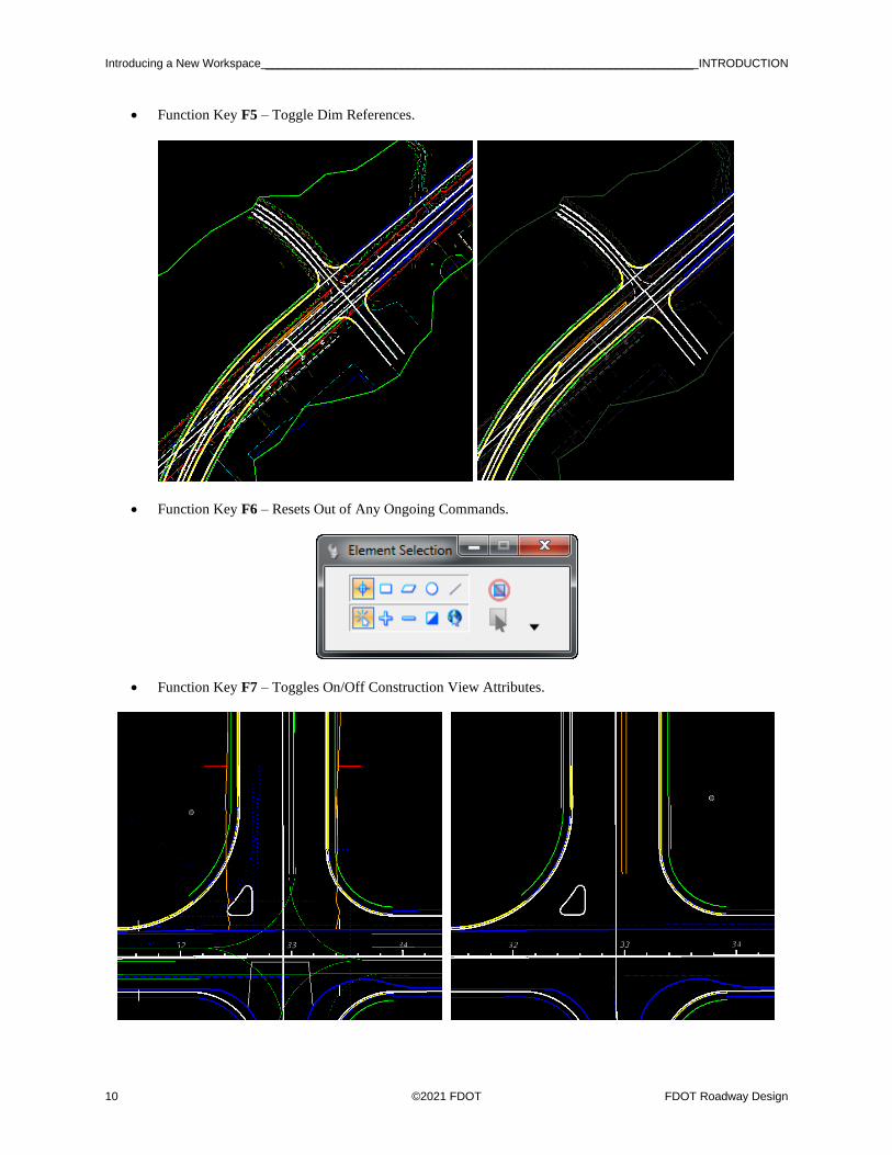
• Function Key F5 – Toggle Dim References.
• Function Key F6 – Resets Out of Any Ongoing Commands.
• Function Key F7 – Toggles On/Off Construction View Attributes.

INTRODUCTION __________________________________________ Introducing a New WorkspaceIntroducing a New Workspace
FDOT Roadway Design ©2021 FDOT 11
• Function Key F8 – Toggles Between MicroStation AccuDraw and Civil AccuDraw.
• Function Key F9 – Toggles Reference Dialog Open\Close.
• Function Key F10 – Toggles Level Display Dialog Open\Close.

Introducing a New Workspace __________________________________________________________________ INTRODUCTION
12 ©2021 FDOT FDOT Roadway Design
• Function Key F11 Toggles Project Explorer Dialog Open/Close.
• Function Key F12 Corridor Modeling, Opens Create Template Dialog.

INTRODUCTION __________________________________________ Introducing a New WorkspaceIntroducing a New Workspace
FDOT Roadway Design ©2021 FDOT 13
FDOTCONNECT USER CONFIGURATION VARIABLES
FDOTCONNECT DESIGN AND 3D MODELING OVERVIEW

Recommended MicroStation Settings _____________________________________________________________ INTRODUCTION
14 ©2021 FDOT FDOT Roadway Design
GENERAL WORKFLOW AND CHAPTER OUTLINE
1. Design Centerlines Alignments
2. Prepare 2D Plan Layout
3. Design Profiles
4. .
RECOMMENDED MICROSTATION SETTINGS
Various tools and settings will be used throughout the workshop. Therefore, for quick accessibility, several of
the dialogs are better docked on the sides the MicroStation view.
GETTING STARTED
LAUNCHING FDOTCONNECT FOR OPENROADS DESIGNER
FDOT Connect can be launched from the FDOT – Roadway and FDOT – ROW icons located in the
FDOTConnect folder on your desktop. The first time it is launched, it is important to select the FDOT
workspace from the workspace dropdown.
1. Find the FDOT Connect launch icons on your desktop or locate the “FDOTConnect” folder on your desktop.
2. Launch FDOTConnect for OpenRoads Designer by double-clicking one of the FDOT icons.
Note that your FDOTConnect launch icons will vary depending on which Bentley Connect
Edition platforms you have installed. FDOTConnect will create an icon for OpenRoads
Designer, an icon for Microstation Connect Edition (MSCE), and an icon for OpenBridge
Modeler (OBM) depending on which of these applications is present on your machine during
installation of the Workstation or Client. (This release of FDOT Connect is the “Alpha test”
version for OpenBridge Modeler).
INTRODUCTION _______________________________ Recommended MicroStation SettingsRecommended MicroStation Settings
FDOT Roadway Design ©2021 FDOT 15
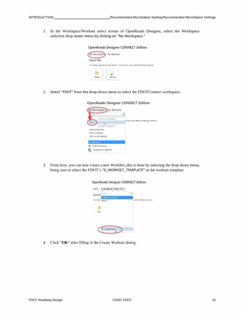
1. In the Workspace/Workset select screen of OpenRoads Designer, select the Workspace
selection drop-down menu by clicking on “No Workspace.”
2. Select “FDOT” from the drop-down menu to select the FDOTConnect workspace.
3. From here, you can now create a new WorkSet,,this is done by selecting the drop-down menu,
being sure to select the FDOT’s “0_WORKSET_TEMPLATE” as the workset template.
4. Click “OK” after filling in the Create Workset dialog.

Recommended MicroStation Settings _____________________________________________________________ INTRODUCTION
16 ©2021 FDOT FDOT Roadway Design
5. After creating a new project using the FDOT Workset Template, you can create new files using
the FDOT Create File tool. This tool is launched from within the FDOTConnect workspace,
so you must first open a file. The FDOT Workset template includes a blank starting file from
which to launch the Create File tool.
6. From the OpenRoads Designer file open dialog, select “Browse” to browse the contents of
your new workset.
7. Locate “_Blankfile.dgn” at the root of your workset folder structure. Select this file and then
select “OPEN” to open it.
INTRODUCTION _______________________________ Recommended MicroStation SettingsRecommended MicroStation Settings
FDOT Roadway Design ©2021 FDOT 17
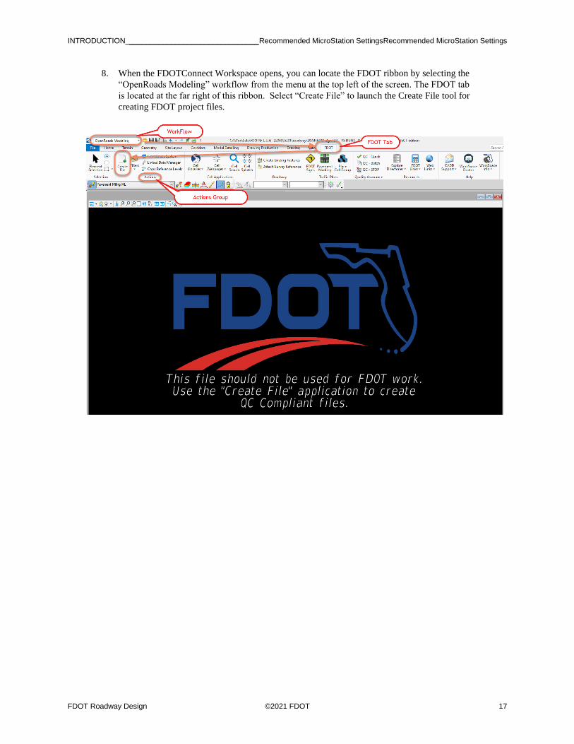
8. When the FDOTConnect Workspace opens, you can locate the FDOT ribbon by selecting the
“OpenRoads Modeling” workflow from the menu at the top left of the screen. The FDOT tab
is located at the far right of this ribbon. Select “Create File” to launch the Create File tool for
creating FDOT project files.

Recommended MicroStation Settings _____________________________________________________________ INTRODUCTION
18 ©2021 FDOT FDOT Roadway Design
MENU DOCKING
1. Verify that the Civil Message Center tool is already docked on the bottom; if not, select it from
the General Geometry Task group, dock and unpin.
2. Verify that the Project Explorer is docked on the left side; if not, from the Ribbon select the
Home tab then in the group named primary click on the explorer icon…Or use the F11 function
key to toggle ON/OFF the dialog.

INTRODUCTION _______________________________ Recommended MicroStation SettingsRecommended MicroStation Settings
FDOT Roadway Design ©2021 FDOT 19
3. Verify that the Level Display is docked on the right side; if not, from the FDOT-Function Keys
press F10, dock and unpin.
4. Verify that the Element Information is docked on the right side; if not, this can be brought up
by selecting Ctrl+I , dock and unpin.
• Many of the dialog settings are stored in user preferences defined in xml data files located in the users data folders i.e. C:\Users\rd964vd\AppData\Local\Bentley\OpenRoadsDesigner\10.0.0\prefs.

Recommended MicroStation Settings _____________________________________________________________ INTRODUCTION
20 ©2021 FDOT FDOT Roadway Design
[PAGE INTENTIONALLY LEFT BLANK.]

FDOT Roadway Design ©2021 FDOT 1-1
1 2D DESIGN GEOMETRICS ALIGNMENTS
INTRODUCTION
This chapter will introduce four (4) important OpenRoads Technologies for creating geometry/line work while
designing in FDOTCONNECT. They are:
• Feature Definitions
• Civil Geometry Design Intent
• Design Standards
• Annotation Groups
We would like to introduce the user to a new workflow terminology using the Ribbon if you see a direction like
this
OPENROADS MODELING>GEOMETRY>HORIZONTAL>Lines>Line From Element>Simple Line From
Element
This means we are in the WorkFlow of OpenRoads Modeling which has a Tab named Geometry and has tools
that are located in the Horizontal Group. Now that we are in the right workflow, Tab and Group we may need
to click on a tool that has more than one option.
FEATURE DEFINITIONS
As defined in the Bentley Civil Tools help files:
“Feature Definitions are used to control symbology, annotation, and various other properties
that are applied to the geometric elements. The feature definitions are used to:
• Define what the geometric elements actually are. What is being modeled such as
curb, centerline, edge of pavement, etcetera.
• Control symbology in various views, including capability to define differing
symbology in plan, profile, and 3D spaces
• Define terrain modeling attributes (spot, break line, void, etcetera)
• Define surface display characteristics
An extensive FDOT_Standards_Features.dgnlib has been developed for the FDOTCONNECT Workspace to be
used for all FDOT projects. All elements placed in the design file should have a defined Feature definition. The
Civil Geometry tools can be set with an Active FDOT Civil Features for element creation and assignment. They
can be viewed in the Project Explorer and in the Feature Toggle Bar.

2D DESIGN GEOMETRICS ALIGNMENTS - Civil Geometry - Design Intent Chapter 1
1-2 ©2021 FDOT FDOT Roadway Design
CIVIL GEOMETRY - DESIGN INTENT
As defined in the Bentley Civil Tools help file:
“Design intent builds associations and relationships between civil elements. Object information
(how, where, and by what method it was created) is stored with the object to insure the original
intent is retained and honored in the design. If an element is modified, any related elements will
recreate themselves based on these stored relationships.
Civil Geometry or rule-base elements are created intelligently as the tools are used and elements are constructed.
The FDOTCONNECT Workspace and design development workflow is highly dependent on using Civil
Geometry for the 2D plan layout rather than traditional MicroStation place elements tools.
CIVIL GEOMETRY DESIGN STANDARDS
Also known as Design Geometrics and Criteria and as defined in the Bentley Civil Tools help files:
“Design standards can be used to maintain required curvature and other alignment checks
when performing geometric layouts. They work at two levels:
• Provide values for the element creation tools (for example, minimum radius and
transition lengths)
• Check the suitability of complex elements (for example, check for kinks in the
alignment)
Design standards are very alignment oriented. You may find limited value for using design
standards for non-alignment computations.
When a design standard is violated, feedback is provided in two ways:
• An icon in the graphics on the element that has the problem. Hover over the icon to
reveal a tool tip report of the error.
• In the Civil Message Center
An extensive FDOT_DesignGeometricsCriteria.dgnlib has been developed for the FDOTCONNECT Workspace
to be used for all FDOT projects. Alignments created in the design file either with Civil Geometry Tools or
Imported should have a set Design Geometrics Criteria. FDOT Design Geometrics Criteria can be viewed in the
Project Explorer and in the Design Standard Toggle Bar.

Chapter 1 _______________________________________________ 2D DESIGN GEOMETRICS ALIGNMENTS - Import Baseline
FDOT Roadway Design ©2021 FDOT 1-3
EXERCISE OVERVIEW
In this chapter exercise, the existing roadway Baselines for SR61 and US98 will be imported from a provided
(LandXML) file. A new Centerline of Construction for the SR61 roadway is required to improve the intersection
with US98. The new intersection will be located across from the School entrance on US98. It will be a 90 degree
angled intersection from US98. The centerline will require a new horizontal curve following the FDM design
guidelines as follows. In order to provide minimal property impacts to a local business on SR61 the alignment
will be offset from existing baseline to the west 30 feet and will re-join SR61 at a small skew that does not require
a horizontal curve.
Design Geometrics and Criteria FDOT Design Manual (FDM), Part 2 Chapter 210
Design Speed 45 MPH
Facility Low Speed Desired Length
Maximum Tangent Deflection w/out curve 1 Degree Section 210.8.1
Minimum Horizontal Radius 694 feet Table 210.9.2
Minimum Length of Curve 675 feet Table 210.8.1
Context Class C3 Max Grade Table 210.10.1
• Low Speed Minimum Length – This will give a minimum Radius at Max Super (emax = .05)
• Low Speed Desired Length – This will give a desired length of curve at Normal Crown.
Note Refer to the FDM for Tables
1.1 Import Baseline
1.2 Design New SR61 Centerline
1.3 Import Side Roads
1.4 Baseline Side Road Design from BL98
1.5 Using Annotation Groups to Label your Alignment Features

2D DESIGN GEOMETRICS ALIGNMENTS - Exercise Overview Chapter 1
1-4 ©2021 FDOT FDOT Roadway Design
Exercise 1.1 Import Baseline
Import Baseline In this exercise, the user will create a new design file and import chains from the LandXML file
provided from the survey.
1. From the desktop FDOTCONNECT folder, double-click on the FDOTConnect for
OpenRoads Designer icon.
2. Set the workspace to FDOT and set the Workset to 22049555201_CE. Navigate to the root
of the folder of 22049555201_CE and find the _Blank File.dgn
3. Once the file opens navigate to FDOT Ribbon Tab of the OpenRoads Modeling WorkFlow
looking for the Actions Group click on the create file.
OPENROADS MODELING>FDOT>ACTIONS
4. Create a ALGNRD01.dgn file with the dialog as shown below.

Chapter 1 _______________________________________________ 2D DESIGN GEOMETRICS ALIGNMENTS - Import Baseline
FDOT Roadway Design ©2021 FDOT 1-5
a. From the Create File Dialog box pick the Base Filename of ALGNRD.
b. Select your County, by selecting this the correct coordinate system will be selected.
c. Click Create - Open File to create the file, ALGNRD01.dgn.
d. You are now in the ALGNRD01.dgn Click Close.
e. Navigate to the models Dialog, you will notice that during the creation of the ALGNRD
a new model of SUPERELEVATION was created.
5. If the SURVRD file exists use the Attach Survey Reference tool which is located on the
FDOT Tab, with in the Roadway Group. These Tabs and Groups can be found within the
OpenRaods Modeling WorkFlow. Otherwise, skip to step 7.
OPENROADS MODELING>FDOT>ROADWAY
6. Select the SURVRD01.dgn file.

2D DESIGN GEOMETRICS ALIGNMENTS - Exercise Overview Chapter 1
1-6 ©2021 FDOT FDOT Roadway Design
7. From the Function key F9 (toggles on the Reference Dialog) to view the attached files:
8. From the Function key F9 (toggles on the Reference Dialog) and attach the following files:
• C:/Workset/FDOT/22049555201_CE/Survey/TOPORD01.dgn (disregard if SURVRD exists)
• C:/Workset/FDOT/22049555201_CE/ROWMap/RWDTRD01.dgn
Set the Logical Name to RWDTRD
• C:/Workset/FDOT/22049555201_CE/Roadway/AERIALS.dgn
Set the Logical Name to AERIALS
9. Fit View and Save Settings, select Ctrl F.
10. Use the OpenRoads Modeling workflow to locate the Geometry Tab, then in the General Tools
Group is where you will find import tools, Import/Export tool – import Geometry and select
the Landxml file in the Roadway folder to import alignments. We are looking for the file name
BL98.xml.
OPENROADS MODELING>GEOMETRY>GENERAL TOOLS>Import/Export>Import
Geometry
a. Navigate to the Alignment > Alignment>BL98 folder.
b. Click in the box to select BL98.

Chapter 1 _______________________________________________ 2D DESIGN GEOMETRICS ALIGNMENTS - Import Baseline
FDOT Roadway Design ©2021 FDOT 1-7
c. Click Import.
d. Repeat this process to import the existing baseline for SR61. The file name of this
LandXML is EX61.xml.
11. Zoom to the intersection of EX-SR61 and US98, hover over the baseline to verify the
alignment imported in the previous step. You will notice that the Baseline for US98 already
has a Feature Definition assigned to it.

2D DESIGN GEOMETRICS ALIGNMENTS - Exercise Overview Chapter 1
1-8 ©2021 FDOT FDOT Roadway Design
12. Use Geometry Tab, and the General Tools Group, and then click on the Standards icon bring
up the dropdown list that for the Set Feature Definition Tool.
OPENROADS MODELING>GEOMETRY>GENERAL TOOLS>Standards>Set Feature
Definition
a. Set the Feature Type to Alignments.
b. Set the Feature Definition to Baseline.
c. Select the EX-SR61, then click Reset to set the Baseline feature on the line.
13. Select the Element Selection to exit the command, you can also do this by the function Key
F6.
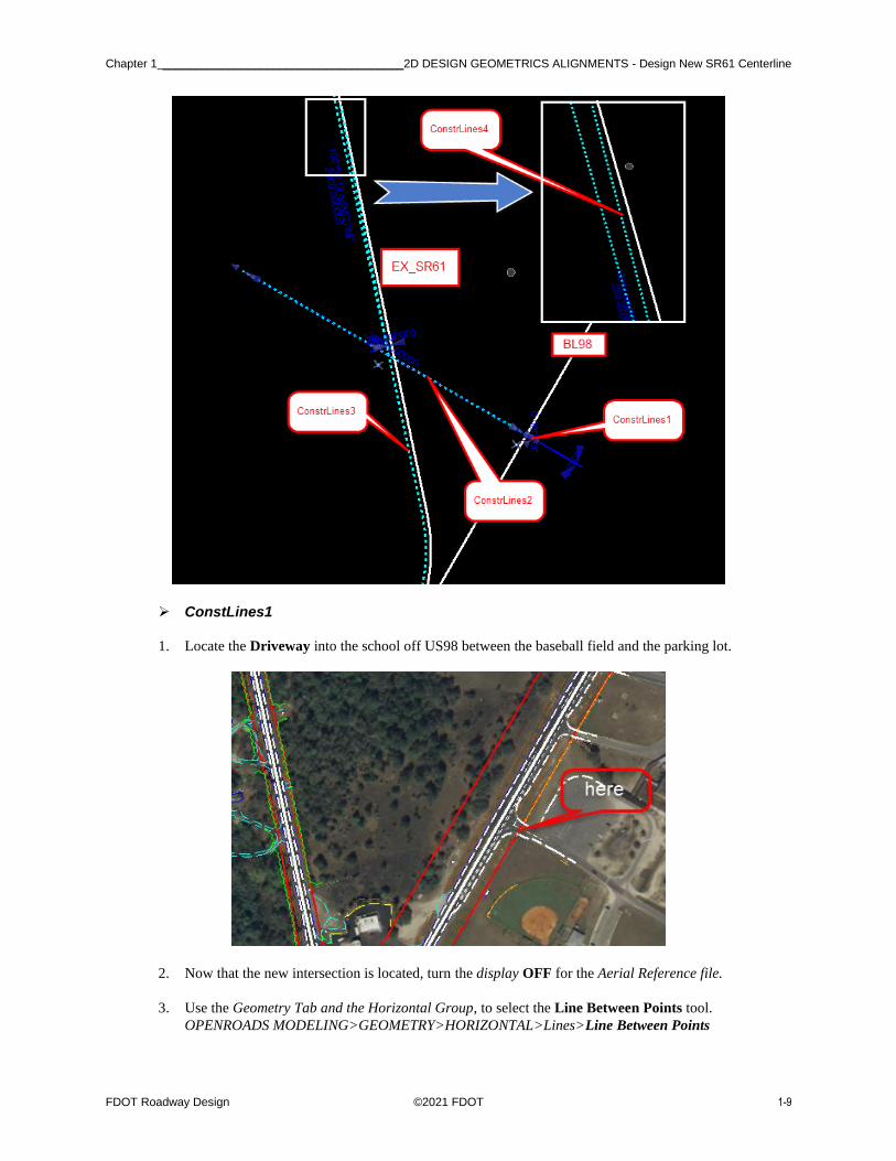
Exercise 1.2 Design New SR61 Centerline
This exercise will use several Construction lines to create the final Centerline as shown below.
Chapter 1 _____________________________________ 2D DESIGN GEOMETRICS ALIGNMENTS - Design New SR61 Centerline
FDOT Roadway Design ©2021 FDOT 1-9
➢ ConstLines1
1. Locate the Driveway into the school off US98 between the baseball field and the parking lot.
2. Now that the new intersection is located, turn the display OFF for the Aerial Reference file.
3. Use the Geometry Tab and the Horizontal Group, to select the Line Between Points tool.
OPENROADS MODELING>GEOMETRY>HORIZONTAL>Lines>Line Between Points

2D DESIGN GEOMETRICS ALIGNMENTS - Exercise Overview Chapter 1
1-10 ©2021 FDOT FDOT Roadway Design
a. Use Feature Definition Const Lines Blue Dash and a Name of ConstLines1. You
will have to add the 1 to the name.
b. Start a line perpendicular to BL98 and ending at in the middle of the Driveway. Be
careful not to snap to anything on the second point.
➢ ConstrLines2
1. Use the Geometry Tab and the Horizontal Group, to select the Simple Line From Element
tool.
OPENROADS MODELING>GEOMETRY>HORIZONTAL>Lines>Line From Element>
Simple Line From Element
2. Use Feature Definition Const Lines Blue Dash and Name ConstLines2

Chapter 1 _____________________________________ 2D DESIGN GEOMETRICS ALIGNMENTS - Design New SR61 Centerline
FDOT Roadway Design ©2021 FDOT 1-11
3. First select ConstLines1, then use the AccuSnap to locate the beginning of the line at BL98.
4. Enter a Distance of -2000 feet. Data point in the View to accept the Distance.
5. Data point to accept Trim None.
➢ ConstrLines3
1. Use the Geometry Tab and Horizontal Group, to select the Single Offset Entire Element
tool.
OPENROADS MODELING>GEOMETRY>HORIZONTAL>Offsets and Tapers>Single
Offset Entire Element
2. Use Feature Definition Const Lines Blue Dash and Name ConstLines3.

2D DESIGN GEOMETRICS ALIGNMENTS - Exercise Overview Chapter 1
1-12 ©2021 FDOT FDOT Roadway Design
3. Data point in the View to create a line -30 feet Offset to EX-61.
4. Uncheck the mirror option to No and click in the View.
5. Once the new line is created, turn the Display OFF for the SURVRD with Logical Name
TOPO in the Reference dialog.

Chapter 1 _____________________________________ 2D DESIGN GEOMETRICS ALIGNMENTS - Design New SR61 Centerline
FDOT Roadway Design ©2021 FDOT 1-13
➢ ConstrLines4
Next step, create a line from the Offset line to intersect the EX-SR61 line at a 1 degree deflection angle.
1. Find the Bearing Angle of EX-61, select the element and click the Context Menu Description.
Copy the Bearing value into the buffer space selecting Ctrl C <OR> right-click Copy.
Note: You may have to right click on the element to make the bearing value active in order to
copy from it.
2. Use the Geometry Tab and Horizontal Group, to select the Line Between Points tool.
OPENROADS MODELING>GEOMETRY>HORIZONTAL>Lines>Line Between Points
3. Use Feature Definition Const Lines Blue Dash and Name ConstLines4.
4. Start a line at the intersection of ConstLine2 and ConstLine3 (this can be done by selecting
the intersection snap) then enter a value of 2000 feet for the Length and use the Bearing in the
buffer as the Line Direction minus 1 degree.

2D DESIGN GEOMETRICS ALIGNMENTS - Exercise Overview Chapter 1
1-14 ©2021 FDOT FDOT Roadway Design
5. Use MicroStation Trim to Element and to Trim ConstLines4 line to intersect EX-61. This
step will create an interval element with a new Name of ConstLines5.
➢ Verify the Construction Lines Maintain Design Intent
1. Change the Active Level to Scratch1_dp. Use MicroStation Drawing to Place Circle with
MicroStation with a center at the end of ConstrLines5
2. Open View 4 and use Copy View from View 1. Zoom into the School Entrance in View 4
3. Move the location of the ConstLines1 and check the end of ConstLines5 to see if the location
has been corrected.
• 1: Select the first line and Use the manipulator tool handle in the middle to move parallel location.

Chapter 1 _____________________________________ 2D DESIGN GEOMETRICS ALIGNMENTS - Design New SR61 Centerline
FDOT Roadway Design ©2021 FDOT 1-15
• 2: Select ConstLines5, Use MicroStation Undo/ Redo to see the end change location.
4. Select Ctrl Z to undo change.
5. (Extra Exercise) Change the Offset Distance of ConstrLines3 from -30 to -40 to verify that
the end of ConstrLines4 will change.
6. Select Ctrl Z to undo change.
➢ Construct a Horizontal Curve between ConstLines2 and ConstLines5 to Meet
Geometric Standards.
1. Use the Design Standards Toolbar that is already docked at the top of the screen.
2. Set Active the Design Facility Standard to: Low Speed Desired Length, 45 MPH.
3. Activate the Toggle Active Design Standard icon.

2D DESIGN GEOMETRICS ALIGNMENTS - Exercise Overview Chapter 1
1-16 ©2021 FDOT FDOT Roadway Design
4. Use the Geometry Tab and the Horizontal Group to select the Simple Arc tool. This tool can
be found using the Arcs button then selecting Arcs between Elements Simple Arc.
OPENROADS MODELING>GEOMETRY>Arcs>Arcs Between Elements>Simple Arc
5. Use Feature Definition Const Lines Blue Dash and Name ConstLines6.
6. Create a Radius between ConstLine2 and ConstLine5 you will notice that setting the Design
Standard has set a default value of 2083.00’ for the Radius, be sure to change this to 881.00.
Set Trim/Extend to Both.
Chapter 1 _____________________________________ 2D DESIGN GEOMETRICS ALIGNMENTS - Design New SR61 Centerline
FDOT Roadway Design ©2021 FDOT 1-17
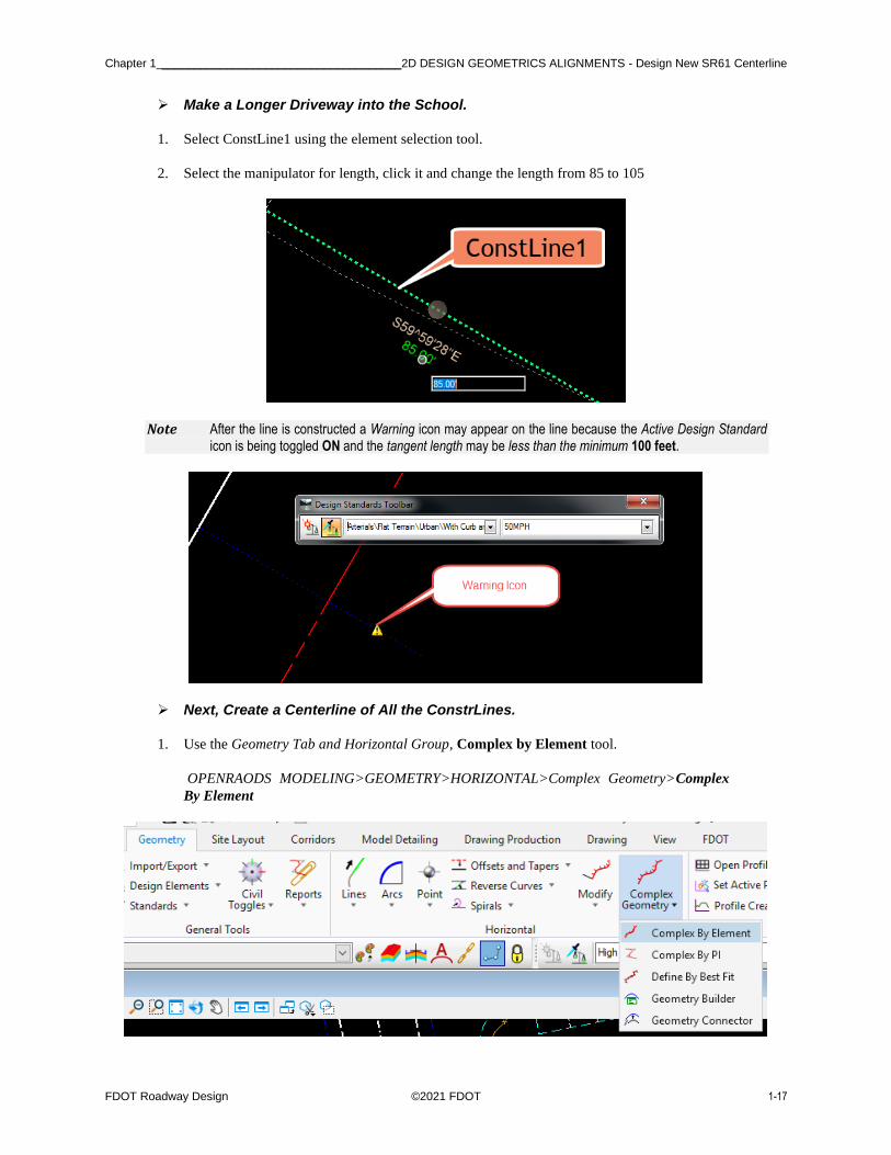
➢ Make a Longer Driveway into the School.
1. Select ConstLine1 using the element selection tool.
2. Select the manipulator for length, click it and change the length from 85 to 105
Note After the line is constructed a Warning icon may appear on the line because the Active Design Standard icon is being toggled ON and the tangent length may be less than the minimum 100 feet.
➢ Next, Create a Centerline of All the ConstrLines.
1. Use the Geometry Tab and Horizontal Group, Complex by Element tool.
OPENRAODS MODELING>GEOMETRY>HORIZONTAL>Complex Geometry>Complex
By Element

2D DESIGN GEOMETRICS ALIGNMENTS - Exercise Overview Chapter 1
1-18 ©2021 FDOT FDOT Roadway Design
2. Create the new Alignment by connecting the elements. Use Feature Definition Centerline and
Name CL_SR61, with no spaces. Use the Manual Method.
3. Be careful to select at the school side first and near the start of the line.
4. Continue until New Centerline is constructed as shown below.

Chapter 1 _____________________________________ 2D DESIGN GEOMETRICS ALIGNMENTS - Design New SR61 Centerline
FDOT Roadway Design ©2021 FDOT 1-19
➢ Set a Begin Station Value at the Intersection of BL98
1. Use the Geometry Tab and Horizontal Group, Start Station tool under the Modify icon.
OPENROADS MODELING>GEOMETRY>HORIZONTAL>Modify>Start Station
2. Set a Begin Station value of 700+00 at the intersection of SR61 and BL98.
3. Select the new SR61 Centerline(CL).
4. Use AccuSnap to locate the Intersection with BL98 and data point to accept.
5. Enter 70000 and select Enter <OR> data point to accept.

2D DESIGN GEOMETRICS ALIGNMENTS - Exercise Overview Chapter 1
1-20 ©2021 FDOT FDOT Roadway Design
➢ Describe the New Centerline Geometry
1. Use the Geometry Tab and General Tools Group, Horizontal Geometry Report tool under
the Reports icon.
OPENROADS MODELING>GEOMETRY>HORIZONTAL>Reports>Horizontal Geometry
Report
2. Select the SR61_CL Centerline. Use the settings below at the prompt to generate the report
shown.

Chapter 1 _____________________________________ 2D DESIGN GEOMETRICS ALIGNMENTS - Design New SR61 Centerline
FDOT Roadway Design ©2021 FDOT 1-21
• If the Stationing format is not displayed correctly, In the Bentley Civil Report Browser, select Tools Format Options.
2D DESIGN GEOMETRICS ALIGNMENTS - Exercise Overview Chapter 1
1-22 ©2021 FDOT FDOT Roadway Design
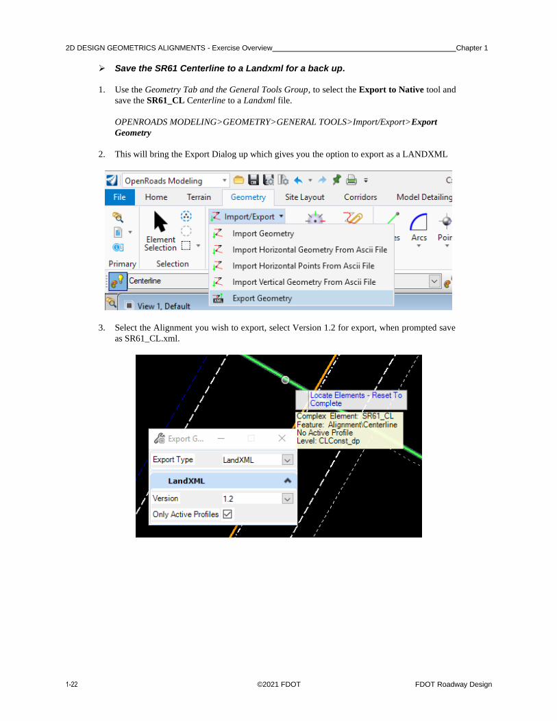
➢ Save the SR61 Centerline to a Landxml for a back up.
1. Use the Geometry Tab and the General Tools Group, to select the Export to Native tool and
save the SR61_CL Centerline to a Landxml file.
OPENROADS MODELING>GEOMETRY>GENERAL TOOLS>Import/Export>Export
Geometry
2. This will bring the Export Dialog up which gives you the option to export as a LANDXML
3. Select the Alignment you wish to export, select Version 1.2 for export, when prompted save
as SR61_CL.xml.
Chapter 1 _____________________________________________ 2D DESIGN GEOMETRICS ALIGNMENTS - Import Side Roads
FDOT Roadway Design ©2021 FDOT 1-23
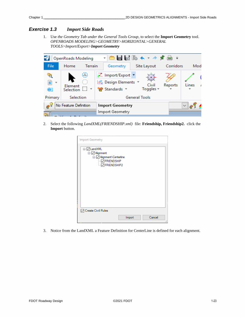
Exercise 1.3 Import Side Roads
1. Use the Geometry Tab under the General Tools Group, to select the Import Geometry tool.
OPENROADS MODELING>GEOMETRY>HORIZONTAL>GENERAL
TOOLS>Import/Export>Import Geometry
2. Select the following LandXML(FRIENDSHIP.xml) file: Friendship, Friendship2. click the
Import button.
3. Notice from the LandXML a Feature Definition for CenterLine is defined for each alignment.

2D DESIGN GEOMETRICS ALIGNMENTS - Exercise Overview Chapter 1
1-24 ©2021 FDOT FDOT Roadway Design
Exercise 1.4 Baseline Side Road Design from US98
In this exercise Civil AccuDraw is used to help construct a side road centerline on BL98.
1. OpenRoads AccuDraw and Civil AccuDraw should never be toggled ON at the same time
because both use some of the same Shortcut Key-ins. Toggle OFF the OpenRoads
AccuDraw.
2. Use Geometry Tab and the General Tools Group, to select the Civil Toggles icon to call Civil
AccuDraw tool to activate the Civil AccuDraw toolbar.
OPENROADS MODELING>GEOMETRY>GENERAL TOOLS>Civil Toggles>Civil
Accudraw
3. Click on the Mode Station-Offset to toggle ON.
4. Use the Geometry Tab and Horizontal Group, to select the Line Between Points tool to create
a Centerline perpendicular to the BL98 at Station 39+00 for a Length of 80 feet used as a side
road centerline. Here are the steps to use Civil AccuDraw with the Station Offset option:
OPENROADS MODELING>GEOMETRY>HORIZONTAL>Lines>Line Between Points

Chapter 1 _____________________________ 2D DESIGN GEOMETRICS ALIGNMENTS - Baseline Side Road Design from US98
FDOT Roadway Design ©2021 FDOT 1-25
• On the cursor prompt, tab to the offset field and use the Shortcut Key-in o, and select the reference line BL98. The cursor will now track the station and offset.
a. For the first data point, set the Snap Locator button to Perpendicular, and select on
the BL98.
2D DESIGN GEOMETRICS ALIGNMENTS - Exercise Overview Chapter 1
1-26 ©2021 FDOT FDOT Roadway Design
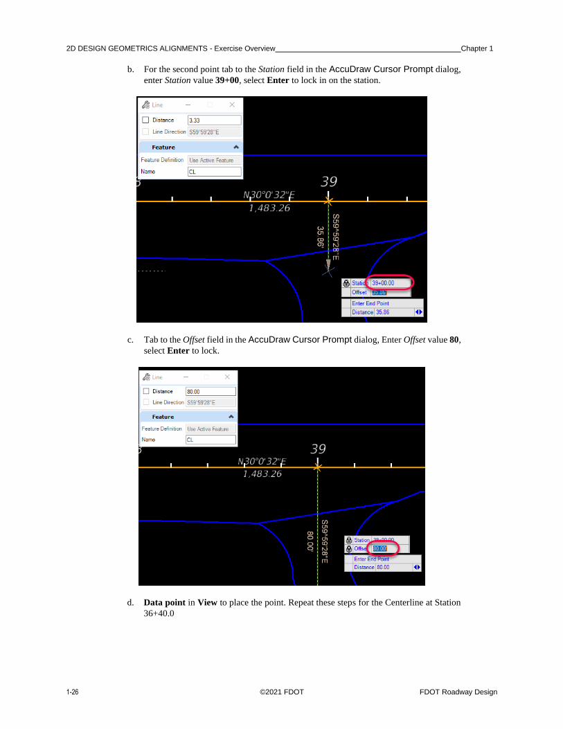
b. For the second point tab to the Station field in the AccuDraw Cursor Prompt dialog,
enter Station value 39+00, select Enter to lock in on the station.
c. Tab to the Offset field in the AccuDraw Cursor Prompt dialog, Enter Offset value 80,
select Enter to lock.
d. Data point in View to place the point. Repeat these steps for the Centerline at Station
36+40.0

Chapter 1 _____________2D DESIGN GEOMETRICS ALIGNMENTS - Using Annotation Groups to Label Your Alignment Features
FDOT Roadway Design ©2021 FDOT 1-27
Exercise 1.5 Using Annotation Groups to Label Your Alignment Features
1. Open the ALGNRD file that has been created in the previous exercises. From the OpenRoads
Modeling WORKFLOW navigate to the DRAWING PRODUCTION TAB and the
Annotations Group. There are two icon buttons for Annotating.
OPENROADS MODELING>DRAWING PRODUCTION>ANNOTATIONS
a. Element Annotation – This will annotate the element and remove the element
Annotation Group.
b. Model Annotation – This will annotate all the elements in the model and remove the
element Annotation Group.
2. From the Drawing Production Tab and the Annotations Group, Select the Annotate Element
button then following the prompts by the cursor. Select SR61 Centerline (optional you may
select multiple alignments if you like) The n reset the tool by right click.
OPENROADS MODELING>DRAWING PRODUCTION>ANNOTATIONS>Annotate
Element

2D DESIGN GEOMETRICS ALIGNMENTS - Exercise Overview Chapter 1
1-28 ©2021 FDOT FDOT Roadway Design
3. You have now just Annotated your Alignments.
a. If you Navigate to the FDOT Tab on the Ribbon, in the Actions Group will be the
Filters Icon Button with a Drop Down list.
OPENROADS MODELING>FDOT>ACTIONS>Filters
b. From this list you will now be able to control what levels will be displayed for the
Annotation Group.

Chapter 1 _____________2D DESIGN GEOMETRICS ALIGNMENTS - Using Annotation Groups to Label Your Alignment Features
FDOT Roadway Design ©2021 FDOT 1-29
c. When you first Annotate the alignments in the level display all levels will be turned
on. When using the Level Filters for annotation group be sure to change the Drawing
Scale to match the applicable scale.
Example: For drawing scales from 1”=10’ to 1”=60’ use the Level Filter for Display Only 100 Foot Major
Annotations


FDOT Roadway Design ©2021 FDOT 2-1
2 2D PLANIMETRICS
INTRODUCTION
This chapter will continue to use the OpenRoads Technology for Horizontal Geometry. Rather than use
traditional MicroStation element creation tools, these exercises will provide participants with practice using the
Civil Tools. Using Civil rule-based Feature Definitions assures design intent is incorporated into the two
dimensional (2D) plan layout. This will, in turn, prove valuable when design changes or “what if” scenarios are
needed or tested.
This chapter also introduces two (2) important new OpenRoads Technologies for creating geometry / line
work while designing in FDOTCONNECT. They are:
• Civil AccuDraw
• Civil Cells
CIVIL ACCUDRAW
As defined in the Bentley Civil Tools help files:
“Use Civil AccuDraw to allow precise input of points, whether the points are physical points or
end points of linear geometry. The Civil AccuDraw values can be persisted as rules on the points
by locking both values in the Civil AccuDraw input. Several methods can be used, among them
are:
• Distance and Direction, to set the order of ordinate entry to distance then direction,
with both sharing a common point of origin.
• Dist-Dir, to set the order of entry to distance for the first ordinate then direction for the
second ordinate, without a common point of origin.
• Dist-Dist, to set the order of entry to distance for the first ordinate then distance for the
second ordinate, without a common point of origin.
• XY, to set the order of ordinate entry to X-axis then Y-axis, with the two sharing a
common point of origin.
• DX DY, to set the order of ordinate entry to the difference in X coordinate then the
difference in the Y coordinate, with the two sharing a common point of origin.
• Station-Offset, to set the order of ordinate entry to station identification then offset
value, with both sharing a common point of origin
The delivered methods are those configured by default. These defaults can be edited, removed,
or additional methods may be added.
Chapter 2 _______________________________________________________________________2D PLANIMETRICS - Civil Cells
2-2 ©2021 FDOT FDOT Roadway Design
CIVIL CELLS
As defined in the Bentley Civil Tools help files:
“A civil cell is a collection of civil elements - geometry, templates, and terrain models - which
can be placed repeatedly in a design. The collection of civil elements will have been created
relative to one or more reference elements. When you place the civil cell, you choose the new
reference elements, and a new collection of civil elements is then created relative to them. A civil
cell can therefore be thought of as a copy of the original collection of civil elements, relative to
the geometry of the new reference elements. Civil cells can be 2D or 3D. They can consist of 2D
(plan) elements only, or 3D elements (2D elements with profiles), and can include terrains,
linear templates, area templates, and simple corridors.
When the new civil elements are created, all of the rules associated to them are also created.
This means that the new civil elements retain their relationships, both with each other and with
the reference elements, and therefore know how to react when these relationships change. In
addition, the Civil and MicroStation toolsets can still be used on the new civil elements, to adjust
and further refine the design as required, because there is no difference between a civil element
created by a civil tool, and one created by placing a civil cell.
Civil cells can save a lot of time and effort, because they replicate the complete series of steps
needed to create the civil elements. They also help to ensure compliance with design standards,
by making a civil cell available to the design team.
EXERCISE OVERVIEW
2.1 Preparation for 2D Plans
2.2 BL98 Milling Limits
2.3 BL98 Side Street
2.4 BL98 Widening
2.5 BL98 Widening Taper Line
2.6 For SR61 New Construction Template Lines
2.7 Add Right Turn lane on BL98
2.8 Add the School Entrance Right Turn Lane off BL98 Intersection
2.9 Create/Edit the Intersection Curve Radii
2.10 Trim Back Sidewalk and Curb Lines to the Curve Radii
2.11 Use Civil Cell Technology to Place Curb and Sidewalk Around the Radii
2.12 Create a Custom Civil Cell for Other Radii
2.13 Place Left Turn with Traffic Separator
2.14 Place Right Turn Island
2.15 For BL98 Intersection Crosswalks Lines
2.16 Create BL98 Turnouts
2.17 For BL98 Intersection Shoulders
2.18 For Friendship Intersection
2D PLANIMETRICS - Preparation for 2D Plans ___________________________________________________________ Chapter 2
FDOT Roadway Design ©2021 FDOT 2-3
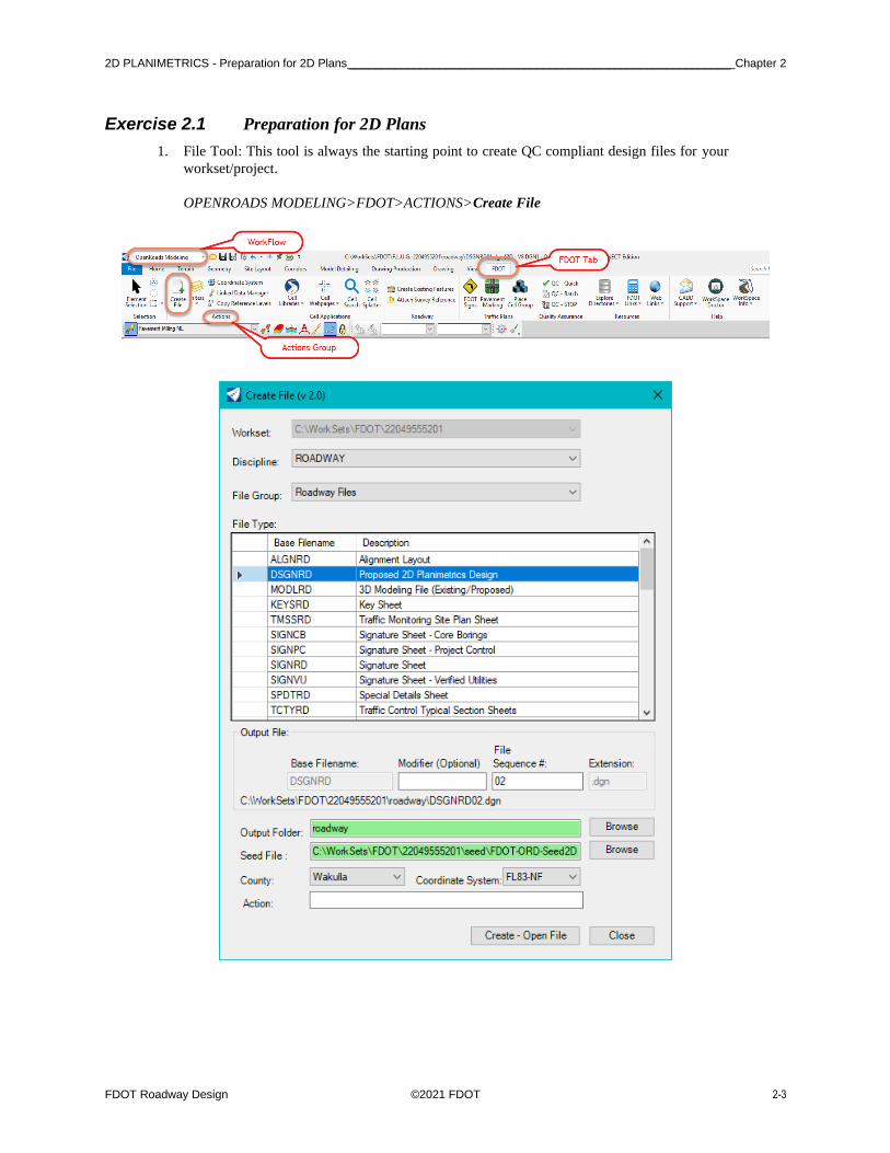
Exercise 2.1 Preparation for 2D Plans
1. File Tool: This tool is always the starting point to create QC compliant design files for your
workset/project.
OPENROADS MODELING>FDOT>ACTIONS>Create File

Chapter 2 _______________________________________________________________ 2D PLANIMETRICS - BL98 Milling Limits
2-4 ©2021 FDOT FDOT Roadway Design
Exercise 2.2 BL98 Milling Limits
In this exercise the existing pavement edge lines from the TOPORD or SURVRD file are copied to be used as
the Milling Lines for the proposed improvements. If the SURVRD does not exist and you only have a TOPORD
skip to step 5.
1. Use the Attach Survey Reference from the FDOT Tab within the Roadway Tools
Group. (This tool will attach a SURVRD file 4 times with different Logical names of
TOPO, GDTM, UTEX, DREX which apply to different level filters.)
OPENROADS MODELING>FDOT>ROADWAY>Attach Survey Reference
2. Once the SURVRD is attached, open your Reference Dialog (Function Key F9) and
Detach the reference files with logical names of GDTM, UTEX, DREX. This will only
leave the TOPO.
3. Now we need to copy or merge the elements that are on the PavtAsphalt_ep level.
This can be done by using the Copy Reference Levels tool from the FDOT Tab within
the Roadway Tools Group
OPENROADS MODELING>FDOT>ACTIONS>Copy Reference Levels

2D PLANIMETRICS - BL98 Milling Limits ________________________________________________________________ Chapter 2
FDOT Roadway Design ©2021 FDOT 2-5
4. This will open a dialog for the Copy Reference File Levels tool. On the left side of the
dialog choose PavtAsphalt_ep level. Then click on the plus to add the level to
the right side of the dialog. Click the process button to merge/copy the elements with
this level into the file.
5. This step if no SURVD Exists Use OpenRoads References (Function Key F9) to
attach and display the TOPORD01 and RWDTRD01 Reference files.
6. Use OpenRoads Level Display to turn OFF all the TOPORD01 Levels except the
PavtAsphalt_ep.
7. Use the Geometry Tab and the Horizontal Group, Line Between Points tool.
OPENROADS MODELING>GEOMETRY>HORIZONTAL>Lines>Line Between Points

Chapter 2 _______________________________________________________________ 2D PLANIMETRICS - BL98 Milling Limits
2-6 ©2021 FDOT FDOT Roadway Design
8. Create a PavementMilling ML line across the existing intersection of SR61 and BL98.
9. Use OpenRoads Break Element on the PavtAsphalt_ep line string elements where the new
PavementMilling(ML) line intersects.
10. Repeat these steps for the other side roads along BL98.

2D PLANIMETRICS - BL98 Milling Limits ________________________________________________________________ Chapter 2
FDOT Roadway Design ©2021 FDOT 2-7
11. Create a Selection Set of the PavtAsphalt_ep by level. This can be done with the right click
function of the mouse, by holding down and Selecting All On Level By Element. Then
selecting an element.
a. Subtract out of the Selection Set the Intersection lines at SR61; these will not be
PavementMilling ML lines.

Chapter 2 _______________________________________________________________ 2D PLANIMETRICS - BL98 Milling Limits
2-8 ©2021 FDOT FDOT Roadway Design
b. Also subtract out of the Selection Set the Intersection lines at Friendship Road.
12. Use the Geometry Tab and the General Tools Group, click on the Standards button to bring up
a drop down that has the Set Feature Definition tool.
OPENROADS MODELING>GEOMETRY>GENERAL TOOLS>Standards>Set Feature
Definition
2D PLANIMETRICS - BL98 Milling Limits ________________________________________________________________ Chapter 2
FDOT Roadway Design ©2021 FDOT 2-9
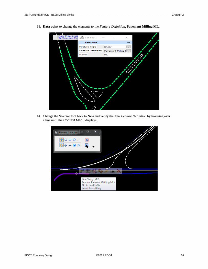
13. Data point to change the elements to the Feature Definition, Pavement Milling ML.
14. Change the Selector tool back to New and verify the New Feature Definition by hovering over
a line until the Context Menu displays.

Chapter 2 __________________________________________________________________ 2D PLANIMETRICS - BL98 Widening
2-10 ©2021 FDOT FDOT Roadway Design
Exercise 2.3 BL98 Widening
Before we start, the ALGNRD will need to be attached as a reference into the DSGNRD file. Making sure when
you attach the ALGNRD it is the Default Model. With a Detail scale of 1”=50’.
In this exercise, the proposed Pavement Lines used for widening on BL98 are created at the following locations:
1. Use the Geometry Tab and the Horizontal Group, to select Single Offset Partial tool located
in the Offsets and Tapers button.
OPENROADS MODELING>GEOMETRY>HORIZONTAL>Offsets and Tapers>Single
Offset Partial
a. Select the BL98 line at the prompt to Locate Element.
START
STATION OFFSET LENGTH
FEATURE
NAME
1 28+00 16 feet 500 feet SW_EOPA
2 33+00 32 feet 600 feet SE_EOPA
3 30+00 -24 feet 300 feet NW_EOPA
4 33+00 -24 feet 1000 feet NE_EOPA

2D PLANIMETRICS - BL98 Widening __________________________________________________________________ Chapter 2
FDOT Roadway Design ©2021 FDOT 2-11
b. Fill in the Single Offset Partial dialog as shown below.
c. Data point in the View to accept the Offset.
d. Data point in the View to accept Length.
e. Data Point in the View to accept No at the Mirror option prompt.
2. Repeat this procedure for each of the Pavement Asphalt EOPA widening lines diagram and
table above.

Chapter 2 _________________________________________________________ 2D PLANIMETRICS - BL98 Widening Taper Line
2-12 ©2021 FDOT FDOT Roadway Design
Exercise 2.4 BL98 Widening Taper Line
In This exercise a tapered Pavement Asphalt EOPA line off BL98 is created at the following location.
Select Alt to enter the End Station.
• Toggle On the Civil AccuDraw.
1. Use the Geometry Tab and the Horizontal Group, to select Variable Offset Taper tool located
in the Offsets and Tapers button.
OPENROADS MODELING>GENERAL >HORIZONTAL>Offsets and Tapers>Variable
Offset Taper
2. Select the BL98 element to offset from.
3. Enter the Station at 39+00 and select Enter to lock the value.
4. Tab to the Offset, enter 20 and select Enter to lock the value.
START
STATION
START
OFFSET END STATION END OFFSET
FEATURE
NAME
39+00 20 feet Alt to end Station Lock Snap Nearest EOPA_TAPER

2D PLANIMETRICS - BL98 Widening Taper Line _________________________________________________________ Chapter 2
FDOT Roadway Design ©2021 FDOT 2-13
5. Data Point in the View to set the first point.
6. Select Alt key to lock the End Station value.
7. Set the AccuSnap tool to Nearest, hover over the right Pavment Milling ML until the Snap
Mode displays.
8. Data Point to place the second point and complete the command.

Chapter 2 ___________________________________________ 2D PLANIMETRICS - For SR61 New Construction Template Lines
2-14 ©2021 FDOT FDOT Roadway Design
Exercise 2.5 For SR61 New Construction Template Lines
First, it is necessary to create a Template Limits line for the Project Typical FDM Civil Cell. This is a Construction
type element which is used to define the Begin and End Station limits.
1. Use the Geometry Tab and the Horizontal Group, to select the Single Offset Partial tool.
OPENROADS MODELING>GEOMETRY>HORIZONTAL>Offsets and Tapers>Single
Offset Partial
2. Create a Feature line, Const Lines Green.
a. Select the SR61 Centerline CL.
b. Set the Offset to 10.00.
c. Set the Name to ConstLines_CL
d. For the first point, set AccuSnap to Intersection and select the intersection of SR61 and
BL98.

2D PLANIMETRICS - For SR61 New Construction Template Lines ___________________________________________ Chapter 2
FDOT Roadway Design ©2021 FDOT 2-15
e. For the second point, zoom out to the first intersection after the end of the SR61 curve
and snap to the right Pavement Milling ML of existing SR61 <OR> Key in Station
716+50.
• Use Intersect Snap and to place first point and Key Point snap for the second point.
3. Use the Model Detailing Tab and the Civil Cells Group, to find the Place Civil Cell tool.
OPENROADS MODELING>MODEL DETAILING>CIVIL CELLS>Place Civil Cell
4. Navigate to the FDOT_2D-FDM_Exhibit_Lines.dgnlib and select 306-5 Exhibit civil cell to
place.

Chapter 2 ___________________________________________ 2D PLANIMETRICS - For SR61 New Construction Template Lines
2-16 ©2021 FDOT FDOT Roadway Design
a. Click OK and follow the prompts to complete the Place Civil Cell command.
b. Locate Reference Element, select the Green Const Line.
• Use the tab key to after clicking on an element to get to the last place Green Const Line.
c. Reset to Skip View Alternates.
d. Data point to accept Civil Cell Placement.
.
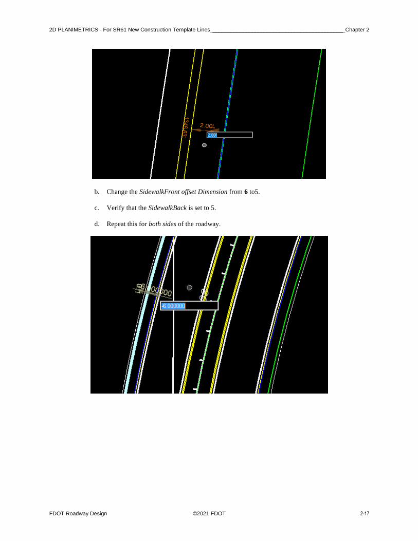
5. Change the Front Sidewalk Utility Strip Width to 2 ft and set the Sidewalk Width to 5ft.
a. Select the Sidewalk Front FSW Feature and zoom to find the Context Menu near
the middle of the element.
2D PLANIMETRICS - For SR61 New Construction Template Lines ___________________________________________ Chapter 2
FDOT Roadway Design ©2021 FDOT 2-17
b. Change the SidewalkFront offset Dimension from 6 to5.
c. Verify that the SidewalkBack is set to 5.
d. Repeat this for both sides of the roadway.

Chapter 2 _______________________________________________________ 2D PLANIMETRICS - Add Right Turn Lane on BL98
2-18 ©2021 FDOT FDOT Roadway Design
Exercise 2.6 Add Right Turn Lane on BL98
This exercise uses Civil Cells to add a right turn lane to the BL98.
1. Use Model Detailing Tab and the Civil Cells Group, Place Civil Cell tool.
OPENROADS MODELING>MODEL DETAILING>CIVIL CELLS>Place Civil Cell
2. From the Place Civil Cell dialog, navigate to the FDOT _2D-Intersection_Details.dgnlib and
select Right Turn Lane.
3. At the prompt, for the first Reference, select the widening Pavement Asphalt EOPA line.
4. For the second Reference, select the SR61 Right EOP Out Pavement Asphalt EOPA.
5. Reset to Skip Elements to View Alternatives.

2D PLANIMETRICS - Add Right Turn Lane on BL98 _______________________________________________________ Chapter 2
FDOT Roadway Design ©2021 FDOT 2-19
6. Data point to accept Civil Cell Placement. The right turn lane is added.
7. Edit the storage length for first Right Turn Lane placed, select the tangent line and change the
Length from 200 to 500 feet.
8. Use OpenRoads Trim to Intersection to correct the Pavement Asphalt EOPA lines.
Chapter 2 ____________________________ 2D PLANIMETRICS - Add the School Entrance Right Turn Lane off BL98 Intersection
2-20 ©2021 FDOT FDOT Roadway Design
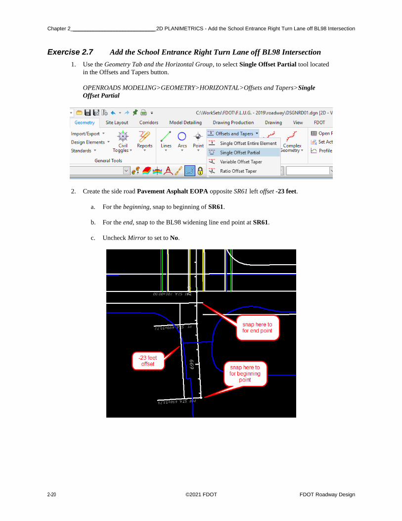
Exercise 2.7 Add the School Entrance Right Turn Lane off BL98 Intersection
1. Use the Geometry Tab and the Horizontal Group, to select Single Offset Partial tool located
in the Offsets and Tapers button.
OPENROADS MODELING>GEOMETRY>HORIZONTAL>Offsets and Tapers>Single
Offset Partial
2. Create the side road Pavement Asphalt EOPA opposite SR61 left offset -23 feet.
a. For the beginning, snap to beginning of SR61.
b. For the end, snap to the BL98 widening line end point at SR61.
c. Uncheck Mirror to set to No.

2D PLANIMETRICS - Add the School Entrance Right Turn Lane off BL98 Intersection ____________________________ Chapter 2
FDOT Roadway Design ©2021 FDOT 2-21
H
3. For the opposite side, use the Geometry Tab and the Horizontal Group, to select Single Offset
Partial tool located in the Offsets and Tapers button.
OPENROADS MODELING>GEOMETRY>HORIZONTAL>Offsets and Tapers>Single
Offset Partial
4. Create the side road Pavement Asphalt EOPA opposite SR61 Left Offset 39 feet.
a. For the beginning, snap to beginning of SR61.
b. For the end, snap to the BL98 widening line end point at SR61.
c. Uncheck Mirror to set to No.
• If necessary, Let the tool place the line on the opposite side and edit it after it is placed.
5. Add another Right Turn Lane Civil Cell on the opposite side of the intersection.

Chapter 2 ____________________________ 2D PLANIMETRICS - Add the School Entrance Right Turn Lane off BL98 Intersection
2-22 ©2021 FDOT FDOT Roadway Design
a. At the prompt, for the first Reference, select the widening Pavement Asphalt EOPA
line.
b. For the second Reference, select the intersection Pavement Asphalt EOPA line.
c. Data point to accept Civil Cell Placement. The Right Turn Lane is added.
6. Click on the Select Tool Set icon to exit the Place Civil Cell command <OR> F6 Function
Key.
7. Edit the storage length for the second Right Turn Lane placed, select the tangent line and
change the Length from 200 to 365 feet. Verify the Change the lane width is -16 feet.

2D PLANIMETRICS - Create/Edit the Intersection Curve Radii _______________________________________________ Chapter 2
FDOT Roadway Design ©2021 FDOT 2-23
Exercise 2.8 Create/Edit the Intersection Curve Radii
1. Use the Geometry Tab and the Horizontal Group, to select the Simple Arc tool located in the
ARCS button then the drop down of Arc Between Elements.
2. Create/Edit the Curve returns.
3. Select Feature Definition, Pavement Asphalt EOPA to place remaining curve radii.
4. Follow the cursor prompt to select the two Roadway Pavement Asphalt EOPA reference
lines.
• Rotating the view along the BL98 BaseLine will set the Top of the screen as North giving a quandrant as shown below.
• Select the two Pavement Asphalt EOPA in each quadrant. Use the value shown and trim both for each of the following quadrants: NorthWest 110 feet,
NorthEast 60 feet, SouthWest 60 feet, SouthEast 60 feet

Chapter 2 _______________________________________________ 2D PLANIMETRICS - Create/Edit the Intersection Curve Radii
2-24 ©2021 FDOT FDOT Roadway Design

2D PLANIMETRICS - Use Civil Cell Technology to Place Curb and Sidewalk Around the Radii _____________________ Chapter 2
FDOT Roadway Design ©2021 FDOT 2-25
Exercise 2.9 Use Civil Cell Technology to Place Curb and Sidewalk Around the Radii
1. Use Model Detailing Tab and the Civil Cells Group, to select the Place Civil Cell tool.
OPENROADS MODELING>MODELING DETAILING>Place Civil Cell
2. Navigate to the FDOT _2D-Curb_Lines_And_Endings.dgnlib and select the Curb Lines Type
F civil cell.
3. At the prompt, select the NW_EOPA radius line, reset to View Alternates and then data point
to accept the Civil Cell Placement.

Chapter 2 _____________________ 2D PLANIMETRICS - Use Civil Cell Technology to Place Curb and Sidewalk Around the Radii
2-26 ©2021 FDOT FDOT Roadway Design
4. Navigate back to the Place Civil cell dialog select the SideWalk Civil cell from the FDOT
_2D-Curb_Lines_And_Endings.dgnlib. Place this civil cell off the back of curb line that you
just placed in the previous step.
5. Edit the SidewalkBack line from -5 to -6 feet from the SidewalkFront line of the element.
Also, the SidewalkFront needs to be set from -4 to 0 feet.

2D PLANIMETRICS - Use Civil Cell Technology to Place Curb and Sidewalk Around the Radii _____________________ Chapter 2
FDOT Roadway Design ©2021 FDOT 2-27
Use OpenRoads Trim to Intersection tool. A quick way to find a tool is to use the search
ribbon.
Chapter 2 _____________________________________________ 2D PLANIMETRICS - Create a Custom Civil Cell for Other Radii
2-28 ©2021 FDOT FDOT Roadway Design
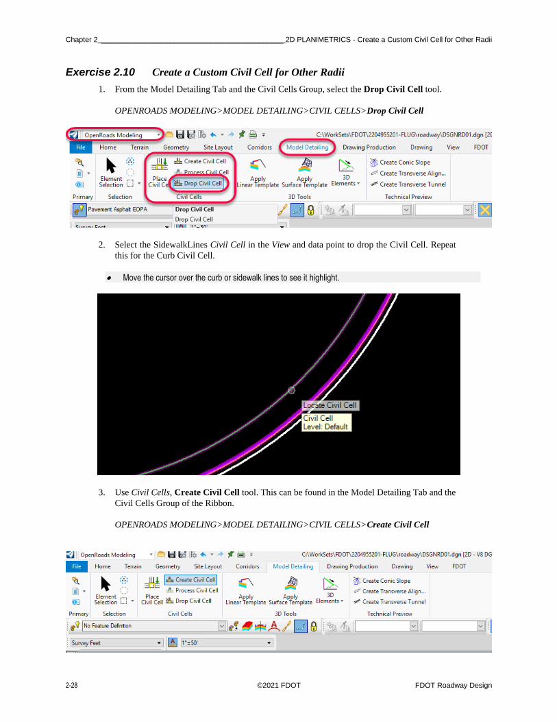
Exercise 2.10 Create a Custom Civil Cell for Other Radii
1. From the Model Detailing Tab and the Civil Cells Group, select the Drop Civil Cell tool.
OPENROADS MODELING>MODEL DETAILING>CIVIL CELLS>Drop Civil Cell
2. Select the SidewalkLines Civil Cell in the View and data point to drop the Civil Cell. Repeat
this for the Curb Civil Cell.
• Move the cursor over the curb or sidewalk lines to see it highlight.
3. Use Civil Cells, Create Civil Cell tool. This can be found in the Model Detailing Tab and the
Civil Cells Group of the Ribbon.
OPENROADS MODELING>MODEL DETAILING>CIVIL CELLS>Create Civil Cell

2D PLANIMETRICS - Create a Custom Civil Cell for Other Radii _____________________________________________ Chapter 2
FDOT Roadway Design ©2021 FDOT 2-29
a. Enter the Civil Cell Name: Custom CurbandSidewalkLines.
b. Data point to accept the new Name.
c. At the prompt, locate Reference Element and select the NW_EOPA line.
d. Reset to Locate Reference Element.
e. Reset to Optional Reference.
f. Data Point to accept Civil Cell.
4. Use the new Civil Cell to place for the other Radii; use Place Civil Cell. This can be found in
the Model Detailing Tab and the Civil Cells Group of the Ribbon.
OPENROADS MODELING>MODEL DETAILING>CIVIL CELLS>Place Civil Cell.

Chapter 2 _____________________________________________ 2D PLANIMETRICS - Create a Custom Civil Cell for Other Radii
2-30 ©2021 FDOT FDOT Roadway Design
a. If the Custom CurbandSidewalkLines is not active, navigate to the Active DGN and
select it from the list. Click OK.
b. At the prompt, select the NE_EOPA Radius line.
c. At the prompt, select Element to View Alternatives, move the cursor over the EOPA
line and click on the Arrow to reflect the Civil Cell to the correct side.

2D PLANIMETRICS - Create a Custom Civil Cell for Other Radii _____________________________________________ Chapter 2
FDOT Roadway Design ©2021 FDOT 2-31
d. Reset to View alternates.
e. Data Point to accept the Civil Cell Placement.
5. Repeat these steps to place the Custom CurbandSidewalkLines Civil Cell on the NE EOPA
Radius.
6. Leave the SE Radius without curb and sidewalk.

Chapter 2 _________________________________________________ 2D PLANIMETRICS - Place Left Turn with Traffic Separator
2-32 ©2021 FDOT FDOT Roadway Design
Exercise 2.11 Place Left Turn with Traffic Separator
1. Use Model Detailing Tab and the Civil Cells Group, to select the Place Civil Cell tool.
NOTE: After the placement of any Civil Cell be sure to verify the Feature Definition on elements in order
to add as a Corridor Reference.
OPENROADS MODELING>MODEL DETAILING>CIVIL CELLS>Place Civil Cell
a. Navigate to the FDOT _Intersections.dgnlib and select Left Turn with TS civil cell.
b. At the Locate Reference Element Centerline, select the BL98 line in the View.

2D PLANIMETRICS - Place Left Turn with Traffic Separator _________________________________________________ Chapter 2
FDOT Roadway Design ©2021 FDOT 2-33
c. At the Locate Reference Element Pavement Asphalt EOPA, select the
RT_PVT_EOP_IN line in the View.
NOTE: For the direction of travel l, this is always the left median EOP line.
d. Click on the Arrow of both Reference Elements to View Alternates, when the Green
Turning Radius and Traffic Separator are both in the correct place, Reset to skip.
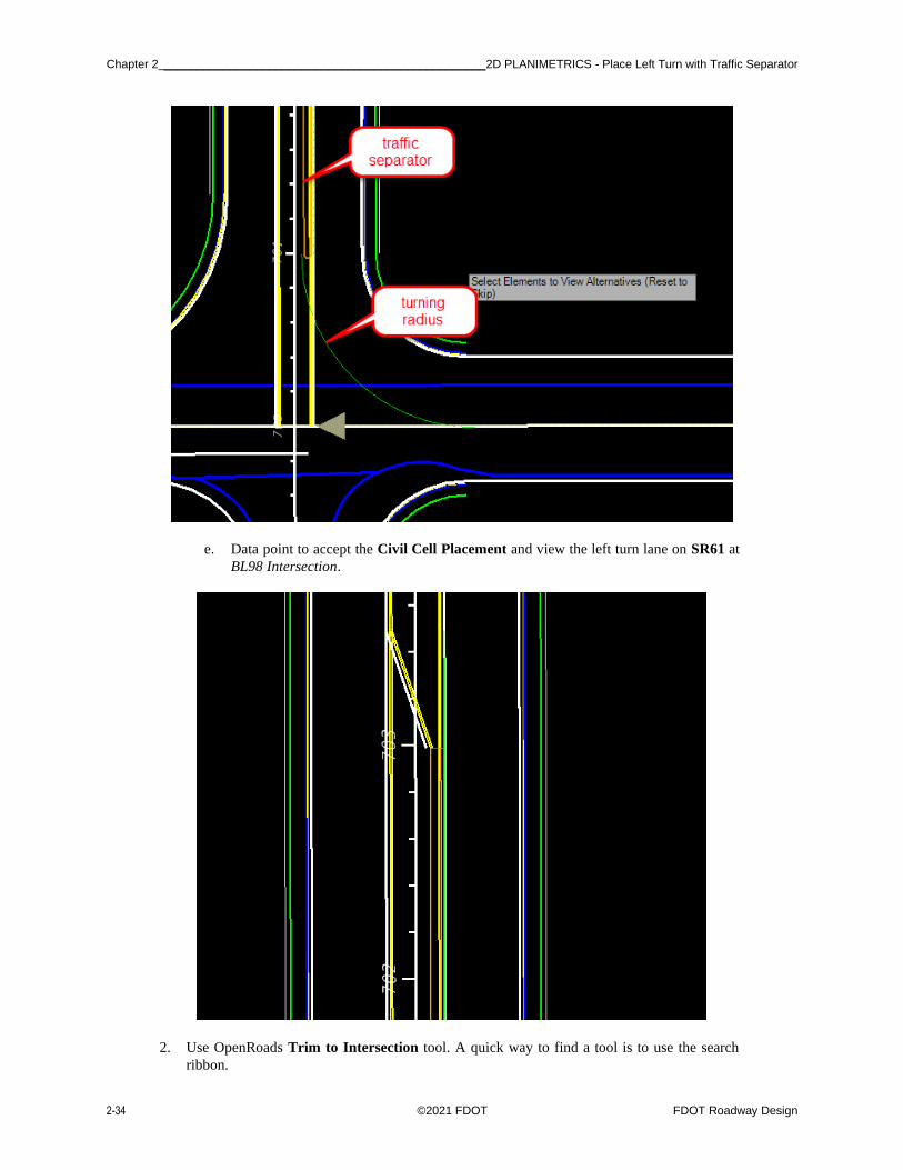
Chapter 2 _________________________________________________ 2D PLANIMETRICS - Place Left Turn with Traffic Separator
2-34 ©2021 FDOT FDOT Roadway Design
e. Data point to accept the Civil Cell Placement and view the left turn lane on SR61 at
BL98 Intersection.
2. Use OpenRoads Trim to Intersection tool. A quick way to find a tool is to use the search
ribbon.

2D PLANIMETRICS - Place Left Turn with Traffic Separator _________________________________________________ Chapter 2
FDOT Roadway Design ©2021 FDOT 2-35
3. Trim the curb median elements at the begin taper as shown.
4. Use OpenRoads Trim to Element tool. Which can found in the Drawing Tab, and the Modify
Group

Chapter 2 _________________________________________________ 2D PLANIMETRICS - Place Left Turn with Traffic Separator
2-36 ©2021 FDOT FDOT Roadway Design
5. Trim the elements at the Curb Median lines at the Traffic Separator as shown, leave the green
line.
6. View the placed left turn, change the Turning Radius from 100 feet to 75 feet.
7. View the placed left turn, change the Storage Length from 200 feet to 300 feet.

2D PLANIMETRICS - Place Left Turn with Traffic Separator _________________________________________________ Chapter 2
FDOT Roadway Design ©2021 FDOT 2-37
• Select the green line, then select the length text.

Chapter 2 _________________________________________________ 2D PLANIMETRICS - Place Left Turn with Traffic Separator
2-38 ©2021 FDOT FDOT Roadway Design
8. Zoom to the Turning Radius Offset Dimension, change the value from -1 feet to -4 feet.

2D PLANIMETRICS - Place Right Turn Island ____________________________________________________________ Chapter 2
FDOT Roadway Design ©2021 FDOT 2-39
Exercise 2.12 Place Right Turn Island
1. Use Model Detailing Tab and the Civil Cells Group, to select the Place Civil Cell tool.
OPENROADS MODELING>MODEL DETAILING>CIVIL CELLS>Place Civil Cell
2. Navigate to the FDOT_2D-Intersection_Details.dgnlib, select Right Turn Island. Click OK.

Chapter 2 ____________________________________________________________ 2D PLANIMETRICS - Place Right Turn Island
2-40 ©2021 FDOT FDOT Roadway Design
3. Select the first Pavement Asphalt EOPA lines.
4. Select the second Pavement Asphalt EOPA line.
5. Reset to Skip Alternates.

2D PLANIMETRICS - Place Right Turn Island ____________________________________________________________ Chapter 2
FDOT Roadway Design ©2021 FDOT 2-41
6. Data Point to accept the Civil Cell.
➢ Change the Right Turn Island Parameters
1. Change Const Lines Blue Dashed Arc Radius from 110 feet to 126 feet.

Chapter 2 ____________________________________________________________ 2D PLANIMETRICS - Place Right Turn Island
2-42 ©2021 FDOT FDOT Roadway Design
2. Check Const Lines Blue Dashed Begin Arc Offset is -18 feet.
3. Check Const Lines Blue Dashed End Arc Offset is -16 feet.

2D PLANIMETRICS - Place Right Turn Island ____________________________________________________________ Chapter 2
FDOT Roadway Design ©2021 FDOT 2-43
4. Change the straight Const Lines Blue Dashed SR61 EOP Offset from 1 foot to -16 feet.
5. Check Const Lines Blue Dashed BL98 EOP Offset is -16 feet.

Chapter 2 ____________________________________________________________ 2D PLANIMETRICS - Place Right Turn Island
2-44 ©2021 FDOT FDOT Roadway Design
6. Change Island EOPA Offset from the Const Lines Blue Dashed BL98 from -5 feet to -2 feet.
7. Change Island EOPA Offset from the Const Lines Blue Dashed SR61 from 1 foot to 6 feet.

2D PLANIMETRICS - Place Right Turn Island ____________________________________________________________ Chapter 2
FDOT Roadway Design ©2021 FDOT 2-45
8. Change Island Radii to 4 feet.
9. Change the Island ingress Offset -4 feet and Island Egress Offset -3 feet.

Chapter 2 ____________________________________________________________ 2D PLANIMETRICS - Place Right Turn Island
2-46 ©2021 FDOT FDOT Roadway Design
10. Move the Offset handles to the Radius Point.
11. Change the Active Level to Miscellaneous0.
12. Use the OpenRoads Create Region Flood tool, this tool can be found by switching to the
Drawing Workflow and then the Home Tab and with in the Groups Group will be the Create
Region.
DRAWING>HOME>GROUP>Create Region

2D PLANIMETRICS - Place Right Turn Island ____________________________________________________________ Chapter 2
FDOT Roadway Design ©2021 FDOT 2-47
13. Select the Center of the Island, and then data point to accept the closed element.
14. Use the OpenRoads Select tool to view the properties of the new island. Record the Area.
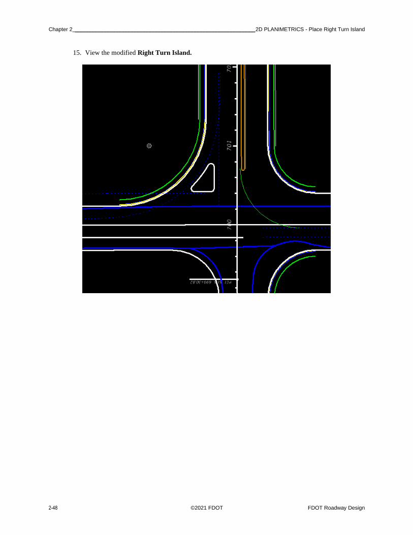
Chapter 2 ____________________________________________________________ 2D PLANIMETRICS - Place Right Turn Island
2-48 ©2021 FDOT FDOT Roadway Design
15. View the modified Right Turn Island.

2D PLANIMETRICS - For BL98 Intersection Crosswalks Lines _______________________________________________ Chapter 2
FDOT Roadway Design ©2021 FDOT 2-49
Exercise 2.13 For BL98 Intersection Crosswalks Lines
1. Use the Geometry Tab and the Horizontal Group, to select Single Offset Partial tool located
in the Offsets and Tapers button.
OPENROADS MODELING>GEOMETRY>HORIZONTAL>Offsets and Tapers>Single
Offset Partial
2. Create a Partial Offset line from BL98 -52 feet across the intersection. Use Feature Definition
Const Lines Blue Dash and Name ConstLineA.
3. Use Geometry Tab and the Horizontal Group, to select the Line Between Points tool.
OPENROADS MODELING>GEOMETRY>HORIZONTAL>Lines>Line Between Points
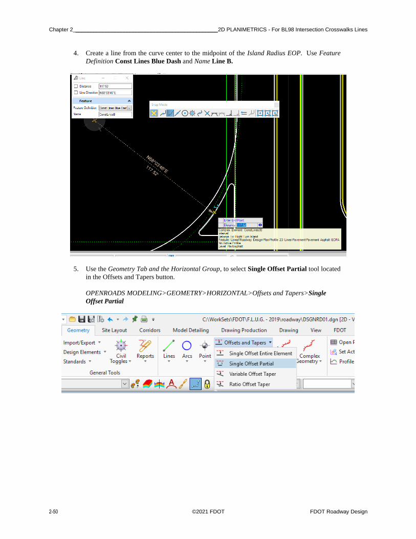
Chapter 2 _______________________________________________ 2D PLANIMETRICS - For BL98 Intersection Crosswalks Lines
2-50 ©2021 FDOT FDOT Roadway Design
4. Create a line from the curve center to the midpoint of the Island Radius EOP. Use Feature
Definition Const Lines Blue Dash and Name Line B.
5. Use the Geometry Tab and the Horizontal Group, to select Single Offset Partial tool located
in the Offsets and Tapers button.
OPENROADS MODELING>GEOMETRY>HORIZONTAL>Offsets and Tapers>Single
Offset Partial

2D PLANIMETRICS - For BL98 Intersection Crosswalks Lines _______________________________________________ Chapter 2
FDOT Roadway Design ©2021 FDOT 2-51
6. Create a Partial Offset line from SR61 across the intersection. Use Feature Definition Const
Lines Blue Dash and Name ConstLineC.
• Snap to the mid-point of the radii.
Note Use these lines in later exercises to place 3D Sidewalk Ramp Civil Cells.

Chapter 2 _____________________________________________________________ 2D PLANIMETRICS - Create BL98 Turnouts
2-52 ©2021 FDOT FDOT Roadway Design
Exercise 2.14 Create BL98 Turnouts
In this exercise the additional rural turnouts can be added to BL98.
1. Use the Geometry Tab and the Horizontal Group, to select Single Offset Entire
Element tool located in the Offsets and Tapers button.
OPENROADS MODELING>GEOMETRY>HORIZONTAL>Offsets and Tapers>Single
Offset Entire Element
a. Select the CenterLine of the second Turnout. (This Turnout is at Sta. 39+00.00 of
BL98)
b. Accept the -20 feet Offset and Mirror.

2D PLANIMETRICS - Create BL98 Turnouts _____________________________________________________________ Chapter 2
FDOT Roadway Design ©2021 FDOT 2-53
2. Use the Geometry Tab and the Horizontal Group, to select the Simple Arc tool located in the
ARCS button then the drop down of Arc Between Elements.
OPENROADS MODELING>GEOMETRY>HORIZONTAL>Arcs>Arc Between Elements>Simple Arc
a. In the Simple Arc tool set Trim/Extend to Both, then set the Radius to 25.0’. Be sure
to set a Feature Definition of Pavement Asphalt EOPA. Then place the Radius on both
sides.
b. Change the Geometry to fit the existing driveway.
• Use the centerline snap and dimensions to modify the location, length and angle. Use the Offset Pavement Asphalt EOPA Dimensions to change the width.

Chapter 2 _____________________________________________________________ 2D PLANIMETRICS - Create BL98 Turnouts
2-54 ©2021 FDOT FDOT Roadway Design
3. (EXTRA Exercise) Repeat the steps above to create an addition Turnout as shown below
<OR> use the Civil Cell, FDOT_2D-Intersection_Details.dgnlib, and Side Road Turnout.
4. First place the Side Road Centerline make sure to go back into the ALGNRD file to adjust the
centerline feature.

2D PLANIMETRICS - For BL98 Intersection Shoulders _____________________________________________________ Chapter 2
FDOT Roadway Design ©2021 FDOT 2-55
Exercise 2.15 For BL98 Intersection Shoulders
This exercise uses the Pavement Asphalt EOPA to create the 5 feet Shoulder Paved PSHLDR Offset lines.
1. Use the Geometry Tab and the Horizontal Group, to select Single Offset Entire
Element tool located in the Offsets and Tapers button.
OPENROADS MODELING>GEOMETRY>HORIZONTAL>Offsets and Tapers>Single Offset Entire
Element
2. Set the Offset to 5 feet and the Feature Definition to Shoulder Paved PSHLDR.
3. Select the Pavement Asphalt EOPA lines from the previous steps.
4. Repeat these steps to add the remaining Shoulder lines for the widening along BL98.
5. View the intersection below for complete details.

Chapter 2 _________________________________________________________ 2D PLANIMETRICS - For Friendship Intersection
2-56 ©2021 FDOT FDOT Roadway Design
Exercise 2.16 For Friendship Intersection
1. Use Model Detailing Tab and the Civil Cells Group, to select the Place Civil Cell tool.
OPENROADS MODELING>MODEL DETAILING>CIVIL CELLS>Place Civil Cell
a. From the Place Civil Cell dialog, navigate to the FDOT_2D-
Intersection_Details.dgnlib and select Rural Side Road Turnout.
b. Add Rural Side Road Turn Out civil cell to both sides of the Intersection with
Friendship and Friendship 2 Centerlines.
c. Use the trim commands located in the Drawing Tab and the Modify Group, to clean
the extra curb line and sidewalk lines across the intersection.
OPENROADS MODELING>DRAWING>MODIFY>Trim to Element
d. Change all Radii to 35 feet.
e. Change Friendship2 Side Road Offsets to 20 feet.

2D PLANIMETRICS - For Friendship Intersection _________________________________________________________ Chapter 2
FDOT Roadway Design ©2021 FDOT 2-57
f. Change Centerline Length to 100 feet. This step will need to be done in the ALGNRD
File.
2. Use Model Detailing Tab and the Civil Cells Group, to select the Place Civil Cell tool.
OPENROADS MODELING>MODEL DETAILING>CIVIL CELLS>Place Civil Cell
a. From the Place Civil Cell dialog, navigate to the FDOT_2D-
Intersection_Details.dgnlib and select Left Turn w/ Traffic Separator Median.
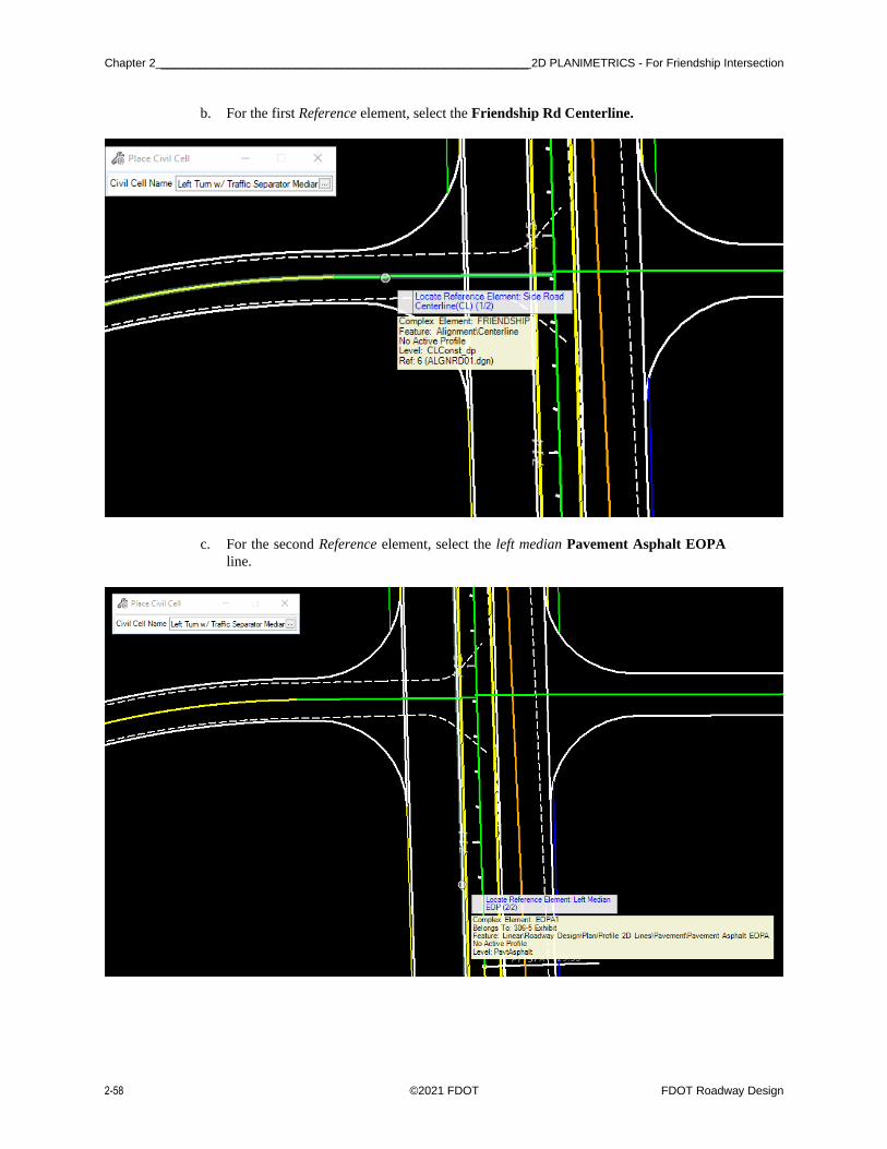
Chapter 2 _________________________________________________________ 2D PLANIMETRICS - For Friendship Intersection
2-58 ©2021 FDOT FDOT Roadway Design
b. For the first Reference element, select the Friendship Rd Centerline.
c. For the second Reference element, select the left median Pavement Asphalt EOPA
line.
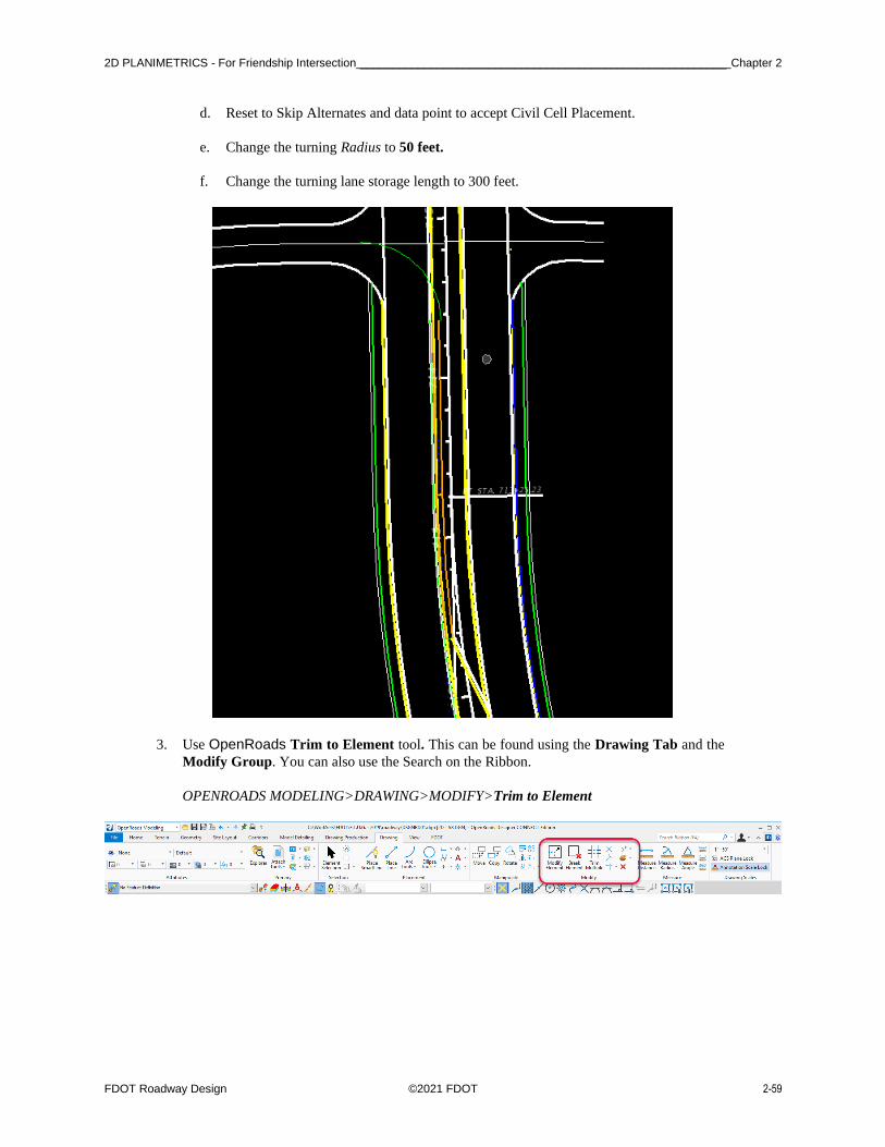
2D PLANIMETRICS - For Friendship Intersection _________________________________________________________ Chapter 2
FDOT Roadway Design ©2021 FDOT 2-59
d. Reset to Skip Alternates and data point to accept Civil Cell Placement.
e. Change the turning Radius to 50 feet.
f. Change the turning lane storage length to 300 feet.
3. Use OpenRoads Trim to Element tool. This can be found using the Drawing Tab and the
Modify Group. You can also use the Search on the Ribbon.
OPENROADS MODELING>DRAWING>MODIFY>Trim to Element

Chapter 2 _________________________________________________________ 2D PLANIMETRICS - For Friendship Intersection
2-60 ©2021 FDOT FDOT Roadway Design
4. Move the LT_PVT_EOP_IN to the beginning of the Traffic Separator.
• Use the Const Lines Green as the cut element.
5. Use OpenRoads Trim to Element tool. This can be found using the Drawing Tab and the
Modify Group. You can also use the Search on the Ribbon.
OPENROADS MODELING>DRAWING>MODIFY>Trim to Element
6. Trim the Curb and EOP lines to the beginning of the median Taper line.
NOTE: After the placement of any Civil Cell be sure to verify the Feature Definition on elements in order to add as a Corridor Reference.

2D PLANIMETRICS - For Friendship Intersection _________________________________________________________ Chapter 2
FDOT Roadway Design ©2021 FDOT 2-61
7. (EXTRA Exercises) Complete the Intersection with Civil Geometry tools as shown below:
a. Add Curb lines for each of the Radius.
b. Trim Sidewalk lines into the Radius Curb lines. There is no sidewalk along SR61 north
of Friendship Road.
c. Add Pavement Asphalt EOPA Taper lines from the Intersection Radii at Friendship
to the End Station of SR61 11 left.
d. Add Shoulder Paved PSHLDR lines to both sides along the Taper.

Chapter 2 _________________________________________________________ 2D PLANIMETRICS - For Friendship Intersection
2-62 ©2021 FDOT FDOT Roadway Design
[PAGE INTENTIONALLY LEFT BLANK.]
FDOT Roadway Design ©2019 FDOT 3-1
3 PROFILES
INTRODUCTION
This chapter will continue to use the OpenRoads Technology Civil Tools, Vertical Geometry. These exercises
will provide participants with practice using the Civil Tools. Using Civil rule-based Feature Definitions assures
design intent is incorporated into the vertical geometry layout. This will be beneficial for design when changes
need to be evaluated throughout the development process.
This chapter introduces important new OpenRoads Technologies for creating vertical geometry line work
while designing in FDOTCONNECT workspace.
OPEN PROFILE MODEL
The Open Profile Model generates an OpenRoads View that presents the desired feature in profile thus enabling
the Vertical Geometry tools to interact with the chosen feature.
Open the Civil Tools Task pane to the Vertical Geometry section then click the Open Profile Model icon. Move
the cursor into the Workspace and note that it is accompanied by a command prompt requesting that you, "Locate
Plan Element". Select the element with which you wish to work in profile. The cursor is now equipped with a
prompt that says, "Select or Open View". Data point or left click in it a view to present a profile of the selected
element. If no other view is open, click one of the view icons on the View Groups toolbar then click again in the
new View. Vertical Geometry tools can then be used to edit/create vertical profile data in the design.
EXERCISE OVERVIEW
4.1 Preparation for SR61 Profile
4.2 Create SR61 Profile
4.3 Edit SR61 Profile
4.4 BL98 Profile
4.5 Friendship Profile

PROFILES - Civil Geometry - Design Intent ______________________________________________________________ Chapter 3
3-2 ©2019 FDOT FDOT Roadway Design
CIVIL GEOMETRY - DESIGN INTENT
As defined in the Bentley Civil Tools help file:
“Design intent builds associations and relationships between civil elements. Object information
(how, where, and by what method it was created) is stored with the object to insure the original
intent is retained and honored in the design. If an element is modified, any related elements will
recreate themselves based on these stored relationships.
Civil Geometry or rule-base elements are created intelligently as the tools are used and elements are constructed.
The FDOTCONNECT Workspace and design development workflow is highly dependent on using Civil
Geometry for the 2D plan layout rather than traditional MicroStation place elements tools.
Design Geometrics and Criteria FDOT Design Manual (FDM), Part 2 Chapter 210
Design Speed 45 MPH
Facility Low Speed Desired Length
Maximum Tangent Deflection w/out curve 1 Degree Section 210.8.1
Minimum Horizontal Radius 694 feet Table 210.9.2
Minimum Length of Curve 675 feet Table 210.8.1
Context Class C3 Max Grade Table 210.10.1
• Low Speed Minimum Length – This will give a minimum Radius at Max Super (emax = .05).
• Low Speed Desired Length – This will give a desired length of curve at Normal Crown.
Note Refer to the FDM for Tables.

Chapter 3 _______________________________________________________________ PROFILES - Preparation for SR61 Profile
FDOT Roadway Design 2D Modeling ©2021 FDOT 3-1
Exercise 3.1 Preparation for SR61 Profile
1. Open the ALGNRD01.dgn that was created in Exercise 2.1.
C:\WorkSets\FDOT\22049555201\roadway.
2. Use Function key F9 (toggles on the Reference Dialog) to view the attached files: Turn the
display off on all the reference files except the SURVRD file with a logical name of GDTM.
This file will be used to create Profiles of the Existing Ground.
Note If the SURVRD file exist, the SURVRD01 -GTMRD logical can be used.
3. Once you have the turned off the SURVRD files, we now need to set the terrain Active. To do
this select the boundary to bring up the context menu and select the second icon in the menu.
Note Setting the terrain to Active will create a new Model that is 3D we will use this Model to view our Profiles.
4. To set up the correct views to design profiles we will use the View Controls located with the
right click and hold function of the Right mouse. Right Click and Hold on the mouse and
navigate to the View Control then arrow over to bring up a second dialog to find different view
control functions select on the (3 Views Plan/Profile/3D) then follow the prompts by the cursor
to complete.

PROFILES - Preparation for SR61 ProfilePreparation for SR61 ProfilePreparation for SR61 ProfilePreparation for SR61
ProfilePreparation for SR61 ProfilePreparation for SR61 Profile ______________________________________________ Chapter 3
3-2 ©2021 FDOT FDOT Roadway Design 2D Modeling
5. At the cursor prompt, select the OK then it will ask you to select a plan element this will be
the SR61 Centerline. Once you are done your view windows should look like this.

Chapter 3 ______________________________________________________________________ PROFILES - Create SR61 Profile
FDOT Roadway Design 2D Modeling ©2021 FDOT 3-3
Exercise 3.2 Create SR61 Profile
In this exercise, several Vertical Geometry tools are used to create a proposed profile for SR61.
1. Use the Geometry Tab and the Vertical Group of the OpenRoads Modeling WorkFlow.
OPENROADS MODELING>GEOMETRY>VERTICAL
2. From the previous exercise select View 4 to make the Profile window active.
3. Use the Geometry Tab and the Vertical Group, to select the Define Profiles by Best Fit tool
that is located within the Complex Geometry pull down.
OPENROADS MODELING>GEOMETRY>VERTICAL>Complex Geometry>Define Profile
By Best Fit

PROFILES - Create SR61 ProfileCreate SR61 ProfileCreate SR61 ProfileCreate SR61 ProfileCreate SR61 ProfileCreate SR61
Profile ___________________________________________________________________________________________ Chapter 3
3-4 ©2021 FDOT FDOT Roadway Design 2D Modeling
a. At the cursor prompt, data point to Make Complex Element option. Enter the Profile
Name, SR61-PR, and then data point on the green line in the profile.
b. Follow the prompts to enter the Best Fit Parameters as shown. Make sure to pick the
Feature Definition of CenterLine.

Chapter 3 ______________________________________________________________________ PROFILES - Create SR61 Profile
FDOT Roadway Design 2D Modeling ©2021 FDOT 3-5
4. Using the Design Standards Toolbar that is already docked at the top of the screen.
5. On the Design Standards Toolbar, using the second drop down list navigate to the C2T C3
C4 C&G (FDOT_DesignGeometrics Criteria Design Library and select 45 MPH. Toggle On
the Active Design Standard.)
• Be sure to set the left field (Horizontal Design Standard) in order to set the right field (Vertical Desgin Stnadard) to 45 MPH.
6. Use the Design Standards Toolbar, to select the Set Design Standard tool.
a. At the prompt, select the Best Fit Profile created in the previous steps. The profile
now has a Vertical Design Standard rule placed on it.
b. Using the Element Select Tool, select the profile element and view its properties in the
Element Information dialog.

PROFILES - Create SR61 ProfileCreate SR61 ProfileCreate SR61 ProfileCreate SR61 ProfileCreate SR61 ProfileCreate SR61
Profile ___________________________________________________________________________________________ Chapter 3
3-6 ©2021 FDOT FDOT Roadway Design 2D Modeling
7. Use the Civil Message Center tool that is located on the Geometry Tab and General Tools
Group in the Standards drop down menu.
a. The Civil Message Center dialog displays the results.
Note It may be docked at the bottom of the screen, click on the Tab.
b. In the Civil Message Center dialog, select on the MicroStation tab. This will toggle
Off all the general messages for MicroStation and leave only Error messages and
Warnings in the list.
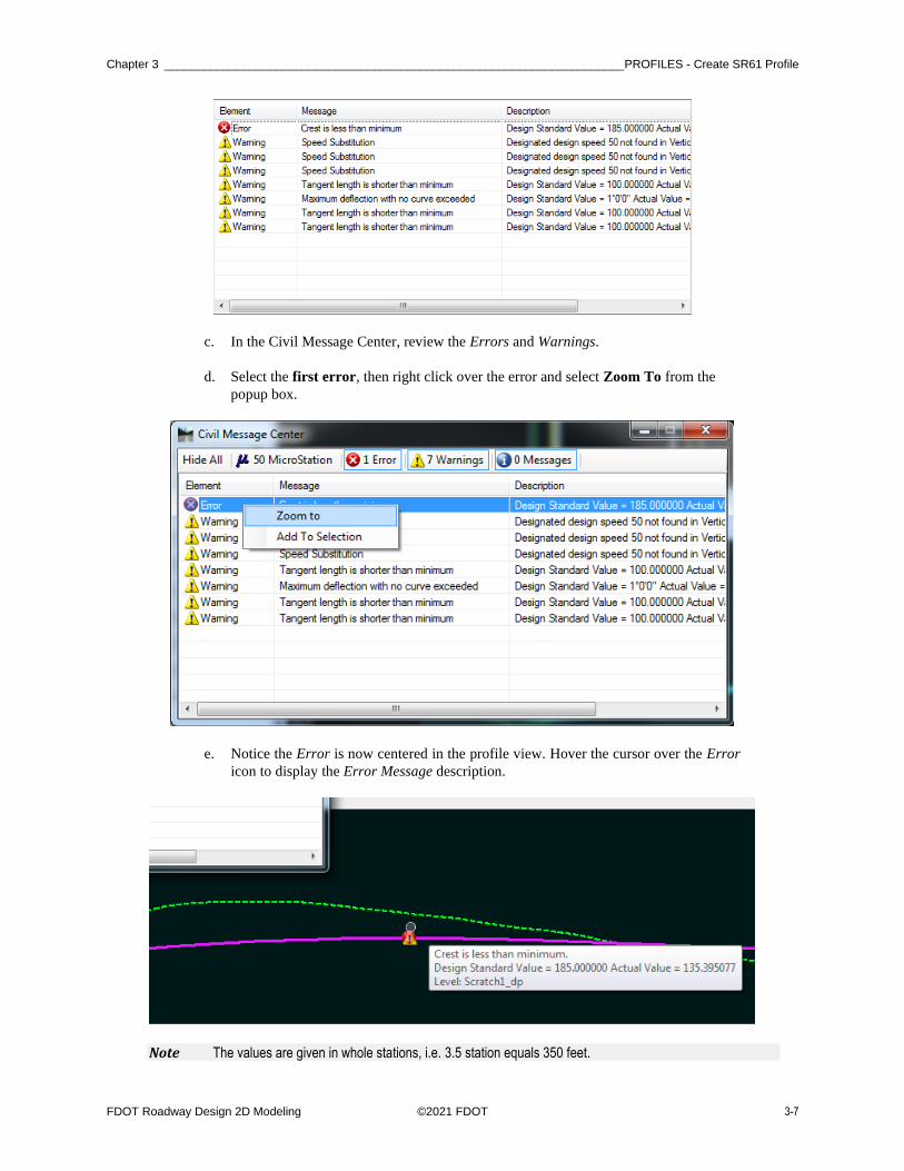
Chapter 3 ______________________________________________________________________ PROFILES - Create SR61 Profile
FDOT Roadway Design 2D Modeling ©2021 FDOT 3-7
c. In the Civil Message Center, review the Errors and Warnings.
d. Select the first error, then right click over the error and select Zoom To from the
popup box.
e. Notice the Error is now centered in the profile view. Hover the cursor over the Error
icon to display the Error Message description.
Note The values are given in whole stations, i.e. 3.5 station equals 350 feet.

PROFILES - Create SR61 ProfileCreate SR61 ProfileCreate SR61 ProfileCreate SR61 ProfileCreate SR61 ProfileCreate SR61
Profile ___________________________________________________________________________________________ Chapter 3
3-8 ©2021 FDOT FDOT Roadway Design 2D Modeling
8. Since there can be a number of different situations for both the horizontal and vertical curve
depending on Context classification and Design Speed we will now set the vertical in the
Explorer Dialog.
a. Using the Explorer Dialog (Function Key F11) if you do not have it docked. Navigate
to the OpenRoads Standards Tab then click on Standards to open the current file you
are in to see the Design Standards Category to view the Design Standard applied the
Alignments in the file.
b. Select the Horizontal Design Section to see which design standard is applied to the
Alignment, next select the desired speed. Now using the Ctrl+I key to bring up the
properties dialog lets link a vertical design speed to the horizontal.
9. Use the Design Standards Toolbar that is docked to toggle on the Set Design Standards.
10. At the prompt, select the Best Fit Profile created in the previous steps. Notice the Error icons
are no longer displayed.

Chapter 3 ________________________________________________________________________ PROFILES - Edit SR61 Profile
FDOT Roadway Design 2D Modeling ©2021 FDOT 3-9
Note A new tool to OpenRoads Designer is the Table Editor Tool. This tool can be found on the Geometry Tab and the Common Tools Group. With this tool a selection of the alignment (Horizontal or Vertical) will bring up a table for easy editing.
OPENROADS MODELING>GEOMETRY>COMMON TOOLS>Table Editor
Exercise 3.3 Edit SR61 Profile
This exercise changes the profile using Civil AccuDraw and MicroStation Modify Element.
➢ Edit the Best Fit Profile
In order to edit this profile, because it was created from the “Profile by BestFit” the rule must first be removed.
1. Select the Profile Element and hover over the element to display the Context Menu.

PROFILES - Edit SR61 ProfileEdit SR61 ProfileEdit SR61 ProfileEdit SR61 ProfileEdit SR61 ProfileEdit SR61 Profile ___ Chapter 3
3-10 ©2021 FDOT FDOT Roadway Design 2D Modeling
2. Select the Convert to Profile Rule tool.
➢ Delete PIs
1. Use MicroStation Modify, Delete Vertex tool. This tool can be found in the Drawing Tab
and the Modify Group.
OPENROADS MODELING>DRAWING>MODIFY>Delete Vertex
2. Zoom to the beginning of the Profile and delete the first two Vertical Elements.

Chapter 3 ________________________________________________________________________ PROFILES - Edit SR61 Profile
FDOT Roadway Design 2D Modeling ©2021 FDOT 3-11
➢ Create Profile with Place Vertical Line
New vertical civil profile elements are added to match the existing profile across US98.
1. Use Geometry Tab and the Vertical Group, to select the Profile Line Between Points tool
located in the Lines Tools.
OPENROADS MODELING>GEOMETRY>VERTICAL>Lines>Profile Line Between Points
2. Place Line Elements on the Existing Ground points to trace the Profile across BL98.
Note This is not exact, simply trace a few lines.

PROFILES - Edit SR61 ProfileEdit SR61 ProfileEdit SR61 ProfileEdit SR61 ProfileEdit SR61 ProfileEdit SR61 Profile ___ Chapter 3
3-12 ©2021 FDOT FDOT Roadway Design 2D Modeling
3. Continue using the Profile Line Between Points tool.
a. Begin at the edge of the existing pavement or connect to the proposed profile line from
the step above.
b. In the Profile Line Between Points dialog, check the length and slope, length of 250
feet and slope of -0.3%. Click a data point in the view to create the line as defined
in the dialog.

Chapter 3 ________________________________________________________________________ PROFILES - Edit SR61 Profile
FDOT Roadway Design 2D Modeling ©2021 FDOT 3-13
c. Using Line Between Points to join the two profiles, place another Profile line
between the “250 at .3%” line and the Best Fit Profile.

PROFILES - Edit SR61 ProfileEdit SR61 ProfileEdit SR61 ProfileEdit SR61 ProfileEdit SR61 ProfileEdit SR61 Profile ___ Chapter 3
3-14 ©2021 FDOT FDOT Roadway Design 2D Modeling
➢ Profile by VPI’s
1. Zoom to the Beginning of the profile, Use the Geometry Tab and the Vertical Group, to select
the Profile Complex By VPI or PI tool located in the Complex Geometry tool Group.
OPENROADS MODELING>GEOMETRY>VERTICAL>Complex Geometry>Profile Complex By PI
2. Toggle OFF the Active Design Standard, set the Curve length to 50 feet.
• Check that the Vertical Curve Type is set to Parabola.
3. Start by snapping to the Beginning Point on the ground and complete the Profile Segment as
shown below.
• This is not exact, snap to 3 points.

Chapter 3 ________________________________________________________________________ PROFILES - Edit SR61 Profile
FDOT Roadway Design 2D Modeling ©2021 FDOT 3-15
4. Zoom to the End of the Profile, select the Line and move the last End Point to snap to the
Existing Ground.
• Click on the solid ball manipulator at the end of the line to move it in both directions.

PROFILES - Edit SR61 ProfileEdit SR61 ProfileEdit SR61 ProfileEdit SR61 ProfileEdit SR61 ProfileEdit SR61 Profile ___ Chapter 3
3-16 ©2021 FDOT FDOT Roadway Design 2D Modeling
➢ Complex Profile Elements
1. Use Geometry Tab and the Vertical Group, to select the Profile Complex by Elements tool
located within the Complex Geometry tool Group.
OPENROADS MODELING>GEOMETRY>VERTICAL>Complex Geometry>Profile
Complex By Elements
2. Key-in the name CL_SR61_PR on the dialog and Start at the Beginning Profile line and create
a new Connected Profile.
• On the Profile Complex by Element tool setting, enter the Feature Name. This is the Profile Name assigned to the Profile. Switching the method should run the entire element if all elements are within the tolerance of Maximum Gap.

Chapter 3 ________________________________________________________________________ PROFILES - Edit SR61 Profile
FDOT Roadway Design 2D Modeling ©2021 FDOT 3-17
➢ Profile Report
1. Use the Geometry Tab and the General Tolls Group, to select the Profile Report tool located
within the Reports tool Group.
OPENROADS MODELING>GEOMETRY>GENERAL TOOLS>Reports>Profile Report
<OR> With the Profile selected, hover over the element to display the Context Menu and
select the Profile Report.

PROFILES - Edit SR61 ProfileEdit SR61 ProfileEdit SR61 ProfileEdit SR61 ProfileEdit SR61 ProfileEdit SR61 Profile ___ Chapter 3
3-18 ©2021 FDOT FDOT Roadway Design 2D Modeling
2. The Bentley Civil Report browser displays the Vertical Alignment Review Report for the
Profile. Close the Civil Report browser.
3. Use Geometry Tab and the Vertical Group, to select the Set Active Profile tool.
<OR> With the Profile selected, hover over the element to display the Context Menu and
select Set Active Profile.
Note The ALGNRD file is your single source for both your Horizontal and Vertical Geometry. This file is now more important than ever in your design. This file will be referenced in to your DSGNRD and MODLRD files to control the 2D Planimetrics (DSGNRDxx.dgn) and your Corridor (MODLRDXX.dgn).
➢ Optional Export Profile
1. Use the Geometry Tab and the General Tools Group, to select the Export Geometry tool
located within the Import/Export tool Group.
OPENROADS MODELING>GEOMETRY>GENERAL TOOLS>Import/Export>Export Geometry
• Always check that the profile has a Feature Name before saving to the LandXML file.
2. Select the SR61 Horizontal Alignment and save as SR61_Alignment.xml for a backup.

Chapter 3 ____________________________________________________________________________ PROFILES - BL98 Profile
FDOT Roadway Design 2D Modeling ©2021 FDOT 3-19
Exercise 3.4 BL98 Profile
1. With the BL98 alignment selected in the Plan View, hover over the element to display the
Context Menu and select the Open Profile Model. (Optional Method - Using the Right Click
Menu under View Control navigate and pick 2 Views Plan\Profile then follow the prompts to
setup a Plan and Profile views.)
2. Select View 3 to view the Existing Ground Profile for the mainline BL98 Centerline.
3. With the Profile selected, hover over the element to display the Context Menu and select the
first icon Properties.
4. In the name field enter BL98_EX.
5. With the Profile selected, hover over the element to display the Context Menu and select Set
As Active Profile.

PROFILES - BL98 ProfileBL98 ProfileBL98 ProfileBL98 ProfileBL98 ProfileBL98 Profile ___________________________ Chapter 3
3-20 ©2021 FDOT FDOT Roadway Design 2D Modeling
6. Use the Geometry Tab and the General Tools Group, to select the Export Geometry tool, select
the BL98_EX plan element and save as a LandXML file. (Ex. BL98_EX.xml).
OPENROADS MODELING>GEOMETRY>GENERAL TOOLS>Import/Export>Export Geometry

Chapter 3 ________________________________________________________________________ PROFILES - Friendship Profile
FDOT Roadway Design 2D Modeling ©2021 FDOT 3-21
Exercise 3.5 Friendship Profile
1. With the Friendship alignment selected in the Plan View, hover over the element to display
the Context Menu and select the Open Profile Model. (Optional Method - Using the Right
Click Menu under View Control navigate and pick 2 Views Plan\Profile then follow the
prompts to setup a Plan and Profile views.)
2. Select View 3 to view the Existing Ground Profile for the mainline Friendship Centerline.

PROFILES - Friendship ProfileFriendship ProfileFriendship ProfileFriendship ProfileFriendship ProfileFriendship Profile __ Chapter 3
3-22 ©2021 FDOT FDOT Roadway Design 2D Modeling
3. With the Profile selected, hover over the element to display the Context Menu and select Set
As Active Profile.
4. Repeat the steps for Friendship2 Rd.
5. Open View 2 using the F2 Function Key to see the 3D alignment cernterlines for the project
(Optional Method - Using the Right Click Menu under View Control navigate and pick 2
Views Plan\Profile then follow the prompts to setup a Plan and Profile views.).
6. Notice the 3D lines displays in View 2.

Chapter 0 _________________________________________________________________________________ - Friendship Profile
FDOT Roadway Design 2D Modeling ©2021 FDOT 3-23


FDOT Roadway Design ©2021 FDOT 3-1
Copyright © 2022 FDOKUMEN