
Thriving in a 2D to 3D to 2D world - Siemens PLM
11
Accelerate your move to 3D and unlock your design teams’ true potential with the right technology. This white paper outlines how to best leverage both existing 2D drawings and design practices and utilize them in a 3D design process. white paper Velocity Series www.siemens.com/solidedge Thriving in a 2D to 3D to 2D world PLM Software Answers for industry.
-
Upload
khangminh22 -
Category
Documents
-
view
3 -
download
0
Transcript of Thriving in a 2D to 3D to 2D world - Siemens PLM

Accelerate your move to 3D and unlock your design teams’ true potential withthe right technology. This white paper outlines how to best leverage both existing2D drawings and design practices and utilize them in a 3D design process.
w h i t e p a p e r
Velocity Series
www.siemens.com/solidedge
Thriving in a 2D to 3D to 2D world
PLM SoftwareAnswers for industry.

Table of contentsExecutive summary 1
Introduction 1
Use 2D where it makes sense 2
Leveraging 2D into 3D design 3
3D with the simplicity of 2D 5
Getting 2D from 3D 7
Conclusion 8
Thriving in a 2D to 3D to 2D world

1
Companies using 2D CAD follow a common path to 3D: use 2D while learning 3D, integrate 2D into3D and phase out 2D except for the tasks for which it is best suited, such as schematic, layout and 2Ddrawing production. The challenge is how to adopt and integrate 2D into the 3D design process.Designing with 3D offers significant productivity gains, but the steep learning curve inherent in the needto pre-plan history based design is often barriers to entry.
This whitepaper discusses the capabilities of Solid Edge® software with synchronous technology and howit accelerates adoption by leveraging 2D drawings and design methods. Users can create and optimizelayouts in 2D, but later them use in 3D. Both 3D design and editing can utilize similar 2D concepts and2D drawings be generated of the 3D models, providing comprehensive design capabilities. Because thisdesign technology is feature-based and history-free, it is similar to the way that 2D systems workaccelerating 2D to 3D to 2D.
Executive summary
Introduction
Figure 1: Most organizations use both 2D and 3D CAD systems during the transition to 3D. This strategyhelps them learn new concepts and leverage 2D into 3D while keeping production going. Best in class 3Dusers are taking their process to the next level with automated manufacturing and analysis.
Source: Aberdeen Group, May 2008
This white paper discusses the key uses of 2D in a 3D design environment, how to best leverage2D drawings and design concepts into 3D, and why 3D is the fastest way to 2D drawings. Inessence, it describes the complete process in 2D to 3D and back to 2D.
Most companies see the need to move to 3D, but do not want to abandon their 2D skills anddrawings. Without the ability to leverage both in 3D, users are left with a tough challenge.
The power of 3D CAD is known, but how to best adopt and utilize 2D isn’t clear. Completeabandonment of 2D isn’t realistic because 2D is still very capable for schematic and layoutconstruction, while required for drawing generation. There needs to be a system that offersboth a path to 3D and continued 2D use in a single system.
According to the Aberdeen Group’s findings, most organizations mix 2D and 3D during thetransition. This white paper looks at how engineers can best make use of 2D, minimize thechange during the move to 3D and leverage what they have and know afterwards.
100%
50%
0%2D CAD 2D and 3D 3D exclusive
Best in class
Industry average
Lagards
2D or 3D CAD usage

2
Use 2D where it makes sense
While 3D is the technology of choice for product design, 2D still has its place in the designer’stoolbox. Some design tasks are better suited for 2D, such as machinery or plant layoutdevelopment. But any work done in 2D should be readily available for 3D design. Finding a 3Dsystem that supports these requirements can be a challenge.
Solid Edge with synchronous technology is designed to do just that and in a single system.Existing 2D drawings can be opened, edited, optimized and be later used in 3D, while new 2Dlayout sketches can be easily generated.
Creating 2D layouts
Layouts are often an initial step in outlining material routing through factories or machines.Using 2D at this stage gets concepts down quickly and facilitates fast change, playing a criticalrole later during 3D part design. Designers can use layouts to speed 3D component modelingwhile ensuring fit and position. As a result, your ability to use 2D directly in 3D becomes critical.
Solid Edge with synchronous technology offers both 2D and 3D design systems that worktogether. Drawings created in 2D (or imported from other systems through various 2D formats),can be edited or used directly in the 3D design process. A wizard improves imports by mappingdrawing entities such as fonts and line-styles, and handling black/white background color conversion.Concepts such as model space/paper space and cross references to other drawings are alsosupported. After the import, drawings can be automatically constrained adding intelligence andpredictability when changes are made. Layouts consisting of geometry, dimensions and layers canbe brought into 3D at any time for component positioning and design.
Optimizing 2D drawings
Almost all designs require multiple calculations ranging from computations that determinestructural rigidity to optimize part locations. Many designers use free-body diagrams as acommon practice for solving complex calcuations. Drawing and solving 2D sketches greatlysimplifies this process and if the results can drive 3D, design becomes more efficient.
Solving free-body diagrams can be done in Solid Edge through the use of the Goal Seek feature,a built-in utility that solves one unknown parameter by adjusting another. The user simplyconstrains a sketch that simulates a systems behavior and indicates both a goal value and whatwill float. Goal Seek then solves the variable parameter until the target value matches the goal.Typically, the Goal Seek feature is used to determine correct beam sizes given a specific load, aswell as to optimize pulley configurations given a fixed belt length, as shown in figure 2. Anadditional benefit from Goal Seek is that optimized 2D sketches drive component positions.
Figure 2: Goal Seek optimizes 2D sketches that simulate a mechanical mechanism, letting designers do“what-if ” scenarios before committing to 3D design. As sketches can drive the fit and position of 3Dcomponents, Goal Seek provides a simplified way to optimize complex assembly designs.
Use 2D where it makes sense but it’s imperative that drawings can be used in 3D. To helpdesigners get started in optimizing 2D layouts, Solid Edge 2D Drafting can be downloaded fromSiemens website free of charge. With Solid Edge, users can create and open 2D drawings,optimize with Goal Seek and feed the results into 3D.
At a glance: Sparkonix India Pvt. Ltd.
Sparkonix India’s primary business is manufacturingelectrical discharge machining (EDM) machines,CNC wire cutting machines and metal arcdisintegrators. For this company, design in 2D wasno longer an option, but is still critical for shopfloor documentation.
Using Solid Edge, Sparkonix is able to visualizemovement and detect collisions, create drawingsautomatically and provide better customer sign-offsusing CAD renderings resulting in a 30 percentreduction in design time and 40 percent costsavings in design, castings and prototyping.
“It was great to look at the 3D model ofthe machine. Preparing the layout for themachine was simple, giving us a clean viewof the assembly – something we never hadpreviously. Preparing the BOM is also easy,we just select the view and ‘boom,’ theBOM is ready.”Anand Atole, Senior Executive DesignerSparkonix India Pvt. Ltd.
3
It shouldn’t matter if a design is in 2D or 3D, if it exists – use it. The challenge is how to bestre-use 2D in 3D. Moving drawings of parts into 3D can be straightforward, but assembly layoutstend to be more complicated because they can contain envelopes, parts lists and componentdetails. Finding a system that can leverage 2D for 3D part creation, parts list development andassembly definition is a challenge.
Solid Edge with synchronous technology’s tools facilitate the re-use of 2D drawings for partcreation, parts lists development and assembly design.
Creating 3D parts from 2D drawings
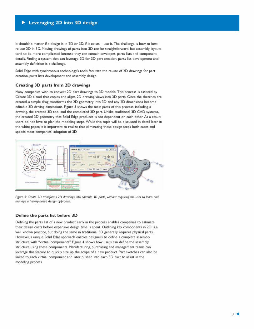
Many companies wish to convert 2D part drawings to 3D models. This process is assisted byCreate 3D, a tool that copies and aligns 2D drawing views into 3D parts. Once the sketches arecreated, a simple drag transforms the 2D geometry into 3D and any 2D dimensions becomeeditable 3D driving dimensions. Figure 3 shows the main parts of this process, including adrawing, the created 3D tool and the completed 3D part. Unlike traditional 3D CAD systems,the created 3D geometry that Solid Edge produces is not dependent on each other. As a result,users do not have to plan the modeling steps. While this topic will be discussed in detail later inthe white paper, it is important to realize that eliminating these design steps both eases andspeeds most companies’ adoption of 3D.
Figure 3: Create 3D transforms 2D drawings into editable 3D parts, without requiring the user to learn andmanage a history-based design approach.
Define the parts list before 3D
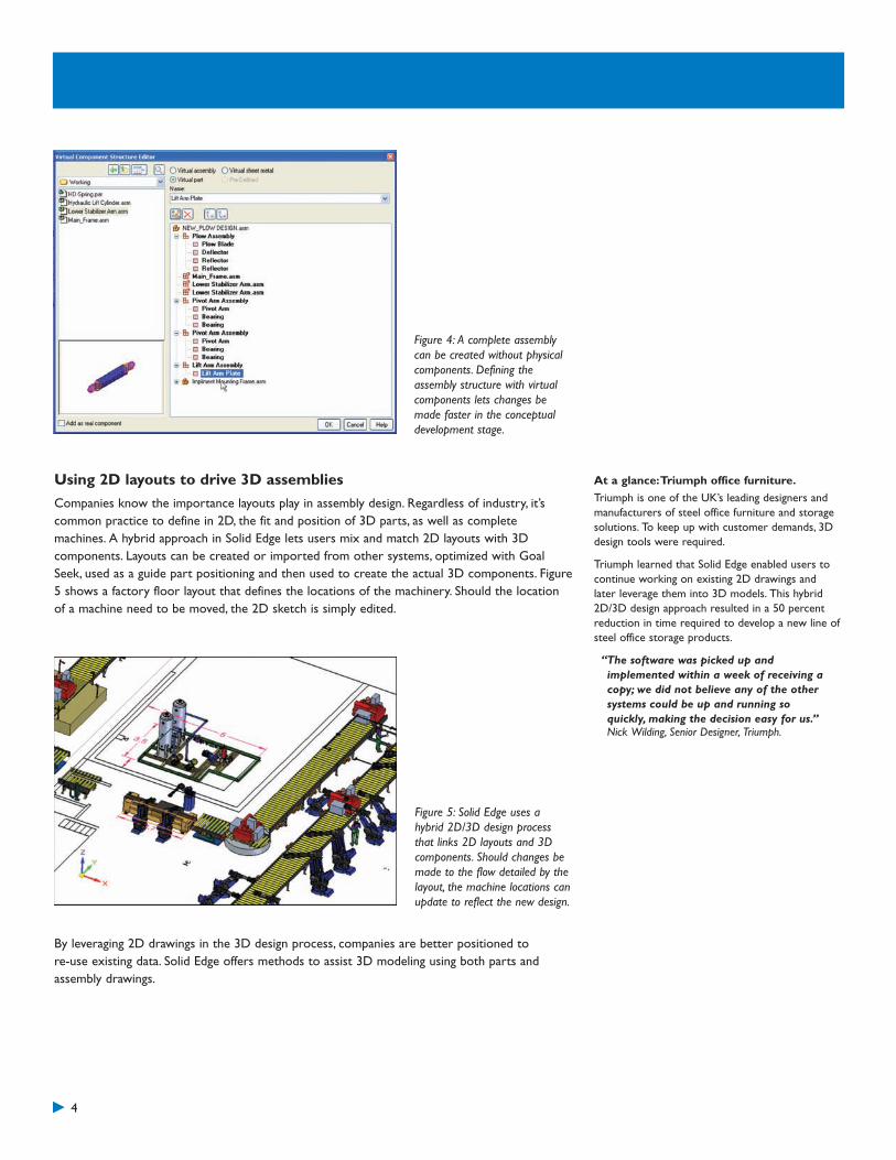
Defining the parts list of a new product early in the process enables companies to estimatetheir design costs before expensive design time is spent. Outlining key components in 2D is awell known practice, but doing the same in traditional 3D generally requires physical parts.However, a unique Solid Edge approach enables designers to define a complete assemblystructure with “virtual components”. Figure 4 shows how users can define the assemblystructure using these components. Manufacturing, purchasing and management teams canleverage this feature to quickly size up the scope of a new product. Part sketches can also belinked to each virtual component and later pushed into each 3D part to assist in themodeling process.
Leveraging 2D into 3D design
4
Figure 4: A complete assemblycan be created without physicalcomponents. Defining theassembly structure with virtualcomponents lets changes bemade faster in the conceptualdevelopment stage.
Using 2D layouts to drive 3D assemblies
Companies know the importance layouts play in assembly design. Regardless of industry, it’scommon practice to define in 2D, the fit and position of 3D parts, as well as completemachines. A hybrid approach in Solid Edge lets users mix and match 2D layouts with 3Dcomponents. Layouts can be created or imported from other systems, optimized with GoalSeek, used as a guide part positioning and then used to create the actual 3D components. Figure5 shows a factory floor layout that defines the locations of the machinery. Should the locationof a machine need to be moved, the 2D sketch is simply edited.
By leveraging 2D drawings in the 3D design process, companies are better positioned tore-use existing data. Solid Edge offers methods to assist 3D modeling using both parts andassembly drawings.
At a glance:Triumph office furniture.
Triumph is one of the UK’s leading designers andmanufacturers of steel office furniture and storagesolutions. To keep up with customer demands, 3Ddesign tools were required.
Triumph learned that Solid Edge enabled users tocontinue working on existing 2D drawings andlater leverage them into 3D models. This hybrid2D/3D design approach resulted in a 50 percentreduction in time required to develop a new line ofsteel office storage products.
“The software was picked up andimplemented within a week of receiving acopy; we did not believe any of the othersystems could be up and running soquickly, making the decision easy for us.”Nick Wilding, Senior Designer, Triumph.
Figure 5: Solid Edge uses ahybrid 2D/3D design processthat links 2D layouts and 3Dcomponents. Should changes bemade to the flow detailed by thelayout, the machine locations canupdate to reflect the new design.

5
Engineers using 2D are familiar with how to design and edit and while 2D systems may not beas powerful as 3D, at least the design principals are known. History-based systems utilizeconstraints to control what happens to the model during edits and requires careful planning or“programming” during creation. Users are concerned with the downtime spent learning acompletely different way of designing, editing and handling imported data.
Solid Edge with synchronous technology uses a new innovative approach that combines thespeed and flexibility of explicit modeling systems (which includes 2D), with the precise controlof parametric 3D CAD. Figure 6 shows how the best of both technologies has been broughtinto a single system while leaving the negative aspects out.
3D with the simplicity of 2D
Synchronizedsolve
Synchronoustechnology
Explicitmodeling
History-basedmodeling
Proceduralfeatures
Live RulesFeature-less
Little dimension-driven editing
Little designautomation
Pre-planningrequired
Inßexible whenchanges outside
designs are needed
Slow, fragileedits on many-featured parts
3D DrivingDimensions
More...
Technology
Des
irab
ility
Flexibleediting
Fast editswith many-featured
partsEasy-to-use,
directinteraction
Dimension-drivenHighly
automated
Feature-based
Figure 6: Solid Edge with synchronous technology combines the speed and flexibility of explicit modelingsystems (including 2D) with the precise control of feature-based parametric systems – all while omitting theundesirable side effects of each.
3D model creation
Because synchronous technology is history-free, Solid Edge’s 3D features can be createdwithout planning how they interact – much like 2D, where lines, arcs and circles are created inany order. Without specific modeling commands, sketches can be immediately dragged into 3Dshapes and geometric conditions such as concentric faces, tangent horizontal and vertical facesare maintained without having to define that behavior. Relationships and 3D driving dimensionscan be added at any point during design, and to virtually any part of the model. This approachlets users create parts quicker because less time is spent manipulating commands anddetermining the order in which to use them.

6
At a glance: Razor USA LLC.
Razor USA LLC rapidly grew from a company witha single product (the popular Razor kick scooter)to more than 30 human and electric-powered toys.
Staying innovative is tough and being able tonarrow down hundreds of ideas down to a few iscritical. Finding a system that would allow quickerdesign iterations but easy for its 2D users to adoptwere the key requirements. Solid Edge withsynchronous technology let Razor to just that.
“I just turned our last AutoCAD user looseon Solid Edge with synchronoustechnology. Since there are no complexhistory rules or modelling strategies tolearn, he picked up Solid Edge very easily.In just a few weeks, he’s already crankingout designs left and right. He’s justincredibly excited about finally joining the3D club!”Bob Hadley, Product Development ManagerRazor USA LLC
3D editing
Models created using synchronous technology support automated design changes, so amodification to one feature can affect another without regenerating unrelated geometry as withtraditional systems. Because features are independent of each other, more flexible changes canbe made with a fence stretch or by editing a 2D cross section placed at will. Figure 7 shows apart with edit results superimposed where the mounting hole, highlighted in blue, is moved andthe overall part changed to maintain concentric and tangent model conditions. A unique conceptcalled Live Rules keeps the model together as concentric, tangent and vertical or horizontalfaces are automatically maintained.
Figure 7: A unique concept insynchronous technology, calledLive Rules finds and maintainsgeometric conditions such astangent, coplanar and concentricconditions, without explicitlydefined constraints. This givestremendous edit flexibility inmaking unplanned changes –a similar approach in how 2Dis edited.
Handing imported 3D models
Most drawings can be used between different 2D systems because there is no design history toconvert. That’s not the cases with history-based 3D because the model steps aren’t portable,hence edit capabilities of imported or supplier data is sacrificed. Edit operations in Solid Edgewith synchronous technology are designed to work equally well on imported data. Edits can bemade with added 3D driving dimensions or by dragging faces or groups of faces recognized byfunction. During the change, strong geometric model conditions are kept with Live Rules. Thepart in figure 7 could be either a native design or imported from a supplier, but a change wouldyield the same results.

7
In most companies, 2D drawings are the primary deliverable. They are used to communicatecritical design details such as dimensions, tolerances and parts lists. In order to reducemisinterpretation by different departments, drawings must be accurate and understandable.While most 3D CAD systems can create 2D drawings from the 3D model, the main challengeis being able to create and manipulate 3D designs.
Because of the importance on accurate drawings, the capabilities offered by synchronoustechnology become more necessary to 2D users. Because of faster 3D model development,designers can begin to create drawings sooner in the design process. Similarly, drawing changescan happen faster because users don’t need to be system experts.
You can get there from here
Creating 2D drawings automatically requires a 3D model but the difficulty 2D users face ismodel development. Creating and extruding sketches is a simple process to learn, but in mostsystems a separate command is required for each operation. Interacting with multiplecommands and establishing how they work together can result in slow model development –and a delay in drawing creation.
Synchronous technology in Solid Edge incorporates a more direct way to create 3D modelswhere sketches and model faces are pushed and pulled into shape. Editable 3D dimensions canbe added to the completed model and are more useful when retrieved in drawings. Featuredimensions used in history-based systems often don’t capture the end result and aren’t helpfulon drawings. Synchronous technology enables companies to create drawings earlier in thedesign process.
Making drawing refinements
When it comes to drawings derived from 3Dmodels, drawing changes originate in 3D. Aswith most 3D CAD systems, once a change ismade, 2D drawing views update accordinglyand any applied dimensions reflect new sizes.The process is fairly automatic, but 2D usersfamiliar with moving lines and stretch editing,are wary about how to manipulate history-based models to achieve a specific result.
Edits in Solid Edge with synchronoustechnology aren’t bound to the limitations ofhistory, so flexible changes can be made moreintuitively. For example, figure 8 shows a 3Dcomponent during an edit, where the usersimply drew a fence and stretched geometryinto shape – a similar approach used in 2D. Aschanges only affect related geometry, there isless chance that undesirable effects will causeinaccurate drawings.
When creating 2D drawings, it’s important toconsider the time it takes to create and refine3D models. Having a system that offers theautomation and accuracy of 3D but leveragessome of the simplistic approaches used in 2Dcan expedite the overall drawing process.
Getting 2D from 3D
Figure 8: Edits in Solid Edge with synchronoustechnology are fast and flexible using fencestretching. Step 1: a part or assembly is opened,step 2: a 2D fence is drawn around a set of 3Dparts and geometry and step 3: the geometry isdragged to key points or with dimension precision.
At a glance: L.S. Starrett Company
The L.S. Starrett Company has a reputation formanufacturing high quality precision tools, gauges,measuring instruments and saw blades for industrial,professional and consumer markets worldwide.
Since Starrett heavily relies on 2D drawings, itneeded to keep the ability to use them during andafter its move to 3D.With Solid Edge, the companywas able to transition to 3D without disrupting its2D design process. The ability to maintain 2D andleverage into 3D, resulted in more productdocumentation in less time.
“We bring our old 2D files into Solid Edgeand use its tools to turn curves and lineson the drawings into 3D models with afew clicks.”Jim Woessner, design/drafting supervisorL. S. Starrett.

8
Conclusion
Moving from 2D to 3D is not a difficult proposition; everyday, companies are making thetransition. While the benefits of 3D are well known, the most effective pathway to 3D has notbeen as well documented. This white paper outlines some of the key areas where companiescan best leverage existing 2D drawings and describes how to utilize them in a 3D designprocess. While there are 3D design tools available, the underlying history-based technology canyield only marginal results. Leveraging 2D drawings and techniques offered by Solid Edge withsynchronous technology will help companies accelerate the move to 3D and maximize its fullpotential for thriving in the 2D to 3D to 2D world.
Further reading
Goal Seek: An automated approach to solving 2D free body diagrams
Hybrid 2D/3D Design: How to best leverage 2D into the 3D assembly design process
Diagramming in Solid Edge: Details a dedicated approach and library of parts
Plant equipment design and layout: How to design 3D plants from 2D layouts
Product Demonstrations: See Solid Edge with synchronous technology in action
L. S. Starrett Co: A use case in leveraging 2D into 3D
Triumph Office Furniture: A use case in for Hybrid 2D/3D design
Razor Scooter: A use case in adopting 3D faster
Sparkonix: A use case in 3D design for fast accurate 2D

Americas800 807 2200Fax 314 264 8922
www.siemens.com/plm
Asia-Pacific852 2230 3308Fax 852 2230 3210
Europe44 (0) 1202 243455Fax 44 (0) 1202 243465
About Siemens PLM Software
Siemens PLM Software, a business unit of the Siemens IndustryAutomation Division, is a leading global provider of productlifecycle management (PLM) software and services with nearlysix million licensed seats and 56,000 customers worldwide.Headquartered in Plano, Texas, Siemens PLM Software workscollaboratively with companies to deliver open solutions thathelp them turn more ideas into successful products. For moreinformation on Siemens PLM Software products and services,visit www.siemens.com/plm.
Siemens PLM Software
© 2009 Siemens Product Lifecycle ManagementSoftware Inc. All rights reserved. Siemens and theSiemens logo are registered trademarks of Siemens AG.Teamcenter, NX, Solid Edge, Tecnomatix, Parasolid,Femap, I-deas and Velocity Series are trademarksor registered trademarks of Siemens Product LifecycleManagement Software Inc. or its subsidiaries inthe United States and in other countries. All otherlogos, trademarks, registered trademarks or servicemarks used herein are the property of theirrespective holders.
XXXXX 10/09 B