Collaborative Multisite PLM Platform
10
651 Collaborative Multisite PLM Platform George Draghici 1 , Anca Draghici 1 [email protected], [email protected] 1 Politehnica University of Timisoara, 300006 Timisoara, Romania Abstract: The product development is a result of a collaborative design process in network. The national research network in the field of product and process integrated engineering (INPRO) main objective is the Product Lifecycle Management (PLM) concept and solution promotion through the Romanian industry. In this context, was built a collaborative multisite platform for product and its associated processes that join together the methodological approach, methods and tools for Product Lifecycle Management (PLM), Knowledge Management (KM) and Human Resources Management (HRU), examples of good practice. In the paper are presented: the product lifecycle model which is the base for the proposed collaborative product development methodology and the multisite PLM platform. The universities partners’ PLM platforms and the potential industrial partners have connected through Internet/ Intranet. Keywords: Product Lifecycle Management (PLM), multisite platform, collaborative product development, conceptual design. 1. Introduction Integrated product and processes development supposes to consider all the knowledge about the product lifecycle from the beginning of product design stage, by integrating the user requirements, with the quality, terms and costs constraints (Draghici, 1999), (Usher, Roy & Parsaei, 2005). Therefore, we can talk about the whole product lifecycle integration and management (Stark, 2005). In the same time, many product development projects require cooperation between research teams with different competence, which are geographical distributed. When such a project/product team is set up, all the require knowledge must be considered to solve a certain design problem in a collaborative environment. The product development process has changed dramatically in the last time because of the progresses in the information and communication technology field. Nowadays, the product development is a result of a collaborative design process in network (Shpitalni, Guttman, & Bossin, 2005). The partners’ collaboration and synergy in the National Research Network for Integrated Product and Process Engineering (INPRO) (Draghici & Draghici, 2007) was adapted to the actual requirements of product development. In this context, was built a collaborative multisite platform for product and its associated processes (Draghici, Savii & Draghici, 2007), (Draghici, Savii & Draghici, 2008), that join together the methodological approach, methods and tools for Product Lifecycle Management (PLM), Knowledge Management (KM) and Human Resources Management (HRU), examples of good practice.
-
Upload
independent -
Category
Documents
-
view
1 -
download
0
Transcript of Collaborative Multisite PLM Platform

651
Collaborative Multisite PLM Platform
George Draghici1, Anca Draghici1
[email protected], [email protected]
1 Politehnica University of Timisoara, 300006 Timisoara, Romania
Abstract: The product development is a result of a collaborative design process in network.
The national research network in the field of product and process integrated engineering
(INPRO) main objective is the Product Lifecycle Management (PLM) concept and solution
promotion through the Romanian industry. In this context, was built a collaborative multisite
platform for product and its associated processes that join together the methodological
approach, methods and tools for Product Lifecycle Management (PLM), Knowledge
Management (KM) and Human Resources Management (HRU), examples of good practice.
In the paper are presented: the product lifecycle model which is the base for the proposed
collaborative product development methodology and the multisite PLM platform. The
universities partners’ PLM platforms and the potential industrial partners have connected
through Internet/ Intranet.
Keywords: Product Lifecycle Management (PLM), multisite platform, collaborative product
development, conceptual design.
1. Introduction
Integrated product and processes development supposes to consider all the knowledge about the
product lifecycle from the beginning of product design stage, by integrating the user requirements,
with the quality, terms and costs constraints (Draghici, 1999), (Usher, Roy & Parsaei, 2005).
Therefore, we can talk about the whole product lifecycle integration and management (Stark,
2005).
In the same time, many product development projects require cooperation between research
teams with different competence, which are geographical distributed. When such a
project/product team is set up, all the require knowledge must be considered to solve a certain
design problem in a collaborative environment. The product development process has changed
dramatically in the last time because of the progresses in the information and communication
technology field. Nowadays, the product development is a result of a collaborative design process
in network (Shpitalni, Guttman, & Bossin, 2005).
The partners’ collaboration and synergy in the National Research Network for Integrated
Product and Process Engineering (INPRO) (Draghici & Draghici, 2007) was adapted to the actual
requirements of product development. In this context, was built a collaborative multisite platform
for product and its associated processes (Draghici, Savii & Draghici, 2007), (Draghici, Savii &
Draghici, 2008), that join together the methodological approach, methods and tools for Product
Lifecycle Management (PLM), Knowledge Management (KM) and Human Resources
Management (HRU), examples of good practice.
652
In the paper are briefly presented: the product lifecycle model which is the base for the
proposed collaborative product development methodology, the human resources competencies
database development, and the multisite PLM platform infrastructure.
2. Product Lifecycle Model
The collaborative product development model integrates knowledge from all the product lifecycle
activities. For the product lifecycle representation there can be used different methods and
modeling languages. Among them, there have been choose the IDEFØ (integrated Definition
Method) (www.idef.com/pdf/idef0.pdf) as our preliminary research approach. This allows
researchers to define the platform needs and also, its future structure.
IDEFØ is a method designed to model the decisions, actions, and activities of an
organization or system. IDEFØ was derived from a well-established graphical language, the
Structured Analysis and Design Technique (SADT).
The followed purpose is the deep analyze of each product lifecycle activity, under different
aspects: the role of each activity, sub activities deployed, the transform parameters, the supports
that allowed the development and control of an activity, the information exchange. In this context,
IDEFØ method best attend the declare purpose. Each activity can be representing under a modular
and graphical form, using arrows with a specific signification. One activity transforms input into
output data. The activity development need assistance tools and control tools that allowed its
development start or control.
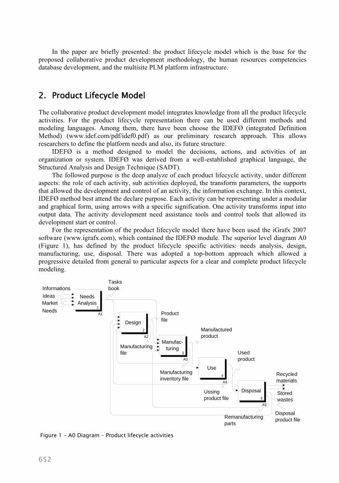
For the representation of the product lifecycle model there have been used the iGrafx 2007
software (www.igrafx.com), which contained the IDEFØ module. The superior level diagram A0
(Figure 1), has defined by the product lifecycle specific activities: needs analysis, design,
manufacturing, use, disposal. There was adopted a top-bottom approach which allowed a
progressive detailed from general to particular aspects for a clear and complete product lifecycle
modeling.
Needs
Analysis1
A1
Design
2
A2
Manufac-
turing3
A3
Use
4
A4
Manufacturing
file
Manufactured
product
Used
product
Ussing
product file
Recycled
materials
Remanufacturing
parts
Product
file
Manufacturing
inventory file
Informations
Ideas
Market
Needs
Stored
wastes
Disposal
product file
Tasks
book
Disposal
5
A5
Figure 1 - A0 Diagram – Product lifecycle activities

653
The superior level diagram, named A0 (Figure 1), has defined by the product life cycle
specific activities:
A1 Activity: Needs analysis. The objective is to identify and formulate the needs for product
development. The initiation of this activity is determinate by many factors as: a new market
perception, an idea and technical and/or commercial un-satisfaction user perception. These
correspond to some marketing function roles. The result of this activity is the product task book.
A2 Activity: Design. The activity’s inputs are the product task book and the feedback
information from manufacturing, use and disposal phases. Using design methods and the study of
possible alternatives there can be chosen the conceptual solution which followed the embodiment
design and detailed design phases; the process planning is then, defined. Finally, is defined the
product file and the manufacturing file that are needed for the following activities.
A3 Activity: Manufacturing, includes preparation and resources allocation for the
components manufacturing deployment and for product assembly and so, it becomes ready for
delivery. The information results from the manufacturing phase are included in the manufacturing
management file that can be use for product design improvement.
A4 Activity: Use. The manufactured product has delivered to the user and his/her
expectations have to be satisfied through the use phase. During the use phase, the product is liable
to maintainable operations. In the use process all the information are record in the using product
file and they had used for the product design improvement, too.
A5 Activity: Disposal. The used product is disposed, at the end of his life cycle. The first
action is the disassembly and the components and materials sort in remanufacturing parts that can
be inputs for other product assembly components; recycled materials that can be inputs for the
supply chain; stored wastes components that have to be destroyed and storage, resulting wastes.
All the output information included in the disposal product file can be use for the product re-
design improvement, too. Each activity module is the object of a progressive decomposition in
diagrams, which contain sub activities, till the elementary detailed level.
3. Human Resources Competencies in the INPRO Network
3.1. Product Life Cycle Ontology
In order to have a global view on the expertise of the INPRO national research network members,
ontology was developed to describe the domain of interest: product life cycle. This was the
second phase of the research approach for defining the input knowledge resources of the PLM
multi site platform.
The creation of the ontology describing the product life cycle started with the evaluation of
the network members’ expertise. This conceptual formalization of the domains in the product life
cycle will be used as a basis for applying intelligent search algorithms with the aim to select the
specific task team members (Shpitalni, Guttman, & Bossin, 2005). Six concept categories were
defined, which determined the first hierarchical level in the ontology: design, manufacturing,
usage/ maintenance, end of life cycle. Each category was further divided and a form was designed
and distributed to the network members. A snippet from the ontology, created using Protégé
(Protégé, 2007, http://protege.stanford.edu), for the design stage, is presented in Figure 2.

654
Figure 2 - Snippet from the product life cycle ontology
3.2. Building the knowledge/expertise map
Information about the network members expertise are processed following a bottom-to-top
scheme, starting from those of the persons and ending with that of the network. To be able to
automate the data processing, at least partially, for each field in the form which indicates the
presence of a competence, the value 1 was assigned, the rest being left with the value 0 (blank).
The first map shows the personal competencies and was created by summing the fields
towards the ontology root. A synthesis of the competencies can be done by computing the
percentage of the persons in the network that have competencies in each field.
Two significant values result were obtained: (1) the number of competency fields in the
domain of the product life cycle for each partner (department/laboratory), and (2) the number of
competency fields for each partner, grouped by products. One must note that a greater number of
competencies for a person does not mean that this has a greater global level of competency than
another person, with a lower number, but possibly with more impact and visibility at international
level (in a narrower field). Another map shows the competencies at the network partners level
(Table 1 part a and b).

655
Table 1a – Competencies at the network partners level – I Life cycle
Partner CO P1 P2 P3 P4 P5 P6 P7 P8 P9 INPRO
Person 12 9 19 15 12 14 7 6 1 5 100
I. Life cycle 399 569 811 491 614 639 443 312 45 112 4435
Design 269 385 569 233 393 362 247 146 14 65 2683
>Conceptual
design 96 113 141 67 134 114 101 49 5 17
837
>Detail design 143 216 353 106 221 181 77 33 9 39 1378
>Support 30 56 75 60 38 67 69 64 0 9 468
Manufacturing 86 155 189 229 185 240 182 133 30 43 1472
>Manufactu-
ring systems 9 11 8 4 18 27 5 6 1 8
97
>Manufactu-
ring processes 38 55 79 165 84 105 111 48 15 13
713
>Quality
control 5 17 49 34 12 9 44 30 10
210
>Operation
management 5 25 19 19 36 44 12 24 4 14
202
>Manufactu-
ring support 13 32 7 5 27 28 8 12 4
136
>Management
support 16 15 27 2 8 27 2 13 4
114
Utilization /
Service 27 24 32 17 28 24 10 16 4
182
>Monitoring 5 3 4 4 7 2 4 2 31
>Diagnosis 3 5 1 4 2 2 17
>e-service 1 4 2 3 2 12
Maintenance 2 4 6 8 4 4 2 30
>Support 16 12 24 4 6 16 10 4 92
End of life
cycle 17 5 21 12 8 13 4 17 1
98
>Disassembly 2 1 2 1 2 1 9
>Testing 1 1
>Recycling 2 3 1 1 1 1 9
>Refurbishing 1 2 1 1 1 6
>Disposal 1 1 2
>Support 16 1 18 7 6 11 12 71
The analysis of the map can yield information about the poor covered zones (empty spaces in
the tables) by certain partners or at the network level, i.e. indications about the domains in which
the network must work to gain competencies through the training procedures of human resources.

656
Table 1b – Competencies at the network partners level – II Products
Partner CO P1 P2 P3 P4 P5 P6 P7 P8 P9 INPRO
Person 12 9 19 15 12 14 7 6 1 5 100
II. Products 17 18 17 23 26 40 24 17 3 185
Manufacturing
systems 9 13 12 6 18 15 12 10 1
96
Sheet metal
process 1 1 2 2 3
9
Home
appliances 5 7 4
16
Medical
equipment 1 1
2
Automobiles 1 1 3 3 5 1 14
Tools and dies 4 3 2 5 5 3 3 3 2 30
Industrial 1 3 1 2 1 1 9
Microelectro-
mech. equip. 2 1
3
Optoelectroni-
cal equipment 1 1
2
Furniture 1 1 2
Cloths 2 2
3.3. Creating the database with the network’s human resources competencies
The data from the forms were extracted in a neutral format (CSV), and then used to create a usual
database (by importing data from CSV text files). For the Microsoft Access application, splitting
the data into three tables was necessary, because of the great number of fields (255+255+253).
The three tables were linked by relations using key fields. In order to find the person with certain
competencies, a usual Access query is launched (Figure 3) or using SQL.
Figure 3 - An Access query about competencies

657
An Internet based interrogation is in train to be finished, using MySQL. This creates the
possibility to query the (sole) competencies database by each partner, from his office or from
anywhere an Internet link exists.
4. The Architecture of the Multisite PLM Platform
Based on the preliminary researches concerning the product lifecycle representation and the
human resources competencies capitalization and explore, there have been developed the
collaborative multisite PLM platform. The main objective and motivation of this approach was to
build a collaborative environment for the product design process.
The collaborative product development (Figure 4) is based on the integration of the Product
Lifecycle Management (PLM), Enterprise Resource Planning (ERP), Supply Chain Management
(SCM) and Customer Relationship Management (CRM) solutions (CIMdata, 2002).
Figure 4 - PLM – ERP – SCM – CRM integration (CIMdata, 2002)
The INPRO universities partners’ PLM platform and the potential industrial partners have
been connected through Internet/Intranet and they built the multisite PLM platform of the
collaborative product development in network. Client-server architecture has been used inside the
network (Figure 5). It consists of a four servers cluster, for: Internet/Intranet (S1), databases (S2),
PLM and videoconference system.
A preliminary stage of the development process includes the definition and the configuration
of the INPRO research network’s web page (Figure 6). This is linked also, with the project
operational objectives and the partners’ integration in the research activities. The web page
consists of information regarding: the project objectives and activities, partners’ description (link
to their own web pages), conferences (scientific events), workshops and meetings that are
organized by the partners, research results (with public interest) and the link to the Intranet section
that was restricted to the network members only.
Beside the INPRO web page development there have been settled an entire communication
system dedicated to the common research work in the network, but also, to the access at some
research resources of the European Network of Excellence, Virtual Research Laboratory for a
Knowledge Community in Production (www.vrl-kcip.org), in the European Research Area (see
Figure 6). Also, with the support of the videoconference system the collaboration was possible.

658
Figure 5 - The collaborative product development network infrastructure
Figure 6 - Detail of the INPRO research network web page
The INPRO partners’ PLM platforms include a large diversity of software. To illustrate the
large variety of information technology applications used in such context, the list of CAD/CAM
and PDM systems of each partner involved in the PLM multisite platform is shown in table 2.
www.eng.upt.ro
UPT internal network
S1 S2 PLM
INPRO cluster of servers
Videoconference
Industrial partners University
partners
Firewall

659
The most important problem that has to be solved between partners was the compatibility of
the design format/representation because of the existing of the different design software. Finally,
the Teamcenter Community software solution was the option for harmonizing the design parts
delivered by the partners and that have conduct to a final product.
Table 2 – CAD/CAM and PDM systems of each partner involved in the multisite PLM platform
Partners
Systems CO P1 P2 P3 P4 P5 P6 P7 P8 P9 INPRO
CAD/CAM 8 7 5 8 6 6 6 5 2 6 59
CATIA 1 1 1 1 1 1 1 1 1 9
ProEngineer 1 1 1 3
SolidWorks 1 1 1 1 1 5
Inventor 1 1 1 1 4
AutoCAD 1 1 1 1 1 1 1 1 8
SolidEdge 1 1 1 1 1 1 6
NX 1 1 1 1 4
Tecnomatix 1 1 1 3
DELMIA 1 1 1 3
Other 3 2 2 2 2 1 1 1 14
PDM 1 1 1 1 1 1 1 7
Teamcenter 1 1 1 1 1 1 1 7
5. Conclusions
In the framework of the National Research Network for Integrated Product and Process
Engineering (INPRO) it was built a collaborative multisite PLM platform for the product
development and its associated processes. The proposed product collaborative development model
integrates knowledge from the entire product lifecycle. There have been discussed the product
conceptual design phase and there have been presented.
In the paper has presented the main aspects that reflect the achieved stage of the project of
building the collaborative product development network: the product life cycle model, the
network members’ expertise, and the PLM multisite platform infrastructure. The product life
cycle model is the base of the collaborative design methodology that has adopted for the PLM
multi-site platform. The model of collaborative product development integrated the whole
lifecycle. For identifying the persons with the required competencies for a specific project, an
Access or an Internet usually query has launched, using MySQL. The universities partners’ PLM
platforms and the potential industrial partners have connected through Internet/ Intranet,
constituting the PLM multisite platform of the collaborative product development network.
The presented research results have been gained in the framework of the Romanian CEEX
Program, National Research Network for Integrated Product and Process Engineering (INPRO)
Project (contract no. 243/2006-2008) and the Virtual Research Laboratory for a Knowledge
Community in Production (VRL-KCiP) a Network of Excellence project (contract no. FP6-
507487).
660
References
Draghici, G. (1999). Ingineria integrata a produselor. Eurobit Publishing, Timisoara.
Draghici, A. & Draghici, G. (2007). Romanian Research Network for Integrated Product and
Process Engineering. The Future of Product Development, Proceedings of the 17th
CIRP
Design Conference, Springer, 341-350.
Draghici, G., Savii, G. & Draghici, A. (2007). Platform for Collaborative Product and Processes
Development. Annals of DAAAM for 2007 & Proceedings of the 18th International DAAAM
Symposium. Published by DAAAM International, Vienna, Austria, 253-254.
Draghici, G., Savii G. & Draghici A. (2008). Building a Collaborative Product Development
Network. Design Synthesis, the 18th
CIRP Design Conference, Enschede, April 7-9, E-book,
2.05 Draghici.pdf.
Shpitalni, M., Guttman, G. & Bossin, D. (2005). Forming Task-Oriented Groups in Networks
based on Knowledge Mapping. The 15th
International CIRP Design Seminar, Shanghai,
China, 22-26 May 2005.
Stark, J. (2005). Product Lifecycle Management: Paradigm for 21st century Product Realization.
Springer-Verlag, London.
Usher, J. M., Roy U. & Parsaei, H. (2005). Integrated Product and Process Development:
Methods, Tools, and Technologies. John Wiley & Sons, Inc., New York, USA.
*** Integration Definition for Function Modeling (IDEF0), Category of Standard: Software
Standard, Modelling Techniques. http://www.idef.com/pdf/idef0.pdf.
*** iGrafx, Enabling Process Excellence. www.igrafx.com
***CIMdata (2002). Product Lifecycle Management. Empowering the Future of Business.
CIMdata report, http://www.cimdata.com/PLM/plm.htm
*** Protégé (2007). The Protégé Ontology Editor for Knowledge Acquisition System
http://protege.stanford.edu.