The FCM Designer Tool
17
M. Glykas (Ed.): Fuzzy Cognitive Maps, STUDFUZZ 247, pp. 71–87, 2010. springerlink.com © Springer-Verlag Berlin Heidelberg 2010 The FCM Designer Tool Aguilar Jose and José Contreras 1 Abstract. In this work we present a tool for the development of Fuzzy Cognitive Map (FCM). In our proposed tool, the FCM is defined by concepts and relation- ships that can change during the execution time. Using the tool, we can design a FCM, follow the evolution of a given FCM, change FCM defined previously, etc. Our tool allows to use the classical casual relationship defined in [2, 4], or to de- fine the casual relationships according to the problem modeled, which can be stat- ics or dynamics, fuzzy or not. In this work, we present the data structures, the interfaces, and the classes that compose the tool. Additionally, we give some ex- amples of utilization of our tool in problems where we need define them specific casual relationships. 1 Introduction Fuzzy Cognitive Maps (FCM) have been present previously in different works [1, 2, 3, 4, 5]. They are a technique to model system based on concepts that describe the main aspects of the modeled system, and causal representations between the concepts. FCM use the theory of fuzzy logic to describe their structure and to infer answers of the map from input data. These maps have been used in different do- main for different proposes [6, 8, 9, 11, 12, 13, 14, 15, 16]. An interesting domain of study about FCM is in the area of methodologies and tools to develop them. This area is very important because in the next years it could expand the utilization of the FCM in different domains. The definition of methodologies to guide the development of FCM in specific domains is necessary because this is a complex task and depends on the characteristics of the problem modeled. The tools help and facilitate the design and the execution of the FCM. Aguilar Jose CEMISID, Departamento de Computación, Facultad de Ingeniería, Universidad de Los Andes, Núcleo la Hechicera, Mérida 5101-Venezuela e-mail: [email protected] José Contreras Distrito Tecnológico, Petróleos de Venezuela (PDSVA), Hosteria El Vallecito, Mérida 5101, Venezuela
-
Upload
independent -
Category
Documents
-
view
0 -
download
0
Transcript of The FCM Designer Tool
M. Glykas (Ed.): Fuzzy Cognitive Maps, STUDFUZZ 247, pp. 71–87, 2010. springerlink.com © Springer-Verlag Berlin Heidelberg 2010
The FCM Designer Tool
Aguilar Jose and José Contreras
1
Abstract. In this work we present a tool for the development of Fuzzy Cognitive Map (FCM). In our proposed tool, the FCM is defined by concepts and relation-ships that can change during the execution time. Using the tool, we can design a FCM, follow the evolution of a given FCM, change FCM defined previously, etc. Our tool allows to use the classical casual relationship defined in [2, 4], or to de-fine the casual relationships according to the problem modeled, which can be stat-ics or dynamics, fuzzy or not. In this work, we present the data structures, the interfaces, and the classes that compose the tool. Additionally, we give some ex-amples of utilization of our tool in problems where we need define them specific casual relationships.
1 Introduction
Fuzzy Cognitive Maps (FCM) have been present previously in different works [1, 2, 3, 4, 5]. They are a technique to model system based on concepts that describe the main aspects of the modeled system, and causal representations between the concepts. FCM use the theory of fuzzy logic to describe their structure and to infer answers of the map from input data. These maps have been used in different do-main for different proposes [6, 8, 9, 11, 12, 13, 14, 15, 16].
An interesting domain of study about FCM is in the area of methodologies and tools to develop them. This area is very important because in the next years it could expand the utilization of the FCM in different domains. The definition of methodologies to guide the development of FCM in specific domains is necessary because this is a complex task and depends on the characteristics of the problem modeled. The tools help and facilitate the design and the execution of the FCM. 1Aguilar Jose CEMISID, Departamento de Computación, Facultad de Ingeniería, Universidad de Los Andes, Núcleo la Hechicera, Mérida 5101-Venezuela e-mail: [email protected]
José Contreras Distrito Tecnológico, Petróleos de Venezuela (PDSVA), Hosteria El Vallecito, Mérida 5101, Venezuela

72 A. Jose and J. Contreras
Recently, different tools have been proposed to model FCM. Some of them are: the FCModeler tool displays the known using interactive graph visualization [19]. The system also models pathway interactions and the effects of assumptions using a FCM-based modelling tool. In [20] has been proposed a tool to study the casual relationships map in multiagent systems, this tool is called Multiagent-Causal Maps. Other work has been proposed by Amit Roy [21], specifically, it developed a FCM tool based on Python. In [22] has been proposed a FCM applet to be used from programs.
In this work we present the FCM Designer Tool. This is a tool in Spanish, which allows the design of the structure of the maps (the definition of the concepts and the relationships between them). In this tool, the causal relationships between concepts can be the classical defined in [2, 4], or we can establish specific casual relationships according to the problem modeled. These casual relationships can be static or dynamic. In the case of dynamic casual relationships, they can be based on logic rules, mathematical equations, fuzzy logic, among others. Additionally, the inference patterns from a given input to a map can be followed. Furthermore, using our tool we can stop the evolution of a map during its runtime, of such form to introduce new information to the map, continue a previous execution, etc. The FCM Designer Tool is a versatile tool that allows to design, and later to execute, the FCM. This work is organized as follows. In section 2 is presented the FCM Designer Tool. Section 3 presents some examples of utilization of our tool, where we need to define specific dynamic casual relationships.
2 The FCM Designer Tool
In this section we present the data structure, the interface and the organization of the tool code (classes diagram, etc.).
2.1 The Data Structure
For the representation of the map we have defined a class called Map. The main attributes of this class are: a set of concepts and a set of relationships (see figures 1 and 9). We can see in figure 1 that each relationship contains a reference to its antecedent and consequent concepts, this is carried out in order to avoid the utili-zation of an adjacency matrix, since the execution time for the adjacency matrices have a complexity equal to O(nxn), where n is the number of concepts. In our data structure, the runtime is O(m), where m is the number of relationships; in this way, our tool has a runtime of linear order instead of quadratic order.
2.2 Tool Interface
The application is divided in 4 parts:
• A work area, where we design the Map • A thread of execution of the Maps

The FCM Designer Tool 73
Fig. 1 Data Structure of the Map class
• A Menu Bar: to access to the general options of the tool • A Control Panel: to access to the options of design, visualization and execution
of the map.
2.2.1 The Work Area
For the visualization of the map (see figure 2), the concepts are represented by circles accompanied by their name. Each concept is defined by:
• An initial value • A name • A values set that represents the domain of values of the concept. • A description of the concept
Each relationship is represented on the work area by an arrow that connects its antecedent concepts with its consequent concepts. Each relationship is defined by:
• A value or weight. When we use static casual relationships, this value does not change during the map execution. When we use dynamic casual relationships, it is the relationship weight defined by the experts. This value can be positive (the value of the Antecedent concept affects directly the Consequent concept) or negative (the value of the Antecedent concept affects inversely the Conse-quent concept).
• A reference to its Antecedent concept • A reference to its Consequent concept
In order to modify the parameters of the nodes or of the relationships, we can use the mouse to generate different actions (see figure 3). These windows are

74 A. Jose and J. Contreras
Fig. 2 Example of the work area
Fig. 3 Windows of the options to modify concept and relationship characteristics
created when the user pushes the right button of the mouse, when it is on a con-cept or on a relationship. We can see in figure 3 that for each concept is possible to modify its name, its initial value, the position of the label that contains the name, and also the description of the concept. In the case of the relationships, we can modify its value, the position of the label that identifies the relationship, and also the description of the casual relationship.

The FCM Designer Tool 75
2.2.2 Thread of Execution
For the execution of the map we use a thread of execution, called RunFCM, which is in charge to carry out the different iterations of the map for a given input, until its convergence. By default, the condition to stop the execution of a map is given by a maximum number of iterations equal to 10, but the user can change this value. Also there is the option to stop the execution of the map when it is stabilized. These options are shown ahead.
Additionally, using the tool we can define specific casual relationships, accord-ing to the characteristics of the problem that we like to model. That is interesting when we like to define dynamic relationships. In the tool, they can have different forms: logic rules, mathematical equations, fuzzy rules, etc. In the tool, the type of dynamic relationship is specified in the class Rules, which allows the definition of each relationship using Java source code. The definition of the dynamic casual relationships must be codified in this class, which is compiled by the tool before the execution of the map.
2.2.3 Menu Bar
The general options of the system are: to establish like stopped condition a maxi-mum number of iterations to be executed, to establish like stopped condition that the map stabilizes, to select the type of visualization and normalization used on the map, to save or to load a map, or its execution. These options are accessed through a menu bar (see figure 4).
Fig. 4 General Menu of the tool
We can see in figure 4 that the “Archivo” menu offers the options: “Abrir” (this option will load a map from a specified file and will draw it in the work area); “Guardar” (this option allows saving the current map in some file (its concepts and relationships, with their characteristics)); “Guardar Ejecución” (this option allows keeping in a file the different iterations of the execution of a map, in order to save these data for their later analysis); “Nuevo” (this option cleans the work area and creates a new map to begin to work); and finally, “Salir” (this option closes the current window).

76 A. Jose and J. Contreras
The “Vista” menu offers two options for the visualization of the concepts in the work area. The default option is “Fixed”, which indicates that all the concepts were drawn in the work area with a size of 8 pixels. The option “Proporcional” would draw the nodes of proportional form to its value, with radios that go from 5 pixels for concepts of value 0 (zero), to 25 pixels for concepts of value 1 (one). The “ejecución” menu offers different types of normalization (possible output values of the concepts) during the execution of the map; they can be:
• For saturations:
( )⎪⎩
⎪⎨
⎧
>≤≤
<=
1x, 1
1x0, x
0x, 0
xS
• In the case nonlinear:
( ) ( )5.0x·9e1
1xS −−+
=
• For bivalent states:
( )⎩⎨⎧
≥<
=5.0x,1
5.0x,0xS
• For trivalent states:
( )⎪⎩
⎪⎨
⎧
>≤<
≤=
3/2x, 1
3/2x3/1, 5.0
3/1x, 0
xS
Where, x is the current value of the concept. The tool also allows adding a delay among iterations of the map, during its exe-
cution, with the option “Asignar Retardo”. This delay is in milliseconds, and has a value by default of 0. This option allows visualizing the iterations of the map dur-ing its execution, in a way that the user has a time interval between iterations to analyze the map. With the option “Asignar Máximo de Iteraciones”, the tool allows to modify the maximum number of iterations allowed before stopping the execu-tion of the map. The windows to modify these options are shown in the figure 5.
Fig. 5 Windows for the options of maximum number of iterations and delay
The FCM Designer Tool 77
Another form to stop the execution of a map is using the option “Parar al Esta-bilizar”. In this case, when the map in the current iteration has the same vector of states that in several of the more recent iterations, the tool stops the execution of the map.
2.2.4 Control Panel
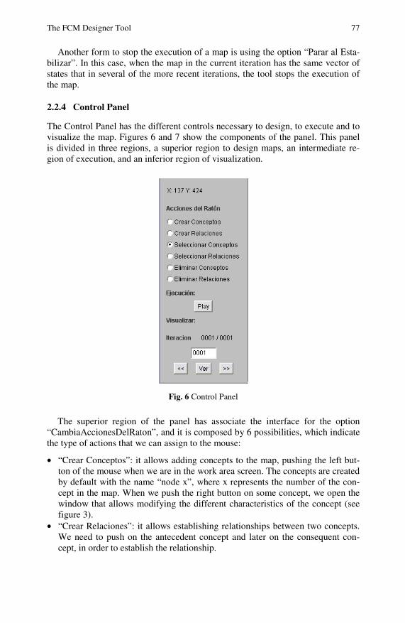
The Control Panel has the different controls necessary to design, to execute and to visualize the map. Figures 6 and 7 show the components of the panel. This panel is divided in three regions, a superior region to design maps, an intermediate re-gion of execution, and an inferior region of visualization.
Fig. 6 Control Panel
The superior region of the panel has associate the interface for the option “CambiaAccionesDelRaton”, and it is composed by 6 possibilities, which indicate the type of actions that we can assign to the mouse:
• “Crear Conceptos”: it allows adding concepts to the map, pushing the left but-ton of the mouse when we are in the work area screen. The concepts are created by default with the name “node x”, where x represents the number of the con-cept in the map. When we push the right button on some concept, we open the window that allows modifying the different characteristics of the concept (see figure 3).
• “Crear Relaciones”: it allows establishing relationships between two concepts. We need to push on the antecedent concept and later on the consequent con-cept, in order to establish the relationship.

78 A. Jose and J. Contreras
• “Seleccionar Conceptos”: with this option activated we can move a concept in the work area, dragging it with the mouse. Also, we can modify the values of the concept using the right button that opens the windows of the figure 3.
• “Seleccionar Relaciones”: this option allows changing the value of the relation-ship and its position, when we push on it with the mouse. For that, it opens the window to modify the characteristics of the relationships (see figure 3).
• “Eliminar Conceptos”: it allows activating this action on the mouse, so that, when it is pressed on some concept it eliminates the concept, with all the rela-tionships associated to this concept.
• “Eliminar Relaciones”: it allows deleting a relationship pushing on the label of the relationship.
The intermediate region of the panel, which is called “ejecución”, has associated the option “Play”. When we press this button, the tool executes the thread of exe-cution called RunFCM (it executes the FCM that is in the work area, for a given input). This thread uses static casual relationships by default (see figure 3), but if the Rules object is not empty, it uses the casual relationships defined in the code of this object. When the map is in execution state, the button is inactive, and the label of the option is changed to “Wait”, which indicate that the user cannot do nothing while the map is in this state.
The Inferior region of the Panel has associated the interface to manage the visualization of the map. In this region is the label: “Iteracion: x/y”, which indi-cates that we are visualizing the iteration x of y possible. In order to visualize a given iteration in the map, we can use the labels: “<<” or “>>” (see figure 6), which allow to show the previous or the following iteration. Another form to visu-alize a given iteration of the map is to write the number of the iteration and then to press the button “ver”, which will show this iteration.
2.3 Main Windows of the Tool
The main window contains all the elements of the tool. The window is divided in three parts, in the superior part is observed the menu bar, in the left part the con-trols, and the central part the work area. This structure is typical of many computer systems. All the elements that compose the main window belong to the MapWin-dows class, and can be visualized in figure 7: the menu bar, the work area, the Control Panel and the thread of execution of the map. In figure 7 we can see the complete interface of the user with the tool.
2.4 Source Code
We have placed the different classes in different packages according to the roll carried out by them (see figure 8).
We are three main packages, which are the Map package that contains all the objects that model a map, the Algorithms package that contains all the classes used for the execution of the maps, and the Interface package that contains all the classes used for the creation of the windows for the interaction with the user. The

The FCM Designer Tool 79
Fig. 7 Main window of the tool
Fig. 8 Organization of the classes in packages
secondary windows used to change the different options of the tool were placed in a sub-package of the interface package, called Options.
Now, we are going to describe two classes, for the rest see [10]. They are the classes used to build the maps in the work area (see figures 2 and 9).

80 A. Jose and J. Contreras
• MapCanvas: it defines a screen with white background, where we design the map. When this objet is instanced, it is created a ScrolledPanel with the dimen-sions of the work area (1024x1024 pixels). Additionally, it calls the Movimien-toRatonEnMapCanvas and AccionesRatonEnMapCanvas classes, which are classes used to define the different actions of the mouse on the work area. These actions can be: to create, to modify, to eliminate or to move concepts or relationships, in the work area.
• Map: it is the class that models the map in the tool. It calls the relation and concept classes, which are the classes that describe the characteristics of the concepts and relationships that compose the map.
In a work area we can only build a map in a given moment. With these classes, our tool defines the screen of the figure 2.
Fig. 9 UML Diagram for the MapCanvas and Map classes
Remember that we have said previously that our tool has an execution thread called RunFCM, which executes the map. It is defined in a class with the same name. It is in charge of carry out the different iterations of the map, given initial values to the concepts of the map. The source code of the thread is:

The FCM Designer Tool 81
private void runStatic(){ int c=1; do{ java.util.Iterator <Map.Relation> itE = this.mapCanvas.getMap().getRelationList().iterator(); while ( itE.hasNext() ){ Map.Relation ref = itE.next(); ref.getFinalConcept().valorAuxiliar += ref.getInitialConcept().getLastValue()*ref.getValue(); } java.util.Iterator <Map.Concept> itN = this.mapCanvas.getMap().getConceptList().iterator(); while ( itN.hasNext() ){ Map.Concept ref = itN.next(); ref.addLastValue( this.normalization( ref.valorAuxiliar ) ); ref.setCurrentValue( ref.getLastValue() ); ref.valorAuxiliar=0.0f; } this.mapCanvas.update( this.mapCanvas.getGraphics() ); try{ this.hilo.sleep(this.retardo); }catch ( java.lang.InterruptedException e ){ System.out.println ( e ); } this.mapCanvas.getMap().setCurrentIteration( c++ ); this.etiqueta.setText( this.mapCanvas.getMap().getIterationLabel() ); }while ( this.Continue( c ) ); }
3 Example of Utilization
In this section we give some examples of utilization of our tool. In the first case, to build FCM where the casual relationships are mathematical equations; and in the second case, where the casual relationships are rules.
3.1 Casual Relationships Like Dynamic Equations In the first example, we use the FCM proposed in [7] to model a system which con-sists of a water tank with a valve of input and a valve of output (see figure 10).
Fig. 10 Scheme of the tank level system

82 A. Jose and J. Contreras
The water enters to the tank from above and leaves the same one by an orifice in the base. The rate of water input is proportional to voltage V applied to a pump that sends water to the tank, the rate of exit of the liquid is proportional to the root square of the level of the water in the tank. The equation for this system is given by:
H·aV·bdt
dHA
dt
dVol −==
Where Vol is the volume of water in the tank, A is the cross-sectional area of the tank, b is the constant of the input stream, and a is the constant of the exit flow. The equation describes the height of water H, like a function of the time.
For the design of the FCM, three concepts were used in [7]: the constant of in-put stream, called b/A, the constant of flow of exit, called a/A, and the level of the liquid in the tank, called H. The dynamic relationships are defined of the follow-ing form [7]:
• The relationship between the constant of input stream and the level is given by the value of the applied voltage to pump V.
• The relationship between the constant of the exit flow and the level is given by the squared root of the value of the concept that represents the level. The resulting map designed using our tool is shown in figure 11.
Fig. 11 FCM to model the dynamic system of the level of the liquid in a tank
We can see in figure 11 that exist relationships that feedback each concept, that is due to that these concepts have a memory property, for example, the values of the concepts b/A and a/A remain constant during all the execution. The casual relationship in this case has the following source code (this is the code of the Rule class in our tool):
static public float computeRelationValue ( Map.Relation relation ){ if ( relation.getInitialConcept().getName().equals("b/A") && relation.getFinalConcept().getName().equals("H") ) relation.setValor ( relation.getDinamicImput() );

The FCM Designer Tool 83
else if ( relation.getInitialConcept().getName().equals("a/A") && relation.getFinalConcept().getName().equals("H") ) relation.setValor( -1.0f * (float)Math.sqrt( relation.getFinalConcept().getCurrentValue() ) ); else relation.setValor ( 1.0f ); return relation.getValue(); }
We can see in the code that the first “If“ determines if the relationship is between the concept b/A and H, the value of this relationship is given by the auxiliary vari-able DynamicImput, which contains the value of voltage V. The second “If” de-termines if the relationship is between the concepts a/A and H, if it is thus, the value of the relationship is calculated according to the squared root of the present value of concept H, the rest of the relationships have a value of 1.
3.2 Casual Relationships Like Rules
In the second example, we are going to use a FCM that have been defined in [17] to describe the emergent and self-organizing properties in a given multiagent sys-tem. In this map, a concept can have the following values: High (between 2/3 and 1) when it works correctly; Medium (between 1/3 and 2/3) when its functioning must be validated; and Low (between 0 and 1/3) when it does not work or work erroneously. Additionally, they have used, to describe the type of casual relation-ships, the set of rules proposed in [7]. Some of the rules defined in [7] are:
• If the preceding concept is High and the consequent one is also High then the relationship is Complete+(1.0).
• If the preceding concept is High and the consequent one is Low then the rela-tionship is Low+ (0.25).
• If the preceding concept is Low and the consequent one is Medium then the relationship is Medium- (-0.5).
• If the preceding concept is Low and the consequent one is Low then the rela-tionship is Complete- (-1.0).
This set of rules was codified in the Rules class in our tool. For this example, the source code of the Rules class is:
public class Rules { static private boolean isHigh ( float v ){ return ( v > 2.0f / 3.0f); } static private boolean isLow ( float v ){ return ( v <= 1.0f / 3.0f); } static private boolean isMedium ( float v ){ return ( v > 1.0f/3.0f && v <= 2.0f/3.0f ); } static public float computeRelationValue ( Map.Relation relation ){ float vInicial = relation.getInitialConcept().getCurrentValue(); float vFinal = relation.getFinalConcept().getCurrentValue(); if ( isHigh ( vInicial ) && isHigh( vFinal ) ) relation.setValor( 1.0f ); else if ( isHigh ( vInicial ) && isMedium ( vFinal ) ) relation.setValor( 0.75f );

84 A. Jose and J. Contreras
else if ( isHigh ( vInicial ) && isLow( vFinal ) ) relation.setValor( 0.25f ); else if ( isMedium ( vInicial )&& isHigh( vFinal ) ) relation.setValor( 0.75f ); else if ( isMedium ( vInicial ) && isMedium ( vFinal ) ) relation.setValor( -0.5f ); else if ( isMedium ( vInicial ) && isLow( vFinal ) ) relation.setValor( -1.0f ); else if ( isLow( vInicial ) && isHigh( vFinal ) ) relation.setValor( -0.75f ); else if ( isLow( vInicial ) && isMedium ( vFinal ) ) relation.setValor( -0.5f ); else if ( isLow( vInicial ) && isLow( vFinal ) ) relation.setValor( -1.0f ); relation.setValor ( relation.getValue() * relation.getDinamicImput() ); return relation.getValue(); }}
In this code, the concepts are labeled according to their values, using the functions isHigh, isMedium and isLow. The value of the antecedent concept is labeled as vInicial, and the value of the consequent concept is labeled like vFinal. Once the values of the concepts are obtained, we can calculate the value of the relationship according to the rules specified previously. Once obtained the value of the rela-tionship, it is multiplied by the DynamicImput variable (it defines the weight of the relationship established by the experts in [17]).
The specific FCM proposed in [17], designed with our tool, is:
Fig. 12 The FCM proposed in [17], designed with our tool
The FCM Designer Tool 85
The meanings of some of the concepts of this FCM are (for the rest, see [17]):
• Self-Organization: It measures the degree of adaptability in a multiagent sys-tem. The self-organization is an adaptive and dynamic process where systems acquire and maintain their own structure without outside control.
• Emergence: It measures the degree of system’s evolution through the possibil-ity of the appearance of emerging properties. Some of the things that could emerge are temporary and space patterns such as: new collective policies and norms, cooperation between agents, among others.
• Diversity It measures the homogeneity or heterogeneity of the society of agents. It is measured by the number of agents of different types defined within the system
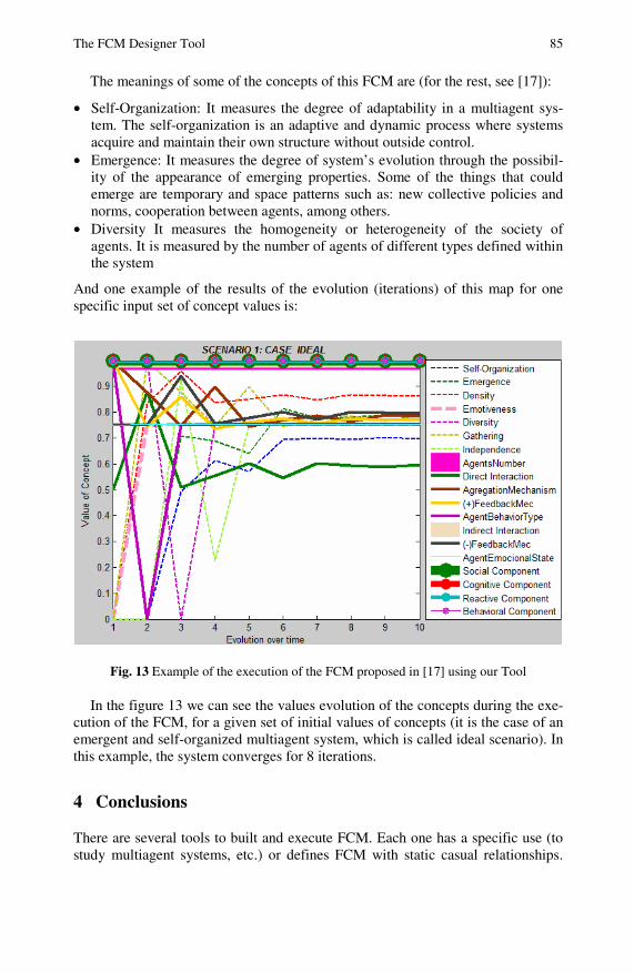
And one example of the results of the evolution (iterations) of this map for one specific input set of concept values is:
Fig. 13 Example of the execution of the FCM proposed in [17] using our Tool
In the figure 13 we can see the values evolution of the concepts during the exe-cution of the FCM, for a given set of initial values of concepts (it is the case of an emergent and self-organized multiagent system, which is called ideal scenario). In this example, the system converges for 8 iterations.
4 Conclusions
There are several tools to built and execute FCM. Each one has a specific use (to study multiagent systems, etc.) or defines FCM with static casual relationships.

86 A. Jose and J. Contreras
The tool proposed in this work allows the definition of different types of dynamic relationship. They are defined in a class that must be programmed by the designer on the class Rules.
The tool proposed in this work requires an expert knowledge about the problem to study in order to determine the type of dynamic relationships among the con-cepts, and knowledge about the tool and the language Java to program the specific relationships of the problem modeled. Future versions of the tools will include a library of dynamic casual relationships, a library of learning methods [6, 13, 14]. Also, a methodology based on this tool will be proposed for specific problems in control, economy, etc. [6, 18].
References
[1] Axelrod, R.: The Structure of Decision: Cognitive Maps of Political Elites. Princeton University Press, Princeton (1976)
[2] Kosko, B.: Fuzzy Cognitive Maps. International Journal of Man-Machine Studies 24, 65–75 (1986)
[3] Eden, C.: On the Nature of Cognitive Maps. Journal of Management Studies 29, 261–265 (1992)
[4] Kosko, B.: Fuzzy Engineering. Prentice-Hall, New Jersey (1999) [5] Aguilar, J.: A Dynamic Fuzzy-Cognitive-Map Approach Based on Random Neural
Networks. International Journal of Computational Cognition 1, 91–107 (2003) [6] Aguilar, J.: A Survey about Fuzzy Cognitive Maps Papers. International Journal of
Computational Cognition 3, 27–33 (2005) (invited paper) [7] Aguilar, J.: Different Dynamic Causal Relationship Approaches for Fuzzy Cognitive
Maps. Technical Report N 10-2009, CEMISID, Universidad de los Andes (2009) (submitted to publication)
[8] Khan, M., Quaddus, M.: Group Decision Support using Fuzzy Cognitive Maps for Causal Reasoning. Group Decision and Negotiation Journal 13, 463–480 (2004)
[9] Sharif, A., Irani, Z.: Exploring Fuzzy Cognitive Mapping for IS Evaluation. European Journal of Operational Research 173, 1175–1187 (2006)
[10] Contreras, J., Aguilar, J.: La Herramienta FCM Designer. Technical Report N 25-2008, CEMISID, Universidad de los Andes
[11] Papageorgiou, E., Stylios, C., Groumpos, P.: An integrated two-level hierarchical de-cision making system based on fuzzy cognitive maps. IEEE Trans. Biomed. Eng. 50, 1326–1339 (2003)
[12] Papageorgiou, E., Parsopoulos, K., Groumpos, P., Vrahatis, M.: Fuzzy Cognitive Maps Learning through Swarm Intelligence. In: Rutkowski, L., Siekmann, J.H., Ta-deusiewicz, R., Zadeh, L.A. (eds.) ICAISC 2004. LNCS (LNAI), vol. 3070, pp. 344–349. Springer, Heidelberg (2004)
[13] Stach, W., Kurgan, L., Pedrycz, W.: A Survey of Fuzzy Cognitive Map Learning Methods. In: Grzegorzewski, P., Krawczak, M., Zadrozny, S. (eds.) Issues in Soft Computing: Theory and Applications, Exit, pp. 71–84 (2005)
[14] Stach, W., Kurgan, L., Pedrycz, W., Reformat, M.: Genetic Learning of Fuzzy Cogni-tive Maps. Fuzzy Sets and Systems 153, 371–401 (2005)

The FCM Designer Tool 87
[15] Elpiniki, I., Papageorgioua, E., Stylios, C., Groumpos, P.: Unsupervised learning techniques for fine-tuning fuzzy cognitive. Int. J. Human-Computer Studies 64, 727–743 (2006)
[16] Papageorgiou, E., Spyridonos, P., Glotsos, D., Stylios, C., Ravazoula, P., Nikiforidis, G., Groumpos, P.: Brain tumor characterization using the soft computing technique of fuzzy cognitive maps. Applied Soft Computing 8, 820–828 (2008)
[17] Perozo, N., Aguilar, J., Teran, O.: A Verification Method for MA-SOES. Technical Report N 14-2009, CEMISID, Universidad de los Andes (2009) (submitted to publi-cation)
[18] Xirogiannis, G., Glykas, M.: Fuzzy Cognitive Maps in Business Analysis and Per-formance Driven Change. IEEE Transactions in Engineering Management 51, 334–351 (2004)
[19] http://orion.math.iastate.edu/danwell/GET/GETFC.html [20] http://www.damas.ift.ulaval.ca/~fabiola/recherche/ [21] http://www.artecs.net/cgi-bin/FCM.cgi [22] http://www.ochoadeaspuru.com/fuzcogmap/software.php