Snider Bridge and Roadway Improvements from Susan Circle ...
67
BRIDGE ALTERNATIVE REPORT Snider Bridge and Roadway Improvements from Susan Circle to Shady Lane City of Lucas Prepared for: City of Lucas Prepared by: Lakes Engineering, Inc. July 2020 Page 1 of 67
-
Upload
khangminh22 -
Category
Documents
-
view
7 -
download
0
Transcript of Snider Bridge and Roadway Improvements from Susan Circle ...

BRIDGE ALTERNATIVE REPORT
Snider Bridge and Roadway Improvements from Susan Circle to Shady Lane
City of Lucas
Prepared for:
City of Lucas
Prepared by:
Lakes Engineering, Inc.
July 2020
Page 1 of 67

Snider Bridge and Roadway Improvements from Susan Circle to Shady Lane Bridge Alternative Report
TABLE OF CONTENTS
SECTION PAGE
Lakes Engineering, Inc. 1
1. EXECUTIVE SUMMARY ......................................................................................................... 3
2. INTRODUCTION ..................................................................................................................... 5
3. GEOMETRIC DESIGN ............................................................................................................ 9
4. STRUCTURAL DESIGN CRITERIA ...................................................................................... 11
5. BRIDGE ALTERNATIVES .................................................................................................... 15
6. ALTERNATIVE COST COMPARISON ................................................................................. 26
Page 2 of 67

Snider Bridge and Roadway Improvements from Susan Circle to Shady Lane Bridge Alternative Report
Lakes Engineering, Inc. ii
APPENDICES
APPENDIX A: Alternatives Cost Comparison
APPENDIX B: Existing Culvert Inspection Report
APPENDIX C: References
EXHIBITS
EXHIBIT A: Existing Right-Of-Way & Easement Plan
Page 3 of 67

Snider Bridge and Roadway Improvements from Susan Circle to Shady Lane Bridge Alternative Report
Lakes Engineering, Inc. 3
1. EXECUTIVE SUMMARY
Lakes Engineering, Inc. has prepared this Bridge Alternative Report (BAR) for the proposed Snider Bridge
and Roadway Improvements from Susan Circle to Shady Lane. The intent of this report is to give the City
of Lucas a comprehensive analysis of the different options and costs to replace Snider Road crossing over
White Rock Creek. It provides our recommendations of the best alternative that will deliver, to the City of
Lucas residents, the most value, best economy, and least impact to the public for these improvements.
Snider Lane Culvert over White Rock Creek is located approximately 0.3 miles east of Winningkoff Road.
Snider Lane crosses the creek with triple 8-ft by 8-ft concrete box culverts within the floodplain and the
roadway is below the flood elevation. White Rock Creek has historically overtopped Snider Lane frequently
from the culvert crossing to Shady Lane. The aging culvert opening is not adequate for larger storm events,
gets clogged easily with large debris, and has caused closure of the roadway many times. The debris build
up contributes to the flooding requires the City to provide regular recurring maintenance. Flooding and
overtopping of Snider Lane is a safety hazard for the residents and road users of the vicinity area.
Replacing the culvert with a bridge above the flood elevation will provide an adequate opening, which will
resolve the clogging and overtopping issues and may lower the water surface elevation locally. Replacing
the existing crossing with a new culvert does not solve the clogging issue and would need to be sized
much larger than any available precast culvert available to raise the roadway above the flood elevation. A
new culvert would need to be cast in place, cost similar to a bridge, and not provide the sustainability of a
bridge structure. For these reasons, a culvert replacement option was not evaluated. We have evaluated
many bridge types and materials, provide a comparison, and recommend solutions, within this report.
This report identifies the project in terms of needs, purpose, and recommended solution. This report also
provides design criteria and parameters, description of bridge superstructure options, and evaluates the
alternatives according to the following:
A. Horizontal/Vertical Alignments
B. Right-of-Way/Easement
C. Access Impact
D. Intersection Impact
E. Bridge Superstructure Options
F. Method of Construction
The major elements discussed above are summarized below:
A. The proposed Horizontal Alignment of, Snider Lane bridge over White Rock Creek will be shifted
slightly to the south of the existing Snider Lane alignment smoothing the curves and to provide
better visibility.
B. Most of the right-of-way within the project limits has been dedicated. However, there is a parcel at
the south side of the bridge crossing owned by the United States Army Corps of Engineers that will
require a temporary construction easement permit to build the proposed improvements.
Snider Lane has existing 20ft utility easements on both sides of the roadway from Winningkoff
Road to White Rock Creek.
C. There is one (1) utility service driveway and one (1) equestrian trail access within the project limits
on Snider Lane that will be impacted. It is recommended that both the utility driveway and trail
access be relocated near Natha Court. An in-depth evaluation for the utility driveway and trail
Page 4 of 67

Snider Bridge and Roadway Improvements from Susan Circle to Shady Lane Bridge Alternative Report
Lakes Engineering, Inc. 4
access locations will be performed in the final design phase. Access must be provided for all
property owners during the duration of construction.
D. The intersection of Snider Lane and Shady Lane will be impacted by the recommended vertical
alignment. The recommended vertical alignment will raise the intersection of Snider Lane and
Shady Lane approximately 5 feet from the existing top of pavement to the proposed top of
pavement with retaining walls along both sides of Snider Lane and Shady Lane. This intersection
will be evaluated in detail during the Preliminary or Final Design.
E. Seven (7) bridge superstructure alternatives are presented, and option 3 is the most cost-effective
superstructure option considered. Option 3 offers overall cost-savings, despite having the largest
vertical profile raise compared to the other options. Therefore, option 3 is the most feasible and is
the recommended bridge superstructure alternative. This recommended alternative has the
following characteristics:
o 100ft single-span bridge with 30-degree skew
o Four (4) TxDOT Prestressed Concrete I-Girders (TX46)
o 8.5in thick cast-in-place reinforced concrete deck and 4in thick prestressed concrete deck
panels
o Aesthetics similar to the Blondy Jhune bridges
o The recommended vertical alignment associated with option 3 will raise the pavement
elevation at the crossing approximately 12 feet from the existing top of pavement and will
have retaining walls at all four corners of the bridge.
F. The recommended method of construction is complete roadway closure and detour. The
intersection of Shady Lane may be constructed in phases to avoid a complete closure.
Page 5 of 67

Snider Bridge and Roadway Improvements from Susan Circle to Shady Lane Bridge Alternative Report
Lakes Engineering, Inc. 5
2. INTRODUCTION
This Bridge Alternatives Report (BAR) is developed to define the parameters which affect the selection of
the superstructure and substructure for the proposed bridge and provide alternatives with a
recommendation. Issues addressed herein include geometric constraints, horizontal and vertical clearance
requirements, utility conflicts, drainage issues, evaluation of span arrangements, evaluation of
superstructure and substructure alternatives, aesthetics, traffic control, construction sequencing and
construction cost.
It is not the intent for this BAR to define the precise geometry of all structural elements, but rather to provide
information in sufficient detail to fairly assess the relative impacts of the various alternatives and establish
basic parameters needed to proceed to the final design phase.
Project Background
Snider Lane crosses White Rock Creek approximately 0.6 miles east Winningkoff Road and approximately
1 mile west of Lavon Lake within the City of Lucas, located in Collin County, Texas. The existing culvert
crossing is comprised of three concrete boxes with 8 feet by 8 feet openings and is approximately 31 feet
long with the roadway directly on top of the boxes. It is estimated that the culvert was constructed around
1990 and does not appear to have been rehabilitated since construction other than slope protection
addition. The crossing has a roadway width of approximately 29 feet and carries one lane of traffic in each
direction with no shoulder width on either side.
Based on an inspection report performed by Lakes Engineering on July 11, 2019 (refer to Appendix B),
the current condition of the culvert is functionally obsolete with a sufficiency rating of 93 (rated by NBIS
procedure). It is important to note that functionally obsolete does not carry the meaning of functionally
unsafe, at the time of this report. The field inspection found the following deficiencies:
1. Various diagonal cracks on approach slab 1 and 2
2. 6” settlement of approach slab 1 at the southwest corner
3. 2.5 settlement of approach slab 2 at the southeast corner
4. Lateral crack across the full width of the roadway on deck span 1
5. Light scaring on deck span 2
6. Concrete riprap settled 9” at abutment 4 southeast corner
7. Toe exposed, chipping and undermining of riprap at abutment 4 southeast corner
8. Exposed bottom slab toe with 18” scour and undermining at south channel south outfall
9. Exposed bottom slab toe with 5” scour at north channel northeast corner
10. Moderate bank erosion at north and south channels
11. 75% delaminated on southwest face of abutment 1
12. 7” x 24” x 3” spall at second railing post on span 1 south headwall
13. 15” x 3” spall at both railing post on span 2 south headwall
14. Full width hairline crack at the beginning of span 3 north headwall
15. Scaring and gouging from debris at northwest corner of abutment 1
16. Scaring and gouging from debris at northeast corner of abutment 4
17. 0.010” full height crack with efflorescence on abutment 1
18. 0.020” full diagonal crack on abutment 4
19. 0.025” full height crack on wall 2 and wall 3
Page 6 of 67
Snider Bridge and Roadway Improvements from Susan Circle to Shady Lane Bridge Alternative Report
Lakes Engineering, Inc. 6
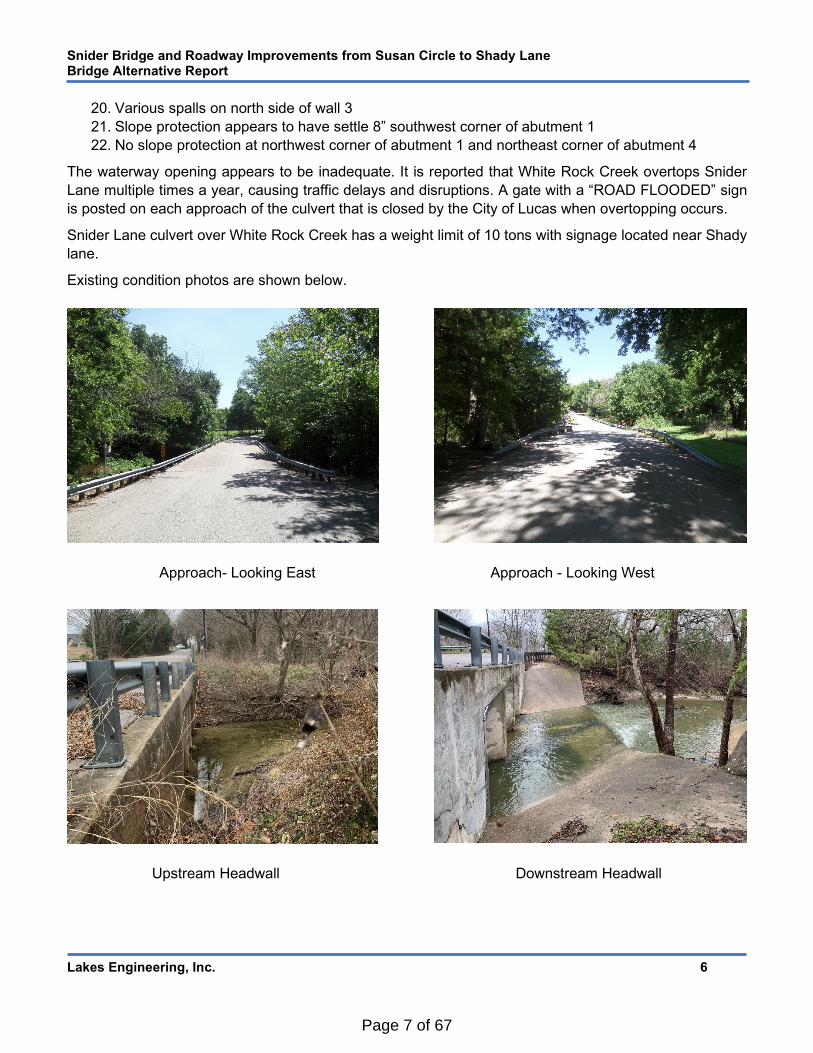
20. Various spalls on north side of wall 3
21. Slope protection appears to have settle 8” southwest corner of abutment 1
22. No slope protection at northwest corner of abutment 1 and northeast corner of abutment 4
The waterway opening appears to be inadequate. It is reported that White Rock Creek overtops Snider
Lane multiple times a year, causing traffic delays and disruptions. A gate with a “ROAD FLOODED” sign
is posted on each approach of the culvert that is closed by the City of Lucas when overtopping occurs.
Snider Lane culvert over White Rock Creek has a weight limit of 10 tons with signage located near Shady
lane.
Existing condition photos are shown below.
Approach- Looking East Approach - Looking West
Upstream Headwall Downstream Headwall
Page 7 of 67

Snider Bridge and Roadway Improvements from Susan Circle to Shady Lane Bridge Alternative Report
Lakes Engineering, Inc. 7
Upstream – During A Storm Event Downstream – During A Storm Event
At Shady Lane – During A Storm Event At Snider Lane Culvert – During A Storm Event
Page 8 of 67

Snider Bridge and Roadway Improvements from Susan Circle to Shady Lane Bridge Alternative Report
Lakes Engineering, Inc. 8
Project Objective
The intent of this project is to address the existing and future operational and safety conditions of Snider
Lane over White Rock Creek. Because the age and current condition, the project proposes to replace the
culvert with a new structure that is sufficiently durable and resilient to environmental effects, and flooding.
The structure must be sustainable, minimize maintenance requirements and provide a safe and rideable
corridor for the traveling public.
The project will involve the construction of a new bridge to carry Snider Lane over White Rock Creek
located in the City of Lucas, Collin County, Texas. See Figure 1 – Project Location Map.
Figure 2 – Project Location Map
Snider Ln Bridge
Begin Project
End Project
N
Page 9 of 67

Snider Bridge and Roadway Improvements from Susan Circle to Shady Lane Bridge Alternative Report
Lakes Engineering, Inc. 9
3. GEOMETRIC DESIGN
Geometric Criteria
Snider Lane is a low-speed, local road. It is classified as a low-speed, minor collector and is under the
jurisdiction of the City of Lucas. Snider Lane has a posted speed limit of 35 mph. Snider Lane widens at
the culvert over White Rock Creek.
Roadway Design Parameters
Functional Classification: Rural/Minor Collector
Design Speed: 35 mph
Minimum Travel Lane Width: 12 ft.
Design Specifications
American Association of State Highway and Transportation Officials (AASHTO) A Policy on Geometric
Design of Highways and Streets “The Green Book” (2018), 7th Edition with latest Interim Revisions
Texas Manual on Uniform Traffic Control Devices (October 2014)
TxDOT Roadway Design Manual (April 2018)
TxDOT Hydraulic Design Manual (September 2019)
TxDOT Environmental Handbook (November 2019)
TxDOT Bridge Project Development Manual (March 2018)
Horizontal Clearance In accordance with the TxDOT Bridge Project Development Manual, Chapter 3, Section 1, bridges over water shall have substructure supports located within the horizontal clearance requirements as follows:
A maximum of 2:1 embankment slope in a direction normal to the abutment cap.
Side slopes should be normal to the roadway and no steeper than 3:1.
Use stone riprap (preferred) or concrete riprap under the bridge and wrap around the abutment.
Embankment slope and stone riprap will be considered for the proposed bridge evaluation.
Vertical Clearance According to Federal Emergency Management Agency (FEMA), the Base Flood Elevation (BFE), which is the current flood elevation, is at EL. 515.00. Based on TxDOT Hydraulic Design Manual a minimum 2’-0” freeboard, additional clearance above the flood elevation, is required. In order to prevent Snider Lane from future flooding, providing a minimum 2’-0” above the BFE should be provided. The minimum Low Member Elevation (bottom of the bearing pad) shall be equal or exceed an elevation of 517.00. However, by replacing the culvert with a bridge, the current flood elevation may be lower. An in-depth Hydrology and Hydraulic study shall be performed in Preliminary or Final Design.
The intent of the design is to provide the minimum vertical clearance. This is proposed to be achieved by
a combination of minimization of the proposed structure depth and raising the vertical profile.
Page 10 of 67

Snider Bridge and Roadway Improvements from Susan Circle to Shady Lane Bridge Alternative Report
Lakes Engineering, Inc. 10
Horizontal and Vertical Alignment
Horizontal Alignment The existing horizontal alignment of Snider Lane, within the limits of the culvert over the White Rock Creek,
is on a tangent segment separated by two curves that do not meet current design standards. Only one
alternative is presented for the proposed alignment.
Proposed Horizontal Alignment, Snider Lane bridge over White Rock Creek will be shifted slightly to the
south of the existing Snider Lane alignment in order to correct the substandard curves. Additionally, this
alignment will improve sight distance and visibility at Shady Lane.
Proposed Horizontal Alignment is shown in Figure 2 – Proposed Horizontal Alignment below.
Figure 2 – Proposed Horizontal Alignment
Vertical Alignment/Profile White Rock has historically frequently overtopped Snider Lane. Raising the top of the roadway to be above the designated flood elevation is recommended throughout the corridor. It is also recommended that the low member elevation of the bridge be a minimum of 2’-0” above the current 100-year flood elevation. Several bridge superstructure alternatives (see section 5.4) were evaluated with the intent to minimize raising the vertical profile, which reduce the limits of the project, impact to property driveway access, and additional roadway embankment.
Page 11 of 67
Snider Bridge and Roadway Improvements from Susan Circle to Shady Lane Bridge Alternative Report
Lakes Engineering, Inc. 11
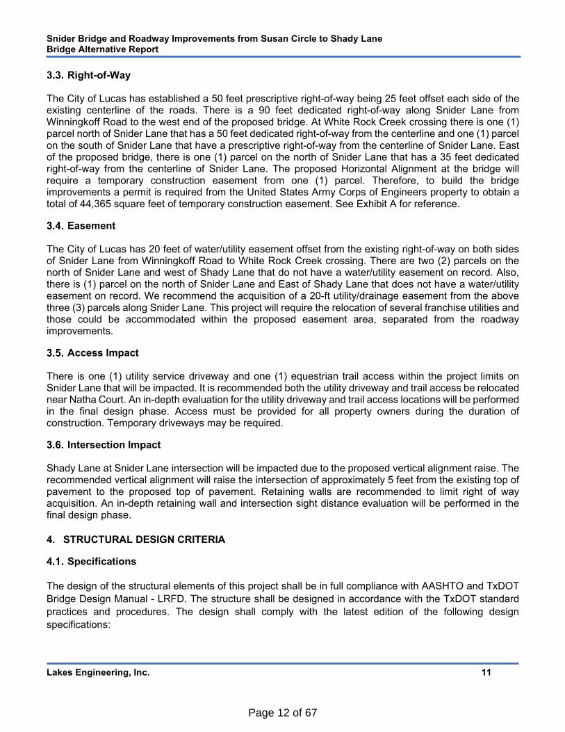
Right-of-Way The City of Lucas has established a 50 feet prescriptive right-of-way being 25 feet offset each side of the existing centerline of the roads. There is a 90 feet dedicated right-of-way along Snider Lane from Winningkoff Road to the west end of the proposed bridge. At White Rock Creek crossing there is one (1) parcel north of Snider Lane that has a 50 feet dedicated right-of-way from the centerline and one (1) parcel on the south of Snider Lane that have a prescriptive right-of-way from the centerline of Snider Lane. East of the proposed bridge, there is one (1) parcel on the north of Snider Lane that has a 35 feet dedicated right-of-way from the centerline of Snider Lane. The proposed Horizontal Alignment at the bridge will require a temporary construction easement from one (1) parcel. Therefore, to build the bridge improvements a permit is required from the United States Army Corps of Engineers property to obtain a total of 44,365 square feet of temporary construction easement. See Exhibit A for reference.
Easement The City of Lucas has 20 feet of water/utility easement offset from the existing right-of-way on both sides of Snider Lane from Winningkoff Road to White Rock Creek crossing. There are two (2) parcels on the north of Snider Lane and west of Shady Lane that do not have a water/utility easement on record. Also, there is (1) parcel on the north of Snider Lane and East of Shady Lane that does not have a water/utility easement on record. We recommend the acquisition of a 20-ft utility/drainage easement from the above three (3) parcels along Snider Lane. This project will require the relocation of several franchise utilities and those could be accommodated within the proposed easement area, separated from the roadway improvements.
Access Impact There is one (1) utility service driveway and one (1) equestrian trail access within the project limits on Snider Lane that will be impacted. It is recommended both the utility driveway and trail access be relocated near Natha Court. An in-depth evaluation for the utility driveway and trail access locations will be performed in the final design phase. Access must be provided for all property owners during the duration of construction. Temporary driveways may be required.
Intersection Impact Shady Lane at Snider Lane intersection will be impacted due to the proposed vertical alignment raise. The recommended vertical alignment will raise the intersection of approximately 5 feet from the existing top of pavement to the proposed top of pavement. Retaining walls are recommended to limit right of way acquisition. An in-depth retaining wall and intersection sight distance evaluation will be performed in the final design phase.
4. STRUCTURAL DESIGN CRITERIA
Specifications
The design of the structural elements of this project shall be in full compliance with AASHTO and TxDOT
Bridge Design Manual - LRFD. The structure shall be designed in accordance with the TxDOT standard
practices and procedures. The design shall comply with the latest edition of the following design
specifications:
Page 12 of 67

Snider Bridge and Roadway Improvements from Susan Circle to Shady Lane Bridge Alternative Report
Lakes Engineering, Inc. 12
General Specifications:
Texas Department of Transportation (TxDOT) Standard Specifications for Construction and
Maintenance of Highways, Streets and Bridge, 2014
Design Standards and Specifications:
American Association of State Highway and Transportation Officials (AASHTO) LRFD Bridge Design
Specifications (2017), 8th Edition with latest Interim Revisions
TxDOT Bridge Project Development Manual (March 2018)
TxDOT Bridge Design Manual - LRFD (July 2018)
TxDOT Bridge Railing Manual (September 2019)
TxDOT Bridge Standard Details Drawings
Design Methodology All structural components shall be designed in accordance with Load and Resistance Factor (LRFD) design
methodology. The design life for bridge structures is 75 years per AASHTO LRFD and TxDOT design
criteria.
Bridge Loading
The following design loads were utilized in the evaluation of the superstructure and substructure
alternatives:
Dead Loads: Unit weights in accordance with the TxDOT Standards and the AASHTO LRFD Bridge Design
Specifications were utilized.
Concrete, Structural ..................................... 150 pcf
Asphalt Concrete Pavement Overlay ........... 150 pcf (Applicable to prestressed slab unit alternative)
Future Wearing Surface ............................... 25 psf
Soil, Compacted .......................................... 120 pcf
Vertical-Faced Concrete Parapet ................. 270 plf (TxDOT Traffic Railing Type T411)
Bridge Deck Sacrificial Thickness ................ ½ in. (½” sacrificial deck thickness for grinding and
grooving was accounted for as dead load but was
not utilized for bridge deck section properties).
Live Loads Vehicular Loading: HL-93
Wind Loads Wind loads will be calculated in accordance with AASHTO LRFD Bridge Design Specifications.
Vessel Collision Not applicable.
Page 13 of 67

Snider Bridge and Roadway Improvements from Susan Circle to Shady Lane Bridge Alternative Report
Lakes Engineering, Inc. 13
Seismic Criteria According to TxDOT Bridge Design Manual, bridges and structure in Texas do not require analysis for seismic loading due to the low seismic hazard as shown in AASHTO Article 3.10.2. TxDOT Bridge Standards and conventional bridge configurations have been evaluated for seismic effects and do not require further analysis.
Environmental Classification Non-Severe: De-icing agents are not frequently used and contact with salt-water spray is not possible.
Materials
The following material properties shall be utilized in the design of the structures:
Concrete Concrete shall be specified in accordance with TxDOT Standard Specifications.
Class Minimum 28-day Compressive Strength (psi)
Location
Superstructure
C (HPC if needed) 3,600 Traffic Railings
S (HPC if needed) 4,000 Decks and Approach Slabs,
H (HPC if needed) 5,500 Prestressed Deck Slab Units
Substructure
C 3,600 Abutments, Bent and Wingwalls
C (Drilled Shaft) 3,600 Drilled Shafts
C (Driven Pile) 3,600 Driven Piles
Reinforcing Steel Reinforcement shall be ASTM A615, Grade 60 deformed carbon-steel bar. All superstructure
reinforcement shall be epoxy coated or galvanized.
Prestressing Steel Prestressing strands shall conform to ASTM A416, Grade 270, low-relaxation strands. Stress-relieved
strands will not be used.
Permit
The following regulatory and permitting agencies may have interest and/or jurisdiction requiring permits to perform the proposed bridge replacement:
City of Lucas
Texas Commission on Environmental Quality (TCEQ)
United States Environmental Protection Agency (EPA)
Federal Emergency Management Agency (FEMA)
United State Army Corp of Engineers (USACE)
Page 14 of 67

Snider Bridge and Roadway Improvements from Susan Circle to Shady Lane Bridge Alternative Report
Lakes Engineering, Inc. 14
Aesthetics
The proposed bridge will not have any non-standard aesthetic requirements. However, the bridge aesthetics may be similar to the Blondy Jhune bridges.
Utilities
Based on field surveying performed by Surveying and Mapping, LLC (SAM) in April 2020, existing overhead and underground utilities were noted at various locations. Further investigation will need to be conducted as the project progresses to identify the exact facility locations. The following companies operate within the project limits:
City of Lucas Public Utilities – 8” water line located along the south side of Snider Lane and 3” water lines tapped at Susan Circle, Natha Court and Shady Lane.
Grayson Collin Electric – Underground facilities on the south side of Snider lane. AT&T Fiber - Underground facilities located along the south side of Snider lane AT&T Telephone - Underground facilities located along the North side of Snider lane Frontier Telephone – Underground facilities located along the south side of Snider lane. Suddenlink CATV – Underground facilities along the east side of Susan Circle and west side of
Natha Court. There are five (5) Utility Agency Owners (UAO) with facilities within the project limits and additional utility coordination will be performed in preliminary and final design phases. The table below lists utility agency owners, utility contact data, and potential for required relocations.
Bridge Mounted Utilities The existing culvert structure does not carry any utilities. No utilities are proposed for attachment to the
bridge. It is recommended that conduit be placed in each bridge railing for future use of utility passthrough.
Overhead Utilities Shared-use utility poles run longitudinally near the west and east fascia of the proposed bridge, carrying
electrical, and telephone/cable. These electric/telephone overhead utilities will need to be adjusted to meet
the vertical clearance requirements. This will need to be discussed with the Franchise Utility owners and
they will adjust or relocate according to their standards.
Construction activities will need to address temporary support or relocation of these utilities.
Existing Utilities Utility Agency Owner Facilities Contact Person Phone/Email Relocation
Potential
1 City of Lucas Water Jeremy Bogle 469-628-8586 Y
2 Grayson Collin Electric Michael Lauer [email protected] Y
3 AT&T Fiber Joanie Baker 972-649-8759 Y
4 AT&T Telephone Joanie Baker 972-649-8759 Y
5 Frontier Telephone David Lemons 972-578-3212 Y
6 Suddenlink CATV N/A N/A N
Page 15 of 67
Snider Bridge and Roadway Improvements from Susan Circle to Shady Lane Bridge Alternative Report
Lakes Engineering, Inc. 15
5. BRIDGE ALTERNATIVES
Span Arrangement Alternatives
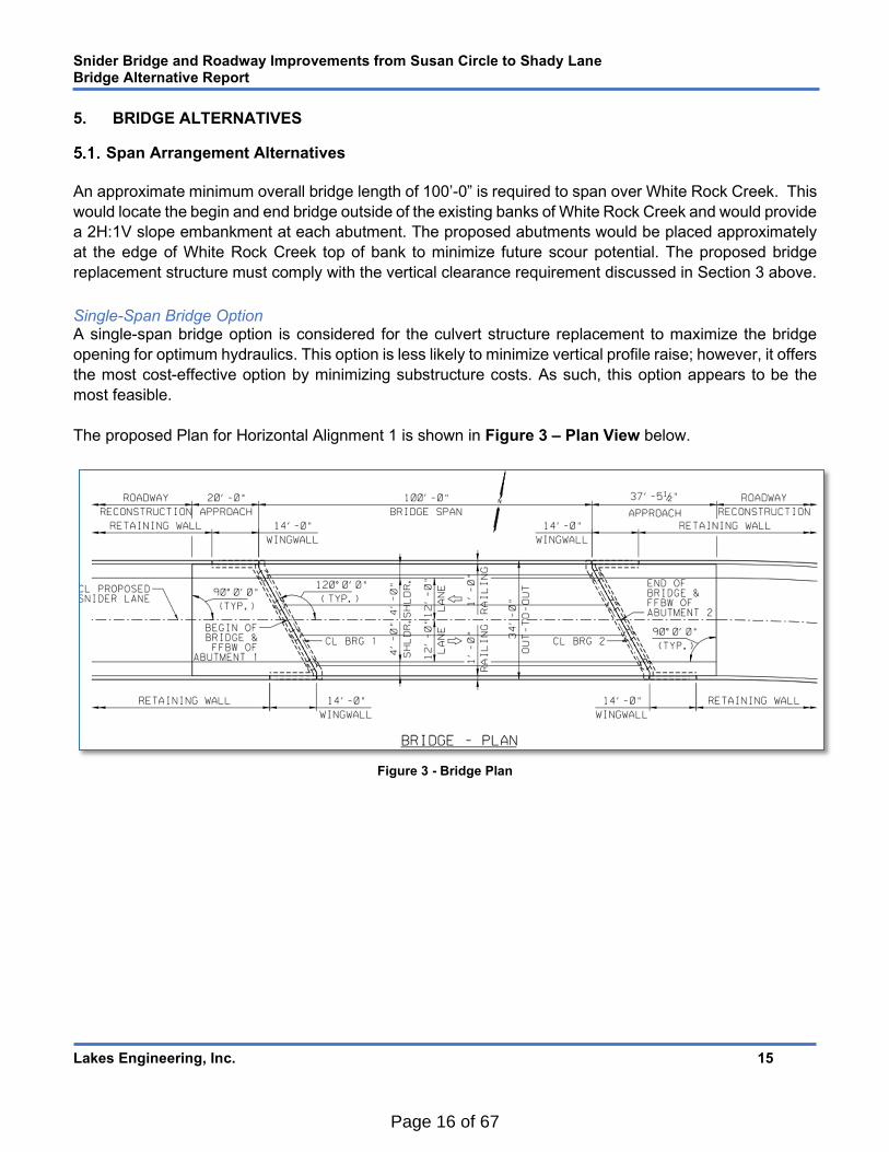
An approximate minimum overall bridge length of 100’-0” is required to span over White Rock Creek. This
would locate the begin and end bridge outside of the existing banks of White Rock Creek and would provide
a 2H:1V slope embankment at each abutment. The proposed abutments would be placed approximately
at the edge of White Rock Creek top of bank to minimize future scour potential. The proposed bridge
replacement structure must comply with the vertical clearance requirement discussed in Section 3 above.
Single-Span Bridge Option A single-span bridge option is considered for the culvert structure replacement to maximize the bridge
opening for optimum hydraulics. This option is less likely to minimize vertical profile raise; however, it offers
the most cost-effective option by minimizing substructure costs. As such, this option appears to be the
most feasible.
The proposed Plan for Horizontal Alignment 1 is shown in Figure 3 – Plan View below.
Figure 3 - Bridge Plan
Page 16 of 67

Snider Bridge and Roadway Improvements from Susan Circle to Shady Lane Bridge Alternative Report
Lakes Engineering, Inc. 16
The proposed Elevation for Horizontal Alignment 1 is shown in Figure 4 – Elevation View below.
Figure 4 - Bridge Elevation
Two-Span Bridge Option A two-span bridge is another option to minimize vertical profile raise; however, this option is less feasible as it would locate an intermediate bent in the middle of the White Rock Creek’s, which would require additional future maintenance, introduces high scour potential, and impedes the hydraulic opening. Having an intermediate bent increases the overall construction cost above a similar length single-span bridge in this particular situation and is not considered economical. As such, a two-span bridge was not further evaluated.
Three-Span Bridge Option A three-span bridge is another option to minimize vertical profile raise; however, this option is not feasible as it would locate two intermediate bents near the edge of the White Rock Creek’s embankments, which increase the negative impacts mentioned above in the two-span option. As such, a three-span bridge was not further evaluated.
Recommendation
A single-span bridge configuration is recommended for the replacement structure.
Bridge Skew
White Rock Creek is on an approximate 30-degree skew to Snider Lane; therefore, the bridge abutments
will have a 30-degree skew.
Page 17 of 67
Snider Bridge and Roadway Improvements from Susan Circle to Shady Lane Bridge Alternative Report
Lakes Engineering, Inc. 17
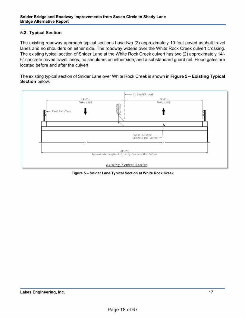
Typical Section The existing roadway approach typical sections have two (2) approximately 10 feet paved asphalt travel
lanes and no shoulders on either side. The roadway widens over the White Rock Creek culvert crossing.
The existing typical section of Snider Lane at the White Rock Creek culvert has two (2) approximately 14’-
6” concrete paved travel lanes, no shoulders on either side, and a substandard guard rail. Flood gates are
located before and after the culvert.
The existing typical section of Snider Lane over White Rock Creek is shown in Figure 5 – Existing Typical Section below.
Figure 5 – Snider Lane Typical Section at White Rock Creek
Page 18 of 67
Snider Bridge and Roadway Improvements from Susan Circle to Shady Lane Bridge Alternative Report
Lakes Engineering, Inc. 18
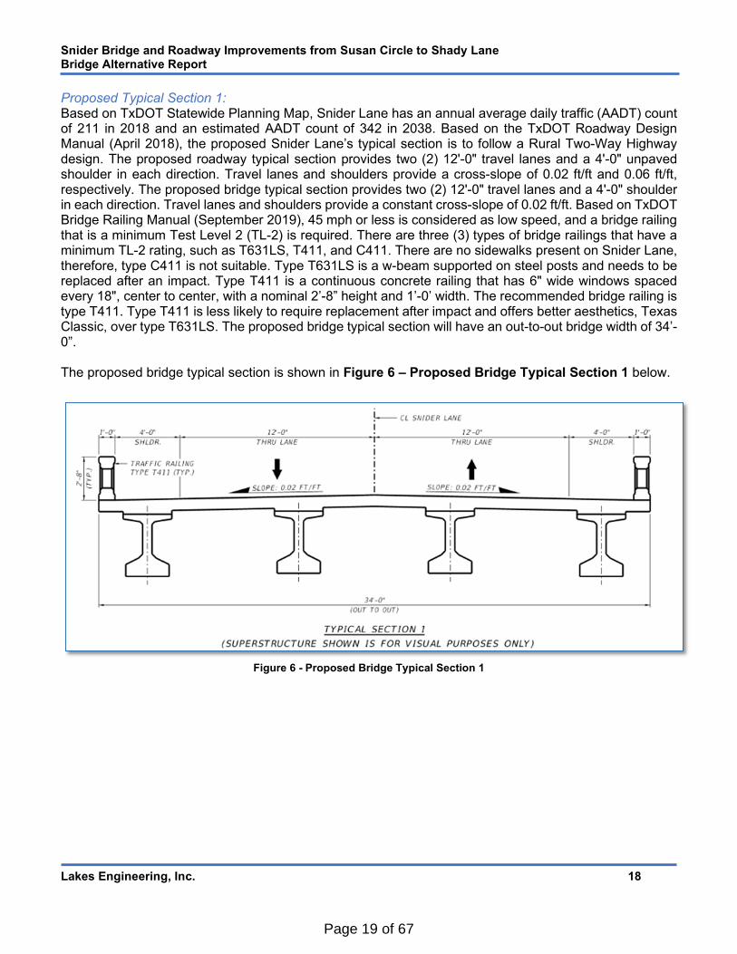
Proposed Typical Section 1: Based on TxDOT Statewide Planning Map, Snider Lane has an annual average daily traffic (AADT) count of 211 in 2018 and an estimated AADT count of 342 in 2038. Based on the TxDOT Roadway Design Manual (April 2018), the proposed Snider Lane’s typical section is to follow a Rural Two-Way Highway design. The proposed roadway typical section provides two (2) 12'-0" travel lanes and a 4'-0" unpaved shoulder in each direction. Travel lanes and shoulders provide a cross-slope of 0.02 ft/ft and 0.06 ft/ft, respectively. The proposed bridge typical section provides two (2) 12'-0" travel lanes and a 4'-0" shoulder in each direction. Travel lanes and shoulders provide a constant cross-slope of 0.02 ft/ft. Based on TxDOT Bridge Railing Manual (September 2019), 45 mph or less is considered as low speed, and a bridge railing that is a minimum Test Level 2 (TL-2) is required. There are three (3) types of bridge railings that have a minimum TL-2 rating, such as T631LS, T411, and C411. There are no sidewalks present on Snider Lane, therefore, type C411 is not suitable. Type T631LS is a w-beam supported on steel posts and needs to be replaced after an impact. Type T411 is a continuous concrete railing that has 6" wide windows spaced every 18", center to center, with a nominal 2’-8” height and 1’-0’ width. The recommended bridge railing is type T411. Type T411 is less likely to require replacement after impact and offers better aesthetics, Texas Classic, over type T631LS. The proposed bridge typical section will have an out-to-out bridge width of 34’-0”. The proposed bridge typical section is shown in Figure 6 – Proposed Bridge Typical Section 1 below.
Figure 6 - Proposed Bridge Typical Section 1
Page 19 of 67

Snider Bridge and Roadway Improvements from Susan Circle to Shady Lane Bridge Alternative Report
Lakes Engineering, Inc. 19
Proposed Typical Section 2: The City of Lucas has requested an ADT design of 20,000 be considered for Snider Lane to accommodate potential future traffic increases. Based on the TxDOT Roadway Design Manual (April 2018), the proposed Snider Lane’s typical section is to follow a Rural Two-Way Highway design. The proposed roadway typical section provides two (2) 12'-0" travel lanes and an 8'-0" unpaved shoulder in each direction. Travel lanes and shoulders provide a cross-slope of 0.02 ft/ft and 0.06 ft/ft, respectively. The proposed bridge typical section provides two (2) 12'-0" travel lanes and an 8'-0" shoulder in each direction. Travel lanes and shoulders provide a constant cross-slope of 0.02 ft/ft. Based on TxDOT Bridge Railing Manual (September 2019), 45 mph or less is considered as low speed, and a bridge railing that is a minimum Test Level 2 (TL-2) is required. There are three (3) types of bridge railings that have a minimum TL-2 rating, such as T631LS, T411, and C411. There are no sidewalks present on Snider Lane, therefore, type C411 is not suitable. Type T631LS is a w-beam supported on steel posts and needs to be replaced after an impact. Type T411 is a continuous concrete railing that has 6" wide windows spaced every 18", center to center, with a nominal 2’-8” height and 1’-0’ width. The recommended bridge railing is type T411. Type T411 is less likely to require replacement after impact and offers better aesthetics, Texas Classic, over type T631LS. The proposed bridge typical section will have an out-to-out bridge width of 42’-0”. The proposed bridge typical section is shown in Figure 7 – Proposed Bridge Typical Section 2 below.
Figure 7 - Proposed Bridge Typical Section 2
Page 20 of 67

Snider Bridge and Roadway Improvements from Susan Circle to Shady Lane Bridge Alternative Report
Lakes Engineering, Inc. 20
Recommendation The advantages of Bridge Typical Section 1 over Bridge Typical Section 2 are listed below.
Lower overall construction cost
Does not require Right-of-Way or easement acquisition from USACE on the south side of Snider
Lane
Less impact to driveways, turnouts and intersections
The disadvantages of Bridge Typical Section 1 over Bridge Typical Section 2 are listed below.
Does not allows construction in phases or at least one lane open to traffic
Less shoulder width
Does not meet design standards for 20,000 ADT (Average Daily Traffic)
Proposed Bridge Typical Section 2 would require right-of-way acquisition and increased overall
construction cost. A significant key disadvantage of Bridge Typical Section 1 over Bridge Typical Section
2 is that it does not meet the design standards for an ADT of 20,000. According to TxDOT Roadway Design
Manual for a collector two-lane rural highway with an ADT more than 2,000 it is recommended to have a
minimum of 8 feet shoulder. Snider Lane serves a small community with property size of 1 acre or more.
It is not expected that this area will be developed with high density lots as most properties along Snider
Lane are developed. Because of the large increase in bridge width required to meet design criteria for an
ADT of 20,000, the cost increase for the Bridge Typical Section 2 is large. Bridge Typical Section 1 is
functional and meets the needs of the community and the wider bridge typical section does not appear to
provide a significant advantage to offset the overall cost increase; therefore, Bridge Typical Section 1 is
recommended.
Superstructure Alternatives
The superstructure alternatives have been selected to satisfy the minimum horizontal and vertical
clearance, hydraulic requirements, and constructability. Many superstructure alternatives were considered
and evaluated based on the recommended Horizontal Alignment as discussed in section 3.2 above.
Seven superstructure alternatives were considered and evaluated for Snider Lane Bridge over White Rock
Creek. The overall bridge length is 100'-0". TxDOT Prestressed Concrete Slab Beam and Decked Slab
Beams were evaluated and eliminated due to capacity limitations at this span length. A steel through-truss
superstructure was considered to minimize superstructure depth. The advantages to a through-truss
superstructure are generally realized in long spans where prestressed concrete does not perform well or
the members become very large. Since the span is relatively short, the structure depth for a through-truss
is not less than other alternatives considered. Further, the structure depth is not a limiting factor since the
roadway must be raised significantly to remain above the 100-year flood elevation. Therefore, the steel
through-truss was eliminated. The remaining four superstructure alternatives are described below, options
1 through 4.
Page 21 of 67

Snider Bridge and Roadway Improvements from Susan Circle to Shady Lane Bridge Alternative Report
Lakes Engineering, Inc. 21
Each superstructure alternative presented below considers the recommended proposed Bridge Typical
Section 1 as discussed in Section 5.3 above.
Option 1: TxDOT Prestressed Concrete Box Beams (5B34 &4B34) This superstructure alternative consists of replacing the existing culvert structure with a single-span bridge
utilizing six (6) TxDOT Prestressed Concrete Box Beams (5B34) and one (1) TxDOT Prestressed Concrete
Box Beam (4B34) with a minimum of 5” thick Cast-in-Place (CIP) reinforced concrete deck. The proposed
superstructure depth is 39”. This shallow superstructure depth in conjunction with a modified vertical profile
results in the lowest vertical profile raise over White Rock Creek and places the bottom of the bridge
bearing elevation to be above the 100-year flood storm. Option 1 proposes a 10.88’ vertical profile raise
and is the second most cost-effective superstructure alternative. Refer to Appendix A for the options cost
comparison.
The proposed TxDOT Prestressed Concrete Box Beams (5B34 & 4B34) typical section is shown in Figure
8 – TxDOT Prestressed Concrete Box Beams (5B34 & 4B34) Typical Section below.
Figure 8 - TxDOT Prestressed Concrete Box Beams (5B34 & 4B34) Typical Section
Page 22 of 67
Snider Bridge and Roadway Improvements from Susan Circle to Shady Lane Bridge Alternative Report
Lakes Engineering, Inc. 22
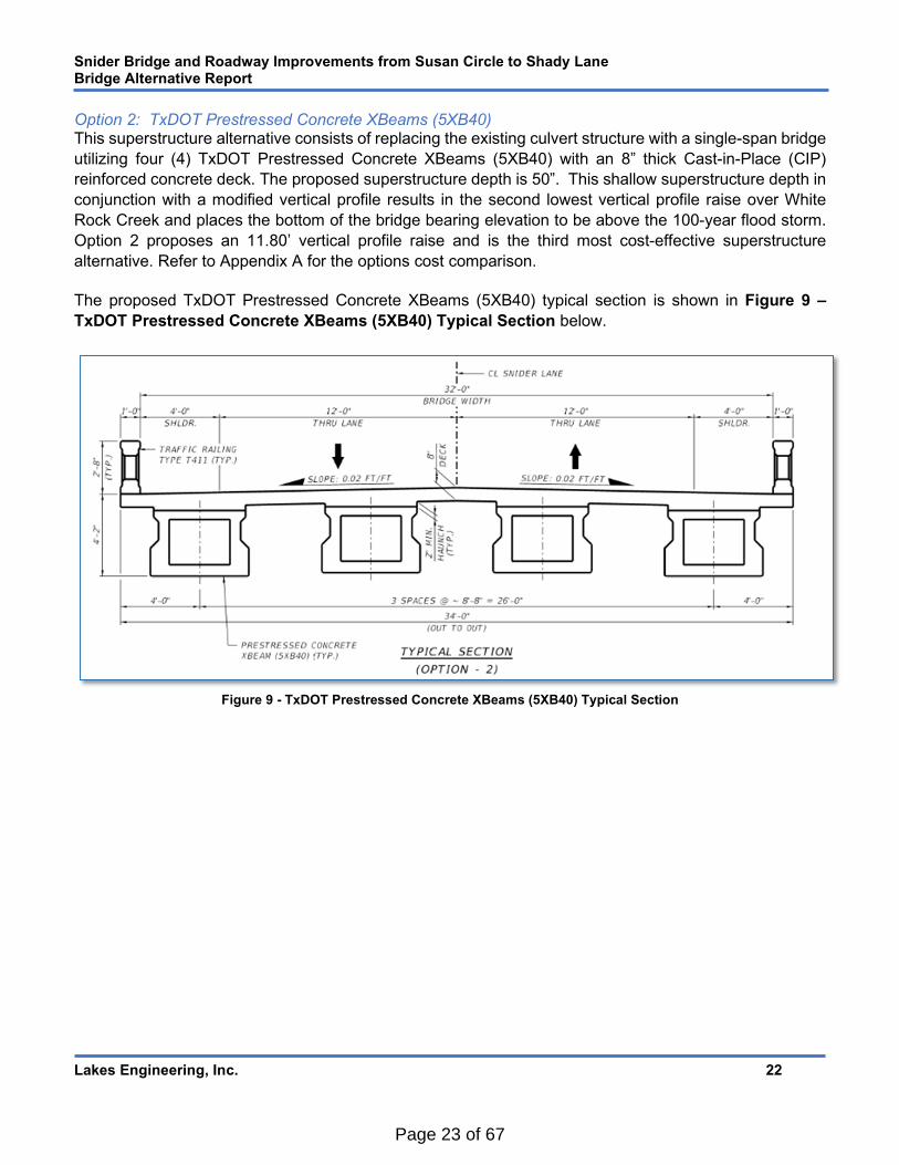
Option 2: TxDOT Prestressed Concrete XBeams (5XB40) This superstructure alternative consists of replacing the existing culvert structure with a single-span bridge
utilizing four (4) TxDOT Prestressed Concrete XBeams (5XB40) with an 8” thick Cast-in-Place (CIP)
reinforced concrete deck. The proposed superstructure depth is 50”. This shallow superstructure depth in
conjunction with a modified vertical profile results in the second lowest vertical profile raise over White
Rock Creek and places the bottom of the bridge bearing elevation to be above the 100-year flood storm.
Option 2 proposes an 11.80’ vertical profile raise and is the third most cost-effective superstructure
alternative. Refer to Appendix A for the options cost comparison.
The proposed TxDOT Prestressed Concrete XBeams (5XB40) typical section is shown in Figure 9 –
TxDOT Prestressed Concrete XBeams (5XB40) Typical Section below.
Figure 9 - TxDOT Prestressed Concrete XBeams (5XB40) Typical Section
Page 23 of 67

Snider Bridge and Roadway Improvements from Susan Circle to Shady Lane Bridge Alternative Report
Lakes Engineering, Inc. 23
Option 3: TxDOT Prestressed Concrete I-Girders (TX46) This superstructure alternative consists of replacing the existing culvert structure with a single-span bridge utilizing four (4) TxDOT Prestressed Concrete I-Girders (TX46) with an 8.5” thick Cast-in-Place (CIP) reinforced concrete deck and 4” thick prestressed concrete deck panels. The proposed superstructure depth is 56.5”. This superstructure depth in conjunction with a modified vertical profile results in the highest vertical profile raise over White Rock Creek and places the bottom of the bridge bearing elevation to be above the 100-year flood storm. Option 3 proposes a 12.34’ vertical profile raise and is the most cost-effective superstructure alternative. Refer to Appendix A for the options cost comparison. The proposed TxDOT Prestressed Concrete I-Girders (TX46) typical shown in Figure 10 – TxDOT Prestressed Concrete I-Girders (TX46) Typical Section below.
Figure 10 - TxDOT Prestressed Concrete I-Girders (TX46) Typical Section
Page 24 of 67

Snider Bridge and Roadway Improvements from Susan Circle to Shady Lane Bridge Alternative Report
Lakes Engineering, Inc. 24
Option 4A: Steel Plate Girders (40”X1/2” Web) or Option 4B: Steel Rolled Beams (W40X211) This superstructure alternative consists of replacing the existing culvert structure with a single-span bridge
utilizing five (5) Steel Plate Girders (40”X1/2” Web) or five (5) Steel Rolled Beams (W40X211), both with
an 8.5” thick Cast-in-Place (CIP) reinforced concrete deck. The proposed superstructure depth is 53” for
plate girders and 50” for rolled beams. These superstructure depths in conjunction with a modified vertical
profile result in the third lowest vertical profile raise for plate girders and second lowest vertical profile raise
for rolled beams over White Rock Creek and place the bottom of the bridge bearing elevation to be above
the 100-year flood storm. Option 4A & 4B propose a 12.03’ vertical profile raise for plate girders and 11.79’
vertical profile raise for rolled beams and are both the least cost-effective superstructure alternatives. Refer
to Appendix A for the options cost comparison.
The proposed Steel Plate Girders (40”X1/2” Web) or Steel Rolled Beams (W40X211) typical section is
shown in Figure 11 – Steel Plate Girders (40”X1/2” Web) or Steel Rolled Beams (W40X211) Typical
Section below.
Figure 11 - Steel Plate Girders (40”X1/2” Web) or Steel Rolled Beams (W40X211) Typical Section
Page 25 of 67

Snider Bridge and Roadway Improvements from Susan Circle to Shady Lane Bridge Alternative Report
Lakes Engineering, Inc. 25
Recommendation
Of the four options discussed above for the proposed Horizontal Alignment, Option 3 is recommended: a
single-span bridge utilizing four (4) TxDOT Prestressed Concrete I-Girders (TX46) with 8.5” thick reinforced
concrete deck. Option 3 does not provide the shallowest superstructure depth, nor does it minimize the
vertical profile raise, but this option is the most feasible superstructure in terms of overall cost savings.
Substructure / Foundation Alternatives
A full geotechnical evaluation of the bridge site will be investigated during the final design phase to
determine the suitability and capacity needed for the proposed bridge replacement. TxDOT standard for
prestressed concrete I-girders allows two foundation alternatives with a cast-in-place concrete abutment
cap. A specialty design may also be considered should the geotechnical evaluation recommend a non-
standard substructure.
Driven Concrete Piles TxDOT Standard allows for six (6) 18”x18” driven concrete piles per an abutment for prestressed concrete
I-girders. An in-depth foundation design will be performed to verify the capacity in the final design phase.
Drilled Shafts TxDOT Standard allows for four (4) 30” diameter drilled shafts per an abutment for prestressed concrete
I-girders. An in-depth foundation design will be performed to verify the capacity in the final design phase.
Recommendation
No recommendation is provided at this time for the substructure foundation alternatives.
Retaining Walls
Retaining walls will be used on this project to minimize the encroachment of the roadway embankment and to contain the typical section footprint within the limits of the existing right-of-way. Two types of walls are considered feasible, conventional Cast-In-Place (CIP) walls and Mechanically Stabilized Earth (MSE) retaining walls. The required wall area is determined by superstructure type as well as the foundation soil conditions to determine what type of wall will be best suited for this application. An in-depth retaining wall evaluation will be performed in the final design phase.
Bridge Drainage
Bridge drainage will be evaluated in preliminary and final design phases.
Bridge Lighting
There is no streetlight system existing along Snider Lane, and there are no light poles on the existing
culvert. Therefore, no lighting will be proposed for the bridge.
Page 26 of 67

Snider Bridge and Roadway Improvements from Susan Circle to Shady Lane Bridge Alternative Report
Lakes Engineering, Inc. 26
Construction Sequencing
Safety to motorists and pedestrians is the highest priority for the Traffic Control Plan and the plan must
minimize disruption to traffic flow during the construction of these improvements. To achieve these goals
several keys issues will be addressed in the development of the selected alternative:
Maintain access to the residential community during all phases of construction.
Communicate with all project stakeholders, including local HOAs.
Avoid or minimize utility facility relocations.
Minimize impacts to traffic during the construction phase.
The following two construction options have been evaluated:
Phased Construction Option To maintain traffic along Snider Lane, phased construction was considered and evaluated. At the culvert,
Snider Lane has a paved roadway width of approximately 21 ft. TxDOT requires a 1’-0” offset from the
temporary barriers and a minimum 12'-0” lane. Given the required widths and width of temporary barriers,
providing two lanes of traffic will be impossible, however, leaving only one westbound or eastbound lane
open was considered. Also, temporary shoring will be needed due to the significant profile raise, which
increases the project limit even farther due to lane shifting requirements. Initial investigations find staged
construction will require either widening the bridge or shifting the horizontal alignment. Either widening the
bridge or shifting the horizontal alignment will require right-of-way or easement acquisition from USACE
property. Widening the bridge or shifting the horizontal alignment to accommodate a phased construction
would significantly increase the cost due to temporary shoring, traffic control items and schedule.
Complete Closure with Detour Option Replacement of the Snider Lane Culvert of White Rock Creek can be completed in a shorter duration and
with a reduced construction cost (when compared to the phased option) by implementing complete closure
from Susan Circle to Shady Lane during construction and implementing a Detour. An initial detour plan will
utilize East Lucas Road for west to east detours and Winningkoff Road for south to north detours. Shady
Lane can be used for west to east detours only during the construction of the bridge and a portion of the
roadway improvement up to Shady Lane. However, due to a change of profile at the intersection of Snider
Lane and Shady Lane, Shady Lane will be closed for the construction of the remaining roadway
improvement and access maintained from the north. An in-depth detour route and access plan will be
evaluated in preliminary design.
Recommendation
The Complete Closure with Detour Option is recommended as this would allow for a shorter construction
duration, resulting in overall construction savings.
6. ALTERNATIVE COST COMPARISON A comparison of the estimated difference in cost of each alternative to Option 3 has been prepared. The
comparison is based on certain major components of cost, such as the bridge, roadway, and retaining
walls evaluated (refer to Appendix A - Alternatives Cost Comparison for more details).
Page 27 of 67

Snider Bridge and Roadway Improvements from Susan Circle to Shady Lane Bridge Alternative Report
Lakes Engineering, Inc. 27
The table below summarizes the bridge alternatives by percentage differences of cost for each alternative
compared with Option 3 based only on superstructure types.
Based on a bridge superstructure cost estimated comparison, Option 3 is the most economical.
The table below summarizes the associated roadway profile raise of each bridge alternatives by
percentage differences of cost compared with Option 3 based only on roadway fill. Profile raise is measured
from the top of the existing pavement at the culvert to the top of the proposed concrete bridge deck at the
beginning of the proposed bridge span. The top of the existing pavement at the culvert and at the beginning
of the proposed bridge span is estimated to be at EL. 509.94.
Based on the roadway profile raise cost estimated comparison, Option 1 is the most economical. However,
Option 3 bridge superstructure cost offsets the cost enough from Option 1 roadway profile cost. Option 3
would be a more suitable alternative in this case.
The table below summarizes the associated retaining wall area of each bridge alternatives and roadway
profile raise by percentage differences of cost compared with Option 3 based only on estimated exposed
retaining wall area.
Bridge Alternatives % Difference Compared to Option 3
Option 1: Single-Span with six-5B34 & one-4B34 Beams 38% increase
Option 2: Single-Span with four-5XB40 Beams 58% increase
Option 3: Single-Span with four-TX46 Beams
Option 4A: Single-Span with five-Plate Girder Beams 66% increase
Option 4B: Single-Span with five-W40x211 Beams 222% increase
Roadway Profile Raise % Difference Compared to Option 3
Option 1: 10.88 feet Profile Raise 3% decrease
Option 2: 11.80 feet Profile Raise 3% decrease
Option 3: 12.34 feet Profile Raise
Option 4A: 12.03 feet Profile Raise 2% decrease
Option 4B: 11.79 feet Profile Raise 3% decrease
Retaining Wall Area % Difference Compared to Option 3
Option 1: 8709 SF 10% decrease
Option 2: 9292 SF 4% decrease
Option 3: 9637 SF
Option 4A: 9438 SF 2% decrease
Option 4B: 9292 SF 4% decrease
Page 28 of 67
Snider Bridge and Roadway Improvements from Susan Circle to Shady Lane Bridge Alternative Report
Lakes Engineering, Inc. 28
Based on retaining wall cost estimated comparison, Option 1 is the most economical. However, Option 3
bridge superstructure cost offsets the cost enough from Option 1 retaining wall cost. Option 3 would be a
more suitable alternative in this case.
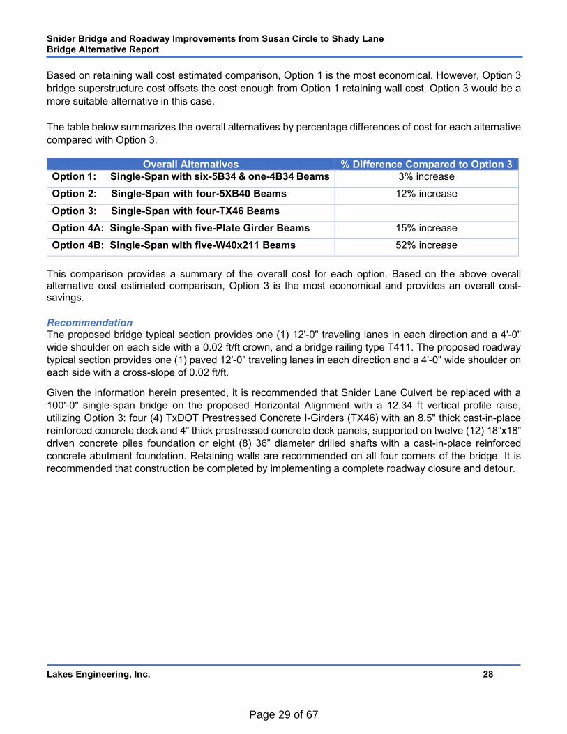
The table below summarizes the overall alternatives by percentage differences of cost for each alternative
compared with Option 3.
This comparison provides a summary of the overall cost for each option. Based on the above overall alternative cost estimated comparison, Option 3 is the most economical and provides an overall cost-savings.
Recommendation
The proposed bridge typical section provides one (1) 12'-0" traveling lanes in each direction and a 4'-0"
wide shoulder on each side with a 0.02 ft/ft crown, and a bridge railing type T411. The proposed roadway
typical section provides one (1) paved 12'-0" traveling lanes in each direction and a 4'-0" wide shoulder on
each side with a cross-slope of 0.02 ft/ft.
Given the information herein presented, it is recommended that Snider Lane Culvert be replaced with a
100'-0" single-span bridge on the proposed Horizontal Alignment with a 12.34 ft vertical profile raise,
utilizing Option 3: four (4) TxDOT Prestressed Concrete I-Girders (TX46) with an 8.5" thick cast-in-place
reinforced concrete deck and 4” thick prestressed concrete deck panels, supported on twelve (12) 18”x18”
driven concrete piles foundation or eight (8) 36” diameter drilled shafts with a cast-in-place reinforced
concrete abutment foundation. Retaining walls are recommended on all four corners of the bridge. It is
recommended that construction be completed by implementing a complete roadway closure and detour.
Overall Alternatives % Difference Compared to Option 3
Option 1: Single-Span with six-5B34 & one-4B34 Beams 3% increase
Option 2: Single-Span with four-5XB40 Beams 12% increase
Option 3: Single-Span with four-TX46 Beams
Option 4A: Single-Span with five-Plate Girder Beams 15% increase
Option 4B: Single-Span with five-W40x211 Beams 52% increase
Page 29 of 67
Snider Bridge and Roadway Improvements from Susan Circle to Shady Lane Bridge Alternative Report
Lakes Engineering, Inc.
APPENDIX A:
Alternative Cost Comparison
Estimate / Calculations
Page 30 of 67

Bridge Superstructure Option 1 Option 2 Option 3 Option 4A Option 4B
Beam Type 5B34/4B34 5XB40 TX46 Plate Girder W40X211
beam length 99.67 lf 99.67 lf 99.67 lf 99.67 lf 99.67 lf
no. beam 7 4 4 5 5
beam unit weight (steel option only) 196 lb/lf 211 lb/lf
total beam length 697.67 lf 398.67 lf 398.67 lf 97673.33 lb 105148.33 lb
unit cost ($/lf) $265.00 $475.00 $150.00 $2.00 /lb $5.00 /lb
total cost $184,881.67 $189,366.67 $59,800.00 $195,346.67 $525,741.67
deck/overlay width 34.67 lf 34.00 lf 34.00 lf 34.00 lf 34.00 lf
deck/overlay length 99.67 lf 99.67 lf 99.67 lf 99.67 lf 99.67 lf
deck thickness 5.0 in 8.0 in 8.5 in 8.5 in 8.5 in
total deck volume 53.32 cy 83.67 cy 88.90 cy 88.90 cy 88.90 cy
unit cost ($/cy) $1,550.00 $1,550.00 $1,550.00 $1,550.00 $1,550.00
total cost $82,645.40 $129,689.71 $137,795.32 $137,795.32 $137,795.32
total no. bearing pads 14 ea 8 ea 8 ea 10 ea 10 ea
unit cost ($/each) $1,700.00 $1,700.00 $1,700.00 $1,700.00 $1,700.00
total cost $23,800.00 $13,600.00 $13,600.00 $17,000.00 $17,000.00
Overall bridge alternative cost * $291,327.07 $332,656.38 $211,195.32 $350,141.99 $680,536.99
% difference Compared to Option 3 38% 58% 0% 66% 222%
Roadway Profile Fill Option 1 Option 2 Option 3 Option 4A Option 4B
roadway profile fill area (elevation view) 4860 sf 5171 sf 5355 sf 5249 sf 5171 sf
roadway profile fill width 34.33 ft 32 ft 32 ft 32 ft 32 ft
roadway profile fill volume 6180.25 cy 6128.55 cy 6346.19 cy 6220.63 cy 6128.55 cy
unit cost ($/cy) $25.00 $25.00 $25.00 $25.00 $25.00
total cost $154,506.36 $153,213.80 $158,654.81 $155,515.77 $153,213.80
Overall roadway alternative cost * $154,506.36 $153,213.80 $158,654.81 $155,515.77 $153,213.80
% difference Compared to Option 3 -3% -3% 0% -2% -3%
Retaining Wall Option 1 Option 2 Option 3 Option 4A Option 4B
retaining wall area 4354 sf 4646 sf 4818 sf 4719 sf 4646 sf
no. retaining walls 2 2 2 2 2
total retaining wall area 8709 sf 9292 sf 9637 sf 9438 sf 9292 sf
unit cost ($/sf) $50.00 $50.00 $50.00 $50.00 $50.00
total cost $435,440.00 $464,599.43 $481,830.00 $471,889.29 $464,599.43
Overall retaining wall cost * $435,440.00 $464,599.43 $481,830.00 $471,889.29 $464,599.43
% difference Compared to Option 3 -10% -4% 0% -2% -4%
Option 1 Option 2 Option 3 Option 4A Option 4B
OVERALL ALTERNATIVE COST ** $881,273.43 $950,469.61 $851,680.13 $977,547.04 $1,298,350.21
% difference Compared to Option 3 3% 12% 0% 15% 52%Recommendation
* Does not reflect all components, and only selective variable components were used for aiding alternative selection.
** Overall Alternative Cost does not reflect fully estimated construction cost, and is only used for aiding alternative selection.
Date: July 10, 2020
Bridge Typical Section 1
Bridge Typical Section 1 - Alternative Cost ComparisonSnider Bridge Roadway Improvements from Susan Circle to Shady Lane
City of Lucas
BEARING PADS
DECK
BEAMS
Bridge Typical Section 1
Page 31 of 67

Bridge Superstructure Option 1 Option 2 Option 3 Option 4A Option 4B
Beam Type 5B34/4B34 5XB40 TX46 Plate Girder W44X262
beam length 99.67 lf 99.67 lf 99.67 lf 99.67 lf 99.67 lf
no. beam 9 5 5 5 5
beam unit weight (steel option only) 245 lb/lf 262 lb/lf
total beam length 897.00 lf 498.33 lf 498.33 lf 122091.67 lb 130563.33 lb
unit cost ($/lf) $265.00 $475.00 $150.00 $2.00 /lb $5.00 /lb
total cost $237,705.00 $236,708.33 $74,750.00 $244,183.33 $652,816.67
deck/overlay width 42.89 lf 42.00 lf 42.00 lf 42.00 lf 42.00 lf
deck/overlay length 99.67 lf 99.67 lf 99.67 lf 99.67 lf 99.67 lf
deck thickness 5.0 in 8.0 in 8.5 in 8.5 in 8.5 in
total deck volume 65.96 cy 103.36 cy 109.82 cy 109.82 cy 109.82 cy
unit cost ($/cy) $1,550.00 $1,550.00 $1,550.00 $1,550.00 $1,550.00
total cost $102,238.92 $160,204.94 $170,217.75 $170,217.75 $170,217.75
total no. bearing pads 18 ea 10 ea 10 ea 10 ea 10 ea
unit cost ($/each) $1,700.00 $1,700.00 $1,700.00 $1,700.00 $1,700.00
total cost $30,600.00 $17,000.00 $17,000.00 $17,000.00 $17,000.00
Overall bridge alternative cost * $370,543.92 $413,913.27 $261,967.75 $431,401.08 $840,034.41
% difference Compared to Option 3 41% 58% 0% 65% 221%
Roadway Profile Fill Option 1 Option 2 Option 3 Option 4A Option 4B
roadway profile fill area (elevation view) 4860 sf 5171 sf 5355 sf 5249 sf 5171 sf
roadway profile fill width 42.56 ft 40 ft 40 ft 40 ft 40 ft
roadway profile fill volume 7661.57 cy 7660.69 cy 7932.74 cy 7775.79 cy 7660.69 cy
unit cost ($/cy) $25.00 $25.00 $25.00 $25.00 $25.00
total cost $191,539.13 $191,517.25 $198,318.52 $194,394.71 $191,517.25
Overall roadway alternative cost * $191,539.13 $191,517.25 $198,318.52 $194,394.71 $191,517.25
% difference Compared to Option 3 -3% -3% 0% -2% -3%
Retaining Wall Option 1 Option 2 Option 3 Option 4A Option 4B
retaining wall area 4354 sf 4646 sf 4818 sf 4719 sf 4646 sf
no. retaining walls 2 2 2 2 2
total retaining wall area 8709 sf 9292 sf 9637 sf 9438 sf 9292 sf
unit cost ($/sf) $50.00 $50.00 $50.00 $50.00 $50.00
total cost $435,440.00 $464,599.43 $481,830.00 $471,889.29 $464,599.43
Overall retaining wall cost * $435,440.00 $464,599.43 $481,830.00 $471,889.29 $464,599.43
% difference Compared to Option 3 -10% -4% 0% -2% -4%
Option 1 Option 2 Option 3 Option 4A Option 4B
OVERALL ALTERNATIVE COST ** $997,523.05 $1,070,029.95 $942,116.27 $1,097,685.07 $1,496,151.09
% difference Compared to Option 3 6% 14% 0% 17% 59%Recommendation
Bridge Typical Section 2
Bridge Typical Section 2 - Alternative Cost ComparisonSnider Bridge Roadway Improvements from Susan Circle to Shady Lane
City of Lucas
BEAMS
DECK
BEARING PADS
* Does not reflect all components, and only selective variable components were used for aiding alternative selection.
** Overall Alternative Cost does not reflect fully estimated construction cost, and is only used for aiding alternative selection.
Date: July 10, 2020
Bridge Typical Section 2
Page 32 of 67

Bridge Typical Section 1 Bridge Typical Section 2
Bridge Superstructure Option 3 Option 3
Beam Type TX46 TX46
beam length 99.67 lf 99.67 lf
no. beam 4 5
beam unit weight (steel option only)
total beam length 398.67 lf 498.33 lf
unit cost ($/lf) $150.00 $150.00
total cost $59,800.00 $74,750.00
deck/overlay width 34.00 lf 42.00 lf
deck/overlay length 99.67 lf 99.67 lf
deck thickness 8.5 in 8.5 in
total deck volume 88.90 sy 109.82 cy
unit cost ($/cy) $1,550.00 / sy $1,550.00
total cost $137,795.32 $170,217.75
total no. bearing pads 8 ea 10 ea
unit cost ($/each) $1,700.00 $1,700.00
total cost $13,600.00 $17,000.00
Overall bridge alternative cost * $211,195.32 $261,967.75
% difference Compared to Horizontal Alignment 2 - Option 2 0% 24%
Roadway Profile Fill Option 3 Option 3
roadway profile fill area (elevation view) 5355 sf 5355 sf
roadway profile fill width 32 ft 40 ft
roadway profile fill volume 6346.19 cy 7932.74 cy
unit cost ($/cy) $25.00 $25.00
total cost $158,654.81 $198,318.52
Overall roadway alternative cost * $158,654.81 $198,318.52
% difference Compared to Horizontal Alignment 2 - Option 2 0% 25%
Retaining Wall Option 3 Option 3
retaining wall area 4818 sf 4818 sf
no. retaining walls 2 2
total retaining wall area 9637 sf 9637 sf
unit cost ($/sf) $50.00 $50.00
total cost $481,830.00 $481,830.00
Overall retaining wall cost * $481,830.00 $481,830.00
% difference Compared to Horizontal Alignment 2 - Option 2 0% 0%
Bridge Typical Section 1 Bridge Typical Section 2
Option 3 Option 3
OVERALL ALTERNATIVE COST ** $851,680.13 $942,116.27
% difference Compared to Horizontal Alignment 2 - Option 2 0% 11%
Recommendation
* Does not reflect all components, and only selective variable components were used for aiding alternative selection.
Date: July 10, 2020
** Overall Alternative Cost does not reflect fully estimated construction cost, and is only used for aiding alternative selection.
Bridge Typical Section 1 VS Bridge Typical Section 2
Alternative Cost ComparisonSnider Bridge Roadway Improvements from Susan Circle to Shady Lane
City of Lucas
BEAMS
DECK
BEARING PADS
Page 33 of 67

Average Low Bid Unit Prices Based on Apr-2020 Link
ITEM CODE ITEM DESCRIPTION ITEM UNITSTATEWIDE
3M COUNT
STATEWIDE 3M
QUANTITY
STATEWIDE
3M AVG
STATEWIDE
12M COUNT
STATEWIDE 12M
QUANTITY
STATEWIDE
12M AVGUSE
01326001 EMBANKMENT (FINAL)(ORD COMP)(TY A) CY 3 984.00 $21.80 24 52,683.00 $16.08 $25.00
04206014 CL C CONC (ABUT)(HPC) CY 4 489.37 $1,852.55 19 2,384.67 $1,540.16 $1,550.00
04236001 RETAINING WALL (MSE) SF 2 50,652.00 $65.56 30 1,481,765.79 $49.61 $50.00
04236008 RETAINING WALL (CAST - IN - PLACE) SF 2 723.00 $51.67 16 40,607.00 $94.99 $95.00
04256005 PRESTR CONC BOX BEAM (4B34) LF 2 656.00 $250.37 5 17,193.50 $195.13 $265.00
04256006 PRESTR CONC BOX BEAM (5B34) LF 2 328.00 $250.37 5 18,850.00 $192.55 $265.00
04256024 PRESTR CONC BOX BEAM (5XB34) LF 1 1,074.00 $371.50 $475.00
04256038 PRESTR CONC GIRDER (TX46) LF 1 8,145.00 $150.00 23 167,490.40 $124.46 $150.00
04346024 ELASTOMERIC BEARING (E5) EA 1 8.00 $1,650.00 3 15.00 $1,474.01 $1,700.00
04426001 STR STEEL (PLATE GIRDER) LB 2 3,241,667.00 $1.57 9 19,872,961.00 $1.57 $2.00
04426004 STR STEEL (ROLLED BEAM) LB 1 54,042.00 $10.00 $5.00
Notes:
Item "EMBANKMENT (FINAL)(ORD COMP)(TY A)" was used as "fill" for Roadway profile raise, similar to recently reconstructed project south of project limits.
Item "CL C CONC (ABUT)(HPC)" was used as "deck" - Class S, similar to a nearby project on Blondy Jhune.
Item "PRESTR CONC BOX BEAM (5XB34)" was used as "5XB40" with a mark up.
Item "ELASTOMERIC BEARING (E5)" was "assumed" use for superstructure types.
Page 34 of 67

Snider Bridge and Roadway Improvements from Susan Circle to Shady Lane Bridge Alternative Report
Lakes Engineering, Inc.
APPENDIX B:
Existing Culvert Inspection Report
Page 35 of 67

Selected Component Description and Rating: Inspection
Rating
(1085)
Inventory
Rating
Operating
Rating
H HS H HS
Comments and/or Upgrade Recommendations (if applicable):
Load Posting Limits for Present Condition (if applicable):
R12-2bT
R12-4Tc
R12-4Tb
R12-2cT
None
lbs Axle or Tandem
lbs Tandem Axle
lbs Gross
Observed Load Posting at Bridge:
R12-2bT
R12-4Tc
Other (desc):
R12-4Tb
R12-2cT
None
lbs Axle or Tandem
lbs Tandem Axle
lbs Gross
Material Needed- R12-2bT
- R12-4Tc
- R12-4Tb
- R12-2cT
- Decals
- W12-5
- Hardware Sets
- Posts
Inventory Operating
Posting Recommendation:
lbs Gross
Sign Code
lbs Axle or Tandem
lbs Tandem Axle
lbs Gross
Sign Code
lbs Axle or Tandem
lbs Tandem Axle1 2 3
4 5
WEIGHT LIMIIT
TANDEM AXLE
LBS
WEIGHT LIMIIT
AXLE OR TANDEM LBS
WEIGHT LIMIITS
TANDEM AXLE
LBS
OTHER R12-4TcR12-4TbR12-2cTR12-2bT
GROSS LBS
WEIGHT LIMIITS
GROSS LBS
AXLE OR TANDEM LBS
6
W12-5T
A. Visible & Legible D. Improper Position G. Sign Missing K. Clean Sign N. None B. Obscured by Vegetation E. Damaged Beyond Repair H. Sign & Post Missing L. Reposition Sign P. Replace Sign C. Sign Needs Cleaning F. Sign Down J. Clear Vegetation M. Reposition Sign & Post S. Replace Sign & Post
Advanced Warning
(optional)
Advanced Warning
(optional)
Bridge
Approach
Bridge
Approach
Sign Code
Maintenance Need
Condition Code
Feature Crossed: Date:
Company Name and Company Number:
City: County: Name: Structure #: Route:
DO NOT DISCLOSE - INFORMATION CONFIDENTIAL UNDER THE TEXAS HOMELAND SECURITY ACT
AND 23 USC SECTION 409, SAFETY SENSITIVE INFORMATION
Previous Load Posting Recommendations:
BRIDGE SUMMARY SHEET
Lucas Collin
7/11/19
3-Barrel Concrete Box Culvert
Backfill and protect undermined areas up and downstream.
MBGF (no blockouts) and terminals (turndowns) at approaches do not meet current standards.
Functionally obsolete. Sufficiency Rating = 93
X X
Concrete Multiple Box Culvert
N
6 - 20.0 - 27.0
Snider Lane
Abut 4
wall 3
Abut 1
wall 2
Lakes Engineering, Inc. F-15243
White Rock Creek
Description: Inspector's Signature:
Page 36 of 67

City: _____ County: ___ Name: ________________ Structure #: Route: ________________
Description: ------------------------------------------------
Date: _____ _
I
Feature Crossed: _______________ Inspector's Signature: _________________
Company Name and Company Number: _____________________ Inspector:
Ratings Defined:
0 = Failed condition - bridge closed and beyond repair
1 = Failing condition - bridge closed but repairable
2 = Critical condition - bridge should be closed until repaired
3 = Serious condition - deterioration seriously affects structural capacity
4 = Poor condition - deterioration significantly affects structural capacity
5 = Fair condition - minor deterioration of structural elements (extensive)
6 = Satisfactory condition - minor deterioration of structural elements (limited)
7 = Good condition - some minor problems
8 = Very good condition - no problems noted Enter a rating for each element of each component. Component ratings should equal the
9 = Excellent condition lowest rating of any element of the component, except for Deck. The Deck component is - = Not applicable independent of its' associated element ratings. Fully supportive comments are to be made
General Comment: hereon or on attachments for all ratings of 7 or below.
DECK (Item 58)
Minimum Description Rating Comments
1 Deck - Rating
6 Wearing Surface
6 Joints, Expansion, Open
6 Joints, Expansion, Sealed
6 Joints, Other
6 Drainage System
6 Curbs, Sidewalks & Parapets
6 Median Barrier
6 Railings
7 Railing Protective Coating
7 Delineation (curve Markers)
Other
SUPERSTRUCTURE (Item 59)
Minimum Description Rating Comments
0 Main Members - Steel
0 Main Members - Concrete
0 Main Members - Timber
0 Main Members - Connections
1 Floor System Members
1 Floor System Connections
5 Secondary Members
5 Secondary Members Connections
6 Expansion Bearings
6 Fixed Bearings
6 Steel Protective Coating
Other
Component Rating
DO NOT DISCLOSE - INFORMATION CONFIDENTIAL UNDER THE TEXAS HOMELAND SECURITY ACT
AND 23 USC SECTION 409, SAFETY SENSITIVE INFORMATION
BRIDGE INSPECTION RECORD
Lucas Collin Snider Lane Bridge Snider Lane
3-Barrel Concrete Box Culvert
White Rock Creek 7/11/2019
Lakes Engineering, Inc. F-15243 Christopher Meszler, P.E.
Elements are numbered and measured west to east and south to north. Functionally obsolete due to waterway adequacy rating (3)
N7--7---6--
Previously Noted:Moderate impact damage to north railing: two posts are missing & flex beam is dented. - REPAIRED (Guardrail beam still dented)
Photo 2: Approach slab 1 southwest corner partially asphalt overlaid
Photo 4: Diagonal crack at southwest portion of approach slab 1
See additional comments
N
Page 37 of 67

BRIDGE INSPECTION RECORD
City: ___ County: ___ Name:__________ Structure #:
SUBSTRUCTURE (Item 60)
Minimum Description Rating
0 Abutment Caps
0 Above Ground
0 Below Ground or Foundation
0 Backwalls and Wingwalls
0 Intermediate Supports
Caps - Concrete
Caps - Steel
Caps - Timber
Above Ground - Concrete
Above Ground - Steel
Above Ground - Timber
Above Ground - Masonry
Below Ground or Foundation
5 Collision Protection System
6 Steel Protective Coating
Component Rating
CHANNEL (Item 61)
Minimum Description Rating
0 Channel Banks
0 Channel Bed
5 Rip Rap, Toe Walls and Aprons
5 Dikes
5 Jetties
Other
Component Rating
CULVERTS (Item 62)
Minimum Description Rating
0 Top Slabs
0 Bottom Slab or Footing
0 Abutments & Intermediate Supports
5 Headwalls and Wingwalls
Other
Component Rating
Route: ____________
Comments
Comments
Comments
DO NOT DISCLOSE - INFORMATION CONFIDENTIAL UNDER THE TEXAS HOMELAND SECURITY ACT
AND 23 USC SECTION 409, SAFETY SENSITIVE INFORMATION
Lucas Collin Snider Lane Bridge Snider Lane
Previously Noted:(1) Minor bank erosion with exposed tree roots - NO CHG.(2) Moderate scour & channel degradations have exposed upto 3.5' of bottom slab toewall at upstream end & 3' of apron slab toewall (with slight undermining) at downstream end. Moderate amount of drift caught on culvert entrance - INCR.
See additional comments
Previously Noted:(1) Minor spalls on north end of interior walls - NO CHG.(2) Minor spalls on north headwall at post locations. Minor Vertical cracks with efflor. in headwalls - NO CHG.
Photo 16: Abutment 1 75% delaminated on southwest face
See additional comments
7766
6
Page 38 of 67

BRIDGE INSPECTION RECORD
City: ___ County: ___ Name: __________ Structure #:
APPROACHES (Item 65)
Minimum Description Rating
0 Embankments
4 Embankment Retaining Walls
5 Slope Protection
5 Roadway
6 Relief Joints
6 Drainage
6 Guardfence
7 Delineation
7 Sight Distance
Other
Component Rating
MISCELLANEOUS
Minimum Description Rating
7 Signs
7 Illumination
7 Warning Devices
7 Utility Lines
Other
TRAFFIC SAFETY (Item 36)
Description Rating
Bridge Railing (036.1)
Transitions (036.2)
Approach Guardrail (036.3)
Approach Guardrail Ends (036.4)
APPRAISAL RATINGS
Description Rating
I Waterway Adequacy (071)
I Approach Roadway Alignment (072)
Route: ____________
Comments
Comments
Comments
Comments
DO NOT DISCLOSE - INFORMATION CONFIDENTIAL UNDER THE TEXAS HOMELAND SECURITY ACT
AND 23 USC SECTION 409, SAFETY SENSITIVE INFORMATION
Lucas Collin Snider Lane Bridge Snider Lane
6-56
Previously Noted: (2) Asphalt surface is worn & cracked at approaches - NO CHG.(3) Minor impact damage to approach guardfence - DECR. (Repaired)
Northwest corner embankment moderate erosion
See additional comments
--6-7
5
0010
Previously Noted:(1) No blockouts. No Turndowns - NO CHG.
General condition: substandard guardrail end treatments (both approaches)
35
Evidence of flooding outside of bridge limits
Frequent overtopping with significant traffic delays. Minor collector
Page 39 of 67

Christopher Meszler, P.E. Lakes Engineering, Inc. F-15243
7/11/2019
3-Barrel Concrete Box Culvert
BRIDGE INSPECTION RECORD ADDITIONAL COMMENTS
City: Lucas
Description:
County: Collin Name: Snider Lane Bridge Structure #: Route: Snider Lane
Feature Crossed: Inspector's Signature: Date:
Company Name and Company Number: Inspector:
DECK (Item 58)
Photo Num. Comments
5 6” settlement of approach slab 1 in southwest corner
- Hairline longitudinal & lateral cracks northwest portion of approach 1
6 Approach slab 2 southeast corner 1/8” diagonal crack
7 Approach slab 2 2-1/2" settlement south east corner
8 Span 1 lateral crack along deck full width of roadway; light scaring (likely from heavy equipment)
9 Span 2 south side light scaring (likely from heavy equipment)
- 27” guardrail height (substandard)
- Loose nuts on 10% of railing post anchors
CHANNEL (Item 61)
Photo Num. Comments
10 Abutment 4 southeast corner concrete riprap settled 9"
11 Abutment 4 southeast corner moderate erosion and toe exposed; chipping & undermining of concrete riprap
12 Exposed bottom slab toe with 18” scour and undermining at south outfall
13 5” scour at bottom slab toe, northeast corner
14-15 Moderate bank erosion upstream and downstream
CULVERTS (Item 62)
Photo Num. Comments
17 Span 1 south headwall 2” x 13” x 1” spall at second railing post
- South headwall 6” x 2” x 1” spall at post 3
18 Span 2 7” x 24” x 3” spall at the second railing post of south headwall
19 Span 2 15” X 3” spall at both railing posts southside (Typ.)
20 Span 3 full width hairline crack north headwall
21 Scaring and gouging from debris at northwest corner of abutment 1 (Typ.)
22 Abutment 1 0.010” crack full height at 10’ with efflorescence
23 Wall 2 0.025” crack full height and depth through wall at 15’
- Wall 2 0.016” crack full height and depth through wall at 21’
- Wall 2 0.016" crack full height and depth through wall at 27'; associated 6' x .025" horizontal cracking at top of wall with efflorescence
24 Wall 3 0.025" crack full height and depth through wall at 12'
25 Wall 3 20” x 7” x 1” spall north side (varies) (likely from debris impact)
- Wall 3 0.020" crack full height and depth through wall at 18'
- Wall 3 0.016" crack full height and depth through wall at 24'
26 Abutment 4 0.020” full diagonal crack center of bridge
- Abutment 4 0.016’ crack full height at 28’
White Rock Creek
Page 40 of 67

Approach
Photo Num. Comments
27 Abutment 1 Slope protection at southside (southwest corner) settled 8”
28 No slope protection at abutment 1 (northwest corner); 1/8” full height crack and spall
29 No slope protection at abutment 4 (northeast corner); Gouging from debris noted (Typ.)
DO NOT DISCLOSE - INFORMATION CONFIDENTIAL UNDER THE TEXAS HOMELAND SECURITY ACT
AND 23 USC SECTION 409, SAFETY SENSITIVE INFORMATION Page 41 of 67

DO NOT DISCLOSE – INFORMATION CONFIDENTIAL UNDER THE TEXAS HOMELAND SECURITY ACT AND 23 USC SECTION 409, SAFETY SENSITIVE INFORMATION
01: Elevation – North View
Page 42 of 67

DO NOT DISCLOSE – INFORMATION CONFIDENTIAL UNDER THE TEXAS HOMELAND SECURITY ACT AND 23 USC SECTION 409, SAFETY SENSITIVE INFORMATION
02: Approach – Eastbound
Page 43 of 67

DO NOT DISCLOSE – INFORMATION CONFIDENTIAL UNDER THE TEXAS HOMELAND SECURITY ACT AND 23 USC SECTION 409, SAFETY SENSITIVE INFORMATION
03: Approach – Westbound
Page 44 of 67

DO NOT DISCLOSE – INFORMATION CONFIDENTIAL UNDER THE TEXAS HOMELAND SECURITY ACT AND 23 USC SECTION 409, SAFETY SENSITIVE INFORMATION
04: Approach Slab 1 – Eastbound
Diagonal crack at southwest portion of approach
06: Approach Slab 2 – Southeast Corner
1/8” diagonal crack
05: Approach Slab 1 – Southwest Corner
6” settlement of approach slab in southwest corner
07: Approach Slab 2 – Southeast Corner
2-1/2” settlement of approach slab 2
Page 45 of 67
DO NOT DISCLOSE – INFORMATION CONFIDENTIAL UNDER THE TEXAS HOMELAND SECURITY ACT AND 23 USC SECTION 409, SAFETY SENSITIVE INFORMATION
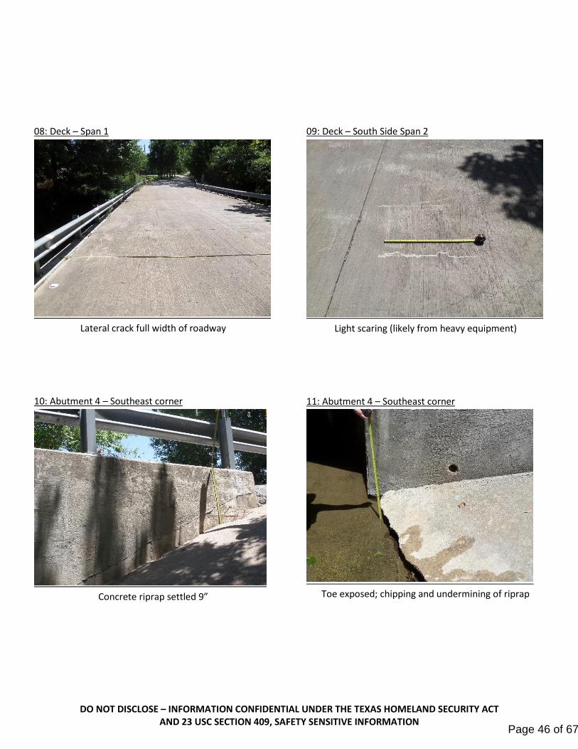
08: Deck – Span 1
Lateral crack full width of roadway
10: Abutment 4 – Southeast corner
Concrete riprap settled 9”
09: Deck – South Side Span 2
Light scaring (likely from heavy equipment)
11: Abutment 4 – Southeast corner
Toe exposed; chipping and undermining of riprap
Page 46 of 67

DO NOT DISCLOSE – INFORMATION CONFIDENTIAL UNDER THE TEXAS HOMELAND SECURITY ACT AND 23 USC SECTION 409, SAFETY SENSITIVE INFORMATION
12: Bottom Slab Toe – South Channel
Exposed bottom slab toe with 18” scour and
undermining at south outfall
14: North Channel – Looking North
Moderate bank erosion looking upstream
13: Bottom Slab Toe – North Channel
5” scour at bottom slab toe, northeast corner
15: South Channel – Looking South
Moderate bank erosion looking downstream
Page 47 of 67
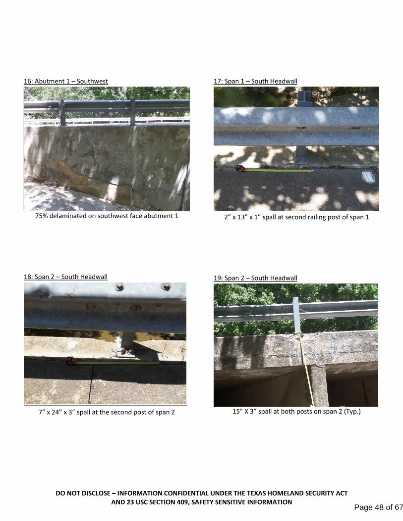
DO NOT DISCLOSE – INFORMATION CONFIDENTIAL UNDER THE TEXAS HOMELAND SECURITY ACT AND 23 USC SECTION 409, SAFETY SENSITIVE INFORMATION
16: Abutment 1 – Southwest
75% delaminated on southwest face abutment 1
18: Span 2 – South Headwall
7” x 24” x 3” spall at the second post of span 2
17: Span 1 – South Headwall
2” x 13” x 1” spall at second railing post of span 1
19: Span 2 – South Headwall
15” X 3” spall at both posts on span 2 (Typ.)
Page 48 of 67

DO NOT DISCLOSE – INFORMATION CONFIDENTIAL UNDER THE TEXAS HOMELAND SECURITY ACT AND 23 USC SECTION 409, SAFETY SENSITIVE INFORMATION
20: Span 3 – North Headwall
Full width hairline crack at the beginning of span 3
22: Abutment 1
0.010” crack full height at 10’ with efflorescence
21: Abutment 1
Scaring and gouging from debris at northwest corner
(Typ.)
23: Wall 2
0.025" crack full height and depth through wall at 15'
Page 49 of 67
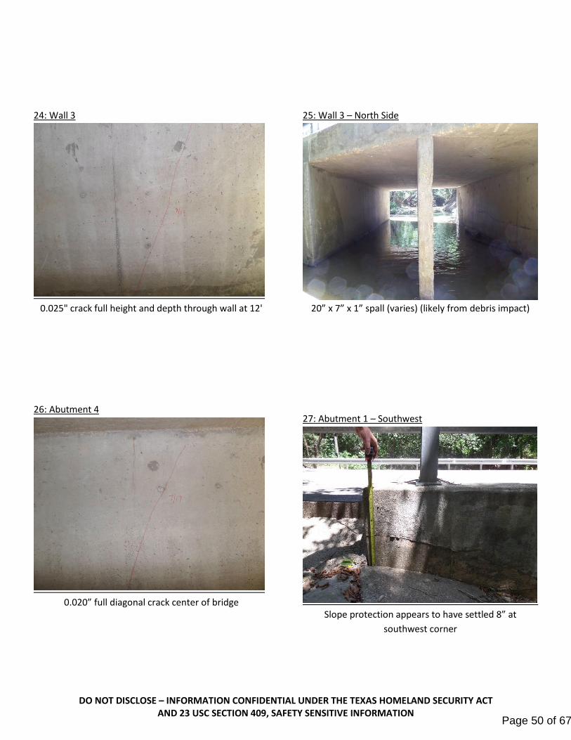
DO NOT DISCLOSE – INFORMATION CONFIDENTIAL UNDER THE TEXAS HOMELAND SECURITY ACT AND 23 USC SECTION 409, SAFETY SENSITIVE INFORMATION
24: Wall 3
0.025" crack full height and depth through wall at 12'
26: Abutment 4
0.020” full diagonal crack center of bridge
25: Wall 3 – North Side
20” x 7” x 1” spall (varies) (likely from debris impact)
27: Abutment 1 – Southwest
Slope protection appears to have settled 8” at
southwest corner
Page 50 of 67

DO NOT DISCLOSE – INFORMATION CONFIDENTIAL UNDER THE TEXAS HOMELAND SECURITY ACT AND 23 USC SECTION 409, SAFETY SENSITIVE INFORMATION
28: Abutment 1 – Northwest corner
No slope protection; 1/8” full height crack and spall;
moderate bank erosion
29: Abutment 4 – Northeast corner
No slope protection; scoring and gouging from debris
(Typ.)
Page 51 of 67

Snider Bridge and Roadway Improvements from Susan Circle to Shady Lane Bridge Alternative Report
Lakes Engineering, Inc.
APPENDIX C:
References
Page 52 of 67

USGS The National Map: Orthoimagery. Data refreshed April, 2019.
National Flood Hazard Layer FIRMette
0 500 1,000 1,500 2,000250Feet
Ü
96°3
4'9.13
"W
33°6'29.59"N
96°33'31.68"W
33°5'59.45"N
SEE FIS REPORT FOR DETAILED LEGEND AND INDEX MAP FOR FIRM PANEL LAYOUT
SPECIAL FLOODHAZARD AREAS
Without Base Flood Elevation (BFE)Zone A, V, A99
With BFE or Depth Zone AE, AO, AH, VE, ARRegulatory Floodway
0.2% Annual Chance Flood Hazard, Areasof 1% annual chance flood with averagedepth less than one foot or with drainageareas of less than one square mile Zone XFuture Conditions 1% AnnualChance Flood Hazard Zone XArea with Reduced Flood Risk due toLevee. See Notes. Zone XArea with Flood Risk due to Levee Zone D
NO SCREEN Area of Minimal Flood Hazard Zone X
Area of Undetermined Flood Hazard Zone D
Channel, Culvert, or Storm SewerLevee, Dike, or Floodwall
Cross Sections with 1% Annual Chance17.5 Water Surface Elevation
Coastal Transect
Coastal Transect BaselineProfile BaselineHydrographic Feature
Base Flood Elevation Line (BFE)
Effective LOMRs
Limit of StudyJurisdiction Boundary
Digital Data AvailableNo Digital Data AvailableUnmapped
This map complies with FEMA's standards for the use of digital flood maps if it is not void as described below. The basemap shown complies with FEMA's basemap accuracy standardsThe flood hazard information is derived directly from theauthoritative NFHL web services provided by FEMA. This mapwas exported on 1/20/2020 at 10:41:29 AM and does notreflect changes or amendments subsequent to this date andtime. The NFHL and effective information may change orbecome superseded by new data over time.This map image is void if the one or more of the following mapelements do not appear: basemap imagery, flood zone labels,legend, scale bar, map creation date, community identifiers,FIRM panel number, and FIRM effective date. Map images forunmapped and unmodernized areas cannot be used forregulatory purposes.
Legend
OTHER AREAS OFFLOOD HAZARD
OTHER AREAS
GENERALSTRUCTURES
OTHERFEATURES
MAP PANELS
8
1:6,000
B 20.2
The pin displayed on the map is an approximate point selected by the user and does not represent an authoritative property location.
Page 53 of 67

StandardDivisionBridge
DN: CK: DW: CK:FILE:
JOB
COUNTY
SECT
DIST
REVISIONS
HIGHWAY
SHEET NO.
C TxDOT
CONT
of this standard to other for
mats or for in
correct results or da
mages resultin
g fro
m its use.
kin
d is
made by Tx
DO
T for any purpose
whatsoever. Tx
DO
T assu
mes no responsibilit
y for the conversio
n
The use of this standard is governed by the "T
exas E
ngin
eerin
g Practic
e
Act".
No
warranty of any
DIS
CL
AI
ME
R:
FILE:
DA
TE:
NO.
BEAM
TYPE
BEAM
SIZE "e"
LC
"e"
END
PRESTRESSING STRANDS
OPTIONAL DESIGN
STRUCTURE
CONCRETE
NO.
SPAN
STRGTH
(in) (in) (in) (in)(ksi)
fpu
(ft-kips)
NO.
TOTAL
DESIGNED BEAMS (STRAIGHT STRANDS)
STRGTH
COMP
28 DAY
MINIMUM
(ksi)
f'c3 6 9 12 15TOTAL
(ft from end)
DE-
BONDED
STRANDS
NO.OF
DEBONDED STRAND PATTERN PER ROW
DEB
NO.
TOT
BOTTOM
FROM
DIST
fct(ksi) fcb(ksi)
PATTERN
STRAND
STD
NON-
(ksi)
f'ci
STRGTH
RELEASE
1 L(SERVICE I)
(TOP C)
STRESS
COMP
LOAD
DESIGN
L(SERVICE III)
(BOTT C)
STRESS
TENSILE
LOAD
DESIGN
(STRENGTH I)
CAPACITY
MOMENT
ULTIMATE
MINIMUM
REQUIRED
ShearMoment
2
FACTOR
DISTRIBUTION
LIVE LOAD
DEBONDED TO
NUMBER OF STRANDS
DESIGN NOTES:
FABRICATION NOTES:
HL93 LOADING
bbstds07.dgn
3
4
1
2 6 8 10
5 7
2 4 86
10 Spa at 2"10 Spa at 2" 13 Spa at 2"
10 814 12 6
13 Spa at 2"
8 4 2
139 11 51113 79
10
"2
12
Typ
4.52.5
1 3
1"1"
4B28
Type
5B28
Type
5B34
Type
4B34
Type
4B20
Type
6.5
8.5
5B20
Type
2"
~ Typ
24
3 1
61214 810
9 115 7 13 7 511 9
6
911 5713
10 814 12
5 71 3 9 1311
13 Spa at 2"
14.516.5
10.512.5
18.5
5B40
Type
4B40
Type
20.5
2"
~ Typ
2
Typ
6 4
"2
12
6.5
8.5
2.54.5
2
57 139
14 12
11131 3
42
5
10
117 9
10 Spa at 2"10 Spa at 2"
64 108 6 410 8 2
13 Spa at 2"
3
1"1"1"1"1"1"
(NON-STANDARD SPANS)
BBND
BOX BEAM DESIGNS
PRESTRESSED CONCRETE
December 2006
TxDOT TxDOT SFS SDB
1
TxDOT B28 BOX BEAMS TxDOT B20 BOX BEAMSTxDOT B40 BOX BEAMS TxDOT B34 BOX BEAMS
2
3
are greater than 100 ft.
4B40 and 5B40 boxes when beam lengths
Bottom corner chamfer required for
Portion of full HL93.
Optional designs must likewise conform.
Tension = 0.24 f'ci
Compression = 0.65 f'ci
Based on the following allowable stresses (ksi):
Full-length debonded strands are only permitted in positions marked .
staggered in each row.
the vertical centerline. Decrease debonded lengths working inward, with debonding
Do not debond strands in position "1". Distribute debonded strands equally about
Strand debonding must comply with Item 424.4.2.2.2.4.
3) Space strands as equally as possible across the entire width.
2) Place strand symmetrically about vertical centerline of box.
1) Locate a strand in each "1" position.
then row "6.5", etc. Place strands within a row as follows:
unless a non-standard stand pattern is indicated. Fill row "2.5", then row "4.5",
Locate strands for the designed beam as low as possible on the 2" grid system
Engineer registered in the State of Texas.
submittals and shop drawings must be signed, sealed and dated by a Professional
the designed beam or an approved optional beam design. All optional design
When shown on this sheet, the Fabricator has the option of furnishing either
Use low relaxation strands, each pretensioned to 75 percent of fpu.
Provide Grade 60 reinforcing steel bars.
Provide Class H concrete.
humidity of percent. Optional designs must likewise conform.
Prestress losses for the designed beams have been calculated for a relative
Designed in accordance with AASHTO LRFD Bridge Design Specifications.
01-16: Notes.
04-11: f'ci and LLDF.
Page 54 of 67

StandardDivisionBridge
DN: CK: DW: CK:FILE:
JOB
COUNTY
SECT
DIST
REVISIONS
HIGHWAY
SHEET NO.
C TxDOT
CONT
of this standard to other for
mats or for in
correct results or da
mages resultin
g fro
m its use.
kin
d is
made by Tx
DO
T for any purpose
whatsoever. Tx
DO
T assu
mes no responsibilit
y for the conversio
n
The use of this standard is governed by the "T
exas E
ngin
eerin
g Practic
e
Act".
No
warranty of any
DIS
CL
AI
ME
R:
FILE:
DA
TE:
NO.
BEAM
TYPE
BEAM
SIZE "e"
LC
"e"
END
PRESTRESSING STRANDS
OPTIONAL DESIGN
STRUCTURE
CONCRETE
STRGTH
(in) (in) (in) (in)(ksi)
fpu
(ft-kips)
NO.
TOTAL
DESIGNED BEAMS (STRAIGHT STRANDS)
STRGTH
COMP
28 DAY
MINIMUM
(ksi)
f'c3 6 9 12 15TOTAL
(ft from end)
DE-
BONDED
STRANDS
NO.OF
DEBONDED STRAND PATTERN PER ROW
DEB
NO.
TOT
BOTTOM
FROM
DIST
fct(ksi) fcb(ksi)
PATTERN
STRAND
STD
NON-
(ksi)
f'ci
STRGTH
RELEASE
1 L(SERVICE I)
(TOP C)
STRESS
COMP
LOAD
DESIGN
L(SERVICE III)
(BOTT C)
STRESS
TENSILE
LOAD
DESIGN
(STRENGTH I)
CAPACITY
MOMENT
ULTIMATE
MINIMUM
REQUIRED
ShearMoment
2
FACTOR
DISTRIBUTION
LIVE LOAD
DEBONDED TO
NUMBER OF STRANDS
5
4
7
6
3
14
13
2
1 3
2
5
4
19
8
11
10
111 3
210
7
6
9
8 10
9
12
11
8
5
4
7
6 6 14
13
13 Spa at 2"
12
13 Spa at 2"
13
13 Spa at 2"
1412
2"
~ Typ
12 14
"2
12
1313
12
2.5
14
11
8
7
10
913
13 Spa at 2"
12 14
Typ
6.5
4.5
10.5
8.5
5 11
10
13
12
9
6
5
8
7
6
5
8
7
4
1
14
3
24
3
6
5
2
1"1"
1
13 Spa at 2"
2
1
4
311
8
7
10
9 9
13 Spa at 2"
1"
4.52.5
1" 1"
13 Spa at 2" 13 Spa at 2"
1"
2
1
4
3
Typ
8.5
6.5
"2
12
2"
~ Typ
5
4
7
6
311
10 2
1
14
13
1"1"
12
9
8
11
10
X-BEAM STANDARD
PRESTRESSED CONCRETE
DESIGNS 32' ROADWAY
XBSD-32
HL93 LOADING
1
2
DESIGN NOTES:
FABRICATION NOTES:
TxDOT 5XB28 BEAMS TxDOT 5XB20 BEAMSTxDOT 5XB40 BEAMS TxDOT 5XB34 BEAMS
xbstds40.dgn
June 2011
SRW BMP SFS SDB
4.50 20 2 2 0 0 0 0
105 ALL 5XB40 48 0.6 270 14.87 14.58 16 2.50 28 14 2 6 2 0 4 4.500 5.100 3.628 -3.630 6854 0.586 0.971
100 ALL 5XB40 42 0.6 270 15.04 14.77 12 2.50 28 12 2 4 2 2 2 4.000 5.000 3.300 -3.318 6319 0.593 0.972
95 ALL 5XB40 36 0.6 270 15.26 15.09 10 2.50 28 10 4 6 0 0 0 4.000 5.000 2.988 -3.020 5806 0.601 0.973
90 ALL 5XB40 32 0.6 270 15.45 15.40 6 2.50 28 6 2 4 0 0 0 4.000 5.000 2.690 -2.735 5310 0.609 0.974
85 ALL 5XB40 28 0.6 270 15.70 15.70 4 2.50 28 4 2 2 0 0 0 4.000 5.000 2.408 -2.464 4834 0.618 0.975
80 ALL 5XB40 24 0.6 270 15.70 15.70 2 2.50 24 2 2 0 0 0 0 4.000 5.000 2.142 -2.207 4378 0.628 0.976
75 ALL 5XB40 20 0.6 270 15.70 15.70 0 2.50 20 0 0 0 0 0 0 4.000 5.000 1.890 -1.962 3939 0.638 0.978
70 ALL 5XB40 18 0.6 270 15.70 15.70 0 2.50 18 0 0 0 0 0 0 4.000 5.000 1.654 -1.731 3521 0.650 0.980
65 ALL 5XB40 16 0.6 270 15.70 15.70 0 2.50 16 0 0 0 0 0 0 4.000 5.000 1.433 -1.513 3137 0.662 0.982
60 ALL 5XB40 14 0.6 270 15.70 15.70 0 2.50 14 0 0 0 0 0 0 4.000 5.000 1.227 -1.308 2947 0.676 0.984
8" Slab 55 ALL 5XB40 14 0.6 270 15.70 15.70 0 2.50 14 0 0 0 0 0 0 4.000 5.000 1.037 -1.117 3007 0.692 0.988
32' Roadway 50 ALL 5XB40 14 0.6 270 15.70 15.70 0 2.50 14 0 0 0 0 0 0 4.000 5.000 0.861 -0.938 2694 0.709 0.991
X-BEAMS 45 ALL 5XB40 12 0.6 270 15.70 15.70 0 2.50 12 0 0 0 0 0 0 4.000 5.000 0.701 -0.772 2255 0.729 0.996
TYPE 5XB40 40 ALL 5XB40 10 0.6 270 15.70 15.70 0 2.50 10 0 0 0 0 0 0 4.000 5.000 0.560 -0.629 1886 0.752 1.001
95 ALL 5XB34 44 0.6 270 12.38 12.17 10 2.50 28 10 2 2 2 2 2 4.600 5.200 3.542 -3.719 5558 0.589 0.945
90 ALL 5XB34 40 0.6 270 12.51 12.31 10 2.50 28 10 2 2 2 2 2 4.200 5.000 3.188 -3.369 5086 0.597 0.946
85 ALL 5XB34 34 0.6 270 12.75 12.65 8 2.50 28 8 4 2 2 0 0 4.000 5.000 2.853 -3.036 4634 0.606 0.947
80 ALL 5XB34 28 0.6 270 13.11 13.11 4 2.50 28 4 2 2 0 0 0 4.000 5.000 2.535 -2.718 4197 0.615 0.949
75 ALL 5XB34 24 0.6 270 13.11 13.11 0 2.50 24 0 0 0 0 0 0 4.000 5.000 2.236 -2.419 3781 0.626 0.951
70 ALL 5XB34 22 0.6 270 13.11 13.11 0 2.50 22 0 0 0 0 0 0 4.000 5.000 1.955 -2.134 3381 0.637 0.953
65 ALL 5XB34 18 0.6 270 13.11 13.11 0 2.50 18 0 0 0 0 0 0 4.000 5.000 1.693 -1.866 2997 0.649 0.956
60 ALL 5XB34 16 0.6 270 13.11 13.11 0 2.50 16 0 0 0 0 0 0 4.000 5.000 1.449 -1.614 2632 0.663 0.958
8" Slab 55 ALL 5XB34 14 0.6 270 13.11 13.11 0 2.50 14 0 0 0 0 0 0 4.000 5.000 1.222 -1.378 2432 0.678 0.962
32' Roadway 50 ALL 5XB34 14 0.6 270 13.11 13.11 0 2.50 14 0 0 0 0 0 0 4.000 5.000 1.014 -1.158 2487 0.695 0.966
X-BEAMS 45 ALL 5XB34 12 0.6 270 13.11 13.11 0 2.50 12 0 0 0 0 0 0 4.000 5.000 0.824 -0.953 2172 0.714 0.971
TYPE 5XB34 40 ALL 5XB34 10 0.6 270 13.11 13.11 0 2.50 10 0 0 0 0 0 0 4.000 5.000 0.657 -0.777 1818 0.736 0.976
80 ALL 5XB28 36 0.6 270 10.19 10.10 6 2.50 28 6 2 2 0 2 0 4.600 5.000 3.124 -3.578 4011 0.601 0.919
75 ALL 5XB28 32 0.6 270 10.38 10.32 6 2.50 28 6 0 2 2 2 0 4.000 5.000 2.753 -3.182 3614 0.611 0.921
70 ALL 5XB28 26 0.6 270 10.63 10.63 2 2.50 26 2 2 0 0 0 0 4.000 5.000 2.404 -2.807 3231 0.621 0.923
65 ALL 5XB28 22 0.6 270 10.63 10.63 0 2.50 22 0 0 0 0 0 0 4.000 5.000 2.079 -2.454 2867 0.633 0.926
60 ALL 5XB28 18 0.6 270 10.63 10.63 0 2.50 18 0 0 0 0 0 0 4.000 5.000 1.777 -2.124 2521 0.647 0.929
8" Slab 55 ALL 5XB28 14 0.6 270 10.63 10.63 0 2.50 14 0 0 0 0 0 0 4.000 5.000 1.497 -1.812 2187 0.661 0.933
32' Roadway 50 ALL 5XB28 12 0.6 270 10.63 10.63 0 2.50 12 0 0 0 0 0 0 4.000 5.000 1.240 -1.523 1870 0.678 0.937
X-BEAMS 45 ALL 5XB28 12 0.6 270 10.63 10.63 0 2.50 12 0 0 0 0 0 0 4.000 5.000 1.006 -1.255 1793 0.697 0.942
TYPE 5XB28 40 ALL 5XB28 12 0.6 270 10.63 10.63 0 2.50 12 0 0 0 0 0 0 4.000 5.000 0.800 -1.023 1748 0.719 0.948
65 ALL 5XB20 36 0.6 270 6.59 6.46 8 2.50 28 8 2 2 2 2 0 4.900 5.200 3.259 -3.946 2739 0.606 0.879
60 ALL 5XB20 30 0.6 270 6.90 6.87 6 2.50 28 6 2 2 2 0 0 4.400 5.000 2.777 -3.406 2407 0.619 0.883
8" Slab 55 ALL 5XB20 24 0.6 270 7.03 7.03 4 2.50 24 4 2 2 0 0 0 4.000 5.000 2.333 -2.901 2090 0.633 0.887
32' Roadway 50 ALL 5XB20 20 0.6 270 7.03 7.03 0 2.50 20 0 0 0 0 0 0 4.000 5.000 1.926 -2.432 1787 0.649 0.891
X-BEAMS 45 ALL 5XB20 14 0.6 270 7.03 7.03 0 2.50 14 0 0 0 0 0 0 4.000 5.000 1.557 -1.997 1498 0.667 0.897
TYPE 5XB20 40 ALL 5XB20 12 0.6 270 7.03 7.03 0 2.50 12 0 0 0 0 0 0 4.000 5.000 1.231 -1.621 1255 0.688 0.903
LENGTH
SPAN
Portion of full HL93.
Optional designs must likewise conform.
Tension = 0.24 f'ci
Compression = 0.65 f'ci
Based on the following allowable stresses (ksi):
Full-length debonded strands are only permitted in positions marked .
with debonding staggered in each row.
about the vertical centerline. Decrease debonded lengths working inward,
Do not debond strands in position "1". Distribute debonded strands equally
Strand debonding must comply with Item 424.4.2.2.2.4.
3) Space strands as equally as possible across the entire width.
2) Place strand symmetrically about vertical centerline of box.
1) Locate a strand in each "1" position.
row "4.5", then row "6.5", etc. Place strands within a row as follows:
system unless a non-standard stand pattern is indicated. Fill row "2.5", then
Locate strands for the designed beam as low as possible on the 2" grid
Engineer registered in the State of Texas.
submittals and shop drawings must be signed, sealed and dated by a Professional
the designed beam or an approved optional beam design. All optional design
When shown on this sheet, the Fabricator has the option of furnishing either
Use low relaxation strands, each pretensioned to 75 percent of fpu.
Provide Grade 60 reinforcing steel bars.
Provide Class H concrete.
through 30 degree skews.
Beam designs are applicable for 8" concrete slabs without overlay and 0
humidity of 60 percent. Optional designs must likewise conform.
Prestress losses for the designed beams have been calculated for a relative
Designed in accordance with AASHTO LRFD Bridge Design Specifications.
(ft)
01-16: Notes, 0.6" strand designs.
Page 55 of 67
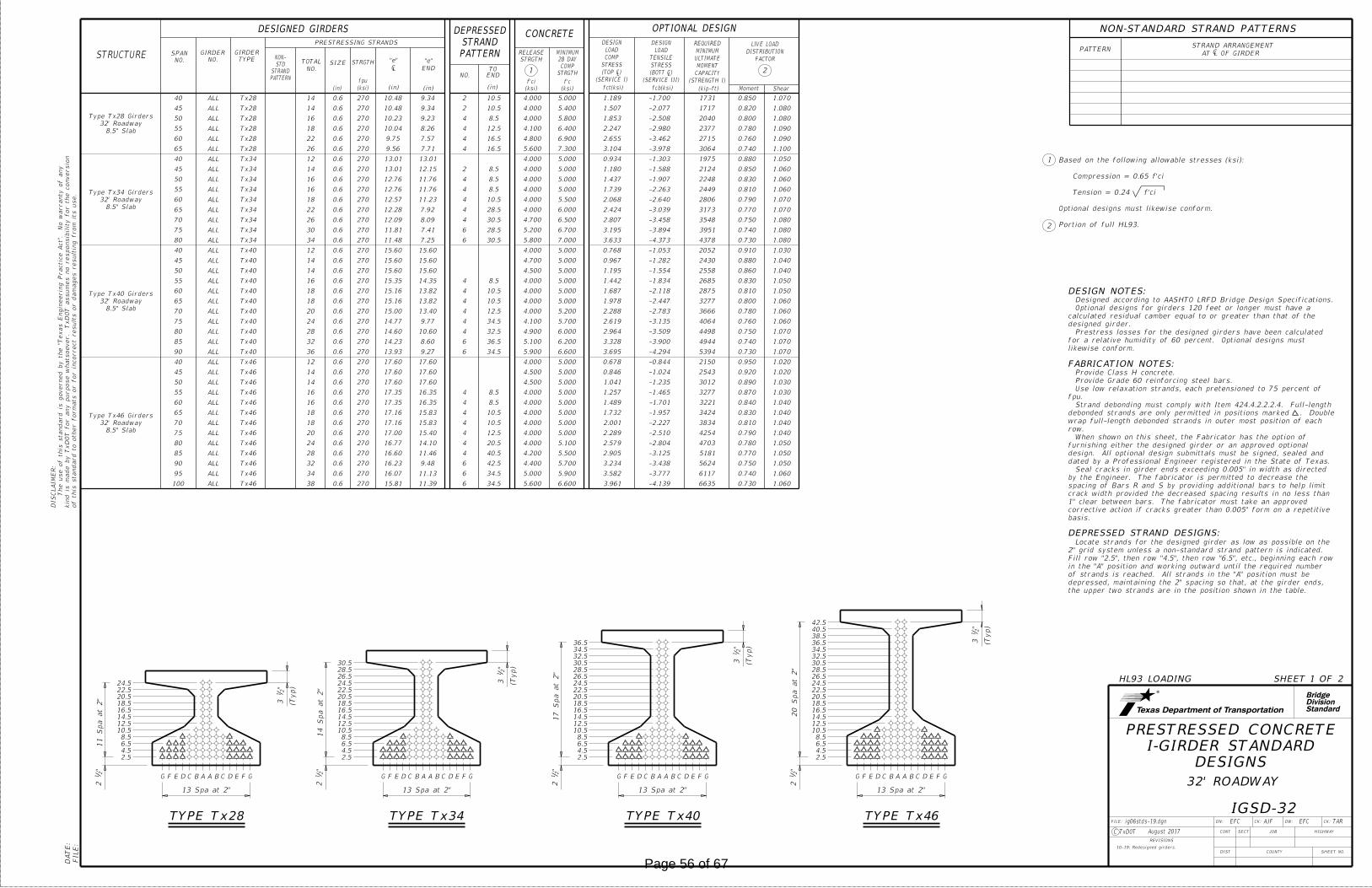
StandardDivisionBridge
FILE:
DA
TE:
DN: CK: DW: CK:FILE:
JOB
COUNTY
SECT
DIST
REVISIONS
TAR
HIGHWAY
SHEET NO.
C TxDOT
CONT
DESIGN NOTES:
"2
12
"2
12
20 S
pa at 2"
11 S
pa at 2"
A A BB CCD DE EF FG G
13 Spa at 2"
A A BB CCD DE EF FG G
13 Spa at 2"
2.5
4.5
6.5
8.5
10.5
12.5
14.5
16.5
18.5
20.5
22.5
24.5
26.5
28.5
30.5
32.5
34.5
36.5
38.5
40.5
42.5
2.5
4.5
6.5
8.5
10.5
12.5
14.5
16.5
18.5
20.5
22.5
24.5HL93 LOADING SHEET 1 OF 2
DESIGNS
I-GIRDER STANDARD
PRESTRESSED CONCRETE
32' ROADWAY
IGSD-32TYPE Tx46
(Typ)"
21
3
"2
12
17 S
pa at 2"
A A BB CCD DE EF FG G
13 Spa at 2"
2.5
4.5
6.5
8.5
10.5
12.5
14.5
16.5
18.5
20.5
22.5
24.5
26.5
28.5
30.5
32.5
34.5
36.5
TYPE Tx40
(Typ)"
21
3
"2
12
14 S
pa at 2"
A A BB CCD DE EF FG G
13 Spa at 2"
2.5
4.5
6.5
8.5
10.5
12.5
14.5
16.5
18.5
20.5
22.5
24.5
26.5
28.5
30.5
TYPE Tx34
(Typ)"
21
3
TYPE Tx28
(Typ)"
21
3
ig06stds-19.dgn EFC EFC
PATTERNSTRAND ARRANGEMENT
CAT L OF GIRDER
NON-STANDARD STRAND PATTERNS
1
2 Portion of full HL93.
Optional designs must likewise conform.
Tension = 0.24 f'ci
Compression = 0.65 f'ci
Based on the following allowable stresses (ksi):
August 2017
AJF
PATTERN
STRAND
STD
NON-SIZE
"e"
LC
"e"
END
PRESTRESSING STRANDS
STRUCTURENO.
SPAN
STRGTH
(in) (in) (in)(ksi)
fpu
(ksi)
f'ci
fct(ksi) fcb(ksi)
NO.
TOTAL
(STRENGTH I)
CAPACITY
MOMENT
ULTIMATE
MINIMUM
REQUIRED
STRGTH
RELEASE
STRGTH
COMP
28 DAY
MINIMUM
(ksi)
f'c
NO.
GIRDER
TYPE
GIRDER
FACTOR
DISTRIBUTION
LIVE LOAD
2
ShearMoment
1
OPTIONAL DESIGNDESIGNED GIRDERS
NO.
(in)
CONCRETE
(kip-ft)
END
TO
(SERVICE I)
(TOP �)STRESS
COMP
LOAD
DESIGN
(SERVICE III)
(BOTT �)STRESS
TENSILE
LOAD
DESIGN
PATTERN
STRAND
DEPRESSED
8.5" Slab
32' Roadway
Type Tx28 Girders
40 ALL Tx28 14 0.6 270 10.48 9.34 2 10.5 4.000 5.000 1.189 -1.700 1731 0.850 1.070
45 ALL Tx28 14 0.6 270 10.48 9.34 2 10.5 4.000 5.400 1.507 -2.077 1717 0.820 1.080
50 ALL Tx28 16 0.6 270 10.23 9.23 4 8.5 4.000 5.800 1.853 -2.508 2040 0.800 1.080
55 ALL Tx28 18 0.6 270 10.04 8.26 4 12.5 4.100 6.400 2.247 -2.980 2377 0.780 1.090
60 ALL Tx28 22 0.6 270 9.75 7.57 4 16.5 4.800 6.900 2.655 -3.462 2715 0.760 1.090
65 ALL Tx28 26 0.6 270 9.56 7.71 4 16.5 5.600 7.300 3.104 -3.978 3064 0.740 1.100
8.5" Slab
32' Roadway
Type Tx34 Girders
40 ALL Tx34 12 0.6 270 13.01 13.01 4.000 5.000 0.934 -1.303 1975 0.880 1.050
45 ALL Tx34 14 0.6 270 13.01 12.15 2 8.5 4.000 5.000 1.180 -1.588 2124 0.850 1.060
50 ALL Tx34 16 0.6 270 12.76 11.76 4 8.5 4.000 5.000 1.437 -1.907 2248 0.830 1.060
55 ALL Tx34 16 0.6 270 12.76 11.76 4 8.5 4.000 5.000 1.739 -2.263 2449 0.810 1.060
60 ALL Tx34 18 0.6 270 12.57 11.23 4 10.5 4.000 5.500 2.068 -2.640 2806 0.790 1.070
65 ALL Tx34 22 0.6 270 12.28 7.92 4 28.5 4.000 6.000 2.424 -3.039 3173 0.770 1.070
70 ALL Tx34 26 0.6 270 12.09 8.09 4 30.5 4.700 6.500 2.807 -3.458 3548 0.750 1.080
75 ALL Tx34 30 0.6 270 11.81 7.41 6 28.5 5.200 6.700 3.195 -3.894 3951 0.740 1.080
80 ALL Tx34 34 0.6 270 11.48 7.25 6 30.5 5.800 7.000 3.633 -4.373 4378 0.730 1.080
8.5" Slab
32' Roadway
Type Tx40 Girders
40 ALL Tx40 12 0.6 270 15.60 15.60 4.000 5.000 0.768 -1.053 2052 0.910 1.030
45 ALL Tx40 14 0.6 270 15.60 15.60 4.700 5.000 0.967 -1.282 2430 0.880 1.040
50 ALL Tx40 14 0.6 270 15.60 15.60 4.500 5.000 1.195 -1.554 2558 0.860 1.040
55 ALL Tx40 16 0.6 270 15.35 14.35 4 8.5 4.000 5.000 1.442 -1.834 2685 0.830 1.050
60 ALL Tx40 18 0.6 270 15.16 13.82 4 10.5 4.000 5.000 1.687 -2.118 2875 0.810 1.050
65 ALL Tx40 18 0.6 270 15.16 13.82 4 10.5 4.000 5.000 1.978 -2.447 3277 0.800 1.060
70 ALL Tx40 20 0.6 270 15.00 13.40 4 12.5 4.000 5.200 2.288 -2.783 3666 0.780 1.060
75 ALL Tx40 24 0.6 270 14.77 9.77 4 34.5 4.100 5.700 2.619 -3.135 4064 0.760 1.060
80 ALL Tx40 28 0.6 270 14.60 10.60 4 32.5 4.900 6.000 2.964 -3.509 4498 0.750 1.070
85 ALL Tx40 32 0.6 270 14.23 8.60 6 36.5 5.100 6.200 3.328 -3.900 4944 0.740 1.070
90 ALL Tx40 36 0.6 270 13.93 9.27 6 34.5 5.900 6.600 3.695 -4.294 5394 0.730 1.070
8.5" Slab
32' Roadway
Type Tx46 Girders
40 ALL Tx46 12 0.6 270 17.60 17.60 4.000 5.000 0.678 -0.844 2150 0.950 1.020
45 ALL Tx46 14 0.6 270 17.60 17.60 4.500 5.000 0.846 -1.024 2543 0.920 1.020
50 ALL Tx46 14 0.6 270 17.60 17.60 4.500 5.000 1.041 -1.235 3012 0.890 1.030
55 ALL Tx46 16 0.6 270 17.35 16.35 4 8.5 4.000 5.000 1.257 -1.465 3277 0.870 1.030
60 ALL Tx46 16 0.6 270 17.35 16.35 4 8.5 4.000 5.000 1.489 -1.701 3221 0.840 1.040
65 ALL Tx46 18 0.6 270 17.16 15.83 4 10.5 4.000 5.000 1.732 -1.957 3424 0.830 1.040
70 ALL Tx46 18 0.6 270 17.16 15.83 4 10.5 4.000 5.000 2.001 -2.227 3834 0.810 1.040
75 ALL Tx46 20 0.6 270 17.00 15.40 4 12.5 4.000 5.000 2.289 -2.510 4254 0.790 1.040
80 ALL Tx46 24 0.6 270 16.77 14.10 4 20.5 4.000 5.100 2.579 -2.804 4703 0.780 1.050
85 ALL Tx46 28 0.6 270 16.60 11.46 4 40.5 4.200 5.500 2.905 -3.125 5181 0.770 1.050
90 ALL Tx46 32 0.6 270 16.23 9.48 6 42.5 4.400 5.700 3.234 -3.438 5624 0.750 1.050
95 ALL Tx46 34 0.6 270 16.07 11.13 6 34.5 5.000 5.900 3.582 -3.777 6117 0.740 1.060
100 ALL Tx46 38 0.6 270 15.81 11.39 6 34.5 5.600 6.600 3.961 -4.139 6635 0.730 1.060
FABRICATION NOTES:
DEPRESSED STRAND DESIGNS:
the upper two strands are in the position shown in the table.
depressed, maintaining the 2" spacing so that, at the girder ends,
of strands is reached. All strands in the "A" position must be
in the "A" position and working outward until the required number
Fill row "2.5", then row "4.5", then row "6.5", etc., beginning each row
2" grid system unless a non-standard strand pattern is indicated.
Locate strands for the designed girder as low as possible on the
basis.
corrective action if cracks greater than 0.005" form on a repetitive
1" clear between bars. The fabricator must take an approved
crack width provided the decreased spacing results in no less than
spacing of Bars R and S by providing additional bars to help limit
by the Engineer. The fabricator is permitted to decrease the
Seal cracks in girder ends exceeding 0.005" in width as directed
dated by a Professional Engineer registered in the State of Texas.
design. All optional design submittals must be signed, sealed and
furnishing either the designed girder or an approved optional
When shown on this sheet, the Fabricator has the option of
row.
wrap full-length debonded strands in outer most position of each
debonded strands are only permitted in positions marked . Double
Strand debonding must comply with Item 424.4.2.2.2.4. Full-length
fpu.
Use low relaxation strands, each pretensioned to 75 percent of
Provide Grade 60 reinforcing steel bars.
Provide Class H concrete.
likewise conform.
for a relative humidity of 60 percent. Optional designs must
Prestress losses for the designed girders have been calculated
designed girder.
calculated residual camber equal to or greater than that of the
Optional designs for girders 120 feet or longer must have a
Designed according to AASHTO LRFD Bridge Design Specifications.
10-19: Redesigned girders.
of this standard to other for
mats or for in
correct results or da
mages resultin
g fro
m its use.
kin
d is
made by Tx
DO
T for any purpose
whatsoever. Tx
DO
T assu
mes no responsibilit
y for the conversio
n
The use of this standard is governed by the "T
exas E
ngin
eerin
g Practic
e
Act".
No
warranty of any
DIS
CL
AI
ME
R:
Page 56 of 67
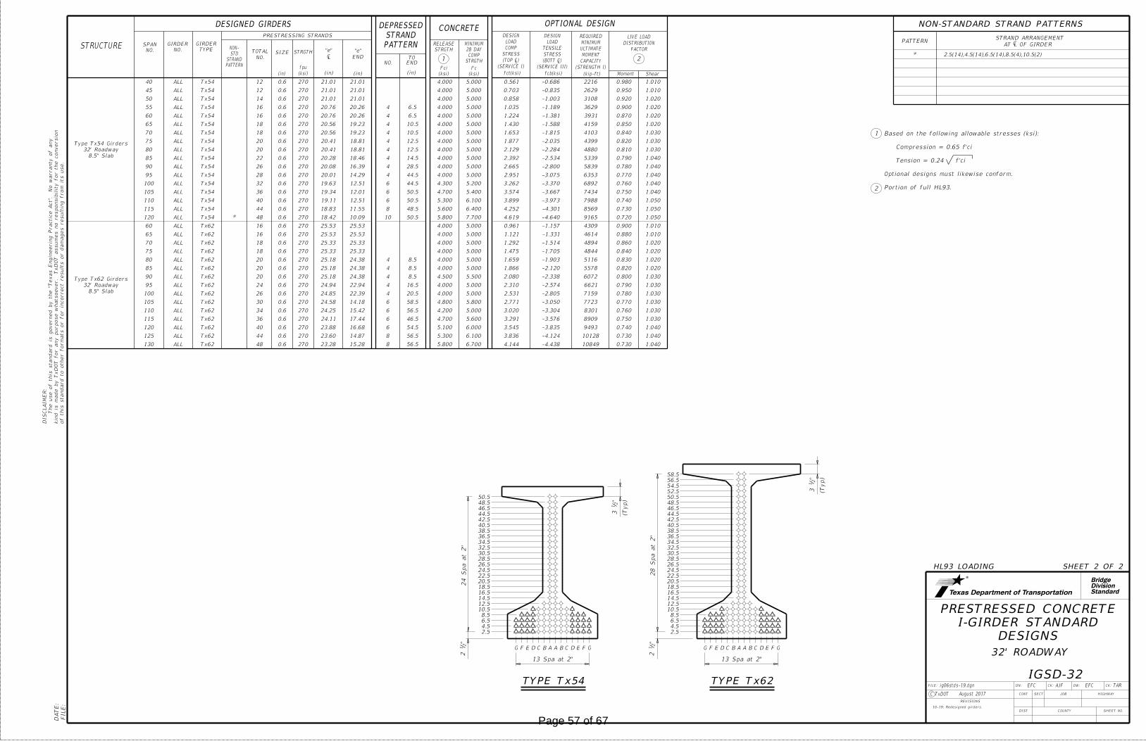
StandardDivisionBridge
FILE:
DA
TE:
DN: CK: DW: CK:FILE:
JOB
COUNTY
SECT
DIST
REVISIONS
TAR
HIGHWAY
SHEET NO.
C TxDOT
CONT
1
2
HL93 LOADING SHEET 2 OF 2
DESIGNS
I-GIRDER STANDARD
PRESTRESSED CONCRETE
"2
12
24 S
pa at 2"
A A BB CCD DE EF FG G
13 Spa at 2"
2.5
4.5
6.5
8.5
10.5
12.5
14.5
16.5
18.5
20.5
22.5
24.5
26.5
28.5
30.5
32.5
34.5
36.5
38.5
40.5
42.5
44.5
46.5
48.5
50.5
34.5
36.5
38.5
40.5
42.5
44.5
46.5
48.5
50.5
52.5
54.5
56.5
58.5
(Typ)
"2
12 A A BB CCD DE EF FG G
13 Spa at 2"
28 S
pa at 2"
2.5
4.5
6.5
8.5
10.5
12.5
14.5
16.5
18.5
20.5
22.5
24.5
26.5
28.5
30.5
32.5
"2
13
TYPE Tx62TYPE Tx54
(Typ)"
21
3
PATTERNSTRAND ARRANGEMENT
CAT L OF GIRDER
NON-STANDARD STRAND PATTERNS
Portion of full HL93.
Optional designs must likewise conform.
Tension = 0.24 f'ci
Compression = 0.65 f'ci
Based on the following allowable stresses (ksi):
IGSD-32
32' ROADWAY
ig06stds-19.dgn
August 2017
EFC AJF EFC
PATTERN
STRAND
STD
NON-SIZE
"e"
LC
"e"
END
PRESTRESSING STRANDS
STRUCTURENO.
SPAN
STRGTH
(in) (in) (in)(ksi)
fpu
(ksi)
f'ci
fct(ksi) fcb(ksi)
NO.
TOTAL
(STRENGTH I)
CAPACITY
MOMENT
ULTIMATE
MINIMUM
REQUIRED
STRGTH
RELEASE
STRGTH
COMP
28 DAY
MINIMUM
(ksi)
f'c
NO.
GIRDER
TYPE
GIRDER
FACTOR
DISTRIBUTION
LIVE LOAD
2
ShearMoment
1
OPTIONAL DESIGNDESIGNED GIRDERS
NO.
(in)
CONCRETE
(kip-ft)
END
TO
(SERVICE I)
(TOP �)STRESS
COMP
LOAD
DESIGN
(SERVICE III)
(BOTT �)STRESS
TENSILE
LOAD
DESIGN
PATTERN
STRAND
DEPRESSED
8.5" Slab
32' Roadway
Type Tx54 Girders
40 ALL Tx54 12 0.6 270 21.01 21.01 4.000 5.000 0.561 -0.686 2216 0.980 1.010
45 ALL Tx54 12 0.6 270 21.01 21.01 4.000 5.000 0.703 -0.835 2629 0.950 1.010
50 ALL Tx54 14 0.6 270 21.01 21.01 4.000 5.000 0.858 -1.003 3108 0.920 1.020
55 ALL Tx54 16 0.6 270 20.76 20.26 4 6.5 4.000 5.000 1.035 -1.189 3629 0.900 1.020
60 ALL Tx54 16 0.6 270 20.76 20.26 4 6.5 4.000 5.000 1.224 -1.381 3931 0.870 1.020
65 ALL Tx54 18 0.6 270 20.56 19.23 4 10.5 4.000 5.000 1.430 -1.588 4159 0.850 1.020
70 ALL Tx54 18 0.6 270 20.56 19.23 4 10.5 4.000 5.000 1.653 -1.815 4103 0.840 1.030
75 ALL Tx54 20 0.6 270 20.41 18.81 4 12.5 4.000 5.000 1.877 -2.035 4399 0.820 1.030
80 ALL Tx54 20 0.6 270 20.41 18.81 4 12.5 4.000 5.000 2.129 -2.284 4880 0.810 1.030
85 ALL Tx54 22 0.6 270 20.28 18.46 4 14.5 4.000 5.000 2.392 -2.534 5339 0.790 1.040
90 ALL Tx54 26 0.6 270 20.08 16.39 4 28.5 4.000 5.000 2.665 -2.800 5839 0.780 1.040
95 ALL Tx54 28 0.6 270 20.01 14.29 4 44.5 4.000 5.000 2.951 -3.075 6353 0.770 1.040
100 ALL Tx54 32 0.6 270 19.63 12.51 6 44.5 4.300 5.200 3.262 -3.370 6892 0.760 1.040
105 ALL Tx54 36 0.6 270 19.34 12.01 6 50.5 4.700 5.400 3.574 -3.667 7434 0.750 1.040
110 ALL Tx54 40 0.6 270 19.11 12.51 6 50.5 5.300 6.100 3.899 -3.973 7988 0.740 1.050
115 ALL Tx54 44 0.6 270 18.83 11.55 8 48.5 5.600 6.400 4.252 -4.301 8569 0.730 1.050
120 ALL Tx54 * 48 0.6 270 18.42 10.09 10 50.5 5.800 7.700 4.619 -4.640 9165 0.720 1.050
8.5" Slab
32' Roadway
Type Tx62 Girders
60 ALL Tx62 16 0.6 270 25.53 25.53 4.000 5.000 0.961 -1.157 4309 0.900 1.010
65 ALL Tx62 16 0.6 270 25.53 25.53 4.000 5.000 1.121 -1.331 4614 0.880 1.010
70 ALL Tx62 18 0.6 270 25.33 25.33 4.000 5.000 1.292 -1.514 4894 0.860 1.020
75 ALL Tx62 18 0.6 270 25.33 25.33 4.000 5.000 1.475 -1.705 4844 0.840 1.020
80 ALL Tx62 20 0.6 270 25.18 24.38 4 8.5 4.000 5.000 1.659 -1.903 5116 0.830 1.020
85 ALL Tx62 20 0.6 270 25.18 24.38 4 8.5 4.000 5.000 1.866 -2.120 5578 0.820 1.020
90 ALL Tx62 20 0.6 270 25.18 24.38 4 8.5 4.500 5.500 2.080 -2.338 6072 0.800 1.030
95 ALL Tx62 24 0.6 270 24.94 22.94 4 16.5 4.000 5.000 2.310 -2.574 6621 0.790 1.030
100 ALL Tx62 26 0.6 270 24.85 22.39 4 20.5 4.000 5.000 2.531 -2.805 7159 0.780 1.030
105 ALL Tx62 30 0.6 270 24.58 14.18 6 58.5 4.800 5.800 2.771 -3.050 7723 0.770 1.030
110 ALL Tx62 34 0.6 270 24.25 15.42 6 56.5 4.200 5.000 3.020 -3.304 8301 0.760 1.030
115 ALL Tx62 36 0.6 270 24.11 17.44 6 46.5 4.700 5.600 3.291 -3.576 8909 0.750 1.030
120 ALL Tx62 40 0.6 270 23.88 16.68 6 54.5 5.100 6.000 3.545 -3.835 9493 0.740 1.040
125 ALL Tx62 44 0.6 270 23.60 14.87 8 56.5 5.300 6.100 3.836 -4.124 10128 0.730 1.040
130 ALL Tx62 48 0.6 270 23.28 15.28 8 56.5 5.800 6.700 4.144 -4.438 10849 0.730 1.040
* 2.5(14),4.5(14),6.5(14),8.5(4),10.5(2)
10-19: Redesigned girders.
of this standard to other for
mats or for in
correct results or da
mages resultin
g fro
m its use.
kin
d is
made by Tx
DO
T for any purpose
whatsoever. Tx
DO
T assu
mes no responsibilit
y for the conversio
n
The use of this standard is governed by the "T
exas E
ngin
eerin
g Practic
e
Act".
No
warranty of any
DIS
CL
AI
ME
R:
Page 57 of 67

StandardDivisionBridge
of this standard to other for
mats or for in
correct results or da
mages resultin
g fro
m its use.
kin
d is
made by Tx
DO
T for any purpose
whatsoever. Tx
DO
T assu
mes no responsibilit
y for the conversio
n
The use of this standard is governed by the "T
exas E
ngin
eerin
g Practic
e
Act".
No
warranty of any
DIS
CL
AI
ME
R:
FILE:
DA
TE:
DN: CK: DW: CK:FILE:
JOB
COUNTY
SECT
DIST
REVISIONS
TxDOT TxDOT TxDOT TxDOT
HIGHWAY
SHEET NO.
C TxDOT
CONTSeptember 2019
SHEET 1 OF 2
CL Slab Jt
CB B
6" 6"
4"
2" 4"
(Typ)
(Typ)
1"
A A
Wingwall
Abutment
Limits of
Wingwall Length
(Variable) 6'-0" Min
1
1'-0"
than 2'-0"
Omit if less
3"
3"
Pilaster Spacing
(Typ) (Typ)
L Interior BentC
Same Criteria as End SpanApprox 1/3 Span LengthApprox 1/3 Span LengthApprox 1/3 Span Length
C
Const Jt (Typ)
Permiss
Const Jt (Typ)
Permiss
6"
Rail for payment
End of Bridge
Abut Pilaster21
Abut Bkwl
Face of
(Typ)
" Pref Bitum Fiber Material21Slab
~
ABUTMENT PILASTER SPAN PILASTER SPAN PILASTER
Abutment Pilaster plus Span Length)21End Span Length = ( Span Length = (Span Length)
C
11
SLAB BREAKBACK
WITH
PILASTER
BENT
SLAB BREAKBACK
WITHOUT
PILASTER
BENT
L Abut Pilaster CL Span Pilaster CL Bent Pilaster
6 5 5
77
9
7
8
C
Connector
Terminal
L Thrie-Beam
3'-0"
2 3
4
2
1
2
3
10
11
4
5
6
7
8
9
ROADWAY ELEVATION OF RAIL
SECTIONELEVATION
Wingwall
Top of Abut
(Showing parapet with Pilaster on 6'-0" Wingwall)
10
8"1'-8"
9
1'-
9" "
16
13
3
"8
57
C
1Connector
Terminal
L Thrie-Beam
TERMINAL CONNECTION DETAILS
R(#7)
1 "21
(Typ)
S(#5)
H(#5)
2"
2"2"
9" Max
S(#5) at
5"R
WH(#5)
9"
6" Max
WU(#5) at
"2
1Bars
WH S
pa ~3
requirements.
maintain cover
slightly to
be rotated
Bars S can
requirements.
maintain cover
slightly to
be rotated
Bars WU can
TYPICAL REINFORCING PLACEMENT
ELEVATION SHOWING
9" Max
U(#5) at
10
9
11
"2
14
1"
1 "21
1"
DETAIL "A"
6"
"2
1"
21
10"
1" (T
yp)
1" (T
yp)
7"
1"
2'-9"
SeeSee
Bars S
1"1"1"
3"3"1'-0"
"212
1"
1'-0"
Typ
"214
"211 "2
11 "211
"2
11
"2
11
2"
Slab
Edge of
Slab
Edge of
2"
Cha
mfer
Chamfer
WH(#5)
S(#5)
2"
SECTION A-A
Side
Traffic
3'-3"
4 Eq Spa = 2'-9"
outside face
3" 3"
SECTION B-B
outside face
2 Eq Spa
2 Eq Spa =
outside face
1'-2"
Chamfer and
Bars S
SECTION C-C
Detail "A" DETAIL "A"Field Bend
See "Roadway
Elevation of Rail"
5 5Connection Details"
See "Terminal
TYPE T411
TRAFFIC RAIL
TEXAS CLASSIC
" Preformed Bituminous Fiber Material at joints.21Shift U Bars from region below
from end of rail when Terminal Connections are required. Field bend as needed.
Place 4 additional Bars WH(#5) 3'-8" in length inside Bars S(#5) and centered 2'-0"
Increase 2" for structures with overlay.
when rail extends over expansion joint. Shift Bars U as necessary.
Place Preformed Bituminous Fiber Material between slab and rail
compound to prevent drainage and staining.
is not left in place, plug the bottom 6" with slab joint sealing
molded cork granules, sponge rubber sheet, etc. If forming material
color and compressible, such as the following materials: polystyrene,
material used in joints may be left in place if it is light in
joints and over sealed deck joints must be plugged. Forming
if slab joint opening is not sealed. Joints over construction
" Max in width. Joints must be open43" Min to 4
1must be
joint opening, except that Rail Joints over construction joints
Provide rail joints at ends of all spans the same width as Slab
Min = 6", Max = 1'-3".
".21Min = 3", Max = 7
Pilasters in a span. Dimension may vary from span to span,
Dimension is the same for all posts adjacent to Span
span length (Approx) for spans greater than 100 ft.
are 100 ft and less, as shown. Space Span Pilasters at 1/5
Space Span Pilasters at 1/3 span length (Approx) when spans
amount in exterior bays (Note 2).
Number of windows in interior bay(s) are not less than the
Number of windows in exterior bays are equal.
Transitions to the bridge unless otherwise shown in the plans.
the Item "Metal Beam Guard Fence". Attach Metal Beam Guard Fence
Terminal Connectors and associated hardware are to be paid for under
1'-6" (Typ)to speeds of 45 mph or less.
The use of this railing is restricted
nut.
" beyond43" to 2
1Provide bolts of sufficient length to extend
when pedestrian sidewalks are adjacent to back of rail.
bolt holes and recesses. Bolt recesses are only required
Adjust placement of reinforcing steel as necessary to avoid
core holes and recesses. Percussion drilling is not permitted.
" Dia x 2" deep recesses. Form or21� 5 ~ 1" Dia holes and 2
rlstd008-19.dgn
Footprint
of Slab.
Outside Edge
Abut Wingwall
of Slab or
Outside Edge
Traffic Side of Rail
Rail
Example showing Slab Expansion Joints without breakbacks.
PLAN OF RAIL AT EXPANSION JOINTS
rail, as shown.
Fiber Material under concrete
" Preformed Bitumuminous21
Cross-hatched area must have
� Concrete Rail Footprint
Joint
Expansion
� Slab perpendicular to slab outside edge.
of � Slab Expansion Joint, � Rail Footprint andRail Expansion Joint must be at the intersection
� Concrete Rail Expansion Joint. Location of
Page 58 of 67

StandardDivisionBridge
of this standard to other for
mats or for in
correct results or da
mages resultin
g fro
m its use.
kin
d is
made by Tx
DO
T for any purpose
whatsoever. Tx
DO
T assu
mes no responsibilit
y for the conversio
n
The use of this standard is governed by the "T
exas E
ngin
eerin
g Practic
e
Act".
No
warranty of any
DIS
CL
AI
ME
R:
FILE:
DA
TE:
DN: CK: DW: CK:FILE:
JOB
COUNTY
SECT
DIST
REVISIONS
TxDOT TxDOT TxDOT TxDOT
HIGHWAY
SHEET NO.
C TxDOT
CONTSeptember 2019
SHEET 2 OF 2
3"3" 3"3" 1'-2"
L PilasterC
C
2" 2"
1'-
0" 2'-
0"
9"R
2'-9"2'-9"
6" 6" 6"
7"
7"
1"1" 1"1"1" 1"
1'-
6"
4"R
12"R
"2
11
"2
17
plans)
elsewhere on
(Use if shown
Bronze Star
8"10"
Typ
8"10"
TypTyp
10" 8"
7"
1'-
6"
7"
7"
1'-
6"
7"
Date
Embossed
Wall Slab
Slab
Top of
ABUTMENT BENT SPAN TYPE A TYPE B TYPE C
Mounting Holes
" Dia85L
7
9
9
12
7
9 9 9
13
EXTERIOR PILASTER ELEVATIONS WINDOW TYPES
7
2"
"2
1
C
36°(Typ)
1"8
13"
(Typ)
Braze
2"
6"R
" Dia Studs83L 2 ~
18
San Antonio, Texas
2. Southwell Company
Austin, Texas
1. Kassons Castings
Two known manufacturers are:
BRONZE STAR DETAIL
18
9
12
13
14
15
16
17
Typ
6"
BARS S (#5)
6"
BARS U (#5)
10"
2'-
6"
6"
Lap
lap on top
Install with
BARS WU (#5)
on top of slab or wall
Installed bar may rest
9
9
14
9
Pin
Bending
" Dia433
"4
11'-
10
5"
1'-0"
~
2'-
8"
1'-
0"
WU(#5)or CRCP
Slab
Approach
OR CIP RETAINING WALLS
ON ABUTMENT WINGWALLS
Reinforcing
Vertical
(Typ)S(#5)
WH(#5)
2"
(Typ)
" Chamfer43
1'-0"Nominal Face of Rail
9
15 "4
16
8"
Min
2'-
8"
SECTIONS THRU RAIL
"2
13
2'-
10"
1"
1"
2" 1'-0"
1'-0"
1"
1"
1"
1"
(Typ)
H(#5)
R(#7)
S(#5)
U(#5)
POST ON BRIDGE SLAB
SECTION THRU
(Showing Pilaster)
(Typ)
" Chamfer43
Nominal Face of Rail
" Chamfer43
9
9
16
17
9
"4
16
8"
Min
2'-
8"
"2
13
H(#5)
U(#5)
WINDOW ON BRIDGE SLAB
SECTION THRU
R(#7)
form removal
for ease of
of all windows
at top & bottom
3% Draft permiss
(Typ)
" Chamfer43
(Typ)
Chamfer
"211
"2
11
1"3"
3"
1"
1" 1"
1'-0"2"
Nominal Face of Rail1'-0"
10"
"2
11
5"
9
916
17
9
"434
"2
14
"2
14
3"
5"
2"
TYPE T411
TRAFFIC RAIL
TEXAS CLASSIC
2014
after casting.
Bronze Star dimensions of the final product can be slightly smaller due to shrinkage
Top longitudinal slab bar may be adjusted laterally 3" plus or minus to tie reinforcing.
expense.
slab with the approval of the Engineer. Such bars must be furnished at the Contractor's
As an aid in supporting reinforcement, additional longitudinal bars may be used in the
in abutment wingwalls or retaining walls on traffic side of wall.
" when vertical reinforcing has closer clear cover over horizontal reinforcing415
Reduce by 2" or field bend over Preformed Bituminous Fiber Material to gain cover.
Dimensions must be the same on each side of joint.
" recess. Placed at one Abutment only or as directed by the Engineer.41with
Construction year (use if shown elsewhere on plans) 3" High "Plantin Bold" Typeface
Increase 2" for structures with overlay.
prevent drainage and staining.
material is not left in place, plug the bottom 6" with slab joint sealing compound to
materials: polystyrene, molded cork granules, sponge rubber sheet, etc. If forming
may be left in place if it is light in color and compressible, such as the following
joints and over sealed deck joints must be plugged. Forming material used in joints
Joints must be open if slab joint opening is not sealed. Joints over construction
" Max in width.43" Min to 4
1that Rail Joints over construction joints must be
Provide rail joints at ends of all spans the same width as Slab joint opening, except
GENERAL NOTES:
MATERIAL NOTES:
CONSTRUCTION NOTES:
rlstd008-19.dgn
"4
311
Reinforcing bar dimensions shown are out-to-out of bar.
Cover dimensions are clear dimensions, unless noted otherwise.
recycled tire rubber
" Rebonded21
pilasters is 270 plf.
Average weight of railing with no overlay increase and no
for approval.
and spacing to first window (see Note 6) to the Engineer
pilaster locations, number of windows between pilasters
Submit erection drawings showing span number, span
identity.
bronze stars, inclusion of construction year with abutment
with the number of windows, window type, inclusion of
dimensions with the number of span pilasters, dimensions
See Bridge Layout or other plan sheets for the following:
Shop drawings will not be required for this rail.
details elsewhere in plans for these modifications.
modification for select structure types. See appropriate
Rail anchorage details shown on this standard may require
providing more than 5" movement.
Do not use this railing on bridges with expansion joints
speed use, speeds of 45 mph and less.
fence transition is used. This rail is only approved for low
speeds of 45 mph and less when a TL-2 or TL-3 rated guard
tested to meet MASH TL-2 criteria. This rail can be used for
strength to railing with like geometry, which have been crash
This rail has been evaluated and approved to be of equal
Epoxy coated ~ #7 = 4'-4"
Epoxy coated ~ #5 = 3'-0"
Uncoated or galvanized ~ #7 = 2'-11"
Uncoated or galvanized ~ #5 = 2'-0"
Provide bar laps, where required, as follows:
following composition: Copper 85 %, Tin 5 %, Lead 5 %, Zinc 5 %.
Bronze Star must be cast of architectural bronze having the
epoxy coated or galvanized.
Epoxy coat or galvanize all reinforcing steel if slab bars are
Provide Grade 60 reinforcing steel.
concrete if shown elsewhere in the plans.
Provide Class "S" concrete for railing. Provide Class "S" (HPC)
shown elsewhere on the plans.
Apply a one rub finish to all railing surfaces unless otherwise
otherwise approved.
Face of rail and pilasters, parapet must be plumb unless
visible epoxy "squeeze out" from under star.
adhesive. Clamp star until epoxy achieves set. Remove any
Attach Bronze Star with a Type III Class C, D, E, or F epoxy
Page 59 of 67

StandardDivisionBridge
DN: CK: DW: CK:FILE:
JOB
COUNTY
SECT
DIST
REVISIONS
TxDOT TxDOT TxDOT TxDOT
HIGHWAY
SHEET NO.
C TxDOT
CONCRETE PAVEMENT
BRIDGE APPROACH SLAB
CONTApril 2019
BAS-C
of this standard to other for
mats or for in
correct results or da
mages resultin
g fro
m its use.
kin
d is
made by Tx
DO
T for any purpose
whatsoever. Tx
DO
T assu
mes no responsibilit
y for the conversio
n
The use of this standard is governed by the "T
exas E
ngin
eerin
g Practic
e
Act".
No
warranty of any
DIS
CL
AI
ME
R:
FILE:
DA
TE:
PLAN
~
Conc Pavement
1
2
3
E (#5 at 12")
F (#5 at 12")
20'-0"
PLAN
this dimension
details for
See structure
~
~
"21
F
A D
GE
T B
"21
CL Structure
D A
T B
(Typ)
Joint Detail
See Isolation
4
7
BAR SIZE
#8 A
#5 B
#5 D
#5
#5
E
#5
F
G
TABLEBAR
14"
16"
45°
~
3
5
Top of Slab)
(Flush with
Approach Slab
~
6
7
5
Approach Slab
"4
3
"21
Joint Detail
Construction
See Sealed
Varie
s
10"
SECTION D-DSECTION B-B SECTION C-C
T #5
1
6'-0"
2 2
2
20'-0"
Bars B (top) and D (bott)
Spaced at 12" Max
2" 2"
B (top)
D (bott)
~
~
~
G
Bars B (top) and D (bott)
Spaced at 12" Max
2"
2"
TRANSVERSE SECTION
Typical section At support slab
12" Max
F, Spa at12" Max
E, Spa at
8
~
reinforcement
standard for
See RW(TRF)
Joint Detail
Construction
See Sealed
D A
B TB T
D A
6
2" TypA
B TD B
DA
D
B T
G
B T
A
D
9
13"
10"
13"
13"
13"
13"
JOINT DETAIL
CONSTRUCTION
SEALED
~
7
8
2'-0"
3'-0"
Uncoated
Epoxy coated Min Lap
5'-0"
2'-6"
~ ~
~~
12" Max
F, Spa at
~
~~
~
~~
~
G
12" Max
E, Spa at
W =
Width of
Approach Sla
b (ft)
W =
Width of
Approach Sla
b (ft)
SECTION A-A
CIP RETAINING WALL
SHOWING WINGWALL OR
SHOWING MSE WALL
W = Width of Approach Slab (ft)
"4
1"
21
rod
Backer
9
"21
ISOLATION JOINT DETAIL
~
8
10
10
23"
Support sla
b
13"
Typ sectio
n
Joint Detail
See Isolation
APPROXIMATE QUANTITIES4
GENERAL NOTES:
5"
13"
4'-8"2'-4"
BARS E (#5) BARS F (#5)
A
A
B
B
A
A
D
D
C
C
A
A
A
A
C
C
B
B
D
D
2"
3"
2" 2"
wall
MSE
S = Skew Angle (deg)
T = Conc Pavement Thickness (in)
W = Width of Approach Slab (ft)
(Includes Support Slab)
Vol of Appr Slab Conc (CY) = 1.057W - 0.008W x T + 0.02W² Tan S
= 18.4 Lbs/LF of Support Slab
Reinf steel weight = 8.5 Lbs/SF of Approach Slab
Reinforcing bar dimensions shown are out-to-out of bar.
Cover dimensions are clear dimensions, unless noted otherwise.
bridge
Edge of
wall
CIP retaining
Wingwall or
at 12" Max
T (top), Spa
slab
Support
at 6" Max
A (bott), Spa
wall
CIP retaining
Wingwall or
(Showing non-skewed approach slab.)
bridge
Edge of
angle (deg)
S = Skew
wall
CIP retaining
Wingwall or
drain
Shoulder
at 12" Max
T (top), Spa
D (bott)
B (top) and
Bend as shown.
D (bott)
B (top) and
at 6" Max
A (bott), Spa
wall
CIP retaining
Wingwall or
(Showing skewed approach slab.)
slab
Support
wall
retaining
or CIP
Wingwall
wall
retaining
or CIP
Wingwall
slab
Support
slab
Support wall
retaining
or CIP
Wingwall
wall
CIP retaining
Wingwall or
joint
Construction
joint
Construction
backwall
Abutment
backwall
abutment
Face of
Const joint Const joint
backwall
abutment
Face of
const joint
Permissible
reinforcing
Abutment
bascste1-20.dgn
"81" - 16
1 "
21
1
" to
41
"2
1
"8
5
8modulus silicone)
joint sealant (low
Class 4, 5, 7 or 8
"41" - 8
1
"41
silicone)
(low modulus
or 8 joint sealant
Class 4, 5, 7,
silicone)
(low modulus
or 8 joint sealant
Class 4, 5, 7,
LONGITUDINAL SAW CUT JOINT DETAIL
(Typ)
" R41Tool
T
joint
in plans for expansion
See details elsewhere
foam
polystyrene
Extruded
~
approach slab.
between concrete railing and top of approach slab as shown when concrete railing projects over the
" rebonded recycled tire rubber21If bridge rail is present at the wingwall or CIP retaining wall, place
Provide backer rod that is 25% larger than joint opening and compatible with the sealant.
Place in accordance with Item 438.
See details elsewhere in plans for required cross-slope.
are achieved.
Multiple piece tie bars are acceptable at longitudinal construction joints provided minimum laps shown
with 60 grade oil and apply heavy coat of powdered graphite. Press down one layer of 30# roofing felt.
required, to accommodate concrete pavement thickness. Smooth trowel finish. Oil top of support slab
On portion of support slab that supports the concrete pavement, adjust top surface elevation, if
For Contractor's information only. Quantities shown are for one approach slab only.
See details elsewhere in plans for shoulder drain location and details.
with bridges built in stages. Other longitudinal construction joints must receive approval of the Engineer.
Provide longitudinal construction joints that align with longitudinal construction joints in the bridge slab
Bend bars as necessary.
Flare Bars B and D in this region (1'-6" Max Spa, 3" Min Spa). Minimum flared bar length = 2'-6".
tire rubber
recycled
Rebonded
02-20: Removed stress relieving pad.
All details shown herein are subsidiary to bridge approach slab.
Cure for 4 days using water or membrane curing per Item 422.
on the plans.
slab to the typical cross-section and to the lines and grades shown
Compact and finish the subgrade or foundation for the approach
otherwise indicated on the plans.
minimum distance of 100 feet prior to the approach slab, unless
Construct the subgrade or subbase away from the bridge for a
requirements of DMS-6310. "Joint Sealants and Fillers."
Provide rebonded recycled tire rubber joint filler that meets the
by the Engineer.)
former (Stress Cap, Zip Strip, Stress Lock, or equal as approved
" vinyl or plastic joint21provide a controlled joint consisting of 1
" and seal in accordance with Item 438. Alternately,21a depth of 1
16 feet. Saw cut joints within 24 hours of concrete placement to
longitudinal construction joints or edges of approach slab exceeds
Joint Detail at lane lines and shoulders when width between
Provide longitudinal joints as shown on the Longitudinal Saw Cut
Provide Grade 60 reinforcing steel.
of 4,000 psi.
Provide Class "S" concrete with a minimum compressive strength
Construct approach slab in accordance with Item 422.
Page 60 of 67
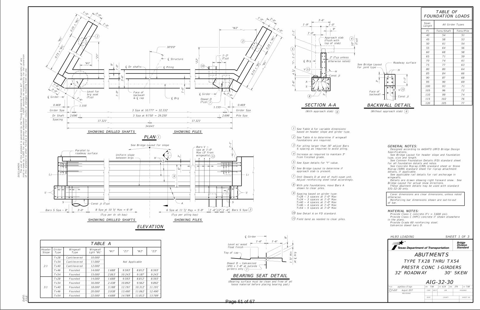
DN: CK: DW: CK:FILE:
JOB
COUNTY
SECT
DIST
REVISIONS
TAR KCM
HIGHWAY
SHEET NO.
C TxDOT
of this standard to other for
mats or for in
correct results or da
mages resultin
g fro
m its use.
kin
d is
made by Tx
DO
T for any purpose
whatsoever. Tx
DO
T assu
mes no responsibilit
y for the conversio
n
The use of this standard is governed by the "T
exas E
ngin
eerin
g Practic
e
Act".
No
warranty of any
DIS
CL
AI
ME
R:
CONT
FILE:
DA
TE:
Dr Shaft
Spacing
30°0'0"
Pile Spa
2'-0"
1'-0"
1'-0"
1'-
0"
1.155'
2'-0"
1.155'
2'-0"
1'-0"2'-0"
1'-0"
(Typ per dr sh bay)
U
S Const jt (Typ) A
H
S
U
6"
2"
1'-
1"
-6"1' 12" -6"1'3'-0"
SHOWING DRILLED SHAFTS SHOWING PILES
ELEVATION
SHOWING DRILLED SHAFTS SHOWING PILES
"WL"
0.7
5 x "W
L"
0.2
5 x "W
L"
"W1"
"Z1"
"WL"
0.7
5 x "W
L"
0.2
5 x "W
L"
"W2"
"Z2"
1PLAN
L 2 L 1
1'-
0"
9"
1'-
9"
3'-
6"
1'-6"
1'-6"
"W1" "Z1" "W2" "Z2"
Not Applicable
TABLE A
3:1
2:1
Tx54
Tx46
Tx40
Tx34
Tx28
Tx54
Tx46
Tx40
Tx34
Tx28
Type
Girder
Founded
Founded
Founded
Founded
Founded
Founded
Founded
Cantilevered
Cantilevered
Cantilevered
22.000'
20.000'
18.000'
16.000'
14.000'
15.000'
14.000'
12.000'
11.000'
10.000'
14.789'
13.490'
12.191'
10.892'
9.593'
10.243'
9.593'
13.789'
12.490'
11.191'
9.892'
8.593'
9.243'
8.593'
9
2
2
10
Girder Spa Girder Spa
0.469'
2.696' 2.696'
0.469'
4.688'
3.938'
3.188'
2.438'
1.688'
2.063'
1.688'
(Typ per piling bay)
3 Spa at 10.777' = 32.332'
3 Spa at 9.750' = 29.250'
17.321' 17.321'
34.641'
Bars S Spa ~ 8"
11.812'
11.062'
10.312'
9.562'
8.812'
9.187'
8.812'
HL93 LOADING SHEET 1 OF 3
TYPE TX28 THRU TX54
PRESTR CONC I-GIRDERS
ABUTMENTS
32' ROADWAY 30° SKEW
AIG-32-30
V H
A
S
(Typ)
Const jt
(With approach slab)
"Y"- 1'-
1"
2'-
6"
1'-
1"
1'-0"
4
5
8
6
3'-6"
1'-9"
9"
1'-0"
SECTION A-A
3"
2" (Typ unless
otherwise noted)
top of slab)
(flush with
Approach slab
10"
A
A
7(Typ)
Dowel D
1
2
3
4
5
6
7
8
9
10
Bars S Spa 3
Slope
Header
Type
Wingwall
Lgth "WL"
Wingwall
(Typ)
1'-3"
(Typ)
brg seat
Level for
StandardDivisionBridge
TAR
6 Spa at 11 ½" Max = 5'-9"
"¼
4
JTR
� Dr shafts
� Structure
� Piling
� Girder
� Brg& � capbackwall
Face of
� Girder
See Bridge Layout for slope
roadway surface
Parallel to
between brgs
Uniform slope wingwalls)
Max (3" from
spa at 1'-0"
Bars V ~
� Brg
GENERAL NOTES:
MATERIAL NOTES:
V
H
(Without approach slab)
1'-
1"
Roadway surface
6
BACKWALL DETAIL
backwall
Face of
Const jt
3"
for joint type
See Bridge Layout
LOADSFOUNDATION
OFTABLE
Length
Span Types GirderAll
Ft Tons/Shaft Tons/Pile
40 54 51
45 58 53
50 61 54
55 64 56
60 68 58
65 71 59
70 74 61
75 77 63
80 80 64
85 84 66
90 87 68
95 90 69
100 93 71
105 96 72
110 99 74
115 102 76
120 105 77
August 2017
" Max = 6'-9"218 Spa at 10
aig43sts-17.dgn
Galvanize dowel bars D.
Provide Grade 60 reinforcing steel.
in the plans.
Provide Class C (HPC) concrete if shown elsewhere
Provide Class C concrete (f'c = 3,600 psi).
of bar.
Reinforcing bar dimensions shown are out-to-out
otherwise.
Cover dimensions are clear dimensions, unless noted
SIG-32-30 only.
These abutment details may be used with standard
Bridge Layout for actual skew directions.
Details are drawn showing right forward skew. See
wingwalls.
See applicable rail details for rail anchorage in
details, if applicable.
Riprap (SRR) standard sheet for riprap attachment
See Concrete Riprap (CRR) standard sheet or Stone
for all foundation details and notes.
See Common Foundation Details (FD) standard sheet
type, size and length.
See Bridge Layout for header slope and foundation
Specifications.
Designed according to AASHTO LRFD Bridge Design
8"
" Min
21
1
7
float finish
Level w/ wood
BEARING SEAT DETAIL
Top of cap
1'-6"1'-6"
at
� brg
� Girder
girders only
(#9) x 1'-8" at outside
Dowel D ~ Galvanized
loose material before placing bearing pad.)
(Bearing surface must be clean and free of all
Field bend as needed to clear piles.
See Detail A on FD standard.
Tx54 ~ 5 spaces at 1'-0" Max
Tx46 ~ 4 spaces at 1'-0" Max
Tx40 ~ 4 spaces at 1'-0" Max
Tx34 ~ 3 spaces at 1'-0" Max
Tx28 ~ 3 spaces at 1'-0" Max
Spacing based on girder type:
shown to clear piles.
With pile foundations, move Bars A
Adjust reinforcing steel total accordingly.
Omit Dowels D at end of multi-span unit.
approach slab is present.
See Bridge Layout to determine if
See Span details for "Y" value.
from finished grade.
Increase as required to maintain 3"
S spacing as required to avoid piling.
For piling larger than 16" adjust Bars
foundations are required.
See Table A to determine if wingwall
based on header slope and girder type.
See Table A for variable dimensions
11
11
11
11
Page 61 of 67

DN: CK: DW: CK:FILE:
JOB
COUNTY
SECT
DIST
REVISIONS
TAR KCM
HIGHWAY
SHEET NO.
C TxDOT
of this standard to other for
mats or for in
correct results or da
mages resultin
g fro
m its use.
kin
d is
made by Tx
DO
T for any purpose
whatsoever. Tx
DO
T assu
mes no responsibilit
y for the conversio
n
The use of this standard is governed by the "T
exas E
ngin
eerin
g Practic
e
Act".
No
warranty of any
DIS
CL
AI
ME
R:
CONT
FILE:
DA
TE:
BARS L2 BARS L1BARS U BARS V & wV
Typ
BARS wS
Typ
BARS S
2'-6"
2'-6"
5"
2'-
0"
2'-0"
2'-0"
2'-
0"
wS
U
S
wV
wH
wH
H
wV
A
L2
CAPBACKWALL
wS
S
U
wV
wH
wH
wV
V
V
1 L
1
2
1
2
CORNER DETAILS
option
Contractor's
to here at
Cap may be cast
5
6"
1'-
1"
Bars wV & wS
U
L
wV
Spacing
wH wS
WINGWALL ELEVATION
2'-
6"
6"
See Table A for length "WL"
9
HL93 LOADING SHEET 2 OF 3
TYPE TX28 THRU TX54
PRESTR CONC I-GIRDERS
ABUTMENTS
32' ROADWAY 30° SKEW
AIG-32-30
StandardDivisionBridge
TAR
2"Spaced at 1'-0" (Max) 3"
top of slab
Flush with
joint
const
Permissroadway grade
Parallel to
wH 2
1
5 wH
wV
SECTION B-B
Const jt
1'-0"1'-0"
2'-0"
2" (Typ unless
otherwise noted)
B
B
3"
9"
9"
3"
5
9
8"
3'-2" 1'-8"1'-
10"
2'-
1"
2'-2"
3'-
0
½"
1'-8 ¾"
"¾
1'-
0
"¾
1'-
0
"½
4
"½
3
"¾
1'-
3
"¼
"Y"+ 4
JTR
1'-10 ¼"
� Brg
2 S
pa at
10"
Max
August 2017
1'-4 ¼"
3'-0 ½"
1'-
3
¾"
aig43sts-17.dgn
11
"4
1"Y
" + 2'-
0
1111
11
11
11
11
11
11
Adjust as required to avoid piling.
Field bend as needed to clear piles.
Tx54 ~ 5 spaces at 1'-0" Max
Tx46 ~ 4 spaces at 1'-0" Max
Tx40 ~ 4 spaces at 1'-0" Max
Tx34 ~ 3 spaces at 1'-0" Max
Tx28 ~ 3 spaces at 1'-0" Max
Spacing based on girder type:
See Span details for "Y" value.
12
12
12
12
wS 12
Page 62 of 67
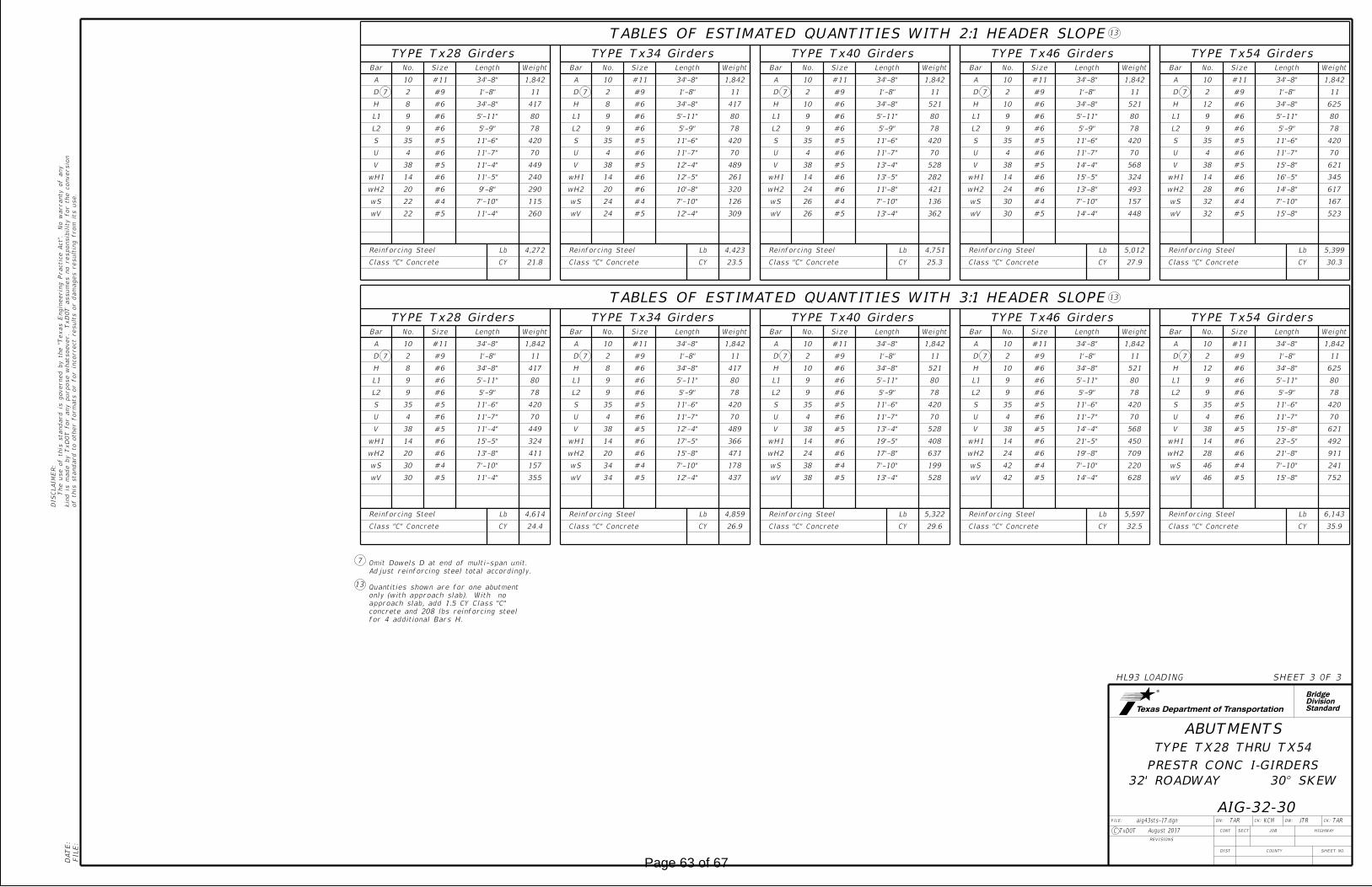
DN: CK: DW: CK:FILE:
JOB
COUNTY
SECT
DIST
REVISIONS
TAR KCM
HIGHWAY
SHEET NO.
C TxDOT
of this standard to other for
mats or for in
correct results or da
mages resultin
g fro
m its use.
kin
d is
made by Tx
DO
T for any purpose
whatsoever. Tx
DO
T assu
mes no responsibilit
y for the conversio
n
The use of this standard is governed by the "T
exas E
ngin
eerin
g Practic
e
Act".
No
warranty of any
DIS
CL
AI
ME
R:
CONT
FILE:
DA
TE:
7
13
HL93 LOADING SHEET 3 OF 3
TYPE TX28 THRU TX54
PRESTR CONC I-GIRDERS
ABUTMENTS
32' ROADWAY 30° SKEW
AIG-32-30TAR
StandardDivisionBridge
JTR
for 4 additional Bars H.
concrete and 208 lbs reinforcing steel
approach slab, add 1.5 CY Class "C"
only (with approach slab). With no
Quantities shown are for one abutment
Adjust reinforcing steel total accordingly.
Omit Dowels D at end of multi-span unit.
August 2017
aig43sts-17.dgn
TABLES OF ESTIMATED QUANTITIES WITH 2:1 HEADER SLOPE
TYPE Tx28 Girders TYPE Tx34 Girders TYPE Tx40 Girders TYPE Tx46 Girders TYPE Tx54 Girders
Bar No. Size Length Weight Bar No. Size Length Weight Bar No. Size Length Weight Bar No. Size Length Weight Bar No. Size Length Weight
A 10 #11 34'-8" 1,842 A 10 #11 34'-8" 1,842 A 10 #11 34'-8" 1,842 A 10 #11 34'-8" 1,842 A 10 #11 34'-8" 1,842
D 2 #9 1'-8" 11 D 2 #9 1'-8" 11 D 2 #9 1'-8" 11 D 2 #9 1'-8" 11 D 2 #9 1'-8" 11
H 8 #6 34'-8" 417 H 8 #6 34'-8" 417 H 10 #6 34'-8" 521 H 10 #6 34'-8" 521 H 12 #6 34'-8" 625
L1 9 #6 5'-11" 80 L1 9 #6 5'-11" 80 L1 9 #6 5'-11" 80 L1 9 #6 5'-11" 80 L1 9 #6 5'-11" 80
L2 9 #6 5'-9" 78 L2 9 #6 5'-9" 78 L2 9 #6 5'-9" 78 L2 9 #6 5'-9" 78 L2 9 #6 5'-9" 78
S 35 #5 11'-6" 420 S 35 #5 11'-6" 420 S 35 #5 11'-6" 420 S 35 #5 11'-6" 420 S 35 #5 11'-6" 420
U 4 #6 11'-7" 70 U 4 #6 11'-7" 70 U 4 #6 11'-7" 70 U 4 #6 11'-7" 70 U 4 #6 11'-7" 70
V 38 #5 11'-4" 449 V 38 #5 12'-4" 489 V 38 #5 13'-4" 528 V 38 #5 14'-4" 568 V 38 #5 15'-8" 621
wH1 14 #6 11'-5" 240 wH1 14 #6 12'-5" 261 wH1 14 #6 13'-5" 282 wH1 14 #6 15'-5" 324 wH1 14 #6 16'-5" 345
wH2 20 #6 9'-8" 290 wH2 20 #6 10'-8" 320 wH2 24 #6 11'-8" 421 wH2 24 #6 13'-8" 493 wH2 28 #6 14'-8" 617
wS 22 #4 7'-10" 115 wS 24 #4 7'-10" 126 wS 26 #4 7'-10" 136 wS 30 #4 7'-10" 157 wS 32 #4 7'-10" 167
wV 22 #5 11'-4" 260 wV 24 #5 12'-4" 309 wV 26 #5 13'-4" 362 wV 30 #5 14'-4" 448 wV 32 #5 15'-8" 523
Reinforcing Steel Lb 4,272 Reinforcing Steel Lb 4,423 Reinforcing Steel Lb 4,751 Reinforcing Steel Lb 5,012 Reinforcing Steel Lb 5,399
Class "C" Concrete CY 21.8 Class "C" Concrete CY 23.5 Class "C" Concrete CY 25.3 Class "C" Concrete CY 27.9 Class "C" Concrete CY 30.3
TABLES OF ESTIMATED QUANTITIES WITH 3:1 HEADER SLOPE
TYPE Tx28 Girders TYPE Tx34 Girders TYPE Tx40 Girders TYPE Tx46 Girders TYPE Tx54 Girders
Bar No. Size Length Weight Bar No. Size Length Weight Bar No. Size Length Weight Bar No. Size Length Weight Bar No. Size Length Weight
A 10 #11 34'-8" 1,842 A 10 #11 34'-8" 1,842 A 10 #11 34'-8" 1,842 A 10 #11 34'-8" 1,842 A 10 #11 34'-8" 1,842
D 2 #9 1'-8" 11 D 2 #9 1'-8" 11 D 2 #9 1'-8" 11 D 2 #9 1'-8" 11 D 2 #9 1'-8" 11
H 8 #6 34'-8" 417 H 8 #6 34'-8" 417 H 10 #6 34'-8" 521 H 10 #6 34'-8" 521 H 12 #6 34'-8" 625
L1 9 #6 5'-11" 80 L1 9 #6 5'-11" 80 L1 9 #6 5'-11" 80 L1 9 #6 5'-11" 80 L1 9 #6 5'-11" 80
L2 9 #6 5'-9" 78 L2 9 #6 5'-9" 78 L2 9 #6 5'-9" 78 L2 9 #6 5'-9" 78 L2 9 #6 5'-9" 78
S 35 #5 11'-6" 420 S 35 #5 11'-6" 420 S 35 #5 11'-6" 420 S 35 #5 11'-6" 420 S 35 #5 11'-6" 420
U 4 #6 11'-7" 70 U 4 #6 11'-7" 70 U 4 #6 11'-7" 70 U 4 #6 11'-7" 70 U 4 #6 11'-7" 70
V 38 #5 11'-4" 449 V 38 #5 12'-4" 489 V 38 #5 13'-4" 528 V 38 #5 14'-4" 568 V 38 #5 15'-8" 621
wH1 14 #6 15'-5" 324 wH1 14 #6 17'-5" 366 wH1 14 #6 19'-5" 408 wH1 14 #6 21'-5" 450 wH1 14 #6 23'-5" 492
wH2 20 #6 13'-8" 411 wH2 20 #6 15'-8" 471 wH2 24 #6 17'-8" 637 wH2 24 #6 19'-8" 709 wH2 28 #6 21'-8" 911
wS 30 #4 7'-10" 157 wS 34 #4 7'-10" 178 wS 38 #4 7'-10" 199 wS 42 #4 7'-10" 220 wS 46 #4 7'-10" 241
wV 30 #5 11'-4" 355 wV 34 #5 12'-4" 437 wV 38 #5 13'-4" 528 wV 42 #5 14'-4" 628 wV 46 #5 15'-8" 752
Reinforcing Steel Lb 4,614 Reinforcing Steel Lb 4,859 Reinforcing Steel Lb 5,322 Reinforcing Steel Lb 5,597 Reinforcing Steel Lb 6,143
Class "C" Concrete CY 24.4 Class "C" Concrete CY 26.9 Class "C" Concrete CY 29.6 Class "C" Concrete CY 32.5 Class "C" Concrete CY 35.9
13
13
7
7 7
7
7
7
7
7
7
7
Page 63 of 67

DN: CK: DW: CK:FILE:
JOB
COUNTY
SECT
DIST
REVISIONS
JMH ASB
HIGHWAY
SHEET NO.
C TxDOT
of this standard to other for
mats or for in
correct results or da
mages resultin
g fro
m its use.
kin
d is
made by Tx
DO
T for any purpose
whatsoever. Tx
DO
T assu
mes no responsibilit
y for the conversio
n
The use of this standard is governed by the "T
exas E
ngin
eerin
g Practic
e
Act".
No
warranty of any
DIS
CL
AI
ME
R:
CONT
FILE:
DA
TE:
34.0
00'
Overall
32.0
00'
Road
way
1.0
00'
2.0
00'
(Typ)
AASee IGTS
AASee IGTS
34.6
41'
(Typ)
20 Spa (9" Max)
(Typ) (Typ)
6'-2"
40.000' thru 120.000' Spans
17.3
21' (T
yp)
17.3
21' (T
yp)
PLAN1
~
~
"4115'-6
HL93 LOADING SHEET 1 OF 2
SIG-32-30
32' ROADWAY 30° SKEW
(TYPE Tx28 THRU Tx54)
I-GIRDER SPANS
PRESTRESSED CONCRETE
TAR
StandardDivisionBridge
2
1
317'-0"17'-0"
34'-0" Overall
32'-0" Roadway
T at 9" Max
Overhang
(Typ)
(Typ)
2"
1'-0"
Sla
b
A
9" (Typ)
3.000'
D
(Showing girder type Tx46)
"2
18
"2
18
TYPICAL TRANSVERSE SECTION
"2
12
3 Spa at 9.333' = 28.000'
3
3.000'
D
Bars P
See PCP for
OA
1'-0"
Panel (Typ)
BAR SIZE
D
A
#4
#4
G
H
M
J
#5
P
BAR TABLE
#5 AA
OA
T #4
#4
#4
#4
#4
#4
1.0
00'
A (Top)
G, H, J, K and M
See IGTS for Bars AA,
Thickened slab end.
30°00'
(Typ)
2
~
~
~
T (Top)
A (Top)
A (Top)
H (Bott)
G (Top) &
A (Top)
A (Top)
H (Bott)
G (Top) &
OA (Top)
~
~
D (Bott)
T (Top)
(Typ)
(Typ)
"414'-4
G, H, J, K and M
See IGTS for Bars AA,
Thickened slab end.
A (Top)
"214
9"
JTR
Bars A at 9" Max Spacing
Bars P
See PCP for
OA (Top)
K #4
or �
bent
Face of bk
wl
locatio
nfor joint ty
pe and
See Brid
ge Layout
� Girder #1
� Structure
� Girder #4
locatio
nfor joint ty
pe and
See Brid
ge Layout
or �
bent
Face of bk
wl
� Structure
See Bridge Layout for slope
� Girder #1
at
� brg
"Y"
at
� brg
� Girder #4
at overhang
spaced between Bars A
OA (Top) ~ 5'-0" long,
between Bars A at overhang
OA (Top) ~ 5'-0" long, spaced
Bars P
See PCP for
No
min
al face of rail
No
min
al face of rail
Nominal face of rail Nominal face of rail
2" End cover Bars T and D
and/or if the precast overhang panel (PCP(O)) option is used.
adjust this value as necessary for any roadway vertical curve
grade, and using precast panels (PCP). The Contractor will
" concrete slab, a constant roadway21load deflection from an 8
"Y" value shown is based on theoretical girder camber, dead
Type Tx54 for spans lengths 40.000' thru 120.000'.
Type Tx46 for spans lengths 40.000' thru 100.000'.
Type Tx40 for spans lengths 40.000' thru 90.000'.
Type Tx34 for spans lengths 40.000' thru 80.000'.
Type Tx28 for spans lengths 40.000' thru 65.000'.
Span lengths for prestressed concrete I-Girder type:
IGCS for adjustment to slab reinforcement and quantities.
bents) are indicated on the Bridge Layout, see standard
If multi-span units (with slab continuous over interior
sig43sts-19.dgn
12"
Tx28
Tx34
Tx40
Tx46
Tx54
Ft/In
3
SECTION DEPTHS
TABLE OF
TYPE
GIRDER "Y" AT � BRG
3'-4"
4'-4"
3'-10"
4'-10"
5'-6"
10-19: Increased "X" and "Y" Values
August 2017
Page 64 of 67
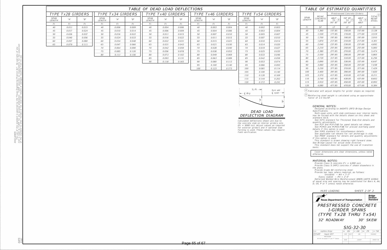
DN: CK: DW: CK:FILE:
JOB
COUNTY
SECT
DIST
REVISIONS
JMH ASB
HIGHWAY
SHEET NO.
C TxDOT
of this standard to other for
mats or for in
correct results or da
mages resultin
g fro
m its use.
kin
d is
made by Tx
DO
T for any purpose
whatsoever. Tx
DO
T assu
mes no responsibilit
y for the conversio
n
The use of this standard is governed by the "T
exas E
ngin
eerin
g Practic
e
Act".
No
warranty of any
DIS
CL
AI
ME
R:
CONT
FILE:
DA
TE:
HL93 LOADING SHEET 2 OF 2
SIG-32-30
32' ROADWAY 30° SKEW
(TYPE Tx28 THRU Tx54)
I-GIRDER SPANS
PRESTRESSED CONCRETE
StandardDivisionBridge
TAR
GENERAL NOTES:
MATERIAL NOTES:
"A"
"B"
Pt41
Sym abt
DEAD LOAD
DEFLECTION DIAGRAM
field verification.
forming is used. These values may require
for exterior girders and if optional slab
(Ec = 5000 ksi). Adjust values as required
the concrete slab on interior girders only
Calculated deflections shown are due to
4
5
factor of 2.3 lbs/SF.
Reinforcing steel weight is calculated using an approximate
Fabricator will adjust lengths for girder slopes as required.
JTR
� Brg � span
5
444
DEFLECTIONS LOAD DEAD OFTABLE
GIRDERS Tx28TYPE GIRDERS Tx34TYPE GIRDERS Tx40TYPE GIRDERS Tx46TYPE GIRDERS Tx54TYPE
LENGTH
SPAN"A" "B"
LENGTH
SPAN"A" "B"
LENGTH
SPAN"A" "B"
LENGTH
SPAN"A" "B"
LENGTH
SPAN"A" "B"
Ft Ft Ft Ft Ft Ft Ft Ft Ft Ft Ft Ft Ft Ft Ft
40 0.011 0.015 40 0.006 0.009 40 0.004 0.006 40 0.003 0.004 40 0.002 0.003
45 0.017 0.024 45 0.010 0.014 45 0.006 0.009 45 0.004 0.006 45 0.003 0.004
50 0.026 0.037 50 0.016 0.022 50 0.011 0.015 50 0.007 0.010 50 0.005 0.007
55 0.040 0.056 55 0.024 0.033 55 0.016 0.022 55 0.011 0.015 55 0.007 0.010
60 0.057 0.080 60 0.034 0.048 60 0.022 0.031 60 0.015 0.021 60 0.010 0.014
65 0.079 0.111 65 0.047 0.066 65 0.031 0.043 65 0.021 0.030 65 0.014 0.020
70 0.064 0.090 70 0.042 0.059 70 0.028 0.040 70 0.019 0.027
75 0.085 0.120 75 0.056 0.078 75 0.038 0.053 75 0.025 0.035
80 0.111 0.156 80 0.073 0.102 80 0.049 0.069 80 0.033 0.046
85 0.093 0.131 85 0.063 0.089 85 0.042 0.059
90 0.118 0.165 90 0.080 0.113 90 0.053 0.074
95 0.100 0.140 95 0.066 0.093
100 0.123 0.173 100 0.081 0.114
105 0.100 0.140
110 0.120 0.169
115 0.144 0.202
120 0.172 0.241
QUANTITIES ESTIMATED OFTABLE
LENGTH
SPAN
SLAB
CONCRETE
REINF
Girders ConcretePrestressed
STEEL
REINF
TOTAL
BTINT
TO
ABUT
BTINT
TO
BTINT
ABUT
TO
ABUT
Ft SF LF LF LF Lb
40 1,360 157.85 158.00 157.69 3,128
45 1,530 177.85 178.00 177.69 3,519
50 1,700 197.85 198.00 197.69 3,910
55 1,870 217.85 218.00 217.69 4,301
60 2,040 237.85 238.00 237.69 4,692
65 2,210 257.85 258.00 257.69 5,083
70 2,380 277.85 278.00 277.69 5,474
75 2,550 297.85 298.00 297.69 5,865
80 2,720 317.85 318.00 317.69 6,256
85 2,890 337.85 338.00 337.69 6,647
90 3,060 357.85 358.00 357.69 7,038
95 3,230 377.85 378.00 377.69 7,429
100 3,400 397.85 398.00 397.69 7,820
105 3,570 417.85 418.00 417.69 8,211
110 3,740 437.85 438.00 437.69 8,602
115 3,910 457.85 458.00 457.69 8,993
120 4,080 477.85 478.00 477.69 9,384
D, OA, P or T unless noted otherwise.
of equal size and spacing may be substituted for Bars A, AA,
Deformed Welded Wire Reinforcement (WWR) (ASTM A1064)
Epoxy coated ~ #4 = 2'-5"
Uncoated ~ #4 = 1'-7"
Provide bar laps, where required, as follows:
Provide Grade 60 reinforcing steel.
the plans.
Provide Class S (HPC) concrete if shown elsewhere in
Provide Class S concrete (f'c = 4,000 psi).
otherwise.
Cover dimensions are clear dimensions, unless noted
bents.
This standard does not support the use of transition
See Bridge Layout for actual skew direction.
This standard is drawn showing right forward skew.
if this option is used.
See PMDF standard for details and quantity adjustments
See applicable rail details for rail anchorage in slab.
See IGMS standard for miscellaneous details.
details if this option is used.
See PCP(O) and PCP(O)-FAB for precast overhang panel
See PCP and PCP-FAB for panel details not shown.
quantity adjustments.
See IGTS standard for Thickened Slab End details and
standard IGCS.
may be formed with the details shown on this sheet and
Multi-span units, with slab continuous over interior bents,
Specifications.
Designed according to AASHTO LRFD Bridge Design
sig43sts-19.dgn
10-19: Increased "X" and "Y" Values
August 2017
Page 65 of 67

Snider Bridge and Roadway Improvements from Susan Circle to Shady Lane Bridge Alternative Report
Lakes Engineering, Inc.
EXHIBIT A:
Existing Right-Of-Way &
Easement Plan
Page 66 of 67

(CALLED 32.80 ACRES)
O.P.R.C.C.T.
INST. NO. 20160407000413150
OUR HAVEN INVESTMENT PROPERTY LC
(CALLED 27.80 ACRES)
D.R.C.C.T.
VOL. 755, PG. 382
UNITED STATES OF AMERICA
TRACT NO. 4410
LOT 1
(CALLED 0.91 ACRES)
D.R.C.C.T.
VOL. 769, PG. 393
UNITED STATES OF AMERICA
TRACT NO. 4411
LOT 12
O.P.R.C.C.T.
INST. NO. 20111129001287780
WILLIAM B. PHILLIPS III
LOT 13
LOT 10
O.P.R.C.C.T.
INST. NO. 20130515000664850
AND PAULA W. HOLMAN
JON L. HOLMANSNIDER ROAD (CR 319)
SH
AD
Y
LA
NE
LOT 9LOT 8
LOT 7
P.R.C.C.T.
CABINET K, PAGE 279
CREEKWOOD ESTATES
BLOCK A LOT 10
LOT 9
LOT 8
LOT 7
LOT 11
P.R.C.C.T.
CAB. Y, PAGE 643
PETWAY FARM SUBDIVISION
(CALLED 32.80 ACRES)
O.P.R.C.C.T.
INST. NO. 20110512000490200
DATED MAY 10, 2011
FAMILY LIVING TRUST
TRUSTEES OF THE BUTLER
VIRGINIA M. BUTLER,
JEROME K. BUTLER AND
O.P.R.C.C.T.
INST. NO. 20140912000992270
SPOUSE, PAULA W. HOLMAN
JOHN HOLMAN AND
P.
R.
C.
C.
T.
CA
B.
K,
PG. 279
(70'
RO
W)
SNIDER ROAD (
CR 319)
P.
R.
C.
C.
T.
CA
B.
K,
PG. 279
(70'
RO
W)
SNIDER ROAD (CR 319)
BLOCK B
P.R.C.C.T.
CAB. K, PAGE 279
CREEKWOOD ESTATES
CI
RC
LE
SU
SA
N
CO
UR
TN
AT
HA
N
200
Feet
0 50
EXHIBIT A
CL CONST.
CL CONST.
CL CONST.
BEGIN PROJECT
RECONSTRUCTION
END SHADY LANE
O.P.R.C.C.T.
20150527000616120
INST. NO.
AMY STUBBS
ETHAN STUBBS AND
(CALLED 1.950 ACRES)
O.P.R.C.C.T.
20191211001574620
INST. NO.
AND CHERI LINDLEY
JENNIFER EMERY
P.R.C.C.T.
CAB. K, PG. 279
(90' ROW)
CALLED 0.06 ACRES)
D.R.C.C.T.
VOL. 2993, PG. 455
COUNTY OF COLLIN
CALLED 0.06 ACRES)
D.R.C.C.T.
VOL. 2993, PG. 451
COUNTY OF COLLIN
P.R.C.C.T.
CAB. Y, PAGE 643
(35' ROW DEDICATION)
(NO DEED OF RECORD FOUND)
APPARENT ROW LINE
(NO DEED OF RECORD FOUND)
APPARENT ROW LINE
1
END PROJECT
CONSTRUCTION EASEMENT
PROPOSED TEMPORARY
EXISTING
EASEMENT PLAN
RIGHT-OF-WAY &
516.847
FI
LE:
DA
TE:
T:\20-101
Snider
Bridge and
Road I
mprove
ments\4 -
Design\
Plan
Set\10.
Miscellaneous\
Snider_
Ex_
RO
W.dgn
7/30/2020
3:43:33
PM
JOB SHEET NO.
COUNTY
SHEET OF
COLLIN
20-101
ROAD
SNIDER RD.or construction purposes.
bidding,
regulatory approval, permit,
It is not to be used for
P.E. 112052 on 08/2020
Chris Meszler
the authority of
informational purposes under
This document is released for
LUCAS, TX. 75002
665 COUNTRY CLUB ROAD
PUBLIC WORKS DEPARTMENT
CITY OF LUCAS
50ft 5
0ft
Page 67 of 67