Fault Detection in dynamic conditions by means of Discrete Wavelet Decomposition for PMSM running...
6
Abstract—This paper presents a study of the Permanent Magnet Synchronous Machine (PMSM) running under bearing damage. To carry out the study a two-dimensional (2-D) Finite Element Analysis (FEA) is used. Stator current induced harmonics for fault condition were investigated. Advanced signal analysis by means of Continuous and Discrete Wavelet Transforms was performed. Simulation were carried out and compared with experimental. Index Terms— PMSM, drive, faults, eccentricity, bearing fault, Continuous, Discrete, Wavelet, Finite Elements analysis, FEA I. INTRODUCTION n many applications the failure of a drive has a serious impact on the operation of a system. In some cases the failure results in lost production, whilst in others it may jeopardize human safety. In such applications it is advantageous to use a drive capable of continuing to operate in the presence of any single point failure. Such a drive is termed fault tolerant and to develop it is necessary to know and understand the faults in motor, which is the aim of the research presented here [1, 2]. The majority of the electrical machines use ball or rolling element bearings. Each of these bearings consists of two rings, inner and outer respectively. A set of balls or rolling elements placed in raceways rotate inside these rings [3]. Even under normal operating conditions with balanced load and good alignment, fatigue failures may take place. Flaking or spalling of bearings might occur when fatigue causes small pieces to break loose from the bearing. Apart from normal internal operating stresses, other causes of bearing damages due to vibration, inherent eccentricity, and bearing currents [3] due to solid state drives appear as well. Sometimes bearing faults might manifest themselves as rotor asymmetry faults [4], which are usually covered under the category of eccentricity-related faults. Otherwise, the ball bearing related defects can be categorized as outer bearing race defect, inner bearing race defect, ball defect, and train defect. All these mechanical defects cause distortions in flux distribution inside the machine, which in turns leads to new current harmonics in stator currents. Time-frequency dependent analysis method is a novel approach in motor diagnosis field. Successful application of these techniques requires understanding of their respective limitations [5].Wigner Ville Distribution (WVD), and Wavelet Transform (WT) describe how the spectrum of a signal changes with time, and this is its major advantage. Such an instantaneous spectrum is very useful in many applications [6- 8]. Coupling between the non-linear magnetic effects and non- linear electric circuits should be token into account in order to determine the behavior of the electrical motor under fault conditions [9]. In this paper Finite Element Analysis (FEA) is proposed for the simulation of electrical machines under fault. FEA analysis reveals itself like an accurate an easy method to determine the interaction between non-linear effects. In this paper, a PMSM under bearing fault are simulated at different speed values using a two-dimensional (2-D) Finite Element Analysis (FEA). In addition, the PMSM running at speed variation are analysis by means of Wavelet transform. Simulations are also compared with experimental results. II. WAVELET TRANSFORM Wavelet analysis is capable of revealing aspects of data that other signal analysis techniques miss, like trends, breakdown points, discontinuities in higher derivatives, and also self- similarity. Also allows to denoise signal and chose bands where focus the analysis, by using properly the mother wavelet function and also the scaling function wavelet [10, 11]. The wavelet approach is essentially an adjustable window Fourier spectral analysis. The wavelet transform decomposes signals over dilated and translated wavelets. It is normalized ||ψ|| = 1, and centered in the neighborhood of t = 0. A family of time-frequency atoms Fault Detection in dynamic conditions by means of Discrete Wavelet Decomposition for PMSM running under Bearing Damage J. Rosero 1 , L. Romeral 2 , E. Rosero 3 , J. Urresty 2 1 ABB, e-mail: [email protected] 2 Motion Control and Industrial Applications Group, Technical University of Catalonia, C/ Colon 1 Tr 2-225. 08222 Terrassa. Catalonia. Spain, e-mail: [email protected] 3 Research Group of Industrial Control (GICI), University of Valle, Calle 13 N° 100-00, Cali – Colombia, e-mail: [email protected] I 978-1-422-2812-0/09/$25.00 ©2009 IEEE 951
-
Upload
independent -
Category
Documents
-
view
1 -
download
0
Transcript of Fault Detection in dynamic conditions by means of Discrete Wavelet Decomposition for PMSM running...
Abstract—This paper presents a study of the Permanent
Magnet Synchronous Machine (PMSM) running under bearing damage. To carry out the study a two-dimensional (2-D) Finite Element Analysis (FEA) is used. Stator current induced harmonics for fault condition were investigated. Advanced signal analysis by means of Continuous and Discrete Wavelet Transforms was performed. Simulation were carried out and compared with experimental.
Index Terms— PMSM, drive, faults, eccentricity, bearing fault, Continuous, Discrete, Wavelet, Finite Elements analysis, FEA
I. INTRODUCTION n many applications the failure of a drive has a serious impact on the operation of a system. In some cases the
failure results in lost production, whilst in others it may jeopardize human safety. In such applications it is advantageous to use a drive capable of continuing to operate in the presence of any single point failure. Such a drive is termed fault tolerant and to develop it is necessary to know and understand the faults in motor, which is the aim of the research presented here [1, 2].
The majority of the electrical machines use ball or rolling element bearings. Each of these bearings consists of two rings, inner and outer respectively. A set of balls or rolling elements placed in raceways rotate inside these rings [3]. Even under normal operating conditions with balanced load and good alignment, fatigue failures may take place. Flaking or spalling of bearings might occur when fatigue causes small pieces to break loose from the bearing. Apart from normal internal operating stresses, other causes of bearing damages due to vibration, inherent eccentricity, and bearing currents [3] due to solid state drives appear as well.
Sometimes bearing faults might manifest themselves as rotor asymmetry faults [4], which are usually covered under the category of eccentricity-related faults. Otherwise, the ball
bearing related defects can be categorized as outer bearing race defect, inner bearing race defect, ball defect, and train defect. All these mechanical defects cause distortions in flux distribution inside the machine, which in turns leads to new current harmonics in stator currents.
Time-frequency dependent analysis method is a novel approach in motor diagnosis field. Successful application of these techniques requires understanding of their respective limitations [5].Wigner Ville Distribution (WVD), and Wavelet Transform (WT) describe how the spectrum of a signal changes with time, and this is its major advantage. Such an instantaneous spectrum is very useful in many applications [6-8].
Coupling between the non-linear magnetic effects and non- linear electric circuits should be token into account in order to determine the behavior of the electrical motor under fault conditions [9]. In this paper Finite Element Analysis (FEA) is proposed for the simulation of electrical machines under fault. FEA analysis reveals itself like an accurate an easy method to determine the interaction between non-linear effects.
In this paper, a PMSM under bearing fault are simulated at different speed values using a two-dimensional (2-D) Finite Element Analysis (FEA). In addition, the PMSM running at speed variation are analysis by means of Wavelet transform. Simulations are also compared with experimental results.
II. WAVELET TRANSFORM Wavelet analysis is capable of revealing aspects of data that
other signal analysis techniques miss, like trends, breakdown points, discontinuities in higher derivatives, and also self-similarity. Also allows to denoise signal and chose bands where focus the analysis, by using properly the mother wavelet function and also the scaling function wavelet [10, 11]. The wavelet approach is essentially an adjustable window Fourier spectral analysis.
The wavelet transform decomposes signals over dilated and translated wavelets. It is normalized ||ψ|| = 1, and centered in the neighborhood of t = 0. A family of time-frequency atoms
Fault Detection in dynamic conditions by means of Discrete Wavelet Decomposition for PMSM
running under Bearing Damage J. Rosero1, L. Romeral2, E. Rosero3, J. Urresty2
1ABB, e-mail: [email protected] 2Motion Control and Industrial Applications Group, Technical University of Catalonia, C/ Colon 1 Tr 2-225. 08222 Terrassa. Catalonia. Spain, e-mail: [email protected]
3Research Group of Industrial Control (GICI), University of Valle, Calle 13 N° 100-00, Cali – Colombia, e-mail: [email protected]
I
978-1-422-2812-0/09/$25.00 ©2009 IEEE 951
is dilated with a scale parameter s, and translated by u:
⎟⎠⎞
⎜⎝⎛ −
=s
uts
tsu ψψ 1)(, (1)
The following general definition [10] is the continuous Wavelet transform (CWT) of a signal at time u and scale s:
( ) ∫+∞
∞−
∂⎟⎠⎞
⎜⎝⎛ −
= ts
uts
tXsuWf *1)(, ψ (2)
Where, ψ(t) is the mother wavelet function. Although time and frequency do not appear explicitly in the
transformed result, the variable 1/s gives the frequency scale and u, the temporal location of an event. An intuitive physical explanation of (2) is very simple: Wf(u,s) is the ´energy´ of X of scale s at t = u.
In the case of discrete Wavelet transform (DWT), the dilation and translation parameters are restricted only to discrete values leading. Through digital signal processing of a signal, it is possible to obtain the Wavelet transform coefficients W(s,u), on a discrete grid corresponding to the discrete time Wavelet coefficients. This is achieved when s and u are assigned regularly spaced values [12]: s=mso and u=nuo, where m and n are integer values. The scale is sample along a dyadic sequence (2n) to simplify the numerical calculations.
The DWT is computed by successive low-pass and high-pass filtering of the discrete time-domain signal together with changes in sampling rates. A signal can be successively approximated by details with different scales.
The information obtained from CWT is redundant. In order to diminish the amount of data and to obtain quality parameter it is necessary to define algorithms to extract the main features. In this sense the Ridges Algorithm is a good choice. This algorithm could be applied to any Time-Frequency transform and it obtains the medium value of the local maxima in the spectrum decomposition for every Δt considered. The time evolution of the calculated parameter is a good tool for our diagnostic proposes [11, 13].
III. WORKBENCH OF SIMULATION AND EXPERIMENTAL The fault analysis for PMSM of 6000 rpm, 2.3 Nm, 3 pair
of poles is based on simulation and experimental tests [14]. The motors were driven at nominal (6000 rpm), medium (3000 rpm) and low speed (1500 rpm).
For simulations two bearing fault degrees were considered, corresponding to different pulsating fault torques. The low one amplitude were 0.5% of the nominal, and the high one amplitude were 1 % of the nominal. The simulation of bearing damage are carry out by means of pulsate torque. For experiments only one medium fault degree were considered.
Speed variations of ±500 rpm were introduced during the experiments to prove the validity of the method even under speed variations. Stator current motor analysis was carried out for speed changes at nominal torque by means of continuous (CWT) and discrete (DWT) Wavelet transforms. The DWT Meyer of 7 levels has been applied. The spectrum has been
normalized to a rotor frequency for every case. Finally, the validity of the proposed method is confirmed by experimental result.
Numerical simulations were developed with the combination of a finite element software, Flux 2D for the model, and Matlab – Simulink for electronics and control [15]
The current has been measured by a current probe A622 Tektronix, 100 Ampere AC/DC. The current ranges are 0/100 mV/A, and the typical DC Accuracy is ±3% ± 50 mA at 100 mV/A (50 mA to a 10 A peak).
The Wavelet transform and AWT ridges algorithm is implemented in Matlab using the Wavelab850 toolbox from Stanford University [13].
IV. BEARING DAMAGE ANALYSIS BY MEANS OF FEA The characteristic fault frequencies are the result of the
absolute motion (vibration) of the machine [16]. The stator current is not affected by the absolute motion of the machine, but rather by a relative motion between the stator and rotor (i.e., changes in the air gap). In the time of a bearing fault, the characteristic fault frequencies are essentially modulated by the electrical supply frequency [16].
The mechanical displacement resulting from damaged bearing causes the machine air gap to vary in a manner that can be described by a combination of rotating eccentricities moving in both directions. As with the air-gap eccentricity, these variations generate stator currents at frequencies given by [17, 18].
oisbng mfff ,±= , ⎥⎦
⎤⎢⎣
⎡±= βcos1
2, pdbdfnf roi
(3)
where, m is 1, 2, 3… , n is the number of bearing balls, fi,o is the characteristic vibration frequencies, fr is the mechanical rotor speed, bd is the ball diameter, pd is the bearing pitch diameter, and β is the contact angle of the balls on the races.
Yazici et al. [19, 20] have reported an adaptive, statistical time frequency method for the detection of bearing faults. Experiments were conducted on defective bearings with scratches on the outer races and bearing balls and cage defects.
Load torque with a bearing fault amplitude at characteristic frequency (fb) is given as [21].
)cos( tTTT bbloadL ω+= (4) Where, Tb is the amplitude of the bearing fault related
torque variations, Tload is a constant load torque and ωb=2πfb. In addition, the equation used to solve the rotor speed, ωr, is
well-known and given as [22]:
( ) rLrr
tTBTe
Jtωθωω
=∂∂
−−=∂
∂ 1 (5)
Where J is the inertia of the rotor, Te is the developed electromechanical torque, B is the coefficient of viscous friction, and TL is the load torque.
The mechanical speed and mechanical rotor angle both consists therefore of a constant component and a sinusoidally varying one. The variations of the mechanical rotor angle have
978-1-422-2812-0/09/$25.00 ©2009 IEEE 952
an influence on the rotor magnetomotive force. The relationship of the bearing vibration to the stator
current spectra can be determined by remembering that any air-gap eccentricity produces anomalies in the air-gap flux density. Since ball bearings support the rotor, any bearing defect will produce a radial motion between the rotor and stator of the machine.
The mechanical displacement resulting from damaged bearing causes the machine air gap to vary in a manner that can be described by a combination of rotating eccentricities moving in both directions [17].
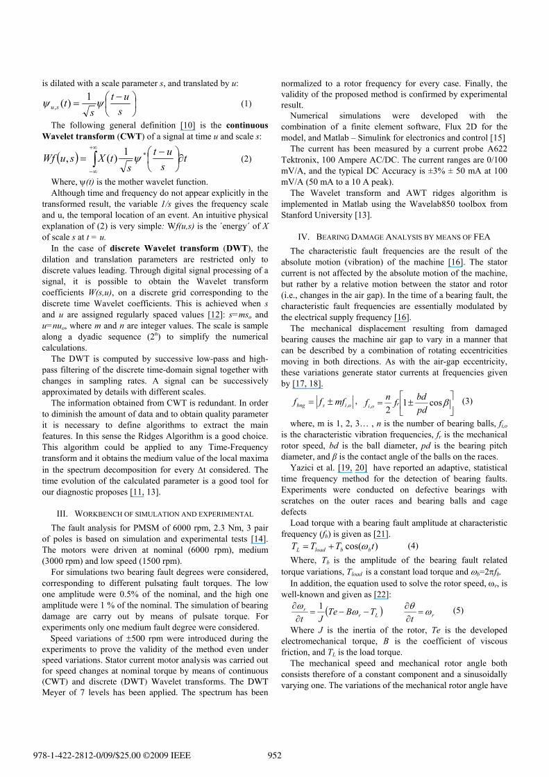
Several harmonics appear, but as expected, they are synchronous harmonics superimposed on the mains harmonics. Although, the discrimination it is more difficult for low speed than for nominal speed. On the other hand, full FFT spectrum shows the presence of additional fault frequencies. These frequencies are induced by the interaction of the bearing fault mechanical frequency and the current main harmonics.
Fig. 1 shows the full current spectrum for simulations of the PMSM drive at 3000 rpm. Fourier Fast Transform allows detecting bearing damage by analyzing the amplitude of additional compound frequencies. These frequencies are induced to mechanical frequency of fault. However, the amplitude is very small and fault detection by FFT is not clear at a low speed.
Fig. 1. Stator current spectrum for PMSM. Simulations at 3000 rpm
V. SIMULATION AND EXPERIMENTAL RESULTS
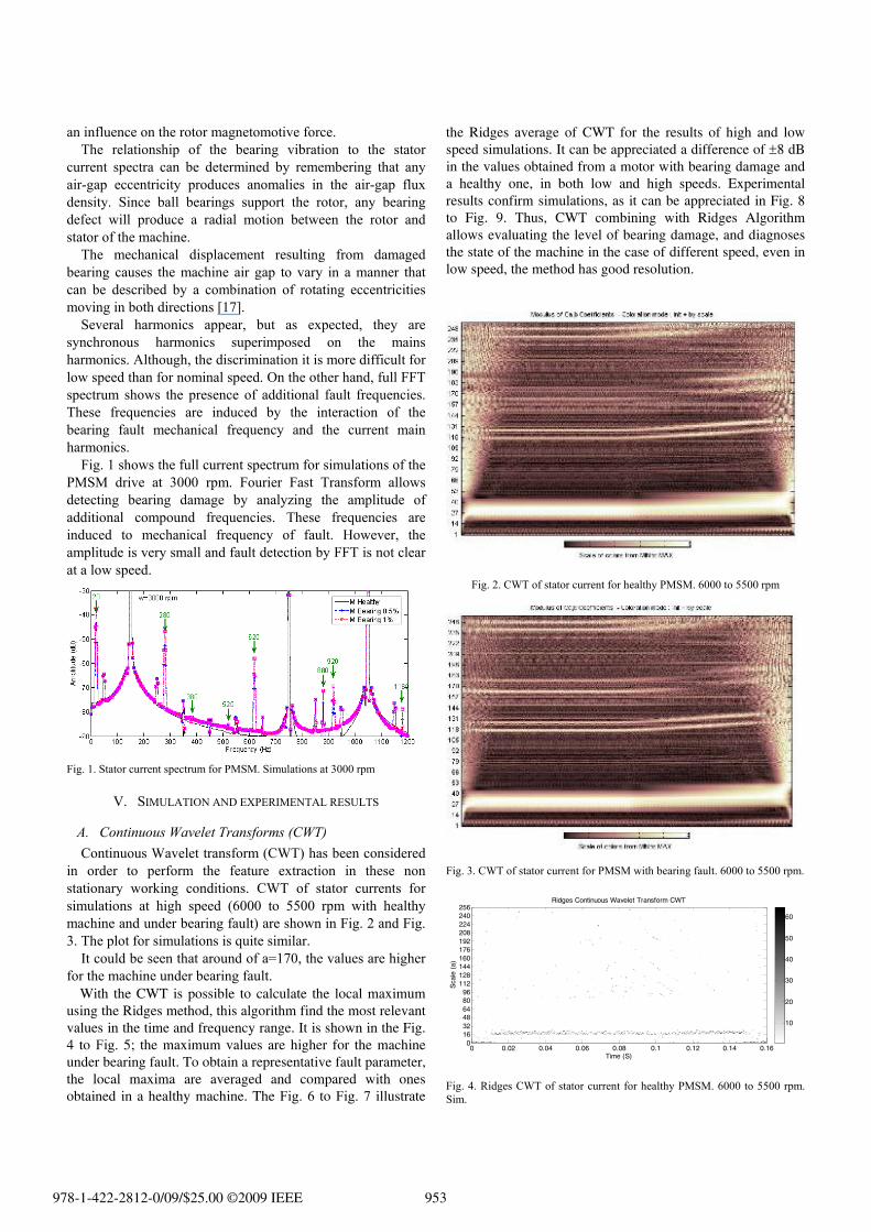
A. Continuous Wavelet Transforms (CWT) Continuous Wavelet transform (CWT) has been considered
in order to perform the feature extraction in these non stationary working conditions. CWT of stator currents for simulations at high speed (6000 to 5500 rpm with healthy machine and under bearing fault) are shown in Fig. 2 and Fig. 3. The plot for simulations is quite similar.
It could be seen that around of a=170, the values are higher for the machine under bearing fault.
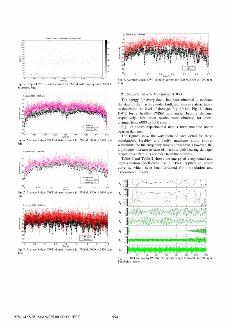
With the CWT is possible to calculate the local maximum using the Ridges method, this algorithm find the most relevant values in the time and frequency range. It is shown in the Fig. 4 to Fig. 5; the maximum values are higher for the machine under bearing fault. To obtain a representative fault parameter, the local maxima are averaged and compared with ones obtained in a healthy machine. The Fig. 6 to Fig. 7 illustrate
the Ridges average of CWT for the results of high and low speed simulations. It can be appreciated a difference of ±8 dB in the values obtained from a motor with bearing damage and a healthy one, in both low and high speeds. Experimental results confirm simulations, as it can be appreciated in Fig. 8 to Fig. 9. Thus, CWT combining with Ridges Algorithm allows evaluating the level of bearing damage, and diagnoses the state of the machine in the case of different speed, even in low speed, the method has good resolution.
Fig. 2. CWT of stator current for healthy PMSM. 6000 to 5500 rpm
Fig. 3. CWT of stator current for PMSM with bearing fault. 6000 to 5500 rpm.
Ridges Continuous Wavelet Transform CWT
Time (S)
Sca
le (
a)
0 0.02 0.04 0.06 0.08 0.1 0.12 0.14 0.160
163248648096
112128144160176192208224240256
10
20
30
40
50
60
Fig. 4. Ridges CWT of stator current for healthy PMSM. 6000 to 5500 rpm. Sim.
978-1-422-2812-0/09/$25.00 ©2009 IEEE 953
Time (S)
Sca
le (
a)
Ridges Continuous Wavelet Transform CWT
0 0.02 0.04 0.06 0.08 0.1 0.12 0.14 0.160
163248648096
112128144160176192208224240256
10
20
30
40
50
60
Fig. 5. Ridges CWT of stator current for PMSM with bearing fault. 6000 to 5500 rpm. Sim.
0 0.02 0.04 0.06 0.08 0.1 0.12 0.14 0.16-50
-45
-40
-35
-30
-25
-20
-15
-10
-5
0
Time (S)
Am
plitu
de (
dB)
speed: 6000 - 5500 rpm
MHealthyMBearing 0.5%MBearing 1%
Fig. 6. Average Ridges CWT of stator current for PMSM. 6000 to 5500 rpm. Sim.
0 0.05 0.1 0.15 0.2 0.25 0.3-50
-40
-30
-20
-10
0
Time (S)
Am
plitu
de (
dB)
speed: 1500 - 1000 rpm
MHealthyMBearing 0.5%MBearing 1%
Fig. 7. Average Ridges CWT of stator current for PMSM. 1500 to 1000 rpm. Sim.
0 0.2 0.4 0.6 0.8 1 1.2 1.4 1.6-50
-45
-40
-35
-30
-25
-20
-15
-10
-5
0
Time (S)
Am
plitu
de (
dB)
speed: 6000 - 5500 rpm
MHealthyMBearing
Fig. 8. Average Ridges CWT of stator current for PMSM. 6000 to 5500 rpm. Test.
0 0.1 0.2 0.3 0.4 0.5 0.6 0.7-50
-45
-40
-35
-30
-25
-20
-15
-10
-5
0
Time (S)
Am
plitu
de (
dB)
speed: 1500 - 1000 rpm
MHealthyMBearing
Fig. 9. Average Ridges CWT of stator current for PMSM. 1500 to 1000 rpm. Test.
B. Discrete Wavelet Transforms (DWT) The energy for every detail has been obtained to evaluate
the state of the machine under fault, and also as criteria factor to determine the level of damage. Fig. 10 and Fig. 11 show DWT for a healthy PMSM and under bearing damage, respectively. Simulation results were obtained for speed changes from 6000 to 5500 rpm.
Fig. 12 shows experimental details form machine under bearing damage.
The figures show the waveform of each detail for these simulations. Healthy and faulty machines show similar waveforms for the frequency ranges considered. However, the amplitudes increase in case of machine with bearing damage, despite this effect it is not clear from the pictures.
Table 1 and Table 2 shows the energy of every detail and approximation coefficient for a DWT applied to stator currents, which have been obtained from simulation and experimental results.
Fig. 10. DWT for healthy PMSM, The speed changes from 6000 to 5500 rpm. Simulation results
978-1-422-2812-0/09/$25.00 ©2009 IEEE 954
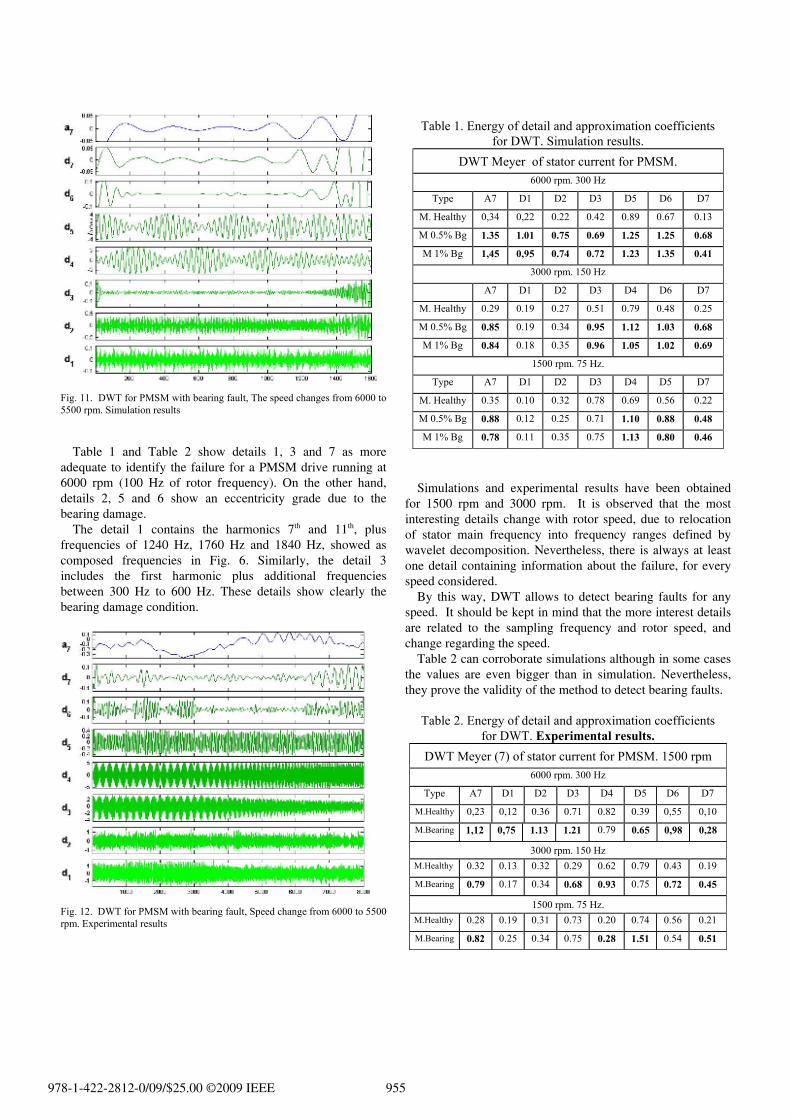
Fig. 11. DWT for PMSM with bearing fault, The speed changes from 6000 to 5500 rpm. Simulation results
Table 1 and Table 2 show details 1, 3 and 7 as more
adequate to identify the failure for a PMSM drive running at 6000 rpm (100 Hz of rotor frequency). On the other hand, details 2, 5 and 6 show an eccentricity grade due to the bearing damage.
The detail 1 contains the harmonics 7th and 11th, plus frequencies of 1240 Hz, 1760 Hz and 1840 Hz, showed as composed frequencies in Fig. 6. Similarly, the detail 3 includes the first harmonic plus additional frequencies between 300 Hz to 600 Hz. These details show clearly the bearing damage condition.
Fig. 12. DWT for PMSM with bearing fault, Speed change from 6000 to 5500 rpm. Experimental results
Table 1. Energy of detail and approximation coefficients for DWT. Simulation results.
DWT Meyer of stator current for PMSM. 6000 rpm. 300 Hz
Type A7 D1 D2 D3 D5 D6 D7
M. Healthy 0,34 0,22 0.22 0.42 0.89 0.67 0.13
M 0.5% Bg 1.35 1.01 0.75 0.69 1.25 1.25 0.68
M 1% Bg 1,45 0,95 0.74 0.72 1.23 1.35 0.41
3000 rpm. 150 Hz
A7 D1 D2 D3 D4 D6 D7
M. Healthy 0.29 0.19 0.27 0.51 0.79 0.48 0.25
M 0.5% Bg 0.85 0.19 0.34 0.95 1.12 1.03 0.68
M 1% Bg 0.84 0.18 0.35 0.96 1.05 1.02 0.69
1500 rpm. 75 Hz.
Type A7 D1 D2 D3 D4 D5 D7
M. Healthy 0.35 0.10 0.32 0.78 0.69 0.56 0.22
M 0.5% Bg 0.88 0.12 0.25 0.71 1.10 0.88 0.48
M 1% Bg 0.78 0.11 0.35 0.75 1.13 0.80 0.46
Simulations and experimental results have been obtained
for 1500 rpm and 3000 rpm. It is observed that the most interesting details change with rotor speed, due to relocation of stator main frequency into frequency ranges defined by wavelet decomposition. Nevertheless, there is always at least one detail containing information about the failure, for every speed considered.
By this way, DWT allows to detect bearing faults for any speed. It should be kept in mind that the more interest details are related to the sampling frequency and rotor speed, and change regarding the speed.
Table 2 can corroborate simulations although in some cases the values are even bigger than in simulation. Nevertheless, they prove the validity of the method to detect bearing faults.
Table 2. Energy of detail and approximation coefficients
for DWT. Experimental results.DWT Meyer (7) of stator current for PMSM. 1500 rpm
6000 rpm. 300 Hz
Type A7 D1 D2 D3 D4 D5 D6 D7
M.Healthy 0,23 0,12 0.36 0.71 0.82 0.39 0,55 0,10
M.Bearing 1,12 0,75 1.13 1.21 0.79 0.65 0,98 0,28
3000 rpm. 150 Hz M.Healthy 0.32 0.13 0.32 0.29 0.62 0.79 0.43 0.19
M.Bearing 0.79 0.17 0.34 0.68 0.93 0.75 0.72 0.45
1500 rpm. 75 Hz. M.Healthy 0.28 0.19 0.31 0.73 0.20 0.74 0.56 0.21
M.Bearing 0.82 0.25 0.34 0.75 0.28 1.51 0.54 0.51
978-1-422-2812-0/09/$25.00 ©2009 IEEE 955
VI. CONCLUSION In this paper bearing faults for a PMSM has been analyzed
by means of Continuous and Discrete Wavelet transform. The faults were simulated with finite elements analysis method (FEA).
FFT allows also detecting bearing damage by analyzing the amplitude of additional compound frequencies. These frequencies are induced to mechanical frequency of fault. However, fault detection by FFT is not clear at low speed and torque change.
The Continuous Wavelet Transforms (CWT) and the Ridges Algorithm allows obtaining a failure parameter, even for low speed in PMSM motors regardless speed variations.
The discrete Wavelet Transform evaluates the failure by calculating the energy in their details. The appropriate choice of the much interesting detail depends of sample frequency and rotation speed of the PMSM. DWT allows analyzing and identifying fault of bearing damage, even under speed variations, at high, medium and low speeds.
REFERENCES [1] J. A. Haylock, B. C. Mecrow, A. G. Jack, and D. J. Atkinson, "Operation
of a fault tolerant PM drive for an aerospace fuel pump application," in Electrical Machines and Drives, 1997 Eighth International Conference on (Conf. Publ. No. 444), 1997, pp. 133-137.
[2] N. Ertugrul, W. L. Soong, S. Valtenbergs, and H. Chye, "Investigation of a fault tolerant and high performance motor drive for critical applications," in TENCON. Proceedings of IEEE Region 10 International Conference on Electrical and Electronic Technology, 2001, pp. 542-548 vol.2.
[3] S. Nandi and H. A. Toliyat, "Condition monitoring and fault diagnosis of electrical machines-a review," in Industry Applications Conference, 1999. Thirty-Fourth IAS Annual Meeting. Conference Record of the 1999 IEEE, 1999, pp. 197-204 vol.1.
[4] S. Nandi, H. A. Toliyat, and X. Li, "Condition Monitoring and Fault Diagnosis of Electrical Motors - A Review," Energy Conversion, IEEE Transactions on, vol. 20, issue 4, p. 719, 2005.
[5] O. A. Mohammed, N. Y. Abed, and S. Ganu, "Modeling and Characterization of Induction Motor Internal Faults Using Finite-Element and Discrete Wavelet Transforms," Magnetics, IEEE Transactions on, vol. 42, issue 10, pp. 3434-3436, 2006.
[6] J. Rosero, O. Almonacid, M. Amaya, and L. Romeral, "Simulation and Fault Detection of Short Circuit Winding in a Permanent Magnet Synchronous Machines (PMSM)," in ISEF 2007 - XIII International Symposium on Electromagnetic Fields in Mechatronics, Electrical and Electronic Engineering, Prague, Czech Republic, 2007.
[7] J. Rosero, J. Cusido, A. Garcia, J. A. Ortega, and L. Romeral, "Broken Bearings Fault Detection for a Permanent Magnet Synchronous Motor under non-constant working conditions by means of a Joint Time Frequency Analysis," in IEEE International Symposium on Industrial Electronics, ISIE 2007, Vigo, Spain, 2007.
[8] J. Rosero, J. Cusido, J. A. Ortega, A. Garcia, and L. Romeral, "On-line condition monitoring technique for PMSM operating with eccentricity," in The 6th IEEE International Symposium on Diagnostics for Electric Machines, Power Electronics and Drives, IEEE SDEMPED, Cracow, Poland, 2007.
[9] A. A. Arkadan and B. W. Kielgas, "The coupled problem in switched reluctance motor drive systems during fault conditions," Magnetics, IEEE Transactions on, vol. 30, issue 5, pp. 3256-3259, 1994.
[10] S. G. Mallat, A wavelet tour of signal processing. San Diego: Academic Press, 1998.
[11] J. M. Aller, T. G. Habetler, R. G. Harley, R. M. Tallam, and L. Sang Bin, "Sensorless speed measurement of AC machines using analytic wavelet transform," Industry Applications, IEEE Transactions on, vol. 38, issue 5, pp. 1344-1350, 2002.
[12] I. S. Cade, P. S. Keogh, and M. N. Sahinkaya, "Fault identification in rotor/magnetic bearing systems using discrete time wavelet coefficients,"
Mechatronics, IEEE/ASME Transactions on, vol. 10, issue 6, pp. 648-657, 2005.
[13] J. Buckheit, S. Chen, D. Donoho, I. Johnstone, and J. Scargle, WaveLab850 http://www-stat.stanford.edu/~wavelab vol. Version .850: Stanford University & NASA-Ames Research Center, 2005.
[14] J. Rosero, J. Cusido, A. Garcia, J. A. Ortega, and L. Romeral, "Broken bearings and eccentricity fault detection for a permanent magnet synchronous motor," in The 32nd Annual Conference of the IEEE Industrial Electronics Society, IECON06, Paris - FRANCE, 2006, pp. 964-969.
[15] CEDRAT, CAD package for electromagnetic and thermal analysis using finite elements, User´s guide. Flux 2D. France, 2005, www.cedrat.com
[16] J. R. Stack, T. G. Habetler, and R. G. Harley, "Fault classification and fault signature production for rolling element bearings in electric machines," Industry Applications, IEEE Transactions on, vol. 40, issue 3, pp. 735-739, 2004.
[17] M. El Hachemi Benbouzid, "A review of induction motors signature analysis as a medium for faults detection," Industrial Electronics, IEEE Transactions on, vol. 47, issue 5, p. 984, 2000.
[18] J. R. Stack, R. G. Harley, and T. G. Habetler, "An amplitude Modulation detector for fault diagnosis in rolling element bearings," Industrial Electronics, IEEE Transactions on, vol. 51, issue 5, pp. 1097-1102, 2004.
[19] B. Yazici, G. B. Kliman, W. J. Premerlani, R. A. Koegl, and A. Abdel-Malek, "An adaptive, on-line, statistical method for detection of broken bars in motors using stator current and torque estimation," in Industry Applications Conference, 1997. Thirty-Second IAS Annual Meeting, IAS '97., Conference Record of the 1997 IEEE, 1997, pp. 221-226 vol.1.
[20] B. Yazici and G. B. Kliman, "An adaptive statistical time-frequency method for detection of broken bars and bearing faults in motors using stator current," Industry Applications, IEEE Transactions on, vol. 35, issue 2, pp. 442-452, 1999.
[21] M. Blodt, P. Granjon, B. Raison, and G. Rostaing, "Models for bearing damage detection in induction motors using stator current monitoring," in IEEE International Symposium on Industrial Electronics, 2004, pp. 383-388 vol. 1.
[22] P. Pillay and R. Krishnan, "Modeling, simulation, and analysis of permanent-magnet motor drives. I. The permanent-magnet synchronous motor drive," Industry Applications, IEEE Transactions on, vol. 25, issue 2, p. 265, 1989.
978-1-422-2812-0/09/$25.00 ©2009 IEEE 956