
Fast Path and Polarization Manipulation of Telecom Wavelength Single Photons in Lithium Niobate...
6
Fast path and polarisation manipulation of telecom wavelength single photons in lithium niobate waveguide devices Damien Bonneau, 1 Mirko Lobino, 1 Pisu Jiang, 1 Chandra M. Natarajan, 2 Michael G. Tanner, 2 Robert H. Hadfield, 2 Sanders N. Dorenbos, 3 Val Zwiller, 3 Mark G. Thompson, 1 and Jeremy L. O’Brien 1, * 1 Centre for Quantum Photonics, H. H. Wills Physics Laboratory & Department of Electrical and Electronic Engineering, University of Bristol, Merchant Venturers Building, Woodland Road, Bristol, BS8 1UB, UK 2 Scottish Universities Physics Alliance and School of Engineering and Physical Sciences, Heriot-Watt University, Edinburgh, EH14 4AS, United Kingdom 3 Kavli Institute of Nanoscience, TU Delft, 2628CJ Delft, The Netherlands (Dated: July 19, 2011) We demonstrate fast polarisation and path control of photons at 1550 nm in lithium niobate waveguide devices using the electro-optic effect. We show heralded single photon state engineer- ing, quantum interference, fast state preparation of two entangled photons and feedback control of quantum interference. These results point the way to a single platform that will enable the integra- tion of nonlinear single photon sources and fast reconfigurable circuits for future photonic quantum information science and technology. Photons are an appealing approach to quantum in- formation science, which promises enhanced information and communication technologies [1]. An integrated op- tics approach appears essential for practical applications as well as advances in the fundamental science of quan- tum optics [2, 3]. Progress towards single photon sources [4, 5], detectors [6], and circuits that use path [7–11] and polarisation [12] encoding have been made, includ- ing circuits that are reconfigurable to allow manipula- tion of photon paths [13, 14]. However, these recon- figurable circuits have relied on inherently slow thermal phase shifters and operation at 800 nm. Fast operation of reconfigurable waveguide circuits at telecom wavelengths is crucial for integration with the existing optical tele- com networks as well as to benefit from the technologies developed in that area. Fast routing and manipulation of single photons is es- sential for both temporally and spatially multiplexed sin- gle photons sources [15–18], quantum communication, including device independent quantum key distribution [19], based on noiseless linear amplifiers [20], circuit [21] and measurement [22–24] based quantum computing [25], quantum control [26], and interaction free measurements [27]. Fast control of both path and polarisation is crucial for these applications. Proof of principle demonstrations of fast manipulation of single photons have been made us- ing bulk Pockels cells [16, 18, 24, 26, 27], however, there have been no such demonstrations in integrated quantum photonic circuits. A fast electro-optic effect and the ability to make low loss single mode waveguides at telecom wavelengths using either proton exchange or titanium indiffusion (Ti:LN) makes lithium niobate an appealing platform for fast reconfigurable quantum photonic devices. Lithium nio- bate is used in telecommunications applications where 40 GHz modulators are standard; 100 GHz has been demon- strated in the laboratory [28]. Polarization controllers based on the electro-optic effect have also been demon- strated for bright light [29, 30]. Lithium niobate is also appealing for the prospect of directly integrating period- ically poled waveguide photon sources [31]. Fast manipulation of photon path is possible using the device shown in Fig. 1(b): A Mach-Zehnder Interferom- eter (MZI) fabricated in Ti:LN is composed of two 50:50 directional couplers. Electrodes above each waveguide in- side the MZI enable rapid manipulation of the refractive index via the eletro-optic effect. Application of the same positive voltage V to each of the inside electrodes rela- tive to the outside ground electrodes produces an equal and opposite electric field, and hence change in refractive index and phase, in each arm of the MZI. The same Ti:LN waveguide technology can be used to control the polarisation of a single photon when it is integrated with an appropriate electrode architecture [29, 30]. The inset to Fig. 1(d) shows a schematic of one stage of the electro-optical polarization controller (PC) used in this work: application of voltages V 1 and V 2 on the electrodes either side of the waveguide, rel- ative to the ground electrode above the waveguide en- ables an arbitrary electric field vector to be applied perpendicular to the waveguide. The device therefore acts as a tunable waveplate with a controllable thick- ness ρ and rotation ϕ that realises the rotation ˆ R = exp[ 2π λ ρ (ˆ σ x sin 2ϕ + ˆ σ z cos 2ϕ)]. The PC has 4 identi- cal stages (one is shown in the inset of Fig. 1(d)) which enables the implementation of any unitary operation of the single photon polarisation when they are controlled independently. Photon pairs at 1550 nm wavelength were generated by spontaneous parametric down conversion (SPDC) in a bismuth borate (BiBO) crystal and collected into two po- larization maintaining optical fibres (see Fig. 1(a)), anal- ogous to the ∼800 nm SPDC sources that have been used routinely over the last decades. Single photons were de- tected with two superconducting single photon detectors (SSPDs) [32–35] having system detection efficiencies of arXiv:1107.3476v1 [quant-ph] 18 Jul 2011
-
Upload
independent -
Category
Documents
-
view
0 -
download
0
Transcript of Fast Path and Polarization Manipulation of Telecom Wavelength Single Photons in Lithium Niobate...
Fast path and polarisation manipulation of telecom wavelength single photons inlithium niobate waveguide devices
Damien Bonneau,1 Mirko Lobino,1 Pisu Jiang,1 Chandra M. Natarajan,2 Michael G. Tanner,2 Robert
H. Hadfield,2 Sanders N. Dorenbos,3 Val Zwiller,3 Mark G. Thompson,1 and Jeremy L. O’Brien1, ∗
1Centre for Quantum Photonics, H. H. Wills Physics Laboratory & Department of Electrical and Electronic Engineering,University of Bristol, Merchant Venturers Building, Woodland Road, Bristol, BS8 1UB, UK
2Scottish Universities Physics Alliance and School of Engineering and Physical Sciences,Heriot-Watt University, Edinburgh, EH14 4AS, United Kingdom
3Kavli Institute of Nanoscience, TU Delft, 2628CJ Delft, The Netherlands(Dated: July 19, 2011)
We demonstrate fast polarisation and path control of photons at 1550 nm in lithium niobatewaveguide devices using the electro-optic effect. We show heralded single photon state engineer-ing, quantum interference, fast state preparation of two entangled photons and feedback control ofquantum interference. These results point the way to a single platform that will enable the integra-tion of nonlinear single photon sources and fast reconfigurable circuits for future photonic quantuminformation science and technology.
Photons are an appealing approach to quantum in-formation science, which promises enhanced informationand communication technologies [1]. An integrated op-tics approach appears essential for practical applicationsas well as advances in the fundamental science of quan-tum optics [2, 3]. Progress towards single photon sources[4, 5], detectors [6], and circuits that use path [7–11]and polarisation [12] encoding have been made, includ-ing circuits that are reconfigurable to allow manipula-tion of photon paths [13, 14]. However, these recon-figurable circuits have relied on inherently slow thermalphase shifters and operation at 800 nm. Fast operation ofreconfigurable waveguide circuits at telecom wavelengthsis crucial for integration with the existing optical tele-com networks as well as to benefit from the technologiesdeveloped in that area.
Fast routing and manipulation of single photons is es-sential for both temporally and spatially multiplexed sin-gle photons sources [15–18], quantum communication,including device independent quantum key distribution[19], based on noiseless linear amplifiers [20], circuit [21]and measurement [22–24] based quantum computing [25],quantum control [26], and interaction free measurements[27]. Fast control of both path and polarisation is crucialfor these applications. Proof of principle demonstrationsof fast manipulation of single photons have been made us-ing bulk Pockels cells [16, 18, 24, 26, 27], however, therehave been no such demonstrations in integrated quantumphotonic circuits.
A fast electro-optic effect and the ability to make lowloss single mode waveguides at telecom wavelengths usingeither proton exchange or titanium indiffusion (Ti:LN)makes lithium niobate an appealing platform for fastreconfigurable quantum photonic devices. Lithium nio-bate is used in telecommunications applications where 40GHz modulators are standard; 100 GHz has been demon-strated in the laboratory [28]. Polarization controllersbased on the electro-optic effect have also been demon-
strated for bright light [29, 30]. Lithium niobate is alsoappealing for the prospect of directly integrating period-ically poled waveguide photon sources [31].
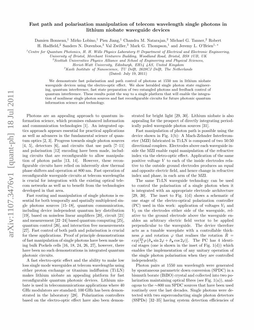
Fast manipulation of photon path is possible using thedevice shown in Fig. 1(b): A Mach-Zehnder Interferom-eter (MZI) fabricated in Ti:LN is composed of two 50:50directional couplers. Electrodes above each waveguide in-side the MZI enable rapid manipulation of the refractiveindex via the eletro-optic effect. Application of the samepositive voltage V to each of the inside electrodes rela-tive to the outside ground electrodes produces an equaland opposite electric field, and hence change in refractiveindex and phase, in each arm of the MZI.
The same Ti:LN waveguide technology can be usedto control the polarisation of a single photon when itis integrated with an appropriate electrode architecture[29, 30]. The inset to Fig. 1(d) shows a schematic ofone stage of the electro-optical polarization controller(PC) used in this work: application of voltages V1 andV2 on the electrodes either side of the waveguide, rel-ative to the ground electrode above the waveguide en-ables an arbitrary electric field vector to be appliedperpendicular to the waveguide. The device thereforeacts as a tunable waveplate with a controllable thick-ness ρ and rotation ϕ that realises the rotation R =exp[ 2πλ ρ (σx sin 2ϕ+ σz cos 2ϕ)]. The PC has 4 identi-cal stages (one is shown in the inset of Fig. 1(d)) whichenables the implementation of any unitary operation ofthe single photon polarisation when they are controlledindependently.
Photon pairs at 1550 nm wavelength were generatedby spontaneous parametric down conversion (SPDC) in abismuth borate (BiBO) crystal and collected into two po-larization maintaining optical fibres (see Fig. 1(a)), anal-ogous to the ∼800 nm SPDC sources that have been usedroutinely over the last decades. Single photons were de-tected with two superconducting single photon detectors(SSPDs) [32–35] having system detection efficiencies of
arX
iv:1
107.
3476
v1 [
quan
t-ph
] 1
8 Ju
l 201
1
2
FIG. 1: Fast path and polarisation control of single photons in lithium niobate waveguides. (a) Pulsed spontaneous parametricdownconversion (SPDC) source for photon pairs at 1550 nm. (b) Fast heralded single photon state preparation set-up. MZI:lithium niobate Mach-Zehnder interferometer; SSPD: single photon superconducting detectors; SMF: single mode fibre; TIA:time interval analyzer. (c) Fast switching of two photon entangled state. The signal generator (SG) drives the MZI with squarewaves alternating between two voltages V0 = −1.6V and Vπ
2= 0.5V . Coincidental events for the two voltages are recorded in
separate counters embedded in a field programmable gate array (FPGA) board. (d) Fast polarisation feedback control of singlephotons using a lithium niobate polarisation controller (PC). The inset shows one stage of the PC consisting of a waveguidesurrounded by 3 electrodes.
8% and 18%, respectively (see Appendix for further de-tails).
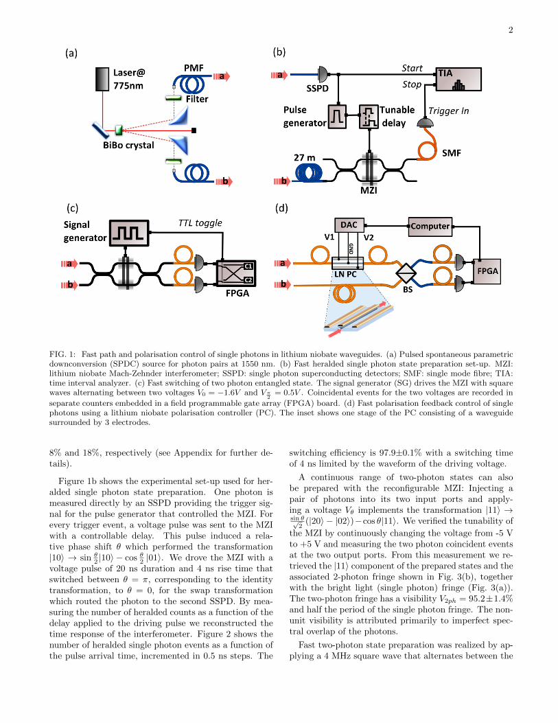
Figure 1b shows the experimental set-up used for her-alded single photon state preparation. One photon ismeasured directly by an SSPD providing the trigger sig-nal for the pulse generator that controlled the MZI. Forevery trigger event, a voltage pulse was sent to the MZIwith a controllable delay. This pulse induced a rela-tive phase shift θ which performed the transformation|10〉 → sin θ
2 |10〉 − cos θ2 |01〉. We drove the MZI with avoltage pulse of 20 ns duration and 4 ns rise time thatswitched between θ = π, corresponding to the identitytransformation, to θ = 0, for the swap transformationwhich routed the photon to the second SSPD. By mea-suring the number of heralded counts as a function of thedelay applied to the driving pulse we reconstructed thetime response of the interferometer. Figure 2 shows thenumber of heralded single photon events as a function ofthe pulse arrival time, incremented in 0.5 ns steps. The
switching efficiency is 97.9±0.1% with a switching timeof 4 ns limited by the waveform of the driving voltage.
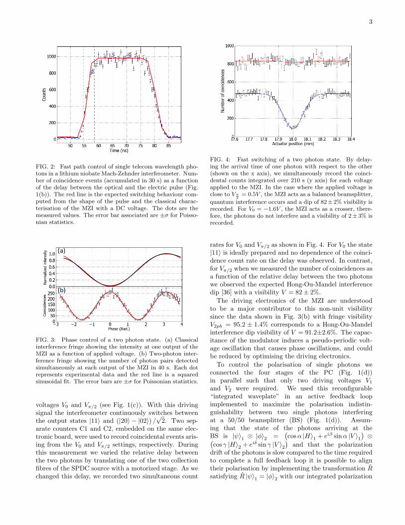
A continuous range of two-photon states can alsobe prepared with the reconfigurable MZI: Injecting apair of photons into its two input ports and apply-ing a voltage Vθ implements the transformation |11〉 →sin θ√
2(|20〉 − |02〉)−cos θ|11〉. We verified the tunability of
the MZI by continuously changing the voltage from -5 Vto +5 V and measuring the two photon coincident eventsat the two output ports. From this measurement we re-trieved the |11〉 component of the prepared states and theassociated 2-photon fringe shown in Fig. 3(b), togetherwith the bright light (single photon) fringe (Fig. 3(a)).The two-photon fringe has a visibility V2ph = 95.2±1.4%and half the period of the single photon fringe. The non-unit visibility is attributed primarily to imperfect spec-tral overlap of the photons.
Fast two-photon state preparation was realized by ap-plying a 4 MHz square wave that alternates between the
3
FIG. 2: Fast path control of single telecom wavelength pho-tons in a lithium niobate Mach-Zehnder interferometer. Num-ber of coincidence events (accumulated in 30 s) as a functionof the delay between the optical and the electric pulse (Fig.1(b)). The red line is the expected switching behaviour com-puted from the shape of the pulse and the classical charac-terisation of the MZI with a DC voltage. The dots are themeasured values. The error bar associated are ±σ for Poisso-nian statistics.
FIG. 3: Phase control of a two photon state. (a) Classicalinterference fringe showing the intensity at one output of theMZI as a function of applied voltage. (b) Two-photon inter-ference fringe showing the number of photon pairs detectedsimultaneously at each output of the MZI in 40 s. Each dotrepresents experimental data and the red line is a squaredsinusoidal fit. The error bars are ±σ for Poissonian statistics.
voltages V0 and Vπ/2 (see Fig. 1(c)). With this drivingsignal the interferometer continuously switches betweenthe output states |11〉 and (|20〉 − |02〉) /
√2. Two sep-
arate counters C1 and C2, embedded on the same elec-tronic board, were used to record coincidental events aris-ing from the V0 and Vπ/2 settings, respectively. Duringthis measurement we varied the relative delay betweenthe two photons by translating one of the two collectionfibres of the SPDC source with a motorized stage. As wechanged this delay, we recorded two simultaneous count
FIG. 4: Fast switching of a two photon state. By delay-ing the arrival time of one photon with respect to the other(shown on the x axis), we simultaneously record the coinci-dental counts integrated over 210 s (y axis) for each voltageapplied to the MZI. In the case where the applied voltage isclose to Vπ
2= 0.5V , the MZI acts as a balanced beamsplitter,
quantum interference occurs and a dip of 82± 2% visibility isrecorded. For V0 = −1.6V , the MZI acts as a crosser, there-fore, the photons do not interfere and a visibility of 2± 3% isrecorded.
rates for V0 and Vπ/2 as shown in Fig. 4. For V0 the state|11〉 is ideally prepared and no dependence of the coinci-dence count rate on the delay was observed. In contrast,for Vπ/2 when we measured the number of coincidences asa function of the relative delay between the two photonswe observed the expected Hong-Ou-Mandel interferencedip [36] with a visibility V = 82± 2%.
The driving electronics of the MZI are understoodto be a major contributor to this non-unit visibilitysince the data shown in Fig. 3(b) with fringe visibilityV2ph = 95.2 ± 1.4% corresponds to a Hong-Ou-Mandelinterference dip visibility of V = 91.2±2.6%. The capac-itance of the modulator induces a pseudo-periodic volt-age oscillation that causes phase oscillations, and couldbe reduced by optimising the driving electronics.
To control the polarisation of single photons weconnected the four stages of the PC (Fig. 1(d))in parallel such that only two driving voltages V1and V2 were required. We used this reconfigurable“integrated waveplate” in an active feedback loopimplemented to maximize the polarisation indistin-guishability between two single photons interferingat a 50/50 beamsplitter (BS) (Fig. 1(d)). Assum-ing that the state of the photons arriving at theBS is |ψ〉1 ⊗ |φ〉2 =
(cosα |H〉1 + eiβ sinα |V 〉1
)⊗(
cos γ |H〉2 + eiδ sin γ |V 〉2)
and that the polarizationdrift of the photons is slow compared to the time requiredto complete a full feedback loop it is possible to aligntheir polarisation by implementing the transformation Rsatisfying R |ψ〉1 = |φ〉2 with our integrated polarization
4
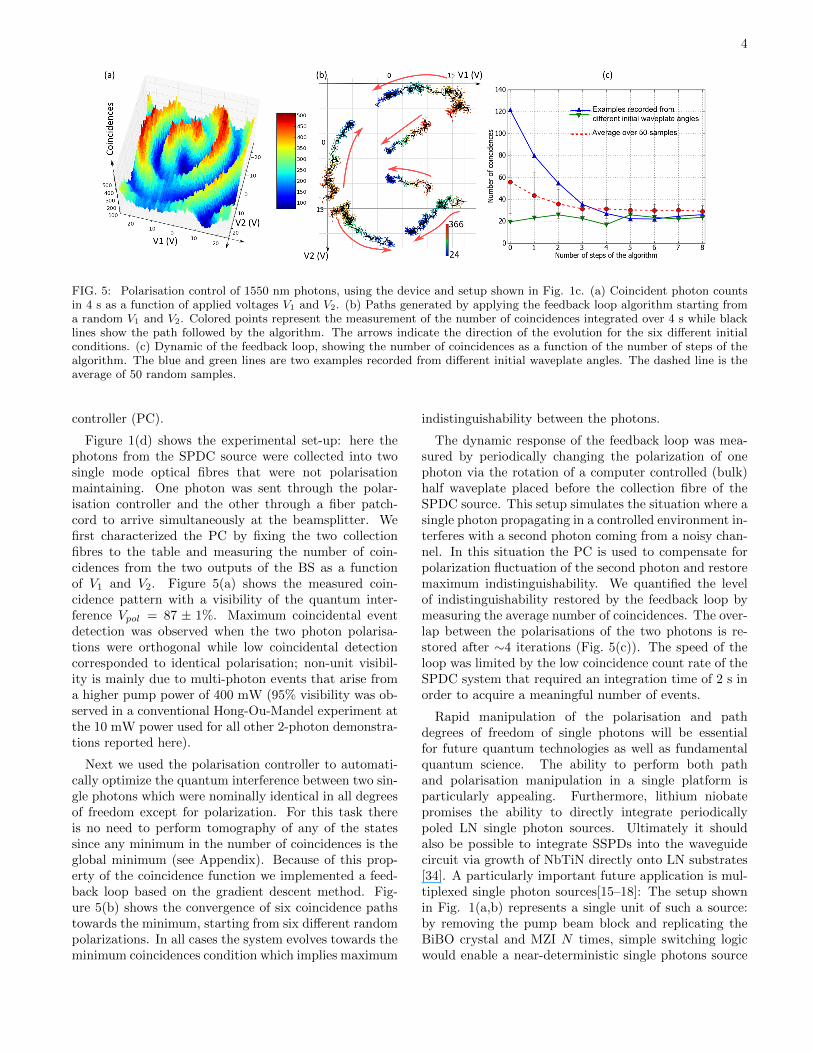
FIG. 5: Polarisation control of 1550 nm photons, using the device and setup shown in Fig. 1c. (a) Coincident photon countsin 4 s as a function of applied voltages V1 and V2. (b) Paths generated by applying the feedback loop algorithm starting froma random V1 and V2. Colored points represent the measurement of the number of coincidences integrated over 4 s while blacklines show the path followed by the algorithm. The arrows indicate the direction of the evolution for the six different initialconditions. (c) Dynamic of the feedback loop, showing the number of coincidences as a function of the number of steps of thealgorithm. The blue and green lines are two examples recorded from different initial waveplate angles. The dashed line is theaverage of 50 random samples.
controller (PC).
Figure 1(d) shows the experimental set-up: here thephotons from the SPDC source were collected into twosingle mode optical fibres that were not polarisationmaintaining. One photon was sent through the polar-isation controller and the other through a fiber patch-cord to arrive simultaneously at the beamsplitter. Wefirst characterized the PC by fixing the two collectionfibres to the table and measuring the number of coin-cidences from the two outputs of the BS as a functionof V1 and V2. Figure 5(a) shows the measured coin-cidence pattern with a visibility of the quantum inter-ference Vpol = 87 ± 1%. Maximum coincidental eventdetection was observed when the two photon polarisa-tions were orthogonal while low coincidental detectioncorresponded to identical polarisation; non-unit visibil-ity is mainly due to multi-photon events that arise froma higher pump power of 400 mW (95% visibility was ob-served in a conventional Hong-Ou-Mandel experiment atthe 10 mW power used for all other 2-photon demonstra-tions reported here).
Next we used the polarisation controller to automati-cally optimize the quantum interference between two sin-gle photons which were nominally identical in all degreesof freedom except for polarization. For this task thereis no need to perform tomography of any of the statessince any minimum in the number of coincidences is theglobal minimum (see Appendix). Because of this prop-erty of the coincidence function we implemented a feed-back loop based on the gradient descent method. Fig-ure 5(b) shows the convergence of six coincidence pathstowards the minimum, starting from six different randompolarizations. In all cases the system evolves towards theminimum coincidences condition which implies maximum
indistinguishability between the photons.
The dynamic response of the feedback loop was mea-sured by periodically changing the polarization of onephoton via the rotation of a computer controlled (bulk)half waveplate placed before the collection fibre of theSPDC source. This setup simulates the situation where asingle photon propagating in a controlled environment in-terferes with a second photon coming from a noisy chan-nel. In this situation the PC is used to compensate forpolarization fluctuation of the second photon and restoremaximum indistinguishability. We quantified the levelof indistinguishability restored by the feedback loop bymeasuring the average number of coincidences. The over-lap between the polarisations of the two photons is re-stored after ∼4 iterations (Fig. 5(c)). The speed of theloop was limited by the low coincidence count rate of theSPDC system that required an integration time of 2 s inorder to acquire a meaningful number of events.
Rapid manipulation of the polarisation and pathdegrees of freedom of single photons will be essentialfor future quantum technologies as well as fundamentalquantum science. The ability to perform both pathand polarisation manipulation in a single platform isparticularly appealing. Furthermore, lithium niobatepromises the ability to directly integrate periodicallypoled LN single photon sources. Ultimately it shouldalso be possible to integrate SSPDs into the waveguidecircuit via growth of NbTiN directly onto LN substrates[34]. A particularly important future application is mul-tiplexed single photon sources[15–18]: The setup shownin Fig. 1(a,b) represents a single unit of such a source:by removing the pump beam block and replicating theBiBO crystal and MZI N times, simple switching logicwould enable a near-deterministic single photons source
5
to be realised, provided efficiencies and losses couldbe controlled; a fully integrated architecture will helpreduce such losses. (We note that heralding efficiencyreported here is not state-of-the art.) Reconfigurablecircuits with path and polarisation encoding will find ap-plications across photonic quantum information scienceand technology ranging from quantum communication,quantum control, quantum measurement and quantuminformation processing.
We thank O. Alibart and S. Tanzilli. This work wassupported by Nokia, EPSRC, ERC, PHORBITECH,QUANTIP, NSQI, FOM and NWO (Vidi grant). M.L.acknowledges a Marie Curie IIF. R.H.H. acknowledges aRoyal Society University Research Fellowship. J.L.O’B.acknowledges a Royal Society Wolfson Merit Award.
∗ Electronic address: [email protected][1] J. L. O’Brien, A. Furusawa, and J. Vuckovic, Nature Pho-
ton. 3, 687 (2009).[2] A. Politi, J. C. F. Matthews, M. G. Thompson, and J. L.
O’Brien, IEEE JSTQE 15, 1673 (2009).[3] New Journal of Physics: Focus on Integrated Quantum
Optics. 1 (2011).[4] Focus on Single Photons on Demand, Eds. P. Grangier,
B. Sanders, and J. Vuckovic, New J. Phys. 6 (2004).[5] A. J. Shields, Nature Photon. 1, 215 (2007).[6] R. H. Hadfield, Nature Photon. 3, 696 (2009).[7] A. Politi, M. J. Cryan, J. G. Rarity, S. Yu, and J. L.
O’Brien, sci 320, 646 (2008).[8] A. Politi, J. C. F. Matthews, and J. L. O’Brien, Science
325, 1221 (2009).[9] A. Peruzzo, M. Lobino, J. C. F. Matthews, N. Matsuda,
A. Politi, K. Poulios, X.-Q. Zhou, Y. Lahini, N. Ismail,K. Worhoff, et al., Science 329, 1500 (2010).
[10] A. Peruzzo, A. Laing, A. Politi, T. Rudolph, and J. L.O’Brien, Nature Communications 2 (2011), ISSN 2041-1723.
[11] A. Laing, A. Peruzzo, A. Politi, M. R. Verde, M. Halder,T. C. Ralph, M. G. Thompson, and J. L. O’Brien, Ap-plied Physics Letters 97, 211109+ (2010).
[12] L. Sansoni, F. Sciarrino, G. Vallone, P. Mataloni,A. Crespi, R. Ramponi, and R. Osellame, Phys. Rev.Lett. 105, 200503 (2010).
[13] J. C. F. Matthews, A. Politi, A. Stefanov, and J. L.O’Brien, Nature Photon. 3, 346 (2009).
[14] B. J. Smith, D. Kundys, N. Thomas-Peter, P. G. R.Smith, and I. A. Walmsley, Opt. Express 17, 13516(2009).
[15] A. L. Migdall, D. Branning, and S. Castelletto, Phys.Rev. A 66, 053805 (2002).
[16] X.-s. Ma, S. Zotter, J. Kofler, T. Jennewein, andA. Zeilinger, Phys. Rev. A 83, 043814 (2011).
[17] T. Jennewein, M. Barbieri, and A. G. White, Journal ofModern Optics 58, 276 (2011).
[18] K. T. McCusker and P. G. Kwiat, Phys. Rev. Lett. 103,163602 (2009).
[19] N. Gisin, G. Ribordy, W. Tittel, and H. Zbinden, rmp
74, 145 (2002).[20] G. Y. Xiang, T. C. Ralph, A. P. Lund, N. Walk, and G. J.
Pryde, Nature Photon. 4, 316 (2010), ISSN 1749-4885.[21] E. Knill, R. Laflamme, and G. J. Milburn, n 409, 46
(2001).[22] M. A. Nielsen, prl 93, 040503 (2004).[23] D. E. Browne and T. Rudolph, prl 95, 010501 (2005).[24] R. Prevedel, P. Walther, F. Tiefenbacher, P. Bohi,
R. Kaltenbaek, T. Jennewein, and A. Zeilinger, Nature445, 65 (2007).
[25] J. L. O’Brien, Science 318, 1567 (2007).[26] G. G. Gillett, R. B. Dalton, B. P. Lanyon, M. P. Almeida,
M. Barbieri, G. J. Pryde, J. L. O’Brien, K. J. Resch, S. D.Bartlett, and A. G. White, Phys. Rev. Lett. 104, 080503(2010).
[27] P. Kwiat, H. Weinfurter, T. Herzog, A. Zeilinger, andM. A. Kasevich, Phys. Rev. Lett. 74, 4763 (1995).
[28] A. Kanno, T. Sakamoto, A. Chiba, T. Kawanishi,K. Higuma, M. Sudou, and J. Ichikawa, IEICE Electron-ics Express 7, 817 (2010).
[29] A. J. P. van Haasteren, J. J. G. M. van der Tol, M. O.van Deventer, and H. J. Frankena, Journal of LightwaveTechnology 11, 1151 (1993).
[30] N. G. Walker and G. R. Walker, Journal of LightwaveTechnology 8, 438 (1990).
[31] A. Martin, A. Issautier, H. Herrmann, W. Sohler, D. B.Ostrowsky, O. Alibart, and S. Tanzilli, New J. Phys. 12,103005 (2010).
[32] R. H. Hadfield, b, and c, Opt. Express 13, 10846 (2005).[33] C. M. Natarajan, A. Peruzzo, S. Miki, M. Sasaki,
Z. Wang, B. Baek, S. Nam, R. H. Hadfield, and J. L.O’Brien, apl 96, 211101 (2010).
[34] S. N. Dorenbos, E. M. Reiger, U. Perinetti, V. Zwiller,T. Zijlstra, and T. M. Klapwijk, Applied Physics Letters93, 131101 (pages 3) (2008).
[35] M. G. Tanner, C. M. Natarajan, V. K. Pottapenjara,J. A. O’Connor, R. J. Warburton, R. H. Hadfield,B. Baek, S. Nam, S. N. Dorenbos, E. B. Urena, et al.,Applied Physics Letters 96, 221109 (pages 3) (2010).
[36] C. K. Hong, Z. Y. Ou, and L. Mandel, Phys. Rev. Lett.59, 2044 (1987).
[37] G. N. Gol’tsman, O. Okunev, G. Chulkova, A. Lipatov,A. Semenov, K. Smirnov, B. Voronov, A. Dzardanov,C. Williams, and R. Sobolewski, apl 79, 705 (2001).
6
Appendix
1550 nm photon source
A BiBO crystal (Θ = 8.8◦,Φ = 0◦, 4 mm thickness),was pumped by a Ti-Sapphire pulsed laser at 775 nmwavelength, focused on the crystal by a plano-convex lens(f = 30 mm). The pulse width was around 80 fs and therepetition rate was 80 MHz. Photon pairs at 1550 nmwavelength arising from spontaneous parametric downconversion were filtered by 10 nm width bandpass filtersand collected by aspheric lenses (f = 11 mm). The sourcewas tested at 30 mW power and exhibited 95% visibilityquantum interference when the two arms were combinedon a balanced beam splitter.
Quantum interference from a two photon state witharbitrary polarisations
We start with an unlimited number of copies of twounknown state of polarisation |Ψ1〉 and |Ψ2〉 , and assumethat we have control of the parameters of |Ψ1〉. Using aniterative process, we aim to achieve quantum interferencebetween the two states without having to measure thepolarisation of any of the states.
The two photon input state can be written as |ΨIn〉 =|Ψ1〉⊗|Ψ2〉 =
(cα |H〉+ eiβsα |V 〉
)⊗(cγ |H〉+ eiδsγ |V 〉
)where cx and sx are respectively cos(x) and sin(x)
Writing the creation operators as m†X where m is thespatial mode and X the polarisation, the input state canbe rewritten as :|ΨIn〉 =
(cαa†H + eiβsαa
†V
)⊗(cγb†H + eiδsγb
†V
)|0〉
The beam splitter scattering matrix provides :
a†X → c†X+id†
X√2
b†X →ic†
X+d†
X√2
Combining the two photons |Ψ1〉 and
|Ψ2〉 on a beam splitter gives the output state
|Ψout〉 = 12
[cαcγ
(c2†H − d2†
H
)+ ei(β+δ)sαsγ
(c2†V − d2†
V
)]+ i
2
(cαsγe
iδ + cγeiβsα
) (c†Hc†V + d†Hd†V
)+ 1
2
(cαsγe
iδ − cγeiβsα) (
c†Hd†V − c†Vd†H
)And the probability of a 2-photon coincidental detection
is then given by
Pcoinc = 12
∣∣cαsγeiδ − cγeiβsα∣∣2We are interested in using an algorithm to minimize
the number of coincidences. And for this purpose, weneed to find where the gradient is 0. The derivative ofPcoinc with respect to the parameters α and β on whichwe have control are given by :
∂Pcoinc∂α = 1
2 [sin (2α) cos (2γ)− cos (2α) sin (2γ) cos (δ − β)]∂Pcoinc∂β = 1
2 [sin (β − δ) sin (2α) sin (2γ)]
The gradient is 0 if and only if ∂Pcoinc∂α = 0 and
∂Pcoinc∂β = 0. This condition is satisfied only in the fol-
lowing cases:|Ψ1〉 = |H〉 or |V 〉 and |Ψ2〉 = |H〉 or |V 〉
orβ = δ + nπ and α = γ + k π2
where {k, n} ∈ ZThe first case provides either identical or orthogonal
photons. The second case gives |Ψ1〉 = |Ψ2〉 up to aglobal phase for even k and |Ψ1〉 ⊥ |Ψ2〉 for odd k. Theonly cases where the gradient is 0 are only either whenthe two photons are the same up to a global phase orwhen they are orthogonal. Thus, in all cases, any lo-cal minimum is also the global minimum and any localmaximum is also the global maximum.
Superconducting single-photon detector system
In this study we used a pair of high perfor-mance nanowire superconducting single-photon detectors(SSPDs) [37] integrated into a practical closed cycle de-tector system [32]. We have previously validated the useof such detectors in quantum waveguide circuit experi-ments at 805 nm [33]. The SSPDs used in this study wereNbTiN nanowire meanders fabricated on oxidised siliconsubstrates [34], coupled efficiently with single mode opti-cal fibre. The packaged SSPDs were operated at 3 K in aGifford-McMahon type closed cycle refrigerator [32]. Thesystem detection efficiency of our two SSPD channels was18% and 8% at 1550 nm wavelength and an ungated darkcount rate per detector of 1 kHz. The measured timingjitter of each detector channel was 60 ps full width at halfmaximum.