Random Sampling for Continuous Streams with Arbitrary Updates
Upload
grenoble-inpCategory
view
2download
0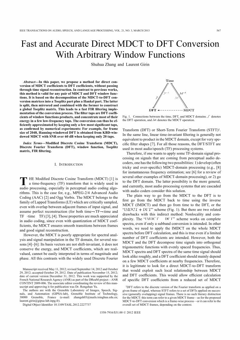
IEEE TRANSACTIONS ON AUDIO, SPEECH, AND LANGUAGE PROCESSING, VOL. 21, NO. 3, MARCH 2013 567
Fast and Accurate Direct MDCT to DFT ConversionWith Arbitrary Window Functions
Shuhua Zhang and Laurent Girin
Abstract—In this paper, we propose a method for direct con-version of MDCT coefficients to DFT coefficients, without passingthrough time signal reconstruction. In contrast to previous works,this method is valid for any pair of MDCT and DFT window func-tions. It is based on the decomposition of the MDCT-to-DFT con-version matrices into a Toeplitz part plus a Hankel part. The latteris split, then mirrored and combined with the former to constructa global Toeplitz matrix. This leads to a fast FIR filtering imple-mentation of the conversion process. The filter taps are DFT coeffi-cients of window functions products, and concentrate most of theirenergy in a few low-frequency taps. The conversion can thus be ef-ficiently approximated by keeping only a few most significant taps,as confirmed by numerical experiments: For example, for framesize of 2048, Hanning-windowed DFT is obtained from KBD-win-dowed MDCT with SNR over 60 dB when keeping only 20 taps.
Index Terms—Modified Discrete Cosine Transform (MDCT),Discrete Fourier Transform (DFT), window function, Toeplitzmatrix, FIR filtering.
I. INTRODUCTION
T HE Modified Discrete Cosine Transform (MDCT) [1] isa time-frequency (TF) transform that is widely used in
audio processing, especially in perceptual audio coding algo-rithms. This is the case for, e.g., MPEG-2/4 Advanced AudioCoding (AAC) [2] and Ogg Vorbis. The MDCT belongs to thefamily of Lapped Transforms (LT) which are critically sampled,even with overlap between adjacent frames of input signal, andassume perfect reconstruction (for both time TF time andTF time TF) [3], [4]. Those properties are much appreciatedin audio coding, since even with quantization of MDCT coef-ficients, the MDCT ensures smooth transitions between framesand good signal reconstruction.However, the MDCT is poorly appropriate for spectral anal-
ysis and signal manipulation in the TF domain, for several rea-sons [4]–[6]: Its basis vectors are not shift-invariant, it does notconserve the energy, and MDCT coefficients, which are real-valued, cannot be easily interpreted in terms of magnitude andphase. All this contrasts with the widely used Discrete Fourier
Manuscript received May 11, 2012; revised September 14, 2012 and October29, 2012; accepted October 29, 2012. Date of publication November 15, 2012;date of current version December 31, 2012. This work was supported by theFrench National Research Agency (ANR) as part of the DReaM project—ANRCONTINT 2009-006. The associate editor coordinating the review of this man-uscript and approving it for publication was Dr. Rongshan Yu.The authors are with the Grenoble Laboratory of Images, Speech, Sig-
nals, and Automation (GIPSA-lab), Grenoble Institute of Technology,38000 Grenoble, France (e-mail: [email protected];[email protected]).Digital Object Identifier 10.1109/TASL.2012.2227737
Fig. 1. Connections between the time, DFT, and MDCT domains. denotesthe DFT operation, and denotes the MDCT operation.
Transform (DFT) or Short-Term Fourier Transform (STFT)1.In the same line, linear time-invariant filtering is generally notequivalent to product in theMDCT domain, except for very spe-cific filter shapes [7]. For all those reasons, the DFT/STFT areused in most audio/speech (TF) processing systems.Therefore, if one wants to apply some TF-domain signal pro-
cessing on signals that are coming from perceptual audio de-coders, one has the following two possibilities: 1) develop (oftentricky and over-specific) MDCT-domain processing (e.g., [8]for instantaneous frequency estimation; see [6] for a review ofseveral other examples of MDCT-domain processing), or 2) goto the DFT domain. The latter possibility is the more general,and currently, most audio processing systems that are cascadedwith audio coders consider this solution.The plain way to go from the MDCT to the DFT is to
first go from the MDCT back to time using the inverseMDCT (IMDCT) and then go from time to the DFT, or the“ ” scheme (Fig. 1). But there are two relateddrawbacks with this indirect method: Nonlocality and com-plexity. The “ ” scheme works on completespectra, even if only a subband conversion is intended. In otherwords, we need to apply the IMDCT on the whole MDCTspectra before DFT calculation, and this is true even if a limitednumber of DFT coefficients are intended. However, both theMDCT and the DFT decompose time signals into orthogonaltrigonometric functions with evenly spaced frequencies. Thus,MDCT spectra and DFT spectra of the same time signal shouldlook alike roughly, and a DFT coefficient should mainly dependon a few MDCT coefficients at nearby frequencies. Therefore,it is legitimate to look for a direct MDCT-to-DFT transformthat would exploit such local relationship between MDCTand DFT coefficients. This would allow efficient calculationof specific DFT coefficients from a reduced set of MDCT1DFT refers to the discrete version of the Fourier transform as applied on a
given frame of signal, whereas STFT refers to a set of DFTs applied on succes-sive (generally ovelapping) signal frames. There is no such literary distinctionfor the MDCT: this term can refer to a given MDCT frame—as for the proposedMDCT-to-DFT conversion which is a frame-wise process—or it can refer to theoverall set of MDCT frames, depending on the context.
1558-7916/$31.00 © 2012 IEEE

568 IEEE TRANSACTIONS ON AUDIO, SPEECH, AND LANGUAGE PROCESSING, VOL. 21, NO. 3, MARCH 2013
Fig. 2. Overlap and add in the time domain and corresponding TF-domain vec-tors. The time vectors and all have the same size .
coefficients at nearby frequencies, hence reduce complexity insubband conversion, and possibly reduce complexity for thefullband conversion either.In [9], the so-called mapping methods were proposed for the
MDCT-to-DFT conversion, but this was only to save memoryusage, not computational complexity. In [10], a method fordirectly converting the MDCT to the Modified Discrete SineTransform (MDST) was proposed, which can be easily ex-tended to direct conversion from the MDCT to the ModifiedComplex Lapped Transform (MCLT) [11], [12]—a specialshifted DFT. However, the window functions for the MDCTand the MDST are required to be identical. This is sufficientwhen the MCLT is intended, but not when the DFT or ageneral shifted DFT is intended. Indeed, in practice differentwindow functions are very often used for the MDCT (e.g., theKaiser-Bessel-Derived (KBD) window [13] or the sine windowthat both ensure the perfect reconstruction property, for coding[1]) and the DFT (e.g., Hamming or Hanning windows, forspectral analysis and processing). In [6], an intermediatetransform called Circulant Lapped Transform (CLT) has beenproposed to convert the MDCT to the DFT, i.e., MDCT-to-CLTfollowed by CLT-to-DFT. The overall process is shown to beefficiently approximated by a complex-valued Finite ImpulseResponse (FIR) filtering applied on MDCT coefficients. But theconversion is limited to the DFT with the rectangular window(and the MDCT with an arbitrary symmetric window).In the present paper, we propose a new direct MDCT-to-DFT
conversion process that has the following advantages. Most im-portantly, it overcomes the limitation of the above methods con-cerning the window functions: It is valid for any arbitrary pair ofMDCT andDFTwindows. Also, this process is more efficient inthe sense that it does not rely on an intermediate representation(such as the CLT) while also leading to a fast and accurate FIRimplementation. This FIR implementation inherently allows lo-cality of theMDCT-to-DFT conversion, i.e., it can be applied ona subband basis, and has a low complexity, even for full-bandconversion. Fast algorithms for the MDCT [14] and the DFT[15] all have computational complexity of (being the number of MDCT coefficients for a single transform,or 1/2 of the frame size), while the proposed direct conversionmethod only has computational complexity of . More-over, unlike fast MDCT or FFT that depends on complicatedbit-reverse indexing and butterfly operations, the direct methodneeds only vector scaling and vector addition, thus it is muchmore simpler to implement and also memory efficient. The re-sulting conversion process can be plugged on the output of anyperceptual audio coder based on MDCT representation to pro-vide DFT coefficients corresponding to any arbitrary window,hence ready-to-use for a large set of audio/speech processingapplications.
The rest of the paper is organized as follows. In Section II, ageneral form of matrix transformation fromMDCT to DFT vec-tors is presented. In Section III, the specific structure of the con-version matrices is investigated. The fast FIR implementationis derived from this specific structure in Section IV. Section Vpresents the accurate low-order approximation of the FIR-basedconversion, numerical simulations, and an example of applica-tion that validate this approach. Section VI concludes the paper.
II. MATRIX TRANSFORMATION FROM MDCT TO DFTAssuming that the MDCT is calculated with a window func-
tion that satisfies the perfect reconstruction condition [1],[3], then MDCT coefficients can be transformed back to timesamples, which can be further transformed to DFT coefficients.Therefore, in this section, we first provide the expression of theDFT coefficients (of a given signal frame) as a linear trans-formation of the MDCT coefficients (of the same frame andneighboring frames). For this aim, let us express the DFT ma-trix and the MDCT matrix as trigonometric matrices. Herea trigonometric matrix is the product of a real diagonal matrix(window function part) and a matrix whose entries are of theform of or its real part. Letbe the size of the MDCT (the number MDCT coefficients for asingle transform). The matrix is of size withis of size , and we have2:
(1)
where for energy normalization. Note that wecan have different arbitrary window functions for and
for (but remind that must satisfy the perfectreconstruction condition).Given a time vector size of , whose first and second
halves are and , respectively, the corresponding MDCTcoefficient vector size of is
(2)
where are the first and last rows of , respectively.Let us denote by , four consecutive samplevectors of size , and denote by , the con-catenation of and (see Fig. 2). Then MDCT coefficientvector from (2). Bythe IMDCT and the overlap-add operation, time samples andcan be recovered from the MDCT coefficients, but from the
last, current, and next frames:
(3)
if and , which isensured by the perfect reconstruction condition of the windowfunction .2Note that for clarity, we adopt the “C convention” for vector/matrix entries
indexing, i.e., all indexes go from 0 to number of terms minus one. Vectors arecolumn oriented if not specified otherwise. The symbol denotes transpose,denotes conjugate, and denotes transpose and conjugate.

ZHANG AND GIRIN: FAST AND ACCURATE DIRECT MDCT TO DFT CONVERSION WITH ARBITRARY WINDOW FUNCTIONS 569
Similarly, for the DFT, let us denote by and the first andlast rows of . Thus the DFT carries the time vectorto DFT coefficient vector
for . Combining this latter equation forwith (3), the DFT coefficient vector for the time
vector is given by
(4)
where
(5)
are called conversion matrices, size of . Thereby,the DFT coefficient vector of a given frame is obtained fromthe MDCT coefficient vectors of the previous, current and nextframes, using three conversion matrices and ,which depend only on the window functions and ,and share a specific structure that we shall see in the next sec-tion.In the following, time samples are supposed to be real, thus
their DFT spectra are conjugate symmetric. Therefore, we onlyconsider the first rows of , hence the con-version matrices are reduced from the original size totruncated size .
III. STRUCTURE OF THE CONVERSION MATRICESEach entry of the three conversion matrices , andis an inner product between one DFT basis vector and one
MDCT basis vector. This gives a specific structure to the ma-trices regardless of the MDCT window function and theDFT window function 3.
A. Phase Shift, Toeplitz and Hankel MatricesFor the purpose of generality, i.e., deriving common proper-
ties for , and , let us define two trigonometric ma-trices and given by
(6)
where are real window functions, and aretime shifts. We first study the product of and , and wewill apply the results to , and in Section IV withspecific settings of and .Remark 1: In the first equation of (6), by changingto , where is a constant frequency
3As already mentioned in the introduction, this is a notable extension to theprevious work [6] where a rectangular window function was considered for theDFT. Note also that a specific matrix structure was also exploited in [6] but thiswas within the MDCT-to-CLT conversion, although we consider here directMDCT-to-DFT conversion matrices.
shift, we can derive conversion from the MDCT to the shiftedDFT, including the MCLT. Since the real part of the MCLT issimply the MDCT and the imaginary part is the MDST, we canderive the MDCT-to-MDST conversion. But for clarity of nota-tions and mathematical development (at the cost of minor gen-erality), we restrict our development to the conversion from theMDCT to the standard DFT.The product of and has the form
(7)
where
(8)
(9)
Here is frequency-dependent phase shift, and is thefrequency response of with time and frequencyshift. See Appendix A for detailed derivation. Both and
are real, thus frequency response is conjugate sym-metric about and -periodic except for a phaseterm :
(10)
From (7), we see that matrix can be factored into two ma-trices, the first one is for phase shift and thesecond one is a sum of a Toeplitz matrix [16] and a Hankelmatrix:
(11)
This way (7) can be written as
(12)
Note that this structure is shared by the conversion matrices, and since are special cases of andare special cases of by (4) and (1).
Product of a Toeplitz matrix and a vector is equivalent to FIRfiltering applied to the vector; product of a Hankel matrix anda vector is equivalent to FIR filtering applied to the reversedvector. Therefore, applying matrix of (12) to a MDCT vectoris equivalent to two FIR filtering processes, one applied toin the order of bin 0 to bin and the other applied to
the same vector but in the order of bin down to bin0. However, neither nor is ready for vectorizedimplementation of FIR filtering, because different rows havedifferent sets of non-zero entries (see the top two matrices inFig. 3), thus modification of filter taps are needed for differentDFT bins. In the following, we shall see that it is possible toreorganize the entries of matrix into a globalToeplitz matrix, where each row has the same sequence of non-zero entries, leading to a single FIR filtering process ready forvectorized implementation.
570 IEEE TRANSACTIONS ON AUDIO, SPEECH, AND LANGUAGE PROCESSING, VOL. 21, NO. 3, MARCH 2013
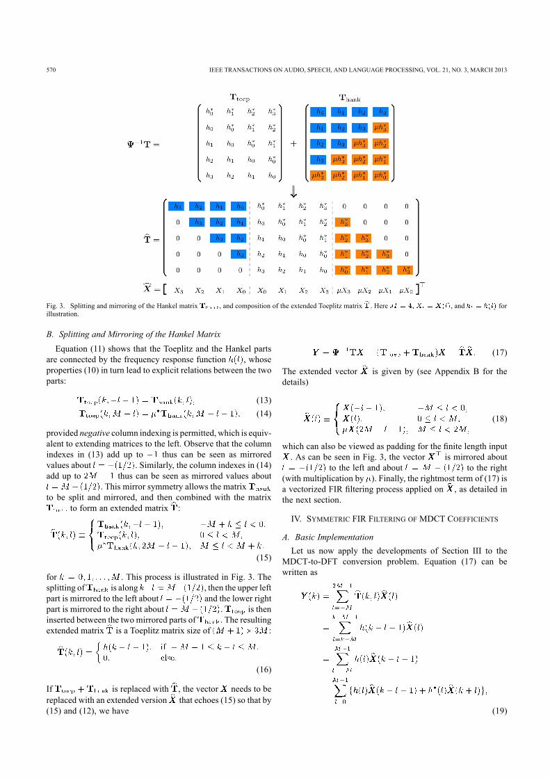
Fig. 3. Splitting and mirroring of the Hankel matrix , and composition of the extended Toeplitz matrix . Here , and forillustration.
B. Splitting and Mirroring of the Hankel MatrixEquation (11) shows that the Toeplitz and the Hankel parts
are connected by the frequency response function , whoseproperties (10) in turn lead to explicit relations between the twoparts:
(13)(14)
provided negative column indexing is permitted, which is equiv-alent to extending matrices to the left. Observe that the columnindexes in (13) add up to thus can be seen as mirroredvalues about . Similarly, the column indexes in (14)add up to thus can be seen as mirrored values about
. This mirror symmetry allows the matrixto be split and mirrored, and then combined with the matrix
to form an extended matrix :
(15)
for . This process is illustrated in Fig. 3. Thesplitting of is along , then the upper leftpart is mirrored to the left about and the lower rightpart is mirrored to the right about . is theninserted between the two mirrored parts of . The resultingextended matrix is a Toeplitz matrix size of :
(16)
If is replaced with , the vector needs to bereplaced with an extended version that echoes (15) so that by(15) and (12), we have
(17)
The extended vector is given by (see Appendix B for thedetails)
(18)
which can also be viewed as padding for the finite length input. As can be seen in Fig. 3, the vector is mirrored about
to the left and about to the right(with multiplication by ). Finally, the rightmost term of (17) isa vectorized FIR filtering process applied on , as detailed inthe next section.
IV. SYMMETRIC FIR FILTERING OF MDCT COEFFICIENTS
A. Basic ImplementationLet us now apply the developments of Section III to the
MDCT-to-DFT conversion problem. Equation (17) can bewritten as
(19)

ZHANG AND GIRIN: FAST AND ACCURATE DIRECT MDCT TO DFT CONVERSION WITH ARBITRARY WINDOW FUNCTIONS 571
Fig. 4. Product of window functions. Here is a Hanningwindow and is a KBD window.
Fig. 5. Filter taps for MDCT to DFT conversion (log-magnitude). Hereis a Hanning window and is a KBD window.
where the last equation is due to the conjugate symmetry ofin (10). Therefore, by extending , and in the
way of extending by (15), and extending , andin the way of extending by (18), the matrix form of directMDCT-to-DFT conversion (4) can be equivalently representedas FIR filtering.Remark 2: Note that in (19), the FIR filtering, or convolution,
is applied in the MDCT domain. This is not the usual fast im-plementation of time-domain convolution by frequency-domainpoint-wise product. Also in (19), for each ,the filtering process requires the same sequence of filter taps
, thus can be easily imple-mented in a vectorized manner. In [10], direct MDCT-to-MDSTconversion with the same window function was derived throughtrigonometric manipulations, resulting in a FIR filter similar to(19). However, a key difference is that in [10], outputs at dif-ferent bins require different segments of a filter taps sequence,which complicates implementation.Let us now calculate the phase term and FIR taps
for each of , and . For shorthand, let us denote here
(20)
Then let us substitute time shifts of , and in place of, and times shifts of , and in place of for matricesand defined in (6). From (8), we have the phase terms:
(21)
and from (9), we have the filter taps determined by the windowfunctions and :
(22)
See Appendix C for the details. Also, the vectorsare extended to , respectively,
using (18) and here .Then applying (21) and (22) to (17), (16), and (4), we have
(23)
Therefore, each of can be seen as a FIR filter withtaps and is conjugate symmetric by (10). The FIR filtering
processing of (23) is represented as a flowchart diagram inFig. 6(a).
B. Filter Coefficients Calculation Using DFT and AlternativeImplementationOne way to compute the filter taps is to use (22) directly. But
it is also possible to compute the filter taps by the DFT, that is,DFT of element-wise window function product with appropriatepre- and post-twiddle. Let
be two circular extensions of , which are different onlyin sign at their second halves. Let and
. Then, we have
(24)
where denotes DFT size of , and the pre- and post-twiddle factors are
(25)
for (see Appendix C). Fig. 4 providesan illustration of window function products and Fig. 5 providesan illustration of the magnitude of the corresponding filter taps(discussed in Section V.A). Note that an important case is whenboth and are symmetric. Then the filter taps in(24) have equal real and imaginary parts except for sign (seeAppendix C):
(26)

572 IEEE TRANSACTIONS ON AUDIO, SPEECH, AND LANGUAGE PROCESSING, VOL. 21, NO. 3, MARCH 2013
Fig. 6. (a) Flowchart of direct MDCT-to-DFT conversion by (23); (b) Flowchart of direct MDCT-to-DFT conversion by (27). Here denotes one frame delayof the MDCT spectrum, denotes extension (padding) operation for the MDCT spectra by (18), denotes convolution with the filter .
Obviously, the taps , and can be easilyrecovered from (24) with
, and , and sincethis calculation is made only once, the FIR process can be thenimplemented with (23). Alternately, the coefficients of (24) canbe used directly in the equivalent FIR filtering:
(27)
where and for consis-tency. This alternative FIR filtering processing is representedas a flowchart diagram in Fig. 6(b). Although a little bit morecomplicated than the implementation of (23)/Fig. 6(a) becauseof the MDCT vectors addition/subtraction, we will consider thisimplementation in the next section since we shall see that (24)is not only a fast way to compute filter taps but also plays a keyrole in addressing the problem of low-order FIR approximationand convergence of filter taps as . Because of the tightand simple links between both sets of filters, similar derivationsand conclusions can be drawn from the simpler implementation(23).
V. LOW-ORDER FIR APPROXIMATION
A. Energy Concentration of Filter TapsBoth the MDCT and the DFT are Fourier-type spectral trans-
forms with a grounded physical interpretation in terms of en-ergy concentration around the spectral components of the trans-formed signal. Given a pure tonal signal wherethe frequency , with appropriate smooth windowing
functions, both its MDCT spectrum and its DFT spec-trum concentrate at . Moreover, and
should have similar shapes since they both approximatethe power spectrum of (for a discussion on the specificshape of MDCT spectra, see, e.g., [17] and [5]). Therefore, onlyminor localmodifications should be needed to go from to
, i.e., each coefficient should be fairly well recon-structed from and the neighboring coefficients, and there-fore, we can expect some energy concentration of the three fil-ters in the coefficients around . Notethat this echoes the discussion about the locality vs. non-localityof the conversion in the introduction.This is totally compliant with the fact that from the perspec-
tive of multirate filterbank, smooth window functionsand are impulse responses of low-pass prototype FIR fil-ters [18], and therefore, in the frequency domain bothand are assumed to have a narrow mainlobe centeredaround 0 that concentrates most of the taps energy (one of themost important design goals of window functions [19]). Thisis, for example, the case for the Hamming or Hanning windowused for the DFT, and the sine or KBD window used for theMDCT. Then, this will also be the case for the product func-tions and . More specifically, sup-pose that the mainlobes of the frequency responses ofand are within and , re-spectively. Since time-domain point-wise product correspondsto frequency-domain convolution, by (24), most energy ofwill be within
Similar results can be drawn for and .

ZHANG AND GIRIN: FAST AND ACCURATE DIRECT MDCT TO DFT CONVERSION WITH ARBITRARY WINDOW FUNCTIONS 573
The energy concentration property of the conversion filtersis illustrated in Fig. 5. Here, the DFT window is a Han-ning window (widely used in, e.g., spectral analysis) and theMDCT window is a KBD window (the most frequentlyused window in AAC coding [2]), Let us recall that the filtertaps are conjugate symmetric (about ) so that weonly represent here their magnitude for positive indexes . Itcan be seen that for the three filters the power of the taps de-creases to 0 very quickly with the index (note the scaleof the -axis). Taps with (i.e., 99.2% of taps)are more than 50 dB below the tap at ; in other words,most of the taps energy is concentrated at a few low-frequencybins. Of course, how much precisely of energy is concentratedat low frequency taps depends on the DFT and MDCT windowfunctions, but similar results are obtained with other windowcombinations.
B. Low-Order Approximation
Based on the above discussion, it is possible to approximate(27) accurately by keeping only several most significant taps,that is, keeping the coefficients of the conversion filters for
, with , and setting the other coefficientsto zeros. Furthermore, when doing that, it may be desirablethat the number of coefficients kept be not the same for thethree filters, i.e., for for , and
for , resulting in an approximate FIR filtering4:
(28)
Indeed, the three filters and display the samegeneral trends, but they generally do not have the same overallmagnitude and decaying speed. As illustrated in Fig. 5,usually decays faster to 0 than , due to their difference inthe phasing of the window functions (Fig. 4). But on the otherhand, usually has larger total energy than , that is,
, by (24)and Parseval’s theorem. Therefore, different values forand in (28) can be set to obtain the best tradeoff between(high) conversion accuracy and (low) computational cost.More specifically, the computational cost of the approximate
FIR processing is proportional to the total number of kept taps4Note that (28) reveals locality between MDCT spectra and DFT spectra, as
discussed in Section V.A: An output coefficient depends mainly on theand consecutive input coefficients in and cen-
tered at bin , respectively. This is a direct consequence of energy concentrationof the filter taps.
Fig. 7. Approximation accuracy versus the total number of taps kept. Hereis a Hanning window. Both the random and music sig-
nals have samples.
. Its accuracy can be estimated in logsignal-to-noise power terms as (see Appendix D):
(29)
where
(30)
Equation (29) can be used to predict approximation accuracybefore filtering signals with given filters length, or to setand corresponding optimal values of and given atarget accuracy. For a given value of , one basic strategyto obtain and is to sort out all coefficients
in decreasing order of their absolute values, thenkeep the first taps, and finally count out , and .Following this sorting strategy for a range of values, it
is shown in Fig. 7 that the estimated SNR of (29) closely fol-lows the actual SNR (resulting from numerical simulations) forboth random and musical signals ( samples, or 113 s of44.1 kHz signal), hence validating (29). This is observed herefor both the Hanning-KBD and the Hanning-sine window con-figurations. The Hanning-KBD configuration appears to be sig-nificantly more accurate than the Hanning-sine given the same
, which is consistent to the significantly lower side-lobes of the KBD window than those of the sine window5. Wecan also see from Fig. 7 that setting is enough to keepSNR at about 60 dB for the Hanning-KBD configuration. Such anumber of coefficients is very low compared to the MDCT size
. (Note that for the Hanning-KBD configuration, areconstruction SNR about 100 dB is obtained with ,i.e., 1/16 of the number of MDCT coefficients.)
C. Asymptotic Analysis of FIR ApproximationAs the MDCT size increases, we may expect that, for a
given accuracy, the required total number of taps increases5This is why the KBD window is used more often in AAC coding.

574 IEEE TRANSACTIONS ON AUDIO, SPEECH, AND LANGUAGE PROCESSING, VOL. 21, NO. 3, MARCH 2013
Fig. 8. Approximation accuracy versus the total number of taps kept over dif-ferent . Here is always a Hanning window.
too. But this is not the case: the required actually tendsto saturate at some value even as , which guarantees
complexity of the approximate FIR filtering process fora given accuracy. This saturation phenomenon is illustrated inFig. 8, where the independence of w.r.t. is visible forSNRs lower than, say, 60 dB with the Hanning-KBD configura-tion, and for SNRs lower than, say, 45 dB with the Hanning-sineconfiguration.There are two reasons for this phenomenon: The first is that
the total energy of the taps of each of the three filters in (27) isproportional to ; the second is that for a fixed , the filter tap
, or , or , when normalized (divided) by ,converges to a fixed value as . Thus, if first ,and taps of the three filters are to be kept, respectively, thenthe ratio of their energy to the total energy converges, and by(29), this implies that the accuracy converges too as .If this limit accuracy is no lower than the required accuracy, then
will ensure the required accuracy forany , in other words, the needed saturates at some valueas . Let be a function defined on [0, 1] whose peri-odical extension on has a convergent Fourier series, and whendiscretely sampled, becomes the window function product withpre-twiddle (or ). By(24) and Parseval’s theorem, as , we have
(31)
Note that the post-twiddle factor, , which does notchange energy, is omitted here for simplicity, and
(32)
(33)
The same is true for and . Therefore, the two reasonsmentioned above are valid and saturation of is guaranteed.
D. Comparison With the Plain MDCT-to-DFT ConversionThe complexity of the direct MDCT-to-DFT conver-
sion for a complete spectrumis real multiplications and
real additions using (28), ortotally . On the other hand, the plainMDCT-to-DFT conversion scheme, that is, ,has the complexity of of ad-ditions and multiplications (the fast IMDCT based onthe FFT costs [14]; the split-radix FFTcosts ). Therefore, roughly, if
, then, theoretically, the directmethod will be faster than the plain method. For a typical
, we have .Moreover, compared to the plain method, the proposed di-
rect method has the two following major advantages. First, itworks also locally, that is, conversion can be applied directlywithin a subband by (28). In contrast, calculating a reduced setof DFT coefficients with the plain scheme implies to calculatethe complete IMDCT. Second, (28) is straightforward to imple-ment in Matlab, C, or assembly. Unlike the fast IMDCT and theFFT, it does not involve any bit-reversed addressing or compli-cated data flow control, and can be very efficient on systemssupporting vector operations, for example, most modern DSPs.We have implemented the direct method on Matlab using
vector operations. It runs about 60X real-time on a 3.0 GHzCPUfor 44.1 kHz mono signals with and . Wehave also implemented both the direct method and the plainmethod in C. (The Matlab and C implementations are availableat http://www.gipsa-lab.grenoble-inp.fr/~laurent.girin/demo/).Running times in ms of both methods with different anddifferent are shown in Table I. Generally, the largeror the smaller , the faster the direct method relatively,and the break-even is about 20, close to the above-men-tioned value. It should be noted that the fast IMDCT and theFFT in the plain method use the renowned FFTW3 library(http://www.fftw.org) which is highly optimized, although thedirect method is implemented without using any optimizedvector library.
E. Example of Application—Phase VocoderAs a straightforward example of application, we have com-
bined our direct conversion method in Matlab with D. Ellis’svocoder [20]. A phase vocoder typically works in the DFTdomain and speeds up or slows down audio signals by interpo-lating the amplitude and phase of DFT coefficients [21], [22].With the direct MDCT-to-DFT method, we can construct aphase vocoder that accepts MDCT coefficients as input. Thisis applicable to audio signals compressed by MDCT-domainaudio coders. For instance, the inputs are MDCT coefficientsdecoded from AAC bitstreams encoded at 32 kbps for a monospeech signal sampled at 16 kHz. The performance are testedin terms of SNR (against exact MDCT-to-DFT conversion, i.e.,log power ratio between reconstructed signal and differencebetween reconstructed signals with the two methods) and

ZHANG AND GIRIN: FAST AND ACCURATE DIRECT MDCT TO DFT CONVERSION WITH ARBITRARY WINDOW FUNCTIONS 575
TABLE IRUNNING TIME OF THE DIRECT MDCT-TO-DFT METHOD AND THE PLAIN
METHOD , C IMPLEMENTATION
TABLE IISNRS AND MOS OF THE PHASE VOCODER WITH THE APPROXIMATEMDCT-TO-DFT CONVERSION AGAINST THE PHASE VOCODER
WITH THE EXACT MDCT-TO-DFT CONVERSION
Mean Opinion Score (MOS, given by the PESQ evaluationsoftware [23], references are time-scaled signals with the exactconversion). In Table II, results with two time scaling factors( , slowing down) and four different approximationorders are given. It is found that the SNRsare noticeably lower than the SNRs of the direct conversionitself (i.e., without time scaling) with the same approximationorder. This is because the phase vocoder accumulates phaseand thus accumulates phase error, and reconstruction SNRs arevery sensitive to this problem. However, the quality in terms ofMOS given by PESQ is quite good for (larger than4, which means the difference between the approximate andexact methods are perceptually insignificant), and it remainsfair even for the extreme case .
VI. CONCLUSIONIn this paper, we have proposed a method for converting
MDCT coefficients to DFT coefficients through conjugatesymmetric FIR filtering, which can be effectively approximatedby retaining only the few first (most significant) taps. Thismethod is based on the observation that three MDCT-to-DFTconversion matrices are involved in this process, and thateach of those three matrices can be separated into a Toeplitzmatrix and a Hankel matrix, which can be combined into anextended Toeplitz matrix due to the 1/2 frequency shift term inthe MDCT. Also, we exploited the fact that the coefficients of
the extended Toeplitz matrices are DFT coefficients of windowfunctions products, resulting in an equivalent FIR filteringprocess with sharp concentration of energy at low-frequencytaps for usual DFT and MDCT window functions.Beyond the presented study, the low order FIR filtering for
MDCT-to-DFT conversion reveals an intrinsic relationship be-tween the MDCT and the DFT: the energy of an MDCT co-efficient is projected locally, that is mostly to a few DFT co-efficients of near frequencies. Therefore, using the presentedconversion technique, it is possible to accurately estimate am-plitude, phase or group delay of a signal in a subband usinglocal MDCT coefficients and very few local computations (in-stead of relying on whole spectra IMDCT synthesis and DFTanalysis). In a general manner, the proposed method allows di-rect chaining of MDCT-based perceptual audio decoders (e.g.,AAC) and DFT-domain processing. As a straightforward ex-ample of application, we have plugged our conversion methodbetween an AAC decoder and a phase vocoder. Another appli-cation of this method is for MDCT quantization in perceptualaudio coders: the method may allow accurate and efficient con-trol of quantization noise in the MDCT domain according toDFT domain psychoacoustic criteria. Finally, we plan to plugthe presented method within the Informed Source Separation(ISS) system of [24], which is based on a DFT-domain Wienerfiltering of source signals from mixture signals, to adapt it effi-ciently to AAC compressed mixture signals: source separationand generation of remix signal will then be possible withoutpassing through mix signal time-domain reconstruction.
APPENDIX A
Note that .Then, the entry of at , by definition of matrixmultiplication and (6), is

576 IEEE TRANSACTIONS ON AUDIO, SPEECH, AND LANGUAGE PROCESSING, VOL. 21, NO. 3, MARCH 2013
as is stated in (7), (8), and (9).
APPENDIX B
To show that the extended vector given by (18) indeedsatisfies (17), we compare the th element in and the thelement in .By (16) and (18), we have
Therefore, the extended vector given by (18) satisfies (17).(Note that the phase term verifies .)
APPENDIX C
From (1), we write explicitly the matrices and as
which implies their time shifts are and ,respectively. Obviously, both and have time shift 0 whileboth and have time shift . Then replace
with the time shifts of and replace with timeshifts of respectively in (8), we have
Note that . To compute thefilter taps by (9), we have to replace with thewindow functions for , and , and then replace withthe window functions for , and :
Note that ranges from to for , from 0 tofor , and from 0 to for . Then (22)
follows readily from the above.For the DFT form (24), the modulation term is
instead of the normal . But we have
which implies (24). Themodulation term also has a special sym-metry due to its phase:
Now consider and are even symmetric (and real).Then window function products andare even symmetric too and is odd symmetric,which, with the above symmetry of the modulation term, leadto (26).

ZHANG AND GIRIN: FAST AND ACCURATE DIRECT MDCT TO DFT CONVERSION WITH ARBITRARY WINDOW FUNCTIONS 577
APPENDIX D
Let us assume that in (28), coefficients are zero-meanuncorrelated white noises with the same variance equal to 1.Then, the variance of the error of approximating (definedin (19), but with subscript ) in (28) is
(34)
And similarly, the variance of the exact filter output is
(35)
Similar results can be drawn for and . Let usfurther assume that in (28) are indepen-dent with each other (in addition to being each one a zero-mean1-variance white noise). The function defined in (30)is the total energy of the first taps of the three filters, re-spectively. Then, by (34), the variance of total approximationerror of DFT coefficient using (28) is
(36)
and by (35), the variance of the DFT coefficient is
(37)
Therefore, the approximation accuracy in term of log-SNR canbe estimated as
(38)
Note that the white noise and independence assumptions of, and may not be valid in reality. Neverthe-
less, (29) still gives very close estimation of the approximationaccuracy even for musical signals, as shown by experiments,illustrated in Fig. 7, and commented in Section V.B.
REFERENCES[1] J. Princen and A. Bradley, “Analysis/synthesis filter bank design based
on time domain aliasing cancellation,” IEEE Trans. Acoust., Speech,Signal Process., vol. ASSP-34, no. 5, pp. 1153–1161, Oct. 1986.
[2] “Coding of moving pictures and audio, Part 7: Advanced audiocoding,” Tech. Rep. ISO/IEC 13818-7, 2005, ISO/IEC JTC1/SC29/WG11 MPEG.
[3] H. Malvar, Signal Processing With Lapped Transforms. Norwood,MA: Artech House, 1992.
[4] Y. Wang, L. Yaroslavsky, M. Vilermo, and M. Vaananen, “Some pecu-liar properties of the MDCT,” in Proc. 5th Int. Conf. Signal Process. .WCCC-ICSP ’00, Aug. 2000, vol. 1, pp. 61–64.
[5] S. Zhang, W. Dou, P. Chi, and H. Yang, “MDCT spectrum separation:Catching the fine spectral structures for stereo coding,” in Proc. IEEEInt. Conf. Acoust., Speech, Signal Process. (ICASSP), Mar. 2010, pp.369–372.
[6] S. Zhang, W. Dou, and H. Yang, “DFT spectrum estimation from crit-ically sampled lapped transforms,” Signal Process., vol. 91, no. 2, pp.300–310, Feb. 2011.
[7] K. Suresh and T. Sreenivas, “Linear filtering in DCT IV/DST IVand MDCT/MDST domain,” Signal Process., vol. 89, no. 6, pp.1081–1089, Jun. 2009.
[8] S. Merdjani and L. Daudet, “Direct estimation of frequency fromMDCT-encoded files,” in Proc. 6th Int. Conf. Digital Audio Effects(DAFx-03). DAFx-03, Sep. 2003, pp. 1–4.
[9] M. Goodwin, “Efficient system and method for converting betweendifferent transform-domain signal representations,” U.S. patent App.09/948 053, Sep. 2001.
[10] C. Cheng, “Method for estimating magnitude and phase in the MDCTdomain,” 116th AES Convention May 2004, Audio EngineeringSocitey, p. Paper Number: 6091.
[11] H. Malvar, “A modulated complex lapped transform and its applica-tions to audio processing,” in Proc. IEEE Int. Conf. Acoust., Speech,Signal Process. ICASSP’99, Mar. 1999, vol. 3, pp. 1421–1424.
[12] S. Chen, N. Xiong, J. H. Park, M. Chen, and R. Hu, “Spatial parametersfor audio coding: MDCT domain analysis and synthesis,” MultimediaTools Applicat., vol. 48, no. 2, pp. 225–246, 2010.
[13] M. Bosi and R. E. Goldberg, Introduction to Digital Audio Coding andStandards. Norwell, MA: Kluwer, 2003.
[14] P. Duhamel, Y. Mahieux, and J. Petit, “A fast algorithm for the imple-mentation of filter banks based on ‘time domain aliasing cancellation’,”in Proc. Int. Conf. Acoust., Speech, Signal Process. ICASSP’91, Apr.1991, vol. 3, pp. 2209–2212.
[15] P. Duhamel, “Implementation of “split-radix” FFT algorithms forcomplex, real, and real-symmetric data,” IEEE Trans. Acoust., Speech,Signal Process., vol. ASSP-34, no. 2, pp. 285–295, Apr. 1986.
[16] R. Gray, Toeplitz and Circulant Matrices: A Review. Hanover, MA:Now Publishers Inc., 2006.
[17] L. Daudet and M. Sandler, “MDCT analysis of sinusoids: Exact resultsand applications to coding artifacts reduction,” IEEE Trans. SpeechAudio Process., vol. 12, no. 3, pp. 302–312, May 2004.
[18] P. Vaidyanathan, Multirate Systems and Filter Banks. EnglewoodCliffs, NJ: Prentice-Hall, 1993.
[19] F. Harris, “On the use of windows for harmonic analysis with the dis-crete Fourier transform,” Proc. IEEE, vol. 66, no. 1, pp. 51–83, Jan.1978.
[20] D. P. W. Ellis, “A phase vocoder in Matlab,” 2002 [Online]. Available:http://www.ee.columbia.edu/~dpwe/resources/matlab/pvoc/
[21] M. Portnoff, “Implementation of the digital phase vocoder using thefast Fourier transform,” IEEE Trans. Acoust., Speech, Signal Process.,vol. 24, no. 3, pp. 243–248, Jun. 1976.
[22] M. Dolson, “The phase vocoder: A tutorial,” Comput. Music J. vol.10, no. 4, pp. 14–27, 1986 [Online]. Available: http://www.panix.com/~jens/pvoc-dolson.par
[23] “Perceptual evaluation of speech quality (PESQ): An objective methodfor end-to-end speech quality assessment of narrow-band telephonenetworks and speech codecs Tech. Rep. ITU-T Rec. P.862, 2001,ITU-T Rec. P.862.
[24] A. Liutkus, J. P. amd Roland Badeau, L. Girin, and G. Richard, “In-formed source separation through spectrogram coding and data em-bedding,” Signal Process., vol. 19, no. 10, pp. 1–13, 2011.
Shuhua Zhang was born in Anhui, China, 1978.From 1997 to 2001, he studied at the Beijing Instituteof Technology, Beijing, China, where he receiveda B.Sc. degree. In January 2011, he received hisPh.D. degree from the department of electronicengineering, Tsinghua University, Beijing, China, onlow-bitrate stereo audio coding. From February 2011to July 2012, he was a post-doctoral researcher at theGIPSA-Lab (Grenoble Laboratory of Image, Speech,Signal, and Automation), Grenoble, France, andworked on informed source separation. His research
interests include: audio and speech coding, spatial audio, time-frequencytransforms, blind and informed source separation, and fast DSP algorithms.

578 IEEE TRANSACTIONS ON AUDIO, SPEECH, AND LANGUAGE PROCESSING, VOL. 21, NO. 3, MARCH 2013
Laurent Girin was born in Moutiers, France, in1969. He received the M.Sc. and Ph.D. degrees insignal processing from the Institut National Poly-technique de Grenoble (INPG), Grenoble, France,in 1994 and 1997, respectively. In 1999, he joinedthe Ecole Nationale Supérieure d’Electronique etde Radioélectricité de Grenoble (ENSERG), as anAssociate Professor. He is now a Professor at Phelma(Physics, Electronics, and Materials Departmentof Grenoble-INP), where he lectures (baseband)signal processing, from theoretical aspects to audio
applications. His research activity is carried out at GIPSA-Lab (Grenoble Labo-ratory of Image, Speech, Signal, and Automation). It concerns different aspectsof speech and audio processing (analysis, modeling, coding, transformation,synthesis), with a special interest in joint audio/visual speech processing andsource separation.
Copyright © 2022 FDOKUMEN