FACULTY OF CIVIL AND ENVIRONMENTAL ENGINEERING DEPARTMENT OF STRUCTURE AND MATERIAL ENGINEERING LAB...
11
FACULTY OF CIVIL AND ENVIRONMENTAL ENGINEERING DEPARTMENT OF STRUCTURE AND MATERIAL ENGINEERING LAB MATERIAL REPORT Subject Code BFC 21201 Code & Experiment Title BUCKLING OF STRUTS Course Code 2 BFF/1 Date 03/10/2011 Section / Group 2 Name MUHAMAD ASYRAF BIN AB MALIK (DF100108) Members of Group 1.MUHAMMAD IKHWAN BIN ZAINUDDIN (DF100018) 2.AHMAD FARHAN BIN RAKAWI (DF100142) 3.IDAMAZLIZA BINTI ISA (DF100128) 4.AINUN NAZHIRIN BINTI ABD JALIL (DF100076) Lecturer/Instructor/Tutor EN MOHAMAD HAIRI BIN OSMAN Received Date 17 OCTOBER 2011 Comment by examiner Received
Transcript of FACULTY OF CIVIL AND ENVIRONMENTAL ENGINEERING DEPARTMENT OF STRUCTURE AND MATERIAL ENGINEERING LAB...

FACULTY OF CIVIL AND ENVIRONMENTAL
ENGINEERING
DEPARTMENT OF STRUCTURE AND MATERIAL
ENGINEERING
LAB MATERIAL
REPORT
Subject Code BFC 21201
Code & Experiment Title BUCKLING OF STRUTS
Course Code 2 BFF/1
Date 03/10/2011
Section / Group 2
Name MUHAMAD ASYRAF BIN AB MALIK (DF100108)
Members of Group 1.MUHAMMAD IKHWAN BIN ZAINUDDIN (DF100018)
2.AHMAD FARHAN BIN RAKAWI (DF100142)
3.IDAMAZLIZA BINTI ISA (DF100128)
4.AINUN NAZHIRIN BINTI ABD JALIL (DF100076)
Lecturer/Instructor/Tutor EN MOHAMAD HAIRI BIN OSMAN
Received Date 17 OCTOBER 2011
Comment by examiner
Received

STUDENT CODE OF ETHIC
(SCE) DEPARTMENT OF STRUCTURE AND MATERIAL
ENGINEERING
FACULTY OF CIVIL & ENVIRONMENTAL ENGINEERING
UTHM
We, hereby confess that we have prepared this report on our effort. We also admit not to receive
or give any help during the preparation of this report and pledge that everything mentioned in the
report is true.
___________________________
Student Signature
Name : MUHAMAD ASYRAF AB MALIK
Matric No. : DF100108
Date : 17/10/2011
_______________________
Student Signature
Name : MUHAMMAD IKHWAN ZAINUDDIN
Matric No. : DF100018
Date : 17/10/2011
___________________________
Student Signature
Name : AHMAD FARHAN RAKAWI
Matric No. : DF100142
Date : 17/10/2011
___________________________
Student Signature
Name : AINUN NAZHIRIN ABD JALIL
Matric No. : DF100076
Date : 17/10/2011
___________________________
Student Signature
Name : IDAMAZLIZA ISA
Matric No. : DF100128
Date : 17/10/2011
1.0 OBJECTIVE
1.1 To examine how shear force varies with an increasing point load.
1.2 To examine how shear force varies at the cut position of the beam for various loading
condition.
2.0 LEARNING OUTCOME
2.1 The application the engineering knowledge in practical application.
2.2 To enhance technical competency in structural engineering through laboratory
application.
2.3 To communicate effectively in group.
2.4 To identify problem, solving and finding out appropriate solution through laboratory
application.
3.0 INTRODUCTION
A compressive member can fail in two ways. The first is via rupture due to the direct
stress and the second is by an elastic mode of failure called buckling. Short wide
compressive member tends to fail by material crushing.
When buckling occurs the strut will no longer carry any more load and it will simply
continue to buckle i.e its stiffness then becomes zero and it is useless as a structural
member.
4.0 THEORY
To predict the buckling load Euler buckling formula is used. The crictical value in
Euler Formula is the slenderness ratio, which is the ratio of the length of the strut to
its radius of gyration (L/K).
The Euler formula become inaccurate for struts with L/K ratio of less than 1.125 and
this should be taken into account in any design work.

Euler buckling formula for pin struts:
Pe=π2EI/L
2
Where;
Pe = Euler buckling load (N)
E = Young’s Modulus (Nm-2)
I = Second moment of area ( m4
)
L = length of strut ( m )
5.0 APPARATUS

Buckling of Strut Digital Display Force
Steel Strut
Buckling of Strut Equipment

6.0 PROCEDURES
Part 1
1. Fit the bottom chuck to the machine and remove the top chuck (to give two pinned ends).
Select the shortest strut, number 1, and measured the cross section using the vernier
provided and calculated the second moment of area, I,for the strut. ( bd3/12)
2. Adjust the position of the sliding crosshead to accept the strut using the thumbnut to lock
off the slider. Ensure that there is the maximum amount of travel available on the hand
wheel threat to compress the strut. Finally tighten the locking screw .
3. Carefully back- off the handwheel so that the strut is resting in the notch but not
transmitting any load. Rezero the forcemeter using the front panel control.
4. Carefully start to load the strut. If the strut begin to buckle to the left, “flick” the strut to
the right and vice versa (this reduces any error associated wih the straightness of strut).
Turn the hand wheel until there is no further increase in load (the load may peak and then
drop as it settles in the notches).
5. Record the final load in Table 1. Repeat with strut numbers 2, 3, 4 and 5 adjusting the
crosshead as required to fit the strut.
Part 2
1. To study the effect of end conditions, follow the same basic procedure as in part 1, but
this time remove the bottom chuck and clamp the specimen using the cap head screw and
plate to make a pinned-fixed end condition.
2. Record your result in Table 2 and calculate the values of 1/ L2 for the struts.
3. Fit the top chuck with the two cap head screws and clamp both ends of the specimen to
make a pinned –pinned end condition. Calculate the new values of 1/L2.
4. Enter the result into Table 3

7.0 RESULTS
Strut
Number
Length
(m)
Buckling Load
(N)
Experiment
Buckling Load
(N)
Theory
1 0.32 -92 88.65
2 0.37 -56 66.31
3 0.42 -24 51.46
4 0.47 -13 41.09
5 0.52 -16 33.57
Table 1
Strut
Number
Length
(m)
Buckling Load
(N)
Buckling Load
(N)
Theory
1/L2 ( m-2)
1 0.32 -196 177.30 9.77
2 0.37 -106 132.62 7.30
3 0.42 -105 102.92 5.67
4 0.47 -101 82.19 4.53
5 0.52 -48 67.14 3.70
Table2
Strut
Number
Length
(m)
Buckling Load
(N)
Buckling Load
(N)
Theory
1/L2 ( m-2)
1 0.32 -397 354.60 9.77
2 0.37 -284 265.24 7.30
3 0.42 -252 205.85 5.67
4 0.47 -174 164.38 4.53
5 0.52 -155 134.29 3.70
Table 3

8.0 DATA ANALYSIS
Part 1
To calculate Buckling Load (N) Theory ( pinned-pinned end condition)
Pe = π2
EI/L2
I = bd3
= π
2 ( 69 x 10
9 ) ( 13.33 x 10
-12 )
12
0.322
= 88.65 N = ( 0.02 ) ( 2 x 10 -3
)
12
= 13.33 x 10 -12
m
Part 2
To calculate Buckling Load (N) Theory ( pinned-fixed end condition)
Pe = 2π2
EI/L2
= 2π2 ( 69 x 10
9 ) ( 13.33 x 10
-12 ) I = bd
3
0.322 12
= 177.30 N = ( 0.02 ) ( 2 x 10 -3
)
12
= 13.33 x 10 -12
m
Part 3
To calculate Buckling Load (N) Theory ( fixed-fixed end condition)
Pe = 4π2
EI/L2
= 4π2
( 69 x 109 ) ( 13.33 x 10
-12 ) I = bd
3
0.32
2 12
= 354.60 N = ( 0.02 ) ( 2 x 10
-3 )
12
= 13.33 x 10 -12
m

9.0 DISCUSSION
Part 1:
1) Examine the Euler buckling equation and select an appropriate parameter to establish a
linear relationship between the buckling load and the length of the strut. Write the
relationship below.
Based Eular formula and Table 1, 2 and 3,
Pe = Euler buckling load (N), L = length
We can consider that when L is bigger, Pe will be small, relation between
buckling load and the length of the strut is inversely proportional in linear condition.
2) Calculate the value and enter them in Table 1 with an appropriate title.
Show on Table 1 using formula: ( )
3) Plot a graph to prove the relationship is linear. Compare your experimental value to those
calculated from Euler formula by entering a theoretical line onto the graph. Comment on
the result.
Graph plotted = In the graph paper.
Base on the graft that we plotted, the difference to the end of the pins for the
results of gradient experiments is 1.46 and the slope of the theoretical calculation results
of 1.28. Difference to the fixed -pin end of the gradient experiment results were 1.33 and
gradient theory results of the calculation is 1.29. In addition, the differences for fixed-
fixed end conditions are for the gradient experiment results are 1.25 and theoretical
calculations are the result of the slope is 1.25. This experiment result shows that the slope
is greater than the slope of the calculation results. In practice, the buckling of the
experiment is higher than theoretical.
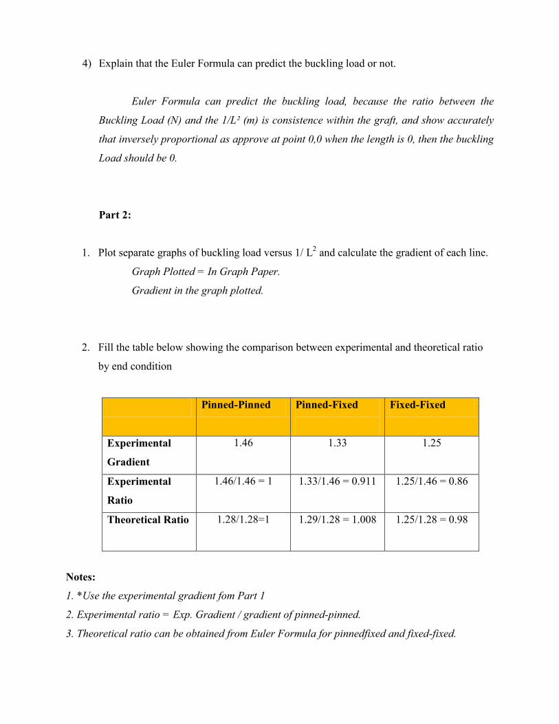
4) Explain that the Euler Formula can predict the buckling load or not.
Euler Formula can predict the buckling load, because the ratio between the
Buckling Load (N) and the 1/L² (m) is consistence within the graft, and show accurately
that inversely proportional as approve at point 0,0 when the length is 0, then the buckling
Load should be 0.
Part 2:
1. Plot separate graphs of buckling load versus 1/ L2 and calculate the gradient of each line.
Graph Plotted = In Graph Paper.
Gradient in the graph plotted.
2. Fill the table below showing the comparison between experimental and theoretical ratio
by end condition
Pinned-Pinned Pinned-Fixed
Fixed-Fixed
Experimental
Gradient
1.46 1.33 1.25
Experimental
Ratio
1.46/1.46 = 1
1.33/1.46 = 0.911 1.25/1.46 = 0.86
Theoretical Ratio 1.28/1.28=1 1.29/1.28 = 1.008
1.25/1.28 = 0.98
Notes:
1. *Use the experimental gradient fom Part 1
2. Experimental ratio = Exp. Gradient / gradient of pinned-pinned.
3. Theoretical ratio can be obtained from Euler Formula for pinnedfixed and fixed-fixed.
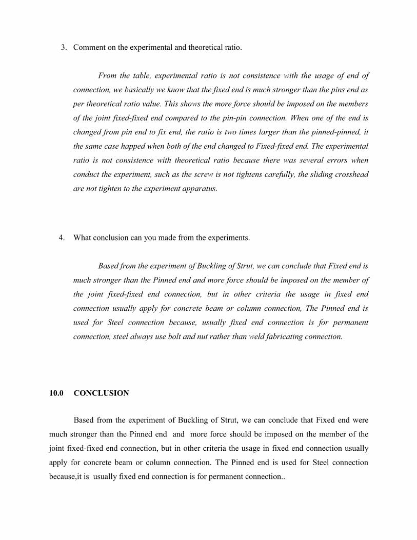
3. Comment on the experimental and theoretical ratio.
From the table, experimental ratio is not consistence with the usage of end of
connection, we basically we know that the fixed end is much stronger than the pins end as
per theoretical ratio value. This shows the more force should be imposed on the members
of the joint fixed-fixed end compared to the pin-pin connection. When one of the end is
changed from pin end to fix end, the ratio is two times larger than the pinned-pinned, it
the same case happed when both of the end changed to Fixed-fixed end. The experimental
ratio is not consistence with theoretical ratio because there was several errors when
conduct the experiment, such as the screw is not tightens carefully, the sliding crosshead
are not tighten to the experiment apparatus.
4. What conclusion can you made from the experiments.
Based from the experiment of Buckling of Strut, we can conclude that Fixed end is
much stronger than the Pinned end and more force should be imposed on the member of
the joint fixed-fixed end connection, but in other criteria the usage in fixed end
connection usually apply for concrete beam or column connection, The Pinned end is
used for Steel connection because, usually fixed end connection is for permanent
connection, steel always use bolt and nut rather than weld fabricating connection.
10.0 CONCLUSION
Based from the experiment of Buckling of Strut, we can conclude that Fixed end were
much stronger than the Pinned end and more force should be imposed on the member of the
joint fixed-fixed end connection, but in other criteria the usage in fixed end connection usually
apply for concrete beam or column connection. The Pinned end is used for Steel connection
because,it is usually fixed end connection is for permanent connection..


![[Lab Report] PSpice](https://static.fdokumen.com/doc/165x107/631a338ebb40f9952b01e638/lab-report-pspice.jpg)