Learning Material - Mechanical Engineering
137
Academic Year: 2019 – 20 Semester: II Class : III B.Tech Subject: Heat Transfer Learning Material UNIT-I Introduction and One Dimensional Steady State Conduction Heat Transfer Syllabus: Introduction: Modes and mechanisms of heat transfer, Basic laws of heat transfer, General discussion about applications of heat transfer. Difference between heat transfer and thermodynamics. Conduction Heat Transfer: Fourier Law of Heat conduction, General heat conduction equation in Cartesian, Cylindrical and Spherical coordinates. Simplification and forms of the field equation, steady, unsteady heat transfer, Initial and boundary conditions One Dimensional Steady State Conduction Heat Transfer: Homogeneous slabs, hollow cylinders and spheres, Electrical Analogy, Thermal Contact Resistance, Thermal Shape Factor, Critical radius of insulation, Variable Thermal conductivity, systems with heat generation. 1.1 Introduction: From the study of thermodynamics, you have learned that energy can be transferred by interactions of a system with its surroundings. These interactions are called work and heat. However, thermodynamics deals with the end states of the process during which an interaction occurs and provides no information concerning the nature of the interaction or the time rate at which it occurs. For example, imagine a water bottle is kept in refrigerator for cooling purpose. Using the laws of thermodynamics, we can find only the amount of heat required to be removed from the water to achieve the specified cold temperature. But we can't find the time it will take to reach that temperature. Also we can't find the temperature of water at different intervals of time in the process of cooling. Thus Thermodynamics deals only with the transfer of heat between two equilibrium states, where as heat transfer deals with rate of energy transfer. In thermodynamics we represent heat in Joules or kJ. But in heat transfer we measure rate of heat transfer by introducing time effect and the unit is Watt or kilowatt. Importance of Heat Transfer: It is the science that deals with the mechanism of energy transfer and the rate of energy transfer due to a difference in temperature. It enables an engineer to design an equipment in which the process occurs. It provides the fundamental information needed to estimate the size and hence the cost of an equipment necessary to transfer a specified amount of heat in a given time. A mechanical engineer is concerned with developing and designing process equipment for thermal and nuclear power plants, and heating and cooling systems for comfort conditions. A chemical engineer concerns with heat transfer processes in numerous chemical reactions. A metallurgical engineer has to monitor rates of temperature change during heat transfer processes in order to achieve the desired properties in a material.
-
Upload
khangminh22 -
Category
Documents
-
view
0 -
download
0
Transcript of Learning Material - Mechanical Engineering
Academic Year: 2019 – 20 Semester: II
Class : III B.Tech Subject: Heat Transfer
Learning Material
UNIT-I
Introduction and One Dimensional Steady State Conduction Heat Transfer
Syllabus:
Introduction: Modes and mechanisms of heat transfer, Basic laws of heat transfer, General
discussion about applications of heat transfer. Difference between heat transfer and
thermodynamics.
Conduction Heat Transfer: Fourier Law of Heat conduction, General heat conduction
equation in Cartesian, Cylindrical and Spherical coordinates.
Simplification and forms of the field equation, steady, unsteady heat transfer, Initial and
boundary conditions
One Dimensional Steady State Conduction Heat Transfer: Homogeneous slabs, hollow
cylinders and spheres, Electrical Analogy, Thermal Contact Resistance, Thermal Shape
Factor, Critical radius of insulation, Variable Thermal conductivity, systems with heat
generation.
1.1 Introduction: From the study of thermodynamics, you have learned that energy can be transferred
by interactions of a system with its surroundings. These interactions are called work and heat.
However, thermodynamics deals with the end states of the process during which an
interaction occurs and provides no information concerning the nature of the interaction or the
time rate at which it occurs.
For example, imagine a water bottle is kept in refrigerator for cooling purpose. Using
the laws of thermodynamics, we can find only the amount of heat required to be removed
from the water to achieve the specified cold temperature. But we can't find the time it will
take to reach that temperature. Also we can't find the temperature of water at different
intervals of time in the process of cooling. Thus Thermodynamics deals only with the transfer
of heat between two equilibrium states, where as heat transfer deals with rate of energy
transfer. In thermodynamics we represent heat in Joules or kJ. But in heat transfer we
measure rate of heat transfer by introducing time effect and the unit is Watt or kilowatt.
Importance of Heat Transfer:
It is the science that deals with the mechanism of energy transfer and the rate of
energy transfer due to a difference in temperature.
It enables an engineer to design an equipment in which the process occurs.
It provides the fundamental information needed to estimate the size and hence the cost
of an equipment necessary to transfer a specified amount of heat in a given time.
A mechanical engineer is concerned with developing and designing process
equipment for thermal and nuclear power plants, and heating and cooling systems for
comfort conditions.
A chemical engineer concerns with heat transfer processes in numerous chemical
reactions.
A metallurgical engineer has to monitor rates of temperature change during heat
transfer processes in order to achieve the desired properties in a material.
An electronics and computer engineer has to ensure that heat is dissipated efficiently
from transistors and chips, so that their temperature do not exceed safe limits.
An electrical engineer has to ensure that the designed electrical appliances (motors,
generators, fans etc.) do not overheat during operation.
1.2 Modes of Heat transfer:
The study of heat transfer requires the knowledge of three modes of heat transfer -
conduction, convection and radiation.
1.2.1 Conduction
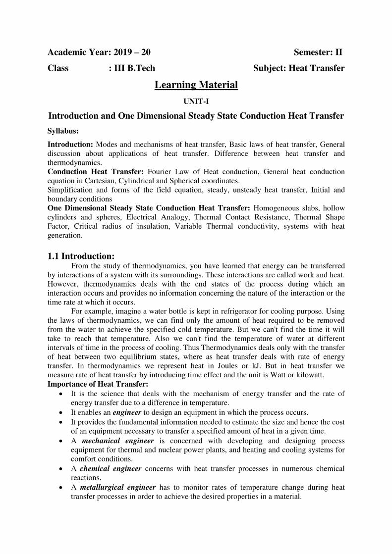
Conduction is the transfer of energy from the more energetic
particles of a substance to the adjacent less energetic ones as a result of
interactions between the particles. Conduction can take place in solids,
liquids, or gases.
In gases and liquids, conduction is due to the collisions and
diffusion of the molecules during their random motion. In solids, it is
due to the combination of vibrations of the molecules in a lattice and the
energy transport by free electron.
The rate of heat conduction through a medium depends on the geometry
of the medium, its thickness, and the material of the medium, as well as
the temperature difference across the medium.
Fourier's Law: The rate of heat transfer by conduction is proportional to the temperature
gradient in the direction of heat flow and the area normal to the heat flow direction. Which is
called Fourier’s law of heat conduction after J. Fourier. Mathematically, it is expressed as
(1.1)
Where, the constant of proportionality k is the thermal conductivity of the material, which is
a measure of the ability of a material to conduct heat and its unit is W/m0C or W/m-K.
dT
dxis
the temperature gradient, which is the slope of the temperature curve ona T-x diagram (the
rate of change of T with x) at a location x. A is the area normal to heat flow direction.
Negative sign is introduced in the equation (1), as the heat is conducted in the
direction of decreasing temperature, and the temperature gradient becomes negative when
temperature decreases with increasing x.
Thermal Conductivity
The thermal conductivity k is a measure of a material’s ability to conduct heat. For
example, k =0.608 W/m0C for water and k = 80.2 W/m
0C for iron at room temperature,
which indicates that iron conducts heat more than 100 times faster than water can. Thus we
say that water is a poor heat conductor relative to iron, although water is an excellent medium
to store thermal energy.
The thermal conductivity of a material can be defined as the rate of heat transfer
through a unit thickness of the material per unit area per unit
temperature difference.
A high value for thermal conductivity indicates that the
material is a good heat conductor, and a low value indicates
that the material is a poor heat conductor or insulator. The
thermal conductivities of some common materials at room
temperature are given in Table 1–1.
Note that materials such as copper and silver that are
good electric conductor are also good heat conductors,
and have high values of thermal conductivity.
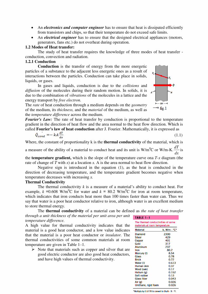
Materials such as rubber, wood, and Styrofoam are poor conductors of heat and have
low conductivity values.
Pure crystals and metals have the highest thermal conductivities, and gases and
insulating materials the lowest.
Fig. 1.2 Thermal conductivity of different materials
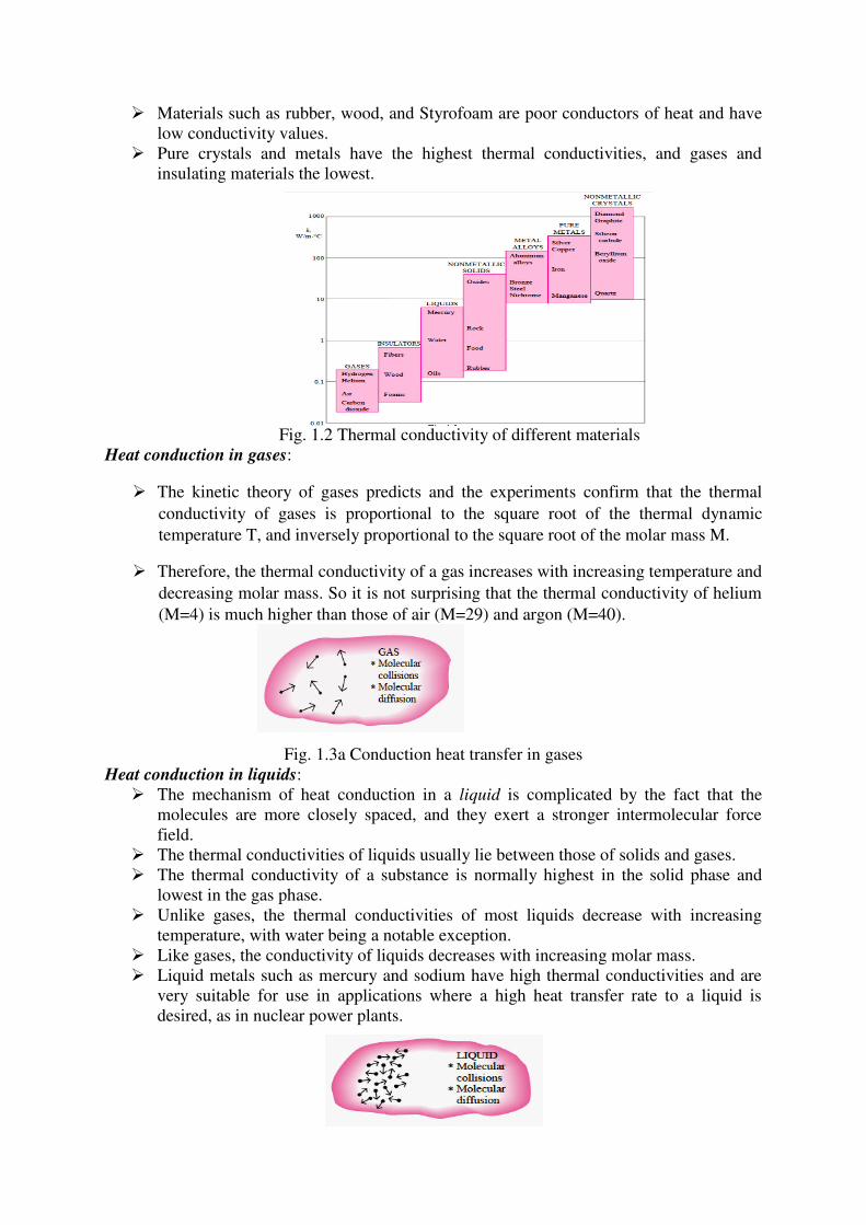
Heat conduction in gases:
The kinetic theory of gases predicts and the experiments confirm that the thermal
conductivity of gases is proportional to the square root of the thermal dynamic
temperature T, and inversely proportional to the square root of the molar mass M.
Therefore, the thermal conductivity of a gas increases with increasing temperature and
decreasing molar mass. So it is not surprising that the thermal conductivity of helium
(M=4) is much higher than those of air (M=29) and argon (M=40).
Fig. 1.3a Conduction heat transfer in gases
Heat conduction in liquids:
The mechanism of heat conduction in a liquid is complicated by the fact that the
molecules are more closely spaced, and they exert a stronger intermolecular force
field.
The thermal conductivities of liquids usually lie between those of solids and gases.
The thermal conductivity of a substance is normally highest in the solid phase and
lowest in the gas phase.
Unlike gases, the thermal conductivities of most liquids decrease with increasing
temperature, with water being a notable exception.
Like gases, the conductivity of liquids decreases with increasing molar mass.
Liquid metals such as mercury and sodium have high thermal conductivities and are
very suitable for use in applications where a high heat transfer rate to a liquid is
desired, as in nuclear power plants.
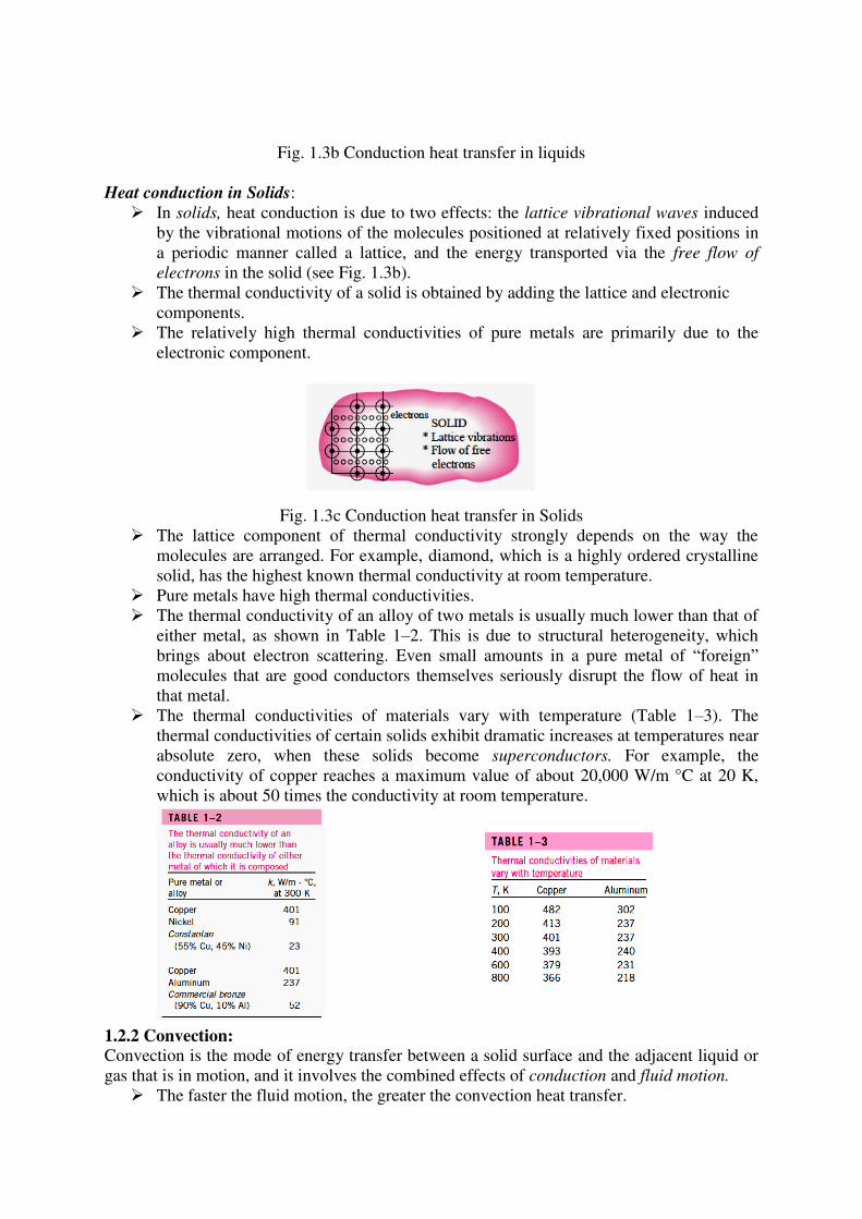
Fig. 1.3b Conduction heat transfer in liquids
Heat conduction in Solids:
In solids, heat conduction is due to two effects: the lattice vibrational waves induced
by the vibrational motions of the molecules positioned at relatively fixed positions in
a periodic manner called a lattice, and the energy transported via the free flow of
electrons in the solid (see Fig. 1.3b).
The thermal conductivity of a solid is obtained by adding the lattice and electronic
components.
The relatively high thermal conductivities of pure metals are primarily due to the
electronic component.
Fig. 1.3c Conduction heat transfer in Solids
The lattice component of thermal conductivity strongly depends on the way the
molecules are arranged. For example, diamond, which is a highly ordered crystalline
solid, has the highest known thermal conductivity at room temperature.
Pure metals have high thermal conductivities.
The thermal conductivity of an alloy of two metals is usually much lower than that of
either metal, as shown in Table 1–2. This is due to structural heterogeneity, which
brings about electron scattering. Even small amounts in a pure metal of “foreign”
molecules that are good conductors themselves seriously disrupt the flow of heat in
that metal.
The thermal conductivities of materials vary with temperature (Table 1–3). The
thermal conductivities of certain solids exhibit dramatic increases at temperatures near
absolute zero, when these solids become superconductors. For example, the
conductivity of copper reaches a maximum value of about 20,000 W/m °C at 20 K,
which is about 50 times the conductivity at room temperature.
1.2.2 Convection:
Convection is the mode of energy transfer between a solid surface and the adjacent liquid or
gas that is in motion, and it involves the combined effects of conduction and fluid motion.
The faster the fluid motion, the greater the convection heat transfer.
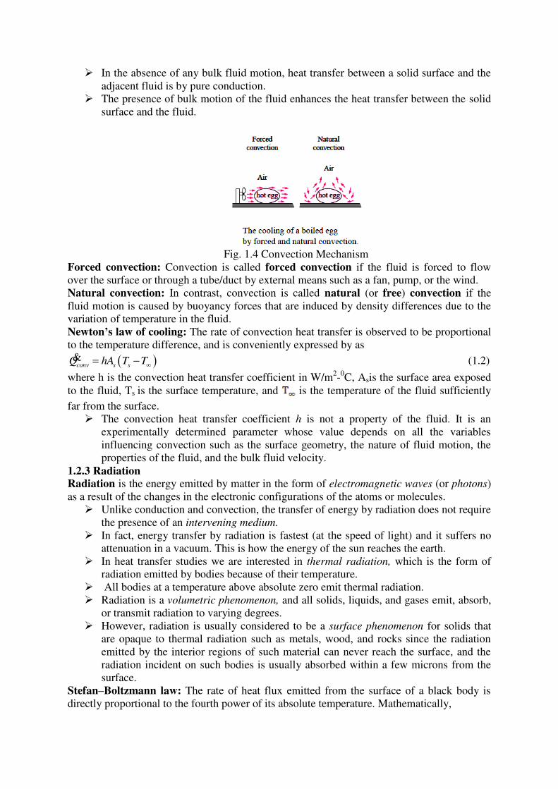
In the absence of any bulk fluid motion, heat transfer between a solid surface and the
adjacent fluid is by pure conduction.
The presence of bulk motion of the fluid enhances the heat transfer between the solid
surface and the fluid.
Fig. 1.4 Convection Mechanism
Forced convection: Convection is called forced convection if the fluid is forced to flow
over the surface or through a tube/duct by external means such as a fan, pump, or the wind.
Natural convection: In contrast, convection is called natural (or free) convection if the
fluid motion is caused by buoyancy forces that are induced by density differences due to the
variation of temperature in the fluid.
Newton’s law of cooling: The rate of convection heat transfer is observed to be proportional
to the temperature difference, and is conveniently expressed by as
conv s sQ hA T T & (1.2)
where h is the convection heat transfer coefficient in W/m2-0C, Asis the surface area exposed
to the fluid, Ts is the surface temperature, and is the temperature of the fluid sufficiently
far from the surface.
The convection heat transfer coefficient h is not a property of the fluid. It is an
experimentally determined parameter whose value depends on all the variables
influencing convection such as the surface geometry, the nature of fluid motion, the
properties of the fluid, and the bulk fluid velocity.
1.2.3 Radiation
Radiation is the energy emitted by matter in the form of electromagnetic waves (or photons)
as a result of the changes in the electronic configurations of the atoms or molecules.
Unlike conduction and convection, the transfer of energy by radiation does not require
the presence of an intervening medium.
In fact, energy transfer by radiation is fastest (at the speed of light) and it suffers no
attenuation in a vacuum. This is how the energy of the sun reaches the earth.
In heat transfer studies we are interested in thermal radiation, which is the form of
radiation emitted by bodies because of their temperature.
All bodies at a temperature above absolute zero emit thermal radiation.
Radiation is a volumetric phenomenon, and all solids, liquids, and gases emit, absorb,
or transmit radiation to varying degrees.
However, radiation is usually considered to be a surface phenomenon for solids that
are opaque to thermal radiation such as metals, wood, and rocks since the radiation
emitted by the interior regions of such material can never reach the surface, and the
radiation incident on such bodies is usually absorbed within a few microns from the
surface.
Stefan–Boltzmann law: The rate of heat flux emitted from the surface of a black body is
directly proportional to the fourth power of its absolute temperature. Mathematically,
4
max s sQ AT& (1.3)
where 8 2 45.667 10 /W m K is called Stefan Boltzmann constant.
The idealized surface that emits radiation at this maximum rate is called a blackbody,
and the radiation emitted by a blackbody is called blackbody radiation.
The radiation emitted by all real surfaces is less than the radiation emitted by a blackbody at
the same temperature, and is expressed as
4
maxreal
s sQ A T & (1.4)
where is the emissivity of the surface.
1.3 Conduction Heat Transfer
The Fourier Law of heat conduction states that the rate of heat flux in a given direction is
directly proportional to temperature gradient. Thus heat flux in x-direction we have
x x
Tq k
x
Conduction in solids can occur in all the possible three directions Such treatment
considering heat transfer in all directions is known as 3- dimensional conduction analysis but
often it is treated as one or two dimensional.
The Fourier law can be expressed for other directions as &y y z z
T Tq k q k
y z
along
y and z directions respectively.
where represent the thermal conductivities of the substances in
respectively.
In the case of wood, asbestos, laminated boards and carbon fiber composites, the
thermal conductivity depends on the direction of heat flow.
In wood or asbestos, the thermal conductivity parallel to the grains differ from that
perpendicular to these grains. Such a material, which exhibits different values in
different directions, is anisotropic material.
However, for metals and alloys the directional variation in thermal conductivity is
negligible and we assume that they are isotropic, i.e. same property in all directions.
1.3.1 General conduction Equation in Cartesian System
Let us consider a volume element as shown in fig. 1.5. having
dimensions We assume that the element has an
internal heat generation of due to chemical reaction or
electrical resistance heating or nuclear reaction etc.
We further consider the conduction heat transfer in three
directions x, y, z as entering the element and
as leaving.
From the Fourier Law of Heat conduction,
Fig. 1.5 Heat conduction
and , (1.5)
Further, the heat leaving in at is mathematically expressed as
Similarly, in y and z directions
and (1.6)
The amount of total heat generated in the elemental volume= g gq vol q dx dy dz .
If we assume the density of the element , then the mass of element, .m dxdydz
Now applying Law of conservation of energy as
Heat energy entering + Heat generated - Heat energy leaving = Rate of energy stored in the
element. The stored energy is responsible for increasing the internal heat capacity of the
element given by where c is the specific heat of the material in and t
represents time.
Now substituting the respective quantities in the energy balance equation:
x y z x dxg y dy z dzQ Q Q q dx dy dz Q Q Q cdxdydz (1.7)
2 2 2
2 2 2x y z g
T T T Tk dxdydz k dxdydz k dxdydz q dx dy dz cdxdydz
x y z t
(1.8)
On simplification, we get: 2 2 2
2 2 2 gx y z
T T T Tk k k q c
x y z t
(1.9)
Assuming isotropic behavior: 2 2 2
2 2 2
1gqT T T c T T
x y z k k t t
(1.10)
is known as thermal diffusivity and its units are Thermal diffusivity is a property of
the material and indicates the rate at which the heat energy is distributed in the material.
Metals have large diffusivity compared to non-metals.
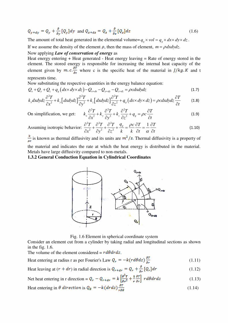
1.3.2 General Conduction Equation in Cylindrical Coordinates
Fig. 1.6 Element in spherical coordinate system
Consider an element cut from a cylinder by taking radial and longitudinal sections as shown
in the fig. 1.6.
The volume of the element considered = .
Heat entering at radius r as per Fourier's Law (1.11)
Heat leaving at ( ) in radial direction is (1.12)
Net heat entering in r direction = (1.13)
Heat entering in is (1.14)
Heat leaving At (1.15)
Net heat entering in is (1.16)
Heat entering in z direction is (1.16)
At (1.17)
Net heat leaving z direction = (1.18)
Total heat generated in the control volume = (1.19)
Applying the energy balance
Heat entering into the element + internal heat generation - heat leaving the element = Rate of
change of energy in the element.
Now substituting the respective quantities in the energy balance equation and on
simplification, we get: 2 2 2
2 2 2 2
1 1 1GqT T T T T
r r r r z k t
&(1.20)
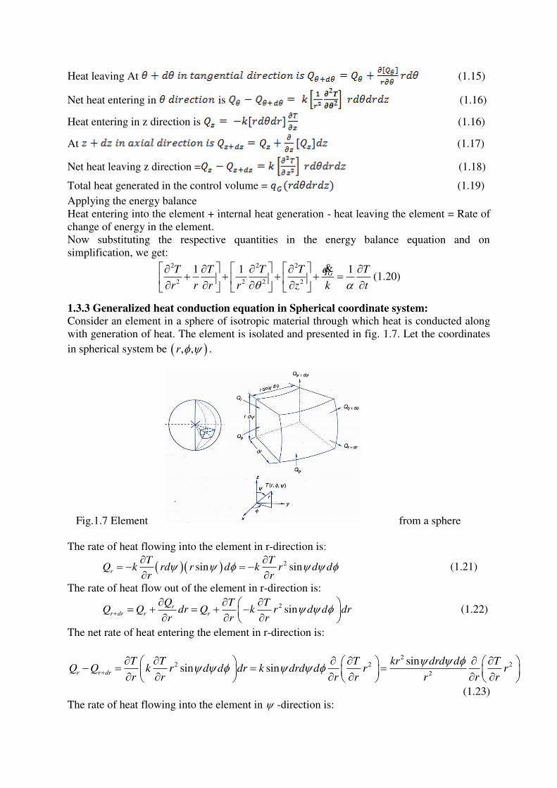
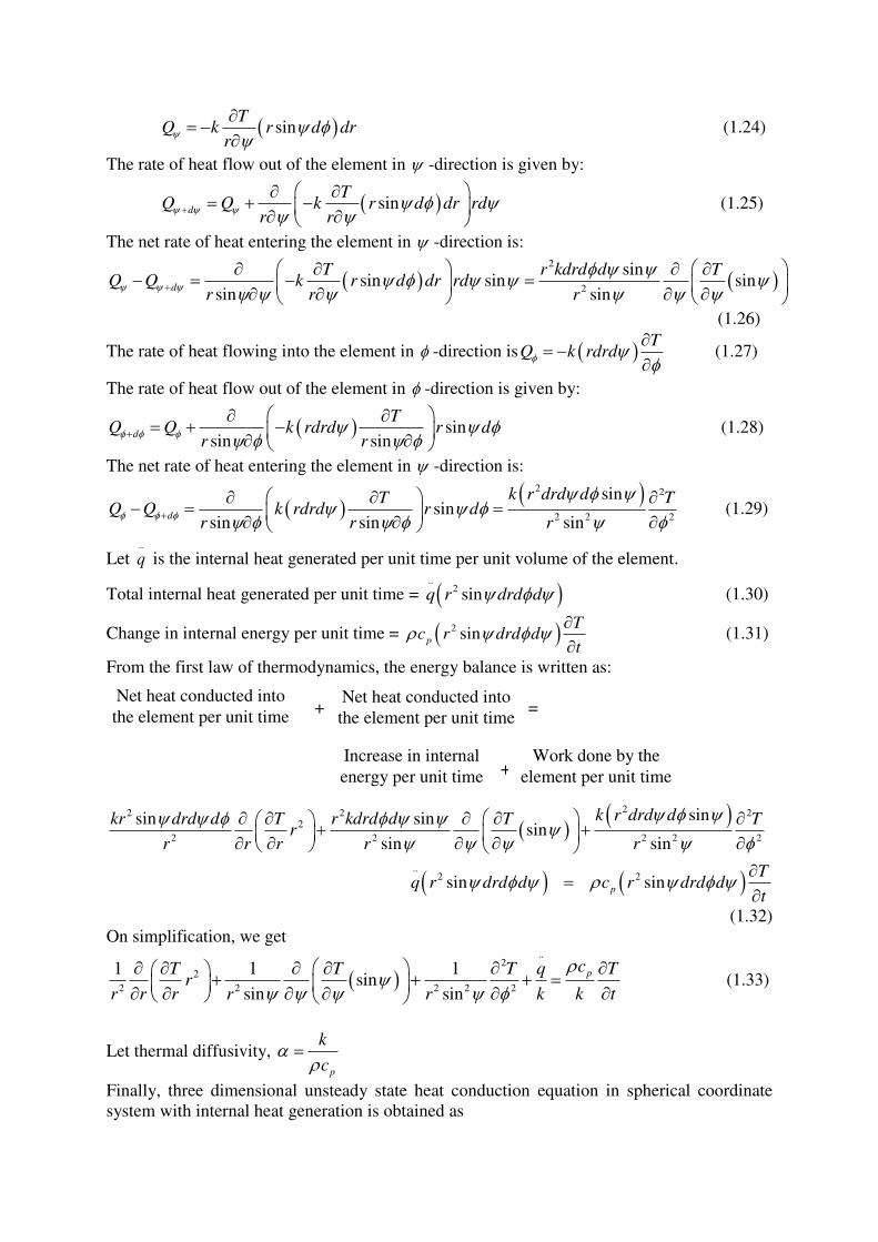
1.3.3 Generalized heat conduction equation in Spherical coordinate system:
Consider an element in a sphere of isotropic material through which heat is conducted along
with generation of heat. The element is isolated and presented in fig. 1.7. Let the coordinates
in spherical system be , ,r .
Fig.1.7 Element from a sphere
The rate of heat flowing into the element in r-direction is:
2sin sinr
T TQ k rd r d k r d d
r r
(1.21)
The rate of heat flow out of the element in r-direction is:
2 sinrr dr r r
Q T TQ Q dr Q k r d d dr
r r r
(1.22)
The net rate of heat entering the element in r-direction is:
2
2 2 2
2
sinsin sin
r r dr
T T T kr drd d TQ Q k r d d dr k drd d r r
r r r r r r r
(1.23)
The rate of heat flowing into the element in -direction is:
sinT
Q k r d drr
(1.24)
The rate of heat flow out of the element in -direction is given by:
sind
TQ Q k r d dr rd
r r
(1.25)
The net rate of heat entering the element in -direction is:
2
2
sinsin sin sin
sin sind
T r kdrd d TQ Q k r d dr rd
r r r
(1.26)
The rate of heat flowing into the element in -direction is TQ k rdrd
(1.27)
The rate of heat flow out of the element in -direction is given by:
sinsin sin
d
TQ Q k rdrd r d
r r
(1.28)
The net rate of heat entering the element in -direction is:
2 2
2 2 2
sinsin
sin sin sind
k r drd dT TQ Q k rdrd r d
r r r
(1.29)
Let ..
q is the internal heat generated per unit time per unit volume of the element.
Total internal heat generated per unit time = ..
2 sinq r drd d (1.30)
Change in internal energy per unit time = 2 sinp
Tc r drd d
t
(1.31)
From the first law of thermodynamics, the energy balance is written as:
+ =
+
22 2 22
2 2 2 2 2
..2 2
sinsin sinsin
sin sin
sin sinp
k r drd dkr drd d T r kdrd d T Tr
r r r r r
Tq r drd d c r drd d
t
(1.32)
On simplification, we get
..
22
2 2 2 2 2
1 1 1sin
sin sin
pcT T T q T
rr r r r r k k t
(1.33)
Let thermal diffusivity, p
k
c
Finally, three dimensional unsteady state heat conduction equation in spherical coordinate
system with internal heat generation is obtained as
Net heat conducted into
the element per unit time
Net heat conducted into
the element per unit time
Increase in internal
energy per unit time
Work done by the
element per unit time
..
22
2 2 2 2 2
1 1 1 1sin
sin sin
T T T q Tr
r r r r r k t
(1.34)
1.4 Forms of Heat Conduction Equations:
Case (i): For a homogeneous and isotropic material with constant thermal conductivity,
generalized heat conduction equation with internal heat generation in 3-D form is ..
2 2 2
2 2 2
1T T T q T
x y z k t
(1.35)
This equation is called as Diffusion equation.
Case (ii): Generalized heat conduction equation without internal heat generation in 3-D form
is 2 2 2
2 2 2
1T T T T
x y z t
(1.36)
This is called Fourier’s equation
Case (iii): Steady heat conduction equation with internal heat generation in 3-D form is ..
2 2 2
2 2 20
T T T q
x y z k
(1.37)
This equation is called Poisson’s equation.
Case (iv): Steady state heat conduction equation without internal heat generation is 2 2 2
2 2 20
T T T
x y z
(1.38)
This equation is called Laplace equation.
Note: Generalized steady state heat conduction equation in one-dimension without internal
heat generation in simplified form is
10n
n
Tr
r r r
(1.39)
where, n = 0 for Cartesian coordinate system
n = 1 for Cylindrical coordinate system
n = 2 for Spherical coordinate system
1.5 Objectives of Conduction Analysis
To estimate the variation of temperature with space coordinates and time. The temperature
field is T(x,y,z,t). The temperature field depends on:
Initial condition
Boundary condition
Material properties
Geometry of the body
Temperature field is useful to:
Compute heat flux at any location
Compute thermal stresses, expansion, and deflection due to temperature etc.,
Design insulation thickness
Simulate heat treatment of metals
Conduction equation is second order in spatial coordinate and first order in time. Hence, to
solve unsteady state problem,
Problem No. of Boundary Conditions needed No. of initial conditions
1-D Two in x-direction One initial condition
2-D Two each in x and y directions
3-D Two each in x, y & z-directions
1.6 Initial and Boundary Conditions
The initial conditions describe the temperature distribution in a medium at the initial
moment of time. These are needed only for the time dependent (transient) problems. It can be
expressed as:
0, , ,at t T T x y z (1.40)
Boundary conditions specify the temperature or the heat flow at the surface of the body.
They can be specified in many ways:
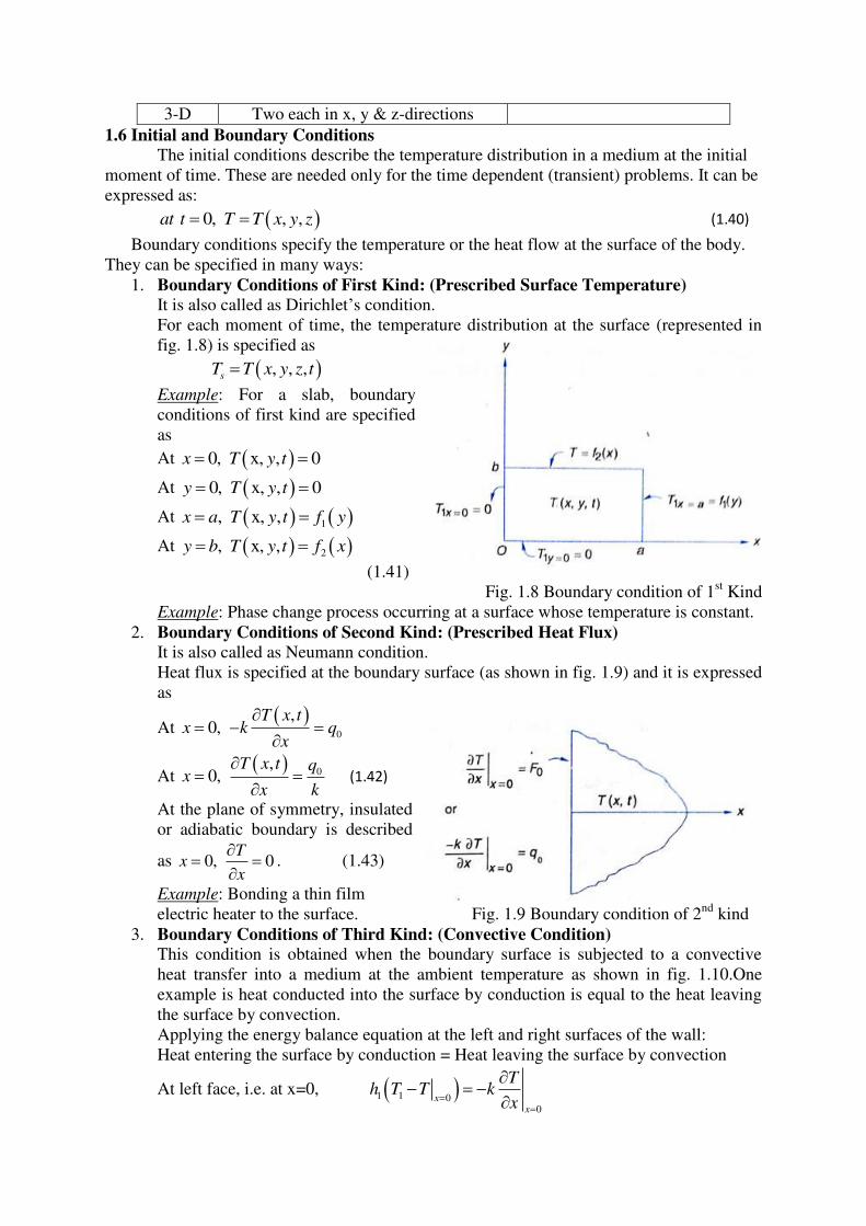
1. Boundary Conditions of First Kind: (Prescribed Surface Temperature)
It is also called as Dirichlet’s condition.
For each moment of time, the temperature distribution at the surface (represented in
fig. 1.8) is specified as
, , ,s
T T x y z t
Example: For a slab, boundary
conditions of first kind are specified
as
At 0, x, , 0x T y t
At 0, x, , 0y T y t
At 1, x, ,x a T y t f y
At 2, x, ,y b T y t f x
(1.41)
Fig. 1.8 Boundary condition of 1st Kind
Example: Phase change process occurring at a surface whose temperature is constant.
2. Boundary Conditions of Second Kind: (Prescribed Heat Flux) It is also called as Neumann condition.
Heat flux is specified at the boundary surface (as shown in fig. 1.9) and it is expressed
as
At
0
,0,
T x tx k q
x
At 0
,0,
T x t qx
x k
(1.42)
At the plane of symmetry, insulated
or adiabatic boundary is described
as 0, 0T
xx
. (1.43)
Example: Bonding a thin film
electric heater to the surface. Fig. 1.9 Boundary condition of 2nd
kind
3. Boundary Conditions of Third Kind: (Convective Condition)
This condition is obtained when the boundary surface is subjected to a convective
heat transfer into a medium at the ambient temperature as shown in fig. 1.10.One
example is heat conducted into the surface by conduction is equal to the heat leaving
the surface by convection.
Applying the energy balance equation at the left and right surfaces of the wall:
Heat entering the surface by conduction = Heat leaving the surface by convection
At left face, i.e. at x=0, 1 1 00
xx
Th T T k
x
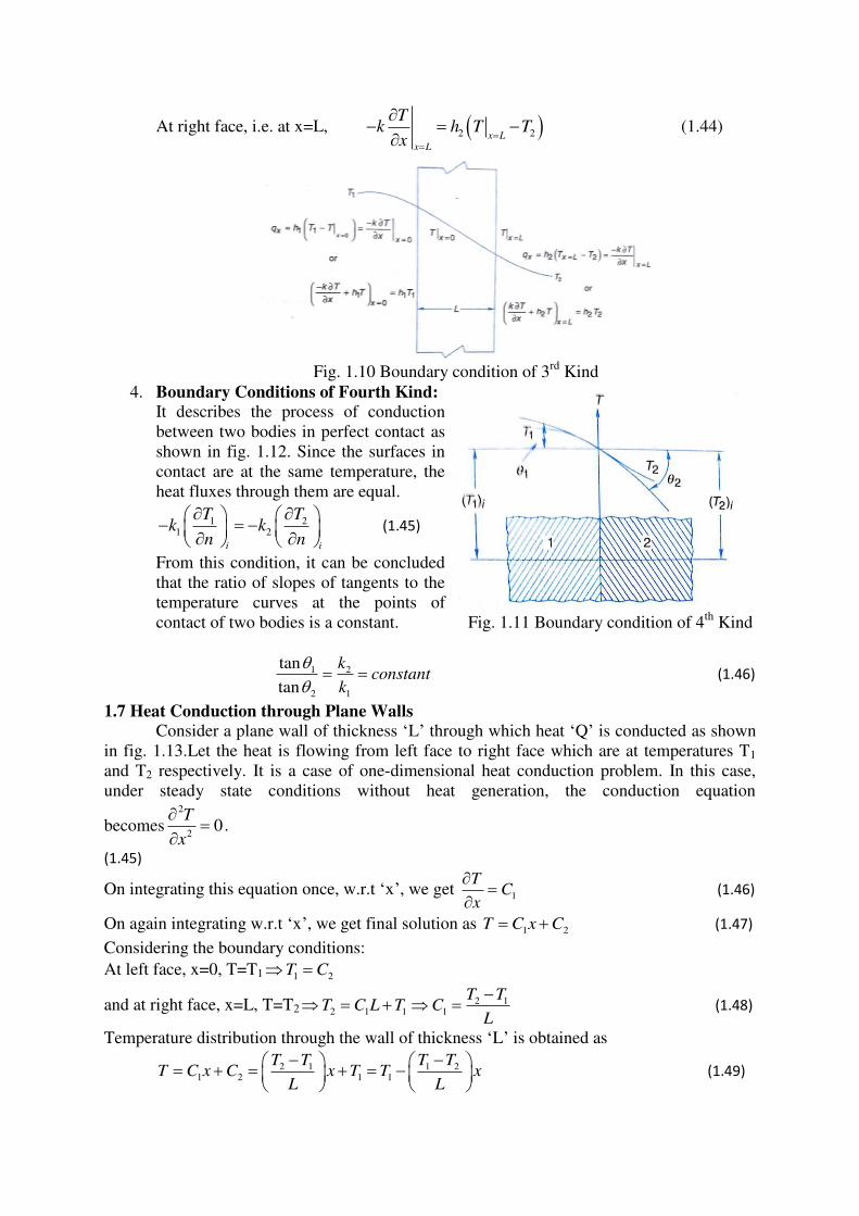
At right face, i.e. at x=L, 2 2x Lx L
Tk h T T
x
(1.44)
Fig. 1.10 Boundary condition of 3
rd Kind
4. Boundary Conditions of Fourth Kind:
It describes the process of conduction
between two bodies in perfect contact as
shown in fig. 1.12. Since the surfaces in
contact are at the same temperature, the
heat fluxes through them are equal.
1 21 2
i i
T Tk k
n n
(1.45)
From this condition, it can be concluded
that the ratio of slopes of tangents to the
temperature curves at the points of
contact of two bodies is a constant. Fig. 1.11 Boundary condition of 4th
Kind
1 2
2 1
tan
tan
kconstant
k
(1.46)
1.7 Heat Conduction through Plane Walls
Consider a plane wall of thickness ‘L’ through which heat ‘Q’ is conducted as shown
in fig. 1.13.Let the heat is flowing from left face to right face which are at temperatures T1
and T2 respectively. It is a case of one-dimensional heat conduction problem. In this case,
under steady state conditions without heat generation, the conduction equation
becomes2
20
T
x
.
(1.45)
On integrating this equation once, w.r.t ‘x’, we get 1
TC
x
(1.46)
On again integrating w.r.t ‘x’, we get final solution as 1 2T C x C (1.47)
Considering the boundary conditions:
At left face, x=0, T=T1 1 2T C
and at right face, x=L, T=T22 1
2 1 1 1
T TT C L T C
L
(1.48)
Temperature distribution through the wall of thickness ‘L’ is obtained as
2 1 1 21 2 1 1
T T T TT C x C x T T x
L L
(1.49)
This equation tells that the temperature decreases linearly from hot surface to cold surface.
The temperature gradient along x-direction is 2 1T TdT
dx L
(1.50)
From the Fourier law, Heat conducted through the wall, 1 2T TdTQ kA kA
dx L
(1.51)
Electrical Analogy
Flow of heat through a conductor is analogous to flow of current through an electrical
conductor since both are due to flow of
electrons. Hence thermal resistance is defined
similar to electrical resistance.
Corresponding to the current ‘i’ and the
potential difference ‘ΔE’ in an electrical circuit,
the analogous quantities in a thermal circuit are
the heat flow rate ‘q’ and the temperature
difference (T1-T2).
The thermal resistance can therefore be defined
as 1 2th
T TR
q
(1.52)
In a plane wall with surface temperatures T1 and
T2 and thickness ‘L’, heat flow rate is written as:
1 2 1 2th
T T T TLQ KA R
L kA Q
(1.53)
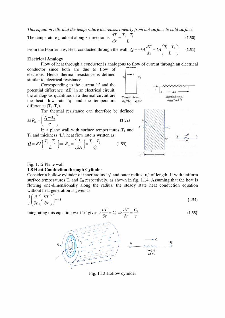
Fig. 1.12 Plane wall 1.8 Heat Conduction through Cylinder
Consider a hollow cylinder of inner radius ‘ri’ and outer radius ‘r0’ of length ‘l’ with uniform
surface temperatures Ti and T0 respectively, as shown in fig. 1.14. Assuming that the heat is
flowing one-dimensionally along the radius, the steady state heat conduction equation
without heat generation is given as
10
Tr
r r r
(1.54)
Integrating this equation w.r.t ‘r’ gives 11
CT Tr C
r r r
(1.55)
Fig. 1.13 Hollow cylinder
On again integrating the above equation, we get 1 2lnT C r C (1.56)
Boundary conditions:
at inner surface, 1 2, ln( )i i ir r T T Ti C r C (1.57)
at outer surface, 0 0 1 0 2, 0 ln( )r r T T T C r C (1.58)
On simplifying these equations, we get, 01
0
ln
i
i
T TC
rr
(1.59)
Also, 02
0
ln
ln
ii i
i
T TC T r
rr
(1.60)
Temperature distribution in a hollow cylinder is obtained as 1 2lnT C r C
0 0
0 0
0
0
ln ln
ln ln
ln
ln
i ii i
i i
ii
ii
T T T TT r T r
r rr r
T T rT Trr
r
(1.61)
Heat transferred from inner to outer cylinder surface,
0 0
0
0
12 2
ln ln
i ii
ir ri
i
T T T TTQ kA k rl kl
r rr rir r
(1.62)
Thermal resistance of a hollow cylinder is written as:
0 0 1 2
0
12 ln
2ln
i
th
i
i
T T r T TQ kL R
kL r Qr
r
01ln
2th
i
rR
kL r
(1.63)
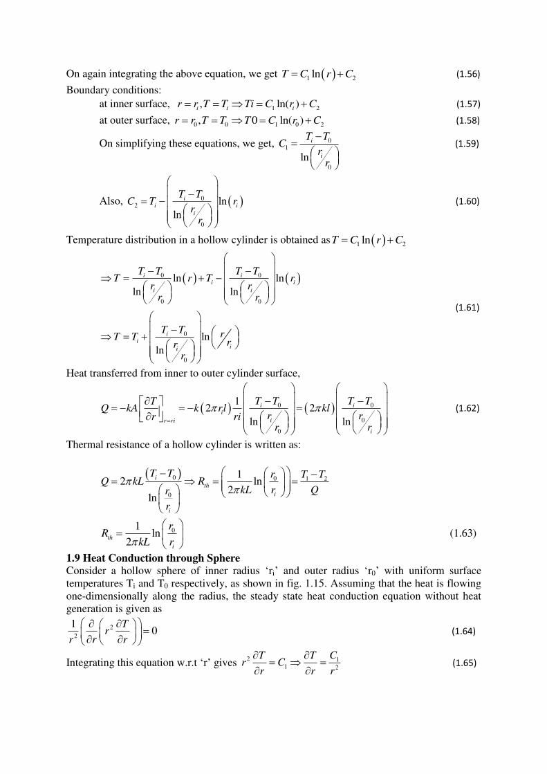
1.9 Heat Conduction through Sphere
Consider a hollow sphere of inner radius ‘ri’ and outer radius ‘r0’ with uniform surface
temperatures Ti and T0 respectively, as shown in fig. 1.15. Assuming that the heat is flowing
one-dimensionally along the radius, the steady state heat conduction equation without heat
generation is given as
2
2
10
Tr
r r r
(1.64)
Integrating this equation w.r.t ‘r’ gives 2 1
1 2
CT Tr C
r r r
(1.65)
On again integrating the above equation, we get 1 2
1T C C
r
(1.66)
Fig. 1.14 Hollow sphere
Boundary conditions:
at inner surface, 1 2
1,
i i
i
r r T T Ti C Cr
at outer surface, 0 0 0 1 2
0
1,r r T T T C C
r
(1.67)
On simplifying these equations, we get, 01
0
1 1
i
i
T TC
r r
(1.68)
Also, 02
0
1
1 1i
i
i
i
T TC T
r
r r
(1.69)
Temperature distribution in a hollow sphere is obtained as
0 0
00
0
0
1 1
1 11 1
1 1
1 1
i ii
i
ii
ii
i
i
T T T TT T
r r
r rr r
T TT T
r r
r r
(1.70)
Rate of heat transferred through the hollow sphere,
2 0 0
02
0
0
414
1 1
i
i ii i
r ri i
i r r
T T krrTQ kA k r T T
r r r r
r r
(1.71)
Thermal resistance of a hollow cylinder is written as:
0 0 1 2
0
0 0
44
i ii th
i i
T T r r T TQ kr r R
r r kr r Q
0
04
ith
i
r rR
kr r
(1.72)
Note:
Thermal Resistance in Convection is written as 1 ss
T TQ hA T T Rth
hA Q
(1.73)
1.10 Composite Systems:
To reduce the heat loss to surroundings, insulation is provided for the surfaces of
tubes, refrigerators, cold storage tanks, and hot water tanks, in furnaces etc., this makes two
or more materials of different thermal conductivity arranged in series or parallel. These will
come under the problem of composite systems, which can be solved by applying the concept
of thermal resistance.
It is assumed that in all the parallel layers, the temperature is continuous i.e. all are in
perfect thermal contact or the resistance due to interface contact is negligible.
(a) Composite Plane Wall: Consider a multilayered plane wall as shown in the figure. It is assumed that the
interior and exterior surfaces are subjected to convective heat transfer to fluids at
mean temperatures Ta and Tb with heat transfer coefficients ha and hb respectively.
The diagram has the configuration of all the layers connected in series in which the
rate of heat flow is constant in each layer.
2 3 3 41 21 1 2 3 4
1 2 3
a a b a
T T T TT TQ h A T T K A K A K A h A T T
L L L
(1.74)
Writing as
31 21 1 2 2 3 3 4 4
1 2 3
1 1a b
a b
LL LT T T T T T T T T T Q
h A K A K A K A h A
1 2 3 4 5
1 2 3 4 5
a b overalla b
total
TT TT T Q R R R R R Q
R R R R R R
(1.75)
(b) Composite Cylinder: Consider a multilayered cylinder as shown in the figure. It is assumed that the interior
and exterior surfaces are subjected to convective heat transfer to fluids at mean
temperatures Ta and Tb with heat transfer coefficients ha and hb respectively.
The diagram has the configuration of all the layers connected in series in which the
rate of heat flow is constant in each layer.
The rate of heat transfer is given as:
1 2 3 4 5
a b overall
total
TT TQ
R R R R R R
(1.76)
(c) Composite Sphere: Consider a multilayered sphere as shown in the figure. It is assumed that the interior
and exterior surfaces are subjected to convective heat transfer to fluids at mean
temperatures Ta and Tb with heat transfer coefficients ha and hb respectively.
The diagram has the configuration of all the layers connected in series in which the
rate of heat flow is constant in each layer.
The rate of heat transfer is given as:
1 2 3 4 5
a b overall
total
TT TQ
R R R R R R
(1.77)
1.11 Systems with variable thermal conductivity:
The thermal conductivity of a material, in general, varies with temperature. However,
this variation is mild for many materials in the range of practical interest and can be
disregarded. In such cases we can use an average value for the thermal conductivity
and treat it as constant.
When the variation of thermal conductivity with temperature in a specified
temperature interval is large, however, it may be necessary to account for this
variation to minimize the error.
Under normal circumstances, for limited ranges of temperature, it is sufficiently
accurate to use the linear expansion for k, i.e. k=k0(1+βT); where k0 is the value of
thermal conductivity at T=0 K and β is the value of temperature coefficient of thermal conductivity.
Case (a): Plane Slab
Consider a plane wall in the region having boundary surfaces at x=0 and x=L kept
at uniform temperatures T1 and T2 respectively. The problem can be formulated as
0d dT
k Tdx dx
for (1.78)
Boundary conditions are:
at x=0, T= T1 and at x=L,T= T2. (1.79)
0k 1 βT 0d dT
dx dx
(1.80)
The integration of above equation w.r.t x gives, 0 1k 1 βT dTC
dx
(1.81)
Integrating again we get, 2
0 1 22
Tk T C x C
(1.82)
Using the Boundary Condition at x=0; we get, 2
12 0 1
2
TC k T
(1.83)
Using the second boundary condition at x=L;2 2
20 11 0
12
2 2
T TC L k T k T
(1.84)
1 11
2 2
0 0 02 21 2 2 21 11 1
2 2m
k k kT T T TC T T T T T T T
L L L
(1.85)
Where Tm is arithmetic mean of the boundary surface temperatures i.e., (T1+T2)/2
The substitution of C1&C2 in Eq. 1.82 gives
22
10 0 2 1 0 1
2
1 2 1 1
( )
( )
12 2
1 1 02 2
m
m
TTk T k T T T k T
xT T T T T T T
L
This is quadratic equation in T and its solution is given by
1 1 1 22
1 1 2 β1 T T 1 βTm
β β β 2x
T T TL
(1.86)
The heat flow rate Q is given by 1 2m
T TdTQ KA K A
dx L
(1.87)
where 1 20 01 1
2m m
T Tk k T k
(1.88)
Case (b): Hollow cylinder
Consider a hollow cylinder with boundary surfaces at ri and r0 kept at uniform temperatures
Ti and To respectively. The thermal conductivity of material of cylinder is temperature
dependant, and is given by
[rk(T) ]=0 [r.k0(1+βT) ]=0 (1.89)
B.C are T=Ti at r=ri and T=To at r=ro (1.90)
Integrating the above equation we get, k0(1+βT) = (1.91)
Again Integrating on both sides we get, k0[T+ T2]= (1.92)
Using Boundary conditions at r=ri and r=ro we get
k0[Ti+ Ti2]= (1.93)
k0[To+ To2]= (1.94)
Solving above two equations for
= ko[(Ti-To)+ (Ti2-To
2)] = ko(Ti-To)1+ Ti+To) = ko(Ti-To)(1+ Tm) (1.95)
Where Tm=(T1+T2)/2
= (1.96)
And substituting the value of in eq-2 we get =k0[Ti+ Ti2]- (1.97)
Substituting the values of in eq-1 we get
k0[T+ T2] = +k0[Ti+ Ti
2]- (1.98)
The above equation can be simplified to
T2+T- -Ti(1+ Ti) = 0s
T= (1.99)
The heat flow rate is given by Q=-k(T)A
Q= (1.100)
Where km=k0(1+βTm)=k0(1+β(T1+T2)/2)
Case (c): Hollow sphere
Consider a hollow sphere with boundary surfaces at r=ri and ro kept at uniform temperatures
Ti and To respectively.
For 1-D flow of heat in radial direction,
Q=-k(T)A
=-k0(1+βT)4 (1.101)
Separating the variables and integrating we get
=
= T+ T2] + (1.102)
Constant is evaluated by using the boundary conditions T=Ti at r=ri
+ [Ti+ Ti2] (1.103)
Substitution of in the equation gives
[Ti+ Ti2]- - T+ T
2] + = 0 (1.104)
T2+T-[Ti+ Ti
2]+ = 0 (1.105)
T= (1.106)
T=- (1.107)
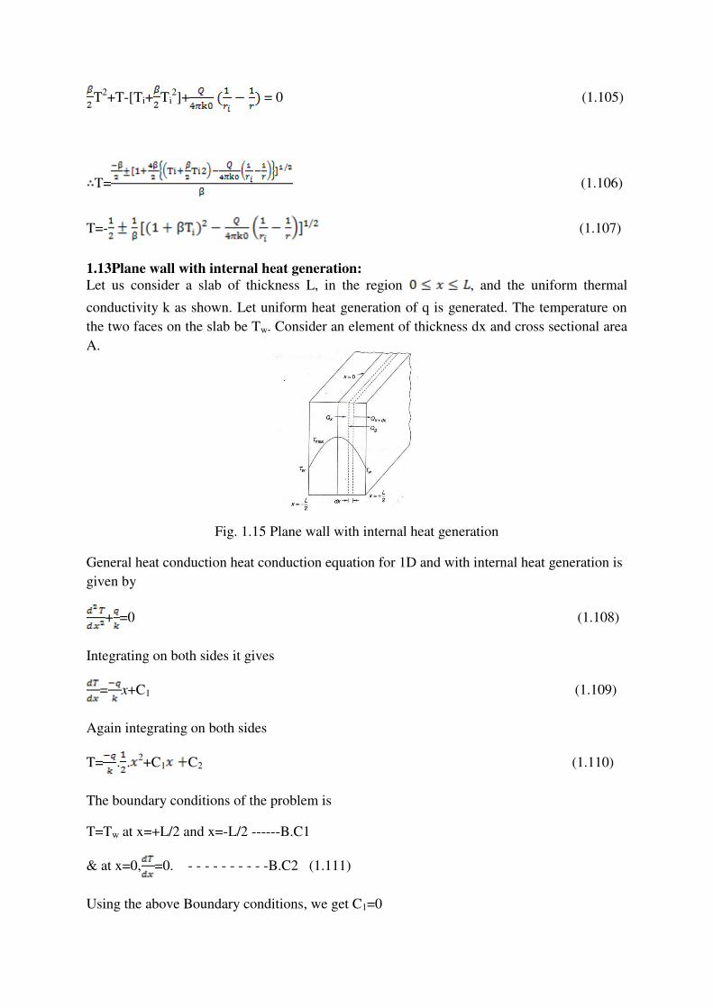
1.13Plane wall with internal heat generation:
Let us consider a slab of thickness L, in the region , and the uniform thermal
conductivity k as shown. Let uniform heat generation of q is generated. The temperature on
the two faces on the slab be Tw. Consider an element of thickness dx and cross sectional area
A.
Fig. 1.15 Plane wall with internal heat generation
General heat conduction heat conduction equation for 1D and with internal heat generation is
given by
+ =0 (1.108)
Integrating on both sides it gives
= x+C1 (1.109)
Again integrating on both sides
T= . .2+C1 C2 (1.110)
The boundary conditions of the problem is
T=Tw at x=+L/2 and x=-L/2 ------B.C1
& at x=0, =0. - - - - - - - - - -B.C2 (1.111)
Using the above Boundary conditions, we get C1=0
C2=Tw+ (1.112)
Substituting the values of C1&C2 in eq-1 we get
T=Tw+ ( ) (1.113)
The heat flow rate is given by Q=-kA x=L/2 = -kA = q.A.L (1.114)
1.14 Hollow cylinder with internal heat generation:
Let us now consider a long hollow cylinder of length L and inside and outside radius ri& ro. A
constant rate of heat q is generated within the cylinder while the boundary surfaces at r=ro
and r=ri are kept at uniform temperatures Ti and To respectively.
General heat conduction heat conduction equation for 1D and with internal heat generation is
given by
(1.115)
The boundary conditions are T=Ti at r =ri and T=To at r=ro (1.116)
Integrating the above equation we get
(1.117)
T= (1.118)
Applying the Boundary conditions, we get,
Ti= (1.119)
To= (1.120)
Solving the above equations we get,
= (1.121)
=Ti+ (1.122)
Substituting the values of in eq-1 we get,
T= (1.123)
T-Ti= (1.124)
(1.125)
1.15 Sphere with internal heat generation:
Let us now consider a solid sphere with a uniform heat source q. The outside surface at r=ro is
maintained at constant temperature To.
General heat conduction heat conduction equation for 1D and with internal heat generation is
given by
(1.126)
Boundary conditions are
=0 at r=0 and T=To at r=ro (1.127)
Integrating the eq-1 we get
(1.128)
(1.129)
Again integrating we get
T= (1.130)
Applying B.C-1 in eq-2 we get C1=0
Applying B.C-2 in eq-3 we get To= +
(1.131)
Substituting the values of in eq-3 we get
T=To+ (1.132)
Assignment-Cum-Tutorial Questions
A. Questions at remembering / understanding level:
I) Objective Questions 1. Which of the following statement(s) is/are correct? [CO1] [BL2]
a. Conduction heat transfer takes place from one particle of the body to another
without the actual motion of the particles.
b. Conduction heat transfer takes place from one particle of the body to another by
actual motion of the heated particles.
c. Convective heat transfer takes place between a surface and the surrounding fluid. d. Convective heat transfer takes place within the fluid medium.
A) a,c & d B) a & d C) a & c D) b,c & d
2. Which of the following statement(s) is/are correct? [CO1] [BL1]
a. The rate of heat transfer by conduction is proportional to the temperatue gradient
in the direction of heat flow and area normal to the heat flow direction.
b. The rate of heat transfer by conduction is proportional to the temperatue gradient
in the direction of heat flow and inversely proportional to the area normal to the
heat flow direction.
c. The thermal conductivtity of matiral can be defined as the rate of heat transfer
through a unit thickness of the material per unit area per unit temperature
difference.
d. Conduction heat transfer can takes place in solids, liquids and gases.
A) a & c B) a,c & d C) a & d D) b,c & d
3. Which of the following statement(s) is/are correct? [CO1] [BL2]
a. Thermal conductivity of liquids increases with decrase in temperature (water as
exception)
b. Themal conductivity of metallic solids decreases with increase in temperture.
c. Themal conductivity of gases increases with increase in temperature.
d. Themal conductivity non metallic solids increases with increas in temperature.
A) a & c B) a,b & c C) a,c & d D) a,b,c & d
4. Which of the following statement(s) is/are correct? [CO1] [BL2]
a. The heat transfer between a solid surface and an adjustant fluid takes place by
convection.
b. The rate of heat transfer by convection is proportional the surface area and
temperature difference between the surface and the fluid.
c. Radiation is the energy emitted by matter in the form of eletromagnetic waves (or
photons) and dose not required the presence of intervening medium.
d. Stefan-Boltzmann law of radiation states that the the radiation energy emitted by
a black surface per unit area is proportional to the fourth power of absolute
temperatue of the surface.
A) a & c B) a,b & c C) a,c & d D) a,b,c & d
5. Which of the following statement(s) is/are correct? [CO1] [BL2]
a. Themal diffusivity is a property of a material and its unit is m2/s.
b. A material that has a high themal conductivity or a low heat capacity will have a
large themal diffusivity.
c. The large the thermal diffusivity, the faster the propagation of heat through the
medium.
d. A small value of themal diffusivity means that heat is mostly absorbed by the
material and a small amount of heat is conducted further.
A) a & c B) a,b & c C) a,c & d D) a,b,c & d
6. Match the following [CO1][BL1]
a. Convection heat transfer i. Heat conducted to heat stored per unit volume
b. Themal diffusivity ii. Heat transfer between a solid surface and
surrounding fluid
c. Themal conductance iii. Electromagnetic phenomenon
d. Radiation heat transfer iv. Reciprocal conduction resistance
A) a-ii, b-i,c-iv,d-iii B) a-iv, b-iii,c-i,d-ii C) a-i, b-iv,c-ii,d-iii D) a-ii, b-i,c-iii,d-iv
7. Match the following [CO1][BL2]
a. Laplas equation i. 2 2 2
2 2 2
1genqT T T T
x y z k t
b. Diffusion equation ii. 2 2 2
2 2 20
genqT T T
x y z k
c. Fourier-Biot equation iii. 2 2 2
2 2 2
1T T T T
x y z t
d. Poission equation iv. 2 2 2
2 2 20
genqT T T
x y z k
A) a-ii, b-i,c-iv,d-iii B) a-iv, b-iii,c-i,d-ii C) a-i, b-iv,c-ii,d-iii D) a-ii, b-i,c-iii,d-iv
8. Match the following [CO1][BL2]
a. Specified temperature boundary conditions i. 1 1
(0, )[ (0, )]
T tk h T T t
x
b. Insulated Boundary conditions ii. (0, ) ( , )
0, 0T t T L t
kx x
c. Themal symmetry boundary conditions iii.
(0)dTk qo
dx
d. Heat flux boundary conditions iv. ( / 2, )
0T L t
x
e. Convection boundary conditions v. T(0,t) =T1, T(L,t) =T2
A) a-ii, b-iii,c-v,d-iv,e-i B) a-iv, b-i,c-ii,d-iii,e-ii
C) a-v, b-ii,c-iv,d-iii,e-i D) a-iii, b-iv,c-ii,d-iv,e-i
9. Which of the following statement(s) is/are correct? [CO1] [BL2]
a. In the case of steam carrying pipes, the outer radius of pipe must be greater than
the critical radius of insulation.
b. In the case of steam carrying pipes, the outer radius of pipe must be less than the
critical radius of insulation.
c. In the case of electric conductors, the wire radius must be less than the critical radius of insulation.
d. In the case of electric conductors, the wire radius must be greater than the critical radius of insulation. A) a & d B) b & d C) a & c D) b & c
10. As the thickness of insulation on a cylindrical tube increases [CO1] [BL2]
a. The conduction resistance increases while the convection resistance decreases.
b. The conduction resistance decreases while the convection resistance increases.
c. Both conduction and convection resistances decrease.
d. Both conduction and convection resistances increase.
II) Descriptive Questions 1. Describe the mechanisms of conduction, convection and radiation and state the laws
governing them. [CO1] [BL2]
2. Explain the mechanisms of heat conduction in gases, liquids and solids. [CO1][BL2]
3. Explain initial and boundary conditions applied to heat conduction. [CO1] [BL2]
4. Explain the concept of critical radius of insulation applied to steam carrying pipes
and electric conductors. [CO1] [BL2]
B. Questions at applying/analyzing level:
I) Multiple choice questions.
1. A composite wall is made up of two different materials arranged in series of the same
thickness and having thermal conductivities of k1 & k2 respectively. The equivalent
thermal conductivity (k) is [CO1] [BL3]
a) 1 2k k k b) 1 2
1 2
2k kk
k k
c) 1 2k k k d) 1 2
1 2
k kk
k k
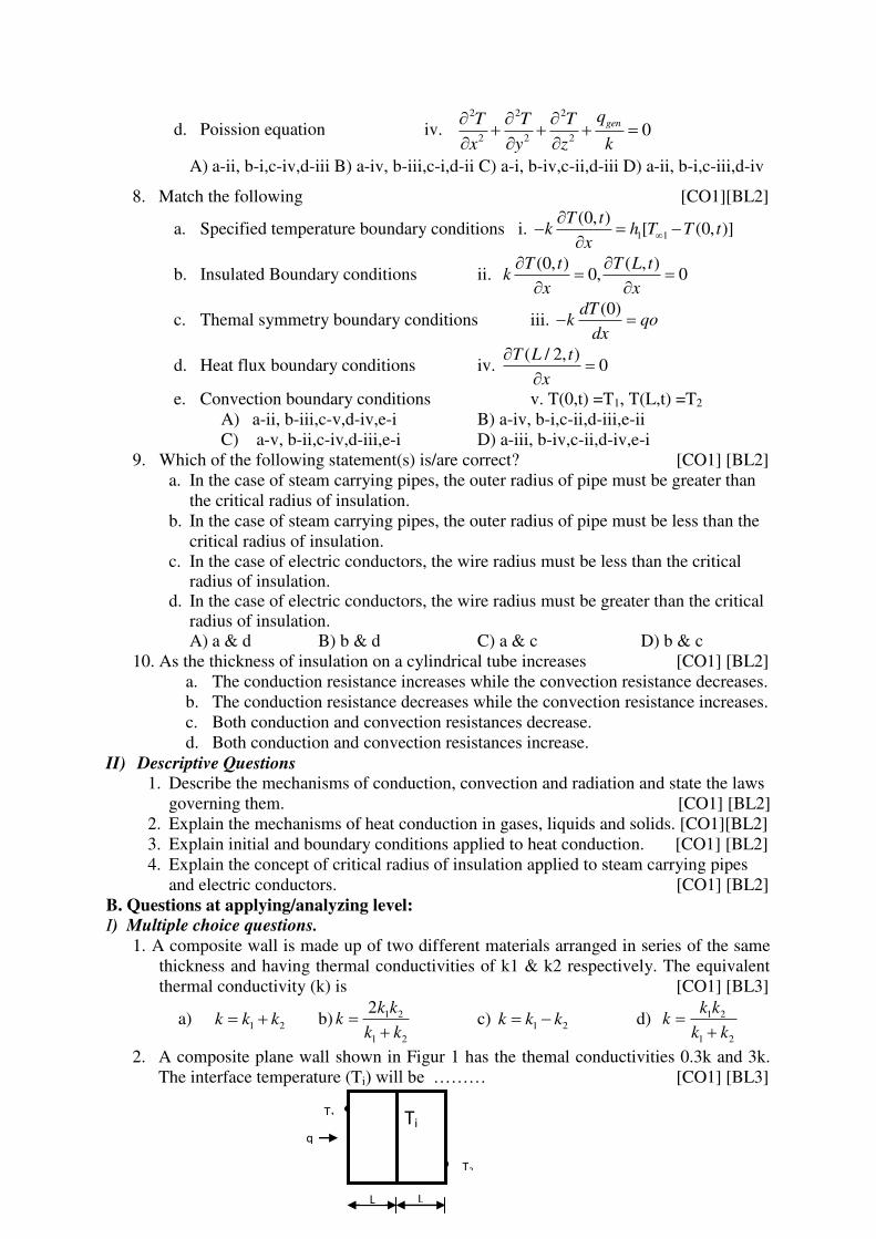
2. A composite plane wall shown in Figur 1 has the themal conductivities 0.3k and 3k.
The interface temperature (Ti) will be ……… [CO1] [BL3]
Ti
L L
T1
T2
q
a) 1 2
2i
T TT
b)
1 2
2i
T TT
c)
1 2
2i
T TT
d) 1
1 2
2i
T TT T
3. Furnace is made of fire brick having thickness x=0.6 m & themal conductivity k=0.8
W/m-K. For the same heat loss (W/m2) and temparature drop, another meterial having
k=0.16 W/m-K will have its thickness …………… [CO1] [BL3]
a) 0.06 m (b) 0.12 m (c) 0.25 m (d) 0.48 m
4. Heat is lost through a brick wall (k =0.72 W/m·K), which is 4 m long, 3 m wide, and
25 m thick at a rate of 500 W. If the inner surface of the wall is at 22°C, the
temperature at the mid-plane of the wall is [CO1] [BL3]
(a) 0°C (b) 7.5°C (c) 11.0°C (d) 14.8°C (e) 22°C
5. Common data questions:
A 0.8 m high and 1.5 m wide double-pane window consisting of two 4 m thick layers
of glass (k = 0.78 W/m-0
c) separated by a 10 mm wide stagnant air space (k=0.026
W/m-0c). The room is maintained at 20
0C, while the temperature of the outdoors is -
100C. The convective heat transfer coefficients on the inner and outer surfaces of the
window to be hi = 10 W/m2 –
0c and h0 = 40 W/m
2 –
0C. [CO1] [BL3]
i) The steady rate of heat transfer through the double – pare window is
a) 50.2 w b) 40.2 w c) 89.2 w d) 69.2 w
ii) The inner surface temperature of double – pane window is
a) 14.2 0C b) 16.2
0C c) 12.2
0C d) 10.2
0C
6. A 40-cm-long, 0.4-cm-diameter electric resistance wire submerged in water is used to
determine the convection heat transfer coefficient in water during boiling at 1 atm
pressure. The surface temperature of the wire is measured to be 114°C when a
wattmeter indicates the electric power consumption to be 7.6 kW. The heat transfer
Coefficient is [CO1] [BL3]
(a) 108 kW/m2 (b) 13.3 kW/m2·K (c) 68.1 kW/m2·K
(d) 0.76 kW/m2·K (e) 256 kW/m2·K.
7. It is intended to reduce the heat loss from a steam pipe of diameter 5cm by applying
an insulation(k=0.72 W/m - K) over the outer surface of the pipe. The outer covective
heat transfer coefficient is 12 W/m2
- K. Which of the following statements is corerct?
[CO1] [BL4]
a. The rate of heat transfer increases up to critical radius and then decreases.
b. The rate of heat transfer increases with increase in insulation thickness.
c. The rate of heat transfer decreases with increase in insulation thickness.
d. The rate of heat transfer decreases up to critical radius and then increases.
A) b B) a C) d D) c
8. A circular plate of 0.2 m diameter has one of its surfaces is insulated; the other is maintained at 550 K. If the hot surface has an emissivity of 0.9 and is exposed to the air at 300 k. Calculate the heat loss by radiation from the Plate to the air. [CO1] [BL3]
a) 133.76 W b) 163.76 W c) 113.76 W d) 93.76 W
9. Determine the maximum current that a 1mm diameter bare aluminum (k=204W/m-K)
wire can carry without exceeding a temperature of 2000C. The wire is suspended in
air at temperature 250C and h = 10 W/m
2k. The electrical resistance of this wire per
unit length is 0.037Ω/m. [CO1] [BL3]
a) 15.2 A b) 12.2 A c) 18.2 A d) 16.2 A
10. Calculate the heat loss per unit length from the surface of a pipe of 75 mm diameter
laid in a room at 200 C. The emissivity of the pipe material is 0.85 and its surface
temperature is 2200 C. The convective heat transfer coefficient may be assumed as 16
W/m2-K. [CO1] [BL3]
a) 750.8 W b) 600.8 W c) 780.9 W d) 500.8 W
11. Consider a steam pipe of length L = 9 m, inner radius r1 = 5 cm, outer radius r2 = 6 cm,
and thermal conductivity k = 12.5 W/m . oC. Steam is flowing through the pipe at an
average temperature of 120oC, and the average convection heat transfer coefficient on
the inner surface is given to be h = 70 W/m2 .
oC. If the average temperature on the
outer surfaces of the pipe is T2 = 70oC. The rate of heat loss from the steam through
the pipe is [CO1] [BL3]
a) 9415 W b) 941.5 W c) 94.15 W d) 94150 W
12. A steam pipe of outer diameter 5cm is covered with a layer of insulation (k=0.05 w/m-0c) and is exposed to outer ambient at a temperature 20
oc with heat transfer
coefficient 5 w/m2-oc. Which of the following statement is correct? [CO1] [BL4]
a) Insulation increases the rate of heat transfer
b) Insulation reduces the rate of heat transfer
c) Insulation increases the rate of heat transfer up to certain radius and then decreases
d) Insulation does not alter the rate of heat transfer
13. In a nuclear reactor, heat is generated in 1 cm diameter cylindrical uranium fuel rods
at a rate of 4 X 10⁷ W/m
3. The temperature difference between the center and the
surface of the fuel rod is [CO1] [BL3]
a) 90oC b) 45
oC c) 22.5
oC d) 9.0
oC
14. A 2-kW resistance heater wire whose thermal conductivity is k=15 W/m.K has a
diameter of D=4 mm and a length of L=0.5 m, and is used to boil water. If the outer
surface temperature of the resistance wire is Ts=1050C, determine the temperature at
the center of the wire. [CO1] [BL3]
a) 115oC b) 126
oC c) 120.5
oC d) 131.5
oC
15. A tube having outside diameter 2cm is maintained at a uniform temperature T and is
covered with an insulation (k=0.2 w/m-k). Heat is dissipated from outer surface of
insulation by natural convection with h=15 w/m2-oc in to the ambient air at Tα. What
is the percentage change in heat loss when the thickness of insulation is equal to
critical thickness? [CO1] [BL4]
a) The heat loss is decreased by 3.5% b) The heat loss is decreased by 35%
c) The heat loss is increased by 3.5% d) The heat loss is increased by 35%
16. An electric wire of 1 mm diameter as covered with a 2 mm thick layer of plastic
insulation (k=0.5 w/m-k). Air surrounding the wire is at 25oC with h=10 w/m
2-k. The
wire temperature is 100oC. [CO1] [BL4]
i) What is the radius of insulation when the rate of heat dissipation is maximum?
a) 75 mm b) 100 mm c) 50 mm d) 25 mm
ii) What is the maximum value of this heat dissipation per meter length?
a) 12 w/m b) 48 w/m c) 24 w/m d) 96 w/m
II) Derivations / Problems. 1. Derive the general heat conduction equation in Cartesian coordinates and deduce it
in one dimensional steady state condition with no internal heat generation. [CO1] [BL3]
2. Derive, starting from fundamentals, general heat conduction equation in cylindrical coordinates. [CO1] [BL3]
3. Derive, starting from fundamentals, general heat conduction equation in spherical coordinates. [CO1] [BL3]
4. Consider the case of long hallow cylinder (of constant thermal conductivity) of
internal and external radius ri and ro respectively. If the temperatures at the inside and outside surfaces are maintained at Ti and To, write the mathematical formulation of
this problem for steady state heat conduction. [CO1] [BL3]
5. A composite wall is made up three layers of thickness 25 cm, 10 cm and 15 cm of
material A, B and C respectively. The thermal conductivities of A and B are 1.7 W/m
K and 9.5 W/m K respectively. The outside surface is exposed to air at 20oC with a
convection coefficient of 15 W/m2 K and the inside is exposed to gases at 1200
oC
with a convection coefficient of 25 W/m2
K and the inside surface is at 1080oC.
Determine the unknown thermal conductivity of layer made up of material C.
[CO1] [BL3]
6. A steel pipe is carrying steam at a pressure of 30 bar. Its outside diameter is 90 mm
and is lagged with a layer of material 45 mm thick (k=0.05 W/m-0C). The ambient
temperature is 20oC and the surface of the lagging has a heat transfer coefficient of
8.4 W/m2-oC. Neglecting resistance due to pipe material and due to steam film on the
inside of steam pipe, find the thickness of the lagging (k=0.07 W/m-0C) which must
be added to reduce the steam condensation rate by 50 percent if the surface coefficient
remains unchanged. [CO1] [BL4]
7. Consider a 2 m high and 0.7m wide bronze plate whose thickness is 0.12 m one side
of the plate is maintained at a constant temperature of 600K while the other side is
maintained at 400K. The thermal conductivity of the bronze plate can be assumed to
vary linearly in that temperature range as k(T)=K0(1+ T), where k0=38 W/m-K and
=9.21 x 10⁻⁴
K-1
. Disregarding the edge effects and assuming steady one-
dimensional heat transfer, determine the rate of heat conduction through the plate.
[CO1] [BL3]
8. Hot gas at a constant temperature of 400oC is contained in a spherical shell (2000 mm
internal diameter, 50 mm thick) made of steel. Mineral wool insulation (k=0.06 W/m
K) of thickness 100 mm is wrapped all around it. Calculate the steady rate at which
heat will flow out if the outside air is at a temperature of 30oC. Heat transfer
coefficient on the inner surface of the steel shell and on the outer surface of the
insulation is 15 W/m2K. [CO1] [BL3]
9. A wall of furnace is made up of inside layer of silica brick 120 mm thick covered with
a layer of magnetite brick 240 mm thick. The temperatures at the inside surface and of
silica brick wall and outside surface of magnetite brick wall are 725oC and 110
oC
respectively. The contact thermal resistance between the two walls at the interface is
0.0035oC/W per unit wall area. If the thermal conductivities of silica and magnetite
bricks are 1.7 W/m oC and 5.8 W/m
oC, calculate the rate of heat loss per unit area of
walls and temperature drop at the interface. [CO1] [BL3]
10. A Steel tube (k=43.26 W/m K) of 5.05 cm I.D. and 7.62 cm O.D. is covered with a
2.54 cm layer of asbestos insulation (k=0.208 W/m K). The inside surface of the tube
receives heat by convection from a hot gas at a temperature of Ta = 316oC with a heat
transfer coefficient ha = 284 W/m2K, while the outer surface of the insulation is
exposed to the ambient air at Tb = 38oC with a heat transfer coefficient of hb = 17
W/m2K. Estimate i) the loss to ambient air for 32 m length of the tube, and ii) the
temperature drops across the tube material and insulation layer. [CO1] [BL3] 11. A steam pipe, 10 cm I.D and 11 cm O.D is covered with an insulating substance (K=1
W/m-K). The steam temperature and the ambient temperatures are 2000C and 20
0C,
respectively. If the convective heat transfer coefficient between the insulation surface and air is 8 W/m
2-K, find the critical radius of insulation. For this value of r0,
calculate the heat loss per meter of pipe. Neglect resistance of the pipe material. [CO1] [BL4]
12. Consider the one-dimensional steady state heat conduction through a copper slab of length 2L submerged in a constant temperature bath at temperature, Tα. An electric current is passed through this slab causing a uniform heat generation, q per unit time and volume. The boundary surfaces dissipate heat by convection resulting in a temperature, Tw on both sides. Formulate the problem mathematically. [CO1] [BL3]
13. Derive an expression for steady state temperature distribution in a plane wall of
uniform thickness with internal heat generation when its two surfaces are at
temperatures T1and T2 respectively. [CO1] [BL3]
14. Consider a large 3 cm thick stainless steel plate whose thermal conductivity is 15.1
W/m.0C, in which heat is generated uniformly at a rate of 5 x 10
5W/m
3. Both sides of
the plate are exposed to an environment at 300C with a heat transfer coefficient of 60
W/m20
C. Explain where in the plate the highest and the lowest temperatures will
occur and determine their values. [CO1] [BL4]
15. Derive the expression for critical radius of insulation (i) in the case of cylinder (ii) in
the case of sphere. [CO1] [BL3]
16. Evaluate the thickness of rubber insulation necessary in the case of a 10 mm diameter
copper conductor to ensure maximum heat transfer to the atmosphere, given the
thermal conductivity of rubber as 0.155 W/m-K and the surface film coefficient as 8.5
W/m2K. Estimate this maximum heat transfer rate per meter length of the conductor
if the temperature of the rubber is not to exceed 65oC (due to heat generated within)
while the atmosphere is at 30oC. Discuss the effect of insulation on the bare
conductor. [CO1] [BL4]
17. A tube of 2 cm O.D maintained at uniform temperature of Ti is covered with
insulation (k=0.2W/m-K) to reduce heat loss to the ambient air at Tα with ha=15
W/m2K. find (i)the critical thickness of insulation rc (ii)the ratio of heat loss from the
tube with insulation to that without insulation (a) if the thickness of insulation equal
to rc (b) if the thickness of insulation is (rc+2) cm. [CO1] [BL4] 18. A 1 mm dia electric wire is covered with 2 mm thick layer of insulation (k=0.5W/m-
K). Air surrounding the wire is at 25°c and h=25 W/m2K. The wire temperature is
100°c. (i) the rate of heat dissipation from the wire per unit length with and without insulation. (ii) The critical radius of insulation. (iii) The maximum value of heat dissipation. [CO1] [BL3]
19. Consider a steam pipe of length L = 20 m, inner radius r1 = 6 cm, outer radius r2 =8
cm, and thermal conductivity k = 20 W/m· K. The inner and outer surfaces of the pipe
are maintained at average temperatures of T1 =150°C and T2 = 60°C, respectively. Obtain a general relation for the temperature distribution inside the pipe under steady
conditions and determine the rate of heat loss from the steam through the pipe.
[CO1] [BL4] 20. Consider a spherical container of inner radius r1 = 8 cm, outer radius r2 = 10 cm, and
thermal conductivity k = 45 W/m· K,. The inner and outer surfaces of the container are maintained at constant temperatures of T1 = 200°C and T2 = 80°C, respectively, as a result of some chemical reactions occurring inside. Obtain a general relation for the temperature distribution inside the shell under steady conditions, and determine the rate of heat loss from the container. [CO1] [BL4]
C. Questions at evaluating/creating level: 1. A steel pipe line (k= 50 W/m-K) of I.D 100 mm and O.D 110 mm is to be covered
with two layers of insulation each having a thickness of 50 mm. The thermal
conductivity of the first insulation material is 0.06 W/m-K and the second is 0.12 W/m-K. Calculate the loss of heat per meter length of pipe and interface temperature between the two layers of insulation when the temperature of the inside tube surface is 250
0C and the outside surface of the insulation is 50
0C. If the order of insulation of
materials for steel pipe were reversed, that is, the insulation with a higher value of thermal conductivity was put first , calculate the change in heat loss with all other conditions remaining unchanged. Comment on the result. [CO1] [BL5]
2. Write an interactive computer program to calculate the heat transfer rate and the value of temperature anywhere in the medium for steady one-dimensional heat conduction in a long cylindrical shell for any combination boundary conditions. Run the program for five different sets of specified boundary conditions. [CO1] [BL6]
3. Write an interactive computer program to calculate the heat transfer rate and the value of temperature anywhere in the medium for steady one-dimensional heat conduction in a spherical shell for any combination of specified temperature, specified heat flux, and convection boundary conditions. Run the program for five different sets of specified boundary conditions. [CO1] [BL6]
4. Write an interactive computer program to calculate the heat transfer rate and the value of temperature anywhere in the medium for steady one-dimensional heat conduction
in a plane wall whose thermal conductivity varies linearly as k(T)=k0(1+ T ) where
the constants k0 and are specified by the user for specified temperature boundary
conditions. [CO1] [BL6]
D. GATE Questions:
1. 1. Air enters a counter-flow heat exchanger at 700C and leaves at 40
0C. Water enters
at 300C and leaves at 50
0C. The LMTD In deg. C is [GATE-2000]
a) 5.65 b) 4.43 c) 19.52 d) 20.172.
2. A composite wall, having unit length normal to the plane of paper, is insulated at the
top and bottom as shown in the figure. It is comprised of four different materials A, B,
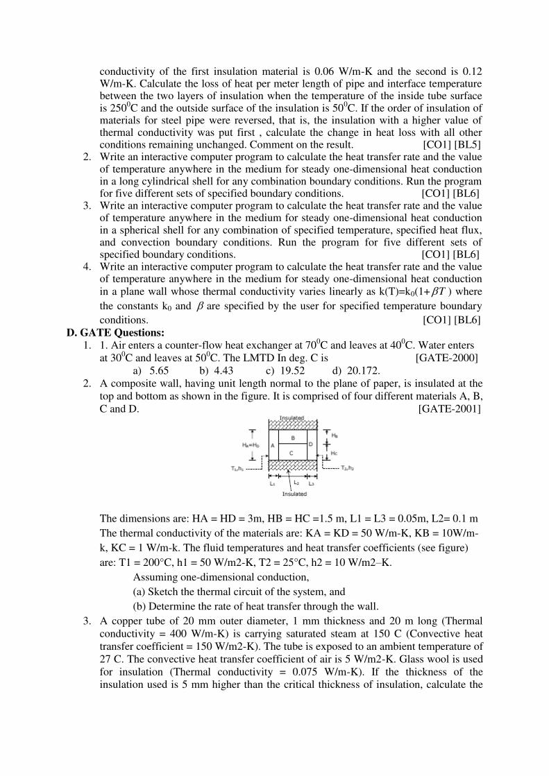
C and D. [GATE-2001]
The dimensions are: HA = HD = 3m, HB = HC =1.5 m, L1 = L3 = 0.05m, L2= 0.1 m
The thermal conductivity of the materials are: KA = KD = 50 W/m-K, KB = 10W/m-
k, KC = 1 W/m-k. The fluid temperatures and heat transfer coefficients (see figure)
are: T1 = 200°C, h1 = 50 W/m2-K, T2 = 25°C, h2 = 10 W/m2–K.
Assuming one-dimensional conduction,
(a) Sketch the thermal circuit of the system, and
(b) Determine the rate of heat transfer through the wall.
3. A copper tube of 20 mm outer diameter, 1 mm thickness and 20 m long (Thermal
conductivity = 400 W/m-K) is carrying saturated steam at 150 C (Convective heat
transfer coefficient = 150 W/m2-K). The tube is exposed to an ambient temperature of
27 C. The convective heat transfer coefficient of air is 5 W/m2-K. Glass wool is used
for insulation (Thermal conductivity = 0.075 W/m-K). If the thickness of the
insulation used is 5 mm higher than the critical thickness of insulation, calculate the
rate of heat lost by the steam and the rate of steam condensation in kg/hr (The
enthalpy of condensation of steam = 2230 kJ/kg). [GATE-2002]
4. One dimensional unsteady state heat transfer equation for a sphere with heat
generation at the rate of ‘q’ can be written as [GATE-2004]
a) t
T
K
q
r
Tr
rr
11
b) t
T
K
q
r
Tr
rr
11 2
2
c) t
T
K
q
r
T
1
2
2
b)
t
T
K
qrT
r
1
2
2
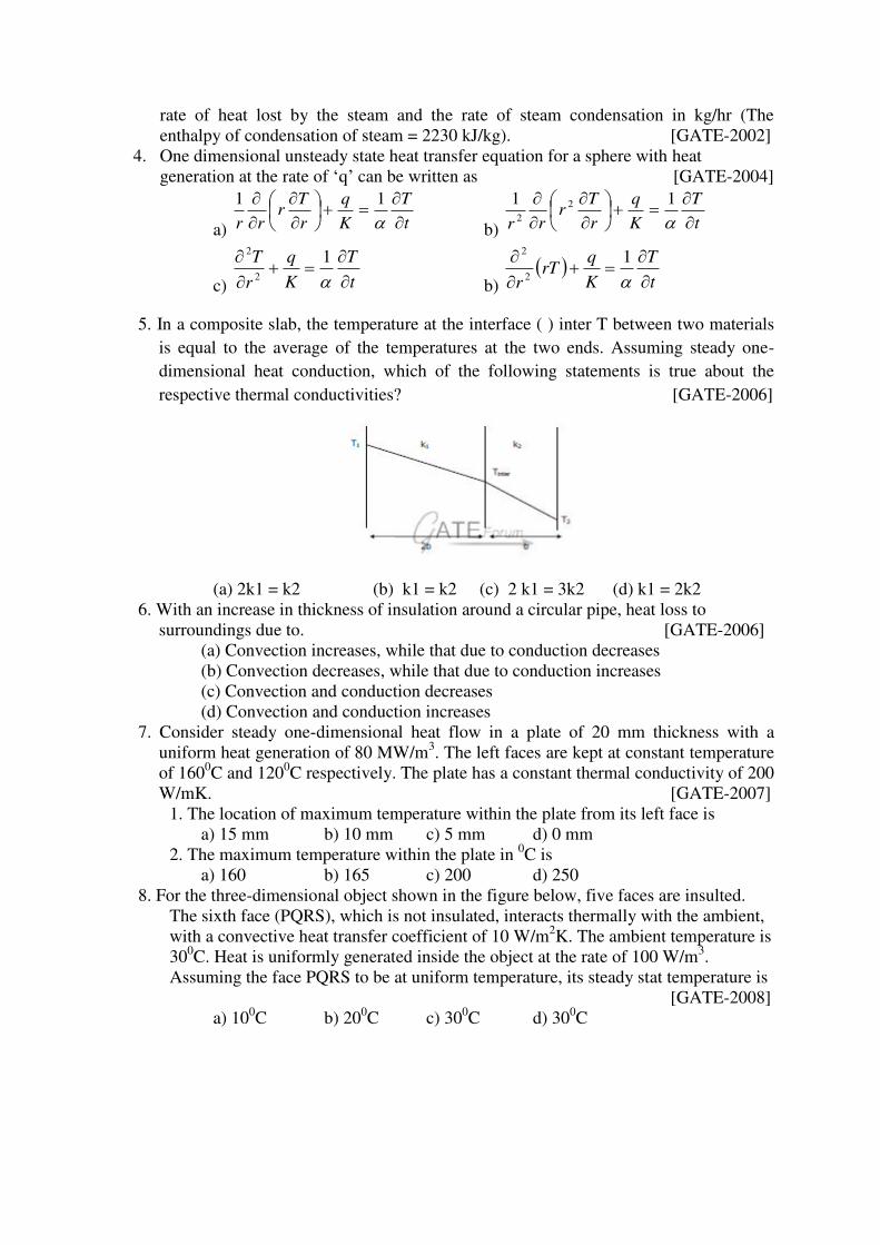
5. In a composite slab, the temperature at the interface ( ) inter T between two materials
is equal to the average of the temperatures at the two ends. Assuming steady one-
dimensional heat conduction, which of the following statements is true about the
respective thermal conductivities? [GATE-2006]
(a) 2k1 = k2 (b) k1 = k2 (c) 2 k1 = 3k2 (d) k1 = 2k2
6. With an increase in thickness of insulation around a circular pipe, heat loss to
surroundings due to. [GATE-2006]
(a) Convection increases, while that due to conduction decreases
(b) Convection decreases, while that due to conduction increases
(c) Convection and conduction decreases
(d) Convection and conduction increases
7. Consider steady one-dimensional heat flow in a plate of 20 mm thickness with a
uniform heat generation of 80 MW/m3. The left faces are kept at constant temperature
of 1600C and 120
0C respectively. The plate has a constant thermal conductivity of 200
W/mK. [GATE-2007]
1. The location of maximum temperature within the plate from its left face is
a) 15 mm b) 10 mm c) 5 mm d) 0 mm
2. The maximum temperature within the plate in 0C is
a) 160 b) 165 c) 200 d) 250
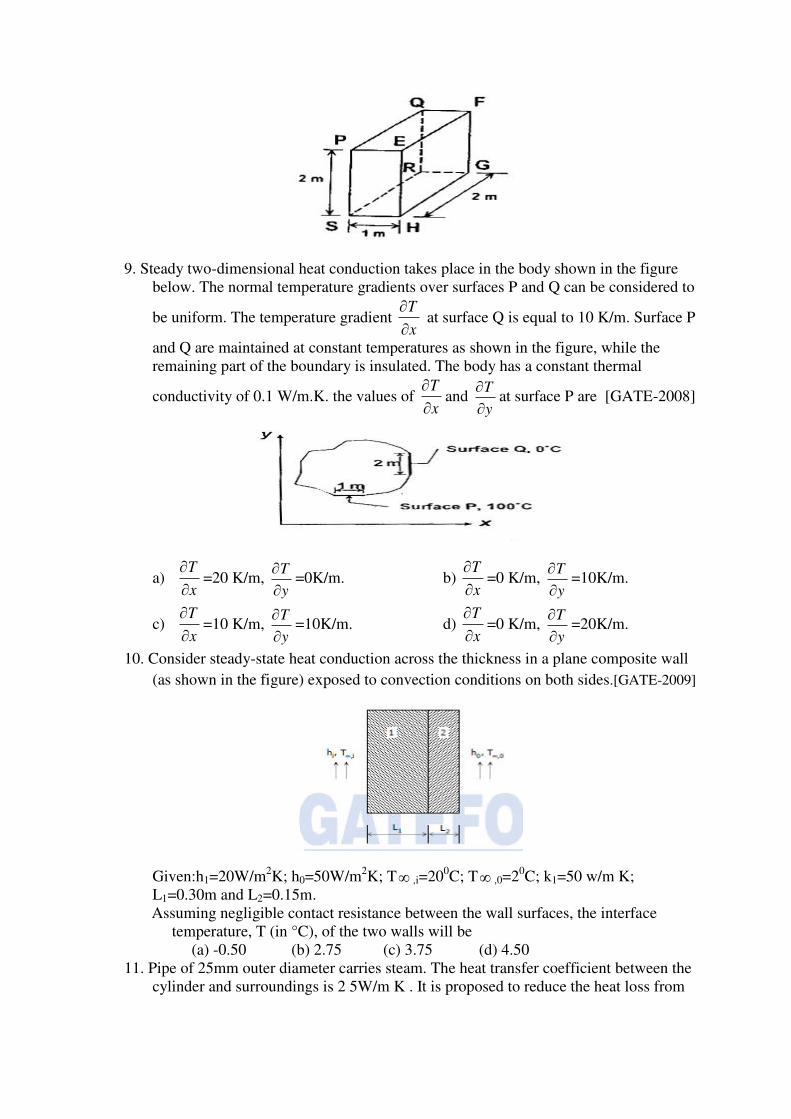
8. For the three-dimensional object shown in the figure below, five faces are insulted.
The sixth face (PQRS), which is not insulated, interacts thermally with the ambient,
with a convective heat transfer coefficient of 10 W/m2K. The ambient temperature is
300C. Heat is uniformly generated inside the object at the rate of 100 W/m
3.
Assuming the face PQRS to be at uniform temperature, its steady stat temperature is
[GATE-2008]
a) 100C b) 20
0C c) 30
0C d) 30
0C
9. Steady two-dimensional heat conduction takes place in the body shown in the figure
below. The normal temperature gradients over surfaces P and Q can be considered to
be uniform. The temperature gradient x
T
at surface Q is equal to 10 K/m. Surface P
and Q are maintained at constant temperatures as shown in the figure, while the
remaining part of the boundary is insulated. The body has a constant thermal
conductivity of 0.1 W/m.K. the values of x
T
and y
T
at surface P are [GATE-2008]
a) x
T
=20 K/m, y
T
=0K/m. b) x
T
=0 K/m, y
T
=10K/m.
c) x
T
=10 K/m, y
T
=10K/m. d) x
T
=0 K/m, y
T
=20K/m.
10. Consider steady-state heat conduction across the thickness in a plane composite wall
(as shown in the figure) exposed to convection conditions on both sides.[GATE-2009]
Given:h1=20W/m2K; h0=50W/m
2K; T ,i=20
0C; T ,0=2
0C; k1=50 w/m K;
L1=0.30m and L2=0.15m.
Assuming negligible contact resistance between the wall surfaces, the interface
temperature, T (in °C), of the two walls will be
(a) -0.50 (b) 2.75 (c) 3.75 (d) 4.50
11. Pipe of 25mm outer diameter carries steam. The heat transfer coefficient between the
cylinder and surroundings is 2 5W/m K . It is proposed to reduce the heat loss from
the pipe by adding insulation having a thermal conductivity of 0.05W/mK. Which
one of the following statements is TRUE? [GATE-2011]
(a) The outer radius of the pipe is equal to the critical radius
(b) The outer radius of the pipe is less than the critical radius
(c) Adding the insulation will reduce the heat loss
(d) Adding the insulation will increase the heat loss
12. Consider one-dimensional steady state heat conduction along x-axis (0 )X L ,
through a plane wall with the boundary surfaces (x = 0 and x = L) maintained at
temperatures 0ºC and 100ºC. Heat is generated uniformly throughout the wall.
Choose the CORRECT statement. [GATE-2013]
(a) The direction of heat transfer will be from the surface at 100ºC to surface at 0ºC.
(b) The maximum temperature inside the wall must be greater than 100ºC
(c) The temperature distribution is linear within the wall
(d) The temperature distribution is symmetric about the mid-plane of the wall
13. Consider one dimensional steady state heat conduction across a wall (as shown in
figure below) of thickness 30 mm and thermal conductivity 15 W/m.K. At x = 0, a
constant heat flux, q" = 1 × 10⁵ W/m2 is applied. On the other side of the wall, heat
is removed from the wall by convection with a fluid at 25OC and heat transfer
coefficient of 250 W/m2.K. The temperature (in OC), at x = 0 is _____[GATE-2014]
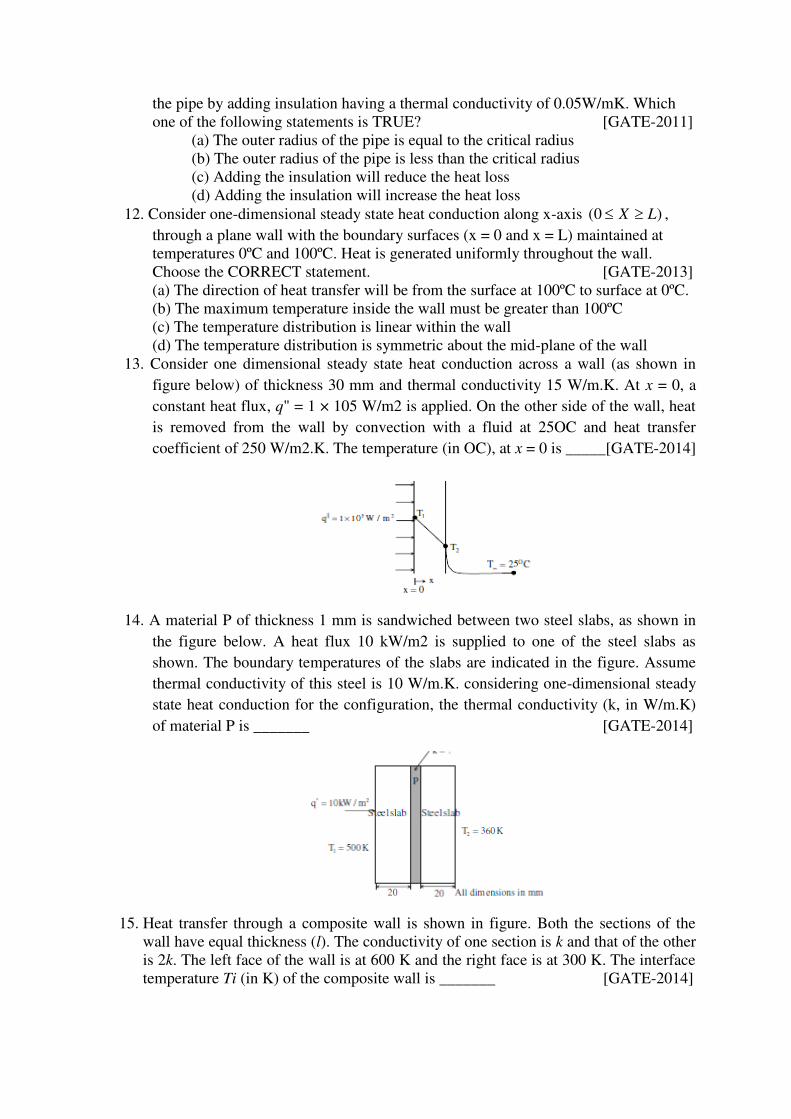
14. A material P of thickness 1 mm is sandwiched between two steel slabs, as shown in
the figure below. A heat flux 10 kW/m2 is supplied to one of the steel slabs as
shown. The boundary temperatures of the slabs are indicated in the figure. Assume
thermal conductivity of this steel is 10 W/m.K. considering one-dimensional steady
state heat conduction for the configuration, the thermal conductivity (k, in W/m.K)
of material P is _______ [GATE-2014]
15. Heat transfer through a composite wall is shown in figure. Both the sections of the
wall have equal thickness (l). The conductivity of one section is k and that of the other
is 2k. The left face of the wall is at 600 K and the right face is at 300 K. The interface
temperature Ti (in K) of the composite wall is _______ [GATE-2014]
16. A plane wall has a thermal conductivity of 1.15 W/m.K. If the inner surface is at
11000C and the outer surface is at 350
0C, then the design thickness (in meter) of the
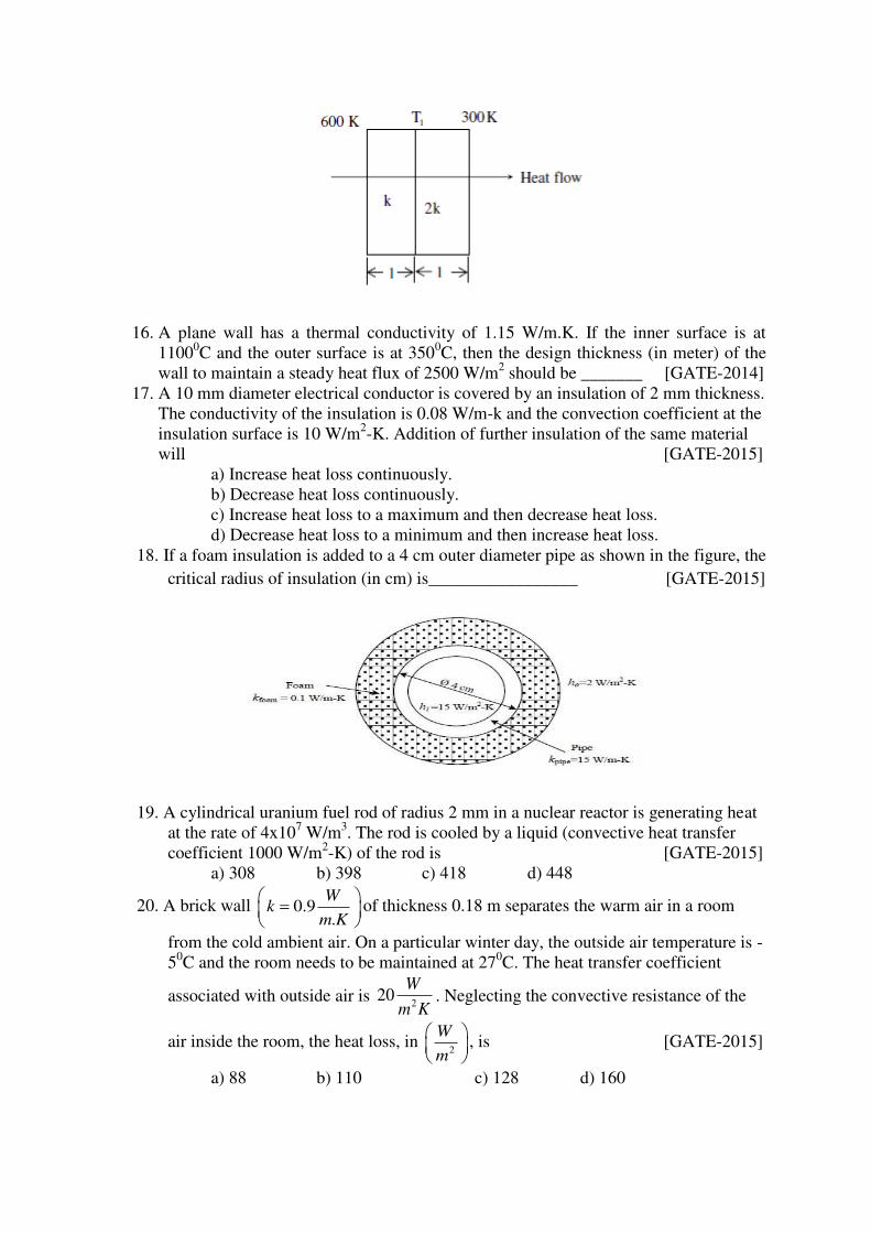
wall to maintain a steady heat flux of 2500 W/m2 should be _______ [GATE-2014]
17. A 10 mm diameter electrical conductor is covered by an insulation of 2 mm thickness.
The conductivity of the insulation is 0.08 W/m-k and the convection coefficient at the
insulation surface is 10 W/m2-K. Addition of further insulation of the same material
will [GATE-2015]
a) Increase heat loss continuously.
b) Decrease heat loss continuously.
c) Increase heat loss to a maximum and then decrease heat loss.
d) Decrease heat loss to a minimum and then increase heat loss.
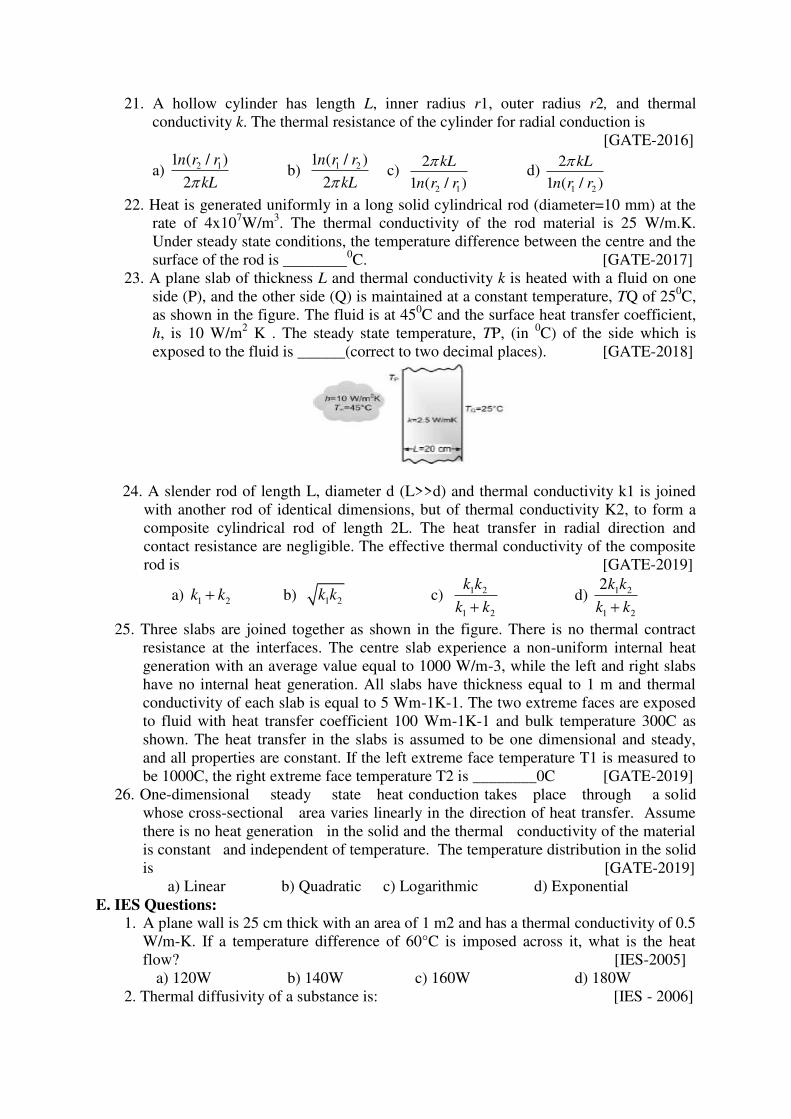
18. If a foam insulation is added to a 4 cm outer diameter pipe as shown in the figure, the
critical radius of insulation (in cm) is_________________ [GATE-2015]
19. A cylindrical uranium fuel rod of radius 2 mm in a nuclear reactor is generating heat
at the rate of 4x10⁷ W/m
3. The rod is cooled by a liquid (convective heat transfer
coefficient 1000 W/m2-K) of the rod is [GATE-2015]
a) 308 b) 398 c) 418 d) 448
20. A brick wall 0.9.
Wk
m K
of thickness 0.18 m separates the warm air in a room
from the cold ambient air. On a particular winter day, the outside air temperature is -
50C and the room needs to be maintained at 27
0C. The heat transfer coefficient
associated with outside air is 2
20W
m K. Neglecting the convective resistance of the
air inside the room, the heat loss, in 2
W
m
, is [GATE-2015]
a) 88 b) 110 c) 128 d) 160
21. A hollow cylinder has length L, inner radius r1, outer radius r2, and thermal
conductivity k. The thermal resistance of the cylinder for radial conduction is
[GATE-2016]
a) 2 11 ( / )
2
n r r
kL b) 1 21 ( / )
2
n r r
kL c)
2 1
2
1 ( / )
kL
n r r
d)
1 2
2
1 ( / )
kL
n r r
22. Heat is generated uniformly in a long solid cylindrical rod (diameter=10 mm) at the
rate of 4x10⁷W/m
3. The thermal conductivity of the rod material is 25 W/m.K.
Under steady state conditions, the temperature difference between the centre and the
surface of the rod is ________0C. [GATE-2017]
23. A plane slab of thickness L and thermal conductivity k is heated with a fluid on one
side (P), and the other side (Q) is maintained at a constant temperature, TQ of 250C,
as shown in the figure. The fluid is at 450C and the surface heat transfer coefficient,
h, is 10 W/m2 K . The steady state temperature, TP, (in
0C) of the side which is
exposed to the fluid is ______(correct to two decimal places). [GATE-2018]
24. A slender rod of length L, diameter d (L>>d) and thermal conductivity k1 is joined
with another rod of identical dimensions, but of thermal conductivity K2, to form a
composite cylindrical rod of length 2L. The heat transfer in radial direction and
contact resistance are negligible. The effective thermal conductivity of the composite
rod is [GATE-2019]
a) 1 2k k b) 1 2k k c) 1 2
1 2
k k
k k d) 1 2
1 2
2k k
k k
25. Three slabs are joined together as shown in the figure. There is no thermal contract
resistance at the interfaces. The centre slab experience a non-uniform internal heat
generation with an average value equal to 1000 W/m-3, while the left and right slabs
have no internal heat generation. All slabs have thickness equal to 1 m and thermal
conductivity of each slab is equal to 5 Wm-1K-1. The two extreme faces are exposed
to fluid with heat transfer coefficient 100 Wm-1K-1 and bulk temperature 300C as
shown. The heat transfer in the slabs is assumed to be one dimensional and steady, and all properties are constant. If the left extreme face temperature T1 is measured to
be 1000C, the right extreme face temperature T2 is ________0C [GATE-2019]
26. One-dimensional steady state heat conduction takes place through a solid
whose cross-sectional area varies linearly in the direction of heat transfer. Assume
there is no heat generation in the solid and the thermal conductivity of the material
is constant and independent of temperature. The temperature distribution in the solid
is [GATE-2019]
a) Linear b) Quadratic c) Logarithmic d) Exponential
E. IES Questions:
1. A plane wall is 25 cm thick with an area of 1 m2 and has a thermal conductivity of 0.5
W/m-K. If a temperature difference of 60°C is imposed across it, what is the heat
flow? [IES-2005]
a) 120W b) 140W c) 160W d) 180W
2. Thermal diffusivity of a substance is: [IES - 2006]
a) Inversely proportional to thermal conductivity
b) Directly proportional to thermal conductivity
c) Directly proportional to the square of thermal conductivity
d) Inversely proportional to the square of thermal conductivity
Which one of the following expresses the thermal diffusivity of a substance in terms
of thermal conductivity (k), mass density (p) and specific heat (c)?
a) k2pc b) 1/pkc c) k/pc d) pc/k2
3. Subjected to symmetrical heat transfer from one face of each block. The other face of
the block will be reaching to the same temperature at a rate [IES-2006]
a) Faster in air block
b) Faster in copper block
c) Equal in air as well as copper block
d) Cannot be predicted with the given information.
4. A large concrete slab 1 m thick has one dimensional temperature distribution:
T = 4 – 10x + 20x2 + 10x3 Where T is temperature and x is distance from one face
towards other face of wall. If the slab material has thermal diffusivity of 2×10⁻³
m2/hr, what is the rate of change of temperature at the other face of the wall?
[IES-2009]
a) 0.1°C/h b) 0.2°C/h c) 0.3°C/h d) 0.4°C/h
Prepared by: Dr.P.Nageswara Reddy
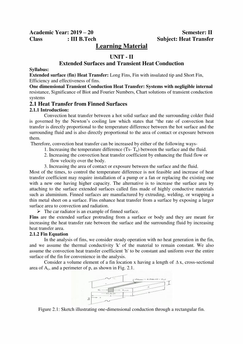
Academic Year: 2019 – 20 Semester: II
Class : III B.Tech Subject: Heat Transfer
Learning Material
UNIT - II
Extended Surfaces and Transient Heat Conduction Syllabus: Extended surface (fin) Heat Transfer: Long Fins, Fin with insulated tip and Short Fin,
Efficiency and effectiveness of fins.
One dimensional Transient Conduction Heat Transfer: Systems with negligible internal
resistance, Significance of Biot and Fourier Numbers, Chart solutions of transient conduction
systems
2.1 Heat Transfer from Finned Surfaces 2.1.1 Introduction:
Convection heat transfer between a hot solid surface and the surrounding colder fluid
is governed by the Newton’s cooling law which states that “the rate of convection heat
transfer is directly proportional to the temperature difference between the hot surface and the
surrounding fluid and is also directly proportional to the area of contact or exposure between
them.
Therefore, convection heat transfer can be increased by either of the following ways-
1. Increasing the temperature difference (Ts- Tα) between the surface and the fluid.
2. Increasing the convection heat transfer coefficient by enhancing the fluid flow or
flow velocity over the body.
3. Increasing the area of contact or exposure between the surface and the fluid.
Most of the times, to control the temperature difference is not feasible and increase of heat
transfer coefficient may require installation of a pump or a fan or replacing the existing one
with a new one having higher capacity. The alternative is to increase the surface area by
attaching to the surface extended surfaces called fins made of highly conductive materials
such as aluminium. Finned surfaces are manufactured by extruding, welding, or wrapping a
thin metal sheet on a surface. Fins enhance heat transfer from a surface by exposing a larger
surface area to convection and radiation.
The car radiator is an example of finned surface.
Fins are the extended surface protruding from a surface or body and they are meant for
increasing the heat transfer rate between the surface and the surrounding fluid by increasing
heat transfer area.
2.1.2 Fin Equation
In the analysis of fins, we consider steady operation with no heat generation in the fin,
and we assume the thermal conductivity 'k' of the material to remain constant. We also
assume the convection heat transfer coefficient 'h' to be constant and uniform over the entire
surface of the fin for convenience in the analysis.
Consider a volume element of a fin location x having a length of x, cross-sectional
area of Ac, and a perimeter of p, as shown in Fig. 2.1.
Figure 2.1: Sketch illustrating one-dimensional conduction through a rectangular fin.
Under steady conditions, the energy balance on this volume element can be expressed as
int
Rateof heat Rateof heat Rateof heat
conduction o conduction from convection from
theelement at x theelement at x x theelement
Or
, ,cond x cond x x convQ Q Q (2.1)
2
2( )c c
dT dT d TkA kA dx hPdx T T
dx dx dx
(2.2)
( ) 0c
d dTkA hp T T
dx dx
(2.3)
Where Ac is the cross-sectional area of the fin at location x.
In general, the cross-sectional area Ac and the perimeter p of a fin vary with x, which
makes this differential equation difficult to solve. In the special case of constant cross section
and constant thermal conductivity, the differential equation 2.6 reduces to 2
2
20
dm
dx
(2.4)
Where 2
c
hpm
kA and T T is the temperature excess.
At the fin base we haveb bT T .
Eq. 2.4 is a linear, homogeneous, second-order differential equation with constant
coefficients. The general solution of the differential equation 2.4 is
1 2( ) mx mxx C e C e
(2.5)
Where C1and C2 are arbitrary constants whose values are to be determined from the boundary
conditions at the base and at the tip of the fin.
At the fin base we have a specified temperature boundary condition, expressed as
Boundary condition at fin base: (0) b bT T (2.6)
At the fin tip we have several possibilities, including specified temperature, negligible heat
loss (idealized as an adiabatic tip), convection, and combined convection and radiation.
2.1.2.1 Infinitely Long Fin (Tfin tip=T )
For a sufficiently long fin of uniform cross section (Ac=constant), the temperature of the fin
at the fin tip approaches the environment temperature T and thus approaches zero. That
is
Boundary condition at fin tip: ( ) ( ) 0L T L T as L (2.7)
The variation of temperature along the fin In this case can be expressed as
/( )cx hp kAmx
b
T x Te e
T T
(2.8)
Note that the temperature along the fin in this case decreases exponentially from Tb to T .
The steady rate of heat transfer from the entire fin can be determined from Fourier’s law of
heat conduction as
0 ( )long fin c x b
dTQ kA hpkA T T
dx
(2.9)
Where p is the perimeter, Ac is the cross-sectional area of the fin, and x is the distance from
the fin base.
2.1.2.2 Negligible Heat Loss from the Fin Tip (Adiabatic fin tip, Qfin tip=0)
Fins are not likely to be so long that their temperature approaches the surrounding
temperature at the tip. A more realistic situation is for heat transfer from the fin tip to be
negligible since the heat transfer from the fin is proportional to its surface area, and the
surface area of the fin tip is usually a negligible fraction of the total fin area. Then the fin tip
can be assumed to be adiabatic, and the condition at the fin tip can be expressed as
0x L
d
dx
(2.10)
The condition at the fin base remains the same as expressed in Eq. 2.9. The
application of these two conditions on the general solution (Eq. 2.8) yields, after some
manipulations, the temperature distribution equation:
( ) cosh ( )
coshb
T x T m L x
T T mL
(2.11)
The rate of heat transfer from the fin can be determined again from Fourier’s law of heat
conduction:
0adiabatictip c x
dTQ kA
dx
( ) tanhbhpkA T T mL
(2.12)
Note that the heat transfer relations for the very long fin and the fin with negligible heat loss
at the tip differ by the factor tanh mL , which approaches 1 as L becomes very large.
2.1.2.3 Convection (Or Combined Convection and Radiation from Fin Tip)
The fin tips, in practice, are exposed to the surroundings, and thus the proper boundary
condition for the fin tip is convection that also includes the effects or radiation.
A practical way of accounting for the heat loss from the fin tip is to replace the fin length L in
the relation for the insulated tip case (Eq. 2.13 & 2.14) by a corrected length defined as
: cc
pCorrected fin l t
AL Leng h (2.13)
Where Ac is the cross-sectional area and p is the perimeter of the fin at the tip.
Therefore, fins subjected to convection at their tips can be treated as fins with insulated tips
by replacing the actual fin length by the corrected length.
Using the proper relations for Ac and p, the corrected lengths for rectangular and cylindrical
fins are easily determined to be
, tan ,4
c rec gular fin c pin fin
DL L and L L (2.14)
Where t is the thickness of the rectangular fins and d is the diameter of the cylindrical fins.
2.1.3 Fin Efficiency
We define fin efficiency as
,max
fin
fin
fin
Q Actual heat transfer rate fromthe fin
Q Ideal heat transfer rate fromthe fin
if theentire fin wereat basetemperatue
For the cases of constant cross section of very long fins and fins with adiabatic tips, the fin
efficiency can be expressed as
,max
( ) 1 1
( )
fin c b clong fin
fin fin b
Q hpkA T T kA
Q hA T T L hp mL
(2.15)
and
,max
( ) tanh tanh
( )
fin c b
adiabatictip
fin fin b
Q hpkA T T mL mL
Q hA T T mL
(2.16)
Note that fins with triangular and parabolic profiles contain less material and are more
efficient than the ones with rectangular profiles, and thus are more suitable for applications
requiring minimum weight such as space applications.
An important consideration in the design of finned surfaces is the selection of the
proper fin length L. Normally the longer the fin, the larger the heat transfer area and
thus the higher the rate of heat transfer from the fin.
But also the larger the fin, the bigger the mass, the higher the price, and the larger the
fluid friction. Therefore, increasing the length of the fin beyond a certain value cannot
be justified unless the added benefits out weight the added cost.
Also, the fin efficiency decreases with increasing fin length because of the decrease in
fin temperature with length.
Fin lengths that cause the fin efficiency to drop below 60 percent usually cannot be
justified economically and should be avoided.
The efficiency of most fins used in practice is above 90 percent.
2.1.4 Fin Effectiveness
The performance of fins is expressed in terms of the fin effectiveness, fin defined as
( )
fin fin bfin
no fin b b
fin
Heat transfer rate from
Q Q the fin of base area A
Q hA T T Heat transfer rate from
the fin of area A
(2.17)
The effectiveness of a long fin is determined to be
( )
( )
fin c b
long fin
no fin c b c
Q hpkA T T kp
Q hA T T hA
(2.18)
We can draw several important conclusions from the fin effectiveness relation given above
for consideration in the design and selection of the fins:
The thermal conductivity k of the fin material should be as high as possible. So, the
fins are made from metals, with copper, aluminium, and iron. Perhaps the most
widely used fins are made of aluminium because of its low cost and weight and its
resistance to corrosion.
The ratio of the perimeter to the cross-sectional area of the fin p/Ac should be as high
as possible. This criterion is satisfied by thin plate fins and slender pin fins.
The use of fins is most effective in applications involving a low convection heat
transfer coefficient. Thus, the use of fins is more easily justified when the medium is a
gas instead of a liquid and heat transfer is by natural convection instead of by forced
convection. Therefore, it is no coincidence that in liquid-to-gas heat exchangers such
as the car radiator, fins are placed on the gas side.
2.2 Transient Heat Conduction 2.2.1. Introduction
The temperature of a body, in general, varies with time as well as position. In
rectangular coordinates, this variation is expressed as T(x, y, z), where (x, y, z) indicate
variation in the x-,y
-, and z
- directions, and t indicates variation with time.
2.2.2 Lumped Heat Capacity Analysis
In heat transfer analysis, some bodies are observed to behave like a “lump” whose
interior temperature remains essentially uniform at all times during a heat transfer process.
The temperature of such bodies can be taken to be a function of time only, T(t). Heat transfer
analysis that utilizes this idealization is known as lumped system analysis.
Consider a body of arbitrary shape of mass m, volume V, surface area As, density ρ,
and specific heat cp initially at a uniform temperature Ti. At time t=0, the body is placed into
a medium at temperature T∞, and heat transfer takes place between the body and its
environment, with a heat transfer coefficient h. We assume lumped system analysis to be
applicable, so that the temperature remains uniform within the body at all times and changes
with time only, T=T(t).
During a differential time interval dt, the temperature of the body decreases by a differential
amount dT. An energy balance of the solid for the time interval dt can be expressed as
Heat transfer from Thedecreaseinenergy
thebody during dt of thebody during dt
Or
s phA T T dt mc dT (2.19)
Noting that m V and dT d T T , equation 2.19 can be rearranged as
( ) s
p
hAd T Tdt
T T Vc
(2.20)
Integrating equation 2.20 and applying the initial condition, i.e. T=Ti at time t=0, we get
( ) s
i p
hAT t Tt
T T Vc
(2.21)
Taking the exponential of both sides and rearranging, we obtain
( ) bt
i
T t Te
T T
(2.22)
Where,
0s
i
p
hAb B F
pVc
(2.23)
is a positive quantity whose dimension is (time)-1
. The reciprocal of b has time unit (usually
s), and is called the time constant.
F0 is the Fourier number and is defined as
3
0 2
3
The rate at which heat is conducted
across L of abody of volume L tF
The rate at which heat is stored L
in abody of volume L
(2.24)
Equation 2.23 enables us to determine the temperature T (t) of a body at time t, or
alternatively, the time t required for the temperature to reach a specified values T (t).
The temperature of a body approaches the ambient temperature T∞ exponentially. The
temperature of the body changes rapidly at the beginning, but rather slowly later on.
A large value of b indicates that the body approaches the environment temperature in
a short time. The larger the value of the exponent b, the higher the rate of decay in
temperature.
b is proportional to the surface area, but inversely proportional to the mass and the
specific heat of the body. Hence, it takes longer to heat or cool a larger mass,
especially when it has a large specific heat.
The total amount of heat transfer between the body and the surrounding medium over the
time interval t=0 to t is simply the change in the energy content of the body:
[ ( )]p iQ mc T T t
(2.25)
The amount of heat transfer reaches its upper limit when the body reaches the surrounding
temperature T∞. Therefore, the maximum heat transfer between the body and its surroundings
is
max [ ]p iQ mc T T
(2.26)
2.2.1.1 Criteria for Lumped System Analysis
The first step in establishing a criterion for the applicability of the lumped system analysis is
to define a characteristic length as
c
s
VL
A
(2.27)
and a Biot number Bi as
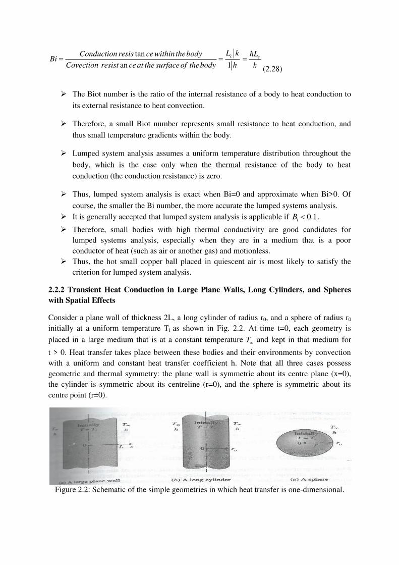
tan
an 1
cL kConduction resis ce within thebodyBi
Covection resist ce at the surfaceof thebody h c
hL
k
(2.28)
The Biot number is the ratio of the internal resistance of a body to heat conduction to
its external resistance to heat convection.
Therefore, a small Biot number represents small resistance to heat conduction, and
thus small temperature gradients within the body.
Lumped system analysis assumes a uniform temperature distribution throughout the
body, which is the case only when the thermal resistance of the body to heat
conduction (the conduction resistance) is zero.
Thus, lumped system analysis is exact when Bi=0 and approximate when Bi>0. Of
course, the smaller the Bi number, the more accurate the lumped systems analysis.
It is generally accepted that lumped system analysis is applicable if 0.1iB .
Therefore, small bodies with high thermal conductivity are good candidates for
lumped systems analysis, especially when they are in a medium that is a poor
conductor of heat (such as air or another gas) and motionless.
Thus, the hot small copper ball placed in quiescent air is most likely to satisfy the
criterion for lumped system analysis.
2.2.2 Transient Heat Conduction in Large Plane Walls, Long Cylinders, and Spheres
with Spatial Effects
Consider a plane wall of thickness 2L, a long cylinder of radius r0, and a sphere of radius r0
initially at a uniform temperature Ti as shown in Fig. 2.2. At time t=0, each geometry is
placed in a large medium that is at a constant temperature T and kept in that medium for
t > 0. Heat transfer takes place between these bodies and their environments by convection
with a uniform and constant heat transfer coefficient h. Note that all three cases possess
geometric and thermal symmetry: the plane wall is symmetric about its centre plane (x=0),
the cylinder is symmetric about its centreline (r=0), and the sphere is symmetric about its
centre point (r=0).
Figure 2.2: Schematic of the simple geometries in which heat transfer is one-dimensional.
The variation of the temperature profile with time in the plane wall is illustrated in Figure
2.3. When the wall is first exposed to the surrounding medium at 0iT T at t , the entire
wall is at its initial temperature Ti. But, the wall temperature near the surface starts to drop as
a result of heat transfer from the wall to the surrounding medium. This creates a temperature
gradient in the wall and initiates heat conduction from the inner parts of the wall toward its
outer surface.
Figure 2.3: Transient temperature profiles in a plane wall exposed to convection from its
surfaces for iT T
The transient temperature charts in Figures: 2.4, 2.5, and 2.6 for a large plane wall, long
cylinder, and sphere were presented by M.P.Heisler in 1947 and are called Heisler charts.
There are three charts associated with each geometry: the first chart is to determine the
temperature T0 at the centre of the geometry at a given time t. The second chart is to
determine the temperature at other locations at the same time in terms of T0. The third chart is
to determine the total amount of heat transfer up to the time t. These plots are valid for
0.2.
Figure 2.4 (a): Mid-plane temperature.
Figure 2.4 (b): Temperature distribution.
Figure 2.4 (c): Heat Transfer.
Figure 2.5 (a): Centreline temperature.
Figure 2.5 (b): Temperature distribution.
Figure 2.5 (C): Heat transfer.
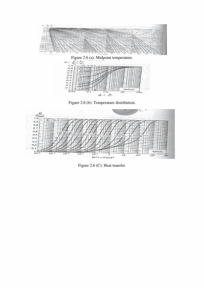
Figure 2.6 (a): Midpoint temperature.
Figure 2.6 (b): Temperature distribution.
Figure 2.6 (C): Heat transfer.
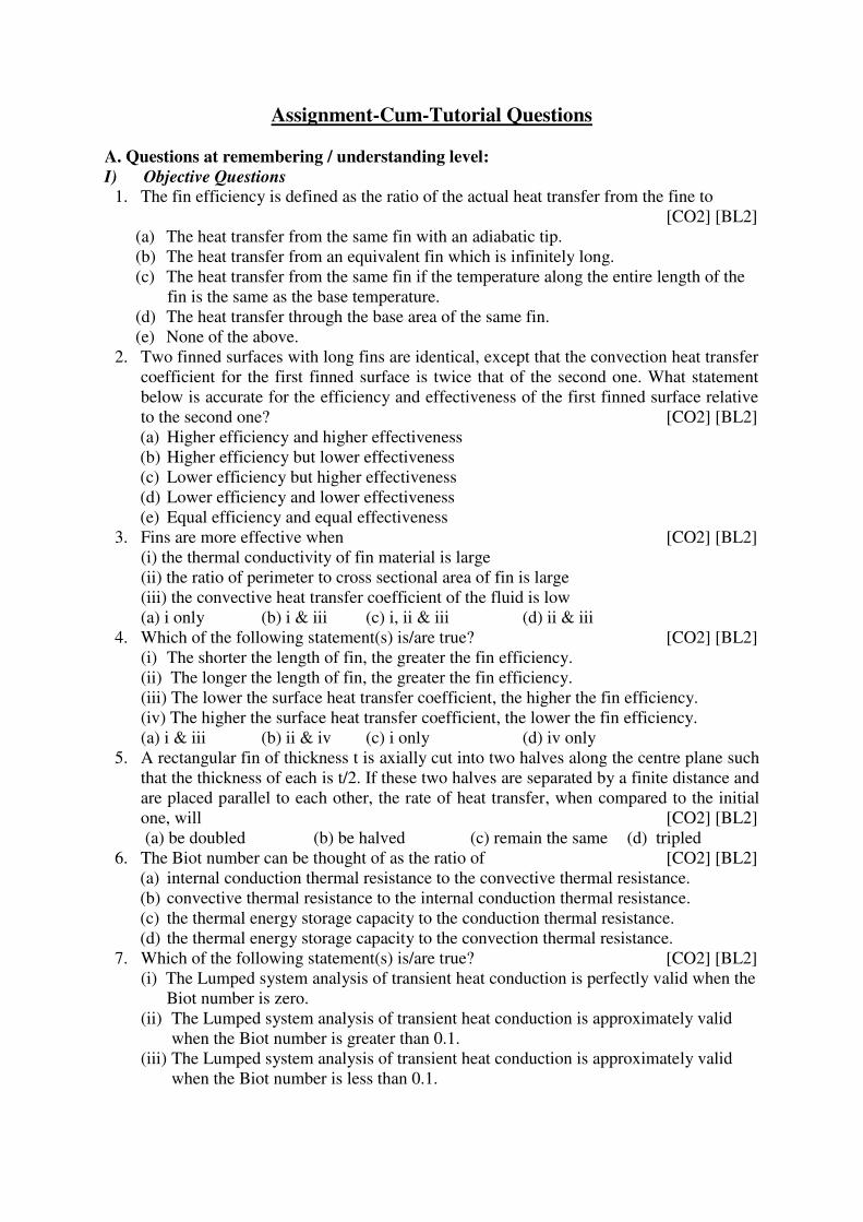
Assignment-Cum-Tutorial Questions
A. Questions at remembering / understanding level:
I) Objective Questions 1. The fin efficiency is defined as the ratio of the actual heat transfer from the fine to
[CO2] [BL2]
(a) The heat transfer from the same fin with an adiabatic tip.
(b) The heat transfer from an equivalent fin which is infinitely long.
(c) The heat transfer from the same fin if the temperature along the entire length of the
fin is the same as the base temperature.
(d) The heat transfer through the base area of the same fin.
(e) None of the above.
2. Two finned surfaces with long fins are identical, except that the convection heat transfer
coefficient for the first finned surface is twice that of the second one. What statement
below is accurate for the efficiency and effectiveness of the first finned surface relative
to the second one? [CO2] [BL2]
(a) Higher efficiency and higher effectiveness
(b) Higher efficiency but lower effectiveness
(c) Lower efficiency but higher effectiveness
(d) Lower efficiency and lower effectiveness
(e) Equal efficiency and equal effectiveness
3. Fins are more effective when [CO2] [BL2]
(i) the thermal conductivity of fin material is large
(ii) the ratio of perimeter to cross sectional area of fin is large
(iii) the convective heat transfer coefficient of the fluid is low
(a) i only (b) i & iii (c) i, ii & iii (d) ii & iii
4. Which of the following statement(s) is/are true? [CO2] [BL2]
(i) The shorter the length of fin, the greater the fin efficiency.
(ii) The longer the length of fin, the greater the fin efficiency.
(iii) The lower the surface heat transfer coefficient, the higher the fin efficiency.
(iv) The higher the surface heat transfer coefficient, the lower the fin efficiency.
(a) i & iii (b) ii & iv (c) i only (d) iv only
5. A rectangular fin of thickness t is axially cut into two halves along the centre plane such
that the thickness of each is t/2. If these two halves are separated by a finite distance and
are placed parallel to each other, the rate of heat transfer, when compared to the initial
one, will [CO2] [BL2]
(a) be doubled (b) be halved (c) remain the same (d) tripled
6. The Biot number can be thought of as the ratio of [CO2] [BL2]
(a) internal conduction thermal resistance to the convective thermal resistance.
(b) convective thermal resistance to the internal conduction thermal resistance.
(c) the thermal energy storage capacity to the conduction thermal resistance.
(d) the thermal energy storage capacity to the convection thermal resistance.
7. Which of the following statement(s) is/are true? [CO2] [BL2]
(i) The Lumped system analysis of transient heat conduction is perfectly valid when the
Biot number is zero.
(ii) The Lumped system analysis of transient heat conduction is approximately valid
when the Biot number is greater than 0.1.
(iii) The Lumped system analysis of transient heat conduction is approximately valid
when the Biot number is less than 0.1.
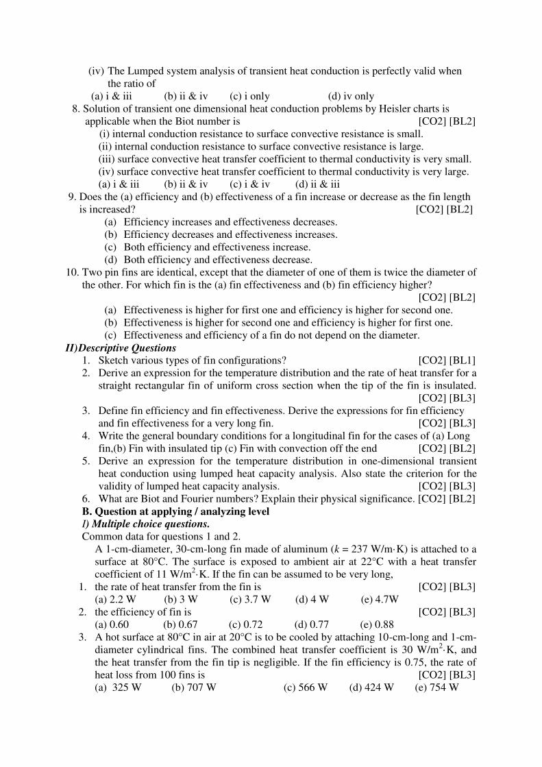
(iv) The Lumped system analysis of transient heat conduction is perfectly valid when
the ratio of
(a) i & iii (b) ii & iv (c) i only (d) iv only
8. Solution of transient one dimensional heat conduction problems by Heisler charts is
applicable when the Biot number is [CO2] [BL2]
(i) internal conduction resistance to surface convective resistance is small.
(ii) internal conduction resistance to surface convective resistance is large.
(iii) surface convective heat transfer coefficient to thermal conductivity is very small.
(iv) surface convective heat transfer coefficient to thermal conductivity is very large.
(a) i & iii (b) ii & iv (c) i & iv (d) ii & iii
9. Does the (a) efficiency and (b) effectiveness of a fin increase or decrease as the fin length
is increased? [CO2] [BL2]
(a) Efficiency increases and effectiveness decreases.
(b) Efficiency decreases and effectiveness increases.
(c) Both efficiency and effectiveness increase.
(d) Both efficiency and effectiveness decrease.
10. Two pin fins are identical, except that the diameter of one of them is twice the diameter of
the other. For which fin is the (a) fin effectiveness and (b) fin efficiency higher?
[CO2] [BL2] (a) Effectiveness is higher for first one and efficiency is higher for second one.
(b) Effectiveness is higher for second one and efficiency is higher for first one.
(c) Effectiveness and efficiency of a fin do not depend on the diameter.
II) Descriptive Questions 1. Sketch various types of fin configurations? [CO2] [BL1]
2. Derive an expression for the temperature distribution and the rate of heat transfer for a
straight rectangular fin of uniform cross section when the tip of the fin is insulated.
[CO2] [BL3]
3. Define fin efficiency and fin effectiveness. Derive the expressions for fin efficiency
and fin effectiveness for a very long fin. [CO2] [BL3]
4. Write the general boundary conditions for a longitudinal fin for the cases of (a) Long
fin,(b) Fin with insulated tip (c) Fin with convection off the end [CO2] [BL2]
5. Derive an expression for the temperature distribution in one-dimensional transient
heat conduction using lumped heat capacity analysis. Also state the criterion for the
validity of lumped heat capacity analysis. [CO2] [BL3]
6. What are Biot and Fourier numbers? Explain their physical significance. [CO2] [BL2]
B. Question at applying / analyzing level
I) Multiple choice questions.
Common data for questions 1 and 2.
A 1-cm-diameter, 30-cm-long fin made of aluminum (k = 237 W/m·K) is attached to a
surface at 80°C. The surface is exposed to ambient air at 22°C with a heat transfer
coefficient of 11 W/m2·K. If the fin can be assumed to be very long,
1. the rate of heat transfer from the fin is [CO2] [BL3]
(a) 2.2 W (b) 3 W (c) 3.7 W (d) 4 W (e) 4.7W
2. the efficiency of fin is [CO2] [BL3]
(a) 0.60 (b) 0.67 (c) 0.72 (d) 0.77 (e) 0.88
3. A hot surface at 80°C in air at 20°C is to be cooled by attaching 10-cm-long and 1-cm-
diameter cylindrical fins. The combined heat transfer coefficient is 30 W/m2·K, and
the heat transfer from the fin tip is negligible. If the fin efficiency is 0.75, the rate of
heat loss from 100 fins is [CO2] [BL3]
(a) 325 W (b) 707 W (c) 566 W (d) 424 W (e) 754 W
4. A cylindrical pin fin of diameter 0.6 cm and length of 3 cm with negligible heat loss
from the tip has an efficiency of 0.7. The effectiveness of this fin is [CO2] [BL3]
(a) 0.3 (b) 0.7 (c) 2 (d) 8 (e) 14
Common data for questions 5 and 6
Consider a very long rectangular fin attached to a flat surface such that the temperature at the
fin is essentially that of the surrounding air, i.e. 200C. Its width is 5.0 cm; thickness is 1.0
mm; thermal conductivity is 200 W/m.K; and base temperature is 400C. The heat transfer
coefficient is 20 W/m2.K.
5. What is the temperature at a distance of 5cm from the base?
(a) 17.80C (b) 20.8
0C (c) 23.8
0C (d) 29.8
0C
6. What is the rate of heat loss from the entire fin?
(a) 2.86 J (b) 2.46 J (c) 2.26 J (d) 2.06 J
7. A triangular shaped fin a motorcycle engine is 0.5-cm thick at its base and 3-cm long
(normal distance between the base and the tip of the triangle), and is made of
aluminium (k=150 W/m.K). This fin is exposed to air with a convective heat transfer
coefficient of 30 W/m2. K acting on its surfaces. The efficiency of the fin is 50 percent.
If the fin base temperature is 1300C and the air temperature is 25
0C, the beat transfer
from this fin per unit width is [CO2] [BL3]
(a) 32 W/m (b) 47 W/m (c) 68 W/m (d) 82 W/m (e) 95 W/m
8. An 18-cm-long, 16-cm-wide, and 12-cm-high hot iron block (ρ= 7870 kg/m3, cp = 447
J/kg-K) initially at 20°C is placed in an oven for heat treatment. The heat transfer
coefficient on the surface of the block is 100 W/m2·K. If it is required that the
temperature of the block rises to 750°C in a 25-min period, the oven must be
maintained at [CO2] [BL3]
(a) 750°C (b) 830°C (c) 875°C (d) 910°C (e) 1000°C
9. Copper balls (ρ = 8933 kg/m3, k = 401 W/m-K, cp = 385 J/kg-°C, α = 1.166x10⁻⁴
m2/s)
initially at 200°C are allowed to cool in air at 30°C for a period of 2 minutes. If the
balls have a diameter of 2 cm and the heat transfer coefficient is 80 W/m2-K, the centre
temperature of the balls at the end of cooling is [CO2] [BL3]
(a) 104°C (b) 87°C (c) 198°C (d) 126°C (e) 152°C
10. A potato may be approximated as a 5.7-cm-diameter solid sphere with the properties
ρ=910 kg/m3, cp=4.25 kJ/kg.
0C, k=0.68 W/m.
0C, and α=1.76 x 10⁻⁷m
2/s. Twelve such
potatoes initially at 250C are to be cooked by placing them in an oven maintained at
2500C with a heat transfer coefficient of 95 W/m
2.0C. The amount of heat transfer in kJ
to the potatoes during a 30- minute period is
[CO2] [BL3]
(a) 77 (b) 483 (c) 927 (d) 970 (e) 1012
Common data for question 11 and 12
A steel ball [c=0.46 kJ/kg.K, k=35 W/m.K] 5.0 cm in diameter and initially at a uniform
temperature of 4500C is suddenly placed in a controlled environment in which the
temperature is maintained at 1000C. The convection heat-transfer coefficient is 10 W/m
2 -K.
11. The time in hours required for the ball to attain a temperature of 1500C is [CO2] [BL3]
(a) 1.42 (b) 1.69 (c) 1.22 (d) 0.82
12. The total heat lost from the steel ball during this time interval is
(a) 53.8 J (b) 43.8 J (c) 73.8 J (d) 63.8 J
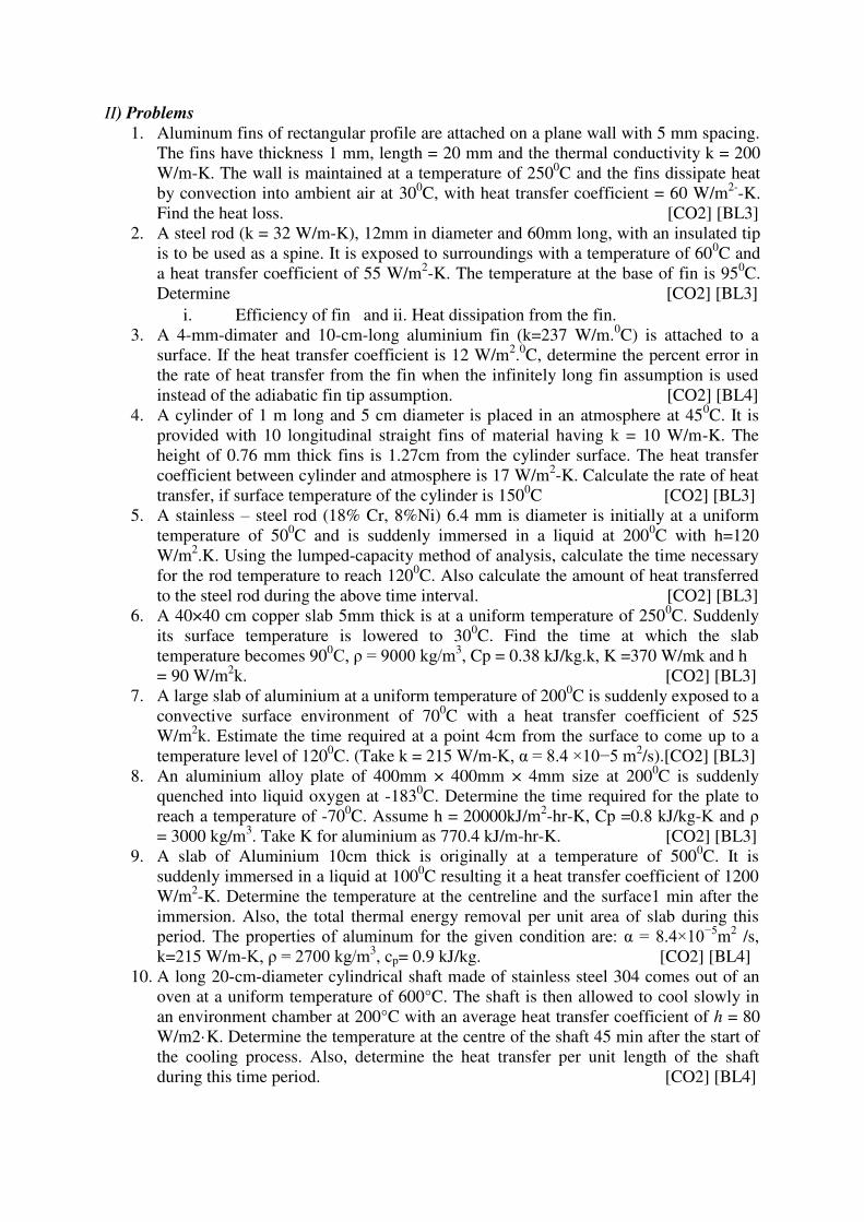
II) Problems
1. Aluminum fins of rectangular profile are attached on a plane wall with 5 mm spacing.
The fins have thickness 1 mm, length = 20 mm and the thermal conductivity k = 200
W/m-K. The wall is maintained at a temperature of 2500C and the fins dissipate heat
by convection into ambient air at 300C, with heat transfer coefficient = 60 W/m
2--K.
Find the heat loss. [CO2] [BL3]
2. A steel rod (k = 32 W/m-K), 12mm in diameter and 60mm long, with an insulated tip
is to be used as a spine. It is exposed to surroundings with a temperature of 600C and
a heat transfer coefficient of 55 W/m2-K. The temperature at the base of fin is 95
0C.
Determine [CO2] [BL3]
i. Efficiency of fin and ii. Heat dissipation from the fin.
3. A 4-mm-dimater and 10-cm-long aluminium fin (k=237 W/m.0C) is attached to a
surface. If the heat transfer coefficient is 12 W/m2.0C, determine the percent error in
the rate of heat transfer from the fin when the infinitely long fin assumption is used
instead of the adiabatic fin tip assumption. [CO2] [BL4]
4. A cylinder of 1 m long and 5 cm diameter is placed in an atmosphere at 450C. It is
provided with 10 longitudinal straight fins of material having k = 10 W/m-K. The
height of 0.76 mm thick fins is 1.27cm from the cylinder surface. The heat transfer
coefficient between cylinder and atmosphere is 17 W/m2-K. Calculate the rate of heat
transfer, if surface temperature of the cylinder is 1500C [CO2] [BL3]
5. A stainless – steel rod (18% Cr, 8%Ni) 6.4 mm is diameter is initially at a uniform
temperature of 500C and is suddenly immersed in a liquid at 200
0C with h=120
W/m2.K. Using the lumped-capacity method of analysis, calculate the time necessary
for the rod temperature to reach 1200C. Also calculate the amount of heat transferred
to the steel rod during the above time interval. [CO2] [BL3]
6. A 40×40 cm copper slab 5mm thick is at a uniform temperature of 2500C. Suddenly
its surface temperature is lowered to 300C. Find the time at which the slab
temperature becomes 900C, ρ = 9000 kg/m3
, Cp = 0.38 kJ/kg.k, K =370 W/mk and h
= 90 W/m2k. [CO2] [BL3]
7. A large slab of aluminium at a uniform temperature of 2000C is suddenly exposed to a
convective surface environment of 700C with a heat transfer coefficient of 525
W/m2k. Estimate the time required at a point 4cm from the surface to come up to a
temperature level of 1200C. (Take k = 215 W/m-K, α = 8.4 ×10⁻⁵ m2
/s).[CO2] [BL3]
8. An aluminium alloy plate of 400mm × 400mm × 4mm size at 2000C is suddenly
quenched into liquid oxygen at -1830C. Determine the time required for the plate to
reach a temperature of -700C. Assume h = 20000kJ/m
2-hr-K, Cp =0.8 kJ/kg-K and ρ
= 3000 kg/m3. Take K for aluminium as 770.4 kJ/m-hr-K. [CO2] [BL3]
9. A slab of Aluminium 10cm thick is originally at a temperature of 5000C. It is
suddenly immersed in a liquid at 1000C resulting it a heat transfer coefficient of 1200
W/m2-K. Determine the temperature at the centreline and the surface1 min after the
immersion. Also, the total thermal energy removal per unit area of slab during this
period. The properties of aluminum for the given condition are: α = 8.4×10⁻⁵m
2 /s,
k=215 W/m-K, ρ = 2700 kg/m3, cp= 0.9 kJ/kg. [CO2] [BL4]
10. A long 20-cm-diameter cylindrical shaft made of stainless steel 304 comes out of an
oven at a uniform temperature of 600°C. The shaft is then allowed to cool slowly in
an environment chamber at 200°C with an average heat transfer coefficient of h = 80
W/m2·K. Determine the temperature at the centre of the shaft 45 min after the start of
the cooling process. Also, determine the heat transfer per unit length of the shaft
during this time period. [CO2] [BL4]
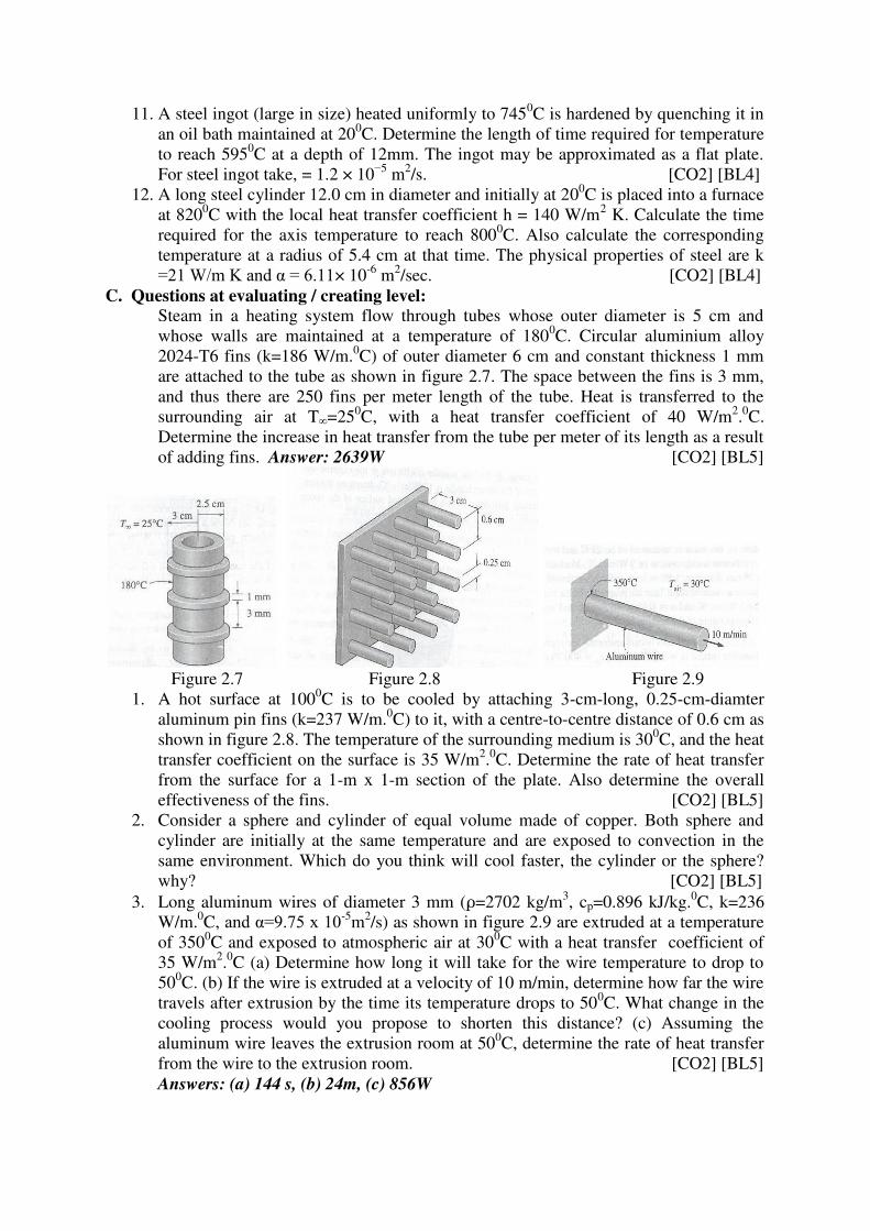
11. A steel ingot (large in size) heated uniformly to 7450C is hardened by quenching it in
an oil bath maintained at 200C. Determine the length of time required for temperature
to reach 5950C at a depth of 12mm. The ingot may be approximated as a flat plate.
For steel ingot take, = 1.2 × 10⁻⁵
m2/s. [CO2] [BL4]
12. A long steel cylinder 12.0 cm in diameter and initially at 200C is placed into a furnace
at 8200C with the local heat transfer coefficient h = 140 W/m
2 K. Calculate the time
required for the axis temperature to reach 8000C. Also calculate the corresponding
temperature at a radius of 5.4 cm at that time. The physical properties of steel are k
=21 W/m K and α = 6.11× 10⁻⁶
m2/sec. [CO2] [BL4]
C. Questions at evaluating / creating level: Steam in a heating system flow through tubes whose outer diameter is 5 cm and
whose walls are maintained at a temperature of 1800C. Circular aluminium alloy
2024-T6 fins (k=186 W/m.0C) of outer diameter 6 cm and constant thickness 1 mm
are attached to the tube as shown in figure 2.7. The space between the fins is 3 mm,
and thus there are 250 fins per meter length of the tube. Heat is transferred to the
surrounding air at T∞=250C, with a heat transfer coefficient of 40 W/m
2.0C.
Determine the increase in heat transfer from the tube per meter of its length as a result
of adding fins. Answer: 2639W [CO2] [BL5]
Figure 2.7 Figure 2.8 Figure 2.9
1. A hot surface at 1000C is to be cooled by attaching 3-cm-long, 0.25-cm-diamter
aluminum pin fins (k=237 W/m.0C) to it, with a centre-to-centre distance of 0.6 cm as
shown in figure 2.8. The temperature of the surrounding medium is 300C, and the heat
transfer coefficient on the surface is 35 W/m2.0C. Determine the rate of heat transfer
from the surface for a 1-m x 1-m section of the plate. Also determine the overall
effectiveness of the fins. [CO2] [BL5]
2. Consider a sphere and cylinder of equal volume made of copper. Both sphere and
cylinder are initially at the same temperature and are exposed to convection in the
same environment. Which do you think will cool faster, the cylinder or the sphere?
why? [CO2] [BL5]
3. Long aluminum wires of diameter 3 mm (ρ=2702 kg/m3, cp=0.896 kJ/kg.
0C, k=236
W/m.0C, and α=9.75 x 10⁻⁵
m2/s) as shown in figure 2.9 are extruded at a temperature
of 3500C and exposed to atmospheric air at 30
0C with a heat transfer coefficient of
35 W/m2.0C (a) Determine how long it will take for the wire temperature to drop to
500C. (b) If the wire is extruded at a velocity of 10 m/min, determine how far the wire
travels after extrusion by the time its temperature drops to 500C. What change in the
cooling process would you propose to shorten this distance? (c) Assuming the
aluminum wire leaves the extrusion room at 500C, determine the rate of heat transfer
from the wire to the extrusion room. [CO2] [BL5]
Answers: (a) 144 s, (b) 24m, (c) 856W
D. GATE Questions:
1. Lumped heat transfer analysis of a solid object suddenly exposed to a fluid medium at
a different temperature is valid when. [GATE-2001]
a) Biot number <0.1 b) Biot number > 0.1
c) Fourier number < 0.1 d) Fourier number > 0.1
2. The value of Biot number is very small (less than 0.01) when [GATE-2002]
(a) The convective resistance of the fluid is negligible
(b) The conductive resistance of the fluid is negligible
(c) The conductive resistance of the solid is negligible
(d) None of these
3. 3. A fin has 5mm diameter and 100mm length. The thermal conductivity of fin
material is 400Wm−1K−1. One end of the fin is maintained at 130ºC and its remaining surface is exposed to ambient air at 30ºC. if the convective heat transfer
coefficient is 40Wm-2K-1, the heat loss (in W) from the fin is [GATE-2010]
(A) 0.08 (B) 5.0 (C) 7.0 (D) 7.8
4. Pipe of 25mm outer diameter carries steam. The heat transfer coefficient between the
cylinder and surroundings is 2 5W/m K . It is proposed to reduce the heat loss from
the pipe by adding insulation having a thermal conductivity of 0.05W/mK. Which one
of the following statements is TRUE? [GATE-2011]
(A) The outer radius of the pipe is equal to the critical radius
(B) The outer radius of the pipe is less than the critical radius
(C) Adding the insulation will reduce the heat loss
(D) Adding the insulation will increase the heat loss
5. Which one of the following configurations has the highest fin effectiveness?
[GATE-2012]
A) Thin, closely spaced fins B) Thin, widely spaced fins
C) Thick widely spaced fins D) Thick, closely spaced fins
6. A steel ball of diameter 60 mm is initially in thermal equilibrium at 1030°C in a
furnace. It is suddenly removed from the furnace and cooled in ambient air at 30°C ,
with convective heat transfer coefficient h=20 2 W /m K. The thermo-physical
properties of steel are: density 3 r = 7800 kg /m , conductivity k=40 W/m-K and
specific heat c=600 J/kgK. The time required in seconds to cool the steel ball in air
from 1030°C to 430°C is [GATE-2013]
(A) 519 (B) 931 (C) 1195 (D) 2144
7. Biot number signifies the ratio of [GATE-2014]
(A) Convective resistance in the fluid to conductive resistance in the sold
(B) Conductive resistance in the solid to convective resistance in the fluid
(C) Inertia force to viscous force in the fluid
(D) Buoyancy force to viscous force in the fluid
8. A 10 mm diameter electrical conductor is covered by an insulation of 2 mm thickness.
The conductivity of the insulation is 0.08 W/m-k and the convection coefficient at the
insulation surface is 10 W/m2-K. Addition of further insulation of the same material
will [GATE-2015]
A) Increase heat loss continuously.
B) Decrease heat loss continuously.
C) Increase heat loss to a maximum and then decrease heat loss.
D) Decrease heat loss to a minimum and then increase heat loss.
9. A steel ball of 10 mm diameter at 1000 K is required to be cooled to 350 K by
immersing it in a water environment at 300 K. The convective heat transfer
coefficient is 1000 W/m2-K. Thermal conductivity of steel is 40 W/m-K. The time
constant for the cooling process is 16 s. The time required (in s) to reach the final
temperature is __________ [GATE-2016]
10. The heat loss from a fin 6 W. the effectiveness and efficiency of the fin are 3 and
0.75 respectively. The heat loss (in W) from the fin keeping the entire fin surface at
base temperature is __________ [GATE-2017]
11. A metal ball of diameter 0 mm is initially at 2200C. The ball is suddenly cooled by an
air jet of 200C. The hat transfer coefficient is 200 W/m
2K. The specific heat, thermal
conductivity and density of the metal ball are 400 J/kg.K, 400 W/m.K and 9000
kg/m3, respectively. The ball temperature (in
0C) after 90 seconds will be
approximately. [GATE-2017]
A) 141 B) 163 C) 189 D) 210
E. IES / IAS Questions
1. On a heat transfer surface, fins are provided [IES-2010]
(a) to increase temperature gradient so as to enhance heat transfer
(b) to increase turbulence in flow for enhancing heat transfer.
(c) to increase surface area to promote the rate of heat transfer.
(d) to decrease the pressure drop of the fluid
2. The temperature distribution in a stainless fin (thermal conductivity 0.17 W/cm0C) of
constant cross-sectional area of 2 cm2 and length of 1-cm, exposed to ambient of 40
0C
(with surface heat transfer coefficient of 0.0025 W/cm2-0C) is given by
( )T T =3x2-5x+6, where T is in
0C and x is in cm. if the base temperature is 100
0C,
then the heat dissipated by the fin surface will be: [IES-1994]
(a) 6.8 W (b) 3.4 W (c) 1.7 W (d) 0.17 W
3. The insulated tip temperature of a rectangular longitudinal fin having an excess (over
ambient) root temperature of 0 is [IES-2004]
(a) 0 tan ( )h ml (b) 0
sin ( )h ml
(c) 0 tan ( )
( )
h ml
ml
(d)
cos ( )h ml
4. The efficiency of a pin fin with insulated tip is : [IES-2001]
(a) 0.5
tan
( / )
hmL
hA kP (b)
tan hmL
mL (c)
tan
mL
hmL (d)
0.5( / )
tan
hA kP
hmL
5. A fin of length l protrudes from a surface held at temperature T0; it being higher than
the ambient temperature Ta. The heat dissipation from the free end of the fin is stated
to be negligibly small, what is the temperature gradient 1x
dT
dx
at the tip of the fin?
[IES-2008]
(a) Zero (b) 0 1T T
l
(c) 0( )ah T T (d)
0
l a
a
T T
T T
6. Which one of the following is correct? [IES-2008]
The effectiveness of a fin will be a maximum in an environment with
(a) Free convection (b) Forced convection

(c) Radiation (d) Convection and radiation
7. Which one of the following is correct? [IES-2008]
Fins are used to increase the heat transfer from a surface by
(a) Increasing the temperature difference
(b) Increasing the effective surface area
(c) Increasing the convective heat transfer coefficient
(d) None of the above
8. Fins are made as thin as possible to: [IES-2010]
(a) Reduce the total weight
(b) Accommodate more number of fins
(c) Increase the width for the same profile area
(d) Improve flow of coolant around the fin
9. In order to achieve maximum heat dissipation, the fin should be designed in such a
way that : [IES-2005]
(a) It should have maximum lateral surface at the root side of the fin
(b) It should have maximum lateral surface towards the tip side of the fin
(c) It should have maximum lateral surface near the centre of the fin
(d) It should have minimum lateral surface near the centre of the fin
10. A finned surface consists of root or base area of 1 m2 and fin surface area of 2 m
2. The
average heat transfer coefficient for finned surface is 20 W/m2K. Effectiveness of fins
provided is 0.75. If finned surface with root or base temperature of 500C is
transferring heat to a fluid at 300C, then rate of heat transfer is: [IES-2003]
(a) 400 W (b) 800 W (c) 1000 W (d) 1200 W
11. Consider the following statement pertaining to large heat transfer rate using fins:
[IES-2002]
1. Fins should be used on the side where hat transfer coefficient is small
2. Long and thick fins should be used
3. Short and thin fins should be used
4. Thermal conductivity of fin material should be large
Which of the above statements are correct?
(a) 1, 2 and 3 (b) 1, 2 and 4 (c)2, 3 and 4 (d) 1, 3 and 4
12. Assertion (A): in a liquid-to-gas heat exchanger fins are provided on the gas side.
Reason (R): The gas offers less thermal resistance than liquid [IES-2002]
(a) Both A and R are individually true and R is the correct explanation of A
(b) Both A and R are individually true but R is not the correct explanation of A
(c) A is true but R is false
(d) A is false but R is true
13. Extended surfaces are used to increase the rate of heat transfer. When the convection
heat transfer coefficient h=mk, the addition of extended surface will: [IES-2010]
(a) increase the rate of heat transfer
(b) decrease the rate of heat transfer
(c) not increase the rate of heat transfer
(d) increase the rate of heat transfer when the length of the fin is very large
14. A metallic rod of uniform diameter and length L connects two heat sources each at
5000C. The atmospheric temperature is 30
0C. The temperature gradient
dT
dLat the
centre of the bar will be: [IAS-2001]
(a) 500
/ 2L (b)
500
/ 2L (c)
470
/ 2L (d) zero
15. Assertion (A): Lumped capacity analysis of unsteady heat conduction assumes a
constant uniform temperature throughout a solid body.
Reason (R): The surface convection resistance is very large compared with the
internal conduction resistance. [IES-2010]
16. Which one of the following statements is correct? [IES-2004]
The curve for unsteady state cooling or heating of bodies
(a) Parabolic curve asymptotic to time axis
(b) Exponential curve asymptotic to time axis
(c) Exponential curve asymptotic both to time and temperature axis
(d) Hyperbolic curve asymptotic both to time and temperature axis
17. Assertion (A): In lumped heat capacity systems, the temperature gradient within the
system is negligible [IES-2004]
Reason (R): In analysis of lumped capacity systems, the thermal conductivity of the
system material is considered very high irrespective of the size of the system
(a) Both A and R are individually true and R is the correct explanation of A
(b) Both A and R are individually true but R is not the correct explanation of A
(c) A is true but R is false
(d) A is false but R is true
18. A solid copper ball of mass 500 grams, when quenched in a water bath at 300C, cools
from 5300C to 430
0C in 10 seconds. What will be the temperature of the ball after the
next 10 seconds? [IES-1997]
(a) 3000C (b) 320
0C (c) 350
0C
(b) (d) Not determinable for want of sufficient date
19. Heisler charts are used to determine transient heat flow rate and temperature
distribution when: [IES-2005]
(a) Solids possess infinitely large thermal conductivity
(b) Internal conduction resistance is small and convective resistance is large
(c) Internal conduction resistance is large and the convective resistance is small
(d) Both conduction and convection resistance are almost of equal significance
Prepared by: Dr.P.Nageswara Reddy
Academic Year: 2019 – 20 Semester: II
Class : III B.Tech Subject: Heat Transfer
Learning Material
UNIT-III
Convective Heat Transfer and Forced Convection
Syllabus
Convective Heat Transfer: Classification of Convective Heat Transfer, Dimensional analysis as a
tool for experimental investigation – Buckingham Pi Theorem for forced and Natural convection,
application for developing semi – empirical non dimensional correlation for convection heat
transfer, Significance of non-dimensional numbers. Concepts of Continuity, Momentum and
Energy Equations.
Forced Convection: Concept of hydrodynamic and thermal boundary layer, use of empirical
correlations for forced convection heat transfer Internal flows and External flows.
3.1 PHYSICAL MECHANISM OF CONVECTION
Heat transfer through a fluid is by convection in the presence of bulk fluid motion and by
conduction in the absence of it.
The fluid motion enhance heat transfer, since it brings warmer and cooler chunks of fluid
into contact, initiating higher rates of conduction at a greater number of sites in a fluid.
The rate of heat transfer through a fluid is much higher by convection than it is by
conduction. If fact, the higher the fluid velocity, the higher the rate of heat transfer.
Experience shown that convection heat transfer strongly depends on the fluid properties:
dynamic viscosity , thermal conductivity k, density p, and specific heat cp, as well as the fluid
velocity V. It also depends on the geometry and the roughness of the solid surface, in addition to
the type of fluid flow, laminar or turbulent.
The rate of convection heat transfer is observed to be proportional to the temperature difference
and is conveniently expressed by Newton’s law of cooling as
( )conv s sQ hA T T
(3.1)
Where
h=convection heat transfer coefficient, W/m2.0
C
As=heat transfer surface area, m2
Ts=temperature of the surface,
0C
T∞ = temperature of the fluid sufficiently far from the surface, 0C
The convection heat transfer coefficient h can be defined as the rate of heat transfer between a
solid surface and a fluid per unit surface area per unit temperature difference.
Heat transfer from the solid surface to the fluid layer adjacent to the surface is by pure
conduction, since the fluid layer is motionless, and can be expressed as
2
0
( / )conv cond fluid
y
Tq q k W m
y
(3.2)
Where T represents the temperature distribution in the fluid and 0
/y
T y
is the temperature
gradient at the surface. Heat is then convected away from the surface as a result of fluid motion.
Nusselt Number
It is also common practice to nondimensionalize the heat transfer coefficient h with the Nuselt
number, defined as
chLNu
k (3.3)
Where k is the thermal conductivity of the fluid Lc is the characteristic length.
Nusselt number is viewed as the dimensionless convection heat transfer coefficient.
It is defined as the ratio of heat transfer through the fluid layer by convection to the heat
transfer by conduction when the fluid layer is motionless.
Heat flux (the rate of heat transfer per unit surface area) in either case is
convq h T and
conv
Tq k
L
Taking their ratio gives
/
conv
cond
q h L hLNu
q k T L k
(3.4)
Therefore, the Nusselt number represents the enhancement of the transfer through a fluid
layer as a result of convection relative to conduction across the same fluid layer.
The larger the Nusselt number, the more effective the convection.
A Nusselt number of Nu=1 for a fluid layer represents heat transfer across the layer by
pure conduction.
3.2 CLASSIFICATION OF FLUID FLOWS
a) Viscous versus inviscid regions of flow.
Flows in which the frictional effects are significant are called viscous flows. However, in
many flows of practical interest, there are negligible small compared to inertial or
pressure forces. Neglecting the viscous terms in such in viscid flow regions greatly
simplifies the analysis without much loss in accuracy.
b) Internal Versus External Flow A fluid flow is classified as being internal or external, depending on whether the fluid is forced to
flow in a confined channel or over a surface.
The flow of an unbounded fluid over a surface such as a plate, a wire, or a pipe is external
flow. Air flow over a ball or over an exposed pipe during a windy day is an example of
external flow.
The flow in pipe or duct is internal flow if the fluid is completely bounded by solid
surfaces. Water flow in a pipe is an example of internal flow.
c) Laminar Versus Turbulent Flow
The highly ordered fluid motion characterized by smooth layers of fluid is called laminar.
The highly disordered fluid motion that typically occurs at high velocities and is characterized by
velocity fluctuations is called turbulent.
d) Natural (or Unformed) versus Forced Flow
A fluid flow is said to be natural or forced, depending on how the fluid motion is initiated.
In forced flow, a fluid is forced to flow over a surface or in a pipe by external means such
as a pump of a fan.
In natural flows, any fluid motion is due to natural means such as the buoyancy effect due
to density difference caused by temperature difference.
e) Steady versus Unsteady Flow
The term steady implies no change at a point with time. The opposite of steady is unsteady. The
term uniform implies no change with location over a specified region.
3.3 DIMENSIONAL ANALYSIS
Dimensional analysis is a method by which we deduce information about a phenomenon from the
single premise that the phenomenon can be described by a dimensionally correct equation among
certain variables.
The method can be applied to all types of fluid resistances, heat flow problems and many other
problems in fluid mechanics and thermodynamics.
The equation produced by this method also gives non-dimensional constants which govern the
problem under consideration.
Buckingham- -Theorem
Buckingham- -theorem states that if a physical phenomenon involves n variables and if these
variables can be expressed in terms of m fundamental dimensions then the physical law
describing the phenomenon can be expressed as a function of (n-m) independent dimensionless
products of variables called terms.
3.3.1 Dimensional Analysis Applied to Forced Convection
The convective heat transfer coefficient in forced convection can be expressed as
( , , , , , )ph f L u C k
( , , , , , , ) 0pf h L u C k (3.5)
This problem is controlled by 7 physical quantities containing 4 fundamental dimensions, so
according to Buckingham theorem, 3 dimensionless variables, 1 2 3, , , can be formed as given
below.
0 0 0 0
1
a b c dh L k M L t T (3.6)
3 1 3 1 1 3 1 0 0 0 0( )( ) ( ) ( ) ( )a b c dMt T ML L ML t MLt T M L t T
(3.7)
Equating the power of M, L, t and T of both sides, we get the following equations:
1 0a c d
3 0a b c d
3 3 0c d
1 0d
Solving the above equations, we get the following values
0, 1, 0, 1a b c d
1
hL
k = Nusselt number (Nu) (3.8)
Similarly 1 1 1 1 0 0 0 0
2
a b c d
pC L k M L t T (3.9)
1 12 2 1 3 1 1 1 1 3 1 0 0 0 0( )( ) ( )
c da b
L t T ML L ML t MLt T M L t T
(3.10)
Equating the powers of M, L, t and T of both sides, we get the following equations:
1 1 1 0a c d
1 1 1 13 2 0a b c d
1 13 2 0c d
1 1 0d
Solving the above equations, we get eh following values:
1 1 1 10, 0, 1, 1a b c d
2
pC
k
= Prandtl number (Pr) (3.11)
Similarly 2 2 2 2 0 0 0 0
3
a b c du L K M L t T (3.12)
2 21 3 2 2 1 1 3 1 0 0 0 0( )( ) ( )
c da b
Lt ML L ML t MLt T M L t T (3.13)
Equating the powers of M, L, t and T of both sides, we get the following equations:
2 2 2 0a c d
2 2 2 21 3 0a b c d
2 21 3 0c d
2 0d
Solving the above equations, we get the following values
2 2 2 21, 1, 1, 0a b c d
3
Lu
= Reynolds number (Re) (3.14)
According to Buckingham theorem
1 2 3 0f (3.15)
3 2 3( , )f (3.16)
(Re) (Pr)m n
Nu C (3.17)
Where C, n and m are constants and Nu, Re and Pr are known as Nesselt, Reynold and Prandtl
numbers respectively.
The constants are calculated with the help of experiments.
The value of C, m and n are co-related for different flow conditions and different geometric
configurations. A few of them are listed below.
(i) Flow of fluid over a flat surface at constant temperature.
Nu=0.664 Re0.5
Pr1/3
This equation is valid for laminar flow over the flat plate for which, the required condition is
Re<5x10⁵
If the flow condition on the flat plate is partly laminar and partly turbulent then the heat flow for
the turbulent region is given by the following equation: 0.8 1/30.036(Re) (Pr)Nu
This equation is valid for 5 72 10 Re 10 .
(ii) Fluid is flowing inside the tube or through the annulus 0.8 0.40.023(Re) (Pr)Nu
This equation is valid for 42300 Re 1 10 and 0.7 Pr 120, 60.
Land
D
3.3.2 Dimensional Analysis Applied to Natural or Free Convection
Natural convection is caused due to buoyancy force which is the effect of the decrease in density
due to heating.
The net force causing the upward flow is given as g T .
The convective heat transfer coefficient in natural convection can be expressed as
( , , , , , )ph f L C k g T (3.18)
Where, g will be considered as one physical factor which is responsible for causing flow.
We can write down the above equation as follows.
[ , , , , , , ( )] 0pf L k h C g T (3.19)
This problem is also controlled by 7 physical quantities containing 4 fundamental dimensions, so
according to Buckingham theorem, this problem can be controlled by (7-4) =3 non-dimensional
groups, 1 2 3, , , as given below.
0 0 0 0
1
a b c dh L k M L t T (3.20)
3 1 3 1 1 3 1 0 0 0 0( )( ) ( ) ( ) ( )a b c dMt T ML L ML t MLt T M L t T
(3.21)
Equating the power of M, L, t and T of both sides, we get the following equations:
1 0a c d
3 0a b c d
3 3 0c d
1 0d
Solving the above equations, we get the following values
0, 1, 0, 1a b c d
1
hL
k = Nusselt number (Nu) (3.22)
Similarly 1 1 1 1 0 0 0 0
2
a b c d
pC L k M L t T (3.23)
1 12 2 1 3 1 1 1 1 3 1 0 0 0 0( )( ) ( )
c da b
L t T ML L ML t MLt T M L t T
(3.24)
Equating the powers of M, L, t and T of both sides, we get the following equations:
1 1 1 0a c d
1 1 1 13 2 0a b c d
1 13 2 0c d
1 1 0d
Solving the above equations, we get eh following values:
1 1 1 10, 0, 1, 1a b c d
2
pC
k
= Prandtl number (Pr) (3.25)
Similarly 2 2 2 2 0 0 0 0
3 ( . )a b c d
g T L k M L t T (3.26)
22 3 2 2 1 1 2 3 1 0 0 0 0( ) ( ) ( )
da b c
Lt ML L ML t MLt T M L t T (3.27)
Equating the powers of M, L, t and T both sides, we get the following equations
2 2 2 0a c d
2 2 2 23 1 0a b c d
2 23 2 0c d
2 0d
Solving the above equations, we get the following values.
2 2 2 22, 3, 2 0a b c and d
2 3 3
3 2 2
. .g T L g T L
v
= Grassoff-Number (Gr)
According to Buckingham theorem
Solving the above equations, we get the following values.
1 2 3( . )f
(Pr) .mn
Nu C Gr (3.28)
2
.n m
pChL g TC
K K v
(3.29)
Where C, n and m are the constant.
The following few correlations for different flow conditions and different geometric
configurations are given by the following equations:
(i) The heat transfer coefficient on vertical plate or vertical cylinder is given by the following
equation. 0.25 5 80.56( .Pr) , 10 Pr 10Nu Gr when Gr
The characteristic length is the height of the plate of cylinder.
(ii) The heat transfer coefficient for horizontal pipe is given by the following equation. 0.25 5 80.47( .Pr) , 10 Pr 10Nu Gr when Gr
The characteristic length is a diameter of the pipe.
(iii) Vertical cylinder of plate 0.330.13( .Pr)Nu Gr
(iv) Horizontal cylinder 0.330.10( .Pr)Nu Gr
3.3.3 Limitations of Dimensional Analysis
The most serious lamination of dimensional analysis is that it gives no information about
the nature of the phenomenon.
A complete solution is not obtained nor is the inner mechanism of a phenomenon revealed
by dimensional analysis.
3.4 LAMINAR BOUNDARY LAYER ON A FLAT PLATE
3.4.1 Momentum equation
We derive the equation of motion for the boundary layer by making a force-and-momentum
balance on an elemental control volume shown in figure 3.1. To simplify the analysis we assume:
1. The fluid is incompressible and the flow is steady.
2. There are no pressure variations in the direction perpendicular to the plate.
3. The viscosity is constant.
4. Viscous-shear forces in the y direction are negligible.
We apply Newton’s second law of motion.
xF =increase in momentum flux in x direction
( )xx
d mVF
d (3.30)
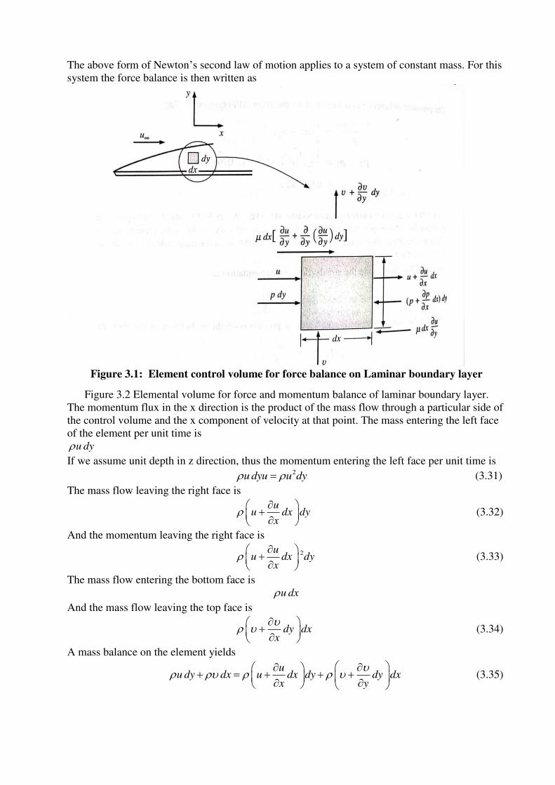
The above form of Newton’s second law of motion applies to a system of constant mass. For this
system the force balance is then written as
Figure 3.1: Element control volume for force balance on Laminar boundary layer
Figure 3.2 Elemental volume for force and momentum balance of laminar boundary layer.
The momentum flux in the x direction is the product of the mass flow through a particular side of
the control volume and the x component of velocity at that point. The mass entering the left face
of the element per unit time is
u dy
If we assume unit depth in z direction, thus the momentum entering the left face per unit time is 2
u dyu u dy (3.31)
The mass flow leaving the right face is
uu dx dy
x
(3.32)
And the momentum leaving the right face is
2uu dx dy
x
(3.33)
The mass flow entering the bottom face is
u dx
And the mass flow leaving the top face is
dy dxx
(3.34)
A mass balance on the element yields
uu dy dx u dx dy dy dx
x y
(3.35)
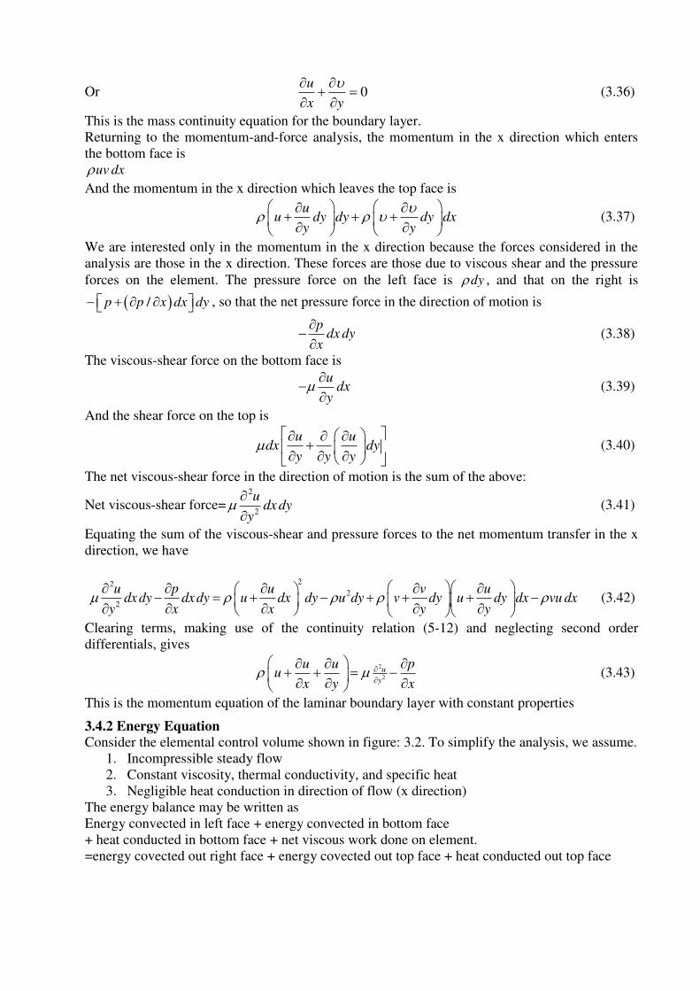
Or 0u
x y
(3.36)
This is the mass continuity equation for the boundary layer.
Returning to the momentum-and-force analysis, the momentum in the x direction which enters
the bottom face is
uv dx
And the momentum in the x direction which leaves the top face is
uu dy dy dy dx
y y
(3.37)
We are interested only in the momentum in the x direction because the forces considered in the
analysis are those in the x direction. These forces are those due to viscous shear and the pressure
forces on the element. The pressure force on the left face is dy , and that on the right is
/p p x dx dy , so that the net pressure force in the direction of motion is
pdx dy
x
(3.38)
The viscous-shear force on the bottom face is
udx
y
(3.39)
And the shear force on the top is
u udx dy
y y y
(3.40)
The net viscous-shear force in the direction of motion is the sum of the above:
Net viscous-shear force=2
2
udx dy
y
(3.41)
Equating the sum of the viscous-shear and pressure forces to the net momentum transfer in the x
direction, we have
222
2
u p u v udx dy dx dy u dx dy u dy v dy u dy dx vu dx
y x x y y
(3.42)
Clearing terms, making use of the continuity relation (5-12) and neglecting second order
differentials, gives
2
2
u
y
u u pu
x y x
(3.43)
This is the momentum equation of the laminar boundary layer with constant properties
3.4.2 Energy Equation
Consider the elemental control volume shown in figure: 3.2. To simplify the analysis, we assume.
1. Incompressible steady flow
2. Constant viscosity, thermal conductivity, and specific heat
3. Negligible heat conduction in direction of flow (x direction)
The energy balance may be written as
Energy convected in left face + energy convected in bottom face
+ heat conducted in bottom face + net viscous work done on element.
=energy covected out right face + energy covected out top face + heat conducted out top face
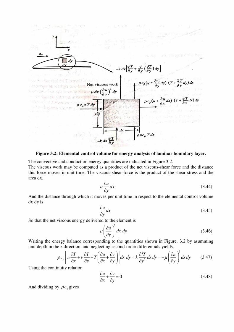
Figure 3.2: Elemental control volume for energy analysis of laminar boundary layer.
The convective and conduction energy quantities are indicated in Figure 3.2.
The viscous work may be computed as a product of the net viscous-shear force and the distance
this force moves in unit time. The viscous-shear force is the product of the shear-stress and the
area dx.
dxy
u
(3.44)
And the distance through which it moves per unit time in respect to the elemental control volume
dx dy is
dxy
u
(3.45)
So that the net viscous energy delivered to the element is 2
udx dy
y
(3.46)
Writing the energy balance corresponding to the quantities shown in Figure. 3.2 by asumming
unit depth in the z direction, and neglecting second-order differentials yields. 22
2p
T T u v T uc u v T dx dy k dx dy dx dy
x y x y y y
(3.47)
Using the continuity relation
0u v
x y
(3.48)
And dividing by pc gives
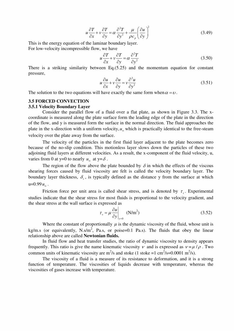
22
2
p
T T T uu v
x y y c y
(3.49)
This is the energy equation of the laminar boundary layer.
For low-velocity incompressible flow, we have 2
2
T T Tu v
x y y
(3.50)
There is a striking similarity between Eq.(5.25) and the momentum equation for constant
pressure, 2
2
u u uu v v
x y y
(3.51)
The solution to the two equations will have exactly the same form when .
3.5 FORCED CONVECTION
3.5.1 Velocity Boundary Layer
Consider the parallel flow of a fluid over a flat plate, as shown in Figure 3.3. The x-
coordinate is measured along the plate surface form the leading edge of the plate in the direction
of the flow, and y is measured form the surface in the normal direction. The fluid approaches the
plate in the x-direction with a uniform velocity, u which is practically identical to the free-steam
velocity over the plate away from the surface.
The velocity of the particles in the first fluid layer adjacent to the plate becomes zero
because of the no-slip condition. This motionless layer slows down the particles of these two
adjoining fluid layers at different velocities. As a result, the x-component of the fluid velocity, u,
varies from 0 at y=0 to nearly u at y= .
The region of the flow above the plate bounded by in which the effects of the viscous
shearing forces caused by fluid viscosity are felt is called the velocity boundary layer. The
boundary layer thickness, v , is typically defined as the distance y from the surface at which
u=0.99u .
Friction force per unit area is called shear stress, and is denoted by s . Experimental
studies indicate that the shear stress for most fluids is proportional to the velocity gradient, and
the shear stress at the wall surface is expressed as
0
s
y
u
y
(N/m
2) (3.52)
Where the constant of proportionally is the dynamic viscosity of the fluid, whose unit is
kg/m.s (or equivalently, N.s/m2, Pa.s, or poise=0.1 Pa.s). The fluids that obey the linear
relationship above are called Newtonian fluids.
In fluid flow and heat transfer studies, the ratio of dynamic viscosity to density appears
frequently. This ratio is give the name kinematic viscosity and is expressed as = / . Two
common units of kinematic viscosity are m2/s and stoke (1 stoke =1 cm
2/s=0.0001 m
2/s).
The viscosity of a fluid is a measure of its resistance to deformation, and it is a strong
function of temperature. The viscosities of liquids decrease with temperature, whereas the
viscosities of gases increase with temperature.
3.5.2 Thermal Boundary Layer
A thermal boundary layer develops when a fluid at a specified temperature flows over a
surface that is at a different temperature
Consider the flow of a fluid at a uniform temperature of T over an isothermal flat plate at
temperature Ts. the fluid particles in the layer adjacent to the surface reach thermal equilibrium
with the plate and assume the surface temperature Ts. These fluid particles then exchange energy
with the particles in the adjoining-fluid layer, and so on. As a result, a temperature profile
develops in the flow field that ranges from Ts at the surface to T sufficiently far from the surface.
The flow region over the surface in which the temperature variation in the direction
normal to the surface is significant is the thermal boundary layer. The thickness of the thermal
boundary layer t at any location along the surface is defined as the distance from the surface at
which the temperature difference T-Ts equals 0.99 sT T .
Prandtl Number The relative thickness of the velocity and the thermal boundary layers is best described by the
dimensionless parameter Prandtl number, defined as
PrpcMolecular diffusivity of momentum v
Molecular diffusivity of heat k
(3.53)
The Prandtl numbers of fluids range from less than 0.01 for liquid metals to more than
100,000 for heavy oils.
The Prandtl number is in the order of 10 for water.
The Prandtl numbers of gases are about 1, which indicates that both momentum and heat
dissipate through the fluid at about the same rate.
Heat diffuses very quickly in liquid metals Pr 1 and very slowly in oils (Pr>>1)
relative to momentum. Consequently the thermal boundary layer is much thicker for
liquid metals and much thinner for oils relative to the velocity boundary layers.
3.5.3 Laminar and Turbulent Flows
The flow regime in the first case is said to be laminar, characterized by smooth
streamlines and highly-ordered motion, and turbulent in the second case where it is
characterized by velocity fluctuations and highly-disordered motion.
The transition from laminar to turbulent flow does not occur suddenly; rather, it occurs
over some region in which the flow fluctuates between laminar and turbulent flows before
it becomes fully turbulent.
Most flow encountered in practice are turbulent. Laminar flow is encounter when highly
viscous fluids such as oils flow in small pipes or narrow passages.
The velocity profile in turbulent flow is much fuller than that in laminar flow, with a
sharp drop near the surface.
The turbulent boundary layer can be considered to consist of four regions, characterized
by the distance from the wall. The very thin layer next to the wall where viscous effects
are dominant is the viscous sub-layer. The velocity profile in this layer is very nearly
linear, and the flow is streamlined. Next to the viscous sub-layers is the buffer layer, in
which turbulent effects are becoming significant, but the flow is still dominated by
viscous effects. Above the buffer layer is the overlap layer, in which the turbulent effects
are much more significant, but still not dominant. Above that is the turbulent layer in
which turbulent effects dominate over viscous effects.
Both the friction and heat transfer coefficients reach maximum values when the flow
becomes fully turbulent.
Reynolds Number
The transition from laminar to turbulent flow depends on the surface geometry, surface
roughness, flow velocity, surface temperature, and type of fluid, among other things. Reynolds
discovered that the flow regime depends mainly on the ratio of the inertia forces to viscous forces
in the fluid. This ratio is called the Reynolds number, which is a dimensionless quantity, and is
expressed for external flows.
ReInertia forces
Viscous forces c cu L u L
v
(3.54)
Where V is the upstream velocity (equivalent to the free-stream velocity for a flat plate), Lc is the
characteristic length of the geometry, and v= / is the kinematic viscosity of the fluid. For a
flat plate, the characteristic length is the distance x from the leading edge.
3.5.4 Parallel Flow over Flat Plates
Consider the parallel flow of a fluid over a flat plate of length L in the flow direction. The x-
coordinate is measured along the plate surface from the leading edge in the direction of the flow.
The fluid approaches the plate in the x-direction with a uniform velocity V and temperatureT .
The flow in the velocity boundary layers starts out as laminar, but if the plate is sufficiently long,
the flow becomes turbulent at a distance xcr from the leading edge where the Reynolds number
reaches its critical value for transition.
The Reynolds number at a distance x from the leading edge of a flat plate
Rex
Vx Vx
v
(3.55)
Note that the value of the Reynolds number varies for a flat plate along the flow, reaching
ReL= u L/ at the end of the plate.
A generally accepted value for the critical Reynolds number is
5Re 5 10crcr
u x (3.56)
Based on analysis, the boundary layer thickness and the local friction coefficient at location x for
laminar flow over a flat plate were determined.
Laminar: , 1/2
5
Rev x
x
x and , 1/2
0664
Ref x
x
C for 5Re 5 10x (3.57)
The corresponding relations for turbulent flow are
Turbulent: , 1/5
0.38
Rev x
x
x and , 1/5
0.059
Ref x
x
C for 5 75 10 Re 10x (3.58)
Where x is the distance from the leading edge of the plate and Rex= u x/ is the Reynolds
number at location x.
The relationship between velocity and thermal boundary layers in laminar region can be
expressed as
,
1/3
,
1
Pr
t x
v x
(3.58a)
Constant Wall Temperature
The average friction coefficient over the entire plate is determined by substituting the relations
above into and performing the integrations. We get
Laminar: 1/2
1.33
Ref
L
C for 5Re 5 10L (3.59)
Turbulent: 1/5
0.074
Ref
L
C for 5 75 10 Re 10L (3.60)
The local Nusselt number at a location x for laminar flow over a flat plate was determined by
solving the differential energy equation:
Laminar: 0.5 1/30.332Re Prxx x
h xNu
k for Pr 0.6 (3.61)
The corresponding relation for turbulent flow is
Turbulent: 0.80.0296Rexx x
h xNu
k for 1/3 5 7Pr 0.6 Pr 60 5 10 Re 10x (3.62)
The average Nusselt number over the entire plate is determined by performing the integrations.
We get
Laminar: 0.5 1/30.664Re PrL
hLNu
k for 5Re 5 10L (3.63)
Turbulent: 0.80.037 ReL
hLNu
k for 1/3 5 7Pr 0.6 Pr 60 5 10 Re 10L (3.64)
In some cases, a flat plate is sufficiently long for the flow to become turbulent, but not long
enough to disregard the laminar flow region. In such cases, the average heat transfer coefficient
over the entire plate is determined as
, min ,0 0
1 cr crx x
x la ar x turbulenth h dx h dxL
(3.65)
Again taking the critical Reynolds number to be Recr = 5 X 10⁵ and performing the integrations
after substituting the indicated expressions, the average Nusselt number over the entire plate is
determined to be
0.5 1/3
5 7
(0.037 Re 871) Pr 0.6 Pr 60
5 10 Re 10
L
L
hLNu
k
(3.66)
Liquid metals such as mercury have high thermal conductivities. The local Nusselt number over
the plate is given by 1/20.565(Re Pr) Pr 0.05x xNu (3.67)
Constant Heat Flux
When a flat plate is subjected to uniform heat flux instead of uniform temperature, the local
Nusselt number is given by
Laminar: 0.5 1/30.453Re Prx xNu (3.68)
Turbulent: 0.8 1/30.0308Re Prx xNu (3.69)
3.5.5 The Relation between Fluid Friction and Heat Transfer
The frictional resistance may be directly related to heat transfer as given below.
The shear stress at the wall may be expressed in terms of a friction coefficient fC as
2
2w f
uC
(3.70)
The shear stress may also be calculated from the relation
w
w
u
y
(3.71)
The velocity distribution equation is given by
33 1
2 2
u y y
u
(3.72)
Using the velocity distribution given by Eq.(3-72), we have
3
2w
u
(3.73)
And making use of the relation for the boundary-layer thickness gives 1
23
2 4.64w
u u
vx
(3.74)
Combining Eqs. (3.69) and (3.73) leads to 1/2
1/2
2
3 10.323Re
2 2 4.64x
u uCfx
vx u
(3.75)
The exact solution of the boundary-layer equations yields
1/20.323Re2
x
Cfx (3.76)
Equation (3.74) may be rewritten in the following form:
2/3 1/20.332Pr ReRe Pr
x xx
x p
Nu h
c u
(3.77)
The group on the left is called the Stanton number,
xx
p
hSt
c u
So that 2/3 1/2Pr 0.332Rex xSt (3.78)
Upon comparing Eqs. (3.74) and (3.77), we get
2/3Pr2
xx
CfSt (3.79)
Equation (3.78), called the Reynolds-Colburn analogy, expresses the relation between fluid
friction and heat transfer for laminar flow on a flat plate. The heat-transfer coefficient thus could
be determined by making measurements of the frictional drag on a plate under conditions in
which no heat transfer is involved.
3.5.6 Flow Across Cylinders and Spheres
Flow across cylinders and sphere is frequently encountered in practice. For example, the tubes in
a shell-and-tube heat exchanger involve both internal flow through the tubes and external flow
over the tubes, and both flows must be considered in the analysis of the heat exchanger.
The characteristic length for a circular cylinder or sphere is taken to be the external diameter D.
Thus, the Reynolds number is defined as Re /u D .
The critical Reynolds for flow across a circular cylinder of sphere is about 5Re 2 10cr .
The average Nusselt number for flow across cylinders can be expressed compactly as
Re Prm n
cyl
hDNu C
k (3.80)
3.5.7 Flow across Tube Banks
Cross-flow over tube banks is commonly encountered in practice in heat transfer equipment such
as the condensers and evaporators of power plants, refrigerators, and air conditioners. In such
equipment, one fluid moves through the tubes while the other moves over the tubes in a
perpendicular direction.
In heat exchanger that involves a tube bank, the tubes are usually placed in a shell.
The tubes in a tube bank are usually arranged either in-line or staggered in the direction of flow.
The outer tube diameter D is taken as the characteristic length. The arrangement of the tubes in
the tube bank is characterized by the transverse pitch ST.
As the fluid enters the tube bank, the flow area decreases from A1=STL to AT=(ST-D)L between
the tubes, and thus flow velocity increases.
Therefore, the Reynolds number is defined on the basis of maximum velocity as
,max ,maxReD
u D u D
v
(3.81)
Then the maximum velocity becomes ,maxT
T
Su u
S D
(3.82)
Staggered and SD<(ST+D)/2: ,max2( )
T
T
Su u
S D
(3.83)
3.5.8 Internal Forced Convection
Liquid or gas flow through pipes or ducts is commonly used in heating and cooling applications.
The fluid in such application is forced to flow by a fan or pump through a flow section that is
sufficiently long to accomplish the desired heat transfer.
Flow sections of circular cross section are referred to as pipes (especially when the fluid is a
liquid), and flow sections of noncircular cross section as ducts (especially when the fluid is a
gas). Small-diameter pipes are usually referred to as tubes.
The fluid properties in internal flow are usually evaluated at the bulk mean fluid temperature,
which is the arithmetic average of the mean temperatures at the inlet and the exit. That is,
Tb=(Tm,i+Tm,e)/2.
For flow in a circular tube, the Reynolds number is defined as Re i iu D u D
v
Where u is the average flow velocity, Di is the internal diameter of the tube, and / is the
kinematic viscosity of the fluid.
For flow through noncircular tubes, the Reynolds number as well as the Nusselt number, and the
friction factor are based on the hydraulic diameter Dh defined as 4 c
h
AD
p
Where Ac, is the cross sectional area of the true and p is its perimeter. The hydraulic diameter is
defined such that it reduces to ordinary diameter D for circular tubes since
Circular tubes: 24 4 / 4c
h
A DD D
P D
(3.84)
Under most practical conditions, the flow in a tube is laminar for Re < 2300, fully turbulent for
Re > 10,000, and transitional in between.
The thickness of this boundary layer increases in the flow direction until the boundary layer
reaches the pipe centre and thus fills the entire pipe. The region from the pipe inlet to the point at
which the boundary layer merges at the centreline is called the hydrodynamic entrance region,
and the length of this region is called the hydrodynamic entry length Lh.
Now consider a fluid at a uniform temperature entering a circular tube whose surface is
maintained at different temperature.
This initiates convection heat transfer in the tube and the development of a thermal boundary
layer along the tube. The thickness of this reaches the tube centre and thus fills the entire tube.
The region of flow over which the thermal boundary layer develops and reaches the tube centre is
called the thermal entrance region, and the length of this region is called the thermal entry length
Lt. flow in the thermal entrance region is called thermally developing flow since this is the region
where the temperature profile develops.
The region beyond the thermal entrance region in which the dimensionless temperature profile
expressed as (TS-T)/(Ts-T∞) remains unchanged is called the thermally fully developed region.
3.5.8.1 Laminar Flow in Tubes
Constant surface heat flux
Circular tube, laminar (qs=constant): 4.36hD
Nuk
(3.85)
Therefore, for fully developed laminar flow in a circular tube subjected to constant surface heat
flux, the Nusselt number is a constant. There is no dependence on the Reynolds or the Prandltl
numbers.
Constant surface temperature
A similar analysis can be performed for fully developed laminar flow in a circular tube for the
case of constant surface temperature Ts.
Circular tube, laminar (Ts=constant): 3.66hD
Nuk
(3.86)
Developing Laminar Flow in the Entrance Region
For a circular tube of length L subjected to constant surface temperature, the average
Nusselt number for the thermal entrance region can be determined form
Entry region, laminar: 2/3
0.065( / ) Re Pr3.66
1 0.04[( / ) Re Pr]
D LNu
D L
The average Nusselt number for developing laminar flow in a circular tube in that case can be
determined form 0.141/3
Re Pr1.86 b
s
DNu
L
(3.87)
All properties are evaluated at the bulk mean fluid temperature, except for s , which is evaluated
at the surface temperature.
The average Nusselt number for the thermal entrance region of flow between isothermal
parallel plates of length L is expressed as
Entry region, laminar: 2/3
0.03( / ) Re Pr7.54
1 0.016[( / ) Re Pr]
hD LNu
Dh L
(3.88)
Where Dh is the hydraulic diameter, which is twice the spacing of the plates. This relation can be
used for Re < 2800.
3.5.8.2 Turbulent Flow in Tubes For smooth tubes, the friction factor in turbulent flow can be determined from the explicit first
Petukhov equation Petukhov (1970) given as
Smooth tubes: 2 0.790 1.64f ln Re
for 3000 < Re < 5 x 10⁶
(3.89)
The Nusselt number in turbulent flow is related to the friction factor through the Chilton-
Colburn analogy expressed as 1/30.125 RePrNu f (3.90)
For fully developed turbulent flow in smooth tubes,
0.8 1/30.7 Pr 160
0.023Re PrRe 10,000
Nu
(3.91)
Equation 3.89 is known as the Colburn equation. The accuracy of this equation can be
improved by modifying it as 0.80.023Re PrnNu (3.92)
Where n=0.4 for heating and 0.3 for cooling of the fluid flowing through the tube. This equation
is known as the Dittus-Boelter equation.
For liquid metals (0.004 < Pr<0.01), the following relations are recommended by Sleichere and
Rouse (1975) for 104<Re<10
6
Liquid metals, Ts=constant: 0.85 0.934.8 0.0156 sNu Re Pr
(3.93)
Liquid metals, qs=constant: 0.85 0.934.8 0.0156 sNu Re Pr
(3.94)
Where the subscripts indicates that the Prandtl number is to be evaluated at the surface
temperature.
A. Questions at remembering / understanding level:
i) Objective Questions 1. Match the following. [CO3][BL2]
a. Nusselt number i. Inertia force
Viscous force
b. Reynolds number ii
heat transfer through the fluid layer by convection
heat transfer through the fluid layer by conduction
c. Prandtl number iii. Molecular diffusivity of momentum
Molecular diffusivity of heat
d. Grashoff number iv. Buoyancy force
Viscous force
A) a-ii, b-i,c-iv,d-iii B) a-ii, b-i,c-iii,d-iv C) a-i, b-iv,c-ii,d-iii D) a-ii, b-i,c-iv,d-iii
2. The __________number is a significant dimensionless parameter for forced convection
and the _________number is a significant dimensionless parameter for natural convection
[CO3][BL1]
(a) Reynolds, Grashof (b) Reynolds, Mach
(c) Reynolds, Eckert (d) Reynolds, Schmidt (e)Grashof, sherwood
3. In any forced or natural convection situation, the velocity of the flowing fluid is zero
where the fluid wets any stationary surface. The magnitude of heat flux where the fluid
wets a stationary surface is given by [CO3][BL1]
a) ( )fluid Fluid Wallk T T (b) fluid wall
dTk
dy
(c) 2
2fluid wall
d Tk
dy (d)
wall
dTh
dy
4. Which of the following is/are true? [CO3][BL2]
a. A physical phenomenon involving a large number of physical variables can be
represented by a small number of dimensionless quantities.
b. Number of dimensionless numbers that can be formed from n physical variables
requireing m fundamental dimensions is (n- m).
c. Number of dimensionless numbers that can be formed from n physical variables
requireing m fundamental dimensions is (m- n).
d. Without experimental results, the relationship obtained between different
dimensionless numbers is of no value.
P) a & b Q) a & c R) a, b & d S) c & d
5. Which of the following is/are true? [CO3][BL2]
a. Heat transfer in fluid medium by convection is higher than that by pure
conduction.
b. Nu=1 means, heat transfer in fluid medium by convection is equal to that by pure
conduction.
c. Nusselt number will always be greater than 1.0.
d. Nusselt number is viewed as the dimensionless convection heat transfer coefficient
P) a, b, c & b Q) a, c & d R) a, b & d S) a & d
6. Which of the following is/are true? [CO3][BL1]
a. Prandtl number for gases is about 1.0.
b. Prandtl number for liquid mettals is lessthan 0.01.
c. Prandtl number for water is about 10.0.
d. Prandtl number for heavy lubricating oils is in the order of 1,00,000
P) a, b, c & b Q) a, c & d R) a, b & d S) a & d
7. Assertion(A): The thermal boundary layer is thicker than the hydrodynamic boundary
layer for the liquid metals. [CO3][BL2]
Reasoning(R): Heat energy will diffuse in liquid metals very fast compared to the
momentum diffusion.
P) Both A and R are correct and R is the correct explanation for A.
Q) Both A and R are correct and R is not the correct explanation for A.
R) A is correct and R is wrong
S) R is correct and A is wrong
8. Assertion(A): The thicknesses of both thermal and velocity boundary layers in gaseous
fluids are nearly same. [CO3][BL2]
Reasoning(R): Prandtl number for gases is about 10.0.
P) Both A and R are correct and R is the correct explanation for A.
Q) Both A and R are correct and R is not the correct explanation for A.
R) A is correct and R is wrong
S) R is correct and A is wrong
9. Assertion(A): The velocity boundary layer is thicker than the thermal boundary layer for
the heavy lubricating oils. [CO3][BL2]
Reasoning(R): Heat energy will diffuse in heavy lubricating oils very fast compared to
the momentum diffusion.
P) Both A and R are correct and R is the correct explanation for A.
Q) Both A and R are correct and R is not the correct explanation for A.
R) A is correct and R is wrong
S) R is correct and A is wrong
10. The Reynolds-Colburn analogy is expressed as [CO3][BL1]
a) 1/3Pr
2
xx
CfSt b)
2/3Pr2
xx
CfSt
c) 2/3 1/3Pr
2
xx
CfSt d)
1/3 2/3Pr2
xx
CfSt
11. Match the following in respect of critical Reynolds number. [CO3][BL1]
a. Flow through a tube i. 5 X 10⁵
b. Flow over a flat plate ii 2 X 10⁵
c. Flow across a cylinder iii. 2300
A) a-iii, b-i,c-ii B) a-ii, b-iii,c-i C) a-i, b-iii,c-ii D) a-ii, b-i,c-iii
12. Which of the following expressions for velocity and thermal boundary layers for the flow
over a flat plate in laminar region are correct? [CO3][BL1]
a) ,
1/2 1/2
5
Re
v x
xx
,
,
1/3
,
1
Pr
t x
v x
b) , 5
Re
v x
xx
,
,
1/3
,
1
Pr
t x
v x
c) ,
1/2
5
Re
v x
xx
,
,
1/3
,
1
Pr
t x
v x
d) ,
1/2
5
Re
v x
xx
,
,
2/3
,
1
Pr
t x
v x
13. In flow through pipes, for the same Reynolds number [CO3][BL2]
a) The thermal entry length is longer for low Prandtl number fluids
b) The thermal entry length is longer for high Prandtl number fluids
c) Prandtl number does not influence the thermal entry length.
d) The thermal entry length effect is more pronounced only in turbulent flow.
ii) Descriptive Questions 1. State the advantages and limitation of dimensional analysis. [CO3] [BL2]
2. Derive the relationship between Nu, Re and Pr for forced convection heat transfer using
dimensional analysis. [CO3] [BL3]
3. Derive the relationship between Nu, Gr and Pr for natural convection heat transfer using
dimensional analysis. [CO3] [BL3]
4. Derive the momentum equation for laminar boundary layer for a flow over a flat plate.
[CO3] [BL3]
5. Derive the energy equation for laminar boundary layer for a flow over a flat plate.
[CO3] [BL3]
6. Explain the significance of the following non-dimensional numbers [CO3][BL2]
a. Nusselt number b. Reynolds number c. Prandtl number d. Grashoff number
7. What do you understand by hydro dynamic and thermal boundary layers? Illustrate with
reference to flow over a flat plate. [CO3] [BL2]
8. Distinguish between bulk mean temperature and film temperature and laminar flow and
turbulent flow. [CO3] [BL2]
9. Explain the development of velocity and thermal boundary layers for the flow over a flat
plate with neat sketches. [CO3] [BL2]
10. What is Reynolds analogy? Describe the relation between fluid friction and heat transfer.
[CO3] [BL3]
B. Question at applying / analyzing level
i) Multiple choice questions.
Common data for questions 1 and 2
Air at 200C flows over a 4-m long and 3-m wide surface of a plate whose temperature is
800C with a velocity of 5 m/s. For air, use k = 0.02735 W/m-K, Pr = 0.7228, =
1.798×10⁻⁵
m2/s.
1. The length of the surface for which the flow remains laminar is [CO3] [BL3]
a) 1.5 m (b) 1.8 m (c) 2.0 m
2. The rate of heat transfer from the laminar flow region of the surface is [CO3] [BL3]
(a) 950 W (b) 1037 W (c) 2074 W d) 1804 W
3. Engine oil at 1050C flows over the surface of a flat plate whose temperature is 15
0C with
a velocity of 1.5 m/s. The local drag force per unit surface area 0.8 m from the leading
edge of the plate is (For oil, use = 8.565 × 10⁻⁵
m2/s, ρ= 864 kg/m3
)
[CO3] [BL3]
a) 21.8 N/m2 (b) 14.3 N/m
2 (c) 10.9 N/m
2 (d) 8.5 N/m
2 (e) 5.5 N/m
2
4. Air (k =0.028 W/m. K, Pr = 0.7) at 500C flows along a 1-m-long flat plate whose
temperature is maintained at 200C with a velocity such that the Reynolds number at the
end of the plate is 10,000. The heat transfer per unit width between the plate and air is
[CO3] [BL3]
(a) 20 W/m (b) 30 W/m (c) 40 W/m (d) 50 W/m (e) 60 W/m
5. Air at 200C flows over a 4-m-long and 3-m-wide surface of a plate whose temperature is
800C with a velocity of 5 m/s. The rate of heat transfer from the surface is (For air, use k
= 0.02735 W/m-K, Pr = 0.7228, = 1.798 × 10⁻⁵
m2/s)
[CO3] [BL3]
a) 383 W b) 8985 W c) 11,231 W d) 14,672 W
6. Water (µ = 9.0×10⁻⁴
kg/m-s, ρ =1000 kg/m3) enters a 2-cm-diameter and 3-m-long tube
whose walls are maintained at 1000C. The water enters this tube with a bulk temperature
of 250C and a volume flow rate of 3 m
3/hour. The Reynolds number for this internal flow
is [CO3] [BL3]
(a) 59,000 (b) 105,000 (c) 178,000 (d) 236,000 (e) 342,000
7. Air (cp =1007 J/kg-K) enters a 17-cm-diameter and 4-m-long tube at 650C at a rate of
0.08 kg/s and leaves at 150C. The tube is observed to be nearly isothermal at 5
0C. The
average convection heat transfer coefficient in W/m2-K is [CO3] [BL3]
a) 24.5 (b) 46.2 (c) 53.9 (d) 67.6 (e) 90.7
Common data for questions 8 and 9
Air at 900C and atmospheric pressure flows over a horizontal flat plate at 60 m/s. The
plate is 60 cm square and is maintained at a uniform temperature of 100C. For air, use k =
0.02735 W/m-K, Pr = 0.7228, = 1.798×10⁻⁵
m2/s.
8. The heat transfer coefficient is [CO3] [BL3]
a) (b) (c) (d) (e)
9. The total heat transfer from the plate is [CO3] [BL3]
a) (b) (c) (d) (e)
10. Air at 270C and 1 atm flows over a flat plate at a speed of 2 m/s. The velocity and thermal
boundary-layer thicknesses at a distance of 20 cm from the leading edge of the plate in
meter are (The viscosity of air at 270C is 1.85 × 10
-5 kg/m.s) [CO3] [BL3]
(a) 0.00559 & (b) 0.00359 &
(c) 0.00259 & (d) 0.00459 &
Common data for questions 11 and 12
Air at 270C and 1 atm flows over a flat plate at a speed of 2 m/s.
11. The average friction coefficient on the first 40 cm of the plate is [CO3] [BL3]
a) 2.05 × 10⁻³
(b) 1.06 × 10⁻³
(c) 3.06 × 10⁻³
(d) 4.06 × 10⁻³
12. The drag force exerted on the first 40 cm of the plate in mN is [CO3] [BL3]
a) 5.44 (b) 6.44 (c) 7.44 (d) 4.44
Common data for questions 13 and 14
Air at 1 atm and 350C flow across a 5.0-cm-diameter cylinder a velocity of 50 m/s. The
cylinder surface is maintained at a temperature of 1500C.
13. The heat transfer coefficient (W/m2.K) for this system is [CO3] [BL3]
(a) 151.7 (b) 161.7 (c) 181.7 (d) 171.7
14. The heat transfer per unit length of the cylinder is [CO3] [BL3]
(a) 4100 W (b) 3100 W (c) 2100 W (d) 1100 W
ii) Problems 1. A 1.0-kW heater is constructed of a glass plate with an electrically conducting film which
produces a constant heat flux. The plate is 60 by 60 cm and placed in an airstream at
270C, 1 atm with u∞=5 m/s. calculate the average temperature difference along the plate
and the temperature difference at eh trailing edge. [CO3] [BL3]
2. Air flows over a flat plate at a constant velocity of 20 m/s and ambient conditions of 20
kPa and 200C. The plate is heated to a constant temperature of 75
0C, starting at a distance
of 7.5 cm from the leading edge. What is the total heat transfer from the leading edge to
appoint 35 cm from the leading edge? [CO3] [BL3]
3. Air flows across a 20-cm-squre plate with a velocity of 5 m/s. free-stream conditions are
100C and 0.2 atm. A heater in the plate surface furnishes a constant heat-flux condition at
the wall so that the average wall temperature is 1000C. Calculate the surface heat flux and
the value of h at an x position of 10 cm. [CO3] [BL3]
4. Air at 270C and 1 atm flows over a flat plate at a speed of 2 m/s. calculate the boundary-
layer thickness at distances of 20 and 40 cm from the leading edge of the plate. The
viscosity of air at 270C is 1.85 × 10
-5 kg/m.s. If the plate is heated over its entire length to
a temperature of 600C, calculate the heat transferred in (a) the first 20 cm of the plate and
(b) the first 40 cm of the plate. Assume unit depth in the z direction. [CO3] [BL4]
5. The bottom of the corn-chip fryer is 3 m long by 0.9 m wide and is maintained at a
temperature of 2150C. Cooking oil flows across this surface at a velocity of 0.3 m/s and
has a free-steam temperature of 2040C. Calculate the heat transfer to the oil and estimate
the maximum boundary-layer thickness. Properties of the oil may be taken as v=2x10-
6m
2/s,k=0.12 W/m.K, and Pr=40. [CO3] [BL4]
6. A fine wire having a diameter of 3.94 × 10⁻⁵
m is placed in a 1-atm airstream at 250C
having a flow velocity of 50 m/s perpendicular to the wire. An electric current is passed
through the wire, raising its surface temperature to 500C. Calculate the heat loss per unit
length. [CO3] [BL3]
7. Air at 1 atm and 100C flows across a bank of tubes 15 rows high and 5 rows deep at a
velocity of 7 m/s measured at a point in the flow before the air enters the tube bank. The
surfaces of the tubes are maintained at 650C. The diameter of the tubes is 2.54 cm; they
are arranged in an in-line manner so that the spacing in both the normal and parallel
directions to the flow is 3.81 cm. Calculate the total heat transfer per unit length for the
tube bank and the exit air temperature. [CO3] [BL4]
8. Water at 600C enters a tube of 2.54-cm diameter at a mean flow velocity of 2 cm/s.
Calculate the exit water temperature if the tube is 3.0 m long and the wall temperature is
constant at 800C. [CO3] [BL3]
9. Water at the rate of 1 kg/s is forced through a tube with a 2.5-cm ID. The inlet water
temperature is 150C, and the outlet water temperature is 50
0C. The tube wall temperature
is 140C higher than the water temperature all along the length of the tube. What is the
length of the tube? [CO3] [BL3]
10. Air at 2 atm and 200C is heated as it flows through a tube with a diameter of 2.54 cm at a
velocity of 10 m/s. Calculate the heat transfer per unit length of tube if a constant-heat-
flux condition is maintained at the wall and the wall temperature is 200C above the air
temperature, all along the length of the tube. How much would bulk temperature over a 3-
m length of the tube? [CO3] [BL3]
11. Air at 1 atm and 270C enters a 5.0-mm-diameter smooth tube with a velocity of 3.0 m/s.
the length of the tube is 10 cm. a constant heat flux is imposed on the tube wall. Calculate
the heat transfer if the exit bulk temperature is 770C. Also calculate the exit wall
temperature and the value of h at exit. [CO3] [BL3]
12. Liquid bismuth flow at a rate of 4.5 kg/s through a 5.0-cm-diameter stainless-steel tube.
The bismuth enters at 4150C and is heated to 440
0C as it passes through the tube. If a
constant heat flux is maintained along the tube and the tube wall is at a temperature 200C
higher than the bismuth bulk temperature, calculate the length of tube required to effect
the heat transfer. [CO3] [BL4]
13. An annulus consists of the region between two concentric tubes having diameters of 4 cm
and 5 cm. Ethylene glycol flows in this space at a velocity of 6.9 m/s. The entrance
temperature is 200C, and the exit temperature is 40
0C. Only the inner tube is a heating
surface, and it is maintained constant at 800C. Calculate the length of annulus necessary to
effect the heat transfer. [CO3] [BL4]
14. Air at 1400 kPa enters a duct 7.5 cm in diameter and 6 m long at a rate of 0.5 kg/s. The
duct wall is maintained at an average temperature of 500 K. The average air temperature
in the duct is 550 K. Estimate the decrease in temperature of the air as it pass through the
duct. [CO3] [BL4]
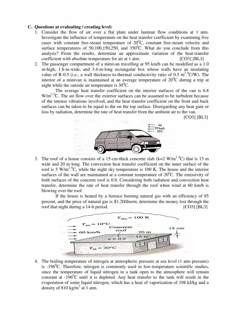
C. Questions at evaluating / creating level: 1. Consider the flow of air over a flat plate under laminar flow conditions at 1 atm.
Investigate the influence of temperature on the heat transfer coefficient by examining five
cases with constant free-steam temperature of 200C, constant free-steam velocity and
surface temperatures of 50,100,150,250, and 3500C. What do you conclude from this
analysis? From the results, determine an approximate variation of the heat-transfer
coefficient with absolute temperature for air at 1 atm. [CO3] [BL3]
2. The passenger compartment of a minivan travelling at 95 km/h can be modelled as a 1.0
m-high, 1.8-m-wide, and 3.4-m-long rectangular box whose walls have an insulating
value of R-0.5 (i.e., a wall thickness-to-thermal conductivity ratio of 0.5 m2.0C/W). The
interior of a minivan is maintained at an average temperature of 200C during a trip at
night while the outside air temperature is 300C.
The average heat transfer coefficient on the interior surfaces of the van is 6.8
W/m2.0C. The air flow over the exterior surfaces can be assumed to be turbulent because
of the intense vibrations involved, and the heat transfer coefficient on the front and back
surfaces can be taken to be equal to the on the top surface. Disregarding any heat gain or
loss by radiation, determine the rate of heat transfer from the ambient air to the van.
[CO3] [BL3]
3. The roof of a house consists of a 15-cm-thick concrete slab (k=2 W/m
2.0C) that is 15 m
wide and 20 m long. The convection heat transfer coefficient on the inner surface of the
roof is 5 W/m2.0C, while the night sky temperature is 100 K. The house and the interior
surfaces of the wall are maintained at a constant temperature of 200C. The emissivity of
both surfaces of the concrete roof is 0.9. Considering both radiation and convection heat
transfer, determine the rate of heat transfer through the roof when wind at 60 km/h is
blowing over the roof.
If the house is heated by a furnace burning natural gas with an efficiency of 85
percent, and the price of natural gas is $1.20/therm, determine the money lost through the
roof that night during a 14-h period. [CO3] [BL3]
4. The boiling temperature of nitrogen at atmospheric pressure at sea level (1 atm pressure)
is -1960C. Therefore, nitrogen is commonly used in low-temperature scientific studies,
since the temperature of liquid nitrogen in a tank open to the atmosphere will remain
constant at -1960C until it is depleted. Any heat transfer to the tank will result in the
evaporation of some liquid nitrogen, which has a heat of vaporization of 198 kJ/kg and a
density of 810 kg/m3 at 1 atm.
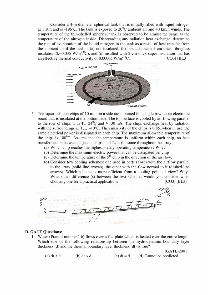
Consider a 4-m diameter spherical tank that is initially filled with liquid nitrogen
at 1 atm and is -1960C. The tank is exposed to 20
0C ambient air and 40 km/h winds. The
temperature of the thin-shelled spherical tank is observed to be almost the same as the
temperature of the nitrogen inside. Disregarding any radiation heat exchange, determine
the rate of evaporation of the liquid nitrogen in the tank as a result of heat transfer from
the ambient air if the tank is (a) not insulated, (b) insulated with 5-cm-thick fibreglass
insulation (k=0.035 W/m2.0C), and (c) insulted with 2-cm-thick super insulation that has
an effective thermal conductivity of 0.00005 W/m2.0C. [CO3] [BL3]
5. Ten square silicon chips of 10 mm on a side are mounted in a single row on an electronic
board that is insulated at the bottom side. The top surface is cooled by air flowing parallel
to the row of chips with T∞=240C and V=30 m/s. The chips exchange heat by radiation
with the surroundings at Tsurr=-100C. The emissivity of the chips is 0.85. when in use, the
same electrical power is dissipated in each chip. The maximum allowable temperature of
the chips is 1000C. Assume that the temperature is uniform within each chip, no heat
transfer occurs between adjacent chips, and T∞ is the same throughout the array.
(a) Which chip reaches the highest steady operating temperature? Why?
(b) Determine the maximum electric power that can be dissipated per chip
(c) Determine the temperature of the 5th
chip in the direction of the air flow.
(d) Consider tow cooling schemes: one used in parts (a)-(c) with the airflow parallel
to the array (solid-line arrows), the other with the flow normal to it (dashed-line
arrows). Which scheme is more efficient from a cooling point of view? Why?
What other difference (s) between the two schemes would you consider when
choosing one for a practical application? [CO3] [BL3]
D. GATE Questions:
1. Water (Prandtl number ˇ 6) flows over a flat plate which is heated over the entire length. Which one of the following relationship between the hydrodynamic boundary layer
thickness (d) and the thermal boundary layer thickness (dt) is true?
[GATE-2001]
(a) dt > d (b) dt < d (c) dt = d (d) Cannot be predicted
2. The properties of mercury at 300 K are: density = 13529 kg/m3, specific heat at constant
pressure = 0.1393 kJ/kg-K, dynamic viscosity =0.1523×10⁻²
N.s/m2 and thermal
conductivity =8.540 W/m-K. The Prandtl number of the mercury at 300 K is
[GATE-2002]
(a) 0.0248 (b) 2.48 (c) 24.8 (d) 248
3. Consider a laminar boundary layer over a heated flat plate. The free stream velocity is
U . At some distance x from the leading edge the velocity boundary layer thickness is
u and the thermal boundary layer thickness is T . If the Prandtl number is greater than 1,
then [GATE-2003]
(a) v T (b)
T v 1/2( )v T U X 1/2
v T X
Common data for Questions 04 and 05
Heat is being transferred by convection from water at 48°C to a glass plate whose surface that is
exposed to the water is at 40°C. The thermal conductivity of water is 0.6 W/mK and the thermal
conductivity of glass is 1.2 W/mK. The spatial gradient of temperature in the water at the water-
glass interface is dT/dy=1×104 K/m.
4. The value of the temperature gradient in the glass at the water-glass interface is K/m is
[GATE-2003]
(a) -2 × 10⁴ (b) 0.0 (c) 0.5 × 10⁴ (d) 2 × 10⁴
5. The heat transfer coefficient h in W/m2 K is [GATE-2003]
(a) 0.0 (b) 4.8 (c) 6 (d) 750
6. For air flow over a flat plate, velocity (U) and boundary layer thickness (d ) can be
expressed respectively, as [GATE-2004] 3
3 1 4.64;
2 2 Rex
U Y Y x
U
If the free stream velocity is 2m/s, and air has kinematic viscosity of 1.5×10⁻⁵
m2/s and
density of 1.23 kg/m3, the wall shear stress at x = 1m, is
(a) 2.36 × 10² N/m
2 (b) 43.6 × 10
-3 N/m
2
(c) 4.36 × 10⁻³N/m2
(d) 2.18 × 10⁻³
N/m2
7. Statement for Linked Answer Questions 85a & 85b: An un-insulated air conditioning duct
of rectangular cross section 1 m × 0.5 m, carrying air at 20°C with a velocity of 10 m/s,
is exposed to an ambient of 30°C. Neglect the effect of duct construction material. For
air in the range of 20-30°C, data are as follows: thermal conductivity =0.025 W/m.K;
viscosity = 18 Pa.s; Prandtl number =0.73; density = 1.2 kg/m3. The laminar flow
Nusselt number is 3.4 for constant wall temperature conditions and, for turbulent flow,
Nu=0.023 Re0.8
Pr0.33
. [GATE-2005]
A) (A) The Reynolds number for the flow is
(a) 444 (b) 890 (c) 4.44×10⁵ (d) 5.33×10⁵
(B) The heat transfer per metre length of the duct, in watts, is:
(a) 3.8 (b) 5.3 (c) 89 (d) 769
8. With an increase in thickness of insulation around a circular pipe, heat loss to
surroundings due to. [GATE-2006]
(A) Convection increases, while that due to conduction decreases
(B) Convection decreases, while that due to conduction increases
(C) Convection and conduction decreases
(D) Convection and conduction increases
9. The temperature distribution within the thermal boundary layer over a heated isothermal
flat plate is given by
3
1
3 1,
2 2
W
W t
T T y y
T T
where Tw and T are the temperatures
of plate and free stream respectively, and y is the normal distance measured from the
plate. The local Nusselt number based on the thermal boundary layer thickness t, is
given by [GATE-2007]
a) 1.33 b) 1.50 c) 2.0 d) 4.64
10. Consider steady one-dimensional heat flow in a plate of 20 mm thickness with a uniform
heat generation of 80 MW/m3. The left faces are kept at constant temperature of 160
0C
and 1200C respectively. The plate has a constant thermal conductivity of 200 W/mK.
[GATE-2007]
1. The location of maximum temperature within the plate from its left face is
a) 15 mm b) 10 mm c) 5 mm d) 0 mm
2. The maximum temperature within the plate in 0C is
a) 160 b) 165 c) 200 d) 250
11. 29. A coolant fluid at 30°C flows over a heated flat plate maintained at a constant
temperature of 100°C. The boundary layer temperature distribution at a given location
on the plate may be approximated as T = 30 + 70exp (−y) where y (in m) is the distance normal to the plate and T is in °C. If thermal conductivity of the fluid is 1.0W/mK, the
local convective heat transfer coefficient (in W/m2K) at that location will be
[GATE-2009]
(A) 0.2 (B) 1 (C) 5 (D) 10
12. Water flows through a pipe having an inner radius of 10 mm at the rate of 36 kg/hr at
250C. The viscosity of water at 25
0C is 0.001 kg/m.s. The Reynolds number of the flow
is _______ [GATE-2014]
13. 47. The non-dimensional fluid temperature profile near the surface of a convectively
cooled flat plate is given by
2
w
w
T T Y Ya b c
T T L L
, where y is measured
perpendicular to the plate, L is the plate length, and a, b and c are arbitrary constants. T
W and T are wall and ambient temperatures, respectively. If the thermal conductivity
of the fluid is k and the wall heat flux is q¢¢ , the Nusselt number w
q LNu
T T k
is
equal to [GATE-2014]
(A) a (B) b (C) 2c (D) (b + 2c)
14. For laminar forced convection over a flat plate, if the free stream velocity increases by a
factor of 2, the average heat transfer coefficient [GATE-2014]
(A) Remains same (B) Decreases by a factor of 2
(C) Rises by a factor of 2 (D) Rises by a factor of 4
15. Consider laminar flow of water over a flat plate of length 1 m. If the boundary layer
thickness at a distance of 0.25 m from the leading edge of the plate is 8 mm, the
boundary layer thickness (in mm), at a distance of 0.75 m, is _______ [GATE-2014]
16. 55. Consider the turbulent flow of a fluid through a circular pipe of diameter, D. Identify
the correct pair of statements. [GATE-2014]
I. The fluid is well-mixed II. The fluid is unmixed
III. Rep < 2300 IV. Rep > 2300
(A) I, III (B) II, IV (C) II, III (D) I, IV
17. Match Group A with Group B: [GATE-2014]
Group A Group B
P: Biot number 1: Ratio of buoyancy to viscous force
Q: Grashof number 2: Ratio of inertia force to viscous force
R: Prandtl number 3: Ratio of momentum to thermal diffusivities
S: Reynolds number 4: Ratio of internal thermal resistance to boundary layer
(A) P-4, Q-1, R-3, S-2 (B) P-4, Q-3, R-1, S-2
(C) P-3, Q-2, R-1, S-4 (D) P-2, Q-1, R-3, S-4
18. Water flows through a tube of diameter 25 mm at an average velocity of 1.0m/s. The
properties of water p=100kg.m3, =7.25 x10
-4N.s/m
2,k=0.625 W/mk, Pr=4.85. Using
Nu = 0.023Re0.8
Pr0.4
, the convective heat transfer coefficient (in W/m2.K) is ______
[GATE-2014]
19. For flow of viscous fluid over a flat plate, if the fluid temperature is the same as the plate
temperature, the thermal boundary layer is [GATE-2015]
A) Thinner than the velocity boundary layer.
B) Thicker than the velocity boundary layer.
C) of the same thickness as the velocity boundary layer
D) not formed at all
20. Air (p=1.2 kg/m3 and kinematic viscosity, v=2x10
-5m
2/s) with a velocity of 2 m/s flows
over the top surface of a flat plate of length 2.5 m. If the average value of friction
coefficient is 1.328
Ref
x
C the total drag force (in N) per unit width of the plate is ____
[GATE-2015]
21. In the laminar flow of air (Pr=0.7) over a heated plate, if and T denote, respectively,
the hydrodynamic and thermal boundary layer thickness, then
[GATE-2015]
A) =T B) >
T C) <T D) =0 but
T 0
22. The ratio momentum diffusivity (v) to thermal diffusivity , is called. [GATE-2015]
A) Prandtl number B) Nusselt number
C) Biot number D) Lewis number
23. A fluid (Prandtl number, Pr = 1) at 500 K flows over a flat plate of 1.5 m length,
maintained at 300 K. The velocity of the fluid is 10 m/s. Assuming kinematic viscosity,
m2/s, the thermal boundary layer thickness (in mm) at 0.5 m from the leading edge is
__________ [GATE-2016]
24. For a hydro-dynamically and thermally fully developed laminar flow through a circular
pipe of constant cross-section, the Nusselt number at constant wall heat flux (Nuq) and
that at constant wall temperature (NuT) are related as [GATE-2019]
A) q TNu Nu B) q TNu Nu C) q TNu Nu
D)
2
q TNu Nu
E. IES / IAS Questions
1. The properties of mercury at 300 K are: density = 13529 kg/m3, specific heat at constant
pressure = 0.1393 kJ/kg-K, dynamic viscosity = 0.1523 x 10⁻² N.s/m2 and thermal
conductivity = 8.540 W/m-K. The Prandtl number of the mercury at 300 K is (a) 0.0248
(b) 2.48 (c) 24.8 (d) 248 [IES-2002]
2. For the fully developed laminar now and heat transfer in a uniformly heated long circular
tube, if the now velocity is doubled and the tube diameter is halved, the heat transfer
coefficient will be [IES-2000]
(a) double of the original value (b) half of the original value
(c) same as before (d) four times of the original value
3. Assertion (A): According to Reynolds analogy for Prandtl number equal to unity. Stanton
number is equal to one half of the friction factor. [IES-2001]
Reason (R): If thermal diffusivity is equal to kinematic viscosity, the velocity and the
temperature distribution in the flow will be the same.
4. The Nusselt number is related to Reynolds number in laminar and turbulent flows
respectively as [IES-2000]
(a) Re-1/2 and Re0.8 (b) Re1/2 and Re0.8 (c) Re-1/2 and Re-0.8 (d) Re1/2 and Re-0.8
5. Match List I with II and select the correct answer using the code given below the Lists:
List I List II
(Non-dimensional Number) (Application)
A. Grashof number 1. Mass transfer
B. Stanton number 2. Unsteady state heat conduction
C. Sherwood number 3. Free convection
D. Fourier number 4. Forced convection
Code: [IES 2007]
A B C D A B C D
(a) 4 3 1 2 (b) 3 4 1 2
(c) 4 3 2 1 (d) 3 4 2 1
6. Match List I (Type of heat transfer) with List II (Governing dimensionless parameter) and
select the correct answer: [IES-2002]
List I List II
A. Forced convection 1. Reynolds, Grashof and Prandtl number
B. Natural convection 2. Reynolds and Prandtl number
C. Combined free and forced convection 3. Fourier modulus and Biot number
D. Unsteady conduction with 4. Prandtl number and Grashof number
convection at surface
A B C D A B C D
(a) 2 1 4 3 (b) 3 4 1 2
(c) 2 4 1 3 (d) 3 1 4 2
7. For steady, uniform flow through pipes with constant heat flux supplied to the wall, what
is the value of Nusselt number? [IES 2007]
(a) 48/11 (b) 11/48 (c) 24/11 (d) 11/24
8. Nusselt number for fully developed turbulent flow in a pipe is given by Nu =
a b
e rNu CR P The values of a and b are [IES-2001]
(a) a = 0.5 and b = 0.33 for heating and cooling both
(b) a = 0.5 and b = 0.4 for heating and b = 0.3 for cooling
(c) a = 0.8 and b = 0.4 for heating and b = 0.3 for cooling
(d) a = 0.8 and b = 0.3 for heating and b = 0.4 for cooling
9. Match List - I with List - II and select the correct answer using the code given below
the Lists: [IES-2006]
List - I (Phenomenon) List – II (Associated Dimensionless Parameter)
A. Transient conduction 1. Reynolds number
B. Forced convection 2. Grashoff number
C. Mass transfer 3. Biot number
D. Natural convection 4. Mach number
5. Sherwood number
A B C D A B C D
(a) 3 2 5 1 (b) 5 1 4 2
(c) 3 1 5 2 (d) 5 2 4 1
10. Nusselt number for a pipe flow heat transfer coefficient is given by the equation
NuD=4.36. Which one of the following combinations of conditions do exactly apply for
use of this equation? [IES-2006]
(a) Laminar flow and constant will temperature
(b) Turbulent flow and constant wall heat flux
(c) Turbulent flow and constant wall temperature
(d) Laminar flow and constant wall heat flux
11. A fluid of thermal conductivity 1.0 W/m-K flows in fully developed flow with Reynolds
number of 1500 through a pipe of diameter 10 cm. The heat transfer coefficient for
uniform heat flux and uniform wall temperature boundary conditions are, respectively.
[IES-2002]
(a) 2
36.57 43.64W
andm K
(b) 2
43.64 36.57W
andm K
(c) 2
43.64W
for boththecasesm K
(d) 2
36.57W
for boththecasesm K
12. Which one of the following stems is correct? [IES-2004]
The non-dimensional parameter known as Stanton number (St) is used in
(a) Forced convection heat transfer in flow over flat plate
(b) Condensation heat transfer with laminar film layer
(c) Natural convection heat transfer over flat plate
(d) Unsteady heat transfer from bodies in which internal temperature gradients cannot
be neglected
13. For fully-developed turbulent flow in a pipe with heating, the Nusselt number Nu, varies
with Reynolds number Re and Prandtl number Pr as [IES-2003]
(a) 1
0.5 3e rR P (b)
0.8 0.2
e rR P (c) 0.8 0.4
e rR P (d) 0.8 0.3
e rR P
14. For laminar flow over a flat plate, the local heat transfer coefficient ‘hx’ varies as x-1/2
,
where x is the distance from the leading edge (x=0) of the plate. The ratio of the average
coefficient ‘ha’ between the leading edge and some location ‘A’ at x=x on the plate to the
local heat transfer coefficient ‘hx’ at A is [IES-1999]
(a) 1 (b) 2 (c) 4 (d) 8
15. The ratio of energy transferred by convection to that by conduction is called
(a) Stanton number (b) Nusselt number (c) Biot number (d) Preclet number
Prepared by: Dr.P.Nageswara Reddy
Academic Year: 2019 – 20 Semester: II
Class : III B.Tech Subject: Heat Transfer
Learning Material
UNIT-IV
Syllabus Free Convection: Development of Hydrodynamic and thermal boundary layer along a
vertical plate, Use of empirical relations for Vertical plates and cylinders.
Heat Transfer with Phase Change:
Boiling: Pool boiling, Regimes-Nucleate boiling and Film boiling, Critical Heat flux, Flow
boiling.
Condensation: Film wise and drop wise condensation, Film condensation on vertical and
horizontal cylinders, using empirical correlations.
4.1 PHYSICAL MECHANISM OF NATURAL CONVECTION
In natural (or free) convection, the fluid motion is caused by buoyancy forces that are
induced by density differences due to the variation of temperature in the fluid.
Many familiar heat transfer applications involve natural convection as the primary
mechanism of heat transfer. Some examples are cooling of electronics equipment such
as power transistors, TVs, and DVDs; heat transfer from electric baseboard heaters or
steam radiators: heat transfer from the refrigeration coils and power transmission
lines; and heat transfer from the bodies of animals and human beings.
4.1.1 Natural Convection from a Vertical Plate
Consider a vertical hot flat plate immersed in a quiescent fluid body. We assume the
natural convection flow to be steady, laminar, and two-dimensional, and the fluid to be
Newtonian with constant properties, including density, with one exception: the density
difference ρ-ρ∞ is to be considered since it is this density difference between the inside and
the outside of the boundary layer that gives rise to buoyancy force and sustains flow. We take
the upward direction along the plate to be x, and the direction normal to surface to be y, as
shown in Fig. 4.1. Therefore, gravity acts in the –x direction.
The velocity and temperature profiles for natural convection over a vertical hot plates
are also shown in Fig.4.1. Note that as in forced convection, the thickness of the boundary
layer increases in the flow direction. Unlike forced convection, however, the fluid velocity is
zero at the outer edge of the velocity boundary layer as well as at the surface of the plate.
This is expected since the fluid beyond the boundary layer is motionless. Thus, the fluid
velocity increases with distance from the surface, reaches a maximum, and gradually
decreases to zero at a distance sufficiently far from the surface. At the surface, the fluid
temperature is equal to the plate temperature, and gradually decreases to the temperature of
the surrounding fluid at a distance sufficiently far from the surface, as show in the figure. In
the case of cold surfaces, the shape of the velocity and temperature profiles remains the same
but their direction is reversed.
Figure 4.1: Typical velocity and temperature profiles for natural convection flow over
a hot vertical plate at temperature Ts inserted in a fluid at temperature T∞.
4.1.2 Natural Convection from a Horizontal Plate
The rate of heat transfer to or from a horizontal surface depends on whether the surface is
facing upward or downward. For a hot surface in a cooler environment, the net force acts
upward, forcing rises freely, inducing strong natural convection currents and thus effective
heat transfer, as shown in Fig. 4.2. But if the hot surface is facing downward, the plate blocks
the heated fluid that tends to rise (except near edges), impending heat transfer. The opposite
is true for a cold plate in a warmer environment since the net force (weight minus buoyancy
force) in the case acts downward, and the cooled fluid near the plate tends to descend.
Figure 4.2: Natural convection flows on the upper and lower surfaces of a horizontal hot
plate.
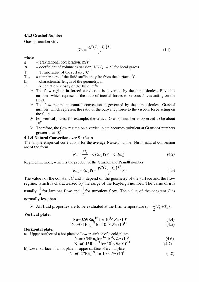
4.1.3 Grashof Number
Grashof number GrL,
3
2
s c
L
g T T LGr
v
(4.1)
where
g = gravitational acceleration, m/s2
= coefficient of volume expansion, 1/K ( =1/T for ideal gases)
Ts = Temperature of the surface, 0C
T = temperature of the fluid sufficiently far from the surface, 0C
Lc = characteristic length of the geometry, m
= kinematic viscosity of the fluid, m2/s
The flow regime in forced convection is governed by the dimensionless Reynolds
number, which represents the ratio of inertial forces to viscous forces acting on the
fluid.
The flow regime in natural convection is governed by the dimensionless Grashof
number, which represent the ratio of the buoyancy force to the viscous force acting on
the fluid.
For vertical plates, for example, the critical Grashof number is observed to be about
109.
Therefore, the flow regime on a vertical plate becomes turbulent at Granshof numbers
greater than 109.
4.1.4 Natural Convection over Surfaces
The simple empirical correlations for the average Nusselt number Nu in natural convection
are of the form
( Pr)n ncL L
hLNu C Gr C Ra
k (4.2)
Reyleigh number, which is the product of the Grashof and Prandlt number
3
2Pr Pr
s c
L L
g T T LRa Gr
v
(4.3)
The values of the constant C and n depend on the geometry of the surface and the flow
regime, which is characterized by the range of the Rayleigh number. The value of n is
usually 1
4for laminar flow and
1
3for turbulent flow. The value of the constant C is
normally less than 1.
All fluid properties are to be evaluated at the film temperature1
( )2
f ST T T .
Vertical plate:
Nu=0.59RaL1/4
for 104< Ra <10
9 (4.4)
Nu=0.1RaL1/3
for 1010
< Ra <1013
(4.5) Horizontal plate:
a) Upper surface of a hot plate or Lower surface of a cold plate:
Nu=0.54RaLfor 1/4
104< Ra <10
7 (4.6)
Nu=0.15RaL1/3
for 107< Ra <10
11 (4.7)
b) Lower surface of a hot plate or upper surface of a cold plate
Nu=0.27RaL1/4
for 105< Ra <10
11 (4.8)
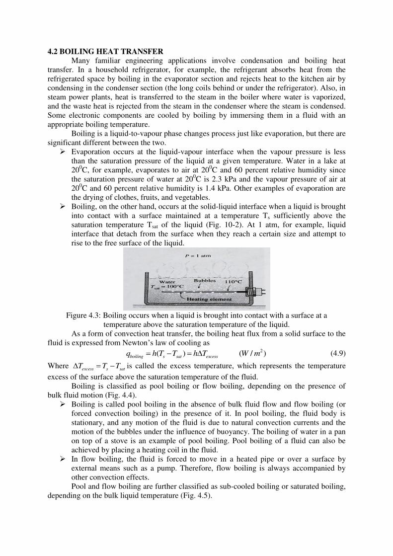
4.2 BOILING HEAT TRANSFER
Many familiar engineering applications involve condensation and boiling heat
transfer. In a household refrigerator, for example, the refrigerant absorbs heat from the
refrigerated space by boiling in the evaporator section and rejects heat to the kitchen air by
condensing in the condenser section (the long coils behind or under the refrigerator). Also, in
steam power plants, heat is transferred to the steam in the boiler where water is vaporized,
and the waste heat is rejected from the steam in the condenser where the steam is condensed.
Some electronic components are cooled by boiling by immersing them in a fluid with an
appropriate boiling temperature.
Boiling is a liquid-to-vapour phase changes process just like evaporation, but there are
significant different between the two.
Evaporation occurs at the liquid-vapour interface when the vapour pressure is less
than the saturation pressure of the liquid at a given temperature. Water in a lake at
200C, for example, evaporates to air at 20
0C and 60 percent relative humidity since
the saturation pressure of water at 200C is 2.3 kPa and the vapour pressure of air at
200C and 60 percent relative humidity is 1.4 kPa. Other examples of evaporation are
the drying of clothes, fruits, and vegetables.
Boiling, on the other hand, occurs at the solid-liquid interface when a liquid is brought
into contact with a surface maintained at a temperature Ts sufficiently above the
saturation temperature Tsat of the liquid (Fig. 10-2). At 1 atm, for example, liquid
interface that detach from the surface when they reach a certain size and attempt to
rise to the free surface of the liquid.
Figure 4.3: Boiling occurs when a liquid is brought into contact with a surface at a
temperature above the saturation temperature of the liquid.
As a form of convection heat transfer, the boiling heat flux from a solid surface to the
fluid is expressed from Newton’s law of cooling as
2( ) ( / )boiling s sat excessq h T T h T W m (4.9)
Where excess s satT T T is called the excess temperature, which represents the temperature
excess of the surface above the saturation temperature of the fluid.
Boiling is classified as pool boiling or flow boiling, depending on the presence of
bulk fluid motion (Fig. 4.4).
Boiling is called pool boiling in the absence of bulk fluid flow and flow boiling (or
forced convection boiling) in the presence of it. In pool boiling, the fluid body is
stationary, and any motion of the fluid is due to natural convection currents and the
motion of the bubbles under the influence of buoyancy. The boiling of water in a pan
on top of a stove is an example of pool boiling. Pool boiling of a fluid can also be
achieved by placing a heating coil in the fluid.
In flow boiling, the fluid is forced to move in a heated pipe or over a surface by
external means such as a pump. Therefore, flow boiling is always accompanied by
other convection effects.
Pool and flow boiling are further classified as sub-cooled boiling or saturated boiling,
depending on the bulk liquid temperature (Fig. 4.5).
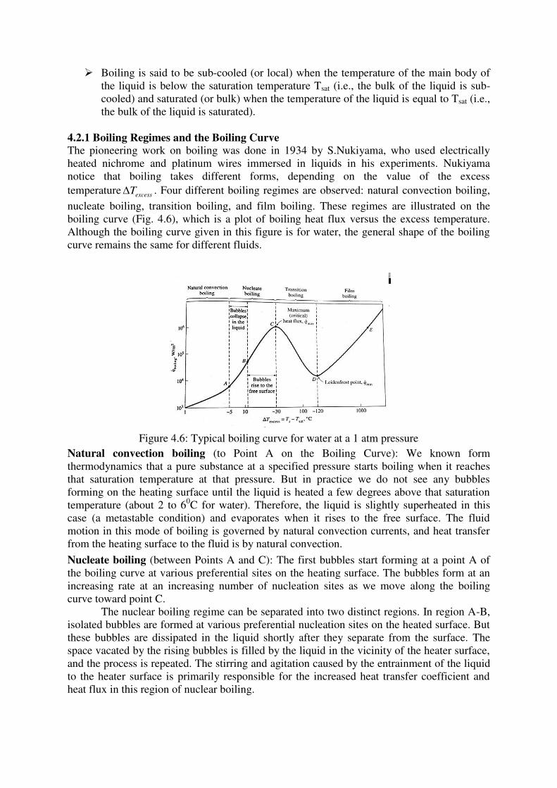
Boiling is said to be sub-cooled (or local) when the temperature of the main body of
the liquid is below the saturation temperature Tsat (i.e., the bulk of the liquid is sub-
cooled) and saturated (or bulk) when the temperature of the liquid is equal to Tsat (i.e.,
the bulk of the liquid is saturated).
4.2.1 Boiling Regimes and the Boiling Curve
The pioneering work on boiling was done in 1934 by S.Nukiyama, who used electrically
heated nichrome and platinum wires immersed in liquids in his experiments. Nukiyama
notice that boiling takes different forms, depending on the value of the excess
temperatureexcessT . Four different boiling regimes are observed: natural convection boiling,
nucleate boiling, transition boiling, and film boiling. These regimes are illustrated on the
boiling curve (Fig. 4.6), which is a plot of boiling heat flux versus the excess temperature.
Although the boiling curve given in this figure is for water, the general shape of the boiling
curve remains the same for different fluids.
Figure 4.6: Typical boiling curve for water at a 1 atm pressure
Natural convection boiling (to Point A on the Boiling Curve): We known form
thermodynamics that a pure substance at a specified pressure starts boiling when it reaches
that saturation temperature at that pressure. But in practice we do not see any bubbles
forming on the heating surface until the liquid is heated a few degrees above that saturation
temperature (about 2 to 60C for water). Therefore, the liquid is slightly superheated in this
case (a metastable condition) and evaporates when it rises to the free surface. The fluid
motion in this mode of boiling is governed by natural convection currents, and heat transfer
from the heating surface to the fluid is by natural convection.
Nucleate boiling (between Points A and C): The first bubbles start forming at a point A of
the boiling curve at various preferential sites on the heating surface. The bubbles form at an
increasing rate at an increasing number of nucleation sites as we move along the boiling
curve toward point C.
The nuclear boiling regime can be separated into two distinct regions. In region A-B,
isolated bubbles are formed at various preferential nucleation sites on the heated surface. But
these bubbles are dissipated in the liquid shortly after they separate from the surface. The
space vacated by the rising bubbles is filled by the liquid in the vicinity of the heater surface,
and the process is repeated. The stirring and agitation caused by the entrainment of the liquid
to the heater surface is primarily responsible for the increased heat transfer coefficient and
heat flux in this region of nuclear boiling.
In region B-C, the heater temperature is further increased, and bubbles form at such
greater rates at such a large number of nucleation sites that they form numerous continuous
columns of vapour in the liquid. These bubbles move all the way up to the free surface, where
they break up and release their vapour content. The large heat fluxes obtainable in this region
are caused by the combined effect of liquid entertainment and evaporation.
At large values of excessT , the rate of evaporation at the heater surface reaches such
high values that a large fraction of the heater surface is covered by bubbles, making it
difficult for the liquid to reach the heater surface and wet it. Consequently, the heat flux
increases at a lower rate with increasingexcessT , and reaches a maximum at point C. the heat
flux at his point is called the critical (or maximum) heat fluxexcessT .
For water, the critical heat flux exceeds 1 MW/m2.
Transition boiling (between Points C and D): As the heater temperature and thus the excessT
is increased past point C, the heat flux decreases, as shown in Fig. 4.6. This is because a large
fraction of the heater surface is covered by a vapour film, which acts as an insulation due to
the low thermal conductivity of the vapour relative to that of the liquid. In the transition
boiling regime, both nucleate and film boiling partially occur. Nucleate boiling at point C is
completely replaced by film boiling regime, which is also called the unstable film boiling
regime, is avoided in practice.
For water, transition boiling occurs over the excess temperature range from about
300C to about 120
0C.
Film boiling (beyond Point D): In this region the heater surface is completely covered by a
continuous stable vapour film. Point D, where the heat flux reaches a minimum, is called the
Leidenfrost point, in honour of J.C.Leidenfrost, who observed in 1756 that liquid droplets on
a very hot surface jump around and slowly boil away. The presence of a vapour film between
the heater surface and the liquid is responsible for the low heat transfer rates in the film
boiling region. The heat transfer rate increases with increasing excess temperature as a result
of heat transfer from the heated surface to the liquid through the vapour film by radiation,
which becomes significant at high temperatures.
Nukiyama noticed, with surprise, that when the power applied to the nichrome wire
immersed in water exceeded qmax even slightly, the wire temperature increased
suddenly to the melting point of the wire and burnout occurred beyond his control.
The burnout phenomenon in boiling can be explained as follows: In order to move
beyond point C where qmax occurs, we must increase the heater surface temperature
Ts, to increase Ts, however, we most increase the heat flux. But the fluid cannot
receive this increased energy at an excess temperature just beyond point C. Therefore,
the heater surface ends up absorbing the increased energy, causing the heater surface
temperature Ts to rise. But the fluid can receive even less energy at this increased
excess temperature, causing the heater surface temperature Ts to rise even further.
This is point E on the boiling curve, which corresponds to very high surface
temperatures. Therefore, any attempt to increase the heat flux beyond qmax will cause
the operation point on the boiling curve to jump suddenly from point C to point E.
However, surface temperature that corresponds to point E is beyond the melting point
of most heater materials, and burnout occurs. Therefore, point C on the boiling curve
is also called the burnout point, and the heat flux at this point the burnout heat flux.
4.2.2 Heat Transfer Correlations in Pool Boiling
4.2.2.1 Nuclear boiling
The most widely used correlation for the rate of heat transfer in the nucleate boiling regime
was proposed in 1952 by Rohsenow, and expressed as
1/2
1
1Pr
pl s satv
nucleat fg n
sf fg l
c T Tgq h
C h
(4.10)
where
qnucleate = nucleate boiling heat flux, W/m2
l = viscosity of the liquid, kg/m.s
hfg = enthalpy of vaporization, J/kg
g = gravitational acceleration, m/s2
1 = density of the liquid, kg/m
3
v = density of the vapour, kg/ m
3
= surface tension of liquid-vapour interface, N/m
cpl = specific heat of the liquid, J/kg.oC
Ts = surface temperature of the heater, oC
Tsat = surface temperature of the fluid, oC
Csf = experimental constant that depends on surface-fluid combination
Prl = Prendtl number of the liquid.
n = experimental constant that depends on the fluid.
Values of the coefficient Csf and n for various fluid-surface combinations are given in Table
4.1.
Table 4.1: Values of the coefficient Csf and n for various fluid-surface combinations
Fluid-Heating surface Combination Csf n
-----------------------------------------------------------------------------------------------------
Water – copper (polished) 0.0130 1.0
Water – copper (scored) 0.0068 1.0
Water – stainless steel (mechanically polished) 0.0130 1.0
Water – stainless steel (ground and polished) 0.0060 1.0
Water – stainless steel (Teflon pitted) 0.0058 1.0
Water – stainless steel (chemically etched) 0.0130 1.0
Water – brass 0.0060 1.0
Water – nickel 0.0060 1.0
Water – platinum 0.0130 1.0
n-Pentane-copper (polished) 0.0154 1.7
n-Pentane-chromium 0.0150 1.7
Benzene –chromium 0.1010 1.7
Ethyl alcohol-chromium 0.0027 1.7
Carbon tetrachloride-copper 0.0130 1.7
Isopropanol-copper 0.0025 1.7
The maximum (or critical) heat flux in nucleate pool boiling was determined theoretically by
S.S.Kutateladze in Russia in 1948 and N.Zuber in the United States in 1958 using quite
different approaches, and is expressed as 1/4
2 ( )mass cr fg v l v
q C h g (4.11)
Where Ccr is a constant whose value depends on the heater geometry
Table 4.2: Value of the coefficient Ccr for use in Eq. 4.1.1 for maximum heat flux
(dimensionless parameter 1/2* [ ( ) / ]l vL L g )
Heater Geometry Ccr
Charac.
Dimension
of Heater, L Range of L*
Large horizontal flat heater 0.149 Width or diameter L* > 27
Small horizontal flat hater1 18.9 K1 Width or diameter 9< L* > 20
Large horizontal cylinder 0.12 Radius L* > 1.2
Small horizontal cylinder 0.12 L*-0.25
Radius 0.15 < L* > 27
Large sphere 0.11 Radius L* > 4.26
Small sphere 0.227 L*-0.5
Radius 0.15 < L* > 4.26
4.2.2.2 Film boiling: The heat flux for film boiling on a horizontal cylinder or sphere of diameter d is given by
1/4
3 0.4v v l v fg pv s sat
film film s sat
v s sat
gk h c T Tq C T T
D T T
(4.12)
Where kv is the thermal conductivity of the vapour in W/m.0C and
0.62
0.67film
for horizontal cylinderC
for sphere
(4.13)
4.2.3 Flow Boiling:
In flow boiling, the fluid is forced to move by an external source such as a pump as it
undergoes a phase-change process. The boiling in this case exhibits the combined effects of
convection and pool boiling. The flow boiling is also classified as either external or internal
flow boiling depending on whether the fluid is forced to flow over a heated surface or inside
a heated tube.
The different stages encountered in flow boiling in a heated tube are illustrated in Fig.
4.7 together with the variation of the heat transfer coefficient along the tube. Initially, the
liquid is sub-cooled and heat transfer to the liquid is by forced convection. Then bubbles start
forming on the inner surfaces of the tube, and the detached bubbles are drafter into the
mainstream. This gives the fluid flow a bubbly appearance, and thus the name bubbly flow
regime. As the fluid is heated further, the bubbles grow in size and eventually coalesce into
slugs of vapour. Up to half of the volume in the tube in this slug flow regime is occupied by
vapour. After a while the core of the flow consists of vapour only, and the liquid is confined
only in the annular space between the vapour core and the tube walls. This is the annular-
flow regime, and very high heat transfer coefficients are realized in this regime. As the
heating continues, the annular liquid layer gets thinner and thinner, and eventually dry spots
start to appear on the inner surfaces of the tube. The appearance of dry spots is accompanied
by a sharp decrease in the heat transfer coefficient. This transition regime continues until the
inner surface of the tube is completely dry. Any liquid at his moment is in the form of
droplets suspended in the vapour core, which resemble a mist, and we have a mist-flow
regime until all the liquid droplets are vaporized. At the end of the mist-flow regime we have
saturated vapour, which becomes superheated with any further heat transfer.
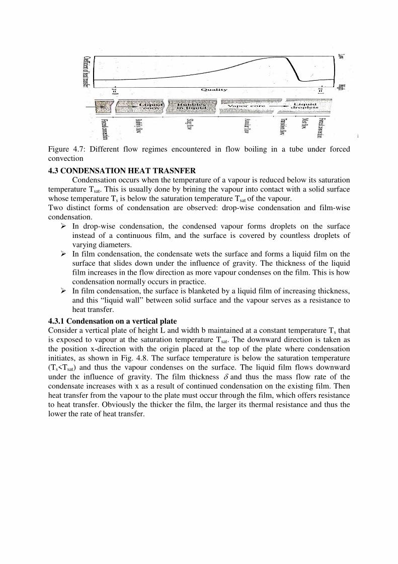
Figure 4.7: Different flow regimes encountered in flow boiling in a tube under forced
convection
4.3 CONDENSATION HEAT TRASNFER
Condensation occurs when the temperature of a vapour is reduced below its saturation
temperature Tsat. This is usually done by brining the vapour into contact with a solid surface
whose temperature Ts is below the saturation temperature Tsat of the vapour.
Two distinct forms of condensation are observed: drop-wise condensation and film-wise
condensation.
In drop-wise condensation, the condensed vapour forms droplets on the surface
instead of a continuous film, and the surface is covered by countless droplets of
varying diameters.
In film condensation, the condensate wets the surface and forms a liquid film on the
surface that slides down under the influence of gravity. The thickness of the liquid
film increases in the flow direction as more vapour condenses on the film. This is how
condensation normally occurs in practice.
In film condensation, the surface is blanketed by a liquid film of increasing thickness,
and this “liquid wall” between solid surface and the vapour serves as a resistance to
heat transfer.
4.3.1 Condensation on a vertical plate
Consider a vertical plate of height L and width b maintained at a constant temperature Ts that
is exposed to vapour at the saturation temperature Tsat. The downward direction is taken as
the position x-direction with the origin placed at the top of the plate where condensation
initiates, as shown in Fig. 4.8. The surface temperature is below the saturation temperature
(Ts<Tsat) and thus the vapour condenses on the surface. The liquid film flows downward
under the influence of gravity. The film thickness and thus the mass flow rate of the
condensate increases with x as a result of continued condensation on the existing film. Then
heat transfer from the vapour to the plate must occur through the film, which offers resistance
to heat transfer. Obviously the thicker the film, the larger its thermal resistance and thus the
lower the rate of heat transfer.
Figure 4.8: Condensation on vertical plate
4.3.2 Film Condensation - Heat Transfer Correlations for Film Condensation
Vertical plates:
The thickness of film at any position x along the plate is given as
1/4
1 1
1 1
4 ( )( )
( )
sat s
v fg
k T T xx
g h
(4.14)
The heat transfer rate from the vapour to the plate at a location x in laminar region can be
expressed as
1/43
1( )
4 ( )
l l v fg
x
l sat s
g h kh
T T x
(4.15)
The average heat transfer coefficient over the entire plate in laminar region is determined
from its definition by substituting the hx relation and performing the integration. It gives 1/4
3
1
0
( )1 40.943
3 ( )
L l l v fg
avg x x L
l sat s
g h kh h h dx h
L T T L
2 0( / . ), 0 Re 30W m C (4.16)
where
g = gravitation acceleration, m/s2
pl,pv = densities of the liquid and vapour, respectively, kg/m3
l = viscosity of the liquid, kg/m.s
*
fgh = latent heat of vaporization, J/kg
k1 = thermal conductivity of the liquid, W/m.0C
L = height of the vertical plate, m
Ts = surface te4mperatur of the plate, 0C
Tsat = saturation temperature of the condensing fluid, 0C
Horizontal Tubes and Spheres
Nusselt’s analysis of film condensation on vertical plates can also be extended to horizontal
tubes and spheres. The average heat transfer coefficient for film condensation on the outer
surfaces of a horizontal tube is determined to be
1/4* 3
1 2 0( )
0.729 ( / . )( )
l l v fg
vert
l sat s
g h kh W m C
T T D
(4.17)
Where D is the diameter of the horizontal tube, Equation 10-31 can easily be modified for as
sphere by replacing he constant 0.729 by 0.815.
A comparison of the heat transfer coefficient relations for a vertical tube of height L and a
horizontal tube of diameter D yields.
1/4
1.29vert
horiz
h D
h L
(4.18)
Horizontal Tube Banks Horizontal tubes stacked on top of each other as shown in Fig. 10-28 are commonly used in
condenser design. The average thickness of the liquid film at the lower tubes is much larger
as a result of condensate falling on top of them from the tubes directly above. Therefore, the
average heat transfer coefficient at the lower tubes in such arrangements is smaller.
1/4* 3
1
, ,11/4
( ) 10.729
( )
l l v fg
horiz N tubes horiz tube
l sat s
g h kh h
T T ND N
(4.19)
A. Questions at remembering / understanding level:
I) Objective Questions 1. For the natural convection heat transfer from a vertical plate, which of the following
is/are true? [CO4][BL2]
i. The thickness of the boundary layers increases along the plate from the bottom to
the top when the surface temperature is less than the fluid temperature.
ii. The thickness of the boundary layers increases along the plate from the top to the
bottom when the surface temperature is less than the fluid temperature.
iii. The thickness of the boundary layers increases along the plate from the bottom to
the top when the surface temperature is more than the fluid temperature.
iv. The thickness of the boundary layers increases along the plate from the top to the
bottom when the surface temperature is more than the fluid temperature.
a) i & iii b) ii & iv c) ii & iii d) ii only
2. Which of the following statement(s) is/are true for the natural convection heat transfer
from a horizontal plate? [CO4][BL2]
i. The rate of heat transfer is more when the hot surface faces up.
ii. The rate of heat transfer is less when the hot surface faces up.
iii. The rate of heat transfer is more when the cold surface faces down
iv. The rate of heat transfer is less when the cold surface faces down.
a) ii & iv b) i & iii c) ii & iii d) ii only
3. Consider laminar natural convection from a vertical hot-plate. Which of the following
statement is correct? [CO4][BL2]
a. The heat flux is higher at the top.
b. The heat flux is higher at the bottom.
c. The heat flux remains the same along the entire length of the plate.
d. Depends on fluid temperature.

4. Will a hot horizontal plate whose back side is insulated cool faster or slower or
remains same when it’s hot surface is facing down instead of up? [CO4][BL2]
a. Faster b. slower c. remains same d. can’t say
5. What is the reason for heater coil burnout in pool boiling? [CO5][BL2]
a. Rate of heat transfer from the surface is reduced due to formation of liquid
film.
b. Rate of heat transfer from the surface is reduced due to formation of vapour
film.
c. Excessive excess temperature.
d. None of the above.
6. Assertion (A): In film boiling, the rate of heat transfer decreases with increase in
excess temperature when radiation effects are minimal.
Reason (R): The rate of heat transfer is reduced as the heating surface is blanketed
with vapour bubbles [CO5][BL2]
a. Both A and R are correct. R is the correct explanation of A.
b. Both A and R are correct. R is not the correct explanation of A.
c. A is correct and R is wrong.
d. R is correct and A is wrong.
7. Assertion (A): The heat transfer rates experienced in drop wise condensation are
higher than those experienced in film wise condensation.
Reason (R): In drop wise condensation, the surface of the tube is more exposed to hot
steam without any film barrier between the surface and steam. [CO5][BL2]
a. Both A and R are correct. R is the correct explanation of A.
b. Both A and R are correct. R is not the correct explanation of A.
c. A is correct and R is wrong.
d. R is correct and A is wrong.
8. Assertion (A): The heat transfer rates experienced in film wise condensation are
lower than those experienced in drop wise condensation.
Reason (R): In film wise condensation, a blanket of vapour film is formed over the
surface of the tube and hence heat transfer rate is reduced. [CO5][BL2]
a. Both A and R are correct. R is the correct explanation of A.
b. Both A and R are correct. R is not the correct explanation of A.
c. A is correct and R is wrong.
d. R is correct and A is wrong.
II) Descriptive Questions 1. What is natural convection? How does it differ from forced convection? What force
causes natural convection currents? [CO4][BL2]
2. Define the Grashof number. What is its physical significance? How does the Rayleigh
number differ from the Grashof number? [CO4][BL2]
3. Explain the development of boundary layers in natural convection from a vertical
plate with neat sketches. [CO4][BL2]
4. Draw the boiling curve and identify the different boiling regimes. Also, explain the
characteristics of each regime. [CO5][BL2]
5. Distinguish between nucleate and film boiling. [CO5][BL2]
6. Draw the boiling curve and identify the burnout point on the curve. Explain how
burnout is caused. Why is the burnout point avoided in the design of boilers?
[CO5][BL2]
7. What is the difference between film and drop-wise condensation? Which is a more
effective mechanism of heat transfer? [CO5][BL2]
8. Consider film condensation on the outer surfaces of tube whose length is 10 times it
diameter. For which orientation of the tube, will the heat transfer rate be the highest:
horizontal or vertical? Explain. Disregard the base and top surfaces of the tube.
[CO5][BL2]
B. Question at applying / analyzing level
I) Multiple choice questions.
Common data for questions 1, 2 and 3.
A large vertical plate 4.0 m high is maintained at 600C and exposed to atmospheric air at
100C. [CO4][BL3]
1. The Rayleigh number is ----
a. 4.62 × 10¹⁰
b. 2.62 × 10¹¹
c. 2.62 × 10¹¹
d. 4.62 × 10¹¹
2. The average heat transfer coefficient (W/m2.K) is -----
a. 4.80 b. 3.80 c. 2.80 d. 5.80
3. The rate of heat transfer (W) if the plate is 10 m wide is -----
a. 8600 b. 6600 c. 7600 d. 9600
Common data for questions 4, 5, and 6.
A vertical square plate, 30 by 30 cm, is exposed to steam at atmospheric pressure. The plate
temperature is 980C. [CO5][BL3]
4. The condensing heat transfer coefficient (W/m2.K) is ----
a. 13150 b. 11150 c. 14150 d. 16150
5. The rate of heat transfer (W) is ---------
a. 1367 b. 1867 c. 2367 d. 2867
6. The mass of steam condensed in kg per hour is --------
a. 1.78 b. 2.78 c. 4.78 d. 3.78
Common data for questions 7, 8, and 9.
Water is to be boiled at atmospheric pressure in a mechanically polished stainless steel pan
placed on top of a heating unit. The inner surface of the bottom of the pan is maintained at
1080C. The diameter of the bottom of the pan is 30 cm. [CO5][BL3]
7. The heat flux (W/m2) in nucleate boiling is ------
a. 7.21 × 10⁴ b. 5.21 × 7
4 c. 2.21 × 10
4 d. 1.21 × 10
4
8. The rate of heat transfer (W) during nucleate boiling is -----
a. 2097 b. 3097 c. 5097 d. 7097
9. The rate of evaporation of water (kg/s) is -----------
a. 1.26 × 10⁻³
b. 2.26 × 10⁻³
c. 3.26 × 10⁻³
d. 4.26 × 10⁻³
II) Problems 1. A 40 cm square vertical plate is heated electrically such that a constant-heat-flux
condition is maintained with a total heat dissipation of 40 W. The ambient air is at 1
atm and 200C. Calculate the value of the heat-transfer coefficient at a height of 15 cm.
Also calculate the average heat-transfer coefficient for the plate. [CO4][BL3]
2. A vertical flat plate is maintained at a constant temperature of 50.00C and exposed to
atmospheric air at 25.00C. At a distance of 40.0 cm. from the leading edge of the plate
the boundary layer thickness is 2.54 cm. Estimate the thickness of the boundary layer
at a distance of 61 cm from the leading edge. [CO4][BL3]
3. A 20 by 20 cm vertical plate is fitted with an electric heater which produces a constant
heat flux of 900 W/m2. The plate is submerged in water at 20
0C. Calculate the heat
transfer coefficient and the average temperature of the plate. How much heat would
be lost by an isothermal surface at this average temperature? [CO4][BL4]
4. A horizontal pipe 5.0 cm in diameter is located in a room where atmospheric air is at
250C. The surface temperature of the pipe is 150
0C. Calculate the free-convection heat
loss per meter length of pipe. [CO4][BL3]
5. Consider a 0.5 m × 0.5 m thin square plate in a room at 250C. One side of the plate is
maintained at a temperature of 1000C, while the other side is insulated. Determine the
rate of heat transfer from the plate by natural convection if the plate is (a) vertical, (b)
horizontal with hot surface facing up, and (c) horizontal with hot surface facing down.
[CO4][BL4]
6. A large vertical plate 6.0 m high and 1.20 m wide is maintained at a constant
temperature of 600C and exposed to atmospheric air 5
0C. Calculate the heat lost by
the plate. [CO4][BL3]
7. A 30 cm square vertical plat is maintained at 900C and exposed to saturated water
vapor at 1 atm pressure. Calculate the condensation rate and film thickness at the
bottom of the plate. [CO5][BL3]
8. A 5 mm diameter copper heater rod is submerged in water at 1 atm. The temperature
excess is 110C. Estimate the hat loss per unit length of the rod. [CO5][BL3]
9. Water is boiled at 900C by a horizontal brass heating element of diameter 5 mm.
determine the maximum heat flux that can be attained in the nucleate boiling regime.
[CO5][BL3]
10. Water is boiled at 1000C by a 0.5 m long and 1.2 cm diameter nickel-plated electric
heating element maintained at 1250C. Determine (a) the boiling heat transfer
coefficient, (b) the electric power consumed by the heating element, and (c) the rate of
evaporation of water. [CO5][BL4]
11. A 60 cm long 2.5 cm diameter brass heating element is to be used to boil water at
1200C. If the surface temperature of the heating element is not to exceed 130
0C,
determine the highest rate of steam production in the boiler, in kg/h. [CO5][BL3]
12. Saturated steam at 500C is to be condensed at a rate of 8 kg/h on the outside of a 2.5
cm outer diameter vertical tube whose surface is maintained at 400C by the cooling
water. Determine the required tube length. [CO5][BL3]
13. The condenser of a steam power plant operates at a pressure of 4.50 kPa. The
condenser consists of 100 horizontal tubes arranged in a 10 x 10 square array. The
tubes are 6 m long and have an outer diameter of 2.5 cm. If the tube surfaces are at
220C, determine (a) the rate of heat transfer from the steam to the cooling water and
(b) the rate of condensation of steam in the condenser. [CO5][BL4]
14. Saturated steam at 450C is condensed on a 1.5 m high vertical plate that is maintained
at 350C. Determine the rate of heat transfer from the steam to the plate and the rate of
condensation per meter width of the plate. [CO5][BL3]
15. Consider a 15 cm × 20 cm printed circuit board (PCB) that has electronic component
on one side. The board is placed in a room at 200C. The heat loss from the back
surface of the board is negligible. If the circuit board is dissipating 8 W of power in
steady operation, determine the average temperature of the hot surface of the board,
assuming the board (a) vertical; (b) horizontal with hot surface facing up; and (c)
horizontal with hot surface facing down. Assume the surrounding surfaces to be at the
same temperature as the air in the room. [CO4][BL4]
C. Questions at evaluating / creating level: 1. Consider a 1.2 m high and 2 m wide glass window with a thickness of 6 mm, thermal
conductivity k = 0.78 W/m.0C, and emissivity ε=0.9. The room and the walls that face
the window are maintained at 250C, and the average temperature of the inner surface
of the outdoors is -50C, determine (a) the convection heat transfer coefficient on the
inner surface of the window, (b) the rate of total heat transfer through the window,
and (c) the rate of the total heat transfer through the window, and (c) the combined
natural convection and radiation heat transfer coefficient on the outer surface of the
window. Is it reasonable to neglect the thermal resistance of the glass in this case?
[CO4][BL5]
2. Design the condenser of a steam power plant that has a thermal efficiency of 40
percentage and generates 10 MW of net electric power. Steam enters the condenser as
saturated vapor at 10 kPa, and it is to be condensed outside horizontal tubes through
which cooling water from a nearby river flows. The temperature rise of the cooling
water is limited to 80C, and the velocity of the cooling water in the pipes is limited to
6 m/s to keep the pressure drop at an acceptable level. Specify the pipe diameter, total
pipe length, and the arrangement of the pipes to minimize the condenser volume.
[CO5][BL6]
3. The technology for power generation using geothermal energy is well established, and
numerous geothermal power plants throughout the world are currently generating
electricity economically. Binary geothermal plants utilize a volatile secondary fluid
such as isobutene, n-pentane, and R-114 in a closed loop. Consider a binary
geothermal plant with R-114 as the working fluid that is flowing at a rate of 600 kg/s.
The R-114 is vaporized in a boiler at 1150C by the geothermal fluid that enters at
1650C and is condensed at 30
0C outside the tubes by cooling water that enters the
tubes at 180C. Design the condenser of the binary plant.
Specify (a) the length, diameter, and number of tubes and their arrangement in
the condenser, (b) the mass flow rate of the cooling water, and (c) the flow rate of
make-up water needed if a cooling tower is used to reject the waste heat from the
cooling water. The liquid velocity is to remain under 6 m/s and the length of the tubes
is limited to 8 m. [CO5][BL6]
D. GATE Questions:
1. The average hat transfer coefficient on a thin hot vertical plate suspended in still air
can be determined from observations of the change in plate temperature with time as
it cools. Assume the plate temperature to be uniform at any instant of time and
radiation heat exchange with the surroundings negligible. The ambient temperature is
250C, the plate has a total surface area of 0.1 m
2 and a mass of 4 kg. The specific heat
of the plate material is 2.5 kJ/kg.K. The convective heat transfer coefficient in
W/m2K, at the instant when the plate temperature is 225
0C and the change in plate
temperature with time dT/dt=-K/s, is [GATE-2007]
a) 200 b) 20 c) 15 d) 10
2. A thin vertical flat plate of height L, and infinite width perpendicular to the plane of
the figure, is losing heat to the surroundings by natural convection. The temperatures
of the plate and the surroundings, and the properties of the surrounding fluid, are
constant. The relationship between the average Nusselt and Rayleigh numbers are
the height of the plate. The height of the plate is increased to 16L keeping all other
factors constant. [GATE-2019]
If the average heat transfer coefficient for the first plate is h1 and that for the second
plate is h2 the value of the ratio h1/h2 is----------
E. IES Question: 1. Assertion (A): A slab of finite thickness heated on one side and held horizontal will
lose more heat per unit time to the cooler air it the hot surface faces upwards when
compared with the case where the hot surface faces downwards. [IES-1996]
Reason (R): When the hot surface faces upwards, convection takes place easily
whereas when the hot surface faces downwards, heat transfer is mainly by conduction
through air.
(a) Both A and R are true, and R is correct explanation for A
(b)
2. In respect of free convection over a vertical flat plate the Nusselt number varies with
Grashof number ‘Gr’ as [IES-2000]
(a) Gr and Gr1/4
for laminar ad turbulent flows respectively.
(b) Gr1/2
and Gr1/3
for laminar and turbulent flows respectively.
(c) Gr1/4
and Gr1/3
for laminar and turbulent flows respectively.
(d) Gr1/3
and Gr1/4
for laminar and turbulent flows respectively.
3. Heat is lost from a 100 mm diameter steam pipe placed horizontally in ambient at
300C. If the Nusselt number is 25 and thermal conductivity of air is 0.03 W/mK, then
the heat transfer co-efficient will be [IES-1999]
(a) 7.5 W/m2K (b) 16.2 W/m
2K (c) 25.2 W/m
2K (d) 30W/m
2K
4. Which one of the following non-dimensional numbers is used for transition from
laminar to turbulent flow in free convection? [IES-2007]
(a) Reynolds number (b) Grashof number
(c) Peclet number (d) Rayleigh number
5. For natural convective now over a vertical flat plate as shown in the given figure, the
governing differential equation for momentum is [IES-2001] 2
2( )
u u uu v g T T
x y y
If equation is non-dimensionalized by , ,s
T Tu u x yU v X y and
U U L L T T
then
the term ( )g T T , is equal to
(a) Grahof number (b) prandtl number
(c) Rayleigh number (d) (Re )
Grashof number
ynolds number
6. A 320 cm high vertical pipe at 1500C wall temperature is in a room with still air at
100C. This pipe supplies heat at the rate of 8 kW into the room air by natural
convection. Assuming laminar flow, the height of the pipe needed to supply 1kW only
is [IES-2002]
(a) 10 cm (b) 20 cm (c) 40 cm (d) 80 cm
7. The average Nusselt number is laminar natural convection from a vertical wall at
1800C with still air at 20
0C is found to be 48. If the wall temperature becomes 30
0C,
all other parameters remaining same, the average Nusselt number will be [IES-2002]
(a) 8 (b) 16 (c) 24 (d) 32
8. In the case of turbulent flow through a horizontal isothermal cylinder of diameter ‘D’ free convection heat transfer coefficient from the cylinder will [IES-1997]
(a) Be independent of diameter (b) vary as D3/4
(c) vary as D1/4
(d) vary as D1/2
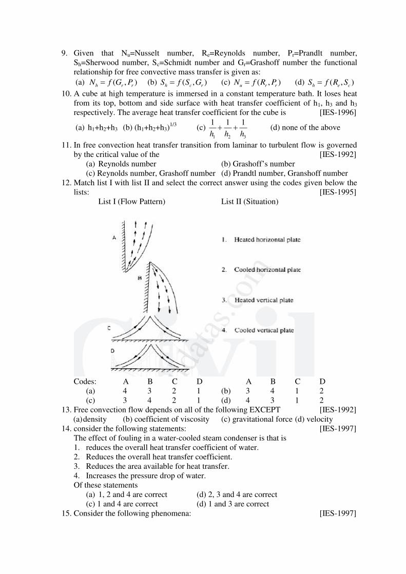
9. Given that Nu=Nusselt number, Re=Reynolds number, Pr=Prandlt number,
Sh=Sherwood number, Sc=Schmidt number and Gr=Grashoff number the functional
relationship for free convective mass transfer is given as:
(a) ( , )h r rN f G P (b) ( , )h c rS f S G (c) ( , )u r rN f R P (d) ( , )h e cS f R S
10. A cube at high temperature is immersed in a constant temperature bath. It loses heat
from its top, bottom and side surface with heat transfer coefficient of h1, h3 and h3
respectively. The average heat transfer coefficient for the cube is [IES-1996]
(a) h1+h2+h3 (b) (h1+h2+h3)1/3
(c) 1 2 3
1 1 1
h h h (d) none of the above
11. In free convection heat transfer transition from laminar to turbulent flow is governed
by the critical value of the [IES-1992]
(a) Reynolds number (b) Grashoff’s number
(c) Reynolds number, Grashoff number (d) Prandtl number, Granshoff number
12. Match list I with list II and select the correct answer using the codes given below the
lists: [IES-1995]
List I (Flow Pattern) List II (Situation)
Codes: A B C D A B C D
(a) 4 3 2 1 (b) 3 4 1 2
(c) 3 4 2 1 (d) 4 3 1 2
13. Free convection flow depends on all of the following EXCEPT [IES-1992]
(a) density (b) coefficient of viscosity (c) gravitational force (d) velocity
14. consider the following statements: [IES-1997]
The effect of fouling in a water-cooled steam condenser is that is
1. reduces the overall heat transfer coefficient of water.
2. Reduces the overall heat transfer coefficient.
3. Reduces the area available for heat transfer.
4. Increases the pressure drop of water.
Of these statements
(a) 1, 2 and 4 are correct (d) 2, 3 and 4 are correct
(c) 1 and 4 are correct (d) 1 and 3 are correct
15. Consider the following phenomena: [IES-1997]
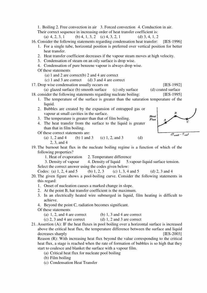
1. Boiling 2. Free convection in air 3. Forced convection 4. Conduction in air.
Their correct sequence in increasing order of heat transfer coefficient is:
(a) 4, 2, 3, 1 (b) 4, 1, 3, 2 (c) 4, 3, 2, 1 (d) 3, 4, 1, 2
16. Consider the following statements regarding condensation heat transfer: [IES-1996]
1. For a single tube, horizontal position is preferred over vertical position for better
heat transfer.
2. Heat transfer coefficient decreases if the vapour steam moves at high velocity.
3. Condensation of steam on an oily surface is drop wise.
4. Condensation of pure benzene vapour is always drop wise.
Of these statements
(a) 1 and 2 are correct(b) 2 and 4 are correct
(c) 1 and 3 are correct (d) 3 and 4 are correct
17. Drop wise condensation usually occurs on [IES-1992]
(a) glazed surface (b) smooth surface (c) oily surface (d) coated surface
18. consider the following statements regarding nucleate boiling: [IES-1995]
1. The temperature of the surface is greater than the saturation temperature of the
liquid.
2. Bubbles are created by the expansion of entrapped gas or
vapour at small cavities in the surface.
3. The temperature is greater than that of film boiling.
4. The heat transfer from the surface to the liquid is greater
than that in film boiling.
Of these correct statements are:
(a) 1, 2 and 4 (b) 1 and 3 (c) 1, 2, and 3 (d)
2, 3, and 4
19. The burnout heat flux in the nucleate boiling regime is a function of which of the
following properties?
1. Heat of evaporation 2. Temperature difference
3. Density of vapour 4. Density of liquid 5.vapour-liquid surface tension.
Select the correct answer using the codes given below:
Codes: (a) 1, 2, 4 and 5 (b) 1, 2, 3 (c) 1, 3, 4 and 5 (d) 2, 3 and 4
20. The given figure shows a pool-boiling curve. Consider the following statements in
this regard:
1. Onset of nucleation causes a marked change in slope.
2. At the point B, hat transfer coefficient is the maximum.
3. In an electrically heated wire submerged in liquid, film heating is difficult to
achieve.
4. Beyond the point C, radiation becomes significant.
Of these statements
(a) 1, 2, and 4 are correct (b) 1, 3 and 4 are correct
(c) 2, 3 and 4 are correct (d) 1, 2 and 3 are correct
21. Assertion (A): IF the heat fluxes in pool boiling over a horizontal surface is increased
above the critical heat flux, the temperature difference between the surface and liquid
decreases sharply [IES-2003]
Reason (R): With increasing heat flux beyond the value corresponding to the critical
heat flux, a stage is reached when the rate of formation of bubbles is so high that they
start to coalesce and blanket the surface with a vapour film.
(a) Critical heat flux for nucleate pool boiling
(b) Film boiling
(c) Condensation Heat Transfer
22. Saturated steam is condense over a vertical flat surface and the condensate film flows
down the surface. The local heat transfer coefficient for condensation [IES-1999]
(a) remains constant at all locations of the surface.
(b) decreases with increasing distance from the top of the surface
(c) increases with increasing thickness of condensate film
(d) increases with decreasing temperature differential between the surface and
vapour.
23. Consider the following statements: [IES-1998]
1. If a condensing liquid does not wet a surface drop wise, then condensation will
take place on it.
2. Drop wise condensation gives a higher heat transfer rate than film-wise
condensation.
3. Reynolds number of condensing liquid is based on its mass flow rate.
4. Suitable coating or vapour additive is used to promote film-wise condensation.
Of these statements:
(a) 1 and 2 are correct (b) 2, 3 and 4 are correct
(c) 4 alone is correct (d) 1, 2 and 3 are correct
24. Assertion (A): Even though drop wise condensation is more efficient, surface
condensers are designed on the assumption of film wise condensation as a matter of
practice [IES-1995]
Reason (R): Drop wise condensation can be maintained with the use of promoters like
oleic acid.
(a) Both A and R are true and R provides satisfactory explanation for A.
(b) A and R are true and A provides satisfactory explanation for R.
(c) Both are true and R provides satisfactory explanation for A.
(d) A and R are true and R provides satisfactory explanation for A.
25. Assertion (A): The rate of condensation over a rusty surface is less than that over a
polished surface [IES-1995]
Reason (R): The polished surface promotes drop wise condensation which does not
wet the surface.
(a) Both A and R are true and R provides satisfactory explanation for A.
(b) A and R are true and A provides satisfactory explanation for R.
(c) Both are true and R provides satisfactory explanation for A.
(d) A and R are true and R provides satisfactory explanation for A.
Prepared by: Dr.P.Nageswara Reddy
Academic Year: 2019 – 20 Semester: II
Class : III B.Tech Subject: Heat Transfer
Learning Material
UNIT-V Heat Exchangers: Classification, overall heat transfer Coefficient, fouling factor, Design of
Heat Exchangers – LMTD and NTU methods.
HEAT EXCHANGERS
INTRODUCTION
A heat exchanger is a device that enables heat transfer between two or more fluids
that are at different temperatures.
The applications of heat exchangers are multi-fold, which include chemical
processing plants, automobile radiators, steam power plants, gas turbine power plants,
domestic and commercial refrigerators, freezers, water coolers, air-conditioners, food
processing systems, nuclear power plants, space radiators, aeronautical system, and so on.
The heat exchanger design is quite a complex proposition, as it should address rate of
heat transfer, pressure drop, sizing and economic aspects mainly, in addition to several other
secondary prerequisites. As an example, applications like power plants and chemical
processing plants call for cost minimization, while space and aeronautical applications pose
restrictions on size and weight factors.
Heat transfer in a heat exchanger usually involves convection in each fluid and
conduction through the wall separating the two fluids. In the analysis of heat exchangers, it is
convenient to work with an overall heat transfer coefficient U that accounts for the
contribution of all these effects on heat transfer. The rate of heat transfer between the two
fluids at a location in a heat exchanger depends on the magnitude of the temperature
difference at that location, which varies along the heat exchanger.
TYPES OF HEAT EXCHANGERS
The simplest type of heat exchanger consists of two concentric pipes of different
diameters, as shown in Fig. 5.1, called the double-pipe heat exchanger. One fluid in a double-
pipe heat exchanger flows through the smaller pipe while the other fluid flows through the
annular space between the two pipes.
Two types of flow arrangement are possible in a double-pipe heat exchanger: in
parallel flow, both the hot and cold fluids enter the heat exchanger at the same end and move
in the same direction. In counter flow, on the other hand, the hot and cold fluids enter the heat
exchanger at opposite ends and flow in opposite directions.
Another type of heat exchanger, which is specifically designed to realize a large heat
transfer surface area per unit volume, is the compact heat exchanger. The ratio of the heat
transfer surface area of a heat exchanger to its volume is called the area density . A heat
exchanger with >700 m2/m
3 (or 200 ft
2/ft
3) is classified as being compact. Examples of
compact heat exchangers are car radiators ( 2 31000 /m m ), glass-ceramic gas turbine heat
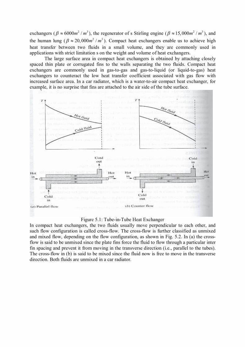
exchangers ( 2 36000 /m m ), the regenerator of s Stirling engine ( 2 315,000 /m m ), and
the human lung ( 2 320,000 /m m ). Compact heat exchangers enable us to achieve high
heat transfer between two fluids in a small volume, and they are commonly used in
applications with strict limitation s on the weight and volume of heat exchangers.
The large surface area in compact heat exchangers is obtained by attaching closely
spaced thin plate or corrugated fins to the walls separating the two fluids. Compact heat
exchangers are commonly used in gas-to-gas and gas-to-liquid (or liquid-to-gas) heat
exchangers to counteract the low heat transfer coefficient associated with gas flow with
increased surface area. In a car radiator, which is a water-to-air compact heat exchanger, for
example, it is no surprise that fins are attached to the air side of the tube surface.
Figure 5.1: Tube-in-Tube Heat Exchanger
In compact heat exchangers, the two fluids usually move perpendicular to each other, and
such flow configuration is called cross-flow. The cross-flow is further classified as unmixed
and mixed flow, depending on the flow configuration, as shown in Fig. 5.2. In (a) the cross-
flow is said to be unmixed since the plate fins force the fluid to flow through a particular inter
fin spacing and prevent it from moving in the transverse direction (i.e., parallel to the tubes).
The cross-flow in (b) is said to be mixed since the fluid now is free to move in the transverse
direction. Both fluids are unmixed in a car radiator.
Figure 5.2: Cross flow Heat Exchanger
Perhaps the most common type of heat exchanger in industrial applications is the shell-and-
tube heat exchanger, shown in Fig.5.3. Shell-and-tube heat exchangers contain a large
number of tubes (sometimes several hundred) packed in a shell with their axes parallel to that
of the shell. Heat transfer takes place as one fluid flows inside the tubes while the other fluid
flows outside the tubes while the other fluid flows outside the tubes through the shell. Baffles
are commonly placed in the shell to force the shell-side fluid to flow across the shell to
enhance heat transfer and to maintain uniform spacing between the tubes.
Figure 5.3: Shell and Tube Heat Exchanger
Shell-and-tube heat exchangers are further classified according to the number of shell and
tube passes involved. Heat exchangers in which all the tubes make one U turn in the shell, for
example, are called one-shell-pass and two-tube-passes heat exchangers (Figure 5.4).
Likewise, a heat exchanger that involves two passes in the shell and four passes in the tubes
is called a two-shell-passes and four-tube-passes heat exchanger.
Figure 5.4: One-shell pass and Two-tube passes and Two-shell pass and Four-tube Passes
Heat Exchangers.
An innovative type foe heat exchanger that has found widespread use is the plate and frame
(or just plate) heat exchanger, which consists of a series of plates with corrugated float flow
passages (Fig.5.5). The hot and cold fluids flow in alternate passages, and thus each cold
fluid stream is surrounded by two hot fluid streams, resulting in very effective heat transfer.
Also, plate heat exchangers can grow with increasing demand for heat transfer by simply
mounting more plates. They are well suited for liquid-to-liquid heat exchange applications.
Figure 5.5: A plate-and-frame liquid-to-liquid Heat Exchanger.
Another type of heat exchanger that involves the alternate passage of the hot and cold
fluid steams through the same flow area is the regenerative heat exchanger. The static-type
regenerative heat exchanger is basically a porous mass that has a large heat storage capacity,
such as a ceramic wire mesh. Hot and cold fluids flow through this porous mass alternatively.
Heat is transferred from the hot fluid to the matrix to the cold fluid during the flow of the
cold fluid. Thus, the matrix serves as a temporary heat storage medium.
The dynamic-type regenerator involves a rotating drum and continuous flow of the
hot and cold fluid through different portions of the drum so that any portion of the drum
passes periodically through the hot stream, storing heat, and then through the cold stream,
rejecting this stored heat. Again the drum serves as the medium to transport the heat from the
hot to the cold fluid stream.
A condenser is a heat exchanger in which one of the fluid is cooled and condenses as
it flows through the heat exchanger. A boiler is another heat exchanger in which one of the
fluids absorbs heat and vaporizes. A space radiator is a heat exchanger that transfers heat
from the hot fluid to the surrounding space by radiation.
THE OVERALL HEAT TRANSFER COEFFICIENT
A heat exchanger typically involves two flowing fluids separated by a solid wall. Heat
is first transferred from the hot fluid to the wall by convection, through the wall by
conduction, and from the wall to the cold fluid again by convection.
The rate of heat transfer between the two fluids is expressed as
0 0i iQ UA T U A T U A T (5.1)
Where U is the overall heat transfer coefficient, whose unit is W/m2.0C, which is identical to
the unit of the ordinary convection coefficient h.
Typical values of the overall heat transfer are given in Table 5.1
Table 5.1: Representative values of the overall heat transfer coefficients in heat exchangers.
------------------------------------------------------------------------------------------------------------
Types of heat exchanger U, W/m2.0C
Water-to-water 850-1700
Water-to-oil 100-350
Water-to-gasoline or kerosene 300-1000
Feed water heaters 1000-8500
Steam-to-light fuel oil 200-400
Steam-to-heavy fuel oil 50-200
Steam condenser 1000-6000
Freon condenser (water cooled) 300-1000
Ammonia condenser (water cooled) 800-1400
Alcohol condensers (water cooled) 250-700
Gas-to-gas 10-40
Water-to-air in finned tubes (water in tubes) 30-60
400-850
Steam-to-air in finned tubes (steam in tubes) 30-300
400-4000
------------------------------------------------------------------------------------------------------------
Ui is the overall heat transfer coefficient estimated based on inner surface area (Ai) of the
inner tube and U0 is the overall heat transfer coefficient estimated based on outer surface area
(A0) of the inner tube. Ui and U0 are given by
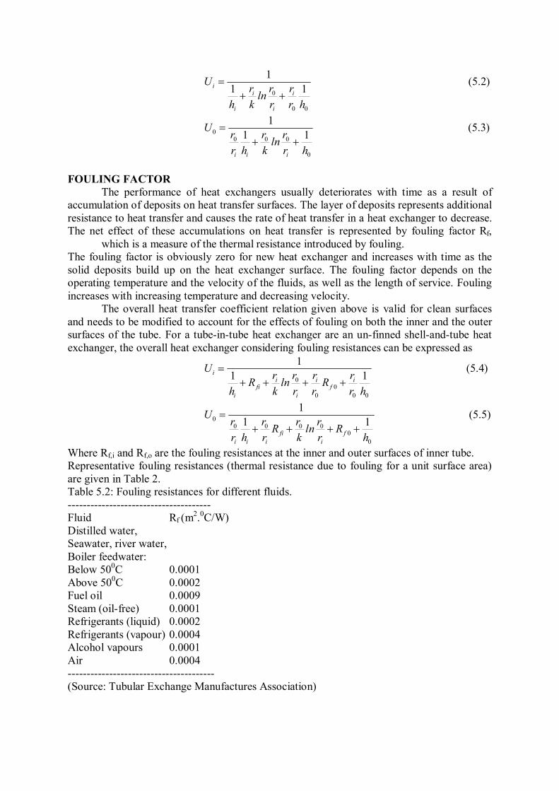
0
0 0
1
1 1ii i
i i
Ur r r
lnh k r r h
(5.2)
00 0 0
0
1
1 1
i i i
Ur r r
lnr h k r h
(5.3)
FOULING FACTOR
The performance of heat exchangers usually deteriorates with time as a result of
accumulation of deposits on heat transfer surfaces. The layer of deposits represents additional
resistance to heat transfer and causes the rate of heat transfer in a heat exchanger to decrease.
The net effect of these accumulations on heat transfer is represented by fouling factor Rf,
which is a measure of the thermal resistance introduced by fouling.
The fouling factor is obviously zero for new heat exchanger and increases with time as the
solid deposits build up on the heat exchanger surface. The fouling factor depends on the
operating temperature and the velocity of the fluids, as well as the length of service. Fouling
increases with increasing temperature and decreasing velocity.
The overall heat transfer coefficient relation given above is valid for clean surfaces
and needs to be modified to account for the effects of fouling on both the inner and the outer
surfaces of the tube. For a tube-in-tube heat exchanger are an un-finned shell-and-tube heat
exchanger, the overall heat exchanger considering fouling resistances can be expressed as
0
0
0 0 0
1
1 1ii i i
fi f
i i
Ur r r r
R ln Rh k r r r h
(5.4)
00 0 0 0
0
0
1
1 1fi f
i i i i
Ur r r r
R ln Rr h r k r h
(5.5)
Where Rf,i and Rf,o are the fouling resistances at the inner and outer surfaces of inner tube.
Representative fouling resistances (thermal resistance due to fouling for a unit surface area)
are given in Table 2.
Table 5.2: Fouling resistances for different fluids.
--------------------------------------
Fluid Rf (m2.0C/W)
Distilled water,
Seawater, river water,
Boiler feedwater:
Below 500C 0.0001
Above 500C 0.0002
Fuel oil 0.0009
Steam (oil-free) 0.0001
Refrigerants (liquid) 0.0002
Refrigerants (vapour) 0.0004
Alcohol vapours 0.0001
Air 0.0004
---------------------------------------
(Source: Tubular Exchange Manufactures Association)
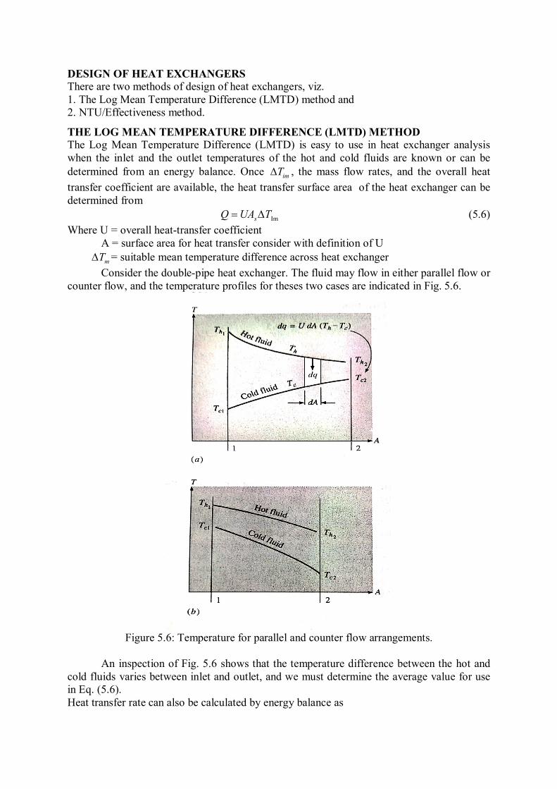
DESIGN OF HEAT EXCHANGERS
There are two methods of design of heat exchangers, viz.
1. The Log Mean Temperature Difference (LMTD) method and
2. NTU/Effectiveness method.
THE LOG MEAN TEMPERATURE DIFFERENCE (LMTD) METHOD
The Log Mean Temperature Difference (LMTD) is easy to use in heat exchanger analysis
when the inlet and the outlet temperatures of the hot and cold fluids are known or can be
determined from an energy balance. Once imT , the mass flow rates, and the overall heat
transfer coefficient are available, the heat transfer surface area of the heat exchanger can be
determined from
ImTUAQ s (5.6)
Where U = overall heat-transfer coefficient
A = surface area for heat transfer consider with definition of U
mT = suitable mean temperature difference across heat exchanger
Consider the double-pipe heat exchanger. The fluid may flow in either parallel flow or
counter flow, and the temperature profiles for theses two cases are indicated in Fig. 5.6.
Figure 5.6: Temperature for parallel and counter flow arrangements.
An inspection of Fig. 5.6 shows that the temperature difference between the hot and
cold fluids varies between inlet and outlet, and we must determine the average value for use
in Eq. (5.6).
Heat transfer rate can also be calculated by energy balance as
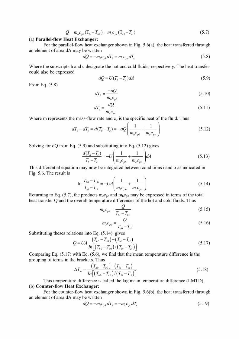
0 0(T ) (T )h ph hi h c pc c ciQ m c T m c T (5.7)
(a) Parallel-flow Heat Exchanger:
For the parallel-flow heat exchanger shown in Fig. 5.6(a), the heat transferred through
an element of area dA may be written
h ph h c pc cdQ m c dT m c dT
(5.8)
Where the subscripts h and c designate the hot and cold fluids, respectively. The heat transfer
could also be expressed
( )h cdQ U T T dA
(5.9)
From Eq. (5.8)
h
h ph
dQdT
m c
(5.10)
c
c pc
dQdT
m c
(5.11)
Where m represents the mass-flow rate and cp is the specific heat of the fluid. Thus
1 1( )h c h c
h ph c pc
dT dT d T T dQm c m c
(5.12)
Solving for dQ from Eq. (5.9) and substituting into Eq. (5.12) gives
( ) 1 1h c
h c h ph c pc
d T TU dA
T T m c m c
(5.13)
This differential equation may now be integrated between conditions i and o as indicated in
Fig. 5.6. The result is
In 0 0 1 1h c
hi ci h ph c pc
T TUA
T T m c m c
(5.14)
Returning to Eq. (5.7), the products mccpc and mhcph may be expressed in terms of the total
heat transfer Q and the overall temperature differences of the hot and cold fluids. Thus
0
h ph
hi h
Qm c
T T
(5.15)
0
c pc
c ci
Qm c
T T
(5.16)
Substituting theses relations into Eq. (5.14) gives
0 0
0 0 /
h c hi ci
h c hi ci
T T T TQ UA
In T T T T
(5.17)
Comparing Eq. (5.17) with Eq. (5.6), we find that the mean temperature difference is the
grouping of terms in the brackets. Thus
0 0
0 0 /
h c hi ci
m
h c hi ci
T T T TT
In T T T T
(5.18)
This temperature difference is called the log mean temperature difference (LMTD).
(b) Counter-flow Heat Exchanger:
For the counter-flow heat exchanger shown in Fig. 5.6(b), the heat transferred through
an element of area dA may be written
h ph h c pc cdQ m c dT m c dT
(5.19)
Where the subscripts h and c designate the hot and cold fluids, respectively. The heat transfer
could also be expressed
( )h cdQ U T T dA
(5.20)
From Eq. (5.19)
h
h ph
dQdT
m c
(5.21)
c
c pc
dQdT
m c
(5.22)
Where m represents the mass-flow rate and cp is the specific heat of the fluid. Thus
1 1( )h c h c
h ph c pc
dT dT d T T dQm c m c
(5.23)
Solving for dQ from Eq. (5.20) and substituting into Eq. (5.23) gives
( ) 1 1h c
h c h ph c pc
d T TU dA
T T m c m c
(5.24)
This differential equation may now be integrated between conditions i and o as indicated in
Fig. 5.6. The result is
In 0 0 1 1h c
hi ci h ph c pc
T TUA
T T m c m c
(5.25)
Returning to Eq. (5.7), the products mccpc and mhcph may be expressed in terms of the total
heat transfer Q and the overall temperature differences of the hot and cold fluids. Thus
0
h ph
hi h
Qm c
T T
(5.26)
0
c pc
c ci
Qm c
T T
(5.27)
Substituting theses relations into Eq. (5.14) gives
0 0
0 0/
h ci hi c
h ci hi c
T T T TQ UA
In T T T T
(5.28)
Comparing Eq. (5.17) with Eq. (5.6), we find that the mean temperature difference is the
grouping of terms in the brackets. Thus
0 0
0 0/
h ci hi c
m
h ci hi c
T T T TT
In T T T T
(5.29)
If a heat exchanger other than the double-pipe type is used, the heat transfer is calculated by
using a correction factor applied to the LMTD for a counter-flow double-pipe arrangement
with the same hot and cold fluid temperatures. The heat transfer equation then takes the form
( )counter flowq UAF LMTD
(5.30)
When a phase change is involved, as in condensation or boiling (evaporation), the
fluid normally remains at essentially constant temperature and hance, F = 1.0 for boiling or
condensation.
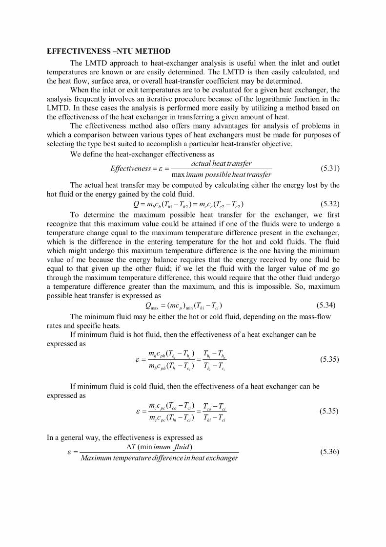
EFFECTIVENESS –NTU METHOD
The LMTD approach to heat-exchanger analysis is useful when the inlet and outlet
temperatures are known or are easily determined. The LMTD is then easily calculated, and
the heat flow, surface area, or overall heat-transfer coefficient may be determined.
When the inlet or exit temperatures are to be evaluated for a given heat exchanger, the
analysis frequently involves an iterative procedure because of the logarithmic function in the
LMTD. In these cases the analysis is performed more easily by utilizing a method based on
the effectiveness of the heat exchanger in transferring a given amount of heat.
The effectiveness method also offers many advantages for analysis of problems in
which a comparison between various types of heat exchangers must be made for purposes of
selecting the type best suited to accomplish a particular heat-transfer objective.
We define the heat-exchanger effectiveness as
max
actual heat transferEffectiveness
imum possible heat transfer
(5.31)
The actual heat transfer may be computed by calculating either the energy lost by the
hot fluid or the energy gained by the cold fluid.
1 2 2 2( ) ( )h h h h c c c cQ m c T T m c T T
(5.32)
To determine the maximum possible heat transfer for the exchanger, we first
recognize that this maximum value could be attained if one of the fluids were to undergo a
temperature change equal to the maximum temperature difference present in the exchanger,
which is the difference in the entering temperature for the hot and cold fluids. The fluid
which might undergo this maximum temperature difference is the one having the minimum
value of mc because the energy balance requires that the energy received by one fluid be
equal to that given up the other fluid; if we let the fluid with the larger value of mc go
through the maximum temperature difference, this would require that the other fluid undergo
a temperature difference greater than the maximum, and this is impossible. So, maximum
possible heat transfer is expressed as
max min( ) ( )p hi ciQ mc T T
(5.34)
The minimum fluid may be either the hot or cold fluid, depending on the mass-flow
rates and specific heats.
If minimum fluid is hot fluid, then the effectiveness of a heat exchanger can be
expressed as
( )
( )
i o i o
i i i i
h ph h h h h
h ph h c h c
m c T T T T
m c T T T T
(5.35)
If minimum fluid is cold fluid, then the effectiveness of a heat exchanger can be
expressed as
( )
( )
c pc co ci co ci
c pc hi ci hi ci
m c T T T T
m c T T T T
(5.35)
In a general way, the effectiveness is expressed as
(min )T imum fluid
Maximum temperature differencein heat exchanger
(5.36)
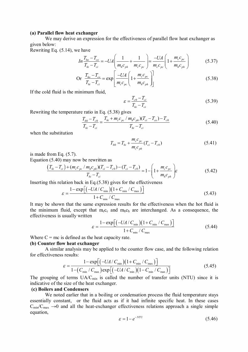
(a) Parallel flow heat exchanger
We may derive an expression for the effectiveness of parallel flow heat exchanger as
given below:
Rewriting Eq. (5.14), we have
1 11
c pcho co
hi ci h ph c pc c pc h ph
m cT T UAIn UA
T T m c m c m c m c
(5.37)
Or exp 1c pcho co
hi ci c pc h ph
m cT T UA
T T m c m c
(5.38)
If the cold fluid is the minimum fluid,
0c ci
hi ci
T T
T T
(5.39)
Rewriting the temperature ratio in Eq. (5.38) gives
00 0/ )( )hi c pc h ph ci co ch c
hi ci hi ci
T m c m c T T TT T
T T T T
(5.40)
when the substitution
0 0( )
c pc
h hi ci c
c ph
m cT T T T
m c
(5.41)
is made from Eq. (5.7).
Equation (5.40) may now be rewritten as
0 0( / )( ) ( )1 1
hi ci c pc h ph ci c ci c c pc
hi ci h ph
T T m c m c T T T T m c
T T m c
(5.42)
Inserting this relation back in Eq.(5.38) gives for the effectiveness
min min max
min max
1 exp / 1 /
1 /
UA C C C
C C
(5.43)
It may be shown that the same expression results for the effectiveness when the hot fluid is
the minimum fluid, except that mccc and mhch are interchanged. As a consequence, the
effectiveness is usually written
min min max
min max
1 exp / 1 /
1 /
UA C C C
C C
(5.44)
Where C = mc is defined as the heat capacity rate.
(b) Counter flow heat exchanger
A similar analysis may be applied to the counter flow case, and the following relation
for effectiveness results:
min min max
min max min min max
1 exp / 1 /
1 / exp / 1 /
UA C C C
C C UA C C C
(5.45)
The grouping of terms UA/Cmin is called the number of transfer units (NTU) since it is
indicative of the size of the heat exchanger.
(c) Boilers and Condensers
We noted earlier that in a boiling or condensation process the fluid temperature stays
essentially constant, or the fluid acts as if it had infinite specific heat. In these cases
Cmin/Cmax →0 and all the heat-exchanger effectiveness relations approach a single simple
equation,
1NTU
e (5.46)
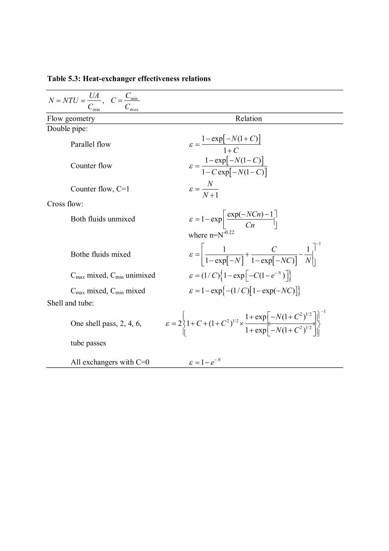
Table 5.3: Heat-exchanger effectiveness relations
min
,UA
N NTUC
min
max
CC
C
Flow geometry Relation
Double pipe:
Parallel flow 1 exp (1 )
1
N C
C
Counter flow
1 exp (1 )
1 exp (1 )
N C
C N C
Counter flow, C=1 1
N
N
Cross flow:
Both fluids unmixed exp( ) 1
1 expNCn
Cn
where n=N-0.22
Bothe fluids mixed
1
1 1
1 exp 1 exp )
C
N NC N
Cmax mixed, Cmin unimixed (1/ ) 1 exp (1 )N
C C e
Cmax mixed, Cmin mixed 1 exp (1/ ) 1 exp( )C NC
Shell and tube:
One shell pass, 2, 4, 6,
12 1/2
2 1/2
2 1/2
1 exp (1 )2 1 (1 )
1 exp (1 )
N CC C
N C
tube passes
All exchangers with C=0 1N
e
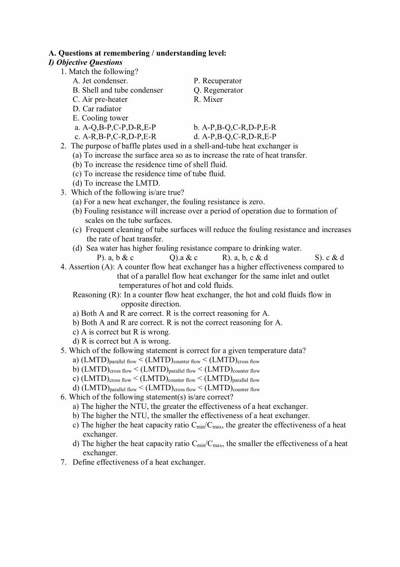
A. Questions at remembering / understanding level:
I) Objective Questions
1. Match the following?
A. Jet condenser. P. Recuperator
B. Shell and tube condenser Q. Regenerator
C. Air pre-heater R. Mixer
D. Car radiator
E. Cooling tower
a. A-Q,B-P,C-P,D-R,E-P b. A-P,B-Q,C-R,D-P,E-R
c. A-R,B-P,C-R,D-P,E-R d. A-P,B-Q,C-R,D-R,E-P
2. The purpose of baffle plates used in a shell-and-tube heat exchanger is
(a) To increase the surface area so as to increase the rate of heat transfer.
(b) To increase the residence time of shell fluid.
(c) To increase the residence time of tube fluid.
(d) To increase the LMTD.
3. Which of the following is/are true?
(a) For a new heat exchanger, the fouling resistance is zero.
(b) Fouling resistance will increase over a period of operation due to formation of
scales on the tube surfaces.
(c) Frequent cleaning of tube surfaces will reduce the fouling resistance and increases
the rate of heat transfer.
(d) Sea water has higher fouling resistance compare to drinking water.
P). a, b & c Q).a & c R). a, b, c & d S). c & d
4. Assertion (A): A counter flow heat exchanger has a higher effectiveness compared to
that of a parallel flow heat exchanger for the same inlet and outlet
temperatures of hot and cold fluids.
Reasoning (R): In a counter flow heat exchanger, the hot and cold fluids flow in
opposite direction.
a) Both A and R are correct. R is the correct reasoning for A.
b) Both A and R are correct. R is not the correct reasoning for A.
c) A is correct but R is wrong.
d) R is correct but A is wrong.
5. Which of the following statement is correct for a given temperature data?
a) (LMTD)parallel flow < (LMTD)counter flow < (LMTD)cross flow
b) (LMTD)cross flow < (LMTD)parallel flow < (LMTD)counter flow
c) (LMTD)cross flow < (LMTD)counter flow < (LMTD)parallel flow
d) (LMTD)parallel flow < (LMTD)cross flow < (LMTD)counter flow
6. Which of the following statement(s) is/are correct?
a) The higher the NTU, the greater the effectiveness of a heat exchanger.
b) The higher the NTU, the smaller the effectiveness of a heat exchanger.
c) The higher the heat capacity ratio Cmin/Cmax, the greater the effectiveness of a heat
exchanger.
d) The higher the heat capacity ratio Cmin/Cmax, the smaller the effectiveness of a heat
exchanger.
7. Define effectiveness of a heat exchanger.
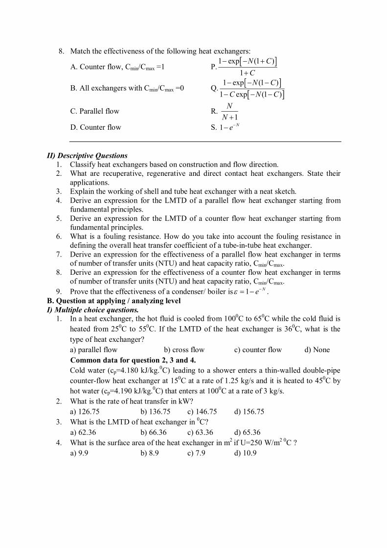
8. Match the effectiveness of the following heat exchangers:
A. Counter flow, Cmin/Cmax =1 P. 1 exp (1 )
1
N C
C
B. All exchangers with Cmin/Cmax =0 Q.
1 exp (1 )
1 exp (1 )
N C
C N C
C. Parallel flow R. 1
N
N
D. Counter flow S. 1N
e
II) Descriptive Questions
1. Classify heat exchangers based on construction and flow direction.
2. What are recuperative, regenerative and direct contact heat exchangers. State their
applications.
3. Explain the working of shell and tube heat exchanger with a neat sketch.
4. Derive an expression for the LMTD of a parallel flow heat exchanger starting from
fundamental principles.
5. Derive an expression for the LMTD of a counter flow heat exchanger starting from
fundamental principles.
6. What is a fouling resistance. How do you take into account the fouling resistance in
defining the overall heat transfer coefficient of a tube-in-tube heat exchanger.
7. Derive an expression for the effectiveness of a parallel flow heat exchanger in terms
of number of transfer units (NTU) and heat capacity ratio, Cmin/Cmax.
8. Derive an expression for the effectiveness of a counter flow heat exchanger in terms
of number of transfer units (NTU) and heat capacity ratio, Cmin/Cmax.
9. Prove that the effectiveness of a condenser/ boiler is 1 Ne .
B. Question at applying / analyzing level
I) Multiple choice questions.
1. In a heat exchanger, the hot fluid is cooled from 1000C to 65
0C while the cold fluid is
heated from 250C to 55
0C. If the LMTD of the heat exchanger is 36
0C, what is the
type of heat exchanger?
a) parallel flow b) cross flow c) counter flow d) None
Common data for question 2, 3 and 4.
Cold water (cp=4.180 kJ/kg.0C) leading to a shower enters a thin-walled double-pipe
counter-flow heat exchanger at 150C at a rate of 1.25 kg/s and it is heated to 45
0C by
hot water (cp=4.190 kJ/kg.0C) that enters at 100
0C at a rate of 3 kg/s.
2. What is the rate of heat transfer in kW?
a) 126.75 b) 136.75 c) 146.75 d) 156.75
3. What is the LMTD of heat exchanger in 0C?
a) 62.36 b) 66.36 c) 63.36 d) 65.36
4. What is the surface area of the heat exchanger in m2
if U=250 W/m2 0
C ?
a) 9.9 b) 8.9 c) 7.9 d) 10.9
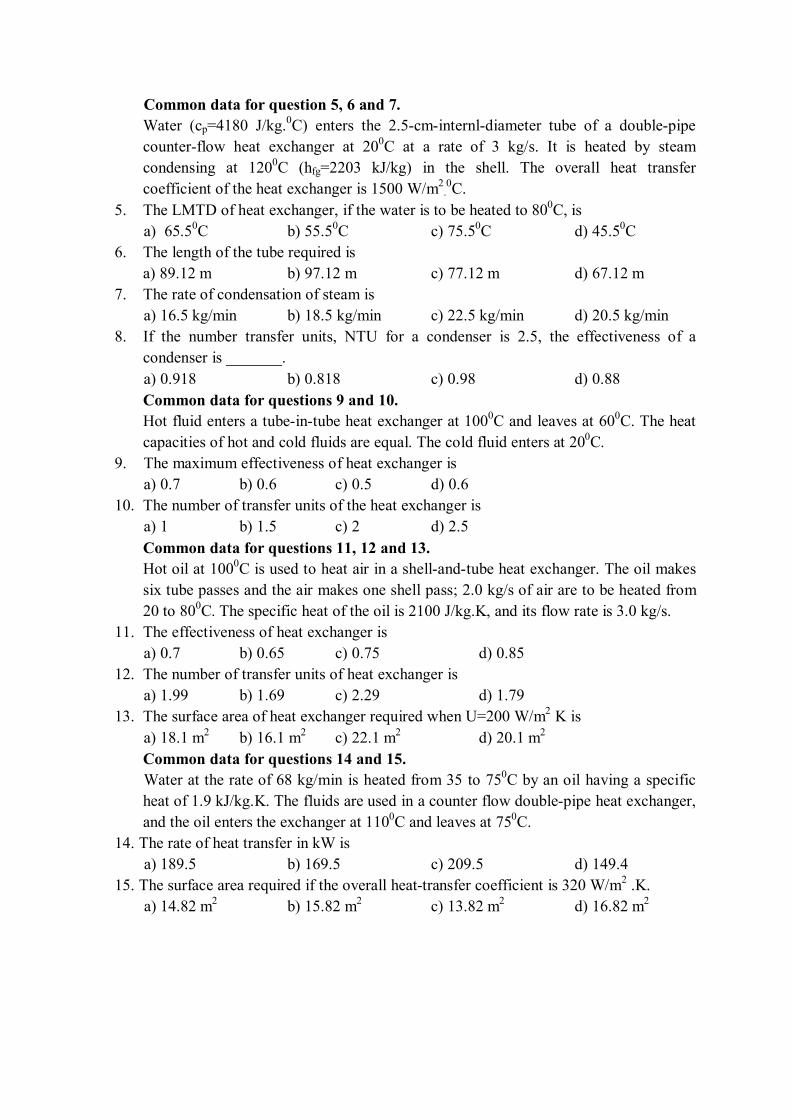
Common data for question 5, 6 and 7.
Water (cp=4180 J/kg.0C) enters the 2.5-cm-internl-diameter tube of a double-pipe
counter-flow heat exchanger at 200C at a rate of 3 kg/s. It is heated by steam
condensing at 1200C (hfg=2203 kJ/kg) in the shell. The overall heat transfer
coefficient of the heat exchanger is 1500 W/m2
.0C.
5. The LMTD of heat exchanger, if the water is to be heated to 800C, is
a) 65.50C b) 55.5
0C c) 75.5
0C d) 45.5
0C
6. The length of the tube required is
a) 89.12 m b) 97.12 m c) 77.12 m d) 67.12 m
7. The rate of condensation of steam is
a) 16.5 kg/min b) 18.5 kg/min c) 22.5 kg/min d) 20.5 kg/min
8. If the number transfer units, NTU for a condenser is 2.5, the effectiveness of a
condenser is _______.
a) 0.918 b) 0.818 c) 0.98 d) 0.88
Common data for questions 9 and 10.
Hot fluid enters a tube-in-tube heat exchanger at 1000C and leaves at 60
0C. The heat
capacities of hot and cold fluids are equal. The cold fluid enters at 200C.
9. The maximum effectiveness of heat exchanger is
a) 0.7 b) 0.6 c) 0.5 d) 0.6
10. The number of transfer units of the heat exchanger is
a) 1 b) 1.5 c) 2 d) 2.5
Common data for questions 11, 12 and 13.
Hot oil at 1000C is used to heat air in a shell-and-tube heat exchanger. The oil makes
six tube passes and the air makes one shell pass; 2.0 kg/s of air are to be heated from
20 to 800C. The specific heat of the oil is 2100 J/kg.K, and its flow rate is 3.0 kg/s.
11. The effectiveness of heat exchanger is
a) 0.7 b) 0.65 c) 0.75 d) 0.85
12. The number of transfer units of heat exchanger is
a) 1.99 b) 1.69 c) 2.29 d) 1.79
13. The surface area of heat exchanger required when U=200 W/m2 K is
a) 18.1 m2 b) 16.1 m
2 c) 22.1 m
2 d) 20.1 m
2
Common data for questions 14 and 15.
Water at the rate of 68 kg/min is heated from 35 to 750C by an oil having a specific
heat of 1.9 kJ/kg.K. The fluids are used in a counter flow double-pipe heat exchanger,
and the oil enters the exchanger at 1100C and leaves at 75
0C.
14. The rate of heat transfer in kW is
a) 189.5 b) 169.5 c) 209.5 d) 149.4
15. The surface area required if the overall heat-transfer coefficient is 320 W/m2 .K.
a) 14.82 m2 b) 15.82 m
2 c) 13.82 m
2 d) 16.82 m
2
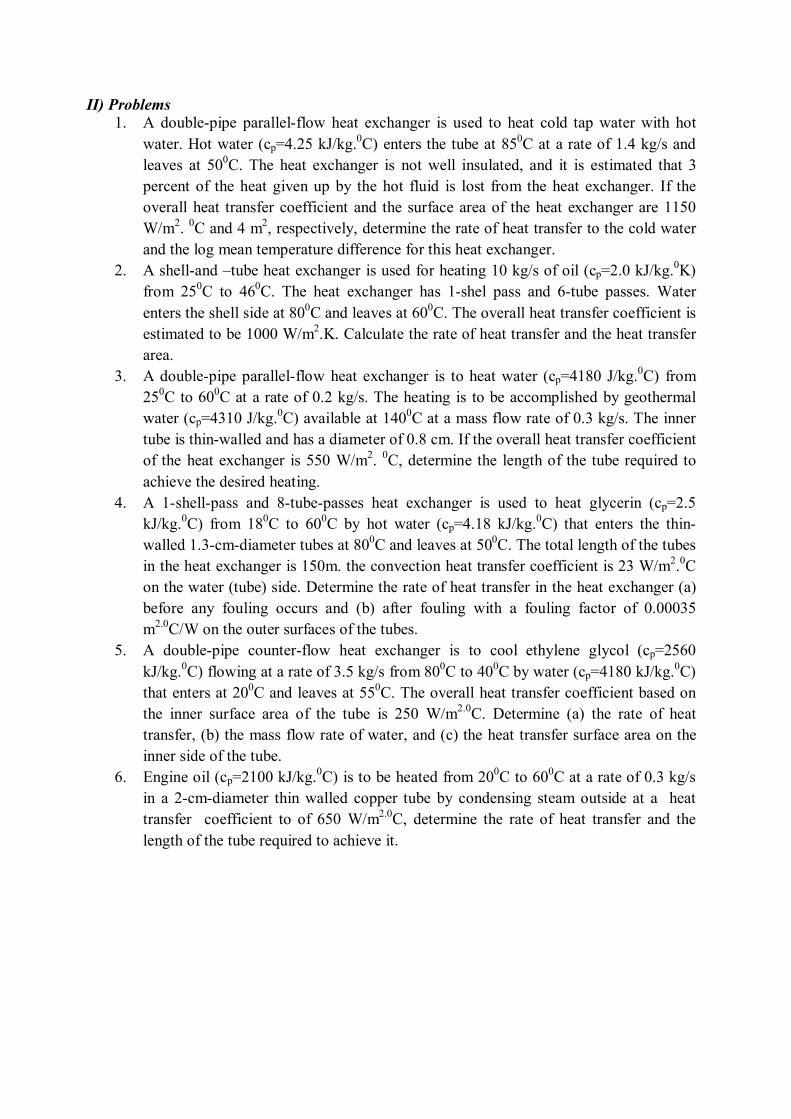
II) Problems
1. A double-pipe parallel-flow heat exchanger is used to heat cold tap water with hot
water. Hot water (cp=4.25 kJ/kg.0C) enters the tube at 85
0C at a rate of 1.4 kg/s and
leaves at 500C. The heat exchanger is not well insulated, and it is estimated that 3
percent of the heat given up by the hot fluid is lost from the heat exchanger. If the
overall heat transfer coefficient and the surface area of the heat exchanger are 1150
W/m2.
0C and 4 m
2, respectively, determine the rate of heat transfer to the cold water
and the log mean temperature difference for this heat exchanger.
2. A shell-and –tube heat exchanger is used for heating 10 kg/s of oil (cp=2.0 kJ/kg.0K)
from 250C to 46
0C. The heat exchanger has 1-shel pass and 6-tube passes. Water
enters the shell side at 800C and leaves at 60
0C. The overall heat transfer coefficient is
estimated to be 1000 W/m2.K. Calculate the rate of heat transfer and the heat transfer
area.
3. A double-pipe parallel-flow heat exchanger is to heat water (cp=4180 J/kg.0C) from
250C to 60
0C at a rate of 0.2 kg/s. The heating is to be accomplished by geothermal
water (cp=4310 J/kg.0C) available at 140
0C at a mass flow rate of 0.3 kg/s. The inner
tube is thin-walled and has a diameter of 0.8 cm. If the overall heat transfer coefficient
of the heat exchanger is 550 W/m2.
0C, determine the length of the tube required to
achieve the desired heating.
4. A 1-shell-pass and 8-tube-passes heat exchanger is used to heat glycerin (cp=2.5
kJ/kg.0C) from 18
0C to 60
0C by hot water (cp=4.18 kJ/kg.
0C) that enters the thin-
walled 1.3-cm-diameter tubes at 800C and leaves at 50
0C. The total length of the tubes
in the heat exchanger is 150m. the convection heat transfer coefficient is 23 W/m2.0C
on the water (tube) side. Determine the rate of heat transfer in the heat exchanger (a)
before any fouling occurs and (b) after fouling with a fouling factor of 0.00035
m2.0
C/W on the outer surfaces of the tubes.
5. A double-pipe counter-flow heat exchanger is to cool ethylene glycol (cp=2560
kJ/kg.0C) flowing at a rate of 3.5 kg/s from 80
0C to 40
0C by water (cp=4180 kJ/kg.
0C)
that enters at 200C and leaves at 55
0C. The overall heat transfer coefficient based on
the inner surface area of the tube is 250 W/m2.0
C. Determine (a) the rate of heat
transfer, (b) the mass flow rate of water, and (c) the heat transfer surface area on the
inner side of the tube.
6. Engine oil (cp=2100 kJ/kg.0C) is to be heated from 20
0C to 60
0C at a rate of 0.3 kg/s
in a 2-cm-diameter thin walled copper tube by condensing steam outside at a heat
transfer coefficient to of 650 W/m2.0
C, determine the rate of heat transfer and the
length of the tube required to achieve it.
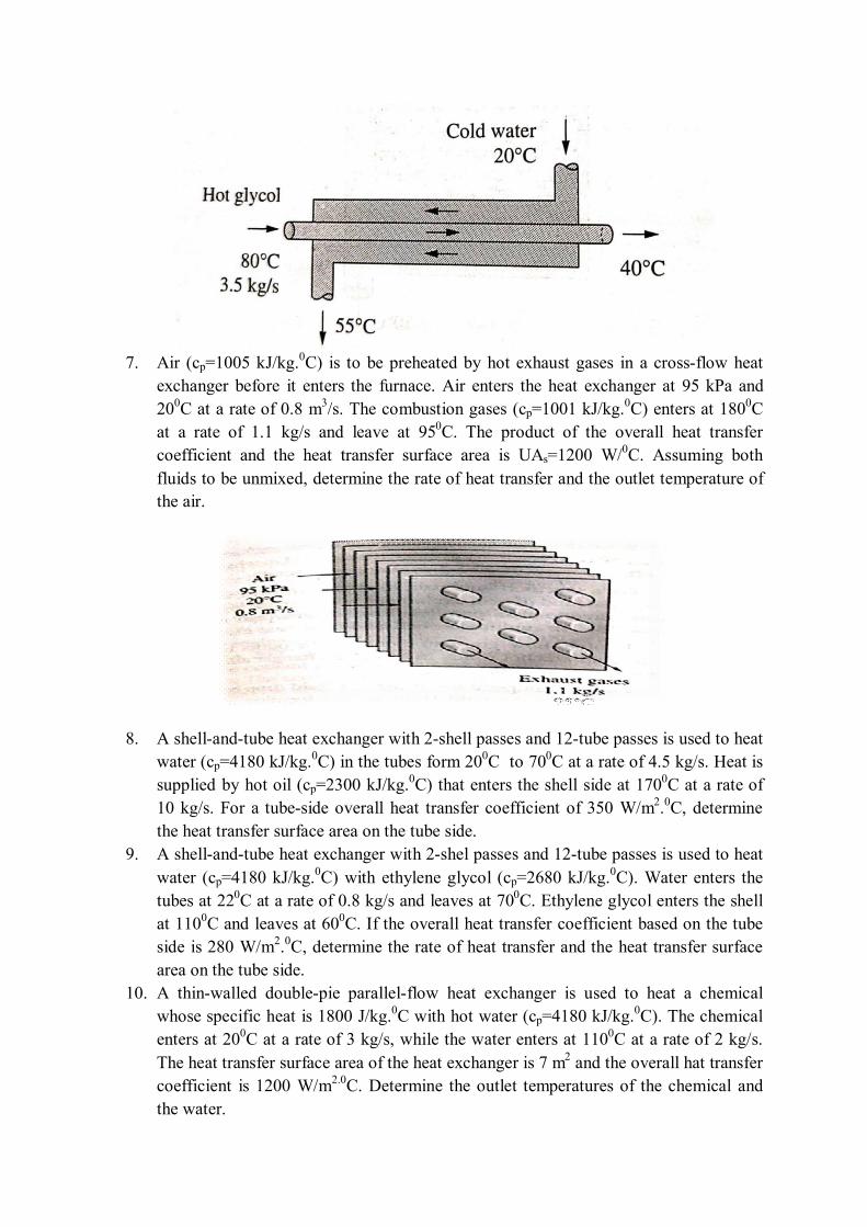
7. Air (cp=1005 kJ/kg.
0C) is to be preheated by hot exhaust gases in a cross-flow heat
exchanger before it enters the furnace. Air enters the heat exchanger at 95 kPa and
200C at a rate of 0.8 m
3/s. The combustion gases (cp=1001 kJ/kg.
0C) enters at 180
0C
at a rate of 1.1 kg/s and leave at 950C. The product of the overall heat transfer
coefficient and the heat transfer surface area is UAs=1200 W/0C. Assuming both
fluids to be unmixed, determine the rate of heat transfer and the outlet temperature of
the air.
8. A shell-and-tube heat exchanger with 2-shell passes and 12-tube passes is used to heat
water (cp=4180 kJ/kg.0C) in the tubes form 20
0C to 70
0C at a rate of 4.5 kg/s. Heat is
supplied by hot oil (cp=2300 kJ/kg.0C) that enters the shell side at 170
0C at a rate of
10 kg/s. For a tube-side overall heat transfer coefficient of 350 W/m2.0C, determine
the heat transfer surface area on the tube side.
9. A shell-and-tube heat exchanger with 2-shel passes and 12-tube passes is used to heat
water (cp=4180 kJ/kg.0C) with ethylene glycol (cp=2680 kJ/kg.
0C). Water enters the
tubes at 220C at a rate of 0.8 kg/s and leaves at 70
0C. Ethylene glycol enters the shell
at 1100C and leaves at 60
0C. If the overall heat transfer coefficient based on the tube
side is 280 W/m2.0C, determine the rate of heat transfer and the heat transfer surface
area on the tube side.
10. A thin-walled double-pie parallel-flow heat exchanger is used to heat a chemical
whose specific heat is 1800 J/kg.0C with hot water (cp=4180 kJ/kg.
0C). The chemical
enters at 200C at a rate of 3 kg/s, while the water enters at 110
0C at a rate of 2 kg/s.
The heat transfer surface area of the heat exchanger is 7 m2 and the overall hat transfer
coefficient is 1200 W/m2.0
C. Determine the outlet temperatures of the chemical and
the water.
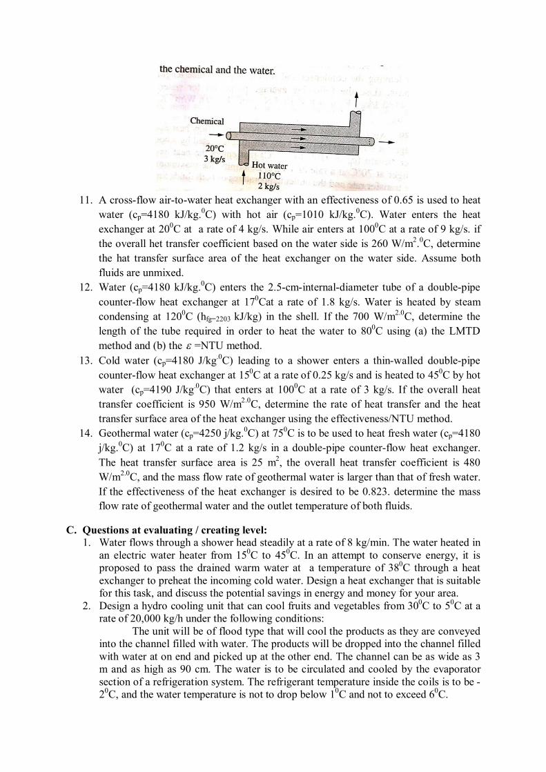
11. A cross-flow air-to-water heat exchanger with an effectiveness of 0.65 is used to heat
water (cp=4180 kJ/kg.0C) with hot air (cp=1010 kJ/kg.
0C). Water enters the heat
exchanger at 200C at a rate of 4 kg/s. While air enters at 100
0C at a rate of 9 kg/s. if
the overall het transfer coefficient based on the water side is 260 W/m2.0C, determine
the hat transfer surface area of the heat exchanger on the water side. Assume both
fluids are unmixed.
12. Water (cp=4180 kJ/kg.0C) enters the 2.5-cm-internal-diameter tube of a double-pipe
counter-flow heat exchanger at 170Cat a rate of 1.8 kg/s. Water is heated by steam
condensing at 1200C (hfg=2203 kJ/kg) in the shell. If the 700 W/m
2.0C, determine the
length of the tube required in order to heat the water to 800C using (a) the LMTD
method and (b) the =NTU method.
13. Cold water (cp=4180 J/kg.0
C) leading to a shower enters a thin-walled double-pipe
counter-flow heat exchanger at 150C at a rate of 0.25 kg/s and is heated to 45
0C by hot
water (cp=4190 J/kg.0
C) that enters at 1000C at a rate of 3 kg/s. If the overall heat
transfer coefficient is 950 W/m2.0
C, determine the rate of heat transfer and the heat
transfer surface area of the heat exchanger using the effectiveness/NTU method.
14. Geothermal water (cp=4250 j/kg.0C) at 75
0C is to be used to heat fresh water (cp=4180
j/kg.0C) at 17
0C at a rate of 1.2 kg/s in a double-pipe counter-flow heat exchanger.
The heat transfer surface area is 25 m2, the overall heat transfer coefficient is 480
W/m2.0
C, and the mass flow rate of geothermal water is larger than that of fresh water.
If the effectiveness of the heat exchanger is desired to be 0.823. determine the mass
flow rate of geothermal water and the outlet temperature of both fluids.
C. Questions at evaluating / creating level: 1. Water flows through a shower head steadily at a rate of 8 kg/min. The water heated in
an electric water heater from 150C to 45
0C. In an attempt to conserve energy, it is
proposed to pass the drained warm water at a temperature of 380C through a heat
exchanger to preheat the incoming cold water. Design a heat exchanger that is suitable
for this task, and discuss the potential savings in energy and money for your area.
2. Design a hydro cooling unit that can cool fruits and vegetables from 300C to 5
0C at a
rate of 20,000 kg/h under the following conditions:
The unit will be of flood type that will cool the products as they are conveyed
into the channel filled with water. The products will be dropped into the channel filled
with water at on end and picked up at the other end. The channel can be as wide as 3
m and as high as 90 cm. The water is to be circulated and cooled by the evaporator
section of a refrigeration system. The refrigerant temperature inside the coils is to be -
20C, and the water temperature is not to drop below 1
0C and not to exceed 6
0C.
Assuming reasonable values for the average product density, specific heat, and
porosity (the fraction of air volume in a box), recommend reasonable values for the
quantities related to the thermal aspects of the hydro cooler, including (a) how long
the fruits and vegetables needs to remain in the channel, (b) the length of the channel,
(c) the water velocity through the channel, (d) the velocity of the conveyor and thus
the fruits and vegetables through the channel, (e) the refrigeration capacity of the
refrigeration system, and (f) the type of heat exchanger for the evaporator and the
surface area on the water side.
3. A company owns a refrigeration system whose refrigeration capacity is 200 tons (1
ton of refrigeration =211 kJ/min), and you are to design a forced-air cooling system
for fruits whose diameters do not exceed 7 cm under the following conditions:
The fruits are to be cooled from 280C to an average temperature of 8
0C at all
times, and the velocity of air approaching the fruits must remain under 2 m/s. The
cooling section can be as wide as 3.5 and as high as 2 m.
Assuming reasonable values for the average fruit density, specific heat, and
porosity (the fraction of air volume in a box), recommend reasonable values for the
quantities related to the thermal aspects of the forced-air cooling, including (a) how
long the fruits need to remain in the cooling section (b) the length of the cooling
section, (c) the air velocity approaching the cooling section, (d) the product cooling
capacity of the system, in kg. fruit/h, (e) the volume flow rate of air, and (f) the type
of heat exchanger for the evaporator and the surface area on the air side.
D. GATE Questions:
1. In a counter flow heat exchanger, for the hot fluid the heat capacity = 2kJ/kg K, mass
flow rate = 5 kg/s, inlet temperature =150°C, outlet temperature =100°C. For the cold
fluid, heat capacity = 4 kJ/kg K, mass flow rate = 10 kg/s, inlet temperature=20°C.
Neglecting heat transfer to the surroundings, the outlet temperature of the cold fluid in
°C is [GATE-2003]
(a) 7.5 (b) 32.5 (c) 45.5 (d) 70.0
2. In a counter flow heat exchanger, hot fluid enters at 600c and cold fluid leaves at
300C. Mass flow rate of the hot fluid is 1 kg/s and that of the cold fluid is 2 kg/s.
Specific heat of the hot fluid is 10 kJ/kgK and that of the cold fluid is 5 kJ/kgK. The
Log Mean Temperature difference (LMTD) for the heat exchanger in 0C is
[GATE-2007]
a) 15 b) 30 c) 30 d) 45
3. In a parallel flow heat exchanger operating under steady state, the heat capacity rates
(product of specific heat at constant pressure and mass flow rate) of the hot and cold
fluid are equal. The hot fluid, flowing at 1kg/s with Cp = 4kJ/kgK, enters the heat
exchanger at 102°C while the cold fluid has an inlet temperature of 15°C. The overall
heat transfer coefficient for the heat exchanger is estimated to be 1kW/m2K and the
corresponding heat transfer surface area is 5m2. Neglect heat transfer between the heat
exchanger and the ambient. The heat exchanger is characterized by the following
relation: [GATE-2009]
2e = 1 - exp (-2NTU) .
The exit temperature (in °C) for the cold fluid is
(A) 45 (B)55 (C) 65 (D) 75
4. In a condenser of a power plant, the steam condenses at a temperature of 0 60 C. The
cooling water enters at 0 30 C and leaves at 0 45 C . The logarithmic mean
temperature difference (LMTD) of the condenser is [GATE-2011]
(A) 0 16.2 C (B) 0 21.6 C (C) 0 30 C (D) 0 37.5 C
5. Water (Cp=4.18kJ/kg.K) at 800C enters a counter flow heat exchanger with a mass
flow rate of 0.5 kg/s. Air (Cp=1kJ/kg.K) enters at 300C with a mass flow rate of 2.09
kg/s. If the effectiveness of the heat exchanger is 0.8, the LMTD (in 0C) is
[GATE-2012]
(A) 40 (B) 20 (C) 10 (D) 5
6. In a heat exchanger, it is observed that T1 = T2 , where T1 is the temperature
difference between the two single phase fluid streams at one end and T2 is the
temperature difference at the other end. This heat exchanger is [GATE-2014]
(A) a condenser (B) an evaporator
(C) a counter flow heat exchanger (D) a parallel flow heat exchanger
7. 4. In a concentric counter flow heat exchanger, water flows through the inner tube at
25OC and leaves at 42OC. The engine oil enters at 100°C and flows in the annular
flow passage. The exit temperature of the engine oil is 50OC. Mass flow rate of water
and the engine oil are 1.5 kg/s and 1 kg/s, respectively. The specific heat of water and
oil are 4178 J/kg.K and 2130 J/kg.K, respectively. The effectiveness of this heat
exchanger is _______ [GATE-2014]
8. A double-pipe counter-flow heat exchanger transfers heat between two water streams.
Tube side water at 19 liter/s is heated from 100C to 38
0C. Shell side water at 25 liter/s
is entering at 460C. Assume constant properties of water, density is 1000 kg/m3 and
specific heat is 4186 J/kg K. The LMTD (in0C) is ________ [GATE-2014]
9. Consider a parallel-flow heat exchanger with area p and a counter-flow heat
exchanger with area c . In both the heat exchangers, the hot stream flowing at 1 kg/s
cools from 800C to 50
0C. For the cold stream in both the heat exchangers, the flow rate
and the inlet temperature are 2 kg/s and 100C, respectively. The hot and cold streams
in both the heat exchangers are of the same fluid. Also, both the heat exchangers have
the same overall heat transfer coefficient. The ratio c/ p is _______ [GATE-2016]
10. The balanced counter-flow heat exchanger has a surface area of 20 m2 and overall heat
transfer coefficient of 20 W/m2-K. Air (Cp=1000 J/kg.K) entering at 0.4 kg/s and 280
K is to be preheated by the air leaving the system at 0.4 kg/s and 300 K. The outlet
temperature (in K) of the preheated air is [GATE-2016]
A) 290 B) 300 C) 320 D) 350
11. In a counter-flow heat exchanger water is heated at the rate of 1.5 kg/s from 40C to
800C by an oil entering at 120
0C and leaving at 60
0C. The specific heats of water and
oil are 4.2 kJ/kg-K and 2 kJ/kg-K, respectively. The overall heat transfer coefficient is
400 W/m2-K. The required heat transfer surface area (in m
2) is [GATE-2017]
A) 0.104 B) 0.022 C) 10.4 D) 21.84
12.Steam in the condenser of a thermal power plant is to be condensed at a temperature of
300C with cooling water which enters the tubes of the condenser at 14
0C and exits at
220C. The total surface area of the tubes is 50 m
2, and the overall heat transfer
coefficient is 2000 W/m2 K. The heat transfer (in MW) to the condenser is ______
(correct to two decimal places). [GATE-2018]
13. Hot and cold fluids enter a parallel flow double tube heat exchanger at 1000C and
150C, respectively. The heat capacity rates of hot and cold fluids are Ch=2000 W/K
and Cc=1200 W/K, respectively. If the outlet temperature of the cold fluid is 450C, the
log mean temperature difference (LMTD) of the heat exchangers _______K (round off
to two decimal places) [GATE-2019]
E. IES Questions:
1. When tc1 and tc2 are the temperatures of cold fluid at entry and exit respectively
and th1 and th2 are the temperatures of hot fluid at entry and exit point, and cold
fluid has lower heat capacity rate as compared to hot fluid, then effectiveness of the
heat exchanger is given by: [IES-1992]
(a) 1 2
1 2
c c
h h
t t
t t
(b) 2 1
2 1
h h
c c
t t
t t
(c) 1 2
1 2
h h
h c
t t
t t
(d) 2 1
1 1
c c
h h
t t
t t
2. In a parallel flow gas turbine recuperator, the maximum effectiveness is: [IES-1992]
(a) 100% (b) 75% (c) 50% (b) Between 25% and 45%
3. ɛ-NTU method is particularly useful in thermal design of heat exchangers when
[IES-1993]
a. The outlet temperature of the fluid streams is not known as a priori
b. Outlet temperature of the fluid streams is known as a priori
c. The outlet temperature of the hot fluid streams is known but
that of the cold fluid streams is not known as a priori
d. Inlet temperatures of the fluid streams are known as a priori
4. For evaporators and condensers, for the given conditions, the logarithmic mean
temperature difference (LMTD) for parallel flow is: [IES-1993]
(a) Equal to that for counter flow
(b) Greater than that for counter flow
(c) Smaller than that for counter flow
(d) Very much smaller than that for counter flow
5. In a counter flow heat exchanger, cold fluid enters at 30°C and leaves at 50°C,
whereas the enters at 150°C and leaves at l30°C. The mean temperature difference for
this case is: [IES-1993]
(a) Indeterminate (b) 20°C (c) 80°C (d) 100°C
6. A designer chooses the values of fluid flow ranges and specific heats in such a manner
that the heat capacities of the two fluids are equal. A hot fluid enters the counter flow
heat exchanger at 100°C and leaves at 60°C. The cold fluid enters the heat exchanger
at 40°C. The mean temperature difference between the two fluids is:
(a) (100 +60 + 40)/3°C (b) 60°C (c) 40°C (d) 20°C
7. Given the following data, [IES-1993]
Inside heat transfer coefficient = 25 W/m2K
Outside heat transfer coefficient = 25 W/m2K
Thermal conductivity of bricks (15 cm thick) = 0.15 W/mK,
The overall heat transfer coefficient (in W/m2K) will be closer to the
(a) Inverse of heat transfer coefficient
(b) Heat transfer coefficient
(c) Thermal conductivity of bricks
(d) Heat transfer coefficient based on the thermal
conductivity of the bricks alone
8. A counter flow heat exchanger is used to heat water from 20°C to 80°C by using hot
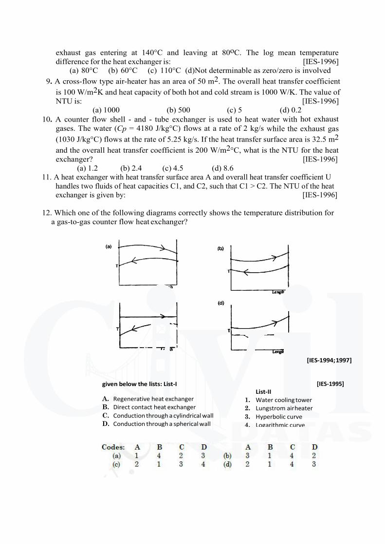
[IES-1994; 1997]
given below the lists: List-I
A. Regenerative heat exchanger
B. Direct contact heat exchanger
C. Conduction through a cylindrical wall
D. Conduction through a spherical wall
[IES-1995]
List-II
1. Water cooling tower
2. Lungstrom air heater
3. Hyperbolic curve
4. Logarithmic curve
exhaust gas entering at 140°C and leaving at 80oC. The log mean temperature
difference for the heat exchanger is: [IES-1996]
(a) 80°C (b) 60°C (c) 110°C (d)Not determinable as zero/zero is involved
9. A cross-flow type air-heater has an area of 50 m2. The overall heat transfer coefficient
is 100 W/m2K and heat capacity of both hot and cold stream is 1000 W/K. The value of
NTU is: [IES-1996]
(a) 1000 (b) 500 (c) 5 (d) 0.2
10. A counter flow shell - and - tube exchanger is used to heat water with hot exhaust
gases. The water (Cp = 4180 J/kg°C) flows at a rate of 2 kg/s while the exhaust gas
(1030 J/kg°C) flows at the rate of 5.25 kg/s. If the heat transfer surface area is 32.5 m2
and the overall heat transfer coefficient is 200 W/m2°C, what is the NTU for the heat
exchanger? [IES-1996]
(a) 1.2 (b) 2.4 (c) 4.5 (d) 8.6
11. A heat exchanger with heat transfer surface area A and overall heat transfer coefficient U
handles two fluids of heat capacities C1, and C2, such that C1 > C2. The NTU of the heat
exchanger is given by: [IES-1996]
12. Which one of the following diagrams correctly shows the temperature distribution for
a gas-to-gas counter flow heat exchanger?
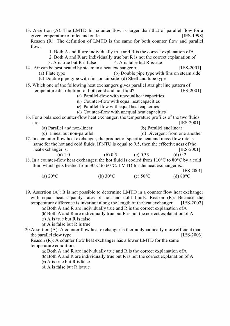
13. Assertion (A): The LMTD for counter flow is larger than that of parallel flow for a
given temperature of inlet and outlet. [IES-1998]
Reason (R): The definition of LMTD is the same for both counter flow and parallel
flow.
1. Both A and R are individually true and R is the correct explanation of A
2. Both A and R are individually true but R is not the correct explanation of
3. A is true but R is false 4. A is false but R is true
14. Air can be best heated by steam in a heat exchanger of [IES-2001]
(a) Plate type (b) Double pipe type with fins on steam side
(c) Double pipe type with fins on air side (d) Shell and tube type
15. Which one of the following heat exchangers gives parallel straight line pattern of
temperature distribution for both cold and hot fluid? [IES-2001]
(a) Parallel-flow with unequal heat capacities
(b) Counter-flow with equal heat capacities
(c) Parallel-flow with equal heat capacities
(d) Counter-flow with unequal heat capacities
16. For a balanced counter-flow heat exchanger, the temperature profiles of the two fluids
are: [IES-2001]
(a) Parallel and non-linear (b) Parallel and linear
(c) Linear but non-parallel (d) Divergent from one another
17. In a counter flow heat exchanger, the product of specific heat and mass flow rate is
same for the hot and cold fluids. If NTU is equal to 0.5, then the effectiveness of the
heat exchanger is: [IES-2001]
(a) 1.0 (b) 0.5 (c) 0.33 (d) 0.2
18. In a counter-flow heat exchanger, the hot fluid is cooled from 110°C to 80°C by a cold
fluid which gets heated from 30°C to 60°C. LMTD for the heat exchanger is:
[IES-2001]
(a) 20°C (b) 30°C (c) 50°C (d) 80°C
19. Assertion (A): It is not possible to determine LMTD in a counter flow heat exchanger
with equal heat capacity rates of hot and cold fluids. Reason (R): Because the
temperature difference is invariant along the length of the heat exchanger. [IES-2002]
(a) Both A and R are individually true and R is the correct explanation of A
(b) Both A and R are individually true but R is not the correct explanation of A
(c) A is true but R is false
(d) A is false but R is true
20.Assertion (A): A counter flow heat exchanger is thermodynamically more efficient than
the parallel flow type. [IES-2003]
Reason (R): A counter flow heat exchanger has a lower LMTD for the same
temperature conditions.
(a) Both A and R are individually true and R is the correct explanation of A
(b) Both A and R are individually true but R is not the correct explanation of A
(c) A is true but R is false
(d) A is false but R is true
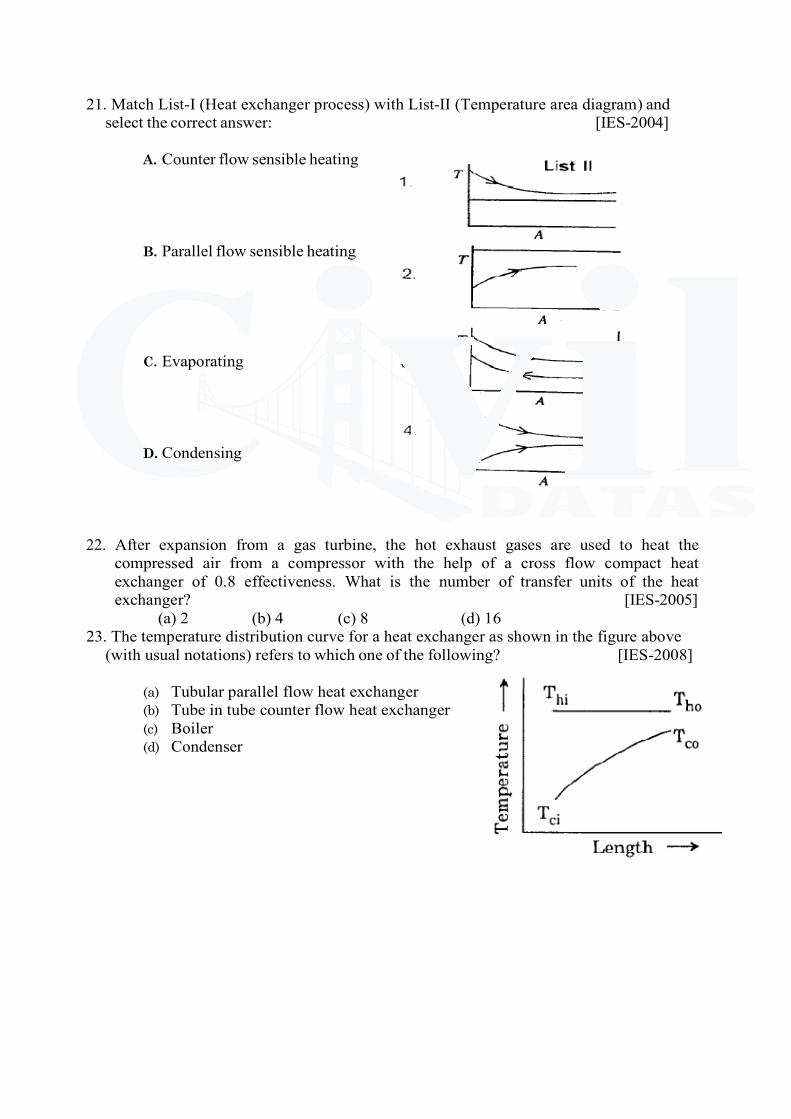
21. Match List-I (Heat exchanger process) with List-II (Temperature area diagram) and
select the correct answer: [IES-2004]
A. Counter flow sensible heating
B. Parallel flow sensible heating
C. Evaporating
D. Condensing
22. After expansion from a gas turbine, the hot exhaust gases are used to heat the
compressed air from a compressor with the help of a cross flow compact heat
exchanger of 0.8 effectiveness. What is the number of transfer units of the heat
exchanger? [IES-2005]
(a) 2 (b) 4 (c) 8 (d) 16
23. The temperature distribution curve for a heat exchanger as shown in the figure above
(with usual notations) refers to which one of the following? [IES-2008]
(a) Tubular parallel flow heat exchanger
(b) Tube in tube counter flow heat exchanger
(c) Boiler
(d) Condenser
24. Match List-I (Application) with List-II (Type of heat exchanger) and select the correct
answer using the code given below the lists: [IES-2008]
List-I List-II
A. Gas to liquid 1. Compact
B. Space vehicle 2. Shell and Tube
C. Condenser 3. Finned tube
D. Air pre-heater 4. Regenerative
Codes: A B C D A B C D
(a) 2 4 3 1 (b) 3 1 2 4
(c) 2 1 3 4 (d) 3 4 2 1
25. Match List-I with List-II and select the correct answer [IES-2008]
List-I List-II
A. Number of transfer units 1. Recuperative type heat exchanger
B. Periodic flow heat exchanger 2. Regenerator type heat exchanger
C. Chemical additive 3. A measure of the heat exchanger size
D. Deposition on heat exchanger surface 4. Prolongs drop-wise condensation
5. Fouling factor
26.Consider the following statements: [IES-2008]
In a shell and tube heat exchanger, baffles are provided on the shell side to:
1. Prevent the stagnation of shell side fluid
2. Improve heat transfer
3. Provide support for tubes
Select the correct answer using the codes given below:
27. The 'NTU' (Number of Transfer Units) in a heat exchanger is given by which one of the
following? [IES-2008]
U = Overall heat transfer coefficient C = Heat capacity
E = Effectiveness A = Heat exchange area
28. Consider the following statements: [IES-2009]
The flow configuration in a heat exchanger, whether counter flow or otherwise, will
NOT matter if:
1. A liquid is evaporating 2. A vapour is condensing
3. Mass flow rate of one of the fluids is far greater Of these statements:
(a) 1 and 2 are correct (b) 1 and 3 are correct
(c) 2 and 3 are correct (d) 1, 2 and 3 are correct
29. In a balanced counter flow heat exchanger with MhCh McCc the NTU is equal to 1.0.
What is the effectiveness of the heat exchanger? [IES-2009]
(a) 0.5 (b) 1.5 (c) 0.33 (d) 0.2
Prepared by: Dr.P.Nageswara Reddy
Codes: A B C D A B C D
(a) 3 2 5 4 (b) 2 1 4 5
(c) 3 2 4 5 (d) 3 1 5 4
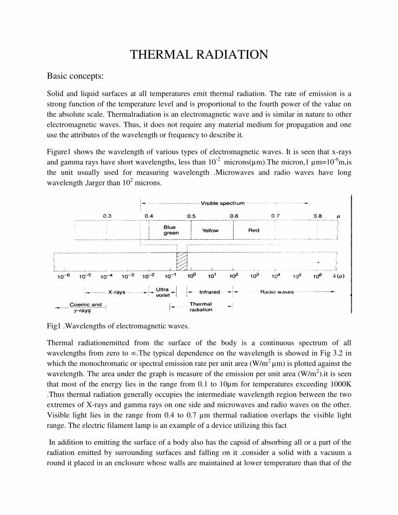
THERMAL RADIATION
Basic concepts:
Solid and liquid surfaces at all temperatures emit thermal radiation. The rate of emission is a
strong function of the temperature level and is proportional to the fourth power of the value on
the absolute scale. Thermalradiation is an electromagnetic wave and is similar in nature to other
electromagnetic waves. Thus, it does not require any material medium for propagation and one
use the attributes of the wavelength or frequency to describe it.
Figure1 shows the wavelength of various types of electromagnetic waves. It is seen that x-rays
and gamma rays have short wavelengths, less than 10-2
microns(µm).The micron,1 µm=10-6
m,is
the unit usually used for measuring wavelength .Microwaves and radio waves have long
wavelength ,larger than 102 microns.
Fig1 .Wavelengths of electromagnetic waves.
Thermal radiationemitted from the surface of the body is a continuous spectrum of all
wavelengths from zero to ∞.The typical dependence on the wavelength is showed in Fig 3.2 in
which the monochromatic or spectral emission rate per unit area (W/m2
µm) is plotted against the
wavelength. The area under the graph is measure of the emission per unit area (W/m2).it is seen
that most of the energy lies in the range from 0.1 to 10µm for temperatures exceeding 1000K
.Thus thermal radiation generally occupies the intermediate wavelength region between the two
extremes of X-rays and gamma rays on one side and microwaves and radio waves on the other.
Visible light lies in the range from 0.4 to 0.7 µm thermal radiation overlaps the visible light
range. The electric filament lamp is an example of a device utilizing this fact
In addition to emitting the surface of a body also has the capsid of absorbing all or a part of the
radiation emitted by surrounding surfaces and falling on it .consider a solid with a vacuum a
round it placed in an enclosure whose walls are maintained at lower temperature than that of the
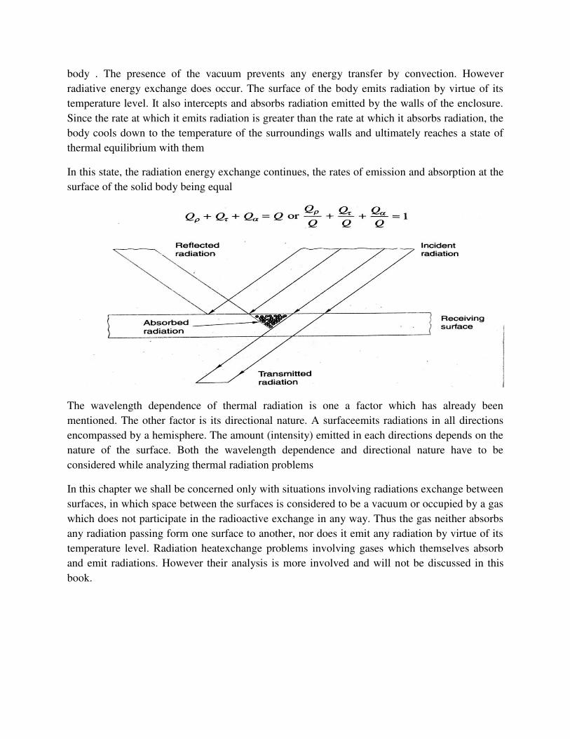
body . The presence of the vacuum prevents any energy transfer by convection. However
radiative energy exchange does occur. The surface of the body emits radiation by virtue of its
temperature level. It also intercepts and absorbs radiation emitted by the walls of the enclosure.
Since the rate at which it emits radiation is greater than the rate at which it absorbs radiation, the
body cools down to the temperature of the surroundings walls and ultimately reaches a state of
thermal equilibrium with them
In this state, the radiation energy exchange continues, the rates of emission and absorption at the
surface of the solid body being equal
The wavelength dependence of thermal radiation is one a factor which has already been
mentioned. The other factor is its directional nature. A surfaceemits radiations in all directions
encompassed by a hemisphere. The amount (intensity) emitted in each directions depends on the
nature of the surface. Both the wavelength dependence and directional nature have to be
considered while analyzing thermal radiation problems
In this chapter we shall be concerned only with situations involving radiations exchange between
surfaces, in which space between the surfaces is considered to be a vacuum or occupied by a gas
which does not participate in the radioactive exchange in any way. Thus the gas neither absorbs
any radiation passing form one surface to another, nor does it emit any radiation by virtue of its
temperature level. Radiation heatexchange problems involving gases which themselves absorb
and emit radiations. However their analysis is more involved and will not be discussed in this
book.
Emission characteristics and laws of black-body radiation
We shall now define a number of terms concerned with theemission characteristics of surfaces
and then state the associated laws. It is useful to introduce first the concept of ideal surfaces
called a black body or black surface. A black surface is one which absorbs all radiation falling on
regardless of its wavelength or direction .For a given a temperature and wavelength. It emits the
maxima amount of energy. It thus serves as a standard on which to base the emission
characteristics.
Definition 1: the radiant flux emitted from the surface of a body is called the total hemispherical
emissive power and will be denoted by the symbol e (units W/m2). The total hemispherical
emissive power of black surfacewill be denoted by is. The adjectives 𝑒 = 𝜖𝜎𝑇4
Where the constant 𝜎 = 5.670 Χ 10−8 𝑊 𝑚2𝐾4⁄ . aboveequation is the Stefan-Boltzmann law
and the constant 𝜎 is called the Stefan-Boltzmann constant.
Definition 2 : the total hemispherical emissivity of a surface is the ratio of the total
hemispherical emissive power of the surface to the total hemispherical emissive power of a black
surface at the same temperature it will be denoted by the symbol Є. Thus,
Є = 𝑒𝑒𝑏
It follows from the definition that the total hemispherical emissivity of a black surface is unity.
Definition-3: The monochromatic hemispherical emissive power of a surface at a wavelength ג is the radiant flux emitted from the surface per unit wavelength about the
wavelength(ג).Alternatively, it can be defined as the quantity which when integrated over all
wavelengths yields total hemispherical emissive power. It will be denoted by the symbol 𝑒ג(units: W/m2 µm). The monochromatic hemispherical emissive power of a black surface will
be denoted by 𝑒ג .The adjectives monochromatic and hemispherical indicate that the quantity
being defined is for a particular wavelength summed over all directions.From the definition it
follows that 𝑒ג = 𝑑𝑒 𝑑ג or 𝑑𝑒 = 𝑒ג dג
Integrating over all wavelengths, we get
e =∫ 𝑒ג∞0 𝑑ג
Similarly fora black surface,
𝑒𝑏 = ∫ 𝑒𝑏ג∞0 dג
Definition-4 : The monochromatic hemispherical emissivity of a surface is the ratio of the
monochromatic hemispherical emissive power of the surface to the monochromatic
hemispherical emissive power of a black surface at the same temperature and wavelength. Thus
єג=𝑒ג𝑒𝑏ג
It is easily seen that the emissivity and monochromatic emissivity of a surface are related as
follows:
Є = 1𝑒𝑏 ∫ єג𝑒𝑏ג∞0 dג
Typically the monochromatic emissivity of a surface will vary in some irregular fashion between
0 and 1.
However, for purposes of analysis, we often idealize a surface by assuming that the value is a
constant. Such a surface is called a gray surface.
The symbol H (units: W/m2). The quantity H is a summation of radiation of all wavelengths
coming from all directions.
Definition 7: thetotal hemisphere absorptivity of a surface is the fraction of the total hemisphere
irradiation absorbed by it. It will be denoted by the symbol α. Thus
α = Ha/H
Where Ha is the absorbed flux. For a black surface, α = 1.
Definition 8: The monochromatic hemisphere irradiation at a wavelength λ is the radiant flux incident on a surface per unit wavelength about the wavelength λ. alternatively, it can be defined as the quantity which when integrated overall wavelengths yields the total hemispherical
irradiation. It will be denoted by the symbol Hλ (units/m2 µm). From the definition
Hλ= dH/dλ
Or dH = Hλdλ
Integrating overall wavelengths, we get
H = ∫0∞ Hλ dλ
Definition9:The monochromatic hemispherical absorptivity of a surface is the fraction of the
monochromatic hemispherical irradiation absorbed by it. It will be denoted by the symbol αλ.
Thus
αλ = Hαλ/Hλ
Where Haλ is the absorbed flux at wavelength λ. For black surface, αλ = 1.
From the definitions, it follows that α and αλ are related by the equation
α =1/H ∫0∞αλ Hλ dλ
In an analogous manner to definitions 7 and 9, we can also define terms like total hemispherical
reflectivity (ρ), monochromatic hemispherical reflectivity (ρλ), total hemispherical transmissivity
(Ϯ) and monochromatic hemispherical transmissivity (Ϯλ).Equations similar to equations (3.3.1),
(3.3.4) and (3.3.5) can be written with the subscripts r and t being used to indicate the reflected
and transmitted quantities. As in section 3.2, we shall often refer to α, ρ and Ϯ as the absorptivity,
reflectivity and transmissivity respectively. Similarly αλ ,ρλ and Ϯλ will be referred to as the
monochromatic absorptivity, monochromatic reflectivity and monochromatic transmissivity
respectively and monochromatic transmissivity respectively.
From the definitions it follows that
α + ρ + Ϯ = 1
And αλ + ρλ + Ϯλ = 1
In case the body is opaque and does not allow any radiation to be transmitted through it, then
α + ρ = 1
And αλ + ρλ = 1
For a non-black surface having an emissivity𝜖,it follows that 𝑒 = 𝜖𝜎𝑇4 (3.2.10)
It is of historic interest to note that both Wien’s law and the Stefan-Boltzmann law were
independently developed before Planck’s law and consequently were not originally derived in
the manner shown above.
In many applications, it is necessary to determine the flux emitted by a black body at a
temperature T over the wavelength interval 0 to𝜆. This is given by 𝑒𝑏(0−𝜆)=∫ 𝑒𝑏𝜆𝜆0 𝑑𝜆
We define 𝐷0−𝜆 as the ratio of the radiant flux emitted over the wavelength interval 0 to 𝜆 to the
radiant flux emitted over the entire interval of 0 to∞. Thus
𝐷0−𝜆 = ∫ 𝑒𝑏𝜆𝜆0 𝑑𝜆∫ 𝑒𝑏𝜆∞0 𝑑𝜆 = ∫ 𝑒𝑏𝜆𝜆0 𝑑𝜆𝜎𝑇4
Substituting the expression for Planck’s law and re-arranging terms, we get D0−λ = ∫ 2𝜋𝐶1𝜆5[exp(𝐶2 𝜆𝑇⁄ ) − 1] 1𝜎𝑇4 𝑑𝜆𝜆0
= ∫ 2𝜋𝐶1𝜎(𝜆𝑇)5[exp(𝐶2 𝜆𝑇⁄ ) − 1] 𝑇𝑑𝜆𝜆0
Changing the variable of integration from 𝜆 to 𝜆𝑇, we have
𝐷0−𝜆 = ∫ 2𝜋𝐶1𝜎(𝜆𝑇)5[exp(𝐶2 𝜆𝑇⁄ ) − 1] 𝑑(𝜆𝑇)𝜆𝑇0
The integration required in equation (3.2.12) cannot be solved analytically and has been
done numerically. The results are presented in table 3.1 where the fraction 𝐷0−𝜆 ranging from 0
to 1 is tabulated as a function of parameters 𝜆T. Note the advantage of introducing the
combination parameter 𝜆T. The integration need not be done for different values of 𝜆 and
different values of T. thus the effort involved in doing the integration is reduced and the result
are also presented in a compact from
Solid Angle and Radiation Intensity
We now turn our tension to the directional nature of thermal radiation and define two terms –
solid angle and radiation intensity.
Consider the radiation emitted from the differential area dA1 towards the area A2 in below
fig. it is obvious that although radiation streams out from dA1 in all directions encompassed by a
hemisphere, only that part which falls within the solid angle subtended by A2 at dA1 will reach
A2.
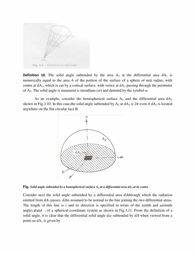
Definition 10. The solid angle subtended by the area A2 at the differential area dA1 is
numerically equal to the area A of the portion of the surface of a sphere of unit radius, with
centre at dA1, which is cut by a conical surface, with vertex at dA1 passing through the perimeter
of A2. The solid angle is measured is steradians (sr) and denoted by the symbol ω
As an example, consider the hemispherical surface A2 and the differential area dA1
shown in Fig.3.10. In this case,the solid angle subtended by A2 at dA1 is 2𝜋 even if dA1 is located
anywhere on the flat circular face B.
Fig. Solid angle subtended by a hemispherical surface A2 at a differential area dA1 at its centre
Consider next the solid angle subtended by a differential area 𝑑𝐴through which the radiation
emitted from 𝑑𝐴1 passes. 𝑑𝐴is assumed to be normal to the line joining the two differential areas.
The length of this line is r and its direction is specified in terms of the zenith and azimuth
angles,𝜓and , of a spherical coordinate system as shown in Fig.3.11. From the definition of a
solid angle, it is clear that the differential solid angle d𝜔 subtended by 𝑑𝐴 when viewed from a
point on dA1 is given by
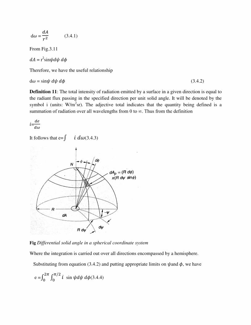
d𝜔 = 𝑑𝐴𝑟2 (3.4.1)
From Fig.3.11 𝑑𝐴 = r2sin𝜓𝑑𝜓 𝑑𝜙
Therefore, we have the useful relationship
d𝜔 = sin𝜓 𝑑𝜓 𝑑𝜙 (3.4.2)
Definition 11: The total intensity of radiation emitted by a surface in a given direction is equal to
the radiant flux passing in the specified direction per unit solid angle. It will be denoted by the
symbol i (units: W/m2sr). The adjective total indicates that the quantity being defined is a
summation of radiation over all wavelengths from 0 to ∞. Thus from the definition 𝑖=𝑑𝑒𝑑𝜔
It follows that e=∫ 𝑖 𝑑𝜔(3.4.3)
Fig Differential solid angle in a spherical coordinate system
Where the integration is carried out over all directions encompassed by a hemisphere.
Substituting from equation (3.4.2) and putting appropriate limits on 𝜓and 𝜙, we have
e =∫ ∫ 𝑖 𝜋/202𝜋0 sin 𝜓𝑑𝜓 𝑑𝜙(3.4.4)
For many real surfaces, the variation of total radiation intensity with direction is given
approximately by the relation
i= 𝑖𝑛cos𝜓(3.4.5)
Where 𝑖𝑛 = intensity in the normal direction to the surface. Equation (3.4.5) is called Lambert’s
law and a surface emitting radiation in this manner is referred to as a diffuse surface. Black
surfaces obey Lambert’s law exactly. Substituting Lambert’s law into equation (3.4.4), we can
find a relation between emissive power and normal intensity. We get
e =∫ ∫ 𝑖𝑛𝜋/202𝜋0 cos𝜓 sin 𝜓𝑑𝜓 𝑑𝜙
= 2𝜋𝑖𝑛 ∫𝜋/20 cos𝜓 sin 𝜓𝑑𝜓
=𝜋𝑖𝑛(3.4.6)
Thus for a diffuse surface, the emissive power is 𝜋 times the normal intensity of radiation.
Laws of black body -radiation:
We shall now consider the laws of black- body radiation.These are planck’s law,wien’s law and
Stefan-Boltzmann law.
Planck’s law:
From electromagnetic considerations, planck showed that the monochromatic(spectral) emmisve power of
a black surface is given by
𝑒𝑏𝜆 = 2𝜋𝐶1𝜆5[𝑒𝑥𝑝(𝐶2 𝜆𝑇⁄ ) − 1] Where 𝐶1 and 𝐶2 are constants whose values are found from experimental data to be 0.596𝑋10−6W𝑚2
and 0.014387 m K respectively ,𝜆 is the wavelength and T, the absolute temperature (in k) of the black
surface.
For non-black surface having a monochromatic emissivity 𝜖𝜆,it follows that
𝑒𝑏𝜆 = 2𝜋𝐶1𝜆5[𝑒𝑥𝑝(𝐶2 𝜆𝑇⁄ ) − 1] Typical curves obtained by plotting equation (3.2.6) for different values of temperature are in Fig..3.5.It I
seen that a particular temperature , the value of 𝑒𝑏𝜆 increases with wavelength ,passes through a
maximum and the decreases asymptotically to zero as 𝜆 ⟶ ∞ . It is also seen that at the same wavelength
as the temperature increases.The truth of the statement made earlier that most of the energy for
temperature above 1000K is emitted in the range from 0.1 t0 10𝜇𝑚 is also seen from Fig.3.5
Wein’s law :
the location of the maximum of the curves plotted in Fig.3.5.can be found readily by differentiating the
right –hand side of the equation (3.2.6) with respect to 𝜆 and equation it to zeroputting 𝐶2 𝜆𝑇⁄ =𝒴, after
simplification we get 𝑒𝒴(5 − 𝒴) = 5
By trail and error.𝒴 = 4.965
Therefore, f 𝜆𝑚 denotes the location of the maximum
𝜆𝑚𝑇 = 0.0143874965 = 0.00290 𝑚𝐾
above Equation is often called Wien’s law.
Stefan-Boltzmann law :
The emissive power of a black surface can be found by integrating the expression for planck’s law over
all wavelengths. Thus
44
4
2
4
1
444
2
4
1
22
3
01
1
2
2
01
2
2
5010
)90
(6
2
......)3
1
2
11(
62
....2)/(exp)/(exp2
1)/exp(2
)/1(/1
1)exp(
12
TσC
TC
C
TC
xTCxTCxC
dxTTCxCe
λdλanddxλngxsubstituti
λdTλCλ
Cλdee
b
bb
Solid angle and radiation intensity:
we now turn our attention to the directional nature of thermal radiation and to
define two terms-solid angle and radiation intensity.
Consider the radiation emitted from the differential area dA1 towards the area A2 in fig.3.. it is
obvious that although radiation streams out from dA1 in all directions encompassed by a
hemisphere ,only that part which falls within the solid angle subtended by A2 at dA1 will reach
A2.
Definition 10:the solid angle subtended by the area A2 at the differential area dA1 is numerically
equal to the area A of the portion of the surface of a sphere of unit radius, with centre
dA1,which is cut out by a conical surface , with vertex at dA1 passing through the perimeter of
A2.the solid angle is measured in Steradians (sr) and denoted by the symbol ω.
As an example ,consider the hemispherical surface A2 and the differential area dA1 as shown. In
this case ,the solid angle subtended by A2at dA1 is 2𝜋.the solid angle would continue to be
2𝜋even if dA1 is located anywhere on the flat circular face B.
Consider next the solid angle subtended by a differential area dA through which the radiation
emitted from dA1 passes . dA is assumed to be normal to the line joining the two differential
areas .the length of this line is r and its direction is specified in terms of the zenith and azimuth
angles ,𝜑𝑎𝑛𝑑𝛹 , of a spherical co-ordinate system as shown in fig.3.11. from the definition of a
solid angle, it is clear that the differential solid angle dω subtended by dA when viewed from a point on dA1, is given by
dω = dA/r2
from fig dA = r^2sin 𝛹𝑑𝛹𝑑𝛷
Therefore , we have the useful relationship
dω = sin 𝛹𝑑𝛹𝑑𝛷
Definition 11:
The total intensity of radiation emitted by a surface in a given direction is equal to the radiant
flux passing in the specified direction per unit solid angle .it will be denoted by the symbol I
(units :W/m^2sr). the adjective total indicates the quantity being defined is a summation of
radiation over all wavelengths from 0 to ∞.thus from the definition
i=de/dω
it follows that e= ∫ 𝑖𝑑𝜔