Factors Affecting the Harmonics Generated by a Generic Voltage Source Converter within a Microgrid
8
1 Abstract-- The increased penetration of renewable and alternative energy systems such as wind turbines and photovoltaic cells upon the distribution network has led to a new concept called “Microgrid”. The renewable/alternative generation systems upon the microgrid are sometimes referred to as Distributed Energy Resource (DER) system and are usually interfaced with the grid using power electronic converters. However, as the power converter switch at high frequencies, harmonic voltages and currents are generated at the converter terminals and these harmonics are further transmitted to the microgrid/grid. This paper presents and evaluates different factors that may affect the produced harmonics and reduce the quality of supply including the switching frequency, modulation index and the converter topology. It clearly shows in detail the relation between these factors and the harmonics generated by the converters. Moreover, it introduces a generic model of a DER grid interfacing Voltage Source Converter (VSC). The paper also presents methods that can be used to mitigate these harmonics. The simulation was modelled and the results are presented using MATLAB Simulink TM and Plecs TM simulation tools. Index Terms—Current Mode Control, Filters, Harmonics, Microgrid, Plecs Modeling, Sinusoidal Pulse Width Modulation, Voltage Source Converters. I. INTRODUCTION he ever increasing demand for electrical energy, the need to conserve fuel sources due to its depletion and the environmental challenges being faced by the world have led to the use of renewable and alternative energy sources in the generation of electrical energy [1], [2]. The increased penetration of renewable and alternative energy systems such as wind turbines and photovoltaic cells upon the distribution network has led to a new concept called “Microgrid” [3]. The microgrid can be described as a close assemblage of small controllable generators, energy storage systems and loads in order to optimize the use of renewable and/or alternative energy generation sources [3], [4]. An advantage of the microgrid is that it can be connected to the The authors are with the George Green Institute of Electromagnetic Research (GGIEMR), Electrical Systems and Optics Research Division, The University of Nottingham, NG7 2RD, Nottingham, UK. (email: [email protected], [email protected], [email protected]). grid to meet the grids electrical energy demand or in a stand- alone mode be used to supply energy to its immediate locality [3], [4]. The renewable/alternative generation systems in the microgrid are sometimes referred to as Distributed Energy Resource (DER) system, and they are usually interfaced with the grid using power electronic converters [3], [4]. Recently, most of the DER system converters are Voltage Source Converters (VSC) which consists of Insulated Gate Bipolar Transistors (IGBTs) for superior controllability and very fast switching responses [5]. As the DER system grid interfacing VSC converter switch at high frequencies, harmonic voltages and currents are generated upon the VSC converter terminals and are further transmitted to the microgrid/grid [5], [6], [7]. The generated harmonics can have adverse effects on the microgrid/grid as it causes sensitive loads and equipment to trip or malfunction, voltage flickers, reduction of equipment life span, overheating of distribution transformer [8]. For these reasons it has become necessary to investigate the harmonics generated by VSC converters on microgrids and establish ways to mitigate these harmonics and ensure best quality of power. This paper presents a generic DER grid interfacing VSC converter (as shown in Fig. 1) whose switching strategy is based on the Sinusoidal Pulse Width Modulation (SPWM) technique and the control scheme is achieved using the current control method. The controllers are the conventional Proportional Integral (PI) controllers. The factors that affect the harmonics produced by VSC converters have been researched and discussed in various literatures [5]-[7], [9], however, they have not clearly shown the exact impact of these factors on the generated harmonics. Therefore the aim of this paper is to present and clearly evaluate important factors that affect harmonics generated on this microgrid system by a VSC converter. GSVSC Edc Idc Rg Lg Grid Vgabc Igabc Distributed Source C Vgcabc IL Ic Fig. 1. A single line diagram of a grid interfacing DER system VSC converter (GSVSC). Factors Affecting the Harmonics Generated by a Generic Voltage Source Converter within a Microgrid Preye M. Ivry, Muhyaddin J. Rawa, and D. W. P. Thomas Electrical Systems and Optics Research Division, The University of Nottingham, UK T
-
Upload
nottingham -
Category
Documents
-
view
5 -
download
0
Transcript of Factors Affecting the Harmonics Generated by a Generic Voltage Source Converter within a Microgrid

1
Abstract-- The increased penetration of renewable and alternative
energy systems such as wind turbines and photovoltaic cells upon
the distribution network has led to a new concept called
“Microgrid”. The renewable/alternative generation systems upon
the microgrid are sometimes referred to as Distributed Energy
Resource (DER) system and are usually interfaced with the grid
using power electronic converters. However, as the power
converter switch at high frequencies, harmonic voltages and
currents are generated at the converter terminals and these
harmonics are further transmitted to the microgrid/grid.
This paper presents and evaluates different factors that may
affect the produced harmonics and reduce the quality of supply
including the switching frequency, modulation index and the
converter topology. It clearly shows in detail the relation between
these factors and the harmonics generated by the converters.
Moreover, it introduces a generic model of a DER grid
interfacing Voltage Source Converter (VSC). The paper also
presents methods that can be used to mitigate these harmonics.
The simulation was modelled and the results are presented using
MATLAB SimulinkTM and PlecsTM simulation tools.
Index Terms—Current Mode Control, Filters, Harmonics,
Microgrid, Plecs Modeling, Sinusoidal Pulse Width Modulation,
Voltage Source Converters.
I. INTRODUCTION
he ever increasing demand for electrical energy, the need
to conserve fuel sources due to its depletion and the
environmental challenges being faced by the world have
led to the use of renewable and alternative energy sources in
the generation of electrical energy [1], [2].
The increased penetration of renewable and alternative
energy systems such as wind turbines and photovoltaic cells
upon the distribution network has led to a new concept called
“Microgrid” [3]. The microgrid can be described as a close
assemblage of small controllable generators, energy storage
systems and loads in order to optimize the use of renewable
and/or alternative energy generation sources [3], [4]. An
advantage of the microgrid is that it can be connected to the
The authors are with the George Green Institute of Electromagnetic
Research (GGIEMR), Electrical Systems and Optics Research Division,
The University of Nottingham, NG7 2RD, Nottingham, UK.
(email: [email protected], [email protected],
grid to meet the grids electrical energy demand or in a stand-
alone mode be used to supply energy to its immediate locality
[3], [4].
The renewable/alternative generation systems in the
microgrid are sometimes referred to as Distributed Energy
Resource (DER) system, and they are usually interfaced with
the grid using power electronic converters [3], [4]. Recently,
most of the DER system converters are Voltage Source
Converters (VSC) which consists of Insulated Gate Bipolar
Transistors (IGBTs) for superior controllability and very fast
switching responses [5].
As the DER system grid interfacing VSC converter switch
at high frequencies, harmonic voltages and currents are
generated upon the VSC converter terminals and are further
transmitted to the microgrid/grid [5], [6], [7].
The generated harmonics can have adverse effects on the
microgrid/grid as it causes sensitive loads and equipment to
trip or malfunction, voltage flickers, reduction of equipment
life span, overheating of distribution transformer [8]. For these
reasons it has become necessary to investigate the harmonics
generated by VSC converters on microgrids and establish ways
to mitigate these harmonics and ensure best quality of power.
This paper presents a generic DER grid interfacing VSC
converter (as shown in Fig. 1) whose switching strategy is
based on the Sinusoidal Pulse Width Modulation (SPWM)
technique and the control scheme is achieved using the current
control method. The controllers are the conventional
Proportional Integral (PI) controllers.
The factors that affect the harmonics produced by VSC
converters have been researched and discussed in various
literatures [5]-[7], [9], however, they have not clearly shown
the exact impact of these factors on the generated harmonics.
Therefore the aim of this paper is to present and clearly
evaluate important factors that affect harmonics generated on
this microgrid system by a VSC converter.
GSVSC
Edc
Idc
Rg Lg
Grid
Vgabc
Igabc
Distributed
SourceC
Vgcabc
IL
Ic
Fig. 1. A single line diagram of a grid interfacing DER system VSC
converter (GSVSC).
Factors Affecting the Harmonics Generated by a
Generic Voltage Source Converter within a
Microgrid
Preye M. Ivry, Muhyaddin J. Rawa, and D. W. P. Thomas
Electrical Systems and Optics Research Division,
The University of Nottingham, UK
T

2
The paper also presents some methods that can be used to
mitigate these harmonics and design procedure for an LCL
filter was given.
Matlab SimulinkTM
[10] and PlecsTM
[11] simulation tools
are used to model the system. The measured harmonics were
quantified using the Individual Harmonic Distortion (IHD) and
THD indices.
II. VSC CONVERTER SWITCHING AND CONTROL
Understanding the switching pattern and control of the
IGBTs in the VSC is necessary as they can affect the generated
harmonics produced by a VSC converter [12].
A. Sinusoidal Pulse Width Modulation (SPWM)
The simplest and most common switching strategy adopted
for IGBTs of VSC converters is the SPWM [6], [13].
The SPWM compares a high frequency triangular wave
known as the carrier wave with a slow varying power
frequency sinusoidal signal that is referred to as the
modulating signal as shown in Fig. 2a. The points of
intersection between the triangular carrier wave and the
sinusoidal modulating signal determines the switching pattern
of the VSC converter IGBTs [5], [6], [13].
Fig. 2a. Sinusoidal Pulse Width Modulation (SPWM) Scheme.
The ratio of the peak amplitude of the modulating signal Vm
and the peak amplitude of the carrier signal Vtri gives the
amplitude modulation index ma [6]:
dc
a
tri
m
a
V
V
V
Vm
1)ˆ(2
ˆ
ˆ
(1)
where 1
)ˆ(a
V is the peak amplitude of the fundamental voltage,
Vdc is the DC voltage and ma ≤ 1.
Fig. 2b. 2-level VSC Terminal Voltage wrt DC Voltage.
The resulting voltage output fluctuates between two values
Vdc/2 and –Vdc/2 as shown in Fig. 2b.
The triangular carrier wave frequency determines the
switching frequency of the VSC converter [6] and the
frequency modulation index is:
m
sw
m
tri
f
f
f
f
fm (2)
where ftri is the frequency of the triangular carrier wave and is
equal to the switching frequency fsw of the VSC and fm is the
frequency of the sinusoidal modulating signal and is equal to
the fundamental frequency of the generated voltage waveform.
Fig. 2c. 2-level VSC Terminal Voltage Harmonic Performance.
It can be seen from Fig. 2c that the voltage contains
harmonics and mf is calculated using (2).
4050
2000
Hz
Hzm
f
The frequency, fh at which the harmonic voltage occurs is
given as [6]:
mfhfkjmf )( (3)
and the harmonic order, h corresponds to the kth sideband of j
times the frequency modulation index mf
kmjhf
)( (4)
j is the group index and k is the sideband harmonic index from
each group. When j is odd k is even and when j is even k is
odd [6], [13].
Fig. 2c shows that the dominant harmonics are at the
switching frequency and multiples of the switching frequency
having negative and positive sidebands. The frequencies at
which the harmonic occur are calculated using (3). For the first
set of harmonics around fsw, the harmonics appear at frequency
fh = 1900Hz, 2000Hz and 2100Hz and they correspond to the
orders, h = 38, 40, 42 using (4). The THD of the VSC terminal
voltage with respect to the DC voltage is 159.8%.
B. Control Technique
The conventional active and reactive current control
technique is employed to control the instantaneous active (P)
and reactive (Q) power of the VSC converter using a PI vector
controller. This is chosen as it is simple to design, less
complex to implement and has a robust control response in a
balanced system [12].
In the current control technique, the active and reactive
power flow in the microgrid is regulated by controlling the
3
active current component Igd and the reactive current
component Igq. The PI controllers forces Igd and Igq to track
certain reference commands Igdref and Igqref, respectively. Igdref
and Igqref are provided from a reference signal generator block.
Utilizing the instantaneous power theory [5]:
acdcPP (5)
)(2
3
gqgqgdgdgIVIVP (6a)
)(2
3
gqgdgdgqgIVIVQ (6b)
where Pdc is the DC source power and Pac is the active power
on the grid (Pg), Qg is the reactive power on the grid.
Since the phase voltage of the grid is aligned to the d-axis
reference frame then Vgq = 0 [5], so the equation can be further
reduced to:
)(2
3
gdgdgIVP (7a)
)(2
3
gqgdgIVQ (7b)
If Igd = Igdref and Igq = Igqref then Pg and Qg can be controlled by
Pgref and Qgref [5]. So that:
gref
gdref
gdrefP
VI
3
2 (8a)
gref
gdref
gqrefQ
VI
3
2 (8b)
Fig. 3 shows the control scheme utilized in the control of
the active and reactive power on the microgrid. GSVSC
Edc
Rg Lg
Grid
Vgabc
IgabcC
Vgcabc
Qg
weLgweLg
Id Current
Controller
Iq Current
Controller
Angle
Calculator
abc
αβ
abc
αβ
abc
αβ
αβ
dq
αβ
dq
dq
αβ
PWM Scheme
Iqref Signal
Generator
Iq*
Id*
Id
Iq
Vabc
Iabc
Mabc
Vd’
θ
Vq’
Vd
-
-
+
-
-
+-
+
-
+
Idref Signal
GeneratorPg
Fig. 3. P and Q Control Scheme for the grid interfacing VSC converter.
The PI controller design is based on the plant of the system
which is [5]:
gggq
gq
gd
gd
c
sLRsV
sI
sV
sIsG
1
)(
)(
)(
)()( (9)
where Rg is the resistance of the grid line (Ω) and Lg is the
inductance of the grid line (mH).
The DC side voltage would not require a controller since we
are considering a constant DC voltage source.
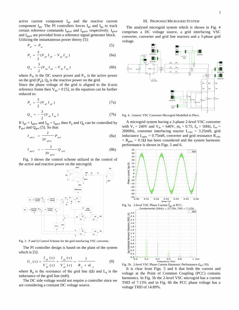
III. PROPOSED MICROGRID SYSTEM
The analysed microgrid system which is shown in Fig. 4
comprises a DC voltage source, a grid interfacing VSC
converter, converter and grid line reactors and a 3-phase grid
voltage.
Fig. 4. Generic VSC Converter Microgrid Modelled in Plecs.
A microgrid system having a 3-phase 2-level VSC converter
with Va = 240V and Vdc = 640V, ma = 0.75, fm = 50Hz, fsw =
2000Hz, converter interfacing reactor Lcabc = 3.25mH, grid
inductance Lgabc = 0.75mH, converter and grid resistance Rcabc
= Rgabc = 0.1Ω has been considered and the system harmonic
performance is shown in Figs. 5 and 6.
Fig. 5a. 2-level VSC Phase Current Iga at PCC.
Fig. 5b. 2-level VSC Phase Current Harmonic Performance (Iga1/10).
It is clear from Figs. 5 and 6 that both the current and
voltage at the Point of Common Coupling (PCC) contains
harmonics. In Fig. 5b the 2-level VSC microgrid has a current
THD of 7.13% and in Fig. 6b the PCC phase voltage has a
voltage THD of 14.89%.

4
Fig. 6a. 2-level VSC Voltage at PCC Vga.
Fig. 6b. 2-level VSC Voltage at PCC Harmonic Performance (Vga1/10).
IV. FACTORS AFFECTING THE HARMONICS GENERATED BY A
GENERIC VSC CONVERTER ON A MICROGRID
The major factors that affect the generated harmonics by an
SPWM VSC converter are:
The Switching Frequency (fsw)/Frequency Modulation
Index (mf)
The Amplitude Modulation Index (ma)
The Converter Topology
A. The Switching Frequency/ Frequency Modulation Index
For a SPWM VSC grid interfacing converter, the generated
harmonics would appear at fsw, and its multiples. There would
also be positive and negative sidebands centred around the
switching frequency and its multiples. This is true for all
values where ma range is from 0 – 1 [6], [13]. In this case mf
defines the frequency at which the harmonic voltage or current
would occur. The frequency, fh at which the harmonic would
occur is given by (3) and the harmonic order by (4).
Fig. 7a. 2-level VSC Phase Current Iga at PCC at fsw = 4kHz.
The fsw can be increased to reduce the harmonics but
considerations should be given to the VSC switching losses, as
increasing fsw to reduce harmonics is done at the expense of
increasing the VSC converter switching losses [5].
To evaluate the effect of the fsw and mf we would increase fsw
from 2kHz to 4kHz and then 8kHz.
Fig. 7b. 2-level VSC Phase Current Harmonic Performance (Iga1/10) at fsw =
4kHz.
Fig. 8. Voltage at PCC Harmonic Performance (Vga1/10) at fsw = 4kHz.
Fig. 9a. 2-level VSC Phase Current Iga at PCC at fsw = 8kHz.
Fig. 9b. 2-level VSC Phase Current Harmonic Performance (Iga1/10) at fsw =
8kHz.

5
Fig. 10. Voltage at PCC Harmonic Performance (Vga1/10) at fsw = 8kHz.
Increasing fsw to 4kHz and 8kHz reduces the impact of the
generated harmonics on the microgrid at the systems frequency
[7]. Figs. 7–10 show that when the frequency of the converter
increases the order at which the harmonic appears increases
and hence would have a lesser impact on the microgrid at the
system frequency [7]. The voltage THD (14.9%) is similar for
all cases this is due to the fact that the IGBTs still switch
through 640V, but as shown in Figs. 7b and 9b the current
THD reduces with the increase of fsw. The current THD
reduces from 7.13% to 3.69% at fsw = 4kHz and when fsw is
further increased to 8kHz the current THD is reduced to
2.12%. The maximum current IHD reduces from 1.1A to
0.25A at 8kHz. The THD is calculated over the entire range of
harmonics on the system using (10). The harmonic groups are
still present, only that they now appear after every 4000Hz as
in Figs. 7b and 8 and after every 8000Hz as shown in Figs. 9b
and 10. Where:
%100
1
1
2max
I
I
THD
h
h h (10)
I1 is the fundamental current component (A), Ih is the
individual current harmonic (A) and hmax is the maximum
harmonic order. This formula can be used for both current and
voltage harmonic calculations.
B. The Amplitude Modulation Index (ma)
The amplitude modulation index determines the amplitude of
the generated current/voltage harmonics at the switching
frequency and its multiples having positive and negative
sidebands. The amplitude of the harmonic is independent of the
modulation frequency index [6], [9], [13]. In practice, ma for an
SPWM VSC converter is usually between 0.6–0.9. Figs. 11–14
show the harmonic performance for the 2-level VSC microgrid
system when the ma is varied from 0.75 to 0.6 and 0.91.
Fig. 11. 2-level VSC Phase Current Harmonic Performance (Iga1/10) at ma =
0.6.
Fig. 12. Voltage at PCC Harmonic Performance (Vga1/10) at ma=0.60.
Fig. 13. 2-level VSC Phase Current Harmonic Performance (Iga1/10) at
ma=0.91.
Fig. 14. Voltage at PCC Harmonic Performance (Vga1/10) at ma=0.91.
In Fig. 11 ma was 0.6 and current THD was 7.84% when ma
was 0.75 in Fig. 5b current THD was 7.13% but as ma was
increased to 0.91 current THD became 6.70%. For a microgrid
with a fixed system phase voltage of 240V, a lower ma implies
a higher DC voltage. This means the VSC IGBTs are made to
switch between a higher DC voltage thus generating higher
amplitudes of the IHD on the voltage. From the above results
in Figs. 12 and 14 it is clearly seen how the amplitude
modulation index, ma affects the voltage harmonics generated
by the VSC. As the ma increased from 0.6 – 0.91 it is observed
that maximum amplitude of the individual harmonic voltages
reduces from 22.5V to 11V thus reducing the voltage THD at
PCC from 18.26% to 12.01%.
C. The Converter Topology
The converter topology determines the maximum voltage a
single IGBT would be required to switch through [9].
Conventionally, the 2-level VSC converter topology has been
extensively used in low and medium power systems. In the

6
case of the 2-level VSC, the IGBTs are made to switch
through the full DC voltage Vdc. In series connection of these
devices the maximum voltage an IGBT is required to switch
through reduces and this has led to the introduction and use of
multilevel VSC converters in medium and high voltage level
applications and in HVDC links [9].
To illustrate how the converter topology affects the
generated harmonics, a 2-level VSC and a 3-level Neutral
Point Clamped (NPC) VSC as shown in Figs. 15a and 15b
respectively would be considered.
Fig. 15a. Generic 2-level VSC Converter Modelled in Plecs.
Fig. 15b. Generic 3-level VSC Converter Modelled in Plecs
In a microgrid system the 3-level VSC would be connected
to a 3-phase low voltage grid via line reactors and this would
help filter the generated current and voltage harmonics, thus
improving the VSC harmonic performance as seen in Figs. 16-
17.
Fig. 16a. 3-level VSC Phase Current Iga at PCC.
Fig. 16b. 3-level VSC Phase Current Harmonic Performance (Iga1/10).
It is clear from Fig. 16a that the current waveform of the 3-
level VSC is cleaner and more sinusoidal to that of the 2-level
VSC in Fig. 5a. Fig. 16b shows the current harmonic
performance is better than that of the 2-level VSC in Fig. 5b. It
has a reduced current IHD, the highest amplitude of the IHD is
0.48A at 1600Hz, whereas, the highest IHD for the 2-level
VSC microgrid system is about 1.1A at 1800Hz and there are
also high values of IHD above 0.8A at frequency 3950Hz and
4050Hz as seen in Fig. 5b. The 3-level VSC current THD is
3.28% while that of the 2-level VSC is 7.13%.
Fig. 17a. 3-level VSC Phase Voltage Vga at PCC.
Fig. 17b. 3-level VSC Voltage at PCC Harmonic Performance (Vga1/10).
The 3-level VSC terminal voltage IHD is much less than
that of the 2-level VSC as shown in Figs. 17b and 6b. The 3-
level VSC has a maximum voltage IHD of 4.2V, while that of
the 2-level VSC has a maximum IHD of 17V. In Fig. 17a it
can be seen that the 3-level VSC waveform is more sinusoidal
than that of the 2-level VSC in Fig. 6a.

7
It could also be seen that the harmonics of the 3-level VSC
contains more sidebands, which is due to the increased number
of switching within the 3-level NPC VSC converter IGBTs.
V. HARMONIC MITIGATION OF THE MICROGRID SYSTEM
Having analysed the major factors that affect harmonics
generated on a microgrid by a VSC converter, it would be
proper to investigate some of the techniques or methods used
in attenuating harmonics. The conventional way of attenuating
harmonics to meet the IEEE 519 harmonic standard [14] or
any other harmonic standards is by the use of filters. In
microgrids the filter most commonly used to mitigate ac
voltage/current harmonics are the L, LC or LCL filter [15].
The L filter provides little attenuation of −20dB/decade. Its
attenuation is based on the size of the filter inductance and is
dependent on the switching frequency [16], [17]. The LC filter
provides an attenuation of −40dB/decade but in a stiff grid
system the LC filter operates like an L filter whereby the shunt
element becomes ineffective and the attenuation is based on
the size of L [16].
The LCL filter provides a better attenuation of
−60dB/decade for frequencies in excess of the resonant
frequency. It achieves the harmonic attenuation with lower
switching frequencies [16], [17]. Notwithstanding, the LCL
filter has been known to cause lots of instability on the system
due to resonance [18]. To overcome this, a damping passive
element is used. An LCL filter is used and designed according
to the procedure shown below and their results are compared
with a system with no filter [16] - [19].
max
1 ˆ8
1
Lsw
dc
f
If
VL
(11)
ratedLII %20ˆ
max (12)
21 ffLL (13)
223
%15
ratedm
rated
f
Vf
PC
(14)
fff
ff
res
CLL
LL
21
21
(15)
fres
d
CR
3
1 (16)
Lf1 and Lf2 are filters inductances 1 and 2, max
ˆL
I is the peak
inductor maximum current ripple (A), α is a limiting factor for
Lf2, Cf is the filter capacitance (mF), ωres is the resonant
frequency (rad/s) and Rd is the damping resistance (Ω).
Using an LCL filter of Lf1 = 5mH, Cf = 18.49µF, Lf2 =
1.5mH, Rd = 2.81Ω for the 2-level VSC microgrid having an
initial system result as shown in Figs. 5 and 6, will achieve an
attenuation of the current and voltage harmonics to be within
the required IEEE 519 standard, that is below 5%.
Fig. 18a. 2-level VSC LCL Filtered Phase Current Iga at PCC.
Fig. 18b. LCL Filtered Phase Current Harmonic Performance (Iga1/10).
Fig. 19a. 2-level VSC LCL Filtered Voltage at PCC.
Fig. 19b. LCL Filtered Voltage at PCC Harmonic Performance (Vga1/10).
Figs. 18a and 19a shows a cleaner and more sinusoidal grid
current and voltage waveform at the point of common coupling
as compared to Figs. 5a and 6a. In Fig. 18b it can be clearly
seen that the current harmonics are successfully attenuated to
2.06% from 7.13% with the help of an LCL filter and Fig. 19b
shows that the voltage THD is reduced to 4.78% from 14.89%
(as shown in Figs. 5b and 6b respectively).

8
VI. CONCLUSIONS
In conclusion, knowing the factors that affect the generated
harmonic by a VSC converter on a microgrid affects a
designer’s choice in selecting optimum operating parameter
values (as in Table 1) for the converter to meet the required
harmonic standard in [14]. This paper has clearly analysed and
stated the factors affecting the harmonics generated by a
generic VSC converter within a microgrid. Where the VSC
converter switching is achieved by using SPWM and the
converter is current controlled. The microgrid system was
simulated using Matlab SimulinkTM
and PlecsTM
simulation
tools and the harmonic effects were quantified using the IHD
and THD indices.
Harmonic attenuation methods and design procedure was
also given and the use of an LCL filter to further attenuate the
harmonics in the microgrid was demonstrated.
TABLE I
COMPARISON OF FACTORS THAT AFFECT HARMONICS GENERATED BY A VSC
CONVERTER ON THE MICROGRID
VII. ACKNOWLEDGMENT
The authors would like to acknowledge The Petroleum
Technology Development Fund (PTDF), Nigeria for funding
this PhD research.
VIII. BIOGRAPHIES
Preye M. Ivry received his BEng. degree in
Electrical and Electronics Engineering (Second
Class Upper Division (Hons)) from the Niger Delta
University, Nigeria in 2006. In 2010, he received his
MSc degree in Electrical Engineering and graduated
with distinction at the University of Nottingham
where he is currently working towards a PhD degree.
His research interests include power system analysis,
power quality, power system transients/harmonics,
power system converters and control, integration of
renewable energy systems to the grid.
Muhyaddin Jamal Rawa was born in Makkah,
Saudi Arabia on August 03 1977. He received a BSc
degree in Electrical and Computer Engineering from
Umm Al-Qura University and an MSc degree in
Electrical and Computer Engineering, Power and
Machines, from King Abdulaziz University in 2000
and 2008, respectively. He has more than 6 years
experience in Saudi Electricity Company before
joining the Department of Electrical and Computer
Engineering at King Abdulaziz Univeristy as a
Lecturer in 2008. Currently, he is a PhD student at the University of
Nottingham. His research interest includes power quality and system
reliability. Mr Muhyaddin is a member of the IET and IEEE.
David W. P. Thomas (M’94–SM’09) received the
B.Sc. degree in physics from Imperial College of
Science and Technology, London, U.K., the M.Phil.
degree in space physics from Sheffield University,
Sheffield, U.K., and the Ph.D. degree in electrical
engineering from Nottingham University,
Nottingham, U.K., in 1981, 1987, and 1990,
respectively. In 1990, he joined the Department of
Electrical and Electronic Engineering, University of
Nottingham, Nottingham, as a Lecturer, where he is
currently an Associate Professor and Reader. His research interests include
power system transients, power system protection, electromagnetic
compatibility, and electromagnetic simulation. Dr. Thomas is a member of
CIGRE and a Convenor for CIGRE JWG 4.207. He is also vice-chair for
IEEE EMC Technical committee 7 “Low frequency EMC”.
IX. REFERENCES
[1] L. Surugiu and I. Paraschivoiu, "Environmental, social and economic
aspects of wind energy," in 35th Intersociety Energy Conversion
Engineering Conference and Exhibit, (IECEC) 2000, pp. 1167-1174.
[2] G. Purevdorj and K. Enkjargal, "Ecological, economic and social
aspects from the renewable energy and energy conservation," in
International Forum on Strategic Technology, 2007, pp. 20-23.
[3] R. H. Lasseter, "MicroGrids," in IEEE Power Engineering Society
Winter Meeting, 2002, pp. 305-308.
[4] R. H. Lasseter, "Smart Distribution: Coupled Microgrids," Proceedings
of the IEEE, vol. 99, pp. 1074-1082, 2011.
[5] Amirnaser Yazdani and Reza Iravani, Voltage-Source Converters in
Power Systems: Modelling, Control and Applications: John Wiley and
Sons, Inc., 2010.
[6] Ned Mohan, Tore M. Undeland, and Williams P. Robbins, Power
Electronics, Converters, Applications and Design, Third ed.: John
Wiley and Sons, Inc., 2003.
[7] W. Huang, J. Zhang, Q. Xie, and Z. Wu, "The impact on power quality
by PWM converter in micro-grid," in Proc. 2008 IEEE Sustainable
Energy Technologies Int. Conf., pp. 239-243.
[8] L. Cividino, "Power factor, harmonic distortion; causes, effects and
considerations," in 14th International Telecommunications Energy
Conference, 1992, pp. 506-513.
[9] Alonso O. Sadaba, Sanchis P. Gurpide, Lopez J. Taberna, Munoz I.
Morales, and Marroyo L. Palomo, "Voltage Harmonics Generated by 3-
Level Converters Using PWM Natural Sampling," presented at the
IEEE 32nd Annual Power Electronics Specialists Conference, 2001.
[10] MATLAB 7.10 (R2010a), MathWorks, Inc., 2010.
[11] PLECS 3.2.3, Plexim GmbH, Zurich, 2011.
[12] T. Hornik and Z. Qing-Chang, "A Current-Control Strategy for
Voltage-Source Inverters in Microgrids Based on H∞ and Repetitive
Control," IEEE Trans. Power Electronics, vol. 26, pp. 943-952, 2011.
[13] Bismal K. Bose, Modern Power Electronics and AC Drives: Prentice
Hall PTR Prentice-Hall, Inc., 2002.
[14] IEEE Recommended Practices and Requirements for Harmonic
Control in Electrical Power Systems, IEEE Std 519-1992, 1993.
[15] A. A. Rockhill, M. Liserre, R. Teodorescu, and P. Rodriguez, "Grid-
Filter Design for a Multimegawatt Medium-Voltage Voltage-Source
Inverter," IEEE Trans. Industrial Electronics, vol. 58, pp. 1205-1217,
2011.
[16] K. H. Ahmed, S. J. Finney, and B. W. Williams, "Passive Filter Design
for Three-Phase Inverter Interfacing in Distributed Generation," in
Compatibility in Power Electronics. CPE, 2007, pp. 1-9.
[17] I. Sefa, N. Altin, and S. Ozdemir, "An implementation of grid
interactive inverter with reactive power support capability for
renewable energy sources," in Proc. 2001 IEEE Power Engineering,
Energy and Electrical Drives, Int. Conf.., pp. 1-6, 2001.
[18] T. C. Y. Wang, Y. Zhihong, S. Gautam, and Y. Xiaoming, "Output
filter design for a grid-interconnected three-phase inverter," in Proc.
2003 IEEE Power Electronics Specialist Conf., pp. 779-784.
[19] S. V. Araujo, A. Engler, B. Sahan, and F. Antunes, "LCL filter design
for grid-connected NPC inverters in offshore wind turbines," in Proc.
2007 IEEE Power Electronics Int. Conf., pp. 1133-1138.