revisions to refrigerant management requirements - Federal ...
Hanfei Tuo is a Phd student in the Department of Mechanical Engineering, University of Illinois Urbana-Champaign, Urbana, IL. Pega Hrnjak is a professor at University of Illinois Urbana-Champaign.
Experimental Study of Refrigerant Two Phase Separation in a Compact Vertical T-junction
Hanfei Tuo Pega Hrnjak, PhD, PE Student Member ASHRAE Fellow ASHRAE
ABSTRACT
This paper presents operation of a transparent vertical T-junction type separator for flash gas bypass operation with
two outlets at the top and bottom for separated vapor and liquid flows. R134a is used as a test refrigerant. Two phase
separation load, i.e. inlet flow rate and quality are in the range of 10 g/s to 35 g/s and 10% to 30%, respectively, which are
determined primarily according to operation of studied flash gas bypass A/C system. T-junctions with different inlet tube
angles of inclination, branch diameter and pre-separation structure are tested to investigate parametric effects on two phase
split and liquid separation efficiency in a vertical T-junction. Two phase flow patterns at the inlet of the junction are
visualized by high speed camera. Results show that two phase separation process is primarily affected by interaction of
gravitational, inertial and vapor phase drag forces and flow regimes at the inlet of T-junctions. Good separation efficiency is
achieved when gravitational force dominates over inertial together with drag forces. It is observed that separated or
stratified flow pattern at the junction assists phase separation in the vertical branch tube.
INTRODUCTION
In order to reduce energy consumption by refrigeration and A/C system, a significant amount of research is constantly being conducted to improve related key components, e.g. compressor, heat exchanger, fan as well as to explore potential novel and efficient to increase cycle efficiency, such as vapor injection cycle (Wang et al., 2009; Heo et al., 2010), ejector cycle (Pottker et al., 2010), and flash gas bypass cycle (Beaver et al., 1999; Shikazono et al., 2010; Tuo et al., 2011).
A liquid-vapor separator as a flash gas tank is one of the essential components in these efficient cycles, and its separation performance determines proper operations and therefore performances of these efficient cycles. This is especially true for controlled flash gas bypass (FGB) A/C systems. Its basic concept is to use a flash gas separator to bypass flashing gas and feed the evpoarator with only single phase liquid. By this method, refrigerant distribution in microchannel evaporators is improved and pressure drop across the evaporator is reduced (Elbel and Hrnjak, 2004). Additionally, a flash gas tank in a compact design is crucial for the purpose of reducing capital costs as well as refrigerant inventory.
Previous researches have shown that when gas-liquid two phase flow divides at a pipe junction, it undergoes a partial phase separation, producing gas-rich and liquid-rich streams, respectively (Azzopardi and Whalley, 1982). Both experimental and modeling work has been conducted to investigate phase split between two outlets of T-junctions with different orientations (Hwang et al., 1988; Asano et al., 2001; Margaris, 2006; Tae and Cho, 2006; Shaboury et al., 2007). Due to flow uneven distribution, branching junctions were employed as phase separators to replace conventional and bulky vessel separators (Azzopardi, 1993; Azzopardi et al., 2002). Performance of phase separation was even enhanced by means of a combined T-junctions in series (Baker et al., 2007).
However, very few results of flow division could be directly applied to refrigerant flow, because most were obtained by using air-water or steam-water mixture. Besides, although T-junctions with various tube orientations are extensively
CH-12-C086
672 ASHRAE Transactions
investigated, rare experiment data in open literature is available for a vertical impacting T-junction. It has horizontal or inclined inlet and two vertically opposite branches, in which case vapor and liquid flow is separated in two oppsoite directions by gravitational force. Thus, a vertical impacting T-junction is expected to be a promising candidate for partial and even complete separation compared to others of different tube orientations (Milosevic and Hrnjak, 2010). This paper experimentally investigates refrigerant R134a vapor-liquid separation in vertical impacting T-junctions and parametric effects on liquid separation performance. These experimental results will be useful for compact separator design.
EXPERIMENT SETUP
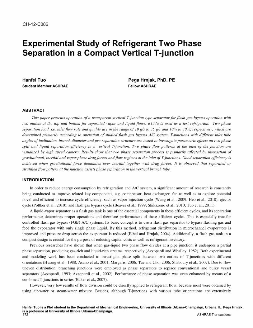
Figure 1. Schematic of experimental facility Figure 2. Detailed schematic of the tested T -junction separator
The schematic of experiment facility is shown in Fig. 1. It primarily consists of a test section, i.e. a vertical
impacting T-junction, a collecting tank, vapor and liquid flow mass flow meters, an electric heater, a plate condenser and a
tube-tube heat exchanger as a subcooler, a refrigerant receiver and a variable-speed refrigerant diaphragm pump. The
diaphragm pump is used to achieve the desired mass flow rate for the R134a refrigerant circuit. The inlet mass flow rate is
measured in the pump discharge line by the Coriolis-type mass flow meter. Quality at the inlet of the test section is controlled
by an electric heater. System pressures and temperatures are measured by pressure transducers and T-type thermocouples.
The subcooled refrigerant is heated up in the electric heater, and then expanded in the throttle valve into two phase flow.
Vapor and liquid are separated in the T-junction. The test section is made by transparent PVC tube for the purpose of flow
visualization, and its detail is shown in Fig. 2. Refrigerant states are illustrated in a p-h diagram in Fig. 3.
Separation efficiencies are measured by using the collecting tank in which liquid and vapor phase from the test section
outlet are assumed to be perfectly separated. Over the given amount of time, mass of liquid collected in the tank is measured,
yielding a time averaged liquid mass flow rates from the top exit of the T-junction. At the same time, vapor flow rate from
the same exit is being measured by the Coriolis-type flow meter. The inlet refrigerant quality is calculated based on heat
input and refrigerant enthalpy before the heater, as following:
© 2012 ASHRAE 673
2 1in
Qh h
m= +
ɺ (1)
2 lin
v l
h hx
h h
−=−
(2)
Where inmɺ and Q are the inlet mass flow rate and electrical heat input, hv and hl are the saturated vapor and liquid
enthalpy, respectively.
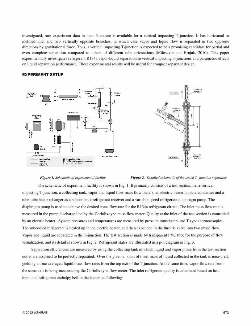
After both vapor and liquid branch exits, throttle valves are installed to simulate real operating conditions in a FGB system. As illustrated in Fig. 4, the valve after the top exit functions as bypass control valve to regulate the amount of vapor bypassed. Another valve installed on the liquid line conceptually works as an “virtual evaporator” which imposes the corresponding pressure drop in a FGB system. This pressure difference is measured by a differential pressure transducer with accuracy of ±0.25% FS. Refrigerant inlet flow rate and quality is based on the typical A/C system capacities and operating conditions, in the ranges of about 10~35 g/s and 5%~30%, respectively.
Figure 3. p-h diagram of separation efficiency test Figure 4. Throttling valves used in the separation test facility and
the idea behind
The T-junction in a FGB system serves to produce single phase liquid and vapor from respective branches. Consequently, its separation performance is evaluated based on two separation efficiencies. Liquid separation efficiency is defined as the ratio of liquid supplied into the designated branch (evaporator inlet) to total liquid at the inlet:
, ,
, (1 )l b l b
l
l i in in
m m
m m xη = =
−ɺ ɺ
ɺ ɺ (3)
Similarly, efficiency for separating vapor phase is defined as the ratio of vapor bypassed into the upward branch (evaporator exit) to total vapor at the inlet:
, ,
,
v t v tv
v i in in
m m
m m xη = =
ɺ ɺ
ɺ ɺ (4)
Where ,l bmɺ and ,v tmɺ denote supplied liquid flow rate at the bottom exit and bypassed vapor flow rate at the top exit of
the separator, respectively. In general, vapor phase with a smaller density has a much lower momentum flux (ρu2) in a two
phase flow, compared to the coupled liquid flow. The momentum flux represents a measure of the fluids resistance to being diverted to branch (Azzopardi and Whalley, 1982). Thus, vapor flow is readily diverted into the upward branch. In addition, if bypass valve is appropriately adjusted to maintain a liquid level in the downward branch according to the pressure balance, vapor is hardly able to penetrate through this liquid plug. In this scenario, all vapor is separated into the upward branch, i.e.
ηv=100%. On the other hand, liquid having much larger density and momentum flux intends to divert into both branches
674 ASHRAE Transactions
against the gravitational force, and would be carried over by upward vapor flow.
Measurement uncertainty analysis
The propagation of uncertainty has been calculated using the root-sum-square combination, as described by Moffat (1988). The accuracy of experiment sensors are reported in Table 1. The maximum values of measurement uncertainty for
refrigerant inlet quality xin and liquid separation efficiency ηliq are estimated around 7% and 5%, respectively.
Table 1. Measured Parameters and Accuracy Measurement Unit Accuracy
Pressure kPa ±3.56 Temperature ºC ±0.5
Mass Flow Rate g/s ±0.1% Heat Input W ±10 (0.5% F.S)
Liquid Level in Colleting Tank
mm ±2
Time s ±2
RESULTS AND DISCUSSIONS
Flow pattern at the inlet of the junction
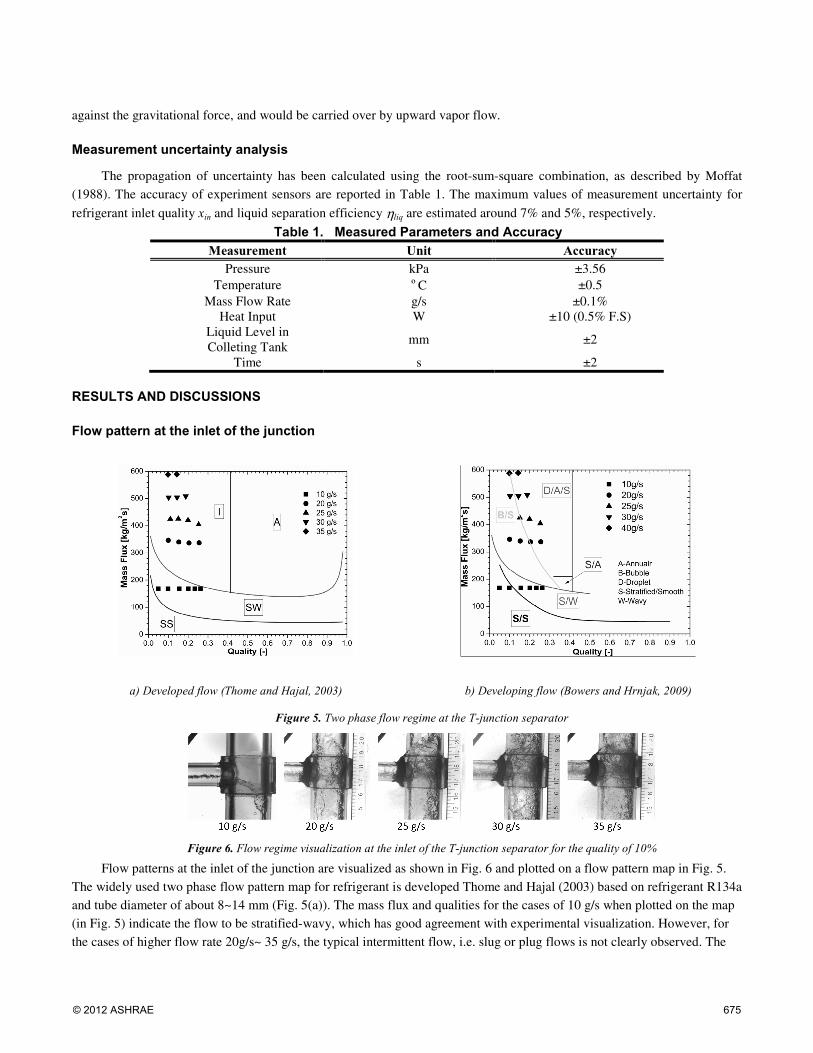
a) Developed flow (Thome and Hajal, 2003) b) Developing flow (Bowers and Hrnjak, 2009)
Figure 5. Two phase flow regime at the T-junction separator
Figure 6. Flow regime visualization at the inlet of the T-junction separator for the quality of 10%
Flow patterns at the inlet of the junction are visualized as shown in Fig. 6 and plotted on a flow pattern map in Fig. 5. The widely used two phase flow pattern map for refrigerant is developed Thome and Hajal (2003) based on refrigerant R134a and tube diameter of about 8~14 mm (Fig. 5(a)). The mass flux and qualities for the cases of 10 g/s when plotted on the map (in Fig. 5) indicate the flow to be stratified-wavy, which has good agreement with experimental visualization. However, for the cases of higher flow rate 20g/s~ 35 g/s, the typical intermittent flow, i.e. slug or plug flows is not clearly observed. The
© 2012 ASHRAE 675
most frequently observed regime for those cases is the droplet/stratified/annular, and is characterized by a noticeable liquid layer forming on the bottom of the tube with a thin liquid layer on the top wall and large amount of droplets between the two. The difference is primarily because most the flow regime maps as shown in Fig. 5(a) are based on fully developed two phase flow. However, a flash gas separator is usually installed directly after the expansion valve, and relatively homogenous flow created at the expansion valve cannot reach the fully developed stage in the short horizontal inlet tube of a T-junction, but is still developing. Bowers and Hrnjak (2009) systematically investigated the adiabatic developing two phase flow in a horizontal pipe. The flow regimes were classified into four regions of development as it processes through the length of the tube, i.e. well mixed, separating, and separated but still developing, and developing regions. More flow regimes in transition stages were carefully identified, including droplet/annular/stratified, bubble/stratified, and etc. The flow patterns in this study indicated good agreements with Bowers’ observation as shown in Fig. 5(b).
Effect of inlet mass flow rate and quality (separation load)
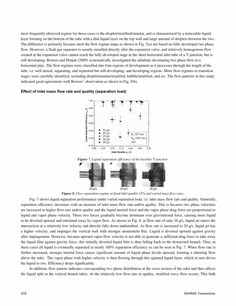
Figure 7. Liquid separation efficiency of the baseline T-junction
Figure 8. Flow separation regime at fixed inlet quality 15% and varied mass flow rates
Fig. 7 shows liquid separation performance under varied separation load, i.e. inlet mass flow rate and quality. Generally, separation efficiency decreases with an increase of inlet mass flow rate and/or quality. This is because two phase velocities are increased at higher flow rate and/or quality and the liquid inertial force and the vapor phase drag force are proportional to liquid and vapor phase velocity. These two forces gradually become dominant over gravitational force, causing more liquid to be diverted upward and entrained away by vapor flow. As shown in Fig. 8, at flow rate of only 10 g/s, liquid jet enters the intersection at a relatively low velocity and directly falls down undisturbed. As flow rate is increased to 20 g/s, liquid jet has a higher velocity, and impinges the vertical wall with stronger momentum flux. Liquid is diverted upward against gravity after impingement. However, because upward vapor flow velocity is not able to generate a sufficient drag force to take away the liquid film against gravity force, this initially diverted liquid film is then falling back to the downward branch. Thus, in these cases all liquid is eventually separated at nearly 100% separation efficiency as can be seen in Fig. 7. When flow rate is further increased, stronger inertial force causes significant amount of liquid phase divide upward, forming a churning flow above the inlet. The vapor phase with higher velocity is then flowing through this agitated liquid layer, which in turn drives the liquid to rise. Efficiency drops significantly.
In addition, flow pattern indicates corresponding two phase distribution at the cross section of the inlet and thus affects the liquid split in the vertical branch tubes. At the relatively low flow rate or quality, stratified wavy flow occurs. This bulk
676 ASHRAE Transactions
liquid layer has low momentum flux and is less likely to be carried over. For higher flow rate or quality, the flow pattern changes into a stratified/annular flow with a large entrainment of droplets in the vapor flow and a very thin film at the top side of the inlet tube. For this case, the thin layer of the liquid phase readily creeps up the T-junction body wall; similarly, the entrained droplets forms Stokes flow in the vapor flow and thus has more chance to be carried over upward.
Effect of angle of inclination of inlet tube
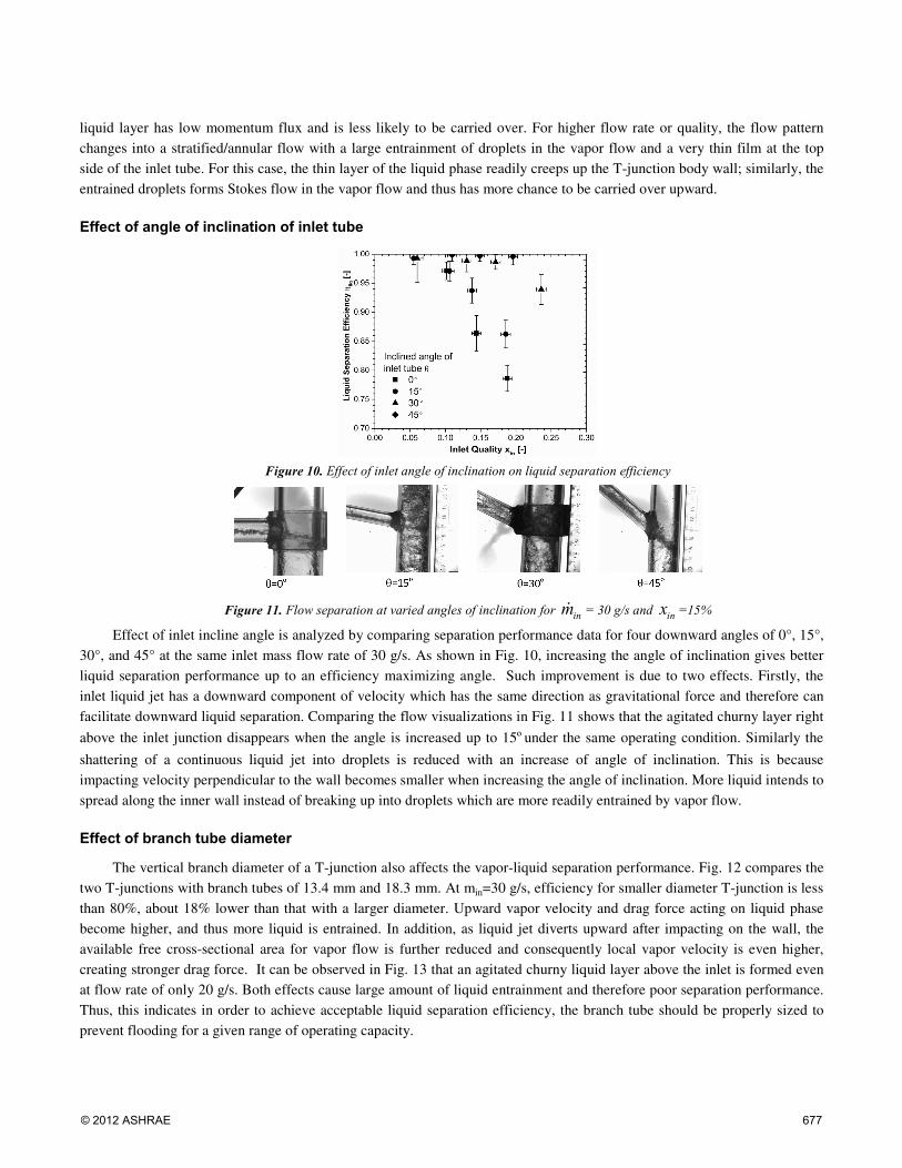
Figure 10. Effect of inlet angle of inclination on liquid separation efficiency
Figure 11. Flow separation at varied angles of inclination for inmɺ = 30 g/s and inx =15%
Effect of inlet incline angle is analyzed by comparing separation performance data for four downward angles of 0°, 15°, 30°, and 45° at the same inlet mass flow rate of 30 g/s. As shown in Fig. 10, increasing the angle of inclination gives better liquid separation performance up to an efficiency maximizing angle. Such improvement is due to two effects. Firstly, the inlet liquid jet has a downward component of velocity which has the same direction as gravitational force and therefore can facilitate downward liquid separation. Comparing the flow visualizations in Fig. 11 shows that the agitated churny layer right
above the inlet junction disappears when the angle is increased up to 15ºunder the same operating condition. Similarly the
shattering of a continuous liquid jet into droplets is reduced with an increase of angle of inclination. This is because impacting velocity perpendicular to the wall becomes smaller when increasing the angle of inclination. More liquid intends to spread along the inner wall instead of breaking up into droplets which are more readily entrained by vapor flow.
Effect of branch tube diameter
The vertical branch diameter of a T-junction also affects the vapor-liquid separation performance. Fig. 12 compares the two T-junctions with branch tubes of 13.4 mm and 18.3 mm. At min=30 g/s, efficiency for smaller diameter T-junction is less than 80%, about 18% lower than that with a larger diameter. Upward vapor velocity and drag force acting on liquid phase become higher, and thus more liquid is entrained. In addition, as liquid jet diverts upward after impacting on the wall, the available free cross-sectional area for vapor flow is further reduced and consequently local vapor velocity is even higher, creating stronger drag force. It can be observed in Fig. 13 that an agitated churny liquid layer above the inlet is formed even at flow rate of only 20 g/s. Both effects cause large amount of liquid entrainment and therefore poor separation performance. Thus, this indicates in order to achieve acceptable liquid separation efficiency, the branch tube should be properly sized to prevent flooding for a given range of operating capacity.
© 2012 ASHRAE 677
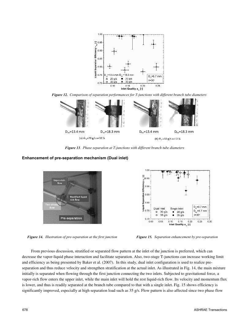
Figure 12. Comparison of separation performances for T-junctions with different branch tube diameters
Figure 13. Phase separation at T-junctions with different branch tube diameters
Enhancement of pre-separation mechanism (Dual inlet)
Figure 14. Illustration of pre-separation at the first junction Figure 15. Separation enhancement by pre-separation
From previous discussion, stratified or separated flow pattern at the inlet of the junction is preferred, which can decrease the vapor-liquid phase interaction and facilitate separation. Also, two-stage T-junctions can increase working limit and efficiency as being presented by Baker et al. (2007). In this study, dual inlet configuration is used to realize pre-separation and thus reduce velocity and strengthen stratification at the actual inlet. As illustrated in Fig. 14, the main mixture initially is separated when flowing through the first junction connecting the two inlets. Subjected to gravitational force, a vapor-rich flow enters the upper inlet, while the main inlet will hold the rest liquid-rich flow. Its velocity and momentum flux is lower, and thus is readily separated at the branch tube compared to that with a single inlet. Fig. 15 shows efficiency is significantly improved, especially at high separation load such as 35 g/s. Flow pattern is also affected since two phase flow
678 ASHRAE Transactions
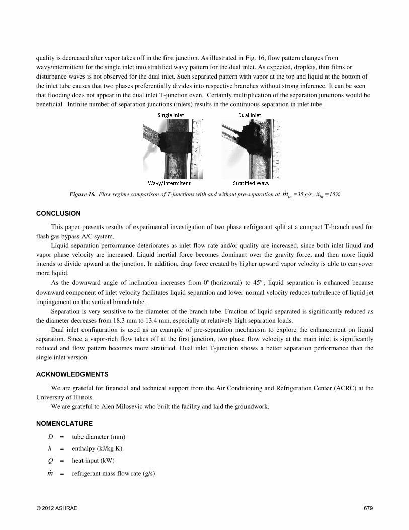
quality is decreased after vapor takes off in the first junction. As illustrated in Fig. 16, flow pattern changes from wavy/intermittent for the single inlet into stratified wavy pattern for the dual inlet. As expected, droplets, thin films or disturbance waves is not observed for the dual inlet. Such separated pattern with vapor at the top and liquid at the bottom of the inlet tube causes that two phases preferentially divides into respective branches without strong inference. It can be seen that flooding does not appear in the dual inlet T-junction even. Certainly multiplication of the separation junctions would be beneficial. Infinite number of separation junctions (inlets) results in the continuous separation in inlet tube.
Figure 16. Flow regime comparison of T-junctions with and without pre-separation at inmɺ =35 g/s, inx =15%
CONCLUSION
This paper presents results of experimental investigation of two phase refrigerant split at a compact T-branch used for flash gas bypass A/C system.
Liquid separation performance deteriorates as inlet flow rate and/or quality are increased, since both inlet liquid and vapor phase velocity are increased. Liquid inertial force becomes dominant over the gravity force, and then more liquid intends to divide upward at the junction. In addition, drag force created by higher upward vapor velocity is able to carryover more liquid.
As the downward angle of inclination increases from 0º(horizontal) to 45º, liquid separation is enhanced because
downward component of inlet velocity facilitates liquid separation and lower normal velocity reduces turbulence of liquid jet impingement on the vertical branch tube.
Separation is very sensitive to the diameter of the branch tube. Fraction of liquid separated is significantly reduced as the diameter decreases from 18.3 mm to 13.4 mm, especially at relatively high separation loads.
Dual inlet configuration is used as an example of pre-separation mechanism to explore the enhancement on liquid separation. Since a vapor-rich flow takes off at the first junction, two phase flow velocity at the main inlet is significantly reduced and flow pattern becomes more stratified. Dual inlet T-junction shows a better separation performance than the single inlet version.
ACKNOWLEDGMENTS
We are grateful for financial and technical support from the Air Conditioning and Refrigeration Center (ACRC) at the University of Illinois.
We are grateful to Alen Milosevic who built the facility and laid the groundwork.
NOMENCLATURE
D = tube diameter (mm)
h = enthalpy (kJ/kg K)
Q = heat input (kW)
mɺ = refrigerant mass flow rate (g/s)
© 2012 ASHRAE 679

η = separation efficiency (-)
θ = angle of inclination (º)
Subscripts
bd = vertical branch tube
in = inlet
l = liquid phase
v = vapor phase
REFERENCES
Asano, H.F., T. Fujii, N. Takenaka, and K. Sakoda, 2001. A study of the phase separation characteristics in gas-liquid two-phase flows by impacting Y-junction. Transactions of the Japan Society of Mechanical Engineerings, Series B, 67(654): 350-355.
Azzopardi, B.J., and P.B. Whalley, 1982. The effect of flow pattern on two-phase flow in a T junction. International Journal of Multiphase Flow, 8(5): 491-507.
Azzopardi, B.J., 1993. T-junctions as phase separators for gas/liquid flows: possibilities and problems. Chemical Engineering Research and Design, 71(3): 273-281.
Azzopardi, B.J., D.A. Colman, and D. Nicholson. 2002. Plant application of a T-junction as a partial separator. Chemical Engineering Research and Design, 80(1): 87-96.
Baker, G., W.W. Clark, B.J. Azzopardi, and J.A. Wilson, 2007. Controlling the phase separation of gas-liquid flows at horizontal T-junctions. Fluid Mechanics and Tranpsort Phenomena, 53(8): 1908-1915.
Beaver, A.C., J. Yin, C.W. Bullard, and P.S. Hrnjak, 1999. An experimental investigation of transcritical carbondioxide systems for residential air-conditioning. ACRC Report CR-18. Urbana, USA: University of Illinois at Urbana-Champaign.
Bowers, C.D., and P.S. Hrnjak, 2009. Developing adiabatic two-phase flow. ACRC Report TR-267. Urbana, USA: University of Illinois at Urbana-Champaign.
Elbel, S., and P.S. Hrnjak, 2004. Flash gas bypass for improving the performance of transcritical R744 systems that use microchannel evaporators. International Journal of Refrigeration, 27(7): 724-735.
Pottker, G., B. Guo, and P.S. Hrnjak, 2010. Experimental investigation of an R410a vapor compression system working with an enjector. Proc. of International Refrigeration and Air Conditioning Conference, West Lafayette, IN, USA, R2473.
Heo, J., M.W. Jeong, and Y. Kim, 2010. Effects of flash tank vapor injection on the heating performance of an inverter-driven heat pump for cold regions. International Journal of Refrigeration ,33(4): 848-855.
Hwang, S.T., H.M. Soliman, R.T. Lahey, 1988. Phase separation in dividing two-phase flows. International Journal of Multiphase Flow14(4):439-458.
Margaris, D.P., 2006. T-junction separation modelling in gas-liquid two-phase flow. Chemical Engineering and Processing, 46(2): 150-158.
Moffat, R.J., 1988. Decribing the uncertainties in experimental results. Experimental Thermal and Fluid Science, 1(1): 3-17. Milosevic, A., and P.S. Hrnjak, 2010. Flash gas bypass concept utilizing low pressure refrigerants. Master Thesis. University of Illinois. Shaboury, A.M.F., H.M. Soliman, and G.E. Sims, 2007. Two phase flow in a horizontal equal-sided impacting tee junction. International
Journal of Multiphase Flow, 33(4): 411-431. Shikazono, N., R. Azuma, T. Sameshima, and H. Iwata, 2010. Development of compact gas-liquid separator using surface tension.
International symposium on Next-generation Air Conditioning and Refrigeration Technology, Tokyo, Japan. Tae, S.J., and K. Cho, 2006. Two-phase split of refrigerants at a T-junction. International Journal of Refrigeration, 29(7): 1128-1137. Tuo, H.F., A. Bielskus, and P.S. Hrnjak, 2011. Effect of flash gas bypass on the performance of R134a mobile air-conditioning system with
microchannel evaporator. SAE International Journal of Materials and Manufacturing, 4(1): 231-239. Wang, X., Y. Hwang, and R. Radermacher, 2009. Two-stage heat pump system with vapor-injected scroll compressor using R410A as a
refrigerant. International Journal of Refrigeration, 32(6):1442-1451.
680 ASHRAE Transactions

Copyright of ASHRAE Transactions is the property of ASHRAE and its content may not be copied or emailed
to multiple sites or posted to a listserv without the copyright holder's express written permission. However,
users may print, download, or email articles for individual use.
Copyright © 2022 FDOKUMEN