EXPERIMENTAL STUDY OF A NEW DISPERSIVE MIXER
10
EXPERIMENTAL STUDY OF A NEW DISPERSIVE MIXER Chris Rauwendaal, Rauwendaal Extrusion Engineering, Inc. Antoine Rios and Tim Osswald, University of Wisconsin, Madison Paul Gramann and Bruce Davis, The Madison Group Maria del P. Noriega and Omar A. Estrada, ICIPC, Medellin, Colombia Abstract New dispersive mixing technology for extruders and mixing devices (1, 2) is based on creating strong elongational flow to achieve efficient dispersive mixing. These mixers are designed so that all fluid elements pass through the high stress regions several times. One version of the new mixer, CRD-4, was tested on a modular 45 mm extruder using a dryblend of polyethylene and polystyrene. The CRD-4 mixer was tested against a Leroy/Maddock mixer and a Maillefer mixer. The mixing capability was studied by microscopic analysis of the domain sizes of cross sections of extruded strands. The mixer performance was also analyzed with respect to pressure profiles, characteristic curves, and melt temperature distribution. It was found that the CRD-4 mixer achieves a fine level of dispersion under most circumstances. The Leroy/Maddock mixer has limited dispersive mixing capability at low screw speed; however, its dispersive mixing capability is better at high screw speed. The CRD-4 mixer is designed with forward pumping capability. As a result, the output-pressure characteristic of a screw with a 6D CRD-4 mixer is essentially identical to the same screw with the mixer replaced by a conveying section. Introduction Single screw extruders generally have poor dispersive mixing capability. The dispersive mixing capability can be improved by adding mixing sections to the screw. However, current dispersive mixing sections for single screw extruders are relatively inefficient mixe rs. Twin screw extruders, on the other hand, have good dispersive mixing capability when properly equipped with dispersive mixing elements, generally kneading disks. In comparing the mixing mechanism in single screw extruders to twin screw extruders, there are two important differences (3). In single screw extruders, the flow in the high stress region (HSR) of most mixers is predominantly shear flow and the fluid elements pass through the HSR only once. In twin screw extruders, the flow in the kneading disks has a strong elongational component and the fluid elements pass through the HSR several times. These differences explain why twin screw extruders are more efficient dispersive mixing devices than single screw extruders. However, there is no reason the mixing mechanism of the twin screw extruder cannot be applied in single screw extruders. New dispersive mixing elements, called CRD mixers, developed by Rauwendaal (1) are designed to create strong elongational flow and multiple passes through the HSR. These CRD mixers (patent pending) allow single screw extruders to achieve dispersive mixing action as good as that of twin screw extruders. The mixing experiments described in this paper are the first experimental studies of a CRD mixer. Experiments The experiments were performed on an Extrudex modular single screw extruder with extensive data acquisition capability. The extruder diameter was 45 mm and the length/diameter ratio 25:1. The modular screw allowed different mixing sections to be mounted on the screw. The feed section length of the screw was 8D, the compression section length 11D, and the metering section length 6D. Three mixing sections were tested, a 2D Leroy/Maddock mixer, a 4D Maillefer mixer, and a CRD-4 mixer. The CRD-4 mixer was available in three lengths, 2D, 4D, and 6D; all three lengths were tested. Figure 1 shows the geometry of the CRD-4 mixer. The extruder was run at three different screw speeds, 30, 60, and 90 rpm. The extruder barrel was equipped with 5 pressure transducers along the length of the barrel at positions 12D, 16D, 20D, 22D, and 25D measured from the feed end of the extruder. With multiple pressure transducers along the barrel, the pressure profile along the length of the screw can be determined. The extruder was also equipped with an adjustable die restriction, which allows adjustment of the back pressure. Three die restriction levels were used in the tests, low (10/0), medium (3/180), and high (2/180). Barrel temperatures were set at 160, 170, 180, 190, 200, and 200 °C going from the feed to discharge section. Melt temperatures at the extruder discharge were measured at five locations across the melt stream with a thermocouple bridge. This
Transcript of EXPERIMENTAL STUDY OF A NEW DISPERSIVE MIXER

EXPERIMENTAL STUDY OF A NEW DISPERSIVE MIXER
Chris Rauwendaal, Rauwendaal Extrusion Engineering, Inc.
Antoine Rios and Tim Osswald, University of Wisconsin, Madison Paul Gramann and Bruce Davis, The Madison Group
Maria del P. Noriega and Omar A. Estrada, ICIPC, Medellin, Colombia
Abstract New dispersive mixing technology for extruders and mixing devices (1, 2) is based on creating strong elongational flow to achieve efficient dispersive mixing. These mixers are designed so that all fluid elements pass through the high stress regions several times. One version of the new mixer, CRD-4, was tested on a modular 45 mm extruder using a dryblend of polyethylene and polystyrene. The CRD-4 mixer was tested against a Leroy/Maddock mixer and a Maillefer mixer. The mixing capability was studied by microscopic analysis of the domain sizes of cross sections of extruded strands. The mixer performance was also analyzed with respect to pressure profiles, characteristic curves, and melt temperature distribution. It was found that the CRD-4 mixer achieves a fine level of dispersion under most circumstances. The Leroy/Maddock mixer has limited dispersive mixing capability at low screw speed; however, its dispersive mixing capability is better at high screw speed. The CRD-4 mixer is designed with forward pumping capability. As a result, the output-pressure characteristic of a screw with a 6D CRD-4 mixer is essentially identical to the same screw with the mixer replaced by a conveying section.
Introduction Single screw extruders generally have poor dispersive mixing capability. The dispersive mixing capability can be improved by adding mixing sections to the screw. However, current dispersive mixing sections for single screw extruders are relatively inefficient mixe rs. Twin screw extruders, on the other hand, have good dispersive mixing capability when properly equipped with dispersive mixing elements, generally kneading disks. In comparing the mixing mechanism in single screw extruders to twin screw extruders, there are two important differences (3). In single screw extruders, the flow in the high stress region (HSR) of most mixers is predominantly shear flow and the fluid elements pass through the HSR only once. In twin screw extruders, the flow in the kneading disks has a strong elongational component and the fluid elements pass through the HSR several times.
These differences explain why twin screw extruders are more efficient dispersive mixing devices than single screw extruders. However, there is no reason the mixing mechanism of the twin screw extruder cannot be applied in single screw extruders. New dispersive mixing elements, called CRD mixers, developed by Rauwendaal (1) are designed to create strong elongational flow and multiple passes through the HSR. These CRD mixers (patent pending) allow single screw extruders to achieve dispersive mixing action as good as that of twin screw extruders. The mixing experiments described in this paper are the first experimental studies of a CRD mixer.
Experiments The experiments were performed on an Extrudex modular single screw extruder with extensive data acquisition capability. The extruder diameter was 45 mm and the length/diameter ratio 25:1. The modular screw allowed different mixing sections to be mounted on the screw. The feed section length of the screw was 8D, the compression section length 11D, and the metering section length 6D. Three mixing sections were tested, a 2D Leroy/Maddock mixer, a 4D Maillefer mixer, and a CRD-4 mixer. The CRD-4 mixer was available in three lengths, 2D, 4D, and 6D; all three lengths were tested. Figure 1 shows the geometry of the CRD-4 mixer. The extruder was run at three different screw speeds, 30, 60, and 90 rpm. The extruder barrel was equipped with 5 pressure transducers along the length of the barrel at positions 12D, 16D, 20D, 22D, and 25D measured from the feed end of the extruder. With multiple pressure transducers along the barrel, the pressure profile along the length of the screw can be determined. The extruder was also equipped with an adjustable die restriction, which allows adjustment of the back pressure. Three die restriction levels were used in the tests, low (10/0), medium (3/180), and high (2/180). Barrel temperatures were set at 160, 170, 180, 190, 200, and 200 °C going from the feed to discharge section. Melt temperatures at the extruder discharge were measured at five locations across the melt stream with a thermocouple bridge. This

allows determination of the melt temperature profile across the channel. The experimental setup is shown in figure 2. The mixing experiments were performed with a dryblend of high density polyethylene and polystyrene in a ratio of 60:40 weight percent. The viscosity ratio was 1.44:1. The Capillary number between the two polymers was 28.9. The material was extruded through a strand die and the extruded strands were microtomed, using a Leica Laborux Autocut 2055, and examined under a Leica Laborux 12 pol s. microscope to determine the morphology within the strand. The smallest domain size that could be observed with the microscope is 2 micron.
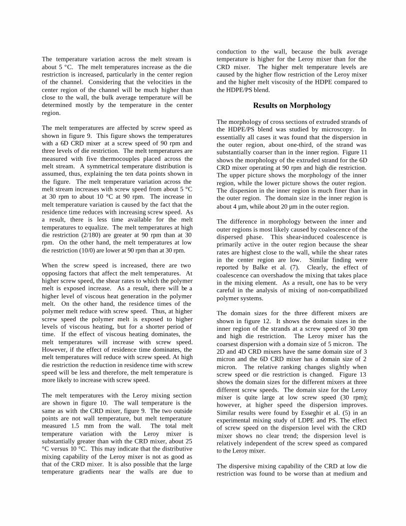
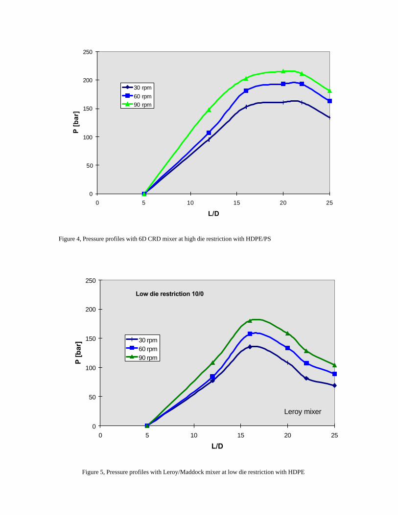
Results, Pressure Profiles The extruder was run at three screw speeds and three levels of die restriction. Figure 3 shows the pressure profiles for the 6D CRD mixer at low die restriction and at three screw speeds. All three pressure profiles show a maximum at an axial position of about 17D; this is about 2D from the end of the compression section of the screw. The maximum pressure increases from about 90 to 150 bar as the screw speed increases from 30 to 90 rpm, while the discharge pressure increases from about 40 to 80 bar. There is a modest pressure drop along the length of the mixing section of about 40 bar. As one would expect, all pressure values increase with screw speed. The pressure profiles with the 6D CRD mixer at high die restriction are shown in figure 4 for three values of the screw speed. The discharge pressures have increased to about 140 to 180 bar, an increase of about 100 bar over the pressures at low die restriction. The maximum pressures now occur in the beginning of the metering section. Actually, with the 6D mixer the entire metering section consists of the mixer. The pressure drop over the length of the mixing section is quite low, about 30 bar. Figure 5 shows the pressure profiles with the 2D Leroy/Maddock mixer at low die restriction for the HDPE material. The maximum pressures again occur at about 17D. The pressure drop over the mixer is about 20 bar. The overall pressure levels are higher than the corresponding case with the 6D CRD mixer, see figure 3. This is because the pressures in figure 3 are for the blend of HDPE/PS, while the pressures in figure 5 are for HDPE only; the viscosity of HDPE is higher than for the blend.
Results, Characteristic Curves The output-pressure relationship for the screw can be plotted with the same relationship for the die. Figure 6 shows the extruder and die characteristic curves for the 6D CRD mixer at three screw speeds and three levels of die restriction. The characteristic curves for the screw are relatively flat, which is desirable because it indicates that the throughput is not strongly dependent on the discharge pressure. The characteristic curves for the die are quite non-linear with a steep increase in slope at higher pressures. The non-linearity of the die characteristic curves is caused by the shear thinning of the polymer melt. The characteristic curves for the 2D and 4D CRD mixer are almost the same as those of the 6D CRD mixer. This indicates that the length of the CRD mixer has little affect on the conveying characteristics of the screw. This is an advantage in that a long (6D or longer) mixing section can be incorporated into the screw design without having to sacrifice the throughput capability. Figure 7 shows the characteristic curves of the Leroy mixer for HDPE. The general shape of the curves is similar to that in figure 6. The values of the pressure are higher because the viscosity of the HDPE is higher than that of the HDPE/PS blend. The throughput values for the screw with the Leroy mixing section are lower than for the screw with the CRD mixers. This indicates that the Leroy mixer presents more flow resistance to the polymer melt than the CRD mixer. The choking action of the mixer not only reduces throughput, it also increases melt temperatures. Melt temperatures will be discussed in the next section. The Leroy mixer chokes the throughput because it has no forward pumping capability as a result of the axial orientation of the flutes. A helical orientation of the flutes can alleviate this drawback of the Leroy mixer (4). As a result, a helical Leroy mixer causes less reduction in throughput than a straight one and allows lower stock temperatures in the extruder. Lower stock temperatures result in higher viscosities and stresses in the polymer melt and thus, result in better dispersive mixing.
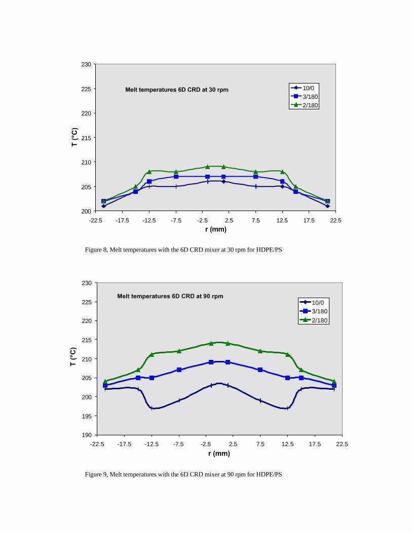
Results, Melt Temperatures The melt temperatures at the discharge end of the extruder were measured with several thermocouples positioned on a bridge across the channel. With this setup the melt temperature profile across the melt stream can be determined. Figure 8 shows the melt temperature distribution for the 6D CRD mixer at 30 rpm at three levels of die restrictions.
The temperature variation across the melt stream is about 5 ºC. The melt temperatures increase as the die restriction is increased, particularly in the center region of the channel. Considering that the velocities in the center region of the channel will be much higher than close to the wall, the bulk average temperature will be determined mostly by the temperature in the center region. The melt temperatures are affected by screw speed as shown in figure 9. This figure shows the temperatures with a 6D CRD mixer at a screw speed of 90 rpm and three levels of die restriction. The melt temperatures are measured with five thermocouples placed across the melt stream. A symmetrical temperature distribution is assumed, thus, explaining the ten data points shown in the figure. The melt temperature variation across the melt stream increases with screw speed from about 5 °C at 30 rpm to about 10 °C at 90 rpm. The increase in melt temperature variation is caused by the fact that the residence time reduces with increasing screw speed. As a result, there is less time available for the melt temperatures to equalize. The melt temperatures at high die restriction (2/180) are greater at 90 rpm than at 30 rpm. On the other hand, the melt temperatures at low die restriction (10/0) are lower at 90 rpm than at 30 rpm. When the screw speed is increased, there are two opposing factors that affect the melt temperatures. At higher screw speed, the shear rates to which the polymer melt is exposed increase. As a result, there will be a higher level of viscous heat generation in the polymer melt. On the other hand, the residence times of the polymer melt reduce with screw speed. Thus, at higher screw speed the polymer melt is exposed to higher levels of viscous heating, but for a shorter period of time. If the effect of viscous heating dominates, the melt temperatures will increase with screw speed. However, if the effect of residence time dominates, the melt temperatures will reduce with screw speed. At high die restriction the reduction in residence time with screw speed will be less and therefore, the melt temperature is more likely to increase with screw speed. The melt temperatures with the Leroy mixing section are shown in figure 10. The wall temperature is the same as with the CRD mixer, figure 9. The two outside points are not wall temperature, but melt temperature measured 1.5 mm from the wall. The total melt temperature variation with the Leroy mixer is substantially greater than with the CRD mixer, about 25 °C versus 10 °C. This may indicate that the distributive mixing capability of the Leroy mixer is not as good as that of the CRD mixer. It is also possible that the large temperature gradients near the walls are due to
conduction to the wall, because the bulk average temperature is higher for the Leroy mixer than for the CRD mixer. The higher melt temperature levels are caused by the higher flow restriction of the Leroy mixer and the higher melt viscosity of the HDPE compared to the HDPE/PS blend.
Results on Morphology The morphology of cross sections of extruded strands of the HDPE/PS blend was studied by microscopy. In essentially all cases it was found that the dispersion in the outer region, about one-third, of the strand was substantially coarser than in the inner region. Figure 11 shows the morphology of the extruded strand for the 6D CRD mixer operating at 90 rpm and high die restriction. The upper picture shows the morphology of the inner region, while the lower picture shows the outer region. The dispersion in the inner region is much finer than in the outer region. The domain size in the inner region is about 4 µm, while about 20 µm in the outer region. The difference in morphology between the inner and outer regions is most likely caused by coalescence of the dispersed phase. This shear-induced coalescence is primarily active in the outer region because the shear rates are highest close to the wall, while the shear rates in the center region are low. Similar finding were reported by Balke et al. (7). Clearly, the effect of coalescence can overshadow the mixing that takes place in the mixing element. As a result, one has to be very careful in the analysis of mixing of non-compatibilized polymer systems. The domain sizes for the three different mixers are shown in figure 12. It shows the domain sizes in the inner region of the strands at a screw speed of 30 rpm and high die restriction. The Leroy mixer has the coarsest dispersion with a domain size of 5 micron. The 2D and 4D CRD mixers have the same domain size of 3 micron and the 6D CRD mixer has a domain size of 2 micron. The relative ranking changes slightly when screw speed or die restriction is changed. Figure 13 shows the domain sizes for the different mixers at three different screw speeds. The domain size for the Leroy mixer is quite large at low screw speed (30 rpm); however, at higher speed the dispersion improves. Similar results were found by Esseghir et al. (5) in an experimental mixing study of LDPE and PS. The effect of screw speed on the dispersion level with the CRD mixer shows no clear trend; the dispersion level is relatively independent of the screw speed as compared to the Leroy mixer. The dispersive mixing capability of the CRD at low die restriction was found to be worse than at medium and

high die restriction. This is believed to be a result of the open design of the CRD mixer. At low discharge pressure, there is a negative pressure gradient along the mixer and which results in short residence times in the mixer. This results in a reduced number of passes through the high stress region of the mixer, as discussed by Rauwendaal et al. (1, 2). This problem can be avoided by adopting a closed mixer design, such as the fluted mixer. The advantage of a fluted geometry is that all fluid elements can be forced to make multiple passes through the mixing clearance regardless of the discharge pressure. The disadvantage is that the distributive mixing capability is reduced relative to the open mixer and extruder output will tend to be lower.
Conclusions A newly developed dispersive mixing device was tested against two commonly used dispersed mixers. The dispersive mixing capability was found to be as good as that of intermeshing twin screw extruders (6). Pressure profiles measured along the length of the extruder indicated that the pumping capability of the CRD mixers results in low pressure drop across the mixer. As a result, the throughput capability of the extruder is reduced very little by incorporation of the mixer, even with a mixer length of 6D. Melt temperatures measured across the melt stream showed small melt temperature variation with the CRD mixer, indicating good distributive mixing capability. The Leroy/Maddock mixer was found to have limited dispersive mixing capability at low screw speed and relatively large melt temperature variation, particularly at high screw speed. This indicates that the Leroy/Maddock mixer has limited distributive mixing capability and poor dispersive mixing action at low screw speed. The Leroy/Maddock mixer resulted in lower throughputs and higher melt temperatures due to the choking action of the mixer. The Maillefer mixer exhibited higher melt temperature variation and pressure drop than the CRD mixer, but lower than the Leroy mixer. The dispersive mixing capability of the
Maillefer mixer was better than the Leroy/Maddock mixer, but not as good as the CRD mixer. In all experiments it was found that the dispersion in the outer region of the strands was much coarser than in the inner region. The coarse dispersion in the outer region is caused by shear-induced coalescence. Clearly, in mixing experiments with incompatible polymer blends one has to be careful in the analysis of the morphologies, because the effects of coalescence can overshadow the effects of dispersive mixing. CRD mixers are now running in a number of industrial extrusion and compounding operations. Experience from the field will also be presented at the ANTEC meeting.
References 1. C. Rauwendaal, T. Osswald, P. Gramann, and B.
Davis, “New Dispersive Mixers for Single Screw Extruders,” SPE ANTEC, Atlanta, GA, 277-283 (1998)
2. C. Rauwendaal, T. Osswald, P. Gramann, and B. Davis, “Design of Dispersive Mixers,” Int. Polym. Proc., Submitted (1998)
3. C. Rauwendaal, “Polymer Mixing, A Self-Study Guide,” Hanser, Cincinnati, OH (1998)
4. C. Rauwendaal, “Design of Dispersive Mixing Sections in Single Screw Extruders," PRI Polymer Extrusion III Conference, London, 1/1-1/13 (1985)
5. M. Esseghir, C.G. Gogos, D-W Yu, D.B. Todd, and B. David, “A Comparative Study in the Performance of Three Single-Screw Elements in Melt-Melt Mixing of Immiscible Blends,” Adv. Polym. Techn., V. 17, No. 1, 1-17 (1998)
6. M. Lee, C. Tzoganakis, and C.B. Park, “Extrusion of PE, PS, and Their Blends with Supercritical Carbon Dioxide,” 14th Annual Meeting Polymer Processing Society, Yokohama, Japan, June 8-12 (1998)
7. S.T. Balke, J. Hu, S. Joseph, R. Salerni, M. Planeta, J. Suhay, and H. Tamber, “Polymer and Particle Separation during Extrusion,” SPE ANTEC, Atlanta, GA, 205-209 (1998)
Figure 1, Geometry of the CRD-4 mixer
PP1 P2 P3 P4 P5
Adjustable die restriction
Thermo-comb Figure 2, Experimental test setup
0
2 0
4 0
6 0
8 0
1 0 0
1 2 0
1 4 0
1 6 0
1 8 0
2 0 0
0 5 1 0 1 5 2 0 2 5
L/D
P [b
ar]
30 rpm60 rpm90 rpm
Figure 3, Pressure profiles with 6D CRD mixer at low die restriction with HDPE/PS
0
50
100
150
200
250
0 5 10 15 20 25
L/D
P [
bar
]
30 rpm60 rpm90 rpm
Figure 4, Pressure profiles with 6D CRD mixer at high die restriction with HDPE/PS
Low die restriction 10/0
0
50
100
150
200
250
0 5 10 15 20 25
L/D
P [b
ar] 30 rpm
60 rpm90 rpm
Leroy mixer
Figure 5, Pressure profiles with Leroy/Maddock mixer at low die restriction with HDPE

0
5
10
15
20
25
30
0 20 40 60 80 100 120 140 160 180 200P [bar]
Mk
(kg/
h)
10/02/18060 rpm3/18030 rpm90 rpm
low dierestriction
high dierestriction
medium dierestriction
Figure 6, Characteristic curves for the 6D CRD mixer for HDPE/PS
2D Leroy/Maddock
0
5
10
15
20
25
30
0 50 100 150 200 250 300P [bar]
Mk
(kg/
h)
10/02/18060 rpm3/18030 rpm90 rpm
low dierestriction
medium dierestriction
high dierestriction
Figure 7, Characteristic curves for the 2D Leroy/Maddock mixer for HDPE
Melt temperatures 6D CRD at 30 rpm
200
205
210
215
220
225
230
-22.5 -17.5 -12.5 -7.5 -2.5 2.5 7.5 12.5 17.5 22.5r (mm)
T (°
C)
10/03/1802/180
Figure 8, Melt temperatures with the 6D CRD mixer at 30 rpm for HDPE/PS
Melt temperatures 6D CRD at 90 rpm
190
195
200
205
210
215
220
225
230
-22.5 -17.5 -12.5 -7.5 -2.5 2.5 7.5 12.5 17.5 22.5r (mm)
T (°
C)
10/03/1802/180
Figure 9, Melt temperatures with the 6D CRD mixer at 90 rpm for HDPE/PS

190
195
200
205
210
215
220
225
230
-22.5 -17.5 -12.5 -7.5 -2.5 2.5 7.5 12.5 17.5 22.5r (mm)
T (°
C)
10/03/1802/180
Melt temperatures withLeroy mixer
Figure 10, Melt temperatures with Leroy mixer at 90 rpm with HDPE
Figure 11, Photomicrograph with 6D CRD mixer at 90 rpm and high die restriction

0
0.5
1
1.5
2
2.5
3
3.5
4
4.5
5D
om
ain
siz
e [m
icro
n]
CRD6DHRCRD4DHRCRD2DHRLeroyHR
Mixer type
Domain sizes at 30 rpm and high die restriction
Figure 12, Domain sizes for different mixers at 30 rpm and high die restriction
CRD6DMRCRD4DMR
CRD2DMRLeroyMR
30 RPM
60 RPM
90 RPM
0
1
2
3
4
5
6
7
8
9
Dom
ain
size
[mic
ron]
Mixer type
Domain sizes at medium die restriction
Figure 13, Domain sizes for different mixers at 30, 60, and 90 rpm and medium die restriction