Experimental investigation on combustion and heat transfer characteristics in a furnace fueled with...
8
Experimental investigation on the combustion and emissions characteristics of 2-methylfuran gasoline blend fuel in spark-ignition engine Haiqiao Wei a,⇑ , Dengquan Feng a , Gequn Shu a , Mingzhang Pan a , Yubin Guo b , Dongzhi Gao a , Wei Li c a State Key Laboratory of Engines, Tianjin University, Tianjin 300072, China b Yunnan Key Laboratory of Internal Combustion Engine, Kunming University of Science and Technology, Kunming, Yunnan 650500, China c School of Architecture, Tianjin Chengjian University, Tianjin 300384, China highlights 2-Methylfuran gasoline blend and ethanol gasoline blend were compared in a SI engine. Combustion duration, thermal efficiency and regulated emissions were studied. Compared with E10, BSFC and COV of IMEP can be improved by M10 blend. M10 are similar to E10 and superior to gasoline in terms of HC and CO emissions. NO X emissions increase is found by using M10 blend fuel. article info Article history: Received 20 January 2014 Received in revised form 7 April 2014 Accepted 4 July 2014 Available online 31 July 2014 Keywords: 2-Methylfuran Ethanol Blend fuel Emissions SI engines abstract Currently, 2,5-dimethylfuran (DMF) has already been extensively studied as a novel potential gasoline substitute. With its improved reaction sequences, another main molecule transformed from fructose has also aroused worldwide interest, which is known as 2-methylfuran (MF). MF has similar energy den- sity and knock suppression ability to DMF. However, little is known about its behavior in spark-ignition (SI) engines, especially when it is used as a gasoline additive. Therefore, focus was given on the combus- tion and emissions characteristics of 10% volume fraction 2-methylfuran gasoline blend fuel (M10) in this work, which was investigated experimentally in a single-cylinder four-stroke SI engine at various engine speeds (800–1800 rpm in 200 rpm intervals) and wide open throttle (WOT). The in-cylinder combustion process as well as engine performance of M10 were compared with gasoline and the same proportion ethanol gasoline blend fuel (E10) under gasoline maximum brake torque (MBT) spark timing and stoichi- ometric air-fuel ratio. Results of engine tests show that M10 produces relatively high in-cylinder peak pressure and temperature, which is mainly attributed to its consistently shorter combustion duration. Compared with engine performance of E10, the output torque and brake power increase slightly with less brake specific fuel consumption when M10 is used. Lower regulated gas emissions of hydrocarbons (HC) and carbon monoxide (CO) can be found for both E10 and M10 blend. In addition, more nitrogen oxides (NO X ) emissions are generated from M10 due to its higher combustion temperature. Ó 2014 Elsevier Ltd. All rights reserved. 1. Introduction Rapid development of industrialization and modernization has led to excessive consumption of petroleum, which is found to be the major source of greenhouse gas (GHG) emissions [1,2]. Today, it is reported that around 62.3% of oil is consumed by transport sector alone [2]. Therefore, it is necessary to search for alternative fuels to reduce the dependency on petroleum-based fuels and to lower GHG emissions. Currently, some substitute fuels have already been used for powering an engine, such as hydrogen, http://dx.doi.org/10.1016/j.apenergy.2014.07.009 0306-2619/Ó 2014 Elsevier Ltd. All rights reserved. Abbreviations: aTDC, after top dead center; bTDC, before top dead center; CA50, crank angle of 50% mass fraction burned; CAD, crank angle degree; CD, combustion duration; CO, carbon monoxide; COV, coefficient of variation; DMF, 2,5-dimethyl- furan; E10, 10% volume blending ratio ethanol gasoline; GHG, greenhouse gas; HC, hydrocarbon; IMEP, net indicated mean effective pressure (calculated over 720 °CA); LHV, lower heating value; M10, 10% volume blending ratio 2-methylfuran gasoline; MF, 2-methylfuran; MFB, mass fraction burned; MON, motor octane number; NO X , oxides of nitrogen; PFI, port-fuelinjection; BSFC, brake specific fuel consumption; SI, spark ignition; RON, research octane number; WOT, wide open throttle. ⇑ Corresponding author. Tel./fax: +86 22 27402609. E-mail address: [email protected] (H. Wei). Applied Energy 132 (2014) 317–324 Contents lists available at ScienceDirect Applied Energy journal homepage: www.elsevier.com/locate/apenergy
Transcript of Experimental investigation on combustion and heat transfer characteristics in a furnace fueled with...
Applied Energy 132 (2014) 317–324
Contents lists available at ScienceDirect
Applied Energy
journal homepage: www.elsevier .com/locate /apenergy
Experimental investigation on the combustion and emissionscharacteristics of 2-methylfuran gasoline blend fuel inspark-ignition engine
http://dx.doi.org/10.1016/j.apenergy.2014.07.0090306-2619/� 2014 Elsevier Ltd. All rights reserved.
Abbreviations: aTDC, after top dead center; bTDC, before top dead center; CA50,crank angle of 50% mass fraction burned; CAD, crank angle degree; CD, combustionduration; CO, carbon monoxide; COV, coefficient of variation; DMF, 2,5-dimethyl-furan; E10, 10% volume blending ratio ethanol gasoline; GHG, greenhouse gas; HC,hydrocarbon; IMEP, net indicated mean effective pressure (calculated over720 �CA); LHV, lower heating value; M10, 10% volume blending ratio 2-methylfurangasoline; MF, 2-methylfuran; MFB, mass fraction burned; MON, motor octanenumber; NOX, oxides of nitrogen; PFI, port-fuelinjection; BSFC, brake specific fuelconsumption; SI, spark ignition; RON, research octane number; WOT, wide openthrottle.⇑ Corresponding author. Tel./fax: +86 22 27402609.
E-mail address: [email protected] (H. Wei).
Haiqiao Wei a,⇑, Dengquan Feng a, Gequn Shu a, Mingzhang Pan a, Yubin Guo b, Dongzhi Gao a, Wei Li c
a State Key Laboratory of Engines, Tianjin University, Tianjin 300072, Chinab Yunnan Key Laboratory of Internal Combustion Engine, Kunming University of Science and Technology, Kunming, Yunnan 650500, Chinac School of Architecture, Tianjin Chengjian University, Tianjin 300384, China
h i g h l i g h t s
� 2-Methylfuran gasoline blend and ethanol gasoline blend were compared in a SI engine.� Combustion duration, thermal efficiency and regulated emissions were studied.� Compared with E10, BSFC and COV of IMEP can be improved by M10 blend.� M10 are similar to E10 and superior to gasoline in terms of HC and CO emissions.� NOX emissions increase is found by using M10 blend fuel.
a r t i c l e i n f o
Article history:Received 20 January 2014Received in revised form 7 April 2014Accepted 4 July 2014Available online 31 July 2014
Keywords:2-MethylfuranEthanolBlend fuelEmissionsSI engines
a b s t r a c t
Currently, 2,5-dimethylfuran (DMF) has already been extensively studied as a novel potential gasolinesubstitute. With its improved reaction sequences, another main molecule transformed from fructosehas also aroused worldwide interest, which is known as 2-methylfuran (MF). MF has similar energy den-sity and knock suppression ability to DMF. However, little is known about its behavior in spark-ignition(SI) engines, especially when it is used as a gasoline additive. Therefore, focus was given on the combus-tion and emissions characteristics of 10% volume fraction 2-methylfuran gasoline blend fuel (M10) in thiswork, which was investigated experimentally in a single-cylinder four-stroke SI engine at various enginespeeds (800–1800 rpm in 200 rpm intervals) and wide open throttle (WOT). The in-cylinder combustionprocess as well as engine performance of M10 were compared with gasoline and the same proportionethanol gasoline blend fuel (E10) under gasoline maximum brake torque (MBT) spark timing and stoichi-ometric air-fuel ratio. Results of engine tests show that M10 produces relatively high in-cylinder peakpressure and temperature, which is mainly attributed to its consistently shorter combustion duration.Compared with engine performance of E10, the output torque and brake power increase slightly with lessbrake specific fuel consumption when M10 is used. Lower regulated gas emissions of hydrocarbons (HC)and carbon monoxide (CO) can be found for both E10 and M10 blend. In addition, more nitrogen oxides(NOX) emissions are generated from M10 due to its higher combustion temperature.
� 2014 Elsevier Ltd. All rights reserved.
1. Introduction
Rapid development of industrialization and modernization hasled to excessive consumption of petroleum, which is found to bethe major source of greenhouse gas (GHG) emissions [1,2]. Today,it is reported that around 62.3% of oil is consumed by transportsector alone [2]. Therefore, it is necessary to search for alternativefuels to reduce the dependency on petroleum-based fuels and tolower GHG emissions. Currently, some substitute fuels havealready been used for powering an engine, such as hydrogen,
318 H. Wei et al. / Applied Energy 132 (2014) 317–324
natural gas, alcohols and so on [3–5]. Among these fuel candidates,liquid biofuels turn out to be highly competitive due to their higherenergy density, better security, and relatively low cost [6–8].Incentive policies have also been formulated in many countriesto promote the application of biofuels. For instance, all EU mem-bers have to realize the mandatory 10% minimum target on useof biofuels in transportation by 2020 [9]. In order to replicate thesuccess in Brazil, tax incentives have also been provided to increasethe bioethanol proportion in gasoline in the US [10,11]. By far, themost widely used biofuel seems to be bioethanol, which is mainlyattributed to its abundant renewable sources, high octane numbersand good compatibility with internal combustion engines [12–14].Despite of these benefits, bioethanol has several limitations com-pared with gasoline, including: low energy density (reducing driv-ing distance), high latent heat of vaporization and low vaporpressure (making engine cold start difficult), and water miscibility[15,16]. Thus, looking for superior gasoline substitutes has becomehighly pronounced in the present context.
Recently, furan-based fuels have been brought into the sight offuel researchers since the breakthrough of its production methods,which were reported by the Nature and Science [17,18]. Dumesicet al. have announced a two-phase reaction sequence to produceDMF from fructose and glucose [17,19]. Then, Shaohua Zhonget al. firstly tested the combustion and emissions of DMF in adirect-injection spark-ignition engine [20]. Experimental resultsrevealed its higher knock resistance and similar engine perfor-mance compared with research octane number (RON) 95 gasoline,thus making it an attractive potential gasoline candidate. In orderto further improve the transformation of fructose to furans, novelselective catalytic reaction sequences without requiring externalhydrogen source have been developed. During this process,another main product is transformed from fructose, known as 2-methylfuran [21,22]. This molecular is even more compact thanDMF, whose main fuel properties are presented in Table 1. Asshown, the RON number of MF is higher than that of DMF and gas-oline, which allows SI engines to operate at higher compressionratios without knock combustion. Compared with conventionalgasoline substitute, bioethanol, some properties of MF are morefavorable for SI engines. For instance, MF is almost insoluble inwater, thus making its gasoline blend more stable. Much lowerlatent heat of vaporization for MF (358.4 kJ/kg) as against bioetha-nol (840 kJ/kg) can also avoid the engine cold-start problem. Mostof all, the energy density of MF (28.5 MJ/L) is almost 34% higherthan that of bioethanol (21.3 MJ/L), which can significantly helpto decrease the engine fuel consumption.
Since its superior physicochemical properties, worldwide inter-est has been triggered in the potential of MF. Matthias Theweset al. experimentally studied the impact of MF on in-cylinder sprayformation and evaporation as well as engine performance in adirect-injection SI engine [25]. The results showed MF had shorter
Table 1Base fuel properties [23–26].
Gasoline Bioethanol MF DMF
Molecular formula C2–C14 C2H6O C5H6 O C6H8 OLower heating value (MJ/kg) 42.9 26.8 31.2 33.27Lower heating value (MJ/L) 31.9 21.4 27.63 29.55Research octane number (RON) 96.8 109 103 101Motor octane number (MON) 85.7 90 86 88Stoichiometric air-fuel ratio 14.46 9 10.05 10.75Heat of vaporization (kJ/kg) 373 919.6 358 330.5Reid vapor pressure (kPa) 32.8 16 18.5 13.4Density @ 20 �C (kg/m3) 744.6 790.9 913.2 889.7H/C ratio 1.795 3 1.2 1.33Gravimetric oxygen content (%) 0 34.73 19.49 16.67Initial boiling point (�C) 32.8 78 64 94Solubility in water (vol.%) Negligible Miscible 0.3 0.26
evaporation duration, excellent combustion stability and lower HCemissions compared with ethanol and RON 95 gasoline, all ofwhich indicated that MF was a promising potential biofuel candi-date. After that, Chongming Wang et al. compared the performanceand emissions of MF with DMF, ethanol and gasoline in a SI engine[24]. Experimental results furthermore highlighted that MF is morecompetitive than DMF, especially for its excellent combustion sta-bility and knock resistance. Meanwhile, a drawback of higher NOX
emissions for MF was also noticed in their research. At present,biofuels are most often used as additives for gasoline and dieselbecause of their inadequate yields and fuel supply infrastructures.Ethanol gasoline blend is a typical and successful example, whosecombustion and emissions behavior in SI engines have alreadybeen reported by many publications [27–29], which are even morethan that of pure ethanol. The engine performance of DMF gasolineblends has also been experimentally investigated [30,31]. How-ever, currently researches on using MF as a biofuel are concen-trated on its pure substance. Still little has been known about theeffect of using it as a gasoline additive on engine performance.
In this paper, the combustion characteristics and emissions of10% MF gasoline (M10) blend fuel is examined in a single cylinderfour-stroke SI engine with port-fuel injection. Experiments wereconducted at constant load of WOT as engine speed ranging from800 to 1800 rpm. The test results were compared with that ofRON 97 gasoline and the same proportion ethanol gasoline blendfuel (E10). In-cylinder pressure, engine output torque, fuel con-sumption as well as regulated gas emissions (CO, NOX and HC)were mainly measured and analyzed. In the following sections,experimental setup and procedures are explained, and then resultsare discussed. Finally, major conclusions are summarized in thelast section.
2. Experimental section
2.1. Engine and instrumentation
The experiments were conducted on a single cylinder, port-fuelinjection, four-stroke SI engine, of which specifications are given inTable 2. Fuel injection duration as well as spark timing of theengine was adjusted through MoTeC M400 ECU manager software.The air-fuel mixture equivalence ratio was determined from ECMLambdaCAN Module using a wideband lambda sensor of resolution0.001, uncertainty ±0.8% and response time within 0.15 s. Theengine was coupled with a direct current dynamometer to main-tain the desired test speeds with an accuracy of ±1 r/min. Engineload applied through the dynamometer was measured by a ZEMICH3-C3-200 kg-3B load cell with uncertainty of ±0.5%.
A Kistler 6041A water-cooled pressure transducer was flushmounted in the combustion chamber to measure in-cylinder pres-sure. The signals were passed to a Kistler 5018 charge amplifierand acquired by a National Instruments PC-6123 data acquisitioncard. Pressure acquisition was triggered using a 0.5 crank angledegree (CAD) resolution photoelectric encoder coupled to the
Table 2Engine specifications.
Engine type Single cylinder, 4-stroke
Bore � stroke (mm) 80 � 100Sweep volume (L) 0.5Compression ratio 9:1Valve mechanism Dual-overhead camshafts, 2-valveCombustion system Port-fuel injection (3.5 bar)
Valve Intake valve Exhaust valve
Open timing (�bTDC) 10 213Close timing (�aTDC) 250 17
H. Wei et al. / Applied Energy 132 (2014) 317–324 319
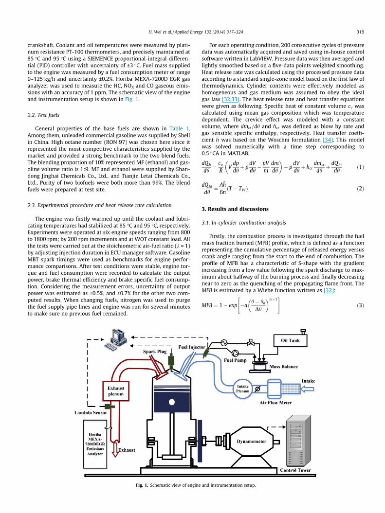
crankshaft. Coolant and oil temperatures were measured by plati-num resistance PT-100 thermometers, and precisely maintained at85 �C and 95 �C using a SIEMENCE proportional-integral-differen-tial (PID) controller with uncertainty of ±3 �C. Fuel mass suppliedto the engine was measured by a fuel consumption meter of range0–125 kg/h and uncertainty ±0.2%. Horiba MEXA-7200D EGR gasanalyzer was used to measure the HC, NOX and CO gaseous emis-sions with an accuracy of 1 ppm. The schematic view of the engineand instrumentation setup is shown in Fig. 1.
2.2. Test fuels
General properties of the base fuels are shown in Table 1.Among them, unleaded commercial gasoline was supplied by Shellin China. High octane number (RON 97) was chosen here since itrepresented the most competitive characteristics supplied by themarket and provided a strong benchmark to the two blend fuels.The blending proportion of 10% represented MF (ethanol) and gas-oline volume ratio is 1:9. MF and ethanol were supplied by Shan-dong Jinghai Chemicals Co., Ltd., and Tianjin Letai Chemicals Co.,Ltd., Purity of two biofuels were both more than 99%. The blendfuels were prepared at test site.
2.3. Experimental procedure and heat release rate calculation
The engine was firstly warmed up until the coolant and lubri-cating temperatures had stabilized at 85 �C and 95 �C, respectively.Experiments were operated at six engine speeds ranging from 800to 1800 rpm; by 200 rpm increments and at WOT constant load. Allthe tests were carried out at the stoichiometric air-fuel ratio (k = 1)by adjusting injection duration in ECU manager software. GasolineMBT spark timings were used as benchmarks for engine perfor-mance comparisons. After test conditions were stable, engine tor-que and fuel consumption were recorded to calculate the outputpower, brake thermal efficiency and brake specific fuel consump-tion. Considering the measurement errors, uncertainty of outputpower was estimated as ±0.5%, and ±0.7% for the other two com-puted results. When changing fuels, nitrogen was used to purgethe fuel supply pipe lines and engine was run for several minutesto make sure no previous fuel remained.
Fig. 1. Schematic view of engine
For each operating condition, 200 consecutive cycles of pressuredata was automatically acquired and saved using in-house controlsoftware written in LabVIEW. Pressure data was then averaged andlightly smoothed based on a five-data points weighted smoothing.Heat release rate was calculated using the processed pressure dataaccording to a standard single-zone model based on the first law ofthermodynamics. Cylinder contents were effectively modeled ashomogeneous and gas medium was assumed to obey the idealgas law [32,33]. The heat release rate and heat transfer equationswere given as following. Specific heat of constant volume cv wascalculated using mean gas composition which was temperaturedependent. The crevice effect was modeled with a constantvolume, where dmcr=dh and hcr was defined as blow by rate andgas sensible specific enthalpy, respectively. Heat transfer coeffi-cient �h was based on the Woschni formulation [34]. This modelwas solved numerically with a time step corresponding to0.5 �CA in MATLAB.
dQh
dh¼ cv
RV
dpdhþ p
dVdh� pV
mdmdh
� �þ p
dVdhþ hcr
dmcr
dhþ dQht
dhð1Þ
dQht
dh¼ A�h
6nðT � TWÞ ð2Þ
3. Results and discussions
3.1. In-cylinder combustion analysis
Firstly, the combustion process is investigated through the fuelmass fraction burned (MFB) profile, which is defined as a functionrepresenting the cumulative percentage of released energy versuscrank angle ranging from the start to the end of combustion. Theprofile of MFB has a characteristic of S-shape with the gradientincreasing from a low value following the spark discharge to max-imum about halfway of the burning process and finally decreasingnear to zero as the quenching of the propagating flame front. TheMFB is estimated by a Wiebe function written as [32]:
MFB ¼ 1� exp �ah� ho
Dh
� �mþ1" #
ð3Þ
and instrumentation setup.
320 H. Wei et al. / Applied Energy 132 (2014) 317–324
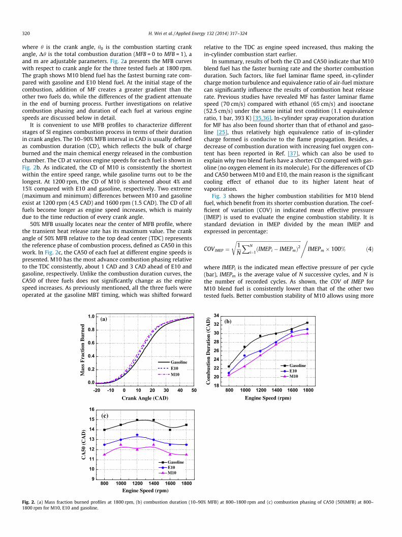
where h is the crank angle, h0 is the combustion starting crankangle, Dh is the total combustion duration (MFB = 0 to MFB = 1), aand m are adjustable parameters. Fig. 2a presents the MFB curveswith respect to crank angle for the three tested fuels at 1800 rpm.The graph shows M10 blend fuel has the fastest burning rate com-pared with gasoline and E10 blend fuel. At the initial stage of thecombustion, addition of MF creates a greater gradient than theother two fuels do, while the differences of the gradient attenuatein the end of burning process. Further investigations on relativecombustion phasing and duration of each fuel at various enginespeeds are discussed below in detail.
It is convenient to use MFB profiles to characterize differentstages of SI engines combustion process in terms of their durationin crank angles. The 10–90% MFB interval in CAD is usually definedas combustion duration (CD), which reflects the bulk of chargeburned and the main chemical energy released in the combustionchamber. The CD at various engine speeds for each fuel is shown inFig. 2b. As indicated, the CD of M10 is consistently the shortestwithin the entire speed range, while gasoline turns out to be thelongest. At 1200 rpm, the CD of M10 is shortened about 4% and15% compared with E10 and gasoline, respectively. Two extreme(maximum and minimum) differences between M10 and gasolineexist at 1200 rpm (4.5 CAD) and 1600 rpm (1.5 CAD). The CD of allfuels become longer as engine speed increases, which is mainlydue to the time reduction of every crank angle.
50% MFB usually locates near the center of MFB profile, wherethe transient heat release rate has its maximum value. The crankangle of 50% MFB relative to the top dead center (TDC) representsthe reference phase of combustion process, defined as CA50 in thiswork. In Fig. 2c, the CA50 of each fuel at different engine speeds ispresented. M10 has the most advance combustion phasing relativeto the TDC consistently, about 1 CAD and 3 CAD ahead of E10 andgasoline, respectively. Unlike the combustion duration curves, theCA50 of three fuels does not significantly change as the enginespeed increases. As previously mentioned, all the three fuels wereoperated at the gasoline MBT timing, which was shifted forward
0.0
0.2
0.4
0.6
0.8
1.0
Mas
s F
ract
ion
Bur
ned
Crank Angle (CAD)
GasolineE10M10
(a)
-20 -10 0 10 20 30 40 50
800 1000 1200 1400 1600 18009
10
11
12
13
14
15
16(c)
CA
50 (
CA
D)
Engine Speed (rpm)
GasolineE10M10
Fig. 2. (a) Mass fraction burned profiles at 1800 rpm, (b) combustion duration (10–901800 rpm for M10, E10 and gasoline.
relative to the TDC as engine speed increased, thus making thein-cylinder combustion start earlier.
In summary, results of both the CD and CA50 indicate that M10blend fuel has the faster burning rate and the shorter combustionduration. Such factors, like fuel laminar flame speed, in-cylindercharge motion turbulence and equivalence ratio of air-fuel mixturecan significantly influence the results of combustion heat releaserate. Previous studies have revealed MF has faster laminar flamespeed (70 cm/s) compared with ethanol (65 cm/s) and isooctane(52.5 cm/s) under the same initial test condition (1.1 equivalenceratio, 1 bar, 393 K) [35,36]. In-cylinder spray evaporation durationfor MF has also been found shorter than that of ethanol and gaso-line [25], thus relatively high equivalence ratio of in-cylindercharge formed is conducive to the flame propagation. Besides, adecrease of combustion duration with increasing fuel oxygen con-tent has been reported in Ref. [37], which can also be used toexplain why two blend fuels have a shorter CD compared with gas-oline (no oxygen element in its molecule). For the differences of CDand CA50 between M10 and E10, the main reason is the significantcooling effect of ethanol due to its higher latent heat ofvaporization.
Fig. 3 shows the higher combustion stabilities for M10 blendfuel, which benefit from its shorter combustion duration. The coef-ficient of variation (COV) in indicated mean effective pressure(IMEP) is used to evaluate the engine combustion stability. It isstandard deviation in IMEP divided by the mean IMEP andexpressed in percentage:
COVIMEP ¼ffiffiffiffiffiffiffiffiffiffiffiffiffiffiffiffiffiffiffiffiffiffiffiffiffiffiffiffiffiffiffiffiffiffiffiffiffiffiffiffiffiffiffiffiffiffiffiffiffiffiffiffiffiffiffi1N
XN
i¼1ðIMEPi � IMEPmÞ2
r ,IMEPm � 100% ð4Þ
where IMEPi is the indicated mean effective pressure of per cycle(bar), IMEPm is the average value of N successive cycles, and N isthe number of recorded cycles. As shown, the COV of IMEP forM10 blend fuel is consistently lower than that of the other twotested fuels. Better combustion stability of M10 allows using more
18
20
22
24
26
28
30
32
34(b)
Com
bust
ion
Dur
atio
n (C
AD
)
Engine Speed (rpm)
GasolineE10M10
800 1000 1200 1400 1600 1800
% MFB) at 800–1800 rpm and (c) combustion phasing of CA50 (50%MFB) at 800–
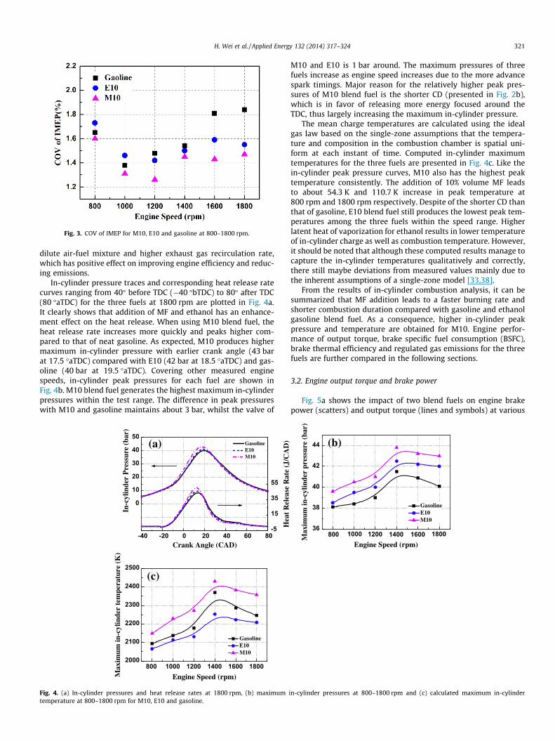
Fig. 3. COV of IMEP for M10, E10 and gasoline at 800–1800 rpm.
H. Wei et al. / Applied Energy 132 (2014) 317–324 321
dilute air-fuel mixture and higher exhaust gas recirculation rate,which has positive effect on improving engine efficiency and reduc-ing emissions.
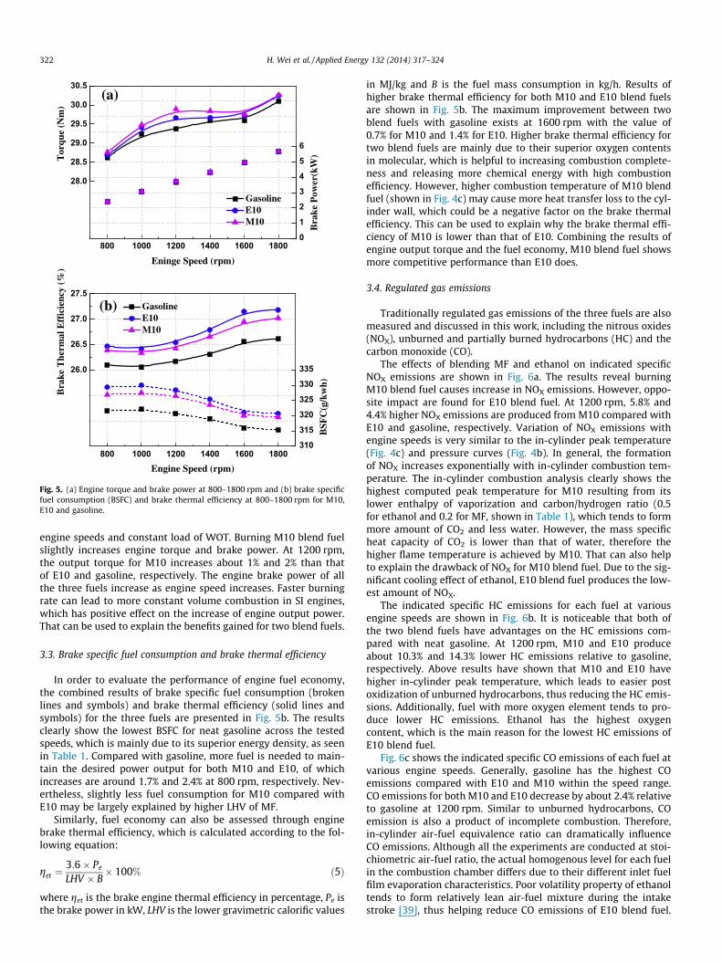
In-cylinder pressure traces and corresponding heat release ratecurves ranging from 40� before TDC (�40 �bTDC) to 80� after TDC(80 �aTDC) for the three fuels at 1800 rpm are plotted in Fig. 4a.It clearly shows that addition of MF and ethanol has an enhance-ment effect on the heat release. When using M10 blend fuel, theheat release rate increases more quickly and peaks higher com-pared to that of neat gasoline. As expected, M10 produces highermaximum in-cylinder pressure with earlier crank angle (43 barat 17.5 �aTDC) compared with E10 (42 bar at 18.5 �aTDC) and gas-oline (40 bar at 19.5 �aTDC). Covering other measured enginespeeds, in-cylinder peak pressures for each fuel are shown inFig. 4b. M10 blend fuel generates the highest maximum in-cylinderpressures within the test range. The difference in peak pressureswith M10 and gasoline maintains about 3 bar, whilst the valve of
-40 -20 0 20 40 60 80
(a)
In-c
ylin
der
Pre
ssur
e (b
ar)
Crank Angle (CAD)
GasolineE10M10
0
10
20
30
40
50
-5
15
35
55
800 1000 1200 1400 1600 18002000
2100
2200
2300
2400
2500(c)
GasolineE10M10
Max
imum
in-c
ylin
der
tem
pera
ture
(K
)
Engine Speed (rpm)
Fig. 4. (a) In-cylinder pressures and heat release rates at 1800 rpm, (b) maximumtemperature at 800–1800 rpm for M10, E10 and gasoline.
M10 and E10 is 1 bar around. The maximum pressures of threefuels increase as engine speed increases due to the more advancespark timings. Major reason for the relatively higher peak pres-sures of M10 blend fuel is the shorter CD (presented in Fig. 2b),which is in favor of releasing more energy focused around theTDC, thus largely increasing the maximum in-cylinder pressure.
The mean charge temperatures are calculated using the idealgas law based on the single-zone assumptions that the tempera-ture and composition in the combustion chamber is spatial uni-form at each instant of time. Computed in-cylinder maximumtemperatures for the three fuels are presented in Fig. 4c. Like thein-cylinder peak pressure curves, M10 also has the highest peaktemperature consistently. The addition of 10% volume MF leadsto about 54.3 K and 110.7 K increase in peak temperature at800 rpm and 1800 rpm respectively. Despite of the shorter CD thanthat of gasoline, E10 blend fuel still produces the lowest peak tem-peratures among the three fuels within the speed range. Higherlatent heat of vaporization for ethanol results in lower temperatureof in-cylinder charge as well as combustion temperature. However,it should be noted that although these computed results manage tocapture the in-cylinder temperatures qualitatively and correctly,there still maybe deviations from measured values mainly due tothe inherent assumptions of a single-zone model [33,38].
From the results of in-cylinder combustion analysis, it can besummarized that MF addition leads to a faster burning rate andshorter combustion duration compared with gasoline and ethanolgasoline blend fuel. As a consequence, higher in-cylinder peakpressure and temperature are obtained for M10. Engine perfor-mance of output torque, brake specific fuel consumption (BSFC),brake thermal efficiency and regulated gas emissions for the threefuels are further compared in the following sections.
3.2. Engine output torque and brake power
Fig. 5a shows the impact of two blend fuels on engine brakepower (scatters) and output torque (lines and symbols) at various
Hea
t R
elea
se R
ate
(J/C
AD
)
36
38
40
42
44 (b)
Max
imum
in-c
ylin
der
pres
sure
(ba
r)
Engine Speed (rpm)
GasolineE10M10
800 1000 1200 1400 1600 1800
in-cylinder pressures at 800–1800 rpm and (c) calculated maximum in-cylinder
(a)
Tor
que
(Nm
)
Eninge Speed (rpm)
GasolineE10M10
Bra
ke P
ower
(kW
)
0
1
2
3
4
5
6
28.0
28.5
29.0
29.5
30.0
30.5
800 1000 1200 1400 1600 1800
Bra
ke T
herm
al E
ffic
ienc
y (%
)
Engine Speed (rpm)
GasolineE10M10
(b) B
SFC
(g/k
wh)
26.0
26.5
27.0
27.5
310
315
320
325
330
335
800 1000 1200 1400 1600 1800
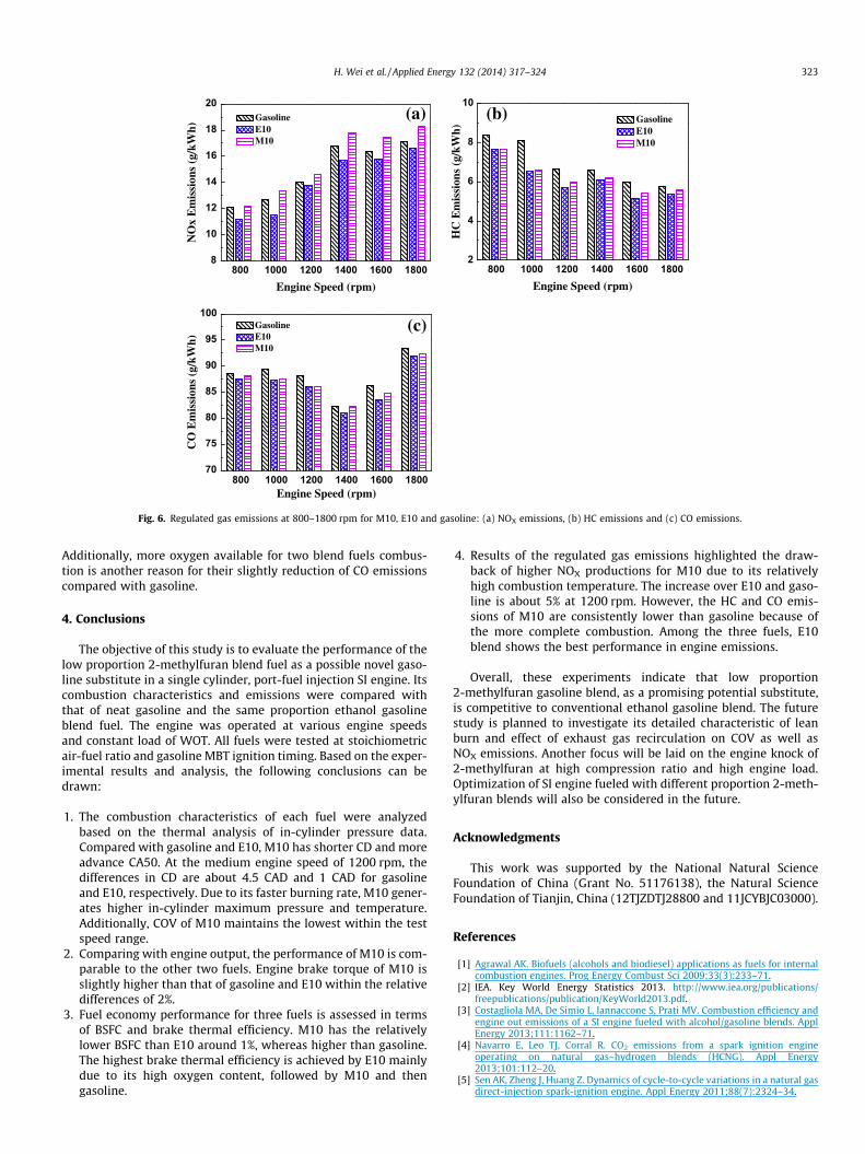
Fig. 5. (a) Engine torque and brake power at 800–1800 rpm and (b) brake specificfuel consumption (BSFC) and brake thermal efficiency at 800–1800 rpm for M10,E10 and gasoline.
322 H. Wei et al. / Applied Energy 132 (2014) 317–324
engine speeds and constant load of WOT. Burning M10 blend fuelslightly increases engine torque and brake power. At 1200 rpm,the output torque for M10 increases about 1% and 2% than thatof E10 and gasoline, respectively. The engine brake power of allthe three fuels increase as engine speed increases. Faster burningrate can lead to more constant volume combustion in SI engines,which has positive effect on the increase of engine output power.That can be used to explain the benefits gained for two blend fuels.
3.3. Brake specific fuel consumption and brake thermal efficiency
In order to evaluate the performance of engine fuel economy,the combined results of brake specific fuel consumption (brokenlines and symbols) and brake thermal efficiency (solid lines andsymbols) for the three fuels are presented in Fig. 5b. The resultsclearly show the lowest BSFC for neat gasoline across the testedspeeds, which is mainly due to its superior energy density, as seenin Table 1. Compared with gasoline, more fuel is needed to main-tain the desired power output for both M10 and E10, of whichincreases are around 1.7% and 2.4% at 800 rpm, respectively. Nev-ertheless, slightly less fuel consumption for M10 compared withE10 may be largely explained by higher LHV of MF.
Similarly, fuel economy can also be assessed through enginebrake thermal efficiency, which is calculated according to the fol-lowing equation:
get ¼3:6� Pe
LHV � B� 100% ð5Þ
where get is the brake engine thermal efficiency in percentage, Pe isthe brake power in kW, LHV is the lower gravimetric calorific values
in MJ/kg and B is the fuel mass consumption in kg/h. Results ofhigher brake thermal efficiency for both M10 and E10 blend fuelsare shown in Fig. 5b. The maximum improvement between twoblend fuels with gasoline exists at 1600 rpm with the value of0.7% for M10 and 1.4% for E10. Higher brake thermal efficiency fortwo blend fuels are mainly due to their superior oxygen contentsin molecular, which is helpful to increasing combustion complete-ness and releasing more chemical energy with high combustionefficiency. However, higher combustion temperature of M10 blendfuel (shown in Fig. 4c) may cause more heat transfer loss to the cyl-inder wall, which could be a negative factor on the brake thermalefficiency. This can be used to explain why the brake thermal effi-ciency of M10 is lower than that of E10. Combining the results ofengine output torque and the fuel economy, M10 blend fuel showsmore competitive performance than E10 does.
3.4. Regulated gas emissions
Traditionally regulated gas emissions of the three fuels are alsomeasured and discussed in this work, including the nitrous oxides(NOX), unburned and partially burned hydrocarbons (HC) and thecarbon monoxide (CO).
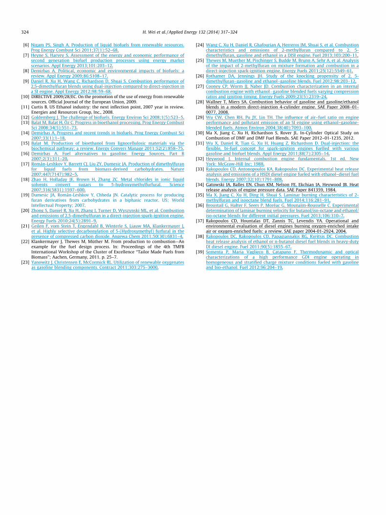
The effects of blending MF and ethanol on indicated specificNOX emissions are shown in Fig. 6a. The results reveal burningM10 blend fuel causes increase in NOX emissions. However, oppo-site impact are found for E10 blend fuel. At 1200 rpm, 5.8% and4.4% higher NOX emissions are produced from M10 compared withE10 and gasoline, respectively. Variation of NOX emissions withengine speeds is very similar to the in-cylinder peak temperature(Fig. 4c) and pressure curves (Fig. 4b). In general, the formationof NOX increases exponentially with in-cylinder combustion tem-perature. The in-cylinder combustion analysis clearly shows thehighest computed peak temperature for M10 resulting from itslower enthalpy of vaporization and carbon/hydrogen ratio (0.5for ethanol and 0.2 for MF, shown in Table 1), which tends to formmore amount of CO2 and less water. However, the mass specificheat capacity of CO2 is lower than that of water, therefore thehigher flame temperature is achieved by M10. That can also helpto explain the drawback of NOX for M10 blend fuel. Due to the sig-nificant cooling effect of ethanol, E10 blend fuel produces the low-est amount of NOX.
The indicated specific HC emissions for each fuel at variousengine speeds are shown in Fig. 6b. It is noticeable that both ofthe two blend fuels have advantages on the HC emissions com-pared with neat gasoline. At 1200 rpm, M10 and E10 produceabout 10.3% and 14.3% lower HC emissions relative to gasoline,respectively. Above results have shown that M10 and E10 havehigher in-cylinder peak temperature, which leads to easier postoxidization of unburned hydrocarbons, thus reducing the HC emis-sions. Additionally, fuel with more oxygen element tends to pro-duce lower HC emissions. Ethanol has the highest oxygencontent, which is the main reason for the lowest HC emissions ofE10 blend fuel.
Fig. 6c shows the indicated specific CO emissions of each fuel atvarious engine speeds. Generally, gasoline has the highest COemissions compared with E10 and M10 within the speed range.CO emissions for both M10 and E10 decrease by about 2.4% relativeto gasoline at 1200 rpm. Similar to unburned hydrocarbons, COemission is also a product of incomplete combustion. Therefore,in-cylinder air-fuel equivalence ratio can dramatically influenceCO emissions. Although all the experiments are conducted at stoi-chiometric air-fuel ratio, the actual homogenous level for each fuelin the combustion chamber differs due to their different inlet fuelfilm evaporation characteristics. Poor volatility property of ethanoltends to form relatively lean air-fuel mixture during the intakestroke [39], thus helping reduce CO emissions of E10 blend fuel.
8
10
12
14
16
18
20(a)
NO
x E
mis
sion
s (g
/kW
h)
Engine Speed (rpm)
GasolineE10M10
2
4
6
8
10(b)
HC
Em
issi
ons
(g/k
Wh)
Engine Speed (rpm)
GasolineE10M10
800 1000 1200 1400 1600 180070
75
80
85
90
95
100(c)
CO
Em
issi
ons
(g/k
Wh)
Engine Speed (rpm)
GasolineE10M10
800 1000 1200 1400 1600 1800 800 1000 1200 1400 1600 1800
Fig. 6. Regulated gas emissions at 800–1800 rpm for M10, E10 and gasoline: (a) NOX emissions, (b) HC emissions and (c) CO emissions.
H. Wei et al. / Applied Energy 132 (2014) 317–324 323
Additionally, more oxygen available for two blend fuels combus-tion is another reason for their slightly reduction of CO emissionscompared with gasoline.
4. Conclusions
The objective of this study is to evaluate the performance of thelow proportion 2-methylfuran blend fuel as a possible novel gaso-line substitute in a single cylinder, port-fuel injection SI engine. Itscombustion characteristics and emissions were compared withthat of neat gasoline and the same proportion ethanol gasolineblend fuel. The engine was operated at various engine speedsand constant load of WOT. All fuels were tested at stoichiometricair-fuel ratio and gasoline MBT ignition timing. Based on the exper-imental results and analysis, the following conclusions can bedrawn:
1. The combustion characteristics of each fuel were analyzedbased on the thermal analysis of in-cylinder pressure data.Compared with gasoline and E10, M10 has shorter CD and moreadvance CA50. At the medium engine speed of 1200 rpm, thedifferences in CD are about 4.5 CAD and 1 CAD for gasolineand E10, respectively. Due to its faster burning rate, M10 gener-ates higher in-cylinder maximum pressure and temperature.Additionally, COV of M10 maintains the lowest within the testspeed range.
2. Comparing with engine output, the performance of M10 is com-parable to the other two fuels. Engine brake torque of M10 isslightly higher than that of gasoline and E10 within the relativedifferences of 2%.
3. Fuel economy performance for three fuels is assessed in termsof BSFC and brake thermal efficiency. M10 has the relativelylower BSFC than E10 around 1%, whereas higher than gasoline.The highest brake thermal efficiency is achieved by E10 mainlydue to its high oxygen content, followed by M10 and thengasoline.
4. Results of the regulated gas emissions highlighted the draw-back of higher NOX productions for M10 due to its relativelyhigh combustion temperature. The increase over E10 and gaso-line is about 5% at 1200 rpm. However, the HC and CO emis-sions of M10 are consistently lower than gasoline because ofthe more complete combustion. Among the three fuels, E10blend shows the best performance in engine emissions.
Overall, these experiments indicate that low proportion2-methylfuran gasoline blend, as a promising potential substitute,is competitive to conventional ethanol gasoline blend. The futurestudy is planned to investigate its detailed characteristic of leanburn and effect of exhaust gas recirculation on COV as well asNOX emissions. Another focus will be laid on the engine knock of2-methylfuran at high compression ratio and high engine load.Optimization of SI engine fueled with different proportion 2-meth-ylfuran blends will also be considered in the future.
Acknowledgments
This work was supported by the National Natural ScienceFoundation of China (Grant No. 51176138), the Natural ScienceFoundation of Tianjin, China (12TJZDTJ28800 and 11JCYBJC03000).
References
[1] Agrawal AK. Biofuels (alcohols and biodiesel) applications as fuels for internalcombustion engines. Prog Energy Combust Sci 2009;33(3):233–71.
[2] IEA. Key World Energy Statistics 2013. http://www.iea.org/publications/freepublications/publication/KeyWorld2013.pdf.
[3] Costagliola MA, De Simio L, Iannaccone S, Prati MV. Combustion efficiency andengine out emissions of a SI engine fueled with alcohol/gasoline blends. ApplEnergy 2013;111:1162–71.
[4] Navarro E, Leo TJ, Corral R. CO2 emissions from a spark ignition engineoperating on natural gas–hydrogen blends (HCNG). Appl Energy2013;101:112–20.
[5] Sen AK, Zheng J, Huang Z. Dynamics of cycle-to-cycle variations in a natural gasdirect-injection spark-ignition engine. Appl Energy 2011;88(7):2324–34.
324 H. Wei et al. / Applied Energy 132 (2014) 317–324
[6] Nigam PS, Singh A. Production of liquid biofuels from renewable resources.Prog Energy Combust Sci 2011;37(1):52–68.
[7] Heyne S, Harvey S. Assessment of the energy and economic performance ofsecond generation biofuel production processes using energy marketscenarios. Appl Energy 2013;101:203–12.
[8] Demirbas A. Political, economic and environmental impacts of biofuels: areview. Appl Energy 2009;86:S108–17.
[9] Daniel R, Xu H, Wang C, Richardson D, Shuai S. Combustion performance of2,5-dimethylfuran blends using dual-injection compared to direct-injection ina SI engine. Appl Energy 2012;98:59–68.
[10] DIRECTIVE 2009/28/EC. On the promotion of the use of energy from renewablesources. Official Journal of the European Union, 2009.
[11] Curtis B. US Ethanol industry: the next inflection point, 2007 year in review.Energies and Resources Group, Inc., 2008.
[12] Goldemberg J. The challenge of biofuels. Energy Environ Sci 2008;1(5):523–5.[13] Balat M, Balat H, Öz C. Progress in bioethanol processing. Prog Energy Combust
Sci 2008;34(5):551–73.[14] Demirbas A. Progress and recent trends in biofuels. Prog Energy Combust Sci
2007;33(1):1–18.[15] Balat M. Production of bioethanol from lignocellulosic materials via the
biochemical pathway: a review. Energy Convers Manage 2011;52(2):858–75.[16] Demirbas A. Fuel alternatives to gasoline. Energy Sources, Part B
2007;2(3):311–20.[17] Román-Leshkov Y, Barrett CJ, Liu ZY, Dumesic JA. Production of dimethylfuran
for liquid fuels from biomass-derived carbohydrates. Nature2007;447(7147):982–5.
[18] Zhao H, Holladay JE, Brown H, Zhang ZC. Metal chlorides in ionic liquidsolvents convert sugars to 5-hydroxymethylfurfural. Science2007;316(5831):1597–600.
[19] Dumesic JA, Román-Leshkov Y, Chheda JN. Catalytic process for producingfuran derivatives from carbohydrates in a biphasic reactor. US: WorldIntellectual Property; 2007.
[20] Zhong S, Daniel R, Xu H, Zhang J, Turner D, Wyszynski ML, et al. Combustionand emissions of 2,5-dimethylfuran in a direct-injection spark-ignition engine.Energy Fuels 2010;24(5):2891–9.
[21] Geilen F, vom Stein T, Engendahl B, Winterle S, Liauw MA, Klankermayer J,et al. Highly selective decarbonylation of 5-(Hydroxymethyl) furfural in thepresence of compressed carbon dioxide. Angewa Chem 2011;50(30):6831–4.
[22] Klankermayer J, Thewes M, Müther M. From production to combustion—Anexample for the fuel design process. In: Proceedings of the 4th TMFBInternational Workshop of the Cluster of Excellence ‘‘Tailor Made Fuels fromBiomass’’; Aachen, Germany, 2011. p. 25–7.
[23] Yanowitz J, Christensen E, McCormick RL. Utilization of renewable oxygenatesas gasoline blending components. Contract 2011;303:275–3000.
[24] Wang C, Xu H, Daniel R, Ghafourian A, Herreros JM, Shuai S, et al. Combustioncharacteristics and emissions of 2-methylfuran compared to 2, 5-dimethylfuran, gasoline and ethanol in a DISI engine. Fuel 2013;103:200–11.
[25] Thewes M, Muether M, Pischinger S, Budde M, Brunn A, Sehr A, et al. Analysisof the impact of 2-methylfuran on mixture formation and combustion in adirect-injection spark-ignition engine. Energy Fuels 2011;25(12):5549–61.
[26] Rothamer DA, Jennings JH. Study of the knocking propensity of 2, 5-dimethylfuran–gasoline and ethanol–gasoline blends. Fuel 2012;98:203–12.
[27] Cooney CP, Worm JJ, Naber JD. Combustion characterization in an internalcombustion engine with ethanol�gasoline blended fuels varying compressionratios and ignition timing. Energy Fuels 2009;23(5):2319–24.
[28] Wallner T, Miers SA. Combustion behavior of gasoline and gasoline/ethanolblends in a modern direct-injection 4-cylinder engine. SAE Paper 2008–01-0077, 2008.
[29] Wu CW, Chen RH, Pu JY, Lin TH. The influence of air–fuel ratio on engineperformance and pollutant emission of an SI engine using ethanol–gasoline-blended fuels. Atmos Environ 2004;38(40):7093–100.
[30] Ma X, Jiang C, Xu H, Richardson S, Rover JL. In-Cylinder Optical Study onCombustion of DMF and DMF Fuel Blends. SAE Paper 2012–01-1235, 2012.
[31] Wu X, Daniel R, Tian G, Xu H, Huang Z, Richardson D. Dual-injection: theflexible, bi-fuel concept for spark-ignition engines fuelled with variousgasoline and biofuel blends. Appl Energy 2011;88(7):2305–14.
[32] Heywood J. Internal combustion engine fundamentals. 1st ed. NewYork: McGraw-Hill Inc; 1988.
[33] Rakopoulos CD, Antonopoulos KA, Rakopoulos DC. Experimental heat releaseanalysis and emissions of a HSDI diesel engine fueled with ethanol–diesel fuelblends. Energy 2007;32(10):1791–808.
[34] Gatowski JA, Balles EN, Chun KM, Nelson FE, Ekchian JA, Heywood JB. Heatrelease analysis of engine pressure data. SAE Paper 841359, 1984.
[35] Ma X, Jiang C, Xu H, Ding H, Shuai S. Laminar burning characteristics of 2-methylfuran and isooctane blend fuels. Fuel 2014;116:281–91.
[36] Broustail G, Halter F, Seers P, Moréac G, Mounaïm-Rousselle C. Experimentaldetermination of laminar burning velocity for butanol/iso-octane and ethanol/iso-octane blends for different initial pressures. Fuel 2013;106:310–7.
[37] Rakopoulos CD, Hountalas DT, Zannis TC, Levendis YA. Operational andenvironmental evaluation of diesel engines burning oxygen-enriched intakeair or oxygen-enriched fuels: a review. SAE paper 2004-01-2924, 2004.
[38] Rakopoulos DC, Rakopoulos CD, Papagiannakis RG, Kyritsis DC. Combustionheat release analysis of ethanol or n-butanol diesel fuel blends in heavy-dutyDI diesel engine. Fuel 2011;90(5):1855–67.
[39] Sementa P, Maria Vaglieco B, Catapano F. Thermodynamic and opticalcharacterizations of a high performance GDI engine operating inhomogeneous and stratified charge mixture conditions fueled with gasolineand bio-ethanol. Fuel 2012;96:204–19.