
Effectiveness of replacing catalytic converters in LPG-fueled ...
Upload
independentCategory
view
0download
0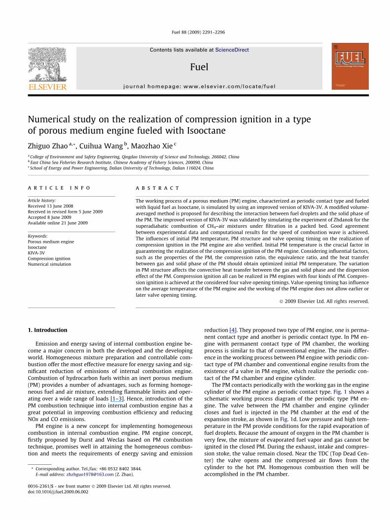
Fuel 88 (2009) 2291–2296
Contents lists available at ScienceDirect
Fuel
journal homepage: www.elsevier .com/locate / fuel
Numerical study on the realization of compression ignition in a typeof porous medium engine fueled with Isooctane
Zhiguo Zhao a,*, Cuihua Wang b, Maozhao Xie c
a College of Environment and Safety Engineering, Qingdao University of Science and Technology, 266042, Chinab East China Sea Fisheries Research Institute, Chinese Academy of Fishery Sciences, 200090, Chinac School of Energy and Power Engineering, Dalian University of Technology, Dalian 116024, China
a r t i c l e i n f o a b s t r a c t
Article history:Received 13 June 2008Received in revised form 5 June 2009Accepted 8 June 2009Available online 21 June 2009
Keywords:Porous medium engineIsooctaneKIVA-3VCompression ignitionNumerical simulation
0016-2361/$ - see front matter � 2009 Elsevier Ltd. Adoi:10.1016/j.fuel.2009.06.002
* Corresponding author. Tel./fax: +86 0532 8402 38E-mail address: [email protected] (Z. Zhao).
The working process of a porous medium (PM) engine, characterized as periodic contact type and fueledwith liquid fuel as Isooctane, is simulated by using an improved version of KIVA-3V. A modified volume-averaged method is proposed for describing the interaction between fuel droplets and the solid phase ofthe PM. The improved version of KIVA-3V was validated by simulating the experiment of Zhdanok for thesuperadiabatic combustion of CH4–air mixtures under filtration in a packed bed. Good agreementbetween experimental data and computational results for the speed of combustion wave is achieved.The influences of initial PM temperature, PM structure and valve opening timing on the realization ofcompression ignition in the PM engine are also verified. Initial PM temperature is the crucial factor inguaranteeing the realization of the compression ignition of the PM engine. Considering influential factors,such as the properties of the PM, the compression ratio, the equivalence ratio, and the heat transferbetween gas and solid phase of the PM should obtain optimized initial PM temperature. The variationin PM structure affects the convective heat transfer between the gas and solid phase and the dispersioneffect of the PM. Compression ignition all can be realized in PM engines with four kinds of PM. Compres-sion ignition is achieved at the considered four valve opening timings. Value opening timing has influenceon the average temperature of the PM engine and the working of the PM engine does not allow earlier orlater valve opening timing.
� 2009 Elsevier Ltd. All rights reserved.
1. Introduction
Emission and energy saving of internal combustion engine be-come a major concern in both the developed and the developingworld. Homogeneous mixture preparation and controllable com-bustion offer the most effective measure for energy saving and sig-nificant reduction of emissions of internal combustion engine.Combustion of hydrocarbon fuels within an inert porous medium(PM) provides a number of advantages, such as forming homoge-neous fuel and air mixture, extending flammable limits and oper-ating over a wide range of loads [1–3]. Hence, introduction of thePM combustion technique into internal combustion engine has agreat potential in improving combustion efficiency and reducingNOx and CO emissions.
PM engine is a new concept for implementing homogeneouscombustion in internal combustion engine. PM engine concept,firstly proposed by Durst and Weclas based on PM combustiontechnique, promises well in attaining the homogeneous combus-tion and meets the requirements of energy saving and emission
ll rights reserved.
44.
reduction [4]. They proposed two type of PM engine, one is perma-nent contact type and another is periodic contact type. In PM en-gine with permanent contact type of PM chamber, the workingprocess is similar to that of conventional engine. The main differ-ence in the working process between PM engine with periodic con-tact type of PM chamber and conventional engine results from theexistence of a valve in PM engine, which realize the periodic con-tact of the PM chamber and engine cylinder.
The PM contacts periodically with the working gas in the enginecylinder of the PM engine as periodic contact type. Fig. 1 shows aschematic working process diagram of the periodic type PM en-gine. The valve between the PM chamber and engine cylindercloses and fuel is injected in the PM chamber at the end of theexpansion stroke, as shown in Fig. 1d. Low pressure and high tem-perature in the PM provide conditions for the rapid evaporation offuel droplets. Because the amount of oxygen in the PM chamber isvery few, the mixture of evaporated fuel vapor and gas cannot beignited in the closed PM. During the exhaust, intake and compres-sion stoke, the value remain closed. Near the TDC (Top Dead Cen-ter) the valve opens and the compressed air flows from thecylinder to the hot PM. Homogenous combustion then will beaccomplished in the PM chamber.
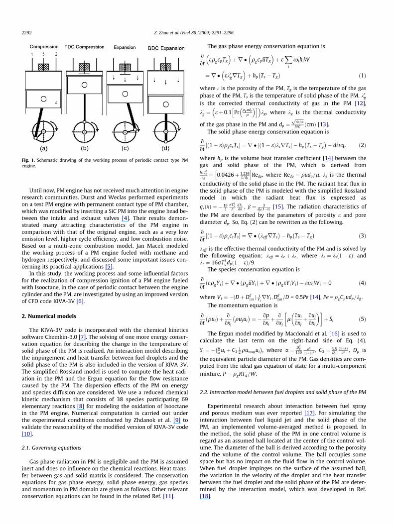
Fig. 1. Schematic drawing of the working process of periodic contact type PMengine.
2292 Z. Zhao et al. / Fuel 88 (2009) 2291–2296
Until now, PM engine has not received much attention in engineresearch communities. Durst and Weclas performed experimentson a test PM engine with permanent contact type of PM chamber,which was modified by inserting a SiC PM into the engine head be-tween the intake and exhaust valves [4]. Their results demon-strated many attracting characteristics of the PM engine incomparison with that of the original engine, such as a very lowemission level, higher cycle efficiency, and low combustion noise.Based on a multi-zone combustion model, Jan Macek modeledthe working process of a PM engine fueled with methane andhydrogen respectively, and discussed some important issues con-cerning its practical applications [5].
In this study, the working process and some influential factorsfor the realization of compression ignition of a PM engine fueledwith Isooctane, in the case of periodic contact between the enginecylinder and the PM, are investigated by using an improved versionof CFD code KIVA-3V [6].
2. Numerical models
The KIVA-3V code is incorporated with the chemical kineticssoftware Chemkin-3.0 [7]. The solving of one more energy conser-vation equation for describing the change in the temperature ofsolid phase of the PM is realized. An interaction model describingthe impingement and heat transfer between fuel droplets and thesolid phase of the PM is also included in the version of KIVA-3V.The simplified Rossland model is used to compute the heat radi-ation in the PM and the Ergun equation for the flow resistancecaused by the PM. The dispersion effects of the PM on energyand species diffusion are considered. We use a reduced chemicalkinetic mechanism that consists of 38 species participating 69elementary reactions [8] for modeling the oxidation of Isooctanein the PM engine. Numerical computation is carried out underthe experimental conditions conducted by Zhdanok et al. [9] tovalidate the reasonability of the modified version of KIVA-3V code[10].
2.1. Governing equations
Gas phase radiation in PM is negligible and the PM is assumedinert and does no influence on the chemical reactions. Heat trans-fer between gas and solid matrix is considered. The conservationequations for gas phase energy, solid phase energy, gas speciesand momentum in PM domain are given as follows. Other relevantconservation equations can be found in the related Ref. [11].
The gas phase energy conservation equation is
o
oteqgcpTg
� �þr � qgcp~uTg
� �þ e
Xi
xihiW
¼ r � ek0grTg
� �þ hp Ts � Tg
� �ð1Þ
where e is the porosity of the PM, Tg is the temperature of the gasphase of the PM, Ts is the temperature of solid phase of the PM. k0gis the corrected thermal conductivity of gas in the PM [12],
k0g ¼ eþ 0:1 Pr qg udp
l
� �h i� �kg , where kg is the thermal conductivity
of the gas phase in the PM and dp ¼ffiffiffiffiffiffiffi4e=pp
PPC ðcmÞ [13].The solid phase energy conservation equation is
o
ot1� eð ÞqscsTs½ � ¼ r � ð1� eÞksrTs½ � � hp Ts � Tg
� �� divqr ð2Þ
where hp is the volume heat transfer coefficient [14] between thegas and solid phase of the PM, which is derived fromhpd2
p
kg¼ 0:0426þ 1:236
L=dp
h iRedp, where Redp ¼ qudp=l. ks is the thermal
conductivity of the solid phase in the PM. The radiant heat flux inthe solid phase of the PM is modeled with the simplified Rosslandmodel in which the radiant heat flux is expressed as
qrðxÞ ¼ � 163
rT3s
bdTsdx ; b ¼ 3
dpð1�eÞ [15]. The radiation characteristics of
the PM are described by the parameters of porosity e and porediameter dp: So, Eq. (2) can be rewritten as the following.
o
ot1� eð ÞqscsTs½ � ¼ r � keffrTs
� �� hp Ts � Tg
� �ð3Þ
keff is the effective thermal conductivity of the PM and is solved bythe following equation: keff ¼ ke þ kr; where ke ¼ ksð1� eÞ andkr ¼ 16rT3
s dpð1� eÞ=9:The species conservation equation is
o
otðeqgYiÞ þ r � ðqg~uYiÞ þ r � ðqgeYiViÞ � exiWi ¼ 0 ð4Þ
where Vi ¼ �ðDþ DdjjmÞ 1
YirYi;D
djjm=D = 0.5Pe [14], Pe = qgCpudp=kg .
The momentum equation is
o
otquið Þ þ o
oxjqujui� �
¼ � opoxiþ o
oxjl oui
oxjþ ouj
oxi
� � þ Si ð5Þ
The Ergun model modified by Macdonald et al. [16] is used tocalculate the last term on the right-hand side of Eq. (4).
Si ¼ � la ui þ C2
12 qumagui
� �, where a ¼ D2
p
150e3
ð1�eÞ2, C2 ¼ 3:5
Dp
ð1�eÞe3 ; Dp is
the equivalent particle diameter of the PM. Gas densities are com-puted from the ideal gas equation of state for a multi-componentmixture, P ¼ qgRTg=W .
2.2. Interaction model between fuel droplets and solid phase of the PM
Experimental research about interaction between fuel sprayand porous medium was ever reported [17]. For simulating theinteraction between fuel liquid jet and the solid phase of thePM, an implemented volume-averaged method is proposed. Inthe method, the solid phase of the PM in one control volume isregard as an assumed ball located at the center of the control vol-ume. The diameter of the ball is derived according to the porosityand the volume of the control volume. The ball occupies somespace but has no impact on the fluid flow in the control volume.When fuel droplet impinges on the surface of the assumed ball,the variation in the velocity of the droplet and the heat transferbetween the fuel droplet and the solid phase of the PM are deter-mined by the interaction model, which was developed in Ref.[18].
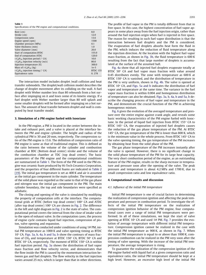
Table 1Specifications of the PM engine and computational conditions.
Bore (cm) 8.0Stroke (cm) 12.0Compression ratio 13.6Engine speed (rpm) 1500Chamber pressure (MPa) 0.1Valve thickness (mm) 1.0Valve diameter (mm) 20.0Start of computation BTDC 155.0End of computation ATDC 120.0i-C8H18 Injection period (� CA) 10.0i-C8H18 Injection velocity (m/s) 80.0Injection temperature (K) 300.0Mass of i-C8H18 (kg) 1e-5i-C8H18 injection timing (� CA) BTDC 155Equivalence ratio 0. 278
Z. Zhao et al. / Fuel 88 (2009) 2291–2296 2293
The interaction model includes droplet /wall collision and heattransfer submodels. The droplet/wall collision model describes thechange of droplet movement after its colliding on the wall. A fueldroplet with Weber number less than 80 rebounds from a hot sur-face after impinging on it and loses some of its kinetic energy. If afuel droplet with Weber number larger than 80 will splash andsome smaller droplets will be formed after impinging on a hot sur-face. The amount of heat transfer between droplet and wall is com-puted by heat transfer model.
3. Simulation of a PM engine fueled with Isooctane
In the PM engine, a PM is located in the center between the in-take and exhaust port, and a valve is placed at the interface be-tween the PM and engine cylinder. The height and radius of thecylindrical PM is 30 and 20 mm, respectively. The compression ra-tio of the PM engine is 13.6. The definition of compression ratio ofPM engine is same as that of traditional engine. This is defined asthe ratio between the volume of the cylinder and combustionchamber at BDC (Bottom dead center) stroke and the volume ofthe combustion chamber at TDC (top dead center). The basicparameters of the PM engine and the computational conditionsare summarized in Table 1. The form of the PM used in the PM en-gine was ceramic foam produced by Hi-Tech Ceramics Corporation,and the properties of four different foams are indicated in Table 2[19]. The initial gas temperature is set as 400 K and air is assumedas the initial gas component in the main cylinder. The temperatureof the solid phase was regarded as the same to that of the gas phaseand nitrogen was the initial gas component in the PM. The maincylinder boundary, the top and side boundaries were specified asadiabatic.
The closing and opening of the valve is simulated by modifyingthe property of computation cells at the interface. The computa-tional grids at BTDC (before top dead center) 100� CA and ATDC(after top dead center) 100� CA are shown in Fig. 2. The differencein the left and right diagram in Fig. 2 is the state of valve. The com-putational period covers the interval from the close of intake valveto the open of exhaust valve. In the computation cases, the processof engine cycle contains liquid fuel injection, compression of pis-ton, valve opening and expansion.
Simulation was conducted under conditions of using 1# PM, ini-tial PM temperature as 1000 K and valve opening timing as BTDC10� CA. Figs. 3a, b, 4a, b and 5a, b show the contours of mass frac-tion of CH4 and temperature at BTDC 150� CA, BTDC 50� CA andBTDC 10� CA, respectively. The moment of BTDC 150� CA is withinfuel injection period. Fig. 3a shows the distribution of fuel vapormass fraction and flow velocity vector, and demonstrates thatthe flow inside the PM is caused by the momentum interaction be-tween gas and fuel droplets. The flow velocity in the fuel injectionvaries around 25 m/s, which is larger than that in other directions.
The profile of fuel vapor in the PM is totally different from that infree space. In this case, the highest concentration of fuel vapor ap-pears in some place away from the fuel injection origin, rather thanaround the fuel injection origin when fuel is injected in free space.The reason for resulting in such fuel vapor distribution is that theinteraction between fuel droplets and the PM is considered.The evaporation of fuel droplets absorbs heat form the fluid inthe PM, which induces the reduction of fluid temperature alongthe injection direction. At the location with the highest fuel vapormass fraction, as shown in Fig. 3b, the fluid temperature is 600 Kresulting from the fact that large number of droplets is accumu-lated at the surface of the assumed ball.
Fig. 4a show that all injected fuel droplets evaporate totally atBTDC 50� CA and fuel vapor mass fraction with value around0.45 distributes evenly. The zone with temperature as 600 K atBTDC 150� CA is vanished, and the distribution of temperature inthe PM is very uniform, shown in Fig. 4b. The valve is opened atBTDC 10� CA, and Figs. 5a and b indicates the distribution of fuelvapor and temperature at the same time. The variance in the fuelvapor mass fraction is within 0.004 and homogenous distributionof temperature can also be obtained. Figs. 3a, b, 4a, b and 5a, b de-scribe the changing process of fuel vapor and temperature in thePM, and demonstrate the crucial function of the PM in achievinghomogenous mixture.
Fig. 6 gives the evolution of the averaged temperature and pres-sure over the entire engine against crank angle, and reveals somebasic working characteristics of the PM engine fueled with Isooc-tane. In the period of liquid fuel injection from BTDC 155� CA toBTDC 145� CA, the evaporation of injected fuel droplets causesthe reduction of the gas phase temperature of the PM. At BTDC145� CA, the gas temperature of the PM is lower than 800 K, whichis the minimum value in the whole process. From BTDC 145� CA tothe valve opening timing, the gas temperature of the PM increasesby obtaining heat from the solid phase of the PM.
The gas phase temperature of the PM increases instantly afterthe valve is opened. However, there is no significant change inthe solid phase temperature of the PM for its large heat capacity.The very short combustion period of the engine, as an outstandingfeature of the PM engine, results in the sharp increase in tempera-ture and pressure soon after the opening of the valve. The peakpressure and temperature is about 4.2 MPa and 1700 K, due tosmall compression ratio and low equivalence ratio.
4. Computational results and discussion
4.1. Influence of the initial PM temperature
Initial PM temperature is one of crucial factors in determiningthe realization of compression ignition and affecting the peak tem-perature and pressure in combustion period. To investigate the ef-fects of the initial PM temperature on the realization ofcompression ignition behavior of the PM engine, four computa-tional cases over a range of initial PM temperatures were per-formed. In all of these simulations, we kept the start of valveopening at BTDC 10� CA and used 1# PM. Fig. 7 provides the evo-lution of average temperature with different initial PM tempera-ture. Compression ignition cannot be realized in the case withthe initial PM temperature as 900 K, as shown in Fig. 7. Whenthe initial PM temperature is equal to or above than 1000 K, com-pression combustion can be realized in the PM very soon after thetiming of valve opening. With the increase of the initial PM tem-perature, the average temperature is rising.
To guarantee the realization of the compression ignition of thePM engine fueled with liquid fuel at a given compression ratio andequivalence ratio, the initial PM temperature should be kept at ahigh level. However, an excessive high level of the initial PM

Table 2The properties of ceramic foams.
No Number of pores (cm�1) Mean pore size (mm) Bulk density (Kg m�3) Porosity Thermal conductivity (Wm�1 K�1) Specific heat (J kg�1 K�1)
1# 4 1.52 510 0.87 3.87 824.72# 8 0.94 610 0.85 3.87 824.73# 12 0.76 660 0.83 3.82 824.74# 18 0.42 650 0.84 4.23 824.7
Fig. 2. Computational grids of the PM engine at BTDC100� CA and ATDC100� CA.
Fig. 3a. Fuel vapor mass fraction at BTDC 150� CA.
Fig. 3b. Temperature distribution at BTDC 150� CA.
Fig. 4a. Fuel vapor mass fraction at BTDC 50� CA.
Fig. 4b. Temperature distribution at BTDC 50� CA.
Fig. 5a. Fuel vapor mass fraction at BTDC 10� CA.
2294 Z. Zhao et al. / Fuel 88 (2009) 2291–2296
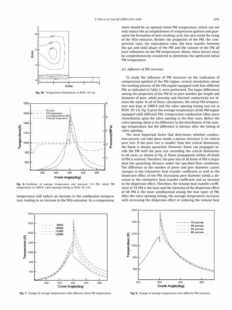
Fig. 5b. Temperature distribution at BTDC 10� CA.
Fig. 6. Evolution of average temperature and pressure (1# PM, initial PMtemperature as 1000 K, valve opening timing as BTDC 10� CA).
Z. Zhao et al. / Fuel 88 (2009) 2291–2296 2295
temperature will induce an increase in the combustion tempera-ture, leading to an increase in the NOx emission. As a compromise,
Fig. 7. Change of average temperature with different initial PM temperature.
there should be an optimal initial PM temperature, which can notonly induce the accomplishment of compression ignition and guar-antee the formation of next working cycle, but also avoid the risingof the NOx emission. Besides the properties of the PM, the com-pression ratio, the equivalence ratio, the heat transfer betweenthe gas and solid phase of the PM and the volume of the PM allhave influences on the PM temperature. Hence, these factors mustbe comprehensively considered to determine the optimized initialPM temperature.
4.2. Influence of PM structure
To study the influence of PM structure on the realization ofcompression ignition of the PM engine, several simulations aboutthe working process of the PM engine equipped with four differentPM, as indicated in Table 2, were performed. The major differencesamong the properties of the PM lie in pore number per length anddiameter of pore, while porosity and thermal conductivity are al-most the same. In all of these calculations, the initial PM tempera-ture was kept at 1000 K and the valve opening timing was set atBTDC 10� CA. Fig. 8 gives the average temperature of the PM engineequipped with different PM. Compression combustion takes placeimmediately upon the valve opening in the four cases. Before thevalve opening, there is no difference in the distribution of the aver-age temperature, but the difference is obvious after the timing ofvalve opening.
The most important factor that determines whether combus-tion process can take place inside a porous structure is its criticalpore size. If the pore size is smaller than this critical dimension,the flame is always quenched. However, flame can propagate in-side the PM with the pore size exceeding the critical dimension.In all cases, as shown in Fig. 8, flame propagation within all kindsof PM is realized. Therefore, the pore size of all kinds of PM is largerthan the quenching distance under the specified flow conditions.The difference in the number of pores and pore diameter causeschanges in the volumetric heat transfer coefficient as well as thedispersion effect of the PM. Increasing pore diameter yields a de-crease in the volumetric heat transfer coefficient and an increasein the dispersion effect. Therefore, the volume heat transfer coeffi-cient of 1# PM is the least and the intensity of the dispersion effectof 4# PM is the most uninfluential among the four types of PM.After the valve opening timing, the average temperature increaseswith increasing the dispersion effect or reducing the volume heat
Fig. 8. Change of average temperature with different PM structure.
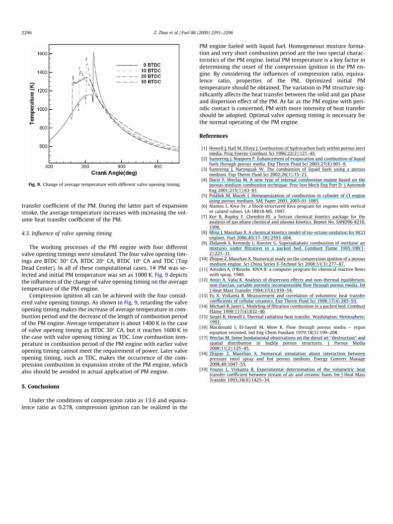
Fig. 9. Change of average temperature with different valve opening timing.
2296 Z. Zhao et al. / Fuel 88 (2009) 2291–2296
transfer coefficient of the PM. During the latter part of expansionstroke, the average temperature increases with increasing the vol-ume heat transfer coefficient of the PM.
4.3. Influence of valve opening timing
The working processes of the PM engine with four differentvalve opening timings were simulated. The four valve opening tim-ings are BTDC 30� CA, BTDC 20� CA, BTDC 10� CA and TDC (TopDead Center). In all of these computational cases, 1# PM was se-lected and initial PM temperature was set as 1000 K. Fig. 9 depictsthe influences of the change of valve opening timing on the averagetemperature of the PM engine.
Compression ignition all can be achieved with the four consid-ered valve opening timings. As shown in Fig. 9, retarding the valveopening timing makes the increase of average temperature in com-bustion period and the decrease of the length of combustion periodof the PM engine. Average temperature is about 1400 K in the caseof valve opening timing as BTDC 30� CA, but it reaches 1600 K inthe case with valve opening timing as TDC. Low combustion tem-perature in combustion period of the PM engine with earlier valveopening timing cannot meet the requirement of power. Later valveopening timing, such as TDC, makes the occurrence of the com-pression combustion in expansion stroke of the PM engine, whichalso should be avoided in actual application of PM engine.
5. Conclusions
Under the conditions of compression ratio as 13.6 and equiva-lence ratio as 0.278, compression ignition can be realized in the
PM engine fueled with liquid fuel. Homogeneous mixture forma-tion and very short combustion period are the two special charac-teristics of the PM engine. Initial PM temperature is a key factor indetermining the onset of the compression ignition in the PM en-gine. By considering the influences of compression ratio, equiva-lence ratio, properties of the PM, Optimized initial PMtemperature should be obtained. The variation in PM structure sig-nificantly affects the heat transfer between the solid and gas phaseand dispersion effect of the PM. As far as the PM engine with peri-odic contact is concerned, PM with more intensity of heat transfershould be adopted. Optimal valve opening timing is necessary forthe normal operating of the PM engine.
References
[1] Howell J, Hall M, Ellzey J. Combustion of hydrocarbon fuels within porous inertmedia. Prog Energy Combust Sci 1996;22(2):121–45.
[2] Sumrerng J, Nopporn P. Enhancement of evaporation and combustion of liquidfuels through porous media. Exp Therm Fluid Sci 2003;27(8):901–9.
[3] Sumrerng J, Narongsak W. The combustion of liquid fuels using a porousmedium. Exp Therm Fluid Sci 2002;26(1):15–23.
[4] Durst F, Weclas M. A new type of internal combustion engine based on theporous-medium combustion technique. Proc Inst Mech Eng Part D: J AutomobEng 2001;215(1):63–81.
[5] Polášek M, Macek J. Homogenization of combustion in cylinder of CI engineusing porous medium. SAE Paper 2003, 2003-01-1085.
[6] Alamos L. Kiva-3v: a block-structured Kiva program for engines with verticalor canted values. LA-18818-MS, 1997.
[7] Kee R, Rupley F. Chemkin-III: a fortran chemical kinetics package for theanalysis of gas phase chemical and plasma kinetics. Report No. SAND96-8216,1996.
[8] Ming J, Maozhao X. A chemical kinetics model of iso-octane oxidation for HCCIengines. Fuel 2006;85(17–18):2593–604.
[9] Zhdanok S, Kennedy L, Koester G. Superadiabatic combustion of methane airmixtures under filtration in a packed bed. Combust Flame 1995;100(1-2):221–31.
[10] Zhiguo Z, Maozhao X. Numerical study on the compression ignition of a porousmedium engine. Sci China Series E-Technol Sci 2008;51(3):277–87.
[11] Amsden A, O’Rourke. KIVA II: a computer program for chemical reactive flowswith spray, 1989.
[12] Amiri A, Vafai K. Analysis of dispersion effects and non-thermal equilibrium,non-Darcian, variable porosity incompressible flow through porous media. IntJ Heat Mass Transfer 1994;37(6):939–54.
[13] Fu X, Viskanta R. Measurement and correlation of volumetric heat transfercoefficients of cellular ceramics. Exp Therm Fluid Sci 1998;17(4):285–93.
[14] Michael R, Janet L. Modeling of filtration combustion in a packed bed. CombustFlame 1999;117(4):832–40.
[15] Siegel R, Howell J. Thermal radiation heat transfer. Washington: Hemisphere;1992.
[16] Macdonald I, El-Sayed M, Mow K. Flow through porous media – ergunequation revisited. Ind Eng Chem Fundam 1979;18(3):199–208.
[17] Weclas M. Some fundamental observations on the diesel jet ‘‘destruction” andspatial distribution in highly porous structures. J Porous Media2008;11(2):125–45.
[18] Zhiguo Z, Maozhao X. Numerical simulation about interaction betweenpressure swirl spray and hot porous medium. Energy Convers Manage2008;49:1047–55.
[19] Younis L, Viskanta R. Experimental determination of the volumetric heattransfer coefficient between stream of air and ceramic foam. Int J Heat MassTransfer 1993;36(6):1425–34.
Copyright © 2022 FDOKUMEN