Experimental Investigation of an Engine Quick-Start System ...
11
HAL Id: hal-02402153 https://hal.archives-ouvertes.fr/hal-02402153 Submitted on 10 Dec 2019 HAL is a multi-disciplinary open access archive for the deposit and dissemination of sci- entific research documents, whether they are pub- lished or not. The documents may come from teaching and research institutions in France or abroad, or from public or private research centers. L’archive ouverte pluridisciplinaire HAL, est destinée au dépôt et à la diffusion de documents scientifiques de niveau recherche, publiés ou non, émanant des établissements d’enseignement et de recherche français ou étrangers, des laboratoires publics ou privés. Experimental Investigation of an Engine Quick-Start System with Compact Air Supply for Rotorcraft Application Martin Kerler, Christian Schäffer, Wolfgang Eberhardt, Volker Gümmer To cite this version: Martin Kerler, Christian Schäffer, Wolfgang Eberhardt, Volker Gümmer. Experimental Investigation of an Engine Quick-Start System with Compact Air Supply for Rotorcraft Application. 17th Interna- tional Symposium on Transport Phenomena and Dynamics of Rotating Machinery (ISROMAC2017), Dec 2017, Maui, United States. hal-02402153
-
Upload
khangminh22 -
Category
Documents
-
view
3 -
download
0
Transcript of Experimental Investigation of an Engine Quick-Start System ...

HAL Id: hal-02402153https://hal.archives-ouvertes.fr/hal-02402153
Submitted on 10 Dec 2019
HAL is a multi-disciplinary open accessarchive for the deposit and dissemination of sci-entific research documents, whether they are pub-lished or not. The documents may come fromteaching and research institutions in France orabroad, or from public or private research centers.
L’archive ouverte pluridisciplinaire HAL, estdestinée au dépôt et à la diffusion de documentsscientifiques de niveau recherche, publiés ou non,émanant des établissements d’enseignement et derecherche français ou étrangers, des laboratoirespublics ou privés.
Experimental Investigation of an Engine Quick-StartSystem with Compact Air Supply for Rotorcraft
ApplicationMartin Kerler, Christian Schäffer, Wolfgang Eberhardt, Volker Gümmer
To cite this version:Martin Kerler, Christian Schäffer, Wolfgang Eberhardt, Volker Gümmer. Experimental Investigationof an Engine Quick-Start System with Compact Air Supply for Rotorcraft Application. 17th Interna-tional Symposium on Transport Phenomena and Dynamics of Rotating Machinery (ISROMAC2017),Dec 2017, Maui, United States. �hal-02402153�

Experimental Investigation of an Engine Quick-Start Sys-tem with Compact Air Supply for Rotorcraft Application
Martin Kerler1*, Christian Schäffer1
, Wolfgang Erhard1, Volker Gümmer1
ISROMAC 2017
International Sym-
posium on
Transport Phe-
nomena and Dy-
namics of Rotating
Machinery
Hawaii, Maui
December 16-212017
Abstract
A quick-start system for turboshaft engines is an appropriate method to enhance safety and
the flight operation range of a helicopter during intended single engine operation. Such a
system was designed and successfully tested at the institute. However, the quick-start
system used shop air of 13 bar(a) pressure for proof of concept. The shop air supply has to
be replaced by an airworthy, compact and lightweight air supply system for feasible rotorcraft
application. This comprises in first case general identification of adjustable system
parameters by numerical studies and experimental tests in consideration of certain system
constraints. Therewith, the ideal nozzle count is determined to 3 and the required nozzle
entry pressure has to be about 19 bar(a). Based on these findings the final air supply system
for rotorcraft application is designed and simulated with ESPSS. This system is built up at the
engine testbed with some modifications for experimental testing. Gas generator acceleration
tests as well as engine starting tests to idle speed are performed with the new system. A final
engine start-up time of 2.8 s was achieved. Finally, further advice is given for feasibility.
Keywords
Turboshaft, Engine, Quick-Start, Helicopter, Air Supply
1 Institute for Turbomachinery and Flight Propulsion, Technical University of Munich, Garching, Germany
*Corresponding author: [email protected]
1. INTRODUCTION
Future challenges in rotorcraft and propulsion design are
diverse. Governmental regulations are tending to achieve a
reduction in carbon emissions of engines and lowering the
noise level of rotorcrafts. More strict regulations will apply in
the future [1]. Then, rotorcraft operators claimed the devel-
opment of efficient engines with significant lower fuel con-
sumption a few years ago, due to high fuel prices. In addi-
tion, lowering other direct operational costs as well as
maintenance and repair costs is crucial for the success of
future rotorcrafts [2]. An entire new development of a com-
plex system like an engine or rotorcraft is often usually risky
and costly in terms of time and money. Some objectives can
be partially achieved due to evolution of available and relia-
ble technologies.
1.1 Potential of Intended Single Engine Operation
On account of this, a flying technology demonstrator was
introduced by Airbus Helicopters in 2015. This rotorcraft
called Bluecopter [3] (see Fig. 1) should comprise besides
aerodynamic improvements also a modified operational us-
age strategy of the installed turboshaft engines for fuel sav-
ing. The helicopters original powertrain design is mainly driv-
en by safety reasons. Thus, two engines are installed to
cover an engine failure during flight and avoiding autorotation
mode. Due to this requirement, the installed maximum en-
gine power exceeds by far the usual required power during
ordinary helicopter flight missions. The engines are loafing
most of the mission time at part load at worse specific fuel
consumption (SFC) [4]. To resolve this predicament, a modi-
fied operational usage strategy can be an intended shutdown
of one engine at appropriate helicopter flight states. Then, the
shut off engine does not burn any fuel and the remaining run-
ning engine has a better SFC by means of higher power
loads.
Figure 1. Bluecopter Demonstrator of Airbus Helicopters. (Im-
age: Airbus Helicopters, Charles Abarr)
This can be observed in Fig. 2 in the power required range
in which ISEO mode is possible. Here, a sample engine with
max. 500 kW output power is used. Overall, this results in sig-
nificant fuel savings up to 20% depending on the flight mission
[5]. The savings can be used either for extending mission
range and mission time or overall fuel burn. However, if this
intended single engine operation (ISEO) strategy is applied on
current powertrain designs, neither low and high speed flights
nor steep climb flights are possible during ISEO. The required
power of these flight states of exceeds the available maximum
continuous power (MCP) of one engine. The fuel advantage of
ISEO is also a drawback for flight safety.

Figure 2. Fuel saving potential due to use of ISEO at appropri-
ate flight operation. (similar to [3])
1.2 Flight Safety and Capability Enhancement with Engine Quick-Start
During ISEO flights, the twin-powered helicopter is just
like a single engine powered helicopter. In case of an engine
failure, flight cannot be maintained and autorotation has to
be initiated. A solution to ease this emergency situation is a
re-start of the engine which was shut off before due to
switching in ISEO mode. Regular starts to idle of turboshaft
engines of 500 to 1000 kW class are up to 30 s. Further time
is elapsing until sufficient shaft power can be provided. A
helicopter has sink rates of about 8 to 15 m/s which means in
worst case the helicopter has lost about 700 m of altitude
until engine power is available again. Thus, sufficient altitude
margin must be available during active ISEO. This cuts the
flight envelope of the helicopter and the reasonable usage of
ISEO. A solution to overcome this drawback is a reduction of
the turboshaft engine’s start-up time.
1.2.1 Evaluation of Engine Quick-Start Methods
An engine quick-start (QS) can be achieved by additional
acceleration torque for the gas generator GG provided by a
technical device. Pascoe [6] gives a general overview of
common gas turbine start devices. Hull and Santo [7] made
an evaluation of suitable devices for high torque demands,
too. One system comprises a hydraulic motor with an appro-
priate hydraulic system of high pressure. Experimental tests
of the system were promising but the prerequisite of a hy-
draulic system for proper operation may not apply for a heli-
copter due to excessive additional weight. Another method is
Hydrazine impingement or cartridge impingement. This is
realized by directing a hot gas stream of high velocity onto
the blades of a GG turbine stage. However, the hydrazine
solution has many drawbacks like costs, complexity and
health hazards and is thus, not really a practical solution.
The cartridge impingement requires for operational usage
too much installation space and has to be replaced after each
use [7]. Since the required system for quick starts should be
an emergency system, the replacement after use is not an
issue. But installation space is restricted at helicopters. Thus,
this variant seems not really applicable for a compact and
lightweight quick-start system (QSS). Rodgers [8] picks up the
basic idea of impingement nozzles but utilizes high-pressure
air or hot-gas as propellant at the turbine. The hot-gas was of
approximately 533 K and the gas generator was accelerated
just to 4770 rpm. Due to radial turbine design and its opera-
tional principle, a less nozzle expansion efficiency [8] and
therewith lower acceleration rates were achieved. Another
problem which cannot be satisfactorily resolved is the required
proper long term storage of pressurized air at temperatures
above 500 K. A gas impingement at the compressor section
was also investigated by Rodgers [8]. Utilization of pressur-
ized gas seems feasible and compressor shroud impingement
was the most convenient method for GG acceleration with im-
pingement nozzles [8]. QS tests of a gas turbine with 260 kW
power output were conducted with compressed nitrogen at
several operating conditions. Start times could be reduced by
55%. More results of this investigation can be found in [8] and
[9].
1.2.2 Design of a Quick-Start System for the Allison 250
Based on these findings, a QSS comprising impingement
nozzles directing a gas jet onto the trailing edge of a radial
compressor rotor seems to be a proper solution. However, the
use of compressed nitrogen seems not feasible, since it can-
not be used for combustion during QSS operation. This would
not be an issue if the compressor is regularly operating during
QS. But the compressor of Rodger’s experiments did not. Compressor surge and backflows out of the compressor oc-
curred. This means, the compressor does not deliver any air
for combustion during QS. Thus, regular air injection instead
of nitrogen would be the better case, since this air can be
used for combustion. For proof of concept with a common hel-
icopter turboshaft engine, the institute’s Allison 250-C20B was
chosen. The engine is fully functional as well as instrumented
for further performance analysis. The modular design of the
engine enables an easy replacement of engine modules. MCP
is about 300 kW and the compressor has a radial last stage.
Thus, this engine is similar to the engine modified by Rodgers
[8]. Hence, the Allison QSS has similar design parameters as
the QSS of Rodgers [9]. The new compressor casing is
equipped with de Laval nozzles which are asymmetrical posi-
tioned in circumferential direction due to available design
space and to avoid harmonic excitation (see Fig. 3).
Figure 3. New radial compressor casing with 5 nozzles, supply pipes and its integration into the compressor section.

Article Title — 3
With these restrictions a maximum nozzle count of 5 is possible. The angle of the injected air is defined to provide best impulse propagation to the impeller’s trailing edge and to allow proper connection to an air supply. The available shop air for nozzle supply has a static pressure of about 13 bar(a). This QSS with shop air and 5 nozzles is called Testbed Quick-Start System (TQSS). Due to total pressure losses caused by valves, pipes and hoses the nozzle entry working total pressure is about 12.3 bar(a). Based on these specifications and with a required start performance of less than 3 s from off-state to idle, the calculations revealed the following nozzle parameters. The nozzle’s throat diameter is 6.6 mm which means an air mass flow of 0.1 kg/s resulting in 0.5 kg/s overall air mass flow. The design Mach number of the nozzle is 2.3. Operation time is 2.2 s. During GG accel-eration, the starter motor is also working. Approximately 0.85 s from off-state, ignition of the injected fuel takes place and the high pressure turbine supports the GG acceleration. Finally, start-up time was reduced by over 90% from 26s to 2.4 s for ambient conditions close to the International Stand-ard Atmosphere at sea level at a Standard Day (see Fig. 4).
Figure 4. Allison 250 ground idle start times of a regular engine
start and a quick-start [10] [11].
For sufficient power delivery, the GG has to be further accelerated. Initial conservative tests were performed with 100 Nm brake torque preset at the testbed. As Fig. 5 shows, 60 kW (equals 20% of MCP) is available within approximate-ly 8 s from off-state. Further details on design and initial test-ing of the Allison QSS supplied with 13 bar(a) shop air can be found in Hönle et al. [10] and Hönle [11]. These results show the successful proof of concept of a TQSS for a tur-boshaft engine of 300 kW power class.
Figure 5. Power delivery curve after performing a quick-start to
FADEC mode “flight” [10] [11].
The TQSS is supplied at this development stage with shop
air which is not available in a rotorcraft. Hence, the next step is design and test of a pressurized air supply system which can be integrated into a helicopter airframe. If an existing air-frame is used, extensive structural airframe modifications have to be avoided and the system must be compact as well as of lightweight design. 2. DESIGN PARAMETERS IDENTIFACTION
Prior to final airworthy design, adjustable design parame-ters of the QSS have to be identified. Due to cost-containment and development time optimization, the components of the air impingement system (AIS) are predefined and thus the modi-fied compressor casing as well as the nozzles cannot be modified or exchanged. Consequently, changeable parame-ters are on the air supply system (ASS) side. The ideal accel-eration torque MQSS,id is basically the result of the relative noz-zle forces Fnoz to the surface of the trailing edge of the radial compressor and the distance r from the origin of force to the shaft axis. Since the acting force of the nozzle’s jet is not per-pendicular to the trailing edge, the relative deflection angles α and β have to be considered (see Eq. 1). These angles are based on design space restrictions. Further information about this can be found in Hönle [11]. Hönle sets the transfer effi-ciency 𝜂𝑛𝑜𝑧 of the force between nozzle and trailing edge for an initial TQSS design to a fixed value of 0.7 based on litera-ture data. Later on (see section 4.1.) this value is redefined.
𝑀𝑄𝑆𝑆,𝑖𝑑 = ∑ 𝜂𝑛𝑜𝑧 ⋅ 𝑟 ⋅ 𝐹𝑛𝑜𝑧,𝑖 ⋅ sin(𝛼) ⋅ sin (𝛽)𝑛𝑖=1 (1)
Each nozzle has the same distance to the axis as well as the same deflection angles. Thus, 𝑀𝑄𝑆𝑆 varies with varying nozzle force 𝐹𝑛𝑜𝑧. This force can be adjusted by changing nozzle mass flow m, nozzle exit velocity vnoz,exit or the nozzle count n (see Eq. 2).
∑ 𝑑𝐼𝑎𝑖𝑟,𝑖𝑑𝑡𝑛𝑖=1 = ∑ 𝐹𝑛𝑜𝑧,𝑖𝑛
𝑖=1 = ∑(�� ⋅ 𝑣𝑛𝑜𝑧,𝑒𝑥𝑖𝑡)𝑖𝑛𝑖=1 (2)
Since weight saving is important for helicopters, QSS noz-zle count reduction saves weight due to fewer parts. To keep Fnoz at the same level, mass flow or exit velocity has to be increased. The nozzles of the QSS are basically operating at choking conditions and consequently the air mass flow �� does not depend on the ambient pressure at nozzle outlet an-ymore. A feasible exit velocity increase is not possible. The geometry of the nozzle and thus the critical throat cross sec-tion area 𝐴∗ is fixed. Since variation of gas constant 𝑅 and isentropic coefficient 𝜅 are negligible, an air mass flow �� change can only be achieved by change in total temperature 𝑇𝑡 or total pressure 𝑝𝑡. This relationship is depicted in Eq. 3.

Article Title — 4
�� = 𝐴∗ ⋅ √𝜅 ⋅ (1 + 𝜅)2 ⋅ 𝑅 ⋅ 𝑇𝑡 ⋅ 𝑝𝑡 ⋅ (1 + 𝜅2 ) −𝜅𝜅−1 (3)
A lower gas temperature 𝑇𝑡 results in higher mass flow. A temperature drop by approximately 30 K would increase the air mass flow in best case by only 6%. A device to re-duce the temperature in front of the nozzles seems not rea-sonable because of high air mass flow rate and low cooling effectiveness. Finally, if nozzle count is reduced, the nozzle entry total pressure has to be increased.
For a final compact QSS (CQSS) design this appropriate pressure level has to be identified. Similar test were per-formed by Rodgers [9]. He measured the acceleration time until 40% of the GG speed is reached, depending on nozzle count and nozzle entry pressure (see Fig. 6). These tests were declared as cold-crank test, which means no additional acceleration torque, like electric starter or turbine operation, was used. With a nozzle pressure of about 160 psig (~11 bar(a)) and five active nozzles, the start-up time is about 2.45 s. This performance can be also achieved by three nozzles and an increased pressure of 275 psig (~19 bar(a)). Further pressure increase reduces the nozzle count to two or one. But this means very high nozzle entry pressures which are difficult to deal with in an helicopter en-vironment. Finally, increasing nozzle pressure for better start-up performance is only reasonable up to a certain pres-sure level.
Figure 6. Start-up time to 40% design gas generator speed de-
pending on nozzle count and nozzle entry pressure [9].
It was decided to realize the CQSS with three active nozzles. One reason was to have them almost evenly dis-tributed in circumferential direction to reduce excessive radial loads on the shaft bearings. Based on analytical start-up per-formance calculations, each nozzle must provide a thrust of approximately 83.5 N. For verification reasons, simulations and experiments were conducted to find the appropriate pressure level. The simulations were done with the simula-tion tool ESPSS. Further information about this tool can be found in Isselhorst [12], Pérez-Vara et al. [13] and Moral et al. [14]. A compressed air cylinder bundle, a pressure regula-tor and a coaxial valve are main components of the experi-mental set-up (see Fig. 9). Further information about this set-up is given in Kerler et al. [15]. Evaluation of the simulation results revealed a nozzle entry total pressure of about 18 bar(a) (see Fig.7).
Figure 7. Total pressure in measuring pipe short before nozzle
entry – experimental and simulation results [15].
The total pressure measured inside the measuring pipe was 17.9 bar(a). A measured thrust of about 80 N is achieved with this pressure. The simulated thrust is 83.5 N (Fig. 8). The differences between both values rely on measurement accu-racy as well as manufacturing tolerances. The load cell which measures the thrust has an uncertainty of measurement of about 1% of its whole measurement range. This means, the maximum error can be up to +/-5 N. In addition, further flow effects inside the measuring tube may influence the result, too. The slower increase in pressure of the measured curve depends mainly on the response time of the pressure trans-ducers. The results are very satisfying and define objectives for the CQSS design.
Figure 8. Nozzle thrust – Experimental and simulation results
[15] [16].
3. AIRWORTHY QUICK-START SYSTEM DESIGN
The design of the airworthy CQSS design is realized in
two different ways: The first one is to define a system with parameters of the
airworthy one but realized with respect to ground test-bed application. This means, the used parts of the hy-draulic sector are mainly not optimized for aerospace application. Therewith, a cost effective realization at the test bed is possible. Overall, this system is not optimized regarding weight and used space as well as regarding length of pipes and hoses. Furthermore, additional adapters are incorporated in the flow paths to offer measurement possibilities for temperature and pressure of the flow. These adapters are usually not required for helicopter application.
The second design is based on the parameters of the first design and accounts especially for helicopter appli-cation with respect to lightweight design, compactness, safety, reliability and robustness. However, this system

Article Title — 5
is modeled just virtually and gives a prospect of how such an airworthy CQSS can look like.
3.1 Basic considerations for experimental CQSS
design for testbed application The CQSS for testbed application is designed in a way
which comes close to the CQSS for helicopter application. But instead of expensive aerospace certified components, the testbed setup is realized with widely used parts of the hydraulic sector. In general, the CQSS has a mass flow of 0.5 kg/s and an operation time of approximately 2.2 s, result-ing in an air mass demand of 1.1 kg at a pressure level of about 18 bar(a). The equivalent air volume is 50 l at 18 bar(a) pressure. However, for any kind of reasonable air-frame integration, this volume is far too big. Feasible cost effective high pressure sources are pressurized bottles for diving applications. These are available with pressure levels up to 300 bar(a). Since the institute is owner of a 200 bar(a) air pressure pump, a pressure bottle of maximum 230 bar(a) working pressure is a reasonable choice. These bottles have standardized connecting screw diameters of 25 mm offering sufficient flow path diameter. Based on the requirement of having the capability for two consecutive QS, the bottle vol-ume was determined to at least 15 l. A minimum pressure level of about 80 bar(a) inside the bottle ensures at all opera-tion times the required overall mass flow of 0.5 kg/s. An adapter for pressure and temperature measurement as well as refilling the bottle is connected to the bottle. Further downstream is a ball valve which is closed for refilling pro-cess and opened when the CQSS is armed for operation. The bottle pressure has to be reduced to the nozzle working pressure of 18 bar(a). This is realized with a pressure regula-tor which can handle 300 bar(a) input pressure and provides an output pressure range up to 100 bar(a). The required out-put pressure of the pressure regulator is higher than 18 bar(a) because further downstream is a pressure releas-ing valve and other devices causing total pressure loss. This pressure regulator output pressure is found by a parameter study with ESPSS. Between ball valve of the bottle adapter and pressure regulator is a measuring adapter offering static pressure measurement and recovery temperature measure-ment. This device is also available after the pressure regula-tor. Then, between pressure source and AIS is a coaxial valve to release the pressurized air to the nozzles. Such a valve is the best choice regarding weight and high flow rates as well as safety and compactness. Another aspect is the fast response time. Opening and closing times are about 0.1 s. Besides these main components, some other compo-nents are required like flow distribution manifolds, adapters and valves as well as sensors for system health monitoring. The diameter of the flow paths cross section areas are de-fined to realize slow flow velocities inside the manifolds, adapters, pipes and hoses. A slower velocity causes less total pressure losses. Thus, a trade-off between pressure loss, cross section area and weight has to be found. In this case, flow velocities with a maximum of Mach 0.3 are ac-ceptable. Significant further compressibility effects can be avoided.
Fig. 9 shows the scheme of the system’s final design for integration in a twin engine powered helicopter.
Figure 9. Scheme of an airworthy QSS for testbed application
and helicopter integration.
In general, the ASS comprises one bottle and one pres-sure regulator. After the pressure regulator, the manifold block (1/2) splits the one flow path into two feeding lines for both engines. This junction is not needed and thus not realized for the CQSS at the testbed. Further downstream is the coaxial valve and another manifold block (1/3) where the single feed-ing line for the engine is divided into three supply lines for each nozzle of the AIS. The control of the CQSS is integrated in the engine controller.
3.2 Basic considerations for an airworthy CQSS de-
sign for helicopter application Since lightweight is crucial, regular bottles made of steel
are too heavy. Thus, a high pressurized air tank made of composite material is a good choice. Here, already aerospace certified pressure bottles made of carbon and glass fiber with aluminum liner and 300 bar(a) working pressure are available. Since the maximum pressure is greater than the 200 bar(a) used in the testbed solution, the bottle volume may be re-duced for further weight saving. A possible integration of the system in a BO 105 helicopter is illustrated in Fig. 10.
Figure 10. CAD model of a possible QSS arrangement
within the BO 105 fuselage.

Article Title — 6
This airworthy CQSS has a weight of 46.4 kg using com-
mon components [16]. If special optimized components are
used, the weight can be reduced to approximately 36 kg.
All main components are located in the helicopter main
transmission compartment due to safety reasons. None
important component should be integrated into the fire risky
engine bays. The CQSS fits almost into the transmission
compartment. For this design, some small modifications of
the engine cowlings have to be done. An advantage of this
CQSS location is its closeness to the helicopter’s center of gravity since helicopters are sensitive to center of gravity
changes. Further details of the design can be found in
Kerler et al. [16]. Between bottle and pressure regulator is
an adapter and a ball valve. The adapter is used for bottle
condition monitoring as well as for bottle pressurization.
The ball valve is required for safe bottle replacement. For
weight saving, only one bottle is used to supply both AIS of
the engines with pressurized air. This means, a manifold
block with two output lines (1/2) is used between the pres-
sure regulator and the coaxial valves. This manifold block is
missing in the testbed CQSS.
4. EXPERIMENTAL RESULTS
The testbed QSS was set up as described in section 3.1.
An overview of the installation gives the image in Fig. 11.
The ASS and the (1/3) manifold block are mounted on a
moveable rack. The supply hoses of the AIS can be quickly
disconnected from the supply pipes. This arrangement al-
lows an easy removal of the CQSS from the engine itself.
The compressed air bottle is mounted in an own rack which
is located at the top of the ASS rack. Thus, the bottle rack
can be detached easily for transportation to the refilling sta-
tion of the institute. In the background of the image in Fig. 11
the compressed air bundle is visible. For first GG accelera-
tion tests (described in section 4.1) the CQSS’s compressed
air source was the compressed air bundle. The output port of
the bundle was directly connected to the pressure regulator.
Since the 600 l volume of the bundle is 40 times greater than
the bottle volume, the pressure regulator entry conditions of
the air are nearly constant during the short test runs.
Figure 11. CQSS test setup with compressed air bundle and
compressed air bottle at the Allison 250 testbed.
The experiments were conducted in four main test cam-
paigns. The first two campaigns used the compressed air
bundle as pressure source. The other two used the bottle.
Each campaign is split into a cold quick-start (CQS) and a hot
quick-start (HQS). The CQS is without any fuel injection and
thus no combustion takes place. This setup is used to deter-
mine general CQSS behavior and to investigate important
CQSS parameters, for instance air temperatures in the supply
pipes and at the pressure regulator as well as static pressures
at these stations. The HQS is important to determine the
overall QS performance and proper gas turbine operation dur-
ing QS.
For temperature measurements thermocouples of type K
and with a diameter of 1 mm are used as compromise for fast
response and good durability. Signal conditioning was
achieved with appropriate 7B modules of manufacturer Analog
Devices. Final measurement accuracy is about +/-2 K. The
recovery factor for calculation of static and total temperature is
set to 0.85. Pressure is measured with pressure sensors type
A-10 of manufacturer WIKA. The sensors were chosen in a
way, that the maximum design pressure of the sensor is two
times the expected pressure at the measurement position.
The sensors have an accuracy of +/-1.5% of their range and a
response time less than 4 ms. Total pressure measurements
were realized with a pitot tube. The data acquisition system
from manufacturer United Electronic Industries has a sample
rate of 2500 samples per second for each measurement
channel.
4.1 Compressed air bundle – cold quick-start
For future rotorcraft application it was decided to reduce
the nozzle count from five to three to save weight. This
means, that the nozzle mass flow has to be increased to en-
sure the required overall 500 g/s air mass flow through the
nozzles. Thus, the nozzle entry total pressure must be raised
until each nozzle provides a mass flow of 167 g/s. How the
engine behaves during a quick GG acceleration with just three
nozzles and different nozzle entry pressures is investigated in
the following.
The static pressure short after the pressure regulator was
chosen as variable, since it can be easily adjusted with the
pressure regulator. Downstream the pressure regulator is de-
fined as low pressure side. These static absolute pressure
values are on the x-axis of Fig. 12. On the y-axis is the result-
ing final GG speed after an acceleration time of 4 s. After this
short time period the coax valve was closed. Longer valve op-
eration was not required since the final QS should take less
than 3 s. There was no combustion and the tests were con-
ducted with and without the starter motor to identify the influ-
ence of the starter motor on the acceleration performance dur-
ing acceleration as well. The test series was started with a
similar pressure level like the proof-of-concept design. But due
to pressure losses over pressure regulator and coax valve and
losses caused by pipes and manifolds, the final nozzle entry
total pressure drops to 5.2 bar(a). However, to finish the ac-
celeration test series, the pressure level after the pressure
regulator was further increased until the required nozzle entry
total pressure of about 18 bar(a) was reached with setting the
low pressure side to 33 bar(a). In Fig. 12 it can be seen as
Article Title — 7
well that the starter motor’s influence gets less distinctive for greater GG speeds and therewith nozzle entry pressures. However, the additional rotational speed gain is between 5% and 10% and thus significant. This means, during QS the starter motor should operate to ensure greater GG accelera-tions. Both curves in Fig. 12 are leveling for greater nozzle entry pressures. An extrapolation of the red curve with starter motor support indicates a reasonable static pressure level after the pressure regulator of 33 to 35 bar(a). Pressure lev-els beyond these values would lead to insignificant additional GG speed gaining.
Figure 12. Allison 250 gas generator acceleration tests with
compressed air bundle and with/without starter motor support
Similar tests were made by Hönle [11] with the TQSS. Here, the effective shaft torque was compared to the nozzle entry pressure. In addition some aspects are discussed about flow interaction of the air jet with the radial compres-sor. One of these is the definition of the real transfer efficien-cy 𝜂𝑛𝑜𝑧. Hönle [11] sets it to 0.85 based on his findings.
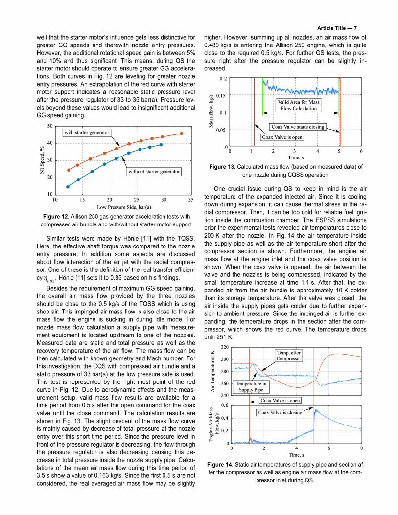
Besides the requirement of maximum GG speed gaining, the overall air mass flow provided by the three nozzles should be close to the 0.5 kg/s of the TQSS which is using shop air. This impinged air mass flow is also close to the air mass flow the engine is sucking in during idle mode. For nozzle mass flow calculation a supply pipe with measure-ment equipment is located upstream to one of the nozzles. Measured data are static and total pressure as well as the recovery temperature of the air flow. The mass flow can be then calculated with known geometry and Mach number. For this investigation, the CQS with compressed air bundle and a static pressure of 33 bar(a) at the low pressure side is used. This test is represented by the right most point of the red curve in Fig. 12. Due to aerodynamic effects and the meas-urement setup, valid mass flow results are available for a time period from 0.5 s after the open command for the coax valve until the close command. The calculation results are shown in Fig. 13. The slight descent of the mass flow curve is mainly caused by decrease of total pressure at the nozzle entry over this short time period. Since the pressure level in front of the pressure regulator is decreasing, the flow through the pressure regulator is also decreasing causing this de-crease in total pressure inside the nozzle supply pipe. Calcu-lations of the mean air mass flow during this time period of 3.5 s show a value of 0.163 kg/s. Since the first 0.5 s are not considered, the real averaged air mass flow may be slightly
higher. However, summing up all nozzles, an air mass flow of 0.489 kg/s is entering the Allison 250 engine, which is quite close to the required 0.5 kg/s. For further QS tests, the pres-sure right after the pressure regulator can be slightly in-creased.
Figure 13. Calculated mass flow (based on measured data) of
one nozzle during CQSS operation
One crucial issue during QS to keep in mind is the air temperature of the expanded injected air. Since it is cooling down during expansion, it can cause thermal stress in the ra-dial compressor. Then, it can be too cold for reliable fuel igni-tion inside the combustion chamber. The ESPSS simulations prior the experimental tests revealed air temperatures close to 200 K after the nozzle. In Fig. 14 the air temperature inside the supply pipe as well as the air temperature short after the compressor section is shown. Furthermore, the engine air mass flow at the engine inlet and the coax valve position is shown. When the coax valve is opened, the air between the valve and the nozzles is being compressed, indicated by the small temperature increase at time 1.1 s. After that, the ex-panded air from the air bundle is approximately 10 K colder than its storage temperature. After the valve was closed, the air inside the supply pipes gets colder due to further expan-sion to ambient pressure. Since the impinged air is further ex-panding, the temperature drops in the section after the com-pressor, which shows the red curve. The temperature drops until 251 K.
Figure 14. Static air temperatures of supply pipe and section af-ter the compressor as well as engine air mass flow at the com-
pressor inlet during QS.

Article Title — 8
At time 3.5 s the compressor has reached a certain rota-tional speed, where the compressor starts to act as it should be. This can be seen in the increasing curve of the engine air mass flow. Due to the compression, the compressed air’s temperature is increasing and is mixing with the cold im-pinged air mass flow. Thus, the air temperature after the compressor is also slightly increasing. When the coax valve is closed, the mass flow blockage due to the injected air is gone and the compressor air mass flow makes a sudden jump to greater values until it is run out. This also accounts for the temperature after the compressor. Further investiga-tion of other air temperatures and pressures at different en-gine station revealed no critical values for future HQS.
4.2 Compressed air bundle – hot quick-start
Based on the findings of the CQS tests with the com-pressed air bundle, HQS are performed. Main parameters of FADEC adaption for a QS are fuel injection timing, amount of fuel and deactivation timing of the coax valve. For first tests, the known parameters of the TQSS were taken and adapted to have kind of conservative adjustments. An interesting point is the QSS deactivation and in the following the re-sumption of the compressor’s work, as seen before in Fig. 14. The conservative settings are fuel injection at 20% GG rotational speed and deactivation of the QSS at 52% GG rotational speed. The result is shown as blue curve in Fig. 15. On the x-axis is the elapsed time and on the y-axis is the absolute pressure at the end of the compressor section. The coax valve opens and the pressure at the end of the compressor is slightly increasing. At time 2.2 s fuel is inject-ed into the combustion chamber and ignition takes place. This increases the overall pressure level at the compressor end. Since the QSS is deactivated at 52% GG speed, the GG has not reached the required 60% rotational speed at idle mode. The compressor should operate in a regular man-ner but surge occurred for nearly a second until real regular compressor operation is achieved at 4.5 s and the GG is op-erating at stable 60% speed. An explanation can be that the compressor has not reached an operation point where suffi-cient pressure increase is possible to cope with the back pressure from the combustion chamber. Nevertheless, this surge behavior is not tolerable for a safe QS.
Figure 15. Pressure at the end of the compressor for two HQSs
with cylinder bundle and different FADEC settings.
Within a second test the deactivation limit was pushed to 58% GG rotational speed. Here the compressor works fine as the red curve in Fig. 15 shows around time 4 s. The transition from nozzle operation mode to regular compressor operation may be further smoothening by QSS deactivation at 60% GG rotational speed. This will be investigated in the future. To shorten the start-up time the beginning of fuel injection starts earlier at 14% GG speed. However, on compressor end pres-sure this does not have any significant influence. The fuel schedule was not changed. Further HQS tests with some changes in FADEC parameters were performed for finding a better QS performance. But in summary, the red curve in Fig. 15 represents one of the best HQS with the compressed air bundle. The result is a start-up time of 3 s from off-state until 60% GG rotational speed is reached.
4.3 Compressed air bottle – cold quick-start
The compressed air bundle tests paved the way for final tests with a bottle as pressure source. Thus, the compressed air bundle was replaced by the compressed air bottle of 15 l volume and maximum 200 bar(a) pressure level. First, CQSs were performed to identify critical engine parameters during this short phase. Since the air mass inside the bottle and the bottle pressure is decreasing during QS, the entry pressure of the pressure regulator is accordingly changing and causing less mass flow through the pressure regulator. This can be seen in Fig. 16 where the total pressure inside the supply pipe is dropping with decreasing bottle pressure. The QSS opera-tion time was set to 3 s. For the HQS with the bottle this time should not exceed.
Figure 16. Total pressure in the supply pipe and
in the bottle for a 3 s CQS.
The bottle pressure drops to 67 bar(a) within these 3 s. The lowest measured air temperature at the bottle exit was 228 K. Air temperatures at the compressor end were about 250 K. Further downstream, the air temperature was increas-ing, what is a good prerequisite for proper initial fuel ignition. The final GG rotational speed was 45% and is a good starting basis for the following HQS with the bottle as pressurized air source.
4.4 Compressed air bottle – hot quick-start
Based on the findings of the HQS with the cylinder bundle and the CQS with the bottle, the FADEC was modified and tests were conducted. The recovery temperatures at certain measurement points of the CQSS are shown in Fig. 17. The

Article Title — 9
QS starts at 1 s and the command for coax valve opening is given. After 0.2 s the valve signals, that it is fully open. Due to compression of the stored air volume at ambient pressure inside the hoses, the temperature in the supply pipe is slight-ly increasing until it drops due to the following expanded cold air downstream the pressure regulator. The pressure regula-tor is at the beginning closed. Since it cannot deliver the air mass at adjusted pressure the stored air between pressure regulator and coax valve expands faster and the temperature drops faster as well. This can be seen during 1.2 s and 1.7 s. Like pressure vs. time curve of Fig. 16, the air temperature inside the bottle as well as the air temperature at the pres-sure regulator entry drops almost linearly until a minimum at -40 °C (233.15 K) is reached.
Figure 17. Recovery temperatures of the CQSS powered by
the bottle at certain measurement positions.
The temperature short after the compressor section drops to -21 °C (252.15 K) until the compressor is working properly and a temperature increase is realized due to com-pression. The measured temperature between both turbines of the egnine drops to almost 273 K until combustion takes place and temperature is rising. Thus, conditions inside the combustion chamber during the QS are at all time sufficient for reliable ignition of the injected air.
The final GG acceleration result is shown in Fig. 18. Here, the blue curve is the QS with the 200 bar compressed air bottle supply and the red curve is a QS with 13 bar shop air supply of the proof of concept design. This TQSS has a start-up time advance of 0.3 sec. Nevertheless, with bottle supply, start-up times of 2.8 sec can be reliably achieved.
Figure 18. GG spool speeds of QS with 13 bar and with
200 bar air supply.
This was proven several times at the testbed. This start-up time can be improved, if combustion is starting much ear-lier. But a certain GG speed is required for sufficient fuel pressure to achieve reasonable spray generation of the fuel nozzle inside the combustion chamber. However, the cold air temperature in the combustion chamber has a non-negligible influence on proper combustion.
5. CONCLUSION AND OUTLOOK
This paper shortly describes the development process of an airworthy and compact compressed air supply for an en-gine QSS for rotorcraft application. Based on a given proof-of-concept design with low pressure shop air, an analysis of ad-justable system parameters was performed and a new air supply with high pressure source was designed. Tests of this system were conducted in first case with a cylinder bundle to ensure constant inlet conditions of the system, followed by final tests with a bottle as compressed air source. The experi-mental test campaign was successful and the engine can be quick-started within 2.8 s using the compact compressed air supply. Further work has to be done on control parameters of the system and improvements regarding combustion. In addi-tion, the overall system has to lose weight for real rotorcraft application. This can be achieved for instance with a pressure bottle based on carbon and shorter pipes and hoses. Another investigation has to be done on systems failures. This means, how does the engine behave if the system is somehow unre-quested activated during regular engine operation.
NOMENCLATURE
Abbreviations AIS Air Impingement System ASS Air Supply System CQS Cold Quick-Start ESPSS European Space Propulsion System Simulation FADEC Full Authority Digital Engine Control GG Gas Generator HQS Hot Quick-Start ISEO Intended Single Engine Operation QS Quick-Start QSS Quick-Start System CQSS Compact Quick-Start System (3 Nozzles) TQSS Testbed Quick-Start System (5 Nozzles) MCP Maximum Continuous Power SFC Specific Fuel Consumption
Symbols �� Mass flow, [kg/s] 𝑝 Pressure, [bar, Pa] 𝑟 Radius/distance, [m]

Article Title — 10 𝑣 Velocity,[m/s] 𝑡 Time, [s] 𝐴∗ Nozzle throat cross section area, [m²] 𝐹 Force, [N] 𝐼 Jet momentum, [N/s] 𝑅 Gas constant, [J/(kg K)] 𝑇 Temperature, [K] 𝛼 Deflection angle, [deg] 𝛽 Deflection angle, [-] 𝜂 Efficiency, [-] 𝜅 Isentropic coeffcient, [-]
Indices 𝑎𝑖𝑟 Air parameter 𝑒𝑥𝑖𝑡 Nozzle exit 𝑖 Sum count 𝑖𝑑 Ideal 𝑛 Nozzle count 𝑛𝑜𝑧 Nozzle related 𝑄𝑆𝑆 Quick-Start System 𝑡 Total Value
REFERENCES
[1] G. Warwick. Collective Approach. Aviation Week & Space Technology, Vol. 174, No. 6, February 2012, pp. 43-44.
[2] G. Norris. Little Bigger. Aviation Week & Space Technology, Vol. 174, No. 6, February 2012, pp. 46-47.
[3] M. Bebesel, A. D’Alascio, S. Schneider, S. Guenther, F. Vogel, C. Wehle and D. Schimke. Bluecopter Demonstrator – An Approach to Eco-Efficient Heli-copter Design. Proceedings of the 41
st European
Rotorcraft Forum, Munich, Germany, September 1st - 4th, 2015.
[4] P. P. Walsh and P. Fletcher. Gas Turbine Perfor-mance. 2nd Edition, Blackwell Science Publishing, 2004.
[5] M. Kerler, W. Erhard. Evaluation of Helicopter Flight Missions with Intended Single Engine Operation. Proceedings of the 40
th European Rotorcraft Forum,
Southampton, England, September 2nd - 5th, 2014.
[6] A. G. Pascoe. Start systems for aero gas turbines. Aircraft Engineering and Aerospace Technology,
Vol. 77, Issue 6, 2005, pp. 448-454.
[7] L. Hull, H. Santo. Development of a Rapid-Start Sys-tem for the Boeing Model 502-2E Gas Turbine En-gine. SAE Technical Paper 670961, 1967.
[8] C. Rodgers. Impingement Starting and Power Boost-ing of Small Gas Turbines. J. Eng. Gas Turbines Power 107(4), 1st October, 1985, pp. 821-827.
[9] C. Rodgers. Fast Start System for a 200-KW Gas Tur-bine Generator Set. SAE Technical Paper 841568, 1984.
[10] J. Hönle, A. Barth, W. Erhard, H.-P. Kau. Engine Quick Start in Case of Emergency - A Requirement for Saving Fuel by Means of Engine Shutdown. Pro-ceedings of the 38
th European Rotorcraft Forum, Am-
sterdam, Netherlands, September 4th - 7th, 2012.
[11] J. Hönle. Ökonomische Optimierung von Trieb-werksbetriebsstrategien von zweimotorigen Hub-schraubern. Ph.D. Thesis, TU München, Verlag Dr. Hut, 2014.
[12] A. Isselhorst. HM7B Simulation with ESPSS Tool on Ariane 5 ESC-A Upper Stage. 46
th
AIAA/ASME/SAE/ASEE Joint Propulsion Conference & Exhibit, Nashville, TN, USA, July 2010.
[13] R. Pérez-Vara, S. Mannu, O. Pin, R. Müller. Over-view of European Applications of EcosimPro to ECLSS, CELSS and ATCS. 33
rd International Confer-
ence on Environmental Systems (ICES), Vancouver, BC, Canada, July 2003, SAE Technical Paper 2003-01-2439.
[14] J. Moral, F. Rodríguez, J. Vilá, F. Di Matteo, J. Steelant. 1-D Simulation of Solid and Hybrid Combus-tors with EcosimPro/ESPSS. Space Propulsion 2010, ESPSS, European Space Propulsion System Simula-
tion - EcosimPro Libraries User Manual, ESA docu-ment 4000103800/11/NL/CP -TN4130, March, 2014.
[15] M. Kerler, C. Schäffer, W. Erhard, V. Gümmer. De-sign Parameter Identification of the Air Supply for a Turboshaft Engine Quick-Start System. 52
nd
AIAA/SAE/ASEE Joint Propulsion Conference, Pro-
pulsion and Energy Forum, Salt Lake City, USA, July 25th -27th, 2016, AIAA-2016-5062.
[16] M. Kerler, W. Erhard. Design of an Airworthy Tur-boshaft Engine Quick-Start System with Compact Pressurized Air Supply for Rotorcraft Application. Proceedings of the 42
nd European Rotorcraft Forum,
Lille, France, September 5th - 8th, 2016.