
EUROCONTROL Specification for European Mode S Station ...
354
EUROCONTROL Specification for European Mode S Station (EMS) Edition: 4.0 Edition date: 17/09/2021 Reference nr: EUROCONTROL-SPEC-189
-
Upload
khangminh22 -
Category
Documents
-
view
0 -
download
0
Transcript of EUROCONTROL Specification for European Mode S Station ...
EUROCONTROL Specification for European Mode S Station (EMS)
Edition: 4.0 Edition date: 17/09/2021 Reference nr: EUROCONTROL-SPEC-189

Specification EUROPEAN MODE S STATION (EMS)
EUROCONTROL Specification for European
Mode S Station (EMS)
DOCUMENT IDENTIFIER : EUROCONTROL-SPEC-189
Edition Number : Edition Date : Status : Intended for : Category :
4.0 17/09/2021
Released Issue General Public
EUROCONTROL Specification

EUROCONTROL Specification for
European Mode S Station (EMS)
Page 2 Released Issue Edition: 4.0
DOCUMENT CHARACTERISTICS
TITLE
EUROCONTROL Specification for European Mode S Station (EMS)
Publication Reference: SPEC-189 ISBN Number: 978-2-87497-119-8
Document Identifier Edition Number: 4.0 EUROCONTROL-SPEC-189 Edition Date: 17/09/2021
Abstract This document provides specification for a Mode S ground station used for Surveillance functions. The station detailed in this document provides Elementary and Enhanced Surveillance Services to ATC through use of Mode S Specific Services, particularly Ground Initiated Comm-B and Mode S Comm-B Broadcast, and Mode S Extended Squitters (ADS-B). Mode S ground stations compliant with this specification support performance, secondary surveillance radar transponders and exchange of surveillance data as referred in the European Commission Implementing Regulation (EU) No 1207/2011 of 22 November 2011 as amended by (EU) No 1028/2014 of 26 September 2014, (EU) 2017/386 of 6 March 2017 and (EU) 2020/587 of 29 April 2020. Mode S ground stations that meet this specification can be used to support aircraft separation applications. The stations defined in this document have interfaces to work in a cooperative way with other surveillance systems. This edition includes new functions to decrease the Mode S interrogations and to optimize the use of the 1 030/1 090 MHz frequency band.
Keywords Surveillance Secondary Radar GICB Monopulse Specification Mode S ELS Passive Acquisition Performance SSR EHS FFM ATC ADS-B DAP Extraction MIP
Contact Person(s) E-mailJavier CEBALLOS GUTIÉRREZ [email protected]
STATUS, AUDIENCE AND ACCESSIBILITY Status Intended for Accessible via
Working Draft General Public Intranet Draft EUROCONTROL Extranet Proposed Issue Restricted Internet (www.eurocontrol.int)
Released Issue


EUROCONTROL Specification for
European Mode S Station (EMS)
Page 4 Released Issue Edition: 4.0
DOCUMENT CHANGE RECORD
The following table records the complete history of the successive editions of the present document.
EDITION NUMBER
EDITION DATE REASON FOR CHANGE PAGES
AFFECTED
2.00-2.19 12/96-10/99 POEMS Functional Specification, baseline version for POEMS contract.
Whole Document
3.00-3.10 10/99-04/05 New version resulting from ANSP comments. Following editions resulting from TSC and MSTF meetings. Correction of typos.
Whole Document
3.11 9/05/2005 Released Issue. -
4.0 17/09/2021
New document with a reviewed structure focus in performance, functions and interfaces. Full integration of ADS-B. New requirements to monitor and mitigate RF occupancy at 1 030/1 090 MHz (re-interrogation limits, BDS overlay, new use for Datalink map, etc.). Introduction of Passive Acquisition and DAP extraction as cooperation functions. Phase Overlay and Basic Dataflash as optional functionalities. Changes in performance analysis metrics, target load models and test tools. Update of International Standards and reference documentation. Optional requirements for ground station elements (antenna, radome, lightning protection, etc.). Basic traceability with (EU) No 1207/2011 (SPI IR) and subsequent amendments. Datalink and complete Mode S subnetwork capabilities removed. Cluster requirements relocated to optional annex.
Whole Document

EUROCONTROL Specification for
European Mode S Station (EMS)
Edition: 4.0 Released Issue Page 5
CONTENTS
DOCUMENT CHARACTERISTICS ............................................................................ 2
DOCUMENT APPROVAL .......................................................................................... 3
DOCUMENT CHANGE RECORD .............................................................................. 4
CONTENTS ................................................................................................................ 5
LIST OF FIGURES ................................................................................................... 13
LIST OF TABLES ..................................................................................................... 14
EXECUTIVE SUMMARY .......................................................................................... 15
Introduction .................................................................................................... 16 1.1 General ................................................................................................................. 16
1.1.1 Mode S ground stations .............................................................................. 16 1.1.2 ADS-B information ....................................................................................... 16 1.1.3 Stations cooperation ................................................................................... 17 1.1.4 Use of RF band ............................................................................................ 17
1.2 Conventions ........................................................................................................ 17 1.2.1 Specification language ................................................................................ 17 1.2.2 Paragraphs identification ............................................................................ 18 1.2.3 Compliance .................................................................................................. 18
1.3 Scope of the document ....................................................................................... 19 1.3.1 Tender response .......................................................................................... 20
1.4 Abbreviations ...................................................................................................... 22 1.5 Reference material .............................................................................................. 27
1.5.1 System .......................................................................................................... 27 1.5.2 Interfaces ..................................................................................................... 28 1.5.3 Others ........................................................................................................... 29
1.6 Document structure ............................................................................................ 31
Performance Requirement ............................................................................. 33 2.1 Introduction ......................................................................................................... 33 2.2 General ................................................................................................................. 33 2.3 Scope ................................................................................................................... 34 2.4 Coverage .............................................................................................................. 35 2.5 Data Collection .................................................................................................... 38 2.6 Mode S Performance ........................................................................................... 39
2.6.1 Position Detection ....................................................................................... 39 2.6.1.1 SSR detection ...................................................................................... 41 2.6.1.2 Mode S detection ................................................................................. 42
2.6.2 Code detection ............................................................................................. 43 2.6.2.1 SSR code detection and validation ..................................................... 44

EUROCONTROL Specification for
European Mode S Station (EMS)
Page 6 Released Issue Edition: 4.0
2.6.2.2 Mode S code detection and validation ............................................... 46 2.6.3 Long gaps .................................................................................................... 47 2.6.4 Resolution .................................................................................................... 48
2.6.4.1 SSR position ........................................................................................ 48 2.6.4.2 SSR decoding ...................................................................................... 49 2.6.4.3 SSR phantoms ..................................................................................... 50 2.6.4.4 Mode S position ................................................................................... 50 2.6.4.5 Mode S decoding ................................................................................. 51
2.6.5 Position accuracy ........................................................................................ 51 2.6.5.1 Slant range errors ................................................................................ 52 2.6.5.2 Azimuth errors ..................................................................................... 53 2.6.5.3 Systematic error adjustment ............................................................... 54 2.6.5.4 Range and Azimuth precision ............................................................. 55 2.6.5.5 Jumps ................................................................................................... 55
2.6.6 False and Multiple Targets .......................................................................... 55 2.6.7 Targets Velocity Limits ............................................................................... 57 2.6.8 Targets load ................................................................................................. 58
2.6.8.1 Peak target models .............................................................................. 58 2.6.8.2 RTCC target models ............................................................................ 60 2.6.8.3 Applicability of models for other scan rates ...................................... 62
2.6.9 Processing delays and overload ................................................................ 62 2.6.10 System Expansion ....................................................................................... 64
2.7 ADS-B performance ............................................................................................ 65 2.7.1 Probability of Update ................................................................................... 66 2.7.2 Code detection ............................................................................................. 67 2.7.3 Probability of long gap ................................................................................ 68 2.7.4 Targets load ................................................................................................. 68 2.7.5 Processing delays and overload ................................................................ 68 2.7.6 System Expansion ....................................................................................... 69
Functional Requirement ................................................................................ 71 3.1 Description of the System .................................................................................. 71 3.2 Surveillance Mode Interlace Pattern (MIP) ......................................................... 72 3.3 Mode S data extraction ....................................................................................... 77
3.3.1 Elementary Surveillance ............................................................................. 77 3.3.2 Enhanced Surveillance ............................................................................... 80 3.3.3 Re-interrogations ......................................................................................... 82 3.3.4 BDS overlay ................................................................................................. 84 3.3.5 Basic Dataflash ............................................................................................ 85
3.4 Interrogator Code operation ............................................................................... 87 3.5 On-site ADS-B...................................................................................................... 89
3.5.1 Implementation ............................................................................................ 89 3.5.2 ADS-B functionalities .................................................................................. 90
3.6 Phase Overlay...................................................................................................... 93 3.7 Cooperation Functions ....................................................................................... 95
3.7.1 Passive Acquisition ..................................................................................... 95 3.7.2 DAP Extraction interface ............................................................................. 98
3.8 Test Targets ....................................................................................................... 101

EUROCONTROL Specification for
European Mode S Station (EMS)
Edition: 4.0 Released Issue Page 7
3.8.1 Real Time Quality Control (RTQC) ............................................................ 101 3.8.2 Far Field Monitor (FFM) ............................................................................. 102
3.9 Cone of Silence ................................................................................................. 105 3.10 Ground, Pressure-altitude and Speed suppression ........................................ 106 3.11 Radio protection ................................................................................................ 107
3.11.1 Jamming ..................................................................................................... 107 3.11.2 Solar storms ............................................................................................... 108
Interfaces ...................................................................................................... 110 4.1 System Interfaces .............................................................................................. 110 4.2 Network .............................................................................................................. 110
4.2.1 LAN and WAN ............................................................................................ 110 4.2.2 External data streams ............................................................................... 112 4.2.3 ASTERIX protocol ...................................................................................... 116
4.3 Time Synchronization ....................................................................................... 117 4.4 Coverage Maps .................................................................................................. 120 4.5 System Parameters ........................................................................................... 122 4.6 Control and Monitoring System (CMS) ............................................................ 125 4.7 Real Time Monitoring ........................................................................................ 130 4.8 Built In Test Equipment (BITE) ......................................................................... 133 4.9 Log ..................................................................................................................... 135 4.10 Local Display ..................................................................................................... 136 4.11 Data Recorder and Playback ............................................................................ 141 4.12 Cyber security ................................................................................................... 145
4.12.1 Non-essential elements ............................................................................. 145 4.12.2 Operator credentials .................................................................................. 146 4.12.3 Network ...................................................................................................... 148
4.13 Test interfaces ................................................................................................... 149 4.14 System Interconnections .................................................................................. 152
Processing System ...................................................................................... 154 5.1 Logical Blocks ................................................................................................... 154 5.2 System Management Function (SMF) .............................................................. 154 5.3 Real Time Channel Controller function (RTCC) .............................................. 157 5.4 Link Controller function (LC) ............................................................................ 159
5.4.1 Plot Assignor Function (PAF) ................................................................... 160 5.4.1.1 Tracks management .......................................................................... 161 5.4.1.2 False target processing ..................................................................... 165
5.4.1.2.1 Reflections .................................................................................. 166 5.4.2 Station Selective Roll-Call List ................................................................. 167 5.4.3 Communication Management Processor (CMP)...................................... 167 5.4.4 Mode S Link Management Process (LMP) ............................................... 168
5.5 Datalink Function (DLF) .................................................................................... 169 5.5.1 Internal GICB application .......................................................................... 171
5.6 Passive Acquisition Interface (PAI) .................................................................. 172
Interrogator System ..................................................................................... 173

EUROCONTROL Specification for
European Mode S Station (EMS)
Page 8 Released Issue Edition: 4.0
6.1 The Interrogator ................................................................................................. 173 6.2 Transmitter ........................................................................................................ 174
6.2.1 Pulse transmissions .................................................................................. 174 6.2.2 Power levels ............................................................................................... 176
6.2.2.1 Range control ..................................................................................... 177 6.2.2.2 Azimuth control.................................................................................. 178
6.3 Receiver ............................................................................................................. 179 6.3.1 Interference ................................................................................................ 180 6.3.2 Phase overlay capability ........................................................................... 181
6.4 Video Signal Processing ................................................................................... 182 6.5 RF Changeover Unit .......................................................................................... 186 6.6 Access to radio spectrum ................................................................................. 188
Mode S Ground Station Elements ............................................................... 192 7.1 The Mode S ground station .............................................................................. 192 7.2 Antenna .............................................................................................................. 193 7.3 Turning gear and azimuth data generator ....................................................... 195 7.4 Tower ................................................................................................................. 199 7.5 Radome .............................................................................................................. 202 7.6 Obstruction lights ............................................................................................. 205 7.7 Lightning protection .......................................................................................... 206 7.8 Earthing.............................................................................................................. 207 7.9 Equipment Cabinets .......................................................................................... 208 7.10 Peripheral Devices ............................................................................................ 209 7.11 Air Conditioning unit ......................................................................................... 210 7.12 Shelter ................................................................................................................ 211 7.13 Collocation with Primary Radar........................................................................ 215 7.14 Far Field Monitor ............................................................................................... 217
General Equipment Requirements .............................................................. 219 8.1 Equipment Qualification ................................................................................... 219 8.2 Redundancy ....................................................................................................... 221
8.2.1 Operation modes ....................................................................................... 221 8.2.2 Hot switchover ........................................................................................... 223 8.2.3 Cold switchover ......................................................................................... 224
8.3 System initialization .......................................................................................... 224 8.4 Hardware Requirements ................................................................................... 226
8.4.1 Maintenance ............................................................................................... 229 8.4.2 Labelling ..................................................................................................... 230
8.5 Software and Firmware Requirements............................................................. 230 8.5.1 Design Methods ......................................................................................... 232 8.5.2 Software and Firmware Safety .................................................................. 233 8.5.3 Operating System ...................................................................................... 233 8.5.4 Processing load ......................................................................................... 234 8.5.5 Verification and Validation ........................................................................ 236 8.5.6 Software and Firmware Development Environment ................................ 238

EUROCONTROL Specification for
European Mode S Station (EMS)
Edition: 4.0 Released Issue Page 9
General Conditions ...................................................................................... 240 9.1 Standards ........................................................................................................... 240 9.2 Environmental Conditions ................................................................................ 240
9.2.1 Internal Conditions .................................................................................... 240 9.2.2 External Conditions ................................................................................... 241 9.2.3 Storage Conditions .................................................................................... 242
9.3 Design Considerations ..................................................................................... 243 9.4 Safety ................................................................................................................. 246
9.4.1 Health of Personnel ................................................................................... 246 9.4.1.1 Noise exposure .................................................................................. 247 9.4.1.2 Electromagnetic field exposure ........................................................ 248 9.4.1.3 Climbing Devices ............................................................................... 248
9.4.2 Air Traffic Service ...................................................................................... 249 9.4.2.1 Safety Plan ......................................................................................... 250 9.4.2.2 Mode S Safety Requirements ............................................................ 252 9.4.2.3 Mode S Safety Analysis ..................................................................... 253
9.5 Quality Assurance ............................................................................................. 255 9.5.1 Quality Standards ...................................................................................... 255 9.5.2 Quality Plan ................................................................................................ 256 9.5.3 Software and Firmware Quality Plan ........................................................ 258 9.5.4 Quality records .......................................................................................... 259 9.5.5 Audit ........................................................................................................... 260
9.6 Configuration Management .............................................................................. 260 9.6.1 Configuration Items ................................................................................... 262 9.6.2 Hardware and Software/Firmware CM Plan ............................................. 262 9.6.3 Configuration Control ............................................................................... 264 9.6.4 Change Control .......................................................................................... 265 9.6.5 Audit ........................................................................................................... 266
9.7 Integrated Logistic Support (ILS) ..................................................................... 267 9.7.1 Logistic ....................................................................................................... 267
9.7.1.1 Delivery ............................................................................................... 268 9.7.1.2 Maintenance ....................................................................................... 269 9.7.1.3 Reparable items ................................................................................. 271
9.7.2 Reliability, Availability, and Maintainability ............................................. 272 9.7.2.1 Reliability ............................................................................................ 273 9.7.2.2 Availability .......................................................................................... 276 9.7.2.3 Maintainability .................................................................................... 277
9.7.3 Knowledge transfer ................................................................................... 279 9.7.3.1 Documentation ................................................................................... 279 9.7.3.2 Training .............................................................................................. 283
9.8 Project Management ......................................................................................... 285 9.9 Testing and Acceptance ................................................................................... 285
9.9.1.1 Test Resources .................................................................................. 287 9.9.1.2 Verification and Validation Plan ........................................................ 288 9.9.1.3 Test Results ....................................................................................... 290 9.9.1.4 Testing ................................................................................................ 292
9.9.1.4.1 Factory Acceptance Tests (FAT) ............................................... 292 9.9.1.4.2 Site Acceptance Tests (SAT) ..................................................... 293

EUROCONTROL Specification for
European Mode S Station (EMS)
Page 10 Released Issue Edition: 4.0
9.9.1.5 Acceptance ......................................................................................... 295 9.10 Installation and Commissioning....................................................................... 297
ANNEX A - Mode S General Operating Model .................................................... 300 A.1 Performance requirements in Mode S CAV ..................................................... 300 A.2 Targets Load ...................................................................................................... 301
A.2.1 Peak target models .................................................................................... 301 A.2.1.1 Targets equipment cases .................................................................. 301
A.2.1.1.1 Case one, 100% Mode S targets ................................................ 301 A.2.1.1.2 Case two, 50% Mode A/C and 50% Mode S targets ................. 301 A.2.1.1.3 Case three, 5% Mode A/C and 95% Mode S targets ................. 301
A.2.1.2 Targets distribution ........................................................................... 302 A.2.1.2.1 Model A range distribution ........................................................ 302 A.2.1.2.2 Model B range distribution ........................................................ 302 A.2.1.2.3 Azimuth distribution .................................................................. 302
A.2.2 RTCC target models .................................................................................. 302 A.2.2.1 Targets equipment ............................................................................. 302 A.2.2.2 Targets distribution ........................................................................... 302
A.2.2.2.1 Model C ....................................................................................... 302 A.2.2.2.2 Model D ....................................................................................... 303
A.3 Environmental Parameters ............................................................................... 303 A.3.1 Mean FRUIT rate ........................................................................................ 303 A.3.2 Mean BDS swap rate ................................................................................. 303 A.3.3 Reflection false targets ............................................................................. 303
A.4 System Parameters ........................................................................................... 304 A.4.1 Cone of silence .......................................................................................... 304 A.4.2 Maximum vertical coverage ...................................................................... 304 A.4.3 Azimuth coverage ...................................................................................... 304 A.4.4 Gap free cover ........................................................................................... 304 A.4.5 Maximum operating range ........................................................................ 304 A.4.6 Rotating antenna turning rates ................................................................. 304 A.4.7 IRF .............................................................................................................. 304 A.4.8 Transmitted modes .................................................................................... 304 A.4.9 Transponder sensitivity ............................................................................ 304 A.4.10 Transponder output power ....................................................................... 304 A.4.11 Round trip reliability .................................................................................. 304
ANNEX B - ADS-B General Operating Model ...................................................... 305 B.1 Performance requirements in ADS-B CAV ...................................................... 305 B.2 Target Load ........................................................................................................ 305
B.2.1 Target load model ...................................................................................... 305 B.3 Environmental Parameters ............................................................................... 305
B.3.1 Mean FRUIT rate ........................................................................................ 305 B.4 System Parameters ........................................................................................... 305
B.4.1 Maximum vertical coverage ...................................................................... 305 B.4.2 Azimuth coverage ...................................................................................... 305 B.4.3 Gap free cover ........................................................................................... 305 B.4.4 Maximum operating range ........................................................................ 305

EUROCONTROL Specification for
European Mode S Station (EMS)
Edition: 4.0 Released Issue Page 11
B.4.5 Surveillance data output ........................................................................... 306 B.4.6 Transponder output power ....................................................................... 306
ANNEX C - Analysis Tools ................................................................................... 307 C.1 Introduction ....................................................................................................... 307 C.2 Surveillance Performance Analysis Tool ......................................................... 307
C.2.1 SASS-C by EUROCONTROL ..................................................................... 309 C.2.1.1 PREDICTion tool ................................................................................ 309 C.2.1.2 VERIFication tool ............................................................................... 310
C.3 Multilevel Analysis Tool .................................................................................... 310 C.4 Data Format Analysis Tool ............................................................................... 311
ANNEX D - Cluster ................................................................................................ 312 D.1 Introduction ....................................................................................................... 312 D.2 General ............................................................................................................... 312 D.3 Operation modes ............................................................................................... 314 D.4 Mode transitions and Errors ............................................................................. 316 D.5 Surveillance Coordination Function ................................................................ 318 D.6 Performance ...................................................................................................... 321 D.7 Real Time Monitoring ........................................................................................ 321 D.8 Cluster Controller .............................................................................................. 322
D.8.1.1 CC Surveillance Cooperation Function ............................................ 324 D.8.1.2 CC Surveillance Processing Function .............................................. 327 D.8.1.3 CC Network Link ................................................................................ 328
ANNEX E - System Error Analysis ...................................................................... 330 E.1 General ............................................................................................................... 330 E.2 Error sources ..................................................................................................... 330 E.3 Applicability ....................................................................................................... 331 E.4 Verification ......................................................................................................... 331
ANNEX F - Project Management .......................................................................... 332 F.1 Project Management Plan ................................................................................. 332 F.2 Support Tools .................................................................................................... 332 F.3 Control and Reporting ...................................................................................... 332 F.4 Project Risk Management Plan ........................................................................ 332 F.5 Quality Plan ....................................................................................................... 333
ANNEX G - Mode S Safety Overview ................................................................... 334
ANNEX H - Outline Safety Plan ............................................................................ 335 H.1 Purpose .............................................................................................................. 335 H.2 Scope ................................................................................................................. 335 H.3 Definitions .......................................................................................................... 335 H.4 Safety Management ........................................................................................... 335 H.5 Mode S Safety Requirements ........................................................................... 335 H.6 Hazard Log ......................................................................................................... 335

EUROCONTROL Specification for
European Mode S Station (EMS)
Page 12 Released Issue Edition: 4.0
H.7 Hazard Identification and Analysis .................................................................. 335 H.8 Progress Monitoring and Reporting ................................................................ 335 H.9 Independent Safety Assessment ...................................................................... 335 H.10 Safety Assurance Traceability .......................................................................... 335 H.11 Deliverables ....................................................................................................... 335 H.12 Standards ........................................................................................................... 336
ANNEX I - Life Cycle Costing (input data) .......................................................... 337 I.1 Abbreviations for this ANNEX .......................................................................... 337 I.2 System data ....................................................................................................... 337 I.3 Investment data ................................................................................................. 337 I.4 Support Equipment data ................................................................................... 338 I.5 Spares and consumables data ......................................................................... 338 I.6 Personnel data ................................................................................................... 338 I.7 Training data ...................................................................................................... 338 I.8 Maintenance data .............................................................................................. 339 I.9 Preventive maintenance data ........................................................................... 339 I.10 PHS&T data ........................................................................................................ 340 I.11 Software maintenance data .............................................................................. 340 I.12 Inflation / escalation data .................................................................................. 340
ANNEX J – EC Regulation (EU) 1207/2011 (SPI IR) ............................................ 341 J.1 Introduction ....................................................................................................... 341 J.2 Performance requirements as Annex I ............................................................ 341 J.3 Support of transponders as Annex II, part A ................................................... 346 J.4 Support of transponders as Annex II, part B ................................................... 347 J.5 Support of transponders as Annex II, part C ................................................... 350 J.6 Support of exchange of surveillance data as Annex III .................................. 351
ANNEX K - Specification Update Procedures .................................................... 352

EUROCONTROL Specification for
European Mode S Station (EMS)
Edition: 4.0 Released Issue Page 13
LIST OF FIGURES
Figure 2-A: Target load azimuth distribution ............................................................................ 59 Figure 3-A: Stochastic All-Call example .................................................................................... 76 Figure 4-A: Local Display access points ................................................................................. 137 Figure 4-B: Data Recorder and Playback access points ........................................................ 142 Figure 5-A: System Management Function (SMF) overview .................................................. 155 Figure 5-B: Real Time Channel Controller function (RTCC) Overview .................................. 157 Figure 5-C: Link Controller function (LC) Overview ............................................................... 159 Figure 5-D: Datalink Function (DLF) Overview ....................................................................... 170 Figure 5-E: Passive Acquisition Interface (PAI) Overview ..................................................... 172 Figure 6-A: Interrogator system overview ............................................................................... 173 Figure 6-B: Interrogator transmitter spectrum mask .............................................................. 189 Figure 7-A: Mode S ground station Functional Overview ...................................................... 192 Figure 7-B: Antenna, turning gear and azimuth data generator overview ............................ 196 Figure 8-A: Equipment Qualification Overview ....................................................................... 219 Figure 9-A: Mode S ground station Functional Overview ...................................................... 273 Figure C-A: Access Level for Performance Tools .................................................................. 307 Figure C-B: Performance Analysis Tool Functional Architecture ......................................... 309 Figure D-A: Cluster typologies ................................................................................................ 315 Figure D-B: Surveillance Coordination Function overview .................................................... 319 Figure D-C: Cluster Controller in the SCN .............................................................................. 322 Figure D-D: Cluster Controller functional overview ............................................................... 323

EUROCONTROL Specification for
European Mode S Station (EMS)
Page 14 Released Issue Edition: 4.0
LIST OF TABLES
Table 1-1: Compliance summary table ...................................................................................... 18 Table 6-1: Transmission Spectrum Limits .............................................................................. 188 Table 6-2: Emissions in idle mode limits ................................................................................. 189 Table 6-3: Transmission pulses shape .................................................................................... 189 Table 6-4: Transmission pulses spacing ................................................................................. 190 Table 6-5: Receiver Blocking Limits ........................................................................................ 190 Table 6-6: Receiver Selectivity Limits ..................................................................................... 191 Table A-1: Performance Requirements in Mode S CAV ......................................................... 300 Table A-2: Targets Load Model A, range distribution ............................................................. 302 Table A-3: Targets Load Model B, range distribution ............................................................. 302 Table A-4: Mode S FRUIT replies distribution ......................................................................... 303 Table B-1: Performance Requirements in ADS-B CAV ........................................................... 305 Table G-1: Mode S Safety Overview ........................................................................................ 334 Table I-1: System data for Life Cycle Costing ......................................................................... 337 Table I-2: Investment data for Life Cycle Costing ................................................................... 337 Table I-3: Support Equipment data for Life Cycle Costing ..................................................... 338 Table I-4: Spares and consumables data for Life Cycle Costing ........................................... 338 Table I-5: Personnel data for Life Cycle Costing .................................................................... 338 Table I-6: Training data for Life Cycle Costing ....................................................................... 339 Table I-7: Maintenance data for Life Cycle Costing ................................................................ 339 Table I-8: Preventive Maintenance data for Life Cycle Costing ............................................. 340 Table I-9: PHS&T data for Life Cycle Costing ......................................................................... 340 Table I-10: Software Maintenance data for Life Cycle Costing .............................................. 340 Table I-11: Inflation data for Life Cycle Costing ...................................................................... 340 Table J-1: ESASSP requirements for supporting 5 NM horizontal separation ..................... 343 Table J-2: ESASSP requirements for supporting 3 NM horizontal separation ..................... 346 Table J-3: SPI IR annex II part A requirements ....................................................................... 347 Table J-4: SPI IR annex II part B requirements ....................................................................... 350 Table J-5: SPI IR annex II part C requirements ....................................................................... 351 Table J-6: SPI IR annex III requirements ................................................................................. 351

EUROCONTROL Specification for
European Mode S Station (EMS)
Edition: 4.0 Released Issue Page 15
EXECUTIVE SUMMARY
This document provides specification for a Mode S ground station.
This edition represents the best-available state of requirements at the time of issue. In the event of changes to this specification, every effort will be taken to ensure that such changes are brought to the attention of those who have formally been issued with a copy. ANSP can use this document as a kernel for their procurement specification. Previous editions are superseded by this document.
EUROCONTROL Specification for
European Mode S Station (EMS)
Page 16 Released Issue Edition: 4.0
Introduction 1.1 General This edition of the specification includes changes to optimise the use of the 1 030/1 090 MHz frequency band and removes functionalities that are no longer planned to be used. In addition, it takes into account the increase of number of flights and the availability of other surveillance techniques like ADS-B, WAM and TCAS ([RD 3]). It also contains updates to comply with the evolution of international standards and regulations.
1.1.1 Mode S ground stations The Mode S Secondary Surveillance stations are used for surveillance functions. These stations act autonomously, each providing a surveillance service for Air Traffic Control (ATC). The Mode S ground stations are required to operate unattended and must therefore rely on control and monitoring information via a Control and Monitoring System (CMS). The Mode S ground station detailed in this document provides Elementary (ELS) and Enhanced (EHS) Surveillance Services to ATC through use of Mode S Specific Services, particularly Ground Initiated Comm-B (GICB) and Comm-B Broadcast, and Mode S Extended Squitters (ADS-B). The necessary functionalities to support the Mode S Specific Services are resident in the ground station. These are capable of automatically extracting aircraft derived data which can be selected by programmable criteria (e.g. periodic, on initiation of track, within an azimuth window, etc.). Additional extracted aircraft data is transmitted together with target report messages. Examples of such data are aircraft address, capability, pressure-altitude, aircraft identification, ACAS resolution advisory data and aircraft intention data (e.g. Selected Altitude). Mode S ground stations compliant with this specification support performance, secondary surveillance radar transponders and exchange of surveillance data as referred in the European Commission Implementing Regulation (EU) No 1207/2011 ([RD 10]) of 22 November 2011 as amended by (EU) No 1028/2014 of 26 September 2014, (EU) 2017/386 of 6 March 2017 and (EU) 2020/587 of 29 April 2020, ANNEX I, ANNEX II parts A, B and C and ANNEX III (see this document ANNEX J). Mode S ground stations described in this specification support implementation as indicated in the ICAO European Regional Supplementary Procedures ([RD 5]) and the ICAO European Air Navigation Plan, section B0-ASUR ([RD 8]). The Surveillance information together with the extracted data can be used to support aircraft separation applications (e.g. 3 and 5 NM). There is no longer any plan to provide the complete Mode S Subnetwork capabilities. This means that some functionalities are no longer considered necessary and therefore have been removed in this new edition.
1.1.2 ADS-B information The reception and processing on-site of ADS-B information have been identified as a core functionality for the new generation of Mode S ground stations. This specification allows a flexible way of implementation:
(a) An integrated ADS-B system, by using the same receivers and processing chain of the Mode S system;
(b) An independent ADS-B station located within the Mode S ground Station.

EUROCONTROL Specification for
European Mode S Station (EMS)
Edition: 4.0 Released Issue Page 17
The ADS-B information will be used as a source to perform Passive Acquisition, helping to improve the 1 030/1 090 MHz band occupancy by reducing the Mode S all-call interrogations, but also to provide a new surveillance service to ATC based on ADS-B information provided through a different data stream.
1.1.3 Stations cooperation This document describes two possibilities to perform cooperation between Mode S ground stations
and other systems: (a) Passive Acquisition cooperation, based on incoming targets information to inform the
Mode S ground station of aircraft inside its Surveillance Volume. This cooperation type includes the reception of ADS-B information and ASTERIX Cat. 017 track data in the Mode S system. The use of this information to perform Passive Acquisition allows a reduction of the all-call interrogations by including new targets directly in the Selective Roll-Call List.
(b) DAP Extraction cooperation, based on a group of Mode S ground stations working coordinated to optimise the BDS registers extraction. The DAP Extraction function is included in this Specification as a new feature to reduce the 1 030/1 090 MHz band occupancy. This function allows the use of a centralized entity (DAP Extraction Controller) that manage the GICB interrogations of several Mode S stations to optimise the BDS registers extraction rates, allowing an overall reduction of the selective interrogations. The GICB extraction is coordinated through ASTERIX Cat. 018 messages.
In the ANNEX D of this Specification, information about another optional function for cooperation, the classic cluster, can be found.
1.1.4 Use of RF band The 1 030/1 090 MHz frequency band where the Mode S ground station operates is a limited
resource to be shared between multiple users: Mode S systems, IFF, anti-collision systems and other surveillance technologies like ADS-B. Mode S transponder capabilities are finite, over-interrogation may drastically impact the performance of surveillance systems, therefore this new edition of this specification includes multiple requirements to decrease the Mode S interrogations and optimise the use of the 1 030/1 090 MHz frequency band. These requirements include the new cooperation modes, Passive Acquisition and DAP Extraction as described in 1.1.3, limits in the re-interrogation, the BDS overlay function, a new use for the Datalink map to restrict the EHS BDS register extraction and other optional functions as the Phase Overlay and the Basic Dataflash.
Users of Mode S ground station are expected to configure all its parameters to achieve the required performance with the minimum occupancy of the 1 030/1 090 MHz frequency band.
1.2 Conventions 1.2.1 Specification language Throughout this document, the use of the word ‘Shall’ indicates a mandated criterion; i.e. compliance with the particular procedure or specification is mandatory and no alternative can be applied. The use of the word ‘Should’ indicates that though the procedure or criterion is regarded as the preferred option, alternative procedures, specifications or criteria can be applied, provided that the manufacturer, installer or tester can provide information or data to adequately support and justify the alternative.

EUROCONTROL Specification for
European Mode S Station (EMS)
Page 18 Released Issue Edition: 4.0
The use of the word ‘May’ indicates an optional requirement and the use of ‘Will’ a statement of intent. ‘The Tenderer’ means the company submitting the Tender and ‘the Contractor’ means the successful Tenderer to whom the contract arising from the Tender has been awarded. Throughout this document, the term ‘Agency’ is used to mean the authorities responsible for procurement. The term ‘The System’ is used to refer the Mode S ground station, and the term ‘Target’ is employed to describe any manned or unmanned aerial vehicle equipped with a Transponder able to reply the Surveillance Interrogations produced by the Mode S ground station.
1.2.2 Paragraphs identification The identification or referencing of each requirement is standardised to enable a concise compliance status summary to be provided in the proposals. Each requirement is composed by:
(a) An identification code, with structure EMS-CZZ-SUB-TTT-NNNNn, where: a. EMS identifies this document; b. CZZ identifies the Chapter ‘ZZ’ within the EMS document; c. SUB identifies the subject of the requirement, with ‘SUB’ equal to ‘TEN’ for
requirements for the Tenderer, ‘CON’ for the Contractor and ‘SYS’ for the System; d. TTT identifies the type of requirement, with ‘TTT’ equal to ‘SHA’ for mandatory
requirements (i.e. formulated with a “shall”), to ‘SHO’ for adaptable requirement (i.e. formulated with a “should”) and to ‘MAY’ for optional requirements (i.e. formulated with a “may”);
e. NNNNn identifies the number of the requirement in a unique way. The value of ‘n’ is set to ‘0’ in edition 4.0 of this specification to reserve space for future requirement insertions.
(b) A Requirement description; (c) A Rationale, if applicable, with details for a better understanding of the requirement; (d) A Fit Criteria, if applicable, with details of the expected way to test the requirement.
1.2.3 Compliance Compliance with the specification is required unless departure from the specification requirements can be demonstrated during the call for Tenders to provide advantages technically or to provide advantages in cost terms without any degradation of performances. The response to the specification is required to be comprehensive with a completed Compliance Summary as set out below. The compliance summary provided shall be completed and returned with the proposal. This compliance summary is in the form of a table, constructed from the following column headings:
Requirement identification code (split) Compliance
Proposal
Ref. Doc. Id.
(EMS)
Chapter
(CZZ)
Subject of Req.
(SUB)
Type of Req. (TTT)
Req. number (NNNNn)
Table 1-1: Compliance summary table

EUROCONTROL Specification for
European Mode S Station (EMS)
Edition: 4.0 Released Issue Page 19
Each row of the table uniquely identifies each requirement by the requirement identification code (i.e. the code is split by columns containing the document identification, chapter, type of requirement and requirement). The requirements are introduced in the table following the consecutive order in which they appear in this specification. The Tenderer compliance status shall be indicated against each requirement of this specification in the 'Compliance' column with:
(a) For ‘SHA’ mandatory requirements (i.e. formulated with a “shall”): a. A ‘C’ for Compliance. This response indicates that the requirement is fully met in all
respects, exactly as stated in this specification; b. A ‘NC’ for Not Compliant; c. A ‘NO’ for requirements related to options Not Offered.
(b) For ‘SHO’ preferable requirements (i.e. formulated with a “should”): a. A ‘C’ for Compliance. This response indicates that the requirement is fully met in all
respects, exactly as stated in this specification; b. An ‘AC’ for Alternative Compliance. This response indicates that the Tenderer,
despite the preferred option, presents an alternative that can be supported and justified as an equal or better substitute. The alternative shall be detailed in the tender response;
c. A ‘NC’ for Not Compliant. (c) For ‘MAY’ optional requirements (i.e. formulated with a “may”):
a. A ‘C’ for Compliance. This response indicates that the option is offered, it will meet the requirements in all respects, exactly as stated in the specification, and is itemised and priced separately in the commercial response;
b. An ‘AC’ for Alternative Compliance. This response indicates that the Tenderer, despite the preferred option, presents an alternative that can be supported and justified as an equal or better substitute. The response shall be separately in the commercial response;
c. A ‘C ST’ for Compliance when an option is offered as a Standard without additional cost and is fully compliant with the requirement as specified. The response shall be itemised as a zero cost option in the commercial response;
d. A ‘NC’ for Not Compliant. When a ‘C’ response is present for a requirement for the Tenderer, this indicates that the required information is supplied complete as requested in the specification and the information shall become contractual after the signature of the contract. No other responses will be recognised during the evaluation and absence of ‘C’, ‘C ST’, ‘AC’, ‘NO’ or ‘NC’ will be counted as Non-Compliant, as well as statements such as 'Read and understood'.
1.3 Scope of the document EMS-C01-CON-SHA-000100 REQUIREMENT: The Contractor shall develop, supply, install and commission a working system that is complete in every respect, provides specified outputs and meets the performance requirements to the full specification detailed in this document and referenced documents. RATIONALE: Acceptance of the ground station equipment will comprise the full system up to and including all the interfaces described in this specification.

EUROCONTROL Specification for
European Mode S Station (EMS)
Page 20 Released Issue Edition: 4.0
For guidance, the following issues are anticipated to be confirmed during a 12 month Interoperability Validation exercise:
(a) Interoperability with an ATCC for Enhanced Surveillance and ADS-B data (e.g. data requests and delivery);
(b) Interoperability with an ATCC during passive acquisition cooperation (e.g. surveillance integrity);
(c) Interoperability with other Systems during DAP Extraction cooperation (e.g. data requests and delivery, failure cases and effects).
FIT CRITERIA: N/A.
1.3.1 Tender response EMS-C01-TEN-SHA-00020 REQUIREMENT: The information and the data provided in the proposal descriptions and specifications pertinent to each of the paragraphs of this specification shall be cross referenced via the Proposal Ref. column in the Compliance summary. RATIONALE: It can be noted that compliance information not included, or included but in error, in the compliance status summary will be counted as a Non-Compliant statement. FIT CRITERIA: N/A. EMS-C01-TEN-SHA-00030 REQUIREMENT: All reference to cost implications and specific cost details shall not appear in the Technical response. RATIONALE: N/A. FIT CRITERIA: N/A.
EMS-C01-TEN-SHA-00040 REQUIREMENT: All reference to cost implications and specific cost details shall be confined to the Commercial response, i.e. a separate document. RATIONALE: N/A. FIT CRITERIA: N/A. EMS-C01-TEN-SHA-00050 REQUIREMENT: The operational and technical facilities defined by this Specification shall be regarded as essential. Within the defined limits of the specification the Contractor has the freedom of design on the condition that the System meets the requirements. RATIONALE: N/A. FIT CRITERIA: N/A.

EUROCONTROL Specification for
European Mode S Station (EMS)
Edition: 4.0 Released Issue Page 21
EMS-C01-TEN-SHA-00060 REQUIREMENT: In the event of conflict between any of the requirements expressed for the Mode S ground station in any reference documents, the requirements expressed in ICAO ANNEX 10 ([RD 1]) and STANAG 4193 ([RD 2]) shall take priority, followed by the requirement in this Specification. RATIONALE: N/A. FIT CRITERIA: N/A.
EMS-C01-TEN-SHA-00070 REQUIREMENT: In the event of conflict between any of the requirements expressed in ICAO ANNEX 10 ([RD 1]) and STANAG 4193 ([RD 2]), the first one shall take priority. RATIONALE: N/A. FIT CRITERIA: N/A. EMS-C01-TEN-SHA-00080 REQUIREMENT: Where conflict occurs between this specification and any other specification or document, the Agency shall be notified. RATIONALE: N/A. FIT CRITERIA: N/A.
EMS-C01-TEN-SHA-00090 REQUIREMENT: As part of their Tender response, the Tenderer shall advise the Agency of any amendments to any of the interface specification material included in this document which is either considered desirable or necessary. RATIONALE: N/A. FIT CRITERIA: N/A. EMS-C01-TEN-SHA-00100 REQUIREMENT: In the absence of any agreed amendments or relaxations, the specification and associated attachments and other documents or specifications referred to, herein shall be the definitive document(s) for all equipment supplied. RATIONALE: N/A. FIT CRITERIA: N/A. EMS-C01-TEN-SHA-00110 REQUIREMENT: The Tenderer shall provide all proposal material in electronic format. RATIONALE: N/A. FIT CRITERIA: N/A.

EUROCONTROL Specification for
European Mode S Station (EMS)
Page 22 Released Issue Edition: 4.0
1.4 Abbreviations The meaning of abbreviations and acronyms used in this document can be found in this section: ACAS Airborne Collision Avoidance System ACK Acknowledgement (data networks) ACP Azimuth Count Pulses ADS-B Automatic Dependent Surveillance-Broadcast AICB Air Initiated Comm-B ANSI American National Standards Institute ANSP Air Navigation Service Provider ARP Azimuth Reference Pulse ASTERIX All Purpose Structured EUROCONTROL Radar Information Exchange ATC Air Traffic Control ATCC Air Traffic Control Centre ATM Air Traffic Management ATS Air Traffic Service AU Azimuth Unit BDS Comm-B Data Selector BITE Built-In Test Equipment BS British Standards CAV Conformity Assessment Volume CC Cluster Controller CFGMP Configuration Management Plan CMP Communication Management Process CMS Control and Monitoring System CNS Communication, Navigation and Surveillance CoS Cone of Silence COTS Commercial Off The Shelf CPU Central Processing Unit CSCI Computer Software Configuration Item CSV Comma-Separated Values CW Continuous Wave DAP Downlink Aircraft Parameters DF Downlink Format DGPS Differential GPS DIP Dual In-line Package DLF Datalink Function DOD Department Of Defence (US)

EUROCONTROL Specification for
European Mode S Station (EMS)
Edition: 4.0 Released Issue Page 23
DPSK Differential Phase Shift Keying DTED Digital Terrain Elevation Data EHS Enhanced Surveillance ELM Extended Length Message ELS Elementary Surveillance EMC Electromagnetic Compatibility EMS EUROCONTROL specification for European Mode S Station ESASSP EUROCONTROL Specification for ATM Surveillance System Performance EUROCAE European Organisation for Civil Aviation Equipment EUROCONTROL European Organisation for the Safety of Air Navigation FAT Factory Acceptance Tests FCU Flight Control Unit FFM Far Field Monitor FL Flight Level (1 FL = 100 ft) FMECA Failure Modes Effect and Criticality Analysis FRUIT False Replies Unsynchronised In Time FTA Fault Tree Analysis GDLP Ground Link Data Processor GICB Ground Initiated Comm-B GPS Global Positioning System GVA Geometric vertical accuracy HDLC High level Data Link Control HMI Human Machine Interface HP Horizontal Position HW Hardware HWCI Hardware Configuration Item IC Interrogator Code ICAO International Civil Aviation Organisation ICD Interface Control Document ICP Installation and Commissioning Plan IEC International Electrotechnical Commission IEEE Institute of Electrical and Electronics Engineers IETF Internet Engineering Task Force IF Intermediate Frequency IFF Identification Friend or Foe II Interrogator Identifier IISLS Improved Interrogator Sidelobe Suppression
EUROCONTROL Specification for
European Mode S Station (EMS)
Page 24 Released Issue Edition: 4.0
ILS Integrated Logistic Support IM Interval Management IP Internet Protocol IPsec Internet Protocol Security IQ Quadrature Signals IRF Interrogation Repetition Frequency IRM Interrogation/Reply Monitor ISO International Organization for Standardization ITU International Telecommunication Union LAN Local Area Network LC Link Control LDPC Low-Density Parity-Check LMP Link Management Process LRU Lowest Replaceable Unit LVA Large Vertical Aperture (rotating antenna) MCP Mode Control Panel MIL-HDBK Military Defence Handbooks (US) MIL-STD Military Defence Standard (US) MIP Mode Interlace Patten MMI Multi Media Interface MOPS Minimum Operational Performance Specifications MRT Mean Response Time MSP Mode S Specific Protocol MSSR Monopulse Secondary Surveillance Radar MTBF Mean Time Between Failures MTL Minimum Triggering Level MTTR Mean Time To Repair NACp Navigational Accuracy Category - position NACv Navigational Accuracy Category - velocity NATO North Atlantic Treaty Organization NIC Navigation Integrity Category NICbaro NIC barometric NTP Network Time Protocol NUCp Navigational Uncertainty Category - position NUCr Navigational Uncertainty Category - rate OBA Off-Boresight Angle OBI Off Boresight Indication

EUROCONTROL Specification for
European Mode S Station (EMS)
Edition: 4.0 Released Issue Page 25
OS Operating System OTS Off The Shelf PAF Plot Assignor Function PAI Passive Acquisition Interface Pc Probability of Correct code Pc&v Probability of Correct and Validated code PCB Printed Circuit Board Pd Probability of Detection PEP Peak Envelope Power Pgap Probability of long Gap PHA Process Hazard Analysis Pi Probability of Incorrect code Pi&v Probability of Incorrect and Validated code PMP Project Management Plan PPM Pulse Position Modulation PSR Primary Surveillance Radar Pu Probability of Update QA Quality Assurance QP Quality Plan QT Qualification Test RA Resolution Advisory RAM Random Access Memory RDP Remote Desktop Protocol RDPS Radar Data Processing System RED Radio Equipment Directive RF Radio Frequency RMA Reliability, Maintainability and Availability RMP Risk Management Plan RMS Root Mean Square RSLS Receiver Side-Lobe Suppression RTCA Radio Technical Commission for Aeronautics RTCC Real Time Channel Control RTQC Real Time Quality Control SAC System Area Code SASS-C Surveillance Analysis Support System for ATC Centres SAT Site Acceptance Tests SCF Surveillance Coordination Function

EUROCONTROL Specification for
European Mode S Station (EMS)
Page 26 Released Issue Edition: 4.0
SCN Surveillance Coordination Network SD Standard Deviation SDA System Design Assurance SFDP Software and Firmware Development Plan SFQP Software and Firmware Quality Plan SIC Surveillance Identifier Capability SIL Source Integrity Level SILsup SIL supplement SLM Standard Length Message SMF Systems Management Function SPI Special Position Identification pulse SQA Software Quality Assurance SSH Secure Shell SSR Secondary Surveillance Radar STANAG Standardization Agreement (NATO) STC Sensitivity Time Control STD Standard Deviation SW Software TCAS Traffic Alert and Collision Avoidance System TCP Transmission Control Protocol TLS Transport Layer Security TTL Transistor–Transistor Logic UAS Unmanned Aircraft Systems UDP User Datagram Protocol UF Uplink Format UPS Uninterruptible Power Supply USB Universal Serial Bus UTC Coordinated Universal Time VHDL Very high-speed integrated circuit Hardware Description Language VHF Very High Frequency VSWR Voltage Standing Wave Ratio VVP Verification and Validation Plan WAM Wide Area Multilateration WAN Wide Area Network XPD Transponder

EUROCONTROL Specification for
European Mode S Station (EMS)
Edition: 4.0 Released Issue Page 27
1.5 Reference material 1.5.1 System [RD 1] ICAO ANNEX 10, Fifth Edition of Volume IV, incorporating Amendments until 90.
[RD 2] STANAG 4193, NATO Technical characteristics of IFF MK XA and MKXII Interrogators and Transponder.
[RD 3] ICAO Doc. 9924, Aeronautical Surveillance Manual, third edition, 2020.
[RD 4] ICAO Doc. 9871, Technical Provisions for Mode S Services and Extended Squitter, second edition, incorporating Amendment 1 of 2017.
[RD 5] ICAO Doc.7030, European (EUR) Regional Supplementary Procedures (SUPPs), April 2014.
[RD 6] EUROCONTROL Standard Document for Radar Surveillance in En-Route Airspace and Major Terminal Areas, SUR.ET1.ST01.1000-STD-01-01, edition 1.0, March 1997.
[RD 7] ICAO Doc. 8071, Manual on Testing of Radio Navigation Aids: Volume III (Testing of Surveillance Radar Systems), second edition, 2020.
[RD 8] ICAO DOC 7754/24, European (EUR) Air Navigation Plan, July 2018.
[RD 9] EUROCONTROL Specification for ATM Surveillance System Performance (ESASSP), EUROCONTROL-GUID-147, edition 1.2, Volumes I and II, April 2021.
[RD 10] European Commission Regulation (EU) No 1207/2011 (Surveillance Performance and Interoperability Implementing Regulation) of 22 November 2011 as amended by (EU) No 1028/2014 of 26 September 2014, (EU) 2017/386 of 6 March 2017 and (EU) 2020/587 of 29 April 2020.
[RD 11] EUROCAE ED-73F, Minimum Operational Performance Specification for Secondary Surveillance Radar Mode S Transponders, December 2020.
[RD 12] EUROCAE ED-102, Minimum Operational Performance Specifications (MOPS) for Automatic Dependent Surveillance – Broadcast (ADS-B), November 2000.
[RD 13] RTCA DO-260A, Minimum Operational Performance Specifications (MOPS) for Automatic Dependent Surveillance – Broadcast (ADS-B) and Traffic Information Services – Broadcast (TIS-B), April 2003.
[RD 14] EUROCAE ED-102A, Minimum Operational Performance Standards for 1 090 MHz Extended Squitter Automatic Dependent Surveillance – Broadcast (ADS-B) and Traffic Information Services – Broadcast (TIS-B), January 2012.
[RD 15] EUROCAE ED-102B, Minimum Operational Performance Standards for 1 090 MHz Extended Squitter Automatic Dependent Surveillance – Broadcast (ADS-B), December 2020.
[RD 16] EUROCAE ED-129B, Technical Specification For A 1 090 MHz Extended Squitter ADS-B Ground System, March 2016.
[RD 17] ETSI Air Traffic Control Surveillance Radar Sensors, Secondary Surveillance Radar (SSR), Part 1: Harmonised Standard for access to radio spectrum for SSR Interrogator,

EUROCONTROL Specification for
European Mode S Station (EMS)
Page 28 Released Issue Edition: 4.0
draft v1.0.2, May 2021, or later.
[RD 18] ETSI Air Traffic Control Surveillance Radar Sensors, Secondary Surveillance Radar (SSR), Harmonised Standard for access to radio spectrum, Part 2: Far Field Monitor (FFM), draft v0.1.14, June 2021, or later.
[RD 19] EUROCONTROL Guidelines on the Assessment of Ground-based Surveillance Interrogations, EUROCONTROL-GUID-178, edition 2.0, September 2020, or later.
1.5.2 Interfaces [RD 20] EUROCONTROL Specification for Surveillance Data Exchange Part 1: All Purpose
Structured EUROCONTROL Surveillance Information Exchange (ASTERIX), EUROCONTROL-SPEC-0149, edition: 3.0, December 2020, or later.
[RD 21] EUROCONTROL Standard Document for Surveillance Data Exchange Part 5: ASTERIX Category 017 - Mode S Surveillance Coordination Function Messages, SUR.ET2.ST03.3111-SPC-02-00, edition: 1.3, January 2009, or later; and Appendix A: Coordinate transformation algorithms for the hand-over of targets between POEMS Interrogators, Edition: 1.0, June 2005, or later.
[RD 22] EUROCONTROL Specification for Surveillance Data Exchange Part 6: ASTERIX Category 018 - Mode S Datalink Function Messages, EUROCONTROL-SPEC-0149-06, edition: 1.7, November 2015, or later.
[RD 23] EUROCONTROL Specification for Surveillance Data Exchange Part 12: ASTERIX Category 021 - ADS-B Target Reports, EUROCONTROL-SPEC-0149-12, Edition 2.5, February 2021, or later; and Appendix A: Reserved Expansion Field, EUROCONTROL-SPEC-0149-12-A, edition 1.4, March 2018, or later.
[RD 24] EUROCONTROL Specification for Surveillance Data Exchange Part 26: ASTERIX Category 025 – CNS/ATM Ground System Status Reports, EUROCONTROL-SPEC-0149-26, edition 1.5, July 2021, or later.
[RD 25] EUROCONTROL Standard Document for Surveillance Data Exchange Part 2b: ASTERIX Category 034 - Transmission of Monoradar Service Messages, EUROCONTROL-SPEC-0149-2b, Edition: 1.29, March 2021, or later.
[RD 26] EUROCONTROL Specification for Surveillance Data Exchange Part 4: ASTERIX Category 048 - Transmission of Monoradar Target Reports, EUROCONTROL-SPEC-0149-4, edition: 1.28, February 2021, or later; and Appendix A: Reserved Expansion Field, EUROCONTROL-SPEC-0149-4-A, edition 1.9, July 2017, or later.
[RD 27] EUROCONTROL Specification for Surveillance Data Exchange Part 20: ASTERIX Category 247 – Version Number Exchange, edition: 1.2, February 2008, or later.
[RD 28] ASTERIX to MADREC Converter User Manual, SASSC-IOSS_I-UM-03-0971, edition A, November 2003.
[RD 29] EATCHIP GDLP/Local User ICD for POEMS, SUR.ET2.ST03.3112-SPC-02-00, Proposed Issue, edition 1.7, March 1999.
[RD 30] EUROCONTROL European Mode S Station Intersite Surveillance Co-ordination Interface Control Document, SUR/MODES/EMS/ICD-01, edition 2.06, May 2005.
[RD 31] EUROCONTROL European Mode S Station Coverage Map Interface Control

EUROCONTROL Specification for
European Mode S Station (EMS)
Edition: 4.0 Released Issue Page 29
Document, SUR/MODES/EMS/ICD-03, edition 1.16, May 2005.
[RD 32] EUROCONTROL European Mode S Station Surveillance Output Interface Control Document, SUR/MODES/EMS/ICD-04, edition 1.02, April 2001.
[RD 33] Network Time Protocol Version (NTP): Protocol and Algorithms Specification, IETF RFC 5905, DOI 10.17487/RFC5905, version 4, June 2010.
[RD 34] ISO/IEC 7776:1995: Information Technology-Telecommunications and information exchanges between systems-High level data link control procedures-Description of the X.25 Lap-B compatible data link procedures.
[RD 35] ISO/IEC 13239:2002: Telecommunications and information exchange between systems, High-level Data Link Control (HDLC).
[RD 36] ITU T-REC V.24: Interchange circuits between data terminal equipment (DTE) and data circuit-terminating equipment (DCE). Standard for RS-232 serial communication.
[RD 37] ITU T-REC V.11: Double-current interchange circuits operating at data signalling rates up to 10 Mbit/s. Standard for RS-422 serial communication.
[RD 38] IETF 791: Internet Protocol, version 4 (IPv4).
[RD 39] IETF 2460: Internet Protocol, version 6 (IPv6).
[RD 40] IETF 793: Transmission Control Protocol (TCP).
[RD 41] IETF 768: User Datagram Protocol (UDP).
[RD 42] IETF RFC 4304: IP Encapsulating Security Payload (IPsec).
[RD 43] IETF RFC 8446: The Transport Layer Security (TLS)
1.5.3 Others [RD 44] ISO 9001 (2015): Quality management systems.
[RD 45] ISO/TS 9002 (2016): Quality management systems, Guidelines for the application of ISO 9001. (2015).
[RD 46] ISO/IEC/IEEE 9000 3 (2018): Software engineering, Guidelines for the application of ISO 9001 (2015) to computer software
[RD 47] ISO/IEC/IEEE 12207 (2017): Systems and software engineering, Software life cycle processes, 2017.
[RD 48] ISO/IEC/IEEE 29119 (2013/16): Software and systems engineering, Software testing.
[RD 49] IEEE 1012 (2016): System, Software, and Hardware Verification and Validation.
[RD 50] ISO 19011 (2018): Audit of quality assurance.
[RD 51] IEEE 730 (2014): Software quality assurance plans.
[RD 52] EUROCAE ED-109A: Software Integrity Assurance Considerations for Communication and Navigation and Surveillance and Air Traffic Management (CNS/ATM).

EUROCONTROL Specification for
European Mode S Station (EMS)
Page 30 Released Issue Edition: 4.0
[RD 53] IEC 60812(2018): Analysis techniques for system reliability.
[RD 54] BS 5760 (2014): Reliability of systems, equipment and components.
[RD 55] ARP 926C (2018): Fault/Failure Analysis Procedure.
[RD 56] Directive 2014/30/EU: Electromagnetic compatibility (EMC).
[RD 57] Directive 2014/35/EU: Electrical Equipment, Low Voltage Directive (LVD).
[RD 58] Directive 92/58/ECC: Health and safety signs and markings.
[RD 59] Directive 2014/27/EU: Classification, labelling and packaging of substances and mixtures.
[RD 60] Directive 2003/10/EC: Exposure to noise risks.
[RD 61] Directive 2013/35/EU: Exposure to electromagnetic field risks.
[RD 62] Directive 2014/53/EU: Radio Equipment Directive.
[RD 63] Directive 2011/65/EU: Restriction of the use of certain hazardous substances in electrical and electronic equipment.
[RD 64] Directive 2006/42/EC: Machinery.
[RD 65] MIL-STD-470: Maintainability Program.
[RD 66] MIL-STD-471A: Maintainability Verification/Demonstration.
[RD 67] MIL-STD-721C: Definition of Terms for Reliability and Maintainability.
[RD 68] MIL-STD-785: Reliability Program.
[RD 69] MIL-STD-1388-1A: Logistic Support Analysis.
[RD 70] MIL-STD-1388-2B: Logistic Support Analysis Record.
[RD 71] MIL-STD-1629: Failure Modes, Effects and Criticality Analysis.
[RD 72] MIL-STD-2165A: Testability Program.
[RD 73] MIL-HDBK-217F: Reliability Prediction.
[RD 74] MIL-HDBK-338: Reliability Design.
[RD 75] MIL-HDBK-472: Maintainability Prediction.
[RD 76] MIL-STD-454: Standard General Requirements for Electronic Equipment.
[RD 77] MIL-STD-882B: System Safety Program Requirements.
[RD 78] MIL-STD-1521: Technical Reviews and Audits for Systems, Equipment, and Computer Programs.
[RD 79] EN 10025 (2019): European standard for hot-rolled structural steel.

EUROCONTROL Specification for
European Mode S Station (EMS)
Edition: 4.0 Released Issue Page 31
[RD 80] BS EN ISO 1461 (2009): Hot dip galvanized coatings on fabricated iron and steel articles.
[RD 81] BS EN 1991-1-4 (2005) + Amendment 1 (2010): Eurocode 1, Actions on structures, Wind actions.
[RD 82] BS EN/IEC 62305 (2010): Standard for lightning protection.
[RD 83] EN/IEC 60529: Degrees of protection provided by enclosures (IP Code).
[RD 84] DEF STAN 07-55: Environmental testing of service material.
1.6 Document structure This document presents a top-bottom structure (chapters 2 to 8), starting from a high level of abstraction and moving to low level details:
• Chapter 2: Performance Requirements, with requirements for the Mode S and ADS-B performance, coverage volumes, data collection, etc.;
• Chapter 3: Functional Requirements, with requirements for the MIPs, Mode S ELS/EHS data extraction, on-site ADS-B, cooperation functions (PAI and DAP extraction), etc.;
• Chapter 4: Interfaces, with requirements for the time synchronization, network interfaces, coverage maps, local display, data recorder and playback, cyber security, etc.;
• Chapter 5: Processing System, with requirements for the interrogation scheduling and the extraction of surveillance data from the target replies;
• Chapter 6: Interrogator System, with requirements for the transmitter, receiver, video signal processing, radio spectrum, etc.;
• Chapter 7: Mode S Ground Station Elements, with requirements for other elements of the System like the antenna, turning gear and azimuth data generator, radome, lightning protection, shelter, equipment cabinets, etc.;
• Chapter 8: General Equipment Requirements, with requirements for the redundancy, hardware and software elements, etc.;
• Chapter 9: General Conditions, out of the top-bottom structure, with transversal requirements regarding the environmental conditions, project management, ILS, safety, quality, testing and acceptance, etc.
The Annexes summarise and enrich the requirements presented in the different chapters:
• Annex A: Mode S General Operation Model;
• Annex B: ADS-B General Operation Model;
• Annex C: Analysis Tools, with information of the tools to measure the Mode S and ADS-B performance at different levels;
• Annex D: Cluster cooperation, with additional requirements to be considered if the cluster functionality is requested to be implemented. These requirements are not part of the main body of this Specification;
• Annex E: System Error Analysis, with information to support the detailed error analysis requested in chapter 2 (Performance Requirements);
• Annex F: Project Management, with information to support the Project Management Plan and the Quality Plan requested in chapter 9 (General Conditions);
• Annex G: Mode S Safety Overview, with information for the Safety Plan requested in chapter 9 (General Conditions);

EUROCONTROL Specification for
European Mode S Station (EMS)
Page 32 Released Issue Edition: 4.0
• Annex H: Outline Safety Plan, with information to support the Safety Plan requested in chapter 9 (General Conditions);
• Annex I: Life Cycle Costing, with information to enable the Life Cycle Cost calculations described in chapter 9 (General Conditions);
• Annex J: SPI IR (EU) No 1207/2011, with information to support the traceability between this Specification and the European Regulation;
• Annex K: Specification Update Procedures, with information on the update process of a EUROCONTROL Specification.

EUROCONTROL Specification for
European Mode S Station (EMS)
Edition: 4.0 Released Issue Page 33
Performance Requirement 2.1 Introduction This chapter details the performance requirements to be met to satisfy the provision of the Mode S ground station. The Mode S ground station interrogates and detects replies from Modes A/C only and Mode S transponders within the specified coverage subject to the System performance requirement detailed in this Chapter. In the following chapters and sections, targets equipped with transponders only able to reply Mode A/C or Mode A/C only all-call interrogation will be often referred as ‘SSR’. Targets able to reply Mode S all-call and selective interrogation will be often referred as ‘Mode S’. The term ‘Trajectory’ will be employed to describe the portion of a target flight that can be detected inside the Surveillance Volume. It is expected that the achieved performance figures by the Mode S ground station will be higher than the following minimum requirements indicated in this chapter. This chapter also details the performance requirements to be met for the on-site ADS-B.
2.2 General EMS-C02-SYS-SHA-00120 REQUIREMENT: The performance requirements specified in this chapter are the minimum operational performance requirements. They shall be met with all site-dependant and operational parameters set following commissioning including antenna tilt, sensitivity time control, MIP and any other variable thresholds. RATIONALE: To ensure that the performance requirements are met, the System will be subjected to Factory Acceptance Tests (FAT), Site Acceptance Tests (SAT) along with system performance evaluations, flight trials and live traffic performance evaluations to cover Modes A/C, Mode S and ADS-B operation prior to acceptance. In addition to coverage confirmation, targets of opportunity will be used to establish accuracy performance. FIT CRITERIA: Tools approved by the Agency are used to check compliance to the required performances. Characteristics of this equipment are included in B.3.1, and a fuller description is available from the Agency. Supplementary or alternative tools can be proposed to satisfy the compliance and safety requirements of the individual member states, the use of which will be agreed by the Agency. EMS-C02-CON-SHA-00130 REQUIREMENT: The Contractor shall fund all costs associated with the provision and use of whichever test tool is selected for the verification of the performance requirements. RATIONALE: N/A FIT CRITERIA: N/A.

EUROCONTROL Specification for
European Mode S Station (EMS)
Page 34 Released Issue Edition: 4.0
EMS-C02-SYS-SHA-00140 REQUIREMENT: The performance requirements specified in the following paragraphs are expected to be achieved globally and for each target trajectory. In case of behaviours out of specifications, an investigation shall be open to find the cause and define, if needed, any necessary corrective action before the acceptance of the System. RATIONALE: N/A. FIT CRITERIA: The performance analysis is done based on data from the output interface to the Surveillance users. EMS-C02-CON-SHA-00150 REQUIREMENT: The procedure and scope for the investigation of targets out of performance shall be agreed between the Agency and the Contractor. RATIONALE: The Agency will support the investigation by providing access to a list of targets with known anomalies on their avionic systems, e.g. Mantis DB from EUROCONTROL. This information can be used to justify a non-performing situation. FIT CRITERIA: N/A. EMS-C02-TEN-SHA-00160 REQUIREMENT: Full coverage analysis and performance details compliant with this specification shall be supplied with the proposal. RATIONALE: It is assumed that SSR Modes A/C and Mode S transponders conform to all the requirements of ICAO ANNEX 10 ([RD 1]). FIT CRITERIA: N/A.
EMS-C02-SYS-SHA-00170 REQUIREMENT: In addition to the general operating model of ANNEX A and ANNEX B, the performance requirements shall be met for the specific operational configurations of the sites to be commissioned. RATIONALE: N/A. FIT CRITERIA: N/A.
2.3 Scope EMS-C02-SYS-SHA-00180 REQUIREMENT: The Mode S ground station shall process transponders compliant with ICAO ANNEX 10, Amendments 69 to 90, and with the transponder MOPS specified in ED-73F ([RD 11]) and previous versions. RATIONALE: European Commission Regulation (EU) No 1207/2011 of 22 November 2011 as amended by (EU) No 1028/2014 of 26 September 2014, (EU) 2017/386 of 6 March 2017 and (EU) 2020/587 of 29 April 2020, requires transponders to be compliant with ICAO ANNEX 10, amendment 77, as a minimum. The requirement covers previous versions of ICAO ANNEX 10 amendments to ensure the correct detection of aircraft not subject to (EU) No 1207/2011. FIT CRITERIA: N/A.

EUROCONTROL Specification for
European Mode S Station (EMS)
Edition: 4.0 Released Issue Page 35
EMS-C02-SYS-SHA-00190 REQUIREMENT: The Mode S ground station shall process transponder registers compliant with the corresponding section of ICAO document 9871 ([RD 4]). RATIONALE: N/A. FIT CRITERIA: N/A.
EMS-C02-TEN-SHA-00200 REQUIREMENT: The Tenderer shall clearly describe how he intends to fulfil the previous requirement, and more specifically the determination of transponder's communication capability (e.g. CA field in DF = 11 and BDS 1016). RATIONALE: N/A. FIT CRITERIA: N/A. EMS-C02-TEN-SHA-00210 REQUIREMENT: The Tenderer shall in particular indicate the effects of transponders being compliant with different versions of ICAO standards and transponder MOPS on the acquisition processing, GICB Internal Application, DLF, the use of the continuation subfield/flag, on RAs, and on ASTERIX reporting. RATIONALE: N/A. FIT CRITERIA: N/A.
2.4 Coverage EMS-C02-SYS-SHA-00220 REQUIREMENT: The Mode S Radar shall be capable of providing continuous, gap-free cover through 360° of azimuth and over a range of 0.5 NM to at least 256 NM, with an upper limit of at least 66 000 ft and a cone of silence not extending an elevation angle of 45° above the horizontal. RATIONALE: It is expected that, due to site conditions and earth curvature, the lower limit of coverage is not horizontal all the way to 256 NM. FIT CRITERIA: N/A. EMS-C02-TEN-SHA-00230 REQUIREMENT: The Tenderer shall state the lower limit of coverage in elevation and under what conditions this lower limit is achieved. RATIONALE: N/A. FIT CRITERIA: N/A. EMS-C02-TEN-SHA-00240 REQUIREMENT: The Tenderer shall provide horizontal and vertical polar diagrams for the ICAO defined transponder frequency bands to achieve the accuracy and detection performance described in this chapter.

EUROCONTROL Specification for
European Mode S Station (EMS)
Page 36 Released Issue Edition: 4.0
RATIONALE: The vertical polar diagrams includes at least the following conditions:
(a) Free space; (b) Antenna tower height of 20 m, medium dry ground with a Relative Permittivity of 15 and
Conductivity of 0.04 Siemens per metre; (c) Antenna tower height of 20 m, sea water with a Relative Permittivity of 70 and
Conductivity of 5 Siemens per metre. For the purposes of calculation the reflection surfaces of (b) and (c) can be assumed to be spherical and optically smooth and conform to the WGS 84 Earth Model. FIT CRITERIA: N/A.
EMS-C02-TEN-SHA-00250 REQUIREMENT: The Tenderer shall state in their proposals any non-compliance with the performance requirements due radiation nulls above the horizontal. RATIONALE: N/A. FIT CRITERIA: N/A.
EMS-C02-CON-SHA-00260 REQUIREMENT: The Mode S equipment provided by the Contractor shall meet the requirements detailed in the polar diagrams as agreed by the Agency and the Contractor prior to the award of the Contract. RATIONALE: N/A. FIT CRITERIA: N/A.
EMS-C02-CON-SHA-00270 REQUIREMENT: The Mode S Conformity Assessment Volume (Mode S CAV) definition shall be agreed between the Agency and the Contractor. RATIONALE: The Surveillance Volume is the portion of the air space where the surveillance sensor is able to detect targets. It is defined with the surveillance map (part of the Mode S coverage maps) and the line-of-sight constraints (e.g. curvature of the Earth and terrain screening). The Mode S CAV is the space, within the Surveillance Volume, where the sensor meets the performance requirements and can provide air traffic services according to local and operational constraints. The Mode S CAV can be equal or smaller than the Surveillance Volume. Targets in the limit of the line-of-sight coverage in complex environments (e.g. cliffs, sharp mountains, close buildings and towers, etc.) can sometimes present diffraction effects. These situations are considered for the definition of the Mode S CAV (e.g. by adding, if necessary, reasonable margins in the specific azimuth and elevation of certain obstacles). FIT CRITERIA: N/A.
EMS-C02-SYS-SHA-00280 REQUIREMENT: The radar performance analysis shall be performed considering targets detected inside the Mode S CAV.

EUROCONTROL Specification for
European Mode S Station (EMS)
Edition: 4.0 Released Issue Page 37
RATIONALE: Reasonable margins in elevation can be considered, if necessary, for the definition of the Mode S CAV to deal with tropospheric effects. Some of this effects can be the detection of targets below the antenna horizon due anomalous propagation or small changes in the reported pressure-altitude due weather conditions (with impact for targets in the limit of the line-of-sight). Tropospheric effects are completely dependent of the geographical location, the local weather and the season, so they have to be evaluated for each specific site. FIT CRITERIA: N/A.
EMS-C02-CON-SHA-00290 REQUIREMENT: During the commissioning phase, the Contractor shall analyse the radar performance in the Mode S CAV with Opportunity traffic and/or Flight trials. RATIONALE: The CAV can be formed by a unique volume or a group of sub-volumes. FIT CRITERIA: N/A. EMS-C02-SYS-SHA-00300 REQUIREMENT: The on-site ADS-B shall be capable of providing ADS-B information in at least the full Surveillance Volume. RATIONALE: The ADS-B coverage is expected to be equal or greater that the Surveillance Volume to support passive acquisition of incoming targets. FIT CRITERIA: N/A.
EMS-C02-CON-SHA-00310 REQUIREMENT: The ADS-B Conformity Assessment Volume (ADS-B CAV) and the ADS-B Update Interval shall be agreed between the Agency and the Contractor. RATIONALE: The ADS-B CAV definition will consider the on-site ADS-B antennas disposition and the density of air traffic. The definition of ADS-B CAV and the Update Interval can also contemplate the type of air traffic services to be provided. The ADS-B CAV is generally not equal to the Mode S CAV. FIT CRITERIA: N/A.
EMS-C02-SYS-SHA-00320 REQUIREMENT: The ADS-B performance analysis shall be done considering targets detected inside the ADS-B CAV. RATIONALE: N/A. FIT CRITERIA: N/A.
EMS-C02-CON-SHA-00330 REQUIREMENT: During the commissioning phase, the Contractor shall analyse the ADS-B performance in the ADS-B CAV with Opportunity traffic and/or Flight trials. RATIONALE: The CAV can be formed by a unique volume or a group of sub-volumes. FIT CRITERIA: N/A.

EUROCONTROL Specification for
European Mode S Station (EMS)
Page 38 Released Issue Edition: 4.0
2.5 Data Collection EMS-C02-SYS-SHO-00340 REQUIREMENT: In order to provide an adequate sample size for global performance verification, the data collected should include at least 50 000 reports, i.e. the target reports belongs to several target trajectories. RATIONALE: N/A. FIT CRITERIA: Only targets including trajectories of at least 5 minutes of duration will be analysed. EMS-C02-SYS-SHO-00350 REQUIREMENT: In order to provide an adequate sample size for individual trajectories performance verification, the data collected should include at least 100 scans, i.e. per target trajectory. RATIONALE: N/A. FIT CRITERIA: N/A. EMS-C02-SYS-SHO-00360 REQUIREMENT: In order to provide an adequate diversity in the traffic conditions, data for performance verification should be collected at different times, e.g. day and night, peak and valley hours, etc. RATIONALE: N/A. FIT CRITERIA: N/A. EMS-C02-TEN-SHA-00370 REQUIREMENT: To avoid wrong conclusions from non-meaningful samplings, the Tenderer shall provide information on the proposed methodology to analyse the SSR performance (i.e. of targets Mode A/C-only capable) when a low amount of reports is present. This information includes all assumptions and considerations (e.g. discard results below certain number of SSR-only reports, individual analysis, filtering options, etc.). RATIONALE: In recorded data containing SSR (i.e. Mode A/C capable) and Mode S targets in Europe, it is sometimes possible to find a very low amount of SSR-only reports (i.e. reports containing only Mode A/C replies). In addition, these reports can be originated from Mode A/C replies of targets with not optimal conditions for their detection (e.g. old transponders, small target with only 1 antenna, flights at negative elevations, etc.). FIT CRITERIA: N/A.
EMS-C02-SYS-SHA-00380 REQUIREMENT: The data collected (“recordings”) for the System performance analysis shall contain multisensor data, including at least the Mode S and the ADS-B data from the Surveillance Data output of the System. RATIONALE: When feasible, recordings under analysis will also include surveillance data from other adjacent systems (e.g. other Mode S, ADS-B or WAM ground stations). FIT CRITERIA: N/A.
EUROCONTROL Specification for
European Mode S Station (EMS)
Edition: 4.0 Released Issue Page 39
2.6 Mode S Performance EMS-C02-TEN-SHA-00390 REQUIREMENT: The Tenderer shall provide evidence that their proposed system can fully meet the Mode S performance requirements and state under what conditions (e.g. site, garbling, FRUIT rate, etc.). RATIONALE: N/A. FIT CRITERIA: N/A. EMS-C02-CON-SHA-00400 REQUIREMENT: The Mode S performance requirements shall be verified at FAT and SAT. RATIONALE: Factory Acceptance Tests based partial or completely in documental evidences, e.g. production qualification test results or FAT results with similar Systems, can be proposed to the Agency, who can accept or refuse this approach. FIT CRITERIA: All theoretical or required site performances is verified in factory with simulated targets and without any volume restriction.
2.6.1 Position Detection EMS-C02-SYS-SHA-00410 REQUIREMENT: The Probability of Detection (Pd) shall be determined globally and for each target trajectory. RATIONALE: The Pd is determined by the ratio of the number of target reports with measured position to the number of total expected reports within the volume under analysis. FIT CRITERIA: A Performance Analysis Tool, as described in ANNEX C.2 is used to verify this requirement. EMS-C02-TEN-SHA-00420 REQUIREMENT: The Tenderer shall provide detection analysis, including uplink and downlink power budgets for 80, 150, 200 and 256 NM ranges, for the conditions of ANNEX A and for each of the following reply frequencies:
(a) For SSR transponders: a. 1 090 MHz; b. 1 087 MHz; c. 1 093 MHz.
(b) For Mode S transponders: a. 1 090 MHz; b. 1 089 MHz; c. 1 091 MHz.
RATIONALE: Each detection analysis includes a description of the All-Call and Selective period durations and the Modes A/C and Mode S All-Call IRF. FIT CRITERIA: N/A.

EUROCONTROL Specification for
European Mode S Station (EMS)
Page 40 Released Issue Edition: 4.0
EMS-C02-TEN-SHA-00430 REQUIREMENT: The Tenderer shall state, for each performance justification, the values for All-Call and Selective period durations and SSR/Mode S All-Call IRF using the values for antenna rotation speed given in the ANNEX A. RATIONALE: N/A. FIT CRITERIA: N/A. EMS-C02-SYS-SHA-00440 REQUIREMENT: The System shall support a mean FRUIT rate as described in ANNEX A.3.1. RATIONALE: ANNEX A.3.1 includes as well a FRUIT distribution in replies types. FIT CRITERIA: N/A. EMS-C02-TEN-SHA-00450 REQUIREMENT: The Tenderer shall detail in their proposal the effect on the Pd of an increase within the 3dB beamwidth of the FRUIT rate (peak) to double of the mean values described in ANNEX A.3.1. RATIONALE: The increment is proportional for each reply type. FIT CRITERIA: N/A. EMS-C02-TEN-SHA-00460 REQUIREMENT: The Tenderer shall state the achievable plot detection figures for each transmitted and received Mode for the conditions stated in the previous requirement. RATIONALE: The transmitted and received Modes includes at least Mode A, Mode C, Mode A/C only all-call (intermode), Mode S UF = 11, 4 and 5 and Mode S DF = 11, 4, 5, 20 and 21. FIT CRITERIA: N/A.
EMS-C02-TEN-SHA-00470 REQUIREMENT: The Tenderer shall provide a downlink power budget for transponders having a power output of 18.5 dBW, stating the maximum detectable range at 15 000 ft. RATIONALE: In addition to transponders which operate with 21 dBW, transponders having power outputs of 18.5 dBW are permitted for targets not flying above 15 000 ft. FIT CRITERIA: N/A.
EMS-C02-TEN-SHA-00480 REQUIREMENT: The Tenderer shall state any deviation from the detection performance for transponders having power outputs of 18.5 dBW. RATIONALE: N/A. FIT CRITERIA: N/A.

EUROCONTROL Specification for
European Mode S Station (EMS)
Edition: 4.0 Released Issue Page 41
2.6.1.1 SSR detection EMS-C02-TEN-SHA-00490 REQUIREMENT: The Tenderer shall include in their proposal details of the minimum number of replies required at the receivers' inputs to detect a target and output a report when interrogating on the following:
(a) Mode A; (b) Mode C; (c) Modes A/C interlace; (d) Mode A only all-call (intermode); (e) Mode C only all-call (intermode); (f) Mode A/C only all-call (intermode) interlace.
RATIONALE: It is assumed that the detected target is subjected to the full target processing in the System, and that it will be output as a confirmed report with enough level of confidence. FIT CRITERIA: N/A. EMS-C02-TEN-SHA-00500 REQUIREMENT: The Tenderer shall provide in their proposal an analysis of how the System will achieve a theoretical SSR Pd better than 99% for targets which are not in close proximity (slant range > 2 NM, azimuth > 2 times the nominal 3 dB interrogation beamwidth), with the following hypotheses:
(a) 4 interrogations within the 3 dB beam (2 mode A and 2 mode C); (b) A transponder probability of reply equal to 90%; (c) A target and mean FRUIT rate as defined in ANNEX A; (d) Mode A/C transponder.
RATIONALE: N/A. FIT CRITERIA: N/A. EMS-C02-TEN-SHA-00510 REQUIREMENT: The Tenderer shall detail in the theoretical SSR Pd analysis how this Pd will be verified in FAT. RATIONALE: N/A. FIT CRITERIA: N/A.
EMS-C02-SYS-SHA-00520 REQUIREMENT: For SAT (on site) with opportunity traffic and with all the parameters used for the commissioning of the System, the SSR Pd shall be at least 97% for the set of targets:
(a) Which are in the Mode S Conformity Assessment Volume; (b) Which are not in the cone of silence (elevation angle below 45º); (c) Which are not in close proximity (slant range > 2 NM, azimuth > 2 times the nominal 3 dB
interrogation beamwidth). RATIONALE: N/A.

EUROCONTROL Specification for
European Mode S Station (EMS)
Page 42 Released Issue Edition: 4.0
FIT CRITERIA: A Performance Analysis Tool, as described in ANNEX C.2, with multisensor recordings containing opportunity traffic is used to verify this requirement. EMS-C02-SYS-SHA-00530 REQUIREMENT: The Mode S ground station shall not use an SSR-only MIP with the purpose of testing the SSR performance. RATIONALE: The Pd is measured with the MIP agreed with the Agency for regular Mode S operation. FIT CRITERIA: N/A.
2.6.1.2 Mode S detection EMS-C02-TEN-SHA-00540 REQUIREMENT: The Tenderer shall provide in their proposal an analysis of how the System will achieve a theoretical Mode S Pd better than 99%, with the following hypotheses:
(a) A transponder probability of reply equal to 90%; (b) A target and a mean FRUIT rate as defined in ANNEX A; (c) Mode S transponder.
RATIONALE: N/A. FIT CRITERIA: N/A.
EMS-C02-TEN-SHA-00550 REQUIREMENT: The Tenderer shall detail in their proposal how the Pd and the number of re-interrogations will be tested in FAT. RATIONALE: N/A. FIT CRITERIA: N/A. EMS-C02-SYS-SHA-00560 REQUIREMENT: For SAT (on site) with opportunity traffic and with all the parameters used for the commissioning of the System, the Mode S Pd shall be at least 99% (using selective interrogations with, on average, 2 GICB requests per target) for the set of targets:
(a) Which are in the Mode S Conformity Assessment Volume; (b) Which are not in the cone of silence (elevation angle below 45º).
RATIONALE: Systems that will initially operate only extracting ELS BDS registers, and therefore using selective interrogations with less than 2 GICB requests per target on average, are expected to additionally test the performance with a different set of parameters (i.e. in anticipation for future use) that will extract EHS BDS registers with, on average, 2 GICB requests per target. FIT CRITERIA: The Pd is calculated when the station does not operate as a part of a Cluster (i.e. network-aided) or while performing DAP Extraction cooperation. The Passive Acquisition cooperation is enabled during the performance measurements. A Performance Analysis Tool, as described in ANNEX C.2, with multisensor recordings containing opportunity traffic is used to verify this requirement.

EUROCONTROL Specification for
European Mode S Station (EMS)
Edition: 4.0 Released Issue Page 43
EMS-C02-CON-SHA-00570 REQUIREMENT: With the Pd measured in the volume described above, the Contractor shall provide the average number of interrogations per target during one antenna scan. RATIONALE: N/A. FIT CRITERIA: N/A.
2.6.2 Code detection EMS-C02-SYS-SHA-00580 REQUIREMENT: The Probability of Code Detection shall be determined globally and for each target trajectory. RATIONALE: The Probability of Code Detection is determined by the ratio of the number of target reports with correct and validated code data with respect to the total number of target reports detected. FIT CRITERIA: A Performance Analysis Tool, as described in ANNEX C.2, is used to verify this requirement. EMS-C02-SYS-SHA-00590 REQUIREMENT: The special civil codes 7500, 7600 and 7700 shall be detected and recognised, as defined in [RD 1]. RATIONALE: The recognition of the special civil codes allows the System to set the proper alert flags in the ASTERIX Cat. 048 target report ([RD 26]). A new special civil code will be added to define situations of Unmanned Aircraft Systems (UAS) lost link. At the time of issue of this specification, code 7400 is proposed. FIT CRITERIA: N/A.
EMS-C02-TEN-SHA-00600 REQUIREMENT: The Tenderer shall describe in detail how non-discrete Mode A codes are handled by the System. RATIONALE: N/A. FIT CRITERIA: N/A. EMS-C02-SYS-SHA-00610 REQUIREMENT: Target reports including special civil codes shall be sent upon detection, during the same scan, to the Surveillance Data output. RATIONALE: A change in a target report code that includes a special civil code is considered critical information to be released as soon as possible. This requirement refers to changes in target report codes, not to track initializations. FIT CRITERIA: N/A.
EUROCONTROL Specification for
European Mode S Station (EMS)
Page 44 Released Issue Edition: 4.0
EMS-C02-SYS-SHA-00620 REQUIREMENT: The appropriate alert bits, as specified in ASTERIX Cat. 048 ([RD 26]), shall be set in the Surveillance Data output of target reports with special civil codes. RATIONALE: Alert bits for special civil codes are located in field STAT, item I048/230, of ASTERIX Cat. 048. FIT CRITERIA: N/A.
2.6.2.1 SSR code detection and validation EMS-C02-SYS-SHA-00630 REQUIREMENT: The System shall perform a credibility check to all Mode A and Mode C replies to remove the possibility of delivering erroneous data to the surveillance users. RATIONALE: A change in a target report code that includes a special civil code is a particular situation that requires a special dealing as described in 2.6.2. FIT CRITERIA: N/A. EMS-C02-SYS-SHA-00640 REQUIREMENT: All of the pressure-altitude codes defined in Appendix 1 of [RD 1] shall be translated from the corresponding mode C responses. RATIONALE: N/A. FIT CRITERIA: N/A. EMS-C02-SYS-SHA-00650 REQUIREMENT: Any pressure-altitude codes outside the range of values defined in Appendix 1 of [RD 1] shall not be translated from mode C responses. RATIONALE: N/A. FIT CRITERIA: N/A. EMS-C02-SYS-SHA-00660 REQUIREMENT: Pressure-altitude information shall be sent to the Surveillance Data output when Mode C is present and decodable. RATIONALE: N/A. FIT CRITERIA: N/A.
EMS-C02-SYS-SHA-00670 REQUIREMENT: If there are only non-decodable Mode C replies available for a target, the System shall report this situation in item I048/030 of ASTERIX Cat. 048 ([RD 26]). RATIONALE: Item I048/030 indicates Warning/Error Conditions. Code 18 refers to Undecodable Mode C code/ Mode S altitude code. FIT CRITERIA: N/A.

EUROCONTROL Specification for
European Mode S Station (EMS)
Edition: 4.0 Released Issue Page 45
EMS-C02-SYS-SHA-00680 REQUIREMENT: The special Military Emergency reply train, as defined in [RD 2], shall be detected, recognised and the appropriate fields set in the target report. RATIONALE: N/A. FIT CRITERIA: N/A. EMS-C02-SYS-SHA-00690 REQUIREMENT: The special Military Identity reply train, as defined in [RD 2], shall be detected, recognised and the appropriate fields set in the target report. RATIONALE: N/A. FIT CRITERIA: N/A.
EMS-C02-SYS-SHA-00700 REQUIREMENT: The target reports including Military Emergency or Military Identity status shall be sent immediately, not subject to any delay, upon detection to the Surveillance Data output. RATIONALE: N/A. FIT CRITERIA: N/A. EMS-C02-SYS-SHA-00710 REQUIREMENT: The appropriate identifier bits as specified in [RD 26] shall be set in the output message of target reports with Military Emergency or Military Identity status. RATIONALE: N/A. FIT CRITERIA: N/A.
EMS-C02-SYS-SHA-00720 REQUIREMENT: The System shall not reject a reply when the X pulse is present. RATIONALE: N/A. FIT CRITERIA: N/A.
EMS-C02-SYS-SHA-00730 REQUIREMENT: The System shall identify replies with the X pulse present in item I048/020 of the ASTERIX Cat. 048 target reports ([RD 26]). RATIONALE: I048/020 for Target Report Descriptor, bit XPP. FIT CRITERIA: N/A. EMS-C02-SYS-SHA-00740 REQUIREMENT: The Mode A probability of correct and valid code detection shall be better than 98% for opportunity traffic. RATIONALE: N/A.

EUROCONTROL Specification for
European Mode S Station (EMS)
Page 46 Released Issue Edition: 4.0
FIT CRITERIA: A Performance Analysis Tool, as described in ANNEX C.2, with multisensor recordings containing opportunity traffic is used to verify this requirement. EMS-C02-SYS-SHA-00750 REQUIREMENT: The Mode C probability of correct and valid code detection shall be better than 96% for opportunity traffic. RATIONALE: N/A. FIT CRITERIA: A Performance Analysis Tool, as described in ANNEX C.2, with multisensor recordings containing opportunity traffic is used to verify this requirement. EMS-C02-SYS-SHA-00760 REQUIREMENT: The maximum of incorrect but validated Mode A codes shall be lower than 0.1%. RATIONALE: N/A. FIT CRITERIA: A Performance Analysis Tool, as described in ANNEX C.2, with multisensor recordings containing opportunity traffic is used to verify this requirement. EMS-C02-SYS-SHA-00770 REQUIREMENT: The maximum of incorrect but validated Mode C codes shall be lower than 0.1%. RATIONALE: N/A. FIT CRITERIA: A Performance Analysis Tool, as described in ANNEX C.2, with multisensor recordings containing opportunity traffic is used to verify this requirement. EMS-C02-TEN-SHA-00780 REQUIREMENT: The Tenderer shall provide in their proposal details of the SSR code detection performance which the equipment is able to meet and state under what conditions. RATIONALE: N/A. FIT CRITERIA: N/A.
2.6.2.2 Mode S code detection and validation EMS-C02-SYS-SHA-00790 REQUIREMENT: The ratio of the number of times a target is detected and output with all reply data correctly decoded compared to the number of times a target is detected and output shall be at least 99% for all targets replying in Mode S. RATIONALE: N/A. FIT CRITERIA: A Performance Analysis Tool, as described in ANNEX C.2, with multisensor recordings containing opportunity traffic is used to verify this requirement. EMS-C02-SYS-SHA-00800 REQUIREMENT: The ratio of the number of times a target is detected and output with incorrectly decoded pressure-altitude or aircraft identification compared to the number of times a target is detected and output shall be lower than 0.1% for all targets replying in Mode S.

EUROCONTROL Specification for
European Mode S Station (EMS)
Edition: 4.0 Released Issue Page 47
RATIONALE: N/A. FIT CRITERIA: A Performance Analysis Tool, as described in ANNEX C.2, with multisensor recordings containing opportunity traffic is used to verify this requirement. EMS-C02-TEN-SHA-00810 REQUIREMENT: The Tenderer shall provide in their proposal details of the Mode S code detection performance which the equipment is able to meet and state under what conditions. RATIONALE: N/A. FIT CRITERIA: N/A.
2.6.3 Long gaps EMS-C02-SYS-SHA-00820 REQUIREMENT: The probability of long gap shall be determined globally. RATIONALE: N/A. FIT CRITERIA: A Performance Analysis Tool, as described in ANNEX C.2, is used to verify this requirement. EMS-C02-SYS-SHA-00830 REQUIREMENT: The probability of long gap shall be determined by the ratio between the misses inside long gaps, i.e. with length of 3 or more scans, and the number of expected reports inside the Mode S CAV. RATIONALE: As defined in [RD 9], a gap is a portion of target trajectory between 2 consecutive target detections where the information about the position or the pressure-altitude is missed. The size of the gap is the number of antenna scans without detection between these two target reports. FIT CRITERIA: A gap is defined as long gap when its size is equal or longer than 3 scans. EMS-C02-SYS-SHA-00840 REQUIREMENT: The overall probability of long gap for Mode S and SSR position detection shall be smaller than 0.5 %. RATIONALE: N/A. FIT CRITERIA: A Performance Analysis Tool, as described in ANNEX C.2, with multisensor recordings containing opportunity traffic is used to verify this requirement. EMS-C02-SYS-SHA-00850 REQUIREMENT: The overall probability of long gap for the correct and valid pressure-altitude code detection shall be smaller than 0.5 %. RATIONALE: N/A. FIT CRITERIA: A Performance Analysis Tool, as described in ANNEX C.2, with multisensor recordings containing opportunity traffic is used to verify this requirement.

EUROCONTROL Specification for
European Mode S Station (EMS)
Page 48 Released Issue Edition: 4.0
2.6.4 Resolution EMS-C02-TEN-SHA-00860 REQUIREMENT: The Tenderer shall include in their proposal a detailed analysis of the resolution and degarbling performance of the System (including Mode A/C and Mode S replies), and state any conditions for which the performance will not be achieved, including the limits of relative amplitudes and relative off boresight angles of interfering replies. RATIONALE: N/A. FIT CRITERIA: N/A. EMS-C02-TEN-SHA-00870 REQUIREMENT: The Tenderer shall detail in their proposal how the azimuth accuracy of the reply is determined under garble conditions. RATIONALE: N/A. FIT CRITERIA: N/A.
2.6.4.1 SSR position EMS-C02-SYS-SHA-00880 REQUIREMENT: Within a separation window area of 0 NM to less than 0.05 NM in range and 0º to 0.6° in azimuth, the overall probability of detecting two SSR targets shall be at least 60%. RATIONALE: It is expected that this requirement cannot be verified in environments with not enough SSR traffic (2.5). FIT CRITERIA: A Target/FRUIT generator together with a Performance Analysis Tool, as described in ANNEX C.2, or a Multilevel Analysis Tool, as described in ANNEX C.3, is used to verify this requirement.
EMS-C02-SYS-SHA-00890 REQUIREMENT: Within a separation window area of greater than 0.05 NM to less than 2 NM in range and by less than 0.6° in azimuth, the overall probability of detecting two SSR targets shall be at least 98%. RATIONALE: It is expected that this requirement cannot be verified in environments with not enough SSR traffic (2.5). FIT CRITERIA: A Target/FRUIT generator together with a Performance Analysis Tool, as described in ANNEX C.2, or a Multilevel Analysis Tool, as described in ANNEX C.3, is used to verify this requirement.
EMS-C02-SYS-SHA-00900 REQUIREMENT: Within a separation window area less than 2 NM in range and by more than 0.6° and by less than 4.8° in azimuth, the overall probability of detecting two SSR targets shall be at least 98%. RATIONALE: It is expected that this requirement cannot be verified in environments with not enough SSR traffic (2.5).
EUROCONTROL Specification for
European Mode S Station (EMS)
Edition: 4.0 Released Issue Page 49
FIT CRITERIA: A Target/FRUIT generator together with a Performance Analysis Tool, as described in ANNEX C.2, or a Multilevel Analysis Tool, as described in ANNEX C.3, is used to verify this requirement. EMS-C02-SYS-SHA-00910 REQUIREMENT: Outside the separation window areas as defined in 2.6.4.1 the Pd shall be the same as described in 2.6.1.1. RATIONALE: N/A. FIT CRITERIA: N/A.
EMS-C02-TEN-SHA-00920 REQUIREMENT: The Tenderer shall provide guaranteed values for the probability of detecting an SSR target for each of the separation window areas defined in 2.6.4.1 for the MIPs available as standard in the System. RATIONALE: N/A. FIT CRITERIA: N/A.
2.6.4.2 SSR decoding EMS-C02-SYS-SHA-00930 REQUIREMENT: Within a separation window area of 0 NM to less than 0.05 NM in range and 0º to 0.6° in azimuth, the overall probability of detecting two SSR targets with correct and valid Mode A, Mode C codes shall be at least 30%. RATIONALE: It is expected that this requirement cannot be verified in environments with not enough SSR traffic (2.5). FIT CRITERIA: A Target/FRUIT generator together with a Performance Analysis Tool, as described in ANNEX C.2, or a Multilevel Analysis Tool, as described in ANNEX C.3, is used to verify this requirement. EMS-C02-SYS-SHA-00940 REQUIREMENT: Within a separation window area of greater than 0.05 NM to less than 2 NM in range and by less than 0.6° in azimuth, the overall probability of detecting two SSR targets with correct and valid Mode A, Mode C codes shall be at least 90%. RATIONALE: It is expected that this requirement cannot be verified in environments with not enough SSR traffic (2.5). FIT CRITERIA: A Target/FRUIT generator together with a Performance Analysis Tool, as described in ANNEX C.2, or a Multilevel Analysis Tool, as described in ANNEX C.3, is used to verify this requirement. EMS-C02-SYS-SHA-00950 REQUIREMENT: Within a separation window area less than 2 NM in range and by more than 0.6° and by less than 4.8° in azimuth, the overall probability of detecting two SSR targets with correct and valid Mode A, Mode C codes shall be at least 98%.

EUROCONTROL Specification for
European Mode S Station (EMS)
Page 50 Released Issue Edition: 4.0
RATIONALE: It is expected that this requirement cannot be verified in environments with not enough SSR traffic (2.5). FIT CRITERIA: A Target/FRUIT generator together with a Performance Analysis Tool, as described in ANNEX C.2, or a Multilevel Analysis Tool, as described in ANNEX C.3, is used to verify this requirement.
2.6.4.3 SSR phantoms EMS-C02-SYS-SHA-00960 REQUIREMENT: The System shall be capable of processing up to four discrete and mutually overlapping replies simultaneously rejecting all possible phantoms produced by them, including C2/SPI phantoms. RATIONALE: N/A. FIT CRITERIA: N/A. EMS-C02-SYS-SHA-00970 REQUIREMENT: Genuine targets, including relative targets with C2/SPI spacing, shall not be rejected as phantoms. RATIONALE: N/A. FIT CRITERIA: N/A.
EMS-C02-TEN-SHA-00980 REQUIREMENT: The Tenderer shall provide details in the response on their proposed method of handling phantoms replies. RATIONALE: N/A. FIT CRITERIA: N/A.
2.6.4.4 Mode S position EMS-C02-SYS-SHA-00990 REQUIREMENT: At any relative position of two Mode S targets, the System shall maintain the Pd specified in 2.6.1.2 when using selective surveillance interrogations. RATIONALE: N/A. FIT CRITERIA: A Target/FRUIT generator together with a Performance Analysis Tool, as described in ANNEX C.2, or a Multilevel Analysis Tool, as described in ANNEX C.3, is used to verify this requirement. EMS-C02-TEN-SHA-01000 REQUIREMENT: The Tenderer shall state in their proposal the expected acquisition performance for two targets in close proximity at any relative position when using stochastic acquisition. RATIONALE: N/A. FIT CRITERIA: N/A.

EUROCONTROL Specification for
European Mode S Station (EMS)
Edition: 4.0 Released Issue Page 51
EMS-C02-TEN-SHA-01010 REQUIREMENT: The Tenderer shall provide in their proposal details of the Pd for a Mode S short and long reply garbled over an overlapping time ‘T’ as listed below with an SSR or Mode S reply:
(a) T ≤ 20 microseconds; (b) 20 < T ≤ 32 microseconds; (c) 32 < T < 64 microseconds; (d) T ≥ 64 microseconds.
RATIONALE: All replies are considered to have the same amplitude. FIT CRITERIA: A Target/FRUIT generator together with a Performance Analysis Tool, as described in ANNEX C.2, or a Multilevel Analysis Tool, as described in ANNEX C.3, is used to verify this requirement.
2.6.4.5 Mode S decoding EMS-C02-SYS-SHA-01020 REQUIREMENT: At any relative position of both targets, the System shall maintain the decoding probability and reply integrity specified in 2.6.1.2 for all Mode S selective interrogations. RATIONALE: N/A. FIT CRITERIA: A Target/FRUIT generator together with a Performance Analysis Tool, as described in ANNEX C.2, or a Multilevel Analysis Tool, as described in ANNEX C.3, is used to verify this requirement. EMS-C02-TEN-SHA-01030 REQUIREMENT: The Tenderer shall provide in their proposal details of the decoding probability for a Mode S short and long reply garbled over an overlapping time ‘T’ as listed below with an SSR or Mode S reply:
(e) T ≤ 20 microseconds; (f) 20 < T ≤ 32 microseconds; (g) 32 < T < 64 microseconds; (h) T ≥ 64 microseconds.
RATIONALE: All replies are considered to have the same amplitude. FIT CRITERIA: A Target/FRUIT generator together with a Performance Analysis Tool, as described in ANNEX C.2, or a Multilevel Analysis Tool, as described in ANNEX C.3, is used to verify this requirement.
2.6.5 Position accuracy EMS-C02-TEN-SHA-01040 REQUIREMENT: The Tenderer shall provide as part of their proposal:
(a) Detailed accuracy performance characteristics of the proposed equipment; (b) Any conditions which impact the proposed performance characteristic; (c) Detailed system level accuracy error budget analysis as described in ANNEX E.

EUROCONTROL Specification for
European Mode S Station (EMS)
Page 52 Released Issue Edition: 4.0
RATIONALE: N/A. FIT CRITERIA: N/A. EMS-C02-SYS-SHA-01050 REQUIREMENT: The conditions, under which the random errors (azimuth and slant range) and systematic errors (azimuth and slant range) will be measured, shall be:
(a) Plot position data measured at the output interface to the Surveillance users; (b) Non-garbled pulse reply conditions; (c) Targets within the Mode S Conformity Assessment Volume; (d) Interrogation conditions, received power and frequency levels as stated in ANNEX A; (e) Separate measurements for:
a. Modes A/C reports; b. Mode S all-call reports (if included in the Surveillance data output); c. Mode S Selective reports.
(f) Long term effects (i.e. stability with time). (g) Any combination of units/subsystems which are configured to meet redundancy
requirements. (h) Measurements using the conditions for accuracy test requirements stated elsewhere in this
document and as stated by the Tenderer in their proposal; RATIONALE: N/A. FIT CRITERIA: A combination of opportunity traffic, the FFM, a Target/FRUIT generator, a Performance Analysis Tool, as described in ANNEX C.2, and/or a Multilevel Analysis Tool, as described in ANNEX C.3, is used to verify this requirement. EMS-C02-SYS-SHA-01060 REQUIREMENT: The range and azimuth errors shall be determined globally and for each target trajectory; RATIONALE: N/A; FIT CRITERIA: A Performance Analysis Tool, as described in ANNEX C.2, is used to verify this requirement.
2.6.5.1 Slant range errors EMS-C02-SYS-SHA-01070 REQUIREMENT: All detected targets within the Mode S Conformity Assessment Volume for any interrogation mode (Mode A/C, Mode A/C only all-call or Mode S) measured using live traffic or controlled test transponders shall be within the following limits:
(a) Slant range systematic error: a. The bias error shall be < +1/128 NM (+14 metres).
(b) Slant range random error: a. All SSR random errors shall be less than 30 m SD (1 sigma); b. All Mode S random errors shall be less than 15 m SD (1 sigma).

EUROCONTROL Specification for
European Mode S Station (EMS)
Edition: 4.0 Released Issue Page 53
RATIONALE: N/A. FIT CRITERIA: A Performance Analysis Tool, as described in ANNEX C.2, with multisensor recordings containing opportunity traffic is used to verify this requirement. EMS-C02-SYS-SHA-01080 REQUIREMENT: The speed of light value shall be a programmable site-dependant parameter, providing at least 2 values:
(a) The value in vacuum: c = 299,792,458 m/s; (b) Another speed of light value (to be agreed with the Agency).
RATIONALE: N/A. FIT CRITERIA: N/A.
EMS-C02-TEN-SHA-01090 REQUIREMENT: The Tenderer shall clearly describe the effects of speed of light value on the Systematic and random range errors. RATIONALE: N/A. FIT CRITERIA: N/A.
2.6.5.2 Azimuth errors EMS-C02-SYS-SHA-01100 REQUIREMENT: All detected targets within the Mode S Conformity Assessment Volume for any interrogation mode (Mode A/C, Mode A/C only all-call or Mode S) measured using live traffic or controlled test transponders shall be within the following limits:
(a) Azimuth systematic errors: a. The bias error for elevation angles between 0 and +6° shall be less than 1 AU
(0.022°); b. The bias error for elevation angle values between 6 and +10° shall be lower than
0.033° (excluding ice and wind effects on the antenna). (b) Azimuth random errors:
a. All random errors shall be less than 0.068° SD (1 sigma). RATIONALE: 1 AU represents 360º / 16 384, being 16 384 the number of pulses of a 14 bit azimuth data generator. FIT CRITERIA: A Performance Analysis Tool, as described in ANNEX C.2, with multisensor recordings containing opportunity traffic is used to verify this requirement. EMS-C02-SYS-SHA-01110 REQUIREMENT: The azimuth systematic error shall not increase at elevation angles higher than 10° by an amount attributable to the antenna (e.g. beam widening effects, normally the inverse cosine of the elevation angle). RATIONALE: N/A. FIT CRITERIA: N/A.
EUROCONTROL Specification for
European Mode S Station (EMS)
Page 54 Released Issue Edition: 4.0
EMS-C02-TEN-SHA-01120 REQUIREMENT: The azimuth systematic error changes attributable to the antenna beam widening at large elevation angles shall be stated by the Tenderer in their proposal. RATIONALE: N/A. FIT CRITERIA: N/A.
EMS-C02-CON-SHA-01130 REQUIREMENT: The azimuth systematic error changes at large elevation angles shall be verified by tests of the antenna as part of the overall system test. RATIONALE: N/A. FIT CRITERIA: N/A.
2.6.5.3 Systematic error adjustment EMS-C02-SYS-SHA-01140 REQUIREMENT: The System shall provide site-dependant parameters to adjust the bias errors in range and azimuth. RATIONALE: N/A. FIT CRITERIA: N/A.
EMS-C02-SYS-SHA-01150 REQUIREMENT: The bias adjustments for the redundant channels shall be capable of being applied separately and independently such that the System bias requirements are met irrespective of the channel in use (i.e. the data from either channel must meet the System requirement). RATIONALE: N/A. FIT CRITERIA: N/A. EMS-C02-SYS-SHA-01160 REQUIREMENT: Operationally compatible calibration procedures shall be developed and used as part of accuracy tests in each redundant channels. RATIONALE: N/A. FIT CRITERIA: N/A.
EMS-C02-SYS-SHA-01170 REQUIREMENT: Once the System bias values are nulled, the measured bias value (systematic error) during normal operation of the System shall remain within the specified limits, irrespective of the channel in use. RATIONALE: N/A. FIT CRITERIA: N/A.
EUROCONTROL Specification for
European Mode S Station (EMS)
Edition: 4.0 Released Issue Page 55
EMS-C02-SYS-SHA-01180 REQUIREMENT: The angular offset shall be adjusted in order to calibrate the angular measurement of the System to within 1 AU (0.022°). RATIONALE: 1 AU represents 360º / 16 384, being 16 384 the number of pulses of a 14 bit azimuth data generator. FIT CRITERIA: N/A.
2.6.5.4 Range and Azimuth precision EMS-C02-SYS-SHA-01190 REQUIREMENT: Target range shall be reported to a precision of at least 1/128 NM (14 m) at all ranges. RATIONALE: N/A. FIT CRITERIA: N/A. EMS-C02-SYS-SHA-01200 REQUIREMENT: Target azimuth shall be reported to a precision of at least 360º / 16 384 degrees (0.022º) at all ranges and azimuths. RATIONALE: 16 384 is the number of pulses of a 14 bit azimuth data generator. FIT CRITERIA: N/A.
2.6.5.5 Jumps EMS-C02-SYS-SHA-01210 REQUIREMENT: The overall jump rate, i.e. the number of jumps divided by the number of detected reports, shall be less than 0.05%. RATIONALE: Jumps are defined in [RD 6] as reports with positional error higher than 1° in azimuth or 700 m in range. FIT CRITERIA: A Performance Analysis Tool, as described in ANNEX C.2, with multisensor recordings containing opportunity traffic is used to verify this requirement.
2.6.6 False and Multiple Targets EMS-C02-SYS-SHA-01220 REQUIREMENT: The overall Mode S and SSR false target report ratio shall be less than 0.1%. RATIONALE: The false target report ratio is the number of false target reports in relation to the number of detected target reports. False target reports come from non-real targets, e.g. FRUIT, second time replies, etc. FIT CRITERIA: A Performance Analysis Tool, as described in ANNEX C.2, with multisensor recordings containing opportunity traffic is used to verify this requirement. EMS-C02-SYS-SHA-01230 REQUIREMENT: SSR target reports generated by one or more of the following shall be classified as false target reports:

EUROCONTROL Specification for
European Mode S Station (EMS)
Page 56 Released Issue Edition: 4.0
(a) FRUIT; (b) Second time around echoes.
RATIONALE: N/A. FIT CRITERIA: N/A.
EMS-C02-TEN-SHA-01240 REQUIREMENT: The Tenderer shall provide full analysis of the false target processing subject to the mean FRUIT rates and distribution of ANNEX A and state the maximum False Target Rate likely to be incurred under the operating conditions described. RATIONALE: N/A. FIT CRITERIA: N/A.
EMS-C02-SYS-SHA-01250 REQUIREMENT: The overall Multiple Mode S and SSR Target Rate, measured over one hour, shall be less than one target per scan on average. RATIONALE: Multiple target reports comes from real targets where their interrogations or replies have suffered a propagation undesired effect, e.g. multipath, split plots, side and back lobes, other kind of reflections, ring around, etc. FIT CRITERIA: A Performance Analysis Tool, as described in ANNEX C.2, with multisensor recordings containing opportunity traffic is used to verify this requirement. EMS-C02-SYS-SHA-01260 REQUIREMENT: Multiple Mode S and SSR target reports shall include all those target reports generated by:
(a) Replies from a target interrogated by the System via an indirect path (reflection); (b) Replies from a target interrogated through a sidelobe of the directional antenna pattern
and which are not inhibited by the sidelobe suppression antenna pattern (sidelobes); (c) Target split in several sequences either in azimuth or in distance (splits).
RATIONALE: N/A. FIT CRITERIA: N/A. EMS-C02-SYS-SHA-01270 REQUIREMENT: The multiple target processing shall discriminate between false and real non-unique addressed Mode S targets and flag this situation in the ASTERIX Cat. 048 ([RD 26]) data item I048/030 Warning Error/Conditions (code 16 for "Duplicated or Illegal Mode S Aircraft Address”). RATIONALE: N/A. FIT CRITERIA: N/A.

EUROCONTROL Specification for
European Mode S Station (EMS)
Edition: 4.0 Released Issue Page 57
EMS-C02-SYS-SHA-01280 REQUIREMENT: If a Mode S address 000000 or FFFFFF is detected, the System shall label its corresponding ASTERIX Cat. 048 ([RD 26]) target report within the field I048/030 "Warning/Error Conditions" (code 16 for "Duplicated or Illegal Mode S Aircraft Address”). RATIONALE: N/A. FIT CRITERIA: N/A.
EMS-C02-TEN-SHA-01290 REQUIREMENT: The Tenderer shall provide details in their proposal of how will execute the discrimination between false and real non-unique addressed Mode S targets when targets are detected in the same beam-dwell. RATIONALE: N/A. FIT CRITERIA: N/A. EMS-C02-TEN-SHA-01300 REQUIREMENT: The Tenderer shall provide full analysis of the multiple target processing subject to the mean FRUIT rates and distribution of ANNEX A and state the maximum Multiple Target Rate likely to be incurred under the operating conditions described. RATIONALE: N/A. FIT CRITERIA: N/A.
2.6.7 Targets Velocity Limits EMS-C02-SYS-SHA-01310 REQUIREMENT: The targets population to be controlled includes rotary winged and high performance fixed wing targets. Therefore the System shall be capable of detecting and processing targets operating to the following motion parameters, in any combination:
(a) A steady state speed from 0 to 2 000 kts; (b) A vertical rate of climb or descent, as reported by the received Mode C data from 0 to
25 000 ft/min; (c) A vertical rate of climb as in (b) above with no horizontal displacement; (d) A straight line acceleration/deceleration from any initial velocity in the range [0, 2 000] kts,
from 0.01 g to 5 g, to achieve a steady state speed of between [0, 2 000] kts, e.g. from 300 kts steady state, accelerating at 2 g to 2 000 kts.
RATIONALE: N/A. FIT CRITERIA: N/A. EMS-C02-TEN-SHA-01320 REQUIREMENT: The Tenderer shall advise what impact a combination of these motion parameters will have on the surveillance performance, particularly for targets at less than 25 NM range. RATIONALE: N/A. FIT CRITERIA: N/A.

EUROCONTROL Specification for
European Mode S Station (EMS)
Page 58 Released Issue Edition: 4.0
EMS-C02-SYS-SHA-01330 REQUIREMENT: Provision shall be made for the values of the above motion parameters to be set to any value within the ranges specified. RATIONALE: N/A. FIT CRITERIA: N/A.
EMS-C02-SYS-SHA-01340 REQUIREMENT: By default, all performance verifications shall be performed with the System configured to track at least civil traffic. RATIONALE: Civil traffic is defined with the vertical rates and maximum speed defined in the motion parameters above and accelerations (transversal and/or longitudinal) up to 2 g. Military traffic is defined with the vertical rates and maximum speed defined in the motion parameters above and accelerations (transversal and/or longitudinal) up to 5 g. FIT CRITERIA: N/A. EMS-C02-CON-SHA-01350 REQUIREMENT: The Contractor shall demonstrate, when configured for military traffic, that the System is capable of meeting the Pd and the accuracy requirements for trajectories covering the military traffic velocity limits. RATIONALE: N/A. FIT CRITERIA: N/A. EMS-C02-TEN-SHA-01360 REQUIREMENT: The Tenderer shall describe in their proposal how this range of targets performance will be accommodated and how the values of the above motion parameters are preset. RATIONALE: N/A. FIT CRITERIA: N/A.
2.6.8 Targets load 2.6.8.1 Peak target models EMS-C02-SYS-SHA-01370 REQUIREMENT: The System shall be able to support a target load that follows at least the next models (ANNEX A.2.1):
(a) Target load model A: 900 targets, distribution of targets from 0.5 NM to 150 NM and antenna scan rate of 15 RPM;
(b) Target load model B: 1 200 targets, distribution of targets from 0.5 NM to 256 NM and antenna scan rate of 10 RPM.
RATIONALE: These models are calculated considering the current air traffic conditions in Europe and the expected evolution in medium term. The interrogation limits are considered in the number of targets and their distribution.

EUROCONTROL Specification for
European Mode S Station (EMS)
Edition: 4.0 Released Issue Page 59
FIT CRITERIA: For modelling and test purposes, the target load is assumed to vary with range as shown in ANNEX A. A Target/FRUIT generator together with a Performance Analysis Tool, as described in ANNEX C.2, or a Multilevel Analysis Tool, as described in ANNEX C.3, is used to verify this requirement. EMS-C02-SYS-SHA-01380 REQUIREMENT: In both target load models, the System shall be able to request at least 2 GICB extractions for each Mode S target per scan. RATIONALE: N/A. FIT CRITERIA: N/A. EMS-C02-SYS-SHA-01390 REQUIREMENT: The System shall be capable of processing the following targets azimuth distribution for the target load models:
(a) 4 large sector peak of 45°. Each one contains 25% of the total number of targets. Only one large sector peak shall be present in each 90° quadrant;
(b) 4 small sector peak of 3.5°. Each one contains 43 targets, for Model A, or 64 targets, for Model B. Two small sector peaks shall be centrally located within a large sector and the other two small sector shall be centrally located in another large sector separated by 180° from the first one.
RATIONALE: The numbers of targets specified above are considered to be numbers of real targets and do not include false target replies.
Figure 2-A: Target load azimuth distribution
FIT CRITERIA: N/A.

EUROCONTROL Specification for
European Mode S Station (EMS)
Page 60 Released Issue Edition: 4.0
EMS-C02-SYS-SHA-01400 REQUIREMENT: The targets in the target load models shall follow a random distribution on azimuth and pressure-altitude within the azimuth and range intervals defined in ANNEX A.2.1.2. RATIONALE: N/A. FIT CRITERIA: N/A. EMS-C02-SYS-SHA-01410 REQUIREMENT: Both target load models shall include, randomly distributed, FRUIT and reflection false targets as specified in ANNEX A.3.1 and A.3.3. RATIONALE: N/A. FIT CRITERIA: N/A.
EMS-C02-TEN-SHA-01420 REQUIREMENT: The Tenderer shall state in their proposal details of the minimum processing capabilities, for the defined azimuth and range distributions of the target load models, for each of the following cases (ANNEX A.2.1.1):
(a) Case 1: All transponders are Mode S; (b) Case 2: 50% of transponders are Modes A/C and 50% are Mode S; (c) Case 3: 5% of transponders are Modes A/C and 95% are Mode S.
RATIONALE: N/A. FIT CRITERIA: N/A.
EMS-C02-CON-SHA-01430 REQUIREMENT: The Contractor shall test all Cases for each target load test model at least 2 times, with a test duration of at least 150 scans and with different targets random azimuth and pressure-altitude distribution for each test run. RATIONALE: N/A. FIT CRITERIA: N/A.
EMS-C02-SYS-SHA-01440 REQUIREMENT: The minimum probability of success to complete all scheduled BDS register extractions in one scan for the target models and each test run shall be at least 90%. RATIONALE: N/A. FIT CRITERIA: A Target/FRUIT generator together with a Performance Analysis Tool, as described in ANNEX C.2, or a Multilevel Analysis Tool, as described in ANNEX C.3, is used to verify this requirement.
2.6.8.2 RTCC target models EMS-C02-SYS-SHA-01450 REQUIREMENT: The System shall be capable of processing the following RTCC target models (ANNEX A.2.2):

EUROCONTROL Specification for
European Mode S Station (EMS)
Edition: 4.0 Released Issue Page 61
(a) RTCC target model C: a. Distribution of targets from 0.5 NM to 150 NM with an antenna scan rate of 15 RPM; b. A background density (out of the peak sectors) of 6 targets per 3.6º sector; c. 2 small peak sectors of 3.6º separated by 180º and containing 28 targets per sector
(i.e. 56 targets in total). (b) RTCC target model D:
a. Distribution of targets from 0.5 NM to 256 NM with an antenna scan rate of 10 RPM; b. A Background density (out of the peak sectors) of 8 targets per 3.6º sector; c. 2 small peak sectors of 3.6º separated by 180º and containing 43 targets per sector
(i.e. 86 targets in total). RATIONALE: These models are calculated considering the current air traffic conditions in Europe and the expected evolution in medium term. The interrogation limits are considered in the number of targets and their distribution. FIT CRITERIA: A Target/FRUIT generator together with a Performance Analysis Tool, as described in ANNEX C.2, or a Multilevel Analysis Tool, as described in ANNEX C.3, is used to verify this requirement.
EMS-C02-SYS-SHA-01460 REQUIREMENT: In both RTCC target models, the System shall be able to request at least 3 GICB extractions for each target per scan. RATIONALE: N/A. FIT CRITERIA: N/A.
EMS-C02-SYS-SHA-01470 REQUIREMENT: Both RTCC target models shall include, randomly distributed, FRUIT and reflection false targets as specified in ANNEXA.3.1 and A.3.3. RATIONALE: N/A. FIT CRITERIA: N/A.
EMS-C02-TEN-SHA-01480 REQUIREMENT: The Tenderer shall state in their proposal details of the minimum processing capabilities, for the defined azimuth and range distributions of the RTCC target models, considering that all transponders are Mode S (ANNEX A.2.2.1). RATIONALE: N/A. FIT CRITERIA: N/A.
EMS-C02-CON-SHA-01490 REQUIREMENT: The Contractor shall test each RTCC target model at least 3 times, with a test duration of at least 150 scans and with different targets random range, azimuth and pressure-altitude distributions for each test run. RATIONALE: N/A.
EUROCONTROL Specification for
European Mode S Station (EMS)
Page 62 Released Issue Edition: 4.0
FIT CRITERIA: N/A.
EMS-C02-SYS-SHA-01500 REQUIREMENT: The minimum probability of success to complete all scheduled BDS register extractions in one scan for the RTCC target models and each test run shall be at least 90%. RATIONALE: N/A. FIT CRITERIA: A Target/FRUIT generator together with a Performance Analysis Tool, as described in ANNEX C.2, or a Multilevel Analysis Tool, as described in ANNEX C.3, is used to verify this requirement.
2.6.8.3 Applicability of models for other scan rates EMS-C02-SYS-SHA-01510 REQUIREMENT: The Peak target (2.6.8.1) and RTCC target (2.6.8.2) models are defined for antenna scan rates of 10 and 15 RPM. In case of different antenna scan rates, as indicated in ANNEX A.4.6, the performance shall achieve at least the required for the closest and faster scan rate defined in their respective sections. RATIONALE: A scan rate of 12 RPM achieves at least the target load performance required for 15 RPM. It is the same for a scan rate of 7.5 RPM with respect to the required for 10 RPM. FIT CRITERIA: N/A.
2.6.9 Processing delays and overload EMS-C02-SYS-SHA-01520 REQUIREMENT: The total system delay from illumination of the target by the antenna boresight to transmission of the target report in the Surveillance Data output under full load conditions shall not exceed a time equivalent to 120° of an LVA antenna rotation and not more than 2 seconds independently of the turning rate. RATIONALE: N/A. FIT CRITERIA: N/A.
EMS-C02-TEN-SHA-01530 REQUIREMENT: The Tenderer shall provide in their proposal a budget of the delays incurred by each part of the processing for the load conditions described in 2.6.8. RATIONALE: N/A. FIT CRITERIA: N/A.
EMS-C02-TEN-SHA-01540 REQUIREMENT: The Tenderer shall detail the effects of overload, in particular on the performance of the System, and state the conditions under which data can be lost. RATIONALE: N/A. FIT CRITERIA: N/A.

EUROCONTROL Specification for
European Mode S Station (EMS)
Edition: 4.0 Released Issue Page 63
EMS-C02-SYS-SHO-01550 REQUIREMENT: The System should identify an overload affecting the surveillance performance through item I034/050 of the ASTERIX Cat. 034 Service Messages ([RD 25]). RATIONALE: I034/050 for System Configuration and Status: MDs subfield, OVL SUR bit. FIT CRITERIA: N/A.
EMS-C02-SYS-SHA-01560 REQUIREMENT: The System shall include a function to perform a controlled degradation when the target load excess the conditions specified in 2.6.8. RATIONALE: A priority scheme has been defined, from the highest priority information to the lowest:
(a) Any Real Time Quality Control messages, Status, Sector messages, Military and SSR emergencies (7500, 7600 and 7700), Mode S alert flags, Military Identity;
(b) Elementary Surveillance Mode S and SSR plots in volumes of interest; (c) Elementary Surveillance Mode S and SSR plots not in volumes of interest; (d) Enhanced Surveillance Mode S (inclusive ACAS broadcast).
FIT CRITERIA: N/A.
EMS-C02-SYS-SHA-01570 REQUIREMENT: The System shall provide site-dependant parameters to define volumes of interest for the controlled degradation function. RATIONALE: The volumes of interest provide a higher priority in order to keep the performance figures of chapter 2 when a controlled degradation is needed. FIT CRITERIA: N/A.
EMS-C02-TEN-SHA-01580 REQUIREMENT: The Tenderer shall describe in their proposal the dynamic threshold or limit employed for the controlled degradation function by reducing the detection and output of pulses, replies or target reports including:
(a) The point of application of the threshold (e.g. receiver output, reply output, etc.); (b) The conditions under which the threshold is activated; (c) The effect of the threshold on target detection; (d) The indications that are provided to show that the threshold is in operation; (e) The effect on any surveillance cooperation function.
RATIONALE: N/A. FIT CRITERIA: N/A.
EMS-C02-SYS-SHA-01590 REQUIREMENT: The System shall recover from an overload condition and start again the normal operation without the need for any manual intervention. RATIONALE: N/A.

EUROCONTROL Specification for
European Mode S Station (EMS)
Page 64 Released Issue Edition: 4.0
FIT CRITERIA: N/A.
EMS-C02-SYS-SHA-01600 REQUIREMENT: Each logical block of the processing system, as described on chapter 5, shall be monitored for overload conditions and reported in the BITE. RATIONALE: N/A. FIT CRITERIA: N/A. EMS-C02-SYS-SHA-01610 REQUIREMENT: After completion of overload conditions of any part of the processing system, this situation shall also be reported in the BITE. RATIONALE: N/A. FIT CRITERIA: N/A.
2.6.10 System Expansion EMS-C02-SYS-SHA-01620 REQUIREMENT: The System target load capabilities (2.6.8) shall be expandable to accommodate further growth in air traffic movements. RATIONALE: It is essential that any proposed System is not only capable of fully meeting the target load requirements defined in 2.6.8 but is also capable of meeting the indicated increases in loading described in this section during the life of the equipment. FIT CRITERIA: N/A.
EMS-C02-SYS-SHA-01630 REQUIREMENT: Traffic growth to 120% of the SSR and Mode S target figures specified in the target load models defined in 2.6.8 shall be attainable without extension of the system delays described in 2.6.9. The traffic growth is considered for all targets azimuth distribution except the peak sectors. RATIONALE: It is assumed that replies, mean FRUIT rate and false targets increase following the growth proportion. FIT CRITERIA: A Target/FRUIT generator together with a Performance Analysis Tool, as described in ANNEX C.2, or a Multilevel Analysis Tool, as described in ANNEX C.3, is used to verify this requirement. EMS-C02-SYS-SHA-01640 REQUIREMENT: The design architecture shall be capable of supporting the expansion requirements. RATIONALE: N/A. FIT CRITERIA: N/A. EMS-C02-TEN-SHA-01650 REQUIREMENT: The Tenderer shall advise how the expansion can be achieved.

EUROCONTROL Specification for
European Mode S Station (EMS)
Edition: 4.0 Released Issue Page 65
RATIONALE: N/A. FIT CRITERIA: N/A. EMS-C02-TEN-SHA-01660 REQUIREMENT: The Tenderer shall state in their proposal the possible additional sub-units or LRU that are required to achieve a safety margin to cover the traffic growth. RATIONALE: N/A. FIT CRITERIA: N/A. EMS-C02-TEN-SHA-01670 REQUIREMENT: The Tenderer shall indicated in their Commercial Response the cost of the possible additional sub-units or LRU to achieve a safety margin to cover the traffic growth. RATIONALE: N/A. FIT CRITERIA: N/A.
2.7 ADS-B performance EMS-C02-TEN-SHA-01680 REQUIREMENT: The Tenderer shall provide evidence that their proposed system can fully meet the ADS-B performance requirements and state under what conditions (e.g. site, garbling, targets load, etc.). RATIONALE: N/A. FIT CRITERIA: N/A. EMS-C02-CON-SHA-01690 REQUIREMENT: The ADS-B performance requirements shall be verified at FAT and SAT. RATIONALE: Factory Acceptance Tests based partial or completely in documental evidences, e.g. production qualification test results or FAT results with similar Systems, can be proposed to the Agency, who can accept or refuse this approach. FIT CRITERIA: All theoretical or required site performances is verified in factory with simulated targets and without any volume restriction. EMS-C02-TEN-SHA-01700 REQUIREMENT: The Tenderer shall state any deviation in the ADS-B performance figures for transponders having power outputs of 18.5 dBW. RATIONALE: N/A. FIT CRITERIA: N/A.

EUROCONTROL Specification for
European Mode S Station (EMS)
Page 66 Released Issue Edition: 4.0
EMS-C02-TEN-SHA-01710 REQUIREMENT: The Tenderer shall include in their proposal a detailed analysis of the ADS-B degarbling performance, including degarbling figures for ADS-B squitter messages depending on their relative power and relative arrival time with respect to other ADS-B squitter messages, to Mode A/C replies and to Mode S replies. RATIONALE: N/A. FIT CRITERIA: N/A.
2.7.1 Probability of Update EMS-C02-SYS-SHA-01720 REQUIREMENT: The ADS-B Probability of Update (PU) shall be determined globally and for each target trajectory. RATIONALE: The Pu is determined by the ratio of update intervals containing target report information (at least horizontal position and altitude) with the expected update intervals within the volume under analysis. FIT CRITERIA: A Performance Analysis Tool, as described in ANNEX C.2, is used to verify this requirement. EMS-C02-TEN-SHA-01730 REQUIREMENT: The Tenderer shall provide ADS-B update analysis, including downlink power budgets for 80, 120, 150 and 256 NM ranges, for the conditions of ANNEX B and for each of the following update intervals for the surveillance data output:
(a) 1 second; (b) 2 seconds; (c) 4 seconds; (d) 5 seconds.
RATIONALE: N/A. FIT CRITERIA: N/A. EMS-C02-SYS-SHA-01740 REQUIREMENT: The System shall be able to detect and track all ADS-B targets, including targets with duplicated addresses. RATIONALE: N/A. FIT CRITERIA: N/A.
EMS-C02-TEN-SHA-01750 REQUIREMENT: The Tenderer shall provide in their proposal an analysis of how the System will achieve a theoretical ADS-B PU better than 99%, with the following hypotheses:
(a) Update interval equal to the Mode S scan rate; (b) A target and a mean FRUIT rate as defined in ANNEX B; (c) ADS-B MOPS versions 0, 1, 2 and 3 ([RD 12], [RD 13], [RD 14] and [RD 15]).

EUROCONTROL Specification for
European Mode S Station (EMS)
Edition: 4.0 Released Issue Page 67
RATIONALE: N/A. FIT CRITERIA: N/A. EMS-C02-TEN-SHA-01760 REQUIREMENT: The Tenderer shall detail in their proposal how the ADS-B PU will be tested in FAT. RATIONALE: N/A. FIT CRITERIA: N/A. EMS-C02-SYS-SHA-01770 REQUIREMENT: For SAT (on site) with opportunity traffic and with all the parameters used for the commissioning of the ground station, the ADS-B PU, considering an update interval equal to the Mode S scan rate, shall be at least 99% for the set of targets which are in the ADS-B Conformity Assessment Volume. RATIONALE: An update interval equal to the Mode S scan rate is the minimum considered necessary to allow the System to perform the Passive Acquisition function as described in 3.7.1. In case that a specific air traffic service is defined, additional performance figures for the PU and the Update Interval can be tested, e.g. based on ESASSP [RD 9] or ED-129B ([RD 16]). FIT CRITERIA: A Performance Analysis Tool, as described in ANNEX C.2, is used to verify this requirement.
2.7.2 Code detection EMS-C02-SYS-SHA-01780 REQUIREMENT: The Probability of ADS-B Code Detection shall be determined globally and for each target trajectory. RATIONALE: The probability of code detection is determined by the ratio of ADS-B target reports sent to the surveillance data output with data correctly decoded, compared to the total number of ADS-B target reports. FIT CRITERIA: A Performance Analysis Tool, as described in ANNEX C.2, is used to verify this requirement. EMS-C02-SYS-SHA-01790 REQUIREMENT: The ratio of the number of times a target is detected and output with all data correctly decoded compared to the number of times a target is detected and output shall be at least 99% for all ADS-B targets. RATIONALE: N/A. FIT CRITERIA: A Performance Analysis Tool, as described in ANNEX C.2, with multisensor recordings containing opportunity traffic is used to verify this requirement. EMS-C02-SYS-SHA-01800 REQUIREMENT: The ratio of the number of times a target is detected and output with incorrectly decoded horizontal position, altitude or aircraft identification compared to the number of times a target is detected and output shall be lower than 0.1% for all ADS-B targets.

EUROCONTROL Specification for
European Mode S Station (EMS)
Page 68 Released Issue Edition: 4.0
RATIONALE: N/A. FIT CRITERIA: A Performance Analysis Tool, as described in ANNEX C.2, with multisensor recordings containing opportunity traffic is used to verify this requirement.
2.7.3 Probability of long gap EMS-C02-SYS-SHA-01810 REQUIREMENT: The probability of ADS-B long gap shall be determined globally. RATIONALE: A gap is a portion of target trajectory between 2 consecutive target updates where the information about the position or the pressure-altitude is missed. The size of the gap is the number of update intervals without detection between these two target reports. FIT CRITERIA: A Performance Analysis Tool, as described in ANNEX C.2, is used to verify this requirement. EMS-C02-SYS-SHA-01820 REQUIREMENT: The overall probability of long gap in the update of ADS-B target reports, including horizontal position and altitude, shall be smaller than 0.5%. RATIONALE: N/A. FIT CRITERIA: A Performance Analysis Tool, as described in ANNEX C.2, is used to verify this requirement.
2.7.4 Targets load EMS-C02-SYS-SHA-01830 REQUIREMENT: The System shall support a target load as described in ANNEX B.2.1 (i.e. similar to the Mode S peak target load models A and B), with each target transmitting at a rate of 6.7 ADS-B messages per second ([RD 15]) and under a FRUIT rate as indicated in ANNEX B.3.1. RATIONALE: N/A. FIT CRITERIA: For modelling and test purposes, the target load is assumed to be distributed as indicated in ANNEX B.2.1. A Target/FRUIT generator together with a Performance Analysis Tool, as described in ANNEX C.2, or a Multilevel Analysis Tool, as described in ANNEX C.3, is used to verify this requirement.
2.7.5 Processing delays and overload EMS-C02-SYS-SHA-01840 REQUIREMENT: The total system delay from the time of reception of an ADS-B position message until the target report is ready for transmission in the Surveillance Data output under full load conditions shall not exceed 1.5 seconds. RATIONALE: N/A. FIT CRITERIA: N/A.

EUROCONTROL Specification for
European Mode S Station (EMS)
Edition: 4.0 Released Issue Page 69
EMS-C02-TEN-SHA-01850 REQUIREMENT: The Tenderer shall provide in their proposal a budget of the delays incurred by each part of the ADS-B processing for the load conditions described in 2.7.4. RATIONALE: N/A. FIT CRITERIA: N/A.
EMS-C02-TEN-SHA-01860 REQUIREMENT: The Tenderer shall detail the effects of ADS-B overload, in particular on the performance of the System, and state the conditions under which data can be lost. RATIONALE: N/A. FIT CRITERIA: N/A.
EMS-C02-SYS-SHA-01870 REQUIREMENT: The System shall include a function to perform a controlled degradation when the ADS-B target load excess the conditions specified in 2.7.4. RATIONALE: N/A. FIT CRITERIA: N/A. EMS-C02-SYS-SHA-01880 REQUIREMENT: Without the need for any manual intervention, the System shall recover from an ADS-B overload condition and start again the normal operation. RATIONALE: N/A. FIT CRITERIA: N/A.
EMS-C02-SYS-SHA-01890 REQUIREMENT: The ADS-B processing system shall be monitored for overload conditions and reported in the BITE, including completion of overload conditions. RATIONALE: N/A. FIT CRITERIA: N/A.
2.7.6 System Expansion EMS-C02-SYS-SHA-01900 REQUIREMENT: Traffic growth to 120% of the ADS-B target figures specified in the target load defined in 2.7.4 shall be attainable without extension of the system delays described in 2.7.5. RATIONALE: It is assumed that replies, mean FRUIT rate and false targets increase following the growth proportion. FIT CRITERIA: A Target/FRUIT generator together with a Performance Analysis Tool, as described in ANNEX C.2, or a Multilevel Analysis Tool, as described in ANNEX C.3, is used to verify this requirement.
EUROCONTROL Specification for
European Mode S Station (EMS)
Page 70 Released Issue Edition: 4.0
EMS-C02-SYS-SHA-01910 REQUIREMENT: The on-site ADS-B design shall be capable of supporting the expansion requirements. RATIONALE: N/A. FIT CRITERIA: N/A. EMS-C02-TEN-SHA-01920 REQUIREMENT: The Tenderer shall advise how the expansion can be achieved and state in their proposal the possible additional sub-units or LRU that are required to achieve a safety margin to cover the ADS-B traffic growth. RATIONALE: N/A. FIT CRITERIA: N/A. EMS-C02-TEN-SHA-01930 REQUIREMENT: The Tenderer shall indicated in their Commercial Response the cost of the possible additional sub-units or LRU to achieve a safety margin to cover the ADS-B traffic growth. RATIONALE: N/A. FIT CRITERIA: N/A.

EUROCONTROL Specification for
European Mode S Station (EMS)
Edition: 4.0 Released Issue Page 71
Functional Requirement This chapter details the functional requirements to be met to satisfy the provision of the Mode S ground station.
3.1 Description of the System EMS-C03-SYS-SHA-01940 REQUIREMENT: The Mode S ground station shall meet all the requirements of ICAO ANNEX 10 [RD 1], followed by the requirements as detailed in this document. RATIONALE: N/A. FIT CRITERIA: N/A. EMS-C03-SYS-SHA-01950 REQUIREMENT: The Mode S ground station shall meet the requirements of Military SPI, Military Emergency train and Mode 3 as defined in STANAG 4193 [RD 2]. RATIONALE: N/A. FIT CRITERIA: N/A.
EMS-C03-TEN-MAY-01960 REQUIREMENT: The Tenderer may provide equipment as described in STANAG 4193 ([RD 2]) which includes Mode 1 and 2. RATIONALE: There is no requirement to include Mode 4 or Mode 5. FIT CRITERIA: N/A. EMS-C03-SYS-SHA-01970 REQUIREMENT: The Mode S ground station shall support the following modes:
(a) Mode A, interrogation and reply, for identity and surveillance; (b) Mode C, interrogation and reply, for pressure-altitude and surveillance; (c) Intermode:
a. Mode A/C only all-call (intermode P4 short), interrogation and reply. (d) Mode S:
a. Mode S-only all-call, interrogation (UF = 11) and reply (DF = 11); b. Selective addressed surveillance with Standard Length Communication (SLM):
i. Surveillance protocol with pressure-altitude request, interrogation (UF = 4) and reply (DF = 4);
ii. Surveillance protocol with identity request, interrogation (UF = 5) and reply (DF = 5);
iii. Ground Initiated Comm-B (GICB) with pressure-altitude reply (DF = 20); iv. Ground Initiated Comm-B (GICB) with identity reply (DF = 21).
c. Comm-B broadcast.

EUROCONTROL Specification for
European Mode S Station (EMS)
Page 72 Released Issue Edition: 4.0
RATIONALE: There are no longer plans to provide the complete Mode S Subnetwork. Modes as Comm A, Air Initiated Comm B (AICB), Comm C, Comm D and ELM protocol are no longer considered necessary. Mode A/C/S all-call interrogations must not be used on or after 1 January 2020 according to ICAO ANNEX 10 [RD 1]. FIT CRITERIA: N/A.
3.2 Surveillance Mode Interlace Pattern (MIP) EMS-C03-SYS-SHA-01980 REQUIREMENT: The System shall allow the configuration of All-Call periods and Selective periods in the configuration of the MIPs. RATIONALE: The All-Call and Selective periods can be configured statically (fix values) or dynamically (adapting to the target load) but always respecting the IRF limits defined within this section. FIT CRITERIA: N/A. EMS-C03-SYS-SHA-01990 REQUIREMENT: The All-Call period shall be used for the surveillance of Mode A/C transponder equipped targets and the acquisition of Mode S transponder equipped targets. RATIONALE: N/A. FIT CRITERIA: N/A.
EMS-C03-SYS-SHA-02000 REQUIREMENT: The Selective period shall be used only for the selective surveillance of Mode S transponder equipped targets. RATIONALE: N/A. FIT CRITERIA: N/A. EMS-C03-SYS-SHA-02010 REQUIREMENT: When the periods adopt static values, the internal IRF for the All-call period shall be adjustable from 50 Hz to 250 Hz with increments no greater than 1 Hz. RATIONALE: N/A. FIT CRITERIA: N/A.
EMS-C03-SYS-SHA-02020 REQUIREMENT: The internal IRF for the All-call period shall apply to the paired Mode S-only and Mode A/C-only all-call interrogations used for acquisition in the multisite mode. RATIONALE: When both interrogation modes, Mode S-only and Mode A/C-only all-call, belong to the same beam dwell interval, they are counted as a single (paired) interrogation for the IRF calculation. FIT CRITERIA: N/A.

EUROCONTROL Specification for
European Mode S Station (EMS)
Edition: 4.0 Released Issue Page 73
EMS-C03-SYS-SHA-02030 REQUIREMENT: For a target that is not locked out, the System shall not trigger, on average, more than 6 Mode S all-call replies per period of 200 ms (i.e. per scan) and no more than 26 Mode S all-call replies counted over a period of 18 s, as described in as defined in [RD 1]. RATIONALE: During commissioning, the Contractor will configure the System to use the minimum Mode S all-call interrogations (i.e. UF = 11) needed to achieve the required performance. It is expected to achieve a value lower than the limit of 6 Mode S all-call replies per period of 200 ms. This requirement is applicable for the complete coverage of the Mode S ground station, including the Cone of Silence. FIT CRITERIA: N/A.
EMS-C03-SYS-SHA-02040 REQUIREMENT: For all Mode S selective interrogations, the System shall transmit less than 2 400 interrogations per second, averaged over a 40 milliseconds interval, and less than 480 interrogations into any 3º sector, averaged over a 1 second interval, as described in as defined in [RD 1]. RATIONALE: ICAO ANNEX 10 [RD 1] defines additional restrictions for Mode S ground stations separated less than 35 km. This requirement is applicable for the complete coverage of the Mode S ground station, including the Cone of Silence. FIT CRITERIA: N/A.
EMS-C03-SYS-SHA-02050 REQUIREMENT: The System shall comply with the Mode S interrogation limitations (i.e. transmitted interrogations per second and replies triggered for a target that is not locked out) during operation and during any maintenance activity that implies transmissions to the air. RATIONALE: N/A. FIT CRITERIA: N/A.
EMS-C03-SYS-SHA-02060 REQUIREMENT: The System shall provide an operational parameter to select between constant or staggered All-Call periods. RATIONALE: N/A. FIT CRITERIA: N/A. EMS-C03-SYS-SHA-02070 REQUIREMENT: The stagger shall be a fixed sequence, random or pseudo random (e.g. 64 stagger periods which are selectable and a deviation of 0% up to +10% in 0.5% steps from the mean IRF). RATIONALE: N/A. FIT CRITERIA: N/A.

EUROCONTROL Specification for
European Mode S Station (EMS)
Page 74 Released Issue Edition: 4.0
EMS-C03-TEN-SHA-02080 REQUIREMENT: The Tenderer shall describe the method of stagger generation. RATIONALE: N/A. FIT CRITERIA: N/A.
EMS-C03-SYS-SHA-02090 REQUIREMENT: The illumination period for a target in the beam shall be divided into a defined number of intervals that represents one All-Call or one Selective period. RATIONALE: The minimum duration of each All-Call period needs to consider the operational range in the particular sector where it will be applied. FIT CRITERIA: N/A.
EMS-C03-SYS-SHA-02100 REQUIREMENT: The duration and type of each illumination interval for a target in the beam shall be defined separately, but consistently, and considering the IRF, interrogations and triggered replies limits defined within this section (3.2). RATIONALE: N/A. FIT CRITERIA: N/A.
EMS-C03-SYS-SHA-02110 REQUIREMENT: The System shall provide operational parameters to configure the MIPs. RATIONALE: N/A. FIT CRITERIA: N/A.
EMS-C03-SYS-SHA-02120 REQUIREMENT: The minimum number of All-Call periods within the total illumination intervals shall be configurable in the MIPs, including at least:
(a) Single mode: two All-Call periods; (b) Dual mode: four All-Call periods; (c) Triple mode interlace: six All-Call periods.
RATIONALE: N/A. FIT CRITERIA: N/A. EMS-C03-SYS-SHA-02130 REQUIREMENT: Different interlaces for the All-Call periods shall be selectable on an antenna scan basis, including at least:
(a) Single Mode Interlace (e.g. Mode A); (b) Dual Mode Interlace (e.g. Mode A, Mode C); (c) Triple Mode Interlace (e.g. Mode A only all-call, Mode C only all-call and another Mode C
only all-call).

EUROCONTROL Specification for
European Mode S Station (EMS)
Edition: 4.0 Released Issue Page 75
RATIONALE: Mode S all-call occurs at the same All-Call period that the previous interrogation modes, but only once every ‘M’ All-Call periods, as described in following requirements. FIT CRITERIA: N/A. EMS-C03-SYS-SHA-02140 REQUIREMENT: In addition to the Mode A/C and Mode A/C only all-call interrogations, a Mode S only all-call interrogation shall occur once every ‘M’ All-Call periods, where ‘M’ is a configurable parameter in the MIP, with a value between 1 and 9 and with steps of 1. RATIONALE: The ‘M’ parameter allows to have All-Call periods without Mode S all-call interrogations. This enables a reduction in the Mode S all-call rate while keeping the SSR performance. FIT CRITERIA: N/A. EMS-C03-SYS-SHA-02150 REQUIREMENT: It shall be possible to configure up to three different interlaces to be applied during three consecutive antenna scans. RATIONALE: N/A. FIT CRITERIA: N/A.
EMS-C03-SYS-SHA-02160 REQUIREMENT: Changes in interlaces shall be applied on the North crossing. RATIONALE: N/A. FIT CRITERIA: N/A.
EMS-C03-TEN-MAY-02170 REQUIREMENT: The Tenderer may offer in their Tender Response, always respecting the limits on IRF, interrogations and triggered replies specified within this section (3.2), additional alternative methods to manage the illumination periods, MIPs and interlaces. RATIONALE: Illumination, MIPs and interlaces requirements within this section (3.2) are included in the System. Additional methods offered to manage these parameters are present as selectable options. Alternative method proposals will include detailed explanations on how the illumination periods, MIPs and interlaces are handled and enough evidences to show that the limits on IRF, interrogations and triggered replies will be respected. FIT CRITERIA: N/A. EMS-C03-SYS-SHA-02180 REQUIREMENT: Stochastic lockout over-ride shall be selectable to acquire targets. RATIONALE:

EUROCONTROL Specification for
European Mode S Station (EMS)
Page 76 Released Issue Edition: 4.0
Figure 3-A: Stochastic All-Call example
FIT CRITERIA: N/A. EMS-C03-TEN-SHA-02190 REQUIREMENT: The Tenderer shall provide details on how stochastic lockout override is implemented in their proposal. RATIONALE: N/A. FIT CRITERIA: N/A.
EMS-C03-SYS-SHA-02200 REQUIREMENT: Provision for intermittent lockout shall be made for the areas where the lockout coverage map applies. RATIONALE: The provision for intermittent lockout is done through the MIPs available as standard in the System. When operating with intermittent lockout, the System sends lockout instructions for a target on one scan only. The station continues to perform surveillance on the target without sending any more lockout instructions until the target responds to an All-Call. Following reception of an All-Call reply, the station waits for a given period (from 0 to 30 s) and then repeat the above procedure. FIT CRITERIA: N/A.
One beam pass
OverrideP = 1
P = 0.5
One complete all call cycle
Pattern A to achieve 90% probability in two aerial revolutions
One beam pass
Note:Pattern A always gives four interrogations with a probability of 0.5 but every fourth pattern has two override interrogations instead of one. Pattern B always gives two interrogations with a probability of 0.5 and two override interrogations with a probability of 0.25
P = 0.5 P = 0.5 P = 0.5 P = 0.5 P = 0.5 P = 0.5 P = 0.5Override Override
P = 1 P = 1
p = 0.25
One complete all call cycle
OverrideP = 1
P = 0.5 P = 0.5 P = 0.5 P = 0.5Override Override
P = 1 P = 1
p = 0.25 p = 0.25Overridep = 0.25
Pattern B to achieve 90% probability in three aerial revolutions

EUROCONTROL Specification for
European Mode S Station (EMS)
Edition: 4.0 Released Issue Page 77
EMS-C03-SYS-SHA-02210 REQUIREMENT: Provision for stochastic lockout override shall be made for the areas where the lockout coverage map applies. RATIONALE: The provision for stochastic lockout override is done through the MIPs available as standard in the System. FIT CRITERIA: N/A.
EMS-C03-SYS-SHA-02220 REQUIREMENT: When operating with stochastic lockout override, the System shall interrogate the Mode S targets during the All-Call period with a PR value smaller than 1. RATIONALE: N/A. FIT CRITERIA: N/A. EMS-C03-TEN-SHA-02230 REQUIREMENT: The Tenderer shall detail which operational parameters will be use to configure the MIPs (e.g. modes, interlace, probability of reply, ‘M’ All-Call periods, etc.) and how these parameters will be accessed. RATIONALE: N/A. FIT CRITERIA: N/A. EMS-C03-TEN-SHA-02240 REQUIREMENT: The Tenderer shall state in their proposal all the characteristics of the MIPs available as standard in the System. RATIONALE: N/A. FIT CRITERIA: N/A.
3.3 Mode S data extraction 3.3.1 Elementary Surveillance EMS-C03-SYS-SHA-02250 REQUIREMENT: The System shall be able to extract Elementary Surveillance (ELS) data, i.e. BDS registers 1016, 1716, 2016, 3016, 3116 and downlink broadcasts from all targets in the Surveillance Volume of the ground station. RATIONALE: When a Basic Dataflash function is included (3.3.5), BDS register 1116 will be considered as well as Elementary Surveillance (ELS) data. FIT CRITERIA: N/A. EMS-C03-SYS-SHA-02260 REQUIREMENT: When their extraction will be needed, BDS registers containing Mode S specific services GICB capability reports, i.e. 1816 to 1C16, shall be considered as well as part of the Elementary Surveillance Data (ELS).
EUROCONTROL Specification for
European Mode S Station (EMS)
Page 78 Released Issue Edition: 4.0
RATIONALE: They can be extracted from all targets in the Surveillance Volume of the ground station. FIT CRITERIA: N/A. EMS-C03-SYS-SHA-02270 REQUIREMENT: As part of the acquisition process, the System shall extract for all the targets in all the Surveillance Volume:
(a) BDS register 1016 (Data link capability report); (b) If bit 33 of BDS register 1016 is set to 1, BDS register 2016 (Aircraft identification); (c) If bit 25 of BDS register 1016 is set to 1, BDS register 1716 (Common usage GICB capability
report). RATIONALE: The interpretation of the Data link capability report fields is done in function of the Mode-S Subnetwork Version Number reported. The System will be ready to read correctly the field updates introduced in ED-73F ([RD 11]). FIT CRITERIA: N/A. EMS-C03-SYS-SHA-02280 REQUIREMENT: A parameter shall be available to override the check of bit 33 of BDS register 1016 for the extraction of BDS register 2016 during the acquisition process. RATIONALE: N/A. FIT CRITERIA: N/A.
EMS-C03-SYS-SHA-02290 REQUIREMENT: A parameter shall be available to override the check of bit 25 of BDS register 1016 for the extraction of BDS register 1716 during the acquisition process. RATIONALE: N/A. FIT CRITERIA: N/A. EMS-C03-SYS-SHA-02300 REQUIREMENT: The System shall re-extract BDS register 1716 when bit 36 of BDS register 1016 is toggled. RATIONALE: A toggle in a bit is a change from '0' to '1' or from '1' to '0'. FIT CRITERIA: N/A.
EMS-C03-TEN-SHA-02310 REQUIREMENT: The Tenderer shall provide detailed information on the Acquisition Processing of new Mode S targets (in particular the delay in completing the acquisition process, algorithms used in the form of pseudo-code, extraction of CA field, BDS registers 1016, 1716 and 2016, impact on the Surveillance Data output, etc.) RATIONALE: N/A. FIT CRITERIA: N/A.
EUROCONTROL Specification for
European Mode S Station (EMS)
Edition: 4.0 Released Issue Page 79
EMS-C03-SYS-SHA-02320 REQUIREMENT: For Mode S targets, the System shall extract the Mode A code and BDS register 2016 on acquisition and on change. RATIONALE: N/A. FIT CRITERIA: N/A.
EMS-C03-SYS-SHA-02330 REQUIREMENT: Mode A code and BDS register 2016 shall automatically be extracted by the station when the last measured position of the track is older than 18 seconds. RATIONALE: N/A. FIT CRITERIA: N/A. EMS-C03-SYS-SHA-02340 REQUIREMENT: The System shall be able to define a periodic extraction of the Mode A code and BDS register 2016 for Mode S targets through independently configurable operational parameters. RATIONALE: N/A. FIT CRITERIA: N/A.
EMS-C03-SYS-SHA-02350 REQUIREMENT: The System shall provide independently configurable operational parameters to enable and disable the periodic extraction of the Mode A code and BDS register 2016 for Mode S targets. RATIONALE: N/A. FIT CRITERIA: N/A. EMS-C03-SYS-SHA-02360 REQUIREMENT: The System shall be capable of retrieving the Mode A code not later than one antenna revolution after detecting the alert flag, subject to the probability of detection described in 2.6.1. RATIONALE: N/A. FIT CRITERIA: N/A. EMS-C03-SYS-SHA-02370 REQUIREMENT: The System shall be able to extract the pressure-altitude information on every scan, subject to the probability of detection described in 2.6.1. RATIONALE: N/A. FIT CRITERIA: N/A.
EUROCONTROL Specification for
European Mode S Station (EMS)
Page 80 Released Issue Edition: 4.0
EMS-C03-SYS-SHA-02380 REQUIREMENT: The Mode S ground station shall be capable of performing the extraction of the aircraft identification (i.e. BDS register 2016) not later than one antenna revolution after its announcement and subject to the probability of detection described in 2.6.1. RATIONALE: N/A. FIT CRITERIA: N/A.
EMS-C03-SYS-SHA-02390 REQUIREMENT: The Mode S ground station shall be capable of performing the extraction of the ACAS Resolution Advisory Report broadcast (i.e. BDS register 3016) not later than one antenna revolution after its announcement and subject to the probability of detection described in 2.6.1. RATIONALE: N/A. FIT CRITERIA: N/A. EMS-C03-SYS-SHA-02400 REQUIREMENT: When the data link capability report (i.e. BDS register 1016) has reported that the target is equipped with ACAS Xu ([RD 11]), the System shall be capable of performing the extraction of the second part of the ACAS Resolution Advisory Report broadcast (i.e. BDS register 3116), not later than one antenna revolution after its announcement and subject to the probability of detection described in 2.6.1. RATIONALE: BDS register 3116 is reported in item I048/250 (BDS Register Data) of ASTERIX Cat. 048 ([RD 26]), FIT CRITERIA: N/A.
EMS-C03-SYS-SHA-02410 REQUIREMENT: Upon reception of a Mode S reply with a Flight Status field (FS) equal to 4 or 5 (i.e. SPI), the System shall for the corresponding target restart the acquisition process in order to re-acquire airborne information only acquired at track initialisation or on change (target capabilities, Mode A code, Aircraft Identification). RATIONALE: The SPI announcement will last for 18 ± 1 s and the acquisition process can last for several scans. It is therefore recommended to complete an acquisition process before starting a new one. When the SPI remains set for a long period of time the System can foresee to re-acquire data at a given configurable time interval in order to avoid to stay in a continuous acquisition process. FIT CRITERIA: N/A.
3.3.2 Enhanced Surveillance EMS-C03-SYS-SHA-02420 REQUIREMENT: The System shall be capable to request automatically the periodic extraction of at least 4 Enhanced Surveillance (EHS) BDS registers, i.e. different than the ELS BDS registers defined in 3.3.1, for each target per scan. RATIONALE: The extraction is managed through the GICB Internal Application.

EUROCONTROL Specification for
European Mode S Station (EMS)
Edition: 4.0 Released Issue Page 81
FIT CRITERIA: N/A.
EMS-C03-SYS-SHA-02430 REQUIREMENT: The automatic periodic GICB extraction of EHS BDS registers shall be done only in the volume defined in the Datalink map. RATIONALE: In contrast to the ELS BDS registers, which are extracted for the complete Surveillance Volume, EHS BDS registers periodic extraction is restricted to the Datalink map. FIT CRITERIA: N/A. EMS-C03-SYS-SHA-02440 REQUIREMENT: The System shall adapt the extraction of EHS BDS registers to the updated content of BDS register 1716 (common usage GICB capability report) and, if necessary, BDS registers 1816 to 1C16 (Mode S specific services GICB capability report). RATIONALE: N/A. FIT CRITERIA: N/A. EMS-C03-SYS-SHA-02450 REQUIREMENT: If an EHS BDS register is not listed in the GICB capability report (e.g. BDS register 1716), it shall not be extracted. RATIONALE: As a transitory measure to face transponder anomalies, the System can use an operational parameter to force BDS register extraction. FIT CRITERIA: N/A. EMS-C03-SYS-SHA-02460 REQUIREMENT: No GICB extraction request received from the DAP Extraction interface shall be accepted by the System if the programmed EHS BDS register is not supported by the target installation according to the GICB capability report (e.g. BDS register 1716). RATIONALE: As a transitory measure to face transponder anomalies, the System can use an operational parameter to force BDS register extraction. FIT CRITERIA: N/A. EMS-C03-SYS-SHA-02470 REQUIREMENT: An operational parameter shall be available to force the extraction of EHS BDS registers not listed in the GICB capability report (e.g. BDS register 1716). RATIONALE: This operational parameter applies to extractions from the GICB Internal Application and from the DAP Extraction Interface. The forced BDS registers extraction is subject to specific re-interrogation restrictions as described in 3.3.3. FIT CRITERIA: N/A.

EUROCONTROL Specification for
European Mode S Station (EMS)
Page 82 Released Issue Edition: 4.0
EMS-C03-SYS-SHO-02480 REQUIREMENT: The System should be able to extract on acquisition at least four BDS registers with information about the target transponder from all targets in the Surveillance Volume of the ground station. RATIONALE: These registers include useful information for investigation of anomalies of the target transponder, e.g. E316, E416, E516, E616, E716, EA16, etc. This extraction is only in acquisition, so it is performed for the complete Surveillance Volume. FIT CRITERIA: N/A. EMS-C03-SYS-SHA-02490 REQUIREMENT: When the Data link capability report (i.e. BDS register 1016) has reported that the target is equipped with ACAS X ([RD 11]), the System shall extract BDS registers E516 (TCAS/ACAS Unit Part Number) and E616 (TCAS/ACAS Unit Software Revision) on acquisition from all targets in the Surveillance Volume of the ground station. RATIONALE: This extraction is only in acquisition, so it is performed for the complete Surveillance Volume. FIT CRITERIA: N/A.
3.3.3 Re-interrogations EMS-C03-SYS-SHA-02500 REQUIREMENT: The System shall discard replies containing BDS registers 1016, 2016 and 3016 when the decoded BDS number field (first byte) is not corresponding to the requested BDS and re-schedule a new interrogation. RATIONALE: N/A. FIT CRITERIA: N/A. EMS-C03-SYS-SHA-02510 REQUIREMENT: The System shall discard replies with a DF format not corresponding to the reply format requested by the interrogation, i.e. a DF not equal to 4 or 20 for a UF = 4, a DF not equal to 5 or 21 for a UF = 5, and a DF not equal to 11 for a UF = 11, and re-schedule a new interrogation RATIONALE: N/A. FIT CRITERIA: N/A. EMS-C03-SYS-SHA-02520 REQUIREMENT: The System shall not re-interrogate requesting the same BDS register extraction more than 1 time (i.e. a second interrogation) for the same target during the same antenna scan. RATIONALE: A re-interrogation is the repetition of a previous interrogation that didn't have a reply or a valid reply in the same scan. FIT CRITERIA: N/A.

EUROCONTROL Specification for
European Mode S Station (EMS)
Edition: 4.0 Released Issue Page 83
EMS-C03-SYS-SHA-02530 REQUIREMENT: The System shall not re-interrogate more than 2 BDS registers for the same target during the same antenna scan. RATIONALE: N/A. FIT CRITERIA: N/A. EMS-C03-SYS-SHA-02540 REQUIREMENT: If the BDS re-interrogation limit is achieved and the System still needs to perform more interrogations for surveillance purposes, the System shall use only surveillance interrogations requesting short replies (DF = 4 or 5) and identify this situation in item I048/030 of the ASTERIX Cat. 048 target reports ([RD 26]). RATIONALE: I048/030 for Warning/Error Conditions: code 26, maximum number of re-interrogations reached (BDS Extractions). FIT CRITERIA: N/A.
EMS-C03-SYS-SHA-02550 REQUIREMENT: When the System is operating in forced extraction of BDS registers not listed in the GICB capability report (e.g. BDS register 1716), the following limits shall apply to those interrogations until the first successful extraction:
(a) No re-interrogations are allowed; (b) Maximum of 5 attempts to be extracted. After that, the System shall not try to extract a
non-listed BDS register until new track initialization. RATIONALE: The limits apply only to BDS registers not listed in the GICB capability report and only until the first extraction, thereafter the re-interrogation is handle as for the BDS registers listed in the GICB capability report. FIT CRITERIA: N/A.
EMS-C03-SYS-SHA-02560 REQUIREMENT: The System shall provide an operational parameter to define the maximum number of surveillance re-interrogations to the same target in the same scan for situations where the BDS re-interrogation limit is achieved. RATIONALE: N/A. FIT CRITERIA: N/A.
EMS-C03-SYS-SHA-02570 REQUIREMENT: If the number of surveillance re-interrogations to the same target in the same scan is reached, the System shall identify this situation in item I048/030 of the ASTERIX Cat. 048 target reports ([RD 26]). RATIONALE: I048/030 for Warning/Error Conditions: code 25, maximum number of re-interrogations reached (surveillance information). FIT CRITERIA: N/A.

EUROCONTROL Specification for
European Mode S Station (EMS)
Page 84 Released Issue Edition: 4.0
EMS-C03-TEN-SHA-02580 REQUIREMENT: The Tenderer shall define, and support by field data, how many re-interrogations, in function of range, are assumed to achieve the Mode S performance requirements for all configurations given in ANNEX A and target velocity limits specified in 2.6.7. RATIONALE: It is a goal for the System to minimise the re-interrogation rate while meeting all required performances. FIT CRITERIA: N/A.
3.3.4 BDS overlay EMS-C03-SYS-SHA-02590 REQUIREMENT: The System shall check bit 15 of BDS register 1016 (Overlay Command Capability - OCC as described in [RD 1]) to establish and memorize the BDS overlay capability of each target. RATIONALE: Interrogations containing BDS register extraction generated by different Mode S ground station can arrive at the same time at a transponder and only one of them could be serviced by the transponder. In consequence a Mode S ground station can receive a reply that does not correspond to its request. BDS overlay is a mean to detect such wrong replies. FIT CRITERIA: N/A.
EMS-C03-SYS-SHA-02600 REQUIREMENT: BDS overlay operation shall be selectable through an operational parameter. RATIONALE: N/A. FIT CRITERIA: N/A.
EMS-C03-SYS-SHA-02610 REQUIREMENT: If a target is with BDS overlay capability and the BDS operation is enable in the operational parameters, the System shall use DI = 0, 3 or 7 format with OVC bit set to 1 to request the transponder to overlay the BDS number on the parity in the associated reply. RATIONALE: N/A. FIT CRITERIA: N/A.
EMS-C03-SYS-SHA-02620 REQUIREMENT: When BDS overlay is requested, the System shall discard the reply with a decoded BDS number not corresponding to the requested BDS, re-schedule a new interrogation and report this situation in item I048/030 of the ASTERIX Cat. 048 target reports ([RD 24]). RATIONALE: I048/030 for Warning/Error Conditions: code 27, BDS Overlay Incoherence. FIT CRITERIA: N/A.
EMS-C03-SYS-SHA-02630 REQUIREMENT: The System shall provide an operational parameter to enable and disable the BDS overlay request in the interrogations when the message to be extracted is a Comm-B broadcast.

EUROCONTROL Specification for
European Mode S Station (EMS)
Edition: 4.0 Released Issue Page 85
RATIONALE: Extraction of Comm-B broadcast with BDS overlay has not being tested in the transponder MOPS ([RD 11]). As in this case the overlay of the BDS register number to the transponder reply will not have any affect (XOR operation), this parameter is defined to prevent potential interoperability issues. FIT CRITERIA: N/A.
3.3.5 Basic Dataflash EMS-C03-SYS-MAY-02640 REQUIREMENT: The System may provide a Basic Dataflash function to extract EHS BDS registers that are not changing very often (e.g. register 4016) and for which a change is announced by the Basic Dataflash protocol, implemented in the target transponder, within the volume defined in the Datalink map. RATIONALE: Basic Dataflash is a new functionality ([RD 11]) that allows the System to be advised of changes that occur infrequently in various EHS BDS registers of interest. The System is notified of changes via BDS register 1016 Comm-B Broadcast and then it extracts the register(s) of interest. This functionality is different than the former Mode S specific service named Dataflash, which was never implemented operationally, and that was a contract-based service with a different and more complex exchange of information protocol. FIT CRITERIA: N/A.
EMS-C03-SYS-SHA-02650 REQUIREMENT: When the Basic Dataflash function is included, the System shall consider a target as Basic Dataflash capable when BDS register 1016 (Data link capability report), bit 42 is set to “1”. RATIONALE: N/A. FIT CRITERIA: N/A. EMS-C03-SYS-SHA-02660 REQUIREMENT: When the Basic Dataflash function is included, the System shall provide an operational parameter to enable or disable the Basic Dataflash function. RATIONALE: N/A. FIT CRITERIA: N/A.
EMS-C03-SYS-SHA-02670 REQUIREMENT: When the Basic Dataflash function is enabled and as part of the acquisition process, the System shall extract BDS register 1116 (Data link capability report continuation) and store its initial status for all the Basic Dataflash capable targets that are inside the Surveillance Volume. RATIONALE: BDS 1116 indicates which registers are monitored and their change status. The Basic Dataflash includes BDS registers 4016 (Selected Vertical Intent), 4116 (Next Waypoint details), 4216 (Next Waypoint details), 4316 (Next Waypoint details), 4816 (VHF Channel Report), 5416 (Waypoint 1 details), 5516 (Waypoint 2 details), 5616 (Waypoint 3 details), 7116 (IM report), E716 (Transponder Status) and EA16 (Vendor Specific Status). FIT CRITERIA: N/A.
EUROCONTROL Specification for
European Mode S Station (EMS)
Page 86 Released Issue Edition: 4.0
EMS-C03-SYS-SHA-02680 REQUIREMENT: When the Basic Dataflash function is included, the System shall provide an operational parameter to select the mode of Basic Dataflash operation between:
(a) Simple extraction, with a direct extraction of BDS register(s); (b) Complete extractions, with extraction of multiple BDS registers after checking their status in
BDS register 1116 (Data link capability report continuation). RATIONALE: When there are only few registers to be monitored (e.g. one), it is more beneficial to use the Simple extraction mode instead of the Complete extraction mode which requires the additional extraction of BDS register 1116. FIT CRITERIA: N/A.
EMS-C03-SYS-SHA-02690 REQUIREMENT: When the Basic Dataflash function is included, the System shall provide operational parameters to define a Dataflash Extraction List with the EHS BDS registers to be extracted when announced through the Basic Dataflash protocol. RATIONALE: N/A. FIT CRITERIA: N/A.
EMS-C03-SYS-SHA-02700 REQUIREMENT: When the Basic Dataflash function is enabled and the Simple extraction mode is selected, the System shall directly extract the BDS registers defined in the Dataflash Extraction List when bit 51 of BDS register 1016 is toggled for targets which are within the volume defined in the Datalink map. RATIONALE: A toggle in a bit is a change from '0' to '1' or from '1' to '0'. The bit toggle is triggered by a change event in any of the BDS registers under the Basic Dataflash monitoring. The target will have a 30 s waiting time between bit toggles to avoid many broadcasts of register 1016 that could result in an over-occupation of the Comm-B broadcast channel. FIT CRITERIA: N/A. EMS-C03-SYS-SHA-02710 REQUIREMENT: When the Basic Dataflash function is enabled and the Complete extraction mode is selected, the System shall re-extract BDS register 1116 when bit 51 of BDS register 1016 is toggled. RATIONALE: A toggle in a bit is a change from '0' to '1' or from '1' to '0'. The bit toggle is triggered by a change event in any of the BDS registers under the Basic Dataflash monitoring. The target will have a 30 s waiting time between bit toggles to avoid many broadcasts of register 1016 that could result in an over-occupation of the Comm-B broadcast channel. FIT CRITERIA: N/A.

EUROCONTROL Specification for
European Mode S Station (EMS)
Edition: 4.0 Released Issue Page 87
EMS-C03-SYS-SHA-02720 REQUIREMENT: When the Basic Dataflash function is enabled and the Complete extraction mode is selected, after the extraction of BDS register 1116, the System shall compare the status of each BDS register contained in the Dataflash Extraction List and extract those which present a monitored change for targets which are within the volume defined in the Datalink map. RATIONALE: The monitored status for each BDS register presents 4 possible values (decimal): 0 (not monitored), 1 (monitored but no change since included in Dataflash Broadcast), 2 and 3 (monitored changes), A BDS registers monitored will start with a ‘1’ on their monitoring status, then it will change to ‘2’ under the first change, then to ‘3’ with the next change, and then it will continue switching between ‘2’ and ‘3’ for all following changes. FIT CRITERIA: N/A. EMS-C03-SYS-SHA-02730 REQUIREMENT: When the Basic Dataflash function is included, the System shall provide operational parameters to define an extraction periodicity for BDS registers contained in the Dataflash Extraction List over a specific configurable period of time after a change announcement through the Basic Dataflash protocol. RATIONALE: These parameters provide means to extract BDS registers under the Basic Dataflash function more often than the 30 s limit in the updates of BDS register 1116, e.g. one additional extraction every 4 scans without changes. FIT CRITERIA: N/A. EMS-C03-SYS-SHA-02740 REQUIREMENT: When the Basic Dataflash function is included, the System shall provide an operational parameter to keep the extraction of the EHS BDS registers included in the Dataflash Extraction List by the Basic Dataflash function while the rest of the EHS automatic extractions are disable due the DAP Extraction Function (3.7.2). RATIONALE: N/A. FIT CRITERIA: N/A.
3.4 Interrogator Code operation EMS-C03-SYS-SHA-02750 REQUIREMENT: The capability to interrogate and set lockout for an SI code and decode and process replies from an SI capable transponder shall be provided in the ground station. RATIONALE: The number of Interrogator Identity (II) codes available is limited and therefore unique codes cannot be allocated to each Mode S ground station. The Surveillance Identifier (SI) codes described [RD 1] in provide additional codes that can be allocated to interrogators which only perform a surveillance function. FIT CRITERIA: N/A.

EUROCONTROL Specification for
European Mode S Station (EMS)
Page 88 Released Issue Edition: 4.0
EMS-C03-SYS-SHA-02760 REQUIREMENT: The System, when operating with an SI code, shall also acquire targets through All-Call replies which are encoded using the "matching" II code. RATIONALE: An SI code, as defined in [RD 1], is composed of the IC field and the CL field. Only transponders complying with Amendment 73 (or later) of ICAO ANNEX 10 will decode the CL field in order to determine if the content of the IC field is an II code or an SI code. Transponders which have not been upgraded to handle SI code will, by default, consider the content of the IC field as being an II code value. Therefore, if CL is not equal to zero (meaning that the IC field contains a SI code), the non-upgraded transponders will encode the parity sequence of the reply using the "matching" II code rather than the SI code contained in the Mode S All-Call interrogation. FIT CRITERIA: N/A.
EMS-C03-SYS-SHA-02770 REQUIREMENT: Even if the content of BDS register 1016 states that the transponder has the SI capability, if this transponder is detected as using the "matching" II code to encode the parity sequence of the replies, it shall be considered by the System as a non SI equipped transponder. RATIONALE: N/A. FIT CRITERIA: N/A.
EMS-C03-SYS-SHA-02780 REQUIREMENT: Non SI equipped transponders reporting incorrectly their SI capability on BDS register 1016 shall be reported on the corresponding ASTERIX Cat. 048 target report ([RD 26]) with the code "Transponder Anomaly" set within the field I048/030 "Warning/Error Conditions". RATIONALE: I048/030 for Warning/Error Conditions: code 34, Transponder anomaly (SI capability report wrong) and code 15, Transponder anomaly detected. FIT CRITERIA: N/A.
EMS-C03-SYS-SHA-02790 REQUIREMENT: The System, if operating with an SI code, shall interrogate targets equipped with non SI transponders using the Mode S selective protocols foreseen for II code operation and the corresponding "matching" II code. RATIONALE: N/A. FIT CRITERIA: N/A.
EMS-C03-SYS-SHA-02800 REQUIREMENT: The System, if operating with an SI code, shall not lockout SI non-capable transponders on the "matching" II code. RATIONALE: N/A. FIT CRITERIA: N/A. EMS-C03-SYS-SHA-02810 REQUIREMENT: The System, if operating with an II code, shall not lockout Mode S transponders which do not report the SI capability in BDS register 1016 (i.e. non SI capable transponders).

EUROCONTROL Specification for
European Mode S Station (EMS)
Edition: 4.0 Released Issue Page 89
RATIONALE: This allows neighbouring stations operating with an SI code and the “matching” II code to acquire the non SI targets. FIT CRITERIA: N/A. EMS-C03-SYS-SHA-02820 REQUIREMENT: The lockout maps shall not be taken into account for SI non-capable equipped targets. RATIONALE: N/A. FIT CRITERIA: N/A.
3.5 On-site ADS-B 3.5.1 Implementation EMS-C03-SYS-SHA-02830 REQUIREMENT: The System shall receive, decode and process ADS-B Extended Squitter messages (DF = 17 and 18) with MOPS version 0, 1, 2 and 3 ([RD 12], [RD 13], [RD 14] and [RD 15] respectively). RATIONALE: N/A. FIT CRITERIA: N/A. EMS-C03-TEN-SHA-02840 REQUIREMENT: The Tenderer shall provide implementation details regarding reception, decoding and processing of ADS-B Extended Squitter messages. RATIONALE: The receiving, decoding and processing of the ADS-B Extended Squitter can be done indistinctly within the Mode S receiving and processing subsystems (integrated) or in an independent ADS-B system located within the Mode S ground station (independent). FIT CRITERIA: N/A. EMS-C03-SYS-SHA-02850 REQUIREMENT: In the case of an “independent” implementation of the on-site ADS-B, the ADS-B target reports shall be injected to the Mode S system through the Passive Acquisition Interface (3.7.1). RATIONALE: N/A. FIT CRITERIA: N/A. EMS-C03-TEN-SHA-02860 REQUIREMENT: In the case of an “integrated” implementation of the on-site ADS-B, the Tenderer shall describe how the ADS-B information will be handed inside the Processing system. RATIONALE: In the integrated implementation, the ADS-B information is processed within the Mode S Processing system. FIT CRITERIA: N/A.
EUROCONTROL Specification for
European Mode S Station (EMS)
Page 90 Released Issue Edition: 4.0
EMS-C03-TEN-SHA-02870 REQUIREMENT: The control and monitoring of the on-site ADS-B, either integrated or independent implementation, shall be performed through the CMS. RATIONALE: N/A. FIT CRITERIA: N/A.
EMS-C03-TEN-SHA-02880 REQUIREMENT: The Tenderer shall describe, considering the ADS-B performance requirements indicated in 2.7, the configuration of antennas that will use to receive the ADS-B Extended Squitter messages (e.g. Control channel of Mode S LVA antenna, one or more independent omnidirectional antennas, directional antennas, etc.). RATIONALE: The configuration description includes at least the number and position of the antennas, vertical and horizontal radiation diagrams, and the coverage volume. FIT CRITERIA: N/A. EMS-C03-SYS-SHO-02890 REQUIREMENT: The on-site ADS-B should be compliant with the functional and minimum performance requirements indicated in [RD 16]. RATIONALE: Technical Specification for a 1 090 MHz Extended Squitter ADS-B Ground System, ED-129B. FIT CRITERIA: N/A. EMS-C03-TEN-SHA-02900 REQUIREMENT: In the event of conflict between any of the requirements expressed in [RD 16], the requirements expressed in this Specification shall take priority. RATIONALE: N/A. FIT CRITERIA: N/A.
EMS-C03-SYS-SHA-02910 REQUIREMENT: In the case of an “independent” implementation of the on-site ADS-B, the ADS-B system shall be compliant with the phase overlay capability requirements defined in 6.3.2 for the Mode S Interrogator. RATIONALE: N/A. FIT CRITERIA: N/A.
3.5.2 ADS-B functionalities EMS-C03-SYS-SHA-02920 REQUIREMENT: The targets reports produced by the on-site ADS-B shall be used at least for:
(a) Provision of ADS-B service to ATC with a minimum performance (2.7);

EUROCONTROL Specification for
European Mode S Station (EMS)
Edition: 4.0 Released Issue Page 91
(b) Provision of ADS-B information for Passive Acquisition in the Mode S system (3.7.1); (c) Performance improvements in the Mode S system (e.g. anti-reflection processing).
RATIONALE: N/A. FIT CRITERIA: N/A. EMS-C03-SYS-SHA-02930 REQUIREMENT: The on-site ADS-B shall use the NTP messages available in the internal LAN network for time synchronization and time-stamping (4.3). RATIONALE: N/A. FIT CRITERIA: N/A. EMS-C03-TEN-SHA-02940 REQUIREMENT: The Tenderer shall state in their proposal at which level and how the time stamping information is effectively derived and output in ADS-B target reports. RATIONALE: N/A. FIT CRITERIA: N/A.
EMS-C03-SYS-SHA-02950 REQUIREMENT: The System shall provide operational parameters to configure separately the maximum validity periods for MOPS version and the Quality Indicators NIC supplements (A, B and C), SDA and GVA. RATIONALE: When the System receives an ADS-B message in which content is included MOPS version, NIC supplements (A, B, C), SDA or GVA, a validity timer is restarted, and during its duration (up to the maximum validity period configured), the information is included (coasted) in the target report messages in ASTERIX Cat. 021 format ([RD 23]). Concerning the validity period of others Quality Indicators:
(a) NACp, SIL, SILsup and NICbaro show their validity through item I021/295 (Data Age) of the ASTERIX Cat. 021 messages;
(b) NIC/NUCp and NACv/NUCr show their validity through their specific time of applicability (I021/071 and I021/072, respectively) or reception (I021/073 and I021/075, respectively) items of the ASTERIX Cat. 021 messages.
FIT CRITERIA: N/A. EMS-C03-SYS-SHA-02960 REQUIREMENT: The System shall provide a filtering functionality to use only the ADS-B information containing MOPS Version and Quality Indicators (e.g. NIC/NUCp, NACp, NACv/NUCr, etc.) above certain pre-defined configurable levels for Passive Acquisition and the Performance improvements. RATIONALE: The configurable levels needs to consider that the Quality Indicators meaning can be different for each ADS-B MOPS version. FIT CRITERIA: N/A.

EUROCONTROL Specification for
European Mode S Station (EMS)
Page 92 Released Issue Edition: 4.0
EMS-C03-SYS-SHA-02970 REQUIREMENT: The System shall be able to use ADS-B information, if enabled by an operational parameter, to improve the anti-reflection processing. RATIONALE: Performance improvements ADS-B_1. FIT CRITERIA: N/A. EMS-C03-TEN-SHA-02980 REQUIREMENT: The Tenderer shall provide information on how the ADS-B information is use to improve the anti-reflection processing RATIONALE: N/A. FIT CRITERIA: N/A.
EMS-C03-SYS-MAY-02990 REQUIREMENT: The System may be able to use ADS-B information, if enabled by an operational parameter, to keep internal tracking of targets inside the cone of silence (CoS). RATIONALE: Performance improvements ADS-B_2. FIT CRITERIA: N/A. EMS-C03-TEN-SHA-03000 REQUIREMENT: When ADS-B information is used for a function to keep internal tracking of targets inside the CoS, the Tenderer shall provide information on how the ADS-B information is use to keep internal tracking of targets inside the cone of silence. RATIONALE: N/A. FIT CRITERIA: N/A. EMS-C03-SYS-MAY-03010 REQUIREMENT: The System may be able to use ADS-B information, if enabled by an operational parameter, to detect Interrogator Code conflicts. RATIONALE: Performance improvements ADS-B_3. FIT CRITERIA: N/A. EMS-C03-TEN-SHA-03020 REQUIREMENT: When ADS-B information is used to detect Interrogator Code conflicts, the Tenderer shall provide information on how the ADS-B information is use to detect Interrogator Code conflicts. RATIONALE: N/A. FIT CRITERIA: N/A.

EUROCONTROL Specification for
European Mode S Station (EMS)
Edition: 4.0 Released Issue Page 93
EMS-C03-SYS-MAY-03030 REQUIREMENT: The System may be able to use ADS-B information, if enabled by an operational parameter, to detect if the errors in range and azimuth are out of specifications. RATIONALE: Performance improvements ADS-B_4.
The statistical use of ADS-B information allows the System to detect misbehaviours in the North alignment, the monopulse curves, the Mode S antenna, the accuracy of targets in specific areas, etc. FIT CRITERIA: N/A. EMS-C03-TEN-SHA-03040 REQUIREMENT: When ADS-B information is used to detect if the errors in range and azimuth, the Tenderer shall provide information on how the ADS-B information is used to detect if the errors are out of specifications. In particular, the Tenderer details how the ADS-B information is extrapolated and compared with the Mode S detected positions to provide position error statistics. RATIONALE: N/A. FIT CRITERIA: N/A.
EMS-C03-SYS-SHA-03050 REQUIREMENT: The System shall be able to output the on-site ADS-B data on the Surveillance Data output. RATIONALE: Section 4.2.2 provide details on how the ADS-B data is included in the external data streams. FIT CRITERIA: N/A.
3.6 Phase Overlay EMS-C03-SYS-SHA-03060 REQUIREMENT: The System shall support, without the need of any HW upgrade, an efficient phase data extraction for Mode S and ADS-B messages received with phase overlay. RATIONALE: The implementation will be consistent with the phase overlay technique as specified in the MOPS ED73F ([RD 11]) and ED-102B ([RD 15]). FIT CRITERIA: N/A. EMS-C03-SYS-SHA-03070 REQUIREMENT: The System shall support, without the need of any HW upgrade, an efficient Reed-Solomon Parity-Correction decoder for Mode S and ADS-B messages received with phase overlay. RATIONALE: It can be expected a Reed-Solomon RS (54, 34) code with 6-bit symbols. FIT CRITERIA: N/A.
EUROCONTROL Specification for
European Mode S Station (EMS)
Page 94 Released Issue Edition: 4.0
EMS-C03-TEN-SHA-03080 REQUIREMENT: The Tenderer shall indicate on their proposal the capability of the System, or the necessary changes, to support an efficient Low-Density Parity-Check (LDPC) decoder for ADS-B messages received with phase overlay. RATIONALE: N/A. FIT CRITERIA: N/A. EMS-C03-SYS-MAY-03090 REQUIREMENT: The Tenderer may offer a Mode S phase overlay function to extract information contained in the phase of long Mode S replies (DF = 20 or 21) from phase overlay capable targets ([RD 11]). RATIONALE: Phase overlay is based in the addition of 8PSK phase modulated information onto the PPM replies. At the time of issue of this specification, the data information in phase is preselected and not selectable through interrogations. Detailed information regarding phase overlay modulation, phase error and drift tolerance and Reed-Solomon Parity-Correction coding can be found in the transponder MOPS ([RD 11]). FIT CRITERIA: N/A. EMS-C03-SYS-SHA-03100 REQUIREMENT: When the Mode S phase overlay function is included, the System shall provide an operational parameter to enable or disable it. RATIONALE: N/A. FIT CRITERIA: N/A.
EMS-C03-SYS-SHA-03110 REQUIREMENT: When the Mode S phase overlay function is included, the System shall consider a target as Mode S phase overlay capable when BDS register 1016 (Data link capability report), bit 44 is set to “1”. RATIONALE: N/A. FIT CRITERIA: N/A. EMS-C03-SYS-SHA-03120 REQUIREMENT: When the Mode S phase overlay function is included, the System shall be able to define a list of EHS BDS registers to be automatically and periodically extracted (different than indicated in 3.3.2) for phase overlay capable targets when the phase overlay function is enabled. RATIONALE: E.g. BDS register 4016 contains already BDS registers 5016 and 6016 in the phase information, therefore the individual extraction of BDS registers 5016 and 6016 is no longer required. FIT CRITERIA: N/A.

EUROCONTROL Specification for
European Mode S Station (EMS)
Edition: 4.0 Released Issue Page 95
EMS-C03-SYS-SHA-03130 REQUIREMENT: When the Mode S phase overlay function is included and enabled, the System shall extract the phase overlay information, from Mode S phase overlay capable targets, and include it in the corresponding Mode S target report sent to the Surveillance Data output. RATIONALE: BDS registers 1016, 3016, 4016, 5016, and 6016 can include phase overlay data. FIT CRITERIA: N/A.
EMS-C03-SYS-MAY-03140 REQUIREMENT: The Tenderer may offer an ADS-B phase overlay function to extract information contained in the phase of ADS-B Extended Squitter messages from phase overlay capable targets ([RD 15]) RATIONALE: Phase overlay is based in the additional of 8PSK phase modulated information onto the PPM messages. ADS-B phase overlay capability is indicated in BDS register 1016 (Data link capability report), bit 43 set to “1”. Detailed information regarding phase overlay modulation, phase error and drift tolerance and Reed-Solomon Parity-Correction coding can be found in the transponder MOPS ([RD 15]). FIT CRITERIA: N/A.
EMS-C03-SYS-SHA-03150 REQUIREMENT: When the ADS-B phase overlay function is included, the System shall provide an operational parameter to enable or disable it. RATIONALE: N/A. FIT CRITERIA: N/A. EMS-C03-SYS-SHA-03160 REQUIREMENT: When the ADS-B phase overlay function is included and enabled, the System shall extract the phase overlay information, whenever available from ADS-B version 3 capable targets ([RD 15]), and include it in the corresponding ADS-B target report sent to the Surveillance Data output. RATIONALE: N/A. FIT CRITERIA: N/A.
3.7 Cooperation Functions 3.7.1 Passive Acquisition EMS-C03-SYS-SHA-03170 REQUIREMENT: The System shall include an interface (PAI) to perform Passive Acquisition of targets. RATIONALE: N/A. FIT CRITERIA: N/A.

EUROCONTROL Specification for
European Mode S Station (EMS)
Page 96 Released Issue Edition: 4.0
EMS-C03-SYS-SHA-03180 REQUIREMENT: The PAI shall be able to receive track data messages in ASTERIX Cat. 017 format ([RD 21]). RATIONALE: The input data comes from the internal LAN or external WAN network. FIT CRITERIA: N/A.
EMS-C03-SYS-SHA-03190 REQUIREMENT: The System shall be able to output target information as ASTERIX Cat. 017 ([RD 21]) track data messages to the external WAN network. RATIONALE: The track data messages can be used in other Systems for passive acquisition cooperation. FIT CRITERIA: N/A. EMS-C03-SYS-SHA-03200 REQUIREMENT: When an independent implementation of the on-site ADS-B is performed, the PAI shall be able to receive target report messages in ASTERIX Cat. 021 format ([RD 23]). RATIONALE: The input data comes from the internal LAN network.
When an integrated implementation of the on-site ADS-B is performed, the ADS-B information can be provided directly through an internal interface to the PAI. FIT CRITERIA: N/A.
EMS-C03-SYS-MAY-03210 REQUIREMENT: The PAI may be able to receive target report messages in ASTERIX Cat. 021 format ([RD 23]). RATIONALE: Irrespective of the on-site ADS-B implementation. FIT CRITERIA: N/A. EMS-C03-SYS-SHA-03220 REQUIREMENT: The System shall provide site-dependant parameters to configure the data sources details of the target reports coming through the Passive Acquisition interface. RATIONALE: The site-dependant parameters include for each source at least data stream identifier (4.2), SIC, SAC, latitude, longitude, altitude and maximum range. FIT CRITERIA: N/A. EMS-C03-TEN-SHA-03230 REQUIREMENT: The Tenderer shall indicate how many external data sources can send target reports and track data messages at the same time to the PAI. RATIONALE: N/A. FIT CRITERIA: N/A.

EUROCONTROL Specification for
European Mode S Station (EMS)
Edition: 4.0 Released Issue Page 97
EMS-C03-SYS-SHA-03240 REQUIREMENT: The PAI shall include a Volumetric Filtering function to limit the targets received from each data source. RATIONALE: The function discards all received targets that are out of a defined volume, typically the Surveillance Volume (or a Sub-Volume), as defined in the Coverage Maps, plus an additional volume (e.g. additional 15 NM in range for the full azimuth/elevation span) for incoming targets, and provide means to avoid overload in the Mode S system. FIT CRITERIA: N/A.
EMS-C03-SYS-SHA-03250 REQUIREMENT: The PAI shall include a function to discard the targets received if they are older than a configurable time value. RATIONALE: N/A. FIT CRITERIA: N/A. EMS-C03-TEN-SHA-03260 REQUIREMENT: The Tenderer shall detail how the function to limit the targets received from each data source will work and which site-dependant and/or operational parameters will be used. RATIONALE: N/A. FIT CRITERIA: N/A.
EMS-C03-SYS-SHA-03270 REQUIREMENT: The System shall include a Passive Acquisition function to perform selective interrogations to new targets acquired from the PAI. RATIONALE: The Passive Acquisition function allows a reduction of the Mode S all-call interrogation rates by including new targets directly in the Selective Roll-Call List (5.4.2). The Passive Acquisition function allows to keep the performance while decreasing the triggered Mode S all-call replies bellow the limits defined in 3.2, e.g. not triggering more than 2 Mode S all-call replies, on average, per period of 200 ms (i.e. per scan) for a target that is not locked out. FIT CRITERIA: N/A.
EMS-C03-SYS-SHA-03280 REQUIREMENT: The System shall provide operational parameters, configurable separately for each cooperation data source, to enable and disable the Passive Acquisition for targets on-ground, on-air or both. RATIONALE: N/A. FIT CRITERIA: N/A.

EUROCONTROL Specification for
European Mode S Station (EMS)
Page 98 Released Issue Edition: 4.0
EMS-C03-TEN-SHA-03290 REQUIREMENT: The Tenderer shall provide a comparison on the minimum necessary Mode S all-call interrogations when using passive acquisition to acquire new targets, including at least the following situations:
(a) No passive acquisition cooperation; (b) Passive acquisition with on-site ADS-B; (c) Passive acquisition with track data messages from Mode S radars (complete coverage); (d) Passive acquisition with on-site ADS-B and track data messages from Mode S radars
(complete coverage). RATIONALE: The Passive Acquisition function allows to keep the performance while decreasing the triggered Mode S all-call replies bellow the limits defined in 3.2. This requirement provides information to evaluate the decrease of the 1 030/1 090 MHZ frequency band occupancy while using different passive acquisition configurations. FIT CRITERIA: N/A.
EMS-C03-SYS-SHA-03300 REQUIREMENT: The System shall create the Mode S target reports with the information collected from its own interrogations. RATIONALE: The data from the on-site ADS-B is added in the Surveillance Data output as described in 3.5 and 4.2.2. Other data received through the PAI, e.g. track data messages, is only used as input for the passive acquisition and is not included in any Surveillance Data output. FIT CRITERIA: N/A.
3.7.2 DAP Extraction interface EMS-C03-SYS-SHA-03310 REQUIREMENT: The System shall include a DAP Extraction Interface to receive and reply GICB requests to extract BDS registers. RATIONALE: The DAP Extraction Interface allows a centralized DAP Extraction Controller (not a part of the Mode S ground station) to manage the GICB interrogations of several Mode S ground stations to optimise the BDS registers extraction rates. FIT CRITERIA: N/A.
EMS-C03-SYS-SHA-03320 REQUIREMENT: The DAP Extraction Interface shall be able to handle GICB service messages in ASTERIX Cat. 018 format ([RD 22]). RATIONALE: The GICB service messages include GICB extraction, cancel GICB extraction, GICB extraction ACK and GICB response. It can be anticipated a use of GICB service messages as described in [RD 29], section 3.2.4 (GICB service), considering that the DAP Extraction Controller takes the position indicated for the GDLP and with a network architecture as indicated in section 4.2 of this specification (EMS), i.e. Ethernet based. FIT CRITERIA: N/A.

EUROCONTROL Specification for
European Mode S Station (EMS)
Edition: 4.0 Released Issue Page 99
EMS-C03-SYS-SHA-03330 REQUIREMENT: The DAP Extraction Interface shall be able to handle Link Management messages in ASTERIX Cat. 018 format ([RD 22]). RATIONALE: The Link Management messages include connection establishment, connection termination and keep alive messages. It can be anticipated a use of Link Management messages as described in [RD 29], section 3.2.1 (Link management), considering that the DAP Extraction Controller takes the position indicated for the GDLP and with a network architecture as indicated in section 4.2 of this specification, i.e. Ethernet based. FIT CRITERIA: N/A. EMS-C03-SYS-SHA-03340 REQUIREMENT: The System shall provide a DAP Extraction Function to stop the automatic extraction of EHS BDS registers in the volume defined in the Datalink map and perform only the GICB requested through the DAP Extraction Interface . RATIONALE: The ELS BDS registers, or any other BDS registers acquired only during acquisition, are not affected for the DAP Extraction Function. Automatic extraction of EHS BDS registers by the Basic Dataflash function are a special case described in 3.3.5 FIT CRITERIA: N/A. EMS-C03-SYS-SHA-03350 REQUIREMENT: After the DAP Extraction Function is disabled, the System shall go back immediately to the automatic self-extraction of EHS BDS registers in the volume defined in the Datalink map. RATIONALE: N/A. FIT CRITERIA: N/A. EMS-C03-SYS-SHA-03360 REQUIREMENT: The System shall provide an operational parameter to enable and disable the DAP Extraction Function. RATIONALE: The DAP Extraction Function can only be enabled when there is an active connection to a DAP Extraction Controller. FIT CRITERIA: N/A. EMS-C03-SYS-SHA-03370 REQUIREMENT: The DAP Extraction Function shall be able to extract EHS BDS registers beyond the volume defined in the Datalink map, but always within the limits defined in the surveillance map. RATIONALE: N/A. FIT CRITERIA: N/A.
EUROCONTROL Specification for
European Mode S Station (EMS)
Page 100 Released Issue Edition: 4.0
EMS-C03-SYS-SHA-03380 REQUIREMENT: The DAP Extraction Function shall be able to handle single and periodic GICB extraction requests. RATIONALE: N/A. FIT CRITERIA: N/A. EMS-C03-SYS-SHA-03390 REQUIREMENT: Even when the ELS BDS registers are extracted automatically by the System, the DAP Extraction Function shall be able to force their extraction under demand. RATIONALE: The aim of this functionality is not the continuous extraction of ELS BDS registers, as they are already managed automatically by the System. This functionally simply provides means to make punctual BDS register extractions to a specific targets. As described in 5.5, if the DAP Extraction Function requests an extraction already scheduled, the GICB Manager will combine the duplicated GICB requests onto a single data flow. FIT CRITERIA: N/A. EMS-C03-SYS-SHA-03400 REQUIREMENT: When the DAP Extraction Function is activated but the connection with the DAP Extraction Controller is interrupted, i.e. the System doesn’t receive GICB requests or keep alive messages during a defined Link Management timer, the System shall disable temporally the DAP Extraction Function (unavailable status) and go back to the automatic self-extraction of EHS BDS registers in the volume defined in the Datalink map. RATIONALE: N/A. FIT CRITERIA: N/A. EMS-C03-SYS-SHA-03410 REQUIREMENT: When the DAP Extraction Function is activated but temporally unavailable, and the connection with the DAP Extraction Controller is re-established, i.e. the System receives again GICB requests or keep alive messages, the System shall resume the DAP Extraction Function and stop the automatic extraction of EHS BDS registers in the volume defined in the Datalink map. RATIONALE: N/A. FIT CRITERIA: N/A. EMS-C03-SYS-SHA-03420 REQUIREMENT: The System shall include the BDS register data obtained after performing the GICB interrogation, requested through the DAP Extraction Interface, in the Surveillance Data output in ASTERIX Cat. 048 ([RD 26]). RATIONALE: N/A. FIT CRITERIA: N/A.

EUROCONTROL Specification for
European Mode S Station (EMS)
Edition: 4.0 Released Issue Page 101
3.8 Test Targets 3.8.1 Real Time Quality Control (RTQC) EMS-C03-SYS-SHA-03430 REQUIREMENT: The System shall be able to generate at least one internal test target (RTQC) to verify the correct behaviour of Receiver and the SMF. RATIONALE: The RTQC is injected as an RF signal that goes through the full receiving, decoding and processing path. FIT CRITERIA: N/A. EMS-C03-TEN-SHA-03440 REQUIREMENT: The Tenderer shall indicate how many simultaneous RTQC will be available on their System. RATIONALE: N/A. FIT CRITERIA: N/A.
EMS-C03-TEN-SHA-03450 REQUIREMENT: The Tenderer shall indicate where the RTQC will be injected and which subsystem will cross during the receiving, decoding and processing path. RATIONALE: N/A. FIT CRITERIA: N/A. EMS-C03-TEN-SHA-03460 REQUIREMENT: The Tenderer shall describe which parameters will be possible to configure for the RTQC, e.g. range/azimuth, Mode A, Mode S address, Mode C, etc. RATIONALE: N/A. FIT CRITERIA: N/A. EMS-C03-SYS-SHA-03470 REQUIREMENT: The System shall be provide site-dependant parameters to enable or disable the inclusion of the RTQC data in the Surveillance Data output. RATIONALE: N/A. FIT CRITERIA: N/A.
EMS-C03-SYS-SHA-03480 REQUIREMENT: When the RTQC data is sent to the Surveillance Data output, the corresponding ASTERIX Cat. 048 ([RD 26]) target reports shall be labelled accordingly with the bit "TST" set to 1 within the field I048/020 (Target Report Descriptor). RATIONALE: N/A. FIT CRITERIA: N/A.

EUROCONTROL Specification for
European Mode S Station (EMS)
Page 102 Released Issue Edition: 4.0
3.8.2 Far Field Monitor (FFM) EMS-C03-SYS-SHA-03490 REQUIREMENT: The Far Field Monitor (FFM) shall be a self-contained unit acting as a Mode S transponder with at least level 2 (as defined in [RD 1]) and located externally to the Mode S ground station site. RATIONALE: N/A. FIT CRITERIA: N/A. EMS-C03-SYS-SHA-03500 REQUIREMENT: The FFM shall be a dual channel system with redundant capacity in the event of a single channel failure. RATIONALE: N/A. FIT CRITERIA: N/A.
EMS-C03-SYS-SHA-03510 REQUIREMENT: The radar processing shall enable the definition of multiple FFMs and provide the capability to suppress their reports from delivery to the Surveillance Data output. RATIONALE: N/A. FIT CRITERIA: N/A. EMS-C03-SYS-SHA-03520 REQUIREMENT: The FFM shall include the following features:
(a) Operation on Modes A/C, Mode A/C only all-call (intermode) and Mode S (II and SI codes); (b) Simulated range and flight level reporting; (c) Robustness to common-mode failure (i.e. one channel transmits in the event of failure in
the other channel); (d) Comprehensive BITE facilities to enable fault diagnosis to module level; (e) Modular construction with plug/socket connections on all modules; (f) Fully solid state; (g) BITE status and configuration status is reported to CMS; (h) Configuration is controlled by CMS or a dedicated terminal; (i) User definable data to configure the replies; (j) Compliance with all the requirements of [RD 1].
RATIONALE: N/A. FIT CRITERIA: N/A.

EUROCONTROL Specification for
European Mode S Station (EMS)
Edition: 4.0 Released Issue Page 103
EMS-C03-TEN-SHA-03530 REQUIREMENT: The Tenderer shall advise what additional features could enhance the capability of the FFM (e.g. external frequency selection, battery back-up, power attenuation adjustment). RATIONALE: N/A. FIT CRITERIA: N/A. EMS-C03-TEN-SHA-03540 REQUIREMENT: The Tenderer shall include in their proposal details of the Mode S site monitor configuration and how the changeover action is reported to the CMS. RATIONALE: N/A. FIT CRITERIA: N/A.
EMS-C03-SYS-SHA-03550 REQUIREMENT: The user definable data to configure the replies shall include:
(a) The Mode S address for each channel is selectable as a 6 character Hexadecimal address; (b) Separate pressure-altitude and identity information for each channel is selectable (in terms
of octal Mode A code and FL respectively); (c) Each code remains configured during periods of power interruption; (d) Separate Aircraft Identification (call-sign) information for each channel is selectable. During
switchover (due to equipment failure) the change of Aircraft Identification is announced by the use of the standard Mode S broadcast protocol. Such a facility will provide the System with an indication of site monitor failure;
(e) Separate range offset parameters for each channel is selectable; (f) SI capability is selectable; (g) It is anticipated that the data defined in (a), (b), (c) and (d) are all configurable via dedicated
terminal in a portable test equipment (e.g. laptop computer); (h) The portable test equipment is provided with each site monitor equipment.
RATIONALE: N/A. FIT CRITERIA: N/A. EMS-C03-SYS-SHA-03560 REQUIREMENT: In addition, the FFM shall provide the following test functions:
(a) Delivery of "active" II/SI code; (b) Remote failure simulation by remote triggering of:
a. The Alert bit; b. The Downlink Capability Report announcement; c. Change of Flight Identity; d. Test RA broadcast.
RATIONALE: Each test function described above is configurable independently. FIT CRITERIA: N/A.

EUROCONTROL Specification for
European Mode S Station (EMS)
Page 104 Released Issue Edition: 4.0
EMS-C03-SYS-MAY-03570 REQUIREMENT: The System may provide operational parameters to configure the FFM test functions. RATIONALE: N/A. FIT CRITERIA: N/A.
EMS-C03-TEN-SHA-03580 REQUIREMENT: The Tenderer shall provide in their proposal implementation details on how the test functions will be implemented. RATIONALE: N/A. FIT CRITERIA: N/A. EMS-C03-TEN-SHA-03590 REQUIREMENT: The Tenderer shall provide power budget calculations to support a FFM installation at different distance ranges, e.g. 3 NM, 5 NM, 10 NM, 15 NM, 25 NM, 50 NM, 80 NM, 120 NM and 160 NM. RATIONALE: N/A. FIT CRITERIA: N/A. EMS-C03-SYS-SHA-03600 REQUIREMENT: The target reports for all FFMs shall be flagged in the Surveillance Data output as described in [RD 26] (field RAB = 1, item I048/020, ASTERIX Cat. 048). RATIONALE: N/A. FIT CRITERIA: N/A. EMS-C03-SYS-MAY-03610 REQUIREMENT: The FFM may be able to reply only to one or a set of specific II/SI codes defined through a site-dependant parameter. RATIONALE: N/A. FIT CRITERIA: N/A.
EMS-C03-SYS-MAY-03620 REQUIREMENT: The FFM may be able to log the II/SI code of the received interrogations. RATIONALE: The FFM log has the same structure as described in 4.9. FIT CRITERIA: N/A.
EMS-C03-SYS-MAY-03630 REQUIREMENT: The FFM may be able to log statistical information with the type and number of interrogations that is receiving per second per II/SI code.

EUROCONTROL Specification for
European Mode S Station (EMS)
Edition: 4.0 Released Issue Page 105
RATIONALE: The FFM log has the same structure as described in 4.9. FIT CRITERIA: N/A.
3.9 Cone of Silence EMS-C03-SYS-SHA-03640 REQUIREMENT: The System shall be able to maintain the tracks of up to 12 targets simultaneously through the CoS using historical data, so as to facilitate target to track correlation following the targets exit from the Cone of Silence RATIONALE: N/A. FIT CRITERIA: N/A. EMS-C03-SYS-SHA-03650 REQUIREMENT: The System shall respect the interrogations limits defined in 3.2, i.e. transmitted interrogations per second and replies triggered for a target that is not locked out, for any target within the CoS. RATIONALE: N/A. FIT CRITERIA: N/A. EMS-C03-TEN-SHA-03660 REQUIREMENT: The Tenderer shall provide information about how the System processes the targets entering, inside or exiting the CoS. This information details all the System parameters involved in the CoS processing. RATIONALE: N/A. FIT CRITERIA: N/A.
EMS-C03-TEN-SHA-03670 REQUIREMENT: The Tenderer shall provide details on how the System manage the interrogations and lockout process to minimise the triggering of Mode S all-call replies from targets inside the CoS. RATIONALE: N/A. FIT CRITERIA: N/A. EMS-C03-TEN-SHA-03680 REQUIREMENT: The Tenderer shall provide information about the maximum number of tracks maintained inside the CoS and the conditions (e.g. time, number of scans, etc.) to discard them. RATIONALE: N/A. FIT CRITERIA: N/A.

EUROCONTROL Specification for
European Mode S Station (EMS)
Page 106 Released Issue Edition: 4.0
EMS-C03-SYS-SHO-03690 REQUIREMENT: The System should provide an operational parameter to define a CoS filtering angle where the targets, i.e. inside the CoS filtering angle, are not transmitted to the Surveillance Data output. RATIONALE: The CoS filtering angle is defined with respect to a line perpendicular to the ground plane. FIT CRITERIA: N/A.
3.10 Ground, Pressure-altitude and Speed suppression EMS-C03-SYS-SHO-03700 REQUIREMENT: The System should provide operational parameters to enable the suppression in configurable areas (range and azimuth) of the Surveillance Data outputs of targets reported to be on ground. RATIONALE: The ground status is reported in the Flight Status field (FS) of the DF = 4, 5, 20 and 21 replies ([RD 1]). FIT CRITERIA: N/A.
EMS-C03-TEN-SHO-03710 REQUIREMENT: The Tender should provide information on how the ground suppression will be implemented and which operational parameters will be used. RATIONALE: N/A. FIT CRITERIA: N/A. EMS-C03-SYS-SHO-03720 REQUIREMENT: The System should provide operational parameters to enable the suppression in the Surveillance Data outputs of targets within a defined pressure-altitude and/or speed interval. RATIONALE: Pressure-altitude based suppression is not possible for targets without pressure-altitude information. Same occurs for the speed suppression, when this information is unknown, the suppression cannot be executed. FIT CRITERIA: N/A. EMS-C03-SYS-SHO-03730 REQUIREMENT: The operational parameters for the suppression of targets within a defined pressure-altitude and/or speed interval should allow configuration by ranges and azimuths. RATIONALE: The areas where the suppression is enabled will have a decrease or a total absence of target reports. This will produce an intentional decay of the expected performance, so it has to be considered in the Mode S CAV definition. FIT CRITERIA: N/A.
EUROCONTROL Specification for
European Mode S Station (EMS)
Edition: 4.0 Released Issue Page 107
EMS-C03-TEN-SHO-03740 REQUIREMENT: The Tender should provide information on how the pressure-altitude and speed suppression will be implemented and which operational parameters will be used. RATIONALE: N/A. FIT CRITERIA: N/A.
3.11 Radio protection 3.11.1 Jamming EMS-C03-TEN-MAY-03750 REQUIREMENT: The Tenderer may offer in their response a jamming detection function to protect the Mode S processing system and announce the jamming in the Surveillance Data output. RATIONALE: FIT CRITERIA: N/A. EMS-C03-SYS-SHA-03760 REQUIREMENT: When the Jamming detection function is included, the System shall announce in the Surveillance Data output, through Jamming Strobe Messages in ASTERIX Cat. 034 ([RD 25]), when a jamming strobe is detected. RATIONALE: Data item I034/000 of ASTERIX Cat. 034 for Message Type allows the use of generic jamming strobe messages (code 004), SSR jamming strobe messages (code 006) and Mode S jamming strobe messages (code 007). FIT CRITERIA: N/A. EMS-C03-SYS-SHA-03770 REQUIREMENT: When the Jamming detection function is included, the System shall be able to identify azimuth intervals where signals, CW or pulsed CW, can saturate or overload the receiver and video signal processing of the System. RATIONALE: These azimuth intervals are termed Jamming Strobe Sectors. FIT CRITERIA: N/A.
EMS-C03-SYS-SHA-03780 REQUIREMENT: When the Jamming detection function is included, the System shall suppress temporarily (e.g. until the interference disappear), if enabled by an operational parameter, the Surveillance Data output for the Jamming Strobe sectors. RATIONALE: N/A. FIT CRITERIA: N/A.

EUROCONTROL Specification for
European Mode S Station (EMS)
Page 108 Released Issue Edition: 4.0
EMS-C03-TEN-SHA-03790 REQUIREMENT: When the Jamming detection function is included, the Tenderer shall describe which indicators will use to detect a possible Jammer and how the System will supress the affected sector in the Surveillance Data output, e.g. azimuth size and time of the suppression. RATIONALE: N/A. FIT CRITERIA: N/A.
3.11.2 Solar storms EMS-C03-TEN-MAY-03800 REQUIREMENT: The Tenderer may offer in their response a solar storm detection function to protect the Mode S processing system and announce the solar storm in the Surveillance Data output. RATIONALE: A solar storm is a very particular case of jamming situation. FIT CRITERIA: N/A. EMS-C03-SYS-SHA-03810 REQUIREMENT: When the solar storm detection function is included, the System shall announce in the Surveillance Data output, through Solar Storm Messages in ASTERIX Cat. 034 ([RD 25]), when a Solar Storm is detected. RATIONALE: Message Type 005 for Solar Storm messages in data item I034/000 of ASTERIX Cat. 034. FIT CRITERIA: N/A. EMS-C03-SYS-SHA-03820 REQUIREMENT: When the solar storm detection function is included, the System shall be able to use its location (latitude, longitude and altitude) and the current date and time to calculate the Sun position. RATIONALE: N/A. FIT CRITERIA: N/A. EMS-C03-SYS-SHO-03830 REQUIREMENT: When the solar storm detection function is included, the System should detect a possible Solar storm when:
(a) The number of replies non-correlated to targets is increased in the azimuth of the Sun position;
(b) The number of initialization of new targets that disappear after 1 or 2 scans raise up very quickly in the azimuth of the Sun position;
(c) The Sun holds an elevation below 20 degrees. RATIONALE: The highest impact of the Sun radiation is during dawn and dusk due the position of the maximum antenna gain. FIT CRITERIA: N/A.

EUROCONTROL Specification for
European Mode S Station (EMS)
Edition: 4.0 Released Issue Page 109
EMS-C03-SYS-MAY-03840 REQUIREMENT: When the solar storm detection function is included, the System may suppress temporarily (e.g. until the interference disappear), if enabled by an operational parameter, the Surveillance Data output for the Solar Storm sectors. RATIONALE: N/A. FIT CRITERIA: N/A. EMS-C03-TEN-SHA-03850 REQUIREMENT: When the solar storm detection function is included, the Tenderer shall describe which indicators will use to detect a possible Solar Storm and how the System will supress the affected sector in the Surveillance Data output, e.g. azimuth size and time of the suppression. RATIONALE: N/A. FIT CRITERIA: N/A.
EUROCONTROL Specification for
European Mode S Station (EMS)
Page 110 Released Issue Edition: 4.0
Interfaces This chapter details the Interface requirements to be met to satisfy the provision of the Mode S ground station.
4.1 System Interfaces EMS-C04-CON-SHA-03860 REQUIREMENT: The Contractor shall be wholly responsible for the consistency and correct working of all interfaces between equipment and subsystems within the complete Mode S ground station as specified in this document. RATIONALE: N/A. FIT CRITERIA: N/A. EMS-C04-SYS-SHA-03870 REQUIREMENT: The System shall provide interfaces at least for:
(a) Surveillance users; (b) Passive Acquisition cooperation; (c) DAP Extraction cooperation; (d) Time Synchronization; (e) Coverage Maps; (f) The Control and Monitoring System; (g) The Local Display; (h) The Data Recorder and Playback; (i) Performance Analysis Tools.
RATIONALE: N/A. FIT CRITERIA: N/A.
4.2 Network 4.2.1 LAN and WAN EMS-C04-SYS-SHO-03880 REQUIREMENT: The System should have at least 2 internal LAN interfaces to provide redundant communication to all its systems/subsystems. RATIONALE: N/A. FIT CRITERIA: N/A. EMS-C04-SYS-SHA-03890 REQUIREMENT: The System shall have at least 2 external WAN interfaces to exchange data with remote locations.

EUROCONTROL Specification for
European Mode S Station (EMS)
Edition: 4.0 Released Issue Page 111
RATIONALE: This exchange includes the transmission of surveillance data, the reception of remote NTP messages, the surveillance cooperation messages, etc. FIT CRITERIA: N/A. EMS-C04-SYS-SHA-03900 REQUIREMENT: The LAN communication shall be based on Ethernet at least 100BASE-T (IEEE 802.3-2008) with support to IPv4 as Network layer and UDP (unicast and/or multicast) and TCP as Transport layer. RATIONALE: N/A. FIT CRITERIA: N/A. EMS-C04-SYS-SHA-03910 REQUIREMENT: The WAN communication shall be based on Ethernet at least 100BASE-T (IEEE 802.3-2008) with support to IPv4 as Network layer and UDP (unicast and/or multicast) and TCP as Transport layer. RATIONALE: N/A. FIT CRITERIA: N/A. EMS-C04-SYS-SHO-03920 REQUIREMENT: The WAN communication should support, in addition to IPv4, IPv6 as Network layer protocol. RATIONALE: N/A. FIT CRITERIA: N/A.
EMS-C04-SYS-MAY-03930 REQUIREMENT: In addition to the Ethernet interfaces, the WAN communication may include at least 2 serial interfaces based on RS-232/V.24 and/or RS-422/V.11 as physical layer and with X.25 or HDLC Lap-B as communication protocols with a configurable data rate. RATIONALE: N/A. FIT CRITERIA: N/A. EMS-C04-TEN-SHA-03940 REQUIREMENT: When WAN serial interfaces are offered, the Tenderer shall state in their proposal the number and type of interfaces and the minimum data rates for each data stream type, considering the prevision of increase in the traffic load and the protocol headers, to avoid queuing delays. RATIONALE: N/A. FIT CRITERIA: N/A.
EUROCONTROL Specification for
European Mode S Station (EMS)
Page 112 Released Issue Edition: 4.0
EMS-C04-SYS-SHA-03950 REQUIREMENT: Protocols employed within the System shall comply with their respectively standards, e.g. IPv4 ([RD 38]), IPv6 ([RD 39]), TCP ([RD 40]), UDP ([RD 41]), V.24 ([RD 36]), V.11 ([RD 37]), X.25 ([RD 34]), HDLC Lap-B ([RD 35]), etc. RATIONALE: N/A. FIT CRITERIA: N/A.
EMS-C04-TEN-SHA-03960 REQUIREMENT: The Tenderer shall detail which type of messages (protocol and format) will use the different systems/subsystem to communicate between them within the 2 internal LAN networks. RATIONALE: N/A. FIT CRITERIA: N/A.
4.2.2 External data streams EMS-C04-SYS-SHA-03970 REQUIREMENT: The System shall be able to configure different types of data streams for the data crossing the external WAN interfaces, including at least:
(a) Surveillance data (output); (b) Surveillance cooperation data (input and output); (c) Remote NTP messages (input); (d) CMS messages (input and output); (e) System status messages (output).
RATIONALE: N/A. FIT CRITERIA: N/A.
EMS-C04-SYS-SHO-03980 REQUIREMENT: The System should provide site-dependant parameters to configure data streams for the data crossing the external interfaces, including at least:
(a) Data stream name; (b) External interface identifier; (c) Data stream type (e.g. Surveillance data, remote NTP messages); (d) Data stream format (e.g. ASTERIX Cat. 034/48, Cat. 017, NTP messages); (e) Type of Target Report (e.g. plot or track), if applicable; (f) Transport protocol (e.g. TCP, UDP unicast/multicast); (g) Source IP address and Port; (h) Destination IP address and Port; (i) Netmask and Gateway.
RATIONALE: Systems with WAN communication based on serial communication includes other additional parameters relevant for the data stream configuration.

EUROCONTROL Specification for
European Mode S Station (EMS)
Edition: 4.0 Released Issue Page 113
FIT CRITERIA: N/A.
EMS-C04-SYS-SHA-03990 REQUIREMENT: The type of target report shall be selectable for each Surveillance data stream between:
(a) Plots; (b) Tracks; (c) Tracks with extrapolated misses (5.4.1.1).
RATIONALE: A track is a superset of a plot, containing additional data generated by a local tracking system at the radar site, e.g. the Velocity Vector. FIT CRITERIA: N/A.
EMS-C04-TEN-SHA-04000 REQUIREMENT: The Tenderer shall provide details on how the data streams will be configured and which parameters will be available. RATIONALE: FIT CRITERIA: N/A. EMS-C04-SYS-SHA-04010 REQUIREMENT: The System shall support the creation of at least 6 independent data streams for the Surveillance Data output streams. RATIONALE: The Surveillance Data output streams are used for ATC. FIT CRITERIA: N/A.
EMS-C04-SYS-SHA-04020 REQUIREMENT: Each surveillance data stream shall be able to output Mode S target reports and service messages in ASTERIX Cat. 034/048 ([RD 25] / [RD 26]) and/or ADS-B target reports in ASTERIX Cat. 021 ([RD 23]). RATIONALE: N/A. FIT CRITERIA: N/A. EMS-C04-SYS-SHA-04030 REQUIREMENT: Each surveillance data stream with ADS-B target reports in ASTERIX Cat. 021 ([RD 23]) shall be selectable between:
(a) Event driven output; (b) Periodic output, with update interval (≤ 5 s) and data age selectable.
RATIONALE: For periodic output, the on-site ADS-B includes the latest ADS-B data available in the target reports sent to the Surveillance Data output. FIT CRITERIA: N/A.

EUROCONTROL Specification for
European Mode S Station (EMS)
Page 114 Released Issue Edition: 4.0
EMS-C04-TEN-SHA-04040 REQUIREMENT: The Tenderer shall provide details of the update interval and data age configurations of the periodic output for surveillance data stream with ADS-B target reports. RATIONALE: N/A. FIT CRITERIA: N/A. EMS-C04-SYS-SHA-04050 REQUIREMENT: The System shall support the creation of at least 6 independent data streams for the surveillance cooperation data streams. RATIONALE: N/A. FIT CRITERIA: N/A.
EMS-C04-SYS-SHA-04060 REQUIREMENT: Each surveillance cooperation data stream shall be able to input track data messages in ASTERIX Cat. 017 format ([RD 21]). RATIONALE: The track data messages are used for passive acquisition cooperation (3.7.1). FIT CRITERIA: N/A. EMS-C04-SYS-SHA-04070 REQUIREMENT: Each surveillance cooperation data stream shall be able to output track data messages in ASTERIX Cat. 017 format ([RD 21]). RATIONALE: The track data messages are used in other Systems for passive acquisition cooperation (3.7.1). FIT CRITERIA: N/A. EMS-C04-SYS-SHA-04080 REQUIREMENT: When an independent implementation of the on-site ADS-B is performed, each surveillance cooperation data stream shall be able to input target report messages in ASTERIX Cat. 021 format ([RD 23]). RATIONALE: The input data comes from the internal LAN network (3.7.1). FIT CRITERIA: N/A.
EMS-C04-SYS-MAY-04090 REQUIREMENT: Each surveillance cooperation data stream may be able to input target report messages in ASTERIX Cat. 021 format ([RD 23]). RATIONALE: Irrespective of the on-site ADS-B implementation (3.7.1). FIT CRITERIA: N/A.

EUROCONTROL Specification for
European Mode S Station (EMS)
Edition: 4.0 Released Issue Page 115
EMS-C04-SYS-SHA-04100 REQUIREMENT: Each surveillance cooperation data stream shall be able to input and output GICB service messages and Link Management messages in ASTERIX Cat. 018 format ([RD 22]). RATIONALE: The GICB service messages and Link Management messages are used for DAP Extraction cooperation (3.7.2). FIT CRITERIA: N/A.
EMS-C04-SYS-SHA-04110 REQUIREMENT: The System shall support the creation of at least 2 data streams for the remote NTP messages. RATIONALE: N/A. FIT CRITERIA: N/A. EMS-C04-TEN-SHA-04120 REQUIREMENT: The Tenderer shall explain how many data streams will be dedicated for CMS messages and which will be the messages format(s). RATIONALE: N/A. FIT CRITERIA: N/A.
EMS-C04-SYS-SHA-04130 REQUIREMENT: Each data stream of the System transmitting surveillance data or receiving surveillance cooperation data shall support an average rate of at least 300 messages/second. RATIONALE: N/A. FIT CRITERIA: N/A.
EMS-C04-TEN-SHA-04140 REQUIREMENT: The Tender shall indicate the limitations in the messages/second per each type of data stream (e.g. surveillance data, remote NTP messages, etc.). RATIONALE: N/A. FIT CRITERIA: N/A. EMS-C04-SYS-SHO-04150 REQUIREMENT: The System should support the creation of at least 2 data streams for System status messages. RATIONALE: N/A. FIT CRITERIA: N/A.
EMS-C04-SYS-SHO-04160 REQUIREMENT: Each System Status data stream should be able to output Ground System Status Reports in ASTERIX Cat. 025 format ([RD 24]).

EUROCONTROL Specification for
European Mode S Station (EMS)
Page 116 Released Issue Edition: 4.0
RATIONALE: As specified by ED-129B, Technical Specification for a 1 090 MHz Extended Squitter ADS-B Ground System ([RD 16]). FIT CRITERIA: N/A. EMS-C04-TEN-SHA-04170 REQUIREMENT: When the System is able to output Ground System Status Reports ([RD 24]), the Tenderer shall indicate with subsystems, components, services, error types and statistics will be monitored. RATIONALE: N/A. FIT CRITERIA: N/A. EMS-C04-SYS-SHA-04180 REQUIREMENT: Each System Status data stream shall be able to output Version Number Exchange messages in ASTERIX Cat. 247 ([RD 27]). RATIONALE: The transmission of the Edition of the ASTERIX Specification is considered essential for the correct decoding on the ASTERIX messages. FIT CRITERIA: N/A.
4.2.3 ASTERIX protocol EMS-C04-SYS-SHA-04190 REQUIREMENT: The System shall conform to the requirements of the following ASTERIX ([RD 20]) messages types:
(a) Cat. 017, Mode S Surveillance Coordination Function Messages ([RD 21]); (b) Cat. 018, Mode S Datalink Function Messages ([RD 22]); (c) Cat. 021, ADS-B Target Reports ([RD 23]); (d) Cat. 034, Transmission of Monoradar Service Messages ([RD 25]); (e) Cat. 048, Transmission of Monoradar Target Reports ([RD 26]). (f) Cat. 247, Version Number Exchange ([RD 27]).
RATIONALE: Point (d) and (e) follow the supplementary implementation information described in [RD 32]. The System is expected to conform to the latest edition available of the ASTERIX specifications as presented in the EUROCONTROL ASTERIX library (www.eurocontrol.int/asterix). FIT CRITERIA: N/A. EMS-C04-SYS-SHO-04200 REQUIREMENT: The System should conform to the requirements of the following ASTERIX ([RD 20]) messages types:
(a) Cat. 025, CNS/ATM Ground System Status ([RD 24]); RATIONALE: The System is expected to conform to the latest edition available of the ASTERIX specifications as presented in the EUROCONTROL ASTERIX library (www.eurocontrol.int/asterix).

EUROCONTROL Specification for
European Mode S Station (EMS)
Edition: 4.0 Released Issue Page 117
FIT CRITERIA: N/A.
EMS-C04-SYS-SHA-04210 REQUIREMENT: Design precautions shall be taken to minimise the impact and the necessary effort to accommodate the introduction of ASTERIX format modifications; in particular to avoid any re-compilation when upgrading these formats. RATIONALE: N/A. FIT CRITERIA: N/A. EMS-C04-CON-SHA-04220 REQUIREMENT: The Contractor shall supply the Interface Control Documents (ICD) for the ASTERIX message types included in the System. RATIONALE: Any flexible or customizable ASTERIX item will be detailed in its respective ICD. FIT CRITERIA: N/A.
4.3 Time Synchronization EMS-C04-SYS-SHA-04230 REQUIREMENT: The System shall include a Time Function to provide time for the purpose of synchronisation and time-stamping RATIONALE: N/A. FIT CRITERIA: N/A. EMS-C04-SYS-SHA-04240 REQUIREMENT: The Time Function shall obtain the time info information from on site and remote NTP sources or, if they are not available, by an internal clock. RATIONALE: N/A. FIT CRITERIA: N/A. EMS-C04-SYS-SHA-04250 REQUIREMENT: The maximum drift of the internal clock shall be less than 20 ms per month. RATIONALE: N/A. FIT CRITERIA: N/A. EMS-C04-SYS-SHA-04260 REQUIREMENT: The System shall be capable to receive and process NTP messages ([RD 33]) containing time information. RATIONALE: N/A. FIT CRITERIA: N/A.

EUROCONTROL Specification for
European Mode S Station (EMS)
Page 118 Released Issue Edition: 4.0
EMS-C04-SYS-SHA-04270 REQUIREMENT: The System shall be capable to be interfaced with at least one NTP server located on site. RATIONALE: The NTP server located on site produce local NTP messages. FIT CRITERIA: N/A.
EMS-C04-SYS-SHA-04280 REQUIREMENT: The System shall be capable to receive and process NTP messages coming from at least one remote location. RATIONALE: The use of on site and remote NTP messages makes more resilient the System in cases of GPS disturbances. FIT CRITERIA: N/A. EMS-C04-SYS-SHA-04290 REQUIREMENT: The NTP messages shall be available to any systems/subsystems in the network of the System for the purposes of time synchronisation. RATIONALE: FIT CRITERIA: N/A.
EMS-C04-SYS-SHA-04300 REQUIREMENT: The System shall provide an operational parameter to define the default and the fallback time source for the time-stamping. RATIONALE: E.g., local NTP server as a default source and remote NTP server as a fallback. FIT CRITERIA: N/A. EMS-C04-SYS-SHA-04310 REQUIREMENT: In the event that the default time source fails to deliver a correct time reference, the Time Function shall revert its source from the default to the fallback time source. RATIONALE: N/A. FIT CRITERIA: N/A. EMS-C04-SYS-SHA-04320 REQUIREMENT: In the event that default and fallback time sources are both not available, the Time Function shall revert its source to the internal clock and reflect this situation in the Time Source Status as part of the Station Configuration Status item of the ASTERIX Cat. 034 messages ([RD 25]). RATIONALE: N/A. FIT CRITERIA: N/A.

EUROCONTROL Specification for
European Mode S Station (EMS)
Edition: 4.0 Released Issue Page 119
EMS-C04-SYS-SHA-04330 REQUIREMENT: The System shall provide operational parameters to define a time difference threshold and a time difference persistence threshold between the times reported by local and remote NTP messages. RATIONALE: N/A. FIT CRITERIA: N/A.
EMS-C04-SYS-SHA-04340 REQUIREMENT: If the time difference between the local and remote NTP messages is greater than the time difference threshold for longer than the time difference persistence threshold, the System shall indicate it in the BITE and create a message in the System log. RATIONALE: GPS disturbance warning. FIT CRITERIA: N/A. EMS-C04-SYS-SHA-04350 REQUIREMENT: The time-stamping process accuracy shall be such that measured position accuracy requirements defined in 2.6.5 are met for all targets speeds specified in 2.6.7 (i.e. position errors include those due to time-stamping inaccuracies). RATIONALE: N/A. FIT CRITERIA: N/A. EMS-C04-SYS-SHA-04360 REQUIREMENT: The Coordinated Universal Time (UTC) standard shall be used in the time-stamping process. RATIONALE: N/A. FIT CRITERIA: N/A.
EMS-C04-TEN-SHA-04370 REQUIREMENT: The Tenderer shall state in their proposal the accuracy, resolution and drift of the internal and external (NTP) time sources which are used for time-stamping. RATIONALE: N/A. FIT CRITERIA: N/A. EMS-C04-TEN-SHA-04380 REQUIREMENT: The Tenderer shall state in their proposal at which level and how the time stamping information is effectively derived and output in SSR, Mode S and ADS-B target reports. RATIONALE: N/A. FIT CRITERIA: N/A.

EUROCONTROL Specification for
European Mode S Station (EMS)
Page 120 Released Issue Edition: 4.0
EMS-C04-TEN-SHA-04390 REQUIREMENT: The Tenderer shall explain clearly in their proposal how the TSV bit of the data item I034/050 of the ASTERIX Cat. 034 messages ([RD 25]) will be set, in particular for the following cases:
(a) At start-up; (b) When the RF time signal fails (e.g. GPS satellite signal lost); (c) When the default NTP server fail; (d) When the fallback NTP servers fail (i.e. independently and simultaneously to the default
NTP server); (e) When the internal clock fails or drifts out of specification.
RATIONALE: N/A. FIT CRITERIA: N/A. EMS-C04-TEN-SHA-04400 REQUIREMENT: The Tenderer shall state the consequences on the System behaviour (switchover, data output, etc.) of changes in the TSV bit of the data item I034/050 of the ASTERIX Cat. 034 messages ([RD 25]). RATIONALE: N/A. FIT CRITERIA: N/A. EMS-C04-TEN-SHA-04410 REQUIREMENT: The Tenderer shall detail in their proposal how the System will detect and handle any kind of GPS disturbances and which actions will be taken by the System to maintain a correct time-stamping. RATIONALE: GPS disturbances includes jamming, spoofing, satellite issues, propagation effects, solar storms, etc. FIT CRITERIA: N/A.
4.4 Coverage Maps EMS-C04-SYS-SHA-04420 REQUIREMENT: The System shall be able to store and load coverage maps with an ICD as described in [RD 31]. RATIONALE: N/A. FIT CRITERIA: N/A. EMS-C04-SYS-SHA-04430 REQUIREMENT: The System shall be able to select the applicable coverage maps:
a) Manually, by an operator through the local or remote CMS; b) Automatically, by a programmable time.
RATIONALE: N/A.

EUROCONTROL Specification for
European Mode S Station (EMS)
Edition: 4.0 Released Issue Page 121
FIT CRITERIA: N/A.
EMS-C04-SYS-SHA-04440 REQUIREMENT: The applicable coverage maps shall be the same in both redundant channels of the Processing System. RATIONALE: N/A. FIT CRITERIA: N/A. EMS-C04-SYS-SHA-04450 REQUIREMENT: The System shall be able to store and load the following coverage maps:
(a) Surveillance map; (b) Lockout map; (c) Datalink map.
RATIONALE: The Surveillance map includes information about the volume where the targets are interrogated and their replies are included in the Surveillance Data output. This map defines the volume where the ELS BDS registers are automatically extracted by the System. The Lockout map includes information about the volume where the lockout function is applied to the Mode S targets. The Datalink map includes information about the volume where the EHS BDS registers are extracted automatically by the System (via the GICB Internal Application). The DAP Extraction Function can extract EHS BDS registers beyond the volume defined in the Datalink map, but always within the limits defined in the Surveillance map (3.7.2). FIT CRITERIA: N/A.
EMS-C04-SYS-SHA-04460 REQUIREMENT: If a failure in the application of the lockout map is detected, the System shall stop immediately Mode S operation. RATIONALE: The System can continue operating in an SSR-only MIP. FIT CRITERIA: N/A. EMS-C04-CON-SHA-04470 REQUIREMENT: The Contractor shall agree with the Agency on the SSR-only MIP that will be used in case of failure in the application of the lockout map. RATIONALE: N/A. FIT CRITERIA: N/A. EMS-C04-TEN-SHA-TEN-04480 REQUIREMENT: The Tenderer shall provide details of when a failure in the use of the coverage maps can occur. RATIONALE: N/A.

EUROCONTROL Specification for
European Mode S Station (EMS)
Page 122 Released Issue Edition: 4.0
FIT CRITERIA: N/A.
4.5 System Parameters EMS-C04-SYS-SHA-04490 REQUIREMENT: The System shall employ at least two types of parameters:
(a) Site-dependant parameters: To store data specifically configured for the System site and typically not subject to frequent changes, e.g. coverage maps, interrogator code or network data streams;
(b) Operational parameters: To store data related with the System operation and subject to possible changes due performance issues or operational constrains, e.g. MIP or Power sectors.
RATIONALE: N/A. FIT CRITERIA: N/A. EMS-C04-SYS-SHA-04500 REQUIREMENT: The System shall store its parameters in a suitable non-volatile medium. RATIONALE: N/A. FIT CRITERIA: N/A. EMS-C04-SYS-SHA-04510 REQUIREMENT: All parameters within the System shall be stored in a manner that allows for any parameter to be easily changed without any impact on the operational software/firmware and system safety. RATIONALE: N/A. FIT CRITERIA: N/A. EMS-C04-SYS-SHA-04520 REQUIREMENT: The site-dependant and operational parameter shall not be hard-coded within any software/firmware of the System. RATIONALE: N/A. FIT CRITERIA: N/A.
EMS-C04-SYS-SHA-04530 REQUIREMENT: The adjustment of any site-dependant or operational parameter shall not require any alteration or recompilation of the software/firmware. RATIONALE: N/A. FIT CRITERIA: N/A.

EUROCONTROL Specification for
European Mode S Station (EMS)
Edition: 4.0 Released Issue Page 123
EMS-C04-SYS-SHA-04540 REQUIREMENT: The Site-dependant and Operational shall be classified depending on their visibility in the CMS at least as:
(a) Standard visualization parameters: Visible in the CMS at any time (without any login); (b) Basic operator parameters: Visible and programmable from the CMS only after Basic or
Advanced operator login; (c) Advanced operator parameters: Visible and programmable in the CMS only after Advanced
operator login. RATIONALE: N/A. FIT CRITERIA: N/A. EMS-C04-SYS-SHA-04550 REQUIREMENT: The site-dependant and operational parameters shall be defined in a logical manner in a human readable form with units which are related to the parameter concerned (e.g. range in NM; azimuth in degrees, etc.). RATIONALE: N/A. FIT CRITERIA: N/A. EMS-C04-TEN-SHA-04560 REQUIREMENT: The Tenderer shall provide a list with all the site-dependant and operational parameters, including a basic description and their level of access through the CMS. RATIONALE: N/A. FIT CRITERIA: N/A.
EMS-C04-CON-SHA-04570 REQUIREMENT: The Contractor shall detail all the site-dependant and operational parameters, including parameters range, format, units, storage place and format message to modify them. RATIONALE: N/A. FIT CRITERIA: N/A. EMS-C04-CON-SHA-04580 REQUIREMENT: The Contractor shall deliver a special document:
(a) Listing all the site-dependant and operational parameters that could be accessed and/or modified via the CMS;
(b) Indicating for each parameter the default value, increment, minimum & maximum values, units, etc.;
(c) Listing all the hardware components (switches, jumpers, DIP, etc.) that are accessible and/or configurable;
(d) Indicating for each hardware components the default configuration, the possible ones and the physical location on concerned PCB by means of a lay-out diagram;
EUROCONTROL Specification for
European Mode S Station (EMS)
Page 124 Released Issue Edition: 4.0
(e) Describing for each parameter and configurable hardware components the impact of a change at the component, LRU, subsystem and system levels, especially from the point of view of the functionality being modified, and the effects on the output and input data.
RATIONALE: N/A. FIT CRITERIA: N/A. EMS-C04-SYS-SHA-04590 REQUIREMENT: A method shall be provided for changing the content of the site-dependant and operational parameters. RATIONALE: N/A. FIT CRITERIA: N/A.
EMS-C04-SYS-SHA-04600 REQUIREMENT: The method to change the content of the site-dependant and operational parameters shall be capable of range checking the variables to be changed and of providing a plain language description of each parameter that can be changed. RATIONALE: N/A. FIT CRITERIA: N/A.
EMS-C04-SYS-SHA-04610 REQUIREMENT: The method to change the content of the site-dependant and operational parameters shall be separated from any commands used to change the values of these parameters while the System is running. RATIONALE: N/A. FIT CRITERIA: N/A. EMS-C04-SYS-SHA-04620 REQUIREMENT: The programming of the parameters shall be possible either at the CMS locally or remotely. RATIONALE: N/A. FIT CRITERIA: N/A.
EMS-C04-TEN-SHA-04630 REQUIREMENT: The Tenderer shall detail how the consistency of the parameters will be achieve when they are stored in more than one subsystem for redundancy reasons. RATIONALE: The details includes information about how the System deals with inconsistencies. FIT CRITERIA: N/A. EMS-C04-SYS-SHA-04640 REQUIREMENT: The System shall provide the selection of diverse parameter sets.

EUROCONTROL Specification for
European Mode S Station (EMS)
Edition: 4.0 Released Issue Page 125
RATIONALE: N/A. FIT CRITERIA: N/A. EMS-C04-SYS-SHA-04650 REQUIREMENT: The System shall be able to establish a set of validated parameters (e.g. during SAT) as default parameters of the System. RATIONALE: N/A. FIT CRITERIA: N/A. EMS-C04-SYS-SHA-04660 REQUIREMENT: During the life time of the System, it shall be possible to update the default parameters (e.g. due changes in the environment, the air traffic situation or the performance). RATIONALE: N/A. FIT CRITERIA: N/A.
EMS-C04-SYS-SHA-04670 REQUIREMENT: The System shall clearly indicate with a warning in the CMS when it's operating with a parameter set different than the default. RATIONALE: N/A. FIT CRITERIA: N/A. EMS-C04-SYS-SHA-04680 REQUIREMENT: The System shall guarantee that the site-dependant parameter containing the Interrogator Code is the same in both redundant channels of the System. RATIONALE: N/A. FIT CRITERIA: N/A.
EMS-C04-SYS-SHA-04690 REQUIREMENT: The System shall guarantee that site-dependant parameter selecting the applied coverage maps (i.e. Surveillance, Lockout and Datalink) are the same in both redundant channels of the System. RATIONALE: N/A. FIT CRITERIA: N/A.
4.6 Control and Monitoring System (CMS) EMS-C04-SYS-SHA-04700 REQUIREMENT: The System shall provide a Control and Monitoring System (CMS) to manage the site-dependant and operational parameters, to supervise the System Monitoring and BITE, to produce the System Log, and to control the ground station systems/subsystems.

EUROCONTROL Specification for
European Mode S Station (EMS)
Page 126 Released Issue Edition: 4.0
RATIONALE: The Control and Monitoring System ensures that an unattended Mode S ground station provides continuous surveillance throughout its required coverage. FIT CRITERIA: N/A. EMS-C04-TEN-SHA-04710 REQUIREMENT: The Tenderer shall state in their proposal how the control and monitoring of the following is performed:
(a) Antenna, turning gear and azimuth data; (b) Interrogator system (i.e. transmitter, receiver, video processing and RF changeover unit); (c) Processing system (SMF, DLF and PAI); (d) On-site ADS-B; (e) Passive Acquisition Function; (f) DAP Extraction Function; (g) Data streams; (h) RTQC; (i) Far Field site monitor; (j) General site utilities (fire and intruder alarm, air conditioning equipment, etc.).
RATIONALE: N/A. FIT CRITERIA: N/A. EMS-C04-TEN-SHA-04720 REQUIREMENT: The Tender shall detail which systems/subsystems within the ground station will be controlled and monitored from the CMS and how this control will be performed. RATIONALE: N/A. FIT CRITERIA: N/A.
EMS-C04-TEN-SHA-04730 REQUIREMENT: The Tender shall details which systems/subsystems of the Mode S ground station will not be monitored from the CMS. RATIONALE: E.g., Site utilities as an intruder alarm. FIT CRITERIA: N/A.
EMS-C04-TEN-SHA-04740 REQUIREMENT: The Tenderer shall explain how the programming of site-dependant and operational parameter will be done through the CMS and any other possibility available, as a dedicated terminal. RATIONALE: N/A. FIT CRITERIA: N/A.

EUROCONTROL Specification for
European Mode S Station (EMS)
Edition: 4.0 Released Issue Page 127
EMS-C04-SYS-SHA-04750 REQUIREMENT: The System shall include a local CMS connected to the internal LAN interfaces. RATIONALE: N/A. FIT CRITERIA: N/A.
EMS-C04-SYS-MAY-04760 REQUIREMENT: The System may include a second local CMS connected to the internal LAN interfaces to provide redundancy. RATIONALE: N/A. FIT CRITERIA: N/A. EMS-C04-SYS-SHA-04770 REQUIREMENT: The System shall include a remote CMS with the capability to connect to the System through the external WAN interfaces. RATIONALE: N/A. FIT CRITERIA: N/A.
EMS-C04-SYS-MAY-04780 REQUIREMENT: The System may include a second remote CMS, with the capability to connect the System through the external WAN interfaces, to provide redundancy. RATIONALE: N/A. FIT CRITERIA: N/A. EMS-C04-TEN-SHA-04790 REQUIREMENT: The Tenderer shall provide information about how many CMS will be used and where they will be located. RATIONALE: N/A. FIT CRITERIA: N/A.
EMS-C04-SYS-SHA-04800 REQUIREMENT: The remote CMS shall use the CMS data streams to communicate with other systems/subsystems (4.2.2). RATIONALE: N/A. FIT CRITERIA: N/A. EMS-C04-SYS-SHA-04810 REQUIREMENT: A disconnection of the CMS shall not create an interruption in the operation of the System. RATIONALE: N/A.

EUROCONTROL Specification for
European Mode S Station (EMS)
Page 128 Released Issue Edition: 4.0
FIT CRITERIA: N/A.
EMS-C04-SYS-SHA-04820 REQUIREMENT: The CMS shall require the operator identification through user name and password (login) to allow any modification of site-dependant or operational parameters, and to send any control order to any system/subsystem. RATIONALE: N/A. FIT CRITERIA: N/A. EMS-C04-SYS-SHA-04830 REQUIREMENT: The CMS shall allow the creation of several operator identities with different user name, password and access rights. RATIONALE: N/A. FIT CRITERIA: N/A.
EMS-C04-SYS-SHA-04840 REQUIREMENT: It shall be possible to create at least 2 levels of access rights for the operator identities: Basic and Advanced operator. RATIONALE: The information shown in the CMS can be (4.5):
(a) Standard visualization parameters: Visible from the CMS at any time (without any login); (b) Basic operator parameters and control orders: Visible and programmable from the CMS
only after Basic or Advanced operator login; (c) Advanced operator parameters and control orders: Visible and programmable from the
CMS only after Advanced operator login. FIT CRITERIA: N/A. EMS-C04-SYS-SHA-04850 REQUIREMENT: The CMS shall require the operator identification (basic or advance) through user name and password (login) to read the System Log. RATIONALE: N/A. FIT CRITERIA: N/A.
EMS-C04-SYS-SHA-04860 REQUIREMENT: The CMS shall allow to observe the Monitoring stats and the BITE status without any kind of operator identification. RATIONALE: N/A. FIT CRITERIA: N/A. EMS-C04-SYS-SHA-04870 REQUIREMENT: The CMS shall allow to logout an operator at any moment.
EUROCONTROL Specification for
European Mode S Station (EMS)
Edition: 4.0 Released Issue Page 129
RATIONALE: N/A. FIT CRITERIA: N/A. EMS-C04-SYS-SHA-04880 REQUIREMENT: The CMS shall automatically logout any operator after a configurable time (site-dependent parameter) without activity. RATIONALE: N/A. FIT CRITERIA: N/A. EMS-C04-SYS-SHA-04890 REQUIREMENT: The CMS shall have a Token system to avoid that more than one CMS is modifying any site-dependant or operational parameters at the same time. RATIONALE: Any CMS without the Token can still observe the BITE status or visualize parameters according to the operator access rights. FIT CRITERIA: N/A.
EMS-C04-SYS-SHA-04900 REQUIREMENT: The CMS shall allow an operator to release the CMS token at any moment. RATIONALE: N/A. FIT CRITERIA: N/A. EMS-C04-SYS-SHA-04910 REQUIREMENT: The CMS shall release the CMS Token after a configurable time (site-dependent parameter) without activity. RATIONALE: N/A. FIT CRITERIA: N/A.
EMS-C04-TEN-SHA-04920 REQUIREMENT: The Tenderer shall provide details of the HMI, including screen layout, used in the local and remote CMS. RATIONALE: N/A. FIT CRITERIA: N/A. EMS-C04-TEN-SHA-04930 REQUIREMENT: The Tenderer shall provide details of the OS Platform used in the CMS and how its life cycle will be handle, e.g. installation of updates regarding future vulnerabilities. RATIONALE: N/A. FIT CRITERIA: N/A.

EUROCONTROL Specification for
European Mode S Station (EMS)
Page 130 Released Issue Edition: 4.0
EMS-C04-TEN-SHA-04940 REQUIREMENT: The Tenderer shall provide details how the Monitoring and BITE will be represented on the CMS. RATIONALE: N/A. FIT CRITERIA: N/A. EMS-C04-SYS-MAY-04950 REQUIREMENT: The local CMS may be delivered with a printer capable of printing parameters values, BITE and monitored data or Log(s). RATIONALE: N/A. FIT CRITERIA: N/A.
EMS-C04-CON-SHA-04960 REQUIREMENT: The Contractor shall supply the Interface Control Documents (ICD) defining the interfaces, protocols and message formats used for the CMS. RATIONALE: N/A. FIT CRITERIA: N/A.
4.7 Real Time Monitoring EMS-C04-SYS-SHA-04970 REQUIREMENT: The monitoring function shall be accessible through the CMS. RATIONALE: N/A. FIT CRITERIA: N/A. EMS-C04-SYS-SHA-04980 REQUIREMENT: The System shall monitor the number of reports per scan sent through each Surveillance Data output stream, including at least:
(a) Number of solo Mode S reports; (b) Number of solo SSR reports; (c) Number of combined SSR/ Mode S reports; (d) Number of service messages; (e) Number of ADS-B reports; (f) Number of Splits plots; (g) Number of code swaps; (h) Number of reports with duplicated Mode S address; (i) Number of test transponders; (j) Number of test targets.
RATIONALE: N/A.

EUROCONTROL Specification for
European Mode S Station (EMS)
Edition: 4.0 Released Issue Page 131
FIT CRITERIA: N/A.
EMS-C04-SYS-SHA-04990 REQUIREMENT: The System shall monitor the data rate in each configured surveillance data streams. RATIONALE: The data rate is expressed in a decimal multiple of bits per second, e.g. kbps. FIT CRITERIA: N/A. EMS-C04-SYS-SHA-05000 REQUIREMENT: The System shall monitor the CPU load on the different processing boards. RATIONALE: N/A. FIT CRITERIA: N/A. EMS-C04-SYS-SHA-05010 REQUIREMENT: The System shall monitor the number of FRUIT received per sector. RATIONALE: Monitoring sectors are equal in azimuth and position to the ASTERIX Cat. 034 ([RD 25]) sectors defined within the System. FIT CRITERIA: N/A.
EMS-C04-SYS-SHA-05020 REQUIREMENT: The System shall raise a warning in the CMS if the FRUIT rate is greater than a configurable operational parameter. RATIONALE: N/A. FIT CRITERIA: N/A. EMS-C04-SYS-SHA-05030 REQUIREMENT: The System shall be able to report Mode A/C FRUIT rates per sector, when a warning is raised, in item I034/070 of the ASTERIX Cat. 034 Service Messages ([RD 25]). RATIONALE: I034/070 for Message Count Values: code 19, Mode A/C FRUIT per sector. FIT CRITERIA: N/A. EMS-C04-SYS-SHA-05040 REQUIREMENT: The System shall be able to report Mode S FRUIT rates per sector, when a warning is raised, in item I034/070 of the ASTERIX Cat. 034 Service Messages ([RD 25]). RATIONALE: I034/070 for Message Count Values: code 20, Mode S FRUIT per sector. FIT CRITERIA: N/A.
EMS-C04-SYS-SHA-05050 REQUIREMENT: The System shall monitor the re-interrogations per sector.

EUROCONTROL Specification for
European Mode S Station (EMS)
Page 132 Released Issue Edition: 4.0
RATIONALE: Monitoring sectors are equal in azimuth and position to the ASTERIX Cat. 034 ([RD 25]) sectors defined within the System. FIT CRITERIA: N/A. EMS-C04-SYS-SHA-05060 REQUIREMENT: The System shall raise a warning in the CMS if the re-interrogation rate is greater than a configurable operational parameter. RATIONALE: N/A. FIT CRITERIA: N/A.
EMS-C04-SYS-SHA-05070 REQUIREMENT: The System shall be able to report re-interrogation rates per sector, when a warning is raised, in item I034/070 of the ASTERIX Cat. 034 Service Messages ([RD 25]). RATIONALE: I034/070 for Message Count Values: code 17, re-interrogations per sector. FIT CRITERIA: N/A. EMS-C04-SYS-SHA-05080 REQUIREMENT: The System shall monitor BDS swaps and mismatched DF replies and report these situations in item I048/030 of the ASTERIX Cat. 048 target reports ([RD 24]). RATIONALE: Mismatching DF replies are those where the DF format does not correspond to the reply format requested by the interrogation, as described in 3.3. I048/030 for Warning/Error Conditions: code 28, Potential BDS Swap Detected. I048/030 for Warning/Error Conditions: code 32, Wrong DF reply format detected. FIT CRITERIA: N/A. EMS-C04-SYS-SHA-05090 REQUIREMENT: The System shall raise a warning in the CMS if the BDS swap and mismatching DF reply rate per sector is greater than a configurable operational parameter. RATIONALE: Monitoring sectors are equal in azimuth and position to the ASTERIX Cat. 034 ([RD 25]) sectors defined within the System. FIT CRITERIA: N/A.
EMS-C04-SYS-SHA-05100 REQUIREMENT: The System shall be able to report BDS swap and mismatched DF reply rates per sector, when a warning is raised, in item I034/070 of the ASTERIX Cat. 034 Service Messages ([RD 25]). RATIONALE: I034/070 for Message Count Values: code 18, BDS swaps and wrong DF replies per sector. FIT CRITERIA: N/A.

EUROCONTROL Specification for
European Mode S Station (EMS)
Edition: 4.0 Released Issue Page 133
EMS-C04-SYS-SHA-05110 REQUIREMENT: The System shall monitor the OBA look up table with the opportunity traffic. RATIONALE: N/A. FIT CRITERIA: N/A.
EMS-C04-SYS-SHA-05120 REQUIREMENT: The System shall raise a warning, based on a configurable threshold, in the CMS if the OBA look up table is detected to be invalid. RATIONALE: N/A. FIT CRITERIA: N/A. EMS-C04-SYS-SHA-05130 REQUIREMENT: The System shall be able to report amplitude, runlength and number of received replies in item I048/130 of the ASTERIX Cat. 048 ([RD 25]) for each target report sent to the Surveillance Data output. RATIONALE: N/A. FIT CRITERIA: N/A. EMS-C04-SYS-SHA-05140 REQUIREMENT: The System shall be able to identify Mode S transponders replying to Mode A/C only all-call interrogations with SSR Replies in item I048/030 of the ASTERIX Cat. 048 target reports ([RD 26]). RATIONALE: I048/030 for Warning/Error Conditions: code 33 for Transponder anomaly (Mode S XPD replies with Mode A/C to Mode A/C-only all-call) and code 15, Transponder anomaly detected. FIT CRITERIA: N/A. EMS-C04-SYS-MAY-05150 REQUIREMENT: The System may monitor the Targets Interrogation/Reply rate per sector based on target IRM messages, i.e. based on ADS-B Extended Squitters with IRM messages (type 24, subtype 2 and 3, or phase overlay types 3 and 9). RATIONALE: Monitoring sectors are equal in azimuth and position to the ASTERIX Cat. 034 ([RD 25]) sectors defined within the System. FIT CRITERIA: N/A.
4.8 Built In Test Equipment (BITE) EMS-C04-SYS-SHA-05160 REQUIREMENT: Comprehensive BITE shall be provided for both on-line and off-line testing of the System to detect any fault affecting the performance of the System. RATIONALE: On-line BITE testing is defined as BITE tests performed while the System is in the operating mode or in the standby mode; such tests would normally be conducted with normal operating signals or internally injected stimuli that did not interfere with normal operation.

EUROCONTROL Specification for
European Mode S Station (EMS)
Page 134 Released Issue Edition: 4.0
Off-line BITE tests are those conducted while the System is in the maintenance mode using internal test checks and routines. FIT CRITERIA: N/A. EMS-C04-SYS-SHA-05170 REQUIREMENT: The on-line and off-line BITE shall register the faulty equipment (e.g. sub-unit or LRU) and report the information to the CMS. RATIONALE: N/A FIT CRITERIA: N/A.
EMS-C04-SYS-SHA-05180 REQUIREMENT: Off-line BITE shall be capable of being initiated locally and remotely. RATIONALE: N/A FIT CRITERIA: N/A.
EMS-C04-SYS-SHA-05190 REQUIREMENT: The BITE coverage rate (part of the System monitored by BITE) shall be at least 90%. RATIONALE: N/A FIT CRITERIA: N/A. EMS-C04-TEN-SHA-05200 REQUIREMENT: The Tenderer shall provide details of the parts of the System that are not covered, totally or partially, by the BITE (e.g. rotary joint, antenna, etc.). RATIONALE: N/A. FIT CRITERIA: N/A.
EMS-C04-SYS-SHA-05210 REQUIREMENT: The BITE fault finding rate, i.e. the detection and isolation within a three LRU group of all failures, shall be at least 95%. RATIONALE: The BITE fault-finding rate is algebraically equal to the product of the fault detection rate and the fault isolation rate. It is anticipated that this requirement will be met by on-line BITE. FIT CRITERIA: N/A.
EMS-C04-TEN-SHA-05220 REQUIREMENT: The Tenderer shall state in the response the on-line and off-line fault finding rate that will be achieved and state under what conditions. RATIONALE: It is expected that achieved performance figures will be higher than required. FIT CRITERIA: N/A.

EUROCONTROL Specification for
European Mode S Station (EMS)
Edition: 4.0 Released Issue Page 135
EMS-C04-SYS-SHA-05230 REQUIREMENT: The on-line and off-line testing of the System shall work without the need for any additional external test equipment. RATIONALE: N/A FIT CRITERIA: N/A. EMS-C04-SYS-SHA-05240 REQUIREMENT: The on-line fault reporting time shall be less than 2 seconds after detecting the fault. RATIONALE: N/A FIT CRITERIA: N/A.
EMS-C04-TEN-SHA-05250 REQUIREMENT: The Tenderer shall provide details in their proposal of the BITE facilities available and what on-line tests the System will be able to perform. RATIONALE: N/A FIT CRITERIA: N/A. EMS-C04-SYS-SHA-05260 REQUIREMENT: On-line testing shall provide performance data through the CMS, in particular performance degradation providing advance warning of a developing fault condition or the need for maintenance. RATIONALE: N/A FIT CRITERIA: N/A.
4.9 Log EMS-C04-SYS-SHA-05270 REQUIREMENT: The System shall log all user actions and system status messages, including at least:
(a) CMS user actions (e.g. user login, token actions, parameters modification); (b) Systems/subsystems status (e.g. started, rebooted or powered off, operative or
maintenance, master or slave); (c) Monitoring status and warnings (e.g. CPU loading, FRUIT rate greater than parameter); (d) BITE status of LRU:
a. Warning status; b. End of warning status; c. Failure status; d. End of Failure status.
RATIONALE: The log can be implemented in a Database or in a structure of folders and files.

EUROCONTROL Specification for
European Mode S Station (EMS)
Page 136 Released Issue Edition: 4.0
FIT CRITERIA: N/A.
EMS-C04-SYS-SHO-05280 REQUIREMENT: The log should include at least:
(a) UTC time of occurrence of the event; (b) Event designation code; (c) System/subsystem affected; (d) System/subsystem status (e.g. operative or maintenance); (e) Short description of the event.
RATIONALE: N/A. FIT CRITERIA: N/A.
EMS-C04-CON-SHA-05290 REQUIREMENT: The Contractor shall provide the Log ICD. RATIONALE: The Log ICD includes at least the list of user actions and system status messages, their event designation codes and the triggering event that produce them. FIT CRITERIA: N/A. EMS-C04-SYS-SHA-05300 REQUIREMENT: The System shall be able to export the log in a readable format for external analysis (e.g. in CSV format). RATIONALE: N/A. FIT CRITERIA: N/A.
EMS-C04-SYS-SHO-05310 REQUIREMENT: The System should store the log for at least the last 30 days. RATIONALE: Old entries can be deleted while keeping a sliding window of 30 days from the current date FIT CRITERIA: N/A.
4.10 Local Display EMS-C04-SYS-SHA-05320 REQUIREMENT: A Local Display shall be provided with interfaces for video signals and target reports and service messages as described in Figure 4-A. RATIONALE: The following figure shows a functional diagram of the access points ( ) for the Local Display:
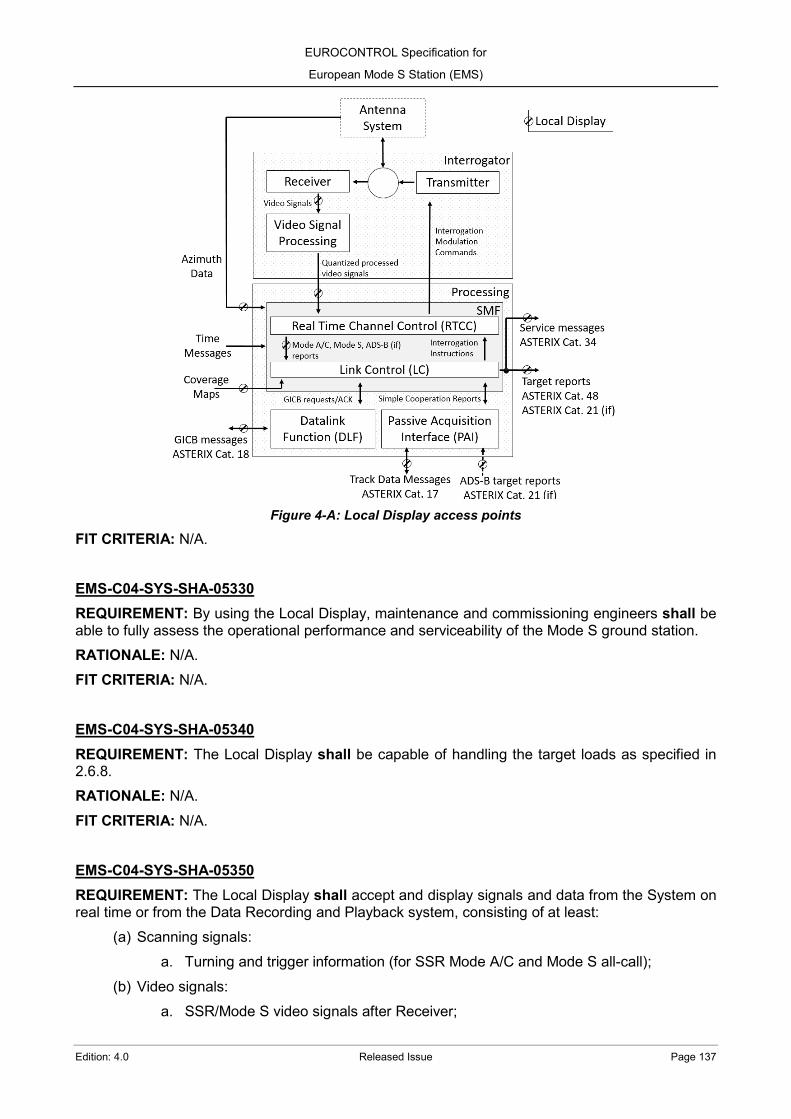
EUROCONTROL Specification for
European Mode S Station (EMS)
Edition: 4.0 Released Issue Page 137
Figure 4-A: Local Display access points
FIT CRITERIA: N/A. EMS-C04-SYS-SHA-05330 REQUIREMENT: By using the Local Display, maintenance and commissioning engineers shall be able to fully assess the operational performance and serviceability of the Mode S ground station. RATIONALE: N/A. FIT CRITERIA: N/A.
EMS-C04-SYS-SHA-05340 REQUIREMENT: The Local Display shall be capable of handling the target loads as specified in 2.6.8. RATIONALE: N/A. FIT CRITERIA: N/A. EMS-C04-SYS-SHA-05350 REQUIREMENT: The Local Display shall accept and display signals and data from the System on real time or from the Data Recording and Playback system, consisting of at least:
(a) Scanning signals: a. Turning and trigger information (for SSR Mode A/C and Mode S all-call);
(b) Video signals: a. SSR/Mode S video signals after Receiver;

EUROCONTROL Specification for
European Mode S Station (EMS)
Page 138 Released Issue Edition: 4.0
b. Quantised Processed Sum Video for SSR and Mode S all-call, consisting in analogue video converted to digital signals synchronised to the monopulse plot extractor master clock timing.
(c) Surveillance Data output: a. Monoradar target reports (ASTERIX Cat. 048, [RD 26]) and service messages
(ASTERIX Cat. 034, [RD 25]); b. ADS-B target reports (ASTERIX Cat. 021, [RD 23]).
(d) Passive Acquisition data: a. Incoming ADS-B target reports (ASTERIX Cat. 021, [RD 23]); b. Incoming/Outgoing Track data messages (ASTERIX Cat. 017, [RD 21]).
(e) Current operational local Coverage maps, for a user-defined altitude: a. Surveillance map; b. Lockout map; c. Datalink map.
(f) Special plots representation: a. The Broadcast Comm-B received; b. ACAS resolution advisories.
RATIONALE: Monoradar target reports include Mode S, SSR, PSR and combined reports. FIT CRITERIA: N/A. EMS-C04-SYS-SHA-05360 REQUIREMENT: The Local Display shall accept and show data from the System on real time or from the Data Recording and Playback system, consisting of at least:
(a) Reply Report Data (messages output from the Mode A/C and Mode S reply processor in the RTCC function);
(b) Data flagged as Anomalies and false plots in the PAF and NOT sent to the Surveillance Data outputs;
(c) All monoradar targets under surveillance (3-D position and identity); (d) The Data link capability of each target (BDS register 1016); (e) The last received message decoded per target; (f) The GICB received; (g) The EHS GICB requests received from the DAP Extraction Interface (ASTERIX Cat. 018,
[RD 22]); (h) The Broadcast Comm-B received; (i) ACAS resolution advisories.
RATIONALE: Monoradar target reports include Mode S, SSR, PSR and combined reports. FIT CRITERIA: N/A.

EUROCONTROL Specification for
European Mode S Station (EMS)
Edition: 4.0 Released Issue Page 139
EMS-C04-TEN-SHA-05370 REQUIREMENT: The Tenderer shall provide information on the subset of data and signals that can be displayed simultaneously. RATIONALE: N/A. FIT CRITERIA: N/A. EMS-C04-SYS-SHA-05380 REQUIREMENT: The Local Display shall be displayed in a geographical representation with a background map facility for up to 300 NM radius of the origin. RATIONALE: N/A. FIT CRITERIA: N/A.
EMS-C04-SYS-SHA-05390 REQUIREMENT: The Local Display shall provide parameters to configure the centre of coordinates for the data representation in the geographical map. RATIONALE: N/A. FIT CRITERIA: N/A. EMS-C04-TEN-SHA-05400 REQUIREMENT: The Tenderer shall provide detailed information about the editing and display of border and coastline maps, and which maps will be delivered as standard representation. RATIONALE: N/A. FIT CRITERIA: N/A.
EMS-C04-TEN-SHA-05410 REQUIREMENT: The Tenderer shall provide detailed information about the editing and display of other geographical maps (other sensor positions, screening coverage maps, airways, runways, etc.). RATIONALE: N/A. FIT CRITERIA: N/A. EMS-C04-TEN-SHA-05420 REQUIREMENT: The Tenderer shall provide detailed information about the display of the coverage maps (Surveillance, Lockout and Datalink). RATIONALE: N/A. FIT CRITERIA: N/A. EMS-C04-TEN-SHA-05430 REQUIREMENT: The Tenderer shall provide detailed information about the display of Passive Acquisition data in ASTERIX Cat. 017 ([RD 21]) and Cat. 021 ([RD 23]). RATIONALE: Track data messages and ADS-B target reports.

EUROCONTROL Specification for
European Mode S Station (EMS)
Page 140 Released Issue Edition: 4.0
FIT CRITERIA: N/A.
EMS-C04-SYS-SHA-05440 REQUIREMENT: The System shall provide the operator with the ability to select any combination of data to be displayed in the Local Display. RATIONALE: N/A. FIT CRITERIA: N/A. EMS-C04-SYS-SHA-05450 REQUIREMENT: The symbols and colours in the Local Display shall be such as to distinguish between different plot types. RATIONALE: N/A. FIT CRITERIA: N/A. EMS-C04-TEN-SHA-05460 REQUIREMENT: The Tenderer shall provide detailed information on how the Local Display data is selected and retrieved from the station (e.g., software or hardware selection). RATIONALE: N/A. FIT CRITERIA: N/A. EMS-C04-SYS-SHA-05470 REQUIREMENT: The Local Display shall use the same Surveillance Data as that available in the external WAN interface. RATIONALE: N/A. FIT CRITERIA: N/A. EMS-C04-SYS-SHA-05480 REQUIREMENT: The Local Display shall recognise, process, interpret and display all the following ASTERIX messages types:
(a) Cat. 017 ([RD 21]); (b) Cat. 018 ([RD 22]); (c) Cat. 021 ([RD 23]); (d) Cat. 034 ([RD 25]); (e) Cat. 048 ([RD 26]).
RATIONALE: N/A. FIT CRITERIA: N/A.

EUROCONTROL Specification for
European Mode S Station (EMS)
Edition: 4.0 Released Issue Page 141
EMS-C04-CON-SHA-05490 REQUIREMENT: The Contractor shall supply any peripherals and/or ancillary equipment that are necessary for the operation of the Local Display. RATIONALE: N/A. FIT CRITERIA: N/A. EMS-C04-TEN-SHA-05500 REQUIREMENT: The Tenderer shall include in the response details of how all the information for selected plots could be displayed (e.g. including GICB reply data, status information, etc.). RATIONALE: N/A. FIT CRITERIA: N/A.
EMS-C04-SYS-SHA-05510 REQUIREMENT: The Local Display hardware shall make use of an industry standard graphics work station with an industry standard Operating System. RATIONALE: N/A. FIT CRITERIA: N/A. EMS-C04-SYS-SHA-05520 REQUIREMENT: Where specialised external processing hardware is proposed, it shall be interfaced to the same Operating System as the Local Display. RATIONALE: N/A. FIT CRITERIA: N/A.
EMS-C04-TEN-SHA-05530 REQUIREMENT: The Tenderer shall provide details of the hardware which will be supplied for the Local Display. RATIONALE: N/A. FIT CRITERIA: N/A.
4.11 Data Recorder and Playback EMS-C04-TEN-SHA-05540 REQUIREMENT: The Tenderer shall provide in their proposal details of the record/replay facilities (i.e. Data Recorder and Playback) which is used to evaluate surveillance data and details on how these facilities are connected with the System.
RATIONALE: The following figure shows a functional diagram of the access points ( ) for the Data Recorder and Playback:

EUROCONTROL Specification for
European Mode S Station (EMS)
Page 142 Released Issue Edition: 4.0
Figure 4-B: Data Recorder and Playback access points
FIT CRITERIA: N/A. EMS-C04-SYS-SHA-05550 REQUIREMENT: The Data Recorder and Playback shall be capable of recording and replaying of the following time-stamped data:
(a) Surveillance Data output: a. Monoradar target reports (ASTERIX Cat. 048, [RD 26]) and service messages
(ASTERIX Cat. 034, [RD 25]); c. ADS-B target reports (ASTERIX Cat. 021, [RD 23]).
(b) Status information (time, date, scan number, etc.); (c) Data flagged as Anomalies and false in the PAF and NOT sent to the Surveillance Data
output; (d) Interrogation instructions; (e) Mode A/C and Mode S reply report data (from RTCC function); (f) Passive Acquisition data:
a. Incoming ADS-B target reports (ASTERIX Cat. 021, [RD 23]); b. Incoming/Outgoing Track data messages (ASTERIX Cat. 017, [RD 21]).
(g) The EHS GICB requests received from the DAP Extraction Interface (ASTERIX Cat. 018, [RD 22]).
RATIONALE: Monoradar target reports include Mode S, SSR, PSR and combined reports.

EUROCONTROL Specification for
European Mode S Station (EMS)
Edition: 4.0 Released Issue Page 143
FIT CRITERIA: N/A.
EMS-C04-SYS-SHA-05560 REQUIREMENT: The Data Recorder and Playback shall record the same Surveillance Data as available in the external WAN interface. RATIONALE: N/A. FIT CRITERIA: N/A. EMS-C04-SYS-SHA-05570 REQUIREMENT: The Data Recorder and Playback shall be capable of recording up to four subsets of data simultaneously. RATIONALE: N/A. FIT CRITERIA: N/A. EMS-C04-TEN-SHA-05580 REQUIREMENT: The Tenderer shall provide details in their proposal of the method used to store the recordings. RATIONALE: N/A. FIT CRITERIA: N/A. EMS-C04-SYS-SHA-05590 REQUIREMENT: The Data Recorder and Playback shall be capable to perform ad-hoc and periodic recordings for up to 24 hours without interrogation instructions and reply report data (2 hours with interrogation instructions or reply report data) with the System operating at full capacity. RATIONALE: N/A. FIT CRITERIA: N/A.
EMS-C04-TEN-SHA-05600 REQUIREMENT: The Tenderer shall provide details on how the periodic recordings will be configured. RATIONALE: N/A. FIT CRITERIA: N/A. EMS-C04-SYS-SHA-05610 REQUIREMENT: The Data Recorder and Playback shall be able to replay only a subset of the recorded data. RATIONALE: N/A. FIT CRITERIA: N/A.

EUROCONTROL Specification for
European Mode S Station (EMS)
Page 144 Released Issue Edition: 4.0
EMS-C04-TEN-SHA-05620 REQUIREMENT: The Tenderer shall provide in the response the proposed method for data recording and playback, stating the expected maximum duration for different subsets of data. RATIONALE: N/A. FIT CRITERIA: N/A. EMS-C04-SYS-MAY-05630 REQUIREMENT: The Data Recorder and Playback may be capable of recording and replaying the following time-stamped data together with azimuth information:
(a) SSR quantised processed SUM video signals; (b) Mode S quantised processed SUM video signals; (c) ADS-B quantised processed video signals (if integrated on-site ADS-B).
RATIONALE: N/A. FIT CRITERIA: N/A.
EMS-C04-TEN-SHA-05640 REQUIREMENT: When offered, the Tenderer shall provide information in their response of the preferred approach to record and replay the quantized processed video signals. RATIONALE: N/A. FIT CRITERIA: N/A. EMS-C04-SYS-SHA-05650 REQUIREMENT: Control of data recording shall be via the operator interface. RATIONALE: N/A. FIT CRITERIA: N/A. EMS-C04-SYS-SHA-05660 REQUIREMENT: The medium to be used for digital recording shall allow recordings to be replayed for analysis on another computer. RATIONALE: N/A. FIT CRITERIA: N/A.
EMS-C04-SYS-SHA-05670 REQUIREMENT: The Data Recorder and Playback shall be able to record, store, replay and export ASTERIX files at least in raw ([RD 20]) and/or final format ([RD 28]). RATIONALE: N/A. FIT CRITERIA: N/A.

EUROCONTROL Specification for
European Mode S Station (EMS)
Edition: 4.0 Released Issue Page 145
EMS-C04-SYS-MAY-05680 REQUIREMENT: The Data Recorder and Playback may include a lossless compression algorithm to store and export the ASTERIX recordings. RATIONALE: The data compression allows to save space disk and improve the transmission time while exporting the recordings. FIT CRITERIA: N/A.
EMS-C04-SYS-SHO-05690 REQUIREMENT: It should be possible filter the record or replay by any logical and/or combination of the following criteria:
(a) All targets within a static volume bounded by any azimuth, range and pressure-altitude interval;
(b) Targets with selected Mode A codes (from a definable list of up to 20 Mode A codes); (c) All targets Mode S addresses selected (from a definable list of up to 20 Mode S addresses); (d) All plot data which falls within a dynamic box (size defined by the user). The centre of the
box to be given by a target defined as in (b) or (c) above; (e) All data described as ‘anomaly’ or ‘false’.
RATIONALE: N/A. FIT CRITERIA: N/A.
4.12 Cyber security 4.12.1 Non-essential elements EMS-C04-SYS-SHA-05700 REQUIREMENT: Software services of Operative Systems and applications not required for the normal operation of the Systems shall be disabled. RATIONALE: N/A. FIT CRITERIA: N/A.
EMS-C04-SYS-SHA-05710 REQUIREMENT: COTS applications (e.g. browsers, demo apps, developments tools, libraries) not required for the normal operation of the Systems shall be disabled. RATIONALE: N/A. FIT CRITERIA: N/A. EMS-C04-SYS-SHA-05720 REQUIREMENT: Firewalls shall be configured to only allow essential communications (i.e., IP addresses and ports) for the normal operation of the Systems. RATIONALE: N/A. FIT CRITERIA: N/A.
EUROCONTROL Specification for
European Mode S Station (EMS)
Page 146 Released Issue Edition: 4.0
EMS-C04-SYS-SHA-05730 REQUIREMENT: All hardware ports unused by the System (e.g. USB, Ethernet ports, SD cards, etc.) shall be disabled during normal operation by default. RATIONALE: N/A. FIT CRITERIA: N/A.
EMS-C04-SYS-SHA-05740 REQUIREMENT: The System shall allow to enable an unused (disabled) hardware port for a limited period of time. RATIONALE: N/A. FIT CRITERIA: N/A. EMS-C04-TEN-SHA-05750 REQUIREMENT: The Tenderer shall describe how the System will allow a hardware port to be temporarily enabled and how the port will be set back to its default disabled status. RATIONALE: N/A. FIT CRITERIA: N/A.
4.12.2 Operator credentials EMS-C04-SYS-SHA-05760 REQUIREMENT: The System shall require the operator identification (login), i.e. through user name and password, to allow any modification or control action in any system/subsystem. RATIONALE: It is preferred when an Operator keeps the same user name and password in all the system/subsystem. FIT CRITERIA: N/A.
EMS-C04-SYS-MAY-05770 REQUIREMENT: The System may include an Identity Server subsystem to be located in a remote central location and to be able to provide the same Operator credentials to several Mode S ground stations. RATIONALE: The Identity Server simplify the creation of the same operator credentials in different locations and ease their central management. FIT CRITERIA: N/A.
EMS-C04-TEN-SHA-05780 REQUIREMENT: When included as a part of the System, the Tenderer shall describe how the Identity Server will be integrated in the System to provide a centralized user credentials repository in a secure way. RATIONALE: N/A.

EUROCONTROL Specification for
European Mode S Station (EMS)
Edition: 4.0 Released Issue Page 147
FIT CRITERIA: N/A.
EMS-C04-SYS-SHO-05790 REQUIREMENT: The System should accept only the creation of passwords with the minimum following complexity:
(a) Length: minimum 10 characters; (b) Complexity: At least one lower case character, one upper case character, one number and
one special character. RATIONALE: N/A. FIT CRITERIA: N/A. EMS-C04-SYS-MAY-05800 REQUIREMENT: The System may request to an Operator to change the password every 90 days. RATIONALE: Next operator login after 90 days of password creation will request to create a new password. FIT CRITERIA: N/A.
EMS-C04-SYS-MAY-05810 REQUIREMENT: The System may have a password history per user to avoid password reuse. RATIONALE: N/A. FIT CRITERIA: N/A.
EMS-C04-SYS-SHA-05820 REQUIREMENT: Passwords storage shall be encrypted. RATIONALE: FIT CRITERIA: N/A.
EMS-C04-SYS-SHO-05830 REQUIREMENT: Any operator account should be blocked after 5 wrong attempts to login. RATIONALE: N/A. FIT CRITERIA: N/A.
EMS-C04-SYS-SHO-05840 REQUIREMENT: Any system/subsystem should automatically logout any Operator after a configurable time (parameter) without activity. RATIONALE: N/A. FIT CRITERIA: N/A.
EUROCONTROL Specification for
European Mode S Station (EMS)
Page 148 Released Issue Edition: 4.0
4.12.3 Network EMS-C04-SYS-SHA-05850 REQUIREMENT: Access to remote services (e.g. RDP or SSH) shall only be granted to known network hosts. RATIONALE: N/A. FIT CRITERIA: N/A. EMS-C04-SYS-SHO-05860 REQUIREMENT: The System should not grant unsecure wireless access to its LAN and WAN network interfaces which differ from dedicated point-to-point radio communications, e.g. microwave links. RATIONALE: The System is not intended to provide a local Wi-Fi access point but to make use of access-controlled point-to-point radio links FIT CRITERIA: N/A.
The System should not broadcast unsecure wireless access to its LAN or WAN network interfaces which differ from dedicated point-to-point radio links e.g. microwave, 4G/5G” and then for the rationale “The System is not intended to be a local Wifi access point but make use of access-controlled point-to-point radio links EMS-C04-SYS-SHO-05870 REQUIREMENT: The System should provide a function to secure the Surveillance Data output in the outer link of the external interfaces. RATIONALE: N/A. FIT CRITERIA: N/A. EMS-C04-SYS-SHO-05880 REQUIREMENT: The security function should use an encryption protocol to secure the link between the external interfaces and the remote locations where the data will be received. RATIONALE: The encryption can be done indistinctly in the Internet Layer, e.g. IPsec ([RD 42]), or in the Transport layer, e.g. TLS ([RD 43]). FIT CRITERIA: N/A. EMS-C04-TEN-SHO-05890 REQUIREMENT: The Tenderer should detail which encryption protocol the System will use and which additional requirements will be needed in the other side of the link where the data will be sent. RATIONALE: N/A. FIT CRITERIA: N/A.
EMS-C04-SYS-MAY-05900 REQUIREMENT: The System may have the capability to include a function to secure the content of the surveillance data by encapsulating the ASTERIX messages. RATIONALE: One possibility, still under development at the time of issue of this specification, is the use of ASTERIX Cat. 0 messages for this purpose.
EUROCONTROL Specification for
European Mode S Station (EMS)
Edition: 4.0 Released Issue Page 149
FIT CRITERIA: N/A.
4.13 Test interfaces EMS-C04-SYS-SHA-05910 REQUIREMENT: The System shall provide interfaces to allow analysis, maintenance and troubleshooting activities. RATIONALE: The interfaces allow the use of standard Tools, i.e. non-manufacturer dependants. FIT CRITERIA: N/A. EMS-C04-SYS-SHA-05920 REQUIREMENT: The System shall provide an interface to monitor the transmitted modulated signals from the Sum and Control channels. RATIONALE: The monitoring point allows to measure the maximum output power and to observe the interrogation signals shape. FIT CRITERIA: N/A. EMS-C04-SYS-MAY-05930 REQUIREMENT: The interface to monitor the transmitted modulated signals may include means to provide a monitoring signal with a maximum power of 15 dBm (i.e. 0.32 kW) without the need of additional external passive elements. RATIONALE: A low output power level in the monitoring interface allows the direct use of test equipment and prevent manipulation of critical elements of the System during analysis, maintenance and troubleshooting activities. FIT CRITERIA: N/A.
EMS-C04-SYS-MAY-05940 REQUIREMENT: The System may provide an interface to monitor the transmitter base band signal before modulation. RATIONALE: The monitoring point allows to observe the interrogation signals shape, e.g. in video TTL format. FIT CRITERIA: N/A.
EMS-C04-SYS-MAY-05950 REQUIREMENT: The System may provide an interface to record the transmitter interrogations in a computer file format. RATIONALE: A computer file containing the transmitted interrogations can be correlated with another computer file containing the received replies to allow deep level performance analysis. FIT CRITERIA: N/A.

EUROCONTROL Specification for
European Mode S Station (EMS)
Page 150 Released Issue Edition: 4.0
EMS-C04-SYS-SHA-05960 REQUIREMENT: When an interface to record the transmitter interrogations is included, each recorded interrogation shall include at least a UTC time stamp, the power level and all the data contained. RATIONALE: N/A. FIT CRITERIA: N/A.
EMS-C04-TEN-SHA-05970 REQUIREMENT: The Tenderer shall indicate which interfaces will be available to monitor the Transmitter and which physical interfaces or digital formats will be used. RATIONALE: N/A. FIT CRITERIA: N/A. EMS-C04-CON-SHA-05980 REQUIREMENT: The Contractor shall provide the ICD of any digital format used in the test interfaces to monitor the Transmitter. RATIONALE: N/A. FIT CRITERIA: N/A.
EMS-C04-SYS-SHA-05990 REQUIREMENT: The System shall provide an interface to monitor the received signals. RATIONALE: The monitoring point allows to observe the received signals shape, e.g. in TTL video format. FIT CRITERIA: N/A. EMS-C04-SYS-MAY-06000 REQUIREMENT: The System may provide an interface to record the received signals in IQ digital format. RATIONALE: The monitoring point allows to export the IQ signals to a computer file. FIT CRITERIA: N/A. EMS-C04-SYS-MAY-06010 REQUIREMENT: The System may provide an interface to record the received replies in a computer file format. RATIONALE: A computer file containing the received interrogations can be correlated with another computer file containing the transmitted replies to allow deep level performance analysis. FIT CRITERIA: N/A.

EUROCONTROL Specification for
European Mode S Station (EMS)
Edition: 4.0 Released Issue Page 151
EMS-C04-SYS-SHA-06020 REQUIREMENT: When an interface to record the transmitter interrogations is included, each received reply to be recorded in a file format shall include at least a UTC time stamp, the received power and OBI levels, and all the decoded data contained. RATIONALE: N/A. FIT CRITERIA: N/A.
EMS-C04-TEN-SHA-06030 REQUIREMENT: The Tenderer shall indicate which interfaces will be available to monitor the Receiver and which physical interfaces or digital formats will be used. RATIONALE: N/A. FIT CRITERIA: N/A. EMS-C04-CON-SHA-06040 REQUIREMENT: The Contractor shall provide the ICD of any digital format used in the test interfaces to monitor the Receiver. RATIONALE: N/A. FIT CRITERIA: N/A.
EMS-C04-SYS-SHA-06050 REQUIREMENT: The System shall provide an interface to monitor the azimuth data signals, e.g. in TTL video format. RATIONALE: The monitoring point allows to observe the data azimuth signals shape and time correlation. FIT CRITERIA: N/A. EMS-C04-TEN-SHA-06060 REQUIREMENT: The Tenderer shall indicate which interfaces will be available to monitor the data azimuth signals and which physical interfaces will be used. RATIONALE: N/A. FIT CRITERIA: N/A.
EMS-C04-SYS-SHA-06070 REQUIREMENT: The System shall provide an interface to record the Surveillance Data output. RATIONALE: The Surveillance Data output recording allows the performance analysis of the System. FIT CRITERIA: A Performance Analysis Tool, as described in ANNEX C.2 is used to verify the Surveillance Data output.

EUROCONTROL Specification for
European Mode S Station (EMS)
Page 152 Released Issue Edition: 4.0
EMS-C04-TEN-SHA-06080 REQUIREMENT: The Tenderer shall provide details, including which items are available at no cost, and those requiring development, of all equipment considered necessary to provide analysis of the Mode S ground station functionality and interfaces that cannot be achieved using standard performance tools. RATIONALE: N/A. FIT CRITERIA: N/A.
4.14 System Interconnections EMS-C04-TEN-SHA-06090 REQUIREMENT: The Tenderer shall provide in their proposal system diagrams for the Mode S ground station showing the proposed system configurations, equipment types and interconnections. RATIONALE: N/A. FIT CRITERIA: N/A.
EMS-C04-TEN-SHA-06100 REQUIREMENT: Where appropriate, specific details shall be given for signals, data formats, etc., particularly where an interface is required between the Mode S ground station being provided against this specification, and another system outside the scope of this specification. RATIONALE: N/A. FIT CRITERIA: N/A.
EMS-C04-TEN-SHA-06110 REQUIREMENT: In other areas, where interface details have yet to be decided, general information shall be given by the Tenderer. The specific details of these interfaces will be defined and agreed with the Agency after contract award. RATIONALE: N/A. FIT CRITERIA: N/A.
EMS-C04-TEN-SHA-06120 REQUIREMENT: For the rotating antenna the Tenderer shall provide, in their proposal, detailed specifications of the rotating joints, with drawings, to meet the Mode S performance and interface requirements. RATIONALE: N/A. FIT CRITERIA: N/A. EMS-C04-TEN-SHA-06130 REQUIREMENT: The System shall allow connection to a power distribution network supplying a nominal line voltage of 3 phase 400 V [-6%, +10%] of frequency 50 Hz [+/-2%]. RATIONALE: N/A.

EUROCONTROL Specification for
European Mode S Station (EMS)
Edition: 4.0 Released Issue Page 153
FIT CRITERIA: N/A.

EUROCONTROL Specification for
European Mode S Station (EMS)
Page 154 Released Issue Edition: 4.0
Processing System This chapter details the processing requirements to be met to satisfy the provision of the Mode S ground station.
5.1 Logical Blocks EMS-C05-TEN-SHA-06140 REQUIREMENT: The Tenderer shall include in their proposal a Processing block diagram showing the functionalities and the differences with the logic blocks indicated in this Specification. RATIONALE: To ease the understanding, the requirements of this Specification have been grouped around logical blocks (i.e. SMF, RTCC, LC, DLF and PAI), but as far as they can provide equal results, it is accepted that the System offered by the Tenderer groups the different functionalities in different logical blocks. This Specification does not impose an architecture design. If a functionality of this chapter is included in the System, but it is located in a different logical block, it can be considered as compliant as far as it can provide the same expected results. FIT CRITERIA: N/A.
5.2 System Management Function (SMF) EMS-C05-SYS-SHA-06150 REQUIREMENT: The System shall include a System Management Function (SMF) which contains the following sub-functions:
(a) Real Time Channel Controller function (RTCC) containing: a. A Mode A/C reply processor; b. A Mode S reply processor; c. An interrogation scheduler.
(b) Link Controller function (LC) containing: a. Plot Assignor Function (PAF); b. Station Selective Roll-Call lists; c. Communications Management Processor (CMP); d. Mode S Link Management Processor (LMP).
RATIONALE: The following figure shows a functional diagram of the SMF:

EUROCONTROL Specification for
European Mode S Station (EMS)
Edition: 4.0 Released Issue Page 155
Figure 5-A: System Management Function (SMF) overview
FIT CRITERIA: N/A. EMS-C05-TEN-SHA-06160 REQUIREMENT: The Tenderer shall include in their proposal a block diagram showing the functionalities and input/output ports of the SMF, and detail any differences and the reason for the different approach. RATIONALE: N/A. FIT CRITERIA: N/A. EMS-C05-SYS-SHA-06170 REQUIREMENT: The SMF shall be able to receive and process reply data from the Interrogator when it the replies are consistent with the requirements of 2.6.8. RATIONALE: N/A. FIT CRITERIA: N/A.
EMS-C05-SYS-SHA-06180 REQUIREMENT: The SMF shall be able to form plots for all targets and output them to the Surveillance Data output. RATIONALE: N/A. FIT CRITERIA: N/A.
EUROCONTROL Specification for
European Mode S Station (EMS)
Page 156 Released Issue Edition: 4.0
EMS-C05-SYS-SHA-06190 REQUIREMENT: The SMF shall be able to take in uplink transactions from the DLF and the surveillance updates, to combine them and to output them to the Interrogator at a rate which meet the maximum interrogation rates specified in 3.1, 3.3.3 and [RD 1]. RATIONALE: N/A. FIT CRITERIA: N/A.
EMS-C05-SYS-SHA-06200 REQUIREMENT: The surveillance update interrogations shall have priority over the DLF interrogations when the interrogation rates exceed the defined limits. RATIONALE: N/A. FIT CRITERIA: N/A. EMS-C05-SYS-SHA-06210 REQUIREMENT: The SMF shall be able to process downlink transactions generated both by requests from the ground system and by transactions initiated by the airborne system (i.e. GICB and Comm-B broadcast). RATIONALE: N/A. FIT CRITERIA: N/A. EMS-C05-TEN-SHA-06220 REQUIREMENT: The Tenderer shall include in their proposal details of the SMF functionalities. RATIONALE: N/A. FIT CRITERIA: N/A. EMS-C05-SYS-SHA-06230 REQUIREMENT: The SMF shall have interfaces to:
(a) The data azimuth signals of the antenna system, to receive information on the azimuth of the boresight of the beam when replies are received;
(b) The Interrogator: a. To send interrogation modulation commands (including power level, probability of
reply and Lockout flags) and data content; b. To obtain processed video and Off Boresight Information (OBI) for all reply pulses.
(c) The Surveillance Data output, to provide ASTERIX target report data; (d) The DLF, to obtain uplink transactions for sending to the targets and to send back received
downlink transactions; (e) Control and Monitoring System (CMS), to enable the control and monitoring functions to
be performed; (f) NTP time servers, to serve as a time reference and permit time stamping of plots, etc.
RATIONALE: N/A.
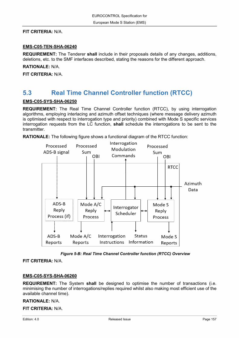
EUROCONTROL Specification for
European Mode S Station (EMS)
Edition: 4.0 Released Issue Page 157
FIT CRITERIA: N/A.
EMS-C05-TEN-SHA-06240 REQUIREMENT: The Tenderer shall include in their proposals details of any changes, additions, deletions, etc. to the SMF interfaces described, stating the reasons for the different approach. RATIONALE: N/A. FIT CRITERIA: N/A.
5.3 Real Time Channel Controller function (RTCC) EMS-C05-SYS-SHA-06250 REQUIREMENT: The Real Time Channel Controller function (RTCC), by using interrogation algorithms, employing interlacing and azimuth offset techniques (where message delivery azimuth is optimised with respect to interrogation type and priority) combined with Mode S specific services interrogation requests from the LC function, shall schedule the interrogations to be sent to the transmitter. RATIONALE: The following figure shows a functional diagram of the RTCC function:
Figure 5-B: Real Time Channel Controller function (RTCC) Overview
FIT CRITERIA: N/A.
EMS-C05-SYS-SHA-06260 REQUIREMENT: The System shall be designed to optimise the number of transactions (i.e. minimising the number of interrogations/replies required whilst also making most efficient use of the available channel time). RATIONALE: N/A. FIT CRITERIA: N/A.

EUROCONTROL Specification for
European Mode S Station (EMS)
Page 158 Released Issue Edition: 4.0
EMS-C05-SYS-SHA-06270 REQUIREMENT: The resulting replies received from the video processor function are processed by the Mode A/C reply processor, the Mode S reply processor and the ADS-B reply processor (if integrated implementation) to create a report for each reply before it is sent to the LC function. RATIONALE: A Mode S Reply Report is defined as a Mode S summary report with, as a minimum, Address, associated position, message data and status (e.g. reservation) for all successful transactions to a given target in the beam-dwell. An SSR Reply Report is defined as an SSR report with, as a minimum, positional information correlated from all the decoded replies associated with the target received during the beam-dwell. SSR replies are triggered by Mode A/C interrogations (mixed mode MIP). Sometimes SSR replies can be triggered accidentally when Mode A/C only all-call interrogations (intermode P4 short) are received with a signal level in close proximity to a transponder MTL (Minimum Triggering Level). FIT CRITERIA: N/A.
EMS-C05-TEN-SHA-06280 REQUIREMENT: The tenderer shall provide information on how the System will proceed if a valid Mode 'S' reply is not decoded in the expected listening period. RATIONALE: N/A. FIT CRITERIA: N/A. EMS-C05-SYS-SHA-06290 REQUIREMENT: As a minimum, the Mode S Reply Processing shall perform preamble detection and error detection and correction. RATIONALE: N/A. FIT CRITERIA: N/A.
EMS-C05-TEN-SHA-06300 REQUIREMENT: The Tenderer shall include in their proposal details of the operation of the RTCC function, including details of the Mode A/C Reply Process, Mode S reply process, ADS-B reply process (if integrated implementation), scheduler and performance monitoring indicator. RATIONALE: N/A. FIT CRITERIA: N/A.
EMS-C05-SYS-SHA-06310 REQUIREMENT: The interrogation scheduler shall:
(a) Control the rate and content of the Mode S only all-call interrogations; (b) Control variable all-call interrogation scheduling (which allows for the concatenation of
Selective periods); (c) Control the rate of intermode mode A/C only all-call interrogations; (d) Control the rate of Modes A and C interrogations;

EUROCONTROL Specification for
European Mode S Station (EMS)
Edition: 4.0 Released Issue Page 159
(e) Control the timing of the Mode S selective interrogations. RATIONALE: N/A. FIT CRITERIA: N/A. EMS-C05-SYS-SHA-06320 REQUIREMENT: The RTCC function shall be monitored via the Control and Monitoring System (CMS). RATIONALE: N/A. FIT CRITERIA: N/A.
EMS-C05-TEN-SHA-06330 REQUIREMENT: The Tenderer shall provide in their proposal details of how the RTCC function will be monitored in the CMS. RATIONALE: N/A. FIT CRITERIA: N/A.
5.4 Link Controller function (LC) EMS-C05-SYS-SHA-06340 REQUIREMENT: The Link Controller function (LC) shall pass Mode S specific services requested interrogations to the RTCC function for action. RATIONALE: The following figure shows a functional diagram of the LC function:
Figure 5-C: Link Controller function (LC) Overview

EUROCONTROL Specification for
European Mode S Station (EMS)
Page 160 Released Issue Edition: 4.0
FIT CRITERIA: N/A.
EMS-C05-SYS-SHA-06350 REQUIREMENT: The Mode A/C, the Mode S and the ADS-B (if integrated implementation) replies received from the RTCC function shall be sent to the Plot Assignor Function (PAF) in order to track targets. RATIONALE: N/A. FIT CRITERIA: N/A. EMS-C05-SYS-SHA-06360 REQUIREMENT: GICB replies shall be sent to plot formatting for delivery as Enhanced Surveillance data in the Surveillance Data output. RATIONALE: N/A. FIT CRITERIA: N/A.
EMS-C05-SYSTEN-SHA-06370 REQUIREMENT: The Tenderer shall provide information on how he will achieve the enhancement of plot data with the GICB replies in the ASTERIX format. RATIONALE: N/A. FIT CRITERIA: N/A. EMS-C05-SYS-SHA-06380 REQUIREMENT: The LC function shall be monitored via the Control and Monitoring System (CMS). RATIONALE: N/A. FIT CRITERIA: N/A. EMS-C05-TEN-SHA-06390 REQUIREMENT: The Tenderer shall provide in their proposal details of how the LC function will be monitored in the CMS. RATIONALE: N/A. FIT CRITERIA: N/A.
5.4.1 Plot Assignor Function (PAF) EMS-C05-SYS-SHA-06400 REQUIREMENT: The Plot Assignor Function (PAF) shall include at least the following sub-functions:
(a) Track initialisation, maintenance and prediction; (b) False target processing that can discriminate against reflected replies, FRUIT replies, split
targets, ring around targets and distinguish between multiple occurrences of targets in the same beam dwell, with the same non-unique address;

EUROCONTROL Specification for
European Mode S Station (EMS)
Edition: 4.0 Released Issue Page 161
(c) ASTERIX plot formatting which delivers Cat. 048 ([RD 26]), Cat. 034. ([RD 25]) and, if integrated implementation, Cat. 021 ([RD 23]) data to the Surveillance Data Output;
(d) Reply merge function, to combine Mode A/C and Mode S reports from the same target. RATIONALE: The PAF reply merge function combines Mode S replies and SSR replies that are wrongly produced from the same Mode S target after Mode A/C only all-call interrogations. FIT CRITERIA: N/A.
5.4.1.1 Tracks management EMS-C05-SYS-SHA-06410 REQUIREMENT: A track shall be initialised and maintained, both upon detection (SSR and Mode S targets) and upon receiving supplementary data (Mode S targets only). RATIONALE: N/A. FIT CRITERIA: N/A. EMS-C05-SYS-SHA-06420 REQUIREMENT: The PAF shall track all the targets, including targets with duplicated addresses, and maintain the Selective Roll-Call list. RATIONALE: N/A. FIT CRITERIA: N/A.
EMS-C05-SYS-SHA-06430 REQUIREMENT: Information from a track initiated for a Mode A/C target that has been confirmed to be in the Surveillance Volume shall be sent to the Surveillance Data output. RATIONALE: N/A. FIT CRITERIA: N/A. EMS-C05-SYS-SHA-06440 REQUIREMENT: Information from a track initiated for a Mode S target that has been confirmed to be in the Surveillance Volume shall be sent to the Surveillance Data output if:
(a) At least one All-Call reply has been detected and confirmed by a Selective reply; or (b) A Selective reply has been received from a Selective interrogation which was initiated by
supplementary data (i.e. ADS-B passive acquisition). RATIONALE: N/A. FIT CRITERIA: N/A.
EMS-C05-TEN-SHA-06450 REQUIREMENT: The Tenderer shall describe how a report is localised in the coverage maps when the report lacks credible pressure-altitude information (i.e. Mode S/SSR targets without credible pressure-altitude code).

EUROCONTROL Specification for
European Mode S Station (EMS)
Page 162 Released Issue Edition: 4.0
RATIONALE: At track initiation, the first selective reply will normally provide pressure-altitude information. As this is the first reply received, then it will not be possible to perform the credibility check. However, it can be assumed that in the majority of cases the pressure-altitude information will be valid. For this reason, the pressure-altitude information can be used to determine the position within the Surveillance Volume. FIT CRITERIA: N/A.
EMS-C05-SYS-SHA-06460 REQUIREMENT: The Mode C shall be updated on the tracks for each antenna revolution. RATIONALE: N/A. FIT CRITERIA: N/A.
EMS-C05-SYS-SHA-06470 REQUIREMENT: Aircraft surveillance data and measured position information shall be sent for every antenna revolution until the track is cancelled. RATIONALE: N/A. FIT CRITERIA: N/A. EMS-C05-SYS-SHA-06480 REQUIREMENT: The position information shall be originated, by decreasing priority, from a detection (All-Call or Selective reply), or from an extrapolation (miss). RATIONALE: N/A. FIT CRITERIA: N/A.
EMS-C05-SYS-SHA-06490 REQUIREMENT: An operational parameter, when enabled, shall force the output of extrapolated target reports to the Surveillance Data output in case of miss. RATIONALE: N/A. FIT CRITERIA: N/A. EMS-C05-SYS-SHA-06500 REQUIREMENT: Position information originating from extrapolation, if sent, shall be flagged accordingly. RATIONALE: N/A. FIT CRITERIA: N/A. EMS-C05-SYS-SHA-06510 REQUIREMENT: The System shall provide operational parameters to define specific geographical areas where quick track initialization can be performed. RATIONALE: The quick initialization will produce “early target reports”. This type of reports are preferably used for radar approach situations in order to notice as soon as possible taking-off targets.
EUROCONTROL Specification for
European Mode S Station (EMS)
Edition: 4.0 Released Issue Page 163
FIT CRITERIA: N/A.
EMS-C05-SYS-SHA-06520 REQUIREMENT: An operational parameter, when enabled, shall activate the delivery of early target reports to the Surveillance Data output, containing at least 3D-position (range, azimuth and pressure-altitude) and identification (Mode A and, if applicable, Aircraft Identification), after a user selectable number of scans following first detection (minimum 1, i.e. on the second scan). RATIONALE: The early target reports will be delivered only in user selectable data streams. FIT CRITERIA: N/A.
EMS-C05-SYS-SHA-06530 REQUIREMENT: An operational parameter, when enabled, shall activate the delivery of early target reports to the Surveillance Data output (irrespective of the detection type, e.g. Mode A, Mode C, Mode S Selective or All-Call), after a user selectable number of scans following first detection (minimum 0, i.e. on the first scan). RATIONALE: The early target reports will be delivered only in user selectable data streams. FIT CRITERIA: N/A. EMS-C05-SYS-SHA-06540 REQUIREMENT: The System shall provide operational parameters to define the Surveillance Data output streams in which the early target reports will be included. RATIONALE: Early target reports are not expected to be delivered in all Surveillance Data output streams as they can potentially increase the probability of false alarm. Performance analysis needs to consider this fact in the geographical areas where the early reports are generated. FIT CRITERIA: N/A. EMS-C05-TEN-SHA-06550 REQUIREMENT: The Tenderer shall provide detailed information (in particular, algorithms used in the form of pseudo-code, impact on the ASTERIX data items, etc.) on the processing required to initiate a track and deliver an SSR report to the Surveillance Data output. RATIONALE: N/A. FIT CRITERIA: N/A. EMS-C05-TEN-SHO-06560 REQUIREMENT: The Tenderer should provide information on the processing required to initiate a track and deliver an SSR report, supported by field data analysis results, in the form of a probability of initialising and delivering a SSR report to the Surveillance Data output in function of time. RATIONALE: N/A. FIT CRITERIA: N/A.

EUROCONTROL Specification for
European Mode S Station (EMS)
Page 164 Released Issue Edition: 4.0
EMS-C05-TEN-SHA-06570 REQUIREMENT: The Tenderer shall provide detailed information (in particular, algorithms used in the form of pseudo-code, impact on the ASTERIX data items, etc.) on the processing required to initiate a track and deliver a Mode S report to the Surveillance Data output. RATIONALE: N/A. FIT CRITERIA: N/A.
EMS-C05-TEN-SHO-06580 REQUIREMENT: The Tenderer should provide information on the processing required to initiate a track and deliver a Mode S report, supported by field data analysis results, in the form of a probability of initialising and delivering a Mode S report to the Surveillance Data output in function of time. RATIONALE: N/A. FIT CRITERIA: N/A. EMS-C05-TEN-SHA-06590 REQUIREMENT: The Tenderer shall provide detailed information (in particular algorithms used in form of pseudo-code, impact on the ASTERIX data items, etc.) on the track processing in particular concerning the following points:
(a) Type of filter, e.g. Alpha/Beta filter, Kalman Filter, etc.; (b) Algorithms used; (c) Slant range correction; (d) Tracking reference system (e.g. Rho/Theta, X/Y, etc.); (e) Method of projection used.
RATIONALE: N/A. FIT CRITERIA: N/A. EMS-C05-TEN-SHA-06600 REQUIREMENT: The Tenderer shall provide detailed information (in particular algorithms used in form of pseudo-code, impact on the ASTERIX data items, etc.) on the following points related to the delivery of a SSR report to the Surveillance Data output:
(a) Resolution of multiple assignment; (b) Combining of Split Plots; (c) Code Swapping; (d) Code Validation; (e) Code Change; (f) Mode C Credibility Checking.
RATIONALE: N/A. FIT CRITERIA: N/A.

EUROCONTROL Specification for
European Mode S Station (EMS)
Edition: 4.0 Released Issue Page 165
EMS-C05-TEN-SHA-06610 REQUIREMENT: The Tenderer shall provide detailed information (in particular algorithms used in form of pseudo-code, impact on the ASTERIX data items, etc.) on the Mode C Code Validation and Credibility Checking for the Mode S target reports to be delivered to the Surveillance Data output. RATIONALE: N/A. FIT CRITERIA: N/A.
EMS-C05-SYS-SHA-06620 REQUIREMENT: A track shall be cancelled when:
(a) A target moves from a cell within the Surveillance Volume to one outside (there is no need to coast); or
(b) The track is not in the Cone of Silence and has not been updated within three antenna revolutions and no additional information has been received during that time period from the cooperation interface (e.g. ADS-B passive acquisition).
RATIONALE: N/A. FIT CRITERIA: N/A.
5.4.1.2 False target processing EMS-C05-SYS-SHA-06630 REQUIREMENT: All tracks including false targets shall be initiated and maintained, but not sent to the Surveillance data output as genuine targets when the target report is identified as reflection. RATIONALE: N/A. FIT CRITERIA: N/A. EMS-C05-SYS-SHA-06640 REQUIREMENT: False targets due to any of the causes listed below shall be identified (marked) as false in the category indicated and rejected (i.e. not output as genuine targets):
(a) False targets at similar range to, but at different azimuths from, an originating genuine target shall be identified as ‘ring-around’;
(b) False targets at similar azimuths to, but at increasingly longer ranges from, an originating genuine target shall be identified as ‘multipath’;
(c) False targets split from an originating genuine target due to antenna beam distortion or splitting as a result of multipath or local obstruction diffraction shall be identified as ‘splits’;
(d) False targets with angular separations from an originating target due to reflection of the interrogations and/or transponder responses by reflecting surfaces in the signal paths shall be identified as ‘reflections’.
RATIONALE: Identification is done through item I048/030 for Warning/Error Conditions in ASTERIX Cat. 048 ([RD 26]). FIT CRITERIA: N/A.
EUROCONTROL Specification for
European Mode S Station (EMS)
Page 166 Released Issue Edition: 4.0
5.4.1.2.1 Reflections EMS-C05-SYS-SHA-06650 REQUIREMENT: The Reflection Processing shall continuously and automatically locate and identify the orientation and position of the reflecting objects within range of the System by analysis of the geometry of reflection data from targets with discrete codes. RATIONALE: N/A. FIT CRITERIA: N/A. EMS-C05-SYS-SHA-06660 REQUIREMENT: The reflectors shall be used to maintain dynamic reflector surface data. RATIONALE: N/A. FIT CRITERIA: N/A. EMS-C05-SYS-SHA-06670 REQUIREMENT: It shall be possible to program into the PAF reflector surface position and orientation data for permanent reflectors, such as hangars. RATIONALE: N/A. FIT CRITERIA: N/A.
EMS-C05-SYS-SHA-06680 REQUIREMENT: The processing shall employ the reflector data stored in the dynamic and permanent reflector surfaces to identify reflections by analysing the geometry of the real target, the reflections and the stored reflector data. RATIONALE: N/A. FIT CRITERIA: N/A.
EMS-C05-TEN-SHA-06690 REQUIREMENT: The Tenderer shall provide detailed information on the methods proposed to eliminate both permanent and dynamic reflection surfaces. RATIONALE: N/A. FIT CRITERIA: N/A. EMS-C05-TEN-SHA-06700 REQUIREMENT: The Tenderer shall state in their proposal the reflector storage capacities and the method of handling both the permanent and dynamic reflecting surfaces. RATIONALE: N/A. FIT CRITERIA: N/A.

EUROCONTROL Specification for
European Mode S Station (EMS)
Edition: 4.0 Released Issue Page 167
EMS-C05-TEN-SHA-06710 REQUIREMENT: The Tenderer shall include in their proposal details of the SSR and Mode S reflection processing. RATIONALE: N/A. FIT CRITERIA: N/A.
5.4.2 Station Selective Roll-Call List EMS-C05-SYS-SHA-06720 REQUIREMENT: The Station Selective Roll-Call List shall contain at least identification and positional information on targets that the station is tracking. RATIONALE: The CMP will use the station Selective Roll-Call list to ensure that requesting applications will be able to send interrogations to the required targets via the ground station. FIT CRITERIA: N/A. EMS-C05-SYS-SHA-06730 REQUIREMENT: The PAF shall maintain the station Selective Roll-Call list. RATIONALE: N/A. FIT CRITERIA: N/A. EMS-C05-SYS-SHA-06740 REQUIREMENT: The PAI shall be able to update the station Selective Roll-Call list by including new targets information obtained from the Passive Acquisition Interface (e.g. on-site ADS-B) after the Volumetric Filtering. RATIONALE: The Volumetric Filtering function provide means to avoid overload in the Mode S system. This Function discards all received targets that are out of a customizable volume, typically the Surveillance Volume (or a sub-volume), as defined in the Coverage Maps, plus an additional volume (e.g. additional 15 NM in range for the full azimuth/elevation span) for incoming targets. FIT CRITERIA: N/A.
5.4.3 Communication Management Processor (CMP) EMS-C05-SYS-SHA-06750 REQUIREMENT: The Communication Management Processor (CMP) shall process all requests for transactions which are coming from the DLF. RATIONALE: N/A. FIT CRITERIA: N/A. EMS-C05-SYS-SHA-06760 REQUIREMENT: The GICB request from the DLF shall be passed to the scheduler for transmission. RATIONALE: N/A. FIT CRITERIA: N/A.

EUROCONTROL Specification for
European Mode S Station (EMS)
Page 168 Released Issue Edition: 4.0
EMS-C05-SYS-SHA-06770 REQUIREMENT: The Mode S downlink information related to GICB requests shall be received from the PAF and sent to plot formatting for delivery as Enhanced Surveillance data in the Surveillance Data output. RATIONALE: The BDS registers extracted from the DLF GICB requests are integrated in the Surveillance Data output in ASTERIX Cat. 048 ([RD 26]). FIT CRITERIA: N/A. EMS-C05-SYS-SHA-06780 REQUIREMENT: The System shall be able to report to the DLF when a target is leaving the coverage of the Datalink map or if no reply to a selective interrogation has been received. RATIONALE: N/A. FIT CRITERIA: N/A.
5.4.4 Mode S Link Management Process (LMP) EMS-C05-SYS-SHA-06790 REQUIREMENT: The Mode S Link Management Process (LMP) shall control all the Mode S link activities except Mode S all-call interrogations which are controlled directly by the RTCC function. RATIONALE: N/A. FIT CRITERIA: N/A. EMS-C05-SYS-SHA-06800 REQUIREMENT: The LMP shall schedule the interrogations which result in the acquisition of Mode S targets from the replies being formed into plots and tracked in the PAF, which in turn ensures that they are presented to the Selective Roll-Call List. RATIONALE: N/A. FIT CRITERIA: N/A. EMS-C05-SYS-SHA-06810 REQUIREMENT: When a Mode S target is detected within the lockout map, the station shall apply immediately the all-call lockout protocol defined in that map. RATIONALE: N/A. FIT CRITERIA: N/A.
EMS-C05-SYS-SHA-06820 REQUIREMENT: For each target on the Station Selective Roll-Call List that the ground station is responsible for, and for new targets input from the Passive Acquisition Interface (e.g. on-site ADS-B), the LMP shall assemble and send interrogation instructions to the RTCC function. RATIONALE: N/A.
EUROCONTROL Specification for
European Mode S Station (EMS)
Edition: 4.0 Released Issue Page 169
FIT CRITERIA: N/A.
EMS-C05-SYS-SHA-06830 REQUIREMENT: The LMP shall take the Mode S interrogation requests from the queues in the CMP, highest priority queue first, and form them into interrogation instructions to send to the RTCC function. RATIONALE: N/A. FIT CRITERIA: N/A. EMS-C05-TEN-SHA-06840 REQUIREMENT: The Tenderer shall describe on their proposal how and in which order the interrogation instructions will be delivered to the RTCC function to ensure that a sequence of interrogations to a particular target can be maintained. RATIONALE: N/A. FIT CRITERIA: N/A. EMS-C05-SYS-SHA-06850 REQUIREMENT: The LMP shall take Mode S reply status information (e.g. successful or failed delivery) to enable it to perform frame repair by making new attempts at succeeding polling intervals and report the final result to the CMP. RATIONALE: N/A. FIT CRITERIA: N/A. EMS-C05-TEN-SHA-06860 REQUIREMENT: The Tenderer shall include details in their proposal of the functions of the LMP. RATIONALE: N/A. FIT CRITERIA: N/A.
5.5 Datalink Function (DLF) EMS-C05-SYS-SHA-06870 REQUIREMENT: The Datalink Function (DLF) shall contain:
(a) The Internal Application, that shall allow pre-configured GICB extractions. The BDS registers can be configured locally/remotely via the CMS;
(b) A DAP Extraction Interface, that shall receive and replies GICB requests from the external WAN network (3.7.2);
(c) The Broadcast Manager, that shall send all downlink broadcasts to the Internal Application; (d) The GICB Manager, that shall combine duplicated GICB requests onto a single data flow.
The GICB Manager shall send the responses to the requesting applications. RATIONALE: The following figure shows a functional diagram of the DLF:

EUROCONTROL Specification for
European Mode S Station (EMS)
Page 170 Released Issue Edition: 4.0
Figure 5-D: Datalink Function (DLF) Overview
FIT CRITERIA: N/A. EMS-C05-SYS-SHA-06880 REQUIREMENT: The DLF shall have a DAP Extraction Interface to receive/send data in ASTERIX Cat. 018 format ([RD 22]). RATIONALE: N/A. FIT CRITERIA: N/A.
EMS-C05-TEN-SHA-06890 REQUIREMENT: The Tenderer shall provide details in their proposal of the DLF functionalities and details of how they will be implemented. RATIONALE: N/A. FIT CRITERIA: N/A. EMS-C05-SYS-SHA-06900 REQUIREMENT: The DLF shall be monitored via the Control and Monitoring System (CMS). RATIONALE: N/A. FIT CRITERIA: N/A.

EUROCONTROL Specification for
European Mode S Station (EMS)
Edition: 4.0 Released Issue Page 171
EMS-C05-TEN-SHA-06910 REQUIREMENT: The Tenderer shall provide in their proposal details of how the DLF will be monitored in the CMS. RATIONALE: N/A. FIT CRITERIA: N/A.
5.5.1 Internal GICB application EMS-C05-SYS-SHA-06920 REQUIREMENT: The System shall have a GICB Internal Application to perform BDS registers extraction requests. RATIONALE: N/A. FIT CRITERIA: N/A.
EMS-C05-SYS-SHA-06930 REQUIREMENT: The System shall allow the programmed extraction of any of the 256 BDS registers through the GICB Internal Application. RATIONALE: N/A. FIT CRITERIA: N/A. EMS-C05-SYS-SHA-06940 REQUIREMENT: A priority shall be assigned to each GICB requests for the GICB Internal Application. RATIONALE: The priority is consistent with the GICB priority field defined in data item I018/030 of the ASTERIX Cat. 018 messages ([RD 22]). FIT CRITERIA: N/A. EMS-C05-SYS-SHA-06950 REQUIREMENT: The BDS registers to be extracted, the periodicity of extraction and their priority shall be operational parameters programmed in the CMS. RATIONALE: N/A. FIT CRITERIA: N/A.
EMS-C05-SYS-SHA-06960 REQUIREMENT: All BDS registers extracted by the GICB Internal Application, from GICB and Comm-B broadcast, shall be delivered to the Surveillance Data output using the MB data item of ASTERIX Cat. 048 ([RD 26]), except where a dedicated data item exists (e.g. items 048/240 and 048/260). RATIONALE: N/A. FIT CRITERIA: N/A.
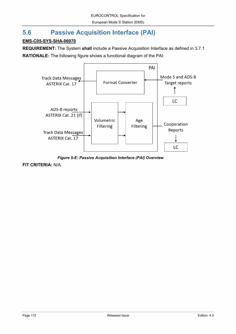
EUROCONTROL Specification for
European Mode S Station (EMS)
Page 172 Released Issue Edition: 4.0
5.6 Passive Acquisition Interface (PAI) EMS-C05-SYS-SHA-06970 REQUIREMENT: The System shall include a Passive Acquisition Interface as defined in 3.7.1 RATIONALE: The following figure shows a functional diagram of the PAI:
Figure 5-E: Passive Acquisition Interface (PAI) Overview
FIT CRITERIA: N/A.

EUROCONTROL Specification for
European Mode S Station (EMS)
Edition: 4.0 Released Issue Page 173
Interrogator System This chapter details the Interrogator requirements to be met to satisfy the provision of the Mode S ground station.
6.1 The Interrogator EMS-C06-SYS-SHA-06980 REQUIREMENT: The Interrogator system shall consist of:
(a) A transmitter, providing Sum and Control channel output; (b) A monopulse receiver, accepting Sum, Difference and Control channel input; (c) A video signal process that provides processed Sum, RSLS and OBI signals; (d) An RF changeover unit to allow the standby channel to become the active channel.
RATIONALE:
Figure 6-A: Interrogator system overview
FIT CRITERIA: N/A. EMS-C06-SYS-SHA-06990 REQUIREMENT: The Interrogator system shall have the following capabilities:
(a) Interrogation and reception on Mode S, Modes A/C and Modes A/C only all-call. Reception of ADS-B when integrated implementation;

EUROCONTROL Specification for
European Mode S Station (EMS)
Page 174 Released Issue Edition: 4.0
(b) Mode S only all-call preceding either a Mode A, or a Mode C, or a Mode A only all-call, or a Mode C only all-call interrogation by between 45 microseconds and 128 microseconds timed from the sync phase reversal to the leading edge of the P3 (Modes A/C, Modes A/C only all-call);
(c) Operation on 3 interlace programmes (i.e. single, dual, triple), including stochastic All-Call and lockout override options;
(d) Operation in azimuth selectable Improved Interrogator Sidelobe Suppression (IISLS) for Modes A/C and Modes A/C only all-call (intermode P4 short);
(e) Operation of Receiver Sidelobe Suppression (RSLS); (f) Output of data suitable for plot processing; (g) Control of all main functions of the Interrogator locally and remotely via the CMS interface; (h) Reception of interrogation modulation commands from the RTCC function.
RATIONALE: N/A. FIT CRITERIA: N/A.
EMS-C06-SYS-MAY-07000 REQUIREMENT: The Interrogator system may have the capability for interrogation and reception on Mode 1 and Mode 2. RATIONALE: N/A. FIT CRITERIA: N/A.
6.2 Transmitter 6.2.1 Pulse transmissions EMS-C06-SYS-SHA-07010 REQUIREMENT: The Transmitter shall provide:
(a) One Sum channel, including transmissions of pulses P1, P2, P3, P4 and P6 (with DPSK modulation);
(b) One Control channel, including transmissions of pulses P2 and P5. RATIONALE: N/A. FIT CRITERIA: N/A. EMS-C06-SYS-SHA-07020 REQUIREMENT: The pulse P5 shall be transmitted on the Control channel for Mode S all-call and selective interrogations. RATIONALE: Selective interrogations are not transmitted without the P5 pulse. FIT CRITERIA: N/A.

EUROCONTROL Specification for
European Mode S Station (EMS)
Edition: 4.0 Released Issue Page 175
EMS-C06-TEN-SHA-07030 REQUIREMENT: A detailed description of the Interrogator transmitter with block diagram and specification shall be provided in the proposal. RATIONALE: N/A. FIT CRITERIA: N/A. EMS-C06-SYS-SHA-07040 REQUIREMENT: The Transmitter shall not require any adjustment or setting up following replacement of any unit. RATIONALE: N/A. FIT CRITERIA: N/A.
EMS-C06-SYS-SHA-07050 REQUIREMENT: The Transmitter shall not require any regular or preventative maintenance of any unit. RATIONALE: N/A. FIT CRITERIA: N/A. EMS-C06-SYS-SHA-07060 REQUIREMENT: The Transmitter shall be capable of operating with a duty cycle supporting all the interrogation modes (3.1) for the defined targets load (2.6.8) and system expansion (2.6.10) requirements. RATIONALE: The duty cycle considers the IRF and MIPs requirements (3.2) and the re-interrogation limits (3.3.3) as well as the general operation requirements of ANNEX A. FIT CRITERIA: N/A. EMS-C06-TEN-SHA-07070 REQUIREMENT: The Tenderer shall include in their proposal information on the Mode S duty cycle capability, including Mode S modes of operation, intermode interlace, power and range performance and transmitter modularity. RATIONALE: N/A. FIT CRITERIA: N/A. EMS-C06-SYS-SHA-07080 REQUIREMENT: A mechanism limiting the number of interrogations shall protect the Transmitter against overloads and guarantee that the requirements of maximum interrogation rates specified in 3.1, 3.3.3 and [RD 1] are not exceeded. RATIONALE: N/A. FIT CRITERIA: N/A.

EUROCONTROL Specification for
European Mode S Station (EMS)
Page 176 Released Issue Edition: 4.0
EMS-C06-SYS-SHA-07090 REQUIREMENT: If the limits are exceeded then the surveillance interrogations shall have priority. RATIONALE: N/A. FIT CRITERIA: N/A.
EMS-C06-TEN-SHA-07100 REQUIREMENT: The Tenderer shall provide in their proposal details of the protection of the Transmitter. RATIONALE: N/A. FIT CRITERIA: N/A. EMS-C06-SYS-SHA-07110 REQUIREMENT: IISLS shall be available for interrogations by transmitting both pulses P1 and P2 on the Control channel. RATIONALE: N/A. FIT CRITERIA: N/A.
EMS-C06-SYS-SHA-07120 REQUIREMENT: When IISLS is enabled it shall be possible to manually adjust the power of pulse P1 on the Control channel in steps of 1.4° for the azimuth and in steps of 2 dB for the power, till the decrease does not exceed the level of 6 dB below the power of pulse P2. RATIONALE: N/A. FIT CRITERIA: N/A.
EMS-C06-TEN-SHA-07130 REQUIREMENT: The Tenderer shall provide in their proposal information on IISLS to clearly show its method of implementation and performance, including the radar range over which it is available, effects on transmitted powers, detection and false targets, particularly in a congested Mode S/SSR environment. RATIONALE: N/A. FIT CRITERIA: N/A.
6.2.2 Power levels EMS-C06-SYS-SHA-07140 REQUIREMENT: The Sum and Control channels shall allow an independent output power variation below the peak power through steps no greater than 2.0 dB, with a step accuracy better or equal to ±1.0 dB and reaching a minimum output power of 12 dB below peak power. RATIONALE: The output power levels are configured independently for the Sum and Control channels. FIT CRITERIA: N/A.

EUROCONTROL Specification for
European Mode S Station (EMS)
Edition: 4.0 Released Issue Page 177
EMS-C06-TEN-SHA-07150 REQUIREMENT: The Tenderer shall state in their proposal the minimum independent power variation between the Sum and the Control pulses, the incremental steps and the accuracy of the incremental steps. RATIONALE: N/A. FIT CRITERIA: N/A.
6.2.2.1 Range control EMS-C06-SYS-SHA-07160 REQUIREMENT: It shall be possible to vary the Sum and Control output power, on each selective interrogation, according to the range of the target. RATIONALE: N/A. FIT CRITERIA: N/A.
EMS-C06-SYS-SHA-07170 REQUIREMENT: The System shall have site-dependant parameters to define range intervals and the power output level applied for the selective interrogations when a target is within the intervals. RATIONALE: When the System includes the power variation with the target elevation, the range intervals are calculated considering the power output while the antenna is providing its maximum gain. FIT CRITERIA: N/A.
EMS-C06-TEN-SHA-07180 REQUIREMENT: The Tenderer shall submit uplink power budget calculations to support the determination of the power level assigned per range interval for the selective interrogations. RATIONALE: The calculations include the description of the Propagation Model used and all the consideration applied, e.g. fade margins. FIT CRITERIA: N/A.
EMS-C06-TEN-SHA-07190 REQUIREMENT: The Tenderer shall describe the method of achieving power variation with range. RATIONALE: N/A. FIT CRITERIA: N/A.
EMS-C06-SYS-MAY-07200 REQUIREMENT: The System may be able to increase automatically the output power level for selective interrogations, up to the limit of the transmitter peak power, when the elevation of the targets is different than the elevation that provides the maximum antenna gain. RATIONALE: The increase of the power is done automatically after comparing the target elevation with the antenna gain diagram and the antenna tilt stored in the site-dependant parameters.

EUROCONTROL Specification for
European Mode S Station (EMS)
Page 178 Released Issue Edition: 4.0
FIT CRITERIA: N/A.
EMS-C06-SYS-SHA-07210 REQUIREMENT: When the power level variation by elevation is included, the System shall provide site-dependant parameters to define the antenna gain depending on the elevation. RATIONALE: N/A. FIT CRITERIA: N/A.
EMS-C06-TEN-SHA-07220 REQUIREMENT: When the power level variation by elevation is proposed, the Tenderer shall describe how the vertical antenna gain will be characterize in the site-dependant parameters. RATIONALE: N/A. FIT CRITERIA: N/A. EMS-C06-SYS-SHA-07230 REQUIREMENT: When the power level variation by elevation is included, the System shall provide a site-dependant parameter to define tilt of the antenna. RATIONALE: The tilt of the antenna shifts in elevation the antenna gain values. FIT CRITERIA: N/A. EMS-C06-TEN-SHA-07240 REQUIREMENT: When the power level variation by elevation is offered, the Tenderer shall describe the method of achieving power variation with range and elevation. RATIONALE: N/A. FIT CRITERIA: N/A.
6.2.2.2 Azimuth control EMS-C06-SYS-SHA-07250 REQUIREMENT: The System shall provide site-dependant parameters to configure independently, as a function of azimuth, the output power level for the Sum and Control channels when transmitting Mode S all-call, Mode A/C and Mode A/C only all-call interrogations. RATIONALE: N/A. FIT CRITERIA: N/A.
EMS-C06-SYS-SHA-07260 REQUIREMENT: The configurable output power level for the Sum and Control channels shall allow to configure at least 32 azimuth intervals, with steps no larger than 1º, over 360°. RATIONALE: N/A. FIT CRITERIA: N/A.
EUROCONTROL Specification for
European Mode S Station (EMS)
Edition: 4.0 Released Issue Page 179
EMS-C06-SYS-SHA-07270 REQUIREMENT: The System shall provide site-dependant parameters to configure, as a function of azimuth, blanking sectors where there will not be output power level, i.e. RF radiation is disabled. RATIONALE: The blanking sectors applies to the Sum and Control channels and to all type of interrogations: Mode S all-call and selective, Mode A/C and Mode A/C only all-call. FIT CRITERIA: N/A.
EMS-C06-SYS-SHA-07280 REQUIREMENT: The configurable blanking sectors shall allow to configure at least 32 azimuth intervals, with steps no larger than 1º, over 360°. RATIONALE: N/A. FIT CRITERIA: N/A.
EMS-C06-TEN-SHA-07290 REQUIREMENT: The Tenderer shall describe the resolution (steps) of the azimuth sectors to configure the output power levels and the blanking sectors. RATIONALE: N/A. FIT CRITERIA: N/A.
EMS-C06-TEN-SHA-07300 REQUIREMENT: The Tenderer shall describe the method of achieving power variation with azimuth. RATIONALE: N/A. FIT CRITERIA: N/A.
6.3 Receiver EMS-C06-SYS-SHA-07310 REQUIREMENT: The Receiver shall provide:
(a) Sum, Difference and Control channels; (b) Outputs to the receiver video process utilising data from the Sum, Difference and Control
channels. RATIONALE: N/A. FIT CRITERIA: N/A.
EMS-C06-TEN-SHA-07320 REQUIREMENT: The Tenderer shall provide a detailed description of the Receivers with block diagrams and specification in their proposal. RATIONALE: N/A. FIT CRITERIA: N/A.
EUROCONTROL Specification for
European Mode S Station (EMS)
Page 180 Released Issue Edition: 4.0
EMS-C06-SYS-SHA-07330 REQUIREMENT: The Receiver shall perform the following functions:
(a) RF filtering; (b) RF amplification, if necessary; (c) IF conversion, IF filtering and logarithmic IF amplification, if necessary.
RATIONALE: Some functions listed above are not necessary for receivers and video processing subsystems working directly at 1 090 MHz without the need of IF signals. FIT CRITERIA: N/A.
6.3.1 Interference EMS-C06-SYS-SHA-07340 REQUIREMENT: The Receiver and the System Management Function shall both withstand and recover, with minimum delay, from the effects of CW interference. RATIONALE: N/A. FIT CRITERIA: N/A. EMS-C06-SYS-SHA-07350 REQUIREMENT: The receiver shall be capable of operating, without saturation or overload any part of the System, in the presence of CW interference over the range 1 080 MHz to 1 100 MHz with a power from -95 dBm to -20 dBm. RATIONALE: The operation without saturation or overload do not imply that replies received during a CW interference will be detected, decoded and processed correctly, as this will be directly related with the relative difference of power between each reply and the CW interference. FIT CRITERIA: N/A. EMS-C06-SYS-SHA-07360 REQUIREMENT: The receiver shall be capable of operating in the presence of pulsed CW interference, over the range 1 080 MHz to 1 100 MHz, formed by two overlapping pulse trains. RATIONALE: N/A. FIT CRITERIA: The two overlapping pulse trains can be characterized as:
(a) A first pulse train: Mode A reply, with a power of -40 dBm and pulses width from 0.50 to 0.55 µs;
(b) A second pulse train, a Mode S preamble, with a power of -60 dBm, pulses width from 0.50 to 0.55 µs and lagging the first pulse train with a 0.7 µs delay.
The quantised output due to the second pulse train for pulsed CW interference is expected to be present in this situation. EMS-C06-SYS-SHA-07370 REQUIREMENT: Following the removal of a CW interference, replies shall be detected, decoded and processed, 2 ms after the end of the interference.

EUROCONTROL Specification for
European Mode S Station (EMS)
Edition: 4.0 Released Issue Page 181
RATIONALE: N/A. FIT CRITERIA: N/A. EMS-C06-SYS-SHA-07380 REQUIREMENT: The System shall be able to decode a reply with a baseline CW transmitted 50 dB below the reply pulse peak power (i.e. between the pulses) and starting up to 10 µs before the first pulse and finishing up to 10 µs after the last pulse. RATIONALE: This unwanted signal can incorrectly trigger the bracket or preamble detectors or can be wrongly considered as a valid pulse. FIT CRITERIA: N/A. EMS-C06-TEN-SHA-07390 REQUIREMENT: The Tenderer shall provide information on the level and effects of interference that the System can tolerate. RATIONALE: N/A. FIT CRITERIA: N/A.
EMS-C06-TEN-SHA-07400 REQUIREMENT: The Tenderer shall state the reaction and recovery times of the interference protection. RATIONALE: N/A. FIT CRITERIA: N/A. EMS-C06-SYSTEN-SHA-07410 REQUIREMENT: The Tenderer shall state the protection modes accommodated and specify the level of protection from both ground and airborne IFF/SSR frequency systems that will be achieved. RATIONALE: N/A. FIT CRITERIA: N/A.
6.3.2 Phase overlay capability EMS-C06-SYS-SHA-07420 REQUIREMENT: The Interrogator shall have a receiver with the capability to extract 8PSK phase modulation data (phase overlay, 3.6) from Mode S replies and, when the on-site ADS-B follows an integrated implementation, also from ADS-B Extended Squitters. RATIONALE: The 8PSK modulation provides 3 additional bits from the phase state of the PPM pulses and the four preamble pulses of long Mode S replies ([RD 11]) and ADS-B Extended Squitters ([RD 15]). When the on-site ADS-B follows an independent implementation, all requirements from this section will be as well applicable for the independent ADS-B system as indicated in 3.5.1. FIT CRITERIA: N/A.

EUROCONTROL Specification for
European Mode S Station (EMS)
Page 182 Released Issue Edition: 4.0
EMS-C06-SYS-SHA-07430 REQUIREMENT: The receiver shall be able to decode 8PSK phase modulated data from signals transmitted at 1 090 MHz ± 25 KHz. RATIONALE: Frequency offset requirement as indicated in [RD 11] and [RD 15]. FIT CRITERIA: N/A. EMS-C06-SYS-SHA-07440 REQUIREMENT: The receiver shall determine the zero degree phase reference using the preamble pulses as well as the first 4 bits of the reply. RATIONALE: Phase reference requirement as indicated in [RD 11] and [RD 15]. FIT CRITERIA: N/A.
EMS-C06-SYS-SHA-07450 REQUIREMENT: The receiver shall be able to decode 8PSK phase modulated data from signals transmitted with a maximum of ± 43º phase drift during a message. RATIONALE: Phase drift requirement as indicated in [RD 11] and [RD 15]. FIT CRITERIA: N/A. EMS-C06-SYS-SHA-07460 REQUIREMENT: The receiver shall be able to decode 8PSK phase modulated data from signals transmitted with a phase error that is not more than 3.0º RMS and 12.2º peak for the duration of any 0.5 µs PPM reply pulse, excluding the leading and trailing edges of the pulse. RATIONALE: Phase error tolerance requirement as indicated in [RD 11] and [RD 15]. FIT CRITERIA: N/A. EMS-C06-SYS-SHA-07470 REQUIREMENT: The receiver shall be able to decode 8PSK phase modulated data from signals with a phase transition interval, for a 1.0 µs pulse which is formed by a PPM ZERO data bit followed by a PPM ONE data bit, in which the phase is allowed to change between states less than the 400 ns interval commencing 200 ns prior to the PPM bit interval transition at the centre of the 1.0 µs pulse. RATIONALE: Phase transition interval requirement as indicated in [RD 11] and [RD 15]. FIT CRITERIA: N/A.
6.4 Video Signal Processing EMS-C06-SYS-SHA-07480 REQUIREMENT: The azimuth data, received from the azimuth data generator, shall be decoded and used to determine boresight. RATIONALE: N/A. FIT CRITERIA: N/A.
EUROCONTROL Specification for
European Mode S Station (EMS)
Edition: 4.0 Released Issue Page 183
EMS-C06-SYS-SHA-07490 REQUIREMENT: Processed Sum Video, RSLS and Off Boresight Indication (OBI) signals shall be provided to the RTCC function. RATIONALE: N/A. FIT CRITERIA: N/A. EMS-C06-SYS-SHA-07500 REQUIREMENT: SSR and Mode S all-call Processed Sum video, together with OBI, shall be provided for monitoring in the Local Display and the Data Recorder. RATIONALE: N/A. FIT CRITERIA: N/A.
EMS-C06-SYS-SHA-07510 REQUIREMENT: The detected pulse output, following pulse detection and quantisation, shall accurately reflect the received pulse. RATIONALE: The Tenderer is referred to the definition for quantised video for monopulse systems in [RD 7]. FIT CRITERIA: N/A.
EMS-C06-SYS-SHA-07520 REQUIREMENT: Sensitivity Time Control (STC), or an equivalent threshold method, shall be provided and selectable between pre-programmed logarithmic options or programmable thresholds. RATIONALE: N/A. FIT CRITERIA: N/A. EMS-C06-SYS-SHA-07530 REQUIREMENT: The System shall provide several STC thresholds pre-programmed. RATIONALE: N/A. FIT CRITERIA: N/A. EMS-C06-SYS-SHA-07540 REQUIREMENT: The System shall provide independent STC thresholds for Mode A/C and Mode S replies. RATIONALE: N/A. FIT CRITERIA: N/A. EMS-C06-SYS-SHA-07550 REQUIREMENT: The programmable STC thresholds shall allow configuration through the CMS. RATIONALE: N/A.

EUROCONTROL Specification for
European Mode S Station (EMS)
Page 184 Released Issue Edition: 4.0
FIT CRITERIA: N/A.
EMS-C06-SYS-SHA-07560 REQUIREMENT: The STC thresholds configuration shall allow to start from a pre-programmed STC threshold and apply a constant offset and/or a change for specific range intervals. RATIONALE: An offset can be either an increase or a decrease of the threshold value. FIT CRITERIA: N/A.
EMS-C06-SYS-SHA-07570 REQUIREMENT: The STC thresholds shall be stored with an exportable readable format. RATIONALE: Graphical representation is expected to be possible in a spreadsheet after the exportation. FIT CRITERIA: N/A. EMS-C06-SYS-SHA-07580 REQUIREMENT: The System shall be able to create azimuth intervals, with steps no larger than 1º, where to apply different STC thresholds. RATIONALE: N/A. FIT CRITERIA: N/A. EMS-C06-TEN-SHA-07590 REQUIREMENT: The Tenderer shall detail how the STC thresholds will be configured and which resolution will be applied for the azimuth intervals. RATIONALE: N/A. FIT CRITERIA: N/A. EMS-C06-TEN-SHA-07600 REQUIREMENT: The Tenderer shall clearly explain the technique used and the effects on the performance of Sensitivity Time Control (STC) and any other threshold in the System (e.g. short pulse elimination and received signal strength), specifically stating the STC levels assumed. RATIONALE: N/A. FIT CRITERIA: N/A. EMS-C06-SYS-SHA-07610 REQUIREMENT: The Off-Boresight Angle (OBA) look up table shall be site-dependent. RATIONALE: N/A. FIT CRITERIA: N/A.

EUROCONTROL Specification for
European Mode S Station (EMS)
Edition: 4.0 Released Issue Page 185
EMS-C06-SYS-SHA-07620 REQUIREMENT: The System shall provide a function to recalibrate the OBA look up table with opportunity traffic. RATIONALE: N/A. FIT CRITERIA: N/A. EMS-C06-TEN-SHA-07630 REQUIREMENT: The Tenderer shall provide detailed information about how and when the OBA look up table is recalibrated. RATIONALE: N/A. FIT CRITERIA: N/A.
EMS-C06-SYS-SHA-07640 REQUIREMENT: The Off-Boresight Angle (OBA) precision shall be within 1 AU (i.e. 0.022°). RATIONALE: 1 AU represents 360º / 16 384, being 16 384 the number of pulses of a 14 bit azimuth data generator. FIT CRITERIA: N/A. EMS-C06-SYS-SHA-07650 REQUIREMENT: The OBA look up table shall be displayed numerically and graphically in the CMS. RATIONALE: N/A. FIT CRITERIA: N/A. EMS-C06-SYS-SHA-07660 REQUIREMENT: Monopulse data from received pulses shall be accumulated and checked for long term consistency against the conversion facility, so as to detect any change or drift in the system monopulse azimuth accuracy. RATIONALE: N/A. FIT CRITERIA: N/A. EMS-C06-TEN-SHA-07670 REQUIREMENT: The Tenderers proposal shall include details of any on-line monitoring of monopulse accuracy. RATIONALE: N/A. FIT CRITERIA: N/A. EMS-C06-TEN-SHA-07680 REQUIREMENT: The Tenderer shall provide in their proposals details of the receiver channel amplitude and phase response matching requirements of the system offered stating the required tolerances to be maintained in the matching of the channels.

EUROCONTROL Specification for
European Mode S Station (EMS)
Page 186 Released Issue Edition: 4.0
RATIONALE: Systems that automatically compensate for any mismatch of channels are preferred. FIT CRITERIA: N/A.
6.5 RF Changeover Unit EMS-C06-SYS-SHA-07690 REQUIREMENT: The RF Changeover Unit shall enable the Interrogator channel in operation to be connected to the antenna and the Interrogator channel in Standby to be connected to a dummy load. RATIONALE: N/A. FIT CRITERIA: N/A.
EMS-C06-SYS-SHA-07700 REQUIREMENT: During changeover, the System shall provide uninterrupted operation without any corruption to the Surveillance Data output. RATIONALE: An example of how this could be achieved is to enable the received signal to be fed to both channels of the dual system, i.e. the standby receiver and processor subsystems are fed with the same receive signals as the main in service receiver. For the purpose of this paragraph, “uninterrupted service” is assumed to neglect the finite switching time (< 100 ms). FIT CRITERIA: N/A.
EMS-C06-SYS-SHA-07710 REQUIREMENT: The RF Changeover Unit shall only be powered by low voltage DC supplies, derived from both channels of the System. RATIONALE: N/A. FIT CRITERIA: N/A. EMS-C06-SYS-SHA-07720 REQUIREMENT: The interruption of transmissions to the antenna when changing over interrogation channels shall meet the requirements of 8.2.1. RATIONALE: N/A. FIT CRITERIA: N/A.
EMS-C06-SYS-SHA-07730 REQUIREMENT: The RF Changeover Unit shall retain its selected state in the absence of control signals and power supplies. RATIONALE: This will ensure that in the event the equipment is switched off, and there is no further controlling or switching action, the same channels will be connected to the antenna or dummy load when power is returned. FIT CRITERIA: N/A.

EUROCONTROL Specification for
European Mode S Station (EMS)
Edition: 4.0 Released Issue Page 187
EMS-C06-SYS-SHA-07740 REQUIREMENT: An indication, to determine which is the active channel, shall be provided locally. RATIONALE: The objective is to verify that the channel selected for output is the one connected to the antenna. FIT CRITERIA: N/A. EMS-C06-SYS-SHA-07750 REQUIREMENT: A monitoring of the RF Changeover selection shall be available in the local and remote CMS. RATIONALE: N/A. FIT CRITERIA: N/A.
EMS-C06-SYS-SHA-07760 REQUIREMENT: The equipment shall be of passive design and require no routine maintenance. RATIONALE: N/A. FIT CRITERIA: N/A.
EMS-C06-SYS-SHA-07770 REQUIREMENT: The design shall include a bi-directional high power precision coupler in each of the Sum, Difference and Control channels to facilitate RF injection and measurement of downlink polar diagrams. RATIONALE: Bi-directional high power precision couplers of 20 dB are preferred. FIT CRITERIA: N/A.
EMS-C06-TEN-SHA-07780 REQUIREMENT: The Tenderer shall state the Insertion Loss of the bi-directional coupler for Transmit and Receive frequencies. RATIONALE: N/A. FIT CRITERIA: N/A. EMS-C06-TEN-SHA-07790 REQUIREMENT: The Tenderer shall state the VSWR and Phase shift between Sum and Difference channels RATIONALE: N/A. FIT CRITERIA: N/A. EMS-C06-SYS-SHA-07800 REQUIREMENT: The isolation between ports and channels shall be:
(a) > 40 dB between channel 1 and channel 2 ports;
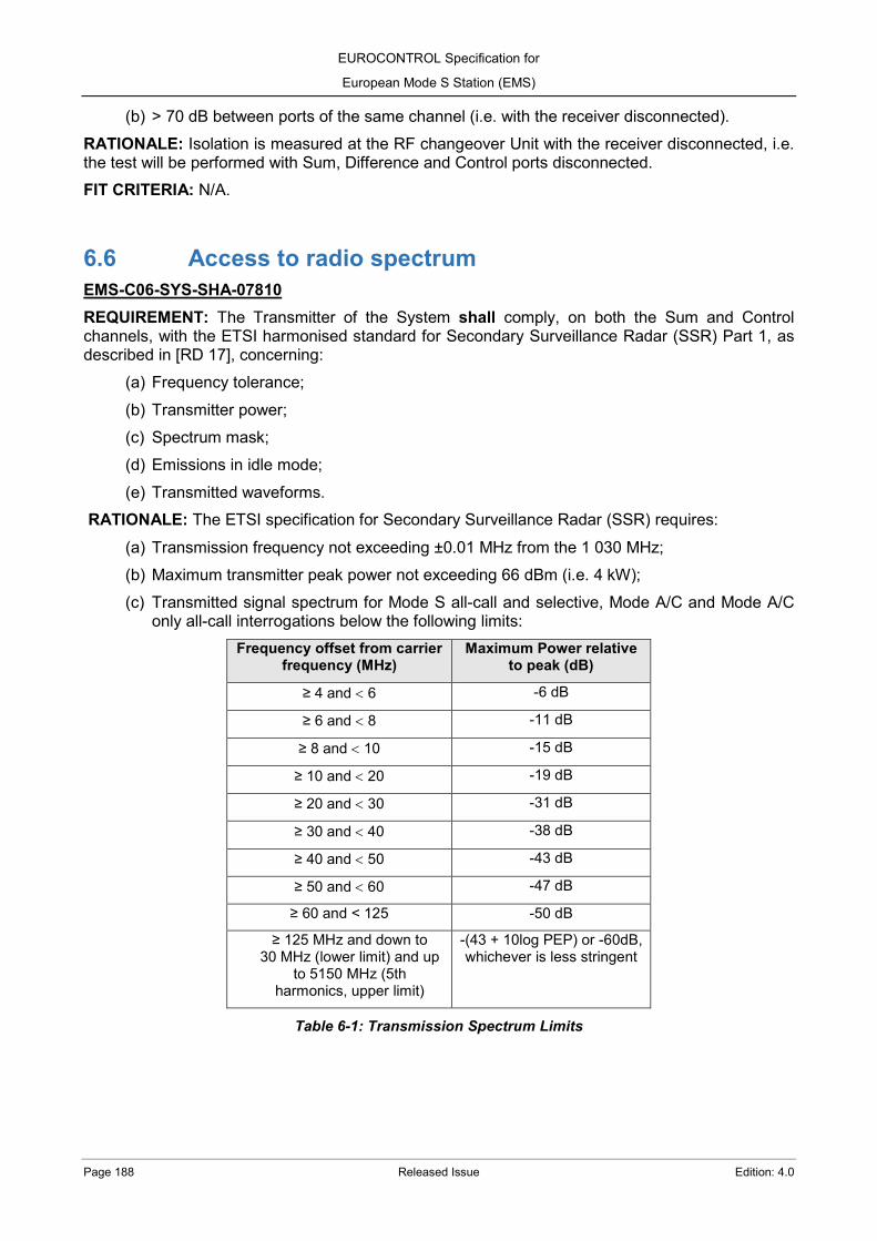
EUROCONTROL Specification for
European Mode S Station (EMS)
Page 188 Released Issue Edition: 4.0
(b) > 70 dB between ports of the same channel (i.e. with the receiver disconnected). RATIONALE: Isolation is measured at the RF changeover Unit with the receiver disconnected, i.e. the test will be performed with Sum, Difference and Control ports disconnected. FIT CRITERIA: N/A.
6.6 Access to radio spectrum EMS-C06-SYS-SHA-07810 REQUIREMENT: The Transmitter of the System shall comply, on both the Sum and Control channels, with the ETSI harmonised standard for Secondary Surveillance Radar (SSR) Part 1, as described in [RD 17], concerning:
(a) Frequency tolerance; (b) Transmitter power; (c) Spectrum mask; (d) Emissions in idle mode; (e) Transmitted waveforms.
RATIONALE: The ETSI specification for Secondary Surveillance Radar (SSR) requires:
(a) Transmission frequency not exceeding ±0.01 MHz from the 1 030 MHz; (b) Maximum transmitter peak power not exceeding 66 dBm (i.e. 4 kW); (c) Transmitted signal spectrum for Mode S all-call and selective, Mode A/C and Mode A/C
only all-call interrogations below the following limits: Frequency offset from carrier
frequency (MHz) Maximum Power relative
to peak (dB)
≥ 4 and < 6 -6 dB
≥ 6 and < 8 -11 dB
≥ 8 and < 10 -15 dB
≥ 10 and < 20 -19 dB
≥ 20 and < 30 -31 dB
≥ 30 and < 40 -38 dB
≥ 40 and < 50 -43 dB
≥ 50 and < 60 -47 dB
≥ 60 and < 125 -50 dB
≥ 125 MHz and down to 30 MHz (lower limit) and up
to 5150 MHz (5th harmonics, upper limit)
-(43 + 10log PEP) or -60dB, whichever is less stringent
Table 6-1: Transmission Spectrum Limits

EUROCONTROL Specification for
European Mode S Station (EMS)
Edition: 4.0 Released Issue Page 189
Figure 6-B: Interrogator transmitter spectrum mask
(d) Emissions in idle mode below the following limits: Frequency band Peak power Limit
30 MHz ≤ f ≤ 1 GHz -57 dBm
1 GHz < f ≤ 5150 MHz -47 dBm
Table 6-2: Emissions in idle mode limits
(e) Transmitted waveforms with the following characteristics:
Pulse Pulse length Duration (µs)
Rise Time (µs) Decay Time (µs)
Min. Max. Min. Max. Min. Max. P1, P2, P3, P5 0.71 0.89 0.05 0.1 0.05 0.2
P4 (short) 0.71 0.89 0.05 0.1 0.05 0.2
P6 (short) 16.05 16.45 0.05 0.1 0.05 0.2
Phase reversal - 0.08 - - - -
Table 6-3: Transmission pulses shape
Pulses Mode Pulse spacing (µs)
Min. Max. P2 to P1 delay Mode A/C 1.9 2.1
P2 to P1 delay Mode S 1.96 2.04
P3 to P1 delay Mode A 7.82 8.18
P3 to P1 delay Mode C 20.82 21.18
P4 to P3 delay Mode A/C only all-call 1.96 2.04
P5 to sync. phase Reversal delay
Mode-S 0.35 0.45
Carrier fre
quency
0 dB
-6 dB
-11 dB
-15 dB
-50 dB
-19 dB
-31 dB
-38 dB
-43 dB
-47 dB
-60 dB
20 MHz
30 MHz
50 MHz
40 MHz
60 MHz
125 MHz4
MHz
4 M
Hz
6 M
Hz
6 M
Hz
8 M
Hz
8 M
Hz
10 M
Hz
10 M
Hz
20 MHz
30 MHz
50 MHz
40 MHz
60 MHz
125 MHz

EUROCONTROL Specification for
European Mode S Station (EMS)
Page 190 Released Issue Edition: 4.0
P6 to sync. phase Reversal delay
Mode-S 1.21 1.29
Table 6-4: Transmission pulses spacing
FIT CRITERIA: [RD 17] provide test procedures for compliance. EMS-C06-SYS-SHO-07820 REQUIREMENT: The Receiver and Video Processing of the System should comply, on both the Sum and Control channels, with the ETSI harmonised standard for Secondary Surveillance Radar (SSR) Part 1, as described in [RD 17], concerning:
(a) Sensitivity and flatness; (b) Saturation level and flatness; (c) Dynamic range; (d) Signal blocking; (e) Selectivity; (f) Inter-modulation response rejection; (g) Co-channel rejection; (h) Noise Figure.
RATIONALE: The ETSI specification for Secondary Surveillance Radar (SSR) requires: (a) Sensitivity: Better than -85 dBm for decoding 90% of Mode A/C, Mode A/C only all-call and
Mode S replies, with a degradation by not more than 1 dB for incoming signals with frequency offset up to 1 MHz;
(b) Saturation level: Not less than -15 dBm for Mode A/C, Mode A/C only all-call and Mode S replies, with a variation by not more than 1 dB for incoming signals with frequency offset up to 1 MHz;
(c) Dynamic range: Not less than 70 dB; (d) Blocking: The rate of correctly received and decoded wanted Mode A/C and Mode S replies
is not reduced by more than 5% in presence of the following unwanted signals: Frequency Level (dB)
-78 MHz to -15 MHz relative to 1 090 MHz
20 dB above the level of a wanted signal within the dynamic range, for any interrogation mode
+15 MHz to +78 MHz relative to 1 090 MHz
20 dB above the level of a wanted signal within the dynamic range, for any interrogation mode
Table 6-5: Receiver Blocking Limits
(e) Selectivity: Rejection of replies such that the reply level of a valid message is increased by at least the value given for the following table before the reply is received and decoded with a probability of 90%;
Frequency Minimum Rejection Level
± 5.5 MHz 3 dB
± 10 MHz 20 dB
± 15 MHz 40 dB
± 25 MHz 60 dB

EUROCONTROL Specification for
European Mode S Station (EMS)
Edition: 4.0 Released Issue Page 191
Table 6-6: Receiver Selectivity Limits
(f) Inter-modulation rejection: Unwanted replies between [-78,-20] MHz and [20, 78] MHz from the receiver carrier (1 090 MHz) do not reduce the probability of detection by more than 5% if the replies level are 40 dB above the reference sensitivity;
(g) Co-channel rejection: Unwanted replies, with a level of at least 12 dB below the level of the wanted replies and with the same type of waveform, do not reduce the rate of correctly received and decoded wanted replies by more than 5%;
(h) Figure of Noise: Better than 5 dB. FIT CRITERIA: [RD 17] provide test procedures for compliance.
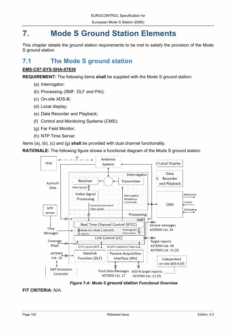
EUROCONTROL Specification for
European Mode S Station (EMS)
Page 192 Released Issue Edition: 4.0
Mode S Ground Station Elements This chapter details the ground station requirements to be met to satisfy the provision of the Mode S ground station.
7.1 The Mode S ground station EMS-C07-SYS-SHA-07830 REQUIREMENT: The following items shall be supplied with the Mode S ground station:
(a) Interrogator; (b) Processing (SMF, DLF and PAI); (c) On-site ADS-B; (d) Local display; (e) Data Recorder and Playback; (f) Control and Monitoring Systems (CMS); (g) Far Field Monitor; (h) NTP Time Server.
Items (a), (b), (c) and (g) shall be provided with dual channel functionality. RATIONALE: The following figure shows a functional diagram of the Mode S ground station:
Figure 7-A: Mode S ground station Functional Overview
FIT CRITERIA: N/A.

EUROCONTROL Specification for
European Mode S Station (EMS)
Edition: 4.0 Released Issue Page 193
EMS-C07-TEN-SHO-07840 REQUIREMENT: The Tenderer should advise where an alternative approach to dual functionality can be more appropriate. RATIONALE: N/A. FIT CRITERIA: N/A. EMS-C07-SYS-MAY-07850 REQUIREMENT: The following items may be supplied with the Mode S ground station:
(a) LVA antenna; (b) Antenna turning gear system with azimuth signals; (c) ADS-B additional antenna(s); (d) Tower with appropriated height (e.g. 20 m); (e) Radome; (f) Obstruction lights; (g) Lightning protection; (h) Air Conditioning Unit; (i) Shelter.
RATIONALE: N/A. FIT CRITERIA: N/A. EMS-C07-SYS-SHA-07860 REQUIREMENT: The System shall provide the necessary interface functionality to support the Mode S ground station to be collocated with a primary surveillance radar. RATIONALE: "Collocated" includes both co-mounted and off-mounted configurations. FIT CRITERIA: N/A. EMS-C07-TEN-SHA-07870 REQUIREMENT: The Tenderer shall provide in their response power consumption figures for the complete Mode S ground station. RATIONALE: When optional elements that can alter significantly the consumption are offered, e.g. turning gear, the power consumption figures of these optional elements are indicated separately. FIT CRITERIA: N/A.
7.2 Antenna EMS-C07-TEN-MAY-07880 REQUIREMENT: The Tenderer may propose a Large Vertical Aperture (LVA) antenna, suitable for SSR and Mode S and providing monopulse sum and difference channels with an additional omnidirectional control channel, which enables the requirements of this specification to be met in all respects.
EUROCONTROL Specification for
European Mode S Station (EMS)
Page 194 Released Issue Edition: 4.0
RATIONALE: N/A. FIT CRITERIA: N/A. EMS-C07-TEN-MAY-07890 REQUIREMENT: The Tenderer may propose one or more additional ADS-B antennas which enable the requirements of this specification to be met in all respects. RATIONALE: Omnidirectional or directional antenna(s) can be offered to improve the ADS-B coverage. FIT CRITERIA: N/A. EMS-C07-TEN-SHA-07900 REQUIREMENT: When proposed as part of the System, the Tenderer shall provide details in their response of the antenna(s) characteristics, with guaranteed parameter limits, and supported with measured antenna vertical and polar diagrams. As a minimum the following information is supplied by the Tenderer in their response:
(a) Sum vertical radiation pattern (field strengths, -3 dB beamwidth, sidelobes, underside roll off rate, etc.);
(b) Sum horizontal radiation pattern (peak forward gain, beamwidth at -3 dB, -10 dB and -20 dB, symmetry/alignment of sum peak and beamwidth over elevation, sidelobes, etc.);
(c) Control radiation pattern (coverage of sum sidelobes and sum cone of silence, crossover points, notch/minimum, symmetry/alignment over elevation, etc.);
(d) Difference radiation pattern (crossover points, peak gain, difference null, symmetry/alignment over elevation, etc.);
(e) Fully dimensioned drawings; (f) Earthing connection; (g) Safety (maintenance personnel, lightning strike protection); (h) Mechanical requirements (dismantling/reassembly of columns, transportation, lifting); (i) Environmental protection; (j) Maximum operational wind speeds and ice depth such that the antenna can function within
the performance described in chapter 2; (k) Maintenance requirements and lifetime of the array.
RATIONALE: N/A. FIT CRITERIA: N/A. EMS-C07-TEN-SHA-07910 REQUIREMENT: When proposed as part of the System, the Tenderer shall detail where the proposed antenna will not capacitate the System to meet the requirements of this specification in all respects. RATIONALE: Special attention is taken for performance (chapter 2) and Interrogator (chapter 6) requirements. FIT CRITERIA: N/A.

EUROCONTROL Specification for
European Mode S Station (EMS)
Edition: 4.0 Released Issue Page 195
EMS-C07-CON-SHA-07920 REQUIREMENT: When included as a part of the System, the Contractor shall deliver, as a part of the Maintenance documentation, the technical characteristics and commercial references for the products needed for each antenna maintenance (e.g. paintwork material, columns radome reparation, etc.). RATIONALE: N/A. FIT CRITERIA: N/A. EMS-C07-CON-SHA-07930 REQUIREMENT: When included as a part of the System, the specialized tools and material necessary for each antenna maintenance and tilt adjustment shall be provided. RATIONALE: N/A. FIT CRITERIA: N/A.
EMS-C07-SYS-SHA-07940 REQUIREMENT: When included as a part of the System, the LVA antenna shall guarantee a correct transmitted power relation between the omnidirectional (control) and the sum patterns above an elevation of 45º (Cone of Silence) to apply correctly the Side Lobe Suppression functionality. RATIONALE: The Side Lobe Suppression functionality is applied anywhere within the Cone of Silence. FIT CRITERIA: N/A. EMS-C07-CON-SHA-07950 REQUIREMENT: When included as a part of the System and prior to acceptance and delivery of each antenna, the Contractor shall provide measured vertical and horizontal radiation patterns for the antenna(s) supplied, according to an agreed test procedure. RATIONALE: N/A. FIT CRITERIA: N/A.
7.3 Turning gear and azimuth data generator EMS-C07-TEN-MAY-07960 REQUIREMENT: The Tenderer may propose in their response a turning gear and azimuth data generator equipment for the Mode S ground station that enables the requirements of this specification to be met in all respects. RATIONALE:
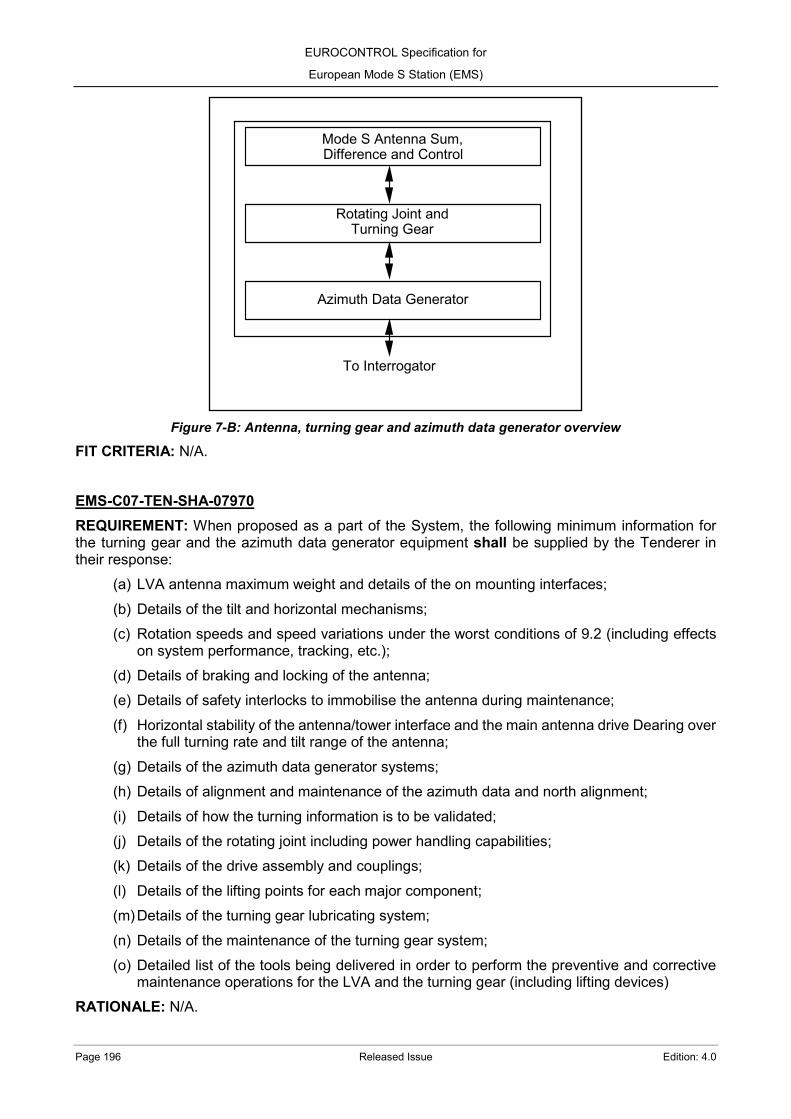
EUROCONTROL Specification for
European Mode S Station (EMS)
Page 196 Released Issue Edition: 4.0
Figure 7-B: Antenna, turning gear and azimuth data generator overview
FIT CRITERIA: N/A. EMS-C07-TEN-SHA-07970 REQUIREMENT: When proposed as a part of the System, the following minimum information for the turning gear and the azimuth data generator equipment shall be supplied by the Tenderer in their response:
(a) LVA antenna maximum weight and details of the on mounting interfaces; (b) Details of the tilt and horizontal mechanisms; (c) Rotation speeds and speed variations under the worst conditions of 9.2 (including effects
on system performance, tracking, etc.); (d) Details of braking and locking of the antenna; (e) Details of safety interlocks to immobilise the antenna during maintenance; (f) Horizontal stability of the antenna/tower interface and the main antenna drive Dearing over
the full turning rate and tilt range of the antenna; (g) Details of the azimuth data generator systems; (h) Details of alignment and maintenance of the azimuth data and north alignment; (i) Details of how the turning information is to be validated; (j) Details of the rotating joint including power handling capabilities; (k) Details of the drive assembly and couplings; (l) Details of the lifting points for each major component; (m) Details of the turning gear lubricating system; (n) Details of the maintenance of the turning gear system; (o) Detailed list of the tools being delivered in order to perform the preventive and corrective
maintenance operations for the LVA and the turning gear (including lifting devices) RATIONALE: N/A.
Mode S Antenna Sum, Difference and Control
Rotating Joint and Turning Gear
Azimuth Data Generator
To Interrogator

EUROCONTROL Specification for
European Mode S Station (EMS)
Edition: 4.0 Released Issue Page 197
FIT CRITERIA: N/A.
EMS-C07-TEN-SHA-07980 REQUIREMENT: When proposed as a part of the System, the Tenderer shall detail in their response where their proposed turning gear and azimuth data generator will not capacitate the System to meet the requirements of this specification in all respects. RATIONALE: N/A. FIT CRITERIA: N/A. EMS-C07-CON-SHA-07990 REQUIREMENT: When included as a part of the System, the Contractor shall deliver, as a part of the Maintenance documentation, the technical characteristics and commercial references for the products needed for the maintenance of the turning gear and the azimuth data generator (e.g. greasing, paintwork, etc.). RATIONALE: N/A. FIT CRITERIA: N/A.
EMS-C07-CON-SHA-08000 REQUIREMENT: When included as a part of the System, the specialized tools and material necessary for the turning gear and the azimuth data generator maintenance shall be provided. RATIONALE: N/A. FIT CRITERIA: N/A. EMS-C07-SYS-SHA-08010 REQUIREMENT: When included as a part of the System, the turning gear and associated components, i.e. rotating joint, slip ring assemblies, etc. shall be based on proven equipment of established mechanical accuracy and reliability. RATIONALE: N/A. FIT CRITERIA: N/A. EMS-C07-TEN-SHA-08020 REQUIREMENT: When proposed as a part of the System, the Tenderer shall provide detailed information on the turning gear and the associated electronics for any possibility of motors configuration (e.g. 1 motor drive, 2 motor drives, etc.). RATIONALE: N/A. FIT CRITERIA: N/A.
EMS-C07-SYS-SHO-08030 REQUIREMENT: When included as a part of the System, it is preferred that duplicated items in the turning gear should be replaced without the need to stop the antenna rotating. RATIONALE: N/A.

EUROCONTROL Specification for
European Mode S Station (EMS)
Page 198 Released Issue Edition: 4.0
FIT CRITERIA: N/A.
EMS-C07-TEN-SHA-08040 REQUIREMENT: When proposed as a part of the System, the Tenderer shall state in their response the turning gear items that require the antenna rotation to be stopped when replaced. RATIONALE: N/A. FIT CRITERIA: N/A. EMS-C07-TEN-SHA-08050 REQUIREMENT: When proposed as a part of the System, the Tenderer shall describe in detail the behaviour of the System when the turning gear speed fluctuates too much due to excessive loading (e.g. due wind conditions). In particular the Tenderer indicates the consequences of such conditions on the Surveillance Data output. RATIONALE: N/A. FIT CRITERIA: N/A. EMS-C07-SYS-SHA-08060 REQUIREMENT: When included as a part of the System, the turning gear shall incorporate a rotation preannouncement system, including visual and acoustic signals, to alert at least 30 seconds in advance that the antenna rotation will start. RATIONALE: Directive 2006/42/EC ([RD 64]) indicates that machinery must not start unexpectedly and leading to dangerous situations. The rotation preannouncement system provide means to alert operators before the antenna rotation is started. Visual and acoustic signals are generated near the antenna location with power enough to be undoubtable noticed by an operator in the antenna platform or the tower. FIT CRITERIA: N/A.
EMS-C07-TEN-SHA-08070 REQUIREMENT: When included as a part of the System, the Tenderer shall provide technical details of the visual and acoustic signals that will be used in the rotation preannouncement system of the turning gear. RATIONALE: N/A. FIT CRITERIA: N/A.
EMS-C07-SYS-SHA-08080 REQUIREMENT: When included as a part of the System, the turning gear shall incorporate safety interlocks and safety switches to stop the antenna rotation while they are activated. RATIONALE: Safety interlocks are located at least in the tower access doors and tower platform hatches to prevent that an operator can get too close to a rotating antenna. Safety switches, shaped as emergency stop push buttons, are located in critical locations to allow an emergency stop of the antenna rotation. At least one safety switch is located in the antenna platform, so one operator perceiving the rotation preannouncement can safely abort an upcoming antenna rotation.

EUROCONTROL Specification for
European Mode S Station (EMS)
Edition: 4.0 Released Issue Page 199
FIT CRITERIA: N/A.
EMS-C07-SYS-SHA-08090 REQUIREMENT: After the deactivation of a safety interlock or a safety switch, the System shall not start automatically the antenna rotation. RATIONALE: Manual intervention is required to avoid potential dangerous situations where an operator can still be in close proximity to the antenna. FIT CRITERIA: N/A. EMS-C07-TEN-SHA-08100 REQUIREMENT: When included as a part of the System, the Tenderer shall provide technical details of the safety interlocks and safety switches that will be used to interrupt the operation of the turning gear. RATIONALE: N/A. FIT CRITERIA: N/A. EMS-C07-SYS-SHA-08110 REQUIREMENT: When included as a part of the System, the azimuth data generator shall have a minimum resolution of 14 bits, i.e. 0.022º (360º/214). RATIONALE: N/A. FIT CRITERIA: N/A.
EMS-C07-TEN-SHA-08120 REQUIREMENT: When prosed as a part of the System, the Tenderer shall provide in their Tender response information on the format (e.g. electrical signals) of the azimuth data. RATIONALE: N/A. FIT CRITERIA: N/A. EMS-C07-SYS-SHA-08130 REQUIREMENT: The System shall not enable transmissions to the air (i.e. interrogations), from both Sum and Control channels, when the antenna is not rotating and the azimuth data is not received. RATIONALE: N/A. FIT CRITERIA: N/A.
7.4 Tower EMS-C07-TEN-MAY-08140 REQUIREMENT: The Tenderer may propose in their response a Tower for the Mode S ground station. RATIONALE: N/A.

EUROCONTROL Specification for
European Mode S Station (EMS)
Page 200 Released Issue Edition: 4.0
FIT CRITERIA: N/A. EMS-C07-SYS-SHA-08150 REQUIREMENT: When included as a part of the System, the Tower shall be designed to meet the operational needs of the System proposed including structural requirements at the environmental extremes and access for maintenance of all antenna elements. RATIONALE: N/A. FIT CRITERIA: N/A. EMS-C07-TEN-SHA-08160 REQUIREMENT: When proposed as a part of the System, the Tenderer shall detail the dimensions, including architectural drawings, for the proposed Tower. RATIONALE: The dimensions include at least height, base width and upper platform width details. FIT CRITERIA: N/A.
EMS-C07-SYS-SHA-08170 REQUIREMENT: When included as a part of the System, the tower torsional deflection shall not exceed 1.5 minutes of Arc. RATIONALE: Measured with the antenna installed on the tower interface and with the specified operational wind speeds (9.2). FIT CRITERIA: N/A.
EMS-C07-SYS-SHA-08180 REQUIREMENT: When included as a part of the System, the tower deflection in the vertical plane shall not exceed 2.0 minutes of Arc. RATIONALE: Measured with the antenna installed on the tower interface and with the specified operational wind speeds (9.2). FIT CRITERIA: N/A.
EMS-C07-SYS-SHA-08190 REQUIREMENT: When included as a part of the System, the tolerance for the tower horizontal level shall not to exceed +/-2 minutes of Arc through the azimuth of 360°. RATIONALE: N/A. FIT CRITERIA: N/A. EMS-C07-SYS-SHA-08200 REQUIREMENT: When included as a part of the System, the design of the tower structure shall be such that the horizontal level tolerance is not be subject to deterioration with age or, alternatively, allow for easy adjustment of the level. RATIONALE: N/A. FIT CRITERIA: N/A.

EUROCONTROL Specification for
European Mode S Station (EMS)
Edition: 4.0 Released Issue Page 201
EMS-C07-SYS-SHA-08210 REQUIREMENT: When included as a part of the System, the steelwork of the tower shall be to EN 10025 (or equivalent) [RD 79]. RATIONALE: N/A. FIT CRITERIA: N/A.
EMS-C07-SYS-SHA-08220 REQUIREMENT: When included as a part of the System, all steelwork of the tower shall be galvanised in accordance with BS EN ISO 1461 (or equivalent), [RD 80], after fabrication. RATIONALE: N/A. FIT CRITERIA: N/A. EMS-C07-SYS-SHA-08230 REQUIREMENT: When included as a part of the System, the tower shall comply with the requirements of BS EN 1991-1-4 + Amendment 1, [RD 81], for wind loads. RATIONALE: N/A. FIT CRITERIA: N/A.
EMS-C07-SYS-SHA-08240 REQUIREMENT: When included as a part of the System, the tower shall have a design life of 25 years, allowing for preventative visits every year, and a time to first maintenance of 10 years. RATIONALE: N/A. FIT CRITERIA: N/A. EMS-C07-SYS-SHA-08250 REQUIREMENT: When included as a part of the System, the tower shall have staircase access to the top inspection/working platform. RATIONALE: N/A. FIT CRITERIA: N/A. EMS-C07-SYS-SHA-08260 REQUIREMENT: When included as a part of the System, the tower staircase shall have suitable lights. RATIONALE: N/A. FIT CRITERIA: N/A.
EMS-C07-SYS-SHA-08270 REQUIREMENT: When included as a part of the System, the tower top inspection/working platform shall have all necessary handrails and toeboards.
EUROCONTROL Specification for
European Mode S Station (EMS)
Page 202 Released Issue Edition: 4.0
RATIONALE: N/A. FIT CRITERIA: N/A. EMS-C07-SYS-SHA-08280 REQUIREMENT: When included as a part of the System, the tower top platform shall have an access hatch with lifting beam over capable of lowering the elements of the array necessary for maintenance to the ground. RATIONALE: N/A. FIT CRITERIA: N/A.
EMS-C07-SYS-SHA-08290 REQUIREMENT: When included as a part of the System, the top of the staircase on to the tower platform shall have a lockable door to prevent unauthorised access to the top platform. RATIONALE: N/A. FIT CRITERIA: N/A. EMS-C07-TEN-SHA-08300 REQUIREMENT: When proposed as a part of the System, the Tenderer shall include in their proposal details of the design of the tower. RATIONALE: N/A. FIT CRITERIA: N/A.
7.5 Radome EMS-C07-TEN-MAY-08310 REQUIREMENT: The Tenderer may propose a Radome to cover and protect the antenna, the turning gear unit and the azimuth data generator. RATIONALE: N/A. FIT CRITERIA: N/A.
EMS-C07-SYS-SHO-08320 REQUIREMENT: When included as a part of the System, the Radome should consist in a set of panel sections joined together to form a self-sustained truncated sphere. RATIONALE: Truncation factor is in accordance with the tower platform dimensions and the characteristics of the antenna and the turning gear. FIT CRITERIA: N/A. EMS-C07-SYS-SHA-08330 REQUIREMENT: When included as a part of the System, the presence of a Radome shall not prevent the System to comply with the performance requirements described in chapter 2.

EUROCONTROL Specification for
European Mode S Station (EMS)
Edition: 4.0 Released Issue Page 203
RATIONALE: The Radome is expected to produce a tiniest perturbation in the propagation of the transmitted and received signals. FIT CRITERIA: N/A. EMS-C07-TEN-SHA-08340 REQUIREMENT: When included as a part of the System, The Tenderer shall provide details in their response of the Radome characteristics, with guaranteed parameter limits, and supported with measured evidences. As a minimum the following information is supplied by the Tenderer in their response:
(a) RF transmission loss and VSWR at the operating frequencies; (b) Impact of Radome in Sum, Difference and Control radiation patterns (widening, narrowing,
new sidelobes, new nulls, effects in cone of silence, etc.); (c) Fully dimensioned drawings; (d) Characteristics, Weight, Mechanical Construction and Support Construction of the
Radome; (e) Lightning strike and earthing connection; (f) Obstruction lights connection; (g) Safety (maintenance personnel, lightning protection); (h) Mechanical requirements (dismantling/reassembly of panels, transportation, lifting, full
installation); (i) Environmental protection; (j) Maintenance requirements and lifetime of the panels.
EMS-C07-SYS-SHA-08350 REQUIREMENT: When included as a part of the System, the Radome shall be able to operate under all the range of conditions detailed in 9.2.2 and to be resilient to salt atmospheres. RATIONALE: N/A. FIT CRITERIA: N/A.
EMS-C07-SYS-SHA-08360 REQUIREMENT: When included as a part of the System, the Radome shall have a design life of 15 years with a minimum maintenance for operation. RATIONALE: N/A. FIT CRITERIA: N/A. EMS-C07-SYS-SHA-08370 REQUIREMENT: When included as a part of the System, the Radome shall be supplied with enough spare panels to achieve its design life. RATIONALE: N/A. FIT CRITERIA: N/A.

EUROCONTROL Specification for
European Mode S Station (EMS)
Page 204 Released Issue Edition: 4.0
EMS-C07-SYS-SHA-08380 REQUIREMENT: When included as a part of the System, the Radome shall be constructed to prevent fungus and algae growth. RATIONALE: N/A. FIT CRITERIA: N/A. EMS-C07-SYS-SHA-08390 REQUIREMENT: When included as a part of the System, the Radome shall be supplied with obstruction lights (7.6) and lightning rod(s) (7.7) to be mounted preferably on its upper part. RATIONALE: N/A. FIT CRITERIA: N/A. EMS-C07-SYS-SHA-08400 REQUIREMENT: When included as a part of the System, the Radome shall be supplied with internal lights to facilitate maintenance activities in low light conditions. RATIONALE: N/A. FIT CRITERIA: N/A. EMS-C07-CON-SHA-08410 REQUIREMENT: When included as a part of the System, the external colour of the Radome shall be agreed between the Agency and the Contractor. RATIONALE: White is a very widespread choice for the Radome external colour (due its sunlight reflection properties), but the colour election can be subject to different local environmental considerations. FIT CRITERIA: N/A. EMS-C07-CON-SHA-08420 REQUIREMENT: When included as a part of the System, the specialized tools and material necessary for the Radome maintenance shall be provided. RATIONALE: N/A. FIT CRITERIA: N/A.
EMS-C07-CON-SHA-08430 REQUIREMENT: When included as a part of the System, The Contractor shall deliver, as a part of the Maintenance documentation, the technical characteristics and commercial references for the products needed for the Radome maintenance (e.g. cleaning products, paintwork material, radome reparation, etc.). RATIONALE: N/A. FIT CRITERIA: N/A.
EUROCONTROL Specification for
European Mode S Station (EMS)
Edition: 4.0 Released Issue Page 205
7.6 Obstruction lights EMS-C07-SYSTEN-MAY-08440 REQUIREMENT: The Tenderer may propose in their response obstruction lights, of 2 000 candela (steady red light) in such a way that they are visible for 360° of the azimuth, to be fitted in the Mode S ground station installation. RATIONALE: The obstruction lights are typically located in the highest suitable point of the installation, i.e. tower platform, LVA antenna or Radome, excluding the lightning rod. FIT CRITERIA: N/A. EMS-C07-SYS-SHA-08450 REQUIREMENT: When included as a part of the System, the obstruction lights shall be designed to provide redundancy for safety reasons. RATIONALE: The failure in one obstruction light does not affect another unit. FIT CRITERIA: N/A.
EMS-C07-SYS-SHA-08460 REQUIREMENT: When included as a part of the System, the obstruction lights shall be able to operate under all the range of conditions detailed in 9.2.2 and to be resilient to salt atmospheres. RATIONALE: It is preferred obstruction lights units enclosed with at least an IP66 protection according to IEC 60529 [RD 83]. FIT CRITERIA: N/A.
EMS-C07-SYS-SHA-08470 REQUIREMENT: When the obstruction lights are included as a part of the System and located on top of the LVA antenna or on top of the Radome, the additional wind load shall be considered. RATIONALE: N/A. FIT CRITERIA: N/A. EMS-C07-SYS-SHA-08480 REQUIREMENT: When included as a part of the System, the Tender shall provide technical details of the offered obstruction lights, including at least details on how many units will be used, their position, and their electrical and mechanical characteristics. RATIONALE: N/A. FIT CRITERIA: N/A. EMS-C07-SYS-SHA-08490 REQUIREMENT: When included as a part of the System, the Tender shall detail how the earthing connection of the obstruction lights will be performed. RATIONALE: N/A. FIT CRITERIA: N/A.

EUROCONTROL Specification for
European Mode S Station (EMS)
Page 206 Released Issue Edition: 4.0
EMS-C07-CON-SHA-08500 REQUIREMENT: When included as a part of the System, any specialized tools and material necessary for the obstruction lights maintenance shall be provided. RATIONALE: N/A. FIT CRITERIA: N/A.
7.7 Lightning protection EMS-C07-TEN-MAY-08510 REQUIREMENT: The Tenderer may propose in their response a lightning protection, based on rods, arrestors and other suitable protection, to protect the System against induced transients from lightning surges. RATIONALE: N/A. FIT CRITERIA: N/A.
EMS-C07-SYS-SHA-08520 REQUIREMENT: When included as a part of the System, the lightning protection shall include all elements in the external environment (e.g. LVA antenna, tower, Radome, shelter, cables, etc.). RATIONALE: N/A. FIT CRITERIA: N/A. EMS-C07-SYS-SHA-08530 REQUIREMENT: When included as a part of the System, the lightning protection shall include one or more lightning rods to protect the highest elements of the installation, i.e. Antenna or Radome. RATIONALE: N/A. FIT CRITERIA: N/A.
EMS-C07-SYS-SHA-08540 REQUIREMENT: When included as a part of the System, the cable connecting the lightning rod(s) to the earthling point shall be thermally insulated, so the thermal energy dissipated while discharging current is going through cable and is not destroying the panel structure because of heat. RATIONALE: N/A. FIT CRITERIA: N/A.
EMS-C07-SYS-SHO-08550 REQUIREMENT: When included as a part of the System, the lightning protection should include lightning arrestors in the highest part of the installation, i.e. top of the tower, to protect the azimuth data generator units from lightning induced transients. RATIONALE: These protection elements are usually not necessary for azimuth data generator transmitting its signals in optical format to the equipment room.

EUROCONTROL Specification for
European Mode S Station (EMS)
Edition: 4.0 Released Issue Page 207
FIT CRITERIA: N/A.
EMS-C07-SYS-SHA-08560 REQUIREMENT: When included as a part of the System, the lightning protection shall include lightning arrestors in the entrance of the equipment room (i.e. shelter or indoor installation) to protect the equipment from lightning induced transients. RATIONALE: The cabling connecting the equipment room and the tower, e.g. RF cables, NTP coaxial, azimuth data cables, etc., can introduce lightning induced transients inside the equipment room. FIT CRITERIA: N/A. EMS-C07-SYS-SHO-08570 REQUIREMENT: When included as a part of the System, the lightning protection should be connected to the Mode S ground station earthing system. RATIONALE: N/A. FIT CRITERIA: N/A.
EMS-C07-TEN-SHA-08580 REQUIREMENT: When included as a part of the System, the Tender shall provide information on how the lightning protection will be implemented. RATIONALE: N/A. FIT CRITERIA: N/A. EMS-C07-CON-SHA-08590 REQUIREMENT: When included as a part of the System, the Contractor shall design, supply and install a lightning protection system in accordance with BS EN/IEC 62305 (or equivalent) [RD 82]. RATIONALE: N/A. FIT CRITERIA: N/A.
7.8 Earthing EMS-C07-TEN-SHA-08600 REQUIREMENT: The Tender shall provide information on how the earthing system will be implemented, including details on how earthing loops will be avoided. RATIONALE: N/A. FIT CRITERIA: N/A.

EUROCONTROL Specification for
European Mode S Station (EMS)
Page 208 Released Issue Edition: 4.0
7.9 Equipment Cabinets EMS-C07-TEN-SHA-08610 REQUIREMENT: The Tenderer shall describe in their proposal the means of maintenance and cable access for the equipment cabinets. RATIONALE: N/A. FIT CRITERIA: N/A.
EMS-C07-SYS-SHO-08620 REQUIREMENT: Installed cabinets should generally be grouped on a channel basis. RATIONALE: N/A. FIT CRITERIA: N/A.
EMS-C07-TEN-SHA-08630 REQUIREMENT: The Tenderer shall state in their proposal the height, width, depth and weight of all the major equipment units, including equipment cabinets, identifying their location with respect to each other. RATIONALE: N/A. FIT CRITERIA: N/A. EMS-C07-TEN-SHA-08640 REQUIREMENT: The Tenderer shall state in their proposal the height, width, depth and weight of all additional peripheral devices required to support the System. RATIONALE: N/A. FIT CRITERIA: N/A.
EMS-C07-TEN-SHA-08650 REQUIREMENT: The Tenderer shall give power consumption and heat dissipation figures for all the equipment units, including equipment cabinets. RATIONALE: N/A. FIT CRITERIA: N/A. EMS-C07-SYS-SHA-08660 REQUIREMENT: The equipment installation shall be such that access to any equipment cabinet, the removal of any sub-unit or LRU, and the use where required of extender cards, external test equipment, etc. is not impeded by any adjacent cabinets, units, etc. RATIONALE: N/A. FIT CRITERIA: N/A.

EUROCONTROL Specification for
European Mode S Station (EMS)
Edition: 4.0 Released Issue Page 209
EMS-C07-TEN-SHA-08670 REQUIREMENT: The Tenderer shall state in their proposal where forced air cooling is employed. RATIONALE: N/A. FIT CRITERIA: N/A.
7.10 Peripheral Devices EMS-C07-SYS-SHA-08680 REQUIREMENT: The number of peripheral equipment required to support the System shall be minimal. RATIONALE: N/A. FIT CRITERIA: N/A.
EMS-C07-TEN-SHA-08690 REQUIREMENT: The Tenderer shall provide in their proposal a list of the peripheral equipment required to support the System. RATIONALE: N/A. FIT CRITERIA: N/A. EMS-C07-SYS-SHA-08700 REQUIREMENT: All peripheral equipment required to support the operation of the System shall be included in the delivered equipment. RATIONALE: N/A. FIT CRITERIA: N/A. EMS-C07-TEN-SHA-08710 REQUIREMENT: The Tenderer shall provide in their proposal details of all peripheral equipment, including any required for commissioning of the System such as special tools to program, calibrate and measure different sub-units and LRUs, data recording devices, adjustment tools, etc. RATIONALE: Any kind of proprietary hardware and software/firmware needs to be included when required for commissioning of the System. FIT CRITERIA: N/A.
EMS-C07-SYS-SHA-08720 REQUIREMENT: The Specification for any peripheral equipment requirements (e.g. MMI, printer, etc.) shall be agreed with the Agency. RATIONALE: N/A. FIT CRITERIA: N/A.

EUROCONTROL Specification for
European Mode S Station (EMS)
Page 210 Released Issue Edition: 4.0
EMS-C07-SYS-SHA-08730 REQUIREMENT: Common and internationally recognised interface standards shall be employed for all peripheral devices. RATIONALE: Wherever possible, the use of common peripheral equipment between different functions is preferred. FIT CRITERIA: N/A.
7.11 Air Conditioning unit EMS-C07-SYSTEN-MAY-08740 REQUIREMENT: The Tenderer may propose in their response an Air Conditioning unit as required by National Administration regulations. RATIONALE: N/A. FIT CRITERIA: N/A. EMS-C07-SYS-SHO-08750 REQUIREMENT: When included as a part of the System, the Air Conditioning unit should able of heating and cooling to maintain a temperature of 21° +/- 3° inside the Shelter for the period at the limit of the hot (with sun loading) and cold soak specified extremes (9.2). RATIONALE: N/A. FIT CRITERIA: N/A. EMS-C07-SYS-MAY-08760 REQUIREMENT: When included as a part of the System, a redundant Air Conditioning unit may be provided. RATIONALE: N/A. FIT CRITERIA: N/A.
EMS-C07-TEN-SHA-08770 REQUIREMENT: When included as a part of the System, the Tenderer shall detail in their proposal how the Air Conditioning unit(s) will maintain the air temperature within the shelter. RATIONALE: N/A. FIT CRITERIA: N/A. EMS-C07-TEN-SHA-08780 REQUIREMENT: The Tenderer shall indicate the optimal temperature and humidity for the equipment operating inside the Shelter. RATIONALE: N/A. FIT CRITERIA: N/A.

EUROCONTROL Specification for
European Mode S Station (EMS)
Edition: 4.0 Released Issue Page 211
7.12 Shelter EMS-C07-TEN-MAY-08790 REQUIREMENT: The Tenderer may propose in their response a shelter to host the Mode S ground station equipment. RATIONALE: N/A. FIT CRITERIA: N/A. EMS-C07-SYS-SHA-08800 REQUIREMENT: When included as a part of the System, the structure of the shelter shall be designed in accordance with the accepted practices, meeting the building codes and other relevant regulations of the country in which it is situated. RATIONALE: A maritime container, e.g. with 20 or 40 feet, properly modified is accepted as shelter to host the Mode S ground station equipment. This will be referred in other requirements as container-based shelter. FIT CRITERIA: N/A. EMS-C07-TEN-SHA-08810 REQUIREMENT: When proposed as a part of the System, the Tenderer shall provide in their proposal details of the shelter's structure, including any specific exceptions. RATIONALE: N/A. FIT CRITERIA: N/A.
EMS-C07-SYS-SHA-08820 REQUIREMENT: When included as a part of the System, the shelter shall have a design life of 25 years with a time to first maintenance of 10 years. RATIONALE: N/A. FIT CRITERIA: N/A. EMS-C07-SYS-SHA-08830 REQUIREMENT: When included as a part of the System, the shelter shall have two access doors, separated for fire safety purposes, with at least one of the doors having sufficient size to permit all equipment to be loaded or removed from the shelter. RATIONALE: It is anticipated that the main personnel door has a lobby area (foyer) with an internal door. This allows to provide different temperature and noise conditions for personnel and equipment areas. FIT CRITERIA: N/A.
EMS-C07-SYS-SHA-08840 REQUIREMENT: When included as a part of the System, the shelter access doors shall have an opening direction to the outside, i.e. direction of escape route, a door stopper and a self-closing element.

EUROCONTROL Specification for
European Mode S Station (EMS)
Page 212 Released Issue Edition: 4.0
RATIONALE: N/A. FIT CRITERIA: N/A. EMS-C07-SYS-SHA-08850 REQUIREMENT: When included as a part of the System, the container-based shelter shall be provided with suitable fixings at each corner to allow the shelter to be secured to the concrete foundations so as to prevent movement (or structural damage) in wind speeds up to the specified wind load environment. RATIONALE: N/A. FIT CRITERIA: N/A. EMS-C07-SYS-SHA-08860 REQUIREMENT: When included as a part of the System, the shelter and equipment shall be designed to meet all current planning requirements and to provide an environment that enables personnel to carry out their work in a manner that it acceptable to the Agency and permits the delivered equipment to be installed and operated without modification to the shelter or equipment. RATIONALE: N/A. FIT CRITERIA: N/A.
EMS-C07-SYS-SHA-08870 REQUIREMENT: When included as a part of the System, the shelter shall be capable of housing all technical equipment required for the System and at least the following office items: desk, chair, filing cabinet (4 drawer) and stationery cupboard RATIONALE: N/A. FIT CRITERIA: N/A. EMS-C07-TEN-SHA-08880 REQUIREMENT: When proposed as a part of the System, the Tenderer shall provide in their proposal details of the layout of the shelter. RATIONALE: N/A. FIT CRITERIA: N/A.
EMS-C07-CON-SHA-08890 REQUIREMENT: When included as a part of the System, the Contractor shall get the Agency approval for fire protection and security. RATIONALE: N/A. FIT CRITERIA: N/A.
EUROCONTROL Specification for
European Mode S Station (EMS)
Edition: 4.0 Released Issue Page 213
EMS-C07-SYS-SHA-08900 REQUIREMENT: When included as a part of the System, the container-based shelter shall have suitable lifting points at each corner to allow its lift on and off from a lorry and to be capable of transportation without police escort. RATIONALE: N/A. FIT CRITERIA: N/A.
EMS-C07-SYS-SHA-08910 REQUIREMENT: When included as a part of the System, the container-based shelter shall be capable of being transported with the full technical load installed. RATIONALE: Delicate equipment can be removed for transportation. FIT CRITERIA: N/A. EMS-C07-SYS-SHA-08920 REQUIREMENT: When included as a part of the System, the shelter roof shall be capable of supporting the necessary snow and maintenance loads. RATIONALE: N/A. FIT CRITERIA: N/A.
EMS-C07-SYS-SHO-08930 REQUIREMENT: When included as a part of the System, the shelter should include the following electrical elements to receive and distribute the nominal line voltage of 3 phase 400 V 50Hz:
(a) Main incoming fuse switch for isolation and protecting the full installation; (b) Domestic distribution board with circuit breaker protection for:
a. Lights; b. Domestic ring main; c. Air Conditioning unit; d. Obstruction light and tower power; e. Fire alarm system; f. Intruder alarm system.
(c) Technical distribution board with circuit breaker protection for the technical equipment. RATIONALE: N/A. FIT CRITERIA: N/A.
EMS-C07-SYS-MAY-08940 REQUIREMENT: The shelter may include an Uninterruptible Power Supply (UPS) system, with automatic switch over between the main electrical line and the UPS in case of electrical network breakdown. RATIONALE: N/A. FIT CRITERIA: N/A.

EUROCONTROL Specification for
European Mode S Station (EMS)
Page 214 Released Issue Edition: 4.0
EMS-C07-TEN-SHA-08950 REQUIREMENT: When proposed as a part of the System, the Tenderer shall detail the capacity of the UPS batteries, which elements will be supplied with full electrical load, and for how long the load will be maintained. RATIONALE: The UPS can supply the full load requirements for the complete System, for some parts, e.g. domestic ring main and air conditioning unit, or only for the critical equipment to keep operation. FIT CRITERIA: N/A.
EMS-C07-SYS-MAY-08960 REQUIREMENT: The shelter may include a connection for mobile a 3 phase 400 V 50Hz Generator, with switch over for selection between the main electrical line and the Generator for supplying the full load requirements for at least the Domestic ring main and the Air Conditioning unit. RATIONALE: N/A. FIT CRITERIA: N/A.
EMS-C07-TEN-SHA-08970 REQUIREMENT: When proposed as a part of the System, the Tenderer shall detail which elements will be supplied with full electrical load and for how long the load will be maintained. RATIONALE: N/A. FIT CRITERIA: N/A. EMS-C07-TEN-SHA-08980 REQUIREMENT: When both UPS and Generator are proposed, the Tenderer shall describe the logic in the switch over between the main electrical line, the UPS and the Generator, which elements will be supplied with full electrical load and for how long the load will be maintained. RATIONALE: N/A. FIT CRITERIA: N/A. EMS-C07-TEN-SHA-08990 REQUIREMENT: When proposed as a part of the System, the Tenderer shall provide details in their proposal of the electrical components of the shelter. RATIONALE: N/A. FIT CRITERIA: N/A. EMS-C07-TEN-SHA-09000 REQUIREMENT: When proposed as a part of the System, the Tenderer shall provide details on how the earthing of the shelter will be performed. RATIONALE: N/A. FIT CRITERIA: N/A.

EUROCONTROL Specification for
European Mode S Station (EMS)
Edition: 4.0 Released Issue Page 215
EMS-C07-SYS-MAY-09010 REQUIREMENT: The System may include lightning arrestors at the entrance of the shelter for any cable of the installation coming from the Tower. RATIONALE: N/A. FIT CRITERIA: N/A.
7.13 Collocation with Primary Radar EMS-C07-SYS-MAY-09020 REQUIREMENT: The System may be capable of operating asynchronously with a collocated primary surveillance radar. RATIONALE: N/A. FIT CRITERIA: N/A. EMS-C07-SYS-SHA-09030 REQUIREMENT: When a collocation with a PSR is implemented, the azimuth data signals shall not be modified for the PSR system before arriving to the Mode S system (e.g. north alignment offset). RATIONALE: N/A. FIT CRITERIA: N/A.
EMS-C07-SYS-SHA-09040 REQUIREMENT: When a collocation with a PSR is implemented, the azimuth data signals shall not be interrupted by any action performed in the primary radar system (e.g. system shutdown, channel switchover, etc.). RATIONALE: N/A. FIT CRITERIA: N/A.
EMS-C07-SYS-SHA-09050 REQUIREMENT: When a collocation with a PSR is implemented, the System shall be able to exchange data with the PSR in the internal LAN network. RATIONALE: N/A. FIT CRITERIA: N/A. EMS-C07-TEN-SHA-09060 REQUIREMENT: When a collocation with a primary surveillance radar is proposed, the Tenderer shall provide details in the proposed interfaces with the PSR. RATIONALE: N/A. FIT CRITERIA: N/A.

EUROCONTROL Specification for
European Mode S Station (EMS)
Page 216 Released Issue Edition: 4.0
EMS-C07-TEN-SHA-09070 REQUIREMENT: When a collocation with a PSR is proposed, the Tenderer shall provide all necessary information of how it is intended to solve the problem of mutual interference. RATIONALE: N/A. FIT CRITERIA: N/A. EMS-C07-SYS-MAY-09080 REQUIREMENT: The System may have a Data Merger Unit to perform plot combination with the PSR data that is found to be associated with an SSR/Mode S target. RATIONALE: The combination cover all instrumented ranges up to 256 NM. FIT CRITERIA: N/A.
EMS-C07-SYS-SHA-09090 REQUIREMENT: When a Data Merger Unit is included, the combined target reports to be sent to the Surveillance Data output shall be labelled accordingly in bit "TYP" of field I048/020 (Target Report Descriptor) of the ASTERIX Cat. 048 messages ([RD 26]). RATIONALE: The Data Merger Unit receives ASTERIX Cat. 048 target reports from the System and the PSR in the internal LAN network. FIT CRITERIA: N/A. EMS-C07-TEN-SHA-09100 REQUIREMENT: When a Data Merger Unit is proposed, The Tenderer shall provide all necessary information about the combination processing:
(a) Criteria used (proximity, quality, weighting, etc.); (b) Correlation window (size, timing, etc.); (c) Measured position definition for combined plots (weighting, etc.); (d) Processing time.
RATIONALE: N/A. FIT CRITERIA: N/A. EMS-C07-TEN-SHA-09110 REQUIREMENT: When a Data Merger Unit is proposed, the Tenderer shall state how many SSR/Mode S targets and PSR targets can be combined per second. RATIONALE: N/A. FIT CRITERIA: N/A. EMS-C07-TEN-SHA-09120 REQUIREMENT: When a Data Merger Unit is proposed, the Tenderer shall state how the following cases are processed:
(a) Multiple PSR targets candidates for combination with one SSR/Mode S target;

EUROCONTROL Specification for
European Mode S Station (EMS)
Edition: 4.0 Released Issue Page 217
(b) Only one PSR target candidate for combination with several SSR/Mode S targets; (c) One SSR target report candidate for combination with one Mode S target.
RATIONALE: N/A. FIT CRITERIA: N/A.
EMS-C07-SYS-SHA-09130 REQUIREMENT: When a collocation with a PSR is implemented, the total system delay for a collocated system (i.e. from illumination of the target by the antennas boresight to transmission of the target report in the Surveillance Data output, including the combination process in the Data Merger Unit), shall not exceed the processing delays indicated in 2.6.9. RATIONALE: The system delay does not exceed a time equivalent to 120° of an LVA antenna rotation nor more than 2 seconds independent of the turning rate. FIT CRITERIA: N/A. EMS-C07-TEN-SHA-09140 REQUIREMENT: When a collocation with a PSR is proposed, the Tenderer shall state in their proposal the maximum target and system delays accounting for plot processing delays and full loads. RATIONALE: N/A. FIT CRITERIA: N/A.
7.14 Far Field Monitor EMS-C07-TEN-SHA-09150 REQUIREMENT: The Tenderer shall provide information on the interconnection of the FFM to the power distribution network. RATIONALE: N/A. FIT CRITERIA: N/A.
EMS-C07-SYS-SHA-09160 REQUIREMENT: The FFM supplied shall include all necessary ancillary equipment, including antenna, cabling power supplies and any needed mounting hardware. RATIONALE: N/A. FIT CRITERIA: N/A. EMS-C07-TEN-MAY-09170 REQUIREMENT: The Tenderer may provide a detailed proposal for the following FFM items:
(a) Power Attenuator; (b) UPS system; (c) Outdoor packaging.
RATIONALE: N/A.

EUROCONTROL Specification for
European Mode S Station (EMS)
Page 218 Released Issue Edition: 4.0
FIT CRITERIA: N/A.
EMS-C07-TEN-SHA-09180 REQUIREMENT: The FFM shall comply with the ETSI harmonised standard for Secondary Surveillance Radar (SSR) Part 2 ([RD 18]). RATIONALE: N/A. FIT CRITERIA: N/A.

EUROCONTROL Specification for
European Mode S Station (EMS)
Edition: 4.0 Released Issue Page 219
General Equipment Requirements This chapter details the general equipment requirements to be met to satisfy the provision of the Mode S ground station.
8.1 Equipment Qualification EMS-C08-SYS-SHA-09190 REQUIREMENT: The Mode S Interrogator, Processing System (SMF, DLF and PAI), Cooperation Functions (Passive Acquisition and DAP Extraction Interface), on-site ADS-B (either integrated or independent), Control and Monitoring System (CMS), Local Display and Data Recorder and Playback shall be supplied as a fully integrated system. RATIONALE: The following figure shows a functional diagram of the Mode S ground station:
Figure 8-A: Equipment Qualification Overview
FIT CRITERIA: N/A.
EMS-C08-TEN-SHA-09200 REQUIREMENT: Information shall be included in the proposal on current operational identical equipment and/or field trials previously carried out on the same type and functionally identical equipment to those offered. RATIONALE: N/A. FIT CRITERIA: N/A.

EUROCONTROL Specification for
European Mode S Station (EMS)
Page 220 Released Issue Edition: 4.0
EMS-C08-TEN-SHA-09210 REQUIREMENT: The statement of compliance and the proposal shall indicate the development stage of the relevant item against the corresponding paragraph identification. RATIONALE: N/A. FIT CRITERIA: N/A. EMS-C08-TEN-SHA-09220 REQUIREMENT: The Tender Response shall include a complete description of the equipment design, and if any is not readily available, a development plan for completion of the equipment design. RATIONALE: N/A. FIT CRITERIA: N/A. EMS-C08-TEN-SHA-09230 REQUIREMENT: The subsystems and equipment which are to be developed shall be identified in the Tender Response. RATIONALE: N/A. FIT CRITERIA: N/A.
EMS-C08-TEN-SHA-09240 REQUIREMENT: The subsystems and equipment which are to be developed shall be indicated with the proportion of development and timescales in the development plan. RATIONALE: N/A. FIT CRITERIA: N/A. EMS-C08-CON-SHA-09250 REQUIREMENT: The appointed Contractor shall be required to prove the equipment by Factory and Site Acceptance Testing (times and frequency to be agreed with the Agency). RATIONALE: FAT and SAT tests. FIT CRITERIA: N/A. EMS-C08-TEN-SHA-09260 REQUIREMENT: The Tenderer shall provide full information on:
(a) The stability of the proposed system, particularly with regard to amplitude and phase variations in the Interrogator transmitter output;
(b) The maintenance requirements of the proposed system. RATIONALE: N/A. FIT CRITERIA: N/A.
EUROCONTROL Specification for
European Mode S Station (EMS)
Edition: 4.0 Released Issue Page 221
EMS-C08-SYSTEN-SHA-09270 REQUIREMENT: The Tenderer shall describe in their proposal the setting up and calibration procedures to obtain range and azimuth registration (i.e. north alignment and range zero relative to replies pulses P3 or P6 synch phase reversal) and quote the accuracy obtainable. RATIONALE: N/A. FIT CRITERIA: N/A.
8.2 Redundancy EMS-C08-SYS-SHA-09280 REQUIREMENT: The System to be supplied shall be dual channel, complete with changeover capability, controlled both locally and remotely by the CMS. RATIONALE: N/A. FIT CRITERIA: N/A.
8.2.1 Operation modes EMS-C08-SYS-SHA-09290 REQUIREMENT: Each channel of the dual channel Mode S system shall operate in any of the three operating modes as follows:
(a) Active: the equipment is used for the operation of the station; (b) Stand-by: the equipment is switched on and normally available for operation, i.e. a
reconfiguration, automatic or controlled, can take place. Only the redundant equipment can be in the stand-by mode;
(c) Maintenance: the equipment is under maintenance and is not available for operation. RATIONALE: N/A. FIT CRITERIA: N/A. EMS-C08-SYS-SHA-09300 REQUIREMENT: Any fault state shall be reported to CMS, including redundant elements in dual channel configurations. RATIONALE: N/A. FIT CRITERIA: N/A. EMS-C08-SYS-SHA-09310 REQUIREMENT: In a dual channel system there shall be only one channel in Active mode. RATIONALE: N/A. FIT CRITERIA: N/A.
EUROCONTROL Specification for
European Mode S Station (EMS)
Page 222 Released Issue Edition: 4.0
EMS-C08-SYS-SHA-09320 REQUIREMENT: Switching from a Stand-by mode to an Active mode shall be performed according to a 'cold switchover' (8.2.3) procedure by an operator command or by a 'hot switchover' (8.2.2) when the Active channel fails. RATIONALE: N/A. FIT CRITERIA: N/A.
EMS-C08-SYS-SHA-09330 REQUIREMENT: Switching from Active to Stand-by mode shall be performed by a 'cold switchover' (8.2.3) procedure, by an operator command. RATIONALE: N/A. FIT CRITERIA: N/A. EMS-C08-SYS-SHA-09340 REQUIREMENT: The normal procedure for switching to Maintenance mode shall be performed from the Stand-by mode, by an operator command. RATIONALE: N/A. FIT CRITERIA: N/A.
EMS-C08-SYS-SHA-09350 REQUIREMENT: When exiting the Maintenance mode, switching shall be always performed to Stand-by mode. RATIONALE: N/A. FIT CRITERIA: N/A. EMS-C08-SYS-SHA-09360 REQUIREMENT: Exit from the Maintenance mode shall be possible local or remotely through the CMS. RATIONALE: N/A. FIT CRITERIA: N/A. EMS-C08-SYS-SHA-09370 REQUIREMENT: When one channel of the System is in Maintenance or under failure, the Active channel shall be able to operate inside the performance specifications. RATIONALE: N/A. FIT CRITERIA: N/A.
EMS-C08-SYS-SHA-09380 REQUIREMENT: The design approach shall be capable of ensuring that the system parameters will not change in the event of a ‘switchover’ of the Active channel.

EUROCONTROL Specification for
European Mode S Station (EMS)
Edition: 4.0 Released Issue Page 223
RATIONALE: N/A. FIT CRITERIA: N/A.
8.2.2 Hot switchover EMS-C08-SYS-SHA-09390 REQUIREMENT: The 'hot switchover' procedure shall correspond to a failure of an Active equipment, where an automatic reconfiguration of the processing occurs through switching. RATIONALE: N/A. FIT CRITERIA: N/A.
EMS-C08-SYS-SHO-09400 REQUIREMENT: In case of 'hot switch-over', the failing channel should be automatically switched to Maintenance mode. RATIONALE: N/A. FIT CRITERIA: N/A. EMS-C08-SYS-SHO-09410 REQUIREMENT: In the case than the non-Active equipment is in a failure condition (i.e. switched to Maintenance mode), a 'hot switchover' should be inhibited in case of additional failure in the Active equipment. RATIONALE: N/A. FIT CRITERIA: N/A.
EMS-C08-TEN-SHA-09420 REQUIREMENT: The Tenderer shall include in their proposal details of how the automatic configuration occurs and the effect on the overall system performance. RATIONALE: N/A. FIT CRITERIA: N/A. EMS-C08-SYS-SHA-09430 REQUIREMENT: The switching shall be effective within one antenna revolution after the fault has been detected and comply with the requirements of 6.5. RATIONALE: N/A. FIT CRITERIA: N/A.
EMS-C08-TEN-SHA-09440 REQUIREMENT: The Tenderer shall describe how the failures from the different LRUs and/or functions (Surveillance, Cooperation, Integrated ADS-B, etc.) are managed by the BITE and taken into account for switching decision. RATIONALE: N/A.

EUROCONTROL Specification for
European Mode S Station (EMS)
Page 224 Released Issue Edition: 4.0
FIT CRITERIA: N/A.
8.2.3 Cold switchover EMS-C08-SYS-SHA-09450 REQUIREMENT: The 'cold switchover' procedure corresponds to the controlled switching of all the Active chains (Interrogator, SMF, etc.) and it shall guarantee that no data, essential for surveillance, is lost during the switching. RATIONALE: N/A. FIT CRITERIA: N/A.
EMS-C08-SYS-SHA-09460 REQUIREMENT: The 'cold switchover' shall be effective within one antenna revolution to perform from operator input. RATIONALE: N/A. FIT CRITERIA: N/A. EMS-C08-TEN-SHA-09470 REQUIREMENT: The Tenderer shall provide details in their proposal how the 'cold switchover' is performed and how it affects the operation of the System. RATIONALE: N/A. FIT CRITERIA: N/A.
8.3 System initialization EMS-C08-SYS-SHA-09480 REQUIREMENT: For an off-mounted configuration, the maximum time between the start-up command of a ground station and the sending of a report on the Surveillance Data output, regardless of the ON/OFF power states of the turning gear and the rest of the Mode S ground station, shall not exceed one minute + rotation announcement time + two scans. RATIONALE: For a partial start-up process, where the antenna is already rotating at its nominal speed and no power is applied to the rest of the Mode S ground station, this response time is expected to be shorter (at least by the absence of rotation announcement time). FIT CRITERIA: N/A.
EMS-C08-TEN-SHA-09490 REQUIREMENT: The Tenderer shall provide in their proposal the maximum response time of their System for a complete and a partial start-up. RATIONALE: N/A. FIT CRITERIA: N/A.

EUROCONTROL Specification for
European Mode S Station (EMS)
Edition: 4.0 Released Issue Page 225
EMS-C08-SYS-SHA-09500 REQUIREMENT: The Mode S ground station shall confirm the serviceability of all hardware elements on power-up. RATIONALE: N/A. FIT CRITERIA: N/A. EMS-C08-SYS-SHA-09510 REQUIREMENT: Each subsystem shall verify that the software/firmware integrity of each sub-unit and LRU, after power up or reset, is correct. RATIONALE: N/A. FIT CRITERIA: N/A.
EMS-C08-TEN-SHA-09520 REQUIREMENT: The Tenderer shall advise how each subsystem can verify that the hardware issue of each board on power up or reset is correct. RATIONALE: N/A. FIT CRITERIA: N/A. EMS-C08-TEN-SHA-09530 REQUIREMENT: The Tenderer shall advise how each subsystem can verify that the default parameters set on power up or reset is correct. RATIONALE: N/A. FIT CRITERIA: N/A.
EMS-C08-SYS-SHA-09540 REQUIREMENT: In each of the hardware and software/firmware verifications, an error message shall be produced if the test fails, but not in the case of an intended reset or shutdown. RATIONALE: N/A. FIT CRITERIA: N/A. EMS-C08-TEN-SHA-09550 REQUIREMENT: The Tenderer shall include in their proposal details of the power up and reset checks. RATIONALE: N/A. FIT CRITERIA: N/A.

EUROCONTROL Specification for
European Mode S Station (EMS)
Page 226 Released Issue Edition: 4.0
EMS-C08-SYS-SHA-09560 REQUIREMENT: Upon the restoration of any of the inputs listed below, following a failure of that input, and irrespective of the duration of the failure, the ground station shall be fully restored to the operating conditions that applied before the failure occurred, without the need for any manual intervention:
(a) Azimuth data; (b) NTP time signals; (c) Mains power supply; (d) RF interfaces in Interrogator.
RATIONALE: Restoration of the main power supply, leading to an automatic start of antenna rotation, is subject to the rotation preannouncement described in 7.3. As indicated in the same section, an antenna rotation deactivation due any safety interlock or a safety switch, even if this happens during the main power supply interruption, will lead to a manual intervention to start the antenna rotation (safety precaution). FIT CRITERIA: N/A. EMS-C08-TEN-SHA-09570 REQUIREMENT: The Tenderer shall state in their proposal the maximum duration of any interruption of the above external inputs that can occur without affecting or impairing the operational status of the System. RATIONALE: N/A. FIT CRITERIA: N/A. EMS-C08-TEN-SHA-09580 REQUIREMENT: The Tenderer shall state in their proposal for every external input, the effect on the Plot Assignor Function (PAF) of a failure of that input, and the recovery state and recovery time following restoration. RATIONALE: N/A. FIT CRITERIA: N/A.
8.4 Hardware Requirements EMS-C08-SYS-SHA-09590 REQUIREMENT: The construction of the System and all its components shall be in accordance with the best current practices and standards in force at the International and European levels. RATIONALE: As part of the Tender Review Process the Agency will have the right to request an on-site audit of the Tenderers Hardware Design and Management processes. The audit will involve an assessment of the controls used in the hardware design and management process and an evaluation of their effectiveness. FIT CRITERIA: N/A.

EUROCONTROL Specification for
European Mode S Station (EMS)
Edition: 4.0 Released Issue Page 227
EMS-C08-SYS-SHA-09600 REQUIREMENT: The System shall comply with the Directive 2011/65/EU ([RD 63]) of restrictions in the use of certain hazardous substances in electronic equipment. RATIONALE: N/A. FIT CRITERIA: N/A. EMS-C08-SYS-SHA-09610 REQUIREMENT: The System shall comply with the Directive 2014/53/EU ([RD 62]) with regulatory framework for radio equipment. RATIONALE: The Directive RED includes essential requirements for safety and health, electromagnetic compatibility, and the efficient use of the radio spectrum. FIT CRITERIA: N/A. EMS-C08-SYS-SHA-09620 REQUIREMENT: Compliance with the EMC standards, contained within Directive 2014/30/EU ([RD 56]), and Low Voltage standards, contained within Directive 2014/35/EU ([RD 57]), shall be required. RATIONALE: Each system/subsystem functions to specification both in its own environment and in the full system environment. This requirement applies for all combinations of operational and maintenance configurations, and includes mutual interference between systems and within systems. FIT CRITERIA: N/A.
EMS-C08-CON-SHA-09630 REQUIREMENT: The Contractor will be required to demonstrate that the delivered system conforms to the EMC recommendations. The cost of this demonstration shall be borne by the Contractor. RATIONALE: N/A. FIT CRITERIA: N/A. EMS-C08-SYS-SHA-09640 REQUIREMENT: The System shall be CE marked to demonstrate compliance with EU Directives. RATIONALE: N/A. FIT CRITERIA: N/A. EMS-C08-TEN-SHA-09650 REQUIREMENT: The Tenderer shall provide a list with information on compliance of the System with any other relevant EU regulatory standards. RATIONALE: N/A. FIT CRITERIA: N/A.

EUROCONTROL Specification for
European Mode S Station (EMS)
Page 228 Released Issue Edition: 4.0
EMS-C08-CON-SHA-09660 REQUIREMENT: The Contractor shall agree with the Agency all the EU regulatory standards that the System complies and how the compliance will be shown. RATIONALE: N/A. FIT CRITERIA: N/A. EMS-C08-TEN-SHA-09670 REQUIREMENT: The Tenderer shall state in their Tender Response the Hardware Standards and Codes of Practice which will be applied to the System. RATIONALE: N/A. FIT CRITERIA: N/A.
EMS-C08-TEN-SHA-09680 REQUIREMENT: Copies of these standards and codes of practice shall be made available on request. RATIONALE: N/A. FIT CRITERIA: N/A. EMS-C08-TEN-SHA-09690 REQUIREMENT: The Tenderer shall identify where each of the following hardware aspects are defined in the standards quoted:
(a) Component Selection, including, but not limited to, semiconductor devices, fuses, fans, etc.;
(b) Circuit Design; (c) Electrical Wiring; (d) Connections; (e) Printed Circuits and Wiring; (f) Circuit and Equipment Layout; (g) Circuit and Equipment Assembly; (h) Protective Devices; (i) Interchangeability of equipment, sub-assemblies and components; (j) Full accessibility of components for maintenance, with easily accessible connection, testing
and fixing points; (k) Replaceable parts located and secured so as to permit inspection, servicing and
replacement without damage to, or interference with adjacent part of wiring; (l) Fail safe characteristics for each component, circuit and equipment; (m) Use of auto test and automatic detection and indication of failed components; (n) Protection of cables, wiring, and board against damage from liquids, heat, shock and
vibration; (o) Marking and labelling of the various components, boards, equipment, cables and wiring;

EUROCONTROL Specification for
European Mode S Station (EMS)
Edition: 4.0 Released Issue Page 229
(p) Use of warning and instruction labels for any risk of danger. RATIONALE: N/A. FIT CRITERIA: N/A. EMS-C08-CON-SHA-09700 REQUIREMENT: Modification to the type of equipment supplied under the Contract made by the Contractor subsequent to delivery shall be notified to the Agency in order that consideration can be given to the embodiment of such modifications in ancillary equipment. RATIONALE: N/A. FIT CRITERIA: N/A.
8.4.1 Maintenance EMS-C08-SYS-SHA-09710 REQUIREMENT: It is required that related equipment maintenance actions shall be carried out from the same side of the equipment. RATIONALE: N/A. FIT CRITERIA: N/A.
EMS-C08-SYS-SHA-09720 REQUIREMENT: Panels, units and chassis which require removal for maintenance shall not normally exceed 10 kg in weight (including the weight of the transit case). RATIONALE: N/A. FIT CRITERIA: N/A. EMS-C08-SYS-SHA-09730 REQUIREMENT: Units exceeding 10 kg in weight shall be provided with suitable lifting facilities. RATIONALE: N/A. FIT CRITERIA: N/A. EMS-C08-SYS-SHA-09740 REQUIREMENT: Units exceeding 10 kg shall be clearly labelled as being heavy with a warning label. RATIONALE: N/A. FIT CRITERIA: N/A.
EMS-C08-TEN-SHA-09750 REQUIREMENT: The Tenderer shall identify in their proposal any special handling requirements. RATIONALE: N/A. FIT CRITERIA: N/A.

EUROCONTROL Specification for
European Mode S Station (EMS)
Page 230 Released Issue Edition: 4.0
EMS-C08-SYS-SHA-09760 REQUIREMENT: The design of panels, units, chassis, etc. shall be such that they can be safely set down without damage. RATIONALE: N/A. FIT CRITERIA: N/A.
EMS-C08-SYS-SHA-09770 REQUIREMENT: Fragile components shall not be positioned in exposed places, but protected in the best way possible (e.g. guard rails). RATIONALE: N/A. FIT CRITERIA: N/A. EMS-C08-CON-SHA-09780 REQUIREMENT: The Contractor shall bring to the Agency's notice components or devices supplied under the Contract that could be in any way affected by electrostatic discharge and which might as a consequence be damaged by incorrect handling or storage. RATIONALE: N/A. FIT CRITERIA: N/A.
8.4.2 Labelling EMS-C08-SYS-SHA-09790 REQUIREMENT: Each hardware element of the System shall have attached its part and serial number in a fix form. RATIONALE: Non-removable labelling, e.g. security stickers, is the preferred option when compatible with the hardware element characteristics and dimensions. FIT CRITERIA: N/A.
8.5 Software and Firmware Requirements EMS-C08-SYS-SHA-09800 REQUIREMENT: The software and firmware shall be designed to preclude abnormal behaviour and to limit the consequences of system failure conditions through appropriate fault avoidance techniques, fault tolerant design architecture, verification and validation methodologies. RATIONALE: For the purpose of this specification, firmware is defined as a low-level software program or set of instructions programmed on hardware devices. FIT CRITERIA: N/A.

EUROCONTROL Specification for
European Mode S Station (EMS)
Edition: 4.0 Released Issue Page 231
EMS-C08-SYS-SHA-09810 REQUIREMENT: Software and firmware design, development, verification, validation and maintenance shall be carried out according to methodical and rigorous procedures to ensure that the System fully complies with the specification, and to ensure that performance, safety and quality objectives are met. RATIONALE: Reference guidance material can be found on [RD 47], [RD 48] and [RD 49]. FIT CRITERIA: N/A. EMS-C08-TEN-SHA-09820 REQUIREMENT: The Tenderer shall list the software and firmware deliverables in a preliminary Configuration Management Plan, to be provided as part of their Tender Response. RATIONALE: As part of the Tender Review Process the Agency will have the right to request an on-site audit of the Tenderers Software/Firmware Development and Management processes. This audit will involve an assessment of the controls used in the software and firmware development and management process and an evaluation of their effectiveness. FIT CRITERIA: N/A.
EMS-C08-SYS-SHA-09830 REQUIREMENT: The software and firmware deliverables shall be produced in accordance with the best current practices and standards in force at the International and European levels. RATIONALE: N/A. FIT CRITERIA: N/A. EMS-C08-SYS-SHA-09840 REQUIREMENT: High order languages conforming to a recognised ISO or ANSI standard shall be used. RATIONALE: N/A. FIT CRITERIA: N/A.
EMS-C08-TEN-SHA-09850 REQUIREMENT: The Tenderer shall state in their response the software and firmware languages to be used. RATIONALE: N/A. FIT CRITERIA: N/A. EMS-C08-TEN-SHA-09860 REQUIREMENT: The Tenderer shall identify in their Tender Response the Software and Firmware Standards and Codes of Practice which will be applied to the Project. RATIONALE: N/A. FIT CRITERIA: N/A.

EUROCONTROL Specification for
European Mode S Station (EMS)
Page 232 Released Issue Edition: 4.0
EMS-C08-CON-SHA-09870 REQUIREMENT: The Contractor shall review with the Agency the appropriate software and firmware standards for this Project. RATIONALE: N/A. FIT CRITERIA: N/A.
8.5.1 Design Methods EMS-C08-SYS-SHA-09880 REQUIREMENT: An industry standard method of software and firmware design shall be employed. RATIONALE: An important factor in an orderly development program is an early establishment of a design discipline which makes the software traceable, testable, maintainable and understandable to persons other than the developers. FIT CRITERIA: N/A. EMS-C08-SYSTEN-SHA-09890 REQUIREMENT: If new software and firmware developments are needed, the Tenderer shall state in a preliminary Software and Firmware Development Plan the development environment in terms of hardware and software/firmware including as a minimum:
(a) Software and Firmware development objectives (criticalities of functions, quality, safety, etc.);
(b) Team organisation; (c) Interfaces; (d) Design methodology and all tools which will be employed; (e) Standards and activities with regards the life cycle; (f) Technical milestones; (g) Support environment to be used or implemented (tools, simulator, etc.); (h) Hardware platform(s) for the tools to be used.
RATIONALE: N/A. FIT CRITERIA: N/A.
EMS-C08-SYS-SHO-09900 REQUIREMENT: The standard for Software Integrity Assurance for CNS/ATM Systems ED-109A ([RD 52]) should be used as guidelines for the software and firmware requirements and tailoring the effort of development, verification and validation versus the criticality of the functions. RATIONALE: N/A. FIT CRITERIA: N/A.

EUROCONTROL Specification for
European Mode S Station (EMS)
Edition: 4.0 Released Issue Page 233
8.5.2 Software and Firmware Safety EMS-C08-SYS-SHA-09910 REQUIREMENT: In order to meet the Safety Requirements defined in 9.4.2, it is essential that the software and firmware processes shall be examined as part of the FMECA (Failure Modes Effect and Criticality Analysis). RATIONALE: N/A. FIT CRITERIA: N/A.
EMS-C08-SYS-SHA-09920 REQUIREMENT: The criticality considered in the FMECA of each module/process shall be identified according to the role carried out by the process within the System. RATIONALE: N/A. FIT CRITERIA: N/A. EMS-C08-TEN-SHA-09930 REQUIREMENT: The Tenderer shall identify in the Software and Firmware Development Plan the various criticalities of the tasks carried out by the software/firmware functions and the measures (in terms of developments, verification, validation and assurance activities and techniques) to ensure that the characteristics of the software/firmware, in particular its failure modes, do not impact on the overall system safety level as defined in 9.4.2. RATIONALE: N/A. FIT CRITERIA: N/A.
EMS-C08-SYS-SHO-09940 REQUIREMENT: Software and Firmware design should follow the guidelines for assurance of software level AL4 contained in ED-109A ([RD 52]). RATIONALE: For the purpose of this specification, as indicated in 8.5, firmware is defined as a low-level software program or set of instructions (e.g. VHDL code) programmed on hardware devices. FIT CRITERIA: N/A.
EMS-C08-TEN-SHA-09950 REQUIREMENT: The Tenderer shall state the levels according to which they have developed, or intend to develop the software and firmware components in terms of the Mode S ground station. RATIONALE: N/A. FIT CRITERIA: N/A.
8.5.3 Operating System EMS-C08-TEN-SHA-09960 REQUIREMENT: The Tenderer shall provide in their Tender response details of the Operating System to be used. RATIONALE: Open-source Linux based Operating Systems are preferred.

EUROCONTROL Specification for
European Mode S Station (EMS)
Page 234 Released Issue Edition: 4.0
FIT CRITERIA: N/A.
EMS-C08-CON-SHA-09970 REQUIREMENT: The Contractor shall ensure that the Operating System design allows future hardware, software, firmware and communication enhancements. RATIONALE: N/A. FIT CRITERIA: N/A. EMS-C08-TEN-SHA-09980 REQUIREMENT: The Tenderer shall state the level to which the Operating System can analyse the type and cause of detected system errors, including the level of ability to record data concerning the error and its cause for error notification and subsequent investigation from a maintenance position. RATIONALE: N/A. FIT CRITERIA: N/A.
EMS-C08-CON-SHA-09990 REQUIREMENT: Where an Operating System has been written by, or is owned by the Tenderer, the source code for the Operating System shall be defined as a deliverable item in the Contract. RATIONALE: N/A. FIT CRITERIA: N/A. EMS-C08-TEN-SHA-10000 REQUIREMENT: The Tenderer shall state the software and firmware booting time. RATIONALE: N/A. FIT CRITERIA: N/A.
8.5.4 Processing load EMS-C08-SYS-SHA-10010 REQUIREMENT: For the maximum targets load conditions and for the mean FRUIT and reflection rates specified in 2.6.8, 2.6.10 and ANNEX A, and 2.7.4, 2.7.6 and ANNEX B:
(a) Each single processor shall not be utilised for more than 50% of the time when this time stands for a complete antenna revolution;
(b) Each single processor shall not be utilised for more than 80% of the time when this time stands for a small sector peak of 3.5°.
RATIONALE: The processing load calculations consider the traffic growth in the targets load models as described in 2.6.10 and 2.7.6. The single processors are elements within the Processing System described in 5 or, when applicable, within the equivalent processing elements of an independent ADS-B implementation. FIT CRITERIA: N/A.

EUROCONTROL Specification for
European Mode S Station (EMS)
Edition: 4.0 Released Issue Page 235
EMS-C08-TEN-SHA-10020 REQUIREMENT: The Tenderer shall describe the maximum utilisation of each single processor for a scanning time corresponding to a large sector peak of 45°. RATIONALE: The single processors are elements within the Processing System described in 5 or, when applicable, within the equivalent processing elements of an independent ADS-B implementation. FIT CRITERIA: N/A. EMS-C08-TEN-SHA-10030 REQUIREMENT: The Tenderer shall state in their proposal the processor utilisation contingencies over and above the maximum capacities defined in 2.6.8. RATIONALE: N/A. FIT CRITERIA: N/A. EMS-C08-TEN-SHA-10040 REQUIREMENT: The Tenderer shall state in their proposal the available storage capacity for the software and firmware of each part of the Processing System. RATIONALE: N/A. FIT CRITERIA: N/A. EMS-C08-SYS-SHA-10050 REQUIREMENT: For the maximum targets load conditions defined in 2.6.8 and 2.7.4, the Processing System software within the proposed System shall not take up more than 50% of the available Random Access Memory (RAM) in each individual processors and 70% of the storage space. RATIONALE: The occupancy for the maximum load implies that this value will be never achieved during operation (i.e. with less processing load). FIT CRITERIA: N/A.
EMS-C08-SYS-SHA-10060 REQUIREMENT: The contingencies about processors load, RAM and storage capacities shall be demonstrated and proved to be met during Factory Acceptance Testing (FAT) of the System, under maximum load conditions. RATIONALE: N/A. FIT CRITERIA: N/A. EMS-C08-TEN-SHA-10070 REQUIREMENT: The Tenderer shall provide in their proposal an outline of how the achievement of the contingencies about processors load, RAM and storage capacities will be demonstrated. RATIONALE: N/A. FIT CRITERIA: N/A.
EUROCONTROL Specification for
European Mode S Station (EMS)
Page 236 Released Issue Edition: 4.0
EMS-C08-CON-SHA-10080 REQUIREMENT: Where any form of distributed processing architecture is used, the Contractor shall provide details of procedures and specific techniques to ensure that the software/firmware that runs in each processor is compatible with the software/firmware running in all the other processors that make up one channel of the overall system. RATIONALE: N/A. FIT CRITERIA: N/A. EMS-C08-SYS-SHA-10090 REQUIREMENT: Suitable recovery mechanisms shall be coded for the case where incompatible software/firmware versions are found to be running in different processors. RATIONALE: N/A. FIT CRITERIA: N/A.
EMS-C08-SYS-SHA-10100 REQUIREMENT: Unless a version of software/firmware for a processor is to be kept on removable media, where changing the version of software/firmware that is running is performed by changing the media and reloading the System, the storage medium built into the System shall be capable of holding two versions of the Processing System software/firmware. RATIONALE: N/A. FIT CRITERIA: N/A. EMS-C08-TEN-SHA-10110 REQUIREMENT: The Tenderer shall indicate the time to switch between the two available software/firmware versions in the Processing System. RATIONALE: FIT CRITERIA: N/A.
8.5.5 Verification and Validation EMS-C08-CON-SHA-10120 REQUIREMENT: The Contractor shall define in a Verification and Validation Plan the verification process being used to ensure that the results of a particular phase/activity in the software and firmware development has met the requirements of the previous phase. RATIONALE: N/A. FIT CRITERIA: N/A.
EMS-C08-CON-SHA-10130 REQUIREMENT: Verification shall be carried out according to methodical and rigorous procedures to ensure that performance, safety and quality objectives allocated to the software and firmware are met.

EUROCONTROL Specification for
European Mode S Station (EMS)
Edition: 4.0 Released Issue Page 237
RATIONALE: N/A. FIT CRITERIA: N/A. EMS-C08-CON-SHA-10140 REQUIREMENT: The Contractor shall define in the Verification and Validation Plan the validation process being used to ensure that the results of the software and firmware development has met the requirements of the project. RATIONALE: N/A. FIT CRITERIA: N/A.
EMS-C08-CON-SHA-10150 REQUIREMENT: Validation shall be carried out according to methodical and rigorous procedures to ensure that performance, safety and quality requirements are met. RATIONALE: N/A. FIT CRITERIA: N/A. EMS-C08-CON-SHA-10160 REQUIREMENT: When the Contractor identifies the use of simulation as appropriate to the validation process, the level of simulation shall be identified. RATIONALE: N/A. FIT CRITERIA: N/A.
EMS-C08-CON-SHA-10170 REQUIREMENT: Any test bench used for module/subsystem testing shall be retained under configuration control for the duration of the Contract (including warranty period). RATIONALE: N/A. FIT CRITERIA: N/A. EMS-C08-CON-SHA-10180 REQUIREMENT: All test bench software and associated test specifications shall be maintained so that any test performed at any time during system development can be re-performed on the versions of software modules that form the final delivery of software and firmware. RATIONALE: N/A. FIT CRITERIA: N/A. EMS-C08-CON-SHA-10190 REQUIREMENT: The Contractor shall state what special arrangements will be undertaken to test and validate critical software and firmware. RATIONALE: This information is essential from the safety aspect. FIT CRITERIA: N/A.
EUROCONTROL Specification for
European Mode S Station (EMS)
Page 238 Released Issue Edition: 4.0
EMS-C08-CON-SHA-10200 REQUIREMENT: The Test Specification shall detail and identify the test harnesses used. RATIONALE: N/A. FIT CRITERIA: N/A. EMS-C08-CON-SHA-10210 REQUIREMENT: The Contractor shall identify in the Software and Firmware Development Plan the verification and validation processes used to integrate the Operating System and software/firmware with the hardware. RATIONALE: N/A. FIT CRITERIA: N/A. EMS-C08-CON-SHA-10220 REQUIREMENT: Results of all tests shall be recorded for subsequent audit. RATIONALE: N/A. FIT CRITERIA: N/A.
8.5.6 Software and Firmware Development Environment EMS-C08-CON-SHA-10230 REQUIREMENT: Qualified or intensively validated tools shall be used to achieve the necessary level of confidence for minimising potential environment related errors. RATIONALE: The Software and Firmware Development and Verification Environment is a significant factor in the production of high quality software. FIT CRITERIA: N/A. EMS-C08-CON-SHA-10240 REQUIREMENT: The Development and Verification Environment shall be subject to Configuration Management. RATIONALE: N/A. FIT CRITERIA: N/A.
EMS-C08-CON-SHA-10250 REQUIREMENT: If the Software and Firmware Development and Verification Environment is changed during the software/firmware life cycle, the validity of previous tests and coverage analyses shall be reconsidered by the Agency. RATIONALE: N/A. FIT CRITERIA: N/A.

EUROCONTROL Specification for
European Mode S Station (EMS)
Edition: 4.0 Released Issue Page 239
EMS-C08-CON-SHA-10260 REQUIREMENT: The Agency shall keep the right to request the re-verification of modules in the event of changes to the Software and Firmware Development and Verification Environment. RATIONALE: N/A. FIT CRITERIA: N/A.

EUROCONTROL Specification for
European Mode S Station (EMS)
Page 240 Released Issue Edition: 4.0
General Conditions This chapter details the general conditions requirements to be met to satisfy the provision of the Mode S ground station.
9.1 Standards EMS-C09-TEN-SHA-10270 REQUIREMENT: The Agency shall have the right to carry out a Pre-Contract Audit to confirm that the standards detailed by the Tenderer fully meet the Agency's requirements. RATIONALE: The audit aims to confirm that the Tenderer is operating to the standards defined in their Tender Response. FIT CRITERIA: N/A. EMS-C09-TEN-SHA-10280 REQUIREMENT: The Tenderer shall include the issue number and amended state of each standard to be applied. RATIONALE: FIT CRITERIA: N/A.
EMS-C09-TEN-SHA-10290 REQUIREMENT: The Tenderer shall advise in the Tender Proposal on suitable related or alternative standards. RATIONALE: FIT CRITERIA: N/A. EMS-C09-CON-SHA-10300 REQUIREMENT: Agency personnel shall approve the agreed standards to be applied. RATIONALE: FIT CRITERIA: N/A.
9.2 Environmental Conditions 9.2.1 Internal Conditions EMS-C09-SYS-SHA-10310 REQUIREMENT: Any equipment housed within the ground station equipment room(s) or remote equipment shelter shall operate and maintain its full operational performance under the following conditions:
(a) Temperature: 0 °C to +40 °C; (b) Relative Humidity: 90% (non-condensing at +25 °C).
RATIONALE: N/A.
EUROCONTROL Specification for
European Mode S Station (EMS)
Edition: 4.0 Released Issue Page 241
FIT CRITERIA: N/A.
EMS-C09-SYS-SHA-10320 REQUIREMENT: Where it is agreed that COTS equipment can be employed in the ground station equipment room, the following condition shall be considered acceptable for that equipment:
(a) Temperature: +10 °C to +40 °C; (b) Humidity: 80% (non-condensing at +25 °C).
RATIONALE: N/A. FIT CRITERIA: N/A.
9.2.2 External Conditions EMS-C09-SYS-SHA-10330 REQUIREMENT: Any equipment not housed within the ground station equipment room(s) or remote equipment shelter, including Far Field Monitor outdoor elements, LVA antenna, turning gear together with any pedestal mounted electronics, shall operate and maintain its full operational performance under the following conditions:
(a) Ambient Air Temperature: -40 °C to +50 °C; (b) Relative Humidity: Up to 100% (Lower than 90% at 40 °C); (c) Driving Rain: Up to 60 mm/h; (d) Snow load: Up to 200 kg/m2 (in or out of operations and in transport); (e) Solar radiation: 1135 W/m2h during 4 hours; (f) Hail: Up to 10 mm at 18 m/s; (g) Wind resistance:
a. In operation, bursts up to 160 km/h without frost or ice, up to 130 km/h with 12 mm frost or ice;
b. In survival, bursts up to 220km/h, without frost or ice, up to 180 km/h with 12 mm frost or ice.
RATIONALE: N/A. FIT CRITERIA: N/A.
EMS-C09-SYS-SHA-10340 REQUIREMENT: All external equipment antennas and turning gear shall be resilient to salt atmospheres. RATIONALE: DEF-STAN 07-55 Test C6 ([RD 84]) provides guidance to the salt resilience to be attained. FIT CRITERIA: N/A.

EUROCONTROL Specification for
European Mode S Station (EMS)
Page 242 Released Issue Edition: 4.0
EMS-C09-TEN-SHA-10350 REQUIREMENT: The Tenderer shall provide in their proposal information on the effects on the detection and accuracy performance of 2.6.1, 2.6.5 and 2.7.1 for a Mode S ground station subject to severe fresh and salt water rime ice formation on the antenna(s). RATIONALE: N/A. FIT CRITERIA: N/A.
EMS-C09-TEN-SHA-10360 REQUIREMENT: The Tenderer shall provide in their proposal information on the external effects listed on the antenna gain and beam patterns. RATIONALE: N/A. FIT CRITERIA: N/A. EMS-C09-TEN-SHA-10370 REQUIREMENT: The Tenderer shall provide in their proposal information on prevention of rime ice formation and/or recommendations to reduce the effects of these climatic conditions. RATIONALE: N/A. FIT CRITERIA: N/A.
EMS-C09-TEN-SHA-10380 REQUIREMENT: Full, individual environmental specifications for all external equipment shall be provided in the proposal. RATIONALE: N/A. FIT CRITERIA: N/A.
9.2.3 Storage Conditions EMS-C09-SYS-SHA-10390 REQUIREMENT: All types of equipment, including spares, shall be capable of being stored under cover for a period of up to 2 years at varying temperatures from -40 °C to +60 °C with an ambient relative humidity ranging from 40% to 90%, damp heat lower than 93% at 40 °C without affecting either their operation and performance to specification, or their normal expected operational life. RATIONALE: N/A. FIT CRITERIA: N/A. EMS-C09-SYS-SHA-10400 REQUIREMENT: Where it is agreed that COTS equipment can be employed, the following condition shall be considered acceptable for that equipment when stored:
(a) Temperature: -10 °C to +60 °C; (b) Humidity: 80% (non-condensing at +25 °C).
RATIONALE: N/A.

EUROCONTROL Specification for
European Mode S Station (EMS)
Edition: 4.0 Released Issue Page 243
FIT CRITERIA: N/A.
EMS-C09-TEN-SHA-10410 REQUIREMENT: Any equipment with components whose operational life could include time in storage, for example memory devices dependent upon batteries, shall be identified and described in the proposal, including the appropriate precautions to be taken and the maximum storage life. RATIONALE: N/A. FIT CRITERIA: N/A. EMS-C09-SYS-SHA-10420 REQUIREMENT: The equipment items shall be capable of undergoing, in their package, the constraints related to the transport by air, sea or land. RATIONALE: N/A. FIT CRITERIA: N/A.
9.3 Design Considerations EMS-C09-SYS-SHA-10430 REQUIREMENT: Fault tolerant design shall be applied wherever the potential for critical consequences results from the design or operation of the Mode S ground station and associated equipment. RATIONALE: Reference guidance material can be found on [RD 76]. FIT CRITERIA: N/A. EMS-C09-SYS-SHA-10440 REQUIREMENT: The following deterministic safety design principles shall be implemented as a minimum:
(a) No single failure condition has a critical consequence for ATC services; (b) No single operator error has a critical consequence for ATC services and the operator; (c) Hardware or software/firmware failures do not cause additional failures with hazardous
effects; (d) Safety-critical functional paths (both hardware and software/firmware) are isolated or
partitioned from non-safety critical functions, in order to prevent propagation of errors and failures;
(e) Alternate or redundant safety-critical functional paths are separated or protected in such a way that any event that causes the loss of one functional path will not result in the loss of alternate back-up, or redundant paths;
(f) Parametric operating ranges and performance limits for safe operation are established for the design and is specified by the Contractor;
(g) The design provides protection to avoid the erroneous acceptance of commands that can affect personnel safety or cause hardware or software damage.
RATIONALE: N/A.

EUROCONTROL Specification for
European Mode S Station (EMS)
Page 244 Released Issue Edition: 4.0
FIT CRITERIA: N/A.
EMS-C09-SYS-SHA-10450 REQUIREMENT: Multiple failures that result from common cause or common mode failure mechanisms shall be considered as single failures for the purpose of determining and designing the fault tolerant system. RATIONALE: Reference guidance material can be found on [RD 55]. FIT CRITERIA: N/A. EMS-C09-SYS-SHA-10460 REQUIREMENT: Failures modes shall be considered to originate from:
(a) Hardware; (b) Software; (c) Firmware; (d) Procedures as the result of design error; (e) Random failure due to environmental effects.
RATIONALE: N/A. FIT CRITERIA: N/A.
EMS-C09-SYS-SHA-10470 REQUIREMENT: The station shall be functionally modular and include facilities to evaluate the performance of individual processes for the specified operating conditions of chapter 2, ANNEX A and ANNEX B. RATIONALE: N/A. FIT CRITERIA: N/A. EMS-C09-TEN-SHA-10480 REQUIREMENT: The Tenderer shall provide in their proposal details of the Mode S ground station's modularity, including the design philosophy regarding technological updates and functional upgrade of the hardware and software/firmware. RATIONALE: N/A. FIT CRITERIA: N/A. EMS-C09-SYS-SHA-10490 REQUIREMENT: The Design shall allow expansion to accommodate future growth through scalable, modular design, built on structured techniques that ensure traceability and consistency between the functional requirements and the ultimate design specifications. RATIONALE: N/A. FIT CRITERIA: N/A.

EUROCONTROL Specification for
European Mode S Station (EMS)
Edition: 4.0 Released Issue Page 245
EMS-C09-TEN-SHA-10500 REQUIREMENT: The Tenderer shall define the methodology, techniques and tools employed to achieve the system design objectives. RATIONALE: N/A. FIT CRITERIA: N/A. EMS-C09-TEN-SHA-10510 REQUIREMENT: The Tenderer shall demonstrate that they are compliant with the requirements in chapters 9.7.2, 9.7.3 and 9.4 of this specification, by delivery of sample design specification documentation described in MIL STD 1521 ([RD 78]). RATIONALE: N/A. FIT CRITERIA: N/A. EMS-C09-SYS-SHA-10520 REQUIREMENT: Traceability, consistency and completeness shall be ensured between design specification and the system requirements. RATIONALE: N/A. FIT CRITERIA: N/A.
EMS-C09-SYS-SHA-10530 REQUIREMENT: The System design shall take into account the necessary features for verification and validation testing, and for maintenance. RATIONALE: N/A. FIT CRITERIA: N/A. EMS-C09-TEN-SHA-10540 REQUIREMENT: The Tenderer shall state how such relationships will be fostered. RATIONALE: The Agency believes that it will be in the best interest for the Project to have a continuous free exchange of technical information between the Agency and the Contractor’s technical staff, especially in the early stages of the project. FIT CRITERIA: N/A.
EMS-C09-CON-SHA-10550 REQUIREMENT: If necessary, the Agency shall convene additional meetings at short notice to discuss specific problems or technical issues. RATIONALE: The Agency considers it essential that there is an ongoing dialogue with the Contractor on all technical issues. FIT CRITERIA: N/A.

EUROCONTROL Specification for
European Mode S Station (EMS)
Page 246 Released Issue Edition: 4.0
9.4 Safety EMS-C09-TEN-SHA-10560 REQUIREMENT: The Agency shall have the right to carry out a Pre-Contract Audit to confirm that the Safety standards and the management system detailed by the Tenderer fully meet the Agency's requirements. RATIONALE: The audit aims to confirm that the Tenderer is operating to the standards defined in their Tender Response. FIT CRITERIA: N/A.
9.4.1 Health of Personnel EMS-C09-CON-SHA-10570 REQUIREMENT: The Contractor shall meet all International, European and National Health and Safety standards, rules and practices and the legislation that has relevance to the equipment being supplied. RATIONALE: National Health and Safety standards, rules and practices in this context is considered to be the standards of the country in which the equipment is to be installed, as specified in the local language. FIT CRITERIA: N/A. EMS-C09-TEN-SHA-10580 REQUIREMENT: The Tenderer shall state the National Health and Safety at Work requirements which will be adhered to. RATIONALE: N/A. FIT CRITERIA: N/A.
EMS-C09-TEN-SHA-10590 REQUIREMENT: The Tenderer shall state the Health and Safety standards relevant to the equipment being supplied. RATIONALE: N/A. FIT CRITERIA: N/A. EMS-C09-CON-SHA-10600 REQUIREMENT: The Contractor shall, at all times, follow the local rules regarding health and safety at work that are affecting to the personnel in their service. The expenses which arise from this obligation (including any necessary translation of documentation) are borne by the Contractor. RATIONALE: The expenses from this obligation will be defined and agreed with the Agency before contract award. FIT CRITERIA: N/A.

EUROCONTROL Specification for
European Mode S Station (EMS)
Edition: 4.0 Released Issue Page 247
EMS-C09-TEN-SHA-10610 REQUIREMENT: The Tenderer shall show their understanding of the rules in force for the sites selected for the implementation of the Mode S ground system. RATIONALE: When necessary, the list of applicable local rules will be provided by the Agency. FIT CRITERIA: N/A. EMS-C09-TEN-SHA-10620 REQUIREMENT: The Tenderer shall provide in Tender response details of their management system for Health and Safety and demonstrate the processes used to ensure compliance. RATIONALE: N/A. FIT CRITERIA: N/A.
EMS-C09-SYS-SHA-10630 REQUIREMENT: The System installation shall comply with the health and safety signs and markings standards described within Directives 92/58/ECC ([RD 58]) and 2014/27/EU ([RD 59]). RATIONALE: N/A. FIT CRITERIA: N/A.
9.4.1.1 Noise exposure EMS-C09-SYS-SHA-10640 REQUIREMENT: The noise exposure inside the shelter shall remain below LEX, 8h = 80 dB(A) at any space where the staff will carry their work, as requested by Directive 2003/10/EC ([RD 60]). RATIONALE: The daily noise exposure (LEX, 8h) is an A-filter weighted value with the average exposure levels for a nominal 8 hours working day, i.e. a LEX, 8h = 80 dB(A) is equivalent to 83 dB(A) along 4 hours or 92 dB(A) along 30 minutes. FIT CRITERIA: N/A. EMS-C09-CON-SHA-10650 REQUIREMENT: If the noise level is higher than LEX, 8h = 80 dB(A), the Contractor shall provide the proper personal noise protection elements for any personnel working inside the shelter. RATIONALE: The noise level inside the shelter is measured not considering the effect of the personal noise protection elements. FIT CRITERIA: N/A. EMS-C09-SYS-SHA-10660 REQUIREMENT: The maximum noise exposure accepted for the staff shall be LEX, 8h = 87 dB(A). RATIONALE: In this case, the exposure can consider the decrease of the noise level provided by the personal noise protection elements. FIT CRITERIA: N/A.

EUROCONTROL Specification for
European Mode S Station (EMS)
Page 248 Released Issue Edition: 4.0
EMS-C09-TEN-SHA-10670 REQUIREMENT: The Tenderer shall provide in Tender response details of the acoustic noise level of the proposed equipment. RATIONALE: N/A. FIT CRITERIA: N/A. EMS-C09-TEN-SHA-10680 REQUIREMENT: The Tenderer shall provide information about the noise exposure levels during operation and maintenance activities. RATIONALE: N/A. FIT CRITERIA: N/A.
9.4.1.2 Electromagnetic field exposure EMS-C09-SYS-SHA-10690 REQUIREMENT: The exposure of personnel to electromagnetic field risks inside the shelter shall remain below the limits described in Directive 2013/35/EU ([RD 61]). RATIONALE: N/A. FIT CRITERIA: N/A. EMS-C09-TEN-SHA-10700 REQUIREMENT: The Tenderer shall provide information about the exposure of personnel to electromagnetic fields during operation and maintenance activities. RATIONALE: N/A. FIT CRITERIA: N/A.
EMS-C09-CON-SHA-10710 REQUIREMENT: The Contractor shall define the safe areas for personnel, in terms of exposure to electromagnetic field risks, according to Directive 2013/35/EU ([RD 61]) and considering the System transmitting at its maximum power. RATIONALE: Proper labelling, to mark the areas where the electromagnetic fields exposure of personnel can be above the limits defined in Directive 2013/35/EU ([RD 61]), will be installed. FIT CRITERIA: N/A.
9.4.1.3 Climbing Devices EMS-C09-SYS-SHA-10720 REQUIREMENT: All ladders that can be required to gain access to areas that are out of reach from ground level in areas where particular hazard can exist shall be fitted with climbing rail-rigid lifelines to prevent personnel falling. RATIONALE: N/A. FIT CRITERIA: N/A.

EUROCONTROL Specification for
European Mode S Station (EMS)
Edition: 4.0 Released Issue Page 249
EMS-C09-SYS-SHA-10730 REQUIREMENT: All installations shall require the approval of the Agency’s delegated Safety Officer. RATIONALE: N/A. FIT CRITERIA: N/A.
9.4.2 Air Traffic Service EMS-C09-CON-SHA-10740 REQUIREMENT: The Contractor shall demonstrate, through analysis of the design, components and maintenance procedures, their understanding of the safety requirements and that their design and implementation plans will meet all of the safety criteria. RATIONALE: The Agency's safety policy is to secure high standards of safety within the air traffic services and systems. It plans, provides and operates by minimising those risks which contribute to aircraft accidents as far as reasonably practicable. Safety is afforded the highest priority and it is an integral part of the Management function. FIT CRITERIA: N/A.
EMS-C09-CON-SHO-10750 REQUIREMENT: The safety activities and analysis should present the evidence, arguments and assumptions, at significant points in the system life cycle, to provide assurance that:
(a) The Safety Requirements of the System are either met or that any shortcomings, limitations or unresolved hazards are understood and accepted;
(b) When introduced into operational service the new system does not, on itself, exhibit any hazards due to installation, commissioning and integration activities;
(c) The introduction of the new system does not adversely affect the safety of the existing Air Traffic Service (ATS).
RATIONALE: N/A. FIT CRITERIA: N/A.
EMS-C09-CON-SHO-10760 REQUIREMENT: The safety assurance activities should provide the necessary confidence that the following objectives have been met:
(a) The Safety Requirements of the System have been correctly identified; (b) The procedures and standards used to design, develop and analyse the System are
adequate and have been implemented correctly; (c) There is sufficient evidence available to show compliance with the Safety Requirements,
and to allow the System to proceed to the next life cycle phase or continue in operation, as appropriate.
RATIONALE: N/A. FIT CRITERIA: N/A.
EUROCONTROL Specification for
European Mode S Station (EMS)
Page 250 Released Issue Edition: 4.0
9.4.2.1 Safety Plan EMS-C09-CON-SHA-10770 REQUIREMENT: The Safety Plan shall define the safety management, safety analysis and assurance activities to be performed by the Contractor. RATIONALE: N/A. FIT CRITERIA: N/A. EMS-C09-TEN-SHA-10780 REQUIREMENT: The Tenderer shall provide a preliminary Safety Plan. RATIONALE: N/A. FIT CRITERIA: N/A. EMS-C09-TEN-SHA-10790 REQUIREMENT: The Tenderer's Safety Plan shall, as a minimum, address the items detailed at ANNEX H and shall confirm that they are commensurate with ensuring the Safety Plan deliverables are met. RATIONALE: N/A. FIT CRITERIA: N/A. EMS-C09-CON-SHA-10800 REQUIREMENT: The Contractor shall provide a Safety Plan. RATIONALE: N/A. FIT CRITERIA: N/A. EMS-C09-CON-SHA-10810 REQUIREMENT: The Contractor shall provide the following documented deliverables resulting from the activities defined in their Safety Plan:
(a) Design Process and Assurance Deliverable; (b) Installation, Commissioning, Integration and Test and Evaluation Deliverable.
RATIONALE: N/A. FIT CRITERIA: N/A. EMS-C09-CON-SHA-10820 REQUIREMENT: The Design Process and Assurance deliverable shall:
(a) Provide a summary description of the Mode S functions, supported with diagrams, showing their physical location(s) and role. The boundaries of the Mode S ground station and its interface with other systems or facilities is clearly identified;
(b) Identify or reference the Safety Requirements of the Mode S ground station; (c) Describe the physical configuration of Mode S, including permitted variations of the
configuration during operation;

EUROCONTROL Specification for
European Mode S Station (EMS)
Edition: 4.0 Released Issue Page 251
(d) Identify the documentation and its status, which records the system build state for Mode S; (e) Provide a description of the design process used for the development of the hardware and
software/firmware aspects of Mode S: a. Showing the design, coding, verification and validation methods to be employed
that will allow the software/firmware to meet the Safety Requirements; b. Providing evidence, arguments and assumptions for claiming that the hardware
design has been implemented to a level consistent with the Safety Requirements. (f) Identify any dependencies on other systems or facilities that affect the ability of Mode S to
meet its Safety Requirements; (g) Address each Safety Requirement:
a. Providing arguments to support the claim that the Mode S design will meet the Safety Requirement;
b. Summarising, and referencing, any evidence available that supports the arguments that the design will meet the Safety Requirement;
c. Identifying the current compliant status of the Safety Requirement (met, not met, not proven);
d. Identifying any further verification and subsequent validation that is to be performed during the Installation, Commissioning and Integration activities;
e. Identifying any features in the design that specifically address the Safety Requirement.
(h) State any limitations on the use, or maintenance, of the Mode S ground station or other shortcomings identified in the design;
(i) Specify any aspects of the Mode S and ADS-B performance that is monitored in service to provide assurance that the Safety Requirements continue to be met in operation;
(j) Detail the confidence that has been gained that the Installation, Commissioning and Integration activities will not have an adverse effect on the safety of the existing ATS.
RATIONALE: N/A. FIT CRITERIA: N/A.
EMS-C09-CON-SHA-10830 REQUIREMENT: The Installation, Commissioning, Integration and Test and Evaluation Deliverable shall:
(a) Describe the installation, commissioning, integration and test and evaluation process and provide evidence, arguments and assumptions for claiming that this process was effective in maintaining the safety of the Mode S ground station and the existing ATS;
(b) Identify any dependencies on other systems or facilities that affect the ability of the Mode S ground station to meet the Safety Requirements;
(c) State any limitations on the use, or maintenance, of the Mode S ground station or other shortcomings identified in the design;
(d) Address each Safety Requirement: a. Identifying the compliant status of the Safety Requirement; b. Identifying and reference the results of any other evidence that confirms or
otherwise that the Safety Requirement will be met, and revise the status of the Safety Requirement accordingly;

EUROCONTROL Specification for
European Mode S Station (EMS)
Page 252 Released Issue Edition: 4.0
c. Where it has not been concluded that a Safety Requirement will be met provide information about the possible impact to ATS.
(e) Declare and identify any other deficiencies in the Mode S ground station that can affect the safety of the ATS;
(f) Identify any aspects of the Mode S and ADS-B performance that is monitored in service to provide assurance that the Safety Requirement continue to be met in operation;
(g) Identify any Mode S ground station operation and maintenance requirements necessary to preserve the safety, including the identification and provision of relevant training;
(h) Detail the confidence that has been gained that the transition to operational use will not have an adverse effect on the safety of the existing ATS;
(i) Identify the documentation and its status, which records the Mode S ground station build state;
(j) Identify or reference the process and responsibilities for initiating, performing and approving changes to the Mode S ground station.
RATIONALE: N/A. FIT CRITERIA: N/A.
9.4.2.2 Mode S Safety Requirements EMS-C09-CON-SHA-10840 REQUIREMENT: The list of failure modes for the Mode S ground station shall be developed and refined by the Contractor, in consultation with the Agency. RATIONALE: A provisional analysis has been undertaken for the Mode S Safety Requirements and was derived by consideration of the failure modes on Air Traffic Operations. ANNEX G provides the target figures for the Mode S system in the operational phase, for a limited list of failure modes. The contribution of Radar Data Processing Systems, communication links and ATC workstations to the Mode S system are not included in ANNEX G. FIT CRITERIA: N/A.
EMS-C09-CON-SHA-10850 REQUIREMENT: The Contractor shall demonstrate that the Mode S ground station based on their design can meet the refined Mode S System Safety Requirements. RATIONALE: Loss of surveillance data is defined as surveillance information that is not available from the ground station. The loss of surveillance data for less than 10 seconds is considered to have no safety effect. Corruption is defined as surveillance information available from the System that is incorrect. Detected corruption is defined as corrupt surveillance information available from the System that has been identified as corrupt. Undetected corruption is defined as corrupt surveillance information available from the System that has not been identified as corrupt. The corruption of any sequence of reports from the same target for less than 10 seconds is considered to have no safety effect. Position, Height and Identity data is used to define the surveillance information for Modes A/C, Mode S and ADS-B target reports. FIT CRITERIA: N/A.

EUROCONTROL Specification for
European Mode S Station (EMS)
Edition: 4.0 Released Issue Page 253
9.4.2.3 Mode S Safety Analysis EMS-C09-CON-SHA-10860 REQUIREMENT: In support of the Safety Plan deliverables the following specific safety activities shall be conducted by the Contractor. The product of these analyses, where appropriate, are deliverables to the Agency:
(a) Hazard log; (b) Hazard Identification and Analyses; (c) Independent Safety Assessment.
RATIONALE: N/A. FIT CRITERIA: N/A.
EMS-C09-TEN-SHA-10870 REQUIREMENT: The Tenderer shall state in their response the standards they will be using for each safety activity. RATIONALE: Reference guidance material can be found on [RD 77]. FIT CRITERIA: N/A. EMS-C09-CON-SHA-10880 REQUIREMENT: The Contractor shall:
(a) Produce and maintain a Hazard Log; (b) Ensure that all changes initiate a review of existing and new hazards that can arise as a
result of such changes; (c) Use common open-source tools (word processor, spreadsheet, etc.) to maintain the
Hazard Log. RATIONALE: N/A. FIT CRITERIA: N/A. EMS-C09-CON-SHA-10890 REQUIREMENT: The Contractor's Hazard Log shall be provided as soon as it is updated throughout the life cycle of the product, including updates resulting from third contracts. RATIONALE: N/A. FIT CRITERIA: N/A.
EMS-C09-CON-SHA-10900 REQUIREMENT: The Contractor shall conduct a programme of Hazard Identification and Analyses, building on that of ANNEX G, and stating any assumptions about other systems; to ensure that the identification of hazards within Mode S ground station are both refined and extended. RATIONALE: N/A. FIT CRITERIA: N/A.

EUROCONTROL Specification for
European Mode S Station (EMS)
Page 254 Released Issue Edition: 4.0
EMS-C09-CON-SHA-10910 REQUIREMENT: The Contractor shall use the Mode S ground station Safety Requirements as the initial assessment of the safety criticality of Mode S for the subsequent hazard analysis as the design progresses. RATIONALE: N/A. FIT CRITERIA: N/A.
EMS-C09-CON-SHA-10920 REQUIREMENT: The Contractor shall incorporate the results of the Hazard Identification and Analyses into the Hazard Log. RATIONALE: N/A. FIT CRITERIA: N/A. EMS-C09-CON-SHA-10930 REQUIREMENT: The Hazard Identification and Analyses shall include, but not be limited to:
(a) A system FMECA (Failure Modes Effect and Criticality Analysis) for Mode S hardware and software/firmware, updating it regularly during system development. In the case of hardware, the FMECA decomposes Mode S ground station elements to Line Replacement Unit (LRU) level. Where the FMECA has identified a safety significant failure, the Contractor takes steps to eliminate, mitigate, circumvent, or otherwise reduce the safety significance of the failure;
(b) A Fault Tree Analysis (FTA) to complement the FMECA, to derive quantitative probabilities of occurrences of all hazards and to demonstrate that the Safety Requirements have been met. The FTA explicitly states the source and justification of all failure probabilities used in the derivation of quantitative probabilities for each hazard.
RATIONALE: N/A. FIT CRITERIA: N/A. EMS-C09-TEN-SHA-10940 REQUIREMENT: The Tenderer shall provide in their Tender Response their approach to the Hazard Identification and Analyses with respect to software/firmware. RATIONALE: N/A. FIT CRITERIA: N/A.
EMS-C09-CON-SHA-10950 REQUIREMENT: The Contractor shall carry out an independent Verification and Validation of the implementation of the Contractor Safety Plan and its products through suitably qualified personnel independent of the development team. RATIONALE: N/A. FIT CRITERIA: N/A.

EUROCONTROL Specification for
European Mode S Station (EMS)
Edition: 4.0 Released Issue Page 255
EMS-C09-CON-SHA-10960 REQUIREMENT: The Contractor shall document, implement and maintain traceability procedures to allow for full forward and backward traceability of all documents, components, materials, designs, reviews, records pertaining to the safety assurance activities. RATIONALE: N/A. FIT CRITERIA: N/A.
9.5 Quality Assurance EMS-C09-SYS-SHA-10970 REQUIREMENT: Quality Assurance (QA) shall be applied to all activities necessary for the achievement of the Mode S ground station project. RATIONALE: Quality Assurance is a planned, controlled and systematic programme to ensure the deliverable equipment or service meets specified requirements. FIT CRITERIA: N/A.
EMS-C09-SYS-SHA-10980 REQUIREMENT: Quality Assurance shall ensure the quality targets, requirements and specifications are correctly and completely fulfilled and ensure traceability and visibility throughout the project. RATIONALE: N/A. FIT CRITERIA: N/A.
EMS-C09-CON-SHA-10990 REQUIREMENT: The Agency will nominate one of their representatives as the Quality Assurance Authority for the purpose of the contract. The Agency Quality Assurance Authority shall have access granted during normal working hours (with minimal advance notice) to verify at source that the activities, processes and techniques employed in the design and manufacture of the hardware, software, firmware and associated documentation conforms to the requirements of the contract, Quality Plan and associated documents. RATIONALE: N/A. FIT CRITERIA: N/A.
9.5.1 Quality Standards EMS-C09-TEN-SHA-11000 REQUIREMENT: The Tenderer shall be approved to ISO 9001/9002 ([RD 44]/[RD 45]), latest version, or to an equivalent standard. RATIONALE: For the software/firmware elements of the Contract, approval to ISO 9000 3 ([RD 46]), latest version, or equivalent is preferred. FIT CRITERIA: N/A.

EUROCONTROL Specification for
European Mode S Station (EMS)
Page 256 Released Issue Edition: 4.0
EMS-C09-CON-SHA-11010 REQUIREMENT: The approved Quality procedures shall apply to both hardware and software/firmware aspects of the Contract. RATIONALE: N/A. FIT CRITERIA: N/A. EMS-C09-CON-SHA-11020 REQUIREMENT: The terms of the applicable standard shall apply throughout the period of the Contract. RATIONALE: N/A. FIT CRITERIA: N/A.
EMS-C09-CON-SHA-11030 REQUIREMENT: The scope of registration shall also cover the scope of the activities relating to the Contract. RATIONALE: N/A. FIT CRITERIA: N/A. EMS-C09-TEN-SHA-11040 REQUIREMENT: If the Tenderer is not certified to these standards, it shall demonstrate that they are working towards such a standard and can be audited against it. RATIONALE: N/A. FIT CRITERIA: N/A.
9.5.2 Quality Plan EMS-C09-TEN-SHA-11050 REQUIREMENT: The Tenderer and their proposed major Subcontractors shall submit, as part of their technical proposal, a preliminary Quality Plan (QP) based on the requirements of this specification and which details the QA programme which would be implemented in the event of a Contract being awarded. RATIONALE: ANNEX F.5 includes additional information expected to be contemplated in the QP. FIT CRITERIA: N/A. EMS-C09-TEN-SHA-11060 REQUIREMENT: The preliminary QP shall list all QA related and supporting documents. RATIONALE: N/A. FIT CRITERIA: N/A.

EUROCONTROL Specification for
European Mode S Station (EMS)
Edition: 4.0 Released Issue Page 257
EMS-C09-CON-SHA-11070 REQUIREMENT: A copy of QA manuals and other related documents shall be supplied to the Quality Assurance Authority upon request. RATIONALE: N/A. FIT CRITERIA: N/A. EMS-C09-CON-SHA-11080 REQUIREMENT: A Quality Plan, in accordance with BS EN ISO 9001/9002 ([RD 44]/[RD 45]), latest version, shall be submitted by the successful Tenderer and their major Subcontractors, detailing how QA will be applied to the Contract. RATIONALE: ANNEX F.5 includes more information of the Quality Plan content. FIT CRITERIA: N/A. EMS-C09-CON-SHA-11090 REQUIREMENT: The Quality Plan shall be submitted for approval by the Agency and implemented immediately. RATIONALE: N/A. FIT CRITERIA: N/A.
EMS-C09-CON-SHA-11100 REQUIREMENT: All defining documents in the Quality Plan shall be subject to document control procedures. RATIONALE: N/A. FIT CRITERIA: N/A. EMS-C09-CON-SHA-11110 REQUIREMENT: The Quality Plan shall require Agency approval at all issues. RATIONALE: N/A. FIT CRITERIA: N/A. EMS-C09-CON-SHA-11120 REQUIREMENT: The Contractor shall remain totally responsible for their Subcontractors. RATIONALE: N/A. FIT CRITERIA: N/A.
EUROCONTROL Specification for
European Mode S Station (EMS)
Page 258 Released Issue Edition: 4.0
9.5.3 Software and Firmware Quality Plan EMS-C09-CON-SHA-11130 REQUIREMENT: A Software and Firmware Quality Plan (SFQP), in accordance with ISO 9000 3 ([RD 46]), latest version, shall be submitted by the Tenderer and their major Subcontractors detailing how QA will be applied to the Contract. RATIONALE: Additional reference guidance material can be found on [RD 51]. FIT CRITERIA: N/A.
EMS-C09-CON-SHA-11140 REQUIREMENT: The SFQP shall describe the quality objectives, the methodologies, the quality verification and assurance activities to be implemented and the software/firmware and associated documentation to be supplied under the contract. RATIONALE: N/A. FIT CRITERIA: N/A.
EMS-C09-CON-SHA-11150 REQUIREMENT: The SFQP shall state the general procedures of the Contractor's Quality Manual that apply to the Contract. RATIONALE: N/A. FIT CRITERIA: N/A. EMS-C09-CON-SHA-11160 REQUIREMENT: The SFQP shall identify additional procedures and amplification to existing procedures that are required to meet the Contract conditions. RATIONALE: N/A. FIT CRITERIA: N/A.
EMS-C09-CON-SHA-11170 REQUIREMENT: The SFQP shall include, but not be limited to, the following:
(a) Description of software/firmware quality objectives; (b) Definition of software/firmware life cycle model to be used; (c) Staff and SQA organisation and their relationship to the project team; (d) Definition of deliverable items and deliverable media; (e) Verification and Quality Assurance activities throughout the life cycle; (f) What techniques, notations, languages, methods, standards (internal and national),
conventions and tools are to be used during the project and to which activity and deliverable each applies;
(g) How the quality of deliverables is assessed; (h) Configuration Management and Change Control procedures; (i) Documentation to be provided and to what standards;

EUROCONTROL Specification for
European Mode S Station (EMS)
Edition: 4.0 Released Issue Page 259
(j) Procedures for subcontracting of software/firmware; (k) Defect and Non Compliance reporting.
RATIONALE: N/A. FIT CRITERIA: N/A.
9.5.4 Quality records EMS-C09-TEN-SHA-11180 REQUIREMENT: The Tenderer shall state what information is to be recorded to monitor the control of the manufacture and test process. RATIONALE: N/A. FIT CRITERIA: N/A. EMS-C09-TEN-SHA-11190 REQUIREMENT: The Tenderer shall state how the information is to be recorded and how it will be shared with the Agency. RATIONALE: N/A. FIT CRITERIA: N/A.
EMS-C09-TEN-SHA-11200 REQUIREMENT: The Tenderer shall state how problems are escalated internally and how these are to be discussed with the Agency, where required, to ensure an agreed solution is reached. RATIONALE: N/A. FIT CRITERIA: N/A. EMS-C09-TEN-SHA-11210 REQUIREMENT: The Tenderer shall state what quality initiatives are in place to ensure that all staff are involved in the quality process. RATIONALE: N/A. FIT CRITERIA: N/A.
EMS-C09-TEN-SHA-11220 REQUIREMENT: The Tenderer shall state what Quality Training their staff receive. RATIONALE: N/A. FIT CRITERIA: N/A.

EUROCONTROL Specification for
European Mode S Station (EMS)
Page 260 Released Issue Edition: 4.0
9.5.5 Audit EMS-C09-SYS-SHA-11230 REQUIREMENT: Reasonable access and accommodation at the Contractor's premises shall be provided to the Quality Assurance Authority, or their representative, in order to perform assessment activity including:
(a) A Quality assessment of the Contractor's Quality Management System to the relevant standard and to the Quality Plans prior to the start of the Contract work;
(b) Selective Quality surveillance audits against the relevant standard and Quality Plans during the term of the Contract;
(c) Similar access as described above to the premises of the major Subcontractors; (d) Quality Progress statements, required monthly, to be provided as part of the regular project
reporting procedures. RATIONALE: The Agency reserves the right to audit the Contractor's and all major Subcontractor's QA organisations against procedures agreed with the Agency at any time during the Contract. Reference guidance material can be found on [RD 50]. FIT CRITERIA: N/A.
9.6 Configuration Management EMS-C09-TEN-SHA-11240 REQUIREMENT: The Tenderer as part of their Tender Response shall provide details of the hardware and software/firmware Configuration Management (CM) plans they would implement following contract award. RATIONALE: Configuration Management (CM) is an essential discipline applying to all deliverable items including documentation, hardware, spares and software (Application software, system software and firmware, compilers & testing facilities). CM identifies the function and physical configuration of an item, and controls changes to the item and records and reports those changes as well as implementing the changes into all identical items. FIT CRITERIA: N/A. EMS-C09-TEN-SHA-11250 REQUIREMENT: The Preliminary CM Plan shall include as a minimum:
(a) List of internal and external items of the project established as Configuration Items; (b) Responsibilities and relevant procedures to be used; (c) Configuration Management tools and techniques; (d) Configuration Identification and modification policy; (e) Configuration Status Accounting; (f) Configuration Auditing; (g) Software/Firmware/Hardware Interface Management; (h) Configuration Control for spares ranging and maintenance;
RATIONALE: N/A.

EUROCONTROL Specification for
European Mode S Station (EMS)
Edition: 4.0 Released Issue Page 261
FIT CRITERIA: N/A.
EMS-C09-TEN-SHA-11260 REQUIREMENT: Change procedures shall be consistent with the configuration approach. RATIONALE: N/A. FIT CRITERIA: N/A.
EMS-C09-CON-SHA-11270 REQUIREMENT: The CM Plan shall state the Configuration Management procedures to be used on the project. RATIONALE: N/A. FIT CRITERIA: N/A. EMS-C09-CON-SHA-11280 REQUIREMENT: A system for identifying the configuration shall be defined and documented, including how the identification is allocated. RATIONALE: N/A. FIT CRITERIA: N/A.
EMS-C09-CON-SHA-11290 REQUIREMENT: The Contractor shall maintain the system to identify the configuration. RATIONALE: N/A. FIT CRITERIA: N/A.
EMS-C09-CON-SHA-11300 REQUIREMENT: Configuration control shall also be applied to spares in maintenance process. RATIONALE: The CM Plan states how this is achieved. FIT CRITERIA: N/A.
EMS-C09-TEN-SHA-11310 REQUIREMENT: The Tenderer shall document their controls over software/firmware/hardware interfaces RATIONALE: N/A. FIT CRITERIA: N/A.

EUROCONTROL Specification for
European Mode S Station (EMS)
Page 262 Released Issue Edition: 4.0
9.6.1 Configuration Items EMS-C09-TEN-SHA-11320 REQUIREMENT: For each Configuration Item, the Tenderer shall state whether it classifies as COTS, OTS or needs to be developed. RATIONALE: Existing products can be defined as Off The Shelf products. They can be classified into Commercial Off The Shelf products (COTS) and non-commercial Off The Shelf products (OTS). FIT CRITERIA: A component is categorised as COTS when it satisfies the following conditions:
(a) It has been developed ready for sale (in stock) by a third party, prior to receiving the contract (e.g. standard PC, etc.);
(b) It is available to the market; (c) It has an established history of use by different customers; (d) It is a product of a reputable, well-established company; (e) It is maintained by the vendor; (f) The vendor possesses the source (in case of a software/firmware component); (g) It is not modified for the contract (customisation in the form of setting/tuning parameters is
not considered a modification). A component is categorised as OTS reused (i.e. no newly developed) component if it satisfies the following conditions:
(a) It has been developed by the Tenderer and used outside the current contract; (b) The product is developed according to an acceptable QA system, the complete lifecycle
documents belonging to the product are available; (c) It needs minor modifications (e.g. no more than 30 % of the original source code is to be
modified/extended for the contract, in case of software/firmware)
9.6.2 Hardware and Software/Firmware CM Plan EMS-C09-CON-SHA-11330 REQUIREMENT: The Contractor shall provide a detailed hardware CM Plan for Agency approval. RATIONALE: N/A. FIT CRITERIA: N/A.
EMS-C09-CON-SHA-11340 REQUIREMENT: The CM Plan shall include details of how the configuration of subcontracted hardware is dealt with. RATIONALE: N/A. FIT CRITERIA: N/A. EMS-C09-CON-SHA-11350 REQUIREMENT: The plan shall describe the Contractor's CM programme that will be used to ensure adequate control of the status of all Configured Items, documentation and spares. RATIONALE: N/A.

EUROCONTROL Specification for
European Mode S Station (EMS)
Edition: 4.0 Released Issue Page 263
FIT CRITERIA: N/A.
EMS-C09-CON-SHA-11360 REQUIREMENT: The hardware CM plan shall also identify proposals for the Agency to assume the CM responsibility post technical completion from the Contractor. RATIONALE: N/A. FIT CRITERIA: N/A. EMS-C09-CON-SHA-11370 REQUIREMENT: The Contractor shall provide a detailed software and firmware CM plan for Agency approval. RATIONALE: N/A. FIT CRITERIA: N/A. EMS-C09-CON-SHA-11380 REQUIREMENT: The CM plan shall describe the Contractor's software and firmware CM programme that will be used to ensure adequate control of the System software/firmware including documentation and deliverable software and firmware. RATIONALE: N/A. FIT CRITERIA: N/A. EMS-C09-CON-SHA-11390 REQUIREMENT: The software and firmware CM plan shall identify the participation of the Contractor SQA department in software/firmware CM activities. RATIONALE: N/A. FIT CRITERIA: N/A.
EMS-C09-CON-SHA-11400 REQUIREMENT: Key personnel for the CM plan shall be identified using organisation charts. RATIONALE: N/A. FIT CRITERIA: N/A.
EMS-C09-CON-SHA-11410 REQUIREMENT: The software and firmware CM plan shall also identify proposals for the Agency to assume software/firmware CM authority post technical completion from the Contractor. RATIONALE: N/A. FIT CRITERIA: N/A.

EUROCONTROL Specification for
European Mode S Station (EMS)
Page 264 Released Issue Edition: 4.0
9.6.3 Configuration Control EMS-C09-CON-SHA-11420 REQUIREMENT: The Contractor shall use Configuration Management software to ensure that only authorised changes are made to source code modules. RATIONALE: N/A. FIT CRITERIA: N/A. EMS-C09-CON-SHA-11430 REQUIREMENT: All Modules/files that make up the System and/or the development environment (compilers, linkers, etc.) shall be under the control of the CM software at all times. This includes the output files from the compile/link process in addition to the input source files. RATIONALE: N/A. FIT CRITERIA: N/A. EMS-C09-CON-SHA-11440 REQUIREMENT: Compatibility between various versions of hardware and software/firmware of the Mode S ground station shall be permanently addressed in the CM Plan. RATIONALE: N/A. FIT CRITERIA: N/A.
EMS-C09-CON-SHA-11450 REQUIREMENT: Where a third party Operating System is used, changes to the code shall only be allowed through formal Configuration Control procedures. RATIONALE: N/A. FIT CRITERIA: N/A. EMS-C09-CON-SHA-11460 REQUIREMENT: Third party Operating System shall allow future upgrades to be provided by the original vendor. RATIONALE: N/A. FIT CRITERIA: N/A.
EMS-C09-CON-SHA-11470 REQUIREMENT: All configuration details for the Operating System employed shall be supplied to the Agency. RATIONALE: N/A. FIT CRITERIA: N/A.

EUROCONTROL Specification for
European Mode S Station (EMS)
Edition: 4.0 Released Issue Page 265
EMS-C09-CON-SHA-11480 REQUIREMENT: For an in-house Operating System, formal Configuration Control procedures shall be fully applied. RATIONALE: N/A. FIT CRITERIA: N/A.
9.6.4 Change Control EMS-C09-CON-SHA-11490 REQUIREMENT: Design records shall be maintained by the Contractor as part of their CM programme. RATIONALE: N/A. FIT CRITERIA: N/A.
EMS-C09-CON-SHA-11500 REQUIREMENT: Any changes, which can alter the agreed Contract production baseline shall be referred to the Agency for their approval. RATIONALE: N/A. FIT CRITERIA: N/A. EMS-C09-TEN-SHA-11510 REQUIREMENT: The Tenderer shall propose specific procedures to monitor the project and control change. RATIONALE: N/A. FIT CRITERIA: N/A.
EMS-C09-CON-SHA-11520 REQUIREMENT: Shortcomings and subsequent corrective actions and/or proposed evolutions shall be described in a "Technical Issue Form" and submitted to the Agency. RATIONALE: N/A. FIT CRITERIA: N/A. EMS-C09-CON-SHA-11530 REQUIREMENT: If the proposed amendment is accepted, a "Change Request" shall be raised using an appropriate agreed procedure. RATIONALE: N/A. FIT CRITERIA: N/A.

EUROCONTROL Specification for
European Mode S Station (EMS)
Page 266 Released Issue Edition: 4.0
EMS-C09-CON-SHA-11540 REQUIREMENT: Before a change is made official, its validity shall be confirmed and the effects on other items identified and thoroughly examined. RATIONALE: N/A. FIT CRITERIA: N/A. EMS-C09-CON-SHA-11550 REQUIREMENT: Methods to show the traceability and compatibility between changes and modified parts of system software/firmware shall be provided. RATIONALE: N/A. FIT CRITERIA: N/A.
EMS-C09-CON-SHA-11560 REQUIREMENT: Any change having a contractual impact shall be the subject of a formal Contract amendment. RATIONALE: Where necessary the Agency's representative will attend change control meetings at the Contractor's premises. FIT CRITERIA: N/A.
9.6.5 Audit EMS-C09-CON-SHA-11570 REQUIREMENT: The Configuration Management system shall be subject to audits by the Contractor to demonstrate that it is suitable and effective. RATIONALE: N/A. FIT CRITERIA: N/A. EMS-C09-CON-SHA-11580 REQUIREMENT: The Configuration Management audits shall verify the accuracy of the configuration information. RATIONALE: N/A. FIT CRITERIA: N/A.
EMS-C09-CON-SHA-11590 REQUIREMENT: The results of these audits shall be made available to the Agency on request. RATIONALE: N/A. FIT CRITERIA: N/A.

EUROCONTROL Specification for
European Mode S Station (EMS)
Edition: 4.0 Released Issue Page 267
EMS-C09-CON-SHA-11600 REQUIREMENT: The Contractor shall allow access to all the necessary information to perform a specific Configuration audit by the Agency, in conformity with the agreed audit objectives and process. RATIONALE: A specific Configuration audit can be decided by the Agency, e.g. if significant discrepancies are detected. This audit will be carried out by the representatives of the Agency, and/or their partners in the project, and/or a third party. FIT CRITERIA: N/A.
9.7 Integrated Logistic Support (ILS) 9.7.1 Logistic EMS-C09-SYS-SHA-11610 REQUIREMENT: All parts of the ground station to be provided under this contract shall be designed and constructed in order to withstand possible operations of 24 hours per day, 7 days per week, and 52 weeks per year for a minimum 10 year life cycle. RATIONALE: N/A. FIT CRITERIA: N/A.
EMS-C09-SYS-SHA-11620 REQUIREMENT: The ground station equipment shall in such a manner that it can be progressively upgraded in functionality and performance. RATIONALE: N/A. FIT CRITERIA: N/A. EMS-C09-SYS-SHA-11630 REQUIREMENT: A modular approach shall be employed to allow an easy access to each LRU and test point, and to facilitate rapid replacement of faulty units, in order to satisfy the availability and maintainability requirements, whilst minimising impact on personnel and equipment safety. RATIONALE: N/A. FIT CRITERIA: N/A. EMS-C09-TEN-SHA-11640 REQUIREMENT: A Logistic Support Plan for the entire planned life cycle of the System shall be provided by the Tenderer with their Proposal regarding cost efficient approaches to Engineering, Logistic Support and Maintenance of the system/subsystem(s), equipment and software/firmware. RATIONALE: N/A. FIT CRITERIA: N/A.

EUROCONTROL Specification for
European Mode S Station (EMS)
Page 268 Released Issue Edition: 4.0
EMS-C09-TEN-SHA-11650 REQUIREMENT: The Logistic Support Plan shall detail the methods and standards to be employed to achieve the Availability, Reliability and Maintainability objectives (including safety aspects) contained in this Specification. RATIONALE: N/A. FIT CRITERIA: N/A.
EMS-C09-TEN-SHA-11660 REQUIREMENT: The Logistic Support Plan shall also provide outline details of types of personnel, training, Support and Test Equipment requirements, Spares availability, and Corrective and Preventative maintenance tasks (particularly those expected to exceed 30 minutes in length). RATIONALE: N/A. FIT CRITERIA: N/A. EMS-C09-TEN-SHA-11670 REQUIREMENT: The Tenderer shall indicate in their Tender response the level of support available from their own resources to provide backing for the Agency or the National organisation's support facilities. RATIONALE: N/A. FIT CRITERIA: N/A. EMS-C09-TEN-SHA-11680 REQUIREMENT: The Tenderer shall indicate in their Tender Response their ability to comply with the objectives of the MIL-STD-1388-1A standard ([RD 69]) or equivalent, by citing previous examples of deliveries using Logistic Support Analysis. RATIONALE: The Agency, or the National organisations can be required to perform Logistic Support Analysis and Analysis Record according to MIL-STD-1388-1A ([RD 69]) and MIL-STD-1388-2B ([RD 70]), or equivalents. FIT CRITERIA: N/A.
9.7.1.1 Delivery EMS-C09-CON-SHA-11690 REQUIREMENT: The Contractor shall deliver the items as described in the ‘List of Deliverables’ at the dates agreed and to the locations specified by the Agency. RATIONALE: N/A. FIT CRITERIA: N/A. EMS-C09-CON-SHA-11700 REQUIREMENT: The Contractor shall deliver the Mode S ground station to site for Site Acceptance Testing (SAT) as specified in this document, following successful completion of all Factory Acceptance Tests (FAT) on their factory test bench, and in addition to any internal verification and validation testing normally described in the project quality assurance and development plans.

EUROCONTROL Specification for
European Mode S Station (EMS)
Edition: 4.0 Released Issue Page 269
RATIONALE: N/A. FIT CRITERIA: N/A. EMS-C09-CON-SHA-11710 REQUIREMENT: For software and firmware, the Contractor shall provide the description and the identification of each delivered version, the associated source and executable code, the identification of the development and testing tools, the updated corresponding documentation (specifications, design, test plan, test results, listing) and the compatibility with the various hardware versions. RATIONALE: N/A. FIT CRITERIA: N/A.
9.7.1.2 Maintenance EMS-C09-SYS-SHO-11720 REQUIREMENT: Maintenance philosophy for the ground station should be consistent with unattended operation, including at least:
(a) Restoration of service by Line Replaceable Unit (LRU) exchange at Organisational level. This is carried out by appropriately trained Contractor, Agency or National personnel;
(b) Further diagnosis and exchange of Field Replaceable Units (FRU) to be carried out by engineering staff, either Contractor, Agency or National, utilising Intermediate or Depot level facilities;
(c) Defective LRU/FRU are returned for appropriate action (e.g. repair, recalibration, replacement) to the Contractor or a designated National Repair Centre.
RATIONALE: N/A. FIT CRITERIA: N/A.
EMS-C09-SYS-SHA-11730 REQUIREMENT: The System maintenance shall not require any adjustment or setting up following the replacement of a LRU. RATIONALE: N/A. FIT CRITERIA: N/A. EMS-C09- TEN-SHA-11740 REQUIREMENT: The Commercial Response shall include appropriate cost scales for:
(a) Maintenance Support Contract set-up and renewal; (b) Manufacturer's repair of LRUs and FRUs; (c) Post Design Services contract to provide technical information and assistance to
component level and to allow any changes or improvements resulting from the test and validation period to be accommodated.
RATIONALE: N/A. FIT CRITERIA: N/A.

EUROCONTROL Specification for
European Mode S Station (EMS)
Page 270 Released Issue Edition: 4.0
EMS-C09-TEN-SHA-11750 REQUIREMENT: Examples for the maintenance cost scales detailed above, where available, shall be included in the Commercial Response. RATIONALE: N/A. FIT CRITERIA: N/A. EMS-C09-SYSTEN-SHA-11760 REQUIREMENT: The Tenderer shall guarantee the availability of all items required to support the System supplied for at least 10 years after final acceptance of the last station to be installed. RATIONALE: N/A. FIT CRITERIA: N/A.
EMS-C09-SYS-SHA-11770 REQUIREMENT: Advance warning of at least 12 months shall be required for inability to meet this commitment to allow the Agency the option of a Lifetime spares procurement. RATIONALE: N/A. FIT CRITERIA: N/A. EMS-C09-SYS-SHA-11780 REQUIREMENT: All components used in the Mode S ground station shall be available from more than one source, except with the prior written agreement of the Agency. RATIONALE: The Agency retains the right to purchase items required to support the System supplied directly from the original equipment or component manufacturers. FIT CRITERIA: N/A. EMS-C09-TEN-SHA-11790 REQUIREMENT: The Tenderer shall include details of their intended software/firmware Maintenance Policy, including life cycles and reprogramming, in their Tender Response. RATIONALE: N/A. FIT CRITERIA: N/A. EMS-C09-SYS-SHA-11800 REQUIREMENT: Software and Firmware maintenance, including reprogramming, shall be addressed specifically by the Tenderer who will include details of the intended software/firmware Maintenance Policy in their Tender Response. RATIONALE: N/A. FIT CRITERIA: N/A.

EUROCONTROL Specification for
European Mode S Station (EMS)
Edition: 4.0 Released Issue Page 271
EMS-C09-CON-SHA-11810 REQUIREMENT: Post Contract Support shall be available for a minimum of five years after acceptance of the equipment. RATIONALE: N/A. FIT CRITERIA: N/A.
9.7.1.3 Reparable items EMS-C09-TEN-SHA-11820 REQUIREMENT: To enable the Agency to fully calculate Life Cycle Cost implications, the Tenderer shall include as part of their proposal a provisional Build List of all repairable items. RATIONALE: The Tenderer needs to be prepared to provide data for life cycle costing (refer to ANNEX I for Data Requirements List). FIT CRITERIA: N/A. EMS-C09-TEN-SHA-11830 REQUIREMENT: The following information shall be provided in the Tender Response for each item listed in the Build List of all repairable items:
(a) Mean Time Between Failures (MTBF); (b) Mean Time To Repair (MTTR); (c) Original Manufacturer (Name, Address, Email and Telephone Number), including
Alternative Manufacturer if available; (d) Manufacturer's Part Number and Designation.
RATIONALE: N/A. FIT CRITERIA: N/A.
EMS-C09-TEN-SHA-11840 REQUIREMENT: The following information shall be provided in the Commercial Response for each item listed in the Build List of all repairable items:
(a) Original Manufacturer; (b) Manufacturer's Part Number and Designation; (c) Supply Price (including volume discount if any) and initial escalation rate.
RATIONALE: N/A. FIT CRITERIA: N/A. EMS-C09-TEN-SHA-11850 REQUIREMENT: The sources for all data in the Build List shall be indicated. RATIONALE: N/A. FIT CRITERIA: N/A.

EUROCONTROL Specification for
European Mode S Station (EMS)
Page 272 Released Issue Edition: 4.0
EMS-C09-TEN-SHA-11860 REQUIREMENT: Where any item of data in the Build List is not supplied, the reason for non-inclusion shall be stated. RATIONALE: N/A. FIT CRITERIA: N/A. EMS-C09-CON-SHA-11870 REQUIREMENT: All data for the Build List shall be supplied by the Contractor within 12 months of Contract Let. RATIONALE: N/A. FIT CRITERIA: N/A.
EMS-C09-TEN-SHA-11880 REQUIREMENT: The Tenderer shall provide as part of the Commercial Response a Life Cycle Cost analysis. RATIONALE: N/A. FIT CRITERIA: N/A.
9.7.2 Reliability, Availability, and Maintainability EMS-C09-SYS-SHA-11890 REQUIREMENT: Reliability, Availability and Maintainability are characteristics of the overall system which shall be specified, designed, implemented, tested, validated and documented. RATIONALE: Availability is defined as a ratio of the time that the System is capable of performing its mission, against the time for which it is required to perform that mission, expressed as a percentage. Reliability is defined as the probability that an item will perform its intended function without error, under stated conditions, for a specified period of time. Maintainability is defined as the ability of an item to be retained in or restored to a specified condition when maintenance is performed by personnel having specified skill levels, using prescribed procedures and resources, at each prescribed level of maintenance and repair. FIT CRITERIA: N/A.
EMS-C09-TEN-SHA-11900 REQUIREMENT: The methodology, techniques, processes and tools that the Tenderer intend to use to achieve the specified Reliability, Availability and Maintainability objectives shall be described or referenced in specific plans addressing architecture, hardware, software and firmware aspects. RATIONALE: Reference guidance material can be found on [RD 67], [RD 71], [RD 72] and [RD 74]. FIT CRITERIA: N/A.

EUROCONTROL Specification for
European Mode S Station (EMS)
Edition: 4.0 Released Issue Page 273
EMS-C09-TEN-SHA-11910 REQUIREMENT: The Tenderer shall substantiate their ability to meet the specified Reliability, Availability and Maintainability by providing in their response a reliability model consisting of block diagrams covering all functions of the System. RATIONALE: N/A. FIT CRITERIA: N/A.
EMS-C09-TEN-SHA-11920 REQUIREMENT: The MTBF (Mean Time Between Failures), MTTR (Mean Time To Repair) and the Availability shall be clearly shown in either the block diagram or in a list showing the equipment breakdown to functional unit level, with identification of specific common failure mode (e.g. switch over equipment). RATIONALE: MTBF and MTTR are expressed in hours, Availability is expressed as a percentage of time. FIT CRITERIA: N/A.
9.7.2.1 Reliability EMS-C09-SYS-SHA-11930 REQUIREMENT: The System reliability requirement for each Mode S ground station shall be greater than 20 000 hours MTBF (interruption of correct and coherent surveillance data from the Mode S ground station). RATIONALE: The following figure shows a functional diagram of the Mode S ground station:
Figure 9-A: Mode S ground station Functional Overview

EUROCONTROL Specification for
European Mode S Station (EMS)
Page 274 Released Issue Edition: 4.0
Reference guidance material can be found on [RD 53] and [RD 54]. FIT CRITERIA: N/A. EMS-C09-SYS-SHA-11940 REQUIREMENT: Where appropriate, hardware and software/firmware shall be separately identified and included in the Reliability predictions. RATIONALE: N/A. FIT CRITERIA: N/A. EMS-C09-TEN-SHA-11950 REQUIREMENT: The Tenderer shall state the individual MTBFs of the equipment listed below and identify which items are duplicated to achieve the required availabilities of 9.7.2.2:
(a) Mode S Antenna and cabling; (b) Main bearing and drive ring; (c) Rotary Joint and slip rings; (d) Drive Motors and clutch; (e) Antenna controllers; (f) Azimuth Data Generators; (g) NTP servers; (h) Control and Monitoring System (Single Channel); (i) Mode S Interrogator (Single Channel); (j) Mode S System Management Function (Single Channel); (k) ADS-B Antenna and cabling; (l) Integrated ADS-B (if applicable); (m) Independent ADS-B (if applicable); (n) Local Display; (o) Data Recorder and Playback; (p) Far Field Monitor.
RATIONALE: N/A. FIT CRITERIA: N/A. EMS-C09-SYSTEN-SHA-11960 REQUIREMENT: The Tenderer shall ensure that the design minimises System outage due to preventative maintenance. RATIONALE: N/A. FIT CRITERIA: N/A.

EUROCONTROL Specification for
European Mode S Station (EMS)
Edition: 4.0 Released Issue Page 275
EMS-C09-TEN-SHA-11970 REQUIREMENT: The Tenderer shall state in their Tender Response all expected System outages. RATIONALE: N/A. FIT CRITERIA: N/A.
EMS-C09-TEN-SHA-11980 REQUIREMENT: The Tenderer shall provide in their Response reliability predictions and analysis for each site as per MIL HDBK 217 ([RD 73]) using exclusively a generic parts count method. RATIONALE: N/A. FIT CRITERIA: N/A. EMS-C09-TEN-SHA-11990 REQUIREMENT: A Ground Fixed environment shall be used for all reliability prediction calculations. RATIONALE: N/A. FIT CRITERIA: N/A. EMS-C09-TEN-SHA-12000 REQUIREMENT: Reliability predictions for single channel MTBF and System MTBF shall be provided for the following:
(a) LRUs; (b) Each major equipment group; (c) Each single channel of the System.
RATIONALE: N/A. FIT CRITERIA: N/A. EMS-C09-TEN-SHA-12010 REQUIREMENT: Where existing equipment is being offered to fulfil the contractual requirements, then field failure rates and MTBF data shall be provided to substantiate the predicted data. RATIONALE: N/A. FIT CRITERIA: N/A. EMS-C09-TEN-SHA-12020 REQUIREMENT: The Tenderer shall indicate the condemnation rate for the following:
(a) LRUs; (b) Each major equipment group; (c) Each single channel of the System.
RATIONALE: N/A. FIT CRITERIA: N/A.

EUROCONTROL Specification for
European Mode S Station (EMS)
Page 276 Released Issue Edition: 4.0
EMS-C09-CON-SHA-12030 REQUIREMENT: Reliability Predictions shall be provided within 90 days of contract award and at agreed intervals thereafter for approval by the Agency. RATIONALE: N/A. FIT CRITERIA: N/A.
EMS-C09-CON-SYS-SHA-12040 REQUIREMENT: The Contractor shall conduct a Reliability Demonstration. RATIONALE: The preferred methodology is described in MIL-STD-785 ([RD 68]). FIT CRITERIA: N/A.
EMS-C09-TEN-MAY-12050 REQUIREMENT: The Tenderer may propose an alternative Reliability Demonstration methodology, to be described in the SAT Strategy, subject to Agency approval. RATIONALE: N/A. FIT CRITERIA: N/A.
9.7.2.2 Availability EMS-C09-SYS-SHA-12060 REQUIREMENT: The figures for Availability quoted in this Specification are for Operational Availability (Ao) and shall be calculated using the following equation:
MRTMTTRMTBFMTBFoA
++=)(
with:
• MTBF = Mean Time Between Failures, in hours;
• MTTR = Mean Time To Repair, in hours;
• MRT = Mean Response Time, in hours (i.e. the average time from notification of failure for a technician to be ready to commence repair action).
RATIONALE: The System is to be considered as failed when coherent and full surveillance data is no longer provided by that system to Air Traffic Control. The availability calculation excludes all planned downtimes. FIT CRITERIA: N/A. EMS-C09-SYS-SHA-12070 REQUIREMENT: The operational availability of correct and coherent surveillance data from the Mode S ground station site shall be greater than 99.98%. RATIONALE: N/A. FIT CRITERIA: N/A.
EUROCONTROL Specification for
European Mode S Station (EMS)
Edition: 4.0 Released Issue Page 277
EMS-C09-SYSTEN-SHA-12080 REQUIREMENT: The Tenderer shall use availability figures for the customer-supplied components in order to predict the overall system availability. RATIONALE: N/A. FIT CRITERIA: N/A.
EMS-C09-SYS-SHA-12090 REQUIREMENT: The MTTR at Organisational Level shall be 30 minutes. RATIONALE: N/A. FIT CRITERIA: N/A.
EMS-C09-TEN-SHO-12100 REQUIREMENT: The following availability figures should be considered:
(a) The MRT is 3.5 hours; (b) The maximum time to repair do not exceed 8 hours for 95% of all repairs; (c) The maximum response time do not exceed 8 hours.
RATIONALE: N/A. FIT CRITERIA: N/A. EMS-C09-SYS-SHA-12110 REQUIREMENT: The operational availability of the Far Filed Monitor shall be greater than 99.995%, based on the same MTTR and MRT figures considered for the Mode S Ground Station. RATIONALE: N/A. FIT CRITERIA: N/A.
9.7.2.3 Maintainability EMS-C09-CON-SHA-12120 REQUIREMENT: The Contractor shall meet or improve on the MTTR targets for the following functional areas:
(a) Mode S Antenna: 4 hours; (b) ADS-B Antenna: 2 hours; (c) Main Bearing: 8 hours; (d) Motors & Azimuth Data Generators: 4 hours; (e) NTP servers: 0.5 hours; (f) Interrogator and SMF electronics: 0.5 hours; (g) Integrated ADS-B (if applicable): 0.5 hours; (h) Independent ADS-B (if applicable): 0.5 hours;
EUROCONTROL Specification for
European Mode S Station (EMS)
Page 278 Released Issue Edition: 4.0
(i) Control and Monitoring System: 0.5 hours; (j) Local Display and Data Recorder and Playback: 1 hours; (k) Far Field Monitor: 0.5 hours.
RATIONALE: MTTR is the sum of corrective maintenance times at any specified level of repair, divided by the total number of failures within an item repaired at that level, during a particular interval under stated conditions. FIT CRITERIA: N/A. EMS-C09-TEN-SHA-12130 REQUIREMENT: The Tenderer shall provide in Tender response the MTTR estimates for each of the following:
(a) LRUs; (b) Each major equipment group; (c) Each single channel of the System.
RATIONALE: N/A. FIT CRITERIA: N/A.
EMS-C09-TEN-SHA-12140 REQUIREMENT: The Tenderer shall provide in their Tender Response Maintainability Predictions for the following equipment:
(a) LRUs; (b) Each major equipment group; (c) Each single channel of the System.
RATIONALE: N/A. FIT CRITERIA: N/A. EMS-C09-TEN-SHA-12150 REQUIREMENT: MTTR predictions shall be in accordance with MIL-HDBK-472 ([RD 75]). RATIONALE: N/A. FIT CRITERIA: N/A. EMS-C09-TEN-SHA-12160 REQUIREMENT: The Tenderer shall conduct a Maintenance Task Analysis in accordance with MIL STD 470 ([RD 65]). RATIONALE: N/A. FIT CRITERIA: N/A.

EUROCONTROL Specification for
European Mode S Station (EMS)
Edition: 4.0 Released Issue Page 279
EMS-C09-CON-SHA-12170 REQUIREMENT: Maintainability Predictions shall be provided within 90 days of contract award and at agreed intervals thereafter for approval by the Agency. RATIONALE: N/A. FIT CRITERIA: N/A. EMS-C09-TEN-SHA-12180 REQUIREMENT: The Tenderer shall provide in the Commercial Response the average material cost of repair, the average cost per repair and the depot response time for the following:
(a) LRUs; (b) Each major equipment group; (c) Each single channel.
RATIONALE: N/A. FIT CRITERIA: N/A.
EMS-C09-CON-SHA-12190 REQUIREMENT: The Contractor shall conduct a Maintainability demonstration in accordance with MIL-STD-471A ([RD 66]). RATIONALE: N/A. FIT CRITERIA: N/A.
9.7.3 Knowledge transfer 9.7.3.1 Documentation EMS-C09-TEN-SHA-12200 REQUIREMENT: The Tenderer shall provide a detailed list of technical documents to be delivered, which include, but is not limited to, the following documents:
(a) System Overview; (b) List of Deliverable Items; (c) Statement of Compliance; (d) Project Management Documentation:
a. Project Management Plan (PMP); b. Configuration Management Plan (CFGMP); c. Quality Plan (QP); d. Software and Firmware Development Plan (SFDP); e. Verification and Validation Plan (VVP); f. Installation and Commissioning Plan (ICP).
(e) Reliability, Maintainability and Availability Predictions (RMA); (f) Lifecycle Documentation:
EUROCONTROL Specification for
European Mode S Station (EMS)
Page 280 Released Issue Edition: 4.0
a. Requirement Specification (SRS or DOD-2167 SSS); b. System Architecture Design Document (SAD or DOD-2167 SSDD); c. Software Requirement Documents (SRD or DOD-2167 SRS), for each CSCI; d. Software Architectural Design Documents (ADD or DOD-2167 SDD), for each
CSCI; e. Interface Control Documents (ICD) for internal and external interfaces; f. Hardware Development Specifications, for each HWCI; g. Hardware Architectural Design Documents, for each HWCI; h. COTS customisation documents; i. Operator Handbooks; j. Verification and Validation Documents (for the System, the hardware and
software/firmware components). (g) COTS standard documentation; (h) Training and Maintenance documentation; (i) System Documentation.
RATIONALE: N/A. FIT CRITERIA: N/A. EMS-C09-SYSTEN-SHA-12210 REQUIREMENT: The Tenderer shall deliver preliminary versions of the technical documents listed in points (a), (b), (c), (d) and (e) of the previous requirement. RATIONALE: N/A. FIT CRITERIA: N/A.
EMS-C09-TEN-SHA-12220 REQUIREMENT: The Tenderer shall state when the full set of documents will be delivered. RATIONALE: N/A. FIT CRITERIA: N/A.
EMS-C09-CON-SHA-12230 REQUIREMENT: The exact documents delivery schedule shall be subject to agreement with the Agency. RATIONALE: N/A. FIT CRITERIA: N/A. EMS-C09-CON-SHA-12240 REQUIREMENT: The Contractor shall deliver the documents identified in the Tenderer’s list. RATIONALE: N/A. FIT CRITERIA: N/A.

EUROCONTROL Specification for
European Mode S Station (EMS)
Edition: 4.0 Released Issue Page 281
EMS-C09-SYS-SHA-12250 REQUIREMENT: All deliverable documentation shall be written in English, using standardised presentation and notation. RATIONALE: N/A. FIT CRITERIA: N/A.
EMS-C09-SYS-SHA-12260 REQUIREMENT: All deliverable documentation shall be provided as paper and computer readable in a format to be agreed with the Agency prior to contract let. RATIONALE: N/A. FIT CRITERIA: N/A. EMS-C09-CON-SHA-12270 REQUIREMENT: The Contractor shall ensure that the Agency has the right to a free licence to copy the deliverable documentation called for under the contract, and to circulate or use the copies within the establishments of the Agency. RATIONALE: N/A. FIT CRITERIA: N/A. EMS-C09-CON-SHA-12280 REQUIREMENT: The Agency will not disclose the deliverable documentation called for under the contract outside their establishments without the prior written consent of the Contractor, which shall not be unreasonably withheld. RATIONALE: N/A. FIT CRITERIA: N/A.
EMS-C09-TEN-SHA-12290 REQUIREMENT: The Tenderer shall identify in their Tender Response any deliverable documentation which will not be subject to free licence. RATIONALE: N/A. FIT CRITERIA: N/A. EMS-C09-SYS-SHA-12300 REQUIREMENT: Delivered documentation shall always be identified on the cover page with the assigned code referred to in the List of Deliverables. RATIONALE: N/A. FIT CRITERIA: N/A.
EUROCONTROL Specification for
European Mode S Station (EMS)
Page 282 Released Issue Edition: 4.0
EMS-C09-SYS-SHA-12310 REQUIREMENT: Flow charts, block diagrams and preventative/ corrective procedures (including diagnostics) shall be included in the technical documentation to be delivered. RATIONALE: These can be provided as a separate document(s) or included in the main document(s). FIT CRITERIA: N/A.
EMS-C09-SYS-SHA-12320 REQUIREMENT: Traceability through cross references of the functional requirements shall exist throughout all levels of the documentation produced, including maintenance phases documentation. RATIONALE: N/A. FIT CRITERIA: N/A. EMS-C09-CON-SHA-12330 REQUIREMENT: The Contractor shall deliver Operator Handbooks and Maintenance Documents to enable operation, maintenance, fault diagnosis and repair of the equipment by trained personnel in the Agency. RATIONALE: Although service restoration will be effected by replacing faulty LRUs with serviceable items, all the data needed to enable staff to locate faults to LRU level is required. FIT CRITERIA: N/A. EMS-C09-SYS-SHA-12340 REQUIREMENT: The System Cabling Schedule shall form part of the System Documentation. RATIONALE: The System cabling comprises all the cables used to interconnect the complete system. FIT CRITERIA: N/A.
EMS-C09-CON-SHA-12350 REQUIREMENT: The COTS standard documentation (User Manual, Reference Manual, etc.) shall be provided, together with documents describing how they were customised to fit in the procured system. RATIONALE: Each Configuration Item is classified as COTS, OTS or new develop as described in 9.6.1. FIT CRITERIA: N/A. EMS-C09-CON-SHA-12360 REQUIREMENT: The existing lifecycle documents belonging to the OTS products shall be provided, updated if they were modified to fit in the procured system. RATIONALE: Each Configuration Item is classified as COTS, OTS or new develop as described in 9.6.1. FIT CRITERIA: N/A.

EUROCONTROL Specification for
European Mode S Station (EMS)
Edition: 4.0 Released Issue Page 283
EMS-C09-CON-SHA-12370 REQUIREMENT: Full lifecycle documentation shall be produced and delivered for newly developed components. RATIONALE: N/A. FIT CRITERIA: N/A.
EMS-C09-CON-SHA-12380 REQUIREMENT: All source code listings of new and OTS reused software/firmware modules shall be provided in in hardcopy and an appropriate computer readable format, including the full definition and identification of the software and firmware development environment used (compilers, testing tools, simulator, etc.). RATIONALE: Each Configuration Item is classified as COTS, OTS or new develop as described in 9.6.1. FIT CRITERIA: N/A. EMS-C09-TEN-SHA-12390 REQUIREMENT: The Tenderer shall advise the Agency in their Tender Response on the exact procedures that will be employed to amend the documentation to include subsequent updates. RATIONALE: N/A. FIT CRITERIA: N/A.
EMS-C09-CON-SHA-12400 REQUIREMENT: Specific Procedures shall be defined to control the various status of documentation, its approval and to ensure that the pertinent issues of appropriate documents are available at the appropriate locations, particularly when computerised documentation is used distributed and archived. RATIONALE: N/A. FIT CRITERIA: N/A.
9.7.3.2 Training EMS-C09-SYS-SHA-12410 REQUIREMENT: Training for the delivered equipment shall be sufficient to enable Agency engineers to efficiently undertake the necessary trials to operate and evaluate the Mode S ground station. RATIONALE: N/A. FIT CRITERIA: N/A.
EMS-C09-TEN-SHA-12420 REQUIREMENT: The Tenderer shall provide a Training Plan for the Mode S ground station equipment as part of their Tender response.

EUROCONTROL Specification for
European Mode S Station (EMS)
Page 284 Released Issue Edition: 4.0
RATIONALE: The following minimum training requirements have been identified:
(a) System description, including data flows; (b) Interpreting system status and BITE; (c) Initiate changes to system configuration; (d) Reinstating equipment after failure/maintenance; (e) Routine maintenance; (f) Fault location; (g) Restoration of service by module changing; (h) Running and interpreting diagnostic software.
FIT CRITERIA: N/A. EMS-C09-SYS-SHA-12430 REQUIREMENT: The Training Plan shall describe the objectives, pre-requisites, duration and approach for training personnel involved with the delivered equipment (both hardware and software/firmware). RATIONALE: N/A. FIT CRITERIA: N/A. EMS-C09-TEN-SHA-12440 REQUIREMENT: The Tenderer shall provide as part of the Commercial Response a separately cost proposal for the training of staff, stating how they intend to comply with the Training Plan objectives. RATIONALE: It is anticipated that all Training Courses are held at the Contractors premises. FIT CRITERIA: N/A.
EMS-C09-CON-SHA-12450 REQUIREMENT: The Contractor's training personnel shall utilise a complete and fully functioning system for all practical training. RATIONALE: N/A. FIT CRITERIA: N/A. EMS-C09-CON-SHA-12460 REQUIREMENT: To ensure a good standard of training, the Contractor shall employ Instructors who are fully trained in Instructional Techniques. RATIONALE: N/A. FIT CRITERIA: N/A.

EUROCONTROL Specification for
European Mode S Station (EMS)
Edition: 4.0 Released Issue Page 285
9.8 Project Management EMS-C09-TEN-SHA-12470 REQUIREMENT: The Tenderer shall provide in their Tender Response a PMP that clearly describes all stages of the project including FAT, installation, commissioning, SAT, flight trial, etc. RATIONALE: ANNEX F includes additional information expected to be contemplated in the PMP. FIT CRITERIA: N/A.
EMS-C09-REQ-TEN-SHA-12480 REQUIREMENT: The Tenderer shall state in their Tender Response the requirements in terms of resources required from the Agency at all phases of the Project. RATIONALE: All Agency resources required will be scheduled into the plan. FIT CRITERIA: N/A. EMS-C09-REQ-TEN-SHA-12490 REQUIREMENT: If different development sites are planned, coordination links and procedures shall be provided. RATIONALE: N/A. FIT CRITERIA: N/A. EMS-C09-TEN-SHA-12500 REQUIREMENT: The Tenderer shall provide in their Tender Response a Risk Management Plan (RMP) detailing how they will manage risks associated with this project. RATIONALE: N/A. FIT CRITERIA: N/A.
EMS-C09-REQ-TEN-SHA-12510 REQUIREMENT: The areas to be covered in the RMP shall be, as a minimum, financial, technical (hardware and software/firmware), quality and programme. RATIONALE: N/A. FIT CRITERIA: N/A.
9.9 Testing and Acceptance EMS-C09-CON-SHA-12520 REQUIREMENT: It is particularly important that all Test Specifications used for proving that the System fulfils the requirement shall be generated directly from the overall system requirement specification, including cross references to trace back to the pertinent requirement area. RATIONALE: N/A. FIT CRITERIA: N/A.

EUROCONTROL Specification for
European Mode S Station (EMS)
Page 286 Released Issue Edition: 4.0
EMS-C09-CON-SHA-12530 REQUIREMENT: In addition, module and subsystem Test Specifications shall be generated directly from the relevant design document, including cross references to trace back to the pertinent design area. RATIONALE: N/A. FIT CRITERIA: N/A.
EMS-C09-CON-SHA-12540 REQUIREMENT: A Verification Cross Reference Index (VCRI) shall be produced to trace continuity from the Specification through the Design Document to the FAT and SAT Acceptance Test Specifications. RATIONALE: It is acceptable for all such cross references to be placed in a separate document. FIT CRITERIA: N/A. EMS-C09-CON-SHA-12550 REQUIREMENT: The cross reference document shall be updated and re-issued whenever any other document changes, including first draft issues of any other document. RATIONALE: N/A. FIT CRITERIA: N/A. EMS-C09-CON-SHA-12560 REQUIREMENT: If a deliverable is non-conformant, the Contractor shall correct it at their own expense and, after rectification, resubmit it for acceptance within a time schedule agreed by the Agency. RATIONALE: N/A. FIT CRITERIA: N/A.
EMS-C09-CON-SHA-12570 REQUIREMENT: The Contractor shall formulate, arrange and conduct tests to satisfactorily demonstrate, to the Agency, compliance of the deliverable equipment with all the performance requirements of this specification. RATIONALE: The purpose of the testing is to prove the Mode S ground equipment fulfils the performance requirements of this specification. FIT CRITERIA: N/A. EMS-C09-TEN-SHA-12580 REQUIREMENT: The Tenderer shall include in their proposal a preliminary Verification and Validation Plan, as detailed in section 9.9.1.2, which outlines their test programme. RATIONALE: N/A. FIT CRITERIA: N/A.

EUROCONTROL Specification for
European Mode S Station (EMS)
Edition: 4.0 Released Issue Page 287
EMS-C09-CON-SHA-12590 REQUIREMENT: The Contractor shall develop an overall Verification and Validation Plan, as detailed in section 9.9.1.2, which will detail how the performance requirements of this specification will be verified, recorded and accepted. RATIONALE: N/A. FIT CRITERIA: N/A.
EMS-C09-CON-SHA-12600 REQUIREMENT: It shall be the responsibility of the Contractor to arrange and perform the acceptance testing. RATIONALE: N/A. FIT CRITERIA: N/A. EMS-C09-CON-SHA-12610 REQUIREMENT: The acceptance tests shall be witnessed by Agency personnel in accordance with an agreed plan. RATIONALE: N/A. FIT CRITERIA: N/A.
9.9.1.1 Test Resources EMS-C09-CON-SHA-12620 REQUIREMENT: The Contractor shall bear the cost of all resources required for testing (including personnel, equipment and premises) to complete FAT and SAT testing as defined in 9.9.1.4.1 and 9.9.1.4.2. RATIONALE: Where possible, the equipment will be identical to that recommended for field maintenance. FIT CRITERIA: N/A.
EMS-C09-CON-SHA-12630 REQUIREMENT: The Contractor shall provide details in the Verification and Validation Plan to show that all resources (test equipment, procedures, personnel and premises, etc.) are adequate and available to perform the testing. RATIONALE: FIT CRITERIA: N/A.
EMS-C09-CON-MAY-12640 REQUIREMENT: If live data is not available at the Contractor's premises, the Contractor may use recorded or simulated traffic data. RATIONALE: It is preferred testing based on live data. FIT CRITERIA: N/A.

EUROCONTROL Specification for
European Mode S Station (EMS)
Page 288 Released Issue Edition: 4.0
EMS-C09-TEN-SHA-12650 REQUIREMENT: The Tenderer shall state the methods they intend to use to verify the targets load models described in 2.6.8 and 2.7.4. RATIONALE: N/A. FIT CRITERIA: N/A. EMS-C09-CON-SHA-12660 REQUIREMENT: The Contractor shall provide details in the Verification and Validation Plan of all tests that cannot be performed at the Contractors or Subcontractors premises, including the reasons. RATIONALE: N/A. FIT CRITERIA: N/A.
EMS-C09-CON-SHA-12670 REQUIREMENT: Agreement shall be required with the Agency of any tests that are to be deferred. RATIONALE: N/A. FIT CRITERIA: N/A.
EMS-C09-CON-SHA-12680 REQUIREMENT: The Contractor shall submit, within the proposed Verification and Validation Plan, adequate evidences to the Agency that the methods of testing provide confirmation that the equipment actually meets the performance requirements of this specification, and that the test procedures provide the required precision and accuracy. RATIONALE: N/A. FIT CRITERIA: N/A.
9.9.1.2 Verification and Validation Plan EMS-C09-TEN-SHA-12690 REQUIREMENT: The Tenderer shall include in their Tender Response a preliminary Verification and Validation Plan for the project. RATIONALE: N/A. FIT CRITERIA: N/A. EMS-C09-TEN-SHA-12700 REQUIREMENT: The Verification and Validation Plan shall include at least the following:
(a) A list of the systems and subsystems to be tested; (b) A list of the types of test to be employed (e.g. QT, FAT, SAT, System) and the tools required
at each stage; (c) A verification matrix that will show for each paragraph of this specification which of the
types of tests in (b) applies;

EUROCONTROL Specification for
European Mode S Station (EMS)
Edition: 4.0 Released Issue Page 289
(d) The names, positions, authority, role and interrelationships of the personnel to be involved in the tests stated in (b).
RATIONALE: N/A. FIT CRITERIA: N/A.
EMS-C09-CON-SHA-12710 REQUIREMENT: The Contractor shall develop and supply a comprehensive Verification and Validation Plan, including at least all the following:
(a) List of the systems and subsystems to be tested with identification of the hardware and software/firmware versions for the equipment under test, and for the development and testing support tools;
(b) Identification of all the parameters which will be tested; (c) A Test Specification for FAT and SAT detailing the methods and procedures that will show
compliance with the performance requirements of this specification; (d) A verification matrix that relates each and every performance requirement of this
specification to the specific test(s) that will be performed to demonstrate compliance with that requirement;
(e) A verification matrix that relates each and every requirement of this specification to the specific test(s) that will be performed to demonstrate compliance with that requirement;
(f) The names, positions, authority, role and interrelationships of the personnel to be involved in the tests stated in (c).
RATIONALE: N/A. FIT CRITERIA: N/A.
EMS-C09-CON-SHA-12720 REQUIREMENT: Each test specification shall be a standalone document. RATIONALE: The use of standardized testing documentation by the Contractor is allowed when the documentation includes all the necessary test cases to prove the specification required by the Agency FIT CRITERIA: N/A. EMS-C09-CON-SHA-12730 REQUIREMENT: The agreed procedures and test data sheets shall form the basis for the testing of the deliverable items. RATIONALE: N/A. FIT CRITERIA: N/A.
EMS-C09-CON-SHA-12740 REQUIREMENT: Testing, as identified in 9.9, shall not begin until the test specifications have been agreed between the Agency and the Contractor. RATIONALE: N/A. FIT CRITERIA: N/A.

EUROCONTROL Specification for
European Mode S Station (EMS)
Page 290 Released Issue Edition: 4.0
EMS-C09-CON-SHA-12750 REQUIREMENT: After agreement has been reached the Contractor shall provide 10 working days’ notice of the commencement of scheduled testing. RATIONALE: This allows the Agency to make the necessary arrangements for witnessing the test. FIT CRITERIA: N/A.
EMS-C09-CON-SHA-12760 REQUIREMENT: Test notification shall not be given until the Contractor has carried out preliminary tests to ensure the equipment is fully compliant with the test procedures. RATIONALE: N/A. FIT CRITERIA: N/A. EMS-C09-CON-SHA-12770 REQUIREMENT: A QA certified copy of the preliminary test results shall be provided 10 working days prior to the commencement of official testing. RATIONALE: N/A. FIT CRITERIA: N/A.
9.9.1.3 Test Results EMS-C09-CON-SHA-12780 REQUIREMENT: Two copies of all test results, certified by an authorised representative of the Contractor's QA organisation, shall be provided to the Agency. RATIONALE: N/A. FIT CRITERIA: N/A. EMS-C09-CON-SHA-12790 REQUIREMENT: One copy shall be sent to site with the tested equipment and another, i.e. a second copy, to the Agency's designated Project Manager. RATIONALE: N/A. FIT CRITERIA: N/A. EMS-C09-CON-SHA-12800 REQUIREMENT: The test result sheets shall clearly identify the equipment name, type, serial number, test specification number and the test date. RATIONALE: N/A. FIT CRITERIA: N/A.
EUROCONTROL Specification for
European Mode S Station (EMS)
Edition: 4.0 Released Issue Page 291
EMS-C09-CON-SHA-12810 REQUIREMENT: Each individual test result shall be clearly identified and signed, in the test result sheet, by the Contractor's QA representative and countersigned by the Agency witness. RATIONALE: N/A. FIT CRITERIA: N/A. EMS-C09-CON-SHA-12820 REQUIREMENT: Any failed unit during testing shall be repaired. RATIONALE: N/A. FIT CRITERIA: N/A. EMS-C09-CON-SHA-12830 REQUIREMENT: The cause of failure of any unit during testing shall be determined and if necessary processes and/or materials or components changed so that all requirements of the specification are met. RATIONALE: N/A. FIT CRITERIA: N/A. EMS-C09-CON-SHA-12840 REQUIREMENT: Repaired units, and all other units that can have been affected by the failed unit, shall be re-tested to demonstrate final compliance with the test specification. RATIONALE: N/A. FIT CRITERIA: N/A.
EMS-C09-CON-SHA-12850 REQUIREMENT: All software and firmware failures shall be rectified and the cause of the error determined. RATIONALE: N/A. FIT CRITERIA: N/A. EMS-C09-CON-SHA-12860 REQUIREMENT: All software and firmware modules that can have been affected by a failed module shall be re-tested. RATIONALE: N/A. FIT CRITERIA: N/A. EMS-C09-CON-SHA-12870 REQUIREMENT: All test failures shall be logged, as Problem Reports by the Contractor's QA Representative, and subject to closure, following explanation to be agreed by the Agency, or the raising of an approved engineering change order.

EUROCONTROL Specification for
European Mode S Station (EMS)
Page 292 Released Issue Edition: 4.0
RATIONALE: N/A. FIT CRITERIA: N/A. EMS-C09-CON-SHA-12880 REQUIREMENT: All test failures shall be categorised and agreed with the Agency. RATIONALE: N/A. FIT CRITERIA: N/A. EMS-C09-CON-SHA-12890 REQUIREMENT: Any equipment damage caused as a result of any testing shall be corrected and the equipment refurbished at the Contractor's expense prior to Agency acceptance. RATIONALE: N/A. FIT CRITERIA: N/A.
9.9.1.4 Testing 9.9.1.4.1 Factory Acceptance Tests (FAT) EMS-C09-CON-SHA-12900 REQUIREMENT: Complete and thorough testing shall be conducted in factory to demonstrate compliance with the equipment design criteria. RATIONALE: As indicated in 2.6 and 2.7, Factory Acceptance Tests based partial or completely in documental evidences, e.g. production qualification test results or FAT results with similar Systems, can be proposed to the Agency, who can accept or refuse this approach. FIT CRITERIA: N/A. EMS-C09-CON-SHA-12910 REQUIREMENT: Unless otherwise agreed by the Agency, all factory testing (FAT) shall occur at the Contractor's or main Subcontractor's premises. RATIONALE: N/A. FIT CRITERIA: N/A.
EMS-C09-CON-SHA-12920 REQUIREMENT: FAT testing shall be carried out using the deliverable hardware, software and firmware. RATIONALE: N/A. FIT CRITERIA: N/A. EMS-C09-CON-SHA-12930 REQUIREMENT: The FAT shall prove conclusively that the equipment meets all applicable specifications and will meet the operational and performance requirements of this specification.

EUROCONTROL Specification for
European Mode S Station (EMS)
Edition: 4.0 Released Issue Page 293
RATIONALE: A representative(s) of the Agency will attend the FAT, except in the case where the Agency has accepted a FAT verification based completely in documental evidences. Subject to agreement with the Agency, parts of FAT testing can be deferred to testing on site to demonstrate design features that cannot be performed at the Contractor's premises. FIT CRITERIA: N/A. EMS-C09-CON-SHA-12940 REQUIREMENT: The Factory Acceptance Test shall include the following software/operating system aspects:
(a) Configuration Identification of every file/module under test. No file or module used in this process is in a development state as reported by the CM software. All files are registered/authenticated before the process starts.
(b) Recompilation of every source file to be built into the system software followed by rebuilding the executable software loads. If a Software Development Facility is one of the deliverables, every file used, at the version used in this process, is delivered to the Agency under the control of CM software.
(c) Recreation of the operating system from either: a. The delivery kit and configuration details if a third-party operating system is used. b. The source code and configuration details if an in-house operating system is used.
(d) Validation of operating system performance. (e) Confirmation that each adaptation parameter can be changed, and that the changes have
the required impact on the operation of the overall system. EMS-C09-CON-SHA-12950 REQUIREMENT: To confirm the performance parameters not tested during FAT at the factory, the Contractor shall make provision for demonstrations of the systems functionality, prior to delivering the equipment for SAT, in a test site nominated by the Contractor. RATIONALE: N/A. FIT CRITERIA: N/A. 9.9.1.4.2 Site Acceptance Tests (SAT) EMS-C09-CON-SHA-12960 REQUIREMENT: The following shall be provided to the Agency 10 working days prior to the commencement of SAT testing:
(a) Evidence of closure of all previously raised observations, or agreement of action with respect to outstanding observations;
(b) Records of changes made since the FAT; (c) The hardware, software and firmware build states; (d) All test documentation to be available and agreed; (e) Justification and explanation in writing of the choice of site parameters.
RATIONALE: N/A. FIT CRITERIA: N/A.
EUROCONTROL Specification for
European Mode S Station (EMS)
Page 294 Released Issue Edition: 4.0
EMS-C09-CON-SHA-12970 REQUIREMENT: The SAT testing shall demonstrate the accuracy, stability, electromagnetic compatibility, availability, reliability and maintainability of the deliverable hardware and software/firmware over all parameters to meet all the operational and performance requirements of this specification RATIONALE: A representative(s) of the Agency will attend the SAT. The SAT specification can be a sub-set of the FAT specification as agreed between the Agency and the Contractor. FIT CRITERIA: N/A. EMS-C09-CON-SHA-12980 REQUIREMENT: The SAT testing shall utilise all the deliverable hardware and software/firmware of all subsystems, both individually and as a complete system, and will be performed using test equipment and live target data as appropriate. RATIONALE: N/A. FIT CRITERIA: N/A. EMS-C09-CON-SHA-12990 REQUIREMENT: The SAT testing shall comprise the following discrete elements:
(a) Deferred FAT Tests; (b) System; (c) Reliability Demonstration; (d) Maintainability Demonstration; (e) Environmental Tests.
RATIONALE: In production systems, where changes to a standard tested System have been properly taken into account and traceability can be assured, the Contractor can discuss with the Agency the possibility to reduce the Site Acceptance to only elements (b) and (c) above. FIT CRITERIA: N/A. EMS-C09-CON-SHA-13000 REQUIREMENT: The Contractor shall conclude the Factory Acceptance Testing by performing all tests deferred to site due to lack of live data or associated facilities RATIONALE: N/A. FIT CRITERIA: N/A. EMS-C09-CON-SHA-13010 REQUIREMENT: The Contractor shall perform complete and thorough testing of all units, modules and subsystems interconnected to form the whole deliverable System to demonstrate the System's compliance with all the operational and performance requirements of this specification. RATIONALE: N/A.

EUROCONTROL Specification for
European Mode S Station (EMS)
Edition: 4.0 Released Issue Page 295
FIT CRITERIA: N/A.
EMS-C09-CON-SHA-13020 REQUIREMENT: The System tests shall include network or site to site interfaces and functional tests as necessary to prove compliance with the requirements of this specification. RATIONALE: N/A. FIT CRITERIA: N/A. EMS-C09-CON-SHA-13030 REQUIREMENT: The Reliability demonstration shall be performed in accordance with 9.7.2.1. RATIONALE: N/A. FIT CRITERIA: N/A. EMS-C09-CON-SHA-13040 REQUIREMENT: The Maintainability demonstration shall be performed in accordance with 9.7.2.3. RATIONALE: N/A. FIT CRITERIA: N/A. EMS-C09-CON-SHA-13050 REQUIREMENT: The Contractor shall provide a QA-approved report which ensures that the System continues to operate and meet all the operational and performance requirements of this specification whilst operating in the internal and external conditions described in 9.2. RATIONALE: N/A. FIT CRITERIA: N/A.
9.9.1.5 Acceptance EMS-C09-CON-SHA-13060 REQUIREMENT: Following satisfactory completion of all Site Acceptance Tests the Contractor shall offer the System for formal acceptance by the Agency. RATIONALE: N/A. FIT CRITERIA: N/A. EMS-C09-CON-SHA-13070 REQUIREMENT: A formal Technical Completion (TC) meeting shall be held to consider the Provisional Acceptance of the System. RATIONALE: N/A. FIT CRITERIA: N/A.

EUROCONTROL Specification for
European Mode S Station (EMS)
Page 296 Released Issue Edition: 4.0
EMS-C09-CON-SHA-13080 REQUIREMENT: The TC meeting shall examine the following areas to establish their completion or identify outstanding observations that have to be cleared within prescribed timescales:
(a) System: The complete Configuration Control (build state) will be provided for all deliverable hardware, software and firmware. Special to type test equipment and support/test software is included as part of the build state. A complete list of all major concessions and production permits is provided with their relevant build states;
(b) Training: All training is complete to ensure that adequately trained engineers are available to undertake equipment maintenance;
(c) Spares: The Configuration Control (build state) of all deliverable spares is provided. All spares has been tested and delivered prior to TC. The build state of spares is identical to that of the main equipment;
(d) Documentation: All deliverable documentation has been provided; (e) Test Equipment: All deliverable test equipment including software and hardware support
facilities (if applicable) has been provided. RATIONALE: N/A. FIT CRITERIA: N/A. EMS-C09-CON-SHA-13090 REQUIREMENT: All Problem Reports and observations shall be closed or action assigned and agreed. RATIONALE: N/A. FIT CRITERIA: N/A.
EMS-C09-CON-SHA-13100 REQUIREMENT: Completion of the SAT shall be recorded on the SAT Completion Certificate. RATIONALE: N/A. FIT CRITERIA: N/A.
EMS-C09-CON-SHA-13110 REQUIREMENT: Certificate of Conformance documentation shall be provided for all deliverable items (including software and firmware) RATIONALE: N/A. FIT CRITERIA: N/A. EMS-C09-CON-SHA-13120 REQUIREMENT: Technical Completion can occur on a subsystem basis, if this option is chosen then a System Technical Completion meeting shall be held to ensure all System aspects have been completed. RATIONALE: N/A. FIT CRITERIA: N/A.

EUROCONTROL Specification for
European Mode S Station (EMS)
Edition: 4.0 Released Issue Page 297
9.10 Installation and Commissioning EMS-C09-SYS-SHA-13130 REQUIREMENT: The System shall be designed to be located in a site which has been prepared for the purpose of containing the Mode S ground station. RATIONALE: The Mode S ground station will be installed on a site to be decided by the Agency. FIT CRITERIA: N/A. EMS-C09-CON-SHA-13140 REQUIREMENT: The Contractor shall prepare, deliver and apply an Installation and Commissioning Plan, describing the objectives, the strategy, the milestones, the installation and site testing procedures, acceptance criteria and the respective responsibilities between the Agency and the Contractor. RATIONALE: N/A. FIT CRITERIA: N/A. EMS-C09-CON-SHA-13150 REQUIREMENT: The Installation and Commissioning Plan shall be subject to a specific planned review, not later than 120 working days before delivery of the Mode S ground station. RATIONALE: N/A. FIT CRITERIA: N/A.
EMS-C09-CON-SHA-13160 REQUIREMENT: The Contractor shall provide all necessary studies and equipment to complete installation at the chosen installation site, and all welfare and temporary services in support of their installation team RATIONALE: The Agency will provide, according to an agreed plan, details of the sites where the Contractor will install the Mode S ground station. FIT CRITERIA: N/A. EMS-C09-CON-SHA-13170 REQUIREMENT: The Installation and Commissioning Plan shall be approved by the Agency. RATIONALE: In order to provide a consistent response for the cost of Installation, the following site facilities will be provided by the Agency:
(a) Tower foundation (Contractor states size and bearing load); (b) Shelter foundation (Contractor states size and bearing load); (c) Electricity supply (Contractor states requirements); (d) Data lines and telephone lines (Contractor states requirements); (e) Access to site; (f) Hardstanding for 2 Agency vehicles.

EUROCONTROL Specification for
European Mode S Station (EMS)
Page 298 Released Issue Edition: 4.0
FIT CRITERIA: N/A.
EMS-C09-CON-SHA-13180 REQUIREMENT: The Installation and Commissioning Plan shall include, but not be limited to, the following aspects:
(a) Physical dimensions and weight of all equipment; (b) Power consumption of all equipment; (c) Heat dissipation of all equipment; (d) Full wiring schedules, interconnection diagram and routing for power, signal, earthing
cables; (e) Full details of waveguide and RF coax connections and fixing including full dimensions and
routing; (f) All details for lifting, assembling and fixing the Antennas; (g) Procedures for levelling of antenna platform and alignment of the antenna(s); (h) Details of site accommodation requirements; (i) Details of site plant requirements.
RATIONALE: N/A. FIT CRITERIA: N/A.
EMS-C09-CON-SHA-13190 REQUIREMENT: The documentation shall be updated periodically in order to reflect accurately the complete installation. RATIONALE: N/A. FIT CRITERIA: N/A. EMS-C09-TEN-SHA-13200 REQUIREMENT: The Tenderer shall state in their proposal the aspects of the installation to be included in the documentation concerning:
(a) Cabling Arrangements, routing and identification; (b) Interference and susceptibility to radio frequency; (c) Earthing arrangements; (d) Equipment mounting and cooling.
RATIONALE: N/A. FIT CRITERIA: N/A. EMS-C09-CON-SHA-13210 REQUIREMENT: The Contractor shall be responsible for all transportation and delivery of equipment to the sites where installation takes place. RATIONALE: N/A.

EUROCONTROL Specification for
European Mode S Station (EMS)
Edition: 4.0 Released Issue Page 299
FIT CRITERIA: N/A.
EMS-C09-CON-SHA-13220 REQUIREMENT: Commissioning will be granted after successful on site testing with a specified operational environment and acceptance of the associated deliverables specified in the plans. RATIONALE: N/A. FIT CRITERIA: N/A.

EUROCONTROL Specification for
European Mode S Station (EMS)
Page 300 Released Issue Edition: 4.0
ANNEX A- Mode S General Operating Model A.1 Performance requirements in Mode S CAV In the table below, a summary of the performance requirements for the Mode S Conformity Assessment Volume can be found.
Measurement Requirement summary Requirement
Position Detection SSR Pd >= 97% 2.6.1.1
Mode S Pd >= 99% 2.6.1.2
Code Detection SSR Pc&v mode A >= 98% 2.6.2.1
SSR Pi&v mode A < 0.1% 2.6.2.1
SSR Pc&v mode C >= 96% 2.6.2.1
SSR Pi&v mode C < 0.1% 2.6.2.1
Mode S Pc Selective >= 99% 2.6.2.2
Mode S Pi mode C | aircraft id < 0.1% 2.6.2.2
Resolution SSR detection [0-0.05] NM x [0-0.6]º : Pd >= 60%
[0.05-2] NM x [0-0.6]º : Pd >= 98% [0-2] NM x [0.6-4.8]º : Pd >= 98%
2.6.4.1
SSR Pc&v modes A/C [0-0.05] NM x [0-0.6]º : Pc&v >= 30% [0.05-2] NM x [0-0.6]º : Pc&v >= 90% [0-2] NM x [0.6-4.8]º : Pc&v >= 98%
2.6.4.2
Mode S selective detection At any position : Pd >= 99% 2.6.4.4
Mode S selective Pc At any position : Pc >= 99% 2.6.4.5
Position accuracy Systematic Range Error Bias < 14 m 2.6.5.1
SSR Random Range Error SD < 30 m 2.6.5.1
Mode S Random Range Error SD < 15 m 2.6.5.1
Systematic Azimuth Error Elevation [0-6]º : Bias < 0.022º
Elevation [>6]º : Bias < 0.033º
2.6.5.2
Random Azimuth Error SD < 0.068º 2.6.5.2
Jumps rate Overall rate < 0.05% 2.6.5.5
False and Multiple target False Targets Distribution Overall false plots rate < 0.1 % 2.6.6
Multiple Targets Distribution Overall multiple plots rate < 1/scan 2.6.6
Long gaps Gap > 3 scans in detection Overall Pgap < 0.5% 2.6.3
Gap > 3 scans in c&v mode C Overall Pgap < 0.5% 2.6.3
Mode S BDS registers extraction Prob. 3 GICB extraction >= 90% 2.6.8.2
Table A-1: Performance Requirements in Mode S CAV

EUROCONTROL Specification for
European Mode S Station (EMS)
Edition: 4.0 Released Issue Page 301
A.2 Targets Load A.2.1 Peak target models A.2.1.1 Targets equipment cases A.2.1.1.1 Case one, 100% Mode S targets (a) Mode Responses:
(i) Mode S: 100% of all targets (b) Mode S Responses:
(i) Targets with a 24 bit address identical to another target: 1% of all targets (ii) Targets with ACAS broadcast: 5% of all targets (iii) Targets with special flight status: 2% of all targets
For the Mode S targets it can be assumed they reply initially to All-Call interrogations and are then locked out to All-Calls and reply only to selective interrogations. The System extracts 2 GICB for each Mode S target. A.2.1.1.2 Case two, 50% Mode A/C and 50% Mode S targets (a) Mode Responses:
(i) Modes A and C: 40% of all targets (ii) Modes A or C (exclusive): 10% of all targets (iii) Mode S: 50% of all targets
(b) Mode A/C Responses: (i) Non-unique identity: 25% of all targets (ii) Same identity: 5% of all targets (iii) Same identity, no mode C: 2.5% of all targets (iv) Mil Emergency: 1% of all targets (v) Codes 7500, 7600, 7700: 1% of all targets (vi) SPI: 4% of all targets (vii) Number of code pulses: at least 5 per reply
(c) Mode S Responses: (i) Targets with a 24 bit address identical to another target: 1% of Mode S targets (ii) Targets with ACAS broadcast: 5% of Mode S targets (iii) Targets with special flight status: 2% of Mode S targets
For the Mode S targets it can be assumed they reply initially to All-Call interrogations and are then locked out to All-Calls and reply only to selective interrogations. The System extracts 2 GICB for each Mode S target. A.2.1.1.3 Case three, 5% Mode A/C and 95% Mode S targets (a) Mode Responses:
(i) Modes A and C: 4% of all targets (ii) Modes A or C (exclusive): 1% of all targets (iii) Mode S: 95% of all targets
(b) Mode S Responses: (i) Targets with a 24 bit address identical to another target: 1% of Mode S targets (ii) Targets with ACAS broadcast: 5% of Mode S targets (iii) Targets with special flight status : 1% of Mode S targets

EUROCONTROL Specification for
European Mode S Station (EMS)
Page 302 Released Issue Edition: 4.0
For the Mode S targets it can be assumed they reply initially to All-Call interrogations and are then locked out to All-Calls and reply only to selective interrogations. The System extracts 2 GICB for each Mode S target.
A.2.1.2 Targets distribution Random azimuth and pressure-altitude distribution within the following intervals: A.2.1.2.1 Model A range distribution 900 targets, 0.5 NM to 150 NM, 15 RPM.
Range (NM) 5 10 20 40 60 80 90 130 150
Total targets 48 116 200 304 428 556 608 716 900
Large Sector Peak (45°) 12 29 50 76 107 139 152 179 225
Small Sector Peak (3.5°) 3 6 12 18 24 30 35 39 43
Table A-2: Targets Load Model A, range distribution
A.2.1.2.2 Model B range distribution 1 200 targets, 0.5 NM to 256 NM, 10 RPM.
Range (NM) 5 10 20 40 60 80 90 130 150 200 256
Total targets 64 140 240 360 512 664 720 848 1072 1140 1200
Large Sector Peak (45°) 16 35 60 90 128 166 180 212 268 285 300
Small Sector Peak (3.5°) 3 6 12 18 26 34 37 44 56 60 64
Table A-3: Targets Load Model B, range distribution
A.2.1.2.3 Azimuth distribution (a) 4 large sector peak of 45°.
a. Each one contains 25% of the total number of targets; b. Only one large sector peak is present in each 90° quadrant.
(b) 4 small sector peak of 3.5°. a. Each one contains 43 targets, for Model A, or 64 targets, for Model B; b. Two small sector peaks are centrally located within a large sector and the other two
small sector are centrally located in another large sector separated by 180° from the first one.
A.2.2 RTCC target models A.2.2.1 Targets equipment All targets are Mode S. Extraction of 3 GICB per Mode S target.
A.2.2.2 Targets distribution Random range, azimuth and pressure-altitude distribution within the following intervals: A.2.2.2.1 Model C 0.5 NM to 150 NM, 15 RPM.

EUROCONTROL Specification for
European Mode S Station (EMS)
Edition: 4.0 Released Issue Page 303
Background density (out of the peak sectors) of 6 targets per 3.6º sector. 2 small peak sectors of 3.6º separated by 180º and containing 28 targets per sector (i.e. 56 targets in total). A.2.2.2.2 Model D 0.5 NM to 256 NM, 10 RPM. Background density (out of the peak sectors) of 8 targets per 3.6º sector. 2 small peak sectors of 3.6º separated by 180º and containing 40 targets per sector (i.e. 80 targets in total).
A.3 Environmental Parameters A.3.1 Mean FRUIT rate 3 000 Mode S FRUIT/second in main 3 dB beamwidth (half short, half long replies). The short replies include at least DF = 0, 4, 5 and 11. The long replies include at least DF = 16, 17, 20 and 21. For orientation, in European air space at the time of issue of this specification, the next table shows a typical replies type distribution:
Reply type Short replies Long replies DF format 0 4 5 11 16 17 20 21 Percentage (%) 8 8 2 36 2 18 18 8
Table A-4: Mode S FRUIT replies distribution
10 000 SSR FRUIT/second in main 3 dB beamwidth, with at least 7 code pulses per FRUIT reply. Distribution of FRUIT: (a) Main 3 dB beamwidth: 1/3 of FRUIT; (b) Backlobe and sidelobes: 2/3 of FRUIT.
Each FRUIT reply exceeds a power level of -79 dBm referred to the sum channel RF port.
A.3.2 Mean BDS swap rate For orientation, in European air space at the time of issue of this specification, a typical BDS swap shows the following characteristics: (a) A total of 60 BDS swap cases per hour, randomly distributed on time; (b) Targets distribution:
a. Not all target trajectories (i.e. complete detected flight) are affected; b. Random distribution of trajectories affected within Mode S targets; c. 95% of the time, BDS swap occurs only 1 time per target trajectory affected; d. 5% of the time, BDS swap occurs up to 3 times per target trajectory affected. In this case,
BDS swap occurs in different scans.
A.3.3 Reflection false targets The greatest of 40 targets/scan or 12% of target load.
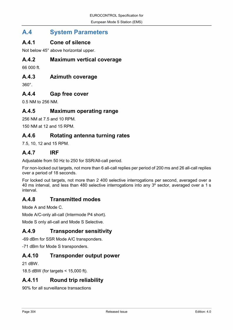
EUROCONTROL Specification for
European Mode S Station (EMS)
Page 304 Released Issue Edition: 4.0
A.4 System Parameters A.4.1 Cone of silence Not below 45° above horizontal upper.
A.4.2 Maximum vertical coverage 66 000 ft.
A.4.3 Azimuth coverage 360°.
A.4.4 Gap free cover 0.5 NM to 256 NM.
A.4.5 Maximum operating range 256 NM at 7.5 and 10 RPM. 150 NM at 12 and 15 RPM.
A.4.6 Rotating antenna turning rates 7.5, 10, 12 and 15 RPM.
A.4.7 IRF Adjustable from 50 Hz to 250 for SSR/All-call period. For non-locked out targets, not more than 6 all-call replies per period of 200 ms and 26 all-call replies over a period of 18 seconds. For locked out targets, not more than 2 400 selective interrogations per second, averaged over a 40 ms interval, and less than 480 selective interrogations into any 3º sector, averaged over a 1 s interval.
A.4.8 Transmitted modes Mode A and Mode C. Mode A/C-only all-call (Intermode P4 short). Mode S only all-call and Mode S Selective.
A.4.9 Transponder sensitivity -69 dBm for SSR Mode A/C transponders. -71 dBm for Mode S transponders.
A.4.10 Transponder output power 21 dBW. 18.5 dBW (for targets < 15,000 ft).
A.4.11 Round trip reliability 90% for all surveillance transactions

EUROCONTROL Specification for
European Mode S Station (EMS)
Edition: 4.0 Released Issue Page 305
ANNEX B- ADS-B General Operating Model B.1 Performance requirements in ADS-B CAV In the table below, a summary of the performance requirements for the Mode S Conformity Assessment Volume can be found.
Measurement Requirement summary Requirement
Position of Update ADS-B PU >= 99%
With update interval = Mode S scan rate
2.7.1
Code Detection ADS-B Pc >= 99% 2.7.2
ADS-B Pi HP | alt. | aircraft id < 0.1% 2.7.2
Long gaps Gap > 3 scans Overall Pgap < 0.5% 2.7.3
Table B-1: Performance Requirements in ADS-B CAV
B.2 Target Load B.2.1 Target load model Targets following same distribution than for Mode S peak target load model (ANNEX A.2.1.2, Models A and B), considering an update interval equal to the Mode S scan rate (2.6.8.3). The targets follow a random distribution on azimuth and pressure-altitude within the azimuth and range intervals defined in ANNEX A.2.1.2 Each target is transmitting with a rate of 6.2 ADS-B messages per second.
B.3 Environmental Parameters B.3.1 Mean FRUIT rate Same conditions in number of replies, types of downlink format and power level as defined in ANNEX A.3.1, but in this case distributed randomly along the entire azimuth (no main or back/sideslobes distinction applicable).
B.4 System Parameters B.4.1 Maximum vertical coverage 66 000 ft.
B.4.2 Azimuth coverage 360°.
B.4.3 Gap free cover 0 NM to 256 NM.
B.4.4 Maximum operating range 256 NM.
EUROCONTROL Specification for
European Mode S Station (EMS)
Page 306 Released Issue Edition: 4.0
B.4.5 Surveillance data output Selectable between: (a) Event driven output. (b) Periodic output, with update interval (≤ 5 s) and data age selectable.
B.4.6 Transponder output power 21 dBW. 18.5 dBW (for targets < 15,000 ft).

EUROCONTROL Specification for
European Mode S Station (EMS)
Edition: 4.0 Released Issue Page 307
ANNEX C- Analysis Tools C.1 Introduction This Annex describes the analysis tools to measure the Mode S and ADS-B performance at different levels. The following figure shows the measurement levels and input/output data under analysis:
Figure C-A: Access Level for Performance Tools
C.2 Surveillance Performance Analysis Tool The Surveillance Performance Analysis Tool provides multisensor analysis capabilities in Network level (see Figure C-1). The analysis runs off-line and derives its information from a number of sources, including at least:
(a) Measured target report messages, in ASTERIX Cat. 048 ([RD 26]) and 021 ([RD 23]) format, from the Mode S ground station under analysis;
(b) Flight trial DGPS positions declared by the targets (if available); (c) Station Mode S Coverage Maps (Surveillance, Lockout and Datalink); (d) Screening Maps providing terrain information; (e) Measured target report messages, in ASTERIX format, from other sensors to support the
analysis or to be analysed simultaneously. By processing the above information the operator will be able to quantify various performance levels for the Mode S ground station under test. The Surveillance Performance Analysis Tool functions (Figure C-2) can be broadly grouped in:
(a) Data Acquisition (DA): To allow the user to import data, including target reports, radar service messages and external references from the sensors under analysis. The imported data is checked and added to the database as part of the current data set;
(b) Object Correlator (OC): To link target reports into target report chains, which are believed to be associated with a single target, and associates them with the external reference data;

EUROCONTROL Specification for
European Mode S Station (EMS)
Page 308 Released Issue Edition: 4.0
(c) Internal Reference Generator (IRG): To reconstruct the “ideal” reference trajectories with full state vector information from the chained target report data. The performance analysis will be done by comparison between the measured target reports and the “ideal” reference trajectories;
(d) Analysis Reference Generator (ARG): To calculate the bias model parameters (e.g. range gain) between data sets originating from different sources (e.g. target reports and reference trajectory or DGPS data). The bias model parameters can then be used to effect target report position corrections. Analysis Filter (AF): To allow the user to select a subset of the current data for analysis. The filtering of the data is carried out by specifying one or more filters (e.g. time window, Mode S address range, screening volume, etc.) when the data matching the current filtering criteria are selected;
(e) Plot Detection Analysis (PDA): To calculate the detection probabilities for target reports and the probabilities of successfully extracting the correct SSR codes and/or Mode S address information;
(f) False Plot Analysis (FPA): To calculate statistics for false plots and multiple targets, i.e. target reports arising from multipath propagation;
(g) Plot Accuracy Analysis (PAA): To calculate statistics for the residual positional errors between the target reports and the reference trajectories, resolved onto the radar’s frame of reference;
(h) Plot Resolution Analysis (PRA): To identify and calculate statistics on target reports with trajectories in close proximity;
(i) Airborne Parameter Analysis (APA):–To calculate the frequency of extraction of BDS registers reported by the sensor and the frequency of interrogations required for extraction;
(j) Load Measurement Analysis (LMA): To calculate statistics to measure the work load of the sensor in terms of the numbers of targets as functions of azimuth and range;
(k) Display Filter (DF): Same than the analysis filter but applying to the data to display on the screen;
(l) Graphical User Interface (GUI): To allow the user the control the operation of the tool and to allow the graphical representation of the input data (measured target reports and data from external source), the internal reference trajectories and the results of the different types of analysis.

EUROCONTROL Specification for
European Mode S Station (EMS)
Edition: 4.0 Released Issue Page 309
Figure C-B: Performance Analysis Tool Functional Architecture
C.2.1 SASS-C by EUROCONTROL The Surveillance Analysis Support System for ATC Centres (SASS-C) is a software developed by EUROCONTROL to predict and verify the performance of the surveillance infrastructure. SASS‑C provides interoperable top-level verification (VERIF) and prediction (PREDICT) functionalities, providing all the expected functions for the Performance Analysis Tool.
C.2.1.1 PREDICTion tool The SASS-C PREDICT tool enables the theoretical calculation of line-of-sight screening maps and other surveillance performance parameters, as probability of receipt of message or position measurement accuracy. It can be used to calculate the surveillance volume and to support the CAV definition. The tool is characterised by:
1. A 3D grid approach, based on Digital Terrain Elevation Data (DTED) resolutions, for calculating, storing and displaying the results; 2. A design facilitating the input of multiple levels of digital terrain elevation data quality. For every single location, it will use the best terrain data available; 3. The ability to calculate a multiplicity of perspectives by the Surveillance System at any point in space.
The prediction function implements a generic Surveillance Infrastructure model supporting sectorised sensors.

EUROCONTROL Specification for
European Mode S Station (EMS)
Page 310 Released Issue Edition: 4.0
C.2.1.2 VERIFication tool The SASS‑C VERIF tool allows the user to verify the compliance of the surveillance infrastructure with EUROCONTROL current surveillance standards and specifications. In addition, it allows the support of air incident investigation, with a particular focus on surveillance aspects, and the support of the development and implementation of new ATM surveillance systems. The verification tool has 5 steps for the performance analysis:
1. Acquiring and importing surveillance data at network level; 2. Reconstructing multi-sensor surveillance data (Mode S, SSR, PSR, ADS-B, WAM, etc.) to build a reference for each flight; 3. Comparing reported data to the reconstructed reference; 4. Aggregating and reporting comparisons against standard-defined thresholds; 5. Investigating, enabled via visual representation to the user.
C.3 Multilevel Analysis Tool The Multilevel Analysis Tool allows comprehensively test the radars functioning by simulating radar returns, recording data present at various processing stages within the radar, verifying interfaces and conducting limited data analysis. This tool permits the evaluation of Mode S stations as part of the FAT. The tool allows the operator to ‘follow’ a target reply through the various processing stages that the Multilevel Analysis Tool monitors. This capability is defined as multilevel analysis. The Multilevel Analysis Tool is typically formed by one or more electronic equipment (commercial or industry in-house devices) and one of more software tools. The Multilevel Analysis Tool functions can be broadly grouped in:
(a) Design capabilities, including: a. Targets simulated scenarios;
(b) Generation capabilities, including: a. Simulation of target replies at 1 090 MHz, according to the radar interrogations and
scenarios where the trajectories are predefined; b. FRUIT environment, according to a FRUIT model predefined; c. Simulation of encoders ACP/ARP signals; d. ASTERIX Cat. 017 messages ([RD 21]), for Passive Acquisition simulation; e. ASTERIX Cat. 018 messages ([RD 22]), for DAP Extraction simulation); f. Output files with recordings and analysis results.
(c) Recording capabilities, including: a. Radar interrogations; b. Target replies in video format; c. Target replies in digital format; d. ASTERIX messages in Cat. 017/018/021/034/048 ([RD 21] to [RD 26]).
(d) Analysis capabilities, by comparison between the plots or tracks in the ASTERIX messages with the predefined scenarios, including:

EUROCONTROL Specification for
European Mode S Station (EMS)
Edition: 4.0 Released Issue Page 311
a. Interrogations rate according to ICAO and EUROCONTROL specifications, including statistical values of global rate of success and rates of re-interrogation;
b. Probability of detection; c. Probability of correct code detection and validation; d. Probability of BDS registers correct extraction; e. Probability of position accuracy, jumps and long gaps; f. Probability of false alarm and multiple targets.
(e) Display, including: a. Representation of the injected scenario; b. Representation of the recorded information; c. Results from the analysis.
C.4 Data Format Analysis Tool The Data Format Analysis Tool allows a verification of the ASTERIX data format independently of their communication protocol (e.g. TCP/IP, UDP/IP) or physical interface (e.g. IEEE 802.3 at least 100BASE-T). The Data Format Data Analysis Tool functions can be broadly grouped in:
(a) Recording capabilities, including: a. Cat. 017, Mode S Surveillance Coordination Function Messages ([RD 21]); b. Cat. 018, Mode S Datalink Function Messages ([RD 22]); c. Cat. 021, ADS-B Target Reports ([RD 23]); d. Cat. 025, CNS/ATM Ground System Status ([RD 24]); e. Cat. 034, Transmission of Monoradar Service Messages ([RD 25]); f. Cat. 048, Transmission of Monoradar Target Reports ([RD 26]); g. Cat. 247, Version Number Exchange ([RD 27]).
(b) Verification capabilities of the ASTERIX format for any recorded data.
EUROCONTROL Specification for
European Mode S Station (EMS)
Page 312 Released Issue Edition: 4.0
ANNEX D - Cluster This Annex describes another possibility for cooperation between Mode S ground stations.
D.1 Introduction In addition to the Passive Acquisition and the DAP Extraction cooperation, Mode S ground stations can adopt additional typologies to perform cooperation functions. These typologies, termed as “Cluster”, are not part of the main specification for the Mode S ground station, but they will be implemented if specifically requested by the Agency. There are two Cluster typologies available. The first one is a Cluster with Centralised Management, where a Cluster Controller eases the interoperability between different Mode S ground station suppliers and can potentially provide other additional functionalities (such as a DAP Extraction Controller). The second typology is a Cluster with Distributed Management, where the Cluster Controller is not needed and all the Mode S ground stations communicate directly between themselves, requesting in this case a more demanding communication architecture while being more flexible in the Mode S ground stations messages routing. The Cluster typologies allow a reduction of the 1 030/1 090 MHz frequency band occupancy, by decreasing the Mode S interrogations, and allow sharing the Interrogator Codes between several Mode S ground stations. The following sections include the requirements to be specifically requested by the Agency if the Cluster is to be included. Otherwise, these requirements are not requested as part of the System.
D.2 General EMS-ANNEXD-SYS-SHA-1323 REQUIREMENT: The Mode S ground station shall be capable of operating as part of a Cluster of ground stations, whereby each station will share the same Interrogator Code. RATIONALE: A Surveillance Coordination Network (SCN) will allow a common II/SI code structure to be implemented for clusters of ground stations. FIT CRITERIA: N/A.
EMS-CLU-SYS-SHA-13240 REQUIREMENT: The System shall provide a Surveillance Coordination Function (SCF), as described in ANNEX D.5, to provide the Cluster functionalities and to interface with the Surveillance Coordination Network (SCN). RATIONALE: The Agency will provide the main communications structure required for the Surveillance Coordination Network (SCN). The Surveillance Coordination Function (SCF) will provide:
(a) Network control and management including failure detection and resolution; (b) Coordination procedures, as defined in [RD 1], between coverage areas of networked ground
stations to allow targets to be acquired without need for All-Call;
EUROCONTROL Specification for
European Mode S Station (EMS)
Edition: 4.0 Released Issue Page 313
(c) Track data to adjacent stations upon request. FIT CRITERIA: N/A. EMS-CLU-SYS-SHA-13250 REQUIREMENT: When operating as part of a Cluster, each station shall advise other neighbour ground stations within the Cluster (nodes) of the arrival of target in their respective coverage as defined in the ICD for Intersite Coordination [RD 30]. RATIONALE: N/A. FIT CRITERIA: N/A.
EMS-CLU-SYS-SHA-13260 REQUIREMENT: The System shall be able to perform Mode S selective interrogations to new targets advised from neighbour ground stations in the Cluster (i.e. the targets are already locked out on the same II/SI code, therefore they do not respond to Mode S All-Call interrogations). RATIONALE: N/A. FIT CRITERIA: N/A.
EMS-CLU-SYS-SHA-13270 REQUIREMENT: New targets advised from neighbour ground stations through the Cluster shall not trigger Mode S selective interrogations when the position of the target is outside of the volume defined in the surveillance map (i.e. surveillance responsibility). RATIONALE: N/A. FIT CRITERIA: N/A.
EMS-CLU-SYS-SHA-13280 REQUIREMENT: The data format to be used over the Surveillance Coordination Network shall be as described in [RD 21]. RATIONALE: N/A. FIT CRITERIA: N/A. EMS-CLU-SYS-SHA-13290 REQUIREMENT: The System shall provide an operational parameter to enable or disable the connection to the SCN when Maintenance Mode is selected. RATIONALE: N/A. FIT CRITERIA: N/A.
EMS-CLU-SYS-SHA-13300 REQUIREMENT: The Cluster related functions shall be controlled and monitored from the CMS. RATIONALE: N/A.

EUROCONTROL Specification for
European Mode S Station (EMS)
Page 314 Released Issue Edition: 4.0
FIT CRITERIA: N/A.
EMS-CLU-SYS-SHA-13310 REQUIREMENT: The CMS shall monitor the Cluster status, including at least:
(a) Interrogator Code in use; (b) SCF Mode (Standalone / Network Aided); (c) Applied State; (d) SCN Stability; (e) Coverage map applied; (f) Date/time for next coverage map change (if programmed).
RATIONALE: N/A. FIT CRITERIA: N/A.
D.3 Operation modes EMS-CLU-SYS-SHA-13320 REQUIREMENT: The System shall support the following modes of Cluster operation:
(a) Central mode, where the coverage map and II/SI code are determined by a Cluster Controller (CC) as described in Appendix A of [RD 30];
(b) Distributed Mode, where the Mode S ground station Surveillance Coordination Function (SCF) perform coordination activities to ensure correct operation with other ground stations, as defined in [RD 30].

EUROCONTROL Specification for
European Mode S Station (EMS)
Edition: 4.0 Released Issue Page 315
RATIONALE: The following figure illustrates the cluster typologies.
Figure D-A: Cluster typologies
FIT CRITERIA: N/A. EMS-CLU-SYS-SHA-13330 REQUIREMENT: In central mode, the station shall operate with the coverage map and II/SI code determined by the Cluster Controller (CC). RATIONALE: N/A. FIT CRITERIA: N/A.
EMS-CLU-SYS-SHA-13340 REQUIREMENT: In distributed mode, the coverage map and II/SI code shall be selected by the algorithm as defined in [RD 30] operating at the Mode S ground station node. RATIONALE: N/A. FIT CRITERIA: N/A.
Coordination with Distributed Management
Coordination with Central Management

EUROCONTROL Specification for
European Mode S Station (EMS)
Page 316 Released Issue Edition: 4.0
EMS-CLU-SYS-SHA-13350 REQUIREMENT: The Mode S ground station shall be capable of forming a Cluster with any Mode S ground station whose network interface comply with [RD 30]. RATIONALE: N/A. FIT CRITERIA: N/A.
D.4 Mode transitions and Errors EMS-CLU-SYS-SHA-13360 REQUIREMENT: In addition to both operation modes (distributed and centralized), the SCF shall also support ‘standalone’ operation where each station operates independently from the central or distributed Cluster. RATIONALE: When operating as part of a Cluster, the stations operation is termed ‘network-aided’. FIT CRITERIA: N/A. EMS-CLU-SYS-SHA-13370 REQUIREMENT: When performed manually by an operator, the connection or disconnection of the Mode S ground station to the SCN shall be possible through the CMS. RATIONALE: N/A. FIT CRITERIA: N/A.
EMS-CLU-SYS-SHA-13380 REQUIREMENT: Transitions shall proceed according to the rules detailed in [RD 30]. RATIONALE: N/A. FIT CRITERIA: N/A.
EMS-CLU-SYS-SHA-13390 REQUIREMENT: The addition of a Mode S ground station to a Cluster shall be achieved without disruption to the operational service. RATIONALE: N/A. FIT CRITERIA: N/A. EMS-CLU-TEN-SHA-13400 REQUIREMENT: The Tenderer shall describe, in their Tender Response, a method to achieve the addition of a Mode S ground station to a Cluster without disruption to the operational service. RATIONALE: N/A. FIT CRITERIA: N/A.

EUROCONTROL Specification for
European Mode S Station (EMS)
Edition: 4.0 Released Issue Page 317
EMS-CLU-SYS-SHA-13410 REQUIREMENT: It shall be possible to load another solution list for the Mode S ground station without affecting its current operation. RATIONALE: As described in [RD 30], each Mode S ground station (node) SCF on a Cluster determines the network topology and cluster stability and hence from this selects the State to be used. Each State has an associated solution list entry which specifies the coverage map, the II and/or SI code configuration to be used, and the site specific set-up, including MIP, Radiated Power (for range and azimuth) settings, etc. FIT CRITERIA: N/A.
EMS-CLU-SYS-SHA-13420 REQUIREMENT: It shall be possible to set the date and time at which the update of a solution list becomes effective. When the new solution list becomes effective, the radar first operates standalone. RATIONALE: N/A. FIT CRITERIA: N/A. EMS-CLU-SYS-SHA-13430 REQUIREMENT: The handling and recovery of failures shall proceed according to the rules detailed in [RD 30]. RATIONALE: N/A. FIT CRITERIA: N/A.
EMS-CLU-SYS-SHA-13440 REQUIREMENT: If the Mode S ground station (node) holds a NOGO status, then it shall not be part of a Cluster RATIONALE: For node failure, the Tenderer is referred to the method used to set the NOGO bit in ASTERIX Cat. 034 item I034/050 ([RD 25]). FIT CRITERIA: N/A.
EMS-CLU-SYS-SHA-13450 REQUIREMENT: A Mode S ground station (node) shall be removed from the Cluster by disabling the SCN connection. RATIONALE: N/A. FIT CRITERIA: N/A. EMS-CLU-SYS-SHA-13460 REQUIREMENT: When a Mode S ground station’s (node) NOGO bit is subsequently cleared, its SCN connection shall be re-enabled. RATIONALE: The NOGO bit in ASTERIX Cat. 034 item I034/050 ([RD 25]) is automatically set to 0 whenever the system is active and therefore released for operational use. FIT CRITERIA: N/A.

EUROCONTROL Specification for
European Mode S Station (EMS)
Page 318 Released Issue Edition: 4.0
EMS-CLU-SYS-SHA-13470 REQUIREMENT: All network and nodal failures shall be reported to the CMS. RATIONALE: N/A. FIT CRITERIA: N/A.
D.5 Surveillance Coordination Function EMS-CLU-SYS-SHA-13480 REQUIREMENT: The SCF shall include the following:
(a) Capability to add and select coverage maps (Surveillance, Lockout and Datalink, as described in [RD 31]), overwriting the default selection by the LC function during Cluster operation;
(b) Capability to add or delete targets to the station Selective Roll-Call list in accordance with the SCF state;
(c) A network system status list containing information on the latest SCF state; (d) A network control and failure control process which contains the processing and protocols
required to maintain the station within the cluster; (e) A communication interface to the SCN. The interface supports the exchange of ASTERIX
messages for surveillance coordination as defined in [RD 21]; (f) A track acquisition and support protocol to ensure that any interrogator is aware of any
new track entering its coverage, and used by a radar to request track information from a neighbouring node when a track miss has occurred, as detailed in [RD 30].

EUROCONTROL Specification for
European Mode S Station (EMS)
Edition: 4.0 Released Issue Page 319
RATIONALE:
Figure D-B: Surveillance Coordination Function overview
FIT CRITERIA: N/A. EMS-CLU-TEN-SHA-13490 REQUIREMENT: The Tenderer shall provide details in the response of how the following processes operate:
(a) Station Selective Roll-Call list; (b) Periodic Monitoring Process; (c) Network and Failure Management Process; (d) Network System Status List; (e) Network Link.
RATIONALE: N/A. FIT CRITERIA: N/A.
EMS-CLU-SYS-SHA-13500 REQUIREMENT: The SCF shall provide track data to adjacent stations within a Cluster upon request.
Station Roll-Call List
Network Link
SMF
Network and Failure Management
Process
Periodic Monitoring Process
Communications Interface
Network System Status List
Coverage Map

EUROCONTROL Specification for
European Mode S Station (EMS)
Page 320 Released Issue Edition: 4.0
RATIONALE: N/A. FIT CRITERIA: N/A. EMS-CLU-SYS-SHA-13510 REQUIREMENT: The SCF shall be designed to minimise the amount or extent of II/SI code reconfiguration. RATIONALE: N/A. FIT CRITERIA: N/A. EMS-CLU-SYS-SHA-13520 REQUIREMENT: The SCF shall be designed to interface at least 5 other Mode S stations, as well as a Cluster Controller, if present, via the Surveillance Coordination Network (SCN). RATIONALE: N/A. FIT CRITERIA: N/A.
EMS-CLU-SYS-SHA-13530 REQUIREMENT: The SCF shall provide a Coordinate Transformation, as defined in [RD 21], to the local coordinate set for the track data received from the connected stations. RATIONALE: N/A. FIT CRITERIA: N/A. EMS-CLU-SYS-SHA-13540 REQUIREMENT: The SCF shall provide a Coordinate Transformation as defined in [RD 21], from the local coordinate set for track data sent to connected stations. RATIONALE: N/A. FIT CRITERIA: N/A.
EMS-CLU-SYS-SHA-13550 REQUIREMENT: A switchover between the redundant channels of the Processing System and/or in the communication channel of the SCN shall not change the SCF state. RATIONALE: N/A. FIT CRITERIA: N/A. EMS-CLU-SYS-SHA-13560 REQUIREMENT: The SCF maximum processing capacity shall be at least 500 track supports per scan while also receiving any other Cluster protocol messages, e.g. Network Information Messages (NIM), ‘Move Node to New Cluster State’ messages (MNNCS), etc. RATIONALE: N/A. FIT CRITERIA: N/A.
EUROCONTROL Specification for
European Mode S Station (EMS)
Edition: 4.0 Released Issue Page 321
D.6 Performance EMS-CLU-TEN-SHA-13570 REQUIREMENT: The Tenderer shall explain how, during handover, the probability of detection will be maintained in a Cluster whereby each station will share the same II/SI code RATIONALE: N/A. FIT CRITERIA: N/A.
EMS-CLU-TEN-SHA-13580 REQUIREMENT: The Tenderer shall detail in the proposal how the probability of detection, during handover, will be tested in the case of operation as part of a Cluster whereby each station will share the same II/SI code. RATIONALE: N/A. FIT CRITERIA: N/A.
D.7 Real Time Monitoring EMS-CLU-TEN-SHA-13590 REQUIREMENT: The monitoring function of the Cluster shall be accessible through the CMS. RATIONALE: N/A. FIT CRITERIA: N/A.
EMS-CLU-TEN-SHA-13600 REQUIREMENT: The Cluster monitoring function shall include at least:
(a) Number of incoming connect requests; (b) Number of outgoing connect requests; (c) Active nodes on the SCN (including a cluster controller if present); (d) Passive nodes on the SCN (including a cluster controller if present); (e) Number of sent track supports per scan; (f) Number of received track supports per scan; (g) Number of sent Network Information Messages (NIM); (h) Number of received Network Information Messages (NIM); (i) Number of received ‘Move Node to New Cluster State’ messages (MNNCS).
RATIONALE: N/A. FIT CRITERIA: N/A.

EUROCONTROL Specification for
European Mode S Station (EMS)
Page 322 Released Issue Edition: 4.0
D.8 Cluster Controller EMS-CLU-SYS-SHA-13610 REQUIREMENT: The Cluster Controller (CC) is an external element to the Mode S ground station and, as such, it shall not require any modification in the Mode S ground station for its operation. RATIONALE: Figure D-3 shows the overall layout of a classic Centralized Cluster with a Cluster Controller. It consists of a number of Mode S ground stations (nodes) which are all using the same limited set of II codes. A Cluster Controller (CC) is connected via a network to a number of ground station SCFs in order to provide centrally controlled mode of operation. The ground station SCFs are also connected via the network so as to provide a distributed mode in the event of the classic CC not being available. The central controlled mode has been designed to take advantage of the central and therefore global view of the Cluster. This view is established in one of two ways:
(a) By passing track information from the connected nodes to the classic CC using track data messages in ASTERIX Cat. 017 ([RD 21]). This information is then processed by the classic CC to construct a Global Selective Roll-call List;
(b) By using system track data already available and processed in a Radar Data Processing System (RDPS). This option allows the classic CC and RDPS flexibility in configuring the Cluster to optimise the overall surveillance performance. The classic CC can take advantage of this pre-processing if a suitable interface is provided between the classic CC and the RDP system.
Figure D-C: Cluster Controller in the SCN
FIT CRITERIA: N/A.

EUROCONTROL Specification for
European Mode S Station (EMS)
Edition: 4.0 Released Issue Page 323
EMS-CLU-SYS-SHA-13620 REQUIREMENT: The Cluster Controller shall include a CC Surveillance Coordination Function designed to operate through the Surveillance Coordination Network. RATIONALE:
Figure D-D: Cluster Controller functional overview
FIT CRITERIA: N/A. EMS-CLU-SYS-SHA-13630 REQUIREMENT: The Cluster Controller shall be able to handle at least 4 000 targets. RATIONALE: N/A. FIT CRITERIA: N/A. EMS-CLU-TEN-SHA-13640 REQUIREMENT: The Tenderer shall provide information on the upgradeability of the classic CC functionality to support a larger number of targets or Mode S ground station nodes.
Global Tracked Target List Station Tracked Target List Station Potential Track List
Surveillance Processing
Coverage Map
Network System and Status List
SCF
CMS Interface
Surveillance Coordination Network SCN
Optional connection to/from RDP system
Periodic Monitoring Process
Network and Failure Control
Network Link
Incoming plot data from
stations via SCN or RDP
Global Roll-call List

EUROCONTROL Specification for
European Mode S Station (EMS)
Page 324 Released Issue Edition: 4.0
RATIONALE: N/A. FIT CRITERIA: N/A. EMS-CLU-SYS-SHA-13650 REQUIREMENT: The Cluster Controller shall provide control and monitoring through the local and remote CMS. RATIONALE: N/A. FIT CRITERIA: N/A. EMS-CLU-SYSTEN-SHA-13660 REQUIREMENT: The Tenderer shall provide details of the CMS capabilities provided with the classic CC. RATIONALE: N/A. FIT CRITERIA: N/A.
D.8.1.1 CC Surveillance Cooperation Function EMS-CLU-SYS-SHA-13670 REQUIREMENT: The classic CC SCF shall maintain a Global Selective Roll-call List by using knowledge of all the solution lists for each connected ground station. Three types of target lists exists:
(a) The Global Tracked Target list, which contains information on every target currently tracked by the connected ground stations;
(b) For each connected station, a Station Tracked Target List containing only those targets that are fully tracked (i.e. successfully added to the selective roll-call list) by the station;
(c) For each connected station, a Station Potential Track List containing targets that the station is capable of tracking.
RATIONALE: N/A. FIT CRITERIA: N/A.
EMS-CLU-SYS-SHA-13680 REQUIREMENT: Track information to maintain the Global Selective Roll-Call lists can be received from:
(a) The SCF via the SCN; (b) The Radar Data Processing System (RDPS).
RATIONALE: N/A. FIT CRITERIA: N/A. EMS-CLU-SYS-SHA-13690 REQUIREMENT: The classic CC SCF shall contain the following functions:

EUROCONTROL Specification for
European Mode S Station (EMS)
Edition: 4.0 Released Issue Page 325
(a) A pre-defined Cluster coverage map indicating all Mode S ground station responsibilities for providing lockout and handover on targets located in different regions of the cluster. The map structure is defined as in [RD 30] and is at least capable of mapping a cluster covering an area of 600 NM by 600 NM;
(b) A network system status list containing the Cluster topology determined by the Network Monitoring Protocol (NMP) running in the Network Failure and Control function of the CC. It consists of a table containing the status of all connections between the network nodes;
(c) A periodic monitoring process is responsible for the routine monitoring of the global selective roll-call list, the coverage map and the network system status list. The process ensures that status changes result in the appropriate cluster handover activity;
(d) A network and failure control process which runs the protocols required to maintain the central mode of operation within the cluster. The acquisition and lockout responsibilities is also noted in the Station Potential Track list for subsequent processing and monitoring of cluster, station and target status.
RATIONALE: N/A. FIT CRITERIA: N/A.
EMS-CLU-SYS-SHA-13700 REQUIREMENT: The Periodic Monitoring Process (PMP) shall:
(a) Monitor the network system status list; (b) Monitor the CC global selective roll-call; (c) Based on the Cluster topology, select the coverage map and maintain the global selective
roll-call list based on that map. RATIONALE: N/A. FIT CRITERIA: N/A. EMS-CLU-SYS-SHA-13710 REQUIREMENT: When the PMP detects a change of target status in global selective roll-call, or of Cluster topology in the network system status list, it shall update the global selective roll-call list and ensure that the Network and Failure control process is made aware of the targets to which this change applies. RATIONALE: N/A. FIT CRITERIA: N/A.
EMS-CLU-SYS-SHA-13720 REQUIREMENT: The PMP shall check the consistency between the Station Potential and Station Tracked target lists and ensure that inconsistencies which could indicate a Cluster fault (e.g. targets which are being tracked but which are not and which are not subject to a lost track request) are resolved consistent with the Cluster system configuration. RATIONALE: N/A. FIT CRITERIA: N/A.

EUROCONTROL Specification for
European Mode S Station (EMS)
Page 326 Released Issue Edition: 4.0
EMS-CLU-TEN-SHA-13730 REQUIREMENT: The Tenderer shall provide information in their Tender Response on the inconsistencies that are checked between the Station Potential and Station Tracked target lists. RATIONALE: N/A. FIT CRITERIA: N/A. EMS-CLU-SYS-SHA-13740 REQUIREMENT: The PMP shall handle at least the following changes of status:
(a) Newly acquired targets: those targets which have flown into the cover of the classic CC coverage area;
(b) Targets flying into the surveillance coverage of clustered nodes; (c) The network system status list indicates a change of Cluster topology. In this case the PMP
selects the appropriate coverage map and amend target details of the global selective roll call to reflect the new target status.
RATIONALE: N/A. FIT CRITERIA: N/A.
EMS-CLU-TEN-SHA-13750 REQUIREMENT: The Tenderer shall propose in their Tender Response a method used to select the appropriate coverage map. RATIONALE: N/A. FIT CRITERIA: N/A. EMS-CLU-CON-SHA-13760 REQUIREMENT: The final method to be used to select the appropriate coverage map shall be agreed between the Contractor and the Agency. RATIONALE: N/A. FIT CRITERIA: N/A.
EMS-CLU-SYS-SHA-13770 REQUIREMENT: The Network and Failure Controller shall perform:
(a) Handover management, which includes running the following protocols defined in [RD 30]: a. Track acquisition protocol, to ensure that any interrogator is aware of any new track
entering its coverage; b. Track support protocol, used when a radar requests track information from the
classic CC on targets where a track miss has occurred. (b) Cluster topology and state determination:
a. This is achieved using the Network Monitoring Protocol (NMP); b. The Network Monitoring Protocol (NMP) derived cluster topology is then
communicated to the cluster stations as defined in [RD 30].

EUROCONTROL Specification for
European Mode S Station (EMS)
Edition: 4.0 Released Issue Page 327
(c) Failure management, where: a. The SCF is able to safely reconfigure the Cluster in the event of failures; b. The reconfiguration ensures the fault is isolated and that the remaining Cluster can
continue to provide for correct Mode S operation; c. The SCF reconfigures the Cluster in the case of CC failure and network failures as
described in [RD 30]. RATIONALE: N/A. FIT CRITERIA: N/A. EMS-CLU-SYS-SHA-13780 REQUIREMENT: The Network and Failure Control process shall determine the Cluster response to the changes in target status. RATIONALE: N/A. FIT CRITERIA: N/A.
EMS-CLU-TEN-SHA-13790 REQUIREMENT: The Tenderer shall provide in their proposal details of all the functions defined below:
(a) The coverage map and adaptations of it; (b) The network system status list; (c) The periodic monitoring process; (d) The network and failure controller.
RATIONALE: N/A. FIT CRITERIA: N/A. EMS-CLU-SYS-SHA-13800 REQUIREMENT: While operating in central mode, reoccurring ‘Move Node to New Cluster State’ messages (MNNCS) from a cluster controller with the same content shall not lead to a reloading of the coverage maps in the System. RATIONALE: N/A. FIT CRITERIA: N/A.
D.8.1.2 CC Surveillance Processing Function EMS-CLU-SYS-SHA-13810 REQUIREMENT: The Surveillance Processing Function maintains the Global Tracked Target List. Track data received from connected stations shall also be inserted into the respective Station Tracked List to which they are associated. RATIONALE: N/A. FIT CRITERIA: N/A.

EUROCONTROL Specification for
European Mode S Station (EMS)
Page 328 Released Issue Edition: 4.0
EMS-CLU-SYS-SHA-13820 REQUIREMENT: The Surveillance Processing Function shall be responsible for the deletion of Selective Roll call entries when no further track data is received. RATIONALE: N/A. FIT CRITERIA: N/A. EMS-CLU-SYS-SHA-13830 REQUIREMENT: The Surveillance Processing Function shall provide a Coordinate Transformation to the local coordinate set for the track data received from the connected stations. RATIONALE: The particular algorithms required for the Coordinate Transformation will be provided to the Contractor by the Agency. FIT CRITERIA: N/A.
D.8.1.3 CC Network Link EMS-CLU-SYS-SHA-13840 REQUIREMENT: The classic CC Network Link shall be able to provide a communication interface with the SCN, the CMS and, optionally, a RDPS. RATIONALE: N/A. FIT CRITERIA: N/A.
EMS-CLU-SYS-SHA-13850 REQUIREMENT: The SCN interface shall support TCP/IP connections (client and server over IPv4 or IPv6). RATIONALE: N/A. FIT CRITERIA: N/A. EMS-CLU-SYS-MAY-13860 REQUIREMENT: The SCN interface may support X.25 and/or HDLC Lap-B for outgoing and incoming data. RATIONALE: N/A. FIT CRITERIA: N/A. EMS-CLU-SYS-SHA-13870 REQUIREMENT: The interface shall support the ASTERIX format for surveillance coordination data defined in 4.2.3. RATIONALE: N/A. FIT CRITERIA: N/A.

EUROCONTROL Specification for
European Mode S Station (EMS)
Edition: 4.0 Released Issue Page 329
EMS-CLU-TEN-SHA-13880 REQUIREMENT: The Tenderer shall propose information on the data bandwidth to be used for the classic CC Network Link, and how it has been calculated. RATIONALE: N/A. FIT CRITERIA: N/A.

EUROCONTROL Specification for
European Mode S Station (EMS)
Page 330 Released Issue Edition: 4.0
ANNEX E- System Error Analysis This Annex includes complementary information for the system error analysis calculations.
E.1 General As required in 2.6.5, the Tenderer will include in their proposal a fully detailed error analysis with calculations and quoting assumptions. This takes into account the appropriate contributory effect of at least all of the sources of error detailed below on the overall system range, azimuth and position error for the Mode S sensors with:
(a) No Radome; (b) No Radome with rain falling at a rate of 25 mm/hr and 60 mm/hr; (c) Radome, if applicable; (d) Radome, if applicable, with rain falling at a rate of 25 mm/hr and 60 mm/hr.
The systematic (mean) and random (SD) error for each individual item, for range and azimuth as appropriate, will be stated over the full range of operating and environmental conditions defined within this specification. The cumulative range and azimuth error, with both mean and standard deviation values for each, will be stated. From the values for range and azimuth errors the system positional error will be stated as a function of target range. Mean and standard deviation values will be stated.
E.2 Error sources As a minimum, the following sources of error for the radar sensor will be stated and included in the system error analyses:
(a) Antennas: a. Wind deflection where appropriate; b. Beam skewing; c. Mechanical alignment; d. Turning moment; e. Target elevation angle; f. Beam defocusing.
(b) Antenna Turning Gear: a. Tower deflection/twist; b. Drive gear backlash; c. Drive shaft twist; d. Azimuth encoding.
(c) Rotating Joint: a. Insertion loss variation per channel and cross channel mismatch; b. Phase variation per channel and cross channel mismatch.
(d) Mode S Cabling - Antenna to Tx/Rx: a. Cable delays;
EUROCONTROL Specification for
European Mode S Station (EMS)
Edition: 4.0 Released Issue Page 331
b. Insertion loss per channel and cross channel mismatch; c. Phase variations per channel and cross channel mismatch; d. Insertion loss/phase variation with age; e. Insertion loss/phase variation with temperature.
(e) Mode Transmitter-Receiver/PAF: a. Interrogator mode to mode jitter; b. Receiver signal/noise ratio; c. Receiver gain, frequency and phase drift; d. Cross channel receiver gain, frequency and phase mismatch; e. Local oscillator drift; f. Quantisation clock drift; g. Target input signal strength; h. Target input frequency; i. Pulse sampling error; j. Analogue to digital conversion error; k. Off boresight angle table calibration error; l. Pulse quantisation error. Mode A/C or synch phase reversal (Mode S); m. P3 (mode A/C) or synch phase reversal (Mode S) start range error; n. Range clock accuracy; o. Pulse to reply OBA look up table averaging error; p. Reply to plot azimuth calculation error; q. Transponder delay variation.
E.3 Applicability The Tenderer will state whether the values provided in responses to the preceding paragraphs apply to both stationary and moving targets. If they do not, two sets of values will be provided, one set for stationary targets and one set for moving targets.
E.4 Verification Verification of the overall system errors will be carried out for each of the sites on target data obtained from each system, which will be evaluated with a Performance Analysis Tool, as described in ANNEX C.2, together with measurements made on a stationary target (e.g. FFM) and/or live traffic. Separate calculations for co-mounted and standalone Mode S ground stations will be provided in the proposal. In the case of co-mounted systems (or where the supplier is interfacing with an existing LVA/Turning Gear/Rotating Joint/cabling), where error details are required for system elements not being proposed by the Tenderer, the Tenderer will state and clearly indicate the error limits required for their proposed system to meet the requirements of this specification.

EUROCONTROL Specification for
European Mode S Station (EMS)
Page 332 Released Issue Edition: 4.0
ANNEX F - Project Management This Annex describes complementary information for managing a project where a Mode S ground station is deployed.
F.1 Project Management Plan The Project Management Plan (PMP) includes the following items as a minimum:
(a) Project Plan with milestones and timescales; (b) Resource Schedule, showing the contribution from team members; (c) A Work Breakdown Structure, showing the work packages, responsibilities, and expected
duration. Each work package is described with the input needed and expected deliverables; (d) Delivery Schedule, showing dates and deliverables; (e) A description of the Tenderer's proposed project team including Curriculum Vitae for the key
project team members; (f) Organisation / Roles and Responsibilities: The role and the responsibilities of each key
member for the various project phases and steps are described; (g) Interfaces with Subcontractors and Suppliers: Any Subcontract and/or Consortium
arrangements are described, covering the respective involvement and responsibility; (h) Key risks and jeopardise to satisfactory project progress and how these will be managed; (i) Methods to manage and control the work performed under the project; (j) Method used to monitor internal communication and reporting; (k) Methods and procedures to manage Quality Assurance.
This PMP is updated throughout the life of the Contract to continually reflect the project team organisation and the work breakdown structure. Any change in the responsibilities during the project is formally reported to the Agency.
F.2 Support Tools The Contractor will ensure the use of common open-source tools (word processor, spreadsheet, pdf reader, etc.) which are compatible with the Agency standards. Any conversion methods that can be necessary for documents produced automatically by Computer-Aided Software Engineering (CASE) tools will be described to the Agency. In order to reduce the size of electronic documents sent to the Agency, and to try to avoid the spreading of malware, the Tenderer will use Portable Document Format (PDF) when possible.
F.3 Control and Reporting The Control and Reporting mechanisms are defined by the Agency responsible for the procurement.
F.4 Project Risk Management Plan The Contractor will maintain a Risk Register (RR) which shows, as a minimum:
(a) Activities that can be affected by each risk; (b) The probability of risk; (c) The areas of impact; (d) Suggested risk reduction measures;

EUROCONTROL Specification for
European Mode S Station (EMS)
Edition: 4.0 Released Issue Page 333
(e) Ownership of the risk. The Contractor will report all risk areas, using the agreed reporting procedures.
F.5 Quality Plan A Quality Plan, in accordance with ISO 9001/9002 ([RD 44]/[RD 45]) latest version, will be submitted by the successful Tenderer and their major Subcontractors, detailing how QA will be applied to the Contract. The QP will identify:
(a) The product specified by the Contract, stating the procedures of the Contractor's Quality Manual that apply to the Contract;
(b) Additional procedures and amplifications to existing procedures that are required to meet the Contract conditions;
(c) The entry criteria for the milestones and the definition on how satisfactory completion is recorded.
The QP highlights the critical control and review stages for the whole Quality task from Contract inception to final acceptance of the product by the Agency. The QP will include:
(a) Quality organisation charts for the Contractor, and all major Subcontractors, showing reporting and responsibility lines within the Companies;
(b) Names and designations for all staff with responsibilities for the Contract; (c) A list of the documents that will be submitted to the Agency for approval prior to issue.
The Contractor will describe in their QP how Subcontractors have been selected and how is passed down to the Subcontractors all aspects of their Quality Plan necessary to ensure the quality of the product and/or service. The QP states which Subcontractors have produced their own QP.

EUROCONTROL Specification for
European Mode S Station (EMS)
Page 334 Released Issue Edition: 4.0
ANNEX G- Mode S Safety Overview This Annex includes an overview of the safety figures to be achieved by the Mode S ground stations. The probabilities have been calculated for 2 Mode S systems with overlapping coverage and not working in cooperation.
Failure Modes (<10 seconds) Probability
Loss of all surveillance information No Effect
Delay of all surveillance information No Effect
Any corruption of surveillance information No Effect
Failure Modes (>10 seconds) Probability
Loss of all surveillance information <10-7
Detected Loss of all Height data <10-5
Detected Loss of all Identity data <10-7
Detected Loss of all target range <10-7
Detected Loss of all target azimuth <10-7
Detected Loss of all target time <10-7
Detected Corrupted all Height data <10-5
Detected Corrupted all Identity data <10-7
Detected Corrupted all target range <10-7
Detected Corrupted all target azimuth <10-7
Detected Corrupted all target time <10-7
Undetected Corrupted Height data(for individual target reports) <10-7
Undetected Corrupted Identity data(for individual target reports) <10-7
Undetected Corrupted target range(for individual target reports) <10-7
Undetected Corrupted target azimuth(for individual target reports) <10-7
Undetected Corrupted target time(for individual target reports) <10-7
Undetected delay of all surveillance information <10-7
Failure to acquire Mode S equipped aircraft <10-7
Failure to release Mode S equipped aircraft <10-5
Undetected spurious plots <10-5
Undetected missing plots <10-7
Table G-1: Mode S Safety Overview

EUROCONTROL Specification for
European Mode S Station (EMS)
Edition: 4.0 Released Issue Page 335
ANNEX H- Outline Safety Plan The following outline will be used as a basis for the Safety Plan for the Mode S Ground Station Tender response and to form the basis of the subsequent contractual requirements.
H.1 Purpose The purpose of the safety plan is to ensure the Mode S Ground Station safety activities are clearly defined and coordinated with other project activities. Furthermore, the plan will ensure that key safety related activities, procedures and responsibilities are clearly defined and understood.
H.2 Scope The scope of the safety plan is the total scope of supply of Mode S ground station by the Contractor.
H.3 Definitions Contractor to provide appropriate definitions consistent with the Safety Plan terminology.
H.4 Safety Management Contractor's approach to Safety Management including sub-Contractor's Safety Management. Include organigram, responsibilities, accountabilities, reporting structure and interfaces with the Agency.
H.5 Mode S Safety Requirements Contractor's approach to performing a PHA and deriving the Mode S Failure Modes as detailed in 9.4.2.3.
H.6 Hazard Log Contractor's approach to the development and maintenance of a system hazard log as detailed in 9.4.2.3.
H.7 Hazard Identification and Analysis Contractor's approach to System and Software Hazard Analyses as detailed in 9.4.2.3.
H.8 Progress Monitoring and Reporting Contractor's approach to progress monitoring and reporting as indicated in ANNEX F.3.
H.9 Independent Safety Assessment Contractor's approach to Independent Safety Assessment as detailed in 9.4.2.3.
H.10 Safety Assurance Traceability Contractor's approach to Safety Assurance Traceability as detailed in 9.4.2.3.
H.11 Deliverables Deliverables are detailed in sections 9.4.2.1, 9.4.2.2 and 9.4.2.3, and include, but are not limited to:
(a) Design Process and Assurance (9.4.2.1);

EUROCONTROL Specification for
European Mode S Station (EMS)
Page 336 Released Issue Edition: 4.0
(b) Installation, Commissioning, Integration, Test and Evaluation (9.4.2.1); (c) PHA and Failure Mode Derivation (9.4.2.3); (d) Hazard Log (9.4.2.1); (e) Hazard Identification and Analyses (9.4.2.3):
a. FMECA; b. FTA.
(f) Progress Monitoring and Reporting (ANNEX F.3); (g) Safety Reviews; (h) Independent Safety Assessment (9.4.2.3); (i) Safety Assurance Traceability (9.4.2.3).
H.12 Standards Standards (e.g. ISO, IEC, MIL STD, etc.) pertinent to the Safety Plan, their scope and applicability will be indicated.

EUROCONTROL Specification for
European Mode S Station (EMS)
Edition: 4.0 Released Issue Page 337
ANNEX I- Life Cycle Costing (input data) This Annex includes information for the life cycle costing calculation.
I.1 Abbreviations for this ANNEX BITE Built-In Test Equipment
CM Corrective Maintenance
D LEVEL Depot Level (3)
I LEVEL Intermediate Level (2)
MTBF Mean Time Between Failures
MTTR Mean Time To Repair
OVHL Overhaul
O LEVEL Organizational Level (1)
PHS&T Packaging, Handling, Storage & Transportation
PM Preventive Maintenance
SE Support Equipment
SW Software
I.2 System data Production System Unit Cost
Predicted MTBF From historical data, testing, predictions and/or the product specification
MTTR From the product specification
1) O level Predicted or actual MTTR for O level
2) I level Predicted or actual MTTR for I level
3) D level Predicted or actual MTTR for D level
(%) BITE fault detection The percent of failures that BITE is capable of detecting
(%) manual fault detection The percent of failures that must be detected using manual procedures or assistance of support equipment
(%) BITE fault isolation The percent of failures that BITE can isolate to a single repairable or replaceable item
(%) manual fault isolation The percent of failures that must be isolated using manual procedures
Table I-1: System data for Life Cycle Costing
I.3 Investment data Investment spares/repair parts Provisioned spares
Table I-2: Investment data for Life Cycle Costing
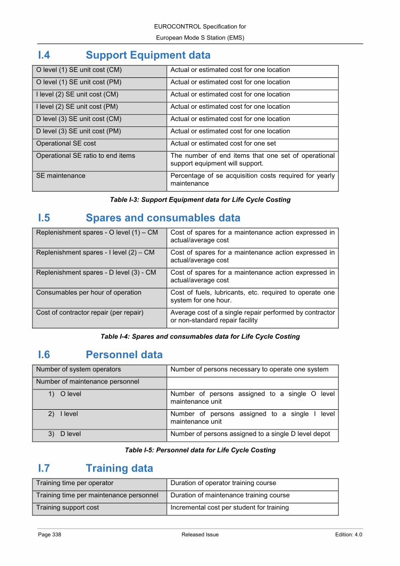
EUROCONTROL Specification for
European Mode S Station (EMS)
Page 338 Released Issue Edition: 4.0
I.4 Support Equipment data O level (1) SE unit cost (CM) Actual or estimated cost for one location
O level (1) SE unit cost (PM) Actual or estimated cost for one location
I level (2) SE unit cost (CM) Actual or estimated cost for one location
I level (2) SE unit cost (PM) Actual or estimated cost for one location
D level (3) SE unit cost (CM) Actual or estimated cost for one location
D level (3) SE unit cost (PM) Actual or estimated cost for one location
Operational SE cost Actual or estimated cost for one set
Operational SE ratio to end items The number of end items that one set of operational support equipment will support.
SE maintenance Percentage of se acquisition costs required for yearly maintenance
Table I-3: Support Equipment data for Life Cycle Costing
I.5 Spares and consumables data Replenishment spares - O level (1) – CM Cost of spares for a maintenance action expressed in
actual/average cost
Replenishment spares - I level (2) – CM Cost of spares for a maintenance action expressed in actual/average cost
Replenishment spares - D level (3) - CM Cost of spares for a maintenance action expressed in actual/average cost
Consumables per hour of operation Cost of fuels, lubricants, etc. required to operate one system for one hour.
Cost of contractor repair (per repair) Average cost of a single repair performed by contractor or non-standard repair facility
Table I-4: Spares and consumables data for Life Cycle Costing
I.6 Personnel data Number of system operators Number of persons necessary to operate one system
Number of maintenance personnel
1) O level Number of persons assigned to a single O level maintenance unit
2) I level Number of persons assigned to a single I level maintenance unit
3) D level Number of persons assigned to a single D level depot
Table I-5: Personnel data for Life Cycle Costing
I.7 Training data Training time per operator Duration of operator training course
Training time per maintenance personnel Duration of maintenance training course
Training support cost Incremental cost per student for training

EUROCONTROL Specification for
European Mode S Station (EMS)
Edition: 4.0 Released Issue Page 339
Initial training program cost Cost of developing training program
Cost of training equipment
Number of training equipment sets
Table I-6: Training data for Life Cycle Costing
I.8 Maintenance data (%) failures R/R at O level (1) Percent of failures that will be fixed by removal and
replacement of defective items at organisational level
(%) failures discard at O level (1) Percent of failures resulting in discard of the failed item
(%) failures repair at I level (2) Percent of failed items that will be repaired at 2 level
(%) failures discard at I level (2) Percent of failed items repaired by removal and discard of a lower level assembly
(%) failures repair at D level (3) Percent of failed items that will be repaired at depot 3 level
(%) failures repair at contractor Percent of failed items repaired by contract
3 level/contractor repair condemnation rate Percent of items that will not be repaired
Table I-7: Maintenance data for Life Cycle Costing
I.9 Preventive maintenance data Number of daily PM tasks Tasks
Average daily PM task time Hours
Cost of resources consumed
Number of weekly PM tasks Tasks
Average weekly PM task time Hours
Cost of resources consumed
Number of monthly PM tasks Tasks
Average monthly PM task time Hours
Cost of resources consumed
Number of semi-annual PM tasks Tasks
Average semi-annual PM task time Hours
Cost of resources consumed
Number of annual PM tasks Tasks
Average annual PM task time Hours
Cost of resources consumed
Number of PM tasks performed at I level (2) Tasks
Average I level (2) PM task time Hours
Times I level (2) PM performed in 5 years Times
Cost of resources consumed
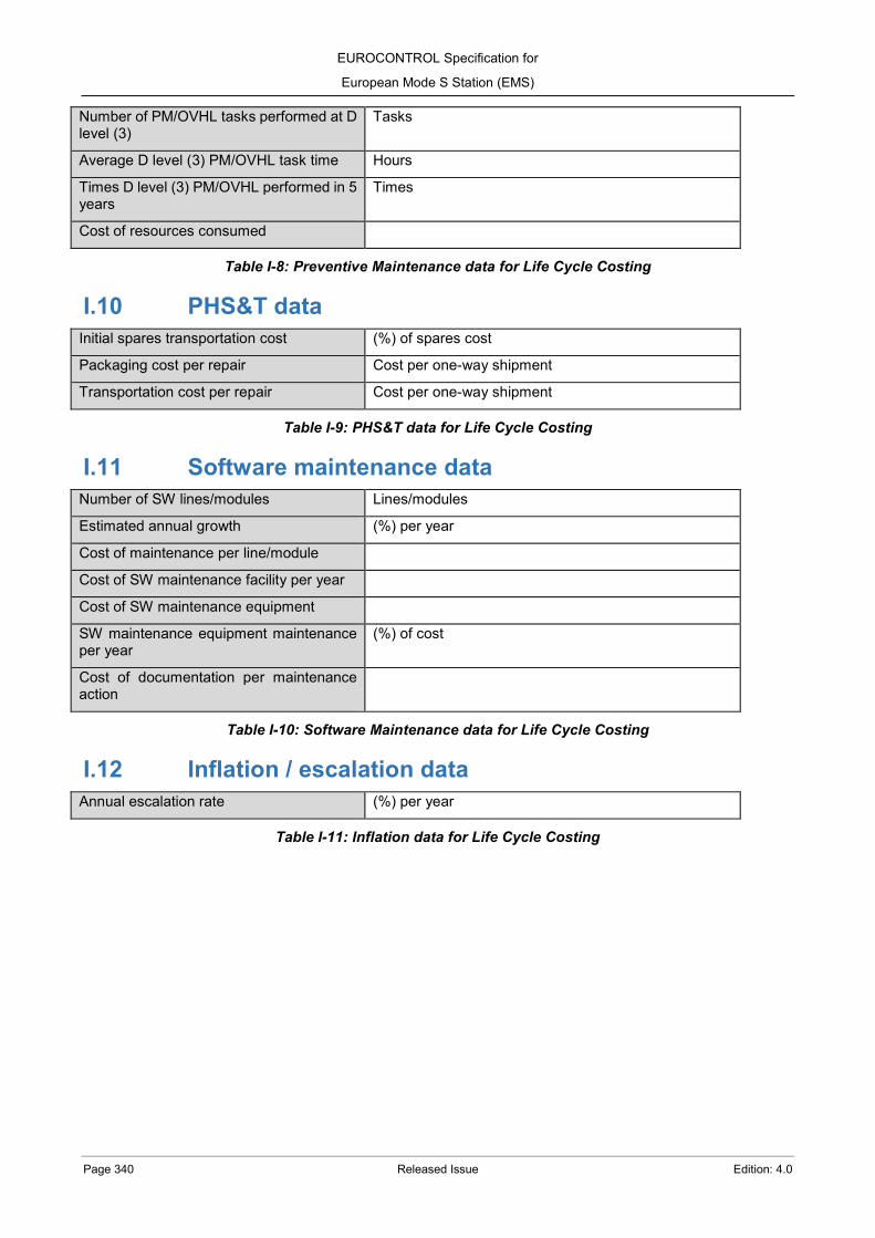
EUROCONTROL Specification for
European Mode S Station (EMS)
Page 340 Released Issue Edition: 4.0
Number of PM/OVHL tasks performed at D level (3)
Tasks
Average D level (3) PM/OVHL task time Hours
Times D level (3) PM/OVHL performed in 5 years
Times
Cost of resources consumed
Table I-8: Preventive Maintenance data for Life Cycle Costing
I.10 PHS&T data Initial spares transportation cost (%) of spares cost
Packaging cost per repair Cost per one-way shipment
Transportation cost per repair Cost per one-way shipment
Table I-9: PHS&T data for Life Cycle Costing
I.11 Software maintenance data Number of SW lines/modules Lines/modules
Estimated annual growth (%) per year
Cost of maintenance per line/module
Cost of SW maintenance facility per year
Cost of SW maintenance equipment
SW maintenance equipment maintenance per year
(%) of cost
Cost of documentation per maintenance action
Table I-10: Software Maintenance data for Life Cycle Costing
I.12 Inflation / escalation data Annual escalation rate (%) per year
Table I-11: Inflation data for Life Cycle Costing

EUROCONTROL Specification for
European Mode S Station (EMS)
Edition: 4.0 Released Issue Page 341
ANNEX J– EC Regulation (EU) 1207/2011 (SPI IR) J.1 Introduction Mode S ground stations compliant with this specification support the performance and exchange requirement referred in the European Commission Regulation (EU) No 1207/2011 (SPI IR) of 22 November 2011 as amended by (EU) No 1028/2014 of 26 September 2014, (EU) 2017/386 of 6 March 2017 and (EU) 2020/587 of 29 April 2020. Member States may use the proposed verification methods and processes described in [RD 19] to support their obligations on spectrum protection detailed in Article 6 of this Regulation.
J.2 Performance requirements as Annex I The “EUROCONTROL Specification for ATM Surveillance System Performance” document (ESASSP) provides performance requirements for ATM surveillance system when supporting 3 and 5 NM horizontal separation applications. ESASSP ([RD 9]) can be used by air navigation service providers to define, as required by the SPI IR, the minimum performance that their surveillance systems must meet. The following tables show a basic traceability between the ESASSP mandatory performance requirements and the requirements of this specification. For all the requirements, the performance is considered to be achievable within the Mode S CAV and the ADS-B CAV as defined in 2.4. The combined performance of the Mode S and ADS-B surveillance data from the same ground station and the addition of other surveillance elements, as sensors or trackers, must be analysed separately.
ESASSP Req.
Quality of service Mandatory performance EMS Req.
5N_C-R1 Measurement interval for probability of update assessments (R2, R7 and R14)
Less than or equal to 8 seconds
Achievable for all antenna rotation included in the Mode S General Operating Model (ANNEX A.4.6). Achievable for all ADS-B update intervals included in the ADS-B General Operating Model (ANNEX B.4.5).
5N_C-R2 Probability of update of horizontal position
Greater than or equal to 97% for 100% of the flights, any flight below 97% shall be investigated as defined in R22
Achievable within Mode S CAV: EMS-C02-SYS-SHA-00520 (2.6.1.1) EMS-C02-SYS-SHA-00560 (2.6.1.2) Achievable within ADS-B CAV: EMS-C02-SYS-SHA-01770 (2.7.1)
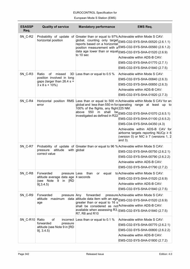
EUROCONTROL Specification for
European Mode S Station (EMS)
Page 342 Released Issue Edition: 4.0
ESASSP Req.
Quality of service Mandatory performance EMS Req.
5N_C-R2 Probability of update of horizontal position
Greater than or equal to 97% global, counting only target reports based on a horizontal position measurement with a data age lower than or equal to 10 sec
Achievable within Mode S CAV: EMS-C02-SYS-SHA-00520 (2.6.1.1) EMS-C02-SYS-SHA-00560 (2.6.1.2) EMS-C02-SYS-SHA-01520 (2.6.9) Achievable within ADS-B CAV: EMS-C02-SYS-SHA-01770 (2.7.1) EMS-C02-SYS-SHA-01840 (2.7.5)
5N_C-R3 Ratio of missed 3D position involved in long gaps (larger than 26.4 s = 3 x 8 s + 10%)
Less than or equal to 0.5 % Achievable within Mode S CAV: EMS-C02-SYS-SHA-00840 (2.6.3) EMS-C02-SYS-SHA-00850 (2.6.3) Achievable within ADS-B CAV: EMS-C02-SYS-SHA-01820 (2.7.3)
5N_C-R4 Horizontal position RMS error
Less than or equal to 500 m global and less than 550 m for 100% of the flights, any flight above 550 m shall be investigated as defined in R22
Achievable within Mode S CAV for an operating range at least up to 225 NM: EMS-C02-SYS-SHA-01070 (2.6.5.1) EMS-C02-SYS-SHA-01100 (2.6.5.2) EMS-C04-SYS-SHA-04350 (4.3) Achievable within ADS-B CAV for airborne targets reporting NUCp ≥ 6 (version 0) or NIC ≥ 7 (versions 1, 2 and 3).
5N_C-R7 Probability of update of pressure altitude with correct value
Greater than or equal to 96 % global
Achievable within Mode S CAV: EMS-C02-SYS-SHA-00750 (2.6.2.1) EMS-C02-SYS-SHA-00790 (2.6.2.2) Achievable within ADS-B CAV: EMS-C02-SYS-SHA-01790 (2.7.2)
5N_C-R8 Forwarded pressure altitude average data age (see Note 9 in [RD 9],3.4.5)
Less than or equal to 4 seconds
Achievable within Mode S CAV: EMS-C02-SYS-SHA-01520 (2.6.9) Achievable within ADS-B CAV: EMS-C02-SYS-SHA-01840 (2.7.5)
5N_C-R9 Forwarded pressure altitude maximum data age
Any forwarded pressure altitude data item with an age greater than or equal to 16 s shall be considered as not available when assessing R3, R7, R8 and R10
Achievable within Mode S CAV: EMS-C02-SYS-SHA-01520 (2.6.9) Achievable within ADS-B CAV: EMS-C02-SYS-SHA-01840 (2.7.5)
5N_C-R10 Ratio of incorrect forwarded pressure altitude (see Note 9 in [RD 9], 3.4.5)
Less than or equal to 0.1 % Achievable within Mode S CAV: EMS-C02-SYS-SHA-00770 (2.6.2.1) EMS-C02-SYS-SHA-00800 (2.6.2.2) Achievable within ADS-B CAV: EMS-C02-SYS-SHA-01800 (2.7.2)

EUROCONTROL Specification for
European Mode S Station (EMS)
Edition: 4.0 Released Issue Page 343
ESASSP Req.
Quality of service Mandatory performance EMS Req.
5N_C-R12 Delay of change in emergency indicator/SPI report
Less than or equal to 12 s for 100% of the cases, case above 12 s shall be investigated as defined in R22
Achievable within Mode S CAV for all antenna rotation included in the Mode S General Operating Model (ANNEX A.4.6). EMS-C02-SYS-SHA-01520 (2.6.9) Achievable for all ADS-B update intervals included in the ADS-B General Operating Model (ANNEX B.4.5). EMS-C02-SYS-SHA-01840 (2.7.5)
5N_C-R13 Delay of change in aircraft identity
Less than or equal to 24 s for 100% of the cases, case above 24 s shall be investigated as defined in R22
Achievable within Mode S CAV for all antenna rotation included in the Mode S General Operating Model (ANNEX A.4.6): EMS-C02-SYS-SHA-02360 (3.3.1) EMS-C02-SYS-SHA-02380 (3.3.1) EMS-C02-SYS-SHA-01520 (2.6.9) Achievable for all ADS-B update intervals included in the ADS-B General Operating Model (ANNEX B.4.5). EMS-C02-SYS-SHA-01840 (2.7.5)
5N_C-R14 Probability of update of aircraft identity with correct value (see Note 10 in [RD 9], 3.4.5)
Greater than or equal to 98 % global
Achievable within Mode S CAV: EMS-C02-SYS-SHA-00740 (2.6.2.1) EMS-C02-SYS-SHA-00790 (2.6.2.2) Achievable within ADS-B CAV: EMS-C02-SYS-SHA-01790 (2.7.2)
5N_C-R15 Ratio of incorrect aircraft identity
Less than or equal to 0.1 % Achievable within Mode S CAV: EMS-C02-SYS-SHA-00760 (2.6.2.1) EMS-C02-SYS-SHA-00800 (2.6.2.2) Achievable within ADS-B CAV: EMS-C02-SYS-SHA-01800 (2.7.2)
5N_C-R22 Investigations Flights/cases for which requirements R2, R4, R12 or R13 are not achieved shall be investigated and an impact assessment conducted and appropriate risk mitigation/reduction measures introduced if necessary.
EMS-C02-SYS-SHA-00140 (2.2)
Table J-1: ESASSP requirements for supporting 5 NM horizontal separation
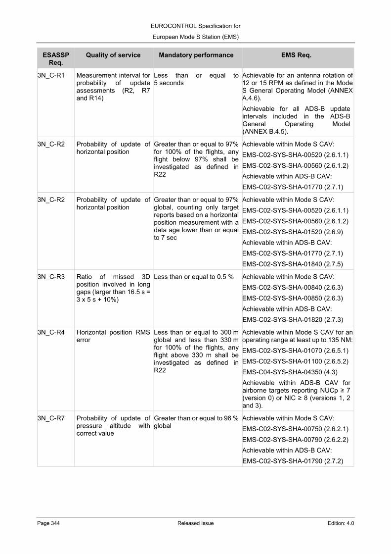
EUROCONTROL Specification for
European Mode S Station (EMS)
Page 344 Released Issue Edition: 4.0
ESASSP Req.
Quality of service Mandatory performance EMS Req.
3N_C-R1 Measurement interval for probability of update assessments (R2, R7 and R14)
Less than or equal to 5 seconds
Achievable for an antenna rotation of 12 or 15 RPM as defined in the Mode S General Operating Model (ANNEX A.4.6). Achievable for all ADS-B update intervals included in the ADS-B General Operating Model (ANNEX B.4.5).
3N_C-R2 Probability of update of horizontal position
Greater than or equal to 97% for 100% of the flights, any flight below 97% shall be investigated as defined in R22
Achievable within Mode S CAV: EMS-C02-SYS-SHA-00520 (2.6.1.1) EMS-C02-SYS-SHA-00560 (2.6.1.2) Achievable within ADS-B CAV: EMS-C02-SYS-SHA-01770 (2.7.1)
3N_C-R2 Probability of update of horizontal position
Greater than or equal to 97% global, counting only target reports based on a horizontal position measurement with a data age lower than or equal to 7 sec
Achievable within Mode S CAV: EMS-C02-SYS-SHA-00520 (2.6.1.1) EMS-C02-SYS-SHA-00560 (2.6.1.2) EMS-C02-SYS-SHA-01520 (2.6.9) Achievable within ADS-B CAV: EMS-C02-SYS-SHA-01770 (2.7.1) EMS-C02-SYS-SHA-01840 (2.7.5)
3N_C-R3 Ratio of missed 3D position involved in long gaps (larger than 16.5 s = 3 x 5 s + 10%)
Less than or equal to 0.5 % Achievable within Mode S CAV: EMS-C02-SYS-SHA-00840 (2.6.3) EMS-C02-SYS-SHA-00850 (2.6.3) Achievable within ADS-B CAV: EMS-C02-SYS-SHA-01820 (2.7.3)
3N_C-R4 Horizontal position RMS error
Less than or equal to 300 m global and less than 330 m for 100% of the flights, any flight above 330 m shall be investigated as defined in R22
Achievable within Mode S CAV for an operating range at least up to 135 NM: EMS-C02-SYS-SHA-01070 (2.6.5.1) EMS-C02-SYS-SHA-01100 (2.6.5.2) EMS-C04-SYS-SHA-04350 (4.3) Achievable within ADS-B CAV for airborne targets reporting NUCp ≥ 7 (version 0) or NIC ≥ 8 (versions 1, 2 and 3).
3N_C-R7 Probability of update of pressure altitude with correct value
Greater than or equal to 96 % global
Achievable within Mode S CAV: EMS-C02-SYS-SHA-00750 (2.6.2.1) EMS-C02-SYS-SHA-00790 (2.6.2.2) Achievable within ADS-B CAV: EMS-C02-SYS-SHA-01790 (2.7.2)

EUROCONTROL Specification for
European Mode S Station (EMS)
Edition: 4.0 Released Issue Page 345
ESASSP Req.
Quality of service Mandatory performance EMS Req.
3N_C-R8 Forwarded pressure altitude average data age (see Note 9 in [RD 9], 3.4.5)
Less than or equal to 2.5 seconds
Achievable within Mode S CAV: EMS-C02-SYS-SHA-01520 (2.6.9) Achievable within ADS-B CAV: EMS-C02-SYS-SHA-01840 (2.7.5)
3N_C-R9 Forwarded pressure altitude maximum data age
Any forwarded pressure altitude data item with an age greater than or equal to 16 s shall be considered as not available when assessing R3, R7, R8 and R10
Achievable within Mode S CAV: EMS-C02-SYS-SHA-01520 (2.6.9) Achievable within ADS-B CAV: EMS-C02-SYS-SHA-01840 (2.7.5)
3N_C-R10 Ratio of incorrect forwarded pressure altitude (see Note 9 in [RD 9], 3.4.5)
Less than or equal to 0.1 % Achievable within Mode S CAV: EMS-C02-SYS-SHA-00770 (2.6.2.1) EMS-C02-SYS-SHA-00800 (2.6.2.2) Achievable within ADS-B CAV: EMS-C02-SYS-SHA-01800 (2.7.2)
3N_C-R12 Delay of change in emergency indicator/SPI report
Less than or equal to 7.5 s for 100% of the cases, case above 7.5 s shall be investigated as defined in R22
Achievable within Mode S CAV for an antenna rotation of 10, 12 or 15 RPM as defined in the Mode S General Operating Model (ANNEX A.4.6). EMS-C02-SYS-SHA-01520 (2.6.9) Achievable for all ADS-B update intervals included in the ADS-B General Operating Model (ANNEX B.4.5). EMS-C02-SYS-SHA-01840 (2.7.5)
3N_C-R13 Delay of change in aircraft identity
Less than or equal to 15 s for 100% of the cases, case above 15 s shall be investigated as defined in R22
Achievable for all antenna rotation included in the Mode S General Operating Model (ANNEX A.4.6). EMS-C02-SYS-SHA-02360 (3.3.1) EMS-C02-SYS-SHA-02380 (3.3.1) EMS-C02-SYS-SHA-01520 (2.6.9) Achievable for all ADS-B update intervals included in the ADS-B General Operating Model (ANNEX B.4.5). EMS-C02-SYS-SHA-01840 (2.7.5)
3N_C-R14 Probability of update of aircraft identity with correct value (see Note 10 in [RD 9], 3.4.5)
Greater than or equal to 98 % global
Achievable within Mode S CAV: EMS-C02-SYS-SHA-00740 (2.6.2.1) EMS-C02-SYS-SHA-00790 (2.6.2.2) Achievable within ADS-B CAV: EMS-C02-SYS-SHA-01790 (2.7.2)
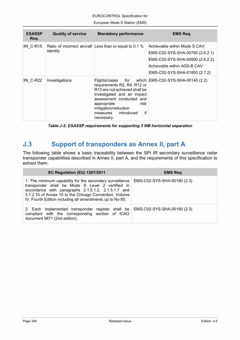
EUROCONTROL Specification for
European Mode S Station (EMS)
Page 346 Released Issue Edition: 4.0
ESASSP Req.
Quality of service Mandatory performance EMS Req.
3N_C-R15 Ratio of incorrect aircraft identity
Less than or equal to 0.1 % Achievable within Mode S CAV: EMS-C02-SYS-SHA-00760 (2.6.2.1) EMS-C02-SYS-SHA-00800 (2.6.2.2) Achievable within ADS-B CAV: EMS-C02-SYS-SHA-01800 (2.7.2)
3N_C-R22 Investigations Flights/cases for which requirements R2, R4, R12 or R13 are not achieved shall be investigated and an impact assessment conducted and appropriate risk mitigation/reduction measures introduced if necessary.
EMS-C02-SYS-SHA-00140 (2.2)
Table J-2: ESASSP requirements for supporting 3 NM horizontal separation
J.3 Support of transponders as Annex II, part A The following table shows a basic traceability between the SPI IR secondary surveillance radar transponder capabilities described in Annex II, part A, and the requirements of this specification to extract them.
EC Regulation (EU) 1207/2011 EMS Req. 1. The minimum capability for the secondary surveillance transponder shall be Mode S Level 2 certified in accordance with paragraphs 2.1.5.1.2, 2.1.5.1.7 and 3.1.2.10 of Annex 10 to the Chicago Convention, Volume IV, Fourth Edition including all amendments up to No 85.
EMS-C02-SYS-SHA-00180 (2.3)
2. Each implemented transponder register shall be compliant with the corresponding section of ICAO document 9871 (2nd edition).
EMS-C02-SYS-SHA-00190 (2.3)

EUROCONTROL Specification for
European Mode S Station (EMS)
Edition: 4.0 Released Issue Page 347
EC Regulation (EU) 1207/2011 EMS Req.
3. The following data items shall be made available to the transponder and be transmitted by the transponder via the Mode S protocol and in accordance with the formats specified in ICAO document 9871 (2nd edition):
(a) 24-bit ICAO aircraft address;
(b) Mode A code;
(c) pressure altitude;
(d) flight status (on the ground or airborne);
(e) data link capability report;
— airborne collision avoidance system (ACAS) capability,
— Mode S specific services capability,
— aircraft identification capability,
— squitter capability,
— surveillance identifier capability,
— common usage Ground Initiated Comms-B (GICB) capability report (indication of change),
— Mode S subnetwork version number;
(f) common usage GICB capability report;
(g) aircraft identification;
(h) special position indication (SPI);
(i) emergency status (general emergency, no communications, unlawful interference) including the use of specific Mode A codes to indicate different emergency states;
(j) ACAS active resolution advisories when the aircraft is equipped with Traffic alert and collision avoidance system II (TCAS II).
EMS-C03-SYS-SHA-01970 (3.1)
EMS-C03-SYS-SHA-02250 (3.3.1)
4. Other data items may be made available to the transponder.
EMS-C03-SYS-SHA-01970 (3.1)
EMS-C03-SYS-SHA-02420 (3.3.2)
5. The data items referred to in point 4 shall only be transmitted by the transponder via the Mode S protocol if the aircraft and equipment certification process covers the transmission of these data items via the Mode S protocol.
N/A for ground station
6. The continuity of transponder functionality supporting the Mode S protocol shall be equal to or less than 2. 10-4 per flight hour (i.e. mean time between failure equal to or greater than 5 000 flight hours).
N/A for ground station
Table J-3: SPI IR annex II part A requirements
J.4 Support of transponders as Annex II, part B The following table shows a basic traceability between the SPI IR secondary surveillance radar

EUROCONTROL Specification for
European Mode S Station (EMS)
Page 348 Released Issue Edition: 4.0
transponder additional surveillance data capabilities described in Annex II, part B, and the requirements of this specification to extract them.
EC Regulation (EU) 1207/2011 EMS Req.
1. The minimum capability for the secondary surveillance transponder shall be Mode S Level 2 certified in accordance with paragraphs 2.1.5.1.2, 2.1.5.1.6, 2.1.5.1.7 and 3.1.2.10 of Annex 10 to the Chicago Convention, Volume IV, Fourth Edition including all amendments up to No 85.
EMS-C02-SYS-SHA-00180 (2.3)
2. Each implemented transponder register shall be compliant with the corresponding section of ICAO document 9871 (2nd edition).
EMS-C02-SYS-SHA-00190 (2.3)
3. The following data items shall be made available to the transponder and be transmitted by the transponder via Version 2 of the extended squitter (ES) ADS-B protocol in accordance with the formats specified in ICAO document 9871 (2nd edition):
(a) 24-bit ICAO aircraft address;
(b) aircraft identification;
(c) Mode A code;
(d) special position indication (SPI) using the same source as for the same parameter specified in Part A;
(e) emergency status (general emergency, no communications, unlawful interference) using the same source as for the same parameter specified in Part A;
(f) ADS-B version number (equal to 2);
(g) ADS-B emitter category;
(h) geodetic horizontal position in accordance with the world geodetic system revision 1984 (WGS84) latitude and longitude, both while airborne or on the ground;
(i) geodetic horizontal position quality indicators (corresponding to the integrity containment bound (NIC), 95 % navigation accuracy category for position (NACp), source integrity level (SIL) and system design assurance level (SDA)); (j) pressure altitude using the same source as for the same parameter specified in Part A; (k) geometric altitude in accordance with the world geodetic system revision 1984 (WGS84), provided in addition and encoded as a difference to pressure altitude; (l) geometric vertical accuracy (GVA); (m) velocity over ground, both while airborne (east/west and north/south airborne velocity over ground) or on the ground (surface heading/ground track and movement); (n) velocity quality indicator corresponding to navigation accuracy category for velocity (NACv); (o) coded aircraft length and width; (p) global navigation satellite system (GNSS) antenna offset;
EMS-C03-SYS-SHA-02830 (3.5.1)

EUROCONTROL Specification for
European Mode S Station (EMS)
Edition: 4.0 Released Issue Page 349
EC Regulation (EU) 1207/2011 EMS Req. (q) vertical rate: barometric vertical rate using the same source as for the same parameter specified in the data item in point 2 (g) of Part C when the aircraft is required and capable to transmit this data item via the Mode S protocol, or Global Navigation Satellite System (GNSS) vertical rate; (r) mode control panel/flight control unit (MCP/FCU) selected altitude using the same source as for the same parameter specified in Part C when the aircraft is required and capable to transmit this data item via the Mode S protocol; (s) barometric pressure setting (minus 800 hectoPascals) using the same source as for the same parameter specified in Part C when the aircraft is required and capable to transmit this data item via the Mode S protocol; (t) ACAS active resolution advisories when the aircraft is equipped with TCAS II using the same source as for the same parameter specified in Part A.
4. Surveillance data items (the data items in point 3(h), (k) and (m)) and their quality indicator data items (the data items in point 3(i), (l) and (n)) shall be provided to the transponders on the same physical interface.
N/A for ground station
5. The data source connected to the transponder and providing the data items in point 3(h) and (i) shall meet the following data integrity requirements: (a) horizontal position (data item in point 3(h)) source integrity level (SIL, expressed with respect to NIC) shall be equal to or less than 10-7 per flight-hour; (b) horizontal position (data item in point 3(h)) integrity time to alert (leading to a change of the NIC quality indicator), if on-board monitoring is required to meet the horizontal position source integrity level, shall be equal to or less than 10 seconds.
N/A for ground station
6. The primary data source providing the data items in point 3(h) and (i) shall be at least compatible with GNSS receivers that perform receiver autonomous integrity monitoring (RAIM) and fault detection and exclusion (FDE), along with the output of corresponding measurement status information, as well as integrity containment bound and 95 % accuracy bound indications.
N/A for ground station
7. The system integrity level of the data sources providing the data items in point 3(f), (g), (k) to (p) shall be equal to or less than 10-5 per flight-hour.
N/A for ground station
8. The quality indicator information (NIC, NACp, SIL, SDA, NACv and GVA) (the data items in point 3(i), (l) and (n)) shall express the actual performance of the selected data source as valid at the time of applicability of the measurement of the data items in point 3(h), (k) and (m)).
N/A for ground station
9. With respect to the processing of the data items in point 3(a) to (t), the transponder system integrity level for the extended squitter ADS-B protocol, including any interconnecting avionics to the transponder, shall be equal to or less than 10-5 per flight-hour.
N/A for ground station

EUROCONTROL Specification for
European Mode S Station (EMS)
Page 350 Released Issue Edition: 4.0
EC Regulation (EU) 1207/2011 EMS Req.
10. The total latency of the horizontal position data (the data items in point 3(h) and (i)) shall be equal to or less than 1,5 second in 95 % of all transmissions.
N/A for ground station
11. The uncompensated latency of the horizontal position data (data item in point 3(h)) shall be equal to or less than 0,6 second in 95 % of the cases and shall be equal to or less than 1,0 second in 99,9 % of all transmissions.
N/A for ground station
12. The total latency of the ground speed data items (the data items in point 3(m) and (n)) shall be equal to or less than 1,5 second in 95 % of all transmissions.
N/A for ground station
13. If the transponder is set to use a Mode A conspicuity code of 1000 then the broadcast of Mode A code information via the extended squitter ADS-B protocol shall be inhibited.
N/A for ground station
14. Other data items may be made available to the transponder.
EMS-C03-SYS-SHA-02830 (3.5.1)
15. Except for military reserved formats, the data items referred to in point 14 shall only be transmitted by the transponder via the extended squitter ADS-B protocol if the aircraft and equipment certification process covers the transmission of these data items via the extended squitter ADS-B protocol.
N/A for ground station
16. The continuity of transponder functionality supporting the ADS-B protocol shall be equal to or less than 2. 10-4 per flight hour (i.e. mean time between failure equal to or greater than 5 000 flight hours).
N/A for ground station
Table J-4: SPI IR annex II part B requirements
J.5 Support of transponders as Annex II, part C The following table shows a basic traceability between the SPI IR secondary surveillance radar transponder additional surveillance data capabilities described in Annex II, part C, and the requirements of this specification to extract them.
EC Regulation (EU) 1207/2011 EMS Req.
1. Each transponder register that is implemented shall be compliant with the corresponding section of ICAO document 9871 (2nd edition).
EMS-C02-SYS-SHA-00190 (2.3)
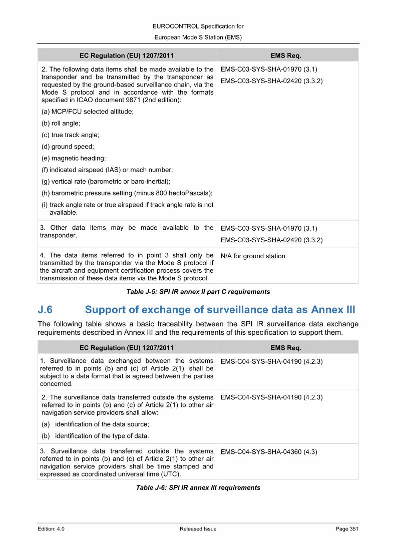
EUROCONTROL Specification for
European Mode S Station (EMS)
Edition: 4.0 Released Issue Page 351
EC Regulation (EU) 1207/2011 EMS Req.
2. The following data items shall be made available to the transponder and be transmitted by the transponder as requested by the ground-based surveillance chain, via the Mode S protocol and in accordance with the formats specified in ICAO document 9871 (2nd edition):
(a) MCP/FCU selected altitude;
(b) roll angle;
(c) true track angle;
(d) ground speed;
(e) magnetic heading;
(f) indicated airspeed (IAS) or mach number;
(g) vertical rate (barometric or baro-inertial);
(h) barometric pressure setting (minus 800 hectoPascals);
(i) track angle rate or true airspeed if track angle rate is not available.
EMS-C03-SYS-SHA-01970 (3.1)
EMS-C03-SYS-SHA-02420 (3.3.2)
3. Other data items may be made available to the transponder.
EMS-C03-SYS-SHA-01970 (3.1)
EMS-C03-SYS-SHA-02420 (3.3.2)
4. The data items referred to in point 3 shall only be transmitted by the transponder via the Mode S protocol if the aircraft and equipment certification process covers the transmission of these data items via the Mode S protocol.
N/A for ground station
Table J-5: SPI IR annex II part C requirements
J.6 Support of exchange of surveillance data as Annex III The following table shows a basic traceability between the SPI IR surveillance data exchange requirements described in Annex III and the requirements of this specification to support them.
EC Regulation (EU) 1207/2011 EMS Req.
1. Surveillance data exchanged between the systems referred to in points (b) and (c) of Article 2(1), shall be subject to a data format that is agreed between the parties concerned.
EMS-C04-SYS-SHA-04190 (4.2.3)
2. The surveillance data transferred outside the systems referred to in points (b) and (c) of Article 2(1) to other air navigation service providers shall allow:
(a) identification of the data source;
(b) identification of the type of data.
EMS-C04-SYS-SHA-04190 (4.2.3)
3. Surveillance data transferred outside the systems referred to in points (b) and (c) of Article 2(1) to other air navigation service providers shall be time stamped and expressed as coordinated universal time (UTC).
EMS-C04-SYS-SHA-04360 (4.3)
Table J-6: SPI IR annex III requirements
EUROCONTROL Specification for
European Mode S Station (EMS)
Page 352 Released Issue Edition: 4.0
ANNEX K- Specification Update Procedures It is necessary to periodically check this EUROCONTROL Specification for consistency with referenced material, notably ICAO SARPS and relevant Regulations. The Specification is also expected to evolve following real project and field experience, as well as advances in technology. The main objectives of a regular review are:
a) to improve the quality of the requirements (e.g. clarity, testability, etc.); b) to verify that the level of detail published is adequate; c) to ensure that design-oriented requirements, imposing unnecessary constraints to technical solutions, have been avoided; d) to ensure that advances in technology are properly reflected; e) to make all partners incl. industry aware of the latest developments.
The update process for this EUROCONTROL Specification may be summarised as follows: partners may provide change proposals either through existing working arrangements (e.g.established working groups) or by sending a formal Change Request (CR) to the generic email address: [email protected] The CR needs to provide following minimum elements:
• Originator information (name, Organisation, contact details) • Specification title, number and edition date • Page, chapter, section (subsection) where the issue appears • Description of the issue and reason for change • Specific change proposal text (incl. potential alternatives, if any).
Main steps towards a revised version: • Agency (Standardisation unit) will assess each CR in coordination with content owners,classify the urgency and establish the CR impact category (major, minor or editorial). • Agency will then prepare resolution proposal(s) and, if needed, discuss those with the originator and/or relevant working arrangements. Note: CR will be grouped into “change packages” to consider reasonable update cycles. • Agreed changes will be integrated into a revised version “Proposed Issue” including a summarised list of changes. • Consultation will be performed in accordance with the CR impact category identified:
o Major changes require full formal stakeholder consultation (PC level) o Minor changes need consultation at working layers (e.g. working group or Team) o Editorial changes may be implemented directly at any stage though grouped with change packages.
Note: Identified errors which may cause potential problems when implementing, may be corrected directly via separate “Corrigendum”. The Agency will apply this process in an objective and impartial way and will consult partners as needed and in line with the formal Standards Development Process.

Edition: 4.0 Edition date: 17/09/2021 Reference nr: EUROCONTROL-SPEC-189
EUROCONTROL Specifications
Subtitle Roboto Light 24pt Second line Date, period or phase Roboto Regular 14pt