Download - EUROCONTROL
52
EUROPEAN ORGANISATION FOR THE SAFETY OF AIR NAVIGATION EUROCONTROL EXPERIMENTAL CENTRE STIF Interface (Speech T echniques for sImulation F acilities) EEC Note No. 25/96 EEC Task R 10 EATCHIP Task FCO.5.02 Issued: December 1996 The information contained in this document is the property of the EUROCONTROL Agency and no part should be reproduced in any form without the Agency’s permission. The views expressed herein do not necessarily reflect the official views or policy of the Agency. EUROCONTROL
-
Upload
khangminh22 -
Category
Documents
-
view
1 -
download
0
Transcript of Download - EUROCONTROL

EUROPEAN ORGANISATIONFOR THE SAFETY OF AIR NAVIGATION
EUROCONTROL EXPERIMENTAL CENTRE
STIF Interface(Speech T echniques for
sImulation F acilities)
EEC Note No. 25/96
EEC Task R 10EATCHIP Task FCO.5.02
Issued: December 1996
The information contained in this document is the property of the EUROCONTROL Agency and no part should be reproduced in anyform without the Agency’s permission.
The views expressed herein do not necessarily reflect the official views or policy of the Agency.
EUROCONTROL
NOTE DOCUMENTATION PAGE
Reference:EEC Note No. 25/96
Security Classification:Unclassified
Originator:EEC - IST(Innovative Support Tools)
Originator (Corporate Author) Name/Location:EUROCONTROL Experimental CentreB.P.15F - 91222 Brétigny-sur-Orge CEDEXFRANCETelephone : +33 (0)1 69 88 75 00
Sponsor:EATCHIP Development DirectorateDED.1
Sponsor (Contract Authority) Name/Location:EUROCONTROL AgencyRue de la Fusée, 96B -1130 BRUXELLESTelephone : +32 2 729 9011
TITLE:
STIF Interface (Speech T echniques for sI mulation F acilities)
Author
H. Hering
Date
12/96
Pages
viii + 47
Figures
6
Tables
2
Appendix
12
References
-
EATCHIP TaskSpecification
FCO.5.02
EEC Task No.
R 10
Task No. Sponsor Period
01/1996 - 10/1996
Distribution Statement:(a) Controlled by: Head of IST(b) Special Limitations: None(c) Copy to NTIS: YES / NO
Descriptors (keywords):STIF, Speech Techniques for sImulation Facilities, Speech Synthesis Interface, Speech RecognitionInterface, ATC Simulator, ATC Communication System,
Abstract:For the evolution of new advanced techniques, like speech synthesis and speech recognition, in an ATCsimulation or experimental environment the existing equipment has to be interfaced to this advancedtechnique. Out of the shelf speech techniques existing for standard PC’s with multimedia capabilities.These techniques may be used to increase pseudo pilot’s capacities by automatically generated actions(computer) and synthesised speech for the communication with the controller. This note prescript thedevelopt hardware interface STIF.

This document has been collated by mechanical means. Should there be missing pages, please report to:
EUROCONTROL Experimental CentrePublications Office
B.P. 1591222 - BRETIGNY-SUR-ORGE CEDEX
France

STIF
v
EUROCONTROL
Table of Contents
1. Abstract 1
2. General 1
3. Structure of the Interface 3
4. Implemented STIF Modes 3
4.1 ATC Modes (Transparency Modes) 34.1.1 ATC-C Mode 44.1.2 ATC-P Mode 4
4.2 Test Mode 4
5. Detection of Speech in the ‘ATC Modes’ 5
5.1 Different Detection Techniques 55.1.1 Conclusion of the Data Monitoring 6
5.2 Speech Detection with the PTT Switch (Speech Input) 75.3 Speech Detector (Squelch Detector) for Speech Output 75.4 Speech Detection via Data Monitoring (RS 232) for Speech Output 9
6. Motherboard 9
7. VF - Modules of STIF 9
7.1 VF - Attenuator 97.2 VF - Signal Level Display 107.3 VF - Mixer 10
8. Voice Recorder Interface 10
9. Front Panel 11
10. Back Panel 13
11. Interconnection to the ATC Simulator (Frequentis System) 14
12. Interconnection with the Speech System PC 14

STIF
vi
EUROCONTROL
13. Acknowledgements 14
14. Bibliography 15
Appendix A - EEC Voice Signal Levels of the Frequentis System 17
Appendix B - VF Speech Detector Module 18
Schematic 18 Board Layout 19 Connector Layout 20 Calibration of the Speech Detector Module (Squelch Detector) 20
Appendix C - Speech Detection via Data Link Monitoring 22
Overlook of some Frequentis internal Communication Principals 22 Relevant Data Frames for the STIF Interface 22
Appendix D - Attenuator Module 24
Schematic 24 Board Layout 25 Connector Layout 26
Appendix E - VF Level Display Module 27
Schematic 27 Board Layout 28 Connector Layout 29
Appendix F - VF - Mixer Module 30
Schematic 30 Board Layout 31 Connector Layout 32
Appendix G - Motherboard 33
Schematic 33 Board Layout 34 Connector Layouts 35
Connector P 01 35 Connector P02 (Headset) 35 Connector P03 (Front-Panel Switches) 36 Connector P 04 (Front Panel LED’s) 36 Connector P 05 (opt. ‘Relay Channel occupied’ for Speech System) 36
Appendix H - Wiring List for Front-Panel 37
Lemo 10F Socket (Headset) 37 LED’s 37

STIF
vii
EUROCONTROL
Switches (S 01, S 02) 37 Potentiometer (VF - Level Control) 38 Signal Level Display 38
Appendix I - Wiring List for Back-Panel 39
Lemo 10B Socket 39 Lemo 03 Socket (option: Version Lemo 05 Socket) 39 DB 25 Socket (RS 232 ATC Simulator Panel Link) 39 DB 09 Socket (RS 232 Speech System) 40 S 03 Switch (Record/Replay) 40 S 04 Switch (Mic./Radio) 40 VF Cinch (Record VF) 41 VF Cinch (Record PTT) 41 VF Cinch (Replay VF) 41 VF Cinch (Replay PTT) 41
Appendix J - STIF - X 471 Wiring 42
Appendix K - Voice Recording Interface 43
Schematic 43 Board Layout 44 Connector Layouts 45
Connector P 21 (Rear Panel Selector Switches) 45 Connector P 22 (VF Signals representing PTT Switch) 45 Connector P 23 (Speech VF Signals) 45 Connector P 10 (Motherboard) 46
Appendix L -RS 232 Speech System Signals 47

STIF
1
EUROCONTROL
1. AbstractFor the evolution of new advanced techniques, like speech synthesis and speech recognition,in an ATC simulation or experimental environment the existing equipment has to beinterfaced to this advanced technique. Out of the shelf speech techniques existing for standardPC’s with multimedia capabilities. These techniques may be used to increase pseudo pilot’scapacities by automatically generated actions (computer) and synthesised speech for thecommunication with the controller.
2. General
The EEC centre of expertise IST (Innovative Support Tools) developed a hardware interfacecalled STIF (Speech Techniques for sImulation Facilities), on the request of the Eurocontrolheadquarters (DEI 1). The idea of this interface is to connect a speech system PC (voiceinput/output only) to a standard ATC (Air Traffic Control) communication system at the levelof the controllers headset. The advantage of such a concept is that the ATC communicationsystem may be used without any modification and undesirable interactions may be excludedvery easily.
ATCCommunication System
Control Panel
HeadsetConnector
Headset
STIF
Controller’s or
Pseudo-Pilot‘sHeadset
Speech System
(Speech Recognition and Synthesis)
VF - SignalsandData Link
VF - SignalsandPTT Switch
VF - SignalsandPTT Switch
withoutSTIF

STIF
2
EUROCONTROL
For a more general use of the STIF interface some other functionality’s are added:
• interfacing a standard ATC controller headset to the speech system PC; • special out/inputs for voice and PTT switch (Push To Talk)
recording/replaying for easy repetitive and comparative testing; • optional monitoring of a serial data link for speech detection on the
‘Frequentis’ ATC communication system; • signal level adjustments for easy adaptation on different speech systems.
These extensions make the development and testing of speech application simpler. Theinterface may then as well be used for repetitive and comparative testing of applications fromdifferent manufactories with the same recorded voice samples.
The STIF interface is fully transparent for voice frequency (VF) signals between thecontroller’s headset and the ATC communication input plug. The headset PTT switch isisolated from the communication system and emulated by a fast (max. 300 Hz) relay for theATC system.
The speech system computer is connected (high impedance > 5 kΩ) in parallel to thetransparent VF links (headset - communication system). Logical data (e.g. presence ofspeech, PTT switch etc.) are received and sent to the speech system host via the use of thesignal lines of a serial communication port.
STIF’s concept is modular. The motherboard is built as some kind of ‘voice bus’ betweenATC simulator, headset and speech system. Small modules with special functions (attenuator,mixer, speech detection, VF level display and recording/replaying interface) are plugged on it.

STIF
3
EUROCONTROL
3. Structure of the Interface
AAAAAAAAAAAAAAAAAAAAAAAAAAAAAAAAAAAAAAAAAAAAAAAAAAAAAAAAAAAAAAAAAAAAAAAAAAAAAAAAAAAAAAAAAAAAAAAAAAAAAAAAAAAAAAAAAAAAAAAAAAAAAAAAAAAAAAAAAAAAAAAAAAAAAAAAAAAAAAAAAAAAAAAAAAAAAAAAAAAAAAAAAAAAAAAAAAAAAAAAAAAAAAAAAAAAAAAAAAAAAAAAAAAAAAAAAAAAAAAAAAAAAAAAAAAAAAAAAAAAAAAAAAAAAAAAAAAAAAAAAAAAAAAAAAAAAAAAAAAAAAAAAAAA
AAAAAAAAAAAAAAAAAAAAAAAAAAAAAAAAAAAAAAAAAAAAAAAAAAAAAAAAAAAAAAAAAAAAAAAAAAAAAAAAAAAAAAAAAAAAAAAAAAAAAAAAAAAAAAAAAAAAAAAAAAAAAAAAAAAAAAAAAAAAAAAAAAAAAAAAAAAAAAAAAAAAAAAAAAAAAAAAAAAAAAAAAAAAAAAAAAAAAAAAAAAAAAAAAAAAAAAAAAAAAAAAAAAAAAAAAAAAAAAAAAAAAAAAAAAAAAAAAAAAAAAAAAAAAAAAAAAAAAAAAAAAAAAAAAAAAAAAAAAAAAAAAAAA
AAAAAAAAAAAAAAAAAAAAAAAAAAAAAAAAAAAAAAAAAAAAAAAAAAAAAAAAAAAAAAAAAAAAAAAAAAAAAAAAAAAAAAAAAAAAAAAAAAAAAAAAAAAAAAAAAAAAAAAAAAAAAAAAAAAAAAAAAAAAAAAAAAAAAAAAAAAAAAAAAAAAAAAAAAAAAAAAAAAAAAAAAAAAAAAAAAAAAAAAAAAAAAAAAAAAAAAAAAAAAAAAAAAAAAAAAAAAAAAAAAAAAAAAAAAAAAAAAAAAAAAAAAAAAAAAAAAAAAAAAAAAAAAAAAAAAAAAAAAAAAAAAAAA
AAAAAAAAAAAAAAAAAAAAAAAAAAAAAAAAAAAAAAAAAAAAAAAAAAAAAAAAAAAAAAAAAAAAAAAAAAAAAAAAAAAAAAAAAAAAAAAAAAAAAAAAAAAAAAAAAAAAAAAAAAAAAAAAAAAAAAAAAAAAAAAAAAAAAAAAAAAAAAAAAAAAAAAAAAAAAAAAAAAAAAAAAAAAAAAAAAAAAAAAAAAAAAAAAAAAAAAAAAAAAAAAAAAAAAAAAAAAAAAAAAAAAAAAAAAAAAAAAAAAAAAAAAAAAAAAAAAAAAAAAAAAAAAAAAAAAAAAAAAAAAAAAAAA
AAAAAAAAAAAAAAAAAAAAAAAAAAAAAAAAAAAAAAAAAAAAAAAAAAAAAAAAAAAAAAAAAAAAAAAAAAAAAAAAAAAAAAAAAAAAAAAAAAAAAAAAAAAAAAAAAAAAAAAAAAAAAAAAAAAAAAAAAAAAAAAAAAAAAAAAAAAAAAAAAAAAAAAAAAAAAAAAAAAAAAAAAAAAAAAAAAAAAAAAAAAAAAAAAAAAAAAAAAAAAAAAAAAAAAAAAAAAAAAAAAAAAAAAAAAAAAAAAAAAAAAAAAAAAAAAAAAAAAAAAAAAAAAAAAAAAAAAAAAAAAAAAAAA
AAAAAAAAAAAAAAAAAAAAAAAAAAAAAAAAAAAAAAAAAAAAAAAAAAAAAAAAAAAAAAAAAAAAAAAAAAAAAAAAAAAAAAAAAAAAAAAAAAAAAAAAAAAAAAAAAAAAAAAAAAAAAAAAAAAAAAAAAAAAAAAAAAAAAAAAAAAAAAAAAAAAAAAAAAAAAAAAAAAAAAAAAAAAAAAAAAAAAAAAAAAAAAAAAAAAAAAAAAAAAAAAAAAAAAAAAAAAAAAAAAAAAAAAAAAAAAAAAAAAAAAAAAAAAAAAAAAAAAAAAAAAAAAAAAAAAAAAAAAAAAAAAAAA
AAAAAAAAAAAAAAAAAAAAAAAAAAAAAAAAAAAAAAAAAAAAAAAAAAAAAAAAAAAAAAAAAAAAAAAAAAAAAAAAAAAAAAAAAAAAAAAAAAAAAAAAAAAAAAAAAAAAAAAAAAAAAAAAAAAAAAAAAAAAAAAAAAAAAAAAAAAAAAAAAAAAAAAAAAAAAAAAAAAAAAAAAAAAAAAAAAAAAAAAAAAAAAAAAAAAAAAAAAAAAAAAAAAAAAAAAAAAAAAAAAAAAAAAAAAAAAAAAAAAAAAAAAAAAAAAAAAAAAAAAAAAAAAAAAAAAAAAAAAAAAAAAAAA
AAAAAAAAAAAAAAAAAAAAAAAAAAAAAAAAAAAAAAAAAAAAAAAAAAAAAAAAAAAAAAAAAAAAAAAAAAAAAAAAAAAAAAAAAAAAAAAAAAAAAAAAAAAAAAAAAAAAAAAAAAAAAAAAAAAAAAAAAAAAAAAAAAAAAAAAAAAAAAAAAAAAAAAAAAAAAAAAAAAAAAAAAAAAAAAAAAAAAAAAAAAAAAAAAAAAAAAAAAAAAAAAAAAAAAAAAAAAAAAAAAAAAAAAAAAAAAAAAAAAAAAAAAAAAAAAAAAAAAAAAAAAAAAAAAAAAAAAAAAAAAAAAAAA
ATC Communication System (‘Frequentis’)
Controller/’Pilot’Headset
Voice Recorder
Speech System
VFSignals
VFSignals
VFSignals
VFSignals
RS 232Data
RS 232Data
Digital Data
Speech Detection
VF - Voice Signals
optional
STIF
PTT SwitchPTT Switch
PTT Switch
4. Implemented STIF Modes
With a switch on the front panel of the interface, STIF’s mode of operation will be selected.Three modes are possible: ‘ATC-P Mode’, ‘ATC-C Mode’ and ‘Test Mode’. The PTTswitch on the front panel is active in all modes. The two attenuator buttons and their VF leveldisplays (front panel) are located in the speech system PC link. This means they influenceonly the VF lines of the speech system plug (back panel) to adapt their levels between thenormal ATC communication levels and the speech system levels.
4.1 ATC Modes (Transparency Modes)
The two implemented ATC modes ‘ATC-P’ and ‘ATC-C’ are very similar. Only the sourceof the speech for the recognition system is different. This gives the possibility to use STIF at

STIF
4
EUROCONTROL
the controller working position (‘ATC-C’ mode) and at the pseudo pilot position (ATC-P’mode).
The connected headset (front panel) is linked ‘directly’ (level adaptations) to the VF plug(back panel) for the ATC communication system. The STIF power supply has to be switched‘ON’. The synthesised VF signal of the speech system PC is mixed to microphone line of theheadset. In this case the PTT switch has to be pressed with a signal from the speech system.If the communication system provides a feed-back on the controller’s earphones, the messagewill be heard on the headset.
4.1.1 ATC-C Mode
In the ‘ATC-C’ mode, speech signals coming from the controller’s microphone (connected atthe front panel of STIF) are connected to the speech system for the recognition task. Thesignal level may be adjusted for the input to the speech recognition device. The full range ofthe microphone frequency is available to the speech system.
4.1.2 ATC-P Mode
‘ATC-P’ mode means, that the controller’s speech, coming from the ATC communicationequipment (radio line), is used as source for the recognition device. The connected speechsystem computer will receive at its speech input (‘microphone’) the adapted signal of theearphone of the headset. In the case that the right and the left earphone have a different VFsignal (telephone, radio) the radio signal is selected for the speech system. The frequencyrange is limited by the communication system.
4.2 Test Mode
This mode allows to test the speech recognition device independent of any ATCcommunication equipment. The connected headset is linked to the VF socket (back panel) ofthe speech system PC. The headset’s microphone is connected to microphone input of thespeech system PC and the synthesised speech is linked to both earphones of the headset. TheVF lines of the ATC simulator (back panel socket) are isolated from this interconnection(PTT switch and detection of speech active).

STIF
5
EUROCONTROL
5. Detection of Speech in the ‘ATC Modes’
5.1 Different Detection Techniques
The normal ATC radio communication is based on the principle that only one partner(controller, pilots) may speak at the same time on the frequency. An artificial speech systemneeds the information about channel occupation for the recognition (start and end of thespeech) and for the insertion (into a cab of speech) of synthesised speech.
A controller speaks after pressing a PTT switch. The PTT switch may be located on themicrophone, in a small case of the headset cable, in a panel of his working position or in afoot-switch. STIF is only able to detect PTT switch actions which are directly linked to thelines of the ATC communication plug (microphone and headset PTT switch) and its ownPTT switch.
A pilot may speak at anytime the communication channel isn’t used. Therefore STIF has towatch the incoming radio communication and generate a digital signal after pilot’s speech isstarting (delay < 10-6 s). If right and left earphones of the controller’s headset have separatevoice signals, each one is watched.
In the case of the Frequentis ATC communication system, a third method of the detection ofthe presence of speech was worked out. The telephone and radio communication controlpanel of a controller working position of the Frequentis system is linked with a special serialdata link to an interface of the communication system. The data stream of this link containsall information about the VF channel use. By filtering the relevant data frames, the VFchannel occupation may be decoded.
Presence of Speech detected bySource of Speech PTT Switch Speech Detector RS-232 Link
Controller viaCommunication System
(ATC-P mode)no yes yes
Controller with PTTSwitch in Micro. or STIF’s
(ATC-C or Test mode)yes no yes
Controller with FootPTT switch
(ATC-C mode)no no yes
The previous table shows the limits of the usage of the different detection methods. Thedisadvantage of the detection with the RS 232 monitoring is that this technique may be to

STIF
6
EUROCONTROL
‘time consuming’ and the incompatibility with other ATC communication systems.
The status of the different ‘Speech Detectors’ and the ‘PTT’ switch is reported via differentstatus lines of the RS 232 port to the speech system PC.
5.1.1 Conclusion of the Data Monitoring
Supposing a controller starts speaking in time with pressing his PTT button. The Frequentissystem activates with this PTT information the voice transmission chain. The delay betweenthe PTT switch pressed and the first voice pattern transmitted is for the Frequentiscommunication system of Bretigny >= 100 ms. This means the first 100 ms of the speech arelost for the receiving Frequentis panel (headset) of pseudo-pilots and controllers.
For speech inputs (microphone) to the Frequentis system via the STIF interface this isn’t aproblem, as STIF handles direct the status of the PTT switch. For the Frequentis systemSTIF emulates the PTT switch by a fast relay (delay <2 ms).
Speech outputs (to the earphones of the headset) from the Frequentis ATC communicationsystem may be detected by STIF’s speech detector module little time (type: <1 ms) after firstvoice pattern starts. This increases the number of voice patterns ‘lost’ outside of thegenerated PTT switch (from STIF’s module) frame for the complete communication chain.
By decoding Frequentis RS 232 data communication from interface to the control panel (forspeech output) the speech system can be informed about the channel activation before thereal speech starts. This means not that the system start delay of >= 100 ms will be reduced,but the generated PTT ‘frame’ starts in this case some milliseconds earlier than the speechoutput.
In the case STIF is used in ATC - P mode, the speech system may be cut of from the speechstart (approx. 100 ms) by the communication system.
The following picture shows the relation of the PTT switch and the speech VF on differentlevels. Monitoring of the RS 232 link could be a time consuming advantage.

STIF
7
EUROCONTROL
PTT Switch (real primary)
Voice Frequencyof Speech Input
Transmitted andReceived VF of Speech Input
Generated PTT Switchof STIF’s Speech Detection Module
Decoded PTT Switchfrom Frequentis Data Link Monitor (RS 232, estimation)
Frequentis SystemStart Delay (VF lost - approx. 100 ms)
Detection Delay (<1 ms)
Speech End Detection Delay (adjusted ~ 500 ms)
5.2 Speech Detection with the PTT Switch (Speech Input)
This mode is based on the active corporation of the controller as he will be asked only to usethe PTT of the hand microphone, the headset or the PTT switch on the front panel of theSTIF interface. (The PTT information of the normal ‘foot switch’ isn’t available as signal onthe headset connector.) For the ATC communication system this switch is emulated by arelay.
5.3 Speech Detector (Squelch Detector) for Speech Output
The detection of the presence of speech on a communication line may cause seriousproblems. Especially isolated spoken very short words (e.g. ‘I’, ‘no’), relative long pausesduring the speech, low voice and a bad signal noise relation on the line give problems todetect the speech frame surely.

STIF
8
EUROCONTROL
For this interface it was requested to detect the start of the speech as quick as possible. Bythis reason a comparator circuit was used for the detection of the presence of a signal higherthan the line noise. This signal is than “integrated” with a retriggerable monoflop to eliminateshort pauses during the speech.
Input: Speech
Output:Speech Frame
uminUp
Upp
tdelay tpause
Upp speech signal (peak to peak)
Up positive part of the speech signal
umin minimum signal level for the detection of speech
tdelay maximum time delay of the output signal ‘Speech Frame’ after speech detection
tpause maximum time of a pause (Up < umin) within a spoken utterance
Conditions for the Detection of Speech
The realised speech detector has following limit values:
• umin : 50 mV....1.4 V• tpause : 200 ms....600 ms• tdelay : < 1 ms.
The value of umin and tpause may be adjusted by potentiometers (on board) to the wishedvalues. These values have to be fixed in relation with the measured signal levels of the usedcommunication system. tdelay is given by the switching behaviour of the used integratedcircuits.
This speech detector module is realised on a small board, plugged in a connector on the STIFmotherboard.
For VF signal levels of the EEC Frequentis system see appendix A.
Hints for the calibration of this module are in appendix B.

STIF
9
EUROCONTROL
5.4 Speech Detection via Data Monitoring (RS 232) for Speech Output
The manufacturer ‘Frequentis’ (Austria) is very successful with his advanced ATCcommunication system. This system is PC based with digitised internal speech links. AFrequentis system is operational at the ATC centre Maastricht and at the EEC (EurocontrolExperimental Centre). In this system, a non standard serial link is charged with the dataexchange of the controller’s communication panel and the system. On this data link theoccupation of the voice communication link for this control position are available. Thischannel occupation data are present prior the digitised voice data (for speech output via loudspeaker or earphones) are converted into analogue speech. The STIF interface gives theconnected speech system the possibility to monitor these data line on its serial connection.
For detailed information see appendix C.
6. Motherboard
For the modular structure (for VF signals) of the STIF interface the motherboard wasdesigned with a bus in form of a ‘Y’. The VF signals are treated on separate small boards(with a single task each) which are plugged to the bus. The motherboard handles VF signalswitching (for the different modes) and all digital signals only. The advantage of this design isthat all VF-boards may be tested and calibrated with a simple test-bench.
For details see appendix G.
7. VF - Modules of STIF
7.1 VF - Attenuator
Signals coming from the headphone or the PC’s loudspeaker are to high (Frequentis EEC:max. 1.7 Vpp for a sinus input signal of 0.8 Vpp) to be fed directly into any microphone input.Therefore the signal has to be attenuated. For this propose a standard operation amplifier isused.
The attenuator module is located on separate board with two connectors. With one connectorthe module is fixed in a slot of the STIF motherboard, the other is for the connection of thepotentiometer of the ‘gain’ regulation. This attenuation/gain may be varied by apotentiometer from 0.12 to 1.4.
For details see appendix D.

STIF
10
EUROCONTROL
7.2 VF - Signal Level Display
For simple monitoring of the output signal of the attenuator/amplifier a level indicator,composed by seven LED’s, is added. This display module is plugged in a motherboardconnector and has on the other side a connector for the LED bar. Each LED is driven by aseparate voltage comparator. The comparators have different fix DC levels (seven equalsteps) as reference to the rectified and integrated VF signal. Start and end of the referencearea may be adjusted with two potentiometers.
For details see appendix E.
7.3 VF - Mixer
This module mix the VF signals of the headset microphone and the synthetic voice of thespeech system together for the microphone input line of the ATC simulator. The headsetmicrophone line may be amplified (fix gain: 1...10). The level of the synthetic voice may becontrolled by the front-panel potentiometer.
For details see appendix F.
8. Voice Recorder Interface
Using a high quality recorded voice input for a speech engine is the only way to havereceptive times the same speech input to one or several speech devices. Comparative testingof several speech engines and the fine tuning should always be done with recorded speechsamples.
Recording/replaying makes use of both channels of a stereo voice recorder. One channel isused for the analogue voice signal the other for the recording of the PTT switch information.The PTT switch is represented as 15 kHz signal during speech pauses (PTT switch released)to eliminate interference with the speech signal.Attention: recorder source selector switch on “Replay” (rear panel) without recorded inputsignal of a PTT switch, will be interpreted as pressed PTT switch!
The recording/replaying is strongly related to the STIF mode of operation and the recorderinterface switches shown in the following table:

STIF
11
EUROCONTROL
STIF Interface ModesATC - Modes Test -Mode
VF Signal PTT VF Signal PTT
MicroRecordfrom
HeadsetMicrophone
Headset’s or STIF’sPTT Switch
HeadsetMicrophone
Headset’s or STIF’sPTT Switch
Replayto/as
ATC SimulatorMicrophone
emulate STIF’sPTT Switch
Speech SystemMicrophone
emulate STIF’sPTT Switch
RadioRecordfrom
HeadsetEarphone
Speech Detectoror Speech System*
Speech SystemSynth. Voice
Speech System
Replayto/as
HeadsetEarphone
emulate STIF’sPTT Switch
HeadsetEarphone
emulate STIF’sPTT Switch
* special jumper setting of STIF and the ‘Speech System’ host has to use the RTS line of its RS232 port for this purpose
For details of the voice recorder interface see appendix K.
9. Front Panel
STIF
Headset
PTT
Mode
Test ATC-P ATC-C
Microphone
Speech System VF Level Control
Synthesizer
EUROCONTROL
Headset Connector(Lemo10F)
Local PTT-Switch (S 01)
LED Channel occupied (L 01)
Mode Switch (S 02)
LED Speech System (L 02)
LED’s VF Signal Level(LED1....LED7)
Potentiometer VFSignal Level
LED’s VF Signal Level(LED1....LED7) Potentiometer VF
Signal Level

STIF
12
EUROCONTROL
Beside the socket (10 pins type ‘LEMO’ JAX 3) for the controller headset (in/output of VFcommunication and PTT switch), the following elements are located:
• one switch for the interface mode: ‘Test’ - ‘ATC-C’ - ‘ATC-P’:
• ATC modes: the VF sockets ‘ATC-Simulator’, ‘Headset’ and ‘speech system’ are interconnected;
• Test mode: only the VF sockets ‘Headset’ and ‘speech system’ are interconnected;
• one button for the attenuation from the ‘speech system’ PC’s syntheticvoice output to the ‘ATC-Simulator’ microphone input (ATC modes) witha level indicator LED band (seven LED’s), in the ‘Test’ mode the output isconnected to the earphones of the controller headset;
• one button for the attenuation from the ‘ATC-Simulator’ radio
communication (ATC-P mode) signal output to the ‘speech system’ PC’smicrophone input with a level indicator LED band (seven LED’s); in ATC-C and Test modes the VF signal from the headset is displayed and adjusted;
• one push-button as PTT (Push To Talk) switch; • one indicator LED (located in the PTT switch) for ‘communication channel
occupied’, activated by speech (squelch) detector, PTT switch of the panel,PTT switch of the headset or from the speech system PC;
• one indicator LED for ‘interface ready’ - interface hardware and speech
system PC’s program is running. In case of the use of the optional detectionof ‘communication channel occupied’ by the speech system (via RS 232ATC communication link monitoring), the STIF interface may be informedvia this line (jumpers) from the speech PC for the correct recording of thePTT switch.
For wiring details see appendix H.

STIF
13
EUROCONTROL
10. Back Panel
ATC - Simulator
VF - Signal
Digital Data (optional)
Speech System
VF - Signal
Digital Data
Record
VF PTT
Replay
VF PTT
Mic.
Radio
Record
Replay
Power Connectorwith Switch and Fuse
Speech SystemVF Connector (Lemo 03)
ATC - SimulatorVF Connector (Lemo 10F)
ATC - SimulatorPanel Link (DB 25F)
Speech SystemData Connector (DB 09M)
Recorder Interface Panel
VF Outputsfor the Recorder
VF Inputsfrom the Recorder
Recorder SourceSelector Switch (S 03)
VF SourceSelector Switch (S 04)
On the rear panel of the interface the following sockets for the interconnection with the ATCsimulator communication system and the speech system PC are located:
• in/output to the ‘ATC-Simulator’ VF communication interface - socketwith 10 pins type ‘LEMO’ JAX 3;
• input for monitoring the ‘Frequentis panel communication’ (optional)-
socket DB 25 for RS 232 communication (19200, N, 8, 1); • input/output to the ‘speech system’ PC - socket DB 9 for RS 232
communication (19200, N, 8, 1); • in/output to the ‘speech system’ PC VF communication interface - socket
with 3 pins type ‘LEMO’ JAX 2 (optional 5 pins including PTT switchsignal);
• input for 220 V power cable - socket type CEE 22 with integrated switch,
fuse and light For wiring details see appendix I.

STIF
14
EUROCONTROL
11. Interconnection to the ATC Simulator (Frequentis System)
STIF is connected with a multiple wire cable to the ATC simulator communication interface.This may be with a cable to the normal controller’s headset connector (wired 1:1) or to theconnector ‘X 471’ of the Frequentis interface ’BGT APL 01’. The first one isn’t allowed ifthere is any signal modification (amplifier...) between headset- and ‘X 471’ connector.
For the RS 232 monitoring of the Frequentis panel communication with the Frequentisinterface ’BGT APL 01’ a ‘RS 232 Multi Port Adapter’ is introduce between the ‘X 371’socket of the ’BGT APL 01’ and the cable connected first at ‘X 371’. From a third socket ofthe ‘RS 232 Multi Port Adapter’ a standard RS 232 cable is connected to the DB 25 socketon the rear STIF panel.
The cable wiring for the ‘X 471’ connector is shown in appendix J.
12. Interconnection with the Speech System PC
On the back panel of STIF are two connectors for the speech PC. The 3 pin LEMO socket (5pin as option if a hard PTT switch is needed) is connected to the multi-media interface card(e.g. Sound-Blaster) of the PC. There are only analogue voice signal on this cable. The othercable is a standard RS 232 cable for 9 pin DB 09 sockets. On the PC this one has to beconnected to the serial port used by the speech software. This is the data link (VF line states,PTT switch, optional data link monitoring) between STIF and the speech system.
The legend for these sockets are shown in appendix I - Wiring List for the Back-Panel.
Signal interpretations of the DB o9 socket are in appendix L.
13. Acknowledgements
The initial idea for the development of STIF comes from Mr. J. Pouzet Eurocontrol HQ (DEI1) in knowledge of EEC activities in speech recognition (EEC note 2/95) and man machineinterface (EEC note 24/94).
My colleague Gilbert Coatleven participated with great effort in producing the prototypes fortesting, measuring, calibrating and many other tasks. Thanks as well to Mme Maryse Meletthe good cabling spirit of the EEC for their well done job and the élan for the multiplemodification

STIF
15
EUROCONTROL
14. Bibliography
For the development of STIF, the technical data sheets of the integrated circuits were usedintensively. As they exist from many different chip manufacturer no special reference isneeded.

STIF
17
EUROCONTROL
Appendix A - EEC Voice Signal Levels of the Frequentis System
On the Frequentis communication system of the EEC Bretigny we measured at the output ofthe headset microphone approximate 0.8 Volt (amplified, peak to peak) with a normalspeaking loudness as a mean value. The Sennheiser headset (type HME 1410 KA)microphone was positioned 2 cm ahead of the edge of the mouth. This headset has anintegrated microphone amplifier.Remark: For the speech recognition task the new Sennheiser headset (HME 45-KA) for jetcockpits with noise cancelling microphone should be used. The output signal of the HME 45-KA is smaller than this of the HME 1410-KA. The difference may be compensated byadjusting the fix gain of the mixer module.
The following table give the headphone output voltages (peak to peak) of the EECFrequentis System for the radio and telephone communication. The results are independent ifonly one or both earphones are connected together (one ear radio and one ear telephone orboth ears radio) as each earphone has an independent amplifier and control.
Uin = 800 mVpp (sinus);gain: set to maximum for each channel;noise = 100 mVpp;
RL = 600 Ohms (each channel)
Input Frequency(Hz)
Output Radio Channel[Vpp]
Output TelephoneChannel [Vpp]
300 1.2 1.3500 1.4 1.51000 1.5 1.52000 1.7 1.73000 1.7 1.73500 1.5 1.53700 1.3 1.34000 0 0
Maximum Headphone Output Voltages

STIF
18
EUROCONTROL
Appendix B - VF Speech Detector Module
Schematic
IC 1LM 311P
Signal OUT
Signal IN 5
22µ
0.1µ
7
2
R 100k
0.1µ
+12V
IC 2MC 14538
+12V
3
2
7
8
4 1
+12V
1/4/8/12/15
3/11/13/16
TP
TP
R 500k
1µ
TP
U ref
1µ100p

STIF
19
EUROCONTROL
Board Layout
R 27k
C22µ
C .1µ
Connector
Ground SignalIN OUT
IC 1LM 311P
+12 VGround Signals
OUT IN
C .1µ
C 1µ
IC 2MC 14538
C 1µ
Potentiometer 100k(U ref: 0.1 ...2V)
Potentiometer 500k(t pause: 0.2 ... 0.6 s)
1 8AB
U ref
R 5.6k

STIF
20
EUROCONTROL
Connector Layout
Pin # Signal Name
1A Digital Detector Signal OUT (high = no speech)1B VF - Signal IN (from Radio or Telephone)
2 A+B n.u.3 A+B n.u.4 A+B n.u.5 A+B n.u.6 A+B Ground7 A+B Ground8 A+B +12 V
Remarks:May be plugged to P 14 (telephone channel) or P 15 (radio channel);
Calibration of the Speech Detector Module (Squelch Detector)
The module is adjusted by default to the following values:
• umin > 100 mVp (equal a signal of 200 mVpp)• tpause = 500 ms.
The value of umin is chosen with reference to the values shown in appendix A (noise level 100mVpp, signal level 0.8 Vpp).
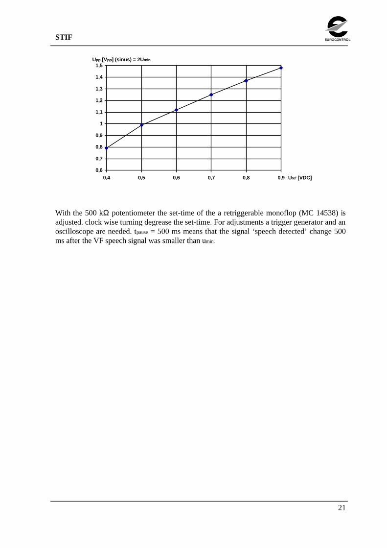
With the potentiometer (100 kΩ) on the squelch module, Uref (TP on module) representingumin may be adjusted. For small values Uref = umin.
The following chart gives the relation for higher values of Uref.
STIF
21
EUROCONTROL
0,6
0,7
0,8
0,9
1
1,1
1,2
1,3
1,4
1,5
0,4 0,5 0,6 0,7 0,8 0,9 Uref [VDC]
Upp [Vpp] (sinus) = 2U min
With the 500 kΩ potentiometer the set-time of the a retriggerable monoflop (MC 14538) isadjusted. clock wise turning degrease the set-time. For adjustments a trigger generator and anoscilloscope are needed. tpause = 500 ms means that the signal ‘speech detected’ change 500ms after the VF speech signal was smaller than umin.

STIF
22
EUROCONTROL
Appendix C - Speech Detection via Data Link Monitoring
Overlook of some Frequentis internal Communication Principals
The control panel of the Frequentis ATC communication system of a controller workingposition is linked to a centralised interface of the communication system. Parts of thisinterconnections are realised via standard DB 25 connectors. The pin occupation of thisconnectors are non standard. By introducing a T-connector, the link may be monitored. Thecabling in the interface is done in a way that a line (data from Frequentis system interface tothe Frequentis control panel) can be observed.
The data link try to emulate a synchron communication. The following port parameters areused:
• 19 200 baud,• 8 bit /character,• no parity bit,• 1 stop bit.
Permanently two different synchronisation frames with 3 bytes are sent. The frames A and Bare sent alternatively:
• frame A: 0x01, 0x00, 0x01,• frame B: 0x08, 0x00, 0x08.
In this synchronisation stream a variable number of data bytes (data frame) may be introducedat the end of frame A or B. The end of the data frame has to be detected by the presence ofthe next synchronisation frame. The synchronisation frames at the start and at the end of adata frame are different (e.g. ‘....+frameA+DATA-frame+frameB+frameA++frameB+frameA+frameB+DATA-frame+frameA+DATA-frame+frameB+....’). Two dataframes are separated by at least one synchronisation frame.
Relevant Data Frames for the STIF Interface
The following list of data frames are from general interest for the interpretation with the STIFinterface:
• 0x21, 0x0f, 0xda, 0x41, 0xb5 Freq. panel PTT switch pressed,• 0x21, 0x0f, 0xda, 0x11, 0xe5 Freq. panel PTT switch released,• 0x21, 0x0f, 0x3c, 0x41, 0x53 Freq. panel ‘radio cha. occupied’ light ON,• 0x21, 0x0f, 0x3c, 0x11, 0x03 Freq. panel ‘radio cha. occupied’ light OFF,

STIF
23
EUROCONTROL
The precedent data frames may be used only for one or both directions of VF signals (inputvia microphone, output via earphone /speaker). In the logical way some data frames have tobe followed by others.
Pressing the PTT switch of the Frequentis panel for voice input with the microphone willgenerate the following sequence of data frames:
‘Freq. panel PTT switch pressed’ + ‘Freq. panel ‘radio channel occupied’ light ON’ (speaking voice)..........‘Freq. panel PTT switch released’ + ‘Freq. panel ‘radio channel occupied’ light OFF’.
Voice signal output to the speaker/headset generate the following data sequence:
.....‘Freq. panel ‘radio channel occupied’ light ON’
......(speaking voice)......
.....‘Freq. panel ‘radio channel occupied’ light OFF’.

STIF
24
EUROCONTROL
Appendix D - Attenuator Module
Schematic
R 82k
R 22k
IC 1TL 072CP
Signal OUT1
Signal IN
100p
2
3
+12V-12V
22µ 22µ
0.1µ0.1µ
8
4
R 100k
TP
TP
P 001
Front Panel
Remarks:
The linearity was successful tested for the area from 500 Hz until 4.5 kHz. The noise level issmaller than 50 mV. The output signal has to respect the limits of the +12 V -12Valimentation.

STIF
25
EUROCONTROL
Board Layout
R 82k
R 22k
C22µ
C .1µ
Connector
Ground/Screen
Potentiometer 100k(Gain: 0.12 ... 1.4)
Ground SignalOUT IN
IC 1TL 072CP
+12 VGround-12 VSignals
OUT IN
C22µ
C .1µ
1 8AB
P 001

STIF
26
EUROCONTROL
Connector Layout
Pin # Signal Name
1A VF - Signal OUT (IN * gain)1B VF - Signal IN
2 A+B n.u.3 A+B n.u.4 A+B -12 V5 A+B n.u.6 A+B Ground7 A+B Ground8 A+B +12 V
Remarks:Output signal inverted; may be connected to P 13 (Synth. voice of the speech system) or P 16(Mic. input of the speech system);

STIF
27
EUROCONTROL
Appendix E - VF Level Display Module
Schematic
0.1µ
IC 2 LM 339N
+12V
IC 1TL 072CP
1
Signal IN
100p
2
3
+12V-12V
22µ 22µ
0.1µ0.1µ
8
4
IC 3 LM 339N
R 680
0.1µ
3
3
12
12
10
11
8
9
6
7
4
5
10
11
8
9
6
7
R 39k
+12V
R 5k
R 10k
R 100k
13
14
1
2
13
14
1
LED 11
LED 22
LED 32
LED 44
LED 55
LED 66
LED 77
8/9/10
1µ
1N914
TP
TP
TP
TP
P 002

STIF
28
EUROCONTROL
Board Layout
C22µ
C 100pConnector
Ground
IC 1TL 072CP
+12 VGround-12 VSignal
IN
C .1µ
IC 3 LM 339N
C 1µ
R 470k
Potentiometer 5k(U ref. lower limit: 0.3 ... 0.8 V)
Potentiometer 10k(U ref. upper limit: 1.1 ... 2.1 V)
C22µ
Signal IN U sig.
IC 2 LM 339N
C .1µ
R 100k
R 100k
R 100k
R 100k
R 100k
R 39k
+12 V
LED 1
LED 2
LED 3
LED 4
LED 5
LED 6
LED 7
1 8AB
P 002
R 1.2k
LED
22n
Front Panel
LED: HLMP-0301 (red), HLMP-0401 (orange), HLMP-0501 (green)

STIF
29
EUROCONTROL
Connector Layout
Pin # Signal Name
1A n.u.1B VF - Signal IN
2 A+B n.u.3 A+B n.u.4 A+B -12 V5 A+B n.u.6 A+B Ground7 A+B Ground8 A+B +12 V
Remarks:For VF Signal IN =1.5 Vpp sinus the voltage at Uref will be approximately 1.5 Vdc (closelogarithmic transformation); may be plugged to P 12 (Synth. voice of the speech system) or P17 (Mic. input of the speech system);
Default Calibration (with 1 kHz sinus input signal):Module for P 12: Uref = 0.35 Vdc and Uref = 1.1 Vdc;
===> middle green LED on at Usig = 0.95 Vpp.Module for P 17: Uref = 0.15 Vdc and Uref = 0.6 Vdc;
===> middle green LED on at Usig = 0.55 Vpp.

STIF
30
EUROCONTROL
Appendix F - VF - Mixer Module
Schematic
R 10k
R 10k
IC 1TL 072CP
Signal OUT1
Signal Mic. IN
100p
6
5
+12V-12V
22µ 22µ
0.1µ0.1µ
8
4
7
R 22k*
R 22k*
R 22k*
1µ
1µ100p
2
3
Signal Synth. Voice IN
* 2% max.
R 100kTP
TP
TP
Remarks:The linearity was successful tested for the area from 500 Hz until 4.5 kHz. The noise level issmaller than 50 mV. The output signal has to respect the limits of the +12 V -12Valimentation.
Default Calibration (with 1 kHz sinus input signal):‘Signal Mic. IN’ = 0.7 Vpp ===> ‘Signal OUT’ =1.5 Vpp;‘Signal Synth. Voice IN’ / ‘Signal OUT’ = 1/1.

STIF
31
EUROCONTROL
Board Layout
C22µ
C .1µ
Connector
GroundSignal OUT
+12 VGround-12 VSignal Synth. Voice Signal Mic.
Signal OUT IN
C22µ
C .1µ
C 100p
C 1µ
R 22k
R 22k*
(Gain Mic. IN: 1 ...10)
(* Tolerance 2% max.)
IC 1TL 072CP
1 8AB

STIF
32
EUROCONTROL
Connector Layout
Pin # Signal Name
1A VF - Signal OUT (mixed from inputs)1B VF - Signal IN (from headset microphone)2A n.u.2 B VF - Signal IN (from synth. voice of the speech system)
3 A+B n.u.4 A+B -12 V5 A+B n.u.6 A+B Ground7 A+B Ground8 A+B +12 V
Remarks:Microphone input may be amplified (gain: 1...10); board connected to P 11;

STIF
33
EUROCONTROL
Appendix G - Motherboard
Schematic
ATCSimulator
SpeechSystem(RS 232)
Speech System ready ORPTT decoded
V
V
+12 V
SpeechDetector
SpeechDetector
JP 1
JP 2
JP 4
JP 5
1.2k
1k
1.2k
1.2k
1.8k 1.8k
3.3k 3.3k +8V-8V
1k
+12V
1µ 1µ
1µ
1µ
27k
1M+8V
-8V1M
1N914
1N914
P 01P 02
P 03
P 04
P 11
P 10
P 16
P 14
P 16
P 17
P 13P 12
1A
1A
1A
1A
1A
1AB
1AB
1B
1B
1B
1B
1B
2B
1A1B
3A
3B
2
3
4
5
A
B
5
6
1
1
3
2
3
4
5
6
11
12
21
20
23
24
17
22
19
18
1598
IC 1*
IC 1*
IC 1*
IC 1*
IC 2*
IC 2*
IC 2*
IC 2*
IC 6
IC 4
IC 4IC 4
IC 4
IC 5
IC 5
IC 5
IC 7
IC 7
IC 7
IC 8
IC 8
IC 8
IC 8
Spare
9 8
6
11 10
12
9 8
6
10
11
12
11
2 2
1313 4
33
4
55
IC 5
2 3
6 4/5
11
12/13
8
9/10
12/13
11
4/5 6
3
2
89/10
3
4
1
2
10
13
11
12
11
12/13
108/9
9
8
4
5/6
2
31
6 13
+12 V2
8
Relay
Mic.
Telephone
Radio
PTT
Headset
Mic.
Telephone
Radio
PTT A
PTT B
Mic.
Synth.Voice
SpeechSystem
PTT Synth. Voice
PTT
Tel. Speech
Radio Speech
Rx (RS 232 ATC Simulator) optional-12V Ground +12V
Rx (optional)
Mode 1/13
Mode 1/5
Mode sw
Mode sw
PTT
LED Channeloccupied
LED Speech SystemorPTT decoded (optional)
1k
2.2k1k 1k
2.2k
39k
10k
10k
+12 V
2
6Relay (opt.)
14
8
P 05
RelayChanneloccupied
IC 7
12
13
1
2
1k
* IC with +/-8V
STIF - Mode dependent status of the electronic switches on the motherboard
Electronic Switch(command pin nbr.)
ATC - P ATC - C Test
IC 1/6, IC 2/5+6+12 close close openIC 1/12, IC 2/13 open open close
IC 1/13 open close closeIC 1/5 close open open

STIF
34
EUROCONTROL
Board Layout
C22µ
IC 1HEF 4066BP
C 1µ
R 1.2k
D 1N914
IC 2HEF 4066BP
IC 6HEF 4025BP
IC 7MM 74C906
IC 4HEF 4011BP
IC 8SN 75188N
IC 5SN 75188N
RelayD31A5100
C 1µ
C22µ
D 1N914 R 1.2k
R 1.8k
JP 1 JP 2JP 5JP 4
1 1
1
1
1 1 1 1
1 1
1 1
P 02
P 03
P 04
P 10 P 11 P 12 P 13
P 14 P 15
P 16 P 17
P 01
1
25
A B
A BA B
A BA BA B
B A B AR 1.2k
R 10k
RelayD31A5100 (opt.)
P 051
R 2.2k
A B 1 6

STIF
35
EUROCONTROL
Connector Layouts
Connector P 01
Pin # Signal Name
1A+B Ground2A+B VF - microphone (ATC Simulator)3A+B VF - Telephone(ATC Simulator)4A+B VF - Radio(ATC Simulator)5A+B PTT A (ATC Simulator)6A+B PTT B (ATC Simulator)7A+B Ground8A+B -12 V9A+B +12V10A+B Ground11A+B VF - microphone (speech system)12A+B VF - synthetic Voice (speech system)13A+B Ground14A+B n.u.15A+B Rx IN (RS 232 ATC Com.Link Monitor for Speech Detection)16A+B Ground17A+B PTT Sw (local)18A+B n.u.19A+B speech system ready OR PTT Sw decoded (from Rx)20A+B PTT Sw Synth. Voice21A+B Spare22A+B Rx OUT (RS 232 ATC Com.Link Monitor for Speech Detection)23A+B Telephone speech detected24A+B Radio speech detected25A+B Ground
Connector P02 (Headset)
Pin # Signal Name
1 Ground2 VF - Microphone (+12 Vdc)3 VF - Telephone4 VF - Radio5 PTT

STIF
36
EUROCONTROL
Connector P03 (Front-Panel Switches)
Pin # Signal Name
A Mode IC 1 pin 13B Mode IC 1 pin 51 PTT Sw (+12V)2 Ground (PTT Sw)3 +8V (Mode Sw)4 -8 V (Mode Sw)5 Mode Sw6 Mode Sw (inverted)
Remark:The LED of the PTT switch is connected via P 04.
Connector P 04 (Front Panel LED’s)
Pin # Signal Name
1 LED Channel occupied2 +12 V3 LED speech system or PTT decoded (optional)
Connector P 05 (opt. ‘Relay Channel occupied’ for Speech System)
Pin # Signal Name
1 Relay Channel occupied (A)2 Relay Channel occupied (B)
Remark:This hardware switch represents the same ‘Speech Channel occupied’ information as the‘LED Channel occupied’ from connector P 04.

STIF
37
EUROCONTROL
Appendix H - Wiring List for Front-Panel
Lemo 10F Socket (Headset)
Pin # Signal Name wired to
1 VF - Radio P 02/42 Ground P 02/13 PTT P 02/54 Ground P 02/15 VF - Telephone P 02/36 Ground P 02/17 VF - Microphone (+12 Vdc) P 02/28 Ground P 02/1910
LED’s
Signal Name wired to
L 1 LED Channel occupied P 04/1+12 V P 04/2
L 2 LED speech system or PTT decoded (optional) P 04/3
Switches (S 01, S 02)
Signal Name wired to
S 01/1 PTT Sw (+12V) P 03/1S 01/2 Ground P 03/2
S 02/1+6+9 +8V (Mode Sw) P 03/3S 02/3+7+12 -8 V (Mode Sw) P 03/4
S 02/5 Mode Sw P 03/5S 02/11 Mode Sw (inverted) P 03/6S 02/2 Mode IC 1 pin 5 P 03/BS 02/8 Mode IC 1 pin 13 P 03/A

STIF
38
EUROCONTROL
Potentiometer (VF - Level Control)
Pin # Signal Name wired to
n.c. Ground / Screen P 001/11 Resistor Side P 001/22 Resistor Middle P 001/33 Resistor Side P 001/4
Remark:Same connection for microphone- and synthesiser voice level.
Signal Level Display
Pin # Signal Name wired to
1 LED1 (red -->low) P 002/12 LED2 (orange) P 002/23 LED3 (green) P 002/34 LED4(green -->normal) P 002/45 LED5(green) P 002/56 LED6(orange) P 002/6
7 LED7(red -->high) P 002/7
8,9,10 +12 Vdc P 002/8,9,10
Remark:Same connection for microphone- and synthesiser voice level display.

STIF
39
EUROCONTROL
Appendix I - Wiring List for Back-Panel
Lemo 10B Socket
Pin # Signal Name wired to
1 VF - Radio P 01/4A+B2 Ground P 01/7 A+B3 PTT A P 01/5 A+B4 PTT B P 01/6 A+B5 VF - Telephone P 01/3 A+B6 Ground P 01/7 A+B7 VF - Microphone P 01/2 A+B8 Ground P 01/7 A+B910
Lemo 03 Socket (option: Version Lemo 05 Socket)
Pin # Signal Name wired to
1 VF - microphone (speech system) P 01/11A+B2 VF - Synthetic Voice (speech system) P 01/12A+B3 Ground P 01/13 A+B
4 (opt.) Relay Channel occupied (A) P 05/15 (opt.) Relay Channel occupied (B) P 05/2
DB 25 Socket (RS 232 ATC Simulator Panel Link)
Pin # Signal Name wired to
2 Rx IN (RS 232 ATC Com.Link Monitor for Speech Detection) P 01/15A+B3 n.u. P 01/14A+B7 Ground P 01/16A+B
STIF
40
EUROCONTROL
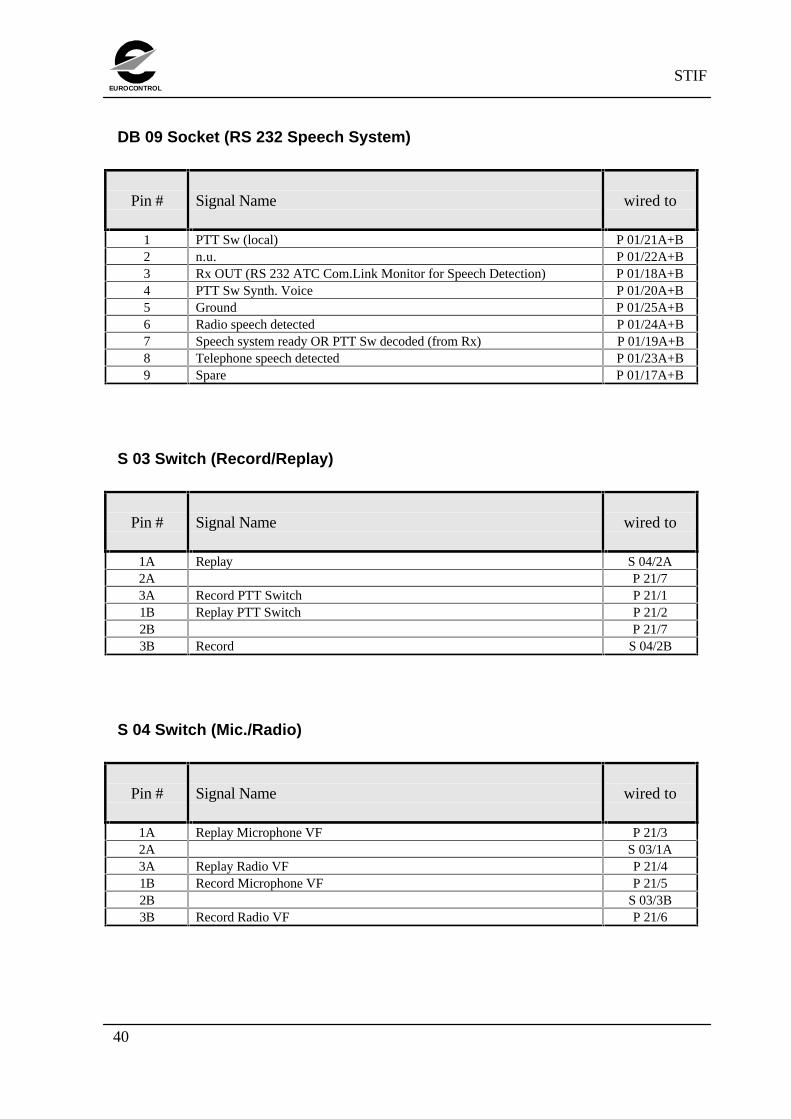
DB 09 Socket (RS 232 Speech System)
Pin # Signal Name wired to
1 PTT Sw (local) P 01/21A+B2 n.u. P 01/22A+B3 Rx OUT (RS 232 ATC Com.Link Monitor for Speech Detection) P 01/18A+B4 PTT Sw Synth. Voice P 01/20A+B5 Ground P 01/25A+B6 Radio speech detected P 01/24A+B7 Speech system ready OR PTT Sw decoded (from Rx) P 01/19A+B8 Telephone speech detected P 01/23A+B9 Spare P 01/17A+B
S 03 Switch (Record/Replay)
Pin # Signal Name wired to
1A Replay S 04/2A2A P 21/73A Record PTT Switch P 21/11B Replay PTT Switch P 21/22B P 21/73B Record S 04/2B
S 04 Switch (Mic./Radio)
Pin # Signal Name wired to
1A Replay Microphone VF P 21/32A S 03/1A3A Replay Radio VF P 21/41B Record Microphone VF P 21/52B S 03/3B3B Record Radio VF P 21/6

STIF
41
EUROCONTROL
VF Cinch (Record VF)
Pin # Signal Name wired to
1 VF Record (OUT) P 23/32 Ground P 23/1
VF Cinch (Record PTT)
Pin # Signal Name wired to
1 Record PTT Switch P 22/32 Ground P 22/2
VF Cinch (Replay VF)
Pin # Signal Name wired to
1 VF Replay (IN) P 23/22 Ground P 23/1
VF Cinch (Replay PTT)
Pin # Signal Name wired to
1 Replay PTT Switch P 22/12 Ground P 22/2

STIF
42
EUROCONTROL
Appendix J - STIF - X 471 Wiring
1
2
3
4
5
6
7
8
9
10
8
21
22
9
7
20
12
25
LEMO 10 pinSTIF Rear Panel
DB 25FFrequentis X 471

STIF
43
EUROCONTROL
Appendix K - Voice Recording Interface
Schematic
-12 V+8 V
+12 V
+12 V
2Relay
14
86
10 11
12
13
2 1
8 9 10 11
6 12
4 3
5
2 1
13
9
10
8
5
4
6
13
12
11
2
3
470k1N914
470k
1N914
1N914
1N914
10k
10k
10k
10k
10k
4 x 240k
4 x 100k
4 x 22k
56k
68k5,6
8
9
22k
22k 10n
47k
0.1µ
0.1µ0.1µ 0.1µ
1µ
1µ
1µ470k
100k
27k
68k
IC 6*
IC 6*IC 6*
IC 6*
IC 7*
IC 7*
IC 7*
IC 4
IC 3IC 1
IC 2
IC 5
IC 5
IC 5
IC 5
Rear Panel
Record PTT Switch
Replay PTT Switch
P 22
3
1
P 10
P 23
P 21
1
7
2
1VF Replay (IN)
VF Record (OUT)
VF - SignalMic. (IN/OUT)
VF - SignalRadio (IN/OUT)
+12 V
Ground
-12 V
Detected PTTSwitch (IN)
Local PTTSwitch (IN/OUT)
1B
1A
3A
3B
-8 V
18k
33k
33k
18k
22µ
22µ
8A+B
4A+B
6A+B7A+B
Microphone
Radio
Replay
Record
S 03
S 04
2
3
81
4
22k
4.3k
47k
5 6
6
1,4,8,12
2
5
3,11,13,16
7
83
2
1,42,4,7,12
+12 V
15k
15k
15k
15k
1N914
IC 2
IC 2
+12V
10k
10k
+12V
14
11
98
10
+12V
* IC with +/-8V
Remarks:‘Record PTT Switch’ output signal (P22/3): 15 kHz square wave, 1.5 Vpp;‘Replay PTT Switch’ input signal (P22/1): 15 kHz, minimum 0.6 Vpp;Attention --> no signal at P22/1 or P22/3 means the PTT switch is pressed!!!

STIF
44
EUROCONTROL
Board Layout
C22µ
IC 6HEF 4066BP
IC 7HEF 4066BP
IC 1MC 14538
IC 2MM 74C906
C 1µ
C22µR 47k
RelayD31A5100
IC 5SN 751888N
IC 4TL 072CP
IC 3LM 311
R 22k
R 22k
R 22k
R 22k
R 470k
P 10
P 21
P 22
P 23
C 1µ D 1N914
D 1N914
D 1N914
R 470kR 10k
R 22k
R 47k
R 18k
R 4.3k1
1
1
R 22k
R 18k
R 10kR 470k

STIF
45
EUROCONTROL
Connector Layouts
Connector P 21 (Rear Panel Selector Switches)
Pin # Signal Name
1 Record PTT Switch2 Replay PTT Switch3 Replay Microphone VF4 Replay Radio VF5 Record Microphone VF6 Record Radio VF7 +12 V
Connector P 22 (VF Signals representing PTT Switch)
Pin # Signal Name
1 Replay PTT Switch2 Ground3 Record PTT Switch
Connector P 23 (Speech VF Signals)
Pin # Signal Name
1 VF Replay (IN)2 VF Record (OUT)3 Ground

STIF
46
EUROCONTROL
Connector P 10 (Motherboard)
Pin # Signal Name
1A VF Signal Radio (IN/OUT)1B VF - Signal Microphone (IN/OUT)
2 A+B n.u.3 A Local PTT Switch (IN/OUT)3B Detected PTT Switch (IN)
4 A+B -12 V5 A+B n.u.6 A+B Ground7 A+B Ground8 A+B +12 V

STIF
47
EUROCONTROL
Appendix L -RS 232 Speech System Signals
PinRS232SignalName
Signal Name“ACTIVE”Signal Level
1 DCD PTT Switch (local) high =>PTT Switch is pressed2 Tx n.u.3 Rx Rx OUT (RS 232 ATC Com.Link Monitor for Speech detection)4 DTR PTT Switch (from speech system for Synth. Voice Input) high =>Speech system ‘speaks’5 GRD Ground6 DSR Radio Speech detected by STIF high =>Speech on Radio Channel7 RTS Speech system ready or (optional) PTT Switch decoded (from Rx)high =>Speech system is ready8 CTS Telephone speech detected by STIF high =>Speech on Tel. Channel9 RI Spare
Remark:DB 9 socket on the rear panel.