Error Analysis of a System for Measuring Three-Dimensional Joint Motion
9
W. J.Suntay E. S. Grood M.S. Hefzy D. L. Butler F. R. Noyes Gianneslras Biomechanics Laboratory, Department of Orthopaedic Surgery, University of Cincinnati Medical Center, Cincinnati, Ohio 45267 Error Analysis of a System for Measuring Three-Dimensional Joint Motion 1 In the past ten years there has been increased use of six-degree-of-freedom in- strumented spatial linkages for the measurement of biological joint motions. In spite of the increased popularity, little information has been reported on the ac- curacy of these devices. In this paper, we present a two-part investigation of the accuracy of the instrumented spatial linkage when used to measure knee joint kinematics. In the first part, we present the results of a theoretical analysis and an experimental determination of the errors associated with spatial linkage systems. In the second part, we describe the errors associated with a bi-planar X-ray system used to obtain the coordinate transformation between the linkage ends and coor- dinate systems located in the bones comprising the joint. We found that the theoretical error analysis consistently overestimated the actual measurement error, thus providing an unreliable estimate of errors. The experimental study of both the linkage system and the bi-planar X-ray system demonstrated that the accuracy of displacement measurement is insensitive to large systematic errors in position measurement. Introduction The idea of using mechanical systems for measuring joint motion was suggested as early as 1874 by Marey [1]. Elec- trogoniometry techniques were applied to human joints in order to measure angular motion using potentiometers. Karpovich and Wilklow [2], Karpovich, et al. [2, 3], Liberson [4] and Tipton and Karpovich [5] developed devices whose usefulness were limited because only a single-plane rotation could be measured at a time and because these devices were not self-aligning with the joint's center of rotation. Lamoreux [6] used a two-degree-of-freedom self-aligning parallelogram linkage to measure any two of the three components of a three-dimensional rotation. Wright [7], Johnston and Smidt [8], Kettelkamp, et al. [9], Chao, et al. [10] and Chao and Morrey [11] used three potentiometers to measure three mutually perpendicular rotations in a joint. However, errors associated with crosstalk occur when using those triaxial goniometers. Chao [12] defines crosstalk as the difference between the actual joint motion and the transducer measurements for the triaxial goniometer. The reason crosstalk occurs in the triaxial goniometer is because the axes of the sensing potentiometers are not always parallel to the axes of the motion being measured. In the triaxial goniometer crosstalk occurs primarily in the poten- This work supported in part by Grant AM 21172 from the Musculoskeletal Diseases Program of the National Institute of Arthritis, Diabetes, Digestive and Kidney Diseases. Contributed by the Bioengineering Division for publication in the JOURNAL OF BIOMECHANICAL ENGINEERING. Manuscript received by the Bioengineering Division, December 7, 1981; revised manuscript received December 28, 1982. NOTE: Appropriate SI Conversion Units—1 in. = 2.54 cm. tiometer which senses internal-external tibial rotation since it is attached to the tibia through a yoke which permits its orientation to vary with respect to the tibia [10]. McKechnie and Cousins [13] developed a parallelogram chain mechanism for the triaxial goniometer in order to eliminate this problem. The mechanism was made of molded plastic and used in place of the yoke to add the necessary three translational degrees of freedom. Proper function of this device relies on the parallelogram mechanism absorbing translations and transmitting rotations. Antonelli, et al. [14] evaluated this device and observed unacceptable magnitudes of crosstalk which may be due to insufficient rigidity of the parallelogram chain to rotary loads. Kinzel and co-workers [15-16] have proposed a six-degree- of-freedom instrumented spatial linkage to indirectly measure the three rotations and the three translations between joint members. The spatial linkage provides a more complete and precise quantification of joint motion than previously possible. In this device none of the angles measured by the potentiometers give a direct measurement of any commonly used position parameters. Thus, the measured angles must be transformed into some other form. These calculations require computer analysis which permits exact kinematic relations to be employed, thereby eliminating crosstalk. Thus, measurement error in spatial linkages results from mechanical and transducer tolerances alone, and not from inherent misalignments with the rotation axes. The instrumented spatial linkage system, like all other devices, should be rigidly attached to each of the two bones which comprise the joint, since it is the relative motion be- Journal of Biomechanical Engineering MAY 1983, Vol. 105/127 Copyright © 1983 by ASME Downloaded 24 Jan 2011 to 129.137.5.42. Redistribution subject to ASME license or copyright; see http://www.asme.org/terms/Terms_Use.cfm
Transcript of Error Analysis of a System for Measuring Three-Dimensional Joint Motion
W. J.Suntay
E. S. Grood
M.S. Hefzy
D. L. Butler
F. R. Noyes
Gianneslras Biomechanics Laboratory, Department of Orthopaedic Surgery,
University of Cincinnati Medical Center, Cincinnati, Ohio 45267
Error Analysis of a System for Measuring Three-Dimensional Joint Motion1
In the past ten years there has been increased use of six-degree-of-freedom instrumented spatial linkages for the measurement of biological joint motions. In spite of the increased popularity, little information has been reported on the accuracy of these devices. In this paper, we present a two-part investigation of the accuracy of the instrumented spatial linkage when used to measure knee joint kinematics. In the first part, we present the results of a theoretical analysis and an experimental determination of the errors associated with spatial linkage systems. In the second part, we describe the errors associated with a bi-planar X-ray system used to obtain the coordinate transformation between the linkage ends and coordinate systems located in the bones comprising the joint. We found that the theoretical error analysis consistently overestimated the actual measurement error, thus providing an unreliable estimate of errors. The experimental study of both the linkage system and the bi-planar X-ray system demonstrated that the accuracy of displacement measurement is insensitive to large systematic errors in position measurement.
Introduction
The idea of using mechanical systems for measuring joint motion was suggested as early as 1874 by Marey [1]. Elec-trogoniometry techniques were applied to human joints in order to measure angular motion using potentiometers. Karpovich and Wilklow [2], Karpovich, et al. [2, 3], Liberson [4] and Tipton and Karpovich [5] developed devices whose usefulness were limited because only a single-plane rotation could be measured at a time and because these devices were not self-aligning with the joint's center of rotation. Lamoreux [6] used a two-degree-of-freedom self-aligning parallelogram linkage to measure any two of the three components of a three-dimensional rotation. Wright [7], Johnston and Smidt [8], Kettelkamp, et al. [9], Chao, et al. [10] and Chao and Morrey [11] used three potentiometers to measure three mutually perpendicular rotations in a joint. However, errors associated with crosstalk occur when using those triaxial goniometers. Chao [12] defines crosstalk as the difference between the actual joint motion and the transducer measurements for the triaxial goniometer.
The reason crosstalk occurs in the triaxial goniometer is because the axes of the sensing potentiometers are not always parallel to the axes of the motion being measured. In the triaxial goniometer crosstalk occurs primarily in the poten-
This work supported in part by Grant AM 21172 from the Musculoskeletal Diseases Program of the National Institute of Arthritis, Diabetes, Digestive and Kidney Diseases.
Contributed by the Bioengineering Division for publication in the JOURNAL OF BIOMECHANICAL ENGINEERING. Manuscript received by the Bioengineering Division, December 7, 1981; revised manuscript received December 28, 1982.
NOTE: Appropriate SI Conversion Units—1 in. = 2.54 cm.
tiometer which senses internal-external tibial rotation since it is attached to the tibia through a yoke which permits its orientation to vary with respect to the tibia [10].
McKechnie and Cousins [13] developed a parallelogram chain mechanism for the triaxial goniometer in order to eliminate this problem. The mechanism was made of molded plastic and used in place of the yoke to add the necessary three translational degrees of freedom. Proper function of this device relies on the parallelogram mechanism absorbing translations and transmitting rotations. Antonelli, et al. [14] evaluated this device and observed unacceptable magnitudes of crosstalk which may be due to insufficient rigidity of the parallelogram chain to rotary loads.
Kinzel and co-workers [15-16] have proposed a six-degree-of-freedom instrumented spatial linkage to indirectly measure the three rotations and the three translations between joint members. The spatial linkage provides a more complete and precise quantification of joint motion than previously possible. In this device none of the angles measured by the potentiometers give a direct measurement of any commonly used position parameters. Thus, the measured angles must be transformed into some other form. These calculations require computer analysis which permits exact kinematic relations to be employed, thereby eliminating crosstalk. Thus, measurement error in spatial linkages results from mechanical and transducer tolerances alone, and not from inherent misalignments with the rotation axes.
The instrumented spatial linkage system, like all other devices, should be rigidly attached to each of the two bones which comprise the joint, since it is the relative motion be-
Journal of Biomechanical Engineering MAY 1983, Vol. 105/127
Copyright © 1983 by ASMEDownloaded 24 Jan 2011 to 129.137.5.42. Redistribution subject to ASME license or copyright; see http://www.asme.org/terms/Terms_Use.cfm
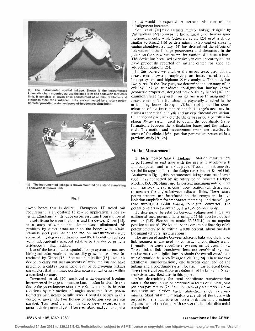
(a) The instrumented spatial linkage. Shown is the instrumentedkinematic cha in mounted across the knee joint 01 a cadaveric left lowerlimb. II consists of seven links constructed 01 aluminum blocks andstainless steel rods. Adjacent links are connected by a rotary paten.tiometer providing a single·degree·of·lreedom revolute joint.
(b) The instrumented linkage is shown mounted on a stand simulatinga cadaveric lelliower limb
Fig. 1
tween bones that is desired. Thompson [17] noted thisrequirement is an obstacle to in-vivo application, since external attachments introduce errors resulting from motion ofthe soft tissue between the bones and the device. Kinzel [15],in a study of canine shoulder motions, eliminated thisproblem by direct attachment to the bones with lI8-in.stainless steel pins. After the motion measurements wererecorded, the dog was euthanized and the articulating surfaceswere independently mapped relative to the device using aBridgeport milling machine.
Use of the instrumented spatial linkage system to measurebiological joint motions has steadily grown since it was introduced by Kinzel [16]. Sommer and Miller [18] used thisdevice to carry out measurements of wrist motion and havepresented a calibration scheme [19] for determining linkageparameters that minimize position measurement errors withina specified volume.
Townsend, et al. [20] employed a six-degree-of-freedominstrumented linkage to measure knee motion in vivo. In thisdevice the potentiometer axes were oriented to obtain the jointrotations by subtraction of angles measured from potentiometers with nearly parallel axes. Crosstalk occurs in thisdevice whenever the two flexion or abduction axes are notparallel. Townsend claimed this error never exceeded onepercent during normal gait. However, abnormal gait and joint
128/VoI.105, MAY 1983
laxities would be expected to increase this error as axismisalignment increases.
Soni, et al. [21] used an instrumented linkage designed byPatwardhan [22] to measure the kinematics of human spinemotion-segments, while Scherrer, et al. [23] used a devicesimilar to Kinzel [16] to determine in-vivo contact areas incanine shoulders. Suntay [24] has determined the effects oftolerances in the linkage parameters and clearances in thejoints on the screw parameters for motion of a human knee.This device has been used extensively in our laboratory and wehave previously reported on instant center for knee abadduction rotations [25].
In this paper, we analyze the errors associated with ameasurement system employing an instrumented spatiallinkage system and biplanar X-ray analysis. The study hastwo parts. In the first part, we determine the accuracy of anexisting linkage transducer configuration having knowngeometric properties, designed previously by Kinzel [16] andcommonly used by several investigators in performing motionmeasurements. The transducer is physically attached to thearticulating bones through lI8-in. steel pins. The determination of the instrumented spatial linkage's accuracy includes a theoretical analysis and an experimental evaluation.In the second part, we describe the errors associated with a biplanar X-ray system used to obtain the coordinate transformations between the articulating bones and the linkageends. The motion and measurement errors are described interms of the clinical joint position parameters presented in aprevious study [26-28].
Motion Measurement
1 Instrumented Spatial Linkage. Motion measurementis performed in real time with the use of a Modcomp IIminicomputer and a six-degree-of-freedom instrumentedspatial linkage similar to the design descri bed by Kinzel [16].As shown in Fig. 1, this instrumented linkage consists of sevenrigid links connected by six rotary potentiometers (HelipotModel 6153, 10k ohms, ±0.15 percent maximum independentnonlinearity, single turn, continuous rotation) which are usedto measure the angles between adjacent links. These rotarypotentiometers are interfaced to the computer throughisolation amplifiers for impedance matching, and the voltagesread through a 12-bit analog to digital converter. Thepotentiometers are powered by a ± 10-V power supply.
To determine the relation between voltage and angle, wecalibrated each potentiometer using a 13-bit absolute opticalencoder (BEl Electronics model 5V232BL) as an angularposition standard. We found the maximum nonlinearity of allpotentiometers to be within ±0.08 percent, about one-halfthe manufacturers' specifications.
The measured angles between adjacent links and the knownlink geometries are used to construct a coordinate transformation between coordinate systems on adjacent links.These link-to-Iink transformations are combined by successive matrix multiplications to obtain the overall coordinatetransformation between linkage ends [16, 20]. There are twoadditional transformations, one between each end of thelinkage and a coordinate system located in the adjacent bone.These two transformations are determined by bi-planar X-rayanalysis as described later in this paper.
After determining the total coordinate transformationmatrix, the motion can be described in terms of clinical jointposition parameters [25-27]. The clinical parameters used inthis study are, flexion angle, abduction angle, externalinternal tibial rotation, medial-lateral shift of the tibia withrespect to the femur, anterior-posterior drawer, and proximaldisplacement of the femur with respect to the tibia (tibia axialtranslation) .
Transactions of the ASME
Downloaded 24 Jan 2011 to 129.137.5.42. Redistribution subject to ASME license or copyright; see http://www.asme.org/terms/Terms_Use.cfm
Table 1 Linkage parameters
POT no.
1 2 3 4 5 6
Ok mm 0.000 0.001
103.308 93.251 0.044 0.032
Sk mm 0.000
25.824 16.234
-25.817 -25.839
0.000
&k deg 0.000
270.000 270.000
90.000 90.000 90.000
xk V/deg 340.037 340.356 340.702
-341.195 -341.627 -341.217
Bk deg
- 82.027 43.858
- 172.463 435.920 445.383 172.526
Table 2 Link and joint tolerances1"1
Mechanical tolerance Link length ± 0 . 0 4 mm Twist angle ± 0 . 5 deg
Transducer tolerance ± 0 . 5 4 deg Maximum clearance rotations ± 0 . 1 5 deg
(a) These tolerances are used for the chain theoretical analysis. The mechanical tolerances are due to the uncertainty in measuring the known linkage geometry. The transducer tolerance is the uncertainty in angle measurement due to potentiometer nonlinearity and electrical noise. Clearance rotations are tolerances due to joint play.
2 Bi-Planar X-Rays. To noninvasively determine the location of the linkage ends relative to the bones, we employed a bi-planar X-ray technique similar to that described by Brown, et al. [29] in their study of the human spine. Several modifications, presented in the forthcoming, were incorporated in implementation of the technique.
X-rays produce spherical projections onto a film plane. When two spherical projections on perpendicular planes are available (bi-planar X-rays), descriptive geometry and vector algebra can be applied to determine the relative positions between points which appear on both projections. Before such an analysis can be performed, however, all positions must be defined relative to a known reference coordinate system.
A reference coordinate system was fabricated from 1/4-in. plexiglas in the form of a 24 in. x 12 in. x 12 in. box with open ends. The X-ray film cassettes were supported at right angles to each other and parallel to the faces of the rectangular box. Radio-opaque reference markers were embedded in the sides at known locations to within ±0.015 mm, forming a rectangular grid in all four planes. These reference markers contain 0.65-mm-dia holes to aid in accurately locating their center on the X-ray.
Brown, et al. [29] assumed in their analysis that no trans-lational transformations occur between the film plane and the reference coordinate system. This imposed a constraint that orthogonal reference wires be mounted immediately in front of the film cassettes and that the distance between the wires and the film plane was negligible. The technique we employed accounts for this transformation, thereby eliminating errors, although of a small magnitude, resulting from such simplifying assumptions.
In Appendix A we present our analysis for the determination of the location of a point P, knowing the coordinates of its projections ( P , ' and P2') onto both film planes. This approach requires the magnification factor for each of the four coordinate reference planes be determined. These data were then used in calculating the spatial location of the two X-ray sources.
In practice, the X-ray films are independently digitized five times and their means calculated to reduce random errors associated with locating the necessary points on the film. To determine the magnification factor for each of the four planes of the calibration box, the 9 reference markers on each plane are used in the analysis. Two points are taken at a time, the distance on the film calculated and ratio relative to the actual distance determined giving 36 estimates of magnification factor. The mean is then used as the magnification factor for
that plane. To determine the source locations, 9 points on the front plane and 9 points on the back plane are used. Two points at a time, one on the front plane and one on the back plane, are analyzed and an estimate of the source location is obtained resulting in a total of 81 possible combinations. Again, the mean is used as an estimate of the source location.
Evaluation of the Measurement System
Part A: Evaluation of Spatial Linkage. The determination of the instrumented spatial linkage's accuracy is divided into two parts—a theoretical and an experimental evaluation.
Theoretical Evaluation. The accuracy of the instrumented spatial linkage in characterizing screw displacements has been previously evaluated by Kinzel [16] and Suntay [24], Here we consider the accuracy in measuring the clinical joint position parameters described previously in [26-28]. The measurement errors can be classified as originating from three sources. First, are the tolerance errors resulting from uncertainties in the fixed geometry of each link. Second are the transducer errors. These are errors in the measurement of the angular rotations between links by the potentiometers. Third, are the clearance errors due to the play at the linkage joint. It is assumed that the errors are small enough to allow the use of linear theory and superposition. A perturbation technique is used (Kinzel [16]) to determine the maximum error due to the tolerance on link geometry; the maximum error due to transducer uncertainty, and the maximum error due to the clearance tolerances in the potentiometer bearings.
Let Y be a desired motion parameter. Y is related to the individual measurements x,'s, which are the linkage parameters by a function designated as
Y=Y(X],x2 ,x„) (1)
The maximum total error in Y resulting from small perturbations (Ax,-) in each of the x, is written as
rr=X>r,-i
where
AY-, = Y(xx,x2, . . . ,x„)
-Y(Xi,x2, • • • ,Xi-i,Xi + AXi,xi+u . . . x„)
(2)
(3)
Since the tolerance errors and transducer errors are independent and randomly distributed, the probable error is a more realistic error estimate than the maximum total error. The probable error is calculated from the root-sum-square criterion (Beckwith and Buck [30])
AY, -[tlW1] (4)
Since the clearance tolerances are not independent of each other, the maximum error was used for this parameter. Therefore, the maximum probable error in Kcan be written as
AY=AYe +AY, +AYC (5) *>rss rss L m a x v '
where AY„ is the root-sum-square error due to the tolerance s rss
on link geometry; Ay, is the root-sum-square error due to transducer uncertainty; and AYr is the maximum error due
. , m a x • i to the clearance tolerances in the potentiometer bearings. In order to perform an error analysis, it is necessary to
know the linkage design, the mounting configuration and the motions occurring since the results depend on these variables. The mounting used to measure knee motion is shown in Fig. 1(a) for a cadaveric left lower limb. To simulate this
Journal of Biomechanical Engineering MAY 1983, Vol. 105/129
Downloaded 24 Jan 2011 to 129.137.5.42. Redistribution subject to ASME license or copyright; see http://www.asme.org/terms/Terms_Use.cfm
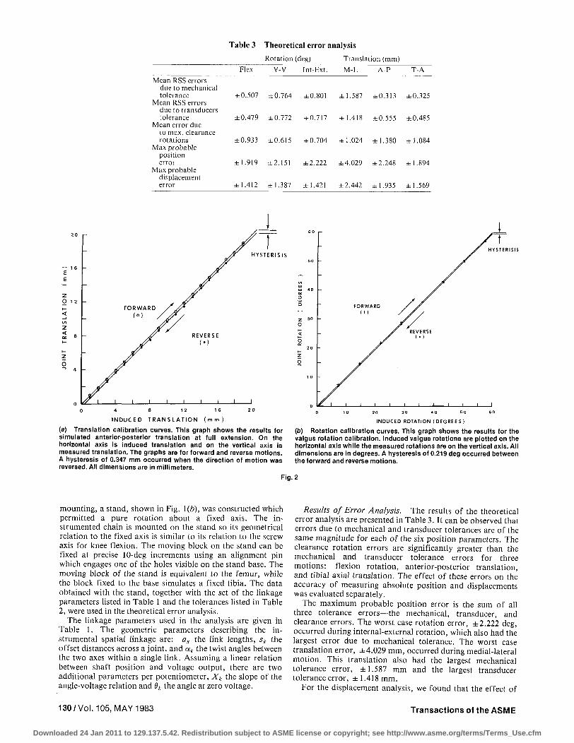
Table 3 Theore t ica l er ror analysis
Rotation (deg) Translation (mm)
Flex V-V Int-Ext. M-L A-P T-A
Mean RSS errors due to mechanical tolerance
Mean RSS errors due to transducers tolerance
Mean error due to max. clearance rotations
Max probable position error
Max probable displacement error
±0.507 ±0.764 ±0.801 ±1.587 ±0.313 ±0.325
±0.479 ±0.772 ±0.717 ±1.418 ±0.555 ±0.485
±0.933 ±0.615 ±0.704 ±1.024 ±1.380 ±1.084
±1.919 ±2.151 ±2.222 ±4.029 ±2.248 ±1.894
±1.412 ±1.387 ±1.421 ±2.442 ±1.935 ±1.569
2 0
— 1 6 E E
~
NS
LA
T
ION
2 8 •-z o • ^ 4
-
-
/y i
FORWARD /
1 1 1 1
7 REVERSE
(•)
i 1 1
r H
I
H Y S T E R I S I S
I N D U C E D T R A N S L A T I O N ( m m )
(a) Translation calibration curves. This graph shows the results for simulated anterior-posterior translation at full extension. On the horizontal axis is induced translation and on the vertical axis is measured translation. The graphs are for forward and reverse motions. A hysteresis of 0.347 mm occurred when the direction of motion was reversed. All dimensions are in millimeters.
INDUCED ROTATION (DEGREES)
(b) Rotation calibration curves. This graph shows the results for the valgus rotation calibration. Induced valgus rotations are plotted on the horizontal axis while the measured rotations are on the vertical axis. All dimensions are in degrees. A hysteresis of 0.219 deg occurred between the forward and reverse motions.
Fig. 2
mounting, a stand, shown in Fig. 1(b), was constructed which permitted a pure rotation about a fixed axis. The instrumented chain is mounted on the stand so its geometrical relation to the fixed axis is similar to its relation to the screw axis for knee flexion. The moving block on the stand can be fixed at precise 10-deg increments using an alignment pin which engages one of the holes visible on the stand base. The moving block of the stand is equivalent to the femur, while the block fixed to the base simulates a fixed tibia. The data obtained with the stand, together with the set of the linkage parameters listed in Table 1 and the tolerances listed in Table 2, were used in the theoretical error analysis.
The linkage parameters used in the analysis are given in Table 1. The geometric parameters describing the instrumental spatial linkage are: ak the link lengths, sk the offset distances across a joint, and ak the twist angles between the two axes within a single link. Assuming a linear relation between shaft position and voltage output, there are two additional parameters per potentiometer, Xk the slope of the angle-voltage relation and 6k the angle at zero voltage.
Results of Error Analysis. The results of the theoretical error analysis are presented in Table 3. It can be observed that errors due to mechanical and transducer tolerances are of the same magnitude for each of the six position parameters. The clearance rotation errors are significantly greater than the mechanical and transducer tolerance errors for three motions: flexion rotation, anterior-posterior translation, and tibial axial translation. The effect of these errors on the accuracy of measuring absolute position and displacements was evaluated separately.
The maximum probable position error is the sum of all three tolerance errors—the mechanical, transducer, and clearance errors. The worst case rotation error, ±2.222 deg, occurred during internal-external rotation, which also had the largest error due to mechanical tolerance. The worst case translation error, ±4.029 mm, occurred during medial-lateral motion. This translation also had the largest mechanical tolerance error, ±1.587 mm and the largest transducer tolerance error, ±1.418 mm.
For the displacement analysis, we found that the effect of
130/Vol. 105, MAY 1983 Transactions of the ASME
Downloaded 24 Jan 2011 to 129.137.5.42. Redistribution subject to ASME license or copyright; see http://www.asme.org/terms/Terms_Use.cfm
mechanical tolerance errors are nearly eliminated. This is because mechanical tolerance errors produce a nearly constant systematic error in position. Therefore, the maximum probable displacement error is just the sum of the transducer and clearance error. The maximum probable displacement error in rotations, ±1.421 deg, occurred during internal-external rotation and the maximum probable displacement error in translations, ±2.442 mm, happened during medial-lateral motion.
Experimental Evaluation. To obtain a direct measure of accuracy, the displacements measured with the instrumented linkage were compared to an accurate standard. The calibration was performed using an Instron high-magnification extensometer calibrator with a resolution of 0.0005-mm translation. The calibrator was modified for use in producing rotations providing a resolution of 0.36 deg. The calibration was performed as a cycle of forward and reverse motion with a total range of 20 mm for translation and 72 deg for rotation. The measurements were recorded every 1.0 mm for translations, every 7.2 deg for rotations. The kinematic chain was mounted on the extensometer calibrator in such a way as to provide displacement in the directions defined by the joint coordinate system described in [28].
Figure 2(a) shows the translation calibration curve for a simulated anterior-posterior translation at full extension. On the horizontal axis is induced translation and on the vertical axis is measured translations. Figure 2(b) shows the rotation calibration curve for the valgus rotation. Induced valgus rotations are plotted on the horizontal axis, while the measured rotations are on the vertical axis. These two parameters—anterior-posterior translation and valgus rotation—were selected because they are the worst case error we found. The graphs of Figs. 2(a) and 2(b) are for forward and reverse motions. Using the data from each direction, we calculated the best fit line with unity slope for both forward and reverse motions and determined the maximum nonlinearity for each direction.
Table 4 Cumulative displacement analysis-lation, 72-deg rotation
-20-mm trans-
Maximum nonlinearity
Hysteresis Forward Reverse Max. errors Translation (mm)
M-L(ext.) M-L (Hexed) A-P(ext.) A-P (Hexed) T-A(ext.) T-A(Hexed)
Rotation (deg) Flexion Valgus (flexed) Tibial rotation (Hexed)
0.005 0.005 0.347 0.319 0.045 0.253
0.169 0.219 0.149
±0.152 ±0.199 ±0.145 ±0.118 ±0.050 ±0.065
±0.205 ±0.368 ±0.144
±0.159 ±0.162 ±0.170 ±0.120 ±0.063 ±0.118
±0.281 ±0.357 ±0.232
0.164 0.204 0.517 0.439 0.108 0.371
0.450 0.581 0.381
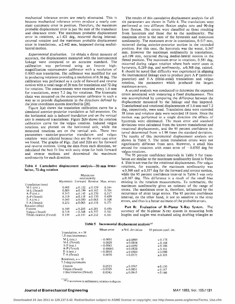
The results of this cumulative displacement analysis for all six parameters are shown in Table 4. The translations were performed at two different flexion angles zero and 90-deg knee flexion. The errors were classified as those resulting from hysteresis and those due to the nonlinearity. The maximum error is the sum of the hysteresis and maximum nonlinearity. The maximum error in translations, 0.517 mm, occurred during anterior-posterior motion in the extended position. For this case, the hysteresis was the worst, 0.347 mm. However the maximum nonlinearity in translations, ±0.199 mm, occurred during medial-lateral motion in the flexed position. The maximum error in rotations, 0.581 deg, occurred during valgus rotation where both worst cases in hysteresis, 0.219 deg, and nonlinearity, ±0.368 deg, existed. It should be noted that difficulty was experienced in aligning the instrumented linkage axes to produce pure A-P (anterior-posterior) and T-A (tibial-axial) translations and valgus rotation, the parameters which produced the largest maximum errors.
A second analysis was conducted to determine the expected errors associated with measuring a fixed displacement. This was accomplished by computing the difference between the displacement measured by the linkage and that imposed. Translational and rotational displacements of 1.0 mm and 7.2 deg, respectively, were used. Translation data were recorded 38 times and rotation data were recorded 18 times. Since the motion was performed in a single direction the effects of hysteresis were eliminated. The mean error and standard deviations were calculated from the known translational and rotational displacements, and the 95 percent confidence internal determined from ±1.96 times the standard deviation. The results of this incremental displacement analysis are shown in Table 5. The mean translation errors were not significantly different from zero. However, a small bias existed for rotations with mean error of —0.0705 deg for valgus rotations.
The 95 percent confidence intervals in Table 5 for translation are similar to the maximum nonlinearity listed in Table 4. This is not true for the rotational displacements. For valgus rotations, for example, the maximum nonlinearity was ±0.368 and ±0.357 deg for the forward and reverse motion, while the 95 percent confidence interval in Table 5 was only ±0.167 deg. This difference is a result of the small bias existing in the rotation measurements. To summarize, the maximum nonlinearity gives an estimate of the range of errors. The maximum error is, therefore, influenced by the occurrence of stray large errors. The 95 percent confidence interval, on the other hand, is not so sensitive to the stray errors, and thus is a better estimate of the probable errors.
Part B: Evaluation of Bi-Planar X-Ray System. The accuracy of the bi-planar X-ray system in measuring both lengths and angles was evaluated using drafting triangles as
Table 5 Incremental displacement analysis''
Translation, n = 38 1.0-mm increments M-L(ext.) M-L (Hexed) A-P(ext.) A-P (flexed) T-A(ext.) T-A(flexed)
Rotations, n = 18 7.2-deg increments
Flexion Valgus (flexed) Tibial rotation (flexed)
Mean error
-0.0001 -0.0029 -0.0063 -0.00003 -0.0010
0.0070
0.0523 -0.0705
0.0343
±Std. deviation
±0.0909 ±0.0856 ±0.0950 ±0.0820 ±0.0460 ±0.0525
±0.0767 ±0.0851 ±0.0845
95 percent con
±0.178 ±0.168 ±0.186 ±0.161 ±0.090 ±0.103
±0.150 ±0.167 ±0.166
'"'Translations in millimeters; rotation in degrees
Journal of Biomechanical Engineering MAY 1983, Vol. 105/131
Downloaded 24 Jan 2011 to 129.137.5.42. Redistribution subject to ASME license or copyright; see http://www.asme.org/terms/Terms_Use.cfm
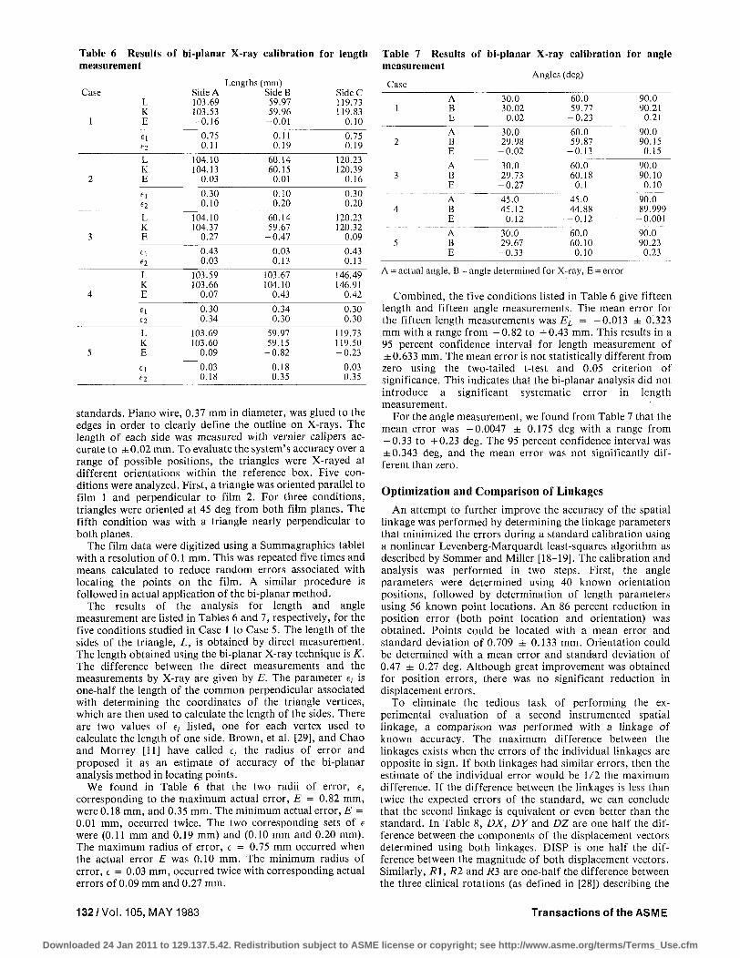
Table 6 Results of bi-planar X-ray calibration for length measurement
Lengths (mm) Case Side A Side B Side C
L 103.69 59.97 119.73 K 103.53 59.96 119.83
1 E -0.16 -0.01 0.10
0.75 0.11 0.75 0.11 0.19 0.19
2
3
4
5
L K E
fi
L K E
El
L K E
«i <=2
L K E
ei
104.10 104.13
0.03
0.30 0.10
104.10 104.37
0.27
0.43 0.03
103.59 103.66
0.07
0.30 0.34
103.69 103.60 -0 .09
0.03 0.18
60.14 60.15 0.01
0.10 0.20
60.14 59.67
-0.47
0.03 0.13
103.67 104.10
0.43
0.34 0.30
59.97 59.15
-0.82
0.18 0.35
120.23 120.39
0.16
0.30 0.20
120.23 120.32
0.09
0.43 0.13
146.49 146.91
0.42
0.30 0.30
119.73 119.50 -0 .23
0.03 0.35
standards. Piano wire, 0.37 mm in diameter, was glued to the edges in order to clearly define the outline on X-rays. The length of each side was measured with vernier calipers accurate to ±0.02 mm. To evaluate the system's accuracy over a range of possible positions, the triangles were X-rayed at different orientations within the reference box. Five conditions were analyzed. First, a triangle was oriented parallel to film 1 and perpendicular to film 2. For three conditions, triangles were oriented at 45 deg from both film planes. The fifth condition was with a triangle nearly perpendicular to both planes.
The film data were digitized using a Summagraphics tablet with a resolution of 0.1 mm. This was repeated five times and means calculated to reduce random errors associated with locating the points on the film. A similar procedure is followed in actual application of the bi-planar method.
The results of the analysis for length and angle measurement are listed in Tables 6 and 7, respectively, for the five conditions studied in Case 1 to Case 5. The length of the sides of the triangle, L, is obtained by direct measurement. The length obtained using the bi-planar X-ray technique is K. The difference between the direct measurements and the measurements by X-ray are given by E. The parameter e, is one-half the length of the common perpendicular associated with determining the coordinates of the triangle vertices, which are then used to calculate the length of the sides. There are two values of e, listed, one for each vertex used to calculate the length of one side. Brown, et al. [29], and Chao and Morrey [11] have called e, the radius of error and proposed it as an estimate of accuracy of the bi-planar analysis method in locating points.
We found in Table 6 that the two radii of error, e, corresponding to the maximum actual error, E = 0.82 mm, were 0.18 mm, and 0.35 mm. The minimum actual error, E = 0.01 mm, occurred twice. The two corresponding sets of e were (0.11 mm and 0.19 mm) and (0.10 mm and 0.20 mm). The maximum radius of error, e = 0.75 mm occurred when the actual error E was 0.10 mm. The minimum radius of error, e = 0.03 mm, occurred twice with corresponding actual errors of 0.09 mm and 0.27 mm.
Table 7 Results of bi-planar X-ray calibration for angle measurement
Angles (deg) Case
1
2
3
4
5
A B E
A B E
A B E
A B E
A B E
30.0 30.02 0.02
30.0 29.98
-0 .02
30.0 29.73
-0 .27
45.0 45.12
0.12
30.0 29.67
-0 .33
60.0 59.77
-0 .23
60.0 59.87
-0 .13
60.0 60.18 0.1
45.0 44.88
-0 .12
60.0 60.10 0.10
90.0 90.21
0.21
90.0 90.15 0.15
90.0 90.10 0.10
90.0 89.999
-0.001
90.0 90.23 0.23
A = actual angle, B = angle determined for X-ray, E = error
Combined, the five conditions listed in Table 6 give fifteen length and fifteen angle measurements. The mean error for the fifteen length measurements was EL = -0.013 ± 0.323 mm with a range from -0 .82 to +0.43 mm. This results in a 95 percent confidence interval for length measurement of ±0.633 mm. The mean error is not statistically different from zero using the two-tailed t-test and 0.05 criterion of significance. This indicates that the bi-planar analysis did not introduce a significant systematic error in length measurement.
For the angle measurement, we found from Table 7 that the mean error was -0.0047 ± 0.175 deg with a range from — 0.33 to +0.23 deg. The 95 percent confidence interval was ±0.343 deg, and the mean error was not significantly different than zero.
Optimization and Comparison of Linkages
An attempt to further improve the accuracy of the spatial linkage was performed by determining the linkage parameters that minimized the errors during a standard calibration using a nonlinear Levenberg-Marquardt least-squares algorithm as described by Sommer and Miller [18-19]. The calibration and analysis was performed in two steps. First, the angle parameters were determined using 40 known orientation positions, followed by determination of length parameters using 56 known point locations. An 86 percent reduction in position error (both point location and orientation) was obtained. Points could be located with a mean error and standard deviation of 0.709 ± 0.133 mm. Orientation could be determined with a mean error and standard deviation of 0.47 ± 0.27 deg. Although great improvement was obtained for position errors, there was no significant reduction in displacement errors.
To eliminate the tedious task of performing the experimental evaluation of a second instrumented spatial linkage, a comparison was performed with a linkage of known accuracy. The maximum difference between the linkages exists when the errors of the individual linkages are opposite in sign. If both linkages had similar errors, then the estimate of the individual error would be 1/2 the maximum difference. If the difference between the linkages is less than twice the expected errors of the standard, we can conclude that the second linkage is equivalent or even better than the standard. In Table 8, DX, DY and DZ are one half the difference between the components of the displacement vectors determined using both linkages. DISP is one half the difference between the magnitude of both displacement vectors. Similarly, Rl, R2 and R3 are one-half the difference between the three clinical rotations (as defined in [28]) describing the
132 /Vol. 105, MAY 1983 Transactions of the ASME
Downloaded 24 Jan 2011 to 129.137.5.42. Redistribution subject to ASME license or copyright; see http://www.asme.org/terms/Terms_Use.cfm
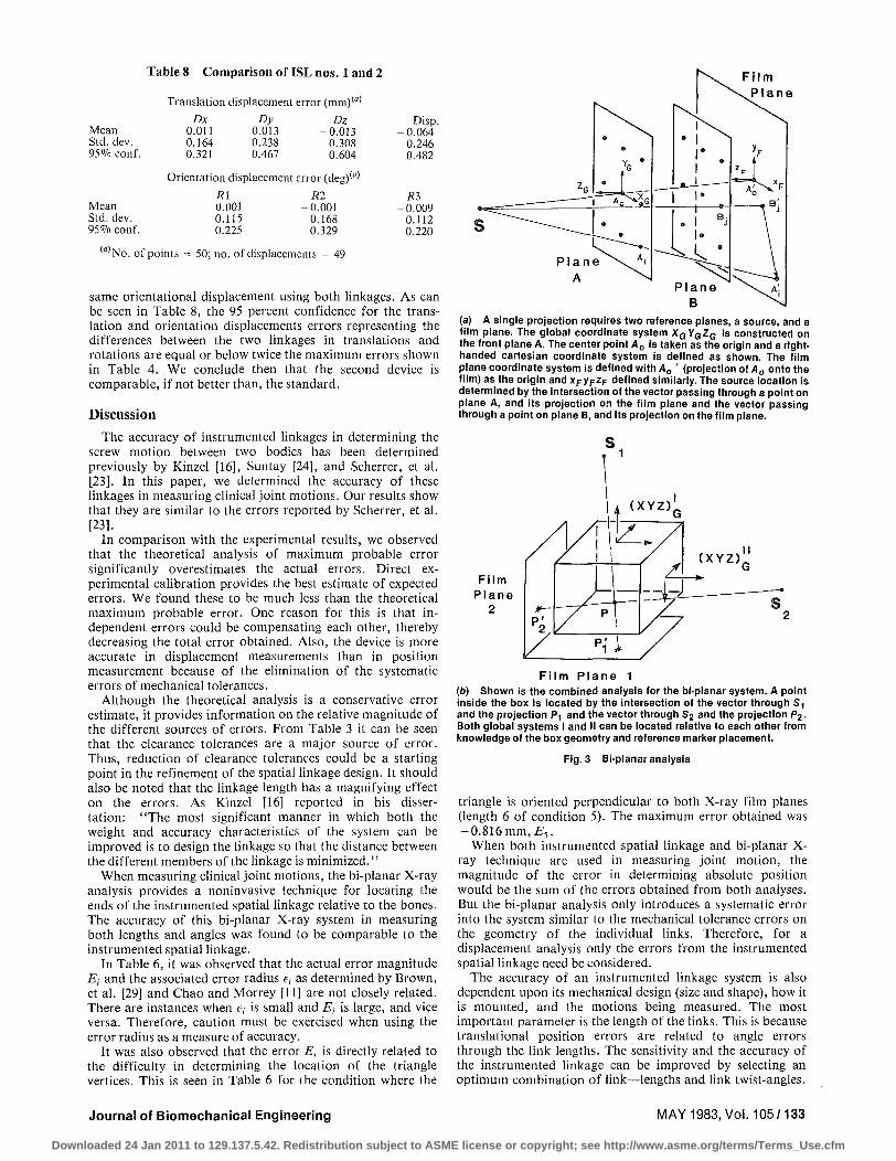
Table 8 Comparison of ISL nos. 1 and 2
Mean Std. dev. 95% conf.
Mean Std. dev. 95% conf.
Translation displacement error (mm)M
Dx Dy Dz 0.011 0.013 -0.013 0.164 0.238 0.308 0.321 0.467 0.604
Orientation displacement error (deg) <«> R\
-0.001 0.115 0.225
Rl -0.001 0.168 0.329
Disp. -0.064 0.246 0.482
R3 -0.009 0.112 0.220
(«) No. of points = 50; no. of displacements = 49
same orientational displacement using both linkages. As can be seen in Table 8, the 95 percent confidence for the translation and orientation displacements errors representing the differences between the two linkages in translations and rotations are equal or below twice the maximum errors shown in Table 4. We conclude then that the second device is comparable, if not better than, the standard.
Discussion
The accuracy of instrumented linkages in determining the screw motion between two bodies has been determined previously by Kinzel [16], Suntay [24], and Scherrer, et al. [23]. In this paper, we determined the accuracy of these linkages in measuring clinical joint motions. Our results show that they are similar to the errors reported by Scherrer, et al. [23].
In comparison with the experimental results, we observed that the theoretical analysis of maximum probable error significantly overestimates the actual errors. Direct experimental calibration provides the best estimate of expected errors. We found these to be much less than the theoretical maximum probable error. One reason for this is that independent errors could be compensating each other, thereby decreasing the total error obtained. Also, the device is more accurate in displacement measurements than in position measurement because of the elimination of the systematic errors of mechanical tolerances.
Although the theoretical analysis is a conservative error estimate, it provides information on the relative magnitude of the different sources of errors. From Table 3 it can be seen that the clearance tolerances are a major source of error. Thus, reduction of clearance tolerances could be a starting point in the refinement of the spatial linkage design. It should also be noted that the linkage length has a magnifying effect on the errors. As Kinzel [16] reported in his dissertation: "The most significant manner in which both the weight and accuracy characteristics of the system can be improved is to design the linkage so that the distance between the different members of the linkage is minimized.''
When measuring clinical joint motions, the bi-planar X-ray analysis provides a noninvasive technique for locating the ends of the instrumented spatial linkage relative to the bones. The accuracy of this bi-planar X-ray system in measuring both lengths and angles was found to be comparable to the instrumented spatial linkage.
In Table 6, it was observed that the actual error magnitude Ej and the associated error radius e, as determined by Brown, et al. [29] and Chao and Morrey [11] are not closely related. There are instances when e,- is small and E-, is large, and vice versa. Therefore, caution must be exercised when using the error radius as a measure of accuracy.
It was also observed that the error Et is directly related to the difficulty in determining the location of the triangle vertices. This is seen in Table 6 for the condition where the
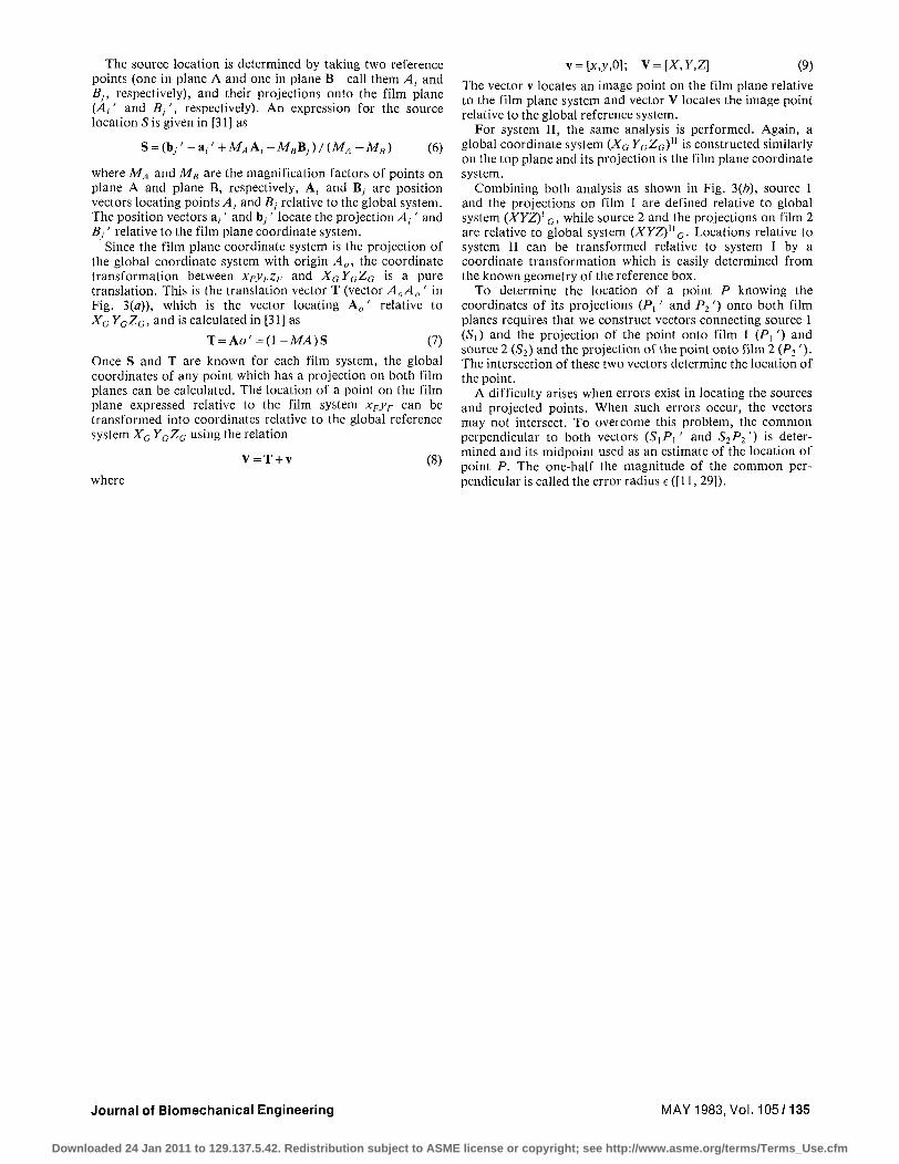
(a) A single projection requires two reference planes, a source, and a film plane. The global coordinate system XGYGZG is constructed on the front plane A. The center point A0 is taken as the origin and a right-handed cartesian coordinate system is defined as shown. The film plane coordinate system is defined with A0 ' (projection of A0 onto the film) as the origin and x^yp^F defined similarly. The source location is determined by the intersection of the vector passing through a point on plane A, and its projection on the film plane and the vector passing through a point on plane B, and its projection on the film plane.
F i l m P l a n e 1 (•) Shown is the combined analysis for the bi-planar system. A point inside the box is located by the intersection of the vector through S1
and the projection P1 and the vector through S2 and the projection P2. Both global systems I and II can be located relative to each other from knowledge of the box geometry and reference marker placement.
Fig. 3 Bi-planar analysis
triangle is oriented perpendicular to both X-ray film planes (length 6 of condition 5). The maximum error obtained was -0.816 mm, Es.
When both instrumented spatial linkage and bi-planar X-ray technique are used in measuring joint motion, the magnitude of the error in determining absolute position would be the sum of the errors obtained from both analyses. But the bi-planar analysis only introduces a systematic error into the system similar to the mechanical tolerance errors on the geometry of the individual links. Therefore, for a displacement analysis only the errors from the instrumented spatial linkage need be considered.
The accuracy of an instrumented linkage system is also dependent upon its mechanical design (size and shape), how it is mounted, and the motions being measured. The most important parameter is the length of the links. This is because translational position errors are related to angle errors through the link lengths. The sensitivity and the accuracy of the instrumented linkage can be improved by selecting an optimum combination of link—lengths and link twist-angles.
Journal of Biomechanical Engineering MAY 1983, Vol. 105/133
Downloaded 24 Jan 2011 to 129.137.5.42. Redistribution subject to ASME license or copyright; see http://www.asme.org/terms/Terms_Use.cfm
However, this optimum combination may not be physically realizable since there are also physical limitations on the lengths of the links. These physical limitations differ from one usage to another. For example, the relative link lengths and link twist angles Kinzel [16] used to measure shoulder motions in the dog are different from those used by Patwardhan [22] in measuring intervertebral motion. In each case the link lengths are chosen to prevent physical interference with the motions being measured.
The analysis and documentation of the errors performed in the present study and associated with joint measurements were for an existing linkage transducer configuration having known geometric properties and designed previously by Kinzel [16] and used by several investigators. It was not our purpose to determine an optimum combination of link parameters which would improve the sensitivity and the accuracy of the transducer nor to determine the optimum mounting condition for minimizing errors.
Summary
1 We have evaluated the accuracy of the instrumented spatial linkage in measuring the clinical knee joint position parameters described previously in [18-20].
2 The theoretical analysis of the maximum probable error associated with the six degrees of freedom instrumented spatial linkage consistently overestimated the actual measurement errors.
3 The instrumented spatial linkage is more accurate in displacement measurements as compared to position measurements because of the elimination of the systematic errors of mechanical tolerances.
4 The maximum errors associated with measuring translations and rotations using the instrumented spatial linkage were ±0.517 mms and ±0.581 deg, respectively, while the maximum probable errors were ±0.186 mms and ±0.167 deg, respectively.
5 The accuracy of the bi-planar X-ray system we employed to measure both lengths and angles is comparable to the instrumented spatial linkage.
References
1 Marey, E. J., "Animal Mechanism," A Treatise on Terrestrial and Aerial Locomotion, Appleton-Century-Crofts, New York, 1874.
2 Karpovich, P. V., and Wilklow, L. B., "A Goniometric Study of the Human Foot in Standing and Walking," U.S. Armed Forces Medical Journal, Vol. 10, 1959, pp. 885-903.
3 Karpovich, P. V., Herden, E. L., Jr., and Asa, M. M., "Elec-trogoniometric Study of Joints," U.S. Armed Forces Medical Journal, Vol. 11, 1960, pp.424-450.
4 Liberson, W. T., "Biomechanics of Gait: A Method of Study," Arch. Phys. Med., Vol. 46, 1965, pp. 37-48.
5 Tipton, C. M., and Karpovich, P. V., "Electrogoniometric Records of Knee and Ankle Movements in Pathologic Gaits," Arch. Phys. Med., Vol. 46, 1965, pp.267-272.
6 Lamoreux, L. W., "Kinematic Measurements in the Study of Human Walking," Bulletin of Prosthetics Research, Spring, 1971.
7 Wright, D. G., Desai, S. M., and Henderson, W. H., "Action of the Subtalar and Ankle-joint Complex During the Stance Phase of Walking," Journal of Bone and Joint Surgery, Vol. 46-A, 1964, pp. 361-382.
8 Johnston, R. C , and Smidt, G. L., "Measuremenl of Hip Joint Motion During Walking," Journal of Bone and Joint Surgery, Vol. 51-A, 1969, pp. 1083-1094.
9 Kettelkamp, D. B., Johnston, R. J., Smidt, G. L., Chao, E. Y. S., and Walker, M., "An Electrogoniometric Study of Knee Motion in Normal Gait," Journal of Bone and Joint Surgery, Vol. 52-A, 1970, pp. 775-790.
10 Chao, E. Y. S., Rim, K., Smidt, G. L., and Johnston, R. C , "The Application of 4 X 4 Matrix Method to the Correction of the Measurements of Hip Joint Rotations," Journal of Biomechanics, Vol. 3, 1970, pp. 459-471.
11 Chao, E. Y. S., and Morrey, B. F., "Three-Dimensional Rotation of the Elbow," Journal of Biomechanics, Vol. 11, 1978, pp. 57-73.
12 Chao, E. Y. S., "Justification of Triaxial Goniometer for the Measurement of Joint Motion," Journal of Biomechanics, Vol. 13, 1980, pp. 989-1006.
13 McKechnie, R. E., and Cousins, S. J., "A Parallelogram Chain
Mechanism for Measuring Human Joint Motion," ASME Paper No. 76-DET-71, 1976.
14 Antonelli, D., Perry, J., Gronley, J., and Harlow, M., "Functional Evaluation of a Parallelogram Triaxial Goniometer," Transactions 28th Annual Orthopaedic Research Society, 1982, p. 256.
15 Kinzel, G. L., Hillbery, B. M.,and Hall, Jr., A. S., "Measurement of the Total Motion Between Two Body Segments - II. Description of Application," Journal of Biomechanics, Vol. 5, 1972, pp. 283-293.
16 Kinzel, G. L., "On the Design of Instrumented Linkage for the Measurement of Relative Motion Between Two Rigid Bodies," Ph.D. dissertation, Purdue University, 1973.
17 Thompson, C. T., "A System for Determining the Spatial Motions of Arbitrary Mechanisms—Demonstrated on a Human Knee," Ph.D. dissertation, Stanford University, 1972.
18 Sommer, III, H. J., and Miller, N. R., "A Technique for Kinematic Modeling of Anatomical Joints," ASME JOURNAL OF BIOMECHANICAL ENGINEERING, Vol. 102, No. 11, 1980, pp. 311-317.
19 Sommer, III, H. J., and Miller, N. R., "A Technique for the Calibration of Instrumented Spatial Linkages Used for Biomechanical Kinematic Measurements," Journal of Biomechanics, Vol. 14, 1981, pp. 91-98.
20 Townsend, M. A., Izak, M., and Jackson, R. W., "Total Motion Knee Goniometry," Journal of Biomechanics, Vol. 10, 1977, pp. 183-193.
21 Soni, A. H., Sulivan, Jr., J. A., Patwardhan, A. G., Gaudavalli, M. R., and Chitwood, J., "Kinematic Analysis and Simulation of Vertebral Motion Under Static Load—Part 1: Kinematic Analysis," ASME JOURNAL OF BIOMECHANICAL ENGINEERING, Vol. 104, No. 5, 1982, pp. 105-111.
22 Patwardhan, A. G., "Kinematic Analysis and Simulation Studies of Intervertebral Motion," doctoral dissertation, Oklahoma State University, Stillwater, Okia., May 1980.
23 Scherrer, P. K., Hillberry, B. M., and Van Sickle, D. C , "Determining the In-Vivo Areas of Contact in the Canine Shoulder," ASME JOURNAL OF BIOMECHANICAL ENGINEERING, Vol. 101, No. 4, 1979, pp. 271-278.
24 Suntay, W. J., "A Study of Spatial Linkages for Relative Motion Measurement with Application to the Knee Joinl," M.S. thesis, University of Cincinnati, 1977.
25 Grood, E. S., Noyes, F. R., Butler, D. L., and Suntay, W. J., "Ligamentous and Capsular Restraints Preventing Straight Medial and Lateral Laxity in Intact Human Cadaver Knees," Journal of Bone and Joint Surgery, Vol.63A, 1981, pp. 1257-1269.
26 Grood, E. S., Suntay, W. J., Noyes, F. R., Butler, D. L., Miller, E. H., and Malek, M., "Total Motion Measurement During Knee Laxity Tests," Transactions 25th Annual Orthopaedic Research Society, 1979, p. 80.
27 Grood, E. S., and Suntay, W. J., "Letter to the Editor," Journal of Biomechanics, Vol. 14, pp. 653-655.
28 Grood, E. S., and Suntay, W. J., "A Joint Coordinate System: A Description of Three Dimensional Motion," ASME JOURNAL OF BIOMECHANICAL ENGINEERING, Vol. 105, May 1983, pp. 136-144.
29 Brown, R. H., Burstein, A. H., Nash, C. L., and Schock, C. C , "Spinal Analysis Using a Three-Dimensional Radiographic Technique," Journal of Biomechanics, Vol. 9, 1976, pp. 355-366.
30 Beckwith, T. G., and Buck, N. L., Mechanical Measurement, Addison-Wesley, New York, 1969.
31 Suntay, W. J., "Three-Dimensional Kinematics of the Human Cadaver Knee: Application to the Clinical Laxity Examination and the Knee Extension Exercise," Ph.D. dissertation, University of Cincinnati, Cincinnati, Ohio, 1982.
A P P E N D I X A
Bi-Planar X-Ray Analysis
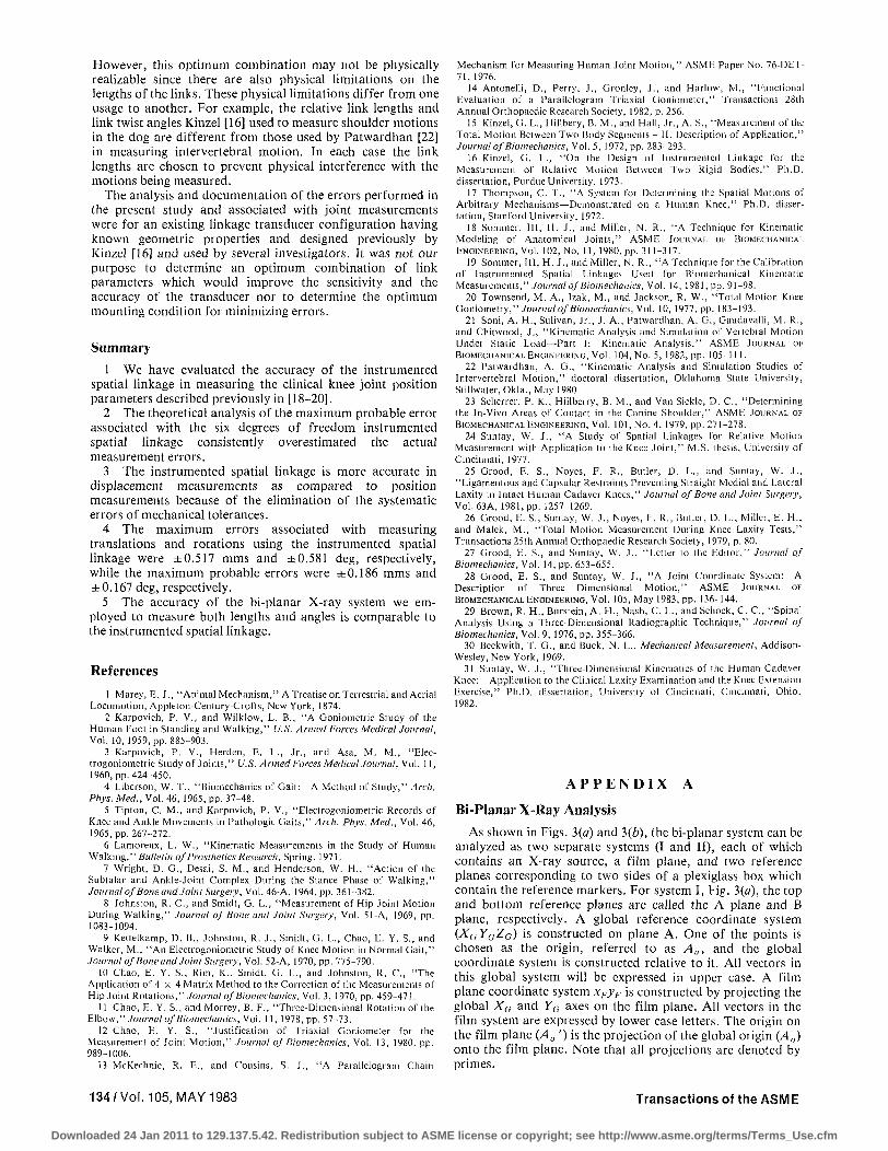
As shown in Figs. 3(a) and 3(6), the bi-planar system can be analyzed as two separate systems (I and II), each of which contains an X-ray source, a film plane, and two reference planes corresponding to two sides of a plexiglass box which contain the reference markers. For system I, Fig. 3(a), the top and bottom reference planes are called the A plane and B plane, respectively. A global reference coordinate system (XG YGZG) is constructed on plane A. One of the points is chosen as the origin, referred to as A„, and the global coordinate system is constructed relative to it. All vectors in this global system will be expressed in upper case. A film plane coordinate system xFyF is constructed by projecting the global Xa and YG axes on the film plane. All vectors in the film system are expressed by lower case letters. The origin on the film plane (A0 ') is the projection of the global origin (A0) onto the film plane. Note that all projections are denoted by primes.
134/Vol. 105, MAY 1983 Transactions of the ASME
Downloaded 24 Jan 2011 to 129.137.5.42. Redistribution subject to ASME license or copyright; see http://www.asme.org/terms/Terms_Use.cfm
The source location is determined by taking two reference points (one in plane A and one in plane B—call them A, and Bj, respectively), and their projections onto the film plane (A/ and Bj', respectively). An expression for the source location 5 is given in [31 ] as
S = (bJ'-ai'+MAAi-MBBJ)/(MA-MB) (6)
where MA and MB are the magnification factors of points on plane A and plane B, respectively, A, and By are position vectors locating points At and Bj relative to the global system. The position vectors a, ' and by ' locate the projection A,' and Bj' relative to the film plane coordinate system.
Since the film plane coordinate system is the projection of the global coordinate system with origin Aa, the coordinate transformation between xFyFzF and XGYaZG is a pure translation. This is the translation vector T (vector A0A0' in Fig. 3(a)), which is the vector locating A 0 ' relative to XG YGZa, and is calculated in [31] as
T = A o ' = ( l - M 4 ) S (7)
Once S and T are known for each film system, the global coordinates of any point which has a projection on both film planes can be calculated. The location of a point on the film plane expressed relative to the film system xFyF can be transformed into coordinates relative to the global reference system Xa YaZG using the relation
V = T + v (8)
where
v = [xj>,0J; \ = [X,Y,Z] (9)
The vector v locates an image point on the film plane relative to the film plane system and vector V locates the image point relative to the global reference system.
For system II, the same analysis is performed. Again, a global coordinate system (XG YGZG)U is constructed similarly on the top plane and its projection is the film plane coordinate system.
Combining both analysis as shown in Fig. 3(b), source 1 and the projections on film 1 are defined relative to global system {XYZ)l
G, while source 2 and the projections on film 2 are relative to global system (XYZ)n
G. Locations relative to system II can be transformed relative to system I by a coordinate transformation which is easily determined from the known geometry of the reference box.
To determine the location of a point P knowing the coordinates of its projections (Px' and P2') onto both film planes requires that we construct vectors connecting source 1 (S\) and the projection of the point onto film 1 (P{ ') and source 2 (S2) and the projection of the point onto film 2 (P2 ')• The intersection of these two vectors determine the location of the point.
A difficulty arises when errors exist in locating the sources and projected points. When such errors occur, the vectors may not intersect. To overcome this problem, the common perpendicular to both vectors (S,Pi ' and S2Pi') is determined and its midpoint used as an estimate of the location of point P. The one-half the magnitude of the common perpendicular is called the error radius e ([11, 29]).
Journal of Biomechanical Engineering MAY 1983, Vol. 105/135
Downloaded 24 Jan 2011 to 129.137.5.42. Redistribution subject to ASME license or copyright; see http://www.asme.org/terms/Terms_Use.cfm