
EPFL_TH7440.pdf - Infoscience
161
2019 Acceptée sur proposition du jury pour l’obtention du grade de Docteur ès Sciences par Dmitry VASILYEV Présentée le 16 août 2019 Thèse N° 7440 Rational design of ionic compounds for electrocatalytic reduction of carbon dioxide Prof. K. Sivula, président du jury Prof. P. J. Dyson, directeur de thèse Prof. P. Broekmann, rapporteur Dr S. Katsyuba, rapporteur Prof. R. Buonsanti, rapporteuse à la Faculté des sciences de base Laboratoire de chimie organométallique et médicinale Programme doctoral en chimie et génie chimique
-
Upload
khangminh22 -
Category
Documents
-
view
0 -
download
0
Transcript of EPFL_TH7440.pdf - Infoscience

2019
Acceptée sur proposition du jury
pour l’obtention du grade de Docteur ès Sciences
par
Dmitry VASILYEV
Présentée le 16 août 2019
Thèse N° 7440
Rational design of ionic compounds for electrocatalytic reduction of carbon dioxide
Prof. K. Sivula, président du juryProf. P. J. Dyson, directeur de thèseProf. P. Broekmann, rapporteurDr S. Katsyuba, rapporteurProf. R. Buonsanti, rapporteuse
à la Faculté des sciences de baseLaboratoire de chimie organométallique et médicinaleProgramme doctoral en chimie et génie chimique
i
Acknowledgements
First of all, I would like to thank my advisor, Prof. Paul J. Dyson, for providing me an opportunity to
join his team. Without his constant belief in me and continuous support of my ideas it would be
impossible to experiment with new things, sometimes very adventurous from the first glance. So
far, applying for a PhD position in Paul’s group was one of the best choices I made.
It is surprising, how enjoyable the atmosphere in LCOM was, despite all the differences in our back-
grounds, habits and interests. I would like to thank Sveta, Erfan, Martin, Felix, Antoine, Hristo and
all the other members of our group for being friendly, creative, professional and able to work to-
gether in harmony.
My most fruitful projects were made in a collaboration with the Interfacial Electrochemistry Group
from the University of Bern, led by Prof. Peter Broekmann. Therefore, I would like to thank Peter
and his group, particularly Prof. Sasha Rudnev, for their expertise, positivity and eagerness to work
together.
Furthermore, I am happy, that the amount of the efforts dedicated to the administrative and organ-
izational part of my studies was reduced to the minimum, so I could concentrate on my direct duties.
For that I would like to acknowledge secretariat of LCOM, particularly Jacqueline and her team (Tif-
fany and Tania) for solving all the general administrative issues; Benjamin, Annelise and Gladis from
the ISIC chemical store for organizing the material support of my studies; Gil from the mechanical
workshop for patiently spending time on manufacturing and tuning electrochemical sandwich cell
on the basis of my drawings.
I believe I was very lucky to meet and become friends with a number of outstanding people. Partic-
ularly, Cornel and Serhii were always sharing the worries and joys with me, so that the worries were
three times easier to bear and the joys three times brighter. The list will not be complete without
my old friend Sasha Sedykh, who was always there to have a nice chat and travel a bit. Additionally,
I would like to acknowledge Racquel, Kostya, Zhenya, Anton and Misha for all the crazy stuff we did

ii
together, innumerous hikes, ski trips, travels and just enjoying the company of each other. Sepa-
rately I have to mention Phillip and the Dolivo Juku school at Lausanne, who has accepted me in the
wonderful family of Aikido Yoshinkan.
The last but the not least important people I want to thank are my family: my Mom and Dad, who
were always around with the support when I needed so; my brother, who is always fun to hang out
with and who, I hope, will soon complete his PhD path as well; and my grandfather, who was always
a source of inspiration for me.
Lausanne, 31st May 2019.
iii
Abstract
Electrochemical reduction of carbon dioxide is one of the plausible approaches towards renewable
energy carriers. When coupled with electricity, which can be provided by sustainable technologies,
it becomes a method of high importance with potential value for future energy challenges. How-
ever, the electrochemical version of the CO2 reduction reaction (CO2RR) proceeds through highly
energetic intermediates, therefore efficient catalytic and co-catalytic systems are needed.
Recently, considerable attention was dedicated to application of ionic liquids (ILs) as promising pro-
moters for the CO2RR. While most efforts in this domain have been concentrated on spectroscopic
and electrochemical investigation of existing IL-based systems and on the development of more
active electrodes, there are only a limited number of studies discussing the structure/activity rela-
tionships of ILs in the CO2RR. Our aim was to fill this gap and to find new classes of ILs that are able
to promote CO2RR. Another aim of our project was to delineate the basic trends in the structures of
the active co-catalysts and provide descriptors for the promoting activity.
In this work three new classes of ILs are evaluated for the CO2RR. Within each IL series the structures
of the cationic core were varied, the dependencies of the stabilities and activities of the ILs on the
structure are discussed. Additionally, a fundamentallyy new type of ionic systems based on deep
eutectic solvents were applied to the CO2RR and found to be highly active, cheap and non-toxic
alternatives for the conventional ILs. Based on the obtained results, the charge and its accessibility
are suggested to be the main descriptors for the activity of the catalysts in non-aqueous environ-
ments.
Keywords
carbon dioxide reduction; electrochemistry; ionic liquids; deep eutectic solvents; non-aqueous elec-
trolytes

iv
Résumé
Réduire électrochimiquement le dioxyde de carbone est l’une des approches possibles pour en faire
un vecteur d’énergie renouvelable. Si cette démarche est couplée à une source d’énergie verte, elle
devient une méthode intéressante pour répondre aux challenges énergétiques. Cependant, la ré-
duction électrochimique du dioxyde de carbone (CO2RR) s’accomplis via des intermédiaires très
énergétiques. Il y a donc besoin qu’un système catalytique et co-catalytique efficace émerge.
Récemment, l’attention c’est tourné sur l’application des liquides ioniques (ILs) comme promoteur
efficace de la CO2RR. Comme la plupart des efforts dans le domaine se sont concentré sur l’investi-
gation spectroscopique et électrochimique de ces systèmes ainsi qu’au développement d’électrodes
plus actives ou au design des cellules électrochimiques, il n’y a qu’une poignée de travaux mettant
en relation la structure et l’activité des ILs. Notre but était donc de remplir ce manque en trouvant
de nouveaux ILs capable de promouvoir la CO2RR, de décrire les relations fondamentales entre leur
structure et leur activité afin d’en dégager des descripteurs promouvant la réaction.
Dans ce travail trois nouvelle classes d’ILs ont été évaluée pour la CO2RR. Chaque série possède une
variation dans la structure du cation et la dépendance entre stabilité et activités seront discutée. De
plus, un nouveau type de system ionique, les solvants eutectiques profonds ont été appliqués à la
CO2RR et apparaissent comme une alternative très active, peu cher et non toxique. Basé sur les
résultats obtenus, la charge et l’accessibilité du cation apparaissent comme les descripteurs princi-
paux de l’activité des catalyseurs en environnement non aqueux.
Mots-clés
réduction de dioxyde de carbone; électrochimie; liquides ioniques; solvants eutectiques profonds;
non aqueux électrolytes

v
Contents Acknowledgements ........................................................................................................................................... i
Abstract ........................................................................................................................................................... iii
Keywords ......................................................................................................................................................... iii
Résumé ........................................................................................................................................................... iv
Mots-clés ......................................................................................................................................................... iv
List of Figures.................................................................................................................................................. vii
List of Schemes ................................................................................................................................................ ix
List of Abbreviations ......................................................................................................................................... x
List of Tables .................................................................................................................................................. xvi
Literature Review ...................................................................................................................... 13
1.1 Introduction .................................................................................................................................... 13
1.2 Redox Shuttles ................................................................................................................................ 15
1.3 Pyridinium Salts and Dihydropyridines .......................................................................................... 17
1.4 Ionic Liquids .................................................................................................................................... 20
1.5 Functionalized Ionic Liquids and Deep Eutectic Solvents .............................................................. 26
1.6 Summary ......................................................................................................................................... 27
1.7 References ...................................................................................................................................... 29
Triazolium Ionic Liquids ............................................................................................................. 43
2.1 Introduction .................................................................................................................................... 43
2.2 Results ............................................................................................................................................. 45
2.3 Summary ......................................................................................................................................... 52
2.4 Experimental ................................................................................................................................... 54
2.4.1 Electrochemical measurements. .......................................................................................... 54
2.4.2 Synthesis and characterization of compounds. ................................................................... 55
2.5 Supporting Information .................................................................................................................. 61
2.6 References ...................................................................................................................................... 74
Pyrazolium Ionic Liquids ............................................................................................................ 75

Contents
vi
3.1 Introduction .................................................................................................................................... 75
3.2 Results ............................................................................................................................................. 76
3.3 Summary ......................................................................................................................................... 82
3.4 Experimental ................................................................................................................................... 83
3.4.1 Materials and methods. ....................................................................................................... 83
3.4.2 Synthesis and characterization of the compounds. ............................................................. 83
3.5 Supporting Information .................................................................................................................. 89
3.5.1 CV data ................................................................................................................................. 89
3.5.2 NMR spectra ........................................................................................................................ 94
3.6 References .................................................................................................................................... 116
Guanidinium Ionic Liquids ....................................................................................................... 117
4.1 Introduction .................................................................................................................................. 117
4.2 Results ........................................................................................................................................... 118
4.3 Summary ....................................................................................................................................... 123
4.4 Experimental ................................................................................................................................. 124
4.4.1 Materials and methods. ..................................................................................................... 124
4.4.2 Synthesis and characterization of the compounds ............................................................ 124
4.1 Supporting Information ................................................................................................................ 127
4.2 References .................................................................................................................................... 135
Deep Eutectic Solvents ............................................................................................................ 137
5.1 Introduction .................................................................................................................................. 137
5.2 Results ........................................................................................................................................... 138
5.3 Summary ....................................................................................................................................... 144
5.4 Experimental ................................................................................................................................. 145
5.4.1 Materials and methods ...................................................................................................... 145
5.4.2 Viscosities of electrolytes and the current densities for the electrolysis .......................... 146
5.4.3 Cyclic voltammetry data .................................................................................................... 147
5.1 References .................................................................................................................................... 153
Conclusions ............................................................................................................................. 157
Curriculum Vitae ........................................................................................................................................... 159
vii
List of Figures
Figure 1.1. Promotion of CO2RR. ......................................................................................... 14
Figure 1.2. Initial proposed mechanism for the reduction of CO2 in the presence of
tetraalkylammonium salts and facilitation of the process in the presence of crown ethers. 15
Figure 1.3. Pyridine-based catalysts suggested for the CO2RR. ......................................... 17
Figure 1.4. Comparison of cyclic voltammetry data for various ionic co-catalytic systems
without and with IR-correction. Adapted from ref. 91. .......................................................... 24
Figure 1.5. Effect of field stabilization on the CO2RR. Left: Ag(111) and Pt(111) without field
stabilization. Right: Ag(111) with field stabilization. Adapted from ref. 111. ........................ 25
Figure 1.6. Ionic promoters probed for the CO2RR. A: The most active co-catalysts cations.
B: Other organic salt cations. C: Anions used in the study. ................................................. 25
Figure 2.1. A: Substituted Im IL, used for the research. B: Hypothesized binding modes of
CO2 and Im ILs on the Ag electrode. C: “Normal” and abnormal carbenes. ........................ 43
Figure 2.2. Cations of the Tz ILs employed in the current project. ...................................... 46
Figure 2.3. CV data on the stability of the Tz ILs. ................................................................ 48
Figure 2.4. Left: CV curves for [DMTz]TFSI recorded at different scan rates. Right: Relation
of the peak current densities to the square root of the scan rate. Experimental conditions:
0.02 M IL in 0.1 M TBAP in MeCN, glassy carbon polished working electrode. .................. 49
Figure 2.5. CV curves for the Tz ILs under N2 and CO2 atmospheres. Experimental
conditions: 0.02 M IL in 0.1 M TBAP in MeCN, Ag polished polycrystalline working electrode.
.............................................................................................................................................. 51
Figure 2.6. Left: Results of potential controlled electrolysis for [MBTz]TFSI - electrolysis
traces and FECO. Right: CVs of [MBTz]TFSI displayed with the electrolysis potentials....... 52
Figure 3.1. Pz cations used in this study.............................................................................. 76
Figure 3.2. CVs for the Pz ILs under Ar, illustrating the differences in stability of diversely
substituted Pz cations (Ag polished disk electrode, 0.1 M NBu4PF6 in dry acetonitrile, 0.02 M
IL additive). ........................................................................................................................... 77
Figure 3.3. Example of the change in the CV after addition of CO2 using Pz12 as the co-
catalyst (red – argon atmosphere, black – carbon dioxide atmosphere). The performance of
the silver electrode towards CO2 reduction with and without Pz IL additives are compared in
the inset. CVs for the other Pz ILs under CO2 are provided in the SI (Figures S3.1 – S3.5).78
Figure 3.4. Dependency of the Faradaic efficiency in the formation of the detected products
on voltage employing Pz1235B. Conditions: cathode – Ag foil; anode – Pt foil; catholyte –

List of Figures
viii
0.1 M NBu4PF6 in MeCN, 0.02 M IL, saturated with CO2; anolyte – 0.5 M H2SO4 (aq);
separator – Nafion 117. ........................................................................................................ 79
Figure 3.5. Decrease of the electrochemical reduction onset potential for the conversion of
CO2 to CO using co-catalyst Pz1235 in the presence of water. .......................................... 81
Figure 3.6. Possible intermediate structures between the Pz cations and the CO2●- radical
anion leading to a lowering of the overpotential in the reduction of CO2 to CO. .................. 82
Figure 4.1. Cations of the synthesized Gua ILs. ................................................................ 118
Figure 4.2. Cyclic voltamograms for the Gua ILs under N2, illustrating stability of diversely
substituted Gua cations (Ag polished disk electrode, NBu4PF6 (0.1 M) in acetonitrile, IL
additive (0.02 M), system flushed with N2). ........................................................................ 120
Figure 4.3. Comparison of CV data, recorded in the presence and in the absence of the co-
catalysts on the example of [MBGua]PF6 (Ag polished disk electrode, NBu4PF6 (0.1 M) in
acetonitrile, IL additive (0.02 M), system flushed with CO2). ............................................. 120
Figure 4.4. Performance of [MB5Gua]Tf2N for the CO2RR. Potentiostatic electrolysis followed
by online GC measurements, Ag working electrode, IL additive (0.02 M) and NBu4PF6 (0.1
M) in acetonitrile. Inset: Faradaic efficiencies for CO. ....................................................... 121
Figure 4.5 Suggested bonding modes for Gua ILs and CO2-based intermediates, two
projections. Left: interaction of CO2 intermediate with unhindered Gua ILs. Right: blocking of
the stabilizing interaction by introduction of cyclic substituents. ........................................ 122
Figure 4.6. Comparison of the activities of diversely substituted Gua ILs. Left: CV data for
the representative Gua ILs (Ag electrode, IL additive (0.02 M) and NBu4PF6 (0.1 M) in
acetonitrile). Right: structures of the corresponding Gua ILs. ............................................ 122
Figure 5.1 Left: Ionic liquids (green) and OH-functionalized compounds (magenta) that
promote the CO2RR. Right: choline DES. .......................................................................... 138
Figure 5.2. Cyclic voltammograms (CVs) of the urea and EG-based DESs employed for the
ERC: Ag working electrode, CO2 atmosphere, undivided cell. .......................................... 139
Figure 5.3. Cyclic voltamograms of [Ch]Cl/EG (1/2) DES solutions in a) water; b) MeCN; c)
3EOH; d) PC under N2 (green) and under CO2 (magenta). Insets: FEs obtained during
potentiostatic electrolysis in presence of CO2. All curves were recorded using Ag electrodes.
Estimated error for the determination of the FE is ±5%. .................................................... 143
Figure 5.4. Mixtures of MeCN with a) [EMImOH]Cl (1M, left); b) [EMImOH]Cl + EG (1M and
2M respectively, right). ....................................................................................................... 144

ix
List of Schemes
Scheme 1.1. Mechanism of the CO2RR catalysis by one-electron redox shuttles (Q). ............ 16
Scheme 1.2. Various mechanisms proposed for the promoting activity of pyridinium ions for the
CO2RR. ...................................................................................................................................... 18
Scheme 1.3. Reduction of CO2 by organic hydrides derived from benzimidazolium salts. ...... 20
Scheme 1.4. Mechanistic pathway for the IL-mediated CO2RR proposed by Wang et al.77 .... 21
Scheme 2.1. Synthesis of 1,3,4-substituted Tz ILs. .................................................................. 45
Scheme 2.2. A: Retrosynthetic analysis for 1,3-substituted triazoles. B: Approach including click
reaction. C: Approach including alkylation of 1,2,3-triazole. ..................................................... 46
Scheme 4.1. Synthesis of Gua ILs. ......................................................................................... 118

x
List of Abbreviations
CV Cyclic voltammetry
3EOH 2-(2-ethoxyethoxy)ethanol
BMIm 1-butyl-3-methylimidazolium
Bn Benzyl
Bu Butyl
Ch Choline
CO2RR CO2 reduction reaction
DBTz 1,3-dibutyl-1,2,3-triazolium
DES Deep eutectic solvents
DMSO Dimethylsulfoxide
DMTz 1,3-dimethyl-1,2,3-triazolium
DPyrMBGua N-(di(pyrrolidin-1-yl)methylene)-N-methylbutan-1-aminium
DPyrPipGua N-butyl-1,3-dimethylimidazolidin-2-iminium
EG Ethylene glycol
EMImOH 2-hydroxyethyl-1-methylimidazolium
EtOAc Ethyl acetate
Fc Ferrocene
FE Faradaic efficiency
Gua Guanidinium
HER Hydrogen evolution reaction
IL Ionic liquid
Im Imidazolium
MB5Gua N-butyl-1,3-dimethylimidazolidin-2-iminium
MBnBuTz 1-benzyl-3-methyl-4-butyl-1,2,3-triazolium
MBnPhTz 1-benzyl-3-methyl-4-phenyl-1,2,3-triazolium
MBPhTz 1-butyl-3-methyl-4-phenyl-1,2,3-trizolium
MBTz 1-butyl-3-methyl-1,2,3-triazolium
Me Methyl
MeCN Acetonitrile
NADH Nicotinamide adenine dinucleotide
NCH N-heterocyclic carbene
NMR Nuclear magnetic resonance
PC Propylene carbonate
PCET Proton-coupled electron transfer
PCHT Proton-coupled hydride transfer
PEG Polyethylene glycol
Ph Phenyl
PMBGua N-(bis(dimethylamino)methylene)-N-methylbutan-1-aminium

List of Abbreviations
xi
Pyrd Pyrrolidinium
Pz Pyrazolium
Pz12 1,2-dimethylpyrazolium
Pz123 1,2,3-trimethylpyrazolium
Pz1234 12.3.4-tetramethylpyrazolium
Pz12345 1,2,3,4,5-pentamethylpyrazolium
Pz1235 1,2,3,5-tetramethylpyrazolium
Pz1235B 1-butyl-2,3,5-trimethylpyrazolium
Pz124 1,2,4-trimethylpyrazolium
RVC Reticulated vitreous carbon
TBAF Tetrabutylammonium fluoride
Tf Trifluoromethylsylfonyl
TFSI Bis(trifluoromethylsulfonyl)imide
TMS Trimethylsilyl
Tz Triazolium

xii
List of Tables
Table 3.1. Faradaic efficiencies for different products as a function of the reduction potential for
CO2 electrolysis employing Pz1235B. ........................................................................................ 80
Table 3.2. Faradaic efficiencies for different products as a function of the reduction potential for
CO2 electrolysis employing [BMIm][BF4]. .................................................................................... 80
Table 5.1. Reduction onset potentials for the CO2RR and product distribution at optimal potentials
for chronoamperometric experiments employing DESs or DES-like systems (neat or as an
additive in various solvents).[a] .................................................................................................. 142

Chapter 1. Literature Review
13
Literature Review
1.1 Introduction
Transformations of carbon dioxide into useful products is an important topic due to the abundance
of anthropogenic CO2 accumulating in the atmosphere (in 2018 alone more than 37 Gt of CO2 was
emitted from human activity).1 Indeed, growing interest in CO2 utilization can be illustrated by the
appearance of companies aiming to use CO2 for the production of a number of materials including
carbon nanotubes and fibers, plastics, carbonates, chemical building blocks, methane and metha-
nol.2 Therefore, the development of methods that efficiently valorize CO2, such as the electrochem-
ical carbon dioxide reduction reaction (CO2RR), when coupled with a renewable source of energy,
could contribute significantly to reducing fossil fuels and the associated production of CO2.3
In 2013 an important review was published entitled, 'Organic molecules as mediators and catalysts
for photocatalytic and electrocatalytic CO2 reduction'.4 In the ensuing years, the field has progressed
tremendously, albeit with some contentious issues. For several appealing systems numerous de-
bates on the origin of their activity and even on the validity of their assignment as catalysts have
been witnessed. Recently, a number of publications have attempted to refine the range of actual
catalysts and discussed the major methodological issues. Therefore, it is timely to review the topic
of organic catalysts for CO2RR from the point of view of these fresh perspectives and to consider the
main challenges that are faced. It should be noted that the expression “organic promoters for the
CO2RR” can be attributed to a very broad range of systems, and in this review we consider only
CO2RR to fuels, accomplished on metal or inert carbon electrodes and catalyzed or promoted by
metal-free, non-enzymatic compounds, used as additives to the electrolyte or as the electrolyte
itself. Complementary to this work are a number of useful reviews covering general trends for the
CO2RR,5–8 cell design,9 application of metal complex catalysis,7,10 metal-free electrodes,11 enzymatic
catalysis12 and photoelectrochemistry.13–15

Chapter 1. Literature Review
14
The high reduction overpotential, i.e. the difference between the thermodynamic onset potential
and the observed one, is one of the key factors hampering the CO2RR. The need to apply extra volt-
age for the transformation not only makes the reduction less energetically attractive, but also re-
sults in lower current densities (which define the amount of the product being produced) and lower
selectivity for the target process due to increased rates of side reactions. The origins of high over-
potentials are believed to be derived from the high energies of the intermediates generated during
the catalytic process (Figure 1.1).16 Side reactions, especially the hydrogen evolution reaction, HER,
lower the Faradaic and energy efficiencies of the transformation.17 Adjustment of the composition
of the electrolyte represents a powerful and simple way to influence the outcome of the reduction,
as in most configurations of the cell an electrolyte is present and, depending upon its composition,
it can drastically influence the overpotential, current densities and even the selectivity of the pro-
cess, as will be demonstrated below. Electrolyte additives with defined structures and, conse-
quently, tailored properties, are accessible via organic chemistry and provide a powerful approach
to enhance the catalytic properties of the entire system.
Figure 1.1. Promotion of CO2RR.

Chapter 1. Literature Review
15
1.2 Redox Shuttles
Due to their high stabilities and solubilities in organic solvents, tetraalkylammonium salts are pres-
ently the component of choice in supporting electrolytes when the electrochemical reduction of
CO2 is conducted in organic solvents. These salts were shown to promote the CO2RR by Bockris et
al,18 and the initial report was followed by studies exploring the possible routes of the reduction,
with a one-electron reduction of the NR4+ cation proposed to be the key step in the reaction (Figure
1.2).19,20 Combining crown ethers with tetraalkylammonium salts further enhances the CO2RR,20 be-
lieved to be due to the formation of a crown-+NR4 complex when size of the crown allows the cation
to fit into the cavity (Figure 1.2). However, the catalytic role of persubstituted ammonium cations
was later disputed as evidence for the formation of •NR4 was elusive.21 Moreover, cyclic voltamo-
grams do not reveal reduction waves for solutions containing tetraalkylammonium salts in the ab-
sence of CO2 and varying the alkyl group does not significantly alter the onset potential for the
CO2RR, which supports an outer sphere reduction mechanism.
Figure 1.2. Initial proposed mechanism for the reduction of CO2 in the presence of tetraalkylammonium salts
and facilitation of the process in the presence of crown ethers.
A straightforward strategy to change the mechanism of the CO2RR is to employ redox shuttles, these
are compounds that can serve as electron transfer agents between the surface of the electrode and
the substrate (namely CO2 in the CO2RR). Several catalysts based on this principle have been sug-
gested and the first confirmed redox shuttle catalysts for the CO2RR were based on aromatic esters
and nitriles (Scheme 1.1, shuttles 1 and 2). When employed in media with a low availability of pro-
tons, the distribution of the reduction products switches from a mixture of CO and oxalate to only
oxalate.22–24 Initially, the reaction was believed to occur through an outer sphere single electron
transfer from the reduced form of the catalyst to CO2. Later, however, evidence for an inner-sphere
mechanism was obtained, which implies the formation of a bond between the C-atom in CO2 and

Chapter 1. Literature Review
16
the O- or N-atom of the catalyst, with subsequent formation of CO2 radical anions which then di-
merize.23,24 Another somewhat more sophisticated mechanism which cannot be ruled out is based
on a two-centered process, taking place through the formation of a derivative of 2-((hydroxycar-
bonyl)oxy)acetic acid with its subsequent decomposition to oxalate.25
Scheme 1.1. Mechanism of the CO2RR catalysis by one-electron redox shuttles (Q).
The range of suitable electron transfer agents is not limited to aromatic nitriles and esters. For in-
stance, 1,2-diphenylethane-1,2-dione (Scheme 1.1, 3), acts as a redox shuttle in the CO2RR,26 reduc-
ing the overpotential for CO2 by ca. 900 mV. Oxalate was identified as the only product of the re-
duction of CO2 with a current efficiency of 70%. The catalytic role of 3 was confirmed and in the
presence of pyridine, with isonicotinic acid (71%) and oxalic acid (12%) obtained, confirming the
radical mechanism.27 The di-Schiff base N,N′-bis(2-hydroxy-1-naphthaldehyde)-m-phenylene-
diimine (Scheme 1.1, 4) also serves as an electron transfer catalyst affording oxalate with a current
efficiency of 57%.28 Compound 4 also catalyzes the synthesis of isonicotinic acid from a mixture of
pyridine and CO2.29
Although electron shuttles are attractive catalysts due to their high propensity for oxalate for-
mation, the high reduction potentials usually associated with them and, therefore, overpotentials
for the CO2RR, make them less attractive.4 Another problem can be coupling of the shuttle with CO2
instead of transferring the electron, as is the case for benzophenone.30,31

Chapter 1. Literature Review
17
1.3 Pyridinium Salts and Dihydropyridines
However, the range of the catalysts for the CO2RR is not limited to redox shuttles and a landmark
report described pyridinium salts as catalysts for the CO2RR (Figure 1.3).32 Combined with a hydro-
genated Pd electrode and 0.01 M additives of pyridinium salts, the formation of MeOH was ob-
served with Faradaic efficiencies of up to 30%. In subsequent studies it was shown that along with
Pd electrodes, Pt electrodes (FECH3OH = 22%, I = 50 µA/cm2),33 and illuminated p-type semiconductors
(FECH3OH = 96%, E = -0.25 — -0.20 V vs. SCE for GaAs; FECH3OH =2.7%, E = -1.1 V vs SCE, for pyrite) can
be used.34–36 It was found that substituents which increase the basicity of pyridine N-atom improve
catalytic performance and sterically bulky substituents on the para-position to the N-atom lower
the activity.37
Inspired by pyridinium catalysts, a range of N-heterocyclic compounds were probed as catalysts for
the CO2RR (Figure 1.3). Pyridoxine (vitamin B6, 6) was reported to catalyze CO2RR with a FECH3OH
around 5%.38 Pyridazine also exhibits a lower FECO compared to pyridinium catalysts (3.6 vs 14%
respectively).39 Initially, mercaptopteridine 8 was reported to transform CO2 and formic acid to
methanol on a glassy carbon electrode.40 However, a subsequent study indicated that 8 does not
function as an electrocatalyst for the CO2RR,41 and this conclusion was later supported by calcula-
tions.42
Figure 1.3. Pyridine-based catalysts suggested for the CO2RR.
The activity of the pyridinium catalyst was originally attributed to the formation of a pyridinium
radical, serving as a hydrogenating source.32 Later the pyridinium radical was considered to be a
Chapter 1. Literature Review
18
one-electron charge-transfer mediator, that forms a reduced neutral pyridine-CO2 complex (Py-
COOH0, Scheme 1.2, A).33,43,44 The corresponding carbamate was investigated in order to clarify the
properties of the possible intermediate.45,46 Yet, the electrochemical potential for the formation of
the reduced intermediate was found to be more negative than the actual reduction potential.47,48
Taking this into consideration, the mechanism of the co-catalytic activity of pyridinium salts was
rather considered to be due to facilitating proton-coupled electron transfer (PCET) or proton-cou-
pled hydride transfer (PCHT) from the surface of the actual catalyst, i.e. the cathode.47
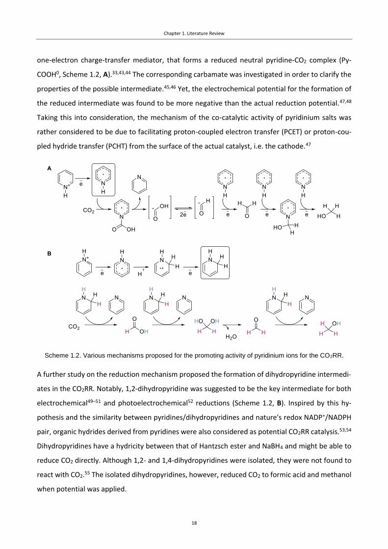
Scheme 1.2. Various mechanisms proposed for the promoting activity of pyridinium ions for the CO2RR.
A further study on the reduction mechanism proposed the formation of dihydropyridine intermedi-
ates in the CO2RR. Notably, 1,2-dihydropyridine was suggested to be the key intermediate for both
electrochemical49–51 and photoelectrochemical52 reductions (Scheme 1.2, B). Inspired by this hy-
pothesis and the similarity between pyridines/dihydropyridines and nature's redox NADP+/NADPH
pair, organic hydrides derived from pyridines were also considered as potential CO2RR catalysis.53,54
Dihydropyridines have a hydricity between that of Hantzsch ester and NaBH4 and might be able to
reduce CO2 directly. Although 1,2- and 1,4-dihydropyridines were isolated, they were not found to
react with CO2.55 The isolated dihydropyridines, however, reduced CO2 to formic acid and methanol
when potential was applied.

Chapter 1. Literature Review
19
The nature of the activity of the pyridinium catalysts continued to be debatable, with some reports
questioning the co-catalytic role of pyridinium ions in the CO2RR. For instance, on platinum56 or
gold57 electrodes, the pyridinium ion was shown to act as a facilitating HER acid, i.e. like conjugated
acids of aniline and benzylamine,58 as no products for the CO2RR were detected. Further research
focused the electrochemistry of pyridinium on glassy carbon (RVC), Pt, Ag, Au and Cu electrodes in
aqueous electrolytes.59,60 It was shown that the observed changes in the CV curves during electrol-
ysis in the presence of CO2 are not due to the CO2RR, but result from alternative pathways for the
HER. Moreover, in the presence of pyridinium ions, deposits on the electrode were observed to
form in both the presence and in the absence of CO2, which might influence the electrolysis as well
and hamper the interpretation of the results.60 Protonated pyridine was also ruled out as a possible
catalyst for the CO2RR on a Pt electrode, with pyridinium ions being smoothly reduced to piperidine
in both presence and absence of CO2, without any sign of the CO2RR.61 The only CO2 reduction prod-
uct that was hypothesized to be formed on a Pt electrode was CO, which is an efficient poison of
the catalytic surface inhibiting the reduction reaction.62 Using a similar system in situ IR spectros-
copy allowed formate to be detected in <3% yield, which is slightly facilitated in the presence of
pyridinium salts.63
The range of experimental conditions employed for the CO2RR hamper comparisons and it cannot
be excluded that pyridinium-based compounds catalyze the CO2RR under certain conditions. More-
over, methodological drawbacks include the misuse of electrochemical methods, lack of internal
standards for the determination of products, and impurities in the electrolytes. Cyclic voltammetry
experiments must be followed by electrolysis at different potentials in order to reveal the actual
reduction products. The application of internal standards for product determination is especially
relevant when small concentrations of products are formed, as impurities and signals from catalyst
decomposition products may prevent quantification of the CO2RR products.64
Despite the uncertainty of the catalytic role of pyridinium ions in the CO2RR, inorganic hydrides such
as boranes65 and borohydrides66 can reduce CO2 to formate (the latter even in absence of a catalyst).
Organic benzimidazole-based hydrides have also been successfully employed in the CO2RR (Scheme
1.3).67 Formate was the main reduction product, and the organic hydride could be regenerated elec-
trochemically from the resulting benzimidazolium salt.

Chapter 1. Literature Review
20
Scheme 1.3. Reduction of CO2 by organic hydrides derived from benzimidazolium salts.
An attempt to define general descriptors for N-heterocycles that are active in the CO2RR was made,
which is based on calculated molecular Pourbaix diagrams and correlating the CO2RR activity of the
N-heterocycle with the position of the triple point, where the conditions are optimal for both elec-
tron and/or proton transfer.68 Pourbaix diagrams might be useful when two-electron reductions
involving organic mediators are considered, e.g. for the prediction of the properties of organic hy-
drides. However, this approach considers only solution-phase thermodynamics and does not take
into account the role of the cathode, which can be key for the transformation.
1.4 Ionic Liquids
Ionic liquids (ILs) have received considerable attention in electrochemical applications69,70 due to
their large potential windows,71 good ionic conductivities,72 low volatilities73 and their ability to dis-
solve high concentrations of CO2.74 In this pioneering study Im ILs were shown to lower the reduc-
tion overpotential from > 700 mV to 170 mV when combined with a silver cathode.17 Moreover, the
parasitic HER was suppressed, which resulted in a FECO close to 100%. It is important to underline
that the electrode is not innocent in this process as no reaction is detected when a glassy carbon
electrode is employed.75 IL additives can also switch the selectivity of the CO2RR. For example, on a
lead electrode oxalate is the main reduction product whereas in the presence of an IL the dominant
product is carbon monoxide.76
Numerous studies have been devoted to the elucidation of the mechanism for the promotion of
CO2RR by ILs. In the original paper, the promoting effect was attributed to the formation of an IL-
CO2 adduct, although the structure of the adduct was not described.17 In a computational study the
most plausible pathway was found to consist of the initial one electron generation of a radical from
the Im cation and formation of an adduct with CO2, followed by electron transfer and subsequent

Chapter 1. Literature Review
21
decomposition of the adduct to water and CO, with the regeneration of the original Im cation
(Scheme 1.4).77 Formation of the IL-CO2 adduct correlates with the known chemistry of Im salts,
which easily form N-heterocyclic carbenes (NHCs) via deprotonation of the acidic 2-proton under
basic conditions78,79 (note that the cathode can serve as a powerful base)80 or by electrochemical
reduction.81,82 The resulting NHC reacts rapidly with available electrophiles,79 e.g. CO2.83,84 In syn-
thetic chemistry this phenomena was employed, for example, to activate CO2 and chemically reduce
it with silanes to produce methanol.85
Scheme 1.4. Mechanistic pathway for the IL-mediated CO2RR proposed by Wang et al.77
The calculated mechanism was supported by experimental data concerning the CO2RR overpoten-
tial in the presence of water employing Im salts as co-catalysts.86 Their behavior differed from other
investigated ionic co-catalysts, and was attributed to the suppression of side reactions due to the
regeneration of the imidazolium (Im) structure during the reduction from the reaction of the NHC
with water. Furthermore, CO2-Im adducts (e.g. 13, Scheme 1.4) were identified in low concentra-
tions in the post-electrolysis mixtures.76,86,87 Carboxylates adducts are stable under ambient condi-
tions and can be synthesized and isolated.88 An attempt to introduce this adduct into the electrolysis
cycle was not successful, i.e. the adduct was not further reduced to the CO2 reduction products and
the starting IL,87 which indicates the formation of the carboxylate is a parasitic reaction. Moreover,
2-substituted Im co-catalysts, lacking an acidic proton at the C2 and cannot form carboxylates, are
more active for the CO2RR than non-substituted Im ILs and are also more stable.87,87,86,89 If radical
formation followed by the coupling with CO2 at the 2-position is the key step for the reduction, then
2-substituted Im rings should not act as co-catalysts as they cannot form carbenes at the C2. Im salts
can form non-classical (abnormal) carbenes at the C4 and C5 positions and, replacing the protons at
the C4 and C5 positions of the Im ring with methyl groups dramatically reduces activity, suggesting

Chapter 1. Literature Review
22
that the protons in these position play a key role (e.g. providing two H-bonds, participating in the
formation of a stabilize CO2-IL complex).89 However, the possibility that the reduction reaction with
substituted and non-substituted Im ILs operate via different mechanisms cannot be excluded.
The influence of the length of the N-alkyl chain on the CO2RR is unclear. According to one study, as
the alkyl chain increases from ethyl to octyl the FE and onset potential both increase.90 The increase
in the reduction onset potential was attributed to the reduced contribution of side reactions, par-
ticularly dimerization of Im cations (due to steric effects) and the HER (due to the increasing hydro-
phobicity of the cations with the length of the alkyl chains). However, in another report the opposite
trend was observed with a positive influence of longer alkyl chains on the CO2RR.86 In the most
recent study the length of the alkyl chain was found to be negligible for the CO2RR.91 In addition, in
a series of tetraalkylammonium salts the smallest cations displayed more positive onset poten-
tials.86
Further improvements in the onset potential can be achieved with Im ILs by adding water to the
system.86 This phenomenon was thoroughly investigated and confirmed by several research
groups,92–96 and it has been suggested that water acts as a proton source for the reduction process
and promotes mass transport.93 In addition, commonly used ILs based on tetrafluoroborate anions
are unstable and hydrolysis of the BF4- anion can occur, which lowers the pH of the solution and
increase the availability of protons.94
The influence of the anion on the CO2RR is complicated as it appears to depend on the structure of
the cathode material employed. For Cu and Ag polycrystalline electrodes, the nature of the anion
(PF6-, BF4
-, Br-, ClO4-, SO4
2- and HCO3-) has negligible effect on the formation of the carbon-based
products.86,97,98 However, the anion might have a considerable influence on the CO2RR when it in-
teracts strongly with the surface of the electrode or changes the pH of the solution. For instance,
enhancement of the CO2RR by adsorbed halides was demonstrated for Ag nanocoral electrodes (Cl-
)99 and for plasma-activated Cu electrodes (Cl-<Br-<I-).100 The nature of the anion alters the perfor-
mance of the electrochemical system when employing pure ILs as electrolytes (NTf2- > BF4
- > tris(per-
fluoroalkyl)trifluorophosphate in terms of activity for the [BMIm]-based ILs),75 as physical properties
of the IL strongly influence the solubility of CO2 and mass transport.93

Chapter 1. Literature Review
23
The anion has a considerable impact on the reduction process if it directly forms intermediates with
CO2, such as when ILs with base-derived anions are used.101,102 Here, the activity of the IL is depend-
ent on the formation of transition state intermediates between CO2 and the base-derived anion,
e.g. 1,2,4-triazolide, which can react with CO2 stoichiometrically and reversibly,103 and leads to the
formation of formate at low overpotentials. Another example of an IL with anion-derived activity
was demonstrated with Im salts with the BF3Cl- anion.104 In the presence of CO2 a new peak appears
on the CV scan, which disappears when the electrolyte is purged with N2. This work is intriguing as
it represents a new CO2 activation process involving Lewis pairs, which was inspired by the lability
of B-halide bonds.105 Unfortunately, the products for this reduction were not determined, although
conventional ILs were inactive under the conditions (possibly due to the use of a Pt electrode which
does not favor CO production).106,107
The inconsistencies regarding the role of the IL ions on the CO2RR are partly due to the problems
associated with correcting for uncompensated Ohmic resistance (IR drop). For more conductive
aqueous electrolytes this problem can be relevant in some reactions;108 for organic electrolytes,
which usually possess higher resistances, not including a IR drop correction significantly distorts the
results. To illustrate this problem, corrected and not corrected CV curves were compared for differ-
ent compositions of Im-based ILs. In the uncorrected curves significant differences are observed
between the different ILs, whereas following correction, the differences were found to be negligible
(Figure 1.4).91

Chapter 1. Literature Review
24
Figure 1.4. Comparison of cyclic voltammetry data for various ionic co-catalytic systems without and with IR-
correction. Adapted from ref. 91.
The mechanism by which Im ILs enhance the CO2RR was probed by in operando sum frequency
generation spectroscopy.109 When a potential is applied, the IL participates in the formation of an
electric double layer, which is further supported by calculations110 and other electrochemical exper-
iments.107 Under certain potentials, irrespective of the presence of CO2 in solution, a structural tran-
sition in the IL occurs. Notably, this potential accurately corresponds to the voltage where the CO2RR
also occurs. The origin of the catalytic effect is believed to be derived from the increased abundance
and high degree of alignment of the IL cations leading to a sharp growth of the local electrical field
in the proximity of the electrode.109 Stabilization of the key reduction intermediates by the local
cation-induced electric field is supported by DFT calculations (Figure 1.5).111 The positive effect of
water additives may then be explained by reducing the negative potential for the IL transition.112

Chapter 1. Literature Review
25
Figure 1.5. Effect of field stabilization on the CO2RR. Left: Ag(111) and Pt(111) without field stabilization.
Right: Ag(111) with field stabilization. Adapted from ref. 111.
The scope of active ILs able to co-catalyze the CO2RR is not limited to Im ILs (Figure 1.6). Pyrazolium-
based ILs are stable co-catalysts that result in quantitative Faradaic efficiencies for CO at high cur-
rent densities.113 Fully substituted pyrazolium cations display good performance in the CO2RR, which
opposes pyrazolium CO2 adduct formation and supports modification of the electric double layer as
the most possible origin of the co-catalytic activity. An study probing different cations in the CO2RR
revealed Im and pyrrolidinium ILs as the most active compounds from the range tested (Figure
1.6).86
Figure 1.6. Ionic promoters probed for the CO2RR. A: The most active co-catalysts cations. B: Other organic
salt cations. C: Anions used in the study.
N-alkylpyridinium ILs do not act as co-catalysts for the CO2RR when used with the most widespread
electrode materials.32,60 However, some N-arylpyridinium salts do behave as co-catalysts with Cu
electrodes.114 It was found that the arylpyridinium salts serve as precatalysts and form deposits on

Chapter 1. Literature Review
26
the electrode during the reduction, which increases the selectivity for C2 products, yielding C2H4
(FEC2H4 = 41%) and C2H5OH (FEC2H5OH ≤ 27%). N-butyl pyridine and protonated pyridine did not show
such activity, which is consistent with the previous reports (see above).
In general, ILs are characterized by their low volatility,73 which significantly simplifies their utiliza-
tion, but can hamper recycling. To overcome this issue an approach for the CO2RR was devised that
employed the distillable IL dimethylammonium dimethylcarbamate as the medium for the reduc-
tion.115 This IL, derived from dimethylamine and CO2, breaks down at 60°C into volatile components
that can be easily removed.116 Optimum results were obtained using dimethylammonium dimethyl-
carbamate with In as the electrode material, yielding CO (FE = 44.5%) and formate (FE = 39.7%) as
the predominant products of the reduction.
1.5 Functionalized Ionic Liquids and Deep Eutectic Solvents
Functionalized ILs were also explored in the CO2RR with, for example, hydroxy-tagged ILs showing
higher co-catalytic activity compared to simple (alkyl) ILs.117 Introduction of the OH-group lowers
the reduction onset potential by 70 mV compared to structurally related unfunctionalized ana-
logues. This observation is in accordance with other studies based on homogeneous metal catalysis,
which show that hydroxyl groups in proximity to metal catalyst facilitate the reduction of CO2.118
Therefore, the presence of hydroxyl groups in the proximity of the electrode surface presumably
enhances the CO2RR. To ensure close proximity of the hydroxy-group with the electrode, the cation
should be modified with the group since the cations associate with the electrode, and in this context
choline derivatives represent a naturally occurring class of cations endowed with a OH-group. More-
over, choline chloride is the basic component of deep eutectic solvents (DESs), which resemble ILs
in many ways, i.e. similar conductivities, low volatilities, high solubility of CO2, etc.119–121 The impact
of choline chloride on several electrochemical reactions including the CO2RR was reported.122 Cho-
line chloride was used in aqueous bicarbonate solutions, which provided the pH necessary for the
reduction and served as a source of CO2. However, the reduction process was investigated by CV
only, without information on electrolysis and the product distribution. Subsequently, choline chlo-
ride and choline chloride/urea (1/2) based electrolytes mixed with KCl (to improve conductivity)
were shown to slightly improve the FECO compared to pure KCl electrolyte.98 However, the jCO value
remained the same for both choline/KCl and pure KCl electrolytes at the same potentials. The influ-
ence of choline additives on the reduction onset potential was not investigated (CV data was not

Chapter 1. Literature Review
27
presented), and addition of urea (the second component of the DES) did not result in any improve-
ment compared to pure choline chloride. However, the effect of the choline derivatives might not
be pronounced in aqueous solutions where the impact of the OH group is diminished. Choline chlo-
ride tends to be poorly soluble in acetonitrile, frequently used for electrochemistry, which hampers
its application.123 The solubility of choline chloride can be increased in organic solvents by employing
the DES principle, i.e. harnessing strong interactions between the chloride and ethylene glycol (as
hydrogen bond donor).123 The resulting systems showed high selectivities for CO (FECO up to 100%)
and lowered onset potentials.
While organic promoters of the CO2RR are largely limited to the classes described above, there are,
however, several systems which have not been mentioned thus far, but are of relevance. For in-
stance, attempts to reduce CO2 in monoethanolamine were made,124 since monoethanolamine is
an industrial solvent used to capture CO2.125 Reduction was highly dependent on the employed elec-
trode (smooth metal electrodes based on silver - FECO = 33.4%, FEHCOO- = 2.0% at -0.8 V and indium
- FECO = 17.0%, FEHCOO- = 45.4% at -0.8 V were evaluated. The activity was significantly improved
when porous metal electrodes were used or surfactants (e.g. CTAB) added. In an investigation of
silver-base complexes in the CO2RR, it was found that the base alone, i.e. 3,5-diamino-1,2,4-triazole
(DAT), decreased the reduction overpotential and increased the current density and Faradaic effi-
ciency for CO formation when used with Ag/C electrodes.126 The co-catalytic effect of DAT was at-
tributed to weakening of the CO-bond at the silver electrode and to the suppression of HER.127
1.6 Summary
Active organic systems for the CO2RR can be divided into three main groups, i.e. redox shuttles
forming radicals, organic hydrides and ionic compounds. Electron shuttles appear to be the catalysts
of choice for the synthesis of oxalate and in general require high overpotentials, which can be ad-
justed by tuning of the shuttle structure. The application of organic hydrides results in the formation
of formate, and the applicability of the catalyst is defined by the hydricity of the hydride and ease
of its regeneration on the electrode. Ionic systems tune the activity of the actual reduction catalyst,
i.e. the electrode, and can be used for a synthesis of various products (CO, formate and methane
are the most widespread outcomes). The activity of this system depends on the properties of the
double layer formed in the reduction process, and the activity of the catalyst can be improved by
introduction of the functional groups (e.g. OH).

Chapter 1. Literature Review
28
As the origin of the catalytic and co-catalytic activities of organic systems become unraveled, ra-
tional design of the promoters becomes possible and can be achieved using the same principles
applied to the rational design of traditional organic catalysis. Indeed, transferring concepts from
organic chemistry to electrochemistry could be fruitful.
Importantly, the evaluation of different organic promoters should take into account that the for-
mation of reactive intermediates can result in various side reactions, which hamper analysis of the
system. The data from cyclic voltammetry experiments and electrolysis should be corrected for the
uncompensated resistance and followed by careful analysis of the reduction products with the ap-
plication of internal standards in order to avoid errors. To provide unambiguous conclusions on the
applicability of organic promoters for industrial CO2RR, their performance must also be assessed at
high current densities (> 200 mA/cm2).128 Based on the versatility of organic promoters and the ease
of tuning the microenvironment of the electrode using them, significant improvements in activity
can be envisaged, which may lead to industrial applications.

Chapter 1. Literature Review
29
1.7 References
(1) Figueres, C.; Le Quéré, C.; Mahindra, A.; Bäte, O.; Whiteman, G.; Peters, G.; Guan, D.
Emissions Are Still Rising: Ramp up the Cuts. Nature 2018, 564, 27–30.
(2) Peter, S. C. Reduction of CO2 to Chemicals and Fuels: A Solution to Global Warming and
Energy Crisis. ACS Energy Lett. 2018, 3, 1557−1561.
(3) Whipple, D. T.; Kenis, P. J. a. Prospects of CO2 Utilization via Direct Heterogeneous
Electrochemical Reduction. J. Phys. Chem. Lett. 2010, 1 (24), 3451–3458.
(4) Oh, Y.; Hu, X. Organic Molecules as Mediators and Catalysts for Photocatalytic and
Electrocatalytic CO2 Reduction. Chem. Soc. Rev. 2013, 42 (6), 2253–2261.
(5) Costentin, C.; Robert, M.; Savéant, J.-M. Catalysis of the Electrochemical Reduction of Carbon
Dioxide. Chem. Soc. Rev. 2013, 42, 2423–2436.
(6) Qiao, J.; Liu, Y.; Hong, F.; Zhang, J. A Review of Catalysts for the Electroreduction of Carbon
Dioxide to Produce Low-Carbon Fuels. Chem. Soc. Rev 2014, 43, 631.
(7) Francke, R.; Schille, B.; Roemelt, M. Homogeneously Catalyzed Electroreduction of Carbon
Dioxide - Methods, Mechanisms, and Catalysts. Chem. Rev. 2018, 118, 4631−4701.
(8) Durst, J.; Rudnev, A.; Dutta, A.; Fu, Y.; Herranz, J.; Kaliginedi, V.; Kuzume, A.; Permyakova, A.
A.; Paratcha, Y.; Broekmann, P.; et al. Electrochemical CO2 Reduction – A Critical View on
Fundamentals, Materials and Applications. Chimia 2015, 69, 769–776.
(9) Weekes, D. M.; Salvatore, D. A.; Reyes, A.; Huang, A.; Berlinguette, C. P.; Blusson, S.
Electrolytic CO2 Reduction in a Flow Cell. Acc. Chem. Res 2018, 51, 910−918.
(10) Finn, C.; Schnittger, S.; Yellowlees, L. J.; Love, J. B. Molecular Approaches to the
Electrochemical Reduction of Carbon Dioxide. Chem. Commun. 2012, 48 (10), 1392–1399.
(11) Mao, X.; Hatton, T. A. Recent Advances in Electrocatalytic Reduction of Carbon Dioxide Using
Metal-Free Catalysts. Ind. Eng. Chem. Res 2015, 54, 4033−4042.
(12) Chiranjeevi, P.; Bulut, M.; Breugelmans, T.; Patil, S. A.; Pant, D. Current Trends in Enzymatic
Electrosynthesis for CO2 Reduction. Curr. Opin. Green Sustain. Chem. 2019, 16, 65–70.

Chapter 1. Literature Review
30
(13) Kalyanasundaram, K.; Graetzel, M. Artificial Photosynthesis : Biomimetic Approaches to Solar
Energy Conversion and Storage. Curr. Opin. Biotechnol. 2010, 21 (3), 298–310.
(14) Kumar, B.; Llorente, M.; Froehlich, J.; Dang, T.; Sathrum, A.; Kubiak, C. P. Photochemical and
Photoelectrochemical Reduction of CO2. Annu. Rev. Phys. Chem. 2012 2012, 63, 541–569.
(15) Kalamaras, E.; Maroto-Valer, M. M.; Shao, M.; Xuan, J.; Wang, H. Solar Carbon Fuel via
Photoelectrochemistry. Catal. Today 2018, 317, 56–75.
(16) Benson, E. E.; Kubiak, C. P.; Sathrum, A. J.; Smieja, J. M. Electrocatalytic and Homogeneous
Approaches to Conversion of CO2 to Liquid Fuels. Chem. Soc. Rev 2009, 38 (1), 89–99.
(17) Rosen, B. A.; Salehi-Khojin, A.; Thorson, M. R.; Zhu, W.; Whipple, D. T.; Kenis, P. J. A.; Masel,
R. I. Ionic Liquid – Mediated Selective Conversion of CO2 to CO at Low Overpotentials. Science
2011, 334, 643–644.
(18) Taniguchi, I.; Aurian-Blajeni, B.; Bockris, J. O. Photo-Aided Reduction of Carbon Dioxide to
Carbon Monoxide. J. Electroanal. Chem. Interfacial Electrochem. 1983, 157 (1), 179–182.
(19) Taniguchi, I.; Aurian-Blajeni, B.; Bockris, J. O. The Mediation of the Photoelectrochemical
Reduction of Carbon Dioxide by Ammonium Ions. J. Electroanal. Chem. Interfacial
Electrochem. 1984, 161 (2), 385–388.
(20) Bockris, J. O.; Wass, J. C. The Photoelectrocatalytic Reduction of Carbon Dioxide. J.
Electrochem. Soc. 1989, 136 (9), 2521.
(21) Berto, T. C.; Zhang, L.; Hamers, R. J.; Berry, J. F. Electrolyte Dependence of CO2
Electroreduction: Tetraalkylammonium Ions Are Not Electrocatalysts. ACS Catal. 2015, 5,
703−707.
(22) Filardo, G.; Gambino, S.; Silvestri, G.; Gennaro, A.; Vianello, E. Electrocarboxylation of Styrene
through Homogeneous Redox Catalysis. J. Electroanal. Chem. Interfacial Electrochem. 1984,
177 (1–2), 303–309.
(23) Gennaro, A.; Isse, A. A.; Severin, M.-G.; Vianello, E.; Bhugun, I.; Savéant, J.-M. Mechanism of
the Electrochemical Reduction of Carbon Dioxide at Inert Electrodes in Media of Low Proton
Availability. J. Chem. Soc., Faraday Trans. 1996, 92 (20), 3963–3968.

Chapter 1. Literature Review
31
(24) Gennaro, A.; Isse, A. A.; Savéant, J.-M.; Severin, M.-G.; Vianello, E. Homogeneous Electron
Transfer Catalysis of the Electrochemical Reduction of Carbon Dioxide. Do Aromatic Anion
Radicals React in an Outer-Sphere Manner? J. Am. Chem. Soc. 1996, 118, 7190–7196.
(25) Savéant, J. Molecular Catalysis of Electrochemical Reactions . Mechanistic Aspects. 2008,
2348–2378.
(26) Koshechko, V. G.; Lopushanskaya, V. A. Electrochemical Conversion of Carbon Dioxide
Catalyzed by Benzil. Theor. Exp. Chem. 2006, 42 (1), 33–36.
(27) Ghobadi, K.; Zare, H. R.; Khoshro, H.; Jafari, A. A. Excellent Electrocatalytic Activity of Benzil
for Direct Reduction of CO2 as Well as Indirect Reduction of Pyridine: A Kinetic View of the
Electrocarboxylation Process. J. Energy Chem. 2017, 26 (3), 569–573.
(28) Ghobadi, K.; Zare, H. R.; Gorji, A.; Benvidi, A. Electrochemical Activation of CO2 by a Di-Schiff
Base of N, N′-Bis(2-Hydroxy-1-Naphthaldehyde)-m-Phenylenediimine. Polyhedron 2018, 155,
13–19.
(29) Ghobadi, K.; Zare, H. R.; Khoshro, H.; Gorji, A. Communication—Electrosynthesis of
Isonicotinic Acid via Indirect Electrochemical Reduction of Pyridine in the Presence of CO2. J.
Electrochem. Soc. 2016, 163 (3), H240–H242.
(30) Wawzonek, S.; Gundersen, A. Polarographic Studies in Acetonitrile and Dimethylformamide
V. Behavior of Aromatic Ketones and Aldehydes. J. Electrochem. Soc. 1960, 107, 537–540.
(31) Zhao, S.-F.; Horne, M.; Bond, A. M.; Zhang, J. Electrocarboxylation of Acetophenone in Ionic
Liquids: The Influence of Proton Availability on Product Distribution. Green Chem. 2014, 16
(4), 2242–2251.
(32) Seshadri, G.; Lin, C.; Bocarsly, A. B. A New Homogeneous Electrocatalyst for the Reduction of
Carbon Dioxide to Methanol at Low Overpotential. J. Electroanal. Chem. 1994, 372 (1–2),
145–150.
(33) Barton Cole, E.; Lakkaraju, P. S.; Rampulla, D. M.; Morris, A. J.; Abelev, E.; Bocarsly, A. B.; Cole,
E. B.; Lakkaraju, P. S.; Rampulla, D. M.; Morris, A. J.; et al. Using a One-Electron Shuttle for the
Multielectron Reduction of CO2 to Methanol: Kinetic, Mechanistic, and Structural Insights. J.

Chapter 1. Literature Review
32
Am. Chem. Soc. 2010, 132 (33), 11539–11551.
(34) Barton, E. E.; Rampulla, D. M.; Bocarsly, A. B. Selective Solar-Driven Reduction of CO2 to
Methanol Using a Catalyzed p-GaP Based Photoelectrochemical Cell. J. AM. CHEM. SOC 2008,
130, 6342–6344.
(35) Bocarsly, A. B.; Gibson, Q. D.; Morris, A. J.; L’esperance, R. P.; Detweiler, Z. M.; Lakkaraju, P.
S.; Zeitler, E. L.; Shaw, T. W. Comparative Study of Imidazole and Pyridine Catalyzed Reduction
of Carbon Dioxide at Illuminated Iron Pyrite Electrodes. ACS Catal. 2012, 2, 1684−1692.
(36) Xu, S.; Li, L.; Carter, E. A. Why and How Carbon Dioxide Conversion to Methanol Happens on
Functionalized Semiconductor Photoelectrodes. J. Am. Chem. Soc. 2018, 140, 16749−16757.
(37) Barton Cole, E. E.; Baruch, M. F.; L’Esperance, R. P.; Kelly, M. T.; Lakkaraju, P. S.; Zeitler, E. L.;
Bocarsly, A. B. Substituent Effects in the Pyridinium Catalyzed Reduction of CO2 to Methanol:
Further Mechanistic Insights. Top. Catal. 2015, 58 (1), 15–22.
(38) Lee, J. H. Q.; Lauw, S. J. L.; Webster, R. D. The Electrochemical Reduction of Carbon Dioxide
(CO2) to Methanol in the Presence of Pyridoxine (Vitamin B6). Electrochem. commun. 2016,
64, 69–73.
(39) Portenkirchner, E.; Enengl, C.; Enengl, S.; Hinterberger, G.; Schlager, S.; Apaydin, D.;
Neugebauer, H.; Knör, G.; Sariciftci, N. S. A Comparison of Pyridazine and Pyridine as
Electrocatalysts for the Reduction of Carbon Dioxide to Methanol. ChemElectroChem 2014, 1
(9), 1543–1548.
(40) Xiang, D.; Magana, D.; Dyer, R. B. CO2 Reduction Catalyzed by Mercaptopteridine on Glassy
Carbon. J. Am. Chem. Soc. 2014, 136, 14007−14010.
(41) Saveant, J.-M.; Tard, C. C. Attempts To Catalyze the Electrochemical CO2-to-Methanol
Conversion by Biomimetic 2e− + 2H+ Transferring Molecules. J. Am. Chem. Soc. 2015, 138,
1017−1021.
(42) Lim, C.-H.; Holder, A. M.; Hynes, J. T.; Musgrave, C. B. Dihydropteridine/Pteridine as a 2H+/2e−
Redox Mediator for the Reduction of CO2 to Methanol: A Computational Study. J. Phys. Chem.
B 2017, 121, 4158−4167.

Chapter 1. Literature Review
33
(43) Morris, A. J.; McGibbon, R. T.; Bocarsly, A. B. Electrocatalytic Carbon Dioxide Activation: The
Rate-Determining Step of Pyridinium-Catalyzed CO2 Reduction. ChemSusChem 2011, 4 (2),
191–196.
(44) Lim, C.-H.; Holder, A. M.; Musgrave, C. B. Mechanism of Homogeneous Reduction of CO2 by
Pyridine: Proton Relay in Aqueous Solvent and Aromatic Stabilization. J. Am. Chem. Soc. 2012,
135, 142−154.
(45) Kamrath, M. Z.; Relph, R. A.; Johnson, M. A. Vibrational Predissociation Spectrum of the
Carbamate Radical Anion, C5H5N-CO2-, Generated by Reaction of Pyridine with (CO2)m
-. J. Am.
Chem. Soc. 2010, 132, 15508–15511.
(46) Tossell, J. A. Calculation of the Properties of Molecules in the Pyridine Catalyst System for the
Photochemical Conversion of CO2 to Methanol. Comput. Theor. Chem. 2011, 977 (1–3), 123–
127.
(47) Ertem, M. Z.; Konezny, S. J.; Moyses Araujo, C.; Batista, V. S. Functional Role of Pyridinium
during Aqueous Electrochemical Reduction of CO2 on Pt(111). J. Phys. Chem. Lett 2013, 4,
745−748.
(48) Keith, J. A.; Carter, E. A. Theoretical Insights into Pyridinium-Based Photoelectrocatalytic
Reduction of CO2. J. Am. Chem. Soc 2012, 134, 17.
(49) Lim, C.-H.; Holder, A. M.; Hynes, J. T.; Musgrave, C. B. Reduction of CO2 to Methanol Catalyzed
by a Biomimetic Organo-Hydride Produced from Pyridine. J. Am. Chem. Soc. 2014, 136,
16081−16095.
(50) Keith, J.; Carter, E. Theoretical Insights into Electrochemical CO2 Reduction Mechanisms
Catalyzed by Surface Bound Nitrogen Heterocycles. J. Phys. Chem. Lett. 2013, 4, 4058 − 4063.
(51) Keith, J. A.; Carter, E. A. Electrochemical Reactivities of Pyridinium in Solution: Consequences
for CO2 Reduction Mechanisms. Chem. Sci. 2013, 4 (4), 1490.
(52) Lessio, M.; Carter, E. A. What Is the Role of Pyridinium in Pyridine-Catalyzed CO2 Reduction
on p-GaP Photocathodes? J. Am. Chem. Soc 2015, 137, 13251.
(53) Alherz, A.; Lim, C.-H.; Kuo, Y.-C.; Lehman, P.; Cha, J.; Hynes, J. T.; Musgrave, C. B. Renewable
Chapter 1. Literature Review
34
Hydride Donors for the Catalytic Reduction of CO2 : A Thermodynamic and Kinetic Study.
2018.
(54) Lim, C.-H.; Holder, A. M.; Hynes, J. T.; Musgrave, C. B. Catalytic Reduction of CO2 by
Renewable Organohydrides. J. Phys. Chem. Lett 2015, 6, 42.
(55) Giesbrecht, P. K.; Herbert, D. E. Electrochemical Reduction of Carbon Dioxide to Methanol in
the Presence of Benzannulated Dihydropyridine Additives. ACS Energy Lett. 2017, 2, 549–555.
(56) Costentin, C.; Canales, J. C.; Haddou, B.; Saveánt, J.-M. Electrochemistry of Acids on Platinum.
Application to the Reduction of Carbon Dioxide in the Presence of Pyridinium Ion in Water. J.
Am. Chem. Soc 2013, 11, 31.
(57) Lucio, A. J.; Shaw, S. K. Pyridine and Pyridinium Electrochemistry on Polycrystalline Gold
Electrodes and Implications for CO2 Reduction. J. Phys. Chem. C 2015, 119, 25.
(58) Creţu, R.; Kellenberger, A.; Vaszilcsin, N. Enhancement of Hydrogen Evolution Reaction
on Platinum Cathode by Proton Carriers. Int. J. Hydrogen Energy 2013, 38 (27), 11685–11694.
(59) Peroff, A. G.; Weitz, E.; Van Duyne, R. P. Mechanistic Studies of Pyridinium Electrochemistry:
Alternative Chemical Pathways in the Presence of CO2. Phys. Chem. Chem. Phys. 2016, 18 (3),
1578–1586.
(60) Lebègue, E.; Agullo, J.; Bélanger, D. Electrochemical Behavior of Pyridinium and N-Methyl
Pyridinium Cations in Aqueous Electrolytes for CO2 Reduction. ChemSusChem 2018, 11 (1),
219–228.
(61) Olu, P.-Y.; Li, Q.; Krischer, K. The True Fate of Pyridinium in the Reportedly Pyridinium-
Catalyzed Carbon Dioxide Electroreduction on Platinum. Angew. Chemie 2018, 130 (45),
14985–14988.
(62) Costentin, C.; Saveánt, J.-M.; Cédric Tard, C. Catalysis of CO2 Electrochemical Reduction by
Protonated Pyridine and Similar Molecules. Useful Lessons from a Methodological
Misadventure. ACS Energy Lett. 2018, 3, 695−703.
(63) Dunwell, M.; Yan, Y.; Xu, B. In Situ Infrared Spectroscopic Investigations of Pyridine-Mediated
CO2 Reduction on Pt Electrocatalysts. ACS Catal. 2017, 7, 5410−5419.

Chapter 1. Literature Review
35
(64) Feaster, J. T.; Jongerius, A. L.; Liu, X.; Urushihara, M.; Nitopi, S. A.; Hahn, C.; Chan, K.; Nørskov,
J. K.; Jaramillo, T. F. Understanding the Influence of [EMIM]Cl on the Suppression of the
Hydrogen Evolution Reaction on Transition Metal Electrodes.
(65) Von Wolff, N.; Lefè, G.; Berthet, J.-C.; Thuéry, P. T.; Cantat, T. Implications of CO2 Activation
by Frustrated Lewis Pairs in the Catalytic Hydroboration of CO2 : A View Using N/Si+ Frustrated
Lewis Pairs. ACS Catal. 2016, 6, 4526−4535.
(66) Knopf, I.; Cummins, C. C. Revisiting CO2 Reduction with NaBH4 under Aprotic Conditions:
Synthesis and Characterization of Sodium Triformatoborohydride. Organometallics 2015, 34,
1601−1603.
(67) Lim, C.-H.; Ilic, S.; Alherz, A.; Worrell, B. T.; Bacon, S. S.; Hynes, J. T.; Glusac, K. D.; Musgrave,
C. B. Benzimidazoles as Metal-Free and Recyclable Hydrides for CO2 Reduction to Formate. J.
Am. Chem. Soc. 2019, 141, 272−280.
(68) Marjolin, A.; Keith, J. a. Thermodynamic Descriptors for Molecules That Catalyze Efficient CO2
Electroreductions. ACS Catal. 2015, 5 (2), 1123–1130.
(69) Faggion, D.; Gonçalves, W. D. G.; Dupont, J. CO2 Electroreduction in Ionic Liquids. Front. Chem.
2019, 7, 102.
(70) Watanabe, M.; Thomas, M. L.; Zhang, S.; Ueno, K.; Yasuda, T.; Dokko, K. Application of Ionic
Liquids to Energy Storage and Conversion Materials and Devices. Chem. Rev. 2017, 117,
7190−7239.
(71) Hayyan, M.; Mjalli, F. S.; Hashim, M. A.; AlNashef, I. M.; Mei, T. X. Investigating the
Electrochemical Windows of Ionic Liquids. J. Ind. Eng. Chem. 2013, 19 (1), 106–112.
(72) Hapiot, P.; Lagrost, C. Electrochemical Reactivity in Room-Temperature Ionic Liquids. Chem.
Rev. 2008, 108, 2238–2264.
(73) Earle, M. J.; Esperança, J. M. S. S.; Gilea, M. A.; Lopes, J. N. C.; Rebelo, L. P. N.; Magee, J. W.;
Seddon, K. R.; Widegren, J. A. The Distillation and Volatility of Ionic Liquids. Nature 2006, 439
(831–834).
(74) Lei, Z.; Dai, C.; Chen, B. Gas Solubility in Ionic Liquids. Chem. Rev. 2013, 114 (2), 1289–1326.

Chapter 1. Literature Review
36
(75) Tanner, E. E. L.; Batchelor-Mcauley, C.; Compton, R. G. Carbon Dioxide Reduction in Room-
Temperature Ionic Liquids: The Effect of the Choice of Electrode Material, Cation, and Anion.
J. Phys. Chem. C 2016, 120, 26442–26447.
(76) Sun, L.; Ramesha, G. K.; Kamat, P. V; Brennecke, J. F. Switching the Reaction Course of
Electrochemical CO2 Reduction with Ionic Liquids. Langmuir 2014, 30, 6302–6308.
(77) Wang, Y.; Hatakeyama, M.; Ogata, K.; Wakabayashi, M.; Jin, F.; Nakamura, S. Activation of
CO2 by Ionic Liquid EMIM–BF4 in the Electrochemical System: A Theoretical Study. Phys.
Chem. Chem. Phys. 2015, 17, 23521–23531.
(78) Arduengo, A. J. I.; Harlow, R. L.; Kline, M. A Stable Crystalline Carbene. J. Am. Chem. Soc. 1991,
113, 361–363.
(79) Herrmann, W. A.; Köcher, C. N-Heterocyclic Carbenes. Angew. Chemie Int. Ed. English 1997,
36 (20), 2162–2187.
(80) Köster, F.; Dinjus, E.; Duñach, E. Electrochemical Selective Incorporation of CO2 into Terminal
Alkynes and Diynes. European J. Org. Chem. 2001, 2001 (13), 2507–2511.
(81) Gorodetsky, B.; Ramnial, T.; Branda, N. R.; Clyburne, J. A. C. Electrochemical Reduction of an
Imidazolium Cation: A Convenient Preparation of Imidazol-2-Ylidenes and Their Observation
in an Ionic Liquid. Chem. Commun. 2004, 0 (17), 1972.
(82) Feroci, M.; Chiarotto, I.; Forte, G.; Vecchio Ciprioti, S.; Inesi, A. Stability and CO2 Capture
Ability of Electrogenerated N -Heterocyclic Carbene in Parent 1-Butyl-3-Methylimidazoliun
Ionic Liquid (BMIm-X): The Role of X−. ChemElectroChem 2014, 1 (8), 1407–1414.
(83) Duong, H. A.; Tekavec, T. N.; Arif, A. M.; Louie, J. Reversible Carboxylation of N-Heterocyclic
Carbenes. Chem. Commun. 2004, 0 (1), 112.
(84) Guillaume, de R.; H. Devillers, C.; Kunz, D.; Cattey, H.; Digard, E.; Andrieu, J. Electrosynthesis
of Imidazolium Carboxylates. Org. Lett. 2013, 15 (17), 4410–4413.
(85) Riduan, S. N.; Zhang, Y.; Ying, J. Y. Conversion of Carbon Dioxide into Methanol with Silanes
over N-Heterocyclic Carbene Catalysts. Angew. Chemie Int. Ed. 2009, 48 (18), 3322–3325.

Chapter 1. Literature Review
37
(86) Zhao, S.-F.; Horne, M.; Bond, A. M.; Zhang, J. Is the Imidazolium Cation a Unique Promoter
for Electrocatalytic Reduction of Carbon Dioxide? J. Phys. Chem. C 2016, 120, 23989−24001.
(87) Watkins, J. D.; Bocarsly, A. B. Direct Reduction of Carbon Dioxide to Formate in High-Gas-
Capacity Ionic Liquids at Post-Transition-Metal Electrodes. ChemSusChem 2014, 7 (1), 284–
290.
(88) Holbrey, J. D.; Reichert, W. M.; Tkatchenko, I.; Bouajila, E.; Walter, O.; Tommasi, I.; Rogers, R.
D. 1,3-Dimethylimidazolium-2-Carboxylate: The Unexpected Synthesis of an Ionic Liquid
Precursor and Carbene-CO2 Adduct. Chem. Commun. 2003, 347 (1), 28–29.
(89) Lau, G. P. S.; Schreier, M.; Vasilyev, D.; Scopelliti, R.; Grätzel, M.; Dyson, P. J. New Insights into
the Role of Imidazolium-Based Promoters for the Electroreduction of CO2 on a Silver
Electrode. J. Am. Chem. Soc. 2016, 138, 7820–7823.
(90) Wang, Q.; Chen, A. C.; Zhong, A. J.; Zhang, C. B. Effect of Alkyl Chain Length of Imidazolium
Cation on the Electroreduction of CO2 to CO on Ag Electrode in Acetonitrile. Aust. J. Chem.
2016, 70, 293–300.
(91) Lim, H.-K.; Kwon, Y.; Kim, H. S.; Jeon, J.; Kim, Y.-H.; Lim, J.-A.; Kim, B.-S.; Choi, J.; Kim, H. Insight
into the Microenvironments of the Metal−Ionic Liquid Interface during Electrochemical CO2
Reduction. ACS Catal. 2018, 8, 2420−2427.
(92) Rudnev, A. V.; Zhumaev, U. E.; Kuzume, A.; Vesztergom, S.; Furrer, J.; Broekmann, P.;
Wandlowski, T. The Promoting Effect of Water on the Electroreduction of CO2 in Acetonitrile.
Electrochim. Acta 2016, 189, 38–44.
(93) Rudnev, A. V.; Fu, Y.-C.; Gjuroski, I.; Stricker, F.; Furrer, J.; Kovács, N.; Vesztergom, S.;
Broekmann, P. Transport Matters: Boosting CO2 Electroreduction in Mixtures of
[BMIm][BF4]/Water by Enhanced Diffusion. ChemPhysChem 2017, 18 (22), 3153–3162.
(94) Rosen, B. A.; Zhu, W.; Kaul, G.; Salehi-Khojin, A.; Masel, R. I. Water Enhancement of CO2
Conversion on Silver in 1-Ethyl-3-Methylimidazolium Tetrafluoroborate. J. Electrochem. Soc.
2012, 160 (2), H138–H141.
(95) Hailu, A.; Shaw, S. K. Efficient Electrocatalytic Reduction of Carbon Dioxide in 1-Ethyl-3-

Chapter 1. Literature Review
38
Methylimidazolium Trifluoromethanesulfonate and Water Mixtures. Energy Fuels 2018, 32,
12695−12702.
(96) Figueiredo, M. C.; Ledezma-Yanez, I.; Koper, M. T. M. In Situ Spectroscopic Study of CO2
Electroreduction at Copper Electrodes in Acetonitrile. ACS Catal. 2016, 6, 2382–2392.
(97) Resasco, J.; Lum, Y.; Clark, E.; Zeledon, J. Z.; Bell, A. T. Effects of Anion Identity and
Concentration on Electrochemical Reduction of CO2. ChemElectroChem 2018, 5 (7), 1064–
1072.
(98) Verma, S.; Lu, X.; Ma, S.; Masel, R. I.; Kenis, P. J. A. The Effect of Electrolyte Composition on
the Electroreduction of CO2 to CO on Ag Based Gas Diffusion Electrodes. Phys. Chem. Chem.
Phys. 2016, 18, 7075–7084.
(99) Hsieh, Y.-C.; Senanayake, S. D.; Zhang, Y.; Xu, W.; Polyansky, D. E. Effect of Chloride Anions on
the Synthesis and Enhanced Catalytic Activity of Silver Nanocoral Electrodes for CO2
Electroreduction. ACS Catal. 2015, 5 (9), 5349–5356.
(100) Gao, D.; Scholten, F.; Roldan Cuenya, B. Improved CO2 Electroreduction Performance on
Plasma-Activated Cu Catalysts via Electrolyte Design: Halide Effect. ACS Catal. 2017, 7,
5112−5120.
(101) Hollingsworth, N.; Taylor, S. F. R.; Galante, M. T.; Jacquemin, J.; Longo, C.; Holt, K. B.; De
Leeuw, N. H.; Hardacre, C. Reduction of Carbon Dioxide to Formate at Low Overpotential
Using a Superbase Ionic Liquid. Angew. Chemie - Int. Ed. 2015, 54, 14164–14168.
(102) Hollingsworth, N.; Taylor, S. F. R.; Galante, M. T.; Jacquemin, J.; Longo, C.; Holt, K. B.; de
Leeuw, N. H.; Hardacre, C.; Karl, T. R.; Trenberth, K. E.; et al. CO2 Capture and Electrochemical
Conversion Using Superbasic [P66614][124Triz]. Faraday Discuss. 2015, 183 (0), 389–400.
(103) Gurkan, B.; Goodrich, B. F.; Mindrup, E. M.; Ficke, L. E.; Massel, M.; Seo, S.; Senftle, T. P.; Wu,
H.; Glaser, M. F.; Shah, J. K.; et al. Molecular Design of High Capacity, Low Viscosity,
Chemically Tunable Ionic Liquids for CO2 Capture. J. Phys. Chem. Lett. 2010, 1 (24), 3494–
3499.
(104) Snuffin, L. L.; Whaley, L. W.; Yu, L. Catalytic Electrochemical Reduction of CO2 in Ionic Liquid

Chapter 1. Literature Review
39
EMIMBF3Cl. J. Electrochem. Soc. 2011, 158 (9), F155–F158.
(105) Hartman, J. S.; Schrobilgen. Contribution from the Mixed Tetrahaloborate Ions. Detection and
Study by Nuclear Magnetic Resonance. Inorg. Chem. 1972, 11(5), 940–951.
(106) Tomita, Y.; Teruya, S.; Koga, O.; Hori, Y. Electrochemical Reduction of Carbon Dioxide at a
Platinum Electrode in Acetonitrile-Water Mixtures. J. Electrochem. Soc. 2000, 147, 4164–
4167.
(107) Rosen, B. A.; Haan, J. L.; Mukherjee, P.; Braunschweig, B.; Zhu, W.; Salehi-Khojin, A.; Dlott, D.
D.; Masel, R. I. In Situ Spectroscopic Examination of a Low Overpotential Pathway for Carbon
Dioxide Conversion to Carbon Monoxide. J. Phys. Chem. C 2012, 116, 15307–15312.
(108) van der Vliet, D.; Strmcnik, D. S.; Wang, C.; Stamenkovic, V. R.; Markovic, N. M.; Koper, M. T.
M. On the Importance of Correcting for the Uncompensated Ohmic Resistance in Model
Experiments of the Oxygen Reduction Reaction. J. Electroanal. Chem. 2010, 647 (1), 29–34.
(109) García Rey, N.; Dlott, D. D. Structural Transition in an Ionic Liquid Controls CO2
Electrochemical Reduction. J. Phys. Chem. C 2015, 119, 20892–20899.
(110) Urushihara, M.; Chan, K.; Shi, C.; Nørskov, J. K. Theoretical Study of EMIM+ Adsorption on
Silver Electrode Surfaces. J. Phys. Chem. C 2015, 119, 20023–20029.
(111) Chen, L. D.; Urushihara, M.; Chan, K.; Nørskov, J. K. Electric Field Effects in Electrochemical
CO2 Reduction. ACS Catal. 2016, 6, 7133–7139.
(112) García Rey, N.; Dlott, D. D. Effects of Water on Low-Overpotential CO2 Reduction in Ionic
Liquid Studied by Sum-Frequency Generation Spectroscopy. Phys. Chem. Chem. Phys. Phys.
Chem. Chem. Phys 2017, 19 (19), 10491–10501.
(113) Vasilyev, D.; Shirzadi, E.; Rudnev, A. V.; Broekmann, P.; Dyson, P. J. Pyrazolium Ionic Liquid
Co-Catalysts for the Electroreduction of CO2. ACS Appl. Energy Mater. 2018, 1, 5124–5128.
(114) Han, Z.; Kortlever, R.; Chen, H.-Y.; Peters, J. C.; Agapie, T. CO2 Reduction Selective for C≥2
Products on Polycrystalline Copper with N-Substituted Pyridinium Additives. ACS Cent. Sci.
2017, 3, 853−859.

Chapter 1. Literature Review
40
(115) Chen, L.; Guo, S.-X.; Li, F.; Bentley, C.; Horne, M.; Bond, A. M.; Zhang, J. Electrochemical
Reduction of CO2 at Metal Electrodes in a Distillable Ionic Liquid. ChemSusChem 2016, 9,
1271–1278.
(116) Kreher, U.; Rosamilia, A.; Raston, C.; Scott, J.; Strauss, C.; Kreher, U. P.; Rosamilia, A. E.;
Raston, C. L.; Scott, J. L.; Strauss, C. R. Self-Associated, “Distillable” Ionic Media. Molecules
2004, 9 (6), 387–393.
(117) Zhang, L.; Wu, N.; Zhang, J.; Hu, Y.; Wang, Z.; Zhuang, L.; Jin, X. Imidazolium Ions with an
Alcohol Substituent for Enhanced Electrocatalytic Reduction of CO2. ChemSusChem 2017, 10
(24), 4824–4828.
(118) Costentin, C.; Drouet, S.; Robert, M.; Savéant, J.-M. A Local Proton Source Enhances CO2
Electroreduction to CO by a Molecular Fe Catalyst. Science 2012, 338, 90–94.
(119) Zhang, Q.; De Oliveira Vigier, K.; Sebastien, R. F.; Jerome, F. Deep Eutectic Solvents :
Syntheses, Properties and Applications. Chem Soc Rev 2012, 41, 7108–7146.
(120) Smith, E. L.; Abbott, A. P.; Ryder, K. S. Deep Eutectic Solvents (DESs) and Their Applications.
Chem. Rev. 2014, 114 (21), 11060–11082.
(121) Garcia, G.; Aparicio, S.; Ullah, R.; Atilhan, M. Deep Eutectic Solvents: Physicochemical
Properties and Gas Separation Applications. Energy Fuels 2015, 29, 2616–2644.
(122) Zhu, W.; Rosen, B. A.; Salehi-Khojin, A.; Masel, R. I. Monolayers of Choline Chloride Can
Enhance Desired Electrochemical Reactions and Inhibit Undesirable Ones. Electrochim. Acta
2013, 96, 18–22.
(123) Vasilyev, D. V; Rudnev, A. V; Broekmann, P.; Dyson, P. J. A General and Facile Paradigm for
the Electrochemical Reduction of Carbon Dioxide Inspired by Deep Eutectic Solvents.
ChemSusChem 2019.
(124) Chen, L.; Li, F.; Zhang, Y.; Bentley, C. L.; Horne, M.; Bond, A. M.; Zhang, J. Electrochemical
Reduction of Carbon Dioxide in a Monoethanolamine Capture Medium. ChemSusChem 2017,
10 (20), 4109–4118.
(125) Rochelle, G. T. Amine Scrubbing for CO2 Capture. Science 2009, 325, 1652–1654.

Chapter 1. Literature Review
41
(126) Tornow, C. E.; Thorson, M. R.; Ma, S.; Gewirth, A. A.; Kenis, P. J. A. Nitrogen-Based Catalysts
for the Electrochemical Reduction of CO2 to CO. J. Am. Chem. Soc. 2012, 10–13.
(127) Schmitt, K. G.; Gewirth, A. A. In Situ Surface-Enhanced Raman Spectroscopy of the
Electrochemical Reduction of Carbon Dioxide on Silver with 3,5-Diamino-1,2,4-Triazole. J.
Phys. Chem. C 2014, 118, 17567−17576.
(128) Burdyny, T.; Smith, W. A. CO2 Reduction on Gas-Diffusion Electrodes and Why Catalytic
Performance Must Be Assessed at Commercially-Relevant Conditions. Energy Environ. Sci.
2019.


43
Triazolium Ionic Liquids
2.1 Introduction
The origin of the promotion of the CO2RR by imidazolium ILs (Im ILs) is still under discussion (see
Chapter 1, 1.4). This ambiguity leads to a lack of clear recommendations towards the optimal struc-
ture of the Im co-catalyst, i.e. which functions should be present in which positions of the Im ring.
To address that issue, we have explored the applicability of a range of the Im ILs with diverse sub-
stitution patterns (Figure 2.1 A) for the CO2RR.1
Figure 2.1. A: Substituted Im IL, used for the research. B: Hypothesized binding modes of CO2 and Im ILs on
the Ag electrode. C: “Normal” and abnormal carbenes.
It was clearly demonstrated that substitution in the C2 position of the Im core by alkyl or aromatic
moieties improves the co-catalytic properties of the IL, whereas substituents at the C4 and C5 sig-
nificantly decrease the performance of the system. We were able to relate the low activity of 4,5-
substituted Im ILs to the possible binding modes of CO2 with the IL cation on the surface of the silver
electrode, where CO2-based intermediates are stabilized by hydrogen bonding (Figure 2.1 B). Mean-
while, improved activity of 2-substituted Im ILs can be explained by suppression of alternative re-
duction pathways and side reactions. For instance, NHC formation is suppressed, which is consid-
ered as a parasite reaction as formation of the adduct of NHC and CO2 is very stable and therefore

Chapter 2. Triazolium Ionic Liquids
44
inhibits the CO2RR. Carbenes can be formed from 2-substituted Im ILs as well (so-called abnormal
carbenes, Figure 2.1 C), but their formation is less favorable compared to classic NHCs. The differ-
ence in stabilities and ease of formation for “normal” and abnormal NHCs can be illustrated by the
fact that for coordination compounds abnormal binding accounts for only around 2% of the overall
amount of characterized NHC-complexes.2
Thus, introduction of a substituent in the C2 position of the Im ring is beneficial for the catalysis,
which contrasts with the assumptions that the CO2-Im adduct plays an important role in the reduc-
tion. However, corresponding 2-substituted Im ILs are less available compared to the classic ionic
liquids with 1-butyl-3-methylimidazolium ([BMIm]) cation, which hampers their application and
makes them unattractive for the further development. To address this issue, we investigated a new
class of ionic liquids, based on the 1,2,3-triazolium cation, since a wide and diverse range of substit-
uents can be introduced into their structure with considerable ease.
In terms of structure, 1,2,3-triazolium ILs (further – Tz ILs) are similar to Im ILs and differ in the
second position of the aromatic ring, where the carbon atom is replaced by nitrogen. This modifica-
tion results in the absence of an acidic proton at the second position and, therefore, prevents the
possibility of NHC formation. Moreover, the N2 atom possesses a lone pair and therefore can serve
as weak nucleophile, which suggests additional binding modes for CO2. Another advantage of the Tz
derivatives is their availability by Huisgen cycloaddition (namely copper-catalyzed click reaction),
which is a powerful and mild approach affording a range of substituted triazoles.3 Moreover, Tz ILs
were reported to possess higher stability towards alkaline conditions compared to Im salts and de-
composition potentials, suitable for the CO2RR.4 To the best of our knowledge Tz ILs have not been
applied as co-catalysts for the CO2RR.
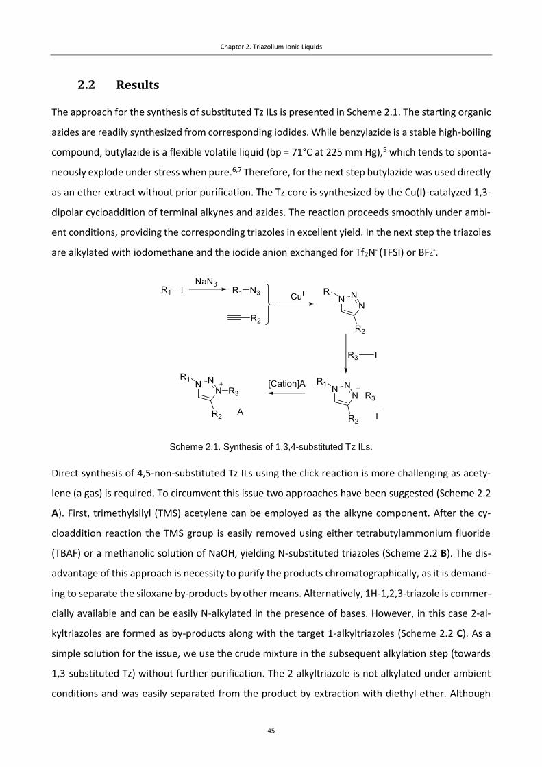
Chapter 2. Triazolium Ionic Liquids
45
2.2 Results
The approach for the synthesis of substituted Tz ILs is presented in Scheme 2.1. The starting organic
azides are readily synthesized from corresponding iodides. While benzylazide is a stable high-boiling
compound, butylazide is a flexible volatile liquid (bp = 71°C at 225 mm Hg),5 which tends to sponta-
neously explode under stress when pure.6,7 Therefore, for the next step butylazide was used directly
as an ether extract without prior purification. The Tz core is synthesized by the Cu(I)-catalyzed 1,3-
dipolar cycloaddition of terminal alkynes and azides. The reaction proceeds smoothly under ambi-
ent conditions, providing the corresponding triazoles in excellent yield. In the next step the triazoles
are alkylated with iodomethane and the iodide anion exchanged for Tf2N- (TFSI) or BF4-.
Scheme 2.1. Synthesis of 1,3,4-substituted Tz ILs.
Direct synthesis of 4,5-non-substituted Tz ILs using the click reaction is more challenging as acety-
lene (a gas) is required. To circumvent this issue two approaches have been suggested (Scheme 2.2
A). First, trimethylsilyl (TMS) acetylene can be employed as the alkyne component. After the cy-
cloaddition reaction the TMS group is easily removed using either tetrabutylammonium fluoride
(TBAF) or a methanolic solution of NaOH, yielding N-substituted triazoles (Scheme 2.2 B). The dis-
advantage of this approach is necessity to purify the products chromatographically, as it is demand-
ing to separate the siloxane by-products by other means. Alternatively, 1H-1,2,3-triazole is commer-
cially available and can be easily N-alkylated in the presence of bases. However, in this case 2-al-
kyltriazoles are formed as by-products along with the target 1-alkyltriazoles (Scheme 2.2 C). As a
simple solution for the issue, we use the crude mixture in the subsequent alkylation step (towards
1,3-substituted Tz) without further purification. The 2-alkyltriazole is not alkylated under ambient
conditions and was easily separated from the product by extraction with diethyl ether. Although
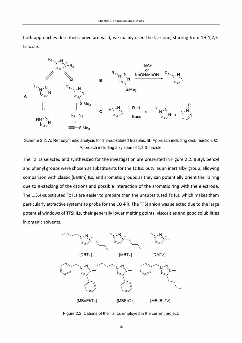
Chapter 2. Triazolium Ionic Liquids
46
both approaches described above are valid, we mainly used the last one, starting from 1H-1,2,3-
triazole.
Scheme 2.2. A: Retrosynthetic analysis for 1,3-substituted triazoles. B: Approach including click reaction. C:
Approach including alkylation of 1,2,3-triazole.
The Tz ILs selected and synthesized for the investigation are presented in Figure 2.2. Butyl, benzyl
and phenyl groups were chosen as substituents for the Tz ILs: butyl as an inert alkyl group, allowing
comparison with classic [BMIm] ILs, and aromatic groups as they can potentially orient the Tz ring
due to π-stacking of the cations and possible interaction of the aromatic ring with the electrode.
The 1,3,4-substituted Tz ILs are easier to prepare than the unsubstituted Tz ILs, which makes them
particularly attractive systems to probe for the CO2RR. The TFSI anion was selected due to the large
potential windows of TFSI ILs, their generally lower melting points, viscosities and good solubilities
in organic solvents.
Figure 2.2. Cations of the Tz ILs employed in the current project.

Chapter 2. Triazolium Ionic Liquids
47
To probe the ability of the Tz ILs to act as co-catalysts in the CO2RR the corresponding compound
(0.02 M) was dissolved in a 0.1 M solution of tetrabutylammonium hexafluorophosphate (TBAP) in
acetonitrile. Polished polycrystalline silver and glassy carbon electrodes were used as the cathodes.
The choice of the electrodes is based on the fact that ILs do not normally have catalytic activities on
their own, but improve the performance of the actual catalyst, i.e. the electrodes. Silver is a well-
established catalyst for the CO2RR, having large FECO at reasonable potentials.8 Meanwhile, glassy
carbon electrodes do not exhibit catalytic properties and are used as an inert electrode, which al-
lows the stability of the system to be probed in the presence of CO2.
First, the electrochemical behavior of the systems in the presence and absence of CO2 was evaluated
by cyclic voltammetry (CV) experiments. Experiments under N2 atmosphere were performed to de-
termine the potential windows of the Tz ILs (Figure 2.3). Tz ILs without aromatic substituents
showed better stability. Benzyl substituents have the most destabilizing effect, which is probably
due to the low stability of the benzyl group under strongly reducing conditions, e.g. benzylamines
can be easily cleaved under the conditions of the Birch reduction, forming toluene and free amines.9
The introduction of the phenyl group in the Tz ring also results in the destabilization of the co-cata-
lyst, which may be a consequence of the formation of a larger electron-deficient conjugated system.
For the 1,3-alkyl substituted Tz, dibutyl Tz is more stable than dimethyl Tz, presumably due to the
larger sterics and stronger electron donating effect of the butyl group compared to the methyl one.
Under N2, CVs obtained using a Ag working electrode correspond to those obtained with a glassy
carbon electrode (Figure 2.3, solid green vs dashed blue lines), suggesting that specific interactions
between the electrodes and the Tz cation are not essential and allowing the CVs for the Ag and C
electrodes, recorded under CO2, to be compared.

Chapter 2. Triazolium Ionic Liquids
48
Figure 2.3. CV data on the stability of the Tz ILs.
The shapes of the decomposition curves are different for the 1,3,4- and 1,3-substituted Tz cations.
For the 1,3,4-Tz ILs no peaks appear on the backward oxidation scan, which implies fully irreversible
reduction of the species. The reduction curves for the 1,3-alkyl ILs have an extremum for the oxida-
tive part of the curve along with the one appearing during the reduction, which might imply a certain

Chapter 2. Triazolium Ionic Liquids
49
degree of reversibility for the degradation process. The CVs are not symmetric, with minima (extre-
mum attributed to the reduction wave) higher in amplitude than the maxima (extremum attributed
to the oxidation wave). Such shape can be a sign of a partial decomposition of the formed reduction
product. For the deeper understanding of the reduction of the Tz cations, CV curves at different scan
rates were recorded (Figure 2.4 left).
Figure 2.4. Left: CV curves for [DMTz]TFSI recorded at different scan rates. Right: Relation of the peak cur-
rent densities to the square root of the scan rate. Experimental conditions: 0.02 M IL in 0.1 M TBAP in
MeCN, glassy carbon polished working electrode.
The CV curve becomes more symmetrical at higher scan rates, further supporting decomposition of
the reduced species as the reason for the asymmetry of the CV. The peak-to-peak separation for all
curves is ca. 77 mV, which is larger than that of a fully reversible process (57 mV).10 In general, the
difference may result from quasi-reversibility of the reduction or from non-ideality of the system
(large resistances between the working and the reference electrodes, which are normal when em-
ploying organic electrolytes). In order to clarify which of these reasons is in operation, the CV exper-
iment was performed for ferrocene (Fc). The reduction of Fc is a one-electron and fully reversible
process, which allows it to be used as a standard for the electrochemical measurements. In our case
peak-to-peak separation for the Fc couple was 76 mV, indicating the reduction of Tz to be a reversi-
ble one-electron process. The relation of the current density to the square root of the scan rate is
linear for both the reduction and oxidation waves, which shows fast electron transfer and, there-
fore, diffusion control of the reduction reaction (Figure 2.4 right).

Chapter 2. Triazolium Ionic Liquids
50
Following the measurements under a N2 atmosphere, the reaction mixtures were flushed with CO2
and the CV experiments were performed again. In the accordance with the data on the Im ILs, 1,3,4-
substituted Tz ILs showed no significant co-catalytic activity, which is concluded from a lack of dif-
ference of the onset potentials and only minor differences in the current densities in the presence
and absence of CO2 (Figure 2.5). However, in the case of 1,3-alkylated Tz ILs, [DMTz]Tf2N,
[BMTz]Tf2N and [DBTz]Tf2N, when CO2 is present in the system the onset potentials of the reduction
waves shift in a positive direction and are followed by the disappearance of the oxidation peaks.
These changes indicate a new Faradaic process in the system due to the presence of CO2. The CV
curves have a peak, nearly corresponding to the reduction peak of the co-catalyst under N2. This
observation may imply that the reduction wave consists of two simultaneous processes, i.e. reduc-
tion of CO2 and decomposition of the co-catalysts, with the latter limiting the reduction. As no cat-
alytic current is observed when the glassy carbon electrode is used instead of the Ag electrode, and
hence the role of the Ag electrode appears to be essential for catalysis and it seems unlikely that
the Tz IL serves as a redox shuttle as shown in Scheme 1.1 in the section 1.2.
However, even when the glassy carbon electrode is employed, the shape of the CV curve is different
in the presence and absence of CO2. When carbon dioxide is in the mixture, the reduction current
increases, the oxidation peaks disappear and the process loses all signs of reversibility. A possible
explanation for these changes is that CO2 reacts rapidly with the reduced form of triazolium cation.
However, a shift in the onset potential does not occur.

Chapter 2. Triazolium Ionic Liquids
51
Figure 2.5. CV curves for the Tz ILs under N2 and CO2 atmospheres. Experimental conditions: 0.02 M IL in
0.1 M TBAP in MeCN, Ag polished polycrystalline working electrode.
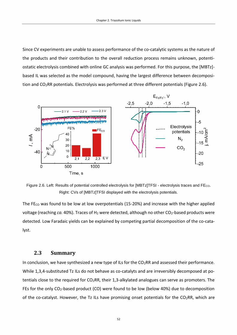
Chapter 2. Triazolium Ionic Liquids
52
Since CV experiments are unable to assess performance of the co-catalytic systems as the nature of
the products and their contribution to the overall reduction process remains unknown, potenti-
ostatic electrolysis combined with online GC analysis was performed. For this purpose, the [MBTz]-
based IL was selected as the model compound, having the largest difference between decomposi-
tion and CO2RR potentials. Electrolysis was performed at three different potentials (Figure 2.6).
Figure 2.6. Left: Results of potential controlled electrolysis for [MBTz]TFSI - electrolysis traces and FECO.
Right: CVs of [MBTz]TFSI displayed with the electrolysis potentials.
The FECO was found to be low at low overpotentials (15-20%) and increase with the higher applied
voltage (reaching ca. 40%). Traces of H2 were detected, although no other CO2-based products were
detected. Low Faradaic yields can be explained by competing partial decomposition of the co-cata-
lyst.
2.3 Summary
In conclusion, we have synthesized a new type of ILs for the CO2RR and assessed their performance.
While 1,3,4-substituted Tz ILs do not behave as co-catalyts and are irreversibly decomposed at po-
tentials close to the required for CO2RR, their 1,3-alkylated analogues can serve as promoters. The
FEs for the only CO2-based product (CO) were found to be low (below 40%) due to decomposition
of the co-catalyst. However, the Tz ILs have promising onset potentials for the CO2RR, which are

Chapter 2. Triazolium Ionic Liquids
53
close to the theoretical ones for non-aqueous systems. Nonetheless, these results contribute to the
understanding of structure/activity relationships for CO2RR catalysts.

Chapter 2. Triazolium Ionic Liquids
54
2.4 Experimental
2.4.1 Electrochemical measurements.
Cyclic voltammetry (CV) measurements were carried out using a Bio-Logic SP200 potentiostat and a
custom-made glass electrochemical cell. Bu4NPF6 (0.1 M, Sigma-Aldrich) in anhydrous acetonitrile
(5 mL, 99.9+ %, Extra Dry, Acros) was used as the supporting electrolyte and the concentration of
catalysts was 0.02 M for all runs if not stated otherwise. Silver and glassy carbon disk electrodes (5
mm diameter, BioLogic) were used as working electrodes. Before each experiment, the electrodes
were polished with Al2O3 slurry (1 micron, Electron Microscopy Sciences), washed with water and
dried using a stream of air. An Ag/AgCl quasi-reference homemade electrode was employed as the
reference. The electrode was prepared by polarization of Ag wire in 2 M HCl (two electrode setup,
Ag wire anode (working electrode), Pt cathode (counter electrode + reference), 2V for 180 s). This
electrode was operated behind a ceramic diaphragm (6.1240.020, Metrohm) and calibrated to the
ferrocene/ferrocenium couple. A Pt wire was used as the counter electrode. All the electrodes were
always set at the same positions in the cell prior to every experiment in order to keep ohmic losses
constant, and the measurements were corrected for the IR drop. Before conducting each experi-
ment, the solution was flushed with Ar for 15 min under stirring. CV scans were recorded at 100
mV/s. All the ILs were dried at 90°C for 30 min before cyclic voltammetry measurements.
Chronoamperometry experiments followed by gas chromatography(GC) analysis were carried out in
a H-type cell employing NBu4PF6 (0.1 M) containing the target IL (0.02 M) as catholyte, H2SO4 (0.5
M, suprapure, Merck) as anolyte, compartments separated by a polymer membrane Nafion 117,
Sigma-Aldrich). As working electrodes, a Ag foil (99.9%, 0.25 mm thickness, Sigma Aldrich) was used.
Before measurements, the Ag foil electrode was mechanically polished with alumina paste (1 µm)
on polishing cloth, ultrasonicated for about 1 minute, then rinsed with Milli-Q water and dried in Ar
stream. A platinized Pt foil and a leakless Ag/AgCl electrode (EDAQ) were used as counter and ref-
erence electrodes, respectively. Before each series of experiments, a calibration mixture of H2, CO,
CO2, CH4, C2H6 and C3H8 (Carbagaz) was injected in the GC. HayeSep D 80-100 mesh column was
employed for the separation.
Potentiostatic control was provided with a Metrohm Autolab PGSTAT302N instrument. The catho-
lyte was continuously purged with CO2 gas at the flow rate of 15 mL/min, thereby transporting vol-

Chapter 2. Triazolium Ionic Liquids
55
atile reaction products from the headspace into the sampling loops of the on-line gas chromato-
graph (SRI Instruments). The partial current density for a given gaseous product was determined
using the following equations:
(1)
(2)
Ii is the Partial current for the conversion of CO2 to product i, ci represents the volume fraction of
the products measured via online GC using an independent calibration standard gas (Carbagas), z is
the number of electrons involved in the reaction to form a particular product, F is the Faraday con-
stant (96485 C/mol), v is the flow rate [L/s], Vm represents the molar volume, Itotal is the total current
at the time of measurement. Faradaic efficiency (FE) was obtained by normalizing the partial current
density for a given reaction product with respect to the total current density. Gas products were
analyzed online during steady-state potentiostatic CO2 electrolysis at different electrode potentials.
2.4.2 Synthesis and characterization of compounds.
All reagents were obtained commercially and used without further purification unless otherwise
stated. CO2 (99.998 %) and Ar (99.9999 %) were obtained from Carbagas, Switzerland. 1H, 19F and
proton-decoupled 13C-NMR spectra were recorded on a Bruker Avance-400 (400 MHz) spectrome-
ter. All reactions were completed under inert conditions (nitrogen atmosphere).
1-azidobutane: To a solution of 1-iodobutane (4.60 mL, 40 mmol) in DMSO (50 mL) was added NaN3
(3.90 g, 60 mmol), the reaction mixture was left stirring at 90°C for 24 hours. The
resulting mixture was cooled down, diluted with water (100 mL) and extracted with
Et2O (3x100 mL). The combined organic fractions were dried over MgSO4, then the volume of the
solution was reduced under vacuum. The resulting mixture was used without further purification,
as BuN3 is potentially explosive when pure. NMR yield: 78%. 1H NMR (400 MHz, Chloroform-d) δ
3.27 (t, J = 6.9 Hz, 2H), 1.68 – 1.53 (m, 2H), 1.51 – 1.34 (m, 2H), 1.01 – 0.87 (m, 3H).
Benzylazide: To a solution of benzylbromide (3.5 mL, 29 mmol) in a 4:1 mixture of acetone and
water (160 and 40 mL respectively) was added NaN3 (2.85 g, 48 mmol). The reaction

Chapter 2. Triazolium Ionic Liquids
56
mixture was left stirring at rt for 24 hours. The resulting mixture was extracted with dichloro-
methane (2x40 mL), the combined organic fractions were washed with brine (50 mL), dried over
MgSO4 and dried under vacuum, affording pale yellow oil (3.97 g, ca. 100%). 1H NMR (400 MHz,
Chloroform-d) δ 7.59 – 7.28 (m, 5H), 4.37 (s, 2H). 13C NMR (101 MHz, CDCl3) δ 135.37, 128.83,
128.30, 128.21, 54.82.
1-butyl-4-phenyl-1,2,3-triazole: To a solution of BuN3 (1.0 g, 10 mmol) in methanol (50 mL) were
added sodium ascorbate (0.40 g, 2 mmol), copper sulfate pentahydrate
(0.38 g, 1.5 mmol) and phenylacetylene (1.11 mL, 10 mmol). The reaction
mixture was left for 12 hours at rt, diluted by water (50 mL), extracted by
dichloromethane (4x50 mL). The combined organic fractions were washed
with Brine (50 mL), dried over MgSO4, filtered through a short silica plug and dried under vacuum,
affording pale pink solid (1.63 g, 80%). 1H NMR (400 MHz, Chloroform-d) δ 7.91 – 7.82 (m, 2H), 7.77
(s, 1H), 7.45 (t, J = 7.5 Hz, 2H), 7.41 – 7.31 (m, 1H), 4.43 (t, J = 7.2 Hz, 2H), 1.96 (p, J = 7.3 Hz, 2H),
1.43 (h, J = 7.4 Hz, 2H), 1.00 (t, J = 7.4 Hz, 3H). 13C NMR (101 MHz, CDCl3) δ 147.73, 130.72, 128.81,
128.06, 125.69, 119.39, 50.15, 32.31, 19.73, 13.46.
1-benzyl-4-phenyl-1,2,3-triazole: To a solution of copper sulfate pentahydrate (0.04 g, 0.16 mmol),
sodium ascorbate (0.60 g, 0.3 mmol) and benzoic acid (0.17 g, 1.4 mmol)
in a 2:1 mixture of H2O (10 mL) and tert-butanol (5 mL) were added ben-
zylazide (2.00 g, 15 mmol) and phenylacetylene (1.57 mL, 14.3 mmol). The
reaction mixture was left for 10 minutes at rt, diluted by dichloromethane
(150 mL), washed by water (100 mL), brine (100 mL), dried over MgSO4 and filtered through a celite
plug. The solvent was removed under vacuum, affording colorless solid (3.4 g, 99%). 1H NMR (400
MHz, Chloroform-d) δ 7.87 – 7.77 (m, 2H), 7.68 (s, 1H), 7.47 – 7.31 (m, 8H), 5.60 (s, 2H). 13C NMR
(101 MHz, CDCl3) δ 148.25, 134.68, 130.53, 129.16, 128.80, 128.17, 128.06, 125.71, 119.47, 54.25.
1-benzyl-4-butyl-1,2,3-triazole: Synthesized employing the same protocol, as for 1-benzyl-4-phenyl-
1,2,3-triazole. Starting from 1-hexyne (1.56 mL, 13.6 mmol). Yield 70%
(2.1 g). 1H NMR (400 MHz, Chloroform-d) δ 7.43 – 7.36 (m, 2H), 7.31 –
7.25 (m, 3H), 5.52 (s, 2H), 2.77 – 2.67 (m, 2H), 1.65 (t, J = 7.5 Hz, 2H),
1.38 (h, J = 7.4 Hz, 2H), 0.94 (t, J = 7.3 Hz, 3H).

Chapter 2. Triazolium Ionic Liquids
57
1-methyl-1,2,3-triazole: To an ice-cooled (0°C) suspension of sodium hydride (4.6 g, 0.19 mol) in dry
THF (100 mL) was added dropwise 1H-1,2,3-triazole (10 mL, 0.17 mol), followed by io-
domethane (16.6 mL, 0.17 mol). The reaction was left stirring for 2 hours at rt. Water
(100 mL) was added, the mixture was extracted by dichloromethane (3x100 mL), combined organic
layers were dried over MgSO4. Activated charcoal (50 mg) was added, the mixture left stirring for 3
hours at rt, then it was filtered through celite, the solvent was removed under vacuum, yielding
colorless liquid (4.7 g, 33%). 1H NMR (400 MHz, Chloroform-d) δ 7.63 (s, 1H), 7.48 (s, 1H), 4.06 (s,
3H).
1-methyl-1,2,3-triazole: To a solution of 1H-1,2,3-triazole (10 mL, 0.17 mol) in dry MeCN (70 mL)
were added butyl bromide (20.5 mL, 0.19 mol) and potassium carbonate (36 g,
0.26 mol). The reaction was left stirring for 12 hours at rt. Water (150 mL) was
added, the mixture was extracted by dichloromethane (3x100 mL), combined or-
ganic layers were dried over MgSO4. The solvent was removed under vacuum, yielding colorless
liquid (17.51 g). As discussed in the main text, two products were formed: 1-butyl-1H-1,2,3-triazole
and 2-butyl-2H-1,2,3-triazole (1:1, 8.8 g and 41% yield each). The mixture was used directly for the
alkylation step. 1H NMR (mixture): 1H NMR (400 MHz, Chloroform-d) δ 7.71 (d, J = 1.0 Hz, 1H), 7.59
(s, 1H), 7.55 (d, J = 1.0 Hz, 1H), 4.43 (dt, J = 20.2, 7.2 Hz, 4H), 2.09 – 1.79 (m, 4H), 1.47 – 1.28 (m, 4H),
1.08 – 0.87 (m, 6H).
1-butyl-3-methyl-4-phenyl-1,2,3-triazolium iodide: To a solution of 1-butyl-4-phenyl-1,2,3-triazole
(360 mg, 1.8 mmol) in dry MeCN (10 mL) was added iodomethane (8.8 mL,
17 mmol). The reaction mixture was left for 12 hours at reflux, then dried
under vacuum, adsorbed on silica, washed with MeCN (5 mL) to remove
the colored side products, then with water (50 mL). The solvent was re-
moved under vacuum, yielding yellow viscous oil (0.30 g, 49%). 1H NMR (400 MHz, Chloroform-d) δ
9.53 (s, 1H), 7.84 – 7.74 (m, 2H), 7.69 – 7.50 (m, 3H), 4.83 (t, J = 7.4 Hz, 2H), 4.33 (s, 3H), 2.11 (tdd, J
= 9.2, 6.8, 4.3 Hz, 2H), 1.48 (h, J = 7.4 Hz, 2H), 1.00 (t, J = 7.4 Hz, 3H).

Chapter 2. Triazolium Ionic Liquids
58
1-benzyl-3-methyl-4-butyl-1,2,3-triazolium iodide: Synthesized employing the same protocol, as
for 1-butyl-3-methyl-4-phenyl-1,2,3-triazolium iodide. Starting from 1-
benzyl-4-butyl-1,2,3-triazole (2.1 g, 9.8 mmol). Yield 81% (2.8 g). 1H NMR
(400 MHz, Chloroform-d) δ 9.12 (s, 1H), 7.57 (dd, J = 6.6, 3.0 Hz, 2H),
7.36 (dp, J = 4.8, 1.9 Hz, 3H), 5.90 (s, 2H), 4.19 (s, 3H), 2.88 – 2.70 (m, 2H), 1.79 – 1.61 (m, 2H), 1.39
(h, J = 7.4 Hz, 2H), 0.89 (t, J = 7.3 Hz, 3H).
1-benzyl-3-methyl-4-phenyl-1,2,3-triazolium iodide: To a solution of 1-benzyl-4-phenyl-1,2,3-tria-
zole (3.36 g, 14.3 mmol) in dry MeCN (30 mL) was added iodomethane (7
mL, 71 mmol). The reaction mixture was left for 12 hours at reflux, the sol-
vent was removed under vacuum and the residue washed with Et2O (15
mL). The product was dried under vacuum, yielding yellow crystalline prod-
uct (4.18 g, 78%). 1H NMR (400 MHz, Chloroform-d) δ 9.47 (s, 1H), 7.80 – 7.66 (m, 4H), 7.65 – 7.53
(m, 3H), 7.49 – 7.41 (m, 3H), 6.08 (s, 2H), 4.31 (s, 3H).
1,3-dimethyl-1,2,3-triazolium iodide: To a solution of 3-methyl-1,2,3-triazole (0.97 g, 11.7 mmol) in
dry MeCN (10 mL) was added iodomethane (1.37 mL, 14 mmol). The reaction mixture
was left for 12 hours at reflux, the solvent was removed under vacuum and the prod-
uct precipitated with Et2O (15 mL). The precipitate was filtered off and dried under vacuum, yielding
colorless crystalline product (1.05 g, 40%). 1H NMR (400 MHz, DMSO-d6) δ 8.82 (s, 2H), 4.31 (s, 6H).
1-methyl-3-butyl-1,2,3-triazolium iodide: To the mixture from the synthesis of 1-butyl-1,2,3-tria-
zole (15 g, 120 mmol) was added iodomethane (12 mL, 120 mmol). The reac-
tion mixture was left for 12 hours at room temperature, the solvent was re-
moved under vacuum, water (50 mL) was added and the solution was washed
with Et2O (3x50 mL). The solvent was removed under vacuum, yielding yellow oily product (21.4 g).
1H NMR (400 MHz, DMSO-d6) δ 8.91 (d, J = 1.4 Hz, 1H), 8.85 (d, J = 1.4 Hz, 1H), 4.63 (t, J = 7.1 Hz,
2H), 4.31 (s, 3H), 2.04 – 1.72 (m, 2H), 1.40 – 1.12 (m, 2H), 0.92 (t, J = 7.4 Hz, 3H).
1,3-dibutyl-1,2,3-triazolium iodide: To an ice-cooled (0°C) suspension of sodium hydride (1.9 g, 80
mmol) in dry THF (100 mL) was added dropwise 1H-1,2,3-triazole (4.19
mL, 72 mmol) followed by 1-iodobutane (21 mL, 181 mmol) The reaction
was left for 5 days at reflux. Water (100 mL) was added, the mixture was
extracted by dichloromethane (3x100 mL), combined organic layers were dried over MgSO4. The

Chapter 2. Triazolium Ionic Liquids
59
solvent was removed under vacuum, yielding dark yellow oil (15.4 g, 69%). 1H NMR (400 MHz,
DMSO-d6) δ 8.98 (s, 2H), 4.65 (t, J = 7.1 Hz, 4H), 2.04 – 1.83 (m, 4H), 1.42 – 1.19 (m, 4H), 0.91 (t, J =
7.4 Hz, 6H). 13C NMR (101 MHz, DMSO) δ 131.26, 53.31, 31.05, 19.20, 13.67.
Typical procedure for the anion metathesis: To a solution of triazolium halide salt (1 eq) in a mixture
of Milli-Q water and dichloromethane (1:1) was added lithium bis(trifluromethylsulfonyl)imide (1
eq). The mixture was left stirring for 3-4 hours at rt. The mixture was diluted by Milli-Q water, ex-
tracted by DCM (3x equal volumes), the solvent from the combined organic phases was removed
under reduced pressure. The residue was washed by Et2O and dried under vacuum, yielding the
target products.
1-butyl-3-methyl-4-phenyl-1,2,3-triazolium bis(trifluoromethylsulfonyl)imide: Yield 97% (503 mg).
1H NMR (400 MHz, DMSO-d6) δ 9.21 (s, 1H), 7.76 (dt, J = 6.9, 2.2 Hz, 2H),
7.69 (dt, J = 5.2, 2.4 Hz, 3H), 4.67 (t, J = 7.1 Hz, 2H), 4.30 (s, 3H), 1.97 (dq,
J = 9.3, 7.2 Hz, 2H), 1.39 (ddt, J = 14.6, 9.5, 7.2 Hz, 2H), 0.96 (t, J = 7.4 Hz,
3H). 13C NMR (101 MHz, DMSO) δ 142.76, 131.93, 129.86, 129.77,
129.23, 123.20, 118.35, 53.44, 31.00, 19.22, 13.70. 19F NMR (376 MHz, DMSO) δ -78.72.
1-benzyl-3-methyl-4-butyl-1,2,3-triazolium bis(trifluoromethylsulfonyl)imide: Yield 87% (2.4 g). 1H
NMR (400 MHz, Chloroform-d) δ 8.08 (s, 1H), 7.46 (s, 5H), 5.68 (s, 2H),
4.20 (s, 3H), 2.79 (ddd, J = 9.0, 6.9, 0.8 Hz, 2H), 1.69 (dddd, J = 9.4, 7.9,
6.9, 5.9 Hz, 2H), 1.44 (dq, J = 14.6, 7.3 Hz, 2H), 0.96 (t, J = 7.3 Hz, 3H). 13C
NMR (101 MHz, CDCl3) δ 145.21, 130.81, 130.14, 129.60, 129.38, 127.47, 57.62, 37.47, 28.68, 23.05,
22.08, 13.32. 19F NMR (376 MHz, CDCl3) δ -78.87, -78.88.
1-benzyl-3-methyl-4-phenyl-1,2,3-triazolium bis(trifluoromethylsulfonyl)imide: Yield 88% (2.48 g).
1H NMR (400 MHz, DMSO-d6) δ 9.29 (s, 1H), 7.82 – 7.72 (m, 2H), 7.68 (q, J
= 4.9, 4.2 Hz, 3H), 7.61 – 7.53 (m, 2H), 7.49 (dd, J = 9.3, 3.9 Hz, 3H), 5.94 (s,
2H), 4.29 (s, 3H). 13C NMR (101 MHz, DMSO) δ 143.11, 133.31, 131.95,
129.84, 129.81, 129.76, 129.55, 129.46, 129.39, 123.09, 121.55, 118.35,
56.75. 19F NMR (376 MHz, DMSO) δ -78.71.
Chapter 2. Triazolium Ionic Liquids
60
1,3-dimethyl-1,2,3-triazolium bis(trifluoromethylsulfonyl)imide: Yield 75% (630 mg). 1H NMR (400
MHz, DMSO-d6) δ 8.80 (s, 2H), 4.30 (s, 6H). 13C NMR (101 MHz, DMSO) δ 132.10,
121.54, 118.34, 40.14. 19F NMR (376 MHz, DMSO) δ -78.73.
1-methyl-3-butyl-1,2,3-triazolium bis(trifluoromethylsulfonyl)imide: Yield 99% (3.7 g). 1H NMR
(400 MHz, DMSO-d6) δ 8.89 (d, J = 1.4 Hz, 1H), 8.83 (d, J = 1.4 Hz, 1H), 4.62
(t, J = 7.1 Hz, 2H), 4.31 (s, 3H), 2.01 – 1.71 (m, 2H), 1.47 – 1.17 (m, 3H), 0.92
(t, J = 7.4 Hz, 3H). 13C NMR (101 MHz, DMSO) δ 132.19, 131.12, 53.20,
31.09, 19.17, 13.61. 19F NMR (376 MHz, DMSO) δ -78.71, -78.71.
1,3-dibutyl-1,2,3-triazolium bis(trifluoromethylsulfonyl)imide: Yield 98% (11.1 g). 1H NMR (400
MHz, DMSO-d6) δ 8.93 (s, 1H), 4.63 (t, J = 7.2 Hz, 2H), 2.00 – 1.81 (m, 2H),
1.41 – 1.21 (m, 2H), 0.92 (t, J = 7.4 Hz, 3H). 13C NMR (101 MHz, DMSO) δ
131.23, 53.31, 31.03, 19.19, 13.60. 19F NMR (376 MHz, DMSO) δ -78.71,
-78.72.
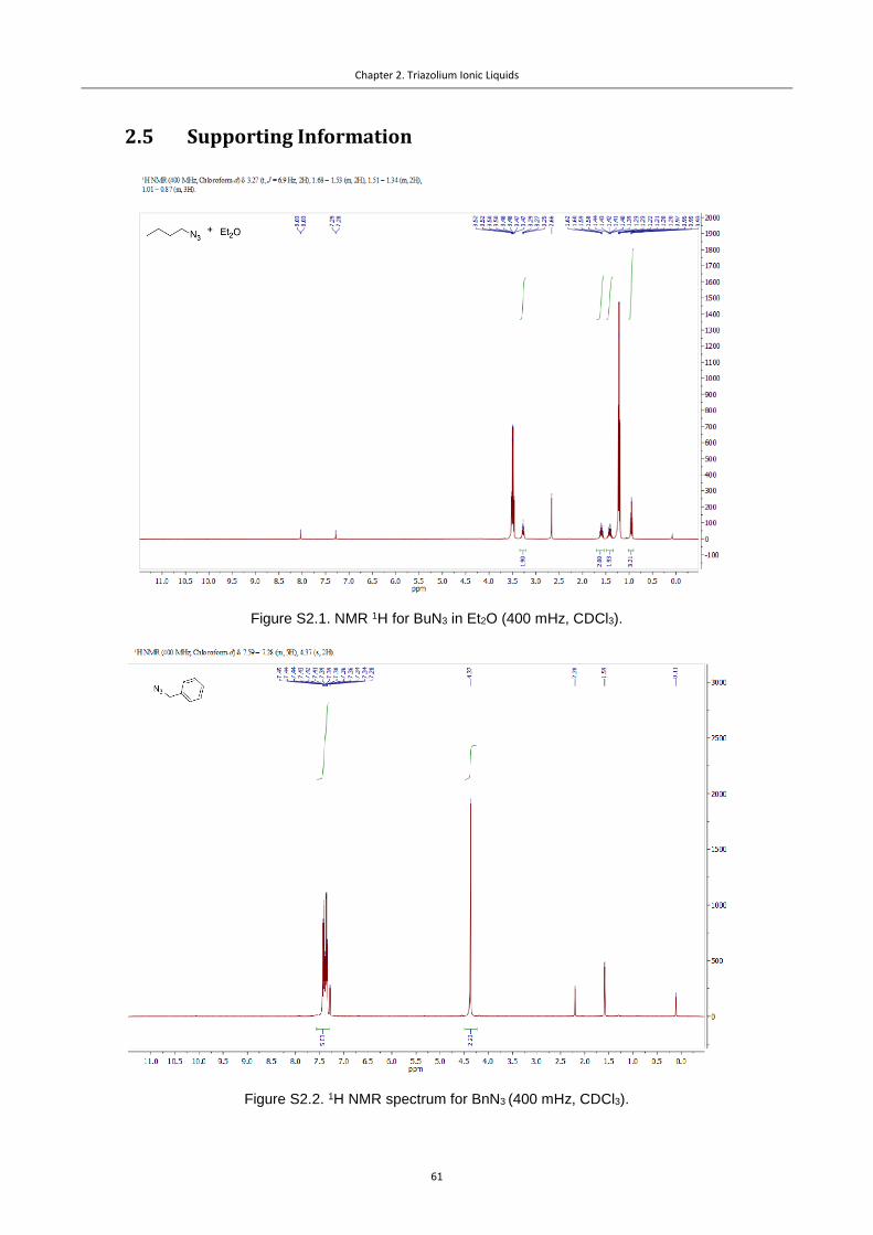
Chapter 2. Triazolium Ionic Liquids
61
2.5 Supporting Information
Figure S2.1. NMR 1H for BuN3 in Et2O (400 mHz, CDCl3).
Figure S2.2. 1H NMR spectrum for BnN3 (400 mHz, CDCl3).

Chapter 2. Triazolium Ionic Liquids
62
Figure S2.3. 13C NMR spectrum for BnN3 (101 mHz, CDCl3).
Figure S2.4. 1H NMR spectrum for 1-butyl-4-phenyltriazole (400 mHz, CDCl3).
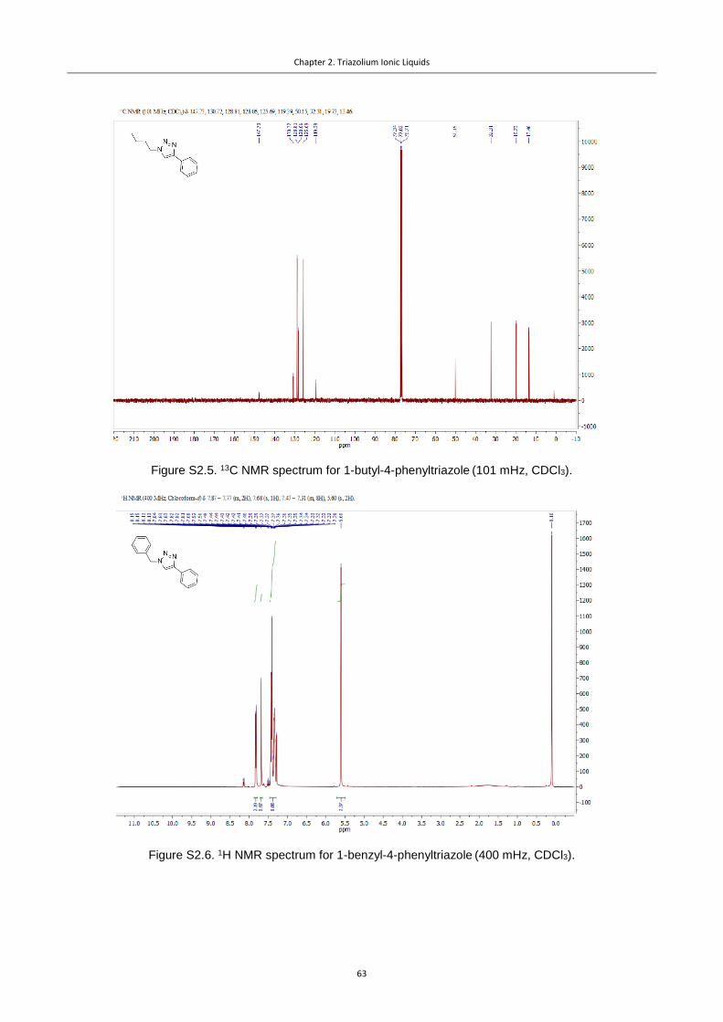
Chapter 2. Triazolium Ionic Liquids
63
Figure S2.5. 13C NMR spectrum for 1-butyl-4-phenyltriazole (101 mHz, CDCl3).
Figure S2.6. 1H NMR spectrum for 1-benzyl-4-phenyltriazole (400 mHz, CDCl3).
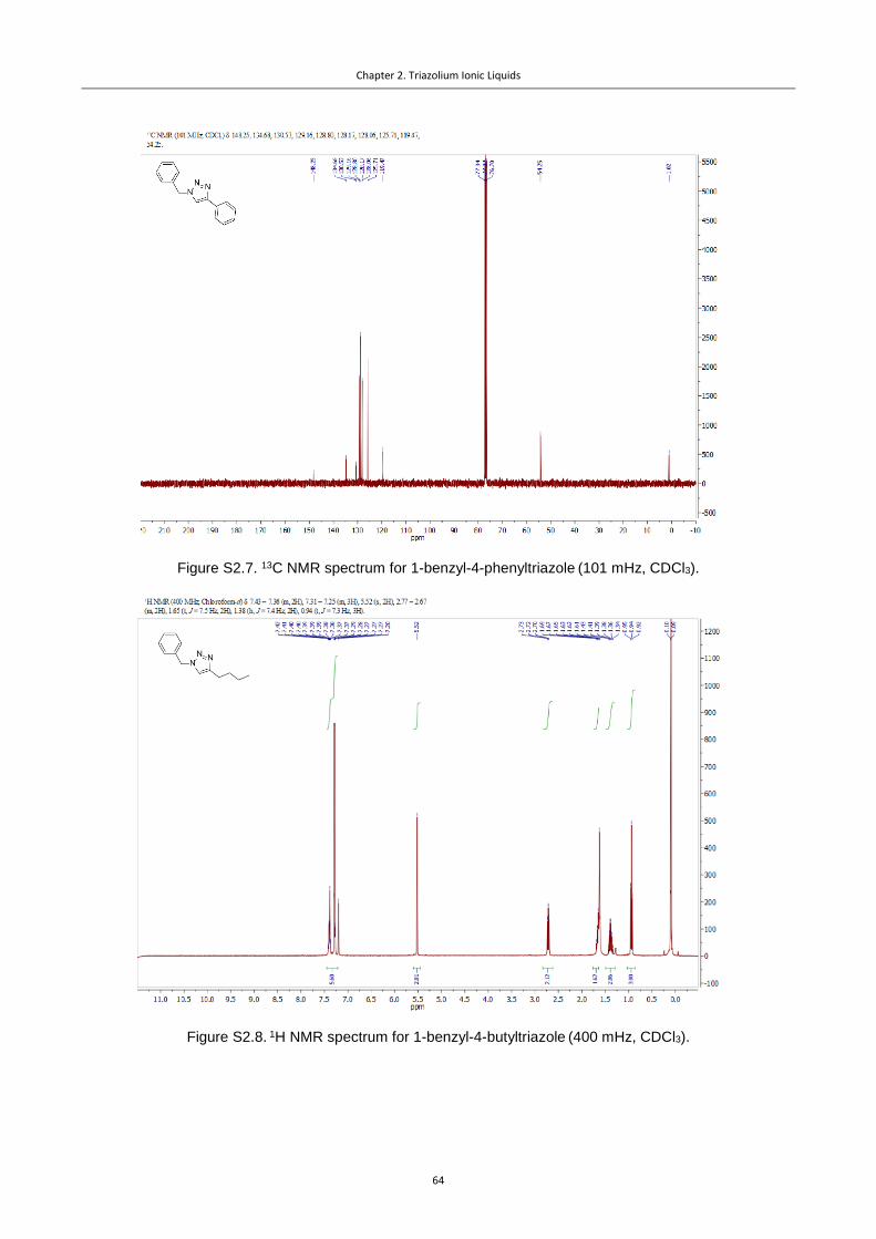
Chapter 2. Triazolium Ionic Liquids
64
Figure S2.7. 13C NMR spectrum for 1-benzyl-4-phenyltriazole (101 mHz, CDCl3).
Figure S2.8. 1H NMR spectrum for 1-benzyl-4-butyltriazole (400 mHz, CDCl3).

Chapter 2. Triazolium Ionic Liquids
65
Figure S2.9. 1H NMR spectrum for 1-methyl-triazole (400 mHz, CDCl3).
Figure S2.10. 1H NMR spectrum for the mixture of 1-butyls and 2-butyl-triazoles (400 mHz, CDCl3).

Chapter 2. Triazolium Ionic Liquids
66
Figure S2.11. 1H NMR spectrum for 1-butyl-3-methyl-4-phenyltriazolium iodide (400 mHz, CDCl3).
Figure S2.12. 1H NMR spectrum for 1-benzyl-3-methyl-4-phenyltriazolium iodide (400 mHz, CDCl3).

Chapter 2. Triazolium Ionic Liquids
67
Figure S2.13. 1H NMR spectrum for 1-benzyl-3-methyl-4-butyltriazolium iodide (400 mHz, CDCl3).
Figure S2.14. 1H NMR spectrum for 1,3-dimethyltriazolium iodide (400 mHz, DMSO-d6).

Chapter 2. Triazolium Ionic Liquids
68
Figure S2.15. 1H NMR spectrum for 1,3-dibutyltriazolium iodide (400 mHz, DMSO-d6).
Figure S2.16. 13C NMR spectrum for 1,3-dibutyltriazolium iodide (101 mHz, DMSO-d6).
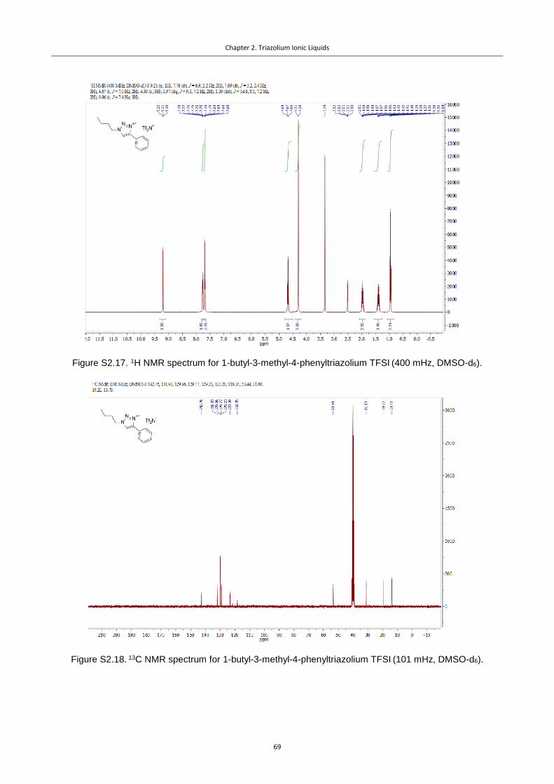
Chapter 2. Triazolium Ionic Liquids
69
Figure S2.17. 1H NMR spectrum for 1-butyl-3-methyl-4-phenyltriazolium TFSI (400 mHz, DMSO-d6).
Figure S2.18. 13C NMR spectrum for 1-butyl-3-methyl-4-phenyltriazolium TFSI (101 mHz, DMSO-d6).

Chapter 2. Triazolium Ionic Liquids
70
Figure S2.19. 1H NMR spectrum for 1-benzyl-3-methyl-4-phenyltriazolium TFSI (400 mHz, DMSO-d6).
Figure S2.20. 13C NMR spectrum for 1-benzyl-3-methyl-4-phenyltriazolium TFSI (101 mHz, DMSO-d6).

Chapter 2. Triazolium Ionic Liquids
71
Figure S2.21. 1H NMR spectrum for 1,3-dimethyltriazolium TFSI (400 mHz, DMSO-d6).
Figure S2.22. 13C NMR spectrum for 1,3-dimethyltriazolium iodide (101 mHz, DMSO-d6).

Chapter 2. Triazolium Ionic Liquids
72
Figure S2.23. 1H NMR spectrum for 1-butyl-3-methyltriazolium TFSI (400 mHz, DMSO-d6).
Figure S2.24. 13C NMR spectrum for 1-butyl-3-methyltriazolium TFSI (101 mHz, DMSO-d6).

Chapter 2. Triazolium Ionic Liquids
73
Figure S2.25. 1H NMR spectrum for 1,3-dibutyltriazolium TFSI (400 mHz, DMSO-d6).
Figure S2.26. 13C NMR spectrum for 1,3-dibutyltriazolium TFSI (101 mHz, DMSO-d6).

Chapter 2. Triazolium Ionic Liquids
74
2.6 References
(1) Lau, G. P. S.; Schreier, M.; Vasilyev, D.; Scopelliti, R.; Grätzel, M.; Dyson, P. J. New Insights into
the Role of Im-Based Promoters for the Electroreduction of CO2 on a Silver Electrode. J. Am.
Chem. Soc. 2016, 138, 7820–7823.
(2) Arnold, P. L.; Pearson, S. Abnormal N-Heterocyclic Carbenes. Coord. Chem. Rev. 2007, 251,
596–609.
(3) Rostovtsev, V. V.; Green, L. G.; Fokin, V. V.; Sharpless, K. B. A Stepwise Huisgen Cycloaddition
Process: Copper(I)-Catalyzed Regioselective “Ligation” of Azides and Terminal Alkynes.
Angew. Chemie Int. Ed. 2002, 41 (14), 2596–2599.
(4) Sanghi, S.; Willett, E.; Versek, C.; Tuominen, M.; Coughlin, E. B. Physicochemical Properties of
1,2,3-Triazolium Ionic Liquids. RSC Adv. 2012, 2, 848–853.
(5) Lieber, E.; Chao, T. S.; Rao, C. N. R. Improved Method for the Synthesis of Alkyl Azides. J. Org.
Chem. 1957, 22, 238–240.
(6) Spencer, D. A. XXXVII.—The Action of Bromine on Sodium and Silver Azides. J. Chem. Soc.,
Trans. 1925, 127 (0), 216–224.
(7) Bock, H.; Dammel, R. The Pyrolysis of Azides in the Gas Phase. Angew. Chemie Int. Ed. English
1987, 26 (6), 504–526.
(8) Rosen, B. A.; Salehi-Khojin, A.; Thorson, M. R.; Zhu, W.; Whipple, D. T.; Kenis, P. J. A.; Masel,
R. I. Ionic Liquid – Mediated Selective Conversion of CO2 to CO at Low Overpotentials. Science
2011, 334, 643–644.
(9) Du, V.; Behrens, O. K. A Method for Protecting The Imidazole Ring of Histidine During Certain
Reactions and Its Application to the Preparation of L-Amino-N-Methylhistidine. 1936, 117,
27–36.
(10) Elgrishi, N. N.; Rountree, K. J.; Mccarthy, B. D.; Rountree, E. S.; Eisenhart, T. T.; Dempsey, J. L.
A Practical Beginner’s Guide to Cyclic Voltammetry. 2017.

75
Pyrazolium Ionic Liquids
3.1 Introduction
In the previous chapter, we considered application of the
Tz ILs for the CO2RR, which is similar to the usage of the
classical Im ILs in the terms of the structure of the co-cata-
lyst. Herein, we report on an even more dramatic change
related to the structure of the cation. By switching from Im
salts to the pyrazolium (Pz) ILs the reduction of CO2 to CO
proceeds with higher Faradaic efficiencies (FEs) without
decomposition while maintaining the same high current
densities, therefore making a further step towards a com-
mercial viable electrochemical CO2 conversion process.1,2 To the best of our knowledge, this is the
first example describing the use of pyrazolium ILs as co-catalysts in the electroreduction of CO2. De-
spite certain similarity of Im and Pz rings, the latter possess different resonance structures, charge
distributions and are usually less likely to form carbenes and hydrogen bonds.
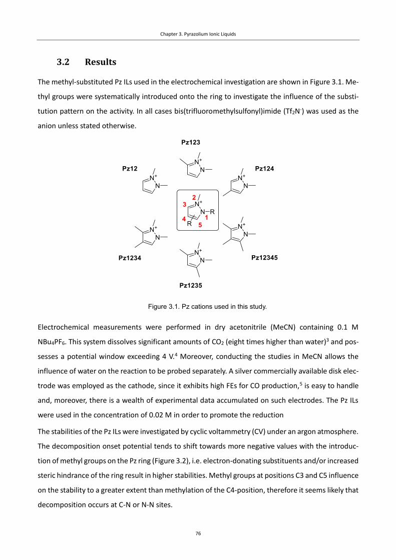
Chapter 3. Pyrazolium Ionic Liquids
76
3.2 Results
The methyl-substituted Pz ILs used in the electrochemical investigation are shown in Figure 3.1. Me-
thyl groups were systematically introduced onto the ring to investigate the influence of the substi-
tution pattern on the activity. In all cases bis(trifluoromethylsulfonyl)imide (Tf2N-) was used as the
anion unless stated otherwise.
Figure 3.1. Pz cations used in this study.
Electrochemical measurements were performed in dry acetonitrile (MeCN) containing 0.1 M
NBu4PF6. This system dissolves significant amounts of CO2 (eight times higher than water)3 and pos-
sesses a potential window exceeding 4 V.4 Moreover, conducting the studies in MeCN allows the
influence of water on the reaction to be probed separately. A silver commercially available disk elec-
trode was employed as the cathode, since it exhibits high FEs for CO production,5 is easy to handle
and, moreover, there is a wealth of experimental data accumulated on such electrodes. The Pz ILs
were used in the concentration of 0.02 M in order to promote the reduction
The stabilities of the Pz ILs were investigated by cyclic voltammetry (CV) under an argon atmosphere.
The decomposition onset potential tends to shift towards more negative values with the introduc-
tion of methyl groups on the Pz ring (Figure 3.2), i.e. electron-donating substituents and/or increased
steric hindrance of the ring result in higher stabilities. Methyl groups at positions C3 and C5 influence
on the stability to a greater extent than methylation of the C4-position, therefore it seems likely that
decomposition occurs at C-N or N-N sites.

Chapter 3. Pyrazolium Ionic Liquids
77
Figure 3.2. CVs for the Pz ILs under Ar, illustrating the differences in stability of diversely substituted
Pz cations (Ag polished disk electrode, 0.1 M NBu4PF6 in dry acetonitrile, 0.02 M IL additive).
CV experiments were then performed under a CO2 atmosphere. A significant shift of the onset po-
tential towards more positive values, followed by a steep increase in the current density is observed
under these conditions (Figure 3.3).
Different variations of the Pz ILs structures effect the co-catalytic performance in the reduction of
CO2 to CO in the following way: (1) the introduction of methyl groups on the Pz ring leads to a slight
increase in the reduction onset potential (SI, Figure S3.1 – S3.5); (2) substitution of the N-methyl
group by a butyl group has minor impact on catalytic performance (SI, Figure S3.6); (3) replacement
of Tf2N- anion by TfO- does not alter the performance of the co-catalyst, which is expected as the
reduction takes place in NBu4PF6 solution, and the concentration of PF6- is 5 times higher than that
of the IL anion (0.1 M vs 0.02 M, respectively, see SI, Figure S3.7). Therefore, neglecting the minor
impact in onset potential with substitution, and taking into consideration the increase in their sta-
bility, the more substituted Pz ILs are the most attractive co-catalysts.

Chapter 3. Pyrazolium Ionic Liquids
78
Figure 3.3. Example of the change in the CV after addition of CO2 using Pz12 as the co-catalyst (red –
argon atmosphere, black – carbon dioxide atmosphere). The performance of the silver electrode towards
CO2 reduction with and without Pz IL additives are compared in the inset. CVs for the other Pz ILs under CO2
are provided in the SI (Figures S3.1 – S3.5).
The reduction waves for the Pz ILs recorded in the presence of CO2 do not reach a current limitation
peak at the decomposition potential of the co-catalyst (Figure 3.3). This is particularly striking for co-
catalyst Pz1235, which affords current densities ≈ 30 mA/cm2 (Figure S3.5).
CVs using a glassy carbon electrode were recorded employing the same conditions both under Ar
and under a CO2 atmosphere. Under Ar, the onset potentials for the CVs do not differ from those
recorded on the silver electrode (SI, Figure S3.8). Moreover, the voltammetric response of the glassy
carbon remains unchanged when the solution is saturated with CO2. Combined, this demonstrates
that the Ag electrode is the actual catalyst for the reduction, and that the IL behaves as a co-catalyst
in the reduction of CO2 to CO. Notably, the introduction of CO2 does not result in destabilization of
the Pz ILs.
In order to confirm that the changes of the current registered are related to the CO2 reduction pro-
cess, rather than catalyst decomposition, chronoamperometric experiments followed by online gas
chromatography analysis were performed using a two-compartment H-type cell and IL Pz1235B as
a compromise between activity and stability of the promoter. An aqueous 0.5 M sulfuric acid solu-
tion was used in the compartment with the counter-electrode in order to decrease the impedance
of the system and avoid the formation of MeCN decomposition products, which interfere with the
separator (a Nafion 117 membrane). As Nafion is able to conduct protons, hydrogen-containing

Chapter 3. Pyrazolium Ionic Liquids
79
products or hydrogen itself could be expected if the HER takes place. The results of the measure-
ments are presented in Figure 3.4 and the values are summarized in Table 3.1.
FEs for CO formation are around 100% with current densities up to 30 mA/cm2, which suggests that
CO is the major product formed. Small amounts of hydrogen (from 1 – 4 %) and formic acid (< 4%)
were detected and 1H NMR spectroscopy, respectively. 1H NMR spectroscopy revealed no decompo-
sition of the Pz IL over the time of the electrolysis (Figure S3.52). Notably, small amounts of methane
(around 0.5 – 1 % FE) were observed as well by GC at low overpotentials (see Table 1). The formation
of methane has been detected as well by GC during CO2 reduction at a Ag foil electrode in aqueous
solution,6 but to the best of our knowledge not in acetonitrile solution. The maximum amount of
methane was obtained at the potential when active decomposition of the catalyst (according to the
CVs recorded under Ar, Figure 3.2) does not take place. Thus, the methane must be derived from
carbon dioxide.
Figure 3.4. Dependency of the Faradaic efficiency in the formation of the detected products on voltage
employing Pz1235B. Conditions: cathode – Ag foil; anode – Pt foil; catholyte – 0.1 M NBu4PF6 in MeCN,
0.02 M IL, saturated with CO2; anolyte – 0.5 M H2SO4 (aq); separator – Nafion 117.

Chapter 3. Pyrazolium Ionic Liquids
80
Table 3.1. Faradaic efficiencies for different products as a function of the reduction potential for CO2 electrol-
ysis employing Pz1235B.
Potential (vs Fc+/Fc), V FECO, %a FEH2, %a FECH4, %a
-2.11 99 4 0.9
-2.21 103 <1 0.4
-2.31 104 <1 0.3
-2.41 99 <1 0.2
-2.51 97 1 0.1
-2.61 102 1 0.3
a – Estimated error is ±5% from the value obtained
Table 3.2. Faradaic efficiencies for different products as a function of the reduction potential for CO2 electrol-
ysis employing [BMIm][BF4].
Potential (vs Fc+/Fc), V FECO, %a FEH2, %a FECH4, %a
-2.11 92 <1 -
-2.21 92 <1 -
-2.31 87 1 -
a – Estimated error is ±5% from the value obtained
Water may impact on the electroreduction process depending upon the nature of the catalyst.7,8 For
Pz ILs, water significantly shifts the CO2 reduction onset potential towards more positive values. As
an example, the influence of water on co-catalysis Pz1235 is shown in Figure 3.5. As the water con-
tent increases the onset potential for the reduction of CO2 gradually decreases, until a concentration
of 0.3-0.6 mM reached (the value depends on the Pz IL employed).

Chapter 3. Pyrazolium Ionic Liquids
81
Figure 3.5. Decrease of the electrochemical reduction onset potential for the conversion of CO2 to CO
using co-catalyst Pz1235 in the presence of water.
The activity of the Pz ILs was compared to [BMIm][BF4] (where BMIm = the 1-butyl-3-methyl-Im
cation, Figure S3.9) using Pz IL Pz1235B as a representative example. [BMIm][BF4] is structurally sim-
ilar to [EMIm][BF4] (where EMIm = the 1-ethyl-3-methyl-Im cation), which is considered as the
benchmark IL co-catalyst for this reaction.5 Under equivalent conditions Pz1235B exhibits a compa-
rable onset potential and current density to [BMIm][BF4], displaying a slightly steeper slope for the
reduction wave.
In order to demonstrate consistency of the working procedures, chronoamperometric experiments
followed by GC analysis were performed for the [BMIm][BF4] and Pz IL systems under the same con-
ditions and employing the same equipment (SI, Figure S3.9). The [BMIm][BF4] co-catalyst results in
good FE for CO (ca. 90% for low overpotentials, ca. 80-90% at higher voltages, see the SI), which is
consistent with the literature.5 However, in case of [BMIm][BF4] the only reduction products ob-
served are CO and negligible amounts of H2. No traces of methane or other products were detected
by 1H and 13C NMR spectroscopy or GC.
The protons in Pz-based ILs should not be readily reduced to form carbenes from the Pz, which ex-
cludes the likelihood of the formation of covalent adducts with CO2, e.g. carboxylates, as is the case
of Im ILs.9 Moreover, the fully substituted Pz IL Pz12345 displays high catalytic performance, exclud-
ing the possibility of covalent interactions between the Pz IL and CO2. As mentioned above, catalysis

Chapter 3. Pyrazolium Ionic Liquids
82
occurs when a silver electrode is used as the cathode and not with a glassy carbon electrode. There-
fore, the initial step of the reduction most probably corresponds to the formation of a CO2-based
radical-anion on the surface of the silver electrode (Figure 3.6). The effect of the co-catalyst should
then result from stabilization of this intermediate by ion pair, dipole-ion interactions or change of
the local microenvironment. According to previous reports, IL cations are able to arrange on the
silver surface in a coplanar fashion to form a double layer.10,11 The nitrogen-containing domain of
the Pz cation is the most positively charged region and substitution at C3 and C5 positions changes
the activity of the system more significantly than at the C4 position. Therefore, it is reasonable to
assume that the CO2- intermediate interacts with the positively charged region of the Pz ring (Figure
3.6), which helps to stabilize the intermediate and lower the overpotential of the reaction.
Figure 3.6. Possible intermediate structures between the Pz cations and the CO2●- radical anion lead-
ing to a lowering of the overpotential in the reduction of CO2 to CO.
3.3 Summary
In conclusion, a series of substituted Pz ILs was synthesized and shown to be efficient co-catalysts
for electrochemical reduction of CO2 to CO, superior to the benchmark Im ILs in terms of FE for CO
formation (100% vs. 80-90%). High current densities (30 mA/cm2 during electrolysis) were achieved.
The influence of the substitution pattern on the Pz ring on stability and activity was investigated,
with substituents generally stabilizing the co-catalyst, but slightly decreasing performance. Water
significantly decreases the reduction onset potential for most Pz co-catalysts. Additionally, during
chronoamperometric experiments the unexpected formation of small quantities of methane and
formic acid was observed, which is highly encouraging and warrants further investigation of Pz ILs
with other electrode materials.
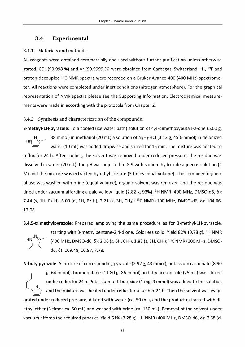
Chapter 3. Pyrazolium Ionic Liquids
83
3.4 Experimental
3.4.1 Materials and methods.
All reagents were obtained commercially and used without further purification unless otherwise
stated. CO2 (99.998 %) and Ar (99.9999 %) were obtained from Carbagas, Switzerland. 1H, 19F and
proton-decoupled 13C-NMR spectra were recorded on a Bruker Avance-400 (400 MHz) spectrome-
ter. All reactions were completed under inert conditions (nitrogen atmosphere). For the graphical
representation of NMR spectra please see the Supporting Information. Electrochemical measure-
ments were made in according with the protocols from Chapter 2.
3.4.2 Synthesis and characterization of the compounds.
3-methyl-1H-pyrazole: To a cooled (ice water bath) solution of 4,4-dimethoxybutan-2-one (5.00 g,
38 mmol) in methanol (20 mL) a solution of N2H4·HCl (3.12 g, 45.6 mmol) in deionized
water (10 mL) was added dropwise and stirred for 15 min. The mixture was heated to
reflux for 24 h. After cooling, the solvent was removed under reduced pressure, the residue was
dissolved in water (20 mL), the pH was adjusted to 8-9 with sodium hydroxide aqueous solution (1
M) and the mixture was extracted by ethyl acetate (3 times equal volume). The combined organic
phase was washed with brine (equal volume), organic solvent was removed and the residue was
dried under vacuum affording a pale yellow liquid (2.82 g, 93%). 1H NMR (400 MHz, DMSO-d6, δ):
7.44 (s, 1H, Pz H), 6.00 (d, 1H, Pz H), 2.21 (s, 3H, CH3); 13C NMR (100 MHz, DMSO-d6, δ): 104.06,
12.08.
3,4,5-trimethylpyrazole: Prepared employing the same procedure as for 3-methyl-1H-pyrazole,
starting with 3-methylpentane-2,4-dione. Colorless solid. Yield 82% (0.78 g). 1H NMR
(400 MHz, DMSO-d6, δ): 2.06 (s, 6H, CH3), 1.83 (s, 3H, CH3); 13C NMR (100 MHz, DMSO-
d6, δ): 109.48, 10.87, 7.78.
N-butylpyrazole: A mixture of corresponding pyrazole (2.92 g, 43 mmol), potassium carbonate (8.90
g, 64 mmol), bromobutane (11.80 g, 86 mmol) and dry acetonitrile (25 mL) was stirred
under reflux for 24 h. Potassium tert-butoxide (1 mg, 9 mmol) was added to the solution
and the mixture was heated under reflux for a further 24 h. Then the solvent was evap-
orated under reduced pressure, diluted with water (ca. 50 mL), and the product extracted with di-
ethyl ether (3 times ca. 50 mL) and washed with brine (ca. 150 mL). Removal of the solvent under
vacuum affords the required product. Yield 61% (3.28 g). 1H NMR (400 MHz, DMSO-d6, δ): 7.68 (d,

Chapter 3. Pyrazolium Ionic Liquids
84
1H, Pz H), 7.41 (d, 1H, Pz H), 6.20 (t, 1H, Pz H), 4.09 (t, 2H, CH2), 1.74 (m, 2H, CH2), 1.22 (m, 2H, CH2),
0.88 (t, 3H, CH3); 13C NMR (100 MHz, DMSO-d6, δ): 138.68, 129.86, 105.14, 51.19, 32.48, 19.63,
13.81.
1-butyl-3,5-dimethylpyrazole: Synthesized employing the same protocol as for N-butylpyrazole,
starting with 3,5-dimethylpyrazole (5.00 g, 69.4 mmol). Product was purified by vac-
uum distillation. Yield: 4.28 g, 40.5%. 1H NMR (400 MHz, DMSO-d6, δ): 5.74 (s, 1H, Pz
H), 3.88 (t, 2H, CH2), 2.18 (s, 3H, CH3), 2.07 (s, 3H, CH3), 1.65 (m, 2H, CH2), 1.26 (m,
2H, CH2), 0.89 (t, 3H, CH3); 13C NMR (100 MHz, DMSO-d6, δ): 145.75, 138.38, 104.66,
47.89, 32.38, 19.76, 13.95, 13.73, 10.93.
General procedure for pyrazolium iodides:
To a solution of corresponding pyrazole (1 eq) in dry acetonitrile (0.75 mL per mmol of butylpyra-
zole), iodomethane (2-4 eq) was added and the reaction mixture was stirred at 60°C for 24 h in the
dark. After cooling, the solvent was removed under reduced pressure and the solid residue was
recrystallized from acetonitrile (1-5 mL mL) sometimes precipitated with ethyl acetate (ca. 5-10 mL).
The product was separated by filtration, washed with ethyl acetate (5-10 mL) and dried under vac-
uum.
1,2-dimethylpyrazolium iodide: Starting with pyrazole (1.00 g, 14.7 mmol). Yield 22% (0.74 g). 1H
NMR (400 MHz, DMSO-d6, δ): 8.47 (d, 2H, Pz H), 6.82 (t, 1H, Pz H), 4.12 (s, 6H, CH3);
13C NMR (100 MHz, DMSO-d6, δ): 137.92, 107.27, 37.00.
1,2,3-trimethylpyrazolium iodide: Starting with 3-methylpyrazole (0.70 g, 8.5 mmol). Yield 45%
(0.91 g). 1H NMR (400 MHz, DMSO-d6, δ): 8.34 (d, 1H, Pz H), 6.69 (d, 1H, Pz H), 4.07
(s, 3H, CH3), 3.94 (s, 3H, CH3), 2.45 (s, 3H, CH3); 13C NMR (100 MHz, DMSO-d6, δ):
146.77, 136.85, 107.25, 37.32, 33.97, 12.14.
1,2,3,5-tetramethylpyrazolium iodide: Starting with 3,5-dimethylpyrazole (1.00 g, 10.4 mmol). Col-
orless crystals. Yield 68% (1.78 g). 1H NMR (400 MHz, DMSO-d6, δ): 6.56 (s, 1H, Pz H),
3.93 (s, 6H, CH3), 2.42 (s, 6H, CH3); 13C NMR (100 MHz, DMSO-d6, δ): 145.63, 107.44,
34.36, 12.01.

Chapter 3. Pyrazolium Ionic Liquids
85
1,2,3,4-tetramethylpyrazolium iodide: Starting with 3,4-dimethylpyrazole (0.50 g, 5.2 mmol). Yield
59% (0.78 g). 1H NMR (400 MHz, DMSO-d6, δ): 8.21 (s, 1H, Pz H), 4.04 (s, 3H, CH3),
3.93 (s, 3H, CH3), 2.37 (s, 3H, CH3), 2.05 (s, 3H, CH3); 13C NMR (100 MHz, DMSO-d6,
δ): 144.84, 135.65, 115.28, 36.96, 34.06, 10.16, 8.31.
1,2,4-trimethylpyrazolium iodide: Starting with 4-methylpyrazole (0.52 g, 6.3 mmol). Yield 47%
(0.60 g). 1H NMR (400 MHz, DMSO-d6, δ): 8.27 (s, 2H, Pz H), 4.06 (s, 3H, CH3), 2.10 (s,
3H, CH3); 13C NMR (100 MHz, DMSO-d6, δ): 136.80, 116.87, 36.81, 8.78.
1,2,3,4,5-pentamethylpyrazolium iodide: Starting from 3,4,5-trimethylpyrazole (0.12 g, 1.1 mmol).
Yield 30% (0.08 g).1H NMR (400 MHz, DMSO-d6, δ): 3.91 (s, 6H, CH3), 2.35 (s, 6H, CH3),
2.00 (s, 3H, CH3); 13C NMR (100 MHz, DMSO-d6, δ): 143.62, 133.80, 34.01, 10.16, 7.75.
1-butyl-2-methylpyrazolium iodide: To a solution of 1-butylpyrazole (1.00 g, 8.0 mmol) in dry ace-
tonitrile (5 mL) iodomethane (2.30 g, 16.1 mmol) was added and the reaction mixture
was stirred at 60°C for 24 h in the dark. After cooling, the solvent was removed under
reduced pressure, the solid residue was dissolved in acetonitrile (ca. 5 mL) and the
product was precipitated by ethyl acetate (ca. 10 mL). The precipitate was separated
by filtration, washed with ethyl acetate (10 mL) and dried under vacuum. Pale yellowish solid, yield
71% (1.52 g). 1H NMR (400 MHz, DMSO-d6, δ): 8.58 (d, 1H, Pz H), 8.53 (d, 1H, Pz H), 6.88 (t, 1H, Pz
H), 4.51 (t, 2H, CH2), 4.17 (s, 3H, CH3), 1.82 (m, 2H, CH2), 1.33 (m, 2H, CH2), 0.92 (t, 3H, CH3); 13C NMR
(100 MHz, DMSO-d6, δ): 138.48, 137.33, 107.52, 49.67, 37.41, 30.39, 19.31, 13.77.
1-butyl-2,3,5-trimethylpyrazolium iodide: was synthesized employing the same protocol as for 1-
butyl-2-methylpyrazolium iodide. Starting with 1-butyl-3,5-dimethylpyrazole (1.00
g, 6.6 mmol). Yield 97% (1.715 g). 1H NMR (400 MHz, DMSO-d6, δ): 6.58 (s, 1H; Pz
H), 4.40 (t, 2H, CH2), 3.95 (s, 3H, CH3), 2.45 (s, 3H, CH3), 2.42 (s, 3H, CH3), 1.66 (m,
2H, CH2), 1.33 (m, 2H, CH2), 0.92 (t, 3H, CH3); 13C NMR (100 MHz, DMSO-d6, δ): 146.63, 145.81,
107.89, 46.63, 34.38, 30.67, 19.44, 13.86, 12.10, 11.90.

Chapter 3. Pyrazolium Ionic Liquids
86
General procedure for pyrazolium bis(trifluoromethylsulfonyl)imide (TFSI) ILs:
Solutions of butylpyrazolium iodide (1 eq) and LiTFSI (1.1 eq) in minimum amounts of water were
mixed stirred at room temperature for 12 h. A biphasic mixture formed. Aqueous phase was re-
moved and the IL phase was washed 3 times with deionized water (2-5 mL) and dried under vacuum.
1,2-dimethylpyrazolium TFSI (Pz12): Starting with 1,2-dimethylpyrazolium iodide (0.40 g, 1.8
mmol). Yield 53% (0.36 g). 1H NMR (400 MHz, DMSO-d6, δ): 8.45 (s, 2H, Pz H),6.85
(s, 1H, Pz H), 4.10 (s, 6H, CH3); 13C NMR (100 MHz, DMSO-d6, δ): 137.93, 121.56,
118.36, 107.25, 36.86; 19F NMR (376 MHz, DMSO-d6, δ): -78.71. HR-MS (ESI) m/z:
[cation]+ calcd for C5H9N2+: 97.0780; found: 97.0766; [anion]- calcd for C2F6NO4S2
-: 279.9178; found:
279.9173.
1,2,3-trimethylpyrazolium TFSI (Pz123): Starting with 1,2,3-trimethylpyrazolium iodide (0.30 g, 1.3
mmol). Yield 71% (0.37 g). 1H NMR (400 MHz, DMSO-d6, δ): 8.34 (d, 1H, Pz H), 6.68
(d, 1H, Pz H), 4.06 (s, 3H, CH3), 3.93 (s, 3H, CH3), 2.45 (s, 3H, CH3); 13C NMR (100
MHz, DMSO-d6, δ): 146.79, 136.86, 124.76, 121.56, 118.36, 115.16, 107.23, 37.14,
33.72, 11.89; 19F NMR (376 MHz, DMSO-d6, δ): -78.71. HR-MS (ESI) m/z: [cation]+ calcd for
C6H11N2+, 111.0917; found, 111.0922; [anion]- calcd for C2F6NO4S2-, 279.9178; found, 279.9182.
1,2,3,5-tetramethylpyrazolium TFSI (Pz1235): Starting with 1,2,3,5-tetramethylpyrazolium iodide
(0.30 g, 1.2 mmol). Yield 79% (0.39 g). 1H NMR (400 MHz, DMSO-d6, δ): 6.53 (s,
1H, Pz H), 3.90 (s, 6H, CH3), 2.40 (s, 6H, CH3); 13C NMR (100 MHz, DMSO-d6, δ):
145.69, 121.54, 118.34, 107.38, 33.94, 11.74; 19F NMR (376 MHz, DMSO-d6, δ): -
78.73. HR-MS (ESI) m/z: [cation]+ calcd for C7H13N2+: 125.1073; found: 125.1079; [anion]- calcd for
C2F6NO4S2-: 279.9178; found: 279.9173.
1,2,3,4-tetramethylpyrazolium TFSI (Pz12345): Starting with 1,2,3,4-tetramethylpyrazolium iodide
(0.50 g, 2.0 mmol). Yield 91% (0.74 g). 1H NMR (400 MHz, DMSO-d6, δ): 8.17 (s,
1H, Pz H), 4.02 (s, 3H, CH3), 3.92 (s, 3H, CH3), 2.36 (s, 3H, CH3), 2.05 (s, 3H, CH3); 13C
NMR (100 MHz, DMSO-d6, δ): 144.85, 135.64, 124.77, 121.57, 118.37, 115.33,
115.37, 36.78, 33.84, 9.97, 8.15; 19F NMR (376 MHz, DMSO-d6, δ): -78.77. HR-MS (ESI) m/z: [cation]+
calcd for C7H13N2+: 125.1073; found: 125.1079; [anion]- calcd for C2F6NO4S2
-: 279.9178; found:
279.9173.

Chapter 3. Pyrazolium Ionic Liquids
87
1,2,4-trimethylpyrazolium TFSI (Pz124): Starting with 1,2,4-trimethylpyrazolium iodide (0.40 g, 1.7
mmol). Yield 64% (0.42 g) of the product. 1H NMR (400 MHz, DMSO-d6, δ): 8.25 (s,
2H, Pz H), 4.05 (s, 6H, CH3), 2.10 (s, 3H, CH3); 13C NMR (100 MHz, DMSO-d6, δ):
136.80, 121.56, 116.90, 36.71, 8.74; 19F NMR (376 MHz, DMSO-d6, δ): -78.71. HR-
MS (ESI) m/z: [cation]+ calcd for C6H11N2+: 111.0917; found: 111.09177; [anion]- calcd for C2F6NO4S2
-
: 279.9178; found: 279.9177.
1,2,3,4,5-pentamethylpyrazolium TFSI (Pz12345): Starting with 1,2,3,4,5-pentamethylpyrazolium
iodide (0.074 g, 0.28 mmol). Yield 78% (0.092 g). 1H NMR (400 MHz, DMSO-d6, δ):
3.90 (s, 6H, CH3), 2.35 (s, 6H, CH3), 2.00 (s, 3H, CH3); 13C NMR (100 MHz, DMSO-
d6, δ): 143.63, 113.81, 33.92, 10.10, 7.70; 19F NMR (376 MHz, DMSO-d6, δ): -
78.71. HR-MS (ESI) m/z: [cation]+ calcd for C8H15N2+: 139.1230; found: 139.1235; [anion]- calcd for
C2F6NO4S2-: 279.9178; found: 279.9173.
1-butyl-2-methylpyrazolium TFSI (Pz12B): Starting with 1-butyl-2-methylpyrazolium iodide (0.50 g,
1.9 mmol). Yield 84% (0.67 g). 1H NMR (400 MHz, DMSO-d6, δ): 8.52 (d, 1H, Pz H),
8.48 (d, 1H, Pz H), 6.86(t, 1H, Pz H), 4.45 (t, 2H, CH2), 4.14 (s, 3H, CH3), 1.82 (m, 2H,
CH2), 1.34 (m, 2H, CH2), 0.94 (t, 3H, CH3); 13C NMR (100 MHz, DMSO-d6, δ): 138.52,
137.32, 124.77, 121.57, 118.37, 115.17, 107.48, 49.56, 37.08, 30.36, 19.29, 13.64; 19F NMR (376
MHz, DMSO-d6, δ): -78.75. HR-MS (ESI) m/z: [cation]+ calcd for C8H15N2+: 139.1230; found:
139.1235; [anion]- calcd for C2F6NO4S2-: 279.9178; found: 279.9173.
1-butyl-2,3,5-trimethylpyrazolium TFSI (Pz1235B): Starting with 1-butyl-2,3,5-trimethylpyrazolium
iodide (0.50 g, 1.7 mmol). Yield 91% (0.695 g). 1H NMR (400 MHz, DMSO-d6, δ):
6.55 (s, 1H, Pz H), 4.38 (t, 2H, CH2), 3.93 (s, 3H, CH3), 2.44 (s, 3H, CH3), 2.41 (s, 3H,
CH3), 1.67 (m, 2H, CH2), 1.34 (m, 2H, CH2), 0.93 (t, 3H, CH3); 13C NMR (100 MHz,
DMSO-d6, δ): 146.58, 145.77, 124.74, 121.54, 118.34, 115.14, 107.81, 46.49, 34.07, 30.63, 19.42,
13.80, 11.90, 11.70; 19F NMR (376 MHz, DMSO-d6, δ): -78.71. HR-MS (ESI) m/z: [cation]+ calcd for
C10H19N2+, 167.1543; found, 167.1548; [anion]- calcd for C2F6NO4S2
-, 279.9178; found, 279.9173.
1,2-dimethylpyrazolium triflate: Pyrazole (0.5 g,7.34 mmol), potassium carbonate (0.6 g,7.35
mmol) and dry acetonitrile (8 mL) were mixed in a Schlenk flask. After 30 min of stirring, the reaction
mixture was cooled in an ice water bath and methyl triflate (3.6 g, 0.22 mmol) was added dropwise.
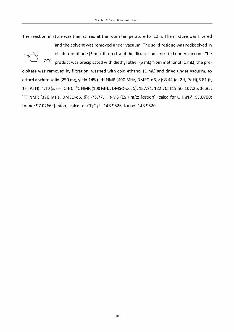
Chapter 3. Pyrazolium Ionic Liquids
88
The reaction mixture was then stirred at the room temperature for 12 h. The mixture was filtered
and the solvent was removed under vacuum. The solid residue was redissolved in
dichloromethane (5 mL), filtered, and the filtrate concentrated under vacuum. The
product was precipitated with diethyl ether (5 mL) from methanol (1 mL), the pre-
cipitate was removed by filtration, washed with cold ethanol (1 mL) and dried under vacuum, to
afford a white solid (250 mg, yield 14%). 1H NMR (400 MHz, DMSO-d6, δ): 8.44 (d, 2H, Pz H),6.81 (t,
1H, Pz H), 4.10 (s, 6H, CH3); 13C NMR (100 MHz, DMSO-d6, δ): 137.91, 122.76, 119.56, 107.26, 36.85;
19F NMR (376 MHz, DMSO-d6, δ): -78.77. HR-MS (ESI) m/z: [cation]+ calcd for C5H9N2+: 97.0760;
found: 97.0766; [anion]- calcd for CF3O3S-: 148.9526; found: 148.9520.

Chapter 3. Pyrazolium Ionic Liquids
89
3.5 Supporting Information
3.5.1 CV data
Figure S3.1. Comparison of cyclic voltammograms for Pz12 and Pz123 (Ag electrode, CO2).
Figure S3.2. Comparison of cyclic voltammograms for Pz12 and Pz124 (Ag electrode, CO2).
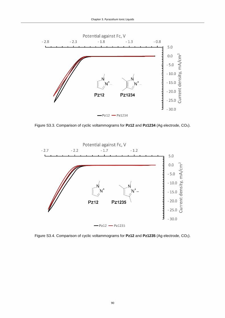
Chapter 3. Pyrazolium Ionic Liquids
90
Figure S3.3. Comparison of cyclic voltammograms for Pz12 and Pz1234 (Ag electrode, CO2).
Figure S3.4. Comparison of cyclic voltammograms for Pz12 and Pz1235 (Ag electrode, CO2).

Chapter 3. Pyrazolium Ionic Liquids
91
Figure S3.5. Comparison of cyclic voltammograms for Pz12 and Pz12345 (Ag electrode, CO2).
Figure S3.6. Comparison of CV data for methylated and butylated Pz ILs Pz12 and Pz12B.
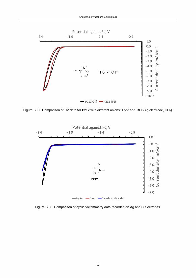
Chapter 3. Pyrazolium Ionic Liquids
92
Figure S3.7. Comparison of CV data for Pz12 with different anions: Tf2N- and TfO- (Ag electrode, CO2).
Figure S3.8. Comparison of cyclic voltammetry data recorded on Ag and C electrodes.

Chapter 3. Pyrazolium Ionic Liquids
93
Figure S3.9. CV data plotted together for Pz1235B and [BMIm][BF4]. Examples of transients (-2.21 V vs Fc)
are compared in the insert.

Chapter 3. Pyrazolium Ionic Liquids
94
3.5.2 NMR spectra
Figure S3.10. 1H NMR spectrum of 3-methylpyrazole (DMSO-d6).
Figure S3.11. 13C NMR spectrum of 3-methylpyrazole (DMSO-d6).

Chapter 3. Pyrazolium Ionic Liquids
95
Figure S3.12. 1H NMR spectrum of 3,4,5-trimethylpyrazole (DMSO-d6).
Figure S3.13. 13C NMR spectrum of 3,4,5-trimethylpyrazole (DMSO-d6).

Chapter 3. Pyrazolium Ionic Liquids
96
Figure S3.14. 1H NMR spectrum of 1-butylpyrazole (DMSO-d6).
Figure S3.15. 13C NMR spectrum of 1-butylpyrazole (DMSO-d6).

Chapter 3. Pyrazolium Ionic Liquids
97
Figure S3.16. 1H NMR spectrum of 1-butyl-3,5-dimethylpyrazole (DMSO-d6).
Figure S3.17. 13C NMR spectrum of 1-butyl-3,5-dimethylpyrazole (DMSO-d6).

Chapter 3. Pyrazolium Ionic Liquids
98
Figure S3.18. 1H NMR spectrum of 1,2-dimethylpyrazolium iodide (DMSO-d6).
Figure S3.19. 13C NMR spectrum of 1,2-dimethylpyrazolium iodide (DMSO-d6).

Chapter 3. Pyrazolium Ionic Liquids
99
Figure S3.20. 1H NMR spectrum of 1,2,3-trimethylpyrazolium iodide (DMSO-d6).
Figure S3.21. 13C NMR spectrum of 1,2,3-trimethylpyrazolium iodide (DMSO-d6).
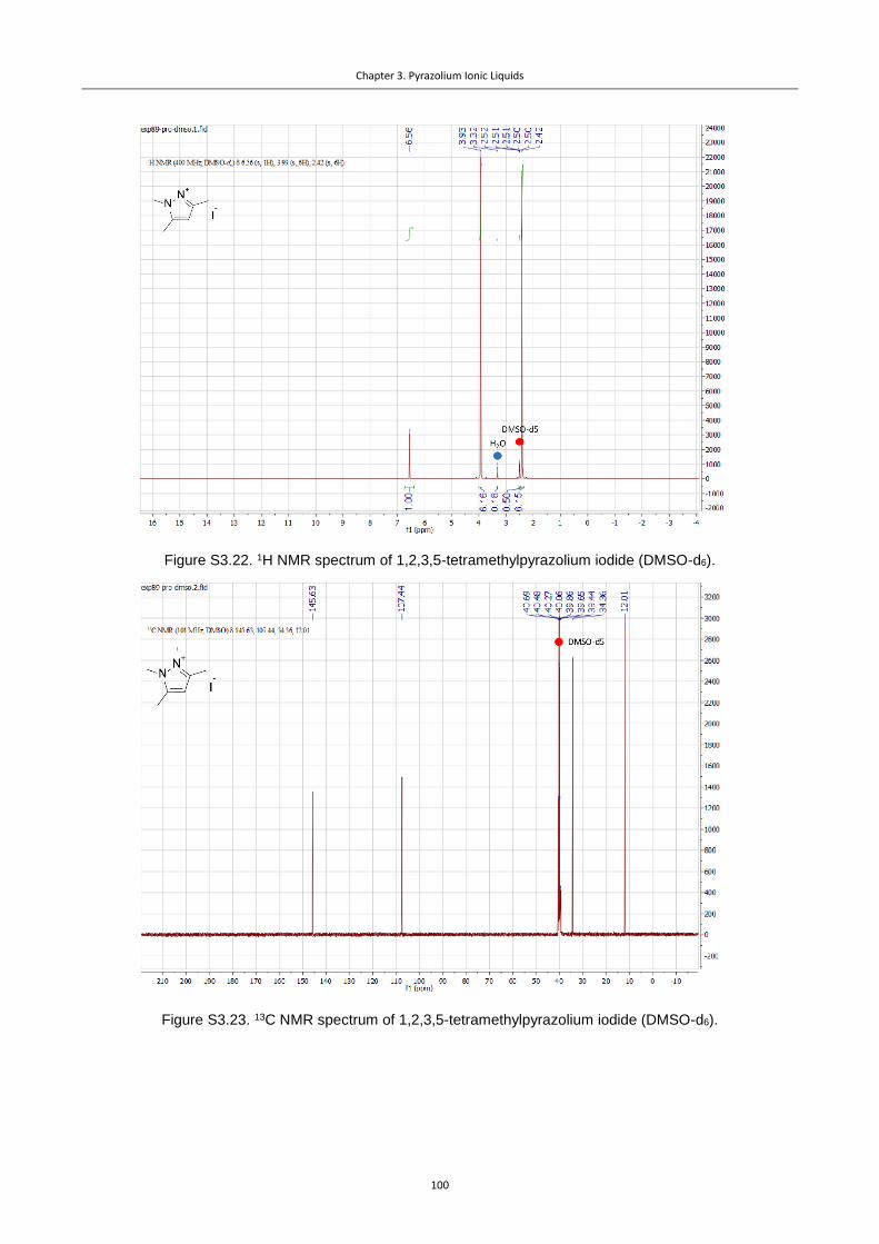
Chapter 3. Pyrazolium Ionic Liquids
100
Figure S3.22. 1H NMR spectrum of 1,2,3,5-tetramethylpyrazolium iodide (DMSO-d6).
Figure S3.23. 13C NMR spectrum of 1,2,3,5-tetramethylpyrazolium iodide (DMSO-d6).

Chapter 3. Pyrazolium Ionic Liquids
101
Figure S 3.24. 1H NMR spectrum of 1,2,3,4-tetramethylpyrazolium iodide (DMSO-d6).
Figure S3.25. 13C NMR spectrum of 1,2,3,4-tetramethylpyrazolium iodide (DMSO-d6).

Chapter 3. Pyrazolium Ionic Liquids
102
Figure S3.26. 1H NMR spectrum of 1,2,4-trimethylpyrazolium iodide (DMSO-d6).
Figure S 3.27. 13C NMR spectrum of 1,2,4-trimethylpyrazolium iodide (DMSO-d6).

Chapter 3. Pyrazolium Ionic Liquids
103
Figure S3.28. 1H NMR spectrum of 1,2,3,4,5-pentamethylpyrazolium iodide (DMSO-d6).
Figure S3.29. 13C NMR spectrum of 1,2,3,4,5-pentamethylpyrazolium iodide (DMSO-d6).
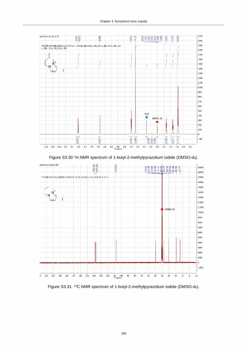
Chapter 3. Pyrazolium Ionic Liquids
104
Figure S3.30 1H NMR spectrum of 1-butyl-2-methylpyrazolium iodide (DMSO-d6).
Figure S3.31. 13C NMR spectrum of 1-butyl-2-methylpyrazolium iodide (DMSO-d6).

Chapter 3. Pyrazolium Ionic Liquids
105
Figure S3.32. 1H NMR spectrum of 1-butyl-2,3,5-trimethylpyrazolium iodide (DMSO-d6).
Figure S3.33. 13C NMR spectrum of 1-butyl-2,3,5-trimethylpyrazolium iodide (DMSO-d6).

Chapter 3. Pyrazolium Ionic Liquids
106
Figure S3.34. 1H NMR spectrum of 1,2-dimethylpyrazolium TFSI Pz12 (DMSO-d6).
Figure S3.35. 13C NMR spectrum of 1,2-dimethylpyrazolium TFSI Pz12 (DMSO-d6).

Chapter 3. Pyrazolium Ionic Liquids
107
Figure S3.36. 1H NMR spectrum of 1,2,3-trimethylpyrazolium TFSI Pz123 (DMSO-d6).
Figure S3.37. 13C NMR spectrum of 1,2,3-trimethylpyrazolium TFSI Pz123 (DMSO-d6).
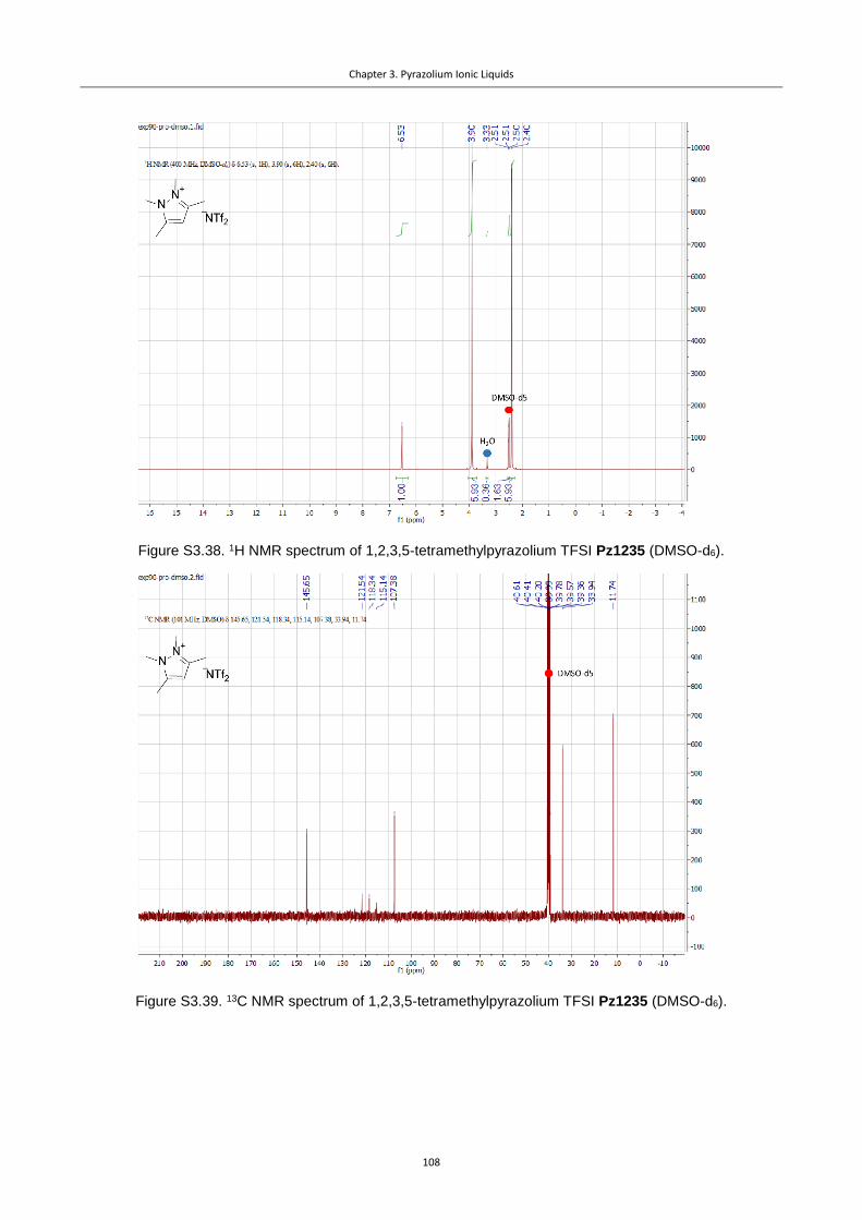
Chapter 3. Pyrazolium Ionic Liquids
108
Figure S3.38. 1H NMR spectrum of 1,2,3,5-tetramethylpyrazolium TFSI Pz1235 (DMSO-d6).
Figure S3.39. 13C NMR spectrum of 1,2,3,5-tetramethylpyrazolium TFSI Pz1235 (DMSO-d6).
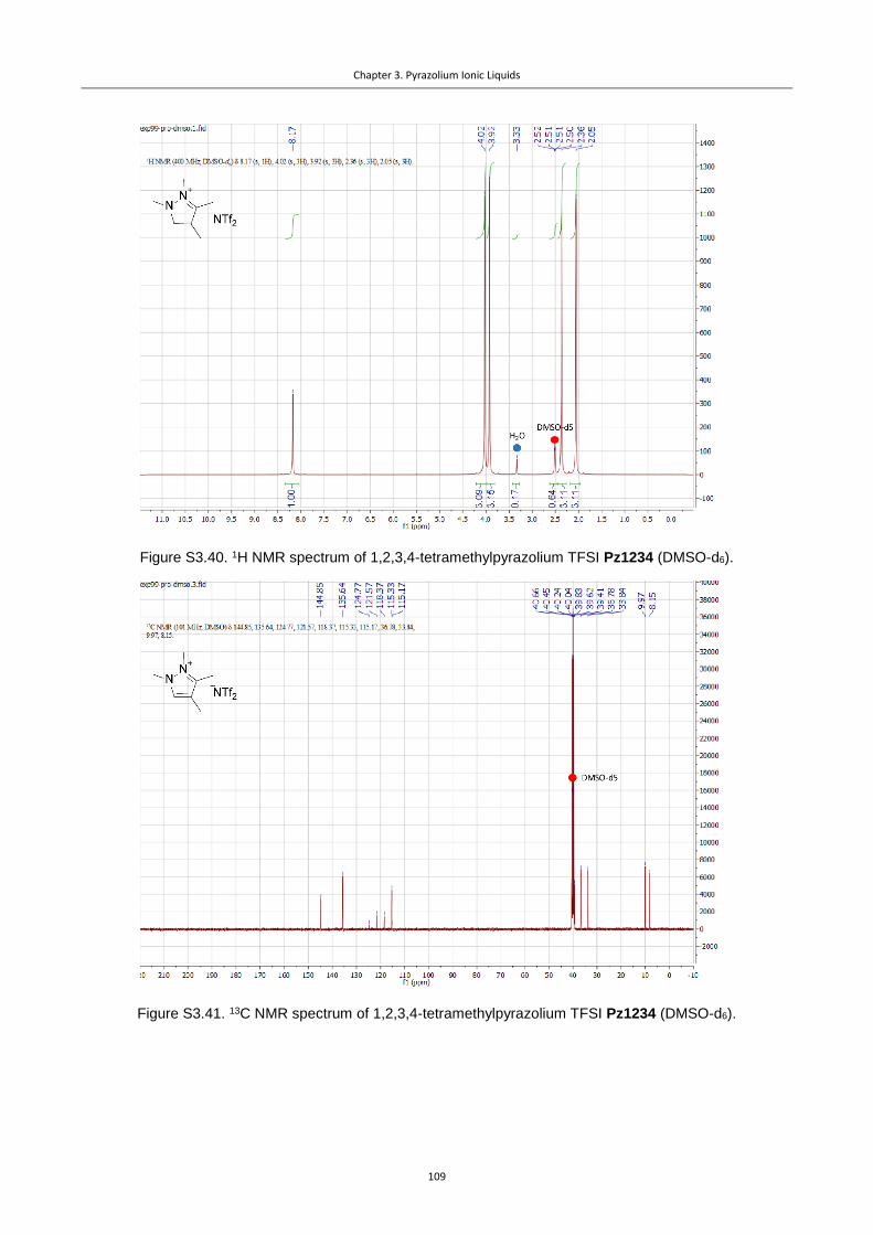
Chapter 3. Pyrazolium Ionic Liquids
109
Figure S3.40. 1H NMR spectrum of 1,2,3,4-tetramethylpyrazolium TFSI Pz1234 (DMSO-d6).
Figure S3.41. 13C NMR spectrum of 1,2,3,4-tetramethylpyrazolium TFSI Pz1234 (DMSO-d6).
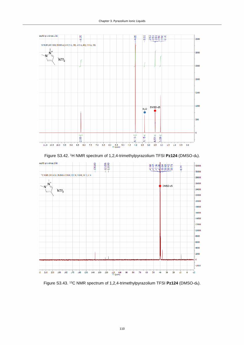
Chapter 3. Pyrazolium Ionic Liquids
110
Figure S3.42. 1H NMR spectrum of 1,2,4-trimethylpyrazolium TFSI Pz124 (DMSO-d6).
Figure S3.43. 13C NMR spectrum of 1,2,4-trimethylpyrazolium TFSI Pz124 (DMSO-d6).

Chapter 3. Pyrazolium Ionic Liquids
111
Figure S3.44. 1H NMR spectrum of 1,2,3,4,5-pentamethylpyrazolium TFSI Pz12345 (DMSO-d6).
Figure S3.45. 13C NMR spectrum of 1,2,3,4,5-pentamethylpyrazolium TFSI Pz12345 (DMSO-d6).

Chapter 3. Pyrazolium Ionic Liquids
112
Figure S3.46. 1H NMR spectrum of 1-butyl-2-methylpyrazolium TFSI Pz12B (DMSO-d6).
Figure S3.47. 13C NMR spectrum of 1-butyl-2-methylpyrazolium TFSI Pz12B (DMSO-d6).

Chapter 3. Pyrazolium Ionic Liquids
113
Figure S3.48. 1H NMR spectrum of 1-butyl-2,3,5-trimethylpyrazolium TFSI Pz1235B (DMSO-d6).
Figure S3.49. 13C NMR spectrum of 1-butyl-2,3,5-trimethylpyrazolium TFSI Pz1235B (DMSO-d6).
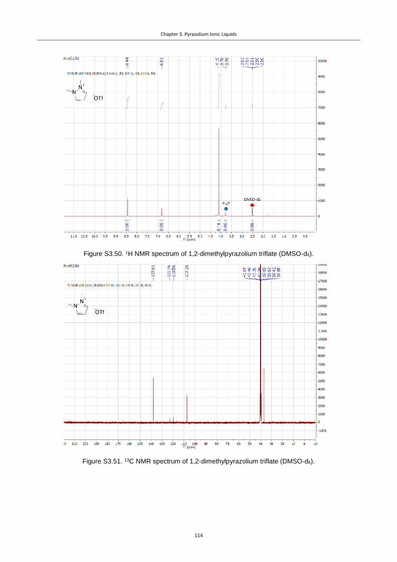
Chapter 3. Pyrazolium Ionic Liquids
114
Figure S3.50. 1H NMR spectrum of 1,2-dimethylpyrazolium triflate (DMSO-d6).
Figure S3.51. 13C NMR spectrum of 1,2-dimethylpyrazolium triflate (DMSO-d6).

Chapter 3. Pyrazolium Ionic Liquids
115
Figure S3.52. Stacked 1H NMR spectra for the system before, during and after electrolysis (red, green and
blue plots respectively; DMSO-d6). Red dot marks formic acid, blue – Pz1235B, green – MeCN decomposition
product. Inset: amplified regions of the same overlapped and normalized 1H NMR spectra for the system be-
fore, during and after electrolysis (low field – selected signal of the Pz IL, high field – selected signal of
NBu4PF6). The inset demonstrates constant relation between intensities of Pz and Bu4N+ NMR signals, and,
therefore, stability of the catalytic system.

Chapter 3. Pyrazolium Ionic Liquids
116
3.6 References
(1) Taheri Najafabadi, A. CO2 Chemical Conversion to Useful Products: An Engineering Insight to
the Latest Advances toward Sustainability. Int. J. Energy Res. 2013, 37, 485–499.
(2) Durst, J.; Rudnev, A.; Dutta, A.; Fu, Y.; Herranz, J.; Kaliginedi, V.; Kuzume, A.; Permyakova, A.
A.; Paratcha, Y.; Broekmann, P.; et al. Electrochemical CO2 Reduction – A Critical View on
Fundamentals, Materials and Applications. Chimia 2015, 69, 769–776.
(3) Tomita, Y.; Teruya, S.; Koga, O.; Hori, Y. Electrochemical Reduction of Carbon Dioxide at a
Platinum Electrode in Acetonitrile-Water Mixtures. J. Electrochem. Soc. 2000, 147, 4164–
4167.
(4) Buzzeo, M. C.; Hardacre, C.; Compton, R. G. Extended Electrochemical Windows Made
Accessible by Room Temperature Ionic Liquid/Organic Solvent Electrolyte Systems.
ChemPhysChem 2006, 7, 176–180.
(5) Rosen, B. A.; Salehi-Khojin, A.; Thorson, M. R.; Zhu, W.; Whipple, D. T.; Kenis, P. J. A.; Masel,
R. I. Ionic Liquid – Mediated Selective Conversion of CO2 to CO at Low Overpotentials. Science
2011, 334, 643–644.
(6) Kuhl, K. P.; Hatsukade, T.; Cave, E. R.; Abram, D. N.; Kibsgaard, J.; Jaramillo, T. F.
Electrocatalytic Conversion of Carbon Dioxide to Methane and Methanol on Transition Metal
Surfaces. J. Am. Chem. Soc. 2014, 136, 14107–14113.
(7) Singh, M. R.; Kwon, Y.; Lum, Y.; Ager, J. W.; Bell, A. T. Hydrolysis of Electrolyte Cations
Enhances the Electrochemical Reduction of CO2 over Ag and Cu. J. Am. Chem. Soc. 2016, 138,
13006–13012.
(8) Zhao, S.-F.; Horne, M.; Bond, A. M.; Zhang, J. Is the Imidazolium Cation a Unique Promoter
for Electrocatalytic Reduction of Carbon Dioxide? J. Phys. Chem. C 2016, 120, 23989−24001.
(9) Sun, L.; Ramesha, G. K.; Kamat, P. V; Brennecke, J. F. Switching the Reaction Course of
Electrochemical CO2 Reduction with Ionic Liquids. Langmuir 2014, 30, 6302–6308.
(10) Rosen, B. A.; Haan, J. L.; Mukherjee, P.; Braunschweig, B.; Zhu, W.; Salehi-Khojin, A.; Dlott, D.
D.; Masel, R. I. In Situ Spectroscopic Examination of a Low Overpotential Pathway for Carbon
Dioxide Conversion to Carbon Monoxide. J. Phys. Chem. C 2012, 116, 15307–15312.
(11) García Rey, N.; Dlott, D. D. Structural Transition in an Ionic Liquid Controls CO2
Electrochemical Reduction. J. Phys. Chem. C 2015, 119, 20892–20899.

117
Guanidinium Ionic Liquids
4.1 Introduction
In the previous chapters it was demonstrated that the scope of the ionic compounds able to pro-
mote the CO2RR is not limited to Im-based ILs. Pz and some tetraalkyl ammonium (e.g. pyrroli-
dinium) salts also display co-catalytic activity. However, the number of room-temperature ILs (RTILs)
that are applicable for the CO2RR remains small, and the structures of these compounds tend to be
similar. Therefore, the development of ILs with fundamentally different structures, which can assist
the CO2RR, is of high relevance. In case of activity, such systems provide valuable data on the possi-
ble active sites, binding modes and electronic factors that are important for the efficient promotion
of the target reaction. Such data facilitates the development of descriptors for a rational design of
superior co-catalysts for the CO2RR.
In this chapter, we show that guanidinium (Gua)-based ILs are promoters for the CO2RR and can be
used to investigate the reduction mechanism. Gua ILs were described as stable1 and readily availa-
ble2 compounds, which were predicted to dissolve reasonable amounts of CO23 and were applied as
electrolytes in Li-ion batteries,4,5 in dye-sensitized solar cells6 and as reaction media for a range of
organic reactions.7,8 The properties of these ILs can be tuned by variation of six substituents at-
tached to the N-atoms. Due to the conjugation in the guanidinium core, the positive charge is sta-
bilized and distributed over three sites. Therefore, gradual changes in the substitution pattern could
be used to elucidate structure/activity dependencies.

Chapter 4. Guanidinium Ionic Liquids
118
4.2 Results
The synthesis of the Gua ILs was performed using a previously reported approach,5 employing chlo-
roamidinium chlorides as the precursors (Scheme 4.1). These chlorides were obtained by the treat-
ment of urea derivatives either with oxalyl chloride, or with phosphoryl chloride, although oxalyl
chloride is preferable due to the easier purification of the product. The guanidine core is formed on
the next step – reaction of the chloroamidinium salt with a primary or secondary amine. Application
of secondary amines reduces the number of synthetic steps and affords guanidinium salts directly.
In the case of cyclic ureas the synthesis of Gua ILs is more complicated, probably due to the slower
double bond rearrangement in the strained systems compared to the acyclic systems.
Scheme 4.1. Synthesis of Gua ILs.
The Gua cations prepared are presented in Figure 4.1. As mentioned above, Gua ILs have three sym-
metrically placed charged N-sites and the stepwise changes of the substitution patterns, and hence
charge accessibility, should influence the activity of the salt. The substituents were selected in a way
to gradually increase the steric hindrance of the nitrogen sites by introduction of cyclic groups. Fur-
thermore, the accessibility of the nitrogen center can be tuned by changing the N-C-N angle of the
guanidinium core. For this purpose, cyclic ureas were employed as precursors for the Gua ILs in
order to introduce intramolecular links between the nitrogen atoms.
Figure 4.1. Cations of the synthesized Gua ILs.
As in the previous chapters, non-aqueous electrolytes were selected in order to minimize the pos-
sibility of the HER. The non-aqueous environment permits the use of PF6- and Tf2N- as suitable anions

Chapter 4. Guanidinium Ionic Liquids
119
for the ILs, as they provide good solubilities in organic solvents. Gua hexafluorophosphates are easy
to synthesize, purify and work with due to the high crystallinity of the compounds, while Tf2N- ILs
with asymmetric cation are liquid at room-temperature and can be probed as media for the CO2RR.
Notably, some of the chloroamidinium precursors for the ILs are also commercially available in the
PF6- form, which significantly simplifies synthesis of the co-catalysts.
As in the previous studies, a silver polished polycrystalline electrode was selected as the actual cat-
alyst for the reduction. A glassy carbon electrode was used to probe the stability of the catalysts in
the presence and absence of CO2, as this electrode is inert and no CO2RR is expected. Tetrabu-
tylammonium hexafluorophospate was employed as a part of the supporting electrolyte to ensure
high conductivities.
The stabilities and activities of the ILs were first tested by the CV experiments. Scans were per-
formed under a N2 atmosphere (for the silver electrode) and under both N2 and CO2 (for the glassy
carbon electrode), and reveal excellent stability of the Gua ILs as no current indicating decomposi-
tion of the ILs was observed within the electrochemical window of the solvent, i.e. acetonitrile (Fig-
ure 4.2).
When CO2 is flushed through the system and the silver electrode is employed, steep reduction
waves appear on the CV, which may be attributed to the CO2RR (Figures 4.3, 4.6). The onset poten-
tial for the reduction shifts towards more positive voltages compared to the reference system, not
containing the IL co-catalyst, as demonstrated by the representative example of [MB5Gua]PF6 (Fig-
ure 4.3). Meanwhile, no currents are observed when the C electrode is employed, supporting the
co-catalytic behavior of the Ag electrode.
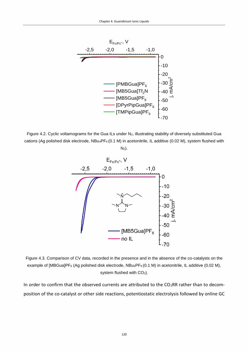
Chapter 4. Guanidinium Ionic Liquids
120
Figure 4.2. Cyclic voltamograms for the Gua ILs under N2, illustrating stability of diversely substituted Gua
cations (Ag polished disk electrode, NBu4PF6 (0.1 M) in acetonitrile, IL additive (0.02 M), system flushed with
N2).
Figure 4.3. Comparison of CV data, recorded in the presence and in the absence of the co-catalysts on the
example of [MBGua]PF6 (Ag polished disk electrode, NBu4PF6 (0.1 M) in acetonitrile, IL additive (0.02 M),
system flushed with CO2).
In order to confirm that the observed currents are attributed to the CO2RR rather than to decom-
position of the co-catalyst or other side reactions, potentiostatic electrolysis followed by online GC
-2,5 -2,0 -1,5 -1,0
-70
-60
-50
-40
-30
-20
-10
0
[PMBGua]PF6
[MB5Gua]Tf2N
[MB5Gua]PF6
[DPyrPipGua]PF6
[TMPipGua]PF6
j, m
A/c
m2
EFc/Fc+, V
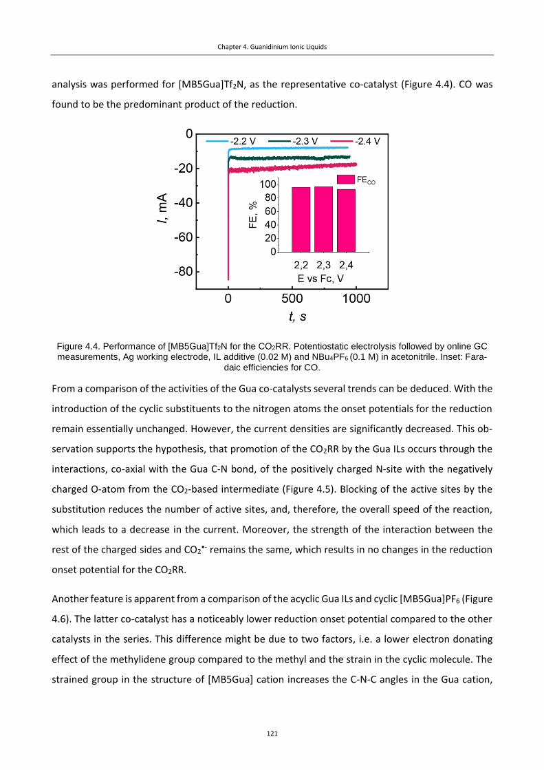
Chapter 4. Guanidinium Ionic Liquids
121
analysis was performed for [MB5Gua]Tf2N, as the representative co-catalyst (Figure 4.4). CO was
found to be the predominant product of the reduction.
Figure 4.4. Performance of [MB5Gua]Tf2N for the CO2RR. Potentiostatic electrolysis followed by online GC measurements, Ag working electrode, IL additive (0.02 M) and NBu4PF6 (0.1 M) in acetonitrile. Inset: Fara-
daic efficiencies for CO.
From a comparison of the activities of the Gua co-catalysts several trends can be deduced. With the
introduction of the cyclic substituents to the nitrogen atoms the onset potentials for the reduction
remain essentially unchanged. However, the current densities are significantly decreased. This ob-
servation supports the hypothesis, that promotion of the CO2RR by the Gua ILs occurs through the
interactions, co-axial with the Gua C-N bond, of the positively charged N-site with the negatively
charged O-atom from the CO2-based intermediate (Figure 4.5). Blocking of the active sites by the
substitution reduces the number of active sites, and, therefore, the overall speed of the reaction,
which leads to a decrease in the current. Moreover, the strength of the interaction between the
rest of the charged sides and CO2•- remains the same, which results in no changes in the reduction
onset potential for the CO2RR.
Another feature is apparent from a comparison of the acyclic Gua ILs and cyclic [MB5Gua]PF6 (Figure
4.6). The latter co-catalyst has a noticeably lower reduction onset potential compared to the other
catalysts in the series. This difference might be due to two factors, i.e. a lower electron donating
effect of the methylidene group compared to the methyl and the strain in the cyclic molecule. The
strained group in the structure of [MB5Gua] cation increases the C-N-C angles in the Gua cation,
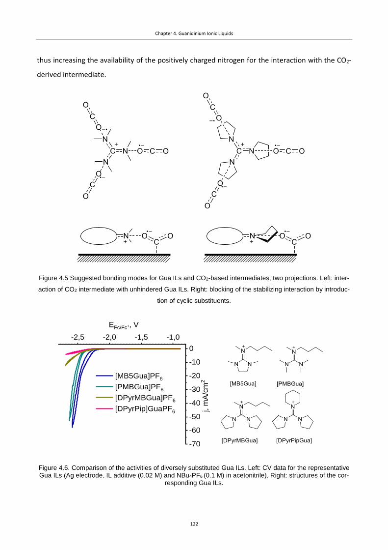
Chapter 4. Guanidinium Ionic Liquids
122
thus increasing the availability of the positively charged nitrogen for the interaction with the CO2-
derived intermediate.
Figure 4.5 Suggested bonding modes for Gua ILs and CO2-based intermediates, two projections. Left: inter-
action of CO2 intermediate with unhindered Gua ILs. Right: blocking of the stabilizing interaction by introduc-
tion of cyclic substituents.
Figure 4.6. Comparison of the activities of diversely substituted Gua ILs. Left: CV data for the representative Gua ILs (Ag electrode, IL additive (0.02 M) and NBu4PF6 (0.1 M) in acetonitrile). Right: structures of the cor-
responding Gua ILs.
-2,5 -2,0 -1,5 -1,0
-70
-60
-50
-40
-30
-20
-10
0
[MB5Gua]PF6
[PMBGua]PF6
[DPyrMBGua]PF6
[DPyrPip]GuaPF6 j, m
A/c
m2
EFc/Fc+, V

Chapter 4. Guanidinium Ionic Liquids
123
Indeed, the concept of charge availability can be used to describe activities of other classes of ILs.
Im ILs, for example, have around 150 mV more positive onset potentials compared to the Gua ILs.
The C-N-C angle for Im ILs is same as for the Gua ILs (around 120°), while the positive charge is
distributed between two nitrogen centers, while for less active Gua ILs the effective charge is lower,
as it is distributed between three nitrogen centers. However, fully substituted Im ILs lose their co-
catalytic activity,9 as the availability of the charged centers for the species in the same plane signif-
icantly drops. Although pyrrolidinium (Pyrd) ILs10have a positive charge localized on one N-center,
the nitrogen atom of the Pyrd ILs has sp3-hybridization, which 1) limits availability of the co-catalyst
for the interaction with counter-ions; 2) makes the nitrogen less electronegative compared to the
sp2-hybridized nitrogens of Im ILs. Pyrd ILs are usually more active co-catalysts than tetraalkylammo-
nium salts,10 which can probably be explained by the strain in the Pyrd cycle, which broadens the
angles between the alkyl groups and makes the interaction with the CO2-based species more plau-
sible. Therefore, we support the statement, that CO2RR is governed by the local electrical field en-
vironment.
4.3 Summary
We describe Gua ILs as co-catalysts for the CO2RR, which are efficient co-catalysts although some-
what less effective than Im ILs and provide valuable information on the structure/activity correla-
tion. Based on the series of Gua ILs studied, the activity appears to be related to the accessibility of
the positively charged nitrogen sites and on the ring. This hypothesis also fits the general activity
trend for various classes of cations with Im ILs > Gua ILs, Pyrd ILs > tetraalkylammonium salts, Pz ILs
≈ Im ILs in the terms of activity. Furthermore, based on this hypothesis, the rational design of effi-
cient co-catalysts for the CO2RR should be possible.

Chapter 4. Guanidinium Ionic Liquids
124
4.4 Experimental
4.4.1 Materials and methods.
All reagents were obtained commercially and used without further purification unless otherwise
stated. CO2 (99.998 %) and Ar (99.9999 %) were obtained from Carbagas, Switzerland. 1H, 19F and
proton-decoupled 13C-NMR spectra were recorded on a Bruker Avance-400 (400 MHz) spectrome-
ter. All reactions were completed under inert conditions (nitrogen atmosphere). For the graphical
representation of NMR spectra please see the Supporting Information. Electrochemical measure-
ments were made in according with the protocols from Chapter 2.
4.4.2 Synthesis and characterization of the compounds
N,N,N’,N’-tetramethylchloroformamidinium chloride: Solution of freshly distilled tetramethylurea
(20 mL, 0.167 mmol, 1 eq) in dry dichloromethane (20 mL) was added dropwise to
oxalyl chloride (15.7 mL, 183 mmol, 1.1 eq). Intense gas evolution was observed.
The solution was left stirring for 24 hours at room temperature, the solvent was
removed under vacuum. The solid residue was washed with diethyl ether and dried under vacuum,
yielding the product (24 g, 85%) as colorless powder. 1H NMR (400 MHz, DMSO-d6) δ 2.69 (s, 12H).
13C NMR (101 MHz, DMSO) δ 164.73, 38.71.
N-butyl-1,3-dimethylimidazolidin-2-imine. To a solution of 2-chloro-1,3-dimethyl-4,5-dihydro-1H-
imidazol-3-ium chloride (2.00 g, 11.83 mmol, 1 eq) in dry acetonitrile (30 mL) n-bu-
tylamine (2.34 mL, 23.66 mmol, 2 eq.) was added dropwise at 0°C. The reaction mix-
ture was refluxed for 16 h, then cooled to rt, diluted with 1M NaOH (100 mL) and
extracted with DCM (3×50 mL). The combined organic layers were dried over Na2SO4 and then con-
centrated under reduced pressure to afford pale yellow oil (2.01 g, 96%). 1H NMR (400 MHz, Chlo-
roform-d) δ 3.36 – 3.26 (m, 2H), 3.11 (d, J = 4.9 Hz, 5H), 2.94 – 2.81 (m, 3H), 2.65 (s, 3H), 1.57 – 1.44
(m, 2H), 1.44 – 1.26 (m, 2H), 0.89 (t, J = 7.3 Hz, 3H). 13C NMR (101 MHz, CDCl3) δ 157.03, 50.92,
48.16, 48.14, 47.40, 38.48, 35.76, 34.64, 20.48, 14.13.
N-butyl-1,3-dimethylimidazolidin-2-iminium iodide. To a solution of N-butyl-1,3-dimethylimidazol-
idin-2-imine (2.1 g, 12.4 mmol, 1 eq) in dry acetonitrile (10 mL) iodomethane
(1.34 mL, 13.6 mmol, 1.1 eq.) was added dropwise. The reaction mixture was left
stirring at room temperature for 24 hours, then concentrated under reduced pres-
sure and dried under vacuum to afford dark yellow oil (3.03 g, 78%). 1H NMR (400 MHz, DMSO-d6)

Chapter 4. Guanidinium Ionic Liquids
125
δ 3.68 (s, 4H), 3.31 – 3.23 (m, 2H), 2.97 (d, J = 1.0 Hz, 9H), 1.72 – 1.42 (m, 2H), 1.28 (h, J = 7.4 Hz,
2H), 0.91 (t, J = 7.4 Hz, 3H). 13C NMR (101 MHz, DMSO) δ 164.07, 52.14, 49.76, 37.73, 36.65, 29.47,
19.56, 14.08.
N-(bis(dimethylamino)methylene)-N-methylbutan-1-aminium hexafluorophosphate. To a solu-
tion of 2.00 g (11.69 mmol) of N-(chloro(dimethylamino)methylene)-N-methyl-
methanaminium chloride in 20 mL of dry acetonitrile a solution of 1.385 mL
(11.69 mmol, 1 eq.) of N-methylbutylamine and 1.625 mL (11.69 mmol, 1 eq.) of
triethylamine in 10 mL of dry diethyl ether was added dropwise at 0°C. The reaction mixture was
allowed to warm up to rt and stirred for 16 h, then diluted with 100 mL of water. Colored contami-
nants were extracted with DCM (3×50 mL). Half of the aqueous layer was separated and directly
used for the anion exchange. To the solution of butyl-pentamethylguanidinium chloride (1.3 g, 5.8
mmol, 1 eq) in Milli-Q water (ca.10 mL) solution of potassium hexafluorophosphate (1.2 g, 1.1 eq)
in Milli-Q water (ca. 100 mL) was added. Colorless precipitate was formed immediately. The mixture
was left stirring at rt for 3 hours, the product was separated by filtration, washed with Et2O (3x50
mL) and dried under vacuum, affording the product as colorless powder (1.4 g, 72%). 1H NMR (400
MHz, DMSO-d6) δ 3.15 (q, J = 8.0 Hz, 2H), 2.87 (2s, 15H), 1.64 – 1.41 (m, 2H), 1.26 (dq, J = 15.2, 7.5
Hz, 2H), 0.91 (t, J = 7.3 Hz, 3H). 13C NMR (101 MHz, DMSO) δ 163.03, 51.78, 37.66, 29.31, 19.85,
14.03. 31P NMR (162 MHz, DMSO-d6) δ -118.50 – -172.13 (m). 19F NMR (376 MHz, DMSO) δ -70.20
(d, 711 Hz).
N-(di(pyrrolidin-1-yl)methylene)-N-methylbutan-1-aminium hexafluorophosphate. To a solution
of 2.00 g (6.01 mmol) of 1-(chloro(pyrrolidin-1-yl)methylene)pyrrolidin-1-ium
hexafluorophosphate in 20 mL of dry acetonitrile a solution of 0.7122 mL
(6.01 mmol, 1 eq.) of N-methylbutylamine and 0.836 mL (6.01 mmol, 1 eq.) of
triethylamine in 10 mL of dry diethyl ether was added dropwise at 0°C. The reaction mixture was
allowed to warm up to rt and stirred for 16 h, then diluted with 100 mL of water and extracted with
DCM (3×50 mL). The combined organic layers were dried over Na2SO4 and concentrated under re-
duced pressure to afford pale yellow solid (2.20 g, 95%). 1H NMR (400 MHz, DMSO-d6) δ 3.37 (td, J
= 6.7, 5.4, 2.9 Hz, 8H), 3.15 – 3.04 (m, 2H), 2.82 (s, 3H), 1.97 – 1.82 (m, 8H), 1.60 – 1.44 (m, 2H), 1.27
(dq, J = 14.6, 7.4 Hz, 2H), 0.90 (t, J = 7.4 Hz, 3H). 13C NMR (101 MHz, DMSO) δ 154.78, 49.97, 47.44,
35.49, 27.45, 23.16, 17.63, 11.96, -0.50. 31P NMR (162 MHz, DMSO-d6) δ -144.21 (sept, J = 711.1 Hz).
19F NMR (376 MHz, DMSO) δ -70.27 (d, 711 Hz).

Chapter 4. Guanidinium Ionic Liquids
126
1-(di(pyrrolidin-1-yl)methylene)piperidin-1-ium hexafluorophosphate. To a solution of 2.00 g
(6.01 mmol) of 1-(chloro(pyrrolidin-1-yl)methylene)pyrrolidin-1-ium hexafluor-
ophosphate in 20 mL of dry acetonitrile a solution of 0.59 mL (6.012 mmol,
1 eq.) of piperidine and 0.84 mL (6.012 mmol, 1 eq.) of triethylamine in 10 mL
of dry diethyl ether was added dropwise at 0°C. The reaction mixture was al-
lowed to warm up to rt and stirred for 16 h, then diluted with 100 mL of water and extracted with
DCM (3×50 mL). The combined organic layers were dried over Na2SO4 and concentrated under re-
duced pressure to afford white solid (2.23 g, 97%). 1H NMR (400 MHz, DMSO-d6) δ 3.37 (d, J = 6.6
Hz, 8H), 3.18 (t, J = 4.6 Hz, 4H), 1.96 – 1.84 (m, 8H), 1.67 – 1.52 (m, 6H). 13C NMR (101 MHz, DMSO)
δ 156.29, 49.75, 49.57, 25.49, 25.32, 23.81. 19F NMR (376 MHz, DMSO) δ -70.28 (d, J = 707 Hz). 31P
NMR (162 MHz, DMSO-d6) δ -144.2 (septet, J = 711 Hz).
N-butyl-1,3-dimethylimidazolidin-2-iminium bis(trifluoromethylsulfonyl)imide. To a solution of N-
butyl-1,3-dimethylimidazolidin-2-iminium iodide (2.0 g, 6.4 mmol, 1 eq) in water
(10 mL) was added LiTf2N (1.94 g, 6.7 mmol, 1.05 eq.) and dichloromethane (10
mL). The reaction mixture was left stirring at room temperature for 24 hours,
then the organic phase was separated, washed by water (3x50 mL), concentrated under reduced
pressure and dried under vacuum to afford pale yellow oil (2.93 g, 98%). 1H NMR (400 MHz, DMSO-
d6) δ 3.67 (s, 4H), 3.29 – 3.22 (m, 2H), 2.96 (d, J = 1.0 Hz, 9H), 1.66 – 1.48 (m, 2H), 1.35 – 1.18 (m,
6H), 0.93 – 0.82 (m, 3H). 13C NMR (101 MHz, DMSO) δ 164.08, 121.55, 118.35, 52.39, 49.72, 37.61,
36.54, 31.29, 27.35, 25.90, 22.45, 14.30. 19F NMR (376 MHz, DMSO) δ -78.75.
N-butyl-1,3-dimethylimidazolidin-2-iminium hexafluorophosphate. To a solution of N-butyl-1,3-di-
methylimidazolidin-2-iminum iodide (0.5 g, 1.6 mmol, 1 eq) in Milli-Q water (5 mL)
was added KPF6 (0.33 g, 1.8 mmol, 1.1 eq.). The reaction mixture was left stirring
at room temperature for 12 hours, dichloromethane (10 mL) was added. The aque-
ous phase was washed with Milli-Q water (2x10 mL), then dried under vacuum to afford pale yellow
oil (0.53 g, 100%). 1H NMR (400 MHz, DMSO-d6) δ 3.67 (s, 4H), 3.30 – 3.23 (m, 2H), 2.96 (s, 9H), 1.63
– 1.49 (m, 2H), 1.28 (h, J = 7.3 Hz, 2H), 0.91 (t, J = 7.4 Hz, 3H). 13C NMR (101 MHz, DMSO) δ 164.08,
52.12, 49.73, 37.65, 36.57, 29.45, 19.55, 14.05. 19F NMR (376 MHz, DMSO) δ -70.21 (d, J = 711 Hz).
31P NMR (162 MHz, DMSO-d6) δ -144.2 (septet, J = 711 Hz).

Chapter 4. Guanidinium Ionic Liquids
127
4.1 Supporting Information
Figure S4.1. 1H NMR spectrum of N,N,N’,N’-tetramethylchloroformamidinium chloride (400 MHz, DMSO-d6).
Figure S4.2. 13C NMR spectrum of N,N,N’,N’-tetramethylchloroformamidinium chloride (101 MHz, DMSO-d6).
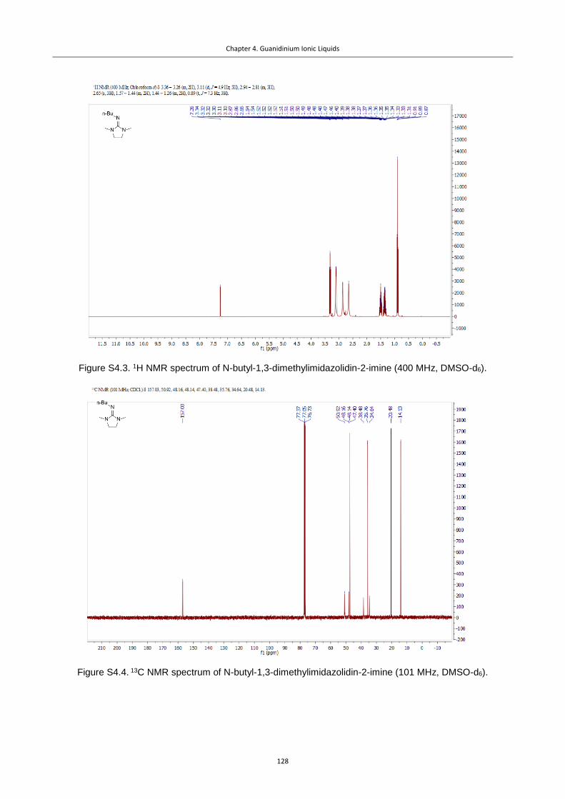
Chapter 4. Guanidinium Ionic Liquids
128
Figure S4.3. 1H NMR spectrum of N-butyl-1,3-dimethylimidazolidin-2-imine (400 MHz, DMSO-d6).
Figure S4.4. 13C NMR spectrum of N-butyl-1,3-dimethylimidazolidin-2-imine (101 MHz, DMSO-d6).

Chapter 4. Guanidinium Ionic Liquids
129
Figure S4.5. 1H NMR spectrum of [MB5Gua]I (400 MHz, DMSO-d6).
Figure S 4.6. 13C NMR spectrum of [MB5Gua]I (101 MHz, DMSO-d6).
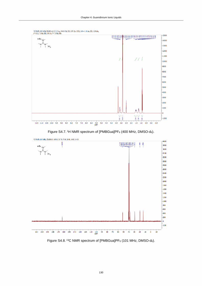
Chapter 4. Guanidinium Ionic Liquids
130
Figure S4.7. 1H NMR spectrum of [PMBGua]PF6 (400 MHz, DMSO-d6).
Figure S4.8. 13C NMR spectrum of [PMBGua]PF6 (101 MHz, DMSO-d6).

Chapter 4. Guanidinium Ionic Liquids
131
Figure S4.9. 1H NMR spectrum of [DPyrMBGua]PF6 (400 MHz, DMSO-d6).
Figure S4.10. 13C NMR spectrum of [DPyrMBGua]PF6 (101 MHz, DMSO-d6).
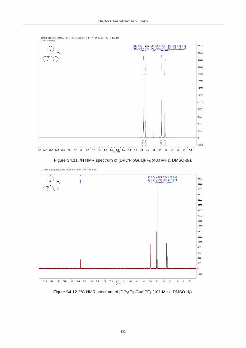
Chapter 4. Guanidinium Ionic Liquids
132
Figure S4.11. 1H NMR spectrum of [DPyrPipGua]PF6 (400 MHz, DMSO-d6).
Figure S4.12. 13C NMR spectrum of [DPyrPipGua]PF6 (101 MHz, DMSO-d6).

Chapter 4. Guanidinium Ionic Liquids
133
Figure S4.13. 1H NMR spectrum of [MB5Gua]PF6 (400 MHz, DMSO-d6).
Figure S4.14. 13C NMR spectrum of [MB5Gua]PF6 (101 MHz, DMSO-d6).

Chapter 4. Guanidinium Ionic Liquids
134
Figure S4.15. 1H NMR spectrum of [MB5Gua]Tf2N (400 MHz, DMSO-d6).
Figure S4.16. 13C NMR spectrum of [MB5Gua]Tf2N (101 MHz, DMSO-d6).

Chapter 4. Guanidinium Ionic Liquids
135
4.2 References
(1) Mateus, N. M. M.; Branco, L. C.; Lourenço, N. M. T.; Afonso, C. A. M. Synthesis and Properties
of Tetra-Alkyl-Dimethylguanidinium Salts as a Potential New Generation of Ionic Liquids.
Green Chem. 2003, 5 (3), 347–352.
(2) Kunkel, H.; Maas, G. Hexaalkylguanidinium Trifluoromethanesulfonates - A General Synthesis
from Tetraalkylureas and Triflic Anhydride, and Properties as Ionic Liquids. European J. Org.
Chem. 2007, No. 22, 3746–3757.
(3) Zhang, X.; Liu, X.; Yao, X.; Zhang, S. Microscopic Structure, Interaction, and Properties of a
Guanidinium-Based Ionic Liquid and Its Mixture with CO2. Ind. Eng. Chem. Res 2011, 50, 8323–
8332.
(4) Hess, S.; Arkhipova, M.; Wohlfahrt-Mehrens, M.; Maas, G.; Wachtler, M. Synthesis and
Characterization of Guanidinium-Based Ionic Liquids as Possible Electrolytes in Lithium-Ion
Batteries. J. Electrochem. Soc. 2014, 161 (5), A753–A761.
(5) Bucher, N.; Hartung, S.; Arkhipova, M.; Yu, D.; Kratzer, P.; Maas, G.; Srinivasan, M.; Hoster, H.
E. A Novel Ionic Liquid for Li Ion Batteries – Uniting the Advantages of Guanidinium and
Piperidinium Cations. RSC Adv. 2014, 4 (4), 1996–2003.
(6) Wang, P.; Zakeeruddin, S. M.; Gratzel, M.; Kantlehner, W.; Mezger, J.; Stoyanov, E. V.; Scherr,
O. Novel Room Temperature Ionic Liquids of Hexaalkyl Substituted Guanidinium Salts for Dye-
Sensitized Solar Cells. Appl. Phys. A Mater. Sci. Process. 2004, 79 (1), 73–77.
(7) Xin, X.; Guo, X.; Duan, H.; Lin, Y.; Sun, H. Efficient Knoevenagel Condensation Catalyzed by
Cyclic Guanidinium Lactate Ionic Liquid as Medium. Catal. Commun. 2007, 8 (2), 115–117.
(8) Li, S.; Lin, Y.; Xie, H.; Zhang, S.; Xu, J. Brønsted Guanidine Acid−Base Ionic Liquids: Novel
Reaction Media for the Palladium-Catalyzed Heck Reaction. Org. Lett. 2006, 8, 391–394.
(9) Lau, G. P. S.; Schreier, M. R.; Vasilyev, D.; Scopelliti, R.; Grätzel, M.; Dyson, P. J. New Insights
Into the Role of Imidazolium-Based Promoters for the Electroreduction of CO2 on a Silver
Electrode. J. Am. Chem. Soc. 2016, 138, 7820–7823.
(10) Zhao, S.-F.; Horne, M.; Bond, A. M.; Zhang, J. Is the Imidazolium Cation a Unique Promoter

Chapter 4. Guanidinium Ionic Liquids
136
for Electrocatalytic Reduction of Carbon Dioxide? J. Phys. Chem. C 2016, 120, 23989−24001.

137
Deep Eutectic Solvents
5.1 Introduction
Altering the composition of the electrolyte
is one of the main approaches aimed at decreas-
ing the overpotential and increasing the selectiv-
ity of the CO2RR reaction.1–3 The most investigated
solvents for the CO2RR are water,4 acetonitrile,5
dimethylsulfoxide,6 dimethyl formamide,7 and
propylene carbonate.8 Aqueous electrolytes,
probably the most investigated and environmen-
tally benign, allow the synthesis of hydrogenated products, such as formic acid, methanol, methane,
etc. However, disadvantages of aqueous systems include the low solubility of CO29 and, in many
cases, the necessity to suppress the parasitic hydrogen evolution reaction (HER).9 Non-aqueous sys-
tems may dissolve higher concentrations of CO2 and the HER does not take place due to absence of
accessible protons in the system. Furthermore, reduction of CO2 to CO, inherent for non-aqueous
systems, appears to be one of the most attractive types of CO2RR.10
The addition of ionic liquids (ILs) to electrolytes significantly decreases the onset potential for
the CO2RR and helps to suppress HER.11 ILs based on Im,11,12 Pyrd13 and Pz14 cations were found to
be efficient co-catalysts. However, the high cost of ILs and their high viscosities hamper their direct
application in the CO2RR.

Chapter 5. Deep Eutectic Solvents
138
Figure 5.1 Left: Ionic liquids (green) and OH-functionalized compounds (magenta) that promote the CO2RR.
Right: choline DES.
The presence of the hydroxyl group in the structure of the IL cation3,15,16 or in close proximity
to a catalytic metal center in an appropriate complex17 further enhances the CO2RR. A positive in-
fluence was also observed for the hydrolysis of cations in the proximity of the electrode18 or for the
presence of water in the electrolyte.13,19 Consequently, choline chloride ([Ch]Cl), a hydroxyl-bearing
ammonium salt, was investigated as an additive in an aqueous electrolyte for the CO2RR on a Pt
electrode.16 Notably, [Ch]Cl is one of the components of deep eutectic solvents (DESs).20 DESs are
usually binary mixtures possessing melting points substantially below that of the individual com-
pounds.21 Many of the properties of DESs (e.g. large potential windows, high solubility of CO2, low
vapor pressure, high conductivity) are similar to those of ILs, and DESs were investigated in similar
applications including CO2 capture, metal deposition, electropolishing, etc.20,22 Simple DESs are
much less expensive than simple ILs and, since [Ch]Cl is derived from choline, a nutrient, are in gen-
eral less toxic.23 Surprisingly, despite DES appear to be promising alternatives to ILs, their application
in the CO2RR has not been systematically explored (the only example we found in the literature is
the work of Verma et al.,3 where DES solution in water was screened among other electrolytes).
Here, we demonstrate the utility of pure DESs and DES-additives to non-aqueous solvents in the
CO2RR (Figure 5.1) and describe a simple and general approach combining IL chlorides with EG to
generate DESs for application in the CO2RR.
5.2 Results
Silver was selected as the working electrode in these studies as it is known to catalyze the
reduction of CO2 to CO with high Faradaic efficiencies and low overpotentials,24 which eliminates
alternative reaction pathways. Initially, the performance of the neat [Ch]Cl-urea (1:2) system, one

Chapter 5. Deep Eutectic Solvents
139
of the most widely investigated DESs, was probed by cyclic voltammetry (CV). Addition of CO2 to the
electrolytic system results in the appearance of a reduction wave in the low potential region, where
decomposition of the [Ch]Cl-urea DES is not observed (Figure S5.1). It should be noted that the
CO2RR occurs at the silver cathode, which is the catalyst, and the DES serves as a promoter (or co-
catalyst) and medium for the reduction. The CO2RR does not take place when a glassy carbon work-
ing electrode is employed in place of the silver electrode (Figure S5.2).
Figure 5.2. Cyclic voltammograms (CVs) of the urea and EG-based DESs employed for the ERC: Ag working
electrode, CO2 atmosphere, undivided cell.
Despite the promising data obtained from the CV experiments, chronoamperometric meas-
urements with online product analysis indicate low applicability of the neat [Ch]Cl-urea DES as an
electrolyte for the CO2RR. The current densities are less than 0.1 mA/cm2 and the Faradaic efficiency
for CO2 to CO conversion is rather low (Table 5.1). These results are attributed to the high viscosity
of the [Ch]Cl-urea DES (Table S5.1, 830 cP at 25°C25), which leads to the rapid depletion of CO2 at
the surface of the electrode and the development of the competing HER and other side reaction
(e.g. electrolyte reduction).
Water (1 to 15 % vol) was added to reduce the viscosity of the [Ch]Cl-urea DES (viscosity drops
from 1244 cP to ~30 cP at 15% of water at 21°C25). Current densities of the order of 0.6 mA/cm2 and
Faradaic efficiencies for CO (FECO) of ca. 70% were obtained (Table 5.1, Figure S5.1). Since addition
of water increases the FECO it is apparent that the high viscosity is the main obstacle in the CO2RR
when using the neat [Ch]Cl-urea DES. Therefore, we switched to [Ch]Cl-ethylene glycol (EG) DES

Chapter 5. Deep Eutectic Solvents
140
(1:2), as it has the lowest viscosity (36 cP22, 40 cP according to our data, Table S5.1) of the wide-
spread room temperature DESs. As expected, the [Ch]Cl-EG DES exhibited better performance com-
pared to urea-based DES with respect to both CV and chronoamperometric experiments. Under N2,
a steep reduction wave for H2 evolution arises on the I-V curve (Figure S5.3). However, introduction
of CO2 in the cell results in the appearance of a new reduction wave at low potentials. According to
the chronoamperometric measurements followed by GC analysis, the new wave appears due to the
CO2RR. During electrolysis a current density of magnitude ca. 0.4 mA/cm2 was reached with FECO
remaining around 78% (Table 5.1). Addition of water (7 % by vol.) leads to an increase of current
density, but with a decrease in the selectivity, i.e. FECO = 40%. From the abovementioned results, it
appears that the application of pure DESs in the CO2RR is possible, but is challenging due to slow
mass transport. Possible solutions to overcome the problem of slow diffusion of CO2 is to use gas
diffusion electrodes or to vary the cell configuration (e.g. the distance between electrodes, elec-
trode surface, etc.). An alternative approach is to employ the DES as an additive in a low viscous
solvent. The choice of the diluted solvent should be defined by miscibility with the DES, high solu-
bility of CO2 and, ideally, low volatility, low toxicity and low price.
As mentioned above, the application of [Ch]Cl additives in an aqueous electrolyte was demon-
strated before.[9,19] However, employing 1M [Ch]Cl in water as the electrolyte was rather discourag-
ing, i.e. hydrogen was the main product of the reduction with only traces of CO formed (Table 1).
Addition of EG (2 eq. vs [Ch]Cl) improves the FECO to the level of only ca.23% (Table 5.1, Figure 5.3a).
Possibly, the difference in pH between our system and the one explored by Verma at al. (we used
0.5 M H2SO4, and they – KHCO3 solution as anolyte)3 leads to the different outcomes of the [Ch]Cl-
urea DES in water as Nafion, used as separator, is permeable for protons.
Acetonitrile (MeCN) is an aprotic polar solvent widely explored in the CO2RR; CO2 is ca. 8 times
more soluble in it compared to water.9 Consequently, the electrochemical behavior of [Ch]Cl (0.02
M) in MeCN solution (containing NBu4PF6, 0.1 M) in the presence and absence of CO2 was studied.
Under a nitrogen atmosphere a wave at ca. -1.9 V vs Ag/AgCl for the reduction of the [Ch] cation is
observed. Addition of CO2 to the system results in a sharp growth of a new wave on the I-V curve,
indicating the development of the CO2RR (Figure S5.4). The fact that the co-catalytic activity can be
attributed to the presence of [Ch]Cl in the system was demonstrated by comparing CV curves regis-
tered in the presence and in the absence of [Ch]Cl: the onset potential for the latter was ca. 600 mV
more negative (Figure S5.5). Potentiostatic electrolysis combined with online GC detection reveal

Chapter 5. Deep Eutectic Solvents
141
CO to be the dominant product, with a Faradaic efficiency approaching 100% at ca. -2.0 V vs Ag/AgCl
(Figure S5.4).
However, [Ch]Cl is poorly soluble in MeCN, with only low concentrations achieved after pro-
longed sonication. To overcome the solubility limitation, the chloride anion in [Ch]Cl was exchanged
with bis(trifluoromethylsulfonyl)imide (Tf2N-), to afford IL which is miscible with MeCN. CV and po-
tentiostatic electrolysis reveal the effect of [Ch][Tf2N] being comparable to that of [Ch]Cl at the same
concentration (Figure S5.5).
In an alternative approach, a DES was obtained by mixing [Ch]Cl and EG (1:2) allowing a con-
centration of [Ch]Cl of 1 M to be achieved in MeCN. According to the CV curves and chronoam-
perometric data (Figure 5.3b, Table 5.1), the addition of EG to the [Ch]Cl solution resulted in a highly
active system with both excellent FECO (99%) and jCO (ca. 7 mA/cm2). Moreover, additives of EG do
not significantly change the reduction onset potential (Figure S5.6). In order to distinguish the effect
of the [Ch] cation from that of EG, additional experiments excluding [Ch] derivatives from the elec-
trolyte were performed, which indicate that EG does not have a considerable impact on the CO2RR
(Figure S5.7).
In order to broaden the applicability of our strategy for the employment of DESs in organic
solvents, propylene carbonate (PC) and 2-(2-ethoxyethoxy)ethanol (3EOH) were also studied. Both
are industrially important solvents with high boiling points. [Ch]Cl is insoluble in 3EOH, but with the
addition of 2 equivalents of EG a concentration of 1 M [Ch]Cl was reached. The resulting solution
was examined in the CO2RR with current densities being 2-3 times higher than those achieved in
neat DES (Figure 5.3c). Moreover, FECO values exceeding 90% (Table 1) with current densities around
4 mA/cm2 (Table S5.1) were obtained.
[Ch]Cl in poorly soluble in PC as well, whereas a combination of [Ch]Cl and EG (1:2) readily
provided 1 M solutions. Reduction of CO2 in this media proceeds with around 100% FECO (Figure
5.3d, Table 5.1) at relatively high (ca. 8 mA/cm2, Table S5.1) current densities. Interestingly, water,
which is a by-product during the CO2RR (CO2 + 2H+ CO + H2O), forms a second phase above the
electrolyte.

Chapter 5. Deep Eutectic Solvents
142
Table 5.1. Reduction onset potentials for the CO2RR and product distribution at optimal po-
tentials for chronoamperometric experiments employing DESs or DES-like systems (neat or as an ad-
ditive in various solvents).[a]
Catholyte FECO, %[b] FEH2, %[
b] EAg/AgCl, V
[Ch]Cl-Urea (1:2) 15.8 17.0 -1.40
[Ch]Cl-Urea (1:2) + H2O
(15% vol) 59.0 26.3 -1.38
[Ch]Cl-EG (1:2) 78.0 9.9 -1.43
[BMIm]Cl-EG (1:2) 95.8 6.8 -1.44
1M [Ch]Cl + 2M EG in H2O 23.3 75.6 N/A[c]
1M [Ch]Cl + 2M EG in MeCN 98.8 4.7 -1.52
1M [Ch]Cl + 2M EG in 3EOH 92.3 8.4 -1.4
1M [Ch]Cl + 2M EG in PC 101.5 0.5 -1.5
1M [Ch]Cl in EG 71.1 28.2 -1.42
1M [Ch]Cl in PEG-200 83.2 7.9 -1.40
1M [BMIm]Cl in PEG-200 85.9 3.7 -1.41
1M [EMImOH]Cl + 2M EG in
PC 101.8 1.6 -1.45
[a] Experimental conditions: U-type divided cell, Ag polished disc cathode, Pt wire anode,
Ag/AgCl reference, anolyte – H2SO4 (aq, 0.5 M), catholyte – given in the Table, Nafion 117 membrane
separator. [b] Estimated error is ±5%. [c] Cannot be determined due to concomitant HER.
In an extension to the use of EG as HBD, polyethylene glycol (PEG), a cheap and stable non-
toxic class of polymers, was also evaluated. [Ch]Cl dissolves in PEG-200, and 1M [Ch]Cl in PEG-200
represents a stable system with low onset potential of the CO2RR and good FECO (Table 5.1, Figure
S5.8).

Chapter 5. Deep Eutectic Solvents
143
Figure 5.3. Cyclic voltamograms of [Ch]Cl/EG (1/2) DES solutions in a) water; b) MeCN; c) 3EOH; d) PC un-
der N2 (green) and under CO2 (magenta). Insets: FEs obtained during potentiostatic electrolysis in presence
of CO2. All curves were recorded using Ag electrodes. Estimated error for the determination of the FE is
±5%.
The idea to employ the concept of DES in order to solubilize [Ch]Cl in organic media can be
expanded to other IL co-catalysts. [BMIm]Cl ([BMIm] = the 1-butyl-3-methylimidazolium cation), a
“classical” co-catalyst for CO2RR, is a crystalline low-melting solid compound (mp = 65°C).26 When
mixed with EG (1:2 respectively), it forms a liquid with viscosity similar to that for [Ch]Cl-EG DES
(36.9 cP and 40.1 cP respectively at 21°C, Table S5.1). The resulting solution was used for the CO2RR,
exhibiting a similar performance to the pure IL [BMIm][BF4] (Tables 5.1, S5.1, Figure S5.9).27
The hydroxyl-functionalized IL, 1-(3-hydroxypropyl)-3-methylimidazolium tetrafluoroborate
[PMImOH][BF4], was found to be a promising promoter for CO2RR.15 Inspired by this work, we de-
cided to broaden our IL scope by 1-(2-hydroxyethyl)-3-methylimidazolium chloride. Although the
direct use of this salt is limited by its low solubility in organic solvents and by the fact that it is not a
room-temperature IL, the addition of 2 equivalents of EG affords a homogeneous system which
dissolves well in solvents like MeCN and PC (Figure 5.4). The resulting electrolytes (1 M) showed
excellent activity for the CO2RR in terms of FECO (both up to ~100%) and onset potentials (both ca. -
1.45 vs Ag/AgCl) for the reduction (Tables 5.1, S5.1, Figures S5.10, S5.11).
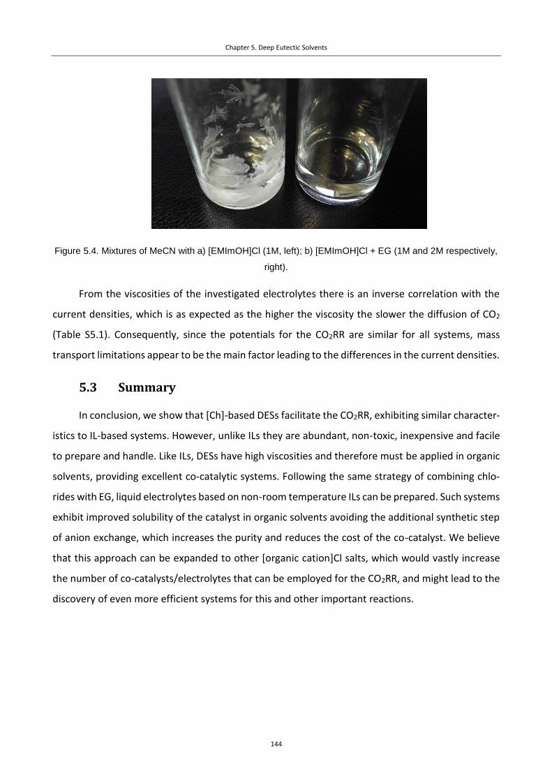
Chapter 5. Deep Eutectic Solvents
144
Figure 5.4. Mixtures of MeCN with a) [EMImOH]Cl (1M, left); b) [EMImOH]Cl + EG (1M and 2M respectively,
right).
From the viscosities of the investigated electrolytes there is an inverse correlation with the
current densities, which is as expected as the higher the viscosity the slower the diffusion of CO2
(Table S5.1). Consequently, since the potentials for the CO2RR are similar for all systems, mass
transport limitations appear to be the main factor leading to the differences in the current densities.
5.3 Summary
In conclusion, we show that [Ch]-based DESs facilitate the CO2RR, exhibiting similar character-
istics to IL-based systems. However, unlike ILs they are abundant, non-toxic, inexpensive and facile
to prepare and handle. Like ILs, DESs have high viscosities and therefore must be applied in organic
solvents, providing excellent co-catalytic systems. Following the same strategy of combining chlo-
rides with EG, liquid electrolytes based on non-room temperature ILs can be prepared. Such systems
exhibit improved solubility of the catalyst in organic solvents avoiding the additional synthetic step
of anion exchange, which increases the purity and reduces the cost of the co-catalyst. We believe
that this approach can be expanded to other [organic cation]Cl salts, which would vastly increase
the number of co-catalysts/electrolytes that can be employed for the CO2RR, and might lead to the
discovery of even more efficient systems for this and other important reactions.

Chapter 5. Deep Eutectic Solvents
145
5.4 Experimental
5.4.1 Materials and methods
All the reagents except 1-(2-hydroxyethyl)-3-methylimidazolium chloride were purchased from
commercial sources and used without further purification. The following reagents were employed:
acetonitrile (>=99.9%, HPLC gradient grade, Fisher Chemical), 1-butyl-3-methylimidazolium chloride
(98.0%, Sigma), choline chloride (98+%, AlfaAesar), 2-(2-ethoxyethoxy)ethanol (98+%, Acros Organ-
ics), ethylene glycol (99.5%, for analysis, Acros Organics), polyethylene glycol (BioUltra, 200, Sigma),
propylene carbonate (99.7%, anhydrous, Sigma), urea (molecular biology grade, Lubio Science). 1-
(2-hydroxyethyl)-3-methylimidazolium chloride was synthesized according to a published proto-
col.28 CO2 (99.998 %) and Ar (99.9999 %) were obtained from Carbagas, Switzerland. Electrochemical
measurements were made in according with the protocols from Chapter 2.
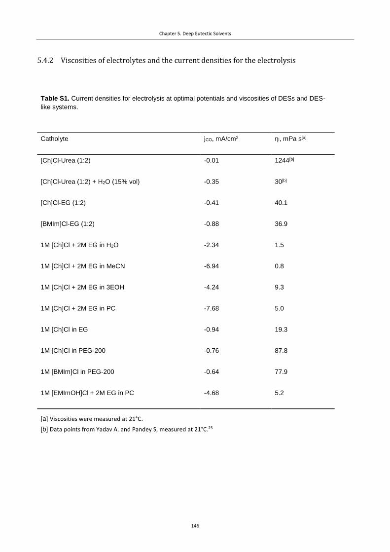
Chapter 5. Deep Eutectic Solvents
146
5.4.2 Viscosities of electrolytes and the current densities for the electrolysis
Table S1. Current densities for electrolysis at optimal potentials and viscosities of DESs and DES-
like systems.
Catholyte jCO, mA/cm2 ηl, mPa s[a]
[Ch]Cl-Urea (1:2) -0.01 1244[b]
[Ch]Cl-Urea (1:2) + H2O (15% vol) -0.35 30[b]
[Ch]Cl-EG (1:2) -0.41 40.1
[BMIm]Cl-EG (1:2) -0.88 36.9
1M [Ch]Cl + 2M EG in H2O -2.34 1.5
1M [Ch]Cl + 2M EG in MeCN -6.94 0.8
1M [Ch]Cl + 2M EG in 3EOH -4.24 9.3
1M [Ch]Cl + 2M EG in PC -7.68 5.0
1M [Ch]Cl in EG -0.94 19.3
1M [Ch]Cl in PEG-200 -0.76 87.8
1M [BMIm]Cl in PEG-200 -0.64 77.9
1M [EMImOH]Cl + 2M EG in PC -4.68 5.2
[a] Viscosities were measured at 21°C.
[b] Data points from Yadav A. and Pandey S, measured at 21°C.25

Chapter 5. Deep Eutectic Solvents
147
5.4.3 Cyclic voltammetry data
Figure S5.1. Cyclic voltammograms for the [Ch]Cl-urea (1:2) mixture, recorded under N2 (green) and under
CO2 (magenta). Insets: a) FEH2 and FECO during electrolysis for this system (Ag electrode, CO2 atmosphere);
b) system evolution with water addition.
Figure S5.2. Cyclic voltammograms for the [Ch]Cl-urea (1:2) mixture under CO2 atmosphere, rec-
orded employing glassy carbon (green) and silver (magenta) electrodes.

Chapter 5. Deep Eutectic Solvents
148
Figure S5.3. Cyclic voltammograms for the [Ch]Cl-EG (1:2) mixture, recorded under N2 (green) and under
CO2 (magenta). Inset: amplified cyclic voltammogram for the reduction under CO2.
Figure S5.4. Cyclic voltammograms for the system, consisting of [Ch]Cl (0.02 M), NBu4PF6 (0.1 M) and
MeCN, recorded under N2 (green) and under CO2 (magenta). Inset: FEH2 and FECO during electrolysis for
this system (Ag electrode).
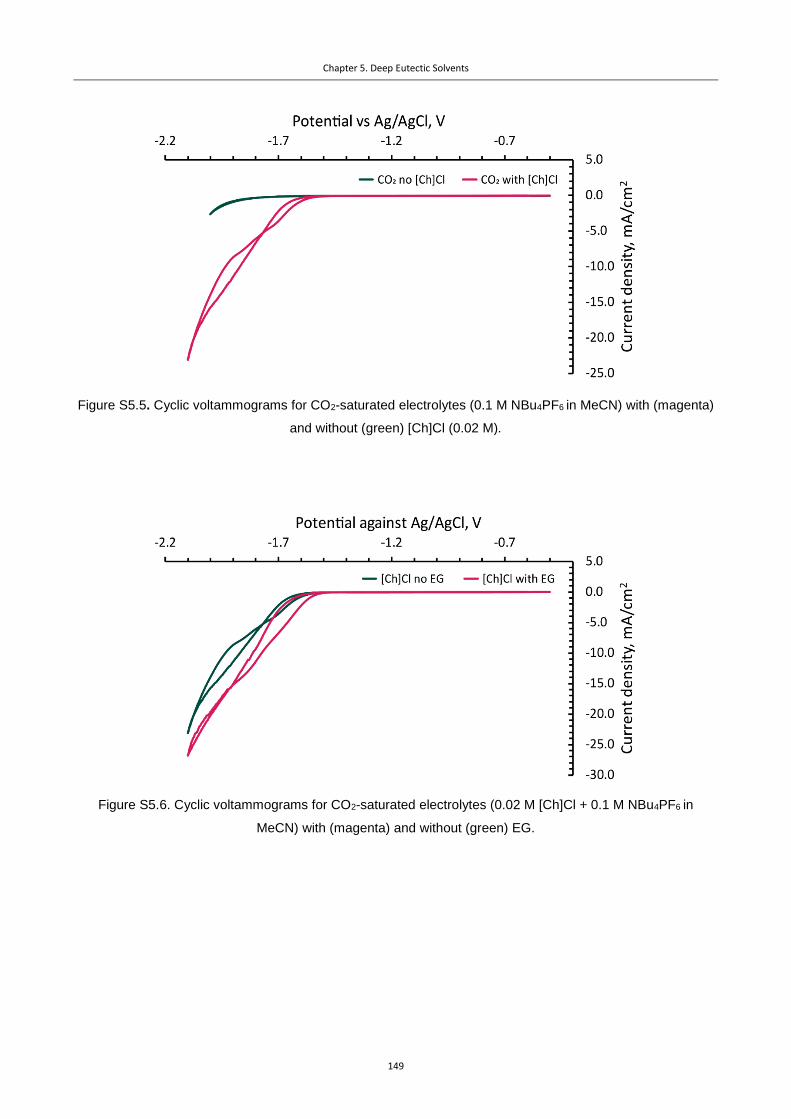
Chapter 5. Deep Eutectic Solvents
149
Figure S5.5. Cyclic voltammograms for CO2-saturated electrolytes (0.1 M NBu4PF6 in MeCN) with (magenta)
and without (green) [Ch]Cl (0.02 M).
Figure S5.6. Cyclic voltammograms for CO2-saturated electrolytes (0.02 M [Ch]Cl + 0.1 M NBu4PF6 in
MeCN) with (magenta) and without (green) EG.

Chapter 5. Deep Eutectic Solvents
150
Figure S5.7. Cyclic voltammograms for CO2-saturated electrolytes (0.1 M NBu4PF6 in MeCN) without any ad-
ditives (green), with 0.02 M urea (magenta) and with 0.02 M EG (blue).
Figure S5.8. Cyclic voltammograms for solution of [Ch]Cl (1M) in PEG-200 under N2 (green) and CO2 (ma-
genta) atmosphere. Inset: FEH2 and FECO during electrolysis for this system (Ag electrode).

Chapter 5. Deep Eutectic Solvents
151
Figure S5.9. Cyclic voltammograms for the mixture of [BMIm]Cl and EG (1:2) under N2 (green) and CO2 (ma-
genta) atmosphere. Inset: FEH2 and FECO during electrolysis for this system (Ag electrode).
Figure S5.10. Cyclic voltammograms for the solution of [EMImOH]Cl (1 M) and EG (2 M) in propylene car-
bonate under N2 (green) and CO2 (magenta) atmosphere. Inset: FEH2 and FECO during electrolysis for this
system (Ag electrode).

Chapter 5. Deep Eutectic Solvents
152
Figure S5.11. Cyclic voltammograms for the solution of [EMImOH]Cl (1 M) and EG (2 M) in MeCN under N2
(green) and CO2 (magenta) atmosphere. Inset: FEH2 and FECO during electrolysis for this system (Ag
electrode).
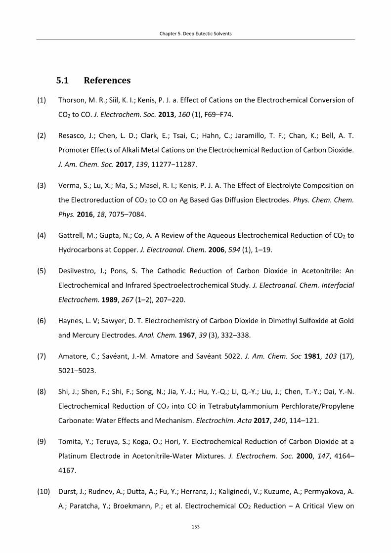
Chapter 5. Deep Eutectic Solvents
153
5.1 References
(1) Thorson, M. R.; Siil, K. I.; Kenis, P. J. a. Effect of Cations on the Electrochemical Conversion of
CO2 to CO. J. Electrochem. Soc. 2013, 160 (1), F69–F74.
(2) Resasco, J.; Chen, L. D.; Clark, E.; Tsai, C.; Hahn, C.; Jaramillo, T. F.; Chan, K.; Bell, A. T.
Promoter Effects of Alkali Metal Cations on the Electrochemical Reduction of Carbon Dioxide.
J. Am. Chem. Soc. 2017, 139, 11277−11287.
(3) Verma, S.; Lu, X.; Ma, S.; Masel, R. I.; Kenis, P. J. A. The Effect of Electrolyte Composition on
the Electroreduction of CO2 to CO on Ag Based Gas Diffusion Electrodes. Phys. Chem. Chem.
Phys. 2016, 18, 7075–7084.
(4) Gattrell, M.; Gupta, N.; Co, A. A Review of the Aqueous Electrochemical Reduction of CO2 to
Hydrocarbons at Copper. J. Electroanal. Chem. 2006, 594 (1), 1–19.
(5) Desilvestro, J.; Pons, S. The Cathodic Reduction of Carbon Dioxide in Acetonitrile: An
Electrochemical and Infrared Spectroelectrochemical Study. J. Electroanal. Chem. Interfacial
Electrochem. 1989, 267 (1–2), 207–220.
(6) Haynes, L. V; Sawyer, D. T. Electrochemistry of Carbon Dioxide in Dimethyl Sulfoxide at Gold
and Mercury Electrodes. Anal. Chem. 1967, 39 (3), 332–338.
(7) Amatore, C.; Savéant, J.-M. Amatore and Savéant 5022. J. Am. Chem. Soc 1981, 103 (17),
5021–5023.
(8) Shi, J.; Shen, F.; Shi, F.; Song, N.; Jia, Y.-J.; Hu, Y.-Q.; Li, Q.-Y.; Liu, J.; Chen, T.-Y.; Dai, Y.-N.
Electrochemical Reduction of CO2 into CO in Tetrabutylammonium Perchlorate/Propylene
Carbonate: Water Effects and Mechanism. Electrochim. Acta 2017, 240, 114–121.
(9) Tomita, Y.; Teruya, S.; Koga, O.; Hori, Y. Electrochemical Reduction of Carbon Dioxide at a
Platinum Electrode in Acetonitrile-Water Mixtures. J. Electrochem. Soc. 2000, 147, 4164–
4167.
(10) Durst, J.; Rudnev, A.; Dutta, A.; Fu, Y.; Herranz, J.; Kaliginedi, V.; Kuzume, A.; Permyakova, A.
A.; Paratcha, Y.; Broekmann, P.; et al. Electrochemical CO2 Reduction – A Critical View on
Chapter 5. Deep Eutectic Solvents
154
Fundamentals, Materials and Applications. Chimia 2015, 69, 769–776.
(11) Rosen, B. A.; Salehi-Khojin, A.; Thorson, M. R.; Zhu, W.; Whipple, D. T.; Kenis, P. J. A.; Masel,
R. I. Ionic Liquid – Mediated Selective Conversion of CO2 to CO at Low Overpotentials. Science
2011, 334, 643–644.
(12) Lau, G. P. S.; Schreier, M.; Vasilyev, D.; Scopelliti, R.; Grätzel, M.; Dyson, P. J. New Insights into
the Role of Imidazolium-Based Promoters for the Electroreduction of CO2 on a Silver
Electrode. J. Am. Chem. Soc. 2016, 138, 7820–7823.
(13) Zhao, S.-F.; Horne, M.; Bond, A. M.; Zhang, J. Is the Imidazolium Cation a Unique Promoter
for Electrocatalytic Reduction of Carbon Dioxide? J. Phys. Chem. C 2016, 120, 23989−24001.
(14) Vasilyev, D.; Shirzadi, E.; Rudnev, A. V.; Broekmann, P.; Dyson, P. J. Pyrazolium Ionic Liquid
Co-Catalysts for the Electroreduction of CO2. ACS Appl. Energy Mater. 2018, 1, 5124–5128.
(15) Zhang, L.; Wu, N.; Zhang, J.; Hu, Y.; Wang, Z.; Zhuang, L.; Jin, X. Imidazolium Ions with an
Alcohol Substituent for Enhanced Electrocatalytic Reduction of CO2. ChemSusChem 2017, 10
(24), 4824–4828.
(16) Zhu, W.; Rosen, B. A.; Salehi-Khojin, A.; Masel, R. I. Monolayers of Choline Chloride Can
Enhance Desired Electrochemical Reactions and Inhibit Undesirable Ones. Electrochim. Acta
2013, 96, 18–22.
(17) Francke, R.; Schille, B.; Roemelt, M. Homogeneously Catalyzed Electroreduction of Carbon
Dioxide - Methods, Mechanisms, and Catalysts. Chem. Rev. 2018, 118, 4631−4701.
(18) Singh, M. R.; Kwon, Y.; Lum, Y.; Ager, J. W.; Bell, A. T. Hydrolysis of Electrolyte Cations
Enhances the Electrochemical Reduction of CO2 over Ag and Cu. J. Am. Chem. Soc. 2016, 138,
13006–13012.
(19) Rudnev, A. V.; Zhumaev, U. E.; Kuzume, A.; Vesztergom, S.; Furrer, J.; Broekmann, P.;
Wandlowski, T. The Promoting Effect of Water on the Electroreduction of CO2 in Acetonitrile.
Electrochim. Acta 2016, 189, 38–44.
(20) Smith, E. L.; Abbott, A. P.; Ryder, K. S. Deep Eutectic Solvents (DESs) and Their Applications.
Chem. Rev. 2014, 114 (21), 11060–11082.
Chapter 5. Deep Eutectic Solvents
155
(21) Garcia, G.; Aparicio, S.; Ullah, R.; Atilhan, M. Deep Eutectic Solvents: Physicochemical
Properties and Gas Separation Applications. Energy Fuels 2015, 29, 2616–2644.
(22) Zhang, Q.; De Oliveira Vigier, K.; Sebastien, R. F.; Jerome, F. Deep Eutectic Solvents :
Syntheses, Properties and Applications. Chem Soc Rev 2012, 41, 7108–7146.
(23) Kudłak, B.; Owczarek, K.; Namieśnik, J. Selected Issues Related to the Toxicity of Ionic Liquids
and Deep Eutectic Solvents-a Review. Environ. Sci. Pollut. Res. 2015, 22, 11975–11992.
(24) Hori, Y.; Wakebe, H.; Tsukamoto, T.; Koga, O. Electrocatalytic Process of CO Selectivity in
Electrochemical Reduction of CO2 at Metal Electrodes in Aqueous Media. Electrochim. Acta
1994, 39, 1833–1839.
(25) Yadav, A.; Pandey, S. Densities and Viscosities of (Choline Chloride + Urea) Deep Eutectic
Solvent and Its Aqueous Mixtures in the Temperature Range 293.15 K to 363.15 K. J. Chem.
Eng. Data 2014, 59, 2221–2229.
(26) Nishikawa, K.; Wang, S.; Katayanagi, H.; Hayashi, S.; Hamaguchi, H.-O.; Koga, Y.; Tozaki, K.-I.
Melting and Freezing Behaviors of Prototype Ionic Liquids, 1-Butyl-3-Methylimidazolium
Bromide and Its Chloride, Studied by Using a Nano-Watt Differential Scanning Calorimeter. J.
Phys. Chem. B 2007, 111, 4894–4900.
(27) Rudnev, A. V.; Fu, Y.-C.; Gjuroski, I.; Stricker, F.; Furrer, J.; Kovács, N.; Vesztergom, S.;
Broekmann, P. Transport Matters: Boosting CO2 Electroreduction in Mixtures of
[BMIm][BF4]/Water by Enhanced Diffusion. ChemPhysChem 2017, 18 (22), 3153–3162.
(28) Yang, H.; Liu, Y.; Ning, H.; Lei, J.; Hu, G. Synthesis, Structure and Properties of Imidazolium-
Based Energetic Ionic Liquids. RSC Adv. 2017, 7 (53), 33231–33240.


157
Conclusions
Three new classes of ILs – Tz, Pz and Gua – were assessed as co-catalysts in the CO2RR in non-aque-
ous electrolytes. The activity of the Tz ILs was highly dependent on the substitution pattern. While
1,3-alkylated Tz ILs show some co-catalytic activity at low overpotentials, their higher substituted
1,3,4-analogues display no co-catalytic activity (which resembles the behavior of the known Im ILs)
and are reduced instead of CO2. Despite the low substituted Tz ILs having promising onset potentials
for the CO2RR, close to the theoretical limit for non-aqueous systems, their instability makes them
less attractive for the application compared to the conventional Im ILs. However, information on
the influence of substitution patterns and onset potentials described above is an important contri-
bution to the understanding of structure/activity relationships for CO2RR catalysts.
The synthesized Pz ILs were shown to be efficient co-catalysts for the CO2RR, superior to the bench-
mark Im ILs in terms of FECO (100% vs. 80-90% at the same potentials). Introduction of substituents
in the Pz ring results in an increase of the stability of the co-catalysts along with a decrease in their
activities. However, unlike the fully substituted Im and Tz ILs, peralkylated Pz ILs show good activities
for the CO2RR. Notably, the presence of water in the electrolyte significantly decreases the reduction
onset potential for most Pz co-catalysts. Another interesting feature of the Pz ILs is the generation
of small amounts of formic acid and methane during the electrolysis, which is not typical of poly-
crystalline Ag electrodes in the presence of Im ILs. The change product selectivity encourages appli-
cation of the Pz IL with other electrodes and electrolytes.
Gua ILs have also shown co-catalytic activity for the CO2RR, although lower than that compared to
the Im ILs. The peculiarities of the Gua structure allow gradual substitution and introduction of bulky
substituents, which makes Gua ILs versatile synthetic tools for the research on the IL structure/ac-
tivity correlations. Decreasing the availability of the N-atoms of the Gua core suppresses the inter-
actions with the CO2-based intermediates, resulting in a decrease in the rate of the reduction,
whereas introduction of a strain between the nitrogen results in the decrease of the reduction onset
potential for the CO2RR.
Additionally to broadening the scope of room-temperature ILs capable of promoting the CO2RR, we
hypothesize that the main descriptors for the IL catalysts with high activity is the accessibility and

Chapter 6. Conclusions
158
charge of the active cationic center, which appears to be crucial in forming interaction with CO2. The
importance of the accessibility is demonstrated for the Gua ILs, where the reaction rates gradually
decrease with the introduction of blocking substituents on the nitrogen atoms. This mechanism also
explains why peralkylated Im and Tz ILs have negligible activity compared to their non-substituted
analogues. Furthermore, we suspect that the higher activity of cyclic Gua IL compared to the acyclic
analogue (see Chapter 4) is due to the strain in the cyclic compound, which widens the C-N-C angle
between the methyl group and the Gua core and makes the charged centers more accessible for
interactions with CO2. The influence of the charge can be demonstrated by comparing the activity
of Gua with Im or Pz ILs. The former have higher reduction overpotentials as the charge is more
delocalized, whereas Tz ILs exhibit even lower overpotentials compared to Im ILs due to the elec-
tronegative N2 atom in the structure. Finally, the relative weight of the charge distribution/charge
accessibility can be appreciated from a comparison of Im and Pyrd ILs. The former have slightly
higher co-catalytic activity than the latter, possessing more distributed charge but higher accessibil-
ity of the charged cites. We believe that based on this hypothesis, the rational design of efficient co-
catalysts for the CO2RR should be possible.
We also developed a new type of non-aqueous electrolytes based on DESs for the CO2RR. The pres-
ence of the OH-group in the structure of the cations was found to significantly facilitate the reduc-
tion. The resulting systems possess similar properties to ILs, but unlike ILs, they are abundant, non-
toxic, inexpensive and facile to prepare and handle. The solubility of conventional DESs in organic
solvents allows viscosity issues to be overcome, thus providing excellent co-catalytic systems. We
believe that this strategy may allow the anion exchange stage for the synthesis of IL to be avoid,
employing DESs based on the IL chlorides. This strategy significantly simplifies preparation of ionic
electrolytes, broadening the scope of catalytic media and making a further step towards green and
efficient electrolytes.

159
Curriculum Vitae : Dmitry V. Vasilyev
22.10.1992
+41 78 901 41 48
Russian
Chemin de la Dôle, 17
1024, Ecublens, Switzerland
0000-0001-7956-0307
EDUCATION
2015 – present PhD: École polytechnique fédérale de Lausanne (EPFL), Institute of Chemi-cal Sciences and Engineering (ISIC). Topic: Development of organic electro-lytes promoting electrochemical reduction of carbon dioxide. Scientific ad-visor: Prof. P. J. Dyson
2010 – 2015 Bachelor & master: Lomonosov Moscow State University, Department of Chemistry (with honors, GPA = 5.0 / 5.0).
OTHER RESEARCH EXPERIENCE
2013 – 2015 Master thesis: A. N. Nesmeyanov Institute of Organoelement Compounds RAS (Russia). Project: Cyclization of 1,11-dien-6-ynes by cobalt (I) catalysis (supervisor: Dr D. S. Perekalin).
July-August 2013 Short term scholar visitor: University of Missouri – St. Louis (USA). Project: Investigation of the mechanism of the rearrangement of 1-acetoxy-α-sac-charides promoted by CAN (supervisor: Prof. A. V. Demchenko)
PRACTICAL SKILLS
Research techniques
Synthesis under inert conditions (Schlenk, glovebox)
Preparative chromatography (man-ual/automatic)
Chronoamperometry Chronopotentiometry
Cyclic voltammetry Impedance spectroscopy (basics) Analytical and spectroscopic methods ( GC;
MS; UV-vis; IR; NMR: 1D, COSY, HSQC, HMBC, DOSY)
Computer literacy
o MS Office o Origin o ChemDraw o Adobe Illustrator o MestReNova o Adobe Photoshop o IgorPro o Gaussian (basics) o Visual Basic (Excel VBA) o Mendeley
LANGUAGES
Russian (native); English (fluent); French (upper intermediate)
Curriculum Vitae
160
PUBLICATIONS
1) M. Hulla, D. Ortiz, S. Katsyuba, D. Vasilyev, P. J. Dyson. Delineation of the Critical Parame-ters of Salts Catalysts in the N-Formylation of Amines with CO2. Chem. Eur. J. 2019 Doi: 10.1002/chem.201901686
2) D. V. Vasilyev, A. V. Rudnev, P. Broekmann, P. J. Dyson. A General and Facile Approach for the Electrochemical Reduction of Carbon Dioxide Inspired by Deep Eutectic Solvents. ChemSusChem 2019, 12, 1635-1639
3) D. Vasilyev, E. Shirzadi, A. V. Rudnev, P. Broekmann, P. J. Dyson. Pyrazolium Ionic Liquid Co-catalysts for the Electroreduction of CO2. ACS Appl. Energy Mater. 2018, 1, 5124−5128
4) F. D. Bobbink, D. Vasilyev, M. Hulla, S. Chamam, F. Menoud, G. Laurenczy, S. Katsyuba, P. J. Dyson. Intricacies of Cation−Anion Combinations in Imidazolium Salt-Catalyzed Cycload-dition of CO2 Into Epoxides. ACS Catal. 2018, 8, 2589−2594
5) A. A. Suleymanov, D. V. Vasilyev, V. V. Novikov, Y. V. Nelyubina, D. S. Perekalin. Unpredict-able cycloisomerization of 1,11-dien-6-ynes by a common cobalt catalyst. Beilstein J. Org. Chem. 2017, 13, 639−643
6) G. P. S. Lau, M. Schreier, D. Vasilyev, R. Scopelliti, M. Grätzel, P. J. Dyson. New Insights Into the Role of Imidazolium-Based Promoters for the Electroreduction of CO2 on a Silver Elec-trode. J. Am. Chem. Soc. 2016, 138, 25, 7820−7823
7) D.S. Volkov, M.A. Proskurnin, I.V. Mikheev, D.V. Vasil’ev, M.V. Korobov, D.A. Nedosekin, V.P. Zharov. Application of photothermal and photoacoustic spectroscopy for the moni-toring of aqueous dispersions of carbon nanomaterials. Advanced Laser Technologies, 1, 2012. DOI: 10.12684/alt.1.94
CONFERENCES & SCHOOLS
2018 International Summer School “Power to X: Fundamentals and Applications of Modern Electrosynthesis” (poster)
2017 – 2019 Swiss Snow Symposiums (organizing committee)
2016 International Summer School on CO2 Conversion: From Fundamentals To-wards Applications
2016 – 2018 SCCER Annual Conferences (talks)
2015 – 2018 Swiss Chemical Society Fall Meetings (posters)
2010 Intel International Science and Engineering Fair (ISEF) (poster)
AWARDS
2017 Best teaching award (PhD students, Chemistry and Chemical Engineering Section)
INTERESTS & ACTIVITIES
Sports (judo, aikido, climbing, hiking, skiing); guitar
2018 – 2019 President of Swiss Young Chemists’ Association 2017 – 2018 Vice-President of Swiss Young Chemists’ Association 2016 – 2017 Treasurer of Swiss Young Chemists’ Association