ENVIRONMENTAL EFFECTS REPORT - EPA Tasmania
340
ENVIRONMENTAL EFFECTS REPORT ARTIFICIAL REEF (AR) IN GREAT BAY, IN THE D’ENTRECASTEAUX CHANNEL, SE TASMANIA TO ENHANCE RECREATIONAL FISHING Report to EPA Board (on behalf of MAST) May 2022 www.marinesolutions.net.au © Marine Solutions 2022. This document should only be used for the specific project and purposes for which it was commissioned. 1 Version Author Date submitted Reviewed by Notes V1 Marine Solutions 13/01/2022 Jo Smart (MS) V2 Marine Solutions 05/04/2022 Justin Foster (MAST) Amendments following initial EPA Request for Information V3 Marine Solutions 22/04/2022 - Addition of rock design component at the request of NRE/EPA V4 Marine Solutions 06/05/2022 - Amendments following additional EPA Request for Information
-
Upload
khangminh22 -
Category
Documents
-
view
0 -
download
0
Transcript of ENVIRONMENTAL EFFECTS REPORT - EPA Tasmania

ENVIRONMENTAL EFFECTS REPORT
ARTIFICIAL REEF (AR) IN GREAT BAY, IN THE D’ENTRECASTEAUX CHANNEL, SE TASMANIA TO
ENHANCE RECREATIONAL FISHING
Report to
EPA Board (on behalf of MAST)
May 2022
www.marinesolutions.net.au
© Marine Solutions 2022. This document should only be used for the specific project and purposes for which it was
commissioned. 1
Version Author Date submitted
Reviewed by Notes
V1 Marine Solutions 13/01/2022 Jo Smart (MS)
V2 Marine Solutions 05/04/2022 Justin Foster (MAST)
Amendments following initial EPA Request for Information
V3 Marine Solutions 22/04/2022 - Addition of rock design component at the request of NRE/EPA
V4 Marine Solutions 06/05/2022 - Amendments following additional EPA Request for Information

Great Bay Artificial Reef EER 2
TABLE OF CONTENTS
Table of Contents .......................................................................................................................................... 2
Table of Figures ............................................................................................................................................. 4
1 Background ........................................................................................................................................... 7
2 PART A – Proponent information .......................................................................................................... 8
2.1 Proponent: Marine and Safety Tasmania (MAST) ........................................................................ 8
2.2 Consultant engaged to prepare EER: Marine Solutions PTY LTD .................................................. 8
3 PART B – Proposal description .............................................................................................................. 9
3.1 Description of proposed activity ................................................................................................... 9
3.1.1 Details of reef design, structure, layout and materials used. ............................................... 9
3.1.2 Methodology and route of transport of reef components to installation site; .................. 12
3.1.3 Methodology of placement/installation of the reef components, including seasonal timing
and duration; ...................................................................................................................................... 13
3.1.4 Methodology for securing installed elements on seabed; ................................................. 14
3.1.5 The main items of equipment to be used. .......................................................................... 15
3.2 Classification of the proposal under the EMPC Act. ................................................................... 15
3.3 Goals and/or objectives of the proposal..................................................................................... 15
3.4 Industry standards or guidelines that are applicable to the activity. ......................................... 16
3.5 Timeframe over which the activity is proposed to occur (construction and commissioning
timetable and anticipated activity lifetime). .......................................................................................... 16
3.6 Overview of ongoing management measures for the reef. ........................................................ 16
3.7 Map and site plan ....................................................................................................................... 18

Great Bay Artificial Reef EER 3
3.8 Proposal location ........................................................................................................................ 18
3.9 Bathymetry ................................................................................................................................. 21
3.9.1 Seabed characteristics ........................................................................................................ 23
3.10 Hydrodynamics ........................................................................................................................... 25
3.10.1 Currents ............................................................................................................................... 26
3.10.2 Waves .................................................................................................................................. 32
3.10.3 Weather and tides .............................................................................................................. 34
3.11 Rationale and alternatives .......................................................................................................... 35
3.12 Planning information .................................................................................................................. 36
4 Part C – Potential environmental impacts .......................................................................................... 37
4.1 Air Quality ................................................................................................................................... 37
4.2 Noise emissions ........................................................................................................................... 38
4.3 Water quality, waste and hazards .............................................................................................. 38
4.4 Natural values ............................................................................................................................. 39
4.4.1 Giant kelp marine forests of south east Australia .............................................................. 42
4.4.2 Marine mammals ................................................................................................................ 43
4.4.3 Australian grayling .............................................................................................................. 45
4.4.4 Handfish .............................................................................................................................. 46
4.4.5 Seastars ............................................................................................................................... 47
4.4.6 Sharks .................................................................................................................................. 48
4.4.7 Migratory Species ............................................................................................................... 48
4.4.8 Seabirds ............................................................................................................................... 49
4.5 Weeds, Pests and Pathogens ...................................................................................................... 50
4.6 Greenhouse Gas Emissions and Climate Change Management ................................................. 51

Great Bay Artificial Reef EER 4
4.7 Other off-site impacts ................................................................................................................. 51
4.8 Environmental Impacts of Traffic ................................................................................................ 51
4.9 Monitoring, maintenance and management .............................................................................. 51
4.10 Decommissioning and Rehabilitation ......................................................................................... 51
5 Part D – Summary of proposed management measures .................................................................... 53
6 Public and stakeholder consultation ................................................................................................... 55
7 References .......................................................................................................................................... 59
Appendix 1. Long-term monitoring plan (LTMP) for a proposed artificial reef development in Great
Bay, Tasmania. Marine Solutions (2022). ............................................................................................... 61
Appendix 2. Subcon’s HSEQ management plan (2021). ..................................................................... 61
Appendix 3. Subcon’s Construction and management plan (2021). ................................................... 61
Appendix 4. Subcon’s Module Installation plan (2021). ..................................................................... 61
Appendix 5. Subcon’s AR module design arrangements (various designs) (2021). ............................ 61
Appendix 6. Subcon’s Great Bay Reef layout (2021)........................................................................... 61
Appendix 7. Subcon’s Design Report (2021). ...................................................................................... 61
Appendix 8. LUPA advice received from Kingborough Council 13/01/2021 ....................................... 61
TABLE OF FIGURES
Figure 1. ‘Bombora’ (left), ‘Apollo’ (centre) and ‘Abitat’ (right) artificial reef modules fabricated by
Subcon Technologies Pty Ltd. ..................................................................................................................... 10
Figure 2. Great Bay proposed Artificial Reef design layout. ....................................................................... 12
Figure 3. Subcons hydraulic module installation tool. Image source: Subcon (2021) ................................ 13
Figure 4. Overview of management responsibility commitments throughout the project development. 17

Great Bay Artificial Reef EER 5
Figure 5. Location of the proposed AR development off Turners Beach (blue square) and Tasmanian
reserve classification of the surrounding area. Approximate route of installation vessel from port to
development site in red. Image source: ListMap 10/01/2021. .................................................................. 18
Figure 6. Location of the proposed AR development in Great Bay (blue square), in the D’Entrecasteaux
Channel, SE Tasmania in relation to the Maritime Boundaries Coastal Waters Limit (red line). Image
source: ListMap 11/02/2021. ...................................................................................................................... 19
Figure 7. Constraint mapping used to identify a suitable location of an artificial reef in Great Bay, SE of
Woodbridge in the D’Entrecasteaux Channel, SE Tasmania (red ellipse). .................................................. 21
Figure 8. Bathymetric contour maps of the seabed across the impacted ‘Reef-Field’ area (delineated by
dashed line) of the proposed Great Bay, D’Entrecasteaux AR development site. Depths corrected to
Chart Datum. ............................................................................................................................................... 23
Figure 9. Positions of subtidal transects around the proposed AR development in Great Bay in the
D’Entrecasteaux Channel. Transects are 250 m in length. ......................................................................... 24
Figure 10. Example images taken from towed video footage of benthic habitat filmed across the
proposed AR development area in Great Bay, in the D’Entrecasteaux channel, SE Tasmania. ................. 25
Figure 11. Mean, depth integrated current direction and velocity measured from ADCP deployment at
the centre of the proposed AR development site in Great Bay, D’Entrecasteaux Channel between 25th
August and 11th October 2020. ................................................................................................................... 27
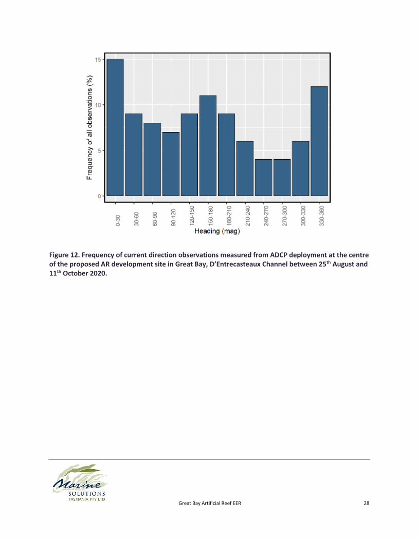
Figure 12. Frequency of current direction observations measured from ADCP deployment at the centre
of the proposed AR development site in Great Bay, D’Entrecasteaux Channel between 25th August and
11th October 2020. ...................................................................................................................................... 28
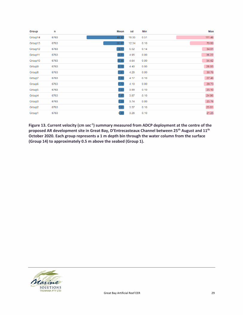
Figure 13. Current velocity (cm sec-1) summary measured from ADCP deployment at the centre of the
proposed AR development site in Great Bay, D’Entrecasteaux Channel between 25th August and 11th
October 2020. Each group represents a 1 m depth bin through the water column from the surface
(Group 14) to approximately 0.5 m above the seabed (Group 1). ............................................................. 29
Figure 14. Rose plots of current velocity and direction through the water column measured from ADCP
deployment at the centre of the proposed AR development site in Great Bay, D’Entrecasteaux Channel
between 25th August and 11th October 2020. Each group represents a 1 m depth bin through the water
column from the surface (Group 14) to approximately 0.5 m above the seabed (Group 1). .................... 30

Great Bay Artificial Reef EER 6
Figure 15. Current velocity profile measured from ADCP deployment at the centre of the proposed AR
development site in Great Bay, D’Entrecasteaux Channel between 25th August and 11th October 2020. 31
Figure 16. Current velocity by direction heading measured from ADCP deployment at the centre of the
proposed AR development site in Great Bay, D’Entrecasteaux Channel between 25th August and 11th
October. ...................................................................................................................................................... 31
Figure 17. Significant wave height by direction measured from ADCP deployment at the centre of the
proposed AR development site in Great Bay, D’Entrecasteaux Channel between 25th August and 11th
October. ...................................................................................................................................................... 32
Figure 18. Significant wave height measured from ADCP deployment at the centre of the proposed AR
development site in Great Bay, D’Entrecasteaux Channel between 25th August and 11th October. ......... 33
Figure 19. Wave period measured from ADCP deployment at the centre of the proposed AR
development site in Great Bay, D’Entrecasteaux Channel between 25th August and 11th October. ......... 34
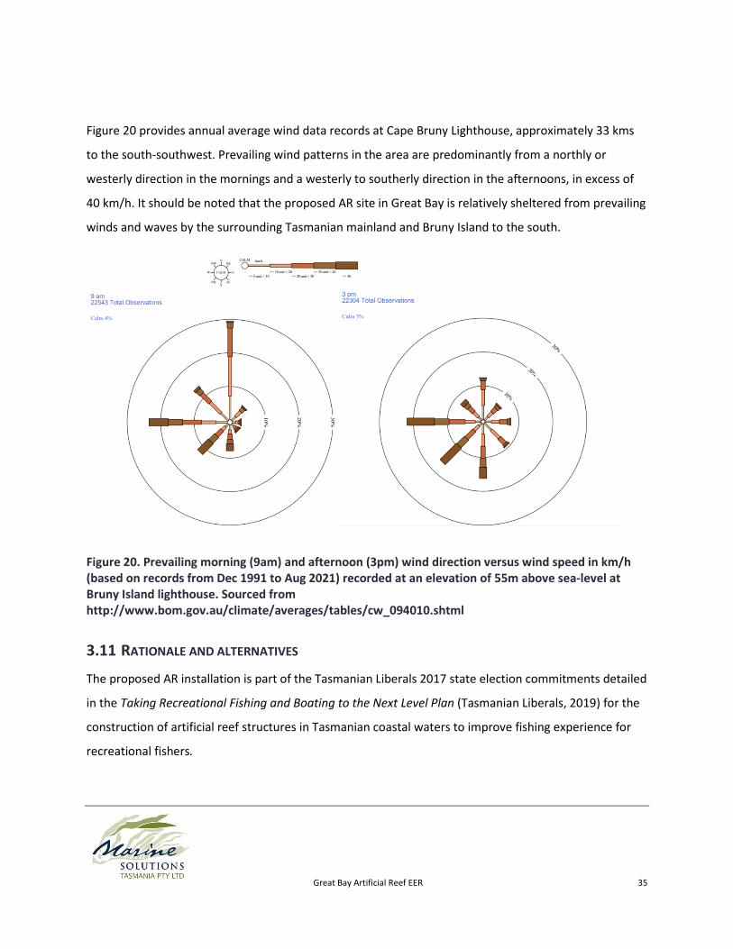
Figure 20. Prevailing morning (9am) and afternoon (3pm) wind direction versus wind speed in km/h
(based on records from Dec 1991 to Aug 2021) recorded at an elevation of 55m above sea-level at Bruny
Island lighthouse. Sourced from http://www.bom.gov.au/climate/averages/tables/cw_094010.shtml . 35
Figure 21. Marine species observed during towed video surveys filmed across the proposed AR
development area in Great Bay, in the D’Entrecasteaux channel, SE Tasmania. A) Ascidian, B) Doughboy
scallop (Mimachlamys asperrimus), C) Sabellid polychaete (Myxicola infundibulum), D) Holothurian
(Neothyonidium dearmartum), E) Commercial scallop (Pecten fumatus), F) Holothurian (unknown), G)
Granular starfish (Uniphora granifera), H) Sponge (Rhizaxinella sp.) and I) Giant spider crab
(Leptomithrax gaimardii). ........................................................................................................................... 42
Figure 22. Stakeholder engagement and reporting phases. ....................................................................... 56
Figure 23. Stakeholder identification. ......................................................................................................... 57

Great Bay Artificial Reef EER 7
1 BACKGROUND
An initial Referral to the EPA board (the Board) for a proposed development in Great Bay, in the
D’Entrecasteaux Channel, SE Tasmania was submitted on the 28th January 2021 by Marine Solutions Pty
Ltd, on behalf of the project proponent, Marine and Safety Tasmania (MAST), to be considered under
the Environmental Management and Pollution Control Act 1994 (the EMPC Act).
A subsequent decision of class assessment and guidelines for preparing the necessary Environmental
Effects Report (EER) in accordance with sections 27D and 74(4) of the EMPC Act were provided to MAST
by the EPA on 1st April 2021. It was advised that the proposed development would be assessed by the
Board as a class 2B assessment under the EMPC Act.
This document forms the EER for the proposed artificial reef (AR) development in Great Bay, in the
D’Entrecasteaux Channel, SE Tasmania and provides the required information as outlined in the
Environmental Effects Report Guidelines: Marine and Safety Authority Artificial Reef, Great Bay (2021)
provided by the EPA.
Subcon Technologies Pty Ltd. (Subcon) has been contracted by MAST to manage the final design and
installation of the proposed AR development including fabrication and deployment of 166 artificial reef
(AR) modules at the proposed site.

Great Bay Artificial Reef EER 8
2 PART A – PROPONENT INFORMATION
2.1 PROPONENT: MARINE AND SAFETY TASMANIA (MAST)
Registered address: MAST, Level 1, Port Tower Building, 18 Hunter Street, Hobart, Tasmania. 7000.
Postal address: GPO Box 607, Hobart, 7001
ABN: 65 826 980 806
Contact person: Justin Foster ([email protected]), (03) 6235 8818
2.2 CONSULTANT ENGAGED TO PREPARE EER: MARINE SOLUTIONS PTY LTD
Registered address: 110 Swanston St, New Town, Tasmania 7008.
ABN: 71 165 838 755
Contact persons: Sam Ibbott ([email protected]), (03) 6228 5906

Great Bay Artificial Reef EER 9
3 PART B – PROPOSAL DESCRIPTION
3.1 DESCRIPTION OF PROPOSED ACTIVITY
3.1.1 Details of reef design, structure, layout and materials used.
Reef modules will be constructed using steel reinforced concrete mix including 20% fly ash. This recycled
material reduces the amount of cement required and makes the concrete impermeable, ensuring the
design life of up to 100 years is met. High strength (50MPa) concrete will be used to ensure integrity
throughout the lifetime of the reef.
The fabrication of the reef modules will be performed at a suitable location near to the main port of
Hobart. Steel moulds will be used for casting of the concrete modules. Steel is preferred to ensure an
efficient and precise fabrication program. The molds are made up of internal and external casting
components which are stripped at various times depending on strength requirements. Steel molds
provide for an efficient and precise fabrication program. Prior to deployment the AR units will be
available for inspection at the fabrication facility.
The AR units will contain no known Annex I or Annex II substances (under Schedule 1 of the Sea
Dumping Act) such as heavy metals, oils and grease, radioactive material, or plastics.
The proposed AR will consist of a multi-module, ‘reef-field’ design utilising five different module designs
and sizes designed and fabricated by Subcon Ltd. See Figure 1 and Table 1 below for a summary of the
various module designs and dimensions.
The AR modules have been designed and purpose-built using materials that have been demonstrated to
be inert, and resistant to deterioration in seawater (from monitoring results of past applications) in line
with the Guidelines for the Placement of Artificial Reefs (London Convention and Protocol/UNEP, 2009).

Great Bay Artificial Reef EER 10
Figure 1. ‘Bombora’ (left), ‘Apollo’ (centre) and ‘Abitat’ (right) artificial reef modules fabricated by Subcon Technologies Pty Ltd.
Table 1. Summary of artificial reef module dimensions designed and fabricated by Subcon Technologies Pty Ltd.
Reef Module Length (m)
Width (m) Height (m)
Weight (t) Surface Area (m2)
Volume (m3)
Quantity
‘Abitat’ 2.8 2.4 1.0 1.8 17.1 6.8 14
‘Apollo’ 1.2 1.2 1.0 0.94 6.7 1.5 40
‘Bombora’ Type 1
2.1 2.1 1.8 3.5 21.1 7.9 84
‘Bombora’ Type 2
1.8 1.8 1.5 2.6 15.7 4.9 7
‘Bombora’ Type 3
1.8 1.8 1.3 2.0 13.8 4.2 21
The proposed AR layout design consists of a multi-unit, ‘reef-field’ layout, incorporating 166
prefabricated concrete modules of varying sizes arranged in ‘sets’ and ‘clusters’ to form an AR complex
totaling approximately 417 tonnes of material (Figure 2). The proposed design represents an
‘ecologically optimal’ layout with the greatest likelihood of achieving high community diversity and
sustainable fish productivity and therefore the greatest likelihood of producing positive recreational
fishing outcomes as outlined in the initial AR feasibility assessment (Marine Solutions Ltd., 2020). The
initial AR feasibility assessment provides further specific details of designs options considered.

Great Bay Artificial Reef EER 11
The layout design will also incorporate provision for the future installation of a maximum 500 m3 of
carbonate-based, locally acquired quarry rock (e.g. whiterock or mudstone weighing upto 2.5 tonnes per
cubic metre) to be deployed on the seabed, in piles 300-400mm high arranged between the AR module
clusters. This rock is intended to become naturally settled by oysters and will provide additional
interstitial microhabitat space important to many invertebrates, post-larval and juvenile fish species.
The installation and management of rock additions will be the sole responsibility of the NRE Marine
Resources division.
Rock will be deployed on the seabed from bulker bags lowered to the seabed and opened remotely from
the vessel on the surface.

Great Bay Artificial Reef EER 12
Figure 2. Great Bay proposed Artificial Reef design layout.
3.1.2 Methodology and route of transport of reef components to installation site;
Road transport of AR components will be minimised by selecting a fabrication site as close as practicable
to the loading port (Hobart). A suitably sized flatbed vehicle will be used to transport AR modules from
the fabrication facility to the vessel loading location.
A Twin-Screw Tug installation vessel with a suitable A-Frame crane will be used to deploy the reef
modules. The deployment is expected to be completed in 8 trips with Subcon’s stackable reef modules,
subject to weather, the vessels stability and safety considerations.

Great Bay Artificial Reef EER 13
3.1.3 Methodology of placement/installation of the reef components, including seasonal timing and
duration;
Modules will be deployed using the vessel A-frame along with a specifically designed deck skidding
system and hydraulic installation tool (Figure 3). The tool is rigged below the A-Frame hook and can be
activated and deactivated to clamp on to modules and release them once in position on the seabed.
Figure 3. Subcons hydraulic module installation tool. Image source: Subcon (2021)
The installation is expected to take approximately two weeks and is planned to be completed during a
suitable weather window before the end of 2022. Installation was intended to be scheduled to avoid the
general whale migration season in Tasmania from May to November, however given ongoing permitting
approval delays installation will now need to occur within this period. To mitigate potential impacts
appropriate measures, as outlined in Section 4.4.2 below will be adhered to during AR installation.
An exclusion zone around the installation vessel will be determined by the contractor and identified and
communicated via a Notice to Mariners and appropriate day-shape markers aboard the vessel.

Great Bay Artificial Reef EER 14
3.1.4 Methodology for securing installed elements on seabed;
The inherent design weight and stability of each concrete module is intended to provide sufficient
down-force to secure them to the seabed and maintain their position in all foreseeable weather
conditions.
Subcon have established strict criteria to confirm stability of their module designs during extreme storm
events. The stability is calculated against the failure mechanisms of uplift, overturning and sliding.
In accordance with the most stringent industry standards (DNV-RP-F109) along with applying
conservative hydrodynamic coefficients (DNV-C205), Airy wave theory has been used to calculate the
resulting orbital velocity at the AR location. Loads were calculated on the structures using Morrisons
equation with considerations to its shape and resulting drag and added mass coefficients. The stability
assessment can be broken down into two forms, sliding and overturning stability. The sliding stability
relies on the friction loads between the reef module and seabed generated by its own submerged
weight, as well as a contribution from the embedment of the structure into the seabed. The overturning
stability compares the overturning moment generated by the particle velocity and acceleration with the
restoring moment generated by the weight of the structure. Lift force on the reef is caused by the
diversion of flow, which leads to a pressure differential region above the reef module. This reduces the
normal force of the structure, resulting in a lower friction load and restoring moment. Statistics are used
to calculate the resulting stability with the reduced normal force considered.
Using this detailed method of analysis, all proposed reef modules have been shown to be stable at the
proposed Great Bay location according to internationally recognized subsea structure design codes
(DNV-RP-F109).
A detailed description of the analysis methodology and results is detailed in Subcons Artificial Reef
Stability Report (2021), included in the supporting documentation. Individual detailed stability reports
for each module design positioned at the proposed site are also included in the supporting
documentation.
Some settlement and sinkage of AR modules is expected however it is difficult to quantify the extent of
settlement without comprehensive geotechnical studies, which would typically be cost prohibitive of a

Great Bay Artificial Reef EER 15
project this scale and nature. Based on the environmental assessment results and previous installation
experience the contractor expects to some degree of settlement typical of any sand, or soft sediment
bottom. Some settlement or sinking is actually advantageous as it improves on bottom stability by
increasing friction between the module and the seabed and reducing exposed surface area of the
module to wave and current induced loading.
3.1.5 The main items of equipment to be used.
• Suitably sized flatbed truck for transport of AR modules from the fabrication facility to the vessel
loading location.
• Twin-Screw Tug installation vessel with an A-Frame crane
• Subcon hydraulic installation tool
3.2 CLASSIFICATION OF THE PROPOSAL UNDER THE EMPC ACT.
The EPA Board has previously advised the proponent that the proposed development will be assessed as
a class 2B assessment under the EMPC Act (correspondence from Cindy Ong, Acting Dept. Director, EPA
Tasmania, 1st April 2021).
The proposal is classified under 7(e), Schedule 2 of the EMPC Act as “Conduct of Certain Activities in
Waters Within the Limits of the State: the placement of an artificial reef”.
3.3 GOALS AND/OR OBJECTIVES OF THE PROPOSAL
The result of a Stakeholder Engagement Process (SEP) completed as part of the initial AR feasibility
assessment (Marine Solutions Ltd, 2020) was the refinement of the initial state governments goal of
improving off-shore catches with Artificial Reefs, as outlined in the Taking Recreational Fishing and
Boating to the next level plan (Tasmanian Liberals 2018) into the following eleven objectives for
successful development of ARs in Tasmania:
1. Create maximum benefit to recreational fishers through habitat enhancement and sustainable
production of target fish stocks.

Great Bay Artificial Reef EER 16
2. Minimise the likelihood that the AR structures will excessively contribute to the fisheries
exploitation and localised depletions through attraction of fish from the surrounding
environment and concentration of fishing pressure.
3. Clear budget commitments and planning for fabrication, installation and ongoing maintenance
and monitoring.
4. Minimise impact on commercial fishing through consultation to maintain good relations
between the different fishing sectors.
5. Consideration of AR depth to minimise barotraumic injury to catch-and-release fish and hazard
to navigation.
6. Ease of access for all sectors of the recreational fishing community and consideration of
distances from boat ramps and distance offshore etc.
7. Value adding outcomes for other sectors of the community including conservation, metocean
monitoring and environmental research opportunities.
8. Minimising interactions between fishers and marine mammals, particularly seals.
9. Minimising user interaction by outlining clear, shared use expectations and protocols.
10. Ongoing consultation and collaboration with other managers inter-state.
11. Consideration of unintended environmental, social and economic impacts.
3.4 INDUSTRY STANDARDS OR GUIDELINES THAT ARE APPLICABLE TO THE ACTIVITY.
The AR modules have been designed and purpose-built in line with the Guidelines for the Placement of
Artificial Reefs (London Convention and Protocol/UNEP, 2009).
3.5 TIMEFRAME OVER WHICH THE ACTIVITY IS PROPOSED TO OCCUR (CONSTRUCTION AND
COMMISSIONING TIMETABLE AND ANTICIPATED ACTIVITY LIFETIME).
Fabrication and installation of the AR modules is planned to be completed by the end of June 2022.
3.6 OVERVIEW OF ONGOING MANAGEMENT MEASURES FOR THE REEF.
A Long-term Management plan (LTMP) has been developed in line with state and federal permitting
requirements. The LTMP is included in the supporting documentation.

Great Bay Artificial Reef EER 17
AR installation will be completed by Subcon and overseen by MAST as the principle project proponent.
On completion of the development, ongoing management and monitoring responsibility for the AR will
be taken by the Department of Natural Resources and Environment Tasmania (NRE) Marine Resources
division and the University of Tasmania’s Institute for Marine and Antarctic Studies (IMAS). It is as yet to
be decided who will be contracted to complete the required fieldwork monitoring components but will
likely be a combination of IMAS staff and external environmental contractors (Figure 4).
Figure 4. Overview of management responsibility commitments throughout the project development.

Great Bay Artificial Reef EER 18
3.7 MAP AND SITE PLAN
The location of the proposed AR installation in approximately 2km southeast of the Green Island Nature
Reserve, 2km northeast of Simpsons Pt Marine Conservation area and approximately 4km east of the
closest residence at Dripstone Pt. (Figure 5). See Figure 2 above for a detailed site layout plan.
Figure 5. Location of the proposed AR development off Turners Beach (blue square) and Tasmanian reserve classification of the surrounding area. Approximate route of installation vessel from port to development site in red. Image source: ListMap 10/01/2021.
3.8 PROPOSAL LOCATION
The proposed AR development will be contained within a proposed AR management area, 200 x 200 m
encompassing 40,000 m2 (4 Ha) of seabed, approximately 8 km southeast of the township of
Woodbridge (Figure 6). The minimum distance from the Great Bay site to the nearest land, ‘Green
Island’ is 2km to the northwest. Green Island is designated as a Nature Reserve under the Nature
Conservation Act (1999) and is managed by the Tasmania Parks and Wildlife Service.
Table 2 provides the coordinates of the AR management area boundary corners.

Great Bay Artificial Reef EER 19
Figure 6. Location of the proposed AR development in Great Bay (blue square), in the D’Entrecasteaux Channel, SE Tasmania in relation to the Maritime Boundaries Coastal Waters Limit (red line). Image source: ListMap 11/02/2021.
Table 2. Great Bay proposed Artificial Reef centre position and management area boundary corner positions.
Site Zone Easting Northing
Great Bay centre 55G 525119.0 5215443.0
Great Bay NW corner 55G 525024.0 5215542.0
Great Bay NE corner 55G 525221.0 5215540.0
Great Bay SW corner 55G 525020.0 5215342.0
Great Bay SE corner 55G 525219.0 5215340.0
A DGPS survey system installed on the crane boom tip will relay module position to a computer on-
board of the installation vessel to enable accurate placement and recording of the modules. This
information will be cross referenced with the bathymetry survey to provide the hydrographic survey
notes.
The depth of water across the Great Bay site ranges from 13 to 14m from chart datum while the reef
modules designs range from 1.0 to 1.8m in height resulting in a minimum depth over any module of
11.2m from chart datum.

Great Bay Artificial Reef EER 20
The benthic substrate across the proposed AR area consisted entirely of soft sediments (Figure 10),
suggesting the site is within a relatively low energy, depositional area of seabed.
Beyond the footprint of the individual AR modules the direct impact to the biota is anticipated to be
minimal. In time, modules are expected to become colonised with a similar diversity of organisms as the
surrounding local rocky reef habitats. The establishment of a resident fish population on the AR is
expected to alter the composition of the local surrounding biota to a similar extent to areas surrounding
nearby natural reef.
The proposed AR location was identified through constraint mapping as the most beneficial location for
an AR in the SE of Tasmania (Figure 7). This location offers suitable depth (approximately <20 m) to
minimise barotrauma injury of caught and released fish, is a distance of > 1 km from the nearest natural
reef habitat, avoids sensitive and threatened habitats, has a significant user population in nearby areas
and does not interfere with any marine farming leases, marine conservation zones, port areas, or
shipping routes. The choice also aligns closely with the original stated election commitments. The site
can be easily accessed from multiple nearby public boat ramps close to Kettering, Woodbridge and
Gordon.

Great Bay Artificial Reef EER 21
Figure 7. Constraint mapping used to identify a suitable location of an artificial reef in Great Bay, SE of Woodbridge in the D’Entrecasteaux Channel, SE Tasmania (red ellipse).
3.9 BATHYMETRY
An area of seabed, approximately 40,000 m2 (4 Ha.) was bathymetrically surveyed across the proposed
AR development site in Great Bay on the 5th September 2020. Weather conditions at the time were fair
and suitable for accurate survey work. Surveys were carried out from a small vessel equipped with a
CHIRP enabled broadband sounder and Garmin EchoMAP plotter, logging GPS positions and water depth
every two seconds. This information was logged at sufficient resolution, such that representative
interpolations between data points can be made, to produce accurate bathymetric data of the given
area to the Australian hydrographic survey requirements. Depths were measured to the nearest tenth of
a metre, and tidally and barometrically corrected for Chart Datum (CD) using tide charts and
observations from the Bureau of Meteorology.

Great Bay Artificial Reef EER 22
Seabed bathymetry across the impacted ‘Reef-Field’ area of the proposed Great Bay AR development
site displayed a gradual increase in depth in a roughly southwest to northeast direction, ranging from
approximately 13.5 m to 13.9 m below CD (Figure 8). No noteworthy or significant seabed features or
obstructions to navigation to warrant concern for AR installation were observed in the bathymetry
survey.
Table 3. Bathymetry Metadata report for Great Bay, D’Entrecasteaux Channel survey.
Projection: UTM GRS80 Ellipsoid GDA-1994-MGA-Zone55
Vertical datum: Nautical Chart Datum
Date of capture: 05/10/2020
Corrections: Tidal adjustment to Port Huon gauge with barometric variation
Grid nodes and spacing: 168 x 186 (31248 nodes) X:1.50, Y:1.50
Interpolation algorithm: Inverse Distance to Power

Great Bay Artificial Reef EER 23
Figure 8. Bathymetric contour maps of the seabed across the impacted ‘Reef-Field’ area (delineated by dashed line) of the proposed Great Bay, D’Entrecasteaux AR development site. Depths corrected to Chart Datum.
3.9.1 Seabed characteristics
Subtidal video surveys were conducted across the Great Bay AR development site to characterise the
benthic habitat type and identify any threatened species present. Surveys were designed based on the
findings of initial Natural Values desktop assessments and the Guidelines for Natural Values Surveys
(Natural and Cultural Heritage Division. DIPIPWE, 2020).
As a result of the Great Bay site being identified through the EPBC Protected matters search tool (PMST)
as potential habitat for Red and Spotted handfish, an in-depth handfish survey design was established

Great Bay Artificial Reef EER 24
consisting of ten 3m x 200m video transects across the proposed AR development site (Figure 9). Due to
the extensive area and relatively deep nature of the site, diver surveys were deemed impractical and as
such a specialised towed, camera array capable of recording high-definition imagery sufficient to survey
hand fish across a 3 m wide transect swath was developed and used. High-definition video footage of
each transect was recorded on a series of three GoPro 8 video cameras arranged in parallel to achieve a
3 m wide view of the seabed. Each video recording was later visually assessed to characterise habitat
and record the presence of any threatened species (i.e. handfish) or suitable threatened species habitat
types.
Video footage is available on request from Marine solutions.
Figure 9. Positions of subtidal transects around the proposed AR development in Great Bay in the D’Entrecasteaux Channel. Transects are 250 m in length.
The habitat was largely similar across all ten transects surveyed; the benthic habitat across the proposed
AR development area consisted almost entirely of soft sediment, dominated by infaunal and epibenthic
invertebrates and largely devoid of macroalgae (Figure 10). Much of the subtidal environment
throughout the D’Entrecasteaux channel is made up of similar soft sediments environments.

Great Bay Artificial Reef EER 25
Figure 10. Example images taken from towed video footage of benthic habitat filmed across the proposed AR development area in Great Bay, in the D’Entrecasteaux channel, SE Tasmania.
3.10 HYDRODYNAMICS
A bottom mounted, upward orientated Nortek WPR 1988 Acoustic Doppler Current Profiler (ADCP) was
deployed on the 25th August 2020, at the centre of the proposed development area in Great Bay, in
approximately 14-15 m water depth (Figure 8). The deployment lasted a duration of 48 days until
retrieval on the 11th October 2020.
The ADCP recorded current direction and velocity every 600 seconds and significant surface wave height
information for the full duration of the deployment.

Great Bay Artificial Reef EER 26
Initial error checking was performed on both raw datasets using a time series plot of sensor pressure.
The pressure time series identified a very short period of inactivity at the end of each time series
indicating the units had been recovered from the site and therefore the data set was clipped to the time
period between indicated in the metadata summary. Wave data was de-spiked to remove low pressure
sensor errors when surface height variation was below threshold values. The error log from the unit did
not show any abnormal warnings indicating the data within the clipped time range was suitable for
processing and summary analysis.
3.10.1 Currents
Mean, depth integrated current direction and velocity at the proposed AR development site in Great Bay
in the D’Entrecasteaux Channel displayed a bimodal pattern in direction (Figure 11) with the highest
frequency of observations in a northerly direction (Figure 12). The highest mean and maximum current
velocities (0.484 and 1.115 m sec-1 respectively) were measured in the surface water depth groups
(Group 14 and 13) (Figure 13 and Figure 15).
Currents at all depths through the water column below 2.5 m displayed a strong bimodal pattern in
current direction; roughly north and south. The top 2 m surface water depth bins (Group 14 and 13)
displayed high current velocities (in excess of 1m s-1) in a predominantly north-easterly direction (Figure
14). Mean and maximum current velocities in bottom water currents were low (0.064 and 0.213 m sec-1
respectively) suggesting ARs would experience negligible current effects. These results suggest there will
likely be a minimal influence of the AR structures on current flow and any resulting sediment transport
and scouring will be negligible and limited to within metre scales of the individual reef modules.
Below 2 m depth, current velocities were fairly constant with depth (Figure 15). Current velocity did not
show any clear relationship with direction heading (Figure 16). It should be noted that due to variations
in local freshwater inputs and the likely intermittent existence of a strong halocline, velocities recorded
in surface waters may at times be erroneously high.

Great Bay Artificial Reef EER 27
Figure 11. Mean, depth integrated current direction and velocity measured from ADCP deployment at the centre of the proposed AR development site in Great Bay, D’Entrecasteaux Channel between 25th August and 11th October 2020.
Great Bay Artificial Reef EER 28
Figure 12. Frequency of current direction observations measured from ADCP deployment at the centre of the proposed AR development site in Great Bay, D’Entrecasteaux Channel between 25th August and 11th October 2020.
Great Bay Artificial Reef EER 29
Figure 13. Current velocity (cm sec-1) summary measured from ADCP deployment at the centre of the proposed AR development site in Great Bay, D’Entrecasteaux Channel between 25th August and 11th October 2020. Each group represents a 1 m depth bin through the water column from the surface (Group 14) to approximately 0.5 m above the seabed (Group 1).

Great Bay Artificial Reef EER 30
Figure 14. Rose plots of current velocity and direction through the water column measured from ADCP deployment at the centre of the proposed AR development site in Great Bay, D’Entrecasteaux Channel between 25th August and 11th October 2020. Each group represents a 1 m depth bin through the water column from the surface (Group 14) to approximately 0.5 m above the seabed (Group 1).

Great Bay Artificial Reef EER 31
Figure 15. Current velocity profile measured from ADCP deployment at the centre of the proposed AR development site in Great Bay, D’Entrecasteaux Channel between 25th August and 11th October 2020.
Figure 16. Current velocity by direction heading measured from ADCP deployment at the centre of the proposed AR development site in Great Bay, D’Entrecasteaux Channel between 25th August and 11th October.

Great Bay Artificial Reef EER 32
3.10.2 Waves
No clear bias in wave direction was evident at the proposed AR development site in Great Bay
throughout the investigation period (Figure 17) and significant wave height was generally low; not
exceeding 0.5 m (Figure 18). Wave period was again generally low and did not exceed 11.5 seconds
(Figure 19).
Figure 17. Significant wave height by direction measured from ADCP deployment at the centre of the proposed AR development site in Great Bay, D’Entrecasteaux Channel between 25th August and 11th October.

Great Bay Artificial Reef EER 33
Figure 18. Significant wave height measured from ADCP deployment at the centre of the proposed AR development site in Great Bay, D’Entrecasteaux Channel between 25th August and 11th October.

Great Bay Artificial Reef EER 34
Figure 19. Wave period measured from ADCP deployment at the centre of the proposed AR development site in Great Bay, D’Entrecasteaux Channel between 25th August and 11th October.
3.10.3 Weather and tides
The tidal range at the proposed AR site is approximately 1.7 m. Table 4 provides precise tidal estimates
at the closest major port to the proposed AR site.
Table 4. Australian Height Datum (AHD) Heights of Lowest Astronomical Tide (LAT), Highest Astronomical Tide (HAT) and Mean Sea Level (MSL) for the main port at Hobart. Sourced from https://NRE.tas.gov.au/land-tasmania/geospatial-infrastructure-surveying/geodetic-survey/coordinate-height-and-tide-datums-tasmania, accessed 11/11/2021
Port Ref BM & Height HAT MSL LAT Range
Hobart SPM 194 1.859 0.86 0.05 -0.83 1.7 m
Great Bay Artificial Reef EER 35
Figure 20 provides annual average wind data records at Cape Bruny Lighthouse, approximately 33 kms
to the south-southwest. Prevailing wind patterns in the area are predominantly from a northly or
westerly direction in the mornings and a westerly to southerly direction in the afternoons, in excess of
40 km/h. It should be noted that the proposed AR site in Great Bay is relatively sheltered from prevailing
winds and waves by the surrounding Tasmanian mainland and Bruny Island to the south.
Figure 20. Prevailing morning (9am) and afternoon (3pm) wind direction versus wind speed in km/h (based on records from Dec 1991 to Aug 2021) recorded at an elevation of 55m above sea-level at Bruny Island lighthouse. Sourced from http://www.bom.gov.au/climate/averages/tables/cw_094010.shtml
3.11 RATIONALE AND ALTERNATIVES
The proposed AR installation is part of the Tasmanian Liberals 2017 state election commitments detailed
in the Taking Recreational Fishing and Boating to the Next Level Plan (Tasmanian Liberals, 2019) for the
construction of artificial reef structures in Tasmanian coastal waters to improve fishing experience for
recreational fishers.

Great Bay Artificial Reef EER 36
The design and location of the proposed AR was determined through a consultation process and initial
feasibility assessment. During this process several alternative options were considered.
The proposed AR location was identified through constraint mapping as the most beneficial location for
an AR in the SE of Tasmania (Figure 7). This location offers suitable depth (approximately <20 m) to
minimise barotrauma injury of caught and released fish, is a distance of > 1 km from the nearest natural
reef habitat, avoids sensitive and threatened habitats, has a significant user population in nearby areas
and does not interfere with any marine farming leases, marine conservation zones, port areas, or
shipping routes. The choice also aligns closely with the original stated election commitments. The site
can be easily accessed from multiple nearby public boat ramps close to Kettering, Woodbridge and
Gordon.
3.12 PLANNING INFORMATION
Timothy Donovan, Senior Planning Officer at Kingborough Council advised via email on the 13th January
2021 that the proposed AR development in Great Bay would not require any planning approval from
Council (see 0 for evidence of written confirmation).

Great Bay Artificial Reef EER 37
4 PART C – POTENTIAL ENVIRONMENTAL IMPACTS
The construction contractor will undertake operations following all relevant International,
Commonwealth (Australian), State (Tasmania) and Local Legislation Regulations, Codes of Practice and
Conventions.
All fabrication and installation activities will adhere to the best practice environmental management
principles as outline in the construction contractor’s HSEQ management plan (2021) included in the
supporting documentation.
Construction of AR modules is being undertaken at a suitable location, away from sensitive and
residential areas on Macquarie Wharf, within the Port of Hobart. This location facilitates easy and
efficient loading of modules directly onto the installation vessel. Loading, transport and installation is
not expected to impact other marine users beyond the existing port activities and restrictions. Loading,
transport and installation may occur at any time during normal 24-hour port activities.
4.1 AIR QUALITY
Construction, transport and installation is not expected to significantly impact air quality. The AR
modules are constructed from concrete, batched off site, there will be minimal dust generated during
fabrication. Fabrication is being undertaken outside at Macquarie Point; this area is an industrial and
port and shipping precinct. All fabrication and installation activities will adhere to the best practices to
safeguard air quality as outlined in the construction contractor’s HSEQ management plan:
• Handling of materials with the potential to become air borne particulates will not be undertaken
during windy conditions.
• Minimal dust generated during fabrication activities will be controlled.
• Community notification will be undertaken where appropriate where work is likely to cause dust
impact on the public and nearby residents.
• Exhaust emissions from plant and equipment will be minimised.
• Any vehicle transporting waste or other materials that may produce odours or dust will be
covered during transportation.

Great Bay Artificial Reef EER 38
4.2 NOISE EMISSIONS
Construction of AR modules will be undertaken at a suitable location for the fabrication and molding of
concrete structures, away from sensitive and residential areas. Fabrication does not emit considerable
noise so is not an issue to surrounding occupants. Construction, transport and installation will not
generate significant noise emissions and all fabrication and installation activities will adhere to the best
practices to minimise noise as outlined in the construction contractor’s HSEQ management plan:
• The substitution of noisy equipment or processes with less noisy alternatives.
• The modification of equipment (where this is practical and can be done safely and following
consultation with the manufacturer).
• Situating noisy equipment away from noise sensitive areas.
• Undertaking noisy work in areas or at times specified by the Superintendent.
• Installing screens to limit the impact of noise on noise-sensitive areas.
• Any other measure that is considered reasonable.
Installation will not use any fixed or mobile equipment that emits noise. Installation involves the use of a
construction vessel only.
4.3 WATER QUALITY, WASTE AND HAZARDS
Construction, transport and installation of AR modules is not expected to generate significant water
quality or waste hazards and all fabrication and installation activities will adhere to the best practices to
minimise water quality and waste hazards as outlined in the construction contractor’s HSEQ
management plan:
• Water quality control measures will be implemented to prevent any materials entering drain
inlet and waterways.
• Refuelling plant and equipment at construction site will be undertaken within bunded areas and
more than 50m away from waterways.
• Spill containment equipment kits will be available on site at construction site and on the
deployment vessel.
Great Bay Artificial Reef EER 39
Fabrication of AR modules utilises re-usable molds and concrete quantities are carefully calculated to
minimise any fabrication waste. The modules require no packaging etc. for transportation or installation.
Installation is not expected to produce or potentially result in any discharge/release to the environment.
There are no chemicals or waste that is installation related. A hydraulic release system will be used for
dry break couplings using only 2L of an environmentally benign hydraulic fluid (Petrocanada ENVIRON
AW68).
The Vessel operates under normal IMO systems and AMSA certification in regards to waste
management.
The impacts on water quality, waste and hazards associated with the AR following installation will be
managed through the development of a ‘Recreational user Code of Conduct’ developed by NRE Marine
Resources. Incidence of marine litter, close to or in relation to the AR sites should be reported to NRE
Marine Resources In the event that there is a notable build-up of marine debris (i.e. recreational or
recreational fishing debris) on the AR deemed to pose a hazard to users or wildlife is identified the
following removal strategy will be implemented.
If safe to do so, debris will be removed by NRE MR staff from a surface vessel. Where necessary, a
commercial dive and/or salvage operation may be employed to remove the hazard.
Significant litter or pollution likely to pose an immediate hazard to threatened and vulnerable species
(i.e. marine mammals, sharks and birds etc.) are to be reported to the EPA (see Section 10.3 in the
LTMP).
4.4 NATURAL VALUES
In a search of the EPBC PMST (DoEE, 2019) and Natural Values Atlas (NRE, 2019b), thirteen threatened
marine species or communities were identified as possibly occurring or known to occur in the vicinity of
the proposed Great Bay AR development (Table 5). There were no verified records of threatened

Great Bay Artificial Reef EER 40
species within a 500 m radius of the proposed AR location. Verified records of five threatened species
were found within a 5000 m radius of the proposed AR location.
Subtidal video surveys were conducted across the Great Bay AR development site to characterise the
benthic habitat type and identify any threatened species present (see Section 3.9.1 for survey outline).
Several mobile and sessile invertebrate species were present across the survey transects in moderate
densities including ascidians, bivalves, sabellid worms, holothurians, starfish, sponges and spider crabs
(Figure 21). A number of fish species including gobies, skate, flounder and flathead were also present in
moderate numbers.
No handfish species or suitable habitat was observed across any of the ten video transects surveyed.
Table 5. Summary of the EPBC Act PMST report for the proposed AR site in Great Bay, D’Entrecasteaux Channel, Tasmania (including 5000 m buffer).
Item # ID’d by PMST
Notes
Mat
ters
of
Nat
ion
al
Envi
ron
me
nta
l Sig
nif
ican
ce World Heritage Properties None
National Heritage Places None
Wetlands of International Importance
None
Great Barrier Reef Marine Park None
Commonwealth Marine Area None
Listed Threatened Ecological Communities
2 Include 1 marine community
Listed Threatened Species 45 Includes 8 marine species
Listed Migratory Species 33 Includes 7 marine species
Oth
er
Mat
ters
Pro
tect
ed
by
EPB
CA
Commonwealth Land None
Commonwealth Heritage Places None
Listed Marine Species 49
Whales and Other Cetaceans 9
Critical Habitats None
Commonwealth Reserves Terrestrial
None
Australian Marine Parks None
Extr
a In
form
atio
n
State and Territory Reserves 5
Regional Forest Agreements 1
Invasive Species 20 Includes no marine species
Nationally Important Wetlands None
Key Ecological Features (Marine) None

Great Bay Artificial Reef EER 41
Table 6. Summary of threatened and migratory marine species and communities identified in a search of the Natural Values Atlas and the EPBC PMST for the proposed AR site in Great Bay, D’Entrecasteaux Channel, Tasmania. Note that the scope does not extend to terrestrial or avian biota.
Species/Communities Listing status NVA findings EPBC PMST findings EPBC Act TSP Act
Giant Kelp Marine Forests of South East Australia (Macrocystis pyrifera)
Endangered - - Community likely to
occur within area
Southern right whale (Eubalaena australis)
Endangered, Migratory
Endangered Verified record within
5000m Breeding likely to occur within area
Humpback Whale (Megaptera novaeangliae)
Vulnerable, Migratory
Endangered Verified record within
5000m
Species or species habitat
likely to occur within area
Blue whale (Balaenoptera musculus)
Endangered, Migratory
Endangered - Species or species
habitat likely to occur within area
Pygmy Right Whale (Caperea marginata)
Migratory - - Foraging, feeding or
relatedbehaviour may occur withinarea
Dusky Dolphin (Lagenorhynchus obscurus)
Migratory - - Species or species
habitat may occur within area
Australian grayling (Prototroctes maraena)
Vulnerable Vulnerable May occur within 5000m based on range boundaries
Species or species habitat likely to occur
within area
Red Handfish (Thymichthys politus)
Critically endangered
Endangered - Species or species habitat may occur
within area
Spotted Handfish (Brachionichthys hirsutus)
Critically endangered
Endangered Verified record within
5000m
Species or species habitat
may occur within area
Bruny Island seastar (Smilasterias tasmaniae)
- Rare; uplisting to
endangered pending Verified record within
5000m -
Tasmanian Live-bearing Seastar (Parvulastra
vivipara) Vulnerable Vulnerable -
Species or species habitat
may occur within area
Great White Shark (Carcharodon Carcharias)
Vulnerable, Migratory
Vulnerable - Species or species
habitat known to occur within area
Porbeagle, Mackerel Shark (Lamna nasus)
Migratory - -
Species or species habitat
likely to occur within area

Great Bay Artificial Reef EER 42
Figure 21. Marine species observed during towed video surveys filmed across the proposed AR development area in Great Bay, in the D’Entrecasteaux channel, SE Tasmania. A) Ascidian, B) Doughboy scallop (Mimachlamys asperrimus), C) Sabellid polychaete (Myxicola infundibulum), D) Holothurian (Neothyonidium dearmartum), E) Commercial scallop (Pecten fumatus), F) Holothurian (unknown), G) Granular starfish (Uniphora granifera), H) Sponge (Rhizaxinella sp.) and I) Giant spider crab (Leptomithrax gaimardii).
4.4.1 Giant kelp marine forests of south east Australia
Giant Kelp Forests of South East Australia were listed under federal legislation as a Threatened
Ecological Community in August 2012 (EPBC Act 1999). The EPBC PMST report identified that Giant kelp
communities were likely to occur with 5000 m of the proposed Great Bay AR site and may occur within
5000 m of the proposed AR site.

Great Bay Artificial Reef EER 43
Dramatic declines in the extent of Giant kelp habitat across this region have been recorded over the last
50 years and are attributed to warming waters, typically associated with the influence of the East
Australian Current (Schiel and Foster, 2015). In Tasmania only 12 % of surface canopy forming forests
remain relative to 1986 (Marine Solutions 2019). Giant kelp forests provide important vertical structure
on shallow (< 30 m) rocky reefs in temperate waters worldwide, increasing local biodiversity through
creating habitat, providing food sources and recruitment grounds to a range of different species,
including commercially fished species (Schiel & Foster, 2015). They also alter the physical environment,
including light penetration, water flow and sedimentation rates (Schiel & Foster, 2015).
The seabed across the proposed Great Bay AR footprint and surrounding impacted area consists
primarily of soft sediment and is consequently unsuitable habitat for giant kelp. The closest potential
giant kelp community identified during aerial surveys in December 2019 is approximately 3 km away
(distance by water) off the proposed AR site at Great Bay (Marine Solutions 2019). Given the distance of
known kelp forests from the development site, and assuming minimal or contained sedimentation from
works at the proposed development, potential impacts of the proposed development to Giant kelp
communities are deemed negligible.
4.4.2 Marine mammals
All cetaceans are protected under the EPBC Act 1999. The Natural Values Atlas report identified verified
records of the Southern Right whale and Humpback whale within 5000 m of the proposed AR site. The
EPBC PMST report also identified that blue whale, Pygmy Right whale, dusky dolphin and killer whales
were likely to, or may occur in the vicinity of the site. No threatened or migratory pinnipeds (seals) were
identified in the Natural Values Atlas or EPBC PMST reports.
Southern right whales and humpback whales are frequently observed in Tasmanian coastal waters
during their winter migration (DoE 2020a, DoE 2020b), while blue whale occurrences are probably rarer,
they are thought to forage around the coast of Tasmania and likely follow migratory routes along the
west coast (DoE 2020c). Various other migratory and resident cetaceans and pinnipeds commonly occur
in the vicinity of the proposed development. Marine mammals are highly mobile, and typically avoid
fixed objects and will actively vacate themselves away from unpleasant stimuli when possible.

Great Bay Artificial Reef EER 44
Threats to marine mammals include acoustic pollution, entanglement and entrapment (e.g. marine
debris, fishing equipment), vessel-strike injury and water quality degradation. Marine mammals,
particularly cetaceans, use acoustic signals for detecting prey, navigating and communication. Acoustic
pollution can significantly impact these species directly through auditory injury, masking of important
natural sounds, inducing behavioural changes or inducing stress, and impacts on larvae or prey species
may also indirectly affect marine mammals (Todd et al., 2014).
The proposed development may generate some short-term, low-level noise pollution from the
installation of ARs and minimal, short-term water quality degradation through benthic disturbance,
however this is not expected to significantly impact any of the identified marine mammals. As a measure
of prudence during installation activities the following mitigations plan will be adopted to minimise
potential impacts on marine mammals:
1. A 300 m radius exclusion zone should be monitored from a suitable high point around the
installation vessel during deployment. A dedicated marine mammal observer will be present
throughout installation activities to undertake the marine mammal observations; The NRE
Marine Conservation Program whale hotline (0427 WHALES or 0427 942 537) will be contacted
at the beginning of each day to obtain up to date information regarding whale sightings in the
region. Occurrences of cetaceans, pinnipeds, turtles, and/or penguins observed within the
installation period will be reported to NRE within 90 days of completion. Reference data will
include species name, location-GPS (grid reference GDA94), observer name, date, number of
individuals and area occupied.
2. This zone will be monitored for marine mammals 30 minutes prior to and during any installation
or construction activities. Should any marine mammals be sighted within the exclusion zone,
works will be halted until such time that no marine mammal have been sighted within the
exclusion zone for 30 minutes or the installation vessel can move to another part of the
development area at least 300 m from any marine mammal.
3. A slow start-up of works activities is recommended to avoid causing unnecessary shock to
animals and to allow them to vacate the area.

Great Bay Artificial Reef EER 45
The risk of entanglement (primarily with marine fishing debris) of marine mammals around AR
structures will be minimised through routine monitoring inspections and debris removals. Entrapment
of marine mammals within AR structures is deemed to be minimal since the AR structures have either
been designed with aperture sizes too small to prevent entry or sufficiently large to allow easy ingress
and egress.
Impacts of vessel-strike, fisher interaction and water quality degradation affecting marine mammals will
be minimised through the development of Recreational user Code of Conduct to be developed by NRE
Marine Resources.
4.4.3 Australian grayling
The Australian grayling (Prototroctes maraena) is native to Tasmania and southeast mainland Australia.
It migrates between fresh and marine waters; adults live and breed in freshwater rivers, and the larvae
are swept downstream into estuaries and coastal waters where they mature for approximately six
months before migrating upstream as adults to freshwater again. The exact timing of spawning appears
to depend on a variety of different factors, including river flow rate and water temperatures, however is
broadly observed to be between summer and winter (DoE 2020e). Little is known about the population
size of this species in Tasmania, however its range is believed to have significantly reduced in recent
years. The main threat to this species is the construction of barriers to transport and migration
pathways which prevent the larvae moving downstream and adults migrating upstream. Poor water
quality from pollution or increased sediment loads and introduced species are also a major concern for
their survival.
The Natural Values Atlas report identified that, based on the known range of the species it may be
present within 5000 m of the proposed AR development site. Similarly, the EPBC PMST assessment
identified that the species or suitable species habitat was likely to occur within the areas of the
proposed developments. However, given the proposed development is not obstructing any freshwater
rivers and will therefore not be obstructing any transport or migratory routes, is not deemed to pose a
risk to the Australian grayling population.

Great Bay Artificial Reef EER 46
4.4.4 Handfish
Red and Spotted handfish are endemic to south-east Tasmania. Red handfish distribution and
populations are small, limited to the coastline of SE Tasmania, although known sightings are limited to
very few locations (DotE, 2015). Given the low number of mature individuals and the extremely limited
distribution of the species, areas supporting known populations represent critical habitat to the survival
of the species (DotE, 2015). Their preferred habitat is on top of rocks, amongst macro-algae, in sandy
areas between rocks and the reef-sand interface and on sediments with weed clumps near reefs, with a
depth distribution ranging from 1 to 20 metres (DotE, 2015).
Red handfish move by using their hand-like fins to crawl across the seafloor, with their diet consisting of
small crustaceans and polychaete worms (Edgar et al. 1982). Red handfish have been recorded to
lengths up to 14 cm and the longevity of red handfish is yet to be determined (DotE, 2015). Red handfish
are known to have low reproductive and dispersal rates (DotE, 2015).
Females produce egg masses of varying sizes made up of an estimated 30-60 eggs, all of which are
connected by tubules and bound together with associated threads (DotE, 2015). Females attach their
egg masses to seaweed species including Sargassum, thin red alga, and green alga (Caulerpa sp.) (Bruce
et al., 1997; DotE, 2015) in late October and early November. (Bruce et al., 1997; DotE, 2015).
Spotted handfish are reliant on spawning substrate for attachment of eggs, preferring stalked ascidians
Sycozoa sp. but also utilising sponges and seagrass (Bruce and Green 1998; Spotted Handfish Recovery
Team 2002). Availability of suitable spawning substrata is considered critical to their reproductive
success (Pogonoski et al 2002). Spotted handfish do not have a larval dispersal phase; juvenile
hatchlings are thought to settle in the immediate vicinity of the hatch-site (Bruce et al 1997).
A number of anthropogenic development activities can impact handfish populations, including
commercial and recreational dredging and land management activities that alter turbidity, water and
sediment quality (Threatened Species Scientific Committee, 2012). Any development activity which
disturbs the benthic substrate may have impacts on any undetected handfish populations in the direct
development footprint or surrounding environment due to physical habitat disturbance, smothering of
eggs and spawning substrata (i.e. seagrass beds) and possible resuspension of pollutants and/or
nutrients and subsequent water quality issues. Any reduction in the availability of suitable spawning

Great Bay Artificial Reef EER 47
substrate has been found to limit the reproductive success of spotted handfish (Spotted Handfish
Recovery Team, 2002).
The EPBC PMST assessment identified that Red and Spotted handfish and/or suitable habitat may occur
within 5000 m of the proposed AR development in the Great Bay. An NVA search identified one verified
observation of a Spotted handfish withing 5000 m of the proposed AR development in Great Bay.
No handfish species were observed during the targeted threatened species surveys at the Great Bay
proposed development site. Additionally, no egg masses or preferred spawning substrate (i.e. stalked
ascidians, Caulerpa, seagrass etc.) were identified at the site and as such an AR development at this site
poses a minimal risk to handfish populations in the vicinity. However, if the project is delayed such that
development activities commence more than two years following the initial marine survey, a follow-up
survey will be conducted to confirm that handfish and their habitat are still not present.
4.4.5 Seastars
The Bruny Island seastar (Smilasterias tasmaniae) is a rare species of seastar that occurs in the shallow
rocky intertidal habitat (0-8 m depth) along the western coast of Bruny Island (Cochran, 2003). Known
threats to the Bruny Island seastars include anthropogenic habitat modification and destruction,
decreasing water quality and sedimentation (Cochran, 2003).
The EPBC PMST assessment identified that the Bruny Island seastar or suitable habitat may occur within
5000 m of the proposed AR development in Great Bay. However, due to the extensive distance of the
proposed AR from any intertidal areas, the likelihood of the proposed development impacting any Bruny
Island seastar populations is considered to be low.
The Tasmanian live-bearing seastar (Parvulastra [formerly Patiriella] vivipara), is endemic to Tasmania
and is listed as endangered under the TSP Act 1995. The greatest threat to the live-bearing seastar is
changes to habitat as they are restricted to rocky reefs in a narrow intertidal zone and prefer living
under rocks near the high tide mark. They are at risk from pollution, including eutrophication or
sedimentation.

Great Bay Artificial Reef EER 48
The EPBC PMST assessment identified that the live-bearing seastar or its habitat may occur within 5000
m of the AR development area. However, due to the extensive distance of the proposed AR from any
intertidal areas, the likelihood of the proposed development impacting any live-bearing seastar
populations is considered to be low.
4.4.6 Sharks
The Great white shark (Carcharodon carcharias) and the Porbeagle or Mackerel Shark (Lamna nasus)
and/or their habitats were identified in a PMST search as known to occur within 5000 m of the proposed
AR location, however, there were no verified records of its presence in the vicinity of the site.
The main process threatening the Great white shark is commercial fishing (DoE, 2019). The species is
epipelagic and exhibits a highly mobile life history, frequently travelling long distances in offshore
waters (Edgar, 1997). The Porbeagle is known to be particularly vulnerable to overfishing. Although
most fisheries are now closed or highly regulated, the Porbeagle is still taken as bycatch in longline
fisheries targeting other species (Francis et al. 2002).Any appearance of large sharks within the areas
identified are likely to be highly transitory.
The proposed AR is not deemed to pose a risk to Great white or Porbeagle sharks. The potential for ARs
and associated fishing activities to attract sharks and therefore increase interactions with recreational
fishers exists and has been considered in the development of long-term monitoring and management of
the installation.
4.4.7 Migratory Species
Migratory species are those animals that migrate to Australia and its external territories or pass through
or over Australian waters during their annual migrations (DAWE 2020).
Listed migratory species2 protected under international agreements are those listed in the:
• Convention on the Conservation of Migratory Species of Wild Animals (Bonn Convention)
2 An EPBC-listed migratory species list can be found at http://www.environment.gov.au/cgi-bin/sprat/public/publicshowmigratory.pl

Great Bay Artificial Reef EER 49
• China-Australia Migratory Bird Agreement (CAMBA)
• Japan-Australia Migratory Bird Agreement (JAMBA)
• Republic of Korea-Australia Migratory Bird Agreement (ROKAMBA)
The PMST search tool identified a total of 9 possible listed marine migratory species (including 6
cetacean, 2 shark and 1 turtle species) occurring at the proposed AR location.
The installation of the proposed AR is not expected to introduce any significant barriers to migration.
Although interaction between migratory species and AR users is unlikely, it is recommended this should
be a consideration in the development of long-term monitoring and management of the installation to
minimise marine debris and negative fauna interactions such collisions or boat users maneuvering
inappropriately close to cetaceans.
4.4.8 Seabirds
A number of diving seabirds species capable of diving to foraging depths in excess of 20 m and
interacting with AR structures are known to be present in the vicinity of the proposed AR development
including Little Penguins (Eudyptular minor), Sooty shearwaters (Ardenna grisea) and Black faced
cormorants (Phalacrocorax fuscesens). These birds are at risk from entanglement and entrapment in
discarded fishing gear and AR structures. Changes to the distribution and feeding activity of these birds
in response to ARs is a possibility due to changes in prey species numbers and distribution, however
effects are expected to be similar to those of local natural reef habitats and are not expected present a
significant impact to local seabird numbers.
The installation and the physical structure of the AR modules are expected to present a minimal risk to
seabirds. All AR structures provide adequate escape openings on their upper surfaces for any diving
birds which enter the internal void space, therefore minimising possible entrapment and drowning.
Routine monitoring and removal of significant build-ups of fishing gear and debris will minimise the
possibility of seabird entanglement. The management of marine debris and litter is outlined in the LTMP
and also through the development of a ‘Recreational user Code of Conduct’ developed by NRE Marine
Resources.

Great Bay Artificial Reef EER 50
4.5 WEEDS, PESTS AND PATHOGENS
No marine ‘weeds,’ pests or pathogens are known to be present at or near the proposed development
site.
Marine pests are introduced into Australian waters and translocated by a variety of vectors (e.g. ballast
water, biofouling, aquaculture operations, and ocean current movements). Once introduced, they often
thrive as they may lack predators and/or competitors in their new environment (Whitehead 2008).
Pests can have a significant impact on human health, fisheries and aquaculture, infrastructure, tourism,
biodiversity and ecosystem health.
Six marine species have been declared as pests under State legislation3. These are:
• Northern Pacific sea star (A. amurensis),
• European shore crab (Carcinus maenas),
• European fan worm (Sabella spallanzanii),
• Japanese Wakame (Undaria pinnatifida),
• Black striped mussel (Mytilopsis sallei), and
• Green algae (Caulerpa taxifolia).
Many more are recognised as pests by the National Introduced Marine Pest Information System
(NIMPIS).
The EPBC PMST and NVA searches did not identify any marine invasive species.
It will be ensured that no marine species are translocated as a result of vessel movement and
development activities, by adopting a thorough cleaning protocol as outlined by NRE Biosecurity
Tasmania (https://nre.tas.gov.au/biosecurity-tasmania/aquatic-pests-and-diseases/protecting-against-
aquatic-threats). Existing state legislation provides controls by which to prevent the translocation of
marine pest species.
3 Fisheries (General and Fees) Regulations 1996, Part 20: Noxious fish, outlined in the Living Marine Resources Management Act 1995
Great Bay Artificial Reef EER 51
Installation poses a minimal risk of introducing any marine pests or diseases.
4.6 GREENHOUSE GAS EMISSIONS AND CLIMATE CHANGE MANAGEMENT
Greenhouse gas emissions will be minimised by restricting vessel and transport operations to the
minimum necessary.
The proposed development is not expected to be significantly affected by the direct impacts of climate
change (i.e. intense storm events, long-term sea level rise, etc.), however the community structure of
fish, invertebrates and algae colonising the structures is expected to change in response to the effects of
climate change to a similar degree as local natural reef habitats.
4.7 OTHER OFF-SITE IMPACTS
The proposed development is not expected to generate any off-site impacts.
4.8 ENVIRONMENTAL IMPACTS OF TRAFFIC
The proposed development is expected to generate minimal, short-term traffic impacts. AR modules will
be loaded onto the installation vessel at the Port of Hobart and transported by sea directly to the
installation site.
4.9 MONITORING, MAINTENANCE AND MANAGEMENT
Monitoring, maintenance and management are considered in-depth as part of the LTMP included in the
supporting documentation.
4.10 DECOMMISSIONING AND REHABILITATION
The proposed AR development has been designed to remain in situ beyond its 30-year design life until
the individual AR modules naturally degrade and breakdown into environmentally inert constituents.
However, in the event that identified trigger values identified in Section 9.3 of the LTMP are exceeded to
the extent that would warrant partial or full removal of the AR modules a decommissioning plan would

Great Bay Artificial Reef EER 52
be enacted. Responsibility for evaluating and carrying out decommissioning falls to NRE Marine
Resources.
The pre-cast concrete modules are designed to retain sufficient structural integrity to be recoverable for
a period of at least 30 years should the need to initiate decommissioning options arise.
Decommissioning would essentially be the reverse process of installation, whereby the individual AR
modules would be located and removed with the aid of a suitably equipped vessel. Accurate DGPS
positioning records (completed at the time of installation) will allow accurate location of AR units with
the assistance of divers or ROV to attach lifting equipment (i.e. strops etc.).

Great Bay Artificial Reef EER 53
5 PART D – SUMMARY OF PROPOSED MANAGEMENT MEASURES
A Long-term Monitoring Plan (LTMP) has been developed for the proposed AR installation within Great
Bay, in the D’Entrecasteaux Channel. The LTMP was designed to satisfy all required state and federal
authority permitting requirements as identified by the original AR feasibility assessment (Marine
Solutions Ltd, 2020). The assessment approaches outlined have been designed to collect data against
which to gauge the success of the stated project monitoring objectives as well as monitoring the
physical stability and structural integrity of the AR units.
The full LTMP is included in supporting documentation. A summary of key management measures are
listed in Table 7 below.
Continued consultation and inclusion of established ‘Key Stakeholders’ will occur as required to establish
an AR management committee which will be responsible for reviewing the ongoing management,
objectives, and performance success of the AR installation and providing ongoing management
recommendations.
Annual surveys will assess changes to target fish and pest species assemblages, impacts to marine
wildlife (including threatened seabirds), fishing catch and effort, user conflicts and the structural
integrity of ARs. Specific survey methods and suggested schedules are outlined in the LTMP.
Collaboration with appropriate commercial, scientific and community groups should be considered for
cost effective, long-term management and monitoring of ARs. Opportunities for synergies with relevant
scientific research organisations exist as a mutually beneficial means to ensure a rigorous long-term
survey and monitoring strategy while simultaneously providing valuable research opportunities.
Indirect, local and long-term impacts of ARs on fish stocks are largely unknown in Tasmanian waters.
Accurate assessment of increased fishing pressure and catch estimates through the development of a
robust Long-term Monitoring Plan are essential to ensure that additional fishing pressures created by
ARs in Tasmanian waters are understood and do not become excessive.

Great Bay Artificial Reef EER 54
Table 7. Summary of key identified management measures for the installation of the Great Bay AR development.
Issue Identified management measure
Air Quality Fabrication and installation activities will adhere to the best practices to safeguard air quality as outlined in the construction contractor’s HSEQ management plan.
Noise Emissions Fabrication and installation activities will adhere to the best practices to minimise noise as outlined in the construction contractor’s HSEQ management plan.
Water Quality, Wastes and Hazards
Fabrication and installation activities will adhere to the best practices to minimise water quality and waste hazards as outlined in the construction contractor’s HSEQ management plan.
The impacts on water quality, waste and hazards associated with the AR following installation will be managed through the development of a ‘Recreational user Code of Conduct’ developed by NRE Marine Resources.
Natural Values Measures to protect and minimise disturbance to Natural Values will adhere to the safeguards described in the LTMP and specifically:
• During installation of the AR units, a dedicated marine wildlife observer will be present, to monitor a 300m radius exclusion zone around the development footprint. Should any marine mammals be sighted within the exclusion zone, works will be halted until such time that no marine mammal has been sighted for 30 minutes.
• Impacts and interactions between recreational AR users and marine mammals (specifically seals) will be managed through the development of a ‘Recreational user Code of Conduct’ developed by NRE Marine Resources.
• The impacts fishing waste and discard will be managed through management plan outlined in the LTMP and development of a ‘Recreational user Code of Conduct’ developed by NRE Marine Resources.
Pests and Pathogens
The risk of introducing marine pests and pathogens during installation as a result of vessel movement and development activities, will be minimised by adopting a thorough cleaning protocol as outlined by NRE Biosecurity Tasmania (https://nre.tas.gov.au/biosecurity-tasmania/aquatic-pests-and-diseases/protecting-against-aquatic-threats).
GHG emissions and Climate Change
Greenhouse gas emissions will be minimised by restricting vessel and transport operations to the minimum necessary.
Traffic Traffic impacts will be minimised as a result of AR modules being fabricated at the Port of Hobart, close to the vessel loading point and transported by sea directly to the installation site.
Monitoring, Maintenance and Management
Monitoring, maintenance and management plans are set out in the LTMP.
Decommissioning and Rehabilitation
Trigger values and a decommissioning plan are set out in the LTMP.

Great Bay Artificial Reef EER 55
6 PUBLIC AND STAKEHOLDER CONSULTATION
During the feasibility assessment process a Stakeholder Engagement Plan (SEP) was developed (outlined
in the initial feasibility assessment included in supporting documents). The SEP provides a useful tool to
share information, build mutually respectful and lasting relationships with stakeholders, and achieve a
shared understanding.
Stakeholders were identified from relevant recreational, commercial, conservation and scientific groups
and invited to present their individual interests and participate in the following discussions:
• Identify and advocate for specific purposes and outcomes of the proposed AR developments.
• Present specific feedback on proposed AR designs, deployment configurations and locations.
• Draw attention to any cultural and social sensitivities surrounding the proposed development of
ARs.
• Prioritise areas of greatest suitability, highest benefit and least constraint for the deployment of
ARs around Tasmania.
• Identify alternative initiatives to ARs that could benefit the recreational fishing and boating
community.
• Identify value-adding benefits and opportunities.
An overview of the stakeholder engagement and consultation process is outlined in Figure 22. Following
the identification of key stakeholders, Marine Solutions initiated contact and consulted with individuals
representing the interested parties in order to identify specific interests, concerns and possible impacts
of the proposed development. A second phase of engagement involved a workshop with these
representatives aimed at facilitating a shared understanding among the key stakeholders. Phase three
involved engagement with a wider range of stakeholders and interested members of the general public.

Great Bay Artificial Reef EER 56
Figure 22. Stakeholder engagement and reporting phases.
Three main stakeholder groups were identified: key stakeholders, secondary stakeholders and
interested members of the broader community (Figure 23). Key stakeholders were defined as those who
have influence and/or those with the highest level of interest in the project, i.e. key decision-makers,
representatives of parties affected by the project or those with considerable knowledge about the topic.
Members of this group were directly engaged in the early stages of project development.
Individual meetings were conducted with representatives of NRE, MAST, Tasmanian Seafood Industry
Council (TSIC), Tasmanian Association for Recreational Fishing (TARFish), and IMAS. This consultation
resulted in a broad understanding of the regulatory, social, research, environmental, and economic
aspects that needed to be considered in the project.
Parties involved in similar projects in other Australian states were contacted to gain a broader
understanding of the opportunities and challenges that may arise during installation of ARs.

Great Bay Artificial Reef EER 57
Figure 23. Stakeholder identification.
The second phase of engagement involved a workshop attended by representatives from five
stakeholder groups including commercial fishery sector, recreational fishery sector, marine safety,
government regulators and research. The objective of the workshop was to identify AR options for
improving the recreational fishing experience. In particular, the workshop explored:
- Target species and ecologies communities
- Benefits; social, economic, environmental
- Challenges; cultural/social sensitivities, environmental factors,
- Other opportunities and value-adding; i.e. synergies with science
- Locations; greatest benefit, suitability and least constraint
- Design configurations

Great Bay Artificial Reef EER 58
- Identify potential performance criteria and weighting for the management and
monitoring of deployment areas.
Information from this workshop shaped the statewide public engagement.
The third phase involved public engagement around Tasmania. Recreational fishing clubs around the
state were contacted and public engagement sessions advertised via these networks. Interested persons
were also encouraged to make contact via phone or email to obtain information or provide input.
Commercial fishers and environmental groups were also contacted and engaged in this process.
Public engagement sessions were held at boat ramps. These sessions discussed the locations and
configurations most likely to facilitate safe and accessible fishing of target species. These public
engagement sessions provided important opportunities to build relationships with user groups in order
to facilitate a shared understanding and two-way information flow. Information gathered during the
public engagement provided insights that helped shape the feasibility study.
Workshop participants identified that the location of the ARs was of highest importance. Within this
theme, further factors included minimising interaction with commercial fishing grounds, safe and easy
access, and ensuring that boat navigation is not impeded. Understanding the cost and responsibilities of
maintenance was also acknowledged by participants. Also associated with maintenance was the
opportunities for value-adding, including research opportunities. The potential for local depletion of
target species was also raised as a key concern. Protocols for shared use was also identified as an
important consideration to guide users.
Due to the large amount of natural reef in Tasmania, the suitability of single, large AR structures was
questioned. It was also acknowledged that two large ARs were unlikely to be feasible within the
prescribed budget. It was continuously highlighted during this engagement process that, rather than two
large AR structures, smaller structures forming a mosaic of habitat was more feasible within the budget
and suitable to environmental conditions in Tasmania.
Ensuring AR locations are safely and easily accessible and will successfully aggregate target species were
critical elements when determining locations. Ensuring the ARs are within 20 m of water or shallower
was identified as critical to the catch and release survival rate of fish. Ensuring ARs are located in areas

Great Bay Artificial Reef EER 59
that will have minimal impact on commercial fishing operations was also identified as important to
minimise interaction between the two fishing sectors. The importance of a code of conduct was also a
reoccurring theme in order to educate and promote fair and ethical use of ARs.
For more details regarding the specific outcomes of the stakeholder engagement process carried out
please see the AR feasibility assessment (Marine Solutions, 2019).
7 REFERENCES
Bruce BD, Green MA and Last PR (1997). Developing captive husbandry techniques for spotted handfish,
Brachionichthys hirsutus, and monitoring the 1996 spawning season. Report to Endangered Species Unit,
Environment Australia CSIRO Division of Marine Research, Hobart, Australia.
Bruce BD, Green MA and Last PR (1998). Threatened Fishes of the World: Brachionichthys hirsutus
(Lacepede, 1804) (Brachionichthyidae). Environmental Biology of Fishes. 52:418.
Cochran, T. (2003) Managing Threatened Species & Communities on Bruny Island. Threatened Species
Unit, Department of Primary Industries, Water and Environment, Tasmania
DIPIPWE, Natural and Cultural Heritage Division (2020) Guidelines for Natural Values Surveys – Estuarine
and Marine Development Proposals.
DNV-RP-F109 Recommended Practice: On-bottom stability design of Submarine Pipelines, (2007) DET
NORSKE VERITAS.
DNV-RP-C205 Recommended Practice: Environmental Conditions and Environmental Loads, (2014) DET
NORSKE VERITAS.
Department of the Environment (DotE) (2015) Recovery Plan for Three Handfish Species
EPBC Act - Environmental Management and Pollution Control Act (1994), Tasmanian Government.
https://www.legislation.tas.gov.au/view/whole/html/inforce/2019-01-18/act-1994-044
Great Bay Artificial Reef EER 60
Edgar, G. (1997) ‘Australian marine life: the plants and animals of temperate waters’
Edgar GJ, Last PR and Wells MW (1982). Coastal Fishes of Tasmania and Bass Strait. Tasmanian
Underwater Photographic Society, Hobart, Australia.
Francis, M., L. Natanson & S. Campana (2002). The Biology and Ecology of the Porbeagle Shark, Lamna
nasus. In: Camhi, M., E. Pikitch & E. Babcock, eds. Sharks of the Open Ocean:Biology, Fisheries and
Conservation. Page(s) 105-113. Blackwell Publishing, United Kingdom.
London Convention and Protocol/UNEP (2009). London Convention and Protocol/UNEP Guidelines for
the Placement of Artificial Reefs. London, UK, 100 pp.
Marine Solutions Ltd (2020) Feasibility Assessment for the installation of Artificial Reefs to Enhance
Recreational Fisheries in Tasmania.
Marine Solutions Ltd (2022) Long-term monitoring plan for a proposed artificial reef development in
Great Bay, Tasmania.
Pogonoski JJ, Pollard DA and Paxton JR (2002). Conservation Overview and Action Plan for Australian
Threatened and Potentially Threatened Marine and Estuarine Fishes. Environment Australia, Canberra,
Australia.
Schiel, D. R. & Foster, M. S. (2015) The Biology and Ecology of Giant Kelp Forests. University of California
Press, Oakland California, USA, 395 pp.
Subcons (2021) Artificial Reef Stability Report.
Tasmanian Liberals (2018) Taking Recreational Fishing and Boating to the next level plan
Todd, V. L. G. et al. (2014) ‘A review of impacts of marine dredging activities on marine mammals’, ICES
Journal of Marine Science. Oxford University Press, pp. 328–340. doi: 10.1093/icesjms/fsu187.

Great Bay Artificial Reef EER 61
Appendices 1-8, listed below are included in order following this section.
Appendix 1. Long-term monitoring plan (LTMP) for a proposed artificial reef
development in Great Bay, Tasmania. Marine Solutions (2022).
Appendix 2. Subcon’s HSEQ management plan (2021).
Appendix 3. Subcon’s Construction and management plan (2021).
Appendix 4. Subcon’s Module Installation plan (2021).
Appendix 5. Subcon’s AR module design arrangements (various designs) (2021).
Appendix 6. Subcon’s Great Bay Reef layout (2021).
Appendix 7. Subcon’s Design Report (2021).
Appendix 8. LUPA advice received from Kingborough Council 13/01/2022

Great Bay Artificial Reef EER
Appendix 1. Long-term monitoring plan (LTMP) for a proposed artificial reef
development in Great Bay, Tasmania. Marine Solutions (2022).

LONG-TERM MONITORING PLAN FOR A PROPOSED ARTIFICIAL REEF
DEVELOPMENT IN GREAT BAY, TASMANIA.
Report to
MAST
May 2022
www.marinesolutions.net.au
© Marine Solutions 2020. This document should only be used for the specific project and purposes for which it was
commissioned. 1
Version Author(s) Date reviewed Reviewed by
V1 Marine Solutions - -
V2 Marine Solutions - Justin Foster (MAST)
V3 Marine Solutions 18/05/2022 Justin Foster (MAST), Sven Frijlink (NRE)

2
TABLE OF CONTENTS
Table of Contents .................................................................................................................................... 2
Executive summary ................................................................................................................................. 3
Background ............................................................................................................................................. 4
Purpose and Scope of Works .................................................................................................................. 4
1 Planning Group ............................................................................................................................... 5
2 Monitoring ...................................................................................................................................... 6
2.1 Monitoring approaches........................................................................................................... 6
2.2 Monitoring timeframes ........................................................................................................... 7
2.3 Performance indicators and trigger points ............................................................................. 7
2.4 Expert management committee ........................................................................................... 12
2.5 Reviews and reporting .......................................................................................................... 12
3 Management ................................................................................................................................. 12
3.1 Decommissioning .................................................................................................................. 12
3.2 Development of shared-use protocols ................................................................................. 13
3.3 Debris and litter .................................................................................................................... 13
3.4 Conflict resolution and complaints procedures .................................................................... 13
3.5 Emergency and incident response ........................................................................................ 14
4 Conclusions ................................................................................................................................... 14
5 References .................................................................................................................................... 16

3
EXECUTIVE SUMMARY
Marine Solutions was engaged by MAST to produce a Long-term Monitoring Plan (LTMP) for a
proposed Artificial Reef (AR) installation within Great Bay, in the D’Entrecasteaux Channel, SE
Tasmania. The LTMP was designed to satisfy all required state and federal authority permitting
requirements as identified by the original AR feasibility assessment (Marine Solutions Ltd, 2020). The
assessment approaches outlined have been designed to collect data against which to gauge the
success of the stated project monitoring objectives as well as monitoring the physical stability and
structural integrity of the AR units.
This document sets out a description of suitable performance indicators, design of biological and
engineering assessment surveys, and a schedule of inspection and monitoring.
Annual surveys for five years will assess changes to target and non-target fish assemblages, impacts
to wildlife and the structural integrity of ARs. Further specific survey methods and suggested
schedules are outlined in the relevant sections of this document.

4
BACKGROUND
Marine and Safety Tasmania (MAST) has previously contracted Marine Solutions to conduct a
feasibility assessment for the installation of Artificial Reefs (ARs) in Tasmania’s marine environment
for the purposes of enhancing recreational fishing. This assessment (hereafter referred to as the AR
feasibility report) was completed and reported to MAST in May 2020 (Marine Solutions Ltd, 2020)
and identified the potential direct and indirect economic, social and environmental impacts and
synergies that the installation of ARs in Tasmania could create and discussed how these may be
managed in order to maximise benefits and mitigate negative impacts to the Tasmanian community
and marine environment.
The proposed AR developments are part of the Tasmanian Liberals 2017 state election commitments
detailed in the Taking Recreational Fishing and Boating to the next level plan (Tasmanian Liberals,
2018). The plan states that;
“A re-elected Hodgman majority Liberal Government will consult with anglers about the construction
of two artificial reef structures in Tasmanian coastal waters at a cost of $1 million over four
years…..One will be in Bass Strait of the North-West Coast and the second will be in Storm Bay in the
south of the State, with actual locations yet to be determined.” Following the initial feasibility
assessment an optimal site was selected in Great Bay based on multiple selection criteria.
A grant allocation of $50,000 has also been provided by the Federal Government for stakeholder
consultation to facilitate the construction of environmentally sustainable artificial reefs which will
provide a range of new fishing locations and increased fish stocks and species.
PURPOSE AND SCOPE OF WORKS
MAST has engaged Marine Solutions to carry out the follow-on permitting, assessments and
management planning work stages recommended in the AR feasibility report (see Figure 1 for
outline of work stages).

5
Figure 1. Workflow stages of feasibility assessment and follow-on works.
The purpose of this document is to outline a Long-term Monitoring Plan (LTMP) against which to
evaluate the ongoing performance of the Great Bay AR development in SE Tasmania against its
objectives.
1 PLANNING GROUP
The AR planning group is made up of the Department of Natural Resources and Environment
Tasmania (NRE – formerly DPIPWE) and Marine and Safety Tasmania (MAST).
MAST has been responsible for the initial project development and installation of the AR sites, after
which NRE (formerly DPIPWE) will take on ongoing active management of the sites.

6
2 MONITORING
To satisfy permitting requirements identified in the original AR feasibility assessment (Marine
Solutions Ltd, 2020), monitoring of environmental, biological and engineering components will be
carried out in line with the monitoring objectives and components identified in the AR feasibility
report (Marine Solutions Ltd, 2020) and Section 3 above. Monitoring surveys will assess changes to
target fish and pest species assemblages, impacts to wildlife, and the structural integrity of ARs.
Monitoring will be carried out through a combination of on and off-site surveys conducted by
trained, independent professionals
Underwater visual survey assessments will be carried out by trained specialists based on a Before-
After, Control-Impact (BACI) survey design to achieve a baseline dataset and for comparison of fish
assemblage structure after the installation of ARs at each site. This approach will also provide data to
allow a basic assessment of localised depletion effects of target fish on surrounding reef and soft
sediment habitats.
2.1 MONITORING APPROACHES
Below is an outline of the survey schedule (Table 1) for environmental/biological and structural
monitoring components, along with sampling methods considered as the minimum required to
collect sufficient and suitable data to evaluate direct impacts and effectively manage each AR
development in line with the monitoring objectives in the AR feasibility assessment (Marine
Solutions Ltd, 2020).
Surveys will include:
1. Underwater visual surveys to record target and non-target species associated within the AR
site.
2. Annual ROV and/or underwater visual surveys of AR installations to inspect and record AR
infrastructure for structural integrity, damage and levels of fishing debris and fouling etc.

7
2.2 MONITORING TIMEFRAMES
Monitoring will be undertaken 6 months following installation and annually thereafter for five years.
This is considered sufficient to identify initial, direct, and indirect ecological effects of AR
developments to detect impacts and implement management options if necessary.
2.3 PERFORMANCE INDICATORS AND TRIGGER POINTS
Trigger points identify when a performance indicator has reached a level which suggests a significant
negative impact requires management action.
Table 2 sets out Environmental/Biological and Engineering monitoring performance indicators,
trigger values and management actions required to meet monitoring objectives. Specific value
metrics have not been set; instead, a description of changes in performance indicators to warrant
management concern has been provided from which to base potential trigger values.

8
Table 1. Environmental/biological and engineering monitoring components, sampling methods and survey schedule.
Biological/Environmental
Monitoring Component Monitoring metrics and assessment Survey method/s Frequency Sampling effort
Fish (target and non-target) fish, marine mammal and invertebrate communities
• presence/number
• size
• diversity
• community structure
• Temporal and spatial variability
underwater visual survey
One survey prior to deployment. Post deployment, surveys at 6, and 12 months, and annually thereafter for 5 years
• 10 sampling sites across the impacted/AR management area
• 10 random control sediment sites
• 10 random control reef sites
Colonisation of AR structures by fouling and invasive species
• counts
• density
• % cover etc.
underwater visual survey Annually for 5 years
10% of AR structures
Human-Wildlife interactions Interactions between AR users, marine mammals, sharks and seabirds
Rec-fisher catch questionnaire surveys Annually for 5 years
Engineering
Monitoring Component Monitoring metrics Survey method/s Frequency Sampling effort
Structural integrity Structural integrity and position of ARs ROV and/or underwater visual inspection
Surveys at 6, and 12 months, and annually thereafter for 3 years
10% of AR structures
Fouling and marine debris Natural fouling and human debris (ie. fishing gear)
ROV and/or underwater visual inspection
Surveys at 6, and 12 months, and annually thereafter for 3 years
10% of AR structures

9
Sediment stability Sediment scour/ movement in the vicinity of AR deployments
ROV and/or underwater visual inspection
Surveys at 6, and 12 months, and annually thereafter for 3 years
10% of AR structures

10
Table 2. Environmental/Biological and Engineering monitoring performance indicators, trigger values and appropriate management actions.
Biological/Environmental
Monitoring Component Performance indicator Trigger value for management action Appropriate management options (in order of severity)
Target fish community Species assemblage, size structure and numbers at AR development location(s) vs. natural control reefs.
Species assemblage, size structure and numbers at AR development location(s) deemed significantly different from natural control reefs to warrant productivity concerns.
• Review of adaptive AR management options to reduce fishing pressure in and around the AR management area (ie cessation of fishing/ temporary closures etc).
• Decommissioning of AR
Sustainable production/localised depletion effects
Species assemblage, size structure and numbers at AR development location(s) vs. natural control reefs.
Changes in species assemblage, size structure and numbers at AR development locations and/or natural control sites to warrant concerns of significant over-fishing and/or localised depletion effects.
• Review of adaptive AR management options to reduce fishing pressure in and around the AR management area (ie cessation of fishing/ temporary closures etc).
• Decommissioning of AR
Colonisation of AR structures by fouling and invasive species
Numbers or density of pest/fouling species colonising AR development location(s) vs. natural control reefs.
Numbers or density of pest/fouling species deemed significantly higher/increasing in comparison with natural control reefs to warrant management concerns.
• Review of adaptive AR management options to reduce spread of invasive marine pests (e.g. cessation/ temporary closures of ARs until outbreak subsides etc).
• Physical removal of invasive marine pests.
• Decommissioning of AR
Wildlife interactions Frequency and type of interactions between vulnerable and threatened species (ie, marine mammals, sharks and seabirds) and AR/users.
Frequency and/or severity of impacts on vulnerable and threatened species is high enough to warrant management concerns.
• Review of adaptive AR management options to reduce wildlife interactions (e.g. seasonal closures, changes to user rules and obligations etc).
• Physical modification of AR structures
• Decommissioning of AR

11
Engineering
Monitoring Component Performance indicator Trigger value for management action Appropriate management options (in order of severity)
Structural integrity Structural integrity and position of ARs Integrity of AR structure deteriorates significantly enough to warrant management action.
• Review of adaptive AR management options (e.g. continued monitoring and likely impacts etc).
• Assessment and modification of AR structures (e.g. repair or removal of damaged modules)
• Decommissioning of AR
Marine debris Levels of human debris accumulation (e.g.. fishing gear)
Levels of debris accumulation deemed significantly high to present a hazard to wildlife and/or users and warrant management action.
• Removal of offending debris and ongoing monitoring by NRE (formerly DPIPWE) personnel (where possible)
• Engagement of commercial dive operators to remove significant or dangerous debris
• Review of adaptive AR management options to improve fishing and user practices (e.g. educational programs, increased user compliance monitoring etc.)
• Decommissioning of AR
Sediment stability Sediment scour/undermining/movement in the vicinity of AR deployments
Sediment stability deteriorates significantly enough to warrant management action.
• Review of adaptive AR management options (e.g. continued monitoring and likely impacts etc).
• Assessment and modification of AR structures (e.g addition of stabilizing base material etc.)
• Decommissioning of AR

12
2.4 EXPERT MANAGEMENT COMMITTEE
As managers of the artificial reef, NRE Tas will assemble a management committee to provide input
into the ongoing management, objectives, and performance of the Great Bay artificial reef. The
committee may include representatives from:
• Department of Natural Resources and Environment Tasmania
• Marine and Safety Tasmania (MAST)
• Tasmanian Seafood Industry Council (TSIC)
• Institute for Marine and Antarctic Studies (IMAS)
• Tasmanian Association for Recreational Fishing (TARFish)
2.5 REVIEWS AND REPORTING
The management committee will be responsible for reviewing the ongoing management, objectives,
and performance success of the Great Bay AR.
Annual reporting on monitoring activities and other relevant information will be undertaken. A final
report at the end of five years will also summarise monitoring outputs (and if relevant, adaptive
management measures) in view of project and monitoring objectives.
3 MANAGEMENT
3.1 DECOMMISSIONING
The Proposed AR development at Great Bay has been designed to remain in situ beyond its 30-year
design life, effectively until the individual AR modules naturally degrade and break down into
environmentally inert constituents.
However, in the event trigger values are exceeded (see Table 2 above) to the extent to warrant
partial or full removal of the AR modules, a suitable decommissioning plan would be developed and
enacted by NRE.

13
The modules are designed to retain sufficient structural integrity to be recoverable for a period of at
least 30 years should the need to initiate decommissioning options arise. Decommissioning would
follow the prescribed plan and the individual AR modules would be located and removed with the
aid a suitably equipped vessel. Accurate DGPS positioning records (completed at the time of
installation) will allow accurate location of AR units with the assistance of divers or ROV to attach
lifting equipment (i.e. strops etc.).
3.2 DEVELOPMENT OF SHARED-USE PROTOCOLS
To ensure safety and minimise user conflict, a Code of Conduct will be developed within 12 months
following the installation of the AR to provide guidance around the following:
• Safety
• Fishing etiquette
• Environmentally responsible fishing practices
• Marine litter
• Wildlife interactions
• Anchoring & mooring
• Diving and Spear fishing
• Shared use and user conflicts
• Environmental reporting and Complaints procedures
3.3 DEBRIS AND LITTER
In the event a build-up of marine debris (i.e. recreational fishing debris) is deemed to pose a hazard
to users or wildlife at the Great Bay AR site,
NRE will coordinate its removal.
If debris poses an threat to threatened and/or vulnerable species, te appropriate Government
agency (e.g. EPA, Marine Conservation Program of NRE Tas) will be notified.
3.4 CONFLICT RESOLUTION AND COMPLAINTS PROCEDURES
Conflict resolution and complaints should be directed to and managed by NRE Tas.

14
3.5 EMERGENCY AND INCIDENT RESPONSE
Environmental emergencies and incidents should be reported (24 hours a day, 7 days a week) to the
EPA via the Pollution Incidents and Complaints Hotline: 1800 005 171
The notifications must include:
• Full name, address and telephone contact details
• date, time and duration of the incident
• the type of pollutant or a description of the incident, discharge or emission
• location of the incident, being as specific as possible
• the source and cause of pollution if known
• the extent or size of the area where the pollution is visible
• anything else relevant to the incident
• where possible, photographs of the incident will be useful and can be sent later.
Alternatively, if the incident is not occurring now and for non-urgent complaints, contact can be
made via email to [email protected].
4 CONCLUSIONS
Marine Solutions was engaged by MAST to produce a Long-term Monitoring Plan (LTMP) for two
Artificial Reef (AR) installations at sites proposed on the north and south coasts of Tasmania. This
LTMP has been developed to satisfy all required federal, state, and local authority permitting
requirements for the development of an AR in Great Bay in the D’Entrecasteux Channel as identified
by the original AR feasibility assessment. The monitoring approaches outlined have been designed to
collect data against which to gauge the success of the original project goals and objectives as well as
monitoring the physical stability and structural integrity of the AR units.
This report sets out a LTMP based on the AR feasibility report recommendations (Marine Solutions
Ltd, 2020) and subsequent environmental assessments of the proposed AR. Included is a description
of suitable performance indicators, suggested biological and engineering assessments, the outline
for ongoing stakeholder communication and social impact assessment and a suitable schedule of
inspection and maintenance.

15
The initial AR feasibility assessment process developed a Stakeholder Engagement Plan and
identified Key Stakeholders, including:
• Department of Natural Resources and Environment Tasmania (NRE)
• Tasmanian Seafood Industry Council (TSIC)
• Institute for Marine and Antarctic Studies (IMAS)
• Tasmanian Association for Recreational Fishing (TARFish)
Budget will be allocated to conduct a regular assessment of the environmental and engineering
performance indicators of the Great Bay AR. An initial pre-installation survey followed by 6 and 12
month and annual surveys for five years thereafter will assess changes to target fish and non-target
specie assemblages, impacts to wildlife, and the structural integrity of ARs. We further outline
specific assessment methods and prescribed survey schedules in the relevant sections of this report.
Indirect, long-term impacts of ARs on fish stocks are largely unknown in Tasmania and therefore
require considered and ongoing monitoring following AR deployment. Accurate assessments of
increased fishing pressure and catch estimates through the implementation of a robust Long-term
Monitoring Plan are essential to ensure additional fishing pressures created by ARs in Tasmanian
waters are understood and do not become excessive, leading to local targeted fish populations
becoming overly depleted.

16
5 REFERENCES
Marine Solutions Ltd (2020) FEASIBILITY ASSESSMENT FOR INSTALLATION OF ARTIFICIAL REEFS TO
ENHANCING RECREATIONAL FISHERIES IN TASMANIA.
Tasmanian Liberals (2018) Taking Recreational Fishing and Boating to the next level. Available at:
https://www.tas.liberal.org.au/news/taking-recreational-fishing-and-boating-next-level (Accessed:
26 November 2019).

Great Bay Artificial Reef EER
Appendix 2. Subcon’s HSEQ management plan (2021).

HSEQ Management Plan
Project Purpose Built Artificial Reef – Turners Beach and Great Bay
Document Name HSEQ Plan
Contact Roy Smit Email [email protected]
Contractor Document Number 500331-MAST-AF-0003 Revision B
B 16/09/2021 Issued for External Review RSm KGe JFr
A 31/08/2021 Issued for Internal Review RSm KGe JFr
Rev Date Revision Description Author Checked Approved Principal Approval

Project Purpose Built Artificial Reef – Turners Beach and Great Bay
Document Name HSEQ Management Plan
Document No. 500331-MAST-AF-0003 Revision B
Page 2 of 48
Table of Contents 1. INTRODUCTION .......................................................................................................................... 6
Background ................................................................................................................................... 6 Purpose ......................................................................................................................................... 7
2. REFERENCES & STANDARDS .................................................................................................. 8 Standards ...................................................................................................................................... 8 Principal Supplied Documents ...................................................................................................... 8 Contractor Reference Documents ................................................................................................ 8 Abbreviations & Definitions ........................................................................................................... 8
3. INTEGRATED MANAGEMENT SYSTEM .................................................................................. 10 4. POLICIES & OBJECTIVES ........................................................................................................ 11
Health, Safety, Environment and Quality Policy Statement ........................................................ 11 Fitness for Work Policy ............................................................................................................... 11 Drug and Alcohol Policy .............................................................................................................. 11 Injury Management ..................................................................................................................... 11 Project Quality Policy and Objectives ......................................................................................... 11
5. COMPLIANCE WITH REGULATIONS AND STANDARDS ...................................................... 13 6. WORKPLACE HSE MANAGEMENT ......................................................................................... 14
Integrated Management System ................................................................................................. 14 HSE Site Management Practices ................................................................................................ 14 Consultation and Communication ............................................................................................... 14 Training and Competency ........................................................................................................... 15
7. DESIGN & CONSTRUCTION INTEGRITY ASSURANCE ......................................................... 17 8. SUB-CONTRACTOR & SUPPLIER MANAGEMENT ................................................................ 18 9. OCCUPATIONAL HEALTH & HYGIENE ................................................................................... 19
Pre-Employment Medical ............................................................................................................ 19 Health Surveillance ..................................................................................................................... 19 Fitness for Work & Fatigue Management ................................................................................... 19 Smoking ...................................................................................................................................... 20 Substance Abuse (Alcohol & controlled drugs) ........................................................................... 20 Manual Handling ......................................................................................................................... 20 Injury Management and Rehabilitation ....................................................................................... 20 Infectious Disease Management / Business Continuity .............................................................. 21
10. RISK EVALUATION & MANAGEMENT .................................................................................... 22 Hazard Management .................................................................................................................. 22 Risk Assessment ........................................................................................................................ 22 HAZID ......................................................................................................................................... 22 Job Hazard Analyses (JHA’s) ..................................................................................................... 22 HAZOB ........................................................................................................................................ 22
11. MANAGEMENT OF CHANGE ................................................................................................... 24 Change Management Process ................................................................................................... 24
12. SITE AND PUBLIC SECURITY .................................................................................................. 25
Project Purpose Built Artificial Reef – Turners Beach and Great Bay
Document Name HSEQ Management Plan
Document No. 500331-MAST-AF-0003 Revision B
Page 3 of 48
13. PROJECT ORGANISATION & RESPONSIBILITIES ................................................................ 26 Quality Management Team ......................................................................................................... 26 Engineering and Operations Manager ........................................................................................ 26 Project Engineer ......................................................................................................................... 27 HSEQ Manager ........................................................................................................................... 27 All Personnel ............................................................................................................................... 27
14. PROJECT MANAGEMENT ........................................................................................................ 29 Project Management ................................................................................................................... 29 Technical Deviation Request and Query Form (TDRQ) ............................................................. 29 Safety in Design and Risk Management ..................................................................................... 29 Auditing ....................................................................................................................................... 30 Lessons Learnt ........................................................................................................................... 30 Monitoring and Measurement ..................................................................................................... 31 Document Control ....................................................................................................................... 31 Cost & Schedule Control ............................................................................................................. 31 Training and Certification ............................................................................................................ 31
Control of Records ...................................................................................................................... 31 Process Control .......................................................................................................................... 31
15. PROCUREMENT & LOGISTICS ................................................................................................ 33 General ....................................................................................................................................... 33 Vendor List .................................................................................................................................. 33 Shipping of Materials .................................................................................................................. 33 Materials ..................................................................................................................................... 33
16. FABRICATION & INSTALLATION ............................................................................................ 34 Design Life .................................................................................................................................. 34 Storage and Preservation ........................................................................................................... 34 Marking ....................................................................................................................................... 34 Traceability .................................................................................................................................. 34 Inspection and Test Plans ........................................................................................................... 34 Inspection and Release .............................................................................................................. 35
17. LIFTING & RIGGING .................................................................................................................. 36 Design and Validation ................................................................................................................. 36 Lift Frames/Hydraulic Release Mechanism ................................................................................ 36 Inspection .................................................................................................................................... 36
18. HAZARDOUS WORKS .............................................................................................................. 37 Working at Heights ...................................................................................................................... 37 Lifting Operations ........................................................................................................................ 37 Vehicle, Mobile Plant and Equipment Use .................................................................................. 37 Traffic Management .................................................................................................................... 37 Confined Space .......................................................................................................................... 37 Work on Live System .................................................................................................................. 37 Hazardous Substances ............................................................................................................... 37
19. EMERGENCY RESPONSE ........................................................................................................ 39

Project Purpose Built Artificial Reef – Turners Beach and Great Bay
Document Name HSEQ Management Plan
Document No. 500331-MAST-AF-0003 Revision B
Page 4 of 48
20. INCIDENT NOTIFICATION & REPORTING REQUIREMENTS ................................................ 40 Regulatory Reporting .................................................................................................................. 40 Project Incident Notification Requirements ................................................................................. 40
21. NON-CONFORMANCES & CORRECTIVE ACTIONS .............................................................. 41 Objective ..................................................................................................................................... 41 Responsibilities ........................................................................................................................... 41 Process ....................................................................................................................................... 41 Reporting of Non-Conforming Product ........................................................................................ 41 Concession ................................................................................................................................. 41 Records ....................................................................................................................................... 41 Corrective Action ......................................................................................................................... 42 Continuous Improvement ............................................................................................................ 42
22. PROJECT HOLD POINTS ......................................................................................................... 43 23. REPORTING ............................................................................................................................... 44
Installation and Fabrication Reporting ........................................................................................ 44 Customer Communications ......................................................................................................... 44 Monthly Project Report ............................................................................................................... 44 Project Coordination Meetings (for the Design and Construction) .............................................. 45
24. MONITORING & MEASUREMENT ............................................................................................ 46 Pre Fabrication Audit .................................................................................................................. 46 HSE System Audits ..................................................................................................................... 46 Inspections .................................................................................................................................. 46 Project Specific Equipment ......................................................................................................... 46
25. ENVIRONMENTAL MANAGEMENT ......................................................................................... 47 Legislative Overview and Additional Requirements .................................................................... 47 Water Quality .............................................................................................................................. 47 Air Quality ................................................................................................................................... 47 Waste Management .................................................................................................................... 47 Noise Control .............................................................................................................................. 48 Environmental Incident, Emergency or Non-Compliance ........................................................... 48

Project Purpose Built Artificial Reef – Turners Beach and Great Bay
Document Name HSEQ Management Plan
Document No. 500331-MAST-AF-0003 Revision B
Page 5 of 48
Figure Index Figure 1-1: Turners Beach Artificial Reef Approximate Location ...................................................................... 6
Figure 1-2: Great Bay Artificial Reef Approximate Location .............................................................................. 7
Figure 11-1: The Change Management Procedure ......................................................................................... 24
Table Index Table 13-1: Quality Management Team .......................................................................................................... 26
Table 14-1: Auditing overview ......................................................................................................................... 30
Table 17-1: Lifting Inspection Certification Requirements for Lift Frames ....................................................... 36
Table 17-2: Lifting Inspection Certification Requirements for Rigging ............................................................ 36
Table 22-1: Project Hold Points ....................................................................................................................... 43
Table 25-1: Emergency Contacts .................................................................................................................... 48

Project Purpose Built Artificial Reef – Turners Beach and Great Bay
Document Name HSEQ Management Plan
Document No. 500331-MAST-AF-0003 Revision B
Page 6 of 48
1. INTRODUCTION
Background The Principal (Marine and Safety Tasmania (MAST)) are requesting tenders for the design and construction of two purpose built artificial reefs offshore Tasmania. The reefs have been instigated by the state government to fulfill commitments made to recreational fishers during the 2017 election and detailed in the Taking Recreational Fishing and Boating to the next level plan (2019). The primary objective of the Works is to increase recreational fishing opportunities in the north and south of the state by creating new productive habitat through Tasmania’s first large scale purpose-built artificial reef. Although the reefs are not designed as a dive attraction their shallow depth and novelty in the Tasmanian environment is sure to attract diver interest. As a result, the contractor shall also consider diver safety and entanglement in the design.
MAST have commissioned Marine Solutions to complete a feasibility assessment of the artificial reef offshore Tasmania [Appendix 1]. The socioeconomic and environmental impacts have been assessed as part of the study and two locations have been chosen for the deployment of purpose-built artificial reefs off Tasmania broadly described as Turners Beach (Figure 1-1) and Great Bay (Figure 1-2).
Figure 1-1: Turners Beach Artificial Reef Approximate Location
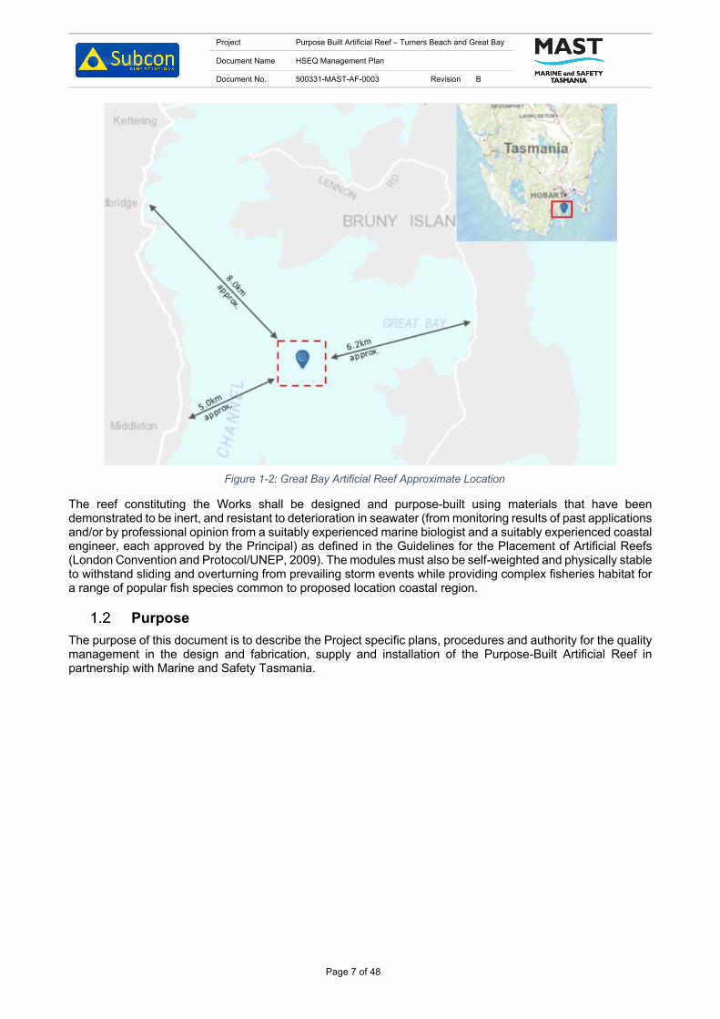
Project Purpose Built Artificial Reef – Turners Beach and Great Bay
Document Name HSEQ Management Plan
Document No. 500331-MAST-AF-0003 Revision B
Page 7 of 48
Figure 1-2: Great Bay Artificial Reef Approximate Location
The reef constituting the Works shall be designed and purpose-built using materials that have been demonstrated to be inert, and resistant to deterioration in seawater (from monitoring results of past applications and/or by professional opinion from a suitably experienced marine biologist and a suitably experienced coastal engineer, each approved by the Principal) as defined in the Guidelines for the Placement of Artificial Reefs (London Convention and Protocol/UNEP, 2009). The modules must also be self-weighted and physically stable to withstand sliding and overturning from prevailing storm events while providing complex fisheries habitat for a range of popular fish species common to proposed location coastal region.
Purpose The purpose of this document is to describe the Project specific plans, procedures and authority for the quality management in the design and fabrication, supply and installation of the Purpose-Built Artificial Reef in partnership with Marine and Safety Tasmania.

Project Purpose Built Artificial Reef – Turners Beach and Great Bay
Document Name HSEQ Management Plan
Document No. 500331-MAST-AF-0003 Revision B
Page 8 of 48
2. REFERENCES & STANDARDS
Standards Ref # Title Doc Number
A1 Submarine Pipeline Systems 2010 DNV OS-F101
A2 On-Bottom Stability Design of Submarine Pipelines DNV RP F109
A3 Modelling and Analysis of Marine Operations DNV RP H103
A4 Environmental Conditions and Environmental Loads DNV-RP-C205
Principal Supplied Documents Ref # Title Doc Number
B1 Environmental Assessment of Artificial Reefs to Enhance Recreational Fisheries in Tasmania
N/A
B2 MAST Artificial Reef Wave Climate Report N/A
B3 Principal Project Requirements N/A
Contractor Reference Documents Ref # Title Doc Number
C1 Project Schedule 500331-MAST-HF-0001
C2 Contractor Document List 500331-MAST-QF-0001
C3 Construction and Management Plan 500331-MAST-AF-0001
C4 Inspection and Test Plan 500331-MAST-AF-0002
C5 MDR Index 500331-MAST-AF-0004
C6 MDR Reef Structures 500331-MAST-AF-0005
C7 Installation Plan 500331-MAST-AF-0006
C8 Transport and Handling Plan 500331-MAST-AF-0007
C9 Handover Management Plan 500331-MAST-AF-0008
C10 Design Report 500331-MAST-RF-0003
Abbreviations & Definitions Abbreviations / Definitions Description
AHD Australian Height Datum
BOD Basis of Design
CAR Corrective Action Report
CDL Contractor Document List
Contractor Subcon Technologies
EPA Environmental Protection Authority
HAZOB Hazard Observation
HIRA Hazard Identification Risk Analysis
HSEQ Health, Safety, Environment, Quality
IFC Issued for Construction
IMS Integrated Management System
ITP Inspection and Test Plan
JHA Job Hazard Analysis

Project Purpose Built Artificial Reef – Turners Beach and Great Bay
Document Name HSEQ Management Plan
Document No. 500331-MAST-AF-0003 Revision B
Page 9 of 48
KPI Key Performance Indicator
MDR Manufacturing Data Record
MOM Minutes of Meeting
NCR Non-Conformance Report
NDT Non-Destructive testing
PDP Project Design Plan
PE Project Engineer
PMMP Project Management and Methodology Plan
Principal Marine and Safety Tasmania
Project All activities pertaining to the Scope of Work as outlined in Contract
QA/QC Quality Assurance/Quality Control
Service Provider Party contracted to Contractor to assist with support activities for the Project
Subcontractor Party contracted to Contractor with active participation and accountability in Project outcomes
SWMS Safe Work Method Statement
TDRQ Technical Deviation Request and Query Form
TQ Technical Query

Project Purpose Built Artificial Reef – Turners Beach and Great Bay
Document Name HSEQ Management Plan
Document No. 500331-MAST-AF-0003 Revision B
Page 10 of 48
3. INTEGRATED MANAGEMENT SYSTEM The Contractor operates and maintains an Integrated Management System (IMS) which meets the requirements of ISO 9001: 2015, 18001:2007 and AS/NZS 4801:2001 compliance with all applicable legal requirements, and with other requirements to which the Contractor subscribes relating to its Health, Safety, Environment, Quality HSEQ aspects. The Health, Safety, Environment and Quality (HSEQ) Manager is responsible for the design, implementation, compliance and periodic review of this system.
The Contractor Integrated Management System (IMS) applies to all company activities including the design, manufacture and installation of marine foundations, stabilisation systems, revetments, reefs, marine concrete repairs and marine infrastructure.
The IMS specifies the requirements by which the Contractor:
1. Demonstrates its ability to consistently provide services that meet customer and applicable regulatory requirements; and
2. Enhances customer satisfaction through the effective application of the IMS, including processes for continual improvement of the IMS and the assurance of conformity to customer and applicable regulatory requirements.
The use of an IMS by the Contractor helps achieve its main goals and objectives in key focus areas such as innovation, organisation, effectiveness and processes.
The development, implementation, and maintenance of the IMS improves the involvement of all the Contractor participants, employees, customers, (internal and external) and stakeholders in the decision-making process and will maximize the effectiveness of processes utilised in providing quality products and services to all participants.
Through the implementation of the IMS policies and procedures, the IMS provides for:
1. Designing and developing processes, products, and services related to the Contractor mission (including critical management and administrative support services);
2. Continually improving and strengthening products and service quality; and 3. Identifying the customers’ stated and implied needs.
The IMS is designed to provide clear organisational guidance. It is incumbent upon the Contractor participants to have an effective working knowledge of and participate in IMS.
The Contractor will manage workplace HSEQ in line with the Integrated Management System, and the Project Works Contract.

Project Purpose Built Artificial Reef – Turners Beach and Great Bay
Document Name HSEQ Management Plan
Document No. 500331-MAST-AF-0003 Revision B
Page 11 of 48
4. POLICIES & OBJECTIVES
Health, Safety, Environment and Quality Policy Statement Subcon is committed to delivering the best possible service to our clients and partners by providing new and innovative technology to the offshore and nearshore environments. Subcon is dedicated to understanding our client’s requirements, and to providing solutions that ensure any required scope is completed in a safe, productive, cost and time efficient manner.
Our services will in all cases consider Health, Safety, Environment and Quality. We work closely with our customers to ensure our products suit our customers’ requirements.
Subcon’s business objectives are to use resources efficiently, minimise waste and the likelihood of accidental discharges of pollutants, maintain a safe, healthy and environmentally friendly working environment in which employees, visitors, subcontractors, suppliers and the general public are not exposed to unreasonable hazards.
Fitness for Work Policy Subcon has a legal responsibility and obligation to provide and maintain a safe and healthy working environment by ensuring that all individuals are fit for work and are not affected by hazards associated with their health and wellbeing. Subcon strives to foster an attitude that it is not acceptable for employees or contractors to work in a condition that will prevent them from performing their duties in a safe manner.
Drug and Alcohol Policy Subcon is committed to providing a safe and healthy workplace to its employees. Subcon expects its employees to perform their work in a productive manner which doesn’t jeopardise their own safety or the safety of others. To reinforce this expectation, Subcon aims to foster a positive attitude among employees that it is unacceptable to come to work under the influence of drugs or alcohol. Subcon personnel will abide by and participate in the prevailing Drug and Alcohol Testing programs as and when requested.
Injury Management Subcon recognises its obligations under the OHS Act (1984) and is committed to preventing workplace injury/illness by taking all reasonable precautions to protect the health, safety and welfare of its employees, clients and visitors whilst they are on Subcon premises or engaged in approved work for Subcon.
Subcon aims to provide a physically safe, healthy and secure environment for all employees, clients and visitors. To achieve this goal, everyone attending a Subcon workplace is required to ensure their actions do not adversely affect the health and safety of others. Subcon is committed to injury management and the rehabilitation of all employees who suffer a work-related injury or illness.
Project Quality Policy and Objectives The Contractor’s success in adhering to its Management Policy depends upon our ability to plan, organise and control our Business Processes. Our Integrated Management System defines these process controls. The Contractor’s objective for the Project is to safely build a sustainable Artificial Reef
To achieve this objective the following Project quality objectives have been established by the Contractor:
1. To successfully deliver the Purpose-Built Artificial Reef on schedule and in accordance with the Principal and the Contractor’s requirements.
2. Fabrication process is clearly documented and consistent with AS/NZ Standards, regulatory and contractual requirements.
3. Provide a safe workplace for personnel; “No Injuries, No Incidents’.

Project Purpose Built Artificial Reef – Turners Beach and Great Bay
Document Name HSEQ Management Plan
Document No. 500331-MAST-AF-0003 Revision B
Page 12 of 48
NO. OBJECTIVE HOW WE ACHIEVE MEASUREMENT
1 To successfully deliver the Purpose-Built Artificial Reef on schedule and in accordance with the Principal’s and the Contractor’s requirements.
Fabrication and Installation Plans Schedule
2 Fabrication process is clearly documented and consistent with AS/NZ Standards, regulatory and contractual requirements.
Inspection and Test Plan (ITP) Inspection Release Certificate
Fabrication and Installation Plans
Fabrication and installation of reefs as per drawings.
As-Built documentation Material certification with fabrication records to provide full traceability of permanent items.
Quality Assurance and Control
Concrete compression tests, material traceability certification, calibration certificates and fabrication check sheet.
3 Provide a safe workplace for personal; “No Injuries, No Incidents”
Construction and Management Plan
Project WHS objectives – Key Performance Indicators (KPI’s), Pre-starts, JSA, HAZOBS

Project Purpose Built Artificial Reef – Turners Beach and Great Bay
Document Name HSEQ Management Plan
Document No. 500331-MAST-AF-0003 Revision B
Page 13 of 48
5. COMPLIANCE WITH REGULATIONS AND STANDARDS Subcon shall, in the execution of PO or subcontract works, be fully responsible for compliance with:
• Relevant local, national and international laws and regulations. • Local, national and international standards or codes of practice, whichever are the most stringent
unless specified otherwise. • Client requirements as contracted, as incorporated in the subcontract or as advised to Subcon by the
Client. Subcon maintains a compliance register to identify its compliance requirements.
Project Purpose Built Artificial Reef – Turners Beach and Great Bay
Document Name HSEQ Management Plan
Document No. 500331-MAST-AF-0003 Revision B
Page 14 of 48
6. WORKPLACE HSE MANAGEMENT
Integrated Management System Subcon operates and maintains an Integrated Management System which meets the requirements of ISO 9001: 2015, 14001:2015, and 45001:2018 compliance with all applicable legal requirements, and with other requirements to which Subcon subscribes relating to its HSEQ aspects. The HSEQ Manager is responsible for the design, implementation, compliance and periodic review of this system.
Subcon Integrated Management System applies to all company activities including the design, manufacture and installation of marine foundations, stabilisation systems, revetments, reefs, marine concrete repairs and marine infrastructure.
The IMS specifies the requirements by which Subcon:
• Demonstrates its ability to consistently provide services that meet customer and applicable regulatory requirements; and
• Enhances customer satisfaction through the effective application of the IMS, including processes for continual improvement of the IMS and the assurance of conformity to customer and applicable regulatory requirements.
The use of an IMS within Subcon helps achieve its main goals and objectives in key focus areas such as innovation, organisation, effectiveness and processes.
The development, implementation, and maintenance of the IMS improves the involvement of all Subcon participants, employees, customers, (internal and external) and stakeholders in the decision-making process and will maximize the effectiveness of processes utilised in providing quality products and services to all participants.
Through the implementation of the IMS policies and procedures, the IMS provides for:
1. Designing and developing processes, products, and services related to the Subcon mission (including critical management and administrative support services);
2. Continually improving and strengthening products and service quality; and 3. Identifying the customers’ stated and implied needs.
The IMS is designed to provide clear organisational guidance. It is incumbent upon Subcon participants to have an effective working knowledge of and participate in IMS.
Subcon will manage workplace HSE in line with the Integrated Management System, and the Project Works Contract.
HSE Site Management Practices Subcon’s HSE site procedures are established to control, mitigate and minimise workplace hazards. Pre-start meetings are used to regularly communicate information and to discuss OHS issues with personnel. JHA’s are used as a safety tool in which the risks or hazards of a specific job are identified and then measures to eliminate or control those hazards are determined and implemented.
Consultation and Communication Subcon is committed to active HSE consultation and communication with all employees, subcontractors, client and other stakeholders. The purpose is to encourage involvement of personnel in all aspects of HSE performance at all levels of the organisation (including Subcontractors) and across all project phases.
Workforce involvement is via the appointed Safety and Health Representative (Project Engineer) and various consultation and communication methods used before and during project activity, inclusive of inductions, meetings, briefings, risk assessments, reviews and other means of sharing information.
Consultation and communication processes cover all project phases (Onshore management and engineering, fabrication, mobilisation and demobilisation).
HSE consultation and communication shall be structured in line with existing Subcon processes and inclusive of (but not limited to):
• Project meetings; • Kick off meetings;

Project Purpose Built Artificial Reef – Turners Beach and Great Bay
Document Name HSEQ Management Plan
Document No. 500331-MAST-AF-0003 Revision B
Page 15 of 48
• HSE, Project & Site-Specific Inductions; • Toolboxes; • Risk Register.
Prestart Meeting A prestart meeting is held every morning to review the daily works, the relevant JHA’s, HAZOBs from the previous day and focus on any key activities or issues being faced by the work crew. All site personnel are to sign onto the pre-start meeting sheet before commencing work. Hard copies of the prestart meeting are saved in the project safety folder. Prestart meetings are removed from the folder, scanned and saved onto the project server monthly.
Stop Work Authority All employees have the authority to stop work when the control of the HSE risk is not clearly established or understood. This instruction is given to all employees during the initial Induction process and reinforced throughout subsequent training and prior to any site mobilisation.
No work will resume until all issues and concerns have been addressed and the employee will not be at risk of any disciplinary action at any time during this process.
Resolution of Issues Where an issue arises, relating to Occupational Health or Safety, Subcon shall attempt to resolve the issue as follows:
1. Employee raises issue with the site health and safety representative (Project Engineer).
2. The Project Engineer (or employee) meets with the Engineering and Operations Manager and the HSEQ manager to try and resolve the issue.
3. The Project Engineer (or employee), the Engineering and Operations Manager and the HSEQ manager agree on resolution of the issue.
4. Yes: Issue resolved; No: Continue.
5. Project Engineer and/or Engineering and Operations Manager consult expert to seek advice on resolution of issue.
6. Project Engineer and Engineering and Operations Manager again discuss resolution of the issue following expert advice and agree on action to be taken.
Training and Competency Subcon’s personnel will have their skills, experience and qualifications assessed and evaluated as required for their respective positions. Employees will receive additional safety training to prepare them for the project specific environment in which they are to work.
The HSEQ Manager maintains a master training matrix for all Subcon employees, the Engineering and Operations Manager will maintain a training register for all personnel working on site.
Induction Prior to commencing fabrication Subcon will ensure that all employees and subcontractors under project control, including subcontractors' and vendors' employees are inducted prior to beginning work on site.
All visitors are required to receive a site-specific induction prior to entering site. This includes but is not limited to Subcon employees, project management employees, and client representatives.
Training Requirements All personnel working on site will be required to have completed a Construction White Card to ensure they are aware and trained in working safely on construction sites.
Any personal working at heights will be required to have a certificate in working at heights.
Personal carrying out high risk work will be required to hold a High-Risk Work (HRW) License for the class of work they will are carrying out. The license will allow them to perform:
1. Rigging work - dogging; basic, intermediate and advanced rigging.

Project Purpose Built Artificial Reef – Turners Beach and Great Bay
Document Name HSEQ Management Plan
Document No. 500331-MAST-AF-0003 Revision B
Page 16 of 48
2. Crane and hoist operation - vehicle loading; non slewing mobile; slewing; vehicle mounted concrete placing boom.
3. Forklift operation - forklift trucks. Subcon maintains a training matrix identifying training requirements of staff. All records are maintained in personnel folders on the company server.
A project specific training matrix for personnel on this project is found in Appendix A.
Managers and Supervisors are responsible for ensuring that personnel under their supervision are competent with regard to their HSE responsibilities and are appropriately qualified and experienced in accordance with the defined position descriptions.
All personnel have a duty of care with respect to their actions and observations at work. All personnel have the authority to stop work they consider unsafe.

Project Purpose Built Artificial Reef – Turners Beach and Great Bay
Document Name HSEQ Management Plan
Document No. 500331-MAST-AF-0003 Revision B
Page 17 of 48
7. DESIGN & CONSTRUCTION INTEGRITY ASSURANCE Subcon shall be responsible for assuring the underlying integrity of any onshore or offshore equipment or systems developed as part of its scope of work, including any associated transport operations.
Integrity will be assured through the effective application of internationally recognised Codes and Standards.
All necessary studies and tests are carried out according to industry best practices such Failure Mode, Effects & Criticality Analysis (FMECA) and fault-tree analysis when relevant.

Project Purpose Built Artificial Reef – Turners Beach and Great Bay
Document Name HSEQ Management Plan
Document No. 500331-MAST-AF-0003 Revision B
Page 18 of 48
8. SUB-CONTRACTOR & SUPPLIER MANAGEMENT All sub-contractors and suppliers engaged by Subcon are assessed by the management to ensure they meet Subcon’s requirements for HSE Management.
HSE requirements and site specific hazards and control methods shall be discussed with all site personnel, including sub-contract personnel through the Induction process and involvement in onsite pre-starts
Management shall make Sub-Contractors aware of Subcon HSE standards and requirements.
Contractors are considered Subcon employees in regard to Duty of Care and are expected to comply with all guidelines and standards and participate in assisting Subcon achieve a safe working environment.
As a minimum sub-contractors and suppliers shall be made aware of the following –
• All major hazards including methods and controls used to reduce the risk to personnel (all procedures and are made available to be viewed).
• The name of the contractor supervisor responsible for onsite activities.
• Contact phone numbers, and after-hour contacts (where relevant) for supervisors and management.
• Requirements for entry to site e.g. if drug and alcohol screens are required.
• Minimum clothing and PPE requirements
• Minimum training standards
Further details of management of contractors and suppliers is documented within the Contractor & Supplier Management Procedure.

Project Purpose Built Artificial Reef – Turners Beach and Great Bay
Document Name HSEQ Management Plan
Document No. 500331-MAST-AF-0003 Revision B
Page 19 of 48
9. OCCUPATIONAL HEALTH & HYGIENE In the interest of maintaining a high standard of hygiene on site, suitable workplace amenities shall be provided to the workforce.
Pre-Employment Medical Pre-employment medicals shall be completed on a needs basis. Records of these medicals and assessments shall be maintained as confidential and filed accordingly. This shall include Drug & Alcohol Testing.
Health Surveillance Health surveillance may be required in the event personnel are considered to be “at risk” as a result of exposure at a workplace to a hazardous substance, health surveillance shall be arranged.
At this point in time, no Subcon employees, contractors or sub-contractors are considered to be “at risk” and therefore there is no routine health surveillance being undertaken. The risk of exposure to harmful substances shall be adequately risk assessed with appropriate control measures introduced as part of the project risk assessment.
Health surveillance records shall be maintained confidentially on the employee’s personal file and they are able to access their results if they wish.
Fitness for Work & Fatigue Management Subcon is committed to ensure the safety and health of all personnel associated with its operations. To achieve this, management ensures that all individuals are "fit for work" whilst on site, refer to the Fitness for Work Policy.
To be "fit for work" means that an individual is in a state (physical, mental and emotional) which enables the individual to perform assigned tasks, competently and in a manner which does not compromise or threaten the safety and health of themselves or others.
It is Subcon’s aim to ensure:
• Employees shall be provided with a safe working environment, which eliminates the risk of injury due to any factors under the control of Subcon Management.
• Assistance shall be provided through a full range of preventative, educational and rehabilitative measures to overcome problems that could impair an employee’s fitness for work, and
• All employees who are deemed unfit for work shall be managed in an effective, fair and constructive manner.
• Subcon recognises that an individual's fitness for work may be affected for a variety of reasons including the adverse effects of fatigue, stress, alcohol or other drugs. These factors can lead to major deficiencies in an individual's work performance and are a contributing factor in industrial incidents.
Project Working Conditions Information that may assist in reducing exposure and risks associated with Fitness for Work issues will be provided during the induction process, and include information on the following:
1. Alcohol and other drugs. 2. Fatigue. 3. Working in Hot Environments. 4. Physical and mental health and fitness.
The project is being carried out in an environment where extreme hot weather may affect personnel.
Work in hot conditions is managed by ensuring personnel have access to appropriate work clothing, provision of drinking water, managing work practices to minimise direct exposure to the sun and programming activities to minimise heat exposure and fatigue.
Project working hours are a maximum of 12 hr shifts in a 6-day working week. Allowing a Sunday rest day. Operations will not involve constant periods of physical activity, with intermittent breaks likely between concrete pours and mould removal, reducing risk of fatigue to workers.

Project Purpose Built Artificial Reef – Turners Beach and Great Bay
Document Name HSEQ Management Plan
Document No. 500331-MAST-AF-0003 Revision B
Page 20 of 48
Smoking Smoking is a health hazard to the smoker and to others in the immediate area.
Smoking is not permitted at any time on Subcon sites or facilities.
Designated or approved smoking areas are to be communicated to all affected employees.
Substance Abuse (Alcohol & controlled drugs) All personnel have the responsibility to be fit and ready to carry out his or her work duties at all times, without risk of their performance being impaired or their competence reduced by substance abuse.
Subcon will not tolerate the use of alcohol or any other prohibited substance on any Subcon worksite. Arriving at any worksite under the influence of alcohol in any amount is strictly prohibited. To maintain a workplace that is free from substance abuse, Subcon will ensure all Subcon and Subcontractor personnel onsite will be subject to a minimum of one drug and alcohol screenings each during the project. Subcon will also have onsite breath testing equipment available.
Abuse of alcohol or other prohibited substances will result in disciplinary action. Subcon management will ensure correct application of this Policy, in accordance with local legislation.
Manual Handling A risk management approach should be used to identify, assess, and control risk associated with Manual Tasking.
Where manual handling tasks are to be carried out, consideration should be given to direct risk factors which include the following:
1. Forceful exertions. 2. Awkward or static postures. 3. Vibration. 4. Repetition. 5. Duration.
The hierarchy of control shall be applied to manual task risks. In order to eliminate or minimise the risk the following should be considered:
6. Redesign the manual task to eliminate, substitute or engineer manual task risk. 7. Where redesign is not practicable, the supervisor shall ensure that workers receive
appropriate training in methods of manual lifting appropriate for that manual task.
Injury Management and Rehabilitation The aim of the injury management system is to ensure that the injured employee returns to pre-disability duties as soon as reasonably practical.
When information that a worker has a First Medical Certificate for a work related injury is received or the worker requests, Subcon shall provide the worker with a workers’ compensation claim form.
When a completed workers’ compensation claim form and the First Medical Certificate are received from the injured worker, Subcon shall send the documents to the insurer within three working days.
Subcon management shall maintain close contact with the injured worker to check on progress and make arrangements for the worker to remain at work or return to work as soon as medically appropriate.
One of the most important functions for the Subcon HSE Management System, after a worker has been injured, is the process of rehabilitation and the return of the worker to pre-disability duties. “Vocational Rehabilitation” is about managing the safe and early return of injured workers to suitable work.
Return to Work Programs A Return-to-Work Program is a formal program developed as part of an injury management system and may be required for an injured worker to assist them to remain at work or return to appropriate duties.
The Return-to-Work Program shall document the activities to be undertaken, any work restrictions and the training for a graduated return to work in line with the employee’s capabilities and medical evidence. A formal

Project Purpose Built Artificial Reef – Turners Beach and Great Bay
Document Name HSEQ Management Plan
Document No. 500331-MAST-AF-0003 Revision B
Page 21 of 48
Return-to-Work Program must be reviewed and signed by all relevant parties, including the injured employee.
Refer to Return-to-Work Program for guidance on developing a Return-to-Work Program.
Infectious Disease Management / Business Continuity Subcon shall implement measures to help protect and support its workforce from the health risks associated with infectious diseases.
Subcon’s offices, work sites and transport providers have a system in place to prevent the spread of infectious diseases that includes:
• Risk assessments and suitable controls in place that comply with government regulations and the World Health Organisation.
• Personnel who are unwell or have symptoms are not permitted to access Subcon’s office(s) or worksite(s).
• Fully implemented cleaning and hygiene regime. • Suitable arrangements in place to ensure compliance with social distancing. • Notification and reporting process for suspected or confirmed cases. • Testing arrangements are in place to confirm a suspected case. Any suspected or confirmed cases of an infectious disease (i.e. COVID19) occurring at a Subcon office or work site shall be reported to the client immediately.
Should a suspected case of COVID 19 become present (prior to a positive test result), all current local and federal government recommendations and advice will be followed. Subcon have contingency personnel that can be mobilised should the need arise.

Project Purpose Built Artificial Reef – Turners Beach and Great Bay
Document Name HSEQ Management Plan
Document No. 500331-MAST-AF-0003 Revision B
Page 22 of 48
10. RISK EVALUATION & MANAGEMENT Subcon takes a proactive approach to identify and assess potential hazards and control risks relating to the project. Subcon’s HSE site procedures are established to control, mitigate and minimise workplace hazards. Pre-start meetings are used to regularly communicate information and to discuss HSE issues with personnel.
Hazard Management A hazard is any actual or potential cause of harm. Where possible, elimination of hazards is the priority. Where elimination is not reasonably practicable, the risk will be controlled in accordance with the remaining levels of the hierarchy of hazard controls. In some cases, a combination of two or more controls may be implemented to reduce risks to an acceptable level.
Subcon will conduct a project specific HAZID prior to the commencement of fabrication activities on the project to ensure all project hazards are identified.
Subcon maintains a Risk Register that records all identified company risks and their applied controls. Any newly identified hazards or risks are included. This register is reviewed on a regular basis by management to ensure controls applied adequately ensure mitigated risk levels.
The top 5 risks identified shall be reported on weekly as to their mitigation strategies.
All employees and subcontractors are responsible for promptly reporting any hazards that they identify on the site to their immediate supervisor or the Site Manager.
Risk Assessment The Company will conduct a Risk Assessment for works on all sites to identify the hazards, assess the risks and nominate controls to reduce the risk of all identified hazards to as low as reasonably practicable. All control methods from the Risk Assessment shall be captured within project HAZID and JHA and made available to all project personnel to assist in safe execution of work.
HAZID Hazard & Risk Assessment Workshops are held prior to mobilization. The workshop (or future workshops) may also include representatives from the client, stakeholders and / or from key subcontractors.
The outcomes of the Construction Risk Assessment Workshop and the Risk Register are to be used to:
• Program works (e.g. plant, personnel, permits, and temporary works). • Identify Site Specific procedures/interface plans/emergency plans. • Develop or revise Construction Execution Procedures. • Consider site specific Safe/Standard Work Instructions or Environmental Protection Instructions &
any necessary changes. • Develop Site HSE Rules in alignment with and in addition to the ‘Golden Rules’. • Develop or modify the Site Induction Presentation.
Job Hazard Analyses (JHA’s) Job Hazard Analyses (JHA’s) are used to outline all hazards associated with the work and detail the required steps to mitigate these risks. JHA’s for standard High-Risk Construction Work are reviewed and signed at the start of the project or if there are any changes.
This JHA shall also identify hazardous items of plant and equipment utilized on the Project.
Where hazards are identified, suitable controls are selected and implemented in accordance with the hierarchy of controls by the HSEQ Manager and Project Engineer in consultation with project personnel.
HAZOB Hazard Observations cards (HAZOB’s) are used to assist in maintaining awareness of the working environment at all times and aid in the identification and control of immediate hazards in the day-to-day work. HAZOB’s can be raised by anyone observing a situation, actions or procedure which could have either a positive or negative impact to personnel, equipment or the environment.

Project Purpose Built Artificial Reef – Turners Beach and Great Bay
Document Name HSEQ Management Plan
Document No. 500331-MAST-AF-0003 Revision B
Page 23 of 48
HAZOB’s are to be submitted by the end of shift and are reviewed during the following days prestart. HAZOB’s that cannot be closed out immediately will be escalated to the Project Engineer for close out action.
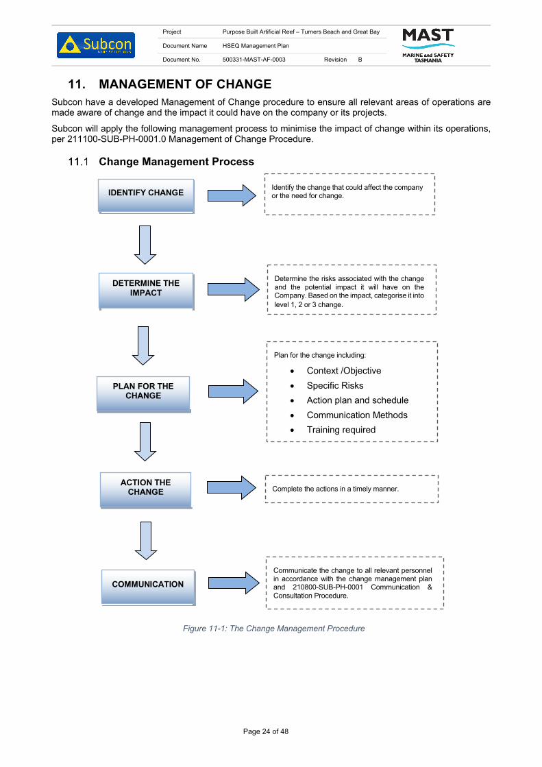
Project Purpose Built Artificial Reef – Turners Beach and Great Bay
Document Name HSEQ Management Plan
Document No. 500331-MAST-AF-0003 Revision B
Page 24 of 48
11. MANAGEMENT OF CHANGE Subcon have a developed Management of Change procedure to ensure all relevant areas of operations are made aware of change and the impact it could have on the company or its projects.
Subcon will apply the following management process to minimise the impact of change within its operations, per 211100-SUB-PH-0001.0 Management of Change Procedure.
Change Management Process
Identify the change that could affect the company or the need for change. IDENTIFY CHANGE
DETERMINE THE IMPACT
PLAN FOR THE CHANGE
ACTION THE CHANGE
COMMUNICATION
Determine the risks associated with the change and the potential impact it will have on the Company. Based on the impact, categorise it into level 1, 2 or 3 change.
Plan for the change including:
• Context /Objective • Specific Risks • Action plan and schedule • Communication Methods • Training required • Evaluation and monitoring
methods
Complete the actions in a timely manner.
Communicate the change to all relevant personnel in accordance with the change management plan and 210800-SUB-PH-0001 Communication & Consultation Procedure.
Figure 11-1: The Change Management Procedure
Project Purpose Built Artificial Reef – Turners Beach and Great Bay
Document Name HSEQ Management Plan
Document No. 500331-MAST-AF-0003 Revision B
Page 25 of 48
12. SITE AND PUBLIC SECURITY The Project Engineer and/or HSEQ Manager are to monitor and control, wherever practicable, the access of all persons to the site. No persons, unrelated to the contract, are to enter the site without the express permission of the Project Engineer.
All persons that enter site are to comply with the site-specific PPE standards at all times and are to attend a safety induction, so they are made aware of all hazards and the controls relevant to the site.

Project Purpose Built Artificial Reef – Turners Beach and Great Bay
Document Name HSEQ Management Plan
Document No. 500331-MAST-AF-0003 Revision B
Page 26 of 48
13. PROJECT ORGANISATION & RESPONSIBILITIES
Quality Management Team Table 13-1 below shows the quality management team for the Project. Specific roles and responsibilities throughout the Project are detailed in this section.
Table 13-1: Quality Management Team
Position Name Engineering and Operations Manager Jack Francis Project Engineer James Davies HSEQ Manager Kim Gleeson
Engineering and Operations Manager The Engineering and Operations Manager is ultimately responsible for the final design of the Project. They are responsible for the management of design, fabrication and installation activities as well as reporting to the Principal.
The Engineering and Operations Manager is responsible for:
1. Delivery of Principal Project Management plans. 2. Reporting Project plans, processes and operations. 3. Preparation of Principal reports. 4. Ensuring compliance with engineering standards and industry best practice. 5. Direct, review and approval product design changes. 6. Ensuring compliance with the Principal’s safe operating procedures and standards. 7. Developing and implementing policies, standards and procedures for the engineering and
technical work performed on the Project. 8. Coordinating manning requirements throughout the Project. 9. Ensuring all personal are inducted on to site. 10. Overseeing overall financial management, planning, systems and controls. 11. Coordinating with the HSEQ Manager to ensure that the products conform to an acceptable
standard. 12. Liaising with the Contractor employees regarding matters concerning the safety or health of
persons in the workplace. 13. Meeting Project WHS objectives by providing leadership, management and accountability to
the team. 14. Ensuring the Contractor participation in the Project risk assessment, evaluation and
development of effective controls and mitigation of escalation. 15. Approving Project risk assessment and mitigation plans. 16. Reporting all incidents and other WHS related matters to the Contractor HSEQ Manager. 17. Presenting and explaining proposals, reports and Project findings to the Principal to promote
personnel WHS awareness. 18. Ensuring implementation of the WHS plan at site. 19. Ensuring participation of personnel in WHS related activities. 20. Promoting WHS initiatives. 21. Leader of the Emergency Response Team.
Project Purpose Built Artificial Reef – Turners Beach and Great Bay
Document Name HSEQ Management Plan
Document No. 500331-MAST-AF-0003 Revision B
Page 27 of 48
Project Engineer The Project Engineer is responsible for coordinating the engineering design works and supervising the onsite fabrication and installation activities throughout the Project.
The Project Engineer is responsible for:
22. Coordinating Project design between design Subcontractors to ensure the stability and structural designs are fully integrated.
23. Delivery of technical Project documentation. 24. Consulting and cooperating with the HSEQ Manager on all matters relating to the safety or
health of persons in the workplace. 25. Performing the functions of a Safety & Health Representative as defined under Section 33 of
the Act. 26. Calling and updating Project Manager during site activities daily. 27. Developing Project objectives by reviewing Project proposals and plans; conferring with
management. 28. Determining Project responsibilities by identifying Project phases and elements; assigning
personnel to phases and elements; reviewing bids from Subcontractors. 29. Determining Project specifications by studying product design, customer requirements, and
performance standards, completing technical studies and preparing cost estimates. 30. Confirming product performance by designing and conducting tests. 31. Determining Project schedule by studying Project plans and specifications, calculating time
requirements and sequencing Project elements. 32. Maintaining Project schedule by monitoring Project progress, coordinating activities and
resolving problems. 33. Controlling Project plans by reviewing design, specifications, and plan and schedule changes
and recommending actions.
HSEQ Manager The HSEQ Manager is responsible for coordinating the day-to-day WHS activities of the Project. The HSEQ Manager reports to the Project Manager, they are responsible for:
34. Meeting Project WHS objectives – KPI’s. 35. Communicating of WHS information. 36. Ensuring internal audits are carried out in accordance with the audit schedule. 37. Providing WHS reports, changes to legislation and brief personnel on Safety Flashes/Alerts. 38. Delivery of Project QHSE documentation. 39. Record keeping of QHSE statistic during onsite activities.
All Personnel Are required to:
40. Observe and work to all site safety standards and rules. 41. Comply with company and Project specific procedures. 42. Visibly support a positive safe work culture. 43. Meeting the Project WHS objectives. 44. Wear appropriate PPE for task being performed. 45. Report all hazards and risks as required. 46. Attend all work-related training required. 47. Comply with the Facility Permit to Work system. 48. Report all potential hazards, Near Misses and Incidents. 49. Understand the risks and controls associated with a job before starting work.

Project Purpose Built Artificial Reef – Turners Beach and Great Bay
Document Name HSEQ Management Plan
Document No. 500331-MAST-AF-0003 Revision B
Page 28 of 48
50. Not use equipment that is unsafe or functioning incorrectly and report it to their supervisor or onsite WHS representative.
51. Take time out for safety. 52. Stop work they believe to be unsafe. 53. Understand and follow the Contractor and the Principal requirements. 54. Visibly support a positive safe work culture.

Project Purpose Built Artificial Reef – Turners Beach and Great Bay
Document Name HSEQ Management Plan
Document No. 500331-MAST-AF-0003 Revision B
Page 29 of 48
14. PROJECT MANAGEMENT
Project Management The Project's design and engineering responsibilities include design methodology, testing and associated certification are defined in the Project Design Plan.
The PE and draftsmen are responsible for complying with the engineering process as described in the Project Management and Methodology Plan.
Engineering requests to Subcontractors are initiated with a Basis of Design (BOD). The completed BOD should include sufficient information on references, contract and general requirements for the Subcontractor to produce the deliverable items.
The documentation the Project team are responsible for, is detailed in the Contractor Document List (CDL) along with the proposed first issue date. All design documents are subject to peer review by key parties prior to final approval being given by the Project Manager. The intention of review is to provide verification and validation of output conformity to input requirements.
Technical Deviation Request and Query Form (TDRQ) A Technical Query is the formal process for asking a clarification or question from the concerned departments involved in the execution of the Project. A Technical Query (TQ) can be raised between the Principal & the Contractor, between site operations of the Contractor and engineering team of the Contractor. The Contractor is to fill in a TDRQ and submit to the Superintendent’s Representative where there is proposed technical deviation or wishes to confirm technical requirements of the Project. The Contractor is to also maintain a TQ register to record, track and close out the status of all TQ.
Safety in Design and Risk Management Safety in design is a key consideration throughout the design process. The Contractor held a safety in design workshop with the Principal on 03/03/2020. The purpose of this workshop was to outline all risks associated with the design phase of the Project, and what controls were in place to mitigate these risks. A risk register has been created as a part of this workshop and has been updated throughout the design phase as new risks are identified. This risk register can be found in Appendix H: Safety in Design Risk Register. Upon finalisation of the fabrication and installation procedures, a HAZID workshop is to be held. This workshop will involve a review of the entire fabrication and installation process from a safety perspective. The outcomes of this workshop will be used to update the JHAs and Construction Management Plan submitted as a part of the Project.
On 08/05/2020 the Contractor held a meeting with the Dive Industry Group to review the current design. The feedback provided by the Dive Industry Group has been incorporated into the design and used to update the Diver Safety Plan. The review of the Diver Safety Plan may also require changes to the Purpose-Built Artificial Reef design to ensure diver safety.
The Diver Safety Plan outlines all considerations for the foreseeable risks to diver safety in accordance with Section 2.9.3 from Part B of the Principal’s Project Requirements.
Risk throughout the Project will be managed via the Contractors Risk Management Plan.
Project Purpose Built Artificial Reef – Turners Beach and Great Bay
Document Name HSEQ Management Plan
Document No. 500331-MAST-AF-0003 Revision B
Page 30 of 48
Auditing Internal quality audits are scheduled based on the status and importance of the activity to be audited. The HSEQ Manager is responsible for scheduling the audits and is responsible for actioning any observations or non-conformances should they arise. The Project audit schedule details the nature, objectives, timing and duration of the fabrication process.
Table 14-1: Auditing overview
NO. SECTION AUDIT MEASUREMENT
1 Quality system 1. Quality control plan/manual 2. Documented procedures 3. Personnel
2 Production practices
1. Storage of chemicals, hardware and equipment 2. Casting areas 3. Curing and finishing areas 4. Moist curing 5. Finished product storage 6. Forms/shells 7. Product identification 8. Surface finishes
3 Mooring Components 1. Mill test certificates 2. Material data sheets
4 Concrete
1. Proportioning 2. Batching 3. Mixing 4. Consolidation equipment 5. Curing concrete 6. Slump Testing 7. Compressive Strength Testing 8. Weld procedures 9. Welder qualifications 10. NDT procedures 11. NDT qualifications 12. Metrology / Dimensional Control
5 Steel/ Fabrication
1. Mill test certificates 2. Material data sheets 3. Weld procedures 4. Welder qualifications 5. NDT procedures 6. NDT qualifications 7. Metrology / Dimensional Control
6 Anodes 1. Chemical Composition 7 Installation 1. As-Built Installation Locations
8 Quality control 1. Inspection 2. Traceability 3. Testing and records
External Audits are to be controlled and arranged by the Superintendent’s Representative using the Principal’s procedures.
Lessons Learnt The Contractor will undertake a Lessons Learnt review at the end of Project completion. The review captures lessons learned and will include the following specific activities:
1. Capture lessons learned throughout the campaign. 2. To perform a structured review of lessons learned. 3. To provide support to ensure team members understand their roles and responsibilities. 4. To discuss potential improvements and follow up actions.

Project Purpose Built Artificial Reef – Turners Beach and Great Bay
Document Name HSEQ Management Plan
Document No. 500331-MAST-AF-0003 Revision B
Page 31 of 48
5. Integrate the lessons into the Integrated Management System.
Monitoring and Measurement Monitoring and measuring will occur through a series of planned meetings, audits, and reports. The Project Manager, PE and HSEQ Manager have weekly meetings to discuss the Project. The minutes generated from these forums is recorded and actioned by the PE. Actions requiring immediate attention will be expedited by the Project Manager or the nominated delegate until such time that the actions are satisfactorily resolved and closed out. A monthly report on Project progress is tabled and distributed to the Principal.
Document Control Document control shall be in accordance with the Contractor’s Document Control Procedure. The Document Control process is administered by the PE and is to include:
1. Communications: e-mail addresses and point of contacts. 2. The Principal’s distribution list. 3. The Contractor’s Distribution list. 4. Superseded Documents - Watermarked and placed into the superseded the Principal’s Project
folder. 5. CDL – Transmittals are recorded, and corresponding documentation is updated and
distributed to the Project Manager and HSEQ Manager. 6. Weekly Teleconference timing, MOM, attendees. 7. Issuing TQ’s. 8. Correspondence register.
Cost & Schedule Control Project costs and schedule are the responsibility of the Project Manager. Costs are tracked through the Contractor’s internal Procurement Process. The schedule is managed through the Project specific schedule and the Contractor Document List.
Training and Certification The Contractor shall provide documentation to ensure that personal are qualified, trained and experienced to undertake the tasks assigned to them. The Contractor is to identify and provide a concrete tester who is NATA accredited and certified to undertake the work; accreditation and certification is to be checked, approved and recorded by the Contractor and provided in the As-Built documentation. The Project personnel (both staff and Subcontractors) qualifications and certificates are recorded on the Contractor’s Internal Training Matrix and are updated by the HSEQ Manager. Certificates of competency are to be obtained of personal who will be engaged in high risk work.
Project personnel are to undertake site specific inductions and are to be signed-off. The Contractor staff and Subcontractor staff are expected to participate in Pre-starts, JHA’s and HAZOB’s in accordance with the WHS Plan, Quality Management, Fabrication and Installation Plans.
Control of Records Records will be controlled in accordance with the Records & Archiving Procedure. A Project folder containing The Contractor’s standard file structure, will be established for filing of all Project related records. The As-Built documentation is to be established with documents as per the Principal’s requirements.
Process Control Quality in the office, such as: Inspections, testing, standards, measurements & monitoring and corrective action is the responsibility of the HSEQ Manager. Quality on site will be managed by the Contractor’s Project Manager and PE for the duration of the Project. Site audits will be conducted as per the audit schedule, to ensure QA/QC during the design, fabrication and install process. The site audit involves auditing of materials, fabrication and As-Built documentation processes.
The ITPs, Fabrication Check Sheet and Construction Management Plan state the QA activities to be conducted.

Project Purpose Built Artificial Reef – Turners Beach and Great Bay
Document Name HSEQ Management Plan
Document No. 500331-MAST-AF-0003 Revision B
Page 32 of 48
The fabrication check sheet provides evidentiary information on individual Reef Foundations and Reef Flutes including casting dates, ID numbers, batch certificate numbers, material certificates, weights and dimensions.
The PE is to compile all information such as Fabrication Check-sheet, Batching Certificates, ITP and associated evidentiary documents pertaining to the As-Built documentation.

Project Purpose Built Artificial Reef – Turners Beach and Great Bay
Document Name HSEQ Management Plan
Document No. 500331-MAST-AF-0003 Revision B
Page 33 of 48
15. PROCUREMENT & LOGISTICS
General The Project Manager and the PE are responsible for ensuring Project procurement and logistical needs are identified and implemented. Procurement of materials for the work, material receipt and fabrication activities will be managed in accordance with the Project Procedures.
Vendor List Commercial, technical, financial and HSEQ capabilities of vendors have been evaluated through the Contractor’s Suppler Evaluation Questionnaire in order to measure and monitor their performance for the purposes of reducing costs, mitigating risk and driving continuous improvement. The PE is responsible for the vendor approval and vetting process. The PE is to prepare, submit and update the vendor list as required. The Contractor requires all vendors to provide test, manufacturing and inspection reports / certifications / qualifications / design documentation of their products or services.
Shipping of Materials The Superintendent’s Representative is to undertake a final inspection and release of all the Reef Flutes and Reef Foundations before installation. ITP documents are to be completed in full, cited and signed off prior to installation. The Contractor equipment is to be maintained and transported in accordance with the Project Plans.
Materials Materials Origination
The Contractor shall ensure that material certification documentation is provided for all aspects of the work. The Contractor is to provide material tractability records and notations confirming the installation of equipment and materials at the point of installation.
Materials Audit The PE is to collate manufactures certification documents to ensure products comply with the ITP and engineering provisions.

Project Purpose Built Artificial Reef – Turners Beach and Great Bay
Document Name HSEQ Management Plan
Document No. 500331-MAST-AF-0003 Revision B
Page 34 of 48
16. FABRICATION & INSTALLATION
Design Life Major elements installed of the Purpose-Built Artificial Reef have a design life of 30-years. These items include:
1. Reef Flutes. 2. Reef Tethers. 3. Reef Foundations. 4. Outer Dive Mooring clump weights. 5. Navigation Aid clump weights.
Other items will require periodic maintenance or replacement including:
6. Navigation Aid and Outer Dive Mooring chains, shackles and sub-surface buoys. 7. Navigation Aid, Outer Dive Mooring and Reef Flute Dive Mooring surface buoys. 8. Reef Flute Dive Mooring chains, ropes, shackles and sub-surface buoys. 9. Dive Mooring vessel connection ropes and pickup buoys. 10. It is expected that these items will require replacement every five years. However, the actual
frequency of maintenance and replacement will depend of the component wear rates observed during regular inspections as described in the Operations and Maintenance Manual in the Handover Management Plan.
Storage and Preservation Once fabrication of the Reef Flutes and Reef Foundations is complete, the PE will ensure the units are inspected, stored and the area is to be cordoned off. Each Reef Foundation will be left to cure until the characteristic strength required for installation is achieved. All modules are to be stored in a secure gated facility from the time fabrication is complete until installation.
Marking Each Reef Foundation and Reef Flute shall be marked with its own unique identifying number that matches the Fabrication Check Sheet.
Traceability The PE will collate all document records, their distribution, review and filing for the As-Built documentation. The PE is to sign-off on the ITPs when an action is completed; ITP sign off indicates that the action/task has been performed and documented to the satisfaction of all the relevant parties.
The PE will collate and sign-off the following in the ITPs when completed:
• Concrete module fabrication. • Steel module fabrication. • Installation.
The PE is also responsible for ensuring all material certificates are compliant with the Project requirements as per the design drawings and ITPs. The PE is responsible for compiling all of these records into the As-Built documentation.
Inspection and Test Plans Inspection and Test Plans are to be used during the Project execution phase to ensure all fabrication and installation activities are completed as per the approved documentation.
Three ITPs have been developed for the Project. These plans relate to the fabrication of the Reef Flutes, fabrication of the Reef Foundations and installation of all elements of the Purpose-Built Artificial Reef. Each ITP details:
1. All quality verification check points relating to the Project task. 2. Acceptance criteria for each verification check point.

Project Purpose Built Artificial Reef – Turners Beach and Great Bay
Document Name HSEQ Management Plan
Document No. 500331-MAST-AF-0003 Revision B
Page 35 of 48
3. Relevant reference for each verification check point. 4. Sign-off points for the Contractor and Superintendent’s Representative.
Inspection and Release Before the Reef Foundations and Reef Flutes are can be released from the fabrication site for installation, the fabrication ITPs and an inspection and release form are to be signed off by the PE and the Superintendent’s Representative. Records of these signed documents are to be kept and compiled into the final As-Built documentation.

Project Purpose Built Artificial Reef – Turners Beach and Great Bay
Document Name HSEQ Management Plan
Document No. 500331-MAST-AF-0003 Revision B
Page 36 of 48
17. LIFTING & RIGGING
Design and Validation The design validation assures the integrity of the equipment for the stated design and operating conditions. Validation of the equipment’s process and design is to be produced and the following specifications, certificates, records are to be made available as appendices in the As-Built documentation:
• Load test certificates. • Proof load. • Lifting certification. • Material Test certification.
Lift Frames/Hydraulic Release Mechanism Lift Frames and hydraulic release mechanisms for the handling of the Artificial Reefs are designed and supplied by the Contractor. All certifications are made available in the As-Built documentation.
Rigging Load Test The sling sets with associated rigging shall be mobilised with valid Visual Inspection and Load Test certification, as per the testing frequency indicated in Table 17-1 and Table 17-2 below. Testing and inspection shall have been carried out by an approved authority. Testing certification is to be provided in the As-Built documentation for permanent materials.
Inspection Lifting equipment inspection durations for offshore lifts are detailed in Table 17-1 and Table 17-2 below: All lifting equipment is designed and certified in accordance with Australian Standards.
Table 17-1: Lifting Inspection Certification Requirements for Lift Frames
Inspection Frequency (Years) Visual inspection Before each use (start of shift) Certification – Visual Within 12 months of last date Certification – Load Test Every 5 Years
Table 17-2: Lifting Inspection Certification Requirements for Rigging
Inspection Frequency (Years) Visual inspection Before each use (start of shift) Certification – Visual Within 12 months of last date

Project Purpose Built Artificial Reef – Turners Beach and Great Bay
Document Name HSEQ Management Plan
Document No. 500331-MAST-AF-0003 Revision B
Page 37 of 48
18. HAZARDOUS WORKS
Working at Heights Subcon aims to prevent all falls which may result in injury. Work undertaken at heights is strictly compliant to the Western Australian Code of Practice: Prevention of Falls at Workplaces, 2004. Subcon personnel who undertake work at heights are to hold a current Work Safety at Heights Certificate and shall abide with Subcon requirements to Work at Height.
Working at Height equipment is to be correct harness/arrest system for the work being undertaken and certified and inspected prior to each use. A Working at Height Permit is to be signed off by all persons involved in any Working at Height on site.
Lifting Operations Lifting operations will be conducted in accordance with developed lifting plans. The plans shall outline roles and responsibilities of the team responsible for the lifting, management and rules of lifting operations, competency and training requirements for personnel, and any rules for using lifting equipment.
Lifts shall not occur without a Lift Plan having been completed.
Vehicle, Mobile Plant and Equipment Use Strict guidelines on vehicle, plant and equipment selection, use, inspection, maintenance, operator certification and equipment operations have been implemented. These requirements include:
• The qualifications of all plant operators (including forklift operators) and driver’s license holders will be reviewed and documented.
• All vehicle, plant and equipment data will be kept on an asset register, inclusive of maintenance and inspection schedules.
• Pre-start checks are required for all vehicles and plant and equipment, as required (e.g. light vehicles must be inspected prior to regional travel). All items identified for repair, replacement, etc. during inspections must be recorded and actioned as deemed appropriate by the operator, maintenance staff and supervisor.
• Site- / client-specific weed and dirt management protocols will be stringently followed to prevent the spread of weeds, disease, etc. where applicable.
• Subcon managed work areas shall be controlled (i.e.: traffic management), as required.
Traffic Management The project will be completed in a gated facility with no access to the general public. There will also be no other operations occurring in the Subcon facility during Subcon’s fabrication project. Error! Reference source not found. presents the proposed site establishment plan. This plan may be alternated once a final site inspection has been completed during mobilisation.
Confined Space Subcon have reviewed work activities for the project and no confined space works have been identified.
Work on Live System Subcon shall ensure that during maintenance and repair work on equipment connected to or containing mechanical, electrical or other energy, the operator has a Lockout and Tag out (LOTO) procedure that defines the requirements to ensure a safe system of work (SSOW) is in place. The purpose of this SSOW is to protect against accidental injury to personnel and damage to company property that could occur if the equipment accidentally becomes energized during such work.
Hazardous Substances Subcon’s handling, use and storage of hazardous substances is in accordance with the model Work Health and Safety Regulations, Code of Practice Labelling of Workplace Hazardous Chemicals and Global Harmonised System of Classification and Labelling of Chemicals. Safety Data Sheets are provided for all

Project Purpose Built Artificial Reef – Turners Beach and Great Bay
Document Name HSEQ Management Plan
Document No. 500331-MAST-AF-0003 Revision B
Page 38 of 48
chemicals or hazardous substances associated with the Project. The HSEQ Manager shall ensure there is suitable and sufficient assessment of any work including potential exposure to any hazardous substances.
Wherever practicable, hazardous substances shall be eliminated. Where it is not practical, substitution for a less hazardous substance will be considered.

Project Purpose Built Artificial Reef – Turners Beach and Great Bay
Document Name HSEQ Management Plan
Document No. 500331-MAST-AF-0003 Revision B
Page 39 of 48
19. EMERGENCY RESPONSE An Emergency Response Plan (ERP) 01-2101-SUB-AH-0001 and emergency maps are developed for the project, aligned with the Client’s processes and be located appropriately for easy access by employees in the event of an emergency.
Emergency numbers will be posted at all amenities and office areas and all worker(s) will be familiar with emergency services contact numbers and reinforced at induction. This shall include details of the location and contact number of the closest hospital to the fabrication site.
Emergency maps include the location of:
� Exit and assembly points.
� Muster points.
� First aid boxes and first aid rooms.
� Fire equipment.
� Instruction for evacuation.
Subcon will have First Aiders as part of the site team. Additional controls and mitigations will be in place in accordance with the HAZID and JHA including but not limited to:
• SDS in the workshop container.
• First Aid Kit in workshop container.
• Eye Wash Station in workshop container.
• Activity Specific PPE, such as safety glasses, ear plugs, dust masks, hard hats and gloves.
• Potable Water for Hydration.
• Daily inspection to include clearing of food waste from the site into municipal bins.

Project Purpose Built Artificial Reef – Turners Beach and Great Bay
Document Name HSEQ Management Plan
Document No. 500331-MAST-AF-0003 Revision B
Page 40 of 48
20. INCIDENT NOTIFICATION & REPORTING REQUIREMENTS
Regulatory Reporting All work-related injuries and diseases involving the death of a person, a serious injury or illness of a person, or a notifiable incident must be reported onsite to Subcon and the Client. Subcon’s HSEQ Manager will inform Work Safe of any notifiable incidents.
The kinds of injury incurred by an employee, requiring notification by an employer to the Commissioner are:
• A fracture of the skull, spine or pelvis. • A fracture of any bone –
- In the arm, other than in the wrists or hand. - In the leg, other than a bone in the ankle or foot.
• An amputation of an arm, a hand, finger, finger joint, leg, foot, toe or toe joint. • The loss of sight of an eye. • Any injury other than an injury of a kind referred to in bullets above which, in the opinion of a medical
practitioner, is likely to prevent the employee from being able to work within 10 days of the day on which the injury occurred.
Project Incident Notification Requirements In general, all employees are responsible for:
• Notification and reporting of incidents, hazard observations and near misses to their immediate supervisor in a timely manner.
• Participating in an incident investigation team as required. • Closing out any delegated items in line with due dates.
Incidents shall be reported and notified using the following Subcon reporting systems:
• The Engineering and Operations Manager will ensure the required Initial Incident Notification is given for all incidents, near misses and medical evacuations and distributed as soon as practicable, but within 2 hours of occurrence. This provides basic incident details.
• All initial incident reports shall be sent to the Subcon Engineering and Operations Manager & HSEQ Manager and the client representative within 24 hours.
• All statutory notification to regulatory authorities will be in accordance with required formats described above.
• The Incident Report Form (with all details) is to be fully completed and submitted internally within 48 hours.
• Preliminary incident report will be available to the client within 24 hours. • The Final Incident report, outlining root cause and corrective actions applied shall be submitted
within 14 days of the incident.

Project Purpose Built Artificial Reef – Turners Beach and Great Bay
Document Name HSEQ Management Plan
Document No. 500331-MAST-AF-0003 Revision B
Page 41 of 48
21. NON-CONFORMANCES & CORRECTIVE ACTIONS
Objective 1. To have all identified non-conformances recorded. 2. To have resolved the identified non-conformances adequately and timely to the satisfaction of
the Principal. 3. To prevent re-occurrence of non-conformances.
Responsibilities Any of the Contractor’s employee or Superintendent’s Representatives can notify the Contractor QHSE Manager of non-conforming items for the QHSE Manager to raise a Corrective Action. The status of the individual NCR’s is controlled by the action owners (Nonconforming Party, Affected Party) as defined in the NCR. The HSEQ Manager ensures that NCR’s are expedited and closed-out, this includes reporting NCR status to the Project Manager and the Principal.
The HSEQ Manager maintains an overall Corrective Actions Register and is responsible for promoting Continuous Improvement.
Process NCR’s raised are to be submitted to the Contractor HSEQ Manager for assessment. The HSEQ Manager will determine by review, inspection and test or evidence the appropriate Corrective Action to ensure NCR’s are addressed, closed-out and placed on the NCR Register.
Upon detection of any product or process that does not meet the Project requirements (specified by the Principal, regulations, ITP, or otherwise) the problem is immediately reported to the HSEQ Manager. The HSEQ Manager in conjunction with the PE is to:
1. Mark or tag the nonconforming product to identify its status. 2. Perform an evaluation to determine the extent of the non-conformance and possible
investigation to determine the root cause in order to take the necessary action. The planned investigation will include:
a. Correction - action to ensure a detected non-conforming product is eliminated. b. Amend - a non-conforming product is to be repaired or changed to result in a conforming
product. c. Use in its current form - permission to use the product in its current state. d. Reject - action on a non-conforming product to preclude it from use.
Reporting of Non-Conforming Product Where applicable, the Contractor will report any non-conforming product information to the Superintendent’s Representative prior to any planed corrective action. Rectification of the product will be jointly verified to ensure the effectiveness of the product.
Reporting of a non-conforming product is to occur, but is not limited to, the following circumstances: • Non-conformity that delays completion or delivery of a product. • Non-conformity that does not meet drawing, design or engineering specifications. • Non-conformity between a material and the material specification.
Concession The Contractor is to obtain a concession from the Principal if authorising the use of a product that does not conform to the Project requirements specified, but will comply with limits imposed by a relevant authority and/ or the Superintendent’s Representative.
Records Records of training, licenses, permits, qualification and certifications required for the performance of work are readily available where work is being performed. Quality records are maintained and are to be submitted in

Project Purpose Built Artificial Reef – Turners Beach and Great Bay
Document Name HSEQ Management Plan
Document No. 500331-MAST-AF-0003 Revision B
Page 42 of 48
accordance with the ITP.
Records of Non-conformance and resulting action is to be comprehensively record in the non-conformance Register.
Corrective Action The Contractor shall determine and implement the necessary action to eliminate the cause of a nonconformity and prevent its reoccurrence.
Continuous Improvement The Contractor’s Continuous Improvement Process is an ongoing effort to improve products, services and procedures. The HSEQ Manager will ensure that the continuous improvement process captures, reviews and analyses non-conformances and lessons learnt to identify trending, root causes and requirements for system changes.

Project Purpose Built Artificial Reef – Turners Beach and Great Bay
Document Name HSEQ Management Plan
Document No. 500331-MAST-AF-0003 Revision B
Page 43 of 48
22. PROJECT HOLD POINTS In the PPR provided by the Principal several Hold Points are defined. In Table 22-1 an overview of these Hold Points is given:
Table 22-1: Project Hold Points
Hold Point Required PPR Clause
Departures from survey and testing requirements of Clause 2.3 in the PPR
1 Month prior to relevant work scope
2.3
Submission of product warranties & guarantees Prior to issuing Certificate of Practical Completion
2.4
Submissions of insurances in accordance with the Contract Conditions
Within 1 week of award 2.5
Contractor Document List for Superintendent approval 2 weeks after Contract award
3.1
Issued for Construction Documentation Package 2 weeks prior to relevant work scope
3.1
90% Design Drawing Set Prior to commencement of procurement
3.2
Design Report Prior to commencement of installation activities
3.3
Certification of the As Built Works Prior to issuing Certificate of Practical Completion
3.4
Submission of Program Within 2 weeks of Contract award
3.5
Approval to deviate from nominated codes and standards Prior to departure from codes and standards
4.1
Concrete Mix Designs 4 weeks prior to use 6.1
Concrete Crack Repair Method 48 hours prior to use 6.1.1
Submission of As Built Documentation Prior to issuing Certificate of Practical Completion
8.3

Project Purpose Built Artificial Reef – Turners Beach and Great Bay
Document Name HSEQ Management Plan
Document No. 500331-MAST-AF-0003 Revision B
Page 44 of 48
23. REPORTING
Installation and Fabrication Reporting Upon commencement of fabrication, the Contractor will provide a weekly report to the Superintendent’s Representative. During installation the frequency of this report will be increased to daily. These will include, but are not limited to, the following topics:
1. A narrative summary of work completed during the period, including an explanation of deviations from the contract program, problems encountered and the means by which they are resolved.
2. Work planned for the next day/ week. 3. Comparison of planned and actual progress. 4. Deliveries of materials. 5. HSE update. 6. QA update including any NCR’s, ITP progress and notifications of upcoming inspection points.
Customer Communications Customer communications may take the form of phone calls, emails and minutes of meeting. Phone calls shall be supported by an email detailing the content of the conversation. Minutes of meeting shall be acknowledged or endorsed by all parties and filed in the Project folder.
Monthly Project Report The Contractor will prepare a Monthly Project Report to summarise progress and highlight issues related to the Works under the Contract and submit it to the Superintendent’s Representative. The report will include but is not limited to:
a) Status of all activities, including a colour copy of the program updated to show the status of the progress of the work under the Contract at the date of submission, including the history of works completed to date as well as future activities.
b) Progress since the previous report. c) Planned progress for coming month and updated program. d) Assessment of percentage complete by task. e) List of outstanding issues requiring resolution. f) Risk management and maintained risk register. g) Changes to approved management plans. h) Detailed Contractor’s program (with status and critical path). i) Financial summary including forecast (monthly cash flow and estimated cost to completion) and actual
monthly expenditure. j) Work Health and Safety risks and issues including incident and accident statistics; SWMS and WMS
status. k) Summary of any stakeholder/community interactions, and proposed future interactions. l) Summary of maintenance activities, including submission status of information and reports. m) Testing summaries. n) Quality assurance issues including:
i. Non-conformances raised and the disposition where the non-conformance affects specified works. ii. Summary of audits and surveillance activities.
o) Approved subcontract works and nominated subcontractors. p) A summary of all approved variations and extensions of time, and all current and possible claims under
the Contract, including current and possible claims for extensions of time. q) Overall progress photos. r) Other matters as required and requested by the Superintendent.

Project Purpose Built Artificial Reef – Turners Beach and Great Bay
Document Name HSEQ Management Plan
Document No. 500331-MAST-AF-0003 Revision B
Page 45 of 48
Project Coordination Meetings (for the Design and Construction) Chair: Principal’s Project Manager Principal’s attendees: Project Manager, the Principal’s Consultants, Design and/or Construction
Manager, Engineer and/or other Consultants as required, Superintendent Contractor’s attendees: Project Manager, PE and/or other Consultants as required Minutes: Principal’s Project Manager Frequency: Fortnightly Location: Via Microsoft Teams unless otherwise agreed by the Principal and the Contractor. The purpose of the meeting is to:
1. Monitor the implement the PMMP, PDP CDL and all other Contractor plans. 2. Discuss and resolve or seek direction on significant design and construction co-ordination
issues. 3. To progress the direction of the Project. 4. Facilitate and participate in value management. 5. To receive reports from the Consultants on Project progress, cost, design, construction and
any other issues that impact on the Project. 6. Provide an open forum to discuss Project issues and design intent. 7. Discuss any other tasks/issues related to design and construction; and 8. Other matters as required.
The Principal will provide an agenda and record meeting minutes and actions five Business Days after the Project coordination meeting.
Project Purpose Built Artificial Reef – Turners Beach and Great Bay
Document Name HSEQ Management Plan
Document No. 500331-MAST-AF-0003 Revision B
Page 46 of 48
24. MONITORING & MEASUREMENT There are a range of monitoring and measurement activities undertaken by Subcon. These monitoring and measurement activities include the following:
• Procedural internal audits.
• Performance indicators corresponding to OHS targets.
• Hazard and incident reporting statistic monitoring.
• Workplace Inspections.
• Training and induction records are monitored and training needs are evaluated.
Outstanding corrective actions from internal and external audits and other sources are reviewed and discussed.
Planned inspections shall be carried out on a regular basis. Refer to Inspection and Test Plans.
A register shall be maintained of all formal equipment inspections undertaken. This shall include any legislative requirements.
Where the client may request to perform HSES Inspections or audits at Subcon worksites, Subcon shall provide sufficient resources and time to facilitate this. Any observations raised shall be recorded and managed as part of the corrective actions process.
Pre Fabrication Audit HSE concerns will be raised during the Quality Assurance pre fabrication audit to be performed one week before starting of fabrication.
HSE System Audits Subcon periodically conducts a management review of the HSE systems as part of its IMS review. Prior to any site works, Subcon will complete a Pre-Production Meeting (PPM) for the intended work scope which will include a specific readiness review of the HSE systems to be implemented by both Subcon and key Subcontractors.
Inspections Subcon carries out regular scheduled inspections of its offices and worksites to identify and respond to unsafe acts and conditions. Reports shall be made available to the client for information upon request.
Project Specific Equipment All equipment is serviced and checked for appropriate certification prior to being mobilised to site.
Daily inspections of vehicles, forklifts, concrete vibrators and lifting equipment are included on the site inspection checklist and in the fabrication procedure.

Project Purpose Built Artificial Reef – Turners Beach and Great Bay
Document Name HSEQ Management Plan
Document No. 500331-MAST-AF-0003 Revision B
Page 47 of 48
25. ENVIRONMENTAL MANAGEMENT
Legislative Overview and Additional Requirements Subcon operations are subject to the relevant International, Commonwealth (Australian), State (Western Australia) and Local Legislation Regulations, Ordinances Codes of Practice and Conventions.
Subcontractor and its lower tier subcontractors and service providers will adhere to all legislation, regulations and codes of practice applicable to their respective activities.
In addition, Subcon will incorporate best practice environmental management principles into all its activities. Subcon requires from all personnel to strictly adhere to this HSEP.
The rules and guidelines in Subcon’s documents including this HSEP will not take precedence over applicable governmental regulations.
Water Quality • Water quality control measures will be implemented to prevent any materials entering drain inlets
and waterways.
• Drums used as markers will not contain chemicals or fuels.
• Refuelling plant and equipment will be undertaken within bunded areas and more than 50m away from waterways.
• Spill containment equipment kits will be available on site.
• Works in waterways will be postponed during or immediately following heavy rainfall or when waterways are running high.
• No burning of vegetation or other materials will be permitted on site.
• Exhaust emissions from plant and equipment will be minimised.
• Any vehicle transporting waste or other materials that may produce odours or dust will be covered during transportation.
Air Quality • Spraying of paint and other materials with the potential to become air borne particulates will not be
undertaken during windy conditions.
• Dust generated during maintenance activities will be controlled.
• Community notification will be undertaken where appropriate where work is likely to cause dust impact on the public and nearby residents.
Waste Management To manage biosecurity and contaminant risks associated with shore-based maintenance activities, the following recommendations will be adhered to:
• Any removed material or liquid is not allowed to enter any body of water or stormwater; and should not come into contact with any land that is below the high-water mark of any tidal body of water.
• All residues, solid coatings, liquid or any other form of waste, including removed biological material and used product containers are to be collected and stored for disposal in line with the requirements of the relevant authority.
• Anti-fouling coatings are not to be incinerated as this may generate toxic fumes, smoke and gases.
• Where available, waste suitable for reuse or recycling will be reused or recycled.
• Materials and products with recycled content will be proposed for the works wherever these are cost and performance competitive and they are environmentally preferable to the non-recycled alternative.
• Waste oil will be sent to approved recyclers where appropriate.
• Waste and containers not able to be recycled will be disposed of at a licensed landfill site.

Project Purpose Built Artificial Reef – Turners Beach and Great Bay
Document Name HSEQ Management Plan
Document No. 500331-MAST-AF-0003 Revision B
Page 48 of 48
• No construction waste material will be left on site once the maintenance activity has been completed.
• The site will be left in a clean and tidy state on completion of the maintenance works
Noise Control Subcon will at all times, take adequate measures to control noise on the site and comply with the requirements of the Environmental Protection (Noise) Regulations 1997 (WA) as amended insofar as they relate to construction work, and comply with any local government requirements relating to noise from construction sites.
Subcon will take reasonable steps to control noise including (but not limited to):
a) The substitution of noisy equipment or processes with less noisy alternatives.
b) The modification of equipment (where this is practical and can be done safely and following consultation with the manufacturer).
c) Situating noisy equipment away from noise sensitive areas.
d) Undertaking noisy work in areas or at times specified by the Superintendent.
e) Installing screens to limit the impact of noise on noise-sensitive areas.
f) Any other measure that is considered reasonable.
Environmental Incident, Emergency or Non-Compliance If at any time during the deployment or operation an environmental incident occurs or an environmental risk is identified, all reasonable measures will be taken immediately to liaise and minimise or mitigate the risk or impact. Subcon shall advise the client of any occurring incident within 2 hrs.
Subcon will provide a report on the environmental incident or environmental risk to the Client within 24 hours, with details of the incident or risk, the measures taken, the success of those measures in addressing the incident or risk and any additional measures proposed to be taken.
Subcon will document any incidents involving the placement that result in injury or death to any marine species. The date, time and nature of each incident and the species involved, if known, will be recorded, and the incident reported to the Client within 24 hours of the time the incident occurred.
Table 25-1: Emergency Contacts
Pollution type or source Organisation Responsible Telephone Threatened or endangered animals and plants
Wildcare Tasmania (03) 6165 4230
Injured or orphaned native wildlife Department of Primary Industries, Parks, Water and Environment
1300 827 727
For all other emergencies Fire, Police, Ambulance 000
Environmental Hazards EPA 1800 005 171
Labour Incidents & Advice Worksafe 1300 366 322

Great Bay Artificial Reef EER
Appendix 3. Subcon’s Construction and management plan (2021).
Construction & Management Plan
Project Purpose Built Artificial Reef – Turners Beach and Great Bay Document Name Construction & Management Plan Contact Roy Smit Email [email protected] Subcon Document Number 500331-MAST-AF-0001 Revision B Client Document Number NA Revision NA B 16/09/2021 Issued for Client Review RSm JFr JFr A 10/09/2021 Issued for Internal Review RSm JFr JFr
Rev Date Revision Description Author Checked Approved Client Approval

Project Purpose Built Artificial Reef – Turners Beach and Great Bay
Document Title Construction & Management Plan
Document No. 500331-MAST-AF-0001 Revision: B
2
Table of Contents 1 Introduction ................................................................................................................................. 4
Purpose ......................................................................................................................................... 4
General ......................................................................................................................................... 4
Scope of Document ...................................................................................................................... 4
Scope of Work .............................................................................................................................. 4
2 References and Standards ......................................................................................................... 5
Standards ...................................................................................................................................... 5
Subcon Reference Project Documents ......................................................................................... 5
Abbreviations/Definitions .............................................................................................................. 6
3 Fabrication ................................................................................................................................... 7
Typical Fabrication Process .......................................................................................................... 7
Reef Type and Dimensions ........................................................................................................... 8
4 Logistics ...................................................................................................................................... 8
General ......................................................................................................................................... 8
Manifesting Requirements ............................................................................................................ 8
Transportation Requirements ....................................................................................................... 8
Appendix A: Abitat Fabrication Procedure .................................................................................................. 9
Appendix B: Apollo Fabrication Procedure ............................................................................................... 10
Appendix C: Bombora Fabrication Procedure .......................................................................................... 11
Appendix D: Prestart Meeting & JHA Proforma ........................................................................................ 12
Appendix E: Inspection and Release Note ................................................................................................ 13

Project Purpose Built Artificial Reef – Turners Beach and Great Bay
Document Title Construction & Management Plan
Document No. 500331-MAST-AF-0001 Revision: B
3
List of Figures Figure 1-1: Abitat, Apollo and Bombora Modules .............................................................................................. 4
List of Tables Table 3-1: General Reef Module Details ........................................................................................................... 8

Project Purpose Built Artificial Reef – Turners Beach and Great Bay
Document Title Construction & Management Plan
Document No. 500331-MAST-AF-0001 Revision: B
4
1 Introduction
Purpose
This document describes the procedures for fabrication of Subcon’s Abita, Apollo and Bombora reefs using Subcon’s reef formworks, ensuring safely produced, high quality products.
General
Subcon Technologies Pty Ltd (Subcon) has been contracted to fabricate 14 Abitat structures, 84 Apollo
structures, and 196 Bombora structures. The structures are to be used to augment two proposed integrated
artificial reefs off the coast of Tasmania, at Turners Beach and Great Bay respectively. All structures are
presented below in Figure 1-1.
Figure 1-1: Abitat, Apollo and Bombora Modules
Scope of Document
This Fabrication Procedure document encompasses guidelines, procedures and best practices specific to fabrication of Subcon’s standard reefs.
Scope of Work
The concrete reefs are fabricated in a flat open yard, for this project Subcon will complete the fabrication within a local yard Tasmania. Ready-mix concrete will be delivered to site as required with the supplied concrete conforming to the project ITP. Moulds along with fabrication tools will be delivered to site in the site container. A lifting tool is also delivered to site for large reef handling and lifting onshore.
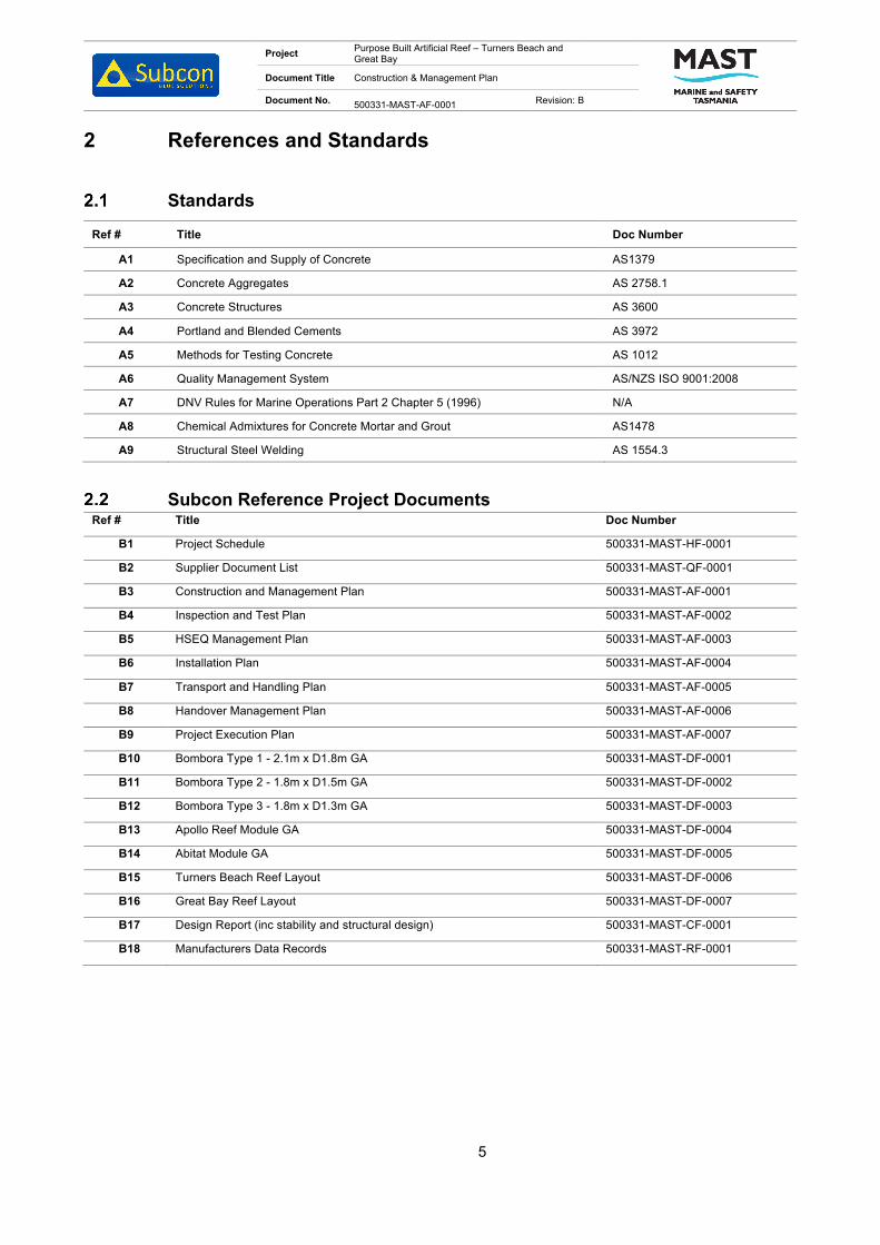
Project Purpose Built Artificial Reef – Turners Beach and Great Bay
Document Title Construction & Management Plan
Document No. 500331-MAST-AF-0001 Revision: B
5
2 References and Standards
Standards
Ref # Title Doc Number
A1 Specification and Supply of Concrete AS1379
A2 Concrete Aggregates AS 2758.1
A3 Concrete Structures AS 3600
A4 Portland and Blended Cements AS 3972
A5 Methods for Testing Concrete AS 1012
A6 Quality Management System AS/NZS ISO 9001:2008
A7 DNV Rules for Marine Operations Part 2 Chapter 5 (1996) N/A
A8 Chemical Admixtures for Concrete Mortar and Grout AS1478
A9 Structural Steel Welding AS 1554.3
Subcon Reference Project Documents Ref # Title Doc Number
B1 Project Schedule 500331-MAST-HF-0001
B2 Supplier Document List 500331-MAST-QF-0001
B3 Construction and Management Plan 500331-MAST-AF-0001
B4 Inspection and Test Plan 500331-MAST-AF-0002
B5 HSEQ Management Plan 500331-MAST-AF-0003
B6 Installation Plan 500331-MAST-AF-0004
B7 Transport and Handling Plan 500331-MAST-AF-0005
B8 Handover Management Plan 500331-MAST-AF-0006
B9 Project Execution Plan 500331-MAST-AF-0007
B10 Bombora Type 1 - 2.1m x D1.8m GA 500331-MAST-DF-0001
B11 Bombora Type 2 - 1.8m x D1.5m GA 500331-MAST-DF-0002
B12 Bombora Type 3 - 1.8m x D1.3m GA 500331-MAST-DF-0003
B13 Apollo Reef Module GA 500331-MAST-DF-0004
B14 Abitat Module GA 500331-MAST-DF-0005
B15 Turners Beach Reef Layout 500331-MAST-DF-0006
B16 Great Bay Reef Layout 500331-MAST-DF-0007
B17 Design Report (inc stability and structural design) 500331-MAST-CF-0001
B18 Manufacturers Data Records 500331-MAST-RF-0001

Project Purpose Built Artificial Reef – Turners Beach and Great Bay
Document Title Construction & Management Plan
Document No. 500331-MAST-AF-0001 Revision: B
6
Abbreviations/Definitions Abbreviations / Definitions Description AS Australian Standards CAR Corrective Action Report DNV Det Norske Veritas DPR Daily Progress Report EWP Elevated Work Platform GA General Arrangement HAZID / HAZOB Hazard Identification / Observation HIRA Hazard Identification Risk Analysis HSEQ Health, Safety, Environment, Quality ID Identification IMS Integrated Management System IRN Inspection Release Note ISO International Organisation for Standardization ITP Inspection and Test Plan JHA Job Hazard Analysis MD Managing Director MDR Manufacturer’s Data Report MSDS Material Safety Data Sheets NCR Non-Conformance Report PM Project Manager PE Project Engineer PPE Personal Protective Equipment PQP Project Quality Plan Project All activities pertaining to the Scope of Work as outlined in Contract QA / QC Quality Assurance / Quality Control QMS Quality Management System SDL Supplier Document List SOW Scope of Work SWMS Safe Work Method Statement TQ Technical Query VOC Verification of Competency

Project Purpose Built Artificial Reef – Turners Beach and Great Bay
Document Title Construction & Management Plan
Document No. 500331-MAST-AF-0001 Revision: B
7
1.•Clean•Replace sealing aids - (Silicone, ableflex and jointing)•Application of form release agent
2.
•Base frame•Internal pyramid•External faces•Break out beams / spacers•Wings•Lid
3.•Self compacting concrete•Quality controlled•Specific marine concrete design
4.
•Lid•Break out beams / spacers•Wings•External faces•Reef Pyramid with base frame•Internal pyramid mould•Lift Concrete Reef Pyramid Base frame
3 Fabrication
Artificial concrete reefs are fabricated by pouring concrete into steel moulds. The steel moulds allow for repeated use and intense compaction.
Typical Fabrication Process
The fabrication of the Abitat modules can be done as a continuous process. The same process is applied to the fabrication of the Apollo and Bombora modules.
1. Mould Preparation
2. Mould Assembly
3. Casting
4. Break Out

Project Purpose Built Artificial Reef – Turners Beach and Great Bay
Document Title Construction & Management Plan
Document No. 500331-MAST-AF-0001 Revision: B
8
Reef Type and Dimensions
Table 3-1 below shows the properties of the Abitat, Apollo and Bombora modules.
Table 3-1: General Reef Module Details
Type Length
(m) Width
(m) Height
(m) Dry Weight
(Te) Quantity
Turners Beach Quantity
Great Bay
Abitat 2.8 2.425 1.0 1.77 - 14
Apollo Æ1.3 - 1.0 0.9 42 42
Bombora – Type 1 Æ2.1 - 1.8 3.3 70 70
Bombora – Type 2 Æ1.8 - 1.5 2.6 7 7
Bombora – Type 3 Æ1.8 - 1.3 2.0 21 21
Appendix A describes the detailed process for the fabrication of the Abitat modules, Appendix B describes the
fabrication process of the Apollo modules, and Appendix C describes the fabrication procedure for the
Bombora modules.
4 Logistics
General
All logistical movements between fabrication site and Client nominated delivery location, will be managed by
the Project Engineer. On completion of fabrication, Client shall be advised on delivery requirements for the
reef modules. No reefs shall leave the fabrication yard until approved by Client.
Manifesting Requirements
All deliveries must be accompanied with an Inspection Release Note signed by Client prior to items leaving
the yard. An inspection and release template can be found in Appendix E: Inspection and Release Note.
Transportation Requirements
Rubber, wood chocks, chain and /or ratchet straps may be used to secure the reefs for transportation around
the base of each reef. For full transportation guidelines, refer to B7.

Project Purpose Built Artificial Reef – Turners Beach and Great Bay
Document Title Construction & Management Plan
Document No. 500331-MAST-AF-0001 Revision: B
9
Appendix A: Abitat Fabrication Procedure
Abitat Fabrication Plan
Project Abitat Reef Modules
Document Name Abitat Fabrication Plan
Contact Roy Smit Email [email protected]
Subcon Document Number 308052-SUB-AF-0001 Revision A
0 Issued for Client Use
B Issued for Client Review
A Issued for Internal Review RSm JFr
Rev Date Revision Description Author Checked Approved Client Approval

Project Abitat Reef Modules
Document Title Abitat Fabrication Plan
Document No. 308052-SUB-AF-0001
Revision:A
2
Table of Contents
1 Introduction .................................................................................................................................. 4
Purpose .......................................................................................................................................... 4
Scope of Document ........................................................................................................................ 4
2 References and Standards .......................................................................................................... 5
Standards ....................................................................................................................................... 5
Subcon Reference Project Documents .......................................................................................... 5
Abbreviations/Definitions ................................................................................................................ 6
3 Fabrication .................................................................................................................................... 7
Typical Fabrication Process ........................................................................................................... 7
Reef Type and Dimensions ............................................................................................................ 8
4 Abitat Fabrication ......................................................................................................................... 9
Steel Mould Preparation ................................................................................................................. 9
Steel Mould Assembly .................................................................................................................... 9
Ready-Mix Concrete on Site .......................................................................................................... 9
Casting ........................................................................................................................................... 9
Reef Breakout .............................................................................................................................. 10
Lift Point Inspection ...................................................................................................................... 11
5 Procedure Symbols Key ............................................................................................................ 12
6 Fabrication Health and Safety .................................................................................................. 13
General ......................................................................................................................................... 13
7 Logistics...................................................................................................................................... 20
General ......................................................................................................................................... 20
Manifesting Requirements ........................................................................................................... 20
Transportation Requirements....................................................................................................... 20
Appendix 1 Prestart Meeting ........................................................................................................................ 21
Appendix 2 Reef Module Drawings .............................................................................................................. 22
Appendix 3 Inspection and Release Note ................................................................................................... 23

Project Abitat Reef Modules
Document Title Abitat Fabrication Plan
Document No. 308052-SUB-AF-0001
Revision:A
3
List of Figures
Figure 1-1: Abitat Module .................................................................................................................................. 4
Figure 4-1: Abitat inner mould (left), outer mould (centre), and assembled mould (right). ............................... 9
List of Tables
Table 3-1: General Abitat Details ...................................................................................................................... 8
Table 4-1: Casting equipment ......................................................................................................................... 10
Table 4-2: External mould breakout equipment .............................................................................................. 10
Table 4-3: Internal mould breakout equipment ................................................................................................ 11
Table 6-1: Pre-start task plan .......................................................................................................................... 14
Table 6-2: Cleaning and preparation task plan ............................................................................................... 15
Table 6-3: Placing and fastening task plan...................................................................................................... 16
Table 6-4: Pouring concrete task plan ............................................................................................................. 17
Table 6-5: Reef break out task plan ................................................................................................................ 18
Table 6-6: Lifting and lay down task plan ........................................................................................................ 19
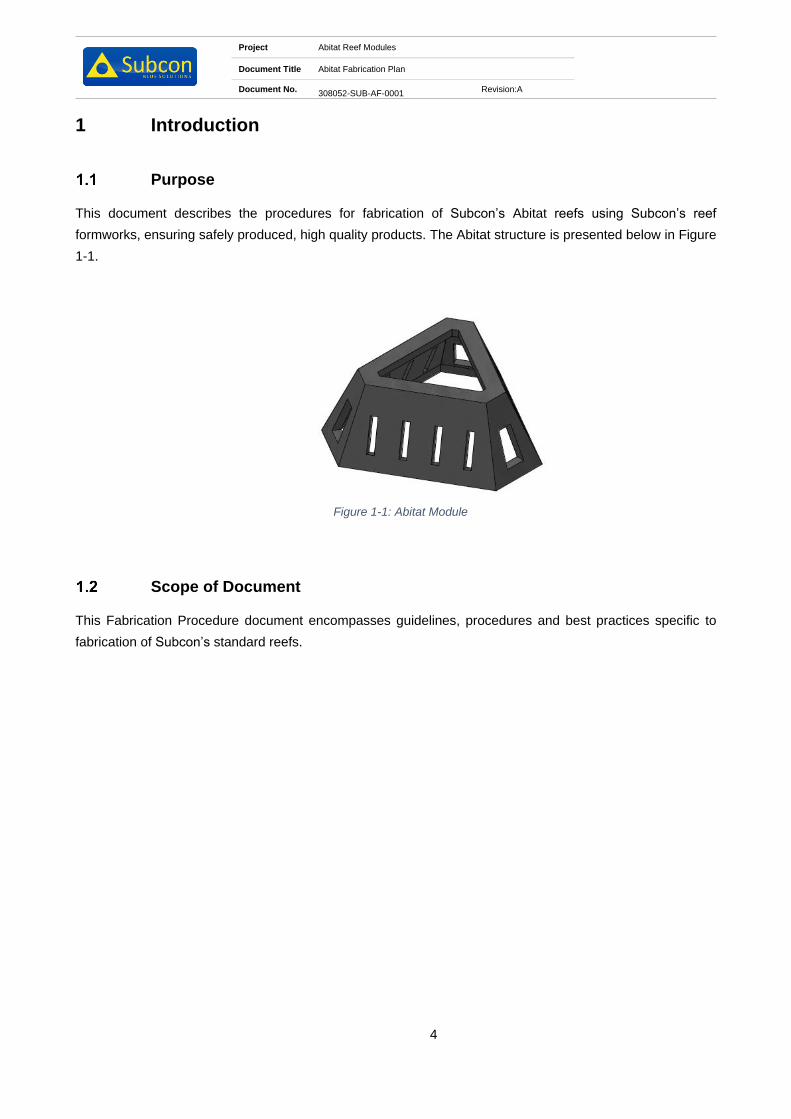
Project Abitat Reef Modules
Document Title Abitat Fabrication Plan
Document No. 308052-SUB-AF-0001
Revision:A
4
1 Introduction
Purpose
This document describes the procedures for fabrication of Subcon’s Abitat reefs using Subcon’s reef
formworks, ensuring safely produced, high quality products. The Abitat structure is presented below in Figure
1-1.
Figure 1-1: Abitat Module
Scope of Document
This Fabrication Procedure document encompasses guidelines, procedures and best practices specific to
fabrication of Subcon’s standard reefs.

Project Abitat Reef Modules
Document Title Abitat Fabrication Plan
Document No. 308052-SUB-AF-0001
Revision:A
5
2 References and Standards
Standards
Ref # Title Doc Number
A1 Specification and Supply of Concrete AS1379
A2 Concrete Aggregates AS 2758.1
A3 Concrete Structures AS 3600
A4 Portland and Blended Cements AS 3972
A5 Methods for Testing Concrete AS 1012
A6 Quality Management System AS/NZS ISO 9001:2008
A7 DNV Rules for Marine Operations Part 2 Chapter 5 (1996) N/A
A8 Chemical Admixtures for Concrete Mortar and Grout AS1478
A9 Structural Steel Welding AS 1554.3
Subcon Reference Project Documents Ref # Title Doc Number
B1 Abitat – General Arrangement 3852-SUB-DF-0001

Project Abitat Reef Modules
Document Title Abitat Fabrication Plan
Document No. 308052-SUB-AF-0001
Revision:A
6
Abbreviations/Definitions
Abbreviations / Definitions Description
AS Australian Standards
CAR Corrective Action Report
DNV Det Norske Veritas
DPR Daily Progress Report
EWP Elevated Work Platform
GA General Arrangement
HAZID / HAZOB Hazard Identification / Observation
HIRA Hazard Identification Risk Analysis
HSEQ Health, Safety, Environment, Quality
ID Identification
IMS Integrated Management System
IRN Inspection Release Note
ISO International Organisation for Standardization
ITP Inspection and Test Plan
JHA Job Hazard Analysis
MD Managing Director
MDR Manufacturer’s Data Report
MSDS Material Safety Data Sheets
NCR Non-Conformance Report
PM Project Manager
PE Project Engineer
PPE Personal Protective Equipment
PQP Project Quality Plan
Project All activities pertaining to the Scope of Work as outlined in Contract
QA / QC Quality Assurance / Quality Control
QMS Quality Management System
SDL Supplier Document List
SOW Scope of Work
SWMS Safe Work Method Statement
TQ Technical Query
VOC Verification of Competency

Project Abitat Reef Modules
Document Title Abitat Fabrication Plan
Document No. 308052-SUB-AF-0001
Revision:A
7
1.
•Clean
•Replace sealing aids - (Silicone, ableflex and jointing)
•Application of form release agent
2.
•Base frame
•Internal pyramid
•External faces
•Break out beams / spacers
•Wings
•Lid
3.
•Self compacting concrete
•Quality controlled
•Specific marine concrete design
4.
•Lid
•Break out beams / spacers
•Wings
•External faces
•Reef Pyramid with base frame
•Internal pyramid mould
•Lift Concrete Reef Pyramid Base frame
3 Fabrication
Artificial concrete reefs are fabricated by pouring concrete into steel moulds. The steel moulds allow for
repeated use and intense compaction.
Typical Fabrication Process
The fabrication of the Abitat modules can be done as a continuous process.
1. Mould Preparation
2. Mould Assembly
3. Casting
4. Break Out

Project Abitat Reef Modules
Document Title Abitat Fabrication Plan
Document No. 308052-SUB-AF-0001
Revision:A
8
Reef Type and Dimensions
Table 3-1 below shows the properties of the Abitat modules.
Table 3-1: General Abitat Details
Type Length (m) Width
(m)
Height
(m)
Dry Weight
(Te)
Abitat 2.8 2.425 1.0 1.8
Sections 4 on the following pages describe the detailed process for the fabrication of the Abitat modules.

Project Abitat Reef Modules
Document Title Abitat Fabrication Plan
Document No. 308052-SUB-AF-0001
Revision:A
9
4 Abitat Fabrication
Steel Mould Preparation
An environmentally friendly steel formwork release oil or form oil is sprayed on the steel moulds surfaces prior
to pouring concrete. The purpose of this form oil is to aid in the release of the mould from the reef. The form
oil allows for easier cleaning of the moulds post fabrication. Any vertical sections of the mould will have Abelflex
expansion foam and Duct tape applied to improve the breakout of the reef. Moulds are to be cleaned regularly
using steel wire brush, scrappers, geo picks or using a high-pressure wash system.
Steel Mould Assembly
Figure 4-1: Abitat inner mould (left), outer mould (centre), and assembled mould (right).
Steel moulds can weigh upwards of 1Te each and require forklifts or a crane for handling. Steel mould
assembly typically consists of 1 internal mould, 1 external mould and various mould inserts. All surfaces of the
moulds exposed to concrete during casting are cleaned and sprayed with sufficient quantities of form oil prior
to assembly. The inner mould is placed on level ground and the outer mould is lowered onto the base mould.
Once in place, the moulds are secured using locking wedges to prevent movement during casting. The mould
inserts are then positioned and secured using wedges. Steel mould assembly is complete when all wedges
are checked to be secured and not loose.
Ready-Mix Concrete on Site
Concrete will typically be transported to site using 5 m3 capacity agitator trucks, delivery dockets for each truck
will be kept by the Project Engineer. Sampling will be completed in accordance to the ITP. Test cubes/cylinders
are kept in storage for compression testing, in accordance with the ITP.
Casting
Steel moulds are filled one at a time to the top surface via the agitator truck chute and shovels. Vibrators are
used to ensure that moulds are filled completely. The concrete vibrating shaft is inserted into each gap within
the mould carefully to ensure no internal voids are present in the concrete. The surface of the concrete is
trowelled to achieve a smooth finish.

Project Abitat Reef Modules
Document Title Abitat Fabrication Plan
Document No. 308052-SUB-AF-0001
Revision:A
10
Table 4-1: Casting equipment
Type Equipment
Abitat • Trowels;
• Vibrator;
• Screeding water bottles;
• Mallets/hammer;
• Wheelbarrow;
• Shovel;
• Safety step and safety platform
• Bulk bag for excess concrete (if expected).
Note: To ensure a clean breakaway by the top mould during demoulding it is recommended that the concrete
is undercut around the mould aperture perimeter using the trowel edge.
Reef Breakout
Reef breakout is a three-step process: (i) removal of mould inserts, (ii) removal of outer mould and (iii) removal
of reef structure from the internal mould. The time between pouring and each of these stages is generalised
however is subject to change due to weather and the type and quality of the supplied concrete mix.
Removal of mould inserts is typically done 2 hours after pouring is completed. Crowbars and mallets should
be used to assist for all inserts. The top inserts for the Abitat should be removed using slings in conjunction
with a forklift or crane.
4 hours after pouring, the outer mould should be removed. For safe and effective removal, the following
equipment is required as a minimum:
Table 4-2: External mould breakout equipment
Type Equipment Comments
Abitat • 5Te forklift;
• 2 x adjustable wrench;
• F clamp;
• 2 x 2T sling;
• Sledgehammer;
• Crowbar.
The mould should first be loosened via the bolt joining
the two sections of the mould together. The mould is
then joined back together and lifted using the forklift and
the slings.
24 hours after the pour is completed the reef can be removed from the internal mould. This should be done
using the following equipment:

Project Abitat Reef Modules
Document Title Abitat Fabrication Plan
Document No. 308052-SUB-AF-0001
Revision:A
11
Table 4-3: Internal mould breakout equipment
Type Equipment Comments
Abitat • 3 x Abitat lifting tool;
• 3 x 4.75Te Shackle;
• 3 x Eye self-lock hook
• 3 x 3Te lifting strap;
• 5Te Forklift;
• Sledgehammer;
• Crowbar.
The module is lifted with the Abitat yard lifting tool. No
hydraulics are required for this tool.
Lift Point Inspection
Once the modules have been fabricated, the lift points are to be inspected to ensure there are no sharp edges
that may damage the lift rigging. Any sharp edges are to be removed prior to release of the Abitat.

Project Abitat Reef Modules
Document Title Abitat Fabrication Plan
Document No. 308052-SUB-AF-0001
Revision:A
12
5 Procedure Symbols Key
Text set off in this manner provides warning that failure to follow these directions in
this WARNING can result in bodily harm or loss of life and possible extensive damage
to equipment.
Text set off in this manner provides warning that failure to follow these directions in
this CAUTION can result in damage to equipment.
Text set off in this manner present CLARIFYING INFORMATION or specific
instructions pertinent to the immediate instruction.
Text set of in this manner presents a HOLD point in the procedure.

Project Abitat Reef Modules
Document Title Abitat Fabrication Plan
Document No. 308052-SUB-AF-0001
Revision:A
13
6 Fabrication Health and Safety
General
Section 6 describes health and safety considerations for the fabrication procedures. The
procedures are divided into six main tasks:
• Prestart
• Cleaning and preparation
• Placing and fastening mould components
• Casting
• Reef break out
• Lifting and laydown
Safety is everyone’s responsibility. Minimum PPE requirements are not negotiable!
The minimum personal protective safety gear is as follows:
• Hard hat
• Steel cap boots
• High visibility clothing (Either shirts or vests)
• Safety glasses/goggles (Clear or Dark) – Depending on site conditions
• Gloves when handling mechanical equipment
• Safety harness when working above 1.8m from ground level
6.1.1 Health and Safety Task Checks
It is good practice to follow routine safety talks, checks and audits. Daily commitments from all staff members
and should become second nature. Looking out for any safety hazards every day should form part of the daily
clean-up process.
Daily safety checks should be done with good faith to oneself and others, taken very seriously and be
considered a vital part of life.
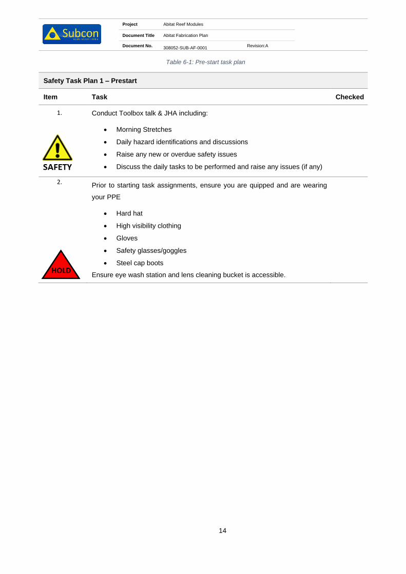
Project Abitat Reef Modules
Document Title Abitat Fabrication Plan
Document No. 308052-SUB-AF-0001
Revision:A
14
Table 6-1: Pre-start task plan
Safety Task Plan 1 – Prestart
Item Task Checked
1.
Conduct Toolbox talk & JHA including:
• Morning Stretches
• Daily hazard identifications and discussions
• Raise any new or overdue safety issues
• Discuss the daily tasks to be performed and raise any issues (if any)
2.
Prior to starting task assignments, ensure you are quipped and are wearing
your PPE
• Hard hat
• High visibility clothing
• Gloves
• Safety glasses/goggles
• Steel cap boots
Ensure eye wash station and lens cleaning bucket is accessible.

Project Abitat Reef Modules
Document Title Abitat Fabrication Plan
Document No. 308052-SUB-AF-0001
Revision:A
15
Table 6-2: Cleaning and preparation task plan
Safety Task Plan 2 – Cleaning and preparation
Item Task Checked
1. Identify the components that needs to be prepared
2. Ensure the lay down area is clear and free of any debris and other obstacles.
3. Ensure you are wearing the correct PPE if chemicals are to be used.
4. Ensure that the lifting equipment is certified and up to date.
5. Ensure that all other personnel are made wary of the lifting process

Project Abitat Reef Modules
Document Title Abitat Fabrication Plan
Document No. 308052-SUB-AF-0001
Revision:A
16
Table 6-3: Placing and fastening task plan
Safety Task Plan 3 – Placing and fastening mould components
Item Task Checked
1.
Check all relevant PPE is ready for placing and fastening mould components:
• Ear protection
• Steel cap boots
• Mono goggles
• Hard hat
• Fall prevention harness
• Gloves
• Hi-Vis coveralls
2.
Crew are not to climb above the anchor point on the face plate of the mould.
3.
Ensure all equipment required for placing and fastening is in place:
• Impact drills
• Wrenches and sockets
• Electrical equipment is tested and tagged
• Mallets/hammer
• Lifting equipment is certified up to date
4. Check that all preparation is done to satisfaction
• Make sure all the components are ready for lifting and placement
• Check surroundings and clear the ground of all obstructions and debris
• Inspect all mould components for fatigue, cracks or damage
• Check that ALL bolts, washers and nuts are clean and good working
order

Project Abitat Reef Modules
Document Title Abitat Fabrication Plan
Document No. 308052-SUB-AF-0001
Revision:A
17
Table 6-4: Pouring concrete task plan
Safety Task Plan 4 – Casting
Item Task Checked
1. Crew are not to climb above the anchor point on the face plate of the mould.
2.
Upon arrival of agitator truck check delivery docket prior to testing and
casting. Ensure the quantity of fibres added to the batch is correct and written
on docket.
3.
Pour 1m3 of concrete mix into wheelbarrow for tester to use.
A slump test should be completed and 3 cylinders should be taken for 1 x 7 day
compressive test and 2 x 28 day compressive tests.
4.
Concrete truck is guided to reverse up to the concrete piston pump hopper.
This MUST be done by one (1) dedicated person.
The discharge pipe should not be moved out of the mould whilst concrete is
being pumped.
5. As the concrete is being poured into the pump hopper, the flow out of the truck
should be carefully monitored to prevent spillage.

Project Abitat Reef Modules
Document Title Abitat Fabrication Plan
Document No. 308052-SUB-AF-0001
Revision:A
18
Table 6-5: Reef break out task plan
Safety Task Plan 5 – Reef break out
Item Task Checked
1. Crew are not to climb above the anchor point on the face plate of the mould.
2. Approximately 12 hours after casting the mould and inserts can be removed.
3. Make sure that there are no tools or equipment left on the moulds before lifting
or breaking out.
4.
Slings are attached to lifting points and lifted away using the crawler crane and
lifting slings/chains. Sledgehammers will often be required to assist the
breakaway.
5.
Remove all bolts from the bottom working upwards, ensuring the lifting
equipment is attached to the component before commencing with loosening
the bolts.
6.
Approximately 24 hours after pouring, the reef should be removed from the
steel base frame. The appropriate lifting tool should be attached to the
appropriate slings and crawler crane before lifting.
Note: If removal of inserts and top moulds is premature the reef will crack and become non-conformant. If
removal is delayed, the process will become extremely difficult due to concrete expansion. Hence the
importance of keeping an eye on conditions and the reefs curing.

Project Abitat Reef Modules
Document Title Abitat Fabrication Plan
Document No. 308052-SUB-AF-0001
Revision:A
19
Table 6-6: Lifting and lay down task plan
Safety Task Plan 6 – Lifting and laydown
Item Task Checked
1. Reef modules will have loose concrete around the perimeter and inside the
voids. These should be cleaned by knocking out with a crowbar.
2.
The crawler crane is utilised to lift the reef off of the steel base frame and place
them on wooden blocks.
Ensure the correct lifting tool is used in conjunction with the correct
slings/chains.
3.
Steel base moulds are to be cleaned & made ready for pouring of the next
reef.

Project Abitat Reef Modules
Document Title Abitat Fabrication Plan
Document No. 308052-SUB-AF-0001
Revision:A
20
7 Logistics
General
All logistical movements between fabrication site and Client nominated delivery location, will be managed by
the Project Engineer. On completion of fabrication, Client shall be advised on delivery requirements for the
reef modules. No reefs shall leave the fabrication yard until approved by Client.
Manifesting Requirements
All deliveries must be accompanied with an Inspection Release Note signed by Client prior to items leaving
the yard. An inspection and release template can be found in Appendix 3 Inspection and Release Note.
Transportation Requirements
Rubber, wood chocks, chain and /or ratchet straps may be used to secure the reefs for transportation around
the base of each reef.

Project Abitat Reef Modules
Document Title Abitat Fabrication Plan
Document No. 308052-SUB-AF-0001
Revision:A
21
Appendix 1 Prestart Meeting

PRESTART MEETING
2101-SUB-MQ-0016Daily Prestart Meeting Template
WEATHER FORCAST:
TODAY’S TASK:
RESPONSIBILITIES:
Team Leaders:
Housekeeping:
First Aid
Forklift:
Crane:
Dogman:
Other:
QUALITY:
Assembly: Diamentions: Rope Length: Surface Finish:
NCR’s:
SAFETY:
Incidents/HAZOBS that the crew need to be aware of:
Everyone is aware of Stop Work Procedures
Stretched Complete:
JSA Complete:
Supervisor Name: Signature:
DATE: SITE:
DAY: PROJECT:
Project Abitat Reef Modules
Document Title Abitat Fabrication Plan
Document No. 308052-SUB-AF-0001
Revision:A
22
Appendix 2 Reef Module Drawings

PLAN VIEW
SCALE 1 : 20
FRONT VIEW
SCALE 1 : 20
ISOMETRIC VIEW
SCALE 1 : 25
SECTION A-A
SCALE 1 : 20
SECTION B-B
SCALE 1 : 20
A
A
B
B
1 2 3 4 5 6 7 8 9 10 11 12
1 2 3 4 5 6 7 8 9 10 11 12
A
B
C
D
E
F
G
H H
G
F
E
D
C
B
A
Perth: +61 8 9200 2218
Singapore: +65 6440 7752
Europe: +32 59 36 9941
China: +86 769 828 06357, +86 137 1529 7879
Web: www.subcon.com
Concrete Marine Solutions
TITLE
SUBCON TECHNOLOGIES
ABITAT MODULE
GENERAL ARRANGEMENT
3852-SUB-DF-0001
DRAWING NUMBER
REV
3 SHEET 1 of 1
SIZE
A3
SCALE
NTS
C Copyright Subcon 2018
CHECKED
DRAWN
APPROVED
I.CLEGG
T.ROE
A.KIKEROS
INITIAL DATE
DRN CHK APPREV DATE DESCRIPTION
1 15.02.15 MS JH MAISSUED FOR USE
18.03.15
19.03.18
2
3
RE-ISSUED FOR USE
RE-ISSUED FOR USE
TRDB
TR
AK
IC AK
NOTES:
1. CONCRETE IS GRADE S50.
2. WEIGHT OF MODULE IS 1773kg.
2800
24
25
800
10
00
4
9
2
4
7
5
4
6
5
5
0
7
157
190
1
0
4
104
156
2
8
3
2
0
1
9
9

Project Abitat Reef Modules
Document Title Abitat Fabrication Plan
Document No. 308052-SUB-AF-0001
Revision:A
23
Appendix 3 Inspection and Release Note

Inspection Release Certificate
Project: Release Number
Release Date: Page No: 1 of 1
Supplier: P.O. Number:
Location:
Dispatch Details:
Supplier Contact:
Partial Order Release Complete Order Release
This Releases Material Rejected on NCR No.: Dated:
Purchase Order Items Released
Line Item
Description Dimension
(L x W x H) m ID
No. As-Built Dry
Weight Est. (Te) Qty On Order
Qty Released
Inspector Notes / Remarks
This release provides documentary evidence that all pertinent material certification relating to fabrication is complete and verified. Any further certification and documentation will be included in the MDR post-installation.
NOTE: This inspection release is considered authorisation to ship/dispatch the items for installation. Prior to fabrication being completed, notice will be given to the Client when inspection can occur. The client shall in no way reasonably delay inspection in a way that will incur costs to the supplier.
Inspector Name Signature Date:
Supplier Name Signature Date:
Continuation Page required? Yes No

Project Purpose Built Artificial Reef – Turners Beach and Great Bay
Document Title Construction & Management Plan
Document No. 500331-MAST-AF-0001 Revision: B
10
Appendix B: Apollo Fabrication Procedure

Project Purpose Built Artificial Reef – Turners Beach and Great Bay
Document Title Construction & Management Plan
Document No. 500331-MAST-AF-0001 Revision: B
11
Appendix C: Bombora Fabrication Procedure

Apollo Fabrication Plan
Project Apollo Reef Modules
Document Name Apollo Fabrication Plan
Contact Roy Smit Email [email protected]
Subcon Document Number 308053-SUB-AF-0001 Revision A
0 Issued for Client Use
B Issued for Client Review
A Issued for Internal Review RSm JFr
Rev Date Revision Description Author Checked Approved Client Approval

Project Apollo Reef Modules
Document Title Apollo Fabrication Plan
Document No. 308053-SUB-AF-0001
Revision:A
2
Table of Contents
1 Introduction .................................................................................................................................. 4
Purpose .......................................................................................................................................... 4
Scope of Document ........................................................................................................................ 4
2 References and Standards .......................................................................................................... 5
Standards ....................................................................................................................................... 5
Subcon Reference Project Documents .......................................................................................... 5
Abbreviations/Definitions ................................................................................................................ 6
3 Fabrication .................................................................................................................................... 7
Typical Fabrication Process ........................................................................................................... 7
Reef Type and Dimensions ............................................................................................................ 8
4 Apollo Fabrication ........................................................................................................................ 9
Steel Mould Preparation ................................................................................................................. 9
Steel Mould Assembly .................................................................................................................... 9
Ready-Mix Concrete on Site .......................................................................................................... 9
Casting ........................................................................................................................................... 9
Reef Breakout .............................................................................................................................. 10
Lift Point Inspection ...................................................................................................................... 11
5 Procedure Symbols Key ............................................................................................................ 12
6 Fabrication Health and Safety .................................................................................................. 13
General ......................................................................................................................................... 13
7 Logistics...................................................................................................................................... 20
General ......................................................................................................................................... 20
Manifesting Requirements ........................................................................................................... 20
Transportation Requirements....................................................................................................... 20
Appendix 1 Prestart Meeting ........................................................................................................................ 21
Appendix 2 Reef Module Drawings .............................................................................................................. 22
Appendix 3 Inspection and Release Note ................................................................................................... 23

Project Apollo Reef Modules
Document Title Apollo Fabrication Plan
Document No. 308053-SUB-AF-0001
Revision:A
3
List of Figures
Figure 1-1: Apollo Module ................................................................................................................................. 4
Figure 4-1: Apollo inner and outer mould (left), and assembled mould (right). ................................................. 9
List of Tables
Table 3-1: General Apollo Details ...................................................................................................................... 8
Table 4-1: Casting equipment ......................................................................................................................... 10
Table 4-2: External mould breakout equipment .............................................................................................. 10
Table 4-3: Internal mould breakout equipment ................................................................................................ 11
Table 6-1: Pre-start task plan .......................................................................................................................... 14
Table 6-2: Cleaning and preparation task plan ............................................................................................... 15
Table 6-3: Placing and fastening task plan...................................................................................................... 16
Table 6-4: Pouring concrete task plan ............................................................................................................. 17
Table 6-5: Reef break out task plan ................................................................................................................ 18
Table 6-6: Lifting and lay down task plan ........................................................................................................ 19

Project Apollo Reef Modules
Document Title Apollo Fabrication Plan
Document No. 308053-SUB-AF-0001
Revision:A
4
1 Introduction
Purpose
This document describes the procedures for fabrication of Subcon’s Apollo reefs using Subcon’s reef
formworks, ensuring safely produced, high quality products. The Apollo structure is presented below in Figure
1-1.
Figure 1-1: Apollo Module
Scope of Document
This Fabrication Procedure document encompasses guidelines, procedures and best practices specific to
fabrication of Subcon’s standard reefs.

Project Apollo Reef Modules
Document Title Apollo Fabrication Plan
Document No. 308053-SUB-AF-0001
Revision:A
5
2 References and Standards
Standards
Ref # Title Doc Number
A1 Specification and Supply of Concrete AS1379
A2 Concrete Aggregates AS 2758.1
A3 Concrete Structures AS 3600
A4 Portland and Blended Cements AS 3972
A5 Methods for Testing Concrete AS 1012
A6 Quality Management System AS/NZS ISO 9001:2008
A7 DNV Rules for Marine Operations Part 2 Chapter 5 (1996) N/A
A8 Chemical Admixtures for Concrete Mortar and Grout AS1478
A9 Structural Steel Welding AS 1554.3
Subcon Reference Project Documents Ref # Title Doc Number
B1 Apollo – General Arrangement 3853-SUB-DWG-0001

Project Apollo Reef Modules
Document Title Apollo Fabrication Plan
Document No. 308053-SUB-AF-0001
Revision:A
6
Abbreviations/Definitions
Abbreviations / Definitions Description
AS Australian Standards
CAR Corrective Action Report
DNV Det Norske Veritas
DPR Daily Progress Report
EWP Elevated Work Platform
GA General Arrangement
HAZID / HAZOB Hazard Identification / Observation
HIRA Hazard Identification Risk Analysis
HSEQ Health, Safety, Environment, Quality
ID Identification
IMS Integrated Management System
IRN Inspection Release Note
ISO International Organisation for Standardization
ITP Inspection and Test Plan
JHA Job Hazard Analysis
MD Managing Director
MDR Manufacturer’s Data Report
MSDS Material Safety Data Sheets
NCR Non-Conformance Report
PM Project Manager
PE Project Engineer
PPE Personal Protective Equipment
PQP Project Quality Plan
Project All activities pertaining to the Scope of Work as outlined in Contract
QA / QC Quality Assurance / Quality Control
QMS Quality Management System
SDL Supplier Document List
SOW Scope of Work
SWMS Safe Work Method Statement
TQ Technical Query
VOC Verification of Competency

Project Apollo Reef Modules
Document Title Apollo Fabrication Plan
Document No. 308053-SUB-AF-0001
Revision:A
7
1.
•Clean
•Replace sealing aids - (Silicone, ableflex and jointing)
•Application of form release agent
2.
•Base frame
•Internal pyramid
•External faces
•Break out beams / spacers
•Wings
•Lid
3.
•Self compacting concrete
•Quality controlled
•Specific marine concrete design
4.
•Lid
•Break out beams / spacers
•Wings
•External faces
•Reef Pyramid with base frame
•Internal pyramid mould
•Lift Concrete Reef Pyramid Base frame
3 Fabrication
Artificial concrete reefs are fabricated by pouring concrete into steel moulds. The steel moulds allow for
repeated use and intense compaction.
Typical Fabrication Process
The fabrication of the Apollo modules can be done as a continuous process.
1. Mould Preparation
2. Mould Assembly
3. Casting
4. Break Out

Project Apollo Reef Modules
Document Title Apollo Fabrication Plan
Document No. 308053-SUB-AF-0001
Revision:A
8
Reef Type and Dimensions
Table 3-1 below shows the properties of the Apollo modules.
Table 3-1: General Apollo Details
Type Length (m) Width
(m)
Height
(m)
Dry Weight
(Te)
Apollo 1.3 - 1.0 0.9
Sections 4 on the following pages describe the detailed process for the fabrication of the Apollo modules.
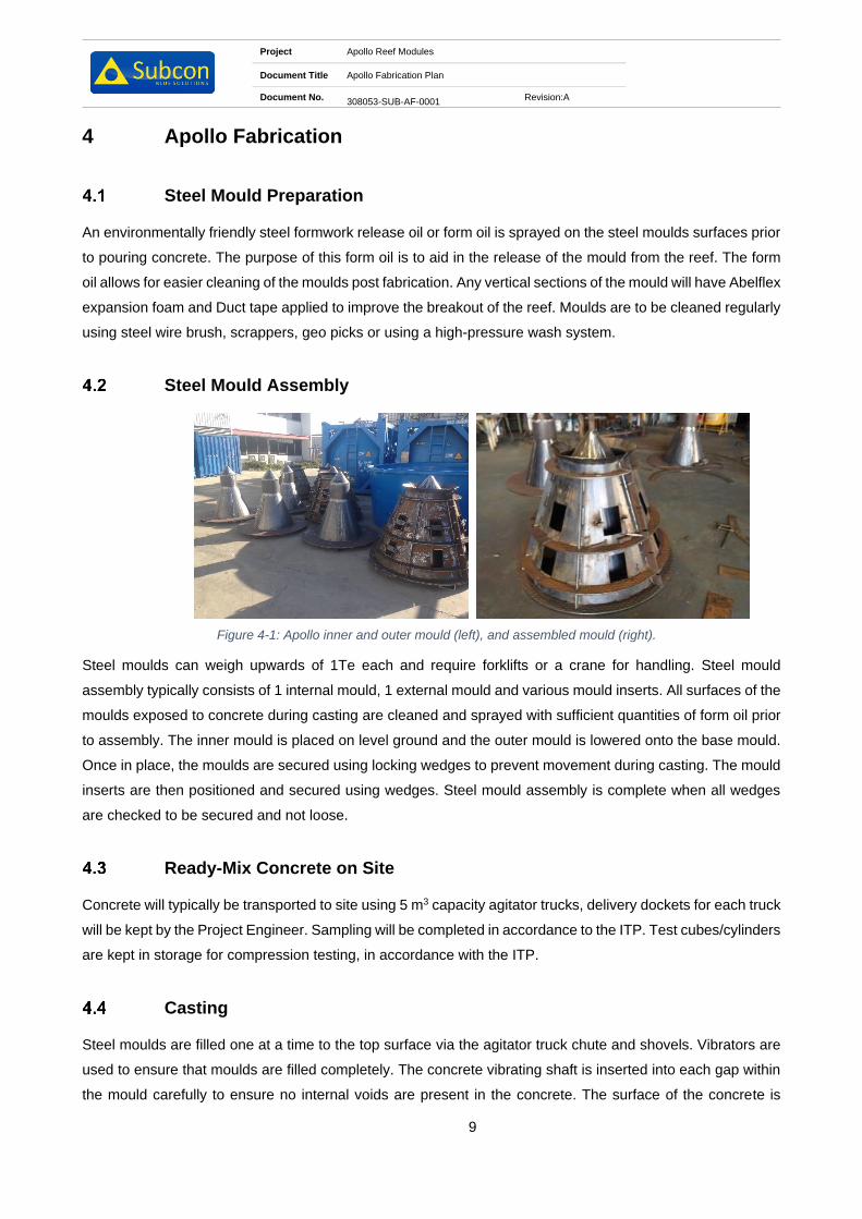
Project Apollo Reef Modules
Document Title Apollo Fabrication Plan
Document No. 308053-SUB-AF-0001
Revision:A
9
4 Apollo Fabrication
Steel Mould Preparation
An environmentally friendly steel formwork release oil or form oil is sprayed on the steel moulds surfaces prior
to pouring concrete. The purpose of this form oil is to aid in the release of the mould from the reef. The form
oil allows for easier cleaning of the moulds post fabrication. Any vertical sections of the mould will have Abelflex
expansion foam and Duct tape applied to improve the breakout of the reef. Moulds are to be cleaned regularly
using steel wire brush, scrappers, geo picks or using a high-pressure wash system.
Steel Mould Assembly
Figure 4-1: Apollo inner and outer mould (left), and assembled mould (right).
Steel moulds can weigh upwards of 1Te each and require forklifts or a crane for handling. Steel mould
assembly typically consists of 1 internal mould, 1 external mould and various mould inserts. All surfaces of the
moulds exposed to concrete during casting are cleaned and sprayed with sufficient quantities of form oil prior
to assembly. The inner mould is placed on level ground and the outer mould is lowered onto the base mould.
Once in place, the moulds are secured using locking wedges to prevent movement during casting. The mould
inserts are then positioned and secured using wedges. Steel mould assembly is complete when all wedges
are checked to be secured and not loose.
Ready-Mix Concrete on Site
Concrete will typically be transported to site using 5 m3 capacity agitator trucks, delivery dockets for each truck
will be kept by the Project Engineer. Sampling will be completed in accordance to the ITP. Test cubes/cylinders
are kept in storage for compression testing, in accordance with the ITP.
Casting
Steel moulds are filled one at a time to the top surface via the agitator truck chute and shovels. Vibrators are
used to ensure that moulds are filled completely. The concrete vibrating shaft is inserted into each gap within
the mould carefully to ensure no internal voids are present in the concrete. The surface of the concrete is
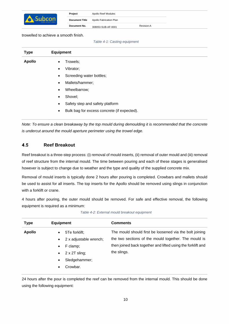
Project Apollo Reef Modules
Document Title Apollo Fabrication Plan
Document No. 308053-SUB-AF-0001
Revision:A
10
trowelled to achieve a smooth finish.
Table 4-1: Casting equipment
Type Equipment
Apollo • Trowels;
• Vibrator;
• Screeding water bottles;
• Mallets/hammer;
• Wheelbarrow;
• Shovel;
• Safety step and safety platform
• Bulk bag for excess concrete (if expected).
Note: To ensure a clean breakaway by the top mould during demoulding it is recommended that the concrete
is undercut around the mould aperture perimeter using the trowel edge.
Reef Breakout
Reef breakout is a three-step process: (i) removal of mould inserts, (ii) removal of outer mould and (iii) removal
of reef structure from the internal mould. The time between pouring and each of these stages is generalised
however is subject to change due to weather and the type and quality of the supplied concrete mix.
Removal of mould inserts is typically done 2 hours after pouring is completed. Crowbars and mallets should
be used to assist for all inserts. The top inserts for the Apollo should be removed using slings in conjunction
with a forklift or crane.
4 hours after pouring, the outer mould should be removed. For safe and effective removal, the following
equipment is required as a minimum:
Table 4-2: External mould breakout equipment
Type Equipment Comments
Apollo • 5Te forklift;
• 2 x adjustable wrench;
• F clamp;
• 2 x 2T sling;
• Sledgehammer;
• Crowbar.
The mould should first be loosened via the bolt joining
the two sections of the mould together. The mould is
then joined back together and lifted using the forklift and
the slings.
24 hours after the pour is completed the reef can be removed from the internal mould. This should be done
using the following equipment:

Project Apollo Reef Modules
Document Title Apollo Fabrication Plan
Document No. 308053-SUB-AF-0001
Revision:A
11
Table 4-3: Internal mould breakout equipment
Type Equipment Comments
Apollo • 2 x Apollo lifting tool;
• 2 x 4.75Te Shackle;
• 2 x Eye self-lock hook
• 2 x 3Te lifting strap;
• 5Te Forklift;
• Sledgehammer;
• Crowbar.
The module is lifted with the Apollo yard lifting tool. No
hydraulics are required for this tool.
Lift Point Inspection
Once the modules have been fabricated, the lift points are to be inspected to ensure there are no sharp edges
that may damage the lift rigging. Any sharp edges are to be removed prior to release of the Apollo.

Project Apollo Reef Modules
Document Title Apollo Fabrication Plan
Document No. 308053-SUB-AF-0001
Revision:A
12
5 Procedure Symbols Key
Text set off in this manner provides warning that failure to follow these directions in
this WARNING can result in bodily harm or loss of life and possible extensive damage
to equipment.
Text set off in this manner provides warning that failure to follow these directions in
this CAUTION can result in damage to equipment.
Text set off in this manner present CLARIFYING INFORMATION or specific
instructions pertinent to the immediate instruction.
Text set of in this manner presents a HOLD point in the procedure.

Project Apollo Reef Modules
Document Title Apollo Fabrication Plan
Document No. 308053-SUB-AF-0001
Revision:A
13
6 Fabrication Health and Safety
General
Section 6 describes health and safety considerations for the fabrication procedures. The
procedures are divided into six main tasks:
• Prestart
• Cleaning and preparation
• Placing and fastening mould components
• Casting
• Reef break out
• Lifting and laydown
Safety is everyone’s responsibility. Minimum PPE requirements are not negotiable!
The minimum personal protective safety gear is as follows:
• Hard hat
• Steel cap boots
• High visibility clothing (Either shirts or vests)
• Safety glasses/goggles (Clear or Dark) – Depending on site conditions
• Gloves when handling mechanical equipment
• Safety harness when working above 1.8m from ground level
6.1.1 Health and Safety Task Checks
It is good practice to follow routine safety talks, checks and audits. Daily commitments from all staff members
and should become second nature. Looking out for any safety hazards every day should form part of the daily
clean-up process.
Daily safety checks should be done with good faith to oneself and others, taken very seriously and be
considered a vital part of life.

Project Apollo Reef Modules
Document Title Apollo Fabrication Plan
Document No. 308053-SUB-AF-0001
Revision:A
14
Table 6-1: Pre-start task plan
Safety Task Plan 1 – Prestart
Item Task Checked
1.
Conduct Toolbox talk & JHA including:
• Morning Stretches
• Daily hazard identifications and discussions
• Raise any new or overdue safety issues
• Discuss the daily tasks to be performed and raise any issues (if any)
2.
Prior to starting task assignments, ensure you are quipped and are wearing
your PPE
• Hard hat
• High visibility clothing
• Gloves
• Safety glasses/goggles
• Steel cap boots
Ensure eye wash station and lens cleaning bucket is accessible.

Project Apollo Reef Modules
Document Title Apollo Fabrication Plan
Document No. 308053-SUB-AF-0001
Revision:A
15
Table 6-2: Cleaning and preparation task plan
Safety Task Plan 2 – Cleaning and preparation
Item Task Checked
1. Identify the components that needs to be prepared
2. Ensure the lay down area is clear and free of any debris and other obstacles.
3. Ensure you are wearing the correct PPE if chemicals are to be used.
4. Ensure that the lifting equipment is certified and up to date.
5. Ensure that all other personnel are made wary of the lifting process

Project Apollo Reef Modules
Document Title Apollo Fabrication Plan
Document No. 308053-SUB-AF-0001
Revision:A
16
Table 6-3: Placing and fastening task plan
Safety Task Plan 3 – Placing and fastening mould components
Item Task Checked
1.
Check all relevant PPE is ready for placing and fastening mould components:
• Ear protection
• Steel cap boots
• Mono goggles
• Hard hat
• Fall prevention harness
• Gloves
• Hi-Vis coveralls
2.
Crew are not to climb above the anchor point on the face plate of the mould.
3.
Ensure all equipment required for placing and fastening is in place:
• Impact drills
• Wrenches and sockets
• Electrical equipment is tested and tagged
• Mallets/hammer
• Lifting equipment is certified up to date
4. Check that all preparation is done to satisfaction
• Make sure all the components are ready for lifting and placement
• Check surroundings and clear the ground of all obstructions and debris
• Inspect all mould components for fatigue, cracks or damage
• Check that ALL bolts, washers and nuts are clean and good working
order

Project Apollo Reef Modules
Document Title Apollo Fabrication Plan
Document No. 308053-SUB-AF-0001
Revision:A
17
Table 6-4: Pouring concrete task plan
Safety Task Plan 4 – Casting
Item Task Checked
1. Crew are not to climb above the anchor point on the face plate of the mould.
2.
Upon arrival of agitator truck check delivery docket prior to testing and
casting. Ensure the quantity of fibres added to the batch is correct and written
on docket.
3.
Pour 1m3 of concrete mix into wheelbarrow for tester to use.
A slump test should be completed and 3 cylinders should be taken for 1 x 7 day
compressive test and 2 x 28 day compressive tests.
4.
Concrete truck is guided to reverse up to the concrete piston pump hopper.
This MUST be done by one (1) dedicated person.
The discharge pipe should not be moved out of the mould whilst concrete is
being pumped.
5. As the concrete is being poured into the pump hopper, the flow out of the truck
should be carefully monitored to prevent spillage.

Project Apollo Reef Modules
Document Title Apollo Fabrication Plan
Document No. 308053-SUB-AF-0001
Revision:A
18
Table 6-5: Reef break out task plan
Safety Task Plan 5 – Reef break out
Item Task Checked
1. Crew are not to climb above the anchor point on the face plate of the mould.
2. Approximately 12 hours after casting the mould and inserts can be removed.
3. Make sure that there are no tools or equipment left on the moulds before lifting
or breaking out.
4.
Slings are attached to lifting points and lifted away using the crawler crane and
lifting slings/chains. Sledgehammers will often be required to assist the
breakaway.
5.
Remove all bolts from the bottom working upwards, ensuring the lifting
equipment is attached to the component before commencing with loosening
the bolts.
6.
Approximately 24 hours after pouring, the reef should be removed from the
steel base frame. The appropriate lifting tool should be attached to the
appropriate slings and crawler crane before lifting.
Note: If removal of inserts and top moulds is premature the reef will crack and become non-conformant. If
removal is delayed, the process will become extremely difficult due to concrete expansion. Hence the
importance of keeping an eye on conditions and the reefs curing.

Project Apollo Reef Modules
Document Title Apollo Fabrication Plan
Document No. 308053-SUB-AF-0001
Revision:A
19
Table 6-6: Lifting and lay down task plan
Safety Task Plan 6 – Lifting and laydown
Item Task Checked
1. Reef modules will have loose concrete around the perimeter and inside the
voids. These should be cleaned by knocking out with a crowbar.
2.
The crawler crane is utilised to lift the reef off of the steel base frame and place
them on wooden blocks.
Ensure the correct lifting tool is used in conjunction with the correct
slings/chains.
3.
Steel base moulds are to be cleaned & made ready for pouring of the next
reef.

Project Apollo Reef Modules
Document Title Apollo Fabrication Plan
Document No. 308053-SUB-AF-0001
Revision:A
20
7 Logistics
General
All logistical movements between fabrication site and Client nominated delivery location, will be managed by
the Project Engineer. On completion of fabrication, Client shall be advised on delivery requirements for the
reef modules. No reefs shall leave the fabrication yard until approved by Client.
Manifesting Requirements
All deliveries must be accompanied with an Inspection Release Note signed by Client prior to items leaving
the yard. An inspection and release template can be found in Appendix 3 Inspection and Release Note.
Transportation Requirements
Rubber, wood chocks, chain and /or ratchet straps may be used to secure the reefs for transportation around
the base of each reef.

Project Apollo Reef Modules
Document Title Apollo Fabrication Plan
Document No. 308053-SUB-AF-0001
Revision:A
21
Appendix 1 Prestart Meeting

PRESTART MEETING
2101-SUB-MQ-0016Daily Prestart Meeting Template
WEATHER FORCAST:
TODAY’S TASK:
RESPONSIBILITIES:
Team Leaders:
Housekeeping:
First Aid
Forklift:
Crane:
Dogman:
Other:
QUALITY:
Assembly: Diamentions: Rope Length: Surface Finish:
NCR’s:
SAFETY:
Incidents/HAZOBS that the crew need to be aware of:
Everyone is aware of Stop Work Procedures
Stretched Complete:
JSA Complete:
Supervisor Name: Signature:
DATE: SITE:
DAY: PROJECT:

Project Apollo Reef Modules
Document Title Apollo Fabrication Plan
Document No. 308053-SUB-AF-0001
Revision:A
22
Appendix 2 Reef Module Drawings

1
1
2
2
3
3
4
4
5
5
6
6
A A
B B
C C
D D
TITLE
DRAWN
CHECKED
ENG.
SIZE
REVDRAWING NUMBER
DATE
PM
BYREVISION HISTORY
DATEREVREFERENCE DRAWING
SCALE
A3
AS SHOWN
CHK ENG
SUBCON TECHNOLOGIES
APOLLO REEF MODULE
3853-SUB-DWG-0001
1
1/12/2014
M.STRACHAN
J.HALLAM
M.ALLEN 7/1/2015
7/1/2015
A17/10/14
ISSUED FOR IDCJH
MA
MSMA
C Copyright Subcon 2015
0
B
ISSUED FOR REVIEW
ISSUED FOR USE
MS
MS
JH
JH
17/12/14
17/1/15
MA
MA
MA
MA
1
5/03/15
RE-ISSUED FOR USE
MS
JH
MAMA
1
2
9
2
150
200
150
200
560
360
NOTES:
1) 50 MPA CONCRETE TO BE USED FOR MODULES
2) FIBRE-REINFORCED CONCRETE TO BE USED
3) WEIGHT OF MODULE IS 930kg
4) ALL CORNERS TO HAVE RADIUS 50mm
5) HPP50 TO BE ADDED AT A RATE OF 4kg/m3
6)FIBERMESH TO BE ADDED AT A RATE OF 1kg/m3

Project Apollo Reef Modules
Document Title Apollo Fabrication Plan
Document No. 308053-SUB-AF-0001
Revision:A
23
Appendix 3 Inspection and Release Note
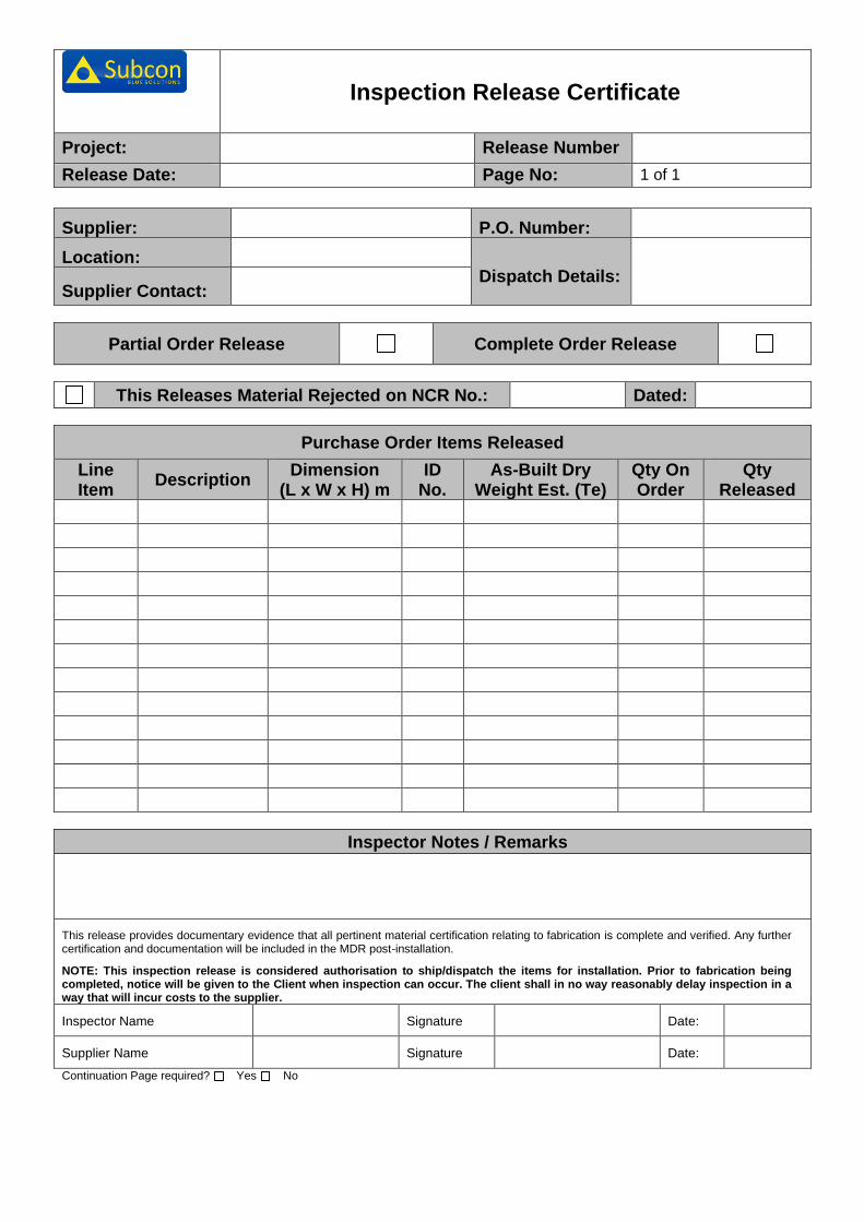
Inspection Release Certificate
Project: Release Number
Release Date: Page No: 1 of 1
Supplier: P.O. Number:
Location:
Dispatch Details:
Supplier Contact:
Partial Order Release Complete Order Release
This Releases Material Rejected on NCR No.: Dated:
Purchase Order Items Released
Line Item
Description Dimension
(L x W x H) m ID
No. As-Built Dry
Weight Est. (Te) Qty On Order
Qty Released
Inspector Notes / Remarks
This release provides documentary evidence that all pertinent material certification relating to fabrication is complete and verified. Any further certification and documentation will be included in the MDR post-installation.
NOTE: This inspection release is considered authorisation to ship/dispatch the items for installation. Prior to fabrication being completed, notice will be given to the Client when inspection can occur. The client shall in no way reasonably delay inspection in a way that will incur costs to the supplier.
Inspector Name Signature Date:
Supplier Name Signature Date:
Continuation Page required? Yes No

Project Purpose Built Artificial Reef – Turners Beach and Great Bay
Document Title Construction & Management Plan
Document No. 500331-MAST-AF-0001 Revision: B
12
Appendix D: Prestart Meeting & JHA Proforma

Bombora Fabrication Plan
Project Bombora Reef Modules
Document Name Bombora Fabrication Plan
Contact Roy Smit Email [email protected]
Subcon Document Number 308100-SUB-AF-0001 Revision A
0 Issued for Client Use
B Issued for Client Review
A Issued for Internal Review RSm JFr
Rev Date Revision Description Author Checked Approved Client Approval

Project Bombora Reef Modules
Document Title Bombora Fabrication Plan
Document No. 308100-SUB-AF-0001
Revision:A
2
Table of Contents
1 Introduction .................................................................................................................................. 4
Purpose .......................................................................................................................................... 4
Scope of Document ........................................................................................................................ 4
2 References and Standards .......................................................................................................... 5
Standards ....................................................................................................................................... 5
Subcon Reference Project Documents .......................................................................................... 5
Abbreviations/Definitions ................................................................................................................ 6
3 Fabrication .................................................................................................................................... 7
Typical Fabrication Process ........................................................................................................... 7
Reef Type and Dimensions ............................................................................................................ 8
4 Bombora Fabrication ................................................................................................................... 9
Steel Mould Preparation ................................................................................................................. 9
Steel Mould Assembly .................................................................................................................... 9
Ready-Mix Concrete on Site .......................................................................................................... 9
Casting ......................................................................................................................................... 10
Reef Breakout .............................................................................................................................. 11
Lift Point Inspection ...................................................................................................................... 12
5 Procedure Symbols Key ............................................................................................................ 13
6 Fabrication Health and Safety .................................................................................................. 14
General ......................................................................................................................................... 14
7 Logistics...................................................................................................................................... 21
General ......................................................................................................................................... 21
Manifesting Requirements ........................................................................................................... 21
Transportation Requirements....................................................................................................... 21
Appendix 1 Prestart Meeting & JHA Proforma ........................................................................................... 22
Appendix 2 Reef Module Drawings .............................................................................................................. 23
Appendix 3 Inspection and Release Note ................................................................................................... 24

Project Bombora Reef Modules
Document Title Bombora Fabrication Plan
Document No. 308100-SUB-AF-0001
Revision:A
3
List of Figures
Figure 1-1: Bombora Module ............................................................................................................................. 4
Figure 4-1: Bombora internal mould (left); external mould (centre); and assembled mould (right). .................. 9
Figure 4-2: Bombora concrete truck ramp. ...................................................................................................... 10
List of Tables
Table 3-1: General Bombora Details ................................................................................................................. 8
Table 4-1: Casting equipment ......................................................................................................................... 10
Table 4-2: External mould breakout equipment .............................................................................................. 11
Table 4-3: Internal mould breakout equipment ................................................................................................ 11
Table 6-1: Pre-start task plan .......................................................................................................................... 15
Table 6-2: Cleaning and preparation task plan ............................................................................................... 16
Table 6-3: Placing and fastening task plan...................................................................................................... 17
Table 6-4: Pouring concrete task plan ............................................................................................................. 18
Table 6-5: Reef break out task plan ................................................................................................................ 19
Table 6-6: Lifting and lay down task plan ........................................................................................................ 20

Project Bombora Reef Modules
Document Title Bombora Fabrication Plan
Document No. 308100-SUB-AF-0001
Revision:A
4
1 Introduction
Purpose
This document describes the procedures for fabrication of Subcon’s Bombora reefs using Subcon’s reef
formworks, ensuring safely produced, high quality products. The Bombora structure is presented below in
Figure 1-1.
Figure 1-1: Bombora Module
Scope of Document
This Fabrication Procedure document encompasses guidelines, procedures and best practices specific to
fabrication of Subcon’s standard reefs.

Project Bombora Reef Modules
Document Title Bombora Fabrication Plan
Document No. 308100-SUB-AF-0001
Revision:A
5
2 References and Standards
Standards
Ref # Title Doc Number
A1 Specification and Supply of Concrete AS1379
A2 Concrete Aggregates AS 2758.1
A3 Concrete Structures AS 3600
A4 Portland and Blended Cements AS 3972
A5 Methods for Testing Concrete AS 1012
A6 Quality Management System AS/NZS ISO 9001:2008
A7 DNV Rules for Marine Operations Part 2 Chapter 5 (1996) N/A
A8 Chemical Admixtures for Concrete Mortar and Grout AS1478
A9 Structural Steel Welding AS 1554.3
Subcon Reference Project Documents Ref # Title Doc Number
B1 Bombora Type 1 – General Arrangement 308105-SUB-DF-0001
B2 Bombora Type 2 – General Arrangement 308104-SUB-DF-0001
B3 Bombora Type 3 – General Arrangement 308103-SUB-DF-0001
B4 Bombora Type 4 – General Arrangement 308102-SUB-DF-0001
B5 Bombora Type 5 – General Arrangement 308101-SUB-DF-0001

Project Bombora Reef Modules
Document Title Bombora Fabrication Plan
Document No. 308100-SUB-AF-0001
Revision:A
6
Abbreviations/Definitions
Abbreviations / Definitions Description
AS Australian Standards
CAR Corrective Action Report
DNV Det Norske Veritas
DPR Daily Progress Report
EWP Elevated Work Platform
GA General Arrangement
HAZID / HAZOB Hazard Identification / Observation
HIRA Hazard Identification Risk Analysis
HSEQ Health, Safety, Environment, Quality
ID Identification
IMS Integrated Management System
IRN Inspection Release Note
ISO International Organisation for Standardization
ITP Inspection and Test Plan
JHA Job Hazard Analysis
MD Managing Director
MDR Manufacturer’s Data Report
MSDS Material Safety Data Sheets
NCR Non Conformance Report
PM Project Manager
PE Project Engineer
PPE Personal Protective Equipment
PQP Project Quality Plan
Project All activities pertaining to the Scope of Work as outlined in Contract
QA / QC Quality Assurance / Quality Control
QMS Quality Management System
SDL Supplier Document List
SOW Scope of Work
SWMS Safe Work Method Statement
TQ Technical Query
VOC Verification of Competency

Project Bombora Reef Modules
Document Title Bombora Fabrication Plan
Document No. 308100-SUB-AF-0001
Revision:A
7
1.
•Clean
•Replace sealing aids - (Silicone, ableflex and jointing)
•Application of form release agent
2.
•Base frame
•Internal pyramid
•External faces
•Break out beams / spacers
•Wings
•Lid
3.
•Self compacting concrete
•Quality controlled
•Specific marine concrete design
4.
•Lid
•Break out beams / spacers
•Wings
•External faces
•Reef Pyramid with base frame
•Internal pyramid mould
•Lift Concrete Reef Pyramid Base frame
3 Fabrication
Artificial concrete reefs are fabricated by pouring concrete into steel moulds. The steel moulds allow for
repeated use and intense compaction.
Typical Fabrication Process
The fabrication of the Reef Pyramid can be done as a continuous process. The same process is applied to the
fabrication of the Bombora modules.
1. Mould Preparation
2. Mould Assembly
3. Casting
4. Break Out

Project Bombora Reef Modules
Document Title Bombora Fabrication Plan
Document No. 308100-SUB-AF-0001
Revision:A
8
Reef Type and Dimensions
Table 3-1 below shows the properties of both the Reef Pyramid and Bombora modules.
Table 3-1: General Bombora Details
Type Length (m) Width
(m)
Height
(m)
Dry Weight
(Te)
Bombora – Type 1 2.1 - 1.8 3.3
Bombora – Type 2 1.8 - 1.5 2.6
Bombora – Type 3 1.8 - 1.3 2.0
Bombora – Type 4 1.2 - 0.9 0.6
Bombora – Type 5 0.9 - 0.6 0.3
Sections 4 on the following pages describe the detailed process for the fabrication of the Bombora modules.

Project Bombora Reef Modules
Document Title Bombora Fabrication Plan
Document No. 308100-SUB-AF-0001
Revision:A
9
4 Bombora Fabrication
Steel Mould Preparation
An environmentally friendly steel formwork release oil or form oil is sprayed on the steel moulds surfaces prior
to pouring concrete. The purpose of this form oil is to aid in the release of the mould from the reef. The form
oil allows for easier cleaning of the moulds post fabrication. Any vertical sections of the mould will have Abelflex
expansion foam and Duct tape applied to improve the breakout of the reef. Moulds are to be cleaned regularly
using steel wire brush, scrappers, geo picks or using a high-pressure wash system.
Steel Mould Assembly
Figure 4-1: Bombora internal mould (left); external mould (centre); and assembled mould (right).
Steel moulds can weigh upwards of 1Te each and require forklifts or a crane for handling. Steel mould
assembly typically consists of 1 internal mould, 1 external mould and various mould inserts. All surfaces of the
moulds exposed to concrete during casting are cleaned and sprayed with sufficient quantities of form oil prior
to assembly. The inner mould is placed on level ground and the outer mould is lowered onto the base mould.
Once in place, the moulds are secured using locking wedges to prevent movement during casting. The mould
inserts are then positioned and secured using wedges. Steel mould assembly is complete when all wedges
are checked to be secured and not loose.
Ready-Mix Concrete on Site
Concrete will typically be transported to site using 5 m3 capacity agitator trucks, delivery dockets for each truck
will be kept by the Project Engineer. Sampling will be completed in accordance to the ITP. Test cubes/cylinders
are kept in storage for compression testing, in accordance with the ITP.
5 m3 capacity agitator trucks will require a ramp when casting Bombora moulds. A minimum additional 200 mm
is necessary for the concrete chute to access the mould. Timber beams and a shipping container forklift ramp
is the recommended way of increasing chute height (see Figure 4-2).

Project Bombora Reef Modules
Document Title Bombora Fabrication Plan
Document No. 308100-SUB-AF-0001
Revision:A
10
Figure 4-2: Bombora concrete truck ramp.
Casting
Steel moulds are filled one at a time to the top surface via the agitator truck chute and shovels. Vibrators are
used to ensure that moulds are filled completely. The concrete vibrating shaft is inserted into each gap within
the mould carefully to ensure no internal voids are present in the concrete. The surface of the concrete is
trowelled to achieve a smooth finish.
Table 4-1: Casting equipment
Type Equipment
Bombora • Trowels;
• Vibrator;
• Screeding water bottles;
• Mallets/hammer;
• Wheelbarrow;
• Shovel;
• Safety step and safety platform
• Bulk bag for excess concrete (if expected).
Note: To ensure a clean breakaway by the top mould during demoulding it is recommended that the concrete
is undercut around the mould aperture perimeter using the trowel edge.
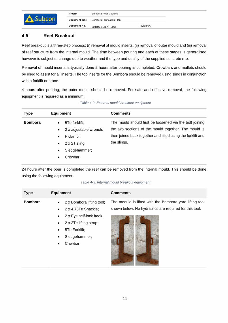
Project Bombora Reef Modules
Document Title Bombora Fabrication Plan
Document No. 308100-SUB-AF-0001
Revision:A
11
Reef Breakout
Reef breakout is a three-step process: (i) removal of mould inserts, (ii) removal of outer mould and (iii) removal
of reef structure from the internal mould. The time between pouring and each of these stages is generalised
however is subject to change due to weather and the type and quality of the supplied concrete mix.
Removal of mould inserts is typically done 2 hours after pouring is completed. Crowbars and mallets should
be used to assist for all inserts. The top inserts for the Bombora should be removed using slings in conjunction
with a forklift or crane.
4 hours after pouring, the outer mould should be removed. For safe and effective removal, the following
equipment is required as a minimum:
Table 4-2: External mould breakout equipment
Type Equipment Comments
Bombora • 5Te forklift;
• 2 x adjustable wrench;
• F clamp;
• 2 x 2T sling;
• Sledgehammer;
• Crowbar.
The mould should first be loosened via the bolt joining
the two sections of the mould together. The mould is
then joined back together and lifted using the forklift and
the slings.
24 hours after the pour is completed the reef can be removed from the internal mould. This should be done
using the following equipment:
Table 4-3: Internal mould breakout equipment
Type Equipment Comments
Bombora • 2 x Bombora lifting tool;
• 2 x 4.75Te Shackle;
• 2 x Eye self-lock hook
• 2 x 3Te lifting strap;
• 5Te Forklift;
• Sledgehammer;
• Crowbar.
The module is lifted with the Bombora yard lifting tool
shown below. No hydraulics are required for this tool.

Project Bombora Reef Modules
Document Title Bombora Fabrication Plan
Document No. 308100-SUB-AF-0001
Revision:A
12
Lift Point Inspection
Once the modules have been fabricated, the lift points are to be inspected to ensure there are no sharp edges
that may damage the lift rigging. Any sharp edges are to be removed prior to release of the Bomboras.

Project Bombora Reef Modules
Document Title Bombora Fabrication Plan
Document No. 308100-SUB-AF-0001
Revision:A
13
5 Procedure Symbols Key
Text set off in this manner provides warning that failure to follow these directions in
this WARNING can result in bodily harm or loss of life and possible extensive damage
to equipment.
Text set off in this manner provides warning that failure to follow these directions in
this CAUTION can result in damage to equipment.
Text set off in this manner present CLARIFYING INFORMATION or specific
instructions pertinent to the immediate instruction.
Text set of in this manner presents a HOLD point in the procedure.

Project Bombora Reef Modules
Document Title Bombora Fabrication Plan
Document No. 308100-SUB-AF-0001
Revision:A
14
6 Fabrication Health and Safety
General
Section 6 describes health and safety considerations for the fabrication procedures. The
procedures are divided into six main tasks:
• Prestart
• Cleaning and preparation
• Placing and fastening mould components
• Casting
• Reef break out
• Lifting and laydown
Safety is everyone’s responsibility. Minimum PPE requirements are not negotiable!
The minimum personal protective safety gear is as follows:
• Hard hat
• Steel cap boots
• High visibility clothing (Either shirts or vests)
• Safety glasses/goggles (Clear or Dark) – Depending on site conditions
• Gloves when handling mechanical equipment
• Safety harness when working above 1.8m from ground level
6.1.1 Health and Safety Task Checks
It is good practice to follow routine safety talks, checks and audits. Daily commitments from all staff members
and should become second nature. Looking out for any safety hazards every day should form part of the daily
clean-up process.
Daily safety checks should be done with good faith to oneself and others, taken very seriously and be
considered a vital part of life.

Project Bombora Reef Modules
Document Title Bombora Fabrication Plan
Document No. 308100-SUB-AF-0001
Revision:A
15
Table 6-1: Pre-start task plan
Safety Task Plan 1 – Prestart
Item Task Checked
1.
Conduct Toolbox talk & JHA including:
• Morning Stretches
• Daily hazard identifications and discussions
• Raise any new or overdue safety issues
• Discuss the daily tasks to be performed and raise any issues (if any)
2.
Prior to starting task assignments, ensure you are quipped and are wearing
your PPE
• Hard hat
• High visibility clothing
• Gloves
• Safety glasses/goggles
• Steel cap boots
Ensure eye wash station and lens cleaning bucket is accessible.

Project Bombora Reef Modules
Document Title Bombora Fabrication Plan
Document No. 308100-SUB-AF-0001
Revision:A
16
Table 6-2: Cleaning and preparation task plan
Safety Task Plan 2 – Cleaning and preparation
Item Task Checked
1. Identify the components that needs to be prepared
2. Ensure the lay down area is clear and free of any debris and other obstacles.
3. Ensure you are wearing the correct PPE if chemicals are to be used.
4. Ensure that the lifting equipment is certified and up to date.
5. Ensure that all other personnel are made wary of the lifting process

Project Bombora Reef Modules
Document Title Bombora Fabrication Plan
Document No. 308100-SUB-AF-0001
Revision:A
17
Table 6-3: Placing and fastening task plan
Safety Task Plan 3 – Placing and fastening mould components
Item Task Checked
1.
Check all relevant PPE is ready for placing and fastening mould components:
• Ear protection
• Steel cap boots
• Mono goggles
• Hard hat
• Fall prevention harness
• Gloves
• Hi-Vis coveralls
2.
Crew are not to climb above the anchor point on the face plate of the mould.
3.
Ensure all equipment required for placing and fastening is in place:
• Impact drills
• Wrenches and sockets
• Electrical equipment is tested and tagged
• Mallets/hammer
• Lifting equipment is certified up to date
4. Check that all preparation is done to satisfaction
• Make sure all the components are ready for lifting and placement
• Check surroundings and clear the ground of all obstructions and debris
• Inspect all mould components for fatigue, cracks or damage
• Check that ALL bolts, washers and nuts are clean and good working
order

Project Bombora Reef Modules
Document Title Bombora Fabrication Plan
Document No. 308100-SUB-AF-0001
Revision:A
18
Table 6-4: Pouring concrete task plan
Safety Task Plan 4 – Casting
Item Task Checked
1. Crew are not to climb above the anchor point on the face plate of the mould.
2.
Upon arrival of agitator truck check delivery docket prior to testing and
casting. Ensure the quantity of fibres added to the batch is correct and written
on docket.
3.
Pour 1m3 of concrete mix into wheelbarrow for tester to use.
A slump test should be completed and 3 cylinders should be taken for 1 x 7 day
compressive test and 2 x 28 day compressive tests.
4.
Concrete truck is guided to reverse up to the concrete piston pump hopper.
This MUST be done by one (1) dedicated person.
The discharge pipe should not be moved out of the mould whilst concrete is
being pumped.
5. As the concrete is being poured into the pump hopper, the flow out of the truck
should be carefully monitored to prevent spillage.

Project Bombora Reef Modules
Document Title Bombora Fabrication Plan
Document No. 308100-SUB-AF-0001
Revision:A
19
Table 6-5: Reef break out task plan
Safety Task Plan 5 – Reef break out
Item Task Checked
1. Crew are not to climb above the anchor point on the face plate of the mould.
2. Approximately 12 hours after casting the mould and inserts can be removed.
3. Make sure that there are no tools or equipment left on the moulds before lifting
or breaking out.
4.
Slings are attached to lifting points and lifted away using the crawler crane and
lifting slings/chains. Sledgehammers will often be required to assist the
breakaway.
5.
Remove all bolts from the bottom working upwards, ensuring the lifting
equipment is attached to the component before commencing with loosening
the bolts.
6.
Approximately 24 hours after pouring, the reef should be removed from the
steel base frame. The appropriate lifting tool should be attached to the
appropriate slings and crawler crane before lifting.
Note: If removal of inserts and top moulds is premature the reef will crack and become non-conformant. If
removal is delayed, the process will become extremely difficult due to concrete expansion. Hence the
importance of keeping an eye on conditions and the reefs curing.

Project Bombora Reef Modules
Document Title Bombora Fabrication Plan
Document No. 308100-SUB-AF-0001
Revision:A
20
Table 6-6: Lifting and lay down task plan
Safety Task Plan 6 – Lifting and laydown
Item Task Checked
1. Reef modules will have loose concrete around the perimeter and inside the
voids. These should be cleaned by knocking out with a crowbar.
2.
The crawler crane is utilised to lift the reef off of the steel base frame and place
them on wooden blocks.
Ensure the correct lifting tool is used in conjunction with the correct
slings/chains.
3.
Steel base moulds are to be cleaned & made ready for pouring of the next
reef.

Project Bombora Reef Modules
Document Title Bombora Fabrication Plan
Document No. 308100-SUB-AF-0001
Revision:A
21
7 Logistics
General
All logistical movements between fabrication site and Client nominated delivery location, will be managed by
the Project Engineer. On completion of fabrication, Client shall be advised on delivery requirements for the
reef modules. No reefs shall leave the fabrication yard until approved by Client.
Manifesting Requirements
All deliveries must be accompanied with an Inspection Release Note signed by Client prior to items leaving
the yard. An inspection and release template can be found in Appendix 3 Inspection and Release Note.
Transportation Requirements
Rubber, wood chocks, chain and /or ratchet straps may be used to secure the reefs for transportation around
the base of each reef.

Project Bombora Reef Modules
Document Title Bombora Fabrication Plan
Document No. 308100-SUB-AF-0001
Revision:A
22
Appendix 1 Prestart Meeting

PRESTART MEETING
2101-SUB-MQ-0016Daily Prestart Meeting Template
WEATHER FORCAST:
TODAY’S TASK:
RESPONSIBILITIES:
Team Leaders:
Housekeeping:
First Aid
Forklift:
Crane:
Dogman:
Other:
QUALITY:
Assembly: Diamentions: Rope Length: Surface Finish:
NCR’s:
SAFETY:
Incidents/HAZOBS that the crew need to be aware of:
Everyone is aware of Stop Work Procedures
Stretched Complete:
JSA Complete:
Supervisor Name: Signature:
DATE: SITE:
DAY: PROJECT:

Project Bombora Reef Modules
Document Title Bombora Fabrication Plan
Document No. 308100-SUB-AF-0001
Revision:A
23
Appendix 2 Reef Module Drawings

TOP VIEW
SCALE 1 : 25
SIDE VIEW
SCALE 1 : 25
ISOMETRIC VIEW
SCALE 1 : 25
SECTION A-A
SCALE 1 : 25
SECTION B-B
SCALE 1 : 25
A
A
B
B
1 2 3 4 5 6 7 8 9 10 11 12
1 2 3 4 5 6 7 8 9 10 11 12
A
B
C
D
E
F
G
H H
G
F
E
D
C
B
A
Perth: +61 8 9200 2218
Singapore: +65 6440 7752
Europe: +31 15 800 0228
China: +86 769 828 06357, +86 137 1529 7879
Web: www.subcon.com
TITLE
2.1m x D1.8m BOMBORA
GENERAL ARRANGEMENT
308105-SUB-DF-0001
DRAWING NUMBER
REV
1 SHEET 1 of 1
SIZE
A3
SCALE
NTS
C Copyright Subcon 2021
CHECKED
DRAWN
APPROVED
I.CLEGG
M.ALLEN
Y.LIM
INITIAL DATE
DRN CHK APPREV DATE DESCRIPTION
0 20.11.19 IC YL MAISSUED FOR CONSTRUCTION
05.03.211 ISSUED FOR CONSTRUCTION MAIC YL
NOTES:
1. ALL DIMENSIONS ARE IN MILLIMETRES UNO.
2. CONCRETE VOLUME: 1.44m3
3. CONCRETE DENSITY: 2.35Te/m3
4. DRY WEIGHT: 3.28Te
5. SURFACE AREA: 21.14m2
6. NUMBER OF HOLES: 27
7. CONCRETE TYPE 50 MPa MARINE CONCRETE.
1550
1600
1750
2 CoG
921
C
oG
170
2100
SMOOTH CONCRETE
SURFACE ON
REMAINING SURFACES
TOP CONCRETE SURFACE
FINISH TO BE EXPOSED
AGGREGATE ONLY
1104
700
131
(T
Y
P
.)
222 (T
Y
P
.)
900 (T
Y
P
.)
2
1
9
(
T
Y
P
.
)
129
550 (T
Y
P
.)

PLAN VIEW
SCALE 1 : 20
SIDE VIEW
SCALE 1 : 20
SECTION A-A
SCALE 1 : 20
ISOMETRIC VIEW
SCALE 1 : 20
SECTION B-B
SCALE 1 : 20
A
A
B
B
1 2 3 4 5 6 7 8 9 10 11 12
1 2 3 4 5 6 7 8 9 10 11 12
A
B
C
D
E
F
G
H H
G
F
E
D
C
B
A
Perth: +61 8 9200 2218
Singapore: +65 6440 7752
Europe: +31 15 800 0228
China: +86 769 828 06357, +86 137 1529 7879
Web: www.subcon.com
Concrete Marine Solutions
TITLE
1.8m x D1.5m BOMBORA
GENERAL ARRANGEMENT
308104-SUB-DF-0001
DRAWING NUMBER
REV
0 SHEET 1 of 1
SIZE
A3
SCALE
NTS
C Copyright Subcon 2019
CHECKED
DRAWN
APPROVED
I.CLEGG
M.ALLEN
Y.LIM
INITIAL DATE
DRN CHK APPREV DATE DESCRIPTION
0 20.11.19 IC YL MAISSUED FOR CONSTRUCTION
NOTES:
1. ALL DIMENSIONS ARE IN MILLIMETRES UNO.
2. CONCRETE VOLUME: 1.08m3
3. CONCRETE DENSITY: 2.35Te/m3
4. DRY WEIGHT: 2.55Te
5. SURFACE AREA: 15.70m2
6. NUMBER OF HOLES: 23
7. CONCRETE TYPE 50 MPa MARINE CONCRETE.
450
237
(T
Y
P
.)
650 (T
Y
P
.)
837
1800
195
1250
1300 1
450
15001
00
TOP CONCRETE SURFACE
FINISH TO BE EXPOSED
AGGREGATE ONLY
SMOOTH CONCRETE
SURFACE ON
REMAINING SURFACES
1.2m x 20mm FIBREGLASS ROD
ORTHOPHTHALIC RESIN WITH
STEEL FLAT CAP
ANCHORAGE VOID
MINIMUM 32mm
DIAMETER 3 PER
REEF MODULE
380 (T
Y
P
.)
131 (TYP.)
16 C
oG
1 CoG
766 C
oG
2
3
3
(
T
Y
P
.
)
122
300
132
(T
Y
P
.)

TOP VIEW
SCALE 1 : 20
SIDE VIEW
SCALE 1 : 20
SECTION A-A
SCALE 1 : 20
SECTION B-B
SCALE 1 : 20
ISOMETRIC VIEW
SCALE 1 : 20
A
A
B
B
1 2 3 4 5 6 7 8 9 10 11 12
1 2 3 4 5 6 7 8 9 10 11 12
A
B
C
D
E
F
G
H H
G
F
E
D
C
B
A
Perth: +61 8 9200 2218
Singapore: +65 6440 7752
Europe: +31 15 800 0228
China: +86 769 828 06357, +86 137 1529 7879
Web: www.subcon.com
Concrete Marine Solutions
TITLE
1.8m x D1.3m BOMBORA
GENERAL ARRANGEMENT
308103-SUB-DF-0001
DRAWING NUMBER
REV
0 SHEET 1 of 1
SIZE
A3
SCALE
NTS
C Copyright Subcon 2019
CHECKED
DRAWN
APPROVED
I.CLEGG
M.ALLEN
Y.LIM
INITIAL DATE
DRN CHK APPREV DATE DESCRIPTION
0 20.11.19 IC YL MAISSUED FOR CONSTRUCTION
NOTES:
1. ALL DIMENSIONS ARE IN MILLIMETRES UNO.
2. CONCRETE VOLUME: 0.85m3
3. CONCRETE DENSITY: 2.35Te/m3
4. DRY WEIGHT: 1.99Te
5. SURFACE AREA: 13.76m2
6. NUMBER OF HOLES: 21
7. CONCRETE TYPE 50 MPa MARINE CONCRETE.
924
1800
150
1050
1100 1
250
13001
00
2
1
5
(
T
Y
P
.
)
500 (T
Y
P
.)
650
ANCHORAGE VOID
MINIMUM 32mm
DIAMETER 3 PER
REEF MODULE
EXPOSED AGGREGATE
ON TOP SURFACE ONLY
SMOOTH CONCRETE
SURFACE ON
REMAINING SURFACES
340 (T
Y
P
.)
218 (T
Y
P
.)
1.2m x 20mm FIBREGLASS ROD
ORTHOPHTHALIC RESIN WITH
STEEL FLAT CAP
136 (TYP.)
153
300
728 C
oG
1 CoG
27 C
oG
138
(T
Y
P
.)

TOP VIEW
SCALE 1:12
SIDE VIEW
SCALE 1:12
SECTION A-A
SCALE 1:12
SECTION B-B
SCALE 1:12
ISOMETRIC VIEW
SCALE 1:12
A
A
B
B
1 2 3 4 5 6 7 8 9 10 11 12
1 2 3 4 5 6 7 8 9 10 11 12
A
B
C
D
E
F
G
H H
G
F
E
D
C
B
A
Perth: +61 8 9200 2218
Singapore: +65 6440 7752
Europe: +31 15 800 0228
China: +86 769 828 06357, +86 137 1529 7879
Web: www.subcon.com
Concrete Marine Solutions
TITLE
1.2m x D0.9m BOMBORA
GENERAL ARRANGEMENT
308102-SUB-DF-0001
DRAWING NUMBER
REV
0 SHEET 1 of 1
SIZE
A3
SCALE
NTS
C Copyright Subcon 2019
CHECKED
DRAWN
APPROVED
I.CLEGG
M.ALLEN
Y.LIM
INITIAL DATE
DRN CHK APPREV DATE DESCRIPTION
0 20.11.19 IC YL MAISSUED FOR CONSTRUCTION
NOTES:
1. ALL DIMENSIONS ARE IN MILLIMETRES UNO.
2. CONCRETE VOLUME: 0.26m3
3. CONCRETE DENSITY: 2.35Te/m3
4. DRY WEIGHT: 0.61Te
5. SURFACE AREA: 6.03m2
6. NUMBER OF HOLES: 14
7. CONCRETE TYPE 50 MPa MARINE CONCRETE.
472
1
8
2
(
T
Y
P
.
)
1200
100
650
700
850
9001
00
500 (T
Y
P
.)
400
186
(T
Y
P
.)
ANCHORAGE VOID
MINIMUM 32mm
DIAMETER 3 PER
REEF MODULE
EXPOSED AGGREGATE
ON TOP SURFACE ONLY
SMOOTH CONCRETE
SURFACE ON
REMAINING SURFACES
1.2m x 20mm FIBREGLASS ROD
ORTHOPHTHALIC RESIN WITH
STEEL FLAT CAP
130 (TYP.)
152
300
519
C
oG
8 C
oG
132
(T
Y
P
.)

PLAN VIEW
SCALE 1:10
SIDE VIEW
SCALE 1:10
SECTION A-A
SCALE 1:10
SECTION B-B
SCALE 1:10
ISOMETRIC VIEW
SCALE 1:10
A
A
B
B
1 2 3 4 5 6 7 8 9 10 11 12
1 2 3 4 5 6 7 8 9 10 11 12
A
B
C
D
E
F
G
H H
G
F
E
D
C
B
A
Perth: +61 8 9200 2218
Singapore: +65 6440 7752
Europe: +31 15 800 0228
China: +86 769 828 06357, +86 137 1529 7879
Web: www.subcon.com
Concrete Marine Solutions
TITLE
0.9m x D0.6m BOMBORA
GENERAL ARRANGEMENT
308101-SUB-DF-0001
DRAWING NUMBER
REV
0 SHEET 1 of 1
SIZE
A3
SCALE
NTS
C Copyright Subcon 2019
CHECKED
DRAWN
APPROVED
I.CLEGG
M.ALLEN
Y.LIM
INITIAL DATE
DRN CHK APPREV DATE DESCRIPTION
0 20.11.19 IC YL MAISSUED FOR CONSTRUCTION
NOTES:
1. ALL DIMENSIONS ARE IN MILLIMETRES UNO.
2. CONCRETE VOLUME: 0.13m3
3. CONCRETE DENSITY: 2.35Te/m3
4. DRY WEIGHT: 0.30Te
5. SURFACE AREA: 3.1m2
6. NUMBER OF HOLES: 7
7. CONCRETE TYPE 50 MPa MARINE CONCRETE.
8. REFER TO DRAWING 01-500192-ROM -DF-0081 FOR
TYPICAL REEF CONNECTION DETAIL.
376
1
8
3
(
T
Y
P
.
)
ANCHORAGE VOID
MINIMUM 32mm
DIAMETER 3 PER
REEF MODULE
100
900
382 4
32
550
6001
00
250
300 (T
Y
P
.)
188
(T
Y
P
.)
EXPOSED AGGREGATE
ON TOP SURFACE ONLY
SMOOTH CONCRETE
SURFACE ON
REMAINING SURFACES
1.2m x 20mm FIBREGLASS ROD
ORTHOPHTHALIC RESIN WITH
STEEL FLAT CAP
130
331
C
oG
11 C
oG
202
300
134
(T
Y
P
.)

Project Bombora Reef Modules
Document Title Bombora Fabrication Plan
Document No. 308100-SUB-AF-0001
Revision:A
24
Appendix 3 Inspection and Release Note

Inspection Release Certificate
Project: Release Number
Release Date: Page No: 1 of 1
Supplier: P.O. Number:
Location:
Dispatch Details:
Supplier Contact:
Partial Order Release Complete Order Release
This Releases Material Rejected on NCR No.: Dated:
Purchase Order Items Released
Line Item
Description Dimension
(L x W x H) m ID
No. As-Built Dry
Weight Est. (Te) Qty On Order
Qty Released
Inspector Notes / Remarks
This release provides documentary evidence that all pertinent material certification relating to fabrication is complete and verified. Any further certification and documentation will be included in the MDR post-installation.
NOTE: This inspection release is considered authorisation to ship/dispatch the items for installation. Prior to fabrication being completed, notice will be given to the Client when inspection can occur. The client shall in no way reasonably delay inspection in a way that will incur costs to the supplier.
Inspector Name Signature Date:
Supplier Name Signature Date:
Continuation Page required? Yes No

Project Purpose Built Artificial Reef – Turners Beach and Great Bay
Document Title Construction & Management Plan
Document No. 500331-MAST-AF-0001 Revision: B
13
Appendix E: Inspection and Release Note

Inspection Release Certificate
Project: Release Number
Release Date: Page No: 1 of 1
Supplier: P.O. Number:
Location:
Dispatch Details:
Supplier Contact:
Partial Order Release Complete Order Release
This Releases Material Rejected on NCR No.: Dated:
Purchase Order Items Released
Line Item
Description Dimension
(L x W x H) m ID
No. As-Built Dry
Weight Est. (Te) Qty On Order
Qty Released
Inspector Notes / Remarks
This release provides documentary evidence that all pertinent material certification relating to fabrication is complete and verified. Any further certification and documentation will be included in the MDR post-installation.
NOTE: This inspection release is considered authorisation to ship/dispatch the items for installation. Prior to fabrication being completed, notice will be given to the Client when inspection can occur. The client shall in no way reasonably delay inspection in a way that will incur costs to the supplier.
Inspector Name Signature Date:
Supplier Name Signature Date:
Continuation Page required? Yes No
Great Bay Artificial Reef EER
Appendix 4. Subcon’s Module Installation plan (2021).
Concrete Module Installation Plan
Author Roy Smit Email [email protected]
Subcon Document Number 500331-MAST-AF-0006 Revision A
Client Document Number - Revision
A Issued for Internal Review RSm JFr
Rev Date Revision Description Author Checked Approved Client Approval
16/09/2021

Project Purpose Built Artificial Reefs – Turners Beach and Great Bay
Document Name Concrete Module Installation Plan
Document No. 500331-MAST-AF-0006 Revision: A
Client No. -
2
Table of Contents
1 Introduction .................................................................................................................................. 5
1.1 Background .................................................................................................................................... 5
1.2 Document Purpose ........................................................................................................................ 7
1.3 Target Audience ............................................................................................................................. 7
2 References and Standards .......................................................................................................... 8
2.1 Industry Standards ......................................................................................................................... 8
2.2 Project Documents ......................................................................................................................... 8
2.3 Abbreviations & Definitions ............................................................................................................ 8
2.4 Procedure Symbols Key ............................................................................................................... 10
3 Project HSEQ .............................................................................................................................. 11
3.1 General ......................................................................................................................................... 11
3.2 Procedure Specific QHSE Requirements .................................................................................... 11
4 Organisation & Responsibilities ............................................................................................... 12
5 Installation Methodology Overview .......................................................................................... 13
5.1 Transport to [HOLD 2] .................................................................................................................. 13
5.2 Marine Spread .............................................................................................................................. 13
5.3 Modules ........................................................................................................................................ 13
5.4 Module Loadout ........................................................................................................................... 13
5.5 Seafastening ................................................................................................................................ 13
5.6 Mobilisation to Installation location .............................................................................................. 14
5.7 Vessel Positioning ........................................................................................................................ 14
5.8 Deployment to seabed ................................................................................................................. 14
5.9 Survey .......................................................................................................................................... 14
6 Task Plans .................................................................................................................................. 15
6.1 Vessel Mobilisation ...................................................................................................................... 15
6.2 Bombora Concrete Modules Installation ...................................................................................... 15
6.3 Apollo Concrete Modules Installation ........................................................................................... 16
6.4 Abitat Concrete Modules Installation ........................................................................................... 17
7 Workplace Health and Safety .................................................................................................... 19
7.1 Policies ......................................................................................................................................... 19
7.2 Integrated Management System .................................................................................................. 19
7.3 WHS Plan ..................................................................................................................................... 20
8 Contingencies ............................................................................................................................ 22
8.1 Crane DPGS System Failure ....................................................................................................... 22

Project Purpose Built Artificial Reefs – Turners Beach and Great Bay
Document Name Concrete Module Installation Plan
Document No. 500331-MAST-AF-0006 Revision: A
Client No. -
3
8.2 Crane Malfunction/ Breakdown .................................................................................................... 22
8.3 Waiting on Weather ...................................................................................................................... 22
8.4 Severe Weather Whilst in Alongside Wharf ................................................................................. 22
8.5 Pennant Wire Parts ...................................................................................................................... 22
8.6 Anchor Wire Parts ........................................................................................................................ 22
8.7 Hydraulic Lift Tool Won’t Disengage ............................................................................................ 22
8.8 Environmental Spill ...................................................................................................................... 22
Appendix A: Installation Vessel Details [HOLD 3] ..................................................................................... 23
List of Figures
Figure 1-1: Turners Beach Artificial Reef Approximate Location ...................................................................... 5
Figure 1-2: Great Bay Artificial Reef Approximate Location .............................................................................. 6
Figure 1-3: Abitat module left, Apollo module centre, and Bombora module right. ........................................... 6
List of Tables
Table 4-1. Responsibilities .............................................................................................................................. 12
Table 5-1. Concrete Module Overview ............................................................................................................ 13
Table 6-1 Bombora Deployment Procedure .................................................................................................... 15
Table 6-2 Apollo Deployment Procedure ......................................................................................................... 16
Table 6-3 Abitat Deployment Procedure ......................................................................................................... 17

Project Purpose Built Artificial Reefs – Turners Beach and Great Bay
Document Name Concrete Module Installation Plan
Document No. 500331-MAST-AF-0006 Revision: A
Client No. -
4
Holds List
Hold # Location Description
HOLD 1 2.3 Deck Layout
HOLD 2 5.1, 8.3 Wharf location
HOLD 3 5.1, Appendix A Vessel selection
HOLD 4 5.7 Vessel Mooring Arrangement
HOLD 5 5.8 Concrete Module Installation Story Boards
HOLD 6 5.1 Subcontractor selection

Project Purpose Built Artificial Reefs – Turners Beach and Great Bay
Document Name Concrete Module Installation Plan
Document No. 500331-MAST-AF-0006 Revision: A
Client No. -
5
1 Introduction
1.1 Background
The Principal (Marine and Safety Tasmania (MAST)) are requesting tenders for the design and construction
of two purpose built artificial reefs offshore Tasmania. The reefs have been instigated by the state government
to fulfill commitments made to recreational fishers during the 2017 election and detailed in the Taking
Recreational Fishing and Boating to the next level plan (2019). The primary objective of the Works is to
increase recreational fishing opportunities in the north and south of the state by creating new productive habitat
through Tasmania’s first large scale purpose-built artificial reef. Although the reefs are not designed as a dive
attraction their shallow depth and novelty in the Tasmanian environment is sure to attract diver interest. As a
result, the contractor shall also consider diver safety and entanglement in the design.
MAST have commissioned Marine Solutions to complete a feasibility assessment of the artificial reef
offshore Tasmania [Appendix 1]. The socioeconomic and environmental impacts have been assessed as
part of the study and two locations have been chosen for the deployment of purpose-built artificial reefs off
Tasmania broadly described as Turners Beach (
Figure 1-1) and Great Bay (Figure 1-2).
Figure 1-1: Turners Beach Artificial Reef Approximate Location

Project Purpose Built Artificial Reefs – Turners Beach and Great Bay
Document Name Concrete Module Installation Plan
Document No. 500331-MAST-AF-0006 Revision: A
Client No. -
6
Figure 1-2: Great Bay Artificial Reef Approximate Location
The reef constituting the Works shall be designed and purpose-built using materials that have been
demonstrated to be inert, and resistant to deterioration in seawater (from monitoring results of past applications
and/or by professional opinion from a suitably experienced marine biologist and a suitably experienced coastal
engineer, each approved by the Principal) as defined in the Guidelines for the Placement of Artificial Reefs
(London Convention and Protocol/UNEP, 2009). The modules must also be self-weighted and physically stable
to withstand sliding and overturning from prevailing storm events while providing complex fisheries habitat for
a range of popular fish species common to proposed location coastal region.
The reefs will be made up of three variations of concrete modules, the Bombora module, the Apollo module
and the Abitat module as displayed in Figure 1-3.
Figure 1-3: Abitat module left, Apollo module centre, and Bombora module right.

Project Purpose Built Artificial Reefs – Turners Beach and Great Bay
Document Name Concrete Module Installation Plan
Document No. 500331-MAST-AF-0006 Revision: A
Client No. -
7
1.2 Document Purpose
This procedure contains all information required for the successful execution of the concrete module
installation of Turners Beach and Great Bay. The document is set out in chronological order with supporting
information attached to each section. For details on the concrete modules, refer to drawings [Ref. B2 - B6].
1.3 Target Audience
This document is targeted at all personnel directly involved with the installation. It should be reviewed and
available offshore for all personnel during execution. This includes but is not limited to:
• Offshore Construction Manager.
• Contractor Site Representative.
• Subcon Technologies Offshore Representative and Crew.
• Subcontractor Personnel.
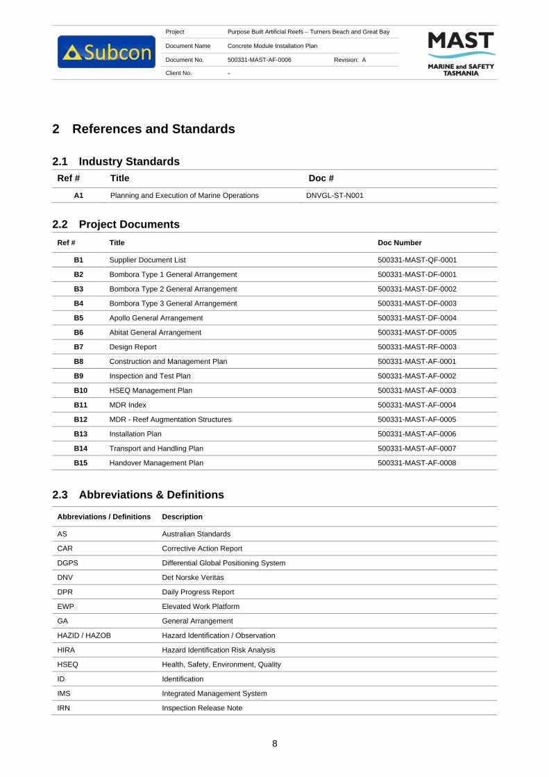
Project Purpose Built Artificial Reefs – Turners Beach and Great Bay
Document Name Concrete Module Installation Plan
Document No. 500331-MAST-AF-0006 Revision: A
Client No. -
8
2 References and Standards
2.1 Industry Standards
Ref # Title Doc #
A1 Planning and Execution of Marine Operations DNVGL-ST-N001
2.2 Project Documents
Ref # Title Doc Number
B1 Supplier Document List 500331-MAST-QF-0001
B2 Bombora Type 1 General Arrangement 500331-MAST-DF-0001
B3 Bombora Type 2 General Arrangement 500331-MAST-DF-0002
B4 Bombora Type 3 General Arrangement 500331-MAST-DF-0003
B5 Apollo General Arrangement 500331-MAST-DF-0004
B6 Abitat General Arrangement 500331-MAST-DF-0005
B7 Design Report 500331-MAST-RF-0003
B8 Construction and Management Plan 500331-MAST-AF-0001
B9 Inspection and Test Plan 500331-MAST-AF-0002
B10 HSEQ Management Plan 500331-MAST-AF-0003
B11 MDR Index 500331-MAST-AF-0004
B12 MDR - Reef Augmentation Structures 500331-MAST-AF-0005
B13 Installation Plan 500331-MAST-AF-0006
B14 Transport and Handling Plan 500331-MAST-AF-0007
B15 Handover Management Plan 500331-MAST-AF-0008
2.3 Abbreviations & Definitions
Abbreviations / Definitions Description
AS Australian Standards
CAR Corrective Action Report
DGPS Differential Global Positioning System
DNV Det Norske Veritas
DPR Daily Progress Report
EWP Elevated Work Platform
GA General Arrangement
HAZID / HAZOB Hazard Identification / Observation
HIRA Hazard Identification Risk Analysis
HSEQ Health, Safety, Environment, Quality
ID Identification
IMS Integrated Management System
IRN Inspection Release Note
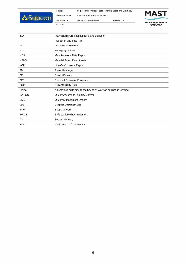
Project Purpose Built Artificial Reefs – Turners Beach and Great Bay
Document Name Concrete Module Installation Plan
Document No. 500331-MAST-AF-0006 Revision: A
Client No. -
9
ISO International Organisation for Standardization
ITP Inspection and Test Plan
JHA Job Hazard Analysis
MD Managing Director
MDR Manufacturer’s Data Report
MSDS Material Safety Data Sheets
NCR Non-Conformance Report
PM Project Manager
PE Project Engineer
PPE Personal Protective Equipment
PQP Project Quality Plan
Project All activities pertaining to the Scope of Work as outlined in Contract
QA / QC Quality Assurance / Quality Control
QMS Quality Management System
SDL Supplier Document List
SOW Scope of Work
SWMS Safe Work Method Statement
TQ Technical Query
VOC Verification of Competency

Project Purpose Built Artificial Reefs – Turners Beach and Great Bay
Document Name Concrete Module Installation Plan
Document No. 500331-MAST-AF-0006 Revision: A
Client No. -
10
2.4 Procedure Symbols Key
Text set off in this manner provides warning that failure to follow these directions in
this WARNING can result in bodily harm or loss of life and possible extensive damage
to equipment.
Text set off in this manner provides warning that failure to follow these directions in
this CAUTION can result in damage to equipment.
Text set off in this manner present CLARIFYING INFORMATION or specific
instructions pertinent to the immediate instruction.
Text set of in this manner presents a HOLD point in the procedure.

Project Purpose Built Artificial Reefs – Turners Beach and Great Bay
Document Name Concrete Module Installation Plan
Document No. 500331-MAST-AF-0006 Revision: A
Client No. -
11
3 Project HSEQ
3.1 General
Subcon Technologies’ company standard and project specific HSEQ policies are described within the HSEQ
Management Plan [Ref B10]. These shall be adhered to at all times and available to all personnel listed in
Section 1.3.
3.2 Procedure Specific QHSE Requirements
This document presents HSEQ requirements for each part of the procedure within the task plans listed in
Section 6. These are to be reviewed prior to the beginning of each task by all personnel involved in the
operation. JHA’s will also be written for each task and reviewed by all personnel involved in the task line with
the project HSEQ Management Plan.

Project Purpose Built Artificial Reefs – Turners Beach and Great Bay
Document Name Concrete Module Installation Plan
Document No. 500331-MAST-AF-0006 Revision: A
Client No. -
12
4 Organisation & Responsibilities
Overall project roles and responsibilities can be found within the HSEQ Management Plan [Ref. B10].
Responsibilities specific to this task are displayed in the below table.
Table 4-1. Responsibilities
Title Organisation Responsibilities
Offshore
Construction
Manager
Subcon
Technologies
Provides direction for all installation activities.
Vessel Master Charterer Responsible for the safe operation of the installation vessel. They
are to follow direction from the OCM in regard to vessel positioning.
Vessel Crew Charterer Assist with vessel operation works. Including handling of mooring
equipment and mooring winches, crane operation.
Project
Manager
Subcon
Technologies
Provide high level management of project HSE requirements
schedule and procedure.
Project
Engineer
Subcon
Technologies
The project engineer is responsible for the refastening of the
modules on deck, confirmation of correct installation locations and
recording of all project information for reporting and documentation
purposes.
Installation
Crew
Subcon
Technologies
Carry out physical installation activities and works required on board
the installation vessel and quayside. This includes, rigging &
dogging,

Project Purpose Built Artificial Reefs – Turners Beach and Great Bay
Document Name Concrete Module Installation Plan
Document No. 500331-MAST-AF-0006 Revision: A
Client No. -
13
5 Installation Methodology Overview
This section gives a general description of the installation methodology. The tasks are described in detail in
Section 6.
5.1 Transport to [HOLD 2]
The concrete modules will be fabricated by Subcontractor [HOLD 6], before being transported to a wharf
[HOLD 2] for loadout prior to installation. Once delivered to the wharf [HOLD 2], the modules will be stored and
the loaded onto a vessel [HOLD 3]. Considerations for vibrations and adequate strapping will be considered
when the modules are transported from Subcontractor [HOLD 6] to the wharf [HOLD 2].
5.2 Marine Spread
The marine spread will consist of the vessel with a mounted crane [HOLD 3] to install the modules. Details of
the installation vessel can be found in Appendix 0.
5.3 Modules
Table 5-1 below contains an overview of the concrete modules that are to be installed. Detailed drawings of
each can be found in their respective general arrangements [Ref B2-B6].
Table 5-1. Concrete Module Overview
Type Length
(m)
Width
(m)
Height
(m)
Dry Weight
(Te)
Quantity
Turners Beach
Quantity
Great Bay
Abitat 2.8 2.425 1.0 1.77 - 14
Apollo 1.3 - 1.0 0.9 42 42
Bombora – Type 1 2.1 - 1.8 3.3 70 70
Bombora – Type 2 1.8 - 1.5 2.6 7 7
Bombora – Type 3 1.8 - 1.3 2.0 21 21
5.4 Module Loadout
The installation vessel will attend the wharf and begin loadout of the modules as per the deck layout [HOLD
1]. The location of each module is to be marked onto the deck with line marking paint to assist with the module
loading. The vessel will be required to re-load with the concrete modules’ multiple times.
5.5 Seafastening
The concrete modules will be seafastened to the deck to prevent movement due to motions during towing to
site and installation. The seafastening will be by 2.5Te ratchet straps in accordance with DNV guidelines [Ref.
A1].

Project Purpose Built Artificial Reefs – Turners Beach and Great Bay
Document Name Concrete Module Installation Plan
Document No. 500331-MAST-AF-0006 Revision: A
Client No. -
14
5.6 Mobilisation to Installation location
Upon confirmation of a suitable weather window, the vessel will steam to site. The vessel will remain crewed
with the installation crew during the transit.
5.7 Vessel Positioning
The vessel will be positioned for installation using a four-point mooring system [HOLD 4]. Details of the mooring
arrangement for each installation location can be found on the mooring arrangement drawings for installation
[HOLD 5] and Section 6.1.
5.8 Deployment to seabed
The vessel crane will be used to lift and deploy the concrete modules to the seabed. The Apollo modules are
installed using a hydraulic lift tool that is able to install four modules simultaneously. The remaining modules
are installed one at a time and released once on the seafloor using inflatable buoys attached to the lift tool.
5.9 Survey
A DGPS survey system will be installed on the crane boom tip for the duration of the installation. This will be
relayed to a tablet or computer on-board of the installation vessel to enable accurate placement and recording
of the modules. This information will be cross referenced with the bathymetry survey to provide the
hydrographic survey notes.

Project Purpose Built Artificial Reefs – Turners Beach and Great Bay
Document Name Concrete Module Installation Plan
Document No. 500331-MAST-AF-0006 Revision: A
Client No. -
15
6 Task Plans
6.1 Vessel Mobilisation
Vessel Mobilisation
Step Task Note Check
1. [HOLD 1, 2 & 3]
6.2 Bombora Concrete Modules Installation
Table 6-1 below describes the procedure for installation of the Bombora concrete modules to the seabed. The
modules are installed using the vessel crane with self-recovering lift tools.
Table 6-1 Bombora Deployment Procedure
Bombora Deployment Procedure
Step Task Note Check
1. All crew to conduct prestart for daily activates and sign onto relevant
JHA’s
2. Project Engineer to confirm that the vessel is moored in the correct
location to install the reef module.
3. Tie off one Norwegian buoy to each of the lift tools. Ensure that the
buoys are fully inflated.
4. Connect the lift tool arms to the vessel crane.
The Bombora concrete modules require two lifting arms for
installation.
5. Release seafastenings on the concrete module that is to be
installed.
6. Crane slews over to reef module and lowers lifting arms to the
concrete module.
7. Insert lift arms into the lifting points on the concrete modules to be
installed.
8. Lift module off deck and slew till the concrete module clears the
deck (ensure lift height will clear railing/winches/bollards etc). Hold
module above surface until Project Engineer confirms that it is
above location.
9. Lower module through the splash zone.
10. Crane operator slews module into the correct installation position.

Project Purpose Built Artificial Reefs – Turners Beach and Great Bay
Document Name Concrete Module Installation Plan
Document No. 500331-MAST-AF-0006 Revision: A
Client No. -
16
11. Modules are lowered until they are 3m above the seabed.
12. Project Engineer reconfirms module positioning.
13. Upon confirmation of positioning, the crane operator lowers the
modules to the seabed and takes the weight fully off the hook.
Record location for MDR.
14. The buoys on the lifting arms will swing the arms out and free from
the concrete module and back to the surface.
15. Crane operator recovers the hook back to deck in preparation to
install the next reef module.
6.3 Apollo Concrete Modules Installation
Table 6-2 below describes the procedure for installation of the Apollo concrete modules to the seabed. The
modules are installed in groups of four using a hydraulic lift tool.
Table 6-2 Apollo Deployment Procedure
Apollo Reef Deployment Procedure
Step Task Note Check
1. All crew to conduct prestart for daily activates and sign onto relevant
JHA’s.
2. Project Engineer to confirm that the vessel is moored in the correct
location to install the reef modules.
3. Crane hook picks up the hydraulic lift tool.
4. Raise the lift tool just off the ground and fully open and close the
lifting arms on the hydraulic lift tool to ensure operations are
functional.
5. Release seafastenings on the concrete modules that are to be
installed.
6. Crane slews over to reef module and lowers lifting tool to the
concrete modules.
7. Align lift tool so that the lifting arms will close into the lifting points
of the four Apollo modules.
8. Activate the hydraulics to close the lifting arms into the lifting points.
9. Lift modules off deck and slew till the reef clears the deck (ensure
lift height will clear railing/winches/bollards etc). Hold module above
surface until Project Engineer confirms that it is above location.

Project Purpose Built Artificial Reefs – Turners Beach and Great Bay
Document Name Concrete Module Installation Plan
Document No. 500331-MAST-AF-0006 Revision: A
Client No. -
17
10. Lower modules through the splash zone.
11. Crane operator slews module into the correct installation position.
12. Modules are lowered until they land out on the seabed. Hold
approximately 50% of the load of the crane hook.
13. Project Engineer reconfirms module positioning. Record position for
MDR.
14. Upon confirmation of positioning complete lowering, the hydraulics
are operated to release the modules to the seabed.
15. Crane operator recovers the hook back to deck in preparation to
install the next reef modules.
6.4 Abitat Concrete Modules Installation
Table 6-3 below describes the procedure for installation of the Bombora concrete modules to the seabed. The
modules are installed using the vessel crane with self-recovering lift tools.
Table 6-3 Abitat Deployment Procedure
Bombora Deployment Procedure
Step Task Note Check
1. All crew to conduct prestart for daily activates and sign onto relevant
JHA’s
2. Project Engineer to confirm that the vessel is moored in the correct
location to install the reef module.
3. Tie off one Norwegian buoy to each of the lift tools. Ensure that the
buoys are fully inflated.
4. Connect the lift tool arms to the vessel crane.
The Bombora concrete modules require two lifting arms for
installation.
5. Release seafastenings on the concrete module that is to be
installed.
6. Crane slews over to reef module and lowers lifting arms to the
concrete module.
7. Insert lift arms into the lifting points on the concrete modules to be
installed.
8. Lift module off deck and slew till the concrete module clears the
deck (ensure lift height will clear railing/winches/bollards etc). Hold
module above surface until Project Engineer confirms that it is
above location.
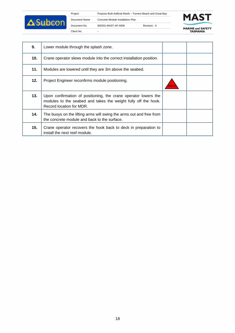
Project Purpose Built Artificial Reefs – Turners Beach and Great Bay
Document Name Concrete Module Installation Plan
Document No. 500331-MAST-AF-0006 Revision: A
Client No. -
18
9. Lower module through the splash zone.
10. Crane operator slews module into the correct installation position.
11. Modules are lowered until they are 3m above the seabed.
12. Project Engineer reconfirms module positioning.
13. Upon confirmation of positioning, the crane operator lowers the
modules to the seabed and takes the weight fully off the hook.
Record location for MDR.
14. The buoys on the lifting arms will swing the arms out and free from
the concrete module and back to the surface.
15. Crane operator recovers the hook back to deck in preparation to
install the next reef module.

Project Purpose Built Artificial Reefs – Turners Beach and Great Bay
Document Name Concrete Module Installation Plan
Document No. 500331-MAST-AF-0006 Revision: A
Client No. -
19
7 Workplace Health and Safety
7.1 Policies
7.1.1 Health, Safety, Environment and Quality Policy Statement
Subcon is committed to delivering the best possible service to our clients and partners by providing new and
innovative technology to the offshore and nearshore environments. Subcon is dedicated to understanding our
client’s requirements, and to providing solutions that ensure any required scope is completed in a safe,
productive, cost and time efficient manner.
Our services will in all cases consider Health, Safety, Environment and Quality issues. We work closely with
our Customers to ensure our reef products suit our customers’ requirements.
Subcon’s business objectives are to use resources efficiently, minimise waste and the likelihood of accidental
discharges of pollutants, maintain a safe, healthy and environmentally friendly working environment in which
staff, visitors, subcontractors, suppliers and the general public are not exposed to unreasonable hazards.
7.1.2 Fitness for Work Policy
Subcon has a legal responsibility and obligation to provide and maintain a safe and healthy working
environment by ensuring that all individuals are fit for work and are not affected by hazards associated with
their health and wellbeing. Subcon strives to foster an attitude that it is not acceptable for employees or
contractors to work in a condition that will prevent them from performing their duties in a safe manner.
7.1.3 Drug and Alcohol Policy
Subcon is committed to providing a safe and healthy workplace to its employees. Subcon expects its
employees to perform their work in a productive manner which doesn’t jeopardise their own safety or the safety
of others. To reinforce this expectation, Subcon aims to foster a positive attitude among employees that it is
unacceptable to come to work under the influence of drugs or alcohol. Subcon personnel will abide by and
participate in the prevailing Drug and Alcohol Testing programs as and when requested.
7.1.4 Injury Management
Subcon recognises its obligations under the OHS Act (2011) and is committed to preventing workplace
injury/illness by taking all reasonable precautions to protect the health, safety and welfare of its employees,
clients and visitors whilst they are on Subcon premises or engaged in approved work for Subcon.
Subcon aims to provide a physically safe, healthy and secure environment for all employees, clients and
visitors. To achieve this goal, everyone attending a Subcon workplace is required to ensure their actions do
not adversely affect the health and safety of others. Subcon is committed to injury management and the
rehabilitation of all employees who suffer a work-related injury or illness.
7.2 Integrated Management System
Subcon operates and maintains a Management System which meets the requirements of ISO 9001: 2015,
14001:2015, 18001:2007 and AS/NZS 4801:2001, compliance with all applicable legal requirements, and with
other requirements to which Subcon subscribes relating to its HSEQ aspects. The Project Manager is
responsible for the design, implementation, compliance and periodic review of this system. The IMS comprises
the following documents:
Project Purpose Built Artificial Reefs – Turners Beach and Great Bay
Document Name Concrete Module Installation Plan
Document No. 500331-MAST-AF-0006 Revision: A
Client No. -
20
Management System Manual
2101-SUB-MQ-0001
Management System Procedures
Contract Management 2101-SUB-MQ-0002
Project Control 2101-SUB-MQ-0003
Document Control 2101-SUB-MQ-0004
Records & Archiving 2101-SUB-MQ-0005
Product Development 2101-SUB-MQ-0006
Training 2101-SUB-MQ-0007
Internal Audits 2101-SUB-MQ-0008
Management Review 2101-SUB-MQ-0009
Corrective & Preventative Action 2101-SUB-MQ-0010
Purchasing 2101-SUB-MQ-0011
Monitoring and Measurement Equipment 2101-SUB-MQ-0012
Rigging and Lifting Equipment 2101-SUB-MQ-0013
Risk Management 2101-SUB-MQ-0014
Emergency Response 2101-SUB-MQ-0015
HSE Plan 2101-SUB-MQ-0016
7.3 WHS Plan
Subcon is committed to active Workplace Health and Safety throughout the entire project. Below is a non-
exhaustive list of items the WHS plan will capture:
Communications
- Project meetings;
- Kick off meetings;
- HSE and Project Inductions;
- Toolboxes;
- Site Specific Inductions.
Training and Competencies
- Verification of Competencies;
- Training Matrix;
- Training Certifications.

Project Purpose Built Artificial Reefs – Turners Beach and Great Bay
Document Name Concrete Module Installation Plan
Document No. 500331-MAST-AF-0006 Revision: A
Client No. -
21
HSE Site Management Practices
- Job Hazard Analysis (JHAs);
- Take 5s;
- Hazard Identifications (HAZIDs);
- Pre-Starts.
High Risk Work
- Working at heights;
- Confined spaces;
- Lifting operations;
- Simultaneous Operations (SIMOPs).
Emergency Response
- Emergency Response Plan (ERP);
- Communications and Reporting.

Project Purpose Built Artificial Reefs – Turners Beach and Great Bay
Document Name Concrete Module Installation Plan
Document No. 500331-MAST-AF-0006 Revision: A
Client No. -
22
8 Contingencies
This section describes the steps which should be taken following an unexpected event.
8.1 Crane DPGS System Failure
During normal operations, the installation location of the reef modules will be assured by cross checking with
a DGPS system mounted in the vessel. If this system fails, a secondary DGPS is available that will be swapped
out for the primary system.
8.2 Crane Malfunction/ Breakdown
If the crane malfunctions the operator will immediately record any error codes and other information relevant
to the malfunction. If the source of the malfunction is obvious then the vessel crew will attempt to rectify the
problem. If after 15mins the problem has still not been rectified, then the vessel owner’s technical support will
be contacted on their 24hr number for assistance and Subcon senior management informed. If the problem
cannot be resolved via phone consultation, then a technician should be mobilised to the vessel immediately.
8.3 Waiting on Weather
In the event that the vessel is loaded at [HOLD 2] but there is no suitable weather window likely within the next
three days then the installation crew will be stood down.
8.4 Severe Weather Whilst in Alongside Wharf
If a storm is forecast for the region, a watchman will be left on the vessel/barge overnight to ensure the integrity
of the mooring lines.
8.5 Pennant Wire Parts
If a pennant wire parts the vessel will no longer be able to recover the anchor. To recover the anchor an ROV
hook will be connected to the anchor wire on the outboard side of the fairleads by the vessel crew. The vessel
will chase the anchor line until it is at the anchor. Once the vessel is at the anchor it will apply weight to free
the anchor. Once free the new pennant can be connected to the anchor crown.
8.6 Anchor Wire Parts
In the event of an anchor wire parting then installation work will cease. The anchor will be recovered using the
pennant line and returned to the vessel. The anchor line will be recovered by the vessel crew and a new
temporary termination will be created using bulldog clips. The anchor will then be redeployed as normal and
work will continue.
8.7 Hydraulic Lift Tool Won’t Disengage
If the Apollo concrete modules are landed out on the sea bed but the lift tool will not disengage then the reefs
will be recovered to the deck where the tool will be inspected and fixed.
8.8 Environmental Spill
The potential for fuel and oil spills will be limited to minor spills during fuel transfers on deck or minor leaks of
hydraulic oil. In the event of a spill incident occurring the vessel emergency response plan will be adhered to.

Project Purpose Built Artificial Reefs – Turners Beach and Great Bay
Document Name Concrete Module Installation Plan
Document No. 500331-MAST-AF-0006 Revision: A
Client No. -
23
Appendix A: Installation Vessel Details [HOLD 3]

Great Bay Artificial Reef EER
Appendix 5. Subcon’s AR module design arrangements (various designs) (2021).

TOP VIEW
SCALE 1 : 25
SIDE VIEW
SCALE 1 : 25
ISOMETRIC VIEW
SCALE 1 : 25
SECTION A-A
SCALE 1 : 25
SECTION B-B
SCALE 1 : 25
A
A
B
B
1 2 3 4 5 6 7 8 9 10 11 12
1 2 3 4 5 6 7 8 9 10 11 12
A
B
C
D
E
F
G
H H
G
F
E
D
C
B
A
Perth: +61 8 9200 2218
Singapore: +65 6440 7752
Europe: +31 15 800 0228
China: +86 769 828 06357, +86 137 1529 7879
Web: www.subcon.com
TITLE
TASMANIAN REEFS
2.1m x D1.8m BOMBORA
GENERAL ARRANGEMENT
500331-MAST-DF-0001
DRAWING NUMBER
REV
A SHEET 1 of 1
SIZE
A3
SCALE
NTS
C Copyright Subcon 2021
CHECKED
DRAWN
APPROVED
I.CLEGG
J.FRANCIS
R.SMIT
INITIAL DATE
DRN CHK APPREV DATE DESCRIPTION
A 26.08.21 IC RS JFISSUED FOR USE
05.03.21
NOTES:
1. ALL DIMENSIONS ARE IN MILLIMETRES UNO.
2. CONCRETE VOLUME: 1.44m3
3. CONCRETE DENSITY: 2.35Te/m3
4. DRY WEIGHT: 3.28Te
5. SURFACE AREA: 21.14m2
6. NUMBER OF HOLES: 27
7. CONCRETE TYPE 50 MPa MARINE CONCRETE.
15
50
16
00
17
50
2 CoG
92
1 C
oG
170
n2100
SMOOTH CONCRETE
SURFACE ON
REMAINING SURFACES
TOP CONCRETE SURFACE
FINISH TO BE EXPOSED
AGGREGATE ONLY
1104
700
131
(T
Y
P
.)
222 (T
Y
P
.)
892
(T
YP
.)
2
1
9
(
T
Y
P
.
)
129
550 (T
Y
P
.)

PLAN VIEW
SCALE 1 : 20
SIDE VIEW
SCALE 1 : 20
SECTION A-A
SCALE 1 : 20
ISOMETRIC VIEW
SCALE 1 : 20
SECTION B-B
SCALE 1 : 20
A
A
B
B
1 2 3 4 5 6 7 8 9 10 11 12
1 2 3 4 5 6 7 8 9 10 11 12
A
B
C
D
E
F
G
H H
G
F
E
D
C
B
A
Perth: +61 8 9200 2218
Singapore: +65 6440 7752
Europe: +31 15 800 0228
China: +86 769 828 06357, +86 137 1529 7879
Web: www.subcon.com
TITLE
TASMANIAN REEFS
1.8m x D1.5m BOMBORA
GENERAL ARRANGEMENT
500331-MAST-DF-0002
DRAWING NUMBER
REV
A SHEET 1 of 1
SIZE
A3
SCALE
NTS
C Copyright Subcon 2021
CHECKED
DRAWN
APPROVED
I.CLEGG
J.FRANCIS
R.SMIT
INITIAL DATE
DRN CHK APPREV DATE DESCRIPTION
A 26.08.21 IC RS JFISSUED FOR USE
NOTES:
1. ALL DIMENSIONS ARE IN MILLIMETRES UNO.
2. CONCRETE VOLUME: 1.08m3
3. CONCRETE DENSITY: 2.35Te/m3
4. DRY WEIGHT: 2.55Te
5. SURFACE AREA: 15.70m2
6. NUMBER OF HOLES: 23
7. CONCRETE TYPE 50 MPa MARINE CONCRETE.
450
237
n (T
Y
P
.)
650 (T
Y
P
.)
837
n1800
195
12
50
13
00 1
45
0
15
00`1
00
TOP CONCRETE SURFACE
FINISH TO BE EXPOSED
AGGREGATE ONLY
SMOOTH CONCRETE
SURFACE ON
REMAINING SURFACES
ANCHORAGE VOID
MINIMUM 32mm
DIAMETER 3 PER
REEF MODULE
380 (T
Y
P
.)
131n (TYP.)
16
C
oG
1 CoG
76
6 C
oG
2
3
3
(
T
Y
P
.
)
132
(T
Y
P
.)

TOP VIEW
SCALE 1 : 20
SIDE VIEW
SCALE 1 : 20
SECTION A-A
SCALE 1 : 20
SECTION B-B
SCALE 1 : 20
ISOMETRIC VIEW
SCALE 1 : 20
A
A
B
B
1 2 3 4 5 6 7 8 9 10 11 12
1 2 3 4 5 6 7 8 9 10 11 12
A
B
C
D
E
F
G
H H
G
F
E
D
C
B
A
Perth: +61 8 9200 2218
Singapore: +65 6440 7752
Europe: +31 15 800 0228
China: +86 769 828 06357, +86 137 1529 7879
Web: www.subcon.com
TITLE
TASMANIAN REEFS
1.8m x D1.3m BOMBORA
GENERAL ARRANGEMENT
500331-MAST-DF-0003
DRAWING NUMBER
REV
A SHEET 1 of 1
SIZE
A3
SCALE
NTS
C Copyright Subcon 2021
CHECKED
DRAWN
APPROVED
I.CLEGG
J.FRANCIS
R.SMIT
INITIAL DATE
DRN CHK APPREV DATE DESCRIPTION
A 26.08.21 IC RS JFISSUED FOR USE
NOTES:
1. ALL DIMENSIONS ARE IN MILLIMETRES UNO.
2. CONCRETE VOLUME: 0.85m3
3. CONCRETE DENSITY: 2.35Te/m3
4. DRY WEIGHT: 1.99Te
5. SURFACE AREA: 13.76m2
6. NUMBER OF HOLES: 21
7. CONCRETE TYPE 50 MPa MARINE CONCRETE.
924
n1800
150
10
50
11
00 1
25
0
13
00`1
00
2
1
5
(
T
Y
P
.
)
500 (T
Y
P
.)
650
ANCHORAGE VOID
MINIMUM 32mm
DIAMETER 3 PER
REEF MODULE
EXPOSED AGGREGATE
ON TOP SURFACE ONLY
SMOOTH CONCRETE
SURFACE ON
REMAINING SURFACES
340 (T
Y
P
.)
218 (T
Y
P
.)
136 (TYP.)
72
8 C
oG
1 CoG
27
C
oG
138
(T
Y
P
.)

PLAN VIEW
SCALE 1:15
ISOMETRIC VIEW
SCALE 1:15
1 2 3 4 5 6 7 8 9 10 11 12
1 2 3 4 5 6 7 8 9 10 11 12
A
B
C
D
E
F
G
H H
G
F
E
D
C
B
A
Perth: +61 8 9200 2218
Singapore: +65 6440 7752
Europe: +31 15 800 0228
China: +86 769 828 06357, +86 137 1529 7879
Web: www.subcon.com
TITLE
TASMANIAN REEFS
APOLLO REEF MODULE
GENERAL ARRANGEMENT
500331-MAST-DF-0004
DRAWING NUMBER
REV
A SHEET 1 of 1
SIZE
A3
SCALE
NTS
C Copyright Subcon 2021
CHECKED
DRAWN
APPROVED
I.CLEGG
J.FRANCIS
R.SMIT
INITIAL DATE
DRN CHK APPREV DATE DESCRIPTION
A 26.08.21 IC RS JFISSUED FOR USE
NOTES:
1. ALL DIMENSIONS ARE IN MILLIMETRES UNO.
2. 50 MPa CONCRETE TO BE USED FOR MODULES.
3. FIBRE-REINFORCED CONCRETE TO BE USED.
4. WEIGHT OF MODULE IS 930kg.
5. VOLUME OF MODULE IS 0.387m³.6. ALL CORNERS TO HAVE RADIUS 50mm.
7. HPP50 TO BE ADDED AT A RATE OF 4kg/m.
8. FIBERMESH TO BE ADDED AT A RATE OF 1kg/m³.360n
560n
20
01
50
20
01
50
10
00
n1292
150

PLAN VIEW
SCALE 1 : 20
FRONT VIEW
SCALE 1 : 20
ISOMETRIC VIEW
SCALE 1 : 25
SECTION A-A
SCALE 1 : 20
SECTION B-B
SCALE 1 : 20
A
A
B
B
1 2 3 4 5 6 7 8 9 10 11 12
1 2 3 4 5 6 7 8 9 10 11 12
A
B
C
D
E
F
G
H H
G
F
E
D
C
B
A
Perth: +61 8 9200 2218
Singapore: +65 6440 7752
Europe: +31 15 800 0228
China: +86 769 828 06357, +86 137 1529 7879
Web: www.subcon.com
TITLE
TASMANIAN REEFS
ABITAT MODULE
GENERAL ARRANGEMENT
500331-MAST-DF-0005
DRAWING NUMBER
REV
A SHEET 1 of 1
SIZE
A3
SCALE
NTS
C Copyright Subcon 2021
CHECKED
DRAWN
APPROVED
I.CLEGG
J.FRANCIS
R.SMIT
INITIAL DATE
DRN CHK APPREV DATE DESCRIPTION
A 26.08.21 IC RS JFISSUED FOR USE
NOTES:
1. CONCRETE IS GRADE S50.
2. WEIGHT OF MODULE IS 1773kg.
3. TOTAL SURFACE AREA: 17.09m2
2800
24
25
800
10
00
4
9
2
4
7
5
4
6
5
5
0
7
15
7
19
0
1
0
4
10
4
156
2
8
3
2
0
1
9
9

Great Bay Artificial Reef EER
Appendix 6. Subcon’s Great Bay Reef layout (2021).

1 2 3 4 5 6 7 8 9 10 11 12
1 2 3 4 5 6 7 8 9 10 11 12
A
B
C
D
E
F
G
H H
G
F
E
D
C
B
A
Perth: +61 8 9200 2218Singapore: +65 6440 7752Europe: +32 59 36 9941China: +86 769 828 06357, +86 137 1529 7879Web: www.subcon.com
TITLE
DRAWING NUMBER REV
SHEETSIZEA3
SCALE
NTSC Copyright Subcon 2020
CHECKED
DRAWN
APPROVED
INITIAL DATE
DRN CHK APPREV DATE DESCRIPTION
of
REEF LAYOUT
GREAT BAY
NTS11A500331-MAST-DF--0007
J.FRANCIS
R.SMIT
I.CLEGG
JFRSICISSUED FOR REVIEW27.08.21A
NOTES:1. ALL DIMENSIONS ARE IN MILLIMETRES UNO.
CENTRE POINT525120 E
5215443 NZONE 55G
200000
2000
00
APOLLO CLUSTER
BOMBORA TYPE 1CLUSTER
BOMBORA TYPE 3
BOMBORA TYPE 2
ABITAT

Great Bay Artificial Reef EER
Appendix 7. Subcon’s Design Report (2021).
Artificial Reef Design Report
Project Purpose Built Artificial Reef – Turners Beach and Great Bay
Document Name Artificial Reef Design Report
Contact Roy Smit Email [email protected]
Subcon Document Number 500331-MAST-RF-0003 Revision B
Client Document Number N/A Revision N/A
A 31/08/2021 Issued for Internal Review RSm JFr
Rev Date Revision Description Author Checked Approved Client Approval
B 16/09/2021 Issued for External Review RSm JFr
JFr
JFr

Project Purpose Built Artificial Reef – Turners Beach and Great Bay
Scope Artificial Reef Design Report
Document No. 500331-MAST-RF-0003 Rev B
Client No. N/A
Page 2
Table of Contents
1 Introduction .................................................................................................................................. 3
Background .................................................................................................................................... 3
Purpose .......................................................................................................................................... 4
Scope ............................................................................................................................................. 4
2 References and Standards .......................................................................................................... 5
Standards ....................................................................................................................................... 5
Client Supplied Documents ............................................................................................................ 5
Abbreviations/Definitions ................................................................................................................ 5
Appendix A: Stability Report .......................................................................................................................... 6
Appendix B: Structural Report ....................................................................................................................... 7
Appendix C: Construction Drawings ............................................................................................................. 8
Table of Figures
Figure 1-1: Turners Beach Artificial Reef Approximate Location ...................................................................... 3
Figure 1-2: Great Bay Artificial Reef Approximate Location .............................................................................. 4

Project Purpose Built Artificial Reef – Turners Beach and Great Bay
Scope Artificial Reef Design Report
Document No. 500331-MAST-RF-0003 Rev B
Client No. N/A
Page 3
1 Introduction
Background
The Principal (Marine and Safety Tasmania (MAST)) are requesting tenders for the design and
construction of two purpose built artificial reefs offshore Tasmania. The reefs have been instigated
by the state government to fulfill commitments made to recreational fishers during the 2017
election and detailed in the Taking Recreational Fishing and Boating to the next level plan (2019).
The primary objective of the Works is to increase recreational fishing opportunities in the north
and south of the state by creating new productive habitat through Tasmania’s first large scale
purpose-built artificial reef. Although the reefs are not designed as a dive attraction their shallow
depth and novelty in the Tasmanian environment is sure to attract diver interest. As a result, the
contractor shall also consider diver safety and entanglement in the design.
MAST have commissioned Marine Solutions to complete a feasibility assessment of the artificial
reef offshore Tasmania [Appendix 1]. The socioeconomic and environmental impacts have been
assessed as part of the study and two locations have been chosen for the deployment of purpose-
built artificial reefs off Tasmania broadly described as Turners Beach (Figure 1-1) and Great Bay
(Figure 1-2).
Figure 1-1: Turners Beach Artificial Reef Approximate Location

Project Purpose Built Artificial Reef – Turners Beach and Great Bay
Scope Artificial Reef Design Report
Document No. 500331-MAST-RF-0003 Rev B
Client No. N/A
Page 4
Figure 1-2: Great Bay Artificial Reef Approximate Location
The reef constituting the Works shall be designed and purpose-built using materials that have
been demonstrated to be inert, and resistant to deterioration in seawater (from monitoring results
of past applications and/or by professional opinion from a suitably experienced marine biologist
and a suitably experienced coastal engineer, each approved by the Principal) as defined in the
Guidelines for the Placement of Artificial Reefs (London Convention and Protocol/UNEP, 2009).
The modules must also be self-weighted and physically stable to withstand sliding and overturning
from prevailing storm events while providing complex fisheries habitat for a range of popular fish
species common to proposed location coastal region.
Purpose
The purpose of this document is to describe the design process used to determine the stability
and structural integrity of the reef modules proposed for the Turners Beach and Great Bay
Artificial Reefs to ensure they meet the requirements as described in the PPR.
Scope
This document is limited to 5 existing designs currently within Subcon’s IP. Their stability is
calculated using the hydrodynamic values provided in the Principal issued documentation, against
the failure mechanisms of uplift, overturning and sliding. Their structural integrity is calculated
using the design parameters, unit weights, and expected lifting operation configurations.

Project Purpose Built Artificial Reef – Turners Beach and Great Bay
Scope Artificial Reef Design Report
Document No. 500331-MAST-RF-0003 Rev B
Client No. N/A
Page 5
2 References and Standards
Standards
Ref # Title Doc Number
A1 Submarine Pipeline Systems 2010 DNV OS-F101
A2 On-Bottom Stability Design of Submarine Pipelines
DNV RP F109
A3 Modelling and Analysis of Marine Operations
DNV RP H103
A4 Environmental Conditions and Environmental Loads
DNV-RP-C205
Client Supplied Documents
Ref # Title Doc Number
B1 Environmental Assessment of Artificial Reefs to Enhance Recreational Fisheries in Tasmania
N/A
B2 MAST Artificial Reef Wave Climate Report N/A
B3 Principal Project Requirements N/A
Abbreviations/Definitions
Abbreviations / Definitions Description
AS Australian Standard
ASB Above Seabed
CoG Centre of Gravity
DNV Det Norske Veritas
FoS Factor of Safety
m Meter
MAST Marine and Safety Tasmania
MPa Mega Pascals
PPR Principal’s Project Requirements
UWA University of Western Australia

Project Purpose Built Artificial Reef – Turners Beach and Great Bay
Scope Artificial Reef Design Report
Document No. 500331-MAST-RF-0003 Rev B
Client No. N/A
Page 6
Appendix A: Stability Report

Artificial Reef Stability Report
Project Purpose Built Artificial Reef – Turners Beach and Great Bay
Document Name Artificial Reef Stability Report
Contact Roy Smit Email [email protected]
Subcon Document Number 500331-MAST-RF-0001 Revision A
Client Document Number N/A Revision N/A
A 25/08/2021 Issued for Internal Review RSm JFr
Rev Date Revision Description Author Checked Approved Client Approval

Project Purpose Built Artificial Reef – Turners Beach and Great Bay
Scope Artificial Reef Stability Report
Document No. 500331-MAST-RF-0001 Rev A
Client No. N/A
Page 2
Table of Contents
1 Introduction .................................................................................................................................. 4
Background .................................................................................................................................... 4
Purpose .......................................................................................................................................... 4
Scope ............................................................................................................................................. 4
2 References and Standards .......................................................................................................... 5
Standards ....................................................................................................................................... 5
Client Supplied Documents ............................................................................................................ 5
Abbreviations/Definitions ................................................................................................................ 5
3 Analysis Methodology ................................................................................................................. 6
General ........................................................................................................................................... 6
4 Design Data ................................................................................................................................ 10
Location ........................................................................................................................................ 10
Structures ..................................................................................................................................... 10
Design Life ................................................................................................................................... 11
Geotechnical Parameters ............................................................................................................. 11
Concrete Density .......................................................................................................................... 12
Metocean Data ............................................................................................................................. 12
Coefficients for Stability Calculation ............................................................................................. 12
5 Stability Reports ......................................................................................................................... 12
6 Summary ..................................................................................................................................... 13
Turners Beach .............................................................................................................................. 13
Great Bay ..................................................................................................................................... 13
7 Conclusion .................................................................................................................................. 13
Appendix 1 – Stability Formula .................................................................................................................... 14
Appendix 2 – Turners Beach Reef Stability ................................................................................................ 15
Project Purpose Built Artificial Reef – Turners Beach and Great Bay
Scope Artificial Reef Stability Report
Document No. 500331-MAST-RF-0001 Rev A
Client No. N/A
Page 3
Appendix 3 – Great Bay Reef Stability ........................................................................................................ 16

Project Purpose Built Artificial Reef – Turners Beach and Great Bay
Scope Artificial Reef Stability Report
Document No. 500331-MAST-RF-0001 Rev A
Client No. N/A
Page 4
1 Introduction
Background
The Principal (Marine and Safety Tasmania (MAST)) are requesting tenders for the design and
construction of two purpose built artificial reefs offshore Tasmania. The reefs have been instigated
by the state government to fulfill commitments made to recreational fishers during the 2017
election and detailed in the Taking Recreational Fishing and Boating to the next level plan (2019).
The primary objective of the Works is to increase recreational fishing opportunities in the north
and south of the state by creating new productive habitat through Tasmania’s first large scale
purpose-built artificial reef. Although the reefs are not designed as a dive attraction their shallow
depth and novelty in the Tasmanian environment is sure to attract diver interest. As a result, the
contractor shall also consider diver safety and entanglement in the design.
Purpose
The purpose of this document is to describe the design process used to determine the stability of
the reef modules proposed for the Turners Beach and Great Bay Artificial Reefs to ensure they
meet the requirements as described in the PPR.
Scope
This document is limited 5 existing designs currently within Subcon’s IP. Their stability is
calculated using the hydrodynamic values provided in the Principal issued documentation, against
the failure mechanisms of uplift, overturning and sliding.

Project Purpose Built Artificial Reef – Turners Beach and Great Bay
Scope Artificial Reef Stability Report
Document No. 500331-MAST-RF-0001 Rev A
Client No. N/A
Page 5
2 References and Standards
Standards
Ref # Title Doc Number
A1 Submarine Pipeline Systems 2010 DNV OS-F101
A2 On-Bottom Stability Design of Submarine Pipelines
DNV RP F109
A3 Modelling and Analysis of Marine Operations
DNV RP H103
A4 Environmental Conditions and Environmental Loads
DNV-RP-C205
Client Supplied Documents
Ref # Title Doc Number
B1 Environmental Assessment of Artificial Reefs to Enhance Recreational Fisheries in Tasmania
NA
B2 MAST Artificial Reef Wave Climate Report NA
B3 Principal Project Requirements NA
Abbreviations/Definitions
Abbreviations / Definitions Description
AS Australian Standard
ASB Above Seabed
CoG Centre of Gravity
DNV Det Norske Veritas
FoS Factor of Safety
m Meter
MPa Mega Pascals
UWA University of Western Australia

Project Purpose Built Artificial Reef – Turners Beach and Great Bay
Scope Artificial Reef Stability Report
Document No. 500331-MAST-RF-0001 Rev A
Client No. N/A
Page 6
3 Analysis Methodology
General
The stability of the reef structures is established by checking both lateral sliding stability and
overturning stability using a quasi-dynamic analysis over one full wave period. Lift is rarely a
failure mode for the large, relatively compact Subcon reef although its effect on reducing
submerged weight is considered when assessing the sliding and overturning stability.
Overturning describes the tipping of the reef from its intended orientation on the seabed and is
considered a catastrophic failure since the purpose-built reef structures would no longer perform
as designed. As overturning is considered the primary failure mode overturning stability is
assessed against the hydrodynamic loads from the maximum current and maximum wave height
(e.g. maximum instantaneous load). As per [B3], this is a 1/50yr event.
Lateral or sliding failure describes the global translation of the reef structures due to wave and
current loading. To assess the sliding stability the significant wave height rather, than the
maximum wave height, is used. This is because it has been concluded that if the structure were
to slide as a result of the peak waves during a storm it would not be deemed a failure. However,
if the structure were to slide as a result of the significant wave in a 1/100yr event, then the structure
would have the potential to slide a significant distance.
The stability analysis is to be based on a two-dimensional approach where Morrison’s equation
will be used to determine the drag, lift and inertial forces generated.
A factor of safety of 1.0 has been applied for all cases due to the low consequence factor of a
module failing, and other conservatism across the design assumptions (such as reduced concrete
density [Section 4.5] and conservative approach to wave climate wave [Ref B2].
The formulae used to calculate on bottom stability are summarised in the following sections below
(diagram of reef is for illustrative purposes only).
3.1.1 Lift Forces
The interaction of flow over the structures on the seabed generates a mean flow that is
asymmetric, which can result in either a lift or down force on the block. Lift or down force is
caused by the diversion of flow over the structures, which leads to a pressure differential region
above the structure.

Project Purpose Built Artificial Reef – Turners Beach and Great Bay
Scope Artificial Reef Stability Report
Document No. 500331-MAST-RF-0001 Rev A
Client No. N/A
Page 7
Figure 4.1 Hydrodynamic Lift
Lift is unlikely to cause failure of itself. However, it is calculated and applied to the analysis to
reduce the on-bottom weight of the structure and hence overall stability. It should be noted that
as the complexity of the structure increases lift is usually seen to decrease due to the generation
of highly turbulent flow and so applying lift to the topsides is considered conservative.
3.1.2 Horizontal Environmental Loads
The introduction of combined steady current and oscillating flow around the structure will generate
drag, lift and inertial loads.
Figure 3-1: Horizontal Force Balance
The following formulas are used to determine the combine Drag and inertia force:
𝐹𝐷 =1
2𝜌𝑤𝐶𝐷𝐴𝑝𝑈2
FD = Drag force (N)
w = Density of seawater (kg/m3)
𝐴𝑝 = Projected Area (m2)
CD = Drag Coefficient
U = Combined water particle velocity (m/s)

Project Purpose Built Artificial Reef – Turners Beach and Great Bay
Scope Artificial Reef Stability Report
Document No. 500331-MAST-RF-0001 Rev A
Client No. N/A
Page 8
𝐹𝐼 = 𝜌𝑤𝐶𝑀𝑎𝑥𝑉𝑖
FI = Inertia force (N)
w = Density of seawater (kg/m3)
Vi = Volume of Displaced Water due to Reef Pyramid (m3)
CM = Added Mass Coefficient
𝑎𝑥 = Water particle acceleration due to waves (m/s2)
To accurate represent the structure, the value of Cm has been used as described in Section 4.7.
3.1.3 Combined Environment Loads
The combination of drag and inertia loads determines the combined horizontal environment load
on the module.
𝐹𝐸𝑁𝑉 = 𝐹𝐷 + 𝐹𝐼
3.1.4 Module Embedment
No module or structure embedment has been assumed for this stability analysis. Based on
available geotechnical information, this may be overly conservative and should be revisited during
the detailed design phase of the project.
3.1.5 Frictional Ground Resistance
The calculation of ground friction on the module perpendicular to the normal force of the wave
action.
Friction Resistance:
𝐹𝐹 = 𝜇𝑠. 𝐹𝑤
Where:
s = Seabed to structure friction coefficient (s=0.6 for concrete to sand and s=0.45 for
steel to sand)
𝐹𝑤 = Submerged weight of module plus submerged ballast weight minus lift force.
𝐹𝑤 = Wsub +Wbal - FL

Project Purpose Built Artificial Reef – Turners Beach and Great Bay
Scope Artificial Reef Stability Report
Document No. 500331-MAST-RF-0001 Rev A
Client No. N/A
Page 9
3.1.6 Lateral Stability of Module
The sliding stability relies on combined lateral resistance being less than combined horizontal
environmental loads at all times as shown below:
𝐹𝐸𝑁𝑉 < 𝐹𝐹
𝐹𝑂𝑆 =𝐹𝑅𝑆
𝐹𝐸𝑁𝑉
𝐹𝐸𝑁𝑉 = Combined horizontal loads on module due to environmental (N)
𝐹𝐹 = Frictional Resistance (N)
A factor of safety (FOS) above unity indicates stability for the design event.
3.1.7 Overturning Stability of Module
Overturning stability is governed by the horizontal forces acting on the structures compared to its
restoring moment, which is based on its resultant weight.
As will be shown below, the resultant weight of each structure is found by combining the lift force
with the submerged weight.
Figure 3-2: Overturning Stability
𝐹𝑜𝑟 𝑠𝑡𝑎𝑏𝑖𝑙𝑖𝑡𝑦: 𝑀𝑅𝑊 > 𝑀𝐶𝑊
𝐹𝑂𝑆 =𝑀𝑅𝑆
𝑀𝑐𝑤
𝑀𝐶𝑊 = Overturning Moment caused by wave and current forces (Nm)
𝑀𝑅𝑊 = Restoring Moment due to weight of the Reef (Nm)

Project Purpose Built Artificial Reef – Turners Beach and Great Bay
Scope Artificial Reef Stability Report
Document No. 500331-MAST-RF-0001 Rev A
Client No. N/A
Page 10
The overturning forces acts at the horizontal centre of geometry of the module and restoring force
act at the centre of gravity. The resultant moment is summated at the pivot point at the edge of
the module.
4 Design Data
Location
Locations for each reef have been taken from Ref B3 Section 5.1.
Structures
Subcon has multiple existing designs for artificial reefs. The designs proposed for this project are:
• 1.8m Bombora (Type 1)
• 1.5m Bombora (Type 2)
• 1.3m Bombora (Type 3)
• Apollo
• Abitat
4.2.1 Bombora Modules
The 3no Bombora modules have a strong performance track record as artificial reef structures
deployed around Australia and have been proven effective through a number of independent
university research projects.
Figure 4-1: Typical Bombora Module
4.2.2 Apollo Modules
The Apollo modules, also with strong track record on Australian artificial reefs, are 1.2m modules
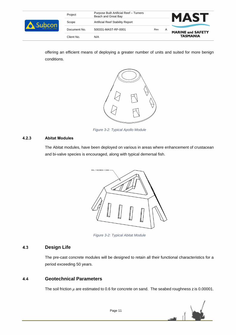
Project Purpose Built Artificial Reef – Turners Beach and Great Bay
Scope Artificial Reef Stability Report
Document No. 500331-MAST-RF-0001 Rev A
Client No. N/A
Page 11
offering an efficient means of deploying a greater number of units and suited for more benign
conditions.
Figure 3-2: Typical Apollo Module
4.2.3 Abitat Modules
The Abitat modules, have been deployed on various in areas where enhancement of crustacean
and bi-valve species is encouraged, along with typical demersal fish.
Figure 3-2: Typical Abitat Module
Design Life
The pre-cast concrete modules will be designed to retain all their functional characteristics for a
period exceeding 50 years.
Geotechnical Parameters
The soil friction 𝜇 are estimated to 0.6 for concrete on sand. The seabed roughness z is 0.00001.
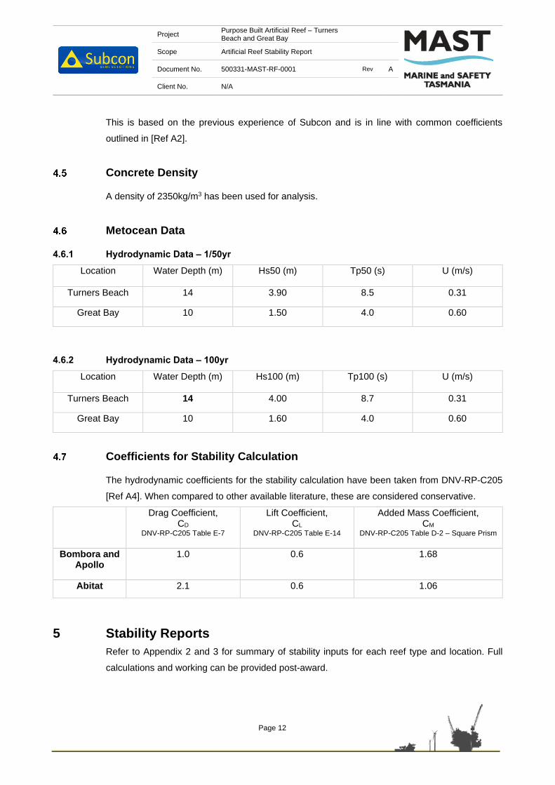
Project Purpose Built Artificial Reef – Turners Beach and Great Bay
Scope Artificial Reef Stability Report
Document No. 500331-MAST-RF-0001 Rev A
Client No. N/A
Page 12
This is based on the previous experience of Subcon and is in line with common coefficients
outlined in [Ref A2].
Concrete Density
A density of 2350kg/m3 has been used for analysis.
Metocean Data
4.6.1 Hydrodynamic Data – 1/50yr
Location Water Depth (m) Hs50 (m) Tp50 (s) U (m/s)
Turners Beach 14 3.90 8.5 0.31
Great Bay 10 1.50 4.0 0.60
4.6.2 Hydrodynamic Data – 100yr
Location Water Depth (m) Hs100 (m) Tp100 (s) U (m/s)
Turners Beach 14 4.00 8.7 0.31
Great Bay 10 1.60 4.0 0.60
Coefficients for Stability Calculation
The hydrodynamic coefficients for the stability calculation have been taken from DNV-RP-C205
[Ref A4]. When compared to other available literature, these are considered conservative.
Drag Coefficient, CD
DNV-RP-C205 Table E-7
Lift Coefficient, CL
DNV-RP-C205 Table E-14
Added Mass Coefficient, CM
DNV-RP-C205 Table D-2 – Square Prism
Bombora and Apollo
1.0 0.6 1.68
Abitat 2.1 0.6 1.06
5 Stability Reports
Refer to Appendix 2 and 3 for summary of stability inputs for each reef type and location. Full
calculations and working can be provided post-award.

Project Purpose Built Artificial Reef – Turners Beach and Great Bay
Scope Artificial Reef Stability Report
Document No. 500331-MAST-RF-0001 Rev A
Client No. N/A
Page 13
6 Summary
See below summary of Factors of Safety for each reef type and location:
Turners Beach
Bombora Type 1
Bombora Type 2
Bombora Type 3
Apollo
Uplift 1.2 1.3 1.5 1.1
Overturning 2.7 2.7 2.7 1.8
Sliding 1.8 1.9 2.0 1.5
Great Bay
Bombora Type 1
Bombora Type 2
Bombora Type 3
Apollo Abitat
Uplift 6.8 10.2 9.4 8.4 10.5
Overturning 19.4 20.0 20.0 13.5 5.6
Sliding 5.0 6.4 6.0 4.4 2.2
7 Conclusion
Based on the results shown in Section 6, modules can be utilised at either location, except for the
Abitat module which should be limited to deployment at Great Bay.
Quantities of each type and layout of reef should be assessed by a series of factors such as
ecological enhancement and commercial feasibility, however this is outside of this document
scope.

Project Purpose Built Artificial Reef – Turners Beach and Great Bay
Scope Artificial Reef Stability Report
Document No. 500331-MAST-RF-0001 Rev A
Client No. N/A
Page 14
Appendix 1 – Stability Formula
DNV-OS-F101 Wave Formula

Project Purpose Built Artificial Reef – Turners Beach and Great Bay
Scope Artificial Reef Stability Report
Document No. 500331-MAST-RF-0001 Rev A
Client No. N/A
Page 15
Appendix 2 – Turners Beach Reef Stability

Project Turners Beach and Great Bay Purpose Built Artificial ReefCalculation Bombora Type 1; On-Bottom Stability - Turners BeachDate Commenced 26/05/2021Date Completed 26/05/2021Author JFRChecked -Approved -Revision 0
Summary
InputsDescription Symbol Value Units ReferenceReef DataHeight 1.8 m 308105-SUB-DF-0001Width 2.1 m 308105-SUB-DF-0001Referenced depth of module 0.9 m 308105-SUB-DF-0001Centroid of Frontal Area 0.9 m 308105-SUB-DF-0001Volume of Module 1.44 m3 308105-SUB-DF-0001Projected frontal area 3.0 m3 308105-SUB-DF-0001Total enclosed volume 2.5 m3 308105-SUB-DF-0001Drag coefficient of block CD 1 DNV-C205 - Table E1 Case 14Lift coefficient of block CL 0.6 DNV-C205 - Table E1 Case 14Mass Coefficient CM 1.68 DNV C205 - Table D2 Square PrismDensity of Concrete 2350 kg/m3 Low for conservatism
Metocean DataWater Depth Wd 14 m PPR Section 5 Table 4Steady State Current Velocity Uc 0.31 m/s EPBC Self-Assessment Report Figure 9Significant Wave Height - (1/50yr) Hs50 3.90 m MAST Artificial Artificial Reef Wave Climate ReportMaximum Wave Height - (1/50yr) Hmax50 7.293 m Hs50 X 1.87 (not depth limited)Significant Wave Height - (1/100yr) Hs100 4.00 m MAST Artificial Artificial Reef Wave Climate ReportPeak Wave Period - (1/50yr) Tp50 8.5 m MAST Artificial Artificial Reef Wave Climate ReportPeak Wave Period - (1/100yr) Tp100 8.7 m MAST Artificial Artificial Reef Wave Climate Report
Metocean DataSeabed Roughness (sand) z0 0.00001 DNV RP F109 - Table 3-1Soil Friction (sand) µ 0.6
ConstantsDensity of water ρsw 1025 kg/m3 -Kinematic viscosity of water n 0.00000105 m2/s DNV-C205 - Appendix FGravity g 9.81 m/s2 -
Results SummaryFactor of safety against overturning (Hmax) 1.2 Structure is StableFactor of safety against uplift (Hmax) 2.7 Structure is StableFactor of safety against sliding (Hs) 1.8 Structure is Stable
The following calculation assesses the on-bottom stability of the Bombora Type 1 reef module. The on-bottom stability calculations analyses 3modes of failure; uplifting, sliding and overturning of the module whilst installed on the seabed. The calculation considers the maximum waveheight for the overturning and uplifting scenario, with the significant wave height being considered for the sliding scenario. The on-bottomstability of the reef is deemed as acceptable if the FOS is greater than or equal to 1.
User defined inputResult

Project Turners Beach and Great Bay Purpose Built Artificial ReefCalculation Bombora Type 2; On-Bottom Stability - Turners BeachDate Commenced 26/05/2021Date Completed 26/05/2021Author JFRChecked -Approved -Revision 0
Summary
InputsDescription Symbol Value Units ReferenceReef DataHeight 1.5 m 308104-SUB-DF-0001Width 1.8 m 308104-SUB-DF-0001Referenced depth of module 0.77 m 308104-SUB-DF-0001Centroid of Frontal Area 0.77 m 308104-SUB-DF-0001Volume of Module 1.08 m3 308104-SUB-DF-0001Projected frontal area 2.4 m2 308104-SUB-DF-0001Total enclosed volume 1.0 m3 308104-SUB-DF-0001Drag coefficient of block CD 1 DNV-C205 - Table E1 Case 14Lift coefficient of block CL 0.6 DNV-C205 - Table E1 Case 14Mass Coefficient CM 1.68 DNV C205 - Table D2 Square PrismDensity of Concrete 2350 kg/m3 Low for conservatism
Metocean DataWater Depth Wd 14 m PPR Section 5 Table 4Steady State Current Velocity Uc 0.31 m/s EPBC Self-Assessment Report Figure 9Significant Wave Height - (1/50yr) Hs50 3.90 m MAST Artificial Artificial Reef Wave Climate ReportMaximum Wave Height - (1/50yr) Hmax50 7.293 m Hs50 X 1.87 (not depth limited)Significant Wave Height - (1/100yr) Hs100 4.00 m MAST Artificial Artificial Reef Wave Climate ReportPeak Wave Period - (1/50yr) Tp50 8.5 m MAST Artificial Artificial Reef Wave Climate ReportPeak Wave Period - (1/100yr) Tp100 8.7 m MAST Artificial Artificial Reef Wave Climate Report
Metocean DataSeabed Roughness (sand) z0 0.00001 DNV RP F109 - Table 3-1Soil Friction (sand) µ 0.6
ConstantsDensity of water ρsw 1025 kg/m3 -Kinematic viscosity of water n 0.00000105 m2/s DNV-C205 - Appendix FGravity g 9.81 m/s2 -
Results SummaryFactor of safety against overturning (Hmax) 1.3 Structure is StableFactor of safety against uplift (Hmax) 2.7 Structure is StableFactor of safety against sliding (Hs) 1.9 Structure is Stable
The following calculation assesses the on-bottom stability of the Bombora Type 2 reef module. The on-bottom stability calculations analyses 3modes of failure; uplifting, sliding and overturning of the module whilst installed on the seabed. The calculation considers the maximum waveheight for the overturning and uplifting scenario, with the significant wave height being considered for the sliding scenario. The on-bottomstability of the reef is deemed as acceptable if the FOS is greater than or equal to 1.
User defined inputResult

Project Turners Beach and Great Bay Purpose Built Artificial ReefCalculation Bombora Type 3; On-Bottom Stability - Turners BeachDate Commenced 26/05/2021Date Completed 26/05/2021Author JFRChecked -Approved -Revision 0
Summary
InputsDescription Symbol Value Units ReferenceReef DataHeight 1.3 m 308103-SUB-DF-0001Width 1.8 m 308103-SUB-DF-0001Referenced depth of module 0.73 m 308103-SUB-DF-0001Centroid of Frontal Area 0.73 m 308103-SUB-DF-0001Volume of Module 1.08 m3 308103-SUB-DF-0001Projected frontal area 2.1 m2 308103-SUB-DF-0001Total enclosed volume 1.4 m3 308103-SUB-DF-0001Drag coefficient of block CD 1 DNV-C205 - Table E1 Case 14Lift coefficient of block CL 0.6 DNV-C205 - Table E1 Case 14Mass Coefficient CM 1.68 DNV C205 - Table D2 Square PrismDensity of Concrete 2350 kg/m3 Low for conservatism
Metocean DataWater Depth Wd 14 m PPR Section 5 Table 4Steady State Current Velocity Uc 0.31 m/s EPBC Self-Assessment Report Figure 9Significant Wave Height - (1/50yr) Hs50 3.90 m MAST Artificial Artificial Reef Wave Climate ReportMaximum Wave Height - (1/50yr) Hmax50 7.293 m Hs50 X 1.87 (not depth limited)Significant Wave Height - (1/100yr) Hs100 4.00 m MAST Artificial Artificial Reef Wave Climate ReportPeak Wave Period - (1/50yr) Tp50 8.5 m MAST Artificial Artificial Reef Wave Climate ReportPeak Wave Period - (1/100yr) Tp100 8.7 m MAST Artificial Artificial Reef Wave Climate Report
Metocean DataSeabed Roughness (sand) z0 0.00001 DNV RP F109 - Table 3-1Soil Friction (sand) µ 0.6
ConstantsDensity of water ρsw 1025 kg/m3 -Kinematic viscosity of water n 0.00000105 m2/s DNV-C205 - Appendix FGravity g 9.81 m/s2 -
Results SummaryFactor of safety against overturning (Hmax) 1.5 Structure is StableFactor of safety against uplift (Hmax) 2.7 Structure is StableFactor of safety against sliding (Hs) 2.0 Structure is Stable
The following calculation assesses the on-bottom stability of the Bombora Type 3 reef module. The on-bottom stability calculations analyses 3modes of failure; uplifting, sliding and overturning of the module whilst installed on the seabed. The calculation considers the maximum waveheight for the overturning and uplifting scenario, with the significant wave height being considered for the sliding scenario. The on-bottomstability of the reef is deemed as acceptable if the FOS is greater than or equal to 1.
User defined inputResult

Project Turners Beach and Great Bay Purpose Built Artificial ReefCalculation Apollo; On-Bottom Stability - Turners BeachDate Commenced 26/05/2021Date Completed 26/05/2021Author JFRChecked -Approved -Revision 0
Summary
InputsDescription Symbol Value Units ReferenceReef DataHeight 1 m 3853-SUB-DWG-0001Width 1.315 m 3853-SUB-DWG-0001Referenced depth of module 0.43 m 3853-SUB-DWG-0001Centroid of Frontal Area 0.43 m 3853-SUB-DWG-0001Volume of Module 0.387 m3 3853-SUB-DWG-0001Projected frontal area 0.9 m2 3853-SUB-DWG-0001Total enclosed volume 0.7 m3 3853-SUB-DWG-0001Drag coefficient of block CD 1 DNV-C205 - Table E1 Case 14Lift coefficient of block CL 0.6 DNV-C205 - Table E1 Case 14Mass Coefficient CM 1.68 DNV C205 - Table D2 Square PrismDensity of Concrete 2350 kg/m3 Low for conservatism
Metocean DataWater Depth Wd 14 m PPR Section 5 Table 4Steady State Current Velocity Uc 0.31 m/s EPBC Self-Assessment Report Figure 9Significant Wave Height - (1/50yr) Hs50 3.90 m MAST Artificial Artificial Reef Wave Climate ReportMaximum Wave Height - (1/50yr) Hmax50 7.293 m Hs50 X 1.87 (not depth limited)Significant Wave Height - (1/100yr) Hs100 4.00 m MAST Artificial Artificial Reef Wave Climate ReportPeak Wave Period - (1/50yr) Tp50 8.5 m MAST Artificial Artificial Reef Wave Climate ReportPeak Wave Period - (1/100yr) Tp100 8.7 m MAST Artificial Artificial Reef Wave Climate Report
Metocean DataSeabed Roughness (sand) z0 0.00001 DNV RP F109 - Table 3-1Soil Friction (sand) µ 0.6
ConstantsDensity of water ρsw 1025 kg/m3 -Kinematic viscosity of water n 0.00000105 m2/s DNV-C205 - Appendix FGravity g 9.81 m/s2 -
Results SummaryFactor of safety against overturning (Hmax) 1.1 Structure is StableFactor of safety against uplift (Hmax) 1.8 Structure is StableFactor of safety against sliding (Hs) 1.5 Structure is Stable
The following calculation assesses the on-bottom stability of the Apollo reef module. The on-bottom stability calculations analyses 3 modes offailure; uplifting, sliding and overturning of the module whilst installed on the seabed. The calculation considers the maximum wave height forthe overturning and uplifting scenario, with the significant wave height being considered for the sliding scenario. The on-bottom stability of thereef is deemed as acceptable if the FOS is greater than or equal to 1.
User defined inputResult

Project Purpose Built Artificial Reef – Turners Beach and Great Bay
Scope Artificial Reef Stability Report
Document No. 500331-MAST-RF-0001 Rev A
Client No. N/A
Page 16
Appendix 3 – Great Bay Reef Stability

Project Turners Beach and Great Bay Purpose Built Artificial ReefCalculation Bombora Type 1; On-Bottom Stability - Great BayDate Commenced 26/05/2021Date Completed 26/05/2021Author JFRChecked -Approved -Revision 0
Summary
InputsDescription Symbol Value Units ReferenceReef DataHeight 1.8 m 308105-SUB-DF-0001Width 2.1 m 308105-SUB-DF-0001Referenced depth of module 0.9 m 308105-SUB-DF-0001Centroid of Frontal Area 0.9 m 308105-SUB-DF-0001Volume of Module 1.44 m3 308105-SUB-DF-0001Projected frontal area 3.0 m3 308105-SUB-DF-0001Total enclosed volume 2.5 m3 308105-SUB-DF-0001Drag coefficient of block CD 1 DNV-C205 - Table E1 Case 14Lift coefficient of block CL 0.6 DNV-C205 - Table E1 Case 14Mass Coefficient CM 1.68 DNV C205 - Table D2 Square PrismDensity of Concrete 2350 kg/m3 Low for conservatism
Metocean DataWater Depth Wd 10 m PPR Section 5 Table 4Steady State Current Velocity Uc 0.6 m/s EPBC Self-Assessment Report Figure 9Significant Wave Height - (1/50yr) Hs50 1.50 m MAST Artificial Artificial Reef Wave Climate ReportMaximum Wave Height - (1/50yr) Hmax50 2.805 m Hs50 X 1.87 (not depth limited)Significant Wave Height - (1/100yr) Hs100 1.60 m MAST Artificial Artificial Reef Wave Climate ReportPeak Wave Period - (1/50yr) Tp50 4 m MAST Artificial Artificial Reef Wave Climate ReportPeak Wave Period - (1/100yr) Tp100 4 m MAST Artificial Artificial Reef Wave Climate Report
Metocean DataSeabed Roughness (sand) z0 0.00001 DNV RP F109 - Table 3-1Soil Friction (sand) µ 0.6
ConstantsDensity of water ρsw 1025 kg/m3 -Kinematic viscosity of water n 0.00000105 m2/s DNV-C205 - Appendix FGravity g 9.81 m/s2 -
Results SummaryFactor of safety against overturning (Hmax) 6.8 Structure is StableFactor of safety against uplift (Hmax) 19.4 Structure is StableFactor of safety against sliding (Hs) 5.0 Structure is Stable
The following calculation assesses the on-bottom stability of the Bombora Type 1 reef module. The on-bottom stability calculations analyses 3modes of failure; uplifting, sliding and overturning of the module whilst installed on the seabed. The calculation considers the maximum waveheight for the overturning and uplifting scenario, with the significant wave height being considered for the sliding scenario. The on-bottomstability of the reef is deemed as acceptable if the FOS is greater than or equal to 1.
User defined inputResult

Project Turners Beach and Great Bay Purpose Built Artificial ReefCalculation Bombora Type 2; On-Bottom Stability - Great BayDate Commenced 26/05/2021Date Completed 26/05/2021Author JFRChecked -Approved -Revision 0
Summary
InputsDescription Symbol Value Units ReferenceReef DataHeight 1.5 m 308104-SUB-DF-0001Width 1.8 m 308104-SUB-DF-0001Referenced depth of module 0.77 m 308104-SUB-DF-0001Centroid of Frontal Area 0.77 m 308104-SUB-DF-0001Volume of Module 1.08 m3 308104-SUB-DF-0001Projected frontal area 2.4 m2 308104-SUB-DF-0001Total enclosed volume 1.0 m3 308104-SUB-DF-0001Drag coefficient of block CD 1 DNV-C205 - Table E1 Case 14Lift coefficient of block CL 0.6 DNV-C205 - Table E1 Case 14Mass Coefficient CM 1.68 DNV C205 - Table D2 Square PrismDensity of Concrete 2350 kg/m3 Low for conservatism
Metocean DataWater Depth Wd 10 m PPR Section 5 Table 4Steady State Current Velocity Uc 0.6 m/s EPBC Self-Assessment Report Figure 9Significant Wave Height - (1/50yr) Hs50 1.50 m MAST Artificial Artificial Reef Wave Climate ReportMaximum Wave Height - (1/50yr) Hmax50 2.805 m Hs50 X 1.87 (not depth limited)Significant Wave Height - (1/100yr) Hs100 1.60 m MAST Artificial Artificial Reef Wave Climate ReportPeak Wave Period - (1/50yr) Tp50 4 m MAST Artificial Artificial Reef Wave Climate ReportPeak Wave Period - (1/100yr) Tp100 4 m MAST Artificial Artificial Reef Wave Climate Report
Metocean DataSeabed Roughness (sand) z0 0.00001 DNV RP F109 - Table 3-1Soil Friction (sand) µ 0.6
ConstantsDensity of water ρsw 1025 kg/m3 -Kinematic viscosity of water n 0.00000105 m2/s DNV-C205 - Appendix FGravity g 9.81 m/s2 -
Results SummaryFactor of safety against overturning (Hmax) 10.2 Structure is StableFactor of safety against uplift (Hmax) 20.0 Structure is StableFactor of safety against sliding (Hs) 6.4 Structure is Stable
The following calculation assesses the on-bottom stability of the Bombora Type 2 reef module. The on-bottom stability calculations analyses 3modes of failure; uplifting, sliding and overturning of the module whilst installed on the seabed. The calculation considers the maximum waveheight for the overturning and uplifting scenario, with the significant wave height being considered for the sliding scenario. The on-bottomstability of the reef is deemed as acceptable if the FOS is greater than or equal to 1.
User defined inputResult
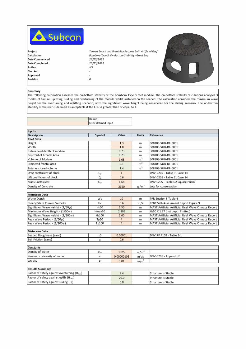
Project Turners Beach and Great Bay Purpose Built Artificial ReefCalculation Bombora Type 3; On-Bottom Stability - Great BayDate Commenced 26/05/2021Date Completed 26/05/2021Author JFRChecked -Approved -Revision 0
Summary
InputsDescription Symbol Value Units ReferenceReef DataHeight 1.3 m 308103-SUB-DF-0001Width 1.8 m 308103-SUB-DF-0001Referenced depth of module 0.73 m 308103-SUB-DF-0001Centroid of Frontal Area 0.73 m 308103-SUB-DF-0001Volume of Module 1.08 m3 308103-SUB-DF-0001Projected frontal area 2.1 m2 308103-SUB-DF-0001Total enclosed volume 1.4 m3 308103-SUB-DF-0001Drag coefficient of block CD 1 DNV-C205 - Table E1 Case 14Lift coefficient of block CL 0.6 DNV-C205 - Table E1 Case 14Mass Coefficient CM 1.68 DNV C205 - Table D2 Square PrismDensity of Concrete 2350 kg/m3 Low for conservatism
Metocean DataWater Depth Wd 10 m PPR Section 5 Table 4Steady State Current Velocity Uc 0.6 m/s EPBC Self-Assessment Report Figure 9Significant Wave Height - (1/50yr) Hs50 1.50 m MAST Artificial Artificial Reef Wave Climate ReportMaximum Wave Height - (1/50yr) Hmax50 2.805 m Hs50 X 1.87 (not depth limited)Significant Wave Height - (1/100yr) Hs100 1.60 m MAST Artificial Artificial Reef Wave Climate ReportPeak Wave Period - (1/50yr) Tp50 4 m MAST Artificial Artificial Reef Wave Climate ReportPeak Wave Period - (1/100yr) Tp100 4 m MAST Artificial Artificial Reef Wave Climate Report
Metocean DataSeabed Roughness (sand) z0 0.00001 DNV RP F109 - Table 3-1Soil Friction (sand) µ 0.6
ConstantsDensity of water ρsw 1025 kg/m3 -Kinematic viscosity of water n 0.00000105 m2/s DNV-C205 - Appendix FGravity g 9.81 m/s2 -
Results SummaryFactor of safety against overturning (Hmax) 9.4 Structure is StableFactor of safety against uplift (Hmax) 20.0 Structure is StableFactor of safety against sliding (Hs) 6.0 Structure is Stable
The following calculation assesses the on-bottom stability of the Bombora Type 3 reef module. The on-bottom stability calculations analyses 3modes of failure; uplifting, sliding and overturning of the module whilst installed on the seabed. The calculation considers the maximum waveheight for the overturning and uplifting scenario, with the significant wave height being considered for the sliding scenario. The on-bottomstability of the reef is deemed as acceptable if the FOS is greater than or equal to 1.
User defined inputResult

Project Turners Beach and Great Bay Purpose Built Artificial ReefCalculation Apollo; On-Bottom Stability - Great BayDate Commenced 26/05/2021Date Completed 26/05/2021Author JFRChecked -Approved -Revision 0
Summary
InputsDescription Symbol Value Units ReferenceReef DataHeight 1 m 3853-SUB-DWG-0001Width 1.315 m 3853-SUB-DWG-0001Referenced depth of module 0.43 m 3853-SUB-DWG-0001Centroid of Frontal Area 0.43 m 3853-SUB-DWG-0001Volume of Module 0.387 m3 3853-SUB-DWG-0001Projected frontal area 0.9 m2 3853-SUB-DWG-0001Total enclosed volume 0.7 m3 3853-SUB-DWG-0001Drag coefficient of block CD 1 DNV-C205 - Table E1 Case 14Lift coefficient of block CL 0.6 DNV-C205 - Table E1 Case 14Mass Coefficient CM 1.68 DNV C205 - Table D2 Square PrismDensity of Concrete 2350 kg/m3 Low for conservatism
Metocean DataWater Depth Wd 10 m PPR Section 5 Table 4Steady State Current Velocity Uc 0.6 m/s EPBC Self-Assessment Report Figure 9Significant Wave Height - (1/50yr) Hs50 1.50 m MAST Artificial Artificial Reef Wave Climate ReportMaximum Wave Height - (1/50yr) Hmax50 2.805 m Hs50 X 1.87 (not depth limited)Significant Wave Height - (1/100yr) Hs100 1.60 m MAST Artificial Artificial Reef Wave Climate ReportPeak Wave Period - (1/50yr) Tp50 4 m MAST Artificial Artificial Reef Wave Climate ReportPeak Wave Period - (1/100yr) Tp100 4 m MAST Artificial Artificial Reef Wave Climate Report
Metocean DataSeabed Roughness (sand) z0 0.00001 DNV RP F109 - Table 3-1Soil Friction (sand) µ 0.6
ConstantsDensity of water ρsw 1025 kg/m3 -Kinematic viscosity of water n 0.00000105 m2/s DNV-C205 - Appendix FGravity g 9.81 m/s2 -
Results SummaryFactor of safety against overturning (Hmax) 8.4 Structure is StableFactor of safety against uplift (Hmax) 13.5 Structure is StableFactor of safety against sliding (Hs) 4.4 Structure is Stable
The following calculation assesses the on-bottom stability of the Apollo reef module. The on-bottom stability calculations analyses 3 modes offailure; uplifting, sliding and overturning of the module whilst installed on the seabed. The calculation considers the maximum wave height forthe overturning and uplifting scenario, with the significant wave height being considered for the sliding scenario. The on-bottom stability of thereef is deemed as acceptable if the FOS is greater than or equal to 1.
User defined inputResult

Project Turners Beach and Great Bay Purpose Built Artificial Reef
Calculation Abitat; On-Bottom Stability - Great Bay
Date Commenced 26-5-2021
Date Completed 26-5-2021
Author JFR
Checked -
Approved -
Revision 0
Summary
Inputs
Description Symbol Value Units Reference
Reef Data
Height 1 m 3852-SUB-DWG-0001
Width 2,8 m 3852-SUB-DWG-0001
Referenced depth of module 0,38 m 3852-SUB-DWG-0001
Centroid of Frontal Area 0,38 m 3852-SUB-DWG-0001
Volume of Module 0,73 m3 3852-SUB-DWG-0001
Projected frontal area 2,2 m2 3852-SUB-DWG-0001
Total enclosed volume 2,7 m3 3852-SUB-DWG-0001
Drag coefficient of block CD 2,1 DNV-C205 - Table E1 Case 16
Lift coefficient of block CL 0,6 DNV-C205 - Table E1 Case 14
Mass Coefficient CM 1,06 DNV C205 - Table D2 Square Prism
Density of Concrete 2350 kg/m3 Low for conservatism
Metocean Data
Water Depth Wd 10 m PPR Section 5 Table 4
Steady State Current Velocity Uc 0,6 m/s EPBC Self-Assessment Report Figure 9
Significant Wave Height - (1/50yr) Hs50 1,50 m MAST Artificial Artificial Reef Wave Climate Report
Maximum Wave Height - (1/50yr) Hmax50 2,805 m Hs50 X 1.87 (not depth limited)
Significant Wave Height - (1/100yr) Hs100 1,60 m MAST Artificial Artificial Reef Wave Climate Report
Peak Wave Period - (1/50yr) Tp50 4 m MAST Artificial Artificial Reef Wave Climate Report
Peak Wave Period - (1/100yr) Tp100 4 m MAST Artificial Artificial Reef Wave Climate Report
Metocean Data
Seabed Roughness (sand) z0 0,00001 DNV RP F109 - Table 3-1
Soil Friction (sand) m 0,6
Constants
Density of water ρsw 1025 kg/m3 -
Kinematic viscosity of water n 0,00000105 m2/s DNV-C205 - Appendix F
Gravity g 9,81 m/s2 -
Results Summary
Factor of safety against overturning (Hmax) 10,5 Structure is Stable
Factor of safety against uplift (Hmax) 5,6 Structure is Stable
Factor of safety against sliding (Hs) 2,2 Structure is Stable
The following calculation assesses the on-bottom stability of the Abitat reef module. The on-bottom stability calculations analyses 3 modes of failure;
uplifting, sliding and overturning of the module whilst installed on the seabed. The calculation considers the maximum wave height for the overturning
and uplifting scenario, with the significant wave height being considered for the sliding scenario. The on-bottom stability of the reef is deemed as
acceptable if the FOS is greater than or equal to 1.
User defined input
Result

Project Purpose Built Artificial Reef – Turners Beach and Great Bay
Scope Artificial Reef Design Report
Document No. 500331-MAST-RF-0003 Rev B
Client No. N/A
Page 7
Appendix B: Structural Report

Structural Design Report
Project Name: Tasmanian Artificial Reefs Date: 30/08/2021
Project Number: 500331 Revision: A
Subject: Abitat, Apollo and Bombora Created By: RSm
Document Number: 500331-MAST-RF-0002 Checked By: JFr
Scope This calculation is to confirm structural capacity of the Abitat, Apollo and Bombora reef modules during lifting and in place. The modules will be made using fibre reinforced concrete but the calculation is performed for plain concrete. The concrete characteristic compressive strength is 50MPa.
References References used within this design calculation include:
1) AS3600 – 2009 Concrete Design 2) AS4997 – 2005 Guidelines for the design of Maritime Structures 3) DNV Classification Note 30.5 Environment Conditions & Loads 4) DNV Rules for Planning and Execution of Marine Operations, Part 2, Chapter 5, Lifting
Material
• Concrete strength is minimum characteristic strength (f’c) of 18MPa
• Fibre reinforced concrete density of 2.35 t/m3
• Design weight is 1773kg for Abitat
• Design weight is 930kg for Apollo
• Design weight is 3280kg for Bombora Type 1
• Design weight is 2550kg for Bombora Type 2
• Design weight is 1990kg for Bombora Type 3
Inplace Load Condition
• Maximum combined wave and current velocity of 2.6m/s (worst case at Turners Beach)
• Velocity profile is constant along the entire reef
• Design drag coefficient Cd of 1.0 for the Apollo and Bombora modules
• Design drag coefficient Cd of 2.1 for the Abitat modules
• Seawater density of 1.025t/m3
Offshore Lift Condition
• Maximum dynamic amplification factor of 1.7
• Design weight is 1773kg for Abitat
• Design weight is 930kg for Apollo
• Design weight is 3280kg for Bombora Type 1
• Design weight is 2550kg for Bombora Type 2
• Design weight is 1990kg for Bombora Type 3
• Allowance for COG shift factor of 1.1 Mode NTE Weight Lift DAF Limit State Factor Analysis DAF
Offshore Exposed Location
1773kg (Abitat) 930kg (Apollo)
3280kg (Bombora Type 1) 2550kg (Bombora Type 2) 1990kg (Bombora Type 3)
1.7 1.25 2.125

Structural Design Report
Project Name: Tasmanian Artificial Reefs Date: 30/08/2021
Project Number: 500331 Revision: A
Subject: Abitat, Apollo and Bombora Created By: RSm
Document Number: 500331-MAST-RF-0002 Checked By: JFr
Fabrication Lift Condition
• Maximum Dynamic amplification factor of 1.2
• Design weight is 1773kg for Abitat
• Design weight is 930kg for Apollo
• Design weight is 3280kg for Bombora Type 1
• Design weight is 2550kg for Bombora Type 2
• Design weight is 1990kg for Bombora Type 3
• Allowance for COG shift factor of 1.1 Mode NTE Weight Lift DAF Limit State Factor Analysis DAF
Fabrication Yard Location
1773kg (Abitat) 930kg (Apollo)
3280kg (Bombora Type 1) 2550kg (Bombora Type 2) 1990kg (Bombora Type 3)
1.2 1.25 1.5
Conclusion The design calculations in Appendix A (Abitat), Appendix B (Apollo) and Appendix C (Bombora) show that all the modules are structurally sound when considering plain concrete alone.

Structural Design Report
Project Name: Tasmanian Artificial Reefs Date: 30/08/2021
Project Number: 500331 Revision: A
Subject: Abitat, Apollo and Bombora Created By: RSm
Document Number: 500331-MAST-RF-0002 Checked By: JFr
Appendix A – Design Check Abitat

Abitat DetailsThe details of the Abitat reef module are summarised below. These have been taken from 3852-SUB-DWG-0001.
Design Dry Weight ≔Wdry 1800 kg
Dynamic Amplification Factor ≔DAF 2.0
Limit State Factor ≔γLS 1.25
Skew Load Factor ≔SKL 1.1
Weight Uncertainty Factor ≔γW 1.05
Design Hook Load ≔DHL ⋅⋅⋅⋅Wdry DAF γLS SKL γW
=DHL ⎛⎝ ⋅5.198 103 ⎞⎠ kg
The Abitat will be lifted from three lift points as shown in the sketch below

Lift Member Loads Treat the top member of the Abitat as a beam for the purposes of the analysis. This is a conservative approach as in reality the side of the Abitat will act as a truss. The beam dimensions are as follows:
Simplified Beam cross section
≔b 110 mm≔h 377 mm≔l 1330 mm
Uniformly distributed loads ≔q =―――⋅DHL g
⋅3 l12.774 ――
kNm
Max Shear ≔Vmax =――⋅q l2
⎛⎝ ⋅8.495 103 ⎞⎠ N
Max Moment ≔Mmax =――⋅q l2
82.825 ⋅kN m

Lift Shear CheckThe simplified beam is checked for shear capacity based on plain concrete (i.e. fibres are not accounted for). This check is based on the uncracked capacity of the concrete in accordance with AS 3600.
The modules are designed to be lifted one day after pour during fabrication and as such the capacity checks are based on the compressive strength after 1 day. This is typically 18MPa (Subcon experience). It should be noted that this is a conservative check as the design hook load is based on installation loads (worst lifting conditions) and the concrete will be fully cured
Shear Reduction ≔ϕv 0.7
Charactistic Concrete Compressive Strength
≔f'c 18
Reduced Concrete Strength for shear calculation
≔f't =⋅⋅‾‾3f'c 1 MPa 2.621 MPa
Plain Concrete Allowable Shear ≔ϕVu =⋅⋅⋅⋅ϕv 0.15 b h f't 11.412 kN
Member Shear Utilisation ≔UCV =――Vmax
ϕVu
0.744 OK
Lift Flexure CheckThe simplified beam is checked for uncracked flexural capacity based on plain concrete (i.e. fibres are not accounted for). Again this is a conservative approach.
Flexure Reduction ≔ϕm 0.8
Characteristic Concrete Flexural Strength
≔f'ctf =⋅⋅‾‾f'c 0.6 MPa 2.546 MPa
Strong axis Section Modulus ≔Zs =――⋅b h2
6⎛⎝ ⋅2.606 106 ⎞⎠ mm 3
Strong axis allowable moment ≔ϕMus =⋅⋅⋅ϕm Zs 1.2 f'ctf 6.368 ⋅kN m
Member flexure utilisation ≔UCf =――Mmax
ϕMus
0.444 OK

Inplace Member Loads (Weak Axis) Weak axis loads come from the hydrodynamic forces when the Abitat is in place. The concrete is fully cured by this time and so the characteristic concrete compressive strength is 50MPa.
The slope of the Abitat and the current velocity profile through the water column are both ignored in this calculation. This is conservative.
Pressure Loads
Current velocity is 2.6m/s from stability report. Use: ≔Uw 2.6 ―
ms
Drag Coefficient ≔Cd 2.1
Sea water density ≔ρsw 1025 ――kg
m3
Pressure (Live Load) ≔P ⋅⋅⋅―12
ρsw Cd Uw2
=P 7.275 kPa
Selfweight Loads (assume acting with pressure - conservative)
Concrete density ≔ρc 2350 ――kg
m3
Self Weight (Dead Load) ≔qw ⋅⋅b ⎛⎝ -ρc ρsw⎞⎠ g
=qw 1.429 kPa
Selfweight Loads (assume acting with pressure - conservative)
Design Pressure ≔Q +(( ⋅2.0 P)) ⎛⎝ ⋅1.25 qw⎞⎠
=Q 16.338 kPa

Design load on beam
UDL ≔w =⋅Q h 6.159 ――kNm
Inplace Flexure CheckThe simplified beam is checked for uncracked flexural capacity based on plain concrete (i.e. fibres are not accounted for). Again this is a conservative approach.
Moment ≔Mw =――⋅w l2
81.362 ⋅kN m
Characteristic Concrete Compressive Strength (Inplace)
≔f'cin 50
Characteristic Concrete Flexural Strength (Inplace)
≔f'ctfin =⋅⋅‾‾‾‾f'cin 0.6 MPa 4.243 MPa
Weak axis Section modulus ≔Zw =――⋅h b2
6⎛⎝ ⋅7.603 105 ⎞⎠ mm 3
Weak axis allowable moment ≔ϕMuw =⋅⋅⋅ϕm Zw 1.2 f'ctfin 3.097 ⋅kN m
Member flexure utilisation ≔UCf =――Mw
ϕMuw
0.44 OK
Lift Shear Check
Shear ≔Vw =――⋅w l2
4.096 kN
Reduced Concrete Strength for shear calculation (Inplace)
≔f'tin =⋅⋅‾‾‾‾3f'cin 1 MPa 3.684 MPa
Plain Concrete Allowable Shear ≔ϕVuin =⋅⋅⋅⋅ϕv 0.15 b h f'tin 16.042 kN
Member Shear Utilisation ≔UCV =――Vw
ϕVuin
0.255 OK
ConclusionThe calculation above proves that the Abitat module is structurally able to resist themost onerous load it is expected to see. Specifically these loads are:Major axis - lifting 24hours after pourMinor axis - inplace hydrodynamic loads
The Abitat is fit for purpose

ConclusionThe calculation above proves that the Abitat module is structurally able to resist the most onerous load it is expected to see. Specifically these loads are:Major axis - lifting 24hours after pourMinor axis - inplace hydrodynamic loads
The Abitat is fit for purpose

Structural Design Report
Project Name: Tasmanian Artificial Reefs Date: 30/08/2021
Project Number: 500331 Revision: A
Subject: Abitat, Apollo and Bombora Created By: RSm
Document Number: 500331-MAST-RF-0002 Checked By: JFr
Appendix B – Design Check Apollo

Apollo DetailsThe details of the Apollo reef module are summarised below. These have been taken from 3853-SUB-DWG-0001. The compact shape of the Apollo does not lend itself to comparison with beam design for analysis (i.e. no flexure). As such only the bearing and shear need be checked .
As the Apollo is effectively a concrete block inplace loads will not be significant compared to structural capacity. As such only the lift case will be checked. The non cured characteristic concrete compressive strength of 18MPa will be used for this.
Design Dry Weight ≔Wdry 1000 kg
Dynamic Amplification Factor ≔DAF 2.0
Limit State Factor ≔γLS 1.25
Skew Load Factor ≔SKL 1.1
Weight Uncertainty Factor ≔γW 1.05
Design Hook Load ≔DHL ⋅⋅⋅⋅Wdry DAF γLS SKL γW
=DHL ⎛⎝ ⋅2.888 103 ⎞⎠ kg
The Apollo will be lifted from two lift points as shown in the sketch below
Assume a 60:40 split of the lift force
Lift point force ≔F ⋅⋅DHL 0.6 g
=F 16.99 kN

Bearing CheckThe lift arrangement has been done for the worst case lifting arrangement. That is using 24mm diameter rope through two of the uppermost Apollo windows.
≔b1 100 mm≔h 300 mm≔b2 130 mm
≔l 1760 mm
≔θrope 24 mm
Bearing Reduction Factor ≔ϕb 0.6
Charactistic Concrete Compressive Strength ≔f'c 18
Bearing Stress ≔qmax ―――F⋅b2 θrope
=qmax 5.446 MPa
Allowable Bearing Stress ≔ϕqb ⋅⋅⋅⋅ϕb 0.6 f'c‾‾‾‾‾‾‾―――
⋅b2 θrope⋅b2 θrope
MPa
=ϕqb 6.48 MPa
Member bearing utilisation ≔UCb =――qmax
ϕqb0.84 OK (Worst case)

Shear CheckThe modules are designed to be lifted one day after pour during fabrication and as such the capacity checks are based on the compressive strength after 1day. This is typically 18MPa (Subcon experience). It should be noted that this is a conservative check as the design hook load is based on installation loads (worst lifting conditions) and the concrete will be fully cured. Also, the shear area has been averaged from b1 to b2 to give bavg
Shear Force ≔Vmax =―F2
8.495 kN
Average width ≔bavg =―――+b1 b22
115 mm
Shear Reduction ≔ϕv 0.7
Reduced Concrete Strength for shear calculation
≔f't =⋅⋅‾‾3f'c 1 MPa 2.621 MPa
Plain Concrete Allowable Shear ≔ϕVu =⋅⋅⋅⋅ϕv 0.15 bavg h f't 9.494 kN
Member Shear Utilisation ≔UCV =――Vmax
ϕVu
0.895 OK
Inplace Member Loads (Weak Axis) Weak axis loads come from the hydrodynamic forces when the Apollo is in place. The concrete is fully cured by this time and so the characteristic concrete compressive strength is 50MPa.
The slope of the Apollo and the current velocity profile through the water column are both ignored in this calculation. This is conservative.
Pressure Loads
Current velocity is 2.6m/s from stability report. Use: ≔Uw 2.6 ―
ms
Drag Coefficient ≔Cd 1.0
Sea water density ≔ρsw 1025 ――kg
m3
Pressure (Live Load) ≔P ⋅⋅⋅―12
ρsw Cd Uw2
=P 3.465 kPa
Selfweight Loads (assume acting with pressure - conservative)
Concrete density ≔ρc 2350 ――kg
m3
Self Weight (Dead Load) ≔qw ⋅⋅h ⎛⎝ -ρc ρsw⎞⎠ g
=qw 3.898 kPa
Selfweight Loads (assume acting with pressure - conservative)
Design Pressure ≔Q +(( ⋅2.0 P)) ⎛⎝ ⋅1.25 qw⎞⎠
=Q 11.802 kPa

Design load on beam
UDL ≔w =⋅Q h 3.541 ――kNm
Inplace Flexure CheckThe simplified beam is checked for uncracked flexural capacity based on plain concrete (i.e. fibres are not accounted for). Again this is a conservative approach.
Flexure Reduction ≔ϕm 0.8
Moment ≔Mw =――⋅w l2
81.371 ⋅kN m
Characteristic Concrete Compressive Strength (Inplace)
≔f'cin 50
Characteristic Concrete Flexural Strength (Inplace)
≔f'ctfin =⋅⋅‾‾‾‾f'cin 0.6 MPa 4.243 MPa
Weak axis Section modulus ≔Zw =―――⋅h b12
6⎛⎝ ⋅5 105 ⎞⎠ mm 3
Weak axis allowable moment ≔ϕMuw =⋅⋅⋅ϕm Zw 1.2 f'ctfin 2.036 ⋅kN m
Member flexure utilisation ≔UCf =――Mw
ϕMuw
0.673 OK
ConclusionThe calculation above proves that the Apollo module is structurally able to resist themost onerous load it is expected to see. Specifically these loads are:Major axis - lifting 24hours after pourMinor axis - inplace hydrodynamic loads
The Apollo is fit for purpose

ConclusionThe calculation above proves that the Apollo module is structurally able to resist the most onerous load it is expected to see. Specifically these loads are:Major axis - lifting 24hours after pourMinor axis - inplace hydrodynamic loads
The Apollo is fit for purpose

Structural Design Report
Project Name: Tasmanian Artificial Reefs Date: 30/08/2021
Project Number: 500331 Revision: A
Subject: Abitat, Apollo and Bombora Created By: RSm
Document Number: 500331-MAST-RF-0002 Checked By: JFr
Appendix C – Design Check Bombora

CALCULATION SHEET
Project Name: Subcon SFRC Bombora & Bombora Project Date: 13/1/2021
Project Number: 126 Revision: 0
Subject: Bombora Structural Design Report Created By: AC
Document No: 126-CS-002 Checked By: AC
Client Doc No: N/A Client Approved: AK
Page 1
Scope
The purpose of this design report is to confirm structural integrity and code compliance of the Bombora Reef Module for onshore and offshore lifting.
References
References used within this design calculation include:
1. Australian Standard, AS3600:2018 – Concrete structures.2. DNVGL-ST-N001 – Marine Operations (2016-06)3. Subcon Drawing, Bombora GA - DWG 500313-DOF-DF-0002.B4. DOF Drawing, Lift Sling Arrangement, DWG 1004086-CA-CL-907-0004 Rev C
Calculation Objective
For the structural design of the Bombora, this calculation investigates the following:
1. Capacity check for Steel Fibre Reinforced Concrete (SFRC) members withoutreinforcement (i.e. minimum flexural tensile strength of concrete without reinforcement)
2. Local stress check at the lift points using the proposed sling arrangement
Methodology
SpaceGass software FEA module has been used for structural analysis.
Design Input / Assumptions
The assessment has been performed using the design data and assumptions listed below.
Design properties of concrete – characteristic compressive strength (𝑓′𝑐) of 50MPa at 28 daysfor offshore lift
Interim concrete strength of 35MPa for the onshore lift case
Bombora design weight is assumed as 3.3 mT
Dynamic Amplification Factor (DAF) of 2.5 as supplied by client
Dynamic Lift Factor (DLF) = DAF x 𝛾𝑊𝑒𝑖𝑔ℎ𝑡 x Load factor x Consequence factor [Ref. 3]
Dynamic Hook Load (DHL) = SHL x DLF [Ref. 2]
Steel fibres provide crack control only for concrete structures and no relied upon for strength
Proposed lifting arrangement is a basket hitch wire rope sling with rubber hose as show inFigure 2.
The sling lift angle is min 85° to the horizontal
Lift factors in accordance with DNV [Ref. 2]
Quasi-static lift analysis only (dynamic loads simulated by lift factors)

CALCULATION SHEET
Project Name: Subcon SFRC Bombora & Bombora Project Date: 13/1/2021
Project Number: 126 Revision: 0
Subject: Bombora Structural Design Report Created By: AC
Document No: 126-CS-002 Checked By: AC
Client Doc No: N/A Client Approved: AK
Page 2
The lift factors used in the this analysis include;
Load Factors Symbol Offshore Onshore Reference
Dynamic Amplification Factor DAF 2.5 1.1 Client specified / DNV
Weight contingency factor 𝛾𝑊𝑒𝑖𝑔ℎ𝑡 1.05 1.05 DNV [Ref. 2]
Load factor ∝𝑓 1.3 1.3 DNV [Ref. 2]
Consequence factor ∝𝑐 1.15 1.15 DNV [Ref. 2]
Dynamic Load Factor DLF 3.92 1.73
Table 1 Summary of DNV Load Factors for Bombora Structural Analysis
SpaceGass Model The Bombora is modelled in SpaceGass using 2D triangular plate elements. The thickness of the plate
elements are 150mm.
Figure 1 SpaceGass Model – Bombora

CALCULATION SHEET
Project Name: Subcon SFRC Bombora & Bombora Project Date: 13/1/2021
Project Number: 126 Revision: 0
Subject: Bombora Structural Design Report Created By: AC
Document No: 126-CS-002 Checked By: AC
Client Doc No: N/A Client Approved: AK
Page 3
Rigging Arrangement
The slings are basket hitched through 2 off round openings at top of the Bombora. To avoid point loading the concrete wall the lift slings have a rubber hose to spread load.
Figure 2 indicates the rigging arrangement assumed for the Bombora analysis.
Figure 2 Lift Arrangement
Wire sling with rubber hose
or equivalent

CALCULATION SHEET
Project Name: Subcon SFRC Bombora & Bombora Project Date: 13/1/2021
Project Number: 126 Revision: 0
Subject: Bombora Structural Design Report Created By: AC
Document No: 126-CS-002 Checked By: AC
Client Doc No: N/A Client Approved: AK
Page 4
Boundary Conditions
The lift points are vertically pinned to simulate the lift loads. Horizontal pins and springs (100KN/m)
are placed at the base of the Bombora to provide stability for the structure. The spring reactions are
checked to be less 1KN from the analysis and hence suitably low for the analysis.
Figure 3 illustrates the boundary conditions for the Bombora model.
Figure 3 Boundary Conditions

CALCULATION SHEET
Project Name: Subcon SFRC Bombora & Bombora Project Date: 13/1/2021
Project Number: 126 Revision: 0
Subject: Bombora Structural Design Report Created By: AC
Document No: 126-CS-002 Checked By: AC
Client Doc No: N/A Client Approved: AK
Page 5
Sling Compression Loads
Due to the basket sling arrangement, the lift load will induce a compression load on the side of the
Bombora. Based on static self weight lift and sling angles the estimate sling compression load is
equated to 15.6KN each side. The compression load is applied over 3 nodes to simulate the load
spread equivalent to the rubber hose diameter of 66mm.
Figure 4 Sling Compression Loads
Load Cases
Table 2 and Table 3 present the primary and combination load cases being analysed in SpaceGass to
confirm the structural adequacy of the reef module during lifting conditions.
Table 2 Primary Load Cases in SpaceGass Model
All Combination Load Cases
Table 3 Combination Load Cases in SpaceGass Model

CALCULATION SHEET
Project Name: Subcon SFRC Bombora & Bombora Project Date: 13/1/2021
Project Number: 126 Revision: 0
Subject: Bombora Structural Design Report Created By: AC
Document No: 126-CS-002 Checked By: AC
Client Doc No: N/A Client Approved: AK
Page 6
Design Results
The structural checks have focused on the induced tensile and shear stresses. The resulting stresses are checked against limiting stress in accordance with AS 3600.
Tensile Stress During the offshore lift case (Case 200) the majority of the Bombora structure is very low stressed. The maximum tensile stress in the Bombora was found to be 2.47MPa (tension) above the lift point at the top of the Bombora. This stress is mainly caused by lift sling compressing the Bombora together. The limiting stress is the flexural tensile stress (f’ct.f) of 50MPa concrete is calculated as;
f’ct.f = 0.6 .sqrt(f’c) [Ref 1]
where = 0.6 f’c = 50 MPa f’ct.f = 2.54 MPa.
Hence the tensile stresses are within the limiting stress and considered suitable. Refer to Figures 5 and 6 show the tensile stress in the Bombora during the offshore lift. Similarly for the onshore lift case, the tensile stress are within limiting stress. For results relating to the onshore lift case and interim concrete strength, refer to Appendix B. Note: Space Gass notation for stress is +MPa is a compressive stress and –MPa is a tensile stress. Note: A peak stress of 16.8 MPa (compression) occurs locally at the lift point and is considered highly localised. As a result some minor cracking may occur locally at the lift point however not a concern for global strength of the Bombora.

CALCULATION SHEET
Project Name: Subcon SFRC Bombora & Bombora Project Date: 13/1/2021
Project Number: 126 Revision: 0
Subject: Bombora Structural Design Report Created By: AC
Document No: 126-CS-002 Checked By: AC
Client Doc No: N/A Client Approved: AK
Page 7
Figure 5 Maximum Tensile Stress – Offshore Lift Case (LC 200)
Figure 6 Maximum Tensile Stress – Offshore Lift Case (LC 200) with deformation
Peak tensile stress
Peak tensile stress

CALCULATION SHEET
Project Name: Subcon SFRC Bombora & Bombora Project Date: 13/1/2021
Project Number: 126 Revision: 0
Subject: Bombora Structural Design Report Created By: AC
Document No: 126-CS-002 Checked By: AC
Client Doc No: N/A Client Approved: AK
Page 8
Shear Stress During the offshore lift case (Case 200) the majority of the Bombora structure have shear stresses within 1.19 MPa. However a peak shear stress of 7.92MPa was found at lift point and considered highly stressed. However this peak stress is highly localised and consider to reduce upon local deformation. As a result the majority of the lift point is considered to have a maximum shear stress of 2.38MPa. The limiting stress is the ultimate shear stress (f’c.v) of 50MPa concrete is calculated as;
f’ct.f = .(f’c)1/3 [Ref 1]
where = 0.7 f’c = 50 MPa f’ct.f = 2.57 MPa.
Hence the majority of shear stresses are within the limiting stress and considered suitable. Figure 7 and 8 show the results for the shear stress during offshore lift. Similarly for the onshore lift case, the shear stress are within limiting stress. For results relating to the onshore lift case and interim concrete strength, refer to Appendix B. Note: As a result of high stresses at the lift point some minor cracking may occur locally at the lift point. However this is not considered a concern for global strength of the Bombora.
Figure 7 Maximum Shear Stress – Offshore Lift Case (LC 200)
Local overstress

CALCULATION SHEET
Project Name: Subcon SFRC Bombora & Bombora Project Date: 13/1/2021
Project Number: 126 Revision: 0
Subject: Bombora Structural Design Report Created By: AC
Document No: 126-CS-002 Checked By: AC
Client Doc No: N/A Client Approved: AK
Page 9
Figure 8 Maximum Shear Stress – Offshore Lift Case (LC 200) with deformation
Local overstress

CALCULATION SHEET
Project Name: Subcon SFRC Bombora & Bombora Project Date: 13/1/2021
Project Number: 126 Revision: 0
Subject: Bombora Structural Design Report Created By: AC
Document No: 126-CS-002 Checked By: AC
Client Doc No: N/A Client Approved: AK
Page 10
Conclusion
In assessing the suitability of Bombora structural members during offshore and onshore lift cases, the design calculations shown in Appendix B demonstrate the members are code compliant.
Despite some local overstress, the majority of the stresses are within code limits and the Bombora is suitable for lifting as unreinforced SFRC section.
The steel fibres are not relied upon for strength and concrete strength checks ignore the contribution of steel fibres to strength.

CALCULATION SHEET
Project Name: Subcon SFRC Bombora & Bombora Project Date: 13/1/2021
Project Number: 126 Revision: 0
Subject: Bombora Structural Design Report Created By: AC
Document No: 126-CS-002 Checked By: AC
Client Doc No: N/A Client Approved: AK
Page 11
Table of Appendices
Appendix A – Drawings Appendix B – Design Checks Appendix C – SpaceGass Data Appendix D – Reference Info
CALCULATION SHEET
Project Name: Subcon SFRC Bombora & Bombora Project Date: 13/1/2021
Project Number: 126 Revision: 0
Subject: Bombora Structural Design Report Created By: AC
Document No: 126-CS-002 Checked By: AC
Client Doc No: N/A Client Approved: AK
Appendix
Appendix A –Drawings

TOP VIEW
SCALE1 : 25
SIDE VIEW
SCALE 1 : 25
SECTION A-A
SCALE 1 : 25
ISOMETRIC VIEW
SCALE 1 : 25
SECTION B-B
SCALE 1 : 25
A
A
B
B
1 2 3 4 5 6 7 8 9 10 11 12
1 2 3 4 5 6 7 8 9 10 11 12
A
B
C
D
E
F
G
H H
G
F
E
D
C
B
A
Perth: +61 8 9200 2218
Singapore: +65 6440 7752
Europe: +31 15 800 0228
China: +86 769 828 06357, +86 137 1529 7879
Web: www.subcon.com
TITLE
BOMBORA
GENERAL ARRANGEMENT
500313-DOF-DF-0002
DRAWING NUMBER
REV
B SHEET 1 of 1
SIZE
A3
SCALE
NTS
C Copyright Subcon 2020
CHECKED
DRAWN
APPROVED
I.CLEGG
J.FRANCIS
A.KIKEROS
INITIAL DATE
DRN CHK APPREV DATE DESCRIPTION
A 20.10.20 IC AK JFISSUED FOR INTERNAL REVIEW
20.10.20B ISSUED FOR INTERNAL REVIEW JFIC AK
NOTES:
1. ALL DIMENSIONS ARE IN MILLIMETRES UNO.
2. CONCRETE VOLUME: 1.44m3
3. CONCRETE DENSITY: 2.35Te/m3
4. DRY WEIGHT: 3.28Te
5. SURFACE AREA: 21.92m2
6. NUMBER OF HOLES: 27
7. CONCRETE TYPE 50 MPa MARINE CONCRETE.
8. DRAMIX 4D 65/35G STEEL FIBRES TO BE USED AT A
DOSAGE RATE OF 25kg/m3.
2
1
9
(
T
Y
P
.
)
1104
2100
170
1550
1600
1750
18001
00
222
(T
Y
P
.)
900 (T
Y
P
.)
700
ANCHORAGE VOID
MINIMUM 32mm
DIAMETER 3 PER
REEF MODULE
TOP CONCRETE SURFACE
FINISH TO BE EXPOSED
AGGREGATE ONLY
SMOOTH CONCRETE
SURFACE ON
REMAINING SURFACES
129
550 (T
Y
P
.)
1.2m x 20mm FIBREGLASS ROD
ORTHOPHTHALIC RESIN WITH
STEEL FLAT CAP
959 C
oG
2 CoG
16 C
oG
122
300
131
(T
Y
P
.)

CALCULATION SHEET
Project Name: Subcon SFRC Bombora & Bombora Project Date: 13/1/2021
Project Number: 126 Revision: 0
Subject: Bombora Structural Design Report Created By: AC
Document No: 126-CS-002 Checked By: AC
Client Doc No: N/A Client Approved: AK
Appendix
Appendix B – Design Checks

CALCULATION SHEET
Project Name: Subcon SFRC Bombora & Bombora Project Date: 13/1/2021
Project Number: 126 Revision: 0
Subject: Bombora Structural Design Report Created By: AC
Document No: 126-CS-002 Checked By: AC
Client Doc No: N/A Client Approved: AK
Appendix
ONSHORE LIFT CASE

CALCULATION SHEET
Project Name: Subcon SFRC Bombora & Bombora Project Date: 13/1/2021
Project Number: 126 Revision: 0
Subject: Bombora Structural Design Report Created By: AC
Document No: 126-CS-002 Checked By: AC
Client Doc No: N/A Client Approved: AK
Appendix
Onshore Lift Case Tensile Stress The limiting stress is the flexural tensile stress (f’ct.f) of 35MPa concrete is calculated as;
f’ct.f = 0.6 .sqrt(f’c) [Ref 1]
where = 0.6 f’c = 35 MPa f’ct.f = 2.13 MPa.
Maximum Tensile Stress The maximum tensile stress in the Bombora for onshore lift case was found to be 1.09MPa. Hence OK.
Figure B.1 Maximum Tensile Stress – Onshore Lift Case (LC 201)

CALCULATION SHEET
Project Name: Subcon SFRC Bombora & Bombora Project Date: 13/1/2021
Project Number: 126 Revision: 0
Subject: Bombora Structural Design Report Created By: AC
Document No: 126-CS-002 Checked By: AC
Client Doc No: N/A Client Approved: AK
Appendix
Shear Stress The limiting stress is the ultimate shear stress (f’c.v) of 35MPa concrete is calculated as;
f’ct.f = .(f’c)1/3 [Ref 1]
where = 0.7 f’c = 35 MPa f’ct.f = 2.29 MPa.
Maximum Shear Stress The maximum shear stress in the Bombora was found to be 2.10MPa. Hence OK.
Figure B.2 Maximum Shear Stress – Onshore Lift Case (LC 201)

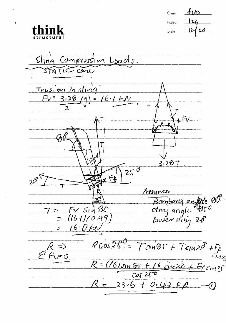


CALCULATION SHEET
Project Name: Subcon SFRC Bombora & Bombora Project Date: 13/1/2021
Project Number: 126 Revision: 0
Subject: Bombora Structural Design Report Created By: AC
Document No: 126-CS-002 Checked By: AC
Client Doc No: N/A Client Approved: AK
Appendix
Appendix C – SpaceGass Data

SPACE GASS 12.60 - THINK STRUCTURALPath: E:\OneDrive\Think Structural\Projects...\SpaceGass\Bombora Reef Ver 04Designer: Date: Tuesday, January 5, 2021 3:49 PM Page: 1
ANALYSIS STATUS REPORT----------------------
Job name ...... Bombora Reef Ver 04Location ...... E:\OneDrive\Think Structural\Projects\126 Subcon DOF SFRC R...
Length units ......................... mSection property units ............... mmMaterial strength units .............. MPaMass density units ................... T/m^3Temperature units .................... CelsiusForce units .......................... kNMoment units ......................... kNmMass units ........................... TAcceleration units ................... g'sTranslation units .................... mmStress units ......................... MPa
Nodes ................................ 17357 ( 32765)Members .............................. 0 ( 32765)Plates ............................... 29112 ( 32765)Restrained nodes ..................... 25 ( 32765)Nodes with spring restraints ......... 20 ( 32765)Section properties ................... 0 ( 32765)Material properties .................. 2 ( 999)Constrained nodes .................... 0 ( 32765)Member offsets ....................... 0 ( 32765)Plate strips ......................... 0 ( 32765)
Node loads ........................... 6 ( 250000)Prescribed node displacements ........ 0 ( 250000)Member concentrated loads ............ 0 ( 250000)Member distributed forces ............ 0 ( 250000)Member distributed torsions .......... 0 ( 250000)Thermal loads ........................ 0 ( 250000)Member prestress loads ............... 0 ( 250000)Plate pressure loads ................. 0 ( 250000)Self weight load cases ............... 1 ( 10000)Combination load cases ............... 3 ( 10000)Load cases with titles ............... 5 ( 10000)Lumped masses ........................ 0 ( 250000)Spectral load cases .................. 0 ( 10000)
Static analysis ...................... YDynamic analysis ..................... NResponse analysis .................... NBuckling analysis .................... NIll-conditioned ...................... NNon-linear convergence ............... YFrontwidth ........................... 2244Total degrees of freedom ............. 104134Static load cases .................... 2 ( 10000)Mass load cases ...................... 1 ( 10000)
NODE RESTRAINTS (kN/m,kNm/rad)--------------- (F=Fixed, R=Released, S=Spring, *=General)
Rest X Axial Y Axial Z Axial X Rotation Y Rotation Z Rotation Node Code Stiffness Stiffness Stiffness Stiffness Stiffness Stiffness
627 RRSRRR 1000.000 628 RRSRRR 1000.000 652 FRRRRR 664 SRRRRR 1000.000 665 SRRRRR 1000.000 673 FRFRRR 3061 RRSRRR 1000.000 3065 RRSRRR 1000.000 3069 FRSRRR 1000.000 3113 RRFRRR 3209 SRRRRR 1000.000 3213 SRRRRR 1000.000 3217 SRRRRR 1000.000 4703 RFRRRR 4964 RRSRRR 1000.000 5990 RRSRRR 1000.000 5993 RRSRRR 1000.000 6098 SRFRRR 1000.000 6101 SRRRRR 1000.000 6104 SRRRRR 1000.000 9725 RFRRRR12100 RRSRRR 1000.00012107 RRSRRR 1000.00012359 SRRRRR 1000.00012366 SRRRRR 1000.000
MATERIAL PROPERTIES (MPa,T/m^3,strain/degC)------------------- Young's Poisson's Mass Coeff of Concrete Matl Material Name Modulus Ratio Density Expansion Strength
1 AS-CONC2009-50 3.4800E+04 0.20 2.4000E+00 1.000E-05 50.00 3 AS-CONC2009-50 3.4800E+04 0.20 2.4000E+00 1.000E-05 50.00
NODE LOADS (kN,kNm)----------
Load X-Axis Y-Axis Z-Axis X-Axis Y-Axis Z-Axis Case Node Force Force Force Moment Moment Moment
2 1744 0.000 0.000 5.200 0.000 0.000 0.000 1745 0.000 0.000 5.200 0.000 0.000 0.000 4703 0.000 0.000 -5.200 0.000 0.000 0.000 4704 0.000 0.000 -5.200 0.000 0.000 0.000 9219 0.000 0.000 -5.200 0.000 0.000 0.000 9725 0.000 0.000 5.200 0.000 0.000 0.000
SELF WEIGHT (g's)-----------
Load X-Axis Y-Axis Z-Axis Case Accel'n Accel'n Accel'n
1 0.000 -1.030 0.000
COMBINATION LOAD CASES----------------------
Load case 100: STATIC
1.000 * Load case 1: SELF WEIGHT1.000 * Load case 2: SLING COMPRESSION
Load case 200: LIFT OFFSHORE (DLF = 3.92)
3.920 * Load case 100: STATIC
Load case 201: LIFT ONSHORE (DLF = 1.73)
1.730 * Load case 100: STATIC
LOAD CASE TITLES----------------
Load Case Title
1 SELF WEIGHT 2 SLING COMPRESSION 100 STATIC 200 LIFT OFFSHORE (DLF = 3.92) 201 LIFT ONSHORE (DLF = 1.73)
NODE REACTIONS (kN,kNm)--------------
Load case 1 (Linear): SELF WEIGHT
X-Axis Y-Axis Z-Axis X-Axis Y-Axis Z-Axis Node Force Force Force Moment Moment Moment
627 0.000 0.000 -0.015 0.000 0.000 0.000 628 0.000 0.000 -0.016 0.000 0.000 0.000 652 -0.306 0.000 0.000 0.000 0.000 0.000 664 -0.019 0.000 0.000 0.000 0.000 0.000 665 -0.017 0.000 0.000 0.000 0.000 0.000 673 0.849 0.000 -2.173 0.000 0.000 0.000 3061 0.000 0.000 -0.015 0.000 0.000 0.000 3065 0.000 0.000 -0.016 0.000 0.000 0.000 3069 -0.360 0.000 -0.016 0.000 0.000 0.000 3113 0.000 0.000 1.121 0.000 0.000 0.000 3209 -0.020 0.000 0.000 0.000 0.000 0.000 3213 -0.018 0.000 0.000 0.000 0.000 0.000 3217 -0.016 0.000 0.000 0.000 0.000 0.000 4703 0.000 13.374 0.000 0.000 0.000 0.000 4964 0.000 0.000 0.001 0.000 0.000 0.000 5990 0.000 0.000 -0.016 0.000 0.000 0.000 5993 0.000 0.000 -0.016 0.000 0.000 0.000 6098 -0.021 0.000 1.191 0.000 0.000 0.000 6101 -0.019 0.000 0.000 0.000 0.000 0.000 6104 -0.016 0.000 0.000 0.000 0.000 0.000 9725 0.000 18.891 0.000 0.000 0.000 0.00012100 0.000 0.000 -0.015 0.000 0.000 0.00012107 0.000 0.000 -0.016 0.000 0.000 0.00012359 -0.020 0.000 0.000 0.000 0.000 0.00012366 -0.018 0.000 0.000 0.000 0.000 0.000 Sum 0.000 32.265 0.000 0.000 0.000 0.000
Load 0.000 -32.265 0.000 0.000 0.000 0.000 Reac 0.000 32.265 0.000 0.000 0.000 0.000
Equil 1.211E-11 0.000E+00 -5.493E-13Resid 2.553E-11 1.136E-11 2.689E-11 8.460E-12 7.612E-12 1.202E-11YCntr 0.007 1.341 -0.129
Load case 2 (Linear): SLING COMPRESSION
X-Axis Y-Axis Z-Axis X-Axis Y-Axis Z-Axis Node Force Force Force Moment Moment Moment
627 0.000 0.000 0.018 0.000 0.000 0.000 628 0.000 0.000 0.018 0.000 0.000 0.000 652 0.151 0.000 0.000 0.000 0.000 0.000 664 0.023 0.000 0.000 0.000 0.000 0.000 665 0.020 0.000 0.000 0.000 0.000 0.000 673 0.027 0.000 1.742 0.000 0.000 0.000 3061 0.000 0.000 0.017 0.000 0.000 0.000 3065 0.000 0.000 0.018 0.000 0.000 0.000 3069 -0.395 0.000 0.018 0.000 0.000 0.000 3113 0.000 0.000 -0.898 0.000 0.000 0.000 3209 0.024 0.000 0.000 0.000 0.000 0.000 3213 0.021 0.000 0.000 0.000 0.000 0.000 3217 0.018 0.000 0.000 0.000 0.000 0.000 4703 0.000 1.192 0.000 0.000 0.000 0.000 4964 0.000 0.000 -0.001 0.000 0.000 0.000 5990 0.000 0.000 0.018 0.000 0.000 0.000 5993 0.000 0.000 0.018 0.000 0.000 0.000 6098 0.024 0.000 -1.002 0.000 0.000 0.000 6101 0.022 0.000 0.000 0.000 0.000 0.000 6104 0.019 0.000 0.000 0.000 0.000 0.000 9725 0.000 -1.192 0.000 0.000 0.000 0.00012100 0.000 0.000 0.018 0.000 0.000 0.00012107 0.000 0.000 0.018 0.000 0.000 0.00012359 0.023 0.000 0.000 0.000 0.000 0.00012366 0.021 0.000 0.000 0.000 0.000 0.000 Sum 0.000 0.000 0.000 0.000 0.000 0.000
Load 0.000 0.000 0.000 0.000 0.000 0.000 Reac 0.000 0.000 0.000 0.000 0.000 0.000
Equil 3.657E-11 1.518E-11 4.382E-11Resid 2.413E-11 5.682E-12 3.266E-11 1.558E-11 2.028E-11 1.772E-11
Load case 100 (Linear): STATIC
X-Axis Y-Axis Z-Axis X-Axis Y-Axis Z-Axis Node Force Force Force Moment Moment Moment
627 0.000 0.000 0.002 0.000 0.000 0.000 628 0.000 0.000 0.002 0.000 0.000 0.000 652 -0.154 0.000 0.000 0.000 0.000 0.000 664 0.003 0.000 0.000 0.000 0.000 0.000 665 0.003 0.000 0.000 0.000 0.000 0.000 673 0.877 0.000 -0.432 0.000 0.000 0.000 3061 0.000 0.000 0.002 0.000 0.000 0.000 3065 0.000 0.000 0.002 0.000 0.000 0.000 3069 -0.755 0.000 0.002 0.000 0.000 0.000 3113 0.000 0.000 0.223 0.000 0.000 0.000 3209 0.004 0.000 0.000 0.000 0.000 0.000 3213 0.003 0.000 0.000 0.000 0.000 0.000 3217 0.003 0.000 0.000 0.000 0.000 0.000 4703 0.000 14.566 0.000 0.000 0.000 0.000 5990 0.000 0.000 0.002 0.000 0.000 0.000 5993 0.000 0.000 0.002 0.000 0.000 0.000 6098 0.004 0.000 0.189 0.000 0.000 0.000 6101 0.003 0.000 0.000 0.000 0.000 0.000 6104 0.003 0.000 0.000 0.000 0.000 0.000 9725 0.000 17.699 0.000 0.000 0.000 0.000

SPACE GASS 12.60 - THINK STRUCTURALPath: E:\OneDrive\Think Structural\Projects...\SpaceGass\Bombora Reef Ver 04Designer: Date: Tuesday, January 5, 2021 3:49 PM Page: 2
X-Axis Y-Axis Z-Axis X-Axis Y-Axis Z-Axis Node Force Force Force Moment Moment Moment
12100 0.000 0.000 0.002 0.000 0.000 0.00012107 0.000 0.000 0.002 0.000 0.000 0.00012359 0.004 0.000 0.000 0.000 0.000 0.00012366 0.003 0.000 0.000 0.000 0.000 0.000 Sum 0.000 32.265 0.000 0.000 0.000 0.000
Load 0.000 -32.265 0.000 0.000 0.000 0.000 Reac 0.000 32.265 0.000 0.000 0.000 0.000
Equil 4.723E-11 0.000E+00 4.344E-11Resid 1.800E-11 5.437E-12 2.581E-11 1.129E-11 1.114E-11 1.307E-11YCntr 0.008 1.344 -0.076
Load case 200 (Linear): LIFT OFFSHORE (DLF = 3.92)
X-Axis Y-Axis Z-Axis X-Axis Y-Axis Z-Axis Node Force Force Force Moment Moment Moment
627 0.000 0.000 0.009 0.000 0.000 0.000 628 0.000 0.000 0.008 0.000 0.000 0.000 652 -0.604 0.000 0.000 0.000 0.000 0.000 664 0.014 0.000 0.000 0.000 0.000 0.000 665 0.011 0.000 0.000 0.000 0.000 0.000 673 3.436 0.000 -1.692 0.000 0.000 0.000 3061 0.000 0.000 0.009 0.000 0.000 0.000 3065 0.000 0.000 0.009 0.000 0.000 0.000 3069 -2.959 0.000 0.008 0.000 0.000 0.000 3113 0.000 0.000 0.872 0.000 0.000 0.000 3209 0.015 0.000 0.000 0.000 0.000 0.000 3213 0.013 0.000 0.000 0.000 0.000 0.000 3217 0.010 0.000 0.000 0.000 0.000 0.000 4703 0.000 57.098 0.000 0.000 0.000 0.000 5990 0.000 0.000 0.009 0.000 0.000 0.000 5993 0.000 0.000 0.008 0.000 0.000 0.000 6098 0.015 0.000 0.741 0.000 0.000 0.000 6101 0.013 0.000 0.000 0.000 0.000 0.000 6104 0.011 0.000 0.000 0.000 0.000 0.000 9725 0.000 69.381 0.000 0.000 0.000 0.00012100 0.000 0.000 0.009 0.000 0.000 0.00012107 0.000 0.000 0.009 0.000 0.000 0.00012359 0.014 0.000 0.000 0.000 0.000 0.00012366 0.012 0.000 0.000 0.000 0.000 0.000 Sum 0.000 126.479 0.000 0.000 0.000 0.000
Load 0.000 -126.479 0.000 0.000 0.000 0.000 Reac 0.000 126.479 0.000 0.000 0.000 0.000
Equil 1.887E-10 0.000E+00 1.878E-10Resid 6.115E-11 2.199E-11 6.366E-11 5.402E-11 4.771E-11 5.136E-11YCntr 0.008 1.344 -0.076
Load case 201 (Linear): LIFT ONSHORE (DLF = 1.73)
X-Axis Y-Axis Z-Axis X-Axis Y-Axis Z-Axis Node Force Force Force Moment Moment Moment
627 0.000 0.000 0.004 0.000 0.000 0.000 628 0.000 0.000 0.004 0.000 0.000 0.000 652 -0.267 0.000 0.000 0.000 0.000 0.000 664 0.006 0.000 0.000 0.000 0.000 0.000 665 0.005 0.000 0.000 0.000 0.000 0.000 673 1.517 0.000 -0.747 0.000 0.000 0.000 3061 0.000 0.000 0.004 0.000 0.000 0.000 3065 0.000 0.000 0.004 0.000 0.000 0.000 3069 -1.306 0.000 0.004 0.000 0.000 0.000 3113 0.000 0.000 0.385 0.000 0.000 0.000 3209 0.007 0.000 0.000 0.000 0.000 0.000 3213 0.006 0.000 0.000 0.000 0.000 0.000 3217 0.004 0.000 0.000 0.000 0.000 0.000 4703 0.000 25.199 0.000 0.000 0.000 0.000 5990 0.000 0.000 0.004 0.000 0.000 0.000 5993 0.000 0.000 0.004 0.000 0.000 0.000 6098 0.007 0.000 0.327 0.000 0.000 0.000 6101 0.006 0.000 0.000 0.000 0.000 0.000 6104 0.005 0.000 0.000 0.000 0.000 0.000 9725 0.000 30.620 0.000 0.000 0.000 0.00012100 0.000 0.000 0.004 0.000 0.000 0.00012107 0.000 0.000 0.004 0.000 0.000 0.00012359 0.006 0.000 0.000 0.000 0.000 0.00012366 0.005 0.000 0.000 0.000 0.000 0.000 Sum 0.000 55.819 0.000 0.000 0.000 0.000
Load 0.000 -55.819 0.000 0.000 0.000 0.000 Reac 0.000 55.819 0.000 0.000 0.000 0.000
Equil 8.249E-11 0.000E+00 7.474E-11Resid 3.012E-11 8.104E-12 3.123E-11 2.375E-11 2.745E-11 2.530E-11YCntr 0.008 1.344 -0.076

CALCULATION SHEET
Project Name: Subcon SFRC Bombora & Bombora Project Date: 13/1/2021
Project Number: 126 Revision: 0
Subject: Bombora Structural Design Report Created By: AC
Document No: 126-CS-002 Checked By: AC
Client Doc No: N/A Client Approved: AK
Appendix
Appendix D – Reference Info

or equivalent

APPROVALPENDING
NOT FOR CONSTRUCTION
·
·
AutoCAD SHX Text
SCALE
AutoCAD SHX Text
TITLE
AutoCAD SHX Text
CLIENT
AutoCAD SHX Text
SHEET
AutoCAD SHX Text
DRAWING NUMBER
AutoCAD SHX Text
REV
AutoCAD SHX Text
A1
AutoCAD SHX Text
1004086-CA-CL-907-0004.2
AutoCAD SHX Text
WOODSIDE ENERGY LIMITED
AutoCAD SHX Text
ENFIELD RTM DECOMMISSIONING
AutoCAD SHX Text
REEF AUGMENTATION STRUCTURES RIGGING
AutoCAD SHX Text
ARRANGEMENT & DETAILS
AutoCAD SHX Text
C
AutoCAD SHX Text
NTS
AutoCAD SHX Text
2 OF 2
AutoCAD SHX Text
LEVEL 5, 181 ST GEORGES TCE PERTH, WA, 6000 PHONE: +61 8 9278 8700 FAX: +61 8 9278 8799 WWW.DOFSUBSEA.COM
AutoCAD SHX Text
DRAWING DIMENSIONAL TOLERANCES
AutoCAD SHX Text
ALL DIMENSIONS IN mm U.N.O
AutoCAD SHX Text
DRAFTING
AutoCAD SHX Text
ENGINEERING
AutoCAD SHX Text
APPROVED
AutoCAD SHX Text
BY
AutoCAD SHX Text
CHK
AutoCAD SHX Text
BY
AutoCAD SHX Text
CHK
AutoCAD SHX Text
BY
AutoCAD SHX Text
2 DECIMAL PLACES 0.05 0.05 ± 0.05 ± 0.05°
AutoCAD SHX Text
0 DECIMAL PLACES 1 1 ± 1 ± 1°
AutoCAD SHX Text
1 DECIMAL PLACE 0.5 0.5 ± 0.5 ± 0.5°
AutoCAD SHX Text
SR
AutoCAD SHX Text
ASH
AutoCAD SHX Text
RWH
AutoCAD SHX Text
GHE
AutoCAD SHX Text
MHO
AutoCAD SHX Text
GENERAL NOTES
AutoCAD SHX Text
1. ALL RIGGING DESIGN AND CONSTRUCTION TO BE IN ACCORDANCE WITH ALL RIGGING DESIGN AND CONSTRUCTION TO BE IN ACCORDANCE WITH AUSTRALIAN STANDARDS OR EQUIVALENT. 2. ALL LENGTHS TO BE FROM BEARING FACE TO BEARING FACE. ALL LENGTHS TO BE FROM BEARING FACE TO BEARING FACE. 3. ALL LOAD SPECIFICATIONS ON IDENTIFICATION PLATE TO BE STATED IN ALL LOAD SPECIFICATIONS ON IDENTIFICATION PLATE TO BE STATED IN WORKING LOAD LIMIT NOT MINIMUM BREAKING LOAD. NOT MINIMUM BREAKING LOAD. MINIMUM BREAKING LOAD. 4. SLING LENGTH TOLERANCES TO COMPLY WITH AS1666 UNLESS NOTED SLING LENGTH TOLERANCES TO COMPLY WITH AS1666 UNLESS NOTED OTHERWISE. 5. ALL RIGGING ASSEMBLIES TO HAVE A DOG TAG ATTACHED TO THE TOP ALL RIGGING ASSEMBLIES TO HAVE A DOG TAG ATTACHED TO THE TOP END OF THE ASSEMBLY. (SEE EXAMPLE) END OF THE ASSEMBLY. (SEE EXAMPLE) 6. BOTTOM END OF SLINGS TO BE MARKED WITH WLL, LEG LENGTH AND BOTTOM END OF SLINGS TO BE MARKED WITH WLL, LEG LENGTH AND WLL, LEG LENGTH AND , LEG LENGTH AND ID# AS A MINIMUM. 7. ALL ASSEMBLY COMPONENTS ARE TO BE PERMANENTLY MARKED ALL ASSEMBLY COMPONENTS ARE TO BE PERMANENTLY MARKED (HARD STAMP, ENGRAVED OR CAST ONTO THE COMPONENT) WITH (HARD STAMP, ENGRAVED OR CAST ONTO THE COMPONENT) WITH UNIQUE ID# WHICH CORRESPONDS TO COMPONENT CERTIFICATION. UNIQUE ID# WHICH CORRESPONDS TO COMPONENT CERTIFICATION. 8. ASSEMBLY MANUFACTURER TO TRIAL ASSEMBLE ALL COMPONENTS TO ASSEMBLY MANUFACTURER TO TRIAL ASSEMBLE ALL COMPONENTS TO CONFIRM FIT.CONFIRM FIT.
AutoCAD SHX Text
STANDARD DOF SUBSEA GUIDELINES
AutoCAD SHX Text
1. ORIGINAL CERTIFICATES FOR ALL COMPONENTS OF ASSEMBLY SHALL BE ORIGINAL CERTIFICATES FOR ALL COMPONENTS OF ASSEMBLY SHALL BE COMPILED INTO AN "AS BUILT" CERTIFICATION PACKAGE. 2. ORIGINAL CERTIFICATION PACKAGE IS TO BE SENT TO THE DOF SUBSEA ORIGINAL CERTIFICATION PACKAGE IS TO BE SENT TO THE DOF SUBSEA OFFICE WHICH ORDERED ASSEMBLY. 3. COPY OF CERTIFICATION PACKAGE SHALL BE SEALED IN A PLASTIC COPY OF CERTIFICATION PACKAGE SHALL BE SEALED IN A PLASTIC WALLET AND ATTACHED TO EACH ASSEMBLY. 4. CERTIFYING AUTHORITY TO BE ACCREDITED TO ISO17025 OR EQUIVALENT CERTIFYING AUTHORITY TO BE ACCREDITED TO ISO17025 OR EQUIVALENT BY AN INTERNATIONALLY RECOGNIZED ACCREDITATION BODY.
AutoCAD SHX Text
OVERALL LOAD DATA
AutoCAD SHX Text
PROJECT No.
AutoCAD SHX Text
1004086
AutoCAD SHX Text
DESCRIPTION
AutoCAD SHX Text
BOMBORA REEF STRUCTURE RIGGING
AutoCAD SHX Text
HEIGHT FROM HOOK TO DECK
AutoCAD SHX Text
9.07m / 9.27m
AutoCAD SHX Text
DESIGN TRIM
AutoCAD SHX Text
-
AutoCAD SHX Text
WEIGHT IN AIR
AutoCAD SHX Text
TARE
AutoCAD SHX Text
-
AutoCAD SHX Text
PAYLOAD
AutoCAD SHX Text
3.6t
AutoCAD SHX Text
MGM (NOMINAL WT +10%)
AutoCAD SHX Text
-
AutoCAD SHX Text
WEIGHT IN WATER
AutoCAD SHX Text
TARE
AutoCAD SHX Text
-
AutoCAD SHX Text
PAYLOAD
AutoCAD SHX Text
-
AutoCAD SHX Text
MGM (NOMINAL WT +10%)
AutoCAD SHX Text
2.1t
AutoCAD SHX Text
DESIGN STANDARD
AutoCAD SHX Text
-
AutoCAD SHX Text
MAXIMUM DYNAMIC HOOK LOAD
AutoCAD SHX Text
9t
AutoCAD SHX Text
LETTERING TO BE 3mm HIGH AND PERMANENTLY MARKED USING APPROPRIATE METHOD EG. HARD STAMPED
AutoCAD SHX Text
3mm WIRE(OR SIMILAR)
AutoCAD SHX Text
IDENTIFICATION PLATE EXAMPLE
AutoCAD SHX Text
PROJECT No. WLL ASSEMBLY = t WLL SLING = t LENGTH/HEIGHT = m IDENTITY No. CERTIFICATE No. DRAWING No. ITEM
AutoCAD SHX Text
DENOTES PART NO#
AutoCAD SHX Text
DENOTES QTY OF PART NO#
AutoCAD SHX Text
X
AutoCAD SHX Text
Y
AutoCAD SHX Text
PARTS LIST
AutoCAD SHX Text
PART
AutoCAD SHX Text
QTY
AutoCAD SHX Text
DESCRIPTION
AutoCAD SHX Text
END TERMINATION (WIRE SLINGS ONLY)
AutoCAD SHX Text
CONFIGURATION (SLINGS ONLY)
AutoCAD SHX Text
WLL
AutoCAD SHX Text
MBL
AutoCAD SHX Text
PROOF LOAD
AutoCAD SHX Text
NOMINAL DIAMETER
AutoCAD SHX Text
EFFECTIVE LENGTH
AutoCAD SHX Text
COMPONENT WEIGHT
AutoCAD SHX Text
TOTAL WEIGHT
AutoCAD SHX Text
UPPER END
AutoCAD SHX Text
LOWER END
AutoCAD SHX Text
t
AutoCAD SHX Text
kN
AutoCAD SHX Text
kN
AutoCAD SHX Text
mm
AutoCAD SHX Text
mm
AutoCAD SHX Text
kg EACH
AutoCAD SHX Text
kg
AutoCAD SHX Text
1
AutoCAD SHX Text
2
AutoCAD SHX Text
ROUND SLING
AutoCAD SHX Text
-
AutoCAD SHX Text
-
AutoCAD SHX Text
-
AutoCAD SHX Text
8
AutoCAD SHX Text
-
AutoCAD SHX Text
-
AutoCAD SHX Text
-
AutoCAD SHX Text
4000
AutoCAD SHX Text
8.8
AutoCAD SHX Text
17.6
AutoCAD SHX Text
2
AutoCAD SHX Text
2
AutoCAD SHX Text
SAFETY PIN BOW SHACKLE - GRADE S
AutoCAD SHX Text
-
AutoCAD SHX Text
-
AutoCAD SHX Text
-
AutoCAD SHX Text
9.5
AutoCAD SHX Text
-
AutoCAD SHX Text
-
AutoCAD SHX Text
29
AutoCAD SHX Text
108
AutoCAD SHX Text
3.75
AutoCAD SHX Text
7.5
AutoCAD SHX Text
3
AutoCAD SHX Text
1
AutoCAD SHX Text
WIRE ROPE, 6x36 IWRC GR1770
AutoCAD SHX Text
SE
AutoCAD SHX Text
SE
AutoCAD SHX Text
DIRECT
AutoCAD SHX Text
-
AutoCAD SHX Text
363
AutoCAD SHX Text
-
AutoCAD SHX Text
24
AutoCAD SHX Text
9000
AutoCAD SHX Text
21.2
AutoCAD SHX Text
21.2
AutoCAD SHX Text
4
AutoCAD SHX Text
2
AutoCAD SHX Text
GUNNEBO SAFETY HOOK BK-13-10 C/W HANDLE
AutoCAD SHX Text
-
AutoCAD SHX Text
-
AutoCAD SHX Text
-
AutoCAD SHX Text
6.8
AutoCAD SHX Text
-
AutoCAD SHX Text
-
AutoCAD SHX Text
-
AutoCAD SHX Text
207
AutoCAD SHX Text
3.1
AutoCAD SHX Text
6.2
AutoCAD SHX Text
SUBSEA LIFT RIGGING - TOTAL WEIGHT (kg)
AutoCAD SHX Text
46.3
AutoCAD SHX Text
ONSHORE HANDLING RIGGING - TOTAL WEIGHT (kg)
AutoCAD SHX Text
52.5
AutoCAD SHX Text
BOMBORA RIGGING ARRANGEMENT - SUBSEA LIFT
AutoCAD SHX Text
BOMBORA RIGGING ARRANGEMENT - ONSHORE HANDLING LOAD OUT, VESSEL TO VESSEL LIFT
AutoCAD SHX Text
NOTES ITEM 4 SAFETY HOOK BK-13-10 SHALL NOT BE USED FOR SUBSEA LIFT WHERE IT MAY BE SHOCK LOADED. ITEM 4 ALTERNATIVE 5.3t YOKE GRADE 80 SELF LOCK HOOK C/W HANDLE.
AutoCAD SHX Text
ENGINEERING DESIGN CALCULATION No.
AutoCAD SHX Text
1004086-DE-CL-403-0007

Designed for the most severe working conditions in mining , quarries , industrial and construction service , this mandrel built hose has a high margin of safety and gives a long and trouble free service under the most arduous working conditions.
ID (mm)
OD (mm)
Working Pressure
Weight (kg/ mtr)
Part N o
38 52 580psi 1.80 MIN40-038-***
51 66 580psi 2.30 MIN40-050-***
Temp Range Min –40°C to Max +100°C Tube Black , smooth , synthetic rubber heat and oil mist resistant Cover 38mm to 50mm Black , smooth wrapped finish long lasting synthetic rubber , weather , abrasion and tear resistant 63mm to 100mm Yellow , smooth wrapped finish long lasting synthetic rubber , weather abrasion and tear resistant Reinforcement Plies of steel wire cord Ink Branding Blue spiral transfer tape
PARKER 9385 HEAVY DUTY STEEL AIR
*** To complete part number, add coil length. Recommended safety factor 3:1 All W.P. ratings are at 20oC. IHF-9385-001
PARKER HANNIFIN AUSTRALIA
RUBBER PRODUCTS
HEAVY DUTY STEEL AIR
9385
63.5 82.5 525 psi 3.23 9385-H-063-***
76 96.5 525 psi 4.97 9385-H-075-***
102 127 450 psi 7.34 9385-H-100-***
NOTE: 9385 38MM TO 50MM IS SUPPLIED WITH A BLACK COVER
NOTE: 9385 63MM TO 100MM IS SUPPLIED WITH A YELLOW COVER

Project Purpose Built Artificial Reef – Turners Beach and Great Bay
Scope Artificial Reef Design Report
Document No. 500331-MAST-RF-0003 Rev B
Client No. N/A
Page 8
Appendix C: Construction Drawings
Refer to drawings:500331-MAST-DF-0001500331-MAST-DF-0002500331-MAST-DF-0003500331-MAST-DF-0004500331-MAST-DF-0005

Great Bay Artificial Reef EER
Appendix 8. LUPA advice received from Kingborough Council 13/01/2022
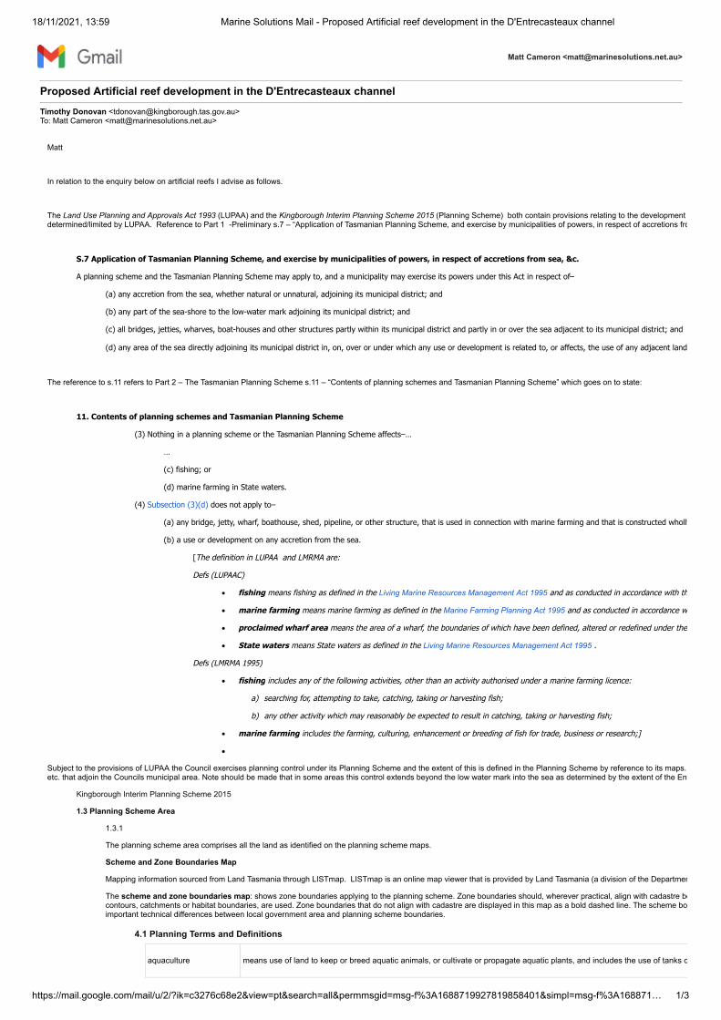
18/11/2021, 13:59 Marine Solutions Mail - Proposed Artificial reef development in the D'Entrecasteaux channel
https://mail.google.com/mail/u/2/?ik=c3276c68e2&view=pt&search=all&permmsgid=msg-f%3A1688719927819858401&simpl=msg-f%3A168871… 1/3
Matt Cameron <[email protected]>
Proposed Artificial reef development in the D'Entrecasteaux channel Timothy Donovan <[email protected]>To: Matt Cameron <[email protected]>
Matt
In relation to the enquiry below on artificial reefs I advise as follows.
The Land Use Planning and Approvals Act 1993 (LUPAA) and the Kingborough Interim Planning Scheme 2015 (Planning Scheme) both contain provisions relating to the development determined/limited by LUPAA. Reference to Part 1 -Preliminary s.7 – “Application of Tasmanian Planning Scheme, and exercise by municipalities of powers, in respect of accretions fro
S.7 Application of Tasmanian Planning Scheme, and exercise by municipalities of powers, in respect of accretions from sea, &c.
A planning scheme and the Tasmanian Planning Scheme may apply to, and a municipality may exercise its powers under this Act in respect of–
(a) any accretion from the sea, whether natural or unnatural, adjoining its municipal district; and
(b) any part of the sea-shore to the low-water mark adjoining its municipal district; and
(c) all bridges, jetties, wharves, boat-houses and other structures partly within its municipal district and partly in or over the sea adjacent to its municipal district; and
(d) any area of the sea directly adjoining its municipal district in, on, over or under which any use or development is related to, or affects, the use of any adjacent land
The reference to s.11 refers to Part 2 – The Tasmanian Planning Scheme s.11 – “Contents of planning schemes and Tasmanian Planning Scheme” which goes on to state:
11. Contents of planning schemes and Tasmanian Planning Scheme
(3) Nothing in a planning scheme or the Tasmanian Planning Scheme affects–…
…
(c) fishing; or
(d) marine farming in State waters.
(4) Subsection (3)(d) does not apply to–
(a) any bridge, jetty, wharf, boathouse, shed, pipeline, or other structure, that is used in connection with marine farming and that is constructed wholly
(b) a use or development on any accretion from the sea.
[The definition in LUPAA and LMRMA are:
Defs (LUPAAC)
· fishing means fishing as defined in the Living Marine Resources Management Act 1995 and as conducted in accordance with th
· marine farming means marine farming as defined in the Marine Farming Planning Act 1995 and as conducted in accordance w
· proclaimed wharf area means the area of a wharf, the boundaries of which have been defined, altered or redefined under the
· State waters means State waters as defined in the Living Marine Resources Management Act 1995 .
Defs (LMRMA 1995)
· fishing includes any of the following activities, other than an activity authorised under a marine farming licence:
a) searching for, attempting to take, catching, taking or harvesting fish;
b) any other activity which may reasonably be expected to result in catching, taking or harvesting fish;
· marine farming includes the farming, culturing, enhancement or breeding of fish for trade, business or research;]
·
Subject to the provisions of LUPAA the Council exercises planning control under its Planning Scheme and the extent of this is defined in the Planning Scheme by reference to its maps. etc. that adjoin the Councils municipal area. Note should be made that in some areas this control extends beyond the low water mark into the sea as determined by the extent of the Env
Kingborough Interim Planning Scheme 2015
1.3 Planning Scheme Area
1.3.1
The planning scheme area comprises all the land as identified on the planning scheme maps.
Scheme and Zone Boundaries Map
Mapping information sourced from Land Tasmania through LISTmap. LISTmap is an online map viewer that is provided by Land Tasmania (a division of the Departmen
The scheme and zone boundaries map: shows zone boundaries applying to the planning scheme. Zone boundaries should, wherever practical, align with cadastre bocontours, catchments or habitat boundaries, are used. Zone boundaries that do not align with cadastre are displayed in this map as a bold dashed line. The scheme boimportant technical differences between local government area and planning scheme boundaries.
4.1 Planning Terms and Definitions
aquaculture means use of land to keep or breed aquatic animals, or cultivate or propagate aquatic plants, and includes the use of tanks o

18/11/2021, 13:59 Marine Solutions Mail - Proposed Artificial reef development in the D'Entrecasteaux channel
https://mail.google.com/mail/u/2/?ik=c3276c68e2&view=pt&search=all&permmsgid=msg-f%3A1688719927819858401&simpl=msg-f%3A168871… 2/3
land means as defined in the Act.
land includes –
(a) buildings and other structures permanently fixed to land; and
(b) land covered with water; and
(c) water covering land; and
(d) any estate, interest, easement, servitude, privilege or right in or over land;
Level 2 Activity means as defined under the Environmental Management and Pollution Control Act 1994.
level 2 activity means an activity specified in Schedule 2 ;
SCHEDULE 2 - Level 2 Activities
7.Other
(e) Conduct of Certain Activities in Waters Within the Limits of the State: the dumping of dredge spoil or the dumping or sinking olimits of the State.
marina means use of land to moor boats, or store boats above or adjacent to the water. It includes boat recovery facilities, and facilit
marine farming shore
facility
means use of land to provide on-shore support infrastructure and facilities for off-shore aquaculture but does not include proc
State waters means as defined in s.5 of the Living Marine Resources Management Act 1995.
wharf means use of land for the manufacture of vineyard products and if land is so used, includes the display and sale of vineyard p
In relation to “accretions” the Planning Scheme states:
9.0 Special Provisions
9.9 Accretions
9.9.1
Unless excluded by s.20 of the Act, use or development of an existing or proposed accretion of land from the sea, whether natural or unnatural, located either partially oto in s.7 (c) and s.7 (d) of the Act may be approved at the discretion of the planning authority having regard to all of the following:
(a) the provisions of the Environmental Management Zone;
(b) the purpose and any relevant standards of all Codes;
(c) the compliance with the planning scheme standards of any related use or development wholly contained within the planning scheme area.
In summary the installation of Artificial Reefs (ARs) at various sites along the Channel will not require any planning approval from Council unless they involve shore based works or devemaps. Further specific advice can be given once the actual sites of the ARs are determined.
I trust this is sufficient for your purposes. Please contact me if you require further advice or information.
regards
Timothy Donovan | Senior Planning Officer | Kingborough Council
Phone (03) 6211 8108 | Fax (03) 6211 8211 Address Email [email protected] | Web www.kingborough.tas.gov.au
Please consider the environment before printing this email. This email and any attachments is strictlyconfidential and should be read only by those persons to whom it is addressed and its content is notintended for use by any other persons. If you are not the intended recipient you must not use, copy ordistribute it. If you have received this message in error, please destroy and delete the message alongwith any attachments from your computer and notify us immediately.
[Quoted text hidden][Quoted text hidden][Quoted text hidden]

18/11/2021, 13:59 Marine Solutions Mail - Proposed Artificial reef development in the D'Entrecasteaux channel
https://mail.google.com/mail/u/2/?ik=c3276c68e2&view=pt&search=all&permmsgid=msg-f%3A1688719927819858401&simpl=msg-f%3A168871… 3/3
[Quoted text hidden]
[Quoted text hidden][Quoted text hidden][Quoted text hidden]
______________________________________________________________________ This email has been scanned by the Symantec Email Security.cloud service. For more information please visit http://www.symanteccloud.com ______________________________________________________________________