Engineering Mechanics ) Semester 1( Syllabus 1.1 Introduction
22
Highway and Transport. Engineering Department First Class College of Engineering Engineering Mechanics Mustansiriyah University 2020-2021 Lec.Rana Hashim 1 .رنا هاشم منقلسم الطرق وال قعة المستنصريةلجامية الهندسة .ا كلEngineering Mechanics ) Semester st 1 ( Syllabus 1.Basic Concepts, Analysis of Forces 2.Concepts of Moments and Couples 3.Resultant of Force System 4.Equilibrium 5.Analysis of Structures: Analysis of Truss 6.The Centroid and Center of Gravity 7.Moment of Inertia. Text book 1. ENGINEERING MECHANICS Third Edition 2002, A. HIGDON and W. STILS 1.1 Introduction physics which deals with the study of the effect of force of the : is a branch Mechanics system acting on a particle or a rigid body which may be at rest or in motion. Engineering Mechanics can be subdivided into three branches: A. Rigid- body mechanics the body is stay in the same shape after applying the forces (no deformation are considered in the body) and this branch is divided into two areas: static and dynamics. B. Deformable-body mechanics C. Fluid mechanics.
-
Upload
khangminh22 -
Category
Documents
-
view
0 -
download
0
Transcript of Engineering Mechanics ) Semester 1( Syllabus 1.1 Introduction

Highway and Transport. Engineering Department First Class
College of Engineering Engineering Mechanics Mustansiriyah University 2020-2021
Lec.Rana Hashim
م.رنا هاشم 1
قسم الطرق والنقل
كلية الهندسة .الجامعة المستنصرية
Engineering Mechanics
) Semester st1(
Syllabus 1.Basic Concepts, Analysis of Forces
2.Concepts of Moments and Couples
3.Resultant of Force System
4.Equilibrium
5.Analysis of Structures: Analysis of Truss
6.The Centroid and Center of Gravity
7.Moment of Inertia.
Text book
1. ENGINEERING MECHANICS
Third Edition 2002, A. HIGDON and W. STILS
1.1 Introduction
physics which deals with the study of the effect of force of the : is a branchMechanics
system acting on a particle or a rigid body which may be at rest or in motion.
Engineering Mechanics can be subdivided into three branches:
A. Rigid- body mechanics the body is stay in the same shape after applying the forces (no
deformation are considered in the body) and this branch is divided into two areas: static and
dynamics.
B. Deformable-body mechanics
C. Fluid mechanics.
Highway and Transport. Engineering Department First Class
College of Engineering Engineering Mechanics Mustansiriyah University 2020-2021
Lec.Rana Hashim
م.رنا هاشم 2
قسم الطرق والنقل
كلية الهندسة .الجامعة المستنصرية
:Static Mechanics
It is the study of the effect of force system acting on a particle or rigid body which is at rest.
: Dynamic Mechanics
It is the study of the effect of force system acting on a particle or rigid body which is in
motion.
1.2 Basic Concepts:
.but negligible dimension nsiderable massit is defined as an entity having co :Particle
.A solid body having considerable mass as well as dimension Rigid Body:
are the quantities which have magnitude and direction, such as : Vector Quantities
force, weight, distance, speed, displacement, acceleration and velocity.

Highway and Transport. Engineering Department First Class
College of Engineering Engineering Mechanics Mustansiriyah University 2020-2021
Lec.Rana Hashim
م.رنا هاشم 3
قسم الطرق والنقل
كلية الهندسة .الجامعة المستنصرية
are the quantities which have only magnitude, such as: time, size, : Scalar Quantities
sound, density, light and volume.
is an action that changes, or tends to change, the state of motion of the body upon :Force
which it acts. In general, force is considered as a "push" or "pull "' exerted by one body on
another.
A complete description of a force must include its:
1. Magnitude
2. Direction and sense.
3. Point of action.
: It states that the condition of equilibrium or uniform Principle of Transmissibility of Force
motion of rigid body will remain unchanged if the point of application of a force acting on a
rigid body is transmitted to act at any other point along its line of action.

Highway and Transport. Engineering Department First Class
College of Engineering Engineering Mechanics Mustansiriyah University 2020-2021
Lec.Rana Hashim
م.رنا هاشم 4
قسم الطرق والنقل
كلية الهندسة .الجامعة المستنصرية
1.3 Force System
Is a number of forces acting in a given situation and can be classified according to the
arrangement of the line of action of the forces on the system.
Coplanar Non Concurrent and
Non Parallel Force System
Coplanar Parallel Force System
Coplanar Concurrent Force System
Non Coplanar Non Concurrent and Non Parallel Force System
Non Coplanar Parallel Force
System
Non Coplanar Concurrent Force
System
* Concurrent: all forces pass through a point.
** Coplanar: in the same plane.
***Parallel: parallel line of action.
****Collinear: common line of action.

Highway and Transport. Engineering Department First Class
College of Engineering Engineering Mechanics Mustansiriyah University 2020-2021
Lec.Rana Hashim
م.رنا هاشم 5
قسم الطرق والنقل
كلية الهندسة .الجامعة المستنصرية
1.4 Units and their Relations:
1.5 Trigonometric Relations
A. Right Angle's Triangles
sin 𝛽 =𝑎
𝑐
cos 𝛽 =𝑏
𝑐
tan 𝛽 =𝑎
𝑏
B.Oblique Triangle
1.Sine Low
𝑎
sin 𝛽=
𝑏
sin 𝛼=
𝑐
sin 𝛾
2. Cosine Low
a2 = b2 + c2 − 2bc cos β
b2 = a2 + c2 − 2ac cos 𝛼
c2 = a2 + b2 − 2ab cos γ

Highway and Transport. Engineering Department First Class
College of Engineering Engineering Mechanics Mustansiriyah University 2020-2021
Lec.Rana Hashim
م.رنا هاشم 6
قسم الطرق والنقل
كلية الهندسة .الجامعة المستنصرية
1.6. Composition and Resolution of Force.
There are two common problems in statics involve either finding the resultant force,
knowing its components, or resolving a known force into two components.
1.6.1 Finding the Components of a Force (Resolution of Force)
the process of breaking the force into a number of components, which are equivalent to
the given forces is called resolution of force.
A. Resolving a force into rectangular components
Two Dimensional Force System
Let the force (F) shown below with the direction (θ); we can resolve this force into
two components:
.axis-n Xo) which lies xFHorizontal Component (-1
.axis-lies on Y) which yFVertical Component (-2

Highway and Transport. Engineering Department First Class
College of Engineering Engineering Mechanics Mustansiriyah University 2020-2021
Lec.Rana Hashim
م.رنا هاشم 7
قسم الطرق والنقل
كلية الهندسة .الجامعة المستنصرية
FX = F cos θ
FY = F sin θ
F = √FX2 + FY
2
In vector expression:-
F = Fxi + FYj = F cosθ i + F sinθ j
θ = tan−1FY
FX
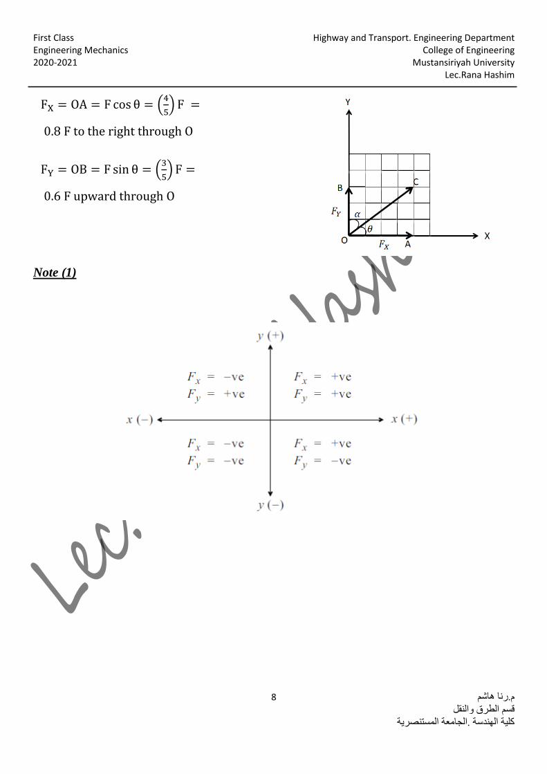
Instead of using the angle however the direction of F can also be defined using a small slope
triangle such as shown in figure below. Since this triangle and the larger shaded triangle are
similar, the proportional length of the sides gives:
FX = Fa
c
FY = Fb
c
Or in another way;
Highway and Transport. Engineering Department First Class
College of Engineering Engineering Mechanics Mustansiriyah University 2020-2021
Lec.Rana Hashim
م.رنا هاشم 8
قسم الطرق والنقل
كلية الهندسة .الجامعة المستنصرية
FX = OA = F cos θ = (4
5) F =
0.8 F to the right through O
FY = OB = F sin θ = (3
5) F =
0.6 F upward through O
Note (1)

Highway and Transport. Engineering Department First Class
College of Engineering Engineering Mechanics Mustansiriyah University 2020-2021
Lec.Rana Hashim
م.رنا هاشم 9
قسم الطرق والنقل
كلية الهندسة .الجامعة المستنصرية
Note(2)

Highway and Transport. Engineering Department First Class
College of Engineering Engineering Mechanics Mustansiriyah University 2020-2021
Lec.Rana Hashim
م.رنا هاشم 10
قسم الطرق والنقل
كلية الهندسة .الجامعة المستنصرية
Dimensions are not always given in horizontal and vertical directions, angles need :(3)Note
not be measured counterclockwise from the X-axis, and the origin of coordinates need not be
on the line of action of a force. Therefore, it is essential that we be able to determine the
correct components of a force no matter how the axes are oriented or how the angles are
measured. The figure below suggests a few typical examples of force resolution in two
dimensions.
s

Highway and Transport. Engineering Department First Class
College of Engineering Engineering Mechanics Mustansiriyah University 2020-2021
Lec.Rana Hashim
م.رنا هاشم 11
قسم الطرق والنقل
كلية الهندسة .الجامعة المستنصرية
B. Resolving a force into nonrectangular components
OA
sin β=
F
sin (180 − α − β)
𝐹 = √𝑂𝐴2 + 𝑂𝐵2 − 2(𝑂𝐴)(𝑂𝐵) cos(180 − 𝛼 − 𝛽)
Examples
(1) Example
The direction of the force (P) is (𝟑𝟎°), find the horizontal components if the vertical
components is (30N).
-:Solution
From the diagram shown:
FY = 30N ↑
FY = F sin θ
30=P sinθ
30=P. 0.5
P=60 N
FX = F cos θ = 60 cos30
FX = 60X√3
2= 30√3 N →

Highway and Transport. Engineering Department First Class
College of Engineering Engineering Mechanics Mustansiriyah University 2020-2021
Lec.Rana Hashim
م.رنا هاشم 12
قسم الطرق والنقل
كلية الهندسة .الجامعة المستنصرية
(2)Example
Determine the magnitude and direction of force (P), if the horizontal and vertical
components are (20N),(40N) respectively.
:Solution
F = √(FX)2 + (FY)2
F = √(20)2 + (40)2 = √400 + 1600 = √2000 = 44.72N
θ = tan−1(FY
FX) = tan−1(
40
20) = 63.43°
Example(3)
Find the two components of the force (100 N) if:
θ=𝟑𝟎°, 𝟏𝟐𝟎°, 𝟐𝟕𝟎°
:Solution
𝜽 = 𝟑𝟎°
Fx = F . cos θ =
100 x cos 30 = 100x √3
2=
50 √3 N →
Fy = F. sin θ =
100 x sin 30 = 100 x 0.5 =
50 N ↑

Highway and Transport. Engineering Department First Class
College of Engineering Engineering Mechanics Mustansiriyah University 2020-2021
Lec.Rana Hashim
م.رنا هاشم 13
قسم الطرق والنقل
كلية الهندسة .الجامعة المستنصرية
𝜽 = 𝟏𝟐𝟎°
Fx = F. cos θ =
100 x cos 120 =
100 x(−0.5) = −50 N ←
Fy = F. sin θ =
100 x sin 120 = 100 x √3
2=
50 √3 N ↑
𝜽 = 𝟐𝟕𝟎°
Fx = F. cos θ =
100 x cos 270 = 100 x 0 =
0
Fy = F. sin θ =
100 x sin 270 =
100 x (−1) = −100 N ↓

Highway and Transport. Engineering Department First Class
College of Engineering Engineering Mechanics Mustansiriyah University 2020-2021
Lec.Rana Hashim
م.رنا هاشم 14
قسم الطرق والنقل
كلية الهندسة .الجامعة المستنصرية
Example(4)
Resolve the horizontal 600 lb force shown in figure into components acting along the u and
v axes and determine the magnitudes of these components.
Solution:-
𝐹𝑢
sin 120=
600
sin 30 𝐹𝑢 = 1039 𝑙𝑏
𝐹𝑣
sin 30=
600
sin 30 𝐹𝑣 = 600 𝑙𝑏

Highway and Transport. Engineering Department First Class
College of Engineering Engineering Mechanics Mustansiriyah University 2020-2021
Lec.Rana Hashim
م.رنا هاشم 15
قسم الطرق والنقل
كلية الهندسة .الجامعة المستنصرية
Example(5)
The force F=450 lb acts on the frame. Resolve this force into components acting along
members AB and AC,and determine the magnitude of each components.
Solution:-
𝐹𝐴𝐵
sin 105=
450
sin 30 𝐹𝐴𝐵 = 869 𝑙𝑏
𝐹𝐴𝐶
sin 45=
450
sin 30 𝐹𝐴𝐶 = 636 𝑙𝑏

Highway and Transport. Engineering Department First Class
College of Engineering Engineering Mechanics Mustansiriyah University 2020-2021
Lec.Rana Hashim
م.رنا هاشم 16
قسم الطرق والنقل
كلية الهندسة .الجامعة المستنصرية
Example (6)
The forces F1, F2, and F3, all of which act on point A of the bracket, are specified in three
different ways. Determine the x and y components of each of the three forces.
Solution:- The components of F1 are
𝐹1𝑋 = 600 cos 35° = 491 𝑁 →
𝐹1𝑌 = 600 sin 35° = 344 𝑁 ↑
The components of F2 are
𝐹2𝑋 = −500 (4
5) = −400 𝑁 ←
𝐹2𝑌 = 500 (3
5) = 300 𝑁 ↑
The components of F3 are
𝛼 = tan−1(0.2
0.4) = 26.6°
𝐹3𝑋 = 𝐹3 sin 𝛼 = 800 sin 26.6° = 358 𝑁 →
F3Y = −𝐹3 𝑐𝑜𝑠 𝛼 = −716 𝑁 ↓

Highway and Transport. Engineering Department First Class
College of Engineering Engineering Mechanics Mustansiriyah University 2020-2021
Lec.Rana Hashim
م.رنا هاشم 17
قسم الطرق والنقل
كلية الهندسة .الجامعة المستنصرية
Example(7)
.acting on the boom shown in figure 2Fand 1Fcomponents of yand x Determine the
-:Solution
By the parallelogram law.F1 is resolved into x and y
components, Fig (b), since F1x acts in the -x
direction, and F1y acts in the +y direction, we have.
𝐹1𝑥 = −200 sin 30 = −100 𝑁 ←
𝐹1𝑦 = 200 cos 30 = 173 𝑁 ↑
𝐹2𝑥
260=
12
13 𝐹2𝑥 = 260 (
12
13) = 240 N →
similarly
F2x = 260 (5
13) = 100 N ↓

Highway and Transport. Engineering Department First Class
College of Engineering Engineering Mechanics Mustansiriyah University 2020-2021
Lec.Rana Hashim
م.رنا هاشم 18
قسم الطرق والنقل
كلية الهندسة .الجامعة المستنصرية
Example(8)
The 500 N force F is applied to the vertical pole as shown in figure.
1. Determine the components of the force F along the �� and �� axis.
2. Determine the components of the force F along the 𝐱 and �� axis.
-:Solution
1. From Fig (b)
𝐹�� = 500 𝑁 → 𝐹�� = 0
2. The components of F in the x and y
directions are nonrectangular and are obtained
by completing the parallelogram as shown in fig
(c). The magnitudes of the components may be
calculated by the law of sines. Thus,
|FX|
sin 90=
500
sin 30 |FX| = 1000N
|FY|
sin 60=
500
sin 30 |FY| = 866N
𝐹𝑋 = 1000 𝑁 → 𝐹��=-866 N↓

Highway and Transport. Engineering Department First Class
College of Engineering Engineering Mechanics Mustansiriyah University 2020-2021
Lec.Rana Hashim
م.رنا هاشم 19
قسم الطرق والنقل
كلية الهندسة .الجامعة المستنصرية
Three Dimensional Force System
Resolving a force into rectangular components
The force F acting at point O in figure
has the rectangular components Fx, Fy, Fz, where
Fx = F cos θx cos 𝜃𝑥 =𝐹𝑥
𝐹
Fy = F cos𝜃𝑦 cos 𝜃𝑦 =𝐹𝑦
𝐹
𝐹𝑧 = 𝐹 𝑐𝑜𝑠𝜃𝑧 𝑐𝑜𝑠𝜃𝑧 =𝐹𝑧
𝑍
F = √Fx2 + Fy
2 + Fz2
In vector expression:-
F = Fxi + Fyj + Fzk
F = F(i cos θx + j cos θy + k cosθz)
Note:- The cosine of θx, θy and θz are called direction cosine.

Highway and Transport. Engineering Department First Class
College of Engineering Engineering Mechanics Mustansiriyah University 2020-2021
Lec.Rana Hashim
م.رنا هاشم 20
قسم الطرق والنقل
كلية الهندسة .الجامعة المستنصرية
Example(9)
A force F with a magnitude of 100 N is applied at the origin O of the axes x-y-z as shown.
The line of action of F passes through a point A whose coordinates are 3 m, 4 m, and 5 m.
Determine the x, y, and z scalar components of F.
-:Solution
Length of OA=√32 + 42 + 52 = 7.07
cos 𝜃𝑥 =3
7.07
cos 𝜃𝑦 =4
7.07
cos 𝜃𝑧 =5
7.07= 0.707
Fx = F cos θx = 1003
7.07= 42.4
Fy = F cos θy = 1004
7.07= 56.6
Fz = F cos θz = 1005
7.07= 70.7
To express the force as a vector
�� = 100(3
7.07 𝑖 +
4
7.07𝑗 +
5
7.07��)

Highway and Transport. Engineering Department First Class
College of Engineering Engineering Mechanics Mustansiriyah University 2020-2021
Lec.Rana Hashim
م.رنا هاشم 21
قسم الطرق والنقل
كلية الهندسة .الجامعة المستنصرية
Home Work(1)
1. Resolve each force acting on the post into its x and y components.
2. Express F as a vector in terms of the unit vectors i, j, and k. Determine the angle between
F and the y-axis.

Highway and Transport. Engineering Department First Class
College of Engineering Engineering Mechanics Mustansiriyah University 2020-2021
Lec.Rana Hashim
م.رنا هاشم 22
قسم الطرق والنقل
كلية الهندسة .الجامعة المستنصرية