SEMESTER -3
164
MECHANICAL ENGINEERING SEMESTER -3
-
Upload
khangminh22 -
Category
Documents
-
view
6 -
download
0
Transcript of SEMESTER -3

MECHANICAL ENGINEERING
SEMESTER -3
MECHANICAL ENGINEERING
CODE MET201
COURSE NAME MECHANICS OF SOLIDS
CATEGORY L T P CREDIT PCC 3 1 0 4
Preamble:
This course helps the students to understand the concept of stress and strain in different types of structure/machine under various loading conditions. The course also covers simple and compound stresses due to forces, stresses and deflection in beams due to bending, torsion in circular section, strain energy, different theories of failure, stress in thin cylinder thick cylinder and spheres due to external and internal pressure.
Prerequisite: EST100 ENGINEERING MECHANICS
Course Outcomes:
After the completion of the course the student will be able to
CO 1 Determine the stresses, strains and displacements of structures by tensorial and graphical (Mohr’s circle) approaches
CO 2 Analyse the strength of materials using stress-strain relationships for structural and thermal loading
CO 3 Perform basic design of shafts subjected to torsional loading and analyse beams subjected to bending moments
CO 4 Determine the deformation of structures subjected to various loading conditions using strain energy methods
CO 5 Estimate the strength of thin cylinders, spherical vessels and columns, and appreciate the theories of failures and its relevance in mechanical design
Mapping of course outcomes with program outcomes
PO 1 PO 2 PO 3 PO 4 PO 5 PO 6 PO 7 PO 8 PO 9 PO 10
PO 11
PO 12
CO 1 3 3 2 1 CO 2 3 3 2 1 CO 3 3 3 1 2 CO 4 3 3 1 1 CO 5 3 3 1 1

MECHANICAL ENGINEERING
Assessment Pattern
Bloom’s Category
Continuous Assessment Tests End Semester
Examination 1 2
Remember
Understand 10 10 20
Apply 20 20 30
Analyse 20 20 50
Evaluate
Create
Mark distribution
Total Marks CIE ESE ESE
Duration
150 50 100 3 hours
Continuous Internal Evaluation Pattern:
Attendance : 10 marks Continuous Assessment Test (2 numbers) : 25 marks Assignment/Quiz/Course project : 15 marks End Semester Examination Pattern: There will be two parts; Part A and Part B. Part A contain 10 questions with 2 questions from each module and having 3 marks for each question. Students should answer all questions. Part B contains 2 questions from each module of which student should answer any one. Each question carries 14 marks and can have a maximum of 2 subdivisions.

MECHANICAL ENGINEERING
COURSE LEVEL ASSESSMENT QUESTIONS
Course Outcome 1 (CO1):
1. Determine the resultant traction at a point in a plane using the stress tensor.
2. Evaluate the principal stresses, principal strains and their directions from a given state of stress or strain.
3. Write the stress tensor and strain tensor.
Course Outcome 2 (CO2)
1. Write the generalized Hooke’s law for stress-strain relations.
2. Estimate the state of strain from a given state of stress.
3. Analyse the strength of a structure subjected to thermal loading.
Course Outcome 3(CO3):
1. Design a shaft to transmit power and torque.
2. Draw the shear force and bending moment diagrams.
3. Determine the bending stress on a beam subjected to pure bending.
Course Outcome 4 (CO4):
1. Apply strain energy method to estimate the deformation of a structure.
2. Use strain energy method to calculate deformations for multiple loads.
3. Use strain energy method to estimate the loads acting on a structure for a maximum deflection.
Course Outcome 5 (CO5):
1. Analyse a column for buckling load.
2. A bolt is subjected to a direct tensile load of 20 kN and a shear load of 15 kN. Suggest suitable size of this bolt according to various theories of elastic failure, if the yield stress in simple tension is 360 MPa. A factor of safety 2 should be used. Assume Poisson’s ratio as 0.3.
3. Estimate the stresses on a thin cylinder or spherical vessel.

MECHANICAL ENGINEERING
SYLLABUS
Module 1 Deformation behaviour of elastic solids in equilibrium under the action of a system of forces, method of sections. Stress vectors on Cartesian coordinate planes passing through a point, stress at a point in the form of a matrix. Equality of cross shear, Cauchy's equation. Displacement, gradient of displacement, Cartesian strain matrix, strain- displacement relations (small-strain only), Simple problems to find strain matrix. Stress tensor and strain tensor for plane stress and plane strain conditions. Principal planes and principal stress, meaning of stress invariants, maximum shear stress. Mohr’s circle for 2D case.
Module 2 Stress-strain diagram, Stress–Strain curves of Ductile and Brittle Materials, Poisson’s ratio. Constitutive equations-generalized Hooke’s law, equations for linear elastic isotropic solids in in terms of Young’s Modulus and Poisson’s ratio, Hooke’s law for Plane stress and plane strain conditions Relations between elastic constants E, G, ν and K. Calculation of stress, strain and change in length in axially loaded members with single and composite materials, Effects of thermal loading – thermal stress and thermal strain. Thermal stress on a prismatic bar held between fixed supports.
Module 3 Torsional deformation of circular shafts, assumptions for shafts subjected to torsion within elastic deformation range, derivation of torsion formula Torsional rigidity, Polar moment of inertia, basic design of transmission shafts. Simple problems to estimate the stress in solid and hollow shafts. Shear force and bending moment diagrams for cantilever and simply supported beams. Differential equations between load, shear force and bending moment. Normal and shear stress in beams: Derivation of flexural formula, section modulus, flexural rigidity, numerical problems to evaluate bending stress, economic sections. Shear stress formula for beams: Derivation, shear stress distribution for a rectangular section.
Module 4 Deflection of beams using Macauley’s method Elastic strain energy and Complementary strain energy. Elastic strain energy for axial loading, transverse shear, bending and torsional loads. Expressions for strain energy in terms of load, geometry and material properties of the body for axial, shearing, bending and torsional loads. Castigliano’s second theorem, reciprocal relation, proof for Castigliano’s second theorem. Simple problems to find the deflections using Castigliano’s theorem.
Module 5 Fundamentals of bucking and stability, critical load, equilibrium diagram for buckling of an idealized structure. Buckling of columns with pinned ends, Euler’s buckling theory for long columns. Critical stress, slenderness ratio, Rankine’s formula for short columns. Introduction to Theories of Failure, Rankine’s theory for maximum normal stress, Guest’s theory for maximum shear stress, Saint-Venant’s theory for maximum normal strain, Hencky-von Mises theory for maximum distortion energy, Haigh’s theory for maximum strain energy Circumferential and Longitudinal stress in a thin cylindrical vessel, stresses in a thin spherical vessel Text Books
1. Mechanics of materials in S.I.units, R .C. Hibbeler, Pearson Higher Education 2018
2. Advanced Mechanics of Solids, L. S. Srinath, TMH

MECHANICAL ENGINEERING
3. Design of Machine Elements, V. B Bhandari
Reference Books
1. Strength of Materials, Surendra Singh, S. K. Kataria & Sons
2. Engineering Mechanics of Solids, Popov E., PHI 2002
3. Mechanics of Materials S. I. units, Beer, Johnston, Dewolf, McGraw Hills 2017
4. Mechanics of Materials, Pytel A. and Kiusalaas J. Cengage Learning India Private Limited, 2nd Edition, 2015
5. Strength of Materials, Rattan, McGraw Hills 2011

MECHANICAL ENGINEERING
COURSE PLAN No Topic No of lectures
1 Module 1: Stress and Strain Analysis 9 hours
1.1
Describe the deformation behaviour of elastic solids in equilibrium under the action of a system of forces. Describe method of sections to illustrate stress as resisting force per unit area. Stress vectors on Cartesian coordinate planes passing through a point and writing stress at a point in the form of a matrix.
2 hr
1.2
Equality of cross shear (Derivation not required). Write Cauchy's equation (Derivation not required),Find resultant stress, Normal and shear stress on a plane given stress tensor and direction cosines (no questions for finding direction cosines).
2 hr
1.3
Displacement, gradient of displacement, Cartesian strain matrix, Write strain- displacement relations (small-strain only), Simple problems to find strain matrix given displacement field (2D and 3D), write stress tensor and strain tensor for Plane stress and plane strain conditions.
1 hr
1.4 Concepts of principal planes and principal stress, characteristic equation of stress matrix and evaluation of principal stresses and principal planes as an eigen value problem, meaning of stress invariants, maximum shear stress
2 hrs
1.5 Mohr’s circle for 2D case: find principal stress, planes, stress on an arbitrary plane, maximum shear stress graphically using Mohr’s circle
2 hrs
2 Module 2: Stress - Strain Relationships 9 hours
2.1 Stress-strain diagram, Stress–Strain curves of Ductile and Brittle Materials, Poisson’s ratio
1 hr
2.2
Constitutive equations-generalized Hooke’s law, equations for linear elastic isotropic solids in in terms of Young’s Modulus and Poisson’s ratio (3D). Hooke’s law for Plane stress and plane strain conditions Relations between elastic constants E, G, ν and K, Numerical problems
2 hrs
2.3
Calculation of stress, strain and change in length in axially loaded members with single and composite materials, Effects of thermal loading – thermal stress and thermal strain. Thermal stress on a prismatic bar held between fixed supports.
2 hrs
2.4 Numerical problems for axially loaded members 4 hrs
3 Module 3: Torsion of circular shafts, Shear Force-Bending Moment Diagrams and Pure bending
9 hours
3.1 Torsional deformation of circular shafts, assumptions for shafts subjected to torsion within elastic deformation range, derivation of torsion formula
1 hr
3.2 Torsional rigidity, Polar moment of inertia, comparison of solid and hollow shaft. Simple problems to estimate the stress in solid and hollow shafts
1 hr
3.3 Numerical problems for basic design of circular shafts subjected to externally applied torques
1 hr

MECHANICAL ENGINEERING
3.4 Shear force and bending moment diagrams for cantilever and simply supported beams subjected to point load, moment, UDL and linearly varying load
2 hrs
3.5 Differential equations between load, shear force and bending moment. 1 hrs
3.6
Normal and shear stress in beams: Derivation of flexural formula, section modulus, flexural rigidity, numerical problems to evaluate bending stress, economic sections Shear stress formula for beams: Derivation, numerical problem to find shear stress distribution for rectangular section
3 hrs
4 Module 4: Deflection of beams, Strain energy 8 hours
4.1 Deflection of cantilever and simply supported beams subjected to point load, moment and UDL using Macauley’s method (procedure and problems with multiple loads)
2 hrs
4.2 Linear elastic loading, elastic strain energy and Complementary strain energy. Elastic strain energy for axial loading, transverse shear, bending and torsional loads (short derivations in terms of loads and deflections).
2 hr
4.3 Expressions for strain energy in terms of load, geometry and material properties of the body for axial, shearing, bending and torsional loads. Simple problems to solve elastic deformations
2 hrs
4.4 Castigliano’s second theorem to find displacements, reciprocal relation, proof for Castigliano’s second theorem.
1 hr
4.5 Simple problems to find the deflections using Castigliano’s theorem 1 hr
5 Module 5: Buckling of Columns, Theories of Failure, Thin pressure vessels 8 hours
5.1 Fundamentals of bucking and stability, critical load, Euler’s formula for long columns, assumptions and limitations, effect of end conditions(derivation only for pinned ends), equivalent length
2 hr
5.2 Critical stress, slenderness ratio, Rankine’s formula for short columns, Problems
2 hr
5.3 Introduction to Theories of Failure. Rankine’s theory for maximum normal stress, Guest’s theory for maximum shear stress, Saint-Venant’s theory for maximum normal strain
1 hr
5.4 Hencky-von Mises theory for maximum distortion energy, Haigh’s theory for maximum strain energy
1 hr
5.5 Circumferential and Longitudinal stress in a thin cylindrical vessel, stresses in a thin spherical vessel (short derivations) and numerical problems
2 hrs

MECHANICAL ENGINEERING
MODEL QUESTION PAPER
APJ ABDUL KALAM TECHNOLOGICAL UNIVERSITY
THIRD SEMESTER B.TECH DEGREE EXAMINATION
Course Code : MET201
Course Name : MECHANICS OF SOLIDS
Max. Marks : 100 Duration : 3 Hours
PART – A (ANSWER ALL QUESTIONS, EACH QUESTION CARRIES 3 MARKS)
1. Express the stress invariants in terms of Cartesian components of stress and principal stress.
2. Write down the Cauchy’s strain displacement relationships.
3. Distinguish between the states of plane stress and plane strain.
4. Represent the generalized Hooke’s law for a Linear elastic isotropic material.
5. List any three important assumptions in the theory of torsion.
6. Write the significance of flexural rigidity and section modulus in the analysis of beams.
7. Discuss reciprocal relation for multiple loads on a structure.
8. Express the strain energy for a cantilever beam subjected to a transverse point load at free end.
9. Discuss Saint-Venant’s theory of failure.
10. Compare the strength of a thin spherical vessel and a thin cylindrical vessel on the basis of hoop stress.
PART – B (ANSWER ONE FULL QUESTION FROM EACH MODULE)
MODULE – 1
11. a) The state of stress at a point is given by σxx = 12.31 MPa, σyy = 8.96 MPa, σzz = 4.34 MPa, τxy = 4.2 MPa, τyz = 5.27 MPa, τxz = 0.84 MPa. Determine the principal stresses. (7 marks)
b) The displacement field for a body is given by u= (x2 + y)i+ (3 + z) j + (x2 + 2y)k. What is the deformed position of a point originally at (3,1,–2)? Write the strain tensor at the point (−3,−1,2).
(7 marks) OR
12. a) The state of plane stress at a point is given by σxx = 40 MPa, σyy = 20 MPa and τxy = 16 MPa. Using Mohr’s circle determine the i) principal stresses and principal planes and ii) maximum shear stress. (7 marks)

MECHANICAL ENGINEERING
b) The state of stress at a point is given below. Find the resultant stress vector acting on a plane with direction cosines nx=0.47, ny=0.82 and nz=0.33. Find the normal and tangential stresses acting on this plane. (7 marks)
MODULE – 2
13. a) Calculate Modulus of Rigidity and Young’s Modulus of a cylindrical bar of diameter 30 mm and of 1.5 m length if the longitudinal strain in a bar during a tensile stress is four times the lateral strain. Find the change in volume when the bar is subjected to a hydrostatic pressure of 100 N/mm2. Take E = 105 N/mm (9 marks)
b) A straight bar 450 mm long is 40 mm in diameter for the first 250 mm length and 20 mm diameter for the remaining length. If the bar is subjected to an axial pull of 15 kN find the maximum axial stress produced and the total extension of the bar. Take E = 2x10⁵ N/mm2 (5 marks)
OR
14. a) A brass bar 20mm diameter is enclosed in a steel tube of 25mm internal diameter and 50mm external diameter. Both bar and tube is of same length and fastened rigidly at their ends. The composite bar is free of stress at 20°C. To what temperature the assembly must be heated to generate a compressive stress of 48MPa in brass bar? Also determine the stress in steel tube. Esteel = 200GPa and Ebrass = 84GPa, αsteel = 12 × 10−6 / °C and αbrass= 18 × 10−6 / °C. (9 marks)
b) Draw the stress-strain diagram for a ductile material and explain the salient points. (5 marks)
MODULE – 3
15. a) Draw shear force and bending moment diagram for the beam given in the figure. (9 marks)
b) Compare the strength of a hollow shaft of diameter ratio 0.75 to that of a solid shaft by considering the permissible shear stress. Both the shafts are of same material, of same length and weight. (5 marks)
OR

MECHANICAL ENGINEERING
16. a) A simply supported beam of span of 10 m carries a UDL of 40 kN/m. The cross section is of I shape as given below. Calculate the maximum stress produced due to bending and plot the bending stress distribution. (9 marks)
b) The shear stress of a solid shaft is not to exceed 40 N/mm2 when the power transmitted is 20 kW at 200 rpm. Determine the minimum diameter of the shaft. (5 marks)
MODULE – 4
17. a) A horizontal girder of steel having uniform section is 14 m long and is simply supported at its ends. It carries concentrated loads of 120 kN and 80 kN at two points 3 m and 4.5 m from the two ends respectively. Moment of inertia for the section of the girder is 16 × 108 mm4 and Es = 210 kN/mm2. Calculate the deflection of the girder at points under the two loads and maximum deflection using Macaulay’s method. (8 marks)
b) Derive the expressions for elastic strain energy in terms of applied load/moment and material property for the cases of a) Axial force b) Bending moment. (6 marks)
OR
18. a) Calculate the displacement in the direction of load P applied at a distance of L/3 from the left end for a simply supported beam of span L as shown in the figure.
(8 marks)
b) State and prove Castigliano’s second theorem. (6 marks)
MODULE – 5
19. a) Find the crippling load for a hollow steel column 50mm internal diameter and 5mm thick. The column is 5m long with one end fixed and other end hinged. Use Rankine’s formula and Rankine’s constant as 1/7500 and σc = 335 N/mm2. Compare this load by crippling load given by Euler’s formula. Take E = 110 GPa. (8 marks)

MECHANICAL ENGINEERING
b) Explain the maximum normal stress theory, maximum strain energy theory and maximum shear stress theory of failure. (6 marks)
OR
20. a) A cylindrical shell 3m long closed at the ends has an internal diameter of 1m and wall thickness 15mm. Calculate the circumferential and longitudinal stresses induced and also the change in dimensions of the shell, if it is subjected to an internal pressure of 1.5MPa. Take E = 2×10⁵ N/mm2 and ν = 0.3. (9 marks)
b) Derive Euler's formula for a column with both ends hinged. (5 marks)

MECHANICAL ENGINEERING
CODE MET203
COURSE NAME MECHANICS OF FLUIDS
CATEGORY L T P CREDIT PCC 3 1 - 4
Preamble :
This course provides an introduction to the properties and behaviour of fluids. It enables to apply the concepts in engineering, pipe networks. It introduces the concepts of boundary layers, dimensional analysis and model testing
Prerequisite : NIL
Course Outcomes :
After completion of the course the student will be able to
CO1 Define Properties of Fluids and Solve hydrostatic problems CO2 Explain fluid kinematics and Classify fluid flows CO3 Interpret Euler and Navier-Stokes equations and Solve problems using Bernoulli’s
equation CO4 Evaluate energy loses in pipes and sketch energy gradient lines CO5 Explain the concept of boundary layer and its applications CO6 Use dimensional Analysis for model studies
Mapping of course outcomes with program outcomes
PO1 PO2 PO3 PO4 PO5 PO6 PO7 PO8 PO9 PO10 PO11 PO12
CO1 3 2 CO2 3 2 1 CO3 3 2 1 CO4 3 3 2 CO5 3 2 1 CO6 3 2 1
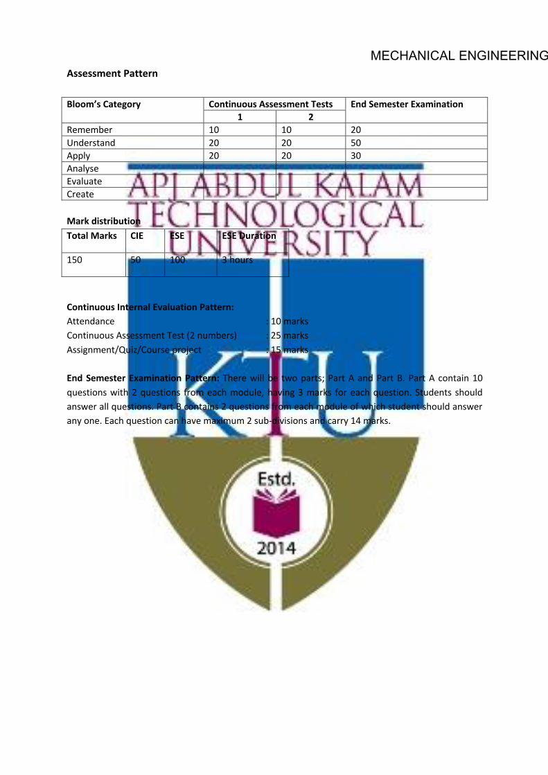
Assessment Pattern
Blooms Category CA ESA Assignment Test - 1 Test - 2 Remember 25 20 20 10 Understand 25 40 40 20 Apply 25 40 40 70 Analyse 25 Evaluate Create

MECHANICAL ENGINEERING
Continuous Internal Evaluation Pattern:
Attendance : 10 marks
Continuous Assessment Test (2 numbers) : 25 marks
Assignment/Quiz/Course project : 15 marks
Mark distribution & Duration of Examination :
Total Marks CA ESE ESE Duration 150 50 100 3 Hours
End semester pattern:
There will be two parts; Part A and Part B. Part A contain 10 questions with 2 questions from each module, having 3 marks for each question. Students should answer all questions. Part B contains 2 questions from each module of which student should answer any one. Each question can have maximum 2 sub-divisions and carry 14 marks.

MECHANICAL ENGINEERINGCOURSE LEVEL ASSESSMENT QUESTIONS
Course Outcome 1
1. A 3.6×1.5 m wide rectangular gate MN is vertical and is hinged at point 0.15 m belowthe center of gravity of the gate. The total depth of water is 6 m. What horizontal forcemust be applied at the bottom of the gate to keep the gate closed.
2. A stationary liquid is stratified so that its density is ρ0(1 + h) at a depth h below the freesurface. At a depth h in this liquid, what is the pressure in excess of ρ0gh?
3. If the velocity profile of a fluid is parabolic with free stream velocity 120 cm/s occurringat 20 cm from the plate, calculate the velocity gradients and shear stress at a distance of0, 10, 20 cm from the plate. Take the viscosity of fluid as 8.5 poise.
Course Outcome 2
1. Differentiate between the Eulerian and Lagrangian method of representing fluid motion.
2. A velocity field is given by u = 3y2, v = 2x and w = 0 in arbitrary units. Is this flowsteady or unsteady? Is it two or three dimensional? At (x,y,z)=(2,1,0), compute
(a) velocity
(b) local acceleration
(c) convective acceleration
3. A stream function in two dimensional flow is ψ = 2xy. Show that the flow is irrotationaland determine the corresponding velocity potential φ.
MECHANICAL ENGINEERINGCourse Outcome 3
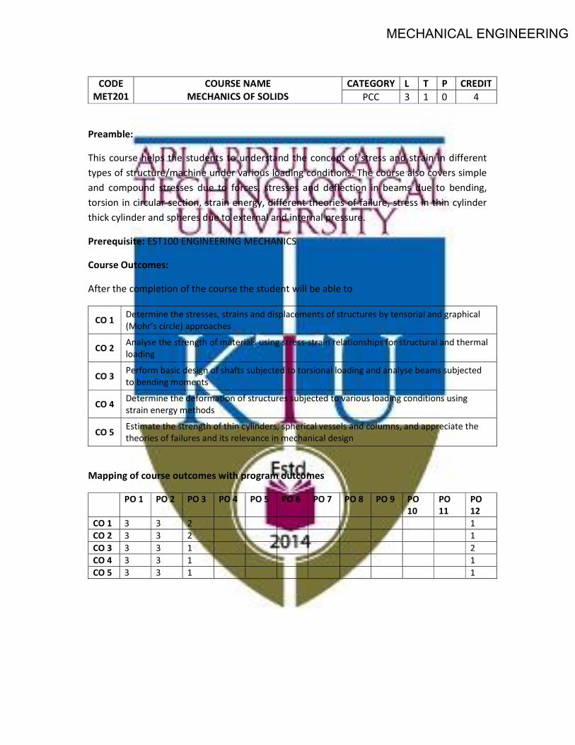
1. A siphon consisting of a pipe of 15 cm diameter is used to empty kerosene oil (relativedensity=0.8) from tank A. The siphon discharges to the atmosphere at an elevation of1.00 m. The oil surface in the tank is at an elevation of 4.00 m. The center line of thesiphon pipe at its highest point C is at an elevation of 5.50 m. Estimate,
(a) Discharge in the pipe
(b) Pressure at point C.
The losses in the pipe can be assumed to be 0.5 m up to the summit and 1.2 m fromsummit to the outlet.
2. Derive the Euler’s equation of motion along a streamline and from that derive the Bernouli’sequation.
3. What is water hammer? Explain different cases of water hammer. Derive the expressionfor pressure rise in any one of the case.
Course Outcome 4
1. Two reservoir with a difference in water surface elevation of 10 m are connected by apipeline AB and BC joined in series. Pipe AB is 10 cm in diameter, 20 m long and has avalue of friction factor f = 0.02. Pipe BC is 16 cm diameter, 25 m long and has a frictionfactor f=0.018. The junctions with reservoirs and between pipes are abrupt.
(a) Sketch Total energy line and Hydraulic gradient line
(b) Calculate the discharge.
2. Oil of viscosity 0.1 Pas and specific gravity 0.9 flows through a horizontal pipe of 25 mmdiameter. If the pressure drop per meter length of the pipe is 12 KPa, determine
(a) Discharge through the pipe
(b) Shear stress at the pipe wall
(c) Reynolds number of the flow
MECHANICAL ENGINEERING(d) Power required in Watts if the length of the pipe is 50m
3. In a hydraulic power plant, a reinforced concrete pipe of diameter D is used to transmitwater from the reservoir to the turbine. If H is the total head supply at the entrance ofthe pipe and hf is the loss of head in the pipe, then derive the condition for maximumpower supply through the pipe.
Course Outcome 5
1. Write a short note on boundary layer separation and discuss any two methods to controlthe same.
2. Find the displacement thickness, momentum thickness and energy thickness for velocitydistribution in boundary layer given by
u
U∞= 2
(yδ
)−(yδ
)2
3. A thin plate is moving in still atmospheric air at a velocity of 4m/s. The length of theplate is 0.5 m and width 0.4 m. Calculate the
(a) thickness of the boundary layer at the end of the plate and
(b) drag force on one side of the plate.
Take density of air as 1.25 kg/m3 and kinematic viscosity 0.15 stokes.
Course Outcome 6
1. State and explain Buckingham’s pi theorem.
2. An underwater device is 1.5m long and is to move at 3.5 m/s speed. A geometricallysimilar model 30 cm long is tested in a variable pressure wind tunnel at a speed of 35m/s. Calculate the pressure of air in the model if the model experience a drag force of40 N, calculate the prototype drag force. [Assume density of water = 998 kg/m3, densityof air at standard atmospheric pressure = 1.17 kg/m3, dynamic viscosity of air at localatmospheric pressure = 1.95 ∗ 10−5 Pas and dynamic viscosity of water = 1 ∗ 10−3 Pas]
3. Explain the importance of dimensionless numbers and discuss any two similarity laws.Where are these model laws used?

MECHANICAL ENGINEERINGSYLLABUS
Module 1: Introduction: Fluids and continuum, Physical properties of fluids, density, specific weight, vapour pressure, Newton’s law of viscosity. Ideal and real fluids, Newtonian and non-Newtonian fluids. Fluid Statics- Pressure-density-height relationship, manometers, pressure on plane and curved surfaces, center of pressure, buoyancy, stability of immersed and floating bodies, fluid masses subjected to uniform accelerations, measurement of pressure.
Module 2: Kinematics of fluid flow: Eulerian and Lagrangian approaches, classification of fluid flow, 1-D, 2-D and 3-D flow, steady, unsteady, uniform, non-uniform, laminar, turbulent, rotational, irrotational flows, stream lines, path lines, streak lines, stream tubes, velocity and acceleration in fluid, circulation and vorticity, stream function and potential function, Laplace equation, equipotential lines, flow nets, uses and limitations.
Module 3: Control volume analysis of mass, momentum and energy, Equations of fluid dynamics: Differential equations of mass, energy and momentum (Euler’s equation), Navier-Stokes equations (without proof) in cartesian co-ordinates. Dynamics of Fluid flow: Bernoulli’s equation, Energies in flowing fluid, head, pressure, dynamic, static and total head, Venturi and Orifice meters, Notches and Weirs (description only for notches and weirs). Hydraulic coefficients, Velocity measurements: Pitot tube and Pitot-static tube.
Module 4: Pipe Flow: Viscous flow: Reynolds experiment to classify laminar and turbulent flows, significance of Reynolds number, critical Reynolds number, shear stress and velocity distribution in a pipe, law of fluid friction, head loss due to friction, Hagen Poiseuille equation. Turbulent flow: Darcy- Weisbach equation, Chezy’s equation Moody’s chart, Major and minor energy losses, hydraulic gradient and total energy line, flow through long pipes, pipes in series, pipes in parallel, equivalent pipe, siphon, transmission of power through pipes, efficiency of transmission, Water hammer, Cavitation.
Module 5: Boundary Layer : Growth of boundary layer over a flat plate and definition of boundary layer thickness, displacement thickness, momentum thickness and energy thickness, laminar and turbulent boundary layers, laminar sub layer, velocity profile, Von- Karman momentum integral equations for the boundary layers, calculation of drag, separation of boundary and methods of control. Dimensional Analysis: Dimensional analysis, Buckingham’s theorem, important non dimensional numbers and their significance, geometric, Kinematic and dynamic similarity, model studies. Froude, Reynolds, Weber, Cauchy and Mach laws- Applications and limitations of model testing, simple problems only
Text Books
John. M. Cimbala and Yunus A. Cengel, Fluid Mechanics: Fundamentals and Applications (4th edition, SIE), 2019
Robert W. Fox, Alan T. McDonald, Philip J. Pritchard and John W. Mitchell, Fluid Mechanics, Wiley India, 2018

MECHANICAL ENGINEERING
Reference Books
White, F. M., Fluid Mechanics, McGraw Hill Education India Private Limited, 8th Edition, 2017
Rathakrishnan, E. Fluid Mechanics: An Introduction, Prentice Hall India, 3rd Edition 2012
COURSE PLAN
Module Topics Hours Allotted
I Introduction: Fluids and continuum, Physical properties of fluids, density, specific weight, vapour pressure, Newton’s law of viscosity. Ideal and real fluids, Newtonian and non-Newtonian fluids. Fluid Statics- Pressure-density-height relationship, manometers, pressure on plane and curved surfaces, center of pressure, buoyancy, stability of immersed and floating bodies, fluid masses subjected to uniform accelerations, measurement of pressure.
7-2-0
II Kinematics of fluid flow: Eulerian and Lagrangian approaches, classification of fluid flow, 1-D, 2-D and 3-D flow, steady, unsteady, uniform, non-uniform, laminar, turbulent, rotational, irrotational flows, stream lines, path lines, streak lines, stream tubes, velocity and acceleration in fluid, circulation and vorticity, stream function and potential function, Laplace equation, equipotential lines, flow nets, uses and limitations.
6-2-0
III Control volume analysis of mass, momentum and energy, Equations of fluid dynamics: Differential equations of mass, energy and momentum (Euler’s equation), Navier-Stokes equations (without proof) in cartesian co-ordinates Dynamics of Fluid flow: Bernoulli’s equation, Energies in flowing fluid, head, pressure, dynamic, static and total head, Venturi and Orifice meters, Notches and Weirs (description only for notches and weirs). Hydraulic coefficients, Velocity measurements: Pitot tube and Pitot-static tube.
6-2-0
IV Pipe Flow: Viscous flow: Reynolds experiment to classify laminar and turbulent flows, significance of Reynolds number, critical Reynolds number, shear stress and velocity distribution in a pipe, law of fluid friction, head
9-3-0

MECHANICAL ENGINEERINGloss due to friction, Hagen Poiseuille equation. Turbulent flow: Darcy- Weisbach equation, Chezy’s equation Moody’s chart, Major and minor energy losses, hydraulic gradient and total energy line, flow through long pipes, pipes in series, pipes in parallel, equivalent pipe, siphon, transmission of power through pipes, efficiency of transmission, Water hammer, Cavitation.
V Boundary Layer : Growth of boundary layer over a flat plate and definition of boundary layer thickness, displacement thickness, momentum thickness and energy thickness, laminar and turbulent boundary layers, laminar sub layer, velocity profile, Von- Karman momentum integral equations for the boundary layers, calculation of drag, separation of boundary and methods of control. Dimensional Analysis: Dimensional analysis, Buckingham’s theorem, important non dimensional numbers and their significance, geometric, Kinematic and dynamic similarity, model studies. Froude, Reynolds, Weber, Cauchy and Mach laws- Applications and limitations of model testing, simple problems only
8-2-0

MECHANICAL ENGINEERINGMODEL QUESTION PAPER
APJ ABDUL KALAM TECHNOLOGICAL UNIVERSITY
IV SEMESTER B.TECH DEGREE EXAMINATION
MET203: MECHANICS OF FLUIDS
Mechanical Engineering
Maximum: 100 Marks Duration: 3 hours
PART A
Answer all questions, each question carries 3 marks
1. The specific gravity of a liquid is 3.0. What are its specific weight, specific mass andspecific volume.
2. State Pascal’s law and give some examples where this principle is used.
3. Explain Streamlines, Streaklines and Pathlines.
4. What do you understand by the terms: (i) Total acceleration, (ii) Convective acceleration,and (iii) Local acceleration.
5. Name the different forces present in a fluid flow. For the Euler’s equation of motion, whichforces are taken into consideration.
6. Differentiate between pitot tube and pitot static tube.
7. Define and explain the terms (i) Hydraulic gradiant line and (ii) Total energy line.
8. Show that the coefficient of friction for viscous flow through a circular pipe is given by
f =16
Re
where Re is the Reynolds number.
9. What do you mean by repeating variables? How repeating variables are selected fordimensional analysis.
10. How will you determine whether a boundary layer flow is attached flow, detached flow oron the verge of separation.
(10×3=30 Marks)

MECHANICAL ENGINEERINGPART B
Answer one full question from each module
MODULE-I
11. (a) Through a very narrow gap of height h, a thin plate of large extend is pulled at avelocity V . On one side of the plate is oil of viscosity µ1 and on the other side oil ofviscosity µ2. Calculate the position of the plate so that
i. the shear force on the two sides of the plate is equal.
ii. the pull required to drag the plate is minimum.
Assume linear velocity distribution in transverse direction. (7 Marks)
(b) A metallic cube of 30 cm side and weight 500 N is lowered into a tank containingtwo fluid layers of water and mercury. Top edge of the cube is at water surface.Determine the position of the block at water mercury interface when it has reachedequilibrium. (7 Marks)
12. (a) A rectangular tank 1.5 m wide, 3 m long and 1.8 m deep contains water to a depthof 1.2 m. Find the horizontal acceleration which may be imparted to the tank in thedirection of length so that
i. there is just no spilling from the tank
ii. front bottom corner of the tank is just exposed.
(7 Marks)
(b) A spherical water drop of 1 mm diameter splits up in air into 64 smaller drops ofequal size. Find the work required in splitting up the drop. The surface tensioncoefficient of water in air = 0.073 N/m (7 Marks)
MODULE-II
13. (a) In a fluid flow field, velocity vector is given by v = (0.5 + 8x)i+ (0.5 − 0.8y)j. Findthe equation of streamline for the given velocity field. (7 Marks)
(b) The stream function ψ = 4xy in which ψ is in cm2/s and x and y are in metersdescribe the incompressible flow between the boundary shown below:
Calculate
i. Velocity at B
ii. Convective acceleration at B

MECHANICAL ENGINEERINGiii. Flow per unit width across AB
(7 Marks)
14. (a) Consider the velocity field given by u = x2 and v = −2xy. Find the circulationaround the area bounded by A(1, 1), B(2, 1), C(2, 2), D(1, 2). (7 Marks)
(b) Verify whether the following are valid potential functions.
i. φ = 2x+ 5y
ii. φ = 4x2 − 5y2
(7 Marks)
MODULE-III
15. (a) A submarine moves horizontally in sea and has its axis 15 m below the surface ofthe water. A pitot tube properly placed just in front of the submarine and alongits axis is connected to two limbs of a U tube containing mercury. The differenceof level is found to be 170 mm. Find the speed of the submarine knowing that thespecific gravity of mercury is 13.6 and that of sea water is 1.026 with respect towater. (7 Marks)
(b) A pitot tube is inserted in a pipe of 30 cm diameter. The static pressure of thetube is 10 cm of mercury vacuum. The stagnation pressure at the centre of the piperecorded by the pitot tube is 1.0 N/cm2. Calculate the rate of flow of water throughthe pipe, if the mean velocity of flow is 0.85 times central velocity. Assume coefficientof tube as 0.98. (7 Marks)
16. (a) A smooth pipe of uniform diameter 25 cm, a pressure of 50 KPa was observed atsection 1 which has an elevation of 10 m. At another section 2, at an elevation of 12m, the pressure was 20 KPa and the velocity was 1.25 m/s. Determine the directionof flow and the head loss between the two sections. The fluid in the pipe is water.(8 Marks)
(b) Petrol of specific gravity 0.8 is following through a pipe of 30 cm diameter. The pipeis inclined at 30◦ to horizontal. The venturi has a throat diameter of 10 cm. U tubemanometer reads 6.25 cm Hg. Calculate the discharge through the pipe. AssumeCd = 0.98. (6 Marks)
MODULE-IV
17. (a) Assuming viscous flow through a circular pipe derive the expression for,
i. Velocity distribution
ii. Shear stress distribution
Also plot the velocity and shear stress distribution. (7 Marks)
(b) A large tank shown in the figure has a vertical pipe 70 cm long and 2 cm in diameter.The tank contain oil of density 920 Kg/m3 and viscosity 1.5 poise. Find the dischargethrough the tube when the height of oil level of the tank is 0.80 m above the pipeinlet.
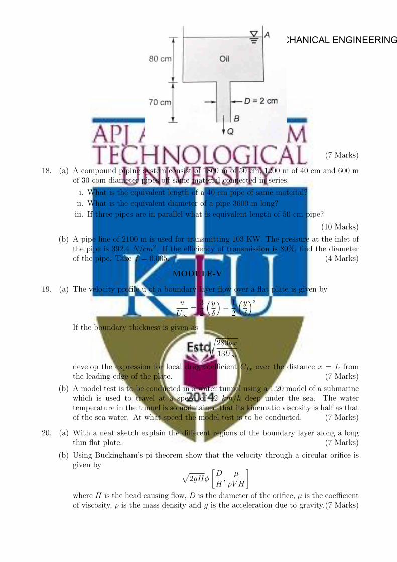
MECHANICAL ENGINEERING
(7 Marks)
18. (a) A compound piping system consist of 1800 m of 50 cm, 1200 m of 40 cm and 600 mof 30 com diameter pipes off same material connected in series.
i. What is the equivalent length of a 40 cm pipe of same material?
ii. What is the equivalent diameter of a pipe 3600 m long?
iii. If three pipes are in parallel what is equivalent length of 50 cm pipe?
(10 Marks)
(b) A pipe line of 2100 m is used for transmitting 103 KW. The pressure at the inlet ofthe pipe is 392.4 N/cm2. If the efficiency of transmission is 80%, find the diameterof the pipe. Take f = 0.005. (4 Marks)
MODULE-V
19. (a) The velocity profile u of a boundary layer flow over a flat plate is given by
u
U∞=
3
2
(yδ
)− 1
2
(yδ
)3If the boundary thickness is given as
δ =
√280νx
13U∞
develop the expression for local drag coefficient Cfx over the distance x = L fromthe leading edge of the plate. (7 Marks)
(b) A model test is to be conducted in a water tunnel using a 1:20 model of a submarinewhich is used to travel at a speed of 12 km/h deep under the sea. The watertemperature in the tunnel is so maintained that its kinematic viscosity is half as thatof the sea water. At what speed the model test is to be conducted. (7 Marks)
20. (a) With a neat sketch explain the different regions of the boundary layer along a longthin flat plate. (7 Marks)
(b) Using Buckingham’s pi theorem show that the velocity through a circular orifice isgiven by √
2gHφ
[D
H,
µ
ρV H
]where H is the head causing flow, D is the diameter of the orifice, µ is the coefficientof viscosity, ρ is the mass density and g is the acceleration due to gravity.(7 Marks)

MECHANICAL ENGINEERING
MET 205 METALLURGY & MATERIAL
SCIENCE
CATEGORY L T P Credits Year of Introduction
PCC 3 1 0 4 2019
Preamble: Understanding of the correlation between the chemical bonds and crystal structure of metallic materials to their mechanical properties. Recognize the importance of crystal imperfections including dislocations in plastic deformation. Learning about different phases and heat treatment methods to tailor the properties of Fe-C alloys. Examine the mechanisms of materials failure through fatigue and creep. To determine properties of unknown materials and develop an awareness to apply this knowledge in material design
Prerequisite: PHT 110 Engineering Physics and CYT 100 Engineering Chemistry
Course Outcomes - At the end of the course students will be able to
CO 1 Understand the basic chemical bonds, crystal structures (BCC, FCC, and HCP), and their relationship with the properties.
CO 2 Analyze the microstructure of metallic materials using phase diagrams and modify the microstructure and properties using different heat treatments.
CO 3 How to quantify mechanical integrity and failure in materials.
CO 4 Apply the basic principles of ferrous and non-ferrous metallurgy for selecting materials for specific applications.
CO 5 Define and differentiate engineering materials on the basis of structure and properties for engineering applications.
Mapping of course outcomes with program outcomes (Minimum requirements)
PO 1
PO 2
PO 3
PO 4
PO 5
PO 6
PO 7
PO 8
PO 9
PO 10
PO 11
PO 12
CO 1 3 - - - - - - - - - - CO 2 - 3 - - - - - - - - - CO 3 - - 2 - - - - - - - - CO 4 - - - 3 - - - - - - - CO 5 - - - - - - - - - - 2
MECHANICAL ENGINEERING
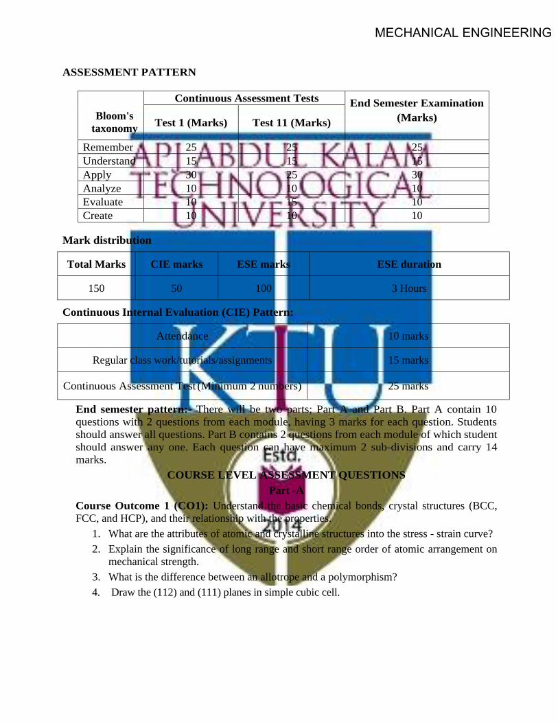
ASSESSMENT PATTERN
Bloom's
taxonomy
Continuous Assessment Tests End Semester Examination (Marks) Test 1 (Marks) Test 11 (Marks)
Remember 25 25 25 Understand 15 15 15 Apply 30 25 30 Analyze 10 10 10 Evaluate 10 15 10 Create 10 10 10
Mark distribution
Total Marks CIE marks ESE marks ESE duration
150 50 100 3 Hours
Continuous Internal Evaluation (CIE) Pattern:
Attendance 10 marks
Regular class work/tutorials/assignments 15 marks
Continuous Assessment Test (Minimum 2 numbers) 25 marks
End semester pattern:- There will be two parts; Part A and Part B. Part A contain 10 questions with 2 questions from each module, having 3 marks for each question. Students should answer all questions. Part B contains 2 questions from each module of which student should answer any one. Each question can have maximum 2 sub-divisions and carry 14 marks.
COURSE LEVEL ASSESSMENT QUESTIONS Part -A
Course Outcome 1 (CO1): Understand the basic chemical bonds, crystal structures (BCC, FCC, and HCP), and their relationship with the properties.
1. What are the attributes of atomic and crystalline structures into the stress - strain curve? 2. Explain the significance of long range and short range order of atomic arrangement on
mechanical strength. 3. What is the difference between an allotrope and a polymorphism? 4. Draw the (112) and (111) planes in simple cubic cell.

MECHANICAL ENGINEERING
Course Outcome 2 (CO2): Analyze the microstructure of metallic materials using phase diagrams and modify the microstructure and properties using different heat treatments.
1. What is the driving force for recrystallisation and grain growth of metallic crystals? 2. What is the driving force for the formation of spheroidite. 3. What is tempered martensite? 4. Why 100 % pure metals are weak in strength?
Part -B Course Outcome 3 (CO3): How to quantify mechanical integrity and failure in materials
1. A small hole is drilled through a steel plate ahead of a crack, whether it can stop the crack’s
progress until repairs can be made. Explain in detail and derive the equation for the principle. 2. Draw and explain S-N curves for ferrous and non-ferrous metals. Explain different methods to
improve fatigue resistance. 3. Explain different stages of creep; Give an application of creep phenomenon. What is
superplasticity? Course Outcome 4 (CO4): Apply the basic principles of ferrous and non-ferrous metallurgy for selecting materials for specific applications.
1. What are the classification, compositions and applications of high speed steel? identify 18:4:1 2. Describe the composition, properties, and use of Bronze and Gun metal. 3. Explain the importance of all the non-ferrous alloys in automotive applications. Elaborate on
the composition, properties and typical applications of any five non-ferrous alloys. Course Outcome 5 (CO5): Define and differentiate engineering materials on the basis of structure and properties for engineering applications.
1. Carbon is allowed to diffuse through a steel plate 15 mm thick. The concentrations of carbon at the two faces are 0.65 and 0.30kgC/m3Fe, which are maintained constant. If the pre- exponential and activation energy are 6.2x10⁻⁷m2/s and 80,000 J/mol, respectively, compute the temperature at which the diffusion flux is 1.43 x 10⁻⁹ kg/m2-s.
2. Explain the fundamental effects of alloying elements in steel on polymorphic transformation temperatures, grain growth, eutectoid point, retardation of the transformation rates, formation and stability of carbides.
3. Describe the kind of fracture which may occur as a result of a loose fitting key on a shaft. SYLLABUS
MODULE - 1 Earlier and present development of atomic structure - Primary bonds: - characteristics of covalent, ionic and metallic bond - properties based on atomic bonding: - Secondary bonds: - classification, application. (Brief review only).
Crystallography: - SC, BCC, FCC, HCP structures, APF - theoretical density simple problems - Miller Indices: - crystal plane and direction - Modes of plastic deformation: - Slip and twinning -Schmid's law - Crystallization: Effects of grain size, Hall - Petch theory, simple problems.

MECHANICAL ENGINEERING
MODULE - II Classification of crystal imperfections - forest of dislocation, role of surface defects on crack initiation- Burgers vector –Frank Read source - Correlation of dislocation density with strength and nano concept - high and low angle grain boundaries– driving force for grain growth and applications - Polishing and etching - X – ray diffraction, simple problems –SEM and TEM - Diffusion in solids, fick’s laws, mechanisms, applications of diffusion in mechanical engineering, simple problems.
MODULE - III Phase diagrams: - need of alloying - classification of alloys - Hume Rothery`s rule - equilibrium diagram of common types of binary systems: five types - Coring - lever rule and Gibb`s phase rule - Reactions- Detailed discussion on Iron-Carbon equilibrium diagram with microstructure and properties -Heat treatment: - TTT, CCT diagram, applications - Tempering- Hardenability, Jominy end quench test, applications- Surface hardening methods. MODULE - IV Strengthening mechanisms - cold and hot working - alloy steels: how alloying elements affecting properties of steel - nickel steels - chromium steels - high speed steels -cast irons - principal non ferrous alloys. MODULE - V Fatigue: - creep -DBTT - super plasticity - need, properties and applications of composites, super alloy, intermetallics, maraging steel, Titanium - Ceramics:- structures, applications. Text Books 1. Callister William. D., Material Science and Engineering, John Wiley, 2014 2. Higgins R.A. - Engineering Metallurgy part - I – ELBS,1998 Reference
1. Avner H Sidney, Introduction to Physical Metallurgy, Tata McGraw Hill,2009 2. Anderson J.C. et.al., Material Science for Engineers, Chapman and Hall,1990 3. Clark and Varney, Physical metallurgy for Engineers, Van Nostrand,1964 4. Dieter George E, Mechanical Metallurgy, Tata McGraw Hill, 1976 5. Raghavan V, Material Science and Engineering, Prentice Hall,2004 6. Reed Hill E. Robert, Physical metallurgy principles, 4th edition, Cengage Learning,2009 7. Myers Marc and Krishna Kumar Chawla, Mechanical behavior of materials, Cambridge
University press,2008 8. Van Vlack -Elements of Material Science - Addison Wesley,1989 9. https://nptel.ac.in/courses/113/106/113106032

MECHANICAL ENGINEERING
MODEL QUESTION PAPER
METALLURGY & MATERIAL SCIENCE - MET 205
Max. Marks : 100 Duration : 3 Hours Part – A
Answer all questions. Answer all questions, each question carries 3 marks
1. What is a slip system? Describe the slip systems in FCC, BCC and HCP metals 2. NASA's Parker Solar Probe will be the first-ever mission to "touch" the Sun. The spacecraft,
about the size of a small car, will travel directly into the Sun's atmosphere about 4 million miles from the earth surface. Postulate the coolant used in the parker solar probe with chemical bonds.
3. What is the driving force for grain growth during heat treatment 4. What are the roles of surface imperfections on crack initiation 5. Explain the difference between hardness and hardenability. 6. What is tempered martensite? Explain its structure with sketch. 7. Postulate, why cast irons are brittle?
8. How are properties of aluminum affected by the inclusion of (a) copper and (b) silicon as alloying elements?
9. What is the grain size preferred for creep applications? Why. Explain thermal fatigue? 10. Explain fracture toughness and its attributes into a screw jack?
PART -B
Answer one full question from each module.
MODULE – 1
11. a. Calculate the APF of SC, BCC and FCC (7 marks).
b. What is slip system and explain why FCC materials exhibit ductility and B C C a n d HCP exhibit brittle nature with details of slip systems (7 marks).
OR
12. Explain the effect of: (i) Grain size; (ii) Grain size distribution and (iii) Grain orientation (iv) Grain shape on strength and creep resistance with neat sketches. Attributes of Hall-Petch equation and grain boundaries (14 marks).
MODULE – 2
13. a. Describe step by step procedure for metallographic specimen preparation? Name different types etchants used for specific metals and methods to determine grain size (7 marks).

MECHANICAL ENGINEERING
b. Carbon is allowed to diffuse through a steel plate 15 mm thick. The concentrations of carbon at the two faces are 0.65 and 0.30 kgC/m3Fe, which are maintained constant. If the pre-exponential and activation energy are 6.2x10⁻⁷m2/s and 80,000 J/mol, respectively, compute the temperature at which the diffusion flux is 1.43 x 10⁻⁹ kg/m2-s (7 marks).
OR 14. a. Explain the fundamental differences of SEM and TEM with neat sketches (7 marks).
b. A beam of X-rays wavelength 1.54Å is incident on a crystal at a glancing angle of 8o35’
when the first order Bragg’s reflection occurs calculate the glancing angle for third order reflection (7 marks).
MODULE – 3
15. Postulate with neat sketches, why 100% pure metals are weaker? What are the primary functions of alloying? Explain the fundamental rules governing the alloying with neat sketches and how is it accomplished in substitution and interstitial solid solutions (14 marks).
OR 16. Draw the isothermal transformation diagram of eutectoid steel and then sketch and label (1) A
time temperature path that will produce 100% pure coarse and fine pearlite (2) A time temperature path that will produce 50% martensite and 50% bainite (3) A time temperature path that will produce 100% martensite (4) A time temperature path that will produce 100% bainite (14 marks).
MODULE – 4
17. Explain the effect of, polymorphic transformation temperature, formation and stability of carbides, grain growth, displacement of the eutectoid point, retardation of the transformation rates, improvement of corrosion resistance on adding alloy elements to steel (14 marks).
OR
18. Give the composition, microstructure, properties and applications of (i) Gray iron and SG iron. (ii) White iron and Gray iron. (iii) Malleable iron and Gray iron. (iv) Gray iron and Mottled iron, (v) SG iron and Vermicullar Graphite Iron (14 marks).
MODULE – 5
19. a A small hole is drilled through a steel plate ahead of a crack, whether it can stop the crack’s
progress until repairs can be made or not? Explain in detail and derive the equation (7 marks).
b What is ductile to brittle transition in steel DBTT? What are the factors affecting ductile to brittle transition? Narrate with neat sketch (7 marks).
OR
20. Classify ceramics with radius ratio with neat sketches. Explain with an example for each of the AX, AmXp, AmBmXp type structures in ceramics with neat sketch (14 marks).

MECHANICAL ENGINEERING
COURSE CONTENT AND LECTURE SCHEDULES.
Module TOPIC No. of
hours
Course outcomes
1.1
Earlier and present development of atomic structure; attributes of ionization energy and conductivity, electronegativity; correlation of atomic radius to strength; electron configurations; - Primary bonds: - characteristics of covalent, ionic and metallic bond: attributes of bond energy, cohesive force, density, directional and non-directional - properties based on atomic bonding:- attributes of deeper energy well and shallow energy well to melting temperature, coefficient of thermal expansion - attributes of modulus of elasticity in metal cutting process -Secondary bonds:- classification- hydrogen bond and anomalous behavior of ice float on water, application- specific heat, applications. (Brief review only).
2 CO1
1.2 Crystallography:- Crystal, space lattice, unit cell- SC, BCC, FCC, atomic packing factor and HCP structures - short and long range order - effects of crystalline and amorphous structure on mechanical properties.
2 CO1 CO2
1.3 Coordination number and radius ratio; theoretical density; simple problems - Polymorphism and allotropy. 1
1.4 Miller Indices: - crystal plane and direction - Attributes of miller indices for slip system, brittleness of BCC, HCP and ductility of FCC - Modes of plastic deformation: - Slip and twinning.
1 CO5
1.5 Schmid's law, equation, critical resolved shear stress, correlation of slip system with plastic deformation in metals and applications. 1
1.6
Mechanism of crystallization: Homogeneous and heterogeneous nuclei formation, under cooling, dendritic growth, grain boundary irregularity - Effects of grain size, grain size distribution, grain shape, grain orientation on dislocation/strength and creep resistance - Hall - Petch theory, simple problems.
2 CO2
2.1 Classification of crystal imperfections: - types of point and dislocations. 1 CO2 2.2 Effect of point defects on mechanical properties - forest of dislocation, role of
surface defects on crack initiation - Burgers vector. 1
2.3 Dislocation source, significance of Frank-Read source in metals deformation - Correlation of dislocation density with strength and nano concept, applications. 3 CO2
2.4 Significance high and low angle grain boundaries on dislocation – driving force for grain growth and applications during heat treatment.
2.5
Polishing and etching to determine the microstructure and grain size- Fundamentals and crystal structure determination by X – ray diffraction, simple problems –SEM and TEM.
2 CO2 CO5
2.6 Diffusion in solids, fick’s laws, mechanisms, applications of diffusion in mechanical engineering, simple problems. 1

MECHANICAL ENGINEERING
3.1 Phase diagrams: - Limitations of pure metals and need of alloying - classification of alloys, solid solutions, Hume Rothery`s rule - equilibrium diagram of common types of binary systems: five types.
2 CO2 CO5
3.2 Coring - lever rule and Gibb`s phase rule - Reactions: - monotectic, eutectic, eutectoid, peritectic, peritectoid. 1
3.3 Detailed discussion on Iron-Carbon equilibrium diagram with microstructure and properties changes in austenite, ledeburite, ferrite, cementite, special features of martensite transformation, bainite, spheroidite etc. 3 CO2
CO5 3.4
Heat treatment: - Definition and necessity – TTT for a eutectoid iron–carbon alloy, CCT diagram, applications - annealing, normalizing, hardening, spheroidizing.
3.5 Tempering:- austermpering, martempering and ausforming - Comparative study on ductility and strength with structure of pearlite, bainite, spherodite, martensite, tempered martensite and ausforming.
1 CO2
3.6
Hardenability, Jominy end quench test, applications- Surface hardening methods:- no change in surface composition methods :- Flame, induction, laser and electron beam hardening processes- change in surface composition methods :carburizing and Nitriding; applications.
2
CO2
4.1 Cold working: Detailed discussion on strain hardening; recovery; re-crystallization, effect of stored energy; re- crystallization temperature - hot working, Bauschinger effect and attributes in metal forming.
1
4.2
Alloy steels:- Effects of alloying elements on steel: dislocation movement, polymorphic transformation temperature, alpha and beta stabilizers, formation and stability of carbides, grain growth, displacement of the eutectoid point, retardation of the transformation rates, improvement in corrosion resistance, mechanical properties
1 CO4
4.3
Nickel steels, Chromium steels etc. – change of steel properties by adding alloying elements: - Molybdenum, Nickel, Chromium, Vanadium, Tungsten, Cobalt, Silicon, Copper and Lead - High speed steels - Cast irons: Classifications; grey, white, malleable and spheroidal graphite cast iron etc, composition, microstructure, properties and applications - Principal Non ferrous Alloys: - Aluminum, Copper, Magnesium, Nickel, study of composition, properties, applications, reference shall be made to the phase diagrams whenever necessary.( Topic 4.3 may be considered as a assignment).
4 CO4 CO5
4.4 Fatigue: - Stress cycles – Primary and secondary stress raisers - Characteristics of fatigue failure, fatigue tests, S-N curve. 1
CO3 4.5
Factors affecting fatigue strength: stress concentration, size effect, surface roughness, change in surface properties, surface residual stress - Ways to improve fatigue life – effect of temperature on fatigue, thermal fatigue and its applications in metal cutting.
2

MECHANICAL ENGINEERING
5.1
Fracture: – Brittle and ductile fracture – Griffith theory of brittle fracture – Stress concentration, stress raiser – Effect of plastic deformation on crack propagation - transgranular, intergranular fracture - Effect of impact loading on ductile material and its application in forging, applications - Mechanism of fatigue failure.
2
CO3
5.2
Structural features of fatigue: - crack initiation, growth, propagation - Fracture toughness (definition only), applications - Ductile to brittle transition temperature (DBTT) in steels and structural changes during DBTT, applications.
1
5.3
Creep: - Creep curves – creep tests - Structural change:- deformation by slip, sub-grain formation, grain boundary sliding - Mechanism of creep deformation - threshold for creep, prevention against creep - Super plasticity: need and applications
2 CO3
5.4 Composites: - Need of development of composites; fiber phase; matrix phase; only need and characteristics of PMC, MMC, and CMC. 2
CO3 CO5 5.5
Modern engineering materials: - only fundamentals, need, properties and applications of, intermetallics, maraging steel, super alloys, Titanium- Ceramics:-coordination number and radius ratios- AX, AmXp, AmBmXp type structures – applications.
3

MECHANICAL ENGINEERING
MEL201 COMPUTER AIDED
MACHINE DRAWING CATEGORY L T P Credits
Year of Introduction
PCC 0 0 3 2 2019
Preamble: To introduce students to the basics and standards of engineering drawing related to
machines and components.
To make studentsfamiliarize with different types of riveted and welded joints, surface roughness
symbols; limits, fits and tolerances.
To convey the principles and requirements of machine and production drawings.
To introduce the preparation ofdrawings of assembled and disassembled view of important valves
and machine components used in mechanical engineering applications.
To introduce standard CAD packages for drafting andmodelingof engineering components.
Prerequisite: EST 110 - Engineering Graphics
Course Outcomes - At the end of the course students will be able to
CO1 Apply the knowledge of engineering drawings and standards to prepare standard dimensioned drawings of machine parts and other engineering components.
CO2 Preparestandard assembly drawings of machine components and valvesusing part drawings and bill of materials.
CO3 Apply limits and tolerances to components and choose appropriate fits for given assemblies
CO 4 Interpret the symbols of welded, machining and surface roughness on the component drawings.
CO 5 Prepare part and assembly drawings and Bill of Materials of machine components and valves using CAD software.
Mapping of course outcomes with program outcomes (Minimum requirements)
PO1 PO2 PO3 PO4 PO5 PO6 PO7 PO8 PO9 PO10 PO11 PO12
CO1 3 3
CO2 3 2 3
CO3 3 2
CO4 3
CO5 3 3 3 1

MECHANICAL ENGINEERING
Assessment Pattern
Bloom’s taxonomy
Continuous Assessment Tests Test 1
PART A Test 2
Sketching and Manual Drawing
PART B CAD Drawing
Remember 25 20 Understand 15 15 Apply 30 20 Analyse 10 10 Evaluate 10 15 Create 10 20
Mark Distribution
Total Marks CIE Marks ESE marks ESE duration 150 75 75 2.5 hours
Continuous Internal Evaluation (CIE) Pattern:
Attendance 15 marks Regular class work/Drawing/Workshop Record/Lab Record and Class Performance
30 marks
Continuous Assessment Test (minimum two tests) 30 marks
End semester examination pattern End semester examination shall be conducted on Sketching and CAD drawing on based complete syllabus The following general guidelines should be maintained for the award of marks Part A Sketching – 15 marks Part B CAD drawing – 50marks Viva Voce – 10 marks. Conduct of University Practical Examinations The Principals of the concerned Engineering Colleges with the help of the Chairmen/Chairperson will conduct the practical examination with the approval from the University and bonafide work / laboratory record, hall ticket, identity card issued by college are mandatory for appearing practical University examinations. No practical examination should be conducted without the presence of an external examiner appointed by the University.

MECHANICAL ENGINEERING
END SEMSTER EXAMINATION
MODEL QUESTION PAPER
MEL 201: COMPUTER AIDED MACHINE DRAWING
Duration : 2.5 hours Marks : 75
Note : 1. All dimensions in mm 2. Assume missing dimensions appropriately 3. A4 size answer booklet shall be supplied 4. Viva Voce shall be conducted for 10 marks
PART A (SKETCHING) (Answer any TWO questions ). 15 marks
1. Sketch two views of a single riveted single strap butt joint. Take dimensions of the plate as
10mm. Mark the proportions in the drawing.
2. Show by means of neat sketches, any three methods employed for preventing nuts from getting loose on account of vibrations
3. Compute the limit dimensions of the shaft and the hole for a clearance fit based on shaft basis system if:
Basic size= φ30 mm Minimum clearance = 0.007 mm Tolerance on hole = 0.021 mm Tolerance on shaft= 0.021 mm
Check the calculated dimensions. Represent the limit dimensions schematically.
PART B (CAD DRAWING) 50 marks
4. Draw any two assembled views of the Rams Bottom Safety Valve as per the details given in the figure using any suitable CAD software. Also prepare bill of materials and tolerance data sheet.
Item Description Qty Material Item Description Qty Material
1 Body 1 C.I. 8 Split Pin 3 M.S.
2 Valve Seat 2 G.M. 9 Pin for Link 2 M.S.
3 Spring 1 Steel 10 Pin for Pivot 1 M.S.
4 Valve 2 G.M. 11 Shackle 1 M.S.
5 Lever 1 M.S. 12 Washer 1 M.S.
6 Pivot 1 M.S. 13 Nut 1 M.S.
7 Link 2 M.S. 14 Lock Nut 1 M.S.

MECHANICAL ENGINEERING

MECHANICAL ENGINEERING
SYLLABUS
Introduction to machine drawing, drawing standards, fits, tolerances, surface roughness, assembly and part drawings of simple assemblies and subassemblies of machine parts viz., couplings, clutches, bearings, I.C. engine components, valves, machine tools, etc; introduction to CAD etc.
Text Books: 1. N. D. Bhatt and V.M. Panchal, Machine Drawing, Charotar Publishing House. 2. P I Varghese and K C John, Machine Drawing, VIP Publishers. Reference Books 1. Ajeet Singh, Machine Drawing Includes AutoCAD, Tata McGraw-hill. 2. P S Gill, Machine Drawing, Kataria& Sons.
Course content and drawing schedules.
No: List of Exercises
Course outcomes
No. of hours
PART –A (Manual drawing)
(Minimum 6 drawings compulsory) 1
Temporary Joint: Principles of drawing, free hand sketching, Importance of machine Drawing. BIScode of practice for Engineering Drawing, lines, types of lines, dimensioning, scales of drawing, sectional views, Riveted joints.
CO 1
3
2
Fasteners: Sketching of conventional representation of welded joints,Bolts and Nuts or Keys and Foundation Bolts.
CO 1
3
3
Fits and Tolerances: Limits, Fits – Tolerances of individual dimensions – Specification of Fits – basic principles of geometric & dimensional tolerances. Surface Roughness: Preparation of production drawings and reading of part and assembly drawings, surface roughness, indication of surface roughness, etc.
CO 2
3
4
Detailed drawing of Cotter joints, Knuckle joint and Pipe joints
CO 2
3
5
Assembly drawings(2D): Stuffing box and Screw jack
CO 1 CO3 CO4
3

MECHANICAL ENGINEERING
PART –B (CAD drawing)
(Minimum 6 drawings compulsory)
6
Introduction to drafting software like Auto CAD, basic commands, keyboard shortcuts. Coordinate and unit setting, Drawing, Editing, Measuring, Dimensioning, Plotting Commands, Layering Concepts, Matching, Detailing, Detailed drawings.
CO 1
CO 2 CO 3 CO5
3
7
Drawing of Shaft couplings and Oldham's coupling
CO 1 CO 2 CO 3 CO5
3
8 Assembly drawings(2D)with Bill of materials: Lathe Tailstock and Universal joint
CO 1 CO3 CO5
3
9
Assembly drawings(2D)with Bill of materials: Connecting rod and Plummer block
CO 1 CO3 CO5
3
10
Assembly drawings(2D)with Bill of materials: Rams Bottom Safety Valve OR steam stop valve
CO 1 CO3 CO5
3

MECHANICAL ENGINEERINGCODE
MEL203 COURSE NAME
MATERIALS TESTING LAB CATEGORY L T P CREDIT
PCC 0 0 3 2
Preamble:
The objective of this course is to give a broad understanding of common materials related to mechanical engineering with an emphasis on the fundamentals of structure-property-application and its relationships. A group of 6/7 students can conduct experiment effectively. A total of six experiments for the duration of 2 hours each is proposed for this course.
Prerequisite: A course on Engineering Mechanics is required
Course Outcomes:
After the completion of the course the student will be able to
CO 1 To understand the basic concepts of analysis of circular shafts subjected to torsion. CO 2 To understand the behaviour of engineering component subjected to cyclic loading and
failure concepts CO 3 Evaluate the strength of ductile and brittle materials subjected to compressive, Tensile
shear and bending forces CO 4 Evaluate the microstructural morphology of ductile or brittle materials and its fracture
modes (ductile /brittle fracture) during tension test CO 5 To specify suitable material for applications in the field of design and manufacturing.
Mapping of course outcomes with program outcomes
PO 1 PO 2 PO 3 PO 4 PO 5 PO 6 PO 7 PO 8 PO 9 PO 10 PO 11 PO 12
CO 1 3 3 CO 2 3 3 1 3 3 2 2 1 CO 3 3 3 3 1 3 3 2 3 2 CO 4 3 3 3 3 3 2 2 1 3 2 3 2 CO 5 3 3 3 1 3 2 2 1 3 2 3 2
Assessment Pattern
Mark distribution
Total Marks CIE ESE ESE Duration
150 75 75 2.5 hours

MECHANICAL ENGINEERINGContinuous Internal Evaluation Pattern:
Attendance : 15 marks Continuous Assessment : 30 marks Internal Test (Immediately before the second series test) : 30 marks
End Semester Examination Pattern:
The following guidelines should be followed regarding award of marks (a) Preliminary work : 15 Marks (b) Implementing the work/Conducting the experiment : 10 Marks (c) Performance, result and inference (usage of equipments and troubleshooting) : 25 Marks (d) Viva voce : 20 marks (e) Record : 5 Marks
General instructions:
Practical examination to be conducted immediately after the second series test covering entire syllabus given below. Evaluation is a serious process that is to be conducted under the equal responsibility of both the internal and external examiners. The number of candidates evaluated per day should not exceed 20. Students shall be allowed for the University examination only on submitting the duly certified record. The external examiner shall endorse the record.
A minimum of 10 experiments are to be performed.
SYLLABUS
LIST OF EXPERIMENTS
1. To conduct tension test on ductile material (mild steel/ tor-steel/ high strength steel) usingUniversal tension testing machine and Extensometer.
2. To conduct compression test on ductile material (mild steel/ tor-steel/ high strength steel)using Universal tension testing machine and Extensometer.
3. To conduct tension test on Brittle material (cast iron) using Universal tension testingmachine and Extensometer.
4. To conduct shear test on mild steel rod.
5. To conduct microstructure features of mild steel/copper/ brass/aluminium using opticalmicroscope, double disc polishing machine, emery papers and etchent.
6. To conduct fractography study of ductile or brittle material using optical microscope.

MECHANICAL ENGINEERING7. To conduct Hardness test of a given material. (Brinell, Vickers and Rockwell)
8. To determine torsional rigidity of mild steel/copper/brass rod.
9. To determine flexural rigidity of mild steel/ copper/brass material using universal testingmachine.
10. To determine fracture toughness of the given material using Universal tension testingmachine.
11. To study the procedure for plotting S-N curve using Fatigue testing machine.
12. To conduct a Toughness test of the given material using Izod and Charpy Machine.
13. To determine spring stiffness of close coiled/open coiled/series/parallel arrangements.
14. To conduct bending test on wooden beam.
15. To conduct stress measurements using Photo elastic methods.
16. To conduct strain measurements using strain gauges.
17. To determine moment of inertia of rotating bodies.
18. To conduct an experiment to Verify Clerk Maxwell’s law of reciprocal deflection anddetermine young's Modulus of steel.
19. To determine the surface roughness of a polished specimen using surface profilometer.
Reference Books
1. G E Dieter. Mechanical Metallurgy, McGraw Hill,2013
2. Dally J W, Railey W P, Experimental Stress analysis , McGarw Hill,1991
3. Baldev Raj, Jayakumar T, Thavasimuthu M., Practical Non destructive testing, Narosa Book
Distributors,2015

MECHANICAL ENGINEERING
SEMESTER -3
MINOR

MECHANICAL ENGINEERINGCODE
MET281 COURSE NAME
MECHANICS OF MATERIALS CATEGORY L T P CREDIT
VAC 3 1 4
Preamble:
This course helps the students to understand the concept of stress and strain, and practice the methodologies to analyze different types of structures under various loading conditions. The course also covers simple and compound stresses due to forces, stresses and deflection in beams due to bending, torsion of shafts.
Prerequisite: EST100 ENGINEERING MECHANICS
Course Outcomes:
After the completion of the course the student will be able to
CO 1 Discuss the concepts of stress and strain in deformable bodies due to structural and thermal loading
CO 2 Analyse the behaviour of materials under shear stress due to torsional loads acting in simple structural members
CO 3 Analyse beams using graphical and analytical methods to determine slope, deflection and stress
CO 4 Transform stresses and strains for plane stress problems mathematically and graphically and determine the principal stresses and its directions
CO 5 Analyze simple structures subjected to compound stresses, and columns subjected to buckling conditions
Mapping of course outcomes with program outcomes
PO 1 PO 2 PO 3 PO 4 PO 5 PO 6 PO 7 PO 8 PO 9 PO 10
PO 11
PO 12
CO 1 3 3 2 1 CO 2 3 2 2 2 CO 3 3 3 2 1 CO 4 3 3 2 1 CO 5 3 2 2 1
MECHANICAL ENGINEERINGAssessment Pattern
Bloom’s Category Continuous Assessment Tests End Semester Examination 1 2
Remember 10 10 20 Understand 20 20 50 Apply 20 20 30 Analyse Evaluate Create
Mark distribution Total Marks CIE ESE ESE Duration
150 50 100 3 hours
Continuous Internal Evaluation Pattern: Attendance : 10 marks Continuous Assessment Test (2 numbers) : 25 marks Assignment/Quiz/Course project : 15 marks
End Semester Examination Pattern: There will be two parts; Part A and Part B. Part A contain 10 questions with 2 questions from each module, having 3 marks for each question. Students should answer all questions. Part B contains 2 questions from each module of which student should answer any one. Each question can have maximum 2 sub-divisions and carry 14 marks.

MECHANICAL ENGINEERINGCOURSE LEVEL ASSESSMENT QUESTIONS
Course Outcome 1 (CO1):
1. Discuss normal strain and shear strain.
2. Determine the deformation of axially loaded bars.
3. State the principle of superposition.
Course Outcome 2 (CO2)
1. Compare the strength of a hollow shaft and a solid shaft.
2. List four important assumptions in the theory of torsion.
3. Determine the shear stress developed in a circular shaft subjected to torsional loading.
Course Outcome 3 (CO3):
1. Draw the Shear Force Diagram and Bending Moment Diagram of a beam.
2. Determine the bending stress and shear stresses in beams.
3. Explain pure bending with example.
Course Outcome 4 (CO4):
1. Estimate the deflection of the beam.
2. Discuss principal planes and principal stresses.
3. Determine principal stresses, maximum shear stress, plane of maximum shear stress and theresultant stress on the plane of maximum shear stress
Course Outcome 5 (CO5):
1. Draw the Mohr’s circle.
2. Discuss the behaviour of structures under compound loading.
3. Calculate the safe buckling load.

MECHANICAL ENGINEERING
Time: 3 hrs
MODEL QUESTION PAPER
THIRD SEMESTER MECHANICAL ENGINEERING MET281 MECHANICS OF MATERIALS Max. Marks: 100
PART – A (ANSWER ALL QUESTIONS, EACH QUESTION CARRIES 3 MARKS)
1. Discuss the significance of Poisson’s ratio.
2. Explain Hooke’s law for linearly elastic isotropic material.
3. List the important assumptions in the theory of torsion.
4. Explain the term 'point of inflection'.
5. Define i) section modulus and ii) flexural rigidity
6. Explain how shear stress is distributed over the cross section of a rectangular beam.
7. Explain how double integration method can be used to obtain slope and deflection of beams.
8. Define principal stresses and principal planes and explain its significance
9. Draw the Mohr’s circle for uniaxial tensile load acting on a mild steel bar.
10. Write a short note on Rankine's crippling load for a column.
PART – B (ANSWER ONE FULL QUESTION FROM EACH MODULE)
MODULE – 1
11. a) Draw a typical stress strain curve for mild steel under tension, describing briefly the salientpoints . (7 marks)
b) A steel bar is fastened between two copper bars as shown in figure. The assembly is subjectedto loads at positions as in figure. Calculate the total deformation of the bar and stresses ateach section. Esteel = 200 GPa and Ecopper = 110 GPa. (7 marks)
OR
12. a) A bar made of brass and steel as shown in figure is held between two rigid supports A and C.Find the stresses in each material if the temperature rises by 40°C. Take Eb = 1×10⁵ N/mm2;αb= 19 × 10-6 / °C, Es = 2 × 10⁵ N/mm2 ; αs = 12 × 10-6 / °C. (9 marks)

MECHANICAL ENGINEERING
b) A straight bar 450 mm long is 40 mm in diameter for the first 250 mm length and 20 mmdiameter for the remaining length. If the bar is subjected to an axial pull of 15 kN, find themaximum and minimum stresses produced in it and the total extension of the bar.Take E = 2 × 10⁵ N/mm2. (5 marks)
MODULE – 2
13. a) A solid aluminium shaft 1 m long and 50 mm diameter is to be replaced by a tubular steelshaft of the same length and the same outside diameter such that each of the two shafts couldhave the same angle of twist per unit torsional moment over the total length. What must theinner diameter of the tubular steel shaft be? Modulus of rigidity of the steel is three times thatof aluminium. (10 marks)
b) A solid steel shaft transmits 20 kW at 120 rpm. Determine the smallest safe diameter of theshaft if the shear stress is not to exceed 40 MPa. (4 marks)
OR
14. a) Draw shear force and bending moment diagram for the beam given in the figure and mark allthe salient points. (10 marks)
b) Explain the sign conventions used for shear forces and bending moments. (4 marks)
MODULE – 3
15. a) Derive the flexure formula for pure bending of a beam. State the assumptions (9 marks)
b) A rolled steel joist of I section has the dimensions as shown in figure. The beam carries auniformly distributed load of 40 kN/mm2 run on a span of 10 m, calculate the maximumstress produced due to bending. (5 marks)

MECHANICAL ENGINEERING
OR
16. a) At the critical section of a beam of rectangular cross section with height 200 mm and width100 mm, the value of the vertical shear force is 40 kN. Draw the shear stress distribution acrossthe depth of the section. (9 marks)
b) Derive the expression for shear stress in a beam. (5 marks)
MODULE – 4
17. a) A horizontal girder of steel having uniform section is 14 m long and is simply supported at itsends. It carries concentrated loads of 120 kN and 80 kN at two points 3 m and 4.5 m from thetwo ends respectively. Moment of inertia for the section of the girder is 16 × 108 mm4 and Es =210 kN/mm2. Calculate the deflection of the girder at points under the two loads and maximumdeflection using Macaulay’s method. (10 marks)
b) A rectangular block of material is subjected to a tensile stress of 110 N/mm2 on one plane anda tensile stress of 47 N/mm2 on a plane at right angles, together with shear stresses of 63N/mm2 on the same planes. Find the magnitude of the principal stresses and maximum shearstress. (4 marks)
OR
18. a) Derive the transformation equations to determine normal and shear stress on an obliqueplane. (10 marks)
b) Define state of stress at point. Show the components of stress on a 3D rectangular element (4 marks)
MODULE – 5
19. a) At a point in a bracket the stresses on two mutually perpendicular planes are 120 N/mm2 and60 N/mm2 both tensile. The shear stress across these planes is 30 N/mm2. Find using the Mohr'sstress circle i) Principal stresses at the point, ii) Maximum shear stress and iii) resultant stress ona plane inclined at 60° to the axis of the major principal stress. (10 marks)
MECHANICAL ENGINEERINGb) Explain with the help of an example, how to calculate the normal stress when axial andtransverse loads act simultaneously. (4 marks)
OR
20. a) Find the crippling load for a hollow steel column 50mm internal diameter and 5mm thick. Thecolumn is 5m long with one end fixed and other end hinged. Use Rankine’s formula andRankine’s constant as 1/7500 and σc = 335 N/mm2. (9 marks)
b) Derive Euler's formula for a column with both ends hinged. (5 marks)

MECHANICAL ENGINEERINGSYLLABUS
Module 1
Introduction to analysis of deformable bodies – internal forces – method of sections – assumptions and limitations. Stress – stresses due to normal, shear and bearing loads – strength design of simple members. Definition of linear and shear strains. Material behavior – uniaxial tension test – stress-strain diagrams – Hooke’s law for linearly elastic isotropic material under axial and shear deformation, Poisson’s ratio, Relationship between Young’s modulus, Poisson’s ratio and rigidity modulus(no derivations) Deformation in axially loaded bars – thermal effects – statically indeterminate problems – principle of superposition.
Module 2
Torsion: Shafts - torsion theory of elastic circular bars – assumptions and limitations – polar modulus - torsional rigidity – economic cross-sections – statically indeterminate problems – shaft design fortorsional load.Beams- classification - diagrammatic conventions for supports and loading - axial force, shear forceand bending moment in a beam.
Shear force and bending moment diagrams for simply supported, cantilever and overhanging beams (with concentrated loads, moment and uniformly distributed loads only), point of inflection and contraflexure
Module 3
Stresses in beams: Pure bending – flexure formula for beams assumptions and limitations – section modulus – flexural rigidity – economic sections, Problems to calculate bending stress for rectangular and I cross sections.
Shearing stress formula for beams – assumptions and limitations – Problems to calculate shear stress for beams of rectangular cross section.
Module 4
Deflection of beams: Moment-curvature relation – assumptions and limitations - double integration method – Macaulay’s method.
Transformation of stress and strains: Definition of state of stress at a point (introduction to stress and strain tensors and its components only) -plane stress – plane strain - equations of transformation (2D) - principal planes and stresses - analogy between stress and strain transformation
Module 5
Mohr’s circles of stress (2D) Compound stresses: Combined axial, flexural and shear loads – combined bending and twisting loads.

MECHANICAL ENGINEERINGTheory of columns: Buckling theory – Euler’s formula for long columns – assumptions and limitations – effect of end conditions – slenderness ratio – Rankine’s formula for intermediate columns.
Text Books
1. S.S Rattan, “Strength of Materials”, McGraw Hill, 2nd edition, 2011.
Reference Books
1. Surya Patnaik, Dale Hopkins, Strength of Materials, Butterworth-Heinemann, 1st edition, 2003.
2. S. H. Crandal, N. C. Dhal, T. J. Lardner, An introduction to the Mechanics of Solids, McGraw Hill,1999.
3. Mechanics of Materials, Pytel A. and Kiusalaas J. Cengage Learning India Private Limited, 2nd
Edition, 2015
4. R. C. Hibbeler, Mechanics of Materials, Pearson Education, 2008.
5. I.H. Shames, J. H. Pitarresi, Introduction to Solid Mechanics, PHI, 2006.
6. James M. Gere, Mechanics of Materials, Brooks/Cole–Thomson Learning, 2004.
7. F. P. Beer, E. R. Johnston, J. T. DeWolf, Mechanics of Materials, Tata McGraw Hill, 2011.
8. MIT Open Courseware web course http://web.mit.edu/emech/dontindex-build/
9. Egor P. Popov, “Engineering Mechanics of Solids”, PHI, 2nd edition, 2002.

MECHANICAL ENGINEERINGCOURSE CONTENTS AND LECTURE SCHEDULE
No Topic No. of Lectures
1 Module 1: Introduction to Stress and Strain Analysis 9 1.1 Introduction to analysis of deformable bodies – internal forces – method of
sections – assumptions and limitations. 1
1.2 Stress – stresses due to normal, shear and bearing loads – strength design of simple members. Definition of linear and shear strains.
2
1.3 Material behavior – uniaxial tension test – stress-strain diagrams for ductile and brittle materials under axial loading, significance of various points on the diagram
1
1.4 Hooke’s law for linearly elastic isotropic material under axial and shear deformation, Poisson’s ratio.
1
1.5 Relationship between Young’s modulus, Poisson’s ratio and rigidity modulus(no derivations)
1
1.6 Deformation in axially loaded bars – thermal effects – statically indeterminate problems – principle of superposition
3
2 Module 2: Torsion and Introduction to beams 9 2.1 Introduction to Torsion of Shafts – torsion theory of elastic circular bars –
assumptions and limitations 1
2.2 Polar modulus - torsional rigidity – economic cross-sections – statically indeterminate problems
2
2.3 Shaft design for torsional load and numerical problems 1 2.4 Introduction to beam bending – sign conventions for supports, loads and
moments, classifications of beams, demonstration of the behaviour of beams for various types of loads
2
2.5 Shear force and bending moment diagrams for simply supported, cantilever and overhanging beams (with concentrated loads, moment and uniformly distributed loads only), point of inflection and contraflexure (simple problems to draw the SF and BM diagrams)
3
3 Module 3: Beam Bending 9 3.1 Stresses in beams: Pure bending – flexure formula for beams assumptions,
limitations and derivation 3
3.2 Section modulus – flexural rigidity – economic sections –, numerical problems to analyze the strength of beams (rectangular and I sections only)
3
3.3 Shearing stress in beams – assumptions and limitations – derivation of formula for shear stress, problems to calculate shear stress for beams of rectangular cross section
3
4 Module 4: Deflection of Beams and Stress-Strain transformations 9 4.1 Introduction to deflection of beams: Moment-curvature relation –
assumptions and limitations 1

MECHANICAL ENGINEERING4.2 Double integration method – Macaulay’s method – Simple problems to
calculate deflection of cantilever and simply supported beams subjected to point load, moment and UDL
3
4.3 Definition of stress at a point (introduction to stress and strain tensors and its components only), plane stress, plane strain
2
4.4 Stress and strain transformations in 2D – transformation equations - analogy between stress and strain transformation
1
4.5 Determination of principal stresses and principal planes 2 5 Module 5: Mohr’s Circle, Compound Stress and Column Buckling 9 5.1 Mohr’s circles of stress (2D) – problems 2 5.2 Compound stresses: Combined axial, flexural and shear loads – discussion
of practical situations of combined loading and compound stresses 2
5.3 Combined bending and twisting loads 1 5.4 Introduction to Buckling of columns – Buckling theory – Euler’s formula for
long columns – assumptions and limitations 2
5.5 Effect of end conditions – slenderness ratio – Rankine’s formula for intermediate columns – numerical problems for maximum buckling
2

MECHANICAL ENGINEERING
CODE MET283
COURSE NAME FLUID MECHANICS AND MACHINERY
CATEGORY L T P CREDIT VAC 3 1 0 4
Preamble:
This course provides an introduction to the properties and behaviour of fluids. It enables to apply the concepts in engineering. The course also gives an introduction of hydraulic pumps and turbines.
Prerequisite: NIL
Course Outcomes:
After the completion of the course the student will be able to
CO 1 Define Properties of Fluids and Solve hydrostatic problems CO 2 Explain fluid kinematics and Classify fluid flows CO 3 Interpret Euler’s equation and Solve problems using Bernoulli’s equation CO 4 Explain the working of turbines and Select a turbine for specific application. CO 5 Explain the characteristics of centrifugal and reciprocating pumps
Mapping of course outcomes with program outcomes
PO 1 PO 2 PO 3 PO 4 PO 5 PO 6 PO 7 PO 8 PO 9 PO 10
PO 11
PO 12
CO 1 3 2 CO 2 3 2 1 CO 3 3 2 1 CO 4 3 2 1 CO 5 3 2 1
Assessment Pattern
Bloom’s Category Continuous Assessment Tests End Semester Examination 1 2
Remember 10 10 10 Understand 20 20 20 Apply 20 20 70 Analyse Evaluate Create

MECHANICAL ENGINEERINGMark distribution
Total Marks CIE ESE ESE Duration
150 50 100 3 hours
Continuous Internal Evaluation Pattern:
Attendance : 10 marks Continuous Assessment Test (2 numbers) : 25 marks Assignment/Quiz/Course project : 15 marks
End Semester Examination Pattern:
There will be two parts; Part A and Part B. Part A contain 10 questions with 2 questions from each module, having 3 marks for each question. Students should answer all questions. Part B contains 2 questions from each module of which student should answer any one. Each question can have maximum 2 sub-divisions and carry 14 marks.

MECHANICAL ENGINEERINGCOURSE LEVEL ASSESSMENT QUESTIONS
Course Outcome 1
1. Define total pressure on a surface and center of pressure on a surface. What do youunderstand by the term hydrostatic pressure ?
2. An isosceles triangle of base 3m and altitude 6m is immersed vertically in water with itsaxis of symmetry horizontal. If the head on its axis is 9m, locate the center of pressure.
3. A triangular plate of 2m base and 2.5m altitude is immersed in water at an inclination of30◦with the base parallel to and at a depth of 2m from the free surface. Find the totalhydrostatic force on the side of the plate and the position of its action.
Course Outcome 2
1. Define the following and give one practical example for each of the following:
(a) laminar flow
(b) Turbulent flow
(c) Steady flow
(d) Uniform flow
2. A two dimensional flow is described by the velocity components, u = 5x3; v = −15x2y.Evaluate the stream function, velocity, and acceleration at point P(1,2).
3. For the velocity components u = ay sin(xy) and v = ax sin(xy), obtain an expression forthe velocity potential function.
Course Outcome 3
1. Derive the Euler’s equation of motion along a streamline and from that derive the Bernouli’sequation.
2. Oil of specific gravity 0.8 flows through a 0.2 m diameter pipe under a pressure of 100KPa. If the datum is 5 m below the center line of the pipe and the total energy withrespect to the datum is 35 N m/N. Calculate the discharge.
3. A siphon consisting of a pipe of 15 cm diameter is used to empty kerosene oil (relativedensity=0.8) from tank A. The siphon discharges to the atmosphere at an elevation of1.00 m. The oil surface in the tank is at an elevation of 4.00 m. The center line of thesiphon pipe at its highest point C is at an elevation of 5.50 m. Estimate,

MECHANICAL ENGINEERING
(a) Discharge in the pipe
(b) Pressure at point C.
Course Outcome 4
1. Differentiate between impulse and reaction turbine.
2. Prove that for a single jet Pelton wheel, the specific speed is given by the relation
Ns = 219.78d
D
√ηo
3. A Pelton wheel having semicircular buckets and working under a head of 120 m is runningat 500 rpm. The discharge through the nozzle is 40 L/s and the diameter of the wheel is50 cm. Find the following:
(a) The power available at the nozzle.
(b) Hydraulic efficiency of the wheel, if coefficient of velocity is 0.96.
Course Outcome 5
1. Distinguis between positive displacement pump and roto dynamic pump
2. Expalin the phenomenon of cavitation and methods to avoid it
3. Explain the significance of NPSH in the installation of a centrifugal pump

MECHANICAL ENGINEERINGSYLLABUS
Module 1
Fundamental concepts: Properties of fluid - density, specific weight, viscosity, surface tension, capillarity, vapour pressure, bulk modulus, compressibility, velocity, rate of shear strain, Newton’s law of viscosity, Newtonian and non-Newtonian fluids, real and ideal fluids, incompressible and compressible fluids.
Module 2
Fluid statics: Atmospheric pressure, gauge pressure and absolute pressure. Pascal’s Law, measurement of pressure - piezo meter, manometers, pressure gauges, energies in flowing fluid, head - pressure, dynamic, static and total head, forces on planar surfaces immersed in fluids, centre of pressure, buoyancy, equilibrium of floating bodies, metacentre and metacentric height.
Fluid kinematics and dynamics: Classification of flow -1D, 2D and 3D flow, steady, unsteady, uniform, non-uniform, rotational, irrotational, laminar and turbulent flow, path line, streak line and stream line.
Module 3
Continuity equation, Euler’s equation, Bernoulli’s equation. Reynolds experiment, Reynold’s number. Hagen- Poiseuille equation, head loss due to friction, friction, Darcy- Weisbach equation, Chezy’s formula, compounding pipes, branching of pipes, siphon effect, water hammer transmission of power through pipes (simple problems) .
Flow rate measurements- venturi and orifice meters, notches and weirs (description only for notches, weirs and meters), practical applications, velocity measurements- Pitot tube and Pitot –static tube.
Module 4
Hydraulic turbines : Impact of jets on vanes - flat, curved, stationary and moving vanes - radial flow over vanes. Impulse and Reaction Turbines – Pelton Wheel constructional features - speed ratio, jet ratio & work done , losses and efficiencies, inward and outward flow reaction turbines- Francis turbine constructional features, work done and efficiencies – axial flow turbine (Kaplan) constructional features, work done and efficiencies, draft tubes, surge tanks, cavitation in turbines.

MECHANICAL ENGINEERINGModule 5
Positive displacement pumps: reciprocating pump, indicator diagram, air vessels and their purposes, slip, negative slip and work required and efficiency, effect of acceleration and friction on indicator diagram (no derivations), multi cylinder pumps.
Rotary pumps: –centrifugal pump, working principle, impeller, casings, manometric head, work, efficiency and losses, priming, specific speed, multistage pumps, selection of pumps, pump characteristics.
Text Books
1. Mahesh Kumar, Fluid Mechanics and Machines, Pearson, 1st edition, 2019.
2. Pati, S., Textbook of Fluid Mechanics and Hydraulic Machines, Tata McGraw Hill, 1st
Edition, 2017.
Reference Books
1. Cimbala & Cengel, Fluid Mechanics: Fundamentals and Applications (4th edition, SIE) ,McGraw Hill, 2019
COURSE CONTENTS AND LECTURE SCHEDULE
No Topic No. of Lectures 1 1.1 Fundamental concepts: Properties of fluid - density, specific weight,
viscosity, surface tension, capillarity, vapour pressure 3
1.2 Bulk modulus, compressibility, velocity, rate of shear strain, Newton’s law of viscosity
3
1.3 Newtonian and non-Newtonian fluids, real and ideal fluids, incompressible and compressible fluids.
3
2 2.1 Fluid statics: Atmospheric pressure, gauge pressure and absolute
pressure. Pascal’s Law, measurement of pressure - piezo meter, manometers, pressure gauges, energies in flowing fluid
3
2.2 Head - pressure, dynamic, static and total head, forces on planar surfaces immersed in fluids, centre of pressure, buoyancy, equilibrium of floating bodies, metacentre and metacentric height.
3

MECHANICAL ENGINEERING2.3 Fluid kinematics and dynamics: Classification of flow -1D, 2D and 3D
flow, steady, unsteady, uniform, non-uniform, rotational, irrotational, laminar and turbulent flow, path line, streak line and stream line
3
3 3.1 Continuity equation, Euler’s equation, Bernoulli’s equation. Reynolds
experiment, Reynold’s number. Hagen- Poiseuille equation 3
3.2 Head loss due to friction, friction, Darcy- Weisbach equation, Chezy’s formula, compounding pipes, branching of pipes, siphon effect, water hammer transmission of power through pipes (simple problems)
3
3.3 Flow rate measurements- venturi and orifice meters, notches and weirs (description only for notches, weirs and meters), practical applications, velocity measurements- Pitot tube and Pitot –static tube
3
4 4.1 Hydraulic turbines: Impact of jets on vanes - flat, curved, stationary and
moving vanes - radial flow over vanes 3
4.2 Impulse and Reaction Turbines – Pelton Wheel constructional features - speed ratio, jet ratio & work done, losses and efficiencies, inward and outward flow reaction turbines- Francis turbine constructional features, work done and efficiencies
3
4.3 Axial flow turbine (Kaplan) constructional features, work done and efficiencies, draft tubes, surge tanks, cavitation in turbines
3
5 5.1 Positive displacement pumps: reciprocating pump, indicator diagram,
air vessels and their purposes 3
5.2 Slip, negative slip and work required and efficiency, effect of acceleration and friction on indicator diagram (no derivations), multi cylinder pumps
3
5.3 Rotary pumps: –centrifugal pump, working principle, impeller, casings, manometric head, work, efficiency and losses, priming, specific speed, multistage pumps, selection of pumps, pump characteristics
3

MECHANICAL ENGINEERINGMODEL QUESTION PAPER
APJ ABDUL KALAM TECHNOLOGICAL UNIVERSITY
IV SEMESTER B.TECH DEGREE EXAMINATION
MET283: FLUID MECHANICS AND MACHINERY
Maximum: 100 Marks Duration: 3 hours
PART A
Answer all questions, each question carries 3 marks
1. Define a fluid. What is the difference between ideal and real fluid?
2. Explain the phenomena of capillarity, Obtain the expression for capillary rise of a liquid
3. Distinguish between gauge pressure and absolute pressure.Estimate in meters the depthbelow the surface of a lake at which the pressure is equal to twice atmospheric pressure.
4. Define and distinguish between Streamline Streak line and path line
5. Water escapes from large storage tank through a small drain hole in the bottom.If thewater depth is 2m, what is the exit velocity?If a similar tank contained gasoline whatwould be the exit velocity?
6. Oil of specific gravity 0.8 flows through a 0.2m diameter pipe under a pressure of 100kN/m2. If the datum is 5m below the center line of the pipe and the total energy withrespect to the datum is 35m, Calculate the discharge.
7. Differentiate between impulse and reaction turbine
8. Explain the functions of Draft tube
9. Define slip and percentage slip of a reciprocating pump, what are the reasons for negativeslip.
10. What are the different classifications of centrifugal pump?
(10×3=30 Marks)

MECHANICAL ENGINEERINGPART B
Answer one full question from each module
MODULE-I
11. (a) Write a short note on surface tension. Derive expressions for the pressure
i. within a droplet of water
ii. inside a soap bubble
(8 marks)
(b) Define the term viscosity,on what factors does it depend and give the units in whichit is expressed. (6 marks)
12. (a) A U-tube is made up of two capillaries of bores 1mm and 2.2mm respectively. Thetube is held vertically with zero contact angle. It is partially filled with liquid ofsurface tension 0.06 N/m. If the estimated difference in the level of two menisci is15mm, determine the mass density of the liquid. (7 marks)
(b) A volume of 3.2 m3 of certain oil weighs 27.5kN. Calculate its
i. mass denisty
ii. weight density
iii. Specific volume
iv. Specific gravity
If the kinematic viscosity of the oil is 7 ∗ 10−3 Stokes, what would be its dynamicviscosity in centipoises. (7 marks)
MODULE-II
13. (a) A steel ball of radius 1 cm is hanging inside the water tank by means of a stringattached to a hollow plastic ball having raadius 3 cm weighing 10g floating at thefree surface, as shown in Fig. Determine the tension in the string and volume ofthe plastic ball submerged in water. Take density of the steel ball to be 7850 kg/m2
(7 marks)
(b) If the velocity distribution for a 2D ideal flow is given by u = x2+t
, v = y1+3t
Obtainthe equation of (a) the streamlines, (b) the pathlines, and (c) the streaklines thatpass through point (1, 2) at t = 0. (7 marks)
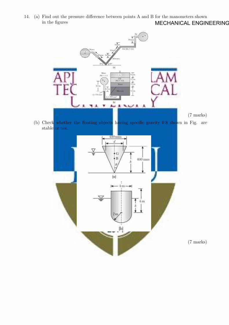
MECHANICAL ENGINEERING14. (a) Find out the pressure difference between points A and B for the manometers shown
in the figures
(7 marks)
(b) Check whether the floating objects having specific gravity 0.8 shown in Fig. arestable or not.
(7 marks)

MECHANICAL ENGINEERINGMODULE-III
15. (a) The maximum velocity for the viscous flow through a 200mm diameter pipe is 3m/s.Determine the average velocity and the radial distance from the pipe axis at whichit occurs. In addition, determine the velocity at 25mm from the pipe wall.(7 marks)
(b) Determine the discharge in each branch of the pipe network shown in Fig. Assumesame friction factor f = 0.03 in each pipe. (7 marks)
16. (a) Prove that for power transmission through pipes transmission power is maximumwhen head loss due to friction is one third of the power available at the inlet.(7 marks)
(b) A 5km long water pipeline is used to transmit 200 kW of hydraulic power. If thepressure at the inlet is 6MPa and the pressure drop across the pipe length is 2MPa.Determine the pipe diameter and its transmission efficiency. Take the friction factorf = 0.04 (7 marks)
MODULE-IV
17. (a) A double jet Pelton wheel has a specific speed of 16 and is required to deliver 1200kW. The turbine is supplied through a pipeline from a reservoir whose level is 380mabove the nozzles. Allowing 8% for friction loss in the pipe, calculate the following:
i. Speed in rpm
ii. Diameter of the jet
iii. Mean diameter of the bucket
Assume Cv = 0.98, speed ratio = 0.46, and overall efficiency = 85% (10 marks)
(b) Define the terms unit power, unit speed, ad unit discharge with reference to a hy-draulic turbine. (4 marks)
18. (a) Show that the force exerted by a fluid jet in its direction of flow on a semicircular vaneis twice that exerted on a flat plate, both plates being fixed in position. (7 marks)
(b) A Keplan turbine runner is to be designed to develop 9000 kW. The net availablehead is 5.5m. Assume a speed ratio 2, flow ratio 0.65, and total efficiency 85%. Thediameter of the boss is 1/3 the diameter of the runner. Find : (7 marks)
i. Diameter of the runner.
ii. Speed of the runner.
iii. Specific speed of the turbine.
MODULE-V
19. (a) Draw the performance curves of a centrifugal pump. Also discuss the effect of bladeoutlet angles (7 marks)

MECHANICAL ENGINEERING(b) A centrifugal pump discharges 0.2 m3/s of water at a head of 25 m when running
at a speed of 1400 rpm.The manometric efficiency is 80%. If the impeller has anouter diameter of 30 cm and width of 5 cm, determine the vane angle at the outlet.(7 marks)
20. (a) A single acting reciprocating pump of 200 mm bore and 300 mm stroke runs at30 rpm. The suction head is 4 m and the delivery head is 15 m. Consideringacceleration determine the pressure in the cylinder at the beginning and end ofsuction and delivery strokes. Take the value of atmospheric pressure as 10.3 m ofwater head. The length of suction pipe is 8 m and that of delivery pipe is 20 m. Thepipe diameters are 120 mm each (7 marks)
(b) The construction details of a centrifugal pump is as follows; Impeller diameter= 50cm Impeller width=2.5 cm Speed= 1200 rpm Suction head= 6 m Delivery head=40 m Outlet blade angle= 30◦. Manometric efficiency : 80% Overall effrciency :75%.Determine the power required to drive the pump. Also calculate the pressures at thesuction and delivery side of the pump. assume the frictional drop in suction is 2 mand in the delivery 8m and inlet swirl as zero (7 marks)

MECHANICAL ENGINEERING
MET 285
MATERIAL SCIENCE AND TECHNOLOGY
(MINOR)
CATEGORY L T P Credits Year of Introduction
VAC 4 0 0 4 2019
Preamble: Understanding the correlation between the chemical bonds and crystal structure of metallic materials. Recognize the importance of crystal imperfections including dislocations in plastic deformation. Understanding the mechanisms of materials failure through fatigue and creep. Understanding the fundamental characteristics of conductors and resistors. Understanding the fundamental characteristics of semi and super conductors.
Prerequisite: PHT 110 Engineering Physics and CYT 100 Engineering Chemistry
Course Outcomes - At the end of the course students will be able to
CO 1 Understand the basic chemical bonds, crystal structures and their relationship with the properties.
CO 2 How to quantify failure of materials
CO 3 Given a hypothetical or real problem with an electronic materials device or process, explain the cause of the problem and propose solutions.
CO 4 Understand how materials interact at the nanoscale
CO 5 Define and differentiate engineering materials on the basis of structure and properties for engineering applications
Mapping of course outcomes with program outcomes (Minimum requirements)
PO 1
PO 2
PO 3
PO 4
PO 5
PO 6
PO 7
PO 8
PO 9
PO 10
PO 11
PO 12
CO 1 3 - - - - - - - - - - CO 2 - 3 - - - - - - - - -
CO 3 - - 2 - - - - - - - -
CO 4 - - - 3 - - - - - - -
CO 5 - - - - - - - - - - 2
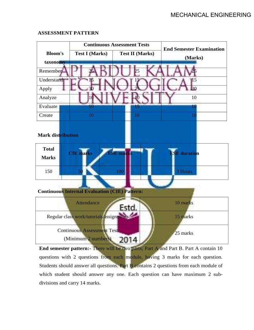
MECHANICAL ENGINEERING
ASSESSMENT PATTERN
Bloom's
taxonomy
Continuous Assessment Tests End Semester Examination
(Marks) Test I (Marks) Test II (Marks)
Remember 25 25 25
Understand 15 15 15
Apply 30 25 30
Analyze 10 10 10
Evaluate 10 15 10
Create 10 10 10
Mark distribution
Total
Marks CIE marks ESE marks ESE duration
150 50 100 3 Hours
Continuous Internal Evaluation (CIE) Pattern:
Attendance 10 marks
Regular class work/tutorials/assignments 15 marks
Continuous Assessment Test (Minimum 2 numbers)
25 marks
End semester pattern:- There will be two parts; Part A and Part B. Part A contain 10
questions with 2 questions from each module, having 3 marks for each question.
Students should answer all questions. Part B contains 2 questions from each module of
which student should answer any one. Each question can have maximum 2 sub-
divisions and carry 14 marks.

MECHANICAL ENGINEERING
Course Level Assessment Questions Course Outcome 1 (CO1): Understand the basic chemical bonds, crystal structures and their relationship with the properties. 1. Why ionic and covalent bonded materials are poor conductors? Draw electronic configurations.2. Correlate the strength of an element with atomic number.3. What kind of bonding you expect in the following materials: NaCl, Cadmium Telluride and
Bronze.4. Explain how grain size influences the strength of a metal
Course Outcome 2 (CO2): How to quantify failure of materials. 1. Explain the factors affecting the fatigue strength?2. Explain the effects of crystalline and non-crystalline structure on strength of a metal.3. What are the roles of surface defects on crack propagation?4. A small hole is drilled through a steel plate ahead of a crack, whether it can stop the crack’s
progress until repairs can be made or not? Explain in detail and derive the equation5. Explain the effect of impact loading on ductile materials
Course Outcome 3 (CO3): Given a hypothetical or real problem with an electronic materials device or process, explain the cause of the problem and propose solutions.
1. Explain why nichrome and not copper is used as a heating element.2. Why does the conductivity of a semiconductor change with impurity content? Compare this
with the behavior of metallic conductors.3. Explain why lead and zinc with an even number of electrons in the outer shell and a full
valence band are conductors.4. When ice melts into water, the dielectric constant increases, in contrast to the decrease
observed during the melting of HCl. Explain why this is so.Course Outcome 4 (CO4): Understand how materials interact at the nanoscale 1. What is the concept of nano? Correlate the significance of dislocation density to single crystal
silicon ICs used in electronic industry.2. Explain touch screens3. Explain flexible electronic circuits
Course Outcome 5 (CO5): Define and differentiate engineering materials on the basis of structure and properties for engineering applications
1. Explain the slip systems of BCC, FCC and HCP. Why B C C and HCP exhibit brittle nature andFCC ductile nature?
2. Explain in detail the different strengthening mechanisms of metallic crystals3. Explain why Aluminum used in long distance transmission lines cannot be strengthened by
solid solution.4. Explain the attributes of surface breakdown of an insulator

MECHANICAL ENGINEERING
SYLLABUS MODULE - 1 Earlier and present development of atomic structure- primary bonds: - secondary bonds - earlier and
present development of atomic structure- primary bonds: - secondary bonds - classification of
engineering materials- levels of structure- crystallography- structure–property relationships in
materials - classification of engineering materials.
MODULE - II Miller indices: - modes of plastic deformation - structure determination by X-ray diffraction -
Classification of crystal imperfections- Diffusion in solids, fick’s laws - dislocation density -
mechanism of crystallization: homogeneous and heterogeneous nuclei formation - Hall - Petch theory.
MODULE - III Phase diagrams: - Limitations of pure metals and need of alloying - classification of alloys, solid
solutions, Hume Rothery`s rule - strengthening mechanisms- Fatigue: - Stress cycles – fatigue tests, S-
N curve - Ductile to brittle transition temperature (DBTT) in steels - Creep: Creep curves – creep tests
- Super plasticity - introduction to super alloys.
MODULE - IV Composites:- fiber and composite phase - polymer matrix composites - metal matrix composites -
ceramic matrix composites - dielectric materials- conductors - resistor materials.
MODULE - V Superconducting phenomenon - semi conductors- fabrication of integrated circuits - semiconductor
devices.
Text Books 1. Callister William. D., Material Science and Engineering, John Wiley, 2014
2. Raghavan V, Material Science and Engineering, Prentice Hall, 2004
Reference 1. Avner H Sidney, Introduction to Physical Metallurgy, Tata McGraw Hill, 2009
2. Anderson J.C. et.al., Material Science for Engineers, Chapman and Hall, 1990
3. Dieter George E, Mechanical Metallurgy, Tata McGraw Hill, 1976

MECHANICAL ENGINEERING
MODEL QUESTION PAPER
MATERIAL SCIENCE & TECHNOLOGY - MET 285
Max. Marks : 100 Duration : 3 Hours Part – A
Answer all questions. Answer all questions, each question carries 3 marks
1. NASA's Parker Solar Probe will be the first-ever mission to "touch" the Sun. The spacecraft, aboutthe size of a small car, will travel directly into the Sun's atmosphere about 4 million miles from theearth surface. Postulate the coolant used in the parker solar probe with chemical bonds.
2. Distinguish between crystal and non crystalline materials.
3. What is the driving force for diffusion?
4. What are the roles of surface imperfections on crack initiation?
5. What is the grain size preferred for creep applications? Why
6. Explain the attributes of DBTT7. Make a list of at least four different sports implements that are made of or contain composites8. What is the distinction between matrix and dispersed phases in a composite material?9. Specify three elements that you would add to pure silicon to make it an extrinsic semiconductor of (i)
the n-type, and (ii) the p-type.10. Explain why nichrome and not copper is used as a heating element
PART -B Answer one full question from each module.
Module -1 11. Calculate the APF of SC, BCC and FCC (14 marks).
OR 12. Distinguish between characteristics of ionic, covalent ad metallic bonds (14 marks).
Module -2 13. Explain the effect of: (i) Grain size; (ii) Grain size distribution and (iii) Grain orientation (iv) Grain
shape on strength and creep resistance with neat sketches. Attributes of Hall-Petch equation and grainboundaries (14 marks).
OR 14. Distinguish between homogeneous and heterogeneous nuclei formation (14 marks).
Module -3 15. Postulate with neat sketches, why 100 % pure metals are weaker? What are the primary functions of
alloying? Explain the fundamental rules governing the alloying with neat sketches and how is itaccomplished in substitution and interstitial solid solutions? (14 marks).
OR

MECHANICAL ENGINEERING
16. Explain fatigue test and attributes of S-N curve (14 marks). Module -4
17. For a polymer-matrix fiber-reinforced composite, (a) list three functions of the matrix phase; (b) Compare the desired mechanical characteristics of matrix and fiber phases; and (c) cite two reasons why there must be a strong bond between fiber and matrix at their interface (14 marks).
OR 18. The dielectric constant of polyethylene is independent of temperature, while that of polyvinylchloride
is not. Explain this difference in behavior on the basis of their monomer structures (14 marks). Module -5
19. (a) Derive the kinetic energy of free electrons as a function of their wave number (7 marks). (b) The resistivity of silver at room temperature is 1.6 x 10⁻⁸ ohm m. Calculate the collision Time for electron scattering (7 marks).
OR 20. (a). Explain why lead and zinc with an even number of electrons in the outer shell and a full valence
band are conductors (7 marks). (b). Calculate the fraction of holes present at 300 K in silicon doped with indium. The acceptor level is
0.16 eV above the top of the valence band (7 marks). Course content and lecture schedules.
Module TOPIC No. of
hours
Course outcomes
1.1
Earlier and present development of atomic structure; correlation of atomic radius to strength; electron configurations; - Primary bonds: - characteristics of covalent, ionic and metallic bond - properties from bonding.
2
CO1 1.2 Secondary bonds: - classification- hydrogen bond and anomalous
behavior of ice float on water, application- specific heat, applications. 2
1.3 Classification of engineering materials- levels of structure- crystallography:- crystal, space lattice, unit cell- APF of BCC, FCC, HCP structures.
2
1.4 short and long range order - non crystalline - structure–property relationships in materials. 1
2.1
Miller indices: - crystal plane and direction - attributes of miller indices for slip system, brittleness of BCC, HCP and ductility of FCC - modes of plastic deformation: - slip and twinning - structure determination by X-ray diffraction.
3 CO1 CO2
2.2 Classification of crystal imperfections: - types of point and dislocations.- Diffusion in solids, fick’s laws, mechanisms, applications - dislocation density and attributes of nano structures.
3

MECHANICAL ENGINEERING
2.3 Mechanism of crystallization: Homogeneous and heterogeneous nuclei formation, under cooling, dendritic growth, grain boundary irregularity. 1
CO1 CO2
2.4 Effects of grain size, grain size distribution, grain shape, grain orientation on dislocation/strength and creep resistance - Hall - Petch theory. 2
3.1 Phase diagrams: - Limitations of pure metals and need of alloying - classification of alloys, solid solutions, Hume Rothery`s rule - strengthening mechanisms.
3
CO2 CO5
3.2 Fatigue: - Stress cycles – Primary and secondary stress raisers - Characteristics of fatigue failure, fatigue tests, S-N curve attributes. 2
3.3 Factors affecting fatigue strength: stress concentration, size effect, surface roughness, change in surface properties, surface residual stress - Ways to improve fatigue life.
2
3.4
Ductile to brittle transition temperature (DBTT) in steels -Creep: Creep curves – creep tests - Super plasticity - introduction to nickel based super alloys, characteristics and applications.
2 CO1
CO2 4.1 Composites:- fiber and composite phase - polymer matrix composites -
metal matrix composites - ceramic matrix composites 2
4.2 Dielectric materials:- polarization, temperature and frequency effects, electric breakdown, ferroelectric materials. 3 CO1
CO2
4.3 Conductors: - the resistivity range, free electron theory. 2
4.4 Conduction by free electrons, conductor and resistor materials. 2
5.1 Superconducting phenomenon, Type I and Type II superconductors, potential applications. 3
CO3 5.2 Semi conductors:- energy gap in solids, intrinsic and extrinsic
semiconductors, semiconductor materials. 2
5.3 Fabrication of integrated circuits: - production of metallurgical grade silicon, semiconductor grade silicon, single crystal growth, wafer manufacture, oxidation, photolithography, doping.
3 CO4
5.4 Ion implantation, epitaxial growth, metallization. 1
5.5 Some semiconductor devices: - junction diodes, lasers and transistor, photon detectors. 2 CO4

MECHANICAL ENGINEERING
SEMESTER -4

MECHANICAL ENGINEERING
CODE MET202
COURSE NAME ENGINEERING THERMODYNAMICS
CATEGORY L T P CREDIT PCC 3 1 - 4
Preamble :
Thermodynamics is the study of energy . Without energy life cannot exist. Activities from breathing to the launching of rockets involves energy transactions and are subject to thermodynamic analysis. Engineering devices like engines, turbines, refrigeration and air conditioning systems, propulsion systems etc., work on energy transformations and must be analysed using principles of thermodynamics. So, a thorough knowledge of thermodynamic concepts is essential for a mechanical engineer. This course offers an introduction to the basic concepts and laws of thermodynamics.
Prerequisite : NIL
Course Outcomes :
After completion of the course the student will be able to
CO1 Understand basic concepts and laws of thermodynamics CO2 Conduct first law analysis of open and closed systems CO3 Determine entropy and availability changes associated with different processes CO4 Understand the application and limitations of different equations of state CO5 Determine change in properties of pure substances during phase change processes CO6 Evaluate properties of ideal gas mixtures
Mapping of course outcomes with program outcomes
PO1 PO2 PO3 PO4 PO5 PO6 PO7 PO8 PO9 PO10 PO11 PO12 CO1 2 2 2 CO2 2 2 1 1 1 CO3 3 3 2 2 1 CO4 2 2 2 2 1 CO5 3 3 2 1 1 CO6 3 3 2 2 1
Assessment Pattern
Blooms Category CA ESA Assignment Test - 1 Test - 2 Remember 25 20 20 10 Understand 25 40 40 20 Apply 25 40 40 70 Analyse 25 Evaluate Create

MECHANICAL ENGINEERINGContinuous Internal Evaluation Pattern:
Attendance : 10 marks
Continuous Assessment Test (2 numbers) : 25 marks
Assignment/Quiz/Course project : 15 marks
Mark distribution & Duration of Examination :
Total Marks CA ESE ESE Duration 150 50 100 3 Hours
End semester pattern:
There will be two parts; Part A and Part B. Part A contain 10 questions with 2 questions from each module, having 3 marks for each question. Students should answer all questions. Part B contains 2 questions from each module of which student should answer any one. Each question can have maximum 2 sub-divisions and carry 14 marks.
COURSE LEVEL ASSESSMENT QUESTIONS Course Outcome 1
1. Discuss the limitations of first law of thermodynamics.
2. Second law of thermodynamics is often called a directional law . Why?
3. Explain Joule-Kelvin effect. What is the significance of the inversion curve ?
Course Outcome 2
1. A mass of 2.4 kg of air at 150 kPa and 12°C is contained in a gas – tight, frictionless piston – cylinder device. The air is now compressed to a final pressure of 600 kPa . During this process, heat is transferred from the air such that the temperature inside the cylinder remains constant. Calculate the work input during this process.
2. Carbon dioxide enters an adiabatic nozzle steadily at 1 MPa and 500°C with a mass flow rate of 600 kg/hr and leaves at 100 kPa and 450 m/s. The inlet area of the nozzle is 40 cm2. Determine (a) the inlet velocity and (b) the exit temperature
3. A vertical piston – cylinder device initially contains 0.25 m3 of air at 600 kPa and 300°C. A valve connected to the cylinder is now opened and air is allowed to escape until three-quarters of the mass leave the cylinder at which point the volume is 0.05 m3. Determine the final temperature in the cylinder and the boundary work during this process.
Course Outcome 3
1.An adiabatic vessel contains 2 kg of water at 25˚C. B paddle – wheel work transfer, the temperature of water is increased to 30˚C. If the specific heat of water is assumed to be constant at 4.186 kJ/kg.K, find the entropy change of the universe.

MECHANICAL ENGINEERING2. Two kilograms of water at 80°C is mixed adiabatically with 3 kg of water at 30°C in a constant pressure process at 1 atm. Find the increase in entropy of the total mass of water due to the mixing process.
3. Argon enters an insulated turbine operating under steady state at 1000˚C and 2 MPa and exhausts at 350 kPa. The mass flow rate is 0.5 kg/s and the turbine develops power at the rate of 120 kW. Determine (a)the temperature of the argon at the turbine exit, (b) the irreversibility of the turbine and (c) the second law efficiency. Neglect KE and PE effects. Take To = 20˚C and Po = 1 bar
Course Outcome 4
1. What are the limitations of ideal gas equation and how does Van der Waals equation overcome these limitations ?
2. Discuss law of corresponding states and its role in the construction of compressibility chart.
3. A rigid tank contains 2 kmol of N2 and 6 kmol of CH4 gases at 200 K and 12 MPa. Estimate the volume of the tank, using (a) ideal gas equation of state (b) the compressibility chart and Amagat’s law
Course Outcome 5
1.Steam is throttled from 3 MPa and 600˚C to 2.5 MPa. Determine the temperature of the steam at the end of the throttling process.
2. Determine the change in specific volume, specific enthalpy and quality of steam as saturated steam at 15 bar expands isentropically to 1 bar. Use steam tables
3. Estimate the enthalpy of vapourization of steam at 500 kPa, using the Clapeyron equation and compare it with the tabulated value
Course Outcome 6
1. A gaseous mixture contains , by volume, 21%nitrogen, 50% hydrogen and 29 % carbon dioxide. Calculate the molecular weight of the mixture, the characteristic gas constant of the mixture and the value of the reversible adiabatic expansion index - γ. At 10˚C, the Cp values of nitrogen, hydrogen and carbon dioxide are 1.039, 14.235 and 0.828 kJ/kg.K respectively.
2. A mixture of 2 kmol of CO2 and 3 kmol of air is contained in a tank at 199 kPa and 20˚C. Treating air to be a mixture of 79% N2 and 21% O2 by volume , calculate (a) the individual mass of CO2 , N2 and O2, (b) the percentage content of carbon by mass in the mixture and (c) the molar mass , characteristic gas constant and the specific volume of the mixture
3. A gas mixture in an engine cylinder has 12% CO2, 11.5 % O2 and 76.5% N2 by volume. The mixture at 1000˚C expands reversibly, according to the law PV1.25 = constant, to 7 times its initial volume. Determine the work transfer and heat transfer per unit mass of the mixture.

MECHANICAL ENGINEERING
SYLLABUS
Module 1: Role of Thermodynamics and it’s applications in Engineering and Science –Basic Concepts Macroscopic and Microscopic viewpoints, Concept of Continuum, Thermodynamic System and Control Volume, Surrounding, Boundaries, Types of Systems, Universe, Thermodynamic properties, Process, Cycle, Thermodynamic Equilibrium, Quasi – static Process, State, Point and Path function. Zeroth Law of Thermodynamics, Measurement of Temperature, reference Points, Temperature Scales.
Module 2: Energy - Work - Pdv work and other types of work transfer, free expansion work, heat and heat capacity. Joule’s Experiment- First law of Thermodynamics - First law applied to Non flow Process- Enthalpy- specific heats- PMM1, First law applied to Flow Process, Mass and Energy balance in simple steady flow process. Applications of SFEE, Transient flow –Filling and Emptying Process, Limitations of the First Law.
Module 3: Second Law of Thermodynamics, Thermal Reservoir, Heat Engine, Heat pump – Kelvin-Planck and Clausius Statements, Equivalence of two statements, Reversibility, Irreversible Process, Causes of Irreversibility, PMM2, Carnot’s theorem and its corollaries, Absolute Thermodynamic Temperature scale. Clausius Inequality, Entropy- Entropy changes in various thermodynamic processes, principle of increase of entropy and its applications, Entropy generation, Entropy and Disorder, Reversible adiabatic process- isentropic process, Third law of thermodynamics, Available Energy, Availability and Irreversibility- Second law efficiency.
Module 4: Pure Substances, Phase Transformations, Triple point, properties during change of phase, T-v, p-v and p-T diagram of pure substance, p-v-T surface, Saturation pressure and Temperature, T-h and T-s diagrams, h-s diagrams or Mollier Charts, Dryness Fraction, steam tables. Property calculations using steam tables. The ideal Gas Equation, Characteristic and Universal Gas constants, Deviations from ideal Gas Model: Equation of state of real substances, Vander Waals Equation of State, Virial Expansion, Compressibility factor, Law of corresponding state, Compressibility charts.
Module 5: Mixtures of ideal Gases – Mole Fraction, Mass fraction, Gravimetric and volumetric Analysis, Dalton’s Law of partial pressure, Amagat’s Laws of additive volumes, Gibbs-Dalton’s law Equivalent Gas constant and Molecular Weight, Properties of gas mixtures: Internal Energy, Enthalpy, specific heats and Entropy, Introduction to real gas mixtures- Kay’s rule. General Thermodynamic Relations – Combined First and Second law equations – Helmholtz and Gibb’s functions - Maxwell’s Relations, Tds Equations. The Clapeyron Equation, equations for internal energy, enthalpy and entropy, specific heats, Throttling process, Joule Thomson Coefficient, inversion curve.
Text Books
1. P. K. Nag, Engineering Thermodynamics, McGraw Hill, 2013
2. E. Rathakrishnan Fundamentals of Engineering Thermodynamics, PHI, 2005
3. Y. A. Cengel and M. A. Boles, Thermodynamics an Engineering Approach, McGraw Hill, 2011

MECHANICAL ENGINEERING
Reference Books:
1. Moran J., Shapiro N. M., Fundamentals of Engineering Thermodynamics, Wiley, 2006
2. R. E. Sonntag and C. Borgnakke, Fundamentals of Thermodynamics, Wiley, 2009
3. Holman J. P. Thermodynamics, McGraw Hill, 2004
4. M. Achuthan, Engineering Thermodynamics, PHI, 2004
COURSE PLAN
Module Topics Hours
Allotted
1
Role of Thermodynamics and it’s applications in Engineering and Science –Basic Concepts Macroscopic and Microscopic viewpoints, Concept of Continuum, Thermodynamic System and Control Volume, Surrounding, Boundaries, Types of Systems, Universe
1L
Thermodynamic properties, Process, Cycle, Thermodynamic Equilibrium, Quasi – static Process, State, Point and Path function.
1L
Zeroth Law of Thermodynamics, Measurement of Temperature, reference Points, Temperature Scales.
2L + 1T
2
Energy - Work - Pdv work and other types of work transfer, free expansion work, heat and heat capacity.
2L + 1T
Joule’s Experiment- First law of Thermodynamics - First law applied to Non flow Process- Enthalpy- specific heats- PMM1
2L + 1T
First law applied to Flow Process, Mass and Energy balance in simple steady flow process. Applications of SFEE
2L + 1T
Transient flow –Filling and Emptying Process, Limitations of the First Law. 1L + 1T
3
Second Law of Thermodynamics, Thermal Reservoir, Heat Engine, Heat pump – Kelvin-Planck and Clausius Statements, Equivalence of two statements
2L
Reversibility, Irreversible Process, Causes of Irreversibility, PMM2, Carnot’s theorem and its corollaries, Absolute Thermodynamic Temperature scale.
2L + 1T
Clausius Inequality, Entropy- Entropy changes in various thermodynamic processes, principle of increase of entropy and its applications, Entropy generation, Entropy and Disorder, Reversible adiabatic process- isentropic process, Third law of thermodynamics
2L + 1T
Available Energy, Availability and Irreversibility- Second law efficiency. 2L + 1T
Pure Substances, Phase Transformations, Triple point, properties during change of phase, T-v, p-v and p-T diagram of pure substance, p-v-T surface,
2L
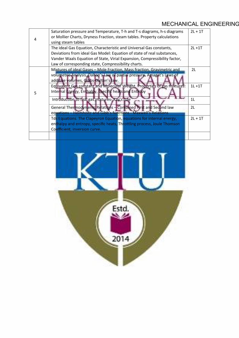
MECHANICAL ENGINEERING
4
Saturation pressure and Temperature, T-h and T-s diagrams, h-s diagrams or Mollier Charts, Dryness Fraction, steam tables. Property calculations using steam tables
2L + 1T
The ideal Gas Equation, Characteristic and Universal Gas constants, Deviations from ideal Gas Model: Equation of state of real substances, Vander Waals Equation of State, Virial Expansion, Compressibility factor, Law of corresponding state, Compressibility charts.
2L +1T
5
Mixtures of ideal Gases – Mole Fraction, Mass fraction, Gravimetric and volumetric Analysis, Dalton’s Law of partial pressure, Amagat’s Laws of additive volumes, Gibbs-Dalton’s law.
2L
Equivalent Gas constant and Molecular Weight, Properties of gas mixtures: Internal Energy, Enthalpy, specific heats and Entropy
1L +1T
Introduction to real gas mixtures- Kay’s rule 1L
General Thermodynamic Relations – Combined First and Second law equations – Helmholtz and Gibb’s functions - Maxwell’s Relations
2L
Tds Equations. The Clapeyron Equation, equations for internal energy, enthalpy and entropy, specific heats, Throttling process, Joule Thomson Coefficient, inversion curve.
2L + 1T

MECHANICAL ENGINEERING
MODEL QUESTION PAPER
APJ ABDUL KALAM TECHNOLOGICAL UNIVERSITY
FOURTH SEMESTER B.TECH DEGREE EXAMINATION
Course Code : MET202
Course Name : ENGINEERING THERMODYNAMICS
( Permitted to use Steam Tables and Mollier Chart )
Max. Marks : 100 Duration : 3 Hours
Part – A
Answer all questions.
1. Define thermodynamics. List a few of its applications
2.Differentiate between intensive and extensive properties.
3. Differentiate between heat and work.
4. Explain system approach and control volume approach as applied in the analysis of a flow process.
5. An inventor claims to have developed an engine that delivers 26 kJ of work using 82 kJ of heatwhile operating between temperatures 120°C and 30°C. Is his claim valid ? Give the reason foryour answer.
6. Show that two reversible adiabatics cannot intersect
7.Define (i)critical point and (ii) triple point, with respect to water
8. Why do real gases deviate from ideal gas behaviour? When do they approach ideal behaviour?
9. Define Helmholtz function and Gibbs function and state their significance
10. Explain Kay’s rule of real gas mixtures
( 3 x 10 = 30 marks )
Part – B
Answer one full question from each module.
Module - 1
11.a] Explain macroscopic and microscopic approach to thermodynamics . ( 7 marks )
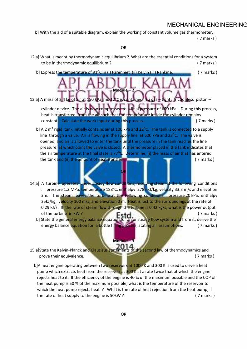
MECHANICAL ENGINEERING b] With the aid of a suitable diagram, explain the working of constant volume gas thermometer. ( 7 marks )
OR
12.a] What is meant by thermodynamic equilibrium ? What are the essential conditions for a system to be in thermodynamic equilibrium ? ( 7 marks )
b] Express the temperature of 91⁰C in (i) Farenhiet (ii) Kelvin (iii) Rankine. ( 7 marks )
Module – 2
13.a] A mass of 2.4 kg of air at 150 kPa and 12°C is contained in a gas – tight, frictionless piston –
cylinder device. The air is now compressed to a final pressure of 600 kPa . During this process, heat is transferred from the air such that the temperature inside the cylinder remains constant. Calculate the work input during this process. ( 7 marks )
b] A 2 m3 rigid tank initially contains air at 100 kPa and 22⁰C. The tank is connected to a supply line through a valve. Air is flowing in the supply line at 600 kPa and 22⁰C. The valve is opened, and air is allowed to enter the tank until the pressure in the tank reaches the line pressure, at which point the valve is closed. A thermometer placed in the tank indicates that the air temperature at the final state is 77⁰C. Determine, (i) the mass of air that has entered the tank and (ii) the amount of heat transfer. ( 7 marks )
OR 14.a] A turbine operates under steady flow conditions, receiving steam at the following conditions : pressure 1.2 MPa, temperature 188°C, enthalpy 2785 kJ/kg, velocity 33.3 m/s and elevation 3m. The steam leaves the turbine at the following conditions : pressure 20 kPa, enthalpy 25kJ/kg, velocity 100 m/s, and elevation 0 m. Heat is lost to the surroundings at the rate of 0.29 kJ/s. If the rate of steam flow through the turbine is 0.42 kg/s, what is the power output of the turbine in kW ? ( 7 marks ) b] State the general energy balance equation for an unsteady flow system and from it, derive the energy balance equation for a bottle filling process, stating all assumptions. ( 7 marks )
Module – 3
15.a]State the Kelvin-Planck and Clausisus statements of the second law of thermodynamics and prove their equivalence. ( 7 marks )
b]A heat engine operating between two reservoirs at 1000 K and 300 K is used to drive a heat pump which extracts heat from the reservoir at 300 K at a rate twice that at which the engine rejects heat to it. If the efficiency of the engine is 40 % of the maximum possible and the COP of the heat pump is 50 % of the maximum possible, what is the temperature of the reservoir to which the heat pump rejects heat ? What is the rate of heat rejection from the heat pump, if the rate of heat supply to the engine is 50kW ? ( 7 marks )
OR

MECHANICAL ENGINEERING16.a] A house is to be maintained at 21°C during winter and at 26°C during summer. Heat leakage through the walls, windows and roof is about 3000 kJ/hr per degree temperature difference between the interior of the house and the environment. A reversible heat pump is proposed for realising the desired heating and cooling. What is the minimum power required to run the heat pump in the reverse, if the outside temperature during summer is 36°C? Also find the lowest environment temperature during winter for which the inside of the house can be maintained at 21°C consuming the same power. ( 7 marks )
b] Air enters a compressor in steady flow at 140 kPa, 17°C and 70 m/s and leaves at 350 kPa, 127°C and 110 m/s. The environment is at 100 kPa and 7°C. Calculate per kg of air (a) the actual work required (b) the minimum work required and (c) the irreversibility of the process.
( 7 marks )
Module – 4
17.a]Show the constant pressure transformation of unit mass of ice at atmospheric pressure and -20⁰C to superheated steam at 220⁰C on P-v , T-v and P-T coordinate systems and explain their salient features . ( 7 marks )
b] A rigid vessel of volume 0.3 m3 contains 10 kg of oxygen at 300 K. Using (i) the perfect gas equation and (ii) the Van der Waal’s equation of state, determine the pressure of oxygen in the vessel. Take the Van der Waal’s constants for oxygen as a =0.1382 m6 Pa/ mol2 and b=0.03186 m3/ kmol . ( 7 marks )
OR
18.a]Steam at 25 bar and 300⁰C expands isentropically to 5 bar. Calculate the change in enthalpy, volume and temperature of unit mass of steam during this process using steam tables and Mollier chart and compare the values ( 7 marks )
b]Explain law of corresponding states and its significance to the generalized compressibility chart. ( 7 marks )
Module – 5
19.a] Derive the expressions for the equivalent molecular weight and characteristic gas constant for a mixture of ideal gases. ( 6 marks )
b] 0.5 kg of Helium and 0.5 kg of Nitrogen are mixed at 20⁰C and at a total pressure of 100 kPa. Find (i) volume of the mixture (ii) partial volumes of the components (iii) partial pressures of the

MECHANICAL ENGINEERING components ( iv) the specific heats of the mixture and (v) the gas constant of the mixture. Take ratio of specific heats for Helium and Nitrogen to be 1.667 and 1.4 respectively. ( 8 marks )
OR
20.a] 2 kg of carbon dioxide at 38°C and 1.4 bar is mixed with 5 kg of nitrogen at 150°C and 1.03 bar to form a mixture at a final pressure of 70 kPa. The process occurs adiabatically in a steady flow apparatus. Calculate the final temperature of the mixture and the change in entropy during the mixing process. Take specific heat at constant pressure for CO2 and N2 as 0.85 kJ/kg.K and 1.04 kJ/kg respectively. ( 7 marks )
b]Derive the Maxwell relations. Explain their significance ? ( 7 marks )

MECHANICAL ENGINEERING
MET 204 MANUFACTURING PROCESS
CATEGORY L T P Credits Year of Introduction
PCC 3 1 0 4 2019
Preamble: 1. To gain theoretical and practical knowledge in material casting processes and develops an
understanding of the dependent and independent variables which control materials casting in a production processes.
2. Provide a detailed discussion on the welding process and the physics of welding. Introduce students to different welding processes weld testing and advanced processes to be able to appreciate the practical applications of welding.
3. The course will also provide methods of analysis allowing a mathematical/physical description of forming processes.
4. Correlate the material type with the possible fabrication processes 5. Generate solutions to problems that may arise in manufacturing engineering
Prerequisite: MET 205 Metallurgy and material science
Course Outcomes - At the end of the course students will be able to
CO 1 Illustrate the basic principles of foundry practices and special casting processes, their advantages, limitations and applications.
CO 2 Categorize welding processes according to welding principle and material.
CO 3 Understand requirements to achieve sound welded joint while welding different similar and dissimilar engineering materials.
CO 4 Student will estimate the working loads for pressing, forging, wire drawing etc. processes
CO 5 Recommend appropriate part manufacturing processes when provided a set of functional requirements and product development constraints.
Mapping of course outcomes with program outcomes (Minimum requirements)
PO 1
PO 2
PO 3
PO 4
PO 5
PO 6
PO 7
PO 8
PO 9
PO 10
PO 11
PO 12
CO 1 3 - - - - - - - - - - CO 2 - - - - - - - - - - - 2
CO 3 - - 3 - - - - - - - - -
CO 4 - - - 3 - - - - - - - -
CO 5 - 4 - - - - - - - - - -

MECHANICAL ENGINEERING
A ssessment Pattern
Bloom's
taxonomy
Continuous Assessment Tests End Semester Examination (Marks) Test I (Marks)
Test II
(Marks)
Remember 25 25 25 Understand 15 15 15 Apply 30 25 30 Analyse 10 10 10 Evaluate 10 15 10 Create 10 10 10
Mark distribution
Total Marks CIE marks ESE marks ESE duration
150 50 100 3 Hours
Continuous Internal Evaluation (CIE) Pattern:
Attendance 10 marks
Regular class work/tutorials/assignments 15 marks
Continuous Assessment Test (Minimum 2 numbers) 25 marks
End semester pattern:- There will be two parts; Part A and Part B. Part A contain 10 questions with 2 questions from each module, having 3 marks for each question. Students should answer all questions. Part B contains 2 questions from each module of which student should answer any one. Each question can have maximum 2 sub-divisions and carry 14 marks.
COURSE LEVEL ASSESSMENT QUESTIONS Part -A
Course Outcome 1 (CO1): - Illustrate the basic principles of foundry practices and special casting processes, their Advantages, Limitations and Applications 1. Why draft allowances are important for patterns. 2. What are the importances of permeability of molding sand? 3. How runner extension is helpful for good casting quality. 4. Internal corners are more prone to solidification shrinkages than external corners.
Explain? 5. Which of the casting processes would be suitable for making small toys in large
numbers? Why?

MECHANICAL ENGINEERING
Course Outcome 2 (CO2): Categorize welding processes according to welding principle and material 1. Why is the quality of welds produced by submerged arc welding very good? 2. What does the strength of a weld nugget in resistance spot welding depends on? 3. What is the strength of a welded joint is inferior or superior to the parent metal? Why? 4. Why some joints may have to be preheated prior to welding.
Part -B Course Outcome 3 (CO3): Understand requirements to achieve sound welded joint while welding different similar and dissimilar engineering materials.
1. Assume that you are asked to inspect a weld for a critical application. Describe the procedure you would follow. If you find a flaw during your inspection, how would you go about determining whether or not this flaw is important for the particular application?
2. In the building of large ships, there is a need to weld large sections of steel together to form a hull, for this application, which welding process would you select? Why?
Course Outcome 4 (CO4): Student will estimate the working loads for pressing, forging, wire drawing etc. processes
1. How can you tell whether a certain part is forged or cast? Describe the features that you would investigate to arrive at a conclusion.
2. Two solid cylindrical specimens A and B, made of a perfectly plastic material, are being forged with friction and isothermally at room temperature to a reduction in height of 50%. specimen A has a height of 2 inch and cross sectional area of 1 square inch, and specimen B has a height of is 1 inch and a cross sectional area of 2 square inch will the work done be the same for the two specimens? Explain.
Course Outcome 5 (CO5): Recommend appropriate part manufacturing processes when provided a set of functional requirements and product development constraints. 1. Many missile components are made by spinning. What other methods would you use to make
missile components if spinning process were not available? Describe the relative advantages and limitations of each method.
2. Suggest a suitable casting process for making an engine piston with Aluminum alloy. What type of mould can be used?
3. Suggest and explain a suitable welding method for welding railway tracks for trains. 4. Suggest a suitable manufacturing process for screw jack, postulate the fundamentals.
SYLLABUS Module I Casting:-Characteristics of sand - patterns- cores- -chaplets- simple problems- solidification of metals and Chvorinov's rule - Elements of gating system- risering -chills –simple problems- Special casting process- Defects in castings- Super alloy Production Methods. Module II Welding:-welding metallurgy-heat affected zone- grain size and hardness- stress reliving- joint quality -heat treatment of welded joints - weldability - destructive and non destructive tests of welded joints-

MECHANICAL ENGINEERING
Thermit welding, friction welding - Resistance welding: HAZ, process and correlation of process parameters with welded joints - applications of each welding process- Arc welding:-HAZ, process and correlation of process parameters with welded joints- simple problems - applications of each welding process - Oxyacetylene welding:-chemistry, types of flame and its applications - brazing- soldering - adhesive bonding. Module III Rolling:- principles - types of rolls and rolling mills - mechanics of flat rolling-Defects-vibration and chatter - flat rolling -miscellaneous rolling process- simple problems - Bulk deformation of metals :- State of stress; yield criteria of Tresca, von Mises, comparisons; Flow rules; power and energy deformations; Heat generation and heat transfer in metal forming process. Module IV Forging: methods analysis, applications, die forging, defects in forging - simple problems - Metal extrusion:- metal flow, mechanics of extrusion, miscellaneous process, defects, simple problems, applications - Wire, Rod, and tube drawing:- mechanics of rod and wire drawing, simple problems, drawing defects - swaging, applications – deep drawing. Module V Locating and clamping methods- locating methods- locating from plane, circular, irregular surface. Locating methods and devices- simple problems - Basic principles of clamping -Sheet metal operations- Press tool operations-Tension, Compression, tension and compression operations - applications - Fundamentals of die cutting operations - simple problems - types of die construction. Text Books 1. Donalson cyril, LeCain, Goold, Ghose:- Tool design, McGraw Hill. 2. Serope Kalpakjian, Steven R. Schmid - Manufacturing Engineering and Technology, Pearson.
Reference 1. Joseph R. Davis, S. L. Semiatin, American Society for Metals - ASM Metals Handbook, Vol. 14
Forming and Forging ASM International (1989). 2. Peter Beeley, Foundry Technology, Butterworth-Heinemann 3. Rao P.N., Manufacturing Technology, Volume -1, Tata McGraw Hill. 4. Taylan Altan, Gracious Ngaile, Gangshu Shen - Cold and Hot Forging Fundamentals and
Applications - ASM International (2004). 5. Matthew J. Donachie, Stephen J. Donachie, Super alloys A Technical Guide, Second Edition, 2002
ASM International.
MODEL QUESTION PAPER MANUFACTURING PROCESS - MET 204
Max. Marks : 100 Duration : 3 Hours Part – A
Answer all questions, each question carries 3 marks 1. Why does porosity have detrimental effects on the mechanical properties of castings? Which
physical properties like thermal and electrical conductivity also are affected by porosity? explain

MECHANICAL ENGINEERING
2. Large parts cannot be manufactured by the centrifugal casting, comment on the statement. 3. What does the strength of a weld nugget in resistance spot welding depends on? 4. Explain how the atmosphere around the work piece affect the weld obtained in electron beam
welding. 5. What is the importance of roll velocity and strip velocity? 6. Explain a suitable rolling process for making threaded fasteners. 7. Explain why forged parts withstand high loads compared to cast parts. 8. Explain why the die pressure in drawing process decreases towards the exit of the die. 9. What is the basic rule for applying clamping forces? 10. What is generally used as the basic reference plane for locating?
PART -B
Answer one full question from each module.
MODULE – 1
11. What is gating ratio? What considerations affect its selection? What are the typical gating ratios for the following applications? (a) Grey iron bed castings made in cast steel, (b) Valve body castings made in cast steel, (c) Aluminum pistons for automobiles, (d) Large gun metal bushes for bearings (14 marks).
OR 12. Explain different types of casting defeats in detail with effects of each defect on quality of the
casting (14 marks). MODULE – 2
13. a. Two plates were welded together and then the strength of the joint was tested. It is found that the weld was stronger than either of the plates. Do you think that the statement is incorrect? Postulate, giving valid reasons with neat sketches (7 marks).
b. what are the methods available for controlling the distortions in welded assembly structure? Describe their relative effects and application(7 marks).
OR 14. a. Two 1-mm thick, flat Copper sheets are being spot welded using a current of 5000A and a
current flow time of t=0.18 seconds the electrodes are 5mm in diameter. Estimate the heat generated in the weld zone (7 marks).
b. Explain why some joints may have to be preheated prior to welding? If the parts to be welded are preheated, is the likelihood that porosity will form increased or decreased? Explain(7 marks).
MODULE – 3 15. a. An annealed Copper strip 228mm wide and 25mm thick is rolled to a thickness 20mm in
one pass. The roll radius is 300mm and the rolls rotate at 100rpm. Calculate the roll force and the power required in this operation (7 marks).
b. A 100mm square billet is to be rolled into a rod of 12.5mm diameter. Draw the sequence of operations (7 marks).
OR 16. Explain the yield criteria of Tresca, von Mises and compare each other (14 marks).
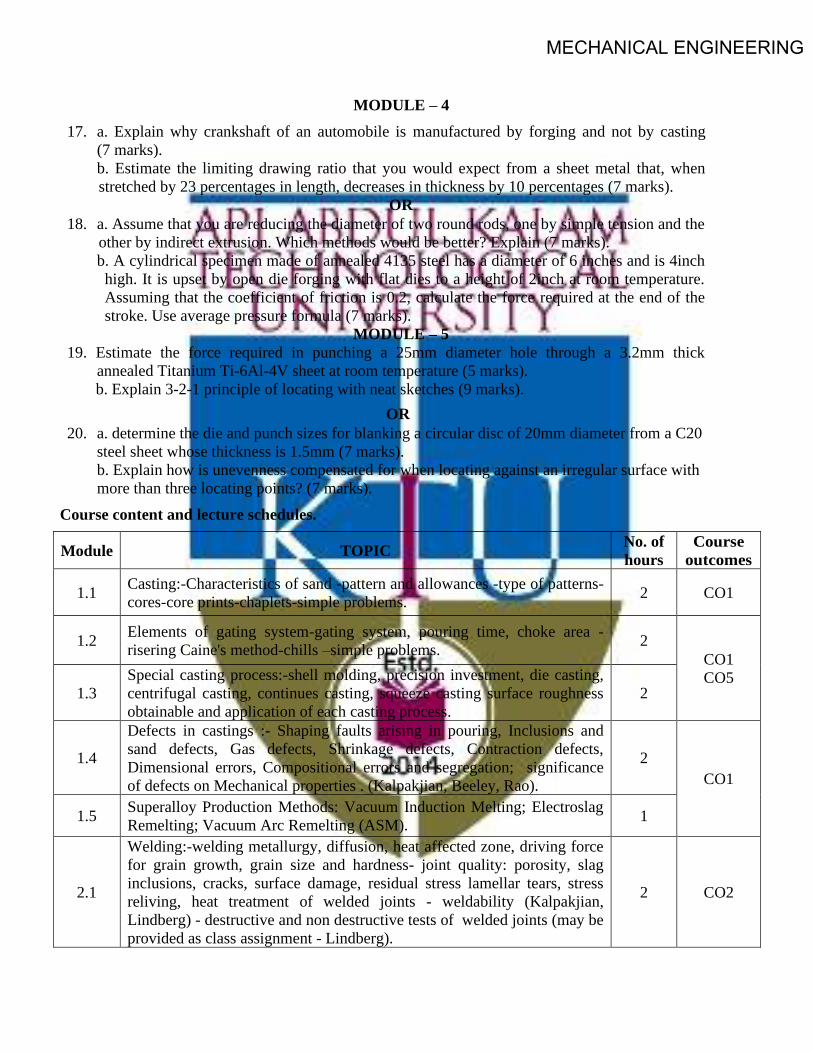
MECHANICAL ENGINEERING
MODULE – 4 17. a. Explain why crankshaft of an automobile is manufactured by forging and not by casting
(7 marks). b. Estimate the limiting drawing ratio that you would expect from a sheet metal that, when stretched by 23 percentages in length, decreases in thickness by 10 percentages (7 marks).
OR 18. a. Assume that you are reducing the diameter of two round rods, one by simple tension and the
other by indirect extrusion. Which methods would be better? Explain (7 marks). b. A cylindrical specimen made of annealed 4135 steel has a diameter of 6 inches and is 4inch high. It is upset by open die forging with flat dies to a height of 2inch at room temperature. Assuming that the coefficient of friction is 0.2, calculate the force required at the end of the stroke. Use average pressure formula (7 marks).
MODULE – 5 19. Estimate the force required in punching a 25mm diameter hole through a 3.2mm thick
annealed Titanium Ti-6Al-4V sheet at room temperature (5 marks). b. Explain 3-2-1 principle of locating with neat sketches (9 marks).
OR 20. a. determine the die and punch sizes for blanking a circular disc of 20mm diameter from a C20
steel sheet whose thickness is 1.5mm (7 marks). b. Explain how is unevenness compensated for when locating against an irregular surface with more than three locating points? (7 marks).
Course content and lecture schedules.
Module TOPIC No. of hours
Course outcomes
1.1 Casting:-Characteristics of sand -pattern and allowances -type of patterns- cores-core prints-chaplets-simple problems. 2 CO1
1.2 Elements of gating system-gating system, pouring time, choke area - risering Caine's method-chills –simple problems. 2
CO1 CO5
1.3 Special casting process:-shell molding, precision investment, die casting, centrifugal casting, continues casting, squeeze casting surface roughness obtainable and application of each casting process.
2
1.4
Defects in castings :- Shaping faults arising in pouring, Inclusions and sand defects, Gas defects, Shrinkage defects, Contraction defects, Dimensional errors, Compositional errors and segregation; significance of defects on Mechanical properties . (Kalpakjian, Beeley, Rao).
2 CO1
1.5 Superalloy Production Methods: Vacuum Induction Melting; Electroslag Remelting; Vacuum Arc Remelting (ASM). 1
2.1
Welding:-welding metallurgy, diffusion, heat affected zone, driving force for grain growth, grain size and hardness- joint quality: porosity, slag inclusions, cracks, surface damage, residual stress lamellar tears, stress reliving, heat treatment of welded joints - weldability (Kalpakjian, Lindberg) - destructive and non destructive tests of welded joints (may be provided as class assignment - Lindberg).
2 CO2

MECHANICAL ENGINEERING
2.2 Resistance welding: HAZ, process and correlation of process parameters with welded joints of spot, seam, projection, stud arc, percussion welding- applications of each welding process –simple problems. (Kalpakjian).
3 CO2 CO5
2.3
Arc welding:-HAZ, process and correlation of process parameters with welded joints of shielded metal arc, submerged, gas metal, flux cored, electrogas, electroslag, gas tungsten, plasma arc, electron beam, laser beam –simple problems - Thermit welding, friction welding- applications of each welding process. (Kalpakjian, Lindberg).
3 CO2
2.4 Oxyacetylene welding:-chemistry, types of flame and its applications - brazing- soldering - adhesive bonding. 1
3.1
Rolling:- principles - types of rolls and rolling mills - mechanics of flat rolling, roll pressure distribution, neutral point, front and back tension, torque and power, roll forces in hot rolling, friction, deflection and flattening, spreading -– simple problems.
3 CO4 CO5
3.2 rolling defects-vibration and chatter - flat rolling -miscellaneous rolling process: shape, roll forging, ring, thread and gear, rotary tube piercing, tube rolling - applications – simple problems. (Kalpakjian).
2 CO4
3.3 Plastic deformation of metals - stress-strain relationships- State of stress - yield criteria of Tresca, von Mises, and comparisons - applications. 2
3.4 Flow rules -power and energy deformations - Heat generation and heat transfer in metal forming process -temperature in forging. (ASM- Taylan Altan).
1 CO4
4.1
Forging: material characterization; grain flow and strength - Forging:- classification - open die forging, forces and work of deformation - Forging methods analysis:- slab method only, solid cylindrical, rectangular work piece in plane strain, forging under sticking condition - simple problems -applications.
3
CO4 Deformation zone geometry – die forging: - impression, close, coining, skew rolling etc. –simple problems– defects in forging. (Kalpakjian). 1
4.2 Metal extrusion: - metal flow - mechanics of extrusion:-deformation and friction, actual forces, die angle, forces in hot extrusion - miscellaneous process- defects -–simple problems- applications. (Kalpakjian, Lindberg).
2
4.3
Wire, Rod, and tube drawing: - mechanics of rod and wire dramwing: deformation, friction, die pressure and angle, temperature, reduction per pass, drawing flat strip and tubes- –simple problems- drawing defects-swaging-applications. (Kalpakjian, Lindberg, Rao).
2 CO4
4.4 Deep drawing- deep drawbility, simple problems - different drawing practices 1
5.1
Locating and clamping methods: - basic principle of location; locating methods; degrees of freedom; locating from plane, circular, irregular surface –simple problems.
2 CO4
Locating methods and devices: - pin and button locators, rest pads and plates, nest or cavity location. 1
MECHANICAL ENGINEERING
5.2 Basic principles of clamping:-strap, cam, screw, latch, wedge, hydraulic and pneumatic clamping –simple problems. (Donaldson, Wilson F.W.). 2 CO4
5.3 Sheet metal operations: Press tool operations: shearing action, shearing operations: blanking, piercing, simple problems, trimming, shaving, nibbing, notching – simple problems - applications.
2 CO4 CO5
5.4
Tension operations: stretch forming - Compression operations: - coining, sizing, ironing, hobbing - tension and compression operations: drawing, spinning, bending, forming, embossing – simple problems- applications. (Donaldson, Wilson F.W., Rao P.N).
2 CO4
Fundamentals of die cutting operations - inverted, progressive and compound die - simple problems. (Donaldson) 1

MECHANICAL ENGINEERING
CODE MET206
COURSE NAME FLUID MACHINERY
CATEGORY L T P CREDIT PCC 3 1 - 4
Preamble :
This course provides an understanding of reciprocating and rotary fluid machinery. The course consists of hydraulic pumps, turbines, air compressors and gas turbines
Prerequisite : NIL
Course Outcomes :
After completion of the course the student will be able to
CO1 Explain the characteristics of centrifugal and reciprocating pumps CO2 Calculate forces and work done by a jet on fixed or moving plate and curved plates CO3 Explain the working of turbines and Select a turbine for specific application. CO4 Analyse the working of air compressors and Select the suitable one based on
application. CO5 Analyse gas turbines and Identify the improvements in basic gas turbine cycles. CO6 Explain the characteristics of centrifugal and reciprocating pumps
Mapping of course outcomes with program outcomes
PO1 PO2 PO3 PO4 PO5 PO6 PO7 PO8 PO9 PO10 PO11 PO12
CO1 3 3 2 CO2 3 3 2 CO3 3 3 2 CO4 3 3 2 CO5 3 3 2
Assessment Pattern
Blooms Category CA ESA Assignment Test - 1 Test - 2 Remember 25 20 20 10 Understand 25 40 40 20 Apply 25 40 40 70 Analyse 25 Evaluate Create

MECHANICAL ENGINEERING
Continuous Internal Evaluation Pattern:
Attendance : 10 marks
Continuous Assessment Test (2 numbers) : 25 marks
Assignment/Quiz/Course project : 15 marks
Mark distribution & Duration of Examination :
Total Marks CA ESE ESE Duration 150 50 100 3 Hours
End semester pattern:
There will be two parts; Part A and Part B. Part A contain 10 questions with 2 questions from each module, having 3 marks for each question. Students should answer all questions. Part B contains 2 questions from each module of which student should answer any one. Each question can have maximum 2 sub-divisions and carry 14 marks.

MECHANICAL ENGINEERINGCOURSE LEVEL ASSESSMENT QUESTIONS
Course Outcome 1
1. A centrifugal pump discharges 0.15 m3/s of water against a head of 12.5 m, the speed ofthe impeller being 600 r.p.m. The outer and inner diameters of impeller are 500 mm and250 mm respectively and the vanes are bent back at 35◦ to the tangent at exit. If the areaof flow remains 0.07 m2 from inlet to outlet, calculate :
(a) Manometric efficiency of pump,
(b) Vane angle at inlet, and
(c) Loss of head at inlet to impeller when discharge is reduced by 40% without changingthe speed.
2. (a) What is slip in a reciprocating pump. What is the reason for negative slip in areciprocating pump.
(b) A single acting reciprocating pump having a bore of 150 mm and a stroke of 300mm length, discharges 250 l of water per minute at 50 rpm. Neglecting losses, findtheoretical discharge and slip of the pump.
(c) With a neat sketch explain the working of a gear pump.
3. Explain the following terms as they are applied to a centrifugal pump:
(a) Static suction lift,
(b) static suction head,
(c) static discharge head and
(d) total static head.
Course Outcome 2
1. Prove that the force exerted by a jet of water on a fixed semi-circular plate in the directionof the jet when the jet strikes at the centre of the semi-circular plate is two times the forceexerted by the jet on an fixed vertical plate.
2. Show that the angle of swing of a vertical hinged plate is given by
sin θ =ρaV 2
W
where V = Velocity of the jet striking the plate, a = Area of the jet, and W = Weight ofthe plate.
3. A jet of water moving at 60 m/s is deflected by a vane moving at 25 m/s in a directionat 30◦ to the direction of the jet. The water jet leaves the blade normally to the motionof the vanes. Draw the inlet and outlet velocity triangles and find the vane angles forno shock at entry or exit. Take the relative velocity at outlet to be 0.85 of the relativevelocity at inlet.

MECHANICAL ENGINEERINGCourse Outcome 3
1. Explain the purpose of providing
(a) scroll casing
(b) stay vanes
(c) guide vanes, for a reaction turbine.
2. A Pelton wheel turbine has a mean bucket speed of 12 m/s with a jet of water flowing ata rate of 900 l/s under a head of 40 m. The bucket deflects the jet at an angle of 165◦.Calculate the power given by the water to the runner and the hydraulic efficiency of theturbine. Draw the velocity triangle. Assume the coefficient of velocity to be 0.96.
3. (a) What are the unit quantities used to analyze the performance of hydraulic turbines.Explain its importance.
(b) What is specific speed of a turbine.
Course Outcome 4
1. With a neat sketch explain the working of centrifugal compressors.
2. An ideal single stage single acting reciprocating compressor logs a displacement volumeof 14 litres and a clearance volume of 5%. It intakes air at 1 bar and delivers the same at7 bar. The compression is polytropic with an index of 1.3 and re-expansion is isentropicwith an index of 1.4. Determine the indicated work of a cycle.
3. What is surging in axial flow compressor? What are its effects? Describe briefly.
Course Outcome 5
1. A gas turbine unit operates at a mass flow of 30 kg/s. Air enters the compressor ata pressure of 1 bar and temperature 15 ◦C and is discharged from the compressor at apressure of 10.5 bar. Combustion occurs at constant pressure and results in a temperaturerise of 420 K. If the flow leaves the turbine at a pressure of 1.2 bar, determine the netpower output from the unit and also the thermal efficiency. Take Cp = 1.005kJ/kgK andγ = 1.4.
2. Derive the expression for maximum specific work output of a gas turbine consideringmachine efficiencies.
3. Write a short note on different type of compression chambers used in a gas turbine engine.

MECHANICAL ENGINEERINGSYLLABUS
Module 1: Impact of jets: Introduction to hydrodynamic thrust of jet on a fixed and moving surface (flat and curve),– Series of vanes - work done and efficiency. Hydraulic Turbines : Impulse and Reaction Turbines – Degree of reaction – Pelton Wheel – Constructional features - Velocity triangles – Euler’s equation – Speed ratio, jet ratio and work done, losses and efficiencies, design of Pelton wheel – Inward and outward flow reaction turbines- Francis Turbine – Constructional features – Velocity triangles, work done and efficiencies. Axial flow turbine (Kaplan) Constructional features – Velocity triangles- work done and efficiencies
Module 2: Characteristic curves of turbines – theory of draft tubes – surge tanks – Cavitation in turbines – Governing of turbines – Specific speed of turbine , Type Number– Characteristic curves, scale Laws – Unit speed – Unit discharge and unit power. Rotary motion of liquids – free, forced and spiral vortex flows Rotodynamic pumps- centrifugal pump impeller types,-velocity triangles-manometric head- work, efficiency and losses, H-Q characteristic, typical flow system characteristics, operating point of a pump. Cavitation in centrifugal pumps- NPSH required and available- Type number-Pumps in series and parallel operations. Performance characteristics- Specific speed-Shape numbers – Impeller shapes based on shape numbers.
Module 3: Positive displacement pumps- reciprocating pump – Single acting and double acting- slip, negative slip and work required and efficiency- indicator diagram- acceleration head - effect of acceleration and friction on indicator diagram – speed calculation- Air vessels and their purposes, saving in work done to air vessels multi cylinder pumps. Multistage pumps-selection of pumps-pumping devices-hydraulic ram, Accumulator, Intensifier, Jet pumps, gear pumps, vane pump and lobe pump.
Module 4: Compressors: classification of compressors, reciprocating compressor-single stage compressor, equation for work with and without clearance volume, efficiencies, multistage compressor, intercooler, free air delivered (FAD). Centrifugal compressor-working, velocity diagram, work done, power required, width of blades of impeller and diffuser, isentropic efficiency, slip factor and pressure coefficient, surging and chocking. Axial flow compressors:- working, velocity diagram, degree of reaction, performance. Roots blower, vane compressor, screw compressor.
Module 5 Gas turbines: classification, Thermodynamic analysis of gas turbine cycles-open, closed and semi closed cycle; ideal working cycle- Brayton cycle-P-v and T-s diagram, thermal efficiency. Effect of compressor and turbine efficiencies. Optimum pressure ratio for maximum specific work output with and without considering machine efficiencies. Comparison of gas turbine and IC engines, Analysis of open cycle gas turbine, Improvements of the basic gas turbine cycles-regeneration, intercooling and reheating-cycle efficiency and work output-Condition for minimum compressor work and maximum turbine work. Combustion chambers for gas turbines. pressure loss in combustion process and stability loop.

MECHANICAL ENGINEERINGText books
Subramanya, K., Hydraulic Machines, Tata McGraw Hill, 1st edition, 2017
Rathore, M., Thermal Engineering, Tata McGraw Hill, 1st edition, 2010
Reference Books
Ganesan, V., Gas Turbines, Tata McGraw Hill, 3rd edition, 2017.
Sawhney G.S., Thermal and Hydraulic Machines, Prentice Hall India Learning Private Limited; 2nd edition , 2011
COURSE PLAN
Module Topics Hours Allotted
I Impact of jets: Introduction to hydrodynamic thrust of jet on a fixed and moving surface (flat and curve),– Series of vanes - work done and efficiency Hydraulic Turbines : Impulse and Reaction Turbines – Degree of reaction – Pelton Wheel – Constructional features - Velocity triangles – Euler’s equation – Speed ratio, jet ratio and work done, losses and efficiencies, design of Pelton wheel – Inward and outward flow reaction turbines- Francis Turbine – Constructional features – Velocity triangles, work done and efficiencies. Axial flow turbine (Kaplan) Constructional features – Velocity triangles- work done and efficiencies
6-3-0
II Characteristic curves of turbines – theory of draft tubes – surge tanks – Cavitation in turbines – Governing of turbines – Specific speed of turbine , Type Number– Characteristic curves, scale Laws – Unit speed – Unit discharge and unit power. Rotary motion of liquids – free, forced and spiral vortex flows Rotodynamic pumps- centrifugal pump impeller types,-velocity triangles-manometric head- work, efficiency and losses, H-Q characteristic, typical flow system characteristics, operating point of a pump. Cavitation in centrifugal pumps- NPSH required and available- Type number-Pumps in series and parallel operations. Performance characteristics- Specific speed-Shape numbers – Impeller shapes based on shape numbers.
7-2-0
III Positive displacement pumps- reciprocating pump – Single acting and double acting- slip, negative slip and work required and efficiency- indicator diagram- acceleration head - effect of acceleration and friction on indicator diagram – speed calculation- Air vessels and their purposes, saving in work done to air vessels multi cylinder pumps. Multistage pumps-selection of
7-2-0

MECHANICAL ENGINEERINGpumps-pumping devices-hydraulic ram, Accumulator, Intensifier, Jet pumps, gear pumps, vane pump and lobe pump.
IV Compressors: classification of compressors, reciprocating compressor-single stage compressor, equation for work with and without clearance volume, efficiencies, multistage compressor, intercooler, free air delivered (FAD) Centrifugal compressor-working, velocity diagram, work done, power required, width of blades of impeller and diffuser, isentropic efficiency, slip factor and pressure coefficient, surging and chocking. Axial flow compressors:- working, velocity diagram, degree of reaction, performance. Roots blower, vane compressor, screw compressor.
7-2-0
V Gas turbines: classification, Thermodynamic analysis of gas turbine cycles-open, closed and semi closed cycle; ideal working cycle- Brayton cycle-P-v and T-s diagram, thermal efficiency. Effect of compressor and turbine efficiencies. Optimum pressure ratio for maximum specific work output with and without considering machine efficiencies. Comparison of gas turbine and IC engines, Analysis of open cycle gas turbine, Improvements of the basic gas turbine cycles-regeneration, intercooling and reheating-cycle efficiency and work output-Condition for minimum compressor work and maximum turbine work. Combustion chambers for gas turbines. pressure loss in combustion process and stability loop.
7-2-0

MECHANICAL ENGINEERINGMODEL QUESTION PAPER
APJ ABDUL KALAM TECHNOLOGICAL UNIVERSITY
IV SEMESTER B.TECH DEGREE EXAMINATION
MET206: FLUID MACHINERY
Mechanical Engineering
Maximum: 100 Marks Duration: 3 hours
PART A
Answer all questions, each question carries 3 marks
1. What is degree of reaction? What will be the degree of reaction for a Pelton wheel.
2. Explain speed ratio and jet ratio.
3. What is governing of a turbine? Why is it important?
4. Explain the term specific speed of a pump. How is it different from specific speed of aturbine.
5. Define slip, percentage slip and negative slip of a reciprocating pump.
6. What is the purpose of air vessels in multi-cylinder reciprocating pump.
7. What are the classifications of compressors? Explain briefly.
8. Write a short note on axial flow compressors. Why is it preferred in aerospace applications.
9. Explain briefly the process of regeneration in a gas turbine engine.
10. Draw the p-v diagram and T-s diagram of Brayton cycle.
(10×3=30 Marks)
PART B
Answer one full question from each module
MODULE-I
11. (a) A 50 mm diameter jet having a velocity of 25 m/s, strikes a flat plate, the normalof which is inclined at 30◦ to the axis of the jet. Calculate the normal force exertedon the plate
i. when the plate is stationary,
ii. when the plate is moving with a velocity of 10 m/s in the direction of the jet.
Find also the work done and the efficiency of the jet when the plate is moving.(7 Marks)

MECHANICAL ENGINEERING(b) A Pelton wheel has a mean bucket speed of 10 m/s with a jet of water flowing at
the rate of 700 litres/s under a head of 30 m. The buckets deflect the jet throughan angle of 160◦. Calculate the power given by the water to the runner and thehydraulic efficiency of the turbine. Assume coefficient of velocity as 0.98. (7 Marks)
12. (a) A reaction turbine works at 450 rpm under a head of 120 m. Its diameter at inletis 120 cm and the flow area is 0.4 m2. The angles made by absolute and relativevelocities at inlet are 20◦ and 60◦ respectively with the tangential velocity. Determine:
i. The volume flow rate,
ii. The power developed, and
iii. Hydraulic efficiency.
Assume whirl at outlet to be zero. (7 Marks)
(b) A Kaplan turbine runner is to be designed to develop 7357.5 kW shaft power. Thenet available head is 10 m. Assume that the speed ratio is 1.8 and flow ratio is 0.6.If the overall efficiency is 70% and diameter of the boss is 0.4 times the diameter ofthe runner, find the diameter of the runner, its speed and specific speed. (7 Marks)
MODULE-II
13. (a) A Pelton wheel is revolving at a speed of 190 rpm and develops 5150.25 kW whenworking under a head of 220 m with an overall efficiency of 80%. Determine unitspeed, unit discharge and unit power. The speed ratio for the turbine is given as0.47. Find the speed, discharge and power when this turbine is working under a headof 140 m. (7 Marks)
(b) What do you understand by the characteristic curves of a turbine? Describe theimportant types of characteristic curves. (7 Marks)
14. (a) Why are centrifugal pumps used sometimes in series and sometimes in parallel? Drawthe following characteristic curves for a centrifugal pump:Head, power and efficiency versus discharge with constant speed. (7 Marks)
(b) State the effects of cavitation on the performance of water turbines and also statehow to prevent cavitation in water turbines. (7 Marks)
MODULE-III
15. (a) Draw an indicator diagram, considering the effect of acceleration and friction insuction and delivery pipes. Find an expression for the work done per second in caseof single-acting reciprocating pump. (7 Marks)
(b) Differentiate :
i. Between a single-acting and double-acting reciprocating pump,
ii. Between a single cylinder and a double cylinder reciprocating pump. (7 Marks)
16. (a) A single-acting reciprocating pump running at 30 r.p.m, delivers 0.012 m3/s of water.The diameter of the piston is 25 cm and stroke length is 50 cm. Determine :
i. The theoretical discharge of the pump,
ii. Coefficient of discharge, and
iii. Slip and percentage slip of the pump. (8 Marks)
(b) Write a short note on gear pumps. Why gear pump is known as positive displacementpump. (6 Marks)

MECHANICAL ENGINEERINGMODULE-IV
17. (a) With a neat sketch explain the working of an axial flow compressor. (7 Marks)
(b) Derive the expression for the work done in a reciprocating compressor with andwithout clearance volume. (7 Marks)
18. (a) A single stage double acting air compressor is required to deliver 14 m3 of air perminute measured at 1.013 bar and 15 ◦C. The delivery pressure is 7 bar and thespeed 300 rpm. Take clearance volume as 5% of the swept volume with compressionand expansion index n=1.3. Calculate
i. Swept volume of the cylinder,
ii. Delivery temperature,
iii. Indicated power.
(10 Marks)
(b) Draw the velocity diagram of an axial flow compressor. (4 Marks)
MODULE-V
19. (a) The air enters the compressor of an open cycle constant pressure gas turbine at apressure of 1 bar and temperature 20 ◦C. The pressure of air after compressionis 4 bar. The isentropic efficiencies of compressor and turbine are 80% and 85%respectively. The air fuel ratio is 90:1. If flow rate of air is 3.0 kg/s, find
i. Power developed
ii. Thermal efficiency of cycle
(7 Marks)
(b) A gas turbine has a pressure ratio of 6:1 and a maximum cycle temperature of 600 ◦C.The isentropic efficiencies of compressor and turbine are 0.82 and 0.85 respectively.Calculate the power output in kW of an electric generator geared to turbine whenthe air enters the compressor at 15 ◦C at the rate of 15 kg/s. Assume the workingfluid to be air with Cp = 1.005 and γ = 1.4. (7 Marks)
20. (a) What are the improvements made to the basic gas turbine cycle. Explain withtemperature entropy diagram. (8 Marks)
(b) Differentiate between open, closed and semi closed gas turbine cycles. (6 Marks)

MECHANICAL ENGINEERINGCODE
MEL202 COURSE NAME FM & HM LAB
CATEGORY L T P CREDIT PCC 0 0 3 2
Preamble:
This lab is mainly focussed to develop a platform where the students can enhance their engineering knowledge in the fluid mechanics domain by applying their theoretical knowledge acquired.
Prerequisite: MET203 Mechanics of Fluids
Course Outcomes:
After the completion of the course the student will be able to
CO 1 Determine the coefficient of discharge of flow measuring devices (notches, orifice meter and Venturi meter)
CO 2 Calibrate flow measuring devices (notches, orifice meter and Venturi meter) CO 3 Evaluate the losses in pipes CO 4 Determine the metacentric height and stability of floating bodies CO 5 Determine the efficiency and plot the characteristic curves of different types of pumps and
turbines
Mapping of course outcomes with program outcomes
PO 1 PO 2 PO 3 PO 4 PO 5 PO 6 PO 7 PO 8 PO 9 PO 10
PO 11
PO 12
CO 1 2 1 2 3 2 2 CO 2 2 1 2 3 2 2 CO 3 2 1 2 3 2 2 CO 4 2 1 2 3 2 2 CO 5 2 1 2 3 2 2
Assessment Pattern
Mark distribution
Total Marks CIE ESE ESE Duration
150 75 75 2.5 hours

MECHANICAL ENGINEERINGContinuous Internal Evaluation Pattern:
Attendance : 15 marks Continuous Assessment : 30 marks Internal Test (Immediately before the second series test) : 30 marks End Semester Examination Pattern: The following guidelines should be followed regarding award of marks (a) Preliminary work : 15 Marks (b) Implementing the work/Conducting the experiment : 10 Marks (c) Performance, result and inference (usage of equipments and trouble shooting) : 25 Marks (d) Viva voce : 20 marks (e) Record : 5 Marks General instructions: Practical examination to be conducted immediately after the second series test covering entire syllabus given below. Evaluation is a serious process that is to be conducted under the equal responsibility of both the internal and external examiners. The number of candidates evaluated per day should not exceed 20. Students shall be allowed for the University examination only on submitting the duly certified record. The external examiner shall endorse the record. A minimum of 10 experiments are to be performed.
SYLLABUS
LIST OF EXPERIMENTS
1. Determination of coefficient of discharge and calibration of Notches.
2. Determination of coefficient of discharge and calibration of Orifice meter.
3. Determination of coefficient of discharge and calibration of Venturi meter.
4. Determination of hydraulic coefficients of orifices.
5. Determination of Chezy’s constant and Darcy’s coefficient on pipe friction apparatus.
6. Determine the minor losses in pipe.
7. Experiments on hydraulic ram.
8. Reynolds experiment.
9. Bernoulli’s experiment.
10. Determination of metacentric height and radius of gyration of floating bodies.
11. Performance test on positive displacement pumps.

MECHANICAL ENGINEERING12. Performance test on centrifugal pumps, determination of operating point and efficiency.
13. Performance test on gear pump.
14. Performance test on Impulse turbines.
15. Performance test on reaction turbines (Francis and Kaplan Turbines).
16. Speed variation test on Impulse turbine.
17. Determination of best guide vane opening for Reaction turbine.
18. Impact of jet.
Reference Books
1. Yunus A. Cenegel, John M. Cimbala; Fluid Mechanics- Fundamentals and Applications (in SI Units); McGraw Hill, 2010.
2. Bansal R.K, Fluid Mechanics and Hydraulic Machines (SI Units); Laxmi Publications, 2011.
3. Modi P.N and Seth S.M, “Hydraulics and Fluid Mechanics Including Hydraulic Machines” Standard Book House, New Delhi, 20th Edition, 2015
4. Graebel. W. P, "Engineering Fluid Mechanics", Taylor & Francis, Indian Reprint, 2011
5. Robert W. Fox, Alan T. McDonald, Philip J. Pritchard, “Fluid Mechanics and Machinery”, John Wiley and sons, 2015.
6. J. Frabzini, 'Fluid Mechanics with Engineering Applications', McGraw Hill, 1997.
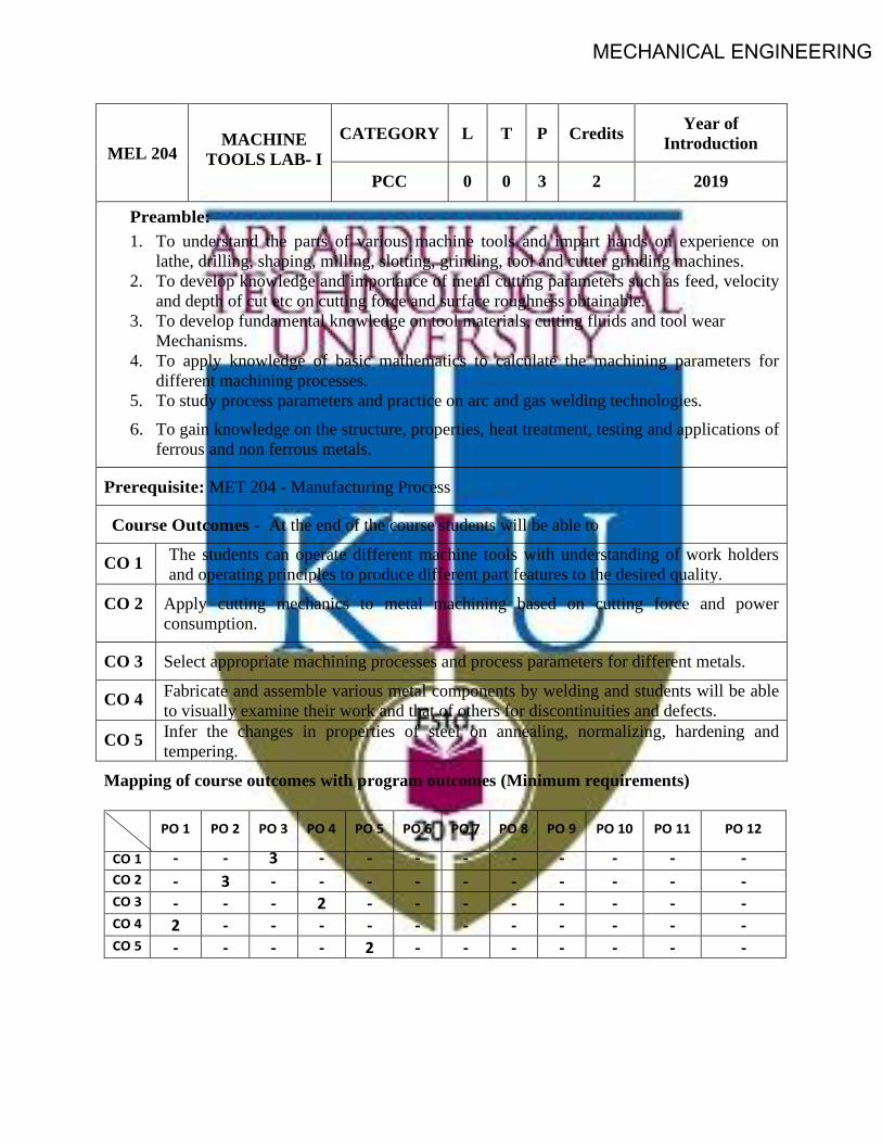
MECHANICAL ENGINEERING
MEL 204 MACHINE
TOOLS LAB- ICATEGORY L T P Credits Year of
Introduction
PCC 0 0 3 2 2019
Preamble: 1. To understand the parts of various machine tools and impart hands on experience on
lathe, drilling, shaping, milling, slotting, grinding, tool and cutter grinding machines.2. To develop knowledge and importance of metal cutting parameters such as feed, velocity
and depth of cut etc on cutting force and surface roughness obtainable.3. To develop fundamental knowledge on tool materials, cutting fluids and tool wear
Mechanisms.4. To apply knowledge of basic mathematics to calculate the machining parameters for
different machining processes.5. To study process parameters and practice on arc and gas welding technologies.6. To gain knowledge on the structure, properties, heat treatment, testing and applications of
ferrous and non ferrous metals.
Prerequisite: MET 204 - Manufacturing Process
Course Outcomes - At the end of the course students will be able to
CO 1 The students can operate different machine tools with understanding of work holders and operating principles to produce different part features to the desired quality.
CO 2 Apply cutting mechanics to metal machining based on cutting force and power consumption.
CO 3 Select appropriate machining processes and process parameters for different metals.
CO 4 Fabricate and assemble various metal components by welding and students will be able to visually examine their work and that of others for discontinuities and defects.
CO 5 Infer the changes in properties of steel on annealing, normalizing, hardening and tempering.
Mapping of course outcomes with program outcomes (Minimum requirements)
PO 1 PO 2 PO 3 PO 4 PO 5 PO 6 PO 7 PO 8 PO 9 PO 10 PO 11 PO 12
CO 1 - - 3 - - - - - - - - - CO 2 - 3 - - - - - - - - - - CO 3 - - - 2 - - - - - - - - CO 4 2 - - - - - - - - - - - CO 5 - - - - 2 - - - - - - -
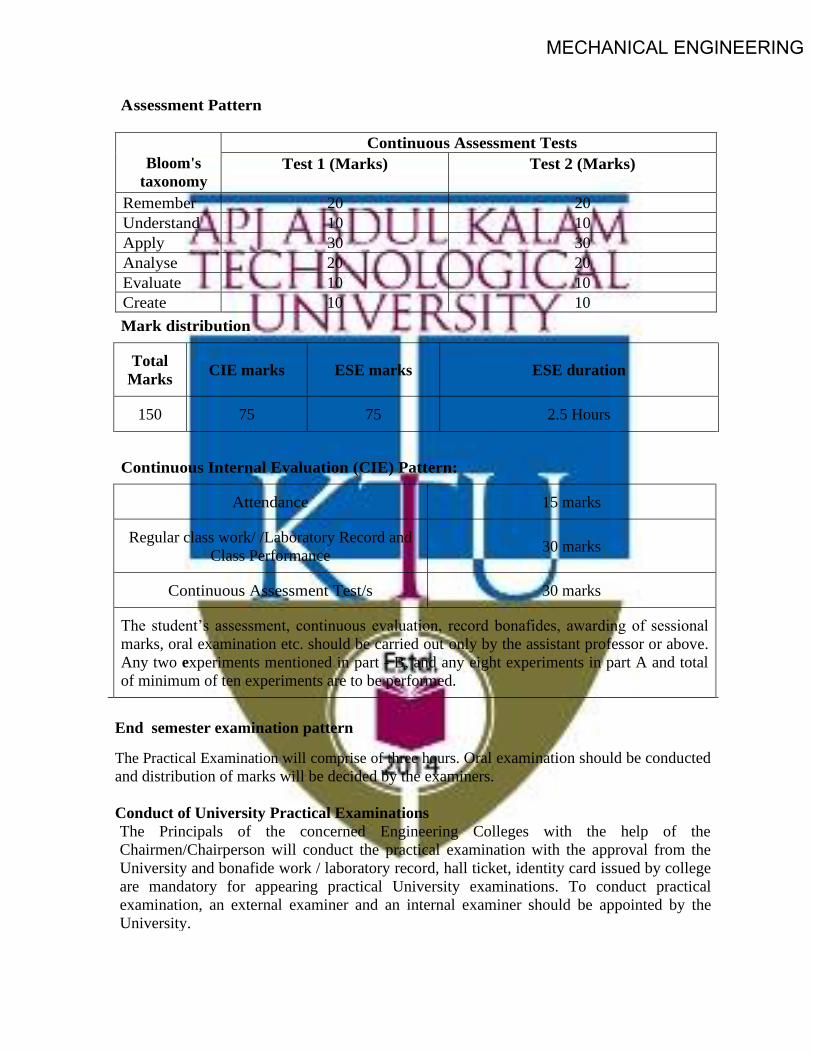
MECHANICAL ENGINEERING
A ssessment Pattern
Bloom's
taxonomy
Continuous Assessment Tests Test 1 (Marks)
Test 2 (Marks)
Remember 20 20 Understand 10 10 Apply 30 30 Analyse 20 20 Evaluate 10 10 Create 10 10
Mark distribution
Total Marks CIE marks ESE marks ESE duration
150 75 75 2.5 Hours
Continuous Internal Evaluation (CIE) Pattern:
Attendance 15 marks
Regular class work/ /Laboratory Record and Class Performance 30 marks
Continuous Assessment Test/s 30 marks
The student’s assessment, continuous evaluation, record bonafides, awarding of sessional
marks, oral examination etc. should be carried out only by the assistant professor or above. Any two experiments mentioned in part - B, and any eight experiments in part A and total of minimum of ten experiments are to be performed.
End semester examination pattern
The Practical Examination will comprise of three hours. Oral examination should be conducted and distribution of marks will be decided by the examiners. Conduct of University Practical Examinations The Principals of the concerned Engineering Colleges with the help of the Chairmen/Chairperson will conduct the practical examination with the approval from the University and bonafide work / laboratory record, hall ticket, identity card issued by college are mandatory for appearing practical University examinations. To conduct practical examination, an external examiner and an internal examiner should be appointed by the University.

MECHANICAL ENGINEERING
END SEMESTER EXAMINATION MODEL QUESTION PAPER
Maximum Marks : 75 Duration: 2.5 hours
1. To machine the hexagonal head and the slot shown in the sketch on the specimen and measure the tool wear using toolmaker's microscope.
OR
2. To drill, file, as shown in the sketch, ream and tap holes on the mild steel plate and measure the tool wear using toolmaker's microscope.
OR

MECHANICAL ENGINEERING
3. To make the part shown in the sketch from a mild steel rod on a Lathe and measure the tool flank wear using toolmaker's microscope.
OR
4. Prepare a metallurgical sample and determine the grain size using a optical microscope.
OR 5. To prepare a butt joint with mild steel strip using suitable welding technique and infer on the welded joint.
OR 6. To make the part shown in the sketch from a mild steel rod on a Lathe and measure the tool flank wear using toolmaker's microscope.

MECHANICAL ENGINEERING
SYLLABUS PART - A
Safety precautions in machine shop - Exercises on machine tools: turning, knurling, drilling,
boring, reaming, trepanning, milling, hobbing, planning, shaping, slotting, broaching, grinding,
lapping, honing etc. - Welding practice.
PART - B Metallurgy, heat treatment and testing. Text Books: 1. Acherkan N. S. “Machine Tool”, Vol. I, II, III and IV, MIR Publications. 2. HMT, Production Technology, Tata McGraw Hill. 3. W. A. J. Chapman, Workshop Technology Part I, ELBS & Edward Arnold Publishers.
Course content and drawing schedules.
List of Experiments A minimum of ten experiments are to be carried out
Course outcomes
No. of hours
Experiments
PART -A (minimum eight experiments)
1
Centre Lathe Study of lathe tools: - tool materials - selection of tool for different operations - tool nomenclature and attributes of each tool angles on cutting processes – effect of nose radius, side cutting edge angle, end cutting edge angle and feed on surface roughness obtainable – tool grinding.
• Study the different methods used to observe the work-piece is precisely fixed on lathe.
• Study the optimum aspect ratio of work-piece to avoid vibration and wobbling during turning.
• Machine tool alignment test on lathe. • Re-sharpening of turning tool to specific geometry
CO 1 3
2,3,4,5,6
Exercises on centre lathe:- Facing, plain turning, step turning and parting – groove cutting, knurling and chamfering - form turning and taper turning – eccentric turning, multi-start thread, square thread and internal thread etc. CO 1
CO 2
3
Exercises on lathe: - Measurement of cutting forces in turning process and correlate the surface roughness obtainable by varying feed, speed, feed, nose radius, side and end cutting edge angles.
6

MECHANICAL ENGINEERING
7 Measurement of cutting temperature and tool life in turning and machine tool alignment test on lathe machine. CO 2 3
86
Exercises on Drilling machine • Exercises on drilling machine: - drilling, boring,
reaming, taping and counter sinking etc. CO 1 CO 2
3 • Exercises on drilling machine: - Measurement of cutting
forces in drilling process and correlate with process parameters.
9
Exercises on Shaping machine • Exercises on shaping machine: - flat surfaces, grooves and
key ways. CO 2
3 Exercises on Slotting machine • Exercises on slotting machine: - flat surfaces, grooves and
key ways.
10
Planing and Broaching machine Study and demonstration of broaching and hobbing machine.
• Exercises on planing machine
CO 1 3
11
Exercises on Grinding machine
• Exercise on surface grinding, cylindrical grinding and tool grinding etc.
• Measurement of cutting forces and roughness in grinding process and correlate with process parameters.
• Study and demonstration of lapping and honing machines.
CO 1 3
12 Exercises on Welding machine • Exercises on arc and gas welding: - butt welding and lap
welding of M.S. sheets. CO 4 3
PART - B - Metallurgy (minimum two experiments)
CO 5 6 13 • Specimen preparation, etching & microscopic study of
Steel, Cast iron and Brass and grain size measurement.
14
• Heat treatment study:–Effect on mechanical properties and microstructure of ferrous and non ferrous metals.
CO 5 6 • Studies of various quenching mediums, Carryout heat treatments on steel based on ASM handbook vol.4 and observe the hardness obtained.

MECHANICAL ENGINEERING
SEMESTER -4
MINOR

MECHANICAL ENGINEERINGCODE MET282
COURSE NAME THEORY OF MACHINES
CATEGORY L T P CREDIT VAC 3 1 0 4
Preamble:
Goal of this course is to expose the students to the fundamentals of kinematics of mechanisms, design of cams, theory and analysis of gears, gear trains, clutches, brakes. The students will also be exposed to velocity and acceleration analysis of different mechanisms. It provides the knowledge on balancing of rotating and reciprocating masses, Gyroscopes, Energy fluctuation in Machines.
Prerequisite: Nil
Course Outcomes: After the completion of the course the student will be able to
CO 1 Interpret basic principles of mechanisms and machines and Analyse a given mechanism based on velocity and acceleration. List the basic selection requirements of different types of mechanical clutches.
CO 2 Describe the theories of gears and gear trains. List the basic selection requirements of different types of mechanical brakes.
CO 3 Develop the profile of CAMs as per the requirements and to understand cam profile. CO 4 Explain the dynamic balancing of revolving and reciprocating masses. Describe the
fundamentals of gyroscope and its application. CO 5 Analyse the performance of governors and flywheels.
Mapping of course outcomes with program outcomes
PO 1 PO 2 PO 3 PO 4 PO 5 PO 6 PO 7 PO 8 PO 9 PO 10
PO 11
PO 12
CO 1 3 3 2 2 3 2
CO 2 3 3 2 2 3 2
CO 3 3 3 2 2 3 2
CO 4 3 3 3 2 1 1
CO 5 3 3 3 3 1 3
Assessment Pattern
Bloom’s Category Continuous Assessment Tests End Semester Examination 1 2
Remember Understand 30 40 80 Apply 10 10 Analyse 20 10 Evaluate Create
MECHANICAL ENGINEERINGMark distribution
Total Marks CIE ESE ESE Duration
150 50 100 3 hours
Continuous Internal Evaluation Pattern:
Attendance : 10 marks Continuous Assessment Test (2 numbers) : 25 marks Assignment/Quiz/Course project : 15 marks
End Semester Examination Pattern: There will be two parts; Part A and Part B. Part A contain 10 questions with 2 questions from each module, having 3 marks for each question. Students should answer all questions. Part B contains 2 questions from each module of which student should answer any one. Each question can have maximum 2 sub-divisions and carry 14 marks.

MECHANICAL ENGINEERINGCOURSE LEVEL ASSESSMENT QUESTIONS
Course Outcome 1 (CO1): Interpret basic principles of mechanisms and machines. Analyse a given mechanism based on velocity and acceleration. List the basic selection requirements of different types of mechanical clutches.
1. Explain the inversions of a four bar mechanism.
2. Explain with neat sketches, the working of single plate clutch.
3. The crank of a slider crank mechanism rotates clockwise at a constant speed of 300 r.p.m.The crank is 150 mm and the connecting rod is 600 mm long. Determine: 1. Linear velocityand acceleration of the midpoint of the connecting rod, and 2. angular velocity and angularacceleration of the connecting rod, at a crank angle of 45° from inner dead centre position
Course Outcome 2 (CO2) Describe the theories of gears and gear trains. List the basic selection requirements of different types of mechanical brakes.
1. State and prove the law of gearing
2. In an epicyclic gear train, an arm carries two gears A and B having 36 and 45 teethrespectively. If the arm rotates at 150 rpm in the anticlockwise direction about the centre ofthe gear A which is fixed, determine the speed of gear B. If the gear A instead of being fixedmakes 300 rpm in the clockwise direction, what will be the speed of gear B?
3. Discuss the various types of the brakes.
Course Outcome 3 (CO3): Develop the profile of CAMs as per the requirements and and to understand cam profile.
1. Explain the different classifications of cam and followers.
2. Draw the displacement, velocity and acceleration diagrams when the follower moves inSHM.
3. A cam with 30 mm as minimum diameter is rotating clockwise at a uniform speed of 1200
r.p.m. and has to give the following motion to a roller follower 10 mm in diameter:
a) Follower to complete outward stroke of 25 mm during 120° of cam rotation with equal
uniform acceleration and retardation;
b) (b) Follower to dwell for 60° of cam rotation;
c) (c) Follower to return to its initial position during 90° of cam rotation with equal uniform
acceleration and retardation;
d) (d) Follower to dwell for the remaining 90° of cam rotation.
Draw the cam profile if the axis of the roller follower passes through the axis of the cam.

MECHANICAL ENGINEERINGCourse Outcome 4 (CO4): Explain the static and dynamic balancing of revolving and reciprocating masses. Describe the fundamentals of gyroscope and its application
1. Four masses m1, m2, m3 and m4 are 200 kg, 300 kg, 240 kg and 260 kg respectively. Thecorresponding radii of rotation are 0.2 m, 0.15 m, 0.25 m and 0.3 m respectively and theangles between successive masses are 45°, 75° and 135°. Find the position and magnitude ofthe balance mass required, if its radius of rotation is 0.2 m.
2. Explain with neat sketches, the terms Swaying Couple and Hammer Blow.
3. A ship propelled by a turbine rotor which has a mass of 5000 kg and a speed of 2100 r.p.m.The rotor has a radius of gyration of 0.5 m and rotates in a clockwise direction when viewedfrom the stern. Find the gyroscopic effects in the following conditions:
a. The ship sails at a speed of 30 km/h and steers to the left in a curve having 60 m radius.
b. The ship pitches 6 degree above and 6 degree below the horizontal position. The bow isdescending with its maximum velocity. The motion due to pitching is simple harmonic andthe periodic time is 20 seconds.
c. The ship rolls and at a certain instant it has an angular velocity of 0.03 rad/s clockwisewhen viewed from stern.
Determine also the maximum angular acceleration during pitching. Explain how the direction of motion due to gyroscopic effect is determined in each case.
Course Outcome 5 (CO5): Analyse the performance of governors and flywheels.
1. The turning moment diagram for a petrol engine is drawn to the following scales : Turningmoment, 1 mm = 5 N-m ; crank angle, 1 mm = 1°. The turning moment diagram repeats itselfat every half revolution of the engine and the areas above and below the mean turningmoment line taken in order are 295, 685, 40, 340, 960, 270 mm2. The rotating parts areequivalent to a mass of 36 kg at a radius of gyration of 150 mm. Determine the coefficient offluctuation of speed when the engine runs at 1800 r.p.m
2. Explain the different types of governors.
3. The arms of a Porter governor are each 250 mm long and pivoted on the governor axis. Themass of each ball is 5 kg and the mass of the central sleeve is 30 kg. The radius of rotation ofthe balls is 150 mm when the sleeve begins to rise and reaches a value of 200 mm formaximum speed. Determine the speed range of the governor. If the friction at the sleeve isequivalent of 20 N of load at the sleeve, determine how the speed range is modified.

MECHANICAL ENGINEERING
SYLLABUS
Module 1: Kinematics - Links, mechanism, Degrees of freedom, Grashoff's law. Four-bar chain, Slider crank chain- Inversions and practical applications. Velocity and acceleration diagrams of simple mechanisms. Coriolis acceleration (Theory only). Friction clutch - Pressure and wear theories, pivot and collar friction, Single and multiple disc clutches.
Module 2: Gear – Classification of gears- Gear terminology- Law of gearing, Gear trains - Simple, compound gear trains and epicyclic gear trains. Brakes - Block and band brakes, self-energizing and self-locking in braking.
Module 3: Cams- Types of cams, cam profiles for knife edged and roller followers with and without offsets for SHM, constant acceleration-deceleration, and constant velocity
Module 4: Static and dynamic balancing of rotating mass- Single and several masses in different planes. Balancing of reciprocating mass. Gyroscope –Gyroscopic torque, gyroscopic stabilization of ships and aeroplanes.
Module 5: Governors - Types of governors- simple watt governor - Porter governor- Theory of Proell governor - Isochronism, hunting, sensitivity and stability. Flywheel - Turning moment diagrams, fluctuation of energy
Text Books
1. Ballaney P.L. Theory of Machines, Khanna Publishers,1994
2. S. S. Rattan, Theory of Machines, Tata McGraw Hill, 2009
3. V. P. Singh, Theory of Machines, Dhanpat Rai,2013
Reference Books
1. C. E. Wilson, P. Sadler, Kinematics and Dynamics of Machinery, Pearson Education,20052. D. H. Myskza, Machines and Mechanisms Applied Kinematic Analysis, Pearson Education,20133. G. Erdman, G. N. Sandor, Mechanism Design: Analysis and synthesis Vol I & II, Prentice Hall ofIndia,1984.4. Ghosh, A. K. Malik, Theory of Mechanisms and Machines, Affiliated East West Press,19885. J. E. Shigley, J. J. Uicker, Theory of Machines and Mechanisms, McGraw Hill,20106. Holowenko, Dynamics of Machinery, John Wiley, 1995

MECHANICAL ENGINEERING
COURSE PLAN
No Topic No. of Lectures 1 Module 1 (CO1) 1.1 Introduction to link, constrained motions, mechanism, machine 1 1.2 Degrees of freedom, Problem, Grashof’s law 1 1.3 Inversion – Four Bar chain – Single Slider Chain – Practical
Applications 2
1.4 Velocity Analysis – I Centre Methos – Relative Velocity Method 2 1.5 Acceleration Analysis - Four Bar Mechanism – Single Slider Chain 2 1.6 Corriolis Component of Acceleration –Quick Return Mechanisms 2 1.7 Clutches – Theories - Classifications 1 2 Module 2 (CO2) 2.1 Gear – Classifications – Terminology – Law of Gearing – Velocity
of Sliding – Interference - Problems 3
2.2 Gear Train –Classifications - Problems on Epi cyclic gear trains 3 2.3 Brake – Theory – Classifications 2 3 Module 3 (CO3) 3.1 Cam – Introduction - Classifications 1 3.2 Velocity and Acceleration Diagrams – Uniform Velocity – Uniform
Acceleration and Deceleration – SHM – Calculations 2
3.3 Construction of Cam Profile 4 4 Module 4 (CO4) 4.1 Static and dynamic balancing of rotating masses –Single and
several masses in different planes 2
4.2 Balancing of reciprocating masses 3 4.3 Gyroscope – Introduction – Stabilization of Ships 2 4.4 Stabilization of Air Planes 2 5 Module 5 (CO5) 5.1 Governors – Introduction –Classifications 2 5.2 Analytical Problems 2 5.3 Hunting – Sensitivity – Isochronism -Stability 2 5.4 Flywheels – Turning Moment Diagrams –Fluctuation of Energy 2 5.5 Analytical Problems 2

MECHANICAL ENGINEERING
MODEL QUESTION PAPER
APJ ABDUL KALAM TECHNOLOGICAL UNIVERSITY
FIFTH SEMESTER B.TECH DEGREE EXAMINATION
Course Code : MET282
Course Name : THEORY OF MACHINES
Max. Marks : 100 Duration : 3 Hours
PART – A (ANSWER ALL QUESTIONS, EACH QUESTION CARRIES 3 MARKS)
1. Write down the Kutzbach criterion of movability of plane mechanisms. Derive the Grubler’sequation from it.
2. Explain the types of constrained motions with neat sketches.
3. With a neat sketch prove the common normal at the point of contact between a pair of teethmust always pass through the pitch point.
4. Explain the terms : (i) Module, (ii) Pressure angle, and (iii) Addendum.
5. Explain the different classifications of followers.
6. Define the following terms as applied to cam with a neat sketch :-(a) Base circle, (b) Pitch circle,(c) Pressure angle
7. Why reciprocating masses is cannot be completely balanced by revolving mass?
8. Derive the formula for the magnitude of gyroscopic couple.
9. Write down the differences between a gyroscope and a flywheel.
10. Explain the term hunting and isochronism.

MECHANICAL ENGINEERINGPART – B
(ANSWER ONE FULL QUESTION FROM EACH MODULE)
MODULE – 1
11. The dimensions and configuration of the four bar mechanism, shown in Figure, are as follows :P1A = 300 mm; P2B = 360 mm; AB = 360 mm, and P1P2 = 600 mm. The angle AP1P2 = 60°. Thecrank P1A has an angular velocity of 10 rad/s and an angular acceleration of 30 rad/s2, bothclockwise. Determine the angular velocities and angular accelerations of P2B, and AB and thevelocity and acceleration of the joint B. (14 marks)
OR
12. a) With neat sketches explain the inversions of a four bar mechanism. (7 marks)
b) Derive the equation for the corrioli’s component of acceleration. (7 marks)
MODULE – 2
13. An internal wheel B with 80 teeth is keyed to a shaft F. A fixed internal wheel C with 82 teeth isconcentric with B. A compound wheel D-E gears with the two internal wheels; D has 28 teethand gears with C while E gears with B. The compound wheels revolve freely on a pin whichprojects from a disc keyed to a shaft A co-axial with F. If the wheels have the same pitch and theshaft A makes 800 r.p.m., what is the speed of the shaft F ? Sketch the arrangement.
(14 marks)
OR
14. a) What do you mean by a self-energizing brake and self-locking brake. (4 Marks)
b) A simple band brake operates on a drum of diameter 600 mm that is running at a speed of200 rpm. The coefficient of friction is 0.3. The brake band has an angle of contact of 270⁰. Oneend of it is fastened to a fixed pin and the other end to the brake arm 125 mm and is placedperpendicular to the line bisecting the angle of contact.
i. What is the effort necessary at the end of brake arm to stop the wheel if 30 kW poweris absorbed? What is the direction of rotation of drum for minimum pull?
ii. What is the width of steel band required for this brake if the maximum tensile stress isnot to exceed 50 N/mm2 and the thickness of band is 2.5 mm.
(10 marks)
MECHANICAL ENGINEERINGMODULE – 3
15. A cam rotating clockwise at a uniform speed of 1000 r.p.m. is required to give a roller followerthe motion defined below : 1. Follower to move outwards through 50 mm during 120° of camrotation, 2. Follower to dwell for next 60° of cam rotation, 3. Follower to return to its startingposition during next 90° of cam rotation, 4. Follower to dwell for the rest of the cam rotation.The minimum radius of the cam is 50 mm and the diameter of roller is 10 mm. The line of strokeof the follower is off-set by 20 mm from the axis of the cam shaft. If the displacement of thefollower takes place with uniform and equal acceleration and retardation on both the outwardand return strokes, draw profile of the cam. (14 marks)
OR
16. From the following data, draw the profile of a cam in which the follower moves with simpleharmonic motion during ascent while it moves with uniformly accelerated motion duringdescent : Least radius of cam = 50 mm ; Angle of ascent = 48° ; Angle of dwell between ascentand descent = 42° ; Angle of descent = 60° ; Lift of follower = 40 mm ; Diameter of roller = 30mm ; Distance between the line of action of follower and the axis of cam = 20 mm. If the camrotates at 360 r.p.m. anticlockwise, find the maximum velocity and acceleration of the followerduring descent. (14 marks)
MODULE – 4
17. a) A shaft carries four masses A, B, C and D of magnitude 200 kg, 300 kg, 400 kg and 200 kgrespectively and revolving at radii 80 mm, 70 mm, 60 mm and 80 mm in planes measured fromA at 300 mm, 400 mm and 700 mm. The angles between the cranks measured anticlockwise areA to B 45°, B to C 70° and C to D 120°. The balancing masses are to be placed in planes X and Y.The distance between the planes A and X is 100 mm, between X and Y is 400 mm and betweenY and D is 200 mm. If the balancing masses revolve at a radius of 100 mm, find their magnitudesand angular positions. (10 marks)
b) Explain the term swaying couple and hammer blow (4 marks)
OR
18. A ship propelled by a turbine rotor which has a mass of 5000 kg and a speed of 2100 r.p.m. Therotor has a radius of gyration of 0.5 m and rotates in a clockwise direction when viewed fromthe stern. Find the gyroscopic effects in the following conditions: 1. The ship sails at a speed of30 km/h and steers to the left in a curve having 60 m radius. 2. The ship pitches 6 degree aboveand 6 degree below the horizontal position. The bow is descending with its maximum velocity.The motion due to pitching is simple harmonic and the periodic time is 20 seconds. 3. The shiprolls and at a certain instant it has an angular velocity of 0.03 rad/s clockwise when viewed fromstern. Determine also the maximum angular acceleration during pitching. Explain how thedirection of motion due to gyroscopic effect is determined in each case.
(14 marks)

MECHANICAL ENGINEERINGMODULE – 5
19. a) A Porter governor has all four arms 250 mm long. The upper arms are attached on the axis ofrotation and the lower arms are attached to the sleeve at a distance of 30 mm from the axis.The mass of each ball is 5 kg and the sleeve has a mass of 50 kg. The extreme radii of rotationare 150 mm and 200 mm. Determine the range of speed of the governor. (10 marks)
b) What is stability of a governor? How does it differ from sensitiveness? (4marks)
OR
20. A three cylinder single acting engine has its cranks set equally at 120° and it runs at 600 r.p.m.The torque-crank angle diagram for each cycle is a triangle for the power stroke with a maximumtorque of 90 N-m at 60° from dead centre of corresponding crank. The torque on the returnstroke is sensibly zero. Determine : 1. power developed. 2. coefficient of fluctuation of speed, ifthe mass of the flywheel is 12 kg and has a radius of gyration of 80 mm, 3. coefficient offluctuation of energy, and 4. maximum angular acceleration of the flywheel. (14 marks)

MECHANICAL ENGINEERING
CODE MET284
COURSE NAME THERMODYNAMICS
CATEGORY L T P CREDIT VAC 3 1 - 4
Preamble:
Thermodynamics is the study of energy. Without energy life cannot exist. Activities from breathing to the launching of rockets involves energy transactions and are subject to thermodynamic analysis. Engineering devices like engines, turbines, refrigeration and air conditioning systems, propulsion systems etc., work on energy transformations and must be analysed using principles of thermodynamics. So, a thorough knowledge of thermodynamic concepts is essential for a mechanical engineer. This course offers an introduction to the basic concepts and laws of thermodynamics.
Prerequisite: NIL
Course Outcomes:
After completion of the course the student will be able to
CO1 Understand basic concepts and laws of thermodynamics CO2 Conduct first law analysis of open and closed systems CO3 Determine entropy changes associated with different processes CO4 Understand the application and limitations of the ideal gas equation of state CO5 Determine change in properties of pure substances during phase change processes CO6 Evaluate properties of ideal gas mixtures
Mapping of course outcomes with program outcomes
PO1 PO2 PO3 PO4 PO5 PO6 PO7 PO8 PO9 PO10 PO11 PO12 CO1 2 2 2 CO2 2 2 1 1 1 CO3 3 3 2 2 1 CO4 2 2 2 2 1 CO5 3 3 2 1 1 CO6 3 3 2 2 1
Assessment Pattern
Blooms Category CA ESA Assignment Test - 1 Test - 2
Remember 25 20 20 10 Understand 25 40 40 20 Apply 25 40 40 70 Analyse 25 Evaluate Create
MECHANICAL ENGINEERINGContinuous Internal Evaluation Pattern:
Attendance : 10 marks
Continuous Assessment Test (2 numbers) : 25 marks
Assignment/Quiz/Course project : 15 marks
Mark distribution & Duration of Examination :
Total Marks CA ESE ESE Duration 150 50 100 3 Hours
End semester pattern:
There will be two parts; Part A and Part B. Part A contain 10 questions with 2 questions from each module, having 3 marks for each question. Students should answer all questions. Part B contains 2 questions from each module of which student should answer any one. Each question can have maximum 2 sub-divisions and carry 14 marks.
COURSE LEVEL ASSESSMENT QUESTIONS Course Outcome 1
1. Discuss the limitations of first law of thermodynamics.
2. Second law of thermodynamics is often called a directional law . Why?
3. Explain Joule-Kelvin effect. What is the significance of the inversion curve ?
Course Outcome 2
1. A mass of 2.4 kg of air at 150 kPa and 12°C is contained in a gas – tight, frictionless piston –cylinder device. The air is now compressed to a final pressure of 600 kPa . During this process, heatis transferred from the air such that the temperature inside the cylinder remains constant.Calculate the work input during this process.
2. Carbon dioxide enters an adiabatic nozzle steadily at 1 MPa and 500°C with a mass flow rate of600 kg/hr and leaves at 100 kPa and 450 m/s. The inlet area of the nozzle is 40 cm2. Determine (a)the inlet velocity and (b) the exit temperature
3. Water is being heated in a closed pan on top of a range while being stirred by a paddle – wheel.During the process, 30 kJ of heat is transferred to the water and 5 kJ of heat is lost to thesurrounding air. The paddle – wheel work amounts to 500 N-m. Determine the final energy ofthe system, if its initial energy is 10 kJ.
Course Outcome 3
1.An adiabatic vessel contains 2 kg of water at 25˚C. B paddle – wheel work transfer, thetemperature of water is increased to 30˚C. If the specific heat of water is assumed to be constant at4.186 kJ/kg.K, find the entropy change of the universe.

MECHANICAL ENGINEERING2. Two kilograms of water at 80°C is mixed adiabatically with 3 kg of water at 30°C in a constantpressure process at 1 atm. Find the increase in entropy of the total mass of water due to the mixingprocess.
3. An iron block of unknown mass at 85⁰C is dropped into an insulated tank that contains 0.1 m3 ofwater at 20⁰C. At the same time a paddle-wheel driven by a 200 W motor is activated to stir thewater. Thermal equilibrium is established after 20 minutes when the final temperature is 24⁰C.Determine the mass of the iron block and the entropy generated during this process.
Course Outcome 4
1. Discuss the limitations of ideal gas equation.
2. Discuss law of corresponding states and its role in the construction of compressibility chart.
3. A rigid tank contains 2 kmol of N2 and 6 kmol of CH4 gases at 200 K and 12 MPa. Estimate thevolume of the tank, using (a) ideal gas equation of state (b) the compressibility chart and Amagat’slaw
Course Outcome 5
1.Steam is throttled from 3 MPa and 600˚C to 2.5 MPa. Determine the temperature of the steam atthe end of the throttling process.
2. Determine the change in specific volume, specific enthalpy and quality of steam as saturatedsteam at 15 bar expands isentropically to 1 bar. Use steam tables
3. Estimate the enthalpy of vapourization of steam at 500 kPa, using the Clapeyron equation andcompare it with the tabulated value
Course Outcome 6
1. A gaseous mixture contains , by volume, 21%nitrogen, 50% hydrogen and 29 % carbon dioxide.Calculate the molecular weight of the mixture, the characteristic gas constant of the mixture and thevalue of the reversible adiabatic expansion index - γ. At 10˚C, the Cp values of nitrogen, hydrogenand carbon dioxide are 1.039, 14.235 and 0.828 kJ/kg.K respectively.
2. A mixture of 2 kmol of CO2 and 3 kmol of air is contained in a tank at 199 kPa and 20˚C. Treatingair to be a mixture of 79% N2 and 21% O2 by volume , calculate (a) the individual mass of CO2 , N2
and O2, (b) the percentage content of carbon by mass in the mixture and (c) the molar mass ,characteristic gas constant and the specific volume of the mixture
3. A gas mixture in an engine cylinder has 12% CO2, 11.5 % O2 and 76.5% N2 by volume. Themixture at 1000˚C expands reversibly, according to the law PV1.25 = constant, to 7 times its initialvolume. Determine the work transfer and heat transfer per unit mass of the mixture.

MECHANICAL ENGINEERINGSYLLABUS
Module 1: Role of Thermodynamics and it’s applications in Engineering and Science –Basic Concepts Macroscopic and Microscopic viewpoints, Concept of Continuum, Thermodynamic System and Control Volume, Surrounding, Boundaries, Types of Systems, Universe, Thermodynamic properties, Process, Cycle, Thermodynamic Equilibrium, Quasi – static Process, State, Point and Path function. Zeroth Law of Thermodynamics, Measurement of Temperature, reference Points, Temperature Scales.
Module 2: Energy - Work - Pdv work and other types of work transfer, free expansion work, heat and heat capacity. Joule’s Experiment- First law of Thermodynamics - First law applied to Non flow Process- Enthalpy- specific heats- PMM1, First law applied to Flow Process, Mass and Energy balance in simple steady flow process. Applications of SFEE, Limitations of the First Law.
Module 3: Second Law of Thermodynamics, Thermal Reservoir, Heat Engine, Heat pump – Kelvin-Planck and Clausius Statements, Equivalence of two statements, Reversibility, Irreversible Process, Causes of Irreversibility, PMM2, Carnot’s theorem and its corollaries, Absolute Thermodynamic Temperature scale. Clausius Inequality, Entropy- Entropy changes in various thermodynamic processes, principle of increase of entropy and its applications, Entropy generation, Entropy and Disorder, Reversible adiabatic process- isentropic process, Third law of thermodynamics.
Module 4: Pure Substances, Phase Transformations, Triple point, properties during change of phase, T-v, p-v and p-T diagram of pure substance, p-v-T surface, Saturation pressure and Temperature, T-hand T-s diagrams, h-s diagrams or Mollier Charts, Dryness Fraction, steam tables. Propertycalculations using steam tables. The ideal Gas Equation, Characteristic and Universal Gas constants,Limitations of ideal Gas Model: Equation of state of real substances, Compressibility factor, Law ofcorresponding state, Compressibility charts.
Module 5: Mixtures of ideal Gases – Mole Fraction, Mass fraction, Gravimetric and volumetric Analysis, Dalton’s Law of partial pressure, Amagat’s Laws of additive volumes, Gibbs-Dalton’s law Equivalent Gas constant and Molecular Weight, Properties of gas mixtures: Internal Energy, Enthalpy, specific heats and Entropy. General Thermodynamic Relations – Combined First and Second law equations – Helmholtz and Gibb’s functions - Maxwell’s Relations, Tds Equations. The Clapeyron Equation, equations for internal energy, enthalpy and entropy, specific heats, Throttling process, Joule Thomson Coefficient, inversion curve.
Text Books
1. P. K. Nag, Engineering Thermodynamics, McGraw Hill, 2013
2. E. Rathakrishnan Fundamentals of Engineering Thermodynamics, PHI, 2005
3. Y. A. Cengel and M. A. Boles, Thermodynamics an Engineering Approach, McGraw Hill, 2011

MECHANICAL ENGINEERINGReference Books:
1. Moran J., Shapiro N. M., Fundamentals of Engineering Thermodynamics, Wiley, 2006
2. R. E. Sonntag and C. Borgnakke, Fundamentals of Thermodynamics, Wiley, 2009
3. Holman J. P. Thermodynamics, McGraw Hill, 2004
4. M. Achuthan, Engineering Thermodynamics, PHI, 2004
COURSE PLAN
Module Topics Hours Allotted
1
Role of Thermodynamics and it’s applications in Engineering and Science –Basic Concepts Macroscopic and Microscopic viewpoints, Concept of Continuum, Thermodynamic System and Control Volume, Surrounding, Boundaries, Types of Systems, Universe
2L
Thermodynamic properties, Process, Cycle, Thermodynamic Equilibrium, Quasi – static Process, State, Point and Path function.
2L
Zeroth Law of Thermodynamics, Measurement of Temperature, reference Points, Temperature Scales.
2L + 1T
2
Energy - Work - Pdv work and other types of work transfer, free expansion work, heat and heat capacity.
2L + 1T
Joule’s Experiment- First law of Thermodynamics - First law applied to Non flow Process- Enthalpy- specific heats- PMM1
2L + 1T
First law applied to Flow Process, Mass and Energy balance in simple steady flow process. Applications of SFEE, Limitations of first law
2L + 1T
3
Second Law of Thermodynamics, Thermal Reservoir, Heat Engine, Heat pump – Kelvin-Planck and Clausius Statements, Equivalence of two statements
3L
Reversibility, Irreversible Process, Causes of Irreversibility, PMM2, Carnot’s theorem and its corollaries, Absolute Thermodynamic Temperature scale.
2L + 1T
Clausius Inequality, Entropy- Entropy changes in various thermodynamic processes, principle of increase of entropy and its applications, Entropy generation, Entropy and Disorder, Reversible adiabatic process- isentropic process, Third law of thermodynamics
2L + 2T
4
Pure Substances, Phase Transformations, Triple point, properties during change of phase, T-v, p-v and p-T diagram of pure substance, p-v-T surface,
3L
Saturation pressure and Temperature, T-h and T-s diagrams, h-s diagrams or Mollier Charts, Dryness Fraction, steam tables. Property calculations using steam tables
2L + 1T

MECHANICAL ENGINEERINGThe ideal Gas Equation, Characteristic and Universal Gas constants, Limitations of ideal Gas Model: Equation of state of real substances, Compressibility factor, Law of corresponding state, Compressibility charts.
2L +1T
5
Mixtures of ideal Gases – Mole Fraction, Mass fraction, Gravimetric and volumetric Analysis, Dalton’s Law of partial pressure, Amagat’s Laws of additive volumes, Gibbs-Dalton’s law.
2L
Equivalent Gas constant and Molecular Weight, Properties of gas mixtures: Internal Energy, Enthalpy, specific heats and Entropy
2L +1T
General Thermodynamic Relations – Combined First and Second law equations – Helmholtz and Gibb’s functions - Maxwell’s Relations
2L
Tds Equations. The Clapeyron Equation, equations for internal energy, enthalpy and entropy, specific heats, Throttling process, Joule Thomson Coefficient, inversion curve.
2L + 1T

MECHANICAL ENGINEERINGMODEL QUESTION PAPER
APJ ABDUL KALAM TECHNOLOGICAL UNIVERSITY
THIRD SEMESTER B.TECH DEGREE EXAMINATION
Course Code : MET284
Course Name : THERMODYNAMICS
( Permitted to use Steam Tables and Mollier Chart )
Max. Marks : 100 Duration : 3 Hours
Part – A
Answer all questions.
1. Define thermodynamics. List a few of its applications
2.Differentiate between intensive and extensive properties.
3. Differentiate between heat and work.
4. Explain system approach and control volume approach as applied in the analysis of a flow process.
5. An inventor claims to have developed an engine that delivers 26 kJ of work using 82 kJ of heatwhile operating between temperatures 120°C and 30°C. Is his claim valid ? Give the reason foryour answer.
6. Show that two reversible adiabatics cannot intersect
7.Define (i)critical point and (ii) triple point, with respect to water
8. Why do real gases deviate from ideal gas behaviour? When do they approach ideal behaviour?
9. Define Helmholtz function and Gibbs function and state their significance
10. State Dalton’s law and Amagat’s laws for ideal gas mixtures.
( 3 x 10 = 30 marks )
Part – B
Answer any two full questions from each module.
Module - 1
11.a] Explain macroscopic and microscopic approach to thermodynamics . ( 7 marks )
b] With the aid of a suitable diagram, explain the working of constant volume gas thermometer. ( 7 marks )
OR
12.a] What is meant by thermodynamic equilibrium ? What are the essential conditions for a system to be in thermodynamic equilibrium ? ( 7 marks )

MECHANICAL ENGINEERING b] Express the temperature of 91⁰C in (i) Farenhiet (ii) Kelvin (iii) Rankine. ( 7 marks )
Module – 2
13.a] A mass of 2.4 kg of air at 150 kPa and 12°C is contained in a gas – tight, frictionless piston –
cylinder device. The air is now compressed to a final pressure of 600 kPa . During this process, heat is transferred from the air such that the temperature inside the cylinder remains constant. Calculate the work input during this process. ( 7 marks )
a] Air enters a 28 cm diameter pipe steadily at 200 kPa and 20°C with a velocity of 5m/s. Air is heated as it flows, and leaves the pipe at 180 kPa and 40°C. Determine (i) the volume flow rate of air at the inlet (ii) the mass flow rate of air and (iii) the velocity and volume flow rate at the exit. ( 7 marks )
OR 14.a] A turbine operates under steady flow conditions, receiving steam at the following conditions : pressure 1.2 MPa, temperature 188°C, enthalpy 2785 kJ/kg, velocity 33.3 m/s and elevation 3m. The steam leaves the turbine at the following conditions : pressure 20 kPa, enthalpy 25kJ/kg, velocity 100 m/s, and elevation 0 m. Heat is lost to the surroundings at the rate of 0.29 kJ/s. If the rate of steam flow through the turbine is 0.42 kg/s, what is the power output of the turbine in kW ? ( 7 marks ) b] Derive the steady flow energy equation, stating all assumptions. ( 7 marks )
Module – 3
15.a]State the Kelvin-Planck and Clausius statements of the second law of thermodynamics and prove their equivalence. ( 7 marks )
b]A heat engine operating between two reservoirs at 1000 K and 300 K is used to drive a heat pump which extracts heat from the reservoir at 300 K at a rate twice that at which the engine rejects heat to it. If the efficiency of the engine is 40 % of the maximum possible and the COP of the heat pump is 50 % of the maximum possible, what is the temperature of the reservoir to which the heat pump rejects heat ? What is the rate of heat rejection from the heat pump, if the rate of heat supply to the engine is 50kW ? ( 7 marks )
OR
16.a] A house is to be maintained at 21°C during winter and at 26°C during summer. Heat leakage through the walls, windows and roof is about 3000 kJ/hr per degree temperature difference between the interior of the house and the environment. A reversible heat pump is proposed for realising the desired heating and cooling. What is the minimum power required to run the

MECHANICAL ENGINEERING heat pump in the reverse, if the outside temperature during summer is 36°C? Also find the lowest environment temperature during winter for which the inside of the house can be maintained at 21°C consuming the same power. ( 8 marks )
b] Give the Nernst statement of the third law and explain its significance. ( 6 marks )
Module – 4
17.a]Show the constant pressure transformation of unit mass of ice at atmospheric pressure and -20⁰C to superheated steam at 220⁰C on P-v , T-v and P-T coordinate systems and explain their salient features . ( 8 marks )
b] Nitrogen enclosed in a piston cylinder arrangement is at a pressure of 2 bar and temperature 75°C. Calculate the specific volume of Nitrogen using ideal gas equation. What would be the specific volume of this Nitrogen , if its compressibility factor at the prevailing condition is 0.9. . ( 6 marks )
OR
18.a]Steam at 25 bar and 300⁰C expands isentropically to 5 bar. Calculate the change in enthalpy, volume and temperature of unit mass of steam during this process using steam tables and Mollier chart and compare the values ( 8 marks )
b]Explain law of corresponding states and its significance to the generalized compressibility chart. ( 6 marks )
Module – 5
19.a] Derive the expressions for the equivalent molecular weight and characteristic gas constant for a mixture of ideal gases. ( 6 marks )
b] 0.5 kg of Helium and 0.5 kg of Nitrogen are mixed at 20⁰C and at a total pressure of 100 kPa. Find (i) volume of the mixture (ii) partial volumes of the components (iii) partial pressures of the components ( iv) the specific heats of the mixture and (v) the gas constant of the mixture. Take ratio of specific heats for Helium and Nitrogen to be 1.667 and 1.4 respectively. ( 8 marks )

MECHANICAL ENGINEERINGOR
20.a] 2 kg of carbon dioxide at 38°C and 1.4 bar is mixed with 5 kg of nitrogen at 150°C and 1.03 bar to form a mixture at a final pressure of 70 kPa. The process occurs adiabatically in a steady flow apparatus. Calculate the final temperature of the mixture and the change in entropy during the mixing process. Take specific heat at constant pressure for CO2 and N2 as 0.85 kJ/kgK and 1.04 kJ/kg respectively. ( 7 marks )
b]Derive the Maxwell relations. Explain their significance? ( 7 marks )
MECHANICAL ENGINEERING
MET 286 MANUFACTURING
TECHNOLOGY (MINOR)
CATEGORY L T P Credits Year of Introduction
VAC 3 1 0 4 2019
Preamble: 1. To understand basic manufacturing processes of casting and welding2. Provide a detailed discussion on the welding process and the physics of welding.3. To understand mechanisms of material removal in LBM and EBM process4. To introduce the different forming process of forging, extrusion and drawing.5. To introduce the different fabrication of microelectronic devices
Prerequisite: MET 255 - Material Science & Technology (Minor)
Course Outcomes - At the end of the course students will be able to
CO 1 Illustrate the basic principles of foundry practices and special casting processes, their advantages, limitations and applications.
CO 2 Categorize welding processes according to welding principle and material.
CO 3 Understand the advantages of LBM and EBM over fusion welding process.
CO 4 An ability to understand the principles of the basic microelectronic processing technology.
CO 5
Learn about key aspects of the microelectronics industry, from device design, to processing, to photolithography, to manufacturing and packaging. Students will come out knowing the core processes of ion implantation, diffusion, oxidation, deposition, etching, including the fundamental physical mechanisms, and the necessary understanding for using these processes in a manufacturing environment.
Mapping of course outcomes with program outcomes (Minimum requirements)
PO 1
PO 2
PO 3
PO 4
PO 5
PO 6
PO 7
PO 8
PO 9
PO 10
PO 11
PO 12
CO 1 3 - - - - - - - - - - CO 2 - - - - - - - - - - - 2
CO 3 - - 3 - - - - - - - - -
CO 4 - - - 3 - - - - - - - -
CO 5 - 4 - - - - - - - - - -

MECHANICAL ENGINEERING
ASSESSMENT PATTERN
Bloom's taxonomy
Continuous Assessment Tests End Semester Examination (Marks) Test I (Marks) Test II (Marks)
Remember 25 25 25 Understand 15 15 15 Apply 30 25 30 Analyze 10 10 10 Evaluate 10 15 10 Create 10 10 10
Mark distribution
Total Marks CIE marks ESE marks ESE duration
150 50 100 3 Hours
Continuous Internal Evaluation (CIE) Pattern:
Attendance 10 marks
Regular class work/tutorials/assignments 15 marks
Continuous Assessment Test (2 numbers) 25 marks
End semester pattern:- There will be two parts; Part A and Part B. Part A contain 10 questions with 2 questions from each module, having 3 marks for each question. Students should answer all questions. Part B contains 2 questions from each module of which student should answer any one. Each question can have maximum 2 sub-divisions and carry 14 marks. Course Level Assessment Questions Course Outcome 1 (CO1): - Illustrate the basic principles of foundry practices and special casting processes, their advantages, limitations and applications. 1. Explain Why casting is an important manufacturing processes2. Name the important factors in selecting sand for molds.3. Why does die casting produce the smallest cast parts?4. What is the difference between sand-mold and shell mold casting?

MECHANICAL ENGINEERING
Course Outcome 2 (CO2): Categorize welding processes according to welding principle and material.
1. Describe the functions and characteristics of electrodes. What functions do coatings have? How areelectrodes classified?
2. Describe the role of filler metals in welding.3. Explain the significance of the stiffness of the components being welded on both weld quality and
part shape.Course Outcome 3 (CO3): Understand the advantages of LBM and EBM over fusion welding process.
1. What is the power of LBM and EBM used for welding?2. Why LBM and EBM are better quality than fusion welding?3. What is the HAZ of LBM as compared to fusion welding process.Course Outcome 4 (CO4): An ability to understand the principles of the basic microelectronic processing technology.
1. Why is silicon the semiconductor most used in IC technology?2. Define selectivity and isotropy and their importance in relation to etching.3. Explain the differences between wet and dry oxidation.4. How is epitaxy different from other techniques used for deposition? Explain.Course Outcome 5 (CO5): Learn about key aspects of the microelectronics industry, from device design, to processing, to photolithography, to manufacturing and packaging. Students will come out knowing the core processes of ion implantation, diffusion, oxidation, deposition, etching, including the fundamental physical mechanisms, and the necessary understanding for using these processes in a manufacturing environment.
1. Describe bulk and surface micromachining.2. Lithography produces projected shapes, so true three dimensional shapes are more difficult to
produce. What lithography processes are best able to produce three-dimensional shapes, such aslenses? Explain.
3. Explain how you would produce a spur gear if its thickness was one-tenth of its diameter and itsdiameter was (a) 10 um, (b) 100 um, (c) 1 mm, (d) 10 mm, and (e) 100 mm.
SYLLABUS Module I Metal casting:-sand casting:- shell molding, evaporative pattern casting, investment casting, permanent mold casting, vacuum casting, slush casting, pressure casting, die casting, centrifugal casting, squeeze casting, semi solid metal forming, casting for single crystal, casting defects. Module II Powder metallurgy:-powder production methods; powder characteristics; blending, mixing; compaction of metal powders; sintering fundamentals and mechanisms; infiltration and impregnation - Welding: arc welding: non consumable electrodes; heat affected zone; quality; case study and weld ability of metals. Module III Consumable electrodes; electron and laser beam welding; heat affected zone; power density; weld

MECHANICAL ENGINEERING
quality; case study; applications - Brazing:- filler metals, fluxes, joint strength; brazing methods, applications -Soldering:- solders and fluxes - soldering methods - solder ability, case study, typical joint designs, applications. Module IV Metal forging: quality, defects -Metal extrusion: process, defects, applications - Metal drawing process, drawing practice, defects, applications - Fabrication of microelectronic devices - crystal growing and wafer preparation - Film deposition - oxidation - Photo lithography Module V Different lithography methods - Etching, wet etching, dry etching- diffusion and Ion implantation- metallization and testing - wire bonding and packing - yield and reliability - fabrication of micro electro mechanical devices. Text Books 1. Serope Kalpakjian, Steven R. Schmid - Manufacturing Engineering and Technology, seventh
edition, Pearson.Reference 1. https://nptel.ac.in/courses/103106075/2. Principles of Metal Casting – Hine and Rosenthal3. Materials and Processes in Manufacturing - Paul Degarma E and Ronald A. Kosher4. Manufacturing Technology Foundry, Forming and Welding – P. N. Rao
MODEL QUESTION PAPER MANUFACTURING PROCESS - MET 286 Max. Marks : 100 Duration : 3 Hours
Part – A Answer all questions.
Answer all questions, each question carries 3 marks
1. What are composite molds? Why are they used?2. What are the advantages of pressure casting over other processes?3. Describe what occurs to metal powders during sintering.4. Explain the basic principles of arc-welding processes.5. Are fluxes necessary in brazing? If so, why?6. Soldering is generally applied to thinner components. Explain Why.7. Why is control of the volume of the blank important in closed-die forging?8. Define selectivity and isotropy and their importance in relation to etching.9. Describe the difference between isotropic etching and anisotropic etching.10. What is the difference between chemically reactive ion etching and dry-plasma etching?
PART -B Answer one full question from each module.
MODULE -1 11. Explain why squeeze casting produces parts with better mechanical properties, dimensional
accuracy, and surface finish than do expendable-mold processes (14 marks).OR
12. Explain different types of casting defeats in detail (14 marks).

MECHANICAL ENGINEERING
MODULE -2 13. a.Explain the difference between impregnation and infiltration. Give some applications of each
(7 marks).b.Describe the relative advantages and limitations of cold and hot isostatic pressing(7 marks).
OR 14. Explain the factors that contribute to the differences in properties across a welded joint (14
marks).MODULE -3
15. a.What are the principles of (a) wave soldering and (b) reflow soldering? (7 marks).b.It is common practice to tin-plate electrical terminals to facilitate soldering. Why is it tin thatis used? (7 marks).
OR 16. Examine various household products and describe how their components are joined and
assembled. Explain why those particular processes were used and not others (14 marks).MODULE -4
17. a.Describe the factors involved in precision forging (7 marks).
b.Explain why cold extrusion is an important manufacturing process (7 marks).
OR 18. a.A common problem in ion implantation is channeling, in which the high-velocity ions travel
deep into the material via channels along the crystallographic planes before finally beingstopped. How could this effect be avoided? Explain (7 marks).b.Describe your understanding of the important features of clean rooms and how they aremaintained (7 marks).
MODULE -5 19. a.List the advantages and disadvantages of surface micromachining compared with bulk
micromachining (7 marks).b.What is the difference between chemically reactive ion etching and dry-plasma etching?(7 marks).
OR 20. a. What is the main limitation to successful application of MEMS? (7 marks).
b. What is the purpose of a spacer layer in surface micromachining? (7 marks).Course content and lecture schedules.
Module TOPIC No. of
hours
Course outcomes
1.1 Metal casting:-sand casting:- sand, types of sand mold, pattern, cores, casting operations. 2 CO1
1.2 Shell molding, plaster and ceramic mold casting; evaporative pattern casting, investment casting, 3
CO1 CO5
1.3 Permanent mold casting, vacuum casting, slush casting, pressure casting, die casting, 2
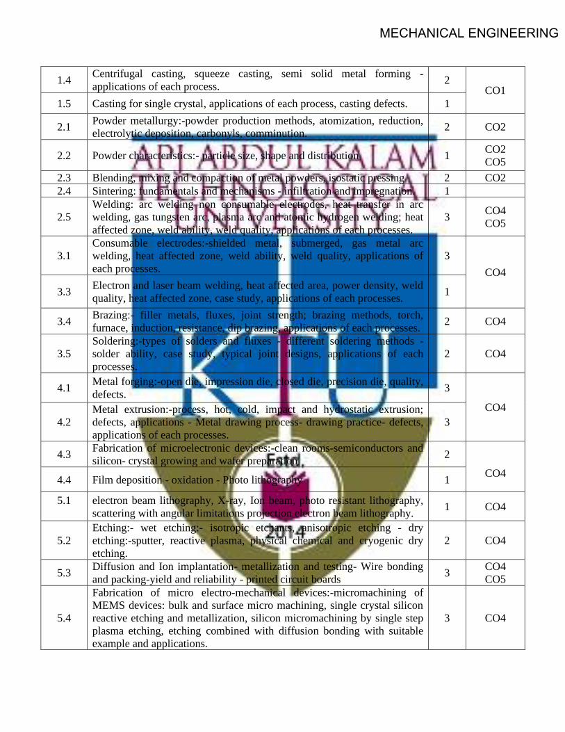
MECHANICAL ENGINEERING
1.4 Centrifugal casting, squeeze casting, semi solid metal forming - applications of each process. 2
CO1 1.5 Casting for single crystal, applications of each process, casting defects. 1
2.1 Powder metallurgy:-powder production methods, atomization, reduction, electrolytic deposition, carbonyls, comminution. 2 CO2
2.2 Powder characteristics:- particle size, shape and distribution 1 CO2 CO5
2.3 Blending, mixing and compaction of metal powders, isostatic pressing 2 CO2 2.4 Sintering: fundamentals and mechanisms - infiltration and impregnation. 1
2.5 Welding: arc welding non consumable electrodes, heat transfer in arc welding, gas tungsten arc, plasma arc and atomic hydrogen welding; heat affected zone, weld ability, weld quality, applications of each processes.
3 CO4 CO5
3.1 Consumable electrodes:-shielded metal, submerged, gas metal arc welding, heat affected zone, weld ability, weld quality, applications of each processes.
3 CO4
3.3 Electron and laser beam welding, heat affected area, power density, weld quality, heat affected zone, case study, applications of each processes. 1
3.4 Brazing:- filler metals, fluxes, joint strength; brazing methods, torch, furnace, induction, resistance, dip brazing, applications of each processes. 2 CO4
3.5 Soldering:-types of solders and fluxes - different soldering methods - solder ability, case study, typical joint designs, applications of each processes.
2 CO4
4.1 Metal forging:-open die, impression die, closed die, precision die, quality, defects. 3
CO4 4.2
Metal extrusion:-process, hot, cold, impact and hydrostatic extrusion; defects, applications - Metal drawing process- drawing practice- defects, applications of each processes.
3
4.3 Fabrication of microelectronic devices:-clean rooms-semiconductors and silicon- crystal growing and wafer preparation 2
CO4 4.4 Film deposition - oxidation - Photo lithography 1
5.1 electron beam lithography, X-ray, Ion beam, photo resistant lithography, scattering with angular limitations projection electron beam lithography. 1 CO4
5.2 Etching:- wet etching:- isotropic etchants, anisotropic etching - dry etching:-sputter, reactive plasma, physical chemical and cryogenic dry etching.
2 CO4
5.3 Diffusion and Ion implantation- metallization and testing- Wire bonding and packing-yield and reliability - printed circuit boards 3 CO4
CO5
5.4
Fabrication of micro electro-mechanical devices:-micromachining of MEMS devices: bulk and surface micro machining, single crystal silicon reactive etching and metallization, silicon micromachining by single step plasma etching, etching combined with diffusion bonding with suitable example and applications.
3 CO4

MECHANICAL ENGINEERING
SEMESTER -4
HONOURS

MECHANICAL ENGINEERING
CODE MET292
COURSE NAME CONTINUUM MECHANICS
CATEGORY L T P CREDIT VAC 3 1 0 4
Preamble:
At the end of the course the students will have a comprehensive, systematic and integrated knowledge of the principles of continuum mechanics. They be conversant with physical laws and analytical tools such as tensor calculus required to formulate and solve continuum problems. Also they have an in-depth understanding of the common principles which underlie the disciplines of solid mechanics and fluid mechanics – hitherto considered mostly separate. The course equip the students to pursue further specialized areas of study such as aeroelasticity, nonlinear mechanics, biomechanics etc. which are essentially based on continuum mechanics.
Prerequisite:
MECHANICS OF SOLIDS
Course Outcomes:
After the completion of the course the student will be able to
CO 1 Make use of the concepts of tensor formalism for practical applications
CO 2 Apply deformation and strain concepts for practical situations
CO 3 Identify stresses acting on components subjected to complex loads
CO 4 Make use of fundamental laws for problem formulations and mathematical modeling
CO 5 Develop constitutive relations and solve 2 D elasticity problems
Mapping of course outcomes with program outcomes
PO 1
PO 2 PO 3 PO 4 PO 5 PO 6 PO 7 PO 8 PO 9 PO10 PO 11
PO 12
CO 1 3 2 2 3 CO 2 3 3 3 2 1 2 3 CO 3 3 3 3 2 1 2 3 CO 4 3 2 3 CO 5 3 3 3 2 1 2 3

MECHANICAL ENGINEERINGAssessment Pattern
Bloom’s Category Continuous Assessment Tests
End Semester Examination
1 2 Remember 10 10 10 Understand 20 20 20 Apply 20 20 70 Analyse Evaluate Create
Mark distribution
Total Marks
CIE ESE ESE Duration
150 50 100 3 hours
Continuous Internal Evaluation Pattern:
Attendance : 10 marks Continuous Assessment Test (2 numbers) : 25 marks Assignment/Quiz/Course project : 15 marks
End Semester Examination Pattern: There will be two parts; Part A and Part B. Part A contain 10 questions with 2 questions from each module, having 3 marks for each question. Students should answer all questions. Part B contains 2 questions from each module of which student should answer any one. Each question can have maximum 2 sub-divisions and carry 14 marks.
COURSE LEVEL ASSESSMENT QUESTIONS
Course Outcome 1
1. With the help of mathematical derivations obtain the relation between circulation ofa vector field per unit area around a point in a plane and curl of the vector.
2. Prove the vector identity 𝑢𝑢 × (𝑣𝑣 × 𝑤𝑤) = (𝑢𝑢.𝑤𝑤)𝑣𝑣 − (𝑢𝑢. 𝑣𝑣)𝑤𝑤3. Show that a) 𝛿𝛿3𝑝𝑝𝑣𝑣𝑝𝑝 = 𝑣𝑣3 b) 𝛿𝛿3𝑖𝑖𝐴𝐴𝑗𝑗𝑖𝑖 = 𝐴𝐴𝑗𝑗3

MECHANICAL ENGINEERINGCourse Outcome 2
1. Discuss the physical interpretations of components of Linearized strain tensor.2. Given the displacement components 𝑢𝑢1 = 𝑘𝑘𝑥𝑥22, 𝑢𝑢2 = 0, 𝑢𝑢3 = 0, 𝑘𝑘 = 10−4, obtain
infinitesimal strain tensor E3. Given 𝑥𝑥1 = 𝑋𝑋1 + 2𝑋𝑋2, 𝑥𝑥2 = 𝑋𝑋2, 𝑥𝑥3 = 𝑋𝑋3, obtain the right Cauchy Green
deformation tensor, right stretch tensor and rotation tensor.
Course Outcome 3
1. Given a continuum, where the stress state is known at one point and is represented
by the Cauchy stress tensor components �𝜎𝜎𝑖𝑖𝑗𝑗� = �1 1 01 1 00 0 2
�Pa, find the principal
stresses and principal directions. 2. The stress state at one point is represented by the Cauchy stress components
�𝜎𝜎𝑖𝑖𝑗𝑗� = �𝜎𝜎 𝑎𝑎𝜎𝜎 𝒃𝒃𝜎𝜎𝑎𝑎𝜎𝜎 𝜎𝜎 𝑐𝑐𝜎𝜎𝑏𝑏𝜎𝜎 𝑐𝑐𝜎𝜎 𝜎𝜎
� , where 𝑎𝑎, 𝑏𝑏, 𝑐𝑐 constants are and 𝜎𝜎 is the value of the
stress. Determine the constants such that the traction vector on the octahedral plane is zero.
3. Find the maximum principal stress, maximum shear stress and their orientations for
the state of stress given �𝜎𝜎𝑖𝑖𝑗𝑗� = �6 9 09 −6 00 0 3
� 𝑀𝑀𝑀𝑀𝑎𝑎
Course Outcome 4
1. Explain Reynold’s Transport Theorem2. Prove the symmetry of stress using principle of conservation of angular momentum.3. Obtain the Eulerian form of continuity equation
Course Outcome 5
1. From linear elastic constitutive relation for isotropic materials, deduce the strain
stress relation 𝜀𝜀𝑖𝑖𝑗𝑗 = 1+𝜈𝜈𝐸𝐸
𝜎𝜎𝑖𝑖𝑗𝑗 −𝜈𝜈𝐸𝐸𝜎𝜎𝑘𝑘𝑘𝑘𝛿𝛿𝑖𝑖𝑗𝑗
2. Formulate the stress compatibility equation for plain strain problems in the absenceof body force.
3. Derive the stress compatibility equation for a plain stress problem with bodyforce. State the condition under which it becomes the biharmonic equation.

MECHANICAL ENGINEERINGMODEL QUESTION PAPER
APJ ABDUL KALAM TECHNOLOGICAL UNIVERSITY
IV SEMESTER B.TECH DEGREE EXAMINATION
Course Code : MET292
Course Name : CONTINUUM MECHANICS
PART A
Each question carries three marks
1. Differentiate between vector space and inner product space.2. Prove div (A x B) = curl A.B – curl B.A, using indicial notation.3. Differentiate between Lagrangian and Eulerian description of fluid motion.4. The Lagrangian coordinate of a material particle is (𝑥𝑥(𝑡𝑡),𝑦𝑦(𝑡𝑡), 𝑧𝑧(𝑡𝑡)). Obtain the
mathematical expression for the component of acceleration along the directionof motion of the material particle.
5. Derive an equation for octahedral shear stress in terms of the stress invariants.
6. The Cauchy stress tensor at a point P is given 𝜎𝜎𝑖𝑖𝑖𝑖 = �5 6 76 8 97 9 2
�GPa. Obtain the
deviatoric and volumetric parts of the tensor.7. Deduce the equilibrium equations from linear momentum principle.8. Express the local and global form of Reynold’s Transport Theorem.9. Write down the stress strain relations of a linear elastic isotropic material.10. Write down the radial and tangential components of stress in terms of Airy’s
stress function.
PART B
Answer one full question from each module.
MODULE 1
11 a) Evaluate using indicial notation (8)
i. 𝐮𝐮 × (𝐯𝐯 × 𝐰𝐰)ii. (𝐮𝐮𝐯𝐯) ∶ (𝐰𝐰𝐰𝐰)
b) Expand using summation convention (6) iii. 𝜌𝜌�̇�𝑣𝑖𝑖 = 𝜌𝜌𝑏𝑏𝑖𝑖 + 𝜎𝜎𝑖𝑖𝑗𝑗,𝑗𝑗iv. 𝑒𝑒′𝑖𝑖 = 𝑄𝑄𝑚𝑚𝑖𝑖𝑒𝑒𝑚𝑚
OR

MECHANICAL ENGINEERING
12 a) Prove that [𝐴𝐴 𝐵𝐵 𝐶𝐶][𝐷𝐷 𝐸𝐸 𝐹𝐹] = �𝐴𝐴.𝐷𝐷 𝐴𝐴.𝐸𝐸 𝐴𝐴.𝐹𝐹𝐵𝐵.𝐷𝐷 𝐵𝐵.𝐸𝐸 𝐵𝐵.𝐹𝐹𝐶𝐶.𝐷𝐷 𝐶𝐶.𝐸𝐸 𝐶𝐶.𝐹𝐹
�, from there show that
𝑒𝑒𝑖𝑖𝑗𝑗𝑘𝑘𝑒𝑒𝑟𝑟𝑟𝑟𝑟𝑟 = �𝛿𝛿𝑖𝑖𝑟𝑟 𝛿𝛿𝑖𝑖𝑟𝑟 𝛿𝛿𝑖𝑖𝑟𝑟𝛿𝛿𝑗𝑗𝑟𝑟 𝛿𝛿𝑗𝑗𝑟𝑟 𝛿𝛿𝑗𝑗𝑟𝑟𝛿𝛿𝑘𝑘𝑟𝑟 𝛿𝛿𝑘𝑘𝑟𝑟 𝛿𝛿𝑘𝑘𝑟𝑟
� (9)
b) Establish the identity 𝑒𝑒𝑖𝑖𝑗𝑗𝑘𝑘𝑒𝑒𝑚𝑚𝑚𝑚𝑘𝑘 = 𝛿𝛿𝑖𝑖𝑚𝑚𝛿𝛿𝑗𝑗𝑚𝑚 − 𝛿𝛿𝑖𝑖𝑚𝑚𝛿𝛿𝑗𝑗𝑚𝑚 (5)
MODULE 2
13 a) Given the motion of a body 𝑥𝑥𝑖𝑖 = 𝑋𝑋𝑖𝑖 + 0.2𝑡𝑡𝑋𝑋2𝛿𝛿1𝑖𝑖, for a temperature field given by 𝜃𝜃 = 2𝑥𝑥1 + (𝑥𝑥2)2, find the material description of temperature and the rate of change of temperature of a particle at time t=0 , which was at the place (0,1,0).
(8) b) Derive compatibility equation (6)
OR
14 a) Given that [𝐹𝐹] = �√3 1 00 2 00 0 1
� , determine the left and right stretch tensors. (14)
b) Explain infinitesimal deformation theory.
c) Obtain an expression for Linearized strain.
MODULE 3
15 a) The stress matrix in MPa when refereed to axes 𝑀𝑀𝑥𝑥1𝑥𝑥2𝑥𝑥3 is (14)
�𝜎𝜎𝑖𝑖𝑗𝑗� = �3 10 0
−10 0 300 30 −27
�
Determine i. the principal stresses
ii. principal planesiii. maximum shear stressiv. Octahedral normal and shear stress
OR
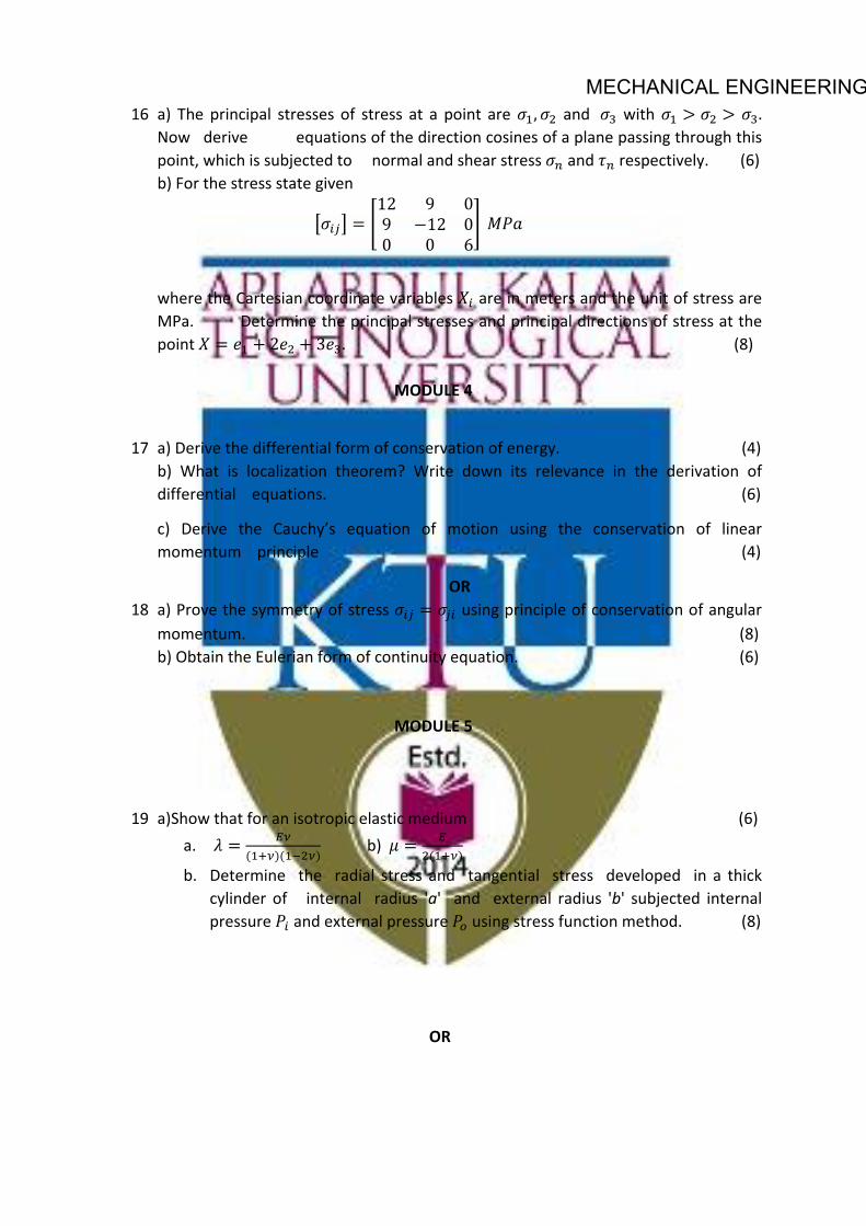
MECHANICAL ENGINEERING16 a) The principal stresses of stress at a point are 𝜎𝜎1,𝜎𝜎2 and 𝜎𝜎3 with 𝜎𝜎1 > 𝜎𝜎2 > 𝜎𝜎3.
Now derive equations of the direction cosines of a plane passing through this point, which is subjected to normal and shear stress 𝜎𝜎𝑚𝑚 and 𝜏𝜏𝑚𝑚 respectively. (6) b) For the stress state given
�𝜎𝜎𝑖𝑖𝑗𝑗� = �12 9 09 −12 00 0 6
� 𝑀𝑀𝑀𝑀𝑎𝑎
where the Cartesian coordinate variables 𝑋𝑋𝑖𝑖 are in meters and the unit of stress are MPa. Determine the principal stresses and principal directions of stress at the point 𝑋𝑋 = 𝑒𝑒1 + 2𝑒𝑒2 + 3𝑒𝑒3. (8)
MODULE 4
17 a) Derive the differential form of conservation of energy. (4) b) What is localization theorem? Write down its relevance in the derivation ofdifferential equations. (6)
c) Derive the Cauchy’s equation of motion using the conservation of linearmomentum principle (4)
OR 18 a) Prove the symmetry of stress 𝜎𝜎𝑖𝑖𝑗𝑗 = 𝜎𝜎𝑗𝑗𝑖𝑖 using principle of conservation of angular
momentum. (8) b) Obtain the Eulerian form of continuity equation. (6)
MODULE 5
19 a)Show that for an isotropic elastic medium (6) a. 𝜆𝜆 = 𝐸𝐸𝜈𝜈
(1+𝜈𝜈)(1−2𝜈𝜈)b) 𝜇𝜇 = 𝐸𝐸
2(1+𝜈𝜈)
b. Determine the radial stress and tangential stress developed in a thickcylinder of internal radius 'a' and external radius 'b' subjected internalpressure 𝑀𝑀𝑖𝑖 and external pressure 𝑀𝑀𝑜𝑜 using stress function method. (8)
OR

MECHANICAL ENGINEERING20 Consider a special stress function having the form 𝜙𝜙 = 𝐵𝐵2𝑥𝑥1𝑥𝑥2 + 𝐷𝐷4𝑥𝑥1𝑥𝑥3. Show
that this stress function ma)'- be adapted to solve for the stresses in an end-loaded cantilever beam as shown in the sketch. Assume the body forces are zero for this problem. (14)

MECHANICAL ENGINEERINGSYLLABUS
Module 1
Mathematical preliminaries - Index notation, Einstein’s summation convention- Kronecker delta and Levi-Civita symbols, Cartesian basis- Concept of tensor- Tensor as a linear transformation - Vector as a first order tensor- Coordinate transformation of vectors and tensors.
Principal values, trace and invariants-Gradient, divergence and curl of vector and tensor fields- Vector identities-Gauss’ divergence and Stokes’ theorems.
Module 2
Concept of continua- Reference and current configuration- Deformation gradient tensor- Lagrangian and Eulerian description of motion.
Polar decomposition theorem- Right and left Cauchy Green tensors- Infinitesimal deformation theory- Linearized strain- Principal strains- Saint Venant’s compatibility equations
Module 3
Traction- Cauchy stress tensor- Stress component along orthonormal basis vector- Components of Cauchy stress tensor on any plane.
Principal planes- Principal stress components- Normal and shear stresses- Stress transformation- Equilibrium equations
Module 4
Balance Laws - Reynold’s transportation theorem- Localization theorem- Lagrangian and Eulerian forms of equation for mass balance.
Balance of linear momentum equation- Balance of angular momentum- Symmetry of stress tensor- Balance of energy
Module 5
Constitutive relations - Generalized Hooke’s law for isotropic materials in indicial and matrix forms- Relation connecting Lame’s constants with Young’s modulus, Poisson’s ratio and Bulk modulus.
2D formulation of field equations; Airy’s stress function- Biharmonic equation-Uni axial tension and pure bending of a beam; End loaded cantilever- Polar coordinates- Axisymmetric formulation- Lame’s thick cylinder problem- Quarter circle cantilevered beam with radial load.

MECHANICAL ENGINEERING
Text Books
1. G. Thomas Mase, George E. Mase.. Ronald E. Smelser. Continuum mechanics forengineers 3rd ed CRC Press
2. . Lawrence E. Malvern. Introduction to the Mechanics of a Continuous Medium –Prentice Hall
Reference Books
1. J.H. Heinbockel, Introduction to Tensor Calculus and Continuum Mechanics – OpenSource
2. W. Michael Lai, David Ribin, Erhard Kaempl, Introduction to Continuum Mechanics4th Ed., Butterworth- Heinemann
3. J. N. Reddy, An Introduction to Continuum Mechanics with applications - CambridgeUniversity Press
4. Y. C. Fung, A First Course in Continuum Mechanics for Physical and BiologicalEngineers and scientists - Prentice Hall
5. Han-Chin W, Continuum mechanics and plasticity - CRC Press6. Sudhakar Nair, Introduction to Continuum Mechanics – Cambridge University press7. Morton E. Gurtin, An introduction to continuum mechanics, Academic Press8. S.P. Timoshenko, J.N. Goodier, Theory of Elasticity, 3rd Edition, McGraw Hill
Publishing
COURSE CONTENTS AND LECTURE SCHEDULE Sl. No. Topic Number of
lecture hours
1 Index notation, Einstein’s summation convention- Kronecker delta and Levi-Civita symbols
2
2 Cartesian basis- Concept of tensor- Tensor as a linear transformation - Vector as a first order tensor
1
3 Coordinate transformation of vectors and tensors. 2
4 Principal values, trace and invariants 2
5 Gradient, divergence and curl of vector and tensor fields 2
6 Vector identities-Gauss’ divergence and Stokes’ theorems. 1
7 Concept of continua- Reference and current configuration, Lagrangian and Eulerian description of motion
2
8 Deformation gradient tensor, Right and left Cauchy Green tensors
2

MECHANICAL ENGINEERING9 Infinitesimal deformation theory- Linearized strain 2
10 Principal strains 1
11 Polar decomposition theorem 1
12 Saint Venant’s compatibility equations 1
13 Traction- Cauchy stress tensor- Stress component along orthonormal basis vector
2
14 Components of Cauchy stress tensor on any plane., Normal and shear stresses
2
15 Principal planes- Principal stress components 2
16 Stress transformation 2
17 Reynold’s transportation theorem- Localization theorem, Introduction on Balance Laws
1
18 Lagrangian and Eulerian forms of equation for mass balance. 1
19 Balance of linear momentum, equilibrium equations 1
20 Balance of angular momentum, Symmetry of stress tensor 1
21 Balance of energy 1
22 Constitutive relations - Generalized Hooke’s law for isotropic materials in indicial and matrix forms
1
23 Relation connecting Lame’s constants with Young’s modulus, Poisson’s ratio and Bulk modulus.
1
24 2D formulation of field equations; Airy’s stress function; Biharmonic equation
4
25 Uni axial tension and pure bending of a beam; End loaded cantilever
1
26 Polar coordinates; Axisymmetric formulation 2
27 Lame’s thick cylinder problem 2
28 Quarter circle cantilevered beam with radial load. 2

MECHANICAL ENGINEERINGCODE
MET294 COURSE NAME
ADVANCED MECHANICS OF FLUIDSCATEGORY L T P CREDIT VAC 3 1 0 4
Preamble:
This course is a survey of principal concepts and methods of fluid dynamics. Topics include conservation equations, exact solutions of Navier-Stokes Equations, potential flow solutions, Boundary layers; introduction to turbulence and turbulence modelling
Prerequisite:
MET 203- Mechanics of Fluids
Course Outcomes: After the completion of the course the student will be able to
CO 1 Apply conservation equations of fluid mechanics
CO 2 Use potential flow theory in fluid problems CO 3 Utilize approximate solutions of the Navier-Stokes equations CO 4 Compute effect on boundary layers. CO 5 Explain turbulence and turbulence modelling
Mapping of course outcomes with program outcomes
PO 1 PO 2 PO 3 PO 4 PO 5 PO 6 PO 7 PO 8 PO 9 PO 10
PO 11
PO 12
CO 1 3 CO 2 3 2 1 CO 3 3 2 1 1 CO 4 3 2 1 CO 5 3 1
Assessment Pattern
Blooms Category CA ESA
Assignment Test - 1 Test - 2
Remember 25 20 20 10
Understand 25 40 40 20
Apply 25 40 40 70
Analyse 25
Evaluate
Create

MECHANICAL ENGINEERINGContinuous Internal Evaluation Pattern:
Attendance : 10 marks
Continuous Assessment Test (2 numbers) : 25 marks
Assignment/Quiz/Course project : 15 marks
Mark distribution & Duration of Examination :
Total Marks CA ESE ESE Duration
150 50 100 3 Hours
End semester pattern:
There will be two parts; Part A and Part B. Part A contain 10 questions with 2 questions from each module, having 3 marks for each question. Students should answer all questions. Part B contains 2 questions from each module of which student should answer any one. Each question can have maximum 2 sub-divisions and carry 14 marks.
MECHANICAL ENGINEERINGCOURSE LEVEL ASSESSMENT QUESTIONS
Course Outcome 1
1. What is the significance of RTT in the study of transport phenomena.
2. Explain the relationship between the stress tensor and the rate of deformation.
3. Derive the expression for the Navier-Stokes equation and explain the different terms in-volved.
Course Outcome 2
1. Derive the expression for stream function and potential function of a doublet using thepotential flow theory.
2. Derive the expression for lift for flow past a cylinder with circulation.
3. What is the significance of conformal mapping?
Course Outcome 3
1. Derive the expression for the pressure gradient for Couette flow.
2. Explain the working of a Viscometer based on the flow through a rotating annulus.
3. What is Stokes’ first problem?
Course Outcome 4
1. Explain the development of boundary layer along a thin flat plate held parallel to a uniformflow. Point out the salient features.
2. Discuss on the effect of pressure gradient on boundary layer separation.
3. Find the thickness of the boundary layer at the trailing edge of a smooth plate of length5 m and width 1.2 m when the plate is moving at 5 m/s in stationary air. Take thekinematic viscosity of air as 0.11 stokes.
Course Outcome 5
1. What are the semi-empirical theories associated with turbulent flow?
2. Explain the two equation models used in turbulent flow.
3. Distinguish between DNS and LES.

MECHANICAL ENGINEERING
Syllabus
Module 1: Concept of viscosity, stress tensor, relation between stress and rate of deformation, Stokes hypothesis, Reynolds Transport Theorem, Mass, Momentum and Energy conservation, Derivation of Navier-Stokes equations.
Module 2: Potential flow: Uniform flow, source flow, sink flow, free vortex flow and super imposed flow-source and sink pair, doublet, plane source in a uniform flow(flow past a half body), source and sink pair in a uniform flow(flow past a Rankine oval body), doublet in a uniform flow(flow past a circular cylinder). Pressure distribution on the surface of the cylinder. Flow past a cylinder with circulation, Kutta-Juokowsky’s law. Complex flow potential, complex flow potentials for source, sink, vortex and doublet. Potential flow between two parallel plates, potential flow in a sector. Introduction to conformal transformation, conformal mapping.
Module 3: Exact Solutions of Navier Stokes Equations. Parallel flow through straight channel and couette flow. Couette flow for negative, zero and positive pressure gradients, flow in a rotating annulus, Viscometer based on rotating annulus. Flow at a wall suddenly set to motion (Stokes first problem)
Module 4: Boundary layer equations; Boundary layer on a flat plate, Prandtl boundary layer equations, Blasius solution for flow over a flat plate, Von- Karman momentum integral equations, Pohlhausen approximation solution of boundary layer for non-zero pressure gradient flow, favorable and adverse pressure gradients, flow separation and vortex shedding. Boundary layer control.
Module 5: Introduction Statistical approach to turbulent flows, Length and time scales and Kolomogrov’s energy cascading theory Reynolds averaged Navier Stokes equations, Turbulence modeling. Concept of eddy viscosity and Prandtl’s mixing length hypothesis Zero, one and two equation turbulence models and Reynold’s stress models. Concepts of LES and DNS.
Text Books
(1) White, F. M. Viscous Fluid Flow, McGraw Hill Education; 3 edition, 2017(2) Schlichting, H. Boundary layer theory. McGraw Hill Education; 7 edition, 2014
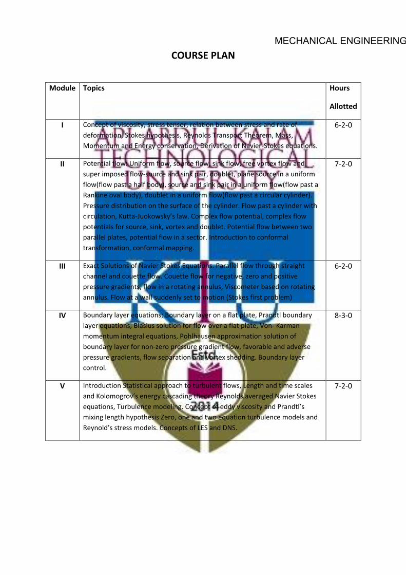
MECHANICAL ENGINEERINGCOURSE PLAN
Module Topics Hours
Allotted
I Concept of viscosity, stress tensor, relation between stress and rate of deformation, Stokes hypothesis, Reynolds Transport Theorem, Mass, Momentum and Energy conservation, Derivation of Navier-Stokes equations.
6-2-0
II Potential flow: Uniform flow, source flow, sink flow, free vortex flow and super imposed flow-source and sink pair, doublet, plane source in a uniform flow(flow past a half body), source and sink pair in a uniform flow(flow past a Rankine oval body), doublet in a uniform flow(flow past a circular cylinder). Pressure distribution on the surface of the cylinder. Flow past a cylinder with circulation, Kutta-Juokowsky’s law. Complex flow potential, complex flow potentials for source, sink, vortex and doublet. Potential flow between two parallel plates, potential flow in a sector. Introduction to conformal transformation, conformal mapping.
7-2-0
III Exact Solutions of Navier Stokes Equations. Parallel flow through straight channel and couette flow. Couette flow for negative, zero and positive pressure gradients, flow in a rotating annulus, Viscometer based on rotating annulus. Flow at a wall suddenly set to motion (Stokes first problem)
6-2-0
IV Boundary layer equations; Boundary layer on a flat plate, Prandtl boundary layer equations, Blasius solution for flow over a flat plate, Von- Karman momentum integral equations, Pohlhausen approximation solution of boundary layer for non-zero pressure gradient flow, favorable and adverse pressure gradients, flow separation and vortex shedding. Boundary layer control.
8-3-0
V Introduction Statistical approach to turbulent flows, Length and time scales and Kolomogrov’s energy cascading theory Reynolds averaged Navier Stokes equations, Turbulence modeling. Concept of eddy viscosity and Prandtl’s mixing length hypothesis Zero, one and two equation turbulence models and Reynold’s stress models. Concepts of LES and DNS.
7-2-0

MECHANICAL ENGINEERINGMODEL QUESTION PAPER
APJ ABDUL KALAM TECHNOLOGICAL UNIVERSITY
IV SEMESTER B.TECH DEGREE EXAMINATION
MET294 ADVANCED MECHANICS OF FLUIDS
Mechanical Engineering
Maximum: 100 Marks Duration: 3 hours
PART A
Answer all questions, each question carries 3 marks
1. What is Stokes hypothesis?
2. What is the importance of RTT in the study of transport phenomena?
3. What are the different elementary flows used in potential flow theory?
4. Draw the stream-lines and potential lines for a doublet in a uniform flow and mark thedifferent regions.
5. With a neat sketch explain the Stokes first problem.
6. Draw the velocity profile in Couette flow for negative, zero and positive pressure gradients.
7. With a neat sketch explain the different regions of boundary layer flow over a flat plat
8. What are the different methods employed in controlling the boundary layer separation?
9. Explain Prandtl’s Mixing length theory.
10. What is the importance of Turbulence Modeling in fluid dynamics?
(10×3=30 Marks)
MECHANICAL ENGINEERINGPART B
Answer one full question from each module
MODULE-I
11. (a) Derive Reynolds Transport Theorem. (7 Marks)
(b) Derive the expression for the law of conservation of mass from RTT. (7 Marks)
12. (a) Derive Navier-Stokes equations in Cartesian coordinate system. (10 Marks)
(b) Write the expanded form of Navier-Stokes equations in Cartesian coordinate system.(4 Marks)
MODULE-II
13. (a) Explain uniform flow with source and sink. Obtain an expression for stream andvelocity potential function and show their approximate distribution. (7 Marks)
(b) A uniform flow with a velocity of 2m/s is flowing over a source placed at the origin.The stagnation point occurs at (−0.398, 0). Determine: (i) Strength of the source,(ii) Maximum width of Rankine half-body and (iii) Other principal dimensions ofthe Rankine half-body. (7 Marks)
14. (a) A uniform flow with a velocity of 3m/s is flowing over a plane source of strength30m2/s. The uniform flow and source flow are in the same plane. A point P issituated in the flow field. The distance of the point P from the source is 0.5m andit is at an angle of 30◦ to the uniform flow. Determine: (i) stream function at pointP (ii) resultant velocity of flow at P and (iii) location of stagnation point from thesource.hfill (10 Marks)
(b) Describe the following terms: i)Complex flow potential ii) Conformal mapping(4 Marks)
MODULE-III
15. (a) An oil of viscosity 18 poise flows between two horizontal fixed parallel plates whichare kept 150mm apart. The maximum velocity of flow is 1.5m/s. Find:
i. The pressure gradient
ii. The shear stress at the two horizontal parallel plates
iii. The discharge per unit width for laminar flow of oil.
(7 Marks)
(b) Explain the significance of Navier-Stokes equation in viscous fluid flow. Derive theexpression for flow in a rotating annulus from the Navier-Stokes Equation. (7 Marks)
16. (a) Derive the expression for pressure gradient in the parallel flow through a straightchannel. (7 Marks)
(b) Explain the working of a Viscometer based on the flow through a rotating annulus.(7 Marks)
MODULE-IV

MECHANICAL ENGINEERING17. (a) Explain the essential features of Blasius method of solving laminar boundary layer
equations for a flat plate. Derive an expression for boundary layer thickness fromthis solution. (7 Marks)
(b) For the velocity profile for laminar boundary layer flows given as
u
U= 2(y/δ) − (y/δ)2
find an expression for boundary layer thickness ( δ ), shear stress ( τ0 ) and co-efficientof drag (CD) in terms of Reynold number. (7 Marks)
18. (a) For the velocity profile in laminar boundary layer as,
u
U=
3
2
(yδ
)− 1
2
(yδ
)3
find the thickness of the boundary layer and the shear stress 1.5 m from the leadingedge of a plate. The plate is 2m long and 1.4m wide and is placed in water which ismoving with a velocity of 200mm per second. Find the total drag force on the plateif µ for water = .01 poise. (7 Marks)
(b) Derive Von Karman momentum integral equation for boundary layer flows.(7 Marks)
MODULE-V
19. (a) Explain and differentiate DNS and LES. (7 Marks)
(b) What is the difference between zero equation, one equation and two equation modelsin turbulent flow? (7 Marks)
20. (a) Explain in detail any one of the two equation models. (7 Marks)
(b) Explain Kolmogrovs energy cascade theory. (7 Marks)
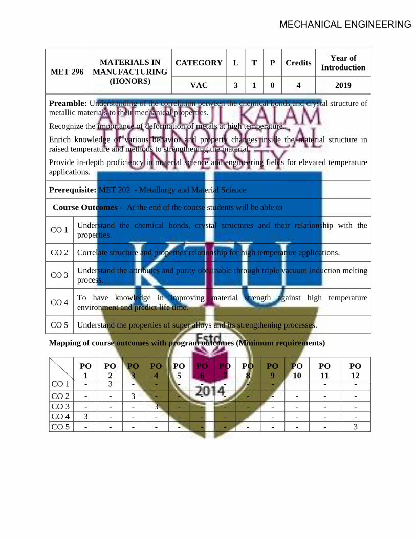
MECHANICAL ENGINEERING
MET 296 MATERIALS IN
MANUFACTURING (HONORS)
CATEGORY L T P Credits Year of Introduction
VAC 3 1 0 4 2019
Preamble: Understanding of the correlation between the chemical bonds and crystal structure of metallic materials to their mechanical properties. Recognize the importance of deformation of metals at high temperature. Enrich knowledge of various behavior and property changes inside the material structure in raised temperature and methods to strengthening the material. Provide in-depth proficiency in material science and engineering fields for elevated temperature applications.
Prerequisite: MET 202 - Metallurgy and Material Science
Course Outcomes - At the end of the course students will be able to
CO 1 Understand the chemical bonds, crystal structures and their relationship with the properties.
CO 2 Correlate structure and properties relationship for high temperature applications.
CO 3 Understand the attributes and purity obtainable through triple vacuum induction melting process.
CO 4 To have knowledge in improving material strength against high temperature environment and predict life time.
CO 5 Understand the properties of super alloys and its strengthening processes.
Mapping of course outcomes with program outcomes (Minimum requirements)
PO 1
PO 2
PO 3
PO 4
PO 5
PO 6
PO 7
PO 8
PO 9
PO 10
PO 11
PO 12
CO 1 - 3 - - - - - - - - - CO 2 - - 3 - - - - - - - - - CO 3 - - - 3 - - - - - - - - CO 4 3 - - - - - - - - - - - CO 5 - - - - - - - - - - - 3

MECHANICAL ENGINEERING
ASSESSMENT PATTERN
Bloom's taxonomy
Continuous Assessment Tests End Semester Examination (Marks) Test 1 (Marks) Test 11 (Marks)
Remember 25 25 25 Understand 15 15 15 Apply 30 25 30 Analyze 10 10 10 Evaluate 10 15 10 Create 10 10 10
Mark distribution
Total Marks CIE marks ESE marks ESE duration
150 50 100 3 Hours
Continuous Internal Evaluation (CIE) Pattern:
Attendance 10 marks
Regular class work/tutorials/assignments 15 marks
Continuous Assessment Test (2 numbers) 25 marks
End semester pattern:- There will be two parts; Part A and Part B. Part A contain 10 questions with 2 questions from each module, having 3 marks for each question. Students should answer all questions. Part B contains 2 questions from each module of which student should answer any one. Each question can have maximum 2 sub-divisions and carry 14 marks.
Course Level Assessment Questions Part -A
Course Outcome 1 (CO1): Understand the chemical bonds, crystal structures and their relationship with the properties. 1. Why electrons of higher principal quantum number form weaker bonds.2. Postulate why ionic and covalent bonded material exhibit bad conductors of heat and
electricity?3. What are the roles of surface imperfections on crack initiation.4. Which mechanism of strengthening is the Hall- Petch equation related to?

MECHANICAL ENGINEERING
Course Outcome 2 (CO2): Correlate structure and properties relationship for high temperature applications. 1. Nickel has an atomic weight of 58.71, a number which arises from the relative proportions of
isotopes of weights 58, 60, 61, 62 and 64. Why is there little contribution from the isotopes ofweight 59 and 63?
2. Comparison of the rates of interdiffusion of the transition group metals (the solutes) with nickel(the solvent) indicates that (i) the interdiffusion rate increases with increasing misfit strain betweensolvent and solute and (ii) the activation energy for interdiffusion decreases with increasing misfitstrain. Why might these observations be contrary to expectation? How might this apparentanomaly be rationalised?
Course Outcome 3 (CO3): Understand the attributes and purity level obtainable through triple vacuum induction melting process. 1. What is the need of vacuum for obtaining purifying metals?2. What are conditions for freckle formation and how can be eliminated?3. Explain the need of electrode quality in ESR and VAR process?4. Which are the factors governs the quality of vacuum arc remelting process.Course Outcome 4 (CO4): To have knowledge in improving material strength against high temperature environment and predict life time. 1. Explain why it might not be sensible, even for single-crystal superalloys, to eliminate completely
the grain-boundary strengtheners such as carbon and boron from the melt chemistry.2. The rate of oxide formation in Al2O3 forming single-crystal superalloys is greatly increased with
additions of Ti to the alloy chemistry. Explain why this effect occurs.3. Non-conductive material will you recommend to use at high temperature explain?4. Both titanium and steel melt at temperatures in excess of 1500 C. Steel can be used at temperatures
as high as 1000C but titanium cannot. Why is this?Course Outcome 5 (CO5): Understand the properties of super alloys and its strengthening processes. 1. The following defects can occur during the casting of single-crystal components:(i) high-angle
grain boundaries, (ii) freckles and (iii) spurious grains. What is meant by these terms? Give a briefexplanation of the origin of each effect.
2. Suggest a high electrical conductive material which can use at 1100C.3. Give two reasons why the use of titanium alloys is increasing at the expense of aluminum in both
civil and military aircraft.SYLLABUS
MODULE - 1 Atomic structure- chemical bonds-crystallography-miller indices - slip - dislocation - crystallization-frank-reed source - Structural parameters in high-temperature deformed metals - dislocation structure - distances between dislocations in sub-boundaries - sub-boundaries as dislocation sources and obstacles -dislocations inside sub-grains - vacancy loops and helicoids - structural peculiarities of high -temperature deformation.MODULE - II Characteristics of high-temperature materials - The super alloys as high-temperature materials- The

MECHANICAL ENGINEERING
requirement: the gas turbine engine- Larson–Miller approach for the ranking of creep performance- development of the super alloys- Nickel as a high-temperature material: justification- super alloy production methods:- vacuum induction melting (VIM), vacuum arc remelting (VAR), VIM, electroslag remelting (ESR),VIM, ESR, VAR- Freckles, three rings, white spot- cleanliness. MODULE - III Superalloys:- metallurgy, characteristics - wrought, cast superalloys, properties -crystal structures, phases in superalloys, Iron-Nickel-base superalloys, Nickel-base superalloys, Cobalt-base superalloys, - elements causing brittle phase formation, detrimental tramp elements, elements producing oxidationand hot corrosion resistance- microstructure, gamma prime, gamma double prime, Carbide and Boridephases, strengthening mechanisms- Heat treatment.MODULE - IV Single-crystal super alloys for blade applications:- solidification, heat transfer, defects - mechanical behavior, performance in creep, fatigue -Titanium: binary phase diagram - production of ingot - forgings - shear bands - pickling - Ti alloys - machining and welding of Titanium - Heat Treatment - properties of titanium aluminides - Niobium: production of niobium - niobium in steel making – niobium alloys characteristics and applications- Niobium products for the superalloy industry. MODULE - V Molybdenum: Ferromolybdenum - production of molybdenum – properties - effect of molybdenum alloying– applications - TZM, TZC- Maraging steel:- reaction in austenite - austenite to martensite transformation- reaction in martensite - time of maraging - precipitate size - fracture toughness - welding and ageing attributes - superior features - applications - cobalt free maraging steel -intermetallics:- phase diagrams- Hume-Rothery phases- structures of MgCu2, MgZn2, MgNi2. Text Books 1. Callister William. D., Material Science and Engineering, John Wiley, 2014
2. Matthew J. Donachie, Stephen J. Donachie, Super alloys A Technical Guide, Second Edition, 2002ASM International.
Reference 1. Barrett, C. S. and Massalski, T. B. Structure of metals, Third edition. New York, N.Y.,
McGraw-Hill Book Company, 1966.2. Decker, Raymond Frank, Source book on maraging steels: A comprehensive collection of
outstanding articles from the periodical and reference literature, Published by AmericanSociety for Metals (1979).
3. Gerd Lutjering James C.Williams, Titanium, springer.
4. Roger C. Reed, The Super alloys Fundamentals and Applications, Cambridge university press.5. Valim Levitin - High temperature strain of metals and alloys - physical fundamentals, Wiley-
VCH (2006).6. https://www.phase-trans.msm.cam.ac.uk/teaching.html

MECHANICAL ENGINEERING
MODEL QUESTION PAPER
MATERIALS IN MANUFACTURING - (HONORS) - MET -296 Max. Marks : 100 Duration : 3 Hours
Part – A Answer all questions.
Answer all questions, each question carries 3 marks
1. NASA's Parker solar probe will be the first-ever mission to "Touch" the Sun. The spacecraft, about thesize of a small car, will travel directly into the Sun's atmosphere about 4 million miles from the earthsurface. Postulate the coolant used in the parker solar probe with chemical bonds.
2. Explain the structural parameters in time and creep curve for Nickel.3. Explain the characteristics required for high-temperature materials4. Explain the ways and means to improve super alloy cleanliness5. What are the elements causing brittle phase formation in super alloys.6. Explain the process and need of stress relieving used for super alloys7. The preferred growth direction of a single-crystal superalloy is (100) Why?8. Where is hundred percentage pure Titanium is used?9. What are the special attributes of marging steel welded joint after ageing process?10. How the structure of intermetallics are determined ?
PART -B Answer one full question from each module.
MODULE -1 11. a. Explain the basic mechanism involved for metal deformation (7 marks).
b. Explain process involved in high temperature strain of metals and alloys (7 marks).OR
12. What are the roles played by the fan, compressor, combustor and turbine arrangements in a typical gasturbine engine? How do these affect (i) the pressure and (ii) the average temperature of the gas stream?Explain why your findings justify the use of nickel based superalloys in the combustor and turbinesections, but not in the compressor regions (14 marks).
MODULE -2 13. Explain the justification for the development of super alloys as high temperature alloys (14 marks).
OR 14. Explain the conditions of freckles, three rings and white spots formation and its implications
(14 marks).MODULE -3
15.Explain with neat sketches of different strengthening mechanisms of super alloys with itsmicrostructure (14 marks).
OR 16.Explain different types of heat treatments employed for super alloys (14 marks).
MODULE -4 17. The materials used for high-pressure turbine blade aerofoils are often referred to as single-crystalsuperalloys. Explain why the use of the term ‘single-crystal’ is disingenuous (14 marks).
OR

MECHANICAL ENGINEERING
18. Explain the process of closed die forging for Titanium alloy manufacturing (14 marks). MODULE -5
19a. Explain the different reaction in austenite in maraging steel (7 marks). 19b. Explain the Maraging steel hardness produced with aging time versus aging time and different temperatures with neat sketches (7 marks).
OR 20a. Explain the synergetic effect of cobalt and molybdenum in maraging steel with graphs and sketch (7 marks). 20b. Explain structures of MgCu2, MgZn2, MgNi2 with neat sketches (7 marks).
Course content and lecture schedules.
Module TOPIC No. of
hours
Course outcomes
1.1 Earlier and present development of atomic structure- Primary bonds: Secondary bonds - crystallography-miller indices- slip- crystallization -frank reed source
1 CO1
1.2 Structural parameters in high-temperature deformed metals: structural parameters. 2 CO1
1.3 Dislocation structure - distances between dislocations in sub-boundaries - sub-boundaries as dislocation sources and obstacles. 3
CO1 1.4 Dislocations inside sub-grains - vacancy loops and helicoids - structural
peculiarities of high-temperature deformation (levitin). 3
2.1 Characteristics of high-temperature materials - The superalloys as high-temperature materials.
3 CO1 CO2
2.2 The requirement: the gas turbine engine- Larson–Miller approach for the ranking of creep performance
2.3 Development of the super alloys- Nickel as a high-temperature material: justification. (Reed). 2 CO2
2.4
Super alloy production methods:- melt routes for super alloys, characteristics, process parameters, application of each process Vacuum induction melting (VIM), Vacuum arc remelting (VAR), VIM, electroslag remelting (ESR),VIM, ESR, VAR.
3 CO2 CO3
2.5
Freckles, conditions of freckles, three rings, white spot- Super alloy cleanliness: ways and means to improve super alloy cleanliness, advantages of improved cleanliness, homogenization oxide cleanliness. (ASM).
2 CO3
3.1 Superalloys:- metallurgy of superalloys, superalloy characteristics - applications - service temperatures for superalloys. 1 CO2

MECHANICAL ENGINEERING
3.2 Wrought superalloys, cast superalloys, properties of superalloys, mechanical properties and the application of superalloys, selecting superalloys.
1 CO2
3.3
Crystal structures, phases in superalloys, Iron-Nickel-base superalloys, Nickel-base superalloys, Cobalt-base superalloys, alloy elements and microstructural effects in superalloys, elements causing brittle phase formation, detrimental tramp elements, elements producing oxidation and hot corrosion resistance.
3 CO2
3.4
Microstructure, gamma prime, gamma double prime, Carbide and Boride phases, strengthening mechanisms: precipitate, gamma prime, gamma double prime, Carbides, M7C3 Carbides, Borides and other beneficial minor elements.
3
CO5
3.5 Heat treatment types:- stress relieving, annealing, quenching, precipitation, (ASM). 1 CO2
4.1
Single-crystal super alloys for blade applications:- directional solidification, heat transfer, formation of defects during directional solidification - mechanical behavior of the single-crystal super alloys, performance in creep, performance in fatigue (Reed).
3 CO4
4.2
Titanium: Ti-based binary phase diagram - production of ingot, Vacuum Arc Remelting - effect of forging temperature and forging pressure - closed die forgings - shear bands - pickling of titanium - Ti alloys - scrap recycling -problems in machining Titanium - welding of titanium - Heat Treatment of Ti - properties of titanium aluminides - applications.
4 CO2 CO5
4.3 Niobium: Production of niobium - niobium alloys - niobium in steel making – niobium alloys characteristics and applications- Niobium products for the superalloy industry.
2 CO2
5.1 Molybdenum: Ferromolybdenum - production of molybdenum – properties - effect of molybdenum alloying on hot strength, corrosion resistance, and toughness – applications - TZM, TZC.
2 CO2
5.2
Maraging steel:- Maraging steel chronology - reaction in austenite - austenite to martensite transformation- reaction in martensite - time of maraging - precipitate size - fracture toughness - welding and ageing attributes - superior features - applications - cobalt free maraging steel and comparisons.
4 CO2 CO4
5.3
Intermetallics:- Electronegativity, characteristics, property prediction - phase diagrams:- Magnesium - Lead, Copper – Zinc, Nickel -Titanium phase diagram - - The Hume-Rothery phases, electron phases /compounds, laves phases - Strukturbericht C15, C14, C36, etc - structures of MgCu2, MgZn2, MgNi2.
3 CO2 CO4


![Semester – 3 PAPER – 3 [Code: EL3202] DIGITAL ELECTRON](https://static.fdokumen.com/doc/165x107/631e10241aedb9cd850f94bc/semester-3-paper-3-code-el3202-digital-electron.jpg)