ENGINE CONTROL SYSTEM
499
EC-1 ENGINE C D E F G H I J K L M SECTION EC A EC N O P CONTENTS ENGINE CONTROL SYSTEM VK56DE PRECAUTION .............................................. 8 PRECAUTIONS .................................................. 8 Precaution for Supplemental Restraint System (SRS) "AIR BAG" and "SEAT BELT PRE-TEN- SIONER" .................................................................. 8 On Board Diagnosis (OBD) System of Engine and A/T ............................................................................ 8 Precaution ................................................................ 9 PREPARATION .......................................... 12 PREPARATION .................................................12 Special Service Tool .............................................. 12 Commercial Service Tool ....................................... 13 SYSTEM DESCRIPTION ............................ 15 ENGINE CONTROL SYSTEM ...........................15 System Diagram ..................................................... 15 Engine Control Component Parts Location ............ 16 MULTIPORT FUEL INJECTION SYSTEM ........23 System Description ................................................ 23 ELECTRIC IGNITION SYSTEM ........................26 System Description ................................................ 26 AIR CONDITIONING CUT CONTROL ..............27 Input/Output Signal Chart ....................................... 27 System Description ................................................ 27 AUTOMATIC SPEED CONTROL DEVICE (ASCD) ..............................................................28 System Description ................................................ 28 Component Description .......................................... 29 CAN COMMUNICATION ...................................30 System Description ................................................ 30 COOLING FAN CONTROL ...............................31 Description ..............................................................31 EVAPORATIVE EMISSION SYSTEM ............... 32 Description ..............................................................32 INTAKE VALVE TIMING CONTROL ................ 35 Description ..............................................................35 FUEL FILLER CAP WARNING SYSTEM ......... 36 System Diagram ....................................................36 System Description .................................................36 ON BOARD DIAGNOSTIC (OBD) SYSTEM .... 38 Diagnosis Description .............................................38 GST (Generic Scan Tool) .......................................38 DIAGNOSIS SYSTEM (ECM) ........................... 39 DIAGNOSIS DESCRIPTION .....................................39 DIAGNOSIS DESCRIPTION : 1st Trip Detection Logic and Two Trip Detection Logic .......................39 DIAGNOSIS DESCRIPTION : DTC and Freeze Frame Data .............................................................39 DIAGNOSIS DESCRIPTION : Counter System .....40 DIAGNOSIS DESCRIPTION : Driving Pattern .......43 DIAGNOSIS DESCRIPTION : System Readiness Test (SRT) Code ....................................................44 DIAGNOSIS DESCRIPTION : Permanent Diag- nostic Trouble Code (Permanent DTC) ..................45 DIAGNOSIS DESCRIPTION : Malfunction Indica- tor Lamp (MIL) ........................................................46 On Board Diagnosis Function .................................46 CONSULT Function ................................................49 ECU DIAGNOSIS INFORMATION ............. 60 ECM ................................................................... 60 CONSULT Reference Value in Data Monitor Mode .......................................................................60 ECM Harness Connector Terminal Layout .............64 ECM Terminal and Reference Value ......................64 Fail-Safe Chart .......................................................73 Revision: August 2013 2014 Armada NAM
-
Upload
khangminh22 -
Category
Documents
-
view
0 -
download
0
Transcript of ENGINE CONTROL SYSTEM

ENGINE
C
D
E
SECTION ECA
EC
ENGINE CONTROL SYSTEM
F
G
H
I
J
K
L
M
N
O
P
CONTENTS
VK56DE
PRECAUTION ............................................... 8
PRECAUTIONS ................................................... 8Precaution for Supplemental Restraint System (SRS) "AIR BAG" and "SEAT BELT PRE-TEN-SIONER" ...................................................................8On Board Diagnosis (OBD) System of Engine and A/T .............................................................................8Precaution .................................................................9
PREPARATION ...........................................12
PREPARATION ..................................................12Special Service Tool ...............................................12Commercial Service Tool ........................................13
SYSTEM DESCRIPTION .............................15
ENGINE CONTROL SYSTEM ............................15System Diagram ......................................................15Engine Control Component Parts Location .............16
MULTIPORT FUEL INJECTION SYSTEM .........23System Description .................................................23
ELECTRIC IGNITION SYSTEM .........................26System Description .................................................26
AIR CONDITIONING CUT CONTROL ...............27Input/Output Signal Chart ........................................27System Description .................................................27
AUTOMATIC SPEED CONTROL DEVICE (ASCD) ...............................................................28
System Description .................................................28Component Description ...........................................29
CAN COMMUNICATION ....................................30System Description .................................................30
COOLING FAN CONTROL ................................31
Description ...............................................................31
EVAPORATIVE EMISSION SYSTEM ...............32Description ...............................................................32
INTAKE VALVE TIMING CONTROL ................35Description ...............................................................35
FUEL FILLER CAP WARNING SYSTEM .........36System Diagram .....................................................36System Description ..................................................36
ON BOARD DIAGNOSTIC (OBD) SYSTEM ....38Diagnosis Description ..............................................38GST (Generic Scan Tool) ........................................38
DIAGNOSIS SYSTEM (ECM) ...........................39
DIAGNOSIS DESCRIPTION ......................................39DIAGNOSIS DESCRIPTION : 1st Trip Detection Logic and Two Trip Detection Logic ........................39DIAGNOSIS DESCRIPTION : DTC and Freeze Frame Data ..............................................................39DIAGNOSIS DESCRIPTION : Counter System ......40DIAGNOSIS DESCRIPTION : Driving Pattern ........43DIAGNOSIS DESCRIPTION : System Readiness Test (SRT) Code .....................................................44DIAGNOSIS DESCRIPTION : Permanent Diag-nostic Trouble Code (Permanent DTC) ...................45DIAGNOSIS DESCRIPTION : Malfunction Indica-tor Lamp (MIL) .........................................................46On Board Diagnosis Function ..................................46CONSULT Function .................................................49
ECU DIAGNOSIS INFORMATION ..............60
ECM ...................................................................60CONSULT Reference Value in Data Monitor Mode ........................................................................60ECM Harness Connector Terminal Layout ..............64ECM Terminal and Reference Value .......................64Fail-Safe Chart ........................................................73
EC-1Revision: August 2013 2014 Armada NAM
DTC Inspection Priority Chart ................................. 74DTC Index .............................................................. 76Test Value and Test Limit ....................................... 80
WIRING DIAGRAM ..................................... 88
ENGINE CONTROL SYSTEM ........................... 88Wiring Diagram ....................................................... 88
BASIC INSPECTION ..................................111
DIAGNOSIS AND REPAIR WORKFLOW ....... 111Trouble Diagnosis Introduction ..............................111
INSPECTION AND ADJUSTMENT ................. 116Basic Inspection ....................................................116Idle Speed and Ignition Timing Check ...................124Procedure After Replacing ECM ...........................124VIN Registration ....................................................126Accelerator Pedal Released Position Learning .....127Throttle Valve Closed Position Learning ...............127Ethanol Mixture Ratio Adaptation (Flexible Fuel Vehicle) ..................................................................127Idle Air Volume Learning .......................................128
HOW TO SET SRT CODE ............................... 130Description .............................................................130SRT Set Driving Pattern ........................................131Work Procedure .....................................................133
HOW TO ERASE PERMANENT DTC ............. 136Description .............................................................136Work Procedure (Group A) ....................................137Work Procedure (Group B) ....................................139
DTC/CIRCUIT DIAGNOSIS ........................142
TROUBLE DIAGNOSIS - SPECIFICATION VALUE ............................................................. 142
Description .............................................................142Testing Condition ...................................................142Inspection Procedure .............................................142Diagnosis Procedure .............................................143
POWER SUPPLY AND GROUND CIRCUIT ... 150Diagnosis Procedure .............................................150Ground Inspection .................................................153
U0101 CAN COMM CIRCUIT .......................... 154Description .............................................................154On Board Diagnosis Logic .....................................154DTC Confirmation Procedure ................................154Diagnosis Procedure .............................................154
U1001 CAN COMM CIRCUIT .......................... 155Description .............................................................155On Board Diagnosis Logic .....................................155DTC Confirmation Procedure ................................155Diagnosis Procedure .............................................155
P0011, P0021 IVT CONTROL ......................... 156On Board Diagnosis Logic .....................................156
DTC Confirmation Procedure ................................ 156Diagnosis Procedure ............................................. 157Component Inspection .......................................... 161
P0031, P0032, P0051, P0052 A/F SENSOR 1 HEATER ...........................................................163
Description ............................................................ 163On Board Diagnosis Logic .................................... 163DTC Confirmation Procedure ................................ 163Diagnosis Procedure ............................................. 163Component Inspection .......................................... 165
P0037, P0038, P0057, P0058 HO2S2 HEAT-ER .....................................................................166
Description ............................................................ 166On Board Diagnosis Logic .................................... 166DTC Confirmation Procedure ................................ 166Diagnosis Procedure ............................................. 167Component Inspection .......................................... 168
P0075, P0081 IVT CONTROL SOLENOID VALVE ..............................................................169
Component Description ........................................ 169On Board Diagnosis Logic .................................... 169DTC Confirmation Procedure ................................ 169Diagnosis Procedure ............................................. 169Component Inspection .......................................... 170
P0101 MAF SENSOR .......................................172Component Description ........................................ 172DTC Logic ............................................................. 172Diagnosis Procedure ............................................. 173Component Inspection .......................................... 174
P0102, P0103 MAF SENSOR ..........................176Component Description ........................................ 176On Board Diagnosis Logic .................................... 176DTC Confirmation Procedure ................................ 176Diagnosis Procedure ............................................. 177Component Inspection .......................................... 178
P0111 IAT SENSOR .........................................181DTC Logic ............................................................. 181Component Function Check ................................. 182Diagnosis Procedure ............................................. 182Component Inspection .......................................... 182
P0112, P0113 IAT SENSOR ............................183Component Description ........................................ 183On Board Diagnosis Logic .................................... 183DTC Confirmation Procedure ................................ 183Diagnosis Procedure ............................................. 183Component Inspection .......................................... 185
P0116 ECT SENSOR .......................................186Component Description ........................................ 186DTC Logic ............................................................. 186Component Function Check ................................. 187Diagnosis Procedure ............................................. 188Component Inspection .......................................... 188
EC-2Revision: August 2013 2014 Armada NAM

C
D
E
F
G
H
I
J
K
L
M
C
A
N
O
P
E
P0117, P0118 ECT SENSOR ........................... 189Component Description ......................................... 189On Board Diagnosis Logic .................................... 189DTC Confirmation Procedure ................................ 190Diagnosis Procedure ............................................. 190Component Inspection .......................................... 191
P0122, P0123 TP SENSOR ............................. 193Component Description ......................................... 193On Board Diagnosis Logic .................................... 193DTC Confirmation Procedure ................................ 193Diagnosis Procedure ............................................. 193Component Inspection .......................................... 196
P0125 ECT SENSOR ....................................... 197Component Description ......................................... 197On Board Diagnosis Logic .................................... 197DTC Confirmation Procedure ................................ 197Diagnosis Procedure ............................................. 198Component Inspection .......................................... 198
P0127 IAT SENSOR ......................................... 200Component Description ......................................... 200On Board Diagnosis Logic .................................... 200DTC Confirmation Procedure ................................ 200Diagnosis Procedure ............................................. 201Component Inspection .......................................... 201
P0128 THERMOSTAT FUNCTION .................. 203On Board Diagnosis Logic .................................... 203DTC Confirmation Procedure ................................ 203Diagnosis Procedure ............................................. 203Component Inspection .......................................... 204
P0130, P0150 A/F SENSOR 1 ......................... 205Component Description ......................................... 205On Board Diagnosis Logic .................................... 205DTC Confirmation Procedure ................................ 205Overall Function Check ......................................... 206Diagnosis Procedure ............................................. 206
P0131, P0151 A/F SENSOR 1 ......................... 209Component Description ......................................... 209On Board Diagnosis Logic .................................... 209DTC Confirmation Procedure ................................ 209Diagnosis Procedure ............................................. 210
P0132, P0152 A/F SENSOR 1 ......................... 213Component Description ......................................... 213On Board Diagnosis Logic .................................... 213DTC Confirmation Procedure ................................ 213Diagnosis Procedure ............................................. 214
P0133, P0153 A/F SENSOR 1 ......................... 217Component Description ......................................... 217On Board Diagnosis Logic .................................... 217DTC Confirmation Procedure ................................ 217Diagnosis Procedure ............................................. 218
P0137, P0157 HO2S2 ...................................... 223Component Description ......................................... 223
On Board Diagnosis Logic .....................................223DTC Confirmation Procedure ................................223Overall Function Check .........................................224Diagnosis Procedure .............................................224Component Inspection ...........................................226
P0138, P0158 HO2S2 ..................................... 228Component Description .........................................228On Board Diagnosis Logic .....................................228DTC Confirmation Procedure ................................228Overall Function Check .........................................229Diagnosis Procedure .............................................230Component Inspection ...........................................233
P0139, P0159 HO2S2 ..................................... 235Component Description .........................................235On Board Diagnosis Logic .....................................235DTC Confirmation Procedure ................................235Overall Function Check .........................................237Diagnosis Procedure .............................................238Component Inspection ...........................................239
P0171, P0174 FUEL INJECTION SYSTEM FUNCTION ...................................................... 242
On Board Diagnosis Logic .....................................242DTC Confirmation Procedure ................................242Diagnosis Procedure .............................................243
P0172, P0175 FUEL INJECTION SYSTEM FUNCTION ...................................................... 247
On Board Diagnosis Logic .....................................247DTC Confirmation Procedure ................................247Diagnosis Procedure .............................................248
P0181 FTT SENSOR ....................................... 252Component Description .........................................252DTC Logic ..............................................................252Component Function Check ..................................254Diagnosis Procedure .............................................254Component Inspection ...........................................255
P0182, P0183 FTT SENSOR .......................... 257Component Description .........................................257On Board Diagnosis Logic .....................................257DTC Confirmation Procedure ................................257Diagnosis Procedure .............................................257Component Inspection ...........................................259
P0222, P0223 APP SENSOR ......................... 260Component Description .........................................260On Board Diagnosis Logic .....................................260DTC Confirmation Procedure ................................260Diagnosis Procedure .............................................260Component Inspection ...........................................263
P0300, P0301, P0302, P0303, P0304, P0305, P0306, P0307, P0308 MISFIRE ...................... 264
On Board Diagnosis Logic .....................................264DTC Confirmation Procedure ................................264Diagnosis Procedure .............................................265
EC-3Revision: August 2013 2014 Armada NAM

P0327, P0328, P0332, P0333 KS .................... 271Component Description .........................................271On Board Diagnosis Logic .....................................271DTC Confirmation Procedure ................................271Diagnosis Procedure .............................................271Component Inspection ...........................................273
P0335 CKP SENSOR (POS) ........................... 274Component Description .........................................274On Board Diagnosis Logic .....................................274DTC Confirmation Procedure ................................274Diagnosis Procedure .............................................274Component Inspection ...........................................276
P0340 CMP SENSOR (PHASE) ...................... 278Component Description .........................................278On Board Diagnosis Logic .....................................278DTC Confirmation Procedure ................................278Diagnosis Procedure .............................................279Component Inspection ...........................................280
P0420, P0430 THREE WAY CATALYST FUNCTION ....................................................... 282
On Board Diagnosis Logic .....................................282DTC Confirmation Procedure ................................282Overall Function Check .........................................283Diagnosis Procedure .............................................283
P0441 EVAP CONTROL SYSTEM .................. 286System Description ................................................286On Board Diagnosis Logic .....................................286DTC Confirmation Procedure ................................286Overall Function Check .........................................287Diagnosis Procedure .............................................287
P0442 EVAP CONTROL SYSTEM .................. 291On Board Diagnosis Logic .....................................291DTC Confirmation Procedure ................................291Diagnosis Procedure .............................................292Component Inspection ...........................................297
P0443 EVAP CANISTER PURGE VOLUME CONTROL SOLENOID VALVE ....................... 298
Description .............................................................298On Board Diagnosis Logic .....................................298DTC Confirmation Procedure ................................299Diagnosis Procedure .............................................300Component Inspection ...........................................302
P0444, P0445 EVAP CANISTER PURGE VOLUME CONTROL SOLENOID VALVE ...... 304
Description .............................................................304On Board Diagnosis Logic .....................................304DTC Confirmation Procedure ................................305Diagnosis Procedure .............................................305Component Inspection ...........................................306
P0447 EVAP CANISTER VENT CONTROL VALVE ............................................................. 307
Component Description .........................................307
On Board Diagnosis Logic .................................... 307DTC Confirmation Procedure ................................ 307Diagnosis Procedure ............................................. 307Component Inspection .......................................... 309
P0448 EVAP CANISTER VENT CONTROL VALVE ..............................................................311
Component Description ........................................ 311On Board Diagnosis Logic .................................... 311DTC Confirmation Procedure ................................ 311Diagnosis Procedure ............................................. 312Component Inspection .......................................... 313
P0451 EVAP CONTROL SYSTEM PRES-SURE SENSOR ................................................315
Component Description ........................................ 315On Board Diagnosis Logic .................................... 315DTC Confirmation Procedure ................................ 315Diagnosis Procedure ............................................. 316Component Inspection .......................................... 317
P0452 EVAP CONTROL SYSTEM PRES-SURE SENSOR ................................................319
Component Description ........................................ 319On Board Diagnosis Logic .................................... 319DTC Confirmation Procedure ................................ 319Diagnosis Procedure ............................................. 320Component Inspection .......................................... 322
P0453 EVAP CONTROL SYSTEM PRES-SURE SENSOR ................................................323
Component Description ........................................ 323On Board Diagnosis Logic .................................... 323DTC Confirmation Procedure ................................ 323Diagnosis Procedure ............................................. 324Component Inspection .......................................... 327
P0455 EVAP CONTROL SYSTEM ..................328On Board Diagnosis Logic .................................... 328DTC Confirmation Procedure ................................ 328Diagnosis Procedure ............................................. 329Component Inspection .......................................... 334
P0456 EVAP CONTROL SYSTEM ..................335On Board Diagnosis Logic .................................... 335DTC Confirmation Procedure ................................ 336Overall Function Check ......................................... 336Diagnosis Procedure ............................................. 337Component Inspection .......................................... 342
P0460 FUEL LEVEL SENSOR .........................343Component Description ........................................ 343On Board Diagnosis Logic .................................... 343DTC Confirmation Procedure ................................ 343Diagnosis Procedure ............................................. 343
P0461 FUEL LEVEL SENSOR .........................345Component Description ........................................ 345On Board Diagnosis Logic .................................... 345Overall Function Check ......................................... 345
EC-4Revision: August 2013 2014 Armada NAM

C
D
E
F
G
H
I
J
K
L
M
C
A
N
O
P
E
Diagnosis Procedure ............................................. 346
P0462, P0463 FUEL LEVEL SENSOR ............ 347Component Description ......................................... 347On Board Diagnosis Logic .................................... 347DTC Confirmation Procedure ................................ 347Diagnosis Procedure ............................................. 347
P0500 VSS ....................................................... 349Description ............................................................ 349DTC Logic ............................................................. 349Diagnosis Procedure ............................................. 349
P0506 ISC SYSTEM ......................................... 351Description ............................................................ 351On Board Diagnosis Logic .................................... 351DTC Confirmation Procedure ................................ 351Diagnosis Procedure ............................................. 351
P0507 ISC SYSTEM ......................................... 353Description ............................................................ 353On Board Diagnosis Logic .................................... 353DTC Confirmation Procedure ................................ 353Diagnosis Procedure ............................................. 353
P050A, P050B, P050E COLD START CON-TROL ................................................................ 355
Description ............................................................ 355DTC Logic ............................................................. 355Diagnosis Procedure ............................................. 356
P0550 PSP SENSOR ....................................... 357Component Description ......................................... 357On Board Diagnosis Logic .................................... 357DTC Confirmation Procedure ................................ 357Diagnosis Procedure ............................................. 357Component Inspection .......................................... 359
P0603 ECM ....................................................... 360DTC Logic ............................................................. 360Diagnosis Procedure ............................................. 360
P0604 ECM ....................................................... 361DTC Logic ............................................................. 361Diagnosis Procedure ............................................. 361
P0605 ECM ....................................................... 362DTC Logic ............................................................. 362Diagnosis Procedure ............................................. 362
P0606 ECM ....................................................... 363DTC Logic ............................................................. 363Diagnosis Procedure ............................................. 363
P0607 ECM ....................................................... 364DTC Logic ............................................................. 364Diagnosis Procedure ............................................. 364
P060A ECM ...................................................... 365DTC Logic ............................................................. 365Diagnosis Procedure ............................................. 365
P060B ECM ..................................................... 366DTC Logic ..............................................................366Diagnosis Procedure .............................................366
P0643 SENSOR POWER SUPPLY ................ 367On Board Diagnosis Logic .....................................367DTC Confirmation Procedure ................................367Diagnosis Procedure .............................................367
P0850 PNP SWITCH ....................................... 370Component Description .........................................370On Board Diagnosis Logic .....................................370DTC Confirmation Procedure ................................370Overall Function Check .........................................370Diagnosis Procedure .............................................371
P1140, P1145 IVT CONTROL POSITION SENSOR .......................................................... 373
Component Description .........................................373On Board Diagnosis Logic .....................................373DTC Confirmation Procedure ................................373Diagnosis Procedure .............................................373Component Inspection ...........................................376
P1148, P1168 CLOSED LOOP CONTROL .... 377On Board Diagnosis Logic .....................................377
P1211 TCS CONTROL UNIT .......................... 378Description .............................................................378On Board Diagnosis Logic .....................................378DTC Confirmation Procedure ................................378Diagnosis Procedure .............................................378
P1212 TCS COMMUNICATION LINE ............. 379Description .............................................................379On Board Diagnosis Logic .....................................379DTC Confirmation Procedure ................................379Diagnosis Procedure .............................................379
P1217 ENGINE OVER TEMPERATURE ........ 380On Board Diagnosis Logic .....................................380Overall Function Check .........................................380Diagnosis Procedure .............................................381Main 13 Causes of Overheating ............................382
P1220 FUEL PUMP CONTROL MODULE (FPCM) ............................................................ 384
Description .............................................................384On Board Diagnosis Logic .....................................384DTC Confirmation Procedure ................................384Diagnosis Procedure .............................................385Component Inspection ...........................................388
P1225 TP SENSOR ......................................... 389Component Description .........................................389On Board Diagnosis Logic .....................................389DTC Confirmation Procedure ................................389Diagnosis Procedure .............................................389
P1226 TP SENSOR ......................................... 391Component Description .........................................391
EC-5Revision: August 2013 2014 Armada NAM

On Board Diagnosis Logic .....................................391DTC Confirmation Procedure ................................391Diagnosis Procedure .............................................391
P1550 BATTERY CURRENT SENSOR .......... 393Component Description .........................................393On Board Diagnosis Logic .....................................393DTC Confirmation Procedure ................................393Diagnosis Procedure .............................................393Component Inspection ...........................................395
P1551, P1552 BATTERY CURRENT SEN-SOR .................................................................. 397
Component Description .........................................397On Board Diagnosis Logic .....................................397DTC Confirmation Procedure ................................397Diagnosis Procedure .............................................397Component Inspection ...........................................399
P1553 BATTERY CURRENT SENSOR .......... 401Component Description .........................................401On Board Diagnosis Logic .....................................401DTC Confirmation Procedure ................................401Diagnosis Procedure .............................................401Component Inspection ...........................................403
P1554 BATTERY CURRENT SENSOR .......... 405Component Description .........................................405On Board Diagnosis Logic .....................................405Overall Function Check .........................................405Diagnosis Procedure .............................................406Component Inspection ...........................................407
P1564 ASCD STEERING SWITCH ................. 409Component Description .........................................409On Board Diagnosis Logic .....................................409DTC Confirmation Procedure ................................409Diagnosis Procedure .............................................409Component Inspection ...........................................411
P1572 ASCD BRAKE SWITCH ....................... 413Component Description .........................................413On Board Diagnosis Logic .....................................413DTC Confirmation Procedure ................................413Diagnosis Procedure .............................................414Component Inspection ...........................................417
P1574 ASCD VEHICLE SPEED SENSOR ...... 418Component Description .........................................418On Board Diagnosis Logic .....................................418DTC Confirmation Procedure ................................418Diagnosis Procedure .............................................418
P1805 BRAKE SWITCH .................................. 420Description .............................................................420On Board Diagnosis Logic .....................................420DTC Confirmation Procedure ................................420Diagnosis Procedure .............................................420Component Inspection ...........................................422
P2096, P2097, P2098, P2099 A/F SENSOR 1 . 423
Component Description ........................................ 423On Board Diagnosis Logic .................................... 423DTC Confirmation Procedure ................................ 423Diagnosis Procedure ............................................. 424
P2100, P2103 THROTTLE CONTROL MO-TOR RELAY .....................................................429
Component Description ........................................ 429On Board Diagnosis Logic .................................... 429DTC Confirmation Procedure ................................ 429Diagnosis Procedure ............................................. 429
P2101 ELECTRIC THROTTLE CONTROL FUNCTION ........................................................432
Description ............................................................ 432On Board Diagnosis Logic .................................... 432DTC Confirmation Procedure ................................ 432Diagnosis Procedure ............................................. 432Component Inspection .......................................... 435
P2118 THROTTLE CONTROL MOTOR ..........436Component Description ........................................ 436On Board Diagnosis Logic .................................... 436DTC Confirmation Procedure ................................ 436Diagnosis Procedure ............................................. 436Component Inspection .......................................... 437
P2119 ELECTRIC THROTTLE CONTROL ACTUATOR ......................................................438
Component Description ........................................ 438On Board Diagnosis Logic .................................... 438DTC Confirmation Procedure ................................ 438Diagnosis Procedure ............................................. 439
P2122, P2123 APP SENSOR ...........................440Component Description ........................................ 440On Board Diagnosis Logic .................................... 440DTC Confirmation Procedure ................................ 440Diagnosis Procedure ............................................. 440Component Inspection .......................................... 442
P2127, P2128 APP SENSOR ...........................443Component Description ........................................ 443On Board Diagnosis Logic .................................... 443DTC Confirmation Procedure ................................ 443Diagnosis Procedure ............................................. 443Component Inspection .......................................... 446
P2135 TP SENSOR ..........................................447Component Description ........................................ 447On Board Diagnosis Logic .................................... 447DTC Confirmation Procedure ................................ 447Diagnosis Procedure ............................................. 447Component Inspection .......................................... 450
P2138 APP SENSOR .......................................451Component Description ........................................ 451On Board Diagnosis Logic .................................... 451DTC Confirmation Procedure ................................ 451Diagnosis Procedure ............................................. 452
EC-6Revision: August 2013 2014 Armada NAM
C
D
E
F
G
H
I
J
K
L
M
C
A
N
O
P
E
Component Inspection .......................................... 454
ASCD BRAKE SWITCH ................................... 455Component Description ......................................... 455Diagnosis Procedure ............................................. 455Component Inspection .......................................... 457
ASCD INDICATOR ........................................... 458Component Description ......................................... 458Diagnosis Procedure ............................................. 458
COOLING FAN ................................................. 459Diagnosis Procedure ............................................. 459Component Inspection .......................................... 460
ELECTRICAL LOAD SIGNAL ......................... 461Description ............................................................ 461Diagnosis Procedure ............................................. 461
FUEL INJECTOR ............................................. 463Component Description ......................................... 463Diagnosis Procedure ............................................. 463Component Inspection .......................................... 465
FUEL PUMP ..................................................... 466Description ............................................................ 466Diagnosis Procedure ............................................. 466Component Inspection .......................................... 471
IGNITION SIGNAL ........................................... 473Component Description ......................................... 473Diagnosis Procedure ............................................. 473Component Inspection .......................................... 476
MALFUNCTION INDICATOR LAMP ............... 478Component Function Check .................................. 478Diagnosis Procedure ............................................. 478
ON BOARD REFUELING VAPOR RECOV-ERY (ORVR) ..................................................... 479
System Description ............................................... 479Diagnosis Procedure ............................................. 479Component Inspection .......................................... 481
POSITIVE CRANKCASE VENTILATION ....... 484Description .............................................................484Component Inspection ...........................................484
REFRIGERANT PRESSURE SENSOR .......... 486Component Description .........................................486Diagnosis Procedure .............................................486
SYMPTOM DIAGNOSIS ............................ 489
ENGINE CONTROL SYSTEM SYMPTOMS ... 489Symptom Matrix Chart ...........................................489
NORMAL OPERATING CONDITION ............. 493Fuel Cut Control (at No Load and High Engine Speed) ...................................................................493
PERIODIC MAINTENANCE ...................... 494
FUEL PRESSURE ........................................... 494Fuel Pressure Check .............................................494
EVAP LEAK CHECK ...................................... 496How to Detect Fuel Vapor Leakage .......................496
SERVICE DATA AND SPECIFICATIONS (SDS) .......................................................... 498
SERVICE DATA AND SPECIFICATIONS (SDS) ............................................................... 498
Fuel Pressure ........................................................498Idle Speed and Ignition Timing ..............................498Calculated Load Value ..........................................498Mass Air Flow Sensor ............................................498Intake Air Temperature Sensor .............................498Engine Coolant Temperature Sensor ....................498A/F Sensor 1 Heater ..............................................498Heated Oxygen sensor 2 Heater ...........................499Crankshaft Position Sensor (POS) ........................499Camshaft Position Sensor (PHASE) .....................499Throttle Control Motor ............................................499Fuel Injector ...........................................................499Fuel Pump .............................................................499
EC-7Revision: August 2013 2014 Armada NAM

[VK56DE]PRECAUTIONS
< PRECAUTION >
PRECAUTIONPRECAUTIONS
Precaution for Supplemental Restraint System (SRS) "AIR BAG" and "SEAT BELT PRE-TENSIONER" INFOID:0000000009824998
The Supplemental Restraint System such as “AIR BAG” and “SEAT BELT PRE-TENSIONER”, used alongwith a front seat belt, helps to reduce the risk or severity of injury to the driver and front passenger for certaintypes of collision. This system includes seat belt switch inputs and dual stage front air bag modules. The SRSsystem uses the seat belt switches to determine the front air bag deployment, and may only deploy one frontair bag, depending on the severity of a collision and whether the front occupants are belted or unbelted.Information necessary to service the system safely is included in the “SRS AIR BAG” and “SEAT BELT” of thisService Manual.WARNING:Always observe the following items for preventing accidental activation.• To avoid rendering the SRS inoperative, which could increase the risk of personal injury or death in
the event of a collision that would result in air bag inflation, all maintenance must be performed byan authorized NISSAN/INFINITI dealer.
• Improper maintenance, including incorrect removal and installation of the SRS, can lead to personalinjury caused by unintentional activation of the system. For removal of Spiral Cable and Air BagModule, see “SRS AIR BAG”.
• Never use electrical test equipment on any circuit related to the SRS unless instructed to in this Ser-vice Manual. SRS wiring harnesses can be identified by yellow and/or orange harnesses or harnessconnectors.
PRECAUTIONS WHEN USING POWER TOOLS (AIR OR ELECTRIC) AND HAMMERSWARNING:Always observe the following items for preventing accidental activation.• When working near the Air Bag Diagnosis Sensor Unit or other Air Bag System sensors with the
ignition ON or engine running, never use air or electric power tools or strike near the sensor(s) witha hammer. Heavy vibration could activate the sensor(s) and deploy the air bag(s), possibly causingserious injury.
• When using air or electric power tools or hammers, always switch the ignition OFF, disconnect thebattery, and wait at least 3 minutes before performing any service.
On Board Diagnosis (OBD) System of Engine and A/T INFOID:0000000009824999
The ECM has an on board diagnostic system. It will light up the malfunction indicator lamp (MIL) to warn thedriver of a malfunction causing emission deterioration.CAUTION:• Be sure to turn the ignition switch OFF and disconnect the negative battery cable before any repair
or inspection work. The open/short circuit of related switches, sensors, solenoid valves, etc. willcause the MIL to light up.
• Be sure to connect and lock the connectors securely after work. A loose (unlocked) connector willcause the MIL to light up due to the open circuit. (Be sure the connector is free from water, grease,dirt, bent terminals, etc.)
• Certain systems and components, especially those related to OBD, may use a new style slide-lock-ing type harness connector. For description and how to disconnect, refer to PG-68, "Description".
• Be sure to route and secure the harnesses properly after work. The interference of the harness witha bracket, etc. may cause the MIL to light up due to the short circuit.
• Be sure to connect rubber tubes properly after work. A misconnected or disconnected rubber tubemay cause the MIL to light up due to the malfunction of the EVAP system or fuel injection system,etc.
• Be sure to erase the unnecessary malfunction information (repairs completed) from the ECM andTCM (Transmission control module) before returning the vehicle to the customer.
EC-8Revision: August 2013 2014 Armada NAM

PRECAUTIONS[VK56DE]
C
D
E
F
G
H
I
J
K
L
M
A
C
N
P
O
< PRECAUTION >
E
Precaution INFOID:0000000009825000
• Always use a 12 volt battery as power source.• Do not attempt to disconnect battery cables while engine is
running.• Before connecting or disconnecting the ECM harness con-
nector, turn ignition switch OFF and disconnect negative bat-tery cable. Failure to do so may damage the ECM becausebattery voltage is applied to ECM even if ignition switch isturned OFF.
• Before removing parts, turn ignition switch OFF and then dis-connect negative battery cable.
• Do not disassemble ECM.• If a battery cable is disconnected, the memory will return to
the ECM value.The ECM will now start to self-control at its initial value.Engine operation can vary slightly when the terminal is dis-connected. However, this is not an indication of a malfunc-tion. Do not replace parts because of a slight variation.
• If the battery is disconnected, the following emission-relateddiagnostic information will be lost within 24 hours.
- Diagnostic trouble codes- 1st trip diagnostic trouble codes- Freeze frame data- 1st trip freeze frame data- System readiness test (SRT) codes- Test values- <Flexible Fuel Vehicle>
Presumed ethanol mixture ratio• When connecting ECM harness connector, fasten it securely
with a lever as far as it will go as shown in the figure.
• When connecting or disconnecting pin connectors into orfrom ECM, take care not to damage pin terminals (bend orbreak).Make sure that there are not any bends or breaks on ECM pinterminal, when connecting pin connectors.
• Securely connect ECM harness connectors.A poor connection can cause an extremely high (surge) volt-age to develop in coil and condenser, thus resulting in dam-age to ICs.
• Keep engine control system harness at least 10 cm (4 in) awayfrom adjacent harness, to prevent engine control system mal-functions due to receiving external noise, degraded operationof ICs, etc.
• Keep engine control system parts and harness dry.
SEF289H
PBIB1164E
BBIA0387E
PBIB0090E
EC-9Revision: August 2013 2014 Armada NAM

[VK56DE]PRECAUTIONS
< PRECAUTION >• Before replacing ECM, perform ECM Terminals and Reference
Value inspection and make sure ECM functions properly.Refer to EC-64, "ECM Terminal and Reference Value".
• Handle mass air flow sensor carefully to avoid damage.• Do not disassemble mass air flow sensor.• Do not clean mass air flow sensor with any type of detergent.• Do not disassemble electric throttle control actuator.• Even a slight leak in the air intake system can cause serious
incidents.• Do not shock or jar the camshaft position sensor (PHASE),
crankshaft position sensor (POS).
• After performing each TROUBLE DIAGNOSIS, perform DTCConfirmation Procedure or Overall Function Check.The DTC should not be displayed in the DTC ConfirmationProcedure if the repair is completed. The Overall FunctionCheck should be a good result if the repair is completed.
• When measuring ECM signals with a circuit tester, never allowthe two tester probes to contact.Accidental contact of probes will cause a short circuit anddamage the ECM power transistor.
• Do not use ECM ground terminals when measuring input/out-put voltage. Doing so may result in damage to the ECM's tran-sistor. Use a ground other than ECM terminals, such as theground.
MEF040D
JSBIA1315ZZ
SEF348N
EC-10Revision: August 2013 2014 Armada NAM
PRECAUTIONS[VK56DE]
C
D
E
F
G
H
I
J
K
L
M
A
C
N
P
O
< PRECAUTION >
E
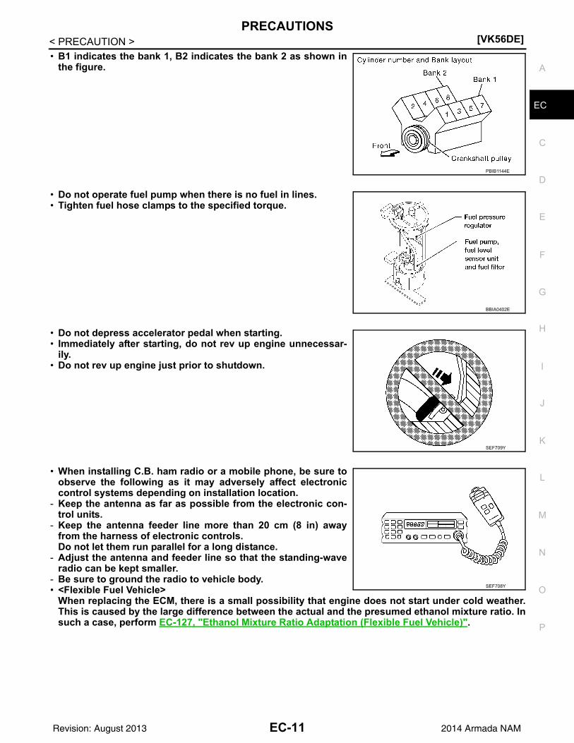
• B1 indicates the bank 1, B2 indicates the bank 2 as shown inthe figure.
• Do not operate fuel pump when there is no fuel in lines.• Tighten fuel hose clamps to the specified torque.
• Do not depress accelerator pedal when starting.• Immediately after starting, do not rev up engine unnecessar-
ily.• Do not rev up engine just prior to shutdown.
• When installing C.B. ham radio or a mobile phone, be sure toobserve the following as it may adversely affect electroniccontrol systems depending on installation location.
- Keep the antenna as far as possible from the electronic con-trol units.
- Keep the antenna feeder line more than 20 cm (8 in) awayfrom the harness of electronic controls.Do not let them run parallel for a long distance.
- Adjust the antenna and feeder line so that the standing-waveradio can be kept smaller.
- Be sure to ground the radio to vehicle body.• <Flexible Fuel Vehicle>
When replacing the ECM, there is a small possibility that engine does not start under cold weather.This is caused by the large difference between the actual and the presumed ethanol mixture ratio. Insuch a case, perform EC-127, "Ethanol Mixture Ratio Adaptation (Flexible Fuel Vehicle)".
PBIB1144E
BBIA0402E
SEF709Y
SEF708Y
EC-11Revision: August 2013 2014 Armada NAM

[VK56DE]PREPARATION
< PREPARATION >
PREPARATIONPREPARATION
Special Service Tool INFOID:0000000009825001
The actual shapes of Kent-Moore tools may differ from those of special service tools illustrated here.
Tool number(Kent-Moore No.) Tool name
Description
EG17650301(J-33984-A)Radiator cap tester adapter
Adapting radiator cap tester to radiator cap and ra-diator filler necka: 28 (1.10) dia.b: 31.4 (1.236) dia.c: 41.3 (1.626) dia.Unit: mm (in)
KV10117100(J-36471-A)Heated oxygen sensor wrench
Loosening or tightening heated oxygen sensors with 22 mm (0.87 in) hexagon nut
KV10114400(J-38365)Heated oxygen sensor wrench
Loosening or tightening heated oxygen sensorsa: 22 mm (0.87 in)
(J-44626)Air fuel ratio (A/F) sen-sor wrench
Loosening or tightening air fuel ratio (A/F) sensor 1
(J-44321)Fuel pressure gauge kit
Checking fuel pressure
(J-44321-6)Fuel pressure adapter
Connecting fuel pressure gauge to quick connec-tor type fuel lines.
S-NT564
S-NT379
S-NT636
LEM054
LEC642
LBIA0376E
EC-12Revision: August 2013 2014 Armada NAM

PREPARATION[VK56DE]
C
D
E
F
G
H
I
J
K
L
M
A
C
N
P
O
< PREPARATION >
E
Commercial Service Tool INFOID:0000000009825002
(J-45488)Quick connector re-lease
Remove fuel tube quick connectors in engine room.
(J-23688)Engine coolant refrac-tometer
Checking concentration of ethylene glycol in en-gine coolant
Tool number(Kent-Moore No.) Tool name
Description
PBIC0198E
WBIA0539E
Tool name(Kent-Moore No.)
Description
Leak detector i.e.: (J-41416)
Locating the EVAP leak
EVAP service port adapteri.e.: (J-41413-OBD)
Applying positive pressure through EVAP service port
Fuel filler cap adapteri.e.: (MLR-8382)
Checking fuel tank vacuum relief valve opening pressure
Socket wrench Removing and installing engine coolant tempera-ture sensor
S-NT703
S-NT704
S-NT815
S-NT705
EC-13Revision: August 2013 2014 Armada NAM

[VK56DE]PREPARATION
< PREPARATION >
Oxygen sensor thread cleaneri.e.: (J-43897-18)(J-43897-12)
Reconditioning the exhaust system threads before installing a new oxygen sensor. Use with anti-seize lubricant shown below.a: 18 mm diameter with pitch 1.5 mm for Zirco-nia Oxygen Sensorb: 12 mm diameter with pitch 1.25 mm for Tita-nia Oxygen Sensor
Anti-seize lubricant
i.e.: (PermatexTM 133AR or equivalent meeting MIL specifica-tion MIL-A-907)
Lubricating oxygen sensor thread cleaning tool when reconditioning exhaust system threads.
Tool name(Kent-Moore No.)
Description
AEM488
S-NT779
EC-14Revision: August 2013 2014 Armada NAM

ENGINE CONTROL SYSTEM[VK56DE]
C
D
E
F
G
H
I
J
K
L
M
A
C
N
P
O
< SYSTEM DESCRIPTION >
E
SYSTEM DESCRIPTIONENGINE CONTROL SYSTEM
System Diagram INFOID:0000000009825003
JMBIA1719GB
EC-15Revision: August 2013 2014 Armada NAM

[VK56DE]ENGINE CONTROL SYSTEM
< SYSTEM DESCRIPTION >
Engine Control Component Parts Location INFOID:0000000009825004
1. ECM 2. Dropping resistor (FFV models only) 3. Battery current sensor
4. Power steering pressure sensor 5. Ignition coil (with power transistor) and spark plug (bank 2)
6. Refrigerant pressure sensor
7. Intake valve timing control position sensor (bank 2)
8. Intake valve timing control solenoid valve (bank 2)
9. Engine coolant temperature sensor
10. Electric throttle control actuator 11. Intake valve timing control position sensor (bank 1)
12. Intake valve timing control solenoid valve (bank 1)
13. Cooling fan motor 14. Camshaft position sensor (PHASE) 15. Ignition coil (with power transistor) and spark plug (bank 1)
16. Mass air flow sensor (with intake air temperature sensor)
17. A/F sensor 1 (bank 1) 18. EVAP service port
19. Fuel injector (bank 1) 20. Knock sensor (bank 1) 21. EVAP canister purge volume control solenoid valve
22. Knock sensor (bank 2) 23. Fuel injector (bank 2) 24. A/F sensor 1 (bank 2)
25. IPDM E/R
BBIA0772E
EC-16Revision: August 2013 2014 Armada NAM

ENGINE CONTROL SYSTEM[VK56DE]
C
D
E
F
G
H
I
J
K
L
M
A
C
N
P
O
< SYSTEM DESCRIPTION >
E
1. Dropping resistor (FFV models only) (view with battery removed)
2. Body ground (view with battery re-moved)
3. Body ground (view with battery re-moved)
4. Body ground 5. No.1 ignition coil 6. Engine ground
7. Mass air flow sensor (with intake air temperature sensor)
8. IPDM E/R 9. Battery
10. Radiator hose 11. Camshaft position sensor (PHASE) 12. Electric throttle control actuator (view with intake air duct removed)
13. Cooling fan motor harness connec-tor
: Vehicle front
BBIA0773E
EC-17Revision: August 2013 2014 Armada NAM

[VK56DE]ENGINE CONTROL SYSTEM
< SYSTEM DESCRIPTION >
1. Knock sensor (bank 1) (view with en-gine removed)
2. Knock sensor (bank 2) (view with en-gine removed)
3. Battery current sensor
4. Power steering pressure sensor 5. Power steering fluid reservoir 6. Intake manifold
7. Engine coolant temperature sensor 8. Ignition coils (with power transistor) 9. Ignition coil (with power transistor)
10. Injector harness connectors (bank 2) 11. Injector harness connectors (bank 1)
: Vehicle front
BBIA0774E
EC-18Revision: August 2013 2014 Armada NAM
ENGINE CONTROL SYSTEM[VK56DE]
C
D
E
F
G
H
I
J
K
L
M
A
C
N
P
O
< SYSTEM DESCRIPTION >
E
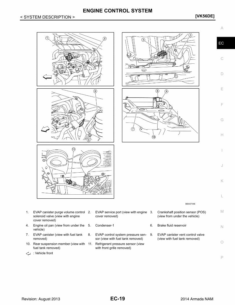
1. EVAP canister purge volume control solenoid valve (view with engine cover removed)
2. EVAP service port (view with engine cover removed)
3. Crankshaft position sensor (POS) (view from under the vehicle)
4. Engine oil pan (view from under the vehicle)
5. Condenser-1 6. Brake fluid reservoir
7. EVAP canister (view with fuel tank removed)
8. EVAP control system pressure sen-sor (view with fuel tank removed)
9. EVAP canister vent control valve (view with fuel tank removed)
10. Rear suspension member (view with fuel tank removed)
11. Refrigerant pressure sensor (view with front grille removed)
: Vehicle front
BBIA0739E
EC-19Revision: August 2013 2014 Armada NAM

[VK56DE]ENGINE CONTROL SYSTEM
< SYSTEM DESCRIPTION >
1. Fuel pump control module (FFV models only)
2. Blower motor 3. Intake valve timing control position sensor (bank 2) (view with engine cover and intake air duct removed)
4. Intake valve timing control position sensor (bank 1) (view with engine cover and intake air duct removed)
5. Intake valve timing control solenoid valve (bank 2) (view with engine cov-er and intake air duct removed)
6 Drive belt (view with engine cover and intake air duct removed)
7. Radiator hose (view with engine cov-er and intake air duct removed)
8. Intake valve timing control solenoid valve (bank 1) (view with engine cov-er and intake air duct removed)
BBIA0779E
EC-20Revision: August 2013 2014 Armada NAM

ENGINE CONTROL SYSTEM[VK56DE]
C
D
E
F
G
H
I
J
K
L
M
A
C
N
P
O
< SYSTEM DESCRIPTION >
E
BBIA0384E
EC-21Revision: August 2013 2014 Armada NAM

[VK56DE]ENGINE CONTROL SYSTEM
< SYSTEM DESCRIPTION >
PBIB2637E
EC-22Revision: August 2013 2014 Armada NAM
MULTIPORT FUEL INJECTION SYSTEM[VK56DE]
C
D
E
F
G
H
I
J
K
L
M
A
C
N
P
O
< SYSTEM DESCRIPTION >
E
MULTIPORT FUEL INJECTION SYSTEM
System Description INFOID:0000000009825005
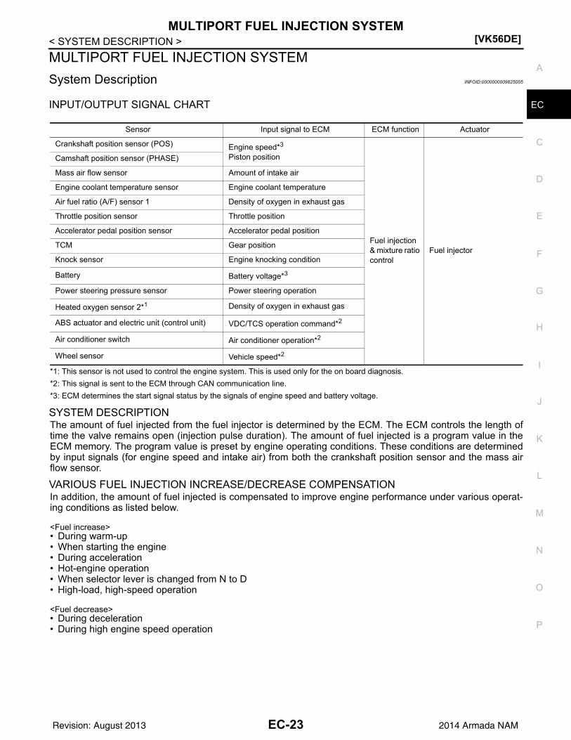
INPUT/OUTPUT SIGNAL CHART
*1: This sensor is not used to control the engine system. This is used only for the on board diagnosis.
*2: This signal is sent to the ECM through CAN communication line.
*3: ECM determines the start signal status by the signals of engine speed and battery voltage.
SYSTEM DESCRIPTIONThe amount of fuel injected from the fuel injector is determined by the ECM. The ECM controls the length oftime the valve remains open (injection pulse duration). The amount of fuel injected is a program value in theECM memory. The program value is preset by engine operating conditions. These conditions are determinedby input signals (for engine speed and intake air) from both the crankshaft position sensor and the mass airflow sensor.
VARIOUS FUEL INJECTION INCREASE/DECREASE COMPENSATIONIn addition, the amount of fuel injected is compensated to improve engine performance under various operat-ing conditions as listed below.
<Fuel increase>• During warm-up• When starting the engine• During acceleration• Hot-engine operation• When selector lever is changed from N to D• High-load, high-speed operation
<Fuel decrease>• During deceleration• During high engine speed operation
Sensor Input signal to ECM ECM function Actuator
Crankshaft position sensor (POS) Engine speed*3
Piston position
Fuel injection & mixture ratio control
Fuel injector
Camshaft position sensor (PHASE)
Mass air flow sensor Amount of intake air
Engine coolant temperature sensor Engine coolant temperature
Air fuel ratio (A/F) sensor 1 Density of oxygen in exhaust gas
Throttle position sensor Throttle position
Accelerator pedal position sensor Accelerator pedal position
TCM Gear position
Knock sensor Engine knocking condition
Battery Battery voltage*3
Power steering pressure sensor Power steering operation
Heated oxygen sensor 2*1 Density of oxygen in exhaust gas
ABS actuator and electric unit (control unit) VDC/TCS operation command*2
Air conditioner switch Air conditioner operation*2
Wheel sensor Vehicle speed*2
EC-23Revision: August 2013 2014 Armada NAM
[VK56DE]MULTIPORT FUEL INJECTION SYSTEM
< SYSTEM DESCRIPTION >
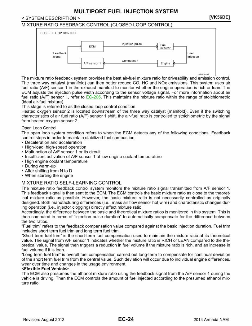
MIXTURE RATIO FEEDBACK CONTROL (CLOSED LOOP CONTROL)
The mixture ratio feedback system provides the best air-fuel mixture ratio for driveability and emission control.The three way catalyst (manifold) can then better reduce CO, HC and NOx emissions. This system uses airfuel ratio (A/F) sensor 1 in the exhaust manifold to monitor whether the engine operation is rich or lean. TheECM adjusts the injection pulse width according to the sensor voltage signal. For more information about airfuel ratio (A/F) sensor 1, refer to EC-205. This maintains the mixture ratio within the range of stoichiometric(ideal air-fuel mixture).This stage is referred to as the closed loop control condition.Heated oxygen sensor 2 is located downstream of the three way catalyst (manifold). Even if the switchingcharacteristics of air fuel ratio (A/F) sensor 1 shift, the air-fuel ratio is controlled to stoichiometric by the signalfrom heated oxygen sensor 2.
Open Loop ControlThe open loop system condition refers to when the ECM detects any of the following conditions. Feedbackcontrol stops in order to maintain stabilized fuel combustion.• Deceleration and acceleration• High-load, high-speed operation• Malfunction of A/F sensor 1 or its circuit• Insufficient activation of A/F sensor 1 at low engine coolant temperature• High engine coolant temperature• During warm-up• After shifting from N to D• When starting the engine
MIXTURE RATIO SELF-LEARNING CONTROLThe mixture ratio feedback control system monitors the mixture ratio signal transmitted from A/F sensor 1.This feedback signal is then sent to the ECM. The ECM controls the basic mixture ratio as close to the theoret-ical mixture ratio as possible. However, the basic mixture ratio is not necessarily controlled as originallydesigned. Both manufacturing differences (i.e., mass air flow sensor hot wire) and characteristic changes dur-ing operation (i.e., injector clogging) directly affect mixture ratio.Accordingly, the difference between the basic and theoretical mixture ratios is monitored in this system. This isthen computed in terms of “injection pulse duration” to automatically compensate for the difference betweenthe two ratios.“Fuel trim” refers to the feedback compensation value compared against the basic injection duration. Fuel trimincludes short term fuel trim and long term fuel trim.“Short term fuel trim” is the short-term fuel compensation used to maintain the mixture ratio at its theoreticalvalue. The signal from A/F sensor 1 indicates whether the mixture ratio is RICH or LEAN compared to the the-oretical value. The signal then triggers a reduction in fuel volume if the mixture ratio is rich, and an increase infuel volume if it is lean.“Long term fuel trim” is overall fuel compensation carried out long-term to compensate for continual deviationof the short term fuel trim from the central value. Such deviation will occur due to individual engine differences,wear over time and changes in the usage environment.<Flexible Fuel Vehicle>The ECM also presumes the ethanol mixture ratio using the feedback signal from the A/F sensor 1 during thevehicle is driving. Then the ECM controls the amount of fuel injected according to the presumed ethanol mix-ture ratio.
PBIB3020E
EC-24Revision: August 2013 2014 Armada NAM

MULTIPORT FUEL INJECTION SYSTEM[VK56DE]
C
D
E
F
G
H
I
J
K
L
M
A
C
N
P
O
< SYSTEM DESCRIPTION >
E
FUEL INJECTION TIMING
Two types of systems are used.
Sequential Multiport Fuel Injection SystemFuel is injected into each cylinder during each engine cycle according to the firing order. This system is usedwhen the engine is running.
Simultaneous Multiport Fuel Injection SystemFuel is injected simultaneously into all eight cylinders twice each engine cycle. In other words, pulse signals ofthe same width are simultaneously transmitted from the ECM.The eight fuel injectors will then receive the signals two times for each engine cycle.This system is used when the engine is being started and/or if the fail-safe system (CPU) is operating.
FUEL SHUT-OFFFuel to each cylinder is cut off during deceleration, operation of the engine at excessively high speeds or oper-ation of the vehicle at excessively high speed.
PBIB0122E
EC-25Revision: August 2013 2014 Armada NAM

[VK56DE]ELECTRIC IGNITION SYSTEM
< SYSTEM DESCRIPTION >
ELECTRIC IGNITION SYSTEM
System Description INFOID:0000000009825006
INPUT/OUTPUT SIGNAL CHART
*1: This signal is sent to the ECM through CAN communication line.
*2: ECM determines the start signal status by the signals of engine speed and battery voltage.
SYSTEM DESCRIPTIONFiring order: 1 - 8 - 7 - 3 - 6 - 5 - 4 -2The ignition timing is controlled by the ECM to maintain the best air-fuel ratio for every running condition of theengine. The ignition timing data is stored in the ECM.The ECM receives information such as the injection pulse width and camshaft position sensor signal. Comput-ing this information, ignition signals are transmitted to the power transistor.During the following conditions, the ignition timing is revised by the ECM according to the other data stored inthe ECM.• At starting• During warm-up• At idle• At low battery voltage• During accelerationThe knock sensor retard system is designed only for emergencies. The basic ignition timing is programmedwithin the anti-knocking zone, if recommended fuel is used under dry conditions. The retard system does notoperate under normal driving conditions. If engine knocking occurs, the knock sensor monitors the condition.The signal is transmitted to the ECM. The ECM retards the ignition timing to eliminate the knocking condition.
Sensor Input signal to ECM ECM function Actuator
Crankshaft position sensor (POS) Engine speed*2
Piston position
Ignition timing control
Power transistor
Camshaft position sensor (PHASE)
Mass air flow sensor Amount of intake air
Engine coolant temperature sensor Engine coolant temperature
Throttle position sensor Throttle position
Accelerator pedal position sensor Accelerator pedal position
Knock sensor Engine knocking
TCM Gear position
Battery Battery voltage*2
Wheel sensor Vehicle speed*1
EC-26Revision: August 2013 2014 Armada NAM

AIR CONDITIONING CUT CONTROL[VK56DE]
C
D
E
F
G
H
I
J
K
L
M
A
C
N
P
O
< SYSTEM DESCRIPTION >
E
AIR CONDITIONING CUT CONTROL
Input/Output Signal Chart INFOID:0000000009825007
*1: This signal is sent to the ECM through CAN communication line.
*2: ECM determines the start signal status by the signals of engine speed and battery voltage.
System Description INFOID:0000000009825008
This system improves engine operation when the air conditioner is used.Under the following conditions, the air conditioner is turned OFF.• When the accelerator pedal is fully depressed.• When cranking the engine.• At high engine speeds.• When the engine coolant temperature becomes excessively high.• When operating power steering during low engine speed or low vehicle speed.• When engine speed is excessively low.• When refrigerant pressure is excessively low or high.
Sensor Input Signal to ECM ECM function Actuator
Air conditioner switch Air conditioner ON signal*1
Air conditioner cut control
Air conditioner relay
Accelerator pedal position sensor Accelerator pedal position
Crankshaft position sensor (POS)Camshaft position sensor (PHASE) Engine speed*2
Engine coolant temperature sensor Engine coolant temperature
Battery Battery voltage*2
Refrigerant pressure sensor Refrigerant pressure
Power steering pressure sensor Power steering operation
Wheel sensor Vehicle speed*1
EC-27Revision: August 2013 2014 Armada NAM

[VK56DE]AUTOMATIC SPEED CONTROL DEVICE (ASCD)
< SYSTEM DESCRIPTION >
AUTOMATIC SPEED CONTROL DEVICE (ASCD)
System Description INFOID:0000000009825009
INPUT/OUTPUT SIGNAL CHART
*: This signal is sent to the ECM through CAN communication line
BASIC ASCD SYSTEMRefer to Owner's Manual for ASCD operating instructions.Automatic Speed Control Device (ASCD) allows a driver to keep vehicle at predetermined constant speedwithout depressing accelerator pedal. Driver can set vehicle speed in advance between approximately 40 km/h (25 MPH) and 144 km/h (89 MPH).ECM controls throttle angle of electric throttle control actuator to regulate engine speed.The ASCD operation status is indicated by two indicators (CRUISE and SET on the information display) on thecombination meter. If any malfunction occurs in the ASCD system, SET indicator blink and ASCD control isdeactivated.NOTE:Always drive vehicle in safe manner according to traffic conditions and obey all traffic laws.
SET OPERATIONPress MAIN switch. (CRUISE is indicator on the information display.)When vehicle speed reaches a desired speed between approximately 40 km/h (25 MPH) and 144 km/h (89MPH), press SET/COAST switch. (Then SET is indicator on the information display, and the set speed is alsodisplayed.)
ACCELERATE OPERATIONIf the RESUME/ACCELERATE switch is pressed during cruise control driving, increase the vehicle speed untilthe switch is released or vehicle speed reaches maximum speed controlled by the system.And then ASCD will keep the new set speed.
CANCEL OPERATIONWhen any of following conditions exist, cruise operation will be canceled.• CANCEL switch is pressed• More than 2 switches at ASCD steering switch are pressed at the same time (Set speed will be cleared)• Brake pedal is depressed• Selector lever is changed to N, P, R position• Vehicle speed decreased to 13 km/h (8 MPH) lower than the set speed• VDC system is operatedWhen the ECM detects any of the following conditions, the ECM will cancel the cruise operation and informthe driver by blinking indicator lamp.• Engine coolant temperature is slightly higher than the normal operating temperature, CRUISE indicator may
blink slowly.When the engine coolant temperature decreases to the normal operating temperature, CRUISE indicator willstop blinking and the cruise operation will be able to work by pressing SET/COAST switch or RESUME/ACCELERATE switch.
• Malfunction for some self-diagnoses regarding ASCD control: SET lamp will blink quickly.If MAIN switch is turned to OFF during ASCD is activated, all of ASCD operations will be canceled and vehiclespeed memory will be erased.
COAST OPERATION
Sensor Input signal to ECM ECM function Actuator
ASCD brake switch Brake pedal operation
ASCD vehicle speed controlElectric throttle control actuator
Stop lamp switch Brake pedal operation
ASCD steering switch ASCD steering switch operation
Wheel sensor Vehicle speed*
TCMGear position
Powertrain revolution*
EC-28Revision: August 2013 2014 Armada NAM

AUTOMATIC SPEED CONTROL DEVICE (ASCD)[VK56DE]
C
D
E
F
G
H
I
J
K
L
M
A
C
N
P
O
< SYSTEM DESCRIPTION >
E
When the SET/COAST switch is pressed during cruise control driving, decrease vehicle set speed until theswitch is released. And then ASCD will keep the new set speed.
RESUME OPERATIONWhen the RESUME/ACCELERATE switch is pressed after cancel operation other than pressing MAIN switchis performed, vehicle speed will return to last set speed. To resume vehicle set speed, vehicle condition mustmeet following conditions.• Brake pedal is released• A/T selector lever is in other than P and N positions• Vehicle speed is greater than 40 km/h (25 MPH) and less than 144 km/h (89 MPH)
Component Description INFOID:0000000009825010
ASCD STEERING SWITCHRefer to EC-409.
ASCD BRAKE SWITCHRefer to EC-413, and EC-455.
STOP LAMP SWITCHRefer to EC-413, EC-420 and EC-455.
ELECTRIC THROTTLE CONTROL ACTUATOR Refer to EC-429, EC-432, EC-436 and EC-438.
ASCD INDICATORRefer to EC-458.
EC-29Revision: August 2013 2014 Armada NAM

[VK56DE]CAN COMMUNICATION
< SYSTEM DESCRIPTION >
CAN COMMUNICATION
System Description INFOID:0000000009825011
CAN (Controller Area Network) is a serial communication line for real time application. It is an on-vehicle mul-tiplex communication line with high data communication speed and excellent error detection ability. Many elec-tronic control units are equipped onto a vehicle, and each control unit shares information and links with othercontrol units during operation (not independent). In CAN communication, control units are connected with 2communication lines (CAN H line, CAN L line) allowing a high rate of information transmission with less wiring.Each control unit transmits/receives data but selectively reads required data only.Refer to LAN-46, "CAN Communication Signal Chart", about CAN communication for detail.
EC-30Revision: August 2013 2014 Armada NAM

COOLING FAN CONTROL[VK56DE]
C
D
E
F
G
H
I
J
K
L
M
A
C
N
P
O
< SYSTEM DESCRIPTION >
E
COOLING FAN CONTROL
Description INFOID:0000000009825012
SYSTEM DESCRIPTION
Cooling Fan Control
*1: The ECM determines the start signal status by the signals of engine speed and battery voltage.
*2: This signal is sent to ECM through CAN communication line.
The ECM controls the cooling fan corresponding to the vehicle speed, engine coolant temperature, refrigerantpressure, and air conditioner ON signal. The control system has 2-step control [HI/OFF].
Cooling Fan Operation
Sensor Input signal to ECM ECM function Actuator
Crankshaft position sensor (POS)Camshaft position sensor (PHASE) Engine speed*1
Cooling fan control
IPDM E/R(Cooling fan relay)
Battery Battery voltage*1
Wheel sensor*2 Vehicle speed
Engine coolant temperature sensor Engine coolant temperature
Air conditioner switch Air conditioner ON signal*2
Refrigerant pressure sensor Refrigerant pressure
PBIB2060E
EC-31Revision: August 2013 2014 Armada NAM

[VK56DE]EVAPORATIVE EMISSION SYSTEM
< SYSTEM DESCRIPTION >
EVAPORATIVE EMISSION SYSTEM
Description INFOID:0000000009825013
SYSTEM DESCRIPTION
The evaporative emission system is used to reduce hydrocarbons emitted into the atmosphere from the fuelsystem. This reduction of hydrocarbons is accomplished by activated charcoals in the EVAP canister.The fuel vapor in the sealed fuel tank is led into the EVAP canister which contains activated carbon and thevapor is stored there when the engine is not operating or when refueling to the fuel tank.The vapor in the EVAP canister is purged by the air through the purge line to the intake manifold when theengine is operating. EVAP canister purge volume control solenoid valve is controlled by ECM. When theengine operates, the flow rate of vapor controlled by EVAP canister purge volume control solenoid valve isproportionally regulated as the air flow increases.EVAP canister purge volume control solenoid valve also shuts off the vapor purge line during decelerating andidling.
PBIB1631E
EC-32Revision: August 2013 2014 Armada NAM
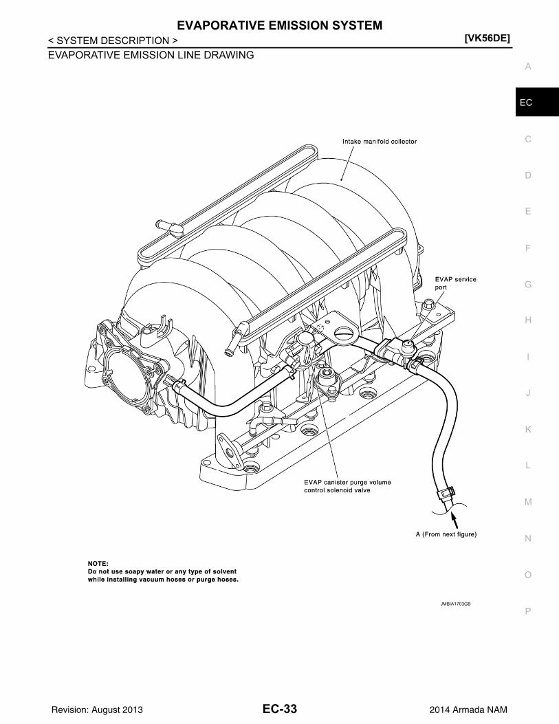
EVAPORATIVE EMISSION SYSTEM[VK56DE]
C
D
E
F
G
H
I
J
K
L
M
A
C
N
P
O
< SYSTEM DESCRIPTION >
E
EVAPORATIVE EMISSION LINE DRAWING
JMBIA1703GB
EC-33Revision: August 2013 2014 Armada NAM

[VK56DE]EVAPORATIVE EMISSION SYSTEM
< SYSTEM DESCRIPTION >
JMBIA1702GB
EC-34Revision: August 2013 2014 Armada NAM

INTAKE VALVE TIMING CONTROL[VK56DE]
C
D
E
F
G
H
I
J
K
L
M
A
C
N
P
O
< SYSTEM DESCRIPTION >
E
INTAKE VALVE TIMING CONTROL
Description INFOID:0000000009825014
SYSTEM DESCRIPTION
*: This signal is sent to the ECM through CAN communication line
This mechanism hydraulically controls cam phases continuously with the fixed operating angle of the intakevalve.The ECM receives signals such as crankshaft position, camshaft position, engine speed, and engine coolanttemperature. Then, the ECM sends ON/OFF pulse duty signals to the intake valve timing (IVT) control sole-noid valve depending on driving status. This makes it possible to control the shut/open timing of the intakevalve to increase engine torque in low/mid speed range and output in high-speed range.
Sensor Input signal to ECM function ECM Actuator
Crankshaft position sensor (POS)Camshaft position sensor (PHASE)
Engine speed
Intake valve timing control
Intake valve timing control solenoid valve
Intake valve timing control position sensor Intake valve timing signal
Engine coolant temperature sensor Engine coolant temperature
Wheel sensor Vehicle speed*
PBIB3276E
EC-35Revision: August 2013 2014 Armada NAM
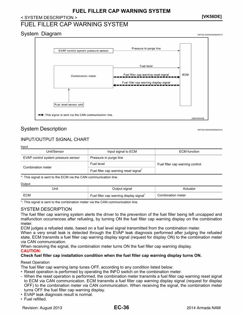
[VK56DE]FUEL FILLER CAP WARNING SYSTEM
< SYSTEM DESCRIPTION >
FUEL FILLER CAP WARNING SYSTEM
System Diagram INFOID:0000000009825015
System Description INFOID:0000000009825016
INPUT/OUTPUT SIGNAL CHART
Input
*: This signal is sent to the ECM via the CAN communication line.
Output
*: This signal is sent to the combination meter via the CAN communication line.
SYSTEM DESCRIPTIONThe fuel filler cap warning system alerts the driver to the prevention of the fuel filler being left uncapped andmalfunction occurrences after refueling, by turning ON the fuel filler cap warning display on the combinationmeter.ECM judges a refueled state, based on a fuel level signal transmitted from the combination meter.When a very small leak is detected through the EVAP leak diagnosis performed after judging the refueledstate, ECM transmits a fuel filler cap warning display signal (request for display ON) to the combination metervia CAN communication. When receiving the signal, the combination meter turns ON the fuel filler cap warning display.CAUTION:Check fuel filler cap installation condition when the fuel filler cap warning display turns ON.
Reset OperationThe fuel filler cap warning lamp tunes OFF, according to any condition listed below:• Reset operation is performed by operating the INFO switch on the combination meter.- When the reset operation is performed, the combination meter transmits a fuel filler cap warning reset signal
to ECM via CAN communication. ECM transmits a fuel filler cap warning display signal (request for displayOFF) to the combination meter via CAN communication. When receiving the signal, the combination meterturns OFF the fuel filler cap warning display.
• EVAP leak diagnosis result is normal.• Fuel refilled.
Unit/Sensor Input signal to ECM ECM function
EVAP control system pressure sensor Pressure in purge line
Fuel filler cap warning controlCombination meter
Fuel level
Fuel filler cap warning reset signal*
JSBIA0954GB
Unit Output signal Actuator
ECM Fuel filler cap warning display signal* Combination meter
EC-36Revision: August 2013 2014 Armada NAM

FUEL FILLER CAP WARNING SYSTEM[VK56DE]
C
D
E
F
G
H
I
J
K
L
M
A
C
N
P
O
< SYSTEM DESCRIPTION >
E
• DTC erased by using CONSULT.NOTE:MIL turns ON if a malfunction is detected in leak diagnosis results again at the trip after the fuel filler cap warn-ing display turns ON/OFF.
EC-37Revision: August 2013 2014 Armada NAM

[VK56DE]ON BOARD DIAGNOSTIC (OBD) SYSTEM
< SYSTEM DESCRIPTION >
ON BOARD DIAGNOSTIC (OBD) SYSTEM
Diagnosis Description INFOID:0000000009825017
This system is an on board diagnostic system that records exhaust emission-related diagnostic informationand detects a sensors/actuator-related malfunction. A malfunction is indicated by the malfunction indicatorlamp (MIL) and stored in control module memory as a DTC. The diagnostic information can be obtained withthe diagnostic tool (GST: Generic Scan Tool).
GST (Generic Scan Tool) INFOID:0000000009825018
When GST is connected with a data link connector equipped on the vehicle side, it will communicate with thecontrol module equipped in the vehicle and then enable various kinds of diagnostic tests. Refer to EC-38,"Diagnosis Description".NOTE:Service $0A is not applied for regions where it is not mandated.
EC-38Revision: August 2013 2014 Armada NAM
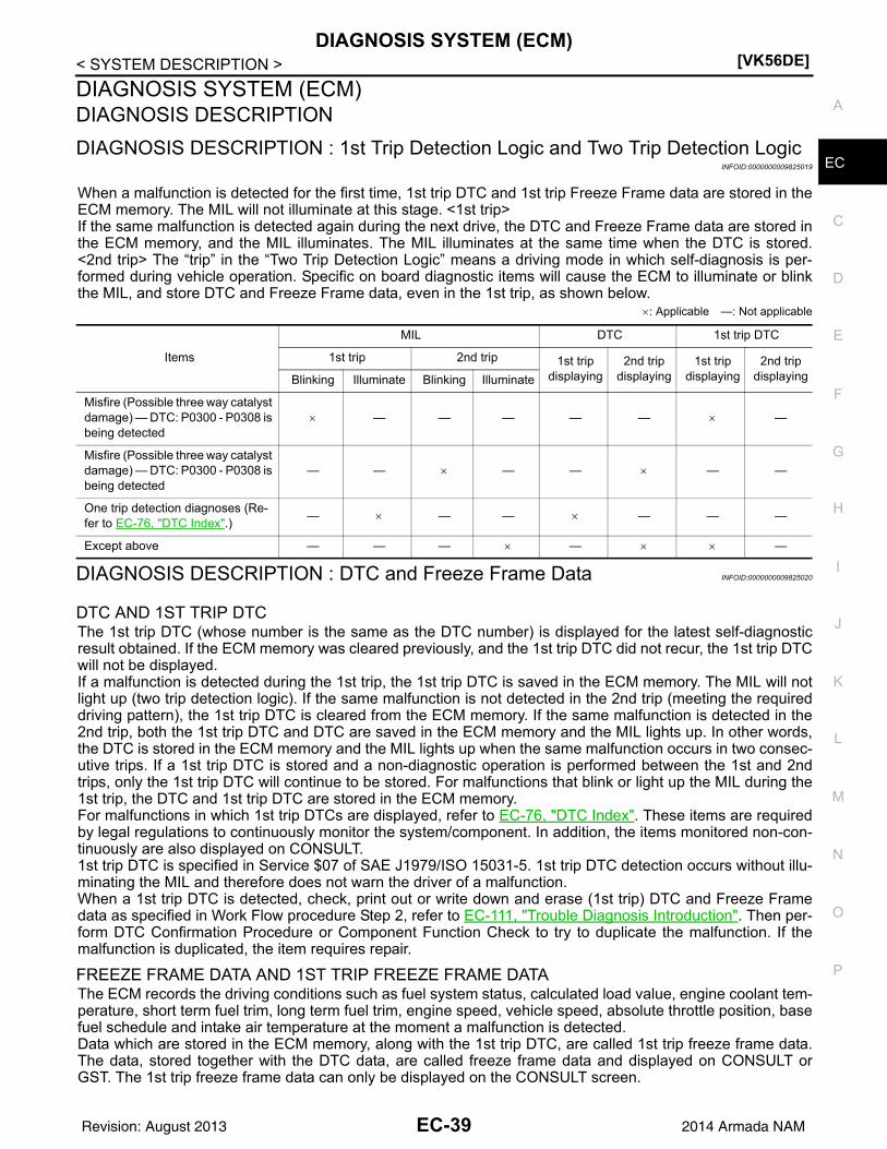
DIAGNOSIS SYSTEM (ECM)[VK56DE]
C
D
E
F
G
H
I
J
K
L
M
A
C
N
P
O
< SYSTEM DESCRIPTION >
E
DIAGNOSIS SYSTEM (ECM)DIAGNOSIS DESCRIPTION
DIAGNOSIS DESCRIPTION : 1st Trip Detection Logic and Two Trip Detection LogicINFOID:0000000009825019
When a malfunction is detected for the first time, 1st trip DTC and 1st trip Freeze Frame data are stored in theECM memory. The MIL will not illuminate at this stage. <1st trip>If the same malfunction is detected again during the next drive, the DTC and Freeze Frame data are stored inthe ECM memory, and the MIL illuminates. The MIL illuminates at the same time when the DTC is stored.<2nd trip> The “trip” in the “Two Trip Detection Logic” means a driving mode in which self-diagnosis is per-formed during vehicle operation. Specific on board diagnostic items will cause the ECM to illuminate or blinkthe MIL, and store DTC and Freeze Frame data, even in the 1st trip, as shown below.
: Applicable —: Not applicable
DIAGNOSIS DESCRIPTION : DTC and Freeze Frame Data INFOID:0000000009825020
DTC AND 1ST TRIP DTCThe 1st trip DTC (whose number is the same as the DTC number) is displayed for the latest self-diagnosticresult obtained. If the ECM memory was cleared previously, and the 1st trip DTC did not recur, the 1st trip DTCwill not be displayed.If a malfunction is detected during the 1st trip, the 1st trip DTC is saved in the ECM memory. The MIL will notlight up (two trip detection logic). If the same malfunction is not detected in the 2nd trip (meeting the requireddriving pattern), the 1st trip DTC is cleared from the ECM memory. If the same malfunction is detected in the2nd trip, both the 1st trip DTC and DTC are saved in the ECM memory and the MIL lights up. In other words,the DTC is stored in the ECM memory and the MIL lights up when the same malfunction occurs in two consec-utive trips. If a 1st trip DTC is stored and a non-diagnostic operation is performed between the 1st and 2ndtrips, only the 1st trip DTC will continue to be stored. For malfunctions that blink or light up the MIL during the1st trip, the DTC and 1st trip DTC are stored in the ECM memory.For malfunctions in which 1st trip DTCs are displayed, refer to EC-76, "DTC Index". These items are requiredby legal regulations to continuously monitor the system/component. In addition, the items monitored non-con-tinuously are also displayed on CONSULT.1st trip DTC is specified in Service $07 of SAE J1979/ISO 15031-5. 1st trip DTC detection occurs without illu-minating the MIL and therefore does not warn the driver of a malfunction.When a 1st trip DTC is detected, check, print out or write down and erase (1st trip) DTC and Freeze Framedata as specified in Work Flow procedure Step 2, refer to EC-111, "Trouble Diagnosis Introduction". Then per-form DTC Confirmation Procedure or Component Function Check to try to duplicate the malfunction. If themalfunction is duplicated, the item requires repair.
FREEZE FRAME DATA AND 1ST TRIP FREEZE FRAME DATAThe ECM records the driving conditions such as fuel system status, calculated load value, engine coolant tem-perature, short term fuel trim, long term fuel trim, engine speed, vehicle speed, absolute throttle position, basefuel schedule and intake air temperature at the moment a malfunction is detected.Data which are stored in the ECM memory, along with the 1st trip DTC, are called 1st trip freeze frame data.The data, stored together with the DTC data, are called freeze frame data and displayed on CONSULT orGST. The 1st trip freeze frame data can only be displayed on the CONSULT screen.
Items
MIL DTC 1st trip DTC
1st trip 2nd trip 1st trip displaying
2nd trip displaying
1st trip displaying
2nd trip displayingBlinking Illuminate Blinking Illuminate
Misfire (Possible three way catalyst damage) — DTC: P0300 - P0308 is being detected
— — — — — —
Misfire (Possible three way catalyst damage) — DTC: P0300 - P0308 is being detected
— — — — — —
One trip detection diagnoses (Re-fer to EC-76, "DTC Index".)
— — — — — —
Except above — — — — —
EC-39Revision: August 2013 2014 Armada NAM

[VK56DE]DIAGNOSIS SYSTEM (ECM)
< SYSTEM DESCRIPTION >Only one set of freeze frame data (either 1st trip freeze frame data or freeze frame data) can be stored in theECM. 1st trip freeze frame data is stored in the ECM memory along with the 1st trip DTC. There is no priorityfor 1st trip freeze frame data and it is updated each time a different 1st trip DTC is detected. However, oncefreeze frame data (2nd trip detection/MIL on) is stored in the ECM memory, 1st trip freeze frame data is nolonger stored. Remember, only one set of freeze frame data can be stored in the ECM. The ECM has the fol-lowing priorities to update the data.
For example, the EGR malfunction (Priority: 2) was detected and the freeze frame data was saved in the 2ndtrip. After that when the misfire (Priority: 1) is detected in another trip, the freeze frame data will be updatedfrom the EGR malfunction to the misfire. The 1st trip freeze frame data is updated each time a different mal-function is detected. There is no priority for 1st trip freeze frame data. However, once freeze frame data isstored in the ECM memory, 1st trip freeze data is no longer stored (because only one freeze frame data or 1sttrip freeze frame data can be stored in the ECM). If freeze frame data is stored in the ECM memory and freezeframe data with the same priority occurs later, the first (original) freeze frame data remains unchanged in theECM memory.Both 1st trip freeze frame data and freeze frame data (along with the DTCs) are cleared when the ECM mem-ory is erased.
DIAGNOSIS DESCRIPTION : Counter System INFOID:0000000009825021
RELATIONSHIP BETWEEN MIL, 1ST TRIP DTC, DTC, AND DETECTABLE ITEMS• When a malfunction is detected for the first time, the 1st trip DTC and the 1st trip freeze frame data are
stored in the ECM memory.• When the same malfunction is detected in two consecutive trips, the DTC and the freeze frame data are
stored in the ECM memory, and the MIL will come on.• The MIL will turn OFF after the vehicle is driven 3 times (driving pattern B) with no malfunction. The drive is
counted only when the recorded driving pattern is met (as stored in the ECM). If another malfunction occurswhile counting, the counter will reset.
• The DTC and the freeze frame data will be stored until the vehicle is driven 40 times (driving pattern A) with-out the same malfunction recurring (except for Misfire and Fuel Injection System). For Misfire and Fuel Injec-tion System, the DTC and freeze frame data will be stored until the vehicle is driven 80 times (driving patternC) without the same malfunction recurring. The “TIME” in “SELF-DIAGNOSTIC RESULTS” mode of CON-SULT will count the number of times the vehicle is driven.
• The 1st trip DTC is not displayed when the self-diagnosis results in OK for the 2nd trip.
COUNTER SYSTEM CHART
For details about patterns B and C under “Fuel Injection System” and “Misfire”, see “EXPLANATION FORDRIVING PATTERNS FOR “MISFIRE <EXHAUST QUALITY DETERIORATION>”, “FUEL INJECTION SYS-TEM”.For details about patterns A and B under Other, see “EXPLANATION FOR DRIVING PATTERNS FOR “MIS-FIRE <EXHAUST QUALITY DETERIORATION>”, “FUEL INJECTION SYSTEM”.• *1: Clear timing is at the moment OK is detected.• *2: Clear timing is when the same malfunction is detected in the 2nd trip.
Relationship Between MIL, DTC, 1st Trip DTC and Driving Patterns for “Misfire <Exhaust Quality De-terioration>”, “Fuel Injection System”
Priority Items
1Freeze frame data Misfire — DTC: P0300 - P0308
Fuel Injection System Function — DTC: P0171, P0172, P0174, P0175
2 Except the above items
3 1st trip freeze frame data
Items Fuel Injection System Misfire Other
MIL (turns OFF) 3 (pattern B) 3 (pattern B) 3 (pattern B)
DTC, Freeze Frame Data (no display) 80 (pattern C) 80 (pattern C) 40 (pattern A)
1st Trip DTC (clear) 1 (pattern C), *1 1 (pattern C), *1 1 (pattern B)
1st Trip Freeze Frame Data (clear) *1, *2 *1, *2 1 (pattern B)
EC-40Revision: August 2013 2014 Armada NAM

DIAGNOSIS SYSTEM (ECM)[VK56DE]
C
D
E
F
G
H
I
J
K
L
M
A
C
N
P
O
< SYSTEM DESCRIPTION >
E
Explanation for Driving Patterns for “Misfire <Exhaust Quality Deterioration>”, “Fuel Injection System”
Driving Pattern BRefer to EC-43, "DIAGNOSIS DESCRIPTION : Driving Pattern".
*1: When the same malfunction is de-tected in two consecutive trips, MIL will light up.
*2: MIL will turn OFF after vehicle is driv-en 3 times (pattern B) without any malfunctions.
*3: When the same malfunction is de-tected in two consecutive trips, the DTC and the freeze frame data will be stored in ECM.
*4: The DTC and the freeze frame data will not be displayed any longer after vehicle is driven 80 times (pattern C) without the same malfunction. (The DTC and the freeze frame data still remain in ECM.)
*5: When a malfunction is detected for the first time, the 1st trip DTC and the 1st trip freeze frame data will be stored in ECM.
*6: The 1st trip DTC and the 1st trip freeze frame data will be cleared at the moment OK is detected.
*7: When the same malfunction is de-tected in the 2nd trip, the 1st trip freeze frame data will be cleared.
*8: 1st trip DTC will be cleared when ve-hicle is driven once (pattern C) with-out the same malfunction after DTC is stored in ECM.
JMBIA1417GB
EC-41Revision: August 2013 2014 Armada NAM

[VK56DE]DIAGNOSIS SYSTEM (ECM)
< SYSTEM DESCRIPTION >Driving Pattern CRefer to EC-43, "DIAGNOSIS DESCRIPTION : Driving Pattern".Example:If the stored freeze frame data is as per the following:Engine speed: 850 rpm, Calculated load value: 30%, Engine coolant temperature: 80C (176F)To be satisfied with driving pattern C, the vehicle should run under the following conditions:Engine speed: 475 – 1,225 rpm, Calculated load value: 27 – 33%, Engine coolant temperature: more than70C (158F)
Relationship Between MIL, DTC, 1st Trip DTC and Driving Patterns Except For “Misfire <ExhaustQuality Deterioration>”, “Fuel Injection System”
JMBIA1418GB
EC-42Revision: August 2013 2014 Armada NAM

DIAGNOSIS SYSTEM (ECM)[VK56DE]
C
D
E
F
G
H
I
J
K
L
M
A
C
N
P
O
< SYSTEM DESCRIPTION >
E
Explanation for Driving Patterns Except for “Misfire <Exhaust Quality Deterioration>”, “Fuel InjectionSystem”
Driving Pattern ARefer to EC-43, "DIAGNOSIS DESCRIPTION : Driving Pattern".
Driving Pattern BRefer to EC-43, "DIAGNOSIS DESCRIPTION : Driving Pattern".
DIAGNOSIS DESCRIPTION : Driving Pattern INFOID:0000000009825022
CAUTION:Always drive at a safe speed.
DRIVING PATTERN ADriving pattern A means a trip satisfying the following conditions.• Engine speed reaches 400 rpm or more.• Engine coolant temperature rises by 20C (36F) or more after starting the engine.• Engine coolant temperature reaches 70C (158F) or more.• The ignition switch is turned from ON to OFF.NOTE:• When the same malfunction is detected regardless of driving conditions, reset the counter of driving pattern
A.• When the above conditions are satisfied without detecting the same malfunction, reset the counter of driving
pattern A.
DRIVING PATTERN BDriving pattern B means a trip satisfying the following conditions.• Engine speed reaches 400 rpm or more.• Engine coolant temperature reaches 70C (158F) or more.• Vehicle speed of 70 – 120 km/h (44 – 75 MPH) is maintained for 60 seconds or more under the control of
closed loop.• Vehicle speed of 30 – 60 km/h (19 – 37 MPH) is maintained for 10 seconds or more under the control of
closed loop.• Under the closed loop control condition, the following state reaches 12 seconds or more in total: Vehicle
speed of 4 km/h (2 MPH) or less with idling condition.• The state of driving at 10 km/h (7 MPH) or more reaches 10 minutes or more in total.• A lapse of 22 minutes or more after engine start.NOTE:• Drive the vehicle at a constant velocity.• When the same malfunction is detected regardless of driving conditions, reset the counter of driving pattern
B.• When the above conditions are satisfied without detecting the same malfunction, reset the counter of driving
pattern B.
DRIVING PATTERN CDriving pattern C means operating vehicle as per the following:The following conditions should be satisfied at the same time:Engine speed: (Engine speed in the freeze frame data) 375 rpm
*1: When the same malfunction is de-tected in two consecutive trips, MIL will light up.
*2: MIL will turn OFF after vehicle is driv-en 3 times (pattern B) without any malfunctions.
*3: When the same malfunction is de-tected in two consecutive trips, the DTC and the freeze frame data will be stored in ECM.
*4: The DTC and the freeze frame data will not be displayed any longer after vehicle is driven 40 times (pattern A) without the same malfunction.(The DTC and the freeze frame data still remain in ECM.)
*5: When a malfunction is detected for the first time, the 1st trip DTC and the 1st trip freeze frame data will be stored in ECM.
*6: 1st trip DTC will be cleared after vehi-cle is driven once (pattern B) without the same malfunction.
*7: When the same malfunction is de-tected in the 2nd trip, the 1st trip freeze frame data will be cleared.
EC-43Revision: August 2013 2014 Armada NAM

[VK56DE]DIAGNOSIS SYSTEM (ECM)
< SYSTEM DESCRIPTION >Calculated load value: (Calculated load value in the freeze frame data) x (10.1) [%]Engine coolant temperature condition:• When the freeze frame data shows lower than 70C (158F), engine coolant temperature should be lower
than 70C (158F).• When the freeze frame data shows higher than or equal to 70C (158F), engine coolant temperature should
be higher than or equal to 70C (158F).NOTE:• When the same malfunction is detected regardless of the above vehicle conditions, reset the counter of driv-
ing pattern C.• When the above conditions are satisfied without detecting the same malfunction, reset the counter of driving
pattern C.• The 1st trip DTC will be cleared when C counter is counted once without the same malfunction after DTC is
stored in ECM.
DRIVING PATTERN DDriving pattern D means a trip satisfying the following conditions.• The state of driving at 40 km/h (25 MPH) reaches 300 seconds or more in total.• Idle speed lasts 30 seconds or more.• A lapse of 600 seconds or more after engine start.NOTE:• When the same malfunction is detected regardless of driving conditions, reset the counter of driving pattern
D.• When the above conditions are satisfied without detecting the same malfunction, reset the counter of driving
pattern D.
DIAGNOSIS DESCRIPTION : System Readiness Test (SRT) Code INFOID:0000000009825023
System Readiness Test (SRT) code is specified in Service $01 of SAE J1979/ISO 15031-5.As part of an enhanced emissions test for Inspection & Maintenance (I/M), certain states require the status ofSRT be used to indicate whether the ECM has completed self-diagnosis of major emission systems and com-ponents. Completion must be verified in order for the emissions inspection to proceed.If a vehicle is rejected for a State emissions inspection due to one or more SRT items indicating “INCMP”, usethe information in this Service Manual to set the SRT to “CMPLT”.In most cases the ECM will automatically complete its self-diagnosis cycle during normal usage, and the SRTstatus will indicate “CMPLT” for each application system. Once set as “CMPLT”, the SRT status remains“CMPLT” until the self-diagnosis memory is erased.Occasionally, certain portions of the self-diagnostic test may not be completed as a result of the customer'snormal driving pattern; the SRT will indicate “INCMP” for these items.NOTE:The SRT will also indicate “INCMP” if the self-diagnosis memory is erased for any reason or if the ECM mem-ory power supply is interrupted for several hours.If, during the state emissions inspection, the SRT indicates “CMPLT” for all test items, the inspector will con-tinue with the emissions test. However, if the SRT indicates “INCMP” for one or more of the SRT items thevehicle is returned to the customer untested.NOTE:If permanent DTC is stored or MIL illuminates during the state emissions inspection, the vehicle is alsoreturned to the customer untested even though the SRT indicates “CMPLT” for all test items. Therefore, it isimportant to check SRT (“CMPLT”), DTC (No DTCs) and permanent DTC (NO permanent DTCs) before theinspection.
SRT SET TIMINGSRT is set as “CMPLT” after self-diagnosis has been performed one or more times. Completion of SRT isdone regardless of whether the result is OK or NG. The set timing is different between OK and NG results andis shown in the table below.
EC-44Revision: August 2013 2014 Armada NAM

DIAGNOSIS SYSTEM (ECM)[VK56DE]
C
D
E
F
G
H
I
J
K
L
M
A
C
N
P
O
< SYSTEM DESCRIPTION >
E
OK: Self-diagnosis is carried out and the result is OK.
NG: Self-diagnosis is carried out and the result is NG.
—: Self-diagnosis is not carried out.
When all SRT related self-diagnoses show OK results in a single cycle (Ignition OFF-ON-OFF), the SRT willindicate “CMPLT”. Case 1 aboveWhen all SRT related self-diagnoses show OK results through several different cycles, the SRT will indicate“CMPLT” at the time the respective self-diagnoses have at least one OK result. Case 2 aboveIf one or more SRT related self-diagnoses show NG results in 2 consecutive cycles, the SRT will also indicate“CMPLT”. Case 3 aboveThe table above shows that the minimum number of cycles for setting SRT as “INCMP” is the number one (1)for each self-diagnosis (Case 1 & 2) or the number two (2) for one of self-diagnoses (Case 3). However, inpreparation for the state emissions inspection, it is unnecessary for each self-diagnosis to be executed twice(Case 3) for the following reasons:• The SRT will indicate “CMPLT” at the time the respective self-diagnoses have one (1) OK result.• The emissions inspection requires “CMPLT” of the SRT only with OK self-diagnosis results.• During SRT driving pattern, the 1st trip DTC (NG) is detected prior to “CMPLT” of SRT and the self-diagnosis
memory must be erased from the ECM after repair.• If the 1st trip DTC is erased, all the SRT will indicate “INCMP”.
NOTE:SRT can be set as “CMPLT” together with the DTC(s). Therefore, DTC check must always be carried outprior to the state emission inspection even though the SRT indicates “CMPLT”.
DIAGNOSIS DESCRIPTION : Permanent Diagnostic Trouble Code (Permanent DTC)INFOID:0000000009825024
Permanent DTC is defined in SAE J1979/ISO 15031-5 Service $0A.ECM stores a DTC issuing a command of turning on MIL as a permanent DTC and keeps storing the DTC asa permanent DTC until ECM judges that there is no presence of malfunction.Permanent DTCs cannot be erased by using the erase function of CONSULT or Generic Scan Tool (GST) andby disconnecting the battery to shut off power to ECM. This prevents a vehicle from passing the in-use inspec-tion without repairing a malfunctioning part.When not passing the in-use inspection due to more than one permanent DTC, permanent DTCs should beerased, referring to this manual.NOTE:• The important items in in-use inspection are that MIL is not ON, SRT test items are set, and permanent
DTCs are not included.• Permanent DTCs do not apply for regions that permanent DTCs are not regulated by law.
Self-diagnosis result
Example
DiagnosisIgnition cycle
ON OFF ON OFF ON OFF ON
All OK Case 1 P0400 OK (1) — (1) OK (2) — (2)
P0402 OK (1) — (1) — (1) OK (2)
P1402 OK (1) OK (2) — (2) — (2)
SRT of EGR “CMPLT” “CMPLT” “CMPLT” “CMPLT”
Case 2 P0400 OK (1) — (1) — (1) — (1)
P0402 — (0) — (0) OK (1) — (1)
P1402 OK (1) OK (2) — (2) — (2)
SRT of EGR “INCMP” “INCMP” “CMPLT” “CMPLT”
NG exists Case 3 P0400 OK OK — —
P0402 — — — —
P1402 NG — NGNG
(Consecutive NG)
(1st trip)DTC
1st trip DTC — 1st trip DTCDTC
(= MIL ON)
SRT of EGR “INCMP” “INCMP” “INCMP” “CMPLT”
EC-45Revision: August 2013 2014 Armada NAM

[VK56DE]DIAGNOSIS SYSTEM (ECM)
< SYSTEM DESCRIPTION >
PERMANENT DTC SET TIMINGThe setting timing of permanent DTC is stored in ECM with the lighting of MIL when a DTC is confirmed.
DIAGNOSIS DESCRIPTION : Malfunction Indicator Lamp (MIL) INFOID:0000000009825025
When emission related ECU detects a malfunction in the emissioncontrol systems components and/or the powertrain control compo-nents (which affect vehicle emissions), it turns on/blinks MIL toinform the driver that a malfunction has been detected.1. The MIL illuminates when ignition switch is turned ON (engine is
not running).NOTE:Check the MIL circuit if MIL does not illuminate. Refer to EC-478, "Component Function Check".
2. When the engine is started, the MIL should go off.NOTE:If MIL continues to illuminate/blink, perform self-diagnoses andinspect/repair accordingly because an emission related ECU has detected a malfunction in the emissioncontrol systems components and/or the powertrain control components (which affect vehicle emissions).
On Board Diagnosis Function INFOID:0000000009825026
ON BOARD DIAGNOSIS ITEMThe on board diagnostic system has the following functions.
BLUB CHECK MODE
DescriptionThis function allows damage inspection in the MIL bulb (blown, open circuit, etc.).
Operation Procedure
1. Turn ignition switch ON.2. The MIL on the instrument panel should stay ON.
If it remains OFF, check MIL circuit. Refer to EC-478, "Diagnosis Procedure".
SRT STATUS MODE
DescriptionThis function allows to read if ECM has completed the self-diagnoses of major emission control systems andcomponents. For SRT, refer to EC-130, "Description".
Operation Procedure
1. Turn ignition switch ON and wait 20 seconds.2. SRT status is indicated as shown blow.
• ECM continues to illuminate MIL if all SRT codes are set.
JSBIA1315ZZ
Diagnostic test mode Function
Bulb check MIL can be checked.
SRT status ECM can read if SRT codes are set.
Malfunction warning If ECM detects a malfunction, it illuminates or blinks MIL to inform the driver that a malfunction has been detected.
Self-diagnostic results DTCs or 1st trip DTCs stored in ECM can be read.
Accelerator pedal released po-sition learning
ECM can learn the accelerator pedal released position. Refer to EC-127, "Accelerator Pedal Re-leased Position Learning".
Throttle valve closed position learning
ECM can learn the throttle valve closed position. Refer to EC-127, "Throttle Valve Closed Position Learning".
Idle air volume learning ECM can learn the idle air volume. Refer to EC-128, "Idle Air Volume Learning".
EC-46Revision: August 2013 2014 Armada NAM

DIAGNOSIS SYSTEM (ECM)[VK56DE]
C
D
E
F
G
H
I
J
K
L
M
A
C
N
P
O
< SYSTEM DESCRIPTION >
E
• ECM blinks MIL for about 10 seconds if all SRT codes are not set.
MALFUNCTION WARNING MODE
DescriptionIn this function ECM turns on or blinks MIL when it detects a malfunction in the emission control system com-ponents and/or the powertrain control components (which affect vehicle emissions) to inform the driver that amalfunction has been detected.
Operation Procedure
1. Turn ignition switch ON.2. Check that MIL illuminates.
If it remains OFF, check MIL circuit. Refer to EC-478, "Diagnosis Procedure".3. Start engine and let it idle.
• For two trip detection logic diagnoses, ECM turns on MIL when it detects the same malfunction twice inthe two consecutive driving cycles.
• For 1st trip detection logic diagnoses, ECM turns on MIL when it detects a malfunction in one drivingcycle.
• ECM blinks MIL when it detects a malfunction that may damage the three way catalyst (misfire).
SELF-DIAGNOSTIC RESULTS MODE
DescriptionThis function allows to indicate DTCs or 1st trip DTCs stored in ECM according to the number of times MIL isblinking.
How to Set Self-diagnostic Results ModeNOTE:• It is better to count the time accurately with a clock.• It is impossible to switch the diagnostic mode when an accelerator pedal position sensor circuit has a mal-
function.• After ignition switch is turned off, ECM is always released from the “Self-diagnostic results” mode.1. Confirm that accelerator pedal is fully released, turn ignition switch ON and wait 3 seconds.2. Repeat the following procedure quickly five times within 5 seconds.
• Fully depress the accelerator pedal.• Fully release the accelerator pedal.
3. Wait 7 seconds, fully depress the accelerator pedal and keep it depressed for approx. 10 seconds until theMIL starts blinking.NOTE:Do not release the accelerator pedal for 10 seconds if MIL starts blinking during this period. This blinkingis displaying SRT status and is continued for another 10 seconds.
4. Fully release the accelerator pedal.ECM has entered to Self-diagnostic results mode.
JMBIA1515GB
EC-47Revision: August 2013 2014 Armada NAM
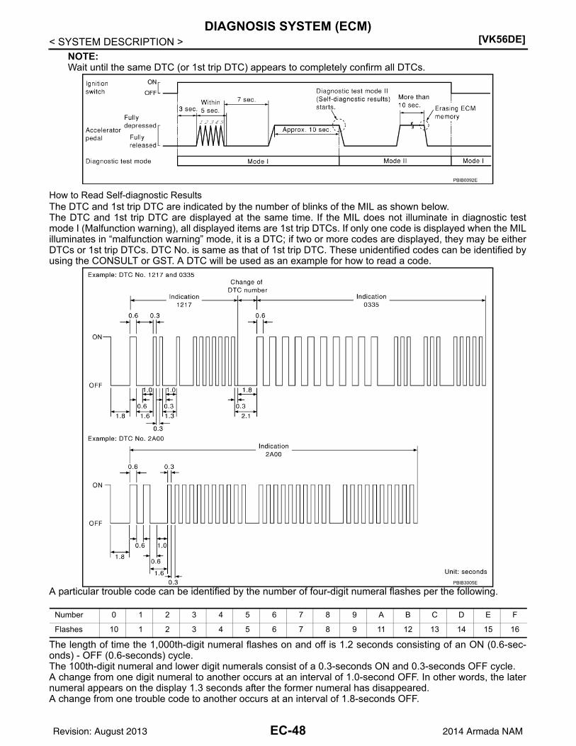
[VK56DE]DIAGNOSIS SYSTEM (ECM)
< SYSTEM DESCRIPTION >NOTE:Wait until the same DTC (or 1st trip DTC) appears to completely confirm all DTCs.
How to Read Self-diagnostic ResultsThe DTC and 1st trip DTC are indicated by the number of blinks of the MIL as shown below.The DTC and 1st trip DTC are displayed at the same time. If the MIL does not illuminate in diagnostic testmode I (Malfunction warning), all displayed items are 1st trip DTCs. If only one code is displayed when the MILilluminates in “malfunction warning” mode, it is a DTC; if two or more codes are displayed, they may be eitherDTCs or 1st trip DTCs. DTC No. is same as that of 1st trip DTC. These unidentified codes can be identified byusing the CONSULT or GST. A DTC will be used as an example for how to read a code.
A particular trouble code can be identified by the number of four-digit numeral flashes per the following.
The length of time the 1,000th-digit numeral flashes on and off is 1.2 seconds consisting of an ON (0.6-sec-onds) - OFF (0.6-seconds) cycle.The 100th-digit numeral and lower digit numerals consist of a 0.3-seconds ON and 0.3-seconds OFF cycle.A change from one digit numeral to another occurs at an interval of 1.0-second OFF. In other words, the laternumeral appears on the display 1.3 seconds after the former numeral has disappeared.A change from one trouble code to another occurs at an interval of 1.8-seconds OFF.
PBIB0092E
PBIB3005E
Number 0 1 2 3 4 5 6 7 8 9 A B C D E F
Flashes 10 1 2 3 4 5 6 7 8 9 11 12 13 14 15 16
EC-48Revision: August 2013 2014 Armada NAM

DIAGNOSIS SYSTEM (ECM)[VK56DE]
C
D
E
F
G
H
I
J
K
L
M
A
C
N
P
O
< SYSTEM DESCRIPTION >
E
In this way, all the detected malfunctions are classified by their DTC numbers. The DTC 0000 refers to no mal-function. Refer to EC-76, "DTC Index".
How to Erase Self-diagnostic ResultsBy performing this procedure, ECM memory is erased and the following diagnostic information is erased aswell.• Diagnostic trouble codes• 1st trip diagnostic trouble codes• Freeze frame data• 1st trip freeze frame data• System readiness test (SRT) codes• Test valuesNOTE:Also, if a battery terminal is disconnected, ECM memory is erased and the diagnostic information as listedabove is erased. (The amount of time required for erasing may vary from a few seconds to several hours.)1. Turn ignition switch OFF and wait at least 10 seconds.2. Turn ignition switch ON.3. Turn ignition switch OFF and wait at least 10 seconds.4. Turn ignition switch ON.5. Set ECM in “Self-diagnostic results”.6. The diagnostic information has been erased from the backup memory in the ECM.
Fully depress the accelerator pedal and keep it depressed for more than 10 seconds.7. Fully release the accelerator pedal, and confirm the DTC 0000 is displayed.
CONSULT Function INFOID:0000000009825027
FUNCTION
*: The following emission-related diagnostic information is cleared when the ECM memory is erased.
• Diagnostic trouble codes
• 1st trip diagnostic trouble codes
• Freeze frame data
• 1st trip freeze frame data
• System readiness test (SRT) codes
• Test values
SELF DIAGNOSTIC RESULTS MODE
Self Diagnostic ItemRegarding items of DTC and 1st trip DTC, refer to EC-76, "DTC Index".
How to Read DTC and 1st Trip DTCDTCs and 1st trip DTCs related to the malfunction are displayed in “Self-diag results”.• When ECM detects a 1st trip DTC, “1t” is displayed for “TIME”.• When ECM has detected a current DTC, “0” is displayed for “TIME”.• If “TIME” is neither “0” nor “1t”, the DTC occurred in the past and ECM shows the number of times the vehi-
cle has been driven since the last detection of the DTC.
Diagnostic test mode Function
Self Diagnostic ResultSelf-diagnostic results such as 1st trip DTC, DTCs and 1st trip freeze frame data or freeze frame data can be read and erased quickly.*
Data Monitor Input/Output data in the ECM can be read.
Work supportThis mode enables a technician to adjust some devices faster and more accurately by following the in-dications on the CONSULT unit.
Active TestDiagnostic Test Mode in which CONSULT drives some actuators apart from the ECMs and also shifts some parameters in a specified range.
Ecu Identification ECM part number can be read.
DTC Work Support The status of system monitoring tests and the self-diagnosis status/result can be confirmed.
EC-49Revision: August 2013 2014 Armada NAM

[VK56DE]DIAGNOSIS SYSTEM (ECM)
< SYSTEM DESCRIPTION >How to Erase DTC and 1st Trip DTCNOTE:• If the ignition switch stays ON after repair work, be sure to turn ignition switch OFF once. Wait at least 10
seconds and then turn it ON (engine stopped) again.• If the DTC is not for A/T related items (see EC-76, "DTC Index"), skip step 1.1. Erase DTC in TCM. Refer to TM-34, "CONSULT Function (TRANSMISSION)".2. Select “ENGINE” with CONSULT.3. Select “SELF-DIAG RESULTS”.4. Touch “ERASE”. (DTC in ECM will be erased.)
Freeze Frame Data and 1st Trip Freeze Frame Data
*: The item is the same as that of 1st trip freeze frame data.
DATA MONITOR MODENOTE:The following table includes information (items) inapplicable to this vehicle. For information (items) applicableto this vehicle, refer to CONSULT display items.
Monitored ItemFor reference values of the following items, refer to EC-60, "CONSULT Reference Value in Data MonitorMode".
Freeze frame data item*
Description
DIAG TROUBLE CODE[PXXXX]
• The engine control component part/control system has a trouble code, it is displayed as PXXXX. (Refer to EC-76, "DTC Index".)
FUEL SYS-B1 • “Fuel injection system status” at the moment a malfunction is detected is displayed.• One mode in the following is displayed.
Mode2: Open loop due to detected system malfunctionMode3: Open loop due to driving conditions (power enrichment, deceleration enleanment)Mode4: Closed loop - using oxygen sensor(s) as feedback for fuel controlMode5: Open loop - has not yet satisfied condition to go to closed loop
FUEL SYS-B2
COMBUST CONDI-TION
• Always a certain value is displayed.• These items are not efficient for TA60 models.
CAL/LD VALUE [%] • The calculated load value at the moment a malfunction is detected is displayed.
COOLANT TEMP[C] or [F]
• The engine coolant temperature at the moment a malfunction is detected is displayed.
L-FUEL TRM-B1 [%] • “Long-term fuel trim” at the moment a malfunction is detected is displayed.• The long-term fuel trim indicates much more gradual feedback compensation to the base fuel schedule than
short-term fuel trim.L-FUEL TRM-B2 [%]
S-FUEL TRM-B1 [%] • “Short-term fuel trim” at the moment a malfunction is detected is displayed.• The short-term fuel trim indicates dynamic or instantaneous feedback compensation to the base fuel sched-
ule.S-FUEL TRM-B2 [%]
ENGINE SPEED [rpm] • The engine speed at the moment a malfunction is detected is displayed.
VEHICL SPEED[km/h] or [mph]
• The vehicle speed at the moment a malfunction is detected is displayed.
INT MANI PRES [kPa] or [psi]
• Always a certain value is displayed.• These items are not efficient for TA60 models.
ABSOL TH-P/S[%]
• The throttle valve opening at the moment a malfunction is detected is displayed.
B/FUEL SCHDL [msec]
• The base fuel schedule at the moment a malfunction is detected is displayed.
INT/A TEMP SE[C] or [F]
• The intake air temperature at the moment a malfunction is detected is displayed.
EC-50Revision: August 2013 2014 Armada NAM
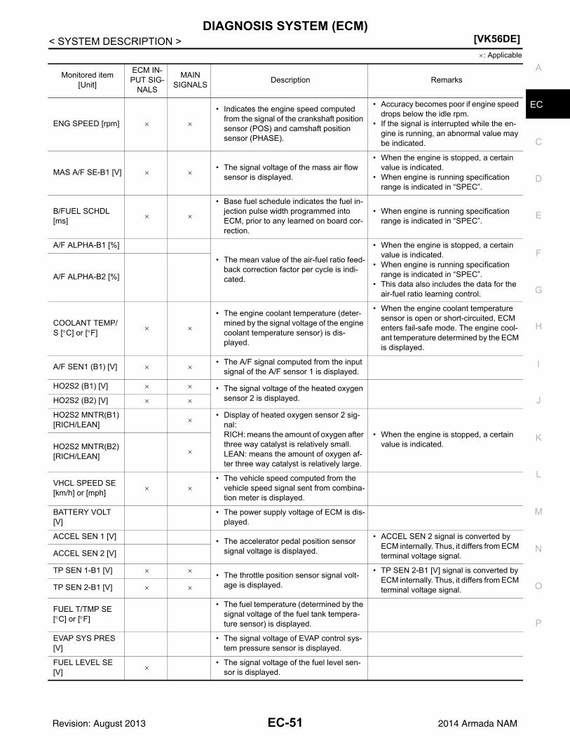
DIAGNOSIS SYSTEM (ECM)[VK56DE]
C
D
E
F
G
H
I
J
K
L
M
A
C
N
P
O
< SYSTEM DESCRIPTION >
E
: Applicable
Monitored item [Unit]
ECM IN-PUT SIG-
NALS
MAIN SIGNALS
Description Remarks
ENG SPEED [rpm]
• Indicates the engine speed computed from the signal of the crankshaft position sensor (POS) and camshaft position sensor (PHASE).
• Accuracy becomes poor if engine speed drops below the idle rpm.
• If the signal is interrupted while the en-gine is running, an abnormal value may be indicated.
MAS A/F SE-B1 [V] • The signal voltage of the mass air flow
sensor is displayed.
• When the engine is stopped, a certain value is indicated.
• When engine is running specification range is indicated in “SPEC”.
B/FUEL SCHDL [ms]
• Base fuel schedule indicates the fuel in-jection pulse width programmed into ECM, prior to any learned on board cor-rection.
• When engine is running specification range is indicated in “SPEC”.
A/F ALPHA-B1 [%]
• The mean value of the air-fuel ratio feed-back correction factor per cycle is indi-cated.
• When the engine is stopped, a certain value is indicated.
• When engine is running specification range is indicated in “SPEC”.
• This data also includes the data for the air-fuel ratio learning control.
A/F ALPHA-B2 [%]
COOLANT TEMP/S [C] or [F]
• The engine coolant temperature (deter-mined by the signal voltage of the engine coolant temperature sensor) is dis-played.
• When the engine coolant temperature sensor is open or short-circuited, ECM enters fail-safe mode. The engine cool-ant temperature determined by the ECM is displayed.
A/F SEN1 (B1) [V] • The A/F signal computed from the input
signal of the A/F sensor 1 is displayed.
HO2S2 (B1) [V] • The signal voltage of the heated oxygen sensor 2 is displayed.HO2S2 (B2) [V]
HO2S2 MNTR(B1) [RICH/LEAN]
• Display of heated oxygen sensor 2 sig-
nal:RICH: means the amount of oxygen after three way catalyst is relatively small.LEAN: means the amount of oxygen af-ter three way catalyst is relatively large.
• When the engine is stopped, a certain value is indicated.HO2S2 MNTR(B2)
[RICH/LEAN]
VHCL SPEED SE [km/h] or [mph]
• The vehicle speed computed from the
vehicle speed signal sent from combina-tion meter is displayed.
BATTERY VOLT [V]
• The power supply voltage of ECM is dis-played.
ACCEL SEN 1 [V]• The accelerator pedal position sensor
signal voltage is displayed.
• ACCEL SEN 2 signal is converted by ECM internally. Thus, it differs from ECM terminal voltage signal.ACCEL SEN 2 [V]
TP SEN 1-B1 [V] • The throttle position sensor signal volt-
age is displayed.
• TP SEN 2-B1 [V] signal is converted by ECM internally. Thus, it differs from ECM terminal voltage signal.TP SEN 2-B1 [V]
FUEL T/TMP SE [C] or [F]
• The fuel temperature (determined by the signal voltage of the fuel tank tempera-ture sensor) is displayed.
EVAP SYS PRES [V]
• The signal voltage of EVAP control sys-tem pressure sensor is displayed.
FUEL LEVEL SE [V]
• The signal voltage of the fuel level sen-
sor is displayed.
EC-51Revision: August 2013 2014 Armada NAM
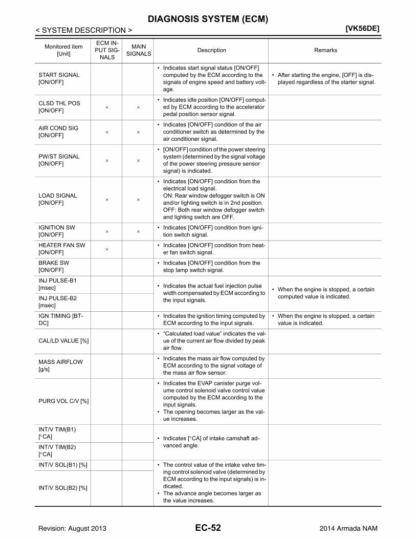
[VK56DE]DIAGNOSIS SYSTEM (ECM)
< SYSTEM DESCRIPTION >
START SIGNAL [ON/OFF]
• Indicates start signal status [ON/OFF] computed by the ECM according to the signals of engine speed and battery volt-age.
• After starting the engine, [OFF] is dis-played regardless of the starter signal.
CLSD THL POS [ON/OFF]
• Indicates idle position [ON/OFF] comput-
ed by ECM according to the accelerator pedal position sensor signal.
AIR COND SIG [ON/OFF]
• Indicates [ON/OFF] condition of the air
conditioner switch as determined by the air conditioner signal.
PW/ST SIGNAL [ON/OFF]
• [ON/OFF] condition of the power steering system (determined by the signal voltage of the power steering pressure sensor signal) is indicated.
LOAD SIGNAL [ON/OFF]
• Indicates [ON/OFF] condition from the electrical load signal.ON: Rear window defogger switch is ON and/or lighting switch is in 2nd position.OFF: Both rear window defogger switch and lighting switch are OFF.
IGNITION SW[ON/OFF]
• Indicates [ON/OFF] condition from igni-
tion switch signal.
HEATER FAN SW[ON/OFF]
• Indicates [ON/OFF] condition from heat-
er fan switch signal.
BRAKE SW[ON/OFF]
• Indicates [ON/OFF] condition from the stop lamp switch signal.
INJ PULSE-B1 [msec] • Indicates the actual fuel injection pulse
width compensated by ECM according to the input signals.
• When the engine is stopped, a certain computed value is indicated.INJ PULSE-B2
[msec]
IGN TIMING [BT-DC]
• Indicates the ignition timing computed by ECM according to the input signals.
• When the engine is stopped, a certain value is indicated.
CAL/LD VALUE [%]• “Calculated load value” indicates the val-
ue of the current air flow divided by peak air flow.
MASS AIRFLOW [g/s]
• Indicates the mass air flow computed by ECM according to the signal voltage of the mass air flow sensor.
PURG VOL C/V [%]
• Indicates the EVAP canister purge vol-ume control solenoid valve control value computed by the ECM according to the input signals.
• The opening becomes larger as the val-ue increases.
INT/V TIM(B1) [CA] • Indicates [CA] of intake camshaft ad-
vanced angle. INT/V TIM(B2) [CA]
INT/V SOL(B1) [%] • The control value of the intake valve tim-ing control solenoid valve (determined by ECM according to the input signals) is in-dicated.
• The advance angle becomes larger as the value increases.
INT/V SOL(B2) [%]
Monitored item [Unit]
ECM IN-PUT SIG-
NALS
MAIN SIGNALS
Description Remarks
EC-52Revision: August 2013 2014 Armada NAM

DIAGNOSIS SYSTEM (ECM)[VK56DE]
C
D
E
F
G
H
I
J
K
L
M
A
C
N
P
O
< SYSTEM DESCRIPTION >
EAIR COND RLY [ON/OFF]
• The air conditioner relay control condi-tion (determined by ECM according to the input signals) is indicated.
FUEL PUMP RLY [ON/OFF]
• Indicates the fuel pump relay control con-dition determined by ECM according to the input signals.
FPCM[HI/LOW]*1
• The control condition of the fuel pump control module (FPCM) (determined by the ECM according to the input signals) is indicated.
VENT CONT/V [ON/OFF]
• The control condition of the EVAP canis-ter vent control valve (determined by ECM according to the input signals) is in-dicated.ON: ClosedOFF: Open
THRTL RELAY [ON/OFF]
• Indicates the throttle control motor relay control condition determined by the ECM according to the input signals.
A/F S1 HTR(B2) [%]
• A/F sensor 1 heater control value com-puted by ECM according to the input sig-nals.
• The current flow to the heater becomes larger as the value increases.
COOLING FAN[HI/OFF]
• The control condition of the cooling fan (determined by ECM according to the in-put signals) is indicated.HI: High speed operationOFF: Stop
HO2S2 HTR (B1) [ON/OFF] • Indicates [ON/OFF] condition of heated
oxygen sensor 2 heater determined by ECM according to the input signals.HO2S2 HTR (B2)
[ON/OFF]
ALT DUTY SIG[ON/OFF]
• The control condition of the power gener-ation voltage variable control (deter-mined by ECM according to the input signals) is indicated.ON: Power generation voltage variable control is active.OFF: Power generation voltage variable control is inactive.
I/P PULLY SPD[rpm]
• Indicates the engine speed computed from the Input speed sensor signal.
VEHICLE SPEED[km/h] or [mph]
• Indicates the vehicle speed computed from the revolution sensor signal.
IDL A/V LEARN [YET/CMPLT]
• Display the condition of idle air volume learningYET: Idle Air Volume Learning has not been performed yet.CMPLT: Idle Air Volume Learning has al-ready been performed successfully.
TRVL AFTER MIL [km] or [mile]
• Distance traveled while MIL is activated.
Monitored item [Unit]
ECM IN-PUT SIG-
NALS
MAIN SIGNALS
Description Remarks
EC-53Revision: August 2013 2014 Armada NAM

[VK56DE]DIAGNOSIS SYSTEM (ECM)
< SYSTEM DESCRIPTION >
A/F S1 HTR(B1) [%]
• A/F sensor 1 heater control value com-puted by ECM according to the input sig-nals.
• The current flow to the heater becomes larger as the value increases.
VHCL SPEED SE [km/h] or [mph]
• The vehicle speed computed from the vehicle speed signal sent from combina-tion meter is displayed.
SET VHCL SPD[km/h] or [mph]
• The preset vehicle speed is displayed.
MAIN SW[ON/OFF]
• Indicates [ON/OFF] condition from MAIN switch signal.
CANCEL SW[ON/OFF]
• Indicates [ON/OFF] condition from CAN-CEL switch signal.
RESUME/ACC SW[ON/OFF]
• Indicates [ON/OFF] condition from RE-SUME/ACCELERATE switch signal.
SET SW[ON/OFF]
• Indicates [ON/OFF] condition from SET/COAST switch signal.
BRAKE SW1[ON/OFF]
• Indicates [ON/OFF] condition from ASCD brake switch signal.
BRAKE SW2[ON/OFF]
• Indicates [ON/OFF] condition of stop lamp switch signal.
VHCL SPD CUT[NON/CUT]
• Indicates the vehicle cruise condition.NON: Vehicle speed is maintained at the ASCD set speed.CUT: Vehicle speed increased to exces-sively high compared with the ASCD set speed, and ASCD operation is cut off.
LO SPEED CUT[NON/CUT]
• Indicates the vehicle cruise condition.NON: Vehicle speed is maintained at the ASCD set speed.CUT: Vehicle speed decreased to exces-sively low compared with the ASCD set speed, and ASCD operation is cut off.
AT OD MONITOR[ON/OFF]
• Indicates [ON/OFF] condition of A/T O/D according to the input signal from the TCM.
AT OD CANCEL[ON/OFF]
• Indicates [ON/OFF] condition of A/T O/D cancel signal sent from the TCM.
CRUISE LAMP[ON/OFF]
• Indicates [ON/OFF] condition of CRUISE lamp determined by the ECM according to the input signals.
SET LAMP[ON/OFF]
• Indicates [ON/OFF] condition of SET lamp determined by the ECM according to the input signals.
ETHANOL M/R[%]*1
• Ethanol mixture ratio presumed by the ECM according to the input signals is dis-played.
ALT DUTY [%]
• Indicates the duty ratio of the power gen-eration command value. The ratio is cal-culated by ECM based on the battery current sensor signal.
BAT CUR SEN [mV]
• The signal voltage of battery current sen-sor is displayed.
Monitored item [Unit]
ECM IN-PUT SIG-
NALS
MAIN SIGNALS
Description Remarks
EC-54Revision: August 2013 2014 Armada NAM

DIAGNOSIS SYSTEM (ECM)[VK56DE]
C
D
E
F
G
H
I
J
K
L
M
A
C
N
P
O
< SYSTEM DESCRIPTION >
EA/F ADJ-B1 • Indicates the correction factor stored in
ECM. The factor is calculated from the difference between the target air/fuel ra-tio stored in ECM and the air-fuel ratio calculated from air fuel ratio (A/F) sensor 1 signal.
A/F ADJ-B2
P/N POSI SW[ON/OFF]
• Indicates [ON/OFF] condition from the
park/neutral position (PNP) switch sig-nal.
INT/A TEMP SE [C] or [F]
• The intake air temperature (determined
by the signal voltage of the intake air temperature sensor) is indicated.
AC PRESS SEN [V]• The signal voltage from the refrigerant
pressure sensor is displayed.
A/F SEN1 (B2) [V] • The A/F signal computed from the input
signal of the A/F sensor 1 is displayed.
VTC DTY EX B2 [%]
—
FPCM DR VOLT [V]*1
• The voltage between fuel pump and FPCM is displayed.
THRTL STK CNT
B1*2 —
HO2 S2 DIAG2 (B1)[INCMP/CMPLT]
• Indicates DTC P0139 self-diagnosis (slow response) condition.INCMP: Self-diagnosis is incomplete.CMPLT: Self-diagnosis is complete.
HO2 S2 DIAG2 (B2)[INCMP/CMPLT]
• Indicates DTC P0159 self-diagnosis (slow response) condition.INCMP: Self-diagnosis is incomplete.CMPLT: Self-diagnosis is complete.
A/F SEN1 DIAG2
(B1)*2
• Indicates DTC P014C or P014D self-di-agnosis condition.INCMP: Self-diagnosis is incomplete.CMPLT: Self-diagnosis is complete.
A/F SEN1 DIAG2
(B2)*2
• Indicates DTC P014E or P014F self-di-agnosis condition.INCMP: Self-diagnosis is incomplete.CMPLT: Self-diagnosis is complete.
A/F-S ATMSPHRC CRCT B1
Displays a determined value of atmospher-ic correction factor necessary for correcting an A/F sensor signal input to ECM. The sig-nal used for the correction is an A/F sensor signal transmitted while driving under at-mospheric pressure.
A/F-S ATMSPHRC CRCT B2
Displays a determined value of atmospher-ic correction factor necessary for correcting an A/F sensor signal input to ECM. The sig-nal used for the correction is an A/F sensor signal transmitted while driving under at-mospheric pressure.
A/F-S ATMSPHRC CRCT UP B1[count]
Displays the number of updates of the A/F sensor atmospheric correction factor.
A/F-S ATMSPHRC CRCT UP B2[count]
Displays the number of updates of the A/F sensor atmospheric correction factor.
Monitored item [Unit]
ECM IN-PUT SIG-
NALS
MAIN SIGNALS
Description Remarks
EC-55Revision: August 2013 2014 Armada NAM

[VK56DE]DIAGNOSIS SYSTEM (ECM)
< SYSTEM DESCRIPTION >
*1: For Flexible Fuel Vehicle
*2: The item is indicated, but not used.
NOTE:
Any monitored item that does not match the vehicle being diagnosed is deleted from the display automatically.
WORK SUPPORT MODE
Work Item
EVAP LEAK DIAG
• Indicates the condition of EVAP leak di-agnosis.YET: EVAP leak diagnosis has not been performed yet.CMPLT: EVAP leak diagnosis has been performed successfully.
EVAP DIAG READY
• Indicates the ready condition of EVAP leak diagnosis.ON: Diagnosis has been ready condition.OFF: Diagnosis has not been ready con-dition.
Monitored item [Unit]
ECM IN-PUT SIG-
NALS
MAIN SIGNALS
Description Remarks
WORK ITEM CONDITION USAGE
IDLE AIR VOL LEARN • THE IDLE AIR VOLUME THAT KEEPS THE ENGINE WITHIN THE SPECIFIED RANGE IS MEMORIZED IN ECM.
When learning the idle air volume
EVAP SYSTEM CLOSE CLOSE THE EVAP CANISTER VENT CONTROL VALVE IN ORDER TO MAKE EVAP SYSTEM CLOSE UNDER THE FOLLOWING CONDITIONS.• IGN SW ON• ENGINE NOT RUNNING• AMBIENT TEMPERATURE IS ABOVE 0C (32F).• NO VACUUM AND NO HIGH PRESSURE IN EVAP SYS-
TEM• FUEL TANK TEMP. IS MORE THAN 0C (32F).• WITHIN 10 MINUTES AFTER STARTING “EVAP SYS-
TEM CLOSE”• WHEN TRYING TO EXECUTE “EVAP SYSTEM CLOSE”
UNDER THE CONDITION EXCEPT ABOVE, CONSULT WILL DISCONTINUE IT AND DISPLAY APPROPRIATE INSTRUCTION.NOTE:WHEN STARTING ENGINE, CONSULT MAY DISPLAY “BATTERY VOLTAGE IS LOW. CHARGE BATTERY”, EVEN IN USING CHARGED BATTERY.
When detecting EVAP vapor leak point of EVAP system
FUEL PRESSURE RELEASE • FUEL PUMP WILL STOP BY TOUCHING “START” DUR-ING IDLING.CRANK A FEW TIMES AFTER ENGINE STALLS.
When releasing fuel pressure from fuel line
SELF-LEARNING CONT • THE COEFFICIENT OF SELF-LEARNING CONTROL MIXTURE RATIO RETURNS TO THE ORIGINAL COEF-FICIENT.
When clearing the coefficient of self-learning control value
TARGET IDLE RPM ADJ* • IDLE CONDITION When setting target idle speed
ETHANOL M/R ADJ*2
• THIS FUNCTION ALLOWS THE ETHANOL MIXTURE RATIO THAT THE ECM ESTIMATED TO BE CHANGED.IMPROPER USAGE OF THIS FUNCTION MAY CAUSE POOR DRIVEABILITY OR DECREASING FUEL ECONO-MY. FOLLOW THE INSTRUCTION OF SERVICE MANU-AL.
When adjusting the ethanol mix-ture ratio to the specified value.
VIN REGISTRATION • IN THIS MODE, VIN IS REGISTERED IN ECM When registering VIN in ECM
EC-56Revision: August 2013 2014 Armada NAM

DIAGNOSIS SYSTEM (ECM)[VK56DE]
C
D
E
F
G
H
I
J
K
L
M
A
C
N
P
O
< SYSTEM DESCRIPTION >
E
*: This function is not necessary in the usual service procedure.
*2: For Flexible Fuel Vehicle
ACTIVE TEST MODE
Test Item
TARGET IGN TIM ADJ* • IDLE CONDITION When adjusting target ignition tim-ing
CLSD THL POS LEARN • Ignition on and engine stopped.When learning the throttle valve closed position
SAVING DATA FOR REPLC CPU In this mode, save data that is in ECM. When ECM is replaced.
WRITING DATA FOR REPLC CPUIn this mode, write data stored by “SAVE DATA FOR CPU REPLC” in work support mode to ECM.
When ECM is replaced.
WORK ITEM CONDITION USAGE
TEST ITEM CONDITION JUDGEMENT CHECK ITEM (REMEDY)
FUEL INJEC-TION
• Engine: Return to the original trouble condition
• Change the amount of fuel injec-tion using CONSULT.
If trouble symptom disappears, see CHECK ITEM.
• Harness and connectors• Fuel injector• Air fuel ratio (A/F) sensor 1
ENG COOLANT TEMP
• Engine: Return to the original trouble condition
• Change the engine coolant tem-perature using CONSULT.
If trouble symptom disappears, see CHECK ITEM.
• Harness and connectors• Engine coolant temperature sen-
sor• Fuel injector
PURG VOL CONT/V
• Engine: After warming up, run en-gine at 1,500 rpm.
• Change the EVAP canister purge volume control solenoid valve opening percent using CON-SULT.
Engine speed changes according to the opening percent.
• Harness and connectors• Solenoid valve
FUEL/T TEMP SEN
• Change the fuel tank temperature using CONSULT.
ALTERNATOR DUTY
• Engine: Idle• Change duty ratio using CON-
SULT.Battery voltage changes.
• Harness and connectors• IPDM E/R• Alternator
FUEL PUMP RE-LAY
• Ignition switch: ON(Engine stopped)
• Turn the fuel pump relay ON and OFF using CONSULT and listen to operating sound.
Fuel pump relay makes the operat-ing sound.
• Harness and connectors• Fuel pump relay
COOLING FAN*• Ignition switch: ON• Turn the cooling fan HI and OFF
using CONSULT.Cooling fan moves and stops.
• Harness and connectors• Cooling fan motor• IPDM E/R
IGNITION TIM-ING
• Engine: Return to the original trouble condition
• Timing light: Set• Retard the ignition timing using
CONSULT.
If trouble symptom disappears, see CHECK ITEM.
• Perform Idle Air Volume Learning.
POWER BAL-ANCE
• Engine: After warming up, idle the engine.
• A/C switch: OFF• Selector lever: P or N• Cut off each fuel injector signal
one at a time using CONSULT.
Engine runs rough or dies.
• Harness and connectors• Compression• Fuel injector• Power transistor• Spark plug• Ignition coil
VENT CON-TROL/V
• Ignition switch: ON(Engine stopped)
• Turn solenoid valve ON and OFF with the CONSULT and listen to operating sound.
Solenoid valve makes an operating sound.
• Harness and connectors• Solenoid valve
EC-57Revision: August 2013 2014 Armada NAM

[VK56DE]DIAGNOSIS SYSTEM (ECM)
< SYSTEM DESCRIPTION >
*: Leaving cooling fan OFF with CONSULT while engine is running may cause the engine to overheat.
DTC WORK SUPPORT MODE
Test Item
*: DTC P1442 and P1456 does not apply to TA60 models but appears in DTC Work Support Mode screens.
SRT & P-DTC MODE
SRT STATUS Mode• For items whose SRT codes are set, “CMPLT” is displayed on the CONSULT screen; for items whose SRT
codes are not set, “INCMP” is displayed.• “SRT STATUS” provides the presence or absence of permanent DTCs stored in ECM memory.
PERMANENT DTC STATUS Mode
How to display permanent DTC status1. Turn ignition switch OFF and wait at least 10 seconds.2. Turn ignition switch ON.3. Turn ignition switch OFF and wait at least 10 seconds.4. Turn ignition switch ON.5. Select “PERMANENT DTC STATUS” in “DTC & SRT CONFIRMATION” mode with CONSULT.
NOTE:Permanent DTCs stored in ECM memory are displayed on the CONSULT screen to show if a driving pat-tern required for erasing permanent DTCs is complete (CMPLT) or incomplete (INCMP).CAUTION:
V/T ASSIGN AN-GLE
• Engine: Return to the original trouble condition
• Change intake valve timing using CONSULT.
If trouble symptom disappears, see CHECK ITEM.
• Harness and connectors• Intake valve timing control sole-
noid valve
FPCM
• Engine: Returns to the original trouble condition
• Select “LOW” and “HI” with CON-SULT.
If trouble symptom disappears, see CHECK ITEM.
• Harness and connectors• FPCM
TEST ITEM CONDITION JUDGEMENT CHECK ITEM (REMEDY)
Test mode Test item Corresponding DTC No. Reference page
A/F SEN1
A/F SEN1 (B1) P1278/P1279 P0133 EC-217
A/F SEN1 (B1) P1276 P0130 EC-205
A/F SEN1 (B2) P1288/P1289 P0153 EC-217
A/F SEN1 (B2) P1286 P0150 EC-205
EVAPORATIVESYSTEM
EVP V/S LEAK P0456/P1456*P0442 EC-291
P0456 EC-335
PURG FLOW P0441 P0441 EC-286
PURG VOL CN/V P1444 P0443 EC-298
HO2S2
HO2S2 (B1) P1146 P0138 EC-228
HO2S2 (B1) P1147 P0137 EC-223
HO2S2 (B1) P0139 P0139 EC-235
HO2S2 (B2) P1166 P0158 EC-228
HO2S2 (B2) P1167 P0157 EC-223
HO2S2 (B2) P0159 P0159 EC-235
EC-58Revision: August 2013 2014 Armada NAM

DIAGNOSIS SYSTEM (ECM)[VK56DE]
C
D
E
F
G
H
I
J
K
L
M
A
C
N
P
O
< SYSTEM DESCRIPTION >
E
Since the “PERMANENT DTC STATUS” screen displays the previous trip information, repeat thefollowing twice to update the information: “Ignition switch OFF”, “Wait for more than 10 seconds”and “Ignition switch ON”.
NOTE:This mode is not used in regions that permanent DTCs are not regulated by law.
SRT WORK SUPPORT ModeThis mode enables a technician to drive a vehicle to set the SRT while monitoring the SRT status.
PERMANENT DTC WORK SUPPORT ModeThis mode enables a technician to drive a vehicle to complete the driving pattern that is required for erasingpermanent DTC.NOTE:This mode is not used in regions that permanent DTCs are not regulated by law.
JSBIA0062GB
EC-59Revision: August 2013 2014 Armada NAM

[VK56DE]ECM
< ECU DIAGNOSIS INFORMATION >
ECU DIAGNOSIS INFORMATIONECM
CONSULT Reference Value in Data Monitor Mode INFOID:0000000009825028
NOTE:• The following table includes information (items) inapplicable to this vehicle. For information (items) applica-
ble to this vehicle, refer to CONSULT display items.• Numerical values in the following table are reference values.• These values are input/output values that ECM receives/transmits and may differ from actual operations.
Example:The ignition timing shown by the timing light may differ from the ignition timing displayed on the data monitor.This occurs because the timing light shows a value calculated by ECM according to signals received fromthe cam shaft position sensor and other sensors related to ignition timing.
For outlines of following items, refer to EC-49, "CONSULT Function".
MONITOR ITEM CONDITION SPECIFICATION
ENG SPEED • Run engine and compare CONSULT value with the tachometer indication.Almost the same speed as the tachometer indication.
MAS A/F SE-B1 See EC-142.
B/FUEL SCHDL See EC-142.
A/F ALPHA-B1A/F ALPHA-B2
See EC-142.
COOLANT TEMP/S • Engine: After warming up More than 70C (158F)
A/F SEN1 (B1) • Engine: After warming up Maintaining engine speed at 2,000 rpm Fluctuates around 2.2 V
HO2S2 (B1)HO2S2 (B2)
• Revving engine from idle to 3,000 rpm quickly after the following conditions are met.
- Engine: After warming up- Keeping engine speed between 3,500 and 4,000 rpm for 1 minute and at
idle for 1 minute under no load
0 - 0.3V Approx. 0.6 - 1.0V
HO2S2 MNTR (B1)HO2S2 MNTR (B2)
• Revving engine from idle to 3,000 rpm quickly after the following conditions are met.
- Engine: After warming-up- Keeping engine speed between 3,500 and 4,000 rpm for 1 minute and at
idle for 1 minute under no load
LEAN RICH
VHCL SPEED SE• Turn drive wheels and compare CONSULT value with the speedometer in-
dication.Almost the same speed as the speedometer indication
BATTERY VOLT • Ignition switch: ON (Engine stopped) 11 - 14V
ACCEL SEN 1• Ignition switch: ON
(Engine stopped)
Accelerator pedal: Fully released 0.5 - 1.0V
Accelerator pedal: Fully depressed 4.2 - 4.8V
ACCEL SEN 2*1 • Ignition switch: ON(Engine stopped)
Accelerator pedal: Fully released 0.5 - 1.0V
Accelerator pedal: Fully depressed 4.2 - 4.8V
TP SEN 1-B1TP SEN 2-B1
• Ignition switch: ON(Engine stopped)
• Selector lever: D
Accelerator pedal: Fully released More than 0.36V
Accelerator pedal: Fully depressed Less than 4.75V
FUEL T/TMP SE • Ignition switch: ON Indicates fuel tank temperature.
EVAP SYS PRES • Ignition switch: ON Approx. 1.8 - 4.8V
FUEL LEVEL SE • Ignition switch: ONDepending on fuel level of fuel tank.
START SIGNAL • Ignition switch: ON START ON OFF ON OFF
CLSD THL POS• Ignition switch: ON
(Engine stopped)
Accelerator pedal: Fully released ON
Accelerator pedal: Slightly depressed OFF
EC-60Revision: August 2013 2014 Armada NAM

ECM[VK56DE]
C
D
E
F
G
H
I
J
K
L
M
A
C
N
P
O
< ECU DIAGNOSIS INFORMATION >
E
AIR COND SIG• Engine: After warming up, idle the
engine
Air conditioner switch: OFF OFF
Air conditioner switch: ON(Compressor: Operates)
ON
PW/ST SIGNAL• Engine: After warming up, idle the
engine
Steering wheel: Not being turned(Forward direction)
OFF
Steering wheel: Being turned ON
LOAD SIGNAL • Ignition switch: ON
Rear window defogger switch is ON and/or lighting switch is in 2nd.
ON
Rear window defogger switch is OFF and lighting switch is OFF.
OFF
IGNITION SW • Ignition switch: ON OFF ON ON OFF ON
HEATER FAN SW• Engine: After warming up, idle the
engine
Heater fan control switch: ON ON
Heater fan control switch: OFF OFF
BRAKE SW • Ignition switch: ONBrake pedal: Fully released OFF
Brake pedal: Slightly depressed ON
INJ PULSE-B1INJ PULSE-B2
• Engine: After warming up• Selector lever: P or N• Air conditioner switch: OFF• No load
Idle 2.0 - 2.8 msec
2,000 rpm 1.9 - 2.9 msec
IGN TIMING
• Engine: After warming up• Selector lever: P or N• Air conditioner switch: OFF• No load
Idle 10 - 20 BTDC
2,000 rpm 25 - 45 BTDC
CAL/LD VALUE
• Engine: After warming up• Selector lever: P or N• Air conditioner switch: OFF• No load
Idle 14% - 33%
2,500 rpm 12% - 25%
MASS AIRFLOW
• Engine: After warming up• Selector lever: P or N• Air conditioner switch: OFF• No load
Idle 3.0 - 9.0 g/s
2,500 rpm 9.0 - 28.0 g/s
PURG VOL C/V
• Engine: After warming up• Selector lever: P or N• Air conditioner switch: OFF• No load
Idle(Accelerator pedal: Not depressed even slightly, after engine starting.)
0%
2,000 rpm —
INT/V TIM(B1)INT/V TIM(B2)
• Engine: After warming up• Selector lever: P or N• Air conditioner switch: OFF• No load
Idle 5) - (+5)CA
2,000 rpm Approx. 0 - 20CA
INT/V SOL (B1)INT/V SOL (B2)
• Engine: After warming up• Selector lever: P or N• Air conditioner switch: OFF• No load
Idle 0% - 2%
2,000 rpm Approx. 25% - 50%
AIR COND RLY• Engine: After warming up, idle the
engine
Air conditioner switch: OFF OFF
Air conditioner switch: ON(Compressor: Operates)
ON
FUEL PUMP RLY
• For 1 second after turning ignition switch ON• Engine running or cranking
ON
• Except above conditions OFF
FPCM*2
• Engine: Cranking HI
• Engine: Idle• Engine coolant temperature: More than 10C (50F)
LOW
VENT CONT/V • Ignition switch: ON OFF
MONITOR ITEM CONDITION SPECIFICATION
EC-61Revision: August 2013 2014 Armada NAM

[VK56DE]ECM
< ECU DIAGNOSIS INFORMATION >
THRTL RELAY • Ignition switch: ON ON
A/F S1 HTR(B2) • Engine: After warming up, idle the engine 4 - 100%
COOLING FAN• Engine: After warming up, idle the
engine• Air conditioner switch: OFF
Engine coolant temperature: 99C (210F) or less
OFF
Engine coolant temperature: 100C (212F) or more
HI
HO2S2 HTR (B1)HO2S2 HTR (B2)
• Engine speed: Below 3,600 rpm after the following conditions are met.- Engine: After warming up- Keeping the engine speed between 3,500 and 4,000 rpm for 1 minute and
at idle for 1 minute under no load
ON
• Engine speed: Above 3,600 rpm OFF
ALT DUTY SIG• Power generation voltage variable control: Operating ON
• Power generation voltage variable control: Not operating OFF
I/P PULLY SPD • Vehicle speed: More than 20 km/h (12 MPH)Almost the same speed as the tachometer indication
VEHICLE SPEED• Turn drive wheels and compare CONSULT value with the speedometer in-
dication.Almost the same speed as the speedometer indication
IDL A/V LEARN • Engine: Running
Idle air volume learning has not been performed yet.
YET
Idle air volume learning has already been performed successfully.
CMPLT
TRVL AFTER MIL • Ignition switch: ONVehicle has traveled after MIL has turned ON.
0 - 65,535 km(0 - 40,723 mile)
A/F S1 HTR(B1) • Engine: After warming up, idle the engine 4 - 100%
VHCL SPEED SE• Turn drive wheels and compare CONSULT value with the speedometer in-
dication.Almost the same speed as the speedometer indication
SET VHCL SPD • Engine: Running ASCD: Operating.The preset vehicle speed is dis-played.
MAIN SW • Ignition switch: ONMAIN switch: Pressed ON
MAIN switch: Released OFF
CANCEL SW • Ignition switch: ONCANCEL switch: Pressed ON
CANCEL switch: Released OFF
RESUME/ACC SW • Ignition switch: ON
RESUME/ACCELERATE switch: Pressed
ON
RESUME/ACCELERATE switch: Re-leased
OFF
SET SW • Ignition switch: ONSET/COAST switch: Pressed ON
SET/COAST switch: Released OFF
BRAKE SW1 • Ignition switch: ONBrake pedal: Fully released ON
Brake pedal: Slightly depressed OFF
BRAKE SW2 • Ignition switch: ONBrake pedal: Fully released OFF
Brake pedal: Slightly depressed ON
VHCL SPD CUT • Ignition switch: ON NON
LO SPEED CUT • Ignition switch: ON NON
AT OD MONITOR • Ignition switch: ON OFF
AT OD CANCEL • Ignition switch: ON OFF
CRUISE LAMP • Ignition switch: ONMAIN switch: Pressed at the 1st time at the 2nd time
ON OFF
MONITOR ITEM CONDITION SPECIFICATION
EC-62Revision: August 2013 2014 Armada NAM

ECM[VK56DE]
C
D
E
F
G
H
I
J
K
L
M
A
C
N
P
O
< ECU DIAGNOSIS INFORMATION >
E
*1: Accelerator pedal position sensor 2 signal and throttle position sensor 2 signal are converted by ECM internally. Thus, they differfrom ECM terminals voltage signal.
*2: For Flexible Fuel Vehicle
*3: Before measuring the terminal voltage, confirm the battery is fully charged. Refer to PG-5, "How to Handle Battery".
SET LAMP
• MAIN switch: ON• Vehicle speed: Between 40 km/h
(25 MPH) and 144 km/h (89 MPH)
ASCD: Operating ON
ASCD: Not operating OFF
ETHANOL M/R*2 • Ignition switch: ON 0 - 85%
ALT DUTY • Engine: Idle 0 - 80%
BAT CUR SEN
• Engine speed: Idle
• Battery: Fully charged*3
• Selector lever: P or N• Air conditioner switch: OFF• No load
Approx. 2,600 - 3,500mV
A/F ADJ-B1 • Engine: Running (–0.330) - (+0.330)
A/F ADJ-B2 • Engine: Running (–0.330) - (+0.330)
P/N POSI SW • Ignition switch: ONSelector lever: P or N ON
Selector lever: Except above OFF
INT/A TEMP SE • Ignition switch: ONIndicates intake air tempera-ture.
AC PRESS SEN• Engine: Idle• Both A/C switch and blower fan switch: ON (Compressor operates.)
1.0 - 4.0V
A/F SEN1 (B2) • Engine: After warming up Maintaining engine speed at 2,000 rpm Fluctuates around 2.2 V
VTC DTY EX B2 — —
FPCM DR VOLT • Not used. —
THRTL STK CNT B1NOTE:The item is indicated, but not used.
—
HO2 S2 DIAG2 (B1)DTC P0139 self-diagnosis (slow response) is incomplete. INCMP
DTC P0139 self-diagnosis (slow response) is complete. CMPLT
HO2 S2 DIAG2 (B2)DTC P0159 self-diagnosis (slow response) is incomplete. INCMP
DTC P0159 self-diagnosis (slow response) is complete. CMPLT
A/F SEN1 DIAG2 (B1)
NOTE:The item is indicated, but not used.
—
A/F SEN1 DIAG2 (B2)
NOTE:The item is indicated, but not used.
—
A/F-S ATMSPHRC CRCT B1
Engine: After warming up, idle the engineVaries depending on vehicle environment.
A/F-S ATMSPHRC CRCT B2
Engine: After warming up, idle the engineVaries depending on vehicle environment.
A/F-S ATMSPHRC CRCT UP B1
Engine: RunningVaries depending on the num-ber of updates.
A/F-S ATMSPHRC CRCT UP B2
Engine: RunningVaries depending on the num-ber of updates.
EVAP LEAK DIAG • Ignition switch: ONIndicates the condition of EVAP leak diagnosis.
EVAP DIAG READY • Ignition switch: ONIndicates the ready condition of EVAP leak diagnosis.
MONITOR ITEM CONDITION SPECIFICATION
EC-63Revision: August 2013 2014 Armada NAM

[VK56DE]ECM
< ECU DIAGNOSIS INFORMATION >
ECM Harness Connector Terminal Layout INFOID:0000000009825029
ECM Terminal and Reference Value INFOID:0000000009825030
PREPARATIONECM is located in the engine room passenger side behind battery.
ECM INSPECTION TABLESpecification data are reference values and are measured between each terminal and ground.Pulse signal is measured by CONSULT.CAUTION:Do not use ECM ground terminals when measuring input/output voltage. Doing so may result in dam-age to the ECMs transistor. Use a ground other than ECM terminals, such as the ground.
PBIB3368E
BBIA0386E
TER-MI-NAL NO.
WIRE COLOR
ITEM CONDITION DATA (DC Voltage)
1 B ECM ground[Engine is running]• Idle speed
Body ground
2 LG/B A/F sensor 1 heater (bank 1)
[Engine is running]• Warm-up condition• Idle speed
(More than 140 seconds after starting en-gine)
Approximately 2.9 - 8.8V
3 LThrottle control motor relay power supply
[Ignition switch: ON]BATTERY VOLTAGE(11 - 14V)
4 L/W Throttle control motor (Close)
[Ignition switch: ON]• Engine: Stopped• Selector lever: D• Accelerator pedal: Fully released
0 - 14V
PBIA8148J
PBIB1104E
EC-64Revision: August 2013 2014 Armada NAM

ECM[VK56DE]
C
D
E
F
G
H
I
J
K
L
M
A
C
N
P
O
< ECU DIAGNOSIS INFORMATION >
E
5 L/B Throttle control motor (Open)
[Ignition switch: ON]• Engine: Stopped• Selector lever: D• Accelerator pedal: Fully depressed
0 - 14V
6 GRHeated oxygen sensor 2 heat-er (bank 1)
[Engine is running]• Engine speed: Below 3,600 rpm after the
following conditions are met.- Engine: After warming up- Keeping the engine speed between 3,500
and 4,000 rpm for 1 minute and at idle for 1 minute under no load
0 - 1.0V
[Ignition switch: ON]• Engine: Stopped[Engine is running]• Engine speed: Above 3,600 rpm
BATTERY VOLTAGE(11 - 14V)
10 WIntake valve timing control so-lenoid valve (bank 1)
[Engine is running]• Warm-up condition• Idle speed
BATTERY VOLTAGE(11 - 14V)
[Engine is running]• Warm-up condition• Engine speed: 2,000rpm
7 - 12V
11 LGIntake valve timing control so-lenoid valve (bank 2)
[Engine is running]• Warm-up condition• Idle speed
BATTERY VOLTAGE(11 - 14V)
[Engine is running]• Warm-up condition• Engine speed: 2,000rpm
7 - 12V
12 RPower steering pressure sen-sor
[Engine is running]• Steering wheel: Being turned
0.5 - 4.5V
[Engine is running]• Steering wheel: Not being turned
0.4 - 0.8V
TER-MI-NAL NO.
WIRE COLOR
ITEM CONDITION DATA (DC Voltage)
PBIB1105E
PBIB1790E
PBIB1790E
EC-65Revision: August 2013 2014 Armada NAM

[VK56DE]ECM
< ECU DIAGNOSIS INFORMATION >
13 OCrankshaft position sensor (POS)
[Engine is running]• Warm-up condition• Idle speedNOTE:The pulse cycle changes depending on rpm at idle
Approximately 10V
[Engine is running]• Engine speed: 2,000 rpm
Approximately 10V
14 YCamshaft position sensor (PHASE)
[Engine is running]• Warm-up condition• Idle speedNOTE:The pulse cycle changes depending on rpm at idle
1.0 - 4.0V
[Engine is running]• Engine speed: 2,000 rpm
1.0 - 4.0V
15 W Knock sensor (bank 1)[Engine is running]• Idle speed
Approximately 2.5V
16 G A/F sensor 1 (bank 2)[Engine is running]• Warm-up condition• Engine speed: 2,000 rpm
Approximately 1.8VOutput voltage varies with air fuel ratio.
TER-MI-NAL NO.
WIRE COLOR
ITEM CONDITION DATA (DC Voltage)
PBIB1041E
PBIB1042E
PBIB1039E
PBIB1040E
EC-66Revision: August 2013 2014 Armada NAM
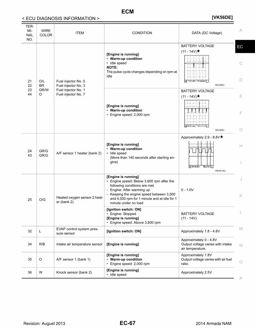
ECM[VK56DE]
C
D
E
F
G
H
I
J
K
L
M
A
C
N
P
O
< ECU DIAGNOSIS INFORMATION >
E
21222344
O/LBRGR/WO
Fuel injector No. 5Fuel injector No. 3Fuel injector No. 1Fuel injector No. 7
[Engine is running]• Warm-up condition• Idle speedNOTE:The pulse cycle changes depending on rpm at idle
BATTERY VOLTAGE
(11 - 14V)
[Engine is running]• Warm-up condition• Engine speed: 2,000 rpm
BATTERY VOLTAGE
(11 - 14V)
2443
GR/GGR/G
A/F sensor 1 heater (bank 2)
[Engine is running]• Warm-up condition• Idle speed
(More than 140 seconds after starting en-gine)
Approximately 2.9 - 8.8V
25 O/GHeated oxygen sensor 2 heat-er (bank 2)
[Engine is running]• Engine speed: Below 3,600 rpm after the
following conditions are met.- Engine: After warming up- Keeping the engine speed between 3,500
and 4,000 rpm for 1 minute and at idle for 1 minute under no load
0 - 1.0V
[Ignition switch: ON]• Engine: Stopped[Engine is running]• Engine speed: Above 3,600 rpm
BATTERY VOLTAGE(11 - 14V)
32 LEVAP control system pres-sure sensor
[Ignition switch: ON] Approximately 1.8 - 4.8V
34 R/B Intake air temperature sensor [Engine is running]Approximately 0 - 4.8VOutput voltage varies with intake air temperature.
35 O A/F sensor 1 (bank 1)[Engine is running]• Warm-up condition• Engine speed: 2,000 rpm
Approximately 1.8VOutput voltage varies with air fuel ratio.
36 W Knock sensor (bank 2)[Engine is running]• Idle speed
Approximately 2.5V
TER-MI-NAL NO.
WIRE COLOR
ITEM CONDITION DATA (DC Voltage)
SEC984C
SEC985C
PBIA8148J
EC-67Revision: August 2013 2014 Armada NAM

[VK56DE]ECM
< ECU DIAGNOSIS INFORMATION >
38 LFuel pump control module (FPCM) check
[Ignition switch: ON]• More than a few seconds after turning igni-
tion switch ONApproximately 0V
[Ignition switch: ON]• For a few seconds after turning ignition
switch ON[Engine is running]• Warm-up condition• Idle speed
4 - 6V
39 L/YFuel pump control module(FPCM)
[When cranking engine] 0 - 0.5V
[Engine is running]• Warm-up condition• Idle speed
8 - 12V
40414263
Y/GPLG
Fuel injector No. 6Fuel injector No. 4 Fuel injector No. 2Fuel injector No. 8
[Engine is running]• Warm-up condition• Idle speedNOTE:The pulse cycle changes depending on rpm at idle
BATTERY VOLTAGE
(11 - 14V)
[Engine is running]• Warm-up condition• Engine speed: 2,000 rpm
BATTERY VOLTAGE
(11 - 14V)
45 L/YEVAP canister purge volume control solenoid valve
[Engine is running]• Idle speed• Accelerator pedal: Not depressed even
slightly, after engine starting
BATTERY VOLTAGE
(11 - 14V)
[Engine is running]• Engine speed: About 2,000 rpm (More than
100 seconds after starting engine)
BATTERY VOLTAGE
(11 - 14V)
TER-MI-NAL NO.
WIRE COLOR
ITEM CONDITION DATA (DC Voltage)
SEC984C
SEC985C
SEC990C
SEC991C
EC-68Revision: August 2013 2014 Armada NAM

ECM[VK56DE]
C
D
E
F
G
H
I
J
K
L
M
A
C
N
P
O
< ECU DIAGNOSIS INFORMATION >
E
46606162
L/RGR/RO/WY/R
Ignition signal No. 7Ignition signal No. 5Ignition signal No. 3Ignition signal No. 1
[Engine is running]• Warm-up condition• Idle speedNOTE:The pulse cycle changes depending on rpm at idle
0 - 0.3V
[Engine is running]• Warm-up condition• Engine speed: 2,500 rpm
0.1 - 0.6V
47 GSensor power supply(Throttle position sensor)
[Ignition switch: ON] Approximately 5V
48 SBSensor power supply(EVAP control system pres-sure sensor)
[Ignition switch: ON] Approximately 5V
49 R/YSensor power supply(Refrigerant pressure sensor)
[Ignition switch: ON] Approximately 5V
50 B Throttle position sensor 1
[Ignition switch: ON]• Engine: Stopped• Selector lever: D• Accelerator pedal: Fully released
More than 0.36V
[Ignition switch: ON]• Engine: Stopped• Selector lever: D• Accelerator pedal: Fully depressed
Less than 4.75V
51 W Mass air flow sensor
[Engine is running]• Warm-up condition• Idle speed
0.9 - 1.3V
[Engine is running]• Warm-up condition• Engine speed: 2,500 rpm
1.7 - 2.1V
53 LIntake valve timing control po-sition sensor (Bank 2)
[Engine is running]• Warm-up condition• Idle speed
0 - 1.0V
[Engine is running]• Engine speed: 2,000 rpm
0 - 1.0V
TER-MI-NAL NO.
WIRE COLOR
ITEM CONDITION DATA (DC Voltage)
SEC986C
SEC987C
PBIB2046E
EC-69Revision: August 2013 2014 Armada NAM

[VK56DE]ECM
< ECU DIAGNOSIS INFORMATION >
55 RHeated oxygen sensor 2 (bank 1)
[Engine is running]• Revving engine from idle to 3,000 rpm
quickly after the following conditions are met.
- Engine: After warming up- Keeping the engine speed between 3,500
and 4,000 rpm for 1 minute and at idle for 1 minute under no load
0 - Approximately 1.0V
56 W A/F sensor 1 (bank 1) [Ignition switch: ON] Approximately 2.2V
65798081
G/RV/WW/RW/G
Ignition signal No. 8Ignition signal No. 6Ignition signal No. 4Ignition signal No. 2
[Engine is running]• Warm-up condition• Idle speedNOTE:The pulse cycle changes depending on rpm at idle
0 - 0.3V
[Engine is running]• Warm-up condition• Engine speed: 2,500 rpm
0.1 - 0.6V
66 RSensor ground(Throttle position sensor)
[Engine is running]• Warm-up condition• Idle speed
Approximately 0V
67 B Sensor ground[Engine is running]• Warm-up condition• Idle speed
Approximately 0V
68 W/LSensor power supply(PSP sensor)
[Ignition switch: ON] Approximately 5V
69 W Throttle position sensor 2
[Ignition switch: ON]• Engine: Stopped• Selector lever: D• Accelerator pedal: Fully released
Less than 4.75V
[Ignition switch: ON]• Engine: Stopped• Selector lever: D• Accelerator pedal: Fully depressed
More than 0.36V
70 B/W Refrigerant pressure sensor
[Engine is running]• Warm-up condition• Both A/C switch and blower fan switch: ON
(Compressor operates.)
1.0 - 4.0V
71 R Battery current sensor[Engine is running]• Battery: Fully charged*• Idle speed
Approximately 2.6 - 3.5V
TER-MI-NAL NO.
WIRE COLOR
ITEM CONDITION DATA (DC Voltage)
SEC986C
SEC987C
EC-70Revision: August 2013 2014 Armada NAM

ECM[VK56DE]
C
D
E
F
G
H
I
J
K
L
M
A
C
N
P
O
< ECU DIAGNOSIS INFORMATION >
E
72 YIntake valve timing control po-sition sensor (Bank 1)
[Engine is running]• Warm-up condition• Idle speed
0 - 1.0V
[Engine is running]• Engine speed: 2,000 rpm
0 - 1.0V
73 Y/BEngine coolant temperature sensor
[Engine is running]Approximately 0 - 4.8VOutput voltage varies with engine coolant temperature.
74 LHeated oxygen sensor 2 (bank 2)
[Engine is running]• Revving engine from idle to 3,000 rpm
quickly after the following conditions are met.
- Engine: After warming up- Keeping the engine speed between 3,500
and 4,000 rpm for 1 minute and at idle for 1 minute under no load
0 - Approximately 1.0V
75 L A/F sensor 1 (bank 2) [Ignition switch: ON] Approximately 2.2V
78 B/WSensor ground(Heated oxygen sensor 2)
[Engine is running]• Warm-up condition• Idle speed
Approximately 0V
82 B/RSensor ground(APP sensor 1)
[Engine is running]• Warm-up condition• Idle speed
Approximately 0V
83 G/WSensor ground(APP sensor 2)
[Engine is running]• Warm-up condition• Idle speed
Approximately 0V
86 P CAN communication line — —
90 LSensor power supply(APP sensor 1)
[Ignition switch: ON] Approximately 5V
91 W/RSensor power supply(APP sensor 2)
[Ignition switch: ON] Approximately 5V
94 L CAN communication line — —
98 G/RAccelerator pedal position sensor 2
[Ignition switch: ON]• Engine: Stopped• Accelerator pedal: Fully released
0.25 - 0.50V
[Ignition switch: ON]• Engine: Stopped• Accelerator pedal: Fully depressed
2.0 - 2.5V
TER-MI-NAL NO.
WIRE COLOR
ITEM CONDITION DATA (DC Voltage)
PBIB2046E
EC-71Revision: August 2013 2014 Armada NAM

[VK56DE]ECM
< ECU DIAGNOSIS INFORMATION >
99 G/Y ASCD steering switch
[Ignition switch: ON]• ASCD steering switch: OFF
Approximately 4V
[Ignition switch: ON]• MAIN switch: Pressed
Approximately 0V
[Ignition switch: ON]• CANCEL switch: Pressed
Approximately 1V
[Ignition switch: ON]• RESUME/ACCELERATE switch: Pressed
Approximately 3V
[Ignition switch: ON]• SET/COAST switch: Pressed
Approximately 2V
101 R/W Stop lamp switch
[Ignition switch: OFF]• Brake pedal: Fully released
Approximately 0V
[Ignition switch: OFF]• Brake pedal: Slightly depressed
BATTERY VOLTAGE(11 - 14V)
102 GR/R PNP signal
[Ignition switch: ON]• Selector lever: P or N
Approximately 0V
[Ignition switch: ON]• Except the above gear position
BATTERY VOLTAGE(11 - 14V)
104 O Throttle control motor relay[Ignition switch: OFF]
BATTERY VOLTAGE(11 - 14V)
[Ignition switch: ON] 0 - 1.0V
106 BR/WAccelerator pedal position sensor 1
[Ignition switch: ON]• Engine: Stopped• Accelerator pedal: Fully released
0.5 - 1.0V
[Ignition switch: ON]• Engine: Stopped• Accelerator pedal: Fully depressed
4.2 - 4.8V
107 V/R Fuel tank temperature sensor [Engine is running]Approximately 0 - 4.8VOutput voltage varies with fuel tank temperature.
108 BR/W ASCD brake switch
[Ignition switch: ON]• Brake pedal: Slightly depressed
Approximately 0V
[Ignition switch: ON]• Brake pedal: Fully released
BATTERY VOLTAGE(11 - 14V)
109 L/W Ignition switch
[Ignition switch: OFF] 0V
[Ignition switch: ON]BATTERY VOLTAGE(11 - 14V)
111 W/BECM relay(Self shut-off)
[Engine is running][Ignition switch: OFF]• For a few seconds after turning ignition
switch OFF
0 - 1.5V
[Ignition switch: OFF]• More than a few seconds after turning igni-
tion switch OFF
BATTERY VOLTAGE(11 - 14V)
113 GR Fuel pump relay
[Ignition switch: ON]• For 1 second after turning ignition switch
ON[Engine is running]
0 - 1.5V
[Ignition switch: ON]• More than 1 second after turning ignition
switch ON
BATTERY VOLTAGE(11 - 14V)
TER-MI-NAL NO.
WIRE COLOR
ITEM CONDITION DATA (DC Voltage)
EC-72Revision: August 2013 2014 Armada NAM

ECM[VK56DE]
C
D
E
F
G
H
I
J
K
L
M
A
C
N
P
O
< ECU DIAGNOSIS INFORMATION >
E
: Average voltage for pulse signal (Actual pulse signal can be confirmed by oscilloscope.)
*: Before measuring the terminal voltage, confirm that the battery is fully charged. Refer to PG-5, "How to Handle Battery".
Fail-Safe Chart INFOID:0000000009825031
When the DTC listed below is detected, the ECM enters fail-safe mode and the MIL lights up.
115116
BB/W
ECM ground[Engine is running]• Idle speed
Body ground
117 L/YEVAP canister vent control valve
[Ignition switch: ON]BATTERY VOLTAGE(11 - 14V)
119120
BRBR
Power supply for ECM [Ignition switch: ON]BATTERY VOLTAGE(11 - 14V)
121 WPower supply for ECM(Back-up)
[Ignition switch: OFF]BATTERY VOLTAGE(11 - 14V)
TER-MI-NAL NO.
WIRE COLOR
ITEM CONDITION DATA (DC Voltage)
DTC No. Detected items Engine operating condition in fail-safe mode
P0101P0102P0103
Mass air flow sensor circuit Engine speed will not rise more than 2,400 rpm due to the fuel cut.
P0117P0118
Engine coolant tempera-ture sensor circuit
Engine coolant temperature will be determined by ECM based on the following condition.CONSULT displays the engine coolant temperature decided by ECM.
ConditionEngine coolant temperature decided
(CONSULT display)
Just as ignition switch is turned ON or START
40C (104F)
Approx. 4 minutes or more after engine starting
80C (176F)
Except as shown above40 - 80C (104 - 176F)(Depends on the time)
When the fail-safe system for engine coolant temperature sensor is activated, the cooling fan operates while engine is running.
P0122P0123P0222P0223P2135
Throttle position sensor The ECM controls the electric throttle control actuator in regulating the throttle opening in order for the idle position to be within +10 degrees.The ECM regulates the opening speed of the throttle valve to be slower than the normal condition.So, the acceleration will be poor.
P0500 Vehicle speed sensor The cooling fan operates (Highest) while engine is running.
P0643 Sensor power supply ECM stops the electric throttle control actuator control, throttle valve is maintained at a fixed opening (approx. 5 degrees) by the return spring.
P2100P2103
Throttle control motor relay ECM stops the electric throttle control actuator control, throttle valve is maintained at a fixed opening (approx. 5 degrees) by the return spring.
P2101 Electric throttle control function
ECM stops the electric throttle control actuator control, throttle valve is maintained at a fixed opening (approx. 5 degrees) by the return spring.
P2118 Throttle control motor ECM stops the electric throttle control actuator control, throttle valve is maintained at a fixed opening (approx. 5 degrees) by the return spring.
EC-73Revision: August 2013 2014 Armada NAM

[VK56DE]ECM
< ECU DIAGNOSIS INFORMATION >
• When there is an open circuit on MIL circuit, the ECM cannot warn the driver by lighting up MIL when thereis malfunction on engine control system.Therefore, when electrical controlled throttle and part of ECM related diagnoses are continuously detectedas NG for 5 trips, ECM warns the driver that engine control system malfunctions and MIL circuit is open bymeans of operating fail-safe function.The fail-safe function also operates when above diagnoses except MIL circuit are detected and demands thedriver to repair the malfunction.
DTC Inspection Priority Chart INFOID:0000000009825032
If some DTCs are displayed at the same time, perform inspections one by one based on the following prioritychart.
P2119 Electric throttle control ac-tuator
(When electric throttle control actuator does not function properly due to the return spring malfunction:)ECM controls the electric throttle actuator by regulating the throttle opening around the idle position. The engine speed will not rise more than 2,000 rpm.
(When throttle valve opening angle in fail-safe mode is not in specified range:)ECM controls the electric throttle control actuator by regulating the throttle opening to 20 degrees or less.
(When ECM detects the throttle valve is stuck open:)While the vehicle is driving, it slows down gradually by fuel cut. After the vehicle stops, the engine stalls.The engine can restart in N or P position, and engine speed will not exceed 1,000 rpm or more.
P2122P2123P2127P2128P2138
Accelerator pedal position sensor
The ECM controls the electric throttle control actuator in regulating the throttle opening in order for the idle position to be within +10 degrees.The ECM regulates the opening speed of the throttle valve to be slower than the normal condition.So, the acceleration will be poor.
DTC No. Detected items Engine operating condition in fail-safe mode
Engine operating condition in fail-safe mode Engine speed will not rise more than 2,500 rpm due to the fuel cut
EC-74Revision: August 2013 2014 Armada NAM

ECM[VK56DE]
C
D
E
F
G
H
I
J
K
L
M
A
C
N
P
O
< ECU DIAGNOSIS INFORMATION >
E
Priority Detected items (DTC)
1 • U0100 U0101 U1001 CAN communication line• P0101 P0102 P0103 Mass air flow sensor• P0112 P0113 P0127 Intake air temperature sensor• P0116 P0117 P0118 P0125 Engine coolant temperature sensor• P0122 P0123 P0222 P0223 P1225 P1226 P2135 Throttle position sensor• P0128 Thermostat function• P0181 P0182 P0183 Fuel tank temperature sensor• P0327 P0328 P0332 P0333 Knock sensor• P0335 Crankshaft position sensor (POS)• P0340 Camshaft position sensor (PHASE)• P0460 P0461 P0462 P0463 Fuel level sensor• P0500 Vehicle speed sensor• P0603 P0604 P0605 P0606 P0607 P060A P060B ECM• P0643 Sensor power supply• P0700 TCM• P0705 Park/neutral position (PNP) switch• P0850 Park/neutral position (PNP) switch• P1550 P1551 P1552 P1553 P1554 Battery current sensor• P1610 - P1615 NATS• P2122 P2123 P2127 P2128 P2138 Accelerator pedal position sensor
2 • P0031 P0032 P0051 P0052 Air fuel ratio (A/F) sensor 1 heater• P0037 P0038 P0057 P0058 Heated oxygen sensor 2 heater• P0075 P0081 Intake valve timing control solenoid valve• P0130 P0131 P0132 P0133 P0150 P0151 P0152 P0153 P2096 P2097 P2098 P2099 Air fuel ratio (A/F) sensor 1• P0137 P0138 P0139 P0157 P0158 P0159 Heated oxygen sensor 2• P0441 EVAP control system purge flow monitoring• P0443 P0444 P0445 EVAP canister purge volume control solenoid valve• P0447 P0448 EVAP canister vent control valve• P0451 P0452 P0453 EVAP control system pressure sensor• P0550 Power steering pressure sensor• P0710 P0717 P0720 P0731 P0732 P0733 P0734 P0735 P0740 P0744 P0745 P1730 P1752 P1754 P1757 P1759
P1762 P1767 P1772 P1774 A/T related sensors, solenoid valves and switches• P1217 Engine over temperature (OVERHEAT)• P1220 Fuel pump control module (FPCM)• P1140 P1145 Intake valve timing control position sensor• P1805 Brake switch• P2100 P2103 P2118 Electric throttle control actuator• P2101 Electric throttle control function
3 • P0011 P0021 Intake valve timing control• P0171 P0172 P0174 P0175 Fuel injection system function• P0300 - P0308 Misfire• P0420 P0430 Three way catalyst function• P0442 EVAP control system (SMALL LEAK)• P0455 EVAP control system (GROSS LEAK)• P0456 EVAP control system (VERY SMALL LEAK)• P0506 P0507 Idle speed control system• P050A P050B P050E Cold start control• P1148 P1168 Closed loop control• P1211 TCS control unit• P1212 TCS communication line• P1564 ASCD steering switch• P1572 ASCD brake switch• P1574 ASCD vehicle speed sensor• P2119 Electric throttle control actuator
EC-75Revision: August 2013 2014 Armada NAM

[VK56DE]ECM
< ECU DIAGNOSIS INFORMATION >
DTC Index INFOID:0000000009825033
:Applicable —: Not applicable
Items (CONSULT screen terms)
DTC*1
SRT codeTest value/ Test limit
(GST only)Trip MIL
Perma-nent DTC
group*12
Reference pageCONSULT
GST*2 ECM*3
LOST COMM (ECM A) U0100 0100*5 — — 1 B TM-42
LOST COMM (TCM) U0101 0101*5 — — 1 B EC-154
CAN COMM CIRCUIT U1001 1001*5 — — 2 — — EC-155
NO DTC IS DETECTED. FURTHER TESTING MAY BE REQUIRED.
P0000 0000 — — —Blink-
ing*7 — —
INT/V TIM CONT-B1 P0011 0011 — — 2 B EC-156
INT/V TIM CONT-B2 P0021 0021 — — 2 B EC-156
A/F SEN1 HTR (B1) P0031 0031 — 2 B EC-163
A/F SEN1 HTR (B1) P0032 0032 — 2 B EC-163
HO2S2 HTR (B1) P0037 0037 — 2 B EC-166
HO2S2 HTR (B1) P0038 0038 — 2 B EC-166
A/F SEN1 HTR (B2) P0051 0051 — 2 B EC-163
A/F SEN1 HTR (B2) P0052 0052 — 2 B EC-163
HO2S2 HTR (B2) P0057 0057 — 2 B EC-166
HO2S2 HTR (B2) P0058 0058 — 2 B EC-166
INT/V TIM V/CIR-B1 P0075 0075 — — 2 B EC-169
INT/V TIM V/CIR-B2 P0081 0081 — — 2 B EC-169
MAF SEN/CIRCUIT-B1 P0101 0101 — — 2 B EC-172
MAF SEN/CIRCUIT-B1 P0102 0102 — — 1 B EC-176
MAF SEN/CIRCUIT-B1 P0103 0103 — — 1 B EC-176
IAT SENSOR 1 B1 P0111 0111 — — 2 A EC-181
IAT SEN/CIRCUIT-B1 P0112 0112 — — 2 B EC-183
IAT SEN/CIRCUIT-B1 P0113 0113 — — 2 B EC-183
ECT SEN/CIRC P0116 0116 — — 2 A EC-186
ECT SEN/CIRC P0117 0117 — — 1 B EC-189
ECT SEN/CIRC P0118 0118 — — 1 B EC-189
TP SEN 2/CIRC-B1 P0122 0122 — — 1 B EC-193
TP SEN 2/CIRC-B1 P0123 0123 — — 1 B EC-193
ECT SENSOR P0125 0125 — — 2 B EC-197
IAT SENSOR-B1 P0127 0127 — — 2 B EC-200
THERMSTAT FNCTN P0128 0128 — — 2 B EC-203
A/F SENSOR1 (B1) P0130 0130 — 2 A EC-205
A/F SENSOR1 (B1) P0131 0131 — 2 B EC-209
A/F SENSOR1 (B1) P0132 0132 — — 2 B EC-213
A/F SENSOR1 (B1) P0133 0133 2 A EC-217
HO2S2 (B1) P0137 0137 2 A EC-223
HO2S2 (B1) P0138 0138 2 A EC-228
HO2S2 (B1) P0139 0139 2 A EC-235
A/F SENSOR1 (B2) P0150 0150 — 2 A EC-205
EC-76Revision: August 2013 2014 Armada NAM

ECM[VK56DE]
C
D
E
F
G
H
I
J
K
L
M
A
C
N
P
O
< ECU DIAGNOSIS INFORMATION >
EA/F SENSOR1 (B2) P0151 0151 — 2 B EC-209
A/F SENSOR1 (B2) P0152 0152 — — 2 B EC-213
A/F SENSOR1 (B2) P0153 0153 2 A EC-217
HO2S2 (B2) P0157 0157 2 A EC-223
HO2S2 (B2) P0158 0158 2 A EC-228
HO2S2 (B2) P0159 0159 2 A EC-235
FUEL SYS-LEAN-B1 P0171 0171 — 2 B EC-242
FUEL SYS-RICH-B1 P0172 0172 — 2 B EC-247
FUEL SYS-LEAN-B2 P0174 0174 — 2 B EC-242
FUEL SYS-RICH-B2 P0175 0175 — 2 B EC-247
FTT SENSOR P0181 0181 — — 2 A and B EC-252
FTT SEN/CIRCUIT P0182 0182 — — 2 B EC-257
FTT SEN/CIRCUIT P0183 0183 — — 2 B EC-257
TP SEN 1/CIRC-B1 P0222 0222 — — 1 B EC-260
TP SEN 1/CIRC-B2 P0223 0223 — — 1 B EC-260
MULTI CYL MISFIRE P0300 0300 — 2 B EC-264
CYL 1 MISFIRE P0301 0301 — 2 B EC-264
CYL 2 MISFIRE P0302 0302 — 2 B EC-264
CYL 3 MISFIRE P0303 0303 — 2 B EC-264
CYL 4 MISFIRE P0304 0304 — 2 B EC-264
CYL 5 MISFIRE P0305 0305 — 2 B EC-264
CYL 6 MISFIRE P0306 0306 — 2 B EC-264
CYL 7 MISFIRE P0307 0307 — 2 B EC-264
CYL 8 MISFIRE P0308 0308 — 2 B EC-264
KNOCK SEN/CIRC-B1 P0327 0327 — — 2 — — EC-271
KNOCK SEN/CIRC-B1 P0328 0328 — — 2 — — EC-271
KNOCK SEN/CIRC-B2 P0332 0332 — — 2 — — EC-271
KNOCK SEN/CIRC-B2 P0333 0333 — — 2 — — EC-271
CKP SEN/CIRCUIT P0335 0335 — — 2 B EC-274
CMP SEN/CIRC-B1 P0340 0340 — — 2 B EC-278
TW CATALYST SYS-B1 P0420 0420 2 A EC-282
TW CATALYST SYS-B2 P0430 0430 2 A EC-282
EVAP PURG FLOW/MON P0441 0441 2 A EC-286
EVAP SMALL LEAK P0442 0442 2 A EC-291
PURG VOLUME CONT/V P0443 0443 — — 2 B EC-298
PURG VOLUME CONT/V P0444 0444 — — 2 B EC-304
PURG VOLUME CONT/V P0445 0445 — — 2 B EC-304
VENT CONTROL VALVE P0447 0447 — — 2 B EC-307
VENT CONTROL VALVE P0448 0448 — — 2 A EC-311
EVAP SYS PRES SEN P0451 0451 — — 2 B EC-315
EVAP SYS PRES SEN P0452 0452 — — 2 B EC-319
EVAP SYS PRES SEN P0453 0453 — — 2 B EC-323
Items (CONSULT screen terms)
DTC*1
SRT codeTest value/ Test limit
(GST only)Trip MIL
Perma-nent DTC
group*12
Reference pageCONSULT
GST*2 ECM*3
EC-77Revision: August 2013 2014 Armada NAM
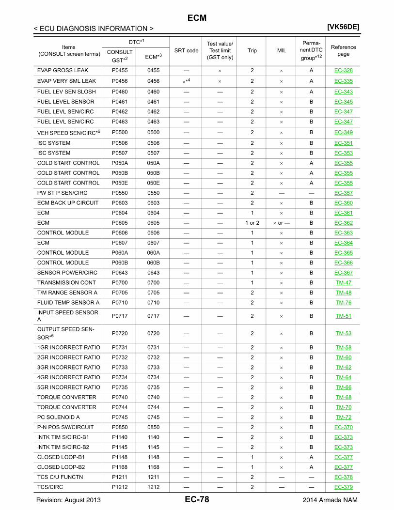
[VK56DE]ECM
< ECU DIAGNOSIS INFORMATION >
EVAP GROSS LEAK P0455 0455 — 2 A EC-328
EVAP VERY SML LEAK P0456 0456 *4 2 A EC-335
FUEL LEV SEN SLOSH P0460 0460 — — 2 A EC-343
FUEL LEVEL SENSOR P0461 0461 — — 2 B EC-345
FUEL LEVL SEN/CIRC P0462 0462 — — 2 B EC-347
FUEL LEVL SEN/CIRC P0463 0463 — — 2 B EC-347
VEH SPEED SEN/CIRC*6 P0500 0500 — — 2 B EC-349
ISC SYSTEM P0506 0506 — — 2 B EC-351
ISC SYSTEM P0507 0507 — — 2 B EC-353
COLD START CONTROL P050A 050A — — 2 A EC-355
COLD START CONTROL P050B 050B — — 2 A EC-355
COLD START CONTROL P050E 050E — — 2 A EC-355
PW ST P SEN/CIRC P0550 0550 — — 2 — — EC-357
ECM BACK UP CIRCUIT P0603 0603 — — 2 B EC-360
ECM P0604 0604 — — 1 B EC-361
ECM P0605 0605 — — 1 or 2 or — B EC-362
CONTROL MODULE P0606 0606 — — 1 B EC-363
ECM P0607 0607 — — 1 B EC-364
CONTROL MODULE P060A 060A — — 1 B EC-365
CONTROL MODULE P060B 060B — — 1 B EC-366
SENSOR POWER/CIRC P0643 0643 — — 1 B EC-367
TRANSMISSION CONT P0700 0700 — — 1 B TM-47
T/M RANGE SENSOR A P0705 0705 — — 2 B TM-48
FLUID TEMP SENSOR A P0710 0710 — — 2 B TM-76
INPUT SPEED SENSOR A
P0717 0717 — — 2 B TM-51
OUTPUT SPEED SEN-
SOR*6 P0720 0720 — — 2 B TM-53
1GR INCORRECT RATIO P0731 0731 — — 2 B TM-58
2GR INCORRECT RATIO P0732 0732 — — 2 B TM-60
3GR INCORRECT RATIO P0733 0733 — — 2 B TM-62
4GR INCORRECT RATIO P0734 0734 — — 2 B TM-64
5GR INCORRECT RATIO P0735 0735 — — 2 B TM-66
TORQUE CONVERTER P0740 0740 — — 2 B TM-68
TORQUE CONVERTER P0744 0744 — — 2 B TM-70
PC SOLENOID A P0745 0745 — — 2 B TM-72
P-N POS SW/CIRCUIT P0850 0850 — — 2 B EC-370
INTK TIM S/CIRC-B1 P1140 1140 — — 2 B EC-373
INTK TIM S/CIRC-B2 P1145 1145 — — 2 B EC-373
CLOSED LOOP-B1 P1148 1148 — — 1 A EC-377
CLOSED LOOP-B2 P1168 1168 — — 1 A EC-377
TCS C/U FUNCTN P1211 1211 — — 2 — — EC-378
TCS/CIRC P1212 1212 — — 2 — — EC-379
Items (CONSULT screen terms)
DTC*1
SRT codeTest value/ Test limit
(GST only)Trip MIL
Perma-nent DTC
group*12
Reference pageCONSULT
GST*2 ECM*3
EC-78Revision: August 2013 2014 Armada NAM

ECM[VK56DE]
C
D
E
F
G
H
I
J
K
L
M
A
C
N
P
O
< ECU DIAGNOSIS INFORMATION >
EENG OVER TEMP P1217 1217 — — 1 B EC-380
FPCM/CIRCUIT*9 P1220 1220 — — 2 — — EC-384
CTP LEARNING-B1 P1225 1225 — — 2 — — EC-389
CTP LEARNING-B2 P1226 1226 — — 2 — — EC-391
BAT CURRENT SENSOR P1550 1550 — — 2 — — EC-393
BAT CURRENT SENSOR P1551 1551 — — 2 — — EC-397
BAT CURRENT SENSOR P1552 1552 — — 2 — — EC-397
BAT CURRENT SENSOR P1553 1553 — — 2 — — EC-401
BAT CURRENT SENSOR P1554 1554 — — 2 — — EC-405
ASCD SW P1564 1564 — — 1 — — EC-409
ASCD BRAKE SW P1572 1572 — — 1 — — EC-413
ASCD VHL SPD SEN*8 P1574 1574 — — 1 — — EC-418
LOCK MODE P1610 1610 — — 2 — —SEC-43*10
SEC-147*11
ID DISCARD IMM-ECM P1611 1611 — — 2 — —SEC-37*10
SEC-144*11
CHAIN OF ECM-IMMU P1612 1612 — — 2 — —SEC-39*10
SEC-146*11
CHAIN OF IMMU-KEY P1614 1614 — — 2 — —SEC-37*10
SEC-140*11
DIFFERENCE OF KEY P1615 1615 — — 2 — —SEC-37*10
SEC-143*11
INTERLOCK P1730 1730 — — 1 B TM-81
INPUT CLUTCH SOL P1752 1752 — — 1 B TM-85
FR BRAKE SOLENOID P1757 1757 — — 1 B TM-87
DRCT CLUTCH SOL P1762 1762 — — 1 B TM-89
HLR CLUTCH SOLE-NOID
P1767 1767 — — 1 B TM-91
L C BRAKE SOLENOID P1772 1772 — — 1 B TM-93
L C BRAKE SOLENOID P1774 1774 — — 1 B TM-95
BRAKE SW/CIRCUIT P1805 1805 — — 2 — — EC-420
ETC MOT PWR-B1 P2100 2100 — — 1 B EC-429
POST CAT FUEL TRIM SYS B1
P2096 2096 — — 2 A EC-423
POST CAT FUEL TRIM SYS B1
P2097 2097 — — 2 A EC-423
POST CAT FUEL TRIM SYS B2
P2098 2098 — — 2 A EC-423
POST CAT FUEL TRIM SYS B2
P2099 2099 — — 2 A EC-423
ETC MOT PWR-B1 P2101 2101 — — 1 B EC-432
ETC MOT PWR P2103 2103 — — 1 B EC-429
ETC MOT-B1 P2118 2118 — — 1 B EC-436
ETC ACTR-B1 P2119 2119 — — 1 B EC-438
Items (CONSULT screen terms)
DTC*1
SRT codeTest value/ Test limit
(GST only)Trip MIL
Perma-nent DTC
group*12
Reference pageCONSULT
GST*2 ECM*3
EC-79Revision: August 2013 2014 Armada NAM

[VK56DE]ECM
< ECU DIAGNOSIS INFORMATION >
*1: 1st trip DTC No. is the same as DTC No.
*2: This number is prescribed by SAE J2012.
*3: In Diagnostic Test Mode II (Self-diagnostic results), this number is controlled by NISSAN.
*4: SRT code will not be set if the self-diagnostic result is NG.
*5: The troubleshooting for this DTC needs CONSULT.
*6: When the fail-safe operations for both self-diagnoses occur, the MIL illuminates.
*7: When the ECM is in the mode of displaying SRT status, MIL may flash. For the details, refer to “How to Display SRT Status”.
*8: 2WD models
*9: Flexible fuel vehicle (FFV)
*10: With intelligent key system
*11: Without intelligent key system
*12: When erasing this DTC, always use CONSULT or GST.
Test Value and Test Limit INFOID:0000000010111967
The following is the information specified in Service $06 of SAE J1979/ISO 15031-5.The test value is a parameter used to determine whether a system/circuit diagnostic test is OK or NG whilebeing monitored by the ECM during self-diagnosis. The test limit is a reference value which is specified as themaximum or minimum value and is compared with the test value being monitored.These data (test value and test limit) are specified by On Board Monitor ID (OBDMID), Test ID (TID), Unit andScaling ID and can be displayed on the GST screen.The items of the test value and test limit will be displayed with GST screen which items are provided by theECM. (e.g., if bank 2 is not applied on this vehicle, only the items of bank 1 are displayed)
APP SEN 1/CIRC P2122 2122 — — 1 B EC-440
APP SEN 1/CIRC P2123 2123 — — 1 B EC-440
APP SEN 2/CIRC P2127 2127 — — 1 B EC-443
APP SEN 2/CIRC P2128 2128 — — 1 B EC-443
TP SENSOR-B1 P2135 2135 — — 1 B EC-447
APP SENSOR P2138 2138 — — 1 B EC-451
Items (CONSULT screen terms)
DTC*1
SRT codeTest value/ Test limit
(GST only)Trip MIL
Perma-nent DTC
group*12
Reference pageCONSULT
GST*2 ECM*3
EC-80Revision: August 2013 2014 Armada NAM

ECM[VK56DE]
C
D
E
F
G
H
I
J
K
L
M
A
C
N
P
O
< ECU DIAGNOSIS INFORMATION >
EItem
OBD-MID
Self-diagnostic test item DTC
Test value and Test limit
(GST display)Description
TIDUnit and Scaling
ID
HO2S 01HAir fuel ratio (A/F) sensor 1 (Bank 1)
P0131 83H 0BHMinimum sensor output voltage for test cycle
P0131 84H 0BHMaximum sensor output voltage for test cycle
P0130 85H 0BHMinimum sensor output voltage for test cycle
P0130 86H 0BHMaximum sensor output voltage for test cycle
P0133 87H 04HResponse rate: Response ratio (lean to rich)
P0133 88H 04HResponse rate: Response ratio (rich to lean)
P2A00 or P2096 89H 84HThe amount of shift in air fuel ratio (too lean)
P2A00 or P2097 8AH 84HThe amount of shift in air fuel ratio (too rich)
P0130 8BH 0BH Difference in sensor output voltage
P0133 8CH 83H Response gain at the limited frequency
P014C 8DH 04HO2 sensor slow response - Rich to lean bank 1 sensor 1
P014C 8EH 04HO2 sensor slow response - Rich to lean bank 1 sensor 1
P014D 8FH 84HO2 sensor slow response - Lean to rich bank 1 sensor 1
P014D 90H 84HO2 sensor slow response - Lean to rich bank 1 sensor 1
P015A 91H 01HO2 sensor delayed response - Rich to lean bank 1 sensor 1
P015A 92H 01HO2 sensor delayed response - Rich to lean bank 1 sensor 1
P015B 93H 01HO2 sensor delayed response - Lean to rich bank 1 sensor 1
P015B 94H 01HO2 sensor delayed response - Lean to rich bank 1 sensor 1
P0133 95H 04HResponse rate: Response ratio (lean to rich)
P0133 96H 84HResponse rate: Response ratio (rich to lean)
EC-81Revision: August 2013 2014 Armada NAM

[VK56DE]ECM
< ECU DIAGNOSIS INFORMATION >
HO2S
02HHeated oxygen sensor 2 (Bank 1)
P0138 07H 0CHMinimum sensor output voltage for test cycle
P0137 08H 0CHMaximum sensor output voltage for test cycle
P0138 80H 0CH Sensor output voltage
P0139 81H 0CH Difference in sensor output voltage
P0139 82H 11HRear O2 sensor delay response diag-nosis
03HHeated oxygen sensor 3 (Bank 1)
P0143 07H 0CHMinimum sensor output voltage for test cycle
P0144 08H 0CHMaximum sensor output voltage for test cycle
P0146 80H 0CH Sensor output voltage
P0145 81H 0CH Difference in sensor output voltage
05HAir fuel ratio (A/F) sensor 1 (Bank 2)
P0151 83H 0BHMinimum sensor output voltage for test cycle
P0151 84H 0BHMaximum sensor output voltage for test cycle
P0150 85H 0BHMinimum sensor output voltage for test cycle
P0150 86H 0BHMaximum sensor output voltage for test cycle
P0153 87H 04HResponse rate: Response ratio (lean to rich)
P0153 88H 04HResponse rate: Response ratio (rich to lean)
P2A03 or P2098 89H 84HThe amount of shift in air fuel ratio (too lean)
P2A03 or P2099 8AH 84HThe amount of shift in air fuel ratio (too rich)
P0150 8BH 0BH Difference in sensor output voltage
P0153 8CH 83H Response gain at the limited frequency
P014E 8DH 04HO2 sensor slow response - Rich to lean bank 2 sensor 1
P014E 8EH 04HO2 sensor slow response - Rich to lean bank 2 sensor 1
P014F 8FH 84HO2 sensor slow response - Lean to rich bank 2 sensor 1
P014F 90H 84HO2 sensor slow response - Lean to rich bank 2 sensor 1
P015C 91H 01HO2 sensor delayed response - Rich to lean bank 2 sensor 1
P015C 92H 01HO2 sensor delayed response - Rich to lean bank 2 sensor 1
P015D 93H 01HO2 sensor delayed response - Lean to rich bank 2 sensor 1
ItemOBD-MID
Self-diagnostic test item DTC
Test value and Test limit
(GST display)Description
TIDUnit and Scaling
ID
EC-82Revision: August 2013 2014 Armada NAM

ECM[VK56DE]
C
D
E
F
G
H
I
J
K
L
M
A
C
N
P
O
< ECU DIAGNOSIS INFORMATION >
E
HO2S
05HAir fuel ratio (A/F) sensor 1 (Bank 2)
P015D 94H 01HO2 sensor delayed response - Lean to rich bank 2 sensor 1
P0153 95H 04HResponse rate: Response ratio (lean to rich)
P0153 96H 84HResponse rate: Response ratio (rich to lean)
06HHeated oxygen sensor 2 (Bank 2)
P0158 07H 0CHMinimum sensor output voltage for test cycle
P0157 08H 0CHMaximum sensor output voltage for test cycle
P0158 80H 0CH Sensor output voltage
P0159 81H 0CH Difference in sensor output voltage
P0159 82H 11HRear O2 sensor delay response diag-nosis
07HHeated oxygen sensor 3 (Bank2)
P0163 07H 0CHMinimum sensor output voltage for test cycle
P0164 08H 0CHMaximum sensor output voltage for test cycle
P0166 80H 0CH Sensor output voltage
P0165 81H 0CH Difference in sensor output voltage
CATA-LYST
21HThree way catalyst function (Bank1)
P0420 80H 01H O2 storage index
P0420 82H 01HSwitching time lag engine exhaust in-dex value
P2423 83H 0CHDifference in 3rd O2 sensor output voltage
P2423 84H 84H O2 storage index in HC trap catalyst
22HThree way catalyst function (Bank2)
P0430 80H 01H O2 storage index
P0430 82H 01HSwitching time lag engine exhaust in-dex value
P2424 83H 0CHDifference in 3rd O2 sensor output voltage
P2424 84H 84H O2 storage index in HC trap catalyst
EGR SYSTEM
31H EGR function
P0400 80H 96HLow flow faults: EGR temp change rate (short term)
P0400 81H 96HLow flow faults: EGR temp change rate (long term)
P0400 82H 96HLow flow faults: Difference between max EGR temp and EGR temp under idling condition
P0400 83H 96H Low flow faults: Max EGR temp
P1402 84H 96HHigh Flow Faults: EGR temp increase rate
ItemOBD-MID
Self-diagnostic test item DTC
Test value and Test limit
(GST display)Description
TIDUnit and Scaling
ID
EC-83Revision: August 2013 2014 Armada NAM

[VK56DE]ECM
< ECU DIAGNOSIS INFORMATION >
VVT SYSTEM
35H VVT Monitor (Bank1)
P0011 80H 9DHVTC intake function diagnosis (VTC alignment check diagnosis)
P0014 81H 9DHVTC exhaust function diagnosis (VTC alignment check diagnosis)
P0011 82H 9DHVTC intake function diagnosis (VTC drive failure diagnosis)
P0014 83H 9DHVTC exhaust function diagnosis (VTC drive failure diagnosis)
P100A 84H 10H VEL slow response diagnosis
P1090 85H 10H VEL servo system diagnosis
P0011 86H 9DHVTC intake intermediate lock function diagnosis (VTC intermediate position alignment check diagnosis)
Advanced: P052ARetarded: P052B
87H 9DHVTC intake intermediate lock system diagnosis (VTC intermediate lock posi-tion check diagnosis)
36H VVT Monitor (Bank2)
P0021 80H 9DHVTC intake function diagnosis (VTC alignment check diagnosis)
P0024 81H 9DHVTC exhaust function diagnosis (VTC alignment check diagnosis)
P0021 82H 9DHVTC intake function diagnosis (VTC drive failure diagnosis)
P0024 83H 9DHVTC exhaust function diagnosis (VTC drive failure diagnosis)
P100B 84H 10H VEL slow response diagnosis
P1093 85H 10H VEL servo system diagnosis
P0021 86H 9DHVTC intake intermediate lock function diagnosis (VTC intermediate position alignment check diagnosis)
Advanced: P052CRetarded: P052D
87H 9DHVTC intake intermediate lock system diagnosis (VTC intermediate lock posi-tion check diagnosis)
EVAP SYSTEM
39HEVAP control system leak (Cap Off)
P0455 80H 0CHDifference in pressure sensor output voltage before and after pull down
3BHEVAP control system leak (Small leak)
P0442 80H 05HLeak area index (for more than 0.04 inch)
3CHEVAP control system leak (Very small leak)
P0456 80H 05HLeak area index (for more than 0.02 inch)
P0456 81H FDHMaximum internal pressure of EVAP system during monitoring
P0456 82H FDHInternal pressure of EVAP system at the end of monitoring
3DH Purge flow system P0441 83H 0CHDifference in pressure sensor output voltage before and after vent control valve close
ItemOBD-MID
Self-diagnostic test item DTC
Test value and Test limit
(GST display)Description
TIDUnit and Scaling
ID
EC-84Revision: August 2013 2014 Armada NAM

ECM[VK56DE]
C
D
E
F
G
H
I
J
K
L
M
A
C
N
P
O
< ECU DIAGNOSIS INFORMATION >
E
O2 SEN-SOR HEATER
41H A/F sensor 1 heater (Bank 1)Low Input: P0031High Input: P0032
81H 0BHConverted value of heater electric cur-rent to voltage
42HHeated oxygen sensor 2 heat-er (Bank 1)
Low Input: P0037High Input: P0038
80H 0CHConverted value of heater electric cur-rent to voltage
43HHeated oxygen sensor 3 heat-er (Bank 1)
P0043 80H 0CHConverted value of heater electric cur-rent to voltage
45H A/F sensor 1 heater (Bank 2)Low Input: P0051High Input: P0052
81H 0BHConverted value of heater electric cur-rent to voltage
46HHeated oxygen sensor 2 heat-er (Bank 2)
Low Input: P0057High Input: P0058
80H 0CHConverted value of heater electric cur-rent to voltage
47HHeated oxygen sensor 3 heat-er (Bank 2)
P0063 80H 0CHConverted value of heater electric cur-rent to voltage
SEC-OND-ARY AIR
71H Secondary air system
P0411 80H 01HSecondary air injection system incor-rect flow detected
Bank1: P0491Bank2: P0492
81H 01HSecondary air injection system insuffi-cient flow
P2445 82H 01HSecondary air injection system pump stuck off
P2448 83H 01HSecondary air injection system high airflow
Bank1: P2440Bank2: P2442
84H 01HSecondary air injection system switch-ing valve stuck open
P2440 85H 01HSecondary air injection system switch-ing valve stuck open
P2444 86H 01HSecondary air injection system pump stuck on
FUEL SYSTEM
81HFuel injection system function (Bank 1)
P0171 or P0172 80H 2FH Long term fuel trim
P0171 or P0172 81H 24HThe number of lambda control clamped
P117A 82H 03H Cylinder A/F imbalance monitoring
82HFuel injection system function (Bank 2)
P0174 or P0175 80H 2FH Long term fuel trim
P0174 or P0175 81H 24HThe number of lambda control clamped
P117B 82H 03H Cylinder A/F imbalance monitoring
ItemOBD-MID
Self-diagnostic test item DTC
Test value and Test limit
(GST display)Description
TIDUnit and Scaling
ID
EC-85Revision: August 2013 2014 Armada NAM

[VK56DE]ECM
< ECU DIAGNOSIS INFORMATION >
MISFIRE A1H Multiple cylinder misfires
P0301 80H 24HMisfiring counter at 1000 revolution of the first cylinder
P0302 81H 24HMisfiring counter at 1000 revolution of the second cylinder
P0303 82H 24HMisfiring counter at 1000 revolution of the third cylinder
P0304 83H 24HMisfiring counter at 1000 revolution of the fourth cylinder
P0305 84H 24HMisfiring counter at 1000 revolution of the fifth cylinder
P0306 85H 24HMisfiring counter at 1000 revolution of the sixth cylinder
P0307 86H 24HMisfiring counter at 1000 revolution of the seventh cylinder
P0308 87H 24HMisfiring counter at 1000 revolution of the eighth cylinder
P0300 88H 24HMisfiring counter at 1000 revolution of the multiple cylinders
P0301 89H 24HMisfiring counter at 200 revolution of the first cylinder
P0302 8AH 24HMisfiring counter at 200 revolution of the second cylinder
P0303 8BH 24HMisfiring counter at 200 revolution of the third cylinder
P0304 8CH 24HMisfiring counter at 200 revolution of the fourth cylinder
P0305 8DH 24HMisfiring counter at 200 revolution of the fifth cylinder
P0306 8EH 24HMisfiring counter at 200 revolution of the sixth cylinder
P0307 8FH 24HMisfiring counter at 200 revolution of the seventh cylinder
P0308 90H 24HMisfiring counter at 200 revolution of the eighth cylinder
P0300 91H 24HMisfiring counter at 1000 revolution of the single cylinder
P0300 92H 24HMisfiring counter at 200 revolution of the single cylinder
P0300 93H 24HMisfiring counter at 200 revolution of the multiple cylinders
ItemOBD-MID
Self-diagnostic test item DTC
Test value and Test limit
(GST display)Description
TIDUnit and Scaling
ID
EC-86Revision: August 2013 2014 Armada NAM

ECM[VK56DE]
C
D
E
F
G
H
I
J
K
L
M
A
C
N
P
O
< ECU DIAGNOSIS INFORMATION >
E
MISFIRE
A2H No. 1 cylinder misfire
P0301 0BH 24HEWMA (Exponential Weighted Moving Average) misfire counts for last 10 driv-ing cycles
P0301 0CH 24HMisfire counts for last/current driving cycles
A3H No. 2 cylinder misfire
P0302 0BH 24HEWMA (Exponential Weighted Moving Average) misfire counts for last 10 driv-ing cycles
P0302 0CH 24HMisfire counts for last/current driving cycles
A4H No. 3 cylinder misfire
P0303 0BH 24HEWMA (Exponential Weighted Moving Average) misfire counts for last 10 driv-ing cycles
P0303 0CH 24HMisfire counts for last/current driving cycles
A5H No. 4 cylinder misfire
P0304 0BH 24HEWMA (Exponential Weighted Moving Average) misfire counts for last 10 driv-ing cycles
P0304 0CH 24HMisfire counts for last/current driving cycles
A6H No. 5 cylinder misfire
P0305 0BH 24HEWMA (Exponential Weighted Moving Average) misfire counts for last 10 driv-ing cycles
P0305 0CH 24HMisfire counts for last/current driving cycles
A7H No. 6 cylinder misfire
P0306 0BH 24HEWMA (Exponential Weighted Moving Average) misfire counts for last 10 driv-ing cycles
P0306 0CH 24HMisfire counts for last/current driving cycles
A8H No. 7 cylinder misfire
P0307 0BH 24HEWMA (Exponential Weighted Moving Average) misfire counts for last 10 driv-ing cycles
P0307 0CH 24HMisfire counts for last/current driving cycles
A9H No. 8 cylinder misfire
P0308 0BH 24HEWMA (Exponential Weighted Moving Average) misfire counts for last 10 driv-ing cycles
P0308 0CH 24HMisfire counts for last/current driving cycles
ItemOBD-MID
Self-diagnostic test item DTC
Test value and Test limit
(GST display)Description
TIDUnit and Scaling
ID
EC-87Revision: August 2013 2014 Armada NAM

[VK56DE]ENGINE CONTROL SYSTEM
< WIRING DIAGRAM >
WIRING DIAGRAMENGINE CONTROL SYSTEM
Wiring Diagram INFOID:0000000009825035
ABBWA0912GB
EC-88Revision: August 2013 2014 Armada NAM

ENGINE CONTROL SYSTEM[VK56DE]
C
D
E
F
G
H
I
J
K
L
M
A
C
N
P
O
< WIRING DIAGRAM >
E
ABBWA0913GB
EC-89Revision: August 2013 2014 Armada NAM

[VK56DE]ENGINE CONTROL SYSTEM
< WIRING DIAGRAM >
ABBWA0914GB
EC-90Revision: August 2013 2014 Armada NAM

ENGINE CONTROL SYSTEM[VK56DE]
C
D
E
F
G
H
I
J
K
L
M
A
C
N
P
O
< WIRING DIAGRAM >
E
ABBWA0916GB
EC-91Revision: August 2013 2014 Armada NAM

[VK56DE]ENGINE CONTROL SYSTEM
< WIRING DIAGRAM >
ABBWA0915GB
EC-92Revision: August 2013 2014 Armada NAM

ENGINE CONTROL SYSTEM[VK56DE]
C
D
E
F
G
H
I
J
K
L
M
A
C
N
P
O
< WIRING DIAGRAM >
E
ABBIA1382GB
EC-93Revision: August 2013 2014 Armada NAM

[VK56DE]ENGINE CONTROL SYSTEM
< WIRING DIAGRAM >
ABBIA1383GB
EC-94Revision: August 2013 2014 Armada NAM

ENGINE CONTROL SYSTEM[VK56DE]
C
D
E
F
G
H
I
J
K
L
M
A
C
N
P
O
< WIRING DIAGRAM >
E
ABBIA1384GB
EC-95Revision: August 2013 2014 Armada NAM

[VK56DE]ENGINE CONTROL SYSTEM
< WIRING DIAGRAM >
ABBIA1385GB
EC-96Revision: August 2013 2014 Armada NAM

ENGINE CONTROL SYSTEM[VK56DE]
C
D
E
F
G
H
I
J
K
L
M
A
C
N
P
O
< WIRING DIAGRAM >
E
ABBIA1386GB
EC-97Revision: August 2013 2014 Armada NAM
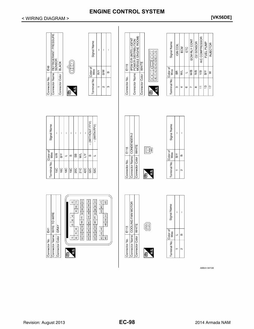
[VK56DE]ENGINE CONTROL SYSTEM
< WIRING DIAGRAM >
ABBIA1387GB
EC-98Revision: August 2013 2014 Armada NAM

ENGINE CONTROL SYSTEM[VK56DE]
C
D
E
F
G
H
I
J
K
L
M
A
C
N
P
O
< WIRING DIAGRAM >
E
ABBIA1388GB
EC-99Revision: August 2013 2014 Armada NAM

[VK56DE]ENGINE CONTROL SYSTEM
< WIRING DIAGRAM >
ABBIA1389GB
EC-100Revision: August 2013 2014 Armada NAM

ENGINE CONTROL SYSTEM[VK56DE]
C
D
E
F
G
H
I
J
K
L
M
A
C
N
P
O
< WIRING DIAGRAM >
E
ABBIA1390GB
EC-101Revision: August 2013 2014 Armada NAM

[VK56DE]ENGINE CONTROL SYSTEM
< WIRING DIAGRAM >
ABBIA1391GB
EC-102Revision: August 2013 2014 Armada NAM

ENGINE CONTROL SYSTEM[VK56DE]
C
D
E
F
G
H
I
J
K
L
M
A
C
N
P
O
< WIRING DIAGRAM >
E
ABBIA1392GB
EC-103Revision: August 2013 2014 Armada NAM

[VK56DE]ENGINE CONTROL SYSTEM
< WIRING DIAGRAM >
ABBIA1393GB
EC-104Revision: August 2013 2014 Armada NAM

ENGINE CONTROL SYSTEM[VK56DE]
C
D
E
F
G
H
I
J
K
L
M
A
C
N
P
O
< WIRING DIAGRAM >
E
ABBIA1394GB
EC-105Revision: August 2013 2014 Armada NAM

[VK56DE]ENGINE CONTROL SYSTEM
< WIRING DIAGRAM >
ABBIA1102GB
EC-106Revision: August 2013 2014 Armada NAM

ENGINE CONTROL SYSTEM[VK56DE]
C
D
E
F
G
H
I
J
K
L
M
A
C
N
P
O
< WIRING DIAGRAM >
E
ABBIA1397GB
EC-107Revision: August 2013 2014 Armada NAM

[VK56DE]ENGINE CONTROL SYSTEM
< WIRING DIAGRAM >
ABBIA1398GB
EC-108Revision: August 2013 2014 Armada NAM

ENGINE CONTROL SYSTEM[VK56DE]
C
D
E
F
G
H
I
J
K
L
M
A
C
N
P
O
< WIRING DIAGRAM >
E
ABBIA1395GB
EC-109Revision: August 2013 2014 Armada NAM

[VK56DE]ENGINE CONTROL SYSTEM
< WIRING DIAGRAM >
ABBIA1396GB
EC-110Revision: August 2013 2014 Armada NAM

DIAGNOSIS AND REPAIR WORKFLOW[VK56DE]
C
D
E
F
G
H
I
J
K
L
M
A
C
N
P
O
< BASIC INSPECTION >
E
BASIC INSPECTIONDIAGNOSIS AND REPAIR WORKFLOW
Trouble Diagnosis Introduction INFOID:0000000009825036
INTRODUCTIONThe engine has an ECM to control major systems such as fuel con-trol, ignition control, idle air control system, etc. The ECM acceptsinput signals from sensors and instantly drives actuators. It is essen-tial that both input and output signals are proper and stable. At thesame time, it is important that there are no malfunctions such as vac-uum leaks, fouled spark plugs, or other malfunctions with the engine.
It is much more difficult to diagnose an incident that occurs intermit-tently rather than continuously. Most intermittent incidents arecaused by poor electric connections or improper wiring. In this case,careful checking of suspected circuits may help prevent the replace-ment of good parts.
A visual check only may not find the cause of the incidents. A roadtest with CONSULT (or GST) or a circuit tester connected should beperformed. Follow the Work Flow on “WORK FLOW”.Before undertaking actual checks, take a few minutes to talk with acustomer who approaches with a driveability complaint. The cus-tomer can supply good information about such incidents, especiallyintermittent ones. Find out what symptoms are present and underwhat conditions they occur. A Diagnostic Worksheet like the exampleon “Worksheet Sample” should be used.Start your diagnosis by looking for conventional malfunctions first.This will help troubleshoot driveability malfunctions on an electroni-cally controlled engine vehicle.
WORK FLOW
MEF036D
SEF233G
SEF234G
EC-111Revision: August 2013 2014 Armada NAM

[VK56DE]DIAGNOSIS AND REPAIR WORKFLOW
< BASIC INSPECTION >Overall Sequence
Detailed Flow
1.GET INFORMATION FOR SYMPTOM
1. Get the detailed information from the customer about the symptom (the condition and the environmentwhen the incident/malfunction occurred) using the “Diagnostic Work Sheet”.
JSBIA0123GB
*1: Include 1st trip DTC.
*2: Include 1st trip freeze frame data.
EC-112Revision: August 2013 2014 Armada NAM

DIAGNOSIS AND REPAIR WORKFLOW[VK56DE]
C
D
E
F
G
H
I
J
K
L
M
A
C
N
P
O
< BASIC INSPECTION >
E
2. Ask if the customer requests I/M examination.
Malfunction information, obtained>>GO TO 2.No malfunction information, but a request for I/M examination>>GO TO 13.
2.CHECK DTC
1. Check DTC.2. Perform the following procedure if DTC is displayed.- Record DTC and freeze frame data. (Print them out with CONSULT or GST.)- Erase DTC.- Study the relationship between the cause detected by DTC and the symptom described by the customer.
(Symptom Matrix Chart is useful. Refer to EC-489, "Symptom Matrix Chart".)3. Check related service bulletins for information.Are any symptoms described and any DTCs detected?Symptom is described, DTC is detected>>GO TO 3.Symptom is described, DTC is not detected>>GO TO 4.Symptom is not described, DTC is detected>>GO TO 5.
3.CONFIRM THE SYMPTOM
Try to confirm the symptom described by the customer (except MIL ON).Also study the normal operation and fail-safe related to the symptom. Refer to EC-493, "Fuel Cut Control (atNo Load and High Engine Speed)" and EC-73, "Fail-Safe Chart".Diagnosis Work Sheet is useful to verify the incident.Verify relation between the symptom and the condition when the symptom is detected.
>> GO TO 5.
4.CONFIRM THE SYMPTOM
Try to confirm the symptom described by the customer.Also study the normal operation and fail-safe related to the symptom. Refer to Refer to EC-493, "Fuel CutControl (at No Load and High Engine Speed)" and EC-73, "Fail-Safe Chart".Diagnosis Work Sheet is useful to verify the incident.Verify relation between the symptom and the condition when the symptom is detected.
>> GO TO 6.
5.PERFORM DTC CONFIRMATION PROCEDURE
Perform DTC CONFIRMATION PROCEDURE for the displayed DTC, and then check that DTC is detectedagain.If two or more DTCs are detected, refer to EC-74, "DTC Inspection Priority Chart" and determine trouble diag-nosis order.NOTE:• Freeze frame data is useful if the DTC is not detected.• Perform Component Function Check if DTC CONFIRMATION PROCEDURE is not included on Service
Manual. This simplified check procedure is an effective alternative though DTC cannot be detected duringthis check.If the result of Component Function Check is NG, it is the same as the detection of DTC by DTC CONFIR-MATION PROCEDURE.
Is DTC detected?YES >> GO TO 10.NO >> Check according to GI-42, "Intermittent Incident".
6.PERFORM BASIC INSPECTION
Perform EC-116, "Basic Inspection".Will CONSULT be used?YES >> GO TO 7.NO >> GO TO 9.
EC-113Revision: August 2013 2014 Armada NAM

[VK56DE]DIAGNOSIS AND REPAIR WORKFLOW
< BASIC INSPECTION >
7.PERFORM SPEC IN DATA MONITOR MODE
With CONSULTCheck that “MAS A/F SE-B1”, “MAS A/F SE-B2”, “B/FUEL SCHDL”, “A/F ALPHA-B1” and “A/F ALPHA-B2”are within the SP value using “SPEC” in “DATA MONITOR” mode with CONSULT. Refer to EC-142, "TestingCondition", EC-142, "Inspection Procedure".Is the measurement value within the SP value?YES >> GO TO 9.NO >> GO TO 8.
8.DETECT MALFUNCTIONING PART BY TROUBLE DIAGNOSIS - SPECIFICATION VALUE
Detect malfunctioning part according to EC-143, "Diagnosis Procedure".Is a malfunctioning part detected?YES >> GO TO 11.NO >> GO TO 9.
9.DETECT MALFUNCTIONING SYSTEM BY SYMPTOM TABLE
Detect malfunctioning system according to EC-489, "Symptom Matrix Chart" based on the confirmed symptomin step 4, and determine the trouble diagnosis order based on possible causes and symptoms.
>> GO TO 10.
10.DETECT MALFUNCTIONING PART BY DIAGNOSIS PROCEDURE
Inspect according to Diagnosis Procedure of the system.NOTE:The Diagnosis Procedure in EC section described based on open circuit inspection. A short circuit inspectionis also required for the circuit check in the Diagnosis Procedure. For details, refer to GI-45, "Circuit Inspec-tion".Is a malfunctioning part detected?YES >> GO TO 11.NO >> Monitor input data from related sensors or check voltage of related ECM terminals using CON-
SULT. Refer to EC-60, "CONSULT Reference Value in Data Monitor Mode", EC-64, "ECM Termi-nal and Reference Value".
11.REPAIR OR REPLACE THE MALFUNCTIONING PART
1. Repair or replace the malfunctioning part.2. Reconnect parts or connectors disconnected during Diagnosis Procedure again after repair and replace-
ment.3. Check DTC. If DTC is displayed, erase it.
>> GO TO 12.
12.FINAL CHECK
When DTC was detected in step 2, perform DTC CONFIRMATION PROCEDURE or Component FunctionCheck again, and then check that the malfunction have been completely repaired.When symptom was described from the customer, refer to confirmed symptom in step 3 or 4, and check thatthe symptom is not detected.Is DTC detected and does symptom remain?YES-1 >> DTC is detected: GO TO 10.YES-2 >> Symptom remains: GO TO 6.NO-1 >> Before returning the vehicle to the customer, always erase unnecessary DTC in ECM and TCM
(Transmission Control Module). If the completion of SRT is needed, drive vehicle under the spe-cific driving pattern. Refer to EC-130, "Description".
NO-2 >> I/M examination, requested from the customer: GO TO 13.
13.PREPARE FOR I/M EXAMINATION
1. Set SRT codes. Refer to EC-130, "Description".2. Erase permanent DTCs. Refer to EC-136, "Description".
EC-114Revision: August 2013 2014 Armada NAM

DIAGNOSIS AND REPAIR WORKFLOW[VK56DE]
C
D
E
F
G
H
I
J
K
L
M
A
C
N
P
O
< BASIC INSPECTION >
E
>> INSPECTION END
DIAGNOSTIC WORKSHEET
DescriptionThere are many operating conditions that lead to the malfunction ofengine components. A good grasp of such conditions can make trou-bleshooting faster and more accurate.In general, each customer feels differently about a incident. It isimportant to fully understand the symptoms or conditions for a cus-tomer complaint.Utilize a diagnostic worksheet like the one on the next page in orderto organize all the information for troubleshooting.Some conditions may cause the MIL to come on steady or blink andDTC to be detected. Examples:• Vehicle ran out of fuel, which caused the engine to misfire.• Fuel filler cap was left off or incorrectly screwed on, allowing fuel to
evaporate into the atmosphere.
Worksheet Sample
SEF907L
MTBL0017
EC-115Revision: August 2013 2014 Armada NAM

[VK56DE]INSPECTION AND ADJUSTMENT
< BASIC INSPECTION >
INSPECTION AND ADJUSTMENT
Basic Inspection INFOID:0000000009825037
EXCEPT FLEXIBLE FUEL VEHICLE
1.INSPECTION START
1. Check service records for any recent repairs that may indicate a related malfunction, or a current need forscheduled maintenance.
2. Open engine hood and check the following:- Harness connectors for improper connections- Wiring harness for improper connections, pinches and cut- Vacuum hoses for splits, kinks and improper connections- Hoses and ducts for leaks- Air cleaner clogging- Gasket3. Confirm that electrical or mechanical loads are not applied.- Headlamp switch is OFF.- Air conditioner switch is OFF.- Rear window defogger switch is OFF.- Steering wheel is in the straight-ahead position, etc.4. Start engine and warm it up until engine coolant temperature
indicator points the middle of gauge.Ensure engine stays below 1,000 rpm.
5. Run engine at about 2,000 rpm for about 2 minutes under noload.
6. Make sure that no DTC is displayed with CONSULT or GST.OK or NGOK >> GO TO 3.NG >> GO TO 2.
2.REPAIR OR REPLACE
Repair or replace components as necessary according to corresponding Diagnostic Procedure.
>> GO TO 3.
3.CHECK TARGET IDLE SPEED
With CONSULT1. Run engine at about 2,000 rpm for about 2 minutes under no load.
SEF983U
SEF976U
SEF977U
EC-116Revision: August 2013 2014 Armada NAM

INSPECTION AND ADJUSTMENT[VK56DE]
C
D
E
F
G
H
I
J
K
L
M
A
C
N
P
O
< BASIC INSPECTION >
E
2. Rev engine (2,000 to 3,000 rpm) two or three times under noload, then run engine at idle speed for about 1 minute.
3. Read idle speed in “DATA MONITOR” mode with CONSULT.Refer to EC-124, "Idle Speed and Ignition Timing Check".
Without CONSULT1. Run engine at about 2,000 rpm for about 2 minutes under no load.2. Rev engine (2,000 to 3,000 rpm) two or three times under no load, then run engine at idle speed for about
1 minute.3. Check idle speed.
Refer to EC-124, "Idle Speed and Ignition Timing Check".
OK or NGOK >> GO TO 10.NG >> GO TO 4.
4.PERFORM ACCELERATOR PEDAL RELEASED POSITION LEARNING
1. Stop engine.2. Perform EC-127, "Accelerator Pedal Released Position Learning".
>> GO TO 5.
5.PERFORM THROTTLE VALVE CLOSED POSITION LEARNING
Perform EC-127, "Throttle Valve Closed Position Learning".
>> GO TO 6.
6.PERFORM IDLE AIR VOLUME LEARNING
Refer to EC-128, "Idle Air Volume Learning".Is Idle Air Volume Learning carried out successfully?Yes or NoYes >> GO TO 7.No >> 1. Follow the instruction of Idle Air Volume Learning.
2. GO TO 4.
7.CHECK TARGET IDLE SPEED AGAIN
With CONSULT1. Start engine and warm it up to normal operating temperature.2. Read idle speed in “DATA MONITOR” mode with CONSULT.
Refer to EC-124, "Idle Speed and Ignition Timing Check".
Without CONSULT1. Start engine and warm it up to normal operating temperature.2. Check idle speed.
Refer to EC-124, "Idle Speed and Ignition Timing Check".
OK or NG
650 50 rpm (in P or N position)
PBIA8513J
650 50 rpm (in P or N position)
650 50 rpm (in P or N position)
650 50 rpm (in P or N position)
EC-117Revision: August 2013 2014 Armada NAM

[VK56DE]INSPECTION AND ADJUSTMENT
< BASIC INSPECTION >OK >> GO TO 10.NG >> GO TO 8.
8.DETECT MALFUNCTIONING PART
Check the following.• Check camshaft position sensor (PHASE) and circuit. Refer to EC-278.• Check crankshaft position sensor (POS) and circuit. Refer to EC-274.OK or NGOK >> GO TO 9.NG >> 1. Repair or replace.
2. GO TO 4.
9.CHECK ECM FUNCTION
1. Substitute another known-good ECM to check ECM function. (ECM may be the cause of an incident, butthis is a rare case.)
2. Perform initialization of NVIS(NATS) system and registration of all NVIS(NATS) ignition key IDs. Refer toSEC-10, "ECM RE-COMMUNICATING FUNCTION : Special Repair Requirement" (With intelligent keysystem) or SEC-128, "ECM RE-COMMUNICATING FUNCTION : Special Repair Requirement" (Withoutintelligent key system).
>> GO TO 4.
10.CHECK IGNITION TIMING
1. Run engine at idle.2. Check ignition timing with a timing light.
Refer to EC-124, "Idle Speed and Ignition Timing Check".
OK or NGOK >> GO TO 19.NG >> GO TO 11.
11.PERFORM ACCELERATOR PEDAL RELEASED POSITION LEARNING
1. Stop engine.2. Perform EC-127, "Accelerator Pedal Released Position Learning".
>> GO TO 12.
12.PERFORM THROTTLE VALVE CLOSED POSITION LEARNING
Perform EC-127, "Throttle Valve Closed Position Learning".
>> GO TO 13.
13.PERFORM IDLE AIR VOLUME LEARNING
Refer to EC-128, "Idle Air Volume Learning".Is Idle Air Volume Learning carried out successfully?Yes or NoYes >> GO TO 14.No >> 1. Follow the instruction of Idle Air Volume Learning.
2. GO TO 4.
14.CHECK TARGET IDLE SPEED AGAIN
With CONSULT1. Start engine and warm it up to normal operating temperature.
15 5 BTDC (in P or N position)
BBIA0379E
EC-118Revision: August 2013 2014 Armada NAM

INSPECTION AND ADJUSTMENT[VK56DE]
C
D
E
F
G
H
I
J
K
L
M
A
C
N
P
O
< BASIC INSPECTION >
E
2. Read idle speed in “DATA MONITOR” mode with CONSULT.Refer to EC-124, "Idle Speed and Ignition Timing Check".
Without CONSULT1. Start engine and warm it up to normal operating temperature.2. Check idle speed.
Refer to EC-124, "Idle Speed and Ignition Timing Check".
OK or NGOK >> GO TO 15.NG >> GO TO 17.
15.CHECK IGNITION TIMING AGAIN
1. Run engine at idle.2. Check ignition timing with a timing light.
Refer to EC-124, "Idle Speed and Ignition Timing Check".
OK or NGOK >> GO TO 19.NG >> GO TO 16.
16.CHECK TIMING CHAIN INSTALLATION
Check timing chain installation. Refer to EM-57, "Removal and Installation".OK or NGOK >> GO TO 17.NG >> 1. Repair the timing chain installation. Refer to EM-57.
2. GO TO 4.
17.DETECT MALFUNCTIONING PART
Check the following.• Check camshaft position sensor (PHASE) and circuit. Refer to EC-278.• Check crankshaft position sensor (POS) and circuit. Refer to EC-274.OK or NGOK >> GO TO 18.NG >> 1. Repair or replace.
2. GO TO 4.
18.CHECK ECM FUNCTION
1. Substitute another known-good ECM to check ECM function. (ECM may be the cause of an incident, butthis is a rare case.)
2. Perform initialization of NVIS (NATS) system and registration of all NVIS (NATS) ignition key IDs. Refer toSEC-10, "ECM RE-COMMUNICATING FUNCTION : Description".
>> GO TO 4.
19.INSPECTION END
Did you replace ECM, referring this Basic Inspection procedure?Yes or NoYes >> 1. Perform EC-126, "VIN Registration".
2. INSPECTION END
650 50 rpm (in P or N position)
650 50 rpm (in P or N position)
15 5 BTDC (in P or N position)
BBIA0379E
EC-119Revision: August 2013 2014 Armada NAM

[VK56DE]INSPECTION AND ADJUSTMENT
< BASIC INSPECTION >No >> INSPECTION END
FLEXIBLE FUEL VEHICLE
1.INSPECTION START
1. Check service records for any recent repairs that may indicate a related malfunction, or a current need forscheduled maintenance.
2. Open engine hood and check the following:- Harness connectors for improper connections- Wiring harness for improper connections, pinches and cut- Vacuum hoses for splits, kinks and improper connections- Hoses and ducts for leaks- Air cleaner clogging- Gasket3. Confirm that electrical or mechanical loads are not applied.- Headlamp switch is OFF.- Air conditioner switch is OFF.- Rear window defogger switch is OFF.- Steering wheel is in the straight-ahead position, etc.4. Start engine and warm it up until engine coolant temperature
indicator points the middle of gauge.Ensure engine stays below 1,000 rpm.
5. Run engine at about 2,000 rpm for about 2 minutes under noload.
6. Make sure that no DTC is displayed with CONSULT or GST.OK or NGOK >> GO TO 3.NG >> GO TO 2.
2.REPAIR OR REPLACE
Repair or replace components as necessary according to corresponding Diagnostic Procedure.
>> GO TO 3.
3.CHECK TARGET IDLE SPEED
With CONSULT1. Run engine at about 2,000 rpm for about 2 minutes under no load.
SEF983U
SEF976U
SEF977U
EC-120Revision: August 2013 2014 Armada NAM

INSPECTION AND ADJUSTMENT[VK56DE]
C
D
E
F
G
H
I
J
K
L
M
A
C
N
P
O
< BASIC INSPECTION >
E
2. Rev engine (2,000 to 3,000 rpm) two or three times under noload, then run engine at idle speed for about 1 minute.
3. Read idle speed in “DATA MONITOR” mode with CONSULT.Refer to EC-124, "Idle Speed and Ignition Timing Check".
Without CONSULT1. Run engine at about 2,000 rpm for about 2 minutes under no load.2. Rev engine (2,000 to 3,000 rpm) two or three times under no load, then run engine at idle speed for about
1 minute.3. Check idle speed.
Refer to EC-124, "Idle Speed and Ignition Timing Check".
OK or NGOK >> GO TO 11.NG >> GO TO 4.
4.PERFORM ACCELERATOR PEDAL RELEASED POSITION LEARNING
1. Stop engine.2. Perform EC-127, "Accelerator Pedal Released Position Learning".
>> GO TO 5.
5.PERFORM THROTTLE VALVE CLOSED POSITION LEARNING
Perform EC-127, "Throttle Valve Closed Position Learning".
ECM is displayed referring this procedure>>GO TO 6.ECM is not displayed>>GO TO 7.
6.PERFORM ETHANOL MIXTURE RATIO ADAPTATION
Perform EC-127, "Ethanol Mixture Ratio Adaptation (Flexible Fuel Vehicle)".
>> GO TO 7.
7.PERFORM IDLE AIR VOLUME LEARNING
Refer to EC-128, "Idle Air Volume Learning".Is Idle Air Volume Learning carried out successfully?Yes or NoYes >> GO TO 8.No >> 1. Follow the instruction of Idle Air Volume Learning.
2. GO TO 4.
8.CHECK TARGET IDLE SPEED AGAIN
With CONSULT1. Start engine and warm it up to normal operating temperature.2. Read idle speed in “DATA MONITOR” mode with CONSULT.
Refer to EC-124, "Idle Speed and Ignition Timing Check".
Without CONSULT
650 50 rpm (in P or N position)
PBIA8513J
650 50 rpm (in P or N position)
650 50 rpm (in P or N position)
EC-121Revision: August 2013 2014 Armada NAM

[VK56DE]INSPECTION AND ADJUSTMENT
< BASIC INSPECTION >1. Start engine and warm it up to normal operating temperature.2. Check idle speed.
Refer to EC-124, "Idle Speed and Ignition Timing Check".
OK or NGOK >> GO TO 11.NG >> GO TO 9.
9.DETECT MALFUNCTIONING PART
Check the following.• Check camshaft position sensor (PHASE) and circuit. Refer to EC-278.• Check crankshaft position sensor (POS) and circuit. Refer to EC-274.OK or NGOK >> GO TO 10.NG >> 1. Repair or replace.
2. GO TO 4.
10.CHECK ECM FUNCTION
1. Substitute another known-good ECM to check ECM function. (ECM may be the cause of an incident, butthis is a rare case.)
2. Perform initialization of NVIS(NATS) system and registration of all NVIS(NATS) ignition key IDs. Refer toSEC-10, "ECM RE-COMMUNICATING FUNCTION : Special Repair Requirement" (With intelligent keysystem) or SEC-128, "ECM RE-COMMUNICATING FUNCTION : Special Repair Requirement" (Withoutintelligent key system).
>> GO TO 4.
11.CHECK IGNITION TIMING
1. Run engine at idle.2. Check ignition timing with a timing light.
Refer to EC-124, "Idle Speed and Ignition Timing Check".
OK or NGOK >> GO TO 21.NG >> GO TO 12.
12.PERFORM ACCELERATOR PEDAL RELEASED POSITION LEARNING
1. Stop engine.2. Perform EC-127, "Accelerator Pedal Released Position Learning".
>> GO TO 13.
13.PERFORM THROTTLE VALVE CLOSED POSITION LEARNING
Perform EC-127, "Throttle Valve Closed Position Learning".
ECM is displayed referring this procedure>>GO TO 14.ECM is not displayed>>GO TO 15.
14.PERFORM ETHANOL MIXTURE RATIO ADAPTATION
Perform EC-127, "Ethanol Mixture Ratio Adaptation (Flexible Fuel Vehicle)".
650 50 rpm (in P or N position)
15 5 BTDC (in P or N position)
BBIA0379E
EC-122Revision: August 2013 2014 Armada NAM

INSPECTION AND ADJUSTMENT[VK56DE]
C
D
E
F
G
H
I
J
K
L
M
A
C
N
P
O
< BASIC INSPECTION >
E
>> GO TO 15.
15.PERFORM IDLE AIR VOLUME LEARNING
Refer to EC-128, "Idle Air Volume Learning".Is Idle Air Volume Learning carried out successfully?Yes or NoYes >> GO TO 16.No >> 1. Follow the instruction of Idle Air Volume Learning.
2. GO TO 4.
16.CHECK TARGET IDLE SPEED AGAIN
With CONSULT1. Start engine and warm it up to normal operating temperature.2. Read idle speed in “DATA MONITOR” mode with CONSULT.
Refer to EC-124, "Idle Speed and Ignition Timing Check".
Without CONSULT1. Start engine and warm it up to normal operating temperature.2. Check idle speed.
Refer to EC-124, "Idle Speed and Ignition Timing Check".
OK or NGOK >> GO TO 17.NG >> GO TO 19.
17.CHECK IGNITION TIMING AGAIN
1. Run engine at idle.2. Check ignition timing with a timing light.
Refer to EC-124, "Idle Speed and Ignition Timing Check".
OK or NGOK >> GO TO 21.NG >> GO TO 18.
18.CHECK TIMING CHAIN INSTALLATION
Check timing chain installation. Refer to EM-57, "Removal and Installation".OK or NGOK >> GO TO 19.NG >> 1. Repair the timing chain installation. Refer to EM-57.
2. GO TO 4.
19.DETECT MALFUNCTIONING PART
Check the following.• Check camshaft position sensor (PHASE) and circuit. Refer to EC-278.• Check crankshaft position sensor (POS) and circuit. Refer to EC-274.OK or NGOK >> GO TO 20.NG >> 1. Repair or replace.
2. GO TO 4.
20.CHECK ECM FUNCTION
650 50 rpm (in P or N position)
650 50 rpm (in P or N position)
15 5 BTDC (in P or N position)
BBIA0379E
EC-123Revision: August 2013 2014 Armada NAM

[VK56DE]INSPECTION AND ADJUSTMENT
< BASIC INSPECTION >1. Substitute another known-good ECM to check ECM function. (ECM may be the cause of an incident, but
this is a rare case.)2. Perform initialization of NVIS(NATS) system and registration of all NVIS(NATS) ignition key IDs. Refer to
SEC-10, "ECM RE-COMMUNICATING FUNCTION : Special Repair Requirement" (With intelligent keysystem) or SEC-128, "ECM RE-COMMUNICATING FUNCTION : Special Repair Requirement" (Withoutintelligent key system).
>> GO TO 4.
21.INSPECTION END
Did you replace ECM, referring this Basic Inspection procedure?Yes or NoYes >> 1. Perform EC-126, "VIN Registration".
2. INSPECTION ENDNo >> INSPECTION END
Idle Speed and Ignition Timing Check INFOID:0000000009825038
IDLE SPEED
With CONSULTCheck idle speed in “DATA MONITOR” mode with CONSULT.
With GSTCheck idle speed with GST.
IGNITION TIMING1. Attach timing light to loop wire as shown.
2. Check ignition timing.
Procedure After Replacing ECM INFOID:0000000009825039
DESCRIPTIONWhen replacing ECM, the following procedure must be performed.
PROGRAMMING OPERATIONNOTE:After replacing with a blank ECM, programming is required to write ECM information. Be sure to follow the pro-cedure to perform the programming.
BBIA0377E
BBIA0379E
EC-124Revision: August 2013 2014 Armada NAM

INSPECTION AND ADJUSTMENT[VK56DE]
C
D
E
F
G
H
I
J
K
L
M
A
C
N
P
O
< BASIC INSPECTION >
E
OPERATION PROCEDURE
1.SAVE ECM DATA
With CONSULT1. Turn ignition switch OFF.2. Reconnect all harness connectors disconnected.3. Turn ignition switch ON.4. Select “SAVING DATA FOR REPLC CPU” in “WORK SUPPORT” mode of “ENGINE” using CONSULT.5. Follow the instruction of CONSULT display.NOTE:• Necessary data in ECM is copied and saved to CONSULT.• Go to Step 2 regardless of with or without success in saving data.
>> GO TO 2.
2.CHECK ECM PART NUMBER
Check ECM part number to see whether it is blank ECM or not.NOTE:• Part number of blank ECM is 23703 - .• Check part number when ordering ECM or the one included in the label on the container box.Is the ECM a blank ECM?YES >> GO TO 3.NO >> GO TO 5.
3.SAVE ECM PART NUMBER
Read out the part number from the old ECM and save the number, following the programming instructions.Refer to CONSULT Operation Manual.NOTE:• The ECM part number is saved in CONSULT.• Even when ECM part number is not saved in CONSULT, go to 4.
>> GO TO 4.
4.PERFORM ECM PROGRAMMING
After replacing ECM, perform the ECM programming. Refer to CONSULT Operation Manual.NOTE:• During programming, maintain the following conditions:- Ignition switch: ON- Electric load: OFF- Brake pedal: Not depressed- Battery voltage: 12 – 13.5 V (Be sure to check the value of battery voltage by selecting “BATTERY VOLT” in
“Data monitor” of CONSULT.)
>> GO TO 6.
5.REPLACE ECM
Replace ECM.
>> GO TO 6.
6.PERFORM INITIALIZATION OF IVIS (NATS) SYSTEM AND REGISTRATION OF ALL IVIS (NATS) IGNI-
TION KEY IDS
Refer to SEC-10, "ECM RE-COMMUNICATING FUNCTION : Special Repair Requirement" (With intelligentkey system) or SEC-128, "ECM RE-COMMUNICATING FUNCTION : Special Repair Requirement" (Withoutintelligent key system).
>> GO TO 7.
EC-125Revision: August 2013 2014 Armada NAM

[VK56DE]INSPECTION AND ADJUSTMENT
< BASIC INSPECTION >
7.CHECK ECM DATA STATUS
Check if the data is successfully copied from the ECM at Step 1 (before replacement) and saved in CONSULT.Is the data saved successfully?YES >> GO TO 8.NO >> GO TO 9.
8.WRITE ECM DATA
With CONSULT1. Select “WRITING DATA FOR REPLC CPU” in “WORK SUPPORT” mode of “ENGINE” using CONSULT.2. Follow the instruction of CONSULT display.NOTE:The data saved by “SAVING DATA FOR REPLC CPU” is written to ECM.
>> GO TO 10.
9.PERFORM VIN REGISTRATION
Refer to EC-126, "VIN Registration".
>> GO TO 10.
10.PERFORM ACCELERATOR PEDAL RELEASED POSITION LEARNING
Perform Accelerator Pedal Released Position Learning. Refer to EC-127, "Accelerator Pedal Released Posi-tion Learning".
>> GO TO 11.
11.PERFORM THROTTLE VALVE CLOSED POSITION LEARNING
Perform Throttle Valve Closed Position Learning. Refer to EC-127, "Throttle Valve Closed Position Learning".
>> GO TO 12.
12.CHECK THE VEHICLE’S FUEL TYPE
Check the vehicle information. Refer to GI-22, "Model Variation".Is the vehicle a Flexible Fuel Vehicle?YES >> GO TO 13.NO >> GO TO 14.
13.PERFORM ETHANOL MIXTURE RATIO ADAPTATION
Perform EC-127, "Ethanol Mixture Ratio Adaptation (Flexible Fuel Vehicle)".
>> GO TO 14.
14.PERFORM IDLE AIR VOLUME LEARNING
Perform Idle Air Volume Learning. Refer to EC-128, "Idle Air Volume Learning".
>> END
VIN Registration INFOID:0000000009825040
DESCRIPTIONVIN Registration is an operation to registering VIN in ECM. It must be performed each time ECM is replaced.NOTE:Accurate VIN which is registered in ECM may be required for Inspection & Maintenance (I/M).
OPERATION PROCEDURE
With CONSULT
EC-126Revision: August 2013 2014 Armada NAM

INSPECTION AND ADJUSTMENT[VK56DE]
C
D
E
F
G
H
I
J
K
L
M
A
C
N
P
O
< BASIC INSPECTION >
E
1. Check the VIN of the vehicle and note it. Refer to GI-23, "Identification Number".2. Turn ignition switch ON and engine stopped.3. Select “VIN REGISTRATION” in “WORK SUPPORT” mode of “ENGINE”.4. Follow the instruction of CONSULT display.
Accelerator Pedal Released Position Learning INFOID:0000000009825041
DESCRIPTIONAccelerator Pedal Released Position Learning is an operation to learn the fully released position of the accel-erator pedal by monitoring the accelerator pedal position sensor output signal. It must be performed each timeharness connector of accelerator pedal position sensor or ECM is disconnected.
OPERATION PROCEDURE1. Make sure that accelerator pedal is fully released.2. Turn ignition switch ON and wait at least 2 seconds.3. Turn ignition switch OFF and wait at least 10 seconds.4. Turn ignition switch ON and wait at least 2 seconds.5. Turn ignition switch OFF and wait at least 10 seconds.
Throttle Valve Closed Position Learning INFOID:0000000009825042
DESCRIPTIONThrottle Valve Closed Position Learning is a function of ECM to learn the fully closed position of the throttlevalve by monitoring the throttle position sensor output signal. It must be performed each time the harness con-nector of the electric throttle control actuator or ECM is disconnected or electric throttle control actuator insideis cleaned.
OPERATION PROCEDUREWith CONSULT
1. Turn ignition switch ON.2. Select “CLSD THL POS LEARN” in “WORK SUPPORT” mode of “ENGINE” using CONSULT.3. Follow the instructions on the CONSULT display.4. Turn ignition switch OFF and wait at least 10 seconds.
Check that throttle valve moves during the above 10 seconds by confirming the operating sound.Without CONSULT
1. Start the engine.NOTE:Engine coolant temperature is 25C (77F) or less before engine starts.
2. Warm up the engine.NOTE:Raise engine coolant temperature until it reaches 65C (149F) or more.
3. Turn ignition switch OFF and wait at least 10 seconds.Check that throttle valve moves during the above 10 seconds by confirming the operating sound.
Ethanol Mixture Ratio Adaptation (Flexible Fuel Vehicle) INFOID:0000000009825043
DESCRIPTIONEthanol mixture ratio adaptation is an operation to change the ethanol mixture ratio presumed by ECM. It mustbe performed when engine does not start after replacing ECM. It is not necessary to be performed whenengine can start.
OPERATION PROCEDURE
With CONSULT
1. Turn ignition switch ON.2. Select “ETHANOL M/R ADJ” in “WORK SUPPORT” mode with CONSULT, then touch “START”.3. Select “E35” and then touch “UPDATE”.4. Crank engine and make sure that engine starts.
If NG, go to next step.
EC-127Revision: August 2013 2014 Armada NAM

[VK56DE]INSPECTION AND ADJUSTMENT
< BASIC INSPECTION >5. Select “E70” and then touch “UPDATE”.6. Crank engine and make sure that engine starts.
Without CONSULT
1. Turn ignition switch ON.2. Fully depress the accelerator pedal.3. Repeat the following procedure quickly for 50 times.a. Turn ignition switch to START position and immediately return to ON position.4. Wait 7 seconds, fully depress the accelerator pedal and keep it for approx. 20 seconds until the MIL stops
blinking and turned ON.5. Fully release the accelerator pedal.6. Crank engine and make sure that engine starts.
Idle Air Volume Learning INFOID:0000000009825044
DESCRIPTIONIdle Air Volume Learning is an operation to learn the idle air volume that keeps each engine within the specificrange. It must be performed under any of the following conditions:• Each time electric throttle control actuator or ECM is replaced.• Idle speed or ignition timing is out of specification.
PREPARATIONBefore performing Idle Air Volume Learning, make sure that all of the following conditions are satisfied.Learning will be cancelled if any of the following conditions are missed for even a moment.• Battery voltage: More than 12.9V (At idle)• Engine coolant temperature: 70 - 100C (158 - 212F)• Select lever: P or N• Electric load switch: OFF
(Air conditioner, headlamp, rear window defogger)On vehicles equipped with daytime light systems, if the parking brake is applied before the engine isstart the headlamp will not be illuminated.
• Steering wheel: Neutral (Straight-ahead position)• Vehicle speed: Stopped• Transmission: Warmed-up- With CONSULT: Drive vehicle until “ATF TEMP SE 1” in “DATA MONITOR” mode of “A/T” system indicates
less than 0.9V.- Without CONSULT: Drive vehicle for 10 minutes.
OPERATION PROCEDURE
With CONSULT
1. Perform EC-127, "Accelerator Pedal Released Position Learning".2. Perform EC-127, "Throttle Valve Closed Position Learning".3. Start engine and warm it up to normal operating temperature.4. Check that all items listed under the topic PREPARATION (previously mentioned) are in good order.5. Select “IDLE AIR VOL LEARN” in “WORK SUPPORT” mode.6. Touch “START” and wait 20 seconds.7. Make sure that “CMPLT” is displayed on CONSULT screen. If “CMPLT” is not displayed, Idle Air Volume
Learning will not be carried out successfully. In this case, find the cause of the incident by referring to theDIAGNOSTIC PROCEDURE below.
8. Rev up the engine two or three times and make sure that idle speed and ignition timing are within thespecifications.
ITEM SPECIFICATION
Idle speed 650 50 rpm (in P or N position)
Ignition timing 15 5 BTDC (in P or N position)
EC-128Revision: August 2013 2014 Armada NAM

INSPECTION AND ADJUSTMENT[VK56DE]
C
D
E
F
G
H
I
J
K
L
M
A
C
N
P
O
< BASIC INSPECTION >
E
Without CONSULTNOTE:• It is better to count the time accurately with a clock.• It is impossible to switch the diagnostic mode when an accelerator pedal position sensor circuit has
a malfunction.1. Perform EC-127, "Accelerator Pedal Released Position Learning".2. Perform EC-127, "Throttle Valve Closed Position Learning".3. Start engine and warm it up to normal operating temperature.4. Check that all items listed under the topic PREPARATION (previously mentioned) are in good order.5. Turn ignition switch OFF and wait at least 10 seconds.6. Confirm that accelerator pedal is fully released, turn ignition switch ON and wait 3 seconds.7. Repeat the following procedure quickly five times within 5 seconds.a. Fully depress the accelerator pedal.b. Fully release the accelerator pedal.8. Wait 7 seconds, fully depress the accelerator pedal and keep it for approx. 20 seconds until the MIL stops
blinking and turned ON.9. Fully release the accelerator pedal within 3 seconds after the MIL turned ON.10. Start engine and let it idle.11. Wait 20 seconds.
12. Rev up the engine two or three times and make sure that idle speed and ignition timing are within thespecifications.
13. If idle speed and ignition timing are not within the specification, Idle Air Volume Learning will not be carriedout successfully. In this case, find the cause of the incident by referring to the DIAGNOSTIC PROCE-DURE below.
DIAGNOSTIC PROCEDUREIf Idle Air Volume Learning cannot be performed successfully, proceed as follows:1. Check that throttle valve is fully closed.2. Check PCV valve operation.3. Check that downstream of throttle valve is free from air leakage.4. When the above three items check out OK, engine component parts and their installation condi-
tion are questionable. Check and eliminate the cause of the incident.It is useful to perform EC-142.
5. If any of the following conditions occur after the engine has started, eliminate the cause of theincident and perform Idle Air Volume Learning all over again:• Engine stalls.• Erroneous idle.
ITEM SPECIFICATION
Idle speed 650 50 rpm (in P or N position)
Ignition timing 15 5 BTDC (in P or N position)
SEC897C
EC-129Revision: August 2013 2014 Armada NAM

[VK56DE]HOW TO SET SRT CODE
< BASIC INSPECTION >
HOW TO SET SRT CODE
Description INFOID:0000000009825045
OUTLINEIn order to set all SRTs, the self-diagnoses as in the “SRT ITEM” table must have been performed at leastonce. Each diagnosis may require actual driving for a long period of time under various conditions.
SRT ITEMThe table below shows required self-diagnostic items to set the SRT to “CMPLT”.
*: If completion of several SRTs is required, perform driving patterns (DTC confirmation procedure), one by one based on the priority formodels with CONSULT.
SRT SERVICE PROCEDUREIf a vehicle has failed the state emissions inspection due to one or more SRT items indicating “INCMP”, reviewthe flowchart diagnostic sequence, referring to the following flowchart.
SRT item(CONSULT indication)
Performance Priority*
Required self-diagnostic items to set the SRT to “CMPLT”Corresponding
DTC No.
CATALYST 2 Three way catalyst function P0420, P0430
EVAP SYSTEM 2 EVAP control system purge flow monitoring P0441
1 EVAP control system P0442
2 EVAP control system P0456
HO2S 2 Air fuel ratio (A/F) sensor 1 P0133, P0153
Heated oxygen sensor 2 P0137, P0157
Heated oxygen sensor 2 P0138, P0158
Heated oxygen sensor 2 P0139, P0159
EC-130Revision: August 2013 2014 Armada NAM

HOW TO SET SRT CODE[VK56DE]
C
D
E
F
G
H
I
J
K
L
M
A
C
N
P
O
< BASIC INSPECTION >
E
SRT Set Driving Pattern INFOID:0000000009825046
CAUTION:
JSBIA0400GB
EC-131Revision: August 2013 2014 Armada NAM

[VK56DE]HOW TO SET SRT CODE
< BASIC INSPECTION >Always drive the vehicle in safe manner according to traffic conditions and obey all traffic laws.
*1: Depress the accelerator pedal until vehicle speed is 90 km/h (56 MPH), then release the accelerator pedaland keep it released for more than 10 seconds. Depress the accelerator pedal until vehicle speed is 90 km/h(56 MPH) again.*2: Checking the vehicle speed with GST is advised.• The time required for each diagnosis varies with road surface conditions, weather, altitude, individual driving
habits, etc.Zone A refers to the range where the time, required for the diagnosis under normal conditions*, is the short-est.
JSBIA1924GB
EC-132Revision: August 2013 2014 Armada NAM

HOW TO SET SRT CODE[VK56DE]
C
D
E
F
G
H
I
J
K
L
M
A
C
N
P
O
< BASIC INSPECTION >
E
Zone B refers to the range where the diagnosis can still be performed if the diagnosis is not completed withinzone A.
*: Normal conditions refer to the following:• Sea level• Flat road• Ambient air temperature: 20 - 30C (68 - 86F)• Diagnosis is performed as quickly as possible under normal conditions.
Under different conditions [For example: ambient air temperature other than 20 - 30C (68 - 86F)], diagno-sis may also be performed.
Work Procedure INFOID:0000000009825047
1.CHECK DTC
Check DTC.Is any DTC detected?YES >> Repair malfunction(s) and erase DTC. Refer to EC-76, "DTC Index".NO >> GO TO 2.
2.CHECK SRT STATUS
WITH CONSULTSelect “SRT STATUS” in “DTC & SRT CONFIRMATION” mode with CONSULT.
WITHOUT CONSULTPerform “SRT status” mode with EC-46, "On Board Diagnosis Function".
WITH GSTSelect Service $01 with GST.Is SRT code(s) set?YES >> GO TO 11.NO-1 >> With CONSULT: GO TO 3.NO-2 >> Without CONSULT: GO TO 4.
3.DTC CONFIRMATION PROCEDURE
1. Select “SRT WORK SUPPORT” in “DTC & SRT CONFIRMATION” mode with CONSULT.2. For SRT(s) that is not set, perform the corresponding “DTC CONFIRMATION PROCEDURE” according to
the “Performance Priority” in the “SRT ITEM” table. Refer to EC-130, "Description".3. Check DTC.Is any DTC detected?YES >> Repair malfunction(s) and erase DTC. Refer to EC-76, "DTC Index".NO >> GO TO 10.
4.PERFORM ROAD TEST
• Check the “Performance Priority” in the “SRT ITEM” table. Refer to EC-130, "Description".• Perform the most efficient SRT set driving pattern to set the SRT properly. Refer to EC-131, "SRT Set Driv-
ing Pattern".In order to set all SRTs, the SRT set driving pattern must be performed at least once.
>> GO TO 5.
5.PATTERN 1
1. Check the vehicle condition;- Engine coolant temperature is 10 to 35C (14 to 95F).- Fuel tank temperature is more than 0C (32F).2. Start the engine.3. Keep engine idling until the engine coolant temperature is greater than 70C (158F)NOTE:ECM terminal voltage is follows;• Engine coolant temperature- 10 to 35C (14 to 95F): 3.0 - 4.3 V- 70(158F): Less than 1.4 V
EC-133Revision: August 2013 2014 Armada NAM

[VK56DE]HOW TO SET SRT CODE
< BASIC INSPECTION >• Fuel tank temperature: Less than 4.1 VRefer to EC-64, "ECM Terminal and Reference Value".
>> GO TO 6.
6.PATTERN 2
1. Drive the vehicle. And depress the accelerator pedal until vehicle speed is 90 km/h (56 MPH), thenrelease the accelerator pedal and keep it released for more than 10 seconds.
2. Depress the accelerator pedal until vehicle speed is 90 km/h (56 MPH) againNOTE:• Checking the vehicle speed with GST is advised.• When steady-state driving is performed again even after it is interrupted, each diagnosis can be conducted.
In this case, the time required for diagnosis may be extended.
>> GO TO 7.
7.PATTERN 3
• Operate vehicle following the driving pattern shown in the figure.• Release the accelerator pedal during deceleration of vehicle speed
from 90 km/h (56 MPH) to 0 km/h (0 MPH).
>> GO TO 8.
8.PATTERN 4
• Operate vehicle following the driving pattern shown in the figure.- Drive the vehicle in a proper gear at 60 km/h (38 MPH) and main-
tainthe speed.- Release the accelerator pedal fully at least 5 seconds.- Repeat the above two steps at least 5 times.
>> GO TO 9.
9.PATTERN 5
• The accelerator pedal must be held very steady during steady-state driving.• If the accelerator pedal is moved, the test must be conducted again.
>> GO TO 10.
10.CHECK SRT STATUS
WITH CONSULTSelect “SRT STATUS” in “DTC & SRT CONFIRMATION” mode with CONSULT.
WITHOUT CONSULTPerform “SRT status” mode with EC-46, "On Board Diagnosis Function".
WITH GSTSelect Service $01 with GST.Is SRT(s) set?YES >> GO TO 11.NO >> Call TECH LINE or take appropriate action.
PBIB2244E
JSBIA0160GB
EC-134Revision: August 2013 2014 Armada NAM

HOW TO SET SRT CODE[VK56DE]
C
D
E
F
G
H
I
J
K
L
M
A
C
N
P
O
< BASIC INSPECTION >
E
11.CHECK PERMANENT DTC
NOTE:Permanent DTC cannot be checked with a tool other than CONSULT or GST.
With CONSULTSelect “SRT STATUS” in “DTC & SRT CONFIRMATION” mode with CONSULT.
With GSTSelect Service $0A with GST.Is permanent DTC(s) detected?YES >> Refer to EC-136, "Description".NO >> END
EC-135Revision: August 2013 2014 Armada NAM

[VK56DE]HOW TO ERASE PERMANENT DTC
< BASIC INSPECTION >
HOW TO ERASE PERMANENT DTC
Description INFOID:0000000009825048
OUTLINE
When a DTC is stored in ECMWhen a DTC is stored in ECM and MIL is ON, a permanent DTC is erased with MIL shutoff if the same mal-function is not detected after performing the driving pattern for MIL shutoff three times in a raw.
When a DTC is not stored in ECMThe erasing method depends on a permanent DTC stored in ECM. Refer to the following table.NOTE:If the applicable permanent DTC includes multiple groups, perform the procedure of Group B first. If the per-manent DTC is not erased, perform the procedure of Group A.
: Applicable —: Not applicable
*: For group, refer to EC-76, "DTC Index".
PERMANENT DTC ITEMFor permanent DTC items, MIL turns ON. Refer to EC-76, "DTC Index".
*1: When the same malfunction is de-tected in two consecutive trips, MIL will illuminate.
*2: MIL will turn off after vehicle is driven 3 times (driving pattern B) without any malfunctions.
JSBIA0063GB
Group* Perform “DTC CONFIRMATION PROCE-DURE” for applicable DTCs.
Driving patternReference
B D
A — — EC-137
B — EC-139
EC-136Revision: August 2013 2014 Armada NAM

HOW TO ERASE PERMANENT DTC[VK56DE]
C
D
E
F
G
H
I
J
K
L
M
A
C
N
P
O
< BASIC INSPECTION >
E
PERMANENT DTC SERVICE PROCEDURE
Work Procedure (Group A) INFOID:0000000009825049
JSBIA0401GB
JSBIA0064GB
EC-137Revision: August 2013 2014 Armada NAM

[VK56DE]HOW TO ERASE PERMANENT DTC
< BASIC INSPECTION >
1.CHECK DTC
Check DTC.Is any DTC detected?YES >> Repair malfunction(s) and erase DTC. Refer to EC-49, "CONSULT Function", EC-46, "On Board
Diagnosis Function".NO >> GO TO 2.
2.CHECK PERMANENT DTC
With CONSULT1. Turn ignition switch OFF and wait at least 10 seconds.2. Turn ignition switch ON.3. Turn ignition switch OFF and wait at least 10 seconds.4. Turn ignition switch ON.5. Select “PERMANENT DTC STATUS” mode with CONSULT.
With GST1. Turn ignition switch OFF and wait at least 10 seconds.2. Turn ignition switch ON.3. Turn ignition switch OFF and wait at least 10 seconds.4. Turn ignition switch ON.5. Select Service $0A with GST.Is any permanent DTC detected?YES >> GO TO 3.NO >> END
3.PERFORM DTC CONFIRMATION PROCEDURE
Perform “DTC CONFIRMATION PROCEDURE” for DTCs which are the same as permanent DTCs stored inECM. Refer to EC-49, "CONSULT Function", EC-46, "On Board Diagnosis Function".
>> GO TO 4.
4.CHECK PERMANENT DTC
With CONSULT1. Turn ignition switch OFF and wait at least 10 seconds.2. Turn ignition switch ON.3. Turn ignition switch OFF and wait at least 10 seconds.4. Turn ignition switch ON.5. Select “PERMANENT DTC STATUS” mode with CONSULT.
With GST1. Turn ignition switch OFF and wait at least 10 seconds.2. Turn ignition switch ON.3. Turn ignition switch OFF and wait at least 10 seconds.4. Turn ignition switch ON.5. Select Service $0A with GST.Is any permanent DTC detected?YES >> GO TO 1.NO >> END
*1: When the same malfunction is de-tected in two consecutive trips, MIL will illuminate.
EC-138Revision: August 2013 2014 Armada NAM

HOW TO ERASE PERMANENT DTC[VK56DE]
C
D
E
F
G
H
I
J
K
L
M
A
C
N
P
O
< BASIC INSPECTION >
E
Work Procedure (Group B) INFOID:0000000009825050
NOTE:Drive the vehicle according to only driving patterns indicating “INCMP” in driving patterns B and D on the“PERMANENT DTC STATUS” screen.
1.CHECK DTC
Check DTC.Is any DTC detected?YES >> Repair malfunction(s) and erase DTC. Refer to EC-49, "CONSULT Function", EC-46, "On Board
Diagnosis Function".NO >> GO TO 2.
2.CHECK PERMANENT DTC
With CONSULT1. Turn ignition switch OFF and wait at least 10 seconds.2. Turn ignition switch ON.3. Turn ignition switch OFF and wait at least 10 seconds.4. Turn ignition switch ON.5. Select “PERMANENT DTC STATUS” mode with CONSULT.
With GST1. Turn ignition switch OFF and wait at least 10 seconds.2. Turn ignition switch ON.3. Turn ignition switch OFF and wait at least 10 seconds.
*1: When the same malfunction is de-tected in two consecutive trips, MIL will illuminate.
*2: After experiencing driving pattern B and D, permanent DTC is erased.
*3: Indication does not change unless the ignition switch is turned from ON to OFF twice even after experiencing driving pattern B or D.
JSBIA0414GB
EC-139Revision: August 2013 2014 Armada NAM

[VK56DE]HOW TO ERASE PERMANENT DTC
< BASIC INSPECTION >4. Turn ignition switch ON.5. Select Service $0A with GST.Is any permanent DTC detected?YES >> GO TO 3.NO >> END
3.DRIVE DRIVING PATTERN B
CAUTION:• Always drive at a safe speed.• Never erase self-diagnosis results.• If self-diagnosis results are erased during the trip of driving pattern B or D, the counter of driving
pattern B and D is reset.With CONSULT
1. Start engine and warm it up to normal operating temperature.2. Use “PERMANENT DTC WORK SUPPORT” mode with CONSULT to drive the vehicle according to driv-
ing pattern B. Refer to EC-49, "CONSULT Function", EC-43, "DIAGNOSIS DESCRIPTION : Driving Pat-tern".
With GST1. Start engine and warm it up to normal operating temperature.2. Drive the vehicle according to driving pattern B. Refer to EC-43, "DIAGNOSIS DESCRIPTION : Driving
Pattern".
>> GO TO 4.
4.CHECK PERMANENT DTC
With CONSULT1. Turn ignition switch OFF and wait at least 10 seconds.2. Turn ignition switch ON.3. Turn ignition switch OFF and wait at least 10 seconds.4. Turn ignition switch ON.5. Select “PERMANENT DTC STATUS” mode with CONSULT.
With GST1. Turn ignition switch OFF and wait at least 10 seconds.2. Turn ignition switch ON.3. Turn ignition switch OFF and wait at least 10 seconds.4. Turn ignition switch ON.5. Select Service $0A with GST.Is any permanent DTC detected?YES >> GO TO 5.NO >> END
5.DRIVE DRIVING PATTERN D
CAUTION:• Always drive at a safe speed.• Never erase self-diagnosis results.• If self-diagnosis results are erased during the trip of driving pattern B or D, the counter of driving
pattern B and D is reset.Drive the vehicle according to driving pattern D. Refer to EC-43, "DIAGNOSIS DESCRIPTION : Driving Pat-tern".
>> GO TO 6.
6.CHECK PERMANENT DTC
With CONSULT1. Turn ignition switch OFF and wait at least 10 seconds.2. Turn ignition switch ON.3. Turn ignition switch OFF and wait at least 10 seconds.4. Turn ignition switch ON.
EC-140Revision: August 2013 2014 Armada NAM

HOW TO ERASE PERMANENT DTC[VK56DE]
C
D
E
F
G
H
I
J
K
L
M
A
C
N
P
O
< BASIC INSPECTION >
E
5. Select “PERMANENT DTC STATUS” mode with CONSULT.With GST
1. Turn ignition switch OFF and wait at least 10 seconds.2. Turn ignition switch ON.3. Turn ignition switch OFF and wait at least 10 seconds.4. Turn ignition switch ON.5. Select Service $0A with GST.Is any permanent DTC detected?YES >> GO TO 1.NO >> END
EC-141Revision: August 2013 2014 Armada NAM

[VK56DE]TROUBLE DIAGNOSIS - SPECIFICATION VALUE
< DTC/CIRCUIT DIAGNOSIS >
DTC/CIRCUIT DIAGNOSISTROUBLE DIAGNOSIS - SPECIFICATION VALUE
Description INFOID:0000000009825051
The specification (SP) value indicates the tolerance of the value that is displayed in “SPEC” of “DATA MONI-TOR” mode with CONSULT during normal operation of the Engine Control System. When the value in “SPEC”of “DATA MONITOR” mode is within the SP value, the Engine Control System is confirmed OK. When thevalue in “SPEC” of “DATA MONITOR” mode is NOT within the SP value, the Engine Control System may haveone or more malfunctions.The SP value is used to detect malfunctions that may affect the Engine Control System, but will not light theMIL.The SP value will be displayed for the following three items:• B/FUEL SCHDL (The fuel injection pulse width programmed into ECM prior to any learned on board correc-
tion)• A/F ALPHA-B1/B2 (The mean value of air-fuel ratio feedback correction factor per cycle)• MAS A/F SE-B1 (The signal voltage of the mass air flow sensor)
Testing Condition INFOID:0000000009825052
• Vehicle driven distance: More than 5,000 km (3,107 miles)• Barometric pressure: 98.3 - 104.3 kPa (1.003 - 1.064 kg/cm2, 14.25 - 15.12 psi)• Atmospheric temperature: 20 - 30C (68 - 86F)• Engine coolant temperature: 75 - 95C (167 - 203F)• Engine speed: Idle• Transmission: Warmed-up- After the engine is warmed up to normal operating temperature, drive vehicle until “ATF TEMP SE 1” (A/T
fluid temperature sensor signal) indicates more than 60C (140F).• Electrical load: Not applied- Rear window defogger switch, air conditioner switch, lighting switch are OFF. Steering wheel is straight
ahead.
Inspection Procedure INFOID:0000000009825053
NOTE:Perform “SPEC” in “DATA MONITOR” mode in maximum scale display.1. Perform EC-116, "Basic Inspection".2. Confirm that the testing conditions indicated above are met.3. Select “B/FUEL SCHDL”, “A/F ALPHA-B1”, “A/F ALPHA-B2” and “MAS A/F SE-B1” in “SPEC” of “DATA
MONITOR” mode with CONSULT.4. Make sure that monitor items are within the SP value.5. If NG, go to EC-143, "Diagnosis Procedure".
EC-142Revision: August 2013 2014 Armada NAM

TROUBLE DIAGNOSIS - SPECIFICATION VALUE[VK56DE]
C
D
E
F
G
H
I
J
K
L
M
A
C
N
P
O
< DTC/CIRCUIT DIAGNOSIS >
E
Diagnosis Procedure INFOID:0000000009825054
OVERALL SEQUENCE
PBIB2268E
EC-143Revision: August 2013 2014 Armada NAM

[VK56DE]TROUBLE DIAGNOSIS - SPECIFICATION VALUE
< DTC/CIRCUIT DIAGNOSIS >
DETAILED PROCEDURE
1.CHECK “A/F ALPHA-B1”, “A/F ALPHA-B2”
1. Start engine.2. Confirm that the testing conditions are met. Refer to EC-142, "Testing Condition".3. Select “A/F ALPHA-B1”, “A/F ALPHA-B2” in “SPEC” of “DATA MONITOR” mode, and make sure that the
each indication is within the SP value.NOTE:
PBIB3214E
EC-144Revision: August 2013 2014 Armada NAM

TROUBLE DIAGNOSIS - SPECIFICATION VALUE[VK56DE]
C
D
E
F
G
H
I
J
K
L
M
A
C
N
P
O
< DTC/CIRCUIT DIAGNOSIS >
E
Check “A/F ALPHA-B1”, “A/F ALPHA-B2” for approximately 1 minute because they may fluctuate. It is NGif the indication is out of the SP value even a little.
OK or NGOK >> GO TO 17.NG (Less than the SP value)>>GO TO 2.NG (More than the SP value)>>GO TO 3.
2.CHECK “B/FUEL SCHDL”
Select “B/FUEL SCHDL” in “SPEC” of “DATA MONITOR” mode, and make sure that the indication is within theSP value.OK or NGOK >> GO TO 4.NG (More than the SP value)>>GO TO 19.
3.CHECK “B/FUEL SCHDL”
Select “B/FUEL SCHDL” in “SPEC” of “DATA MONITOR” mode, and make sure that the indication is within theSP value.OK or NGOK >> GO TO 6.NG (More than the SP value)>>GO TO 6.NG (Less than the SP value)>>GO TO 25.
4.CHECK “A/F ALPHA-B1”, “A/F ALPHA-B2”
1. Stop the engine.2. Disconnect PCV hose, and then plug it.3. Start engine.4. Select “A/F ALPHA-B1”, “A/F ALPHA-B2” in “SPEC” of “DATA MONITOR” mode, and make sure that the
each indication is within the SP value.OK or NGOK >> GO TO 5.NG >> GO TO 6.
5.CHANGE ENGINE OIL
1. Stop the engine.2. Change engine oil.
NOTE:This symptom may occur when a large amount of gasoline is mixed with engine oil because of drivingconditions (such as when engine oil temperature does not rise enough since a journey distance is tooshort during winter). The symptom will not be detected after changing engine oil or changing driving con-dition.
>> INSPECTION END
6.CHECK FUEL PRESSURE
Check fuel pressure. (Refer to EC-494, "Fuel Pressure Check".)OK or NGOK >> GO TO 9.NG (Fuel pressure is too high)>>Replace fuel pressure regulator, refer to EC-494, "Fuel Pressure Check".
GO TO 8.NG (Fuel pressure is too low)>>GO TO 7.
7.DETECT MALFUNCTIONING PART
1. Check the following.- Clogged and bent fuel hose and fuel tube- Clogged fuel filter- Fuel pump and its circuit (Refer to EC-466.)2. If NG, repair or replace the malfunctioning part. (Refer to EC-494, "Fuel Pressure Check".)
If OK, replace fuel pressure regulator. Refer to EC-494, "Fuel Pressure Check".
EC-145Revision: August 2013 2014 Armada NAM

[VK56DE]TROUBLE DIAGNOSIS - SPECIFICATION VALUE
< DTC/CIRCUIT DIAGNOSIS >
>> GO TO 8.
8.CHECK “A/F ALPHA-B1”, “A/F ALPHA-B2”
1. Start engine.2. Select “A/F ALPHA-B1”, “A/F ALPHA-B2” in “SPEC” of “DATA MONITOR” mode, and make sure that the
each indication is within the SP value.OK or NGOK >> INSPECTION ENDNG >> GO TO 9.
9.PERFORM POWER BALANCE TEST
1. Perform “POWER BALANCE” in “ACTIVE TEST” mode.2. Make sure that the each cylinder produces a momentary engine speed drop.OK or NGOK >> GO TO 12.NG >> GO TO 10.
10.DETECT MALFUNCTIONING PART
1. Check the following.- Ignition coil and its circuit (Refer to EC-473.)- Fuel injector and its circuit (Refer to EC-463.)- Intake air leakage- Low compression pressure (Refer to EM-24, "Checking Compression Pressure".)2. If NG, repair or replace the malfunctioning part.
If OK, replace fuel injector. (It may be caused by leakage from fuel injector or clogging.) Refer to EM-43,"Removal and Installation".
>> GO TO 11.
11.CHECK “A/F ALPHA-B1”, “A/F ALPHA-B2”
1. Start engine.2. Select “A/F ALPHA-B1”, “A/F ALPHA-B2” in “SPEC” of “DATA MONITOR” mode, and make sure that the
each indication is within the SP value.OK or NGOK >> INSPECTION ENDNG >> GO TO 12.
12.CHECK A/F SENSOR 1 FUNCTION
Perform all DTC Confirmation Procedure related with A/F sensor 1.• For DTC P0130, P0150, refer to EC-205, "DTC Confirmation Procedure".• For DTC P0131, P0151, refer to EC-209, "DTC Confirmation Procedure".• For DTC P0132, P0152, refer to EC-213, "DTC Confirmation Procedure".• For DTC P0133, P0153, refer to EC-217, "DTC Confirmation Procedure".• For DTC P2096, P2097, P2098, P2099 refer to EC-423, "DTC Confirmation Procedure".OK or NGOK >> GO TO 15.NG >> GO TO 13.
13.CHECK A/F SENSOR 1 CIRCUIT
Perform Diagnostic Procedure according to corresponding DTC.
>> GO TO 14.
14.CHECK “A/F ALPHA-B1”, “A/F ALPHA-B2”
1. Start engine.2. Select “A/F ALPHA-B1”, “A/F ALPHA-B2” in “SPEC” of “DATA MONITOR” mode, and make sure that the
each indication is within the SP value.
EC-146Revision: August 2013 2014 Armada NAM

TROUBLE DIAGNOSIS - SPECIFICATION VALUE[VK56DE]
C
D
E
F
G
H
I
J
K
L
M
A
C
N
P
O
< DTC/CIRCUIT DIAGNOSIS >
E
OK or NGOK >> INSPECTION ENDNG >> GO TO 15.
15.DISCONNECT AND RECONNECT ECM HARNESS CONNECTOR
1. Stop the engine.2. Disconnect ECM harness connector. Check pin terminal and connector for damage, and then reconnect it.
>> GO TO 16.
16.CHECK “A/F ALPHA-B1”, “A/F ALPHA-B2”
1. Start engine.2. Select “A/F ALPHA-B1”, “A/F ALPHA-B2” in “SPEC” of “DATA MONITOR” mode, and make sure that the
each indication is within the SP value.OK or NGOK >> INSPECTION ENDNG >> Detect malfunctioning part according to EC-489, "Symptom Matrix Chart".
17.CHECK “B/FUEL SCHDL”
Select “B/FUEL SCHDL” in “SPEC” of “DATA MONITOR” mode, and make sure that the indication is within theSP value.OK or NGOK >> INSPECTION ENDNG (More than the SP value)>>GO TO 18.NG (Less than the SP value)>>GO TO 25.
18.DETECT MALFUNCTIONING PART
1. Check for the cause of large engine friction. Refer to the following.- Engine oil level is too high- Engine oil viscosity- Belt tension of power steering, alternator, A/C compressor, etc. is excessive- Noise from engine- Noise from transmission, etc.2. Check for the cause of insufficient combustion. Refer to the following.- Valve clearance malfunction- Intake valve timing control function malfunction- Camshaft sprocket installation malfunction, etc.
>> Repair or replace malfunctioning part, and then GO TO 30.
19.CHECK INTAKE SYSTEM
Check for the cause of uneven air flow through mass air flow sensor. Refer to the following.• Crushed air ducts• Malfunctioning seal of air cleaner element• Uneven dirt of air cleaner element• Improper specification of intake air systemOK or NGOK >> GO TO 21.NG >> Repair or replace malfunctioning part, and then GO TO 20.
20.CHECK “A/F ALPHA-B1”, “A/F ALPHA-B2”, AND “B/FUEL SCHDL”
Select “A/F ALPHA-B1”, “A/F ALPHA-B2”, and “B/FUEL SCHDL” in “SPEC” of “DATA MONITOR” mode, andmake sure that the each indication is within the SP value.OK or NGOK >> INSPECTION ENDNG (“B/FUEL SCHDL” is more, “A/F ALPHA-B1”, “A/F ALPHA-B2” are less than the SP value)>>GO TO 21.
21.DISCONNECT AND RECONNECT MASS AIR FLOW SENSOR HARNESS CONNECTOR
EC-147Revision: August 2013 2014 Armada NAM

[VK56DE]TROUBLE DIAGNOSIS - SPECIFICATION VALUE
< DTC/CIRCUIT DIAGNOSIS >1. Stop the engine.2. Disconnect mass air flow sensor harness connector. Check pin terminal and connector for damage and
then reconnect it again.
>> GO TO 22.
22.CHECK “A/F ALPHA-B1”, “A/F ALPHA-B2”
1. Start engine.2. Select “A/F ALPHA-B1”, “A/F ALPHA-B2” in “SPEC” of “DATA MONITOR” mode, and make sure that the
each indication is within the SP value.OK or NGOK >> 1. Detect malfunctioning part of mass air flow sensor circuit and repair it. Refer to EC-176.
2. GO TO 29.NG >> GO TO 23.
23.CHECK “MAS A/F SE-B1”
Select “MAS A/F SE-B1” in “SPEC” of “DATA MONITOR” mode, and make sure that the indication is within theSP value.OK or NGOK >> GO TO 24.NG (More than the SP value)>>Replace mass air flow sensor, and then GO TO 29. Refer to EM-26,
"Removal and Installation".
24.REPLACE ECM
1. Replace ECM.2. Perform initialization of NVIS(NATS) system and registration of all NVIS(NATS) ignition key IDs. Refer to
SEC-10, "ECM RE-COMMUNICATING FUNCTION : Special Repair Requirement" (With intelligent keysystem) or SEC-128, "ECM RE-COMMUNICATING FUNCTION : Special Repair Requirement" (Withoutintelligent key system).
3. Perform EC-126, "VIN Registration".4. Perform EC-127, "Accelerator Pedal Released Position Learning".5. Perform EC-127, "Throttle Valve Closed Position Learning".6. <Flexible Fuel Vehicle>
Perform EC-127, "Ethanol Mixture Ratio Adaptation (Flexible Fuel Vehicle)".7. Perform EC-128, "Idle Air Volume Learning".
>> GO TO 29.
25.CHECK INTAKE SYSTEM
Check for the cause of uneven air flow through mass air flow sensor. Refer to the following.• Crushed air ducts• Malfunctioning seal of air cleaner element• Uneven dirt of air cleaner element• Improper specification of intake air systemOK or NGOK >> GO TO 27.NG >> Repair or replace malfunctioning part, and then GO TO 26.
26.CHECK “B/FUEL SCHDL”
Select “B/FUEL SCHDL” in “SPEC” of “DATA MONITOR” mode, and make sure that the indication is within theSP value.OK or NGOK >> INSPECTION ENDNG (Less than the SP value)>>GO TO 27.
27.CHECK “MAS A/F SE-B1”
Select “MAS A/F SE-B1” in “SPEC” of “DATA MONITOR” mode, and make sure that the indication is within theSP value.
EC-148Revision: August 2013 2014 Armada NAM

TROUBLE DIAGNOSIS - SPECIFICATION VALUE[VK56DE]
C
D
E
F
G
H
I
J
K
L
M
A
C
N
P
O
< DTC/CIRCUIT DIAGNOSIS >
E
OK or NGOK >> GO TO 28.NG (Less than the SP value)>>Replace mass air flow sensor, and then GO TO 30. Refer to EM-26,
"Removal and Installation".
28.CHECK INTAKE SYSTEM
Check for the cause of air leak after the mass air flow sensor. Refer to the following.• Disconnection, looseness, and cracks in air duct• Looseness of oil filler cap• Disconnection of oil level gauge• Open stuck, breakage, hose disconnection, or cracks of PCV valve• Disconnection or cracks of EVAP purge hose, open stuck of EVAP canister purge volume control solenoid
valve• Malfunctioning seal of rocker cover gasket• Disconnection, looseness, or cracks of hoses, such as vacuum hose, connecting to intake air system parts• Malfunctioning seal of intake air system, etc.
>> GO TO 30.
29.CHECK “A/F ALPHA-B1”, “A/F ALPHA-B2”, AND “B/FUEL SCHDL”
Select “A/F ALPHA-B1”, “A/F ALPHA-B2”, and “B/FUEL SCHDL” in “SPEC” of “DATA MONITOR” mode, andmake sure that the each indication is within the SP value. OK or NGOK >> INSPECTION ENDNG >> Detect malfunctioning part according to EC-489, "Symptom Matrix Chart".
30.CHECK “B/FUEL SCHDL”
Select “B/FUEL SCHDL” in “SPEC” of “DATA MONITOR” mode, and then make sure that the indication iswithin the SP value.OK or NGOK >> INSPECTION ENDNG >> Detect malfunctioning part according to EC-489, "Symptom Matrix Chart".
EC-149Revision: August 2013 2014 Armada NAM

[VK56DE]POWER SUPPLY AND GROUND CIRCUIT
< DTC/CIRCUIT DIAGNOSIS >
POWER SUPPLY AND GROUND CIRCUIT
Diagnosis Procedure INFOID:0000000009825055
1.INSPECTION START
Start engine.Is engine running?Yes or NoYes >> GO TO 8.No >> GO TO 2.
2.CHECK ECM POWER SUPPLY CIRCUIT-I
1. Turn ignition switch OFF and then ON.2. Check voltage between ECM terminal 109 and ground with
CONSULT or tester.
OK or NGOK >> GO TO 4.NG >> GO TO 3.
3.DETECT MALFUNCTIONING PART
Check the following.• 10 A fuse (No. 59)• Harness for open or short between ECM and fuse
>> Repair harness or connectors.
4.CHECK GROUND CONNECTIONS
1. Turn ignition switch OFF.2. Loosen and retighten three ground screws on the body.
Refer to EC-153, "Ground Inspection".
OK or NGOK >> GO TO 5.NG >> Repair or replace ground connections.
5.CHECK ECM GROUND CIRCUIT FOR OPEN AND SHORT-I
1. Disconnect ECM harness connector.2. Check harness continuity between ECM terminals 1, 115, 116 and ground.
Refer to Wiring Diagram.
3. Also check harness for short to power.
Voltage: Battery voltage
MBIB0015E
BBIA0354E
Continuity should exist.
EC-150Revision: August 2013 2014 Armada NAM

POWER SUPPLY AND GROUND CIRCUIT[VK56DE]
C
D
E
F
G
H
I
J
K
L
M
A
C
N
P
O
< DTC/CIRCUIT DIAGNOSIS >
E
OK or NGOK >> GO TO 7.NG >> GO TO 6.
6.DETECT MALFUNCTIONING PART
Check the following.• Harness connectors F32, E2• Harness for open or short between ECM and ground
>> Repair open circuit or short to power in harness or connectors.
7.CHECK ECM POWER SUPPLY CIRCUIT-II
1. Reconnect ECM harness connector.2. Turn ignition switch ON.3. Check voltage between IPDM E/R terminal 4 and ground with
CONSULT or tester.
OK or NGOK >> Go to EC-473.NG >> GO TO 8.
8.CHECK ECM POWER SUPPLY CIRCUIT-III
1. Turn ignition switch OFF and wait at least 10 seconds.2. Turn ignition switch ON and then OFF.3. Check voltage between ECM terminals 119, 120 and ground
with CONSULT or tester.
OK or NGOK >> GO TO 13.NG (Battery voltage does not exist.)>>GO TO 9.NG (Battery voltage exists for more than a few seconds.)>>GO TO
11.
9.CHECK ECM POWER SUPPLY CIRCUIT-IV
1. Turn ignition switch OFF and wait at least 10 seconds.2. Check voltage between ECM terminal 111 and ground with
CONSULT or tester.
OK or NGOK >> GO TO 10.NG >> GO TO 11.
10. CHECK ECM POWER SUPPLY CIRCUIT-V
1. Disconnect ECM harness connector.2. Disconnect IPDM E/R harness connector E119.3. Check harness continuity between ECM terminals 119, 120 and IPDM E/R terminal 3.
Voltage: Battery voltage
PBIB2063E
Voltage: After turning ignition switch OFF, battery voltage will exist for a few seconds, then drop approximately 0 V.
PBIB1630E
Voltage: Battery voltage
PBIB1191E
EC-151Revision: August 2013 2014 Armada NAM

[VK56DE]POWER SUPPLY AND GROUND CIRCUIT
< DTC/CIRCUIT DIAGNOSIS >Refer to Wiring Diagram.
4. Also check harness for short to ground and short to power.OK or NGOK >> GO TO 13.NG >> Repair open circuit or short to ground or short to power in harness or connectors.
11.CHECK ECM POWER SUPPLY CIRCUIT-VI
1. Disconnect ECM harness connector.2. Disconnect IPDM E/R harness connector E119.3. Check harness continuity between ECM terminal 111 and IPDM E/R terminal 7.
Refer to Wiring Diagram.
4. Also check harness for short to ground and short to power.OK or NGOK >> GO TO 12.NG >> Repair open circuit or short to ground or short to power in harness or connectors.
12.CHECK 20A FUSE
1. Disconnect 20 A fuse from IPDM E/R.2. Check 20 A fuse (No. 53).OK or NGOK >> GO TO 16.NG >> Replace 20 A fuse.
13.CHECK GROUND CONNECTIONS
1. Turn ignition switch OFF.2. Loosen and retighten three ground screws on the body.
Refer to EC-153, "Ground Inspection".
OK or NGOK >> GO TO 14.NG >> Repair or replace ground connections.
14.CHECK ECM GROUND CIRCUIT FOR OPEN AND SHORT-II
1. Disconnect ECM harness connector.2. Check harness continuity between ECM terminals 1, 115, 116 and ground.
Refer to Wiring Diagram.
3. Also check harness for short to power.OK or NGOK >> GO TO 16.NG >> GO TO 15.
15.DETECT MALFUNCTIONING PART
Continuity should exist.
Continuity should exist.
BBIA0354E
Continuity should exist.
EC-152Revision: August 2013 2014 Armada NAM

POWER SUPPLY AND GROUND CIRCUIT[VK56DE]
C
D
E
F
G
H
I
J
K
L
M
A
C
N
P
O
< DTC/CIRCUIT DIAGNOSIS >
E
Check the following.• Harness connectors F32, E2• Harness for open or short between ECM and ground
>> Repair open circuit or short to power in harness or connectors.
16.CHECK INTERMITTENT INCIDENT
Refer to GI-39, "How to Check Terminal" and GI-42, "Intermittent Incident".OK or NGOK >> Replace IPDM E/R. Refer to PCS-31, "Removal and Installation of IPDM E/R".NG >> Repair open circuit or short to power in harness or connectors.
Ground Inspection INFOID:0000000009825056
Ground connections are very important to the proper operation of electrical and electronic circuits. Groundconnections are often exposed to moisture, dirt and other corrosive elements. The corrosion (rust) canbecome an unwanted resistance. This unwanted resistance can change the way a circuit works.Electronically controlled circuits are very sensitive to proper grounding. A loose or corroded ground can drasti-cally affect an electronically controlled circuit. A poor or corroded ground can easily affect the circuit. Evenwhen the ground connection looks clean, there can be a thin film of rust on the surface.When inspecting a ground connection follow these rules:• Remove the ground bolt or screw.• Inspect all mating surfaces for tarnish, dirt, rust, etc.• Clean as required to assure good contact.• Reinstall bolt or screw securely.• Inspect for “add-on” accessories which may be interfering with the ground circuit.• If several wires are crimped into one ground eyelet terminal, check for proper crimps. Make sure all of the
wires are clean, securely fastened and providing a good ground path. If multiple wires are cased in one eye-let make sure no ground wires have excess wire insulation.
For detailed ground distribution information, refer to “Ground Distribution” in PG section.
PBIB1870E
EC-153Revision: August 2013 2014 Armada NAM

[VK56DE]U0101 CAN COMM CIRCUIT
< DTC/CIRCUIT DIAGNOSIS >
U0101 CAN COMM CIRCUIT
Description INFOID:0000000009825057
CAN (Controller Area Network) is a serial communication line for real time application. It is an on-vehicle mul-tiplex communication line with high data communication speed and excellent error detection ability. Many elec-tronic control units are equipped onto a vehicle, and each control unit shares information and links with othercontrol units during operation (not independent). In CAN communication, control units are connected with 2communication lines (CAN H line, CAN L line) allowing a high rate of information transmission with less wiring.Each control unit transmits/receives data but selectively reads required data only.
On Board Diagnosis Logic INFOID:0000000009825058
This self-diagnosis has the one trip detection logic.
DTC Confirmation Procedure INFOID:0000000009825059
1. Turn ignition switch ON and wait at least 3 seconds.2. Check DTC.3. If DTC is detected, go to EC-154, "Diagnosis Procedure".
Diagnosis Procedure INFOID:0000000009825060
Go to LAN-46, "CAN Communication Signal Chart".
DTC No. Trouble diagnosis name DTC detecting condition Possible cause
U01010101
Lost communication with TCM
When ECM is not transmitting or receiving CAN communication signal of OBD (emission-related diagnosis) with TCM for 2 seconds or more.
• CAN communication line between TCM and ECM
• CAN communication line is open or shorted
EC-154Revision: August 2013 2014 Armada NAM

U1001 CAN COMM CIRCUIT[VK56DE]
C
D
E
F
G
H
I
J
K
L
M
A
C
N
P
O
< DTC/CIRCUIT DIAGNOSIS >
E
U1001 CAN COMM CIRCUIT
Description INFOID:0000000009825061
CAN (Controller Area Network) is a serial communication line for real time application. It is an on-vehicle mul-tiplex communication line with high data communication speed and excellent error detection ability. Many elec-tronic control units are equipped onto a vehicle, and each control unit shares information and links with othercontrol units during operation (not independent). In CAN communication, control units are connected with 2communication lines (CAN H line, CAN L line) allowing a high rate of information transmission with less wiring.Each control unit transmits/receives data but selectively reads required data only.
On Board Diagnosis Logic INFOID:0000000009825062
The MIL will not light up for this self-diagnosis.
DTC Confirmation Procedure INFOID:0000000009825063
1. Turn ignition switch ON and wait at least 3 seconds.2. Check 1st trip DTC.3. If 1st trip DTC is detected, go to EC-155, "Diagnosis Procedure".
Diagnosis Procedure INFOID:0000000009825064
Go to LAN-14, "Trouble Diagnosis Flow Chart".
DTC No.Trouble diagnosis
nameDTC detecting condition Possible cause
U10011001
CAN communication line
When ECM is not transmitting or receiving CAN communication signal other than OBD (emission-related diagnosis) for 2 seconds or more.
• Harness or connectors(CAN communication line is open or shorted)
EC-155Revision: August 2013 2014 Armada NAM

[VK56DE]P0011, P0021 IVT CONTROL
< DTC/CIRCUIT DIAGNOSIS >
P0011, P0021 IVT CONTROL
On Board Diagnosis Logic INFOID:0000000009825065
NOTE:• If DTC P0011 or P0021 is displayed with DTC P0075 or P0081, first perform the trouble diagnosis for
DTC P0075, P0081. Refer to EC-169, "DTC Confirmation Procedure".• If DTC P0011 or P0021 is displayed with DTC P1140 or P1145, first perform the trouble diagnosis for
DTC P1140, P1145. Refer to EC-373, "DTC Confirmation Procedure".
FAIL-SAFE MODEWhen the malfunction is detected, the ECM enters fail-safe mode.
DTC Confirmation Procedure INFOID:0000000009825066
CAUTION:Always drive at a safe speed.NOTE:If DTC Confirmation Procedure has been previously conducted, always perform the following before conduct-ing the next step.1. Turn ignition switch OFF and wait at least 10 seconds.2. Turn ignition switch ON.3. Turn ignition switch OFF and wait at least 10 seconds.TESTING CONDITION:Before performing the following procedure, confirm that battery voltage is between 10 V and 16 V atidle.
PROCEDURE FOR MALFUNCTION A
With CONSULT
1. Turn ignition switch ON.2. Select “DATA MONITOR” mode with CONSULT.3. Maintain the following conditions for at least 10 consecutive seconds.
DTC No. Trouble diagnosis name Detecting condition Possible cause
P00110011(Bank 1)
Intake valve timing control performance
AThe alignment of the intake valve timing control has been misresistered.
• Harness or connectors(Intake valve timing control solenoid valve circuit is open or shorted.)
• Harness or connectors(Intake valve timing control position sensor circuit is open or shorted.)
• Intake valve timing control solenoid valve
• Intake valve timing control position sensor
• Crankshaft position sensor (POS)• Camshaft position sensor (PHASE)• Accumulation of debris to the signal
pick-up portion of the camshaft sprocket
• Timing chain installation• Foreign matter caught in the oil
groove for intake valve timing control
P00210021(Bank 2)
BThere is a gap between angle of target and phase-control angle degree.
Detected items Engine operating condition in fail-safe mode
Intake valve timing control The signal is not energized to the solenoid valve and the valve control does not function
ENG SPEED More than 2,000 rpm (A constant rotation is maintained.)
COOLAN TEMP/S More than 70C (158F)
EC-156Revision: August 2013 2014 Armada NAM

P0011, P0021 IVT CONTROL[VK56DE]
C
D
E
F
G
H
I
J
K
L
M
A
C
N
P
O
< DTC/CIRCUIT DIAGNOSIS >
E4. Maintain the following conditions for at least 20 consecutive seconds.
5. Check 1st trip DTC.6. If 1st trip DTC is detected, go to EC-157, "Diagnosis Procedure".
With GSTFollow the procedure “With CONSULT” above.
PROCEDURE FOR MALFUNCTION B
With CONSULT
1. Turn ignition switch ON.2. Select “DATA MONITOR” mode with CONSULT.3. Maintain the following conditions for at least 10 consecutive seconds.
4. Check 1st trip DTC.5. If 1st trip DTC is detected, go to EC-157, "Diagnosis Procedure".
With GSTFollow the procedure “With CONSULT” above.
Diagnosis Procedure INFOID:0000000009825067
1.CHECK OIL PRESSURE WARNING LAMP
1. Start engine.2. Check oil pressure warning lamp and confirm it is not illumi-
nated.OK or NGOK >> GO TO 2.NG >> Go to LU-8, "Inspection".
2.CHECK GROUND CONNECTIONS
1. Turn ignition switch OFF.2. Loosen and retighten three ground screws on the body.
Selector lever 1st or 2nd position
Driving location uphillDriving vehicle uphill(Increased engine load will help maintain the driving con-ditions required for this test.)
ENG SPEED Idle
COOLAN TEMP/S More than 70C (158F)
Selector lever P or N position
ENG SPEED 1,700 - 3,175 rpm (A constant rotation is maintained.)
COOLAN TEMP/S More than 70C (158F)
Selector lever 1st or 2nd position
Driving location uphillDriving vehicle uphill(Increased engine load will help maintain the driving con-ditions required for this test.)
PBIA8559J
EC-157Revision: August 2013 2014 Armada NAM

[VK56DE]P0011, P0021 IVT CONTROL
< DTC/CIRCUIT DIAGNOSIS >Refer to EC-153, "Ground Inspection".
OK or NGOK >> GO TO 3.NG >> Repair or replace ground connections.
3.CHECK INTAKE VALVE TIMING CONTROL POSITION SENSOR POWER SUPPLY CIRCUIT
1. Disconnect intake valve timing control position sensor harness connector.
2. Turn ignition switch ON.3. Check voltage between intake valve timing control position sen-
sor terminal 3 and ground with CONSULT or tester.
OK or NGOK >> GO TO 5.NG >> GO TO 4.
4.DETECT MALFUNCTIONING PART
Check the following.• Harness connectors E2, F32• Harness for open or short between intake valve timing control position sensor and ECM• Harness for open or short between intake valve timing control position sensor and IPDM E/R
>> Repair open circuit or short to ground or short to power in harness or connectors.
5.CHECK INTAKE VALVE TIMING CONTROL POSITION SENSOR GROUND CIRCUIT FOR OPEN AND
SHORT
1. Turn ignition switch OFF.2. Check harness continuity between intake valve timing control position sensor terminal 1 and ground.
Refer to Wiring Diagram.
BBIA0354E
1. Intake valve timing control position sensor (bank 2)
2. Intake valve timing control solenoid valve (bank 2)
3. Drive belt
4. Radiator hose 5. Intake valve timing control solenoid valve (bank 1)
6. Intake valve timing control position sensor (bank 1)
Voltage: Battery voltage
BBIA0771E
SEF509Y
EC-158Revision: August 2013 2014 Armada NAM

P0011, P0021 IVT CONTROL[VK56DE]
C
D
E
F
G
H
I
J
K
L
M
A
C
N
P
O
< DTC/CIRCUIT DIAGNOSIS >
E
3. Also check harness for short to power. OK or NGOK >> GO TO 7.NG >> GO TO 6.
6.DETECT MALFUNCTIONING PART
Check the following.• Harness for open or short between intake valve timing control position sensor and ground
>> Repair open circuit or short to power in harness or connectors.
7.CHECK INTAKE VALVE TIMING CONTROL POSITION SENSOR INPUT SIGNAL CIRCUIT FOR OPEN
AND SHORT
1. Disconnect ECM harness connector.2. Check harness continuity between the following;
ECM terminal 72 and intake valve timing control position sensor (Bank 1) terminal 2 or ECM terminal 53 and intake valve timing control position sensor (Bank 2) terminal 2.Refer to Wiring Diagram.
3. Also check harness for short to ground and short to power. OK or NGOK >> GO TO 8.NG >> Repair open circuit or short to ground or short to power in harness or connectors.
8.CHECK INTAKE VALVE TIMING CONTROL POSITION SENSOR
Refer to EC-161, "Component Inspection".OK or NGOK >> GO TO 9.NG >> Replace malfunctioning intake valve timing control position sensor. Refer to EM-48.
9.CHECK INTAKE VALVE TIMING CONTROL SOLENOID VALVE POWER SUPPLY CIRCUIT
1. Reconnect ECM harness connector.2. Disconnect intake valve timing control solenoid valve harness connector.
3. Turn ignition switch ON.
Continuity should exist.
Continuity should exist.
1. Intake valve timing control position sensor (bank 2)
2. Intake valve timing control solenoid valve (bank 2)
3. Drive belt
4. Radiator hose 5. Intake valve timing control solenoid valve (bank 1)
6. Intake valve timing control position sensor (bank 1)
BBIA0771E
EC-159Revision: August 2013 2014 Armada NAM

[VK56DE]P0011, P0021 IVT CONTROL
< DTC/CIRCUIT DIAGNOSIS >4. Check voltage between intake valve timing control solenoid
valve terminal 2 and ground with CONSULT or tester.
OK or NGOK >> GO TO 11.NG >> GO TO 10.
10.DETECT MALFUNCTIONING PART
Check the following.• Harness connectors E2, F32• Harness for open or short between intake valve timing control solenoid valve and IPDM E/R.
>> Repair open circuit or short to ground or short to power in harness or connectors.
11.CHECK INTAKE VALVE TIMING CONTROL SOLENOID VALVE OUTPUT SIGNAL CIRCUIT FOR OPEN
AND SHORT
1. Turn ignition switch OFF.2. Disconnect ECM harness connector.3. Check harness continuity between the following;
ECM terminal 10 and intake valve timing control solenoid valve (Bank 1) terminal 1 or ECM terminal 11 and intake valve timing control solenoid valve (Bank 2) terminal 1.Refer to Wiring Diagram.
4. Also check harness for short to ground and short to power. OK or NGOK >> GO TO 12.NG >> Repair open circuit or short to ground or short to power in harness or connectors.
12.CHECK INTAKE VALVE TIMING CONTROL SOLENOID VALVE
Refer to EC-161, "Component Inspection".OK or NGOK >> GO TO 13.NG >> Replace malfunctioning intake valve timing control solenoid valve. Refer to EM-47.
13.CHECK CRANKSHAFT POSITION SENSOR (POS)
Refer to EC-276, "Component Inspection".OK or NGOK >> GO TO 14.NG >> Replace crankshaft position sensor (POS). Refer to EM-78, "Exploded View".
14.CHECK CAMSHAFT POSITION SENSOR (PHASE)
Refer to EC-280, "Component Inspection".OK or NGOK >> GO TO 15.NG >> Replace malfunctioning camshaft position sensor (PHASE). Refer to EM-48.
15.CHECK CAMSHAFT SPROCKET
Check accumulation of debris to the signal pick-up portion of the camshaft sprocket. Refer to EM-71, "Inspec-tion after Installation".OK or NGOK >> GO TO 16.
Voltage: Battery voltage
PBIB0351E
Continuity should exist.
EC-160Revision: August 2013 2014 Armada NAM

P0011, P0021 IVT CONTROL[VK56DE]
C
D
E
F
G
H
I
J
K
L
M
A
C
N
P
O
< DTC/CIRCUIT DIAGNOSIS >
E
NG >> Remove debris and clean the signal pick-up cutout of camshaft sprocket. Refer to EM-62,"Removal and Installation".
16.CHECK TIMING CHAIN INSTALLATION
Check service records for any recent repairs that may cause timing chain misaligned.Are there any service records that may cause timing chain misaligned?Yes or NoYes >> Check timing chain installation. Refer to EM-57, "Removal and Installation".No >> GO TO 17.
17.CHECK LUBRICATION CIRCUIT
Refer to EM-71, "Inspection after Installation".OK or NGOK >> GO TO 18.NG >> Clean lubrication line.
18.CHECK INTERMITTENT INCIDENT
Refer to GI-39, "How to Check Terminal" and GI-42, "Intermittent Incident".
>> INSPECTION END
Component Inspection INFOID:0000000009825068
INTAKE VALVE TIMING CONTROL POSITION SENSOR1. Disconnect intake valve timing control position sensor harness connector.2. Loosen the fixing bolt of the sensor.3. Remove the sensor. Refer to EM-48.4. Visually check the sensor for chipping.
5. Check resistance as shown below.
6. If NG, replace intake valve timing control position sensor. Referto EM-48.
INTAKE VALVE TIMING CONTROL SOLENOID VALVE1. Disconnect intake valve timing control solenoid valve harness connector.
SEF362Z
Terminal No. (Polarity) Resistance [at 25C (77F)]
3 (+) - 1 (-)
Except 0 or 2 (+) - 1 (-)
3 (+) - 2 (-)
PBIB0194E
EC-161Revision: August 2013 2014 Armada NAM

[VK56DE]P0011, P0021 IVT CONTROL
< DTC/CIRCUIT DIAGNOSIS >2. Check resistance between intake valve timing control solenoid
valve terminals as follows.
If NG, replace intake valve timing control solenoid valve. Refer toEM-47.If OK, go to next step.
3. Remove intake valve timing control solenoid valve.
4. Provide 12 V DC between intake valve timing control solenoidvalve terminals and then interrupt it. Make sure that the plungermoves as shown in the figure.CAUTION:Do not apply 12 V DC continuously for 5 seconds or more.Doing so may result in damage to the coil in intake valvetiming control solenoid valve.If NG, replace intake valve timing control solenoid valve. Refer toEM-47.NOTE:Always replace O-ring when intake valve timing controlsolenoid valve is removed.
Terminals Resistance
1 and 2 7.1 - 7.7 [at 20C (68F)]
1 or 2 and ground
(Continuity should not exist)
MBIB0027E
PBIB2388E
EC-162Revision: August 2013 2014 Armada NAM

P0031, P0032, P0051, P0052 A/F SENSOR 1 HEATER[VK56DE]
C
D
E
F
G
H
I
J
K
L
M
A
C
N
P
O
< DTC/CIRCUIT DIAGNOSIS >
E
P0031, P0032, P0051, P0052 A/F SENSOR 1 HEATER
Description INFOID:0000000009825069
SYSTEM DESCRIPTION
The ECM performs ON/OFF duty control of the A/F sensor 1 heater corresponding to the engine operatingcondition to keep the temperature of A/F sensor 1 element at the specified range.
On Board Diagnosis Logic INFOID:0000000009825070
DTC Confirmation Procedure INFOID:0000000009825071
NOTE:If DTC Confirmation Procedure has been previously conducted, always perform the following before conduct-ing the next step.1. Turn ignition switch OFF and wait at least 10 seconds.2. Turn ignition switch ON.3. Turn ignition switch OFF and wait at least 10 seconds.TESTING CONDITION:Before performing the following procedure, confirm that battery voltage is between 10.5 V and 16 V atidle.1. Start engine and let it idle for at least 10 seconds.2. Check 1st trip DTC.3. If 1st trip DTC is detected, go to EC-163, "Diagnosis Procedure".
Diagnosis Procedure INFOID:0000000009825072
1.CHECK GROUND CONNECTIONS
1. Turn ignition switch OFF.2. Loosen and retighten three ground screws on the body.
Sensor Input Signal to ECM ECM function Actuator
Camshaft position sensor (PHASE)Crankshaft position sensor (POS)
Engine speed Air fuel ratio (A/F) sensor 1 heater con-trol
Air fuel ratio (A/F) sensor 1 heater
Mass air flow sensor Amount of intake air
DTC No. Trouble diagnosis name DTC detecting condition Possible cause
P00310031(Bank 1) Air fuel ratio (A/F) sensor
1 heater control circuit low
The current amperage in the air fuel ratio (A/F) sen-sor 1 heater circuit is out of the normal range.(An excessively low voltage signal is sent to ECM through the air fuel ratio (A/F) sensor 1 heater.)
• Harness or connectors(The A/F sensor 1 heater circuit is open or shorted.)
• A/F sensor 1 heaterP00510051(Bank 2)
P00320032(Bank 1) Air fuel ratio (A/F) sensor
1 heater control circuit high
The current amperage in the air fuel ratio (A/F) sen-sor 1 heater circuit is out of the normal range.(An excessively high voltage signal is sent to ECM through the air fuel ratio (A/F) sensor 1 heater.)
• Harness or connectors(The A/F sensor 1 heater circuit is shorted.)
• A/F sensor 1 heaterP00520052(Bank 2)
EC-163Revision: August 2013 2014 Armada NAM

[VK56DE]P0031, P0032, P0051, P0052 A/F SENSOR 1 HEATER
< DTC/CIRCUIT DIAGNOSIS >Refer to EC-153, "Ground Inspection".
OK or NGOK >> GO TO 2.NG >> Repair or replace ground connections.
2.CHECK AIR FUEL RATIO (A/F) SENSOR 1 POWER SUPPLY CIRCUIT
1. Disconnect air fuel ratio (A/F) sensor 1 harness connector.
2. Turn ignition switch ON.3. Check voltage between A/F sensor 1 terminal 4 and ground with
CONSULT or tester.
OK or NGOK >> GO TO 4.NG >> GO TO 3.
3.DETECT MALFUNCTIONING PART
Check the following.• Harness connectors E5, F14• IPDM E/R harness connector E119• 15 A fuse (No. 54)• Harness for open or short between A/F sensor 1 and fuse
>> Repair or replace harness or connectors.
4.CHECK A/F SENSOR 1 HEATER OUTPUT SIGNAL CIRCUIT
1. Turn ignition switch OFF.2. Disconnect ECM harness connector.3. Check harness continuity between ECM terminal 2 (bank 1) or 24, 43 (bank 2) and A/F sensor 1 terminal
3.Refer to Wiring Diagram.
4. Also check harness for short to ground and short to power.
BBIA0354E
Voltage: Battery voltage
BBIA0376E
JSBIA3095GB
Continuity should exist.
EC-164Revision: August 2013 2014 Armada NAM

P0031, P0032, P0051, P0052 A/F SENSOR 1 HEATER[VK56DE]
C
D
E
F
G
H
I
J
K
L
M
A
C
N
P
O
< DTC/CIRCUIT DIAGNOSIS >
E
OK or NGOK >> GO TO 5.NG >> Repair open circuit or short to ground or short to power in harness or connectors.
5.CHECK A/F SENSOR 1 HEATER
Refer to EC-165, "Component Inspection".OK or NGOK >> GO TO 6.NG >> Replace malfunctioning air fuel ratio (A/F) sensor 1. Refer to EM-32, "Exploded View".
6.CHECK INTERMITTENT INCIDENT
Refer to GI-39, "How to Check Terminal" and GI-42, "Intermittent Incident".
>> INSPECTION END
Component Inspection INFOID:0000000009825073
AIR FUEL RATIO (A/F) SENSOR 1 HEATER1. Check resistance between A/F sensor 1 terminals as follows.
2. If NG, replace air fuel ratio (A/F) sensor 1. Refer to EM-32,"Exploded View".
CAUTION:• Discard any A/F sensor which has been dropped from a
height of more than 0.5 m (19.7 in) onto a hard surface suchas a concrete floor; use a new one.
• Before installing new A/F sensor, clean exhaust systemthreads using Heated Oxygen Sensor Thread Cleaner tool J-43897-18 or J-43897-12 and approved anti-seize lubricant.
Terminal No. Resistance
3 and 4 Refer to EC-498, "A/F Sensor 1 Heater".
3 and 1, 2 (Continuity should not exist)4 and 1, 2
JSBIA3096GB
EC-165Revision: August 2013 2014 Armada NAM

[VK56DE]P0037, P0038, P0057, P0058 HO2S2 HEATER
< DTC/CIRCUIT DIAGNOSIS >
P0037, P0038, P0057, P0058 HO2S2 HEATER
Description INFOID:0000000009825074
SYSTEM DESCRIPTION
The ECM performs ON/OFF control of the heated oxygen sensor 2 heater corresponding to the engine speed,amount of intake air and engine coolant temperature.
OPERATION
On Board Diagnosis Logic INFOID:0000000009825075
DTC Confirmation Procedure INFOID:0000000009825076
NOTE:If DTC Confirmation Procedure has been previously conducted, always perform the following before conduct-ing the next step.1. Turn ignition switch OFF and wait at least 10 seconds.2. Turn ignition switch ON.3. Turn ignition switch OFF and wait at least 10 seconds.TESTING CONDITION:Before performing the following procedure, confirm that battery voltage is between 10.5 V and 16 V atidle.1. Start engine and warm it up to the normal operating temperature.2. Turn ignition switch OFF and wait at least 10 seconds.3. Turn ignition switch ON.4. Turn ignition switch OFF and wait at least 10 seconds.5. Start the engine and keep the engine speed between 3,500 rpm and 4,000 rpm for at least 1 minute under
no load.
Sensor Input signal to ECM ECM function Actuator
Camshaft position sensor (PHASE)Crankshaft position sensor (POS)
Engine speedHeated oxygen sensor 2 heater control
Heated oxygen sensor 2 heaterEngine coolant temperature sensor Engine coolant temperature
Mass air flow sensor Amount of intake air
Engine speed (rpm) Heated oxygen sensor 2 heater
Above 3,600 OFF
Below 3,600 rpm after the following conditions are met.• Engine: After warming up• Keeping the engine speed between 3,500 and 4,000 rpm for 1
minute and at idle for 1 minute under no load
ON
DTC No. Trouble diagnosis name DTC detecting condition Possible cause
P00370037(Bank 1) Heated oxygen sensor 2
heater control circuit low
The current amperage in the heated oxygen sen-sor 2 heater circuit is out of the normal range.(An excessively low voltage signal is sent to ECM through the heated oxygen sensor 2 heater.)
• Harness or connectors(The heated oxygen sensor 2 heater circuit is open or shorted.)
• Heated oxygen sensor 2 heaterP00570057(Bank 2)
P00380038(Bank 1) Heated oxygen sensor 2
heater control circuit high
The current amperage in the heated oxygen sen-sor 2 heater circuit is out of the normal range.(An excessively high voltage signal is sent to ECM through the heated oxygen sensor 2 heater.)
• Harness or connectors(The heated oxygen sensor 2 heater circuit is shorted.)
• Heated oxygen sensor 2 heaterP00580058(Bank 2)
EC-166Revision: August 2013 2014 Armada NAM

P0037, P0038, P0057, P0058 HO2S2 HEATER[VK56DE]
C
D
E
F
G
H
I
J
K
L
M
A
C
N
P
O
< DTC/CIRCUIT DIAGNOSIS >
E
6. Let engine idle for 1 minute.7. Check 1st trip DTC.8. If 1st trip DTC is detected, go to EC-167, "Diagnosis Procedure".
Diagnosis Procedure INFOID:0000000009825077
1.CHECK GROUND CONNECTIONS
1. Turn ignition switch OFF.2. Loosen and retighten three ground screws on the body.
Refer to EC-153, "Ground Inspection".
OK or NGOK >> GO TO 2.NG >> Repair or replace ground connections.
2.CHECK HO2S2 POWER SUPPLY CIRCUIT
1. Disconnect heated oxygen sensor 2 harness connector.
2. Turn ignition switch ON.3. Check voltage between HO2S2 terminal 3 and ground with
CONSULT or tester.
OK or NGOK >> GO TO 4.NG >> GO TO 3.
3.DETECT MALFUNCTIONING PART
Check the following.• Harness connectors E5, F14• IPDM E/R harness connector E119• 15 A fuse (No. 54)• Harness for open or short between heated oxygen sensor 2 and fuse
>> Repair harness or connectors.
4.CHECK HO2S2 HEATER OUTPUT SIGNAL CIRCUIT FOR OPEN AND SHORT
BBIA0354E
Voltage: Battery voltage
BBIA0435E
PBIB0112E
EC-167Revision: August 2013 2014 Armada NAM

[VK56DE]P0037, P0038, P0057, P0058 HO2S2 HEATER
< DTC/CIRCUIT DIAGNOSIS >1. Turn ignition switch OFF.2. Disconnect ECM harness connector.3. Check harness continuity between ECM terminal and HO2S2 terminal as follows.
Refer to Wiring Diagram.
4. Also check harness for short to ground and short to power.OK or NGOK >> GO TO 5.NG >> Repair open circuit or short to ground or short to power in harness or connectors.
5.CHECK HEATED OXYGEN SENSOR 2 HEATER
Refer to EC-168, "Component Inspection".OK or NGOK >> GO TO 6.NG >> Replace malfunctioning heated oxygen sensor 2.
6.CHECK INTERMITTENT INCIDENT
Refer to GI-39, "How to Check Terminal" and GI-42, "Intermittent Incident".
>> INSPECTION END
Component Inspection INFOID:0000000009825078
HEATED OXYGEN SENSOR 2 HEATER1. Check resistance between HO2S2 terminals as follows.
2. If NG, replace heated oxygen sensor 2. Refer to EM-32.CAUTION:• Discard any heated oxygen sensor which has been dropped
from a height of more than 0.5 m (19.7 in) onto a hard surfacesuch as a concrete floor; use a new one.
• Before installing new oxygen sensor, clean exhaust systemthreads using Oxygen Sensor Thread Cleaner tool J-43897-18or J-43897-12 and approved anti-seize lubricant.
DTCTerminals
BankECM Sensor
P0037, P0038 6 2 1
P0057, P0058 25 2 2
Continuity should exist.
Terminal No. Resistance
2 and 3 8 - 10 [at 25C (77F)]
1 and 2, 3, 4 (Continuity should not exist)4 and 1, 2, 3
SEF249Y
EC-168Revision: August 2013 2014 Armada NAM
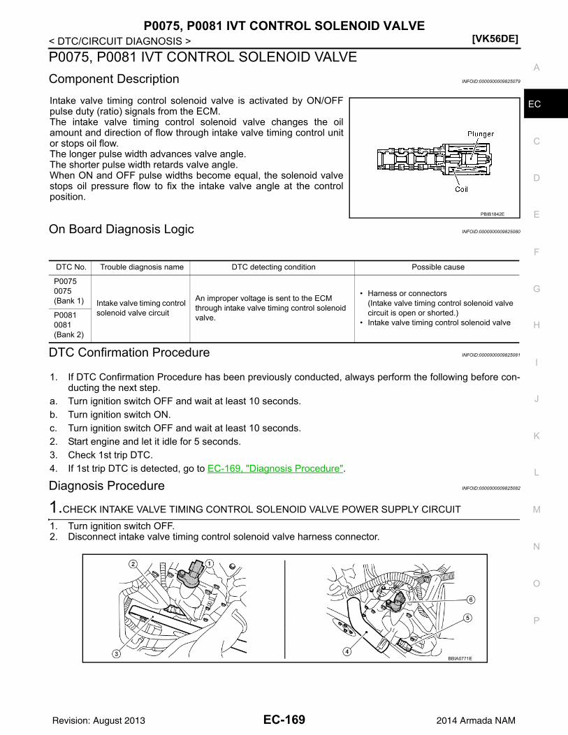
P0075, P0081 IVT CONTROL SOLENOID VALVE[VK56DE]
C
D
E
F
G
H
I
J
K
L
M
A
C
N
P
O
< DTC/CIRCUIT DIAGNOSIS >
E
P0075, P0081 IVT CONTROL SOLENOID VALVE
Component Description INFOID:0000000009825079
Intake valve timing control solenoid valve is activated by ON/OFFpulse duty (ratio) signals from the ECM.The intake valve timing control solenoid valve changes the oilamount and direction of flow through intake valve timing control unitor stops oil flow.The longer pulse width advances valve angle.The shorter pulse width retards valve angle.When ON and OFF pulse widths become equal, the solenoid valvestops oil pressure flow to fix the intake valve angle at the controlposition.
On Board Diagnosis Logic INFOID:0000000009825080
DTC Confirmation Procedure INFOID:0000000009825081
1. If DTC Confirmation Procedure has been previously conducted, always perform the following before con-ducting the next step.
a. Turn ignition switch OFF and wait at least 10 seconds.b. Turn ignition switch ON.c. Turn ignition switch OFF and wait at least 10 seconds.2. Start engine and let it idle for 5 seconds.3. Check 1st trip DTC.4. If 1st trip DTC is detected, go to EC-169, "Diagnosis Procedure".
Diagnosis Procedure INFOID:0000000009825082
1.CHECK INTAKE VALVE TIMING CONTROL SOLENOID VALVE POWER SUPPLY CIRCUIT
1. Turn ignition switch OFF.2. Disconnect intake valve timing control solenoid valve harness connector.
PBIB1842E
DTC No. Trouble diagnosis name DTC detecting condition Possible cause
P00750075(Bank 1) Intake valve timing control
solenoid valve circuit
An improper voltage is sent to the ECM through intake valve timing control solenoid valve.
• Harness or connectors(Intake valve timing control solenoid valve circuit is open or shorted.)
• Intake valve timing control solenoid valveP00810081(Bank 2)
BBIA0771E
EC-169Revision: August 2013 2014 Armada NAM

[VK56DE]P0075, P0081 IVT CONTROL SOLENOID VALVE
< DTC/CIRCUIT DIAGNOSIS >
3. Turn ignition switch ON.4. Check voltage between intake valve timing control solenoid
valve terminal 2 and ground with CONSULT or tester.
OK or NGOK >> GO TO 3.NG >> GO TO 2.
2.DETECT MALFUNCTIONING PART
Check the following.• Harness connectors E2, F32• IPDM E/R harness connector E119• Harness for open or short between intake valve timing control solenoid valve and IPDM E/R
>> Repair open circuit or short to ground or short to power in harness or connectors.
3.CHECK INTAKE VALVE TIMING CONTROL SOLENOID VALVE OUTPUT SIGNAL CIRCUIT FOR OPEN
AND SHORT
1. Turn ignition switch OFF.2. Disconnect ECM harness connector.3. Check harness continuity between the following;
ECM terminal 10 and intake valve timing control solenoid valve (Bank 1) terminal 1 orECM terminal 11 and intake valve timing control solenoid valve (Bank 2) terminal 1.Refer to Wiring Diagram.
4. Also check harness for short to ground and short to power. OK or NGOK >> GO TO 4.NG >> Repair open circuit or short to ground or short to power in harness or connectors.
4.CHECK INTAKE VALVE TIMING CONTROL SOLENOID VALVE
Refer to EC-170, "Component Inspection".OK or NGOK >> GO TO 5.NG >> Replace malfunctioning intake valve timing control solenoid valve. Refer to EM-47.
5.CHECK INTERMITTENT INCIDENT
Refer to GI-39, "How to Check Terminal" and GI-42, "Intermittent Incident".
>> INSPECTION END
Component Inspection INFOID:0000000009825083
INTAKE VALVE TIMING CONTROL SOLENOID VALVE1. Disconnect intake valve timing control solenoid valve harness connector.
1. Intake valve timing control position sensor (bank 2)
2. Intake valve timing control solenoid valve (bank 2)
3. Drive belt
4. Radiator hose 5. Intake valve timing control solenoid valve (bank 1)
6. Intake valve timing control position sensor (bank 1)
Voltage: Battery voltage
JSBIA1925ZZ
Continuity should exist.
EC-170Revision: August 2013 2014 Armada NAM

P0075, P0081 IVT CONTROL SOLENOID VALVE[VK56DE]
C
D
E
F
G
H
I
J
K
L
M
A
C
N
P
O
< DTC/CIRCUIT DIAGNOSIS >
E
2. Check resistance between intake valve timing control solenoidvalve terminals as follows.
If NG, replace intake valve timing control solenoid valve. Refer toEM-47.If OK, go to next step.
3. Remove intake valve timing control solenoid valve. Refer to EM-50, "Removal and Installation".
4. Provide 12 V DC between intake valve timing control solenoidvalve terminals and then interrupt it. Make sure that the plungermoves as shown in the figure.CAUTION:Do not apply 12 V DC continuously for 5 seconds or more.Doing so may result in damage to the coil in intake valvetiming control solenoid valve.If NG, replace intake valve timing control solenoid valve. Refer toEM-47.NOTE:Always replace O-ring when intake valve timing controlsolenoid valve is removed.
Terminals Resistance
1 and 2 7.1 - 7.7 [at 20C (68F)]
1 or 2 and ground
(Continuity should not exist)
JSBIA1926ZZ
JSBIA1927ZZ
EC-171Revision: August 2013 2014 Armada NAM

[VK56DE]P0101 MAF SENSOR
< DTC/CIRCUIT DIAGNOSIS >
P0101 MAF SENSOR
Component Description INFOID:0000000009825084
The mass air flow sensor is placed in the stream of intake air. It mea-sures the intake flow rate by measuring a part of the entire intakeflow. The mass air flow sensor controls the temperature of the hotwire to a certain amount. The heat generated by the hot wire isreduced as the intake air flows around it. The more air, the greaterthe heat loss.Therefore, the electric current supplied to the hot wire is changed tomaintain the temperature of the hot wire as air flow increases. TheECM detects the air flow by means of this current change.
DTC Logic INFOID:0000000009825085
DTC DETECTION LOGICNOTE:If DTC P0101 is displayed with other DTC, first perform the trouble diagnosis for other DTC.
DTC CONFIRMATION PROCEDURE
1.PRECONDITIONING
If DTC CONFIRMATION PROCEDURE has been previously conducted, always perform the following proce-dure before conducting the next test.1. Turn ignition switch OFF and wait at least 10 seconds.2. Turn ignition switch ON.3. Turn ignition switch OFF and wait at least 10 seconds.
>> GO TO 2.
2.PERFORM DTC CONFIRMATION PROCEDURE
1. Start engine and warm it up to normal operating temperature.2. Drive the vehicle for at least 5 seconds under the following conditions:
CAUTION:Always drive vehicle at safe speed.
NOTE:• The gear must be fixed while driving the vehicle.• Keep the accelerator pedal as steady as possible during cruising.
3. Check 1st trip DTC.Is 1st trip DTC detected?YES >> Proceed to EC-173, "Diagnosis Procedure".NO >> INSPECTION END
BBIA0355E
DTC No.Trouble diagnosis
(Trouble diagnosis content)DTC detecting condition Possible cause
P0101MAF SEN/CIRCUIT-B1[Mass air flow (MAF) sensor cir-cuit range/performance]
• A high voltage from the sensor is sent to ECM under light load driving condition.
• A low voltage from the sensor is sent to ECM under heavy load driving condition.
• Harness or connectors(The sensor circuit is open or short-ed.)
• Intake air leaks• MAF sensor• EVAP control system pressure sensor• Intake air temperature sensor
Selector lever Suitable position
Vehicle speed 40 km/h (25 MPH) or more
EC-172Revision: August 2013 2014 Armada NAM

P0101 MAF SENSOR[VK56DE]
C
D
E
F
G
H
I
J
K
L
M
A
C
N
P
O
< DTC/CIRCUIT DIAGNOSIS >
E
Diagnosis Procedure INFOID:0000000009825086
1.CHECK INTAKE SYSTEM
Check the following for connection.• Air duct• Vacuum hoses• Intake air passage between air duct and intake manifoldIs the inspection result normal?YES >> GO TO 2.NO >> Reconnect the parts.
2.CHECK GROUND CONNECTION
1. Turn ignition switch OFF.2. Check ground connection E9. Refer to Ground Inspection in EC-153, "Ground Inspection".Is the inspection result normal?YES >> GO TO 3.NO >> Repair or replace ground connection.
3.CHECK MASS AIR FLOW (MAF) SENSOR POWER SUPPLY CIRCUIT
1. Disconnect MAF sensor harness connector.2. Turn ignition switch ON.3. Check the voltage between MAF sensor harness connector and ground.
Is the inspection result normal?YES >> GO TO 5.NO >> GO TO 4.
4.DETECT MALFUNCTIONING PART
Check the following.• Harness connectors E2, F32• Harness for open or short between mass air flow sensor and IPDM E/R
>> Repair open circuit or short to ground or short to power in harness or connectors.
5.CHECK MAF SENSOR GROUND CIRCUIT FOR OPEN AND SHORT
1. Turn ignition switch OFF.2. Disconnect ECM harness connector.3. Check the continuity between MAF sensor harness connector and ECM harness connector.
4. Also check harness for short to ground and short to power.Is the inspection result normal?YES >> GO TO 6.NO >> Repair open circuit or short to ground or short to power in harness or connectors.
6.CHECK MAF SENSOR INPUT SIGNAL CIRCUIT FOR OPEN AND SHORT
1. Check the continuity between MAF sensor harness connector and ECM harness connector.
MAF sensorGround Voltage
Connector Terminal
F53 2 Ground Battery voltage
MAF sensor ECMContinuity
Connector Terminal Connector Terminal
F53 3 F54 67 Existed
EC-173Revision: August 2013 2014 Armada NAM

[VK56DE]P0101 MAF SENSOR
< DTC/CIRCUIT DIAGNOSIS >
2. Also check harness for short to ground and short to power.Is the inspection result normal?YES >> GO TO 7.NO >> Repair open circuit or short to ground or short to power in harness or connectors.
7.CHECK INTAKE AIR TEMPERATURE SENSOR
Check intake air temperature sensor. Refer to EC-185, "Component Inspection".Is the inspection result normal?YES >> GO TO 8.NO >> Replace MAF sensor (with intake air temperature sensor). Refer to EM-26, "Removal and Installa-
tion".
8.CHECK EVAP CONTROL SYSTEM PRESSURE SENSOR
Check EVAP control system pressure sensor. Refer to EC-317, "Component Inspection".Is the inspection result normal?YES >> GO TO 9.NO >> Replace EVAP control system pressure sensor. Refer to FL-16, "Removal and Installation".
9.CHECK MAF SENSOR
Check MAF sensor. Refer to EC-174, "Component Inspection".Is the inspection result normal?YES >> GO TO 10.NO >> Replace MAF sensor. Refer to EM-26, "Exploded View".
10.CHECK INTERMITTENT INCIDENT
Check intermittent incident. Refer to GI-42, "Intermittent Incident".
>> INSPECTION END
Component Inspection INFOID:0000000009825087
MASS AIR FLOW SENSOR
With CONSULT
1. Reconnect all harness connectors disconnected.2. Start engine and warm it up to normal operating temperature.3. Connect CONSULT and select “DATA MONITOR” mode.4. Select “MAS A/F SE-B1” and check indication under the following conditions.
*: Check for linear voltage rise in response to engine being increased to about 4,000 rpm.
5. If the voltage is out of specification, proceed the following.a. Check for the cause of uneven air flow through mass air flow sensor. Refer to following.
• Crushed air ducts
MAF sensor ECMContinuity
Connector Terminal Connector Terminal
F53 4 F54 51 Existed
Condition MAS A/F SE-B1 (V)
Ignition switch ON (Engine stopped.) Approx. 0.4
Idle (Engine is warmed-up to normal operating temperature.)
0.9 - 1.3
2,500 rpm (Engine is warmed-up to normal operating temperature.)
1.7 - 2.1
Idle to about 4,000 rpm 0.9 - 1.3 to Approx. 2.4*
EC-174Revision: August 2013 2014 Armada NAM
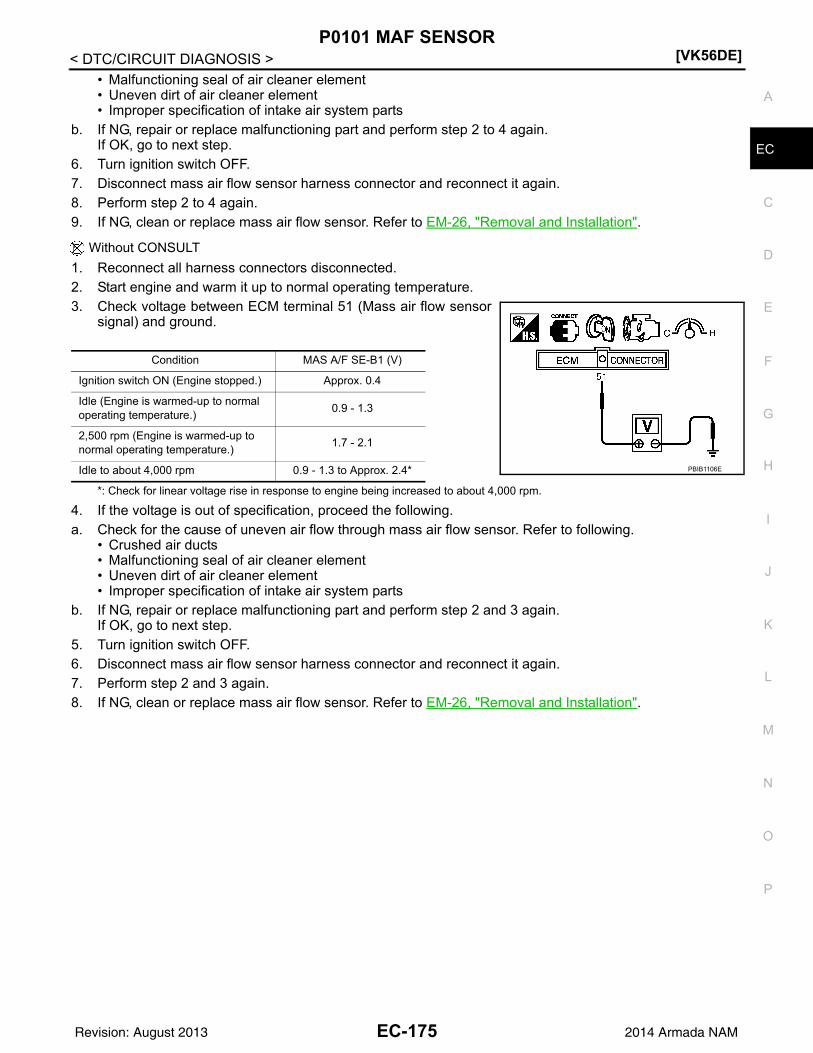
P0101 MAF SENSOR[VK56DE]
C
D
E
F
G
H
I
J
K
L
M
A
C
N
P
O
< DTC/CIRCUIT DIAGNOSIS >
E
• Malfunctioning seal of air cleaner element• Uneven dirt of air cleaner element• Improper specification of intake air system parts
b. If NG, repair or replace malfunctioning part and perform step 2 to 4 again.If OK, go to next step.
6. Turn ignition switch OFF.7. Disconnect mass air flow sensor harness connector and reconnect it again.8. Perform step 2 to 4 again.9. If NG, clean or replace mass air flow sensor. Refer to EM-26, "Removal and Installation".
Without CONSULT
1. Reconnect all harness connectors disconnected.2. Start engine and warm it up to normal operating temperature.3. Check voltage between ECM terminal 51 (Mass air flow sensor
signal) and ground.
*: Check for linear voltage rise in response to engine being increased to about 4,000 rpm.
4. If the voltage is out of specification, proceed the following.a. Check for the cause of uneven air flow through mass air flow sensor. Refer to following.
• Crushed air ducts• Malfunctioning seal of air cleaner element• Uneven dirt of air cleaner element• Improper specification of intake air system parts
b. If NG, repair or replace malfunctioning part and perform step 2 and 3 again.If OK, go to next step.
5. Turn ignition switch OFF.6. Disconnect mass air flow sensor harness connector and reconnect it again.7. Perform step 2 and 3 again.8. If NG, clean or replace mass air flow sensor. Refer to EM-26, "Removal and Installation".
Condition MAS A/F SE-B1 (V)
Ignition switch ON (Engine stopped.) Approx. 0.4
Idle (Engine is warmed-up to normal operating temperature.)
0.9 - 1.3
2,500 rpm (Engine is warmed-up to normal operating temperature.)
1.7 - 2.1
Idle to about 4,000 rpm 0.9 - 1.3 to Approx. 2.4* PBIB1106E
EC-175Revision: August 2013 2014 Armada NAM

[VK56DE]P0102, P0103 MAF SENSOR
< DTC/CIRCUIT DIAGNOSIS >
P0102, P0103 MAF SENSOR
Component Description INFOID:0000000009825088
The mass air flow sensor is placed in the stream of intake air. It mea-sures the intake flow rate by measuring a part of the entire intakeflow. The mass air flow sensor controls the temperature of the hotwire to a certain amount. The heat generated by the hot wire isreduced as the intake air flows around it. The more air, the greaterthe heat loss.Therefore, the electric current supplied to the hot wire is changed tomaintain the temperature of the hot wire as air flow increases. TheECM detects the air flow by means of this current change.
On Board Diagnosis Logic INFOID:0000000009825089
These self-diagnoses have the one trip detection logic.
FAIL-SAFE MODEWhen the malfunction is detected, the ECM enters fail-safe mode and the MIL lights up.
DTC Confirmation Procedure INFOID:0000000009825090
NOTE:If DTC Confirmation Procedure has been previously conducted, always perform the following before conduct-ing the next step.1. Turn ignition switch OFF and wait at least 10 seconds.2. Turn ignition switch ON.3. Turn ignition switch OFF and wait at least 10 seconds.
PROCEDURE FOR DTC P01021. Start engine and wait at least 5 seconds.2. Check DTC.3. If DTC is detected, go to EC-177, "Diagnosis Procedure".
PROCEDURE FOR DTC P01031. Turn ignition switch ON.2. Wait at least 5 seconds.3. Check DTC.4. If DTC is detected, go to EC-177, "Diagnosis Procedure".
If DTC is not detected, go to next step.5. Start engine and wait at least 5 seconds.6. Check DTC.7. If DTC is detected, go to EC-177, "Diagnosis Procedure".
BBIA0355E
DTC No. Trouble diagnosis name DTC detecting condition Possible cause
P01020102
Mass air flow sensor circuit low input
An excessively low voltage from the sensor is sent to ECM.
• Harness or connectors(The sensor circuit is open or shorted.)
• Intake air leaks• Mass air flow sensor
P01030103
Mass air flow sensor circuit high input
An excessively high voltage from the sensor is sent to ECM.
• Harness or connectors(The sensor circuit is open or shorted.)
• Mass air flow sensor
Detected items Engine operating condition in fail-safe mode
Mass air flow sensor circuit Engine speed will not rise more than 2,400 rpm due to the fuel cut.
EC-176Revision: August 2013 2014 Armada NAM

P0102, P0103 MAF SENSOR[VK56DE]
C
D
E
F
G
H
I
J
K
L
M
A
C
N
P
O
< DTC/CIRCUIT DIAGNOSIS >
E
Diagnosis Procedure INFOID:0000000009825091
1.INSPECTION START
Which malfunction (P0102 or P0103) is duplicated?P0102 or P0103P0102 >> GO TO 2.P0103 >> GO TO 3.
2.CHECK INTAKE SYSTEM
Check the following for connection.• Air duct• Vacuum hoses• Intake air passage between air duct to intake manifoldOK or NGOK >> GO TO 3.NG >> Reconnect the parts.
3.RETIGHTEN GROUND SCREWS
1. Turn ignition switch OFF.2. Loosen and retighten three ground screws on the body.
Refer to EC-153, "Ground Inspection".
OK or NGOK >> GO TO 4.NG >> Repair or replace ground connections.
4.CHECK MAF SENSOR POWER SUPPLY CIRCUIT
1. Disconnect mass air flow (MAF) sensor harness connector.2. Turn ignition switch ON.
BBIA0354E
BBIA0368E
EC-177Revision: August 2013 2014 Armada NAM

[VK56DE]P0102, P0103 MAF SENSOR
< DTC/CIRCUIT DIAGNOSIS >3. Check voltage between MAF sensor terminal 2 and ground with
CONSULT or tester.
OK or NGOK >> GO TO 6.NG >> GO TO 5.
5.DETECT MALFUNCTIONING PART
Check the following.• Harness connectors E2, F32• Harness for open or short between IPDM E/R and mass air flow sensor• Harness for open or short between mass air flow sensor and ECM
>> Repair harness or connectors.
6.CHECK MAF SENSOR GROUND CIRCUIT FOR OPEN AND SHORT
1. Turn ignition switch OFF.2. Disconnect ECM harness connector.3. Check harness continuity between MAF sensor terminal 3 and ECM terminal 67.
Refer to Wiring Diagram.
4. Also check harness for short to ground and short to power.OK or NGOK >> GO TO 7.NG >> Repair open circuit or short to ground or short to power in harness or connectors.
7.CHECK MAF SENSOR INPUT SIGNAL CIRCUIT FOR OPEN AND SHORT
1. Check harness continuity between MAF sensor terminal 4 and ECM terminal 51.Refer to Wiring Diagram.
2. Also check harness for short to ground and short to power.OK or NGOK >> GO TO 8.NG >> Repair open circuit or short to ground or short to power in harness or connectors.
8.CHECK MASS AIR FLOW SENSOR
Refer to EC-178, "Component Inspection".OK or NGOK >> GO TO 9.NG >> Replace mass air flow sensor. Refer to EM-26, "Removal and Installation".
9.CHECK INTERMITTENT INCIDENT
Refer to GI-39, "How to Check Terminal" and GI-42, "Intermittent Incident".
>> INSPECTION END
Component Inspection INFOID:0000000009825092
MASS AIR FLOW SENSOR
Voltage: Battery voltage
PBIB1168E
Continuity should exist.
Continuity should exist.
EC-178Revision: August 2013 2014 Armada NAM
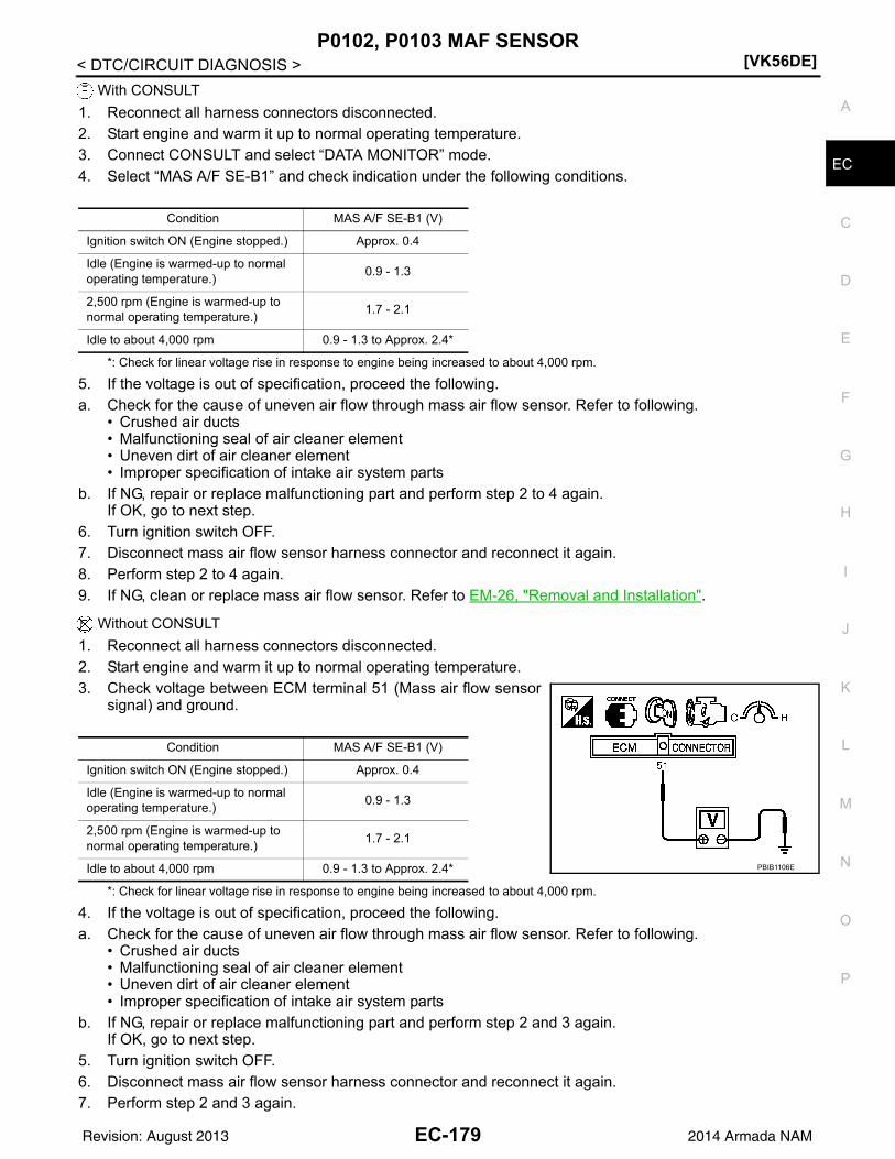
P0102, P0103 MAF SENSOR[VK56DE]
C
D
E
F
G
H
I
J
K
L
M
A
C
N
P
O
< DTC/CIRCUIT DIAGNOSIS >
E
With CONSULT
1. Reconnect all harness connectors disconnected.2. Start engine and warm it up to normal operating temperature.3. Connect CONSULT and select “DATA MONITOR” mode.4. Select “MAS A/F SE-B1” and check indication under the following conditions.
*: Check for linear voltage rise in response to engine being increased to about 4,000 rpm.
5. If the voltage is out of specification, proceed the following.a. Check for the cause of uneven air flow through mass air flow sensor. Refer to following.
• Crushed air ducts• Malfunctioning seal of air cleaner element• Uneven dirt of air cleaner element• Improper specification of intake air system parts
b. If NG, repair or replace malfunctioning part and perform step 2 to 4 again.If OK, go to next step.
6. Turn ignition switch OFF.7. Disconnect mass air flow sensor harness connector and reconnect it again.8. Perform step 2 to 4 again.9. If NG, clean or replace mass air flow sensor. Refer to EM-26, "Removal and Installation".
Without CONSULT
1. Reconnect all harness connectors disconnected.2. Start engine and warm it up to normal operating temperature.3. Check voltage between ECM terminal 51 (Mass air flow sensor
signal) and ground.
*: Check for linear voltage rise in response to engine being increased to about 4,000 rpm.
4. If the voltage is out of specification, proceed the following.a. Check for the cause of uneven air flow through mass air flow sensor. Refer to following.
• Crushed air ducts• Malfunctioning seal of air cleaner element• Uneven dirt of air cleaner element• Improper specification of intake air system parts
b. If NG, repair or replace malfunctioning part and perform step 2 and 3 again.If OK, go to next step.
5. Turn ignition switch OFF.6. Disconnect mass air flow sensor harness connector and reconnect it again.7. Perform step 2 and 3 again.
Condition MAS A/F SE-B1 (V)
Ignition switch ON (Engine stopped.) Approx. 0.4
Idle (Engine is warmed-up to normal operating temperature.)
0.9 - 1.3
2,500 rpm (Engine is warmed-up to normal operating temperature.)
1.7 - 2.1
Idle to about 4,000 rpm 0.9 - 1.3 to Approx. 2.4*
Condition MAS A/F SE-B1 (V)
Ignition switch ON (Engine stopped.) Approx. 0.4
Idle (Engine is warmed-up to normal operating temperature.)
0.9 - 1.3
2,500 rpm (Engine is warmed-up to normal operating temperature.)
1.7 - 2.1
Idle to about 4,000 rpm 0.9 - 1.3 to Approx. 2.4* PBIB1106E
EC-179Revision: August 2013 2014 Armada NAM

[VK56DE]P0102, P0103 MAF SENSOR
< DTC/CIRCUIT DIAGNOSIS >8. If NG, clean or replace mass air flow sensor. Refer to EM-26, "Removal and Installation".
EC-180Revision: August 2013 2014 Armada NAM

P0111 IAT SENSOR[VK56DE]
C
D
E
F
G
H
I
J
K
L
M
A
C
N
P
O
< DTC/CIRCUIT DIAGNOSIS >
E
P0111 IAT SENSOR
DTC Logic INFOID:0000000009825093
DTC DETECTION LOGIC
DTC CONFIRMATION PROCEDURE
1.INSPECTION START
Is it necessary to erase permanent DTC?YES >> GO TO 3.NO >> GO TO 2.
2.PERFORM COMPONENT FUNCTION CHECK
Perform component function check. Refer to EC-182, "Component Function Check".NOTE:Use the component function check to check the overall function of the IAT sensor circut. During this check, a1st trip DTC might not be confirmed.Is the inspection result normal?YES >> INSPECTION ENDNO >> Proceed to EC-182, "Diagnosis Procedure".
3.PRECONDITIONING
If DTC CONFIRMATION PROCEDURE has been previously conducted, always perform the following proce-dure before conducting the next test.1. Turn ignition switch OFF and wait at least 10 seconds.2. Turn ignition switch ON.3. Turn ignition switch OFF and wait at least 10 seconds.TESTING CONDITION:• Before performing the following procedure, do not add fuel.• Before performing the following procedure, check that fuel level is between 1/4 and 4/4.• Before performing the following procedure, confirm that battery voltage is 11 V or more at idle.
>> GO TO 4.
4.PERFORM DTC CONFIRMATION PROCEDURE
1. Start engine and let it idle for 60 minutes.2. Move the vehicle to a cool place.
NOTE:Cool the vehicle in an environment of ambient air temperature between 10C (14F) and 35C (95F).
3. Turn ignition switch OFF and soak the vehicle for 12 hours.CAUTION:Never turn ignition switch ON during soaking.NOTE:The vehicle must be cooled with the food open.
4. Start engine and let it idle for 5 minutes or more.CAUTION:Never turn ignition switch OFF during idling.
DTC No.Trouble diagnosis
(Trouble diagnosis content)DTC detecting condition Possible cause
P0111
IAT SENSOR 1 B1[Intake air temperature (IAT) sensor circuit range/perfor-mance]
The comparison result of signals transmitted to ECM from each temperature sensor (IAT sensor, ECT sensor, and FTT sensor) shows that the voltage signal of the IAT sensor is higher/lower than that of other temperature sensors when the engine is started with its cold state.
• Harness or connectors(High or low resistance in the IAT sen-sor circuit)
• IAT sensor
EC-181Revision: August 2013 2014 Armada NAM

[VK56DE]P0111 IAT SENSOR
< DTC/CIRCUIT DIAGNOSIS >5. Check 1st trip DTC.Is 1st trip DTC detected?YES >> Proceed to EC-182, "Diagnosis Procedure".NO >> INSPECTION END
Component Function Check INFOID:0000000009825094
1.CHECK INTAKE AIR TEMPERATURE (IAT) SENSOR
1. Turn ignition switch OFF.2. Disconnect mass air flow sensorharness connector.3. Check resistance between mass air flow sensorterminals as follows.
Is the inspection result normal?YES >> GO TO 2.NO >> Proceed to EC-182, "Diagnosis Procedure".
2.CHECK INTERMITTENT INCIDENT
Check intermittent incident. Refer to GI-42, "Intermittent Incident".Is the inspection result normal?YES >> INSPECTION ENDNO >> Proceed to EC-182, "Diagnosis Procedure".
Diagnosis Procedure INFOID:0000000009825095
1.CHECK INTAKE AIR TEMPERATURE (IAT) SENSOR
Check intake air temperature sensor. Refer to EC-182, "Component Inspection".Is the inspection result normal?YES >> GO TO 2.NO >> Replace mass air flow sensor (with intake air temperature sensor). Refer to EM-26, "Exploded
View".
2.CHECK INTERMITTENT INCIDENT
Check intermittent incident. Refer to GI-42, "Intermittent Incident".
>> INSPECTION END
Component Inspection INFOID:0000000009825096
1.CHECK INTAKE AIR TEMPERATURE (IAT) SENSOR
1. Turn ignition switch OFF.2. Disconnect mass air flow sensor harness connector.3. Check resistance between mass air flow sensorterminals as follows.
Is the inspection result normal?YES >> INSPECTION ENDNO >> Replace mass air flow sensor (with intake air temperature sensor). Refer to EM-26, "Exploded
View".
Terminals Condition Resistance (k)
5 and 6 Temperature [C (F)] 25 (77) 1.800 – 2.200
Terminals Condition Resistance (k)
5 and 6 Temperature [C (F)] 25 (77) 1.800 – 2.200
EC-182Revision: August 2013 2014 Armada NAM
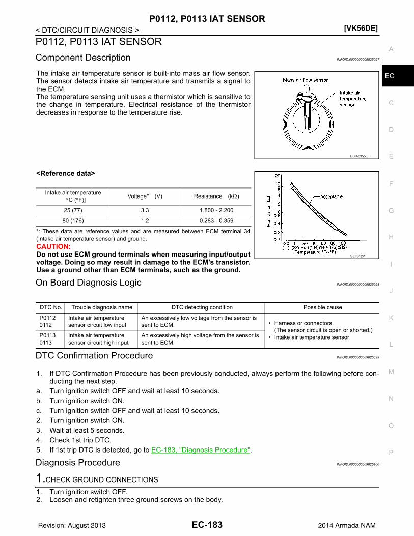
P0112, P0113 IAT SENSOR[VK56DE]
C
D
E
F
G
H
I
J
K
L
M
A
C
N
P
O
< DTC/CIRCUIT DIAGNOSIS >
E
P0112, P0113 IAT SENSOR
Component Description INFOID:0000000009825097
The intake air temperature sensor is built-into mass air flow sensor.The sensor detects intake air temperature and transmits a signal tothe ECM.The temperature sensing unit uses a thermistor which is sensitive tothe change in temperature. Electrical resistance of the thermistordecreases in response to the temperature rise.
<Reference data>
*: These data are reference values and are measured between ECM terminal 34(Intake air temperature sensor) and ground.
CAUTION:Do not use ECM ground terminals when measuring input/outputvoltage. Doing so may result in damage to the ECM's transistor.Use a ground other than ECM terminals, such as the ground.
On Board Diagnosis Logic INFOID:0000000009825098
DTC Confirmation Procedure INFOID:0000000009825099
1. If DTC Confirmation Procedure has been previously conducted, always perform the following before con-ducting the next step.
a. Turn ignition switch OFF and wait at least 10 seconds.b. Turn ignition switch ON.c. Turn ignition switch OFF and wait at least 10 seconds.2. Turn ignition switch ON.3. Wait at least 5 seconds.4. Check 1st trip DTC.5. If 1st trip DTC is detected, go to EC-183, "Diagnosis Procedure".
Diagnosis Procedure INFOID:0000000009825100
1.CHECK GROUND CONNECTIONS
1. Turn ignition switch OFF.2. Loosen and retighten three ground screws on the body.
BBIA0355E
Intake air temperatureC (F)]
Voltage* (V) Resistance (k)
25 (77) 3.3 1.800 - 2.200
80 (176) 1.2 0.283 - 0.359
SEF012P
DTC No. Trouble diagnosis name DTC detecting condition Possible cause
P01120112
Intake air temperature sensor circuit low input
An excessively low voltage from the sensor is sent to ECM. • Harness or connectors
(The sensor circuit is open or shorted.)• Intake air temperature sensorP0113
0113Intake air temperature sensor circuit high input
An excessively high voltage from the sensor is sent to ECM.
EC-183Revision: August 2013 2014 Armada NAM

[VK56DE]P0112, P0113 IAT SENSOR
< DTC/CIRCUIT DIAGNOSIS >Refer to EC-153, "Ground Inspection".
OK or NGOK >> GO TO 2.NG >> Repair or replace ground connections.
2.CHECK INTAKE AIR TEMPERATURE SENSOR POWER SUPPLY CIRCUIT
1. Disconnect mass air flow sensor (with intake air temperaturesensor) harness connector.
2. Turn ignition switch ON.
3. Check voltage between mass air flow sensor terminal 5 andground.
OK or NGOK >> GO TO 3.NG >> Repair harness or connectors.
3.CHECK INTAKE AIR TEMPERATURE SENSOR GROUND CIRCUIT FOR OPEN AND SHORT
1. Turn ignition switch OFF.2. Disconnect ECM harness connector.3. Check harness continuity between mass air flow sensor terminal 6 and ECM terminal 67.
Refer to Wiring Diagram.
4. Also check harness for short to ground and short to power.OK or NGOK >> GO TO 4.NG >> Repair open circuit or short to ground or short to power in harness or connectors.
4.CHECK INTAKE AIR TEMPERATURE SENSOR
Refer to EC-185, "Component Inspection".OK or NGOK >> GO TO 5.NG >> Replace mass air flow sensor (with intake air temperature sensor). Refer to EM-26, "Removal and
Installation".
BBIA0354E
BBIA0368E
Voltage: Approximately 5 V
PBIB1169E
Continuity should exist.
EC-184Revision: August 2013 2014 Armada NAM

P0112, P0113 IAT SENSOR[VK56DE]
C
D
E
F
G
H
I
J
K
L
M
A
C
N
P
O
< DTC/CIRCUIT DIAGNOSIS >
E
5.CHECK INTERMITTENT INCIDENT
Refer to GI-39, "How to Check Terminal" and GI-42, "Intermittent Incident".
>> INSPECTION END
Component Inspection INFOID:0000000009825101
INTAKE AIR TEMPERATURE SENSOR1. Check resistance between mass air flow sensor terminals 5 and
6 under the following conditions.
2. If NG, replace mass air flow sensor (with intake air temperaturesensor). Refer to EM-26, "Removal and Installation".
Intake air temperature C (F)] Resistance (k)
25 (77) 1.800 - 2.200
BBIA0355E
SEF012P
EC-185Revision: August 2013 2014 Armada NAM

[VK56DE]P0116 ECT SENSOR
< DTC/CIRCUIT DIAGNOSIS >
P0116 ECT SENSOR
Component Description INFOID:0000000009825102
The engine coolant temperature sensor is used to detect the enginecoolant temperature. The sensor modifies a voltage signal from theECM. The modified signal returns to the ECM as the engine coolanttemperature input. The sensor uses a thermistor which is sensitive tothe change in temperature. The electrical resistance of the ther-mistor decreases as temperature increases.
<Reference data>
*: This data is reference value and is measured between ECM terminal 73 (Enginecoolant temperature sensor) and ground.
CAUTION:Do not use ECM ground terminals when measuring input/output voltage. Doing so may result in dam-age to the ECM's transistor. Use a ground other than ECM terminals, such as the ground.
DTC Logic INFOID:0000000009825103
DTC DETECTION LOGIC
DTC CONFIRMATION PROCEDURE
1.INSPECTION START
Is it necessary to erase permanent DTC?YES >> GO TO 3.NO >> GO TO 2.
2.PERFORM COMPONENT FUNCTION CHECK
Perform component function check. Refer to EC-187, "Component Function Check".NOTE:Use the component function check to check the overall function of the ECT sensor circut. During this check, a1st trip DTC might not be confirmed.
SEF594K
Engine coolant temperature C (F)]
Voltage* (V) Resistance (k)
10 (14) 4.4 7.0 - 11.4
20 (68) 3.5 2.1 - 2.9
50 (122) 2.2 0.68 - 1.00
90 (194) 0.9 0.236 - 0.260
SEF012P
DTC No.Trouble diagnosis
(Trouble diagnosis content)DTC detecting condition Possible cause
P0116
ECT SEN/CIRC[Engine coolant temperature (ECT) sensor circuit range/per-formance]
The comparison result of signals transmitted to ECM from each temperature sensor (IAT sensor, ECT sensor, and FTT sensor) shows that the voltage signal of the ECT sensor is higher/lower than that of other temperature sensors when the engine is started with its cold state.
• Harness or connectors(High or low resistance in the ECT sensor circuit)
• ECT sensor
EC-186Revision: August 2013 2014 Armada NAM
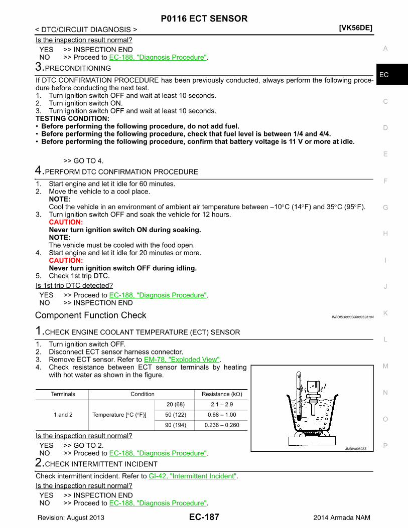
P0116 ECT SENSOR[VK56DE]
C
D
E
F
G
H
I
J
K
L
M
A
C
N
P
O
< DTC/CIRCUIT DIAGNOSIS >
E
Is the inspection result normal?YES >> INSPECTION ENDNO >> Proceed to EC-188, "Diagnosis Procedure".
3.PRECONDITIONING
If DTC CONFIRMATION PROCEDURE has been previously conducted, always perform the following proce-dure before conducting the next test.1. Turn ignition switch OFF and wait at least 10 seconds.2. Turn ignition switch ON.3. Turn ignition switch OFF and wait at least 10 seconds.TESTING CONDITION:• Before performing the following procedure, do not add fuel.• Before performing the following procedure, check that fuel level is between 1/4 and 4/4.• Before performing the following procedure, confirm that battery voltage is 11 V or more at idle.
>> GO TO 4.
4.PERFORM DTC CONFIRMATION PROCEDURE
1. Start engine and let it idle for 60 minutes.2. Move the vehicle to a cool place.
NOTE:Cool the vehicle in an environment of ambient air temperature between 10C (14F) and 35C (95F).
3. Turn ignition switch OFF and soak the vehicle for 12 hours.CAUTION:Never turn ignition switch ON during soaking.NOTE:The vehicle must be cooled with the food open.
4. Start engine and let it idle for 20 minutes or more.CAUTION:Never turn ignition switch OFF during idling.
5. Check 1st trip DTC.Is 1st trip DTC detected?YES >> Proceed to EC-188, "Diagnosis Procedure".NO >> INSPECTION END
Component Function Check INFOID:0000000009825104
1.CHECK ENGINE COOLANT TEMPERATURE (ECT) SENSOR
1. Turn ignition switch OFF.2. Disconnect ECT sensor harness connector.3. Remove ECT sensor. Refer to EM-78, "Exploded View".4. Check resistance between ECT sensor terminals by heating
with hot water as shown in the figure.
Is the inspection result normal?YES >> GO TO 2.NO >> Proceed to EC-188, "Diagnosis Procedure".
2.CHECK INTERMITTENT INCIDENT
Check intermittent incident. Refer to GI-42, "Intermittent Incident".Is the inspection result normal?YES >> INSPECTION ENDNO >> Proceed to EC-188, "Diagnosis Procedure".
Terminals Condition Resistance (k)
1 and 2 Temperature [C (F)]
20 (68) 2.1 – 2.9
50 (122) 0.68 – 1.00
90 (194) 0.236 – 0.260
JMBIA0080ZZ
EC-187Revision: August 2013 2014 Armada NAM

[VK56DE]P0116 ECT SENSOR
< DTC/CIRCUIT DIAGNOSIS >
Diagnosis Procedure INFOID:0000000009825105
1.CHECK ENGINE COOLANT TEMPERATURE (ECT) SENSOR
Check ECT sensor. Refer to EC-188, "Component Inspection".Is the inspection result normal?YES >> GO TO 2.NO >> Replace ECT sensor. Refer to EM-78, "Exploded View".
2.CHECK INTERMITTENT INCIDENT
Check intermittent incident. Refer to GI-42, "Intermittent Incident".
>> INSPECTION END
Component Inspection INFOID:0000000009825106
1.CHECK ENGINE COOLANT TEMPERATURE (ECT) SENSOR
1. Turn ignition switch OFF.2. Disconnect ECT sensor harness connector.3. Remove ECT sensor. Refer to EM-78, "Exploded View".4. Check resistance between ECT sensor terminals by heating
with hot water as shown in the figure.
Is the inspection result normal?YES >> INSPECTION ENDNO >> Replace ECT sensor. Refer to EM-78, "Exploded View".
Terminals Condition Resistance (k)
1 and 2 Temperature [C (F)]
20 (68) 2.1 – 2.9
50 (122) 0.68 – 1.00
90 (194) 0.236 – 0.260
JMBIA0080ZZ
EC-188Revision: August 2013 2014 Armada NAM

P0117, P0118 ECT SENSOR[VK56DE]
C
D
E
F
G
H
I
J
K
L
M
A
C
N
P
O
< DTC/CIRCUIT DIAGNOSIS >
E
P0117, P0118 ECT SENSOR
Component Description INFOID:0000000009825107
The engine coolant temperature sensor is used to detect the enginecoolant temperature. The sensor modifies a voltage signal from theECM. The modified signal returns to the ECM as the engine coolanttemperature input. The sensor uses a thermistor which is sensitive tothe change in temperature. The electrical resistance of the ther-mistor decreases as temperature increases.
<Reference data>
*: These data are reference values and are measured between ECM terminal 73(Engine coolant temperature sensor) and ground.
CAUTION:Do not use ECM ground terminals when measuring input/output voltage. Doing so may result in dam-age to the ECM's transistor. Use a ground other than ECM terminals, such as the ground.
On Board Diagnosis Logic INFOID:0000000009825108
These self-diagnoses have the one trip detection logic.
FAIL-SAFE MODEWhen the malfunction is detected, the ECM enters fail-safe mode and the MIL lights up.
SEF594K
Engine coolant temperatureC (F)]
Voltage* (V) Resistance (k)
–10 (14) 4.4 7.0 - 11.4
20 (68) 3.5 2.1 - 2.9
50 (122) 2.2 0.68 - 1.00
90 (194) 0.9 0.236 - 0.260
SEF012P
DTC No.
Trouble Diagnosis Name DTC Detecting Condition Possible Cause
P01170117
Engine coolant temperature sensor circuit low input
An excessively low voltage from the sensor is sent to ECM. • Harness or connectors
(The sensor circuit is open or shorted.)• Engine coolant temperature sensor P0118
0118Engine coolant temperature sensor circuit high input
An excessively high voltage from the sensor is sent to ECM.
Detected items Engine operating condition in fail-safe mode
Engine coolant temper-ature sensor circuit
Engine coolant temperature will be determined by ECM based on the following condition.CONSULT displays the engine coolant temperature decided by ECM.
ConditionEngine coolant temperature decided
(CONSULT display)
Just as ignition switch is turned ON or START 40C (104F)
Approx. 4 minutes or more after engine starting 80C (176F)
Except as shown above40 - 80C (104 - 176F)(Depends on the time)
When the fail-safe system for engine coolant temperature sensor is activated, the cooling fan operates while engine is running.
EC-189Revision: August 2013 2014 Armada NAM

[VK56DE]P0117, P0118 ECT SENSOR
< DTC/CIRCUIT DIAGNOSIS >
DTC Confirmation Procedure INFOID:0000000009825109
1. If DTC Confirmation Procedure has been previously conducted, always perform the following before con-ducting the next step.
a. Turn ignition switch OFF and wait at least 10 seconds.b. Turn ignition switch ON.c. Turn ignition switch OFF and wait at least 10 seconds.2. Turn ignition switch ON.3. Wait at least 5 seconds.4. Check DTC.5. If DTC is detected, go to EC-190, "Diagnosis Procedure".
Diagnosis Procedure INFOID:0000000009825110
1.CHECK GROUND CONNECTIONS
1. Turn ignition switch OFF.2. Loosen and retighten three ground screws on the body.
Refer to EC-153, "Ground Inspection".
OK or NGOK >> GO TO 2.NG >> Repair or replace ground connections.
2.CHECK ECT SENSOR POWER SUPPLY CIRCUIT
1. Disconnect engine coolant temperature (ECT) sensor (1) harness connector.
2. Turn ignition switch ON.
BBIA0354E
1. Engine coolant temperature (ETC) sensor
2. Intake manifold
BBIA0775E
EC-190Revision: August 2013 2014 Armada NAM

P0117, P0118 ECT SENSOR[VK56DE]
C
D
E
F
G
H
I
J
K
L
M
A
C
N
P
O
< DTC/CIRCUIT DIAGNOSIS >
E
3. Check voltage between ECT sensor (1) terminal 1 and groundwith CONSULT or tester.
OK or NGOK >> GO TO 4.NG >> GO TO 3.
3.DETECT MALFUNCTIONING RART
Check the following.• Harness connector F26, F201• Harness for open or short between ECM and engine coolant temperature sensor
>> Repair open circuit or short to ground or short to power in harness or connectors.
4.CHECK ECT SENSOR GROUND CIRCUIT FOR OPEN AND SHORT
1. Turn ignition switch OFF.2. Disconnect ECM harness connector.3. Check harness continuity between ECT sensor terminal 2 and ECM terminal 67.
Refer to Wiring Diagram.
4. Also check harness for short to ground and short to power.OK or NGOK >> GO TO 6.NG >> GO TO 5.
5.DETECT MALFUNCTIONING PART
Check the following.• Harness connector F26, F201• Harness for open and short between ECT sensor and ECM
>> Repair open circuit or short to ground or short to power in harness or connectors.
6.CHECK ENGINE COOLANT TEMPERATURE SENSOR
Refer to EC-191, "Component Inspection".OK or NGOK >> GO TO 7.NG >> Replace engine coolant temperature sensor. Refer to CO-23, "Exploded View".
7.CHECK INTERMITTENT INCIDENT
Refer to GI-39, "How to Check Terminal" and GI-42, "Intermittent Incident".
>> INSPECTION END
Component Inspection INFOID:0000000009825111
ENGINE COOLANT TEMPERATURE SENSOR
Voltage: Approximately 5 V
PBIB0080E
Continuity should exist.
EC-191Revision: August 2013 2014 Armada NAM

[VK56DE]P0117, P0118 ECT SENSOR
< DTC/CIRCUIT DIAGNOSIS >1. Check resistance between engine coolant temperature sensor
terminals 1 and 2 as shown in the figure.
2. If NG, replace engine coolant temperature sensor. Refer to CO-23, "Exploded View".
PBIB2005E
Engine coolant temperature C (F)] Resistance (k)
20 (68) 2.1 - 2.9
50 (122) 0.68 - 1.00
90 (194) 0.236 - 0.260
SEF012P
EC-192Revision: August 2013 2014 Armada NAM

P0122, P0123 TP SENSOR[VK56DE]
C
D
E
F
G
H
I
J
K
L
M
A
C
N
P
O
< DTC/CIRCUIT DIAGNOSIS >
E
P0122, P0123 TP SENSOR
Component Description INFOID:0000000009825112
Electric throttle control actuator consists of throttle control motor,throttle position sensor, etc. The throttle position sensor responds tothe throttle valve movement. The throttle position sensor has the two sensors. These sensors area kind of potentiometers which transform the throttle valve positioninto output voltage, and emit the voltage signal to the ECM. In addi-tion, these sensors detect the opening and closing speed of thethrottle valve and feed the voltage signals to the ECM. The ECMjudges the current opening angle of the throttle valve from these sig-nals and the ECM controls the throttle control motor to make thethrottle valve opening angle properly in response to driving condi-tion.
On Board Diagnosis Logic INFOID:0000000009825113
These self-diagnoses have the one trip detection logic.
FAIL-SAFE MODEWhen the malfunction is detected, ECM enters fail-safe mode and the MIL lights up.
DTC Confirmation Procedure INFOID:0000000009825114
NOTE:If DTC Confirmation Procedure has been previously conducted, always perform the following before conduct-ing the next step.1. Turn ignition switch OFF and wait at least 10 seconds.2. Turn ignition switch ON.3. Turn ignition switch OFF and wait at least 10 seconds.TESTING CONDITION:Before performing the following procedure, confirm that battery voltage is more than 8 V at idle.1. Start engine and let it idle for 1 second.2. Check DTC.3. If DTC is detected, go to EC-193, "Diagnosis Procedure".
Diagnosis Procedure INFOID:0000000009825115
1.CHECK GROUND CONNECTIONS
1. Turn ignition switch OFF.2. Loosen and retighten three ground screws on the body.
PBIB0145E
DTC No. Trouble diagnosis name DTC detecting condition Possible cause
P01220122
Throttle position sensor 2 circuit low input
An excessively low voltage from the TP sensor 2 is sent to ECM.
• Harness or connectors(TP sensor 2 circuit is open or shorted.)(APP sensor 2 circuit is shorted.)
• Electric throttle control actuator(TP sensor 2)
• Accelerator pedal position sensor(APP sensor 2)
P01230123
Throttle position sensor 2 circuit high input
An excessively high voltage from the TP sensor 2 is sent to ECM.
Engine operation condition in fail-safe mode
The ECM controls the electric throttle control actuator in regulating the throttle opening in order for the idle position to be within +10 degrees.The ECM regulates the opening speed of the throttle valve to be slower than the normal condition.So, the acceleration will be poor.
EC-193Revision: August 2013 2014 Armada NAM

[VK56DE]P0122, P0123 TP SENSOR
< DTC/CIRCUIT DIAGNOSIS >Refer to EC-153, "Ground Inspection".
OK or NGOK >> GO TO 2.NG >> Repair or replace ground connections.
2.CHECK THROTTLE POSITION SENSOR 2 POWER SUPPLY CIRCUIT-I
1. Disconnect electric throttle control actuator harness connector.2. Turn ignition switch ON.
3. Check voltage between electric throttle control actuator terminal2 and ground with CONSULT or tester.
OK or NGOK >> GO TO 7.NG >> GO TO 3.
3.CHECK THROTTLE POSITION SENSOR 2 POWER SUPPLY CIRCUIT-II
1. Turn ignition switch OFF.2. Disconnect ECM harness connector.3. Check harness continuity between electric throttle control actuator terminal 2 and ECM terminal 47.
Refer to Wiring Diagram.
OK or NGOK >> GO TO 4.NG >> Repair open circuit.
4.CHECK THROTTLE POSITION SENSOR 2 POWER SUPPLY CIRCUIT-III
Check harness for short to power and short to ground, between the following terminals.
BBIA0354E
PBIB1480E
Voltage: Approximately 5 V
PBIB2065E
Continuity should exist.
ECM terminal Sensor terminal Reference Wiring Diagram
47 Electric throttle control actuator terminal 2EC-88, "Wiring Diagram"
91 APP sensor terminal 6
EC-194Revision: August 2013 2014 Armada NAM

P0122, P0123 TP SENSOR[VK56DE]
C
D
E
F
G
H
I
J
K
L
M
A
C
N
P
O
< DTC/CIRCUIT DIAGNOSIS >
E
OK or NGOK >> GO TO 5.NG >> Repair short to ground or short to power in harness or connectors.
5.CHECK ACCELERATOR PEDAL POSITION SENSOR
Refer to EC-454, "Component Inspection".OK or NGOK >> GO TO 11.NG >> GO TO 6.
6.REPLACE ACCELERATOR PEDAL ASSEMBLY
1. Replace the accelerator pedal assembly. Refer to ACC-4, "Removal and Installation".2. Perform EC-127, "Accelerator Pedal Released Position Learning".3. Perform EC-127, "Throttle Valve Closed Position Learning".4. Perform EC-128, "Idle Air Volume Learning".
>> INSPECTION END
7.CHECK THROTTLE POSITION SENSOR 2 GROUND CIRCUIT FOR OPEN AND SHORT
1. Turn ignition switch OFF.2. Disconnect ECM harness connector.3. Check harness continuity between electric throttle control actuator terminal 4 and ECM terminal 66.
Refer to Wiring Diagram.
4. Also check harness for short to ground and short to power.OK or NGOK >> GO TO 8.NG >> Repair open circuit or short to ground or short to power in harness or connectors.
8.CHECK THROTTLE POSITION SENSOR 2 INPUT SIGNAL CIRCUIT FOR OPEN AND SHORT
1. Check harness continuity between ECM terminal 69 and electric throttle control actuator terminal 3.Refer to Wiring Diagram.
2. Also check harness for short to ground and short to power.OK or NGOK >> GO TO 9.NG >> Repair open circuit or short to ground or short to power in harness or connectors.
9.CHECK THROTTLE POSITION SENSOR
Refer to EC-196, "Component Inspection".OK or NGOK >> GO TO 11.NG >> GO TO 10.
10.REPLACE ELECTRIC THROTTLE CONTROL ACTUATOR
1. Replace the electric throttle control actuator. Refer to EM-27, "Removal and Installation".2. Perform EC-127, "Throttle Valve Closed Position Learning".3. Perform EC-128, "Idle Air Volume Learning".
>> INSPECTION END
11.CHECK INTERMITTENT INCIDENT
Refer to GI-39, "How to Check Terminal" and GI-42, "Intermittent Incident".
Continuity should exist.
Continuity should exist.
EC-195Revision: August 2013 2014 Armada NAM

[VK56DE]P0122, P0123 TP SENSOR
< DTC/CIRCUIT DIAGNOSIS >>> INSPECTION END
Component Inspection INFOID:0000000009825116
THROTTLE POSITION SENSOR1. Reconnect all harness connectors disconnected.2. Perform EC-127, "Throttle Valve Closed Position Learning".3. Turn ignition switch ON4. Set selector lever to D position. 5. Check voltage between ECM terminals 50 (TP sensor 1 signal),
69 (TP sensor 2 signal) and ground under the following condi-tions.
6. If NG, replace electric throttle control actuator and go to the nextstep. Refer to EM-27, "Removal and Installation".
7. Perform EC-127, "Throttle Valve Closed Position Learning".8. Perform EC-128, "Idle Air Volume Learning".
Terminal Accelerator pedal Voltage
50(Throttle position sensor 1)
Fully released More than 0.36 V
Fully depressed Less than 4.75 V
69 (Throttle position sensor 2)
Fully released Less than 4.75 V
Fully depressed More than 0.36 VPBIB1530E
EC-196Revision: August 2013 2014 Armada NAM

P0125 ECT SENSOR[VK56DE]
C
D
E
F
G
H
I
J
K
L
M
A
C
N
P
O
< DTC/CIRCUIT DIAGNOSIS >
E
P0125 ECT SENSOR
Component Description INFOID:0000000009825117
The engine coolant temperature sensor is used to detect the enginecoolant temperature. The sensor modifies a voltage signal from theECM. The modified signal returns to the ECM as the engine coolanttemperature input. The sensor uses a thermistor which is sensitive tothe change in temperature. The electrical resistance of the ther-mistor decreases as temperature increases.
<Reference data>
*: These data are reference values and are measured between ECM terminal 73(Engine coolant temperature sensor) and ground.
CAUTION:Do not use ECM ground terminals when measuring input/output voltage. Doing so may result in dam-age to the ECM's transistor. Use a ground other than ECM terminals, such as the ground.
On Board Diagnosis Logic INFOID:0000000009825118
NOTE:• If DTC P0125 is displayed with P0116, first perform the trouble diagnosis for DTC P0116. Refer to EC-
186, "DTC Logic".• If DTC P0125 is displayed with P0117 or P0118, first perform the trouble diagnosis for DTC P0117,
P0118. Refer to EC-190, "DTC Confirmation Procedure".
DTC Confirmation Procedure INFOID:0000000009825119
CAUTION:Be careful not to overheat engine.NOTE:If DTC Confirmation Procedure has been previously conducted, always perform the following before conduct-ing the next step.1. Turn ignition switch OFF and wait at least 10 seconds.2. Turn ignition switch ON.3. Turn ignition switch OFF and wait at least 10 seconds.
WITH CONSULT1. Turn ignition switch ON.
SEF594K
Engine coolant temperature C (F)]
Voltage* (V) Resistance (k)
–10 (14) 4.4 7.0 - 11.4
20 (68) 3.5 2.1 - 2.9
50 (122) 2.2 0.68 - 1.00
90 (194) 0.9 0.236 - 0.260
SEF012P
DTC No. Trouble diagnosis name DTC detecting condition Possible cause
P01250125
Insufficient engine coolant temperature for closed loop fuel control
• Voltage sent to ECM from the sensor is not practical, even when some time has passed after starting the engine.
• Engine coolant temperature is insufficient for closed loop fuel control.
• Harness or connectors(High resistance in the circuit)
• Engine coolant temperature sensor• Thermostat
EC-197Revision: August 2013 2014 Armada NAM

[VK56DE]P0125 ECT SENSOR
< DTC/CIRCUIT DIAGNOSIS >2. Select “DATA MONITOR” mode with CONSULT.3. Check that “COOLAN TEMP/S” is above 31C (88F).
If it is above 31C (88F), the test result will be OK.If it is below 31C (88F), go to following step.
4. Start engine and run it for 65 minutes at idle speed.If “COOLAN TEMP/S” increases to more than 31C (88F) within 65 minutes, stop engine becausethe test result will be OK.
5. Check 1st trip DTC.6. If 1st trip DTC is detected, go to EC-198, "Diagnosis Procedure".
WITH GSTFollow the procedure “WITH CONSULT” above.
Diagnosis Procedure INFOID:0000000009825120
1.CHECK GROUND CONNECTIONS
1. Turn ignition switch OFF.2. Loosen and retighten three ground screws on the body.
Refer to EC-153, "Ground Inspection".
OK or NGOK >> GO TO 2.NG >> Repair or replace ground connections.
2.CHECK ENGINE COOLANT TEMPERATURE SENSOR
Refer to EC-198, "Component Inspection".OK or NGOK >> GO TO 3.NG >> Replace engine coolant temperature sensor. Refer to CO-23, "Exploded View".
3.CHECK THERMOSTAT OPERATION
When the engine is cold [lower than 70C (158F)] condition, grasp lower radiator hose and confirm the enginecoolant does not flow.OK or NGOK >> GO TO 4.NG >> Repair or replace thermostat. Refer to CO-23, "Removal and Installation".
4.CHECK INTERMITTENT INCIDENT
Refer to GI-39, "How to Check Terminal" and GI-42, "Intermittent Incident".For Wiring Diagram, refer to EC-88, "Wiring Diagram".
>> INSPECTION END
Component Inspection INFOID:0000000009825121
ENGINE COOLANT TEMPERATURE SENSOR
BBIA0354E
EC-198Revision: August 2013 2014 Armada NAM

P0125 ECT SENSOR[VK56DE]
C
D
E
F
G
H
I
J
K
L
M
A
C
N
P
O
< DTC/CIRCUIT DIAGNOSIS >
E
1. Check resistance between engine coolant temperature sensorterminals 1 and 2 as shown in the figure.
2. If NG, replace engine coolant temperature sensor. Refer to CO-23, "Exploded View".
PBIB2005E
Engine coolant temperature C (F)] Resistance (k)
20 (68) 2.1 - 2.9
50 (122) 0.68 - 1.00
90 (194) 0.236 - 0.260
SEF012P
EC-199Revision: August 2013 2014 Armada NAM

[VK56DE]P0127 IAT SENSOR
< DTC/CIRCUIT DIAGNOSIS >
P0127 IAT SENSOR
Component Description INFOID:0000000009825122
The intake air temperature sensor is built into mass air flow sensor.The sensor detects intake air temperature and transmits a signal tothe ECM.The temperature sensing unit uses a thermistor which is sensitive tothe change in temperature. Electrical resistance of the thermistordecreases in response to the temperature rise.
<Reference data>
*: These data are reference values and are measured between ECM terminal 34(Intake air temperature sensor) and ground.
CAUTION:Do not use ECM ground terminals when measuring input/outputvoltage. Doing so may result in damage to the ECM's transistor.Use a ground other than ECM terminals, such as the ground.
On Board Diagnosis Logic INFOID:0000000009825123
DTC Confirmation Procedure INFOID:0000000009825124
NOTE:If DTC Confirmation Procedure has been previously conducted, always perform the following before conduct-ing the next step.1. Turn ignition switch OFF and wait at least 10 seconds.2. Turn ignition switch ON.3. Turn ignition switch OFF and wait at least 10 seconds.CAUTION:Always drive vehicle at a safe speed.TESTING CONDITION:This test may be conducted with the drive wheels lifted in the shop or by driving the vehicle. If a roadtest is expected to be easier, it is unnecessary to lift the vehicle.
WITH CONSULT1. Wait until engine coolant temperature is less than 90C (194F)a. Turn ignition switch ON.b. Select “DATA MONITOR” mode with CONSULT.c. Check the engine coolant temperature.
BBIA0355E
Intake air temperatureC (F)]
Voltage* (V) Resistance (k)
25 (77) 3.3 1.800 - 2.200
80 (176) 1.2 0.283 - 0.359
SEF012P
DTC No. Trouble diagnosis name DTC detecting condition Possible cause
P01270127
Intake air temperature too high
Rationally incorrect voltage from the sensor is sent to ECM, compared with the voltage signal from engine coolant temperature sensor.
• Harness or connectors(The sensor circuit is open or shorted)
• Intake air temperature sensor
EC-200Revision: August 2013 2014 Armada NAM

P0127 IAT SENSOR[VK56DE]
C
D
E
F
G
H
I
J
K
L
M
A
C
N
P
O
< DTC/CIRCUIT DIAGNOSIS >
E
d. If the engine coolant temperature is not less than 90C (194F), turn ignition switch OFF and cool downengine.• Perform the following steps before engine coolant temperature is above 90C (194F).
2. Turn ignition switch ON.3. Select “DATA MONITOR” mode with CONSULT.4. Start engine.5. Hold vehicle speed at more than 70 km/h (43 MPH) for 100 consecutive seconds.6. Check 1st trip DTC.7. If 1st trip DTC is detected, go to EC-201, "Diagnosis Procedure".
WITH GSTFollow the procedure “WITH CONSULT” above.
Diagnosis Procedure INFOID:0000000009825125
1.CHECK GROUND CONNECTIONS
1. Turn ignition switch OFF.2. Loosen and retighten three ground screws on the body.
Refer to EC-153, "Ground Inspection".
OK or NGOK >> GO TO 2.NG >> Repair or replace ground connections.
2.CHECK INTAKE AIR TEMPERATURE SENSOR
Refer to EC-201, "Component Inspection".OK or NGOK >> GO TO 3.NG >> Replace mass air flow sensor (with intake air temperature sensor). Refer to EM-26, "Removal and
Installation".
3.CHECK INTERMITTENT INCIDENT
Refer to GI-39, "How to Check Terminal" and GI-42, "Intermittent Incident".For Wiring Diagram, refer to EC-88, "Wiring Diagram".
>> INSPECTION END
Component Inspection INFOID:0000000009825126
INTAKE AIR TEMPERATURE SENSOR
BBIA0354E
EC-201Revision: August 2013 2014 Armada NAM

[VK56DE]P0127 IAT SENSOR
< DTC/CIRCUIT DIAGNOSIS >1. Check resistance between intake air temperature sensor termi-
nals 5 and 6 under the following conditions.
2. If NG, replace mass air flow sensor (with intake air temperaturesensor). Refer to EM-26, "Removal and Installation".
Intake air temperature C (F)] Resistance (k)
25 (77) 1.800 - 2.200
BBIA0355E
SEF012P
EC-202Revision: August 2013 2014 Armada NAM

P0128 THERMOSTAT FUNCTION[VK56DE]
C
D
E
F
G
H
I
J
K
L
M
A
C
N
P
O
< DTC/CIRCUIT DIAGNOSIS >
E
P0128 THERMOSTAT FUNCTION
On Board Diagnosis Logic INFOID:0000000009825127
NOTE:If DTC P0128 is displayed with DTC P0300, P0301, P0302, P0303, P0304, P0305, P0306, P0307 or P0308,first perform the trouble diagnosis for DTC P0300, P0301, P0302, P0303, P0304, P0305, P0306, P0307,P0308. Refer to EC-264, "DTC Confirmation Procedure".Engine coolant temperature has not risen enough to open the thermostat even though the engine has run longenough.This is due to a leak in the seal or the thermostat stuck open.
DTC Confirmation Procedure INFOID:0000000009825128
NOTE:If DTC Confirmation Procedure has been previously conducted, always perform the following before conduct-ing the next step.1. Turn ignition switch OFF and wait at least 10 seconds.2. Turn ignition switch ON.3. Turn ignition switch OFF and wait at least 10 seconds.
WITH CONSULTTESTING CONDITION:• For best results, perform at ambient temperature of –10C (14F) or higher.• For best results, perform at engine coolant temperature of –10C (14F) to 56C (133F).• Before performing the following procedure, do not fill with the fuel.1. Turn A/C switch OFF.2. Turn blower fan switch OFF.3. Turn ignition switch ON.4. Select “COOLAN TEMP/S” in “DATA MONITOR” mode with CONSULT.5. Check the indication of “COOLAN TEMP/S”.
If it is below 56C (133F), go to following step.If it is above 56C (133F), cool down the engine to less than 56C (133F). Then go to next steps.
6. Start engine.7. Drive vehicle for 10 consecutive minutes under the following conditions.
If “COOLAN TEMP/S” increases to more than 75C (167F) within 10 minutes, turn ignition switchOFF because the test result will be OK.
8. Check 1st trip DTC.9. If 1st trip DTC is detected, go to EC-203, "DTC Confirmation Procedure".
WITH GSTFollow the procedure “WITH CONSULT” above.
Diagnosis Procedure INFOID:0000000009825129
1.CHECK ENGINE COOLANT TEMPERATURE SENSOR
Refer to EC-204, "Component Inspection".OK or NGOK >> GO TO 2.NG >> Replace engine coolant temperature sensor. Refer to CO-23, "Removal and Installation".
2.CHECK THERMOSTAT
DTC No. Trouble diagnosis name DTC detecting condition Possible cause
P01280128
Thermostat functionThe engine coolant temperature does not reach to specified temperature even though the engine has run long enough.
• Thermostat• Leakage from sealing portion of thermostat• Engine coolant temperature sensor
VHCL SPEED SE More than 56 km/h (35 MPH)
EC-203Revision: August 2013 2014 Armada NAM

[VK56DE]P0128 THERMOSTAT FUNCTION
< DTC/CIRCUIT DIAGNOSIS >Refer to CO-23, "Removal and Installation".OK or NGOK >> INSPECTION ENDNG >> Replace thermostat. Refer to CO-23, "Removal and Installation".
Component Inspection INFOID:0000000009825130
ENGINE COOLANT TEMPERATURE SENSOR1. Check resistance between engine coolant temperature sensor
terminals 1 and 2 as shown in the figure.
2. If NG, replace engine coolant temperature sensor. Refer to CO-23, "Removal and Installation".
PBIB2005E
Engine coolant temperature C (F)] Resistance (k)
20 (68) 2.1 - 2.9
50 (122) 0.68 - 1.00
90 (194) 0.236 - 0.260
SEF012P
EC-204Revision: August 2013 2014 Armada NAM

P0130, P0150 A/F SENSOR 1[VK56DE]
C
D
E
F
G
H
I
J
K
L
M
A
C
N
P
O
< DTC/CIRCUIT DIAGNOSIS >
E
P0130, P0150 A/F SENSOR 1
Component Description INFOID:0000000009825131
The air fuel ratio (A/F) sensor 1 is a planar one-cell limit current sen-sor. The sensor element of the A/F sensor 1 is composed an elec-trode layer, which transports ions. It has a heater in the element.The sensor is capable of precise measurement = 1, but also in thelean and rich range. Together with its control electronics, the sensoroutputs a clear, continuous signal throughout a wide range.The exhaust gas components diffuse through the diffusion layer atthe sensor cell. An electrode layer is applied voltage, and this currentrelative oxygen density in lean. Also this current relative hydrocar-bon density in rich.Therefore, the A/F sensor 1 is able to indicate air fuel ratio by thiselectrode layer of current. In addition, a heater is integrated in thesensor to ensure the required operating temperature of about 800C(1,472F).
On Board Diagnosis Logic INFOID:0000000009825132
To judge the malfunction, the diagnosis checks that the A/F signal computed by ECM from the A/F sensor 1signal fluctuates according to fuel feedback control.
DTC Confirmation Procedure INFOID:0000000009825133
Perform PROCEDURE FOR MALFUNCTION A first.If the DTC cannot be confirmed, perform PROCEDURE FOR MALFUNCTION B.NOTE:If DTC Confirmation Procedure has been previously conducted, always perform the following before conduct-ing the next step.1. Turn ignition switch OFF and wait at least 10 seconds.2. Turn ignition switch ON.3. Turn ignition switch OFF and wait at least 10 seconds.TESTING CONDITION:Before performing the following procedure, confirm that battery voltage is more than 11 V at idle.
PROCEDURE FOR MALFUNCTION A1. Start engine and warm it up to normal operating temperature.2. Let engine idle for 2 minutes.3. Check 1st trip DTC.4. If 1st trip DTC is detected, go to EC-206, "Diagnosis Procedure".
PBIB3353E
JPBIA5446GB
DTC No. Trouble diagnosis name DTC detecting condition Possible Cause
P01300130(Bank 1) Air fuel ratio (A/F) sensor 1
circuit
A)The A/F signal computed by ECM from the A/F sensor 1 signal is constantly in the range other than approx. 2.2 V.
• Harness or connectors(The A/F sensor 1 circuit is open or shorted.)
• Air fuel ratio (A/F) sensor 1P01500150(Bank 2)
B)The A/F signal computed by ECM from the A/F sensor 1 signal is constantly approx. 2.2 V.
EC-205Revision: August 2013 2014 Armada NAM

[VK56DE]P0130, P0150 A/F SENSOR 1
< DTC/CIRCUIT DIAGNOSIS >
PROCEDURE FOR MALFUNCTION BCAUTION:Always drive vehicle at a safe speed.
With CONSULT
1. Start engine and warm it up to normal operating temperature.2. Select “A/F SEN1 (B1)” or “A/F SEN1 (B2)” in “DATA MONITOR” mode with CONSULT.3. Check “A/F SEN1 (B1)” or “A/F SEN1 (B2)” indication.
If the indication is constantly approx. 2.2 V and does not fluctuates, go to EC-206, "Diagnosis Procedure".If the indication fluctuates around 2.2 V, go to next step.
4. Select “A/F SEN1 (B1) P1276” (for DTC P0130) or “A/F SEN1 (B2) P1286” (for DTC P0150) of “A/FSEN1” in “DTC WORK SUPPORT” mode with CONSULT.
5. Touch “START”.6. When the following conditions are met, “TESTING” will be displayed on the CONSULT screen.
If “TESTING” is not displayed after 20 seconds, retry from step 2.7. Release accelerator pedal fully.
NOTE:Never apply brake during releasing the accelerator pedal.
8. Make sure that “TESTING” changes to “COMPLETED”.If “TESTING” changed to “OUT OF CONDITION”, retry from step 6.
9. Make sure that “OK” is displayed after touching “SELF-DIAG RESULT”. If “NG” is displayed, go to EC-206, "Diagnosis Procedure".
Overall Function Check INFOID:0000000009825134
PROCEDURE FOR MALFUNCTION BUse this procedure to check the overall function of the A/F sensor 1 circuit. During this check, a 1st trip DTCmight not be confirmed.
With GST1. Start engine and warm it up to normal operating temperature.2. Drive the vehicle at a speed of 80 km/h (50 MPH) for a few minutes in the suitable gear position.3. Set shift lever to D position, then release the accelerator pedal fully until the vehicle speed decreases to
50 km/h (30 MPH).NOTE:Never apply brake during releasing the accelerator pedal.
4. Repeat steps 2 and 3 for five times.5. Stop the vehicle and turn ignition switch OFF.6. Wait at least 10 seconds and restart engine.7. Repeat steps 2 and 3 for five times.8. Stop the vehicle and connect GST to the vehicle.9. Make sure that no 1st trip DTC is displayed.
If the 1st trip DTC is displayed, go to EC-206, "Diagnosis Procedure".
Diagnosis Procedure INFOID:0000000009825135
1.CHECK GROUND CONNECTIONS
1. Turn ignition switch OFF.2. Loosen and retighten three ground screws on the body.
ENG SPEED 850 - 3,200 rpm
VHCL SPEED SE More than 64 km/h (40 MPH)
B/FUEL SCHDL 1.0 - 8.0 msec
Shift lever D position
EC-206Revision: August 2013 2014 Armada NAM

P0130, P0150 A/F SENSOR 1[VK56DE]
C
D
E
F
G
H
I
J
K
L
M
A
C
N
P
O
< DTC/CIRCUIT DIAGNOSIS >
E
Refer to EC-153, "Ground Inspection".
OK or NGOK >> GO TO 2.NG >> Repair or replace ground connections.
2.CHECK AIR FUEL RATIO (A/F) SENSOR 1 POWER SUPPLY CIRCUIT
1. Disconnect A/F sensor 1 harness connector.
2. Turn ignition switch ON.
3. Check voltage between A/F sensor 1 terminal 4 and ground withCONSULT or tester.
OK or NGOK >> GO TO 4.NG >> GO TO 3.
3.DETECT MALFUNCTIONING PART
Check the following.• Harness connectors E5, F14• IPDM E/R harness connector E119• 15 A fuse (No. 54)• Harness for open or short between A/F sensor 1 and fuse
>> Repair or replace harness or connectors.
4.CHECK A/F SENSOR 1 INPUT SIGNAL CIRCUIT FOR OPEN AND SHORT
1. Turn ignition switch OFF.2. Disconnect ECM harness connector.3. Check harness continuity between the following terminals. Refer to Wiring Diagram.
BBIA0354E
BBIA0376E
Voltage: Battery voltage
JSBIA3095GB
A/F sensor 1 terminal ECM terminal
Bank11 35
2 56
EC-207Revision: August 2013 2014 Armada NAM

[VK56DE]P0130, P0150 A/F SENSOR 1
< DTC/CIRCUIT DIAGNOSIS >
4. Check harness continuity between the following terminals and ground.Refer to Wiring Diagram.
5. Also check harness for short to power.OK or NGOK >> GO TO 5.NG >> Repair open circuit or short to ground or short to power in harness or connectors.
5.CHECK INTERMITTENT INCIDENT
Refer to GI-39, "How to Check Terminal" and GI-42, "Intermittent Incident".OK or NGOK >> GO TO 6.NG >> Repair or replace.
6.REPLACE AIR FUEL RATIO (A/F) SENSOR 1
Replace malfunctioning air fuel ratio (A/F) sensor 1. Refer to EM-32.CAUTION:• Discard any A/F sensor which has been dropped from a height of more than 0.5 m (1.6 ft) onto a hard
surface such as a concrete floor; use a new one.• Before installing new A/F sensor, clean exhaust system threads using Oxygen Sensor Thread
Cleaner tool J-43897-18 or J-43897-12 and approved anti-seize lubricant.
>> INSPECTION END
Bank 21 16
2 75
Continuity should exist.
Bank 1 Bank 2
A/F sensor 1 terminal ECM terminal A/F sensor 1 terminal ECM terminal
1 35 1 16
2 56 2 75
Continuity should not exist.
EC-208Revision: August 2013 2014 Armada NAM

P0131, P0151 A/F SENSOR 1[VK56DE]
C
D
E
F
G
H
I
J
K
L
M
A
C
N
P
O
< DTC/CIRCUIT DIAGNOSIS >
E
P0131, P0151 A/F SENSOR 1
Component Description INFOID:0000000009825136
The air fuel ratio (A/F) sensor 1 is a planar one-cell limit current sen-sor. The sensor element of the A/F sensor 1 is composed an elec-trode layer, which transports ions. It has a heater in the element.The sensor is capable of precise measurement = 1, but also in thelean and rich range. Together with its control electronics, the sensoroutputs a clear, continuous signal throughout a wide range.The exhaust gas components diffuse through the diffusion layer atthe sensor cell. An electrode layer is applied voltage, and this currentrelative oxygen density in lean. Also this current relative hydrocar-bon density in rich.Therefore, the A/F sensor 1 is able to indicate air fuel ratio by thiselectrode layer of current. In addition, a heater is integrated in thesensor to ensure the required operating temperature of about 800C(1,472F).
On Board Diagnosis Logic INFOID:0000000009825137
To judge the malfunction, the diagnosis checks that the A/F signal computed by ECM from the A/F sensor 1signal is not inordinately low.
DTC Confirmation Procedure INFOID:0000000009825138
NOTE:If DTC Confirmation Procedure has been previously conducted, always perform the following before conduct-ing the next step.1. Turn ignition switch OFF and wait at least 10 seconds.2. Turn ignition switch ON.3. Turn ignition switch OFF and wait at least 10 seconds.TESTING CONDITION:Before performing the following procedure, confirm that battery voltage is more than 10.5 V at idle.
WITH CONSULT1. Start engine and warm it up to normal operating temperature.2. Select “A/F SEN1 (B1)” or “A/F SEN1 (B2)” in “DATA MONITOR” mode with CONSULT.3. Check “A/F SEN1 (B1)” or “A/F SEN1 (B2)” indication.
If the indication is constantly approx. 0 V, go to EC-210, "Diagnosis Procedure".If the indication is not constantly approx. 0 V, go to next step.
4. Turn ignition switch OFF, wait at least 10 seconds and then restart engine.
PBIB3353E
JPBIA5446GB
DTC No. Trouble diagnosis name DTC detecting condition Possible Cause
P01310131(Bank 1) Air fuel ratio (A/F) sensor 1
circuit low voltage• The A/F signal computed by ECM from the A/
F sensor 1 signal is constantly approx. 0 V.
• Harness or connectors(The A/F sensor 1 circuit is open or shorted.)
• Air fuel ratio (A/F) sensor 1P01510151(Bank 2)
EC-209Revision: August 2013 2014 Armada NAM

[VK56DE]P0131, P0151 A/F SENSOR 1
< DTC/CIRCUIT DIAGNOSIS >5. Drive and accelerate vehicle to more than 40 km/h (25 MPH) within 20 seconds after restarting engine.6. Maintain the following conditions for about 20 consecutive seconds.
NOTE:• Keep the accelerator pedal as steady as possible during the cruising.• If this procedure is not completed within 1 minute after restarting engine at step 4, return to step
4.7. Check 1st trip DTC.8. If 1st trip DTC is displayed, go to EC-210, "Diagnosis Procedure".
WITH GSTFollow the procedure “WITH CONSULT” above.
Diagnosis Procedure INFOID:0000000009825139
1.CHECK GROUND CONNECTIONS
1. Turn ignition switch OFF.2. Loosen and retighten three ground screws on the body.
Refer to EC-153, "Ground Inspection".
OK or NGOK >> GO TO 2.NG >> Repair or replace ground connections.
2.CHECK AIR FUEL RATIO (A/F) SENSOR 1 POWER SUPPLY CIRCUIT
1. Disconnect A/F sensor 1 harness connector.
2. Turn ignition switch ON.
ENG SPEED 1,000 - 3,200 rpm
VHCL SPEED SE More than 40 km/h (25 MPH)
B/FUEL SCHDL 1.5 - 9.0 msec
Gear position Suitable position
BBIA0354E
BBIA0376E
EC-210Revision: August 2013 2014 Armada NAM

P0131, P0151 A/F SENSOR 1[VK56DE]
C
D
E
F
G
H
I
J
K
L
M
A
C
N
P
O
< DTC/CIRCUIT DIAGNOSIS >
E
3. Check voltage between A/F sensor 1 terminal 4 and ground withCONSULT or tester.
OK or NGOK >> GO TO 4.NG >> GO TO 3.
3.DETECT MALFUNCTIONING PART
Check the following.• Harness connectors E5, F14• IPDM E/R harness connector E119• 15 A fuse (No. 54)• Harness for open or short between A/F sensor 1 and fuse
>> Repair or replace harness or connectors.
4.CHECK A/F SENSOR 1 INPUT SIGNAL CIRCUIT FOR OPEN AND SHORT
1. Turn ignition switch OFF.2. Disconnect ECM harness connector.3. Check harness continuity between A/F sensor 1 terminal and ECM terminal as follows.
Refer to Wiring Diagram.
4. Check harness continuity between the following terminals and ground.Refer to Wiring Diagram.
5. Also check harness for short to power.OK or NGOK >> GO TO 5.NG >> Repair open circuit or short to ground or short to power in harness or connectors.
5.CHECK INTERMITTENT INCIDENT
Refer to GI-39, "How to Check Terminal" and GI-42, "Intermittent Incident".OK or NGOK >> GO TO 6.NG >> Repair or replace.
Voltage: Battery voltage
JSBIA3095GB
A/F sensor 1 terminal ECM terminal
Bank11 35
2 56
Bank 21 16
2 75
Continuity should exist.
Bank 1 Bank 2
A/F sensor 1 terminal ECM terminal A/F sensor 1 terminal ECM terminal
1 35 1 16
2 56 2 75
Continuity should not exist.
EC-211Revision: August 2013 2014 Armada NAM

[VK56DE]P0131, P0151 A/F SENSOR 1
< DTC/CIRCUIT DIAGNOSIS >
6.REPLACE AIR FUEL RATIO (A/F) SENSOR 1
Replace malfunctioning air fuel ratio (A/F) sensor 1. Refer to EM-32.CAUTION:• Discard any air fuel ratio (A/F) sensor which has been dropped from a height of more than 0.5 m (1.6
ft) onto a hard surface such as a concrete floor; use a new one.• Before installing new air fuel ratio (A/F) sensor, clean exhaust system threads (using Oxygen Sensor
Thread Cleaner tool J-43897-18 or J-43897-12) and approved anti-seize lubricant.
>> INSPECTION END
EC-212Revision: August 2013 2014 Armada NAM

P0132, P0152 A/F SENSOR 1[VK56DE]
C
D
E
F
G
H
I
J
K
L
M
A
C
N
P
O
< DTC/CIRCUIT DIAGNOSIS >
E
P0132, P0152 A/F SENSOR 1
Component Description INFOID:0000000009825140
The air fuel ratio (A/F) sensor 1 is a planar one-cell limit current sen-sor. The sensor element of the A/F sensor 1 is composed an elec-trode layer, which transports ions. It has a heater in the element.The sensor is capable of precise measurement = 1, but also in thelean and rich range. Together with its control electronics, the sensoroutputs a clear, continuous signal throughout a wide range.The exhaust gas components diffuse through the diffusion layer atthe sensor cell. An electrode layer is applied voltage, and this currentrelative oxygen density in lean. Also this current relative hydrocar-bon density in rich.Therefore, the A/F sensor 1 is able to indicate air fuel ratio by thiselectrode layer of current. In addition, a heater is integrated in thesensor to ensure the required operating temperature of about 800C(1,472F).
On Board Diagnosis Logic INFOID:0000000009825141
To judge the malfunction, the diagnosis checks that the A/F signal computed by ECM from the A/F sensor 1signal is not inordinately high.
DTC Confirmation Procedure INFOID:0000000009825142
NOTE:If DTC Confirmation Procedure has been previously conducted, always perform the following before conduct-ing the next step.1. Turn ignition switch OFF and wait at least 10 seconds.2. Turn ignition switch ON.3. Turn ignition switch OFF and wait at least 10 seconds.TESTING CONDITION:Before performing the following procedure, confirm that battery voltage is more than 10.5 V at idle.
WITH CONSULT1. Start engine and warm it up to normal operating temperature.2. Select “A/F SEN1 (B1)” or “A/F SEN1 (B2)” in “DATA MONITOR” mode with CONSULT.3. Check “A/F SEN1 (B1)” or “A/F SEN1 (B2)” indication.
If the indication is constantly approx. 5 V, go to EC-214, "Diagnosis Procedure".If the indication is not constantly approx. 5 V, go to next step.
4. Turn ignition switch OFF, wait at least 10 seconds and then restart engine.
PBIB3353E
JPBIA5446GB
DTC No. Trouble diagnosis name DTC detecting condition Possible Cause
P01320132(Bank 1) Air fuel ratio (A/F) sensor 1
circuit high voltage• The A/F signal computed by ECM from the A/F
sensor 1 signal is constantly approx. 5 V.
• Harness or connectors(The A/F sensor 1 circuit is open or shorted.)
• Air fuel ratio (A/F) sensor 1P01520152(Bank 2)
EC-213Revision: August 2013 2014 Armada NAM

[VK56DE]P0132, P0152 A/F SENSOR 1
< DTC/CIRCUIT DIAGNOSIS >5. Drive and accelerate vehicle to more than 40 km/h (25 MPH) within 20 seconds after restarting engine.6. Maintain the following conditions for about 20 consecutive seconds.
NOTE:• Keep the accelerator pedal as steady as possible during the cruising.• If this procedure is not completed within 1 minute after restarting engine at step 4, return to step
4.7. Check 1st trip DTC.8. If 1st trip DTC is displayed, go to EC-214, "Diagnosis Procedure".
WITH GSTFollow the procedure “WITH CONSULT” above.
Diagnosis Procedure INFOID:0000000009825143
1.CHECK GROUND CONNECTIONS
1. Turn ignition switch OFF.2. Loosen and retighten three ground screws on the body.
Refer to EC-153, "Ground Inspection".
OK or NGOK >> GO TO 2.NG >> Repair or replace ground connections.
2.CHECK AIR FUEL RATIO (A/F) SENSOR 1 POWER SUPPLY CIRCUIT
1. Disconnect A/F sensor 1 harness connector.
2. Turn ignition switch ON.
ENG SPEED 1,000 - 3,200 rpm
VHCL SPEED SE More than 40 km/h (25 MPH)
B/FUEL SCHDL 1.5 - 9.0 msec
Gear position Suitable position
BBIA0354E
BBIA0376E
EC-214Revision: August 2013 2014 Armada NAM

P0132, P0152 A/F SENSOR 1[VK56DE]
C
D
E
F
G
H
I
J
K
L
M
A
C
N
P
O
< DTC/CIRCUIT DIAGNOSIS >
E
3. Check voltage between A/F sensor 1 terminal 4 and ground withCONSULT or tester.
OK or NGOK >> GO TO 4.NG >> GO TO 3.
3.DETECT MALFUNCTIONING PART
Check the following.• Harness connectors E5, F14• IPDM E/R harness connector E119• 15 A fuse (No. 54)• Harness for open or short between A/F sensor 1 and fuse
>> Repair or replace harness or connectors.
4.CHECK A/F SENSOR 1 INPUT SIGNAL CIRCUIT FOR OPEN AND SHORT
1. Turn ignition switch OFF.2. Disconnect ECM harness connector.3. Check harness continuity between A/F sensor 1 terminal and ECM terminal as follows.
Refer to Wiring Diagram.
4. Check harness continuity between the following terminals and ground.Refer to Wiring Diagram.
5. Also check harness for short to power.OK or NGOK >> GO TO 5.NG >> Repair open circuit or short to ground or short to power in harness or connectors.
5.CHECK INTERMITTENT INCIDENT
Refer to GI-39, "How to Check Terminal" and GI-42, "Intermittent Incident".OK or NGOK >> GO TO 6.NG >> Repair or replace.
Voltage: Battery voltage
JSBIA3095GB
A/F sensor 1 terminal ECM terminal
Bank11 35
2 56
Bank 21 16
2 75
Continuity should exist.
Bank 1 Bank 2
A/F sensor 1 terminal ECM terminal A/F sensor 1 terminal ECM terminal
1 35 1 16
2 56 2 75
Continuity should not exist.
EC-215Revision: August 2013 2014 Armada NAM

[VK56DE]P0132, P0152 A/F SENSOR 1
< DTC/CIRCUIT DIAGNOSIS >
6.REPLACE AIR FUEL RATIO (A/F) SENSOR 1
Replace malfunctioning air fuel ratio (A/F) sensor 1. Refer to EM-32.CAUTION:• Discard any air fuel ratio (A/F) sensor which has been dropped from a height of more than 0.5 m (1.6
ft) onto a hard surface such as a concrete floor; use a new one.• Before installing new air fuel ratio (A/F) sensor, clean exhaust system threads (using Oxygen Sensor
Thread Cleaner tool J-43897-18 or J-43897-12) and approved anti-seize lubricant.
>> INSPECTION END
EC-216Revision: August 2013 2014 Armada NAM

P0133, P0153 A/F SENSOR 1[VK56DE]
C
D
E
F
G
H
I
J
K
L
M
A
C
N
P
O
< DTC/CIRCUIT DIAGNOSIS >
E
P0133, P0153 A/F SENSOR 1
Component Description INFOID:0000000009825144
The air fuel ratio (A/F) sensor 1 is a planar one-cell limit current sen-sor. The sensor element of the A/F sensor 1 is composed an elec-trode layer, which transports ions. It has a heater in the element.The sensor is capable of precise measurement = 1, but also in thelean and rich range. Together with its control electronics, the sensoroutputs a clear, continuous signal throughout a wide range.The exhaust gas components diffuse through the diffusion layer atthe sensor cell. An electrode layer is applied voltage, and this currentrelative oxygen density in lean. Also this current relative hydrocar-bon density in rich.Therefore, the A/F sensor 1 is able to indicate air fuel ratio by thiselectrode layer of current. In addition, a heater is integrated in thesensor to ensure the required operating temperature of about 800C(1,472F).
On Board Diagnosis Logic INFOID:0000000009825145
To judge the malfunction of A/F sensor 1, this diagnosis measures response time of the A/F signal computedby ECM from the A/F sensor 1 signal. The time is compensated by engine operating (speed and load), fuelfeedback control constant, and the A/F sensor 1 temperature index. Judgment is based on whether the com-pensated time (the A/F signal cycling time index) is inordinately long or not.
DTC Confirmation Procedure INFOID:0000000009825146
NOTE:If DTC Confirmation Procedure has been previously conducted, always perform the following before conduct-ing the next step.1. Turn ignition switch OFF and wait at least 10 seconds.2. Turn ignition switch ON.3. Turn ignition switch OFF and wait at least 10 seconds.TESTING CONDITION:Before performing the following procedure, confirm that battery voltage is more than 11 V at idle.
WITH CONSULT
PBIB3353E
JPBIA5446GB
DTC No. Trouble diagnosis name DTC detecting condition Possible Cause
P01330133(Bank 1)
Air fuel ratio (A/F) sensor 1 circuit slow response
• The response of the A/F signal computed by ECM from A/F sensor 1 signal takes more than the specified time.
• Harness or connectors(The A/F sensor 1 circuit is open or shorted.)
• A/F sensor 1• A/F sensor 1 heater• Fuel pressure• Fuel injector• Intake air leaks• Exhaust gas leaks• PCV• Mass air flow sensor
P01530153(Bank 2)
EC-217Revision: August 2013 2014 Armada NAM

[VK56DE]P0133, P0153 A/F SENSOR 1
< DTC/CIRCUIT DIAGNOSIS >1. Start engine and warm it up to normal operating temperature.2. Turn ignition switch OFF and wait at least 10 seconds.3. Start engine and keep the engine speed between 3,500 and 4,000 rpm for at least 1minute under no load.4. Let engine idle for 1 minute.5. Select “A/F SEN1(B1) P1278/P1279” (for DTC P0133) or “A/F SEN1(B2) P1288/P1289” (for DTC P0153)
of “A/F SEN1” in “DTC WORK SUPPORT” mode with CONSULT.6. Touch “START”.
If “COMPLETED” appears on CONSULT screen, go to step 10.If “COMPLETED” does not appear on CONSULT screen, go to the following step.
7. After perform the following procedure, “TESTING” will be displayed on the CONSULT screen.a. Increase the engine speed up to 4,000 to 5,000 rpm and keep it for 10 seconds.b. Fully release accelerator pedal and then let engine idle for about 10 seconds.
If “TESTING” is not displayed after 10 seconds, refer to EC-498.8. Wait for about 20 seconds at idle at under the condition that “TESTING” is displayed on the CONSULT
screen.9. Make sure that “TESTING” changes to “COMPLETED”.
If “TESTING” changed to “OUT OF CONDITION”, refer to EC-498. 10. Make sure that “OK” is displayed after touching “SELF-DIAG RESULT”.
If “NG” is displayed, go to EC-218, "Diagnosis Procedure".
WITH GST1. Start engine and warm it up to normal operating temperature.2. Select Service $01 with GST.3. Calculate the total value of “Short term fuel trim” and “Long term fuel trim” indications.
Make sure that the total percentage should be within 15%.If OK, go to the following step.If NG, check the following.• Intake air leaks• Exhaust gas leaks• Incorrect fuel pressure• Lack of fuel• Fuel injector• Incorrect PCV hose connection• PCV valve• Mass air flow sensor
4. Turn ignition switch OFF and wait at least 10 seconds.5. Start engine and keep the engine speed between 3,500 and 4,000 rpm for at least 1minute under no load.6. Let engine idle for 1 minute.7. Increase the engine speed up to 4,000 to 5,000 rpm and keep it for 10 seconds.8. Fully release accelerator pedal and then let engine idle for about 1 minute.9. Select Service $07 with GST.
If the 1st trip DTC is displayed, go to EC-218, "Diagnosis Procedure".
Diagnosis Procedure INFOID:0000000009825147
1.CHECK GROUND CONNECTIONS
1. Turn ignition switch OFF.2. Loosen and retighten three ground screws on the body.
EC-218Revision: August 2013 2014 Armada NAM

P0133, P0153 A/F SENSOR 1[VK56DE]
C
D
E
F
G
H
I
J
K
L
M
A
C
N
P
O
< DTC/CIRCUIT DIAGNOSIS >
E
Refer to EC-153, "Ground Inspection".
OK or NGOK >> GO TO 2.NG >> Repair or replace ground connections.
2.RETIGHTEN A/F SENSOR 1
Loosen and retighten the A/F sensor 1.
>> GO TO 3.
3.CHECK EXHAUST GAS LEAK
1. Start engine and run it at idle.2. Listen for an exhaust gas leak before three way catalyst (manifold).
OK or NGOK >> GO TO 4.NG >> Repair or replace.
4.CHECK FOR INTAKE AIR LEAK
Listen for an intake air leak after the mass air flow sensor.OK or NGOK >> GO TO 5.NG >> Repair or replace.
5.CLEAR THE SELF-LEARNING DATA
With CONSULT1. Start engine and warm it up to normal operating temperature.
BBIA0354E
Tightening torque: 50 N-m (5.1 kg-m, 37 ft-lb)
BBIA0375E
PBIB1216E
EC-219Revision: August 2013 2014 Armada NAM

[VK56DE]P0133, P0153 A/F SENSOR 1
< DTC/CIRCUIT DIAGNOSIS >2. Select “SELF-LEARNING CONT” in “WORK SUPPORT” mode with CONSULT.3. Clear the self-learning control coefficient by touching “CLEAR” or “START”.4. Run engine for at least 10 minutes at idle speed.
Is the 1st trip DTC P0171, P172, P0174 or P0175 detected? Is it difficult to start engine?
Without CONSULT1. Start engine and warm it up to normal operating temperature.2. Turn ignition switch OFF.3. Disconnect mass air flow sensor harness connector.4. Restart engine and let it idle for at least 5 seconds.5. Stop engine and reconnect mass air flow sensor harness con-
nector.6. Make sure DTC P0102 is displayed.7. Erase the DTC memory. Refer to EC-76, "DTC Index".8. Make sure DTC P0000 is displayed.9. Run engine for at least 10 minutes at idle speed.
Is the 1st trip DTC P0171, P0172, P0174 or P0175 detected?Is it difficult to start engine?
Yes or NoYes >> Perform trouble diagnosis for DTC P0171, P0174 or
P0172, P0175. Refer to EC-242 or EC-247.No >> GO TO 6.
6.CHECK A/F SENSOR 1 POWER SUPPLY CIRCUIT
1. Turn ignition switch OFF.2. Disconnect A/F sensor 1 harness connector.
3. Turn ignition switch ON.4. Check voltage between A/F sensor 1 terminal 4 and ground with
CONSULT or tester.
OK or NGOK >> GO TO 8.NG >> GO TO 7.
7.DETECT MALFUNCTIONING PART
Check the following.• Harness connectors E5, F14• IPDM E/R harness connector E119• 15 A fuse (No. 54)• Harness for open or short between A/F sensor 1 and fuse
>> Repair or replace harness or connectors.
8.CHECK A/F SENSOR 1 INPUT SIGNAL CIRCUIT FOR OPEN AND SHORT
1. Turn ignition switch OFF.
BBIA0368E
Voltage: Battery voltage
BBIA0376E
JSBIA3095GB
EC-220Revision: August 2013 2014 Armada NAM

P0133, P0153 A/F SENSOR 1[VK56DE]
C
D
E
F
G
H
I
J
K
L
M
A
C
N
P
O
< DTC/CIRCUIT DIAGNOSIS >
E
2. Disconnect ECM harness connector.3. Check harness continuity between A/F sensor 1 terminal and ECM terminal as follows.
Refer to Wiring Diagram.
4. Check harness continuity between the following terminals and ground.Refer to Wiring Diagram.
5. Also check harness for short to power.OK or NGOK >> GO TO 9.NG >> Repair open circuit or short to ground or short to power in harness or connectors.
9.CHECK AIR FUEL RATIO (A/F) SENSOR 1 HEATER
Refer to EC-165, "Component Inspection".OK or NGOK >> GO TO 10.NG >> GO TO 13.
10.CHECK MASS AIR FLOW SENSOR
Refer to EC-178, "Component Inspection".OK or NGOK >> GO TO 11. NG >> Replace mass air flow sensor. Refer to EM-26, "Removal and Installation".
11.CHECK PCV VALVE
Refer to EC-484, "Component Inspection".OK or NGOK >> GO TO 12.NG >> Repair or replace PCV valve. Refer to EM-41.
12.CHECK INTERMITTENT INCIDENT
Perform GI-39, "How to Check Terminal" and GI-42, "Intermittent Incident".OK or NGOK >> GO TO 13.NG >> Repair or replace.
13.REPLACE AIR FUEL RATIO (A/F) SENSOR 1
Replace malfunctioning air fuel ratio (A/F) sensor 1. Refer to EM-32.CAUTION:
A/F sensor 1 terminal ECM terminal
Bank11 35
2 56
Bank 21 16
2 75
Continuity should exist.
Bank 1 Bank 2
A/F sensor 1 terminal ECM terminal A/F sensor 1 terminal ECM terminal
1 35 1 16
2 56 2 75
Continuity should not exist.
EC-221Revision: August 2013 2014 Armada NAM

[VK56DE]P0133, P0153 A/F SENSOR 1
< DTC/CIRCUIT DIAGNOSIS >• Discard any air fuel ratio (A/F) sensor which has been dropped from a height of more than 0.5 m (1.6
ft) onto a hard surface such as a concrete floor; use a new one.• Before installing new air fuel ratio (A/F) sensor, clean exhaust system threads (using Oxygen Sensor
Thread Cleaner tool J-43897-18 or J-43897-12) and approved anti-seize lubricant.
>> INSPECTION END
EC-222Revision: August 2013 2014 Armada NAM

P0137, P0157 HO2S2[VK56DE]
C
D
E
F
G
H
I
J
K
L
M
A
C
N
P
O
< DTC/CIRCUIT DIAGNOSIS >
E
P0137, P0157 HO2S2
Component Description INFOID:0000000009825148
The heated oxygen sensor 2, after three way catalyst (manifold),monitors the oxygen level in the exhaust gas on each bank.Even if switching characteristics of the air fuel ratio (A/F) sensor 1are shifted, the air-fuel ratio is controlled to stoichiometric, by the sig-nal from the heated oxygen sensor 2.This sensor is made of ceramic zirconia. The zirconia generates volt-age from approximately 1V in richer conditions to 0V in leaner condi-tions.Under normal conditions the heated oxygen sensor 2 is not used forengine control operation.
On Board Diagnosis Logic INFOID:0000000009825149
The heated oxygen sensor 2 has a much longer switching timebetween rich and lean than the air fuel ratio (A/F) sensor 1. The oxy-gen storage capacity of the three way catalyst (manifold) causes thelonger switching time. To judge the malfunctions of heated oxygensensor 2, ECM monitors whether the maximum voltage of the sensoris sufficiently high during the various driving condition such as fuel-cut.
DTC Confirmation Procedure INFOID:0000000009825150
NOTE:If DTC confirmation Procedure has been previously conducted, always perform the following before conduct-ing the next step.1. Turn ignition switch OFF and wait at least 10 seconds.2. Turn ignition switch ON.3. Turn ignition switch OFF and wait at least 10 seconds.
WITH CONSULTTESTING CONDITION:For better results, perform “DTC WORK SUPPORT” at a temperature of 0 to 30 C (32 to 86 F).1. Turn ignition switch ON and select “DATA MONITOR” mode with CONSULT.2. Start engine and warm it up to the normal operating temperature.3. Turn ignition switch OFF and wait at least 10 seconds.4. Start engine and keep the engine speed between 3,500 and 4,000 rpm for at least 1 minute under no load.5. Let engine idle for 1 minute.6. Make sure that “COOLAN TEMP/S” indicates more than 70C (158F).
SEF327R
PBIB1154E
DTC No. Trouble diagnosis name DTC detecting condition Possible cause
P01370137(Bank 1) Heated oxygen sensor 2
circuit low voltageThe maximum voltage from the sensor is not reached to the specified voltage.
• Harness or connectors(The sensor circuit is open or shorted)
• Heated oxygen sensor 2• Fuel pressure• Fuel injector• Intake air leaks
P01570157(Bank 2)
EC-223Revision: August 2013 2014 Armada NAM

[VK56DE]P0137, P0157 HO2S2
< DTC/CIRCUIT DIAGNOSIS >If not, warm up engine and go to next step when “COOLAN TEMP/S” indication reaches to 70C (158F).
7. Open engine hood.8. Select “HO2S2 (B1) P1147” or “HO2S2 (B2) P1167” of “HO2S2” in “DTC WORK SUPPORT” mode with
CONSULT.9. Start engine and following the instruction of CONSULT.
NOTE:It will take at most 10 minutes until “COMPLETED” is displayed.
10. Make sure that “OK” is displayed after touching “SELF-DIAG RESULTS”.If “NG” is displayed, refer to EC-224, "Diagnosis Procedure".If “CAN NOT BE DIAGNOSED” is displayed, perform the following.
a. Turn ignition switch OFF and leave the vehicle in a cool place (soak the vehicle).b. Return to step 1.
Overall Function Check INFOID:0000000009825151
Use this procedure to check the overall function of the heated oxygen sensor 2 circuit. During this check, a 1sttrip DTC might not be confirmed.
WITH GST1. Start engine and warm it up to the normal operating temperature.2. Turn ignition switch OFF and wait at least 10 seconds.3. Start engine and keep the engine speed between 3,500 and 4,000 rpm for at least 1 minute under no load.4. Let engine idle for 1 minute.5. Set voltmeter probes between ECM terminal 55 [HO2S2 (B1) signal] or 74 [HO2S2 (B2) signal] and
ground.6. Check the voltage when revving up to 4,000 rpm under no load
at least 10 times.(Depress and release accelerator pedal as soon as possible.)The voltage should be above 0.58 V at least once duringthis procedure.If the voltage can be confirmed in step 6, step 7 is not nec-essary.
7. Keep vehicle at idling for 10 minutes, then check the voltage. Orcheck the voltage when coasting from 80 km/h (50 MPH) in Dposition.The voltage should be above 0.58 V at least once duringthis procedure.
8. If NG, go to EC-224, "Diagnosis Procedure".
Diagnosis Procedure INFOID:0000000009825152
1.CHECK GROUND CONNECTIONS
1. Turn ignition switch OFF.2. Loosen and retighten three ground screws on the body.
Refer to EC-153, "Ground Inspection".
OK or NGOK >> GO TO 2.
PBIB2054E
BBIA0354E
EC-224Revision: August 2013 2014 Armada NAM

P0137, P0157 HO2S2[VK56DE]
C
D
E
F
G
H
I
J
K
L
M
A
C
N
P
O
< DTC/CIRCUIT DIAGNOSIS >
E
NG >> Repair or replace ground connections.
2.CLEAR THE SELF-LEARNING DATA
With CONSULT1. Start engine and warm it up to normal operating temperature.2. Select “SELF-LEARNING CONT” in “WORK SUPPORT” mode with CONSULT.3. Clear the self-learning control coefficient by touching “CLEAR”.4. Run engine for at least 10 minutes at idle speed.
Is the 1st trip DTC P0171 or P0174 detected?Is it difficult to start engine?
Without CONSULT1. Start engine and warm it up to normal operating temperature.2. Turn ignition switch OFF.3. Disconnect mass air flow sensor harness connector, and restart
and run engine for at least 5 seconds at idle speed.4. Stop engine and reconnect mass air flow sensor harness con-
nector.5. Make sure DTC P0102 is displayed.6. Erase the DTC memory. Refer to EC-76, "DTC Index".7. Make sure DTC P0000 is displayed.8. Run engine for at least 10 minutes at idle speed.
Is the 1st trip DTC P0171 or P0174 detected?Is it difficult to start engine?
Yes or NoYes >> Perform trouble diagnosis for DTC P0171or P0174.
Refer to EC-242.No >> GO TO 3.
3.CHECK HO2S2 GROUND CIRCUIT FOR OPEN AND SHORT
1. Turn ignition switch OFF.2. Disconnect heated oxygen sensor 2 (HO2S2) harness connector.
3. Disconnect ECM harness connector.4. Check harness continuity between ECM terminal 78 and HO2S2 terminal 4.
Refer to Wiring Diagram.
5. Also check harness for short to ground and short to power.OK or NGOK >> GO TO 4.NG >> Repair open circuit or short to ground or short to power in harness or connectors.
4.CHECK HO2S2 INPUT SIGNAL CIRCUIT FOR OPEN AND SHORT
1. Check harness continuity between ECM terminal and HO2S2 terminal as follows.Refer to Wiring Diagram.
BBIA0368E
Continuity should exist.
BBIA0435E
EC-225Revision: August 2013 2014 Armada NAM
[VK56DE]P0137, P0157 HO2S2
< DTC/CIRCUIT DIAGNOSIS >
2. Check harness continuity between the following terminals and ground.Refer to Wiring Diagram.
3. Also check harness for short to power.OK or NGOK >> GO TO 5.NG >> Repair open circuit or short to ground or short to power in harness or connectors.
5.CHECK HEATED OXYGEN SENSOR 2
Refer to EC-226, "Component Inspection".OK or NGOK >> GO TO 6.NG >> Replace malfunctioning heated oxygen sensor 2. Refer to EX-6.
6.CHECK INTERMITTENT INCIDENT
Refer to GI-39, "How to Check Terminal" and GI-42, "Intermittent Incident".
>> INSPECTION END
Component Inspection INFOID:0000000009825153
HEATED OXYGEN SENSOR 2
With CONSULT
1. Turn ignition switch ON and select “DATA MONITOR” mode with CONSULT.2. Start engine and warm it up to the normal operating temperature.3. Turn ignition switch OFF and wait at least 10 seconds.4. Start engine and keep the engine speed between 3,500 and 4,000 rpm for at least 1 minute under no load.5. Let engine idle for 1 minute.6. Select “FUEL INJECTION” in “ACTIVE TEST” mode, and select “HO2S2 (B1)/(B2)” as the monitor item
with CONSULT.
DTCTerminals
BankECM Sensor
P0137 55 1 1
P0157 74 1 2
Continuity should exist.
DTCTerminals
BankECM Sensor
P0137 55 1 1
P0157 74 1 2
Continuity should not exist.
E C - 2 2 6Revision: August 2013 2014 Armada NAM

P0137, P0157 HO2S2[VK56DE]
C
D
E
F
G
H
I
J
K
L
M
A
C
N
P
O
< DTC/CIRCUIT DIAGNOSIS >
E
7. Check “HO2S2 (B1)/(B2)” at idle speed when adjusting “FUEL INJECTION” to 25%.
“HO2S2 (B1)/(B2)” should be above 0.58 V at least once when the “FUEL INJECTION” is +25%.“HO2S2 (B1)/(B2)” should be below 0.18 V at least once when the “FUEL INJECTION” is 25%.
CAUTION:• Discard any heated oxygen sensor which has been dropped from a height of more than 0.5 m (1.6 ft)
onto a hard surface such as a concrete floor; use a new one.• Before installing new oxygen sensor, clean exhaust system threads using Oxygen Sensor Thread
Cleaner tool J-43897-18 or J-43897-12 and approved anti-seize lubricant.
Without CONSULT
1. Start engine and warm it up to the normal operating temperature.2. Turn ignition switch OFF and wait at least 10 seconds.3. Start engine and keep the engine speed between 3,500 and 4,000 rpm for at least 1 minute under no load.4. Let engine idle for 1 minute.5. Set voltmeter probes between ECM terminal 55 [HO2S2 (B1) signal] or 74 [HO2S2 (B2) signal] and
ground.6. Check the voltage when revving up to 4,000 rpm under no load
at least 10 times.(Depress and release accelerator pedal as soon as possible.)The voltage should be above 0.58 V and below 0.18 V atleast once during this procedure.If the voltage can be confirmed at step 6, step 7 is not nec-essary.
7. Keep vehicle at idling for 10 minutes, then check voltage. Orcheck the voltage when coasting from 80 km/h (50 MPH) in Dposition.The voltage should be above 0.58 V and below 0.18V atleast once during this procedure.
8. If NG, replace heated oxygen sensor 2. Refer to EX-6.CAUTION:• Discard any heated oxygen sensor which has been dropped from a height of more than 0.5 m (1.6 ft)
onto a hard surface such as a concrete floor; use a new one.• Before installing new oxygen sensor, clean exhaust system threads using Oxygen Sensor Thread
Cleaner tool J-43897-18 or J-43897-12 and approved anti-seize lubricant.
JMBIA0605GB
PBIB2054E
EC-227Revision: August 2013 2014 Armada NAM

[VK56DE]P0138, P0158 HO2S2
< DTC/CIRCUIT DIAGNOSIS >
P0138, P0158 HO2S2
Component Description INFOID:0000000009825154
The heated oxygen sensor 2, after three way catalyst (manifold),monitors the oxygen level in the exhaust gas on each bank.Even if switching characteristics of the air fuel ratio (A/F) sensor 1are shifted, the air-fuel ratio is controlled to stoichiometric, by the sig-nal from the heated oxygen sensor 2.This sensor is made of ceramic zirconia. The zirconia generates volt-age from approximately 1V in richer conditions to 0V in leaner condi-tions.Under normal conditions the heated oxygen sensor 2 is not used forengine control operation.
On Board Diagnosis Logic INFOID:0000000009825155
The heated oxygen sensor 2 has a much longer switching time between rich and lean than the air fuel ratio (A/F) sensor 1. The oxygen storage capacity of the three way catalyst (manifold) causes the longer switchingtime.MALFUNCTION ATo judge the malfunctions of heated oxygen sensor 2, ECM monitorswhether the voltage is unusually high during the various driving con-dition such as fuel-cut.
MALFUNCTION BTo judge the malfunctions of heated oxygen sensor 2, ECM monitorswhether the minimum voltage of sensor is sufficiently low during thevarious driving condition such as fuel-cut.
DTC Confirmation Procedure INFOID:0000000009825156
Perform PROCEDURE FOR MALFUNCTION A first.
SEF327R
PBIB1848E
PBIB2376E
DTC No. Trouble diagnosis name DTC detecting condition Possible cause
P01380138(Bank 1)
Heated oxygen sensor 2 circuit high voltage
A)An excessively high voltage from the sen-sor is sent to ECM.
• Harness or connectors(The sensor circuit is open or shorted)
• Heated oxygen sensor 2
P01580158(Bank 2)
B)The minimum voltage from the sensor is not reached to the specified voltage.
• Harness or connectors(The sensor circuit is open or shorted)
• Heated oxygen sensor 2• Fuel pressure• Fuel injector
EC-228Revision: August 2013 2014 Armada NAM

P0138, P0158 HO2S2[VK56DE]
C
D
E
F
G
H
I
J
K
L
M
A
C
N
P
O
< DTC/CIRCUIT DIAGNOSIS >
E
If DTC cannot be confirmed, perform PROCEDURE FOR MALFUNCTION B.NOTE:If DTC Confirmation Procedure has been previously conducted, always perform the following before conduct-ing the next step.1. Turn ignition switch OFF and wait at least 10 seconds.2. Turn ignition switch ON.3. Turn ignition switch OFF and wait at least 10 seconds.
PROCEDURE FOR MALFUNCTION A1. Start engine and warm it up to the normal operating temperature.2. Turn ignition switch OFF and wait at least 10 seconds.3. Turn ignition switch ON.4. Turn ignition switch OFF and wait at least 10 seconds.5. Start engine and keep the engine speed between 3,500 and 4,000 rpm for at least 1 minute under no load.6. Let engine idle for 2 minutes.7. Check 1st trip DTC.8. If 1st trip DTC is detected, go to EC-230, "Diagnosis Procedure".
PROCEDURE FOR MALFUNCTION B
With CONSULTTESTING CONDITION:For better results, perform “DTC WORK SUPPORT” at a temperature of 0 to 30 C (32 to 86 F).1. Turn ignition switch ON and select “DATA MONITOR” mode with CONSULT.2. Start engine and warm it up to the normal operating temperature.3. Turn ignition switch OFF and wait at least 10 seconds.4. Turn ignition switch ON.5. Turn ignition switch OFF and wait at least 10 seconds.6. Start engine and keep the engine speed between 3,500 and 4,000 rpm for at least 1 minute under no load.7. Let engine idle for 1 minute.8. Make sure that “COOLAN TEMP/S” indicates more than 70C (158F).
If not, warm up engine and go to next step when “COOLAN TEMP/S” indication reaches to 70C (158F).9. Open engine hood.10. Select “HO2S2 (B1) P1146” (for DTC P0138) or “HO2S2 (B2) P1166” (for DTC P0158) of “HO2S2” in
“DTC WORK SUPPORT” mode with CONSULT.11. Start engine and following the instruction of CONSULT.
NOTE:It will take at most 10 minutes until “COMPLETED” is displayed.
12. Make sure that “OK” is displayed after touching “SELF-DIAG RESULTS”.If “NG” is displayed, refer to EC-230, "Diagnosis Procedure".If “CAN NOT BE DIAGNOSED” is displayed, perform the following.
a. Turn ignition switch OFF and leave the vehicle in a cool place (soak the vehicle).b. Return to step 1.
Overall Function Check INFOID:0000000009825157
PROCEDURE FOR MALFUNCTION BUse this procedure to check the overall function of the heated oxygen sensor 2 circuit. During this check, a 1sttrip DTC might not be confirmed.
With GST
1. Start engine and warm it up to the normal operating temperature.2. Turn ignition switch OFF and wait at least 10 seconds.3. Turn ignition switch ON.4. Turn ignition switch OFF and wait at least 10 seconds.
EC-229Revision: August 2013 2014 Armada NAM

[VK56DE]P0138, P0158 HO2S2
< DTC/CIRCUIT DIAGNOSIS >5. Start engine and keep the engine speed between 3,500 and 4,000 rpm for at least 1 minute under no load.6. Let engine idle for 1 minute.7. Set voltmeter probes between ECM terminal 55 [HO2S2 (B2) signal] or 74 [HO2S2 (B1) signal] and
ground.8. Check the voltage when revving up to 4,000 rpm under no load
at least 10 times.(Depress and release accelerator pedal as soon as possible.)The voltage should be below 0.18V at least once during thisprocedure.If the voltage can be confirmed in step 6, step 7 is not nec-essary.
9. Keep vehicle at idling for 10 minutes, then check the voltage. Orcheck the voltage when coasting from 80 km/h (50 MPH) in Dposition.The voltage should be below 0.18V at least once during thisprocedure.
10. If NG, go to EC-230, "Diagnosis Procedure".
Diagnosis Procedure INFOID:0000000009825158
PROCEDURE FOR MALFUNCTION A
1.CHECK GROUND CONNECTIONS
1. Turn ignition switch OFF.2. Loosen and retighten two ground screws on the body.
Refer to EC-153, "Ground Inspection".
OK or NGOK >> GO TO 2.NG >> Repair or replace ground connections.
2.CHECK HO2S2 GROUND CIRCUIT FOR OPEN AND SHORT
1. Disconnect heated oxygen sensor 2 harness connector.
2. Disconnect ECM harness connector.3. Check harness continuity between ECM terminal 78 and HO2S2 terminal 4.
Refer to Wiring Diagram.
4. Also check harness for short to ground and short to power.
PBIB2054E
BBIA0354E
Continuity should exist.
BBIA0435E
EC-230Revision: August 2013 2014 Armada NAM

P0138, P0158 HO2S2[VK56DE]
C
D
E
F
G
H
I
J
K
L
M
A
C
N
P
O
< DTC/CIRCUIT DIAGNOSIS >
E
OK or NGOK >> GO TO 3.NG >> Repair open circuit or short to ground or short to power in harness or connectors.
3.CHECK HO2S2 INPUT SIGNAL CIRCUIT FOR OPEN AND SHORT
1. Check harness continuity between ECM terminal and HO2S2 terminal as follows.Refer to Wiring Diagram.
2. Check harness continuity between the following terminals and ground.Refer to Wiring Diagram.
3. Also check harness for short to power.OK or NGOK >> GO TO 4.NG >> Repair open circuit or short to ground or short to power in harness or connectors.
4.CHECK HO2S2 CONNECTOR FOR WATER
Check connectors for water.
OK or NGOK >> GO TO 5.NG >> Repair or replace harness or connectors.
5.CHECK HEATED OXYGEN SENSOR 2
Refer to EC-233, "Component Inspection".OK or NGOK >> GO TO 6.NG >> Replace malfunctioning heated oxygen sensor 2. Refer to EX-6.
6.CHECK INTERMITTENT INCIDENT
Refer to GI-39, "How to Check Terminal" and GI-42, "Intermittent Incident".
>> INSPECTION END
PROCEDURE FOR MALFUNCTION B
1.CHECK GROUND CONNECTIONS
1. Turn ignition switch OFF.2. Loosen and retighten two ground screws on the body.
DTCTerminals
BankECM Sensor
P0138 55 1 1
P0158 74 1 2
Continuity should exist.
DTCTerminals
BankECM Sensor
P0138 55 1 1
P0158 74 1 2
Continuity should not exist.
Water should not exist.
EC-231Revision: August 2013 2014 Armada NAM

[VK56DE]P0138, P0158 HO2S2
< DTC/CIRCUIT DIAGNOSIS >Refer to EC-153, "Ground Inspection".
OK or NGOK >> GO TO 2.NG >> Repair or replace ground connections.
2.CLEAR THE SELF-LEARNING DATA
With CONSULT1. Start engine and warm it up to normal operating temperature.2. Select “SELF-LEARNING CONT” in “WORK SUPPORT” mode with CONSULT.3. Clear the self-learning control coefficient by touching “CLEAR”.4. Run engine for at least 10 minutes at idle speed.
Is the 1st trip DTC P0172 or P0175 detected?Is it difficult to start engine?
Without CONSULT1. Start engine and warm it up to normal operating temperature.2. Turn ignition switch OFF.3. Disconnect mass air flow sensor harness connector, and restart
and run engine for at least 5 seconds at idle speed.4. Stop engine and reconnect mass air flow sensor harness con-
nector.5. Make sure DTC P0102 is displayed.6. Erase the DTC memory. Refer to EC-76, "DTC Index".7. Make sure DTC P0000 is displayed.8. Run engine for at least 10 minutes at idle speed.
Is the 1st trip DTC P0172 or P0175 detected?Is it difficult to start engine?
Yes or NoYes >> Perform trouble diagnosis for DTC P0172, P0175. Refer
to EC-247.No >> GO TO 3.
3.CHECK HO2S2 GROUND CIRCUIT FOR OPEN AND SHORT
1. Turn ignition switch OFF.2. Disconnect heated oxygen sensor 2 harness connector.
3. Disconnect ECM harness connector.4. Check harness continuity between ECM terminal 78 and HO2S2 terminal 4.
Refer to Wiring Diagram.
BBIA0354E
BBIA0368E
Continuity should exist.
BBIA0435E
EC-232Revision: August 2013 2014 Armada NAM

P0138, P0158 HO2S2[VK56DE]
C
D
E
F
G
H
I
J
K
L
M
A
C
N
P
O
< DTC/CIRCUIT DIAGNOSIS >
E
5. Also check harness for short to ground and short to power.OK or NGOK >> GO TO 4.NG >> Repair open circuit or short to ground or short to power in harness or connectors.
4.CHECK HO2S2 INPUT SIGNAL CIRCUIT FOR OPEN AND SHORT
1. Check harness continuity between ECM terminal and HO2S2 terminal as follows.Refer to Wiring Diagram.
2. Check harness continuity between the following terminals and ground.Refer to Wiring Diagram.
3. Also check harness for short to power.OK or NGOK >> GO TO 5.NG >> Repair open circuit or short to ground or short to power in harness or connectors.
5.CHECK HEATED OXYGEN SENSOR 2
Refer to EC-233, "Component Inspection".OK or NGOK >> GO TO 6.NG >> Replace malfunctioning heated oxygen sensor 2. Refer to EX-6.
6.CHECK INTERMITTENT INCIDENT
Refer to GI-39, "How to Check Terminal" and GI-42, "Intermittent Incident".
>> INSPECTION END
Component Inspection INFOID:0000000009825159
HEATED OXYGEN SENSOR 2
With CONSULT
1. Turn ignition switch ON and select “DATA MONITOR” mode with CONSULT.2. Start engine and warm it up to the normal operating temperature.3. Turn ignition switch OFF and wait at least 10 seconds.4. Start engine and keep the engine speed between 3,500 and 4,000 rpm for at least 1 minute under no load.5. Let engine idle for 1 minute.6. Select “FUEL INJECTION” in “ACTIVE TEST” mode, and select “HO2S2 (B1)/(B2)” as the monitor item
with CONSULT.
DTCTerminals
BankECM Sensor
P0138 55 1 1
P0158 74 1 2
Continuity should exist.
DTCTerminals
BankECM Sensor
P0138 55 1 1
P0158 74 1 2
Continuity should not exist.
EC-233Revision: August 2013 2014 Armada NAM

[VK56DE]P0138, P0158 HO2S2
< DTC/CIRCUIT DIAGNOSIS >7. Check “HO2S2 (B1)/(B2)” at idle speed when adjusting “FUEL INJECTION” to 25%.
“HO2S2 (B1)/(B2)” should be above 0.58 V at least once when the “FUEL INJECTION” is +25%.“HO2S2 (B1)/(B2)” should be below 0.18 V at least once when the “FUEL INJECTION” is 25%.
CAUTION:• Discard any heated oxygen sensor which has been dropped from a height of more than 0.5 m (1.6 ft)
onto a hard surface such as a concrete floor; use a new one.• Before installing new oxygen sensor, clean exhaust system threads using Oxygen Sensor Thread
Cleaner tool J-43897-18 or J-43897-12 and approved anti-seize lubricant.
Without CONSULT
1. Start engine and warm it up to the normal operating temperature.2. Turn ignition switch OFF and wait at least 10 seconds.3. Start engine and keep the engine speed between 3,500 and 4,000 rpm for at least 1 minute under no load.4. Let engine idle for 1 minute.5. Set voltmeter probes between ECM terminal 55 [HO2S2 (B1) signal] or 74 [HO2S2 (B2) signal] and
ground.6. Check the voltage when revving up to 4,000 rpm under no load
at least 10 times.(Depress and release accelerator pedal as soon as possible.)The voltage should be above 0.58 V and below 0.18 V atleast once during this procedure.If the voltage can be confirmed at step 6, step 7 is not nec-essary.
7. Keep vehicle at idling for 10 minutes, then check voltage. Orcheck the voltage when coasting from 80 km/h (50 MPH) in Dposition.The voltage should be above 0.58V and below 0.18V at leastonce during this procedure.
8. If NG, replace heated oxygen sensor 2. Refer to EX-6.CAUTION:• Discard any heated oxygen sensor which has been dropped from a height of more than 0.5 m (1.6 ft)
onto a hard surface such as a concrete floor; use a new one.• Before installing new oxygen sensor, clean exhaust system threads using Oxygen Sensor Thread
Cleaner tool J-43897-18 or J-43897-12 and approved anti-seize lubricant.
JMBIA0605GB
PBIB2054E
EC-234Revision: August 2013 2014 Armada NAM

P0139, P0159 HO2S2[VK56DE]
C
D
E
F
G
H
I
J
K
L
M
A
C
N
P
O
< DTC/CIRCUIT DIAGNOSIS >
E
P0139, P0159 HO2S2
Component Description INFOID:0000000009825160
The heated oxygen sensor 2, after three way catalyst (manifold),monitors the oxygen level in the exhaust gas on each bank.Even if switching characteristics of the air fuel ratio (A/F) sensor 1are shifted, the air-fuel ratio is controlled to stoichiometric, by the sig-nal from the heated oxygen sensor 2.This sensor is made of ceramic zirconia. The zirconia generates volt-age from approximately 1V in richer conditions to 0V in leaner condi-tions.Under normal conditions the heated oxygen sensor 2 is not used forengine control operation.
On Board Diagnosis Logic INFOID:0000000009825161
The heated oxygen sensor 2 has a much longer switching timebetween rich and lean than the air fuel ratio (A/F) sensor 1. The oxy-gen storage capacity of the three way catalyst 1 causes the longerswitching time. To judge the malfunctions of heated oxygen sensor2, ECM monitors whether the switching response of the sensor'svoltage is faster than specified during various driving conditions suchas fuel cut.
DTC Confirmation Procedure INFOID:0000000009825162
1.INSPECTION START
Do you have CONSULT?Do you have CONSULT?YES >> GO TO 2.NO >> GO TO 7.
2.PRECONDITIONING
If DTC Confirmation Procedure has been previously conducted, always perform the following procedurebefore conducting the next test.1. Turn ignition switch OFF and wait at least 10 seconds.2. Turn ignition switch ON.3. Turn ignition switch OFF and wait at least 10 seconds.TESTING CONDITION:For better results, perform “DTC WORK SUPPORT” at a temperature of 0 to 30C (32 to 86F).
>> GO TO 3.
SEF327R
SEF302U
DTC No. Trouble diagnosis name DTC detecting condition Possible cause
P0139Heated oxygen sensor 2 (bank 1) circuit slow re-sponse The switching time between rich and lean of a
heated oxygen sensor 2 signal delays more than the specified time computed by ECM.
• Harness or connectors(The sensor circuit is open or shorted)
• Heated oxygen sensor 2• Fuel system• EVAP system• Intake air system
P0159Heated oxygen sensor 2 (bank 2) circuit slow re-sponse
EC-235Revision: August 2013 2014 Armada NAM

[VK56DE]P0139, P0159 HO2S2
< DTC/CIRCUIT DIAGNOSIS >
3.PERFORM DTC CONFIRMATION PROCEDURE
With CONSULT1. Turn ignition switch ON and select “DATA MONITOR” mode with CONSULT.2. Start engine and warm it up to the normal operating temperature.3. Turn ignition switch OFF and wait at least 10 seconds.4. Turn ignition switch ON.5. Turn ignition switch OFF and wait at least 10 seconds.6. Start engine and keep the engine speed between 3,500 and 4,000 rpm for at least 1 minute under no load.7. Let engine idle for 1 minute.8. Make sure that “COOLAN TEMP/S” indicates more than 70C (158F).9. Drive the vehicle in a proper gear at 60 km/h (38MPH) and maintain the speed.
CAUTION:Always drive vehicle at a safe speed.
10. Release the accelerator pedal fully at least 5 seconds.CAUTION:• Enable the engine brake.• Always drive carefully.• Never apply brake when releasing the accelerator pedal.
11. Repeat step 9 and 10 at least 8 times.12. Check the following item of “DATA MONITOR”.
Is “CMPLT” displayed on CONSULT screen?YES >> GO TO 6.NO-1: “CMPLT” is not displayed on DIAG 1>>Perform DTC confirmation procedure again.NO-2: “CMPLT” is not displayed on DIAG 2>>GO TO 4.
4.PERFORM DTC WORK SUPPORT
1. Open engine hood.2. Select “HO2S2 (B1) P0139” or “HO2S2 (B2) P0159” of “HO2S2” in “DTC WORK SUPPORT” mode with
CONSULT.3. Start engine and follow the instruction of CONSULT display.
NOTE:It will take at most 10 minutes until “COMPLETED” is displayed.
Is “COMPLETED” displayed on CONSULT screen?YES >> GO TO 6.NO >> GO TO 5.
5.PERFORM DTC CONFIRMATION PROCEDURE AGAIN
1. Turn ignition switch OFF and leave the vehicle in a cool place (soak the vehicle).2. Perform DTC confirmation procedure again.
>> GO TO 3.
6.PERFORM SELF-DIAGNOSIS
With CONSULTPerform ECM self-diagnosis.Is DTC “P0139” or “P0159” detected?YES >> Proceed to EC-238, "Diagnosis Procedure".NO >> INSPECTION END
7.PERFORM COMPONENT FUNCTION CHECK
DTC Data monitor item Status
P0139HO2 S2 DIAG1 (B1)
CMPLTHO2 S2 DIAG2 (B1)
P0159HO2 S2 DIAG1 (B2)
HO2 S2 DIAG2 (B2)
EC-236Revision: August 2013 2014 Armada NAM

P0139, P0159 HO2S2[VK56DE]
C
D
E
F
G
H
I
J
K
L
M
A
C
N
P
O
< DTC/CIRCUIT DIAGNOSIS >
E
Perform component function check. Refer to EC-237, "Overall Function Check".NOTE:Use component function check to check the overall function of the heated oxygen sensor 2 circuit. During thischeck, a 1st trip DTC might not be confirmed.Is the inspection result normal?YES >> INSPECTION ENDNO >> Proceed to EC-238, "Diagnosis Procedure".
Overall Function Check INFOID:0000000009825163
1.PERFORM COMPONENT FUNCTION CHECK-I
Without CONSULT1. Start engine and warm it up to the normal operating temperature.2. Turn ignition switch OFF and wait at least 10 seconds.3. Start engine and keep the engine speed between 3,500 and 4,000 rpm for at least 1 minute under no load.4. Let engine idle for 1 minute.5. Check the voltage between ECM harness connector terminals under the following condition.
Is the inspection result normal?YES >> INSPECTION ENDNO >> GO TO 2.
2.PERFORM COMPONENT FUNCTION CHECK-II
Check the voltage between ECM harness connector terminals under the following condition.
Is the inspection result normal?YES >> INSPECTION ENDNO >> GO TO 3.
3.PERFORM COMPONENT FUNCTION CHECK-III
Check the voltage between ECM harness connector terminals under the following condition.
Is the inspection result normal?YES >> INSPECTION ENDNO >> Proceed to EC-238, "Diagnosis Procedure".
DTC
ECM
Condition VoltageConnector
Terminal
+ –
P0139F54
5578
Revving up to 4,000 rpm under no load at least 10 times
A change of voltage should be more than 0.08 V for 1 second during this procedure.P0159 74
DTC
ECM
Condition VoltageConnector
Terminal
+ –
P0139F54
5578 Keeping engine at idle for 10 minutes
A change of voltage should be more than 0.08 V for 1 second during this procedure.P0159 74
DTC
ECM
Condition VoltageConnector
+ –
Terminal Terminal
P0139F54
5578
Coasting from 80 km/h (50 MPH) on the suitable gear position
A change of voltage should be more than 0.08 V for 1 second during this procedure.P0159 74
EC-237Revision: August 2013 2014 Armada NAM

[VK56DE]P0139, P0159 HO2S2
< DTC/CIRCUIT DIAGNOSIS >
Diagnosis Procedure INFOID:0000000009825164
1.CHECK GROUND CONNECTION
1. Turn ignition switch OFF.2. Check ground connection M95. Refer to Ground Inspection in GI-45, "Circuit Inspection".Is the inspection result normal?YES >> GO TO 2.NO >> Repair or replace ground connection.
2.CLEAR THE MIXTURE RATIO SELF-LEARNING VALUE
1. Clear the mixture ratio self-learning value. Refer to EC-127, "Ethanol Mixture Ratio Adaptation (FlexibleFuel Vehicle)".
2. Run engine for at least 10 minutes at idle speed.Is the 1st trip DTC P0171, P0172, P0174 or P0175 detected? Is it difficult to start engine?YES >> Perform trouble diagnosis for DTC P0171, P0174 or P0172, P0175. Refer to EC-242, "On Board
Diagnosis Logic" or EC-247, "On Board Diagnosis Logic".NO >> GO TO 3.
3.CHECK HO2S2 GROUND CIRCUIT FOR OPEN AND SHORT
1. Turn ignition switch OFF.2. Disconnect heated oxygen sensor 2 (HO2S2) harness connector.3. Disconnect ECM harness connector.4. Check the continuity between HO2S2 harness connector and ECM harness connector.
5. Also check harness for short to ground and short to power.Is the inspection result normal?YES >> GO TO 4.NO >> Repair open circuit, short to ground or short to power in harness or connectors.
4.CHECK HO2S2 INPUT SIGNAL CIRCUIT FOR OPEN AND SHORT
1. Check the continuity between HO2S2 harness connector and ECM harness connector.
2. Check the continuity between HO2S2 harness connector and ground, or ECM harness connector andground.
DTCHO2S2 ECM
ContinuityBank Connector Terminal Connector Terminal
P0139 1 F13 4F54 78 Existed
P0159 2 F12 4
DTCHO2S2 ECM
ContinuityBank Connector Terminal Connector Terminal
P0139 1 F13 1F54
55Existed
P0159 2 F12 1 74
DTCHO2S2
Ground ContinuityBank Connector Terminal
P0139 1 F13 1Ground Not existed
P0159 2 F12 1
EC-238Revision: August 2013 2014 Armada NAM

P0139, P0159 HO2S2[VK56DE]
C
D
E
F
G
H
I
J
K
L
M
A
C
N
P
O
< DTC/CIRCUIT DIAGNOSIS >
E
3. Also check harness for short to power.Is the inspection result normal?YES >> GO TO 5.NO >> Repair open circuit, short to ground or short to power in harness or connectors.
5.CHECK HEATED OXYGEN SENSOR 2
Refer to EC-239, "Component Inspection".Is the inspection result normal?YES >> GO TO 7.NO >> GO TO 6.
6.REPLACE HEATED OXYGEN SENSOR 2
Replace malfunctioning heated oxygen sensor 2. Refer to EX-6.CAUTION:• Discard any heated oxygen sensor which has been dropped from a height of more than 0.5 m (19.7
in) onto a hard surface such as a concrete floor; use a new one.• Before installing new heated oxygen sensor, clean exhaust system threads using Oxygen Sensor
Thread Cleaner [commercial service tool (J-43897-18 or J-43897-12)] and approved Anti-seize Lubri-cant (commercial service tool).
>> INSPECTION END
7.CHECK INTERMITTENT INCIDENT
Refer to GI-42, "Intermittent Incident".
>> INSPECTION END
Component Inspection INFOID:0000000009825165
1.INSPECTION START
Do you have CONSULT?Do you have CONSULT?YES >> GO TO 2.NO >> GO TO 3.
2.CHECK HEATED OXYGEN SENSOR 2
With CONSULT1. Turn ignition switch ON and select “DATA MONITOR” mode with CONSULT.2. Start engine and warm it up to the normal operating temperature.3. Turn ignition switch OFF and wait at least 10 seconds.4. Start engine and keep the engine speed between 3,500 and 4,000 rpm for at least 1 minute under no load.5. Let engine idle for 1 minute.6. Select “FUEL INJECTION” in “ACTIVE TEST” mode, and select “HO2S2 (B1)/(B2)” as the monitor item
with CONSULT.
DTCECM
Ground ContinuityBank Connector Terminal
P0139 1F54
55Ground Not existed
P0159 2 74
EC-239Revision: August 2013 2014 Armada NAM

[VK56DE]P0139, P0159 HO2S2
< DTC/CIRCUIT DIAGNOSIS >7. Check “HO2S2 (B1) / (B2)” at idle speed when adjusting “FUEL INJECTION” to 25%.
“HO2S2 (B1)/(B2)” should be above 0.70 V at least once when the “FUEL INJECTION” is +25%.“HO2S2 (B1)/(B2)” should be below 0.18 V at least once when the “FUEL INJECTION” is 25%.
Is the inspection result normal?YES >> INSPECTION ENDNO >> GO TO 6.
3.CHECK HEATED OXYGEN SENSOR 2-I
Without CONSULT1. Start engine and warm it up to the normal operating temperature.2. Turn ignition switch OFF and wait at least 10 seconds.3. Start engine and keep the engine speed between 3,500 and 4,000 rpm for at least 1 minute under no load.4. Let engine idle for 1 minute.5. Check the voltage between ECM harness connector terminals under the following condition.
Is the inspection result normal?YES >> INSPECTION ENDNO >> GO TO 4.
4.CHECK HEATED OXYGEN SENSOR 2-II
Check the voltage between ECM harness connector terminals under the following condition.
Is the inspection result normal?YES >> INSPECTION ENDNO >> GO TO 5.
5.CHECK HEATED OXYGEN SENSOR 2-III
Check the voltage between ECM harness connector terminals under the following condition.
PBIB3458E
ECM
Condition VoltageConnector
+ –
Terminal Terminal
F54
55[HO2S2 (bank 1)]
78Revving up to 4,000 rpm under no load at least 10 times
The voltage should be above 0.70 V at least once during this procedure.The voltage should be below 0.18 V at least once during this procedure.
74[HO2S2 (bank 2)]
ECM
Condition VoltageConnector
+ –
Terminal Terminal
F54
55[HO2S2 (bank 1)]
78 Keeping engine at idle for 10 minutes
The voltage should be above 0.70 V at least once during this procedure.The voltage should be below 0.18 V at least once during this procedure.
74[HO2S2 (bank 2)]
EC-240Revision: August 2013 2014 Armada NAM

P0139, P0159 HO2S2[VK56DE]
C
D
E
F
G
H
I
J
K
L
M
A
C
N
P
O
< DTC/CIRCUIT DIAGNOSIS >
E
Is the inspection result normal?YES >> INSPECTION ENDNO >> GO TO 6.
6.REPLACE HEATED OXYGEN SENSOR 2
Replace malfunctioning heated oxygen sensor 2. Refer to EX-6.CAUTION:• Discard any heated oxygen sensor which has been dropped from a height of more than 0.5 m (19.7
in) onto a hard surface such as a concrete floor; use a new one.• Before installing new heated oxygen sensor, clean exhaust system threads using Oxygen Sensor
Thread Cleaner [commercial service tool (J-43897-18 or J-43897-12)] and approved Anti-seize Lubri-cant (commercial service tool).
>> INSPECTION END
ECM
Condition VoltageConnector
+ –
Terminal Terminal
F54
55[HO2S2 (bank 1)]
78Coasting from 80 km/h (50 MPH) on the suit-able gear position
The voltage should be above 0.70 V at least once during this procedure.The voltage should be below 0.18 V at least once during this procedure.
74[HO2S2 (bank 2)]
EC-241Revision: August 2013 2014 Armada NAM

[VK56DE]P0171, P0174 FUEL INJECTION SYSTEM FUNCTION
< DTC/CIRCUIT DIAGNOSIS >
P0171, P0174 FUEL INJECTION SYSTEM FUNCTION
On Board Diagnosis Logic INFOID:0000000009825166
With the Air/Fuel Mixture Ratio Self-Learning Control, the actual mixture ratio can be brought closely to thetheoretical mixture ratio based on the mixture ratio feedback signal from the A/F sensors 1. The ECM calcu-lates the necessary compensation to correct the offset between the actual and the theoretical ratios.In case the amount of the compensation value is extremely large (The actual mixture ratio is too lean.), theECM judges the condition as the fuel injection system malfunction and lights up the MIL (2 trip detection logic).
DTC Confirmation Procedure INFOID:0000000009825167
NOTE:If DTC Confirmation Procedure has been previously conducted, always perform the following procedurebefore conducting the next step.1. Turn ignition switch OFF and wait at least 10 seconds.2. Turn ignition switch ON.3. Turn ignition switch OFF and wait at least 10 seconds.
WITH CONSULT1. Start engine and warm it up to normal operating temperature.2. Turn ignition switch OFF and wait at least 10 seconds.3. Turn ignition switch ON.4. Turn ignition switch OFF and wait at least 10 seconds.5. Turn ignition switch ON and select “SELF-LEARNING CONT” in “WORK SUPPORT” mode with CON-
SULT.6. Clear the self-learning control coefficient by touching “CLEAR”.7. Start engine.
If it is difficult to start engine, the fuel injection system has a malfunction.Performing the following procedure is advised.
a. Crank engine while depressing accelerator pedal.NOTE:When depressing accelerator pedal three-fourths (3/4) or more, the control system does not start theengine. Do not depress accelerator pedal too much.
b. If engine starts, go to EC-243, "Diagnosis Procedure".If engine does not start, check exhaust and intake air leakage visually.
8. Keep engine at idle for least 5 minutes.9. Check 1st trip DTC.10. The 1st trip DTC P0171 or P0174 should be detected at this stage, if a malfunction exists. If so, go to EC-
243, "Diagnosis Procedure".NOTE:If 1st trip DTC is not detected during above procedure, performing the following procedure is advised.
Sensor Input signal to ECM ECM function Actuator
A/F sensor 1Density of oxygen in exhaust gas(Mixture ratio feedback signal)
Fuel injection control Fuel injector
DTC No. Trouble diagnosis name DTC detecting condition Possible cause
P01710171(Bank 1)
Fuel injection system too lean
• Fuel injection system does not operate properly.• The amount of mixture ratio compensation is too
large. (The mixture ratio is too lean.)
• Intake air leaks• A/F sensor 1• Fuel injector• Exhaust gas leaks• Incorrect fuel pressure• Lack of fuel• Mass air flow sensor• Incorrect PCV hose connection
P01740174(Bank 2)
EC-242Revision: August 2013 2014 Armada NAM

P0171, P0174 FUEL INJECTION SYSTEM FUNCTION[VK56DE]
C
D
E
F
G
H
I
J
K
L
M
A
C
N
P
O
< DTC/CIRCUIT DIAGNOSIS >
E
a. Turn ignition switch OFF and wait at least 10 seconds.b. Start engine.c. Maintain the following conditions for at least 10 consecutive minutes.
Hold the accelerator pedal as steady as possible.
CAUTION:Always drive vehicle at a safe speed.
d. Check 1st trip DTC.e. If 1st trip DTC is detected, go to EC-243, "Diagnosis Procedure".
WITH GST1. Start engine and warm it up to normal operating temperature.2. Turn ignition switch OFF and wait at least 10 seconds.3. Turn ignition switch ON.4. Turn ignition switch OFF and wait at least 10 seconds.5. Disconnect mass air flow sensor harness connector.6. Restart engine and let it idle for at least 5 seconds.7. Stop engine and reconnect mass air flow sensor harness con-
nector.8. Select Service $03 with GST. Make sure DTC P0102 is
detected.9. Select Service $04 with GST and erase the DTC P0102.10. Start engine.
If it is difficult to start engine, the fuel injection system has a mal-function.Performing the following procedure is advised.
a. Crank engine while depressing accelerator pedal.NOTE:When depressing accelerator pedal three-fourths (3/4) or more, the control system does not start theengine. Do not depress accelerator pedal too much.
b. If engine starts, go to EC-243, "Diagnosis Procedure".If engine does not start, check exhaust and intake air leakage visually.
11. Keep engine at idle for at least 5 minutes.12. Check 1st trip DTC.13. The 1st trip DTC P0171 or P0174 should be detected at this stage, if a malfunction exists. If so, go to EC-
243, "Diagnosis Procedure".NOTE:If 1st trip DTC is not detected during above procedure, performing the following procedure is advised.
a. Turn ignition switch OFF and wait at least 10 seconds.b. Start engine.c. Maintain the following conditions for at least 10 consecutive minutes.
Hold the accelerator pedal as steady as possible.
CAUTION:Always drive vehicle at a safe speed.
d. Check 1st trip DTC.e. If 1st trip DTC is detected, go to EC-243, "Diagnosis Procedure".
Diagnosis Procedure INFOID:0000000009825168
1.CHECK EXHAUST GAS LEAK
VHCL SPEED SE 50 - 120 km/h (31 - 75 MPH)
VHCL SPEED SE 50 - 120 km/h (31 - 75 MPH)
BBIA0368E
EC-243Revision: August 2013 2014 Armada NAM

[VK56DE]P0171, P0174 FUEL INJECTION SYSTEM FUNCTION
< DTC/CIRCUIT DIAGNOSIS >1. Start engine and run it at idle.2. Listen for an exhaust gas leak before three way catalyst (manifold).
OK or NGOK >> GO TO 2.NG >> Repair or replace.
2.CHECK FOR INTAKE AIR LEAK
1. Listen for an intake air leak after the mass air flow sensor.2. Check PCV hose connection.OK or NGOK >> GO TO 3.NG >> Repair or replace.
3.CHECK A/F SENSOR 1 INPUT SIGNAL CIRCUIT
1. Turn ignition switch OFF.2. Disconnect corresponding A/F sensor 1 harness connector.
3. Disconnect ECM harness connector.4. Check harness continuity between the following terminals.
Refer to Wiring Diagram.
5. Check harness continuity between the following terminals and ground.Refer to Wiring Diagram.
PBIB1216E
A/F sensor 1 terminal ECM terminal
Bank 11 35
2 56
Bank 21 16
2 75
Continuity should exist.
Bank 1 Bank 2
A/F sensor 1 terminal ECM terminal A/F sensor 1 terminal ECM terminal
1 35 1 16
2 56 2 75
BBIA0376E
EC-244Revision: August 2013 2014 Armada NAM

P0171, P0174 FUEL INJECTION SYSTEM FUNCTION[VK56DE]
C
D
E
F
G
H
I
J
K
L
M
A
C
N
P
O
< DTC/CIRCUIT DIAGNOSIS >
E
6. Also check harness for short to power.OK or NGOK >> GO TO 4.NG >> Repair open circuit or short to ground or short to power in harness or connectors.
4.CHECK FUEL PRESSURE
1. Release fuel pressure to zero. Refer to EC-494, "Fuel Pressure Check".2. Install fuel pressure gauge kit [SST (J-44321)] and check fuel pressure. Refer to EC-494, "Fuel Pressure
Check".
OK or NGOK >> GO TO 6.NG >> GO TO 5.
5.DETECT MALFUNCTIONING PART
Check the following.• Fuel pump and circuit (Refer to EC-466.)• <Flexible Fuel Vehicle>
FPCM and circuit (Refer to EC-384.)• Fuel pressure regulator (Refer to EC-494, "Fuel Pressure Check".)• Fuel lines• Fuel filter for clogging
>> Repair or replace.
6.CHECK MASS AIR FLOW SENSOR
With CONSULT1. Install all removed parts.2. Check “MASS AIR FLOW” in “DATA MONITOR” mode with CONSULT.
With GST1. Install all removed parts.2. Check mass air flow sensor signal in Service $01 with GST.
OK or NGOK >> GO TO 7.NG >> Check connectors for rusted terminals or loose connections in the mass air flow sensor circuit or
grounds. Refer to EC-172.
7.CHECK FUNCTION OF FUEL INJECTOR
With CONSULT1. Start engine.2. Perform “POWER BALANCE” in “ACTIVE TEST” mode with CONSULT.3. Make sure that each circuit produces a momentary engine speed drop.
Without CONSULT1. Start engine.
Continuity should not exist.
At idling: Approximately 350 kPa (3.57 kg/cm2, 51 psi)
3.0 - 9.0 g/s : at idling
9.0 - 28.0 g/s : at 2,500 rpm
3.0 - 9.0 g/s : at idling
9.0 - 28.0 g/s : at 2,500 rpm
EC-245Revision: August 2013 2014 Armada NAM

[VK56DE]P0171, P0174 FUEL INJECTION SYSTEM FUNCTION
< DTC/CIRCUIT DIAGNOSIS >2. Listen to each fuel injector operating sound.
OK or NGOK >> GO TO 8.NG >> Perform trouble diagnosis for FUEL INJECTOR, refer to
EC-463.
8.CHECK FUEL INJECTOR
1. Confirm that the engine is cooled down and there are no fire hazards near the vehicle.2. Turn ignition switch OFF.3. Disconnect all fuel injector harness connectors.4. Remove fuel injector gallery assembly. Refer to EM-43, "Removal and Installation".
Keep fuel hose and all fuel injectors connected to fuel injector gallery.5. For DTC P0171, reconnect fuel injector harness connectors on bank 1.
For DTC P0174, reconnect fuel injector harness connectors on bank 2.6. Disconnect all ignition coil harness connectors.7. Prepare pans or saucers under each fuel injector.8. Crank engine for about 3 seconds.
For DTC P0171, make sure that fuel sprays out from fuel injec-tors on bank 1.For DTC P0174, make sure that fuel sprays out from fuel injec-tors on bank 2.
OK or NGOK >> GO TO 9.NG >> Replace fuel injectors from which fuel does not spray
out. Refer to EM-43. Always replace O-ring with newones.
9.CHECK INTERMITTENT INCIDENT
Refer to GI-39, "How to Check Terminal" and GI-42, "Intermittent Incident".
>> INSPECTION END
Clicking noise should be heard.
PBIB1986E
Fuel should be sprayed evenly for each fuel injector.
PBIB1726E
EC-246Revision: August 2013 2014 Armada NAM

P0172, P0175 FUEL INJECTION SYSTEM FUNCTION[VK56DE]
C
D
E
F
G
H
I
J
K
L
M
A
C
N
P
O
< DTC/CIRCUIT DIAGNOSIS >
E
P0172, P0175 FUEL INJECTION SYSTEM FUNCTION
On Board Diagnosis Logic INFOID:0000000009825169
With the Air/Fuel Mixture Ratio Self-Learning Control, the actual mixture ratio can be brought closely to thetheoretical mixture ratio based on the mixture ratio feedback signal from the A/F sensors 1. The ECM calcu-lates the necessary compensation to correct the offset between the actual and the theoretical ratios.In case the amount of the compensation value is extremely large (The actual mixture ratio is too rich.), theECM judges the condition as the fuel injection system malfunction and lights up the MIL (2 trip detection logic).
DTC Confirmation Procedure INFOID:0000000009825170
NOTE:If DTC Confirmation Procedure has been previously conducted, always perform the following procedurebefore conducting the next step.1. Turn ignition switch OFF and wait at least 10 seconds.2. Turn ignition switch ON.3. Turn ignition switch OFF and wait at least 10 seconds.
WITH CONSULT1. Start engine and warm it up to normal operating temperature.2. Turn ignition switch OFF and wait at least 10 seconds.3. Turn ignition switch ON.4. Turn ignition switch OFF and wait at least 10 seconds.5. Turn ignition switch ON and select “SELF-LEARNING CONT” in “WORK SUPPORT” mode with CON-
SULT.6. Clear the self-learning control coefficient by touching “CLEAR”.7. Start engine.
If it is difficult to start engine, the fuel injection system has a malfunction.Performing the following procedure is advised.
a. Crank engine while depressing accelerator pedal.NOTE:When depressing accelerator pedal three-fourths (3/4) or more, the control system does not start theengine. Do not depress accelerator pedal too much.
b. If engine starts, go to EC-248, "Diagnosis Procedure".If engine does not start, check exhaust and intake air leakage visually.
8. Keep engine at idle for least 5 minutes.9. Check 1st trip DTC.10. The 1st trip DTC P0172 or P0175 should be detected at this stage, if a malfunction exists. If so, go to EC-
248, "Diagnosis Procedure".NOTE:If 1st trip DTC is not detected during above procedure, performing the following procedure is advised.
a. Turn ignition switch OFF and wait at least 10 seconds.b. Start engine.
Sensor Input signal to ECM ECM function Actuator
A/F sensor 1Density of oxygen in exhaust gas(Mixture ratio feedback signal)
Fuel injection control Fuel injector
DTC No. Trouble diagnosis name DTC detecting condition Possible cause
P01720172(Bank 1) Fuel injection system too
rich
• Fuel injection system does not operate properly.• The amount of mixture ratio compensation is too
large. (The mixture ratio is too rich.)
• A/F sensor 1• Fuel injector• Exhaust gas leaks• Incorrect fuel pressure• Mass air flow sensor
P01750175(Bank 2)
EC-247Revision: August 2013 2014 Armada NAM

[VK56DE]P0172, P0175 FUEL INJECTION SYSTEM FUNCTION
< DTC/CIRCUIT DIAGNOSIS >c. Maintain the following conditions for at least 10 consecutive minutes.
Hold the accelerator pedal as steady as possible.
CAUTION:Always drive vehicle at a safe speed.
d. Check 1st trip DTC.e. If 1st trip DTC is detected, go to EC-248, "Diagnosis Procedure".
WITH GST1. Start engine and warm it up to normal operating temperature.2. Turn ignition switch OFF and wait at least 10 seconds.3. Turn ignition switch ON.4. Turn ignition switch OFF and wait at least 10 seconds.5. Disconnect mass air flow sensor harness connector.6. Restart engine and let it idle for at least 5 seconds.7. Stop engine and reconnect mass air flow sensor harness con-
nector.8. Select Service $03 with GST. Make sure DTC P0102 is
detected.9. Select Service $04 with GST and erase the DTC P0102.10. Start engine.
If it is difficult to start engine, the fuel injection system has a mal-function.Performing the following procedure is advised.
a. Crank engine while depressing accelerator pedal.NOTE:When depressing accelerator pedal three-fourths (3/4) or more, the control system does not start theengine. Do not depress accelerator pedal too much.
b. If engine starts, go to EC-248, "Diagnosis Procedure".If engine does not start, check exhaust and intake air leakage visually.
11. Keep engine at idle for at least 5 minutes.12. Check 1st trip DTC.13. The 1st trip DTC P0172 or P0175 should be detected at this stage, if a malfunction exists. If so, go to EC-
248, "Diagnosis Procedure".NOTE:If 1st trip DTC is not detected during above procedure, performing the following procedure is advised.
a. Turn ignition switch OFF and wait at least 10 seconds.b. Start engine.c. Maintain the following conditions for at least 10 consecutive minutes.
Hold the accelerator pedal as steady as possible.
CAUTION:Always drive vehicle at a safe speed.
d. Check 1st trip DTC.e. If 1st trip DTC is detected, go to EC-248, "Diagnosis Procedure".
Diagnosis Procedure INFOID:0000000009825171
1.CHECK EXHAUST GAS LEAK
1. Start engine and run it at idle.
VHCL SPEED SE 50 - 120 km/h (31 - 75 MPH)
VHCL SPEED SE 50 - 120 km/h (31 - 75 MPH)
BBIA0368E
EC-248Revision: August 2013 2014 Armada NAM

P0172, P0175 FUEL INJECTION SYSTEM FUNCTION[VK56DE]
C
D
E
F
G
H
I
J
K
L
M
A
C
N
P
O
< DTC/CIRCUIT DIAGNOSIS >
E
2. Listen for an exhaust gas leak before three way catalyst (manifold).
OK or NGOK >> GO TO 2.NG >> Repair or replace.
2.CHECK FOR INTAKE AIR LEAK
Listen for an intake air leak after the mass air flow sensor.OK or NGOK >> GO TO 3.NG >> Repair or replace.
3.CHECK A/F SENSOR 1 INPUT SIGNAL CIRCUIT
1. Turn ignition switch OFF.2. Disconnect corresponding A/F sensor 1 harness connector.
3. Disconnect ECM harness connector.4. Check harness continuity between the following terminals.
Refer to Wiring Diagram.
5. Check harness continuity between the following terminals and ground.Refer to Wiring Diagram.
6. Also check harness for short to power.
PBIB1216E
A/F sensor 1 terminal ECM terminal
Bank 11 35
2 56
Bank 21 16
2 75
Continuity should exist.
Bank 1 Bank 2
A/F sensor 1 terminal ECM terminal A/F sensor 1 terminal ECM terminal
1 35 1 16
2 56 2 75
Continuity should not exist.
BBIA0376E
EC-249Revision: August 2013 2014 Armada NAM

[VK56DE]P0172, P0175 FUEL INJECTION SYSTEM FUNCTION
< DTC/CIRCUIT DIAGNOSIS >OK or NGOK >> GO TO 4.NG >> Repair open circuit or short to ground or short to power in harness or connectors.
4.CHECK FUEL PRESSURE
1. Release fuel pressure to zero. Refer to EC-494, "Fuel Pressure Check".2. Install fuel pressure gauge and check fuel pressure. Refer to EC-494, "Fuel Pressure Check".
OK or NGOK >> GO TO 6.NG >> GO TO 5.
5.DETECT MALFUNCTIONING PART
Check the following.• Fuel pump and circuit (Refer to EC-466.)• <Flexible Fuel Vehicle>
FPCM and circuit (Refer to EC-384.)• Fuel pressure regulator (Refer to EC-494, "Fuel Pressure Check".)
>> Repair or replace.
6.CHECK MASS AIR FLOW SENSOR
With CONSULT1. Install all removed parts.2. Check “MASS AIR FLOW” in “DATA MONITOR” mode with CONSULT.
With GST1. Install all removed parts.2. Check mass air flow sensor signal in Service $01 with GST.
OK or NGOK >> GO TO 7.NG >> Check connectors for rusted terminals or loose connections in the mass air flow sensor circuit or
grounds. Refer to EC-172.
7.CHECK FUNCTION OF FUEL INJECTOR
With CONSULT1. Start engine.2. Perform “POWER BALANCE” in “ACTIVE TEST” mode with CONSULT.3. Make sure that each circuit produces a momentary engine speed drop.
Without CONSULT1. Start engine.
At idling: Approximately 350 kPa (3.57 kg/cm2, 51 psi)
3.0 - 9.0 g/s : at idling
9.0 - 28.0 g/s : at 2,500 rpm
3.0 - 9.0 g/s : at idling
9.0 - 28.0 g/s : at 2,500 rpm
EC-250Revision: August 2013 2014 Armada NAM

P0172, P0175 FUEL INJECTION SYSTEM FUNCTION[VK56DE]
C
D
E
F
G
H
I
J
K
L
M
A
C
N
P
O
< DTC/CIRCUIT DIAGNOSIS >
E
2. Listen to each fuel injector operating sound.
OK or NGOK >> GO TO 8.NG >> Perform trouble diagnosis for FUEL INJECTOR, refer to
EC-463.
8.CHECK FUEL INJECTOR
1. Remove fuel injector assembly. Refer to EM-43, "Removal and Installation".Keep fuel hose and all fuel injectors connected to fuel injector gallery.
2. Confirm that the engine is cooled down and there are no fire hazards near the vehicle.3. Disconnect all fuel injector harness connectors.4. Disconnect all ignition coil harness connectors.5. Prepare pans or saucers under each fuel injectors.6. Crank engine for about 3 seconds.
Make sure fuel does not drip from fuel injector.OK or NGOK (Does not drip.)>>GO TO 9.NG (Drips.)>>Replace the fuel injectors from which fuel is dripping. Refer to EM-43. Always replace O-ring
with new one.
9.CHECK INTERMITTENT INCIDENT
Refer to GI-39, "How to Check Terminal" and GI-42, "Intermittent Incident".
>> INSPECTION END
Clicking noise should be heard.
PBIB1986E
EC-251Revision: August 2013 2014 Armada NAM

[VK56DE]P0181 FTT SENSOR
< DTC/CIRCUIT DIAGNOSIS >
P0181 FTT SENSOR
Component Description INFOID:0000000009825172
The fuel tank temperature sensor is used to detect the fuel tempera-ture inside the fuel tank. The sensor modifies a voltage signal fromthe ECM. The modified signal returns to the ECM as the fuel temper-ature input. The sensor uses a thermistor which is sensitive to thechange in temperature. The electrical resistance of the thermistordecreases as temperature increases.
<Reference data>
*: These data are reference values and are measured between ECM terminal 107(Fuel tank temperature sensor) and ground.
CAUTION:Do not use ECM ground terminals when measuring input/outputvoltage. Doing so may result in damage to the ECM's transistor.Use a ground other than ECM terminals, such as the ground.
DTC Logic INFOID:0000000009825173
DTC DETECTION LOGIC
DTC CONFIRMATION PROCEDURE
1.INSPECTION START
Is it necessary to erase permanent DTC?YES >> GO TO 7.NO >> GO TO 2.
2.PRECONDITIONING
If DTC CONFIRMATION PROCEDURE has been previously conducted, always perform the following proce-dure before conducting the next test.
BBIA0583E
Fluid temperature[C (F)]
Voltage*(V)
Resistance(k)
20 (68) 3.5 2.3 - 2.7
50 (122) 2.2 0.79 - 0.90
SEF012P
DTC No.Trouble diagnosis
(Trouble diagnosis content)DTC detecting condition Possible cause
P0181
FTT SENSOR[Fuel tank temperature (FTT) sensor circuit range/perfor-mance]
A)
Rationally incorrect voltage from the sensor is sent to ECM, compared with the voltage signals from ECT sensor and intake air temperature sensor.
• Harness or connectors(The FTT sensor circuit is open or shorted)
• FTT sensor
B)
The comparison result of signals trans-mitted to ECM from each temperature sensor (IAT sensor, ECT sensor, and FTT sensor) shows that the voltage signal of the FTT sensor is higher/low-er than that of other temperature sen-sors when the engine is started with its cold state.
• Harness or connectors(High or low resistance in the FTT sensor circuit)
• FTT sensor
EC-252Revision: August 2013 2014 Armada NAM

P0181 FTT SENSOR[VK56DE]
C
D
E
F
G
H
I
J
K
L
M
A
C
N
P
O
< DTC/CIRCUIT DIAGNOSIS >
E
1. Turn ignition switch OFF and wait at least 10 seconds.2. Turn ignition switch ON.3. Turn ignition switch OFF and wait at least 10 seconds.
>> GO TO 3.
3.PERFORM DTC CONFIRMATION PROCEDURE FOR MALFUNCTION A-I
1. Turn ignition switch ON and wait at least 10 seconds.2. Check 1st trip DTC.Is 1st trip DTC detected?YES >> Proceed to EC-254, "Diagnosis Procedure".NO >> GO TO 4.
4.CHECK ENGINE COOLANT TEMPERATURE
With CONSULT1. Select “COOLAN TEMP/S” in “DATA MONITOR” with CONSULT.2. Check “COOLAN TEMP/S” value.
With GSTFollow the procedure “With CONSULT” above.“COOLAN TEMP/S” less than 60C (140F)?YES >> INSPECTION ENDNO >> GO TO 5.
5.PERFORM DTC CONFIRMATION PROCEDURE FOR MALFUNCTION A-II
With CONSULT1. Cool engine down until “COOLAN TEMP/S” is less than 60C (140F).2. Wait at least 10 seconds.3. Check 1st trip DTC.
With GSTFollow the procedure “With CONSULT” above.Is 1st trip DTC detected?YES >> Proceed to EC-254, "Diagnosis Procedure".NO >> GO TO 6.
6.PERFORM COMPONENT FUNCTION CHECK (FOR MALFUNCTION B)
Perform component function check. Refer to EC-254, "Component Function Check".NOTE:Use the component function check to check the overall function of the FTT sensor circuit. During this check, a1st trip DTC might not be confirmed.Is the inspection result normal?YES >> INSPECTION ENDNO >> Proceed to EC-254, "Diagnosis Procedure".
7.PRECONDITIONING
If DTC CONFIRMATION PROCEDURE has been previously conducted, always perform the following proce-dure before conducting the next test.1. Turn ignition switch OFF and wait at least 10 seconds.2. Turn ignition switch ON.3. Turn ignition switch OFF and wait at least 10 seconds.TESTING CONDITION:• Before performing the following procedure, do not add fuel.• Before performing the following procedure, check that fuel level is between 1/4 and 4/4.• Before performing the following procedure, confirm that battery voltage is 11 V or more at idle.
>> GO TO 8.
8.PERFORM DTC CONFIRMATION PROCEDURE B
1. Start engine and let it idle for 60 minutes.
EC-253Revision: August 2013 2014 Armada NAM

[VK56DE]P0181 FTT SENSOR
< DTC/CIRCUIT DIAGNOSIS >2. Move the vehicle to a cool place.
NOTE:Cool the vehicle in an environment of ambient air temperature between 10C (14F) and 35C (95F).
3. Turn ignition switch OFF and soak the vehicle for 12 hours.CAUTION:Never turn ignition switch ON during soaking.NOTE:The vehicle must be cooled with the food open.
4. Start engine and let it idle for 5 minutes or more.CAUTION:Never turn ignition switch OFF during idling.
5. Check 1st trip DTC.Is 1st trip DTC detected?YES >> Proceed to EC-254, "Diagnosis Procedure".NO >> INSPECTION END
Component Function Check INFOID:0000000009825174
1.CHECK FUEL TANK TEMPERATURE (FTT) SENSOR
1. Turn ignition switch OFF.2. Disconnect fuel level sensor unit and fuel pump harness connector.3. Remove fuel level sensor unit. Refer to FL-12, "Removal and Installation".4. Check resistance between fuel level sensor unit and fuel pump
terminals by heating with hot water as shown in the figure.
Is the inspection result normal?YES >> GO TO 2.NO >> Proceed to EC-254, "Diagnosis Procedure".
2.CHECK INTERMITTENT INCIDENT
Check intermittent incident. Refer to GI-42, "Intermittent Incident".Is the inspection result normal?YES >> INSPECTION ENDNO >> Proceed to EC-254, "Diagnosis Procedure".
Diagnosis Procedure INFOID:0000000009825175
1.INSPECTION START
Confirm the detected malfunction (A or B). Refer to EC-252, "DTC Logic".Which malfunction is detected?A >> GO TO 2.B >> GO TO 6.
2.CHECK FUEL TANK TEMPERATURE (FTT) SENSOR POWER SUPPLY CIRCUIT
1. Turn ignition switch OFF.2. Disconnect fuel level sensor unit and fuel pump harness connector.3. Turn ignition switch ON.4. Check the voltage between fuel level sensor unit and fuel pump harness connector and ground.
Terminals Condition Resistance (k)
4 and 3 Temperature [C (F)]20 (68) 2.3 – 2.7
50 (122) 0.79 – 0.90
JMBIA0167ZZ
Fuel level sensor unit and fuel pumpGround Voltage (V)
Connector Terminal
C5 4 Ground Approx. 5
EC-254Revision: August 2013 2014 Armada NAM

P0181 FTT SENSOR[VK56DE]
C
D
E
F
G
H
I
J
K
L
M
A
C
N
P
O
< DTC/CIRCUIT DIAGNOSIS >
E
Is the inspection result normal?YES >> GO TO 4.NO >> GO TO 3.
3.DETECT MALFUNCTIONING PART
Check the following.• Harness for open or short between ECM and fuel level sensor unit and fuel pump• Loose or poor connection for each connector and harness
>> Repair open circuit, short to ground or short to power in harness or connector.
4.CHECK FTT SENSOR GROUND CIRCUIT FOR OPEN AND SHORT
1. Turn ignition switch OFF.2. Check the continuity between fuel level sensor unit and fuel pump harness connector and ground.
3. Also check harness for short to ground and short to power.Is the inspection result normal?YES >> GO TO 6.NO >> GO TO 5.
5.DETECT MALFUNCTIONING PART
Check the following.• Harness for open or short between fuel level sensor unit and fuel pump and ground• Loose or poor connection for each connector and harness
>> Repair open circuit, short to ground or short to power in harness or connector.
6.CHECK FTT SENSOR
Check FTT sensor. Refer to EC-255, "Component Inspection".Is the inspection result normal?YES >> GO TO 7.NO >> Replace fuel level sensor unit and fuel pump. Refer to FL-12, "Removal and Installation".
7.CHECK INTERMITTENT INCIDENT
Check intermittent incident. Refer to GI-42, "Intermittent Incident".
>> INSPECTION END
Component Inspection INFOID:0000000009825176
1.CHECK FUEL TANK TEMPERATURE (FTT) SENSOR
1. Turn ignition switch OFF.2. Disconnect fuel level sensor unit and fuel pump harness connector.3. Remove fuel level sensor unit. Refer to FL-12, "Removal and Installation".
Fuel level sensor unit and fuel pumpGround Continuity
Connector Terminal
C5 3 Ground Existed
EC-255Revision: August 2013 2014 Armada NAM

[VK56DE]P0181 FTT SENSOR
< DTC/CIRCUIT DIAGNOSIS >4. Check resistance between fuel level sensor unit and fuel pump
terminals by heating with hot water as shown in the figure.
Is the inspection result normal?YES >> INSPECTION ENDNO >> Replace fuel level sensor unit and fuel pump. Refer to
FL-12, "Removal and Installation".
Terminals Condition Resistance (k)
4 and 3 Temperature [C (F)]20 (68) 2.3 – 2.7
50 (122) 0.79 – 0.90
JMBIA0167ZZ
EC-256Revision: August 2013 2014 Armada NAM

P0182, P0183 FTT SENSOR[VK56DE]
C
D
E
F
G
H
I
J
K
L
M
A
C
N
P
O
< DTC/CIRCUIT DIAGNOSIS >
E
P0182, P0183 FTT SENSOR
Component Description INFOID:0000000009825177
The fuel tank temperature sensor is used to detect the fuel tempera-ture inside the fuel tank. The sensor modifies a voltage signal fromthe ECM. The modified signal returns to the ECM as the fuel temper-ature input. The sensor uses a thermistor which is sensitive to thechange in temperature. The electrical resistance of the thermistordecreases as temperature increases.
<Reference data>
*: These data are reference values and are measured between ECM terminal 107(Fuel tank temperature sensor) and ground.
CAUTION:Do not use ECM ground terminals when measuring input/outputvoltage. Doing so may result in damage to the ECM's transistor.Use a ground other than ECM terminals, such as the ground.
On Board Diagnosis Logic INFOID:0000000009825178
DTC Confirmation Procedure INFOID:0000000009825179
1. If DTC Confirmation Procedure has been previously conducted, always perform the following before con-ducting the next step.
a. Turn ignition switch OFF and wait at least 10 seconds.b. Turn ignition switch ON.c. Turn ignition switch OFF and wait at least 10 seconds.2. Turn ignition switch ON.3. Wait at least 5 seconds.4. Check 1st trip DTC.5. If 1st trip DTC is detected, go to EC-257, "Diagnosis Procedure".
Diagnosis Procedure INFOID:0000000009825180
1.CHECK FUEL TANK TEMPERATURE SENSOR POWER SUPPLY CIRCUIT
1. Turn ignition switch OFF.
BBIA0583E
Fluid temperature[C (F)]
Voltage*(V)
Resistance(k)
20 (68) 3.5 2.3 - 2.7
50 (122) 2.2 0.79 - 0.90
SEF012P
DTC No. Trouble diagnosis name DTC detecting condition Possible cause
P01820182
Fuel tank temperature sensor circuit low input
An excessively low voltage from the sensor is sent to ECM. • Harness or connectors
(The sensor circuit is open or shorted.)• Fuel tank temperature sensorP0183
0183Fuel tank temperature sensor circuit high input
An excessively high voltage from the sensor is sent to ECM.
EC-257Revision: August 2013 2014 Armada NAM

[VK56DE]P0182, P0183 FTT SENSOR
< DTC/CIRCUIT DIAGNOSIS >2. Disconnect “fuel level sensor unit and fuel pump” harness con-
nector.3. Turn ignition switch ON.
4. Check voltage between “fuel level sensor unit and fuel pump”terminal 4 and ground with CONSULT or tester.
OK or NGOK >> GO TO 3.NG >> GO TO 2.
2.DETECT MALFUNCTIONING PART
Check the following.• Harness connectors C1, E41• Harness for open or short between ECM and “fuel level sensor unit and fuel pump”
>> Repair harness or connector.
3.CHECK FUEL TANK TEMPERATURE SENSOR GROUND CIRCUIT FOR OPEN AND SHORT
1. Turn ignition switch OFF.2. Check harness continuity between “fuel level sensor unit and fuel pump” terminal 3 and ground. Refer to
Wiring Diagram.
3. Also check harness for short to power.OK or NGOK >> GO TO 5.NG >> GO TO 4.
4.DETECT MALFUNCTIONING PART
Check the following.• Harness connectors C1, E41• Harness for open or short between “fuel level sensor unit and fuel pump” and ground
>> Repair open circuit or short to power in harness or connector.
5.CHECK FUEL TANK TEMPERATURE SENSOR
Refer to EC-259, "Component Inspection".OK or NGOK >> GO TO 6.NG >> Replace “fuel level sensor unit and fuel pump”. Refer to FL-12, "Removal and Installation".
6.CHECK INTERMITTENT INCIDENT
Refer to GI-39, "How to Check Terminal" and GI-42, "Intermittent Incident".
BBIA0583E
Voltage: Approximately 5 V
PBIB0932E
Continuity should exist.
EC-258Revision: August 2013 2014 Armada NAM

P0182, P0183 FTT SENSOR[VK56DE]
C
D
E
F
G
H
I
J
K
L
M
A
C
N
P
O
< DTC/CIRCUIT DIAGNOSIS >
E
>> INSPECTION END
Component Inspection INFOID:0000000009825181
FUEL TANK TEMPERATURE SENSOR1. Remove fuel level sensor unit. Refer to FL-12.2. Check resistance between “fuel level sensor unit and fuel pump”
terminals 3 and 4 by heating with hot water as shown in the fig-ure.
If NG, replace fuel level sensor unit. Refer to FL-12, "Removal andInstallation".
Temperature [C (F)] Resistance (k)
20 (68) 2.3 - 2.7
50 (122) 0.79 - 0.90
PBIB0931E
EC-259Revision: August 2013 2014 Armada NAM

[VK56DE]P0222, P0223 APP SENSOR
< DTC/CIRCUIT DIAGNOSIS >
P0222, P0223 APP SENSOR
Component Description INFOID:0000000009825182
Electric throttle control actuator consists of throttle control motor,throttle position sensor, etc. The throttle position sensor responds tothe throttle valve movement.The throttle position sensor has the two sensors. These sensors area kind of potentiometers which transform the throttle valve positioninto output voltage, and emit the voltage signal to the ECM. In addi-tion, these sensors detect the opening and closing speed of thethrottle valve and feed the voltage signals to the ECM. The ECMjudges the current opening angle of the throttle valve from these sig-nals and the ECM controls the throttle control motor to make thethrottle valve opening angle properly in response to driving condi-tion.
On Board Diagnosis Logic INFOID:0000000009825183
These self-diagnoses have the one trip detection logic.
FAIL-SAFE MODEWhen the malfunction is detected, ECM enters fail-safe mode and the MIL lights up.
DTC Confirmation Procedure INFOID:0000000009825184
NOTE:If DTC Confirmation Procedure has been previously conducted, always perform the following before conduct-ing the next step.1. Turn ignition switch OFF and wait at least 10 seconds.2. Turn ignition switch ON.3. Turn ignition switch OFF and wait at least 10 seconds.TESTING CONDITION:Before performing the following procedure, confirm that battery voltage is more than 8 V at idle.1. Start engine and let it idle for 1 second.2. Check DTC.3. If DTC is detected, go to EC-260, "Diagnosis Procedure".
Diagnosis Procedure INFOID:0000000009825185
1.CHECK GROUND CONNECTIONS
1. Turn ignition switch OFF.2. Loosen and retighten three ground screws on the body.
PBIB0145E
DTC No. Trouble diagnosis name DTC detecting condition Possible cause
P02220222
Throttle position sensor 1 circuit low input
An excessively low voltage from the TP sensor 1 is sent to ECM.
• Harness or connectors(TP sensor 1 circuit is open or shorted.)(APP sensor 2 circuit is shorted.)
• Electric throttle control actuator(TP sensor 1)
• Accelerator pedal position sensor(APP sensor 2)
P02230223
Throttle position sensor 1 circuit high input
An excessively high voltage from the TP sensor 1 is sent to ECM.
Engine operation condition in fail-safe mode
The ECM controls the electric throttle control actuator in regulating the throttle opening in order for the idle position to be within +10 degrees.The ECM regulates the opening speed of the throttle valve to be slower than the normal condition.So, the acceleration will be poor.
EC-260Revision: August 2013 2014 Armada NAM

P0222, P0223 APP SENSOR[VK56DE]
C
D
E
F
G
H
I
J
K
L
M
A
C
N
P
O
< DTC/CIRCUIT DIAGNOSIS >
E
Refer to EC-153, "Ground Inspection".
OK or NGOK >> GO TO 2.NG >> Repair or replace ground connections.
2.CHECK THROTTLE POSITION SENSOR 1 POWER SUPPLY CIRCUIT-I
1. Disconnect electric throttle control actuator harness connector.2. Turn ignition switch ON.
3. Check voltage between electric throttle control actuator terminal2 and ground with CONSULT or tester.
OK or NGOK >> GO TO 7.NG >> GO TO 3.
3.CHECK THROTTLE POSITION SENSOR 1 POWER SUPPLY CIRCUIT-II
1. Turn ignition switch OFF.2. Disconnect ECM harness connector.3. Check harness continuity between electric throttle control actuator terminal 2 and ECM terminal 47.
Refer to Wiring Diagram.
OK or NGOK >> GO TO 4.NG >> Repair open circuit.
4.CHECK THROTTLE POSITION SENSOR 1 POWER SUPPLY CIRCUIT-III
Check harness for short to power and short to ground, between the following terminals.
BBIA0354E
BBIA0371E
Voltage: Approximately 5 V
PBIB2065E
Continuity should exist.
ECM terminal Sensor terminal Reference Wiring Diagram
47 Electric throttle control actuator terminal 2EC-88, "Wiring Diagram"
91 APP sensor terminal 6
EC-261Revision: August 2013 2014 Armada NAM

[VK56DE]P0222, P0223 APP SENSOR
< DTC/CIRCUIT DIAGNOSIS >OK or NGOK >> GO TO 5.NG >> Repair short to ground or short to power in harness or connectors.
5.CHECK ACCELERATOR PEDAL POSITION SENSOR
Refer to EC-454, "Component Inspection".OK or NGOK >> GO TO 11.NG >> GO TO 6.
6.REPLACE ACCELERATOR PEDAL ASSEMBLY
1. Replace the accelerator pedal assembly. Refer to ACC-4, "Removal and Installation".2. Perform EC-127, "Accelerator Pedal Released Position Learning".3. Perform EC-127, "Throttle Valve Closed Position Learning".4. Perform EC-128, "Idle Air Volume Learning".
>> INSPECTION END
7.CHECK THROTTLE POSITION SENSOR 1 GROUND CIRCUIT FOR OPEN AND SHORT
1. Turn ignition switch OFF.2. Disconnect ECM harness connector.3. Check harness continuity between electric throttle control actuator terminal 4 and ECM terminal 66.
Refer to Wiring Diagram.
4. Also check harness for short to ground and short to power.OK or NGOK >> GO TO 8.NG >> Repair open circuit or short to ground or short to power in harness or connectors.
8.CHECK THROTTLE POSITION SENSOR 1 INPUT SIGNAL CIRCUIT FOR OPEN AND SHORT
1. Check harness continuity between ECM terminal 50 and electric throttle control actuator terminal 1.Refer to Wiring Diagram.
2. Also check harness for short to ground and short to power.OK or NGOK >> GO TO 9.NG >> Repair open circuit or short to ground or short to power in harness or connectors.
9.CHECK THROTTLE POSITION SENSOR
Refer to EC-263, "Component Inspection".OK or NGOK >> GO TO 11.NG >> GO TO 10.
10.REPLACE ELECTRIC THROTTLE CONTROL ACTUATOR
1. Replace the electric throttle control actuator. Refer to EM-27, "Exploded View".2. Perform EC-127, "Throttle Valve Closed Position Learning".3. Perform EC-128, "Idle Air Volume Learning".
>> INSPECTION END
11.CHECK INTERMITTENT INCIDENT
Refer to GI-39, "How to Check Terminal" and GI-42, "Intermittent Incident".
Continuity should exist.
Continuity should exist.
EC-262Revision: August 2013 2014 Armada NAM

P0222, P0223 APP SENSOR[VK56DE]
C
D
E
F
G
H
I
J
K
L
M
A
C
N
P
O
< DTC/CIRCUIT DIAGNOSIS >
E
>> INSPECTION END
Component Inspection INFOID:0000000009825186
THROTTLE POSITION SENSOR1. Reconnect all harness connectors disconnected.2. Perform EC-127, "Throttle Valve Closed Position Learning".3. Turn ignition switch ON.4. Set selector lever to D position. 5. Check voltage between ECM terminals 50 (TP sensor 1 signal),
69 (TP sensor 2 signal) and ground under the following condi-tions.
6. If NG, replace electric throttle control actuator, refer to EM-27,"Removal and Installation", and go to the next step.
7. Perform EC-127, "Throttle Valve Closed Position Learning".8. Perform EC-128, "Idle Air Volume Learning".
Terminal Accelerator pedal Voltage
50(Throttle position sensor 1)
Fully released More than 0.36 V
Fully depressed Less than 4.75 V
69 (Throttle position sensor 2)
Fully released Less than 4.75 V
Fully depressed More than 0.36 VPBIB1530E
EC-263Revision: August 2013 2014 Armada NAM

[VK56DE]P0300, P0301, P0302, P0303, P0304, P0305, P0306, P0307, P0308 MISFIRE
< DTC/CIRCUIT DIAGNOSIS >
P0300, P0301, P0302, P0303, P0304, P0305, P0306, P0307, P0308 MIS-FIRE
On Board Diagnosis Logic INFOID:0000000009825187
When a misfire occurs, engine speed will fluctuate. If the engine speed fluctuates enough to cause the crank-shaft position (CKP) sensor (POS) signal to vary, ECM can determine that a misfire is occurring.
The misfire detection logic consists of the following two conditions.1. One Trip Detection Logic (Three Way Catalyst Damage)
On the 1st trip that a misfire condition occurs that can damage the three way catalyst (TWC) due to over-heating, the MIL will blink.When a misfire condition occurs, the ECM monitors the CKP sensor signal every 200 engine revolutionsfor a change.When the misfire condition decreases to a level that will not damage the TWC, the MIL will turn off.If another misfire condition occurs that can damage the TWC on a second trip, the MIL will blink.When the misfire condition decreases to a level that will not damage the TWC, the MIL will remain on.If another misfire condition occurs that can damage the TWC, the MIL will begin to blink again.
2. Two Trip Detection Logic (Exhaust quality deterioration)For misfire conditions that will not damage the TWC (but will affect vehicle emissions), the MIL will onlylight when the misfire is detected on a second trip. During this condition, the ECM monitors the CKP sen-sor signal every 1,000 engine revolutions.A misfire malfunction can be detected on any one cylinder or on multiple cylinders.
DTC Confirmation Procedure INFOID:0000000009825188
CAUTION:Always drive vehicle in safe manner according to traffic conditions and obey all traffic laws when driv-ing.1. If DTC Confirmation Procedure has been previously conducted, always perform the following before con-
ducting the next step.a. Turn ignition switch OFF and wait at least 10 seconds.b. Turn ignition switch ON.
Sensor Input signal to ECM ECM function
Crankshaft position sensor (POS) Engine speed On board diagnosis of misfire
DTC No. Trouble diagnosis name DTC detecting condition Possible cause
P03000300
Multiple cylinder misfire detected
Multiple cylinder misfire.
• Improper spark plug• Insufficient compression• Incorrect fuel pressure• The fuel injector circuit is open or shorted• Fuel injector• Intake air leak• The ignition signal circuit is open or short-
ed• Lack of fuel• Signal plate• Air fuel ratio (A/F) sensor 1• Incorrect PCV hose connection
P03010301
No.1 cylinder misfire de-tected
No. 1 cylinder misfires.
P03020302
No. 2 cylinder misfire detected
No. 2 cylinder misfires.
P03030303
No. 3 cylinder misfire detected
No. 3 cylinder misfires.
P03040304
No. 4 cylinder misfire detected
No. 4 cylinder misfires.
P03050305
No. 5 cylinder misfire detected
No. 5 cylinder misfires.
P03060306
No. 6 cylinder misfire detected
No. 6 cylinder misfires.
P03070307
No. 7 cylinder misfire detected
No. 7 cylinder misfires.
P03080308
No. 8 cylinder misfire detected
No. 8 cylinder misfires.
EC-264Revision: August 2013 2014 Armada NAM

P0300, P0301, P0302, P0303, P0304, P0305, P0306, P0307, P0308 MISFIRE[VK56DE]
C
D
E
F
G
H
I
J
K
L
M
A
C
N
P
O
< DTC/CIRCUIT DIAGNOSIS >
E
c. Turn ignition switch OFF and wait at least 10 seconds.2. Start engine and warm it up to normal operating temperature.3. Turn ignition switch OFF and wait at least 10 seconds.4. Restart engine and let it idle for about 15 minutes.5. Check 1st trip DTC.6. If 1st trip DTC is detected, go to EC-265, "Diagnosis Procedure".
NOTE:If 1st trip DTC is not detected during above procedure, performing the following procedure is advised.
a. Turn ignition switch OFF and wait at least 10 seconds.b. Start engine and drive the vehicle under the similar conditions to (1st trip) Freeze Frame Data for a certain
time. Refer to the table below.Hold the accelerator pedal as steady as possible.
The similar conditions to (1st trip) Freeze Frame Data means the vehicle operation that the following con-ditions should be satisfied at the same time.
The time to driving varies according to the engine speed in the freeze frame data.
Diagnosis Procedure INFOID:0000000009825189
1.CHECK FOR INTAKE AIR LEAK AND PCV HOSE
1. Start engine and run it at idle speed.2. Listen for the sound of the intake air leak.3. Check PCV hose connection.OK or NGOK >> GO TO 2.NG >> Discover air leak location and repair.
2.CHECK FOR EXHAUST SYSTEM CLOGGING
Stop engine and visually check exhaust tube, three way catalyst and muffler for dents.OK or NGOK >> GO TO 3.NG >> Repair or replace it.
3.PERFORM POWER BALANCE TEST
With CONSULT1. Perform “POWER BALANCE” in “ACTIVE TEST” mode.2. Is there any cylinder which does not produce a momentary engine speed drop?
Without CONSULT
Engine speed Engine speed in the freeze frame data 400 rpm
Vehicle speed Vehicle speed in the freeze frame data 10 km/h (6 MPH)
Basic fuel schedule Basic fuel schedule in freeze frame data (1 0.1)
Engine coolant temperature (T) condition
When the freeze frame data shows lower than 70 C (158 F),T should be lower than 70 C (158 F).
When the freeze frame data shows higher than or equal to 70 C (158 F),T should be higher than or equal to 70 C (158 F).
Engine speed Time
Around 1,000 rpm Approximately 10 minutes
Around 2,000 rpm Approximately 5 minutes
More than 3,000 rpm Approximately 3.5 minutes
EC-265Revision: August 2013 2014 Armada NAM

[VK56DE]P0300, P0301, P0302, P0303, P0304, P0305, P0306, P0307, P0308 MISFIRE
< DTC/CIRCUIT DIAGNOSIS >When disconnecting each fuel injector harness connector one at a time, is there any cylinder which does notproduce a momentary engine speed drop?
Yes or NoYes >> GO TO 4.No >> GO TO 7.
4.CHECK FUEL INJECTOR
Does each fuel injector make an operating sound at idle?Yes or No Yes >> GO TO 5.No >> Check fuel injector(s) and circuit(s). Refer to EC-463.
5.CHECK FUNCTION OF IGNITION COIL-I
CAUTION:Do the following procedure in the place where ventilation is good without the combustible.1. Turn ignition switch OFF.2. Remove fuel pump fuse in IPDM E/R to release fuel pressure.
NOTE:Do not use CONSULT to release fuel pressure, or fuel pressureapplies again during the following procedure.
3. Start engine.4. After engine stalls, crank it two or three times to release all fuel
pressure.5. Turn ignition switch OFF.6. Remove all ignition coil harness connectors to avoid the electri-
cal discharge from the ignition coils. 7. Remove ignition coil and spark plug of the cylinder to be
checked. Refer to EM-40, "Removal and Installation".8. Crank engine for 5 seconds or more to remove combustion gas in the cylinder.9. Connect spark plug and harness connector to ignition coil.10. Fix ignition coil using a rope etc. with gap of 13 - 17 mm (0.52 –
0.66 in) between the edge of the spark plug and grounded metalportion as shown in the figure.
11. Crank engine for about 3 seconds, and check whether spark isgenerated between the spark plug and the grounded metal por-tion.
CAUTION:• During the operation, always stay 0.5 m (1.6 ft) or more
away from the spark plug and the ignition coil. Be careful
BBIA0374E
PBIB1986E
Spark should be generated.
BBIA0380E
PBIB2325E
EC-266Revision: August 2013 2014 Armada NAM

P0300, P0301, P0302, P0303, P0304, P0305, P0306, P0307, P0308 MISFIRE[VK56DE]
C
D
E
F
G
H
I
J
K
L
M
A
C
N
P
O
< DTC/CIRCUIT DIAGNOSIS >
E
not to get an electrical shock while checking, because the electrical discharge voltage becomes20kV or more.
• It might cause to damage the ignition coil if the gap of more than 17 mm (0.66 in) is taken.NOTE:When the gap is less than 13 mm (0.52 in), the spark might be generated even if the coil is mal-functioning.
OK or NGOK >> GO TO 9.NG >> GO TO 6.
6.CHECK FUNCTION OF IGNITION COIL-II
1. Turn ignition switch OFF.2. Disconnect spark plug and connect a known-good spark plug.3. Crank engine for about 3 seconds, and recheck whether spark is generated between the spark plug and
the grounded metal portion.
OK or NGOK >> GO TO 7.NG >> Check ignition coil, power transistor and their circuits. Refer to EC-473.
7.CHECK SPARK PLUG
Check the initial spark plug for fouling, etc.OK or NGOK >> Replace malfunctioning spark plug(s) with standard type
one(s). For spark plug type, refer to EM-17, "Removaland Installation".
NG >> 1. Repair or clean spark plug.2. GO TO 8.
8.CHECK FUNCTION OF IGNITION COIL-III
1. Reconnect the initial spark plugs.2. Crank engine for about 3 seconds, and recheck whether spark is generated between the spark plug and
the grounded portion.
OK or NGOK >> INSPECTION ENDNG >> Replace malfunctioning spark plug(s) with standard type one(s). For spark plug type, refer to EM-
17, "Removal and Installation".
9.CHECK COMPRESSION PRESSURE
Check compression pressure. Refer to EM-24, "Checking Compression Pressure".OK or NGOK >> GO TO 10.NG >> Check pistons, piston rings, valves, valve seats and cylinder head gaskets.
10.CHECK FUEL PRESSURE
1. Install all removed parts.2. Release fuel pressure to zero. Refer to EC-494, "Fuel Pressure Check".3. Install fuel pressure gauge and check fuel pressure. Refer to EC-494, "Fuel Pressure Check".
Spark should be generated.
SEF156I
Spark should be generated.
At idling: Approximately 350 kPa (3.57 kg/cm2, 51 psi)
EC-267Revision: August 2013 2014 Armada NAM

[VK56DE]P0300, P0301, P0302, P0303, P0304, P0305, P0306, P0307, P0308 MISFIRE
< DTC/CIRCUIT DIAGNOSIS >OK or NGOK >> GO TO 12.NG >> GO TO 11.
11.DETECT MALFUNCTIONING PART
Check the following.• Fuel pump and circuit (Refer to EC-466, "Diagnosis Procedure".)• <Flexible Fuel Vehicle>
FPCM and circuit (Refer to EC-385, "Diagnosis Procedure".)• Fuel pressure regulator (Refer to EC-494, "Fuel Pressure Check".)• Fuel lines• Fuel filter for clogging
>> Repair or replace.
12.CHECK IGNITION TIMING
Check the following items. Refer to EC-116, "Basic Inspection".
OK or NGOK >> GO TO 13.NG >> Follow the EC-116, "Basic Inspection".
13.CHECK A/F SENSOR 1 INPUT SIGNAL
1. Turn ignition switch OFF.2. Disconnect A/F sensor 1 harness connector.
3. Disconnect ECM harness connector.4. Check harness continuity between the following terminals.
Refer to Wiring Diagram.
5. Check harness continuity between the following terminals and ground.Refer to Wiring Diagram.
Items Specifications
Target idle speed 650 50 rpm (in P or N position)
Ignition timing 15 5 BTDC (in P or N position)
A/F sensor 1 terminal ECM terminal
Bank 11 35
2 56
Bank 21 16
2 75
Continuity should exist.
BBIA0376E
EC-268Revision: August 2013 2014 Armada NAM

P0300, P0301, P0302, P0303, P0304, P0305, P0306, P0307, P0308 MISFIRE[VK56DE]
C
D
E
F
G
H
I
J
K
L
M
A
C
N
P
O
< DTC/CIRCUIT DIAGNOSIS >
E
6. Also check harness for short to power.OK or NGOK >> GO TO 14.NG >> Repair open circuit or short to ground or short to power in harness or connectors.
14.CHECK A/F SENSOR 1 HEATER
Refer to EC-165, "Component Inspection".OK or NGOK >> GO TO 16.NG >> GO TO 15.
15.REPLACE AIR FUEL RATIO (A/F) SENSOR 1
Replace malfunctioning air fuel ratio (A/F) sensor 1. Refer to EM-32.CAUTION:• Discard any air fuel ratio (A/F) sensor which has been dropped from a height of more than 0.5 m (1.6
ft) onto a hard surface such as a concrete floor; use a new one.• Before installing new air fuel ratio (A/F) sensor, clean exhaust system threads (using Oxygen Sensor
Thread Cleaner tool J-43897-18 or J-43897-12) and approved anti-seize lubricant.
>> INSPECTION END
16.CHECK MASS AIR FLOW SENSOR
With CONSULTCheck mass air flow sensor signal in “DATA MONITOR” mode with CONSULT.
With GSTCheck mass air flow sensor signal in Service $01 with GST.
OK or NGOK >> GO TO 17.NG >> Check connectors for rusted terminals or loose connections in the mass air flow sensor circuit or
ground. Refer to EC-172.
17.CHECK SYMPTOM MATRIX CHART
Check items on the rough idle symptom in EC-489, "Symptom Matrix Chart".OK or NGOK >> GO TO 18.NG >> Repair or replace.
18.ERASE THE 1ST TRIP DTC
Some tests may cause a 1st trip DTC to be set.Erase the 1st trip DTC from the ECM memory after performing the tests. Refer to EC-76, "DTC Index".
Bank 1 Bank 2
A/F sensor 1 terminal ECM terminal A/F sensor 1 terminal ECM terminal
1 35 1 16
2 56 2 75
Continuity should not exist.
3.0 - 9.0 g/s : at idling
9.0 - 28.0 g/s : at 2,500 rpm
3.0 - 9.0 g/s : at idling
9.0 - 28.0 g/s : at 2,500 rpm
EC-269Revision: August 2013 2014 Armada NAM

[VK56DE]P0300, P0301, P0302, P0303, P0304, P0305, P0306, P0307, P0308 MISFIRE
< DTC/CIRCUIT DIAGNOSIS >>> GO TO 19.
19.CHECK INTERMITTENT INCIDENT
Refer to GI-39, "How to Check Terminal" and GI-42, "Intermittent Incident".
>> INSPECTION END
EC-270Revision: August 2013 2014 Armada NAM

P0327, P0328, P0332, P0333 KS[VK56DE]
C
D
E
F
G
H
I
J
K
L
M
A
C
N
P
O
< DTC/CIRCUIT DIAGNOSIS >
E
P0327, P0328, P0332, P0333 KS
Component Description INFOID:0000000009825190
The knock sensor is attached to the cylinder block. It senses engineknocking using a piezoelectric element. A knocking vibration fromthe cylinder block is sensed as vibrational pressure. This pressure isconverted into a voltage signal and sent to the ECM.
On Board Diagnosis Logic INFOID:0000000009825191
The MIL will not light up for these self-diagnoses.
DTC Confirmation Procedure INFOID:0000000009825192
NOTE:If DTC Confirmation Procedure has been previously conducted, always perform the following before conduct-ing the next step.1. Turn ignition switch OFF and wait at least 10 seconds.2. Turn ignition switch ON.3. Turn ignition switch OFF and wait at least 10 seconds.TESTING CONDITION:Before performing the following procedure, confirm that battery voltage is more than 10 V at idle.1. Start engine and run it for at least 5 seconds at idle speed.2. Check 1st trip DTC.3. If 1st trip DTC is detected, go to EC-271, "Diagnosis Procedure".
Diagnosis Procedure INFOID:0000000009825193
1.CHECK KNOCK SENSOR INPUT SIGNAL CIRCUIT FOR OPEN AND SHORT-I
1. Turn ignition switch OFF.2. Disconnect ECM harness connector.3. Check resistance between ECM terminals 15, 36 and ground. Refer to Wiring Diagram.
NOTE:It is necessary to use an ohmmeter which can measure more than 10 M.
4. Also check harness for short to ground and short to power.
PBIB0021E
DTC No. Trouble diagnosis name DTC detecting condition Possible cause
P03270327(bank 1) Knock sensor circuit low in-
putAn excessively low voltage from the sensor is sent to ECM.
• Harness or connectors(The sensor circuit is open or shorted.)
• Knock sensor
P03320332(bank 2)
P03280328(bank 1) Knock sensor circuit high in-
putAn excessively high voltage from the sensor is sent to ECM.
P03330333(bank 2)
Resistance: Approximately 532 - 588 k [at 20C (68F)]
EC-271Revision: August 2013 2014 Armada NAM

[VK56DE]P0327, P0328, P0332, P0333 KS
< DTC/CIRCUIT DIAGNOSIS >OK or NGOK >> GO TO 5.NG >> GO TO 2.
2.CHECK KNOCK SENSOR INPUT SIGNAL CIRCUIT FOR OPEN AND SHORT-II
1. Disconnect knock sensor harness connector.2. Check harness continuity between ECM terminal 15 and knock
sensor (bank1) terminal 1, ECM terminal 36 and knock sensor(bank 2) terminal 1. Refer to Wiring Diagram.
3. Also check harness for short to ground and short to power.OK or NGOK >> GO TO 4.NG >> GO TO 3.
3.DETECT MALFUNCTIONING PART
Check the following.• Harness connectors F26, F201• Harness for open or short between ECM and knock sensor
>> Repair open circuit or short to ground or short to power in harness or connectors.
4.CHECK KNOCK SENSOR
Refer to EC-273, "Component Inspection".OK or NGOK >> GO TO 5.NG >> Replace malfunctioning knock sensor. Refer to EM-92.
5.CHECK GROUND CONNECTIONS
1. Loosen and retighten three ground screws on the body.Refer to EC-153, "Ground Inspection".
OK or NGOK >> GO TO 6.NG >> Repair or replace ground connections.
6.CHECK KNOCK SENSOR SHIELD CIRCUIT FOR OPEN AND SHORT
1. Disconnect knock sensor harness connector.2. Check harness continuity between knock sensor terminal 2 and ground. Refer to Wiring Diagram.
3. Also check harness for short to power.OK or NGOK >> GO TO 8.NG >> GO TO 7.
Continuity should exist.
PBIB0021E
BBIA0354E
Continuity should exist.
EC-272Revision: August 2013 2014 Armada NAM

P0327, P0328, P0332, P0333 KS[VK56DE]
C
D
E
F
G
H
I
J
K
L
M
A
C
N
P
O
< DTC/CIRCUIT DIAGNOSIS >
E
7.DETECT MALFUNCTIONING PART
Check the following.• Harness connectors F26, F201• Harness connectors F14, E5• Harness for open or short between knock sensor terminal 2 and ground
>> Repair open circuit or short power in harness or connectors.
8.CHECK INTERMITTENT INCIDENT
Refer to GI-39, "How to Check Terminal" and GI-42, "Intermittent Incident".
>> INSPECTION END
Component Inspection INFOID:0000000009825194
KNOCK SENSORCheck resistance between knock sensor terminal 1 and ground.NOTE:It is necessary to use an ohmmeter which can measure morethan 10 M.
CAUTION:Do not use any knock sensors that have been dropped or phys-ically damaged. Use only new ones.
Resistance: Approximately 532 - 588 k [at 20C (68F)]
SEF227W
EC-273Revision: August 2013 2014 Armada NAM

[VK56DE]P0335 CKP SENSOR (POS)
< DTC/CIRCUIT DIAGNOSIS >
P0335 CKP SENSOR (POS)
Component Description INFOID:0000000009825195
The crankshaft position sensor (POS) is located on the A/T assem-bly facing the gear teeth (cogs) of the signal plate. It detects the fluc-tuation of the engine revolution.The sensor consists of a permanent magnet and Hall IC.When the engine is running, the high and low parts of the teethcause the gap with the sensor to change.The changing gap causes the magnetic field near the sensor tochange.Due to the changing magnetic field, the voltage from the sensorchanges.The ECM receives the voltage signal and detects the fluctuation ofthe engine revolution.ECM receives the signals as shown in the figure.
On Board Diagnosis Logic INFOID:0000000009825196
DTC Confirmation Procedure INFOID:0000000009825197
NOTE:If DTC Confirmation Procedure has been previously conducted, always perform the following before conduct-ing the next step.1. Turn ignition switch OFF and wait at least 10 seconds.2. Turn ignition switch ON.3. Turn ignition switch OFF and wait at least 10 seconds.TESTING CONDITION:Before performing the following procedure, confirm that battery voltage is more than 10.5 V with igni-tion switch ON.1. Crank engine for at least 2 seconds and run it for at least 5 seconds at idle speed.2. Check 1st trip DTC.3. If 1st trip DTC is detected, go to EC-274, "Diagnosis Procedure".
Diagnosis Procedure INFOID:0000000009825198
1.CHECK GROUND CONNECTIONS
PBIB0562E
PBIB3459E
DTC No. Trouble diagnosis name DTC detecting condition Possible cause
P03350335
Crankshaft position sen-sor (POS) circuit
• The crankshaft position sensor (POS) signal is not detected by the ECM during the first few seconds of engine cranking.
• The proper pulse signal from the crankshaft position sensor (POS) is not sent to ECM while the engine is running.
• The crankshaft position sensor (POS) signal is not in the normal pattern during engine run-ning.
• Harness or connectors(The sensor circuit is open or shorted)
• Crankshaft position sensor (POS)• Signal plate
EC-274Revision: August 2013 2014 Armada NAM

P0335 CKP SENSOR (POS)[VK56DE]
C
D
E
F
G
H
I
J
K
L
M
A
C
N
P
O
< DTC/CIRCUIT DIAGNOSIS >
E
1. Turn ignition switch OFF.2. Loosen and retighten three ground screws on the body.
Refer to EC-153, "Ground Inspection".
OK or NGOK >> GO TO 2.NG >> Repair or replace ground connections.
2.CHECK CRANKSHAFT POSITION (CKP) SENSOR (POS) POWER SUPPLY CIRCUIT
1. Disconnect crankshaft position (CKP) sensor (POS) harnessconnector.
2. Turn ignition switch ON.
3. Check voltage between CKP sensor (POS) terminal 3 andground with CONSULT or tester.
OK or NGOK >> GO TO 4.NG >> GO TO 3.
3.DETECT MALFUNCTIONING PART
Check the following.• Harness connectors F32, E2• Harness for open or short between crankshaft position sensor (POS) and ECM • Harness for open or short between crankshaft position sensor (POS) and IPDM E/R
>> Repair open circuit or short to ground or short to power in harness or connectors.
4.CHECK CKP SENSOR (POS) GROUND CIRCUIT FOR OPEN AND SHORT
1. Turn ignition switch OFF.2. Check harness continuity between CKP sensor (POS) terminal 1 and ground.
Refer to Wiring Diagram.
3. Also check harness for short to power.OK or NG
BBIA0354E
BBIA0367E
Voltage: Battery voltage
SEF481Y
Continuity should exist.
EC-275Revision: August 2013 2014 Armada NAM

[VK56DE]P0335 CKP SENSOR (POS)
< DTC/CIRCUIT DIAGNOSIS >OK >> GO TO 6.NG >> GO TO 5.
5.DETECT MALFUNCTIONING PART
Check the following.• Harness connectors F32, E2• Harness for open or short between crankshaft position sensor (POS) and ground
>> Repair open circuit or short to power in harness or connectors.
6.CHECK CKP SENSOR (POS) INPUT SIGNAL CIRCUIT FOR OPEN AND SHORT
1. Disconnect ECM harness connector.2. Check harness continuity between ECM terminal 13 and CKP sensor (POS) terminal 2.
Refer to Wiring Diagram.
3. Also check harness for short to ground and short to power.OK or NGOK >> GO TO 7.NG >> Repair open circuit or short to ground or short to power in harness or connectors.
7.CHECK CRANKSHAFT POSITION SENSOR (POS)
Refer to EC-276, "Component Inspection".OK or NGOK >> GO TO 8.NG >> Replace crankshaft position sensor (POS). Refer to EM-78, "Exploded View".
8.CHECK GEAR TOOTH
Visually check for chipping signal plate gear tooth.OK or NGOK >> GO TO 9.NG >> Replace the signal plate. Refer to EM-80, "Disassembly and Assembly".
9.CHECK INTERMITTENT INCIDENT
Refer to GI-39, "How to Check Terminal" and GI-42, "Intermittent Incident".
>> INSPECTION END
Component Inspection INFOID:0000000009825199
CRANKSHAFT POSITION SENSOR (POS)1. Loosen the fixing bolt of the sensor.2. Disconnect crankshaft position sensor (POS) harness connector.3. Remove the sensor. Refer to EM-48.4. Visually check the sensor for chipping.
Continuity should exist.
PBIB0563E
EC-276Revision: August 2013 2014 Armada NAM

P0335 CKP SENSOR (POS)[VK56DE]
C
D
E
F
G
H
I
J
K
L
M
A
C
N
P
O
< DTC/CIRCUIT DIAGNOSIS >
E
5. Check resistance as shown in the figure.
Terminal No. (Polarity) Resistance [at 25C (77F)]
1 (+) - 2 (-)
Except 0 or 1 (+) - 3 (-)
2 (+) - 3 (-)
PBIB0564E
EC-277Revision: August 2013 2014 Armada NAM

[VK56DE]P0340 CMP SENSOR (PHASE)
< DTC/CIRCUIT DIAGNOSIS >
P0340 CMP SENSOR (PHASE)
Component Description INFOID:0000000009825200
The camshaft position sensor (PHASE) senses the protrusion ofexhaust valve cam sprocket to identify a particular cylinder. Thecamshaft position sensor (PHASE) senses the piston position.When the crankshaft position sensor (POS) system becomes inoper-ative, the camshaft position sensor (PHASE) provides various con-trols of engine parts instead, utilizing timing of cylinder identificationsignals.The sensor consists of a permanent magnet and Hall IC.When engine is running, the high and low parts of the teeth causethe gap with the sensor to change.The changing gap causes the magnetic field near the sensor tochange.Due to the changing magnetic field, the voltage from the sensor changes.ECM receives the signals as shown in the figure.
On Board Diagnosis Logic INFOID:0000000009825201
DTC Confirmation Procedure INFOID:0000000009825202
NOTE:If DTC Confirmation Procedure has been previously conducted, always perform the following before conduct-ing the next step.1. Turn ignition switch OFF and wait at least 10 seconds.2. Turn ignition switch ON.3. Turn ignition switch OFF and wait at least 10 seconds.TESTING CONDITION:Before performing the following procedure, confirm that battery voltage is more than 10.5 V with igni-tion switch ON.1. Turn ignition switch ON.2. Crank engine for at least 2 seconds and run it for at least 5 seconds at idle speed.3. Check 1st trip DTC.4. If 1st trip DTC is detected, go to EC-279, "Diagnosis Procedure".
If 1st trip DTC is not detected, go to next step.5. Maintaining engine speed at more than 800 rpm for at least 5 seconds.
PBIB0562E
PBIB3459E
DTC No. Trouble diagnosis name DTC detecting condition Possible cause
P03400340
Camshaft position sen-sor (PHASE) circuit
• The cylinder No. signal is not sent to ECM for the first few seconds during engine cranking.
• The cylinder No. signal is not sent to ECM during engine running.
• The cylinder No. signal is not in the normal pattern during engine running.
• Harness or connectors(The sensor circuit is open or shorted)
• Camshaft position sensor (PHASE)• Camshaft (Exhaust)• Starter motor (Refer to STR-11, "System
Diagram".)• Starting system circuit (Refer to STR-11,
"System Diagram".)• Dead (Weak) battery
EC-278Revision: August 2013 2014 Armada NAM

P0340 CMP SENSOR (PHASE)[VK56DE]
C
D
E
F
G
H
I
J
K
L
M
A
C
N
P
O
< DTC/CIRCUIT DIAGNOSIS >
E
6. Check 1st trip DTC.7. If 1st trip DTC is detected, go to EC-279, "Diagnosis Procedure".
Diagnosis Procedure INFOID:0000000009825203
1.CHECK STARTING SYSTEM
Turn ignition switch to “START” position.
Yes or NoYes >> GO TO 2.No >> Check starting system. (Refer to STR-11, "System Diagram".)
2.CHECK GROUND CONNECTIONS
1. Turn ignition switch OFF.2. Loosen and retighten three ground screws on the body.
Refer to EC-153, "Ground Inspection".
OK or NGOK >> GO TO 3.NG >> Repair or replace ground connections.
3.CHECK CAMSHAFT POSITION (CMP) SENSOR (PHASE) POWER SUPPLY CIRCUIT
1. Disconnect camshaft position (CMP) sensor (PHASE) (2) har-ness connector.
- Radiator hose (1)2. Turn ignition switch ON.
3. Check voltage between CMP sensor (PHASE) terminal 3 andground with CONSULT or tester.
OK or NGOK >> GO TO 5.NG >> GO TO 4.
Does the engine turn over?
Does the starter motor operate?
BBIA0354E
BBIA0740E
Voltage: Battery voltage
SEF481Y
EC-279Revision: August 2013 2014 Armada NAM

[VK56DE]P0340 CMP SENSOR (PHASE)
< DTC/CIRCUIT DIAGNOSIS >
4.DETECT MALFUNCTIONING PART
Check the following.• Harness connectors F32, E2• Harness for open or short between camshaft position sensor (PHASE) and ECM• Harness for open or short between camshaft position sensor (PHASE) and IPDM E/R
>> Repair open circuit or short to ground or short to power in harness or connectors.
5.CHECK CMP SENSOR (PHASE) GROUND CIRCUIT FOR OPEN AND SHORT
1. Turn ignition switch OFF.2. Check harness continuity between CMP sensor (PHASE) terminal 1 and ground.
Refer to Wiring Diagram.
3. Also check harness for short to power.OK or NGOK >> GO TO 7.NG >> GO TO 6.
6.DETECT MALFUNCTIONING PART
Check the following.• Harness connectors F32, E2• Harness for open or short between CMP sensor (PHASE) and ground
>> Repair open circuit or short to power in harness or connectors.
7.CHECK CMP SENSOR (PHASE) INPUT SIGNAL CIRCUIT FOR OPEN AND SHORT
1. Disconnect ECM harness connector.2. Check harness continuity between ECM terminal 14 and CMP sensor (PHASE) terminal 2.
Refer to Wiring Diagram.
3. Also check harness for short to ground and short to power.OK or NGOK >> GO TO 8.NG >> Repair open circuit or short to ground or short to power in harness or connectors.
8.CHECK CAMSHAFT POSITION SENSOR (PHASE)
Refer to EC-280, "Component Inspection".OK or NGOK >> GO TO 9.NG >> Replace camshaft position sensor (PHASE). Refer to EM-48.
9.CHECK INTERMITTENT INCIDENT
Refer to GI-39, "How to Check Terminal" and GI-42, "Intermittent Incident".
>> INSPECTION END
Component Inspection INFOID:0000000009825204
CAMSHAFT POSITION SENSOR (PHASE)1. Loosen the fixing bolt of the sensor.2. Disconnect camshaft position sensor (PHASE) harness connector.3. Remove the sensor. Refer to EM-48.
Continuity should exist.
Continuity should exist.
EC-280Revision: August 2013 2014 Armada NAM

P0340 CMP SENSOR (PHASE)[VK56DE]
C
D
E
F
G
H
I
J
K
L
M
A
C
N
P
O
< DTC/CIRCUIT DIAGNOSIS >
E
4. Visually check the sensor for chipping.
5. Check resistance as shown in the figure.
PBIB0563E
Terminal No. (Polarity) Resistance [at 25C (77F)]
3(+) - 1 (-)
Except 0 or 2 (+) - 1 (-)
3 (+) - 2 (-)
PBIB0564E
EC-281Revision: August 2013 2014 Armada NAM

[VK56DE]P0420, P0430 THREE WAY CATALYST FUNCTION
< DTC/CIRCUIT DIAGNOSIS >
P0420, P0430 THREE WAY CATALYST FUNCTION
On Board Diagnosis Logic INFOID:0000000009825205
The ECM monitors the switching frequency ratio of air fuel sensor(A/F) sensor 1 heated oxygen sensor 2.A three way catalyst (manifold) with high oxygen storage capacitywill indicate a low switching frequency of heated oxygen sensor 2.As oxygen storage capacity decreases, the heated oxygen sensor 2switching frequency will increase.When the frequency ratio of air fuel ratio (A/F) sensor 1 and heatedoxygen sensor 2 approaches a specified limit value, the three waycatalyst (manifold) malfunction is diagnosed.
DTC Confirmation Procedure INFOID:0000000009825206
NOTE:If DTC Confirmation Procedure has been previously conducted, always perform the following before conduct-ing the next step.1. Turn ignition switch OFF and wait at least 10 seconds.2. Turn ignition switch ON.3. Turn ignition switch OFF and wait at least 10 seconds.
WITH CONSULTTESTING CONDITION:Do not hold engine speed for more than the specified minutes below.1. Turn ignition switch ON and select “DATA MONITOR” mode with CONSULT.2. Start engine and warm it up to the normal operating temperature.3. Turn ignition switch OFF and wait at least 10 seconds.4. Start engine and keep the engine speed between 3,500 and 4,000 rpm for at least 1 minute under no load.5. Let engine idle for 1 minute.6. Make sure that “COOLAN TEMP/S” indicates more than 70C (158F).
If not, warm up engine and go to next step when “COOLAN TEMP/S” indication reaches to 70C (158F).7. Open engine hood.8. Select “DTC & SRT CONFIRMATION” then “SRT WORK SUPPORT” mode with CONSULT.9. Rev engine up to 2,000 to 3,000 rpm and hold it for 3 consecutive minutes then release the accelerator
pedal completely.If “INCMP” of “CATALYST” changed to “CMPLT”, go to step 12.
10. Wait 5 seconds at idle.11. Rev engine up to 2,000 to 3,000 rpm and maintain it until “INCMP” of “CATALYST” changes to “CMPLT” (It
will take approximately 5 minutes).If not “CMPLT”, stop engine and cool it down to less than 70C (158F) and then retest from step 1.
12. Select “SELF-DIAG RESULTS” mode with CONSULT.13. Confirm that the 1st trip DTC is not detected.
PBIB2055E
DTC No. Trouble diagnosis name DTC detecting condition Possible cause
P04200420(Bank 1)
Catalyst system efficien-cy below threshold
• Three way catalyst (manifold) does not oper-ate properly.
• Three way catalyst (manifold) does not have enough oxygen storage capacity.
• Three way catalyst (manifold)• Exhaust tube• Intake air leaks• Fuel injector• Fuel injector leaks• Spark plug• Improper ignition timing
P04300430(Bank 2)
EC-282Revision: August 2013 2014 Armada NAM

P0420, P0430 THREE WAY CATALYST FUNCTION[VK56DE]
C
D
E
F
G
H
I
J
K
L
M
A
C
N
P
O
< DTC/CIRCUIT DIAGNOSIS >
E
If the 1st trip DTC is detected, go to EC-283, "Diagnosis Procedure".
Overall Function Check INFOID:0000000009825207
Use this procedure to check the overall function of the three way catalyst (manifold). During this check, a 1sttrip DTC might not be confirmed.
WITH GST1. Start engine and warm it up to the normal operating temperature.2. Turn ignition switch OFF and wait at least 10 seconds.3. Start engine and keep the engine speed between 3,500 and 4,000 rpm for at least 1 minute under no load.4. Let engine idle for 1 minute.5. Open engine hood.6. Set voltmeter probes between ECM terminals ECM terminals 55
[HO2S2 (bank 1) signal], 74 [HO2S2 (bank 2) signal] andground.
7. Keep engine speed at 2,500 rpm constant under no load.8. Make sure that the voltage does not vary for more than 5 sec-
onds.If the voltage fluctuation cycle takes less than 5 seconds, go toEC-283, "Diagnosis Procedure".• 1 cycle: 0.6 - 1.0 0 - 0.3 0.6 - 1.0
Diagnosis Procedure INFOID:0000000009825208
1.CHECK EXHAUST SYSTEM
Visually check exhaust tubes and muffler for dent.OK or NGOK >> GO TO 2.NG >> Repair or replace.
2.CHECK EXHAUST GAS LEAK
1. Start engine and run it at idle.2. Listen for an exhaust gas leak before the three way catalyst (manifold).
OK or NGOK >> GO TO 3.NG >> Repair or replace.
3.CHECK INTAKE AIR LEAK
Listen for an intake air leak after the mass air flow sensor.OK or NGOK >> GO TO 4.NG >> Repair or replace.
4.CHECK IGNITION TIMING
Check the following items. Refer to EC-116, "Basic Inspection".
PBIB2056E
PBIB1216E
EC-283Revision: August 2013 2014 Armada NAM

[VK56DE]P0420, P0430 THREE WAY CATALYST FUNCTION
< DTC/CIRCUIT DIAGNOSIS >
OK or NGOK >> GO TO 5.NG >> Follow the EC-116, "Basic Inspection".
5.CHECK FUEL INJECTOR
1. Stop engine and then turn ignition switch ON.2. Check voltage between ECM terminals 21, 22, 23, 40, 41, 42,
44, 63 and ground with CONSULT or tester.Refer to Wiring Diagram for fuel injector, EC-88, "Wiring Dia-gram".
OK or NGOK >> GO TO 6.NG >> Perform EC-463, "Diagnosis Procedure".
6.CHECK FUNCTION OF IGNITION COIL-I
CAUTION:Do the following procedure in the place where ventilation is good without the combustible.1. Turn ignition switch OFF.2. Remove fuel pump fuse in IPDM E/R to release fuel pressure.
NOTE:Do not use CONSULT to release fuel pressure, or fuel pressureapplies again during the following procedure.
3. Start engine.4. After engine stalls, crank it two or three times to release all fuel
pressure.5. Turn ignition switch OFF.6. Remove all ignition coil harness connectors to avoid the electri-
cal discharge from the ignition coils.7. Remove ignition coil and spark plug of the cylinder to be
checked. Refer to EM-40, "Removal and Installation" and .8. Crank engine for 5 seconds or more to remove combustion gas in the cylinder.9. Connect spark plug and harness connector to ignition coil.10. Fix ignition coil using a rope etc. with gap of 13 - 17 mm (0.52 –
0.66 in) between the edge of the spark plug and grounded metalportion as shown in the figure.
11. Crank engine for about 3 seconds, and check whether spark isgenerated between the spark plug and the grounded metal por-tion.
CAUTION:• During the operation, always stay 0.5 m (1.6 ft) or more
away from spark plug and the ignition coil. Be careful notto get an electrical shock while checking, because theelectrical discharge voltage becomes 20 kV or more.
• It might cause to damage the ignition coil if the gap of more than 17 mm (0.66 in) is taken.NOTE:When the gap is less than 13 mm (0.52 in), the spark might be generated even if the coil is mal-functioning.
OK or NG
Items Specifications
Target idle speed 650 50 rpm (in P or N position)
Ignition timing 15 5 BTDC (in P or N position)
Battery voltage should exist.
PBIB1527E
Spark should be generated.
BBIA0380E
PBIB2325E
EC-284Revision: August 2013 2014 Armada NAM
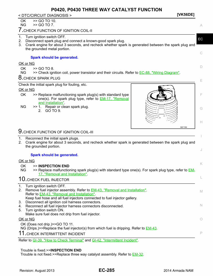
P0420, P0430 THREE WAY CATALYST FUNCTION[VK56DE]
C
D
E
F
G
H
I
J
K
L
M
A
C
N
P
O
< DTC/CIRCUIT DIAGNOSIS >
E
OK >> GO TO 10.NG >> GO TO 7.
7.CHECK FUNCTION OF IGNITION COIL-II
1. Turn ignition switch OFF.2. Disconnect spark plug and connect a known-good spark plug.3. Crank engine for about 3 seconds, and recheck whether spark is generated between the spark plug and
the grounded metal portion.
OK or NGOK >> GO TO 8.NG >> Check ignition coil, power transistor and their circuits. Refer to EC-88, "Wiring Diagram".
8.CHECK SPARK PLUG
Check the initial spark plug for fouling, etc.OK or NGOK >> Replace malfunctioning spark plug(s) with standard type
one(s). For spark plug type, refer to EM-17, "Removaland Installation".
NG >> 1. Repair or clean spark plug.2. GO TO 9.
9.CHECK FUNCTION OF IGNITION COIL-III
1. Reconnect the initial spark plugs.2. Crank engine for about 3 seconds, and recheck whether spark is generated between the spark plug and
the grounded portion.
OK or NGOK >> INSPECTION ENDNG >> Replace malfunctioning spark plug(s) with standard type one(s). For spark plug type, refer to EM-
17, "Removal and Installation".
10.CHECK FUEL INJECTOR
1. Turn ignition switch OFF.2. Remove fuel injector assembly. Refer to EM-43, "Removal and Installation".
Refer to EM-43, "Removal and Installation".Keep fuel hose and all fuel injectors connected to fuel injector gallery.
3. Disconnect all ignition coil harness connectors.4. Reconnect all fuel injector harness connectors disconnected.5. Turn ignition switch ON.
Make sure fuel does not drip from fuel injector.OK or NGOK (Does not drip.)>>GO TO 11.NG (Drips.)>>Replace the fuel injector(s) from which fuel is dripping. Refer to EM-43.
11.CHECK INTERMITTENT INCIDENT
Refer to GI-39, "How to Check Terminal" and GI-42, "Intermittent Incident".
Trouble is fixed.>>INSPECTION ENDTrouble is not fixed.>>Replace three way catalyst assembly. Refer to EM-32.
Spark should be generated.
SEF156I
Spark should be generated.
EC-285Revision: August 2013 2014 Armada NAM

[VK56DE]P0441 EVAP CONTROL SYSTEM
< DTC/CIRCUIT DIAGNOSIS >
P0441 EVAP CONTROL SYSTEM
System Description INFOID:0000000009825209
NOTE:If DTC P0441 is displayed with other DTC such as P2122, P2123, P2127, P2128 or P2138, first performtrouble diagnosis for other DTC.
In this evaporative emission (EVAP) control system, purge flow occurs during non-closed throttle conditions.Purge volume is related to air intake volume. Under normal purge conditions (non-closed throttle), the EVAPcanister purge volume control solenoid valve is open to admit purge flow. Purge flow exposes the EVAP con-trol system pressure sensor to intake manifold vacuum.
On Board Diagnosis Logic INFOID:0000000009825210
Under normal conditions (non-closed throttle), sensor output voltage indicates if pressure drop and purge floware adequate. If not, a malfunction is determined.
DTC Confirmation Procedure INFOID:0000000009825211
CAUTION:Always drive vehicle at a safe speed.NOTE:If DTC Confirmation Procedure has been previously conducted, always perform the following before conduct-ing the next step.1. Turn ignition switch OFF and wait at least 10 seconds.2. Turn ignition switch ON.3. Turn ignition switch OFF and wait at least 10 seconds.
PBIB1026E
DTC No. Trouble diagnosis name DTC detecting condition Possible cause
P04410441
EVAP control system in-correct purge flow
EVAP control system does not operate proper-ly, EVAP control system has a leak between in-take manifold and EVAP control system pressure sensor.
• EVAP canister purge volume control so-lenoid valve stuck closed
• EVAP control system pressure sensor and the circuit
• Loose, disconnected or improper con-nection of rubber tube
• Blocked rubber tube• Cracked EVAP canister• EVAP canister purge volume control so-
lenoid valve circuit• Accelerator pedal position sensor• Blocked purge port• EVAP canister vent control valve
EC-286Revision: August 2013 2014 Armada NAM

P0441 EVAP CONTROL SYSTEM[VK56DE]
C
D
E
F
G
H
I
J
K
L
M
A
C
N
P
O
< DTC/CIRCUIT DIAGNOSIS >
E
TESTING CONDITION:Always perform test at a temperature of 5C (41F) or more.
WITH CONSULT1. Start engine and warm it up to normal operating temperature.2. Turn ignition switch OFF and wait at least 10 seconds.3. Start engine and let it idle for at least 70 seconds.4. Select “PURG FLOW P0441” of “EVAPORATIVE SYSTEM” in “DTC WORK SUPPORT” mode with CON-
SULT.5. Touch “START”.
If “COMPLETED” is displayed, go to step 7.6. When the following conditions are met, “TESTING” will be displayed on the CONSULT screen. Maintain
the conditions continuously until “TESTING” changes to “COMPLETED”. (It will take at least 35 seconds.)
If “TESTING” is not changed for a long time, retry from step 2.7. Make sure that “OK” is displayed after touching “SELF-DIAG RESULTS”. If “NG” is displayed, refer to EC-
287, "Diagnosis Procedure".
Overall Function Check INFOID:0000000009825212
Use this procedure to check the overall monitoring function of the EVAP control system purge flow monitoring.During this check, a 1st trip DTC might not be confirmed.
WITH GST1. Lift up drive wheels.2. Start engine (VDC switch OFF) and warm it up to normal operating temperature.3. Turn ignition switch OFF, wait at least 10 seconds.4. Start engine and wait at least 70 seconds.5. Set voltmeter probes to ECM terminals 32 (EVAP control system
pressure sensor signal) and ground.6. Check EVAP control system pressure sensor value at idle speed
and note it.7. Establish and maintain the following conditions for at least 1
minute.
8. Verify that EVAP control system pressure sensor value stays 0.1 V less than the value at idle speed (mea-sured at step 6) for at least 1 second.
9. If NG, go to EC-287, "Diagnosis Procedure".
Diagnosis Procedure INFOID:0000000009825213
1.CHECK EVAP CANISTER
1. Turn ignition switch OFF.2. Check EVAP canister for cracks.OK or NGOK (With CONSULT)>>GO TO 2.OK (Without CONSULT)>>GO TO 3.
Selector lever Suitable position
VHCL SPEED SE 32 - 120 km/h (20 - 75 MPH)
ENG SPEED 500 - 3,000 rpm
B/FUEL SCHDL 1.0 - 12.0 msec
COOLAN TEMP/S More than 0C
Air conditioner switch ON
Headlamp switch ON
Rear window defogger switch ON
Engine speed Approx. 3,000 rpm
Gear position Any position other than P, N or R
PBIB1109E
EC-287Revision: August 2013 2014 Armada NAM

[VK56DE]P0441 EVAP CONTROL SYSTEM
< DTC/CIRCUIT DIAGNOSIS >NG >> Replace EVAP canister. Refer to FL-16.
2.CHECK PURGE FLOW
With CONSULT1. Disconnect vacuum hose connected to EVAP canister purge volume control solenoid valve at EVAP ser-
vice port and install vacuum gauge. For the location of EVAP service port, refer to EC-32, "Description".2. Start engine and let it idle.3. Select “PURG VOL CONT/V” in “ACTIVE TEST” mode with CONSULT.4. Rev engine up to 2,000 rpm.5. Touch “Qd” and “Qu” on CONSULT screen to adjust “PURG VOL CONT/V” opening and check vacuum
existence.
OK or NGOK >> GO TO 7.NG >> GO TO 4.
3.CHECK PURGE FLOW
Without CONSULT1. Start engine and warm it up to normal operating temperature.2. Stop engine.3. Disconnect vacuum hose connected to EVAP canister purge volume control solenoid valve at EVAP ser-
vice port and install vacuum gauge. For the location of EVAP service port, refer to EC-32, "Description".4. Start engine and let it idle.
Do not depress accelerator pedal even slightly.5. Check vacuum gauge indication before 60 seconds passed after starting engine.
6. Revving engine up to 2,000 rpm after 100 seconds passed after starting engine.
OK or NGOK >> GO TO 7.NG >> GO TO 4.
4.CHECK EVAP PURGE LINE
1. Turn ignition switch OFF.2. Check EVAP purge line for improper connection or disconnection.
Refer to EC-32, "Description".OK or NGOK >> GO TO 5.NG >> Repair it.
5.CHECK EVAP PURGE HOSE AND PURGE PORT
1. Disconnect purge hoses connected to EVAP service port A andEVAP canister purge volume control solenoid valve B.
2. Blow air into each hose and EVAP purge port C.
PURG VOL CONT/V Vacuum
100% Should exist.
0% Should not exist.
Vacuum should not exist.
Vacuum should exist.
SEF367U
EC-288Revision: August 2013 2014 Armada NAM

P0441 EVAP CONTROL SYSTEM[VK56DE]
C
D
E
F
G
H
I
J
K
L
M
A
C
N
P
O
< DTC/CIRCUIT DIAGNOSIS >
E
3. Check that air flows freely.OK or NGOK (With CONSULT)>>GO TO 6.OK (Without CONSULT)>>GO TO 7.NG >> Repair or clean hoses and/or purge port.
6.CHECK EVAP CANISTER PURGE VOLUME CONTROL SOLENOID VALVE
With CONSULT1. Start engine.2. Perform “PURG VOL CONT/V” in “ACTIVE TEST” mode with CONSULT. Check that engine speed varies
according to the valve opening.OK or NGOK >> GO TO 8.NG >> GO TO 7.
7.CHECK EVAP CANISTER PURGE VOLUME CONTROL SOLENOID VALVE
Refer to EC-306, "Component Inspection".OK or NGOK >> GO TO 8.NG >> Replace EVAP canister purge volume control solenoid valve. Refer to EM-27.
8.CHECK EVAP CONTROL SYSTEM PRESSURE SENSOR CONNECTOR
1. Disconnect EVAP control system pressure sensor harness connector.2. Check connectors for water.
OK or NGOK >> GO TO 9.NG >> Replace EVAP control system pressure sensor. Refer to FL-16.
9.CHECK EVAP CONTROL SYSTEM PRESSURE SENSOR FUNCTION
Refer to DTC Confirmation Procedure for DTC P0452, EC-319, "DTC Confirmation Procedure" and P0453,EC-323, "DTC Confirmation Procedure".OK or NGOK >> GO TO 10.NG >> Replace EVAP control system pressure sensor. Refer to FL-16.
10.CHECK RUBBER TUBE FOR CLOGGING
1. Disconnect rubber tube connected to EVAP canister vent control valve.2. Check the rubber tube for clogging.OK or NGOK >> GO TO 11.NG >> Clean the rubber tube using an air blower.
11.CHECK EVAP CANISTER VENT CONTROL VALVE
Refer to EC-309, "Component Inspection".OK or NGOK >> GO TO 12.NG >> Replace EVAP canister vent control valve. Refer to FL-16.
12.CHECK EVAP PURGE LINE
SEF368U
Water should not exist.
EC-289Revision: August 2013 2014 Armada NAM

[VK56DE]P0441 EVAP CONTROL SYSTEM
< DTC/CIRCUIT DIAGNOSIS >Inspect EVAP purge line (pipe and rubber tube). Check for evidence of leaks.Refer to EC-32, "Description".OK or NGOK >> GO TO 13.NG >> Replace it.
13.CLEAN EVAP PURGE LINE
Clean EVAP purge line (pipe and rubber tube) using air blower.
>> GO TO 14.
14.CHECK INTERMITTENT INCIDENT
Refer to GI-39, "How to Check Terminal" and GI-42, "Intermittent Incident".
>> INSPECTION END
EC-290Revision: August 2013 2014 Armada NAM

P0442 EVAP CONTROL SYSTEM[VK56DE]
C
D
E
F
G
H
I
J
K
L
M
A
C
N
P
O
< DTC/CIRCUIT DIAGNOSIS >
E
P0442 EVAP CONTROL SYSTEM
On Board Diagnosis Logic INFOID:0000000009825214
This diagnosis detects leaks in the EVAP purge line using engine intake manifold vacuum.If pressure does not increase, the ECM will check for leaks in the line between the fuel tank and EVAP canisterpurge volume control solenoid valve, under the following “Vacuum test” conditions.The EVAP canister vent control valve is closed to shut the EVAP purge line off. The EVAP canister purge vol-ume control solenoid valve will then be opened to depressurize the EVAP purge line using intake manifoldvacuum. After this occurs, the EVAP canister purge volume control solenoid valve will be closed.
CAUTION:• Use only a genuine NISSAN fuel filler cap as a replacement. If an incorrect fuel filler cap is used, the
MIL may come on.• If the fuel filler cap is not tightened properly, the MIL may come on.• Use only a genuine NISSAN rubber tube as a replacement.
DTC Confirmation Procedure INFOID:0000000009825215
NOTE:
DTC No. Trouble diagnosis name DTC detecting condition Possible cause
P04420442
EVAP control system small leak detected (negative pressure)
EVAP control system has a leak, EVAP control system does not operate prop-erly.
• Incorrect fuel tank vacuum relief valve• Incorrect fuel filler cap used• Fuel filler cap remains open or fails to close.• Foreign matter caught in fuel filler cap.• Leak is in line between intake manifold and EVAP
canister purge volume control solenoid valve.• Foreign matter caught in EVAP canister vent con-
trol valve.• EVAP canister or fuel tank leaks• EVAP purge line (pipe and rubber tube) leaks• EVAP purge line rubber tube bent• Loose or disconnected rubber tube• EVAP canister vent control valve and the circuit• EVAP canister purge volume control solenoid
valve and the circuit• Fuel tank temperature sensor• O-ring of EVAP canister vent control valve is
missing or damaged• EVAP canister is saturated with water• EVAP control system pressure sensor• Fuel level sensor and the circuit• Refueling EVAP vapor cut valve• ORVR system leaks
PBIB1026E
EC-291Revision: August 2013 2014 Armada NAM

[VK56DE]P0442 EVAP CONTROL SYSTEM
< DTC/CIRCUIT DIAGNOSIS >• If DTC Confirmation Procedure has been previously conducted, always perform the following before con-
ducting the next step.1. Turn ignition switch OFF and wait at least 10 seconds.2. Turn ignition switch ON.3. Turn ignition switch OFF and wait at least 10 seconds.TESTING CONDITION:• Perform “DTC WORK SUPPORT” when the fuel level is between 1/4 and 3/4 full, and vehicle is placed
on flat level surface.• Always perform test at a temperature of 0 to 30C (32 to 86F).
WITH CONSULT1. Turn ignition switch ON.2. Turn ignition switch OFF and wait at least 10 seconds.3. Turn ignition switch ON and select “DATA MONITOR” mode with CONSULT.4. Make sure that the following conditions are met.
COOLAN TEMP/S: 0 - 70C (32 - 158F)INT/A TEMP SE: 0 - 30C (32 - 86F)
5. Select “EVP V/S LEAK P0456/P1456” of “EVAPORATIVE SYSTEM” in “DTC WORK SUPPORT” modewith CONSULT.Follow the instruction displayed.NOTE:If the engine speed cannot be maintained within the range displayed on the CONSULT screen, go to EC-116, "Basic Inspection".
6. Make sure that “OK” is displayed.If “NG” is displayed, refer to EC-292, "Diagnosis Procedure".NOTE:Make sure that EVAP hoses are connected to EVAP canister purge volume control solenoid valveproperly.
WITH GSTNOTE:Be sure to read the explanation of EC-76, "DTC Index" before driving vehicle.1. Start engine.2. Drive vehicle according to EC-76, "DTC Index".3. Stop vehicle.4. Turn ignition switch OFF, wait at least 10 seconds and then turn ON.5. Select Service $07 with GST.- If P0442 is displayed on the screen, go to EC-292, "Diagnosis Procedure".- If P0441 is displayed on the screen, go to EC-287, "Diagnosis Procedure".
Diagnosis Procedure INFOID:0000000009825216
1.CHECK FUEL FILLER CAP DESIGN
1. Turn ignition switch OFF.2. Check for genuine NISSAN fuel filler cap design.OK or NGOK >> GO TO 2.NG >> Replace with genuine NISSAN fuel filler cap. Refer to
FL-8.
2.CHECK FUEL FILLER CAP INSTALLATION
Check that the cap is tightened properly by rotating the cap clockwise.OK or NG
SEF915U
EC-292Revision: August 2013 2014 Armada NAM

P0442 EVAP CONTROL SYSTEM[VK56DE]
C
D
E
F
G
H
I
J
K
L
M
A
C
N
P
O
< DTC/CIRCUIT DIAGNOSIS >
E
OK >> GO TO 3.NG >> 1. Open fuel filler cap, then clean cap and fuel filler neck threads using air blower.
2. Retighten until ratcheting sound is heard.
3.CHECK FUEL FILLER CAP FUNCTION
Check for air releasing sound while opening the fuel filler cap.OK or NGOK >> GO TO 5.NG >> GO TO 4.
4.CHECK FUEL TANK VACUUM RELIEF VALVE
Refer to EC-297, "Component Inspection".OK or NGOK >> GO TO 5.NG >> Replace fuel filler cap with a genuine one. Refer to FL-8.
5.INSTALL THE PRESSURE PUMP
To locate the EVAP leak, install EVAP service port adapter (commer-cial service tool) and pressure pump to EVAP service port securely.NOTE:Improper installation of the EVAP service port adapter to theEVAP service port may cause leaking.
With CONSULT>>GO TO 6.Without CONSULT>>GO TO 7.
6.CHECK FOR EVAP LEAK
With CONSULT1. Turn ignition switch ON.2. Select “EVAP SYSTEM CLOSE” of “WORK SUPPORT” mode with CONSULT.3. Touch “START” and apply pressure into the EVAP line until the pressure indicator reaches the middle of
the bar graph.CAUTION:• Never use compressed air or a high pressure pump.• Do not exceed 4.12 kPa (0.042 kg/cm2, 0.6 psi) of pressure in the system.
BBIA0366E
SEF916U
EC-293Revision: August 2013 2014 Armada NAM

[VK56DE]P0442 EVAP CONTROL SYSTEM
< DTC/CIRCUIT DIAGNOSIS >4. Using EVAP leak detector, locate the EVAP leak. For the leak
detector, refer to the instruction manual for more details.Refer to EC-32, "Description".
OK or NGOK >> GO TO 8.NG >> Repair or replace.
7.CHECK FOR EVAP LEAK
Without CONSULT1. Turn ignition switch OFF.2. Apply 12 volts DC to EVAP canister vent control valve. The valve will close. (Continue to apply 12 volts
until the end of test.)
3. Pressurize the EVAP line using pressure pump with 1.3 to 2.7 kPa (10 to 20 mag, 0.39 to 0.79 mmHg),then remove pump and EVAP service port adapter.CAUTION:• Never use compressed air or a high pressure pump.• Do not exceed 4.12 kPa (0.042 kg/cm2, 0.6 psi) of pressure in the system.
4. Using EVAP leak detector, locate the EVAP leak. For the leakdetector, refer to the instruction manual for more details. Referto EC-32, "Description".
OK or NGOK >> GO TO 8.NG >> Repair or replace.
8.CHECK EVAP CANISTER VENT CONTROL VALVE
Check the following.• EVAP canister vent control valve is installed properly.
Refer to FL-16, "Removal and Installation".• EVAP canister vent control valve.
Refer to EC-309, "Component Inspection".OK or NGOK >> GO TO 9.NG >> Repair or replace EVAP canister vent control valve and O-ring.
9.CHECK IF EVAP CANISTER SATURATED WITH WATER
1. Remove EVAP canister with EVAP canister vent control valve and EVAP control system pressure sensorattached. Refer to FL-16.
SEF200U
BBIA0403E
SEF200U
EC-294Revision: August 2013 2014 Armada NAM

P0442 EVAP CONTROL SYSTEM[VK56DE]
C
D
E
F
G
H
I
J
K
L
M
A
C
N
P
O
< DTC/CIRCUIT DIAGNOSIS >
E
2. Does water drain from the EVAP canister?Yes or NoYes >> GO TO 10.No (With CONSULT)>>GO TO 12.No (Without CONSULT)>>GO TO 13.
10.CHECK EVAP CANISTER
Weigh the EVAP canister with the EVAP canister vent control valve and EVAP control system pressure sensorattached.The weight should be less than 2.5 kg (5.5 lb).OK or NGOK (With CONSULT)>>GO TO 12.OK (Without CONSULT)>>GO TO 13.NG >> GO TO 11.
11.DETECT MALFUNCTIONING PART
Check the following.• EVAP canister for damage• EVAP hose between EVAP canister and vehicle frame for clogging or poor connection
>> Repair hose or replace EVAP canister. Refer to FL-8, "Removal and Installation" or FL-16,"Removal and Installation".
12.CHECK EVAP CANISTER PURGE VOLUME CONTROL SOLENOID VALVE OPERATION
With CONSULT1. Disconnect vacuum hose to EVAP canister purge volume control solenoid valve at EVAP service port.2. Start engine.3. Perform “PURG VOL CONT/V” in “ACTIVE TEST” mode.4. Touch “Qu” on CONSULT screen to increase “PURG VOL CONT/V” opening to 100%.5. Check vacuum hose for vacuum when revving engine up to 2,000 rpm.
OK or NGOK >> GO TO 15.NG >> GO TO 14.
13.CHECK EVAP CANISTER PURGE VOLUME CONTROL SOLENOID VALVE OPERATION
Without CONSULT1. Start engine and warm it up to normal operating temperature.2. Stop engine.3. Disconnect vacuum hose to EVAP canister purge volume control solenoid valve at EVAP service port.4. Start engine and let it idle for at least 80 seconds.5. Check vacuum hose for vacuum when revving engine up to 2,000 rpm.
OK or NGOK >> GO TO 16.NG >> GO TO 14.
14.CHECK VACUUM HOSE
Check vacuum hoses for clogging or disconnection. Refer to EC-32, "Description".
BBIA0351E
Vacuum should exist.
Vacuum should exist.
EC-295Revision: August 2013 2014 Armada NAM

[VK56DE]P0442 EVAP CONTROL SYSTEM
< DTC/CIRCUIT DIAGNOSIS >OK or NGOK >> GO TO 15.NG >> Repair or reconnect the hose.
15.CHECK EVAP CANISTER PURGE VOLUME CONTROL SOLENOID VALVE
Refer to EC-306, "Component Inspection".OK or NGOK >> GO TO 16.NG >> Replace EVAP canister purge volume control solenoid valve. Refer to EM-27.
16.CHECK FUEL TANK TEMPERATURE SENSOR
Refer to EC-255, "Component Inspection".OK or NGOK >> GO TO 17.NG >> Replace fuel level sensor unit. Refer to FL-12.
17.CHECK EVAP CONTROL SYSTEM PRESSURE SENSOR
Refer to EC-317, "Component Inspection".OK or NGOK >> GO TO 18.NG >> Replace EVAP control system pressure sensor. Refer to FL-16.
18.CHECK EVAP PURGE LINE
Check EVAP purge line (pipe, rubber tube, fuel tank and EVAP canister) for cracks or improper connection.Refer to EC-32, "Description".OK or NGOK >> GO TO 19.NG >> Repair or reconnect the hose.
19.CLEAN EVAP PURGE LINE
Clean EVAP purge line (pipe and rubber tube) using air blower.
>> GO TO 20.
20.CHECK EVAP/ORVR LINE
Check EVAP/ORVR line between EVAP canister and fuel tank for clogging, kink, looseness and improper con-nection. For location, refer to EC-479.OK or NGOK >> GO TO 21.NG >> Repair or replace hoses and tubes. Refer to FL-8.
21.CHECK RECIRCULATION LINE
Check recirculation line between filler neck tube and fuel tank for clogging, kink, cracks, looseness andimproper connection.OK or NGOK >> GO TO 22.NG >> Repair or replace hose, tube or filler neck tube. Refer to FL-8.
22.CHECK REFUELING EVAP VAPOR CUT VALVE
Refer to EC-481, "Component Inspection".OK or NGOK >> GO TO 23.NG >> Replace refueling EVAP vapor cut valve with fuel tank. Refer to FL-8.
23.CHECK FUEL LEVEL SENSOR
Refer to MWI-37, "Component Inspection".OK or NG
EC-296Revision: August 2013 2014 Armada NAM
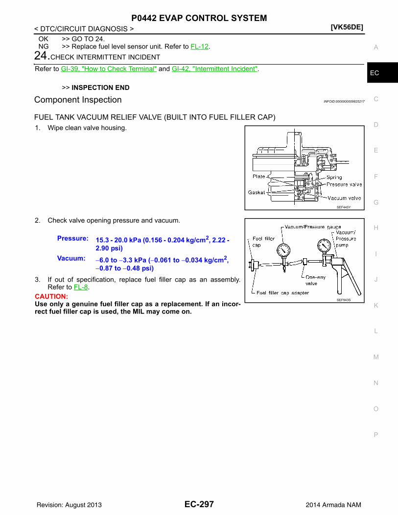
P0442 EVAP CONTROL SYSTEM[VK56DE]
C
D
E
F
G
H
I
J
K
L
M
A
C
N
P
O
< DTC/CIRCUIT DIAGNOSIS >
E
OK >> GO TO 24.NG >> Replace fuel level sensor unit. Refer to FL-12.
24.CHECK INTERMITTENT INCIDENT
Refer to GI-39, "How to Check Terminal" and GI-42, "Intermittent Incident".
>> INSPECTION END
Component Inspection INFOID:0000000009825217
FUEL TANK VACUUM RELIEF VALVE (BUILT INTO FUEL FILLER CAP)1. Wipe clean valve housing.
2. Check valve opening pressure and vacuum.
3. If out of specification, replace fuel filler cap as an assembly.Refer to FL-8.
CAUTION:Use only a genuine fuel filler cap as a replacement. If an incor-rect fuel filler cap is used, the MIL may come on.
SEF445Y
Pressure: 15.3 - 20.0 kPa (0.156 - 0.204 kg/cm2, 2.22 - 2.90 psi)
Vacuum: 6.0 to 3.3 kPa (0.061 to 0.034 kg/cm2, 0.87 to 0.48 psi)
SEF943S
EC-297Revision: August 2013 2014 Armada NAM

[VK56DE]P0443 EVAP CANISTER PURGE VOLUME CONTROL SOLENOID VALVE
< DTC/CIRCUIT DIAGNOSIS >
P0443 EVAP CANISTER PURGE VOLUME CONTROL SOLENOID VALVE
Description INFOID:0000000009825218
SYSTEM DESCRIPTION
*1: ECM determines the start signal status by the signals of engine speed and battery voltage.
*2: This signal is sent to the ECM through CAN communication line.
This system controls flow rate of fuel vapor from the EVAP canister. The opening of the vapor by-pass pas-sage in the EVAP canister purge volume control solenoid valve changes to control the flow rate. The EVAPcanister purge volume control solenoid valve repeats ON/OFF operation according to the signal sent from theECM. The opening of the valve varies for optimum engine control. The optimum value stored in the ECM isdetermined by considering various engine conditions. When the engine is operating, the flow rate of fuel vaporfrom the EVAP canister is regulated as the air flow changes.
COMPONENT DESCRIPTIONThe EVAP canister purge volume control solenoid valve uses a ON/OFF duty to control the flow rate of fuel vapor from the EVAP canis-ter. The EVAP canister purge volume control solenoid valve ismoved by ON/OFF pulses from the ECM. The longer the ON pulse,the greater the amount of fuel vapor that will flow through the valve.
On Board Diagnosis Logic INFOID:0000000009825219
Sensor Input signal to ECM ECM function Actuator
Crankshaft position sensor (POS)Camshaft position sensor (PHASE) Engine speed*1
EVAP canister purge flow control
EVAP canister purge vol-ume control solenoid valve
Mass air flow sensor Amount of intake air
Engine coolant temperature sensor Engine coolant temperature
Battery Battery voltage*1
Throttle position sensor Throttle position
Accelerator pedal position sensor Accelerator pedal position
Air fuel ratio (A/F) sensor 1Density of oxygen in exhaust gas(Mixture ratio feedback signal)
Fuel tank temperature sensor Fuel temperature in fuel tank
Wheel sensor Vehicle speed*2
PBIB2057E
DTC No.Trouble diagnosis
nameDTC detecting condition Possible cause
P04430443
EVAP canister purge volume control sole-noid valve
A)
The canister purge flow is detected during the vehicle is stopped while the the engine is run-ning, even when EVAP canister purge volume control solenoid valve is completely closed.
• EVAP control system pressure sensor• EVAP canister purge volume control so-
lenoid valve(The valve is stuck open.)
• EVAP canister vent control valve• EVAP canister• Hoses
(Hoses are connected incorrectly or clogged.)
B)
The canister purge flow is detected during the specified driving conditions, even when EVAP canister purge volume control solenoid valve is completely closed.
EC-298Revision: August 2013 2014 Armada NAM

P0443 EVAP CANISTER PURGE VOLUME CONTROL SOLENOID VALVE[VK56DE]
C
D
E
F
G
H
I
J
K
L
M
A
C
N
P
O
< DTC/CIRCUIT DIAGNOSIS >
E
DTC Confirmation Procedure INFOID:0000000009825220
Perform PROCEDURE FOR MALFUNCTION A first.If the DTC cannot be confirmed, perform PROCEDURE FOR MALFUNCTION B.NOTE:If DTC Confirmation Procedure has been previously conducted, always perform the following before conduct-ing the next step.1. Turn ignition switch OFF and wait at least 10 seconds.2. Turn ignition switch ON.3. Turn ignition switch OFF and wait at least 10 seconds.
PROCEDURE FOR MALFUNCTION ATESTING CONDITION:• Perform “DTC CONFIRMATION PROCEDURE” when the fuel level is between 1/4 and 3/4 full, and
vehicle is placed on flat level surface.• Always perform test at a temperature of 5 to 60C (41F).• Cool the vehicle so that engine coolant temperature becomes same level as ambient temperature.
With CONSULT1. Turn ignition switch ON and select “DATA MONITOR” mode with CONSULT.2. Check that the following condition are met.
FUEL T/TMP SE: 0 – 35C (32 – 95F)3. Start engine and wait at least 60 seconds.4. Check 1st trip DTC.5. If 1st trip DTC is detected, go to EC-300, "Diagnosis Procedure".
With GST1. Turn ignition switch ON.2. Set voltmeter probes to ECM terminal 107 (FTT sensor signal)
and ground.3. Check that the voltage is 3.1 – 4.2 V.4. Start engine and wait at least 60 seconds.5. Check 1st trip DTC.6. If 1st trip DTC is detected, go to EC-300, "Diagnosis Procedure".
PROCEDURE FOR MALFUNCTION BNOTE:If DTC Confirmation Procedure has been previously conducted, always perform the following before conduct-ing the next step.1. Turn ignition switch OFF and wait at least 10 seconds.2. Turn ignition switch ON.3. Turn ignition switch OFF and wait at least 10 seconds.TESTING CONDITION:Always perform test at a temperature of 5C (41F) or more.
With CONSULT1. Start engine and warm it up to normal operating temperature.2. Turn ignition switch OFF and wait at least 10 seconds.3. Turn ignition switch ON.4. Turn ignition switch OFF and wait at least 10 seconds.5. Turn ignition switch ON.6. Select “PURG VOL CN/V P1444” of “EVAPORATIVE SYSTEM” in “DTC WORK SUPPORT” mode with
CONSULT.7. Touch “START”.
JMBIA2925ZZ
EC-299Revision: August 2013 2014 Armada NAM

[VK56DE]P0443 EVAP CANISTER PURGE VOLUME CONTROL SOLENOID VALVE
< DTC/CIRCUIT DIAGNOSIS >8. Start engine and let it idle until “TESTING” on CONSULT changes to “COMPLETED”. (It will take approxi-
mately 10 seconds.)If “TESTING” is not displayed after 5 minutes, retry from step 2.
9. Make sure that “OK” is displayed after touching “SELF-DIAG RESULTS”. If “NG” is displayed, refer to EC-300, "Diagnosis Procedure".
With GST1. Start engine and warm it up to normal operating temperature.2. Turn ignition switch OFF and wait at least 10 seconds.3. Turn ignition switch ON.4. Turn ignition switch OFF and wait at least 10 seconds.5. Start engine and let it idle for at least 20 seconds.6. Select Service $07 with GST.7. If 1st trip DTC is detected, go to EC-300, "Diagnosis Procedure".
Diagnosis Procedure INFOID:0000000009825221
1.CHECK EVAP CANISTER PURGE VOLUME CONTROL SOLENOID VALVE POWER SUPPLY CIRCUIT
1. Turn ignition switch OFF.2. Disconnect EVAP canister purge volume control solenoid valve
harness connector.3. Turn ignition switch ON.
4. Check voltage between EVAP canister purge volume controlsolenoid valve terminal 1 and ground with CONSULT or tester.
OK or NGOK >> GO TO 3.NG >> GO TO 2.
2.DETECT MALFUNCTIONING PART
Check the following.• Harness connectors E2, F32• Harness for open or short between EVAP canister purge volume control solenoid valve and IPDM E/R• Harness for open or short between EVAP canister purge volume control solenoid valve and ECM
>> Repair harness or connectors.
3.CHECK EVAP CANISTER PURGE VOLUME CONTROL SOLENOID VALVE OUTPUT SIGNAL CIRCUIT
FOR OPEN AND SHORT
1. Turn ignition switch OFF.2. Disconnect ECM harness connector.3. Check harness continuity between ECM terminal 45 and EVAP canister purge volume control solenoid
valve terminal 2. Refer to Wiring Diagram.
BBIA0366E
Voltage: Battery voltage
PBIB2245E
Continuity should exist.
EC-300Revision: August 2013 2014 Armada NAM

P0443 EVAP CANISTER PURGE VOLUME CONTROL SOLENOID VALVE[VK56DE]
C
D
E
F
G
H
I
J
K
L
M
A
C
N
P
O
< DTC/CIRCUIT DIAGNOSIS >
E
4. Also check harness for short to ground and short to power.OK or NGOK >> GO TO 4.NG >> Repair open circuit or short to ground or short to power in harness or connectors.
4.CHECK EVAP CONTROL SYSTEM PRESSURE SENSOR CONNECTOR
1. Disconnect EVAP control system pressure sensor harness connector.2. Check connectors for water.
OK or NGOK >> GO TO 5.NG >> Replace EVAP control system pressure sensor. Refer to FL-16.
5.CHECK EVAP CONTROL SYSTEM PRESSURE SENSOR
Refer to EC-317, "Component Inspection".OK or NGOK (With CONSULT)>>GO TO 6.OK (Without CONSULT)>>GO TO 7.NG >> Replace EVAP control system pressure sensor. Refer to FL-16.
6.CHECK EVAP CANISTER PURGE VOLUME CONTROL SOLENOID VALVE
With CONSULT1. Turn ignition switch OFF.2. Reconnect all harness connectors disconnected.3. Start engine.4. Perform “PURG VOL CONT/V” in “ACTIVE TEST” mode with CONSULT. Check that engine speed varies
according to the valve opening.OK or NGOK >> GO TO 8.NG >> GO TO 7.
7.CHECK EVAP CANISTER PURGE VOLUME CONTROL SOLENOID VALVE
Refer to EC-302, "Component Inspection".OK or NGOK >> GO TO 8.NG >> Replace EVAP canister purge volume control solenoid valve. Refer to EM-27.
8.CHECK RUBBER TUBE FOR CLOGGING
1. Disconnect rubber tube connected to EVAP canister vent control valve.2. Check the rubber tube for clogging.OK or NGOK >> GO TO 9.NG >> Clean the rubber tube using an air blower.
9.CHECK EVAP CANISTER VENT CONTROL VALVE
Refer to EC-313, "Component Inspection".OK or NGOK >> GO TO 10.NG >> Replace EVAP canister vent control valve. Refer to FL-16.
10.CHECK IF EVAP CANISTER SATURATED WITH WATER
1. Remove EVAP canister with EVAP canister vent control valve and EVAP control system pressure sensorattached. Refer to FL-16.
Water should not exist.
EC-301Revision: August 2013 2014 Armada NAM

[VK56DE]P0443 EVAP CANISTER PURGE VOLUME CONTROL SOLENOID VALVE
< DTC/CIRCUIT DIAGNOSIS >2. Check if water will drain from the EVAP canister.Yes or NoYes >> GO TO 11.No >> GO TO 13.
11.CHECK EVAP CANISTER
Weigh the EVAP canister with the EVAP canister vent control valve and EVAP control system pressure sensorattached.The weight should be less than 2.5 kg (5.5 lb).OK or NGOK >> GO TO 13.NG >> GO TO 12.
12.DETECT MALFUNCTIONING PART
Check the following.• EVAP canister for damage• EVAP hose between EVAP canister and vehicle frame for clogging or poor connection
>> Repair hose or replace EVAP canister. Refer to FL-8, "Removal and Installation" or FL-16,"Removal and Installation".
13.CHECK INTERMITTENT INCIDENT
Refer to GI-39, "How to Check Terminal" and GI-42, "Intermittent Incident".
>> INSPECTION END
Component Inspection INFOID:0000000009825222
EVAP CANISTER PURGE VOLUME CONTROL SOLENOID VALVE
With CONSULTCheck air passage continuity of EVAP canister purge volume controlsolenoid valve under the following conditions.
Without CONSULT
BBIA0351E
Condition(PURG VOL CONT/V value)
Air passage continuity between A and B
100% Yes
0% No
PBIB2058E
EC-302Revision: August 2013 2014 Armada NAM

P0443 EVAP CANISTER PURGE VOLUME CONTROL SOLENOID VALVE[VK56DE]
C
D
E
F
G
H
I
J
K
L
M
A
C
N
P
O
< DTC/CIRCUIT DIAGNOSIS >
E
Check air passage continuity of EVAP canister purge volume controlsolenoid valve under the following conditions.
ConditionAir passage continuity
between A and B
12V direct current supply between terminals 1 and 2
Yes
No supply No
PBIB2059E
EC-303Revision: August 2013 2014 Armada NAM

[VK56DE]
P0444, P0445 EVAP CANISTER PURGE VOLUME CONTROL SOLENOID VALVE
< DTC/CIRCUIT DIAGNOSIS >
P0444, P0445 EVAP CANISTER PURGE VOLUME CONTROL SOLENOIDVALVE
Description INFOID:0000000009825223
SYSTEM DESCRIPTION
*1: ECM determines the start signal status by the signals of engine speed and battery voltage.
*2: This signal is sent to the ECM through CAN communication line.
This system controls flow rate of fuel vapor from the EVAP canister. The opening of the vapor by-pass pas-sage in the EVAP canister purge volume control solenoid valve changes to control the flow rate. The EVAPcanister purge volume control solenoid valve repeats ON/OFF operation according to the signal sent from theECM. The opening of the valve varies for optimum engine control. The optimum value stored in the ECM isdetermined by considering various engine conditions. When the engine is operating, the flow rate of fuel vaporfrom the EVAP canister is regulated as the air flow changes.
COMPONENT DESCRIPTIONThe EVAP canister purge volume control solenoid valve uses a ON/OFF duty to control the flow rate of fuel vapor from the EVAP canis-ter. The EVAP canister purge volume control solenoid valve ismoved by ON/OFF pulses from the ECM. The longer the ON pulse,the greater the amount of fuel vapor that will flow through the valve.
On Board Diagnosis Logic INFOID:0000000009825224
Sensor Input signal to ECM ECM function Actuator
Crankshaft position sensor (POS)Camshaft position sensor (PHASE) Engine speed*1
EVAP canister purge flow control
EVAP canister purge vol-ume control solenoid valve
Mass air flow sensor Amount of intake air
Engine coolant temperature sensor Engine coolant temperature
Battery Battery voltage*1
Throttle position sensor Throttle position
Accelerator pedal position sensor Accelerator pedal position
Air fuel ratio (A/F) sensor 1Density of oxygen in exhaust gas(Mixture ratio feedback signal)
Fuel tank temperature sensor Fuel temperature in fuel tank
Wheel sensor Vehicle speed*2
PBIB2057E
DTC No. Trouble diagnosis name DTC detecting condition Possible cause
P04440444
EVAP canister purge volume control solenoid valve circuit open
An excessively low voltage signal is sent to ECM through the valve
• Harness or connectors(The solenoid valve circuit is open or shorted.)
• EVAP canister purge volume control so-lenoid valve
P04450445
EVAP canister purge volume control solenoid valve circuit shorted
An excessively high voltage signal is sent to ECM through the valve
• Harness or connectors(The solenoid valve circuit is shorted.)
• EVAP canister purge volume control so-lenoid valve
EC-304Revision: August 2013 2014 Armada NAM

P0444, P0445 EVAP CANISTER PURGE VOLUME CONTROL SOLENOID VALVE
[VK56DE]
C
D
E
F
G
H
I
J
K
L
M
A
C
N
P
O
< DTC/CIRCUIT DIAGNOSIS >
E
DTC Confirmation Procedure INFOID:0000000009825225
NOTE:If DTC Confirmation Procedure has been previously conducted, always perform the following before conduct-ing the next step.1. Turn ignition switch OFF and wait at least 10 seconds.2. Turn ignition switch ON.3. Turn ignition switch OFF and wait at least 10 seconds.TESTING CONDITION:Before performing the following procedure, confirm battery voltage is more than 11 V at idle.1. Start engine and let it idle for at least 13 seconds.2. Check 1st trip DTC.3. If 1st trip DTC is detected, go to EC-305, "Diagnosis Procedure".
Diagnosis Procedure INFOID:0000000009825226
1.CHECK EVAP CANISTER PURGE VOLUME CONTROL SOLENOID VALVE POWER SUPPLY CIRCUIT
1. Turn ignition switch OFF.2. Disconnect EVAP canister purge volume control solenoid valve
harness connector.3. Turn ignition switch ON.
4. Check voltage between EVAP canister purge volume controlsolenoid valve terminal 1 and ground with CONSULT or tester.
OK or NGOK >> GO TO 3.NG >> GO TO 2.
2.DETECT MALFUNCTIONING PART
Check the following.• Harness connectors E2, F32• Harness for open or short between EVAP canister purge volume control solenoid valve and IPDM E/R• Harness for open or short between EVAP canister purge volume control solenoid valve and ECM
>> Repair harness or connectors.
3.CHECK EVAP CANISTER PURGE VOLUME CONTROL SOLENOID VALVE OUTPUT SIGNAL CIRCUIT
FOR OPEN AND SHORT
1. Turn ignition switch OFF.2. Disconnect ECM harness connector.3. Check harness continuity between ECM terminal 45 and EVAP canister purge volume control solenoid
valve terminal 2. Refer to Wiring Diagram.
BBIA0366E
Voltage: Battery voltage
PBIB2245E
Continuity should exist.
EC-305Revision: August 2013 2014 Armada NAM

[VK56DE]
P0444, P0445 EVAP CANISTER PURGE VOLUME CONTROL SOLENOID VALVE
< DTC/CIRCUIT DIAGNOSIS >4. Also check harness for short to ground and short to power.OK or NGOK (With CONSULT)>>GO TO 4.OK (Without CONSULT)>>GO TO 5.NG >> Repair open circuit or short to ground or short to power in harness or connectors.
4.CHECK EVAP CANISTER PURGE VOLUME CONTROL SOLENOID VALVE OPERATION
With CONSULT1. Reconnect all harness connectors disconnected.2. Start engine.3. Perform “PURG VOL CONT/V” in “ACTIVE TEST” mode with CONSULT. Check that engine speed varies
according to the valve opening.OK or NGOK >> GO TO 6.NG >> GO TO 5.
5.CHECK EVAP CANISTER PURGE VOLUME CONTROL SOLENOID VALVE
Refer to EC-306, "Component Inspection".OK or NGOK >> GO TO 6.NG >> Replace EVAP canister purge volume control solenoid valve.
6.CHECK INTERMITTENT INCIDENT
Refer to GI-39, "How to Check Terminal" and GI-42, "Intermittent Incident".
>> INSPECTION END
Component Inspection INFOID:0000000009825227
EVAP CANISTER PURGE VOLUME CONTROL SOLENOID VALVE
With CONSULTCheck air passage continuity of EVAP canister purge volume controlsolenoid valve under the following conditions.
Without CONSULTCheck air passage continuity of EVAP canister purge volume controlsolenoid valve under the following conditions.
Condition(PURG VOL CONT/V value)
Air passage continuity between A and B
100% Yes
0% No
PBIB2058E
ConditionAir passage continuity
between A and B
12 V direct current supply between terminals 1 and 2
Yes
No supply No
PBIB2059E
EC-306Revision: August 2013 2014 Armada NAM

P0447 EVAP CANISTER VENT CONTROL VALVE[VK56DE]
C
D
E
F
G
H
I
J
K
L
M
A
C
N
P
O
< DTC/CIRCUIT DIAGNOSIS >
E
P0447 EVAP CANISTER VENT CONTROL VALVE
Component Description INFOID:0000000009825228
The EVAP canister vent control valve is located on the EVAP canis-ter and is used to seal the canister vent.This solenoid valve responds to signals from the ECM. When theECM sends an ON signal, the coil in the solenoid valve is energized.A plunger will then move to seal the canister vent. The ability to sealthe vent is necessary for the on board diagnosis of other evaporativeemission control system components.This solenoid valve is used only for diagnosis, and usually remainsopened.When the vent is closed, under normal purge conditions, the evapo-rative emission control system is depressurized and allows EVAPControl System diagnosis.
On Board Diagnosis Logic INFOID:0000000009825229
DTC Confirmation Procedure INFOID:0000000009825230
NOTE:If DTC Confirmation Procedure has been previously conducted, always perform the following before conduct-ing the next step.1. Turn ignition switch OFF and wait at least 10 seconds.2. Turn ignition switch ON.3. Turn ignition switch OFF and wait at least 10 seconds.TESTING CONDITION:Before performing the following procedure, confirm battery voltage is more than 11 V at idle.1. Start engine and wait at least 8 seconds.2. Check 1st trip DTC.3. If 1st trip DTC is detected, go to EC-307, "Diagnosis Procedure".
Diagnosis Procedure INFOID:0000000009825231
1.INSPECTION START
Do you have CONSULT?Yes or NoYes >> GO TO 2.No >> GO TO 3.
PBIB1263E
BBIA0403E
DTC No. Trouble diagnosis name DTC detecting condition Possible cause
P04470447
EVAP canister vent con-trol valve circuit open
An improper voltage signal is sent to ECM through EVAP canister vent control valve.
• Harness or connectors(The valve circuit is open or shorted.)
• EVAP canister vent control valve
EC-307Revision: August 2013 2014 Armada NAM

[VK56DE]P0447 EVAP CANISTER VENT CONTROL VALVE
< DTC/CIRCUIT DIAGNOSIS >
2.CHECK EVAP CANISTER VENT CONTROL VALVE CIRCUIT
With CONSULT1. Turn ignition switch OFF and then turn ON.2. Select “VENT CONTROL/V” in “ACTIVE TEST” mode with CONSULT.3. Touch “ON/OFF” on CONSULT screen.4. Check for operating sound of the valve.
Clicking noise should be heard.OK or NGOK >> GO TO 7.NG >> GO TO 3.
3.CHECK EVAP CANISTER VENT CONTROL VALVE POWER SUPPLY CIRCUIT
1. Turn ignition switch OFF.2. Disconnect EVAP canister vent control valve harness connector.
3. Turn ignition switch ON.4. Check voltage between EVAP canister vent control valve termi-
nal 2 and ground with CONSULT or tester.
OK or NGOK >> GO TO 5.NG >> GO TO 4.
4.DETECT MALFUNCTIONING PART
Check the following.• Harness connectors E41, C1• Harness for open or short between EVAP canister vent control valve and IPDM E/R
>> Repair harness or connectors.
5.CHECK EVAP CANISTER VENT CONTROL VALVE OUTPUT SIGNAL CIRCUIT FOR OPEN AND SHORT
1. Turn ignition switch OFF.2. Disconnect ECM harness connector.3. Check harness continuity between ECM terminal 117 and EVAP canister vent control valve terminal 2.
Refer to Wiring Diagram.
4. Also check harness for short to ground and short to power.OK or NGOK >> GO TO 7.NG >> GO TO 6.
6.DETECT MALFUNCTIONING PART
Voltage: Battery voltage
BBIA0403E
PBIB0080E
Continuity should exist.
EC-308Revision: August 2013 2014 Armada NAM

P0447 EVAP CANISTER VENT CONTROL VALVE[VK56DE]
C
D
E
F
G
H
I
J
K
L
M
A
C
N
P
O
< DTC/CIRCUIT DIAGNOSIS >
E
Check the following.• Harness connectors E41, C1• Harness for open or short between EVAP canister vent control valve and ECM
>> Repair open circuit or short to ground or short to power in harness or connectors.
7.CHECK RUBBER TUBE FOR CLOGGING
1. Disconnect rubber tube connected to EVAP canister vent control valve.2. Check the rubber tube for clogging.OK or NGOK >> GO TO 8.NG >> Clean the rubber tube using an air blower.
8.CHECK EVAP CANISTER VENT CONTROL VALVE
Refer to EC-309, "Component Inspection".OK or NGOK >> GO TO 9.NG >> Replace EVAP canister vent control valve.
9.CHECK INTERMITTENT INCIDENT
Refer to GI-39, "How to Check Terminal" and GI-42, "Intermittent Incident".
>> INSPECTION END
Component Inspection INFOID:0000000009825232
EVAP CANISTER VENT CONTROL VALVE
With CONSULT
1. Remove EVAP canister vent control valve from EVAP canister. Refer to FL-16.2. Check portion B of EVAP canister vent control valve for being
rusted.If NG, replace EVAP canister vent control valve. Refer to FL-16.If OK, go to next step.
3. Reconnect harness connectors disconnected.4. Turn ignition switch ON.5. Perform “VENT CONTROL/V” in “ACTIVE TEST” mode.6. Check air passage continuity and operation delay time.
Make sure new O-ring is installed properly.
Operation takes less than 1 second.
If NG, replace EVAP canister vent control valve. Refer to FL-16.If OK, go to next step.
7. Clean the air passage (portion A to B) of EVAP canister vent control valve using an air blower.8. Perform step 6 again.
Without CONSULT
1. Remove EVAP canister vent control valve from EVAP canister. Refer to FL-16.
Condition VENT CONTROL/V Air passage continuity between A and B
ON No
OFF Yes
PBIB1033E
EC-309Revision: August 2013 2014 Armada NAM

[VK56DE]P0447 EVAP CANISTER VENT CONTROL VALVE
< DTC/CIRCUIT DIAGNOSIS >2. Check portion B of EVAP canister vent control valve for being
rusted.
3. Check air passage continuity and operation delay time under thefollowing conditions.Make sure new O-ring is installed properly.
Operation takes less than 1 second.
If NG, replace EVAP canister vent control valve. Refer to FL-16.If OK, go to next step.
4. Clean the air passage (portion A to B) of EVAP canister vent control valve using an air blower.5. Perform step 3 again.
PBIB1033E
Condition Air passage continuity between A and B
12 V direct current supply between terminals 1 and 2
No
OFF Yes
PBIB1034E
EC-310Revision: August 2013 2014 Armada NAM

P0448 EVAP CANISTER VENT CONTROL VALVE[VK56DE]
C
D
E
F
G
H
I
J
K
L
M
A
C
N
P
O
< DTC/CIRCUIT DIAGNOSIS >
E
P0448 EVAP CANISTER VENT CONTROL VALVE
Component Description INFOID:0000000009825233
The EVAP canister vent control valve is located on the EVAP canis-ter and is used to seal the canister vent.This solenoid valve responds to signals from the ECM. When theECM sends an ON signal, the coil in the solenoid valve is energized.A plunger will then move to seal the canister vent. The ability to sealthe vent is necessary for the on board diagnosis of other evaporativeemission control system components.This solenoid valve is used only for diagnosis, and usually remainsopened.When the vent is closed, under normal purge conditions, the evapo-rative emission control system is depressurized and allows EVAPControl System diagnosis.
On Board Diagnosis Logic INFOID:0000000009825234
DTC Confirmation Procedure INFOID:0000000009825235
1. If DTC Confirmation Procedure has been previously conducted, always perform the following before con-ducting the next step.
a. Turn ignition switch OFF and wait at least 10 seconds.b. Turn ignition switch ON.c. Turn ignition switch OFF and wait at least 10 seconds.2. Turn ignition switch ON and wait at least 5 seconds.3. Turn ignition switch OFF and wait at least 10 seconds.4. Start engine and let it idle for at least 1 minute. 5. Repeat next procedures 3 times.a. Increase the engine speed up to 3,000 to 3,500 rpm and keep it for 2 minutes and 50 seconds to 3 min-
utes.Never exceed 3 minutes.
b. Fully released accelerator pedal and keep engine idle for about 5 seconds.6. Check 1st trip DTC.7. If 1st trip DTC is detected, go to EC-312, "Diagnosis Procedure".
If 1st trip DTC is not detected, go to the next step.8. Repeat next procedure 20 times.
PBIB1263E
BBIA0403E
DTC No. Trouble diagnosis name DTC detecting condition Possible cause
P04480448
EVAP canister vent con-trol valve close
EVAP canister vent control valve remains closed under specified driving conditions.
• EVAP canister vent control valve• EVAP control system pressure sensor
and the circuit• Blocked rubber tube to EVAP canister
vent control valve• EVAP canister is saturated with water
EC-311Revision: August 2013 2014 Armada NAM

[VK56DE]P0448 EVAP CANISTER VENT CONTROL VALVE
< DTC/CIRCUIT DIAGNOSIS >a. Quickly increase the engine speed up to 4,000 to 4,500 rpm or more and keep it for 25 to 30 seconds.b. Fully released accelerator pedal and keep engine idle for at least 35 seconds.
9. Check 1st trip DTC.10. If 1st trip DTC is detected, go to EC-312, "Diagnosis Procedure".
Diagnosis Procedure INFOID:0000000009825236
1.CHECK RUBBER TUBE
1. Turn ignition switch OFF.2. Disconnect rubber tube connected to EVAP canister vent control valve.
3. Check the rubber tube for clogging.OK or NGOK >> GO TO 2.NG >> Clean rubber tube using an air blower.
2.CHECK EVAP CANISTER VENT CONTROL VALVE
Refer to EC-313, "Component Inspection".OK or NGOK >> GO TO 3.NG >> Replace EVAP canister vent control valve. Refer to FL-16.
3.CHECK IF EVAP CANISTER SATURATED WITH WATER
1. Remove EVAP canister with EVAP canister vent control valve and EVAP control system pressure sensorattached. Refer to FL-16.
2. Check if water will drain from the EVAP canister.Yes or NoYes >> GO TO 4.No >> GO TO 6.
4.CHECK EVAP CANISTER
PBIB0972E
BBIA0403E
BBIA0351E
EC-312Revision: August 2013 2014 Armada NAM

P0448 EVAP CANISTER VENT CONTROL VALVE[VK56DE]
C
D
E
F
G
H
I
J
K
L
M
A
C
N
P
O
< DTC/CIRCUIT DIAGNOSIS >
E
Weigh the EVAP canister with the EVAP canister vent control valve and EVAP control system pressure sensorattached.The weight should be less than 2.5 kg (5.5 lb).OK or NGOK >> GO TO 6.NG >> GO TO 5.
5.DETECT MALFUNCTIONING PART
Check the following.• EVAP canister for damage• EVAP hose between EVAP canister and vehicle frame for clogging or poor connection
>> Repair hose or replace EVAP canister. Refer to FL-8, "Removal and Installation" or FL-16,"Removal and Installation".
6.CHECK EVAP CONTROL SYSTEM PRESSURE SENSOR CONNECTOR
1. Disconnect EVAP control system pressure sensor harness connector.2. Check connectors for water.
OK or NGOK >> GO TO 7.NG >> Replace EVAP control system pressure sensor. Refer to FL-16.
7.CHECK EVAP CONTROL SYSTEM PRESSURE SENSOR
Refer to EC-317, "Component Inspection".OK or NGOK >> GO TO 8.NG >> Replace EVAP control system pressure sensor. Refer to FL-16.
8.CHECK INTERMITTENT INCIDENT
Refer to GI-39, "How to Check Terminal" and GI-42, "Intermittent Incident".
>> INSPECTION END
Component Inspection INFOID:0000000009825237
EVAP CANISTER VENT CONTROL VALVE
With CONSULT
1. Remove EVAP canister vent control valve from EVAP canister. Refer to FL-16.2. Check portion B of EVAP canister vent control valve for being
rusted.If NG, replace EVAP canister vent control valve. Refer to FL-16.If OK, go to next step.
3. Reconnect harness connectors disconnected.4. Turn ignition switch ON.5. Perform “VENT CONTROL/V” in “ACTIVE TEST” mode.6. Check air passage continuity and operation delay time.
Make sure that new O-ring is installed properly.
Operation takes less than 1 second.
Water should not exist.
Condition VENT CONTROL/V Air passage continuity between A and B
ON No
OFF Yes
PBIB1033E
EC-313Revision: August 2013 2014 Armada NAM

[VK56DE]P0448 EVAP CANISTER VENT CONTROL VALVE
< DTC/CIRCUIT DIAGNOSIS >If NG, replace EVAP canister vent control valve. Refer to FL-16.If OK, go to next step.
7. Clean the air passage (Portion A to B) of EVAP canister vent control valve using an air blower.8. Perform step 6 again.
Without CONSULT
1. Remove EVAP canister vent control valve from EVAP canister. Refer to FL-16.2. Check portion B of EVAP canister vent control valve for being
rusted.
3. Check air passage continuity and operation delay time under thefollowing conditions.Make sure that new O-ring is installed properly.
Operation takes less than 1 second.
If NG, replace EVAP canister vent control valve. Refer to FL-16.If OK, go to next step.
4. Clean the air passage (Portion A to B) of EVAP canister vent control valve using an air blower.5. Perform step 3 again.
PBIB1033E
Condition Air passage continuity between A and B
12 V direct current supply between terminals 1 and 2
No
OFF Yes
PBIB1034E
EC-314Revision: August 2013 2014 Armada NAM

P0451 EVAP CONTROL SYSTEM PRESSURE SENSOR[VK56DE]
C
D
E
F
G
H
I
J
K
L
M
A
C
N
P
O
< DTC/CIRCUIT DIAGNOSIS >
E
P0451 EVAP CONTROL SYSTEM PRESSURE SENSOR
Component Description INFOID:0000000009825238
The EVAP control system pressure sensor detects pressure in the purge line. The sensor output voltage to theECM increases as pressure increases.
On Board Diagnosis Logic INFOID:0000000009825239
NOTE:If DTC P0451 is displayed with DTC P0643, first perform the trouble diagnosis for DTC P0643. Refer toEC-367.
DTC Confirmation Procedure INFOID:0000000009825240
NOTE:Never remove fuel filler cap during DTC confirmation procedure.
1.PRECONDITIONING
If DTC Confirmation Procedure has been previously conducted, always perform the following procedurebefore conducting the next test.1. Turn ignition switch OFF and wait at least 10 seconds.2. Turn ignition switch ON.3. Turn ignition switch OFF and wait at least 10 seconds.
With CONSULT>>GO TO 2.Without CONSULT>>GO TO 5.
2.PERFORM DTC CONFIRMATION PROCEDURE-1
With CONSULT1. Start engine and let it idle for least 40 seconds.
NOTE:Do not depress accelerator pedal even slightly.
BBIA0403E
PBIB1207E
DTC No. Trouble diagnosis name DTC detecting condition Possible cause
P04510451
EVAP control system pressure sensor performance
ECM detects a sloshing signal from the EVAP control system pressure sensor
• Harness or connectors• EVAP control system pressure sensor
EC-315Revision: August 2013 2014 Armada NAM

[VK56DE]P0451 EVAP CONTROL SYSTEM PRESSURE SENSOR
< DTC/CIRCUIT DIAGNOSIS >2. Check 1st trip DTC.Is 1st trip DTC detected?YES >> Proceed to EC-316, "Diagnosis Procedure".NO >> GO TO 3.
3.PERFORM DTC CONFIRMATION PROCEDURE-2
With CONSULT1. Select “EVAP DIAG READY” in “DATA MONITOR” mode of “ENGINE”.2. Let it idle until “OFF” of “EVAP DIAG READY” changes to “ON”.
NOTE:It will take at most 2 hours until “OFF” of “EVAP DIAG READY” changes to “ON”.
3. Turn ignition switch OFF and wait at least 90 minutes.NOTE:Never turn ignition switch ON during 90 minutes.
4. Turn ignition switch ON.5. Select “EVAP LEAK DIAG” in “DATA MONITOR” mode of “ENGINE”.6. Check that “EVAP LEAK DIAG” indication.Which is displayed on CONSULT?CMPLT>> GO TO 4.YET >> 1. Perform DTC CONFIRMATION PROCEDURE again.
2. GO TO 1.
4.PERFORM DTC CONFIRMATION PROCEDURE-3
With CONSULTCheck 1st trip DTC.Is 1st trip DTC detected?YES >> Proceed to EC-316, "Diagnosis Procedure".NO >> INSPECTION END
5.PERFORM DTC CONFIRMATION PROCEDURE-4
With GST1. Start engine and let it idle for least 40 seconds.
NOTE:Do not depress accelerator pedal even slightly.
2. Check 1st trip DTC.Is 1st trip DTC detected?YES >> Proceed to EC-316, "Diagnosis Procedure".NO >> GO TO 6.
6.PERFORM DTC CONFIRMATION PROCEDURE-5
With GST1. Let it idle for at least 2 hours.2. Turn ignition switch OFF and wait at least 90 minutes.
NOTE:Never turn ignition switch ON during 90 minutes.
3. Turn ignition switch ON.4. Check 1st trip DTC.Is 1st trip DTC detected?YES >> Proceed to EC-316, "Diagnosis Procedure".NO >> INSPECTION END
Diagnosis Procedure INFOID:0000000009825241
1.CHECK GROUND CONNECTIONS
1. Turn ignition switch OFF.2. Loosen and retighten three ground screws on the body.
EC-316Revision: August 2013 2014 Armada NAM

P0451 EVAP CONTROL SYSTEM PRESSURE SENSOR[VK56DE]
C
D
E
F
G
H
I
J
K
L
M
A
C
N
P
O
< DTC/CIRCUIT DIAGNOSIS >
E
Refer to EC-153, "Ground Inspection".
OK or NGOK >> GO TO 2.NG >> Repair or replace ground connections.
2.CHECK EVAP CONTROL SYSTEM PRESSURE SENSOR CONNECTOR FOR WATER
1. Disconnect EVAP control system pressure sensor harness connector.
2. Check sensor harness connector for water.
OK or NGOK >> GO TO 3.NG >> Repair or replace harness connector.
3.CHECK EVAP CONTROL SYSTEM PRESSURE SENSOR
Refer to EC-317, "Component Inspection".OK or NGOK >> GO TO 4.NG >> Replace EVAP control system pressure sensor. Refer to FL-16.
4.CHECK INTERMITTENT INCIDENT
Refer to GI-39, "How to Check Terminal" and GI-42, "Intermittent Incident".For wiring diagram, refer to EC-88, "Wiring Diagram".
>> INSPECTION END
Component Inspection INFOID:0000000009825242
EVAP CONTROL SYSTEM PRESSURE SENSOR1. Remove EVAP control system pressure sensor with its harness connector connected from EVAP canister.
Refer to FL-16.Always replace O-ring with a new one.
2. Install a vacuum pump to EVAP control system pressure sensor.
BBIA0354E
Water should not exist.
BBIA0403E
EC-317Revision: August 2013 2014 Armada NAM

[VK56DE]P0451 EVAP CONTROL SYSTEM PRESSURE SENSOR
< DTC/CIRCUIT DIAGNOSIS >3. Turn ignition switch ON and check output voltage between ECM
terminal 32 and ground under the following conditions.
CAUTION:• Always calibrate the vacuum pump gauge when using it.• Do not apply below -93.3 kPa (-700 mmHg, -27.56 inHg) or
pressure over 101.3 kPa (760 mmHg, 29.92 inHg).4. If NG, replace EVAP control system pressure sensor. Refer to FL-16.
Applied vacuum kPa(mmHg, inHg)
Voltage (V)
Not applied 1.8 - 4.8
-26.7 (-200, -7.87) 2.1 to 2.5 V lower than above value
PBIB1173E
EC-318Revision: August 2013 2014 Armada NAM

P0452 EVAP CONTROL SYSTEM PRESSURE SENSOR[VK56DE]
C
D
E
F
G
H
I
J
K
L
M
A
C
N
P
O
< DTC/CIRCUIT DIAGNOSIS >
E
P0452 EVAP CONTROL SYSTEM PRESSURE SENSOR
Component Description INFOID:0000000009825243
The EVAP control system pressure sensor detects pressure in the purge line. The sensor output voltage to theECM increases as pressure increases.
On Board Diagnosis Logic INFOID:0000000009825244
NOTE:If DTC P0452 is displayed with DTC P0643, first perform the trouble diagnosis for DTC P0643. Refer toEC-367.
DTC Confirmation Procedure INFOID:0000000009825245
NOTE:If DTC Confirmation Procedure has been previously conducted, always perform the following before conduct-ing the next step.1. Turn ignition switch OFF and wait at least 10 seconds.2. Turn ignition switch ON.3. Turn ignition switch OFF and wait at least 10 seconds.TESTING CONDITION:Always perform test at a temperature of 5C (41F) or more.
WITH CONSULT1. Start engine and warm it up to normal operating temperature.2. Turn ignition switch OFF and wait at least 10 seconds.3. Turn ignition switch ON.4. Select “DATA MONITOR” mode with CONSULT.5. Make sure that “FUEL T/TMP SE” is more than 0C (32F).
BBIA0403E
PBIB1207E
DTC No. Trouble diagnosis name DTC detecting condition Possible cause
P04520452
EVAP control system pressure sensor low input
An excessively low voltage from the sen-sor is sent to ECM.
• Harness or connectors(The sensor circuit is open or shorted.)
• EVAP control system pressure sensor
EC-319Revision: August 2013 2014 Armada NAM
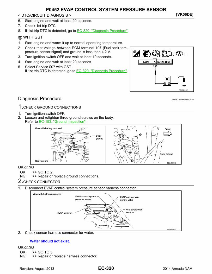
[VK56DE]P0452 EVAP CONTROL SYSTEM PRESSURE SENSOR
< DTC/CIRCUIT DIAGNOSIS >6. Start engine and wait at least 20 seconds.7. Check 1st trip DTC.8. If 1st trip DTC is detected, go to EC-320, "Diagnosis Procedure".
WITH GST1. Start engine and warm it up to normal operating temperature.2. Check that voltage between ECM terminal 107 (Fuel tank tem-
perature sensor signal) and ground is less than 4.2 V.3. Turn ignition switch OFF and wait at least 10 seconds.4. Start engine and wait at least 20 seconds.5. Select Service $07 with GST.
If 1st trip DTC is detected, go to EC-320, "Diagnosis Procedure".
Diagnosis Procedure INFOID:0000000009825246
1.CHECK GROUND CONNECTIONS
1. Turn ignition switch OFF.2. Loosen and retighten three ground screws on the body.
Refer to EC-153, "Ground Inspection".
OK or NGOK >> GO TO 2.NG >> Repair or replace ground connections.
2.CHECK CONNECTOR
1. Disconnect EVAP control system pressure sensor harness connector.
2. Check sensor harness connector for water.
OK or NGOK >> GO TO 3.NG >> Repair or replace harness connector.
PBIB1110E
BBIA0354E
Water should not exist.
BBIA0403E
EC-320Revision: August 2013 2014 Armada NAM

P0452 EVAP CONTROL SYSTEM PRESSURE SENSOR[VK56DE]
C
D
E
F
G
H
I
J
K
L
M
A
C
N
P
O
< DTC/CIRCUIT DIAGNOSIS >
E
3.CHECK EVAP CONTROL SYSTEM PRESSURE SENSOR POWER SUPPLY CIRCUIT
1. Turn ignition switch ON.2. Check voltage between EVAP control system pressure sensor
terminal 3 and ground with CONSULT or tester.
OK or NGOK >> GO TO 5.NG >> GO TO 4.
4.DETECT MALFUNCTIONING PART
Check the following.• Harness connectors C1, E41• Harness connectors E5, F14• Harness for open or short between EVAP control system pressure sensor and ECM
>> Repair open circuit or short to ground or short to power in harness or connectors.
5.CHECK EVAP CONTROL SYSTEM PRESSURE SENSOR GROUND CIRCUIT FOR OPEN AND SHORT
1. Turn ignition switch OFF.2. Disconnect ECM harness connector.3. Check harness continuity between EVAP control system pressure sensor terminal 1 and ECM terminal
67.Refer to Wiring Diagram.
4. Also check harness for short to ground and short to power.OK or NGOK >> GO TO 7.NG >> GO TO 6.
6.DETECT MALFUNCTIONING PART
Check the following.• Harness connectors C1, E41• Harness connectors E5, F14• Harness for open or short between EVAP control system pressure sensor and ECM
>> Repair open circuit or short to ground or short to power in harness or connectors.
7.CHECK EVAP CONTROL SYSTEM PRESSURE SENSOR INPUT SIGNAL CIRCUIT FOR OPEN AND
SHORT
1. Check harness continuity between ECM terminal 32 and EVAP control system pressure sensor terminal2.Refer to Wiring Diagram.
2. Also check harness for short to ground and short to power.OK or NGOK >> GO TO 9.NG >> GO TO 8.
8.DETECT MALFUNCTIONING PART
Voltage: Approximately 5 V
PBIB0138E
Continuity should exist.
Continuity should exist.
EC-321Revision: August 2013 2014 Armada NAM

[VK56DE]P0452 EVAP CONTROL SYSTEM PRESSURE SENSOR
< DTC/CIRCUIT DIAGNOSIS >Check the following.• Harness connectors C1, E41• Harness connectors E5, F14• Harness for open or short between EVAP control system pressure sensor and ECM
>> Repair open circuit or short to ground or short to power in harness or connectors.
9.CHECK EVAP CONTROL SYSTEM PRESSURE SENSOR
Refer to EC-322, "Component Inspection".OK or NGOK >> GO TO 10.NG >> Replace EVAP control system pressure sensor. Refer to FL-16.
10.CHECK INTERMITTENT INCIDENT
Refer to GI-39, "How to Check Terminal" and GI-42, "Intermittent Incident".
>> INSPECTION END
Component Inspection INFOID:0000000009825247
EVAP CONTROL SYSTEM PRESSURE SENSOR1. Remove EVAP control system pressure sensor with its harness connector connected from EVAP canister.
Refer to FL-16.Always replace O-ring with a new one.
2. Install a vacuum pump to EVAP control system pressure sensor.3. Turn ignition switch ON and check output voltage between ECM
terminal 32 and ground under the following conditions.
CAUTION:• Always calibrate the vacuum pump gauge when using it.• Do not apply below -93.3 kPa (-700 mmHg, -27.56 inHg) or
pressure over 101.3 kPa (760 mmHg, 29.92 inHg).4. If NG, replace EVAP control system pressure sensor. Refer to FL-16.
Applied vacuum [kPa(mmHg, inHg)]
Voltage (V)
Not applied 1.8 - 4.8
-26.7 (-200, -7.87) 2.1 to 2.5 lower than above value
PBIB1173E
EC-322Revision: August 2013 2014 Armada NAM

P0453 EVAP CONTROL SYSTEM PRESSURE SENSOR[VK56DE]
C
D
E
F
G
H
I
J
K
L
M
A
C
N
P
O
< DTC/CIRCUIT DIAGNOSIS >
E
P0453 EVAP CONTROL SYSTEM PRESSURE SENSOR
Component Description INFOID:0000000009825248
The EVAP control system pressure sensor detects pressure in the purge line. The sensor output voltage to theECM increases as pressure increases.
On Board Diagnosis Logic INFOID:0000000009825249
NOTE:If DTC P0451 is displayed with DTC P0643, first perform the trouble diagnosis for DTC P0643. Refer toEC-367.
DTC Confirmation Procedure INFOID:0000000009825250
NOTE:If DTC Confirmation Procedure has been previously conducted, always perform the following before conduct-ing the next step.1. Turn ignition switch OFF and wait at least 10 seconds.2. Turn ignition switch ON.3. Turn ignition switch OFF and wait at least 10 seconds.TESTING CONDITION:Always perform test at a temperature of 5C (41F) or more.
With CONSULT1. Start engine and warm it up to normal operating temperature.2. Turn ignition switch OFF and wait at least 10 seconds.
BBIA0403E
PBIB1207E
DTC No. Trouble diagnosis name DTC detecting condition Possible cause
P04530453
EVAP control system pressure sensor high input
An excessively high voltage from the sensor is sent to ECM.
• Harness or connectors(The sensor circuit is open or shorted.)
• EVAP control system pressure sensor• EVAP canister vent control valve• EVAP canister• Rubber hose from EVAP canister vent
control valve to vehicle frame
EC-323Revision: August 2013 2014 Armada NAM

[VK56DE]P0453 EVAP CONTROL SYSTEM PRESSURE SENSOR
< DTC/CIRCUIT DIAGNOSIS >3. Turn ignition switch ON.4. Select “DATA MONITOR” mode with CONSULT.5. Make sure that “FUEL T/TMP SE” is more than 0C (32F).6. Start engine and wait at least 20 seconds.7. Check 1st trip DTC.8. If 1st trip DTC is detected, go to EC-324, "Diagnosis Procedure".
With GST1. Start engine and warm it up to normal operating temperature.2. Check that voltage between ECM terminal 107 (Fuel tank tem-
perature sensor signal) and ground is less than 4.2 V.3. Turn ignition switch OFF and wait at least 10 seconds.4. Start engine and wait at least 20 seconds.5. Select Service $07 with GST.
If 1st trip DTC is detected, go to EC-324, "Diagnosis Procedure".
Diagnosis Procedure INFOID:0000000009825251
1.CHECK GROUND CONNECTIONS
1. Turn ignition switch OFF.2. Loosen and retighten three ground screws on the body.
Refer to EC-153, "Ground Inspection".
OK or NGOK >> GO TO 2.NG >> Repair or replace ground connections.
2.CHECK CONNECTOR
1. Disconnect EVAP control system pressure sensor harness connector.
2. Check sensor harness connector for water.
OK or NG
PBIB1110E
BBIA0354E
Water should not exist.
BBIA0403E
EC-324Revision: August 2013 2014 Armada NAM

P0453 EVAP CONTROL SYSTEM PRESSURE SENSOR[VK56DE]
C
D
E
F
G
H
I
J
K
L
M
A
C
N
P
O
< DTC/CIRCUIT DIAGNOSIS >
E
OK >> GO TO 3.NG >> Repair or replace harness connector.
3.CHECK EVAP CONTROL SYSTEM PRESSURE SENSOR POWER SUPPLY CIRCUIT
1. Turn ignition switch ON.2. Check voltage between EVAP control system pressure sensor
terminal 3 and ground with CONSULT or tester.
OK or NGOK >> GO TO 5.NG >> GO TO 4.
4.DETECT MALFUNCTIONING PART
Check the following.• Harness connectors C1, E41• Harness connectors E5, F14• Harness for open or short between EVAP control system pressure sensor and ECM
>> Repair open circuit or short to ground or short to power in harness or connectors.
5.CHECK EVAP CONTROL SYSTEM PRESSURE SENSOR GROUND CIRCUIT FOR OPEN AND SHORT
1. Turn ignition switch OFF.2. Disconnect ECM harness connector.3. Check harness continuity between EVAP control system pressure sensor terminal 1 and ECM terminal
67.Refer to Wiring Diagram.
4. Also check harness for short to ground and short to power.OK or NGOK >> GO TO 7.NG >> GO TO 6.
6.DETECT MALFUNCTIONING PART
Check the following.• Harness connectors C1, E41• Harness connectors E5, F14• Harness for open or short between EVAP control system pressure sensor and ECM
>> Repair open circuit or short to ground or short to power in harness or connectors.
7.CHECK EVAP CONTROL SYSTEM PRESSURE SENSOR INPUT SIGNAL CIRCUIT FOR OPEN AND
SHORT
1. Check harness continuity between ECM terminal 32 and EVAP control system pressure sensor terminal2.Refer to Wiring Diagram.
2. Also check harness for short to ground and short to power.OK or NGOK >> GO TO 9.NG >> GO TO 8.
Voltage: Approximately 5 V
PBIB0138E
Continuity should exist.
Continuity should exist.
EC-325Revision: August 2013 2014 Armada NAM

[VK56DE]P0453 EVAP CONTROL SYSTEM PRESSURE SENSOR
< DTC/CIRCUIT DIAGNOSIS >
8.DETECT MALFUNCTIONING PART
Check the following.• Harness connectors C1, E41• Harness connectors E5, F14• Harness for open or short between EVAP control system pressure sensor and ECM
>> Repair open circuit or short to ground or short to power in harness or connectors.
9.CHECK RUBBER TUBE
1. Disconnect rubber tube connected to EVAP canister vent control valve.2. Check the rubber tube for clogging, vent or kinked.OK or NGOK >> GO TO 10.NG >> Clean the rubber tube using an air blower, repair or replace rubber tube.
10.CHECK EVAP CANISTER VENT CONTROL VALVE
Refer to EC-309, "Component Inspection".OK or NGOK >> GO TO 11.NG >> Replace EVAP canister vent control valve. Refer to FL-16.
11.CHECK EVAP CONTROL SYSTEM PRESSURE SENSOR
Refer to EC-327, "Component Inspection".OK or NGOK >> GO TO 12.NG >> Replace EVAP control system pressure sensor. Refer to FL-16.
12.CHECK IF EVAP CANISTER SATURATED WITH WATER
1. Remove EVAP canister with EVAP canister vent control valve and EVAP control system pressure sensorattached. Refer to FL-16.
2. Check if water will drain from the EVAP canister.Yes or NoYes >> GO TO 13.No >> GO TO 15.
13.CHECK EVAP CANISTER
Weigh the EVAP canister with the EVAP canister vent control valve and EVAP control system pressure sensorattached.The weight should be less than 2.5 kg (5.5 lb).OK or NGOK >> GO TO 15.NG >> GO TO 14.
14.DETECT MALFUNCTIONING PART
Check the following.• EVAP canister for damage• EVAP hose between EVAP canister and vehicle frame for clogging or poor connection
>> Repair hose or replace EVAP canister. Refer to FL-8, "Removal and Installation" or FL-16,"Removal and Installation".
BBIA0351E
EC-326Revision: August 2013 2014 Armada NAM

P0453 EVAP CONTROL SYSTEM PRESSURE SENSOR[VK56DE]
C
D
E
F
G
H
I
J
K
L
M
A
C
N
P
O
< DTC/CIRCUIT DIAGNOSIS >
E
15.CHECK INTERMITTENT INCIDENT
Refer to GI-39, "How to Check Terminal" and GI-42, "Intermittent Incident".
>> INSPECTION END
Component Inspection INFOID:0000000009825252
EVAP CONTROL PRESSURE SENSOR1. Remove EVAP control system pressure sensor with its harness connector connected from EVAP canister.
Refer to FL-16.Always replace O-ring with a new one.
2. Install a vacuum pump to EVAP control system pressure sensor.3. Turn ignition switch ON and check output voltage between ECM
terminal 32 and ground under the following conditions.
CAUTION:• Always calibrate the vacuum pump gauge when using it.• Do not apply below -93.3 kPa (-700 mmHg, -27.56 inHg) or
pressure over 101.3 kPa (760 mmHg, 29.92 inHg).4. If NG, replace EVAP control system pressure sensor. Refer to FL-16.
Applied vacuum [kPa(mmHg, inHg)]
Voltage (V)
Not applied 1.8 - 4.8
-26.7 (-200, -7.87) 2.1 to 2.5 lower than above value
PBIB1173E
EC-327Revision: August 2013 2014 Armada NAM

[VK56DE]P0455 EVAP CONTROL SYSTEM
< DTC/CIRCUIT DIAGNOSIS >
P0455 EVAP CONTROL SYSTEM
On Board Diagnosis Logic INFOID:0000000009825253
This diagnosis detects a very large leak (fuel filler cap fell off etc.) in EVAP system between the fuel tank andEVAP canister purge volume control solenoid valve.
CAUTION:• Use only a genuine NISSAN fuel filler cap as a replacement. If an incorrect fuel filler cap is used, the
MIL may come on.• If the fuel filler cap is not tightened properly, the MIL may come on.• Use only a genuine NISSAN rubber tube as a replacement.
DTC Confirmation Procedure INFOID:0000000009825254
CAUTION:Never remove fuel filler cap during the DTC Confirmation Procedure.NOTE:
PBIB1026E
DTC No. Trouble diagnosis name DTC detecting condition Possible cause
P04550455
EVAP control system gross leak detected
EVAP control system has a very large leak such as fuel filler cap fell off, EVAP control system does not operate properly.
• Fuel filler cap remains open or fails to close.• Incorrect fuel tank vacuum relief valve• Incorrect fuel filler cap used• Foreign matter caught in fuel filler cap.• Leak is in line between intake manifold and
EVAP canister purge volume control sole-noid valve.
• Foreign matter caught in EVAP canister vent control valve.
• EVAP canister or fuel tank leaks• EVAP purge line (pipe and rubber tube)
leaks• EVAP purge line rubber tube bent.• Loose or disconnected rubber tube• EVAP canister vent control valve and the cir-
cuit• EVAP canister purge volume control sole-
noid valve and the circuit• Fuel tank temperature sensor• O-ring of EVAP canister vent control valve is
missing or damaged.• EVAP control system pressure sensor• Refueling EVAP vapor cut valve• ORVR system leaks
EC-328Revision: August 2013 2014 Armada NAM

P0455 EVAP CONTROL SYSTEM[VK56DE]
C
D
E
F
G
H
I
J
K
L
M
A
C
N
P
O
< DTC/CIRCUIT DIAGNOSIS >
E
• Make sure that EVAP hoses are connected to EVAP canister purge volume control solenoid valveproperly.
• If DTC Confirmation Procedure has been previously conducted, always perform the following before con-ducting the next step.
1. Turn ignition switch OFF and wait at least 10 seconds.2. Turn ignition switch ON.3. Turn ignition switch OFF and wait at least 10 seconds.TESTING CONDITION:• Perform “DTC WORK SUPPORT” when the fuel level is between 1/4 and 3/4 full, and vehicle is placed
on flat level surface.• Open engine hood before conducting the following procedures.
WITH CONSULT1. Tighten fuel filler cap securely until ratcheting sound is heard.2. Turn ignition switch ON.3. Turn ignition switch OFF and wait at least 10 seconds.4. Turn ignition switch ON and select “DATA MONITOR” mode with CONSULT.5. Make sure that the following conditions are met.
COOLAN TEMP/S: 0 - 70C (32 - 158F)INT/A TEMP SE: 0 - 60C (32 - 140F)
6. Select “EVP SML LEAK P0442/P1442” of “EVAPORATIVE SYSTEM” in “DTC WORK SUPPORT” modewith CONSULT.Follow the instruction displayed.NOTE:If the engine speed cannot be maintained within the range displayed on the CONSULT screen, go to EC-116, "Basic Inspection".
7. Make sure that “OK” is displayed.If “NG” is displayed, select “SELF-DIAG RESULTS” mode and make sure that “EVAP GROSS LEAK[P0455]” is displayed. If it is displayed, refer to EC-329, "Diagnosis Procedure".If P0442 is displayed, perform Diagnostic Procedure for DTC P0442, EC-292, "Diagnosis Procedure".
WITH GSTNOTE:Be sure to read the explanation of EC-76, "DTC Index" before driving vehicle.1. Start engine.2. Drive vehicle according to EC-76, "DTC Index".3. Stop vehicle.4. Turn ignition switch OFF, wait at least 10 seconds and then turn ON.5. Select Service $07 with GST.
• If P0441 is displayed on the screen, go to EC-287, "Diagnosis Procedure".• If P0442 is displayed on the screen, go to EC-292, "Diagnosis Procedure".• If P0455 is displayed on the screen, go to EC-329, "Diagnosis Procedure".
Diagnosis Procedure INFOID:0000000009825255
1.CHECK FUEL FILLER CAP DESIGN
1. Turn ignition switch OFF.
EC-329Revision: August 2013 2014 Armada NAM

[VK56DE]P0455 EVAP CONTROL SYSTEM
< DTC/CIRCUIT DIAGNOSIS >2. Check for genuine NISSAN fuel filler cap design.OK or NGOK >> GO TO 2.NG >> Replace with genuine NISSAN fuel filler cap. Refer to
FL-8.
2.CHECK FUEL FILLER CAP INSTALLATION
Check that the cap is tightened properly by rotating the cap clockwise.OK or NGOK >> GO TO 3.NG >> 1. Open fuel filler cap, then clean cap and fuel filler neck threads using air blower.
2. Retighten until ratcheting sound is heard.
3.CHECK FUEL FILLER CAP FUNCTION
Check for air releasing sound while opening the fuel filler cap.OK or NGOK >> GO TO 5.NG >> GO TO 4.
4.CHECK FUEL TANK VACUUM RELIEF VALVE
Refer to EC-334, "Component Inspection".OK or NGOK >> GO TO 5.NG >> Replace fuel filler cap with a genuine one. Refer to FL-8.
5.CHECK EVAP PURGE LINE
Check EVAP purge line (pipe, rubber tube, fuel tank and EVAP canister) for cracks, improper connection ordisconnection.Refer to EC-32, "Description".OK or NGOK >> GO TO 6.NG >> Repair or reconnect the hose.
6.CLEAN EVAP PURGE LINE
Clean EVAP purge line (pipe and rubber tube) using air blower.
>> GO TO 7.
7.CHECK EVAP CANISTER VENT CONTROL VALVE
Check the following.• EVAP canister vent control valve is installed properly.
Refer to FL-16, "Removal and Installation".• EVAP canister vent control valve.
Refer to EC-309, "Component Inspection".OK or NGOK >> GO TO 8.NG >> Repair or replace EVAP canister vent control valve and O-ring. Refer to FL-16.
8.INSTALL THE PRESSURE PUMP
SEF915U
EC-330Revision: August 2013 2014 Armada NAM

P0455 EVAP CONTROL SYSTEM[VK56DE]
C
D
E
F
G
H
I
J
K
L
M
A
C
N
P
O
< DTC/CIRCUIT DIAGNOSIS >
E
To locate the EVAP leak, install EVAP service port adapter and pres-sure pump to EVAP service port securely.NOTE:Improper installation of the EVAP service port adapter to theEVAP service port may cause leaking.
With CONSULT>>GO TO 9.Without CONSULT>>GO TO 10.
9.CHECK FOR EVAP LEAK
With CONSULT1. Turn ignition switch ON.2. Select “EVAP SYSTEM CLOSE” of “WORK SUPPORT” mode with CONSULT.3. Touch “START” and apply pressure into the EVAP line until the pressure indicator reaches the middle of
the bar graph.CAUTION:• Do not use compressed air or a high pressure pump.• Do not exceed 4.12 kPa (0.042 kg/cm2, 0.6 psi) of pressure in the system.
4. Using EVAP leak detector, locate the EVAP leak. For the leakdetector, refer to the instruction manual for more details.Refer to EC-32, "Description".
OK or NGOK >> GO TO 11.NG >> Repair or replace.
10.CHECK FOR EVAP LEAK
Without CONSULT1. Turn ignition switch OFF.
BBIA0366E
SEF916U
SEF200U
EC-331Revision: August 2013 2014 Armada NAM

[VK56DE]P0455 EVAP CONTROL SYSTEM
< DTC/CIRCUIT DIAGNOSIS >2. Apply 12 volts DC to EVAP canister vent control valve. The valve will close. (Continue to apply 12 volts
until the end of test.)
3. Pressurize the EVAP line using pressure pump with 1.3 to 2.7 kPa (10 to 20 mmHg, 0.39 to 0.79 inHg),then remove pump and EVAP service port adapter.CAUTION:• Do not use compressed air or a high pressure pump.• Do not exceed 4.12 kPa (0.042 kg/cm2, 0.6 psi) of pressure in the system.
4. Using EVAP leak detector, locate the EVAP leak. For the leakdetector, refer to the instruction manual for more details. Referto EC-32, "Description".
OK or NGOK >> GO TO 12.NG >> Repair or replace.
11.CHECK EVAP CANISTER PURGE VOLUME CONTROL SOLENOID VALVE OPERATION
With CONSULT1. Disconnect vacuum hose to EVAP canister purge volume control solenoid valve at EVAP service port.2. Start engine.3. Perform “PURG VOL CONT/V” in “ACTIVE TEST” mode.4. Touch “Qu” on CONSULT screen to increase “PURG VOL CONT/V” opening to 100%.5. Check vacuum hose for vacuum when revving engine up to 2,000 rpm.
OK or NGOK >> GO TO 14.NG >> GO TO 13.
12.CHECK EVAP CANISTER PURGE VOLUME CONTROL SOLENOID VALVE OPERATION
Without CONSULT1. Start engine and warm it up to normal operating temperature.2. Stop engine.3. Disconnect vacuum hose to EVAP canister purge volume control solenoid valve at EVAP service port.4. Start engine and let it idle for at least 80 seconds.5. Check vacuum hose for vacuum when revving engine up to 2,000 rpm.
OK or NGOK >> GO TO 15.NG >> GO TO 13.
13.CHECK VACUUM HOSE
Check vacuum hoses for clogging or disconnection. Refer to EC-32, "Description".
BBIA0403E
SEF200U
Vacuum should exist.
Vacuum should exist.
EC-332Revision: August 2013 2014 Armada NAM

P0455 EVAP CONTROL SYSTEM[VK56DE]
C
D
E
F
G
H
I
J
K
L
M
A
C
N
P
O
< DTC/CIRCUIT DIAGNOSIS >
E
OK or NGOK (With CONSULT)>>GO TO 14.OK (Without CONSULT)>>GO TO 15.NG >> Repair or reconnect the hose.
14.CHECK EVAP CANISTER PURGE VOLUME CONTROL SOLENOID VALVE
With CONSULT1. Start engine.2. Perform “PURG VOL CONT/V” in “ACTIVE TEST” mode with CONSULT. Check that engine speed varies
according to the valve opening.OK or NGOK >> GO TO 16.NG >> GO TO 15.
15.CHECK EVAP CANISTER PURGE VOLUME CONTROL SOLENOID VALVE
Refer to EC-306, "Component Inspection".OK or NGOK >> GO TO 16.NG >> Replace EVAP canister purge volume control solenoid valve. Refer to EM-27.
16.CHECK FUEL TANK TEMPERATURE SENSOR
Refer to EC-255, "Component Inspection".OK or NGOK >> GO TO 17.NG >> Replace fuel level sensor unit. Refer to FL-12.
17.CHECK EVAP CONTROL SYSTEM PRESSURE SENSOR
Refer to EC-317, "Component Inspection".OK or NGOK >> GO TO 18.NG >> Replace EVAP control system pressure sensor. Refer to FL-16.
18.CHECK EVAP/ORVR LINE
Check EVAP/ORVR line between EVAP canister and fuel tank for clogging, kink, looseness and improper con-nection. For location, refer to EC-479.OK or NGOK >> GO TO 19.NG >> Repair or replace hoses and tubes.
19.CHECK RECIRCULATION LINE
Check recirculation line between filler neck tube and fuel tank for clogging, kink, cracks, looseness andimproper connection.OK or NGOK >> GO TO 20.NG >> Repair or replace hose, tube or filler neck tube.
20.CHECK REFUELING EVAP VAPOR CUT VALVE
Refer to EC-479.OK or NGOK >> GO TO 21.NG >> Replace refueling EVAP vapor cut valve with fuel tank. Refer to FL-8.
21.CHECK INTERMITTENT INCIDENT
Refer to GI-39, "How to Check Terminal" and GI-42, "Intermittent Incident".
>> INSPECTION END
EC-333Revision: August 2013 2014 Armada NAM

[VK56DE]P0455 EVAP CONTROL SYSTEM
< DTC/CIRCUIT DIAGNOSIS >
Component Inspection INFOID:0000000009825256
FUEL TANK VACUUM RELIEF VALVE (BUILT INTO FUEL FILLER CAP)1. Wipe clean valve housing.
2. Check valve opening pressure and vacuum.
3. If out of specification, replace fuel filler cap as an assembly.Refer to FL-8.
CAUTION:Use only a genuine fuel filler cap as a replacement. If an incor-rect fuel filler cap is used, the MIL may come on.
SEF445Y
Pressure: 15.3 - 20.0 kPa (0.156 - 0.204 kg/cm2, 2.22 - 2.90 psi)
Vacuum: 6.0 to 3.3 kPa (0.061 to 0.034 kg/cm2, 0.87 to 0.48 psi)
SEF943S
EC-334Revision: August 2013 2014 Armada NAM

P0456 EVAP CONTROL SYSTEM[VK56DE]
C
D
E
F
G
H
I
J
K
L
M
A
C
N
P
O
< DTC/CIRCUIT DIAGNOSIS >
E
P0456 EVAP CONTROL SYSTEM
On Board Diagnosis Logic INFOID:0000000009825257
This diagnosis detects very small leaks in the EVAP line between fuel tank and EVAP canister purge volumecontrol solenoid valve, using the intake manifold vacuum in the same way as conventional EVAP small leakdiagnosis.If ECM judges a leak which corresponds to a very small leak, the very small leak P0456 will be detected.If ECM judges a leak equivalent to a small leak, EVAP small leak P0442 will be detected.If ECM judges there are no leaks, the diagnosis will be OK.
CAUTION:• Use only a genuine NISSAN fuel filler cap as a replacement. If an incorrect fuel filler cap is used, the
MIL may come on.• If the fuel filler cap is not tightened properly, the MIL may come on.• Use only a genuine NISSAN rubber tube as a replacement.
DTC No. Trouble diagnosis name DTC detecting condition Possible cause
P04560456
Evaporative emission control system very small leak (negative pressure check)
• EVAP system has a very small leak.• EVAP system does not operate prop-
erly.
• Incorrect fuel tank vacuum relief valve• Incorrect fuel filler cap used• Fuel filler cap remains open or fails to close.• Foreign matter caught in fuel filler cap.• Leak is in line between intake manifold and EVAP
canister purge volume control solenoid valve.• Foreign matter caught in EVAP canister vent con-
trol valve.• EVAP canister or fuel tank leaks• EVAP purge line (pipe and rubber tube) leaks• EVAP purge line rubber tube bent• Loose or disconnected rubber tube• EVAP canister vent control valve and the circuit• EVAP canister purge volume control solenoid
valve and the circuit• Fuel tank temperature sensor• O-ring of EVAP canister vent control valve is miss-
ing or damaged• EVAP canister is saturated with water• EVAP control system pressure sensor• Refueling EVAP vapor cut valve• ORVR system leaks• Fuel level sensor and the circuit• Foreign matter caught in EVAP canister purge vol-
ume control solenoid valve
PBIB1026E
EC-335Revision: August 2013 2014 Armada NAM

[VK56DE]P0456 EVAP CONTROL SYSTEM
< DTC/CIRCUIT DIAGNOSIS >
DTC Confirmation Procedure INFOID:0000000009825258
NOTE:• If DTC P0456 is displayed with P0442, first perform trouble diagnosis for DTC P0456.• After repair, make sure that the hoses and clips are installed properly.• If DTC Confirmation Procedure has been previously conducted, always perform the following before con-
ducting the next step.1. Turn ignition switch OFF and wait at least 10 seconds.2. Turn ignition switch ON.3. Turn ignition switch OFF and wait at least 10 seconds.TESTING CONDITION:• Open engine hood before conducting following procedure.• If any of following conditions are met just before the DTC confirmation procedure, leave the vehicle
for more than 1 hour.- Fuel filler cap is removed.- Fuel is refilled or drained.- EVAP component parts is/are removed.• Before performing the following procedure, confirm that battery voltage is more than 11V at idle.
WITH CONSULT1. Turn ignition switch ON and select “DATA MONITOR” mode with CONSULT.2. Make sure the following conditions are met.
FUEL LEVEL SE: 0.25 - 1.4VCOOLAN TEMP/S: 0 - 32C (32 - 90F)FUEL T/TMP SE: 0 - 35C (32 - 95F)INT/A TEMP SE: More than 0C (32F)If NG, turn ignition switch OFF and leave the vehicle in a cool place (soak the vehicle) or refilling/drainingfuel until the output voltage condition of the “FUEL LEVEL SE” meets within the range above and leavethe vehicle for more than 1 hour. Then start from step 1).
3. Turn ignition switch OFF, wait at least 10 seconds and then turn ON.4. Select “EVP V/S LEAK P0456/P1456” of “EVAPORATIVE SYSTEM” in “DTC WORK SUPPORT” mode
with CONSULT.Follow the instruction displayed.
5. Make sure that “OK” is displayed.If “NG” is displayed, refer to EC-337, "Diagnosis Procedure".NOTE:• If the engine speed cannot be maintained within the range displayed on CONSULT screen, go to
EC-116, "Basic Inspection".• Make sure that EVAP hoses are connected to EVAP canister purge volume control solenoid
valve properly.
Overall Function Check INFOID:0000000009825259
WITH GSTUse this procedure to check the overall function of the EVAP very small leak function. During this check, a 1sttrip DTC might not be confirmed.CAUTION:• Do not use compressed air, doing so may damage the EVAP system.• Do not start engine.• Do not exceeded 4.12 kPa (0.042 kg/cm2, 0.6 psi).
EC-336Revision: August 2013 2014 Armada NAM

P0456 EVAP CONTROL SYSTEM[VK56DE]
C
D
E
F
G
H
I
J
K
L
M
A
C
N
P
O
< DTC/CIRCUIT DIAGNOSIS >
E
1. Attach the EVAP service port adapter (commercial service tool)securely to the EVAP service port.
2. Set the pressure pump and a hose.3. Also set a vacuum gauge via 3-way connector and a hose.4. Turn ignition switch ON.5. Connect GST and select Service $08.6. Using Service $08, control the EVAP canister vent control valve
(close).7. Apply pressure and make sure the following conditions are sat-
isfied.Pressure to be applied: 2.7 kPa (20 mmHg, 0.79 inHg)Time to be waited after the pressure drawn in to the EVAPsystem and the pressure to be dropped: 60 seconds andthe pressure should not be dropped more than 0.4 kPa (3mmHg, 0.12 inHg).If NG, go to EC-337, "Diagnosis Procedure".If OK, go to next step.
8. Disconnect GST.9. Start engine and warm it up to normal operating temperature.10. Turn ignition switch OFF and wait at least 10 seconds.11. Restart engine and let it idle for 90 seconds.12. Keep engine speed at 2,000 rpm for 30 seconds.13. Turn ignition switch OFF.
NOTE:For more information, refer to GST Instruction Manual.
Diagnosis Procedure INFOID:0000000009825260
1.CHECK FUEL FILLER CAP DESIGN
1. Turn ignition switch OFF.2. Check for genuine NISSAN fuel filler cap design.OK or NGOK >> GO TO 2.NG >> Replace with genuine NISSAN fuel filler cap. Refer to
FL-8.
2.CHECK FUEL FILLER CAP INSTALLATION
Check that the cap is tightened properly by rotating the cap clockwise.OK or NGOK >> GO TO 3.NG >> 1. Open fuel filler cap, then clean cap and fuel filler neck threads using air blower.
2. Retighten until ratcheting sound is heard.
BBIA0366E
SEF462UI
SEF915U
EC-337Revision: August 2013 2014 Armada NAM

[VK56DE]P0456 EVAP CONTROL SYSTEM
< DTC/CIRCUIT DIAGNOSIS >
3.CHECK FUEL FILLER CAP FUNCTION
Check for air releasing sound while opening the fuel filler cap.OK or NGOK >> GO TO 5.NG >> GO TO 4.
4.CHECK FUEL TANK VACUUM RELIEF VALVE
Refer to EC-342, "Component Inspection".OK or NGOK >> GO TO 5.NG >> Replace fuel filler cap with a genuine one. Refer to FL-8.
5.INSTALL THE PRESSURE PUMP
To locate the EVAP leak, install EVAP service port adapter and pres-sure pump to EVAP service port securely.NOTE:Improper installation of the EVAP service port adapter to theEVAP service port may cause leaking.
With CONSULT>>GO TO 6.Without CONSULT>>GO TO 7.
6.CHECK FOR EVAP LEAK
With CONSULT1. Turn ignition switch ON.2. Select “EVAP SYSTEM CLOSE” of “WORK SUPPORT” mode with CONSULT.3. Touch “START” and apply pressure into the EVAP line until the pressure indicator reaches the middle of
the bar graph.CAUTION:• Do not use compressed air or a high pressure pump.• Do not exceed 4.12 kPa (0.042 kg/cm2, 0.6 psi) of pressure in the system.
BBIA0366E
SEF916U
EC-338Revision: August 2013 2014 Armada NAM

P0456 EVAP CONTROL SYSTEM[VK56DE]
C
D
E
F
G
H
I
J
K
L
M
A
C
N
P
O
< DTC/CIRCUIT DIAGNOSIS >
E
4. Using EVAP leak detector, locate the EVAP leak. For the leakdetector, refer to the instruction manual for more details.Refer to EC-32, "Description".
OK or NGOK >> GO TO 8.NG >> Repair or replace.
7.CHECK FOR EVAP LEAK
Without CONSULT1. Turn ignition switch OFF.2. Apply 12 volts DC to EVAP canister vent control valve. The valve will close. (Continue to apply 12 volts
until the end of test.)
3. Pressurize the EVAP line using pressure pump with 1.3 to 2.7 kPa (10 to 20 mmHg, 0.39 to 0.79 inHg),then remove pump and EVAP service port adapter.CAUTION:• Do not use compressed air or a high pressure pump.• Do not exceed 4.12 kPa (0.042 kg/cm2, 0.6 psi) of pressure in the system.
4. Using EVAP leak detector, locate the EVAP leak. For the leakdetector, refer to the instruction manual for more details. Referto EC-32, "Description".
OK or NGOK >> GO TO 8.NG >> Repair or replace.
8.CHECK EVAP CANISTER VENT CONTROL VALVE
Check the following.• EVAP canister vent control valve is installed properly.
Refer to FL-16, "Removal and Installation".• EVAP canister vent control valve.
Refer to EC-309, "Component Inspection".OK or NGOK >> GO TO 9.NG >> Repair or replace EVAP canister vent control valve and O-ring. Refer to FL-16.
9.CHECK IF EVAP CANISTER SATURATED WITH WATER
1. Remove EVAP canister with EVAP canister vent control valve and EVAP control system pressure sensorattached. Refer to FL-16.
SEF200U
BBIA0403E
SEF200U
EC-339Revision: August 2013 2014 Armada NAM

[VK56DE]P0456 EVAP CONTROL SYSTEM
< DTC/CIRCUIT DIAGNOSIS >2. Does water drain from the EVAP canister?Yes or NoYes >> GO TO 10.No (With CONSULT)>>GO TO 12.No (Without CONSULT)>>GO TO 13.
10.CHECK EVAP CANISTER
Weigh the EVAP canister with the EVAP canister vent control valve and EVAP control system pressure sensorattached.The weight should be less than 2.5 kg (5.5 lb).OK or NGOK (With CONSULT)>>GO TO 12.OK (Without CONSULT)>>GO TO 13.NG >> GO TO 11.
11.DETECT MALFUNCTIONING PART
Check the following.• EVAP canister for damage• EVAP hose between EVAP canister and vehicle frame for clogging or poor connection
>> Repair hose or replace EVAP canister. Refer to FL-8, "Removal and Installation" or FL-16,"Removal and Installation".
12.CHECK EVAP CANISTER PURGE VOLUME CONTROL SOLENOID VALVE OPERATION
With CONSULT1. Disconnect vacuum hose to EVAP canister purge volume control solenoid valve at EVAP service port.2. Start engine.3. Perform “PURG VOL CONT/V” in “ACTIVE TEST” mode.4. Touch “Qu” on CONSULT screen to increase “PURG VOL CONT/V” opening to 100%.5. Check vacuum hose for vacuum when revving engine up to 2,000 rpm.
OK or NGOK >> GO TO 15.NG >> GO TO 14.
13.CHECK EVAP CANISTER PURGE VOLUME CONTROL SOLENOID VALVE OPERATION
Without CONSULT1. Start engine and warm it up to normal operating temperature.2. Stop engine.3. Disconnect vacuum hose to EVAP canister purge volume control solenoid valve at EVAP service port.4. Start engine and let it idle for at least 80 seconds.5. Check vacuum hose for vacuum when revving engine up to 2,000 rpm.
OK or NGOK >> GO TO 16.NG >> GO TO 14.
14.CHECK VACUUM HOSE
Check vacuum hoses for clogging or disconnection. Refer to EC-32, "Description".
BBIA0351E
Vacuum should exist.
Vacuum should exist.
EC-340Revision: August 2013 2014 Armada NAM

P0456 EVAP CONTROL SYSTEM[VK56DE]
C
D
E
F
G
H
I
J
K
L
M
A
C
N
P
O
< DTC/CIRCUIT DIAGNOSIS >
E
OK or NGOK >> GO TO 15.NG >> Repair or reconnect the hose.
15.CHECK EVAP CANISTER PURGE VOLUME CONTROL SOLENOID VALVE
Refer to EC-306, "Component Inspection".OK or NGOK >> GO TO 16.NG >> Replace EVAP canister purge volume control solenoid valve. Refer to EM-27.
16.CHECK FUEL TANK TEMPERATURE SENSOR
Refer to EC-255, "Component Inspection".OK or NGOK >> GO TO 17.NG >> Replace fuel level sensor unit. Refer to FL-12.
17.CHECK EVAP CONTROL SYSTEM PRESSURE SENSOR
Refer to EC-317, "Component Inspection".OK or NGOK >> GO TO 18.NG >> Replace EVAP control system pressure sensor. Refer to FL-16.
18.CHECK EVAP PURGE LINE
Check EVAP purge line (pipe, rubber tube, fuel tank and EVAP canister) for cracks or improper connection.Refer to EC-32, "Description".OK or NGOK >> GO TO 19.NG >> Repair or reconnect the hose.
19.CLEAN EVAP PURGE LINE
Clean EVAP purge line (pipe and rubber tube) using air blower.
>> GO TO 20.
20.CHECK EVAP/ORVR LINE
Check EVAP/ORVR line between EVAP canister and fuel tank for clogging, kink, looseness and improper con-nection. For location, refer to EC-479.OK or NGOK >> GO TO 21.NG >> Repair or replace hoses and tubes. Refer to FL-8.
21.CHECK RECIRCULATION LINE
Check recirculation line between filler neck tube and fuel tank for clogging, kink, cracks, looseness andimproper connection.OK or NGOK >> GO TO 22.NG >> Repair or replace hose, tube or filler neck tube. Refer to FL-8.
22.CHECK REFUELING EVAP VAPOR CUT VALVE
Refer to EC-481, "Component Inspection".OK or NGOK >> GO TO 23.NG >> Replace refueling EVAP vapor cut valve with fuel tank. Refer to FL-8.
23.CHECK FUEL LEVEL SENSOR
Refer to MWI-37, "Component Inspection".OK or NG
EC-341Revision: August 2013 2014 Armada NAM

[VK56DE]P0456 EVAP CONTROL SYSTEM
< DTC/CIRCUIT DIAGNOSIS >OK >> GO TO 24.NG >> Replace fuel level sensor unit. Refer to FL-12.
24.CHECK INTERMITTENT INCIDENT
Refer to GI-39, "How to Check Terminal" and GI-42, "Intermittent Incident".
>> INSPECTION END
Component Inspection INFOID:0000000009825261
FUEL TANK VACUUM RELIEF VALVE (BUILT INTO FUEL FILLER CAP)1. Wipe clean valve housing.
2. Check valve opening pressure and vacuum.
3. If out of specification, replace fuel filler cap as an assembly.Refer to FL-8.
CAUTION:Use only a genuine fuel filler cap as a replacement. If an incor-rect fuel filler cap is used, the MIL may come on.
SEF445Y
Pressure: 15.3 - 20.0 kPa (0.156 - 0.204 kg/cm2, 2.22 - 2.90 psi)
Vacuum: 6.0 to 3.3 kPa (0.061 to 0.034 kg/cm2, 0.87 to 0.48 psi)
SEF943S
EC-342Revision: August 2013 2014 Armada NAM

P0460 FUEL LEVEL SENSOR[VK56DE]
C
D
E
F
G
H
I
J
K
L
M
A
C
N
P
O
< DTC/CIRCUIT DIAGNOSIS >
E
P0460 FUEL LEVEL SENSOR
Component Description INFOID:0000000009825262
The fuel level sensor is mounted in the fuel level sensor unit. Thesensor detects a fuel level in the fuel tank and transmits a signal tothe combination meter. The combination meter sends the fuel levelsensor signal to the ECM through CAN communication line.It consists of two parts, one is mechanical float and the other is vari-able resistor. Fuel level sensor output voltage changes depending onthe movement of the fuel mechanical float.
On Board Diagnosis Logic INFOID:0000000009825263
NOTE:• If DTC P0460 is displayed with DTC UXXXX, first perform the trouble diagnosis for DTC UXXXX.• If DTC P0460 is displayed with DTC P0607, first perform the trouble diagnosis for DTC P0607. Refer
to EC-364.When the vehicle is parked, naturally the fuel level in the fuel tank is stable. It means that output signal of thefuel level sensor does not change. If ECM senses sloshing signal from the sensor, fuel level sensor malfunc-tion is detected.
DTC Confirmation Procedure INFOID:0000000009825264
1. If DTC Confirmation Procedure has been previously conducted, always perform the following before con-ducting the next step.
a. Turn ignition switch OFF and wait at least 10 seconds.b. Turn ignition switch ON.c. Turn ignition switch OFF and wait at least 10 seconds.2. Start engine and wait maximum of 2 consecutive minutes.3. Check 1st trip DTC.4. If 1st trip DTC is detected, go to EC-343, "Diagnosis Procedure".
Diagnosis Procedure INFOID:0000000009825265
1.CHECK COMBINATION METER FUNCTION
Refer to MWI-27, "CONSULT Function (METER/M&A)".OK or NGOK >> GO TO 2.NG >> Go to MWI-36, "Diagnosis Procedure".
2.CHECK INTERMITTENT INCIDENT
Refer to GI-39, "How to Check Terminal" and GI-42, "Intermittent Incident".
BBIA0402E
DTC No. Trouble diagnosis name DTC detecting condition Possible cause
P04600460
Fuel level sensor circuit noise
Even though the vehicle is parked, a signal be-ing varied is sent from the fuel level sensor to ECM.
• Harness or connectors(The CAN communication line is open or shorted)
• Harness or connectors(The sensor circuit is open or shorted)
• Combination meter• Fuel level sensor
EC-343Revision: August 2013 2014 Armada NAM

[VK56DE]P0460 FUEL LEVEL SENSOR
< DTC/CIRCUIT DIAGNOSIS >>> INSPECTION END
EC-344Revision: August 2013 2014 Armada NAM

P0461 FUEL LEVEL SENSOR[VK56DE]
C
D
E
F
G
H
I
J
K
L
M
A
C
N
P
O
< DTC/CIRCUIT DIAGNOSIS >
E
P0461 FUEL LEVEL SENSOR
Component Description INFOID:0000000009825266
The fuel level sensor is mounted in the fuel level sensor unit. Thesensor detects a fuel level in the fuel tank and transmits a signal tothe combination meter. The combination meter sends the fuel levelsensor signal to the ECM through CAN communication line.It consists of two parts, one is mechanical float and the other is vari-able resistor. Fuel level sensor output voltage changes depending onthe movement of the fuel mechanical float.
On Board Diagnosis Logic INFOID:0000000009825267
NOTE:• If DTC P0461 is displayed with DTC UXXXX, first perform the trouble diagnosis for DTC UXXXX.• If DTC P0461 is displayed with DTC P0607, first perform the trouble diagnosis for DTC P0607. Refer
to EC-364.Driving long distances naturally affect fuel gauge level.This diagnosis detects the fuel gauge malfunction of the gauge not moving even after a long distance hasbeen driven.
Overall Function Check INFOID:0000000009825268
Use this procedure to check the overall function of the fuel level sensor function. During this check, a 1st tripDTC might not be confirmed.WARNING:When performing following procedure, be sure to observe the handling of the fuel. Refer to FL-8,"Removal and Installation".TESTING CONDITION:Before starting overall function check, preparation of draining fuel and refilling fuel is required.
WITH CONSULTNOTE:Start from step 10, if it is possible to confirm that the fuel cannot be drained by 30 (7-7/8 US gal, 6-5/8 Imp gal) in advance.1. Prepare a fuel container and a spare hose.2. Release fuel pressure from fuel line, refer to EC-494, "Fuel Pressure Check".3. Remove the fuel feed hose on the fuel level sensor unit.4. Connect a spare fuel hose where the fuel feed hose was removed.5. Turn ignition switch OFF and wait at least 10 seconds then turn ON.6. Select “FUEL LEVEL SE” in “DATA MONITOR” mode with CONSULT.7. Check “FUEL LEVEL SE” output voltage and note it.8. Select “FUEL PUMP” in “ACTIVE TEST” mode with CONSULT.9. Touch “ON” and drain fuel approximately 30 (7-7/8 US gal, 6-5/8 Imp gal) and stop it.10. Check “FUEL LEVEL SE” output voltage and note it.11. Fill fuel into the fuel tank for 30 (7-7/8 US gal, 6-5/8 Imp gal).12. Check “FUEL LEVEL SE” output voltage and note it.
BBIA0402E
DTC No. Trouble diagnosis name DTC detecting condition Possible cause
P04610461
Fuel level sensor circuit range/performance
The output signal of the fuel level sensor does not change within the specified range even though the vehicle has been driven a long dis-tance.
• Harness or connectors(The CAN communication line is open or shorted)
• Harness or connectors(The sensor circuit is open or shorted)
• Combination meter• Fuel level sensor
EC-345Revision: August 2013 2014 Armada NAM

[VK56DE]P0461 FUEL LEVEL SENSOR
< DTC/CIRCUIT DIAGNOSIS >13. Confirm whether the voltage changes more than 0.03V during step 7 to 10 and 10 to 12.
If NG, go to EC-346, "Diagnosis Procedure".
WITH GSTNOTE:Start from step 8, if it is possible to confirm that the fuel cannot be drained by 30 (7-7/8 US gal, 6-5/8Imp gal) in advance.1. Prepare a fuel container and a spare hose.2. Release fuel pressure from fuel line. Refer to EC-494, "Fuel Pressure Check".3. Remove the fuel feed hose on the fuel level sensor unit.4. Connect a spare fuel hose where the fuel feed hose was removed.5. Turn ignition switch ON.6. Drain fuel by 30 (7-7/8 US gal, 6-5/8 Imp gal) from the fuel tank using proper equipment.7. Confirm that the fuel gauge indication varies.8. Fill fuel into the fuel tank for 30 (7-7/8 US gal, 6-5/8 Imp gal).9. Confirm that the fuel gauge indication varies.10. If NG, go to EC-346, "Diagnosis Procedure".
Diagnosis Procedure INFOID:0000000009825269
1.CHECK COMBINATION METER FUNCTION
Refer to MWI-27, "CONSULT Function (METER/M&A)".OK or NGOK >> GO TO 2.NG >> Go to MWI-36, "Diagnosis Procedure".
2.CHECK INTERMITTENT INCIDENT
Refer to GI-39, "How to Check Terminal" and GI-42, "Intermittent Incident".
>> INSPECTION END
EC-346Revision: August 2013 2014 Armada NAM

P0462, P0463 FUEL LEVEL SENSOR[VK56DE]
C
D
E
F
G
H
I
J
K
L
M
A
C
N
P
O
< DTC/CIRCUIT DIAGNOSIS >
E
P0462, P0463 FUEL LEVEL SENSOR
Component Description INFOID:0000000009825270
The fuel level sensor is mounted in the fuel level sensor unit. Thesensor detects a fuel level in the fuel tank and transmits a signal tothe combination meter. The combination meter sends the fuel levelsensor signal to the ECM through CAN communication line.It consists of two parts, one is mechanical float and the other is vari-able resistor. Fuel level sensor output voltage changes depending onthe movement of the fuel mechanical float.
On Board Diagnosis Logic INFOID:0000000009825271
NOTE:• If DTC P0462 or P0463 is displayed with DTC UXXXX, first perform the trouble diagnosis for DTC
UXXXX.• If DTC P0462 or P0463 is displayed with DTC P0607, first perform the trouble diagnosis for DTC
P0607. Refer to EC-364.This diagnosis indicates the former, to detect open or short circuit malfunction.
DTC Confirmation Procedure INFOID:0000000009825272
NOTE:If DTC Confirmation Procedure has been previously conducted, always perform the following before conduct-ing the next step.1. Turn ignition switch OFF and wait at least 10 seconds.2. Turn ignition switch ON.3. Turn ignition switch OFF and wait at least 10 seconds.TESTING CONDITION:Before performing the following procedure, confirm that battery voltage is more than 11 V at ignitionswitch ON.1. Turn ignition switch ON.2. Wait at least 5 seconds.3. Check 1st trip DTC.4. If 1st trip DTC is detected, go to EC-347, "Diagnosis Procedure".
Diagnosis Procedure INFOID:0000000009825273
1.CHECK COMBINATION METER FUNCTION
Refer to MWI-27, "CONSULT Function (METER/M&A)".OK or NGOK >> GO TO 2.NG >> Go to MWI-36, "Diagnosis Procedure".
2.CHECK INTERMITTENT INCIDENT
BBIA0402E
DTC No. Trouble diagnosis name DTC detecting condition Possible cause
P04620462
Fuel level sensor circuit low input
An excessively low voltage from the sensor is sent to ECM.
• Harness or connectors(The CAN communication line is open or shorted)
• Harness or connectors(The sensor circuit is open or shorted)
• Combination meter• Fuel level sensor
P04630463
Fuel level sensor circuit high input
An excessively high voltage from the sensor is sent to ECM.
EC-347Revision: August 2013 2014 Armada NAM

[VK56DE]P0462, P0463 FUEL LEVEL SENSOR
< DTC/CIRCUIT DIAGNOSIS >Refer to GI-39, "How to Check Terminal" and GI-42, "Intermittent Incident".
>> INSPECTION END
EC-348Revision: August 2013 2014 Armada NAM
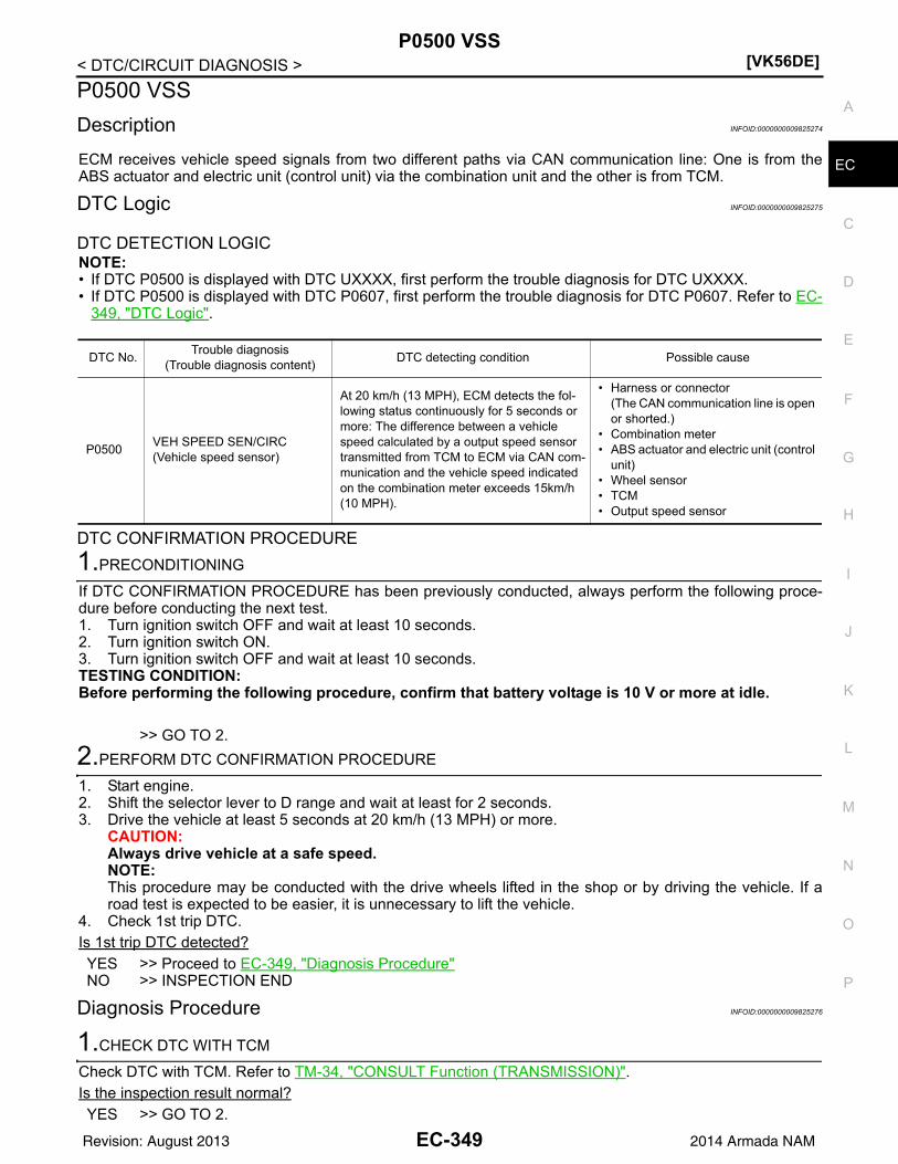
P0500 VSS[VK56DE]
C
D
E
F
G
H
I
J
K
L
M
A
C
N
P
O
< DTC/CIRCUIT DIAGNOSIS >
E
P0500 VSS
Description INFOID:0000000009825274
ECM receives vehicle speed signals from two different paths via CAN communication line: One is from theABS actuator and electric unit (control unit) via the combination unit and the other is from TCM.
DTC Logic INFOID:0000000009825275
DTC DETECTION LOGICNOTE:• If DTC P0500 is displayed with DTC UXXXX, first perform the trouble diagnosis for DTC UXXXX.• If DTC P0500 is displayed with DTC P0607, first perform the trouble diagnosis for DTC P0607. Refer to EC-
349, "DTC Logic".
DTC CONFIRMATION PROCEDURE
1.PRECONDITIONING
If DTC CONFIRMATION PROCEDURE has been previously conducted, always perform the following proce-dure before conducting the next test.1. Turn ignition switch OFF and wait at least 10 seconds.2. Turn ignition switch ON.3. Turn ignition switch OFF and wait at least 10 seconds.TESTING CONDITION:Before performing the following procedure, confirm that battery voltage is 10 V or more at idle.
>> GO TO 2.
2.PERFORM DTC CONFIRMATION PROCEDURE
1. Start engine.2. Shift the selector lever to D range and wait at least for 2 seconds.3. Drive the vehicle at least 5 seconds at 20 km/h (13 MPH) or more.
CAUTION:Always drive vehicle at a safe speed.NOTE:This procedure may be conducted with the drive wheels lifted in the shop or by driving the vehicle. If aroad test is expected to be easier, it is unnecessary to lift the vehicle.
4. Check 1st trip DTC.Is 1st trip DTC detected?YES >> Proceed to EC-349, "Diagnosis Procedure"NO >> INSPECTION END
Diagnosis Procedure INFOID:0000000009825276
1.CHECK DTC WITH TCM
Check DTC with TCM. Refer to TM-34, "CONSULT Function (TRANSMISSION)".Is the inspection result normal?YES >> GO TO 2.
DTC No.Trouble diagnosis
(Trouble diagnosis content)DTC detecting condition Possible cause
P0500VEH SPEED SEN/CIRC(Vehicle speed sensor)
At 20 km/h (13 MPH), ECM detects the fol-lowing status continuously for 5 seconds or more: The difference between a vehicle speed calculated by a output speed sensor transmitted from TCM to ECM via CAN com-munication and the vehicle speed indicated on the combination meter exceeds 15km/h (10 MPH).
• Harness or connector(The CAN communication line is open or shorted.)
• Combination meter• ABS actuator and electric unit (control
unit)• Wheel sensor• TCM• Output speed sensor
EC-349Revision: August 2013 2014 Armada NAM

[VK56DE]P0500 VSS
< DTC/CIRCUIT DIAGNOSIS >NO >> Perform trouble shooting relevant to DTC indicated.
2.CHECK DTC WITH ABS ACTUATOR AND ELECTRIC UNIT (CONTROL UNIT)
Check DTC with ABS actuator and electric unit (control unit). Refer to BRC-24, "CONSULT Function (ABS)".Is the inspection result normal?YES >> GO TO 3.NO >> Perform trouble shooting relevant to DTC indicated.
3.CHECK DTC WITH COMBINATION METER
Check DTC with combination meter. Refer to MWI-27, "CONSULT Function (METER/M&A)".Is the inspection result normal?YES >> GO TO 4.NO >> Perform trouble shooting relevant to DTC indicated.
4.CHECK OUTPUT SPEED SENSOR
Check output speed sensor. Refer to TM-53, "On Board Diagnosis Logic".Is the inspection result normal?YES >> GO TO 5.NO >> Replace or replace error-detected parts.
5.CHECK WHEEL SENSOR
Check wheel sensor. Refer to BRC-43, "Component Inspection".Is the inspection result normal?YES >> Check intermittent incident. Refer to GI-42, "Intermittent Incident".NO >> Replace or replace error-detected parts.
EC-350Revision: August 2013 2014 Armada NAM

P0506 ISC SYSTEM[VK56DE]
C
D
E
F
G
H
I
J
K
L
M
A
C
N
P
O
< DTC/CIRCUIT DIAGNOSIS >
E
P0506 ISC SYSTEM
Description INFOID:0000000009825277
NOTE:If DTC P0506 is displayed with other DTC, first perform the trouble diagnosis for the other DTC.The ECM controls the engine idle speed to a specified level through the fine adjustment of the air, which is letinto the intake manifold, by operating the electric throttle control actuator. The operating of the throttle valve isvaried to allow for optimum control of the engine idling speed. The crankshaft position sensor (POS) detectsthe actual engine speed and sends a signal to the ECM.The ECM controls the electric throttle control actuator so that the engine speed coincides with the target valuememorized in the ECM. The target engine speed is the lowest speed at which the engine can operate steadily.The optimum value stored in the ECM is determined by taking into consideration various engine conditions,such as during warming up, deceleration, and engine load (air conditioner, power steering and cooling fanoperation, etc.).
On Board Diagnosis Logic INFOID:0000000009825278
DTC Confirmation Procedure INFOID:0000000009825279
NOTE:• If DTC Confirmation Procedure has been previously conducted, always perform the following before con-
ducting the next step.1. Turn ignition switch OFF and wait at least 10 seconds.2. Turn ignition switch ON.3. Turn ignition switch OFF and wait at least 10 seconds.• If the target idle speed is out of the specified value, perform EC-128, "Idle Air Volume Learning",
before conducting DTC Confirmation Procedure. For the target idle speed, refer to the EC-498.TESTING CONDITION:• Before performing the following procedure, confirm that battery voltage is more than 11V at idle.• Always perform the test at a temperature above 10C (14F).1. Open engine hood.2. Start engine and warm it up to normal operating temperature.3. Turn ignition switch OFF and wait at least 10 seconds.4. Start engine and run it for at least 1 minute at idle speed.5. Check 1st trip DTC.6. If 1st trip DTC is detected, go to EC-351, "Diagnosis Procedure".
Diagnosis Procedure INFOID:0000000009825280
1.CHECK INTAKE AIR LEAK
1. Start engine and let it idle.2. Listen for an intake air leak after the mass air flow sensor.OK or NGOK >> GO TO 2.NG >> Discover air leak location and repair.
2.REPLACE ECM
1. Stop engine.2. Replace ECM.3. Perform initialization of NVIS(NATS) system and registration of all NVIS(NATS) ignition key IDs. Refer to
SEC-10, "ECM RE-COMMUNICATING FUNCTION : Special Repair Requirement" (With intelligent key
DTC No. Trouble diagnosis name DTC detecting condition Possible cause
P05060506
Idle speed control system RPM lower than expected
The idle speed is less than the target idle speed by 100 rpm or more.
• Electric throttle control actuator• Intake air leak
EC-351Revision: August 2013 2014 Armada NAM

[VK56DE]P0506 ISC SYSTEM
< DTC/CIRCUIT DIAGNOSIS >system) or SEC-128, "ECM RE-COMMUNICATING FUNCTION : Special Repair Requirement" (Withoutintelligent key system).
4. Perform EC-126, "VIN Registration".5. Perform EC-127, "Accelerator Pedal Released Position Learning".6. Perform EC-127, "Throttle Valve Closed Position Learning".7. <Flexible Fuel Vehicle>
Perform EC-127, "Ethanol Mixture Ratio Adaptation (Flexible Fuel Vehicle)".8. Perform EC-128, "Idle Air Volume Learning".
>> INSPECTION END
EC-352Revision: August 2013 2014 Armada NAM
P0507 ISC SYSTEM[VK56DE]
C
D
E
F
G
H
I
J
K
L
M
A
C
N
P
O
< DTC/CIRCUIT DIAGNOSIS >
E
P0507 ISC SYSTEM
Description INFOID:0000000009825281
NOTE:If DTC P0507 is displayed with other DTC, first perform the trouble diagnosis for the other DTC.The ECM controls the engine idle speed to a specified level through the fine adjustment of the air, which is letinto the intake manifold, by operating the electric throttle control actuator. The operating of the throttle valve isvaried to allow for optimum control of the engine idling speed. The crankshaft position sensor (POS) detectsthe actual engine speed and sends a signal to the ECM.The ECM controls the electric throttle control actuator so that the engine speed coincides with the target valuememorized in the ECM. The target engine speed is the lowest speed at which the engine can operate steadily.The optimum value stored in the ECM is determined by taking into consideration various engine conditions,such as during warming up, deceleration, and engine load (air conditioner, power steering and cooling fanoperation, etc.).
On Board Diagnosis Logic INFOID:0000000009825282
DTC Confirmation Procedure INFOID:0000000009825283
NOTE:• If DTC Confirmation Procedure has been previously conducted, always perform the following before con-
ducting the next step.1. Turn ignition switch OFF and wait at least 10 seconds.2. Turn ignition switch ON.3. Turn ignition switch OFF and wait at least 10 seconds.• If the target idle speed is out of the specified value, perform EC-128, "Idle Air Volume Learning",
before conducting DTC Confirmation Procedure. For the target idle speed, refer to the EC-498.TESTING CONDITION:• Before performing the following procedure, confirm that battery voltage is more than 11 V at idle.• Always perform the test at a temperature above 10C (14F).1. Open engine hood.2. Start engine and warm it up to normal operating temperature.3. Turn ignition switch OFF and wait at least 10 seconds.4. Start engine and run it for at least 1 minute at idle speed.5. Check 1st trip DTC.6. If 1st trip DTC is detected, go to EC-353, "Diagnosis Procedure".
Diagnosis Procedure INFOID:0000000009825284
1.CHECK PCV HOSE CONNECTION
Confirm that PCV hose is connected correctly.OK or NGOK >> GO TO 2.NG >> Repair or replace.
2.CHECK INTAKE AIR LEAK
1. Start engine and let it idle.2. Listen for an intake air leak after the mass air flow sensor.OK or NGOK >> GO TO 3.NG >> Discover air leak location and repair.
DTC No. Trouble diagnosis name DTC detecting condition Possible cause
P05070507
Idle speed control system RPM higher than expected
The idle speed is more than the target idle speed by 200 rpm or more.
• Electric throttle control actuator• Intake air leak• PCV system
EC-353Revision: August 2013 2014 Armada NAM

[VK56DE]P0507 ISC SYSTEM
< DTC/CIRCUIT DIAGNOSIS >
3.REPLACE ECM
1. Stop engine.2. Replace ECM.3. Perform initialization of NVIS(NATS) system and registration of all NVIS(NATS) ignition key IDs. Refer to
SEC-10, "ECM RE-COMMUNICATING FUNCTION : Special Repair Requirement" (With intelligent keysystem) or SEC-128, "ECM RE-COMMUNICATING FUNCTION : Special Repair Requirement" (Withoutintelligent key system).
4. Perform EC-126, "VIN Registration".5. Perform EC-127, "Accelerator Pedal Released Position Learning".6. Perform EC-127, "Throttle Valve Closed Position Learning".7. <Flexible Fuel Vehicle>
Perform EC-127, "Ethanol Mixture Ratio Adaptation (Flexible Fuel Vehicle)".8. Perform EC-128, "Idle Air Volume Learning".
>> INSPECTION END
EC-354Revision: August 2013 2014 Armada NAM

P050A, P050B, P050E COLD START CONTROL[VK56DE]
C
D
E
F
G
H
I
J
K
L
M
A
C
N
P
O
< DTC/CIRCUIT DIAGNOSIS >
E
P050A, P050B, P050E COLD START CONTROL
Description INFOID:0000000009825285
ECM controls ignition timing and engine idle speed when engine is started with pre-warming up condition.This control promotes the activation of three way catalyst by heating the catalyst and reduces emissions.
DTC Logic INFOID:0000000009825286
DTC DETECTION LOGICNOTE:If DTC P050A, P050B or P050E is displayed with other DTC, first perform the trouble diagnosis forother DTC.
DTC CONFIRMATION PROCEDURE
1.PRECONDITIONING
If DTC Confirmation Procedure has been previously conducted, always perform the following procedurebefore conducting the next test.1. Turn ignition switch OFF and wait at least 10 seconds.2. Turn ignition switch ON.3. Turn ignition switch OFF and wait at least 10 seconds.TESTING CONDITION:Before performing the following procedure, confirm that battery voltage is 11 V or more at idle.
>> GO TO 2.
2.PERFORM DTC CONFIRMATION PROCEDURE-I
WITH CONSULT1. Turn ignition switch OFF and wait at least 10 seconds.2. Turn ignition switch ON.3. Select “DATA MONITOR” mode with CONSULT.4. Check the indication of “COOLAN TEMP/S”.
WITH GSTFollow the procedure “With CONSULT” above.Is the value of “COOLAN TEMP/S” between 5C (41F) and 36C (97F)?YES >> GO TO 3.NO-1 [If it is below 5C (41F)]>>Warm up the engine until the value of “COOLAN TEMP/S” reaches 5C
(41F) or more. Retry from step 1.NO-2 [If it is above 36C (97F)]>>Cool engine down to less than 36C (97F). Retry from step 1.
3.PERFORM DTC CONFIRMATION PROCEDURE-II
WITH CONSULT1. Set the select lever in N range.2. Start the engine and warm up in idle with the value of “COOLAN TEMP/S” between 5C (41F) and 40C
(104F) for more than 15 seconds.3. Check 1st trip DTC.
DTC No. Trouble diagnosis name DTC detecting condition Possible cause
P050ACold start idle air control system performance
ECM does not control engine idle speed properly when engine is started with pre-warming up con-dition.
• Lack of intake air volume• Fuel injection system• ECM
P050BCold start ignition timing perfor-mance
ECM does not control engine timing properly when engine is started with pre-warming up con-dition.
P050ECold start engine exhaust temper-ature too low
The temperature of the catalyst inlet does not rise to the proper temperature when the engine is started with pre-warming up condition.
EC-355Revision: August 2013 2014 Armada NAM

[VK56DE]P050A, P050B, P050E COLD START CONTROL
< DTC/CIRCUIT DIAGNOSIS >
WITH GSTFollow the procedure “With CONSULT” above.Is 1st trip DTC detected?YES >> Proceed to EC-356, "Diagnosis Procedure".NO >> INSPECTION END
Diagnosis Procedure INFOID:0000000009825287
1.PERFORM IDLE AIR VOLUME LEARNING
Perform EC-128, "Idle Air Volume Learning".Is Idle Air Volume Learning carried out successfully?YES >> GO TO 2.NO >> Follow the instruction of Idle Air Volume Learning.
2.CHECK INTAKE SYSTEM
Check for the cause of intake air volume lacking. Refer to the following.• Crushed intake air passage• Intake air passage clogging• Clogging of throttle bodyIs the inspection result normal?YES >> GO TO 3.NO >> Repair or replace malfunctioning part
3.CHECK FUEL INJECTION SYSTEM FUNCTION
Perform DTC Confirmation Procedure for DTC P0171, P0174. Refer to EC-242, "On Board Diagnosis Logic".Is the inspection result normal?YES >> GO TO 4.NO >> Proceed to EC-243, "Diagnosis Procedure" for DTC P0171, P0174.
4.PERFORM DTC CONFIRMATION PROCEDURE
1. Turn ignition switch ON.2. Erase DTC.3. Perform DTC Confirmation Procedure.
See EC-355, "DTC Logic".Is the 1st trip DTC P050A, P050B or P050E displayed again?YES >> GO TO 5.NO >> INSPECTION END
5.REPLACE ECM
Replace ECM. Refer to EC-16, "Engine Control Component Parts Location" and EC-124, "Procedure AfterReplacing ECM".
>> INSPECTION END
EC-356Revision: August 2013 2014 Armada NAM

P0550 PSP SENSOR[VK56DE]
C
D
E
F
G
H
I
J
K
L
M
A
C
N
P
O
< DTC/CIRCUIT DIAGNOSIS >
E
P0550 PSP SENSOR
Component Description INFOID:0000000009825288
Power steering pressure (PSP) sensor (1) is installed to the powersteering high-pressure tube and detects a power steering load. Thissensor is a potentiometer which transforms the power steering loadinto output voltage, and emits the voltage signal to the ECM. TheECM controls the electric throttle control actuator and adjusts thethrottle valve opening angle to increase the engine speed andadjusts the idle speed for the increased load.
On Board Diagnosis Logic INFOID:0000000009825289
The MIL will not light up for this self-diagnosis.NOTE:If DTC P0550 is displayed with DTC P0643, first perform the trouble diagnosis for DTC P0643. Refer toEC-367.
DTC Confirmation Procedure INFOID:0000000009825290
1. If DTC Confirmation Procedure has been previously conducted, always perform the following before con-ducting the next step.
a. Turn ignition switch OFF and wait at least 10 seconds.b. Turn ignition switch ON.c. Turn ignition switch OFF and wait at least 10 seconds.2. Start engine and let it idle for at least 5 seconds.3. Check 1st trip DTC.4. If 1st trip DTC is detected, go to EC-357, "Diagnosis Procedure".
Diagnosis Procedure INFOID:0000000009825291
1.CHECK GROUND CONNECTIONS
1. Turn ignition switch OFF.2. Loosen and retighten three ground screws on the body.
Refer to EC-153, "Ground Inspection".
OK or NGOK >> GO TO 2.NG >> Repair or replace ground connections.
BBIA0741E
DTC No. Trouble diagnosis name DTC detecting condition Possible cause
P05500550
Power steering pressure sensor circuit
An excessively low or high voltage from the sensor is sent to ECM.
• Harness or connectors(The sensor circuit is open or shorted)
• Power steering pressure sensor
BBIA0354E
EC-357Revision: August 2013 2014 Armada NAM

[VK56DE]P0550 PSP SENSOR
< DTC/CIRCUIT DIAGNOSIS >
2.CHECK PSP SENSOR POWER SUPPLY CIRCUIT
1. Disconnect power steering pressure (PSP) sensor (1) harnessconnector.
2. Turn ignition switch ON.
3. Check voltage between PSP sensor terminal 1 and ground withCONSULT or tester.
OK or NGOK >> GO TO 3.NG >> Repair harness or connectors.
3.CHECK PSP SENSOR GROUND CIRCUIT FOR OPEN AND SHORT
1. Turn ignition switch OFF.2. Disconnect ECM harness connector.3. Check harness continuity between PSP sensor terminal 3 and ECM terminal 67.
Refer to Wiring Diagram.
4. Also check harness for short to ground and short to power.OK or NGOK >> GO TO 4.NG >> Repair open circuit or short to ground or short to power in harness or connectors.
4.CHECK PSP SENSOR INPUT SIGNAL CIRCUIT FOR OPEN AND SHORT
1. Check harness continuity between ECM terminal 12 and PSP sensor terminal 2.
2. Also check harness for short to ground and short to power.OK or NGOK >> GO TO 5.NG >> Repair open circuit or short to ground or short to power in harness or connectors.
5.CHECK PSP SENSOR
Refer to EC-359, "Component Inspection".OK or NGOK >> GO TO 6.NG >> Replace PSP sensor. Refer to ST-18.
6.CHECK INTERMITTENT INCIDENT
Refer to GI-39, "How to Check Terminal" and GI-42, "Intermittent Incident".
>> INSPECTION END
BBIA0741E
Voltage: Approximately 5 V
PBIB0188E
Continuity should exist.
Continuity should exist.
EC-358Revision: August 2013 2014 Armada NAM

P0550 PSP SENSOR[VK56DE]
C
D
E
F
G
H
I
J
K
L
M
A
C
N
P
O
< DTC/CIRCUIT DIAGNOSIS >
E
Component Inspection INFOID:0000000009825292
POWER STEERING PRESSURE SENSOR1. Reconnect all harness connectors disconnected.2. Start engine and let it idle.3. Check voltage between ECM terminal 12 and ground under the
following conditions.
Condition Voltage
Steering wheel: Being turned. 0.5 - 4.5 V
Steering wheel: Not being turned. 0.4 - 0.8 V
MBIB0126E
EC-359Revision: August 2013 2014 Armada NAM

[VK56DE]P0603 ECM
< DTC/CIRCUIT DIAGNOSIS >
P0603 ECM
DTC Logic INFOID:0000000010129299
DTC DETECTION LOGIC
DTC CONFIRMATION PROCEDURE
1.PRECONDITIONING
TESTING CONDITION:Before performing the following procedure, confirm that battery voltage is 11 V or more with ignitionswitch ON.
>> GO TO 2.
2.PERFORM DTC CONFIRMATION PROCEDURE
1. Turn ignition switch ON and wait at least 1 second.2. Turn ignition switch OFF and wait at least 10 seconds.3. Repeat step 1 and 2 for 10 times.4. Turn ignition switch ON.5. Check 1st trip DTC.Is 1st trip DTC detected?YES >> Proceed to EC-360, "Diagnosis Procedure".NO >> INSPECTION END
Diagnosis Procedure INFOID:0000000010129300
1.CHECK ECM POWER SUPPLY AND GROUND CIRCUIT
Perform trouble diagnosis for ECM power supply and ground circuit. Refer to GI-39, "How to Check Terminal".Is the inspection result normal?YES >> GO TO 2.NO >> Repair or replace error-detected parts.
2.CHECK INTERMITTENT INCIDENT
Check intermittent incident. Refer to GI-42, "Intermittent Incident".Is the inspection result normal?YES >> GO TO 3.NO >> Repair or replace error-detected parts.
3.PERFORM DTC CONFIRMATION PROCEDURE
1. Turn ignition switch ON.2. Erase DTC.3. Perform DTC confirmation procedure. Refer to EC-360, "DTC Logic".Is the 1st trip DTC P0603 displayed again?YES >> Replace ECM.NO >> INSPECTION END
DTC No.CONSULT screen terms
(Trouble diagnosis content)DTC detecting condition Possible cause
P0603ECM BACK UP CIRCUIT[Internal control module keep alive memory (KAM) error]
• Malfunction in the internal back up RAM of ECM.• Malfunction in the internal EEP-ROM system of
ECM.
• ECM power supply• ECM
EC-360Revision: August 2013 2014 Armada NAM

P0604 ECM[VK56DE]
C
D
E
F
G
H
I
J
K
L
M
A
C
N
P
O
< DTC/CIRCUIT DIAGNOSIS >
E
P0604 ECM
DTC Logic INFOID:0000000010129301
DTC DETECTION LOGIC
DTC CONFIRMATION PROCEDURE
1.PRECONDITIONING
1. Turn ignition switch OFF and wait at least 10 seconds.2. Turn ignition switch ON.3. Turn ignition switch OFF and wait at least 10 seconds.TESTING CONDITION:Before performing the following procedure, confirm that battery voltage is 11 V or more with ignitionswitch ON.
>> GO TO 2.
2.PERFORM DTC CONFIRMATION PROCEDURE
1. Turn ignition switch ON (engine stopped) and wait least 20 minutes.CAUTION:Never start engine during this procedure.
2. Turn ignition switch OFF and wait at least 10 seconds.3. Turn ignition switch ON.4. Check 1st trip DTC.Is 1st trip DTC detected?YES >> Proceed to EC-361, "Diagnosis Procedure".NO >> INSPECTION END
Diagnosis Procedure INFOID:0000000010129302
1.PERFORM DTC CONFIRMATION PROCEDURE
1. Turn ignition switch ON.2. Erase DTC.3. Perform DTC confirmation procedure. Refer to EC-361, "DTC Logic".Is the 1st trip DTC P0604 displayed again?YES >> Replace ECM.NO >> INSPECTION END
DTC No.CONSULT screen terms
(Trouble diagnosis content)DTC detecting condition Possible cause
P0604
ECM[Internal control module random access memory (RAM) error]
Malfunction in the internal RAM of ECM. ECM
EC-361Revision: August 2013 2014 Armada NAM

[VK56DE]P0605 ECM
< DTC/CIRCUIT DIAGNOSIS >
P0605 ECM
DTC Logic INFOID:0000000010129303
DTC DETECTION LOGIC
DTC CONFIRMATION PROCEDURE
1.PRECONDITIONING
1. Turn ignition switch OFF and wait at least 10 seconds.2. Turn ignition switch ON.3. Turn ignition switch OFF and wait at least 10 seconds.TESTING CONDITION:Before performing the following procedure, confirm that battery voltage is 11 V or more with ignitionswitch ON.
>> GO TO 2.
2.PERFORM DTC CONFIRMATION PROCEDURE
1. Turn ignition switch ON (engine stopped) and wait least 20 minutes.CAUTION:Never start engine during this procedure.
2. Turn ignition switch OFF and wait at least 10 seconds.3. Turn ignition switch ON.4. Check 1st trip DTC.Is 1st trip DTC detected?YES >> Proceed to EC-362, "Diagnosis Procedure".NO >> INSPECTION END
Diagnosis Procedure INFOID:0000000010129304
1.PERFORM DTC CONFIRMATION PROCEDURE
1. Turn ignition switch ON.2. Erase DTC.3. Perform DTC confirmation procedure. Refer to EC-362, "DTC Logic".Is the 1st trip DTC P0605 displayed again?YES >> Replace ECM.NO >> INSPECTION END
DTC No.CONSULT screen terms
(Trouble diagnosis content)DTC detecting condition Possible cause
P0605
ECM[Internal control module read only memory (ROM) error]
Malfunction in the internal ROM of ECM. ECM
EC-362Revision: August 2013 2014 Armada NAM

P0606 ECM[VK56DE]
C
D
E
F
G
H
I
J
K
L
M
A
C
N
P
O
< DTC/CIRCUIT DIAGNOSIS >
E
P0606 ECM
DTC Logic INFOID:0000000010129305
DTC DETECTION LOGIC
DTC CONFIRMATION PROCEDURE
1.PRECONDITIONING
1. Turn ignition switch OFF and wait at least 10 seconds.2. Turn ignition switch ON.3. Turn ignition switch OFF and wait at least 10 seconds.TESTING CONDITION:Before performing the following procedure, confirm that battery voltage is 11 V or more with ignitionswitch ON.
>> GO TO 2.
2.PERFORM DTC CONFIRMATION PROCEDURE-I
1. Turn ignition switch ON (engine stopped) and wait at least 10 seconds.CAUTION:Never start engine during this procedure.
2. Turn ignition switch OFF and wait at least 10 seconds.3. Turn ignition switch ON.4. Check 1st trip DTC.Is 1st trip DTC detected?YES >> Proceed to EC-363, "Diagnosis Procedure".NO >> GO TO 3.
3.PERFORM DTC CONFIRMATION PROCEDURE-II
1. Start engine.2. Rev up the engine quickly to approximately 3,000 rpm under unloaded condition and completely release
the accelerator pedal.3. Let the engine idle and wait at least 10 seconds.4. Turn ignition switch OFF and wait at least 10 seconds.5. Turn ignition switch ON.6. Check 1st trip DTC.Is 1st trip DTC detected?YES >> Proceed to EC-363, "Diagnosis Procedure".NO >> INSPECTION END
Diagnosis Procedure INFOID:0000000010129306
1.PERFORM DTC CONFIRMATION PROCEDURE
1. Turn ignition switch ON.2. Erase DTC.3. Perform DTC confirmation procedure for 3 times. Refer to EC-363, "DTC Logic".Is the 1st trip DTC P0606 displayed again?YES >> Replace ECM.NO >> INSPECTION END
DTC No.CONSULT screen terms
(Trouble diagnosis content)DTC detecting condition Possible cause
P0606CONTROL MODULE(Control module processor)
Malfunction in ECM processor. ECM
EC-363Revision: August 2013 2014 Armada NAM
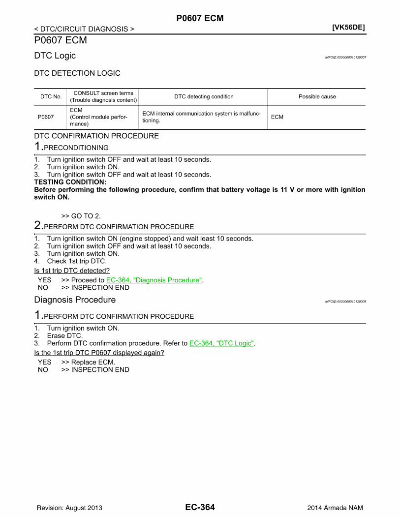
[VK56DE]P0607 ECM
< DTC/CIRCUIT DIAGNOSIS >
P0607 ECM
DTC Logic INFOID:0000000010129307
DTC DETECTION LOGIC
DTC CONFIRMATION PROCEDURE
1.PRECONDITIONING
1. Turn ignition switch OFF and wait at least 10 seconds.2. Turn ignition switch ON.3. Turn ignition switch OFF and wait at least 10 seconds.TESTING CONDITION:Before performing the following procedure, confirm that battery voltage is 11 V or more with ignitionswitch ON.
>> GO TO 2.
2.PERFORM DTC CONFIRMATION PROCEDURE
1. Turn ignition switch ON (engine stopped) and wait least 10 seconds.2. Turn ignition switch OFF and wait at least 10 seconds.3. Turn ignition switch ON.4. Check 1st trip DTC.Is 1st trip DTC detected?YES >> Proceed to EC-364, "Diagnosis Procedure".NO >> INSPECTION END
Diagnosis Procedure INFOID:0000000010129308
1.PERFORM DTC CONFIRMATION PROCEDURE
1. Turn ignition switch ON.2. Erase DTC.3. Perform DTC confirmation procedure. Refer to EC-364, "DTC Logic".Is the 1st trip DTC P0607 displayed again?YES >> Replace ECM.NO >> INSPECTION END
DTC No.CONSULT screen terms
(Trouble diagnosis content)DTC detecting condition Possible cause
P0607ECM(Control module perfor-mance)
ECM internal communication system is malfunc-tioning.
ECM
EC-364Revision: August 2013 2014 Armada NAM

P060A ECM[VK56DE]
C
D
E
F
G
H
I
J
K
L
M
A
C
N
P
O
< DTC/CIRCUIT DIAGNOSIS >
E
P060A ECM
DTC Logic INFOID:0000000010129309
DTC DETECTION LOGIC
DTC CONFIRMATION PROCEDURE
1.PRECONDITIONING
1. Turn ignition switch OFF and wait at least 10 seconds.2. Turn ignition switch ON.3. Turn ignition switch OFF and wait at least 10 seconds.TESTING CONDITION:Before performing the following procedure, confirm that battery voltage is 11 V or more with ignitionswitch ON.
>> GO TO 2.
2.PERFORM DTC CONFIRMATION PROCEDURE
1. Start engine and wait at least 10 seconds.2. Turn ignition switch OFF and wait at least 10 seconds.3. Repeat step 1 and 2 for 5 times.4. Turn ignition switch ON.5. Check 1st trip DTC.Is 1st trip DTC detected?YES >> Proceed to EC-365, "Diagnosis Procedure".NO >> INSPECTION END
Diagnosis Procedure INFOID:0000000010129310
1.PERFORM DTC CONFIRMATION PROCEDURE
1. Turn ignition switch ON.2. Erase DTC.3. Perform DTC confirmation procedure. Refer to EC-365, "DTC Logic".Is the 1st trip DTC P060A displayed again?YES >> Replace ECM.NO >> INSPECTION END
DTC No.CONSULT screen terms
(Trouble diagnosis content)DTC detecting condition Possible cause
P060A
CONTROL MODULE(Internal control module monitoring processor per-formance)
ECM internal monitoring processor is malfunction-ing.
ECM
EC-365Revision: August 2013 2014 Armada NAM

[VK56DE]P060B ECM
< DTC/CIRCUIT DIAGNOSIS >
P060B ECM
DTC Logic INFOID:0000000010129311
DTC DETECTION LOGIC
DTC CONFIRMATION PROCEDURE
1.PRECONDITIONING
1. Turn ignition switch OFF and wait at least 10 seconds.2. Turn ignition switch ON.3. Turn ignition switch OFF and wait at least 10 seconds.TESTING CONDITION:Before performing the following procedure, confirm that battery voltage is 11 V or more with ignitionswitch ON.
>> GO TO 2.
2.PERFORM DTC CONFIRMATION PROCEDURE
1. Turn ignition switch ON (engine stopped) and wait least 10 seconds.2. Turn ignition switch OFF and wait at least 10 seconds.3. Turn ignition switch ON.4. Check 1st trip DTC.Is 1st trip DTC detected?YES >> Proceed to EC-366, "Diagnosis Procedure".NO >> INSPECTION END
Diagnosis Procedure INFOID:0000000010129312
1.PERFORM DTC CONFIRMATION PROCEDURE
1. Turn ignition switch ON.2. Erase DTC.3. Perform DTC confirmation procedure. Refer to EC-366, "DTC Logic".Is the 1st trip DTC P060B displayed again?YES >> Replace ECM.NO >> INSPECTION END
DTC No.CONSULT screen terms
(Trouble diagnosis content)DTC detecting condition Possible cause
P060BCONTROL MODULE(Internal control module A/D processing performance)
ECM internal analog/digital conversion processing system is malfunctioning.
ECM
EC-366Revision: August 2013 2014 Armada NAM

P0643 SENSOR POWER SUPPLY[VK56DE]
C
D
E
F
G
H
I
J
K
L
M
A
C
N
P
O
< DTC/CIRCUIT DIAGNOSIS >
E
P0643 SENSOR POWER SUPPLY
On Board Diagnosis Logic INFOID:0000000009825305
This self-diagnosis has the one trip detection logic.
FAIL-SAFE MODEWhen the malfunction is detected, ECM enters fail-safe mode and the MIL lights up.
DTC Confirmation Procedure INFOID:0000000009825306
NOTE:If DTC Confirmation Procedure has been previously conducted, always perform the following before conduct-ing the next step.1. Turn ignition switch OFF and wait at least 10 seconds.2. Turn ignition switch ON.3. Turn ignition switch OFF and wait at least 10 seconds.TESTING CONDITION:Before performing the following procedure, confirm that battery voltage is more than 10 V at idle.1. Start engine and let it idle for 1 second.2. Check DTC.3. If DTC is detected, go to EC-367, "Diagnosis Procedure".
Diagnosis Procedure INFOID:0000000009825307
1.CHECK GROUND CONNECTIONS
1. Turn ignition switch OFF.2. Loosen and retighten three ground screws on the body.
Refer to EC-153, "Ground Inspection".
OK or NGOK >> GO TO 2.
DTC No. Trouble diagnosis name DTC detecting condition Possible cause
P06430643
Sensor power supply circuit short
ECM detects a voltage of power source for sensor is excessively low or high.
• Harness or connectors(APP sensor 1 circuit is shorted.)(PSP sensor circuit is shorted.)(Battery current sensor circuit is shorted.)(Refrigerant pressure sensor circuit is short-ed.)(EVAP control system pressure sensor circuit is shorted.)
• Accelerator pedal position sensor• Power steering pressure sensor• Refrigerant pressure sensor• EVAP control system pressure sensor
Engine operation condition in fail-safe mode
ECM stops the electric throttle control actuator control, throttle valve is maintained at a fixed opening (approx. 5 degrees) by the return spring.
BBIA0354E
EC-367Revision: August 2013 2014 Armada NAM
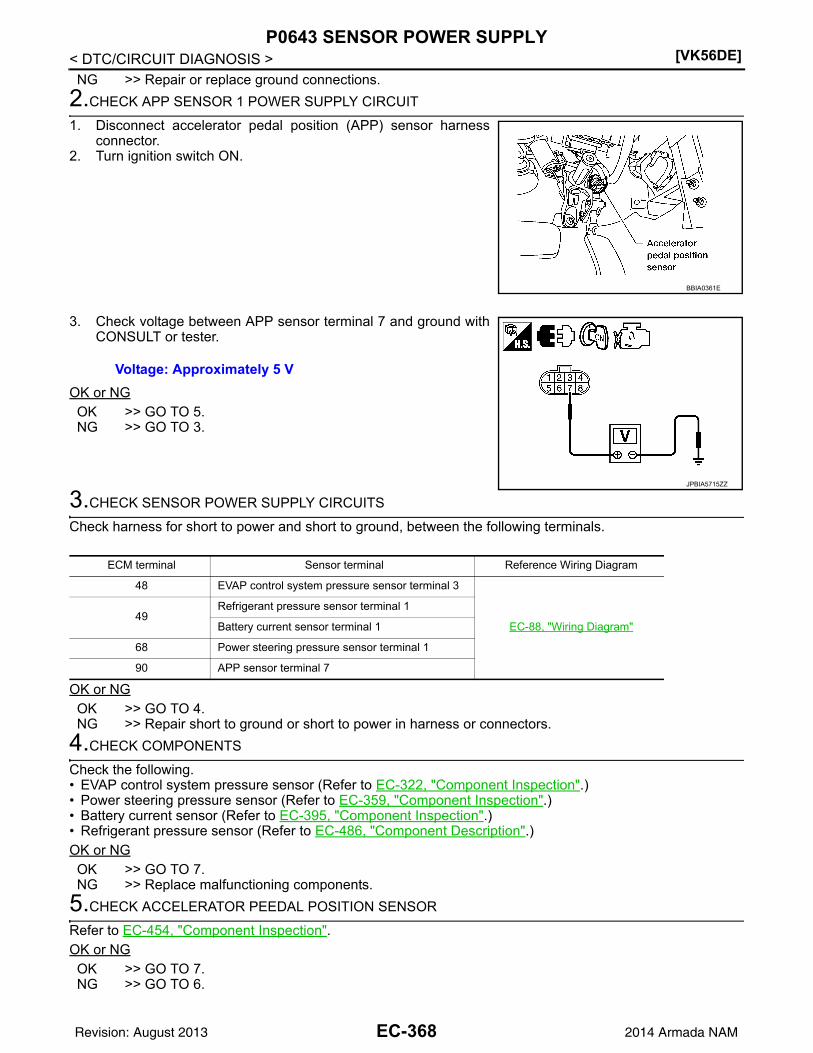
[VK56DE]P0643 SENSOR POWER SUPPLY
< DTC/CIRCUIT DIAGNOSIS >NG >> Repair or replace ground connections.
2.CHECK APP SENSOR 1 POWER SUPPLY CIRCUIT
1. Disconnect accelerator pedal position (APP) sensor harnessconnector.
2. Turn ignition switch ON.
3. Check voltage between APP sensor terminal 7 and ground withCONSULT or tester.
OK or NGOK >> GO TO 5.NG >> GO TO 3.
3.CHECK SENSOR POWER SUPPLY CIRCUITS
Check harness for short to power and short to ground, between the following terminals.
OK or NGOK >> GO TO 4.NG >> Repair short to ground or short to power in harness or connectors.
4.CHECK COMPONENTS
Check the following.• EVAP control system pressure sensor (Refer to EC-322, "Component Inspection".)• Power steering pressure sensor (Refer to EC-359, "Component Inspection".)• Battery current sensor (Refer to EC-395, "Component Inspection".)• Refrigerant pressure sensor (Refer to EC-486, "Component Description".)OK or NGOK >> GO TO 7.NG >> Replace malfunctioning components.
5.CHECK ACCELERATOR PEEDAL POSITION SENSOR
Refer to EC-454, "Component Inspection".OK or NGOK >> GO TO 7.NG >> GO TO 6.
BBIA0361E
Voltage: Approximately 5 V
JPBIA5715ZZ
ECM terminal Sensor terminal Reference Wiring Diagram
48 EVAP control system pressure sensor terminal 3
EC-88, "Wiring Diagram"49
Refrigerant pressure sensor terminal 1
Battery current sensor terminal 1
68 Power steering pressure sensor terminal 1
90 APP sensor terminal 7
EC-368Revision: August 2013 2014 Armada NAM

P0643 SENSOR POWER SUPPLY[VK56DE]
C
D
E
F
G
H
I
J
K
L
M
A
C
N
P
O
< DTC/CIRCUIT DIAGNOSIS >
E
6.REPLACE ACCELERATOR PEDAL ASSEMBLY
1. Replace accelerator pedal position assembly. Refer to ACC-4.2. Perform EC-127, "Accelerator Pedal Released Position Learning".3. Perform EC-127, "Throttle Valve Closed Position Learning".4. Perform EC-128, "Idle Air Volume Learning".
>> INSPECTION END
7.CHECK INTERMITTENT INCIDENT
Refer to GI-39, "How to Check Terminal" and GI-42, "Intermittent Incident".
>> INSPECTION END
EC-369Revision: August 2013 2014 Armada NAM

[VK56DE]P0850 PNP SWITCH
< DTC/CIRCUIT DIAGNOSIS >
P0850 PNP SWITCH
Component Description INFOID:0000000009825308
When the selector lever position is P or N, park/neutral position (PNP) signal from the TCM is sent to ECM.When the gear position is P or N, transmission range switch is ON.
On Board Diagnosis Logic INFOID:0000000009825309
DTC Confirmation Procedure INFOID:0000000009825310
CAUTION:Always drive vehicle at a safe speed.NOTE:If DTC Confirmation Procedure has been previously conducted, always perform the following before conduct-ing the next step.1. Turn ignition switch OFF and wait at least 10 seconds.2. Turn ignition switch ON.3. Turn ignition switch OFF and wait at least 10 seconds.
WITH CONSULT1. Turn ignition switch ON.2. Select “P/N POSI SW” in “DATA MONITOR” mode with CONSULT. Then check the “P/N POSI SW” signal
under the following conditions.
If NG, go to EC-371, "Diagnosis Procedure".If OK, go to following step.
3. Select “DATA MONITOR” mode with CONSULT.4. Start engine and warm it up to normal operating temperature.5. Maintain the following conditions for at least 60 consecutive seconds.
6. Check 1st trip DTC.7. If 1st trip DTC is detected, go to EC-371, "Diagnosis Procedure".
Overall Function Check INFOID:0000000009825311
Use this procedure to check the overall function of the park/neutral position (PNP) signal circuit. During thischeck, a 1st trip DTC might not be confirmed.
WITH GST
DTC No. Trouble diagnosis name DTC detecting condition Possible cause
P08500850
Park/neutral position switch
The signal of the park/neutral position (PNP) signal is not changed in the process of engine starting and driving.
• Harness or connectors[The park/neutral position (PNP) signal circuit is open or shorted.]
• Combination meter• TCM
Position (Selector lever) Known-good signal
N or P position ON
Except the above position OFF
ENG SPEED 1,000 - 6,375 rpm
COOLAN TEMP/S More than 70C (158F)
B/FUEL SCHDL 2.0 - 31.8 msec
VHCL SPEED SE More than 64 km/h (40 MPH)
Selector lever Suitable position
EC-370Revision: August 2013 2014 Armada NAM

P0850 PNP SWITCH[VK56DE]
C
D
E
F
G
H
I
J
K
L
M
A
C
N
P
O
< DTC/CIRCUIT DIAGNOSIS >
E
1. Turn ignition switch ON.2. Check voltage between ECM terminal 102 (PNP signal) and
ground under the following conditions.
3. If NG, go to EC-371, "Diagnosis Procedure".
Diagnosis Procedure INFOID:0000000009825312
1.CHECK DTC WITH TCM
Refer to TM-32, "OBD-II Diagnostic Trouble Code (DTC)".OK or NGOK >> GO TO 2.NG >> Repair or replace.
2.CHECK STARTING SYSTEM
Turn ignition switch OFF, then turn it to START.Does starter motor operate?Yes or NoYes >> GO TO 3.No >> Refer to STR-11, "System Diagram".
3.CHECK PNP SWITCH INPUT SIGNAL CIRCUIT FOR OPEN AND SHORT-I
1. Turn ignition switch OFF.2. Disconnect A/T assembly harness connector.3. Disconnect combination meter harness connector.4. Check harness continuity between A/T assembly terminal 9 and combination meter terminal 39.
Refer to Wiring Diagram.
5. Also check harness for short to ground and short to power.OK or NGOK >> GO TO 5.NG >> GO TO 4.
4.DETECT MALFUNCTIONING PART
Check the following.• Harness connectors F14, E5• Harness connectors E152, M31• Harness for open or short between A/T assembly and combination meter
>> Repair open circuit or short to ground or short to power in harness or connectors.
5.CHECK PNP SWITCH INPUT SIGNAL CIRCUIT FOR OPEN AND SHORT-II
1. Disconnect ECM harness connector.2. Check harness continuity between ECM terminal 102 and combination meter terminal 40.
Refer to Wiring Diagram.
3. Also check harness for short to ground and short to power.OK or NG
Condition (Gear position) Voltage (Known good data)
P or N position Approx. 0
Except the above positionBATTERY VOLTAGE
(11 - 14 V)
MBIB0043E
Continuity should exist.
Continuity should exist.
EC-371Revision: August 2013 2014 Armada NAM

[VK56DE]P0850 PNP SWITCH
< DTC/CIRCUIT DIAGNOSIS >OK >> GO TO 7.NG >> GO TO 6.
6.DETECT MALFUNCTIONING PART
Check the following.• Harness connectors M31, E152• Harness for open or short between ECM and combination meter
>> Repair open circuit or short to ground or short to power in harness or connectors.
7.CHECK PNP SWITCH INPUT SIGNAL CIRCUIT FOR OPEN AND SHORT-III
1. Check harness continuity between A/T assembly terminal 9 and TCM terminal 8.Refer to Wiring Diagram.
2. Also check harness for short to ground and short to power.OK or NGOK >> GO TO 8.NG >> Repair open circuit or short to ground or short to power in harness or connectors.
8.CHECK INTERMITTENT INCIDENT
Refer to GI-39, "How to Check Terminal" and GI-42, "Intermittent Incident".OK or NGOK >> GO TO 9.NG >> Repair or replace.
9.REPLACE COMBINATION METER
Refer to MWI-98, "Removal and Installation".
>> INSPECTION END
Continuity should exist.
EC-372Revision: August 2013 2014 Armada NAM

P1140, P1145 IVT CONTROL POSITION SENSOR[VK56DE]
C
D
E
F
G
H
I
J
K
L
M
A
C
N
P
O
< DTC/CIRCUIT DIAGNOSIS >
E
P1140, P1145 IVT CONTROL POSITION SENSOR
Component Description INFOID:0000000009825313
Intake valve timing control position sensors are located in the front ofcylinder heads in both bank 1 and bank 2.This sensor uses a Hall IC.The cam position is determined by the intake camshaft sprocket con-cave (in four places). The ECM provides feedback to the intake valvetiming control for appropriate target valve open-close timing accord-ing to drive conditions based on detected cam position.
On Board Diagnosis Logic INFOID:0000000009825314
DTC Confirmation Procedure INFOID:0000000009825315
1. If DTC Confirmation Procedure has been previously conducted, always perform the following before con-ducting the next step.
a. Turn ignition switch OFF and wait at least 10 seconds.b. Turn ignition switch ON.c. Turn ignition switch OFF and wait at least 10 seconds.2. Turn ignition switch ON.3. Maintain the following conditions for at least 10 seconds.
4. Check 1st trip DTC.5. If 1st trip DTC is detected, go to EC-373, "Diagnosis Procedure".
Diagnosis Procedure INFOID:0000000009825316
1.CHECK GROUND CONNECTIONS
1. Turn ignition switch OFF.2. Loosen and retighten three ground screws on the body.
SEF359Z
DTC No. Trouble diagnosis name DTC detecting condition Possible cause
P11401140(Bank 1)
Intake valve timing control position sensor circuit
An excessively high or low voltage from the sensor is sent to ECM.
• Harness or connectors(Intake valve timing control position sensor circuit is open or shorted)
• Intake valve timing control position sensor
• Crankshaft position sensor (POS)• Camshaft position sensor (PHASE)• Accumulation of debris to the signal
pick-up portion of the camshaft sprock-et
P11451145(Bank 2)
ENG SPEED More than idle speed
Selector lever P or N position
EC-373Revision: August 2013 2014 Armada NAM

[VK56DE]P1140, P1145 IVT CONTROL POSITION SENSOR
< DTC/CIRCUIT DIAGNOSIS >Refer to EC-153, "Ground Inspection".
OK or NGOK >> GO TO 2.NG >> Repair or replace ground connections.
2.CHECK INTAKE VALVE TIMING CONTROL POSITION SENSOR POWER SUPPLY CIRCUIT
1. Disconnect intake valve timing control position sensor harness connector.
2. Turn ignition switch ON.3. Check voltage between intake valve timing control position sen-
sor terminal 3 and ground with CONSULT or tester.
OK or NGOK >> GO TO 4.NG >> GO TO 3.
3.DETECT MALFUNCTIONING PART
Check the following.• Harness connectors E2, F32• Harness for open or short between intake valve timing control position sensor and IPDM E/R• Harness for open or short between intake valve timing control position sensor and ECM
>> Repair open circuit or short to ground or short to power in harness or connectors.
4.CHECK INTAKE VALVE TIMING CONTROL POSITION SENSOR GROUND CIRCUIT FOR OPEN AND
SHORT
1. Turn ignition switch OFF.2. Check harness continuity between intake valve timing control position sensor terminal 1 and ground.
Refer to Wiring Diagram.
BBIA0354E
1. Intake valve timing control position sensor (bank 2)
2. Intake valve timing control solenoid valve (bank 2)
3. Drive belt
4. Radiator hose 5. Intake valve timing control solenoid valve (bank 1)
6. Intake valve timing control position sensor (bank 1)
Voltage: Battery voltage
BBIA0771E
SEF509Y
EC-374Revision: August 2013 2014 Armada NAM

P1140, P1145 IVT CONTROL POSITION SENSOR[VK56DE]
C
D
E
F
G
H
I
J
K
L
M
A
C
N
P
O
< DTC/CIRCUIT DIAGNOSIS >
E
3. Also check harness for short to power. OK or NGOK >> GO TO 6.NG >> GO TO 5.
5.DETECT MALFUNCTIONING PART
Check the following.• Harness connectors E2, F32• Harness for open or short between intake valve timing control position sensor and ground
>> Repair open circuit or short to power in harness or connectors.
6.CHECK INTAKE VALVE TIMING CONTROL POSITION SENSOR INPUT SIGNAL CIRCUIT FOR OPEN
AND SHORT
1. Disconnect ECM harness connector.2. Check harness continuity between the following;
ECM terminal 72 and intake valve timing control position sensor (Bank 1) terminal 2 or ECM terminal 53 and intake valve timing control position sensor (Bank 2) terminal 2.Refer to Wiring Diagram.
3. Also check harness for short to ground and short to power. OK or NGOK >> GO TO 7.NG >> Repair open circuit or short to ground or short to power in harness or connectors.
7.CHECK INTAKE VALVE TIMING CONTROL POSITION SENSOR
Refer to EC-376, "Component Inspection".OK or NGOK >> GO TO 8.NG >> Replace malfunctioning intake valve timing control position sensor. Refer to EM-48.
8.CHECK CRANKSHAFT POSITION SENSOR (POS)
Refer to EC-276, "Component Inspection".OK or NGOK >> GO TO 9.NG >> Replace crankshaft position sensor (POS). Refer to EM-92.
9.CHECK CAMSHAFT POSITION SENSOR (PHASE)
Refer to EC-280, "Component Inspection".OK or NGOK >> GO TO 10.NG >> Replace camshaft position sensor (PHASE). Refer to EM-48.
10.CHECK CAMSHAFT SPROCKET
Check accumulation of debris to the signal pick-up portion of the camshaft sprocket. Refer to EM-62,"Removal and Installation".OK or NGOK >> GO TO 11.NG >> Remove debris and clean the signal pick-up cutout of camshaft sprocket. Refer to EM-62.
11.CHECK INTERMITTENT INCIDENT
Refer to GI-39, "How to Check Terminal" and GI-42, "Intermittent Incident".
Continuity should exist.
Continuity should exist.
EC-375Revision: August 2013 2014 Armada NAM

[VK56DE]P1140, P1145 IVT CONTROL POSITION SENSOR
< DTC/CIRCUIT DIAGNOSIS >>> INSPECTION END
Component Inspection INFOID:0000000009825317
INTAKE VALVE TIMING CONTROL POSITION SENSOR1. Disconnect intake valve timing control position sensor harness connector.2. Loosen the fixing bolt of the sensor.3. Remove the sensor. Refer to EM-48.4. Visually check the sensor for chipping.
5. Check resistance as shown below.
6. If NG, replace intake valve timing control position sensor. Referto EM-48.
SEF362Z
Terminal No. (Polarity) Resistance [at 25C (77F)]
3 (+) - 1 (-)
Except 0 or 2 (+) - 1 (-)
3 (+) - 2 (-)
PBIB0194E
EC-376Revision: August 2013 2014 Armada NAM

P1148, P1168 CLOSED LOOP CONTROL[VK56DE]
C
D
E
F
G
H
I
J
K
L
M
A
C
N
P
O
< DTC/CIRCUIT DIAGNOSIS >
E
P1148, P1168 CLOSED LOOP CONTROL
On Board Diagnosis Logic INFOID:0000000009825318
These self-diagnoses have the one trip detection logic.
DTC P1148 or P1168 is displayed with another DTC for air fuel ratio (A/F) sensor 1.Perform the trouble diagnosis for the corresponding DTC.
DTC No. Trouble diagnosis name DTC detecting condition Possible cause
P11481148(Bank 1) Closed loop control
function
The closed loop control function for bank 1 does not operate even when vehicle is driving in the specified condition.
• Harness or connectors[The air fuel ratio (A/F) sensor 1 circuit is open or shorted.]
• Air fuel ratio (A/F) sensor 1• Air fuel ratio (A/F) sensor 1 heater
P11681168(Bank 2)
The closed loop control function for bank 2 does not operate even when vehicle is driving in the specified condition.
EC-377Revision: August 2013 2014 Armada NAM

[VK56DE]P1211 TCS CONTROL UNIT
< DTC/CIRCUIT DIAGNOSIS >
P1211 TCS CONTROL UNIT
Description INFOID:0000000009825319
The malfunction information related to TCS is transferred through the CAN communication line from “ABSactuator and electric unit (control unit)” to ECM.Be sure to erase the malfunction information such as DTC not only for “ABS actuator and electric unit(control unit)” but also for ECM after TCS related repair.
On Board Diagnosis Logic INFOID:0000000009825320
Freeze frame data is not stored in the ECM for this self-diagnosis.The MIL will not light up for this self-diagnosis.
DTC Confirmation Procedure INFOID:0000000009825321
TESTING CONDITION:Before performing the following procedure, confirm that battery voltage is more than 10.5 V at idle.1. Start engine and let it idle for at least 60 seconds.2. Check 1st trip DTC.3. If 1st trip DTC is detected, go to EC-378, "Diagnosis Procedure".
Diagnosis Procedure INFOID:0000000009825322
Go to BRC-24, "CONSULT Function (ABS)".
DTC No. Trouble diagnosis name DTC detecting condition Possible cause
P12111211
TCS control unitECM receives a malfunction information from“ABS actuator electric unit (control unit)”
• ABS actuator and electric unit (control unit)
• TCS related parts
EC-378Revision: August 2013 2014 Armada NAM

P1212 TCS COMMUNICATION LINE[VK56DE]
C
D
E
F
G
H
I
J
K
L
M
A
C
N
P
O
< DTC/CIRCUIT DIAGNOSIS >
E
P1212 TCS COMMUNICATION LINE
Description INFOID:0000000009825323
NOTE:• If DTC P1212 is displayed with DTC UXXXX, first perform the trouble diagnosis for DTC UXXXX.• If DTC P1212 is displayed with DTC P0607, first perform the trouble diagnosis for DTC P0607. Refer
to EC-364.This CAN communication line is used to control the smooth engine operation during the TCS operation. Pulsesignals are exchanged between ECM and “ABS actuator and electric unit (control unit)”.Be sure to erase the malfunction information such as DTC not only for “ABS actuator and electric unit(control unit)” but also for ECM after TCS related repair.
On Board Diagnosis Logic INFOID:0000000009825324
Freeze frame data is not stored in the ECM for this self-diagnosis.The MIL will not light up for this self-diagnosis.
DTC Confirmation Procedure INFOID:0000000009825325
TESTING CONDITION:Before performing the following procedure, confirm that battery voltage is more than 10.5 V at idle.1. Start engine and let it idle for at least 10 seconds.2. Check 1st trip DTC.3. If 1st trip DTC is detected, go to EC-379, "Diagnosis Procedure".
Diagnosis Procedure INFOID:0000000009825326
Go to BRC-24, "CONSULT Function (ABS)".
DTC No. Trouble diagnosis name DTC detecting condition Possible cause
P12121212
TCS communication lineECM can not receive the information from “ABS actuator and electric unit (control unit)” continuously.
• Harness or connectors(The CAN communication line is open or short-ed.)
• ABS actuator and electric unit (control unit)• Dead (Weak) battery
EC-379Revision: August 2013 2014 Armada NAM

[VK56DE]P1217 ENGINE OVER TEMPERATURE
< DTC/CIRCUIT DIAGNOSIS >
P1217 ENGINE OVER TEMPERATURE
On Board Diagnosis Logic INFOID:0000000009825327
NOTE:• If DTC P1217 is displayed with DTC UXXXX, first perform the trouble diagnosis for DTC UXXXX.• If DTC P1217 is displayed with DTC P0607, first perform the trouble diagnosis for DTC P0607. Refer
to EC-364.If the cooling fan or another component in the cooling system malfunctions, engine coolant temperature willrise.When the engine coolant temperature reaches an abnormally high temperature condition, a malfunction isindicated.This self-diagnosis has the one trip detection logic.
CAUTION:When a malfunction is indicated, be sure to replace the coolant. Refer to CO-11, "Changing EngineCoolant". Also, replace the engine oil. Refer to LU-9, "Changing Engine Oil".1. Fill radiator with coolant up to specified level with a filling speed of 2 liters per minute. Be sure to
use coolant with the proper mixture ratio. Refer to CO-10, "Inspection".2. After refilling coolant, run engine to ensure that no water-flow noise is emitted.
Overall Function Check INFOID:0000000009825328
Use this procedure to check the overall function of the cooling fan. During this check, a DTC might not be con-firmed.WARNING:Never remove the radiator cap and/or reservoir tank cap when the engine is hot. Serious burns couldbe caused by high pressure fluid escaping from the radiator and/or reservoir tank.Wrap a thick cloth around cap. Carefully remove the cap by turning it a quarter turn to allow built-uppressure to escape. Then turn the cap all the way off.
WITH CONSULT1. Check the coolant level in the reservoir tank and radiator.
Allow engine to cool before checking coolant level.If the coolant level in the reservoir tank and/or radiator is belowthe proper range, skip the following steps and go to EC-459,"Diagnosis Procedure".
2. Confirm whether customer filled the coolant or not. If customerfilled the coolant, skip the following steps and go to EC-459,"Diagnosis Procedure".
3. Turn ignition switch ON.4. Perform “COOLING FAN” in “ACTIVE TEST” mode with CON-
SULT.5. If the results are NG, go to EC-459, "Diagnosis Procedure".
DTC No. Trouble diagnosis name DTC detecting condition Possible cause
P12171217
Engine over tempera-ture (Overheat)
• Cooling fan does not operate properly (Over-heat).
• Cooling fan system does not operate proper-ly (Overheat).
• Engine coolant was not added to the system using the proper filling method.
• Engine coolant is not within the specified range.
• Harness or connectors(The cooling fan circuit is open or short-ed.)
• Cooling fan• Cooling fan (crankshaft driven)• IPDM E/R (Cooling fan relay)• Radiator hose• Radiator• Radiator cap• Reservoir tank• Reservoir tank cap• Water pump• ThermostatFor more information, refer to EC-382, "Main 13 Causes of Overheating".
SEF621W
EC-380Revision: August 2013 2014 Armada NAM

P1217 ENGINE OVER TEMPERATURE[VK56DE]
C
D
E
F
G
H
I
J
K
L
M
A
C
N
P
O
< DTC/CIRCUIT DIAGNOSIS >
E
WITH GST1. Check the coolant level in the reservoir tank and radiator.
Allow engine to cool before checking coolant level.If the coolant level in the reservoir tank and/or radiator is belowthe proper range, skip the following steps and go to EC-459,"Diagnosis Procedure".
2. Confirm whether customer filled the coolant or not. If customerfilled the coolant, skip the following steps and go to EC-459,"Diagnosis Procedure".
3. Disconnect engine coolant temperature sensor harness connec-tor.
4. Connect 150 resistor to engine coolant temperature sensorharness connector.
5. Start engine and make sure that cooling fan operates.CAUTION:Be careful not to overheat engine.
6. If NG, go to EC-459, "Diagnosis Procedure".
Diagnosis Procedure INFOID:0000000009825329
1.CHECK COOLING FAN (CRANKSHAFT DRIVEN) OPERATION
1. Start engine and let it idle.2. Make sure that cooling fan (crankshaft driven) operates normally.OK or NGOK (With CONSULT)>>GO TO 2.OK (Without CONSULT)>>GO TO 3.NG >> Check cooling fan (crankshaft driven). Refer to CO-19, "Removal and Installation (Crankshaft
Driven Type)".
2.CHECK COOLING FAN MOTOR OPERATION
With CONSULT1. Start engine and let it idle.2. Select “COOLING FAN” in “ACTIVE TEST” mode with CONSULT.3. Make sure that cooling fan operates.OK or NGOK >> GO TO 4.NG >> Check cooling fan control circuit. (Proceed to “PROCEDURE A”.)
3.CHECK COOLING FAN MOTOR OPERATION
Without CONSULT1. Disconnect engine coolant temperature sensor harness connector.2. Connect 150 resistor to engine coolant temperature sensor harness connector.3. Start engine and let it idle.
SEF621W
SEF882V
EC-381Revision: August 2013 2014 Armada NAM

[VK56DE]P1217 ENGINE OVER TEMPERATURE
< DTC/CIRCUIT DIAGNOSIS >4. Make sure that cooling fan operates.OK or NGOK >> GO TO 4.NG >> Check cooling fan control circuit. (Proceed to “PROCE-
DURE A”.)
4.CHECK COOLING SYSTEM FOR LEAK
Refer to CO-10, "Inspection".OK or NGOK >> GO TO 5.NG >> Check the following for leak.
• Hose• Radiator• Radiator cap• Water pump• Reservoir tank
5.CHECK COMPONENT PARTS
Check the following.• RESERVOIR TANK CAP (Refer to CO-15, "Checking Radiator".)• Thermostat. (Refer to CO-23, "Removal and Installation".)• Water control valve. (Refer to CO-23, "Removal and Installation".)• Engine coolant temperature sensor. (Refer to EC-191, "Component Inspection".)OK or NGOK >> GO TO 6.NG >> Replace malfunctioning component.
6.CHECK MAIN 13 CAUSES
If the cause cannot be isolated, go to EC-382, "Main 13 Causes of Overheating".
>> INSPECTION END
Main 13 Causes of Overheating INFOID:0000000009825330
SEF882V
Engine Step Inspection item Equipment Standard Reference page
OFF 1 • Blocked radiator• Blocked condenser• Blocked radiator grille• Blocked bumper
• Visual No blocking —
2 • Coolant mixture • Coolant tester 50 - 50% coolant mixture CO-10, "Inspection"
3 • Coolant level • Visual Coolant up to MAX level in reservoir tank and radiator filler neck
CO-11, "Changing Engine Coolant"
4 • Reservoir tank cap • Pressure tester 95 - 125 kPa
(0.97 - 1.28 kg/cm2, 14 - 18 psi) (Limit)
CO-10, "Inspection"
ON*2 5 • Coolant leaks • Visual No leaks CO-10, "Inspection"
ON*2 6 • Thermostat • Touch the upper and lower radiator hoses
Both hoses should be hot CO-23, "Removal and In-stallation"
EC-382Revision: August 2013 2014 Armada NAM

P1217 ENGINE OVER TEMPERATURE[VK56DE]
C
D
E
F
G
H
I
J
K
L
M
A
C
N
P
O
< DTC/CIRCUIT DIAGNOSIS >
E
*1: Turn the ignition switch ON.
*2: Engine running at 3,000 rpm for 10 minutes.
*3: Drive at 90 km/h (55 MPH) for 30 minutes and then let idle for 10 minutes.
*4: After 60 minutes of cool down time.
For more information, refer to CO-8, "Troubleshooting Chart".
ON*1 7 • Cooling fan • CONSULT Operating See trouble diagnosis for DTC P1217 (EC-31).
OFF 8 • Combustion gas leak • Color checker chemical tester 4 Gas analyzer
Negative —
ON*3 9 • Coolant temperature gauge
• Visual Gauge less than 3/4 when driving
—
• Coolant overflow to res-ervoir tank
• Visual No overflow during driving and idling
CO-11, "Changing Engine Coolant"
OFF*4 10 • Coolant return from res-ervoir tank to radiator
• Visual Should be initial level in reservoir tank
CO-11, "Changing Engine Coolant"
OFF 11 • Water control valve • Remove and inspect the valve
Within the specified value CO-23, "Removal and In-stallation"
OFF 12 • Cylinder head • Straight gauge feeler gauge
0.1 mm (0.004 in) Maxi-mum distortion (warping)
EM-78, "Removal and In-stallation"
13 • Cylinder block and pis-tons
• Visual No scuffing on cylinder walls or piston
EM-82, "Inspection After Disassembly"
Engine Step Inspection item Equipment Standard Reference page
EC-383Revision: August 2013 2014 Armada NAM

[VK56DE]P1220 FUEL PUMP CONTROL MODULE (FPCM)
< DTC/CIRCUIT DIAGNOSIS >
P1220 FUEL PUMP CONTROL MODULE (FPCM)
Description INFOID:0000000009825331
SYSTEM DESCRIPTION
*: ECM determines the start signal status by the signals of engine speed and battery voltage.
This system controls the fuel pump operation. The amount of fuel flow delivered from the fuel pump is alteredbetween two flow rates by the FPCM operation. The FPCM determines the voltage supplied to the fuel pump(and therefore fuel flow) according to the following conditions.
COMPONENT DESCRIPTIONThe FPCM adjusts the voltage supplied to the fuel pump to controlthe amount of fuel flow. When the FPCM increases the voltage sup-plied to the fuel pump, the fuel flow is increased. When the FPCMdecreases the voltage, the fuel flow is decreased.
On Board Diagnosis Logic INFOID:0000000009825332
DTC Confirmation Procedure INFOID:0000000009825333
CAUTION:Always drive vehicle at a safe speed.NOTE:If DTC Confirmation Procedure has been previously conducted, always perform the following before conduct-ing the next step.1. Turn ignition switch OFF and wait at least 10 seconds.2. Turn ignition switch ON.3. Turn ignition switch OFF and wait at least 10 seconds.TESTING CONDITION:Before performing the following procedure, confirm that battery voltage is more than 11V with ignitionswitch ON.
Sensor Input Signal to ECM ECM function Actuator
Crankshaft position sensor (POS)Camshaft position sensor (PHASE)
Engine speed*
Fuel pump controlFuel pump control module (FPCM)
Mass air flow sensor Amount of intake air
Engine coolant temperature sensor Engine coolant temperature
Battery Battery voltage*
Conditions Amount of fuel flow Supplied voltage
• Engine cranking• Engine coolant temperature is below 10C (50F).• Engine is running under heavy load and high speed conditions
highBattery voltage(11 - 14V)
Except the above low Approximately 8V
BBIA0601E
DTC No. Trouble diagnosis name DTC detecting condition Possible cause
P12201220
Fuel pump control module(FPCM)
An improper voltage signal from the FPCM, which is supplied to a point between the fuel pump and the dropping resistor, is detected by ECM.
• Harness or connectors(FPCM circuit is shorted.)
• Dropping resistor• FPCM
EC-384Revision: August 2013 2014 Armada NAM

P1220 FUEL PUMP CONTROL MODULE (FPCM)[VK56DE]
C
D
E
F
G
H
I
J
K
L
M
A
C
N
P
O
< DTC/CIRCUIT DIAGNOSIS >
E
WITH CONSULT1. Turn ignition switch ON and select “DATA MONITOR” mode with CONSULT.2. Make sure that “COOLAN TEMP/S” indicates less than 70C (158F). If not, cool down the engine.3. Start engine.4. Hold vehicle at the following conditions for 12 seconds.
5. Check 1st trip DTC.6. If 1st trip DTC is detected, go to EC-385, "Diagnosis Procedure".
WITH GSTFollow the procedure “WITH CONSULT” above.
Diagnosis Procedure INFOID:0000000009825334
1.CHECK GROUND CONNECTIONS
1. Turn ignition switch OFF.2. Loosen and retighten three ground screws on the body.
Refer to EC-153, "Ground Inspection".
OK or NGOK >> GO TO 2.NG >> Repair or replace ground connections.
2.CHECK FPCM POWER SUPPLY CIRCUIT
1. Disconnect fuel pump control module (FPCM) harness connector.
2. Turn ignition switch ON.
ENG SPEED 900 - 2,600 rpm
VHCL SPEED SE More than 70 km/h (43 MPH)
B/FUEL SCHDL 0 - 25 msec
Selector lever Suitable position
BBIA0354E
BBIA0599E
EC-385Revision: August 2013 2014 Armada NAM

[VK56DE]P1220 FUEL PUMP CONTROL MODULE (FPCM)
< DTC/CIRCUIT DIAGNOSIS >3. Check voltage between FPCM terminal 4 and ground with CON-
SULT or tester.
OK or NGOK >> GO TO 3.NG >> Repair open circuit or short to ground or short to power
in harness or connectors.
3.CHECK FPCM GROUND CIRCUIT FOR OPEN AND SHORT-I
1. Turn ignition switch OFF.2. Check harness continuity between FPCM terminal 1 and ground.
Refer to Wiring Diagram.
3. Also check harness for short to power.OK or NGOK >> GO TO 4.NG >> Repair open circuit or short to power in harness or connectors.
4.CHECK FPCM GROUND CIRCUIT FOR OPEN AND SHORT-II
1. Disconnect “fuel level sensor unit and fuel pump” harness con-nector.
2. Disconnect dropping resistor harness connector.3. Check harness continuity between the following;
“fuel level sensor unit and fuel pump” terminal 3 and droppingresistor terminal 2, FPCM terminal 2 and dropping resister terminal 2.Refer to Wiring Diagram.
4. Check harness continuity between the following;FPCM terminal 2 and ground, “fuel level sensor and fuel pump” terminal 3 and ground.Refer to Wiring Diagram.
5. Also check harness for short to power.OK or NGOK >> GO TO 6.NG >> GO TO 5.
5.DETECT MALFUNCTIONING PART
Check the following.• Harness connectors C1, E41• Harness for open or short between “fuel level sensor unit and fuel pump” and dropping resistor• Harness for open or short between FPCM and dropping resistor• Harness for short between “fuel level sensor unit and fuel pump” and ground• Harness for short between FPCM and ground
>> Repair open circuit or short to ground or short to power in harness or connectors.
6.CHECK FPCM INPUT SIGNAL CIRCUIT FOR OPEN AND SHORT
1. Disconnect ECM harness connector.
Voltage: Battery voltage
PBIB2754E
Continuity should exist.
Continuity should exist.
Continuity should not exist.
BBIA0442E
EC-386Revision: August 2013 2014 Armada NAM

P1220 FUEL PUMP CONTROL MODULE (FPCM)[VK56DE]
C
D
E
F
G
H
I
J
K
L
M
A
C
N
P
O
< DTC/CIRCUIT DIAGNOSIS >
E
2. Check harness continuity between ECM terminal 38 and FPCM terminal 2.Refer to Wiring Diagram.
3. Check harness continuity between ECM terminal 38 and ground.Refer to Wiring Diagram.
4. Also check harness for short to power.OK or NGOK >> GO TO 8.NG >> GO TO 7.
7.DETECT MALFUNCTIONING PART
Check the following.• Harness connectors F32, E2• Harness for open or short between ECM and FPCM
>> Repair open circuit or short to ground or short to power in harness or connectors.
8.CHECK FPCM OUTPUT SIGNAL CIRCUIT FOR OPEN AND SHORT
1. Check harness continuity between ECM terminal 39 and FPCM terminal 3.Refer to Wiring Diagram.
2. Also check harness for short to ground and short to power.OK or NGOK >> GO TO 10.NG >> GO TO 9.
9.DETECT MALFUNCTIONING PART
Check the following.• Harness connectors F32, E2• Harness for open or short between ECM and FPCM
>> Repair open circuit or short to ground or short to power in harness or connectors.
10.CHECK FPCM
Refer to EC-388, "Component Inspection".OK or NGOK >> GO TO 11.NG >> Replace FPCM.
11.CHECK INTERMITTENT INCIDENT
Refer to GI-39, "How to Check Terminal" and GI-42, "Intermittent Incident".
>> INSPECTION END
Continuity should exist.
Continuity should not exist.
Continuity should exist.
EC-387Revision: August 2013 2014 Armada NAM

[VK56DE]P1220 FUEL PUMP CONTROL MODULE (FPCM)
< DTC/CIRCUIT DIAGNOSIS >
Component Inspection INFOID:0000000009825335
FUEL PUMP CONTROL MODULE (FPCM)
1. Start engine and warm it up to normal operating temperature.2. Turn ignition switch OFF and wait at least 10 seconds.3. Check voltage between FPCM terminal 2 and ground under the
following conditions.
4. If NG, replace fuel pump control module.
BBIA0599E
Condition Voltage
When engine cranking Approx. 0 V
After starting engine Approx. 5 V
PBIB2755E
EC-388Revision: August 2013 2014 Armada NAM

P1225 TP SENSOR[VK56DE]
C
D
E
F
G
H
I
J
K
L
M
A
C
N
P
O
< DTC/CIRCUIT DIAGNOSIS >
E
P1225 TP SENSOR
Component Description INFOID:0000000009825336
Electric throttle control actuator consists of throttle control motor,throttle position sensor, etc. The throttle position sensor responds tothe throttle valve movement. The throttle position sensor has the two sensors. These sensors area kind of potentiometers which transform the throttle valve positioninto output voltage, and emit the voltage signal to the ECM. In addi-tion, these sensors detect the opening and closing speed of thethrottle valve and feed the voltage signals to the ECM. The ECMjudges the current opening angle of the throttle valve from these sig-nals and the ECM controls the throttle control motor to make thethrottle valve opening angle properly in response to driving condi-tion.
On Board Diagnosis Logic INFOID:0000000009825337
The MIL will not light up for this self-diagnosis.
DTC Confirmation Procedure INFOID:0000000009825338
NOTE:If DTC Confirmation Procedure has been previously conducted, always perform the following before conduct-ing the next step.1. Turn ignition switch OFF and wait at least 10 seconds.2. Turn ignition switch ON.3. Turn ignition switch OFF and wait at least 10 seconds.TESTING CONDITION:Before performing the following procedure, confirm that battery voltage is more than 10 V at idle.1. Turn ignition switch ON.2. Turn ignition switch OFF and wait at least 10 seconds.3. Turn ignition switch ON.4. Check 1st trip DTC.5. If 1st trip DTC is detected, go to EC-389, "Diagnosis Procedure".
Diagnosis Procedure INFOID:0000000009825339
1.CHECK ELECTRIC THROTTLE CONTROL ACTUATOR VISUALLY
1. Turn ignition switch OFF.2. Remove the intake air duct. Refer to EM-26.3. Check if foreign matter is caught between the throttle valve and
the housing.OK or NGOK >> GO TO 2.NG >> Remove the foreign matter and clean the electric throttle
control actuator inside, and then perform throttle valveclosed position learning. Refer to EC-127, "ThrottleValve Closed Position Learning".
2.REPLACE ELECTRIC THROTTLE CONTROL ACTUATOR
PBIB0145E
DTC No. Trouble diagnosis name DTC detecting condition Possible cause
P12251225
Closed throttle position learning performance
Closed throttle position learning value is exces-sively low.
• Electric throttle control actuator(TP sensor 1 and 2)
BBIA0364E
EC-389Revision: August 2013 2014 Armada NAM

[VK56DE]P1225 TP SENSOR
< DTC/CIRCUIT DIAGNOSIS >1. Replace the electric throttle control actuator. Refer to EM-27.2. Perform EC-127, "Throttle Valve Closed Position Learning".3. Perform EC-128, "Idle Air Volume Learning".
>> INSPECTION END
EC-390Revision: August 2013 2014 Armada NAM

P1226 TP SENSOR[VK56DE]
C
D
E
F
G
H
I
J
K
L
M
A
C
N
P
O
< DTC/CIRCUIT DIAGNOSIS >
E
P1226 TP SENSOR
Component Description INFOID:0000000009825340
Electric throttle control actuator consists of throttle control motor,throttle position sensor, etc. The throttle position sensor responds tothe throttle valve movement. The throttle position sensor has the two sensors. These sensors area kind of potentiometers which transform the throttle valve positioninto output voltage, and emit the voltage signal to the ECM. In addi-tion, these sensors detect the opening and closing speed of thethrottle valve and feed the voltage signals to the ECM. The ECMjudges the current opening angle of the throttle valve from these sig-nals and the ECM controls the throttle control motor to make thethrottle valve opening angle properly in response to driving condi-tion.
On Board Diagnosis Logic INFOID:0000000009825341
The MIL will not light up for this self-diagnosis.
DTC Confirmation Procedure INFOID:0000000009825342
NOTE:If DTC Confirmation Procedure has been previously conducted, always perform the following before conduct-ing the next step.1. Turn ignition switch OFF and wait at least 10 seconds.2. Turn ignition switch ON.3. Turn ignition switch OFF and wait at least 10 seconds.TESTING CONDITION:Before performing the following procedure, confirm that battery voltage is more than 10 V at idle.1. Turn ignition switch ON.2. Turn ignition switch OFF and wait at least 10 seconds.3. Turn ignition switch ON.4. Repeat steps 2 and 3 for 32 times.5. Check 1st trip DTC.6. If 1st trip DTC is detected, go to EC-391, "Diagnosis Procedure".
Diagnosis Procedure INFOID:0000000009825343
1.CHECK ELECTRIC THROTTLE CONTROL ACTUATOR VISUALLY
1. Turn ignition switch OFF.2. Remove the intake air duct. Refer to EM-26.3. Check if foreign matter is caught between the throttle valve and
the housing.OK or NGOK >> GO TO 2.NG >> Remove the foreign matter and clean the electric throttle
control actuator inside, and then perform throttle valveclosed position learning. Refer to EC-127, "ThrottleValve Closed Position Learning".
PBIB0145E
DTC No. Trouble diagnosis name DTC detecting condition Possible cause
P12261226
Closed throttle position learning performance
Closed throttle position learning is not per-formed successfully, repeatedly.
• Electric throttle control actuator(TP sensor 1 and 2)
BBIA0364E
EC-391Revision: August 2013 2014 Armada NAM

[VK56DE]P1226 TP SENSOR
< DTC/CIRCUIT DIAGNOSIS >
2.REPLACE ELECTRIC THROTTLE CONTROL ACTUATOR
1. Replace the electric throttle control actuator. Refer to EM-27.2. Perform EC-127, "Throttle Valve Closed Position Learning".3. Perform EC-128, "Idle Air Volume Learning".
>> INSPECTION END
EC-392Revision: August 2013 2014 Armada NAM

P1550 BATTERY CURRENT SENSOR[VK56DE]
C
D
E
F
G
H
I
J
K
L
M
A
C
N
P
O
< DTC/CIRCUIT DIAGNOSIS >
E
P1550 BATTERY CURRENT SENSOR
Component Description INFOID:0000000009825344
The power generation voltage variable control enables fuel con-sumption to be decreased by reducing the engine load which iscaused by the power generation of the generator. The battery cur-rent sensor (1) is installed to the battery cable at the negative termi-nal. The sensor measures the charging/discharging current of thebattery. Based on the sensor signal, ECM judges whether or not thepower generation voltage variable control is performed. When per-forming the power generation voltage variable control, ECM calcu-lates the target power generation voltage based on the sensorsignal. And ECM sends the calculated value as the power genera-tion command value to IPDM E/R. For the details of the power gen-eration voltage variable control, refer to CHG-12, "SystemDescription".
CAUTION:Do not connect the electrical component or the ground wire directly to the battery terminal. The con-nection causes the malfunction of the power generation voltage variable control, and then the batterydischarge may occur.
On Board Diagnosis Logic INFOID:0000000009825345
The MIL will not light up for this self-diagnosis.NOTE:If DTC P1550 is displayed with DTC P0643, first perform the trouble diagnosis for DTC P0643. Refer toEC-367.
DTC Confirmation Procedure INFOID:0000000009825346
If DTC Confirmation Procedure has been previously conducted, always perform the following before conduct-ing the next step.1. Turn ignition switch OFF and wait at least 10 seconds.2. Turn ignition switch ON.3. Turn ignition switch OFF and wait at least 10 seconds.TESTING CONDITION:Before performing the following procedure, confirm that battery voltage is more than 8 V at idle.1. Start engine and wait at least 10 seconds.2. Check 1st trip DTC.3. If 1st trip DTC is detected, go to EC-393, "Diagnosis Procedure".
Diagnosis Procedure INFOID:0000000009825347
1.CHECK GROUND CONNECTIONS
1. Turn ignition switch OFF.2. Loosen and retighten ground screws on the body.
: Vehicle front
BBIA0744E
DTC No. Trouble diagnosis name DTC detecting condition Possible cause
P15501550
Battery current sensor circuit range/performance
The output voltage of the battery current sensor remains within the specified range while engine is running.
• Harness or connectors(The sensor circuit is open or shorted.)
• Battery current sensor
EC-393Revision: August 2013 2014 Armada NAM
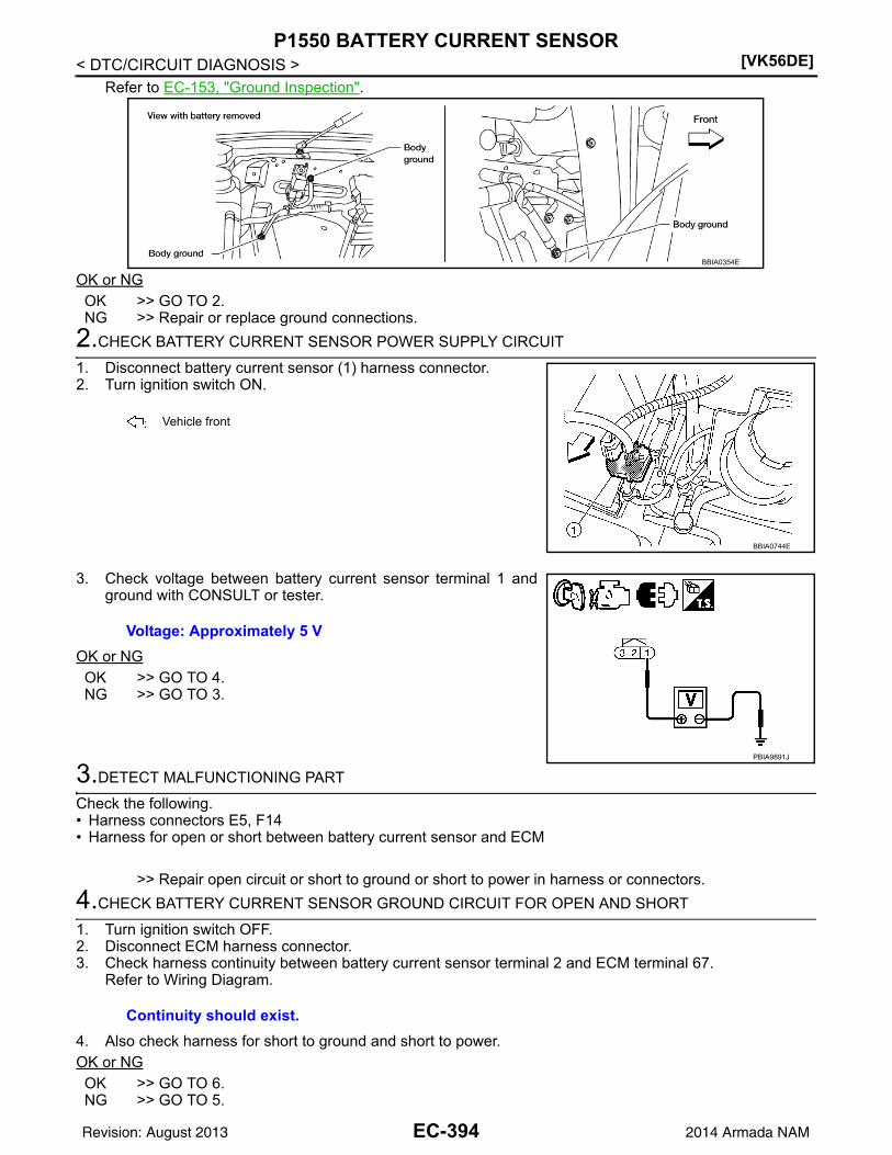
[VK56DE]P1550 BATTERY CURRENT SENSOR
< DTC/CIRCUIT DIAGNOSIS >Refer to EC-153, "Ground Inspection".
OK or NGOK >> GO TO 2.NG >> Repair or replace ground connections.
2.CHECK BATTERY CURRENT SENSOR POWER SUPPLY CIRCUIT
1. Disconnect battery current sensor (1) harness connector.2. Turn ignition switch ON.
3. Check voltage between battery current sensor terminal 1 andground with CONSULT or tester.
OK or NGOK >> GO TO 4.NG >> GO TO 3.
3.DETECT MALFUNCTIONING PART
Check the following.• Harness connectors E5, F14• Harness for open or short between battery current sensor and ECM
>> Repair open circuit or short to ground or short to power in harness or connectors.
4.CHECK BATTERY CURRENT SENSOR GROUND CIRCUIT FOR OPEN AND SHORT
1. Turn ignition switch OFF.2. Disconnect ECM harness connector.3. Check harness continuity between battery current sensor terminal 2 and ECM terminal 67.
Refer to Wiring Diagram.
4. Also check harness for short to ground and short to power.OK or NGOK >> GO TO 6.NG >> GO TO 5.
BBIA0354E
: Vehicle front
BBIA0744E
Voltage: Approximately 5 V
PBIA9891J
Continuity should exist.
EC-394Revision: August 2013 2014 Armada NAM

P1550 BATTERY CURRENT SENSOR[VK56DE]
C
D
E
F
G
H
I
J
K
L
M
A
C
N
P
O
< DTC/CIRCUIT DIAGNOSIS >
E
5.DETECT MALFUNCTIONING PART
Check the following.• Harness connectors E5, F14• Harness for open or short between battery current sensor and ECM
>> Repair open circuit or short to ground or short to power in harness or connectors.
6.CHECK BATTERY CURRENT SENSOR INPUT SIGNAL CIRCUIT FOR OPEN AND SHORT
1. Check harness continuity between battery current sensor terminal 3 and ECM terminal 71.Refer to Wiring Diagram.
2. Also check harness for short to ground and short to power.OK or NGOK >> GO TO 8.NG >> GO TO 7.
7.DETECT MALFUNCTIONING PART
Check the following.• Harness connectors E2, F32• Harness for open or short between battery current sensor and ECM
>> Repair open circuit or short to ground or short to power in harness or connectors.
8.CHECK BATTERY CURRENT SENSOR
Refer to EC-395, "Component Inspection".OK or NGOK >> GO TO 9.NG >> Replace battery negative cable assembly.
9.CHECK INTERMITTENT INCIDENT
Refer to GI-39, "How to Check Terminal" and GI-42, "Intermittent Incident".
>> INSPECTION END
Component Inspection INFOID:0000000009825348
BATTERY CURRENT SENSOR1. Reconnect harness connectors disconnected.2. Disconnect battery negative cable (1).3. Install jumper cable (A) between battery negative terminal and
body ground.4. Turn ignition switch ON.
Continuity should exist.
BBIA0745E
EC-395Revision: August 2013 2014 Armada NAM

[VK56DE]P1550 BATTERY CURRENT SENSOR
< DTC/CIRCUIT DIAGNOSIS >5. Check voltage between ECM terminal 71 (battery current sensor
signal) and ground.
6. If NG, replace battery negative cable assembly.
Voltage: Approximately 2.5 V
PBIB2617E
EC-396Revision: August 2013 2014 Armada NAM

P1551, P1552 BATTERY CURRENT SENSOR[VK56DE]
C
D
E
F
G
H
I
J
K
L
M
A
C
N
P
O
< DTC/CIRCUIT DIAGNOSIS >
E
P1551, P1552 BATTERY CURRENT SENSOR
Component Description INFOID:0000000009825349
The power generation voltage variable control enables fuel con-sumption to be decreased by reducing the engine load which iscaused by the power generation of the generator. The battery cur-rent sensor (1) is installed to the battery cable at the negative termi-nal. The sensor measures the charging/discharging current of thebattery. Based on the sensor signal, ECM judges whether or not thepower generation voltage variable control is performed. When per-forming the power generation voltage variable control, ECM calcu-lates the target power generation voltage based on the sensorsignal. And ECM sends the calculated value as the power genera-tion command value to IPDM E/R. For the details of the power gen-eration voltage variable control, refer to CHG-12, "SystemDescription".
CAUTION:Do not connect the electrical component or the ground wire directly to the battery terminal. The con-nection causes the malfunction of the power generation voltage variable control, and then the batterydischarge may occur.
On Board Diagnosis Logic INFOID:0000000009825350
The MIL will not light up for these self-diagnoses.NOTE:If DTC P1551 or P1552 is displayed with DTC P0643, first perform the trouble diagnosis for DTC P0643.Refer to EC-367.
DTC Confirmation Procedure INFOID:0000000009825351
If DTC Confirmation Procedure has been previously conducted, always perform the following before conduct-ing the next step.1. Turn ignition switch OFF and wait at least 10 seconds.2. Turn ignition switch ON.3. Turn ignition switch OFF and wait at least 10 seconds.TESTING CONDITION:Before performing the following procedure, confirm that battery voltage is more than 8 V with ignitionswitch ON1. Turn ignition switch ON.2. Wait at least 10 seconds.3. Check 1st trip DTC.4. If 1st trip DTC is detected, go to EC-397, "Diagnosis Procedure".
Diagnosis Procedure INFOID:0000000009825352
1.CHECK GROUND CONNECTIONS
1. Turn ignition switch OFF.2. Loosen and retighten ground screws on the body.
: Vehicle front
BBIA0744E
DTC No. Trouble diagnosis name DTC detecting condition Possible cause
P15511551
Battery current sensor circuit low input
An excessively low voltage from the sensor is sent to ECM. • Harness or connectors
(The sensor circuit is open or shorted.)• Battery current sensorP1552
1552Battery current sensor circuit high input
An excessively high voltage from the sensor is sent to ECM.
EC-397Revision: August 2013 2014 Armada NAM

[VK56DE]P1551, P1552 BATTERY CURRENT SENSOR
< DTC/CIRCUIT DIAGNOSIS >Refer to EC-153, "Ground Inspection".
OK or NGOK >> GO TO 2.NG >> Repair or replace ground connections.
2.CHECK BATTERY CURRENT SENSOR POWER SUPPLY CIRCUIT
1. Disconnect battery current sensor (1) harness connector.2. Turn ignition switch ON.
3. Check voltage between battery current sensor terminal 1 andground with CONSULT or tester.
OK or NGOK >> GO TO 4.NG >> GO TO 3.
3.DETECT MALFUNCTIONING PART
Check the following.• Harness connectors E5, F14• Harness for open or short between battery current sensor and ECM
>> Repair open circuit or short to ground or short to power in harness or connectors.
4.CHECK BATTERY CURRENT SENSOR GROUND CIRCUIT FOR OPEN AND SHORT
1. Turn ignition switch OFF.2. Disconnect ECM harness connector.3. Check harness continuity between battery current sensor terminal 2 and ECM terminal 67.
Refer to Wiring Diagram.
4. Also check harness for short to ground and short to power.OK or NGOK >> GO TO 6.NG >> GO TO 5.
BBIA0354E
: Vehicle front
BBIA0744E
Voltage: Approximately 5 V
PBIA9891J
Continuity should exist.
EC-398Revision: August 2013 2014 Armada NAM

P1551, P1552 BATTERY CURRENT SENSOR[VK56DE]
C
D
E
F
G
H
I
J
K
L
M
A
C
N
P
O
< DTC/CIRCUIT DIAGNOSIS >
E
5.DETECT MALFUNCTIONING PART
Check the following.• Harness connectors E5, F14• Harness for open or short between battery current sensor and ECM
>> Repair open circuit or short to ground or short to power in harness or connectors.
6.CHECK BATTERY CURRENT SENSOR INPUT SIGNAL CIRCUIT FOR OPEN AND SHORT
1. Check harness continuity between battery current sensor terminal 3 and ECM terminal 71.Refer to Wiring Diagram.
2. Also check harness for short to ground and short to power.OK or NGOK >> GO TO 8.NG >> GO TO 7.
7.DETECT MALFUNCTIONING PART
Check the following.• Harness connectors E2, F32• Harness for open or short between battery current sensor and ECM
>> Repair open circuit or short to ground or short to power in harness or connectors.
8.CHECK BATTERY CURRENT SENSOR
Refer to EC-399, "Component Inspection".OK or NGOK >> GO TO 9.NG >> Replace battery negative cable assembly.
9.CHECK INTERMITTENT INCIDENT
Refer to GI-39, "How to Check Terminal" and GI-42, "Intermittent Incident".
>> INSPECTION END
Component Inspection INFOID:0000000009825353
BATTERY CURRENT SENSOR1. Reconnect harness connectors disconnected.2. Disconnect battery negative cable (1).3. Install jumper cable (A) between battery negative terminal and
body ground.4. Turn ignition switch ON.
Continuity should exist.
BBIA0745E
EC-399Revision: August 2013 2014 Armada NAM

[VK56DE]P1551, P1552 BATTERY CURRENT SENSOR
< DTC/CIRCUIT DIAGNOSIS >5. Check voltage between ECM terminal 71 (battery current sensor
signal) and ground.
6. If NG, replace battery negative cable assembly.
Voltage: Approximately 2.5 V
PBIB2617E
EC-400Revision: August 2013 2014 Armada NAM

P1553 BATTERY CURRENT SENSOR[VK56DE]
C
D
E
F
G
H
I
J
K
L
M
A
C
N
P
O
< DTC/CIRCUIT DIAGNOSIS >
E
P1553 BATTERY CURRENT SENSOR
Component Description INFOID:0000000009825354
The power generation voltage variable control enables fuel con-sumption to be decreased by reducing the engine load which iscaused by the power generation of the generator. The battery cur-rent sensor (1) is installed to the battery cable at the negative termi-nal. The sensor measures the charging/discharging current of thebattery. Based on the sensor signal, ECM judges whether or not thepower generation voltage variable control is performed. When per-forming the power generation voltage variable control, ECM calcu-lates the target power generation voltage based on the sensorsignal. And ECM sends the calculated value as the power genera-tion command value to IPDM E/R. For the details of the power gen-eration voltage variable control, refer to CHG-12, "SystemDescription".
CAUTION:Do not connect the electrical component or the ground wire directly to the battery terminal. The con-nection causes the malfunction of the power generation voltage variable control, and then the batterydischarge may occur.
On Board Diagnosis Logic INFOID:0000000009825355
The MIL will not light up for this self-diagnosis.NOTE:If DTC P1553 is displayed with DTC P0643, first perform the trouble diagnosis for DTC P0643. Refer toEC-367.
DTC Confirmation Procedure INFOID:0000000009825356
If DTC Confirmation Procedure has been previously conducted, always perform the following before conduct-ing the next step.1. Turn ignition switch OFF and wait at least 10 seconds.2. Turn ignition switch ON.3. Turn ignition switch OFF and wait at least 10 seconds.TESTING CONDITION:Before performing the following procedure, confirm that battery voltage is more than 8 V at idle.1. Start engine and wait at least 10 seconds.2. Check 1st trip DTC.3. If 1st trip DTC is detected, go to EC-401, "Diagnosis Procedure".
Diagnosis Procedure INFOID:0000000009825357
1.CHECK GROUND CONNECTIONS
1. Turn ignition switch OFF.2. Loosen and retighten ground screws on the body.
: Vehicle front
BBIA0744E
DTC No. Trouble diagnosis name DTC detecting condition Possible cause
P15531553
Battery current sensor performanceThe signal voltage transmitted from the sensor to ECM is higher than the amount of the maximum power generation.
• Harness or connectors(The sensor circuit is open or shorted.)
• Battery current sensor
EC-401Revision: August 2013 2014 Armada NAM

[VK56DE]P1553 BATTERY CURRENT SENSOR
< DTC/CIRCUIT DIAGNOSIS >Refer to EC-153, "Ground Inspection".
OK or NGOK >> GO TO 2.NG >> Repair or replace ground connections.
2.CHECK BATTERY CURRENT SENSOR POWER SUPPLY CIRCUIT
1. Disconnect battery current sensor (1) harness connector.2. Turn ignition switch ON.
3. Check voltage between battery current sensor terminal 1 andground with CONSULT or tester.
OK or NGOK >> GO TO 4.NG >> GO TO 3.
3.DETECT MALFUNCTIONING PART
Check the following.• Harness connectors E5, F14• Harness for open or short between battery current sensor and ECM
>> Repair open circuit or short to ground or short to power in harness or connectors.
4.CHECK BATTERY CURRENT SENSOR GROUND CIRCUIT FOR OPEN AND SHORT
1. Turn ignition switch OFF.2. Disconnect ECM harness connector.3. Check harness continuity between battery current sensor terminal 2 and ECM terminal 67.
Refer to Wiring Diagram.
4. Also check harness for short to ground and short to power.OK or NGOK >> GO TO 6.NG >> GO TO 5.
BBIA0354E
: Vehicle front
BBIA0744E
Voltage: Approximately 5 V
PBIA9891J
Continuity should exist.
EC-402Revision: August 2013 2014 Armada NAM

P1553 BATTERY CURRENT SENSOR[VK56DE]
C
D
E
F
G
H
I
J
K
L
M
A
C
N
P
O
< DTC/CIRCUIT DIAGNOSIS >
E
5.DETECT MALFUNCTIONING PART
Check the following.• Harness connectors E5, F14• Harness for open or short between battery current sensor and ECM
>> Repair open circuit or short to ground or short to power in harness or connectors.
6.CHECK BATTERY CURRENT SENSOR INPUT SIGNAL CIRCUIT FOR OPEN AND SHORT
1. Check harness continuity between battery current sensor terminal 3 and ECM terminal 71.Refer to Wiring Diagram.
2. Also check harness for short to ground and short to power.OK or NGOK >> GO TO 8.NG >> GO TO 7.
7.DETECT MALFUNCTIONING PART
Check the following.• Harness connectors E2, F32• Harness for open or short between battery current sensor and ECM
>> Repair open circuit or short to ground or short to power in harness or connectors.
8.CHECK BATTERY CURRENT SENSOR
Refer to EC-403, "Component Inspection".OK or NGOK >> GO TO 9.NG >> Replace battery negative cable assembly.
9.CHECK INTERMITTENT INCIDENT
Refer to GI-39, "How to Check Terminal" and GI-42, "Intermittent Incident".
>> INSPECTION END
Component Inspection INFOID:0000000009825358
BATTERY CURRENT SENSOR1. Reconnect harness connectors disconnected.2. Disconnect battery negative cable (1).3. Install jumper cable (A) between battery negative terminal and
body ground.4. Turn ignition switch ON.
Continuity should exist.
BBIA0745E
EC-403Revision: August 2013 2014 Armada NAM

[VK56DE]P1553 BATTERY CURRENT SENSOR
< DTC/CIRCUIT DIAGNOSIS >5. Check voltage between ECM terminal 71 (battery current sensor
signal) and ground.
6. If NG, replace battery negative cable assembly.
Voltage: Approximately 2.5 V
PBIB2617E
EC-404Revision: August 2013 2014 Armada NAM
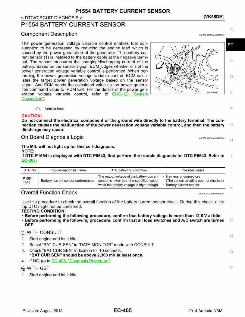
P1554 BATTERY CURRENT SENSOR[VK56DE]
C
D
E
F
G
H
I
J
K
L
M
A
C
N
P
O
< DTC/CIRCUIT DIAGNOSIS >
E
P1554 BATTERY CURRENT SENSOR
Component Description INFOID:0000000009825359
The power generation voltage variable control enables fuel con-sumption to be decreased by reducing the engine load which iscaused by the power generation of the generator. The battery cur-rent sensor (1) is installed to the battery cable at the negative termi-nal. The sensor measures the charging/discharging current of thebattery. Based on the sensor signal, ECM judges whether or not thepower generation voltage variable control is performed. When per-forming the power generation voltage variable control, ECM calcu-lates the target power generation voltage based on the sensorsignal. And ECM sends the calculated value as the power genera-tion command value to IPDM E/R. For the details of the power gen-eration voltage variable control, refer to CHG-12, "SystemDescription".
CAUTION:Do not connect the electrical component or the ground wire directly to the battery terminal. The con-nection causes the malfunction of the power generation voltage variable control, and then the batterydischarge may occur.
On Board Diagnosis Logic INFOID:0000000009825360
The MIL will not light up for this self-diagnosis.NOTE:If DTC P1554 is displayed with DTC P0643, first perform the trouble diagnosis for DTC P0643. Refer toEC-367.
Overall Function Check INFOID:0000000009825361
Use this procedure to check the overall function of the battery current sensor circuit. During this check, a 1sttrip DTC might not be confirmed.TESTING CONDITION:• Before performing the following procedure, confirm that battery voltage is more than 12.8 V at idle.• Before performing the following procedure, confirm that all load switches and A/C switch are turned
OFF.
WITH CONSULT1. Start engine and let it idle.2. Select “BAT CUR SEN” in “DATA MONITOR” mode with CONSULT.3. Check “BAT CUR SEN” indication for 10 seconds.
“BAT CUR SEN” should be above 2,300 mV at least once.4. If NG, go to EC-406, "Diagnosis Procedure".
WITH GST1. Start engine and let it idle.
: Vehicle front
BBIA0744E
DTC No. Trouble diagnosis name DTC detecting condition Possible cause
P15541554
Battery current sensor performanceThe output voltage of the battery current sensor is lower than the specified value while the battery voltage is high enough.
• Harness or connectors(The sensor circuit is open or shorted.)
• Battery current sensor
EC-405Revision: August 2013 2014 Armada NAM

[VK56DE]P1554 BATTERY CURRENT SENSOR
< DTC/CIRCUIT DIAGNOSIS >2. Check voltage between ECM terminal 71 (battery current sensor
signal) and ground for 10 seconds.The voltage should be above 2.3 V at least once.
3. If NG, go to EC-406, "Diagnosis Procedure".
Diagnosis Procedure INFOID:0000000009825362
1.CHECK GROUND CONNECTIONS
1. Turn ignition switch OFF.2. Loosen and retighten ground screws on the body.
Refer to EC-153, "Ground Inspection".
OK or NGOK >> GO TO 2.NG >> Repair or replace ground connections.
2.CHECK BATTERY CURRENT SENSOR POWER SUPPLY CIRCUIT
1. Disconnect battery current sensor (1) harness connector.2. Turn ignition switch ON.
3. Check voltage between battery current sensor terminal 1 andground with CONSULT or tester.
OK or NGOK >> GO TO 4.NG >> GO TO 3.
3.DETECT MALFUNCTIONING PART
Check the following.
PBIB2616E
BBIA0354E
: Vehicle front
BBIA0744E
Voltage: Approximately 5 V
PBIA9891J
EC-406Revision: August 2013 2014 Armada NAM
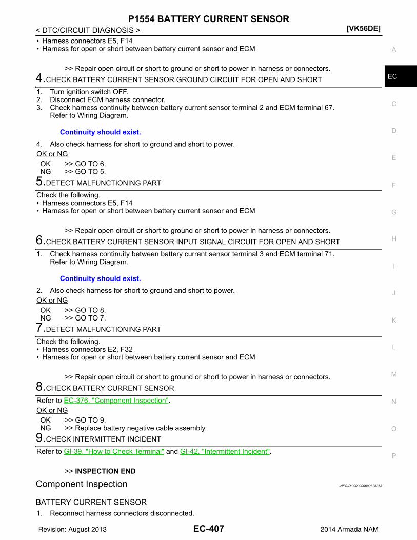
P1554 BATTERY CURRENT SENSOR[VK56DE]
C
D
E
F
G
H
I
J
K
L
M
A
C
N
P
O
< DTC/CIRCUIT DIAGNOSIS >
E
• Harness connectors E5, F14• Harness for open or short between battery current sensor and ECM
>> Repair open circuit or short to ground or short to power in harness or connectors.
4.CHECK BATTERY CURRENT SENSOR GROUND CIRCUIT FOR OPEN AND SHORT
1. Turn ignition switch OFF.2. Disconnect ECM harness connector.3. Check harness continuity between battery current sensor terminal 2 and ECM terminal 67.
Refer to Wiring Diagram.
4. Also check harness for short to ground and short to power.OK or NGOK >> GO TO 6.NG >> GO TO 5.
5.DETECT MALFUNCTIONING PART
Check the following.• Harness connectors E5, F14• Harness for open or short between battery current sensor and ECM
>> Repair open circuit or short to ground or short to power in harness or connectors.
6.CHECK BATTERY CURRENT SENSOR INPUT SIGNAL CIRCUIT FOR OPEN AND SHORT
1. Check harness continuity between battery current sensor terminal 3 and ECM terminal 71.Refer to Wiring Diagram.
2. Also check harness for short to ground and short to power.OK or NGOK >> GO TO 8.NG >> GO TO 7.
7.DETECT MALFUNCTIONING PART
Check the following.• Harness connectors E2, F32• Harness for open or short between battery current sensor and ECM
>> Repair open circuit or short to ground or short to power in harness or connectors.
8.CHECK BATTERY CURRENT SENSOR
Refer to EC-376, "Component Inspection".OK or NGOK >> GO TO 9.NG >> Replace battery negative cable assembly.
9.CHECK INTERMITTENT INCIDENT
Refer to GI-39, "How to Check Terminal" and GI-42, "Intermittent Incident".
>> INSPECTION END
Component Inspection INFOID:0000000009825363
BATTERY CURRENT SENSOR1. Reconnect harness connectors disconnected.
Continuity should exist.
Continuity should exist.
EC-407Revision: August 2013 2014 Armada NAM

[VK56DE]P1554 BATTERY CURRENT SENSOR
< DTC/CIRCUIT DIAGNOSIS >2. Disconnect battery negative cable (1).3. Install jumper cable (A) between battery negative terminal and
body ground.4. Turn ignition switch ON.
5. Check voltage between ECM terminal 71 (battery current sensorsignal) and ground.
6. If NG, replace battery negative cable assembly.
BBIA0745E
Voltage: Approximately 2.5 V
PBIB2617E
EC-408Revision: August 2013 2014 Armada NAM

P1564 ASCD STEERING SWITCH[VK56DE]
C
D
E
F
G
H
I
J
K
L
M
A
C
N
P
O
< DTC/CIRCUIT DIAGNOSIS >
E
P1564 ASCD STEERING SWITCH
Component Description INFOID:0000000009825364
ASCD steering switch has variant values of electrical resistance for each button. ECM reads voltage variationof switch, and determines which button is operated.
Refer to EC-28 for the ASCD function.
On Board Diagnosis Logic INFOID:0000000009825365
• This self-diagnosis has the one trip detection logic.• The MIL will not light up for this self-diagnosis.NOTE:If DTC P1564 is displayed with DTC P0605, first perform the trouble diagnosis for DTC P0605. Refer toEC-362.
DTC Confirmation Procedure INFOID:0000000009825366
1. If DTC Confirmation Procedure has been previously conducted, always perform the following before con-ducting the next step.
a. Turn ignition switch OFF and wait at least 10 seconds.b. Turn ignition switch ON.c. Turn ignition switch OFF and wait at least 10 seconds.2. Turn ignition switch ON.3. Wait at least 10 seconds.4. Press MAIN switch for at least 10 seconds, then release it and wait at least 10 seconds.5. Press CANCEL switch for at least 10 seconds, then release it and wait at least 10 seconds.6. Press RESUME/ACCELERATE switch for at least 10 seconds, then release it and wait at least 10 sec-
onds.7. Press SET/COAST switch for at least 10 seconds, then release it and wait at least 10 seconds.8. Check DTC.9. If DTC is detected, go to EC-409, "Diagnosis Procedure".
Diagnosis Procedure INFOID:0000000009825367
1.CHECK GROUND CONNECTIONS
1. Turn ignition switch OFF.2. Loosen and retighten three ground screws on the body.
PBIB2638E
DTC No. Trouble Diagnosis Name DTC Detecting Condition Possible Cause
P15641564
ASCD steering switch
• An excessively high voltage signal from the ASCD steering switch is sent to ECM.
• ECM detects that input signal from the ASCD steer-ing switch is out of the specified range.
• ECM detects that the ASCD steering switch is stuck ON.
• Harness or connectors(The switch circuit is open or shorted.)
• ASCD steering switch• Combination switch (spiral ca-
ble)• ECM
EC-409Revision: August 2013 2014 Armada NAM

[VK56DE]P1564 ASCD STEERING SWITCH
< DTC/CIRCUIT DIAGNOSIS >Refer to EC-153, "Ground Inspection".
OK or NGOK >> GO TO 2.NG >> Repair or replace ground connections.
2.CHECK ASCD STEERING SWITCH CIRCUIT
With CONSULT1. Turn ignition switch ON.2. Select “MAIN SW”, “CANCEL SW”, RESUME/ACC SW” and “SET SW” in “DATA MONITOR” mode with
CONSULT.3. Check each item indication under the following conditions.
Without CONSULT1. Turn ignition switch ON.2. Check voltage between ECM terminal 99 and ground with press-
ing each button.
OK or NGOK >> GO TO 8.NG >> GO TO 3.
3.CHECK ASCD STEERING SWITCH GROUND CIRCUIT FOR OPEN AND SHORT
1. Turn ignition switch OFF.
BBIA0354E
Switch Monitor item Condition Indication
MAIN switch MAIN SWPressed ON
Released OFF
CANCEL switch CANCEL SWPressed ON
Released OFF
RESUME/ACCELERATE switch
RESUME/ACC SWPressed ON
Released OFF
SET/COAST switch SET SWPressed ON
Released OFF
Switch Condition Voltage [V]
MAIN switchPressed Approx. 0
Released Approx. 4
CANCEL switchPressed Approx. 1
Released Approx. 4
RESUME/ACCELERATE switch
Pressed Approx. 3
Released Approx. 4
SET/COAST switchPressed Approx. 2
Released Approx. 4
PBIB0311E
EC-410Revision: August 2013 2014 Armada NAM

P1564 ASCD STEERING SWITCH[VK56DE]
C
D
E
F
G
H
I
J
K
L
M
A
C
N
P
O
< DTC/CIRCUIT DIAGNOSIS >
E
2. Disconnect combination switch harness connector M30.3. Disconnect ECM harness connector.4. Check harness continuity between combination switch terminal
26 and ECM terminal 67.Refer to Wiring Diagram.
5. Also check harness for short to ground and short to power.OK or NGOK >> GO TO 5.NG >> GO TO 4.
4.DETECT MALFUNCTIONING PART
Check the following.• Harness connectors M31, E152• Harness connectors E5, F14• Combination switch (spiral cable)• Harness for open and short between ECM and combination switch
>> Repair open circuit or short to ground or short to power in harness or connectors.
5.CHECK ASCD STEERING SWITCH INPUT SIGNAL CIRCUIT FOR OPEN AND SHORT
1. Check harness continuity between ECM terminal 99 and combination switch terminal 27.Refer to Wiring Diagram.
2. Also check harness for short to ground and short to power.OK or NGOK >> GO TO 7.NG >> GO TO 6.
6.DETECT MALFUNCTIONING PART
Check the following.• Harness connectors M31, E152• Combination switch (spiral cable)• Harness for open and short between ECM and combination switch
>> Repair open circuit or short to ground or short to power in harness or connectors.
7.CHECK ASCD STEERING SWITCH
Refer to EC-411, "Component Inspection".OK or NGOK >> GO TO 8.NG >> Replace ASCD steering switch. Refer to ST-28, "Removal and Installation".
8.CHECK INTERMITTENT INCIDENT
Refer to GI-39, "How to Check Terminal" and GI-42, "Intermittent Incident".
>> INSPECTION END
Component Inspection INFOID:0000000009825368
ASCD STEERING SWITCH1. Disconnect combination switch (spiral cable) harness connector M102.
Continuity should exist.
BBIA0362E
Continuity should exist.
EC-411Revision: August 2013 2014 Armada NAM

[VK56DE]P1564 ASCD STEERING SWITCH
< DTC/CIRCUIT DIAGNOSIS >2. Check continuity between combination switch (spiral cable) ter-
minals 14 and 15 with pushing each switch.
Switch Condition Resistance []
MAIN switchPressed Approx. 0
Released Approx. 4,000
CANCEL switchPressed Approx. 250
Released Approx. 4,000
RESUME/ACCELERATE switch
Pressed Approx. 1,480
Released Approx. 4,000
SET/COAST switchPressed Approx. 660
Released Approx. 4,000
JMBIA0603ZZ
EC-412Revision: August 2013 2014 Armada NAM

P1572 ASCD BRAKE SWITCH[VK56DE]
C
D
E
F
G
H
I
J
K
L
M
A
C
N
P
O
< DTC/CIRCUIT DIAGNOSIS >
E
P1572 ASCD BRAKE SWITCH
Component Description INFOID:0000000009825369
When the brake pedal is depressed, ASCD brake switch is turnedOFF and stop lamp switch is turned ON. ECM detects the state ofthe brake pedal by this input of two kinds (ON/OFF signal).Refer to EC-28 for the ASCD function.
On Board Diagnosis Logic INFOID:0000000009825370
• This self-diagnosis has the one trip detection logic.• The MIL will not light up for this self-diagnosis.NOTE:• If DTC P 1572 is displayed with DTC P0605, first perform the trouble diagnosis for DTC P0605. Refer
to EC-362.• This self-diagnosis has the one trip detection logic. When malfunction A is detected, DTC is not
stored in ECM memory. And in that case, 1st trip DTC and 1st trip freeze frame data are displayed.1st trip DTC is erased when ignition switch OFF. And even when malfunction A is detected in twoconsecutive trips, DTC is not stored in ECM memory.
DTC Confirmation Procedure INFOID:0000000009825371
CAUTION:Always drive vehicle at a safe speed.NOTE:• Procedure for malfunction B is not described here. It takes extremely long time to complete procedure for
malfunction B. By performing procedure for malfunction A, the incident that causes malfunction B can bedetected.
• If DTC Confirmation Procedure has been previously conducted, always perform the following before con-ducting the next step.
1. Turn ignition switch OFF and wait at least 10 seconds.2. Turn ignition switch ON.3. Turn ignition switch OFF and wait at least 10 seconds.TESTING CONDITION:Steps 4 and 7 may be conducted with the drive wheels lifted in the shop or by driving the vehicle. If aroad test is expected to be easier, it is unnecessary to lift the vehicle.
WITH CONSULT1. Start engine (VDC switch OFF).2. Select “DATA MONITOR” mode with CONSULT.3. Press MAIN switch and make sure that CRUISE indicator lights up.
BBIA0373E
DTC No.Trouble Diagnosis
NameDTC Detecting Condition Possible Cause
P15721572
ASCD brake switch
A)
When the vehicle speed is above 30km/h (19 MPH), ON signals from the stop lamp switch and the ASCD brake switch are sent to ECM at the same time.
• Harness or connectors(The stop lamp switch circuit is shorted.)
• Harness or connectors(The ASCD brake switch circuit is shorted.)
• Stop lamp switch• ASCD brake switch• Incorrect stop lamp switch installation• Incorrect ASCD brake switch installation• ECM
B)ASCD brake switch signal is not sent to ECM for extremely long time while the vehicle is driving
EC-413Revision: August 2013 2014 Armada NAM

[VK56DE]P1572 ASCD BRAKE SWITCH
< DTC/CIRCUIT DIAGNOSIS >4. Drive the vehicle for at least 5 consecutive seconds under the following condition.
5. Check 1st trip DTC.6. If 1st trip DTC is detected, go to EC-414, "Diagnosis Procedure".
If 1st trip DTC is not detected, go to the following step.7. Drive the vehicle for at least 5 consecutive seconds under the following condition.
8. Check 1st trip DTC.9. If 1st trip DTC is detected, go to EC-414, "Diagnosis Procedure".
WITH GSTFollow the procedure “WITH CONSULT” above.
Diagnosis Procedure INFOID:0000000009825372
1.CHECK OVERALL FUNCTION-I
With CONSULT1. Turn ignition switch ON.2. Select “BRAKE SW1” in “DATA MONITOR” mode with CONSULT.3. Check “BRAKE SW1” indication under the following conditions.
Without CONSULT1. Turn ignition switch ON.2. Check voltage between ECM terminal 108 and ground under the
following conditions.
OK or NGOK >> GO TO 2.NG >> GO TO 3.
2.CHECK OVERALL FUNCTION-II
With CONSULTCheck “BRAKE SW2” indication in “DATA MONITOR” mode.
VHCL SPEED SE More than 30 km/h (19 MPH)
Selector lever Suitable position
VHCL SPEED SE More than 30 km/h (19 MPH)
Selector lever Suitable position
Driving locationDepress the brake pedal for more than five seconds so as not to come off from the above-mentioned condition.
CONDITION INDICATION
Brake pedal: Slightly depressed OFF
Brake pedal: Fully released ON
CONDITION VOLTAGE
Brake pedal: Slightly depressed Approximately 0 V
Brake pedal: Fully released Battery voltage
MBIB0061E
EC-414Revision: August 2013 2014 Armada NAM

P1572 ASCD BRAKE SWITCH[VK56DE]
C
D
E
F
G
H
I
J
K
L
M
A
C
N
P
O
< DTC/CIRCUIT DIAGNOSIS >
E
Without CONSULTCheck voltage between ECM terminal 101 and ground under the following conditions.
OK or NGOK >> GO TO 11.NG >> GO TO 7.
3.CHECK ASCD BRAKE SWITCH POWER SUPPLY CIRCUIT
1. Turn ignition switch OFF.2. Disconnect ASCD brake switch harness connector.3. Turn ignition switch ON.
4. Check voltage between ASCD brake switch terminal 1 andground with CONSULT or tester.
OK or NGOK >> GO TO 5.NG >> GO TO 4.
4.DETECT MALFUNCTIONING PART
Check the following.• Harness connectors M31, E152• Fuse block (J/B) connector M4• 10 A fuse (No. 15)• Harness for open or short between ASCD brake switch and fuse
>> Repair open circuit or short to ground or short to power in harness or connectors.
CONDITION INDICATION
Brake pedal: Fully released OFF
Brake pedal: Slightly depressed ON
CONDITION VOLTAGE
Brake pedal: Fully released Approximately 0 V
Brake pedal: Slightly depressed Battery voltage
PBIB1537E
BBIA0373E
Voltage: Battery voltage
PBIB0857E
EC-415Revision: August 2013 2014 Armada NAM

[VK56DE]P1572 ASCD BRAKE SWITCH
< DTC/CIRCUIT DIAGNOSIS >
5.CHECK ASCD BRAKE SWITCH INPUT SIGNAL CIRCUIT FOR OPEN AND SHORT
1. Turn ignition switch OFF.2. Disconnect ECM harness connector.3. Check harness continuity between ECM terminal 108 and ASCD brake switch terminal 2.
Refer to Wiring Diagram.
4. Also check harness for short to ground and short to power.OK or NGOK >> GO TO 6.NG >> Repair open circuit or short to ground or short to power in harness or connectors.
6.CHECK ASCD BRAKE SWITCH
Refer to EC-417, "Component Inspection".OK or NGOK >> GO TO 11.NG >> Replace ASCD brake switch. Refer to BR-18.
7.CHECK STOP LAMP SWITCH POWER SUPPLY CIRCUIT
1. Turn ignition switch OFF.2. Disconnect stop lamp switch harness connector.
3. Check voltage between stop lamp switch terminal 1 and groundwith CONSULT or tester.
OK or NGOK >> GO TO 9.NG >> GO TO 8.
8.DETECT MALFUNCTIONING PART
Check the following.• Harness connectors M31, E152• Fuse block (J/B) connector M60• 10 A fuse (No. 21)• Harness for open or short between stop lamp switch and battery
>> Repair open circuit or short to ground or short to power in harness or connectors.
9.CHECK STOP LAMP SWITCH INPUT SIGNAL CIRCUIT FOR OPEN AND SHORT
1. Disconnect ECM harness connector.2. Check harness continuity between ECM terminal 101 and stop lamp switch terminal 2.
Refer to Wiring Diagram.
Continuity should exist.
BBIA0373E
Voltage: Battery voltage
PBIB0117E
EC-416Revision: August 2013 2014 Armada NAM
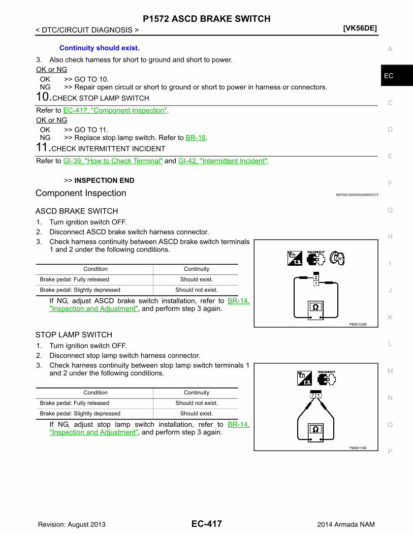
P1572 ASCD BRAKE SWITCH[VK56DE]
C
D
E
F
G
H
I
J
K
L
M
A
C
N
P
O
< DTC/CIRCUIT DIAGNOSIS >
E
3. Also check harness for short to ground and short to power.OK or NGOK >> GO TO 10.NG >> Repair open circuit or short to ground or short to power in harness or connectors.
10.CHECK STOP LAMP SWITCH
Refer to EC-417, "Component Inspection".OK or NGOK >> GO TO 11.NG >> Replace stop lamp switch. Refer to BR-18.
11.CHECK INTERMITTENT INCIDENT
Refer to GI-39, "How to Check Terminal" and GI-42, "Intermittent Incident".
>> INSPECTION END
Component Inspection INFOID:0000000009825373
ASCD BRAKE SWITCH1. Turn ignition switch OFF.2. Disconnect ASCD brake switch harness connector.3. Check harness continuity between ASCD brake switch terminals
1 and 2 under the following conditions.
If NG, adjust ASCD brake switch installation, refer to BR-14,"Inspection and Adjustment", and perform step 3 again.
STOP LAMP SWITCH1. Turn ignition switch OFF.2. Disconnect stop lamp switch harness connector.3. Check harness continuity between stop lamp switch terminals 1
and 2 under the following conditions.
If NG, adjust stop lamp switch installation, refer to BR-14,"Inspection and Adjustment", and perform step 3 again.
Continuity should exist.
Condition Continuity
Brake pedal: Fully released Should exist.
Brake pedal: Slightly depressed Should not exist.
PBIB1536E
Condition Continuity
Brake pedal: Fully released Should not exist.
Brake pedal: Slightly depressed Should exist.
PBIB0118E
EC-417Revision: August 2013 2014 Armada NAM

[VK56DE]P1574 ASCD VEHICLE SPEED SENSOR
< DTC/CIRCUIT DIAGNOSIS >
P1574 ASCD VEHICLE SPEED SENSOR
Component Description INFOID:0000000009825374
The ECM receives two vehicle speed sensor signals via CAN communication line. One is sent from combina-tion meter and the other is from TCM (Transmission control module). The ECM uses these signals for ASCDcontrol. Refer to EC-28 for ASCD functions.
On Board Diagnosis Logic INFOID:0000000009825375
• This self-diagnosis has the one trip detection logic.• The MIL will not light up for this self-diagnosis.NOTE:• If DTC P1574 is displayed with DTC UXXXX, first perform the trouble diagnosis for DTC UXXXX.• If DTC P1574 is displayed with DTC P0500, first perform the trouble diagnosis for DTC P0500. Refer
to EC-349.• If DTC P1574 is displayed with DTC P0605, first perform the trouble diagnosis for DTC P0605. Refer
to EC-362.• If DTC P1574 is displayed with DTC P0607, first perform the trouble diagnosis for DTC P0607. Refer
to EC-364.
DTC Confirmation Procedure INFOID:0000000009825376
CAUTION:Always drive vehicle at a safe speed.NOTE:If DTC Confirmation Procedure has been previously conducted, always perform the following before conduct-ing the next step.1. Turn ignition switch OFF and wait at least 10 seconds.2. Turn ignition switch ON.3. Turn ignition switch OFF and wait at least 10 seconds.TESTING CONDITION:Step 3 may be conducted with the drive wheels lifted in the shop or by driving the vehicle. If a road testis expected to be easier, it is unnecessary to lift the vehicle.1. Start engine (VDC switch OFF).2. Drive the vehicle at more than 40 km/h (25 MPH).3. Check DTC.4. If DTC is detected, go to EC-418, "Diagnosis Procedure".
Diagnosis Procedure INFOID:0000000009825377
1.CHECK DTC WITH TCM
Check DTC with TCM. Refer to TM-32, "OBD-II Diagnostic Trouble Code (DTC)".OK or NGOK >> GO TO 2.NG >> Perform trouble shooting relevant to DTC indicated.
2.CHECK DTC WITH ABS ACTUATOR AND ELECTRIC UNIT (CONTROL UNIT)
Refer to BRC-24, "CONSULT Function (ABS)".
DTC No.Trouble Diagnosis
NameDTC Detecting Condition Possible Cause
P15741574
ASCD vehicle speed sensor
ECM detects a difference between two vehicle speed signals is out of the specified range.
• Harness or connectors(The CAN communication line is open or shorted.)
• Combination meter• ABS actuator and electric unit (control unit)• Wheel sensor• TCM• ECM
EC-418Revision: August 2013 2014 Armada NAM

P1574 ASCD VEHICLE SPEED SENSOR[VK56DE]
C
D
E
F
G
H
I
J
K
L
M
A
C
N
P
O
< DTC/CIRCUIT DIAGNOSIS >
E
OK or NGOK >> GO TO 3.NG >> Repair or replace.
3.CHECK COMBINATION METER FUNCTION
Check combination meter function.Refer to MWI-27, "CONSULT Function (METER/M&A)".
>> INSPECTION END
EC-419Revision: August 2013 2014 Armada NAM

[VK56DE]P1805 BRAKE SWITCH
< DTC/CIRCUIT DIAGNOSIS >
P1805 BRAKE SWITCH
Description INFOID:0000000009825378
Brake switch signal is applied to the ECM through the stop lamp switch when the brake pedal is depressed.This signal is used mainly to decrease the engine speed when the vehicle is driving.
On Board Diagnosis Logic INFOID:0000000009825379
The MIL will not light up for this self-diagnosis.
FAIL-SAFE MODEWhen the malfunction is detected, the ECM enters fail-safe mode.
DTC Confirmation Procedure INFOID:0000000009825380
1. Turn ignition switch ON.2. Fully depress the brake pedal for at least 5 seconds.3. Erase the DTC with CONSULT.4. Check 1st trip DTC.5. If 1st trip DTC is detected, go to EC-420, "Diagnosis Procedure".
Diagnosis Procedure INFOID:0000000009825381
1.CHECK STOP LAMP SWITCH CIRCUIT
1. Turn ignition switch OFF.2. Check the stop lamp when depressing and releasing the brake pedal.
OK or NGOK >> GO TO 4.NG >> GO TO 2.
2.CHECK STOP LAMP SWITCH POWER SUPPLY CIRCUIT
DTC No. Trouble diagnosis name DTC detecting condition Possible cause
P18051805
Brake switchA brake switch signal is not sent to ECM for ex-tremely long time while the vehicle is driving.
• Harness or connectors(Stop lamp switch circuit is open or short-ed.)
• Stop lamp switch
Engine operating condition in fail-safe mode
ECM controls the electric throttle control actuator by regulating the throttle opening to a small range.Therefore, acceleration will be poor.
Vehicle condition Driving condition
When engine is idling Normal
When accelerating Poor acceleration
Brake pedal Stop lamp
Fully released Not illuminated
Slightly depressed Illuminated
EC-420Revision: August 2013 2014 Armada NAM

P1805 BRAKE SWITCH[VK56DE]
C
D
E
F
G
H
I
J
K
L
M
A
C
N
P
O
< DTC/CIRCUIT DIAGNOSIS >
E
1. Disconnect stop lamp switch harness connector.
2. Check voltage between stop lamp switch terminal 1 and groundwith CONSULT or tester.
OK or NGOK >> GO TO 4.NG >> GO TO 3.
3.DETECT MALFUNCTIONING PART
Check the following.• Harness connectors M31, E152• Fuse block (J/B) connector M60• 10A fuse (No. 21)• Harness for open and short between stop lamp switch and battery
>> Repair open circuit or short to ground or short to power in harness or connectors.
4.CHECK STOP LAMP SWITCH INPUT SIGNAL CIRCUIT FOR OPEN AND SHORT
1. Turn ignition switch OFF.2. Disconnect ECM harness connector.3. Check harness continuity between ECM terminal 101 and stop lamp switch terminal 2.
Refer to Wiring Diagram.
4. Also check harness for short to ground and short to power.OK or NGOK >> GO TO 5.NG >> Repair open circuit or short to ground or short to power in harness or connectors.
5.CHECK STOP LAMP SWITCH
Refer to EC-422, "Component Inspection" .OK or NGOK >> GO TO 6.NG >> Replace stop lamp switch. Refer to BR-18.
6.CHECK INTERMITTENT INCIDENT
Refer to GI-39, "How to Check Terminal" and GI-42, "Intermittent Incident".
>> INSPECTION END
BBIA0373E
Voltage: Battery voltage
PBIB0117E
Continuity should exist.
EC-421Revision: August 2013 2014 Armada NAM

[VK56DE]P1805 BRAKE SWITCH
< DTC/CIRCUIT DIAGNOSIS >
Component Inspection INFOID:0000000009825382
STOP LAMP SWITCH1. Disconnect stop lamp switch harness connector.
2. Check continuity between stop lamp switch terminals 1 and 2under the following conditions.
3. If NG, adjust stop lamp switch installation, refer to BR-14,"Inspection and Adjustment", and perform step 2 again.
BBIA0373E
Conditions Continuity
Brake pedal: Fully released Should not exist.
Brake pedal: Slightly depressed Should exist.
PBIB0118E
EC-422Revision: August 2013 2014 Armada NAM

P2096, P2097, P2098, P2099 A/F SENSOR 1[VK56DE]
C
D
E
F
G
H
I
J
K
L
M
A
C
N
P
O
< DTC/CIRCUIT DIAGNOSIS >
E
P2096, P2097, P2098, P2099 A/F SENSOR 1
Component Description INFOID:0000000009825421
The air fuel ratio (A/F) sensor 1 is a planar one-cell limit current sen-sor. The sensor element of the A/F sensor 1 is composed an elec-trode layer, which transports ions. It has a heater in the element.The sensor is capable of precise measurement = 1, but also in thelean and rich range. Together with its control electronics, the sensoroutputs a clear, continuous signal throughout a wide range.The exhaust gas components diffuse through the diffusion layer atthe sensor cell. An electrode layer is applied voltage, and this currentrelative oxygen density in lean. Also this current relative hydrocar-bon density in rich.Therefore, the A/F sensor 1 is able to indicate air fuel ratio by thiselectrode layer of current. In addition, a heater is integrated in thesensor to ensure the required operating temperature of about 800C(1,472F).
On Board Diagnosis Logic INFOID:0000000009825422
DTC Confirmation Procedure INFOID:0000000009825423
NOTE:If DTC Confirmation Procedure has been previously conducted, always perform the following before conduct-ing the next step. 1. Turn ignition swich OFF and wait at least 10 seconds.2. Turn ignition swich ON.3. Turn ignition swich OFF and wait at least 10 seconds.TESTING CONDITION:
PBIB3353E
JPBIA5446GB
DTC No.Trouble diagnosis name
(Trouble diagnosis content)DTC detecting condition Possible Cause
P2096
POST CAT FUEL TRIM SYS B1(Post catalyst fuel trim system too lean bank 1)
The output voltage computed by ECM from the A/F sensor 1 signal is shifts to the lean side for a specified period.
• A/F sensor 1 (bank 1)• A/F sensor 1 heater• Heated oxygen sensor 2 (bank 1)• Fuel pressure• Fuel injector• Intake air leaks• Exhaust gas leaks
P2097
POST CAT FUEL TRIM SYS B1(Post catalyst fuel trim system too rich bank 1)
The A/F signal computed by ECM from the A/F sensor 1 signal is shifts to the rich side for a spec-ified period.
P2098
POST CAT FUEL TRIM SYS B2(Post catalyst fuel trim system too lean bank 2)
The output voltage computed by ECM from the A/F sensor 1 signal is shifts to the lean side for a specified period.
• A/F sensor 1 (bank 2)• A/F sensor 1 heater• Heated oxygen sensor 2 (bank 2)• Fuel pressure• Fuel injector• Intake air leaks• Exhaust gas leaks
P2099
POST CAT FUEL TRIM SYS B2(Post catalyst fuel trim system too rich bank 2)
The A/F signal computed by ECM from the A/F sensor 1 signal is shifts to the rich side for a spec-ified period.
EC-423Revision: August 2013 2014 Armada NAM

[VK56DE]P2096, P2097, P2098, P2099 A/F SENSOR 1
< DTC/CIRCUIT DIAGNOSIS >Before performing the following procedure, confirm that battery voltage is more than 11V at idle.
WITH CONSULT1. Start engine and warm it up to normal operating temperature.2. Turn ignition switch OFF and wait at least 10 seconds.3. Turn ignition switch ON and select “SELF-LEARNING CONT” in “WORK SUPPORT” mode with CON-
SULT.4. Clear the self-learning coefficient by touching “CLEAR”.5. Turn ignition switch OFF and wait at least 10 seconds.6. Start engine and keep the engine speed between 3,500 and 4,000 rpm for 1 minute under no load.7. Let engine idle for 1 minute.8. Keep engine speed between 2,500 and 3,000 rpm for 20 minutes.9. Check 1st trip DTC.10. If 1st trip DTC is detected, go to EC-424, "Diagnosis Procedure".
WITH GST1. Start engine and warm it up to normal operating temperature.2. Turn ignition switch OFF and wait at least 10 seconds.3. Disconnect mass air flow sensor harness connector.4. Start engine and let it idle for at least 5 seconds.5. Stop engine and reconnect mass air flow sensor harness con-
nector.6. Select Service $03 with GST and make sure that DTC P0102 is
detected.7. Select Service $04 with GST and erase the DTC P0102.8. Start engine and keep the engine speed between 3,500 and
4,000 rpm for 1 minute under no load.9. Let engine idle for 1 minute.10. Keep engine speed between 2,500 and 3,000 rpm for 20 min-
utes.11. Select Service $07 with GST.
If 1st trip DTC is detected, go to EC-424, "Diagnosis Procedure".
Diagnosis Procedure INFOID:0000000009825424
1.CHECK GROUND CONNECTIONS
1. Turn ignition switch OFF.2. Loosen and retighten two ground screws on the body.
Refer to EC-153, "Ground Inspection".
OK or NGOK >> GO TO 2.NG >> Repair or replace ground connections.
2.RETIGHTEN A/F SENSOR 1 AND HEATED OXYGEN SENSOR 2
BBIA0368E
BBIA0354E
EC-424Revision: August 2013 2014 Armada NAM

P2096, P2097, P2098, P2099 A/F SENSOR 1[VK56DE]
C
D
E
F
G
H
I
J
K
L
M
A
C
N
P
O
< DTC/CIRCUIT DIAGNOSIS >
E
Loosen and retighten the A/F sensor 1 and heated oxygen sensor 2. Refer to EM-32, "Exploded View" andEX-6, "Removal and Installation".
>> GO TO 3.
3.CHECK FOR EXHAUST GAS LEAK
1. Start engine and run it at idle.2. Listen for an exhaust gas leak before the three way catalyst 2.Is exhaust gas detected?YES >> Repair or replace.NO >> GO TO 4.
4.CHECK FOR INTAKE AIR LEAK
1. Start engine and run it at idle.2. Listen for an intake air leak after the mass air flow sensor.OK or NGOK >> GO TO 5.NG >> Repair or replace.
5.CLEAR THE SELF-LEARNING DATA
With CONSULT1. Start engine and warm it up to normal operating temperature.2. Select “SELF-LEARNING CONT” in “WORK SUPPORT” mode with CONSULT.3. Clear the self-learning control coefficient by touching “CLEAR”.4. Run engine for at least 10 minutes at idle speed.
Is the 1st trip DTC P0171, P0172, P0174 or P0175 detected?Is it difficult to start engine?
Without CONSULT1. Start engine and warm it up to normal operating temperature.2. Turn ignition switch OFF.3. Disconnect mass air flow sensor harness connector.4. Restart engine and let it idle for at least 5 seconds.5. Stop engine and reconnect mass air flow sensor harness con-
nector.6. Make sure DTC P0102 is displayed.7. Erase the DTC memory. Refer to EC-49, "CONSULT Function"
or EC-46, "On Board Diagnosis Function".8. Make sure DTC P0000 is displayed.9. Run engine for at least 10 minutes at idle speed.
Is the 1st trip DTC P0171, P0172, P0174 or P0175 detected?Is it difficult to start engine?
Yes or NoYes >> Perform trouble diagnosis for DTC P0171, P0174 or P0172, P0175. Refer to EC-242 or EC-247.No >> GO TO 6.
6.CHECK HARNESS CONNECTOR
1. Turn ignition switch OFF.
BBIA0368E
EC-425Revision: August 2013 2014 Armada NAM

[VK56DE]P2096, P2097, P2098, P2099 A/F SENSOR 1
< DTC/CIRCUIT DIAGNOSIS >2. Disconnect A/F sensor 1 harness connector.
3. Check harness connector for water.
OK or NGOK >> GO TO 7.NG >> Repair or replace harness connector.
7.CHECK A/F SENSOR 1 POWER SUPPLY CIRCUIT
1. Turn ignition switch ON.2. Check voltage between A/F sensor 1 terminal 4 and ground with
CONSULT or tester.
OK or NGOK >> GO TO 9.NG >> GO TO 8.
8.DETECT MALFUNCTIONING PART
Check the following.• Harness connectors E5, F14• IPDM E/R harness connector E119• 15A fuse• Harness for open or short between A/F sensor 1 and fuse
>> Repair or replace harness or connectors.
9.CHECK A/F SENSOR 1 INPUT SIGNAL CIRCUIT FOR OPEN AND SHORT
1. Turn ignition switch OFF.2. Disconnect ECM harness connector.3. Check harness continuity between A/F sensor 1 terminal and ECM terminal as follows.
Refer to Wiring Diagram.
4. Check harness continuity between the following terminals and ground.Refer to Wiring Diagram.
Water should not exit.
BBIA0376E
Voltage: Battery voltage
JSBIA3095GB
A/F sensor 1 terminal ECM terminal
Bank11 35
2 56
Bank 21 16
2 75
Continuity should exist.
EC-426Revision: August 2013 2014 Armada NAM

P2096, P2097, P2098, P2099 A/F SENSOR 1[VK56DE]
C
D
E
F
G
H
I
J
K
L
M
A
C
N
P
O
< DTC/CIRCUIT DIAGNOSIS >
E
5. Also check harness for short to power.OK or NGOK >> GO TO 10.NG >> Repair open circuit or short to ground or short to power in harness or connectors.
10.CHECK A/F SENSOR 1 HEATER
Refer to EC-165, "Component Inspection".OK or NGOK >> GO TO 11.NG >> GO TO 13.
11.CHECK HEATED OXYGEN SENSOR 2
Refer to EC-226, "Component Inspection".Is the inspection result normal?YES >> GO TO 12.NO >> Replace heated oxygen sensor 2. Refer to EX-6, "Removal and Installation".
12.CHECK INTERMITTENT INCIDENT
Refer to GI-39, "How to Check Terminal" and GI-42, "Intermittent Incident".OK or NGOK >> GO TO 13.NG >> Repair or replace.
13.REPLACE AIR FUEL RATIO (A/F) SENSOR 1
Replace malfunctioning air fuel ratio (A/F) sensor 1.CAUTION:• Discard any A/F sensor which has been dropped from a height of more than 0.5 m (19.7 in) onto a
hard surface such as a concrete floor; use a new one.• Before installing new A/F sensor, clean exhaust system threads using Oxygen Sensor Thread
Cleaner tool J-43897-18 or J-43897-12 and approved anti-seize lubricant.
>> GO TO 14.
14.CONFIRM A/F ADJUSTMENT DATA
1. Turn ignition switch OFF and then ON.2. Select “A/F ADJ-B1” and “A/F ADJ-B2” in “DATA MONITOR” mode with CONSULT.3. Make sure that “0.000” is displayed on CONSULT screen.OK or NGOK >> INSPECTION ENDNG >> GO TO 15.
15.CLEAR THE SELF-LEARNING DATA
With CONSULT1. Start engine and warm it up to normal operating temperature.2. Select “SELF-LEARNING CONT” in “WORK SUPPORT” mode with CONSULT.3. Clear the self-learning control coefficient by touching “CLEAR”.
Without CONSULT1. Start engine and warm it up to normal operating temperature.
Bank 1 Bank 2
A/F sensor 1 terminal ECM terminal A/F sensor 1 terminal ECM terminal
1 35 1 16
2 56 2 75
Continuity should not exist.
EC-427Revision: August 2013 2014 Armada NAM

[VK56DE]P2096, P2097, P2098, P2099 A/F SENSOR 1
< DTC/CIRCUIT DIAGNOSIS >2. Turn ignition switch OFF.3. Disconnect mass air flow sensor harness connector.4. Restart engine and let it idle for at least 5 seconds.5. Stop engine and reconnect mass air flow sensor harness con-
nector.6. Make sure DTC P0102 is displayed.7. Erase the DTC memory. Refer to EC-49, "CONSULT Function"
or EC-46, "On Board Diagnosis Function".8. Make sure DTC P0000 is displayed.
>> GO TO 16.
16.CONFIRM A/F ADJUSTMENT DATA
1. Turn ignition switch OFF and then ON.2. Select “A/F ADJ-B1” and “A/F ADJ-B2” in “DATA MONITOR” mode with CONSULT.3. Make sure that “0.000” is displayed on CONSULT screen.
>> INSPECTION END
BBIA0368E
EC-428Revision: August 2013 2014 Armada NAM

P2100, P2103 THROTTLE CONTROL MOTOR RELAY[VK56DE]
C
D
E
F
G
H
I
J
K
L
M
A
C
N
P
O
< DTC/CIRCUIT DIAGNOSIS >
E
P2100, P2103 THROTTLE CONTROL MOTOR RELAY
Component Description INFOID:0000000009825383
Power supply for the throttle control motor is provided to the ECM via throttle control motor relay. The throttlecontrol motor relay is ON/OFF controlled by the ECM. When the ignition switch is turned ON, the ECM sendsan ON signal to throttle control motor relay and battery voltage is provided to the ECM. When the ignitionswitch is turned OFF, the ECM sends an OFF signal to throttle control motor relay and battery voltage is notprovided to the ECM.
On Board Diagnosis Logic INFOID:0000000009825384
These self-diagnoses have the one trip detection logic.
FAIL-SAFE MODEWhen the malfunction is detected, ECM enters fail-safe mode and the MlL lights up.
DTC Confirmation Procedure INFOID:0000000009825385
NOTE:If DTC Confirmation Procedure has been previously conducted, always perform the following before conduct-ing the next step.1. Turn ignition switch OFF and wait at least 10 seconds.2. Turn ignition switch ON.3. Turn ignition switch OFF and wait at least 10 seconds.
PROCEDURE FOR DTC P21001. Turn ignition switch ON and wait at least 2 seconds.2. Start engine and let it idle for 5 seconds.3. Check DTC.4. If DTC is detected, go to EC-429, "Diagnosis Procedure".
PROCEDURE FOR DTC P2103TESTING CONDITION:Before performing the following procedure, confirm that battery voltage is more than 8 V.1. Turn ignition switch ON and wait at least 1 second.2. Check DTC.3. If DTC is detected, go to EC-429, "Diagnosis Procedure".
Diagnosis Procedure INFOID:0000000009825386
1.CHECK THROTTLE CONTROL MOTOR RELAY POWER SUPPLY CIRCUIT-I
1. Turn ignition switch OFF.
DTC No. Trouble diagnosis name DTC detecting condition Possible cause
P21002100
Throttle control motor relay circuit open
ECM detects a voltage of power source for throttle control motor is excessively low.
• Harness or connectors(Throttle control motor relay circuit is open)
• Throttle control motor relay
P21032103
Throttle control motor relay circuit short
ECM detect the throttle control motor relay is stuck ON.
• Harness or connectors(Throttle control motor relay circuit is shorted)
• Throttle control motor relay
Engine operating condition in fail-safe mode
ECM stops the electric throttle control actuator control, throttle valve is maintained at a fixed opening (approx. 5 degrees) by the return spring.
EC-429Revision: August 2013 2014 Armada NAM
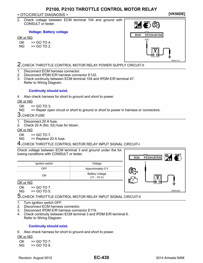
[VK56DE]P2100, P2103 THROTTLE CONTROL MOTOR RELAY
< DTC/CIRCUIT DIAGNOSIS >2. Check voltage between ECM terminal 104 and ground with
CONSULT or tester.
OK or NGOK >> GO TO 4.NG >> GO TO 2.
2.CHECK THROTTLE CONTROL MOTOR RELAY POWER SUPPLY CIRCUIT-II
1. Disconnect ECM harness connector.2. Disconnect IPDM E/R harness connector E122.3. Check continuity between ECM terminal 104 and IPDM E/R terminal 47.
Refer to Wiring Diagram.
4. Also check harness for short to ground and short to power.OK or NGOK >> GO TO 3.NG >> Repair open circuit or short to ground or short to power in harness or connectors.
3.CHECK FUSE
1. Disconnect 20 A fuse.2. Check 20 A (No. 52) fuse for blown.OK or NGOK >> GO TO 7.NG >> Replace 20 A fuse.
4.CHECK THROTTLE CONTROL MOTOR RELAY INPUT SIGNAL CIRCUIT-I
Check voltage between ECM terminal 3 and ground under the fol-lowing conditions with CONSULT or tester.
OK or NGOK >> GO TO 7.NG >> GO TO 5.
5.CHECK THROTTLE CONTROL MOTOR RELAY INPUT SIGNAL CIRCUIT-II
1. Turn ignition switch OFF.2. Disconnect ECM harness connector.3. Disconnect IPDM E/R harness connector E119.4. Check continuity between ECM terminal 3 and IPDM E/R terminal 6.
Refer to Wiring Diagram.
5. Also check harness for short to ground and short to power.OK or NGOK >> GO TO 7.NG >> GO TO 6.
Voltage: Battery voltage
PBIB1171E
Continuity should exist.
Ignition switch Voltage
OFF Approximately 0 V
ONBattery voltage
(11 - 14 V)
MBIB0028E
Continuity should exist.
EC-430Revision: August 2013 2014 Armada NAM

P2100, P2103 THROTTLE CONTROL MOTOR RELAY[VK56DE]
C
D
E
F
G
H
I
J
K
L
M
A
C
N
P
O
< DTC/CIRCUIT DIAGNOSIS >
E
6.DETECT MALFUNCTIONING PART
Check the following.• Harness connectors E2, F32• Harness for open or short between ECM and IPDM E/R
>> Repair open circuit or short to ground or short to power in harness or connectors.
7.CHECK INTERMITTENT INCIDENT
Refer to GI-39, "How to Check Terminal" and GI-42, "Intermittent Incident".OK or NGOK >> Replace IPDM E/R. Refer to PCS-31, "Removal and Installation of IPDM E/R".NG >> Repair or replace harness or connectors.
EC-431Revision: August 2013 2014 Armada NAM
[VK56DE]P2101 ELECTRIC THROTTLE CONTROL FUNCTION
< DTC/CIRCUIT DIAGNOSIS >
P2101 ELECTRIC THROTTLE CONTROL FUNCTION
Description INFOID:0000000009825387
NOTE:If DTC P2101 is displayed with DTC P2100 or 2119, first perform the trouble diagnosis for DTC P2100or P2119. Refer to EC-429 or EC-438 .Electric throttle control actuator consists of throttle control motor, throttle position sensor, etc.The throttle control motor is operated by the ECM and it opens and closes the throttle valve.The current opening angle of the throttle valve is detected by the throttle position sensor and it provides feed-back to the ECM to control the throttle control motor to make the throttle valve opening angle properly inresponse to driving condition.
On Board Diagnosis Logic INFOID:0000000009825388
This self-diagnosis has the one trip detection logic.
FAIL-SAFE MODEWhen the malfunction is detected, ECM enters fail-safe mode and the MIL lights up.
DTC Confirmation Procedure INFOID:0000000009825389
NOTE:If DTC Confirmation Procedure has been previously conducted, always perform the following before conduct-ing the next step.1. Turn ignition switch OFF and wait at least 10 seconds.2. Turn ignition switch ON.3. Turn ignition switch OFF and wait at least 10 seconds.TESTING CONDITION:Before performing the following procedure, confirm that battery voltage is more than 11 V whenengine is running.1. Turn ignition switch ON and wait at least 2 seconds.2. Start engine and let it idle for 5 seconds.3. Check DTC.4. If DTC is detected, go to EC-432, "Diagnosis Procedure".
Diagnosis Procedure INFOID:0000000009825390
1.CHECK GROUND CONNECTIONS
1. Turn ignition switch OFF.2. Loosen and retighten three ground screws on the body.
DTC No. Trouble diagnosis name DTC detecting condition Possible cause
P21012101
Electric throttle control performance
Electric throttle control function does not oper-ate properly.
• Harness or connectors(Throttle control motor circuit is open or shorted)
• Electric throttle control actuator
Engine operating condition in fail-safe mode
ECM stops the electric throttle control actuator control, throttle valve is maintained at a fixed opening (approx. 5 degrees) by the return spring.
EC-432Revision: August 2013 2014 Armada NAM

P2101 ELECTRIC THROTTLE CONTROL FUNCTION[VK56DE]
C
D
E
F
G
H
I
J
K
L
M
A
C
N
P
O
< DTC/CIRCUIT DIAGNOSIS >
E
Refer to EC-153, "Ground Inspection" .
OK or NGOK >> GO TO 2.NG >> Repair or replace ground connections.
2.CHECK THROTTLE CONTROL MOTOR RELAY INPUT SIGNAL CIRCUIT-I
1. Check voltage between ECM terminal 3 and ground under thefollowing conditions with CONSULT or tester.
OK or NGOK >> GO TO 9.NG >> GO TO 3.
3.CHECK THROTTLE CONTROL MOTOR RELAY POWER SUPPLY CIRCUIT-I
1. Turn ignition switch OFF.2. Check voltage between ECM terminal 104 and ground with
CONSULT or tester.
OK or NGOK >> GO TO 6.NG >> GO TO 4.
4.CHECK THROTTLE CONTROL MOTOR RELAY POWER SUPPLY CIRCUIT-II
1. Disconnect ECM harness connector.2. Disconnect IPDM E/R harness connector E122.3. Check harness continuity between ECM terminal 104 and IPDM E/R terminal 47.
Refer to Wiring Diagram.
4. Also check harness for short to ground and short to power.OK or NGOK >> GO TO 5.NG >> Repair open circuit or short to ground or short to power in harness or connectors.
5.CHECK FUSE
1. Disconnect 20 A fuse.2. Check 20 A (No. 52) fuse for blown.OK or NG
BBIA0354E
Ignition switch Voltage
OFF Approximately 0 V
ONBattery voltage
(11 - 14 V)
MBIB0028E
Voltage: Battery voltage
PBIB1171E
Continuity should exist.
EC-433Revision: August 2013 2014 Armada NAM

[VK56DE]P2101 ELECTRIC THROTTLE CONTROL FUNCTION
< DTC/CIRCUIT DIAGNOSIS >OK >> GO TO 8.NG >> Replace 20 A fuse.
6.CHECK THROTTLE CONTROL MOTOR RELAY INPUT SIGNAL CIRCUIT-II
1. Disconnect ECM harness connector.2. Disconnect IPDM E/R harness connector E119.3. Check harness continuity between ECM terminal 3 and IPDM E/R terminal 6.
Refer to Wiring Diagram.
4. Also check harness for short to ground and short to power.OK or NGOK >> GO TO 8.NG >> GO TO 7.
7.DETECT MALFUNCTIONING PART
Check the following.• Harness connectors E2, F32• Harness for open or short between ECM and IPDM E/R
>> Repair open circuit or short to ground or short to power in harness or connectors.
8.CHECK INTERMITTENT INCIDENT
Refer to GI-39, "How to Check Terminal" and GI-42, "Intermittent Incident".OK or NGOK >> Replace IPDM E/R. Refer to PCS-31, "Removal and Installation of IPDM E/R" .NG >> Repair or replace harness or connectors.
9.CHECK THROTTLE CONTROL MOTOR OUTPUT SIGNAL CIRCUIT FOR OPEN OR SHORT
1. Turn ignition switch OFF.2. Disconnect electric throttle control actuator harness connector.3. Disconnect ECM harness connector.4. Check harness continuity between the following terminals.
Refer to Wiring Diagram.
5. Also check harness for short to ground and short to power.OK or NGOK >> GO TO 10.NG >> Repair or replace.
10.CHECK ELECTRIC THROTTLE CONTROL ACTUATOR VISUALLY
1. Remove the intake air duct. Refer to EM-26.
Continuity should exist.
Electric throttle control actuator terminal
ECM terminal Continuity
55 Should not exist
4 Should exist
65 Should exist
4 Should not exist
PBIB1480E
EC-434Revision: August 2013 2014 Armada NAM

P2101 ELECTRIC THROTTLE CONTROL FUNCTION[VK56DE]
C
D
E
F
G
H
I
J
K
L
M
A
C
N
P
O
< DTC/CIRCUIT DIAGNOSIS >
E
2. Check if foreign matter is caught between the throttle valve andthe housing.
OK or NGOK >> GO TO 11.NG >> Remove the foreign matter and clean the electric throttle
control actuator inside, and then perform throttle valveclosed position learning. Refer to EC-127, "ThrottleValve Closed Position Learning".
11.CHECK THROTTLE CONTROL MOTOR
Refer to EC-435, "Component Inspection" .OK or NGOK >> GO TO 12.NG >> GO TO 13.
12.CHECK INTERMITTENT INCIDENT
Refer to GI-39, "How to Check Terminal" and GI-42, "Intermittent Incident".OK or NGOK >> GO TO 13.NG >> Repair or replace harness or connectors.
13.REPLACE ELECTRIC THROTTLE CONTROL ACTUATOR
1. Replace the electric throttle control actuator.2. Perform EC-127, "Throttle Valve Closed Position Learning".3. Perform EC-128, "Idle Air Volume Learning".
>> INSPECTION END
Component Inspection INFOID:0000000009825391
THROTTLE CONTROL MOTOR1. Disconnect electric throttle control actuator harness connector.2. Check resistance between terminals 5 and 6.
3. If NG, replace electric throttle control actuator and go to nextstep.
4. Perform EC-127, "Throttle Valve Closed Position Learning" .5. Perform EC-128, "Idle Air Volume Learning" .
BBIA0364E
Resistance: Approximately 1 - 15 [at 25 C (77F)]
PBIB2066E
EC-435Revision: August 2013 2014 Armada NAM

[VK56DE]P2118 THROTTLE CONTROL MOTOR
< DTC/CIRCUIT DIAGNOSIS >
P2118 THROTTLE CONTROL MOTOR
Component Description INFOID:0000000009825392
The throttle control motor is operated by the ECM and it opens and closes the throttle valve.The current opening angle of the throttle valve is detected by the throttle position sensor and it provides feed-back to the ECM to control the throttle control motor to make the throttle valve opening angle properly inresponse to driving condition.
On Board Diagnosis Logic INFOID:0000000009825393
This self-diagnosis has the one trip detection logic.
FAIL-SAFE MODEWhen the malfunction is detected, the ECM enters fail-safe mode and the MIL lights up.
DTC Confirmation Procedure INFOID:0000000009825394
1. If DTC Confirmation Procedure has been previously conducted, always perform the following before con-ducting the next step.
a. Turn ignition switch OFF and wait at least 10 seconds.b. Turn ignition switch ON.c. Turn ignition switch OFF and wait at least 10 seconds.2. Turn ignition switch ON and wait at least 2 seconds.3. Start engine and let it idle for 5 seconds.4. Check DTC.5. If DTC is detected, go to EC-436, "Diagnosis Procedure".
Diagnosis Procedure INFOID:0000000009825395
1.CHECK GROUND CONNECTIONS
1. Turn ignition switch OFF.2. Loosen and retighten three ground screws on the body.
Refer to EC-153, "Ground Inspection".
OK or NGOK >> GO TO 2.NG >> Repair or replace ground connections.
DTC No. Trouble diagnosis name DTC detecting condition Possible cause
P21182118
Throttle control motor circuit short
ECM detects short in both circuits between ECM and throttle control motor.
• Harness or connectors(Throttle control motor circuit is shorted.)
• Electric throttle control actuator(Throttle control motor)
Engine operating condition in fail-safe mode
ECM stops the electric throttle control actuator control, throttle valve is maintained at a fixed opening (approx. 5 degrees) by the return spring.
BBIA0354E
EC-436Revision: August 2013 2014 Armada NAM

P2118 THROTTLE CONTROL MOTOR[VK56DE]
C
D
E
F
G
H
I
J
K
L
M
A
C
N
P
O
< DTC/CIRCUIT DIAGNOSIS >
E
2.CHECK THROTTLE CONTROL MOTOR OUTPUT SIGNAL CIRCUIT FOR OPEN OR SHORT
1. Disconnect electric throttle control actuator harness connector.- Illustration shows the view with intake air duct removed.2. Disconnect ECM harness connector.3. Check harness continuity between the following terminals.
Refer to Wiring Diagram.
4. Also check harness for short to ground and short to power.OK or NGOK >> GO TO 3.NG >> Repair or replace.
3.CHECK THROTTLE CONTROL MOTOR
Refer to EC-437, "Component Inspection".OK or NGOK >> GO TO 4.NG >> GO TO 5.
4.CHECK INTERMITTENT INCIDENT
Refer to GI-39, "How to Check Terminal" and GI-42, "Intermittent Incident".OK or NGOK >> GO TO 5.NG >> Repair or replace harness or connectors.
5.REPLACE ELECTRIC THROTTLE CONTROL ACTUATOR
1. Replace the electric throttle control actuator.2. Perform EC-127, "Throttle Valve Closed Position Learning".3. Perform EC-128, "Idle Air Volume Learning".
>> INSPECTION END
Component Inspection INFOID:0000000009825396
THROTTLE CONTROL MOTOR1. Disconnect electric throttle control actuator harness connector.2. Check resistance between terminals 5 and 6.
3. If NG, replace electric throttle control actuator and go to nextstep.
4. Perform EC-127, "Throttle Valve Closed Position Learning".5. Perform EC-128, "Idle Air Volume Learning".
Electric throttle control actuator terminal
ECM terminal Continuity
55 Should not exist
4 Should exist
65 Should exist
4 Should not exist
BBIA0776E
Resistance: Approximately 1 - 15 [at 25 C (77F)]
PBIB2066E
EC-437Revision: August 2013 2014 Armada NAM

[VK56DE]P2119 ELECTRIC THROTTLE CONTROL ACTUATOR
< DTC/CIRCUIT DIAGNOSIS >
P2119 ELECTRIC THROTTLE CONTROL ACTUATOR
Component Description INFOID:0000000009825397
Electric throttle control actuator consists of throttle control motor, throttle position sensor, etc.The throttle control motor is operated by the ECM and it opens and closes the throttle valve.The throttle position sensor detects the throttle valve position, and the opening and closing speed of the throt-tle valve and feeds the voltage signals to the ECM. The ECM judges the current opening angle of the throttlevalve from these signals and the ECM controls the throttle control motor to make the throttle valve openingangle properly in response to driving condition.
On Board Diagnosis Logic INFOID:0000000009825398
This self-diagnosis has one trip detection logic.
FAIL-SAFE MODEWhen the malfunction is detected, ECM enters fail-safe mode and the MIL lights up.
DTC Confirmation Procedure INFOID:0000000009825399
NOTE:• Perform PROCEDURE FOR MALFUNCTION A AND B first. If the DTC cannot be confirmed, perform
PROCEDURE FOR MALFUNCTION C.• If DTC Confirmation Procedure has been previously conducted, always perform the following before con-
ducting the next step.1. Turn ignition switch OFF and wait at least 10 seconds.2. Turn ignition switch ON.3. Turn ignition switch OFF and wait at least 10 seconds.
PROCEDURE FOR MALFUNCTION A AND B1. Turn ignition switch ON and wait at least 1 second.2. Shift selector lever to D position and wait at least 3 seconds.3. Shift selector lever to P or N position.4. Turn ignition switch OFF and wait at least 10 seconds.5. Turn ignition switch ON and wait at least 1 second.6. Shift selector lever to D position and wait at least 3 seconds.7. Shift selector lever to P or N position.8. Turn ignition switch OFF, wait at least 10 seconds and then turn ON.9. Check DTC.10. If DTC is detected, go to EC-439, "Diagnosis Procedure".
PROCEDURE FOR MALFUNCTION C
DTC No. Trouble diagnosis name DTC detecting condition Possible cause
P21192119
Electric throttle control actuator
A)Electric throttle control actuator does not func-tion properly due to the return spring malfunc-tion.
• Electric throttle control actuatorB)
Throttle valve opening angle in fail-safe mode is not in specified range.
C) ECM detect the throttle valve is stuck open.
Detected items Engine operating condition in fail-safe mode
Malfunction AThe ECM controls the electric throttle actuator by regulating the throttle opening around the idle position. The engine speed will not rise more than 2,000 rpm.
Malfunction B ECM controls the electric throttle control actuator by regulating the throttle opening to 20 degrees or less.
Malfunction CWhile the vehicle is driving, it slows down gradually by fuel cut. After the vehicle stops, the engine stalls.The engine can restart in N or P position, and engine speed will not exceed 1,000 rpm or more.
EC-438Revision: August 2013 2014 Armada NAM

P2119 ELECTRIC THROTTLE CONTROL ACTUATOR[VK56DE]
C
D
E
F
G
H
I
J
K
L
M
A
C
N
P
O
< DTC/CIRCUIT DIAGNOSIS >
E
1. Turn ignition switch ON and wait at least 1 second.2. Shift selector lever to D position and wait at least 3 seconds.3. Shift selector lever to P position.4. Start engine and let it idle for 3 seconds.5. Check DTC.6. If DTC is detected, go to EC-439, "Diagnosis Procedure".
Diagnosis Procedure INFOID:0000000009825400
1.CHECK ELECTRIC THROTTLE CONTROL ACTUATOR VISUALLY
1. Remove the intake air duct. Refer to EM-26, "Removal and Installation".2. Check if a foreign matter is caught between the throttle valve
and the housing.OK or NGOK >> GO TO 2.NG >> Remove the foreign matter and clean the electric throttle
control actuator inside, and then perform throttle valveclosed position learning. Refer to EC-127, "ThrottleValve Closed Position Learning".
2.REPLACE ELECTRIC THROTTLE CONTROL ACTUATOR
1. Replace the electric throttle control actuator. Refer to EM-27, "Removal and Installation".2. Perform EC-127, "Throttle Valve Closed Position Learning".3. Perform EC-128, "Idle Air Volume Learning".
>> INSPECTION END
BBIA0364E
EC-439Revision: August 2013 2014 Armada NAM

[VK56DE]P2122, P2123 APP SENSOR
< DTC/CIRCUIT DIAGNOSIS >
P2122, P2123 APP SENSOR
Component Description INFOID:0000000009825401
The accelerator pedal position sensor is installed on the upper endof the accelerator pedal assembly. The sensor detects the accelera-tor position and sends a signal to the ECM.Accelerator pedal position sensor has two sensors. These sensorsare a kind of potentiometers which transform the accelerator pedalposition into output voltage, and emit the voltage signal to the ECM.In addition, these sensors detect the opening and closing speed ofthe accelerator pedal and feed the voltage signals to the ECM. TheECM judges the current opening angle of the accelerator pedal fromthese signals and controls the throttle control motor based on thesesignals.Idle position of the accelerator pedal is determined by the ECMreceiving the signal from the accelerator pedal position sensor. The ECM uses this signal for the engine oper-ation such as fuel cut.
On Board Diagnosis Logic INFOID:0000000009825402
These self-diagnoses have the one trip detection logic.NOTE:If DTC P2122 or P2123 is displayed with DTC P0643, first perform the trouble diagnosis for DTC P0643.Refer to EC-367 .
FAIL-SAFE MODEWhen the malfunction is detected, ECM enters fail-safe mode and the MIL lights up.
DTC Confirmation Procedure INFOID:0000000009825403
NOTE:If DTC Confirmation Procedure has been previously conducted, always perform the following before conduct-ing the next step.1. Turn ignition switch OFF and wait at least 10 seconds.2. Turn ignition switch ON.3. Turn ignition switch OFF and wait at least 10 seconds.TESTING CONDITION:Before performing the following procedure, confirm that battery voltage is more than 8 V at idle.1. Start engine and let it idle for 1 second.2. Check DTC.3. If DTC is detected, go to EC-440, "Diagnosis Procedure".
Diagnosis Procedure INFOID:0000000009825404
1.CHECK GROUND CONNECTIONS
PBIB1741E
DTC No. Trouble diagnosis name DTC detecting condition Possible cause
P21222122
Accelerator pedal position sensor 1 circuit low input
An excessively low voltage from the APP sen-sor 1 is sent to ECM.
• Harness or connectors(The APP sensor 1 circuit is open or shorted.)
• Accelerator pedal position sensor(Accelerator pedal position sensor 1)
P21232123
Accelerator pedal position sensor 1 circuit high input
An excessively high voltage from the APP sen-sor 1 is sent to ECM.
Engine operating condition in fail-safe mode
The ECM controls the electric throttle control actuator in regulating the throttle opening in order for the idle position to be within +10 degrees.The ECM regulates the opening speed of the throttle valve to be slower than the normal condition.So, the acceleration will be poor.
EC-440Revision: August 2013 2014 Armada NAM

P2122, P2123 APP SENSOR[VK56DE]
C
D
E
F
G
H
I
J
K
L
M
A
C
N
P
O
< DTC/CIRCUIT DIAGNOSIS >
E
1. Turn ignition switch OFF.2. Loosen and retighten three ground screws on the body.
Refer to EC-153, "Ground Inspection" .
OK or NGOK >> GO TO 2.NG >> Repair or replace ground connections.
2.CHECK APP SENSOR 1 POWER SUPPLY CIRCUIT
1. Disconnect accelerator pedal position (APP) sensor harnessconnector.
2. Turn ignition switch ON.
3. Check voltage between APP sensor terminal 7 and ground withCONSULT or tester.
OK or NGOK >> GO TO 3.NG >> Repair open circuit or short to ground or short to power
in harness or connectors.
3.CHECK APP SENSOR 1 GROUND CIRCUIT FOR OPEN AND SHORT
1. Turn ignition switch OFF.2. Disconnect ECM harness connector.3. Check harness continuity between ECM terminal 82 and APP sensor terminal 1.
Refer to Wiring Diagram.
4. Also check harness for short to ground and short to power.OK or NGOK >> GO TO 4.NG >> Repair open circuit or short to ground or short to power in harness or connectors.
4.CHECK APP SENSOR INPUT SIGNAL CIRCUIT FOR OPEN AND SHORT
1. Check harness continuity between ECM terminal 106 and APP sensor terminal 2.Refer to Wiring Diagram.
BBIA0354E
BBIA0361E
Voltage: Approximately 5 V
JPBIA5715ZZ
Continuity should exist.
EC-441Revision: August 2013 2014 Armada NAM

[VK56DE]P2122, P2123 APP SENSOR
< DTC/CIRCUIT DIAGNOSIS >
2. Also check harness for short to ground and short to power.OK or NGOK >> GO TO 5.NG >> Repair open circuit or short to ground or short to power in harness or connectors.
5.CHECK APP SENSOR
Refer to EC-442, "Component Inspection" .OK or NGOK >> GO TO 7.NG >> GO TO 6.
6.REPLACE ACCELERATOR PEDAL ASSEMBLY
1. Replace the accelerator pedal assembly. Refer to ACC-4.2. Perform EC-127, "Accelerator Pedal Released Position Learning".3. Perform EC-127, "Throttle Valve Closed Position Learning".4. Perform EC-128, "Idle Air Volume Learning".
>> INSPECTION END
7.CHECK INTERMITTENT INCIDENT
Refer to GI-39, "How to Check Terminal" and GI-42, "Intermittent Incident".
>> INSPECTION END
Component Inspection INFOID:0000000009825405
ACCELERATOR PEDAL POSITION SENSOR1. Reconnect all harness connectors disconnected.2. Turn ignition switch ON.3. Check voltage between ECM terminals 106 (APP sensor 1 sig-
nal), 98 (APP sensor 2 signal) and ground under the followingconditions.
4. If NG, replace accelerator pedal assembly, refer to ACC-4, and go to next step.5. Perform EC-127, "Accelerator Pedal Released Position Learning".6. Perform EC-127, "Throttle Valve Closed Position Learning".7. Perform EC-128, "Idle Air Volume Learning".
Continuity should exist.
Terminal Accelerator pedal Voltage
106 (Accelerator pedal position sensor 1)
Fully released 0.5 - 1.0 V
Fully depressed 4.2 - 4.8 V
98(Accelerator pedal position sensor 2)
Fully released 0.25 - 0.5 V
Fully depressed 2.0 - 2.5 V MBIB0023E
EC-442Revision: August 2013 2014 Armada NAM

P2127, P2128 APP SENSOR[VK56DE]
C
D
E
F
G
H
I
J
K
L
M
A
C
N
P
O
< DTC/CIRCUIT DIAGNOSIS >
E
P2127, P2128 APP SENSOR
Component Description INFOID:0000000009825406
The accelerator pedal position sensor is installed on the upper endof the accelerator pedal assembly. The sensor detects the accelera-tor position and sends a signal to the ECM.Accelerator pedal position sensor has two sensors. These sensorsare a kind of potentiometers which transform the accelerator pedalposition into output voltage, and emit the voltage signal to the ECM.In addition, these sensors detect the opening and closing speed ofthe accelerator pedal and feed the voltage signals to the ECM. TheECM judges the current opening angle of the accelerator pedal fromthese signals and controls the throttle control motor based on thesesignals.Idle position of the accelerator pedal is determined by the ECMreceiving the signal from the accelerator pedal position sensor. The ECM uses this signal for the engine oper-ation such as fuel cut.
On Board Diagnosis Logic INFOID:0000000009825407
These self-diagnoses have the one trip detection logic.
FAIL-SAFE MODEWhen the malfunction is detected, ECM enters fail-safe mode and the MIL lights up.
DTC Confirmation Procedure INFOID:0000000009825408
NOTE:If DTC Confirmation Procedure has been previously conducted, always perform the following before conduct-ing the next step.1. Turn ignition switch OFF and wait at least 10 seconds.2. Turn ignition switch ON.3. Turn ignition switch OFF and wait at least 10 seconds.TESTING CONDITION:Before performing the following procedure, confirm that battery voltage is more than 8 V at idle.1. Start engine and let it idle for 1 second.2. Check DTC.3. If DTC is detected, go to EC-443, "Diagnosis Procedure".
Diagnosis Procedure INFOID:0000000009825409
1.CHECK GROUND CONNECTIONS
1. Turn ignition switch OFF.2. Loosen and retighten three ground screws on the body.
PBIB1741E
DTC No. Trouble diagnosis name DTC detecting condition Possible cause
P21272127
Accelerator pedal position sensor 2 circuit low input
An excessively low voltage from the APP sensor 2 is sent to ECM.
• Harness or connectors(APP sensor 2 circuit is open or shorted.)(TP sensor circuit is shorted.)
• Accelerator pedal position sensor(Accelerator pedal position sensor 2)
• Electric throttle control actuator(TP sensor)
P21282128
Accelerator pedal position sensor 2 circuit high input
An excessively high voltage from the APP sensor 2 is sent to ECM.
Engine operating condition in fail-safe mode
The ECM controls the electric throttle control actuator in regulating the throttle opening in order for the idle position to be within +10 degrees.The ECM regulates the opening speed of the throttle valve to be slower than the normal condition.So, the acceleration will be poor.
EC-443Revision: August 2013 2014 Armada NAM
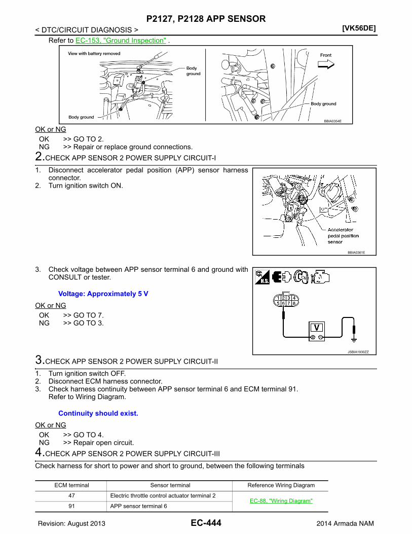
[VK56DE]P2127, P2128 APP SENSOR
< DTC/CIRCUIT DIAGNOSIS >Refer to EC-153, "Ground Inspection" .
OK or NGOK >> GO TO 2.NG >> Repair or replace ground connections.
2.CHECK APP SENSOR 2 POWER SUPPLY CIRCUIT-I
1. Disconnect accelerator pedal position (APP) sensor harnessconnector.
2. Turn ignition switch ON.
3. Check voltage between APP sensor terminal 6 and ground withCONSULT or tester.
OK or NGOK >> GO TO 7.NG >> GO TO 3.
3.CHECK APP SENSOR 2 POWER SUPPLY CIRCUIT-II
1. Turn ignition switch OFF.2. Disconnect ECM harness connector.3. Check harness continuity between APP sensor terminal 6 and ECM terminal 91.
Refer to Wiring Diagram.
OK or NGOK >> GO TO 4.NG >> Repair open circuit.
4.CHECK APP SENSOR 2 POWER SUPPLY CIRCUIT-III
Check harness for short to power and short to ground, between the following terminals
BBIA0354E
BBIA0361E
Voltage: Approximately 5 V
JSBIA1930ZZ
Continuity should exist.
ECM terminal Sensor terminal Reference Wiring Diagram
47 Electric throttle control actuator terminal 2EC-88, "Wiring Diagram"
91 APP sensor terminal 6
EC-444Revision: August 2013 2014 Armada NAM

P2127, P2128 APP SENSOR[VK56DE]
C
D
E
F
G
H
I
J
K
L
M
A
C
N
P
O
< DTC/CIRCUIT DIAGNOSIS >
E
OK or NGOK >> GO TO 5.NG >> Repair short to ground or short to power in harness or connectors.
5.CHECK THROTTLE POSITION SENSOR
Refer to EC-450, "Component Inspection" .OK or NGOK >> GO TO 11.NG >> GO TO 6.
6.REPLACE ELECTRIC THROTTLE CONTROL ACTUATOR
1. Replace the electric throttle control actuator. Refer to EM-27.2. Perform EC-127, "Throttle Valve Closed Position Learning".3. Perform EC-128, "Idle Air Volume Learning".
>> INSPECTION END
7.CHECK APP SENSOR 2 GROUND CIRCUIT FOR OPEN AND SHORT
1. Turn ignition switch OFF.2. Disconnect ECM harness connector.3. Check harness continuity between ECM terminal 83 and APP sensor terminal 3.
Refer to Wiring Diagram.
4. Also check harness for short to ground and short to power.OK or NGOK >> GO TO 8.NG >> Repair open circuit or short to ground or short to power in harness or connectors.
8.CHECK APP SENSOR 2 INPUT SIGNAL CIRCUIT FOR OPEN AND SHORT
1. Check harness continuity between ECM terminal 98 and APP sensor terminal 5.Refer to Wiring Diagram.
2. Also check harness for short to ground and short to power.OK or NGOK >> GO TO 9.NG >> Repair open circuit or short to ground or short to power in harness or connectors.
9.CHECK APP SENSOR
Refer to EC-446, "Component Inspection".OK or NGOK >> GO TO 11.NG >> GO TO 10.
10.REPLACE ACCELERATOR PEDAL ASSEMBLY
1. Replace the accelerator pedal assembly. Refer to ACC-4.2. Perform EC-127, "Accelerator Pedal Released Position Learning".3. Perform EC-127, "Throttle Valve Closed Position Learning".4. Perform EC-128, "Idle Air Volume Learning".
>> INSPECTION END
11.CHECK INTERMITTENT INCIDENT
Refer to GI-39, "How to Check Terminal" and GI-42, "Intermittent Incident".
Continuity should exist.
Continuity should exist.
EC-445Revision: August 2013 2014 Armada NAM

[VK56DE]P2127, P2128 APP SENSOR
< DTC/CIRCUIT DIAGNOSIS >>> INSPECTION END
Component Inspection INFOID:0000000009825410
ACCELERATOR PEDAL POSITION SENSOR1. Reconnect all harness connectors disconnected.2. Turn ignition switch ON.3. Check voltage between ECM terminals 106 (APP sensor 1 sig-
nal), 98 (APP sensor 2 signal) and ground under the followingconditions.
4. If NG, replace accelerator pedal assembly, refer to ACC-4, and go to next step.5. Perform EC-127, "Accelerator Pedal Released Position Learning".6. Perform EC-127, "Throttle Valve Closed Position Learning".7. Perform EC-128, "Idle Air Volume Learning".
Terminal Accelerator pedal Voltage
106 (Accelerator pedal position sensor 1)
Fully released 0.5 - 1.0 V
Fully depressed 4.2 - 4.8 V
98(Accelerator pedal position sensor 2)
Fully released 0.25 - 0.5 V
Fully depressed 2.0 - 2.5 V MBIB0023E
EC-446Revision: August 2013 2014 Armada NAM

P2135 TP SENSOR[VK56DE]
C
D
E
F
G
H
I
J
K
L
M
A
C
N
P
O
< DTC/CIRCUIT DIAGNOSIS >
E
P2135 TP SENSOR
Component Description INFOID:0000000009825411
Electric throttle control actuator consists of throttle control motor,throttle position sensor, etc. The throttle position sensor responds tothe throttle valve movement.The throttle position sensor has the two sensors. These sensors area kind of potentiometers which transform the throttle valve positioninto output voltage, and emit the voltage signal to the ECM. In addi-tion, these sensors detect the opening and closing speed of thethrottle valve and feed the voltage signals to the ECM. The ECMjudges the current opening angle of the throttle valve from these sig-nals and the ECM controls the throttle control motor to make thethrottle valve opening angle properly in response to driving condi-tion.
On Board Diagnosis Logic INFOID:0000000009825412
This self-diagnosis has the one trip detection logic.
FAIL-SAFE MODEWhen the malfunction is detected, the ECM enters fail-safe mode and the MIL lights up.
DTC Confirmation Procedure INFOID:0000000009825413
NOTE:If DTC Confirmation Procedure has been previously conducted, always perform the following before conduct-ing the next step.1. Turn ignition switch OFF and wait at least 10 seconds.2. Turn ignition switch ON.3. Turn ignition switch OFF and wait at least 10 seconds.TESTING CONDITION:Before performing the following procedure, confirm that battery voltage is more than 8 V at idle.1. Start engine and let it idle for 1 second.2. Check DTC.3. If DTC is detected, go to EC-447, "Diagnosis Procedure".
Diagnosis Procedure INFOID:0000000009825414
1.CHECK GROUND CONNECTIONS
1. Turn ignition switch OFF.2. Loosen and retighten three ground screws on the body.
PBIB0145E
DTC No. Trouble diagnosis name DTC detecting condition Possible cause
P21352135
Throttle position sensor circuit range/performance
Rationally incorrect voltage is sent to ECM compared with the signals from TP sensor 1 and TP sensor 2.
• Harness or connector(TP sensor 1 and 2 circuit is open or shorted.)(APP sensor 2 circuit is shorted.)
• Electric throttle control actuator(TP sensor 1 and 2)
• Accelerator pedal position sensor(APP sensor 2)
Engine operation condition in fail-safe mode
The ECM controls the electric throttle control actuator in regulating the throttle opening in order for the idle position to be within +10 degrees.The ECM regulates the opening speed of the throttle valve to be slower than the normal condition.So, the acceleration will be poor.
EC-447Revision: August 2013 2014 Armada NAM

[VK56DE]P2135 TP SENSOR
< DTC/CIRCUIT DIAGNOSIS >Refer to EC-153, "Ground Inspection" .
OK or NGOK >> GO TO 2.NG >> Repair or replace ground connections.
2.CHECK THROTTLE POSITION SENSOR POWER SUPPLY CIRCUIT-I
1. Disconnect electric throttle control actuator harness connector.2. Turn ignition switch ON.
3. Check voltage between electric throttle control actuator terminal2 and ground with CONSULT or tester.
OK or NGOK >> GO TO 7.NG >> GO TO 3.
3.CHECK THROTTLE POSITION SENSOR POWER SUPPLY CIRCUIT-II
1. Turn ignition switch OFF.2. Disconnect ECM harness connector.3. Check harness continuity between electric throttle control actuator terminal 2 and ECM terminal 47.
Refer to Wiring Diagram.
OK or NGOK >> GO TO 4.NG >> Repair open circuit.
4.CHECK THROTTLE POSITION SENSOR POWER SUPPLY CIRCUIT-III
Check harness for short to power and short to ground, between the following terminals.
BBIA0354E
BBIA0371E
Voltage: Approximately 5 V
PBIB2065E
Continuity should exist.
ECM terminal Sensor terminal Reference Wiring Diagram
47 Electric throttle control actuator terminal 2EC-88, "Wiring Diagram"
91 APP sensor terminal 7
EC-448Revision: August 2013 2014 Armada NAM

P2135 TP SENSOR[VK56DE]
C
D
E
F
G
H
I
J
K
L
M
A
C
N
P
O
< DTC/CIRCUIT DIAGNOSIS >
E
OK or NGOK >> GO TO 5.NG >> Repair short to ground or short to power in harness or connectors.
5.CHECK ACCELERATOR PEDAL POSITION SENSOR
Refer to EC-454, "Component Inspection" .OK or NGOK >> GO TO 11.NG >> GO TO 6.
6.REPLACE ACCELERATOR PEDAL ASSEMBLY
1. Replace the accelerator pedal assembly. Refer to ACC-4.2. Perform EC-127, "Accelerator Pedal Released Position Learning".3. Perform EC-127, "Throttle Valve Closed Position Learning".4. Perform EC-128, "Idle Air Volume Learning".
>> INSPECTION END
7.CHECK THROTTLE POSITION SENSOR GROUND CIRCUIT FOR OPEN AND SHORT
1. Turn ignition switch OFF.2. Disconnect ECM harness connector.3. Check harness continuity between electric throttle control actuator terminal 4 and ECM terminal 66.
Refer to Wiring Diagram.
4. Also check harness for short to ground and short to power.OK or NGOK >> GO TO 8.NG >> Repair open circuit or short to ground or short to power in harness or connectors.
8.CHECK THROTTLE POSITION SENSOR INPUT SIGNAL CIRCUIT FOR OPEN AND SHORT
1. Check harness continuity between ECM terminal 50 and electric throttle control actuator terminal 1, ECMterminal 69 and electric throttle control actuator terminal 3.Refer to Wiring Diagram.
2. Also check harness for short to ground and short to power.OK or NGOK >> GO TO 9.NG >> Repair open circuit or short to ground or short to power in harness or connectors.
9.CHECK THROTTLE POSITION SENSOR
Refer to EC-450, "Component Inspection".OK or NGOK >> GO TO 11.NG >> GO TO 10.
10.REPLACE ELECTRIC THROTTLE CONTROL ACTUATOR
1. Replace the electric throttle control actuator. Refer to EM-27.2. Perform EC-127, "Throttle Valve Closed Position Learning".3. Perform EC-128, "Idle Air Volume Learning".
>> INSPECTION END
11.CHECK INTERMITTENT INCIDENT
Refer to GI-39, "How to Check Terminal" and GI-42, "Intermittent Incident".
Continuity should exist.
Continuity should exist.
EC-449Revision: August 2013 2014 Armada NAM

[VK56DE]P2135 TP SENSOR
< DTC/CIRCUIT DIAGNOSIS >
>> INSPECTION END
Component Inspection INFOID:0000000009825415
THROTTLE POSITION SENSOR1. Reconnect all harness connectors disconnected.2. Perform EC-127, "Throttle Valve Closed Position Learning" .3. Turn ignition switch ON.4. Set selector lever to D position. 5. Check voltage between ECM terminals 50 (TP sensor 1 signal),
69 (TP sensor 2 signal) and ground under the following condi-tions.
6. If NG, replace electric throttle control actuator, refer to EM-27,and go to the next step.
7. Perform EC-127, "Throttle Valve Closed Position Learning".8. Perform EC-128, "Idle Air Volume Learning".
Terminal Accelerator pedal Voltage
50(Throttle position sensor 1)
Fully released More than 0.36 V
Fully depressed Less than 4.75 V
69 (Throttle position sensor 2)
Fully released Less than 4.75 V
Fully depressed More than 0.36 VPBIB1530E
EC-450Revision: August 2013 2014 Armada NAM

P2138 APP SENSOR[VK56DE]
C
D
E
F
G
H
I
J
K
L
M
A
C
N
P
O
< DTC/CIRCUIT DIAGNOSIS >
E
P2138 APP SENSOR
Component Description INFOID:0000000009825416
The accelerator pedal position sensor is installed on the upper endof the accelerator pedal assembly. The sensor detects the accelera-tor position and sends a signal to the ECM.Accelerator pedal position sensor has two sensors. These sensorsare a kind of potentiometers which transform the accelerator pedalposition into output voltage, and emit the voltage signal to the ECM.In addition, these sensors detect the opening and closing speed ofthe accelerator pedal and feed the voltage signals to the ECM. TheECM judges the current opening angle of the accelerator pedal fromthese signals and controls the throttle control motor based on thesesignals.Idle position of the accelerator pedal is determined by the ECMreceiving the signal from the accelerator pedal position sensor. The ECM uses this signal for the engine oper-ation such as fuel cut.
On Board Diagnosis Logic INFOID:0000000009825417
This self-diagnosis has the one trip detection logic.NOTE:If DTC P2138 is displayed with DTC P0643, first perform the trouble diagnosis for DTC P0643. Refer toEC-367 .
FAIL-SAFE MODEWhen the malfunction is detected, ECM enters fail-safe mode and the MIL lights up.
DTC Confirmation Procedure INFOID:0000000009825418
NOTE:If DTC Confirmation Procedure has been previously conducted, always perform the following before conduct-ing the next step.1. Turn ignition switch OFF and wait at least 10 seconds.2. Turn ignition switch ON.3. Turn ignition switch OFF and wait at least 10 seconds.TESTING CONDITION:Before performing the following procedure, confirm that battery voltage is more than 8 V at idle.1. Start engine and let it idle for 1 second.2. Check DTC.3. If DTC is detected, go to EC-452, "Diagnosis Procedure".
PBIB1741E
DTC No. Trouble diagnosis name DTC detecting condition Possible cause
P21382138
Accelerator pedal position sensor circuit range/per-formance
Rationally incorrect voltage is sent to ECM compared with the signals from APP sensor 1 and APP sensor 2.
• Harness or connector(APP sensor 1 and 2 circuit is open or shorted.)(TP sensor circuit is shorted.)
• Accelerator pedal position sensor 1 and 2• Electric throttle control actuator
(TP sensor)
Engine operating condition in fail-safe mode
The ECM controls the electric throttle control actuator in regulating the throttle opening in order for the idle position to be within +10 degrees.The ECM regulates the opening speed of the throttle valve to be slower than the normal condition.So, the acceleration will be poor.
EC-451Revision: August 2013 2014 Armada NAM

[VK56DE]P2138 APP SENSOR
< DTC/CIRCUIT DIAGNOSIS >
Diagnosis Procedure INFOID:0000000009825419
1.CHECK GROUND CONNECTIONS
1. Turn ignition switch OFF.2. Loosen and retighten three ground screws on the body.
Refer to EC-153, "Ground Inspection" .
OK or NGOK >> GO TO 2.NG >> Repair or replace ground connections.
2.CHECK APP SENSOR 1 POWER SUPPLY CIRCUIT
1. Disconnect accelerator pedal position (APP) sensor harnessconnector.
2. Turn ignition switch ON.
3. Check voltage between APP sensor terminal 7 and ground withCONSULT or tester.
OK or NGOK >> GO TO 3.NG >> Repair open circuit or short to ground or short to power
in harness or connectors.
3.CHECK APP SENSOR 2 POWER SUPPLY CIRCUIT-I
1. Turn ignition switch ON.2. Check voltage between APP sensor terminal 6 and ground with
CONSULT or tester.
OK or NGOK >> GO TO 8.NG >> GO TO 4.
BBIA0354E
BBIA0361E
Voltage: Approximately 5 V
JPBIA5715ZZ
Voltage: Approximately 5 V
JSBIA1930ZZ
EC-452Revision: August 2013 2014 Armada NAM

P2138 APP SENSOR[VK56DE]
C
D
E
F
G
H
I
J
K
L
M
A
C
N
P
O
< DTC/CIRCUIT DIAGNOSIS >
E
4.CHECK APP SENSOR 2 POWER SUPPLY CIRCUIT-II
1. Turn ignition switch OFF.2. Disconnect ECM harness connector.3. Check harness continuity between APP sensor terminal 6 and ECM terminal 91.
Refer to Wiring Diagram.
OK or NGOK >> GO TO 5.NG >> Repair open circuit in harness or connectors.
5.CHECK APP SENSOR 2 POWER SUPPLY CIRCUIT-III
Check harness for short to power and short to ground, between the following terminals
OK or NGOK >> GO TO 6.NG >> Repair short to ground or short to power in harness connectors.
6.CHECK THROTTLE POSITION SENSOR
Refer to EC-450, "Component Inspection" .OK or NGOK >> GO TO 12.NG >> GO TO 7.
7.REPLACE ELECTRIC THROTTLE CONTROL ACTUATOR
1. Replace the electric throttle control actuator. Refer to EM-27.2. Perform EC-127, "Throttle Valve Closed Position Learning".3. Perform EC-128, "Idle Air Volume Learning".
>> INSPECTION END
8.CHECK APP SENSOR GROUND CIRCUIT FOR OPEN AND SHORT
1. Turn ignition switch OFF.2. Disconnect ECM harness connector.3. Check harness continuity between ECM terminal 82 and APP sensor terminal 1, ECM terminal 83 and
APP sensor terminal 3.Refer to Wiring Diagram.
4. Also check harness for short to ground and short to power.OK or NGOK >> GO TO 9.NG >> Repair open circuit or short to ground or short to power in harness or connectors.
9.CHECK APP SENSOR INPUT SIGNAL CIRCUIT FOR OPEN AND SHORT
1. Check harness continuity between ECM terminal 106 and APP sensor terminal 2, ECM terminal 98 andAPP sensor terminal 5.Refer to Wiring Diagram.
2. Also check harness for short to ground and short to power.
Continuity should exist.
ECM terminal Sensor terminal Reference Wiring Diagram
47 Electric throttle control actuator terminal 2EC-88, "Wiring Diagram"
91 APP sensor terminal 6
Continuity should exist.
Continuity should exist.
EC-453Revision: August 2013 2014 Armada NAM

[VK56DE]P2138 APP SENSOR
< DTC/CIRCUIT DIAGNOSIS >OK or NGOK >> GO TO 10.NG >> Repair open circuit or short to ground or short to power in harness or connectors.
10.CHECK ACCELERATOR PEDAL POSITION SENSOR
Refer to EC-454, "Component Inspection".OK or NGOK >> GO TO 12.NG >> GO TO 11.
11.REPLACE ACCELERATOR PEDAL ASSEMBLY
1. Replace the accelerator pedal assembly. Refer to ACC-4.2. Perform EC-127, "Accelerator Pedal Released Position Learning".3. Perform EC-127, "Throttle Valve Closed Position Learning".4. Perform EC-128, "Idle Air Volume Learning".
>> INSPECTION END
12.CHECK INTERMITTENT INCIDENT
Refer to GI-39, "How to Check Terminal" and GI-42, "Intermittent Incident".
>> INSPECTION END
Component Inspection INFOID:0000000009825420
ACCELERATOR PEDAL POSITION SENSOR1. Reconnect all harness connectors disconnected.2. Turn ignition switch ON.3. Check voltage between ECM terminals 106 (APP sensor 1 sig-
nal), 98 (APP sensor 2 signal) and ground under the followingconditions.
4. If NG, replace accelerator pedal assembly, refer to ACC-4, and go to next step.5. Perform EC-127, "Accelerator Pedal Released Position Learning".6. Perform EC-127, "Throttle Valve Closed Position Learning".7. Perform EC-128, "Idle Air Volume Learning".
Terminal Accelerator pedal Voltage
106 (Accelerator pedal position sensor 1)
Fully released 0.5 - 1.0 V
Fully depressed 4.2 - 4.8 V
98(Accelerator pedal position sensor 2)
Fully released 0.25 - 0.5 V
Fully depressed 2.0 - 2.5 V MBIB0023E
EC-454Revision: August 2013 2014 Armada NAM

ASCD BRAKE SWITCH[VK56DE]
C
D
E
F
G
H
I
J
K
L
M
A
C
N
P
O
< DTC/CIRCUIT DIAGNOSIS >
E
ASCD BRAKE SWITCH
Component Description INFOID:0000000009825425
When the brake pedal is depressed, ASCD brake switch is turnedOFF and stop lamp switch is turned ON. ECM detects the state ofthe brake pedal by this input of two kinds (ON/OFF signal).Refer to EC-28 for the ASCD function.
Diagnosis Procedure INFOID:0000000009825426
1.CHECK OVERALL FUNCTION-I
With CONSULT1. Turn ignition switch ON.2. Select “BRAKE SW1” in “DATA MONITOR” mode with CONSULT.3. Check “BRAKE SW1” indication under the following conditions.
Without CONSULT1. Turn ignition switch ON.2. Check voltage between ECM terminal 108 and ground under the
following conditions.
OK or NGOK >> INSPECTION ENDNG >> GO TO 2.
2.CHECK ASCD BRAKE SWITCH POWER SUPPLY CIRCUIT
1. Turn ignition switch OFF.
BBIA0373E
CONDITION INDICATION
Brake pedal: Slightly depressed OFF
Brake pedal: Fully released ON
CONDITION VOLTAGE
Brake pedal: Slightly depressed Approximately 0 V
Brake pedal: Fully released Battery voltage
MBIB0061E
EC-455Revision: August 2013 2014 Armada NAM

[VK56DE]ASCD BRAKE SWITCH
< DTC/CIRCUIT DIAGNOSIS >2. Disconnect ASCD brake switch harness connector.3. Turn ignition switch ON.
4. Check voltage between ASCD brake switch terminal 1 andground with CONSULT or tester.
OK or NGOK >> GO TO 4.NG >> GO TO 3.
3.DETECT MALFUNCTIONING PART
Check the following.• Harness connectors M31, E152• Fuse block (J/B) connector M4• 10 A fuse (No. 15)• Harness for open or short between ASCD brake switch and fuse
>> Repair open circuit or short to ground or short to power in harness or connectors.
4.CHECK ASCD BRAKE SWITCH INPUT SIGNAL CIRCUIT FOR OPEN AND SHORT
1. Turn ignition switch OFF.2. Disconnect ECM harness connector.3. Check harness continuity between ECM terminal 108 and ASCD brake switch terminal 2.
Refer to Wiring Diagram.
4. Also check harness for short to ground and short to power.OK or NGOK >> GO TO 5.NG >> Repair open circuit or short to ground or short to power in harness or connectors.
5.CHECK ASCD BRAKE SWITCH
Refer to EC-457, "Component Inspection".OK or NGOK >> GO TO 6.NG >> Replace ASCD brake switch. Refer to BR-18.
6.CHECK INTERMITTENT INCIDENT
Refer to GI-39, "How to Check Terminal" and GI-42, "Intermittent Incident".
>> INSPECTION END
BBIA0373E
Voltage: Battery voltage
PBIB0857E
Continuity should exist.
EC-456Revision: August 2013 2014 Armada NAM
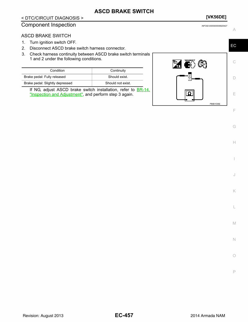
ASCD BRAKE SWITCH[VK56DE]
C
D
E
F
G
H
I
J
K
L
M
A
C
N
P
O
< DTC/CIRCUIT DIAGNOSIS >
E
Component Inspection INFOID:0000000009825427
ASCD BRAKE SWITCH1. Turn ignition switch OFF.2. Disconnect ASCD brake switch harness connector.3. Check harness continuity between ASCD brake switch terminals
1 and 2 under the following conditions.
If NG, adjust ASCD brake switch installation, refer to BR-14,"Inspection and Adjustment", and perform step 3 again.
Condition Continuity
Brake pedal: Fully released Should exist.
Brake pedal: Slightly depressed Should not exist.
PBIB1536E
EC-457Revision: August 2013 2014 Armada NAM

[VK56DE]ASCD INDICATOR
< DTC/CIRCUIT DIAGNOSIS >
ASCD INDICATOR
Component Description INFOID:0000000009825428
The ASCD operation status is indicated by two indicators (CRUISE and SET on the information display) on thecombination meter.CRUISE indicator is displayed to indicated that ASCD system is ready for operation when MAIN switch onASCD steering switch is turned ON.SET indicator is displayed when the following conditions are met. • CRUISE indicator is displayed.• SET/COAST switch on ASCD steering switch is turned ON while vehicle speed is within the range of the
ASCD setting.SET indicator is displayed during ASCD control.Refer to EC-28 for the ASCD function.
Diagnosis Procedure INFOID:0000000009825429
1.CHECK OVERALL FUNCTION
Check ASCD indicator under the following conditions.
OK or NGOK >> INSPECTION ENDNG >> GO TO 2.
2.CHECK DTC
Check that DTC UXXXXX is not displayed.OK or NGOK >> GO TO 3.NG >> Perform trouble diagnosis for DTC UXXXX.
3.CHECK COMBINATION METER FUNCTION
Refer to MWI-27, "CONSULT Function (METER/M&A)".OK or NGOK >> GO TO 4.NG >> Go to MWI-98, "Removal and Installation".
4.CHECK INTERMITTENT INCIDENT
Refer to GI-39, "How to Check Terminal" and GI-42, "Intermittent Incident".
>> INSPECTION END
ASCD INDICATOR CONDITION SPECIFICATION
CRUISE • Ignition switch: ON• MAIN switch: Pressed at the 1st
time at the 2nd timeON OFF
SET
• MAIN switch: ON• When vehicle speed is between 40
km/h (25 MPH) and 144 km/h (89 MPH)
• ASCD: Operating ON
• ASCD: Not operating OFF
EC-458Revision: August 2013 2014 Armada NAM
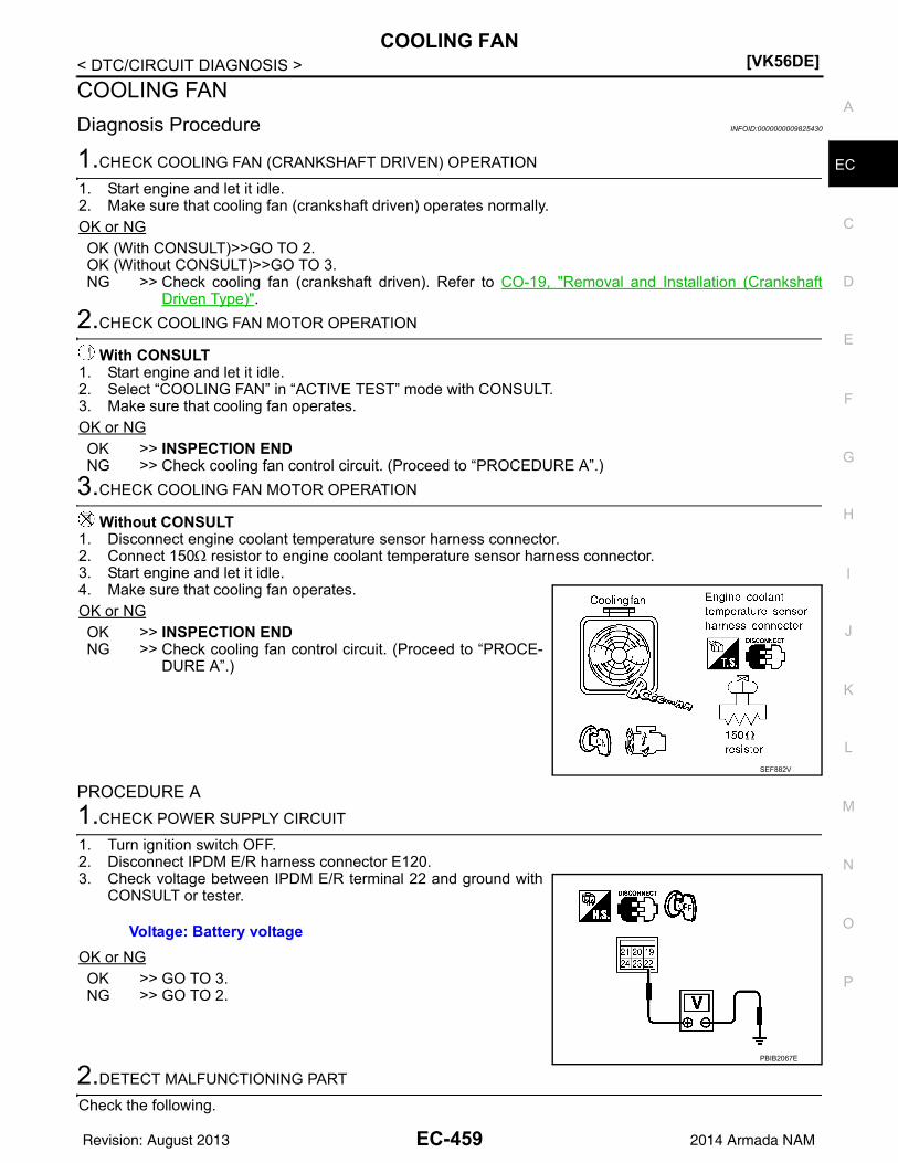
COOLING FAN[VK56DE]
C
D
E
F
G
H
I
J
K
L
M
A
C
N
P
O
< DTC/CIRCUIT DIAGNOSIS >
E
COOLING FAN
Diagnosis Procedure INFOID:0000000009825430
1.CHECK COOLING FAN (CRANKSHAFT DRIVEN) OPERATION
1. Start engine and let it idle.2. Make sure that cooling fan (crankshaft driven) operates normally.OK or NGOK (With CONSULT)>>GO TO 2.OK (Without CONSULT)>>GO TO 3.NG >> Check cooling fan (crankshaft driven). Refer to CO-19, "Removal and Installation (Crankshaft
Driven Type)".
2.CHECK COOLING FAN MOTOR OPERATION
With CONSULT1. Start engine and let it idle.2. Select “COOLING FAN” in “ACTIVE TEST” mode with CONSULT.3. Make sure that cooling fan operates.OK or NGOK >> INSPECTION ENDNG >> Check cooling fan control circuit. (Proceed to “PROCEDURE A”.)
3.CHECK COOLING FAN MOTOR OPERATION
Without CONSULT1. Disconnect engine coolant temperature sensor harness connector.2. Connect 150 resistor to engine coolant temperature sensor harness connector.3. Start engine and let it idle.4. Make sure that cooling fan operates.OK or NGOK >> INSPECTION ENDNG >> Check cooling fan control circuit. (Proceed to “PROCE-
DURE A”.)
PROCEDURE A
1.CHECK POWER SUPPLY CIRCUIT
1. Turn ignition switch OFF.2. Disconnect IPDM E/R harness connector E120.3. Check voltage between IPDM E/R terminal 22 and ground with
CONSULT or tester.
OK or NGOK >> GO TO 3.NG >> GO TO 2.
2.DETECT MALFUNCTIONING PART
Check the following.
SEF882V
Voltage: Battery voltage
PBIB2067E
EC-459Revision: August 2013 2014 Armada NAM

[VK56DE]COOLING FAN
< DTC/CIRCUIT DIAGNOSIS >• 40 A fusible link (letter L)• 25 A fusible link (letter N)• Harness for open or short between IPDM E/R and battery
>> Repair open circuit or short to ground or short to power in harness or connectors.
3.CHECK COOLING FAN MOTOR CIRCUIT FOR OPEN OR SHORT
1. Disconnect cooling fan motor harness connector.2. Check harness continuity between cooling fan motor terminal 1
and IPDM E/R terminal 24, cooling fan motor terminal 2 andground.Refer to wiring diagram.
3. Also check harness for short to ground and short to power.OK or NGOK >> GO TO 4.NG >> Repair open circuit or short to ground or short to power
in harness or connectors.
4.CHECK COOLING FAN MOTOR
Refer to EC-460, "Component Inspection".OK or NGOK >> GO TO 5.NG >> Replace cooling fan motor. Refer to CO-20.
5.CHECK INTERMITTENT INCIDENT
Perform GI-39, "How to Check Terminal" and GI-42, "Intermittent Incident".OK or NGOK >> Replace IPDM E/R. Refer to PCS-31, "Removal and Installation of IPDM E/R".NG >> Repair or replace harness connectors.
Component Inspection INFOID:0000000009825431
COOLING FAN MOTOR1. Disconnect cooling fan motor harness connector.2. Supply cooling fan motor terminals with battery voltage and
check operation.Cooling fan motor should operate.If NG, replace cooling fan motor. Refer to CO-20.
Continuity should exist.
BBIA0363E
JSBIA3094GB
EC-460Revision: August 2013 2014 Armada NAM

ELECTRICAL LOAD SIGNAL[VK56DE]
C
D
E
F
G
H
I
J
K
L
M
A
C
N
P
O
< DTC/CIRCUIT DIAGNOSIS >
E
ELECTRICAL LOAD SIGNAL
Description INFOID:0000000009825432
The electrical load signal (Headlamp switch signal, rear window defogger switch signal, etc.) is transferredthrough the CAN communication line from BCM to ECM via IPDM E/R.
Diagnosis Procedure INFOID:0000000009825433
1.CHECK LOAD SIGNAL CIRCUIT OVERALL FUNCTION-I
1. Turn ignition switch ON.2. Connect CONSULT and select “DATA MONITOR” mode.3. Select “LOAD SIGNAL” and check indication under the following conditions.
OK or NGOK >> GO TO 2.NG >> GO TO 4.
2.CHECK LOAD SIGNAL CIRCUIT OVERALL FUNCTION-II
Check “LOAD SIGNAL” indication under the following conditions.
OK or NGOK >> GO TO 3.NG >> GO TO 5.
3.CHECK HEATER FAN SIGNAL CIRCUIT OVERALL FUNCTION
Select “HEATER FAN SW” and check indication under the following conditions.
OK or NGOK >> INSPECTION ENDNG >> GO TO 6.
4.CHECK REAR WINDOW DEFOGGER SYSTEM
Refer to DEF-4, "System Diagram".
>> INSPECTION END
5.CHECK HEADLAMP SYSTEM
Refer to EXL-7, "System Diagram" (For USA), or EXL-9, "System Diagram" (For Canada).
>> INSPECTION END
6.CHECK HEATER FAN CONTROL SYSTEM
Refer to HAC-20, "CONSULT Function (HVAC)".
Condition Indication
Rear window defogger switch: ON ON
Rear window defogger switch: OFF OFF
Condition Indication
Lighting switch: ON at 2nd position ON
Lighting switch: OFF OFF
Condition Indication
Heater fan control switch: ON ON
Heater fan control switch: OFF OFF
EC-461Revision: August 2013 2014 Armada NAM
[VK56DE]ELECTRICAL LOAD SIGNAL
< DTC/CIRCUIT DIAGNOSIS >>> INSPECTION END
EC-462Revision: August 2013 2014 Armada NAM

FUEL INJECTOR[VK56DE]
C
D
E
F
G
H
I
J
K
L
M
A
C
N
P
O
< DTC/CIRCUIT DIAGNOSIS >
E
FUEL INJECTOR
Component Description INFOID:0000000009825434
The fuel injector is a small, precise solenoid valve. When the ECMsupplies a ground to the fuel injector circuit, the coil in the fuel injec-tor is energized. The energized coil pulls the needle valve back andallows fuel to flow through the fuel injector into the intake manifold.The amount of fuel injected depends upon the injection pulse dura-tion. Pulse duration is the length of time the fuel injector remainsopen. The ECM controls the injection pulse duration based onengine fuel needs.
Diagnosis Procedure INFOID:0000000009825435
1.INSPECTION START
Turn ignition switch to START.Is any cylinder ignited?Yes or NoYes >> GO TO 2.No >> GO TO 3.
2.CHECK OVERALL FUNCTION
With CONSULT1. Start engine.2. Perform “POWER BALANCE” in “ACTIVE TEST” mode with CONSULT.3. Make sure that each circuit produces a momentary engine speed drop.
Without CONSULT1. Start engine.2. Listen to each fuel injector operating sound.
Clicking noise should be heard.
OK or NGOK >> INSPECTION ENDNG >> GO TO 3.
3.CHECK FUEL INJECTOR POWER SUPPLY CIRCUIT
1. Turn ignition switch OFF.
SEF375Z
PBIB1986E
EC-463Revision: August 2013 2014 Armada NAM

[VK56DE]FUEL INJECTOR
< DTC/CIRCUIT DIAGNOSIS >2. Disconnect fuel injector harness connector.
3. Turn ignition switch ON.4. Check voltage between fuel injector terminal 1 and ground with
CONSULT or tester.
OK or NGOK >> GO TO 5.NG >> GO TO 4.
4.DETECT MALFUNCTIONING PART
Check the following.• Harness connectors E2, F32• IPDM E/R connector E119• 15 A (No. 55) fuse • Harness for open or short between fuel injector and fuse
>> Repair harness or connectors.
5.CHECK FUEL INJECTOR OUTPUT SIGNAL CIRCUIT FOR OPEN AND SHORT
1. Turn ignition switch OFF.2. Disconnect ECM harness connector.3. Check harness continuity between fuel injector terminal 2 and ECM terminals 21, 22, 23, 40, 41, 42, 44,
63. Refer to Wiring Diagram.
4. Also check harness for short to ground and short to power.OK or NGOK >> GO TO 6.NG >> Repair open circuit or short to ground or short to power in harness or connectors.
6.CHECK INJECTOR
Refer to EC-465, "Component Inspection".OK or NGOK >> GO TO 7.NG >> Replace malfunctioning fuel injector. Refer to EM-43.
7.CHECK INTERMITTENT INCIDENT
Refer to GI-39, "How to Check Terminal" and GI-42, "Intermittent Incident".
>> INSPECTION END
Voltage: Battery voltage
BBIA0374E
PBIB0582E
Continuity should exist.
EC-464Revision: August 2013 2014 Armada NAM

FUEL INJECTOR[VK56DE]
C
D
E
F
G
H
I
J
K
L
M
A
C
N
P
O
< DTC/CIRCUIT DIAGNOSIS >
E
Component Inspection INFOID:0000000009825436
FUEL INJECTOR1. Disconnect fuel injector harness connector.2. Check resistance between terminals as shown in the figure.
Resistance: 11.1 - 14.5 [at 10 - 60C (50 - 140F)]
PBIB1727E
EC-465Revision: August 2013 2014 Armada NAM

[VK56DE]FUEL PUMP
< DTC/CIRCUIT DIAGNOSIS >
FUEL PUMP
Description INFOID:0000000009825437
SYSTEM DESCRIPTION
*: ECM determines the start signal status by the signals of engine speed and battery voltage.
The ECM activates the fuel pump for several seconds after the ignition switch is turned ON to improve enginestartability. If the ECM receives a engine speed signal from the camshaft position sensor (PHASE), it knowsthat the engine is rotating, and causes the pump to operate. If the engine speed signal is not received whenthe ignition switch is ON, the engine stalls. The ECM stops pump operation and prevents battery discharging,thereby improving safety. The ECM does not directly drive the fuel pump. It controls the ON/OFF fuel pumprelay, which in turn controls the fuel pump.
COMPONENT DESCRIPTIONA turbine type design fuel pump is used in the fuel tank.
Diagnosis Procedure INFOID:0000000009825438
EXCEPT FLEXIBLE FUEL VEHICLE
1.CHECK OVERALL FUNCTION
1. Turn ignition switch ON.2. Pinch fuel feed hose with two fingers.
OK or NGOK >> INSPECTION ENDNG >> GO TO 2.
2.CHECK FUEL PUMP POWER SUPPLY CIRCUIT-I
1. Turn ignition switch OFF.
Sensor Input signal to ECM ECM Function Actuator
Crankshaft position sensor (POS)Camshaft position sensor (PHASE)
Engine speed*Fuel pump control Fuel pump relay
Battery Battery voltage*
Condition Fuel pump operation
Ignition switch is turned to ON. Operates for 1 second.
Engine running and cranking Operates.
When engine is stopped Stops in 1.5 seconds.
Except as shown above Stops.
BBIA0402E
Fuel pressure pulsation should be felt on the fuel feed hose for 1 second after ignition switch is turned ON.
BBIA0357E
EC-466Revision: August 2013 2014 Armada NAM

FUEL PUMP[VK56DE]
C
D
E
F
G
H
I
J
K
L
M
A
C
N
P
O
< DTC/CIRCUIT DIAGNOSIS >
E
2. Disconnect ECM harness connector.3. Turn ignition switch ON.4. Check voltage between ECM terminal 113 and ground with
CONSULT or tester.
OK or NGOK >> GO TO 4.NG >> GO TO 3.
3.CHECK FUEL PUMP POWER SUPPLY CIRCUIT-II
Check voltage between IPDM E/R terminal 46 and ground withCONSULT or tester.
OK or NGOK >> Repair open circuit or short to ground or short to power
in harness or connector.NG >> Replace IPDM E/R. Refer to PCS-31.
4.CHECK CONDENSER-2 POWER SUPPLY CIRCUIT
1. Turn ignition switch OFF.2. Reconnect all harness connectors disconnected.3. Disconnect condenser-2 harness connector.4. Turn ignition switch ON.
5. Check voltage between condenser-2 terminal 1 and ground withCONSULT or tester.
6. Also check harness for short to ground and short to power.OK or NGOK >> GO TO 7.NG >> GO TO 5.
5.CHECK 15A FUSE
1. Turn ignition switch OFF.2. Disconnect 15 A fuse.3. Check 15 A (No. 48) fuse.OK or NG
Voltage: Battery voltage
PBIB1187E
Voltage: Battery voltage
PBIB2656E
BBIA0388E
Voltage: Battery voltage should exist for 1 sec-ond after ignition switch is turned ON.
PBIB0624E
EC-467Revision: August 2013 2014 Armada NAM
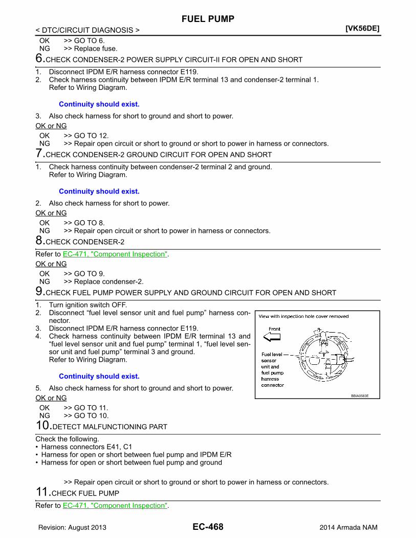
[VK56DE]FUEL PUMP
< DTC/CIRCUIT DIAGNOSIS >OK >> GO TO 6.NG >> Replace fuse.
6.CHECK CONDENSER-2 POWER SUPPLY CIRCUIT-II FOR OPEN AND SHORT
1. Disconnect IPDM E/R harness connector E119.2. Check harness continuity between IPDM E/R terminal 13 and condenser-2 terminal 1.
Refer to Wiring Diagram.
3. Also check harness for short to ground and short to power.OK or NGOK >> GO TO 12.NG >> Repair open circuit or short to ground or short to power in harness or connectors.
7.CHECK CONDENSER-2 GROUND CIRCUIT FOR OPEN AND SHORT
1. Check harness continuity between condenser-2 terminal 2 and ground.Refer to Wiring Diagram.
2. Also check harness for short to power.OK or NGOK >> GO TO 8.NG >> Repair open circuit or short to power in harness or connectors.
8.CHECK CONDENSER-2
Refer to EC-471, "Component Inspection".OK or NGOK >> GO TO 9.NG >> Replace condenser-2.
9.CHECK FUEL PUMP POWER SUPPLY AND GROUND CIRCUIT FOR OPEN AND SHORT
1. Turn ignition switch OFF.2. Disconnect “fuel level sensor unit and fuel pump” harness con-
nector.3. Disconnect IPDM E/R harness connector E119.4. Check harness continuity between IPDM E/R terminal 13 and
“fuel level sensor unit and fuel pump” terminal 1, “fuel level sen-sor unit and fuel pump” terminal 3 and ground.Refer to Wiring Diagram.
5. Also check harness for short to ground and short to power.OK or NGOK >> GO TO 11.NG >> GO TO 10.
10.DETECT MALFUNCTIONING PART
Check the following.• Harness connectors E41, C1• Harness for open or short between fuel pump and IPDM E/R• Harness for open or short between fuel pump and ground
>> Repair open circuit or short to ground or short to power in harness or connectors.
11.CHECK FUEL PUMP
Refer to EC-471, "Component Inspection".
Continuity should exist.
Continuity should exist.
Continuity should exist.
BBIA0583E
EC-468Revision: August 2013 2014 Armada NAM

FUEL PUMP[VK56DE]
C
D
E
F
G
H
I
J
K
L
M
A
C
N
P
O
< DTC/CIRCUIT DIAGNOSIS >
E
OK or NGOK >> GO TO 12.NG >> Replace “fuel level sensor unit and fuel pump”. Refer to FL-12.
12.CHECK INTERMITTENT INCIDENT
Refer to GI-39, "How to Check Terminal" and GI-42, "Intermittent Incident".
OK or NGOK >> Replace IPDM E/R. Refer to PCS-31.NG >> Repair or replace harness or connectors.
FLEXIBLE FUEL VEHICLE
1.CHECK OVERALL FUNCTION
1. Turn ignition switch ON.2. Pinch fuel feed hose with two fingers.
OK or NGOK >> INSPECTION ENDNG >> GO TO 2.
2.CHECK FUEL PUMP POWER SUPPLY CIRCUIT-I
1. Turn ignition switch OFF.2. Disconnect ECM harness connector.3. Turn ignition switch ON.4. Check voltage between ECM terminal 113 and ground with
CONSULT or tester.
OK or NGOK >> GO TO 4.NG >> GO TO 3.
3.CHECK FUEL PUMP POWER SUPPLY CIRCUIT-II
Check voltage between IPDM E/R terminal 46 and ground withCONSULT or tester.
OK or NGOK >> Repair open circuit or short to ground or short to power
in harness or connector.NG >> Replace IPDM E/R. Refer to PCS-31.
4.CHECK CONDENSER-2 POWER SUPPLY CIRCUIT
1. Turn ignition switch OFF.2. Reconnect all harness connectors disconnected.
Fuel pressure pulsation should be felt on the fuel feed hose for 1 second after ignition switch is turned ON.
BBIA0357E
Voltage: Battery voltage
PBIB1187E
Voltage: Battery voltage
PBIB2656E
EC-469Revision: August 2013 2014 Armada NAM

[VK56DE]FUEL PUMP
< DTC/CIRCUIT DIAGNOSIS >3. Disconnect condenser-2 harness connector.4. Turn ignition switch ON.
5. Check voltage between condenser-2 terminal 1 and ground withCONSULT or tester.
6. Also check harness for short to ground and short to power.OK or NGOK >> GO TO 7.NG >> GO TO 5.
5.CHECK 15A FUSE
1. Turn ignition switch OFF.2. Disconnect 15 A fuse.3. Check 15 A (No. 48) fuse.OK or NGOK >> GO TO 6.NG >> Replace fuse.
6.CHECK CONDENSER-2 POWER SUPPLY CIRCUIT-II FOR OPEN AND SHORT
1. Disconnect IPDM E/R harness connector E119.2. Check harness continuity between IPDM E/R terminal 13 and condenser-2 terminal 1.
Refer to Wiring Diagram.
3. Also check harness for short to ground and short to power.OK or NGOK >> GO TO 13.NG >> Repair open circuit or short to ground or short to power in harness or connectors.
7.CHECK CONDENSER-2 GROUND CIRCUIT FOR OPEN AND SHORT
1. Check harness continuity between condenser-2 terminal 2 and ground.Refer to Wiring Diagram.
2. Also check harness for short to power.OK or NGOK >> GO TO 8.NG >> Repair open circuit or short to power in harness or connectors.
8.CHECK CONDENSER-2
Refer to EC-471, "Component Inspection".OK or NGOK >> GO TO 9.
BBIA0388E
Voltage: Battery voltage should exist for 1 sec-ond after ignition switch is turned ON.
PBIB0624E
Continuity should exist.
Continuity should exist.
EC-470Revision: August 2013 2014 Armada NAM

FUEL PUMP[VK56DE]
C
D
E
F
G
H
I
J
K
L
M
A
C
N
P
O
< DTC/CIRCUIT DIAGNOSIS >
E
NG >> Replace condenser-2.
9.CHECK FUEL PUMP POWER SUPPLY AND GROUND CIRCUIT FOR OPEN AND SHORT
1. Turn ignition switch OFF.2. Disconnect “fuel level sensor unit and fuel pump” harness con-
nector.3. Disconnect IPDM E/R harness connector E119.4. Disconnect dropping resistor harness connector.5. Check harness continuity between IPDM E/R terminal 13 and
“fuel level sensor unit and fuel pump” terminal 1, “fuel level sen-sor unit and fuel pump” terminal 2 and dropping resistor terminal2, dropping resistor terminal 1 and ground.Refer to Wiring Diagram.
6. Also check harness for short to ground and short to power.OK or NGOK >> GO TO 11.NG >> GO TO 10.
10.DETECT MALFUNCTIONING PART
Check the following.• Harness connectors E41, C1• Harness for open or short between fuel pump and IPDM E/R• Harness for open or short between fuel pump and dropping resistor• Harness for open or short between dropping resistor and ground
>> Repair open circuit or short to ground or short to power in harness or connectors.
11.CHECK DROPPING RESISTOR
Refer to EC-471, "Component Inspection".OK or NGOK >> GO TO 12.NG >> Replace dropping resistor.
12.CHECK FUEL PUMP
Refer to EC-471, "Component Inspection".OK or NGOK >> GO TO 13.NG >> Replace “fuel level sensor unit and fuel pump”. Refer to FL-12.
13.CHECK INTERMITTENT INCIDENT
Refer to GI-39, "How to Check Terminal" and GI-42, "Intermittent Incident".
OK or NGOK >> Replace IPDM E/R. Refer to PCS-31.NG >> Repair or replace harness or connectors.
Component Inspection INFOID:0000000009825439
FUEL PUMP1. Disconnect “fuel level sensor unit and fuel pump” harness connector.
Continuity should exist.BBIA0442E
EC-471Revision: August 2013 2014 Armada NAM

[VK56DE]FUEL PUMP
< DTC/CIRCUIT DIAGNOSIS >2. Check resistance between fuel level sensor unit and fuel pump
terminals 1 and 3.
DROPPING RESISTOR1. Turn ignition switch OFF.2. Disconnect dropping resistor harness connector.3. Check resistance between dropping resistor terminals as 1 and
2.
CONDENSER-21. Turn ignition switch OFF.2. Disconnect condenser-2 harness connector.3. Check resistance between condenser-2 terminals as 1 and 2.
Resistance: 0.2 - 5.0 [at 25C (77F)]
SEC918C
Resistance Above 1 M at 25C (77F)
PBIB0131E
Resistance Above 1 M at 25C (77F)
PBIB0794E
EC-472Revision: August 2013 2014 Armada NAM

IGNITION SIGNAL[VK56DE]
C
D
E
F
G
H
I
J
K
L
M
A
C
N
P
O
< DTC/CIRCUIT DIAGNOSIS >
E
IGNITION SIGNAL
Component Description INFOID:0000000009825440
IGNITION COIL & POWER TRANSISTORThe ignition signal from the ECM is sent to and amplified by the power transistor. The power transistor turnsON and OFF the ignition coil primary circuit. This ON/OFF operation induces the proper high voltage in the coilsecondary circuit.
Diagnosis Procedure INFOID:0000000009825441
1.CHECK ENGINE START
Turn ignition switch OFF, and restart engine.Is engine running?Yes or NoYes (With CONSULT)>>GO TO 2.Yes (Without CONSULT)>>GO TO 3.No >> GO TO 4.
2.CHECK OVERALL FUNCTION
With CONSULT1. Perform “POWER BALANCE” in “ACTIVE TEST” mode with CONSULT.2. Make sure that each circuit produces a momentary engine speed drop.OK or NGOK >> INSPECTION ENDNG >> GO TO 10.
3.CHECK OVERALL FUNCTION
Without CONSULT1. Let engine idle.2. Read the voltage signal between ECM terminals 46, 60, 61, 62,
65, 79, 80, 81 and ground with an oscilloscope.3. Verify that the oscilloscope screen shows the signal wave as
shown below.NOTE:The pulse cycle changes depending on rpm at idle.
OK or NGOK >> INSPECTION ENDNG >> GO TO 10.
4.CHECK IGNITION COIL POWER SUPPLY CIRCUIT-I
BBIA0359E
PBIB2094E
PBIB0044E
EC-473Revision: August 2013 2014 Armada NAM

[VK56DE]IGNITION SIGNAL
< DTC/CIRCUIT DIAGNOSIS >1. Turn ignition switch OFF, wait at least 10 seconds and then turn ON.2. Check voltage between ECM terminals 119, 120 and ground
with CONSULT or tester.
OK or NGOK >> GO TO 5.NG >> Go to EC-150.
5.CHECK IGNITION COIL POWER SUPPLY CIRCUIT-II
1. Turn ignition switch OFF.2. Disconnect condenser-1 harness connector.3. Turn ignition switch ON.
4. Check voltage between condenser-1 terminal 1 and ground withCONSULT or tester.
OK or NGOK >> GO TO 8.NG >> GO TO 6.
6.CHECK IGNITION COIL POWER SUPPLY CIRCUIT-III
1. Turn ignition switch OFF.2. Disconnect IPDM E/R connector E119.3. Check harness continuity between IPDM E/R terminal 4 and condenser-1 terminal 1.
Refer to Wiring Diagram.
4. Also check harness for short to ground and short to power.OK or NGOK >> Go to EC-150.NG >> GO TO 7.
7.DETECT MALFUNCTIONING PART
Check the following.• Harness connectors E2, F32• Harness for open or short between condenser-1 and IPDM E/R
>> Repair open circuit or short to ground or short to power in harness or connectors.
Voltage: Battery voltage
MBIB0034E
BBIA0358E
Voltage: Battery voltage
PBIB0624E
Continuity should exist.
EC-474Revision: August 2013 2014 Armada NAM

IGNITION SIGNAL[VK56DE]
C
D
E
F
G
H
I
J
K
L
M
A
C
N
P
O
< DTC/CIRCUIT DIAGNOSIS >
E
8.CHECK CONDENSER-1 GROUND CIRCUIT FOR OPEN AND SHORT
1. Turn ignition switch OFF.2. Check harness continuity between condenser-1 terminal 2 and ground.
Refer to Wiring Diagram.
3. Also check harness for short to power.OK or NGOK >> GO TO 9.NG >> Repair open circuit or short to power in harness or connectors.
9.CHECK CONDENSER-1
Refer to EC-476, "Component Inspection".OK or NGOK >> GO TO 10.NG >> Replace condenser-1.
10.CHECK IGNITION COIL POWER SUPPLY CIRCUIT-IV
1. Turn ignition switch OFF.2. Reconnect all harness connectors disconnected.3. Disconnect ignition coil harness connector.
4. Turn ignition switch ON.5. Check voltage between ignition coil terminal 3 and ground with
CONSULT or tester.
OK or NGOK >> GO TO 12.NG >> GO TO 11.
11.DETECT MALFUNCTIONING PART
Check the following.• Harness connectors E2, F32• Harness for open or short between ignition coil and harness connector F32
>> Repair or replace harness or connectors.
12.CHECK IGNITION COIL GROUND CIRCUIT FOR OPEN AND SHORT
1. Turn ignition switch OFF.
Continuity should exist.
1. Ignition coils (with power transistor) (bank 2)
2. Ignition coils (with power transistor) (bank 1)
Voltage: Battery voltage
BBIA0777E
PBIB0138E
EC-475Revision: August 2013 2014 Armada NAM

[VK56DE]IGNITION SIGNAL
< DTC/CIRCUIT DIAGNOSIS >2. Check harness continuity between ignition coil terminal 2 and ground.
Refer to Wiring Diagram.
3. Also check harness for short to power.OK or NGOK >> GO TO 13.NG >> Repair open circuit or short to power in harness or connectors.
13.CHECK IGNITION COIL OUTPUT SIGNAL CIRCUIT FOR OPEN AND SHORT
1. Disconnect ECM harness connector.2. Check harness continuity between ECM terminals 46, 60, 61, 62, 65, 79, 80, 81 and ignition coil terminal
1.Refer to Wiring Diagram.
3. Also check harness for short to ground and short to power.OK or NGOK >> GO TO 14.NG >> Repair open circuit or short to ground or short to power in harness or connectors.
14.CHECK IGNITION COIL WITH POWER TRANSISTOR
Refer to EC-476, "Component Inspection". OK or NGOK >> GO TO 15.NG >> Replace ignition coil with power transistor. Refer to EM-40.
15.CHECK INTERMITTENT INCIDENT
Refer to GI-39, "How to Check Terminal" and GI-42, "Intermittent Incident".
>> INSPECTION END
Component Inspection INFOID:0000000009825442
IGNITION COIL WITH POWER TRANSISTORCAUTION:Do the following procedure in the place where ventilation is good without the combustible.1. Turn ignition switch OFF.2. Disconnect ignition coil harness connector.3. Check resistance between ignition coil terminals as follows.
4. If NG, replace ignition coil with power transistor. Refer to EM-40.If OK, go to next step.
5. Turn ignition switch OFF.6. Reconnect all harness connectors disconnected.
Continuity should exist.
Continuity should exist.
Terminal No. (Polarity) Resistance [at 25C (77F)]
1 and 2 Except 0 or
1 and 3Except 0
2 and 3
PBIB0847E
EC-476Revision: August 2013 2014 Armada NAM

IGNITION SIGNAL[VK56DE]
C
D
E
F
G
H
I
J
K
L
M
A
C
N
P
O
< DTC/CIRCUIT DIAGNOSIS >
E
7. Remove fuel pump fuse in IPDM E/R to release fuel pressure.NOTE:Do not use CONSULT to release fuel pressure, or fuel pressureapplies again during the following procedure.
8. Start engine.9. After engine stalls, crank it two or three times to release all fuel
pressure.10. Turn ignition switch OFF.11. Remove all ignition coil harness connectors to avoid the electri-
cal discharge from the ignition coils.12. Remove ignition coil and spark plug of the cylinder to be
checked.13. Crank engine for 5 seconds or more to remove combustion gas in the cylinder.14. Connect spark plug and harness connector to ignition coil.15. Fix ignition coil using a rope etc. with gap of 13 - 17 mm (0.52 -
0.66 in) between the edge of the spark plug and grounded metalportion as shown in the figure.
16. Crank engine for about 3 seconds, and check whether spark isgenerated between the spark plug and the grounded metal por-tion.
CAUTION:• During the operation, always stay 0.5 m (1.6 ft) or more
away from the spark plug and the ignition coil. Be carefulnot to get an electrical shock while checking, because theelectrical discharge voltage becomes 20 kV or more.
• It might cause to damage the ignition coil if the gap of more than 17 mm (0.66 in) is taken.NOTE:When the gap is less than 13 mm (0.52 in), the spark might be generated even if the coil is mal-functioning.
17. If NG, replace ignition coil with power transistor. Refer to EM-40.
CONDENSER-11. Turn ignition switch OFF.2. Disconnect condenser-1 harness connector.3. Check resistance between condenser-1 terminals 1 and 2.
Spark should be generated.
BBIA0380E
PBIB2325E
Resistance Above 1 M [at 25C (77F)]
PBIB0794E
EC-477Revision: August 2013 2014 Armada NAM

[VK56DE]MALFUNCTION INDICATOR LAMP
< DTC/CIRCUIT DIAGNOSIS >
MALFUNCTION INDICATOR LAMP
Component Function Check INFOID:0000000009825443
1.CHECK MIL FUNCTION
1. Turn ignition switch ON.2. Check that MIL illuminates.Is the inspection result normal?YES >> INSPECTION ENDNO >> Proceed to EC-478, "Diagnosis Procedure".
Diagnosis Procedure INFOID:0000000009825444
1.CHECK DTC
Check that DTC UXXXX is not displayed.Is the inspection result normal?YES >> GO TO 2.NO >> Perform trouble diagnosis for DTC UXXXX.
2.CHECK DTC WITH COMBINATION METER
Refer to MWI-27, "CONSULT Function (METER/M&A)".Is the inspection result normal?YES >> GO TO 3.NO >> Perform trouble diagnosis for DTC indicated.
3.CHECK INTERMITTENT INCIDENT
Refer to GI-42, "Intermittent Incident".Is the inspection result normal?YES >> Replace combination meter. Refer to MWI-98, "Removal and Installation".NO >> Repair or replace malfunctioning part.
EC-478Revision: August 2013 2014 Armada NAM

ON BOARD REFUELING VAPOR RECOVERY (ORVR)[VK56DE]
C
D
E
F
G
H
I
J
K
L
M
A
C
N
P
O
< DTC/CIRCUIT DIAGNOSIS >
E
ON BOARD REFUELING VAPOR RECOVERY (ORVR)
System Description INFOID:0000000009825445
From the beginning of refueling, the air and vapor inside the fuel tank go through refueling EVAP vapor cutvalve and EVAP/ORVR line to the EVAP canister. The vapor is absorbed by the EVAP canister and the air isreleased to the atmosphere.When the refueling has reached the full level of the fuel tank, the refueling EVAP vapor cut valve is closed andrefueling is stopped because of auto shut-off. The vapor which was absorbed by the EVAP canister is purgedduring driving.WARNING:When conducting inspections below, be sure to observe the following:• Put a “CAUTION: FLAMMABLE” sign in workshop.• Do not smoke while servicing fuel system. Keep open flames and sparks away from work area.• Be sure to furnish the workshop with a CO2 fire extinguisher.CAUTION:• Before removing fuel line parts, carry out the following procedures:- Put drained fuel in an explosion-proof container and put lid on securely.- Release fuel pressure from fuel line. Refer to EC-494, "Fuel Pressure Check".- Disconnect battery ground cable.• Always replace O-ring when the fuel gauge retainer is removed.• Do not kink or twist hose and tube when they are installed.• Do not tighten hose and clamps excessively to avoid damaging hoses.• After installation, run engine and check for fuel leaks at connection.• Do not attempt to top off the fuel tank after the fuel pump nozzle shuts off automatically.
Continued refueling may cause fuel overflow, resulting in fuel spray and possibly a fire.
Diagnosis Procedure INFOID:0000000009825446
SYMPTOM: FUEL ODOR FROM EVAP CANISTER IS STRONG.
1.CHECK EVAP CANISTER
1. Remove EVAP canister with EVAP canister vent control valve and EVAP control system pressure sensorattached. Refer to FL-16.
2. Weigh the EVAP canister with EVAP canister vent control valve and EVAP control system pressure sensorattached.The weight should be less than 2.5 kg (5.5 lb).
OK or NGOK >> GO TO 2.NG >> GO TO 3.
2.CHECK IF EVAP CANISTER SATURATED WITH WATER
PBIB1068E
EC-479Revision: August 2013 2014 Armada NAM

[VK56DE]ON BOARD REFUELING VAPOR RECOVERY (ORVR)
< DTC/CIRCUIT DIAGNOSIS >Does water drain from the EVAP canister?Yes or NoYes >> GO TO 3.No >> GO TO 5.
3.REPLACE EVAP CANISTER
Replace EVAP canister with a new one. Refer to FL-16.
>> GO TO 4.
4.DETECT MALFUNCTIONING PART
Check the EVAP hose between EVAP canister and vehicle frame for clogging or poor connection.
>> Repair or replace EVAP hose. Refer to FL-8.
5.CHECK REFUELING EVAP VAPOR CUT VALVE
Refer to EC-481, "Component Inspection".OK or NGOK >> INSPECTION ENDNG >> Replace refueling EVAP vapor cut valve with fuel tank. Refer to FL-8.
SYMPTOM: CANNOT REFUEL/FUEL ODOR FROM THE FUEL FILLER OPENING IS STRONGWHILE REFUELING.
1.CHECK EVAP CANISTER
1. Remove EVAP canister with EVAP canister vent control valve and EVAP control system pressure sensorattached. Refer to FL-16.
2. Weigh the EVAP canister with EVAP canister vent control valve and EVAP control system pressure sensorattached.The weight should be less than 2.5 kg (5.5 lb).
OK or NGOK >> GO TO 2.NG >> GO TO 3.
2.CHECK IF EVAP CANISTER SATURATED WITH WATER
Does water drain from the EVAP canister?Yes or NoYes >> GO TO 3.No >> GO TO 5.
3.REPLACE EVAP CANISTER
Replace EVAP canister with a new one. Refer to FL-16.
>> GO TO 4.
BBIA0351E
BBIA0351E
EC-480Revision: August 2013 2014 Armada NAM

ON BOARD REFUELING VAPOR RECOVERY (ORVR)[VK56DE]
C
D
E
F
G
H
I
J
K
L
M
A
C
N
P
O
< DTC/CIRCUIT DIAGNOSIS >
E
4.DETECT MALFUNCTIONING PART
Check the EVAP hose between EVAP canister and vehicle frame for clogging or poor connection.
>> Repair or replace EVAP hose. Refer to FL-8.
5.CHECK VENT HOSES AND VENT TUBES
Check hoses and tubes between EVAP canister and refueling EVAP vapor cut valve for clogging, kink, loose-ness and improper connection.OK or NGOK >> GO TO 6.NG >> Repair or replace hoses and tubes. Refer to FL-8.
6.CHECK FILLER NECK TUBE
Check recirculation line for clogging, dents and cracks. OK or NGOK >> GO TO 7.NG >> Replace filler neck tube. Refer to FL-8.
7.CHECK REFUELING EVAP VAPOR CUT VALVE
Refer to EC-481, "Component Inspection".OK or NGOK >> GO TO 8.NG >> Replace refueling EVAP vapor cut valve with fuel tank. Refer to FL-8.
8.CHECK FUEL FILLER TUBE
Check filler neck tube and hose connected to the fuel tank for clogging, dents and cracks.OK or NGOK >> GO TO 9.NG >> Replace fuel filler tube. Refer to FL-8.
9.CHECK ONE-WAY FUEL VALVE-I
Check one-way valve for clogging.OK or NGOK >> GO TO 10.NG >> Repair or replace one-way fuel valve with fuel tank. Refer to FL-8.
10.CHECK ONE-WAY FUEL VALVE-II
1. Make sure that fuel is drained from the tank.2. Remove fuel filler tube and hose. Refer to FL-8.3. Check one-way fuel valve for operation as follows.
When a stick is inserted, the valve should open, when removingstick it should close.Do not drop any material into the tank.
OK or NGOK >> INSPECTION ENDNG >> Replace fuel filler tube or replace one-way fuel valve
with fuel tank. Refer to FL-8.
Component Inspection INFOID:0000000009825447
REFUELING EVAP VAPOR CUT VALVE
With CONSULT
1. Remove fuel tank. Refer to FL-8, "Removal and Installation".
SEF665U
EC-481Revision: August 2013 2014 Armada NAM
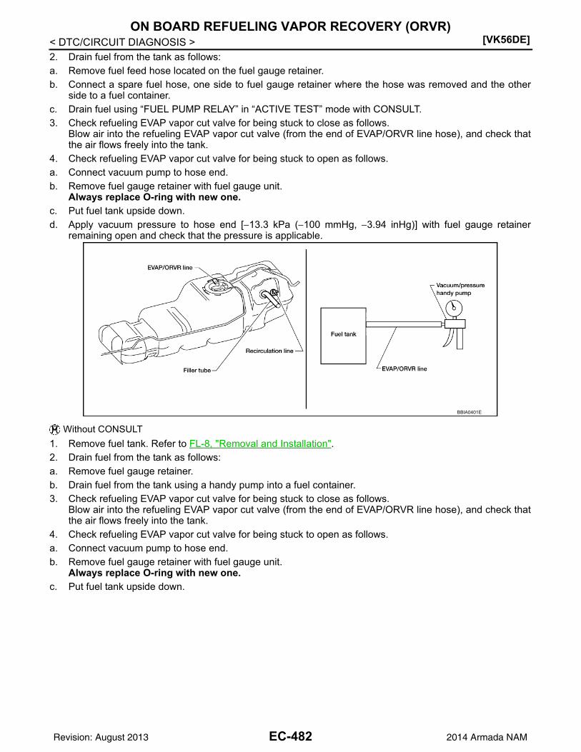
[VK56DE]ON BOARD REFUELING VAPOR RECOVERY (ORVR)
< DTC/CIRCUIT DIAGNOSIS >2. Drain fuel from the tank as follows:a. Remove fuel feed hose located on the fuel gauge retainer. b. Connect a spare fuel hose, one side to fuel gauge retainer where the hose was removed and the other
side to a fuel container.c. Drain fuel using “FUEL PUMP RELAY” in “ACTIVE TEST” mode with CONSULT.3. Check refueling EVAP vapor cut valve for being stuck to close as follows.
Blow air into the refueling EVAP vapor cut valve (from the end of EVAP/ORVR line hose), and check thatthe air flows freely into the tank.
4. Check refueling EVAP vapor cut valve for being stuck to open as follows.a. Connect vacuum pump to hose end.b. Remove fuel gauge retainer with fuel gauge unit.
Always replace O-ring with new one.c. Put fuel tank upside down.d. Apply vacuum pressure to hose end [13.3 kPa (100 mmHg, 3.94 inHg)] with fuel gauge retainer
remaining open and check that the pressure is applicable.
Without CONSULT
1. Remove fuel tank. Refer to FL-8, "Removal and Installation".2. Drain fuel from the tank as follows:a. Remove fuel gauge retainer.b. Drain fuel from the tank using a handy pump into a fuel container.3. Check refueling EVAP vapor cut valve for being stuck to close as follows.
Blow air into the refueling EVAP vapor cut valve (from the end of EVAP/ORVR line hose), and check thatthe air flows freely into the tank.
4. Check refueling EVAP vapor cut valve for being stuck to open as follows.a. Connect vacuum pump to hose end.b. Remove fuel gauge retainer with fuel gauge unit.
Always replace O-ring with new one.c. Put fuel tank upside down.
BBIA0401E
EC-482Revision: August 2013 2014 Armada NAM

ON BOARD REFUELING VAPOR RECOVERY (ORVR)[VK56DE]
C
D
E
F
G
H
I
J
K
L
M
A
C
N
P
O
< DTC/CIRCUIT DIAGNOSIS >
E
d. Apply vacuum pressure to hose end [13.3 kPa (100 mmHg, 3.94 inHg)] with fuel gauge retainerremaining open and check that the pressure is applicable.
BBIA0401E
EC-483Revision: August 2013 2014 Armada NAM

[VK56DE]POSITIVE CRANKCASE VENTILATION
< DTC/CIRCUIT DIAGNOSIS >
POSITIVE CRANKCASE VENTILATION
Description INFOID:0000000009825448
SYSTEM DESCRIPTION
This system returns blow-by gas to the intake manifold.The positive crankcase ventilation (PCV) valve is provided to conduct crankcase blow-by gas to the intakemanifold. During partial throttle operation of the engine, the intake manifold sucks the blow-by gas through thePCV valve. Normally, the capacity of the valve is sufficient to handle any blow-by and a small amount of venti-lating air. The ventilating air is drawn from the air inlet tubes into the crankcase. In this process the air passesthrough the hose connecting air inlet tubes to rocker cover. Under full-throttle condition, the manifold vacuumis insufficient to draw the blow-by flow through the valve. The flow goes through the hose connection in thereverse direction.On vehicles with an excessively high blow-by, the valve does notmeet the requirement. This is because some of the flow will gothrough the hose connection to the air inlet tubes under all condi-tions.
Component Inspection INFOID:0000000009825449
PCV (POSITIVE CRANKCASE VENTILATION) VALVEWith engine running at idle, remove PCV valve from rocker cover.Refer to EM-41. A properly working valve makes a hissing noise asair passes through it. A strong vacuum should be felt immediatelywhen a finger is placed over valve inlet.
PCV VALVE VENTILATION HOSE
PBIB0062E
PBIB1588E
PBIB1589E
EC-484Revision: August 2013 2014 Armada NAM

POSITIVE CRANKCASE VENTILATION[VK56DE]
C
D
E
F
G
H
I
J
K
L
M
A
C
N
P
O
< DTC/CIRCUIT DIAGNOSIS >
E
1. Check hoses and hose connections for leaks.2. Disconnect all hoses and clean with compressed air. If any hose
cannot be freed of obstructions, replace.
S-ET277
EC-485Revision: August 2013 2014 Armada NAM
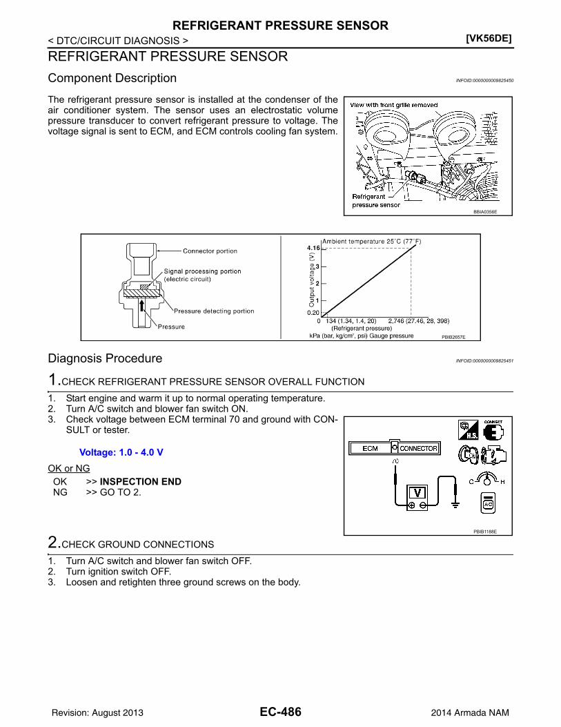
[VK56DE]REFRIGERANT PRESSURE SENSOR
< DTC/CIRCUIT DIAGNOSIS >
REFRIGERANT PRESSURE SENSOR
Component Description INFOID:0000000009825450
The refrigerant pressure sensor is installed at the condenser of theair conditioner system. The sensor uses an electrostatic volumepressure transducer to convert refrigerant pressure to voltage. Thevoltage signal is sent to ECM, and ECM controls cooling fan system.
Diagnosis Procedure INFOID:0000000009825451
1.CHECK REFRIGERANT PRESSURE SENSOR OVERALL FUNCTION
1. Start engine and warm it up to normal operating temperature.2. Turn A/C switch and blower fan switch ON.3. Check voltage between ECM terminal 70 and ground with CON-
SULT or tester.
OK or NGOK >> INSPECTION ENDNG >> GO TO 2.
2.CHECK GROUND CONNECTIONS
1. Turn A/C switch and blower fan switch OFF.2. Turn ignition switch OFF.3. Loosen and retighten three ground screws on the body.
BBIA0356E
PBIB2657E
Voltage: 1.0 - 4.0 V
PBIB1188E
EC-486Revision: August 2013 2014 Armada NAM

REFRIGERANT PRESSURE SENSOR[VK56DE]
C
D
E
F
G
H
I
J
K
L
M
A
C
N
P
O
< DTC/CIRCUIT DIAGNOSIS >
E
Refer to EC-153, "Ground Inspection".
OK or NGOK >> GO TO 3.NG >> Repair or replace ground connections.
3.CHECK REFRIGERANT PRESSURE SENSOR POWER SUPPLY CIRCUIT
1. Disconnect refrigerant pressure sensor harness connector.2. Turn ignition switch ON.
3. Check voltage between refrigerant pressure sensor terminal 1and ground with CONSULT or tester.
OK or NGOK >> GO TO 5.NG >> GO TO 4.
4.DETECT MALFUNCTIONING PART
Check the following.• Harness connectors E5, F14• Harness for open or short between ECM and refrigerant pressure sensor
>> Repair harness or connectors.
5.CHECK REFRIGERANT PRESSURE SENSOR GROUND CIRCUIT FOR OPEN AND SHORT
1. Turn ignition switch OFF.2. Disconnect ECM harness connector.3. Check harness continuity between refrigerant pressure sensor terminal 3 and ECM terminal 67.
Refer to Wiring Diagram.
4. Also check harness for short to ground and short to power.OK or NGOK >> GO TO 7.NG >> GO TO 6.
BBIA0354E
BBIA0356E
Voltage: Approximately 5 V
PBIB0188E
Continuity should exist.
EC-487Revision: August 2013 2014 Armada NAM
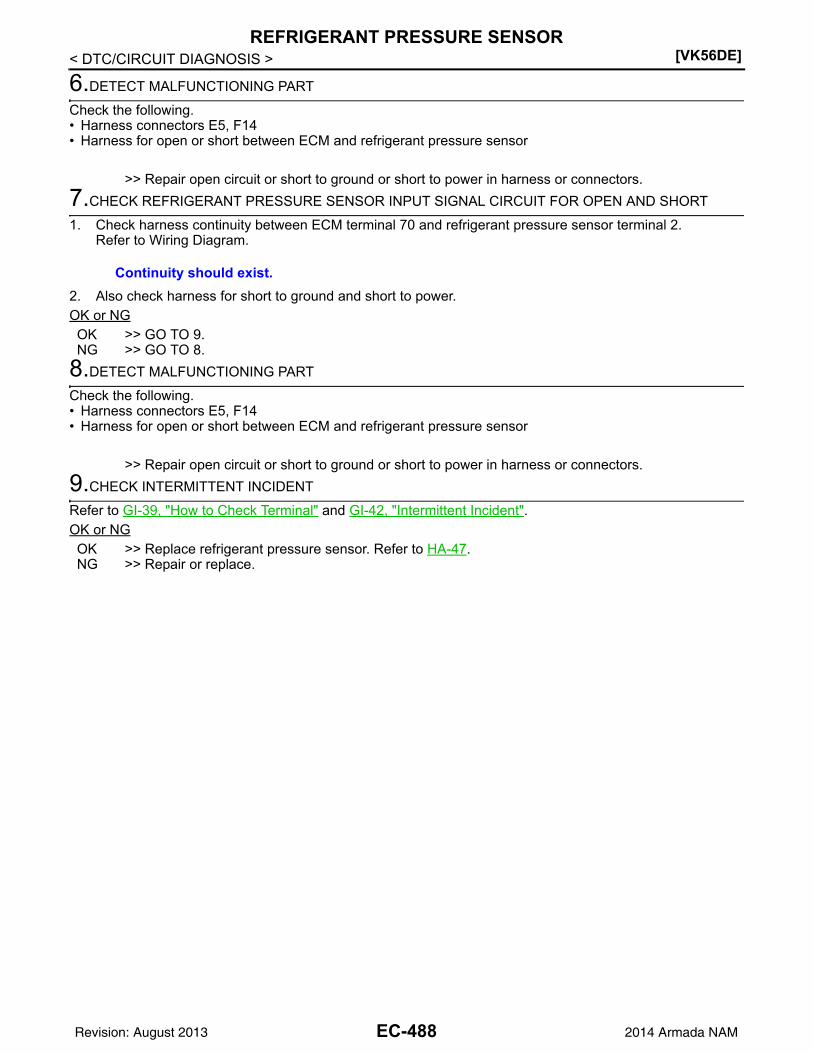
[VK56DE]REFRIGERANT PRESSURE SENSOR
< DTC/CIRCUIT DIAGNOSIS >
6.DETECT MALFUNCTIONING PART
Check the following.• Harness connectors E5, F14• Harness for open or short between ECM and refrigerant pressure sensor
>> Repair open circuit or short to ground or short to power in harness or connectors.
7.CHECK REFRIGERANT PRESSURE SENSOR INPUT SIGNAL CIRCUIT FOR OPEN AND SHORT
1. Check harness continuity between ECM terminal 70 and refrigerant pressure sensor terminal 2.Refer to Wiring Diagram.
2. Also check harness for short to ground and short to power.OK or NGOK >> GO TO 9.NG >> GO TO 8.
8.DETECT MALFUNCTIONING PART
Check the following.• Harness connectors E5, F14• Harness for open or short between ECM and refrigerant pressure sensor
>> Repair open circuit or short to ground or short to power in harness or connectors.
9.CHECK INTERMITTENT INCIDENT
Refer to GI-39, "How to Check Terminal" and GI-42, "Intermittent Incident".OK or NGOK >> Replace refrigerant pressure sensor. Refer to HA-47.NG >> Repair or replace.
Continuity should exist.
EC-488Revision: August 2013 2014 Armada NAM

ENGINE CONTROL SYSTEM SYMPTOMS[VK56DE]
C
D
E
F
G
H
I
J
K
L
M
A
C
N
P
O
< SYMPTOM DIAGNOSIS >
E
SYMPTOM DIAGNOSISENGINE CONTROL SYSTEM SYMPTOMS
Symptom Matrix Chart INFOID:0000000009825452
SYSTEM — BASIC ENGINE CONTROL SYSTEM
SYMPTOM
Refer-ence page
HA
RD
/NO
STA
RT
/RE
STA
RT
(E
XC
P. H
A)
EN
GIN
E S
TALL
HE
SIT
AT
ION
/SU
RG
ING
/FLA
T S
PO
T
SP
AR
K K
NO
CK
/DE
TO
NA
TIO
N
LAC
K O
F P
OW
ER
/PO
OR
AC
CE
LER
AT
ION
HIG
H ID
LE
/LO
W ID
LE
RO
UG
H ID
LE/H
UN
TIN
G
IDLI
NG
VIB
RA
TIO
N
SLO
W/N
O R
ET
UR
N T
O ID
LE
OV
ER
HE
AT
S/W
AT
ER
TE
MP
ER
AT
UR
E H
IGH
EX
CE
SS
IVE
FU
EL
CO
NS
UM
PT
ION
EX
CE
SS
IVE
OIL
CO
NS
UM
PT
ION
BA
TT
ER
Y D
EA
D (
UN
DE
R C
HA
RG
E)
Warranty symptom code AA AB AC AD AE AF AG AH AJ AK AL AM HA
Fuel Fuel pump circuit 1 1 2 3 2 2 2 3 2 EC-384
Fuel pressure regulator system 3 3 4 4 4 4 4 4 4 4 EC-494
Fuel injector circuit 1 1 2 3 2 2 2 2 EC-463
Evaporative emission system 3 3 4 4 4 4 4 4 4 4 EC-32
Air Positive crankcase ventilation sys-tem 3 3
4 4 4 4 4 4 4 4 1 EC-484
Incorrect idle speed adjustment 1 1 1 1 1 EC-116
Electric throttle control actuator 1 1 2 3 3 2 2 2 2 2 2
EC-429, EC-432 , EC-436 , EC-438
Ignition Incorrect ignition timing adjustment 3 3 1 1 1 1 1 1 EC-116
Ignition circuit 1 1 2 2 2 2 2 2 EC-473
Main power supply and ground circuit 2 2 3 3 3 3 3 2 3 EC-150
EC-489Revision: August 2013 2014 Armada NAM

[VK56DE]ENGINE CONTROL SYSTEM SYMPTOMS
< SYMPTOM DIAGNOSIS >
Mass air flow sensor circuit
1
1 2
2
2 2 2 2
EC-172, EC-176
Engine coolant temperature sensor circuit
3
3 3EC-189, EC-197
Air fuel ratio (A/F) sensor 1 circuit
EC-205, EC-209 , EC-213 , EC-217 , EC-423
Throttle position sensor circuit
2 2
EC-193, EC-260 , EC-389 , EC-391 , EC-447
Accelerator pedal position sensor circuit 3 2 1
EC-451, EC-440 , EC-443 , EC-447
Knock sensor circuit 2 3 EC-271
Crankshaft position sensor (POS) circuit 2 2 EC-274
Camshaft position sensor (PHASE) circuit 3 2 EC-278
Vehicle speed signal circuit 2 3 3 3 EC-349
Power steering pressure sensor circuit 2 3 3 EC-357
ECM 2 2 3 3 3 3 3 3 3 3 3
EC-360, EC-361, EC-362, EC-363, EC-364, EC-365, EC-366
Intake valve timing control solenoid valve cir-cuit
3 2 1 3 2 2 3 3 EC-169
Transmission range switch signal circuit 3 3 3 3 3 EC-370
Refrigerant pressure sensor circuit 2 3 3 4 EC-486
Electrical load signal circuit 3 EC-461
Air conditioner circuit 2 2 3 3 3 3 3 3 3 3 2 HAC-3
ABS actuator and electric unit (control unit) 4EC-378, EC-379 or BRC-4
SYMPTOM
Refer-ence page
HA
RD
/NO
STA
RT
/RE
STA
RT
(E
XC
P. H
A)
EN
GIN
E S
TALL
HE
SIT
AT
ION
/SU
RG
ING
/FLA
T S
PO
T
SP
AR
K K
NO
CK
/DE
TO
NA
TIO
N
LAC
K O
F P
OW
ER
/PO
OR
AC
CE
LER
AT
ION
HIG
H I
DLE
/LO
W I
DL
E
RO
UG
H ID
LE/H
UN
TIN
G
IDLI
NG
VIB
RA
TIO
N
SLO
W/N
O R
ET
UR
N T
O ID
LE
OV
ER
HE
AT
S/W
AT
ER
TE
MP
ER
AT
UR
E H
IGH
EX
CE
SS
IVE
FU
EL
CO
NS
UM
PT
ION
EX
CE
SS
IVE
OIL
CO
NS
UM
PT
ION
BA
TT
ER
Y D
EA
D (
UN
DE
R C
HA
RG
E)
Warranty symptom code AA AB AC AD AE AF AG AH AJ AK AL AM HA
EC-490Revision: August 2013 2014 Armada NAM

ENGINE CONTROL SYSTEM SYMPTOMS[VK56DE]
C
D
E
F
G
H
I
J
K
L
M
A
C
N
P
O
< SYMPTOM DIAGNOSIS >
E
1 - 6: The numbers refer to the order of inspection.
(continued on next page)
SYSTEM — ENGINE MECHANICAL & OTHER
SYMPTOM
Reference page
HA
RD
/NO
STA
RT
/RE
STA
RT
(E
XC
P. H
A)
EN
GIN
E S
TALL
HE
SIT
AT
ION
/SU
RG
ING
/FLA
T S
PO
T
SP
AR
K K
NO
CK
/DE
TO
NA
TIO
N
LAC
K O
F P
OW
ER
/PO
OR
AC
CE
LER
AT
ION
HIG
H ID
LE
/LO
W ID
LE
RO
UG
H I
DLE
/HU
NT
ING
IDL
ING
VIB
RA
TIO
N
SLO
W/N
O R
ET
UR
N T
O ID
LE
OV
ER
HE
AT
S/W
AT
ER
TE
MP
ER
AT
UR
E H
IGH
EX
CE
SS
IVE
FU
EL
CO
NS
UM
PT
ION
EX
CE
SS
IVE
OIL
CO
NS
UM
PT
ION
BA
TT
ER
Y D
EA
D (
UN
DE
R C
HA
RG
E)
Warranty symptom code AA AB AC AD AE AF AG AH AJ AK AL AM HA
Fuel Fuel tank5
5
FL-8
Fuel piping 5 5 5 5 5 5 EM-43
Vapor lock —
Valve deposit
5 5 5 5 5 5 5
—
Poor fuel (Heavy weight gasoline, Low octane)
—
Air Air duct
5 5 5 5 5 5
EM-26
Air cleaner EM-26
Air leakage from air duct(Mass air flow sensor — electric throttle control actuator)
5 5 5 5
EM-26
Electric throttle control actuator EM-27
Air leakage from intake manifold/Collector/Gasket
EM-27
Cranking Battery1 1 1 1 1 1
1
1PG-77
Generator circuit CHG-28
Starter circuit 3 STR-20
Signal plate 6 EM-93
Transmission range switch signal 4 TM-48
Engine Cylinder head5 5 5 5 5 5 5 5 EM-80
Cylinder head gasket 4 3
Cylinder block
6 6 6 6 6 6 6 6
4
EM-93
Piston
Piston ring
Connecting rod
Bearing
Crankshaft
EC-491Revision: August 2013 2014 Armada NAM

[VK56DE]ENGINE CONTROL SYSTEM SYMPTOMS
< SYMPTOM DIAGNOSIS >
1 - 6: The numbers refer to the order of inspection.
Valve mecha-nism
Timing chain
5 5 5 5 5 5 5 5
EM-57
Camshaft EM-62
Intake valve timing control EM-57
Intake valve3 EM-82
Exhaust valve
Exhaust Exhaust manifold/Tube/Muffler/Gasket 5 5 5 5 5 5 5 5
EM-43, EX-6
Three way catalyst
Lubrica-tion
Oil pan/Oil strainer/Oil pump/Oil filter/Oil gallery/Oil cooler 5 5 5 5 5 5 5 5
EM-35, LU-14 , LU-11 , LU-12
Oil level (Low)/Filthy oil LU-8
Cooling Radiator/Hose/Radiator filler cap
5 5 5 5 5 5 5 4 5
CO-15
Thermostat 5 CO-23
Water pump CO-21
Water gallery CO-23
Cooling fan 5CO-19, CO-20
Coolant level (Low)/Contaminat-ed coolant
5 CO-10
NVIS (NISSAN Vehicle Immobilizer System — NATS)
1 1 SEC-5
SYMPTOM
Reference page
HA
RD
/NO
STA
RT
/RE
STA
RT
(E
XC
P. H
A)
EN
GIN
E S
TALL
HE
SIT
AT
ION
/SU
RG
ING
/FLA
T S
PO
T
SP
AR
K K
NO
CK
/DE
TO
NA
TIO
N
LAC
K O
F P
OW
ER
/PO
OR
AC
CE
LER
AT
ION
HIG
H I
DLE
/LO
W I
DL
E
RO
UG
H ID
LE/H
UN
TIN
G
IDLI
NG
VIB
RA
TIO
N
SLO
W/N
O R
ET
UR
N T
O ID
LE
OV
ER
HE
AT
S/W
AT
ER
TE
MP
ER
AT
UR
E H
IGH
EX
CE
SS
IVE
FU
EL
CO
NS
UM
PT
ION
EX
CE
SS
IVE
OIL
CO
NS
UM
PT
ION
BA
TT
ER
Y D
EA
D (
UN
DE
R C
HA
RG
E)
Warranty symptom code AA AB AC AD AE AF AG AH AJ AK AL AM HA
EC-492Revision: August 2013 2014 Armada NAM

NORMAL OPERATING CONDITION[VK56DE]
C
D
E
F
G
H
I
J
K
L
M
A
C
N
P
O
< SYMPTOM DIAGNOSIS >
E
NORMAL OPERATING CONDITION
Fuel Cut Control (at No Load and High Engine Speed) INFOID:0000000009825453
INPUT/OUTPUT SIGNAL CHART
*: This signal is sent to the ECM through CAN communication line.
SYSTEM DESCRIPTIONIf the engine speed is above 1,800 rpm under no load (for example, the shift position is neutral and enginespeed over is 1,800 rpm) fuel will be cut off after some time. The exact time when the fuel is cut off variesbased on engine speed.Fuel cut will be operated until the engine speed reaches 1,500 rpm, then fuel cut will be cancelled.NOTE:This function is different from deceleration control listed under EC-23, "System Description".
Sensor Input signal to ECM ECM function Actuator
TCM Neutral position
Fuel cut control Fuel injector
Accelerator pedal position sensor Accelerator pedal position
Engine coolant temperature sensor Engine coolant temperature
Crankshaft position sensor (POS)Camshaft position sensor (PHASE)
Engine speed
Wheel sensor Vehicle speed*
EC-493Revision: August 2013 2014 Armada NAM

[VK56DE]FUEL PRESSURE
< PERIODIC MAINTENANCE >
PERIODIC MAINTENANCEFUEL PRESSURE
Fuel Pressure Check INFOID:0000000009825454
FUEL PRESSURE RELEASE
With CONSULT
1. Turn ignition switch ON.2. Perform “FUEL PRESSURE RELEASE” in “WORK SUPPORT” mode with CONSULT.3. Start engine.4. After engine stalls, crank it two or three times to release all fuel pressure.5. Turn ignition switch OFF.
Without CONSULT
1. Remove fuel pump fuse located in IPDM E/R. Refer to PCS-19,"Terminal Layout".
2. Start engine.3. After engine stalls, crank it two or three times to release all fuel
pressure.4. Turn ignition switch OFF.5. Reinstall fuel pump fuse after servicing fuel system.
FUEL PRESSURE CHECKCAUTION:• Before disconnecting fuel line, release fuel pressure from fuel line to eliminate danger.• Be careful not to scratch or get the fuel hose connection area dirty when servicing, so that the quick
connector o-ring maintains sealability.• Use Fuel Pressure Gauge Kit J-44321 and Fuel Pressure Adapter J-44321-6 to check fuel pressure.• Do not perform fuel pressure check with electrical system operating (i.e. lights, rear defog, A/C, etc.).
Fuel pressure gauge may indicate false readings due to varying engine loads and changes in mani-fold vacuum.
NOTE:Prepare pans or saucers under the disconnected fuel line because the fuel may spill out. The fuel pres-sure cannot be completely released because TA60 models do not have fuel return system.1. Release fuel pressure to zero. Refer to "FUEL PRESSURE RELEASE".2. Remove engine cover.3. Remove fuel hose using Quick Connector Release J-45488. Refer to EM-27, "Removal and Installation".
• Do not twist or kink fuel hose because it is plastic hose.• Do not remove fuel hose from quick connector.• Keep fuel hose connections clean.
4. Install Fuel Pressure Adapter J-44321-6 and Fuel PressureGauge (from kit J-44321) as shown in figure.• Do not distort or bend fuel rail tube when installing fuel pres-
sure gauge adapter.• When reconnecting fuel hose, check the original fuel hose for
damage and abnormality.5. Turn ignition switch ON (reactivate fuel pump), and check for
fuel leakage.6. Start engine and check for fuel leakage.7. Read the indication of fuel pressure gauge.
• During fuel pressure check, check for fuel leakage from fuelconnection every 3 minutes.
BBIA0380E
BBIA0390E
EC-494Revision: August 2013 2014 Armada NAM

FUEL PRESSURE[VK56DE]
C
D
E
F
G
H
I
J
K
L
M
A
C
N
P
O
< PERIODIC MAINTENANCE >
E
8. If result is unsatisfactory, go to next step.9. Check the following.
• Fuel hoses and fuel tubes for clogging• Fuel filter for clogging• Fuel pump• Fuel pressure regulator for cloggingIf OK, replace fuel pressure regulator.If NG, repair or replace.
10. Before disconnecting Fuel Pressure Gauge and Fuel Pressure Adapter J-44321-6, release fuel pressureto zero. Refer to "FUEL PRESSURE RELEASE".
At idling: Approximately 350 kPa (3.57 kg/cm2, 51 psi)
EC-495Revision: August 2013 2014 Armada NAM

[VK56DE]EVAP LEAK CHECK
< PERIODIC MAINTENANCE >
EVAP LEAK CHECK
How to Detect Fuel Vapor Leakage INFOID:0000000009825455
CAUTION:• Never use compressed air or a high pressure pump.• Do not exceed 4.12 kPa (0.042 kg/cm2, 0.6 psi) of pressure in EVAP system.NOTE:• Do not start engine.• Improper installation of EVAP service port adapter to the EVAP service port may cause a leak.
WITH CONSULT1. Attach the EVAP service port adapter securely to the EVAP service port.2. Also attach the pressure pump and hose to the EVAP service port adapter.3. Turn ignition switch ON.4. Select the “EVAP SYSTEM CLOSE” of “WORK SUPPORT MODE” with CONSULT.5. Touch “START”. A bar graph (Pressure indicating display) will appear on the screen.6. Apply positive pressure to the EVAP system until the pressure indicator reaches the middle of the bar
graph.7. Remove EVAP service port adapter and hose with pressure pump.8. Locate the leak using a leak detector. Refer to EC-32, "Descrip-
tion".
WITHOUT CONSULT1. Attach the EVAP service port adapter securely to the EVAP ser-
vice port.
2. Also attach the pressure pump with pressure gauge to the EVAPservice port adapter.
SEF200U
BBIA0366E
SEF462UA
EC-496Revision: August 2013 2014 Armada NAM

EVAP LEAK CHECK[VK56DE]
C
D
E
F
G
H
I
J
K
L
M
A
C
N
P
O
< PERIODIC MAINTENANCE >
E
3. Apply battery voltage between the terminals of EVAP canister vent control valve to make a closed EVAPsystem.
4. To locate the leak, deliver positive pressure to the EVAP system until pressure gauge points reach 1.38 to2.76 kPa (0.014 to 0.028 kg/cm2, 0.2 to 0.4 psi).
5. Remove EVAP service port adapter and hose with pressure pump.6. Locate the leak using a leak detector. Refer to EC-32, "Description".
BBIA0443E
EC-497Revision: August 2013 2014 Armada NAM

[VK56DE]SERVICE DATA AND SPECIFICATIONS (SDS)
< SERVICE DATA AND SPECIFICATIONS (SDS)
SERVICE DATA AND SPECIFICATIONS (SDS)SERVICE DATA AND SPECIFICATIONS (SDS)
Fuel Pressure INFOID:0000000009825456
Idle Speed and Ignition Timing INFOID:0000000009825457
*: Under the following conditions:
• Air conditioner switch: OFF
• Electric load: OFF (Lights, heater fan & rear window defogger)
• Steering wheel: Kept in straight-ahead position
Calculated Load Value INFOID:0000000009825458
Mass Air Flow Sensor INFOID:0000000009825459
*: Engine is warmed up to normal operating temperature and running under no load.
Intake Air Temperature Sensor INFOID:0000000009825460
Engine Coolant Temperature Sensor INFOID:0000000009825461
A/F Sensor 1 Heater INFOID:0000000009825462
Fuel pressure at idling kPa (kg/cm2, psi) Approximately 350 (3.57, 51)
Target idle speed No-load* (in P or N position) 65050 rpm
Air conditioner: ON In P or N position 700 rpm or more
Ignition timing In P or N position 15 5 BTDC
Condition Calculated load value % (Using CONSULT or GST)
At idle 14.0 - 33.0
At 2,500 rpm 12.0 - 25.0
Supply voltage Battery voltage (11 - 14V)
Output voltage at idle 0.9 - 1.3V*
Mass air flow (Using CONSULT or GST)3.0 - 9.0 g/s at idle*
9.0 - 28.0 g/s at 2,500 rpm*
Temperature C (F) Resistance k
25 (77) 1.800 - 2.200
Temperature C (F) Resistance k
20 (68) 2.1 - 2.9
50 (122) 0.68 - 1.00
90 (194) 0.236 - 0.260
Resistance [at 25C (77F)] 1.80 - 2.44
EC-498Revision: August 2013 2014 Armada NAM

SERVICE DATA AND SPECIFICATIONS (SDS)[VK56DE]
C
D
E
F
G
H
I
J
K
L
M
A
C
N
P
O
< SERVICE DATA AND SPECIFICATIONS (SDS)
E
Heated Oxygen sensor 2 Heater INFOID:0000000009825463
Crankshaft Position Sensor (POS) INFOID:0000000009825464
Refer to EC-276, "Component Inspection".
Camshaft Position Sensor (PHASE) INFOID:0000000009825465
Refer to EC-280, "Component Inspection".
Throttle Control Motor INFOID:0000000009825466
Fuel Injector INFOID:0000000009825467
Fuel Pump INFOID:0000000009825468
Resistance [at 25C (77F)] 8 - 10
Resistance [at 25C (77F)] Approximately 1 - 15
Resistance [at 10 - 60C (50 - 140F)] 11.1 - 14.5
Resistance [at 25C (77F)] 0.2 - 5.0
EC-499Revision: August 2013 2014 Armada NAM