
CE-2019-205 F-16 turbofan engine monitoring system
13
Article citation info: SZRAMA, S. F-16 turbofan engine monitoring system. Combustion Engines. 2019, 177(2), 23-35. DOI: 10.19206/CE-2019-205 COMBUSTION ENGINES, 2019, 177(2) 23 Slawomir SZRAMA CE-2019-205 F-16 turbofan engine monitoring system The multirole F-16 is the most advanced aircraft in the Polish Air Forces. It has been equipped with the very modern, sophisticated and advanced turbofan engine F100-PW-229. Due to the fact, that there is only one engine, its reliability, durability, efficiency and performance are the crucial factors for the safety reasons. In the article author researched maintenance system of the F100 turbofan engines, to describe Engine Monitoring System features. Engine Monitoring System (EMS) is the key element in the engine prognostic and health monitoring. The EMS provides engine fault indicators to the pilots and technicians and with the engine performance trending affects the F-16 flight safety risk and enhanced engine maintenance management concept. The main goal of this article was to provide information on the F-16 Engine Monitoring System and its impact on the aircraft airworthiness and F-16 fleet readiness resulting from the engine reliability. It is also an introduction to the F-16 Engine Health Management concept. Key words: F100 turbofan engine, F-16, Engine Monitoring System (EMS), EDU, DEEC, Engine Health Management (EHM) 1. Introduction The F-16 engine indicating and monitoring system al- lows the operator, either a pilot or technician to follow and monitor engine operation and performance. F-16 Engine Monitoring System (EMS) (Fig. 1) pro- vides an electronic flow of engine life usage data to the engine tracking systems. The EMS also collects infor- mation during engine operation to support maintenance personnel during engine troubleshooting. These features allow for increased aircraft availability, reduced mainte- nance man-hours per Engine Flight Hour (EFH), and more accurate tracking [8]. The Engine Monitoring System (EMS) forms an inte- gral part of the overall engine maintenance management plan. The EMS acquires relevant engine data during flight. It analyzes the data and provides a concise output at the Aircraft Maintenance Unit (AMU) being flightline level to define required maintenance actions and to allow transfer of data to ground support equipment for appropriate levels of analysis and usage [1]. The main purpose of the EMS is to: a) Determine which control system is installed and select the appropriate set of diagnostic algorithms for accurate Line Replaceable Unit (LRU) isolation. b) Detect in-flight failures, set faults and isolate failures to the appropriate LRUs where possible. c) Record pre- and post-event data when specific opera- tional limits are exceeded. d) Establish EMS fault and engine NO-GO indications that lead to determination of appropriate maintenance ac- tions required at the flightline. Fig. 1. Engine Monitoring System
-
Upload
khangminh22 -
Category
Documents
-
view
1 -
download
0
Transcript of CE-2019-205 F-16 turbofan engine monitoring system

Article citation info:
SZRAMA, S. F-16 turbofan engine monitoring system. Combustion Engines. 2019, 177(2), 23-35. DOI: 10.19206/CE-2019-205
COMBUSTION ENGINES, 2019, 177(2) 23
Sławomir SZRAMA CE-2019-205
F-16 turbofan engine monitoring system
The multirole F-16 is the most advanced aircraft in the Polish Air Forces. It has been equipped with the very modern, sophisticated
and advanced turbofan engine F100-PW-229. Due to the fact, that there is only one engine, its reliability, durability, efficiency and
performance are the crucial factors for the safety reasons. In the article author researched maintenance system of the F100 turbofan
engines, to describe Engine Monitoring System features. Engine Monitoring System (EMS) is the key element in the engine prognostic
and health monitoring. The EMS provides engine fault indicators to the pilots and technicians and with the engine performance trending
affects the F-16 flight safety risk and enhanced engine maintenance management concept. The main goal of this article was to provide
information on the F-16 Engine Monitoring System and its impact on the aircraft airworthiness and F-16 fleet readiness resulting from
the engine reliability. It is also an introduction to the F-16 Engine Health Management concept.
Key words: F100 turbofan engine, F-16, Engine Monitoring System (EMS), EDU, DEEC, Engine Health Management (EHM)
1. Introduction The F-16 engine indicating and monitoring system al-
lows the operator, either a pilot or technician to follow and
monitor engine operation and performance.
F-16 Engine Monitoring System (EMS) (Fig. 1) pro-vides an electronic flow of engine life usage data to the
engine tracking systems. The EMS also collects infor-
mation during engine operation to support maintenance
personnel during engine troubleshooting. These features
allow for increased aircraft availability, reduced mainte-
nance man-hours per Engine Flight Hour (EFH), and more
accurate tracking [8].
The Engine Monitoring System (EMS) forms an inte-
gral part of the overall engine maintenance management
plan. The EMS acquires relevant engine data during flight.
It analyzes the data and provides a concise output at the
Aircraft Maintenance Unit (AMU) being flightline level to
define required maintenance actions and to allow transfer of
data to ground support equipment for appropriate levels of
analysis and usage [1].
The main purpose of the EMS is to:
a) Determine which control system is installed and select
the appropriate set of diagnostic algorithms for accurate Line Replaceable Unit (LRU) isolation.
b) Detect in-flight failures, set faults and isolate failures to
the appropriate LRUs where possible.
c) Record pre- and post-event data when specific opera-
tional limits are exceeded.
d) Establish EMS fault and engine NO-GO indications that
lead to determination of appropriate maintenance ac-
tions required at the flightline.
Fig. 1. Engine Monitoring System
F-16 Turbofan Engine Monitoring System
24 COMBUSTION ENGINES, 2019, 177(2)
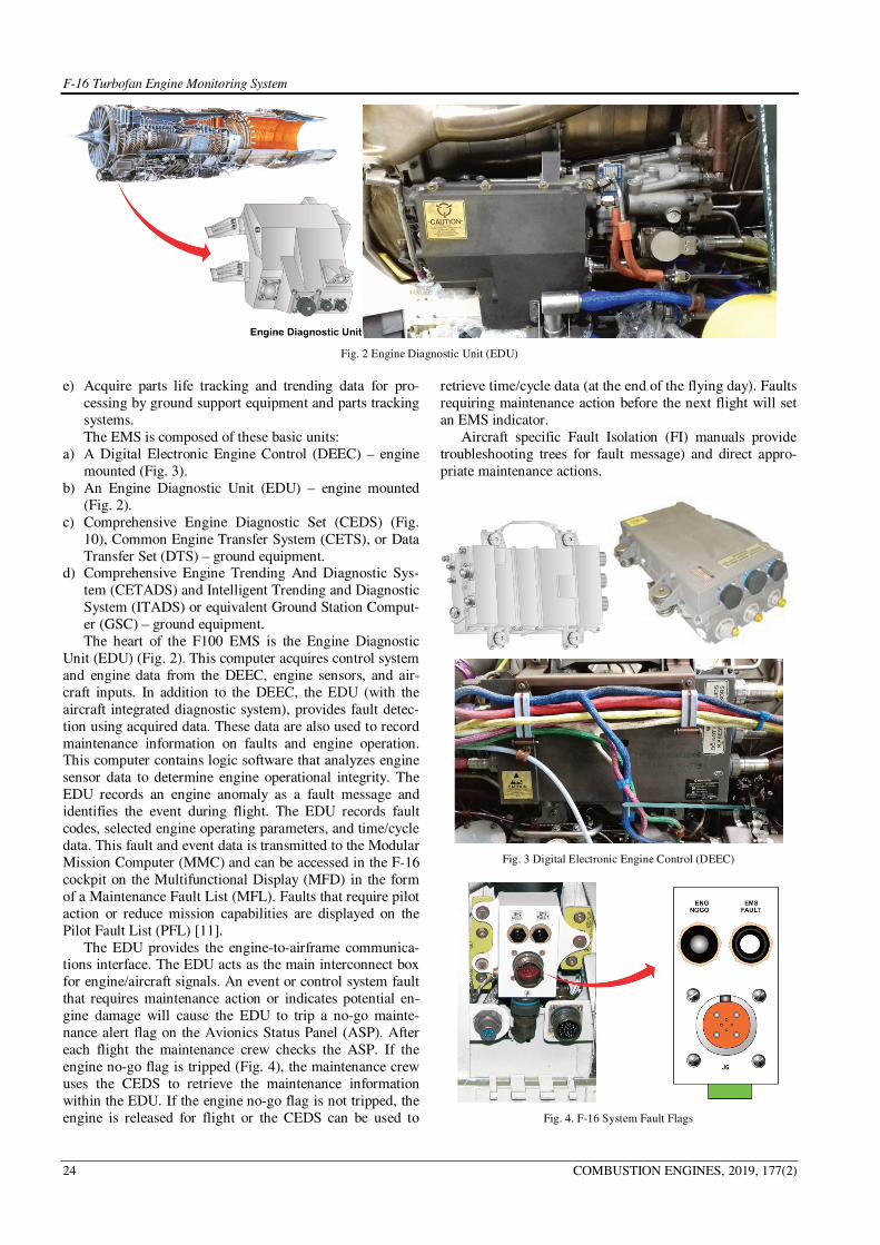
Fig. 2 Engine Diagnostic Unit (EDU)
e) Acquire parts life tracking and trending data for pro-
cessing by ground support equipment and parts tracking
systems.
The EMS is composed of these basic units:
a) A Digital Electronic Engine Control (DEEC) – engine
mounted (Fig. 3).
b) An Engine Diagnostic Unit (EDU) – engine mounted
(Fig. 2).
c) Comprehensive Engine Diagnostic Set (CEDS) (Fig.
10), Common Engine Transfer System (CETS), or Data
Transfer Set (DTS) – ground equipment. d) Comprehensive Engine Trending And Diagnostic Sys-
tem (CETADS) and Intelligent Trending and Diagnostic
System (ITADS) or equivalent Ground Station Comput-
er (GSC) – ground equipment.
The heart of the F100 EMS is the Engine Diagnostic
Unit (EDU) (Fig. 2). This computer acquires control system
and engine data from the DEEC, engine sensors, and air-
craft inputs. In addition to the DEEC, the EDU (with the
aircraft integrated diagnostic system), provides fault detec-
tion using acquired data. These data are also used to record
maintenance information on faults and engine operation. This computer contains logic software that analyzes engine
sensor data to determine engine operational integrity. The
EDU records an engine anomaly as a fault message and
identifies the event during flight. The EDU records fault
codes, selected engine operating parameters, and time/cycle
data. This fault and event data is transmitted to the Modular
Mission Computer (MMC) and can be accessed in the F-16
cockpit on the Multifunctional Display (MFD) in the form
of a Maintenance Fault List (MFL). Faults that require pilot
action or reduce mission capabilities are displayed on the
Pilot Fault List (PFL) [11].
The EDU provides the engine-to-airframe communica-tions interface. The EDU acts as the main interconnect box
for engine/aircraft signals. An event or control system fault
that requires maintenance action or indicates potential en-
gine damage will cause the EDU to trip a no-go mainte-
nance alert flag on the Avionics Status Panel (ASP). After
each flight the maintenance crew checks the ASP. If the
engine no-go flag is tripped (Fig. 4), the maintenance crew
uses the CEDS to retrieve the maintenance information
within the EDU. If the engine no-go flag is not tripped, the
engine is released for flight or the CEDS can be used to
retrieve time/cycle data (at the end of the flying day). Faults
requiring maintenance action before the next flight will set
an EMS indicator.
Aircraft specific Fault Isolation (FI) manuals provide
troubleshooting trees for fault message) and direct appro-
priate maintenance actions.
Fig. 3 Digital Electronic Engine Control (DEEC)
Fig. 4. F-16 System Fault Flags

F-16 Turbofan Engine Monitoring System
COMBUSTION ENGINES, 2019, 177(2) 25
2. EMS data flow The EMS becomes operative at engine start and records
performance data at takeoff. There are two types of Takeoff
performance data: MIL-POWER (PLA between 83 and 90
degrees) and MAX-POWER (PLA at or above 90 degrees).
Sensor inputs from the engine are processed by the
DEEC. The DEEC conditions and digitizes these signals for
transmission to the engine mounted EDU. The EDU re-
ceives these signals, as well as signal inputs from the air-craft and performs diagnostic logic and data storage. Data
downloading from the EDU is accomplished by connecting
the CEDS, CETS or DTS to the engine. There are six types
of DEEC and EDU fault or code categories: Event (EVT)
codes-1000 series, DEEC faults-2000 series, EDU faults-
3000 series, System faults-4000 series, Advisory faults-
5000 series and Performance advisories-6000 series. IT-
ADS faults are the 8000 series. This data is then download-
ed into the ground station software, which is currently CE-
TADS and ITADS.
EMS data flow is presented at Fig. 5.
Fig. 5. EMS Data Flow
The Engine Diagnostic Unit (EDU) (Fig. 2) is an en-
gine mounted, fuel cooled, self-contained diagnostic com-
puter used in Monitoring System that operates with con-
junction with the DEEC gr. V to acquire and record diag-
nostic data when the engine is operating. EDU stores data
that could be collected later on with Engine Monitoring Support Equipment (EMSE) for further evaluation and
analysis. The EDU receives and stores engine and aircraft
sensor data, and control system data from the DEEC. These
signals and data are monitored by the EDU to detect control
system faults and engine malfunctions. When the EDU
detects a system fault or anomaly, it records a 3-digit fault
code, along with the time of event. This information is
stored in the EDU and is retrievable at the flightline level
for troubleshooting. The EDU receives and stores data in
six basic engine usage data groups: (Fig. 6) [1].
1. Time/Cycle Data. The EDU monitors the engine for overlimit conditions. In addition, it accumulates low cy-
cles fatigue counts and engine flight hours.
2. Event Data. The EDU monitors the engine for overlimit
conditions and anomalies. The data is stored in three
parts: a three digit code number which identifies the
event, the elapsed time when the event occurred and
critical parameters to establishing minimum mainte-
nance requirements.
3. Fault Data. The EDU records engine control system,
DEEC and EDU faults. The fault data is used to deter-
mine maintenance requirements. Faults are stored in two
parts: three digit code number which uniquely identifies
the source of the fault.
4. Transient Data is recorded in the EDU when an auto
transfer to SEC has occurred, a random or recurrent event has taken place or when requested by the operator
by positioning the AB RESET switch to ENG DATA
position.
5. Performance Data. During any of the two engine operat-
ing conditions, the EDU automatically records nine pa-
rameters. The operating conditions are: on the ground at
intermediate power or takeoff at intermediate or maxi-
mum power.
6. Documentary Data. It is used to for parts life tracking
and configuration management.
Fig. 6. EDU Engine Data
The F-16C/D Block 52 is powered by the Pratt & Whit-
ney F100-PW-229 low-bypass, high compression ratio,
fully ducted, twin–spool turbofan engine which incorpo-
rates a FADEC Digital Electronic Engine Control (DEEC).
The Digital Electronic Engine Control (DEEC) is a fuel
cooled, engine mounted, full authority, electronic control, digital computer (Fig. 3). It is mounted to the front fan duct,
on the left side, at approximately the 8 o’clock position.
The DEEC provides precise management of thrust and
airflow in response to Power Lever Angle (PLA) changes
while in the Primary (PRI) mode of operation. It monitors
engine temperature, speed, and pressure limits, while main-
taining stall margin during steady state and transient condi-
tions. The DEEC continually examines and accommodates
control system faults. These faults are recorded as a three-
digit code and stored in the DEEC, and then transferred to
the EDU. If the DEEC cannot control the engine due to an

F-16 Turbofan Engine Monitoring System
26 COMBUSTION ENGINES, 2019, 177(2)
engine fault, or a problem with the system itself, engine
control is transferred to the Secondary (SEC) mode portion
of the Main Fuel Control (MFC), thus placing the engine in
SEC mode of operation.
The DEEC responds to approximately 50 input parame-
ters and provides approximately 20 outputs to the hydrome-
chanical components (Fig. 7). The DEEC provides the
engine system with maximum level of save operation along
with fault detection and accommodation. Polish Air Force
are using two series of DEEC: group V and Group VI. The
Group VI DEEC will incorporate all functionality of the EDU [3].
Input signals for DEEC gr V:
a) Fan inlet static pressure (Ps2)
b) Burner pressure (Pb)
c) Fan turbine discharge pressure (Pt6m)
d) Fan inlet temperature (Tt2)
e) Fan turbine inlet temperature (FTIT)
f) Front compressor speed (N1)
g) Rear compressor speed (N2)
h) Geometry position signals from Resolvers
i) Augmentor light-off detector (LOD) j) Ps2 resistance temperature detector (RTD)
k) Metering/sequencing Valve position
l) Several airframe signals
m) Automatic warning system
DEEC VI Series: DEEC group VI has additional fea-
tures:
a) Temperature sensor TT3
b) Instead of EDU there is Prognostic Health Monitor
(PHM) built in DEEC (more memory available, higher
resolution of data scan)
c) Predictive Prognostics
d) Useful Life Remaining Predictions
e) Component Life Tracking
f) Performance Degradation Trending
g) Selective Fault Reporting – Only tells pilot what
NEEDS to be known immediately – Informs Maintenance
of the rest of the engine information
h) Supports Maintenance Decision Making & Resource
Management
i) Fault Accommodation
j) Information Management The DEEC monitors engine operation for possible
anomalies. If an anomaly is detected, the DEEC will record
the anomaly and inform the Engine Diagnostic Unit (EDU).
The DEEC also takes corrective action depending on the
severity of the anomaly.
There are 5 Engine Control Loops (Fig. 8):
a) Compressor Inlet Variable Vanes (CIVV)
b) Rear Compressor Variable Vanes (RCVV)
c) Main Fuel Control (MFC)
d) Augmentor Fuel Control (AFC)
e) Exhaust Nozzle Area (AJ) Compressor Inlet Variable Vanes - its purpose is to im-
prove fan efficiency and stall margin by controlling the air
entering the fan.
a) Primary Mode Control
– Scheduled as a function of fan speed and TT2
b) Secondary Mode Control
– Move to fully cambered position
Fig. 7. F-16 Engine sensors and control - DEEC Inputs and Outputs [3]
F-16 Turbofan Engine Monitoring System
COMBUSTION ENGINES, 2019, 177(2) 27
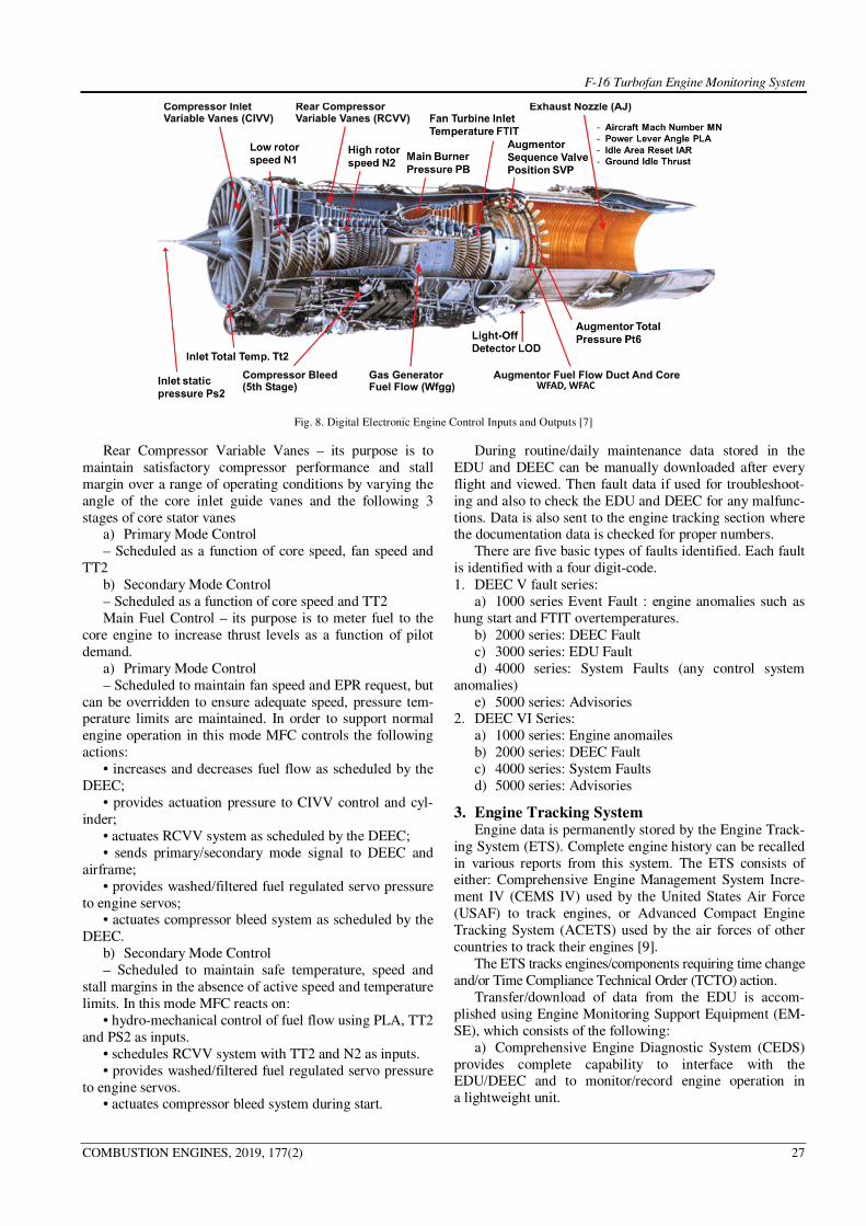
Fig. 8. Digital Electronic Engine Control Inputs and Outputs [7]
Rear Compressor Variable Vanes – its purpose is to
maintain satisfactory compressor performance and stall
margin over a range of operating conditions by varying the
angle of the core inlet guide vanes and the following 3
stages of core stator vanes a) Primary Mode Control
– Scheduled as a function of core speed, fan speed and
TT2
b) Secondary Mode Control
– Scheduled as a function of core speed and TT2
Main Fuel Control – its purpose is to meter fuel to the
core engine to increase thrust levels as a function of pilot
demand.
a) Primary Mode Control
– Scheduled to maintain fan speed and EPR request, but
can be overridden to ensure adequate speed, pressure tem-perature limits are maintained. In order to support normal
engine operation in this mode MFC controls the following
actions:
• increases and decreases fuel flow as scheduled by the
DEEC;
• provides actuation pressure to CIVV control and cyl-
inder;
• actuates RCVV system as scheduled by the DEEC;
• sends primary/secondary mode signal to DEEC and
airframe;
• provides washed/filtered fuel regulated servo pressure
to engine servos; • actuates compressor bleed system as scheduled by the
DEEC.
b) Secondary Mode Control
– Scheduled to maintain safe temperature, speed and
stall margins in the absence of active speed and temperature
limits. In this mode MFC reacts on:
• hydro-mechanical control of fuel flow using PLA, TT2
and PS2 as inputs.
• schedules RCVV system with TT2 and N2 as inputs.
• provides washed/filtered fuel regulated servo pressure
to engine servos. • actuates compressor bleed system during start.
During routine/daily maintenance data stored in the
EDU and DEEC can be manually downloaded after every
flight and viewed. Then fault data if used for troubleshoot-
ing and also to check the EDU and DEEC for any malfunc-
tions. Data is also sent to the engine tracking section where the documentation data is checked for proper numbers.
There are five basic types of faults identified. Each fault
is identified with a four digit-code.
1. DEEC V fault series:
a) 1000 series Event Fault : engine anomalies such as
hung start and FTIT overtemperatures.
b) 2000 series: DEEC Fault
c) 3000 series: EDU Fault
d) 4000 series: System Faults (any control system
anomalies)
e) 5000 series: Advisories 2. DEEC VI Series:
a) 1000 series: Engine anomailes
b) 2000 series: DEEC Fault
c) 4000 series: System Faults
d) 5000 series: Advisories
3. Engine Tracking System Engine data is permanently stored by the Engine Track-
ing System (ETS). Complete engine history can be recalled
in various reports from this system. The ETS consists of either: Comprehensive Engine Management System Incre-
ment IV (CEMS IV) used by the United States Air Force
(USAF) to track engines, or Advanced Compact Engine
Tracking System (ACETS) used by the air forces of other
countries to track their engines [9].
The ETS tracks engines/components requiring time change
and/or Time Compliance Technical Order (TCTO) action.
Transfer/download of data from the EDU is accom-
plished using Engine Monitoring Support Equipment (EM-
SE), which consists of the following:
a) Comprehensive Engine Diagnostic System (CEDS)
provides complete capability to interface with the EDU/DEEC and to monitor/record engine operation in
a lightweight unit.

F-16 Turbofan Engine Monitoring System
28 COMBUSTION ENGINES, 2019, 177(2)
b) The downloaded data is used to aid maintenance
personnel and is transferred to the engine tracking section
The Comprehensive Engine Diagnostic Unit (CEDS) is
a ground-based data collection and diagnostic system (Fig.
9) that supports F100 engines using the Engine Monitoring
System (EMS). The CEDS acquires, processes, and dis-
plays engine data to maintenance crews and can transfer the
data to Air Force tracking systems, such as:
a) Comprehensive Engine Management System Incre-
ment IV (CEMS IV)
b) Advanced Compact Engine Tracking System (ACETS).
Fig. 9. Typical Engine Monitoring System
The CEDS is used to communicate with the Engine Di-
agnostic Unit (EDU), Digital Electronic Engine Control
(DEEC), and Data Collection Unit (DCU).
Engine Downloading
Downloading is usually performed using a single CEDS
transfer unit (Fig. 10) to download all aircraft in a section.
Fig. 10. Comprehensive Engine Diagnostic Set CEDS
This configuration is typically used at the end of the fly-
ing day, if the pilot reported an engine anomaly, or in the
event of an EMS-reported engine malfunction (aircraft NO-
GO flag tripped).
DEEC download capability supports special investiga-
tions and is not required during normal maintenance.
Only fault code data will be downloaded (without a time
stamp). This data is for read-only purposes and will not be
stored in the CEDS.
4. Engine Monitor CEDS allows the operator to perform real-time monitor-
ing of an aircraft-installed engine (O-Level) [3].
This is typically performed during engine troubleshoot-
ing or operational checks, as required by the applicable
Technical Order (T.O.).
The Intermediate Maintenance (IM or I-Level) is used at
the test cell, after engine maintenance, or when trouble-
shooting, as required by the applicable T.O. The CEDS
transfer unit is permanently mounted in the control room of
the Hush House in conjunction with the interconnecting box (Fig. 11).
Fig. 11. Engine Monitoring System at I-Level
The EDU downloads are normally done at the end of the
day for flight-line operations, at the end of the acceptance
test for test cell operations, or when faults are detected by
the EMS.
The EDU download summary report (Fig. 12) provides
a brief summary of downloaded data. An option is provided for the operator to examine the download data in detail.
When downloading data from the EDU, CEDS will store
identical data into two locations. One location is a file to
transfer data to Air Force tracking systems. The other loca-
tion stores the data in the CEDS database (internal
memory). Up to 500 complete downloads may be stored in
CEDS memory at a time.
Once CEDS memory is full, subsequent downloads are
accommodated by deletion of the oldest data in CEDS
memory. The transfer file grows continuously until the data
is transferred to Air Force tracking systems or CEDS runs out of memory.
If CEDS detects an error during its operations, messages
will be displayed to inform the operator of a malfunction.
CEDS (Fig. 10) allows the operator to download/view
DEEC fault codes, clear DEEC fault codes, update DEEC
logic, perform an LOD test, and view the memory locations
within the DEEC that may be required to support special
investigations, as requested by P&W.

F-16 Turbofan Engine Monitoring System
COMBUSTION ENGINES, 2019, 177(2) 29
Fig. 12. EDU Download Summary Report
Fig. 13. CEDS menu
EMS Report Generator
The EMS Report Generator option (Fig. 13-14) allows
the generation and display of EMS data in several different
screen formats.
Fig. 14. EMS Report Generator submenu
The secondary menu options are described on the fol-
lowing pages.
1. Flight Data Report – This option allows the operator to
view all or selected parts of information recorded from
a selected engine for a single download.
The data may be contained on several different screens
(Fig. 15-20). It shows all downloads stored in CEDS for the
engine selected like:
1. Documentation data and time/cycle data:
Fig. 15. Documentation data and time/cycle data
2. Engine Fault Data:
Fig. 16. Engine Fault Data

F-16 Turbofan Engine Monitoring System
30 COMBUSTION ENGINES, 2019, 177(2)
3. Engine Performance data:
Fig. 17. Engine Performance Data
4. Event (maintenance) Data;
Fig. 18. Event (maintenance) Data
5. Engine Advisory Data:
Fig. 19. Engine Advisory Data
6. Transient data.
Fig. 20. Engine Transient Data
Engine Monitor
The engine monitor option allows the operator to
view/record real-time EDU (Fig. 21) or DEEC (Fig. 22)
with the engine running or view DEEC parameters when the engine is static. The operator is presented with a display
of selected parameters and may select up to four additional
parameters.
Fig. 21. EDU Real Time Monitor
Fig. 22. DEEC Real-Time Monitor
Troubleshooting scenario for flightline operations
When the aircraft returns, the ground crew performs the required postflight inspections including a check of aircraft
system fault indicators. The ground crew takes the follow-
ing actions based on the fault indicator flags.
When neither flag (Fig. 4) is tripped (NO-GO or EMS),
the aircraft is released. When the NO-GO or EMS BIT flags
are tripped, the technician uses Engine Maintenance Sup-
port Equipment (EMSE) to download the EDU and extract
fault data.
If a fault has been recorded by the EMS, the technician
refers to the Technical Order (T.O.) work package, which
contains information required to troubleshoot the fault and
return the engine to service. There may be instances when the pilot or engine opera-
tor may complain about improper engine operation, but the
EMS will not indicate a need for troubleshooting (no fault
or event codes).
Aircraft Indications
Troubleshooting usually begins with an engine malfunc-
tion reported by the pilot. Most engine anomalies will be
reported by the pilot and recorded by the EMS. However,
some engine faults will be recorded only by the EMS
(without the pilot noticing any fault exists). The pilot may
report some engine anomalies only (no EMS data). Cockpit indicators can be verified to ensure that the
fault exists with the engine and not the airframe. It is done
by using the Comprehensive Engine Diagnostic System
(CEDS) to check the engine EMS faults that are recorded.
Indicators in the cockpit may be erroneous due to an air-
frame malfunction.
The pilot monitors engine parameters through gauges
mounted in the cockpit (Fig. 23).

F-16 Turbofan Engine Monitoring System
COMBUSTION ENGINES, 2019, 177(2) 31
Fig. 23. Engine Controls and Indicators [1]
Table 1. Engine indicators
Indicator Description
HUD (Head-Up Display) Warnings, Fuel, Pilot Fault List (PFL)
Master Caution Illuminated for all warnings displays and PFLs
Engine Fire Engine Bay Temperature >765°F
HYD/OIL Engine Oil Pressure < 10 PSI
ENGINE Engine overtemperature, flameout or stagnation
PFLs (located on the data entry display) Pilot Fault List
A/B Failure Augmentor Failure
Mach No. Failure Loss of the Mach signal to the DEEC
DEEC/EDU Communication Failure Loss of the multiplex (MUX) communication to the EDU/DEEC
Anti-ice overtemperature Anti-ice problems
Anti-ice valve Failed Closed Anti-ice problems
Engine Low Thrust (indicates both FTITA and FTITB signals failed) Engine Low Thrust
A/C Engine MUX-Bus Failure Caution Panel, Engine in Secondary Mode (SEC)
Engine Fault PFL Fault present
Overheat Engine bay overheat
Inlet Icing Icing Condition Present
Fuel/Oil Hot Fuel temperature is hot causing a hot oil condition
UCADC Upgraded Central Air Data Computer Failure
The engine parameters that are monitored in the cockpit
are:
1. Core rotor speed: N2 (% RPM)
2. Fan turbine inlet temperature: FTIT (°C)
3. Fuel flow: (PPH)
4. Exhaust nozzle position: ENP (%)
5. Main oil pressure: MOP (PSI). Caution lights alert the pilot to warnings or malfunc-
tions and indicate the engine system affected. The pilot
takes appropriate action required by the indication.
F-16 engine indicators are shown in Table 1.
5. Engine fault troubleshooting procedure Engine troubleshooting procedures are the part of Tech-
nical Manual Fault Isolation Power Plant MODEL F100-
PW-229 [12]. This manual provides fault identification,
description and isolation procedures for power plant system.
Fault Identification and Description. The fault diagnostic logic information appears in the
body of the page in block flow form (Fig. 24). This form
identifies the fault as well as relevant conditions leading to
a specific eight-character numeric-alphanumeric code.
It provides the conditions existing at the time the fault oc-
curred and/or, when applicable, a crossreference listing
from self-test failed test number to a fault code.
As an example, a complete fault code as would appear
on a fault identification page or in a job guide test result (except for location code) is as follows: 70-00-AD-00. The
fault code elements are broken down as follows:

F-16 Turbofan Engine Monitoring System
32 COMBUSTION ENGINES, 2019, 177(2)
The two-letter fault identifier used to identify faults is assigned so that the first letter identifies the basic fault. The
second letter identifies a subfault found within the basic
fault.
Fault Isolation Procedures
The user will find the fault isolation procedure for the
required fault code on the appropriate fault isolation proce-
dure flow chart. Each fault code is followed by a series of
action instructions contained in rectangular blocks with the
monitored results of the actions outside the blocks (Fig. 24).
These actions terminate with fault correction instructions or
reference to a schematic diagram or another system fault
isolation manual for further fault analysis. The action blocks also contain any required reference to locator data,
schematic or wiring diagrams, or job guide function in
parentheses (Fig. 24).
Fig. 24. Fault Isolation Flow Chart [12]
The next step of the fault troubleshooting it to follow
the procedures in the LOG BOOK REPORT (70-00-00)
section of the aforementioned fault isolation manual (Fig.
25).
Information from the Log Book Reports leads to the
fault tree. In this case: 70-00-AA (Fig. 25). Fault tree of our interest is described in the Fault Isolation Information (70-
00-00) (Fig. 26).
In our case scenario first step of the fault isolation pro-
cedure is to review even/fault data in accordance with the
supplemental data described in Tables 9-1 and 9-5 (Fig.
26). Supplemental data from Table 9-1 provides the infor-
mation about EMS data downloading procedures (Table 2).
SECTION II
LOG BOOK REPORT (70-00-00)
PILOT DETECTABLE FAULTS
NO START
AA No start; RPM not OK; Fault Tree 70-
00-AA
AD No start; RPM not OK; no Pilot Fault
List (PFL) or MFL displayed; did not
increase above 27%; primary. Fault
Tree 70-00-AD
AH Hot start (ground); FTIT high; no PFL or MFL displayed;
did not exceed 1112OC; exceeded 1098
OC longer than 5
seconds; primary. Fault Tree 70-00-AH
AL No start; RPM not OK; no PFL or
MFL displayed; did not increase
above 27%; secondary. Fault Tree 70-
00-AL
AQ Hot start (ground); FTIT high; no PFL or MFL displayed;
did not exceed 1112OC; exceeded 1098
OC longer than 5
seconds; secondary. Fault Tree 70-00-AQ
Fig. 25. Log book report (Fault code 70-00-AA) [12]
Fig. 26. Fault tree. Fault isolation information [12]
1

F-16 Turbofan Engine Monitoring System
COMBUSTION ENGINES, 2019, 177(2) 33
Table 2. Fault Data Review procedure
PROCEDURE NORMAL
INDICATION
REMEDY FOR ABNORMAL
INDICATION
Aircraft safe for maintenance (JG10-30-01)
Power source: Battery
Support Equipment: Common Engine Transfer Set
1. Open access door 3309 and 3316
2. Connect data download cable to receptacle J1 on CETS unit
3. Connect data download cable to receptacle J146/1
4. Position laptop power switch to ON
5. Select WinCEDS from menu shell program or double click on WinCEDS
icon
6. With CET unit on main menu, select EDU COMMUNICATIONS
7. Select EDU DOWNLOAD. Verify cable connection. Select OK
No faults/events
displayed
Troubleshoot existing events/faults per supplemental
data, Table 9-5. If communication error is displayed,
replace CETS and cables. If problem persists go to
fault code 77-00-ZF
If there are no engine fault codes downloaded from ei-
ther EDU or DEEC then one should follow the Fault tree
branch downwards from (Fig. 26). In case there are some fault codes downloaded one should follow the supplemental
data in Table 9-5 (Table 3 and Table 4).
There are six basic types of events/faults. Each
event/fault is identified with a four-digit code. A different
series of numbers is used for each fault type; i.e., EDU
events are 1000 to 1999, DEEC faults 2000 to 2999, EDU
faults 3000 to 3999, system faults 4000 to 4999, and EDU
advisory faults 5000 to 5999, and 8000 series ITADS faults.
Intelligent trending and diagnostics system (ITADS)
faults are displayed as four digit code numbers (8000 series)
on the comprehensive engine trending and diagnostics sys-tem (CETADS) only after engine data is downloaded from
the EDU and uploaded to the engine management computer
running the CETADS software. ITADS only utilized takeoff
performance data sets. It does not utilize ground performance data sets or test cell performance data [9].
Let us assume that the fault code downloaded was the
1120 (Table 5).
Corrective action should be followed in accordance with
the chart “P” (Table 6). If the engine control mode was the
PRIMARY MODE then one should go to fault code 70-00-
AD. In case it was SEC MODE – fault code 76-00-BG.
Following the Log Book Report (Fig. 27) one may find
the right corrective action searching for the Fault tree
70-00-AD.
Part of the fault isolation procedure of the fault tree 70-00-AD is shown in the Fig. 28.
Table 3. EDU event. EDU fault, DEEC fault, System fault and EDU advisory code reference
MFL / PFL
CODES
FAULT CODES EVENT/FAULT
DESCRIPTION
CORRECTIVE ACTION
CHART TABLE MIDAS FAULT CODE
Table 4. Supplemental data for EDU event, EDU fault, DEEC fault, system fault, cont.
MFL/PFL
CODES
FAULT
CODES
EVENT/FAULT
DESCRIPTION
CORRECTIVE ACTION
CHART TABLE MIDAS FAULT CODE
023 4054 RCVV Resolver Number 2 Position 76-00-ZY
024 4050 RCVV Resolver 76-00-ZS
025 1000 Stagnation A
Table 5. Supplemental data for EDU event, EDU fault, DEEC fault, system fault, cont.
MFL/PFL
CODES
FAULT
CODES
EVENT/FAULT
DESCRIPTION
CORRECTIVE ACTION
CHART TABLE MIDAS FAULT CODE
036 1090 N2 Overspeed G
037 1120 Engine No Start P
038 1151 Axial RCVV Flutter H
Table 6. CHART P. Engine no start corrective procedures
CHART P. ENGINE NO START
NOTE
• If fault was recorded during wet or dry motoring procedure, or engine depreservation, trouble shooting is not required.
• Following data may be obtained during engine data review to determine appropriate troubleshooting procedure: control mode (primary
or secondary)
PRIMARY SECONDARY
A B
CORRECTIVE ACTION
“A” – Go to fault code 70-00-AD “B” – Go to fault code 76-00-BG

F-16 Turbofan Engine Monitoring System
34 COMBUSTION ENGINES, 2019, 177(2)
Let us assume one have reached to the point when we
should check main fuel gear pump filter assembly IAW
supplemental data from Table 9-32 (Table 7).
While inspecting fuel filter one finds it clogged by
a foreign material. Then one should install filter IAW Job
Guide JG73-00-09 (Table 8).
The next step of the troubleshooting procedure is to per-
form engine start and leak check IAW (JG70-00-01) as
a follow-on maintenance of the MFGP Fuel Filter element,
removal and installation procedure IAW T.O PL1F-16CJ-2-
73JG-00-21 (Table 9).
This step ends fault isolation procedure. As a result of
the case study research we may propose the Engine Dis-
crepancy Removal Schematic Diagram (Fig. 29).
NO START
AA No start; RPM not OK; Fault Tree 70-00-AA
AD No start; RPM not OK; no Pilot Fault List (PFL) or MFL displayed; did not increase
above 27%; primary. Fault Tree 70-00-AD
Fig. 27. Log Book Report (Fault code 70-00-AD)
Fig. 28. Part of the Engine Fault Tree (Engine Fault 70-00-AD)
Table 7. Supplemental data. Main fuel gear pump filter assembly inspection procedure (part of Table 9-32)
NOTE
Instructions for main fuel gear pump filter assembly inspection are unique to gear / pump bypass valve configuration
1. Remove main fuel gear pump filter (JG73-00-09)
2. Visually inspect filter assembly (Figure 9-48) as follows:
INSPECTION
AREA
CONDITION MAXIMUM SER-
VICEABLE LIMITS
CORRECTIVE ACTION
Fuel filter cover Cracks or distortion None Replace cover
Stripped, crossed or worn
threads
None Replace cover
Packing groove for wear and
foreign material build-up
None Remove foreign material. If grooves are damaged, replace cover
Differential pressure indicator
housing operation
None If housing is damaged or operation is not smooth, replace cover. After
check, reset differential pressure indicator by inverting fuel filter cover
and pressing button. If indicator does not reset, replace differential
pressure indicator (JG73-00-25)
Table 8. Troubleshooting procedure for the clogged filter (part of Table 9-32), cont.
PROCEDURE
3. Install main fuel pump filter (JG73-00-09)
Table 9. Part of the MFGP Fuel Filter element, removal and installation procedure
TO PL1F-16CJ-2-73JG-00-21
FOLLOW-ON MAINTENANCE:
• (2) Perform engine start and leak check (JG70-00-01).

F-16 Turbofan Engine Monitoring System
COMBUSTION ENGINES, 2019, 177(2) 35
Fig. 29. Engine discrepancy removal schematic diagram. Own elaboration
6. Summary Engine Monitoring System (EMS) is the key element in
the engine prognostic and health monitoring. This is also
the integral part of the engine performance trending. It
allows to track engine performance parameters and their
projections using historical data. In cooperation with Prog-
nostic Health Monitor (PHM) and Engine Management
And Tracking System (EMATS) it allows engine mainte-
nance personnel for an easier troubleshooting and im-
provements implementation (right maintenance in right time), Time Accumulated Cycles TACs counting, engine
parameters analysis, life time usage and the possibility of
forecasting engine life remaining time. As a result, it is
possible to manage engine components replacement, mod-
ules, and forecasting spare parts in advance.
As most of the complex systems it requires special
preparation and experienced personnel. It supports engine
tracking personnel in their work but it will never replace
experienced and qualified personnel in engine diagnosis
and prognostics.
It is very important to stress that while performing en-
gine discrepancies removal sometimes corrective actions described in the fault isolation manual are just the most
probable solution of the encountered problem. It does not
guarantee that all engine discrepancies found during flight
operations could be removed with the proposed corrective
actions. In many cases one goes through the whole engine
troubleshooting process, reaches the end of the engine fault
tree and does not find the solution for the encountered en-
gine problem.
Nomenclature
AJ Exhaust nozzle area
AJRATIO Exhaust nozzle area ratio (Aj CENC feedback / calculated Aj for choked nozzle)
CEDS Comprehensive Engine Diagnostic Set CEMS Comprehensive Engine Management System CENC Convergent Exhaust Nozzle Control
CETADS Comprehensive Engine Trending And Diagnostic System
CETS Common Engine Transfer System CIVV Compressor Inlet Variable Vanes
DEEC Digital Electronic Engine Control EDU Engine Diagnostic Unit EHM Engine Health Management EMB Engine Management Branch EMS Engine Monitoring System EOT Engine Operating Time EPR Engine Pressure Ratio FLT Fault
FTIT Fan Turbine Inlet Temperature
GSC Ground Station Computer ITADS Intelligent Trending And Diagnostic System LODCNT Light Off Detector Count MFC Main Fuel Control MNAC Aircraft Mach Number MOP Main Oil Pressure N1 Fan speed N1C2 Corrected fan speed N2 Core speed
PB Burner pressure PLA Power Lever Angle PT4 Combustion chamber discharge TAC Total Accumulated Cycles Tt2 Fan Inlet Total Temperature WFAC Augmentor fuel flow, core WFAD Augmentor fuel flow, duct WFMFC Main fuel control fuel flow
Bibliography
[1] Lockheed Martin STM 16-329PL (Poland Block 52) F100-PW-229 Power Plant.
[2] F100 Pratt&Whitney F100 WUC, October 2018. [3] F100-PW-229 Periodic Engineering Excellence Reviev. [4] Lockheed Martin Aero Flight Safety, Operations and
Maintenance, June 2018. [5] International Engine Management Program, October 2018. [6] Technical Manual T.O.00-20-1 Aerospace Equipment
Maintenance Inspections, Documentation, Policies and pro-cedures.
[7] F100 Pratt&Whitney F100 WUC, October 2018.
[8] Technical Manual General System Organizational Mainte-nance Power Plant Model F100-PW-229 Technical Order PL1F-16CJ-2-70GS-00-21.
[9] Engine Management and Tracking System EMATS Maintenix [10] F100-PW-229 Engine Interactive Electronic Technical
Manuals. [11] Technical Manual Maintenance Instructions Intermediate
Level Introduction and General Information Aircraft Engine
F100-PW-229 Technical Order 2J-F100-56-1. [12] Technical Manual Fault Isolation Organizational Mainte-
nance Power Plant Model F100-PW-229 Technical Order PL1F-16CJ-2-70FI-00-21.
Sławomir Szrama, DEng. – Squadron Commander at
31st Air Force Base Poznań-Krzesiny.
e-mail: [email protected]