Flexy 205 - NET
35
Flexy 205 INSTALLATION GUIDE IG-0028-00 1.5 en-US ENGLISH
-
Upload
khangminh22 -
Category
Documents
-
view
2 -
download
0
Transcript of Flexy 205 - NET

Flexy 205
INSTALLATION GUIDEIG-0028-00 1.5 en-US ENGLISH

Important User InformationDisclaimerThe information in this document is for informational purposes only. Please inform HMS Industrial Networks of anyinaccuracies or omissions found in this document. HMS Industrial Networks disclaims any responsibility or liabilityfor any errors that may appear in this document.
HMS Industrial Networks reserves the right to modify its products in line with its policy of continuous productdevelopment. The information in this document shall therefore not be construed as a commitment on the part ofHMS Industrial Networks and is subject to change without notice. HMS Industrial Networks makes no commitmentto update or keep current the information in this document.
The data, examples and illustrations found in this document are included for illustrative purposes and are onlyintended to help improve understanding of the functionality and handling of the product. In view of the wide rangeof possible applications of the product, and because of the many variables and requirements associated with anyparticular implementation, HMS Industrial Networks cannot assume responsibility or liability for actual use based onthe data, examples or illustrations included in this document nor for any damages incurred during installation of theproduct. Those responsible for the use of the product must acquire sufficient knowledge in order to ensure that theproduct is used correctly in their specific application and that the application meets all performance and safetyrequirements including any applicable laws, regulations, codes and standards. Further, HMS Industrial Networks willunder no circumstances assume liability or responsibility for any problems that may arise as a result from the use ofundocumented features or functional side effects found outside the documented scope of the product. The effectscaused by any direct or indirect use of such aspects of the product are undefined and may include e.g. compatibilityissues and stability issues.
Flexy 205 Installation Guide IG-0028-00 1.5 en-US

Flexy 205 Installation Guide IG-0028-00 1.5 en-US
Table of Contents Page
1 Preface ................................................................................................................................. 31.1 About This Document .......................................................................................................3
1.2 Document history ............................................................................................................3
1.3 Related Documents ..........................................................................................................3
1.4 Trademark Information .....................................................................................................3
2 Product Summary................................................................................................................ 42.1 Introduction....................................................................................................................4
2.2 Modular Concept of the Flexy 205 ......................................................................................4
2.3 Features of the Flexy 205 ..................................................................................................5
2.4 General Specification of the Hardware Platform ....................................................................5
2.5 Typical applications ..........................................................................................................6
2.6 Part Numbers ..................................................................................................................6
3 Safety, Environmental and Regulatory Information.......................................................... 73.1 Scope.............................................................................................................................7
3.2 Power Supply ..................................................................................................................7
3.3 ESD Damage Prevention ....................................................................................................7
3.4 Applicable Directives, Standards and Compliance ..................................................................7
3.5 Reference Standards for Type Tests.....................................................................................8
3.6 Internal Battery ...............................................................................................................9
3.7 Field Implementation & Environmental Conditions ................................................................9
4 Hardware Description ....................................................................................................... 134.1 Label............................................................................................................................ 13
4.2 Mechanical Dimensions................................................................................................... 14
4.3 Physical Interface ........................................................................................................... 14
5 Extension Cards ................................................................................................................. 185.1 Slot Compatibility........................................................................................................... 18
5.2 Extension Card Insertion.................................................................................................. 18
5.3 Powering On the Flexy 205 with its Extension Cards ............................................................. 19
5.4 Multiple Extension Cards ................................................................................................. 19
5.5 Ethernet Extension Card - FLX 3101................................................................................... 20
6 IP Address & Access to the Web Configuration............................................................... 216.1 Factory Default IP Settings ............................................................................................... 21
6.2 Powering On ................................................................................................................. 21
6.3 Connecting to the LAN IP Address ..................................................................................... 21
6.4 Web Interface ............................................................................................................... 21

Flexy 205 Installation Guide IG-0028-00 1.5 en-US
7 Resetting the Flexy 205..................................................................................................... 237.1 Normal Boot Sequence ................................................................................................... 23
7.2 First Level Reset (User Reset) ........................................................................................... 23
7.3 Second Level Reset (Factory Reset) ................................................................................... 23
7.4 Reset Impact Matrix ....................................................................................................... 24
A Connector Pinout & Related Specifications ..................................................................... 25A.1 Main Connector............................................................................................................. 25
A.2 Specification of the External Power Supply ......................................................................... 25
A.3 Digital Output & Digital Inputs.......................................................................................... 26
B Flexy 205 Products Overview ........................................................................................... 28B.1 Extension Cards ............................................................................................................. 28
C Flexy 205 Isolation Scheme ........................................................................................ 31C.1 Base Unit............................................................................................................................................ 31
C.2 Extension Cards ................................................................................................................................. 31

Preface 3 (32)
1 Preface1.1 About This Document
This document describes the hardware of the Ewon Flexy 205 and explains how to get startedwith the embedded web site. It also describes the basic software tools needed to install theequipment.
For additional related documentation and file downloads, please visit www.ewon.biz/support.
1.2 Document historyVersion Date Description
1.0 2018-01-12 Official release1.1 2018-11-06 Changed: Flexy 205 label
1.2 2019-01-29 Changed: general review
1.3 2019-08-20 Changed: Safety, Environmental and Regulatory Information, p. 7
1.4 2020-01-02 Changed: Digital Output & Digital Inputs, p. 26
1.3 Related DocumentsDocument Author Document ID
Easy Commissioning via SD Card & USB Drive HMS AUG-0062-00
eBuddy HMS AUG-0063-00
Reference Guide for Flexy 205 HMS RG-0008-00
1.4 Trademark InformationEwon® is a registered trademark of HMS Industrial Networks SA. All other trademarks mentionedin this document are the property of their respective holders.
Flexy 205 Installation Guide IG-0028-00 1.5 en-US
1.5 2022-08-02 Changed: product images & logos, adding missing extension cards, update isolation scheme

Product Summary 4 (32)
2 Product Summary2.1 Introduction
The Flexy 205 is a modular industrial M2M router.
It has been designed to fulfill the following key requirements:
• Flexible WAN, allowing within the same product to address different Internet connectivitytechnologies (Ethernet, Wi-Fi, 4G,…) and securing the investment in case of technologyupgrade (eg. 3G > 4G).
• Flexible Field, providing easy connection to a wide range of external devices, includingvarious field protocols.
• Flexible Apps, embedding alarms, data logging, remote access, routing and web HMIapplications with mouse click based configuration but also customization offering opennessand programming tools.
The Flexy 205 is fully compatible with the Talk2M cloud connectivity services and with the eFive(a VPN server appliance) for real-time control application.
Fig. 1 Housing of the Flexy 205
2.2 Modular Concept of the Flexy 205As the name Flexy 205 suggests, it has been designed to enable numerous differentcombinations by addition of extension cards (check Extension Cards, p. 28).
Fig. 2 Modular Concept of the Flexy 205
1 Main connector including power input terminals (1 DO and 2 DIs)
2 Communication interface3 Placeholder for extension cards
Flexy 205 Installation Guide IG-0028-00 1.5 en-US

Product Summary 5 (32)
2.2.1 Flexy 205The Flexy 205 features:
• 2 DIs and 1 DO.
• 2 free slots allowing the insertion of extension cards
2.2.2 Extension CardsThe extension cards extend the communication features by adding either:
• a WAN communication interface (Ethernet WAN, wireless modem, ...)
• a field communication interface (serial, IO card, …)
How the extension cards should be integrated in the Ewon Flexy 205 is explained in ExtensionCards, p. 18.
2.3 Features of the Flexy 205The following section lists the different main features supported by the Flexy 205.
• Open VPN
• Talk2M connections
• Data acquisition protocols (IO Servers)
• Alarm management and notification
• Data logging
• BASIC scripting
• JAVA ETK
• Web server
• ViewON 4 Web HMI
• FTP client and server
• HTTP(S) client (Get & Post requests)
• Ethernet to Serial gateway
• Routing between Ethernet interfaces (WAN to LAN)
• Routing features: IP forwarding, NAT, Port forwarding
2.4 General Specification of the Hardware PlatformCharacteristic ValueDesign Industrial design (24 VDC power supply, DIN Rail mounting, extended temperature)
Processor ARM9Clock Real Time Clock (RTC) with battery backup
Expected lifetime: 10 years
Ethernet Interface 4 configurable LAN/WAN Ethernet ports 10/100 Mbps
Digital Input 2
Digital Output 1
Mounting Latch for DIN rail EN50022 compliant
Flexy 205 Installation Guide IG-0028-00 1.5 en-US

Product Summary 6 (32)
2.5 Typical applicationsSome of the typical applications for the Flexy 205 are the following ones:
• Remote access of Ethernet, serial and MPI devices
• Industrial VPN router
• Remote monitoring
2.6 Part NumbersAvailable Part NumbersPart Number Type Description
FLEXY20500_00MA Flexy 205 M2M Data Gateway – 4 Ethernet ports
In the above table, the MA extension stands for “Multiple language A” (regrouping EN, FR, DE and IT).The part number syntax is explained in the Label, p. 13.
Flexy 205 Installation Guide IG-0028-00 1.5 en-US

Safety, Environmental and Regulatory Information 7 (32)
3 Safety, Environmental and Regulatory Information3.1 Scope
The present section addresses safety, environmental and regulatory information for the EwonFlexy 205.
This safety, environmental and regulatory information generally has a similar compliance framebut some aspects differ. For example: in the case of telecommunication extension cards,additional directives, standards and instructions apply.
3.2 Power SupplyThe external power supply is a third party device that is not part of this certification.
The device shall be powered by an LPS power supply certified according to IEC/UL60950-1 orClass2 per NEC or by a 12-24Vdc 100w max. certified for 60°C and for altitudes up to 2000m forconformity to the UL/IEC 62368-1 (for more information, refer to Specification of the ExternalPower Supply, p. 25).
3.3 ESD Damage PreventionTo avoid possible damage to the base unit and / or extension card, please wait 30 seconds afterswitching off the equipment before inserting (or removing) an extension card.
Always use ESD precautions when handling extension cards and / or opened base unit asthey contain parts and assemblies susceptible to be damaged by electrostatic discharge(ESD).
The printed circuit boards (PCBs) of the Ewon Flexy 205 described in the present document arepartially exposed when slot fillers are removed to place extension cards. In order to avoid ESDdamage, the product, when it is opened, must be handled with the necessary precautionincluding:
• Grounded ESD functional work surface
• Personal grounding
• Verification that the configuration is compatible with the firmware capabilities before beingoperated.
The extension cards described in this document are modules exposing both sides of an electronicprinted circuit board. Therefore, they are packed in anti static ESD bags. In order to avoid ESDdamage, the product must be handled with the necessary precaution as described above.
3.4 Applicable Directives, Standards and ComplianceThe Ewon Flexy 205 belongs to class A Information Technology Equipment (ITE). In a domesticenvironment, this product may cause radio interference in which case the user might have totake appropriate measures.
3.4.1 Conformity to European DirectivesThe Ewon Flexy 205 and its extension cards are in conformity with the following EC directives:
• RoHS Directive 2011/65/EU
• EMC Directive 2014/30/EU
Flexy 205 Installation Guide IG-0028-00 1.5 en-US

Safety, Environmental and Regulatory Information 8 (32)
• RE Directive 2014/53/EU1
3.4.2 Applicable Safety StandardsThe Ewon Flexy 205 and its extension cards are in conformity with the following safetystandards:
• IEC/EN 60950-1
• UL 60950-1
• CSA-C22.2 No 60950-1-07
• EN/IEC 62368-1
• UL 62368-1
• CAN 62368-1
3.4.3 FCC ComplianceThe Ewon Flexy 205 and its extension cards comply with Part 15 of the FCC Rules.
Operating is subject to the following two conditions:
• This device may not cause harmful interference
• This device must accept any interference received, including interference that may causeundesired operation.
3.4.4 CertificationsThe Ewon Flexy 205 and its extension cards have been duly certified by authorized bodies:
• UL Certificate of Compliance (COC) # 20190529_E350576
• CB certificate # DK-84039-UL
These certificates can be downloaded on www.ewon.biz/support
3.5 Reference Standards for Type TestsThe Ewon Flexy 205 and their extension cards have been fully validated on temperature,vibration and shock against the requirements of the following standards:
Operating & Storage Temperature
Test nature Reference StandardCold test IEC 60068-2-1
Dry heat test IEC 60068-2-2
Temperature change test IEC 60068-2-14
Cyclic damp heat test IEC 60068-2-30
Vibration & Shock TestsTest nature Reference StandardVibration test (sinusoidal) IEC 60068-2-6
Vibration test (broad-band random) IEC 60068-2-64
Shock test IEC60068-2-27
Flexy 205 Installation Guide IG-0028-00 1.5 en-US
1. When applicable, the product conforms to the corresponding RE Directive articles: RF spectrum efficiency: Art 3(2); EMC: Art. 3(1)(b); Safety: Art. (3)(1)(a)

Safety, Environmental and Regulatory Information 9 (32)
3.6 Internal BatteryThe Ewon Flexy 205 contains a CR2032 battery. This battery is used to maintain the real timeclock up-to-date even when the unit is not powered.
Here is a list of risks and recommendations regarding the battery:
• Risk of explosion if the battery is replaced by an incorrect type. The battery is not intendedto be replaced by the consumer: the product shall be returned to the manufacturer forreplacement.
• Do not ingest battery, chemical burn hazard.
• Keep new and used batteries away from children.
• If the cell battery is swallowed, it can cause several internal burns in just 2 hours and canlead to death.
• If the equipment’s enclosure do not close securely, stop using the product and keep it awayfrom children.
• If you think batteries might have been swallowed or placed inside any part of the body, seekimmediate medical attention.
Risk of explosion if the battery is replaced by an incorrect type. The battery is notintended to be replaced by the consumer: the product shall be returned to themanufacturer for replacement.
3.7 Field Implementation & Environmental Conditions3.7.1 Ingress Protection
The Ewon Flexy 205 has an IP20 protection grade. Therefore, the Ewon Flexy 205 is NOT suitedfor outdoor mounting.
It has to be integrated in an electrical cabinet, protected from excessive heat, humidity and dust.Do not push any sharp object into the air vents or openings of the equipment.
3.7.2 Mounting RecommendationsThe product is intended to be mounted vertically, label on the right side.
The normal mounting position of the Ewon Flexy 205 is wall mounted on a horizontalOmega type DIN-rail (EN 50022).
• Mounting the unit on DIN-rail
Pull the slide lock (located at the bottom of the back-side of the unit) downwards andpresent the unit in front of the DIN rail. Tilt the Ewon upwards in order to hang it on theupper edge of the DIN rail by its hook. Gently tilt the unit downwards until it finds itsoriginal position. Pull the slide lock upwards to fix and lock the unit on the DIN rail.
• Removing the unit from DIN-rail
Release the unit by pulling the slide lock downwards while gently tilting the unit upwards.Free the unit by unhooking it from the upper rail edge.
Flexy 205 Installation Guide IG-0028-00 1.5 en-US

Safety, Environmental and Regulatory Information 10 (32)
Fig. 3 DIN rail mounting position
# Description
1 DIN rail mounting bracket
Fig. 4 Wall mounting position
# Description
1 Wall mounting bracket (suggested screw dimensions 4,2 x 32 mm)
To ensure a proper ventilation of the equipment, a free gap of at least 2 cm must be respected infront of all upper & lower ventilation openings of the unit.
A free gap of at least 1 cm must be respected on each side of the unit.
Flexy 205 Installation Guide IG-0028-00 1.5 en-US

Safety, Environmental and Regulatory Information 11 (32)
Fig. 5 Free gap surrounding the Ewon for heat dissipation.
3.7.3 EarthingEarthing the Ewon is necessary to eliminate unwanted transients and to conform to the EMCrequirements. Therefore, a functional earth (FE) terminal is available on the main connector asshown in Specification of the External Power Supply, p. 25.
Connect this terminal directly to allow impedance ground. Shielded cables have to be used forEthernet and USB to comply with the EMC requirements.
3.7.4 Environmental LimitsThe equipment will operate properly within the following environmental limits provided it ismounted according to Mounting Recommendations, p. 9.
Characteristic ValueOperating temperature -25° to +60°C
Storage temperature -40° to +70°C
Relative humidity 10 to 95% non-condensing
Operating altitude Up to maximum 2000m
Storage altitude Up to maximum 3000m
Mounting Latch for DIN rail EN50022-compliant
3.7.5 Labelling InformationThe OEM User Manual (for integrators) must provide clear instructions, to the OEM, explainingthe labeling requirements, options and OEM User Manual instructions that are required.
Flexy 205 Installation Guide IG-0028-00 1.5 en-US

Safety, Environmental and Regulatory Information 12 (32)
The host OEM User Manuel (Ewon's manual) must contain clear instructions on how end userscan find and/or access the module and the FCC ID
Flexy 205 Installation Guide IG-0028-00 1.5 en-US

Hardware Description 13 (32)
4 Hardware Description4.1 Label
The identification label of the Ewon Flexy 205 is placed on the right hand side of the housing.The different parts of the label are described below:
Fig. 6 Flexy 205 Label
Label DefinitionPN Part Number
(see syntax in Syntax of the Part Number, p. 13)
SN Serial Number YYWW-SSSS-PPYY = 2 last digits of production yearWW = production week numberSSSS = Sequential production numberPP = Product Code
MAC MAC address of the Ethernet adapter
Rating Power supply requirements
Marks CE, UL,... logos if applicable
Syntax of the Part Number
FLEXY12233_44AA/B
Position(s) Description Acceptable values
FLEXY Name of the Ewon device model Only Flexy (constant)
1 Single figureDefines routing capabilities
2 M2M Router
22 Two figuresDefines the type of the motherboard
05 4 configurable LAN/WAN Ethernet ports
33 Two figuresDefines the primary software option
00 No primary software option
44 Two figuresDefines the secondary software option
00 No secondary software option
AA Two capital lettersDefines the firmware language
MA EN + FR + DE + IT
/B Single capital lettersDefines the model type
S Compliance with UL / IEC / EN 60950 Standard
MarksMarks Description
Conformité Européenne or European Conformity (EC)
UL Recognized - Underwriters Laboraties
Flexy 205 Installation Guide IG-0028-00 1.5 en-US

Hardware Description 14 (32)
4.2 Mechanical Dimensions
Fig. 7 Mechanical Dimensions
In the above picture:
• Unit: Dimensions are in millimeters (mm).
• Accuracy: Suited only for implementation drawings (rounded @ full mm).
Shaded areas show provisions of empty space that should be considered in the implementationarrangement.
The provision of empty space in front of the slot fillers is spared for the connectors of extensioncards. Even if the application requires no extension card(s), it is good practice to plan the freespace anyhow, in case an extension card is inserted later on.
4.3 Physical InterfaceThis section addresses the interface that represents the Ewon Flexy 205. The items numbered inthe image below are explained subsequently in separate paragraphs.
Flexy 205 Installation Guide IG-0028-00 1.5 en-US

Hardware Description 15 (32)
Fig. 8 Base Unit Interface
1 LED panel
2 RESET button - BI13 SD card slot4 Main connector
Used to connect the power supply and the digital I/O
5 2 slots fillersCan be removed and replaced by extension cards
6 Main board communication interfaces: 4 Ethernet Ports
4.3.1 LED PanelThe LED panel displays the system status and is located bottom to the 4 Ethernet ports. Thefollowing table explains the common LEDs of all base units.
Fig. 9 LED Panel Example of a Flexy 205
Label DefinitionPWR Power
Steady green = unit is powered on
USR UserBlinking green slowly = Unit is okRed pattern = special attention required
DI1 Digital IN 1Green = ON : Signal on Input 1 detected
DI2 Digital IN 2Green = ON : Signal on Input 2 detected
DO Digital outputGreen = ON : Signal on Output detected
T2M Talk2MGreen = ON : Talk2M VPN connection established
BI1 Button BI1 inputSteady green = reset button is being pressed
4.3.2 Reset ButtonThe reset button allows the reset of the Flexy 205 partially (Reset Level 1) or completely (ResetLevel 2). For the reset procedures check Resetting the Flexy 205, p. 23.
Flexy 205 Installation Guide IG-0028-00 1.5 en-US

Hardware Description 16 (32)
4.3.3 SD Card SlotThe SD card can be used for two purposes:
• Easy Commissioning: Configure a Flexy 205 and perform actions such as a firmware upgrade/ downgrade, recovery, restore a backup, Talk2M account integration, ...
• Extended User Memory: Named as the EUM card, it increases the user memory capacity ofthe Flexy 205.
The SD card slot is based on the Push-Push mechanism:
• Push the SD card down the slot until the mechanism clicks. As the click sound is heard, theSD card is now locked inside the card holder.
• Push on the SD card until it clicks again to retrieve it from the Flexy 205.
For more information on each of the possibilities offered with the SD card, easy commissioningor EUM, please refer to the Related Documents, p. 3.
4.3.4 Main ConnectorThe Flexy 205 is powered via its main connector using a male connector (a mating femaleconnector with screw terminals is delivered with the Ewon Flexy 205).
For details see Main Connector, p. 25.
4.3.5 Two Slots for ExtensionsThe slot fillers can be removed to add extension cards. A general overview of the availableextension cards is available in the Extension Cards, p. 28.
It is recommended to never leave a slot empty. Either a slot filler or an extension card shouldalways be inserted in the Flexy 205.
4.3.6 LAN / WAN Ethernet portsThe LAN / WAN interface consists of a 4 auto-sense Ethernet ports (10/100 Mbps). Auto-sensemeans that both UTP Class 5 direct and crossed cables with RJ45 terminations at both ends canbe used. Default parameters see Factory Default IP Settings, p. 21.
Fig. 10 Interface of the Flexy 205
However, the minimum required regarding the Ethernet cable type is Cat.5 with RJ45 connectors.
Flexy 205 Installation Guide IG-0028-00 1.5 en-US

Hardware Description 17 (32)
LED Interface
Fig. 11 LED Panel of the Flexy 205
Label Definition1 Big
rectan-gle
Green = LAN portOrange = WAN port
Smallsquare
Ethernet activity on port 1Green steady = Ethernet link OKGreen flashing = Ethernet traffic (Rx and Tx)
2 Ethernet activity on port 2 (same as above)
3 Ethernet activity on port 3 (same as above)
4 Ethernet activity on port 4 (same as above)
Flexy 205 Installation Guide IG-0028-00 1.5 en-US
Extension Cards 18 (32)
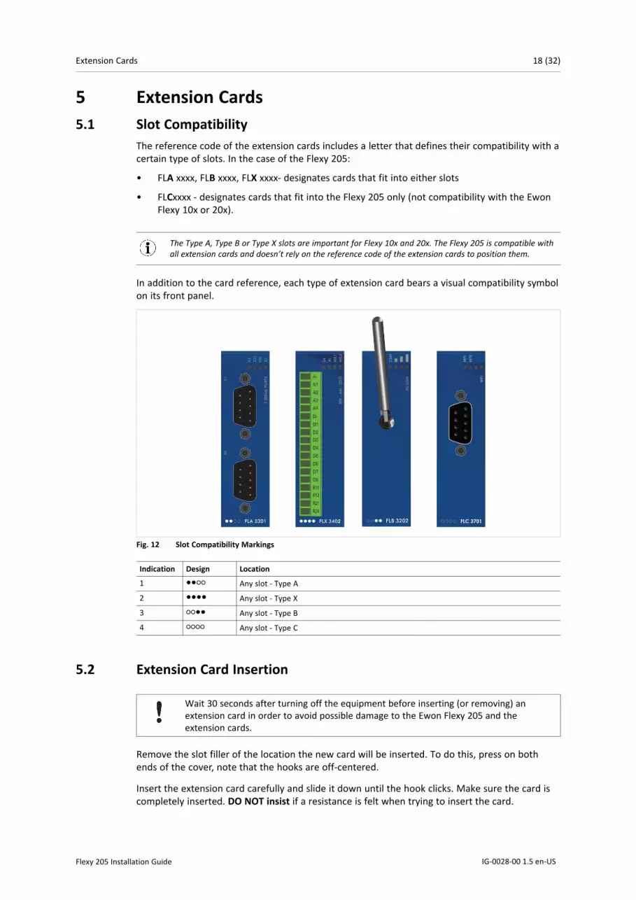
5 Extension Cards5.1 Slot Compatibility
The reference code of the extension cards includes a letter that defines their compatibility with acertain type of slots. In the case of the Flexy 205:
• FLA xxxx, FLB xxxx, FLX xxxx- designates cards that fit into either slots
• FLCxxxx - designates cards that fit into the Flexy 205 only (not compatibility with the EwonFlexy 10x or 20x).
The Type A, Type B or Type X slots are important for Flexy 10x and 20x. The Flexy 205 is compatible withall extension cards and doesn’t rely on the reference code of the extension cards to position them.
In addition to the card reference, each type of extension card bears a visual compatibility symbolon its front panel.
Fig. 12 Slot Compatibility Markings
Indication Design Location
1 ●●○○ Any slot - Type A
2 ●●●● Any slot - Type X
3 ○○●● Any slot - Type B
4 ○○○○ Any slot - Type C
5.2 Extension Card Insertion
Wait 30 seconds after turning off the equipment before inserting (or removing) anextension card in order to avoid possible damage to the Ewon Flexy 205 and theextension cards.
Remove the slot filler of the location the new card will be inserted. To do this, press on bothends of the cover, note that the hooks are off-centered.
Insert the extension card carefully and slide it down until the hook clicks. Make sure the card iscompletely inserted. DO NOT insist if a resistance is felt when trying to insert the card.
Flexy 205 Installation Guide IG-0028-00 1.5 en-US

Extension Cards 19 (32)
Fig. 13 Slot Removal
Hooks to be pressed are off-centered – press while pulling upwards
Boot the unit for the inserted extension cards to be detected. As explained in Detected CardsDisplayed in the System Page, p. 22, the web interface of the Flexy 205 has a diagnostic pageshowing the extension cards in their order of detection (from left to right).
5.3 Powering On the Flexy 205 with its Extension CardsThe normal boot sequence of the Flexy 205 takes approximately 25 seconds to complete. Duringthis process, all LEDs go ON for a while except BI1 as long as the RESET button is not pressed andthe WAN / LAN Ethernet ports.
If the RESET button was pressed, the USR LED will be orange for a little time.
As soon as the boot process is finished and the unit is ready to be used, the USR LED blinks greenslowly.
The extension card types are detected one slot after the other during the boot sequence and areautomatically installed from a system standpoint.
5.4 Multiple Extension Cards5.4.1 Detection Order
The boot sequence of the Flexy 205 includes an automated detection of the inserted extensioncards. This detection is done sequentially, one slot after the other, starting from the left to theright (when holding the Flexy 205 with its logo on the right side).
5.4.2 Software Compatibility of Multiple Cards CombinationThe Ewon Flexy 205 allows the insertion of multiple extension cards of the same type. Someconfigurations including multiple extension cards, even if mechanically acceptable, are notsupported by the embedded software. Cards in excess are ignored during the automateddetection process which means that the Flexy 205 and its running extension cards will operatenormally.
The ignored card(s) will appear in the Diagnostic > Status > System Info > System but they willnot be functional.
Flexy 205 Installation Guide IG-0028-00 1.5 en-US

Extension Cards 20 (32)
Fig. 14 Order of the Extension Cards
The picture above shows an example of a configuration that would be OK mechanically andpower wise but would not be supported by the firmware.
During the boot process, the first 2 serial port extension cards are detected and both can be used.In case of 2 single Ethernet cards, these 2 cards are also detected but the second single Ethernetcard is not supported by the firmware and so it cannot be used. The presence of this “ignored”card in the Flexy 205 does not alter the operation of the Flexy 205 itself nor does it alter its“accepted” extension cards.
5.5 Ethernet Extension Card - FLX 3101By default and if there is no extension card available in the Flexy 205, the 4 Ethernet ports willbe distributed as:
• Ports #1, #2 and #3 are set as LAN port.
• Port #4 is set as a WAN port.
If a FLX 3101 (single Ethernet port) extension card is inserted, the Flexy 205 will automaticallyswitch all its ports to LAN leaving the Ethernet port of the extension card as the only WAN portable to connect to the Internet.
This switch to 4 LAN ports occurs only when an FLX 3101 is inserted. This doesn’t happen if a Wi-Fi (FLB3271) or a 3G / 4G (FLB 3202 / 3203 / 3204 / 3205) extension cards are plugged-in.
Flexy 205 Installation Guide IG-0028-00 1.5 en-US

IP Address & Access to the Web Configuration 21 (32)
6 IP Address & Access to the Web Configuration6.1 Factory Default IP Settings
Characteristics ValuesLAN IP address 10.0.0.53
LAN subnet mask 255.255.255.0Gateway 0.0.0.0
The WAN IP address is set by default in DHCP mode.
6.2 Powering OnPower the unit on and wait approximately 25 seconds until the boot process is completed.
After a successful boot process the USR LED is blinking green slowly.
If the USR LED is blinking red according to a given pattern, it indicates an interruption of the bootprocess due to a problem. The most frequent issue is:
• a duplicate IP address was detected on the LAN network: USR LED blinking pattern is red 1xshort, 1x long
For other LED patterns in case of error, please refer to General Reference Guide from the RelatedDocuments, p. 3.
6.3 Connecting to the LAN IP AddressEstablish the first communication with the Flexy 205 by using Ewon companion tool eBuddywhich can be downloaded from www.ewon.biz/support.
Connect the LAN port #1 of the Flexy 205 to the computer point-to-point or through a networkprovided the default IP address of the Flexy 205 will not conflict with another connected device.
Start the eBuddy application. The application scans through the Ethernet adapter network andretrieves the connected Ewon devices displaying the IP address, subnet mask and serial number.
The utility also allows the modification of the default IP address without being necessarily in thesame network range. To do so, follow this process:
1. Start the eBuddy utility
2. Optional: Highlight the row representing the device which IP address needs to be modified
3. Click on the button “Set IP” from the top bar menu or hit F2 keyboard shortcut
4. If step 2 has been fulfilled, the serial number of the selected device appears in the newpopup. If not, indicate the serial number of the device that needs to be modified. Click Next
5. Indicate the new IP address and its subnet mask. By clicking Next, eBuddy sends thecommand to the device to change its IP address and to reboot
6. Wait until the reboot has ended to reach the Flexy 205 on its new IP address
6.4 Web InterfaceWhile the computer is connected to a LAN port of the Flexy 205, open an Internet browser andreach the Flexy 205 web server which URL is the LAN IP address of the Flexy 205 (default is10.0.0.53).
Flexy 205 Installation Guide IG-0028-00 1.5 en-US

IP Address & Access to the Web Configuration 22 (32)
Another way to access the web panel of the Flexy 205 is by using eBuddy with its EZ DHCPfeature. For more info, refer to eBuddy from the Related Documents, p. 3.
Before beginning the configuration of the Flexy 205, an authentication is required.
Default login & password are both adm. For security reasons, default password must bemodified. To change it, go to Setup > Users and double click on the adm entry to edit itsparameters. Enter the new password twice and click Save.
At the very first boot of the Flexy 205 or after a reset level 2 and after successfully logging in, aninterface language selection will be proposed.
A configuration wizard will be proposed afterwards which sets the configuration of the Flexy 205but also the connection to the Talk2M environment.
On Ewon website, a Quick Start Guide can be found which helps in the configuration of the Flexy205.
6.4.1 Detected Cards Displayed in the System PageThe System page allows to check the status of the system including detected extension cards.
To access the system status summary, click on Diagnostic > Status > System Info > System.
Flexy 205 Installation Guide IG-0028-00 1.5 en-US

Resetting the Flexy 205 23 (32)
7 Resetting the Flexy 205The reset button BI1 is located at the bottom right of the Ewon Flexy 205 (see Reset Button, p.15). The reset function of this button is active only if pressed while powering on. The Flexy 205features two type of reset levels. A table with the impacted configuration zones per reset levelcan be found in Reset Impact Matrix, p. 24.
7.1 Normal Boot SequenceThe normal boot sequence of the Flexy 205 takes approximately 25 seconds to complete. Duringthis process, all LEDs of the left row go ON for a while, except BI1 as long as the RESET button isnot pressed and the WAN / LAN Ethernet ports.
If the RESET button was pressed, the USR LED will be orange for a little time.
As soon as the boot process is finished and the unit is ready to be used, the USR LED blinks greenslowly.
7.2 First Level Reset (User Reset)The first level reset consists in formatting only the “user files” part of the non volatile memory.This type of reset does not modify the communication parameters of the Flexy 205.
How to generate a first level reset:
1. Power the unit OFF and ON again
2. Immediately press and maintain the reset button. The LED labeled BI1 turns ON
3. Wait approximately 30 seconds until the USR LED blinks red 1x per second
4. Immediately release the button. The LED labeled BI1 turns OFF. If the button keeps beingpressed at this point, the second level reset will be engaged
5. Wait approximately 30 seconds until the reset procedure is completed.
6. The Flexy 205 restarts automatically and the unit is ready to be used, the USR LED blinksgreen slowly.
7.3 Second Level Reset (Factory Reset)This second level reset formats all non volatile memories and erases the Flexy 205 back to itsfactory defaults. This operation consists in 3 steps:
• Erasement of all non volatile memories, including all COM parameters and IP addresses
• Full hardware auto test with result shown by the USR LED
• Return to factory configuration (default one)
How to generate a second level reset:
1. Power the unit OFF and ON again
2. Immediately press and maintain the reset button. The LED labeled BI1 turns ON
3. Wait approximately 35 seconds until the USR LED remains red steady
4. When this state is reached, release the button. The LED labeled BI1 turns OFF
5. It takes no longer than 5 seconds to complete.
Flexy 205 Installation Guide IG-0028-00 1.5 en-US
Resetting the Flexy 205 24 (32)
6. Check if the auto test is successful, the USR LED blinks red following a pattern of 200ms ONand 1,5 sec OFF. The Flexy 205 does not restart in normal mode by itself and remains in thisdiagnose mode.
7. Power the Flexy 205 OFF and ON again to reboot the unit in normal mode. As describedbefore, the Flexy 205 returns to its default COM parameters and factory IP addresses(default LAN IP: 10.0.0.53) after this second level reset is performed.
If a different pattern than the successful auto test one is displayed then this pattern reflects anissue.
The pattern starts with 200ms ON (beginning of the pattern) followed by OFF and a certainnumber of times 1 sec ON which allows to identify the nature of the detected problem. Pleasewrite down the observed pattern and contact the local distributor referring to the pattern error.
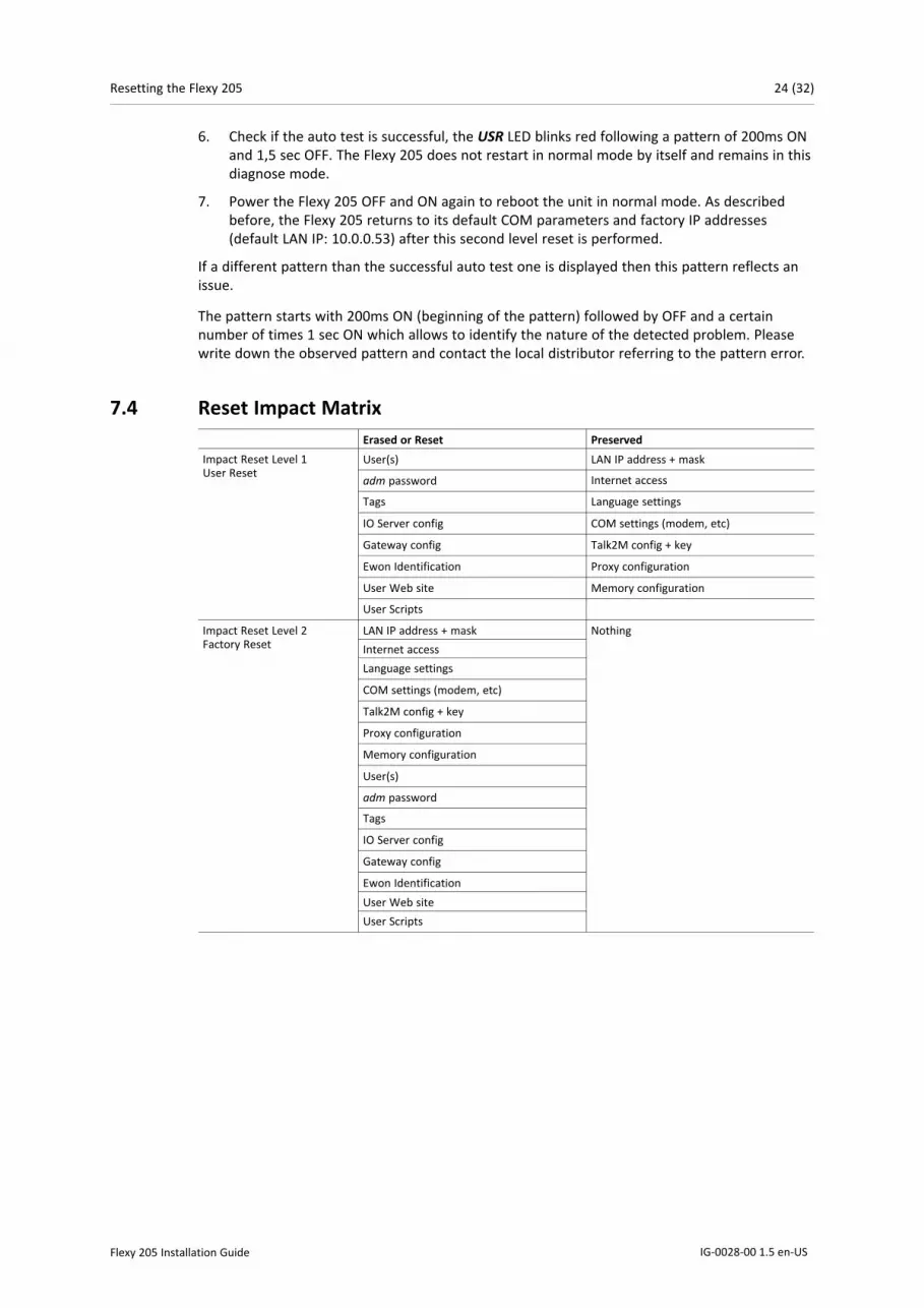
7.4 Reset Impact MatrixErased or Reset Preserved
Impact Reset Level 1User Reset
User(s) LAN IP address + mask
adm password Internet access
Tags Language settings
IO Server config COM settings (modem, etc)
Gateway config Talk2M config + key
Ewon Identification Proxy configuration
User Web site Memory configuration
User Scripts
Impact Reset Level 2Factory Reset
LAN IP address + mask NothingInternet accessLanguage settings
COM settings (modem, etc)
Talk2M config + key
Proxy configuration
Memory configuration
User(s)
adm password
Tags
IO Server config
Gateway config
Ewon IdentificationUser Web siteUser Scripts
Flexy 205 Installation Guide IG-0028-00 1.5 en-US

Appendix A: Connector Pinout & Related Specifications 25 (32)
A Connector Pinout & Related SpecificationsA.1 Main Connector
As shown in the below picture, the female mating connector is labeled with the appropriatesymbols.
Characteristic ValueConnector type MINICONNEC MC model
Type MC 1.5 / 9–ST-3.5Pitch = 3.50mm9–pin female
Maximal tightening torque 0.25NmIn the absence of a torque wrench, a soft manual tightening is sufficient
Fig. 15 Connector pinout
PIN ICON ID Description
1 O- DO_COM Output signal (0V ground)connected to the emitter of theMOSFET transistor
2 O DO Output signal connected to thedrain of the MOSFET transistor
3 O+ DO_VDC Common of the externalpredrive power supply(between +12 et +24 VDC)
4 I- DI_COM Ground of the input (isolated)
5 I1 DI1 Input signal 1
6 I2 DI2 Input signal 2
7 + Power inVDD +
Between +12 and +24 VDC
8 - Power inGND —
0V
9 Functionalearth
A.2 Specification of the External Power SupplyThe Ewon Flexy 205 must be powered by a 12-24Vdc 100w max. certified for 60°C and foraltitudes up to 2000m for conformity to the UL/IEC 62368-1 or by a safety Low Power Supply(LPS) in accordance with clause 2.5 of UL/IEC 60950-1 Ed2. Standard, 12-24Vdc, 30W min.Certified for 70°C and for altitudes up to 2000m. The safety LPS power supply is not part of thedelivery.
Characteristic ValuePower supply voltage external 12-24 VDC +/- 20%
Max. input power 30W max.
Internal voltage protection max 30V
Input protection protected against polarity inversion
Suggested power supply:
• SIEMENS SITOP logo power 24V 2.5A 60W - Siemens order ref: 6EP1332-1SH43
• Equivalents of the above on the market
Flexy 205 Installation Guide IG-0028-00 1.5 en-US

Appendix A: Connector Pinout & Related Specifications 26 (32)
A.3 Digital Output & Digital Inputs
Fig. 16 Current scheme of the main connector
Characteristic ValueType of digital output 2 Open drain MOSFET
Maximum current (ext,source) 200 mA
Isolation (both DI & DO) 1.5 kV
DI voltage range 0 to 30 VDC
DI protection 33 VDC Max
DI max frequency 10Hz or 100ms
DI OFF state — input voltage range 0 to 5 VDC
DI ON state — input voltage range 10 to 30 VDC
DI ON state — current range From 3,8 mA @ 12 VDC to 8,2 mA @ 24 VDC
The Digital Output is activated by an open drain MOSFET transistor driven by an optocoupler. Themaximum current flow inside this transistor has a value above the one specified in the Ewon, inorder to cope with the switching power losses.
The transistor used is in an open drain type with predrive. This means the relay power supply hasto be supplied from an external source to the predrive electronics.
The diagram below shows the external wiring needed for proper operation of the digital output.A relay has been chosen for this sample application but any load within the specifications can beused instead.
This is a sink only output to ground (the transistor acts as a switch ground).
Flexy 205 Installation Guide IG-0028-00 1.5 en-US
2. During the starting boot process, the DO will be switched ON for a short time (2 seconds)

Appendix A: Connector Pinout & Related Specifications 27 (32)
Fig. 17 External wiring for the Digital Output
Flexy 205 Installation Guide IG-0028-00 1.5 en-US

Appendix B: Flexy 205 Products Overview 28 (32)
B Flexy 205 Products OverviewB.1 Extension Cards
Picture Reference & name Slot compatibility Maximum supported Installation Guide
FLA 33012 Serial-Ports
●●○○ 2 IG-0016-00
FLX 3101Ethernet 10/100 ●●●● 1 IG-0017-00
FLX 34018DI-4AI-2DO
●●●● 4 IG-0018-00
FLX 34028DI-4AI-2DO
●●●● 4 IG-0018-01
FLB 32023G GSM
○○●● 1 IG-0019-00
Flexy 205 Installation Guide IG-0028-00 1.5 en-US
Since July 2016, the FLX 3401 has been tagged as end of life and is replaced by the FLX3402.

Appendix B: Flexy 205 Products Overview 29 (32)
Picture Reference & name Slot compatibility Maximum supported Installation Guide
FLB 32044G EU
○○●● 1 IG-0026-00
FLB 32034G Verizon
○○●● 1 IG-0025-00
FLB 3205 ●●○○ 1 IG-0027-00
FLB 32094G APAC
○○●●
1
FLB 320A4G EU 1
Flexy 205 Installation Guide IG-0028-00 1.5 en-US
4G Verizon
4G NA
○○○●
IG-0034-00
IG-0032-00●

Appendix B: Flexy 205 Products Overview 30 (32)
Picture Reference & name Slot compatibility Maximum supported Installation Guide
FLB 3271Wi-Fi
○○●● 1 IG-0020-00
FLA 3501PSTN
●●○○ 1 IG-0021-00
FLB 3601USB
○○●● 1 IG-0024-00
Flexy 205 Installation Guide IG-0028-00 1.5 en-US
Ewon Flexy Devices support a wide range of protocols that can also evolve, don't hesitate to cross-check on our website if new extension cards models are available.
As explained in Software Compatibility of Multiple Cards Combination, p. 19, the number of cardsof the same type supported by the firmware is indicated in this table.
FLC 3701MPI
○○○○ 1 IG-0029-00

Appendix C: Flexy 205 Isolation Scheme 31 (32)
C Flexy 205 Isolation SchemeC.1 Base Unit
Flexy 205
Connector shielding Earth connected
Ethernet signals Isolated from DGND with a transformer
Serial ports GND = DGND
Fig. 18 Isolation Scheme for the Base Unit
Based on the above picture:
• External and internal power supplies are isolated from each other (1.5kV)
• DI signals: isolated from DO signals, PGND and DGND (optocoupler)
• DO signals: isolated from DI signals, PGND and DGND (optocoupler)
• Earth is isolated from external and internal power supplies
C.2 Extension CardsC.2.1 FLB 320x – Cellular
DGND = GND RF from SMA connector
Avoid external connections between GND RF and Earth.
C.2.2 FLX 3101 – WAN EthernetConnector shielding: Earth connected
Ethernet signals: isolated from DGND with a transformer
Flexy 205 Installation Guide IG-0028-00 1.5 en-US

Appendix C: Flexy 205 Isolation Scheme 32 (32)
C.2.3 FLX 3271 – Wi-FiDGND = GND RF from SMA connector
Avoid external connections between GND RF and Earth.
C.2.4 FLX 340x – I/ODO signals: isolated relays outputs
DI signals: isolated from DGND (optocoupler)
AI signals: isolated from PGND only
AI-GND = DGND
C.2.5 FLA 3301 – Dual Serial PortsSerial port signals: isolated from PGND only
Connector shielding: connected to Earth
Serial ports GND = DGND
C.2.6 FLC 3701 – MPI PortMPI port signals: isolated from PGND only
Connector shielding: connected to Earth
MPI port GND = DGND
C.2.7 FLB 3601 – 3 USB PortsUSB signals: isolated from PGND only
Connector shielding: connected to Earth
Due to USB connector design, Earth-DGND isolation is limited to 500V when the USB extensioncard is inserted
AI-GND = DGND
Flexy 205 Installation Guide IG-0028-00 1.5 en-US

last page
© 2020 HMS Industrial NetworksBox 4126300 04 Halmstad, Sweden
[email protected] IG-0028-00 1.5 en-US / 2020-01-03 / 16588