
OSEKNDX - NET
139
BMW EXHIBIT 1009 §I I I Open Systems and the Corresponding Interfaces for Automotive Electronics OSEKNDX Network Management Concept and Application Programming Interface Version 2.5 1 31st of May 2000 This document is an official release and replaces all previously distr ibuted documents. The OSEK group retains the right to make changes to this document wit hout notice and does not accept liability for enors. All rights reser ved. No part of t his document may be reproduced, in any fonn or by any means, wit hout permission in v. •riting from the OSEKNDX steeri ng committee. Page 1 ###by OSEKIVDX NM Concept & API 2.51 PAGE 1 OF 139
-
Upload
khangminh22 -
Category
Documents
-
view
0 -
download
0
Transcript of OSEKNDX - NET

BMW EXHIBIT 1009
§I I I
Open Systems and the Corresponding Interfaces for Automotive Electronics
OSEKNDX
Network Management
Concept and Application Programming Interface
Version 2.5 1
31st of May 2000
This document is an official release and replaces all previously distributed documents. The OSEK
group retains the right to make changes to this document without notice and does not accept liability
for enors. All rights reserved. No part of this document may be reproduced, in any fonn or by any
means, without permission in v.•riting from the OSEKNDX steering committee.
Page 1 ###by OSEKIVDX NM Concept & API 2. 51
PAGE 1 OF 139

81 l l
Table of Contents
Open Systems and the Corresponding Interfaces
for Automotive Electronics
Sunnnary. . . . . . . . . . . . . . . . . . . . . . . . . . . . . . . . . . . . . . . . . . . . . . . . . . . . . . . . . . . . . . . . . . . . . . . . . . . . . . . . . . . . . . . . . . . . . . . . . . . . . . . . . . . . . . . . . . . . . . . . . . . . . . . . 5
1. Scope of the OSEK Network Management .. .... .... ... .... ... .... ... .... .... ... .... ... .... ... .... .... ... .... .. 6
2. Direct Network Managernent. .. ... .... ... .... ... .... .... ... .... ... .... ... .... .... ... .... ... .... ... .... .... ... .... ... .. 8
2.1. Concept .... .... ... .... .... ... .... ... .... ... .... .... ... .... ... .... ... .... .... ... .... ... .... ... .... .... ... .... ... .... ... ... 8 2.1.1. Node Monitoring ..... .... ... .... ... .... ... .... .... ... .... ... .... ... .... .... ... .... ... .... ... .... .... ... .... ... .. 8 2.1.2. Addressing ... .... .... ... .... ... .... ... .... .... ... .... ... .... ... .... .... ... .... ... .... ... .... .... ... .... ... .... ... . 10 2.1. 3. NM Iruiastructure for Data Exchange ..... ... .... ... ... .... ... .... ... ... .... ... .... ... ... .... ... .... 11 2.1.4. Standard Functionality ... ... ... .... ... .... ... ... .... ... .... ... ... .... ... .... ... ... .... ... .... ... ... .... ... .. 11 2.1. 5. Configuration Management ... .... .... ... .... ... .... ... .... .... ... .... ... .... ... .... .... ... .... ... .... ... . 12
2.1.5.1. Network Configurations .... .... ... .... ... .... ... .... .... ... .... ... .... ... .... .... ... .... ... .... ... . 12 2.1.5.2. Detection of a Node in Fault Condition .. .... .... ... .... ... .... ... .... .... ... .... ... .... ... . 12 2.1.5.3. Internal Network Management States ..... ... .... ... ... .... ... .... ... ... .... ... .... ... ... .... 13
2.1.6. Operating Modes .... .... ... .... ... .... .... ... .... ... .... ... .... .... ... .... ... .... ... .... .... ... .... ... .... ... . 15 2.1.7. Network Enor Detection and Treatment .. ... .... ... ... .... ... .... ... ... .... ... .... ... ... .... ... ... 15 2.1.8. Support ofDiagnostic Application .. ... .. ... .. ... .. ... .. ... .. ... .. ... .. ... .. ... ... .. ... .. ... .. ... .. ... 16
2.2. Algorithms and Behaviour ..... ... .... ... .... ... .... ... .... ... .... ... .... ... .... ... .... ... .... ... .... ... .... .. 16 2.2.1. Communication of the Network Management System .. ... ... .... ... .... ... .... ... .... ... ... 16
2.2.1.1. Network Management Protocol Data Unit.. ... .... ... .... ... .... ... .... ... .... ... ... .... .. 16 2.2.1.2. Addressing Mechanisms used by the Network Management.. .. ... .... ... .... ... .. 18
2.2.2. NM Infi·astructure for Data Exchange .. .... ... .... ... .... ... .... ... .... ... .... ... .... ... .... ... ... .. 20 2.2.3. Standard Tasks .... .... ... .... ... .... ... ... .... ... .... ... .... ... .... ... .... ... .... ... .... ... .... ... .... ... .... .. 21
2.2.3.1. Network Management Parameters .. .... ... .... ... .... ... .... ... .... ... .... ... .... ... .... ... ... 21 2.2.3.2. Network Status .. .... ... .... ... .... ... .... ... .... ... ... .... ... .... ... .... ... .... ... .... ... .... ... .... ... 22 2.2.3.3. Extended Network Status ..... ... .... ... .... ... .... ... .... ... .... ... .... ... .... ... ... .... ... .... ... 23
2.2.4. Configuration Management ... ... .... ... .... ... .... ... .... ... .... ... ... .... ... .... ... .... ... .... ... .... ... 24 2.2.4.1. Timing Reference ... .... ... .... .... ... .... ... .... ... .... .... ... .... ... .... ... .... .... ... .... ... .... ... . 24 2.2.4.2. Monitoring Counter .... ... .... ... .... .... ... .... ... .... ... .... .... ... .... ... .... ... .... .... ... .... ... 25 2.2.4.3. State transition diagram .. .... ... .... .... ... .... ... .... ... .... .... ... .... ... .... ... .... .... ... .... ... 25 2.2.4.4. Particularities Regar·ding Implementation ... .... ... ... .... ... ... .... ... .... ... ... .... ... .... 29
2.2.5. Example: Skipped in the logical ring .... ... .... ... ... .... ... .... ... ... .... ... .... ... ... .... ... .... ... . 32 2.2.6. Example: Logical Successor ... ... .... ... .... .... ... .... ... .... ... .... .... ... .... ... .... ... .... .... ... .... 34 2.2.7. Operating Mode ... ... .... ... .... ... .... .... ... .... ... .... ... .... .... ... .... ... .... ... .... .... ... .... ... .... ... . 35
2.2.7.1. NMActive - NMPassive .... .... ... .... ... .... ... .... .... ... .... ... .... ... .... .... ... .... ... .... ... . 35 2.2.7.2. NMBusSleep - NMAwake ..... ... .... ... .... ... .... .... ... .... ... .... ... .... .... ... .... ... .... ... . 36
2.2.8. Fusion of Configuration Management and Operating Modes ... .... .... ... .... ... .... ... . 40
Page2 ### by OSEKIVDX NM Concept & API 2.5 1
PAGE2 OF 139

OSEKNDX Network Management Concept and Application Programming Interface
2.2.8 .1 . State Dia.grruns ........ ........................ .. ........................ .......................... ...... 40 2.2.8 .2. SDL DiagralllS ........ ........................ .. ........................ .......................... ...... 46
2.2.9. Alru1ns inside the Network Management ...... .. ........................ ........................... 57 2.2.9.1. Rules to design the a.lanns T Typ and TMax .................... ............................ .... 57 2.2.9.2. Rules to design the a.lrum TEnor ........ .. ........................ ............................ .... 59 2.2.9.3. Rules to design the a.lrum T waitBussteep .. ........................ ............................ .... 59 2.2.9.4. Design of a. syste1n ............................ ........................ .......................... ...... 59
2.2.9.4.1 . Worst case .......... ........................ .. ........................ ........................... 60 2.2.9.4.2 . Example .......... ........................ .. ....................... ............................ ... 60
3. Indirect Network Management ............ ......................... .. ........................ ...................... 61
3.1 . Concept .. ............................ ........................ .. ........................ ............................ .... 61 3.1 .1 . Node Monitoring ................ ......................... .. ........................ ........................... 61
3. 1.1 . 1. Node states .. .. .. .. .. .. . . . . . . . . . . . . . . . . . . . . . . . . . .. . . . . . . . . . . . . . . . . . . . . . . . . .. .. .. .. .. .. .. .. .. .. .. .. .. . . . . . . 61 3.1 .1 .2. Extended Node states ....................... .. ........................ ............................ ... 62
3.1 .2. Configuration-Management ..................... .. ....................... ............................ ..... 62 3.1 .2 .1 . Configuration .......... ........................ .. ........................ ............................ .... 62 3.1 .2.2. Extended Configuration .................... .. ........................ ............................ ... 63
3.1 .3. Standru·d Task ........................ ........................ .. ........................ ......................... 63 3.1 .3 .1 . Network status ........ ........................ .. ........................ .......................... ...... 63 3.1 .3.2. Extended network status .................. .. ........................ ............................ ... 63
3.1 .4. Monitoring Mechanis1ns ...... ......................... .. ........................ ........................... 64 3.1 .5. Monitoring time-outs ................ ........................ .. ........................ ...................... 65
3.1 .5 .1 . One global time-out ...... ........................ .. ........................ ........................... 65 3.1.5.2. One monitoring time-out per message .. .. ........................ ........................... 66 3 .1 . 5. 3. Intemal Network Management States ................ ................... ................... .. 66
3.1 .6. Operating Modes ............ ........................ .. ........................ .......................... ...... 68 3.2. Algorithins and behaviour ........ ........................ .. ........................ ........................... 68
3 .2.1 . Configuration Management ..................... .. ....................... ............................ ..... 68 3.2.1 .1 . Counter Inanageinent. ...................... .. ........................ .......................... ...... 68
3.2.2 . Operating Mode .............. ........................ .. ........................ .......................... ...... 72 3.2.2 .1. User Guide to handle BusSleep ........ ........................ ............................ ..... 72
3.2.3 . State Machine in SDL .... ......................... .. ........................ .......................... ...... 74 3.2.3 .1. SDL Model for one global time-out TOB .......................... ........................ 74 3.2.3 .2. SDL Model for one monitoring time-out per message ........ ................ ........ 79
4. System generation and API ........ .................... .. .................... ........................ ................. 86
4.1 . Overview ...................... .................... .. .................... ........................ .................... .. 86 4.2. Conventions for Service Description ........ .. .................... ........................ ............... 87
4.2.1 . System Generation .......... .................... .. .................... ........................ ................ 87 4.2.2 . Type of Calls .............. .................... .. .................... ........................ .................... 88 4.2.3 . En·or Characteristics ................ ..................... .. .................... ........................ ...... 88 4.2.4. Stmcture of the Description ..................... .. .................... ........................ ........... 88
4.2.4.1 . System Generation Support.. .. ...... .. ..... ........ ...... .. ..... .......... ...... ...... ........ ... 89 4.2.4.2. Se1vice Descriptions .................... .. .................... ........................ ................ 89
4.3. General Data. Types ............ .................... .. .................... ...................... .................. 90
Page2 ### by OSEKIVDX NM Concept & API 2.51
PAGE3 OF 139

QSEKNDX NetworkManagement Concept and Application Programming Interface
4.4. Conunon se1vices .... ......................... ............................ ........................ .. ................ 90 4.4.1 . Standard Functionality ...................... ............................ ........................ .. ........... 90
4.4 .1 .1 . System Generation Support .. .. ..... .......... ...... ....... ........ ...... .. ...... ........ ........ .. 90 4.4.2 . Configuration Management .......... ............................ ........................ .. ................ 92
4.4.2 .1 . Data Types .. ......................... ............................ ........................ .. ................ 92 4.4.2.2 . System Generation Support .. .. ..... .......... ..... .. ...... ........ ...... .. ...... ........ ....... .. . 92 4.4.2 .3. Se1vices ...... .. .................... ........................ .................... .. .................... ....... 95
4.4.3 . Operating Modes and Operating Mode Management.. ................ ...................... .. 98 4.4.3 .1 . Data Types .................... ........................ .................... .. .................... ........... 98 4.4.3.2. System Generation Support .. .. ..... .......... ..... .. ...... ........ ...... .. ...... ........ ....... .. . 99 4.4.3 .3. Se1vices ...... .. .................... ........................ .................... .. .................... ....... 99
4.5. Se1vices for direct NM ................... ........................ .................... .. .................... .... 102 4.5.1 . Standard Functionality ............... ........................ .................... .. .................... .... 102
4. 5 .1 .1 . System Generation Support.. ..... .. ..... ........ ..... .. ..... ........ ..... .. ..... ........ ..... .. . 102 4.5.2. Operating Modes and Operating Mode Management.. ................ ...................... 103
4.5.2 .1 . Se1vices ...... .. .................... ........................ .................... .. .................... ..... 103 4.5.3. Data Field Management ......... ........................ .................... .. .................... ........ 104
4.5.3 .1 . Data Types .................... ........................ .................... .. .................... ......... 104 4.5.3.2. System Generation Support.. ..... .. ..... ........ ...... ...... ........ ..... .. ..... ........ ...... .. 104 4.5.3.3. Se1vices ...... .. .................... ........................ .................... .. .................... ..... 105
4.6. Se1vices for indirect NM ................ ........................ .................... .. .................... .... 106 4.6.1 . Standard functionality ................ ........................ .................... .. ................... ..... 106
4. 6 .1 .1 . System Generation Support ........ ....... ...... ....... ....... ...... ....... ....... ...... ....... .. 106 4.6.2 . Configuration Mangement. ........... ............................ ........................ .. .............. 107
4.6.2.1 . System Generation Support.. ...... ...... ........ ...... ...... ........ ...... ...... ........ ...... .. 1 07
5. I1npacts to OS and to COM ................... ........................ .................... .. .................... .... 107
5.1 . EITorCodes .................. .. .................... ........................ .................... .. ................... 107 5.2. Conunon iinpacts .. .................... ........................ .................... .. .................... ......... 108
5.2.1. Requii·ements to OSEK C01mnunication (OSEK COM) ................ ................... 1 08 5.2.2 . Requii·ements to OSEK Operating System (OSEK OS) .. .............. ................ .... 11 0
5.3. Impacts fi:om dii'ect NM ..................... ........................ .................... .. ................... 111 5.3.1. Inte1face to OSEK Conununication (OSEK-COM) ........ .. .............. ................ .. 111
5. 4. Impacts fi:om indii·ect NM ................... ........................ .................... .. ................... 113 5.4.1. Inte1face to OSEK Conununication (OSEK-COM) ........ .. .............. ................ .. 113
5.4.1 .1 . Mapping Nodeid, Netld ~Sender .................. ........................ .. .............. 114
6. Histo1y .. ........................ .. ........................ ............................ ........................ .. .............. 115
7. Annex .. ................................................... ...................................................... .............. 115
7 .1 . IIDplementation proposal ( dii·ect NM) .................. ................. .. ................. ............ 115 7 .1 .1 . Ove1view oflntemal Activities .. .................... ................... .. ................. ............. 116 7.1 .2. Specification oflntemal Activities ............................ ........................ .. .............. 118 7.1 .3. NMPDU ............ .. ........................ ............................ ........................ .. .............. 123
7.1 .3 .1 . OpCode ...... ......................... ............................ ........................ .. .............. 124 7 .1 .3 .2. Encoding and decoding .......... ............................ ........................ .. ............ 125
NM Concept & API 2.51 ### by OSEKIVDX Page 3
PAGE40F 139

QSEKNDX NetworkManagement Concept and Application Programming Interface
7.1 .3.2.1. Addressing Mechanisms .... .......................... .......................... .......... 125 7.1.3.2 .2. Coherent Allocation ofNM message Headers ........ .................... ..... 126 7.1.3.2 .3. Non-coherent Allocation ofNM message Headers .. ................... ..... 128 7.1 .3.2.4. Node Identifications .... ................... ................... ................... ........... 128
7.1 .4. Scalability ................ .......................... .......................... .......................... .......... 128 7 .2. Implementation proposal (indirect NM) .................. ................... ................... ....... 130
7.2 .1. Scalability ................ .......................... .......................... .......................... .......... 130 7.2 .2. IInple1nentation hints ..... .......................... .......................... .......................... ..... 131
7.2 .2.1. Choice one global time-out I one monitoring time-out per message ......... . l31 7.2 .2.2 . Configuration of extended states detection algorithm ...................... .......... 131
7.2 .3. Summa1y ofSDL state diagram graphical notation ......... ............... ............... .... l33 7.3 . Outlook ....................... .......................... .......................... .......................... .......... 134
8. Index ................ .......................... ......................... .......................... .......................... ..... 135
Introduction
There is an increasing tendency for electronic control units (ECUs) made by different manufacturers to be networked within vehicles by serial data c01mnunication links. Therefore, standardisation of basic and non-c01npetitive in:fi·astmcture in ECUs aims at avoiding the design ofunnecessruy vru·iants and saving development time.
In the scope of the OSEKNDX co-operation, the Network Management system (NM) provides standardised features which ensure the functionality of inter-networking by standru·dised interfaces.
The essential task ofNM is to ensure the safety and the reliability of a c01mnunication network for ECUs.
In a vehicle a networked ECU is expected to provide ce1tain features:
### each node must be accessible for authoiised entities
### maximum tolerance with regard to te1nporruy failures
### supp01t of network related diagnostic features.
At a basic configuration stage, NM implementations complying with OSEK specifications must be ilnplemented in all networked nodes. This ilnplies a solution for NM which can be implemented throughout the broad range of available hardware offered in to day's ECUs. Therefore, the status of the network must be recorded and evaluated unifonnly at all ECUs at intervals. Thus each node features a detennined behaviour as regards the network and the application concemed.
OSEK-NM offers two altemative mechanisms for network monitoring
### indirect monitoring by monitored application messages, and
### direct monitoring by dedicated NM communication using token principle.
Page4 ### by OSEKIVDX NM Concept & API 2.51
PAGE50F 139

OSEK/VDX NetworkManagement
I Concept and Application Programming Interface
However, the use of these mechanisms is up to the system responsible. Processing of info1mation collected by these mechanisms must be in accordance to requirements as regards the entire networked system.
System status
In view of the application, NM comprises two standardised interfaces:
### Software:
### Network behaviour:
Application program ### NM
Station ### Communication medium
The resulting entire system is open. Thus, it can adapt to new requirements within the restrictions defined by the system design.
Remarks by the authors
This document descdbes the concept and the API of a network management, which can be used for ECUs in vehicles. It is not a product description which relates to a specific implementation.
General conventions, explanations of te1ms and abbreviations have been compiled in the additional inter project "OSEK Overall Glossary" .
Summary
In order to achieve the essential task of a network monitoring, i.e.
### ensure safety and reliability of a communication network for ECU s,
OSEK-NM describes node-related (local) and network-related (global) management methods. The global NM component is optional. However, it requires a minimum local component to be operational.
Therefore, the following services ru·e provided:
### Initialisation ofECU resources, e.g. network inte1face.
### Strut-up of network
### Providing network configuration
### Management of different mechanisms for node monitoring
### Detecting, processing and signalling of operating states for network and node
### Reading and setting of network- and node-specific pru·ameters
### Co-ordination of global operation modes (e.g. network wide sleep mode)
NM Concept & API 2.51 ### by OSEKIVDX Page 5
PAGE60F139

QSEKNDX NetworkManagement Concept and Application Programming Interface
### Support of diagnosis
There are two main pa1ts within the document: Direct Netl·vork Management described by Chapter 2 and Indirect Netlvork Management described by Chapter 3. Both chapters describe the concepts, the algorithms and behaviour.
The Subsections Concept describe the fimdamental aspects of the configuration management, the operating states and operating state management.
The Subsections Algorithms and Behaviour describe the protocol used for communication between nodes.
Chapter 4 describes the Application Programming Interface comprising the pure specification of the setvices offered by NM for both direct and indirect. Input and output data, the functional description, patticularities, etc. are described for each setvice. Fmthennore System Generation services are described within this chapter.
Chapter 5 describes Impacts on OSEK Infrastructure and gives a brief description of all requirements to OSEK Collllllunication and OSEK Operating System for both direct and indirect NM.
1. Scope of the OSEK Network Management
Embedding of the Network Management
OSEK NM defines a set of services for node monitoring. The next figure shows how the NM is embedded into a system. It is also shown that the NM has to be adapted to specific requirements of the bus system used or to the resources of the nodes.
Page6 ### by OSEKIVDX NM Concept & API 2.51
PAGE 7 0 F 139

OSEK/VDX Network Management
Concept and Application Programming Interface
Operating System
Application
Station 5)
1..111 1) ..... Management ~ ...... Network
Management
u Communication
Interaction Layer 11 Ill 4) .....
I Ill ....
u
n OSEK Network Layer Algorithms
; 3)
Data Link Layer Ill 2) 1 Protocol Circuit r Protocol Circuit f
Ill
1 1nterface Circuit H Interface Circuit
~, . . . ~,
Network 1 Network k
Figure 1 inte1face and algodthms responsibility 1) API, fixed by OSEK
Protocol ..... ...... specific
Algorithms
2) several busses collllected to one !lController 3) interface to DLL- COM specific, protocol specific 4) interface to COM Interaction Layer 5) station management (outside OSEK, see text below)
6) OSEK algorithms 7) protocol specific management algorithms
OSEK NM
interface to interact with the application (API)
algorithm for node monitoring
OSEK intemal interfaces (NM <-> COM, ... )
algorithm for transition into sleep mode
NM protocol data unit (NMPDU)
adaptation to bus protocol specific requirements
CAN, VAN, Jl850, K-BUS, D2B, ...
7)
6)
1---
enor handling, e.g. bus-off handling in a CAN, transmission line enor handling
NM Concept & API 2.51 ### by OSEKIVDX Page 7
PAGE80F 139

QSEKNDX NetworkManagement Concept and Application Programming Interface
interpretation of the status infonnation, e.g. oven1lll or enor active/passive in a CAN
adaptation to node resources
scaling of the NM as a requirement of the node
application specific usage of the NM se1vices
adaptation to hardware specific requirements
adaptation to a protocol circuit and a physical layer circuit e.g. switching the bus hardware to one of the possible physically power save modes
station management (system specific algolithms)
There are a variety of additional tasks to co-ordinate a network. Those are not described by OSEK, since they are system dependent. Hence these tasks are done by the application, e.g. by a module called station management.
Philosophy of Node Monitoling
Node Monitoring is used to inf01m the application about the nodes on the network. Thus the application can check with the appropliate service if all stations required for operation are present on the network.
2. Direct Network Management
2.1. Concept
2.1.1. Node Monitoring
OSEK-NM supp01ts the direct node monitoring by dedicated NM communication. A node is a logical whole to which a c01mnunication access is possible. A micro processor with two c01mnunication modules connected to two different communication media (e.g. low speed CAN and a high speed CAN) represents two nodes fi:om the OSEK point of view.
The rate of the NM communication is controlled across the network (minimisation ofbus load and consumption of resources) and the messages are synchronised (avoiding negative effects on application data by message bursts).
Eve1y node is actively monitored by eve1y other node in the network. For this purpose the monitored node sends a NM message according to a dedicated and unif01m algorithm.
Page 8 ### by OSEKIVDX NM Concept & API 2.51
PAGE9 OF 139

OSEKNDX Network Management Concept and Application Programming Interface
Direct node monitoring requires a network-wide synchronisation of NM messages. For this purpose a logical ring is used.
Logical ring
In a logical ring the communication sequence is defined independent fi:om the network stmcture. Therefore each node is assigned a logical successor. The logically first node is the successor of the logically last node in the ring.
Thus the decentralised control of the overall amount of NM messages is ensured and the bus load due to these messages is dete1mined. The communication sequence of the logical ring synchronises NM communication. Any node must be able to send NM messages to all other nodes and receive messages fi:om them.
node Electronic Communication Unit
-- - ----B...,A - --- - - -- - --- B ~A. - -- - - -- ...
' . A->~ c ..., s
' ' \.-----'·c--~,·---~f
' I
' ' I
I
' ' I I
I
communication media 1
I
I
communication media2
Figure 2
Princip le
Infrastmcture of the NM (logical ring), example with two busses
The direct NM translnits and receives two types of messages to build the logical ring. An alive message introduces a new translnitter to the logical ring. A ring message is responsible for the synchronised nmning of the logical ring. It will be passed fi:om one node to another (successor) node.
Receive alive message
Receive ring message
Time-out on ring message
State of a node
Interpretation as translnitter related registration to the logical ring.
Interpretation as translnitter specific alive signal and synchronisation to initiate translnission of own NM message according to the logical ring algorithm.
Interpretation as trans1nitter specific break down
A monitoring node is able to distinguish 2 states of a monitored node.
node present ~ specific NM message received (alive or ring)
NM Concept & API 2. 51 ### by OSEKIVDX Page9
PAGE 10 OF 139

QSEK/VD X Network Management Concept and Application Programming Interface
node absent ~ specific NM message not received during time-out
A monitoring node is able to distinguish 2 states of itself
present or not mute
absent or mute
2.1.2. Addressing
~ specific NM message transmitted (alive or ring)
~ specific NM message not transmitted during time-out
The status of nodes and of the network has to be acquired and evaluated unifomlly at intervals. For this purpose, all nodes must communicate via their NM.
The NM communication is independent of the underlying bus protocol. Each node can c01mnunicate unidirectional and address related with any other node of the network. Therefore individual and group addressing of nodes is required.
Node addressing
Address related communication has to take into account receiver and emitter. Each node has a mlique identification which is known in the network.
Each address related communication message contains certain data, the emitter identification and the receiver identification. OSEK NM does not specify the encoding of these components into selected bus protocols.
Emitter (source)
Receiver (destination)
I Header I Data I
Data address related message
I] general protocol format
Figure 3 Exemplruy representation of encoding of a NM c01mnunication message onto a general protocol f01mat.
Individual addressing is implemented by node addressing using 1 : 1 connections. Group addressing is implemented by node addressing using 1 :k connections (k < number of nodes in the network). For this purpose groups of receivers join group addresses.
Page 10 ### by OSEKIVDX NM Concept & API 2.51
PAGE 11 OF 139

OSEK/VDX NetworkManagement Concept and Application Programming Interface I
Features of node addressing
### Each node is assigned a unique identification known within the whole network.
### Emitter and receiver identifications are explicitly included in the message.
### 1 :k connections are implemented using group addresses.
### all messages are broadcasted
### Integrating a new node in an existing network does not require notification of the existing nodes.
2.1.3. NM Infrastructure for Data Exchange
The NM supports the transfer of application data via its infrastmcture (the logical ring). During the time delay between the reception and the transmission of the ring message the application is able to modify the data.
The possibility is given to the application to specify and implement management algorithms which are not provided by OSEK.
logical predecessor
\ t=O
Station
' ~ ~J>J:>Iication!
NMmessagereceived
I I I Data I I ...
.... Data -> ind ->Read
• Buffer <-Transmit
t=T
( delay
I I I Data I NM message to transmit
logical successor
Figure 4 Mechanism to transfer application data via the logical ring
2.1.4. 2.1.4.Standard Functionality
### Initialisations are perf01med with any system start ("cold start"), e. g. timer services required fi:om the operating system or communication hardware via the data link layer interface.
### Before the system is switched off - or switches off automatically - NM can be "shutdown", so that it can restore e.g. to the previously known network hist01y when the system is statted up again.
NM Concept & API 2 .5I ### by OSEKIVDX Page I I
PAGE 12 OF 139
QSEK/VD X Network Management Concept and Application Programming Interface
### The NM handles individual parameters, e.g. time outs and node identifications and, ifnecessruy, version numbers to identify hardware and software versions.
2.1.5. Configuration Management
2.1.5.1. Network Configurations
In the absence of any faults, the networked nodes are activated at different times, e. g.:
Stations on temlinal30 (pe1manent power): Wakeup via extemal event
Stations on te1minal l S (ignition): Switch ON via ignition key
Stations with switch in supply line: switching ON and OFF at random, by dliver
However, the actual configuration is also altered by faulty nodes and by defects in the c01mnunication network. Consequently, different actual configurations can result for the individual nodes in the course of time, which ru·e additionally subject to extemal influences, e.g. actions by the driver.
As a mle, each node wants to strut its application as quickly as possible. In view ofNM, this means that an actual configuration is made available to the applications as soon as possible. Finally, it is up to the application to decide whether to strut communication ilmnediately after it has become operable, or whether to wait lmtil a minimum configuration is detected by NM.
OSEK-NM distinguishes between
### actual configuration: set of nodes to which access is possible
### limp home configuration: set of nodes which due to failure cannot pruticipate in the logical ring
Therefore NM provides the following services:
### supply of the actual configuration
### comparison of a configuration with a tru·get configuration
### indication of changed configuration
2.1.5.2. Detection of a Node in Fault Condition
Operability of a node
A node is considered operable in te1ms ofNM, if the node pa1ticipates in the logical ring.
Page 12 ### by OSEKIVDX NM Concept & API 2.51
PAGE 13 OF 139

OSEKNDX NetworkManagement
I Concept and Application Programming Interface
Detection of failures
Only a node which is expected operable on the network can be recognised failed. The application recognises node failures by comparison to the previous knowledge regarding the target configuration. There are several ways possible by which the application can acquire this knowledge.
### the last stable state of the actual configuration
### one or several progrrumned target configuration(s)
### the tru·get/actual configuration detemlined by NM since system strut up
The NM recognises its own node failed if it cannot send via the bus or it cannot receive any messages fi:om the bus, i.e. it is no longer operable.
Another node is considered failed, if its NM message is not received or a NM message is received signalling an enor state.
Reaction to a node failure
The NM of a node detecting a failure cannot distinguish whether the failed node is no longer able to communicate due to a line fault or due to a complete failure, without additional supp01t. Any possible reactions, e.g. change over to redundant physical paths, must be specified together with entire system requirements.
2.1.5.3. Internal Network Management States
The OSEK NM is specified in a hierru·chical way. The OSEK-NM can enter the intemal states listed hereafter:
### NMOff
### NMOn
### NMShutDown
NMOn:
### NMinit
### NMAwake
### NMBusSleep
### NMActive
### NMPassive
NMAwake:
### NMReset
NM Concept & API 2.51
PAGE 14 OF 139
NM is shut off
NM is switched on
Selective shut off ofNM entity
NM initialisation
Active state of the NM
NM is in sleep mode
NM collllllunication enabled
NM collllllunication disabled
The operability of the own node is determined
### by OSEKIVDX Page 13

Figure 5
Page 14
OSEKNDX NetworkManagement
### NMNormal
### NMLimpHome
•
\ communication
/ /
/
ffit st
/ /
/
/ /
NMAwake
/ /
"Failuffi at own station ffipaired"
/ /
e.g. NM transmission and NM reception possible
Concept and Application Programming Interface
Processing of direct node monitoring
Handling of failure in own node
~~~
t
8 7' \
/ /
' ' ' ' '\rjSilentNM
. ., . ' : ' , NM Passive . ' . ' . ' : ' .
'
~-own station non operational" \ e g. not any NM transmission
"Own station non operational" i.e. not any NM reception ~
I "Station operational"
' ' ' ' ' ' ' '
e.g. not any error "data inconsistent" /at NM receptiion e.g. time out at ring
fficognized message
Simplified state transition diagram of the direct NM.
### by OSEKIVDX NM Concept & API 2.51
PAGE 15 OF 139

I OSEKNDX NetworkManagement
Concept and Application Programming Interface
2.1.6. Operating Modes
The NM does not manage application modes, but exclusively manages NM operating modes. NM distinguishes two main operating modes. The modes of the NM are directly mapped to intemal NM states.
NMAwake (NMActive) In NMAwake the node participates in NM cOimnunication (logical ring) and monitors all nodes with a NM in NMAwake.
NMBusSleep If a node is in NMBusSleep, it does not participate in NM c01mmmication. Depending on the har·dwar·e integrated in the networks, nodes can switch into NMBusSleep simultaneously.
The NM provides se1vices for:
### adjustment ofNM operation modes, and
### indication ofNM operating modes.
2.1.7. Network Error Detection and Treatment
Only a limited pa1t of the network activities is "visible" for the NM to detect enors. The status of OSEK-COM can be intenogated.
The problem with enor detection is that many enors appear· identical fi:om the node's point of view:
### The fact that a node on the network is not transmitting messages may be due to var·ious reasons: it may due to be a control unit which has failed completely, or which has not been installed, the collllllunication module or the bus driver may be defective, bus lines may have been disconnected or the connector may be defective.
### Great interest is attributed to any information which helps detect the cause of an enor clear·ly, so as to enable replacement or repair of the faulty component or to initiate an NMLimpHome.
### Most enors occur in the course of assembly of the network during production and after repairs. If connectors ar·e interchanged or contacts ar·e pushed back, this will have fatal consequences for the network. Lines which are laid inconectly, e.g. directly along components with sharp edges, can also cause operating malftmctions within the network.
NM Concept & API 2.51 ### by OSEKIVDX Page 15
PAGE 16 OF 139

QSEKNDX Network Management Concept and Application Programming Interface
2.1.8. Support of Diagnostic Application
The NM supp01ts the diagnostic application in the ECU by providing on request:
### status info1mation of OSEK-NM
### configuration info1m ation acquired
The NM is not responsible for recording the enor history.
2.2. Algorithms and Behaviour
2.2.1. Communication of the Network Management System
2.2.1.1. Network Management Protocol Data Unit
Any NM message contains the NM protocol data unit (NMPDU). The NMPDU defined hereafter represents the OSEK-NM data to be communicated in order to control NM perfonnance.
In order to fulfil all requirements in regard to c01mnunication and NM the NMPDU contains the following elements
### NM address field
- source Id
- destination Id
### NM control field
- OpCode
### NM data field optional
- application specific data
The definition of network addresses is not dealt within OSEK. This parameter is dedicated to specific system design and therefore in the responsibility of the respective system developer.
Page 16 ### by OSEKIVDX NM Concept & API 2.51
PAGE 17 OF 139

QSEKNDX NetworkManagement Concept and Application Programming Interface
Address Field Control Field Data Field
Source Id I Dest. Id OpCode Data
mandat01y optional res Ring Message (4 types)
Alive Message (2 types)
Limp Home Message (2 types)
Table 1 NMPDU- the representation of the data is not fixed To guarantee the interoperability the data representation and the NMPDU encoding and decoding algorithms have to be fixed.
It is necessaty to initialise the reserved area of the OpCode for future expansions. Whenever a network management message is received and transmitted after TTyp, the reserved pa1t of the OpCode is copied to the transmitted message.
logical predecessor
\ no~d_e __________________________ ~ t=O
logical successor
Figure 6 NM actions with the reserved area of the OpCode XXX encoding ofNM message types
Data consistency
The NM gum·antees the data consistency of the NMPDU, e.g. during the reception of a burst ofNMPDUs. The ovenun of complete NMPDUs is possible.
NMPDU length
OSEK does neither fix the length of the NMPDU nor dete1mine whether the data length is static or dynatnic. Dynamic means that the length of the user data may change fi:om NM message to NM message without affecting the specified algorithms.
NM Concept & API 2.51 ### by OSEKIVDX Page 17
PAGE 18 OF 139

QSEK/VD X Network Management Concept and Application Programming Interface
2.2.1.2. Addressing Mechanisms used by the Network Management
Each node in the network is assigned a global identification known by all nodes within the entire network.
NM c01mnunication is perfonned by directional connnunication of NM messages using 1: !connections. The connnunication sequence complies with the definition of the logical ring in the respective network.
Therefore node addressing mechanisms are used for NM connnunication. NM protocol data milts must include global identifications of source and destination among other data.
These identifications are transfened into address related NM messages. Each node transmits NM messages with its global node identification and addresses the receiver by specifying its global node identification, e.g. in the message header or in the data field.
lnteroperability on node level
NM respons bility
NM responsibility
NMPDU to transmit
Message with Header, e.g. CAN
received NMPDU
Figure 7 Encoding/decoding of the NMPDU to/11-om a message on the bus.
Examples for mapping node identifiers into address-related NM messages are given in the annex.
In order to simplifY the handling of that amount of similar connnunication objects for NM c01mnunication OSEK-COM provides the interface of a window cOimnunication mechanism at the data link layer interface. The window mechanism is defined by a WindowMask and an IdBase. However, the window mechanism has to be implemented by the respective NM system responsible.
Page 18 ### by OSEKIVDX NM Concept & API 2.51
PAGE 19 OF 139

OSEK/VDX Network Management
Concept and Application Programming Interface
)Node AJ (Node BJ
Network Management Network Management
I O_WindowData_req(Netld,NMPDU)
I I O_WindowData_ind(Netld,NMPDU) I
--------- -------------- ---- --------- --------------· ~lr Data Link Layer Data Link Layer
WindowMask WindowMask Decoding:
ldBase _. Encoding: ldBase _.
Data length -> NMPDU, Netld (Sourceld) -> Protocol Frame Data length t
WindowMask _. SW-Acceptance:
ldBase -> Protocol Frame
_, --- • I .. HW-Acceptance: Mask
->Protocol Frame
Protocol controller ~~ Protocol controller
Message Frame Message Frame , Network
Figure 8 Transmission and reception ofNM protocol data units (NMPDU).
Hint
It depends on the system generation fimctionality whether the parameter DataLength is static and located inside the DLL or whether it is dynamic and located inside NM.
NM Concept & API 2.51 ### by OSEKIVDX Page 19
PAGE 20 OF 139

OSEK/VDX Network Management
Concept and Application Programming Interface
ldBase 10 ... 1 '------.---+-1-----,
WindowMask
emitting NM I
Node A
Protocol Frame
hardware acceptance: IF (Receive ld AND AcceptanceMask = AcceptanceCode) = TRUE
software acceptance: IF (Receiveld AND WindowMask = ldBase) = TRUE
CAN-Identifie CAN Data Field
D _ V\AI"''CbAA:rta j rd(Net:ld,l\rvPDJ) • receiving NM Node B
Figure 9 CAN-Example for the transmission and reception mechanisms of a NMPDU The CAN identifier consists of two parts :
1) a fixed IdBase 2) some bits of the address field, chosen by a mask
2.2.2. NM Infrastructure for Data Exchange
The NM does not monitor the contents of the NMPDU data field. Eve1y received ring message will be indicated to the application. The data field will be copied immediately into the buffer. The buffer will be copied into the data field, when the ring message has to be passed to the logical successor.
Data consistency
The NM uses several mechanisms to guarantee the data consistency:
Page 20 ### by OSEKIVDX NM Concept & API 2.51
PAGE 21 OF 139

I OSEKNDX Network Management
Concept and Application Programming Interface
the application can modify the ring data only between the reception of a ring message 11-om the logical predecessor and the emission of the ring message to the logical successor
The NM allows the access to the ring data only, if the logical ring nms in a stable state. The logical ring mns stable, if the configuration does not change and there is no NM message during the allowed access time of the application to the ring data.
logical predecessor
\ t=O
node
NM tApplication~ NMPDU received
- .-t Source I Destination I OpCode I Ring Datal
I ..... ..... Ring -> RingData.ind
Data -> ReadRingData
Buffer <- TransmitRingData
• Source I Destination I OpCode I Ring Datal
t=TT
t yp NMPDU to transmit
logical successor
Figure 10 Handling of data exchange between NM and Application
2.2.3. Standard Tasks
2.2.3.1. Network Management Parameters
All NM parameters introduced in the concept description are known at compile time for a specific implementation and stored in the ROM of all ECU s.
NM Concept & API 2.51 ### by OSEKIVDX Page 21
PAGE 22 OF 139

OSEK/VDX Network Management
Concept and Application Programming Interface
NM Parameter Definition Valid Area
### Nodeld Relative identification of the node-specific local NMmessages for each node specific
### TTyp Typical time interval between two ring global messages for all nodes
### TMax Maximum time interval between two ring global messages for all nodes
### TError Time interval between two ring messages global with NMLimpHome identification all nodes
### TwaitBusSleep Time the NM waits before transmission in global NMBusSleep all nodes
### TTx Delay to repeat the transmission request of local a NM message if the request was rejected for each node specific bytheDLL
Table 2 NM parameters
To ensure the implementation of open and adaptive systems, all parameters of each node should be stored in a non-volatile, however erasable and writeable memo1y. Thus these can be adapted whenever required, e.g. by a diagnostic node. As regards transfer of parameters, reference is made to a specific download mode which is not dealt with in implementation specific system definitions.
2.2.3.2. Network Status
The NM info1ms the application on request about the network status it has acquired. The interpretation of these data is system specific and therefore with the application.
OSEK-NM implementation should comply with minimum requirements to memo1y size which enables representation and storage of the network state, can appear as shown in the next table.
Page 22 ### by OSEKIVDX NM Concept & API 2 .51
PAGE 23 OF 139

1~1 OSEK/VDX NetworkManagement
Concept and Application Programming Interface
I I
Network Status Interpretation
### Present network 0 No
configuration stablet) 1 Yes
### Operating mode of 0 No enor2)
network interface 1 Enor, bus blocked3)
### Operation modes 0 NMPassive
1 NMActive
0 NMOn
1 NMOff
0 no NMLimpHome
1 NMLimpHome
0 no NMBusSleep
1 NMBusSleep
0 no NMTwbsNonnal and no NMTwbsLimpHome
1 NMTwbsNonnal or NMTwbsLimpHome
0 using of Ring Data allowed
1 using of Ring Data not allowed
0 Service GotoMode(Awake) called
1 Service GotoMode(BusSleep) called
Table 3 Encoding ofthe network status. 1)Configuration did not change during the last loop ofthe NM message in the logical ring 2) Reception and transmission ofNM messages successihl 3) e.g. CAN-busoff
2.2.3.3. Extended Network Status
The extended Network status is specific to the user.
NM Concept & API 2.51 ### by OSEKIVDX Page 23
PAGE 24 OF 139

OSEK/VDX Network Management
Concept and Application Programming Interface
Extended Network Status Interpretation
### Operating mode of network 00 No enor1)
interface 01 Enor, connnunication possible2)
10 Enor, Communication not possible3)
11 reserved
### Number of nodes which up to the user
participate in the monitoring algorithm "logical ring"
### Number of nodes which signal its up to the user
limp home
### time since the logical ring is in a up to the user
stable state
### time since the logical ring is in a up to the user
dynamic state
### ...
Table 4 Example for the encoding of the extended network status. 1) Reception and transmission ofNM messages successful 2) communication via one wire 3)e.g. CAN-busofffor a "long" time
2.2.4. Configuration Management
Direct node monitoring is based on decentralised configuration management. The respective procedures are described by one state transition diagram. This OSEK algorithm for decentralised configuration management can be used for:
### regular NM communication, i.e. transmission of ring messages according to the collllmmication sequence
### exceptional NM communication, i.e. strut up and limp home/failure modes
2.2.4.1. Timing Reference
Implementation of decentralised communication management requires several timing criteria to be respected. To the resulting time intervals a relatively high jitter may be applied in the individual nodes. In order to minimise the negative effect on user software NM must not require any sharp timing criteria in general. The following timing criteria apply with OSEK-NM implementations:
T Typ
TMax
Page 24
typical interval between two ring messages on the bus
maximum admissible interval between two ring messages on the bus
### by OSEKIVDX NM Concept & API 2.51
PAGE 25 OF 139

QSEKNDX NetworkManagement Concept and Application Programming Interface
TError cycle time in which a node signals that an enor has occmTed
TTx delay to repeat the transmission request of a NM message if the preceding request was rejected
2.2.4.2. Monitoring Counter
To dete1mine if a node is operationaL the writing path and the reading path of the node should be checked explicitly by the NM.
This is accomplished most easily by indirect mechanisms, using monitoring counters which are incremented or decremented by different events. Their states - contents greater or lesser than the predefined limits - are considered as info1mation pe1taining to the node's readiness for operation.
2.2.4.3. State transition diagram
From the point ofview ofthe application the basic states ofOSEK-NM are
### NMReset
### NMNo1mal
### NMLimpHome
NMReset
In NMReset, the node notifies its presence once in the network. For that purpose the alive message is transmitted. The NM then changes innnediately over to NMNonnal.
NMNormal
In NMN01mal the NM tries to pass one ring message cyclically with T Typ fi:om one node to another one. If a node is unable to receive or to trans1nit any NM messages, it switches over into NMLimpHome.
NMLimpHome
In NMLimpHome the NM signals its limp home status by a limp home message cyclically with TError and repetitively until it is able to trans1nit its own ring message to the bus and until it is able to receive NM messages of other nodes conectly.
NM Concept & API 2.51 ### by OSEKIVDX Page 25
PAGE 26 OF 139

QSEK/VDX NetworkManagement
0 v
initialize hardware by D_l n~(. .. ;Buslnit)
- NMrxcount=O - NMtxcount=O
I NMinitReset
- enable appl ication communication by D_Online
Concept and Application Programming Interface
NMOn
- Timeout (T~<ax) at ring message
limphome message transmitted NMReset
NMrxcount <= rx_lim)· optional and
~ ~coru-n-t<_=_t_x __ li_m_ij----~------------, and any NM message received - reset the system specific default
configuration :___/ NMinitNormal
Hints
- increment the reception counter - send an alive message,
increment the transmission counter - initialize the NMPDU (reserved area
in the Opcode and the data field)
NMrxcount > rx_limit___/ optional or
""""'(,""~"',"-"•"
NMinitLimpHome •
disable application communication by D_Offtine
initialize the hardware by D_lnit( ... ;BusAwake)
I start TError to transmit the 1st I limp home message
NMLimpHome
- send limphome message cyclically (fErro-)
- enable cyclically (TError) application communication by D_Online
\tal Bus E~r signalled by D_Status ind (e.g. Busotf)
start ITyp to transmit the 1st ring message
NMNormal
- determine present configuration LJ (alive and ring messages received)
- determine logical successor (alive and ring message received)
- determine the limp home configuration - dear NMrxcount, if any NM message
is received - dear NMtxcount in case of the
transmission of any NM message - increment NMtxcount, if a
NM message has to be transmitted - repeat the transmission request (IT X)
in case of a rejection from the DLL, no effect to NMtxcount
- send an alive message, if skipped in the logical ring
- pass the ring message delayed (ITyp) (source=destination or destinafion=own station), if there is no ring message on the bus
Figure 11 State transition diagram of the NM algoritlnns for initialisation. start up and monitoring of a network (logical ring and limp home)
Time-out TMax in case of ring messages ### another node in the logical ring has disappeared
NMixcount This counter is used to detect a failure at the receive ftmctionality of the NM.
NMtxcount This counter is used to detect a failure at the transmit functionality of the NM.
enter NMLimpHome This state is entered, if NMtxcount or NMixcmmt is greater than system specific
Page 26 ### by OSEKIVDX NM Concept & API 2.51
PAGE 27 OF 139

OSEKNDX NetworkManagement Concept and Application Programming Interface
limits (rx_limit, tx_limit) . Typical value for rx_limit is 4 and a typical value for tx limit is 8.
leave NMLimpHome This state is left, if the receive functionality and the transmit functionality is always available for the NM.
node skipped If a node is skipped it transmits asynchronously an alive message.
Source Skipped Node
Figure 12 skipped in the logical ring
system specific default configuration
Destination
"I am p resent at the network and I am my own logical successor"
start up of the logical ring By entering the state NMNonnal eve1y node statts the alarm T Typ·
registration of a node Alive messages and ring messages ar·e used to introduce a node in the network.
delay TTx A transmit request can be rejected by the lower collllllunication layer and has to be repeated with a delay.
NM Concept & API 2. 51 ### by OSEKIVDX Page 27
PAGE 28 OF 139

Figure 13
OSEKNDX NetworkManagement
not skipped
ring message or
Concept and Application Programming Interface
alive message
i nl)home message
determine limphome configuratioo
Actions during NMNormal in case a NM messages is received "at a time"
During the establishment of the logical ring NM transmits and receives alive messages and ring messages fi:om the network interface.
Page 28 ### by OSEKIVDX NM Concept & API 2.51
PAGE 29 OF 139

OSEK/VDX Network Management Concept and Application Programming Interface
Struting with a stable NM communication in the logical ring the management of two configuration failures
### dynmnic introduction of a "new" node in the NM communication (here: node no. 3)
### failure condition of a node leading to its disapperu·ance fi:om the logical ring (here: nodeno. 1)
are shown in the figure below.
1>&1.1messages ' u
sBble NM ocnvnuricatbn in tile logical ring
sq,node 1
stable NM c:ornm.ricatim in tile logical ring
rerognize node failure a1ne message ~ ring message ~ NOOeld
slable NM canmlllication in tile logical ring
Figure 14 Regeneration principle of decentralised configuration management as a basis for NM communication in the logical ring
2.2.4.4. Particularities Regarding Implementation
The emitting of a message is not interruptible
During n01mal operation, a ring message must be transmitted or passed with a delay unless another ring message has been received during the delay.
Due to pa1ticulru·ities of some asynchronous protocol implementations, this task cannot be executed directly in line with the verbal statement.
In view of node i, there is no way to prevent an extemal ring message being received which really prohibits the transmission of the node's own ring message between the decision to send the ring message of its own and the actual transmission.
This effect is only cdtical if the extemal ring message received is destinated to node i. In this case, two ring messages can be maintained pe1manently, as exactly the same constellation may occur at the logical successor.
The figure below shows a constellation of ring messages which enables the simultaneous occunence oftwo ring messages without specific measures.
NM Concept & API 2.51 ### by OSEKIVDX Page 29
PAGE 30 OF 139

OSEKNDX NetworkManagement Concept and Application Programming Interface
node i
node k
t1 t2 t3 t4
l ll l !---------1 i~? L_l --
-----~~ k~ i L-1 ----------
time
Figure 15 ring messages fi:om the nodes i and k on an asynchronous bus h The timer TTyp in node i has elapsed and the ring message of node i is
released for transmission. As the bus is busy, this ring message cannot be transfened.
t2 Node i receives the respective ring message fi:om node k. t3 The ring message of node i is transmitted to the bus. t4 The ring message of node i was transmitted to the bus successfully.
Node i would really pass the ring message received at t2 with a delay ofTTyp. However in this case, it would have to terminate the ring message requested at h which has not yet been emitted. This is not possible in most cases.
To avoid two simultaneous ring messages occUlTing at the same time, each node must ignore a ring message addressed to it between the moments h and t4.
Timer Structure in the State "NMNormal"
The timers TTyp and TMax are started, reset and cancelled for supervision of the NM communication.
The applicability of alarm se1vices SetAl arm and CanceiAiarm is assumed (see also section Requirements to OSEK Operating System) .
TTyp TMax
SetAl arm CanceiAiarm SetAl arm
ring message received - ../ ../
Addressed by ring ../ -message or source equal destination
ring message transmitted - ,/1) ../
Transition from NMReset ../ - -toNMNormal
Table 5 Timer actions in NMNo1mal, during various bus actions. 1) a duplicated ring is avoided (see text below)
Page 30 ### by OSEKIVDX
PAGE 31 OF 139
CanceiAiarm
../
../
-
NM Concept & API 2.51

I OSEKNDX NetworkManagement
Concept and Application Programming Interface
This application fulfils the bus-specific requirement to avoid several ring messages. The table shows the activities of the timers in NMNonnal. Individual timer requests are terminated abnonnally and/or set as required by the bus activities detected. In this context, 1) is of particular interest. Between the moment when the decision to pass the node's own ring message is made and the moment when it is actually transmitted, any additional request to pass the ring message must be ignored. So, if the request TTyp is cancelled as a precautionaty measure whenever its own ring message is transmitted, this task is accomplished with minimum eff01t.
Processing a timer request only necessitates triggering two actions in NMNonnal. Timer TTyp is responsible for passing the ring message, whereas timer TMax monitors the cyclic occunence of the ring messages; it serves to detect a general configuration enor.
TTyp elapses TMax elapses
send ring message ../ -go to NMReset - ../
Table 6 Main actions which are triggered by an expired timer in NMNonnal.
How are two ring messages prevented
The NM was specified on the base of a broadcast challllel and a serial bus protocol. Therefore evety node receives evety NM message nearly the same time. NM adjustments are ovetwritten by a received NM message - NM messages are handled with time priority.
One of the basic principals of the NM is the synonym between a elapsed TTyp alatm and the einission of a regulru· ring message to a logical successor. The specified algorithms guarantee, that a mnning TTyp alatm exists always in only one node inside the whole network. A received regulru· ring message re-triggers in the addressed node (destination of the message) the TTyp alatm and cancels in all other nodes the TTyp alru1ns.
NM Concept & API 2.51 ### by OSEKIVDX Page 31
PAGE 32 OF 139

OSEK/VDX Network Management
Concept and Application Programming Interface
Node 1 received an regular ring
node 1, NMNormal message and set a TTyp Alann to pass the ring message.
TMax TTvo TMax When TTyp elapses, the ala1m TMax
l t f' is set and the regular ring message is
I I elapsed message message prepared to transmit. alarm ready to emitted to
transmit the bus After emitting the prepared regular messages
m ring message on the bus, the mnning on the bus
ala1m TMax is re-triggered . • time
Node 1 received an regular ring node 1, NMNormal message and set a TTyp Alann to
TTyp pass the ring message. TTyp TMax TMax
1 t f t When TTyp elapses, the ala1m TMax is
ela~ meslage Iring melage set and the regular ring message is alarm ready to message emitted to prepared to transmit.
transmit received the bus
messages
m m A regular ring message was received
on the bus and a TTyp alann was set while
time f preparing the emission of the regular ring message. The emitted regular ring message retriggers now the TTyp ala1m.
node during NMNorrnal Eve1y received regular ring message re-tdggers an set TMax alrum.
TMax
TMax TMax
f t I ri~g nng
message message received received
messages
~ m oo the bus
time f
Figure 16 Examples for mechanisms to synchronise the NM alrums and their effects to the behaviour of the NM
top Passing of a ring message during the fixed state of the logical ring.
1niddle Passing of a ring message during the dynrunic state of the logical ring - mechanism to avoid two ring messages.
bottom Monitoring of ring messages during the fixed state ofthe logical ring.
2.2.5. Example: Skipped in the logical ring
Page 32 ### by OSEKIVDX NM Concept & API 2.51
PAGE 33 OF 139

I OSEKNDX Network Management
Concept and Application Programming Interface
Eve1y node is able to define a temporary logical ring in case ofthe reception of a ring message to any node in the network. The ring is given by the identifications of the receiver node, the source node of the message and the addressed destination node.
receiver node was not skipped
receiver node was skipped Figure 17
temporary logical ring for the test, whether the receiver node has been skipped
Source ID Transmitter ofthe ring message
Destination ID addressed node
Receiver ID Receiver of the ring message
By ananging the node identifications in a numerical order, one will get:
SDR (Source###) < (###Destination) < (Receiver) ###
RSD (Receiver) < (Source ###) < (###Destination) ###
DRS (###Destination) < (Receiver) < (Source ###) ###
DSR (###Destination) < (Source ###) < (Receiver) skipped
RDS (Receiver) < (###Destination) < (Source ###) skipped
SRD (Source ###) < (Receiver) < (###Destination) skipped
The receiver node has been skipped in the lower three combinations. An alive message has to be emitted asynchronously by the receiver node.
Note
Sometimes it is not necessary to look for skipping at the reception of a ring message.
S=D The source node do not know anything about other nodes.
D=R The receiver node of the ring message itself was addressed.
S=R The receiver node was the sender of the message
NM Concept & API 2.51 ### by OSEKIVDX Page 33
PAGE 34 OF 139


QSEKNDX NetworkManagement
L=S L=S
Note
SLR LRS LSR
ro
L=S
Concept and Application Programming Interface
SLR ro RSL LRS LSR RLS SRL
ro RSL RLS SRL
S<L
RSL yes SRL
RSL ro
L=S
ro RLS
igure 19
IF conditions to detennine a logical successor
S node identification of the source
R node identification of the receiver
L node identification of the logical successor in the receiver node
From three to four IF conditions are necessary.
Of course it is possible to detennine the logical successor fi:om the stored present configuration when a ring message has to be emitted.
2.2.7. Operating Mode
2.2.7.1. NMActive - NMPassive
In heterogeneous networks, individual nodes can suspend their network communication due to their specific requirements.
Each node owns a silent mark which can be set and reset by the application.
### silent mat·k set
### silent mark clear·ed
NM Concept & API 2.51
PAGE 36 OF 139
NMPassive desired
NMActive desired
### by OSEKIVDX
= "1"
= "0"
Page 35

OSEK/VDX Network Management
Concept and Application Programming Interface
NMOn
Figure 20 Toggling between NMActive and NMPassive
2.2.7.2. NMBusSieep - NMAwake
The NM controls the access to the corrnnunication media on demand of the application. If the application in all nodes do not require the corrnnunication media, then the NM changes to the state NMBusSleep.
Principle for Transition into BusSleep Mode
Each node owns a sleep mark, which can be set and cleared by the application.
Service DesCiiption sleep mark
GotoMode(BusSleep) NMBusSleep desired set
GotoMode(Awake) NMBusSleep not desired cleared
Table 7 Services to change between the states NMBusSleep and NMA wake.
The NM maps this sleep mark (e. g. represented by a sleep bit) into each ring message ( ~ bit sleep.ind). If a set bit sleep.ind is transmitted, the NM intemally changes to the state NM~PrepBusSleep (~: No1mal or LimpHome).
When the sleep mark is set NM prepares for notified and network wide confumed sleep mode.
The request for global NMBusSleep is set in a ring message. At each node pa1ticipating in the logical ring this request for global sleep must be confumed. The sleep mode initiating node must wait for network-wide confinnation of his request.
Page 36 ### by OSEKIVDX NM Concept & API 2.51
PAGE 37 OF 139

OSEKNDX NetworkManagement
I Concept and Application Programming Interface
If the NM message has completely looped in the logical ring then the request is confumed by a ring message with a set bit sleep.ack. The signalling specified by InitindDeltaStatus is canied out and the transition is perf01med after a global delay TwaitBusSleep. After the successful transmission of the ling message with a set bit sleep.ack, there still can be user messages in the transmit queues. Nodes in the state LimpHome are transmitting limp-home messages delayed by TError. Several limp-home messages can be received in this time period thus a transition in the state NMBusSleep is possible without trouble.
If the NM message has completely looped in the logical ring and the request is not confumed, a NM message with different content is received or a NM message did not loop completely, the signalling specified by InitindDeltaStatus cannot be canied out.
Note:
Ring message cleared Sleep ind cleared Sleep ack
( Ring message
set Sleep illd cleared Sleep ack
wait lWaitBusSieep
BusSieep ~
wait TWaitBusSieep
~ BusS Jeep
Rilg message set Sleepj nd cleared Sleep.ack
Ring message ----t:!~--~ ___ --------set Sleep ind
- -:;: ,- -----------~---cleared Sleep.ack
\
GotoMode(BusSieep)
' ' GotoMode(BusSieep)
Figure 21 Algodthm of the transition: NMNonnal ### NMBusSleep
All nodes are ready to change over into NMBusSleep only if tile signalling specified by InitlndDeltaStatus is carried out. Up to that moment, application and NM must operate in its normal mode (i.e. NMNormal). Tile application still continues witll its communication in tile network, thus preventing error messages by tile asynchronous transition of tile nodes into NMBusSleep.
For transition into nenvork-wide sleep mode the following cases are dealt with differently:
### transition fi:om NMN01mal into NMBusSleep
### transition f01m NMLimpHome into NMBusSleep
NM Concept & API 2.51 ### by OSEKIVDX Page 37
PAGE 38 OF 139

OSEKNDX Network Management Concept and Application Programming Interface
Transition from NMNormal into Network-wide BusSieep Mode
The NM is info1med about the mode requested by the local function GotoMode(BusSleep). The figures below show the respective definitions.
NMawake
NMNormal any NM message with a cleared bit sleep.ind received or GotoMode(Awake} called
NMNormaiActivePrepSieep
pass the ring message delayed (TTyp}(source=destination or destination=own station}
pass the regular ring message with the bit sleep.ack delayed (TTyp}
GotoMode(BuSSieep) called and ring message transmitted with a set bit sleep.ind
GotoMode(BusSieep) called and any NM message with a set bit sleep.ack received
ring message transmitted with a set bit sleep.ack
NMTwbsNormal wait lWaitBusSieep
)
NMReset r--any NM message with a cleared bit Sleep.ind received
L-------' ~otoMode(Awake} called
NMBusSieep
Figure 22 Algorithm for transition NMNon nal ### NMBusSleep
Page 38 ### by OSEKIVDX
PAGE 39 OF 139 NM Concept & API 2.51

OSEK/VDX Network Management
Concept and Application Programming Interface
Transition from NMLimpHome into network wide BusSleep Mode
The fimction GotoMode(BusSleep) can also be called while NM operates in the mode NMLimpHome. The figure below shows the respective definitions.
\ fatal Bus Error s ignalled by D_Status.ind (e.g. BusOff)\
NMAwake
Figure 23
NM Concept & API 2 .51
NMNormal NMReset
NMLimpHome any NM message received witn a cleared bit sleep.ind
(
or GotoMode(Awake} called
~-NMLimpHomeActive
{ NMLimpHome- n ActivePrepSieep Timeout TMax at
ring messa~e
send limp home message ) cyclically {TError)
""" /( GotoMode(BusSieep} called and service to transmit limp home message (set bit sleep.ind) called
i any NM message received with a cleared bit Sleep .ind or GotoMode(Awake} called
\ GotoMode(BusSieep) called and any NM message wi h a set bit slee~ck received ,,
disable application communication by D_Omine
NMTwbslimpHome wait TWaitBusSieep
timer ru ~s down
NMBusSieep
Algorithm for transition NMLimpHome ### NMBusSleep
### by OSEKIVDX Page 39
PAGE 40 OF 139

OSEK/VDX Network Management
Concept and Application Programming Interface
Transition from Network-wide BusSleep Mode to NMAwake
The state NMBusSleep is left if the service GotoMode(Awake) is called or if anyNM message is received, i.e. a communication request exists.
2.2.8. Fusion of Configuration Management and Operating Modes
2.2.8.1. State Diagrams
NMAwake NMLimpHome
I NMActive~ NMPassive h -PreP.BusSieep - PrepBusSieeR - NMNormal
) J I'" NMActive :til NMPassive h I~ _/
,, 12'
-PrepBusSieep - PrepBusSieej:j
l ....... \I
NMReset
~I NMActive ~ NMPassive I
r---./ > '
;f\
NMBusSieep ...... NMinit ,
NMOn t -} t
I NMShutDownl >·I NMOff I t
Figure 24 Simplified state transition diagram of the direct NM configuration management and operation modes are smmnruised
Page 40 ### by OSEKIVDX NM Concept & API 2.51
PAGE 41 OF 139

OSEK/VDX Network Management
Concept and Application Programming Interface
~ NMShutDown
NMOff switch the bus hardware off by D_ lnit( ... ;BusShutDown)
\. 1: serv1ce serv1ce Sta\ NM Sto :>NM
NMOn NMBusSieep
NMinit
'~ clear the bits sleep.ind and sleep.ack
'~ initialize the hardware initialize the hardware by D_ lnit( ... ;Buslnit) by D_ lnit( .. . ;BusAwake)
clear limp home configuration
" I NMAwake
Figure 25 State transition diagram ofNMinit
NM Concept & API 2.51 ### by OSEKIVDX Page 41
PAGE 42 OF 139

Figure 26
Page 42
OSEK/VDX Network Management
N MOn
Concept and Application Programming Interface
NMAwake
+ NMinitBusSieep
initialize the sleep mode of the bus hardware by D_lnit( ... ;BusSieep)
NMBusSieep wait for communication request
I communication request received (e.g. GotoMode(Awake) called or wake-up signal from the bus signalled by D_Status.ind or any NM message received)
B State transition diagram of NMBusSleep
### by OSEKIVDX NM Concept & API 2 .51
PAGE 43 OF 139

OSEK/VDX Network Management
Concept and Application Programming Interface
NMinit
NMAwake
Figure 27
NM Con cept & API 2.51
PAGE 44 OF 139
NMLimpHome NMNormal
NMinitReset ,, - NMrxco~r~t=O - NMtxcount=O - enable application comm~r~ication by D_Online
- reset the system specific defautt configuration - initialize he NMPOU (reserved area in the OpCode and the data field) - increment he reception co~r~ter
NMReset
NMReset Sandard
-
I NMrxcount > rx imit optiona I or -
NMtxcoun~ tx_limit
NMLimpHome
NMResetActive NMActive .
... ..J - send an ahve message ) --~.,...1 wi h a cleared bit sleep.ind
I - 1n crement the transmission counter
NMPassive
\. - NMActive
NMPassi~ NMResetPassivel ....
I NMrxcount <= rx limit optional and -
NMtxcou~= tx_limit
NMNormal
State transition diagram ofNMReset
### by OSEKIVDX Page 43

OSEK/VDX Network Management
NMAwake
NMNormal
NMNormaiStandard
- detennine present configuration (alive and ring messages received)
- detennine logical successor (alive and ring messages received)
- detennine the limphome configuration - dear NMrxcount, if any NM message
is received -dear NMtxcount in case of the
transmission of any NM message - send the bit Sleep.ind in case of an
existing logical successor - increment NMtxcount, if a
NM message has to be transmitted -repeat the transmission request in case of a rejection from the DLL, no effect to NMtxcount -send an alive meessage if skipped in the logical ring
txcounter > tx _limit
NMLimpHome
Concept and Application Programming Interface
NMReset
NMinitNonnal
start TTyp to transm~ the 1st ring message
NMActive
any NM message with a cleared b~ sleep.ind received or GotoMode(Awake) called
NMNormaiActive NMNormaiActivePrepSieep
- pass the regular ring message delayed (TTyp) (source=destination or destination=own station), if there is no ring message on the bus
- pass the regular ring message with the bit Sleep.ack delayed (TTyp) if there Is no ring message on the bus
( NMPassive
NMPassive
Time-Out (TMax) at ring message
NMReset
Goto~ep) called
cleared bit sleep.ind received in any NM message or GotoMode(Awake) called
GotoMode(BusSieep) called and a ring message ~h a set bit sleep.ack received
NMTwbsNormal
ring message with a set bit sleep.ack transmitted
any NM message ~h a cleared bit Sleep.ind received or timer runs down
GotoMode(Awake) called
NMBusSieep
Figure 28 State transition diagram ofNMNonnal
Page 44 ### by OSEKIVDX NM Concept & API 2 .51
PAGE 45 OF 139

OSEK/VDX Network Management
NMAwake
NMinitlimpHome
NMLimpHome
NMPassive and { (GotoMode{Awake) called
and NM message received)
or [GotoMode(BusSieep) called and any NM message with a cleared bit sleep.ack received]}
NMReset
Concept and Application Programming Interface
\ fatal Bus Error signalled by D_Status.ind (e.g . BusOff)
NMNormal
disable application communication by D_Offline
initialize the hardware by D_lnit( ... ;BusRestart)
NMReset
start TError to transmit the 1st limp home message
- send limp home cyclically {TError)
any NM message with a cleared bit sleep.ind received or GotoMode(Awake) called
~
- enable cyclically application communication (TErroi) byO_Online ring message
NMPassive service to transmit
NMActive limphome message NMActive
NMLimpHomePassive
enable cyclically application communication {TError) by D _Online
(bit sleep.ind is set) called
\ GotoMode (BusSieep) called
\ NMLimpHome f\ PassivePrepSieer \
Timeout TMax at
GotoMode(Awake) called ring message
NMActive and { limphome message transmitted and
[ (GotoMode(Awake) called and any NM message received)
or (GotoMode(BusSieep) called and any N M message with a cleared bit sleep.ack received) ) }
GotoMode(BusSieep) called and any NM message with a set bit sleep.ack received
any NM message with a cleared bit Sleep.ind received or GotoMode(Awake) called
wait TWai1BusSioep
timer runs down
Figure 29 State transition diagram of NMLimpHome
NM Concept & API 2.51 ### by OSEKIVDX
PAGE 46 OF 139

OSEK/VDX Network Management
Concept and Application Programming Interface
2.2.8.2. SOL Diagrams
The specified behaviour is represented by the state transition diagrams. This chapter describes a proposed SDL realisation.
Hints
The following abbreviations are used:
sleep.ind
sleep.ack
networkstatus. bussleep
Page 46
PAGE 47 OF 139
the bit "sleep.ind" fi:om the actual received or transmitted NM message
the bit "sleep.ack" from the actual received or transmitted NM message
the bit of the network status "service GotoMode(Awake) called" or "service GoToMode(BusSleep) called"
### by OSEKIVDX NM Concept & API 2.51

OSEK/VDX Network Management
Concept and Application Programming Interface
Start-up of tile network
Slartt4' .------- -., I - 1
I
·----- ---·
cany out sootdown activities
NMini
NMinitReset
sleopj nd:.O ~.ack:=O
initialise the hardware O_lnit ( ... ;Buslnit)
ooofig.impllome :=0
oonfig.present := own station
logical sua:essor :=cwn statim
Initialise Ill<! NMPOU
(Data.Opoodo)
LeawNMBus~
NMinit
iritia.Jise the hardware O_lnit ( ... ;BusAwal<a)
- CanceiAiarm(TError) - NMMel1<ar.impllome
:=0
Leave NMNomlal
from bus off or normal
Figure 30 Sta1t-up of the network
NM Concept & API 2.51 ### by OSEKIVDX
PAGE 48 OF 139
send an alive message
Nt.!txcount := NMtxcount + 1
SeiAiarm(TError)
NMlimpHome
SeiAiarm{TTyp)
Page 47

StateNMOn
NMOn 1------- -1, I - 1
I I ______ _ _ J
networkstatus. NMactive := 0
NMPassive
Figure 31
Page 48
QSEK/VDX Network Management
NMPassive
networkstatus. NMactive := 1
NMAdive
Concept and Application Programming Interface
NMBusSieep
GotoMode (Awake) called
NMinit
disable apjllication communication
(O_Oflline)
initialise the hardware
D_lnit ( . .. ;BusRestart)
enter state NMLimpHome
Transitions between NMActive and NMPassive, wake up fi:om NMBusSleep, and bus off event.
### by OSEKIVDX NM Concept & API 2.51
PAGE 49 OF 139

OSEK/VDX Network Management
State NMNormal
I z
Figure 32
NM Concept & API 2.51
PAGE 50 OF 139
Concept and Application Programming Interface
~----~------------------------------~·~
~---~--------------------------------~·~ v L:J
1'----------------~ v
~-----------------------,
v __________.__l ~m :
--------------~~ ~ ~
~------------------------~ill ~______n v~
--ill Actions during the state NMNormal and transitions to leave the state NMNonnal
### by OSEKIVDX Page 49

QSEK/VDX NetworkManagement Concept and Application Programming Interface
State NMNormalPrepSleep
NMNonnaiPropSieep . - - - - - - - ..,~
I I I I . ________ ,
GoloModo (Awako) callod
I NMNonnal
Figure 33
Page 50
I NMNonnal PrepSioep
I
) Timo~t TTyp )any NM mossago rocoivod
) ring mossago transmitted
networkstatus. NMactivo = 1
~err sloep.ind = 0
<truo>
(t~se) <truo> <truo>
< !also)
I Sond ring mossago disablo application ) with sot sloep.ad< bit communication
(D_Offlino)
.. SotAlarm(Twbs)
r ~ NMNonnal
I NMNoonal ) NMNoonal ) ( NMTwbsNormal ) PrepSioop PropSieep
Actions during the state NMNormalPrepSleep and transitions to leave the state NMNonnalPrepSleep
### by OSEKIVDX NM Concept & API 2.51
PAGE 51 OF 139

OSEK/VDX
State NMTwbsNormal
NMT wbsNoonal .------- ,, I - 1
I
· - - - - - - -- J
Tim~ut Twbs
initialize the sleep mode of the bus hardware 0 _in it( . .. ;BusSieep)
NMBusSieep
Network Management
Concept and Application Programming Interface
NMT wbsNormal
NMT wbsNormal
GotoMode(Awake) called
CanoeiAiarm(T wbs)
NMinitReset
Figure 34 Transitions to leave state NMTwbsN01m al
NM Concept & API 2.51 ### by OSEKIVDX Page 51
PAGE 52 OF 139

QSEK/VDX NetworkManagement Concept and Application Programming Interface
State NMLimpHome
"'1-- .. ' ' ' '
Figure 35
Page 52
--------+{)
Actions during the state NMLimpHome and transitions to leave the state NMLimpHome
### by OSEKIVDX NM Concept & API 2.51
PAGE 53 OF 139

OSEK/VDX Network Management
Concept and Application Programming Interface
State NMLimpHomePrepSleep
NMlimpHomePrepSieep ,------- - 1, I I
I I _ _ _ _ _ ___ ,
<false)
NMlimpHome NMlimpHome ) ( PrepSieep
Figure 36 NMLimpHomePrepSleep
NMlimpHome PrepSieep
received any NM message
NMlimpHome )
NM Concept & API 2.51 ### by OSEKIVDX
PAGE 54 OF 139
7
NMinitBusSieep
Page 53

QSEK/VDX Network Management
State NMTwbsLimpHome
NMT wbslimpHome .----- - -., I - 1
I I
·-------- J
)
GotoMode(Awake) called
CanceiAiarm (Twbs)
NMUmpHome
CanceiAiarm (Twbs)
Concept and Application Programming Interface
NMTwbslimpHome
)
received any NM message
sleep.ind = 0
<f·~~
Time-out T wbs
inftialize the sleep mode of the bus hardware D_init ( ... ;BusSieep)
Figure 37 Transmissions to leave the state NMTwbsLimpHome
Page 54 ### by OSEKIVDX NM Concept & API 2.51
PAGE 55 OF 139

OSEK/VDX Network Management
Concept and Application Programming Interface
Procedure NormalStandardNM
Procedure NormaiStandardNM .- ------ -...
: : '-------- ·
Figure 38
NM Concept & API 2.51
PAGE 56 OF 139
CanceWann (TTyp) CanceWann {TMax)
add sender to config.present
NMMetker.stal:lle := 0 netwclrUtatus.
c:oofigurationstable :=0
Actions during NMNonnalStandard
### by OSEKIVDX Page 55

QSEK/VDX Network Management Concept and Application Programming Interface
DLL transmit rejection, GotoMode(Awake) and GotoMode(BusSleep)
NMN<rmal ~- --- - -- -~, 9:JsSieEI!anJWa109up ' , ' ' ·--------·
.------- -. .. ' ' ' ' ·--------·
Figure 39 DLL transmit rejection and GotoMode(Awake/BusSleep)
Page 56 ### by OSEKIVDX NM Concept & API 2.51
PAGE 57 OF 139

I OSEKNDX Network Management
Concept and Application Programming Interface
Indication of Ring Data, Configuration and Status
RilgData. ConligUtation and Status indication ,-- ------,, I - 1
I I
'------- - ·
RingOata.ind
Status.ind
<'·~·>
Figure 40 Indication of ring date, configuration and network status
2.2.9. Alarms inside the Network Management
2.2.9.1. Rules to design the alarms T Typ and T Max
The definition of the logical ring requires, that not any alrum TMax may mn down, if a ring message is passed delayed with TTyp. This delives a requirement to the precision of the alrums inside a networked system (the transmission time of a message and the nmtime of the softwru·e ru·e not taken into consideration):
NM Concept & API 2.51 ###by OSEKIVDX Page 57
PAGE 58 OF 139

node B
node D
node E
OSEKNDX NetworkManagement
TTyp,B ,.
w w ring message ring message
NMNormal NMNormal
I TMax,D
~
rMax,E llol
[J alive message
NMReset
Concept and Application Programming Interface
llol
\~I
~ ·n.,.·~ NMReset
t
Figure 41
Effect ofthe condition
( T Max )I K > ( TTyp t K,J E [O,N -1].
condition TRUE: The Node D recognises the conect mrming of the logical ring.
condition FALSE: The node E recognises the failure of another node although the ring is mrming perfectly.
The failure of a monitored node has to be recognised by all the other nodes inside the logical ring. All nodes have to be in NMNonnal again, when the 1st ring message is transmitted after NMReset. This delives a requirement to the precision of the alanns inside a networked system (the trans1nission time of a message and the mntime of the software are not taken into consideration):
TTyp,A TMax,A
I llol I
node A ~ last ring message
NMNormal logical successor: B
M is out o f order
I
node D
l ~.c I
Page 58
PAGE 59 OF 139
TTyp,A
llol I llol
[J w alive message 1st ring message
NMReset NMN ormal logical successor C
TMax,D ~ llol
\'DI
~ •f. mes~
NMRese
TMax,c llol
[J a'ive message
NMResetC
K,J E [O;N -1]
I
t
Figure 42
Effect ofthe condition
(TMax + TTyp t > (TMax)L
K,J E [O,N -1].
condition FALSE: The node D does not recognise the failure of the node B.
condition TRUE: The node C recognises the failure of the node B.
### by OSEKIVDX NM Concept & API 2.51

OSEK/VDX NetworkManagement
I Concept and Application Programming Interface
Each of this alrums has to be provided with a tolerance ( ... I min and ... I max) for eve1y node. Inside a network all nodes must meet both requirements:
K,J E [O;N - 1]
K,J E [O;N - 1]
2.2.9.2. Rules to design the alarm Terror
There does not exist any impo1tant requirement for the alrum TError, which should be taken into consideration. A useful value of the ala1m TError is the value ofTTyp multiplied by 10. Tolerance calculations ru·e insignificant.
2.2.9.3. Rules to design the alarm T waitBussleep
After the successful transmission of the ring message with a set bit sleep.ack, there still can be user messages in the transmit queues. Nodes in the state limp-home ru·e transmitting limp-home messages delayed by TError. Several limp-home messages can be received in this time period thus a transition in the state NMBusSleep is possible without trouble.
The timer TWaitBusSleep is defined in addiction to the timer TEITor. TWaitBusSleep I min 2:: TError I max should be valid network wide. TWaitBusSleep is selected typically to 1. 5 times of TError.
2.2.9.4. Design of a system
System requirements result fi:om the requirements to the single alatms.
recognising a node failure: 11TMax = Trw lmin fs O<fs < 1
recognising the logical ring:
The tolerances of both alru1ns should be adapted to each other.
precision:
NM Concept & API 2 .51 ### by OSEKIVDX Page 59
PAGE 60 OF 139

QSEK/VD X Network Management Concept and Application Programming Interface
The solution to detennine the system requirements is:
T I = T I 1+ f s ft. Max min Typ min !R
T I = T I (f + 1+/s/1!.) Max max Typ min S !R
The designer of a system has to fix the values Tryp I min .fs ,fR .fa inside the whole network.
2.2.9.4.1. Worst case
The worst case design points out the limit of the logical ring. The tolerances are selected for the perfect mnning of the logical ring in case of ideal communication system (e.g. the transmission time of a message and the mntime of the software disappears).
recognising a node failure:
recognising the logical ring:
precision:
worst case system requirements:
11TMax = Tryp lmin
TTyp I max = T M<n" I min
Tryp Lax = Tryp lmin (1+ fa)
TMax lmin = Tryp lmin (1+ ft.)
TMax lmax = Tryp lmin (2+ fa)
=> fs = 1
r---------------------------------------------,
...-nyp.min ...... fA TTyp,min ...... TTyp,min ... Figure 43
allowed allowed Worst case system design of range range
the alanns inside the NM. ofTTyp ofTMax
0 TTyp,min TTyp,max TMax,max TMax,min
2.2.9.4.2. Example
The designer of the system fixed the values Tryp lmin .fs ,fR .fa exemplaty.
f s = 0.92 ft. = 0.62
The system wide minimum and maximum values of the ala1ms TTyp and TMax result fi:om the
fixed values Tryp lmin .fs ,fR .fa :
Page 60 ### by OSEKIVDX NM Concept & API 2 .51
PAGE 61 OF 139

OSEK/VDX Network Management Concept and Application Programming Interface
Eve1y node has to guarantee that their ala1ms remain inside the fixed limits.
Example: System design
TTyp = 70ms ... llOms TMax = 220ms ... 284ms
T Error = ... ls ... TWaitBusSleep = ... 1.5s ...
3. Indirect Network Management
According to system design aspects, direct monitoring of the nodes may be impossible or nondesirable. This could be the case for example for ve1y simple or time-critical applications.
Therefore mechanism of indirect monitoring is introduced. This network management is based on the use of monitored application messages. Therefore indirect monitoring is limited to nodes that periodically send messages in the course of n01mal operation.
In this case, a node emitting such a pedodical message is monitored by one or more other nodes receiving that message. Nodes whose n01mal fimctionality is limited to receiving must send a dedicated periodic message in order to be monitored.
3.1. Concept
3.1.1. Node Monitoring
Indirect network management uses monitoring of periodic application messages to dete1mine states of nodes connected to the network. It does not make use of dedicated network management messages.
3.1.1.1. Node states
Emitter states
For a given node ~ elnitter states are used to check that node i, which is supposed to elnit infonnation on the bus, is indeed able to translnit.
node is not mute specific application message transmitted
NM Concept & API 2 .51 ### by OSEKIVDX Page 61
PAGE 62 OF 139

QSEK/VD X Network Management
node is mute
Concept and Application Programming Interface
specific application message not transmitted during a time-out
Node state "mute" can be extended to several state types (see "Extended node states").
Receiver states
A given node i monitors a subset of k nodes on the network: node i monitors only source nodes, fi:om which it receives cyclic application messages. Therefore, node i will maintain a set of k receivers states, where k is the number of source nodes monitored by node i. Receiver states are used to check that node i, which is supposed to receive information fi:om its k other source nodes, indeed receives inf01mation 1i'om each of its sources.
node is present
node is absent
~ specific application message received
~ specific application message not received during a timeout
Node state "absent" can be extended to several state types (see "Extended node states").
3.1.1.2. Extended Node states
Extended Emitter states
node is not mute statically
node is mute statically
Extended Receiver states
node is present statically
node is absent statically
3.1.2. Configuration-Management
3.1.2.1. Configuration
~ specific application message transmitted
~ specific application message not transmitted during a "long" time (several time-outs)
~ specific application message received
~ specific application message not received during a "long" time (several time-outs)
The configuration puts together the node states of all the monitored nodes determined by the NM.
Target Configuration
The application recognises node failures by comparison ofthe configuration (detemlined by the NM) with a target configuration. This target configuration may nonnally change depending on vehicle operation (e.g. nodes can appear and disappear fi:om the network depending on ignition switch position) .
Page 62 ### by OSEKIVDX NM Concept & API 2.51
PAGE 63 OF 139

OSEKND X Network Management
I Concept and Application Programming Interface
Remark
The target configuration is not located inside NM. Several target configurations and several masks can be pre-progrannned in the application. By using these masks depending on vehicle operation, the application is then able to filter by itself inf01mation provided by NM and recognise node failures.
3.1.2.2. Extended Configuration
The extended configuration puts together the extended node states of all the monitored nodes dete1mined by the NM.
3.1.3. Standard Task
3.1.3.1. Network status
The Network status is a set of info1mation relating to local node hardware inte1face operation and local NM intemal operating states.
Network Status Interpretation
Operating mode of network interface 0 No enor1)
1 Enor, Bus blocked2)
Operation modes 0 NMOn
1 NMOff
0 no NMLimpHome
1 NMLimpHome
0 no NMBusSleep
1 NMBusSleep
0 no NMWaitBusSleep
1 NMWaitBusSleep
Table 8 Encoding of the network status 1) Reception and translnission of application messages successfhl 2) e.g. CAN-busoff
3.1.3.2. Extended network status
The extended Network status is specific to the user.
NM Concept & API 2.51 ### by OSEKIVDX Page 63
PAGE 64 OF 139

QSEK/VD X Network Management Concept and Application Programming Interface
Network Status Interpretation
Operating mode of network interface 00 No enor1)
...
Table 9
01 Enor, Communication possible2)
10 Enor, Communication not possible3)
11 reserved
Example of encoding of the extended network status. 1) Reception and trans1nission of application messages successful 2) communication via one wire 3)e.g. CAN-busofffor a "long" time
3.1.4. Monitoring Mechanisms
In order to evaluate node states and network status, Indirect Network Management provides three non-exclusive mechanisms of monitoring.
A) transmission
Detemrination of the enritter states by using transnrission monitoring scheme: transllllssion proble1ns are detected by checking local confumations related to transnrissions of a umque periodic application fi:ame chosen among those to be sent. Tills local confumation is used to set the emitter states accordingly.
Example If a message is conectly transnritted in case of CAN, it is then acknowledged on the bus. If the transnrission fails, there is no acknowledgement and after a time-out, node i is considered "mute" by the NM.
B) reception
Dete1mination of the set of receiver states by using reception monitoring scheme : node i checks the presence of all its source nodes by monitoring the reception of a chosen cyclic fi:ame per each remote source.
If the supervised message of node k is not received at least once by node i before a configurable time-out, node k is then considered absent.
Page 64 ### by OSEKIVDX NM Concept & API 2.51
PAGE 65 OF 139

OSEKNDX Network Management
node i
Concept and Application Programming Interface
message cycles Source 1 Present/ Absent
Source 2 Present/Absent
Source k Present/Absent
Figure 44 Reception monitoring
C) status signal
Detemlination of Network Inte1face status by using controller indications fi:om communication Data Link Layer, which itself uses low level controller or driver info1mation.
Example Ifthe bus is blocked in case of CAN, controller indicates a "bus oft'' enor to upper layers.
3.1.5. Monitoring time-outs
OSEK Indirect NM trans1nission and reception monitoring is based on two possible time-out monitoring mechanisms.
all messages are monitored by one global time-out TOB (time-out for observation)
each message is monitored by its own dedicated time-out.
3.1.5.1. One global time-out
The global monitoring time-out is located inside NM and is used as a time-window observation.
node present/not mute
NM Concept & API 2.51
PAGE 66 OF 139
at least one message has been transmitted or received fi:om node k during the global time-out (time window observation)
### by OSEKIVDX Page 65

QSEK/VD X Network Management
node absent/ mute
Concept and Application Programming Interface
not any message has been transmitted or received fi:om node k during the global time-out (time window observation)
The monitoring time-out has to be adapted to the longest time requirement among all the monitored application messages.
Hint
The global time-window observation is handled in the SDL diagrams by a private configuration and a public configuration.
3.1.5.2. One monitoring time-out per message
In this case, Indirect NM uses "COM Deadline Monitoring"1 mechanisms to monitor dedicated application messages. Time-outs are located at Interaction Layer level. NM is infonned dynamically by COM each time a message has been conectly transmitted or received, or a time-out has expired for this message.
Each monitoring time-out can be adapted to the time requirements of each monitored application message.
3.1.5.3. Internal Network Management States
The OSEK-NM can enter the intemal states listed hereafter:
### NMOff
### NMOn
NM is switched off
NM is switched on
NMOn:
### NMBusSleep
### NMAwake
NMAwake:
### NMNonnal
### NMLimpHome
### NMWaitBusSleep
1 see paper OSEKIVDX COM current version
Page 66
PAGE 67 OF 139
NM is in sleep mode
Active state of the NM
Processing of indirect node monitoring
Handling of failure in own node
Synchronising the network wide jump to the state BusSleep
### by OSEKIVDX NM Concept & API 2.51

OSEKNDX Network Management Concept and Application Programming Interface
NMOff
t I StartNM called StopNM
called
.-----------------~----------~t~-----------------------------NMOn
Fatal Bus Error
NMBusSieep
I GoToMode(Awake) called or wake-up signal from the bus
.--+----~------------~--------+---------------~-----NMAwake
Timer WaitBusSieep is running down
transmission o~ AND NMNo rmal \
\
GoToMode(Awake)
NMLimpHome
GoT oMode(BusSieep)
not called
~ ~ ~ ~ ·supported - - - - - ____ _ __ _
~GoToMode(BusSieep) called
called
NMWaitBusSieep
Figure 45 Simplified state transition diagram of the indirect NM.
NML impHome
This state is entered after a failure of the network communication inte1face, communication not being operational (e.g. Bus-Off failure for CAN).
Node states values (e.g. "node absent") do not switch NM to the state NMLimphome. NM only perfonns monitoring actions but has no knowledge about the expected target configuration - NM does not know if a missing node is a failure or not.
NMWaitBusSleep
This state is entered after the demand of the application for entering the BusSleep mode. It is a waiting state preparing for BusSleep mode. During this time, all other nodes have to receive as well the Sleep Mode command via their application2 .
2 see chapter "User guide"
NM Concept & API 2.51 ### by OSEKIVDX Page 67
PAGE 68 OF 139

QSEKNDX NetworkManagement Concept and Application Programming Interface
3.1.6. Operating Modes
The NM does not manage application modes, but exclusively manages NM operating modes. NM distinguishes two main operating modes. The modes of the NM are directly mapped to intemal NM states.
NMAwake In NMAwake the node monitors the selected application messages.
NMBusSleep If a node is in NMBusSleep, it does not monitor application messages. Depending on the hardware integrated in the networks, nodes can switch into some low power mode.
The NM provides services for:
### selection ofNM operation modes, and
### indication ofNM operating modes.
3.2. Algorithms and behaviour
3.2.1. Configuration Management
The NM supports the configuration and the optional extended configuration management. The extended configuration is specified by monitoring application messages with a "long" time. This "long" time is realised by using counters.
3.2.1.1. Counter management
The states of the extended configuration are determined by decremeting and incrementing3
specific counters and by comparing the cOlmters with a threshold.
From the point of view of the functionality one of the values is redlmdant and can be selected statically. Therefore OSEK NM sets the threshold to a constant value.
3 The fimctions used to increment and decrement shall avoid any overflow and underflow.
Page 68 ### by OSEKIVDX NM Concept & API 2.51
PAGE 69 OF 139

OSEK/VDX Network Management
Concept and Application Programming Interface
Timeout at monitoring a message from node k
INC counter by Deltalnc
0 ... threshold
yes
node static absent
message from node k received
DEC counter by DeltaDec
0 .. . threshold
no counter = threshold ?>;>-------,
node static present
Figure 46 Extended configuration illustrated at node k.
Counter behaviour and conesponding states are illustrated by the three following figures.
NM Concept & API 2.51 ### by OSEKIVDX Page 69
PAGE 70 OF 139

Counter
Threshold
0
state of node k
extended state of node k
Figure 47
Page 70
QSEKNDX Network Management Concept and Application Programming Interface
message received from message received from remote node k remote node k
I I I I time-oot time-out
I r r I I expired expired
v v I
Ek 1 &Dec I &Dec
&Inc
Present Absent Present
li
Static Present
Extended configuration illustrated at node k in the case of a ve1y transient state of the node - the state "static absent" will not be reached.
~
t
### by OSEKIVDX NM Concept & API 2.51
PAGE 71 OF 139

QSEKNDX NetworkManagement
Counter
Threshold
0
state of node k
extended state of node k
Time<>ut expired
v
Time-out
t.Jnc
Concept and Application Programming Interface
Time-out expired
v
Time-out expired
v
Absent
Static Present
Time<>ut expired
v
Time-out expired
v
Static Absent
message received from remote node k
Presen
Stat1c Present
t.Dec
Figure 48 Extended configuration illustrated at node k in the case of a pen nanent state of the node.
NM Concept & API 2.51 ### by OSEKIVDX Page 7 1
PAGE 72 OF 139

QSEK/VD X Network Management Concept and Application Programming Interface
message receiVed from node k
Time-out Time-out nme-out Time-out Time-out expired expired expired expired expired
v v v v v I I I I I I I
Time-<>ut I I I I I I I t Counter I I I I I I I
I I I I I I I I I I I I I I
Threshold I I I I I I I I I I I I I alnc1 I I I I I I I aDe I I t.Jnc a De alnc I aDec
alncl
0 atnc
t state of node k
Absent Present Absent
t
extended state static Absent of node k
Static Present static Absent
t
Figure 49 Extended configuration illustrated at node k in case of a repetitive state of the node.
OSEK Indirect NM static state detection algoritlnn is flexible and scaleable. It allows choosing different kinds of detection for static states by setting the parameters Deltalnc and DeltaDec at system generation time.
3.2.2. Operating Mode
3.2.2.1. User Guide to handle BusSieep
The NM handles power down modes on demand of the user. Net-wide negotiations are not supported. Master slave and multi master behaviour can be realised by using the given services - GotoMode(Awake) and GotoMode(BusSleep).
Example_- Master - Slave
The user does reserve one bit in a application message which does the master broadcast to the slaves.
bit is set the master requires the mode NMBusSleep fi:om all slaves
bit is cleared the master does not require the mode NMBusSleep 1i'om any slave
Page 72 ### by OSEKIVDX NM Concept & API 2.51
PAGE 73 OF 139

I OSEKNDX NetworkManagement
Concept and Application Programming Interface
application NMAwake NMBusSleep
in the set the reserved bit and send the call GoToMode(Awake) master conesponding message clear the reserved bit and send the
call GoToMode(BusSleep) after the conesponding message message has been sent via the bus
in the slave call GoToMode(BusSleep) when -receiving the set bit call GoToMode(Awake) when receiving the cleared bit
Table 10 Example of the application behaviour to handle NMAwake and NMBusSleep according to a master slave approach.
Hint
The master and the slave behaviours can be supported by a single implementation of the indirect NM.
NM Concept & API 2.51 ### by OSEKIVDX Page 73
PAGE 74 OF 139

QSEK/VD X Network Management Concept and Application Programming Interface
3.2.3. State Machine in SOL
3.2.3.1. SOL Model for one global time-out TOB
P rocess lnd ir ect _N M 1 (4)
r------ .,.. I ~
I I
L------- •
--------, P e rf orm h arwarel init ia lizat ion r---------_I
ln itP riv a te C onfig
ln itC onfig
ln itN etwo r1tS tatu s
ln itN etwo rkS ta tus
r----------- ~any N M state
L--------
---------------, P e rfo rm sh u tdow n activities r 1 D_ ln it ______________ ..J - (N e d d .B u sS hutdown )
etwork Sta tus!opm o d e 1 := N MO f f
R e m a rk :
SOl l an g u age does not h a n dle h ie ra rc h ica l sta tes.
Th e refore . con ce ptu a l s ta tes NMO n an d NMAwake do n o t a pp ea r as SOL -states in th is m o d e l. Th is d escr ip tio n d irectly refe rs to b o t to m -sub sta tes .
Figure 50 Handling of the se1vices StartNM and StopNM
Page 74 ### by OSEKIVDX NM Concept & API 2.51
PAGE 75 OF 139

OSEK/VDX Network Management
Process lnd irect_NM
. -------,. I ' .,
I I L, _______ J
------------.., Time-out tlr Observationl expired i 1
------------ -•
----------------.., last private conf ig is saved il1ol · config" i!..
________________ J
Concept and Application Programming Interface
( NMNonmal
I I I
~ '~ ;,;,;;,;;..,-;-,;;,..,-m-,;.;;,-1 )· received from remote node t-1 I_MsgTransfer.ir. or monijored application message: ---- (Sender) transmitted by own node 1 -----------------~
I ·--------------.., I Determine Nodeld and Netldl
Config from Sender infonmation I-I NMNetNodeMapping := PrivateConfig I - (Sender,Nodek,Netk) ---------------1
I I --------------, Update private config : 1
lni1PrivateConfig ~ (Node k = own node) thent- 1 PrivateConfi](Nodek) Node k is "not mute" I - := True I else I Node k is "presenr I
I ______________ j
I I
SetTimer
I (TOB) NetworkStatus!opmode2
l := nolimphome,
( NetworkStatus!interface - := noError
~ ( NMNormal
Figure 51 Handling of the events "TOB" and "message received" during state NMNonnal
NM Concept & API 2.51 ### by OSEKIVDX Page 75
PAGE 76 OF 139
2(4)

OSEK/VDX Network Management
Concept and Application Programming Interface
Process lnd irect_N M
r------ -.. · ~ I I ________ J
·----------- --, Time-out for Observation! expired r1
·----------------, ast p rivate con fig i s saved intol r "Con i g" r ·
• TOB
Conig := PrivateConfig
lnitPrivat eC onfig
;;,;;nit;r;d-aPPii;ati;n -m~;s-;9e- i received from remote node r 1 or monitored appli cation message1 tra nsm itted by own node 1 -----------------~
----------------, Determ ine Nodeld and NeUd l
I_MsgTransfer jn Sender)
from Sender information r I NMNetNodeMapping ______________ _ ! - (Sender,Nodek ,Netk)
UPdate Private Coiltig: -- ~ K (Node k = own node) the nr 1 PrivateCon fig(Nod ek) Node k is •not mute" I - := True else Node k is "prese nt"
true
.NM- i"xitsfiOnl Uffii)hOffie Sta-ti"if oWO - ~ node messagehas been transm itted and r- r--- ::: one message has been received I false from a monitored rem ote node ---------------------1
NetworkStatus!opmod e2 := noUmphome.
NetworkStatu~ interface
:= noError
Figure 52 Handling of the events "TOB" and "message received" during NMLimpHome
3(4)
Page 76 ### by OSEKIVDX NM Concept & API 2.51
PAGE 77 OF 139

QSEKNDX NetworkManagement Concept and Application Programming Interface
Process lndirect_NM
r------ -.. I \ · ;
~-----------
1 --- -1any N MAwake state
I
---------------, F ala I bus error I
example: BusOff for CANi ~ __ _ 0 _Status. ind (Netld,Error) ______________ !
·-----------.., I
NetworkStatus!opmode2 := Limphome
NetworkStatus!i1terface := CommunicationNotPossible
Disable transmissionsL----I I ------------·
---------.., I
Restart hardwareL 1 : L-----
O_ln~ (NeUd,BusRestart)
Figure 53 Handling of a fatal bus enor
Procedu.re lntte ontlg
.-----"""' ·-'!
I -------
Ai"'init•ii•zatiO~ Owii noGe RC-on,Taeredl ·mute• ancl a1u uperva&ed remote noau~----are c on61<1ered ·ao6e nt• I
C I I T
f or l L H NodeMax Co nl'lg( l ) Fal6e
I -----------
-----------.., I
Enable transmissions!-I
-----------_I
ProceCI ure I n tiP nva t e·C onng
,----- """' · 'I
I ------- ·
At"il ii'~altii iiOii: OWii iioOel5 cOn'itdefecil ·mute· ana a ll 6up ervl6e <l remo te L----noae' are con&~aered ·aounr -----------------~
Figure 54 Initialisation of the configuration
NM Concept & API 2.51 ### by OSEKIVDX
PAGE 78 OF 139
I I) I
for l 1.NN OCi et.U P nvatec o n tlg ( l ) F
Page 77

OSEK/VDX Network Management
Procedure In itN e tw orkS t atu s
r---------,.. I ' --~
I I
L. ----------·
Concept and Application Programming Interface
NetworkS ta tu s! in te rface:= no E rro r ,
N etworkS tatus!opmode t := NMO n .
NetworkS tatu s!o pm od e2 :=n oN M Limp home,
NetworkS tatus !o pm od e3 :=n oN M BusS lee p .
NetworkS tatu s!op mod e4 :=no TWa itB usS le ep
Figure 55 Initialisation of the NM status
Page 78 ### by OSEKIVDX NM Concept & API 2.51
PAGE 79 OF 139

OSEK/VDX Network Management
Concept and Application Programming Interface
3.2.3.2. SOL Model for one monitoring time-out per message
Process lnd ireet_NM 1(6)
r - - ----,.
'" I I
L------ -
r-------- ~any NM state
'--.---J '--------
---------, Pe rfo rm shutdow n I act jvities 11 D_ lnit --------_I - (N et ld.SusSh utdown)
ln i tConfig
In itExt endedC o n ftg
ln itN etworkS tatus
1 i Exten dedNetworkSta s
etworkStatus! op mod e 1 :=NM O ff
lni tE xten dedC on fig
Figure 56 Handling of the services Sta1tNM, StopNM and InitConfig
NM Concept & API 2.51 ### by OSEKIVDX
PAGE 80 OF 139
r---------.2~ any NMAwah state
L---------
Page 79

P rocess lnd irec t_ NM
r----- .,.. ' 'I
I '- -------
OSEK/VDX
-------------.., Dete rm ine Nod e ld and Netld 1 from Sender in formation I!._ ---- ----------•
-If (N-ode-k-; ~;-n~;d-;fth-;~ ~~::e t is "static mute" 11
Nodet is "statica bsen t" :: --------------I
~---~
I I I
Network Management
Concept and Application Programming Interface
-------------.., Determ in e Nodeld a nd NeUd l from Sen der hfo rm ati on I L -------- ------•
li(N-ode""i -; ;;-n -n;d-;)th-;~ Node t is s tat ic n ot mu te 1 L e k e 1 Node t is stat ic prese nt 1 --------------
N etw ott Sta tus !opm ode 2 := nolimpho me .
N etw ortStatus!in terface :=no Error
2 (6 )
xte nd ed N e tworkS tatus! in terfac := n o Erro r
Figure 57 Handling of the events "timeout for message" and "message received" during state NMNonnal
Page 80 ### by OSEKIVDX NM Concept & API 2.51
PAGE 81 OF 139

OSEK/VDX
Process lnd irect_N M
.------,.. ' i
'- ------..!
-------------.., Determ ine N odeSd a nd N etld L from Sender informa i on 1 L
l t(N-ode-t - OWn-nOdef the lil Node t is "mute" ~ L e lse ~~d~~ i_:~~~n: ____ J
Y (N-ode- t - OWn-nOdef t lielil Nod e k is "stat ic mute" L 1 else 1
1 Nod e k is "stat ic absent" ~ 1 ------------- I
1----
I I I I L
Network Management
Concept and Application Programming Interface
-------------.., Determ in e Nod e ld a nd NeUd L from Sen der fl fo rmati on 1 L
f i (N-ode- k- OWn-nOde)t herll N ode t is " sta tic no t m ute" L 1 e lse I -N od e t is " sta tic present" 1 _____________ J
N etwor1tStatu sb pmo d e2 n o l imp h ome.
NetworkS Ia tus !interfac e n oError
3 (6)
xten dedN etwort Status !in teriac n o Erro r
Figure 58 Handling of the events "timeout for message" and "message received" during state NMLimpHome
NM Concept & API 2.51 ### by OSEKIVDX Page 81
PAGE 82 OF 139

OSEK/VDX Network Management
Concept and Application Programming Interface
P ro cess lnd irect_NM
,------ .,. l l,
I I
L------- •
--------------, F a ta l bus er ror 1
N MNorma l.
example : BusOff fo r CAN r ~ __ _ _____________ J
N etwor kStatus! opm ode2 := limphom e
N etwort Status! in te rface
r----------r ~any N MAwake sta te
- L _________ _
-----------.., E n ab le transm issions~-___________ J
:= Commun ica tO nNotPossib le
>------,~ :S;;ssi;;P -;,;;,;-m-.;;.-true 1 was called before
1error occured
-----------..,
---------, Restart hardware~ 1 O_ lnit _________ 1 ----- { Ne tld .BusResta rt)
l ncS&atusCount
---------, xte ndedN etwortSta tus!i nte rfa
;a~:::ticpaotisosnbil:t- := CommunicationNotPossib le _________ J
MW aiiBusSiee
false
xte nde dN etworttStatu s! in terfac := no Er ro r
Figure 59 Handling of a fatal bus enor
Page 82 ### by OSEKIVDX
PAGE 83 OF 139
4 (6)
NM Concept & API 2.51

OSEK/VDX Network Management
Process hlire<:t_NM
r - - ----,. I \ ..,
I I ._ ______ J
Slee-p miide oorr.~ 1eceilled from the r 1 GoToMode
~~~----- ~ ---- (iiletld,BusSieep)
tv.akStaus!QI)IllJd := TWaitBusSieep
Concept and Application Programming Interface
5(6)
r---------
TWait9JsSieep
1Wal<~~ conmand GoToMode ~)romthe~icaial (Netld,QJsAv.ek ~ ________ _
--------.., Tum hard'loare intll
IONpo.r.er mode i !._ D_lnit(Netld,BusSieep ----- ____ ,
tv.akSiatus!o := noTWait9JsSieep
Figure 60 Handle the transition to the state NMBusSleep
NM Concept & API 2.51 ### by OSEKIVDX Page 83
PAGE 84 OF 139

OSEK/VDX Network Management
Process lndirect_NM
r -------- -.. I I \
L ~
·--------------, Wake-up signal : received from the busi-:_ ____ ~_Status
Concept and Application Programming Interface
NMBusSieep
,-------------- -----:wake-up command r ceived
~--- i trom the application _______________ , (Netld ,WakeUp)
GoToMode (Netld,Awa ke) I
etworkStatus!opmode := noNMBusSieep
D_lnl(Netld,BusAwak
D_Online(Netl )
NMNormal
Figure 61 Handle the transition fi:om NMBusSleep into NMNo1mal
Page 84 ### by OSEKIVDX
PAGE 85 OF 139 NM Concept & API 2 .51

OSEK/VDX Network Management
Concept and Application Programming Interface
P roced ure ln itCon f ig
'- ------ _.
A tTniiiaiiZatlon .-ow n rlode-is-cOnS id efed-, "m ute " and a ll supervised rem o te n od esL----are con sid ered "absent" I --------------------·
I I I
fork 1.NNode Co ni g (t ) Fa
Procedur e l n itE xtendedCon f ig
r ------ "'1-
·~ '---------~
;w-n -n~de -i;-c~; sid -;~d ~~tic-n ~t;,~t~:l a n d s u pe r vised rem o te nodes a re ~---a ll co n side red • static p resent •
------------, each coun t e r is set to 0 1
r--------------- _I
fo r k= 1 .N N E xte n dedCon f
I
fo r k= 1 .N N Counter(
Figure 62 Initialisation of the configuration
P rocedu re lnitEx te n ded N e t wo r kS ta tu s
r-------..,.. Procedu re lnitN etworkStatu s
· ~ r------ .,. L _____ _ __ _! I I ~ I I
L-------·
I I I I I
N et worttS&atus!i nterface: = n o E rror I N etwortStatu s!opm ode 1 := NMOn,
N etwortStatu s !opm ode2 :=n oN M Lim ph -n -;tw~ ;k in-t;rfa~; ;;m- m- u-n Tc:;tio~ 1 x te nded Netwo rkS t a t u is cons ide red sta tic ope rab l e ~- := n o E r ro r a t in ilia li za tio n
N et worttS&atus !o pm ode3 :=n oN MB usSI
N etworkStatus!op m ode4 :=noTW a itS us
I I Co unt:= O
0 Figure 63 Initialisation of the NM status
NM Concept & API 2 .51 ### by OSEKIVDX Page 85
PAGE 86 OF 139

QSEKNDX Network Management
Prooedu.re 1ncconngeoun.t
.---- ...,. I '-\ I
COUntH( Nooel) nter(Nodel) + Oelalnc(NO<Ie )
I.Ue
Concept and Application Programming Interface
Prooeoure Decconngcount
r -----,.. " '\ !_ _____ _!
C ount e.r{No<lel) ounter(No<lel)-Denaoec(Node )
Figure 64 Decrement and increment procedures for the extended configuration
r--- -,. I '1 '- ---- J
Figure 65
r---- -.. I · -\ L _____ ,
Decrement and increment procedures for the extended network status
4. System generation and API
4.1. Overview
Figure 66
Syntax of a NM service.
Example: GetConfig
Page 86 ### by OSEKIVDX NM Concept & API 2. 51
PAGE 87 OF 139

OSEKNDX Network Management Concept and Application Programming Interface
ISL Hook Level Task Level
dit·. ind. I E p p s s T Cor·e or Senice Call NIH NIH s r I" 0 t h a Optio-
R r e s a u s nal 0 T t r t k Senice r a T t d H s a H 0
0 k s 0 w
0 H k 0 n k 0 H k H
0 0 0
k 0 0
k k Configuration management - - - - 1- - 1-
- hllti~~tion ofgaticpar.unerer lnitDirectNM Params -/ -/ OPT lnitlndirectNM Params
- hllti~~tion of individual lnitCMaskTable -/ -/ OPT configurations masks
- hllti~~tion of individual target lnitTargetConfigTable -/ -/ OPT configurations
- Indication of Configuration change lnitlndDeltaConfig -/ -/ OPT - select the indication sensitivity SelectDeltaConfig -/ -/ -/ -- - 1- - -/ OPT - gart orr~ the configuration lnitConfig -/ -/ -/ -/ OPT
management - Make current configuration available GetConfig -/ -/ -/ -/ OPT - Comparison of two configurations CmpConfig -/ -/ -/ -/ OPT
Opeuting mode management - hllti~~tion of individual gatus masks lnitSM askTable -/ -/ OPT - hllti~~tion of individual target gates lnitTargetStatusTable -/ -/ OPT - Indication of Status change lnitlndDeltaStatus -/ -/ OPT - Start of NM, i e. transition to NM mode StartNM -/ -/ -/ -- - 1- - -/ CORE
'NMON'. - Stop ofNM, i.e. transition to NM mode StopNM -/ -/ -/ -/ CORE
'NMShutDown' and finally to 'NMOff' - Transition to NM mode 'NMPassive' SilentNM -/ -/ -/ -/ OPT
\vithout network-wide notification - Transition to NM mode 'NMActive' TalkNM -/ -/ -/ -/ OPT
after a previous call of SilentNM - Transition to a new operating mode GotoMode -/ -/ -/ -/ -/ OPT
(e.g. BusSleep, Awake) - select the indication sensitivity SelectDeltaStatus -/ -/ -/ -/ OPT - Get gatus information (network, node) GetStatus -/ -/ -/ -/ OPT - Comparison of two states CmpStatus -/ -/ -/ -/ OPT
Data Field management - Indication of received data lnitlndRingData -/ OPT - Transmit data TransmitRingData -/ -/
- - - 1- --/ OPT
- Read received data ReadRinaData -/ -/ -/ OPT
Table 11 Breakdown ofNM API-services into core setvices and optional setvices . ../ Call to the NM setvice is allowed in this level (Intenupt level ISL,
Hook level and Task level)
4.2. Conventions for Service Description
4.2.1. System Generation
Within OSEK-NM all system objects have to be detennined statically by the user (fixed at compile time). There are no system setvices available to dynamically create system objects.
System objects have to be defined or declared for usage in the application programs' source using specific calls.
NM Concept & API 2.51 ### by OSEKIVDX Page 87
PAGE 88 OF 139

QSEK/VD X Network Management Concept and Application Programming Interface
The design of system objects may require additional specific tools. They enable the user to add or to modify values which have been specified. Consequently, the system generation and the tools are also implementation specific.
4.2.2. Type of Calls
System setvices are called according to the ANSI-C syntax. The implementation is nonnally a function call, but may also be solved differently, as required by the implementation - for example by C-pre-processor macros.
4.2.3. Error Characteristics
All system setvices retum a status to the user. The retum status is E _OK if it has been possible to execute the system service without any restrictions. If the system recognises an exceptional condition which restricts execution of any system setvice, a different status is retumed.
If it is possible to exclude some real enors before nm time, the nm time version may omit checking of these enors. If the only possible retum status is E _OK, the implementation is fi:ee not to retum a status.
To keep the system efficient and fast, OSEK NM does not prevent to test all real enors. OSEK-NM assumes debugged applications, and the conect usage of the system setvices. It must be expected that lmdetected enors in the application result in undefined system behaviour.
All retum values of a system setvice are listed under the individual descriptions. The retum status distinguishes between the "Standard" and "Extended" status. The "Standard" version ihlfils the requirements of a debugged application system as described before. The "Extended" version is considered to supp01t testing of not yet fhlly debugged applications. It complises extended enor checking compared to the standard version.
The sequence of enor checking within the NM module is not specified. If multiple enors occur, the status retumed depends on the implementation.
In case of fatal enors, the system service does not retum to the application. Fatal enor treatment is perf01med by the operating system.
4.2.4. Structure of the Description
The descriptions of NM setvices are logically grouped. A coherent descliption is provided for all setvices of the configuration management, the management of operating modes and data field management.
Page 88 ### by OSEKIVDX NM Concept & API 2.51
PAGE 89 OF 139

QSEKNDX NetworkManagement Concept and Application Programming Interface
The description of each of these logical groups starts with a description of the data types defined for the group. That section is followed by a description of the group specific system generation supp01t and subsequently the mn time services are described.
4.2.4.1. System Generation Support
The description of system generation actions comprises the following fields:
Name: Name of system generation action
Syntax: Call interface in C syntax
Parameter (In): List of all input parameters
Description: Explanation of the function
Particularities: Explanation of restrictions relating to the utilisation
4.2.4.2. Service Descriptions
A service description comprises the following fields:
Service name: Name of NM service
Syntax: Interface in AN SI-C syntax. The return value of the service is always of data type Status Type.
Parameter (In): List of all input parameters.
Parameter (Out): List of all output parameters. Strictly speaking, transfers via the memory use the memory reference as input parameter and the memory contents as output parameter. To clarify the description, the reference is already specified with the output parameters.
Description: Explanation of the functionality of NM service.
Particularities: Explanation of restrictions related to the use of NM service.
Status: List of possible return values. Standard: • List of return values provided in NM standard version.
Extended: • List of additional return values in NM extended version.
NM Concept & API 2.51 ### by OSEKIVDX Page 89
PAGE 90 OF 139

QSEKNDX NetworkManagement Concept and Application Programming Interface
4.3. General Data Types
General Data Types Remark NodeidType Type for references to several nodes. NetldType Type for references to several connnunication networks. RoutineReffype Type for references to low level routines EventMaskType Type for references to event masks.
SignallingMode Unique name defining the mode of signalling. Legal names are: "Activation", "Event".
Status Type Type4 ofretumed status infonnation. TaskReffype References to tasks. Tick Type This type represents count values in ticks.
Table 12 General data types
4.4. Common services
4.4.1. Standard Functionality
4.4.1.1. System Generation Support
In general the system designer has to select a NM which fits to his needs. The selected NM can be scaled and has to be parameterised.
Example
The system designer selects an special implementation of the direct NM which guarantees a miniinal calculating power de1nand. He decides to do it without using any scaling features. He concludes by fixing the parameter of the NM.
The services to supp01t the system designer are the reflection of the know-how of a software vendor. The following proposals should give an idea how system generation could be handled.
Name:
Syntax:
Parameter (In): Netld
Ini t NMType
lnitNMType ( NetldType <Netld>, NMType <NMType>
Addressed communication network
4 common definition OS, NM and COM - see document "binding" - tmsigned char proposed
Page 90 ### by OSEKIVDX NM Concept & API 2.51
PAGE 91 OF 139

I OSEKNDX NetworkManagement
Concept and Application Programming Interface
NMType selected NM (e.g. direct or indirect)
Description: lnitNMType is a directive to select a NM from a given set of NM implementations.
Particularities: none
Name: InitNMScaling
Syntax: lnitNMScaling ( NetldType <Netld>, ScalingParamType <ScalingParams>
Parameter (In): Netld Addressed communication network
ScalingParams Set of parameter to scale the given NM
Description: lnitNMScaling is a directive for scaling the given NM of the referenced net (e.g. the state NMBusSieep is supported or the state NMBusSieep ist not supported).
Particularities: none
Name: SelectHWRoutines
Syntax: SelectHWRoutines ( NetldType <Netld>,
Parameter (In):
RoutineRefType <Buslnit>, RoutineRefType <BusAwake>, RoutineRefType <BusSieep> RoutineRefType <BusRestart> RoutineRefType <BusShutDown>
Netld Addressed communication network
Buslnit Referenced routine to initialise the bus hardware once at the start of the network.
BusAwake Referenced routine to reinitialise the bus hardware to leave the power down mode.
BusSieep Referenced routine to initialise the power down mode of the bus hardware.
BusRestart Referenced routine to restart the bus hardware in the case of a fatal bus error
NM Concept & API 2.51 ### by OSEKIVDX Page 91
PAGE 92 OF 139

OSEKNDX Network Management Concept and Application Programming Interface
BusShutDown Referenced routine to shut down the bus hardware
Description: SelectHWRoutines is a directive to select routines from a given set of routines to drive the bus hardware.
Particularities: none
Figure 67
Routines to initialise, resta1t and shut down the bus hardware.
The routines depend on the given hardware design and on the behaviour of the NM which the application does require.
4.4.2. Configuration Management
4.4.2.1. Data Types NM Data Types Remark ConfigReffype This data type represents the reference of a configuration. ConfigKindName Unique name defining the requested kind of configuration:
ConfigHandleType
"N01mal" supported by direct and indirect NM "N01mal extended" only supp01ted by indirect NM "LirnpHome" only supp01ted by direct NM.
This data type represents a handle to reference values of the type ConfigReffype.
Table 13 Special data types of the configuration management
4.4.2.2. System Generation Support
Name: InitCMaskTable
Page 92 ### by OSEKIVDX NM Concept & API 2.51
PAGE 93 OF 139

OSEK/VDX Network Management
Concept and Application Programming Interface
Syntax: lnitCMaskTable ( NetldType <Netld>,
Parameter (In):
ConfigKindName <ConfigKind>, ConfigRefType <CMask>
Netld Addressed communication network
ConfigKind Kind of configuration
CMask Configuration mask (list of relevant nodes)
Description: lnitCMaskTable is a directive for initialising an element of a table of relevant configuration masks to be used by the signalling of changed configurations.
Particularities: none
Name: InitTargetConfigTable
Syntax: lnitTargetConfigTable ( NetldType <Netld>,
Parameter (In):
ConfigKindName <ConfigKind>, ConfigRefType <TargetConfig>
Netld Addressed communication network
ConfigKind Kind of configuration
TargetConfig Target Configuration
Description: lnitTargetConfigTable is a directive for initialising an element of a table of relevant target configurations to be used by the signalling of changed configurations.
Particularities: none
Name: InitindDeltaConfig
Syntax:
Parameter (In): Netld
NM Concept & API 2.51
PAGE 94 OF 139
lnitlndDeltaConfig ( NetldType <Netld> ConfigKindName <ConfigKind>, SignallingMode <SMode>, TaskRefType <Taskld>, EventMaskType <EMask>)
Addressed communication network
### by OSEKIVDX Page 93

OSEKNDX NetworkManagement
ConfigKind
SMode
Taskld
EMask
Description:
Particularities:
Name:
Syntax:
Parameter (In): Netld
SMask
Description:
Particularities:
Name:
Syntax:
Parameter (In):
Page 94
Concept and Application Programming Interface
Kind of configuration
Mode of signalling
Reference to the task to be signalled
Mask of the events to be set
lnitlndDeltaConfig is a directive for specifying the indication of configuration changes. The concerned configuration is specified by <ConfigKind>.
The parameter <SMode> specifies whether task activation (SMode =Activation) or event signalling (SMode =Event) is used for indication. In case of task activation, <Taskld> contains a reference of the task to be activated if the configuration <ConfigKind> has changed. In case of event signalling <EMask> specified the event to be set for task <Taskld>, if the configuration <ConfigKind> has changed.
none
InitSMaskTable
lnitSMaskTable ( NetldType <Netld>, StatusRefType <SMask>
Addressed communication network
status mask (l ist of relevant network states)
lnitSMaskTable is a directive for initialising an element of a table of relevant status masks to be used by the signalling of changed network states.
none
InitTargetStatusTable
lnitTargetStatusTable ( NetldType <Netld>, StatusRefType <TargetStatus>
### by OSEKIVDX NM Concept & API 2.51
PAGE 95 OF 139

I OSEKND X Network Management
Concept and Application Programming Interface
Netld Addressed communication network
TargetStatus Target network status
Description: lnitTargetStatusTable is a directive for initialising an element of a table of relevant target network states to be used by the signalling of changed network states.
Particularities: none
Name: Ini tindDel taStatus
Syntax:
Parameter (In): Netld
SMode
Taskld
EMask
Description:
lnitlndDeltaStatus ( NetldType <Netld> SignallingMode <SMode>, TaskRefType <Taskld>, EventMaskType <EMask>)
Addressed communication network
Mode of signalling
Reference to the task to be signalled
Mask of the events to be set
lnitlndDeltaStatus is a directive for specifying the indication of status changes.
The parameter <SMode> specifies whether task activation (SMode =Activation) or event signalling (SMode =Event) is used for indication . In case of task activation, <Taskld> contains a reference of the task to be activated if the status has changed . In case of event signalling <EMask> specified the event to be set for task <Taskld>, if the status has changed.
Particularities: none
The extended network status is not supported by the proposed system generation.
4.4.2.3. Services
Service name: InitConfig
Syntax: StatusType lnitConfig ( NetldType <Netld>)
NM Concept & API 2.51 ### by OSEKIVDX Page 95
PAGE 96 OF 139
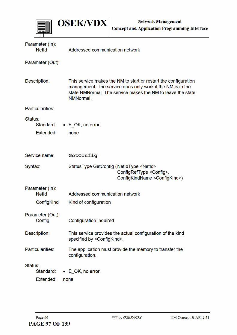
OSEKNDX NetworkManagement Concept and Application Programming Interface
Parameter (In): Netld Addressed communication network
Parameter (Out):
Description: This service makes the NM to start or restart the configuration management. The service does only work if the NM is in the state NMNormal. The service makes the NM to leave the state NMNormal.
Particularities:
Status: Standard: • E_OK, no error.
Extended: none
Service name: GetConfig
Syntax: Status Type GetConfig ( NetldType <Netld> ConfigRefType <Config>, ConfigKindName <ConfigKind>)
Parameter (In): Netld Addressed communication network
ConfigKind Kind of configuration
Parameter (Out): Config Configuration inquired
Description: This service provides the actual configuration of the kind specified by <ConfigKind>.
Particularities: The application must provide the memory to transfer the configuration.
Status: Standard: • E_OK, no error.
Extended: none
Page 96 ### by OSEKIVDX NM Concept & API 2.51
PAGE 97 OF 139

QSEKNDX NetworkManagement
Service name:
Syntax:
Parameter( In): Netld
TestConfig
RefConfig
CMask
Parameter (Out):
Description:
NM Concept & API 2.51
PAGE 98 OF 139
Concept and Application Programming Interface
CmpConfig
StatusType CmpConfig ( NetldType <Netld> ConfigRefType <TestConfig>, ConfigRefType <RefConfig>, ConfigRefType <CMask>)
Addressed communication network
Test configuration
Reference configuration
List of relevant nodes
none
The test configuration <TestConfig> is compared to the specified reference configuration <RefConfig> taking account of the mask <CMask>.
The presence of a node in the network is identified within the test configuration and the reference configuration by TRUE. The relevance of the result of the comparison (<TestConfig> EXOR <RefConfig>) of the node within the network is identified within the <CMask> by TRUE.
Status = NOT ( <CMask> AND (<TestConfig> EXOR <RefConfig>))
Example
Testeonfig I 1 11 11 I 1 I 0 I 0 I 0 I 0 I EXOR
RefConfig I 1 I 1 I 0 I 0 I 1 I 1 I 0 I 0 I
1° 1° 11 11 11 11 1° 1° 1 AND
CMask 11 1 o ! 1 1 o 11 I o 11 I o I
1° 1° 11
1° 11
1° 1° 1° 1 NOT
Status
### by OSEKIVDX
1 node present 1 not mute 0 node absent I mute
0 don't care
1 True 0 False
Page 97

OSEKNDX NetworkManagement Concept and Application Programming Interface
Status: Standard: • TRUE, test condition for specified mask exists.
• FALSE, else.
Extended: none
Service name: SelectDel taConfig
Syntax: StatusType SelectDeltaConfig ( NetldType <Netld>, ConfigKindName <ConfigKind>), ConfigHandle Type <ConfigHandle>, ConfigHandle Type <CMaskHandle>
Parameter(ln ): Netld Addressed communication network
ConfigKind Kind of configuration
ConfigHandle Referenced target configuration
CMaskHandle Referenced configuration mask
Parameter (Out): none
Description: A set of predefined parameter is selectable to drive the signalling of changed configurations.
Status: none
4.4.3. Operating Modes and Operating Mode Management
4.4.3.1. Data Types
NM Data Types Remark NMModeName Unique name defining the NM operational modes. Legal names are:
NetworkStatusType
StatusHandleType
"BusSleep" and "Awake" Type ofNetwork status.
This data type represents a handle to reference values of the type StatusRefiype.
Table 14 Special data types of the operating mode management
Page 98 ### by OSEKIVDX NM Concept & API 2.51
PAGE 99 OF 139

OSEK/VDX NetworkManagement Concept and Application Programming Interface
4.4.3.2. System Generation Support
4.4.3.3. Services
Service name: StartNM
Syntax: StatusType StartNM (NetldType <Netld>)
Parameter (In): Netld Addressed communication network
Parameter (Out): none
Description: StartNM starts the local network management. This causes the state transition from NMOff to NMOn.
Particularities: none
Status: Standard: • E_OK, no error.
E~ended: • none
Service name: S topNM
Syntax: StatusType StopNM (NetldType <Netld>)
Parameter (In): Netld Addressed communication network
Parameter (Out): none
Description: StopNM stops the local network management. This causes the state transition from NMOn to NMShutDown and after processing of the shutdown activities to NMOff.
Particularities: none
Status: Standard: • E_OK, no error.
E~ended: • none
Service name: GotoMode
NM Concept & API 2 .51 ### by OSEKIVDX Page 99
PAGE 100 OF 139

OSEKNDX NetworkManagement
Syntax:
Parameter (In): Netld
NewMode
Parameter (Out):
Description:
Concept and Application Programming Interface
StatusType GotoMode ( NetldType <Netld> NMModeName <NewMode>)
Addressed communication network
NM operating mode to be set (only BusSieep, Awake).
none
GotoMode serves to set the NM operating mode specified by <NewMode>. Operating modes to be set globally are recognised by the local NM and treated accordingly.
Note:
If a global operating mode has been set, the application - depending on the task specified by Initl ndDeltaStatus - is informed accordingly .
Particularities: none
Status: Standard: • E_OK, no error
• Extended: • none
Service name: GetStatus
Syntax: Status Type GetStatus ( NetldType <Netld> Network Status Type <Network Status>)
Parameter (In): Netld Addressed communication network
Parameter (Out): Network Status requested Status of the node
Description: This service provides the current status of the network.
Particularities:
Status: Standard:
Extended:
Page 100
none
E_ OK, no error.
none
PAGE 101 OF 139 ### by OSEKIVDX NM Concept & API 2.51

I OSEK/VDX NetworkManagement
Service name:
Syntax:
Parameter( In): Netld
TestStatus
RefStatus
SMask
Parameter (Out):
Description:
Status:
Concept and Application Programming Interface
CmpStatus
StatusType CmpStatus ( NetldType <Netld> StatusRefType <TestStatus>, StatusRefType <RefStatus>, StatusRefType <SMask>)
Addressed communication network
Test status
Reference status
List of relevant states
none
The test status <TestStatus> is compared to the specified reference status <RefStatus> taking account of the mask <SMask>.
Status = NOT ( <SMask> AND (<TestStatus> EXOR <RefStatus>))
Example .--.--.--.--.--.--.--r-----1 T estStatus I 1 I 1 I 1 I 1 I 0 I 0 I 0 I 0 I
EXOR RefStatus I 1 I 1 I o I o I 1 I 1 I o I o I
l ol ol 11111111ol ol AND
SMask I 1 I o I 1 I o I 1 I o I 1 I o I
l ol oi 1I OI 11ol ol ol NOT
Status
0 don't care
1 True 0 False
Standard: • TRUE, test condition for specified mask exists.
• FALSE, else.
Extended: none
NM Concept & API 2 .51 ### by OSEKIVDX Page 101
PAGE 102 OF 139
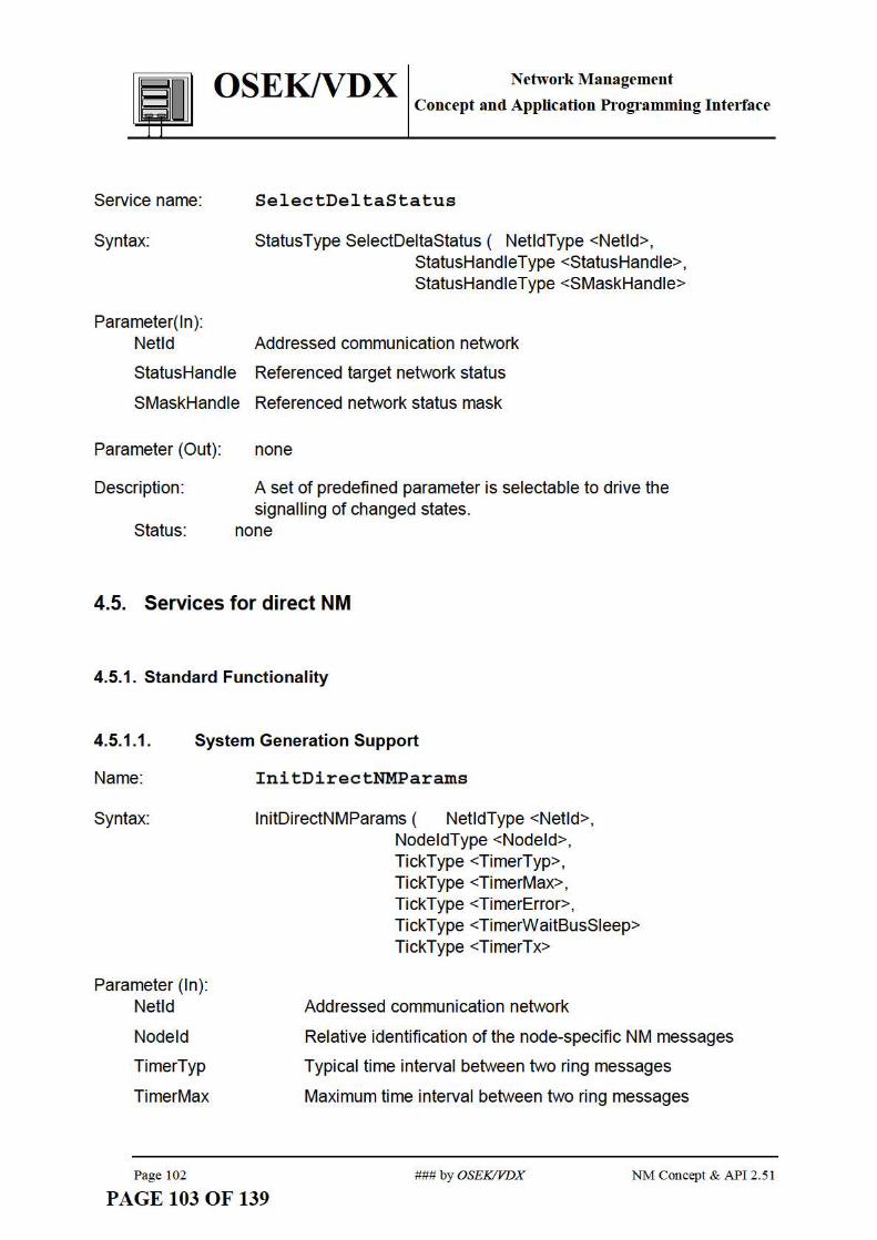
I QSEKNDX NetworkManagement
~ Concept and Application Programming Interface
Service name:
Syntax:
Parameter( In): Netld
SelectDeltaStatus
StatusType SelectDeltaStatus ( NetldType <Netld>, StatusHandleType <StatusHandle>, StatusHandleType <SMaskHandle>
Addressed communication network
StatusHandle Referenced target network status
SMaskHandle Referenced network status mask
Parameter (Out): none
Description: A set of predefined parameter is selectable to drive the signalling of changed states.
Status: none
4.5. Services for direct NM
4.5.1. Standard Functionality
4.5.1.1. System Generation Support
Name:
Syntax:
Parameter (In): Netld
Nodeld
TimerTyp
TimerMax
Page 102
InitDirectNMParams
lnitDirectNMParams ( NetldType <Netld>, NodeldType <Nodeld>, TickType <TimerTyp>, Tick Type <TimerMax>, TickType <TimerError>, TickType <TimerWaitBusSieep> TickType <TimerTx>
Addressed communication network
Relative identification of the node-specific NM messages
Typical time interval between two ring messages
Maximum time interval between two ring messages
### by OSEKIVDX NM Concept & API 2.51
PAGE 103 OF 139

OSEKNDX NetworkManagement
I Concept and Application Programming Interface
TimerError Time interval between two ring messages with NMLimpHome identification
TimerWaitBusSieep Time the NM waits before transmission into the state NMBusSieep
TimerTx Delay to repeat transmission requests
Description: lnitDirectNMParams is a directive for initialising the parameters of the direct NM.
Particularities: none
4.5.2. Operating Modes and Operating Mode Management
4.5.2.1. Services
Service name: SilentNM
Syntax: StatusType SilentNM (NetldType <Netld>)
Parameter (In): Netld Addressed communication network
Parameter (Out): none
Description: SilentNM disables the communication of the NM. This causes the state transition from NMActive to NMPassive.
Particularities: none
Status: Standard: • E_OK, no error.
Extended: • none
Service name: TalkNM
Syntax: StatusType TalkNM (NetldType <Netld>)
Parameter (In): Netld Addressed communication network
Parameter (Out): none
NM Concept & API 2.51 ### by OSEKIVDX Page 103
PAGE 104 OF 139

OSEKNDX NetworkManagement
Description:
Particularities:
Status:
Concept and Application Programming Interface
TalkNM enables the communication of the NM again, after a previous call of SilentNM. This causes the state transition from NMPassive to NMActive.
After a call of StartNM the NM is always in state NMActive.
Standard: • E_OK, no error.
Extended: • none
4.5.3. Data Field Management
4531 Dt T .... a a (pes
NM Data Types Remark RingDataType Type of the data field in the NMPDU
Table 15 Special data types of the data field management
4.5.3.2. System Generation Support
Service name:
Syntax:
Parameter (In): Netld
SMode
Taskld
EMask
Description:
Page 104
InitindRingData
lnitlndRingData ( NetldType <Netld> SignallingMode <SMode>, TaskRefType <Taskld>, EventMaskType <EM ask>)
Addressed communication network
Mode of signalling
Reference to the task to be signalled
Mask of the events to be set
lnitlndRingData is a directive for specifying the indication of received data in the data field of a ring message, which is addressed to this node.
The parameter <SMode> specifies whether task activation (SMode =Activation) or event signalling (SMode =Event) is used for indication.
### by OSEKIVDX NM Concept & API 2.51
PAGE 105 OF 139

QSEKNDX NetworkManagement Concept and Application Programming Interface
In case of task activation, <Taskld> contains a reference of the task to be activated if the NM received ring data. In case of event signalling, <EMask> specified the event to be set for task <Taskld> if the NM received ring data.
Particularities: none
4.5.3.3. Services
Service name:
Syntax:
Parameter (In): Netld
Parameter (Out): Ring Data
Description:
Particularities:
Status:
ReadRingData
StatusType ReadRingData ( NetldType <Netld> RingDataType <RingData>)
Addressed communication network
Contents of the data field within the Network management that contains the data either received by the last NM message or written to by TransmitRingData
ReadRingData enables the application to read the data that has been received by a ring message.
none.
Standard: • E_ OK, no error.
• E NotOK
Service name:
Syntax:
Parameter (In): Ring Data
NM Concept & API 2.51
PAGE 106 OF 139
- the NM does not pass a ring message currently -the logical ring does not run in a stable state.
TransmitRingData
Status Type TransmitRingData (NetldType <Netld> RingDataType <RingData>)
Data which is written to the data field to be transmitted with the next ring message.
### by OSEKIVDX Page 105

QSEKNDX NetworkManagement
Netld
Parameter (Out):
Description:
Concept and Application Programming Interface
Addressed communication network
none
This service enables the application to transmit data via the ring message.
Particularities: none
Status: Standard: • E_OK, no error.
• E NotOK - the NM does not pass a ring message currently - the logical ring does not run in a stable state.
4.6. Services for indirect NM
4.6.1. Standard functionality
4.6.1.1. System Generation Support
Name:
Syntax:
Parameter (In): Netld
Nodeld
TOB
TimerError
InitindirectNMParams
lnitlndirectNMParams ( NetldType <Netld>, NodeldType <Nodeld>, Tick Type <TOB>, TickType <TimerError>, TickType <TimerWaitBusSieep>
Addressed communication network
Relative identification of the node-specific NM messages
Time to monitor a subset of nodes.
Time interval before reinitialising the bus hardware after an error which makes the NM shift to Limp Home
TimerWaitBusSieep Time the NM waits before transmission in NMBusSieep
Description:
Page 106
lnitlndirectNMParams is a directive for initialising the parameters of the indirect NM.
### by OSEKIVDX NM Concept & API 2.51
PAGE 107 OF 139

QSEKNDX NetworkManagement Concept and Application Programming Interface
Particularities: none
4.6.2. Configuration Mangement
4.6.2.1. System Generation Support
The determination of the monitored messages which are used by the indirect NM is located and described by the system generation of COM.
Name:
Syntax:
Parameter (In): Netld
Nodeld
Delta Inc
Delta Dec
Description:
Particularities:
InitExtNodeMonitoring
lnitExtNodeMonitiring ( NetldType <Netld>, NodeldType <Nodeld>, lnt < Deltalnc> lnt < DeltaDec>
Addressed communication network
Relative identification of the node-specific NM messages
Value to increment the node status counter when a message is not received during a given time.
Value to decrement the node status counter when a message is received.
lnitExtNodeMonitoring is a directive for initialising a set of parameters to monitor one node with an individual time-out. The (redundant) parameter "threshold" is hidden.
none
5. Impacts to OS and to COM
5.1. Error Codes
The NM supp01ts several mechanisms to pass enors inside the NM to the application:
NM Concept & API 2.51 ### by OSEKIVDX Page 107
PAGE 108 OF 139

QSEKNDX Network Management Concept and Application Programming Interface
• retum value5 of the API-services
• indications which are activated by the NM if required configurations or network states are not recognised by the NM
The NM does not supp01t centralised enor handling by the application:
• not any enor-hook specific to NM
• not a common enor-hook used by OS, COM and NM
• services to pass kemel enors to the application are not supported
• the handling ofNM kemel enors are up to the implementers
5.2. Common impacts
5.2.1. Requirements to OSEK Communication (OSEK COM)
D Init
From the NM point of view five services to initialise the DLL are needed in general Parameter are adjusted according to the following examples:
baud rate
sample point
sample algorithm
synchronisation mechanism
bit timing
Sleep Mode of the protocol circuit
Sleep Mode of the physical layer
Standby Mode of the physical layer
operation modes of the protocol circuit
example
parameter (in) Netld connected bus (not necessaty when just one bus is connected)
5 see "Error Codes" inside the docmnent "binding"
Page 108 ### by OSEKIVDX NM Concept & API 2.51
PAGE 109 OF 139

OSEKNDX Network Management Concept and Application Programming Interface
InitRoutine Buslnit initialise the bus hardware once at the sta1t of the network
BusShutDown
BusRestart
Bus Sleep
BusAwake
D Status.ind
shut down the bus hardware
restart the bus hardware in the case of a fatal bus enor
initialise the power down mode of the bus hardware
reinitialise the bus hardware to leave the power down mode
Indication of states of the data link layer (software and hardware) according to the following examples:
enors fi:om the physical layer
enors 11-om bus monitoring circuits
enors fi:om the protocol circuit (CAN e.g.: bus off or enor active/passive)
enors fi:om the DLL
wake-up signal
example
parameter (out)
D _ GetLayerStatus
Netld
status
connected bus (not necessaty when just one bus is connected)
hardware specific status data
Reading the status inf01mation of the data link layer according to the following examples:
intem1pt acknowledge to the protocol circuit
get the status of the protocol circuit, e.g. translnit, receive, ovenun, bus off
get the status of the physical layer, e.g. translnission line enor
example
pm·ameter (in)
pm·ameter (out)
NM Concept & API 2.51
PAGE 110 OF 139
Netld connected bus (not necessaty when just one bus is connected)
status hardwm·e specific status data
###by OSEKIVDX Page 109

QSEK/VD X Network Management Concept and Application Programming Interface
D Oftline
This se1vice allows to block the user transmission via the data link layer at least.
example
parameter (in)
D Online
Netld connected bus (not necessary when just one bus is connected)
This se1vice enables the user communication on the data link layer, e.g. after a call of D Oftline.
example
par·ameter (in) Netld connected bus (not necessary when just one bus is connected)
The NM calls DLL se1vices at the transition fi:om one state to another state.
I I
~ ... Figure 68 Using of DLL se1vices by the NM
left indirect NM right direct NM
5.2.2. Requirements to OSEK Operating System (OSEK OS)
The operating system requirements for implementation of OSEK NM are listed below. The standard se1vices for configuration management, management of operating modes and data field management are available at the lowest confo1mance class BCCl of OSEK-OS. This allows the implementation ofNM on the basis of OSEK OS class BCCl. Additional features pa1tly require higher confo1mance classes.
Page 110 ### by OSEKIVDX NM Concept & API 2 .51
PAGE 111 OF 139

QSEK/VDX Network Management
I Concept and Application Programming Interface
If NM uses the event triggering mechanism, then this feature is required fi:om the operating system.
The implementation can also be based on a non OSEK OS, which provides at least the functionality ofOSEK OS services listed below.
### Alann services: SetRelAlrum and CancelAlatm
### Task management: GetTaskState, DeclareTask, ActivateTask, TetminateTask and ChainTask.
5.3. Impacts from direct NM
5.3.1. Interface to OSEK Communication (OSEK-COM)
From the NM point of view the NM in a node has to transinit a NMPDU to the bus and has to receive evety NMPDU from the NMs in all networked nodes. The stmcture of the NMPDU is fixed by the NM. However the data representation inside a NMPDU and how to code/decode a NMPDU to a message is out of the scope of the NM. The annex contents proposals to handle these tasks.
topic responsible
stmcture of the NMPDU OSEKNM
example
Address-Field (source and destination) Control-Field (12 message types) optional Data-Field
data representation inside the NMPDU out ofthe scope ofOSEK NM
coding and decoding of a NMPDU to a out of the scope ofOSEK NM message
Table 16 NMPDU - responsible
In general the interface between NM and the DLL to transtnit and receive NMPDUs will be directly influenced by the agreement to fix the data representation inside a NMPDU and the coding/decoding to a message.
Based on the experiences according to the state of the a1t and the proposals given in the annex an interface between NM and the DLL can be suggested.
D DefineWindow
NM Concept & API 2.51 ### by OSEKIVDX Page 111
PAGE 112 OF 139

QSEKNDX NetworkManagement Concept and Application Programming Interface
Definition of the encoding/decoding algorithm to broadcast/receive the NMPDU via the bus. This action will be handled by a system generation tool. The system generator is responsible for the selected algorithm.
example
static parameter (in) Netld
D_ Window_Data_req
Window Mask
IdBase
Sourceld
DataLengthTx
DataLengthRx
Service to transmit a NMPDU to the network.
example
parameter (in)
D Window Data ind - - -
Netld
NMPDU
DataLengthTx
Service to receive a NMPDU to the network.
example
pru·runeter (in)
pru·ameter (out)
Page 112
PAGE 113 OF 139
Netld
NMPDU
DataLengthRx
connected bus (not necessaty when just one bus is connected)
mask for filtering NM messages
base identification of an NM message
identification of the source of the NMPDU
number of bytes of the NMPDU to transmit (if data length is static)
number of bytes of the NMPDUs to receive (if data length is static)
connected bus (not necessruy when just one bus is connected)
except the source (static see the example D _Define_ Window, DataLengthTx)
number of bytes of the NMPDU to transmit (if data length is dynrunic)
connected bus (not necessruy when just one bus is connected)
number of bytes referenced by the value DataLengthRx (static see the example D _Define_ Window)
number of bytes of the NMPDUs to receive (if data length is dynamic)
### by OSEKIVDX NM Concept & API 2.51

OSEK/VDX Network Management Concept and Application Programming Interface
5.4. Impacts from indirect NM
5.4.1. Interface to OSEK Communication (OSEK-COM)
When a monitored application message is received/transmitted by COM, indirect NM has to be infonned. In case of using one dedicated time-out per message monitored, indirect NM has to be info1med when a monitoring time-out expires.
For each of these situations the indirect NM needs to know to which Netld and Nodeid the monitored message refers. OSEK COM provides this info1mation to NM via a parameter called "Sender", conesponding to a combination ofboth Netld and Nodeid.
Services needed between indirect OSEK-NM and OSEK-COM IAL depend on the selected monitoring scheme (one global time-out I one dedicated time-out per monitored message).
Interface to OSEK-COM IL Options
One global One dedicated time-out time-out per
monitored messa2e
I MessageTransfer.ind core core
I MessageTimeOut.ind core
Table 17 Interface of indirect OSEK-NM with OSEK-IAL
I_ MessageTransfer.ind
Indication fi:om COM that a monitored message has been received fi:om a remote node or that the local monitored message has been transmitted.
parameter (out) Sender combination ofNodeid and Netld
I_ MessageTimeOut.ind
Indication :fi.·om COM that a time-out at monitoring a message :fi.·om a remote node has expired or that the time-out at monitoring the local message transmission has expired.
parameter (out) Sender combination ofNodeid and Netld
NM Concept & API 2 .51 ### by OSEKIVDX Page 113
PAGE 114 OF 139

QSEK/VD X Network Management Concept and Application Programming Interface
5.4.1.1. Mapping Nodeld, Netld ¢=> Sender
Sender
Node Mask
Nodeld
NetMask
Netld
Figure 69 Encoding and decoding of sender to a Nodeld and a Netld by using a mechanism with a Mask. (x = don't care, take Message bit; ! =do not take this bit)
NMDefineNetNodeMapping
Definition of the algorithm to map a sender to a node and to a net. This action will be handled by a system generation tool. The system generator is responsible for the selected algorithm.
example
static parameter (in) NetMask
NodeMask
NMNetNodeMapping
mask for filtering NM messages
mask for filtering NM messages
Mapping of a given sender to the conesponding node and the conesponding net.
example
parameter (in)
parameter (out)
Page 114
PAGE 115 OF 139
sender
Nodeld
Netld
node which conesponds to the referenced identification
connected bus (not necessruy when just one bus is connected)
### by OSEKIVDX NM Concept & API 2 .51

I OSEKND X Network Management
Concept and Application Programming Interface
6. History Version Date Remarks
1.00 11th Sept. 1995 initial release Authors involved in version 1.00 Clnistoph Hoffinann Volkswagen AG Jiirgen Minuth Daimler-Benz AG JosefKrannner BMW AG Jorg Graf Adam Opel AG Karl Joachim Nemnann IIIT, Univ. ofKarlsmhe Frans:ois Kaag PSA Peugeot Citroen
2.00 24th Dec. 1996 2.10 4th April 1997 Authors involved in Version 2.0 and 2.1
JosefKrannner BMW AG Jii.rgen Minuth Daimler-Benz AG Ansgar Maisch IIIT, University of Karlsruhe Willy Roche HIT, University ofKarlsmhe Clnistoph Hoffinann Volkswagen AG 0 livier Quelenis Magneti Marelli Edc Farges Renault Peter Aberl Texas Instmments
2.50 preliminaty 31st March 1998 Authors involved in Version 2.5
2.50 2.5 1
7. Annex
31st May 1998 31st May 2000
JosefKrannner BMW AG Dirk John HIT, University ofKm·lsmhe Clnistoph Hoffinann Volkswagen AG Lise Mathieu Renault Jii.rgen Minuth Daimler-Benz AG 0 livier Quelenis Magneti Mm·elli summa1y of modifications since Version 2 .1 - indirect NM: individual time outs per monitored message - update system generation services -update stmctme of the docmnent - hatmonisation ofNM se1vices - hatmonisation interface to COM - update state transition diagratnS and SDL diagrams editorial ove1working of the preliminaty version 2.50 Results ofthe hatmonisation Authors involved in version 2.5 1 Jii.rgen Minuth DaimlerClnysler Ma1tin Schiitze Robe1t Bosch AG Dirk Gronemann Siemens
7.1. Implementation proposal (direct NM)
NM Concept & API 2.51 ### by OSEKIVDX Page 115
PAGE 116 OF 139

QSEK/VD X Network Management Concept and Application Programming Interface
7 .1.1. Overview of Internal Activities
All the intemal services of the NM begin with NM. All words of the service name begin with a capital letter.
--
-
--------
Shut-off ofNM Save parameters, store hist01y and shutdownNM Initialise NM and the resources pe1taining to it NM in the state NMBusSleep NM in the state NMActive NM in the state NMPassive NM in the state NM~Standard NM in the state NM~Active NM in the state NM~Passive NM in the state NM~ActivePrepBusSleep
NM in the state NM~PassivePrepBusSleep
Figure 70
Syntax of the names of intemal NM services.
Example: NMShutDown
Activity Core or Optional
NMOff CORE NMShutDown CORE
NMinit CORE
NMBusSieep CORE NMActive CORE NMPassive CORE NM~tandard CORE NM~Active CORE NM~Passive CORE NM~ActivePrepBusSieep CORE NM~PassivePrepBusSieep CORE
Table 18 Breakdown of intemal NM activities into core se1vices and optional services. ~ Reset, Nonnal or LimpHome
The state transition diagrams (STD) listed hereafter define system hierarchy and general transition mles for the NM behaviour.
NM activities are perfo1med by calls of the intemal activities in the respective states of the STD and identified by the names of these dedicated intemal activity. Intemal activities are defined verbally in the referenced chapters according to the description of their characteristics.
Consequently, they can be considered as macros which are generated at compile time, using (elementary) se1vices which are defined othe1wise.
Thus, there is neither an appropriate C syntax, nor specifications about input I output parameters or status of the intemal activity.
Page 116 ### by OSEKIVDX NM Concept & API 2 .51
PAGE 117 OF 139

OSEK/VDX Network Management
Concept and Application Programming Interface
, ,
level 0
NM0n8
NMBusSieep
not any ~communication \ re uest
communication
t
~~ rt est
··•~-->·8 , , ,
'"'""':,,,' To'k~NM J ntNM
.. . ' : ', NMPassive . ' . ' . ' . ' . '
level 1 : '
Figure 71
NM Concept & API 2 .51
PAGE 118 OF 139
level 2
NMAwake
"Failure at own station repaired" e g. NM transmission and NM reception possible
fatal Bus Error
' ' ' ' '
' '
~-Own station non operationar'
'\ e g. not an~s~on
"Own station non operationar i.e. not any NM reception
I ~ "Station operational" e.g. not any error
/at NM reception recognized
·data inconsistenr e.g. time out at ring message
Simplified state transition diagram of the direct NM.
### by OSEKIVDX Page 117

OSEKNDX NetworkManagement Concept and Application Programming Interface
NMReset, NMNonnal, NMLimpHome GotoMode(Awake) called or
g. nmAcfve
level 3
network not ready ~for BusSieep
nmPassive
GotoMode (BusSieep)~ called
)
GotoMode(Awake) called or network not ready for Bussleep
network ready -+--~ for BusSieep
Figure 72 NM intemal states "NMNonnal" or "NMReset" or "NMLimpHome"
7 .1.2. Specification of Internal Activities
Service name:
Description:
Particularities:
Service name:
Description:
Page 118
NMOff
NM of the node is shut-off.
none
NMShutDown
Service for selective shut-off of NM entity. This includes all "clearing-up work" (see below) to be effected by NM.
This service is effected without confirmation throughout the whole network. (see Figure 71 )
The tasks of this service comprise:
- Saving NM state incl. the last valid network configuration, operating state, version number (optional , depending on system design).
- Releasing all resources assigned for NM.
- Reset interface module.
### by OSEKIVDX NM Concept & API 2 .51
PAGE 119 OF 139

OSEK/VDX Network Management
Particularities:
Service name:
Description:
Particularities:
Service name:
Description:
Particularities:
Service name:
Description:
Particularities:
Service name:
Description:
Particularities:
NM Concept & API 2 .51
PAGE 120 OF 139
Concept and Application Programming Interface
none
NMinit
Service for initialising NM according to NM STD:
- Initialisation of network interface.
- Assignment and initialisation of NM resources.
none
NMBusSleep
The NM module of the node is mode NMBusSieep according to the NM STD (level 1 ).
Concrete procedures must be specified by the respective system responsible.
NMActive
The NM module of the node is mode NMActive according to the NM STD (level 1 ).
Concrete procedures must be specified by the respective system responsible.
NMPassive
The NM module of the node is mode NMPassive according to the NM STD (level 1 ).
Concrete procedures must be specified by the respective system responsible.
### by OSEKIVDX Page 119

Service name:
Description:
Particularities:
Service name:
Description:
Particularities:
Service name:
Description:
Particularities:
Page 120
OSEKNDX NetworkManagement Concept and Application Programming Interface
NMNormalActivePrepBusSleep
The NM module of the node is mode NMNormaiActivePrepBusSieep according to the NM STD (level 3).
The activities performed are according to the concept of OSEKNM the notification of a sleep request for the whole network to all nodes in the network and pending for confirmation.
Concrete procedures must be specified by the respective system responsible.
NMLimpHomeActivePrepBusSleep
The NM module of the node is mode NMLimpHomeActivePrepBusSieep according to the NM STD (level 3).
The activities performed are according to the concept of OSEKNM the notification of a sleep request for the whole network to all nodes in the network and pending for confirmation.
Concrete procedures must be specified by the respective system responsible.
NMResetActivePrepBusSleep
The NM module of the node is mode NMResetActivePrepBusSieep according to the NM STD (level 3).
The activities performed are according to the concept of OSEKNM the notification of a sleep request for the whole network to all nodes in the network and pending for confirmation.
Concrete procedures must be specified by the respective system responsible.
### by OSEKIVDX NM Concept & API 2.51
PAGE 121 OF 139

OSEKNDX NetworkManagement
Service name:
Description:
Particularities:
Service name:
Description:
Particularities:
Service name:
Description:
Particularities:
Service name:
Description:
Concept and Application Programming Interface
NMNormaiPassi vePrepBusSleep
The NM module of the node is mode NMNormaiPassivePrepBusSieep according to the NM STD (level 3).
Concrete procedures must be specified by the respective system responsible.
NMLimpHomePassivePrepBusSleep
The NM module of the node is mode NMLimpHomePassivePrepBusSieep according to the NM STD (level 3)
Concrete procedures must be specified by the respective system responsible.
NMResetPassivePrepBusSleep
The NM module of the node is mode NMResetPassivePrepBusSieep according to the NM STD (level 3)
Concrete procedures must be specified by the respective system responsible.
NMNormalActive
The NM module of the node is mode NMNormaiActive according to the NM STD (level 3).
The procedure performed is to participate in the NM communication according to the logical ring concept and to assess the NMPDU.
Particularities: none
NM Concept & API 2.51 ### by OSEKIVDX Page 121
PAGE 122 OF 139

Service name:
Description:
Particularities:
Service name:
Description:
Particularities:
Service name:
Description:
Particularities:
Service name:
Description:
Particularities:
Service name:
Description:
Particularities:
Page 122
OSEKNDX NetworkManagement Concept and Application Programming Interface
NMLimpHomeActive
The NM module of the node is mode NMLimpHomeActive according to the NM STD (level 3).
The procedure performed is to participate in the NM communication according to the logical ring concept and to assess the NMPDU.
none
NMResetActive
The NM module of the node is mode NMResetActive according to the NM STD (level 3).
The procedure performed is to participate in the NM communication according to the logical ring concept and to assess the NMPDU.
none
NMNormalPassive
The NM module of the node is mode NMNormaiPassive according to the NM STD (level 3).
none
NMLimpHomePassive
The NM module of the node is mode NMLimpHomePassive according to the NM STD (level 3).
none
NMResetPassive
The NM module of the node is mode NMResetPassive according to the NM STD (level 3).
none
### by OSEKIVDX NM Concept & API 2.51
PAGE 123 OF 139

I OSEKNDX NetworkManagement
Service name:
Description:
Particularities:
Service name:
Description:
Particularities:
Service name:
Description:
Particularities:
7.1.3. NMPDU
Concept and Application Programming Interface
NMNormalStandard
The NM module of the node is mode NMNormaiStandard according to the NM STD (level 3).
none
NMLimpHomeStandard
The NM module of the node is mode NMLimpHomeStandard according to the NM STD (level 3).
none
NMResetStandard
The NM module of the node is mode NMResetStandard according to the NM STD (level 3).
none
OSEK implementation of direct node monitoring supports the implementation of NMPDU as listed hereafter.
Additional information for extended NM features, e.g. dedicated enhanced diagnosis suppo1t, could be mapped into the data field of the NM message. This is an optional feature in the responsibility of the respective system developer and it depends on the used bus protocol.
Implementation
The implementation features
### suppo1t of a maximum number of 256 nodes
### demand of3 Bytes
NM Concept & API 2.51 ### by OSEKIVDX
PAGE 124 OF 139 Page 123

QSEK/VD X Netw ork Management Concept and Application Programming Interface
Addressing Field Control Field Data Field (optional)
8 bit 8 bit 8 bit specific to the protocol (e.g. CAN)
Source Id Destination Id OpCode Data
Figure 73 Implementation ofNMPDU
7.1.3.1. OpCode
Address Field Control Field Data Field
Source Dest. Id OpCode Data Id
mandat01y optional Coding Exam ple Interpretation
0 0 0 0 0 0 0 1 Ring Message, cleared 0
Bussleep.ack, cleared Bussleep.ind
0 0 0 0 0 1 0 1 Ring Message, cleared Bussleep.ack, set Bussleep.ind
0 0 0 0 0 X 1 1 Ring Message, set Bussleep.ack
0 0 0 0 0 0 1 0 Alive Message, cleared Bussleep.ind
0 0 0 0 0 1 1 0 Alive Message, set Bussleep.ind
0 0 0 0 0 0 0 0 Limp Home Message, cleared Bussleep.ind
0 0 0 0 0 1 0 0 Limp Home Message, set Bussleep.ind
Table 19 NMPDU The 1st 5 bits of the OpCode are reserved for ihture extensions. They should be initialised to logical zero. The data field should be initialised to logical zero
Page 124 ### by OSEKIVDX NM Concept & API 2.51
PAGE 125 OF 139

I OSEKNDX NetworkManagement
Concept and Application Programming Interface
7.1.3.2. Encoding and decoding
7.1.3.2.1. Addressing Mechanisms
The following set-up is required for each node to implement the window mechanism with a broadcast behaviour:
### one node-specific transmit object
### one or more global receive objects (windows) for all node-specific NM messages
Under worst case condition NM has to use a range of message headers for network-wide collllllunication. Such a range of messages can be mapped to one or more window objects. Each window object is identified by the values:
IdBase
Window Mask
Base identification of any NM message header.
Mask for filtering NM messages (acceptance).
Example for Acceptance Filtering
Reception is OK: IF( Id_of_Frame & WindowMask = = IdBase)
Example for encoding and decoding of a NMPDU
Data NMPDU to transmit
WindowMask
Message
WindowMask
Destination OpCode Data received NMPDU
Figure 74 Encoding and decoding of the NMPDU to a message by using the window mechanism with IdBase and WindowMask. (x = don't care, take NMPDU bit; ! = take original bit ofidBase)
The example shows, that the receiving node can detennine parts of the NMPDU, e.g. the identification of the transmitting node, 11-om the transmitted fi:ame.
NM Concept & API 2.51 ### by OSEKIVDX Page 125
PAGE 126 OF 139

QSEK/VD X Network Management Concept and Application Programming Interface
7.1.3.2.2. Coherent Allocation of NM message Headers
A simple implementation results if the message headers for NM are selected in a coherent numeric range.
Two integers n and k must be selected in order to enable straightforward acceptance filtering ofNM messages.
Using the constant n, 2n (WindowSize) directly addressable nodes are made available. The constant k defines the Base of the message header as an integer multiple of the maximum munber of directly addressable nodes.
Node identification 0 oo• 2n- 1
IdBase k2n
least message header k2n+O
greatest message header k 2n + 2n- 1
Table 20 Selection of message headers and NodeNumbers
General Example
Addressing of 32 separate nodes shall be enabled. The NM message headers have to strut with message identifier 600hex. This implies:
### Selected pru·runeters: 32 = (25) ### n = S
600hex = (48*32) ### k = 48.
### Node identification 0 000 31 dec
### Least header (600hex) 110 0000 0000 bin, 110 000 bin conesponds to k
### Greatest header (61Fhex) 110 0001 1111 bin
### IdBase 110 0000 0000 bin
### Window Mask 111 1110 0000 bin "1" : target
"0" : don't care
CAN Example
A NM message containing the NMPDU has to be mapped into diverse bus protocols. The figures below show a CAN realisation example (i.e. max. 256 nodes can be addressed). Because CAN implementations do not allow tmique message identifiers used by more than one transmitter, it is essential that all NM messages differ fi·om each another. This can be achieved by e.g. encoding the NM Source Id into the CAN message Id.
Page 126 ### by OSEKIVDX NM Concept & API 2.51
PAGE 127 OF 139

I OSEKNDX NetworkManagement
Concept and Application Programming Interface
CAN Identifier DLC CAN Data Field
11 (29) bit 4 bit ~ 64 bit
Addressing Field Control Field Data Field
3 (21) bit 8 bit 8bit 8bit 48bit
IdBase Source Id Dest. Id OpCode Data
X s 8 D X X
Figure 75 Stmcture ofNM message in case of CAN (6 Byte Data Field).
CAN Identifier DLC CAN Data Field
11 (29) bit 4 bit 16 bit
Addressing Field Control Field
3 (21) bit 8 bit 8bit 8bit
IdBase Source Id Dest. Id OpCode
X s 2 D X
Figure 76 Stmcture ofNM message in case of CAN (without Data Field).
I CAN Identifier I CAN Data Field I 11 (29) bit I 3 - 8 byte
Address Field Control Field Data Field 1 3 (21l bit 8bit 1 1 byte 1 byte I 1 byte < 5 byte
Source ld I Dest. ld OD<ode Data :X D hex 0 0 X X X X X X
:X D hex 1 0 X X X X X X Ring Messages :X D hex 0 1 X X X X X X
:X D hex 1 1 X X X X X X
:xl B hex 0 I 0 I XI XI XI XI X 1 X Alive Messages )(I B hex 1 i 0 i XI XI xi xi X i X
:X c hex 0 0 X X X X X X Limp-Home :X c hex 1 0 X X X X X X Messages
Figure 77 Example ofthe mapping of the NMPDU to a NM message based on CAN-comparable to the DaimlerClnysler encoding
x reserved
Important Note:
In principle, message /leaders required to implement tile window can obviously be assigned in any order. Selecting tile digits n and k according to tile principle introduced above, tile choice is automatically limited to powers of two and enables straiglltjonvard filtering for acceptance in tile destination system.
In tile case of possible dynamic allocations, tile window parameters can be coded using two bytes, and can be transmitted with a message.
NM Concept & API 2.51 ### by OSEKIVDX Page 127
PAGE 128 OF 139

QSEK/VD X Network Management Concept and Application Programming Interface
7.1.3.2.3. Non-coherent Allocation of NM message Headers
If the system design requires distribution - i.e. numerically separate anangement - of the message headers, they can remain coherent within the software if an appropriate mask is used.
Example
Addressing of 32 separate nodes shall be enabled. The NM message headers 400hex to 40Fhex and 600hex to 60Fhex have to be used This implies:
### Node identification 0 ... 31 dec
### Least header ( 400hex) 100 0000 0000 bin
### Header 40Fhex 100 0000 1111 bin
### Header 600hex 110 0000 0000 bin
### Header 60Fhex 110 0000 1111 bin
### IdBase 100 0000 0000 bin
### WindowMask 101 1111 0000 bin "1" : target "0" : don't care
7.1.3.2.4. Node Identifications
The local node identifications ofNM, and consequently the global node identifications must be allocated mliquely within the entire network.
In accordance with the detemlinations, numeric values in the range fi:om 0 to (2n - 1) are used for this pmpose. Group addresses are provided for special applications by the system responsible. It depends on the selected transfo1mation for node identification into message header, whether the local and global node identifications are equal.
Node Identification Interpretation
0 reserved
1 ... 254 node no. 1 up to node no. 254
255 Group "all nodes"
Table 21 Dete1mination of node identifications using the example n=8
7.1.4. Scalability
In most control unit networks with a centralised stmcture, three node types are distinguished:
Function master Clearly defined node which perfo1ms all centralised and co-ordination ftmctions.
Page 128 ### by OSEKIVDX NM Concept & API 2.51
PAGE 129 OF 139

QSEKNDX NetworkManagement Concept and Application Programming Interface
Potential function master In case of failure of the function master, e.g. node breaks down, each of these back-up masters is capable ofpe1fonning at least some of the master's functions.
Function slaves
The individual nodes may feature broadly va1ying available computing power for implementation of NM. The decentralised NM can be scaled to save resources (requirements ofRAM/ROM and computer time), resulting in two extreme NM types:
Max NM Set of all NM functions according to direct node monitoring.
Min NM Minimum set of required functionality enabling participation in direct node monitoring.
The choice of functions can be adapted to the nodes' performance.
scaleable
Task MaxNM Min NM
Store the present configuration ### -Time-out monitoring to detect faulty ### -node
"Re-login" if skipped ### ###
Login ### -Detennine logical successor ### ###
Delayed transmission of NM message ### ###
according to sequencing mle of the logical ring
Strut up of the logical ring ### -Table 22 Functionality of the configuration algorithins of Max NM and Min NM
If necessruy, the individual node types (Function master . . . Function slave) can be supplied with subsets of the decentralised NM.
In a centrally stmctured network, the group of nodes cons1stmg of function master and potential fhnction masters, can be considered as decently stmctured with regard to the configuration adjustment within the NM.
The dynrunic concept of configuration detennination enables integration of any function slaves perfomling Min NM and of any potential ftmction master into the network.
NM Concept & API 2.51 ### by OSEKIVDX Page 129
PAGE 130 OF 139

QSEKNDX Network Management Concept and Application Programming Interface
Important Note:
For tile sake of clarity, tile implementation of identical NM modules is required in each node. In other words: the basic scalability of the decentralised NM should only be used in vital, exceptional cases.
7.2. Implementation proposal (indirect NM)
7 .2.1. Scalability
According to system designer needs and to computing power performance of nodes (RAM/ROM and computer time), Indirect NM can be scaled in NM types ranging fi:om:
Max NM Set of all NM functions including all extended features.
down to
Min NM Minimmn set of required ftmctionality enabling network corrnmmication.
scalable ~ Function MaxNM MinNM
Hardware initialisation, resta1t ../ ../ ../ ../ ../
of hardware after a failure, bus shutdown
Dynamic states monitoring ../ ../ ../ ../ -Static states monitoring ../ - ../ - -BusSleep ../ ../ - - -
Table 23 Example offtmctionality for different NM types
Important Note:
Tile implementation of identical indirect NM type is not required in each node. Choice of functions to be implemented is let to system designer.
Page 130 ### by OSEKIVDX NM Concept & API 2. 51
PAGE 131 OF 139

I OSEK/VDX NetworkManagement
Concept and Application Programming Interface
7.2.2. Implementation hints
7.2.2.1. message
Choice one global time-out I one monitoring time-out per
Implementing node monitoring fhnctionality, the system designer can choose to monitoring schemes:
all messages are monitored by one global time-out TOB (time-out for observation)
each message is monitored by its own dedicated time-out.
One global time-out
Advantage This solution does no require much micro-controller CPU time resource.
Drawback If monitored messages have ve1y different transmission period (for example, one lOins message fi:om a node and one 500IUS message fi·om another), the user has to choose the biggest value for timer TOB to be sure than each message has anived before time - out expires. The resulting delay on the 1 OIUS message monitoring may be unacceptable if this message is time-critical for the application.
One time-out per monitored message
Advantage Each message can be monitored regarding its time-criticity.
Drawback This solution requires more micro-controller CPU time resource.
7.2.2.2. Configuration of extended states detection algorithm
Extended states detection algorithm has to be configured at system generation time. Parameters to be set are:
the Threshold value, which is the same for all counters,
a Deltalnc (increment of counter) and a DeltaDec (decrement of cmmter) values per monitored node.
Threshold value is usually set to 255; its value has no impact on the algorithm behaviour. Deltalnc and DeltaDec modify algorithm behaviour.
Examples
• If the system designer needs:
NM Concept & API 2.51 ### by OSEKIVDX Page 131
PAGE 132 OF 139

OSEKNDX Network Management Concept and Application Programming Interface
"static states" conesponding to states during a unique T static time value for eve1y monitored node, although these nodes have different transmission periods and are monitored by different time,
counters retUin directly to 0 when static states are left
Counter. '' Parameters: DeltaDec;. Deltalnc;
extended state of the node k
I'
-------------
/ ./ .....
T Static/
static absent/mute
Figure 78 Extended state example one
Parameter of node k
---------Thre
' 't
' ....
Value
shold
Deltalnc Tbceshold x TimeOut t
Tswi:
DeltaDec Threshold
Table 24 Calculation ofDeltalnc and DeltaDec according example one TimeOutk: monitoring time-out for node k
• If the system designer needs :
"static states" conesponding to states during a unique T static time value for eve1y monitored node, although these nodes have different transmission periods and are monitored by different time-outs,
counters keeping track of node states during a T Erase time value after static states are left
Page 132 ### by OSEKIVDX NM Concept & API 2.51
PAGE 133 OF 139

OSEK/VDX Network Management
Concept and Application Programming Interface
Countert Parameters: DeltaDe~. Deltaln~
extended state of the node k
static absent/mute
Figure 79 Extended state example two
Parameter for node k
Deltalnc
DeltaDec
Value
Threshold x TimeOut t
Ts .. ric
Threshold . T•
T Eru c
Table 25 Calculation of Deltainc and DeltaDec according example one TimeOutk: monitoring time-out for node k Tk: period of the supervised message received fi:om node k
7.2.3. Summary of SOL state diagram graphical notation
The SDL graphical symbols used in the specification of the indirect network management state machine are described below:
NM Concept & API 2 .51 ### by OSEKIVDX Page 133
PAGE 134 OF 139

QSEKNDX NetworkManagement Concept and Application Programming Interface
Process Symbols
.---------, : \.~ 1/• SDL graphic al symbol s summary • / ~
1 ( 1 )
0 0 0 0 '- ----------•
St art up Stat e
Case 1
/Signal" ~ondit iony
Act i ons and
Assi gnment s
r-----1
I I I
I I ·-----------L---------i~~~!::te
I ""----------·
r I
r-----------1 :Annot a t i ons I '-----------·
Case 3
1'-------' I I
I I r-----------------L--------i~~~u~e;~o~e St a t e
I ._ ________________ _
Figure 80 Smmnruy of SDL state diagram graphical notation
7 .3. Outlook
The mapping of a NMPDU into a CAN message is on the way to be confumed among the vehicle manufacturers. Future requirements are visible, first steps to meet them were done:
• Sub-net operating selective wake-up/go-to sleep via the bus lines ~ a subset of nodes is active ~ a subset of nodes is in a low power mode
• Gateway support ~ monitoring of nodes across several networks ~ negotiated operating modes across several networks
Page 134 ### by OSEKIVDX
PAGE 135 OF 139 NM Concept & API 2.51

OSEKNDX NetworkManagement Concept and Application Programming Interface
• Standardised Data Representation ~ NMPDU inside a CAN message ~ Network states ~ simple cettification
• API ~ adding of service-prefix to simplify the readability ~ negotiated operating modes across several networks ~ optimised retum value ~ support sub-net operationg e. g. by LogOff and LogOn
• Station Management ~ e. g. algorithms specific to the application to handle a CAN bus-off
8. Index
List of all network management services, data types and intemal activities.
CmpConfig 97 NMBusSleep 119
NMinit 119 CmpStatus 101
ConfigHandleType 92
ConfigKindName 92
ConfigRefrype 92
EventMaskType 90
GetConfig 96
GetStatus 100
NMLimpHomeActive 122
NMLimpHomeActivePrepBusSleep 120
NMLimpHomePassive 122
NMLimpHomePassivePrepBusSleep 121
NMLimpHomeStandard 123
NMModeName 98
GotoMode 99
InitCMaskTable 92
InitConfig 95
InitDirectNMParams 102, 106
InitExtNodeMonitoring 107
InitindDeltaConfig 93
InitindDeltaStatus 95
InitindRingData 104
InitNMScaling 91
InitNMType 90
InitSMaskTable 94
InitTargetConfigTable 93
InitTargetStatusTable 94
NetldType 90
NetworkStatusType 98
NMActive 119
NM Concept & API 2.5 1
PAGE 136 OF 139
NMNonnalActive 121
NMNonnalActivePrepBusSleep 120
NMNonnalPassive 122
NMNonnalPassivePrepBusSleep 121
NMNonnalStandard 123
NMOff 118
NMPassive 119
NMR.esetActive 122
NMR.esetActivePrepBusSleep 120
NMR.esetPassive 122
NMR.esetPassivePrepBusSleep 121
NMR.esetStandard 123
NMShutDown 118
NodeldType 90
ReadRingData 105
RingDataType 104
### by OSEKIVDX Page 135

OSEKNDX
RoutineReffype 90
SelectDeltaConfig 98
SelectDeltaStatus 102
SelectHWR.outines 91
SignallingMode 90
SilentNM 103
StartNM 99
NM Con cept & API 2.5 1
PAGE 137 OF 139
Network Management
Concept and Application Programming Interface
StatusHandleType 98
StatusType 90
StopNM 99
TalkNM 103
TaskReffype 90
TickType 90
TransmitRingData 105
### by OSEKIVDX Page 1

PAGE 138 OF 139

PAGE 139 OF 139