Addendum 1 - NET
34
This document is not an API Standard; it is under consideration within an API technical committee but has not received all approvals required to become an API Standard. It shall not be reproduced or circulated or quoted, in whole or in part, outside of API committee activities except with the approval of the Chairman of the committee having jurisdiction and staff of the API Standards Dept. Copyright API. All rights reserved. Affected Publication: API Specification 16D, Control Systems for Drilling Well Control Equipment and Control Systems for Diverter Equipment, Third Edition, November 2018 Addendum 1 The reference to the Monogram Program to be removed from Section 1 and elsewhere throughout the document, including the Annex. Section 4.5 heading shall be renamed from ‘Auxiliary Equipment Control Systems and Interfaces’ to ‘Auxiliary Equipment Control Systems’. This is being done to provide a clear distinction from both the requirements of section 7.5 and what will be a new section 7.6. Section 5.7.2 is duplicated within the document. Remove the duplicated section. Change Section 5.7.3 from: 5.7.3 Ethylene Glycol Reservoir The ethylene glycol reservoir, if installed, shall be sized using the maximum anticipated ethylene glycol/water ratio for the minimum anticipated ambient temperature to which the control fluid is to be exposed. The reservoir shall have sufficient capacity to contain enough ethylene glycol to mix at least 1.5 times the total (surface and subsea) accumulator power fluid volume capacity of the control system fluid. To: 5.7.3 Ethylene Glycol Reservoir The ethylene glycol reservoir, if installed, shall be sized using the maximum anticipated ethylene glycol/water ratio for the minimum anticipated ambient temperature to which the control fluid is to be exposed. The reservoir shall have sufficient capacity to contain enough ethylene glycol to mix at least 1.5 times the power fluid volume of the main accumulator system. Change Section 5.15.3.2 from: 5.15.3.2 The main accumulator system shall be designed such that the loss of an individual accumulator or bank, or both, does not result in more than 25 % loss of the total accumulator system capacity. To: 5.15.3.2 The main accumulator system shall be designed such that the loss of an individual accumulator or bank does not result in more than 25 % loss of the total accumulator system capacity.
-
Upload
khangminh22 -
Category
Documents
-
view
1 -
download
0
Transcript of Addendum 1 - NET
This document is not an API Standard; it is under consideration within an API technical committee but has not received all approvals required to become an API Standard. It shall not be reproduced or circulated or quoted, in whole or in part, outside of API committee activities except with the approval of the Chairman of the committee having jurisdiction and staff of the API Standards Dept. Copyright API. All rights reserved.
Affected Publication: API Specification 16D, Control Systems for Drilling Well Control Equipment and Control Systems for Diverter Equipment, Third Edition, November 2018
Addendum 1
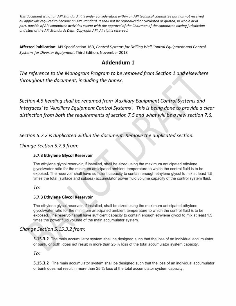
The reference to the Monogram Program to be removed from Section 1 and elsewhere throughout the document, including the Annex.
Section 4.5 heading shall be renamed from ‘Auxiliary Equipment Control Systems and Interfaces’ to ‘Auxiliary Equipment Control Systems’. This is being done to provide a clear distinction from both the requirements of section 7.5 and what will be a new section 7.6.
Section 5.7.2 is duplicated within the document. Remove the duplicated section.
Change Section 5.7.3 from:
5.7.3 Ethylene Glycol Reservoir
The ethylene glycol reservoir, if installed, shall be sized using the maximum anticipated ethylene glycol/water ratio for the minimum anticipated ambient temperature to which the control fluid is to be exposed. The reservoir shall have sufficient capacity to contain enough ethylene glycol to mix at least 1.5 times the total (surface and subsea) accumulator power fluid volume capacity of the control system fluid.
To:
5.7.3 Ethylene Glycol Reservoir
The ethylene glycol reservoir, if installed, shall be sized using the maximum anticipated ethylene glycol/water ratio for the minimum anticipated ambient temperature to which the control fluid is to be exposed. The reservoir shall have sufficient capacity to contain enough ethylene glycol to mix at least 1.5 times the power fluid volume of the main accumulator system.
Change Section 5.15.3.2 from:
5.15.3.2 The main accumulator system shall be designed such that the loss of an individual accumulator or bank, or both, does not result in more than 25 % loss of the total accumulator system capacity.
To:
5.15.3.2 The main accumulator system shall be designed such that the loss of an individual accumulator or bank does not result in more than 25 % loss of the total accumulator system capacity.
This document is not an API Standard; it is under consideration within an API technical committee but has not received all approvals required to become an API Standard. It shall not be reproduced or circulated or quoted, in whole or in part, outside of API committee activities except with the approval of the Chairman of the committee having jurisdiction and staff of the API Standards Dept. Copyright API. All rights reserved.
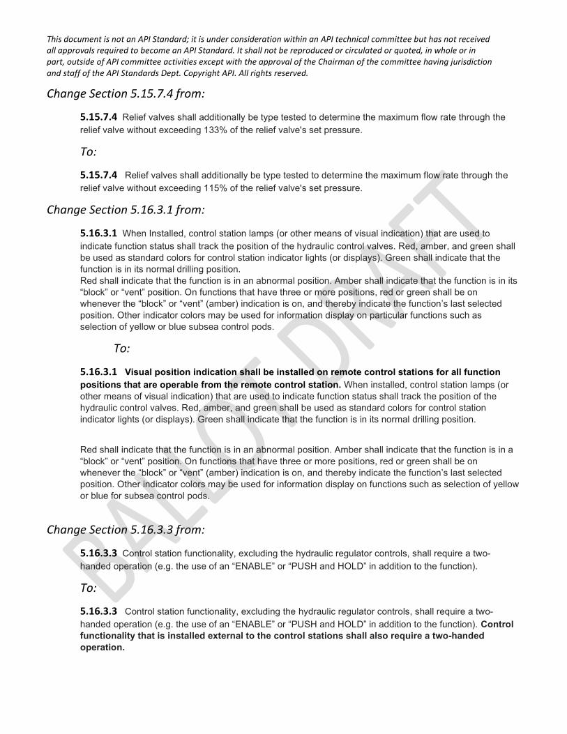
Change Section 5.15.7.4 from:
5.15.7.4 Relief valves shall additionally be type tested to determine the maximum flow rate through the relief valve without exceeding 133% of the relief valve's set pressure.
To:
5.15.7.4 Relief valves shall additionally be type tested to determine the maximum flow rate through the relief valve without exceeding 115% of the relief valve's set pressure.
Change Section 5.16.3.1 from:
5.16.3.1 When Installed, control station lamps (or other means of visual indication) that are used to indicate function status shall track the position of the hydraulic control valves. Red, amber, and green shall be used as standard colors for control station indicator lights (or displays). Green shall indicate that the function is in its normal drilling position. Red shall indicate that the function is in an abnormal position. Amber shall indicate that the function is in its “block” or “vent” position. On functions that have three or more positions, red or green shall be on whenever the “block” or “vent” (amber) indication is on, and thereby indicate the function’s last selected position. Other indicator colors may be used for information display on particular functions such as selection of yellow or blue subsea control pods.
To:
5.16.3.1 Visual position indication shall be installed on remote control stations for all function positions that are operable from the remote control station. When installed, control station lamps (or other means of visual indication) that are used to indicate function status shall track the position of the hydraulic control valves. Red, amber, and green shall be used as standard colors for control station indicator lights (or displays). Green shall indicate that the function is in its normal drilling position.
Red shall indicate that the function is in an abnormal position. Amber shall indicate that the function is in a “block” or “vent” position. On functions that have three or more positions, red or green shall be on whenever the “block” or “vent” (amber) indication is on, and thereby indicate the function’s last selected position. Other indicator colors may be used for information display on functions such as selection of yellow or blue for subsea control pods.
Change Section 5.16.3.3 from:
5.16.3.3 Control station functionality, excluding the hydraulic regulator controls, shall require a two-handed operation (e.g. the use of an “ENABLE” or “PUSH and HOLD” in addition to the function).
To:
5.16.3.3 Control station functionality, excluding the hydraulic regulator controls, shall require a two-handed operation (e.g. the use of an “ENABLE” or “PUSH and HOLD” in addition to the function). Control functionality that is installed external to the control stations shall also require a two-handed operation.
This document is not an API Standard; it is under consideration within an API technical committee but has not received all approvals required to become an API Standard. It shall not be reproduced or circulated or quoted, in whole or in part, outside of API committee activities except with the approval of the Chairman of the committee having jurisdiction and staff of the API Standards Dept. Copyright API. All rights reserved.
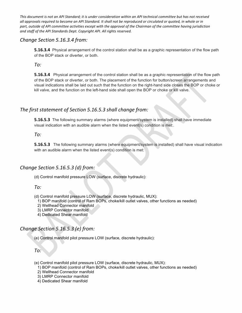
Change Section 5.16.3.4 from:
5.16.3.4 Physical arrangement of the control station shall be as a graphic representation of the flow path of the BOP stack or diverter, or both.
To:
5.16.3.4 Physical arrangement of the control station shall be as a graphic representation of the flow path of the BOP stack or diverter, or both. The placement of the function for button/screen arrangements and visual indications shall be laid out such that the function on the right-hand side closes the BOP or choke or kill valve, and the function on the left-hand side shall open the BOP or choke or kill valve.
The first statement of Section 5.16.5.3 shall change from:
5.16.5.3 The following summary alarms (where equipment/system is installed) shall have immediate visual indication with an audible alarm when the listed event(s) condition is met:.
To:
5.16.5.3 The following summary alarms (where equipment/system is installed) shall have visual indication with an audible alarm when the listed event(s) condition is met:
Change Section 5.16.5.3 (d) from:
(d) Control manifold pressure LOW (surface, discrete hydraulic):
To:
(d) Control manifold pressure LOW (surface, discrete hydraulic, MUX): 1) BOP manifold (control of Ram BOPs, choke/kill outlet valves, other functions as needed) 2) Wellhead Connector manifold 3) LMRP Connector manifold 4) Dedicated Shear manifold
Change Section 5.16.5.3 (e) from:
(e) Control manifold pilot pressure LOW (surface, discrete hydraulic):
To: (e) Control manifold pilot pressure LOW (surface, discrete hydraulic, MUX):
1) BOP manifold (control of Ram BOPs, choke/kill outlet valves, other functions as needed) 2) Wellhead Connector manifold 3) LMRP Connector manifold 4) Dedicated Shear manifold
This document is not an API Standard; it is under consideration within an API technical committee but has not received all approvals required to become an API Standard. It shall not be reproduced or circulated or quoted, in whole or in part, outside of API committee activities except with the approval of the Chairman of the committee having jurisdiction and staff of the API Standards Dept. Copyright API. All rights reserved.
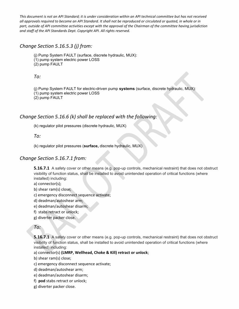
Change Section 5.16.5.3 (j) from:
(j) Pump System FAULT (surface, discrete hydraulic, MUX): (1) pump system electric power LOSS (2) pump FAULT
To:
(j) Pump System FAULT for electric-driven pump systems (surface, discrete hydraulic, MUX): (1) pump system electric power LOSS (2) pump FAULT
Change Section 5.16.6 (k) shall be replaced with the following:
(k) regulator pilot pressures (discrete hydraulic, MUX)
To:
(k) regulator pilot pressures (surface, discrete hydraulic, MUX)
Change Section 5.16.7.1 from:
5.16.7.1 A safety cover or other means (e.g. pop-up controls, mechanical restraint) that does not obstruct visibility of function status, shall be installed to avoid unintended operation of critical functions (where installed) including: a) connector(s); b) shear ram(s) close; c) emergency disconnect sequence activate; d) deadman/autoshear arm; e) deadman/autoshear disarm; f) stabs retract or unlock; g) diverter packer close.
To:
5.16.7.1 A safety cover or other means (e.g. pop-up controls, mechanical restraint) that does not obstruct visibility of function status, shall be installed to avoid unintended operation of critical functions (where installed) including: a) connector(s) (LMRP, Wellhead, Choke & Kill) retract or unlock; b) shear ram(s) close; c) emergency disconnect sequence activate; d) deadman/autoshear arm; e) deadman/autoshear disarm; f) pod stabs retract or unlock; g) diverter packer close.
This document is not an API Standard; it is under consideration within an API technical committee but has not received all approvals required to become an API Standard. It shall not be reproduced or circulated or quoted, in whole or in part, outside of API committee activities except with the approval of the Chairman of the committee having jurisdiction and staff of the API Standards Dept. Copyright API. All rights reserved.
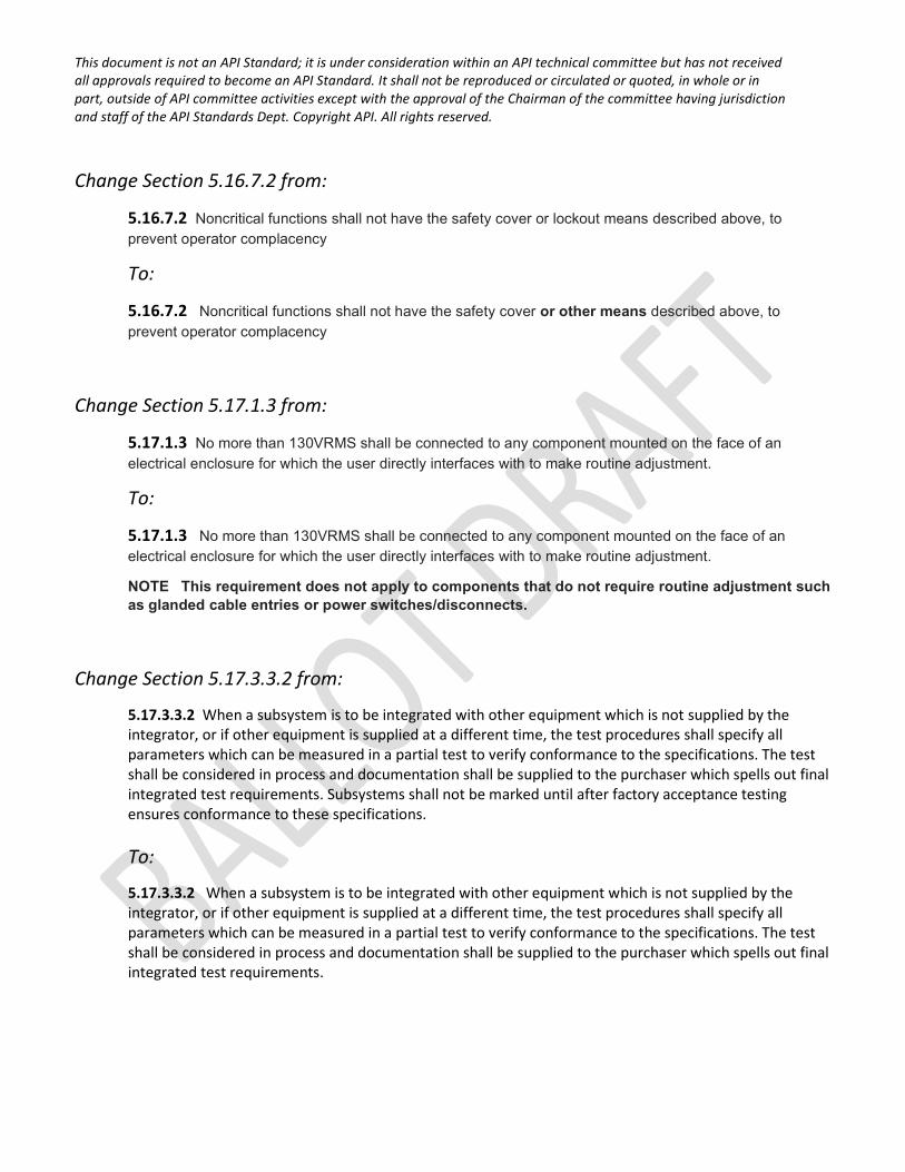
Change Section 5.16.7.2 from:
5.16.7.2 Noncritical functions shall not have the safety cover or lockout means described above, to prevent operator complacency
To:
5.16.7.2 Noncritical functions shall not have the safety cover or other means described above, to prevent operator complacency
Change Section 5.17.1.3 from:
5.17.1.3 No more than 130VRMS shall be connected to any component mounted on the face of an electrical enclosure for which the user directly interfaces with to make routine adjustment.
To:
5.17.1.3 No more than 130VRMS shall be connected to any component mounted on the face of an electrical enclosure for which the user directly interfaces with to make routine adjustment.
NOTE This requirement does not apply to components that do not require routine adjustment such as glanded cable entries or power switches/disconnects.
Change Section 5.17.3.3.2 from:
5.17.3.3.2 When a subsystem is to be integrated with other equipment which is not supplied by the integrator, or if other equipment is supplied at a different time, the test procedures shall specify all parameters which can be measured in a partial test to verify conformance to the specifications. The test shall be considered in process and documentation shall be supplied to the purchaser which spells out final integrated test requirements. Subsystems shall not be marked until after factory acceptance testing ensures conformance to these specifications.
To:
5.17.3.3.2 When a subsystem is to be integrated with other equipment which is not supplied by the integrator, or if other equipment is supplied at a different time, the test procedures shall specify all parameters which can be measured in a partial test to verify conformance to the specifications. The test shall be considered in process and documentation shall be supplied to the purchaser which spells out final integrated test requirements.
This document is not an API Standard; it is under consideration within an API technical committee but has not received all approvals required to become an API Standard. It shall not be reproduced or circulated or quoted, in whole or in part, outside of API committee activities except with the approval of the Chairman of the committee having jurisdiction and staff of the API Standards Dept. Copyright API. All rights reserved.
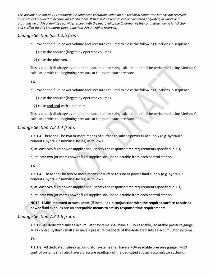
Change Section 6.5.1.2.b from:
b) Provide the fluid power volume and pressure required to close the following functions in sequence:
1) close the annular (largest by operator volume)
2) close the pipe ram
This is a quick discharge event and the accumulator sizing calculations shall be performed using Method C, calculated with the beginning pressure at the pump start pressure.
To:
b) Provide the fluid power volume and pressure required to close the following functions in sequence:
1) close the annular (largest by operator volume)
2) close and seal with a pipe ram
This is a quick discharge event and the accumulator sizing calculations shall be performed using Method C, calculated with the beginning pressure at the pump start pressure.
Change Section 7.2.1.4 from:
7.2.1.4 There shall be two or more means of surface to subsea power fluid supply (e.g. hydraulic conduits, hydraulic umbilical hoses) as follows:
a) at least two fluid power supplies shall satisfy the response time requirements specified in 7.1;
b) at least two (or more) power fluid supplies shall be selectable from each control station.
To:
7.2.1.4 There shall be two or more means of surface to subsea power fluid supply (e.g. hydraulic conduits, hydraulic umbilical hoses) as follows:
a) at least two fluid power supplies shall satisfy the response time requirements specified in 7.1;
b) at least two (or more) power fluid supplies shall be selectable from each control station.
NOTE LMRP-mounted accumulators (if installed) in conjunction with the required surface to subsea power fluid supplies are an acceptable means to satisfy response time requirements.
Change Section 7.3.1.8 from:
7.3.1.8 All dedicated subsea accumulator systems shall have a ROV readable, isolatable pressure gauge. MUX control systems shall also have a pressure readback of the dedicated subsea accumulator systems.
To:
7.3.1.8 All dedicated subsea accumulator systems shall have a ROV readable pressure gauge. MUX control systems shall also have a pressure readback of the dedicated subsea accumulator systems.
This document is not an API Standard; it is under consideration within an API technical committee but has not received all approvals required to become an API Standard. It shall not be reproduced or circulated or quoted, in whole or in part, outside of API committee activities except with the approval of the Chairman of the committee having jurisdiction and staff of the API Standards Dept. Copyright API. All rights reserved.
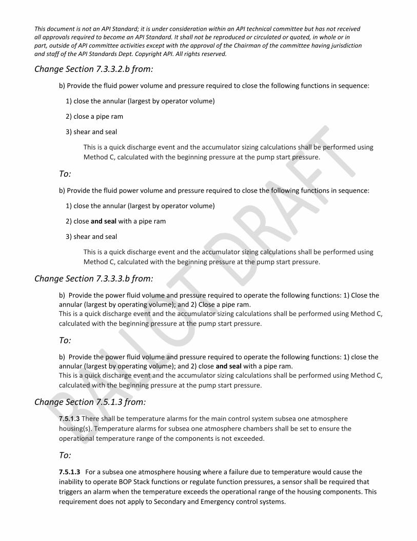
Change Section 7.3.3.2.b from:
b) Provide the fluid power volume and pressure required to close the following functions in sequence:
1) close the annular (largest by operator volume)
2) close a pipe ram
3) shear and seal
This is a quick discharge event and the accumulator sizing calculations shall be performed using Method C, calculated with the beginning pressure at the pump start pressure.
To:
b) Provide the fluid power volume and pressure required to close the following functions in sequence:
1) close the annular (largest by operator volume)
2) close and seal with a pipe ram
3) shear and seal
This is a quick discharge event and the accumulator sizing calculations shall be performed using Method C, calculated with the beginning pressure at the pump start pressure.
Change Section 7.3.3.3.b from:
b) Provide the power fluid volume and pressure required to operate the following functions: 1) Close the annular (largest by operating volume); and 2) Close a pipe ram. This is a quick discharge event and the accumulator sizing calculations shall be performed using Method C, calculated with the beginning pressure at the pump start pressure.
To:
b) Provide the power fluid volume and pressure required to operate the following functions: 1) close the annular (largest by operating volume); and 2) close and seal with a pipe ram. This is a quick discharge event and the accumulator sizing calculations shall be performed using Method C, calculated with the beginning pressure at the pump start pressure.
Change Section 7.5.1.3 from:
7.5.1.3 There shall be temperature alarms for the main control system subsea one atmosphere housing(s). Temperature alarms for subsea one atmosphere chambers shall be set to ensure the operational temperature range of the components is not exceeded.
To:
7.5.1.3 For a subsea one atmosphere housing where a failure due to temperature would cause the inability to operate BOP Stack functions or regulate function pressures, a sensor shall be required that triggers an alarm when the temperature exceeds the operational range of the housing components. This requirement does not apply to Secondary and Emergency control systems.
This document is not an API Standard; it is under consideration within an API technical committee but has not received all approvals required to become an API Standard. It shall not be reproduced or circulated or quoted, in whole or in part, outside of API committee activities except with the approval of the Chairman of the committee having jurisdiction and staff of the API Standards Dept. Copyright API. All rights reserved.
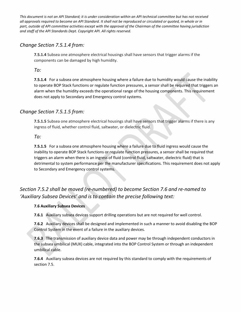
Change Section 7.5.1.4 from:
7.5.1.4 Subsea one atmosphere electrical housings shall have sensors that trigger alarms if the components can be damaged by high humidity.
To:
7.5.1.4 For a subsea one atmosphere housing where a failure due to humidity would cause the inability to operate BOP Stack functions or regulate function pressures, a sensor shall be required that triggers an alarm when the humidity exceeds the operational range of the housing components. This requirement does not apply to Secondary and Emergency control systems.
Change Section 7.5.1.5 from:
7.5.1.5 Subsea one atmosphere electrical housings shall have sensors that trigger alarms if there is any ingress of fluid, whether control fluid, saltwater, or dielectric fluid.
To:
7.5.1.5 For a subsea one atmosphere housing where a failure due to fluid ingress would cause the inability to operate BOP Stack functions or regulate function pressures, a sensor shall be required that triggers an alarm when there is an ingress of fluid (control fluid, saltwater, dielectric fluid) that is detrimental to system performance per the manufacturer specifications. This requirement does not apply to Secondary and Emergency control systems.
Section 7.5.2 shall be moved (re-numbered) to become Section 7.6 and re-named to ‘Auxiliary Subsea Devices’ and is to contain the precise following text:
7.6 Auxiliary Subsea Devices
7.6.1 Auxiliary subsea devices support drilling operations but are not required for well control.
7.6.2 Auxiliary devices shall be designed and implemented in such a manner to avoid disabling the BOP Control System in the event of a failure in the auxiliary devices.
7.6.3 The transmission of auxiliary device data and power may be through independent conductors in the subsea umbilical (MUX) cable, integrated into the BOP Control System or through an independent umbilical cable.
7.6.4 Auxiliary subsea devices are not required by this standard to comply with the requirements of section 7.5.
This document is not an API Standard; it is under consideration within an API technical committee but has not received all approvals required to become an API Standard. It shall not be reproduced or circulated or quoted, in whole or in part, outside of API committee activities except with the approval of the Chairman of the committee having jurisdiction and staff of the API Standards Dept. Copyright API. All rights reserved.
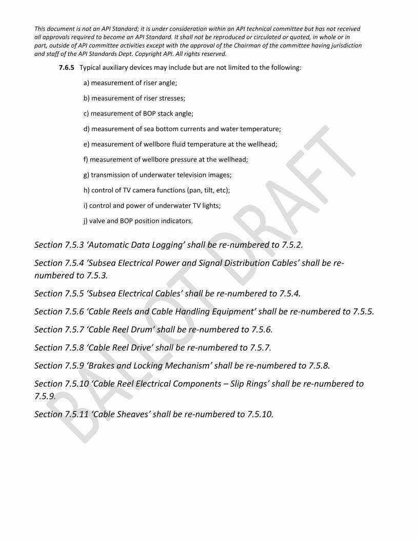
7.6.5 Typical auxiliary devices may include but are not limited to the following:
a) measurement of riser angle;
b) measurement of riser stresses;
c) measurement of BOP stack angle;
d) measurement of sea bottom currents and water temperature;
e) measurement of wellbore fluid temperature at the wellhead;
f) measurement of wellbore pressure at the wellhead;
g) transmission of underwater television images;
h) control of TV camera functions (pan, tilt, etc);
i) control and power of underwater TV lights;
j) valve and BOP position indicators.
Section 7.5.3 ‘Automatic Data Logging’ shall be re-numbered to 7.5.2.
Section 7.5.4 ‘Subsea Electrical Power and Signal Distribution Cables’ shall be re-numbered to 7.5.3.
Section 7.5.5 ‘Subsea Electrical Cables’ shall be re-numbered to 7.5.4.
Section 7.5.6 ‘Cable Reels and Cable Handling Equipment’ shall be re-numbered to 7.5.5.
Section 7.5.7 ‘Cable Reel Drum’ shall be re-numbered to 7.5.6.
Section 7.5.8 ‘Cable Reel Drive’ shall be re-numbered to 7.5.7.
Section 7.5.9 ‘Brakes and Locking Mechanism’ shall be re-numbered to 7.5.8.
Section 7.5.10 ‘Cable Reel Electrical Components – Slip Rings’ shall be re-numbered to 7.5.9.
Section 7.5.11 ‘Cable Sheaves’ shall be re-numbered to 7.5.10.
This document is not an API Standard; it is under consideration within an API technical committee but has not received all approvals required to become an API Standard. It shall not be reproduced or circulated or quoted, in whole or in part, outside of API committee activities except with the approval of the Chairman of the committee having jurisdiction and staff of the API Standards Dept. Copyright API. All rights reserved.
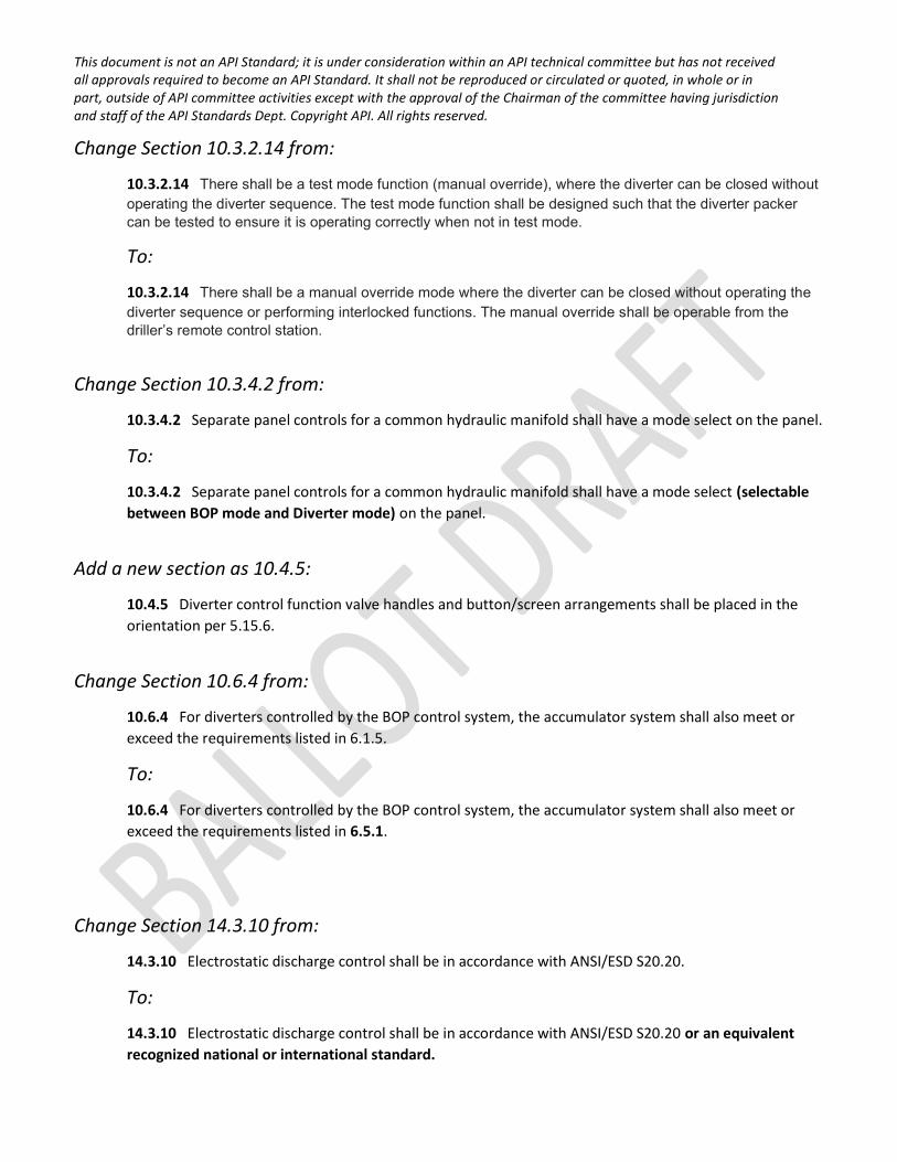
Change Section 10.3.2.14 from:
10.3.2.14 There shall be a test mode function (manual override), where the diverter can be closed without operating the diverter sequence. The test mode function shall be designed such that the diverter packer can be tested to ensure it is operating correctly when not in test mode.
To:
10.3.2.14 There shall be a manual override mode where the diverter can be closed without operating the diverter sequence or performing interlocked functions. The manual override shall be operable from the driller’s remote control station.
Change Section 10.3.4.2 from:
10.3.4.2 Separate panel controls for a common hydraulic manifold shall have a mode select on the panel.
To:
10.3.4.2 Separate panel controls for a common hydraulic manifold shall have a mode select (selectable between BOP mode and Diverter mode) on the panel.
Add a new section as 10.4.5:
10.4.5 Diverter control function valve handles and button/screen arrangements shall be placed in the orientation per 5.15.6.
Change Section 10.6.4 from:
10.6.4 For diverters controlled by the BOP control system, the accumulator system shall also meet or exceed the requirements listed in 6.1.5.
To:
10.6.4 For diverters controlled by the BOP control system, the accumulator system shall also meet or exceed the requirements listed in 6.5.1.
Change Section 14.3.10 from:
14.3.10 Electrostatic discharge control shall be in accordance with ANSI/ESD S20.20.
To:
14.3.10 Electrostatic discharge control shall be in accordance with ANSI/ESD S20.20 or an equivalent recognized national or international standard.
This document is not an API Standard; it is under consideration within an API technical committee but has not received all approvals required to become an API Standard. It shall not be reproduced or circulated or quoted, in whole or in part, outside of API committee activities except with the approval of the Chairman of the committee having jurisdiction and staff of the API Standards Dept. Copyright API. All rights reserved.
Change Section 14.3.11 from:
14.3.11 Ground conductors shall be sized in accordance with NFPA 70.
To:
14.3.11 Ground conductors shall be sized in accordance with NFPA 70 or an equivalent recognized national or international standard.
Change the first line of Section 14.4.2 from:
Control Pot equipment shall conform to the following:
To:
Control Pod equipment shall conform to the following:
Change Section 14.8.5 from:
14.8.5 A certificate of the relief valve setting and operation shall be provided indicating the set point and the pressure at which the relief valve re-seats in accordance with 5.15.7.
To:
14.8.5 A certificate of the relief valve setting and operation shall be provided indicating the set point and the pressure at which the relief valve re-seats.
Annex B shall be renamed to Annex A.
B.1 shall be renamed to A.1
Annex C shall be renamed to Annex B.
C.1 through C.4 shall be renamed to B.1 through B.4, respectively.
Annex D shall be renamed to Annex C.
- D.1 through D.18 shall be renamed to C.1 through C.18, respectively. References to Annex D within shall also be changed to Annex C.
- Figures D.1 through D.13 shall be renamed to Figures C.1 through C.13.
The remaining Addendum updates are related to the Accumulator Sizing Examples (Examples being updated: 2, 3, 5, 6, 7, 8, and 12).

This document is not an API Standard; it is under consideration within an API technical committee but has not received all approvals required to become an API Standard. It shall not be reproduced or circulated or quoted, in whole or in part, outside of API committee activities except with the approval of the Chairman of the committee having jurisdiction and staff of the API Standards Dept. Copyright API. All rights reserved.
The content of Table D.1 (to be Table C.1) is being updated to reflect the updated volumes for the related Examples, and shall be replaced with the following:
This document is not an API Standard; it is under consideration within an API technical committee but has not received all approvals required to become an API Standard. It shall not be reproduced or circulated or quoted, in whole or in part, outside of API committee activities except with the approval of the Chairman of the committee having jurisdiction and staff of the API Standards Dept. Copyright API. All rights reserved.
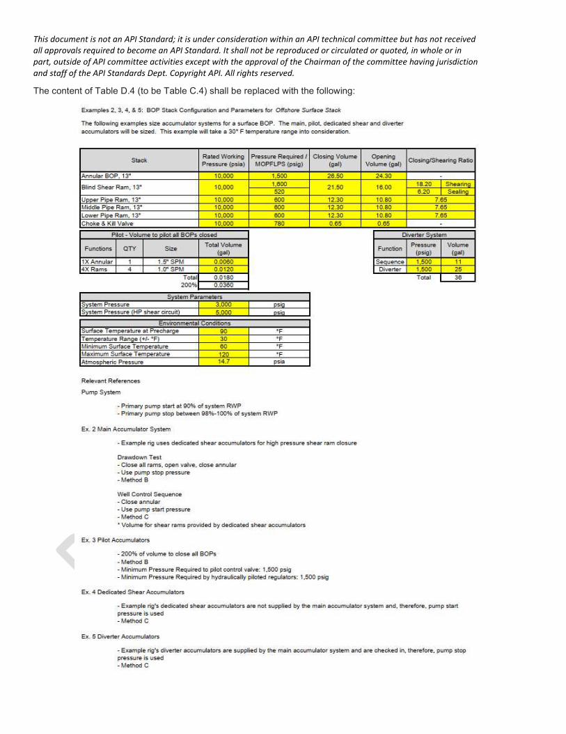
The content of Table D.4 (to be Table C.4) shall be replaced with the following:
This document is not an API Standard; it is under consideration within an API technical committee but has not received all approvals required to become an API Standard. It shall not be reproduced or circulated or quoted, in whole or in part, outside of API committee activities except with the approval of the Chairman of the committee having jurisdiction and staff of the API Standards Dept. Copyright API. All rights reserved.
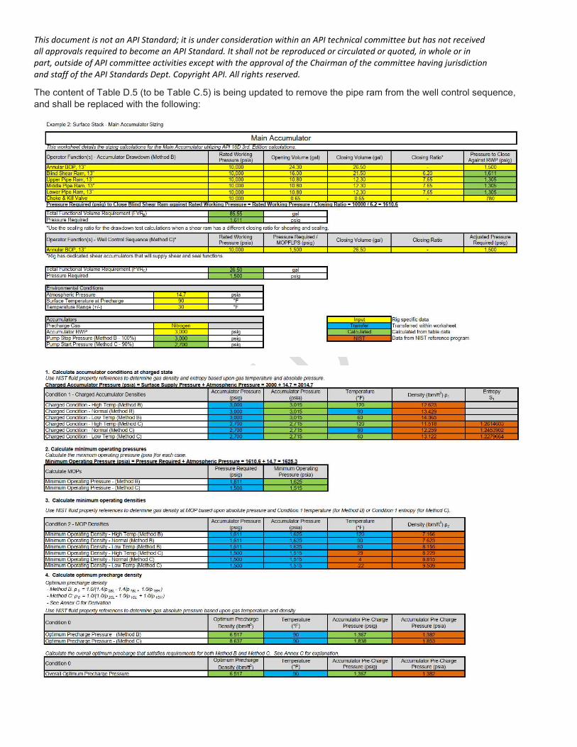
The content of Table D.5 (to be Table C.5) is being updated to remove the pipe ram from the well control sequence, and shall be replaced with the following:
This document is not an API Standard; it is under consideration within an API technical committee but has not received all approvals required to become an API Standard. It shall not be reproduced or circulated or quoted, in whole or in part, outside of API committee activities except with the approval of the Chairman of the committee having jurisdiction and staff of the API Standards Dept. Copyright API. All rights reserved.
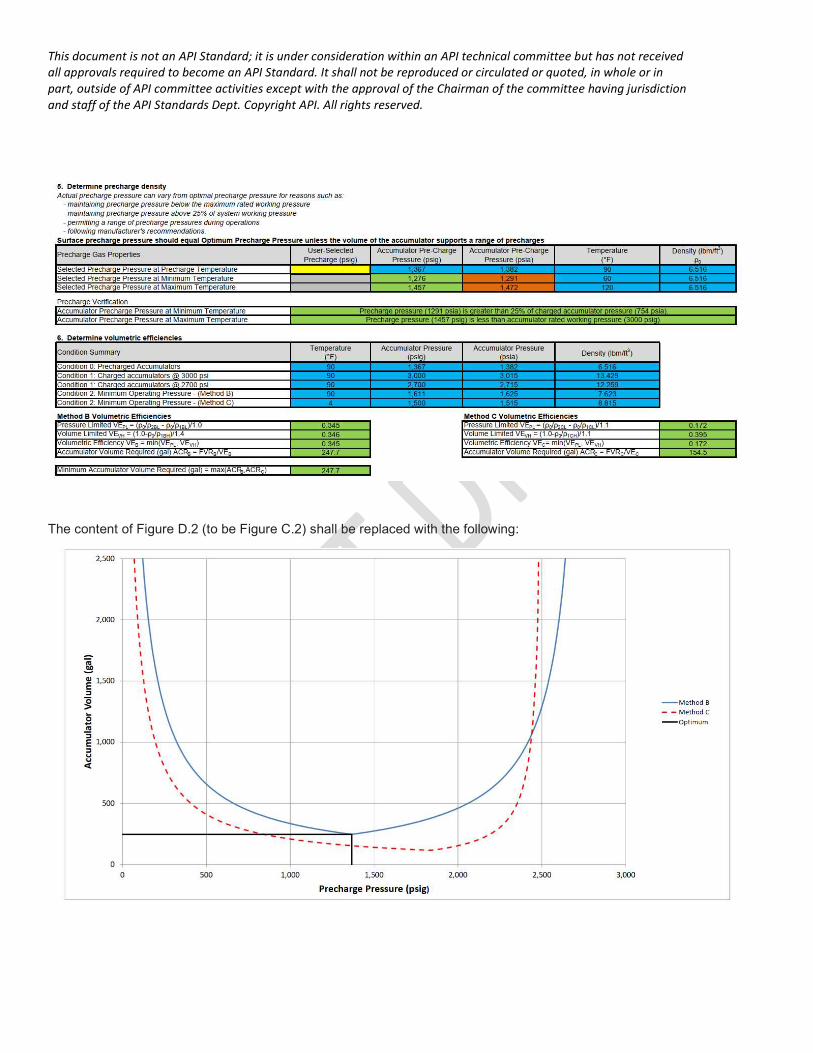
The content of Figure D.2 (to be Figure C.2) shall be replaced with the following:
This document is not an API Standard; it is under consideration within an API technical committee but has not received all approvals required to become an API Standard. It shall not be reproduced or circulated or quoted, in whole or in part, outside of API committee activities except with the approval of the Chairman of the committee having jurisdiction and staff of the API Standards Dept. Copyright API. All rights reserved.
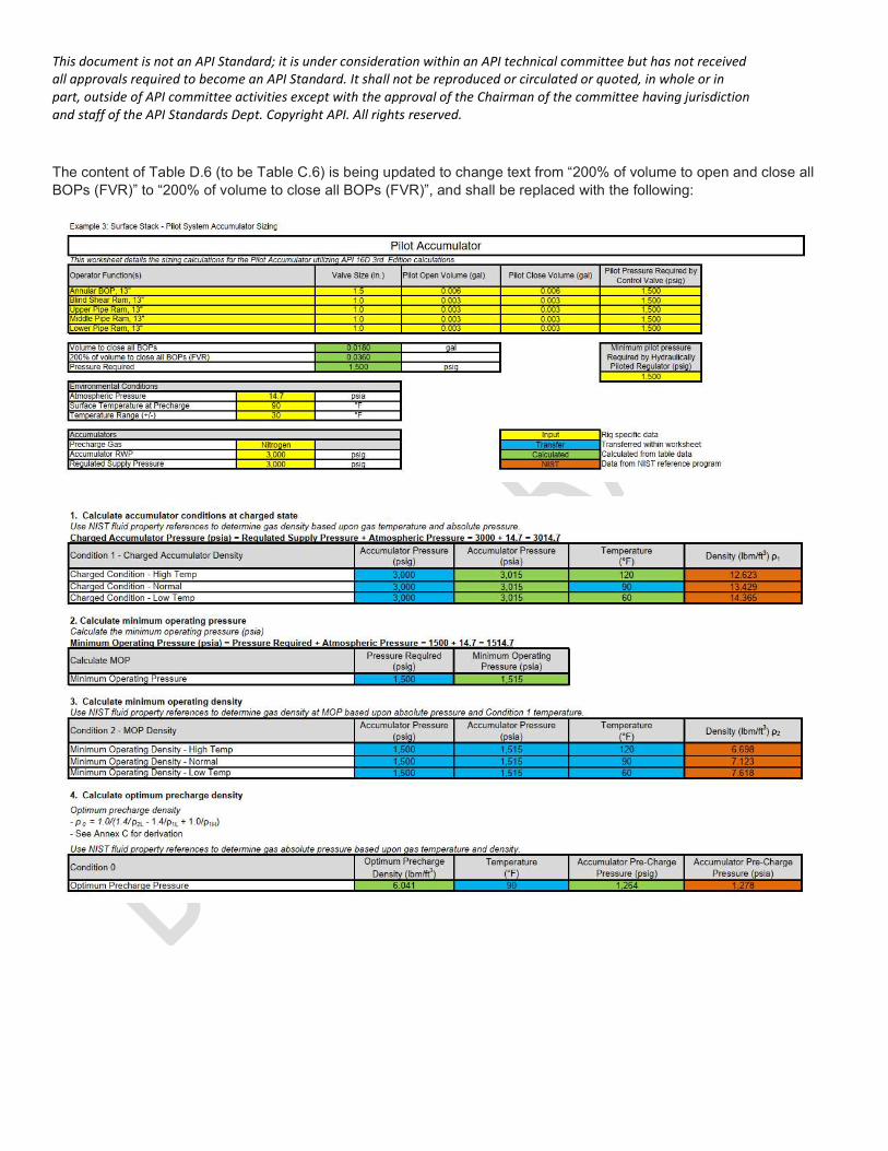
The content of Table D.6 (to be Table C.6) is being updated to change text from “200% of volume to open and close all BOPs (FVR)” to “200% of volume to close all BOPs (FVR)”, and shall be replaced with the following:
This document is not an API Standard; it is under consideration within an API technical committee but has not received all approvals required to become an API Standard. It shall not be reproduced or circulated or quoted, in whole or in part, outside of API committee activities except with the approval of the Chairman of the committee having jurisdiction and staff of the API Standards Dept. Copyright API. All rights reserved.
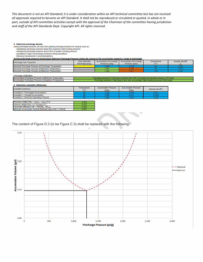
The content of Figure D.3 (to be Figure C.3) shall be replaced with the following:
This document is not an API Standard; it is under consideration within an API technical committee but has not received all approvals required to become an API Standard. It shall not be reproduced or circulated or quoted, in whole or in part, outside of API committee activities except with the approval of the Chairman of the committee having jurisdiction and staff of the API Standards Dept. Copyright API. All rights reserved.
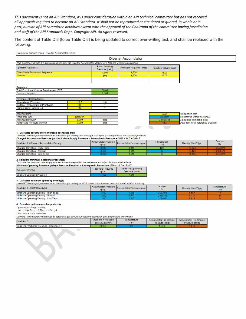
The content of Table D.8 (to be Table C.8) is being updated to correct over-writing text, and shall be replaced with the following:
This document is not an API Standard; it is under consideration within an API technical committee but has not received all approvals required to become an API Standard. It shall not be reproduced or circulated or quoted, in whole or in part, outside of API committee activities except with the approval of the Chairman of the committee having jurisdiction and staff of the API Standards Dept. Copyright API. All rights reserved.
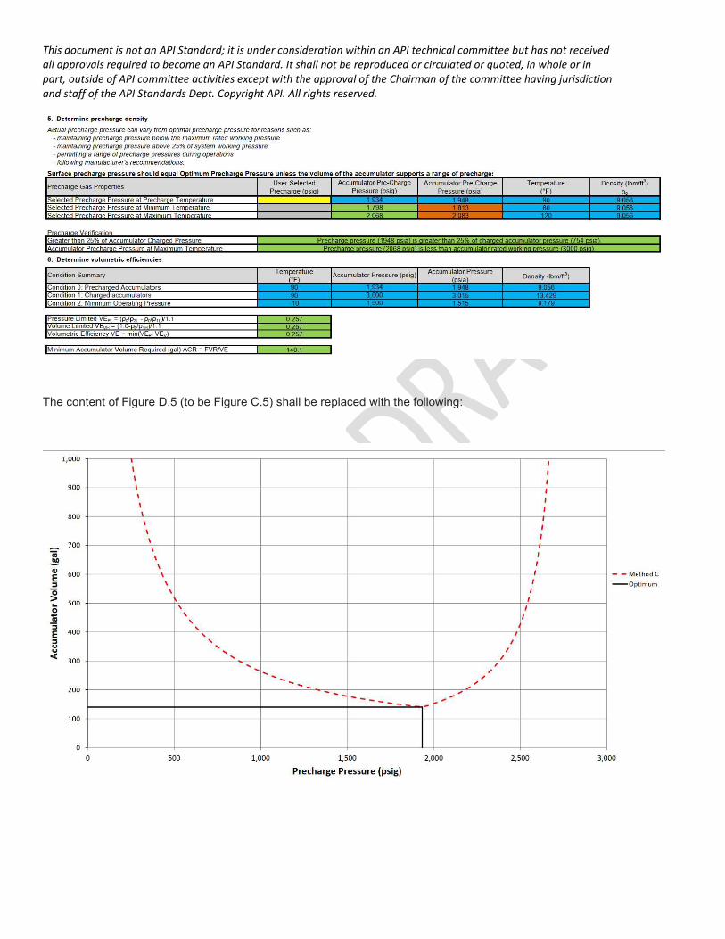
The content of Figure D.5 (to be Figure C.5) shall be replaced with the following:
This document is not an API Standard; it is under consideration within an API technical committee but has not received all approvals required to become an API Standard. It shall not be reproduced or circulated or quoted, in whole or in part, outside of API committee activities except with the approval of the Chairman of the committee having jurisdiction and staff of the API Standards Dept. Copyright API. All rights reserved.
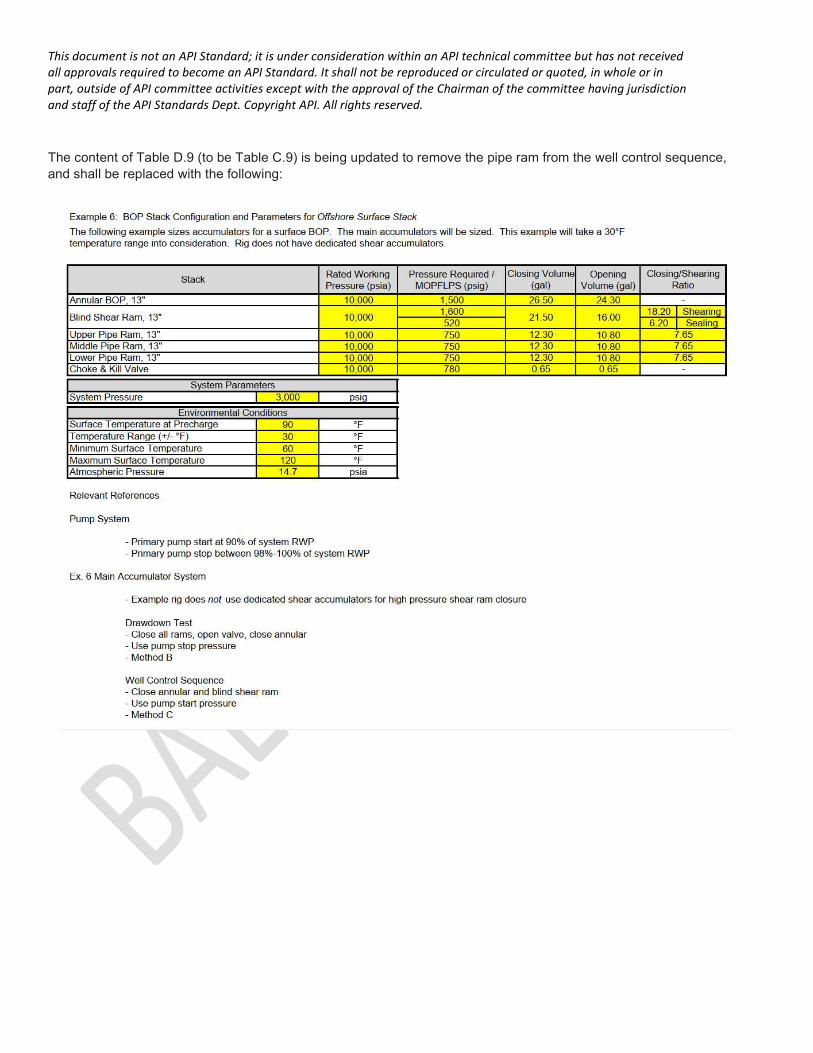
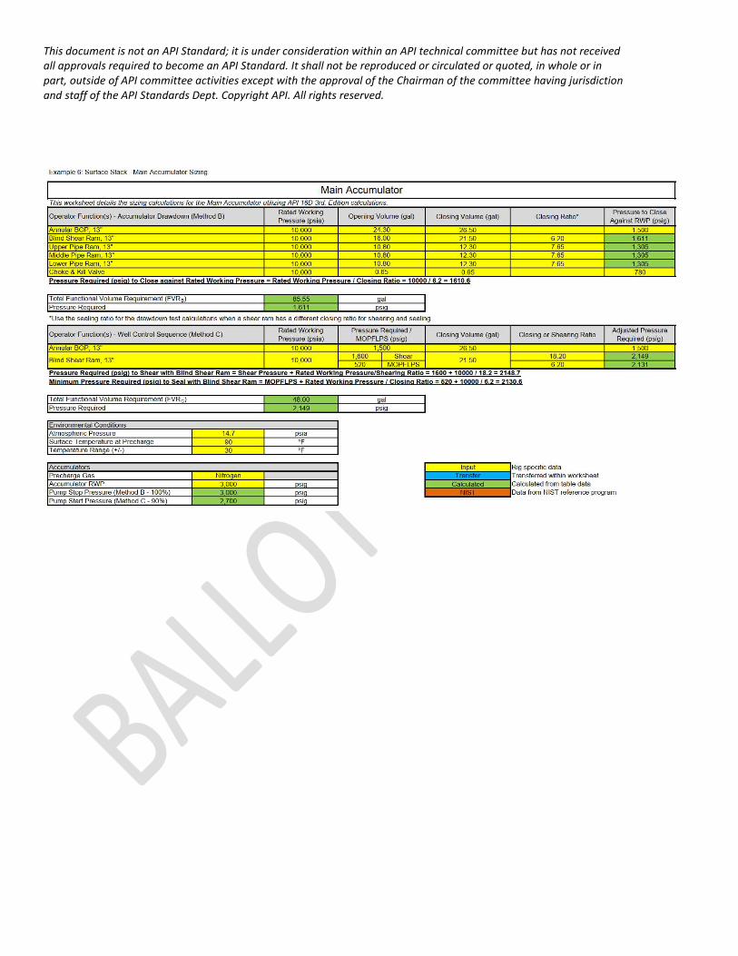
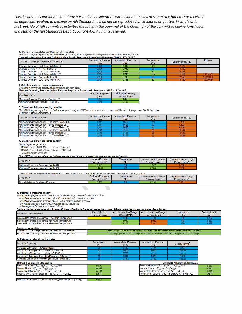
The content of Table D.9 (to be Table C.9) is being updated to remove the pipe ram from the well control sequence, and shall be replaced with the following:
This document is not an API Standard; it is under consideration within an API technical committee but has not received all approvals required to become an API Standard. It shall not be reproduced or circulated or quoted, in whole or in part, outside of API committee activities except with the approval of the Chairman of the committee having jurisdiction and staff of the API Standards Dept. Copyright API. All rights reserved.
This document is not an API Standard; it is under consideration within an API technical committee but has not received all approvals required to become an API Standard. It shall not be reproduced or circulated or quoted, in whole or in part, outside of API committee activities except with the approval of the Chairman of the committee having jurisdiction and staff of the API Standards Dept. Copyright API. All rights reserved.
This document is not an API Standard; it is under consideration within an API technical committee but has not received all approvals required to become an API Standard. It shall not be reproduced or circulated or quoted, in whole or in part, outside of API committee activities except with the approval of the Chairman of the committee having jurisdiction and staff of the API Standards Dept. Copyright API. All rights reserved.
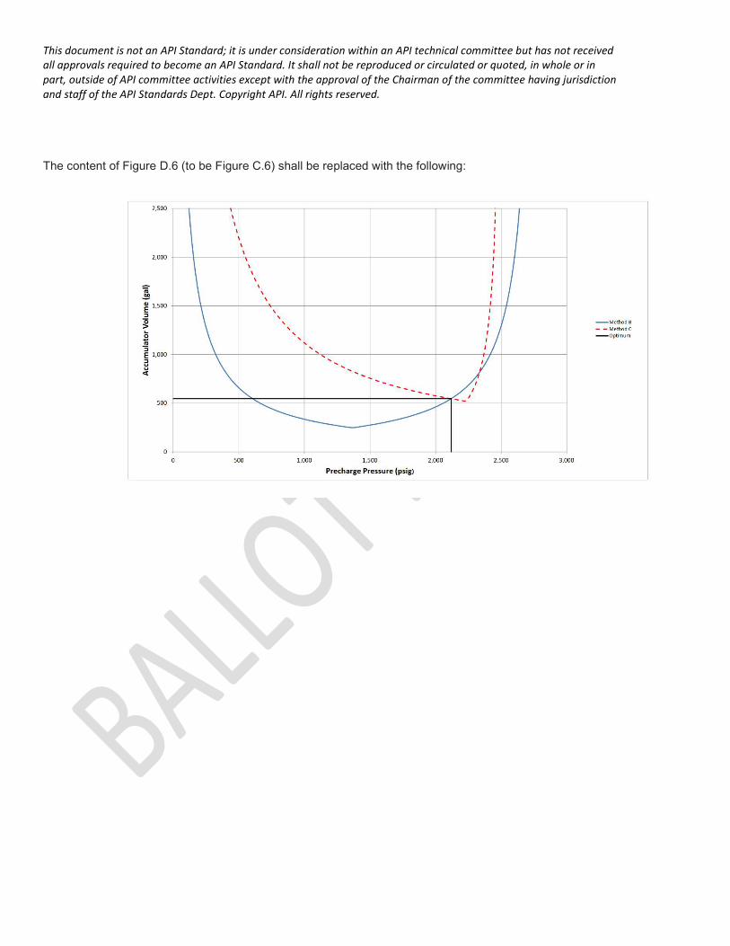
The content of Figure D.6 (to be Figure C.6) shall be replaced with the following:
This document is not an API Standard; it is under consideration within an API technical committee but has not received all approvals required to become an API Standard. It shall not be reproduced or circulated or quoted, in whole or in part, outside of API committee activities except with the approval of the Chairman of the committee having jurisdiction and staff of the API Standards Dept. Copyright API. All rights reserved.
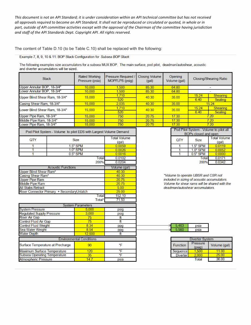
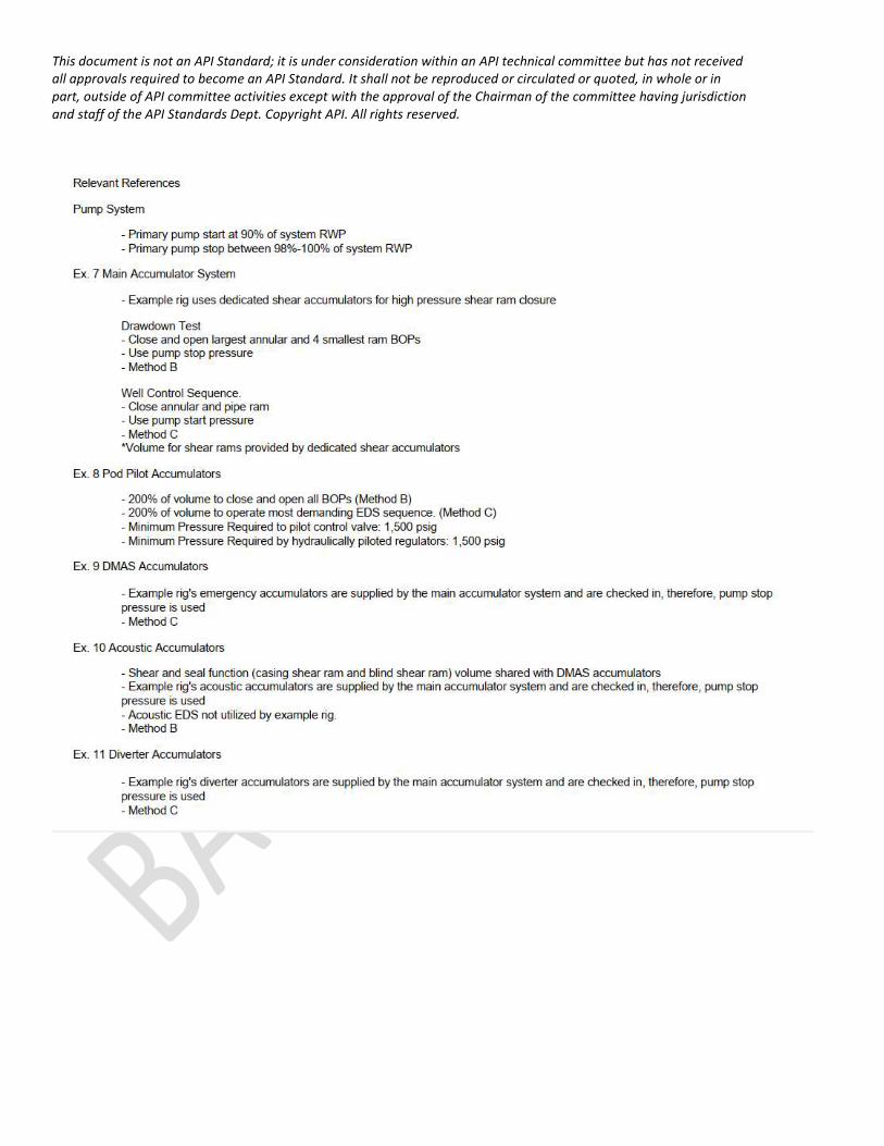
The content of Table D.10 (to be Table C.10) shall be replaced with the following:
This document is not an API Standard; it is under consideration within an API technical committee but has not received all approvals required to become an API Standard. It shall not be reproduced or circulated or quoted, in whole or in part, outside of API committee activities except with the approval of the Chairman of the committee having jurisdiction and staff of the API Standards Dept. Copyright API. All rights reserved.
This document is not an API Standard; it is under consideration within an API technical committee but has not received all approvals required to become an API Standard. It shall not be reproduced or circulated or quoted, in whole or in part, outside of API committee activities except with the approval of the Chairman of the committee having jurisdiction and staff of the API Standards Dept. Copyright API. All rights reserved.
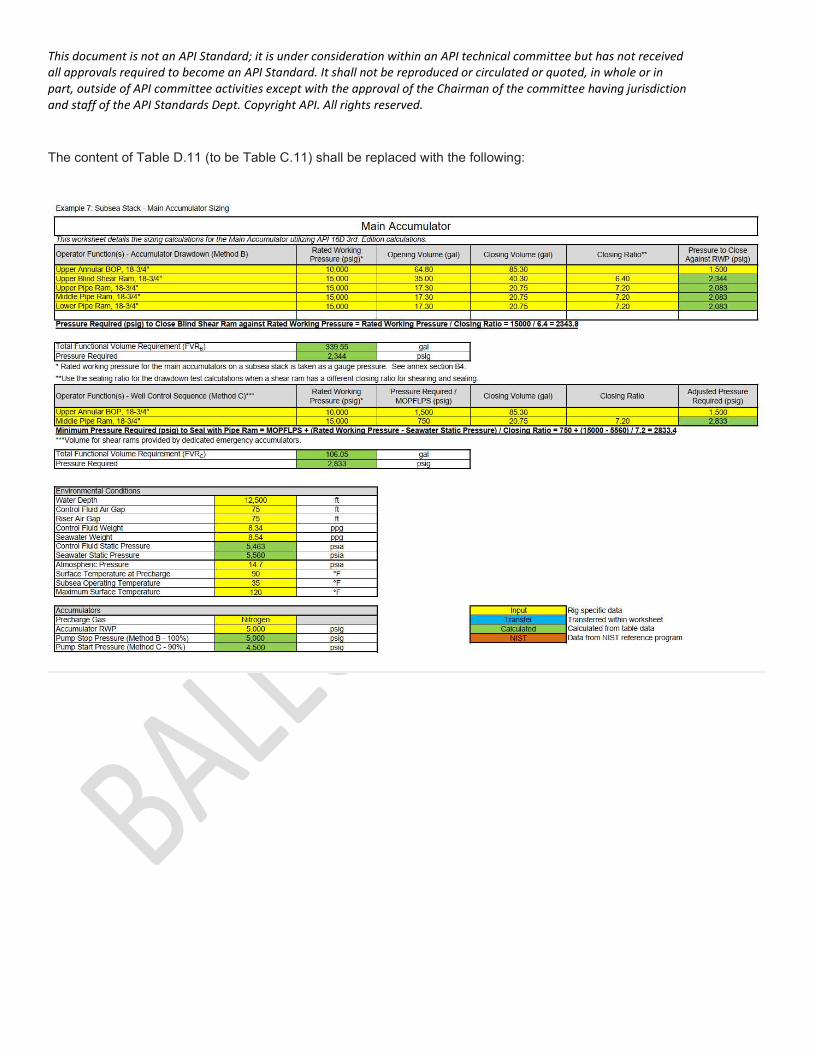
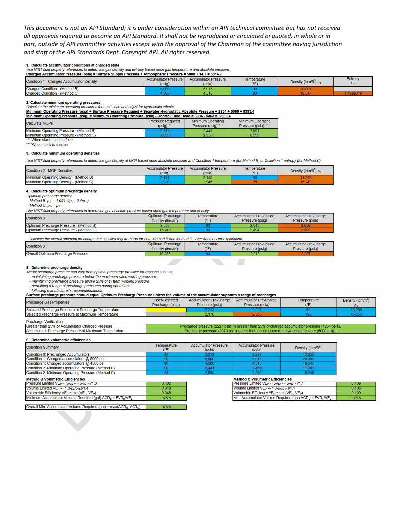
The content of Table D.11 (to be Table C.11) shall be replaced with the following:
This document is not an API Standard; it is under consideration within an API technical committee but has not received all approvals required to become an API Standard. It shall not be reproduced or circulated or quoted, in whole or in part, outside of API committee activities except with the approval of the Chairman of the committee having jurisdiction and staff of the API Standards Dept. Copyright API. All rights reserved.
This document is not an API Standard; it is under consideration within an API technical committee but has not received all approvals required to become an API Standard. It shall not be reproduced or circulated or quoted, in whole or in part, outside of API committee activities except with the approval of the Chairman of the committee having jurisdiction and staff of the API Standards Dept. Copyright API. All rights reserved.
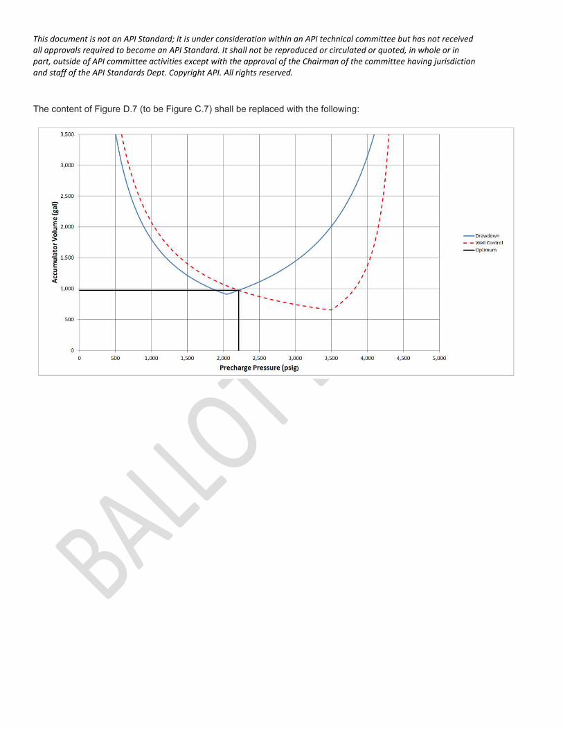
The content of Figure D.7 (to be Figure C.7) shall be replaced with the following:
This document is not an API Standard; it is under consideration within an API technical committee but has not received all approvals required to become an API Standard. It shall not be reproduced or circulated or quoted, in whole or in part, outside of API committee activities except with the approval of the Chairman of the committee having jurisdiction and staff of the API Standards Dept. Copyright API. All rights reserved.
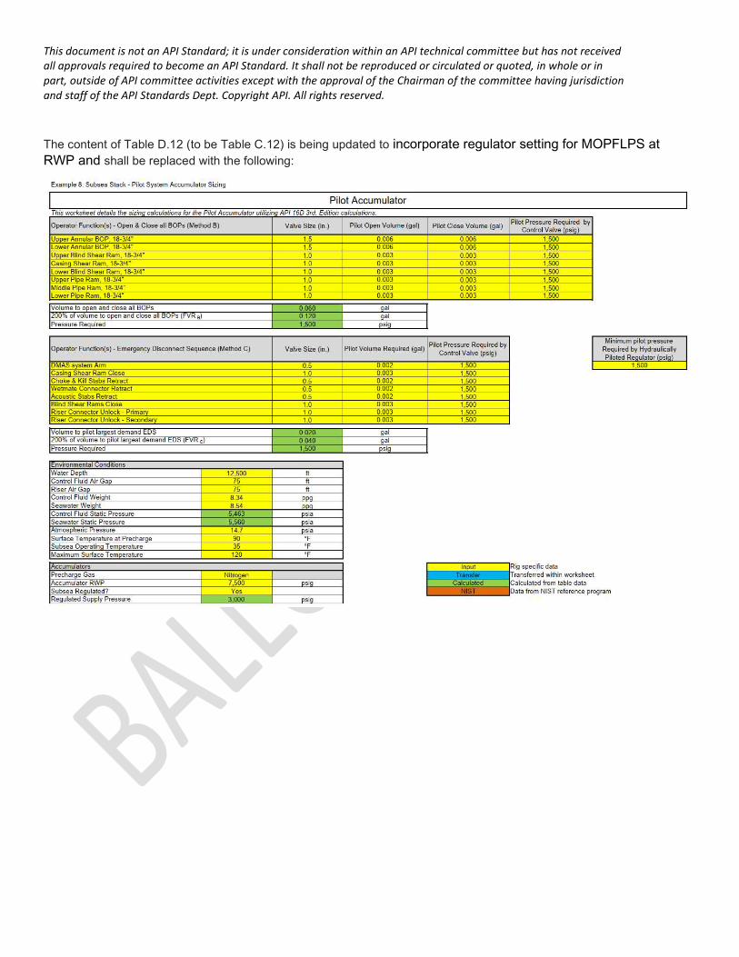
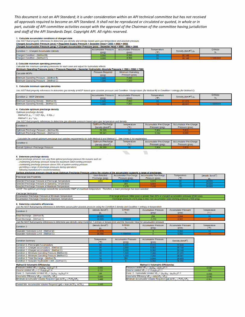
The content of Table D.12 (to be Table C.12) is being updated to incorporate regulator setting for MOPFLPS at RWP and shall be replaced with the following:
This document is not an API Standard; it is under consideration within an API technical committee but has not received all approvals required to become an API Standard. It shall not be reproduced or circulated or quoted, in whole or in part, outside of API committee activities except with the approval of the Chairman of the committee having jurisdiction and staff of the API Standards Dept. Copyright API. All rights reserved.
This document is not an API Standard; it is under consideration within an API technical committee but has not received all approvals required to become an API Standard. It shall not be reproduced or circulated or quoted, in whole or in part, outside of API committee activities except with the approval of the Chairman of the committee having jurisdiction and staff of the API Standards Dept. Copyright API. All rights reserved.
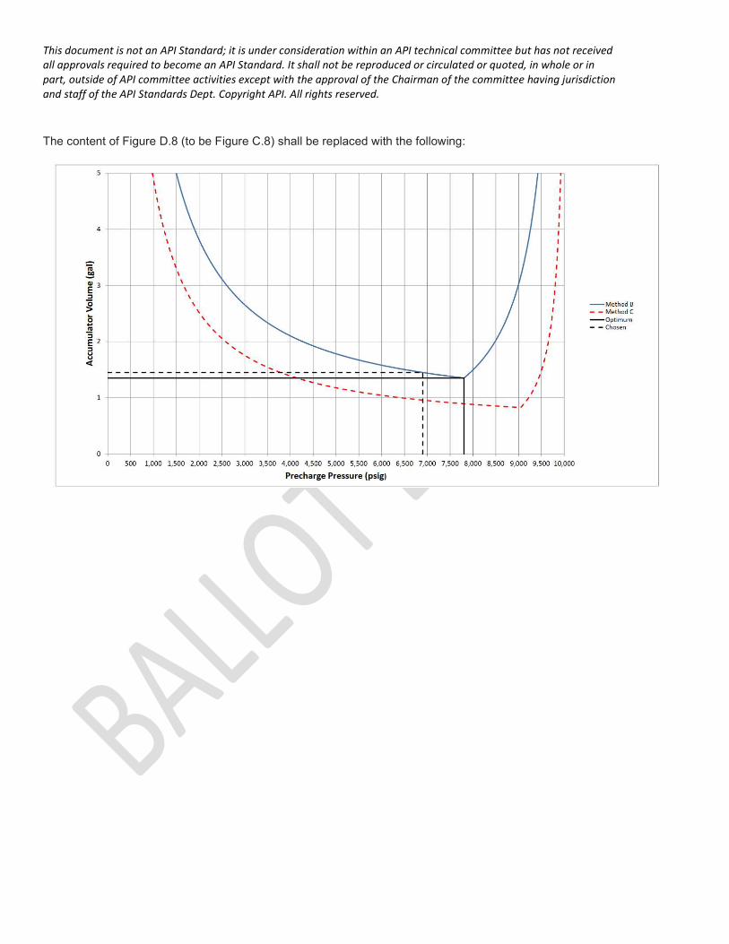
The content of Figure D.8 (to be Figure C.8) shall be replaced with the following:
This document is not an API Standard; it is under consideration within an API technical committee but has not received all approvals required to become an API Standard. It shall not be reproduced or circulated or quoted, in whole or in part, outside of API committee activities except with the approval of the Chairman of the committee having jurisdiction and staff of the API Standards Dept. Copyright API. All rights reserved.
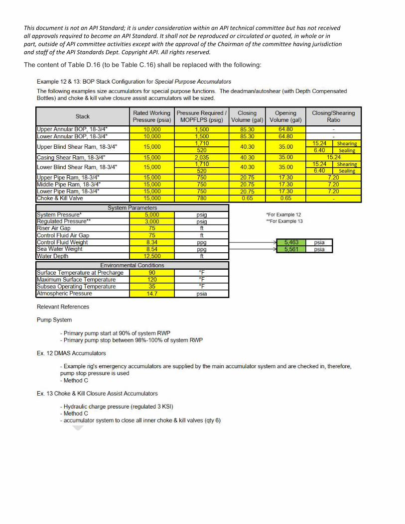
The content of Table D.16 (to be Table C.16) shall be replaced with the following:
This document is not an API Standard; it is under consideration within an API technical committee but has not received all approvals required to become an API Standard. It shall not be reproduced or circulated or quoted, in whole or in part, outside of API committee activities except with the approval of the Chairman of the committee having jurisdiction and staff of the API Standards Dept. Copyright API. All rights reserved.
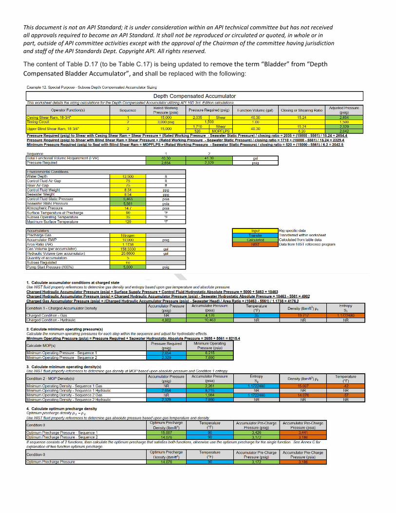
The content of Table D.17 (to be Table C.17) is being updated to remove the term “Bladder” from “Depth Compensated Bladder Accumulator”, and shall be replaced with the following:
This document is not an API Standard; it is under consideration within an API technical committee but has not received all approvals required to become an API Standard. It shall not be reproduced or circulated or quoted, in whole or in part, outside of API committee activities except with the approval of the Chairman of the committee having jurisdiction and staff of the API Standards Dept. Copyright API. All rights reserved.
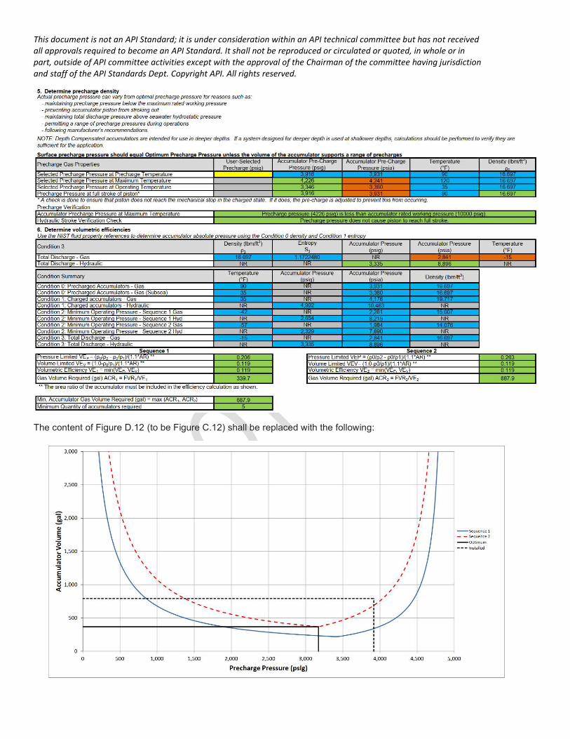
The content of Figure D.12 (to be Figure C.12) shall be replaced with the following: