
Energy saving and dynamic stability of planning hull due to hydrodynamic control of trim angles
14
Maritime Transportation and Exploitation of Ocean and Coastal Resources – Guedes Soares, Garbatov & Fonseca (eds) © 2005 Taylor & Francis Group, London, ISBN 0 415 39036 2 229 1 INTRODUCTION The hydrodynamic characteristics of high-speed plan- ning hulls had provided some design principles and features that make the hull performs safely its func- tion. Planning hulls are high-speed marine crafts that develop dynamic lift effects. However, the dynamic instability is still a critical design problem of such hulls and has different phases and actions on the hull. Por- poising instability is harmful to both the bottom and fore-body structures of planning hulls, where it pro- duces large dynamic impact forces especially, when motions become so severe that the hull is thrown entirely out of the water. To improve the performance of high-speed marine craft, it is required to find the most suitable trim angle providing minimum drag at specific speed. The trim angle, at which the craft is in equilibrium, is not nec- essarily the most suitable angle for minimum resis- tance. Controlling trim angle of the craft is not only required to achieve minimum resistance, but also, to set the craft free from porpoising (longitudinal instability). In order to predict the performance of high-speed marine craft, it is usually required to review some useful research works which have been already pub- lished. The experimental work of Clement, et al., (1963), on the resistance and performance of Series 62 models, has been considered. A very useful and interesting work developed by Savitsky, (1964 & 1976), on the prediction of planning hull performance is also considered. The development of Blount factor, (1975), to modify Savitsky method, (1964), for better predic- tion of Series 62 models’ resistance, is reviewed. Savitsky and Brown, (1976) published formulas for modeling the stern wedge trim flap. They indicate that these devices have become commonplace as methods to control the trim of planning hulls. As they point out, a fixed wedge, while being obviously cheaper and sim- pler, does not provide the capability to minimize the planning hull resistance and fuel consumption when the speed and loading change. Lalangas, (1983) presents the performance data results of 25 m motor yacht showing the effect of fixed trim wedge and shift of weight on the performance of yacht. The important review to the benefit of this present work is provided by the developed work on the improve- ment in performance, especially power saving due to flap installation performed by Gabor Karafiath, (1999), Michael R, (2000), and Cusanelli S, (2001 & 2002). Finding optimum trim angle not a new task, it has begun when Shoemaker, (1934) and Diehl, (1940) Energy saving and dynamic stability of planning hull due to hydrodynamic control of trim angles M.A. Mosaad, M.M. Gaafary & I.A. Amin Department of Naval Arch. & Marine Engineering, Faculty of Engineering, Suez Canal University, Port-Said, Egypt ABSTRACT: To find the most suitable trim angle for a planning hull, as a high-speed marine craft, is not an easy task. The right trim angle yields the best performance of a planning hull. It is the main task of this work to develop and provide proposed design contours for the best planning hull trim angles. These trim angles should yield minimum total drag and keep the hull off dynamic-instability regime (porpoising), at different speed ranges. This has been accomplished through hydrodynamic investigation of planning hull performance at dif- ferent trim angles and speed ranges. In the present work, hydrodynamic equilibrium of planning hull has been considered. In addition, new hydro- dynamic applications of transom flap, longitudinal shifting of weights, and proposed wind spoiler have been introduced as trim controlling devices. These applied devices improve and optimize the control of planning hull trim angles at different speeds, aiming to achieve best possible planning hull performance. To perform an optimization process and develop design contours for the best operating trim, three phases of computer program, have been specially designed. Applications of the present analysis have been performed on specific planning hull geometry. Useful and encouraging, results for the best trim angles operating regimes have been determined for different hull designs at different ranges of speed.
-
Upload
portsaid-university -
Category
Documents
-
view
1 -
download
0
Transcript of Energy saving and dynamic stability of planning hull due to hydrodynamic control of trim angles
Maritime Transportation and Exploitation of Ocean and Coastal Resources – Guedes Soares, Garbatov & Fonseca (eds)
© 2005 Taylor & Francis Group, London, ISBN 0 415 39036 2
229
1 INTRODUCTION
The hydrodynamic characteristics of high-speed plan-ning hulls had provided some design principles andfeatures that make the hull performs safely its func-tion. Planning hulls are high-speed marine crafts thatdevelop dynamic lift effects. However, the dynamicinstability is still a critical design problem of such hullsand has different phases and actions on the hull. Por-poising instability is harmful to both the bottom andfore-body structures of planning hulls, where it pro-duces large dynamic impact forces especially, whenmotions become so severe that the hull is thrownentirely out of the water.
To improve the performance of high-speed marinecraft, it is required to find the most suitable trim angleproviding minimum drag at specific speed. The trimangle, at which the craft is in equilibrium, is not nec-essarily the most suitable angle for minimum resis-tance. Controlling trim angle of the craft is not onlyrequired to achieve minimum resistance, but also, to setthe craft free from porpoising (longitudinal instability).
In order to predict the performance of high-speedmarine craft, it is usually required to review someuseful research works which have been already pub-lished. The experimental work of Clement, et al.,
(1963), on the resistance and performance of Series62 models, has been considered. A very useful andinteresting work developed by Savitsky, (1964 & 1976),on the prediction of planning hull performance is alsoconsidered. The development of Blount factor, (1975),to modify Savitsky method, (1964), for better predic-tion of Series 62 models’ resistance, is reviewed.
Savitsky and Brown, (1976) published formulas formodeling the stern wedge trim flap. They indicate thatthese devices have become commonplace as methods tocontrol the trim of planning hulls. As they point out, afixed wedge, while being obviously cheaper and sim-pler, does not provide the capability to minimize theplanning hull resistance and fuel consumption when thespeed and loading change.
Lalangas, (1983) presents the performance dataresults of 25 m motor yacht showing the effect of fixedtrim wedge and shift of weight on the performance ofyacht.
The important review to the benefit of this presentwork is provided by the developed work on the improve-ment in performance, especially power saving due toflap installation performed by Gabor Karafiath, (1999),Michael R, (2000), and Cusanelli S, (2001 & 2002).
Finding optimum trim angle not a new task, it hasbegun when Shoemaker, (1934) and Diehl, (1940)
Energy saving and dynamic stability of planning hull due tohydrodynamic control of trim angles
M.A. Mosaad, M.M. Gaafary & I.A. AminDepartment of Naval Arch. & Marine Engineering, Faculty of Engineering, Suez Canal University, Port-Said, Egypt
ABSTRACT: To find the most suitable trim angle for a planning hull, as a high-speed marine craft, is not aneasy task. The right trim angle yields the best performance of a planning hull. It is the main task of this work todevelop and provide proposed design contours for the best planning hull trim angles. These trim angles shouldyield minimum total drag and keep the hull off dynamic-instability regime (porpoising), at different speedranges. This has been accomplished through hydrodynamic investigation of planning hull performance at dif-ferent trim angles and speed ranges.
In the present work, hydrodynamic equilibrium of planning hull has been considered. In addition, new hydro-dynamic applications of transom flap, longitudinal shifting of weights, and proposed wind spoiler have beenintroduced as trim controlling devices. These applied devices improve and optimize the control of planning hulltrim angles at different speeds, aiming to achieve best possible planning hull performance.
To perform an optimization process and develop design contours for the best operating trim, three phases ofcomputer program, have been specially designed. Applications of the present analysis have been performed onspecific planning hull geometry. Useful and encouraging, results for the best trim angles operating regimes havebeen determined for different hull designs at different ranges of speed.
found best trim angle for seaplane design and used itin flying boat. Best trim angle with flap installationand suitable flap chord are found for two models inSeries 62 in a work performed by Millward, (1976).
Celano, (1998) published simple equation to pre-dict the critical trim angle; where high speed planninghulls should operate at lower than this angle to avoidporpoising regime.
In the present work, the hydrodynamic equilibriumequations of high speed marine craft have been mod-ified. The new applications of transom flap, longitu-dinal shifting of weight and wind spoiler flap will bepresented. This research work has made it possible todetermine the optimum trim angle for different speedsand loading conditions. Applications of the proposedcontinually adjustable devices on high speed marinecrafts of known specific geometry, such as the Series62 models, have provided the optimum trim angle atwhich, minimum resistance occurs.
Planning hulls operate at different speed ranges,namely; displacement, cruising, and planing rangesof speed. However, there are different optimum trimangles for each operating speed. Improving the plan-ning hull performance at different operating speedrequires continuous control of trim angle during oper-ation. Transom flap, shift of weight, and newly pro-posed wind spoiler have been considered in thisresearch as controlling devices of boat trim angles.These devices can be continuously adjustable provid-ing the suitable trim angles at any operating speed andloading condition.
The applications of the method on different geom-etry of high speed boats have produced the followingfacts:
1. Shift of weight is the most efficient method of controlling trim angle. However, considering ofmechanism complication and slowness, made itsapplication a bit restricted.
2. Transom flaps are the most common mechanismof controlling trim angle due to its simplicity andits instantaneous effect on the boat. However, itsmost useful application is limited to about Fnv �2�3 compared with shifting of weights.
3. The proposed wind spoiler applications to the equi-librium equation yield the lowest effect on chang-ing trim angle. This fact is implemented by thedifference of density between air and sea water.
To perform an optimization process and developdesign contours for best operating trim, three phasesof flow charts and computer programs have been spe-cially designed. Applications of the present analysishave been performed on specific planning hull geom-etry. The results are very useful and encouraging, wherethe best trim angles operating regimes have been deter-mined for different hull designs at different ranges ofspeed.
2 HYDRODINAMIC OF PLANNING HULL
2.1 Lift of planning hulls
Lift in planning surface can be attributed to two sepa-rate effects; dynamic reaction against the moving surface, and buoyant contribution to lift which isassociated with the static pressure corresponding to agiven draft and trim. At displacement speed regime,the buoyant lift component predominates. While as thespeed is increased, passing through cruising regime,the dynamic contribution to lift predominates, until thevessel reaches pure planning regime, where the static-pressure effect can be neglected.
According to Savitsky, (1964), the lift coefficientcan be obtained from an empirical equation at zerodeadrise angles which is given by:
(1)
While for a Vee-surface, the lift coefficient wascompared with that of a flat plate at identical valuesof �, �, and CV, by the following equation:
(2)
2.2 Drag of planning hulls
The total hydrodynamic drag of a planning surfaceconsists of pressure drag developed by dynamic pres-sure acting normal to bottom, and viscous drag actingtangential to the bottom in both pressure and sprayareas. If there is side wetting then, of course, this addi-tional component of viscous drag must be added tothe hydrodynamic drag acting on the bottom of plan-ning surface.
According to Savitsky, (1964) the pressure drag isgiven by:
(3)
and the viscous drag is given by:
(4)
Where, Cf is applied according to ITTC, 1959 frictionline, and is given by the following:
(5)
2.3 Center of pressure
It has been shown by Savitsky (1964) that the resul-tant center of pressure of planning surfaces can be fairlyand accurately evaluated by separate components of
230

buoyant and dynamic force components of the lift.The center of pressure of the dynamic component istaken to be at 75 percent of the mean wetted length for-ward of transom, while the center of pressure of thebuoyant force is assumed to be 33 percent forward oftransom.
Savitsky has shown an empirical equation to deter-mine the center of pressure, as in the following equation:
(6)
2.4 Dynamic instability
While planning hulls introduced the ability to operateat high speed across the surface of the water, it caneasily fall victim to dynamic instability, which havemanifested themselves in both vertical and transverseresponses. In mild cases, these instabilities can beannoyance, but in the most extreme cases, they haveled to catastrophic structural failure, to capsizing andto series of personal injury. One of the most commoninstabilities is known as “porpoising”, in verticalplane, which can be defined as a coupled oscillationof both pitch and heave which occurs in calm water,and can be divergent in magnitude.
For a given deadrise angle, there is a specific relation-ship between trim angle, �, and lift coefficient, CL�,which defined the inception of porpoising. Many stud-ies tried to present this relation, Savitsky (1964), hasshown this relation graphically.
Celano, (1998) collected Day and Haag (1952),work in a simple equation for the determination ofcritical trim as follows:
2.5 Equilibrium of planning hulls
Consider the equilibrium of forces and moments act-ing on a planning hull, the vertical and horizontal equa-tions of forces are given by the following equation:
(8)
(9)
Using Figure 1, a simple equilibrium equation hasbeen developed previously by Savitsky, (1964), asgiven by the following:
(10)
Also, Savitsky has developed a method for predict-ing the performance of prismatic planning hulls. Thismethod involves the determination of running trimand resistance which provide equilibrium conditionof the hull at given running speed, load, and locationof LCG. In the following section, a flow chart and acomputer program have been developed based on thismethod and on Celano’s work, (1998).
2.6 Computer-aided design for equilibrium trim
On the first phase of the present development, flowchart and a computer program have been specially cre-ated to determine the effective horsepower, and theequilibrium trim angle. Also, the program is preparedto check on longitudinal stability, based on Celano,(1998), as shown in equation (7). Through an iteratingprocess, the developed program is designed to useplanning hull data to determine all forces and momentsacting on that hull for a range of trim angles, until equi-librium trim angle is satisfied. Hence, this trim angleis tested according to equation (7) for safe operation.
The present computer program is also equipped tomodify the Savitsky prediction of planning hull resist-ance at cruising speed range, using Blount multiply-ing factor, (1975). This factor improves the predictedresults, and makes them closer to the experimentaltest results of hull resistance.
2.7 Comparison of computer programapplications with experimental data
For specific planning hull geometry, the models ofSeries 62 are considered for the present program appli-cations, at standard condition of the following data:
• Ap/V2/3 � 7.0,• LCG at 6% lp aft the centroid of Ap, and• � � 45.37 tons.
The computer program has been developed todetermine the drag at predicted equilibrium and alsoat experimental trim angles. The program predicts aswell the drag after modification with Blount multi-plying factor, (1975).
The program results show good agreement with theexact testing results in pure planning regime as shown
231
Figure 1. Equilibrium of forces acting on planning hull.
(7)

in Figures 2, 3, and 4. While for slow speed range,Savitsky regression analysis method, (1976), shouldbe considered.
Hence, the computer program is valid and might bedeveloped to add the process of controlling trim angleusing different controlling devices. Also, the programcan be more developed to reach for the optimum trimangle through a proposed optimization process, toachieve best operating trim regimes.
3 OPTIMUM TRIM ANGLE
Optimum trim angle may be defined as the trim angle atwhich the boat total resistance is a minimum. Theresistance of planning hull consists of two main com-ponents, namely, the friction resistance, due to theshear forces acting on the hull surface, and the residualresistance, due to all the remaining forces acting onthe hull. This division of the total resistance into fric-tion and residual resistances is illustrated in Figure 5,based on Murray, (1950), for different trim angles atfixed speed. It can be seen that to reduce the residualresistance the hull should run at the lowest trim anglepossible, whereas to reduce the friction resistance, thehull should run at the highest trim angle. Thus, there isan optimum trim angle which will produce the mini-mum resistance at specific speed. In addition, optimumtrim angle varies with speed of craft even for a fixed dis-placement. If the total weight of the craft also changesthen further variation in the optimum trim angle willoccur. Therefore, optimum trim angle depends on:
1. Speed,2. Load condition,3. Hull characteristics, such as: L/B, deadrise angle,
shaft angle, and LCG position.
For specific hull characteristics at fixed displace-ment, one may obtain an optimum trim angle at dif-ferent speeds by controlling trim angle.
Shoemaker (1934) published the results of testingfour planning hulls of 0, 10, 20, and 30 degrees dead-rise angles over a wide range of speed, load, and trimangles. As a fact based on these tests, it is noted thatat constant trim angle and constant load, the total resis-tance does not change much with speed. As speedincreases, and true planning is approached, the besttrim angle at all loads and speeds are found in therange between 4.5 and 5.5 degrees, (1934).
Also, Savitsky, (1964) has shown for two modelstested at fixed speed and displacement that the mini-mum resistance occurs for both models at trim angleapproximately between 4 and 5 degrees. Savitsky has
232
Comparision between Series 62Model 4665 data and Program Result
0
0.02
0.04
0.06
0.08
0.1
0.12
0.14
0.16
0 1 2 3 4 5Fn
R/W
R/W(Series 62)R/W(Program)R/W(Blount)R/W(Equi)
Figure 2. Program Results for model 4665 of Series 62.
Comparision between Series 62Model 4666 data and Program Result
0
0.02
0.04
0.06
0.08
0.1
0.12
0.14
0.16
0 1 2 3 4 5Fn
R/W
R/W(Series 62)R/W(Program)R/W(Blount)R/W(Equi)
Figure 3. Program Results for model 4666 of Series 62.
Comparision between Series 62Model 4667-1data and Program Result
00.02
0.04
0.06
0.08
0.1
0.12
0.14
0.16
0 1 2 3 4 5Fn
R/W
R/W(Series 62)R/W(Program)R/W(Blount)R/W(Equi)
Figure 4. Program Results for model 4667 of Series 62.Figure 5. Data from Michael et al. (1983) showing the reason of min. drag.

also shown that a designer should increase the dead-rise angle to avoid porpoising regime which canincrease resistance.
Diehl, (1940), reproduced Shoemaker, (1934), asshown in Figure 6, the variation of the “best trimangle” with deadrise angle. It should be noted thatthis information is for optimum trim from standpointof resistance only, and it suits pure planning regime.
Based on the results of Diehl, (1940) given inFigure 7, a simple equation has been developed usingone of the simple curve fitting methods. This equa-tion provides a relationship between best trim angleand deadrise angle as follows:
(11)
3.1 Optimum trim for Series 62 models
The performance of Series 62 models can be improvedif optimum trim angles are applied. This will lead toboth minimum total resistance and safe dynamic stabil-ity. Clement, et al., (1963) tested five models of Series62 with different (L/B), speeds, load conditions, andLCG positions. The models are tested at LCG 0, 4, 6, 8,and 12 percent of Lop, with standard condition at 6% ofLp from the center of wetted area. In order to employthis useful data in the present work, the optimum trimangles are collected at minimum resistance for all speedand load conditions of Ap/V2/3 equal to 5.5, 7.0 and 8.5.
For each model at specific load condition, thedetermination of optimum trim angle is described inthe following simple steps:
1. For each model, measuring R/W at different LCGpositions of 0, 4, 8, and 12 percent of Lp, and atFn � 2, 3, and 4, as shown in Figure. 8, for model4666. This range of speed represents both cruisingand planning regimes.
2. Plotting R/W versus trim angle at different speeds,as shown in Figure 9.
3. Choosing the optimum trim angle at minimumresistance.
This process is repeated for all other models, andthen optimum trim angles are plotted versus Fn, asshown in Figure 10.
233
Figure 6. Variation of optimum trim angle with deadriseangle.
Figure 7. The relationship between optimum trim anddeadrise angles.
Figure 8. Performance chart of model 4666 from Series 62.
Figure 9. Determination of the optimum trim angle whichproduces minimum drag.
Optimum Trim Angle for Series 62 At Ap/V=5.5
22.5
33.5
44.5
55.5
66.5
7
1.5 2 2.5 3 3.5 4 4.5Fn
Tri
m a
ng
le in
Deg
.
Model 4665Model 4666
Model 4667-1Model 4668
Model 4669
Figure 10. Collecting all optimum trim angles for allSeries 62 models.
4 CONTROLLING TRIM ANGLE DEVICES
In many designs of high speed boats, the variation ofoperating condition such as load and speed imposes trimangles that are not optimum from resistance point ofview. Hence, the need for controlling trim angle deviceswas initiated. Obtaining best trim angle can be achievedby different controlling devices. These devices have acommon principle of generating moments to changetrim angle that consequently changes the boat planningcondition. Each controlling device has its own mech-anism to generate the required moment. The most com-mon controlling devices used in planning hulls areflaps, wedges, and shifting of weights.
4.1 Flap application
Stern wedges, flaps, and integrated wedge-flap havebeen applied commonly to many high speed smallcrafts, such as workboats, patrol crafts and pleasurecrafts. Its successful usage in controlling trim anglefor minimum resistance and stable operating regime,make this device the most important tool for improv-ing performance.
All the above devices are unified in its action, butthey are different in their arrangements. The sternwedge is located beneath the transom and inlayed intothe hull plating, at an angle relative to the buttock. Onthe other hand, a stern flap is an extension of the hullbottom surface which extends aft of the transom. It is arelatively small appendage built of a plate fitted to thetransom at an angle relative to the buttock of the craft.
Flap generates lift which creates a moment that con-sequently will reduce trim angle. The useful action offlap may appear in cruising and planning speed ranges,which results in a reduction of total resistance. Never-theless, in planning regime, reducing trim angle mayincrease total resistance, but will protect the boat fromproposing. Thus, many high-speed pleasure crafts haverecently applied the adjustable trim flaps.
The flap hydrodynamic effects on planning hullsare summarized in the following points:
• After body flow modification– Flow velocity under the hull decreases.– Pressure recovery increases.– Transom exit velocity increases.
• Wave system modification.– Localized transom wave system altered.– Near field wave height reduced.– Far field wave energy reduced.
• Secondary hydrodynamic effect of stern flap– Craft length increased– Beneficial propulsion interactions.– Craft trim modified.– Craft sinkage is reduced.
Lift and drag forces developed on flap.
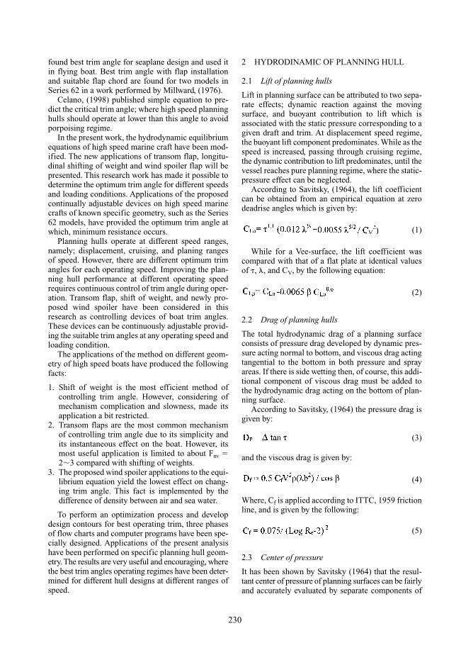
4.1.1 Flap geometryKarafiath (1999) has shown that flap geometry has an effect on the reduction of effective horsepower. Hehas also found that the best flap shape is the parabolictapered one, which maintains the maximum wedgeangle for about the middle third of its span, and thentapered transversely as a parabolic surface as shownin Figure 11.
In the following, the different types of flap areintroduced:
• Rectangular shape.• Parabolic taper.• Flat taper.• Wrapped around bilge with no taper.
4.1.2 Flap chord lengthActually, the hydrodynamic effects of flap and wedgeare similar to each other, except the arrangements andthe position of action. Wedge length was tested byMillwared, (1976), on two models of Series 62. He hasproved that the greatest reduction in resistance wasobtained with a wedge length of 10% length of chine,but since the results for 5% chine length are only a lit-tle lower, it seems that the optimum wedge length liesbetween 5% and 10% lp, tending toward 5% lp forlighter displacement.
Karafiath, (1999), has developed nearly the sameresult, saying that the effective flap chord length forlarge size vessel should be between 5% and 10% per-cent of vessel’s length.
4.1.3 Hull equilibrium with flap applicationA study of flap effectiveness by Brown, (1975), hasintroduced simple expressions for the increase in lift,drag and moment due to flap application. The studyintroduced an expression for the flap lift, which isgiven by:
(12)
In addition, the pressure on the flap causes a drag,which is proportional to the flap lift and is given by:
(13)
234
Figure 11. Types of Flap shapes.
While the flap friction drag is accounted for in thehull friction drag.
The hydrodynamic flap moment taken about thetrailing edge of the flap is given by:
(14)
According to Savitsky, (1976), for full span flaps,where � � 1, the flap lift acts at 0.6 beam ahead of thetrailing edge of flap as shown in Figure 12. Savitsky,(1976), has also developed the required modificationsof his performance prediction method, (1964), inorder to account for the effect of flaps or wedge in asimple manner. For simplified calculations with full-span flap, it is only required to assume effective val-ues for displacement (�e) and (LCGe) measured fromthe flap trailing edge:
(15)
Hence, the total drag is defined as:
(16)
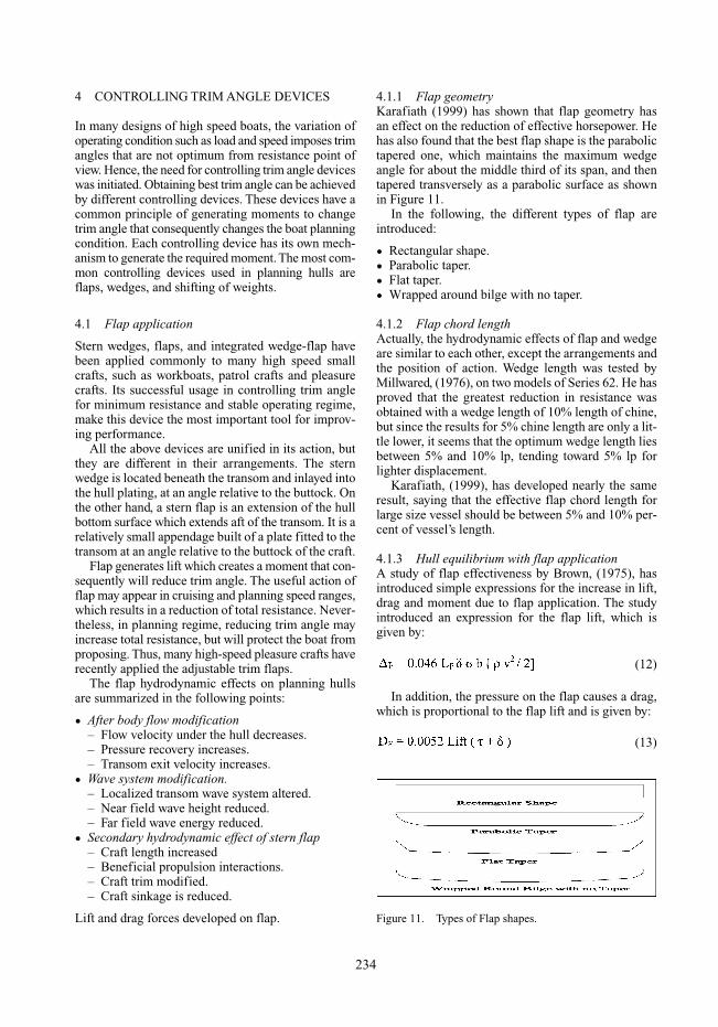
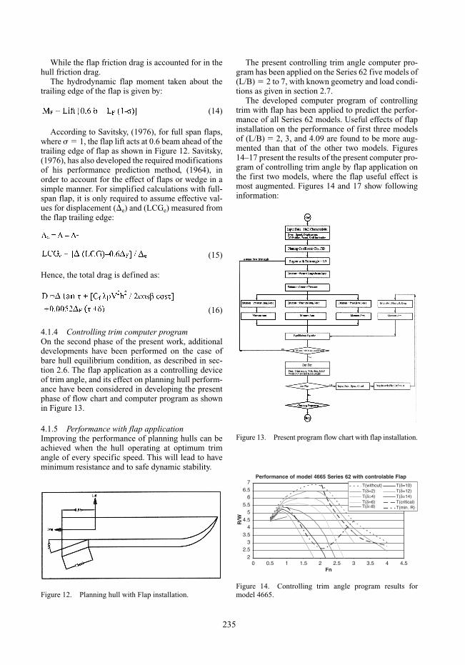
4.1.4 Controlling trim computer programOn the second phase of the present work, additionaldevelopments have been performed on the case ofbare hull equilibrium condition, as described in sec-tion 2.6. The flap application as a controlling deviceof trim angle, and its effect on planning hull perform-ance have been considered in developing the presentphase of flow chart and computer program as shownin Figure 13.
4.1.5 Performance with flap applicationImproving the performance of planning hulls can beachieved when the hull operating at optimum trimangle of every specific speed. This will lead to haveminimum resistance and to safe dynamic stability.
The present controlling trim angle computer pro-gram has been applied on the Series 62 five models of(L/B) � 2 to 7, with known geometry and load condi-tions as given in section 2.7.
The developed computer program of controllingtrim with flap has been applied to predict the perfor-mance of all Series 62 models. Useful effects of flapinstallation on the performance of first three modelsof (L/B) � 2, 3, and 4.09 are found to be more aug-mented than that of the other two models. Figures14–17 present the results of the present computer pro-gram of controlling trim angle by flap application onthe first two models, where the flap useful effect ismost augmented. Figures 14 and 17 show followinginformation:
235
Figure 12. Planning hull with Flap installation.
Figure 13. Present program flow chart with flap installation.
Performance of model 4665 Series 62 with controlable Flap
22.5
33.5
44.5
55.5
66.5
7
0 0.5 1 1.5 2 2.5 3 3.5 4 4.5Fn
R/W
T(without)T(δ=2)T(δ=4)T(δ=6)T(δ=8)
T(δ=10)T(δ=12)T(δ=14)T(critical)T(min. R)
Figure 14. Controlling trim angle program results formodel 4665.
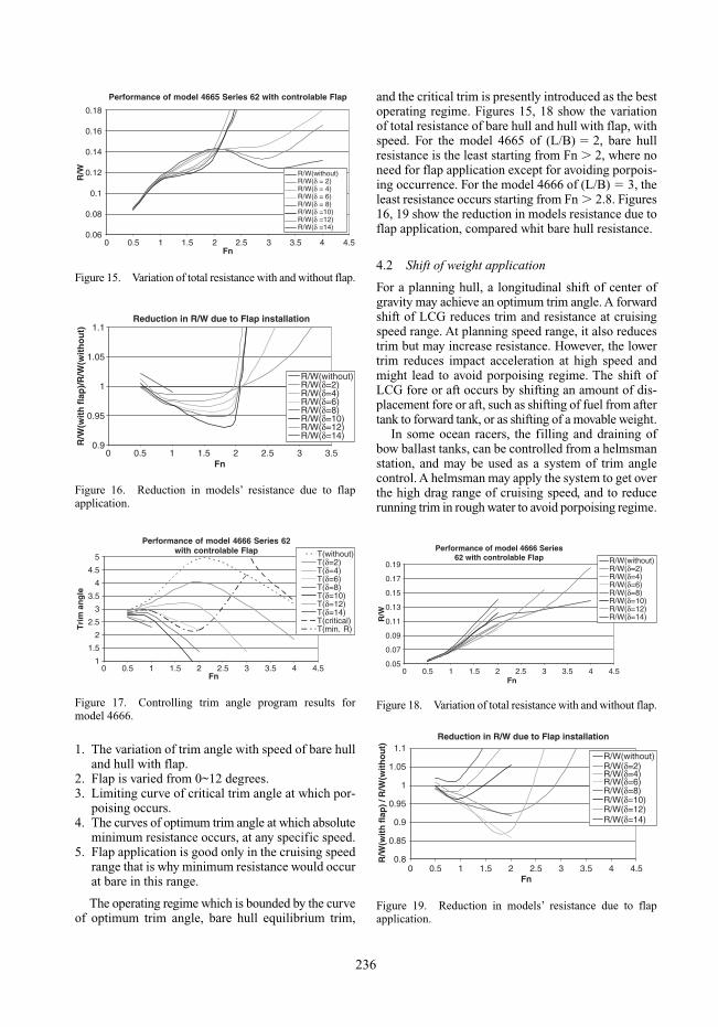
1. The variation of trim angle with speed of bare hulland hull with flap.
2. Flap is varied from 0~12 degrees.3. Limiting curve of critical trim angle at which por-
poising occurs.4. The curves of optimum trim angle at which absolute
minimum resistance occurs, at any specific speed.5. Flap application is good only in the cruising speed
range that is why minimum resistance would occurat bare in this range.
The operating regime which is bounded by the curveof optimum trim angle, bare hull equilibrium trim,
and the critical trim is presently introduced as the bestoperating regime. Figures 15, 18 show the variationof total resistance of bare hull and hull with flap, withspeed. For the model 4665 of (L/B) � 2, bare hullresistance is the least starting from Fn � 2, where noneed for flap application except for avoiding porpois-ing occurrence. For the model 4666 of (L/B) � 3, theleast resistance occurs starting from Fn � 2.8. Figures16, 19 show the reduction in models resistance due toflap application, compared whit bare hull resistance.
4.2 Shift of weight application
For a planning hull, a longitudinal shift of center ofgravity may achieve an optimum trim angle. A forwardshift of LCG reduces trim and resistance at cruisingspeed range. At planning speed range, it also reducestrim but may increase resistance. However, the lowertrim reduces impact acceleration at high speed andmight lead to avoid porpoising regime. The shift ofLCG fore or aft occurs by shifting an amount of dis-placement fore or aft, such as shifting of fuel from aftertank to forward tank, or as shifting of a movable weight.
In some ocean racers, the filling and draining ofbow ballast tanks, can be controlled from a helmsmanstation, and may be used as a system of trim anglecontrol. A helmsman may apply the system to get overthe high drag range of cruising speed, and to reducerunning trim in rough water to avoid porpoising regime.
236
Performance of model 4665 Series 62 with controlable Flap
0.06
0.08
0.1
0.12
0.14
0.16
0.18
0 0.5 1 1.5 2 2.5 3 3.5 4 4.5Fn
R/W R/W(without)
R/W(δ = 2)R/W(δ = 4)R/W(δ = 6)R/W(δ = 8)R/W(δ =10)R/W(δ =12)R/W(δ =14)
Figure 15. Variation of total resistance with and without flap.
Reduction in R/W due to Flap installation
R/W(without)R/W(δ=2)R/W(δ=4)R/W(δ=6)R/W(δ=8)R/W(δ=10)R/W(δ=12)R/W(δ=14)
0.9
0.95
1
1.05
1.1
0 0.5 1 1.5 2 3Fn
R/W
(wit
h fl
ap)/
R/W
(wit
ho
ut)
2.5 3.5
Figure 16. Reduction in models’ resistance due to flapapplication.
Performance of model 4666 Series 62with controlable Flap
1
1.5
2
2.5
3
3.5
4
4.5
5
0Fn
Tri
m a
ng
le
T(δ=2)T(without)
T(δ=4)T(δ=6)T(δ=8)T(δ=10)T(δ=12)T(δ=14)T(critical)T(min. R)
0.5 1 1.5 2 2.5 3 3.5 4 4.5
Figure 17. Controlling trim angle program results formodel 4666.
Performance of model 4666 Series62 with controlable Flap
0.05
0.07
0.09
0.11
0.13
0.15
0.17
0.19
0 0.5 1 1.5 2 2.5 3 3.5 4 4.5Fn
R/W
R/W(without)R/W(δ=2)R/W(δ=4)R/W(δ=6)R/W(δ=8)R/W(δ=10)R/W(δ=12)R/W(δ=14)
Figure 18. Variation of total resistance with and without flap.
Reduction in R/W due to Flap installation
0.8
0.85
0.9
0.95
1
1.05
1.1
0 0.5 1 1.5 2 3 4 4.5Fn
R/W
(wit
h fl
ap) /
R/W
(wit
ho
ut)
R/W(without)R/W(δ=2)R/W(δ=4)R/W(δ=6)R/W(δ=8)R/W(δ=10)R/W(δ=12)R/W(δ=14)
2.5 3.5
Figure 19. Reduction in models’ resistance due to flapapplication.

In case of impossible application of shift of weight, itis recommended to rearrange the hull weights to pro-vide a position for LCG such that the best possible trimangle is achieved at the range of boat service speed.
4.2.1 Hull equilibrium with shift of weight system application
Due to a longitudinal shift of weight, (w) distance, (L),a moment will be generated as shown in Figure. 20.The equilibrium equation of planning hull has beendeveloped by adding the effect of new trimmingmoment, and is introduced as follows:
A designer may suggest the use of controlling trimdevices to improve the performance of planning hull.The application of controlling trim angle devices canbe useful for the following reasons:
• Achieve the optimum trim angle.• Reduction of hull total resistance, which will lead
to a reduction of hull EHP.• Avoid dynamic instability.
Planning hull pass through many speed regimesbefore it reaches planning speed. Each speed regimehas its own characteristics in load and speed limit.There is no single optimum trim angle that fits alloperating ranges of speed. Hence, a continuous controlof trim angle is required to provide the best improve-ment in planning hull performance at all operatingranges of speed.
Figure 20 show an example of using shift liquidbetween two tanks, of distance (L), to control trim anglein planning hull. The two tanks are connected by apipe line and pump to transfer the liquid between the tanks, this system is controlled from the wheelhouse.
It is proposed that a helmsman might enter the hullload and speed conditions to a controlling system,hence, suitable shift of weight is to be made and the hull will make the best trim angle. Consequently,improvement in hull performance will be acquired.
4.2.2 Performance with shift of weight systemAs previously discussed in the section of performancewith flap application, the developed computer pro-gram of controlling trim angle has been applied onSeries 62 models.
The main difference between the two cases of controlling devices is that the longitudinal shift ofweight might increase the hull trim as well as it mightdecrease it. While for the case of flap can control, itmight only decrease the hull trim.
The computer program predicts the planning hullperformance with and without any shift of weight, atspeed range of Fn � 0.5�4.0. The shift of weight isgoing from 5% to 20% of hull weight, both forwardand afterward for a distance, (L � 9.85 m). This shiftof weight will produce a trim moment, causing LCGto move forward or afterward, changing the hull equi-librium trim.
The computer program predicts for Series 62 mod-els the equilibrium trim angle, total resistance, andthe critical trim angle for both conditions of with andwithout shift of weight and speed range fromFn � 0.5�4.0, as shown on the Figures 21, 24.
Also, the resistance and its percentage reduction ofSeries 62 models with shift of weight controlling trimsystem are determined and presented on the Figures22, 25, 23, 26 to show the useful effect of controllingtrim using shifting of weights.
4.3 Proposed wind spoiler
It is newly proposed to apply a wind spoiler to theuppermost deck of planning hull superstructure, as anew controlling device of the hull trim angle. Modifi-cations, due to application of the device, to the plan-ning hull equilibrium equation have been performed.Hydrodynamic investigation of the effect of windspoiler on a specific hull geometry, yield the lowesteffect on changing trim angle compared to other pre-sented devices. A wind spoiler of span equal to hullbeam, and a chord of 1.5 m, located on the upper deck
237
Figure 20. Shift of weight system.
Performance of model 4665 Series62 with Shift Weight 9.85m
2468
1012141618
Tri
m a
ng
le
T(without)T(20%∆)foreT(15%∆)foreT(10%∆)foreT(5%∆)foreT(5%∆)aftT(10%∆)aftT(15%∆)aftT(20%∆)aftT(min. R)
0 0.5 1 1.5 2 3 4 4.5Fn
2.5 3.5
Figure 21. Controlling trim angle program results for model 4665.
(17)
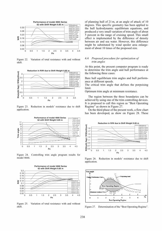
of planning hull of 21 m, at an angle of attack of 10degrees. This specific geometry has been applied tothe hull hydrodynamic equilibrium equations, andproduced a very small variation of trim angle of about5 percent in the range of cruising speed. This smalleffect is implemented by the difference of densitybetween air and sea water. However, this differencemight be substituted by wind spoiler area enlarge-ment of about 10 times of the proposed size.
4.4 Proposed procedure for optimization oftrim angles
At this point, the present computer program is readyto determine the trim angle and hull performance atthe following three cases:
Bare hull equilibrium trim angles and hull perform-ance at different speeds.The critical trim angle that defines the porpoisinglimit.Optimum trim angle at minimum resistance.
The region between the three boundaries can beachieved by using one of the trim controlling devices.It is proposed to call this region as “Best OperatingRegime” as shown in Figure 27.
On the third phase of the present work, a flow charthas been developed, as show on Figure 28. These
238
Performance of model 4665 Series62 with Shift Weight 9.85 m
W/R
0 0.5 1 1.5 2 3 4 4.5Fn
2.5 3.5
0.33
0.28
0.23
0.18
0.13
0.08
0.03
R/W(without)R/W(20%∆)foreR/W(15%∆)foreR/W(10%∆)foreR/W(5%∆)foreR/W(5%∆)aftR/W(10%∆)aftR/W(15%∆)aftT(20%∆)aft
Figure 22. Variation of total resistance with and withoutshift.
Reduction in R/W due to Shift Weight 9.85 m
0
1
2
3
R/w
(wit
h f
lap
) / R
/W(w
ith
ou
t)
0 0.5 1 1.5 2 3Fn
2.5 3.5
R/W(without)R/W(20%∆)foreR/W(15%∆)foreR/W(10%∆)foreR/W(5%∆)foreR/W(5%∆)aftR/W(10%∆)aftR/W(15%∆)aftR/W(20%∆)aft
2.5
1.5
0.5
Figure 23. Reduction in models’ resistance due to shiftapplication.
Performance of model 4666 Series62 with Shift Weight 9.85 m
123456789
1011
Tri
m a
ng
le
0 0.5 1 1.5 2 3 4 4.5Fn
2.5 3.5
T(without)T(20%∆)foreT(15%∆)foreT(10%∆)foreT(5%∆)foreT(5%∆)aftT(10%∆)aftT(15%∆)aft
T(20%∆)aft
T(critical)T(min. R)
Figure 24. Controlling trim angle program results formodel 4666.
Performance of model 4666 Series62 with Shift Weight 9.85 m
R/W
0 0.5 1 1.5 2 3 4 4.5Fn
2.5 3.5
0.20.180.160.140.12
0.10.080.060.040.02
R/W(without)R/W(20%∆)foreR/W(15%∆)foreR/W(10%∆)foreR/W(5%∆)foreR/W(5%∆)aftR/W(10%∆)aftR/W(15%∆)aftR/W(20%∆)aft
Figure 25. Variation of total resistance with and withoutshift.
Reduction in R/W due to Shift Weight 9.85 m
1.9
R/W
(wit
h f
lap
) / R
/W(w
ith
ou
t)
0 0.5 1 1.5 2 3 4 4.5Fn
2.5 3.5
1.7
1.5
1.3
1.1
0.9
0.7
0.5
R/W(without)R/W(20%∆)foreR/W(15%∆)foreR/W(10%∆)foreR/W(5%∆)foreR/W(5%∆)aftR/W(10%∆)aftR/W(15%∆)aftR/W(20%∆)aft
Figure 26. Reduction in models’ resistance due to shiftapplication.
Figure 27. Determination of the “Best Operating Regime”.

developments have prepared the computer program tooptimize between the abovementioned boundaries,taking into account the following constraints:
1. First priority is for safe navigation, i.e., how to avoid porpoising using one of controlling trimdevices.
2. Second priority is to achieve optimum trim angle,at which minimum resistance occurs, by means ofcontrolling devices.
3. Finally, not to use trim controlling devices, unlessthere is a reduction in hull resistance and power, orto avoid porpoising.
It is the main goal of the present work to make itpossible to provide the boat designer with a simpleand easy method to determine one trim angle for eachspecific speed and loading condition.
5 ANALYSIS OF CONTROLLINGTRIM DEVICES
5.1 Flap analysis
In planning hulls, since the flap lift is proportional tothe square of speed, hence, the flap lift at low speedranges is very weak and will not change the boat trimand it might cause an increase in the boat total resis-tance, as shown in Figures 29, 30.
The flap actual effects on changing trim angle appearin cruising and planning regimes, i.e. when the speedgrows up, as shown in Figure 31. The critical trim anglelimit was plotted to show the effect of flap in ovoidproposing regime.
239
Figure 28. Flow chart for “Best Operating Regime”.
0
0.05
0.15
0.25R
/WR/W(with flap)Rf/W(with flap)Rp/W(with flap)R/WRf/WRp/W
Effect of instale Flap with def.=6 , Chord=1.4 m withfull span-beam ratio on Resistance Component for
Model 4665 Series 620.3
0.2
0.1
0 0.5 1 1.5 2 3 4 4.5Fn
2.5 3.5
Figure 29. The resistance components with and w/o flap.
Reduction in Resistance Due to use Flap
-20
-15
-10
-5
0
5
10
15
0 0.5 1 1.5 2 2.5 3 3.5
Fn
Red
uct
ion
%
reduction
Figure 30. Reduction in resistance due to use flap.
0
1
2
3
4
5
6
7
Tri
m a
ng
le T
Effect of instale Flap with def.=6 , Chord=1.4 m withfull span-beam ratio on Trim angle for
Model 4665 Series 62
0 0.5 1 1.5 2 3 4 4.5Fn
2.5 3.5
T(with flap)
T(cratical)
Figure 31. Effect of flap on trim angle.

In planning regime, the flap changes trim strongly,therefore the flap application is very useful to avoidproposing but the resistance may increase rapidly inthat range, as shown in Figures 29, 31.
5.2 Shift of weight analysis
From the results of the developed computer programof controlling trim angle, it is clear that shift ofweight forward improves the hull performance in therange of displacement and cruising speeds. While itincreases the resistance in planning speed range, asshown on Figures 32, 34 show the reduction in hullresistance due to shift of weight compared to no shiftcondition. Figure 33 shows the variation of trim anglewith Fn at cruising speed range. The critical trimangle limit is also plotted to show the effect of weightshift on proposing avoidance.
5.3 Comparison between flap and shift ofweight applications
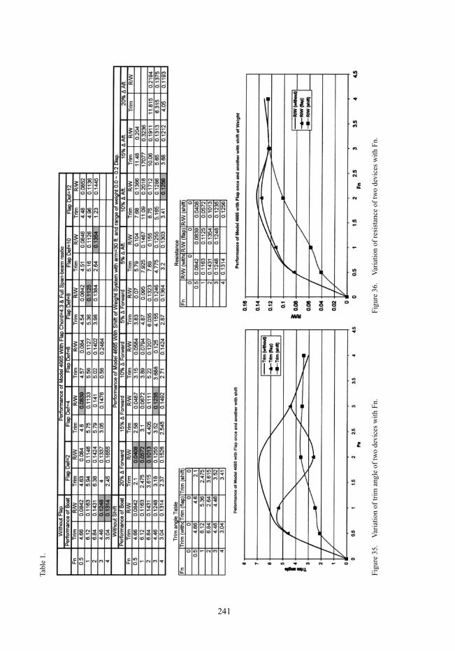
To illustrate the difference between the two methodsof controlling trim angle, one model of Series 62, no. 4665 is considered for comparison between adjust-able flap and dynamic shift of weight systems.
The flap chord is 10% of projected chine lengthwith a full span-beam ratio, and will be deflected zeroto 12 degrees. While the weights which will be shiftedlongitudinally, for a distance of 9.85 m, from 0% to20% of boat displacement.
The program results are tabulated in Table 1, whichintroduces model performance with and without con-trolling devices, of flap installation and weight shiftsystem. Shaded results represent minimum resistanceand optimum trim angles. These results are also pre-sented graphically in Figures 35, 36.
In this case of study, both of the considered devicesof trim control, have the continuous adjustability ofoptimum trim at any range of speed. Each device hasbeen tested on the developed program of the proposedoptimization process, and it has been proven that it isan efficient controlling trim device.
5.3.1 Advantages of flap application1. The time required to make a change in trim angle
is very short compared to that of shift of weight.2. Low cost of flap installation compared to that of
shift of weight system.3. The use of external weight to shift will increase
the displacement and may increase the resistance.4. When the vessel use tanks in shift of weight sys-
tem, the vessel will suffer from free surface effect.5. The shift of liquid from tanks depends on the avail-
able quantity in these tanks.6. Flap modifies after body flow characteristics, such
as decreasing flow velocity under the hull, increas-ing pressure recovery, and increasing transom exitvelocity.
7. Easy to use and maintain.8. Flaps may be applied in stopping and turning
maneuvers.9. No need for special arrangements, such as tanks,
pumps, or valves.
Suitable for other vessels of different size.
5.3.2 Advantages of shift of weight application1. Reduction in resistance is larger than that of flap;
because there is no additional resistance due toshift of weight.
2. The shift of weight system can decrease or increasetrim angle, which can reduce the resistance in pureplanning regime when the vessel needs to increasetrim angle. While flap can only decrease trim angles.
3. No appendage outside of the hull.4. It may be applied in higher range of speed com-
pared with flap.
240
Effect of Shift of 0.1 Disp. Forward onResistance Component for Model 4665 Series 62
0
Rt/
W R
f/W
Rp
/W
0.160.140.120.1
0.080.060.040.02
0 0.5 1 1.5 2 3 4 4.5
R/W(after shift)
R/W
Rf/W(after shift)
Rf
Rp/W(after shift)
Rp/W
Fn2.5 3.5
Figure 32. The resistance components with and w/o shift.
2
3
4
5
6
7
Tri
m a
ng
le
TT(cratical)
Effect of shift of 0.1 Disp. Forward on Trim anglefor Model 4665 Series 62
6.5
5.5
4.5
3.5
2.5
0 0.5 1 1.5 2 3 4 4.5Fn
2.5 3.5
T(after shift)
Figure 33. Effect of shift on trim angle.
Reduction in Resistance due to Shift of 0.1 Disp.for Model 4665 Series 62
-15-10-505
101520253035
Red
uct
ion
in %
0 0.5 1 1.5 2 3 4 4.5
Fn
2.5 3.5
reduction
Figure 34. Reduction in resistance due to shift.
241
Figu
re 3
5.V
aria
tion
of tr
im a
ngle
of
two
devi
ces
with
Fn.
Figu
re 3
6.V
aria
tion
of r
esis
tanc
e of
two
devi
ces
with
Fn.
Tabl
e 1.
6 CONCLUSION
It is the main goal of this paper, to introduce a justifiedmethod to determine the best trim angle at any speedor operating condition, which is valid for applicationto any planning hull design using one of the presentedcontrolling devices. Useful conclusions are drawn asfollows:
1. A wide range of recently published and importantresearch works, on the subject have been reviewedand utilized.
2. Prediction of planning hull performance has beendeveloped at three phases of developments; namely:• Bare hull equilibrium trim based on Savitsky,
(1964) and Blount, (1975).• Planning hull with controlling trim devices.• Planning hull with optimum trim angle.For each phase of the above mentioned, a specialflow chart and computer program have been devel-oped.
3. A proposed procedure of a new of optimizationprocess for the so called “Best Operating Trim”,has been introduced.
4. Critical trim to avoid porpoising has been deter-mined, based on Celano, (1998), and it is consid-ered in the developed computer program.
5. Operating at optimum trim angle will save energyof the boat. Therefore, controlling trim angle devicesshould be used in order to improve the perform-ance of planning hull and for safe navigation.
6. Due to the variety of operating conditions in plan-ning hull, there are many optimum trim anglesshould be achieved during operation. Hence,adjustable trim control devices are considered andhave proven efficient in reducing total resistance.
7. Shift of weight is the most efficient method of controlling trim angle. However, considering itscomplicated mechanism and slowness made itsapplication a bit restricted.
Transom flaps are the most common mechanism ofcontrolling trim angle due to its simplicity and itsinstantaneous effect on the boat. However, its usefulapplication is limited to cruising speed range of aboutFnv � 2�3 compared with shifting of weights.
7 RECOMMENDATIONS
The present work requires some experimental appli-cations for validating the proposed optimization pro-cedure of planning hull trim angle. Looking to thefuture, it is required to develop such a system whichwill control continuously, the planning hull trim angle.This system is proposed to have self adjustment for
optimum operating trim angle, at each speed and load-ing condition.
The proposed wind spoiler applications to theequilibrium equation yield the lowest effect on chang-ing trim angle. This fact is implemented by the differ-ence of density between air and sea water.
REFERENCES
Millward A., “Effect of Wedges on the Performance Char-acteristics of Two Planing Hulls”, Journal of Research,Vol. 20, No. 4, Dec. 1976.
Allan B. Murray, “The Hydrodynamics of Planing Hulls”,SNAME Meeting, 1950.
Clement, E.P. and Blount, D.L., “Resistance Tests of aSystematic Series of Planing Hull Forms”, SNAMETransactions, Vol. 71, 1963.
Calkins D. E., “An Interactive Computer-Aided DesignSynthesis Program for Recreational Powerboats”, SNAMETrans. Vol. 91, 1983, pp. 49–87.
Danko Gugie and Tea Prolic, “The Design Space of Hydro-dynamically Adequate Projects of Planing Hulls”,IMAM, April, 1995.
Day, James P. and Richard J. Haag, “Planing Boat Porpoising”,Webb Institute of Navel Architecture, New York, 1952.
Diehl, Walter S., “The Application of Basic Data on PlaningSurfaces to the Design of Flying Boat Hulls”, NationalAdvisory Committee for Aeronautics, Report No. 694,1940.
Donald, L. Blount, D.L., Fox, “Small Craft Power Predic-tion”, Navel Ship Engineering Center, 1975.
Gabor Karafiath and Cheng Wen, “Stern Wedges and SternFlaps for Improved Powering-U.S. Navy Experience”,SNAME Trans., Vol. 107, 1999.
Gabor Karafiath, Cusanelli S., Jessup D. and Barry D.,“Hydrodynamic Efficiency Improvements to the USCG110 Ft WPB Island Class Patrol Boats”, SNAME Tran-sactions, Vol. 109, 2001.
Lalangas, P., and Yannoulies, P., “Design and Constructionof a 25 m High-Speed Aluminum Motor Yacht” TheSociety of Navel Architects and Marine Engineers, Vol.91, 1983.
Michael R., Michael G. and Armin W., “Stern Flap PoweringPerformance Prediction for the Coast Guard 110-footWPB Island Patrol Boat”, Marine Technology, Vol. 37,No. 2, Spring 2000.
Cusanelli S., “Stern Flaps – A Chronicle of Success at Sea(1989–2002)”.
Savitsky D., “Hydrodynamic Design of Planing Hulls”,Marine Technology, Vol. 1, No. 1, Oct. 1964.
Savitsky, Brown P., “Procedures for Hydrodynamic Evaluationof Planing Hulls in Smooth and Rough Water”, MarineTechnology, Vol. 13, No. 4, Oct. 1976.
Shoemaker, James M., “Tank Tests of Flat and V-BottomPlaning Surfaces”, National Advisory Committee forAeronautics, Technical Note No. 509, November 1934.
Tullio Celano, “The Prediction of Porpoising Inception forModern Planing Craft”, SNAME Transactions, Vol. 106,1998.
242