
«Energy production by small hydropower plants in Greece ...
93
«Energy production by small hydropower plants in Greece. Selected case study» SCHOOL OF SCIENCE & TECHNOLOGY A thesis submitted for the degree of Master of Science (MSc) in Energy Systems Stergios Dimopoulos Supervisor: Galiatsatou Panagiota DECEMBER 2018 THESSALONIKI – GREECE
-
Upload
khangminh22 -
Category
Documents
-
view
0 -
download
0
Transcript of «Energy production by small hydropower plants in Greece ...

«Energy production by small hydropower plants in
Greece. Selected case study»
SCHOOL OF SCIENCE & TECHNOLOGY
A thesis submitted for the degree of
Master of Science (MSc) in Energy Systems
Stergios Dimopoulos
Supervisor: Galiatsatou Panagiota
DECEMBER 2018
THESSALONIKI – GREECE

2
Abstract
This dissertation was written as a part of the MSc in Energy Systems at the
International Hellenic University. All of the conventional energy sources (carbon,
petroleum, etc.) have harmful effects to the environment (e.g. intensification of the
greenhouse effect), because of the high amounts of carbon dioxide (CO2) that they
produce during their combustion and not only. Since these conventional supplies are
eventually going to deplete, it will be good to turn our attention to alternative energy
sources (renewables), like in this case to hydroelectric power.
The goal and scope of the present thesis is to describe the operation and the
equipment of a small hydro plant that is situated on tributary of the river “Haliacmon”
river in Greece. Also, the principal of the operation of a small hydro power plant is
going to be described. Furthermore, a q-frequency diagram is going to be presented.
Stergios Dimopoulos
Date: 16/12/2018

3
Contents
ABSTRACT……………………………………………….…………2
INTRODUCTION……………………………………….…….…….7
CHAPTER 1
ENERGY SOURCES
1.1 Conventional energy source………………………….………….8
1.1.1 Unfavorable effects of conventional energy sources………….9
1.2 Renewable energy sources……………………………………….10
1.3 Hydropower constructions……………………………………….15
CHAPTER 2
SMALL HYDROPOWER PLANTS
2.1 Brief history of hydropower...………………………………........17
2.2 Comparison between small and large hydropower plants….…....18
2.3 Pros and cons of small hydropower plants…………………........21
2.3.1 Advantages of small hydropower plants…………….……….21
2.3.2 Disadvantages of small hydropower plants…………………...21
2.4 Recording and analysis of the existing state……………………...23
2.4.1 General energy sizes………………………………………….23
2.4.1.1 Electrical energy consumption in Greece and Europe…….23
2.4.1.2 Electricity production in Greece………………………….26
4
2.4.2 Spatial distribution of plants………………………………….27
2.4.3 Mean power of plants………………………………………....29
2.4.4 Evaluation of the results………………………………………32
2.5 Operating principle of small hydropower plants…………………33
2.5.1 Selection of installation site…………………………………...35
2.5.2 Technical works of intake…………………………………….35
2.5.3 The penstock system………………………………………….36
2.5.4 The power house……………………………………………....37
2.5.5 Turbines……………………………………………………….38
2.5.5.1 Definitions-Field of application………………………....…38
2.5.5.2 Types of hydro turbines……………………………………39
2.5.5.3 Description of reaction turbines………………………. ….40
CHAPTER 3
LEGISLATION FOR RES AND SMALL HYDROPOWER PLANT
INSTALLATION IN GREECE
3.1 Legal framework for small hydropower plants in Greece………...43
3.1.1 Legislation 2244/1994…………………………………………43
3.1.2 Legislation 2773/1999…………………………………………44
3.1.3 Legislation 2941/2001…………………………………………44
3.1.4 Legislation 3175/2003…………………………………………45
3.1.5 Legislation 3468/2006…………………………………………45
3.2 Small hydropower plants licensing procedures…………………...46
3.2.1 Production license issue……………………………………….47
3.2.2 Installation license issue……………………………………….48

5
3.2.2.1 Preliminary Environmental Assessment and Evaluation……49
3.2.2.2 Approval of environmental conditions (AEC)………………50
3.2.2.3 Approval of forest intervention (AFI)………………………51
3.2.2.4 Water utilization License (WUL)…………………………...51
3.3 Operating license issue…………………………………………….52
CHAPTER 4
STAGES OF CONSTRUCTION OF A SMALL HYDROPOWER
PLANT
4.1 Estimation of the area’s hydrodynamic and installation site
selection…………………………………………………………….…53
4.2 Feasibility study………………………………………………….54
4.3 Preliminary design of a small hydropower plant…………………54
4.4 Study-construction of hydro turbines…………………………….55
4.5 Environmental Impact Study (IEP)……………………………….55
4.6 Operating measurements and efficiency of a small hydropower
plant……………………………………………………………………56
CHAPTER 5
ENVIRONMENTAL IMPACT AND LCA OF SMALL
HYDROPOWER PLANTS
5.1 Visual nuisance - aesthetic integration…………………………….57
5.2 Natural environment, flora-fauna………………………………….58
5.3 Soil, surface and groundwater…………………………………….59
5.4 Life cycle assessment (LCA)……………………………………....61
5.5 Environmental impacts from the water intake and related works....64

6
CHAPTER 6
HYDROPOWER PLANTS IN HALIACMON RIVER
6.1 Existing hydropower plants in Haliacmon river………….……......67
6.1.1 Hydropower plant of Polifito…………………….….…….……68
6.1.2 Hydropower plant of Sfikia……………………………….……70
6.1.3 Hydropower plant of Asomata………………………………….72
6.1.4 Small hydropower plant of Agia Varvara…………………...….74
6.1.5 Hydropower plant of Makrochori………………………...…….76
CHAPTER 7
DESIGN OF A NEW SMALL HYDROPOWER PLANT AT
ALIACMON RIVER (CASE STUDY)
7.1 Daily flow duration curve………………………………...….……77
7.2 Assessment of optimum power……………………….………….80
7.3 Selection of an optimum diameter for the penstock...…………….82
7.4 Estimation of the power of turbines…………….………………...87
7.5 Sustainability study of the investment………….…………………88
CHAPTER 8
CONCLUSIONS…………………………………………………….89
Bibliography…………………………………………………………91

7
Introduction
The hydraulic power is a renewable energy source, which is created by the kinetic
power of water. The potential of this power source was discovered many years ago
and helped the humanity to progress really fast. Since that day the technology of the
hydropower plants has improved significantly.
The small hydropower plants for the exploitation of the energy of the water they use
turbines. The efficiency of these turbines (sometimes above 90%) and the long
lifetime of the small hydropower plants (>100 years), are two very important
components for the energetic efficiency and the technological maturity of these plants.
Additionally, a small hydropower plant has many advantages as the potential of the
direct coupling-decoupling to the network, their autonomous operation, their
reliability, the excellent energy quality, the low maintenance and operational cost, the
zero emissivity etc..
Finally, a small hydropower plant is a structure completely compatible with the
environment and the sum of its individual components can be aesthetically and
functionally integrated in the environmental characteristics, making use of local
materials with a traditional way and upgrading the surrounding area.

8
CHAPTER 1
ENERGY SOURCES
1.1 Conventional energy sources
The conventional energy sources are:
• Coal
• Petroleum
• Nuclear energy
• Natural gas
Coal: Coal is found in the underground and formed by plant substances (trees,
seaweed etc.) that were buried many millions years ago after natural disasters such as
settlements and earthquakes. The solar energy that has been committed to these
substances during their development is attributed to the carbon during its combustion
in the form of heat. It has the form of a black or brown stone and its collection is
made in coal mines, which are responsible for severe environmental impacts as toxic
chemicals are released to the environment. During combustion of coal, except heat,
ash, carbon dioxide and other oxides are produced.
Petroleum: Petroleum is found in the underground in liquid form within cavities. It
was formed by animal and plant microorganisms that were plundered due to
embankments or other processes in the depths of the sea basins. There, without the
presence air, turned into oil over thousands of years. Petroleum, such as coal, is also
hazardous for the environment. Furthermore, the upcoming depletion of its stocks
makes the exploitation of renewable energy sources more and more important, in
order to resolve the worldwide energy problem.
Nuclear energy: Is the energy that is released during nuclear reactions. Controlled
nuclear reactions are used as the primary energy source for the production of
electricity, as well as for the production of mechanical energy through special
engines. Even though, nuclear energy is the most energy efficiency source, its use is

9
still questionable by both politics and scientific-technological perspective. The main
arguments of its opponents are risks to man and the environment in case of nuclear
accidents, such as the Chernobyl accident, and the problems associated with the
collection and storage of radioactive waste.
Natural gas: Is a cheap and environmentally friendly solution, but not a renewable
energy source. It is a conventional gas fuel, which in an industry can substitute liquid
conventional fuels (diesel, fuel oil) that are consumed for the production of thermal
energy in boilers, ovens, furnaces etc. Compared to other conventional energy
sources, natural gas is the best option from the point of view that is cheaper, more
environmental friendly and has higher efficiency during its combustion. Although
there are many natural gas reserves for decades, they are limited, thus its price is
going to rise.
1.1.1 Unfavorable effects of conventional energy sources
The energy production through the combustion of fossil fuels has as a result the
emittance of carbon dioxide, one of the main greenhouse gases. The result of the
increasing concentration of these gases in the atmosphere means more heat retention
on the planet, leading to a gradual increase of the earth’s average temperature.
The concentration of carbon dioxide in the atmosphere has increased over the past 40
years. In the last 40 years, carbon dioxide concentration in the atmosphere increased
by 17% (from 316ppm to 367ppm). The temperature increase will have disastrous
phenomena such as floods, hurricanes, heat waves, increase of the sea level etc.1
In the long run, if no action is taken to address the problem, the temperature increase
can reach 4-5oC in the next 100 years. This will lead ecosystems and many living
organisms to extinction.2
1 https://ec.europa.eu/clima/change 2 Dalezios, N.R. (2011). Climatic change and Agriculture: Impacts-Mitigation- Adaptation, chapter 10. Scientific Journal of GEOTEE. 27(January)

10
1.2 Renewable energy sources
With this term we refer to those forms of exploitable energy coming from natural
processes and phenomena that are not subject to some kind of exhaustion, such as
solar radiation, wind, geothermal energy, water circulation from river and waves,
biofuels and others.
The use of renewable energy is not a privilege of our modern technological
development. From ancient times human civilizations were exploiting this energy
sources e.g. wind power for sailing or irrigating the crops. The modern era of
renewable energy sources started at the ‘70s, where the energy crisis that breaks out
leads to economic shock and requires the search for new energy sources and the
detoxification from oil and nuclear energy. At the following decades the interest was
fueled by protecting the environment and upgrading the quality of life that was
downgraded from the widespread use of conventional energy sources.
At the start, renewable energy sources were expensive, non-cost-effective and from
the technical point of view weak. Nowadays, however, the cost of the applications of
mild forms of energy is constantly decreasing and can now compete the traditional
energy sources, such as coal and nuclear energy.
Renewable energy sources produce energy without burdening the environment having
essentially zero residuals and wastes, while they are never going to deplete. They are
flexible applications that can produce energy for the needs of decentralized
populations, limiting in that way the energy losses due to long distance energy
transportation. They can also constitute an additional option in the energy mix which
is consumed by a society and lead to energy autonomy of countries that do not have
sufficient resources for fossil fuels, while their equipment and maintenance is relative
simple and has a long life.
However, no one could claim that there are no difficulties in practical application of
renewable energy systems. First of all they have a lower efficiency factor and
therefore a higher initial cost is required and large area of land, that’s why till now
they are used as a supplement energy source and not to meet the needs of large urban
centers. Also, the supply and performance of many systems depends on the potential
of each region, while for some forms of renewable sources there is the bias that is not

11
aesthetic elegant and perhaps noise-inducing, of course by placing them in remote
areas these disadvantages are eliminated.
The Commission of the European Communities on Renewable Energy Resources in
the 21st Century believes that the complexity, innovation and the decentralized nature
of most RES result in numerous administrative problems, citing in this context the
vague and discouraging licensing procedures for programming, manufacturing and
operating systems for renewable energy sources.
Under these circumstances the European Union (EU) aims to increase the share of
renewable energy sources in the total energy market of EU, proposes to introduce a
legally binding 20%, while the European Parliament decided by resolution of 14th
December 2006 to increase it to 25% till 2020.3 At the same time, it analyzes the
possibilities and prospects to achieve this goal through the adoption of binding targets
and policies which will provide the long-term stability that it needs for the investment
decisions in the RES sector.
The use of renewable energy sources not only does not bring environmental changes
but their exploitation can have economic benefits. A prerequisite constitutes the
reliable link between the existing technology and of the renewable energy sources, in
order to deliver the greatest possible energy gain, wherever is possible.
A large number of countries have integrated the renewable energy sources in the list
with the most important domestic energy sources, which can either be used locally, or
by the wider national network. Greece among all countries has considerable potential
of RES, which can offer an alternative to our energy needs.
The main forms of RES that we can find in Greece and not only are:
-Solar energy
The sun emits huge amounts of energy per day. Solar radiation is used both for the
direct and the indirect heating of buildings with the use of active or passive systems
and for electricity production. Electricity is produced in two ways: a) by using
3 http://www.europarl.europa.eu/factsheets/el/sheet/70/renewable-energy-sources

12
photovoltaic systems that convert solar power directly to electrical and b) by using
solar thermal systems which use the solar energy in order to heat a liquid to produce
steam that feeds a turbine and a generator.
-Geothermal energy
Is the thermal energy that comes from the interior of earth and occurs in the form of
hot water or steam. This energy is related to the volcanicity and the particular
geological and geotechnical conditions of each area. It is a mild renewable energy
source, which with today’s technological data can meet important energy needs.
There are two main applications of geothermal energy. The former is based on the use
of the earth’s heat for the production of electricity and other uses (heating of buildings
and greenhouses). This heat can come from geothermal geysers that arrive naturally to
the surface of the earth. These sources are usually from a few hundred to 3000 meters
below the surface of the earth. The second application of geothermal energy exploits
the thermal ground masses or underground water too drive thermal pumps for heating
and cooling applications.
The exploitation of geothermal energy contributes to: exchange savings by reducing
oil imports, saving natural resources, mainly by lowering domestic consumption
deposits of lignite and cleaner atmosphere.
-Biomass
By biomass we mean the residues of various processes which are derived directly or
indirectly from the plants which are used for heating, electricity production, but also
transportation. These residues may be of urban origin (garbage), from agricultural
production (wood, animal waste, crop), as well as industrial by-products (from food
or organic processing materials). By appropriate treatment, the biomass is converted
into a fuel (biofuel). With the combustion of this gas electricity is produced, with high
efficiency and reduced environmental impacts. This technology provides the
maximum potential for energy production on a pan-European level. Its combustion
though cannot be characterized as a clean one.

13
-Wind energy
Wind energy is indirectly generated by solar radiation, because the uneven heating of
the earth’s surface causes the movement of large masses of air from one region to
another, creating in that way winds. It is a mild energy form, environmentally friendly
and practically inexhaustible. If it was possible, with current technology, to exploit
the total wind potential of earth, is estimated that the electricity that was going to be
produced in one year would cover more than twice the energy need of humanity at the
same time. It is worth noting that the operation of a wind farm, with a capacity of
10MW, offers annually the electricity needed by 7250 households (based on
electricity consumption of Greece in 2002) and saves about 580 tons of oil equivalent.
An ordinary wind turbine of 750 KW produces an average of 2.25 million kilowatt-
hours per year in Greece.4
-Wave and tidal energy
Wave energy is the form of energy resulting from the kinetic energy of waves. The
wind phenomenon has the effect of forming waves which are exploitable in areas with
high wind ratios and oceanic shores. The kinetic energy of waves can rotate a turbine.
The lifting motion of the wave presses the air upward into a chamber and sets it up
rotating the turbine so that the generator generates current. The energy produced can
meet the needs of a home, a lighthouse etc.
The tidal energy is the energy from the gravitational pull of the moon and earth. The
difference in sea level can be used for energy production. The water turbines are
placed in a barrier built on the estuaries of a river to the sea. In few places on earth the
difference of the tidal range is so great that it can be exploitable. The incoming tidal
water on the shore during flood can be trapped in dams, so at low tide the stored
waters are released and move a turbine, like in hydropower plants. The most suitable
places for building such stations are at narrow estuaries. The difference at sea level
between low tide and flood has to be at least 10m.5
4 http://www.rae.gr/old/K2/greenpeace.pdf 5 Efthymiou, Karagiannakis, 2005, "Energy from Waves", AUTh, Electrical engineering department
14
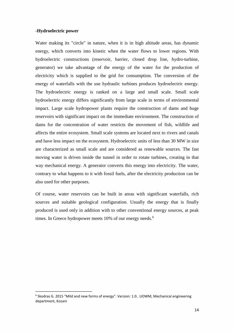
-Hydroelectric power
Water making its "circle" in nature, when it is in high altitude areas, has dynamic
energy, which converts into kinetic when the water flows to lower regions. With
hydroelectric constructions (reservoir, barrier, closed drop line, hydro-turbine,
generator) we take advantage of the energy of the water for the production of
electricity which is supplied to the grid for consumption. The conversion of the
energy of waterfalls with the use hydraulic turbines produces hydroelectric energy.
The hydroelectric energy is ranked on a large and small scale. Small scale
hydroelectric energy differs significantly from large scale in terms of environmental
impact. Large scale hydropower plants require the construction of dams and huge
reservoirs with significant impact on the immediate environment. The construction of
dams for the concentration of water restricts the movement of fish, wildlife and
affects the entire ecosystem. Small scale systems are located next to rivers and canals
and have less impact on the ecosystem. Hydroelectric units of less than 30 MW in size
are characterized as small scale and are considered as renewable sources. The fast
moving water is driven inside the tunnel in order to rotate turbines, creating in that
way mechanical energy. A generator converts this energy into electricity. The water,
contrary to what happens to it with fossil fuels, after the electricity production can be
also used for other purposes.
Of course, water reservoirs can be built in areas with significant waterfalls, rich
sources and suitable geological configuration. Usually the energy that is finally
produced is used only in addition with to other conventional energy sources, at peak
times. In Greece hydropower meets 10% of our energy needs.6
6 Skodras G. 2015 "Mild and new forms of energy". Version: 1.0.. UOWM, Mechanical engineering department, Kozani

15
1.3 Hydropower constructions
A hydropower project consists of Civil Engineering works and electromechanical
equipment. The main parts of a hydroelectric construction are:
The dam which purpose is to create a reservoir, in which a quantity of water is
concentrated (coming from the natural drainage of the water) from which, through the
inlet duct, the water is supplied to the hydro turbine. With the formation of a large
capacity reservoir (function of position, height and opening of the dam) flexibility is
achieved in the operation of the project, which means that the energy production, to a
certain extent, is independent of the natural supply. As already mentioned the
formation of a large capacity reservoir is a feature of large hydropower projects,
through which the grid’s peak demand can be covered.
But the construction of a large dam and the formation of a large reservoir increases
cost the project considerably, while in the case of a small hydroelectric project, the
units’ production does not contribute substantially to the peak demand of a strong
interconnected grid. For these reasons the purpose of the dam in small hydroelectric
projects is not the formation of large reservoir, but ensuring smooth water intake
conditions at the entrance of the supply system, in order to prevent the water steam
sediments enter.
The hydraulic system for the adduction and the abduction of supply from the water
intake to the hydro turbines and then in the natural watercourse, consists of an open
duct (canal), or a canal (usually found only in large hydroelectric constructions), the
loading tank (at the end of the intake canal) and the supply canal, valves and control
gates and possibly control towers where the protection of the delivery pipes from
overpressures and depressions (these transient phenomena occur during the charging
and discharging of hydro-turbines) is required. Depending on the project
configuration the delivery system may not include a tunnel or a delivery channel. The
dimensioning of its inlet and outlet system of water is determined by economical and
technical criteria. In the case of a supply line of great length it is preferable to
construct one supply duct for the supply of all the hydro-turbines of the hydropower
plant, while on the contrary each hydro-turbine is fed by an independent duct. For the

16
needs of the construction and maintenance of the project, control gates and emergency
valves have to be installed; both upstream and downstream, which during the normal
operation of the station will be completely open.
The electromechanical equipment consists of hydro-turbines, speed regulators,
power generators, transformers, electric panels, circuit breakers and auxiliary
equipment, such as lifting machines (cranes), the compressed oil and air system, the
automations etc. Each power generator is directly connected to the hydro-turbine on
the same shaft, except from very small units in which a gear transmission is inserted.
The purpose of the transformers is to rise the generated from the generators voltage,
to the high voltage of the interconnected network, in order for energy transportation
has the minimal possible losses.
The number of units, for example the hydro-turbine-electrical-transformer assemblies
etc., depends on its predicted project’s production schedule, taking into consideration
the variance in supply, the need to cover the grid’s peaks etc. and of course is
determined by econometric criteria. For safety reasons, the number of units of a large
hydropower project is usually is greater or equal to two. This enables the maintenance
and the greater flexibility in the production program. In small hydropower projects the
optimal production lines number is based on purely econometric criteria.
Picture 1.1: Inside a hydropower plant (main parts of a hydropower construction) (source: www.vchpe.com)

17
CHAPTER 2
SMALL HYDROPOWER PLANTS
2.1 Brief history of hydropower
Hydraulic power faithfully served and continues to serve humanity on the road of
development. The evolution of small hydroelectric precursors lost in the centuries.
There are many descriptions which concerns hydraulic wheels and watermills by
Roman writers, Buddhists and Jesuit monks. But the roots of these systems are purely
Greek. The first relevant written descriptions related to movement transmission
systems, is attributed to Aristotle.7 The oldest surviving proof of existence of such a
relative technology of classical times is the famous Mechanism of the Antikythera. It
is speculated that the technological knowledge of the Hellenistic years on the toothed
wheel drive problems contributed significantly to shaping the technique of the
hydraulic wheels. Heron of Alexandria, a Greek engineer, contributed a lot to the
technological knowledge of that era. Leonardo da Vinci re-discovers many of the
inscriptions of Heron. Hydropower, in the form of mechanical energy, was for many
years the driving force for the movement of horizontal or vertical axis watermills,
mainly for the milling of cereals.8
The technology of watermills has not evolved essentially until the appearance, in the
early 19th century, of the first machines that could be described as hydro turbines. The
first projects for hydropower exploitation were low power because of the
technological immaturity of that time.9
Gradually, the increasing energy needs, which have matched the technological
advances and the available means, allowed the construction of increasingly larger
projects for the conversion of hydraulic into mechanical energy. An important
milestone in the exploitation of hydraulic power was the development of applications
of electricity, a form of energy which transfers from the production to the
7 http://www.cres.gr/kape/energeia_politis/energeia_politis_hydro.htm 8 http://users.sch.gr/imarinakis/hydraulic_energy.htm 9 Pyrforos. 2002. Small hydropower plants in the Greek territory, Potential and prospects. Papantonis

18
consumption area relatively easy. Since then, all these projects become Hydroelectric,
which means hydraulic energy is converted to mechanical through the turbine and
then into electrical through the electric generator that is coupled with the turbine.
In Europe at least, two to three decades after the 2nd World War could be described as
the golden period of large hydroelectric projects because the extensive utilization of
the available hydraulic power was done with large units with high power, of several
hundred MW each. Compared to the old-tech large hydroelectric projects, small
hydroelectric projects that already existed were proved uneconomic (inefficient and
high cost per kWh produced) and were gradually abandoned. Since the 1980s, it is
internationally observed a high interest in the development of small hydropower
plants. This international interest for the small hydropower projects is reflected by the
growth of a significant number of manufacturing companies, most of them
subsidiaries companies that manufacture equipment for large hydroelectric projects,
which specialize in the manufacture of standardized electromechanical equipment for
the new generation of small hydroelectric projects.10
2.2 Comparison between Small and Large Hydropower plants
It should first be pointed out that in terms of operating principle, a small does not
differ from a large hydropower plant in the conversion path (hydraulic-mechanical-
electrical power). Also, they do not differ in terms of the number and the type of
individual parts from which a hydropower plant is composed.
The characterization of a hydropower plant as “small” does not refer exclusively to
installed power or unit dimensions but in a set of features, many of which are not
measurable, thus the differences between small and large hydropower plant are not
only quantitative but also qualitative.
A hydropower plant is characterized as “small” when its rated power is lower than
10MW, without this value being a generally accepted limit. It should be noted that in
some countries the threshold for distinguishing between large and small hydropower
10 Papantonis D. E. “Small hydropower works”, Symeon publishing, Athens 2001

19
plants is set at 5MW.11 The fact that the threshold of discrimination is not very clear is
due to the fact that their differences are not as quantitative as qualitative and involve
the choice of the electromechanical equipment, the configuration and the operation of
the hydropower plant. As will be developed below, a basic differentiation between
small and large hydropower plants lies to the selection and installation of standardized
electromechanical equipment in the case of small hydropower plants. Considering that
the standardization of the electromechanical equipment for the equipment of small
hydropower plants usually reaches up to the power of 10MW (although some
companies offer standardized hydro turbines of up to 15 MW), it appears that this
value is the most acceptable limit of distinction between small and large hydropower
plants, as indeed is accepted by all the countries of European Union. The
distinguishing threshold between small and large hydropower plants has meaning also
in terms of processing and licensing because for a small hydropower plant the
procedures are simpler while in other countries, like Greece, a large hydropower plant
can only be manufactured by PPC (Δ.Ε.Η.).
There are also more distinctions in the international literature. A hydropower plant is
characterized as “micro” when its rated power is lower to 100KW, as “mini” when its
rated power is lower than 1MW and “small” when its rated power is between 1 and
10MW. These limits differ from country to country because they are mainly related to
licensing procedures and specifications for the connection with interconnected grid.12
The Greek Legislation (Laws 1559/85 and 2244/94) as small hydropower plants
defines the plants with a capacity of less than 10MW, provided that the only projects
than can be operated freely can be those with power output up to 2MW. It is also
noted that under conditions it is possible to undertake a relative action for micro-
hydroelectric plants of power output between 2 and 5MW.13
A small hydropower plant should not be considered as a miniature of a large one
because this approach will lead the investment to a financial failure. The main
differences between small and large hydropower plants are located in the selection
and installation of standardized electromechanical equipment as well as in the
11 “Report on the electricity generation sector from RES in planning the support mechanism”. April, 2012, from www.ypeka.gr 12 Papantonis D. E. “Small hydropower works”, Symeon publishing, Athens 2001 13 http://www.rae.gr/old/SUB2/2_4.htm

20
operational program which has a direct impact on the layout and the dimensioning of
the various elements that compose it.
Some other favorable factor for the construction of a small hydropower plant is that it
can easily combined with other arrangements, such as water and irrigation, so it
would be possible for small irrigation dams to be used. Furthermore, the
environmental impacts of a small hydropower plant are not as many as those of large
scale, as most of them are due to the formation of a large reservoir upstream.
Another distinction between those two hydropower plants refers to the size of the
available dynamic hydraulic head “H”, the value of which represents the per unit mass
of hydraulic energy of the water and the magnitude of the static pressure in the supply
line and in the input section of the turbine, from which depends the choice of the
turbine. Therefore, there are three categories:
• Low height when H<20m
• Average height when 20m<H<150m and
• High height when H>150m
As hydraulic power is the product of water flow rate and of hydraulic head, becomes
evident that the manufacturing cost of a small hydropower plant is such lower, thus
the investment is such much more efficient, as higher is the hydraulic head “H”.
However, large hydraulic heads occur in mountainous and remote areas so the cost of
the electricity transmission lines may be high and it can offset the benefits of a low-
cost small hydropower plant. The exact opposite occurs to small hydropower plants
with small hydraulic head. However, the cost of the investment is generally increased,
but because they are located near lowland and residential areas, the cost of the
connection with the grid projects is low.14
Yet hydropower plant can be characterized by whether the dam forms a reservoir
(large storage tank) or if the plant is operating according to the flow of the river, as in
the case of low hydraulic head plants.
14 Skodras G. 2015 "Mild and new forms of energy". Version: 1.0.. UOWM, Mechanical engineering department, Kozani

21
2.3 Pros and cons of small hydropower plants
2.3.1 Advantages of small hydropower plants
In comparison with the other RES, small hydropower plants have a high rate energy
efficiency, which means that the energy produced during their lifetime is a lot higher
than the energy required for their construction, maintenance and operation.
Specifically, the energy efficiency rate for the small hydropower plants is in the range
of 30-67%, while the corresponding values for the wind power, biomass and
photovoltaics is 5-39% and 1-4% respectively.15 Due to the fact that small
hydropower plants are constructed in isolated mountainous areas, the nuisance caused
by them is minimal. The transport pipeline is usually underground, the building of the
plant can be adapted to the local architecture, modern turbine technology ensures
reduced sound nuisance and there is no need to store water. The result is not only not
to be disturbed, but often for the visual environment area to be upgraded.
The construction of a small hydropower plant, if proper environmental plan is made,
has little to do with the nearby natural ecosystem. There are technologies for
facilitating the migration of the fish along the river, while estimating the minimum
ecological discharge ensures the survival of riparian fauna and flora.
The quality of the water is not degraded at all by passing through the turbine and may
be suitable even for drinking after standard treatment. Instead, the water treatment
installations can yield water even purer in the natural water stream, if it does not bear
chemical pollutants.
The small hydropower plants can easily be combined with parallel uses such as water
supply and irrigation, helping to maximize the utilization of water resources.
2.3.2 Disadvantages of small hydropower plants
Despite their significant advantages, small hydropower plants present some
disadvantages which they have to be taken into account in order to maximize the
benefits from the application of this technology.
15 ESHA, State of The Art of Small Hydropower in EU-25, 2005

22
Like all RES technologies, small hydropower plants have significantly lower energy
efficiency from that of conventional energy sources. This in term of the energy market
means that they produce expensive energy, if the fossil fuels are still sufficient.
Nowadays the promotion of small hydropower plants depends essentially on the state
subsidies and the high market price of renewable energy from the PPC. As state aid
through community funds is not unlimited innovative technological solutions should
be sought in order to reduce the price of the energy that is produced by the small
hydropower plants.
Small unlike large hydropower plants, they have no capacity to store water in in a
reservoir. This feature, which is an advantage in terms of size of the environmental
burden, implies zero flexibility in the management of energy in the Transmission
System, since the energy produced should be consumed immediately. For this reason,
the energy produced by small hydropower plants is not used as peak energy, but it is
primarily consumed by the system. Furthermore, small hydropower plants have
maximum output during winter months, while the peak of demand is observed on the
summer months.
Finally, the spatial dispersion of small hydropower plants, which is conducive for the
decentralization of the Transmission System, translates into a corresponding
dispersion of human intervention in the natural environment. In combination with the
large number of projects, which are managed by the private sector and by the
concerned services responsible for the monitoring of the projects, the monitoring of
the compliance of the environmental conditions is really difficult. The formation of
institutions and tools for the implementation of the relevant legislation is a crucial
parameter.
The difficulties that occur by the small hydropower plants, should not, in any case, be
considered as an inhibiting factor in their promotion. The insurance of energy
sustainability and the protection of the environment require the exploitation of every
economically and environmentally sustainable energy source. It depends on the
methods and the philosophy which will be implemented if the integration of the small
hydropower plants in the energy system will be done with rational and efficient way.

23
2.4 Recording and analysis of the existing state
In this subchapter an analysis of the statistics is going to take place which concern the
development of small hydropower plants in Greece. The main objective is to
investigate the degree of penetration of this technology into the energy system, to see
how they reached till present situation, their spatial distribution and their prospects for
the future.
2.4.1 General energy sizes
In order to understand the order of magnitude of the under-consideration data, some
general energy sizes are presented by Greece and the European Union Community, in
terms of power and energy. These figures relate the consumption and production of
energy and the goals that have set for the future.
2.4.1.1 Electrical energy consumption in Greece and Europe
The delimitation of objectives for energy balance and the planning for the energy
policy presuppose, not only recording the existing consumer needs, in quantitative
and qualitative terms, but also assess of the future trends. The gross electricity
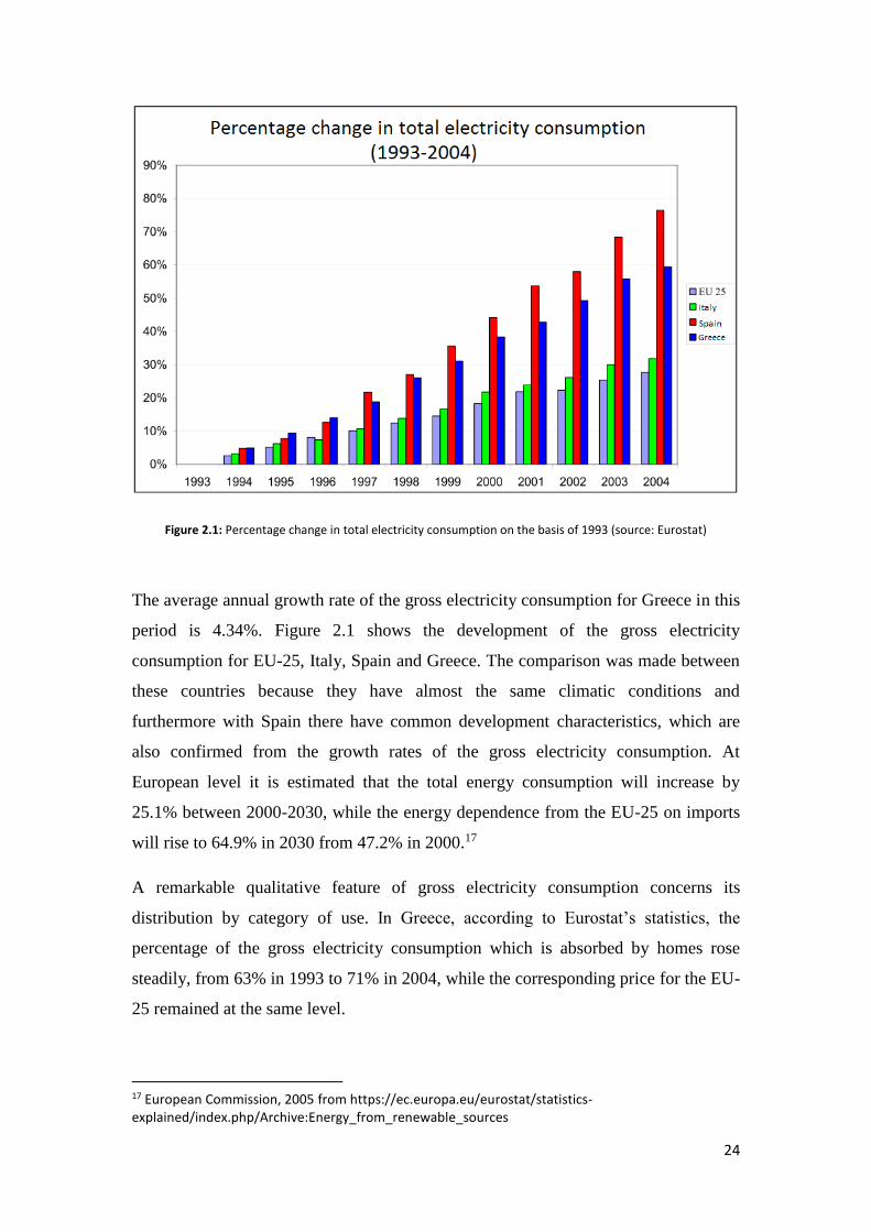
consumption in the EU-25 in 2004 had risen to 2652TWh. For Greece the
corresponding size was 49.72TWh. The percentage change of the gross electricity
consumption between the years 1993-2004 for the EU-25 and Greece is 27.65% and
59.46% respectively.16
16 https://www.eea.europa.eu/data-and-maps/indicators/en18-electricity-consumption/en18-electricity-consumption
24
Figure 2.1: Percentage change in total electricity consumption on the basis of 1993 (source: Eurostat)
The average annual growth rate of the gross electricity consumption for Greece in this
period is 4.34%. Figure 2.1 shows the development of the gross electricity
consumption for EU-25, Italy, Spain and Greece. The comparison was made between
these countries because they have almost the same climatic conditions and
furthermore with Spain there have common development characteristics, which are
also confirmed from the growth rates of the gross electricity consumption. At
European level it is estimated that the total energy consumption will increase by
25.1% between 2000-2030, while the energy dependence from the EU-25 on imports
will rise to 64.9% in 2030 from 47.2% in 2000.17
A remarkable qualitative feature of gross electricity consumption concerns its
distribution by category of use. In Greece, according to Eurostat’s statistics, the
percentage of the gross electricity consumption which is absorbed by homes rose
steadily, from 63% in 1993 to 71% in 2004, while the corresponding price for the EU-
25 remained at the same level.
17 European Commission, 2005 from https://ec.europa.eu/eurostat/statistics-explained/index.php/Archive:Energy_from_renewable_sources

25
Figure 2.2: Electricity consumption percentage for domestic use/total electricity consumption (source: Eurostat)
Figure 2.2 shows the evolution of the electricity consumption percentage for
households and services in the period 1993-2004 for the EU-25, Italy, Spain and
Greece. The particularly high price for Greece is indicative of the national
development orientation and the consumer’s behavior.
Figure 2.3: Percentage distribution of electricity consumption per region for the year 2004 (source: National Statistical Service of Greece (NSSG))

26
The greatest part of the gross electricity consumption is consumed by large urban
centers, with the regions of Attica, Central Macedonia and Central Greece to
concentrate 62% of the total. Figure 2.3 shows the electricity consumption percentage
per region in Greece.
2.4.1.2 Electricity production in Greece
In 2004, domestic electricity production of EU-25 and Greece rose up to 31791 and
59.4TWh respectively. According to data of the Hellenic Ministry of Development in
2005, 55.9% of electricity needs was covered by lignite units and just 12.2% by
renewable energy sources. In the figure below (Figure 2.4) we can see the
participation of each technology in the coverage of Greece’s electricity needs in
2005.18
Figure 2.4: Percentage of electricity needs coverage per technology in Greece, in 2005 (source: Hellenic Ministry of Development)
The biggest part of the energy produced by RES in Greece is covered by large
hydropower plant which contributes with the percentage of 75%. Today in Greece are
operating 15 large hydropower plants of total power, approximately, of 3GW and with
average annual capacity of 4160GWh.
18 http://www.mindev.gov.gr

27
Apart from the large hydropower plants, there are installed RES units with a total
installed capacity of 747MW, of which 77.4% are wind farms, 13.6% small
hydropower plants and 9% rest RES technologies. Figure 2.5 shows the per-
technology distribution of the installed power capacity of RES units.
Figure 2.5: Percentage of contribution of each technology in the total installed capacity of RES units in 2005 (source: Hellenic Ministry of Development)
2.4.2 Spatial distribution of plants
An important qualitative feature of today's image in the field of small hydropower
plants is their spatial distribution in Greek territory. The natural resource that they use
for electricity production is water, i.e. rainfall or, in general precipitation and it is
natural their development to be geared towards areas with rich water potential. In
Greece the richest hydrological basins are concentrated mainly in the northern and
western regions of the mainland, which are dominated by the mountain range of
Pindos. The map of the Image 2.1 presents the distribution of small hydropower
plants, depending on the stage of their implementation. The map also shows the
spatial distribution of the mean annual rainfall in the country of Greece.

28
Picture 2.1: Distribution of small hydropower plants, depending on the stage of their implementation and mean annual rainfall in the country of Greece (source: Hellenic Ministry of Development)
For the projects already in operation, the regions of Central Macedonia, Central
Greece and Epirus concentrate 34 out of 48 operating plants, i.e. 71% of the total. In
terms of installed capacity, those three regions altogether concentrate the 91% of the
total, as the average power of these plants is greater due to the richer energy potential.
As the investment interest in small hydropower plants has become particularly intense
the last 3 years, the search for new sites has turned to the least rich areas. Today in
Thessaly there are 28 under development projects, in West Macedonia 29 and in
Peloponnese 9.
An important parameter regarding the spatial distribution of small hydropower plants
(and RES in general) is related to the design and development of the transmission
system. Monitoring of the under-development plants is necessary so that to fulfill the
future electricity transmission needs and to smoothly integrate new projects into it.
Figure 2.6 shows the total power of small hydropower plants per region and stage of
implementation. The regions of Western and Central Greece, Epirus, Thessaly and

29
Western Macedonia accumulate 84% of the total power of the under-development
plants (production and installation license).
In addition to the need for proper and timely design of the System, monitoring of the
spatial distribution of new plants has also management value in administrative level.
Most of the time required to implement one small hydropower plant, usually the
largest, is used in the required licensing procedures, consequently the speed of the
development of the projects will depend heavily on the preparedness and capabilities
of the services involved. Most of the licenses are handled locally, thus the highly
charged regions have to be well prepared to cope with the expectations of the plant.
Figure 2.6: Total power per region and implementation stage (August 2006) (source: Hellenic Ministry of Development)
2.4.3 Mean Power of plants
One final parameter that needs to be reported is the mean power of the plants, which
is directly related to the water potential and the topography of the site as well as the
financial and technical design of the projects. To ensure a satisfactory exploitation of
water resources, a minimum Energy Efficiency Rating of 75% for the small
hydropower plants has been established. This means that in order for a project to be

30
approved must use at least 75% of the average annual surface runoff in the occupied
position.19
Of course, plants with a higher installed capacity are concentrated on hydrologically
rich areas. Diagram 2.7 shows the mean power of small hydropower plants per region
and implementation stage. The mean power of the projects that have production,
installation and operating license is 2.08, 2.26 and 1.53MW respectively.
Furthermore, the regions of Western Macedonia and Epirus present a mean power of
the class of 3MW independently of the implementation stage, while in the other
regions the corresponding one size is less than or equal to 2 MW.
Figure 2.7: Mean power of small hydropower plants per region and implementation stage (Source: Hellenic Ministry of Development)
Figure 2.8 presents the number of plants per power class and implementation stage.
As can be seen, the under-development plants occupy a greater power range in
relation to those already in operation. The liberalization of the energy market had as a
result the search of suitable locations by prospective investors and the exploitation of
the high energy potential basins.
19 Ramos, H., Almeida, Small Hydropower Schemes as an Important Renewable Energy Source, Hidrienergia’99-Int. Conf. on Small and Medium Hydropower, Austria, 1999.

31
Figure 2.8: Distribution of projects by power class and implementation stage (source: Hellenic Ministry of Development)
Figure 2.9: Mean power of small hydropower plants which become part of the system in Greece per year (source: Hellenic Ministry of Development)

32
2.4.4 Evaluation of the results
According to the analysis above, we conclude that the market of small hydropower
plants grows rapidly as it moves towards the maturing stage. The performance of the
legislative and institutional arrangements that have been made over the last five years
for RES is obvious and is expected to yield important results over the next five years.
A prerequisite for this to happen is the combined effort for the penetration of RES in
the energy system to continue as intensely. Also, the institutional stakeholders must
adapt timely in the current data of the energy market and legislation and to respond
adequately to the significant workload resulting from the need of licensing and
monitoring of the new projects. The overall design of the Transmission System should
also follow the fast pace of the implementation of new projects, so that their
production ability to be exploited immediately.
The challenge for RES is their integration into the energy system to be unblocked
from the need of subsidies. To achieve this goal, new innovative technologies have to
be implemented, through scientific research, which will be more energy efficient and
will reduce the production cost so that to be more competitive against conventional
power generation methods. The same also applies for small hydropower plants in
contrast to the common belief that their technology does not have much room for
development. There is an internationally important research activity to find cheaper
materials and manufacturing methods, improving the performance of the
electromechanical equipment and use more environmentally friendly technologies.
As the sector of small hydropower plants in Greece is starting developing, the
promoters will benefit from international scientific experience. The large number of
projects that are going to be constructed should be built with best technical, economic
and environmental terms. That is why it is important for the international as well as
the domestic technical knowledge to be exploited.
At the same time the construction of a small hydropower plant, with a large dispersion
in many small hydrological basins, is an excellent opportunity for collecting primary
hydrological information in the context of national water resource management
obligations. The water supply works can be the infrastructure for the installation of
measuring tools for the water run-off and the sediment yield.

33
The small hydropower plants is a field in which almost all engineering specialties and
numerous state and non-governmental organizations are involved. In order for their
smooth implementation to proceed, it is required the smooth co-operation of all
directly involved and the consensus of local communities. The public should be
informed for the necessity of RES and also to integrate into citizens' mindset the
concept of sustainable development. Although direct financial profit is used today as a
lever for the promotion of RES, it is important to recall that the ultimate goal is to
ensure a sustainable development and the environmental protection.
2.5 Operating principle of small hydropower plants
The operating principle of small hydropower plants is based on the exploitation of
dynamic energy of surface water, conversion of the dynamic into kinetic energy and
then into electrical energy, in accordance with the laws of electromagnetic fields.
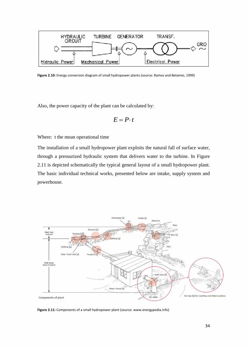
Figure 2.10 illustrates the conversion process of hydraulic energy to mechanical
(rotation), through the turbine and to electrical, via the generator. The operational
power, i.e. the rate of power generation, of the installation is calculated by:
netP n g Q H=
Where:
P the operational power (KW)
n the total efficiency of the turbine ( . .turb gen transn n n n= )
ρ the density of water ( 1000 kg/ 3m at 4oC)
g the acceleration due to gravity (9.81m/s2)
Q the flow rate of the water (m3/s) and
Hnet the available head
34
Figure 2.10: Energy conversion diagram of small hydropower plants (source: Ramos and Betamio, 1999)
Also, the power capacity of the plant can be calculated by:
Where: t the mean operational time
The installation of a small hydropower plant exploits the natural fall of surface water,
through a pressurized hydraulic system that delivers water to the turbine. In Figure
2.11 is depicted schematically the typical general layout of a small hydropower plant.
The basic individual technical works, presented below are intake, supply system and
powerhouse.
Figure 2.11: Components of a small hydropower plant (source: www.energypedia.info)
E P t=
35
2.5.1 Selection of installation site
The factors for the selection of the location of the installation of a small hydropower
plant are:
• River’s flow rate: It is necessary to have a complete study of the river’s flow
rate. Seasonal fluctuations are another factor that should be taken into account.
• Total gross head of plant: The total gross head of plant depends on the
geometry of site of installation of the small hydropower plant.
• Estimation of the available power: The theoretical power that can be obtained
from 1lt/s which falls from height of 1m is 9.91Nm/s or 9.91W. Thus, for flow
rate of 1m3/s the theoretical power obtained is 9810W. If Q is the flow rate in
m3/s, Hnet the available head in m, ρ the water density, g the acceleration due
to gravity, n the overall turbine and generator efficiency, then the obtained
power from the turbine is:
netP n g Q H=
2.5.2 Technical works of intake
The first in-line, upstream work is technical waterlogging with which the exploitable
energy from water is abstracted from the stream or, more generally, from the water
source. The main types of waterlogging are the tyrolean intake, the lateral intake and
the siphon intake. The first two types are usually applied when the water comes from
a natural stream, while the third one is applied in case of utilization of water from an
existing reservoir or canal. Figure 2.12 shows a typical section of the tyrolean and
syphon intakes.
An important distinction between small and large hydropower plants apart from the
capacity limit of 10MW of installed power, is the way that waterlogging works. The
terrace that is constructed at the intakes of a small hydropower plant aims in forming
suitable conditions for the channeling of the required supply to the delivery system.

36
Figure 2.12: Tyronean (left) and siphon (right) intakes. (source: ESHA)
The water abstraction is designed so that part of the flow (ecological supply) can
attribute directly to the natural water stream, in order for the riparian ecosystem be
able to survive. Wherever is required, a ladder is constructed in order for the fish to
move freely along the river bed (fish ladder). At the lateral intakes, shutters are
constructed in order for the transported by the river materials not to be blocked.
After being discharged from the riverbed, water flows freely into the sedimentation
tank or desilter, with exception of the siphon intake where a desilter is not required.
The sedimentation tank has specific dimensions to determine the retention of the
smallest sized grain of sediments, which is determined by the turbine specifications.
Next to the desilter is the forebay, which is designed to ensure the appropriate
hydraulic conditions of the input into the penstock. The basic criterion for designing
the forebay is the prevention of air into the supply pipeline, which can cause
cavitation problems.
2.5.3 The penstock system
The basic part of the penstock system is the pipeline, through which the flow rate is
transferred to the turbine. The construction material and the dimensions of the
pipeline are selected according to techno-economic criteria. The routing of the pipe
depends on the forebay’s and plant’s location, the existing topography and geological
conditions of the area. Its length may be from a few hundred meters to several
kilometers.

37
The material that are typically used are steel, synthetic materials (PVC, GRP),
reinforced or common concrete (tunneling) and, rarely, wood. The choice of the
appropriate material is related to the on-site installation condition, the expected
stresses and the available means and the manufacturing capabilities. Basic criteria for
choosing diameter are the constraint of hydraulic losses and cost, as well as
maintaining the speed at certain levels. In order to reduce the transport cost, two or
three different diameter categories are often selected and the smaller tubes are placed
inside in larger ones during transportation (nesting).
The installation of the pipeline may be either underground or superficial. The pipeline
is usually placed in a pit and then is buried, for environmental reasons as well as for
the protection of the pipe from wear. At the same time, in the penstock pipe is placed
the necessary wiring for the remote control of water intakes by the power house.
Other necessary technical works of the pipe are venting valves and sediments
discharge valves, at the high and low points of the pipeline, respectively, and the anti-
flood protection system, if necessary. Abrupt start up or shut down of the operation
(load rejection), can develop in the pipeline very low or high pressures, multiples to
static pressure, due to transient dynamic phenomena; summarized in the term
hydraulic shock. The intensity of the shock, which can be devastating, depends on the
type of turbine, the length, cross section, pipe material and the start and stop
conditions. The most common technologies tackling the problem are relief valves and
regeneration tanks and towers.
The high pressures on the pipeline result in the development of significant thrusts
forces in places like corners and changes in the diameter. In order to ensure the
stability of the pipeline and for the reduction of the wall stresses, concrete thrust
blocks are constructed, which transport the trends to the ground. Dimensions of the
thrust blocks are dependent on the internal design pressure, the diameter of the
pipeline and existing soil conditions.
2.5.4 The power house
The power house is the place where the penstock ends and the electromechanical
equipment (turbines), the transformers, the generator and the monitoring and control

38
equipment are installed. The type and number of turbines is selected according to the
flow rate and head of plant and the best-case scenario for the operation of the plant.
The most common turbine types are Francis, Kaplan, Pelton and Turgo. Out of these,
the first two are used for low and medium gross heads and high flow rates, while the
last two for high gross heads and a wide range of operating flow rates.
The layout of the power house depends on the existing topography, the flow
conditions of the natural water stream and the type of electromechanical equipment.
The siting of the equipment is different for horizontal, vertical and diagonal axis
turbines. The power house can be underground or superficial. In the second case the
volume and siting of the power house are subject to the building conditions of the area
and must be kept within certain limits of the site and the boundary of the watercourse.
After exiting the turbine, water is attributed to the natural flow of the water stream
through the outlet channel. The escape canal is designed to maintain smooth free flow
conditions and to avoid cavitation phenomenon when it comes to reaction turbines
(Kaplan, Francis).
2.5.5 Turbines
2.5.5.1 Definitions - Field of applications
Hydro-turbines are engines through which the energy of liquid is converted into
mechanical energy. In almost all cases, except for a few exceptions, the moving liquid
is the natural water and the energy that it possesses is dynamic energy that is
expressed by its level compared to the level of the sea.
In general, a hydro-turbine is composed by a wing-mounted wheel placed suitably in a
shell with a supply and drainage conduit. This set-up is placed in an appropriate
position for maximum exploitation of water’s potential energy. The pressurized water
which drops into the turbine strikes on the blades and causes the movement of the
turbine.
They used for the conversion of hydraulic energy, which is given by the total gross
head of the plant, into mechanical work which then, with help of power motors, is
converted to electrical energy.

39
As it concerns the efficiency of these turbines, they have excellent results. Their
efficiency can reach up to 90%. The acquired power is possible to be transmitted
directly either by belts on the shaft of installed machines, or to be, through generators,
converted to electrical energy which is transported inside high-voltage lines over long
distances.
2.5.5.2 Types of hydro turbines
The hydro-turbines are distinguished in principle by the rate of reaction. A turbine is
called impulse turbine when the inner rim is moving due to the compressive power of
water. At this type of turbines, the compressive power of water is entirely converted
to kinetic. The only type of impulse turbine that has prevailed is the Pelton turbine.
On the other hand, when water drops with pressure due to its high load, the turbine is
called reaction turbine. These reaction turbines are of total infiltration, i.e. the entire
impeller runs axiometrically, while the impulse turbine (reaction rate equals to zero),
is of partial infiltration.
The reaction turbines that have prevailed are the Francis turbines, for medium values
of the gross head of the plant (H=50 to 500m), the diagonal flow Deriaz turbines and
various forms of axial flow turbines, for low values of the gross head of the plant
(H<50m), like Kaplan, bulb, tube turbine etc. This ranking shows the variation
associated with the available gross head.
In general, all turbines are consisting of the adductor layout and a rotor or a rotating
wheel, which consists of concentric hoops, a fixed and a mobile one. The second hoop
is rotating along with the motor shaft, which is vertical or rarely horizontal or
inclined. These hoops carry a series of containers, which are called trunks, with
curved or tubular shape for the water distribution and for the water to obtain the most
profitable speed, during its circulation in the turbine, in order for the rotor’s efficiency
to increase.
Based on water guidance, hydro turbines are distinguished in: axial, radial and mixed,
whereas pressure-based are distinguished in: high pressure hydro turbines, medium
pressure hydro turbines and low-pressure hydro turbines.
40
A turbine is called axial when water is driven in such a way to the movable hoop so
that its circulation is in a direction parallel to the engine’s axis.
However, if the water supply is not parallel to the shaft, but perpendicular to it, then
the turbine is called radial. In hydro-turbines of this type we can distinguish two
subtypes: the centripetal and the centrifugal. Whenever water molecules, during their
circulation inside the rotor, directed towards the shaft, the turbine is called centripetal,
while, whenever they move away, centrifuge.
Finally, a hydro turbine is called mixed when the circulation of water inside motor is
partly parallel to its axis and partly vertical.
The position of the shaft of the turbine (horizontal-vertical), their external
configuration and the way they coupled to the generator are the main factors by which
the shape and the layout of a turbine are characterized.
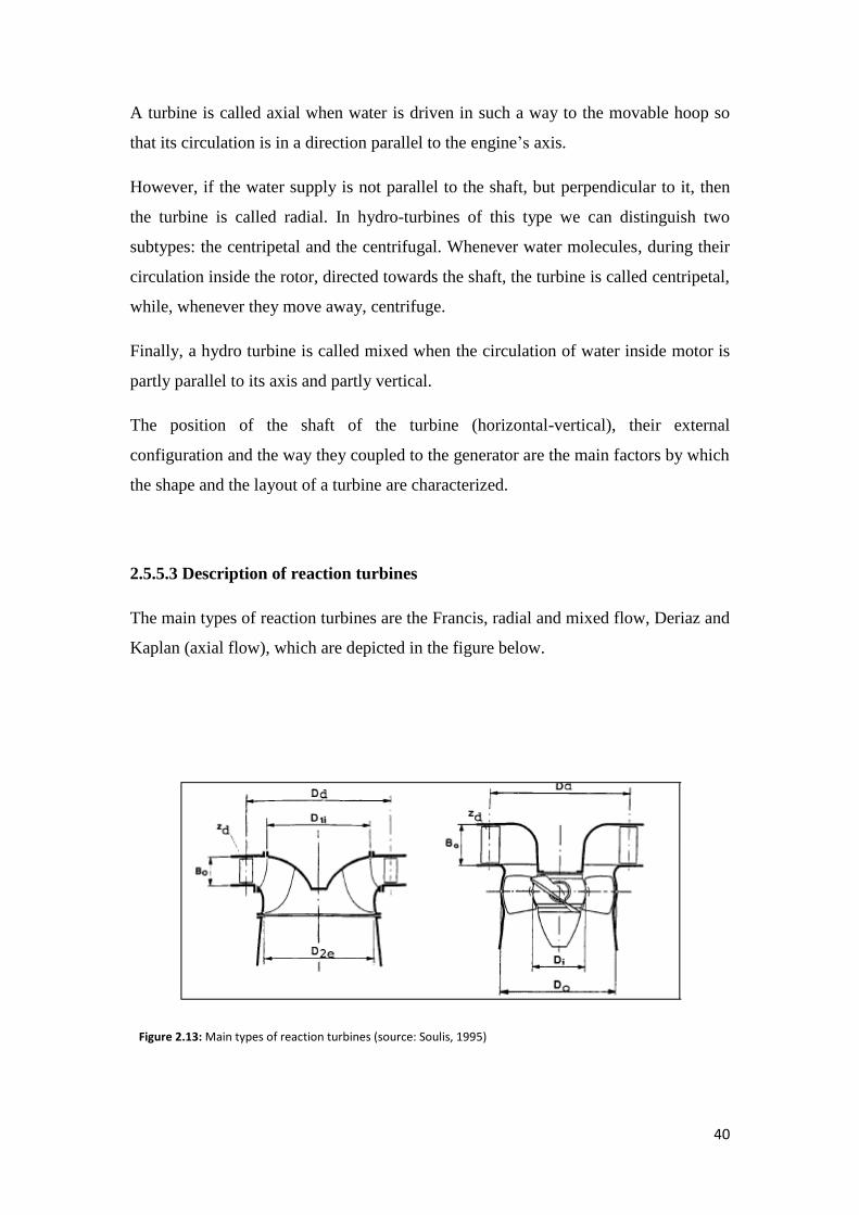
2.5.5.3 Description of reaction turbines
The main types of reaction turbines are the Francis, radial and mixed flow, Deriaz and
Kaplan (axial flow), which are depicted in the figure below.
Figure 2.13: Main types of reaction turbines (source: Soulis, 1995)

41
Figure 2.14: Francis (left) and Kaplan (right) turbine. (source: Soulis,1995)
The flow in the reaction turbines through the impeller is done after the parallel
alteration of the static pressure and therefore their impellers operate uniformly in the
circumferential direction.
In order to achieve uniform feeding and operation of the impeller, the inlet section
surrounds the impeller and, for the same reason as in the centrifuges pumps, has the
shape of a spiral shell, as shown in the figure below.
Figure 2.15: Section of the reaction turbine’s impeller (source: Soulis, 1995)
The rotary impeller is part of the turbine which converts the energy of the liquid into
mechanical energy. It is the part in which the mechanical driving torque develops.
The blades of the impeller of the Francis turbine extend between the ham and the
hoop on which they are attached. This increases the mechanical robustness of the

42
construction and the resistance to the forces that develop on the blades from the
passing flow. It is recalled that the larger is the gross head of the plant H, the greater
the developing power are.
On the contrary, in axial flow impellers, suitable for the exploitation of small gross
head, the forces are not as strong, thus the surface of the blades is limited to the
minimum possible.
Axial flow turbine blades have the ability to rotate (in respect to the hub) so as to alter
their inclination to the relative flow. From the construction point, this rotation
capability increases significantly the cost and complexity of the machine; on the other
hand, it gives the turbine the operating advantage of a good efficiency. The following
figure illustrates schematic forms of Francis and axial flow turbine impellers.
Figure 2.16: Schematic forms of Francis (left) and axial flow turbine impellers (right). (source: Soulis, 1995)
Finally, the outlet section (draft tube) intends to slow down the liquid and lead it to
the outlet. It should be noted that the draft tube has an important role in the operation
and the efficiency of the turbine.
The sections of input, output and the impeller are parts of the engine that participate in
the energy conversion of hydraulic power into mechanical. Nevertheless, as in pumps,
a complete turbine is also comprising from other parts, which ensure the tightness
with the environment (outer shell, seals), the transfer of mechanical power (spindle,
clutches), the receipt of developing forces (bearing thrust) etc.

43
CHAPTER 3
LEGISLATION FOR RES AND SMALL
HYDROPOWER PLANTS INSTALLATION IN
GREECE
3.1 Legal framework for small hydropower plants in Greece20
The following paragraph analyzes the basic national legislation which formed the
current institutional-regulatory framework for the penetration of renewable energy
sources in Greece’s energy system. These legislative acts are essentially the product
of the community guidance and have two main axes: the liberalization and
organization of the domestic energy market in accordance with the Directive 96/92
EC and the institutionalization and acceleration of the integration of RES in
accordance with the requirement of Directive 2001/77 EC.
The first penetration of RES in Greece was due to the Legislation 1559/1958
“Regularization of alternative energy forms affairs and of specialized power
generation from conventional fuels affair”, under which PPC (Δ.Ε.Η.) installed 24
MW while local authorities (Ο.Τ.Α) limited to the minimum level of 3MW and the
private sector remained out of the scene. Despite this almost insignificant result, the
effort revealed the potentials of the sector and the system’s weaknesses and paved the
way for subsequent improvements.
3.1.1 Legislation 2244/1994
This Legislation formed the basis for the substantial development of RES. The energy
pricing system for the produced energy and the installation permit procedure and
operation were set out. Even though PPC retained the exclusive right to produce and
20http://www.rae.gr/site/categories_new/global_regulation/global_national/global_national_laws.csp?s=120&power=&type=&low_text=&lawfek=&lawcode=&lawdesc=

44
dispose electricity, the concept of independent producer was introduced under quite
restrictive conditions. As it concerns small hydropower plants, the maximum
allowable power limit, for private ownership plants was set at 5MW.
3.1.2 Legislation 2773/1999
“Liberalization of the electricity market-Regulation of energy policy issues and other
provisions”
The Legislation 2773/1999 was the founding act of the modern national energy
market and the chance of the private sector to penetrate the electricity production and
supply sectors. With this legislation the Regulatory Authority for Energy was
established (Ρ.Α.Ε.) as independent authority and its competencies as well as its rules
of internal operation have been defined. The Operator of the Hellenic Power
Transmission System (Δ.Ε.Σ.Μ.Η.Ε.) was founded as limited liability company
incorporating 51% of public sector and 49% of PPC and it was designated as the
Transmission System Operator and its operating rules was established.
The PPC transformed into a limited liability company and in that way stopped being
the head of the energy system. It continued to have the ownership of the Transmission
and Transportation System, designated as operator of the first and became the first
private producer and supplier of electricity. The legislation established the
organization and operation framework of the domestic energy market, according with
the directive 96/92 EC, maintained the pricing policy of L. 2244/1994 for RES and
charged a 2% fee on the energy produced by RES for the local authorities.
For small hydropower plants the discriminatory threshold of 10MW of installed
capacity is officially recognized and are included in RES, for which connection
priority to the system is given.
3.1.3 Legislation 2941/2001
“Simplification of procedures for company establishment, licensing of Renewable
Energy Sources and other provisions”

45
This legislation effectively addressed the issue on RES installation in forests and
woodlands with provisions that have been accepted and judged constitutional by the
Council of State. It also covered important gaps and encountered many pathogenic
features of the licensing regime. Some of the main axes of this legislation were the
following:
-Exceptions to large infrastructures installations inside forest and woodland of public
interest are also being extended to RES.
-No licensing is required for the installation of solar stations and wind parks, with the
exception of civil engineering works.
-Power plant connection projects using RES with the interconnected system of the
mainland and the autonomous island regions can be manufactured by any interested
investor according to specifications provided by the system and network operator.
3.1.4 Legislation 3175/2003
“Geothermal potential exploitation, district heating and other provisions”
Although the main theme of this legislation concerns the exploitation of geothermal
potential, its main purpose was to develop and strengthen the competition in the
electricity market attracting new investment sources and securing the adequacy of
electricity to achieve competitive prices for the consumer.
This legislation was essentially a revision of L. 2773/1999 in order for the process of
the liberalization of the electricity market to accelerate. After the Olympic projects in
2004, this legislation includes further actions, such as introducing abridged and
simplified procedures for expropriations which are necessary to strengthen and extend
the power transmission lines in order to serve the development of RES.
3.1.5 Legislation 3468/2006
“Electricity production from renewable energy sources and Combined Heat and
Power and other provisions”

46
The purpose of this law is the introduction of the Directive 2001/77 to the Greek law
and the promotion in the domestic electricity market, with principles and rules, of the
electricity production from RES and CHP units. The basic axes of this legislation are
summarized below:
-Establish clear operational principles of the licensing system, with binding deadlines
for the issuance of permits and opinions from the regulatory authorities.
-Ensure pricing policy by setting a market price for the produced by RES MWh,
including PV systems. For small hydropower plants, this price is set at 73 and
84.6€/MWh for the interconnected and non-interconnected system respectively.
-Establishment of the system of issuing guarantees of origin and of the regulatory
authorities. The Operator of the Hellenic Power Transmission System is designated as
the release manager for the interconnected system, the PPC for the non-
interconnected, the Center of Renewable Energy Sources (CRES) for the autonomous
units and the Regulatory Authority for Energy (RAE) is designated as the control
body of the issue of Guarantees of Origin.
-Establish measures for the promotion of the energy production by PV modules.
-RES units construction is allowed at sea, beach and coastal line, paving the way for
the exploitation of the coastal wind and wave potential.
- An interministerial committee is hereby established which includes the Hellenic
Ministry of Development, the Hellenic Ministry of Economy and Development, the
Hellenic Ministry of Rural Development and Food, the Hellenic Ministry of Culture,
the RAE and the CRES. The aim of the Committee is to promote the implementation
of investment projects of RES and CHP units of large scale (installed power>30MW
or budget>30 million €). The same also applies for small scale RES units.
3.2 Small hydropower plants licensing procedures21
21 http://www.desmie.gr/ape-sithya/adeiodotiki-diadikasia-kodikopoiisi-nomothesias-ape/periechomena/diadikasia-adeiodotisis/

47
The following paragraph presents the required actions and the scheduling for issuing
production, installation and operation licenses. The figure below presents
diagrammatically the typical course of development – implementation of a small
hydropower plant.
Figure 3.1: Typical licensing procedure of a small hydropower plant (source: www.ypeka.gr)
3.2.1 Production License Issue
The procedures for issuing a production license are set out by the provision of L.
3468/2006 and the “Electricity production and supply regulation license” of RAE. In
order to issue a license for the production of electric power from a small hydropower
plant the corresponding application must be submitted to RAE, which is obliged to
submit its opinion within 4 months to the Hellenic Ministry of Development. Then the
Development Minister shall issue the relevant decision within 15 days.
The criteria taken into account for the positive or negative opinion of RAE are the
following:
-Security and protection of the system, the production faculties and of the associated
equipment.
-Protection of the environment

48
-The efficient production and use of electricity.
-The project’s maturity, according to the researches.
-The long-term energy planning of the country and
-Consumer’s protection
In order to issue an opinion according to the criteria above, RAE may cooperate with
the System Operator and transmit the Preliminary Environmental Impact Assessment
(EIA) to the competent authority for environmental licensing, which is required to
make its contribution within 60 days.
The granted production license has a duration of 25 years with the possibility to
renewal for other 25 years. If the installation license has not been licensed, at fault of
the licensee, the production license is revoked.
3.2.2 Installation license issue
The main procedures for issuing the installation license are defined by the provisions
of L.3468/2000 and of the M.D.104247/2002. Responsible for issuing the installation
license is the General Secretary of the concerned region, who must issue it within 15
days from the submission of the necessary supporting documents.
The basic general documentation of the submission file which accompanies the
application for the installation license are the following:
-Summary study - description of the project accompanied by a topographic diagram
(scale 1: 5,000) certified by RAE
-Legal proof of exclusive use of the installation site of the plant.
-A certified copy of each relevant approval issued by a public authority, if this is not
notified to the Licensing Authority.
-Formal declaration of the station owner and of the researcher for commissioning and
undertaking of the installation research respectively.
-Proof of payment of taxes, deductions, charges etc.

49
The specific supporting documents that have to be included in the application file that
concern small hydropower plants are:
-In case of plant connection to a system or to a grid, the necessary data for the plant
subscription bidding (Topographic diagram 1: 50,000, coverage diagram 1:200 ~ 500,
description of E / M installations, etc.).
-Pre-approval site authorization for consideration of decision-making of the site of the
plant for AII category projects.
-Environmental impact assessment file to consider issuing an approval decision of
environmental decisions.
-Water use license and, if the applicant is a non-legal-affiliated entity in the wider
public sector, license for the implementation of a water resource project, according
with the provisions of L.1739/1987.
The granted installation license has a validity period of 2 years and it can be extended
for other 2 years, provided that:
-At the end of the second year a project has been carried out, which costs cover 50%
of the investment.
-The project has not been started for reasons which, proven, are not the fault of the
installation license holder and provided that the necessary contracts for the supply of
the necessary equipment have been concluded. No contracts are required if a
suspension of the implementation of the installation license exists.
3.2.2.1 Preliminary Environmental Assessment and Evaluation (PEAE)
Competent authority for the PEAE is, for small hydropower plants with pipe length
over 3km Special Environmental Service of the Hellenic Ministry for the
Environment Physical Planning and Public Works, for small hydropower plants with
pipe length between 1-3km the Hellenic Directorate for the Environment and Physical
Planning of the relevant region and for small hydropower plants with pipe length

50
smaller than 1km the competent Environmental Service of the relevant Prefectural
Authority.
The application file to be submitted to the competent authority on a case-by-case basis
should include the following:
-Project’s technical description – Includes the project’s identification data, its
geographical location, basic design elements, the type and the intervention area and
the prevention and response measures.
- Preliminary Environmental Impact Assessment – Includes the project’s general
description, the applied technology, the existing on site conditions, impacts on the
natural and man - made environment, possible alternatives, benefits, the necessary
measures for the shutdown etc.
-Maps and photographic material – Topographic maps of scale 1:50,000 and 1:
5,000 that will reflect the location and extent of the project and photos from the
installation site and characteristic points of the wider region.
For issuing the approval of Preliminary Environmental Assessment and Evaluation
the opinions of the organization influenced by the project (e.g. forestry authorities) are
necessary.
Within 10 business days, the responsible service for PEAE must forward the dossier
to the advisory bodies, who in turn must within 15 business days to issue a decision.
The environmental authorization decision for PEAE is granted within 5 business days
from the receipt of those opinions.
3.2.2.2 Approval of environmental conditions (AEC)
The same as reported in the previous paragraph applies for the competent service for
AEC. The accompanying application envelope includes the project’s full
Environmental Impact Study (IEP). In the case that the licensing authority considers
that the project does not have significant impacts on the environment, IEP can be used
for editing AEC.

51
3.2.2.3 Approval of forest intervention (AFI)
Competent of AFI authorization is the General Secretary of the concerned region,
who owe within 40 days of the delivery of the relevant application and file, and with
the agreement of the Forestry Authority to issue the decision. Prerequisite for granting
AFI is the IEP of the specific project. The contents of the dossier for the AFI are the
Project Technical Description, maps and photographic material.
3.2.2.4 Water utilization License-Implementation of Water Resources Utilization
Project (WUL)
According to P.D.256/1989 a single license may be granted for water utilization and
the implementation of a water resource project, in accordance with the procedure set
out in L.1739/1987. The competent authority for issuing the license is the Hellenic
Ministry of development, which is obliged to issue the relevant decision within 2
months of the deposit of the required supporting documents. The contents of the
accompanying the request envelope are the following:
-A topographic diagram, showing the area of the implementation of the project, water
utilization and land uses within a radius of 200 meters of the project’s implementation
area.
-A copy of a private agreement, in case of water utilization from an area of different
ownership, if required.
- Legal representation mandate, if the applicant represents a private law body or a
collective body.
-General description of the project.
- Adequate study elements on which the qualitative and quantitative status of water
resources are analyzed, before and after the implementation of the project.

52
3.3 Operating license issue
Authorization is granted upon special request, as well as the installation license, by
the General Secretary of the concerned region, who is required to issue it within 15
days of the completion of the required technical inspections. The license is valid for
20 years and can be renewed for other 20 years. The supporting documents of the
request file are:
-Verified copy of the connection agreement to the system or the grid, between
producer and transmitter respectively.
-A certified copy on the purchase/sale agreement, between producer and transmitter,
depending on whether the generated energy is diverted in the System or the grid
respectively.
-Certification of Hellenic Transmission System Operator (HTSO) or of PPC on
completion of grid connection and other necessary facilities constructions, in
accordance with the minimum requirements set out in the Association Agreement.
- Legally certified copy of the building permit for the plant.
- Certificate of the Fire Brigade that all necessary the fire safety measures are taken in
accordance with its recommendations.
- Autopsy Report of the Licensing Authority confirming compliance with the
conditions and restrictions of the installation license.
-Formal declaration of the project’s body that the terms of the decision of IEP have
been met and that they will be respected during operation.
-Other formal declarations of the owner, the supervised engineer and of the engineer
that supervises the project.
Prior to the issuance of the license and after completion of the plant’s installation, the
station is temporarily connected to the system or to a grid in order to perform the
required plant testing, for up to 4 months.
53
CHAPTER 4
STAGES OF CONSTRUCTION OF A SMALL
HYDROPOWER PLANT
4.1 Estimation of the area’s hydrodynamic and installation site
selection
The hydrodynamic of an area is the ability to produce work from flowing waters.
Hydrodynamic position is the location of a water stream that has potential for
hydrodynamic exploitation.
The estimation of the hydroelectric potential of a region is the primary and most
critical stage for the development of small hydropower applications. The
determination of the hydrological characteristics, combined with the recognition of
the area, has as goal describing the variance of the specific supply and selecting
potential spots for small hydropower plant installations.
For locations that have the highest hydroelectric potential density index, the flow rate
curve is estimated using a variety of hydrological models in combination with a
minimum set of flow measurements.
Taking into account topography, geology, precipitation and any existing
measurements, the theoretical hydrodynamic of the area is calculated.
The basic equipment used to measure flows and the recognition of the area includes:
• Ultrasonic closed-circuit flow meter
• Sensors for measuring pressure
• Sensors for measuring electrical quantities
• Tachometers and accelerometers
• Data collection units and broadcasting system
• S.I. measuring system and data processing software.

54
4.2 Feasibility study
The first step for the installation of a small hydropower project is considered carrying
out a feasibility study by examine various alternative scenarios for project designing.
The purpose of the feasibility study is:
I. Determination of drop height, with an initial selection of the water abstraction
site and of station.
II. The construction of the flow duration curve of the site, for the assessment of
the annual energy production and the calculation of the annual revenue of the
plant.
III. Determining the construction cost of the project based on the morphology of
the site, the length of the depressant duct, the type of electromechanical
equipment and the distance of its interconnection with the PPC’s grid.
IV. Determining the financial viability of the project, by calculating the necessary
economic indicators and drawing conclusions.
4.3 Preliminary design of a small hydropower plant
If the outcome of the feasibility study is positive, then the design study of the small
hydropower plant’s installation is being prepared at a premeditated level. The depth of
the premeditation is such that it is sufficient for editing various licenses required for
the construction of a small hydropower plant.
The design that is based on the results of the feasibility study contains:
I. The selection of hydro turbines and the determination of their hydraulic
characteristics.
II. The generators selection with their characteristics and all the concomitant
electrical equipment.
III. The determination of the characteristics of the automation system and of the
operation and installation.
IV. The determination of the water supply system to the station, i.e. water intake,
the supply line (open or closed), the loading tank and other auxiliary facilities.

55
V. The building infrastructure for the installation of mechanical equipment with
the turbine-generators layout, for easy access and maintenance without
interrupting the operation of the other facilities, of the automation and all the
auxiliary equipment, of the substation as well as the interconnection to the
grid.
4.4 Study-construction of hydro turbines
For the electromechanical equipment of small hydropower plants, a study is being
prepared for the design and construction of the hydro turbines of the project, the
selection of the appropriate generator and the automation system.
4.5 Environmental Impact Study (IEP)
The subject of the study is to assess the potential environmental impacts resulting
from the construction and operation of small hydropower plants and the evaluation of
these impacts in order to propose appropriate measures to avoid or limit them.
The aim of IEP is to offer, to those who make decisions for the public, clear and in-
depth assessments and information on the project’s environmental impact. In the
framework of IEP the most significant burdens and pressures during the construction
phase are examined, which are mainly connected to the water supply works in the
river bed, the installation of inlet duct and the construction of the machinery and other
structures. Furthermore, the potential impacts of cross-cutting works are examined,
such as road mapping, which in some cases occurs in inaccessible places with
aesthetic and environmental value, causing additional technical and environmental
difficulties. Particular emphasis is given on the aesthetic adaptation and the
harmonization of all the individual works in the environment. During the project’s
operational phase, the impacts on the diversion of a major segment of the river flow
from the water inlet till the electrical power plant are examined. These impacts may
be important in flora and fauna particularly when the works are extended in
environmentally protected areas.

56
Finally, other issues that are examined in the context of the small hydropower plant’s
operation concern noise pollution and the safe operation of the engine room and the
protection of the residents when they come into contact with parts of the work.
4.6 Operating measurements and efficiency of a small hydropower
plant
Optimizing the operation and maximizing the energy produced are the determinant
keys of the thriftiness of small hydropower plants.
Increasing the plant’s efficiency by 1%, leads to a significant increase of energy
output, annual revenue and a remarkable decrease of the depreciation period and
investment.
For the proper operation of the project measurements are made, such as the
calculation of power curve, the efficiency and the losses of the small hydropower
plant in relation to the variation of the flow rate and net height. Also, a measurement
of the generator's electrical magnitudes is made (voltage cosine, intensity, active and
inactive power, energy) and automation testing in case of load shedding.
For the optimal allocation and exploitation of the flow rate in small hydropower
plants with more than one installed turbines, optimal combinations of the units’
efficiency curves are proposed.

57
CHAPTER 5
ENVIRONMENTAL IMPACT AND LCA OF
SMALL HYDROPOWER PLANTS
Various engineering works, in order to achieve the desirable goals, modify the
environment. However due to some sensitive characteristics, but also due to the
imperfection of the designs and technologies used, undesirable changes occur to the
environment, as side effects of human interventions.
The environmental impact assessment is the compatibility test of various development
designs, programs or projects with environmental protection requirements. Avoiding
unpleasant or even disastrous environmental impacts from various projects is
facilitated, if an appropriate study which will predict and evaluate them preceded. The
environmental impact researches, especially at local level, have been a very important
tool for the environmental protection, especially on developed countries. The main
subject of the environmental rehabilitation studies is the future environmental impacts
prediction that will occur under the influence of the project. The difficulty of
forecasting is due to many factors such as data deficiency, complexity etc. A complete
assessment also requires consideration of the environmental impact of all the project’s
alternatives solutions because some may be less harmful to the environment, even if
they are economically or technically lagging.
5.1 Visual nuisance - aesthetic integration
Visual nuisance is mainly cause by road construction projects, which if are not
carefully designed and executed, can create large slopes and have a strong impact on
the landscape’s aesthetic. They can also cause landslides in an unstable ground. An
indirect but serious impact is the unreasonable disposal of debris to nearby water
steams or ravines. The visual impact from the dam and the water abstraction work, the
58
supply line, the building of the plant and from the transportation lines is minimal, up
to zero, if the project is designed with some basic environmental sensitivity.
In case of reservoirs, the possible visual nuisance come from the land’s occupation
which may affect the area’s agriculture, local infrastructure, archaeological sites and
protected areas. Visual nuisance will be cause due to landscape change and possibly
of the local aquifer, which in turn will cause changes in the aquatic and terrestrial
natural environment. Of course, in most cases, reservoir (when the dam construction
is selected) can lead to the creation of wetland and to an entirely acceptable aesthetic
result.
5.2 Natural environment, flora-fauna
Areas of water potential exploitation are mainly found in semi-mountainous areas
where the existence of this natural resource (water) in combination with altitude
difference which is achieves from the water abstraction point to the power station,
ensure the project’s feasibility and sustainability.
From the mountainous water abstraction or the dam (downstream), till the natural bed
of the river, the water’s flow rate can be zero for long time periods. This fact can have
irreversible consequences to the flora and fauna that is found between the abstraction
point and the power station. For this reason, the appropriate downstream the
abstraction point water quantity should be ensured, to maintain the balance of flora
and fauna.
Furthermore, during the construction phase, deforestation should be limited. In cases
of creating a reservoir, permanently changes occur to flora of the basin and the of the
vegetation clearing of the land that is used from the created reservoir is necessary.
Finally, special attention should be paid to the fauna which lives or uses the area and
ensure the free movement of the aquatic organisms such as fish, so as not to create
obstacles to fish species moving along the river. For this reason, a specific technical
construction should be provided (fish passage).

59
5.3 Soil, surface and groundwater
The water abstraction/dam interrupts the continuous supply of sediments along the
river, as a result to accumulate over time in the water intake or the created reservoir.
Sediments is a problem that requires frequent treatment for the proper operation of the
small hydropower plant. Stopping the sediments’ flow creates a long-term change in
the river bed and estuary, while it increases the corrosion which may occur
downstream of the power plant, if appropriate measures are not taken.
The operation of small hydropower plants affects the surface waters of the area and
specifically, from the dam till the outlet of the water to the river bed. At this section,
with the utilization of the water potential, the ecological balance will be reduced
drastically.
At the same time, during designing and siting a small hydropower plant, the existing
uses of water downstream the water intake work should be ensured or consider
alternative solutions. It should be noted that after the water utilization, there is no
change in its quality.
Concluding, in the case of dam construction and the creation of dam, the elevation of
the water’s free surface is noted, resulting the lift of the underground aquifer.
Picture 5.1: The impact of dams on river ecosystems (Pyramid of impacts) (source: www.labond /dams/…)
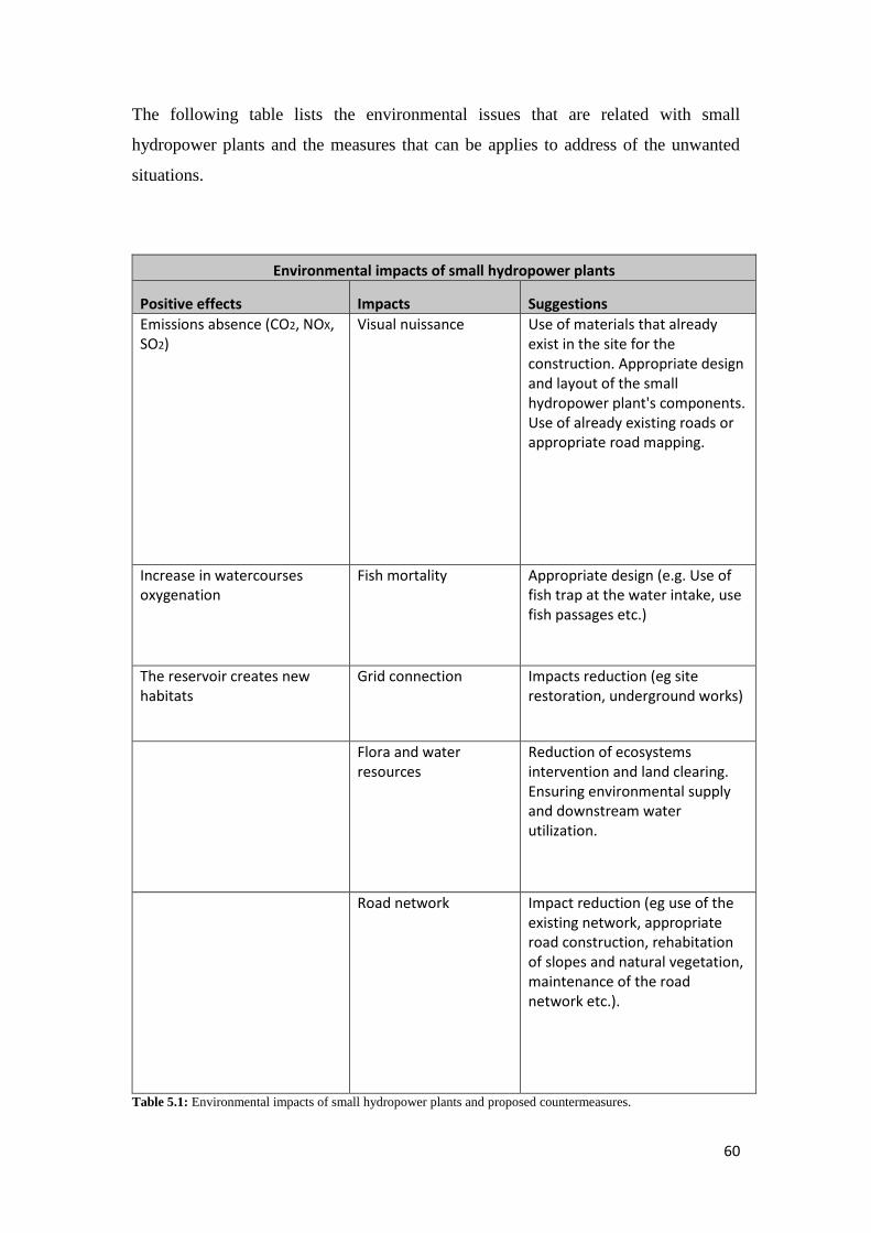
60
The following table lists the environmental issues that are related with small
hydropower plants and the measures that can be applies to address of the unwanted
situations.
Environmental impacts of small hydropower plants
Positive effects Impacts Suggestions
Emissions absence (CO2, NOX, SO2)
Visual nuissance Use of materials that already exist in the site for the construction. Appropriate design and layout of the small hydropower plant's components. Use of already existing roads or appropriate road mapping.
Increase in watercourses oxygenation
Fish mortality Appropriate design (e.g. Use of fish trap at the water intake, use fish passages etc.)
The reservoir creates new habitats
Grid connection Impacts reduction (eg site restoration, underground works)
Flora and water resources
Reduction of ecosystems intervention and land clearing. Ensuring environmental supply and downstream water utilization.
Road network Impact reduction (eg use of the existing network, appropriate road construction, rehabitation of slopes and natural vegetation, maintenance of the road network etc.).
Table 5.1: Environmental impacts of small hydropower plants and proposed countermeasures.

61
5.4 Life cycle assessment (LCA) – Comparison between a small
hydropower plant and a conventional thermal power plant
Life cycle assessment a number of methods for identifying, the assessment and,
wherever is possible, the quantification of the environmental impacts of a project or of
an activity throughout their life cycle.
There are two main phases of the LCA: locating the important components and their
impact assessment. The identification of important environmental components aims at
the quantification of the environmental inputs and outputs over the project’s life. The
result is a list of pollutants or other burdens which may cause negative impact on the
environment. Usually, these burdens are not comparable between them. The impact
assessment aims at grouping and evaluating the potential environmental burdens that
have been identified. The impacts are aggregated on the basis of equivalence factors.
Usually the inclusion of different impacts is not obvious, thus the corresponding
values of quantitative and qualitative nature have to be set, depending on their relative
importance. The different evaluation methodologies used can be linked to objectives
or costs or be estimated by a group of experts.
Picture 5.2: Lignite (used in lignite power plant) (left) and small hydropower plant (right) (source: energis.ba)
The different stages of the life cycle of a convention thermal power plant, in our case
a lignite power plant, are presented in the following figure:

62
Figure 5.1: Life cycle stages of a lignite power plant (source: www.researchgate.net)
The main features of the Life Cycle of a lignite power plant (region of Ptoleimaida)
are given below:
Stage Prameter Quantity
1. Extraction of lignite Area Ptolemaida
Mining type Surface
% of lignite supernatants 3.3-5 m^3/t
2. Transportation Air emissions TSP 1,525 t/yr
NOx 203 t/yr
SO2 94,5 t/yr
CO2 114,946 t/yr
3. Electricity production Fuel Lignite
Area Ptolemaida
Installed power 366.5MW
Energy production 2199000 MWh
Air emissions TSP 556 t/yr
NOx 2170 t/yr
SO2 2615 t/yr
CO2 2902680 t/yr
4. Station construction Matterials 107500 t steel
198000 t cement
5. Waste Solid 12200000 m^3/yr (mines)
335000 t/yr (station)
Liquid 1500000 t/yr Table 5.2: Life Cycle Characteristics of a Lignite Station in Ptolemaida (source: ypan.gr)

63
The different stages of the Life Cycle of a small hydropower plant are shown in the
figure below:
Figure 5.2: Life cycle stages of a small hydropower plant (source: ypan.gr)
The basic characteristics of a Life Cycle of an already existing small hydropower
plant in the region of Drama are given to the following table:
Stage Prameter Quantity
1. Construction of dams and power production stations
Material needed 12000000 m^3 rocks
540000m^3 cement
Work 9360 human years
Construction period 15 years
Dams Thisavros (175m height)
Platanovrisi (95 m)
Temenos (45 m)
2. Electricity production Area Region of Drama
Reservoir Thisavros (18 km^2)
Platanovrisi (3.25 km^2)
Temenos (1.05 km^2)
Total installed power Thisavros (300 MW)
Platanovrisi (100 MW)
Temenos (19.5 MW)
Annual energy production Thisavros (355 GWh)
Platanovrisi (203.3 GWh)
Temenos (61 GWh) Table 5.3: Life Cycle Characteristics of small hydropower plants in the region of Drama (source: ypan.gr)

64
During the operation phase of a small hydropower plant, there are no air emissions in
the atmosphere and in that way, there is no degradation of its quality. On the contrary,
due to its operation, there is a reduction in the total quantities of gaseous pollutants
(CO2, NOx, particulates), because of substitution of the electrical energy that is
produced from conventional fuels at PPC’s plants, with analogue that is produced
from small hydropower plants.
Specifically, and in accordance with the specific emission of gaseous pollutants from
conventional power generation stations in the interconnected grid, 1kWh contributes
to the emission of the following atmospheric pollutants:
Pollutants Emission (g/kWh)
CO2 850
SO2 15.50
CO 0.18
NOX 1.20
HC 0.05
Particles 0.80 Table 5.4: Pollutants emission from the production of 1 kWh in conventional power generation plants (source:
ypan.gr)
5.5 Environmental impacts from the water intake and related works
In the case of the mountain-type water intake selection and the construction of access
roads, no significant impacts on the natural environment are expected, provided that:
• The adaptation of the water intake to the river bed is ensuring, with low height
works, so as for the character of the site not to alter.
• An effort is being made, especially in areas of particular natural beauty or
Protected Areas (NATURA 2000), to avoid land clearing of a significant
number of trees, for the construction of the water intake and access roads.
• A special technical construction (fish passage), in order for the fish free
movement.
• An appropriate road design, tree planting and slopes retaining, to deal with
relatively large excavations.

65
• The appropriate amount of water downstream of the water intake is ensuring,
to maintain the flora and fauna balance.
• The existing water utilization downstream the water abstraction work is
ensuring.
• A special disposal device is constructed of the fine-grained sediments,
downstream the project. In case of mountain water intake, a periodic disposal
of coarse sediments downstream should be planned.
In the case of choosing a dam construction, the following should be carefully
examined:
• Construction materials of the dam and of individual works (e.g. clay dams,
because they are better adapted to the site have good behavior in earthquakes).
• Places for materials removing and disposing (avoiding the removal and
disposal in places that are outside the occupation place of the dam, if this
possibility not firstly examined).
• Dam’s layout (although in most cases the dam is located in river narrowing, it
should be examined if the created reservoir and the operation of the project
can ensure the creation of wetland ecosystem and do not negatively affect
flora and fauna of the area, both during construction and operation phase).
• Stability of the dam and seismicity of the area (in large constructions, the
investigation of flood wave propagation is advisable, in case of partial or total
dam’s destruction)

66
CHAPTER 6
HYDROPOWER PLANTS IN HALIACMON
RIVER
Haliacmon river (or Aliakmon) is a large river, 297 kilometers long, which runs
through Greek territory along its whole length. It rises at Mavri Petra on Mountain
Voio and flows into the Thermaic Gulf, after a course running almost at right angles,
with the point of the angle to the south.
Aliakmon’ course, originally in a south-easterly direction, is confined between the
almost parallel massifs of Pindos to the west and Askios-Vourinos to the east. At its
southernmost point, the Aliakmonas river is forced to turn northeast by the
Kamvounia, Titaros and Pieria range.
Aliakmon river maximum width (apart from the artificial Polyphyto Lake) is 120
meters, with a flow rate of 1 meter per second. Formerly, during the rainy season it
did not have a regular course at its mouth and often flooded large expanses, earning it
the name Lolopotamos (“Crazy River”). Sources mention that in ancient times,
triremes were able to row up it quite a distance from the river mouth.
Image 6.1: Geographical position of Haliacmon river in Greece

67
6.1 Existing hydropower plants in Haliacmon river22
The Aliakmon river is one of the most important resources in Western and Central
Macedonia with a total length of about 297 km, drainage area of approximately 9.210
km2 and mean annual flow of 2x10⁹m3. PPC developed the suitable places to
exploitation of hydro potential of river manufactured a line of dams and hydroelectric
power stations since 1970.
The installed capacity of PPC in 2006 was 12,695MW.
Table 6.1: Installed capacity of PPC SA (source: www.portal.tee.gr)
The total installed capacity of hydropower plants at national level is 3,060MW,
representing 24% of the total installed capacity of PPC and produce on average
annual basis 13% of the total generated electricity.
PPC hydropower plants on Aliakmon river, starting from its source to the estuary are:
Table 6.2: Main features of hydropower plants in operation, Aliakmon river (PPC) (source: www.portal.tee.gr)
22 Karagiannidis A.P., Papaioannou E.A., “The Aliakmon Hydropower Croup of PPC” fromhttp://portal.tee.gr/portal/page/portal/teelar/EKDILWSEIS/damConference/eisigiseis/5.2.pdf

68
The annual energy output (GWh) from Polifito (P), Sfikia (S), Asomata (A)
Macrochori (M), are respectively:
On average hydro conditions: 515 - 263 - 175 - 28
On good hydro conditions: 1056 - 536 - 361 -43
On poor hydro conditions: 374 - 192 - 127 -22
On drought: 200 - 103 - 68 -16
6.1.1 Hydropower plant of Polifito
This hydropower plant is located 45 km southeast of Kozani. The project as a whole
consists of the Reservoir, the diversion tunnel, the dam, the spillway, the water intake,
the addition tunnel, the hydroelectric station, the reservoir and the under-pressure
shaft.
-Reservoir
The reservoir of Polifito has a capacity of 2,244 million m3, while its useful volume is
1,220 million m3.
The average annual runoff during the years 1998-2007 was 1,373 million m3, 18% of
total average runoff of PPC’s reservoirs during these years.
The runoff area is 5,800 km2, while the flooded area is 74 km2.
The maximum operating water level is 291 m (a.s.l) and a flood level of 293 m.
-Diversion channel
The length of the diversion channel is 634 m, its diameter 9.7 m and its flow rate
1,600 m3/s.
-Dam
The dam is stony with an upstream inclined core.
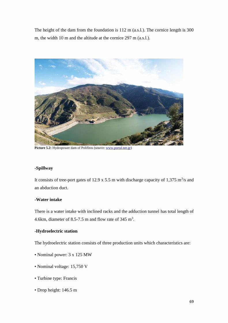
69
The height of the dam from the foundation is 112 m (a.s.l.). The cornice length is 300
m, the width 10 m and the altitude at the cornice 297 m (a.s.l.).
Picture 5.2: Hydropower dam of Polifitos (source: www.portal.tee.gr)
-Spillway
It consists of tree-port gates of 12.9 x 5.5 m with discharge capacity of 1,375 m3/s and
an abduction duct.
-Water intake
There is a water intake with inclined racks and the adduction tunnel has total length of
4.6km, diameter of 8.5-7.5 m and flow rate of 345 m3.
-Hydroelectric station
The hydroelectric station consists of three production units which characteristics are:
• Nominal power: 3 x 125 MW
• Nominal voltage: 15,750 V
• Turbine type: Francis
• Drop height: 146.5 m

70
• Number of rotates: 125 rot/min
• Special consumption for production: 3.2 m3/kWh
-Reservoir
The reservoir is constructed with two upper horizontal chambers, its height is 84m
and has a diameter of 28m.
-Under pressure shaft
The height of the shaft is at 86m and its diameter at 7m.
6.1.2 Hydropower plant of Sfikia
This hydropower plant is located about 20km south of Veria. The project as a whole
consists of the reservoir, the diversion tunnel, the dam, the ejector, the water intake,
the addition tunnels, the power station and the escape bottom.
-Reservoir
The reservoir of Sfikia’s hydropower plant is daily arranged with a capacity of 99
million m3. The flooded area is 4.3 km2 and the maximum operating level is 146 m
(a.s.l), the minimum 141.8 m and the flood level 147.0 m.
-Diversion tunnel
The type of the tunnel is that of pressurizes by concrete, its internal diameter is 490 m
and its flow rate 620 m3/s. The bottom altitude at the input is 88 m and at the outlet of
84 m.
-Dam
The dam is rock filled with a central alloy core and volume of 1,620,000 m3. The
height of the dam is 82 m, the cornice length is 220 m and the minimum width 12 m.
-Ejector
There are two ejectors with two arched doors of 7.2 m x 9.0 m each and a lifting
mechanism. The altitude at the cornice is 137 m and the flow rate is 1,600 m3/s.

71
-Water intakes
There are three water intakes (one for each unit) with inclined grilles, with dimensions
of the openings at the entrance of the tunnel of 5.6 m x 10.9 m and distance between
their axles of 22 m. The clogging means are rolling shutters and steel barriers. The
altitude of the bottom is 126 m.
Picture 5.3: Hydropower plant of Sfikia. Water rejection works (left) and water intakes (right). (source:
www.portal.tee.gr)
-Conduction channels
There are three conduction channels (one for each unit). The total length of each
tunnel is 160.8 m and the inside diameter is 7 m. The axis altitude at water intake is
134m and at the power station 73m. Upstream they constructed by concrete while
downstream from steel.
-Power station
The Production Station is located on the left side of the dam, is underground and
consists of three units of vertical reversible axis, whose characteristics are:
• Function as generators: 3 x 10⁵ MW
• Function as pumps: 3 x 10⁸ MW
• Nominal voltage: 15,750 V
• Turbine type: Francis

72
• Turbine power: 143.000 HP
• Average drop height: 62 m
• Number of rotates: 125 rot/min
• Special Consumption for Production: 7.2 m3/kWh
• Special Consumption for Pumping: 0.19 kWh/m3
-Evacuator bottom
It is located on the left side of the dam and its type is a tunnel from concrete. The
inner diameter of the tunnel is 3.5 / 3 m, the length 309 m and the maximum drainage
capacity 100 m3/s.
6.1.3 Hydropower plant of Asomata
This plant is located about 8 km south of Veria. The project as a whole consists of the
reservoir, the diversion tunnel, the dam, the ejector, the water intakes, the conduction
channels, the hydropower station and the evacuator bottom.
Picture 5.4: Hydropower plant and dam of Asomata (source: www.portal.tee.gr)
-Reservoir
This reservoir has a capacity of 53 million m3 and a useful volume of 10 million m3.
The flooded area of 2.6 km2. The maximum operating level is 85.5 m (a.s.l), the
minimum 81 m and the flood level 89 m.

73
-Diversion tunnel
The type of tunnel is with concrete pressure, has a length of 496 m, the internal
diameter is 7.5 m / 8.5 m and the flow rate is 600 m3/sec. The bottom altitude at the
entrance is 42.5 m and at the exit 37.6 m.
-Dam
The dam is made from soil with outer bands of gravel central aluminate core and a
volume of 1,450,000 m3. The height of the dam is 52 m, the cornice length is 205 m
and the minimum width 15 m.
-Ejector
The ejector consists of three arched doors 7 m x 8 m each and a lifting mechanism, an
abduction tunnel and an ejection work. The elevation in the cornice is 77 m and the
flow rate is 1,600 m3/s.
-Water intakes
There are two water intakes with inclined grilles, with opening at the entrance of the
tunnel of 4.8 m x 9.3m and distance between their axles of 17.9m. The clogging
means are rolling shutters and steel barriers. The altitude of the bottom is 69.5 m.
-Conduction channels
There are two conduction channels (one for each unit). The total length of each tunnel
is 59 m and their internal diameter 6.0 m. The altitude of the axle at the water intake is
74.4m and at the power station 42.5 m.
-Hydropower station
The Production Station is located on the right side of the dam, it is underground and
consists of two vertical axis units, the characteristics of which are:
• Nominal power: 2 x 55 MW
• Nominal voltage: 15,750 V
• Turbine type: Francis

74
• Turbine power: 75,700 HP
• Average drop height: 42 m
• Number of rotations: 125 rot/min
• Special Consumption for Production: 10 m3/kWh
-Evacuator bottom
It is located within the diversion tunnel, on the right side of the dam and its type is a
tunnel of concrete. The altitude at the entrance is 53 m, at the exit 37.6 m and has a
maximum drainage capacity of 90 m3/s.
6.1.4 Small hydropower plant of Agia Varvara
The project is located about 6 km south of Veria on the provincial road of Veroia-
Vergina. The project as a whole consists of the Old and New Reservoir (currently
operating as one), the dam, the ejector, the water intakes and the small hydropower
station.
Picture 5.5: Small hydropower plant of Agia Varvara (source: www.portal.tee.gr)
-Reservoir
The reservoir has a capacity and useful volume of 4.5 million m3. The highest
operating level is 42.5 m (a.s.l), the normal 42 m and the minimum 38.75 m.

75
-Dam
The New Reformed Dam is constructed with an impermeable aluminum core. The
altitude at its nominal coronation is 43.5 m.a.s.l., the length 2,296 m, its height from
the foundation is 10 m and width 7 m.
-Ejector
There is an ejector with five (5) arched door of 6.44 m x 7.45 m each, a hydraulic
lifting mechanism and an expansion work. The altitude in coronation is 34.55 m and
has a flow rate of 1,600 m3/s. At the top of the three intermediate doors, three smaller
sliding doors have been constructed, with dimensions of 4.44m x 1.65m.
-Water intakes
The water intake duct is upstream of the first right dam accordingly with the river
flow and has a length of 33 m and a diameter of 1,4 m.
-Small hydropower station
The station is located on the right by the river's flow side of the ejector, is
underground and consists of a horizontal axis unit with the following features:
• Nominal power: 920 kW
• Nominal voltage: 600 V
• Turbine type: Kaplan
• Average drop height: 15 m
• Number of rotations: 500 rot/min
• Special Consumption: 32 m3/kWh
• Transformer: 800 KVA-0.6/20 KV

76
6.1.5 Hydropower plant of Makrochori
This hydropower plant is located within the Main Irrigation Canal Α0 within the
boundaries of M.D. of Diavata of the Municipality of Ag.Pavlos. The project as a
whole is composed by the spillway, the water intakes and the conducting channels,
the automatic grilles cleaner and the power station.
-Spillway
There is a spillway with a 9.9m x 3.7m sliding gate and a hydraulic operating
mechanism. The altitude at the coronation is 34.05 m and the discharge flow is 78
m3/s.
-Water intakes
There are three water intakes (one for each unit) with inclined grilles, with openings
at the entrance of the tunnel of 4.6 x 6 m and distance between their axles of 6 m. The
altitude of the bottom is 20.18 m.
-Conduction channels
There are three conduction channels (one for each unit). The length of each channel is
9.0 m and the inside diameter is 4.0 m.
-Hydropower station
The hydropower station is located on the left side of the dam, it is underground and
consists of three horizontal axis units, the characteristics of which are:
• Nominal power: 3x3.6 kW
• Nominal voltage: 15,750 V
• Turbine type: Kaplan
• Average drop height: 15 m
• Number of rotations: 250 rot/min
• Special Consumption: 32 m3/kWh

77
CHAPTER 7
DESIGN OF A NEW SMALL HYDROPOWER
PLANT AT ALIACMON RIVER (CASE STUDY)
7.1 Daily flow duration curve
As it concerns hydrologic potential, the energy produced depends on the flow rate. It
is important to know the dependence of Q(t) on time and the time period (time rate)
that the flow rate can exceed a specific value. Knowing that the design flow can be
calculated.
The flow rate (discharge) is treated as a random variable following a certain
distribution. This distribution is approximated by means of the daily flow duration
curve, a cumulative distribution function of the flow rate exceedance probability.
The basic assumption made is that the parameters of the distribution are constant in
time and therefore, the daily flow duration curve is also considered constant. The
basic rule is that the flow rate is characterized by the effect of seasonality. The daily
flow duration curve is only constructed to integer number of years (never to periods
shorter than a year). Also, its basic characteristics are the following:
- Mean: For the majority of Greek streams it is at 30-35% of time.
- Median: The flow rate with 50% probability of exceedance.
- Passing volume: The area under the daily flow duration curve is the
volume of water in a certain amount of years.
The exceedance probabilities for flood discharges are lower than 10% and for design
discharge between 15-20%. The operation of the small hydro for discharges with
exceedance probability higher than 80%, depends critically on the form of the daily
flow duration curve, on the equipment and the environmental discharge.
For rivers with high flow rate at high exceedance probabilities (e.g. Gorgopotamos,
Hydrousa) when the contribution of a spring is significant, the design of a small hydro
78
is more economical and profitable. If a large part of the discharge volume of the daily
flow curve is at small exceedance probabilities, the design is uneconomic.
The available water volume for energy production, can be estimated from the daily
flow duration curve, after subtracting the environmental discharge (the obligation to
release a specific volume of water during the whole year to preserve the ecosystem
balance) and the water needs for irrigation or water distribution. To construct the
curves, all the available data of flow and precipitation are used.
Environmental discharge
Until now, the environmental discharge was estimated at 30% of the mean flow rate
of the months June, July and August. After approval of the Special Spatial Planning
for RES, for the calculation of the environmental discharge the following apply.
For the carrying capacity of small hydropower plants, the following specific criteria
are determined:
a. If there is also another utilization of water in the projects occupancy zone,
priority must be given for the satisfaction of the already existing water supply,
irrigational and ecological needs.
b. Throughout the length of the section of the natural bed of the watercourse,
from which water is diverted, a minimum environmental discharge must be
ensured as provided below.
c. Whenever the diversion of the water of the natural river bed for distance
longer than 250 m is planned, the part of the natural bed to be left between two
successive small hydropower plants cannot be smaller than 1000 m
d. The restrictions above do not apply in case:
• the new small hydropower plant exploits a waterfall of an already
existing large hydropower plant and
• of projects of multiple utilization of water or in the case of small
hydropower plant’s integration into an existing irrigation or water

79
supply network, even if a replacement of a part or of the total network
is required.
e. Until for the criteria of the minimum environmental discharge per
hydrological basin to be determined, according to the provisions of L.
3199/2003, as minimum required environmental discharge of the water which
remains in the natural watercourse’s bed, right downstream of the water intake
work of the small hydropower plant, should be the largest of the following
sizes, due to requirements of the ecosystem downstream:
• 30% of the mean discharge of the months June-July-August
• 50% of the mean discharge of September
• 30 lt/s in any case
f. Particular attention should be paid upon approval of the relevant
environmental terms in assessing and addressing the total and cumulative
impacts of small hydropower plants, which are located within 10 km of the
river’s natural bed upstream and downstream of the proposed project limits.
The daily flow duration curve is a function of the flow rates classified in decreasing
order, according to their occurrence frequency. To construct the daily flow duration
curve a time series of data over a period of time is required. For the region
(Chourdaki) of this case study we have a time period of 14 years (1974-1988).
The diagram bellow shows the daily flow duration curve for the under-study area
(Chourdaki). For the construction of the curve the daily flow values were place in
descending order.

80
Diagram 7.1: Daily flow-duration curve for the years 1974-1988.
7.2 Assessment of optimum power
After the construction of the daily flow duration curve, the optimum power that the
plant will produce in accordance with the value of the flow that it operates is
calculated. The total hydraulic power in a small hydropower plant depends on two
factors, the hydraulic height and the water supply. The hydraulic height (in m) is the
vertical distance between the highest point of the water line and the point from which
water leaves the hydro turbine, while the water supply is the amount of water (in lit or
in m3) passing through a cross section of the pipe over the time of one second (1 sec).
Having calculated the hydraulic height and water supply, the hydraulic power of the
plant is easily calculated from the ratio:
3( ) 9.81 ( ) ( ( )) (FlowRate(m / ))Power kW turbinesEfficiency HydraulicHeight m s=
It is obvious that the higher the available hydraulic height and the flow rate, the higher
their product, thus their hydraulic power. In some cases, the flow is clearly greater
than the required, thus so the measurements made on it are not necessary. Finally, it is
0.00
50.00
100.00
150.00
200.00
250.00
300.00
350.00
400.00
450.00
500.00
0 500 1000 1500 2000 2500 3000 3500 4000 4500 5000
Dis
char
ge (
m^3
/s)
Days
Daily flow-duration curve

81
stated that it is preferable to underestimate the flow rate and hydraulic height values
than being overestimated.
In the flow duration curve, the area between the curve and the axis of the abscissas
gives the energy that can be produced over a period of time. The obtained optimal
energy is given by the following formula:
( ) 9.81 (h)E kWh n H Q t=
It is clear that the energy produced is proportional to the flow rate (Q). Therefore, the
goal is for the curve to be covered as much as possible by a histogram according to
the diagram bellow, in which the difference in height will show the flow rate and the
operation time of a unit.
Knowing the daily flow duration curve, we divide it into individual parts in order to
use as much of the below the curve area as possible, as shown in the figure below.
The number of the installed hydro turbines is proportional to the number of the parts
to which the daily flow duration curve will be divided.
Diagram 7.2: Calculation of the area below the flow-duration curve.
82
From the graph above we conclude that the under-study small hydropower plant will
be consisted of 4 units, of which:
• For 11.9% of time all 4 units operate exploiting a discharge of 42.3 m3/s with
power (nturvb.= 0.85):
9.81 0.85 42.3 100 35272 35.27MWP kW= = =
• For 13.04% (24.94-11.9%) of time 3 units operate exploiting a discharge of
23.14 m3/s with power:
9.81 0.85 23.14 100 19295 19.29MWP kW= = =
• For 15.06% (40-24.94%) of time 2 units operate exploiting a discharge of
13.28 m3/s with power:
9.81 0.85 13.28 100 11073 11.07MWP kW= = =
• For 25.47% (65.47-40%) of time 1 unit operates exploiting a discharge of 4.07
m3/s with power:
9.81 0.85 4.07 100 3393 3.93MWP kW= = =
7.3 Selection of an optimum diameter for the penstock
The next step in designing a small hydropower plant is the selection of an optimum
diameter for the penstock which will transport the water from the water intake to the
hydropower station. The calculate the optimal diameter for the penstock we are based
on economic criteria and the following two parameters are taken into account:
- The cost of the penstock, increasing with the diameter
- The cost of energy losses, decreasing with the diameter
For each unit combination and for a number of different possible diameters, we
calculate the annual cost of energy losses.
✓ Local losses at the intake of the penstock: 2
, 0.52
E E E
Uh K K
g = =
✓ Local losses at the outlet to the tailrace: 2
, 12
A A A
Uh K K
g = =

83
✓ Linear friction losses at the penstock: 2 2
4/3( / 4)L
n U Lh
D
=
n: Manning’s roughness coefficient (n=0.012), L= length of penstock (unit
length)
✓ Velocity: 2
4QU
D=
, Q= Discharge (m3/s)
✓ Total height of energy losses: E A Lh h h h = + +
✓ Power corresponding to losses: 9.81lP n Q h=
✓ Annual energy losses: 8760l l lE P t P= =
The energy losses are multiplied each time with the operation proportion of
each unit.
✓ The cost of energy losses: l lC E c=
The price, c, of the energy produced is 0.07 €/KWh.
✓ Costs for Q=42.3 m3/s, Q=23.14 m3/s, Q=13.28 m3/s and Q=4.07 m3/s for
different diameters.
In the case that the small hydropower plant works with a discharge of Q=42.3 m3/s,
the annual cost of energy losses for the different penstock’s diameter values are
presented in the following table:
COST OF ENERGY LOSSES FOR Q=42,3 m^3/s
D (m) Q ΔhE ΔhA ΔhL Σh Pl El (KWh) Cl (euros)
2 42,3 4,62 9,25 0,07 13,94 4916,98 5125,66 358,80
1,9 42,3 5,68 11,36 0,09 17,12 6038,78 6295,06 440,65
1,8 42,3 7,05 14,10 0,12 21,26 7499,59 7817,87 547,25
1,7 42,3 8,86 17,72 0,16 26,74 9430,15 9830,37 688,13
1,6 42,3 11,29 22,58 0,22 34,09 12023,99 12534,29 877,40
1,5 42,3 14,62 29,23 0,31 44,16 15574,40 16235,38 1136,48
1,4 42,3 19,26 38,52 0,44 58,23 20537,79 21409,41 1498,66
1,3 42,3 25,91 51,82 0,66 78,38 27646,11 28819,41 2017,36
1,2 42,3 35,69 71,37 1,00 108,06 38114,58 39732,16 2781,25
1,1 42,3 50,54 101,08 1,60 153,22 54043,25 56336,85 3943,58
1 42,3 74,00 147,99 2,65 224,65 79236,48 82599,27 5781,95
0,9 42,3 112,78 225,57 4,66 343,00 120984,17 126118,74 8828,31
0,8 42,3 180,66 361,31 8,73 550,70 194240,66 202484,23 14173,90
0,7 42,3 308,19 616,38 17,79 942,36 332389,41 346496,02 24254,72

84
0,6 42,3 570,96 1141,92 40,48 1753,37 618445,13 644691,94 45128,44 Table 7.1: Cost of energy losses for discharge Q=42.3 m3/s.
In the case that the small hydropower plant works with a discharge of Q=23.14 m3/s,
the annual cost of energy losses for the different penstock’s diameter values are
presented in the table below:
COST OF ENERGY LOSSES FOR Q=23,14 m^3/s
D (m) Q ΔhE ΔhA ΔhL Σh Pl El (KWh) Cl (euros)
2 23,14 1,38 2,77 0,02 4,17 804,95 919,49 64,36
1,9 23,14 1,70 3,40 0,03 5,12 988,59 1129,28 79,05
1,8 23,14 2,11 4,22 0,03 6,36 1227,74 1402,45 98,17
1,7 23,14 2,65 5,30 0,05 8,00 1543,79 1763,48 123,44
1,6 23,14 3,38 6,76 0,06 10,20 1968,42 2248,53 157,40
1,5 23,14 4,37 8,75 0,09 13,21 2549,65 2912,47 203,87
1,4 23,14 5,76 11,53 0,13 17,42 3362,19 3840,65 268,85
1,3 23,14 7,75 15,51 0,20 23,46 4525,88 5169,93 361,90
1,2 23,14 10,68 21,36 0,30 32,34 6239,65 7127,57 498,93
1,1 23,14 15,12 30,25 0,48 45,85 8847,29 10106,30 707,44
1 23,14 22,14 44,29 0,79 67,23 12971,62 14817,53 1037,23
0,9 23,14 33,75 67,50 1,39 102,65 19806,03 22624,51 1583,72
0,8 23,14 54,06 108,13 2,61 164,80 31798,68 36323,76 2542,66
0,7 23,14 92,23 184,46 5,32 282,01 54414,69 62158,12 4351,07
0,6 23,14 170,87 341,73 12,11 524,71 101244,20 115651,65 8095,62 Table 7.2: Cost of energy losses for discharge Q=23.14 m3/s.
In the case that the small hydropower plant works with a discharge of Q=13.28 m3/s,
the annual cost of energy losses for the different penstock’s diameter values are
presented in the following table:
COST OF ENERGY LOSSES FOR Q=13,28 m^3/s
D (m) Q ΔhE ΔhA ΔhL Σh Pl El (KWh) Cl (euros)
2 13,28 0,46 0,91 0,01 1,37 152,15 200,72 14,05
1,9 13,28 0,56 1,12 0,01 1,69 186,86 246,52 17,26
1,8 13,28 0,69 1,39 0,01 2,10 232,07 306,15 21,43
1,7 13,28 0,87 1,75 0,02 2,64 291,80 384,96 26,95
1,6 13,28 1,11 2,23 0,02 3,36 372,07 490,85 34,36
1,5 13,28 1,44 2,88 0,03 4,35 481,93 635,79 44,51
1,4 13,28 1,90 3,80 0,04 5,74 635,52 838,41 58,69
1,3 13,28 2,55 5,11 0,06 7,73 855,47 1128,59 79,00

85
1,2 13,28 3,52 7,03 0,10 10,65 1179,41 1555,94 108,92
1,1 13,28 4,98 9,96 0,16 15,10 1672,30 2206,19 154,43
1 13,28 7,29 14,59 0,26 22,14 2451,87 3234,65 226,43
0,9 13,28 11,12 22,23 0,46 33,81 3743,71 4938,91 345,72
0,8 13,28 17,81 35,61 0,86 54,28 6010,54 7929,44 555,06
0,7 13,28 30,38 60,75 1,75 92,88 10285,38 13569,05 949,83
0,6 13,28 56,28 112,55 3,99 172,82 19137,02 25246,63 1767,26 Table 7.3: Cost of energy losses for discharge Q=13.28 m3/s.
In the case that the small hydropower plant works with a discharge of Q=4.07 m3/s,
the annual cost of energy losses for the different penstock’s diameter values are
presented in the table below:
COST OF ENERGY LOSSES FOR Q=4,07 m^3/s
D (m) Q ΔhE ΔhA ΔhL Σh Pl El (KWh) Cl (euros)
2 4,07 0,04 0,09 0,001 0,13 4,38 9,77 0,68
1,9 4,07 0,05 0,11 0,001 0,16 5,38 12,00 0,84
1,8 4,07 0,07 0,13 0,001 0,20 6,68 14,91 1,04
1,7 4,07 0,08 0,16 0,001 0,25 8,40 18,74 1,31
1,6 4,07 0,10 0,21 0,002 0,32 10,71 23,90 1,67
1,5 4,07 0,14 0,27 0,003 0,41 13,87 30,95 2,17
1,4 4,07 0,18 0,36 0,004 0,54 18,29 40,82 2,86
1,3 4,07 0,24 0,48 0,006 0,73 24,63 54,95 3,85
1,2 4,07 0,33 0,66 0,009 1,00 33,95 75,75 5,30
1,1 4,07 0,47 0,94 0,015 1,42 48,14 107,41 7,52
1 4,07 0,69 1,37 0,025 2,08 70,58 157,48 11,02
0,9 4,07 1,04 2,09 0,043 3,18 107,77 240,45 16,83
0,8 4,07 1,67 3,34 0,081 5,10 173,02 386,04 27,02
0,7 4,07 2,85 5,71 0,165 8,72 296,08 660,61 46,24
0,6 4,07 5,29 10,57 0,375 16,23 550,89 1229,13 86,04 Table 7.4: Cost of energy losses for discharge Q=4.07 m3/s.
The table below (Table 7.5) shows the total energy losses (ΣEl) and the total cost of
losses (ΣCl) for each diameter, D. Furthermore, the respective curve on a (D, Cl) plot
and the diameter and cost of a unit length of the pipe is plotted (Diagram 7.3).

86
COST OF TOTAL ANNUAL ENERGY LOSSES
D (m) ΣEl (KWh) ΣCl (euros)
2 6255,65 437,90
1,9 7682,86 537,80
1,8 9541,39 667,90
1,7 11997,55 839,83
1,6 15297,57 1070,83
1,5 19814,60 1387,02
1,4 26129,28 1829,05
1,3 35172,88 2462,10
1,2 48491,43 3394,40
1,1 68756,75 4812,97
1 100808,93 7056,63
0,9 153922,61 10774,58
0,8 247123,47 17298,64
0,7 422883,79 29601,87
0,6 786819,34 55077,35 Table 7.5: Costs of total annual energy losses Table 7.6: Commercial cost of pipe per 1m
(source: www.petzetakis.gr)
If we construct the graph for the costs of energy loss and the costs of pipe and
combine them into the same graph, the intersection point of the two curves will
correspond to the optimum penstock diameter with which we achieve greater
economy, balancing the cost of the pipe with the cost of the energy losses.
Diagram 7.3: Optimum diameter selection.
0.00
2000.00
4000.00
6000.00
8000.00
10000.00
12000.00
14000.00
16000.00
18000.00
20000.00
0.8 0.9 1 1.1 1.2 1.3 1.4 1.5 1.6 1.7 1.8 1.9 2
Co
st (
eu
ros)
Diameter (m)
Selection of optimum diameter
Cost of losses Pipe cost
COST OF PIPE
D (m) C/m (euros)
2,00 600
1,90 550
1,80 500
1,70 450
1,60 400
1,50 360
1,40 320
1,30 290
1,20 250
1,10 220
1,00 190
0,90 155
0,80 122

87
From the Diagram 7.3 it is obvious that the two curves intersect at some point (1.9 m).
This means that the optimum diameter is 1.9 m. This diameter selection is the most
economical and the one that will have the lowest energy losses.
7.4 Estimation of the power of turbines
The power of each turbine is calculated by the following formula:
P n g Q H= , in KW
For the value of discharge Q for which the turbine works, the calculation of H value is
required. For the calculation of H, we have to know the altitude difference between
the abstraction and installation point. The altitude difference of the under-study
project is 100m.
According to paragraph 7.2, the sum of the power of the four units exceeds 10MW,
which is the limit for small hydropower plants. Therefore, the hydropower plant
operates with only one unit of:
9.81 0.85 4.07 100 3393.76 3.394P kW MW= = =
exploiting a discharge Q=4.07 m3/s and produces energy on an annual basis:
3.394 8760 29731.44E MWh= =
The annual revenues from the sale of hydroelectrical energy are calculated as the
product of the net electricity generated by the current electricity tariff, as is
determined by the State (Papantonis Dimitrios, 2001). Therefore:
Annual Income=29729420.82 x 0.07 €/kWh =2081059 €
Annual Profit=Annual Income - Annual Expenses
The selection of the number of turbines based on economic criteria is a complex
procedure depending on multiple criteria (e.g. costs of equipment, installation,
operation, maintenance, damage to one of the turbines etc.)

88
Total cost = Cost of civil engineering works + Costs of equipment + Cost of
installation of equipment + Operating costs + Maintenance costs + Costs of
availability
The cost of Civil engineering works is the same either we use one or more turbines.
The costs that are differentiated are those of equipment purchase, operating costs
which includes the mechanical and electrical cost, maintenance cost and the cost from
the plant’s availability. Also, we have to take into consideration that the overall
efficiency of two or more turbines might be lower than that of a single one, which
means economic disaster. Furthermore, the profits that resulting from the operation of
one or more backup turbines, in case of one’s failure, have also to be taken into
account.
7.5 Sustainability study of the investment
In order for the operation of the small hydropower plant to be viable, the earnings
before taxes have to be more than the money we spend each year and for the 30 years
that is the time horizon of the economic analysis.
The total construction cost of the small hydropower plant is calculated by taking into
account the following costs of:
- The main mechanical equipment
- The power transformer
- The low voltage, control and automation panel
- The telematic and remote-control system
- Other mechanical equipment
- The construction of the turbine’s housing building
- Pipelines
- Testing and staff training
- Surveillance studies
- Other expenses and unpredictable
- The connection with PPC

89
CHAPTER 8
CONCLUSIONS
The exploitation of small hydrodynamic of thousands of small or larger
watercourses of Greece contributes to the implementation of decentralized,
multipurposed small hydropower plants, which can operate to cover water supply,
irrigational or other local needs.
Small hydropower plants have significant advantages such as direct connection-
disconnection to or of the grid, or autonomous operation, their reliability, the
excellent quality energy production without fluctuations, their excellent durability,
their long-life, the predictable depreciation time of the necessary investments due
to the very low maintenance and operational cost, the environmental friendliness
with zero emissions and limited environmental impacts, the simultaneous
satisfaction of other water uses, the possibility of interfering with existing
plumbing facilities, etc.
A disadvantage of small hydropower plants is the fact that the maximum
electricity output is observed during winter months where the rainfalls are
frequent, while the peak of demand is noted during the summer months when the
rainfall is rare. This fact combined with the fact that the energy storage in small
hydropower plants is impossible and that the whole energy is attributed to the
network, intensifies the problem of energy autonomy.
By definition, a small hydropower plant is a project completely compatible with
the environment, which can even contribute to the creation of new small scaled
aquifers upstream of the small reservoirs. The sum of the individual components
of the project can be aesthetically and functionally integrated into the
environment’s characteristics, using local materials in a traditional way and
upgrading the surrounding area.
The need to replace harmful conventional energy sources with renewable ones,
makes small hydropower plants a clean form of energy, when is produced under

90
certain conditions. For this reason, we should not lead unnecessarily to intensive
water exploitation phenomena, but meet the criteria for environmental protection.
It is worth noting that electricity generation from small hydropower plants
contributes to the energy autonomy of local society and, on a larger scale, and
with combination of other renewable energy sources, mitigates the dependence of
the national economy and politics on exogenous factors.

91
Bibliography
✓ Αndaroodi, M., “Standardization of Civil Engineering Works of Small
Hydropower Plants”. Presentation, Ecole Politechnique Federale de Lausane,
2005.
✓ Bellos, K., 2002. “Elements of Technical Hydrology”. Civil Engineering
Department, Department of Hydraulic Engineering, Xanthi.
✓ Chrysanthou, 2000. “Hydropower works”. D.U.TH. Civil Engineering
Department, Department of Hydraulic Engineering, Xanthi.
✓ ESHA, “Layman’s Guidebook on How to Develop a Small Hydro Site”, 2nd
Edition, 1998.
✓ European Commission, White paper “An energy policy for the European
Union”, 1995.
✓ European Commission, Green Paper “Towards a European Strategy for the
Security of Energy Supply”, 2001.
✓ Hatzibiros, K., 2007. “Ecology. Ecosystems and Environmental Protection”
Edition, Symmetria, Athens.
✓ Marina N. Mega. “SHPP in mountainous areas and their environmental
assessment”. Postgraduate thesis, N.M.P., Athens.
✓ Papantonis, D., 2001. “Small Hydropower Plants”. N.M.P., Athens.
✓ Ramos, H., Betamio, A., “Small Hydropower Schemes as an Important
Renewable Energy Source”, HIDROENERGIA'99 - Int. Conf. on Small and
Medium Hydropower, Vienna, Austria, 1999
✓ Sakkas, I., 2004. “Technical Hydrology”, Volume 1: Hydrology of surface
water. Publishing Aivazi, Thessaloniki.
✓ Siouti, P.G., 1993. “Environmental law”, Ant. N. Sakkoula, Athens.
✓ Soulis, I. B., 1994. “Small Hydrodynamic Projects”. Civil Engineering
Department, Department of Hydraulic Engineering, Xanthi.

92
✓ Soulis, I. B., 1995. “Hydraulic Turbines”, First Volume, Aivazi Publishing,
Xanthi.
✓ Soulis, I. B., 1995. "Hydraulic of Closed Pipes", Aivazi Publishing, Xanthi.
✓ Tsakiris, G., 1995. “Technical Hydrology”, Symmetria Publications, Athens.
Websites:
✓ www.cres.gr
✓ www.dsa.gr
✓ www.ecoway.com
✓ www.eere.energy.gov/RE/hydropower.html
✓ www.eia.doe.gov/oiaf/ieo98/hydro.html
✓ www.energolab.gr
✓ www.europa.eu
✓ www.fluid.mech.ntua.gr
✓ www.geocities.com
✓ www.hydropower.inel.gov
✓ www.hydro.org
✓ www.hydroenergy.gr
✓ www.hydrogeneration.co.uk
✓ www.hydropower-dams.com/ansum.html
✓ www.hydropower.inel.gov/more.html
✓ www.hydropower.inel.gov/facts/costs-graphs.html
✓ www.hydrosolarenergy.gr
✓ www.in.gr
✓ www.library.tee.gr

93
✓ www.microhydropower.com
✓ www.petzetakis.gr
✓ www.power-technology.com/projects/ertan/
✓ www.rae.gr
✓ www.reneable.com
✓ www.small-hydro.com
✓ www.statistics.gr
✓ www.turbogen-engineering.com
✓ www.waterpowermagazine.com
✓ www.ypan.gr
✓ www.ypeka.gr


![“Yunanistan” [Greece]](https://static.fdokumen.com/doc/165x107/63250e4a85efe380f30680d9/yunanistan-greece.jpg)