Electrospinning Carbon nanofibers Polyacrylonitrile Polypyrrole Lithium-ion batteries
7
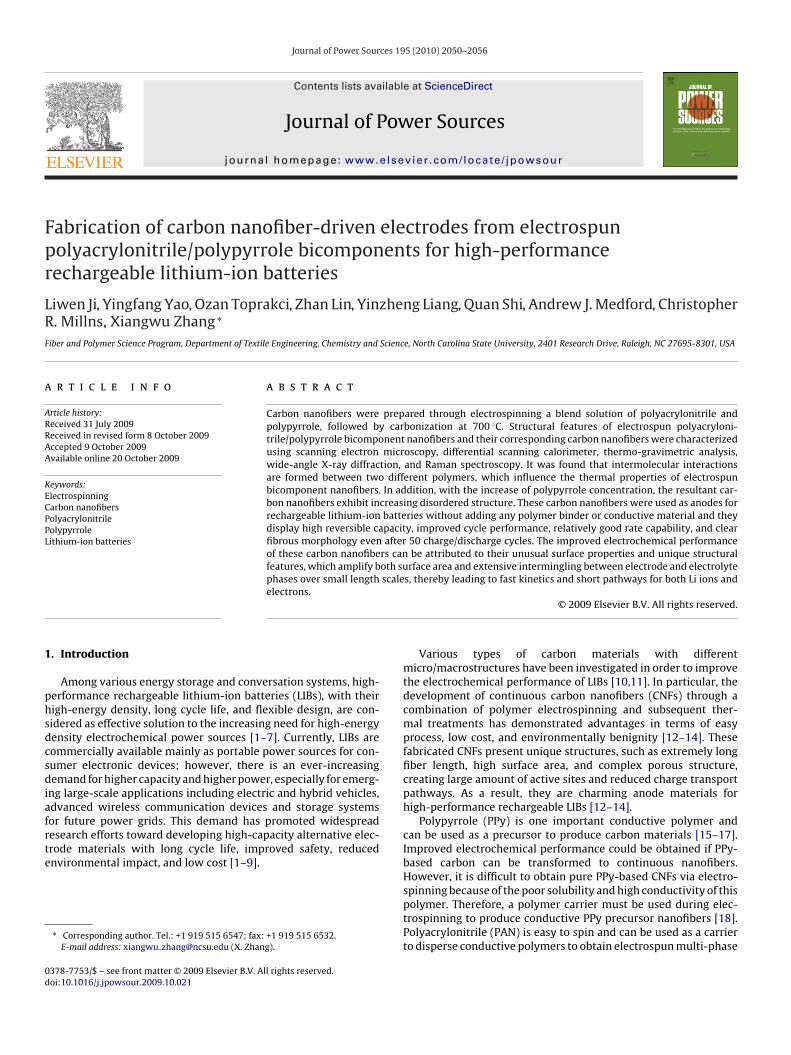
Journal of Power Sources 195 (2010) 2050–2056 Contents lists available at ScienceDirect Journal of Power Sources journal homepage: www.elsevier.com/locate/jpowsour Fabrication of carbon nanofiber-driven electrodes from electrospun polyacrylonitrile/polypyrrole bicomponents for high-performance rechargeable lithium-ion batteries Liwen Ji, Yingfang Yao, Ozan Toprakci, Zhan Lin, Yinzheng Liang, Quan Shi, Andrew J. Medford, Christopher R. Millns, Xiangwu Zhang ∗ Fiber and Polymer Science Program, Department of Textile Engineering, Chemistry and Science, North Carolina State University, 2401 Research Drive, Raleigh, NC 27695-8301, USA article info Article history: Received 31 July 2009 Received in revised form 8 October 2009 Accepted 9 October 2009 Available online 20 October 2009 Keywords: Electrospinning Carbon nanofibers Polyacrylonitrile Polypyrrole Lithium-ion batteries abstract Carbon nanofibers were prepared through electrospinning a blend solution of polyacrylonitrile and polypyrrole, followed by carbonization at 700 ◦ C. Structural features of electrospun polyacryloni- trile/polypyrrole bicomponent nanofibers and their corresponding carbon nanofibers were characterized using scanning electron microscopy, differential scanning calorimeter, thermo-gravimetric analysis, wide-angle X-ray diffraction, and Raman spectroscopy. It was found that intermolecular interactions are formed between two different polymers, which influence the thermal properties of electrospun bicomponent nanofibers. In addition, with the increase of polypyrrole concentration, the resultant car- bon nanofibers exhibit increasing disordered structure. These carbon nanofibers were used as anodes for rechargeable lithium-ion batteries without adding any polymer binder or conductive material and they display high reversible capacity, improved cycle performance, relatively good rate capability, and clear fibrous morphology even after 50 charge/discharge cycles. The improved electrochemical performance of these carbon nanofibers can be attributed to their unusual surface properties and unique structural features, which amplify both surface area and extensive intermingling between electrode and electrolyte phases over small length scales, thereby leading to fast kinetics and short pathways for both Li ions and electrons. © 2009 Elsevier B.V. All rights reserved. 1. Introduction Among various energy storage and conversation systems, high- performance rechargeable lithium-ion batteries (LIBs), with their high-energy density, long cycle life, and flexible design, are con- sidered as effective solution to the increasing need for high-energy density electrochemical power sources [1–7]. Currently, LIBs are commercially available mainly as portable power sources for con- sumer electronic devices; however, there is an ever-increasing demand for higher capacity and higher power, especially for emerg- ing large-scale applications including electric and hybrid vehicles, advanced wireless communication devices and storage systems for future power grids. This demand has promoted widespread research efforts toward developing high-capacity alternative elec- trode materials with long cycle life, improved safety, reduced environmental impact, and low cost [1–9]. ∗ Corresponding author. Tel.: +1 919 515 6547; fax: +1 919 515 6532. E-mail address: xiangwu [email protected] (X. Zhang). Various types of carbon materials with different micro/macrostructures have been investigated in order to improve the electrochemical performance of LIBs [10,11]. In particular, the development of continuous carbon nanofibers (CNFs) through a combination of polymer electrospinning and subsequent ther- mal treatments has demonstrated advantages in terms of easy process, low cost, and environmentally benignity [12–14]. These fabricated CNFs present unique structures, such as extremely long fiber length, high surface area, and complex porous structure, creating large amount of active sites and reduced charge transport pathways. As a result, they are charming anode materials for high-performance rechargeable LIBs [12–14]. Polypyrrole (PPy) is one important conductive polymer and can be used as a precursor to produce carbon materials [15–17]. Improved electrochemical performance could be obtained if PPy- based carbon can be transformed to continuous nanofibers. However, it is difficult to obtain pure PPy-based CNFs via electro- spinning because of the poor solubility and high conductivity of this polymer. Therefore, a polymer carrier must be used during elec- trospinning to produce conductive PPy precursor nanofibers [18]. Polyacrylonitrile (PAN) is easy to spin and can be used as a carrier to disperse conductive polymers to obtain electrospun multi-phase 0378-7753/$ – see front matter © 2009 Elsevier B.V. All rights reserved. doi:10.1016/j.jpowsour.2009.10.021
Transcript of Electrospinning Carbon nanofibers Polyacrylonitrile Polypyrrole Lithium-ion batteries
Fpr
LRF
a
ARRAA
KECPPL
1
phsdcsdiafrte
0d
Journal of Power Sources 195 (2010) 2050–2056
Contents lists available at ScienceDirect
Journal of Power Sources
journa l homepage: www.e lsev ier .com/ locate / jpowsour
abrication of carbon nanofiber-driven electrodes from electrospunolyacrylonitrile/polypyrrole bicomponents for high-performanceechargeable lithium-ion batteries
iwen Ji, Yingfang Yao, Ozan Toprakci, Zhan Lin, Yinzheng Liang, Quan Shi, Andrew J. Medford, Christopher. Millns, Xiangwu Zhang ∗
iber and Polymer Science Program, Department of Textile Engineering, Chemistry and Science, North Carolina State University, 2401 Research Drive, Raleigh, NC 27695-8301, USA
r t i c l e i n f o
rticle history:eceived 31 July 2009eceived in revised form 8 October 2009ccepted 9 October 2009vailable online 20 October 2009
eywords:lectrospinningarbon nanofibers
a b s t r a c t
Carbon nanofibers were prepared through electrospinning a blend solution of polyacrylonitrile andpolypyrrole, followed by carbonization at 700 ◦C. Structural features of electrospun polyacryloni-trile/polypyrrole bicomponent nanofibers and their corresponding carbon nanofibers were characterizedusing scanning electron microscopy, differential scanning calorimeter, thermo-gravimetric analysis,wide-angle X-ray diffraction, and Raman spectroscopy. It was found that intermolecular interactionsare formed between two different polymers, which influence the thermal properties of electrospunbicomponent nanofibers. In addition, with the increase of polypyrrole concentration, the resultant car-bon nanofibers exhibit increasing disordered structure. These carbon nanofibers were used as anodes for
olyacrylonitrileolypyrroleithium-ion batteries
rechargeable lithium-ion batteries without adding any polymer binder or conductive material and theydisplay high reversible capacity, improved cycle performance, relatively good rate capability, and clearfibrous morphology even after 50 charge/discharge cycles. The improved electrochemical performanceof these carbon nanofibers can be attributed to their unusual surface properties and unique structuralfeatures, which amplify both surface area and extensive intermingling between electrode and electrolytephases over small length scales, thereby leading to fast kinetics and short pathways for both Li ions and
electrons.. Introduction
Among various energy storage and conversation systems, high-erformance rechargeable lithium-ion batteries (LIBs), with theirigh-energy density, long cycle life, and flexible design, are con-idered as effective solution to the increasing need for high-energyensity electrochemical power sources [1–7]. Currently, LIBs areommercially available mainly as portable power sources for con-umer electronic devices; however, there is an ever-increasingemand for higher capacity and higher power, especially for emerg-
ng large-scale applications including electric and hybrid vehicles,dvanced wireless communication devices and storage systemsor future power grids. This demand has promoted widespread
esearch efforts toward developing high-capacity alternative elec-rode materials with long cycle life, improved safety, reducednvironmental impact, and low cost [1–9].∗ Corresponding author. Tel.: +1 919 515 6547; fax: +1 919 515 6532.E-mail address: xiangwu [email protected] (X. Zhang).
378-7753/$ – see front matter © 2009 Elsevier B.V. All rights reserved.oi:10.1016/j.jpowsour.2009.10.021
© 2009 Elsevier B.V. All rights reserved.
Various types of carbon materials with differentmicro/macrostructures have been investigated in order to improvethe electrochemical performance of LIBs [10,11]. In particular, thedevelopment of continuous carbon nanofibers (CNFs) through acombination of polymer electrospinning and subsequent ther-mal treatments has demonstrated advantages in terms of easyprocess, low cost, and environmentally benignity [12–14]. Thesefabricated CNFs present unique structures, such as extremely longfiber length, high surface area, and complex porous structure,creating large amount of active sites and reduced charge transportpathways. As a result, they are charming anode materials forhigh-performance rechargeable LIBs [12–14].
Polypyrrole (PPy) is one important conductive polymer andcan be used as a precursor to produce carbon materials [15–17].Improved electrochemical performance could be obtained if PPy-based carbon can be transformed to continuous nanofibers.However, it is difficult to obtain pure PPy-based CNFs via electro-
spinning because of the poor solubility and high conductivity of thispolymer. Therefore, a polymer carrier must be used during elec-trospinning to produce conductive PPy precursor nanofibers [18].Polyacrylonitrile (PAN) is easy to spin and can be used as a carrierto disperse conductive polymers to obtain electrospun multi-phase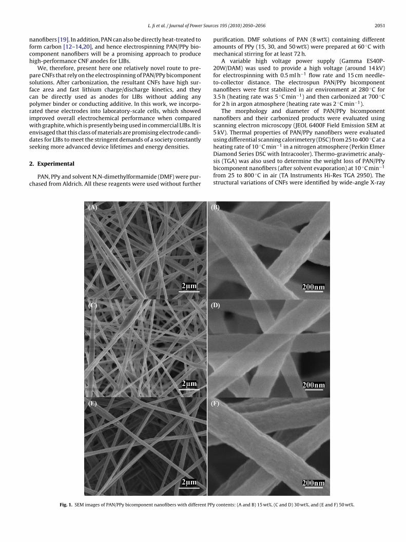
Sourc
nfch
psfcpriweds
2
c
L. Ji et al. / Journal of Power
anofibers [19]. In addition, PAN can also be directly heat-treated toorm carbon [12–14,20], and hence electrospinning PAN/PPy bio-omponent nanofibers will be a promising approach to produceigh-performance CNF anodes for LIBs.
We, therefore, present here one relatively novel route to pre-are CNFs that rely on the electrospinning of PAN/PPy bicomponentolutions. After carbonization, the resultant CNFs have high sur-ace area and fast lithium charge/discharge kinetics, and theyan be directly used as anodes for LIBs without adding anyolymer binder or conducting additive. In this work, we incorpo-ated these electrodes into laboratory-scale cells, which showedmproved overall electrochemical performance when compared
ith graphite, which is presently being used in commercial LIBs. It isnvisaged that this class of materials are promising electrode candi-ates for LIBs to meet the stringent demands of a society constantlyeeking more advanced device lifetimes and energy densities.
. Experimental
PAN, PPy and solvent N,N-dimethylformamide (DMF) were pur-hased from Aldrich. All these reagents were used without further
Fig. 1. SEM images of PAN/PPy bicomponent nanofibers with different PPy
es 195 (2010) 2050–2056 2051
purification. DMF solutions of PAN (8 wt%) containing differentamounts of PPy (15, 30, and 50 wt%) were prepared at 60 ◦C withmechanical stirring for at least 72 h.
A variable high voltage power supply (Gamma ES40P-20W/DAM) was used to provide a high voltage (around 14 kV)for electrospinning with 0.5 ml h−1 flow rate and 15 cm needle-to-collector distance. The electrospun PAN/PPy bicomponentnanofibers were first stabilized in air environment at 280 ◦C for3.5 h (heating rate was 5 ◦C min−1) and then carbonized at 700 ◦Cfor 2 h in argon atmosphere (heating rate was 2 ◦C min−1).
The morphology and diameter of PAN/PPy bicomponentnanofibers and their carbonized products were evaluated usingscanning electron microscopy (JEOL 6400F Field Emission SEM at5 kV). Thermal properties of PAN/PPy nanofibers were evaluatedusing differential scanning calorimetery (DSC) from 25 to 400 ◦C at aheating rate of 10 ◦C min−1 in a nitrogen atmosphere (Perkin Elmer
Diamond Series DSC with Intracooler). Thermo-gravimetric analy-sis (TGA) was also used to determine the weight loss of PAN/PPybicomponent nanofibers (after solvent evaporation) at 10 ◦C min−1from 25 to 800 ◦C in air (TA Instruments Hi-Res TGA 2950). Thestructural variations of CNFs were identified by wide-angle X-ray
contents: (A and B) 15 wt%, (C and D) 30 wt%, and (E and F) 50 wt%.
2052 L. Ji et al. / Journal of Power Sources 195 (2010) 2050–2056
Fc5e
dSY
cbwA(u(Cbwe2c5
3
nspsTt
nstPaccfidbatat
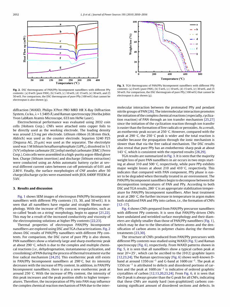
Fig. 3. TGA thermograms of PAN/PPy bicomponent nanofibers with different PPy
ig. 2. DSC thermograms of PAN/PPy bicomponent nanofibers with different PPyontents: (a) 0 wt% (pure PAN), (b) 5 wt%, (c) 10 wt%, (d) 15 wt%, (e) 30 wt%, and (f)0 wt%. For comparison, the DSC thermogram of pure PPy (100 wt%) that cannot belectrospun is also shown (g).
iffraction (WAXD, Philips X’Pert PRO MRD HR X-Ray Diffractionystem, Cu k�, � = 1.5405 Å) and Raman spectroscopy (Horiba Jobinvon LabRam Aramis Microscope, 633 nm HeNe Laser).
Electrochemical performance was evaluated using 2032 coinells (Hohsen Corp.). CNFs were attached onto copper foils toe directly used as the working electrode. The loading densityas around 2.5 mg per electrode. Lithium ribbon (0.38 mm thick,ldrich) was used as the counter electrode. Separion S240 P25
Degussa AG, 25 �m) was used as the separator. The electrolytesed was 1 M lithium hexafluorophosphate (LiPF6), dissolved in 1/1V/V) ethylene carbonate (EC)/ethyl methyl carbonate (EMC) (Ferroorp.). Coin cells were assembled in a high-purity argon-filled gloveox. Charge (lithium insertion) and discharge (lithium extraction)ere conducted using an Arbin automatic battery cycler at sev-
ral different current rates between cut-off potentials of 0.01 and.80 V. Finally, the surface morphologies of CNF anodes after 50harge/discharge cycles were examined with JEOL 6400F FESEM atkV.
. Results and discussion
Fig. 1 shows SEM images of electrospun PAN/PPy bicomponentanofibers with different PPy contents (15, 30, and 50 wt%). It iseen that all nanofibers have regular and straight fibrous mor-hology. With the increase of PPy content, irregularities, such aso-called ‘beads on a string’ morphology, begin to appear [21,22].his may be a result of the increased conductivity and viscosity ofhe electrospinning solutions at higher PPy contents [22,23].
Thermal properties of electrospun PAN/PPy bicomponentanofibers are explored using DSC and TGA characterizations. Fig. 2hows DSC results of PAN/PPy nanofibers with different PPy con-ents. For comparison, the DSC curve of pure PPy is also shown.AN nanofibers show a relatively large and sharp exothermic peakt about 290 ◦C, which is due to the complex and multiple chemi-al reactions (i.e., dehydrogenation, instantaneous cyclization, androsslinking) of PAN during the process of thermal treatment via theree radical mechanism [24,25]. This exothermic peak still existsn PAN/PPy bicomponent nanofibers at 290◦C, but its intensityecreases with the increase of PPy content. In addition, in PAN/PPyicomponent nanofibers, there is also a new exothermic peak at
round 250 ◦C. With the increase of PPy content, the intensity ofhis peak increases and the peak position shifts to higher temper-tures. Therefore, the incorporation of PPy into PAN may influencehe complex chemical reaction mechanism of PAN due to the inter-contents: (a) 0 wt% (pure PAN), (b) 5 wt%, (c) 10 wt%, (d) 15 wt%, (e) 30 wt%, and (f)50 wt%. For comparison, the DSC thermogram of pure PPy (100 wt%) that cannot beelectrospun is also shown (g).
molecular interaction between the protonated PPy and pendantnitrile groups of PAN [26]. The intermolecular interaction promotesthe initiation of the complex chemical reactions (especially, cycliza-tion reaction) of PAN through an ion transfer mechanism [25,27]since the initiation of the cyclization reaction through ion transferis easier than the formation of free radicals or peroxides. As a result,an exothermic peak occurs at 250 ◦C. However, compared with thepeak at 290 ◦C, the 250 ◦C peak is wider and the total reaction issmaller because the propagation through the ionic mechanism isslower than that via the free radical mechanism. The DSC resultsalso reveal that pure PPy has an endothermic sharp peak at about143 ◦C, which is consistent with the reported results [28,29].
TGA results are summarized in Fig. 3. It is seen that the majorityweight loss of pure PAN nanofibers in air occurs in two steps start-ing at about 310 and 500 ◦C, respectively, while pure PPy exhibitsmajor weight losses at about 210 and 410 ◦C, respectively. Thisindicates that compared with PAN component, PPy phase is eas-ier to be degraded when thermally treated in air environment. ThePAN/PPy bicomponent nanofibers begin to decompose between thedecomposition temperatures of PAN and PPy. According to bothDSC and TGA results, 280 ◦C is an appropriate stabilization temper-ature for PAN/PPy bicomponent nanofibers. After heat treatmentin air at 280 ◦C, the further increase in temperature in argon makesboth stabilized PAN and PPy into carbon, i.e., the formation of CNFs[12–17].
Fig. 4 shows CNFs prepared from PAN/PPy precursor nanofiberswith different PPy contents. It is seen that PAN/PPy-driven CNFshave undulated and wrinkled surface morphology and their diam-eters are slightly smaller than those of PAN/PPy nanofibers (Fig. 1),which may be due to the liberation of hetero-atoms and the den-sification of carbon atoms in polymer chains during the thermaltreatments [23,30].
The structure of CNFs produced from PAN/PPy precursors withdifferent PPy contents was studied using WAXD (Fig. 5) and Ramanspectroscopy (Fig. 6), respectively. From WAXD patterns shown inFig. 5, it is seen that all nanofibers show a typical carbon peak atnear 2� = 25◦, which can be ascribed to the (0 0 2) graphite layers[12,23,24]. The Raman spectroscopy (Fig. 6) shows well-known D-band at around 1350 cm−1 and G-band at 1600 cm−1. The peak at1350 cm−1 is attributed to defects and disordered portions of car-bon and the peak at 1600 cm−1 is indicative of ordered graphitic
crystallites of carbon [12,13,20,23,24]. From Fig. 6, it is seen thatthe D peak is always greater than the G peak for all CNFs, indicatingthat these CNFs are mainly hard (non-graphitized) carbons con-taining significant amount of disordered sections and defects. In
L. Ji et al. / Journal of Power Sources 195 (2010) 2050–2056 2053
Fig. 4. SEM images of CNFs prepared from PAN/PPy precursors with different
FP
ig. 5. WAXD patterns of CNFs prepared from PAN/PPy precursors with differentPy contents: (a) 0 wt%, (b) 15 wt%, (c) 30 wt%, and (d) 50 wt%.
PPy contents: (A and B) 15 wt%, (C and D) 30 wt%, and (E and F) 50 wt%.
addition, the integrated intensity of D peak increases slightly withthe increase of PPy content, and hence the presence of PPy phasein precursor helps create more defects or disordered carbon in theresultant CNFs [12,13,20,23,24].
CNFs prepared from PAN/30 wt% PPy bicomponent precursorare used as anodes to assemble lithium-ion half cells withoutadding any polymer binder or conductive additive. Galvanostaticcharge–discharge experiments were carried out to evaluate theelectrochemical performance of these CNFs in half cells. Fig. 7 dis-plays the charge–discharge curves and cycling performance of CNFsunder a constant current rate of 0.13 C (50 mA g−1) with a poten-tial window from 0.01 to 2.8 V. As shown in Fig. 7A, during the firstcharge, the voltage of CNFs decreases steeply to about 0.7 V wherea plateau region appear, followed by a slow decrease to the cut-off voltage. The plateau starting at 0.7 V may be assigned to theformation of a solid-electrolyte interface (SEI) layer on the elec-
trode surface during the first charge [12,24,31]. This plateau doesnot appear from the second cycle, indicating that the SEI layer isrelatively stable. From Fig. 7A, it is also seen that CNFs have no def-inite discharge plateau, which is the characteristic of the graphiteanodes, because these CNFs are formed mainly by non-graphitized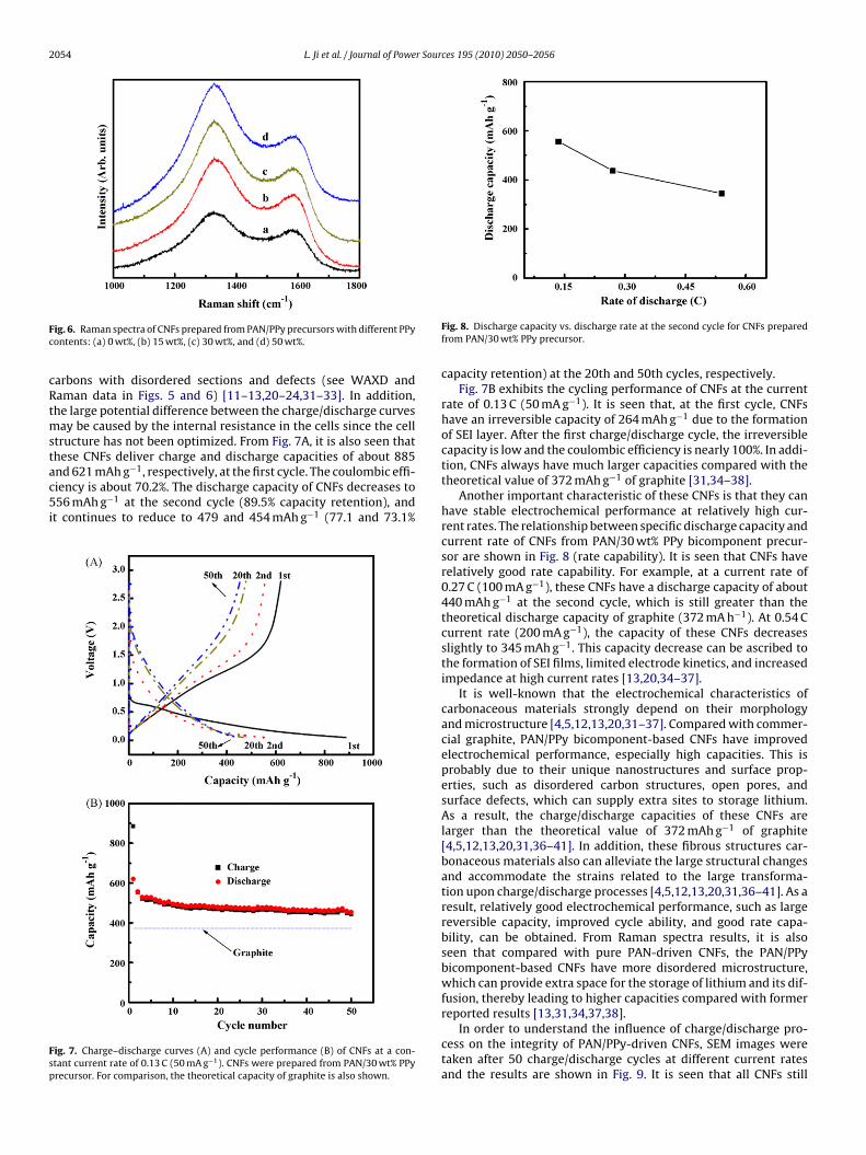
2054 L. Ji et al. / Journal of Power Sources 195 (2010) 2050–2056
Fc
cRtmstac5i
Fsp
ig. 6. Raman spectra of CNFs prepared from PAN/PPy precursors with different PPyontents: (a) 0 wt%, (b) 15 wt%, (c) 30 wt%, and (d) 50 wt%.
arbons with disordered sections and defects (see WAXD andaman data in Figs. 5 and 6) [11–13,20–24,31–33]. In addition,he large potential difference between the charge/discharge curves
ay be caused by the internal resistance in the cells since the celltructure has not been optimized. From Fig. 7A, it is also seen thathese CNFs deliver charge and discharge capacities of about 885
nd 621 mAh g−1, respectively, at the first cycle. The coulombic effi-iency is about 70.2%. The discharge capacity of CNFs decreases to56 mAh g−1 at the second cycle (89.5% capacity retention), andt continues to reduce to 479 and 454 mAh g−1 (77.1 and 73.1%
ig. 7. Charge–discharge curves (A) and cycle performance (B) of CNFs at a con-tant current rate of 0.13 C (50 mA g−1). CNFs were prepared from PAN/30 wt% PPyrecursor. For comparison, the theoretical capacity of graphite is also shown.
Fig. 8. Discharge capacity vs. discharge rate at the second cycle for CNFs preparedfrom PAN/30 wt% PPy precursor.
capacity retention) at the 20th and 50th cycles, respectively.Fig. 7B exhibits the cycling performance of CNFs at the current
rate of 0.13 C (50 mA g−1). It is seen that, at the first cycle, CNFshave an irreversible capacity of 264 mAh g−1 due to the formationof SEI layer. After the first charge/discharge cycle, the irreversiblecapacity is low and the coulombic efficiency is nearly 100%. In addi-tion, CNFs always have much larger capacities compared with thetheoretical value of 372 mAh g−1 of graphite [31,34–38].
Another important characteristic of these CNFs is that they canhave stable electrochemical performance at relatively high cur-rent rates. The relationship between specific discharge capacity andcurrent rate of CNFs from PAN/30 wt% PPy bicomponent precur-sor are shown in Fig. 8 (rate capability). It is seen that CNFs haverelatively good rate capability. For example, at a current rate of0.27 C (100 mA g−1), these CNFs have a discharge capacity of about440 mAh g−1 at the second cycle, which is still greater than thetheoretical discharge capacity of graphite (372 mA h−1). At 0.54 Ccurrent rate (200 mA g−1), the capacity of these CNFs decreasesslightly to 345 mAh g−1. This capacity decrease can be ascribed tothe formation of SEI films, limited electrode kinetics, and increasedimpedance at high current rates [13,20,34–37].
It is well-known that the electrochemical characteristics ofcarbonaceous materials strongly depend on their morphologyand microstructure [4,5,12,13,20,31–37]. Compared with commer-cial graphite, PAN/PPy bicomponent-based CNFs have improvedelectrochemical performance, especially high capacities. This isprobably due to their unique nanostructures and surface prop-erties, such as disordered carbon structures, open pores, andsurface defects, which can supply extra sites to storage lithium.As a result, the charge/discharge capacities of these CNFs arelarger than the theoretical value of 372 mAh g−1 of graphite[4,5,12,13,20,31,36–41]. In addition, these fibrous structures car-bonaceous materials also can alleviate the large structural changesand accommodate the strains related to the large transforma-tion upon charge/discharge processes [4,5,12,13,20,31,36–41]. As aresult, relatively good electrochemical performance, such as largereversible capacity, improved cycle ability, and good rate capa-bility, can be obtained. From Raman spectra results, it is alsoseen that compared with pure PAN-driven CNFs, the PAN/PPybicomponent-based CNFs have more disordered microstructure,which can provide extra space for the storage of lithium and its dif-fusion, thereby leading to higher capacities compared with former
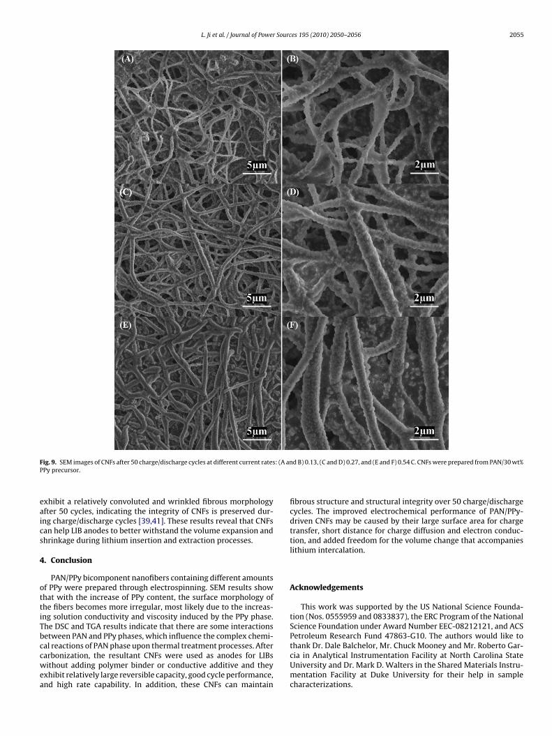
reported results [13,31,34,37,38].In order to understand the influence of charge/discharge pro-cess on the integrity of PAN/PPy-driven CNFs, SEM images weretaken after 50 charge/discharge cycles at different current ratesand the results are shown in Fig. 9. It is seen that all CNFs still
L. Ji et al. / Journal of Power Sources 195 (2010) 2050–2056 2055
F : (A anP
eaics
4
ottiTbccwea
ig. 9. SEM images of CNFs after 50 charge/discharge cycles at different current ratesPy precursor.
xhibit a relatively convoluted and wrinkled fibrous morphologyfter 50 cycles, indicating the integrity of CNFs is preserved dur-ng charge/discharge cycles [39,41]. These results reveal that CNFsan help LIB anodes to better withstand the volume expansion andhrinkage during lithium insertion and extraction processes.
. Conclusion
PAN/PPy bicomponent nanofibers containing different amountsf PPy were prepared through electrospinning. SEM results showhat with the increase of PPy content, the surface morphology ofhe fibers becomes more irregular, most likely due to the increas-ng solution conductivity and viscosity induced by the PPy phase.he DSC and TGA results indicate that there are some interactionsetween PAN and PPy phases, which influence the complex chemi-
al reactions of PAN phase upon thermal treatment processes. Afterarbonization, the resultant CNFs were used as anodes for LIBsithout adding polymer binder or conductive additive and theyxhibit relatively large reversible capacity, good cycle performance,nd high rate capability. In addition, these CNFs can maintain
d B) 0.13, (C and D) 0.27, and (E and F) 0.54 C. CNFs were prepared from PAN/30 wt%
fibrous structure and structural integrity over 50 charge/dischargecycles. The improved electrochemical performance of PAN/PPy-driven CNFs may be caused by their large surface area for chargetransfer, short distance for charge diffusion and electron conduc-tion, and added freedom for the volume change that accompanieslithium intercalation.
Acknowledgements
This work was supported by the US National Science Founda-tion (Nos. 0555959 and 0833837), the ERC Program of the NationalScience Foundation under Award Number EEC-08212121, and ACSPetroleum Research Fund 47863-G10. The authors would like to
thank Dr. Dale Balchelor, Mr. Chuck Mooney and Mr. Roberto Gar-cia in Analytical Instrumentation Facility at North Carolina StateUniversity and Dr. Mark D. Walters in the Shared Materials Instru-mentation Facility at Duke University for their help in samplecharacterizations.
2 r Sour
R
[
[
[[[[[
[[[[
[[[
[
[[
[[[[[
[
[
[[[[[[39] L. Wang, Y. Yu, P.C. Chen, D.W. Zhang, C.H. Chen, J. Power sources 183 (2008)
056 L. Ji et al. / Journal of Powe
eferences
[1] J.M. Tarascon, M. Armand, Nature 414 (2001) 359–367.[2] P. Balaya, Energy Environ. Sci. 1 (2008) 645–654.[3] A. Manthiram, A.V. Murugan, A. Sarkar, T. Muraliganth, Energy Environ. Sci. 1
(2008) 621–638.[4] P.G. Bruce, B. Scrosati, J.M. Tarascon, Angew. Chem. Int. Ed. 47 (2008)
2930–2946.[5] F. Cheng, Z. Tao, J. Liang, J. Chen, Chem. Mater. 20 (2008) 667–681.[6] Y.G. Guo, J.S. Hu, L.J. Wan, Adv. Mater. 20 (2008) 2878–2887.[7] M.G. Kim, J. Cho, Adv. Funct. Mater. 19 (2009) 1497–1514.[8] J. Baxter, Z. Bian, G. Chen, D. Danielson, M.S. Dresselhaus, A.G. Fedorov, T.S.
Fisher, C.W. Jones, E. Maginn, U. Kortshagen, A. Manthiram, A. Nozik, D. Rolison,T. Sands, L. Shi, D. Sholl, Y. Wu, Energy Environ. Sci. 2 (2009) 559–588.
[9] A.S. Aricò, P. Bruce, B. Scrosati, J.M. Tarascon, W.V. Schalkwijk, Nat. Mater. 4(2005) 366–377.
10] Y.S. Hu, R.Z. Demir-Cakan, M.M. Titirici, J.O. Müller, R. Schlögl, M. Antonietti, J.Maier, Angew. Chem. Int. Ed. 47 (2008) 1645–1649.
11] G. Zou, D. Zhang, C. Dong, H. Li, K. Xiong, L. Fei, Y.T. Qian, Carbon 44 (2006)828–832.
12] L.W. Ji, X.W. Zhang, Nanotechnology 20 (2009) 155705.13] L.W. Ji, X.W. Zhang, Electrochem. Commun. 11 (2009) 684–687.14] V. Thavasi, G. Singh, S. Ramakrishna, Energy Environ. Sci. 1 (2008) 205–221.15] S.M. Shang, X.M. Yang, X.M. Tao, Polymer 50 (2009) 2815–2818.16] C.M. Yang, C. Weidenthaler, B. Spliethoff, M. Mayanna, F. Schuth, Chem. Mater.
17 (2005) 355–358.17] X.M. Yang, T.Y. Dai, Z.X. Zhu, Y. Lu, Polymer 48 (2007) 4021–4027.18] I.S. Chronakis, S. Grapenson, A. Jakob, Polymer 47 (2006) 1597–1603.19] A. El-Aufy, Thesis, Doctor of Philosophy, Drexel University, 2004.20] C. Kim, K. Yang, M. Kojima, K. Yoshida, Y. Kim, Y. Kim, M. Endo, Adv. Funct.
Mater. 16 (2006) 2393–2397.
[
[
ces 195 (2010) 2050–2056
21] J.F. Zheng, A.H. He, J.X. Li, J. Xu, C.C. Han, Polymer 47 (2006) 7095–7102.22] L.W. Ji, A.J. Medford, X.W. Zhang, Polymer 50 (2009) 605–612.23] L.W. Ji, A.J. Medford, X.W. Zhang, J. Polym. Sci. Part B: Polym. Phys. 47 (2009)
493–503.24] C. Kim, Y. Jeong, B.T. Nhu-Ngoc, K.S. Yang, M. Kojima, Y.A. Kim, M. Endo, J.W.
Lee, Small 3 (2007) 91–95.25] J. Kim, Y.C. Kim, W. Ahn, C.Y. Kim, Polym. Eng. Sci. 33 (1994) 1452–1457.26] H.S. Park, Y.J. Kim, W.H. Hong, Y.S. Choi, H.K. Lee, Macromolecules 38 (2005)
2289–2295.27] N. Grassie, R. McGuchan, Eur. Polym. J. 7 (1971) 1503–1514.28] J.M. Yeh, C.P. Chin, S. Chang, J. Appl. Polym. Sci. 88 (2003) 3264–3272.29] S.J. Peighambardoust, B. Pourabbas, J. Appl. Polym. Sci. 106 (2007) 697–705.30] H. Dong, W.E. Jones, Langmuir 22 (2006) 11384–11387.31] H.S. Zhou, S.M. Zhu, M. Hibino, I. Honma, M. Ichihara, Adv. Mater. 15 (2003)
2107–2111.32] J.R. Dahn, A.K. Sleigh, Hang Shi, J.N. Reimers, Q. Zhong, B.M. Way, Electrochim.
Acta 38 (1993) 1179–1191.33] S.H. Yoon, C.W. Park, H. Yang, Y. Korai, I. Mochida, R.T.K. Baker, N.M. Rodriguez,
Carbon 42 (2004) 21–32.34] J.R. Dahn, T. Zheng, Y.H. Liu, J.S. Xue, Science 270 (1995) 590–593.35] K. Sato, M. Noguchi, A. Demachi, N. Oki, M. Endo, Science 264 (1994) 556–558.36] J. Chen, F. Chen, Acc. Chem. Res. 42 (2009) 713–723.37] L.W. Ji, Z. Lin, A.J. Medford, X.W. Zhang, Carbon 47 (2009) 3346–3354.38] L.W. Ji, X.W. Zhang, Electrochem. Commun. 11 (2009) 795–798.
717–723.40] G.L. Cui, Y.S. Hu, L.J. Zhi, D.Q. Wu, I. Lieberwirth, J. Maier, K. Müllen, Small 3
(2007) 2066–2069.41] C.K. Chan, H.L. Peng, G. Liu, K. McIlwrath, X.F. Zhang, R.A. Huggins, Y. Cui, Nat.
Nanotechnol. 3 (2008) 31–35.